three-phase series-buck rectifier with split dc- bus … series-buck rectifier with split dc- ......
TRANSCRIPT

516
Three-Phase Series-Buck Rectifier with Split DC-Bus Based on the Scott Transformer
Alceu André Badin and Ivo Barbi Federal University of Santa Catarina/Department of Electrical Engineering/Power Electronics Institute
P. O. BOX 5119 – 88040-970 – Florianópolis – SC - Brazil E-mail: [email protected]
Abstract— In this paper, a new unity power factor isolated three-phase buck rectifier is presented. Based on the Scott transformer, this rectifier is simple and it has the capability to obtain low output voltage. Besides, it protects against short circuit and it needs no auxiliary circuit for inrush current. Using only two active switches, it is able to generate symmetrical currents in the line and output voltage regulated. The modulation is used conventional SPWM. The control has only one voltage control loop. Theoretical analysis, design procedure, complete simulation results with closed loop operation are given, as well as results of an experimental verification.
I. INTRODUCTION
Looking for improve the energy quality in the distribution networks and efficiency, it were created strict current harmonic limitation imposed on power supplies [1]. Therefore, rectifier with power factor correction are researched and used for the developments of power supplies in recent years.
In this paper, the unity power factor three-phase rectifier buck with a simplified control loop technique, based on the Scott transformer is presented.
The single-phase PWM buck pre-regulator in Fig. 1 has some important characteristics such as the absence of inrush current, low DC output voltage, protection against short circuit, among others.
Figure 1. Single-phase buck pre-regulator.
In continuous conduction mode, with a low frequency output inductor designed in suck a way that if behaves as a constant current source. Therefore the size and weight of the output inductor, in this case, is much bigger.
In order to optimizer the size and weight, the inductance Lo may be decreased, so it no longer behaves as a constant current source. Although, increasing the
output inductor current ripple distorts the input current, with a significant third harmonic component.
In [2] proposes a control technique to eliminate the distortion on the input current even when the output inductor current presented large ripple. In reference [3] is also presented control techniques more simple to eliminate the distortion on the input current.
In [4]-[5] the unity power factor three-phase rectifier with a split DC-bus based on the Scott transformer is presented.
The proposed topology is show in the Fig. 2. In this application use two single-phase buck rectifiers in continuous conduction mode. There is a output voltage with a split DC-bus and the output inductors are coupled. It is reduced de size and cost of rectifier.
The LC input current filter of high frequency make use the leakage inductances of transformers and thus there are not necessary input inductors.
Figure 2. Unity power factor isolated three-phase rectifier buck series.
II. SCOTT TRANSFORMER
The Scott connection is realized with two single phase transformers, TM and TT. The primary windings are fed by two different voltages, VAO(t) e VCB(t), that are generated from a symmetrical three phase system VA(t) VB(t) e VC(t). The connection is represented at Fig. 3.
Each secondary winding is simply a single phase winding, and the voltage across it and the current in it do not differ from what would be expected in an ordinary single phase transformer. In the case of the three phase side, however, it is interest to consider the actual voltages and currents, which are as follows:
978-1-4244-1668-4/08/$25.00 ©2008 IEEE
Authorized licensed use limited to: UNIVERSIDADE FEDERAL DE SANTA CATARINA. Downloaded on November 13, 2009 at 06:16 from IEEE Xplore. Restrictions apply.

517
3|V |= ×|V |AO CB2 (1)
| | | |AO CBI I (2)
By multiplying the voltage across each transformer by the current in it, the equivalent size of each transformer is obtained. In the case of main transformer, this is equal to 0.577 times the group output; and in the case of the teaser transformer, 0.5 times the group output. Therefore, in a Scott connected group, the two phase windings are equivalent to the windings of two ordinary single-phase of the same output, but on the three phase side the winding of the main transformer is increased by 15.5% above what would be required in a single phase transformer of the same output. Assuming that the primary and secondary windings of an ordinary single phase transformer each occupies the same space, then, in a Scott connected group it is necessary a transformer of 7.75% greater capacity in the main transformer than a single phase transformer.
vsecT(t) and vsecM(t) represent a two phase voltage system, with a phase angle 90o between then. The phasor diagram is represented at Fig. 4.
TM
TT
O
VsecM(t)
A
B C
VsecT(t)
Figure 3. Scott connected transformers.
Figure 4. Phasor diagram of Scott Transformer.
III. THEORETICAL ANALISIS
In the unity power factor isolated three-phase rectifier theoretical study, only the secondary circuitry will be taken into account. Therefore, the secondary windings of the Scott transformer are considered to be ideal AC power sources. The full-bridge diode rectifiers were substituted by power sources that represent the rectified secondary voltage vinT(t) and VinM(t). The topology of Fig. 2 can be reduced to the circuit of Fig. 5.
The secondary voltages of the Scott transformer are sine and cosine waveforms [5]. Therefore, the rectified voltages at the inputs of the buck converters are:
( ) | sin( ) |inT pv t V w t (3)
( ) | cos( ) |inM pv t V w t (4)
The purpose of using a buck PFC is to correct the power factor of the structure by forcing the input current to follow the shape of the rectified secondary voltage. For that, instantaneous average duty cycles of the switches are:
( ) | sin( ) |T vd t K w t (5)
( ) | cos( ) |M vd t K w t (6)
Where Kv is the modulation index.
Figure 5. Three-phase rectifier equivalent circuit.
The buck diode voltages are, therefore, multiplication between input voltages rectifiers and average duty cycles of the switches:
2( ) sin( )DT p vV t V K w t (7)
2( ) cos( )DM p vV t V K w t (8)
The equivalent circuit of Fig. 5 can be reduced to the circuit of Fig. 6.
Authorized licensed use limited to: UNIVERSIDADE FEDERAL DE SANTA CATARINA. Downloaded on November 13, 2009 at 06:16 from IEEE Xplore. Restrictions apply.

518
vDM(t)
vDT(t) CoTvoT(t)+
-
CoM voM(t)+
-
iLT(t)
vo(t)
LoM
LoT
iLM(t)
+
-
Ro
Ro
c
Figure 6. Equivalent circuit of the output filter.
Considering VoT(t) and VoM(t) constant the equivalent circuit can be reduced to Fig. 7.
Figure 7. Equivalent circuit of the output filter.
Where:
2( ) cos( ) ( )LM p i oMV t V M w t V t (9)
2( ) sin( ) ( )LT p i oTV t V M w t V t (10)
The equivalent circuit of the coupled inductor can be show to Fig. 8.
Figure 8. Equivalent circuit of the coupled inductor.
Where:
1m dT
oTL L
Lk k
(11)
1m dM
oML L
Lk k
(12)
Where k is the magnetic coupling coefficient; Considering model coupled inductor show in Fig. 8(c),
equivalent circuit can be reduced to Fig. 9.
LdM
V’LM(t)
V’LT(t)
Lm LdT
M1
M2
Figure 9. Equivalent circuit of the output filter.
Where:
cos(2 ) ' ( ) 22
( ' ( ) ' ( )) 2 0
p iLM dM
LM LT m
V Mw t I t j w L
I t I t j w L
(13)
cos(2 ) ' ( ) 22
( ' ( ) ' ( )) 2 0
p iLT dT
LT LM m
V Mw t I t j w L
I t I t j w L
(14)
Solving equations (13) and (14), obtains the inductor current ripples (only AC signals):
cos(2 )' ( )
4 (1 )p i
LToT
V M w tI t
j w L k (15)
cos(2 )' ( )
4 (1 )p i
LMoM
V M w tI t
j w L k (16)
The inductor current ripples of the each buck PFC is show to Fig. 10, with parametric values.
Authorized licensed use limited to: UNIVERSIDADE FEDERAL DE SANTA CATARINA. Downloaded on November 13, 2009 at 06:16 from IEEE Xplore. Restrictions apply.

519
Figure 10. Inductor current ripples.
In a buck converter the output current is bigger than the input current. The limit for the output inductor current ripple is the one that guarantees that the output inductor current equals the input current in one point only.
IV. CONTROL STRATEGY
Each buck PFC presents its own voltage control loop (Fig. 11). The output voltage is sensor and compared to a reference voltage. The resulting error is injected in an appropriate voltage controller. The output of the voltage controller is multiplied by a sensor of the rectified input voltage and divided by a sensor of the current in the output inductor. The resulting modulation signal is compared with the saw-tooth signal, generating the drive signal to the switch.
The feedforward strategy the modulation signal presents a distortion that eliminates the input current distortion due to the output inductor current ripple.
Both transfers functions of the plant voltages loop were obtained from model of Fig. 6 and can be seen in (17) and (18). The equivalent series resistance (Resr) of the output capacitor was taken into account.
2
(1 )( )( )
1 1
p esr oToT
T esr oToT oT oT esr
oT oT
V s R CV sD s R Ls L C s C R
R R
(17)
2
(1 )( )( )
1 1
p esr oMoM
M esr oMoM oM oM esr
oM oM
V s R CV sD s R Ls L C s C R
R R
(18)
Figure 11. Control loop block diagram.
V. SIMULATION RESULTS
The results of two simulations are presented to check the validity of the study until this point. The first simulation aims to verify the performance of the current loop.
The design specifications of the prototype can be seen in Table 1.
TABLE I. DESIGN SPECIFICATIONS.
Parameters Value Line frequency (fr) 60 Hz RMS line voltage (Vin) 380 V Secondary voltage (VsecT) 220 V Rated power (Po) 6 kW Minimum rated power (Pomin) 3 kW Output voltage (Vo) 200 V Switching frequency (fs) 20 kHz Efficiency ( ) 90%Output voltage ripple ( VoT e VoM) 2%
In Fig. 12 shows the input current IT(t) and IM(t). The total harmonics distortions (THD) of the input currents for full load operation are: THDIM=2.15% and THDIM=2.10%.
Authorized licensed use limited to: UNIVERSIDADE FEDERAL DE SANTA CATARINA. Downloaded on November 13, 2009 at 06:16 from IEEE Xplore. Restrictions apply.
520
0.565 0.57 0.575 0.58 0.585 0.59 0.595-40
-30
-20
-10
0
10
20
30
40
time (s)
Figure 12. Currents IT(t) and IM(t) at each buck PFC
Fig. 13 shows the secondary voltage VsecT(t) and secondary current IT(t). Detail of crossover shows to Fig. 14.
Figure 13. Input Current iM(t) and input voltage vsecT(t).
0.5748 0.5748 0.5749 0.5749 0.575 0.575 0.5751 0.5751
-0.6
-0.4
-0.2
0
0.2
0.4
0.6
0.8
time (s)
Figure 14. Detail crossover of the input Current iM(t) and input voltage vsecT(t).
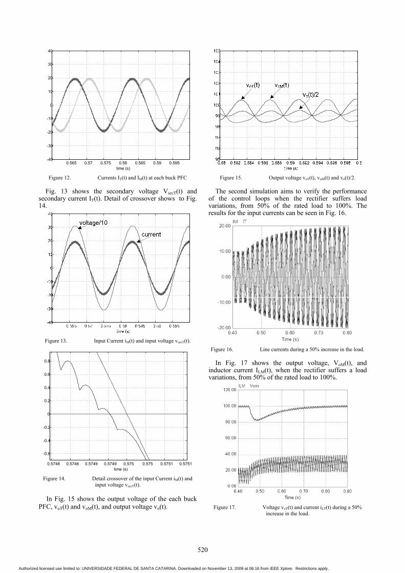
In Fig. 15 shows the output voltage of the each buck PFC, voT(t) and voM(t), and output voltage vo(t).
Figure 15. Output voltage voT(t), voM(t) and vo(t)/2.
The second simulation aims to verify the performance of the control loops when the rectifier suffers load variations, from 50% of the rated load to 100%. The results for the input currents can be seen in Fig. 16.
Figure 16. Line currents during a 50% increase in the load.
In Fig. 17 shows the output voltage, VoM(t), and inductor current ILM(t), when the rectifier suffers a load variations, from 50% of the rated load to 100%.
Figure 17. Voltage voT(t) and current iLT(t) during a 50% increase in the load.
Authorized licensed use limited to: UNIVERSIDADE FEDERAL DE SANTA CATARINA. Downloaded on November 13, 2009 at 06:16 from IEEE Xplore. Restrictions apply.
521
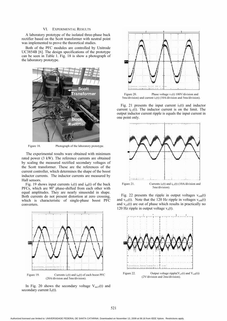
VI. EXPERIMENTAL RESULTS
A laboratory prototype of the isolated three-phase buck rectifier based on the Scott transformer with neutral point was implemented to prove the theoretical studies.
Both of the PFC modules are controlled by Unitrode UC3854B [6]. The design specifications of the prototype can be seen in Table 1. Fig. 18 is show a photograph of the laboratory prototype.
Figure 18. Photograph of the laboratory prototype.
The experimental results ware obtained with minimum rated power (3 kW). The reference currents are obtained by scaling the measured rectified secondary voltages of the Scott transformer. These are the references of the current controller, which determines the shape of the boost inductor currents. The inductor currents are measured by Hall sensors.
Fig. 19 shows input currents iT(t) and iM(t) of the buck PFCs, which are 90o phase-shifted from each other with equal amplitudes. They are nearly sinusoidal in shape. Both currents do not present distortion at zero crossing, which is characteristic of single-phase boost PFC converters.
Figure 19. Currents iT(t) and iM(t) of each boost PFC (20A/division and 5ms/division).
In Fig. 20 shows the secondary voltage VsecT(t) and secondary current IT(t).
Figure 20. Phase voltage vT(t) 100V/division and 5ms/division) and current iT(t) (10A/division and 5ms/division).
Fig. 21 presents the input current iT(t) and inductor current iLT(t). The inductor current is on the limit. The output inductor current ripple is equals the input current in one point only.
Figure 21. Currents iT(t) and iLT(t) (10A/division and 5ms/division).
Fig. 22 presents the ripple in output voltages voM(t)and voT(t). Note that the 120 Hz ripple in voltages voM(t) and voT(t) are out of phase which results in practically no 120 Hz ripple in output voltage vo(t).
Figure 22. Output voltage ripple(VoT(t) and VoM(t)) (2V/division and 2ms/division).
Authorized licensed use limited to: UNIVERSIDADE FEDERAL DE SANTA CATARINA. Downloaded on November 13, 2009 at 06:16 from IEEE Xplore. Restrictions apply.

522
VII. CONCLUSIONS
In this paper it is presented and studied a control strategy to a simplified isolated three-phase Buck based unity power factor single-phase buck rectifier and Scott transformer, operating in continuous conduction mode. It presents only two switches and a balanced split DC-bus.
A 6 kW laboratory prototype was implemented. The experimental results demonstrate the performance of the proposed system. The resulting input line currents are nearly sinusoidal in shape, even processing only 3 kW.
The low-pass LC input filters are obtaining with leakage inductances of Scott Transformer. Is not necessary add inductors, only capacitors.
The power factor is independent on the relation between the output voltage average value and the input voltage peak value. The output inductors are coupled. It is reducing de size and cost of rectifier.
REFERENCES
[1] IEEE Recommended Pratictices and Requirements for harmonics Control in Eletric Power Systems, IEEE Std. 519, 1992.
[2] K. Hirachi, T. Iwada, K. Shibayama, “A specific control Implementation on buck-type Active Power Filtering Converters.” INTELEC Proceedings, 1995, p. 444-449, 1995.
[3] F. Pöttker de Souza, I. Barbi, “A Unity Power Factor Buck Pré-Regulator with Feedforward of the Output Inductor Current.” Applied Power Electronics Conference and Exposition, 1999.
[4] A. A. Badin, I. Barbi, “Simplified control technique for three-phase rectifier PFC based on the Scott transformer.” IEEE International Symposium on Industrial Electronics, Vol. 2, p. 931-936 Montreal, July 2006.
[5] A. A. Badin, I. Barbi, “Unity power factor isolated three-phase rectifier with neutral point based on the Scott transformer.” Applied Power Electronics Conference and Exposition, p.1289-1295, Dallas, TX, 2006.
[6] P. C. Todd, “UC3854 controlled power factor correction circuit design”, Unitrode Corp., Unitrode Application Note U-134,Merrimack, NH, 1999.
Authorized licensed use limited to: UNIVERSIDADE FEDERAL DE SANTA CATARINA. Downloaded on November 13, 2009 at 06:16 from IEEE Xplore. Restrictions apply.