through-needle all-optical ultrasound imaging in vivo: a ... · the use of this needle within the...
TRANSCRIPT

OPEN
ORIGINAL ARTICLE
Through-needle all-optical ultrasound imaging in vivo:a preclinical swine study
Malcolm C Finlay1, Charles A Mosse2, Richard J Colchester2, Sacha Noimark2,3, Edward Z Zhang2,Sebastien Ourselin2, Paul C Beard2, Richard J Schilling1, Ivan P Parkin3, Ioannis Papakonstantinou4
and Adrien E Desjardins2
High-frequency ultrasound imaging can provide exquisite visualizations of tissue to guide minimally invasive procedures. Here,
we demonstrate that an all-optical ultrasound transducer, through which light guided by optical fibers is used to generate and
receive ultrasound, is suitable for real-time invasive medical imaging in vivo. Broad-bandwidth ultrasound generation was
achieved through the photoacoustic excitation of a multiwalled carbon nanotube-polydimethylsiloxane composite coating on the
distal end of a 300-μm multi-mode optical fiber by a pulsed laser. The interrogation of a high-finesse Fabry–Pérot cavity on a
single-mode optical fiber by a wavelength-tunable continuous-wave laser was applied for ultrasound reception. This transducer
was integrated within a custom inner transseptal needle (diameter 1.08 mm; length 78 cm) that included a metallic septum to
acoustically isolate the two optical fibers. The use of this needle within the beating heart of a pig provided unprecedented real-
time views (50 Hz scan rate) of cardiac tissue (depth: 2.5 cm; axial resolution: 64 μm) and revealed the critical anatomical
structures required to safely perform a transseptal crossing: the right and left atrial walls, the right atrial appendage, and the
limbus fossae ovalis. This new paradigm will allow ultrasound imaging to be integrated into a broad range of minimally invasive
devices in different clinical contexts.
Light: Science & Applications (2017) 6, e17103; doi:10.1038/lsa.2017.103; published online 1 December 2017
Keywords: cardiac; medical devices; optoacoustic; photoacoustic; ultrasound
INTRODUCTION
High-frequency ultrasound imaging can provide an exquisitevisualization of tissue to guide minimally invasive procedures,but it remains severely underutilized in clinical practice. Higherlevels of spatial resolution are achieved at the expense ofimaging depth, so the integration of ultrasound transducersinto medical devices is often required to visualize tissue micro-structures from within the body. Since its inception, ultrasoundimaging has been achieved using electronic transducers. All-opticalultrasound transducers, which perform ultrasonic generation usingpulsed light and optical reception of ultrasonic reflections fromtissues, could serve as viable alternatives1–7.Here, we demonstrate that all-optical ultrasound transducers
can provide real-time interventional imaging to guide minimallyinvasive procedures. To bring all-optical ultrasound imaging to apoint of clinical utility, three advances were required: sufficientsensitivity to reflected ultrasound to provide soft-tissue contrastat centimeter-scale depths in the presence of tissue and devicemotion; the integration of sensing elements into devices in amanner that preserves current clinical workflows; and an in vivo
demonstration through which clinically relevant information can beacquired. We are the first to report the successful attainment of theserequirements.As an illustration of the clinical utility of real-time in vivo all-
optical ultrasound imaging, we adapted our technique to be usedduring cardiac transseptal puncturing. During this widely per-formed procedural step, a needle is inserted into the right atrium ofthe heart via the femoral vein, where it is used to puncture theforamen ovale to gain access to the left atrium for therapeuticintervention8,9. In current practice, transseptal puncturing isprincipally guided by X-ray fluoroscopy, which does not providesoft-tissue contrast; cost sensitivities prevent the routine use ofconventional intracardiac echocardiography (ICE) outside of theUSA10.In the present study, all-optical pulse-echo ultrasound imaging
was used to visualize cardiac tissue directly ahead of the distal endof a transseptal puncture needle. This was achieved using twooptical fibers within a custom inner transseptal needle smallenough to be fitted within a commercial outer needle cannula(Figure 1a). Ultrasound waves were generated photoacoustically
1William Harvey Cardiovascular Research Institute, Queen Mary University of London and Barts Heart Centre, London EC1A 7BE, UK; 2Wellcome/EPSRC Centre for Interventionaland Surgical Sciences, University College London, Charles Bell House, 67-73 Riding House Street, London W1W 7EJ, UK; 3UCL Centre for Materials Research, Department ofChemistry, University College London, London WC1H 0AJ, UK and 4Department of Electronic and Electrical Engineering, University College London, London WC1E 7JE, UKCorrespondence: AE Desjardins, Email: [email protected] 4 January 2017; revised 11 June 2017; accepted 14 June 2017
Light: Science & Applications (2017) 6, e17103; doi:10.1038/lsa.2017.103Official journal of the CIOMP 2047-7538/17www.nature.com/lsa
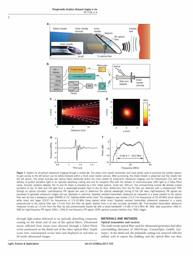
through light pulses delivered to an optically absorbing compositecoating on the distal end of one of the optical fibers. Ultrasoundwaves reflected from tissue were detected through a Fabry–Pérotcavity positioned on the distal end of the other optical fiber. Depthscans were concatenated across time and displayed in real-time asM-mode ultrasound images.
MATERIALS AND METHODS
Optical transmitter and receiverThe multi-mode optical fiber used for ultrasound generation had silicacore/cladding diameters of 300/318 μm (CeramOptec GmbH, Ger-many). At the distal end, the polyimide coating was removed with hotsulfuric acid to expose the cladding, and the optical fiber was then
Dilator sheath
a
b
c d
e f
Outer needlecannula
Innerneedle
Inner needle
Tx optical fiber
PC +display
Pulsed laser
Attenuator Saline
Side-armadapter
Outerneedlecannula
�–tunable CW laser
PR
Filters
–4–2
MPa
8
6
4
2
–1
0
1
2
–2 0 2
y (mm)
–2
0
2
4
4
0
–5
–10
–150 20 40
Frequency (MHz)
–6 dB: 6.7 – 33.2 MHz
2
0
–2
–4
–60.8 1 1.2 1.4
Time (µs)
Pre
ssur
e (M
Pa)
Pow
er (
dB)
0 5 10
Distance (mm)
x (m
m)
x (m
m)
Circulator
TRIG
GPIB
DAQ L
DAQ H
Cardiacwall
Septum
Rx opticalfiber
Figure 1 System for all-optical ultrasound imaging through a needle (a). The sharp inner needle (schematic and inset photo) used to puncture the cardiac septumto gain access to the left atrium can be safely recessed within a blunt outer needle cannula. After puncturing, the dilator sheath is advanced over the needle intothe left atrium. The probe includes two optical fibers positioned within the inner needle for pulse-echo ultrasound imaging: one for transmission (Tx) with thedelivery of pulsed excitation light to an optically absorbing coating and one for reception (Rx) with the delivery of continuous-wave (CW) light to a Fabry–Pérotcavity. Acoustic isolation between the Tx and Rx fibers is provided by a thin metal septum. Scale bar, 500 μm. The corresponding console (b) delivers pulsedexcitation to the Tx fiber and CW light from a wavelength-tunable laser to the Rx fiber. Reflections from the Rx fiber are detected with a photoreceiver (PR)through an optical circulator. Low-frequency PR signals are used to determine the optimal wavelength tuning of the CW laser; high-frequency PR signals areprocessed to generate ultrasound images and are displayed in real-time. Spatially resolved transmitted ultrasound as measured in a plane parallel to the opticalfiber axis (c) had a divergence angle (FWHM) of 23° (dashed-dotted white lines). The divergence was smaller (15.2°) for frequencies of 20–40 MHz (short dashedwhite lines) and larger (29.9°) for frequencies of 2.5–20 MHz (long dashed white lines). Spatially resolved transmitted ultrasound measured in a planeperpendicular to the optical fiber axis 1.5 mm from the fiber tip (green dashed lines in c) was circularly symmetric (d). Time-resolved transmitted ultrasoundmeasured on-axis at 1.5 mm from the fiber tip was predominantly bipolar (e) with a broad bandwidth (−6 dB) of 26.5 MHz (f). DAQ, data acquisition; DAQ H,DAQ for high-frequency PR signal; DAQ L, DAQ for low-frequency PR signal; GPIB, general purpose interface bus; TRIG, trigger.
Through-needle all-optical ultrasound imaging in vivoMC Finlay et al
2
Light: Science & Applications doi:10.1038/lsa.2017.103
cleaved perpendicular to its axis. Ultrasound was generated with amultiwalled carbon nanotube (MWCNT)-polydimethylsiloxane(PDMS) coating11,12. The coating was applied by dip-coating anorganogel that was prepared as follows: MWCNTs (6–9 nm×5 μm,Sigma Aldrich, UK) were functionalized using an oleylamine-functionalized pyrene as described previously13 and were dispersedin xylene (14 mg ml−1). The xylene dispersed functionalizedMWCNTs were sonicated with acetone (VWR, UK) using a 2:1MWCNT-xylene:acetone ratio and were allowed to rest overnight,forming a gel14. After dip-coating with the gel, the fibers were left tostand for ~1 h to allow the evaporation of solvents prior to dip-coatingwith PDMS (Nusil MED1000, Polymer Systems Technology, UK)diluted in xylene (1 g PDMS: 1.8 ml xylene).The optical fiber used for ultrasound reception was of single-mode
(SMF-28) with core/cladding diameters of 8/125 μm. A Fabry–Pérot(FP) cavity was created by dip-coating with an optically transparentpolymer, as previously described15. Two dielectric mirrors weredeposited before and after dip-coating the polymer: one on the opticalfiber end face and a second on the outer surface of the polymer. Bothmirror reflectivities were nominally 98% in the range of 1500–1600 nm. The FP cavity was coated in a protective layer of paryleneC of approximately 5 μm.
Cardiac needleTransmitting and receiving fibers were housed within the custominner needle of a coaxial transseptal needle. This inner needle wasfabricated from a stainless steel hypotube with nominal inner/outerdiameters of 0.889/1.08 mm (19X; MicroGroup, USA) and a length of78 cm. The distal end was beveled at 60° relative to the hypotube axis.When fully extended within a commercial 17 gauge Endry’s transseptalpuncture outer needle cannula, its distal end protruded by 10 mm. Abeveled septum that provided acoustic isolation between the twooptical fibers used for transmission and reception was positionedwithin the inner needle at the distal end. With a length of 10 mmalong the hypotube axis and a width equal to the inner diameter of thehypotube, the septum was laser cut from 0.1-mm-thick stainless steel.The septum did not extend beyond the bevel surface of the needle.The optical fibers were affixed to the inner wall of the hypotube
30 mm from the distal end. To do so, a small opening was created inthe hypotube. Once the fibers were positioned within the needle, asmall bolus of sealing wax was deposited through the opening so thatit held fibers adjacent to the inner wall of the hypotube. This leftsufficient space within the hypotube to permit fluid injections throughthe inner needle; fluid was prevented from flowing out from thewindow through the outer needle cannula in close apposition to theinner needle (Figure 1a).At the proximal end, a side-arm adapter (Cook Medical, UK)
allowed for fluid to be injected through the inner needle via the sideLuer lock port and for optical fibers to exit the needle through theother port. The inner needle had a Luer lock at its proximal end toconnect it with the outer needle cannula. Outside of the needle,optical fibers from the inner needle were contained within Tefzeltubing with adhesive-lined heat shrink tubing at the ends for strainrelief.
ConsoleThe main components of the console were lasers for interrogating theall-optical ultrasound probe, electronics for receiving and digitizing theultrasound signal, and a workstation with custom software(Figure 1b). For ultrasound generation, pulsed excitation light witha wavelength of 1064 nm, a pulse width of 2 ns, and a pulse energy
level of 20 μJ was delivered into the ultrasound generating optical fiberfrom an Nd:YAG laser (SPOT-10-500-1064, Elforlight, UK). This laserwas externally triggered at 50 Hz. For ultrasound reception,continuous-wave light from a tunable laser (Tunics T100S-HP CL,Yenista Optics, France) operated at an output power level of 9 mW inthe wavelength range of 1520–1570 nm was first attenuated by 10 dBwith a fiber-optic coupler and then delivered to the ultrasoundreception optical fiber through a circulator. The reflected signal wasreceived by a photoreceiver with custom electronics that provided twooutput signals: low (o50 kHz) and high-frequency (4500 kHz)components of the photodetector signal. To prevent aliasing duringdigitization, a low pass analog filter with a cut-off of 48 MHz wasapplied to the high-frequency component. The low-frequency com-ponent was digitized at 16 bits with a sample rate of 1 MS s−1
(PCI-6251, National Instruments, UK) and was used to record theFP transfer function. The wavelength of the tunable laser was adjustedto correspond to a local maximum of the derivative of the FP transferfunction to optimize sensitivity16. The high-frequency component wasthe ultrasound signal that originated from variations in the reflectivityof the FP cavity produced by impinging ultrasound waves; it wasdigitized at 14 bits at a sample rate of 100 MS s−1 (PCI-5142, NationalInstruments, UK).
Signal and image processingThe custom software, written in LabVIEW (National Instruments,USA), controlled data acquisition, performed processing, and provideda real-time display of the ultrasound signal as an M-mode image at50 Hz. Offline processing was performed using the same algorithmsimplemented in Matlab (Mathworks, USA). The software also con-tinuously saved data to allow for offline processing. Noise removalinvolved bandpass filtering and ultrasonic cross-talk modeling. First,low- and high-pass frequency filters with cut-offs of 1.5 and 45 MHz(4th order Butterworth) were applied. Next, ultrasound signals wereprocessed to remove ultrasonic cross-talk that arose from ultrasoundpropagation directly from the generation fiber to the reception fiber,which varied with time. This cross-talk removal algorithm has beendescribed in other work4. In brief, each scan was fit with a generallinear model of 3 components: a local average obtained from 20 scans,the derivative of the local average to allow for temporal offsets, and aconstant term. The modeled cross-talk for each scan was subtractedfrom the signals.After noise and cross-talk removal, digital time-gain compensation
was applied. This was achieved by multiplying the signal by thefollowing gain factor, g(i):
g ið Þ ¼ min i; imaxð Þ=imax½ �gwhere i is the sample index of the signal (i= 1, 2, …). Parameters imax
and γ were empirically designated as 700 and 2.5, respectively. Theenvelope of the signal was then obtained with the absolute value of theHilbert transform. The enveloped signals were logarithmically trans-formed, concatenated across time, and displayed in real-time as anM-mode image. A two-dimensional median filter with a 3× 3 windowsize was used to suppress speckle noise. Conversion from sampleindices to the depth from the needle tip was performed using a soundspeed of 1540 m s−1.
In vivo imagingPigs were housed in accordance with UK Home Office guidelinesrelating to animal welfare, and our work was conducted within thescope of UK Home Office License PPL 70/7765 of the Northwick ParkInstitute for Medical Research (NPIMR, London, UK). The protocol
Through-needle all-optical ultrasound imaging in vivoMC Finlay et al
3
Light: Science & Applicationsdoi:10.1038/lsa.2017.103

was reviewed and approved by the NPIMR Animal Welfare andEthical Review Body. Imaging was performed on two pigs (45 kgeach). Pigs were placed under terminal anesthesia and maintained withisoflurane; they were continuously monitored. Transseptal punctureneedles with all-optical ultrasound imaging were inserted through a 10French (F) introducer sheath (Flexor, Cook Medical, USA) via thefemoral vein. A second 10 F introducer sheath was used to introducean intracardiac echocardiography (ICE) catheter (AcuNav 8 F, Sie-mens, USA). Transseptal puncture needles were introduced through adilator sheath (Flexor, Cook Medical) to the superior vena cava over a0.889 mm (0.035’) diameter guidewire.
RESULTS AND DISCUSSION
The all-optical ultrasound transducer used in this study was the first tobe developed and used for interventional imaging. Its integration intothe inner transseptal puncture needle presented several challenges:mitigating acoustic reverberations within the device, adhering to spaceconstraints imposed by the use of the commercial outer needlecannula, and allowing for fluid injections through the inner needle.Further, its use during an invasive procedure required video-rateimage acquisition and real-time display. Here, optically generatedultrasound pulses generated peak-to-peak pressure levels of 8.8 MPa at1.5 mm from the distal end of the fiber with a − 6 dB bandwidth of26.5 MHz and an angular divergence (full-width at half-maximum,FWHM) of 23° (Figure 1c–1f). This angular divergence increasedwith decreasing frequency: it was 29.9° over a frequency rangeof 2.5–20 MHz and 15.2° over a range of 20–40MHz. By contrast,
the fiber-optic ultrasound generator with a MWCNT-PDMS coatingdeveloped by Colchester et al.13 used for benchtop all-optical ultra-sound imaging with synthetic aperture reconstruction generated apeak-to-peak pressure level of 1.96 MPa at 1.5 mm, a − 6 dB band-width of 15MHz, and an angular divergence (FWHM) of 29°. Forinterventional imaging with a single transducer, lower levels ofdivergence help increase imaging depths and improve lateral resolu-tions when synthetic aperture reconstruction is impractical due totissue and device motion. The ultrasound generation performancecompared favorably with that measured from the commercialelectronic ICE probe (Supplementary Information; SupplementaryFigs. S1 and S2; Supplementary Table S1).Through-needle all-optical ultrasound images of multiple loca-
tions within a swine heart were obtained with needle tip locationsverified via X-ray fluoroscopy and ICE. An ICE catheter waspositioned within the superior right atrium, and agitated salinebubble contrast injection facilitated the identification of the needletip. Cardiac tissue structures and their kinematics were visualizedin real time (Figure 2). The cardiac wall could be distinguished atdistances of greater than 2.5 cm from the needle tip, and thedistance from the needle tip to the cardiac wall could readily bemeasured. Before transseptal puncturing, the right atrial appendage(RAA) wall was visualized at imaging depths of beyond 1 cm(Figure 2a). Subsequently, the far left atrial wall exhibited pro-nounced systolic motion (Figure 2b). This is of significant clinicalrelevance: inadvertent far-wall puncturing is a well-recognized risk,yet the true distance between a needle tip and atrial wall is difficult
Dep
th fr
om n
eedl
e tip
(cm
)
0
1
2
b
Time (s)
121060 2 4 8
Tented septumLAwall
LA wall
Needle tip(approx.)
d1 cm
Dep
th fr
om n
eedl
e tip
(cm
)
a
Time (s)121060 2 4 8
0
1
2
RAAwall
cNeedle tip
RAA wall
1 cm
0
–25
dB
0
–25
dB
Figure 2 All-optical ultrasound imaging (M-mode) before (a) and after (b) the perforation of the cardiac septum. Corresponding needle tip positions wereidentified with a commercial intracardiac echocardiography catheter (c and d). With the needle tip positioned at the right atrial appendage wall, imagingdepths extended more than 1 cm into tissue a. Cardiac motion, which manifested as slight deviations of the tissue surface relative to the needle tip, wasmore prominent during mechanical ventilation (diagonal bars). Immediately following perforation and entrance into the left atrium (LA), pronounced LA wallcardiac motion was readily apparent b.
Through-needle all-optical ultrasound imaging in vivoMC Finlay et al
4
Light: Science & Applications doi:10.1038/lsa.2017.103

to determine through the indirect view provided when using othermodalities (for example, catheter-based ICE). Variations in thepositioning of the endocardial surface resulting from both systoliccontractions and respiration were apparent, as were those of deeperstructures and contralateral cardiac walls. The movements ofcomplex infoldings of the RAA were visible with the through-needle ultrasound stylet pointed anteriorly (Figure 3); the advance-ment of the needle at this point would risk extracardiac puncturing.An illustration of the relationships of this device to theseanatomical structures is provided in Supplementary Informationand Supplementary Fig. S3.In clinical practice, a needle ‘drag-back’ is often performed to
identify a foramen ovale via X-ray fluoroscopy8. Through thismaneuver, the needle is manually translated from superior to inferiorparts of the right atrium (Supplementary Information and
Supplementary Fig. S4). A slight deflection of the needle tip can beobserved as the needle tip passes over the thick ridge of the limbusfossae ovalis, but this movement is often ambiguous. We performedsuch a maneuver via concurrent through-needle ultrasound imagingand extended translation into the inferior vena cava (Figure 4).Variations in the thicknesses of tissues in front of the tip wereobserved. An apparent tissue thickness of greater than 0.9 cm wasobserved at the limbus fossae ovalis; immediately beyond this point,the thickness decreased, and the ultrasound reflectivity decreasedabruptly at the foramen ovale. The thickness then increased again,reaching 1.5 cm at the tendon of Todaro.Several challenges remain to be addressed for the translation of all-
optical ultrasound transducers into medical devices used in clinicalpractice. First, it must be ensured that heat generated on a coatingdoes not elevate the temperature of surrounding blood to harmful
Dep
th fr
om n
eedl
e tip
(cm
)
0
1
2
a b
Time (s)2420120 4 8 16
RAwall
RAAInfolding
ICE catheter
Needle tip
Cardiacsilhouette0
–25
dB
Figure 3 All-optical ultrasound imaging from the right atrium (RA) with depth scans shown longitudinally in time for M-mode imaging (a). The needle waspointed anteriorly and was initially held against the RA wall (vertical bars). Slight retraction was performed (412 s), and pulsations of the RA wall becameapparent (0.1–0.3 cm in depth from the needle tip). As mechanical ventilation was performed (diagonal bars), the resulting cardiac shifts produced changesin the apparent thickness of the RA wall. Right atrial appendage infolding and motion was visible beyond the RA wall. Conventional X-ray fluoroscopy imagingwas performed concurrently (b).
0
Dep
th fr
om n
eedl
e tip
(cm
)
1
Limbusfossae ovalis
Foramenovale
Tendonof
Todaro
Inferior right atrium
Inferiorvena cava
Needle translation2
0 cm 4 cm
4 cm
Highright
atrium
0
–20
dB
Figure 4 Two-dimensional all-optical ultrasound imaging (B-Mode) acquired during the manual translation of the needle tip across a distance of 4 cm. As theneedle tip progressed from the high right atrium to the inferior vena cava, the thin foramen ovale manifested as a hypoechoic region between the thicklimbus fossae ovalis and the tendon of Todaro (with a diagonal artifact from the ICE catheter and sheath). X-ray fluoroscopic imaging was acquiredconcurrently (inset).
Through-needle all-optical ultrasound imaging in vivoMC Finlay et al
5
Light: Science & Applicationsdoi:10.1038/lsa.2017.103

levels. The all-optical ultrasound transducer described here has anefficiency of ~ 0.5%, as estimated through spatially resolved pressuremeasurements (Figure 1c) and from the spatial integration of energycomputed at each location via Biagi et al.’s (Equation (8)) method17.The remaining energy level of an excitation light pulse, which is notconverted into ultrasound waves, transiently elevated the temperatureof the coating. On the basis of the assumption that the thermalbehavior of this coating is dominated by the pure PDMS region(specific heat: 1.46 J g− 1 K− 1; estimated coating thickness: 20 μm), thetemperature elevation reached approximately 10 °C. In future versionsof the transducer, the peak temperature experienced by adjacenttissues could be significantly lowered by means of a polymer coating.With the pulse energy and repetition rate used here, the time-averagedheating rate is only 0.995 mW, and blood flow will reduce heat in thevicinity of the needle tip. An additional translation challenge involvesthe biocompatibility of the MWCNT-PDMS composite, which wasnot tested in this study. The integration of MWCNTs within PDMSshould prevent their contact with biological tissues. A thin barriercoating with a biologically inert polymer such as parylene, as appliedto the outer surface of the FP cavity, would likely ensurebiocompatibility.Given their small lateral dimensions, flexibility, and immunity to
electromagnetic interference, fiber optics tend to be very well suited tosensing from within medical devices, and this is particularly the casefor those used in cardiovascular medicine18. In future devices, fiberoptics in the all-optical ultrasound transducer presented here could beused to deliver light to tissues for concurrent photoacousticimaging19–24 or for optical coherence tomography25–27. The omni-directionality of the ultrasound receiver15 is well suited to receivingpulses from distant ultrasound imaging probes to track the positioningof the needle tip28.All-optical ultrasound transducers may serve as valuable alternatives
to electronic transducers in many cases, with levels of optimalitygenerally depending on several factors such as depths, sizes, andangulations of the relevant structures to be imaged. With bothtransducer types, improvements in sensitivity yield increases inimaging depth; these increases can also be achieved at the expenseof decreased spatial resolutions. Electronic transducer sensitivity levelstend to be improved by increasing the element size, which also reducesbeam divergence. However, space available for transducers can beextremely limited within invasive medical devices. These constraints,along with the practicalities and complexities associated with incor-porating electromagnetic shielding and integrated circuits, significantlylimit the integration of electronic transducers into invasive medicaldevices.In terms of imaging depths and spatial resolutions, the all-optical
ultrasound transducer used in this study performed favorably withrespect to electronic counterparts with broadly comparable frequencyranges that provided forward visualizations from the distal ends ofneedles and catheters29–33. For instance, Chiang et al.30 integrated anelectronic transducer with a diameter of 0.5 mm and a centerfrequency of 40 MHz (−6 dB fractional bandwidth of 50%) into anepidural needle and reported an imaging depth of 10 mm in soft-tissuein vivo and an axial resolution of 150 μm. Similarly, in Wright et al.29,forward-viewing catheters (3.3 mm outer diameter; 10 F) with singletransducers that were operated in the frequency range of 25–33 MHzallowed for the intracardiac visualization of myocardial tissues todepths of 5–10 mm in vivo. With all-optical ultrasound transducers,optimizations for biological tissues could readily be performed in waysthat are not possible with electronic transducers. As optical ultrasoundtransmitters are non-resonant, the central frequency of transmitted
ultrasound can be varied by changing the pulse duration of excitationlight. The same transmitter can thus provide both low-frequency,high-depth imaging and high-frequency, low-depth imaging6. Like-wise, the responsiveness, sensitivity and directionality of a Fabry–Pérotultrasound receiver can be altered by changing the shape and thicknessof the cavity15.
CONCLUSIONS
In summary, we present a novel platform for performing pulse-echoultrasound imaging using fiber optics integrated within a clinicalneedle through the photoacoustic excitation of a nanocompositecoating for generation and a high-finesse Fabry–Pérot cavity forreception. Our study is, to the best of our knowledge, the first toprove the viability of all-optical ultrasound methods for in vivomedical imaging and for dynamic imaging from within a beatingheart for procedural guidance. The all-optical ultrasound transducersused in this study are ideally suited to interventional imaging, as theycan deliver high resolutions at significant depths from within single-use medical devices. In the context of transseptal punctures, they yielda degree of soft-tissue contrast that is unattainable through X-rayimaging to visualize the correct location for crossing the septum andincorrect locations for avoiding complications. The advances presentedhere can readily be extended to a broad range of clinical andpreclinical devices to generate ultrasound images of areas of the bodyfor which they were previously unavailable.
CONFLICT OF INTERESTThe authors declare no conflict of interest.
AUTHOR CONTRIBUTIONSMCF, IPP, and AED conceived of and performed the study and wrote thepaper. Transmitter and receiver coatings were conceived of and constructed bySN, RJC, EZZ, PCB, IPP and AED. The inner needle assembly was created byCAM. The software was written by RJC and AED. Advice on study protocolsand assistance with the experiments was provided by RJS and SO. All of theauthors discussed the results and commented on the manuscript.
ACKNOWLEDGEMENTS
We thank the following people for their support with the in vivo experiments:the staff at the Northwick Park Institute for Medical Research, Dr Ross Hunterand Dr Guy Lloyd (Barts Heart Centre), and Dr Daniil Nikitichev (UniversityCollege London). We thank Mr Mike Berry and Mr Dwayne Head for theirtechnical support with this study. This work was funded through a StartingGrant from the European Research Council (ERC-2012-StG, Proposal 310970MOPHIM), an Innovative Engineering for Health award from the WellcomeTrust (WT101957) and Engineering and Physical Sciences Research Council(EPSRC) (NS/A000027/1), and the EPSRC and European Union projectFAMOS (FP7 ICT, Contract 317744). This work was partially funded byNational Institute for Health Research University College London HospitalsBiomedical Research Centre and the National Institute for Health ResearchBarts and the London Biomedical Research Unit.
1 Biagi E, Cerbai S, Masotti L, Belsito L, Roncaglia A et al. Fiber optic broadbandultrasonic probe for virtual biopsy: technological solutions. J Sensors 2010; 2010:917314.
2 Zou XT, Wu N, Tian Y, Wang XW. Broadband miniature fiber optic ultrasound generator.Opt Express 2014; 22: 18119–18127.
3 Sheaff C, Ashkenazi S. Polyimide-etalon all-optical ultrasound transducer for highfrequency applications. Proc SPIE 2014; 8943: 89434M.
4 Colchester RJ, Zhang EZ, Mosse CA, Beard PC, Papakonstantinou I et al. Broadbandminiature optical ultrasound probe for high resolution vascular tissue imaging. BiomedOpt Express 2015; 6: 1502–1511.
Through-needle all-optical ultrasound imaging in vivoMC Finlay et al
6
Light: Science & Applications doi:10.1038/lsa.2017.103
5 Hsieh BY, Chen SL, Ling T, Guo LJ, Li PC. All-optical scanhead for ultrasound andphotoacoustic imaging—Imaging mode switching by dichroic filtering. Photoacoustics2014; 2: 39–46.
6 Alles EJ, Colchester RJ, Desjardins AE. Adaptive light modulation for improvedresolution and efficiency in all-optical pulse-echo ultrasound. IEEE Trans UltrasonFerroelectr Freq Control 2016; 63: 83–90.
7 Vannacci E, Granchi S, Belsito L, Roncaglia A, Biagi E. Wide bandwidth fiber-opticultrasound probe in MOMS technology: preliminary signal processing results. Ultra-sonics 2016; 75: 164–173.
8 Earley MJ. How to perform a transseptal puncture. Heart 2009; 95: 85–92.9 Ross J Jr. Transseptal left heart catheterization: a 50-year odyssey. J Am Coll Cardiol
2008; 51: 2107–2115.10 Babaliaros VC, Green JT, Lerakis S, Lloyd M, Block PC. Emerging applications for
transseptal left heart catheterization: old techniques for new procedures. J Am CollCardiol 2008; 51: 2116–2122.
11 Baac HW, Ok JG, Park HJ, Ling T, Chen SL et al. Carbon nanotube compositeoptoacoustic transmitters for strong and high frequency ultrasound generation. AppPhys Lett 2010; 97: 234104.
12 Baac HW, Ok JG, Lee T, Guo LJ. Nano-structural characteristics of carbon nanotube-polymer composite films for high-amplitude optoacoustic generation. Nanoscale 2015;7: 14460–14468.
13 Colchester RJ, Mosse CA, Bhachu DS, Bear JC, Carmalt CJ et al. Laser-generatedultrasound with optical fibres using functionalised carbon nanotube composite coatings.App Phys Lett 2014; 104: 173502.
14 Noimark S, Colchester RJ, Blackburn BJ, Zhang EZ, Alles EJ et al. Carbon-nanotube-PDMS composite coatings on optical fibers for all-optical ultrasound imaging. Adv FunctMater 2016; 26: 8390–8396.
15 Zhang EZ, Beard PC. Characteristics of optimized fibre-optic ultrasound receivers forminimally invasive photoacoustic detection. Proc SPIE 2015; 9323: 932311.
16 Morris P, Hurrell A, Shaw A, Zhang E, Beard P. A Fabry-Pérot fiber-optic ultrasonichydrophone for the simultaneous measurement of temperature and acoustic pressure.J Acoust Soc Am 2009; 125: 3611–3622.
17 Biagi E, Margheri F, Menichelli D. Efficient laser-ultrasound generation by using heavilyabsorbing films as targets. IEEE Trans Ultrason Ferroelectr Freq Control 2001; 48:1669–1680.
18 van Soest G, Regar E, van der Steen AFW. Photonics in cardiovascular medicine. NatPhotonics 2015; 9: 626–629.
19 Taruttis A, Herzog E, Razansky D, Ntziachristos V. Real-time imaging of cardiovasculardynamics and circulating gold nanorods with multispectral optoacoustic tomography.Opt Express 2010; 18: 19592–19602.
20 Taruttis A, Wildgruber M, Kosanke K, Beziere N, Licha K et al. Multispectraloptoacoustic tomography of myocardial infarction. Photoacoustics 2013; 1: 3–8.
21 Pang GA, Bay E, Deán-Ben XL, Razansky D. Three-dimensional optoacoustic monitoringof lesion formation in real time during radiofrequency catheter ablation. J CardiovascElectrophysiol 2015; 26: 339–345.
22 Deán-Ben XL, Ford SJ, Razansky D. High-frame rate four dimensional optoacoustictomography enables visualization of cardiovascular dynamics and mouse heart perfu-sion. Sci Rep 2015; 5: 10133.
23 Xia WF, Nikitichev DI, Mari JM, West SJ, Pratt R et al. Performance characteristics of aninterventional multispectral photoacoustic imaging system for guiding minimallyinvasive procedures. J Biomed Opt 2015; 20: 086005.
24 Piras D, Grijsen C, Schütte P, Steenbergen W, Manohar S. Photoacoustic needle:minimally invasive guidance to biopsy. J Biomed Opt 2013; 18: 070502.
25 Boppart SA, Tearney GJ, Bouma BE, Southern JF, Brezinski ME et al. Noninvasiveassessment of the developing Xenopus cardiovascular system using optical coherencetomography. Proc Natl Acad Sci USA 1997; 94: 4256–4261.
26 Villiger M, Lorenser D, McLaughlin RA, Quirk BC, Kirk RW et al. Deep tissue volumeimaging of birefringence through fibre-optic needle probes for the delineation ofbreast tumour. Sci Rep 2016; 6: 28771.
27 Li XD, Chudoba C, Ko T, Pitris C, Fujimoto JG. Imaging needle for optical coherencetomography. Opt Lett 2000; 25: 1520–1522.
28 Xia WF, Mari JM, West SJ, Ginsberg Y, David AL et al. In-plane ultrasonic needletracking using a fiber-optic hydrophone. Med Phys 2015; 42: 5983–5991.
29 Wright M, Harks E, Deladi S, Suijver F, Barley M et al. Real-time lesion assessmentusing a novel combined ultrasound and radiofrequency ablation catheter. Heart Rhythm2011; 8: 304–312.
30 Chiang HK, Zhou QF, Mandell MS, Tsou MY, Lin SP et al. Eyes in the Needle: novelepidural needle with embedded high-frequency ultrasound transducer–epidural accessin porcine model. Anesthesiology 2011; 114: 1320–1324.
31 Lee PY, Huang CC, Chiang HK. Implementation of a novel high frequency ultrasounddevice for guiding epidural anesthesia-in vivo animal study. Proceedings of 2013 IEEEInternational Ultrasonics Symposium; 21-25 July 2013; Prague, Czech Republic. IEEE:Prague, Czech Republic; 2013.
32 Gurun G, Tekes C, Zahorian J, Xu T, Satir S et al. Single-chip CMUT-on-CMOS front-endsystem for real-time volumetric IVUS and ICE imaging. IEEE Trans Ultrason FerroelectrFreq Control 2014; 61: 239–250.
33 Ameri G, Son J, Liang JW, Foster FS, Ganapathy S et al. Development of a highfrequency single-element ultrasound needle transducer for anesthesia delivery. ProcSPIE 2017; 10139: 101390S.
This work is licensed under a Creative Commons Attribution 4.0International License. The images or other third party material in this
article are included in the article’s Creative Commons license, unless indicated otherwisein the credit line; if thematerial is not includedunder theCreativeCommons license, userswill need toobtainpermission fromthe licenseholder to reproduce thematerial.Toviewacopy of this license, visit http://creativecommons.org/licenses/by/4.0/
r The Author(s) 2017
Supplementary Information for this article can be found on the Light: Science & Applications’ website (http://www.nature.com/lsa).
Through-needle all-optical ultrasound imaging in vivoMC Finlay et al
7
Light: Science & Applicationsdoi:10.1038/lsa.2017.103