ti-101 manual 03-04 - radio systems inc
TRANSCRIPT

R a d i o S y s t e m s , I n c . T I - 1 0 1 M a n u a l
3 / 0 4 P a g e 1
TI-101Telephone Interface
Manual


R a d i o S y s t e m s , I n c . T I - 1 0 1 M a n u a l
3 / 0 4 P a g e 3
Contents
1. INTRODUCTION .............................................................. 41.1 2 Wire to 4 Wire Conversion ..................................................... 41.2 Level Control ............................................................................. 41.3 Dynamic Range Control ............................................................. 41.4 Equalization of Receive Signal.................................................... 41.5 Receive Mute ............................................................................ 41.6 Conference Link ........................................................................ 4
2. FUNCTION DESCRIPTION ............................................... 52.1 Hybrid (2 to 4 wire conversion) .................................................. 52.2 Send Equalization ..................................................................... 52.3 Send Limiting ............................................................................ 52.4 Receive Compression/Expansion ................................................ 52.5 Receive Equalization ................................................................. 52.6 Telephone Line Interface Circuit ................................................ 62.7 Receive Output Circuit .............................................................. 6
3. TI-101 BLOCK DIAGRAM .................................................. 7
4. CONNECTIONS TO THE TI-101 ...................................... 84.1 Caller Output ............................................................................ 84.2 Mute ......................................................................................... 84.3 Caller Output Level Switch ........................................................ 84.4 Conference IN and OUT............................................................ 84.5 Input (from console)................................................................... 84.6 Input Level Switch ..................................................................... 84.7 Telephone TIP-RING ................................................................. 9
5. INSTALLATION................................................................ 10
6. FRONT PANEL SETUP OF THE TI-101 ............................ 116.1 For Starters .............................................................................. 116.2 Send Level Adjust (Host) .......................................................... 116.3 Receive Level (Caller) ............................................................... 116.4 Hybrid Null Adjust................................................................... 116.5 Send Limiter ............................................................................ 116.6 Compress/Expand Threshold ................................................... 126.7 Equalization ............................................................................ 12
7. USING THE CONFERENCE MODE................................. 13
8. SERVICE INFORMATION/SCHEMATICS ........................ 148.1 In Warranty Repairs ................................................................. 148.2 Out of Warranty Repairs .......................................................... 148.3 Schematic Diagrams ................................................................ 14

R a d i o S y s t e m s , I n c . T I - 1 0 1 M a n u a l
3 / 0 4 P a g e 4
Schematics .............................................................................. 15Schematics, cont. ..................................................................... 16Parts Layout ............................................................................ 17Parts List .................................................................................. 18Parts List (cont.) ....................................................................... 19
9. TI-101 SPECIFICATIONS ................................................. 20
10. THEORY OF OPERATION............................................... 2110.1 Deriving a Mix Minus Signal .................................................... 2110.2 Why Have a Mix-Minus Signal? ............................................... 2110.3 Using a Small Add-on Mixer .................................................... 2110.4 Using the Cue Bus of an Existing Mixing Console ..................... 22
11. COMMON QUESTIONS AND ANSWERS ...................... 23

R a d i o S y s t e m s , I n c . T I - 1 0 1 M a n u a l
3 / 0 4 P a g e 5
1. INTRODUCTIONThe TI-101 telephone interface is intended to allow convenient, easy connection of audioequipment to telephone lines by fulfilling the following functions:
1.1 2 WIRE TO 4 WIRE CONVERSIONMost telephone systems are 2-wire bi-directional systems. That is to say, both parties in aconversation are carried on the same pair of wires. For most professional and industrial audioapplications, it is more desirable to have the parties on two pairs so that one can adjust their levelindependently, avoid feedback due to multiple signal paths, and perform other signal processingfunctions.
1.2 LEVEL CONTROLSend (host) level and return (caller) level are independently adjustable.
1.3 DYNAMIC RANGE CONTROLThe user may adjust a limiter on the send circuit and a compressor expander (to reduce telephoneline noise) on the receive circuit.
1.4 EQUALIZATION OF RECEIVE SIGNALA boost or cut of 8 dB at 400 Hz and 2.5 Hz may be added to the caller’s signal to increaseintelligibility.
1.5 RECEIVE MUTEThe caller signal may be attenuated by a rear panel accessible contact closure. This is especiallyhelpful for repressing the off-hook dial tone and dialing generated noises.
1.6 CONFERENCE LINKTwo TI-101’s may be connected to separate telephone lines and then interconnected andpatched to the user’s mixer for three-way conversations.

R a d i o S y s t e m s , I n c . T I - 1 0 1 M a n u a l
3 / 0 4 P a g e 6
2. FUNCTION DESCRIPTION
2.1 HYBRID (2 TO 4 WIRE CONVERSION)Hybrids are necessary to separate the host from the caller line so that individual signal routing andprocessing may be applied to each one. To do so, the phone line that has a bi-directional twowire conversation between the caller and the host must have the host audio removed. This caneffectively be done by taking the host audio at the source on its own two wire path and adding itto the bi-direction conversation audio path with the “two host lines” in opposite phase.Of course,the situation is really not quite this simple. The telephone line represents a complex impedancenetwork (i.e. not just resistive, but capacitive and inductive as well), which phase shifts the sendsignal compared to the original. Phase correction must be applied to the send signal in order for itto be subtracted (nulled). The course null adjusts the hybrid for the variable resistive componentof the telephone line; the low frequency (LF) and high frequency (HF) nulls adjust the phasecorrection network for the complex components of the line.
2.2 SEND EQUALIZATIONThe FCC requires 18 dB of attenuation at 4 kHz and increasing attenuation at higher frequenciesto avoid interference with telephone company equipment. This is accomplished by an ellipticallow pass filter with a 3 kHz -3 dB point.
2.3 SEND LIMITINGThe send signal is limited by two different methods.
The first is a voltage-controlled amplifier with user adjustable threshold, allowing less audiblecompression of the send dynamic range for greater intelligibility. The limit operation is indicatedwith the enabling of the “LIMIT” LED on the TI-101 front panel.
The second method available is hard limiting (clipping) with a fixed threshold of offering completeoverdrive prevention of the phone line and hybrid circuit. Operation is indicated on the frontpanel when the “CLIP” LED is on.
2.4 RECEIVE COMPRESSION/EXPANSIONThe caller signal input will trigger either the EXPANDER or the COMPRESSOR of this circuitdepending on which side of the user set threshold the caller level falls on.
The VCA which accomplishes this operates at zero gain with no signal present. When the signalgoes above the first threshold, the gain increases, and when the signal goes above a higherthreshold still, the gain decreases. In this fashion background noise and other spurious low-levelsignals are passed at a lower level than the desired signal and loud signals are somewhatattenuated.
2.5 RECEIVE EQUALIZATIONA three-pole (18 dB per octave) 300 -3 kHz bandpass filter attenuates out-of-band signals, andimproves the quality of the null. Gyrator circuits provide symmetrical boost and cut of 8 dB at 400Hz and 2.5 kHz with a “Q” at full cut or boost of 9.

R a d i o S y s t e m s , I n c . T I - 1 0 1 M a n u a l
3 / 0 4 P a g e 7
2.6 TELEPHONE LINE INTERFACE CIRCUITThe telephone line is buffered by a transformer with good common mode rejection (another FCCrequirement) and high DC breakdown voltage. In addition, this circuit includes a Metal OxideVaristor to shunt AC or DC voltages of over 130 volts and a 2.2 μF 250V blocking capacitor tokeep DC voltages off the transformer. Although the TI-101 is not type-approved by the FCC fordirect connection to the telephone line, it is completely protected should this occur.
2.7 RECEIVE OUTPUT CIRCUITThis consists of a current-boost amplifier (emitter follower) and transformer for DC isolation andcommon mode rejection.

R a d i o S y s t e m s , I n c . T I - 1 0 1 M a n u a l
3 / 0 4 P a g e 8
3. TI-101 BLOCK DIAGRAM

R a d i o S y s t e m s , I n c . T I - 1 0 1 M a n u a l
3 / 0 4 P a g e 9
4. CONNECTIONS TO THE TI-101
4.1 CALLER OUTPUTThe caller OUTPUT XLR connector feeds the caller’s signal to your mixer. Pin 3 is high, pin 2 islow, and pin 1 is ground. For unbalanced operation, pin 2 may be grounded.
4.2 MUTEA user supplied contact closure may be connected to this 1/4" jack. When contact is made fromring to tip, the caller's signal will be attenuated by a minimum of 20 dB.
4.3 CALLER OUTPUT LEVEL SWITCHThis switch sets the nominal output gain of the TI-101. Push the switch in for +8 dBm nominaland release the switch for -10 dBm nominal. The switch setting is, of course, dependent uponthe requirements of the equipment being interfaced to the TI-101. In particular, professionalmixing consoles will want to see +8 levels and semi-pro gear will want to see -10 levels.
4.4 CONFERENCE IN AND OUTThese connect to their opposite designated references on another TI-101 (that is to say “IN” to“OUT” and “OUT” to “IN”). The conference function is activated by the front panel“CONFERENCE LINK” switch. Refer to Section 7 for details.
4.5 INPUT (FROM CONSOLE)The INPUT XLR connector accepts the send signal (the host) from your mixing console. This isthe signal that will be sent to the caller on the other end of the phone line. Pin 3 is high, pin 2 islow, and pin 1 is ground. For unbalanced input signals, you should connect pin 2 to ground andapply the signal to pin 3.
NOTE.This signal should be only the talent’s voice and not a full mix that includes the caller'ssignal (referred to as a “MIX-MINUS”). If you “loop” the caller’s voice back down the line, youwill cause an echo or perhaps an oscillation. Therefore, this input to the TI-101 should be fedfrom the mic pre-amp output patch or a separate console bus containing just the talent voice.
4.6 INPUT LEVEL SWITCHThe output level from your console or mixer can be matched to the input stage of the TI-101 withthis switch. Press the switch in to the -10 dBm position if your mixer output level is nominally“low” (as the case with a semi-pro type of mixer). Alternately, use the +8 dBm positioning of theswitch for professional mixers with high +4 or +8 dBm output bus levels.

R a d i o S y s t e m s , I n c . T I - 1 0 1 M a n u a l
3 / 0 4 P a g e 1 0
4.7 TELEPHONE TIP-RINGConnections are made from the TI-101 to your phone line on this terminal strip through an FCC-approved coupler (QKT or other supplied by your telephone company). As mentioned above,the TI-101 is both transformer isolated and capacitively coupled to the phone line. Therefore,although “TIP” and “RING” are indicated, these connections may be reversed without anyrepercussions.

R a d i o S y s t e m s , I n c . T I - 1 0 1 M a n u a l
3 / 0 4 P a g e 1 1
5. INSTALLATIONConnecting the TI-101 in parallel with the host phone line as described below is the leastcomplex method to interface into your studio system.
Follow these steps to complete basic installation:
1) Split the host phone line in a “Y” with a user-supplied RJ-11 splitter. This modularphone jack splitter is available through Radio Shack (Part #279-357).
2) One side of the split will go to the studio phone.
3) The second side of the split will terminate at the terminal connector on the rearpanel of the TI-101. Connection may be made using Radio Shack RJ-11, 12 footextension with RJ-11 and spade lug ends (#279-364). Connect the GREEN and REDwires to the terminal connector.
4) A PROGRAM INPUT channel from the mixing console should connect to theOUTPUT XLR connector on the TI-101 rear panel.
5) The INPUT XLR connector on the TI-101 should receive HOST MIC audio bytapping off of the mic input channel at a pre-fader point, or by using a dedicatedmix-minus bus from the console.
6) A remote contact closure connects to the MUTE jack on the rear panel.

R a d i o S y s t e m s , I n c . T I - 1 0 1 M a n u a l
3 / 0 4 P a g e 1 2
6. FRONT PANEL SETUP OF THE TI-101Once the TI-101 has been installed, the front panel controls may be adjusted using the followingsteps.
6.1 FOR STARTERSFirst, rotate both equalization controls to their “12 o’clock” position. Then rotate the send limiterthreshold control and the receive compressor/ expander threshold control to their full clockwiseposition. Doing so will effectively cancel these functions for the moment. Next, rotate thereceive level control to its full counterclockwise (off) position.
6.2 SEND LEVEL ADJUST (HOST)Now, call an assistant on the telephone. Make sure that your telephone mouthpiece is noweither disconnected (unscrewed) or removed from the acoustic environment in which yourmicrophone is located. Speak into your microphone and make the proper level adjustments onyour console or mixer. Then, while speaking into the microphone at a normal voice level,advance the TI-101’s send LEVEL control until the clip LED only occasionally flashes. This will giveyou the maximum send level to the phone line. Check with your assistant at the other end of theline and verify that you are being heard clearly and at a proper level.
6.3 RECEIVE LEVEL (CALLER)Adjust your console or mixer so that you can monitor the return from the phone line (the TI-101’scaller output). Have your assistant on the other end of the phone line speak to you at normalconversational volume. Turn up the receive level control on the TI-101 until a good receive signalis obtainable, using the 0 dB reference as a starting point. You should now be hearing yourassistant’s voice returning through your console or mixer clearly and without distortion.
6.4 HYBRID NULL ADJUSTNext you will adjust the null. Ask your assistant to place the telephone receiver in a quiet placeand not to make any noise for a few moments. Speak into your microphone and adjust the frontpanel “COARSE NULL” potentiometer for the minimum signal (receive signal) in your monitors.Continue speaking into the microphone and adjust the “LF” and “HF” potentiometers. As youmake these adjustments, be sure that the send or receive circuit clip lights are not coming on.The null degrades if either of these circuits are driven into clipping. The LIMIT and COMPRESS/EXPAND THRESHOLD controls will be adjusted to help prevent this from happening as describedin the next section.
6.5 SEND LIMITERYou are now ready to adjust the SEND LIMIT threshold control. With the telephone connectionmade, shout into your microphone. Make sure that you are not overloading the input to yourmixer or clipping its output. As you shout, you should observe the send CLIP LED flashing. Adjustthe send threshold control counterclockwise until the LED is no longer lit. You should now be atthe optimum operating send level. Make sure no one changes these settings!

R a d i o S y s t e m s , I n c . T I - 1 0 1 M a n u a l
3 / 0 4 P a g e 1 3
6.6 COMPRESS/EXPAND THRESHOLDNow, ask your assistant to shout back at you. Adjust the COMPRESS/EXPAND THRESHOLDcontrol in the counterclockwise direction. You will notice an increase in the volume level as youadjust this control. Compensate for this by decreasing the RECEIVE LEVEL control slightly. If youcontinue to adjust the COMPRESS/EXPAND THRESHOLD in the counterclockwise direction, youwill start to notice the effects of the expander. Any of the noise on the phone line will beattenuated during the pauses in the conversation. Adjust the settings of this threshold controluntil you get the desired effect. Remember, that if you set this threshold control too low, thenyou run the risk of cutting off your caller if he/she speaks weakly. A little experimentation withdifferent callers should help determine the optimum setting.
6.7 EQUALIZATIONFinally, have your assistant read something. As he does, adjust the equalization section of the TI-101. In general, some boost of high frequency (2.5 kHz) is always helpful for improvingintelligibility. However, adjust both controls to suit your taste.

R a d i o S y s t e m s , I n c . T I - 1 0 1 M a n u a l
3 / 0 4 P a g e 1 4
7. USING THE CONFERENCE MODE

R a d i o S y s t e m s , I n c . T I - 1 0 1 M a n u a l
3 / 0 4 P a g e 1 5
8. SERVICE INFORMATION/SCHEMATICSRadio Systems will service any of its products, no matter when it was manufactured or whatcondition it’s in. However, no goods will be accepted without a Return Authorization Number.If we don’t know its coming, we won’t be prepared to make the necessary repairs.
Before sending anything to Radio Systems, call for an R/A number. Just ask, we’ll gladlygive you one. Call 856/467-8000 weekdays 8:30 a.m. to 6:00 p.m. EST.
8.1 IN WARRANTY REPAIRSThe TI-101 Telephone interface is covered by a limited warranty for a period of one year from thedate of purchase. The Limited Warranty statement supplied with your unit spells out all the legaldetails and the generalities that follow are not intended to modify that warranty statement.
Contact Radio Systems at 856-467-8000 for a return authorization number.
Pack all items carefully and ship pre-paid, via UPS insured, to:
Radio Systems
601 Heron Drive
Logan Township, NJ 08085
Attn: R.A.#_____________
Enclose a note which includes your name, company, phone number, the serial number,return address (no box numbers), and a complete description of the problem.
8.2 OUT OF WARRANTY REPAIRSWe’ll gladly service any Radio Systems product at any time. If the warranty period is passed,you’ll be billed for all necessary parts, labor, packaging materials, as well as any applicable freightcharges.
Remember, you must call for an R/A number before you send the unit to Radio Systems.
8.3 SCHEMATIC DIAGRAMSThe schematic diagrams are to be used by qualified service technicians only. No license to usethis information for anything other than normal repairs is implied to given by the inclusion ofproprietary information in the schematic diagrams.

R a d i o S y s t e m s , I n c . T I - 1 0 1 M a n u a l
3 / 0 4 P a g e 1 6
SCHEMATICS

R a d i o S y s t e m s , I n c . T I - 1 0 1 M a n u a l
3 / 0 4 P a g e 1 7
SCHEMATICS, CONT.
R a d i o S y s t e m s , I n c . T I - 1 0 1 M a n u a l
3 / 0 4 P a g e 1 8
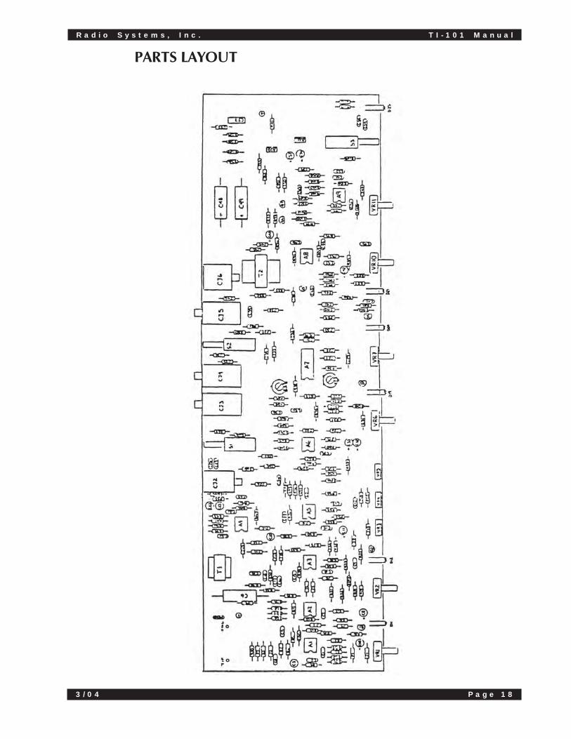
PARTS LAYOUT

R a d i o S y s t e m s , I n c . T I - 1 0 1 M a n u a l
3 / 0 4 P a g e 1 9
PARTS LIST

R a d i o S y s t e m s , I n c . T I - 1 0 1 M a n u a l
3 / 0 4 P a g e 2 0
PARTS LIST (CONT.)

R a d i o S y s t e m s , I n c . T I - 1 0 1 M a n u a l
3 / 0 4 P a g e 2 1
9. TI-101 SPECIFICATIONSInput impedance 16.7K ohms (Electronically balanced)
Output Impedance >600 ohms (Transformer Balanced)
Telephone Port Impedance 560 ohms (Transformer Isolated)
Nominal Input and Output Level Ranges Switchable between -10 dBm and +8dBm
CMRR >4 dB at Input @ 1 kHz
Maximum Input Level +21 dBm
Maximum Output Level +20 dBm
Typical THD .1%
Controls Send Level, send limit, receive levelreceive compress/expand 400 Hz and2.5 Hz. Equalization, conference link,coarse, low frequency and highfrequency null adjust
Visual Indicators LED’s for indication of send, clip, sendlimit, receive, clip, receive compress/expand, receive mute and power on
Frequency response 300 Hz to 3k Hz +/-3 dB (measuredfrom telephone port to output port)
Typical Transhybrid loss 20 dB over the specified frequencyband width
Connectors 3 pin XLR type for input and outputports, barrier terminal strip fortelephone tip and ring, 1/4" phone jacksfor external mute and conferenceinterconnect cables
Physical Size 1 3/4" high, 19" wide, 6" deep (4.45 x48.3 x 15.2 cm)
Shipping Weight 5 lbs (11.0 kg)
Power Requirements 60 Hz, 120 VAC standard, 50 Hz 220VAC, upon request
Construction All plated steel chassis

R a d i o S y s t e m s , I n c . T I - 1 0 1 M a n u a l
3 / 0 4 P a g e 2 2
10. THEORY OF OPERATION
10.1 DERIVING A MIX MINUS SIGNALMix-minus refers to one of two almost identical bus mixes. The first bus mix, which can bethought of as the main mix, contains all line inputs as its summed output. If a second bus mixcontains all but one of the main mix inputs, and is identical to it in every other respect, it is knownas a mix-minus.
In broadcasting situations, the mix-minus signal usually contains all but the receive audio (thecaller). ‘This might consist of a host and a guest along with a tape deck or two in a studio, and aguest calling in on the phone. In the studio, they are both hearing a full audio mix, but the callerwho is also on the air is hearing a mix which contains all but his own voice.
10.2 WHY HAVE A MIX-MINUS SIGNAL?Utilizing a mix-minus as a monitoring send for the remote location allows the remote source tohear all aspects of the mix without sending the source’s output back down the line to itself. Bydoing this, two problems of considerable importance can easily be avoided. The first is feedback.This situation is very much like speaking into a microphone directly in front of the monitoringspeaker. Without using a mix-minus approach, the caller source signal would almost inevitablyform a regenerative audio loop resulting in a “howl”. The second problem is echo in thecircumstance that the call is satellite delivered. This is due to a delay which is inherent to the useof a satellite link in communications. Without a mix-minus, the caller will hear a slap back repeatof his/her own voice.
The following examples provide some of the interfacing methods for a variety of systemconfigurations to derive and apply a mix-minus signal.
10.3 USING A SMALL ADD-ON MIXERAny small mixer with mic inputs can be used to derive a mix-minus signal. The outboard mixercan be used as a sub-mixer for all the mics in the booth. If the mixing console used with the TI-101 doesn’t have multiple bus capability, this technique must be used if programming is toinclude guests (and, therefore, the need for more than one studio mic).
All microphones used during a phone show are routed through the small mixer. Since the outputfrom this mixer contains only signals from the studio mics and no caller audio, it is, by definition, amix-minus signal. This output is fed to the TI-101 host audio input and to a line input of the airconsole. The TI-101’s receive audio output is run to another line input of the air console, so thestudio level and the caller level can be controlled separately.

R a d i o S y s t e m s , I n c . T I - 1 0 1 M a n u a l
3 / 0 4 P a g e 2 3
10.4 USING THE CUE BUS OF AN EXISTING MIXINGCONSOLE
Where there are enough extra line inputs available on the existing air console, use the followingtechnique:
The input used for the studio mic is switched to the cue (or audition) bus. Assuming the caller isnot put on cue, the cue bus output will be a mix-minus signal because it contains only the signalsfrom the studio microphones. It can, therefore, be used to feed the host audio input on the TI-101.
In addition, the cue bus output is routed to the air bus through a separate line input on theconsole, so the studio mic can be heard on the air. To complete this technique, the TI-101’scaller audio output is returned to the console through yet another line input to the air bus only,providing separate level controls for both the studio host and the caller.

R a d i o S y s t e m s , I n c . T I - 1 0 1 M a n u a l
3 / 0 4 P a g e 2 4
11. COMMON QUESTIONS AND ANSWERSBelow are listed some of the most often asked questions about connecting the TI-101:
How do I seize the telephone line if I don’t have a telephone set connected inparallel with the TI-101?
The telephone company uses the DC current flowing between tip and ring to sense off-hookcondition. Since the TI-101 is AC coupled to the line, it will not seize the line. Basically, asubstitute for the coil in the telephone set must be provided. This can be a holding coil such asthe following:
Radio Systems Part No. 10170
Triad-Utrad Part No. TY-350P
These are available from many electronic distributors. In a pinch, one side of a signal transformer,either primary or secondary, with the other side unterminated, can be used. It should beapproximately 1-2 Henries inductance 180 Ohms DC resistance. Also, a holding coil salvagedfrom an old telephone set could be used. The primary considerations are (1) that the coil hold theline when connected across tip and ring of the line; and (2) that a satisfactory low frequency null isachieved with the coil connected. In no case should a resistor be used to hold the line, since thiswould shift the impedance of the line such that the TI-101 cannot effectively null.
What should the signal be that I apply to the SEND INPUT of the TI-101?
The signal should be everything you want the caller (the person on the other end of the phoneline) to hear except:
1) The caller’s voice which has come from the “RECEIVE OUTPUT” of the TI-101.Including this would give the caller an objectionable echo of his own voice. Thismeans you should not use the total mix from the output of your mixing board, sincethis contains the caller’s voice. Rather, assign all mic signals to another bus, or patchoff the mic preamp output to derive the send input signal.
2) Other callers’ voices if the “conference” feature of the TI-101 is to be used. Theseare to be provided through the “CONFERENCE IN” and “CONFERENCE OUT”jacks on the back of the TI-101. Also, the input signal should be line level, nominally-10 or +8 dBm, depending on the setting of the rear panel “LEVEL” switch.
What should I do if I still get feedback (or too much of the local talent/sendinput signal from my monitor speakers after I null the TI-101?
This can be caused by several conditions:
1) A telephone mouthpiece connected to the line in the same acoustic space as themonitors. In general, all signals feeding the telephone line must go through the TI-101.
2) The null adjustment being incorrect. This can be because:
a) The telephone line has been disconnected
b) The TI-101 is no longer connected to the line for which it was nulled (i.e. it’sbeen connected to a line with different impedance)

R a d i o S y s t e m s , I n c . T I - 1 0 1 M a n u a l
3 / 0 4 P a g e 2 5
c) In general, anything has been changed about the telephone connection thatwould effect its impedance.
3) The gain from the microphone to the monitor speaker through the TI-101 is toohigh. Reasons for this include:
a) Too high send or receive levels in the TI-101, or too high receive EQ settings.
b) Too much EQ or too high level settings anywhere else in the mic to monitorsignal chain.
c) Omni-directional microphones, microphones or monitor speaker with peaksin their frequency response. Note: the above three situations, like any otherfeedback, can sometimes be cured by the judicious application of narrow-band EQ of the monitor (not main signal).
4) The telephone and signal is being clipped. This degrades the null and is indicatedby the flashing of the CLIP LED on the send sections of the TI-101.
How can I get more RECEIVE/OUTPUT level from the TI-101?
1) Change the rear panel switch from -10 dBm to +8 dBm
2) Decrease (turn counterclockwise) the RECEIVE EXPAND/COMPRESS THRESHOLDcontrol.
3) Apply gain in the unit following the TI-101
What telephone load is the TI-101 designed to be connected to?
For effective nulling, the TI-101 should be connected to the same line for which it was nulled orpossibly to sequentially numbered lines on the same exchange. This would rule out connecting itafter rotary line selectors or key sets if the lines to which they are connected are of different


For Assy:
Part #99453/06
601 Heron DriveLogan Township, NJ 08085
Phone: 856-467-8000 Fax: 856-467-3044http://www.radiosystems.com