ti c2000 mcus for ev/hev powertrain
TRANSCRIPT

TI Confidential – NDA Restrictions
1
TI C2000™ MCUs for EV/HEV Powertrain
Wayne Huang
Apr, 2019
2
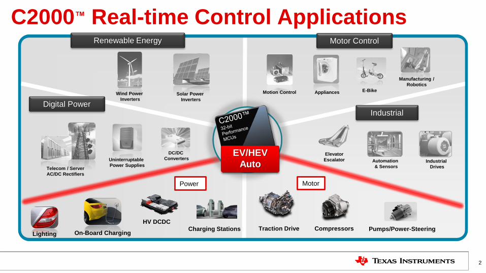
C2000™ Real-time Control Applications
On-Board Charging
Motion Control
Manufacturing /
Robotics
Wind Power
Inverters Solar Power
Inverters
Traction Drive Charging Stations
Elevator
Escalator
E-Bike
HV DCDC
Appliances
Telecom / Server
AC/DC Rectifiers
Uninterruptable
Power Supplies
DC/DC
Converters
Digital Power Industrial
Industrial
Drives
Automation
& Sensors
Lighting
Renewable Energy Motor Control
Pumps/Power-Steering
EV/HEV
Auto
Compressors
Power Motor
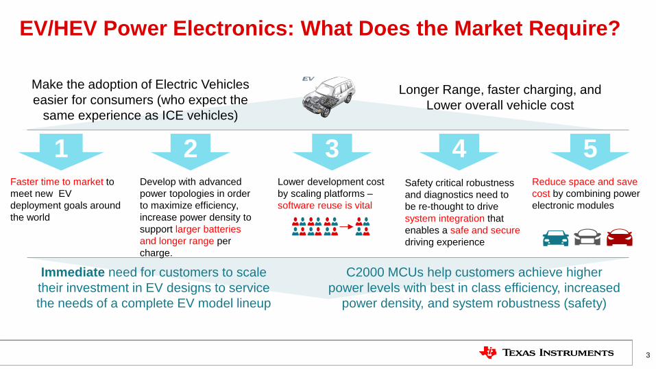
EV/HEV Power Electronics: What Does the Market Require?
3
Make the adoption of Electric Vehicles
easier for consumers (who expect the
same experience as ICE vehicles)
Faster time to market to
meet new EV
deployment goals around
the world
1 4 Reduce space and save
cost by combining power
electronic modules
5 Develop with advanced
power topologies in order
to maximize efficiency,
increase power density to
support larger batteries
and longer range per
charge.
2
Immediate need for customers to scale
their investment in EV designs to service
the needs of a complete EV model lineup
C2000 MCUs help customers achieve higher
power levels with best in class efficiency, increased
power density, and system robustness (safety)
Longer Range, faster charging, and
Lower overall vehicle cost
Safety critical robustness
and diagnostics need to
be re-thought to drive
system integration that
enables a safe and secure
driving experience
Lower development cost
by scaling platforms –
software reuse is vital
3
12-bit upto
4.6 MSPS
Dual S/H
Auto Seq
ADC
A 0 A 1 A 2 A 3 A 4 A 5 A 6 A 7
B 0 B 1 B 2 B 3 B 4 B 5 B 6 B 7
Analog
Comparators
CMP 1 - Out
DAC 10 bit
CMP 2 - Out
VrefHi VrefLo
Flash Memory
32-bit C28x Core Flt Pt
RAM
(Dual Access)
CLA Core
Flt Pt ( Accelerator )
PWM1
CAN
COMMS
UART x 2
SPI x 2
I2C
PWM2
PWM3
PWM4
PWM5
PWM6
PWM7
PWM - 1 A PWM - 1 B
Int - Osc - 1
Vreg PWR
GND
POR / BOR
4
Int - Osc - 2
6
CMP 3 - Out
2 Ext - Osc - 2
5
CAP
Timer - 0
TIMERS 32-bit
Timer - 1
Timer - 2
GPIO
Control
4
6
2
X 1
X 2
PLL
WD
C L
K S
E L
PWM - 2 A PWM - 2 B
PWM - 3 A PWM - 3 B
PWM - 4 A PWM - 4 B
PWM - 5 A PWM - 5 B
PWM - 6 A PWM - 6 B
PWM - 7 A PWM - 7 B
TZ 1
TZ 2 TZ 3
CMP 1 - out CMP 2 - out CMP 3 - out
ECAP
Vref
RAM Memory
Temp
Sensor
System
QEP QEP 4
Trip Zone
DAC 10 bit
DAC 10 bit
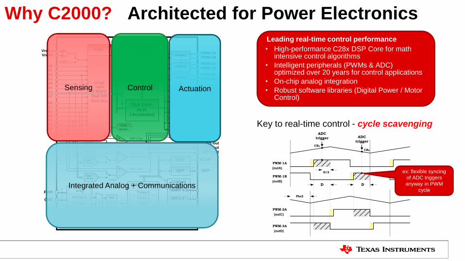
Why C2000? Architected for Power Electronics
Leading real-time control performance
• High-performance C28x DSP Core for math intensive control algorithms
• Intelligent peripherals (PWMs & ADC) optimized over 20 years for control applications
• On-chip analog integration
• Robust software libraries (Digital Power / Motor Control)
Sensing Control Actuation
Integrated Analog + Communications
(outA)
PWM-1A
PWM-1B
Phs2
(outB)
(outC)
(outD)
PWM-2A
PWM-3A
D D
CBU
D/2
CBD
ADC
trigger ADC
trigger
ex: flexible syncing
of ADC triggers
anyway in PWM
cycle
Key to real-time control - cycle scavenging
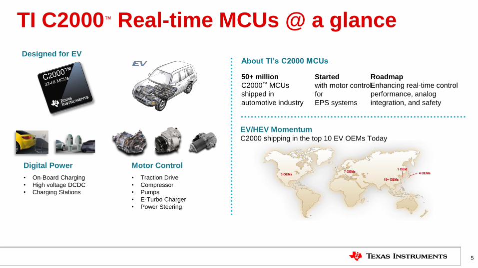
TI C2000™ Real-time MCUs @ a glance
5
Digital Power
• On-Board Charging
• High voltage DCDC
• Charging Stations
Motor Control
• Traction Drive
• Compressor
• Pumps
• E-Turbo Charger
• Power Steering
Designed for EV About TI’s C2000 MCUs
EV/HEV Momentum C2000 shipping in the top 10 EV OEMs Today
Started
with motor control
for
EPS systems
50+ million
C2000™ MCUs
shipped in
automotive industry
Roadmap
Enhancing real-time control
performance, analog
integration, and safety
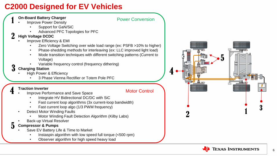
C2000 Designed for EV Vehicles
6
On-Board Battery Charger
• Improve Power Density
• Support for GaN/SiC
• Advanced PFC Topologies for PFC
High Voltage DCDC
• Improve Efficiency & EMI
• Zero Voltage Switching over wide load range (ex: PSFB >10% to higher)
• Phase-shedding methods for interleaving (ex: LLC improved light load)
• Mode transition techniques with different switching patterns (Current to
Voltage)
• Variable frequency control (frequency dithering)
Charging Station
• High Power & Efficiency
• 3 Phase Vienna Rectifier or Totem Pole PFC
Traction Inverter
• Improve Performance and Save Space
• Integrate HV Bidirectional DC/DC with SiC
• Fast current loop algorithms (3x current-loop bandwidth)
• Fast current loop algo (1/3 PWM frequency)
• Detect Motor Winding Faults
• Motor Winding Fault Detection Algorithm (Kilby Labs)
• Back-up Virtual Resolver
Compressor & Pumps
• Save EV Battery Life & Time to Market
• Instaspin algorithm with low speed full torque (<500 rpm)
• Observer algorithm for high speed heavy load
Power Conversion
Motor Control
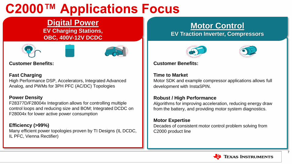
C2000™ Applications Focus
Customer Benefits:
Fast Charging High Performance DSP, Accelerators, Integrated Advanced
Analog, and PWMs for 3PH PFC (AC/DC) Topologies
Power Density F28377D/F28004x Integration allows for controlling multiple
control loops and reducing size and BOM; Integrated DCDC on
F28004x for lower active power consumption
Efficiency (>99%) Many efficient power topologies proven by TI Designs (IL DCDC,
IL PFC, Vienna Rectifier)
Digital Power EV Charging Stations,
OBC, 400V-12V DCDC
Customer Benefits:
Time to Market Motor SDK and example compressor applications allows full
development with InstaSPIN.
Robust / High Performance Algorithms for improving acceleration, reducing energy draw
from the battery, and providing motor system diagnostics.
Motor Expertise Decades of consistent motor control problem solving from
C2000 product line
Motor Control EV Traction Inverter, Compressors
7
8
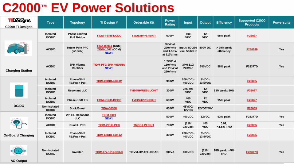
C2000™ EV Power Solutions
C2000 TI Designs
Type Topology TI Design # Orderable Kit Power
Rating Input Output Efficiency
Supported C2000
Products Powersuite
Charging Station
Isolated
DC/DC
Phase-Shifted
Full Bridge TIDM-PSFB-DCDC TMDSHVPSFBKIT 600W
400
VDC
12
VDC 95% peak F28027
AC/DC Totem Pole PFC
(w/ GaN)
TIDA-00961 (CRM)
TIDM-1007 (CCM)
NEW!!
3KW at
220Vrms
and 1.5KW
at 110Vrms
Input: 80-260
Vac, 50/60Hz
400V DC
> 99% peak
efficiency F280049 Yes
AC/DC 3PH Vienna
Rectifier
TIDM-PFC-3PH-VIENNA
NEW!!
1.2KW at
110Vrms
and 2KW at
220Vrms
3PH 110/
220Vac 700VDC 98% peak F28377D Yes
DC/DC
Isolated
DC/DC
Phase-Shift
FB/Push-Pull TIDM-BIDIR-400-12 300W
200VDC -
400VDC
9VDC-
13.5VDC F28035
Isolated
DC/DC Resonant LLC TMDSHVRESLLCKIT 300W
375-405
VDC
12
VDC 93% peak; 90% F28027
Isolated
DC/DC Phase-Shift FB TIDM-PSFB-DCDC TMDSHVPSFBKIT 600W
400
VDC
12
VDC 95% peak F28027
Non-Isolated
DC/DC Buck/Boost TIDA-00558 600W
48VDC/
12VDC 12VDC/48V F28069
On-Board Charging
Isolated
DC/DC
2PH IL Resonant
LLC
TIDM-1001
NEW!! 500W 400VDC 12VDC 93% peak F28377D Yes
AC/DC Dual IL PFC TIDM-2PHILPFC TMDSILPFCKIT 700W (110/
220Vac)
400
VDC
0.99;
<1.5% THD F28035 Yes
Isolated
DC/DC
Phase-Shift
FB/Push-Pull TIDM-BIDIR-400-12 300W
200VDC -
400VDC
9VDC-
13.5VDC F28035
AC Output
Non-Isolated
DC/AC Inverter TIDM-HV-1PH-DCAC TIEVM-HV-1PH-DCAC 600VA 400VDC
(110/
220Vac)
98% peak; <5%
THD F28377D Yes
9
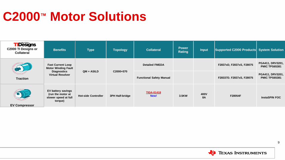
C2000™ Motor Solutions
C2000 TI Designs or
Collateral
Benefits Type Topology Collateral Power
Rating Input Supported C2000 Products System Solution
Traction
Fast Current Loop
Motor Winding Fault
Diagnostics
Virtual Resolver
QM + ASILD C2000+570
Detailed FMEDA F2837xD, F2837xS, F28075 PGA411, DRV3201,
PMIC TPS65381
Functional Safety Manual F28337D. F2837xS, F28075
PGA411, DRV3201,
PMIC TPS65381
EV Compressor
EV battery savings
(run the motor at
slower speed at full
torque)
Hot-side Controller 3PH Half-bridge
TIDA-01418
New!
3.5KW 400V
8A F28054F
InstaSPIN FOC
TI Confidential – NDA Restrictions
10
OBC & HV DCDC Architectures
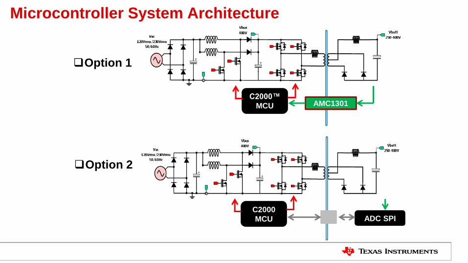
Microcontroller System Architecture
C2000™
MCU
ADC SPI
Option 1
AMC1301
Option 2
C2000
MCU
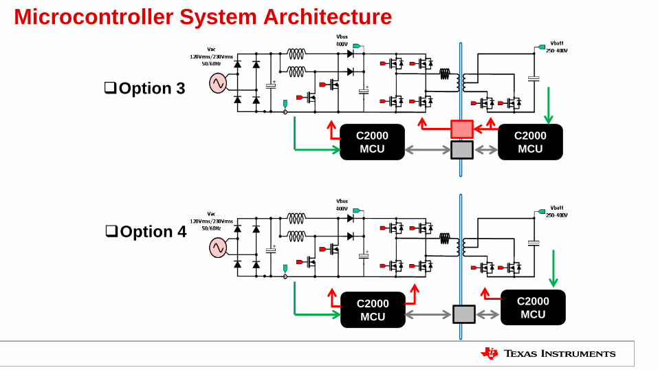
Microcontroller System Architecture
C2000
MCU
Option 3
Option 4
C2000
MCU
C2000
MCU
C2000
MCU
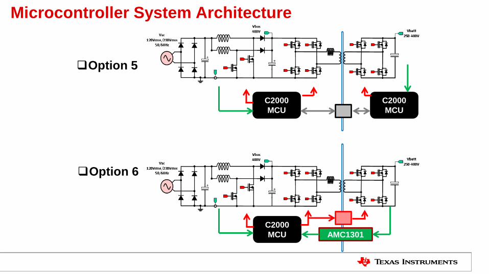
Microcontroller System Architecture
C2000
MCU
Option 5
Option 6
C2000
MCU
C2000
MCU
AMC1301
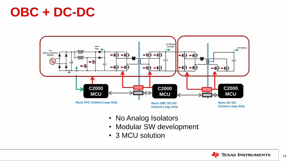
OBC + DC-DC
14
C2000
MCU C2000
MCU
C2000
MCU
• No Analog Isolators
• Modular SW development
• 3 MCU solution
Runs PFC Control Loop Only Runs OBC DC-DC
Control Loop Only
Runs DC-DC
Control Loop Only

OBC + DC-DC Optimized
15
C2000
MCU C2000
MCU
• 2 MCU solution
• Least number of digital isolators
• At least 1 iso-opamp needed
AMC1301 Runs PFC Control Loop +
Primary side control of OBC DC-DC Runs OBC DC-DC Control Loop+
OBC DC-DC Sec side FET Control +
DC-DC Control loop+
both Prim & Sec Side FET Control
TI Confidential – NDA Restrictions
16
TI Reference Designs
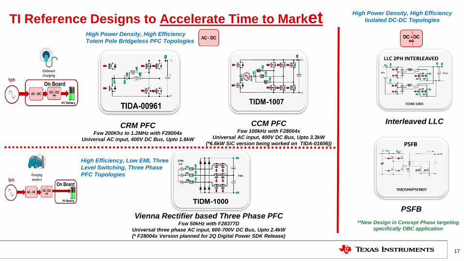
TI Reference Designs to Accelerate Time to Market
17
High Power Density, High Efficiency
Totem Pole Bridgeless PFC Topologies
CRM PFC
Fsw 200Khz to 1.2MHz with F28004x
Universal AC input, 400V DC Bus, Upto 1.6kW
CCM PFC Fsw 100kHz with F28004x
Universal AC input, 400V DC Bus, Upto 3.3kW
(*6.6kW SiC version being worked on TIDA-01606))
Vienna Rectifier based Three Phase PFC Fsw 50kHz with F28377D
Universal three phase AC input, 600-700V DC Bus, Upto 2.4kW
(* F28004x Version planned for 2Q Digital Power SDK Release)
High Efficiency, Low EMI, Three
Level Switching, Three Phase
PFC Topologies
Interleaved LLC
PSFB
High Power Density, High Efficiency
Isolated DC-DC Topologies
**New Design in Concept Phase targeting
specifically OBC application
Vac 120Vrms/230Vrms
50/60Hz
Vbus 400V-800V
SiC
SiC
SiC
SiC
Si
Si
Vbatt 250-400V
GaN
GaN GaN GaN
GaN
GaN
Vac 120Vrms/230Vrms
50/60Hz
Vbus 400V
Vbatt 250-400V
GaN GaN
GaN GaN GaN
GaN GaN GaN
Si
Si
GaN
GaN
Vac 120Vrms/230Vrms
50/60Hz
Vbus 400V
Si
Si
Vbatt 250-400V
Si
Si
Si
Si Si Si
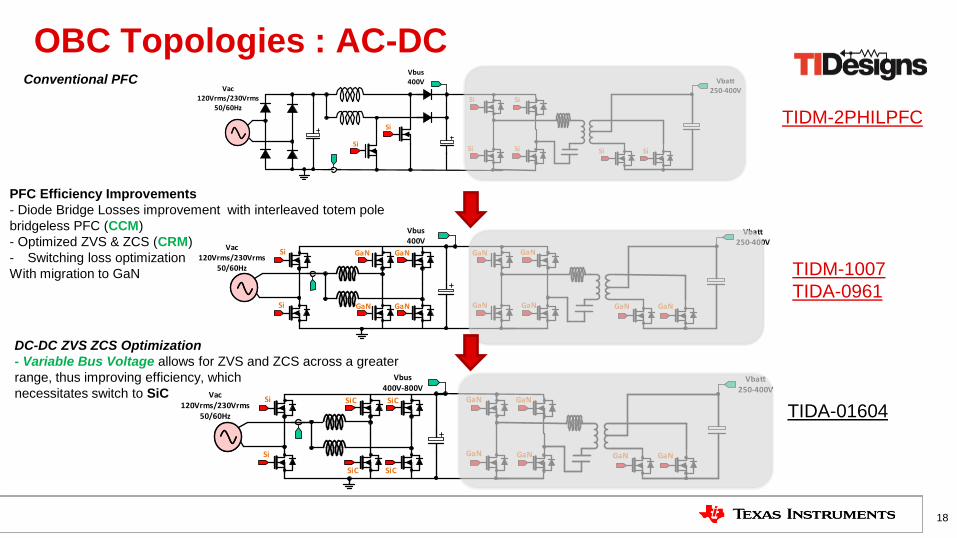
OBC Topologies : AC-DC
18
PFC Efficiency Improvements
- Diode Bridge Losses improvement with interleaved totem pole
bridgeless PFC (CCM)
- Optimized ZVS & ZCS (CRM)
- Switching loss optimization
With migration to GaN
TIDM-2PHILPFC
Conventional PFC
TIDM-1007
TIDA-0961
DC-DC ZVS ZCS Optimization
- Variable Bus Voltage allows for ZVS and ZCS across a greater
range, thus improving efficiency, which
necessitates switch to SiC
TIDA-01604
TIDM-2PHILPFC: 2-Phase Interleaved Boost PFC
19
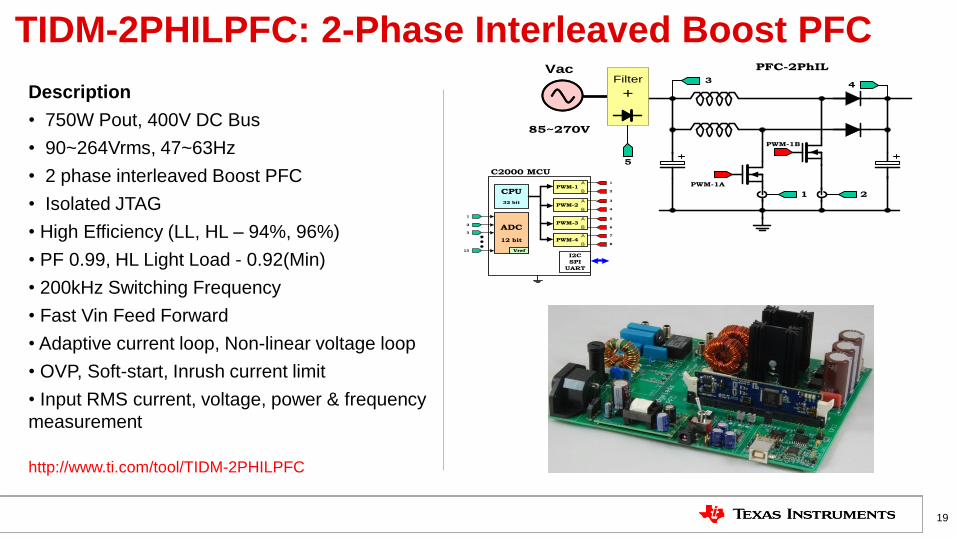
Description
• 750W Pout, 400V DC Bus
• 90~264Vrms, 47~63Hz
• 2 phase interleaved Boost PFC
• Isolated JTAG
• High Efficiency (LL, HL – 94%, 96%)
• PF 0.99, HL Light Load - 0.92(Min)
• 200kHz Switching Frequency
• Fast Vin Feed Forward
• Adaptive current loop, Non-linear voltage loop
• OVP, Soft-start, Inrush current limit
• Input RMS current, voltage, power & frequency
measurement
PFC-2PhIL
PWM-1A
PWM-1B
Filter
+
Vac
1 2
34
85~270V
5
PWM-1
C2000 MCU
I2C
SPI
UART
CPU
32 bit
A
B
PWM-2 A
B
PWM-3 A
B
PWM-4 A
B
ADC
12 bit
Vref
1
2
3
13
1
2
3
4
5
6
7
8
http://www.ti.com/tool/TIDM-2PHILPFC
• Key TI Devices: TMS320F28075, LMG3410, UCC27714D,
UCC28740, UCC24636
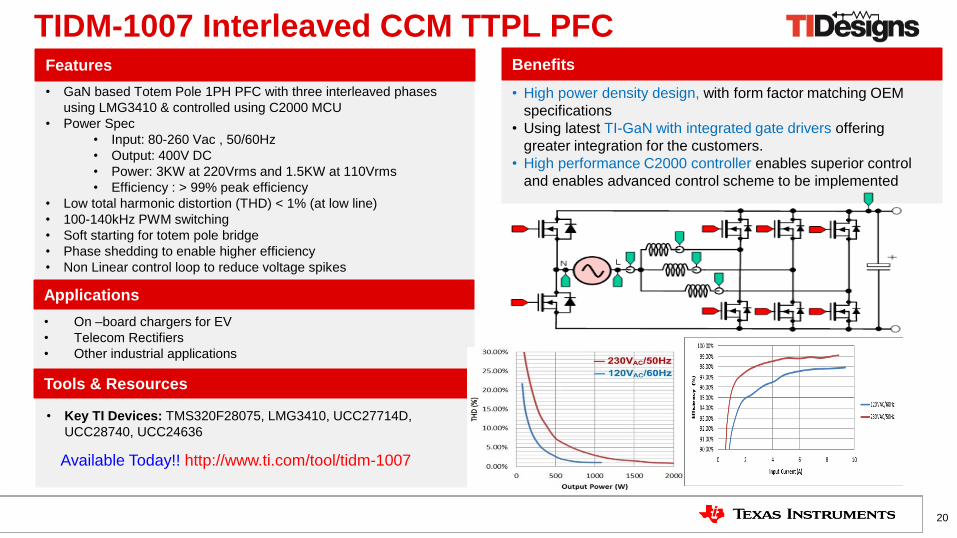
• On –board chargers for EV
• Telecom Rectifiers
• Other industrial applications
TIDM-1007 Interleaved CCM TTPL PFC
• High power density design, with form factor matching OEM
specifications
• Using latest TI-GaN with integrated gate drivers offering
greater integration for the customers.
• High performance C2000 controller enables superior control
and enables advanced control scheme to be implemented
• GaN based Totem Pole 1PH PFC with three interleaved phases
using LMG3410 & controlled using C2000 MCU
• Power Spec
• Input: 80-260 Vac , 50/60Hz
• Output: 400V DC
• Power: 3KW at 220Vrms and 1.5KW at 110Vrms
• Efficiency : > 99% peak efficiency
• Low total harmonic distortion (THD) < 1% (at low line)
• 100-140kHz PWM switching
• Soft starting for totem pole bridge
• Phase shedding to enable higher efficiency
• Non Linear control loop to reduce voltage spikes
Features Benefits
Applications
20
Tools & Resources
Available Today!! http://www.ti.com/tool/tidm-1007
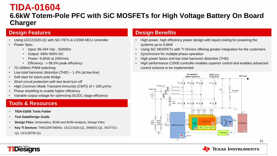
• Using UCC21520-Q1 with SiC FETs & C2000 MCU controller
• Power Spec
• Input: 85-264 Vac , 50/60Hz
• Output: 400V-600V DC
• Power: 6.6KW at 240Vrms
• Efficiency : > 98.5% peak efficiency
• 70-100kHz PWM switching
• Low total harmonic distortion (THD) ~ 1-2% (at low line)
• Soft start for totem pole bridge
• Short circuit protection with two-level turn off
• High Common Mode Transient Immunity (CMTI) of > 100 µV/ns
• Phase shedding to enable higher efficiency
• Variable output voltage for optimizing DC/DC stage efficiency
• High power, high efficiency power design with liquid cooling for powering the
systems up to 6.6kW
• Using SiC MOSFETs with TI Drivers offering greater integration for the customers
• Synchronize for multiple phase operation
• High power factor and low total harmonic distortion (THD)
• High performance C2000 controller enables superior control and enables advanced
control scheme to be implemented
Design Features Design Benefits
Tools & Resources
• TIDA-01605 Tools Folder
• Test Data/Design Guide
• Design Files: Schematics, BOM and BOM Analysis, Design Files
• Key TI Devices: TMS320F28004x, UCC21520-Q1, SN6501-Q1, ISO7721-
Q1, UCC28700-Q1
TIDA-01604 6.6kW Totem-Pole PFC with SiC MOSFETs for High Voltage Battery On Board Charger
21
0Driver
VdcVdc Sense
Line
Voltage
Sense
Neutral
Voltage
Sense
SiC MOSFET
(High Frequency)Si/SiC (Low
Frequency)
Power Grid
V_N
Ineu
Vdc Sense
F28004x Control Card
V_L UCC28700-Q1
TLV71333-Q1
Vdc
5V
3.3V
F28004x Control CardF28004x Control Card
SN6501-
Q1
G1 G2 G3 G4 G5 G6 G7 G8
G8
Ic
Ib
Ia
Ineu
Ic
Ib
Ia +15V & -4V
+15V & -4V
+15V & -4V
G1
G2
G3
G4
G5
G6
PFC Vout
Hall
Sensor
Hall Sensor x 3 La
Lb
Lc
ISO7721
-Q1x3
ResetDESAT
DetectionSoft Turn-off
Fault
Reset
5V
G7
+15V & -4V
UCC21520-Q1 x 3
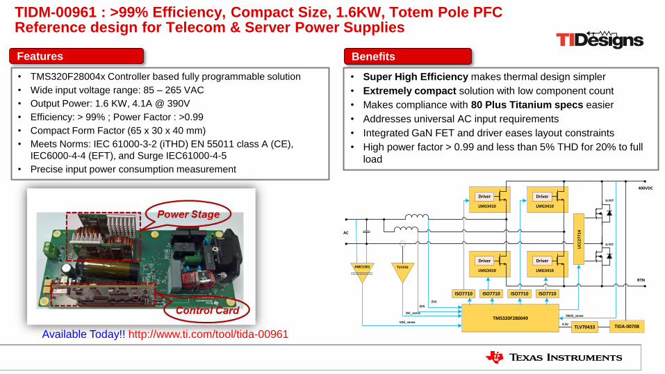
TIDM-00961 : >99% Efficiency, Compact Size, 1.6KW, Totem Pole PFC Reference design for Telecom & Server Power Supplies Features
• TMS320F28004x Controller based fully programmable solution
• Wide input voltage range: 85 – 265 VAC
• Output Power: 1.6 KW, 4.1A @ 390V
• Efficiency: > 99% ; Power Factor : >0.99
• Compact Form Factor (65 x 30 x 40 mm)
• Meets Norms: IEC 61000-3-2 (iTHD) EN 55011 class A (CE),
IEC6000-4-4 (EFT), and Surge IEC61000-4-5
• Precise input power consumption measurement
Benefits
• Super High Efficiency makes thermal design simpler
• Extremely compact solution with low component count
• Makes compliance with 80 Plus Titanium specs easier
• Addresses universal AC input requirements
• Integrated GaN FET and driver eases layout constraints
• High power factor > 0.99 and less than 5% THD for 20% to full
load
Driver
LMG3410
Driver
LMG3410
400VDC
TLV316
TMS320F280049
TLV70433 TIDA-00708VAC_sense
IAC_senseVBUS_sense
3.3V
AMC1301
Driver
LMG3410
Driver
LMG3410
RTN
ZVS
ZVS
AC
Si FET
Si FET
UC
C2
77
14
ISO7710 ISO7710ISO7710 ISO7710
Available Today!! http://www.ti.com/tool/tida-00961
Vbus 600-1000V
Vac VL-N 120Vrms/230Vrms
50/60Hz
Vbatt 800V
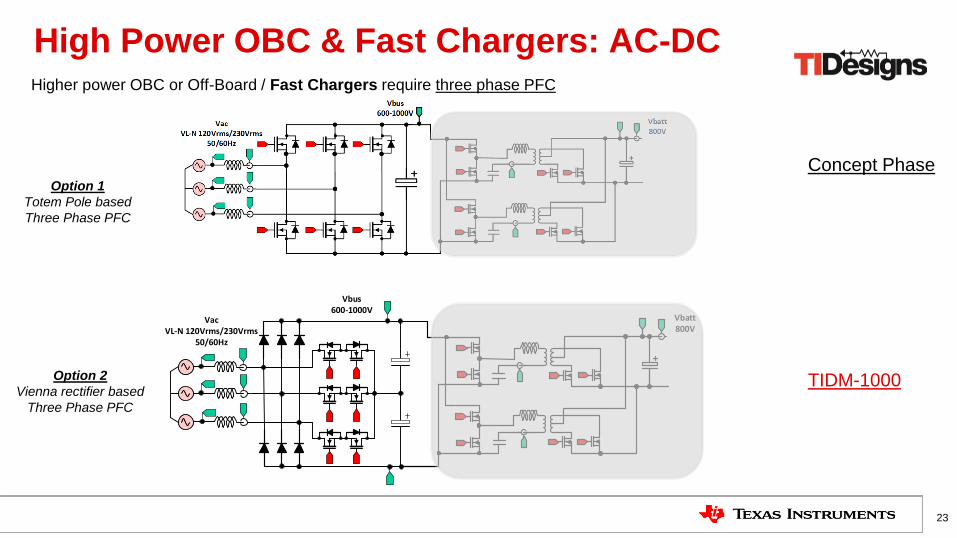
High Power OBC & Fast Chargers: AC-DC
23
Higher power OBC or Off-Board / Fast Chargers require three phase PFC
TIDM-1000
Concept Phase Option 1
Totem Pole based
Three Phase PFC
Option 2
Vienna rectifier based
Three Phase PFC
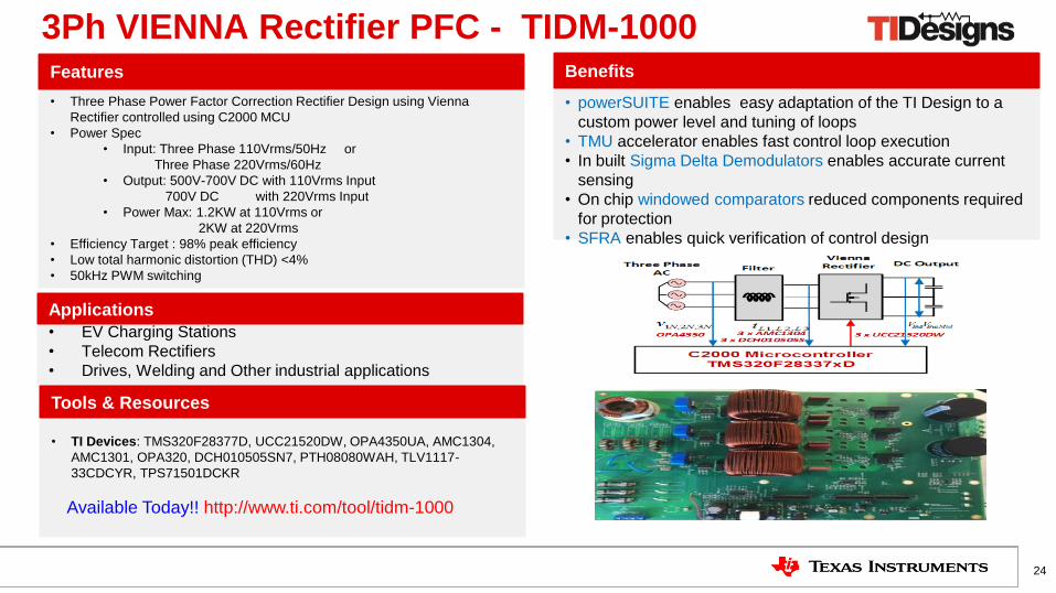
• TI Devices: TMS320F28377D, UCC21520DW, OPA4350UA, AMC1304,
AMC1301, OPA320, DCH010505SN7, PTH08080WAH, TLV1117-
33CDCYR, TPS71501DCKR
• EV Charging Stations
• Telecom Rectifiers
• Drives, Welding and Other industrial applications
Available Today!! http://www.ti.com/tool/tidm-1000
3Ph VIENNA Rectifier PFC - TIDM-1000
• powerSUITE enables easy adaptation of the TI Design to a
custom power level and tuning of loops
• TMU accelerator enables fast control loop execution
• In built Sigma Delta Demodulators enables accurate current
sensing
• On chip windowed comparators reduced components required
for protection
• SFRA enables quick verification of control design
• Three Phase Power Factor Correction Rectifier Design using Vienna
Rectifier controlled using C2000 MCU
• Power Spec
• Input: Three Phase 110Vrms/50Hz or
Three Phase 220Vrms/60Hz
• Output: 500V-700V DC with 110Vrms Input
700V DC with 220Vrms Input
• Power Max: 1.2KW at 110Vrms or
2KW at 220Vrms
• Efficiency Target : 98% peak efficiency
• Low total harmonic distortion (THD) <4%
• 50kHz PWM switching
Features Benefits
Applications
24
Tools & Resources
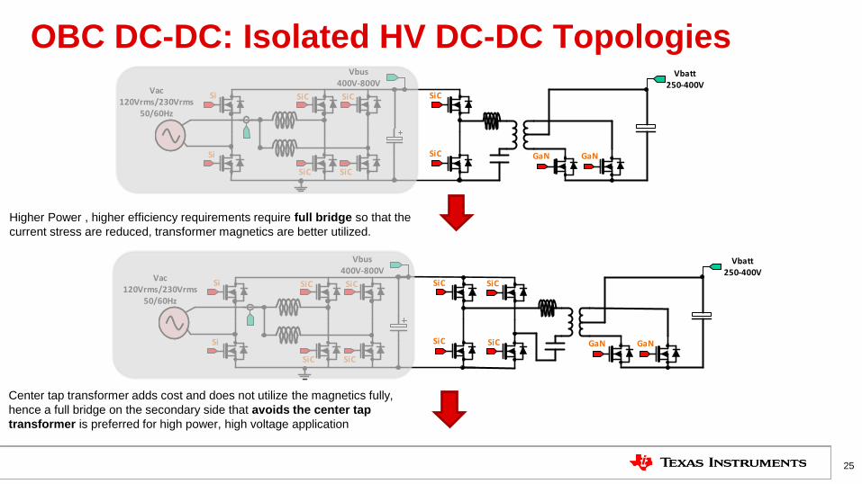
OBC DC-DC: Isolated HV DC-DC Topologies
25
Vac 120Vrms/230Vrms
50/60Hz
Vbus 400V-800V
SiC
SiC
SiC
SiC
Si
Si
Vbatt 250-400V
SiC
SiC GaN GaN
Higher Power , higher efficiency requirements require full bridge so that the
current stress are reduced, transformer magnetics are better utilized.
Vac 120Vrms/230Vrms
50/60Hz
Vbus 400V-800V
SiC
SiC
SiC
SiC
Si
Si
Vbatt 250-400V
SiC
SiC GaN GaN
SiC
SiC
Center tap transformer adds cost and does not utilize the magnetics fully,
hence a full bridge on the secondary side that avoids the center tap
transformer is preferred for high power, high voltage application
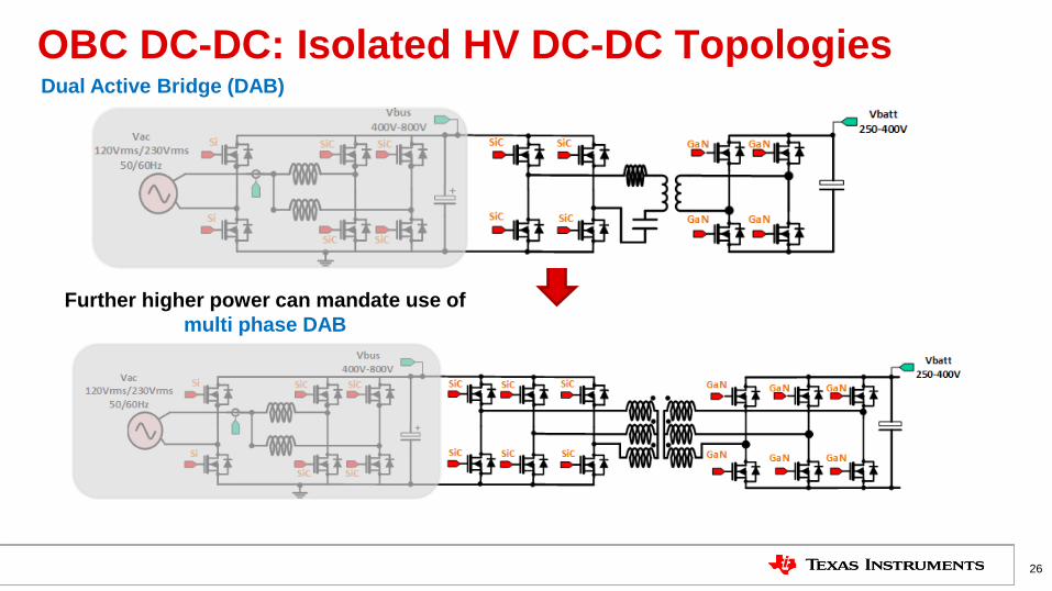
OBC DC-DC: Isolated HV DC-DC Topologies
26
Dual Active Bridge (DAB)
Further higher power can mandate use of
multi phase DAB
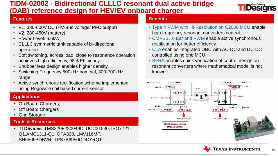
• TI Devices: TMS320F280049C, UCC21530, ISO7721-
Q1,AMC1311-Q1, OPA320, LMV116MF,
SN6505BDBVR, TPS7B6950QDCYRQ1
• On Board Chargers,
• Off Board Chargers
• Grid Storage
TIDM-02002 - Bidirectional CLLLC resonant dual active bridge (DAB) reference design for HEV/EV onboard charger
• Type 4 PWM with Hi-Resolution on C2000 MCU enable
high frequency resonant converters control.
• CMPSS, X-Bar and PWM enable active synchronous
rectification for better efficiency.
• CLA enables integrated OBC with AC-DC and DC-DC
controlled using one MCU
• SFRA enables quick verification of control design on
resonant converters where mathematical model is not
known
• V1: 380-600V DC (HV-Bus voltage/ PFC output)
• V2: 280-450V (battery)
• Power Level: 6.6kW
• CLLLC symmetric tank capable of bi-directional
operation
• Soft switching, across load, close to resonance operation
achieves high efficiency, 98% Efficiency
• Snubber less design enables higher density
• Switching Frequency 500kHz nominal, 300-700kHz
range
• Active synchronous rectification scheme implemented
using Rogowski coil based current sensor
• Power Density of 40W/inch^3
Features Benefits
Applications
27
Tools & Resources
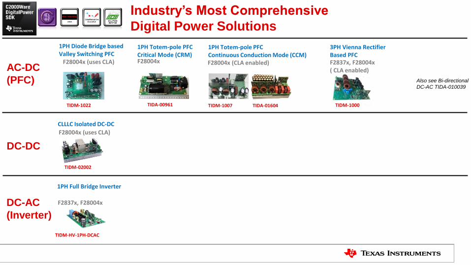
1PH Totem-pole PFC Critical Mode (CRM) F28004x F28004x (CLA enabled)
3PH Vienna Rectifier Based PFC F2837x, F28004x ( CLA enabled)
1PH Diode Bridge based Valley Switching PFC
F28004x (uses CLA)
1PH Totem-pole PFC Continuous Conduction Mode (CCM)
TIDA-00961 TIDM-1007 TIDA-01604 TIDM-1022 TIDM-1000
AC-DC
(PFC)
DC-DC
DC-AC
(Inverter)
CLLLC Isolated DC-DC
F28004x (uses CLA)
TIDM-02002
1PH Full Bridge Inverter
F2837x, F28004x
TIDM-HV-1PH-DCAC
Industry’s Most Comprehensive
Digital Power Solutions
Also see Bi-directional
DC-AC TIDA-010039
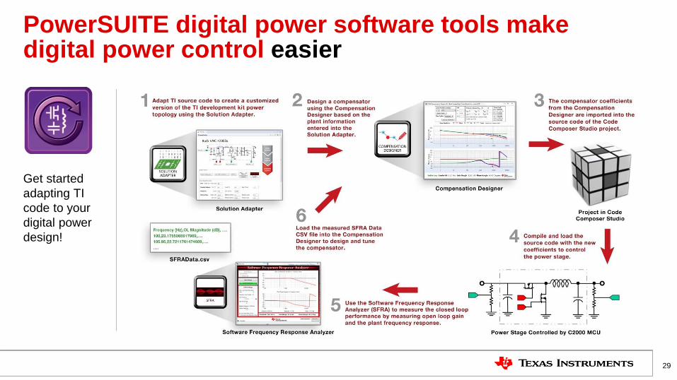
PowerSUITE digital power software tools make digital power control easier
29
Get started
adapting TI
code to your
digital power
design!
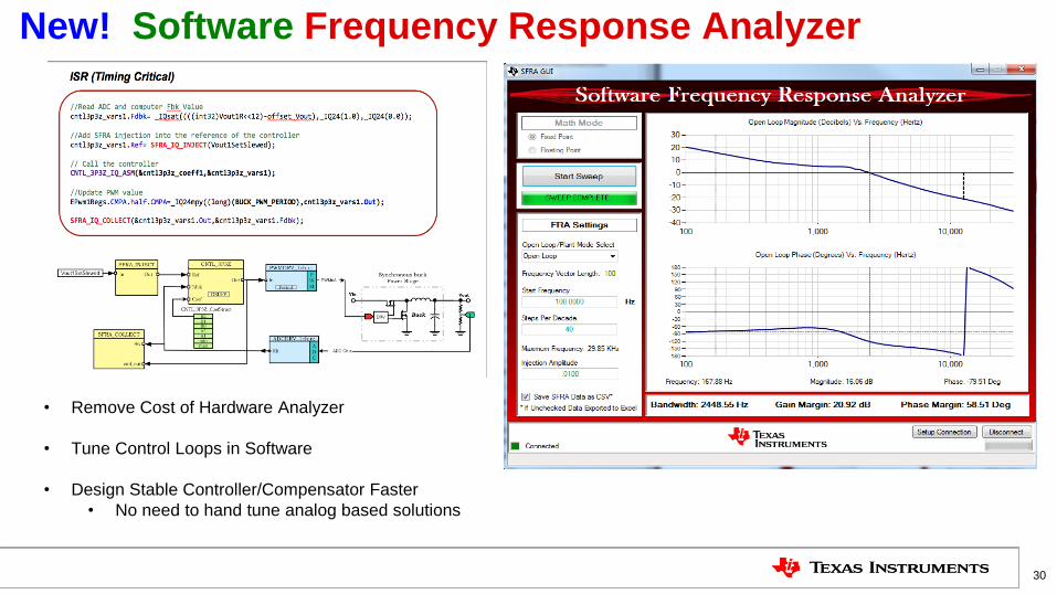
New! Software Frequency Response Analyzer
30
• Remove Cost of Hardware Analyzer
• Tune Control Loops in Software
• Design Stable Controller/Compensator Faster
• No need to hand tune analog based solutions

TI Confidential – NDA Restrictions
31
Traction and HVAC
Electric Vehicle (EV) Trends
32
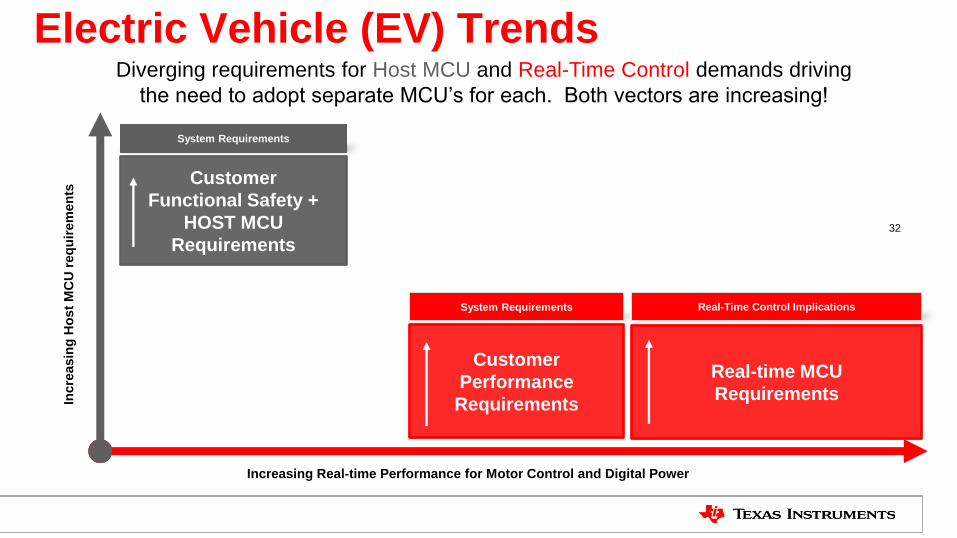
Increasing Real-time Performance for Motor Control and Digital Power
Incre
asin
g H
ost
MC
U r
eq
uir
em
en
ts
System Requirements Real-Time Control Implications
Diverging requirements for Host MCU and Real-Time Control demands driving
the need to adopt separate MCU’s for each. Both vectors are increasing!
System Requirements
Customer
Functional Safety +
HOST MCU
Requirements
Customer
Performance
Requirements
Real-time MCU
Requirements
Electric Vehicle (EV) Trends
33
Increasing Real-time Performance for Motor Control and Digital Power
Incre
asin
g H
ost
MC
U r
eq
uir
em
en
ts
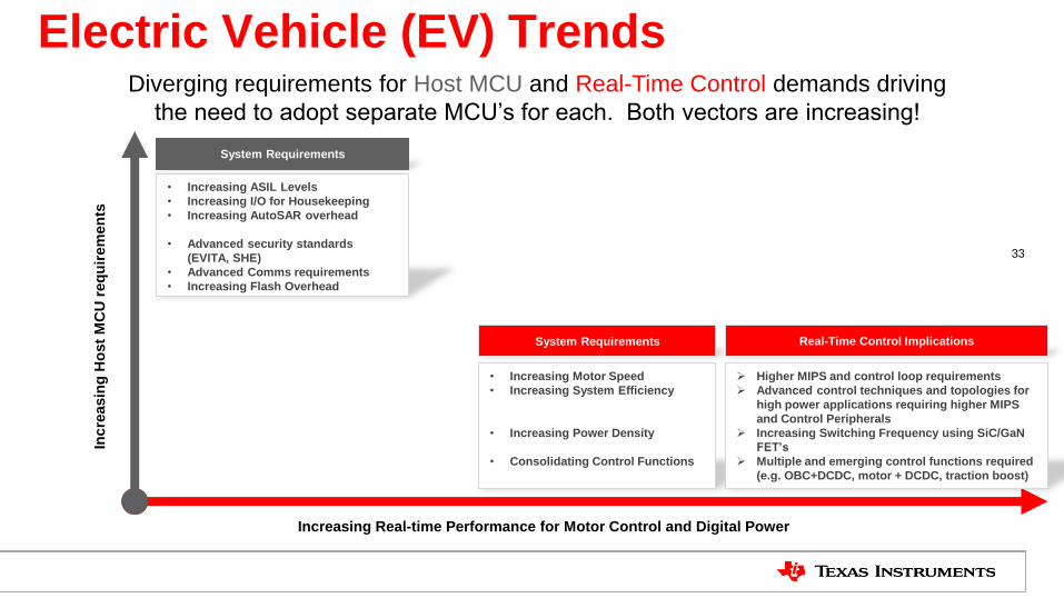
System Requirements
• Increasing Motor Speed
• Increasing System Efficiency
• Increasing Power Density
• Consolidating Control Functions
• Increasing ASIL Levels
• Increasing I/O for Housekeeping
• Increasing AutoSAR overhead
• Advanced security standards
(EVITA, SHE)
• Advanced Comms requirements
• Increasing Flash Overhead
Real-Time Control Implications
Higher MIPS and control loop requirements
Advanced control techniques and topologies for
high power applications requiring higher MIPS
and Control Peripherals
Increasing Switching Frequency using SiC/GaN
FET’s
Multiple and emerging control functions required
(e.g. OBC+DCDC, motor + DCDC, traction boost)
Diverging requirements for Host MCU and Real-Time Control demands driving
the need to adopt separate MCU’s for each. Both vectors are increasing!
System Requirements
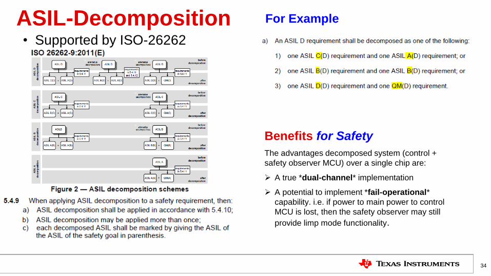
ASIL-Decomposition • Supported by ISO-26262
34
For Example
Benefits for Safety
The advantages decomposed system (control +
safety observer MCU) over a single chip are:
A true *dual-channel* implementation
A potential to implement *fail-operational*
capability. i.e. if power to main power to control
MCU is lost, then the safety observer may still
provide limp mode functionality.

35
C2000 + TMS570 for ASIL-D Uncompromised motor control performance paired with pre-certified ASIL-D microcontroller
C2000 MCU Benefits Hercules TMS570 MCU Benefits
• Best In Class Real-time Control MCU for Traction Inverter ( >24k rpm
Motor Speed with fast current loop SW)
• Ability to add integrated Bi-directional HV DC/DC (>800V with SiC) for
Traction Drive (Saves cost on bulky relays to charge DC Link Capacitor
at start-up)
• Enhanced System Robustness: Virtual Back-up Resolver, Motor Fault
Diagnostics
• Safety MCU device certification upto ASILD
• Safety Diagnostic Libraries
• AutoSAR support
• Add Functional Safety to EV Traction System to support up to ISO26262 ASILD
• Leveraging ASIL decomposition (ASIL-D -> ASIL-D(D) + ASIL-QM(D), customers can reuse existing motor control code that may not been developed for
ISO26262 when running on the QM device
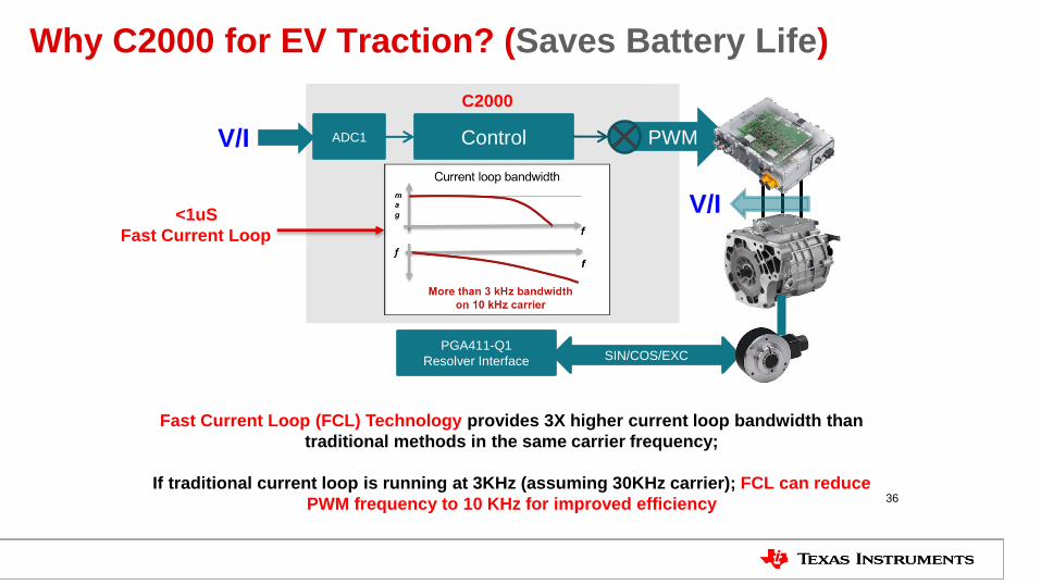
Why C2000 for EV Traction? (Saves Battery Life)
36
Control ADC1
V/I
C2000
PWM V/I
Fast Current Loop (FCL) Technology provides 3X higher current loop bandwidth than
traditional methods in the same carrier frequency;
If traditional current loop is running at 3KHz (assuming 30KHz carrier); FCL can reduce
PWM frequency to 10 KHz for improved efficiency
PGA411-Q1
Resolver Interface SIN/COS/EXC
<1uS
Fast Current Loop
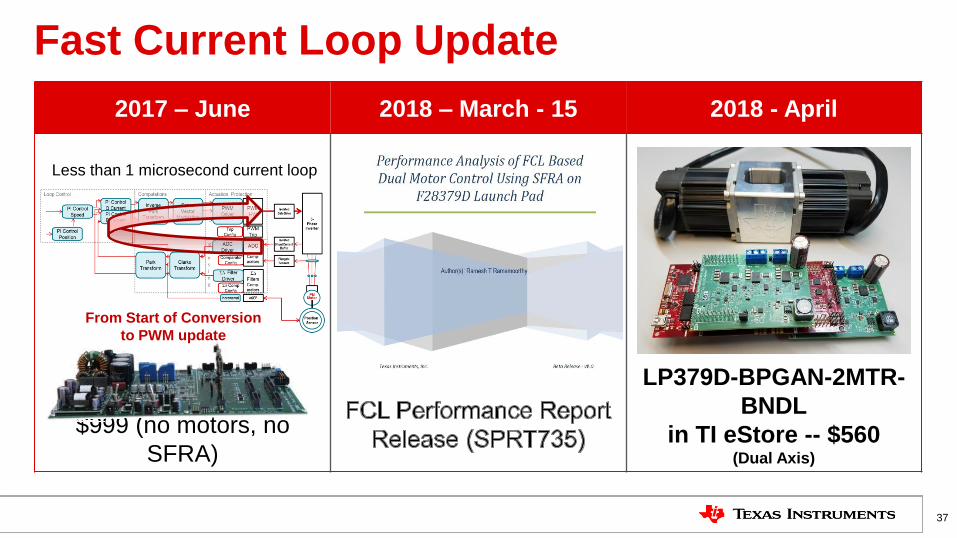
Fast Current Loop Update
2017 – June 2018 – March - 15 2018 - April
$999 (no motors, no
SFRA)
LP379D-BPGAN-2MTR-
BNDL
in TI eStore -- $560 (Dual Axis)
37
Less than 1 microsecond current loop
From Start of Conversion
to PWM update

Single-axis Bandwidth and Phase Margin Measurements Using C2000 Software Frequency Response Analyzer (SFRA) tools
38
0
1000
2000
3000
4000
5000
6000
7000
8000
9000
0 20 40 60 80 100
Ban
dw
idth
Phase Margin
CC-Id
CC-Iq
CPI-Id
CPI-Iq
CC-Id shdw
CC-Iq shdw
CPI-Id shdw
CPI-Iq shdw
• PowerSUITE tool updated for motors
• Real time data collection
• PC-based analysis tools
• Integrated into Fast Current Loop release
• FCL delivers 3 times the control bandwidth
• > 5 kHz on 10kHz carrier at 45º phase margin (typ)
• Unprecedented for any MCU – challenging for FPGAs!
• Measured by SFRA
Conventional Method
Fast Current Loop
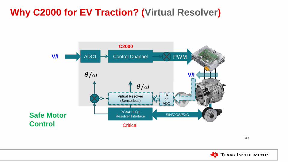
Why C2000 for EV Traction? (Virtual Resolver)
39
Control Channel ADC1
V/I
C2000
𝜃/𝜔
𝜃/𝜔
PGA411-Q1
Resolver Interface
Reference Channel
PWM PWM
SIN/COS/EXC
Virtual Resolver
(Sensorless)
V/I
SIN/COS/EXC
16-
bit
ADC
Safe Motor
Control Critical
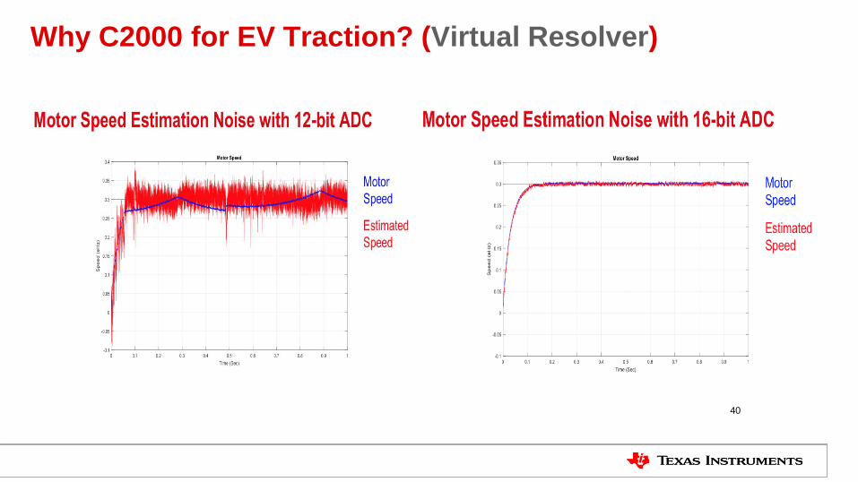
Why C2000 for EV Traction? (Virtual Resolver)
40
Control Channel ADC1
V/I
C2000
𝜃/𝜔
𝜃/𝜔
PGA411-Q1
Resolver Interface
Reference Channel
PWM PWM
SIN/COS/EXC
Virtual Resolver
(Sensorless)
V/I
SIN/COS/EXC
16-
bit
ADC
Safe Motor
Control Critical
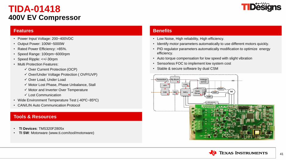
• TI Devices: TMS320F2805x
• TI SW: Motorware (www.ti.com/tool/motorware)
• Low Noise, High reliability, High efficiency.
• Identify motor parameters automatically to use different motors quickly.
• PID regulator parameters automatically modification to optimize energy
efficiency.
• Auto torque compensation for low speed with slight vibration
• Sensorless FOC to implement low system cost
• Stable & secure software by dual CSM
• Power Input Voltage: 200~400VDC
• Output Power: 100W~5000W
• Rated Power Efficiency: >85%.
• Speed Range: 100rpm~6000rpm
• Speed Ripple: <+/-30rpm
• Multi Protection Features:
Over Current Protection (OCP)
Over/Under Voltage Protection ( OVP/UVP)
Over Load, Under Load
Motor Lost Phase, Phase Unbalance, Stall
Motor and Inverter Over Temperature
Lost Communication
• Wide Environment Temperature Test (-40ºC~85ºC)
• CAN/LIN Auto Communication Protocol
Features Benefits
41
Tools & Resources
TIDA-01418 400V EV Compressor

TI Confidential – NDA Restrictions
42
Key Devices
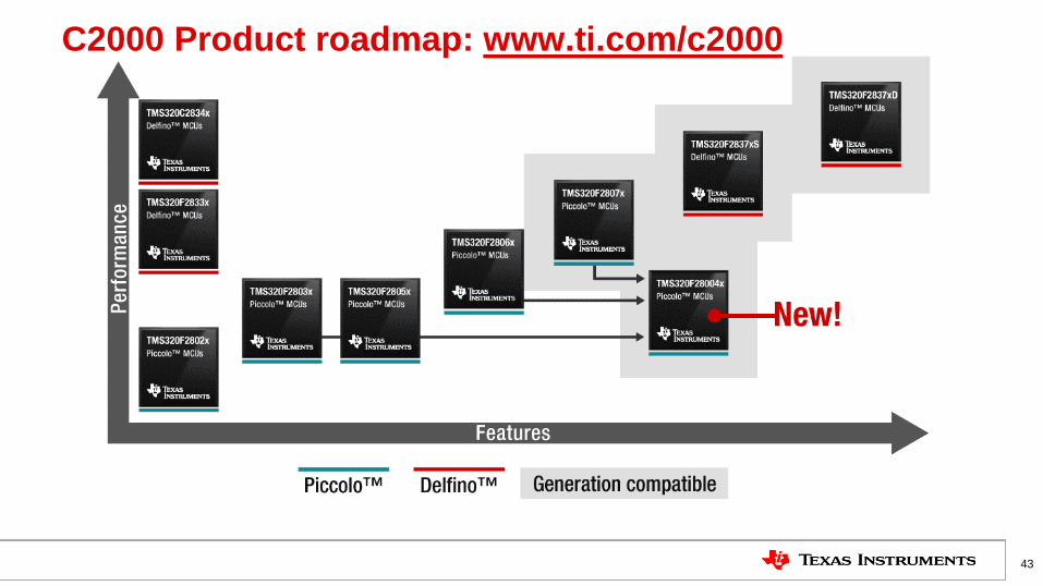
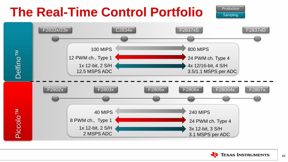
The Real-Time Control Portfolio
44
Delfin
o™
P
iccolo
™
800 MIPS
1x 12-bit, 2 S/H
12.5 MSPS ADC
12 PWM ch., Type 1
100 MIPS
24 PWM ch. Type 4
4x 12/16-bit, 4 S/H
3.5/1.1 MSPS per ADC
240 MIPS
1x 12-bit, 2 S/H
2 MSPS ADC
8 PWM ch., Type 1
40 MIPS
24 PWM ch. Type 4
3x 12-bit, 3 S/H
3.1 MSPS per ADC
Sampling
Production
F2837xD C2834x
F2806x
F2837xS F2833x/23x
F2802x F2803x F2805x F2807x F28004x

45
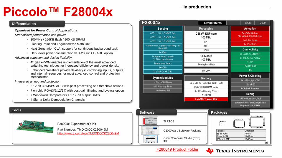
Piccolo™ F28004x F28004x
Actuation
8x ePWM Modules
16x Outputs (16x High-Res)
Fault Trip Zones
2x 12-bit DAC
Connectivity
2x UART, 1x LIN/UART
2x I2C (1x true PMBus)
2x SPI
2x CAN 2.0B
FSI
Sensing
ADC1: 12-bit, 3.5 MSPS, 8ch
ADC2: 12-bit, 3.5 MSPS, 8ch
ADC3: 12-bit, 3.5 MSPS, 8ch
7x Windowed Comparators w/ Integrated
12-bit DAC
7x PGAs
4x Sigma Delta Channels
(2x Filters per channel)
Temperature Sensor
2x eQEP
7x eCAP (2x HRCAP)
Power & Clocking
2x 10 MHz 0-pin OSC
1.2V VREG
POR/BOR Protection
System Modules
3x 32-bit CPU Timers
NMI Watchdog Timer
192 Interrupt PIE
Memory
Up to 256 KB Flash (dual-bank) +ECC
Up to 100 KB SRAM +parity
2x 128-bit Security Zones
Boot ROM
InstaSPIN™ Motor ROM
Debug
cJTAG / Real-time JTAG
Embedded Real -time Analysis And
Diagnostic unit (ERAD)
CLA core
100 MHz
Floating Point Math
Processing
C28x™ DSP core
100 MHz
FPU
TMU
VCU-I
Tools
Optimized for Power Control Applications
Streamlined performance and power
• 100MHz / 256KB flash / 100 KB SRAM
• Floating Point and Trigonometric Math Unit
• Next Generation CLA; support for continuous background task
• 60% lower power consumption vs. F2806x + DC-DC option
Advanced actuation and design flexibility
• 4th gen ePWM enables implementation of the most advanced switching techniques for increased efficiency and power density
• Enhanced crossbars provide flexibility in combining inputs, outputs and internal resources for most advanced control and protection mechanisms
Integrated analog and protection
• 3 12-bit 3.5MSPS ADC with post processing and threshold actions
• 7 on-chip PGA(3/6/12/24) with post gain filtering and bypass option
• 7 Windowed Comparators + 2 12-bit output DACs
• 4 Sigma Delta Demodulation Channels
Differentiation
F28004x Experimenter’s Kit
Part Number: TMDXDOCK280049M
http://www.ti.com/tool/TMDXDOCK280049M Package Dimension
56-pin QFN 7x7mm
64-pin LQFP 12x12mm
100-pin LQFP 16x16mm
Packages
6ch DMA
TI RTOS
C2000Ware Software Package
Code Composer Studio (CCS) IDE
Software
Temperatures 125C Q100
In production
‘F280049 Product Folder
46
Piccolo™ F28004x F28004x
Actuation
8x ePWM Modules
16x Outputs (16x High-Res)
Fault Trip Zones
2x 12-bit DAC
Connectivity
2x UART, 1x LIN/UART
2x I2C (1x true PMBus)
2x SPI
2x CAN 2.0B
FSI
Sensing
ADC1: 12-bit, 3.5 MSPS, 8ch
ADC2: 12-bit, 3.5 MSPS, 8ch
ADC3: 12-bit, 3.5 MSPS, 8ch
7x Windowed Comparators w/ Integrated
12-bit DAC
7x PGAs
4x Sigma Delta Channels
(2x Filters per channel)
Temperature Sensor
2x eQEP
7x eCAP (2x HRCAP)
Power & Clocking
2x 10 MHz 0-pin OSC
1.2V VREG
POR/BOR Protection
System Modules
3x 32-bit CPU Timers
NMI Watchdog Timer
192 Interrupt PIE
Memory
Up to 256 KB Flash (dual-bank) +ECC
Up to 100 KB SRAM +parity
2x 128-bit Security Zones
Boot ROM
InstaSPIN™ Motor ROM
Debug
cJTAG / Real-time JTAG
Embedded Real -time Analysis And
Diagnostic unit (ERAD)
CLA core
100 MHz
Floating Point Math
Processing
C28x™ DSP core
100 MHz
FPU
TMU
VCU-I
Tools
Optimized for Power Control Applications
Streamlined performance and power
• 100MHz / 256KB flash / 100 KB SRAM
• Floating Point and Trigonometric Math Unit
• Next Generation CLA; support for continuous background task
• 60% lower power consumption vs. F2806x + DC-DC option
Advanced actuation and design flexibility
• 4th gen ePWM enables implementation of the most advanced switching techniques for increased efficiency and power density
• Enhanced crossbars provide flexibility in combining inputs, outputs and internal resources for most advanced control and protection mechanisms
Integrated analog and protection
• 3 12-bit 3.5MSPS ADC with post processing and threshold actions
• 7 on-chip PGA(3/6/12/24) with post gain filtering and bypass option
• 7 Windowed Comparators + 2 12-bit output DACs
• 4 Sigma Delta Demodulation Channels
Differentiation
F28004x Experimenter’s Kit
Part Number: TMDXDOCK280049M
http://www.ti.com/tool/TMDXDOCK280049M Package Dimension
56-pin QFN 7x7mm
64-pin LQFP 12x12mm
100-pin LQFP 16x16mm
Packages
6ch DMA
TI RTOS
C2000Ware Software Package
Code Composer Studio (CCS) IDE
Software
Temperatures 125C Q100
In production
‘F280049 Product Folder
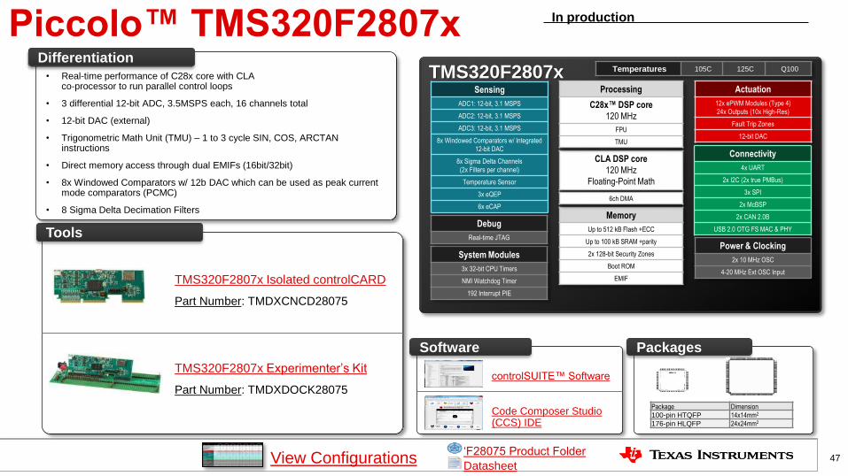
Piccolo™ TMS320F2807x TMS320F2807x
Actuation
12x ePWM Modules (Type 4)
24x Outputs (10x High-Res)
Fault Trip Zones
12-bit DAC
Connectivity
4x UART
2x I2C (2x true PMBus)
3x SPI
2x McBSP
2x CAN 2.0B
USB 2.0 OTG FS MAC & PHY
Sensing
ADC1: 12-bit, 3.1 MSPS
ADC2: 12-bit, 3.1 MSPS
ADC3: 12-bit, 3.1 MSPS
8x Windowed Comparators w/ Integrated
12-bit DAC
8x Sigma Delta Channels
(2x Filters per channel)
Temperature Sensor
3x eQEP
6x eCAP
Power & Clocking
2x 10 MHz OSC
4-20 MHz Ext OSC Input
System Modules
3x 32-bit CPU Timers
NMI Watchdog Timer
192 Interrupt PIE
Memory
Up to 512 kB Flash +ECC
Up to 100 kB SRAM +parity
2x 128-bit Security Zones
Boot ROM
EMIF
Debug
Real-time JTAG
CLA DSP core
120 MHz
Floating-Point Math
Temperatures 105C 125C Q100
Processing
C28x™ DSP core
120 MHz
FPU
TMU
Tools
• Real-time performance of C28x core with CLA co-processor to run parallel control loops
• 3 differential 12-bit ADC, 3.5MSPS each, 16 channels total
• 12-bit DAC (external)
• Trigonometric Math Unit (TMU) – 1 to 3 cycle SIN, COS, ARCTAN instructions
• Direct memory access through dual EMIFs (16bit/32bit)
• 8x Windowed Comparators w/ 12b DAC which can be used as peak current mode comparators (PCMC)
• 8 Sigma Delta Decimation Filters
Differentiation
TMS320F2807x Isolated controlCARD
Part Number: TMDXCNCD28075
TMS320F2807x Experimenter’s Kit
Part Number: TMDXDOCK28075
Package Dimension
100-pin HTQFP 14x14mm2
176-pin HLQFP 24x24mm2
Packages
In production
6ch DMA
controlSUITE™ Software
Code Composer Studio (CCS) IDE
Software
47 View Configurations Datasheet
‘F28075 Product Folder
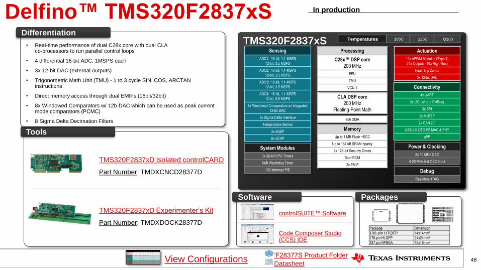
Delfino™ TMS320F2837xS
TMS320F2837xS Actuation
12x ePWM Modules (Type 4)
24x Outputs (16x High-Res)
Fault Trip Zones
3x 12-bit DAC
Connectivity
4x UART
2x I2C (w/ true PMBus)
3x SPI
2x McBSP
2x CAN 2.0
USB 2.0 OTG FS MAC & PHY
uPP
Sensing
ADC1: 16-bit, 1.1-MSPS
12-bit, 3.5 MSPS
ADC2: 16-bit, 1.1-MSPS
12-bit, 3.5 MSPS
ADC3: 16-bit, 1.1-MSPS
12-bit, 3.5 MSPS
ADC4: 16-bit, 1.1-MSPS
12-bit, 3.5 MSPS
8x Windowed Comparators w/ Integrated
12-bit DAC
8x Sigma Delta Interface
Temperature Sensor
3x eQEP
6x eCAP
Power & Clocking
2x 10 MHz OSC
4-20 MHz Ext OSC Input
System Modules
3x 32-bit CPU Timers
NMI Watchdog Timer
192 Interrupt PIE
Memory
Up to 1 MB Flash +ECC
Up to 164 kB SRAM +parity
2x 128-bit Security Zones
Boot ROM
2x EMIF
Debug
Real-time JTAG
CLA DSP core
200 MHz
Floating-Point Math
Temperatures 105C 125C Q100
Processing
C28x™ DSP core
200 MHz
FPU
TMU
VCU-II
Tools
• Real-time performance of dual C28x core with dual CLA co-processors to run parallel control loops
• 4 differential 16-bit ADC, 1MSPS each
• 3x 12-bit DAC (external outputs)
• Trigonometric Math Unit (TMU) - 1 to 3 cycle SIN, COS, ARCTAN instructions
• Direct memory access through dual EMIFs (16bit/32bit)
• 8x Windowed Comparators w/ 12b DAC which can be used as peak current mode comparators (PCMC)
• 8 Sigma Delta Decimation Filters
Differentiation
TMS320F2837xD Isolated controlCARD
Part Number: TMDXCNCD28377D
TMS320F2837xD Experimenter’s Kit
Part Number: TMDXDOCK28377D Package Dimension
100-pin HTQFP 14x14mm2
176-pin HLQFP 24x24mm2
337-pin NFBGA 16x16mm2
Packages
In production
View Configurations 48
6ch DMA
Datasheet
‘F28377S Product Folder
controlSUITE™ Software
Code Composer Studio (CCS) IDE
Software
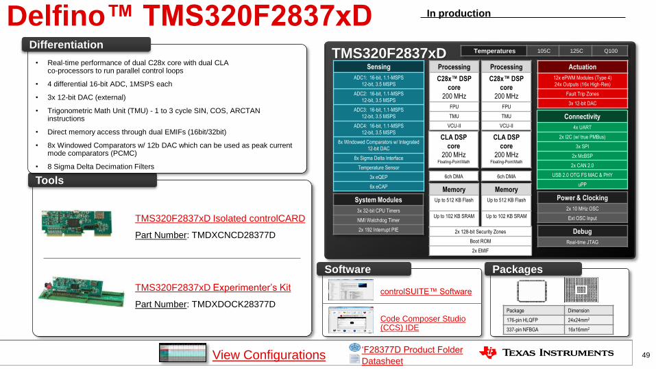
Delfino™ TMS320F2837xD TMS320F2837xD
Actuation
12x ePWM Modules (Type 4)
24x Outputs (16x High-Res)
Fault Trip Zones
3x 12-bit DAC
Connectivity
4x UART
2x I2C (w/ true PMBus)
3x SPI
2x McBSP
2x CAN 2.0
USB 2.0 OTG FS MAC & PHY
uPP
Sensing
ADC1: 16-bit, 1.1-MSPS
12-bit, 3.5 MSPS
ADC2: 16-bit, 1.1-MSPS
12-bit, 3.5 MSPS
ADC3: 16-bit, 1.1-MSPS
12-bit, 3.5 MSPS
ADC4: 16-bit, 1.1-MSPS
12-bit, 3.5 MSPS
8x Windowed Comparators w/ Integrated
12-bit DAC
8x Sigma Delta Interface
Temperature Sensor
3x eQEP
6x eCAP
Power & Clocking
2x 10 MHz OSC
Ext OSC Input
System Modules
3x 32-bit CPU Timers
NMI Watchdog Timer
2x 192 Interrupt PIE Debug
Real-time JTAG
Temperatures 105C 125C Q100
Processing
C28x™ DSP
core
200 MHz
FPU
TMU
VCU-II
Tools
• Real-time performance of dual C28x core with dual CLA co-processors to run parallel control loops
• 4 differential 16-bit ADC, 1MSPS each
• 3x 12-bit DAC (external)
• Trigonometric Math Unit (TMU) - 1 to 3 cycle SIN, COS, ARCTAN instructions
• Direct memory access through dual EMIFs (16bit/32bit)
• 8x Windowed Comparators w/ 12b DAC which can be used as peak current mode comparators (PCMC)
• 8 Sigma Delta Decimation Filters
Differentiation
Package Dimension
176-pin HLQFP 24x24mm2
337-pin NFBGA 16x16mm2
Packages
In production
Processing
C28x™ DSP
core
200 MHz
FPU
TMU
VCU-II
View Configurations 49
CLA DSP
core
200 MHz Floating-Point Math
CLA DSP
core
200 MHz Floating-Point Math
6ch DMA 6ch DMA
Memory
Up to 512 KB Flash
Up to 102 KB SRAM
Memory
Up to 512 KB Flash
Up to 102 KB SRAM
2x 128-bit Security Zones
Boot ROM
2x EMIF
Datasheet
‘F28377D Product Folder
controlSUITE™ Software
Code Composer Studio (CCS) IDE
Software
TMS320F2837xD Isolated controlCARD
Part Number: TMDXCNCD28377D
TMS320F2837xD Experimenter’s Kit
Part Number: TMDXDOCK28377D

TI Confidential – NDA Restrictions
50
Thank you