tia-eia-is 801 - 1999
TRANSCRIPT

8/20/2019 TIA-EIA-IS 801 - 1999
http://slidepdf.com/reader/full/tia-eia-is-801-1999 1/138
TIA/EIA
INTERIM STANDARD
Position Determination Service
Standard for Dual ModeSpread Spectrum Systems
TIA/EIA/IS-801
NOVEMBER 1999
TELECOMMUNICATIONS INDUSTRY ASSOCIATION
Representing the telecommunications industry in
association with the Electronic Industries Alliance
T I A / E I A / I S - 8 0 1

8/20/2019 TIA-EIA-IS 801 - 1999
http://slidepdf.com/reader/full/tia-eia-is-801-1999 2/138
NOTICE
TIA/EIA Engineering Standards and Publications are designed to serve the public interest through eliminating
misunderstandings between manufacturers and purchasers, facilitating interchangeability and improvement of
products, and assisting the purchaser in selecting and obtaining with minimum delay the proper product for
his particular need. Existence of such Standards and Publications shall not in any respect preclude any
member or nonmember of TIA/EIA from manufacturing or selling products not conforming to such
Standards and Publications, nor shall the existence of such Standards and Publications preclude their voluntary use by those other than TIA/EIA members, whether the standard is to be used either domestically
or internationally.
Standards and Publications are adopted by TIA/EIA in accordance with the American National Standards
Institute (ANSI) patent policy. By such action, TIA/EIA does not assume any liability to any patent owner,
nor does it assume any obligation whatever to parties adopting the Standard or Publication.
TIA/EIA INTERIM STANDARDS
TIA/EIA Interim Standards contain information deemed to be of technical value to the industry, and are
published at the request of the originating Committee without necessarily following the rigorous public review
and resolution of comments which is a procedural part of the development of a TIA/EIA Standard.
TIA/EIA Interim Standards should be reviewed on an annual basis by the formulating Committee and a
decision made on whether to proceed to develop a TIA/EIA Standard on this subject. TIA/EIA Interim
Standards must be cancelled by the Committee and removed from the TIA/EIA Standards Catalog before the
end of their third year of existence.
Publication of this TIA/EIA Interim Standard for trial use and comment has been approved by the
Telecommunications Industry Association. Distribution of this TIA/EIA Interim Standard for comment shall
not continue beyond 36 months from the date of publication. It is expected that following this 36 month
period, this TIA/EIA Interim Standard, revised as necessary, will be submitted to the American National
Standards Institute for approval as an American National Standard. Suggestions for revision should be
directed to: Standards & Technology Department, Telecommunications Industry Association, 2500 WilsonBoulevard, Arlington, VA 22201.
(From Project No. 4535, formulated under the cognizance of the TIA TR-45.5 Subcommittee on Spread
Spectrum Digital Technology.)
Published by
©TELECOMMUNICATIONS INDUSTRY ASSOCIATION 1999
Standards & Technology Department
2500 Wilson Boulevard
Arlington, VA 22201
PRICE: Please refer to current Catalog of
EIA ELECTRONIC INDUSTRIES ALLIANCE STANDARDS and ENGINEERING
PUBLICATIONS or call Global Engineering Documents, USA and Canada
(1-800-854-7179) International (303-397-7956)
All rights reserved
Printed in U.S.A.

8/20/2019 TIA-EIA-IS 801 - 1999
http://slidepdf.com/reader/full/tia-eia-is-801-1999 3/138
PLEASE!
DON'T VIOLATE
THE
LAW!
This document is copyrighted by the TIA and may not be reproduced without
permission.
Organizations may obtain permission to reproduce a limited number of copies
through entering into a license agreement. For information, contact:
Global Engineering Documents
15 Inverness Way East
Englewood, CO 80112-5704 or call
U.S.A. and Canada 1-800-854-7179, International (303) 397-7956

8/20/2019 TIA-EIA-IS 801 - 1999
http://slidepdf.com/reader/full/tia-eia-is-801-1999 4/138

8/20/2019 TIA-EIA-IS 801 - 1999
http://slidepdf.com/reader/full/tia-eia-is-801-1999 5/138
TIA/EIA/IS-801
i
CONTENTS
1 GENERAL ......................................................................................................................... 1-1
1.1 Terms ......................................................................................................................... 1-1
2 MESSAGE TRANSPORT PROTOCOL ................................................................................ 2-1
2.1 Analog Transport Protocol .......................................................................................... 2-1
2.2 CDMA Transport Protocol........................................................................................... 2-1
2.2.1 Session Tags ........................................................................................................ 2-1
3 MOBILE STATION PROCEDURES .................................................................................... 3-1
3.1 Analog Mobile Station Procedures .............................................................................. 3-1
3.2 CDMA Mobile Station Procedures...............................................................................3-1
3.2.1 Position Determination Data Message Processing ................................................ 3-1
3.2.1.1 Overview ........................................................................................................ 3-1
3.2.1.2 Requirements................................................................................................. 3-2
3.2.2 Point-to-point Procedures .................................................................................... 3-5
3.2.2.1 Control Channel Procedure............................................................................ 3-5
3.2.2.1.1 Mobile Position Message Termination...................................................... 3-5
3.2.2.1.1.1 Base Station Request Elements Received ..........................................3-5
3.2.2.1.1.2 Base Station Response Elements Received........................................ 3-9
3.2.2.1.2 Mobile Position Message Origination ....................................................... 3-9
3.2.2.1.2.1 Position Determination Data Message Transmission Requirements .. 3-9
3.2.2.1.2.2 Unsolicited Response Elements....................................................... 3-10
3.2.2.1.2.3 Request Elements ............................................................................ 3-10
3.2.2.2 Authentication Procedures........................................................................... 3-10
3.2.2.3 Traffic Channel Procedure ........................................................................... 3-11
3.2.2.3.1 Message Encryption............................................................................... 3-11
3.2.2.3.2 Negotiation for the Position Determination Service Option .................... 3-11
3.2.2.3.2.1 Procedures Using Service Negotiation..............................................3-11
3.2.2.3.3 Mobile Position Message Termination....................................................3-13
3.2.2.3.3.1 Base Station Request Elements Received ........................................ 3-13
3.2.2.3.3.2 Base Station Response Elements Received...................................... 3-17
3.2.2.3.4 Traffic Channel Setup............................................................................ 3-17
3.2.2.3.5 Mobile Position Message Origination in the Conversation Substate.......3-18
8/20/2019 TIA-EIA-IS 801 - 1999
http://slidepdf.com/reader/full/tia-eia-is-801-1999 6/138
TIA/EIA/IS-801
ii
CONTENTS
3.2.2.3.5.1 Position Determination Data Message Transmission Requirements 3-18
3.2.2.3.5.2 Unsolicited Response Elements....................................................... 3-18
3.2.2.3.5.3 Request Elements ............................................................................ 3-18
3.2.3 Broadcast Procedures ........................................................................................ 3-18
3.2.4 Reverse Link Message Format ............................................................................ 3-18
3.2.4.1 Request Element Parameters Record ...........................................................3-23
3.2.4.2 Response Element Parameters Record......................................................... 3-27
4 BASE STATION PROCEDURES ........................................................................................ 4-1
4.1 Analog Base Station Procedures................................................................................. 4-1
4.2 CDMA Base Station Procedures ................................................................................. 4-1
4.2.1 Position Determination Data Message Processing ................................................ 4-1
4.2.1.1 Overview ........................................................................................................ 4-1
4.2.1.2 Requirements................................................................................................. 4-2
4.2.2 Point-to-point Procedures .................................................................................... 4-4
4.2.2.1 Control Channel Procedure............................................................................ 4-4
4.2.2.1.1 Mobile Position Message Origination ....................................................... 4-4
4.2.2.1.1.1 Mobile Station Request Elements Received........................................ 4-4
4.2.2.1.1.2 Mobile Station Response Elements Received ..................................... 4-7
4.2.2.1.2 Mobile Position Message Termination...................................................... 4-7
4.2.2.1.2.1 Position Determination Data Message Transmission Requirements .. 4-7
4.2.2.1.2.2 Unsolicited Response Elements......................................................... 4-8
4.2.2.1.2.3 Request Elements .............................................................................. 4-8
4.2.2.2 Authentication Procedures............................................................................. 4-8
4.2.2.3 Traffic Channel Procedure .............................................................................4-8
4.2.2.3.1 Message Encryption................................................................................. 4-8
4.2.2.3.2 Negotiation for the Position Determination Service Option ......................4-8
4.2.2.3.2.1 Procedures Using Service Negotiation................................................4-9
4.2.2.3.3 Mobile Position Message Origination ....................................................... 4-9
4.2.2.3.3.1 Mobile Station Request Elements Received......................................4-10
4.2.2.3.3.2 Mobile Station Response Elements Received ...................................4-12
4.2.2.3.4 Traffic Channel Setup............................................................................ 4-12

8/20/2019 TIA-EIA-IS 801 - 1999
http://slidepdf.com/reader/full/tia-eia-is-801-1999 7/138
TIA/EIA/IS-801
iii
CONTENTS
4.2.2.3.5 Mobile Station Message Termination in the Conversation Substate ......4-12
4.2.2.3.5.1 Position Determination Data Message Transmission Requirements 4-12
4.2.2.3.5.2 Unsolicited Response Elements....................................................... 4-13
4.2.2.3.5.3 Request Elements ............................................................................ 4-13
4.2.3 Broadcast Procedures ........................................................................................ 4-13
4.2.4 Forward Link Message Format ........................................................................... 4-13
4.2.4.1 Request Element Parameters Record ...........................................................4-18
4.2.4.2 Response Element Parameters Record......................................................... 4-22
Annex A - TIMERS...............................................................................................................A-1
Annex B – REQUEST/RESPONSE ELEMENT TYPES ..........................................................B-1
Annex C – EXAMPLE POSITION DETERMINATION DATA MESSAGE..................................C-1

8/20/2019 TIA-EIA-IS 801 - 1999
http://slidepdf.com/reader/full/tia-eia-is-801-1999 8/138
TIA/EIA/IS-801
iv
TABLES
Table 3.2.1.2-1. Response Elements Sent in Response to Received Request Elements.....3-4
Table 3.2.2.3.2.1-1. Valid Service Configuration Attributes for Service Option 35..........3-12
Table 3.2.2.3.2.1-2. Valid Service Configuration Attributes for Service Option 36..........3-12
Table 3.2.4-1. Reverse Link Messages ............................................................................3-19
Table 3.2.4-2. Request Element Type .............................................................................3-22
Table 3.2.4-3. Response Element Type...........................................................................3-23
Table 3.2.4.2-1. Reject Reason .......................................................................................3-28
Table 3.2.4.2-2. Pilot Phase Capability...........................................................................3-29
Table 3.2.4.2-3. Mapping Table for GPS Acquisition Capability......................................3-29
Table 3.2.4.2-4. Mapping Table for Position Calculation Capability ...............................3-30
Table 3.2.4.2-5. Inverse of Weighting Factor Representation..........................................3-32
Table 3.2.4.2-6. Time Reference Source .........................................................................3-34
Table 3.2.4.2-7. Multipath Indicator...............................................................................3-36
Table 3.2.4.2-8. Pseudorange RMS Error Representation...............................................3-36
Table 3.2.4.2-9. RMS Error in Pilot Phase Measurement Representation.......................3-42
Table 3.2.4.2-10. Position Uncertainty ...........................................................................3-46
Table 4.2.1.2-1. Response Elements Sent in Response to Received Request Elements.....4-3
Table 4.2.4-1. Forward Link Messages ...........................................................................4-14
Table 4.2.4-2. Request Element Type .............................................................................4-17
Table 4.2.4-3. Response Element Type...........................................................................4-18
Table 4.2.4.2-1. Reject Reason .......................................................................................4-23
Table 4.2.4.2-2. Autonomous Location Determination Capability in the Base Station ...4-25
Table 4.2.4.2-3. Reference PN.........................................................................................4-27
Table 4.2.4.2-4. DOPPLER_WIN Parameter Format........................................................4-28
Table 4.2.4.2-5. Code Phase Search Window Parameter Format ....................................4-29
Table 4.2.4.2-6. Position Uncertainty .............................................................................4-54
Table A-1. Time Limits..................................................................................................... A-1
Table B-1. MS Requests and BS Responses .................................................................... B-1
Table B-2. MS Responses and BS Requests .................................................................... B-1
Table C-1. Bit Field of the Position Determination Data Message.................................... C-1

8/20/2019 TIA-EIA-IS 801 - 1999
http://slidepdf.com/reader/full/tia-eia-is-801-1999 9/138
TIA/EIA/IS-801
v
FOREWORD
(This foreword is not part of this standard)
This Standard was prepared by Telecommunications Industry Association Subcommittee
TR45.5, Spread Spectrum Digital Technology - Mobile and Personal Communicat ions
Standards .
This standard is an adjunct standard to TIA/EIA-95-B, Mobile Station-Base Station
Compatibi l i ty Standard for Dual-Mode Spread Spectrum Systems or TIA/EIA/IS-2000-5,
Upper Lay er (Lay er 3) Signal ing Standa rd for cdm a20 00 Spread Spectrum Sys tems . This
standard defines a set of signaling messages between the mobile station and base station to
provide a position determination service.
This standard consists of the following sections:
1. General. This section defines the terms and numeric indications used in this document.
2 . Mes sage Transpo rt Proto col . This section defines the transport protocol used between
the mobile station and base station.
3. Mobile Station Procedures. This section describes the procedures used by the mobile
station to process messages received from the base station and to send messages to the
base station. This section also specifies the message formats for messages sent from the
mobile station to the base station.
4. Base Station Procedures. This section describes the procedures used by the base
station to process messages received from the mobile station and to send messages to the
mobile station. This section also specifies the message formats for messages sent from the
base station to the mobile station.
Ann ex A. This section provides values from various timers used in the standard.
Annex B. This section provides the summary tables of the request/response element
types.
Annex C. This section provides an example of the Posit ion Determin at ion Da ta Message .
8/20/2019 TIA-EIA-IS 801 - 1999
http://slidepdf.com/reader/full/tia-eia-is-801-1999 10/138
TIA/EIA/IS-801
vi
NOTES
1.
For purposes of this standard, “shall” and “shall not” identify requirements to be
followed strictly to conform to the standard, and from which no deviation is
permitted. “Should” and “should not” indicate that one of several possibilities is
recommended as particularly suitable, without mentioning or excluding others; that
a certain course of action is preferred, but not necessarily required; or (in negative
form) that a certain possibility or course of action is discouraged, but not
prohibited. “May” and “may not” indicate a course of action permissible within the
limits of this standard. “Can” and “cannot” are used for statements of possibility
and capability, whether material, physical or causal.
2. The terms “location” and “position” are used interchangeably throughout this
document. In this respect the definition of the term differs from the historic use of
location in wireless systems to identify the mobile’s current serving system.
3. Those wishing to deploy systems in the United States should also take notice of the
requirement to be compliant with Federal Communications Commission (FCC)
Rulings on 911 Emergency Services.
4. “Base station” refers to the functions performed on the land side, which are typically
distributed among a Base Station Transceiver (BTS), a Base Station Controller
(BSC), a Mobile Switching Center (MSC), Mobile Positioning Center (MPC), Position
Determination Entity (PDE) and any Inter-Working Function (IWF) required for
network connection. These elements are grouped together, because there is no need
to distinguish them in an air interface standard. See TSB-100 Wir eless Reference
Model and Enha nced Wireless 9-1-1 Phase 2 (to be released, currently PN-3890).
5. Footnotes appear at various points in this specification to elaborate and to further
clarify items discussed in the body of the specification.
6. Unless indicated otherwise, this document presents numbers in decimal form.
Binary numbers are distinguished in the text by the use of single quotation marks.
7. The following operators define mathematical operations:
× indicates multiplication.
x indicates the largest integer less than or equal to x: 1.1 = 1, 1.0 = 1.
x indicates the smallest integer greater or equal to x: 1.1 = 2, 2.0 = 2.
|x| indicates the absolute value of x: |-17|=17, |17|=17.
⊕ indicates exclusive OR (modulo-2 addition).
min (x, y) indicates the minimum of x and y.
max (x, y) indicates the maximum of x and y.
x mod y indicates the remainder after dividing x by y: x mod y = x - (y × x/y ).
8. References in this document are to TIA/EIA-95-B. This standard is equally
applicable to TIA/EIA/IS-2000. Except where explicit references are made to
TIA/EIA/IS-2000, the reference to TIA/EIA-95-B can be converted directly to
TIA/EIA/IS-2000 usage.

8/20/2019 TIA-EIA-IS 801 - 1999
http://slidepdf.com/reader/full/tia-eia-is-801-1999 11/138
TIA/EIA/IS-801
vii
9. Wherever this document refers to CDMA System time in frames, it is taken to mean
an integer value t such that: t = s/0.02, where s represents System Time in
seconds.

8/20/2019 TIA-EIA-IS 801 - 1999
http://slidepdf.com/reader/full/tia-eia-is-801-1999 12/138
TIA/EIA/IS-801
viii
REFERENCES
The following standards contain provisions which, through reference in this text, constitute
provisions of this standard. At the time of publication, the editions indicated were valid.
All standards are subject to revision, and parties to agreements based on this standard are
encouraged to investigate the possibility of applying the most recent editions of the
standards indicated below. ANSI and TIA maintain registers of currently valid national
standards published by them.
1.
TIA/EIA-95-B, Mobile Stat ion-Base Stat ion Compatibi l i ty Standard for Dual-Mode
Spread Spectrum Sy stems , March 1999.
2.
TIA/EIA/TSB58-B, Adm inistr at ion of Parameter Value Assignments for TIA/ EIA
Spread Spectrum Standard s , August 1999.
3. ICD-GPS-200C, Navsta r GPS Space Segment / Navigat ion User Interfaces , September
1997.
4.
DMA TR 8350.2, Defense Mapping Agency Publicat ion , September 30, 1987.
5. Enh an ced Wireless 9-1-1 Phase 2 . TR45.2 AHES. To be released. (Currently
PN-3890).
6. Beyond Enhanced Wireless 9-1-1 Phase 2 . TR45.2 AHES. To be released.
(Currently PN-4288).
7. Geo-Location Support on the Analog Air Interface . TR45.1.1.1. To be released.
(Currently PN-4662).
8.
TSB-100, Wireless Netw ork Reference Model , July 1998.
9.
TIA/EIA/IS-2000-1, Introduct ion to cdma2000 Standards for Spread Spectrum
System , July 1999.
10.
TIA/EIA/IS-2000-2, Medium Access Control (MAC) Stand ard s for cdma2 00 0 Spread
Spectrum Systems , July 1999.
11.
TIA/EIA/IS-2000-3, Signal ing Link Access Control (LAC) Standard for cdma2000
Spread Spectrum Sy stems , July 1999.
12. TIA/EIA/IS-2000-4, Upper Layer (Layer 3) Signal in g Stan da rd for cdma2 00 0 Spread
Spectrum Systems , July 1999.
13. TIA/EIA/IS-2000-5, Upper Layer (Layer 3) Signal in g Stan da rd for cdma2 00 0 Spread
Spectrum Systems , July 1999.
14. TIA/EIA/IS-2000-6, Analog Signal ing Standard for cdma2000 Spread Spectrum
Systems , July 1999.

8/20/2019 TIA-EIA-IS 801 - 1999
http://slidepdf.com/reader/full/tia-eia-is-801-1999 13/138
TIA/EIA/IS-801
1-1
1 GENERAL
1 .1 Terms
2 D Fix. A two-dimensional (latitude and longitude) position determination process.
3D Fix. A three-dimensional (latitude, longitude and height) position determination
process.
Advanced Forward Link Trilateration (AFLT). A geolocation technique that utilizes the
mobile station’s measured time of arrival of radio signals from the base stations (and,
possibly, other terrestrial measurements).
AFLT. See Advanced Forward Link Trilateration.
Almanac. See GPS Almanac.
Alpha. See Alpha, Beta Parameters.
Alpha, Beta Parameters.Ionospheric parameters which allow the “L1 only” user to utilize
the ionospheric mode for computation of ionospheric delay are contained in page 18 of
subframe 4 of GPS navigation data.
Angle of Axis for Position Uncertainty. Position uncertainty is represented as a 1-σ (one
standard deviation) ellipse. This angle is the angle of one of the ellipse’s axes with respect
to True North.
Assistance Data. The assistance data provided by the base station to the mobile station
for various purposes (e.g., acquisition, location calculation or sensitivity improvement).
Authent icat ion. A procedure used by a base station to validate a mobile station’s identity.
Autonomous Mobile Station. A mobile station that is capable of detecting a navigation
signal without any help from the base station. The mobile station may be capable of
autonomously calculating its own position.
Autonomous Base Stat ion. A base station capable of determining the location of the
mobile station without requiring any cooperation from the mobile station.
Azimuth. An angle that specifies a direction in the horizontal plane, expressed in degrees
measured clockwise from True North.
Base Stat ion. The base station includes the transceiver equipment, Mobile Switching
Center (MSC), Mobile Positioning Center (MPC), Position Determination Entity (PDE) and
any Inter-Working Function (IWF) required for network connection.
Base Station Almanac. The location and reference time correction for a collection of base
stations in the immediate neighborhood of the mobile station (the size of the immediate
neighborhood is a service provider option).
Beta. See Alpha, Beta Parameters.
C/ A Code. Coarse/Acquisition code used for spectral spreading of the GPS signal.

8/20/2019 TIA-EIA-IS 801 - 1999
http://slidepdf.com/reader/full/tia-eia-is-801-1999 14/138
TIA/EIA/IS-801
1-2
C/ A Code Chip. The interval defined by the chipping (spreading) rate of the GPS C/A code.
Stated as a time interval, one chip equals approximately 977.5 ns; as a distance it is
approximately 293.0 m.
C/ N0. The ratio of carrier signal power (C) to the power spectral density of background
noise (N0).
CDMA System Time. All base station digital transmissions are referenced to a common
CDMA system-wide time scale that uses the Global Positioning System (GPS) time scale,
which is traceable to and synchronous with Universal Coordinated Time (UTC). GPS and
UTC differ by an integer number of seconds, specifically the number of leap second
corrections added to UTC since January 6, 1980. The start of CDMA System Time is
January 6, 1980 00:00:00 UTC, which coincides with the start of GPS time. (See
TIA/EIA/95-B Section 1.2).
Clock Bias. The difference between the GPS System Time and the local time in the mobile
station.
Clock Drift. The rate of change of the clock bias.
Code Phase. At a given time, the code phase is the fraction of the code period that has
elapsed since the latest code boundary.
Code Phase Search Window. The expected range of possible code phase values.
DGPS. Differential GPS.
Doppler nth
Order. The nth
order moment specifying a satellite’s observed Doppler.
Doppler Se arch Window. The expected range of possible Doppler values.
ECEF. “Earth-Centered-Earth-Fixed”. A frame of reference for specifying positions that is
centered in the center of the Earth and rotates with it.
Elevation Angle. The angle between a (GPS) satellite and the horizon, expressed in
degrees.
Ephemeris. The ephemeris data embedded in the GPS signal. The precise (high accuracy)
orbital parameters of one GPS satellite, as transmitted by that satellite in GPS subframes 1,
2, and 3. The ephemeris also includes satellite clock correction.
Extended Base Station Almanac. The location and reference time correction for a
collection of base stations in the extended neighborhood of the mobile station (the size of
the extended neighborhood is a service provider option).
Fix. The process of performing position computation.
Frame. See GPS Navigation Message Frame.
Geolocation. The process of determining a geographic location.
GPS. Global Positioning System.
GPS Almanac. The almanac data embedded in the GPS signal. The almanac data are a
reduced-precision subset of the clock and ephemeris parameters for all satellites, as
transmitted by every satellite in GPS subframes 4 and 5.
8/20/2019 TIA-EIA-IS 801 - 1999
http://slidepdf.com/reader/full/tia-eia-is-801-1999 15/138
TIA/EIA/IS-801
1-3
GPS Navigation Message Frame. A GPS navigation message frame contains five
subframes. Subframes 1 through 3 contain ephemeris information, subframes 4 and 5
contain message and almanac information.
GPS Navigation Message Subframe. One of the five GPS subframes of the GPS navigation
message. Subframe is 300-bits long.
GPS Navigation Message Superframe. A GPS navigation message superframe consists of
25 frames and has a duration of 12.5 minutes.
ICD. Interface Control Document.
IWF. InterWorking Function. A network entity enabling interactions between network
elements, such as interactions between an MSC and a landline function. The IWF usually
performs protocol conversions as its primary function.
Legacy Terminal. A mobile station that is not compliant with the messages defined in
this document.
Location. The terms “location” and “position” are used interchangeably throughout this
document. In this respect, the definition of the term differs from the historic use of location
in wireless systems to identify the mobile’s current serving system. See Position.
LSB. Least Significant Bit.
MPC. Mobile Positioning Center: The network entity that serves as the point of interface of
the wireless network for the exchange of geographic position information.
Mobile Station (MS). A station that communicates with the base station.
Mobile Station Originated Message. A message originating from a mobile station.
Mobile S tation Terminate d Message. A message received by a mobile station.
Mobile Switching Center (MSC). A configuration of equipment that provides cellular
radio-telephone service. Also called the Mobile Telephone Switching Office (MTSO).
ms. Millisecond (10-3 second).
MS. See Mobile Station.
MSB. Most Significant Bit.
MSC. See Mobile Switching Center.
Navigation Message Bits . The message bits (50 bits per second) transmitted by GPS
satellites, containing the satellite clock, ephemeris, almanac and other parameters.
ns . Nanosecond (10-9
second).
PDE. See Position Determination Entity.
PN Offset. The PN offset measured in units of 64 PN chips of a pilot, relative to the zero-
offset pilot PN sequence.
Posit ion. The geographic position of the mobile station expressed in latitude and
longitude.
8/20/2019 TIA-EIA-IS 801 - 1999
http://slidepdf.com/reader/full/tia-eia-is-801-1999 16/138
TIA/EIA/IS-801
1-4
Posit ion Determination Entity (PDE). A network entity which manages the position or
geographic location determination of the mobile station.
ppb. Parts per billion.
Pseudodoppler. The measured Doppler frequency shift in the signal received from the GPS
satellite. Since the satellite and receiver clock drifts are included, it is referred to as
pseudodoppler.
Pseudorange. The measured range (in GPS chip) from the observed satellite to the GPS
receiver antenna. Since the satellite and receiver clock biases are included, it is referred to
as pseudorange.
Push. An unsolicited response.
Referenc e Bit Boun dary. A boundary between two 20-ms GPS bit intervals chosen as the
reference point for code phases.
Sensi t iv i ty . The minimum level (dBm) of received GPS signal at mobile station that allows
the determination of the geolocation of the mobile station.
Subframe. See GPS Navigation Message Subframe.
Superframe. See GPS Navigation Message Superframe.
SV. Space Vehicle; a way of referring to one of the GPS satellites; note SV will often be
used in this context as part of a message name, so the message is associated with a
satellite.
PRN Num ber. The GPS PRN signal number as defined in ICD-GPS-200C, table 3-I.
Time of Arrival. The time occurrence, as measured at the mobile station antenna
connector, of the earliest arriving usable multipath component of the signal.
Unsol ic i ted Response . A response element that is issued in the absence of the
corresponding request element.
Weighting Factor. Weighting factor is a weight applied to the GPS measurement as part of
a Weighted Least Squares Filter (WLSF) implementation of the navigation algorithm used by
the Mobile Station to compute its position.
WGS-84. World Geodetic System - 1984.
WGS-84 reference ellipsoid. Worldwide datum reference system defining the surface of
the Earth (note: Supersedes WGS-72), i.e., the standard physical model of the Earth used
for GPS applications. Ellipsoid reference models are location specific and may be obtained
from Defense Mapping Agency publication DMA TR 8350.2 (September 30, 1987).
WLSF. Weighted Least Squares Filter navigation algorithm.

8/20/2019 TIA-EIA-IS 801 - 1999
http://slidepdf.com/reader/full/tia-eia-is-801-1999 17/138
TIA/EIA/IS-801
2-1
2 MESSAGE TRANSPORT PROTOCOL
Posit ion Determina t ion Data Messages (see 3 and 4) can be sent over the CDMA Traffic
Channel or the CDMA Control Channel. Posit ion Determin at ion Da ta Messages are sent
using a Layer-2 protocol that provides reliable delivery and duplicate detection.
2 .1 Analog Transport Protocol
The analog transport protocol is defined in [7].
2 .2
CDMA Transport Protocol
The message defined in 3.2.4 and 4.2.4 shall be sent in the CHARi fields of Data Burst
Messages (see 6.7.1.3.2.3, 6.7.2.3.2.4, 7.7.2.3.2.9 and 7.7.3.3.2.4 of TIA/EIA-95-B). The
BURST_TYPE field of Data B urst Messages carrying Posit ion Determin at ion Da ta Messa ges
shall be set to ‘000101’ (as assigned in TSB58-B). The MSG_NUMBER and NUM_MSGS
fields shall be set to 1 and the NUM_FIELDS fields shall be set to the number of octets in
the Posit ion Determin at ion Data Message. Data Burst Messages carrying Position
Determinat ion Data Message shall be sent as messages requiring Layer-2 acknowledgement
(see 6.6.4.1.3.1 and 7.6.4.1.3.1 of TIA/EIA-95-B).
2.2.1 Session Tags
The first CHARi field of each Data Burst Message of BURST_TYPE ‘000101’ is intended to
identify groups of Posit ion Determ inat ion Data Messages that are related to one another.
The purpose is to assist the network in routing the data to the proper destination.
Two Posit ion Determin at ion Da ta Messages are defined to be related, and the elements or
parts of elements they contain are defined to be related if any of the following is true.
•
One Posit ion Determina t ion Data Message contains a request element and the other
Posit ion Determin at ion Da ta Message contains the associated response element or
part of the associated response element.
• One Posit ion Determin at ion Data Message contains part of a response element and
the other Posit ion Determina t ion Data Message contains another part of the same
response element.1
• The sending entity (mobile station or base station) of a Posit ion Determinat ion Da ta
Message had previously received or previously sent another Position Determination
Data Message , and the two Posit ion Determin at ion Data Message s contain elements
that are related. The criteria for determining if a relation exists are defined by the
sending entity in an implementation-dependent fashion.
The structure of the first CHARi field is detailed in 3.2.4 and 4.2.4. It includes a session
tag (SESS_TAG) and three flags. Procedures for assigning a value to SESS_TAG are also
detailed in 3.2.4 and 4.2.4.
1 This definition covers unsolicited responses that are divided into several parts in different
messages.

8/20/2019 TIA-EIA-IS 801 - 1999
http://slidepdf.com/reader/full/tia-eia-is-801-1999 18/138
TIA/EIA/IS-801
2-2
All request elements, response elements, and parts of response elements that are related
should, if possible, be included in the same Posit ion Determin at ion Da ta Messa ge. A
Posit ion Determinat ion Data Message shall only include request elements, response
elements, or parts of response elements that are mutually related.

8/20/2019 TIA-EIA-IS 801 - 1999
http://slidepdf.com/reader/full/tia-eia-is-801-1999 19/138
TIA/EIA/IS-801
3-1
3 MOBILE STATION PROCEDURES
3 .1 Analog Mobile Station Procedures
The analog mobile station procedures are defined in [7].
3 .2 CDMA Mobile S tatio n Proc edures
3.2.1
Position Determination Data Message Processing
3.2.1.1
Overview
The Posit ion Determina t ion Data Message sent by the mobile station is comprised of request
elements and response elements, as specified below.
Request elements sent by mobile station:
• Request BS Capabilities
•
Request GPS Acquisition Assistance
•
Request GPS Location Assistance
•
Request GPS Sensitivity Assistance
• Request Base Station Almanac
• Request GPS Almanac
•
Request GPS Ephemeris
• Request GPS Navigation Message Bits
• Request Location Response
• Request GPS Almanac Correction
Response elements sent by mobile station:
• Reject
• Provide MS Information
• Provide Autonomous Measurement Weighting Factors
• Provide Pseudorange Measurement
• Provide Pilot Phase Measurement
•
Provide Location Response
• Provide Time Offset Measurement
• Provide Cancellation Acknowledgement
The Posit ion Determina t ion Data Message received by the mobile station is also comprised of
request elements and response elements, as specified below.
Request elements received by mobile station:

8/20/2019 TIA-EIA-IS 801 - 1999
http://slidepdf.com/reader/full/tia-eia-is-801-1999 20/138
TIA/EIA/IS-801
3-2
• Request MS Information
• Request Autonomous Measurement Weighting Factors
• Request Pseudorange Measurement
• Request Pilot Phase Measurement
•
Request Location Response
• Request Time Offset Measurement
• Request Cancellation
Response elements received by mobile station:
•
Reject
• Provide BS Capabilities
• Provide GPS Acquisition Assistance
•
Provide GPS Location Assistance – Spherical Coordinates
• Provide GPS Location Assistance – Cartesian Coordinates
• Provide GPS Sensitivity Assistance
• Provide Base Station Almanac
•
Provide GPS Almanac
• Provide GPS Ephemeris
• Provide GPS Navigation Message Bits
•
Provide Location Response
•
Provide GPS Almanac Correction
Response elements sent by the mobile station may be generated in response to request
elements received by the mobile station or they may be generated as unsolicited response
elements. Every request element includes a REQ_TYPE (request element type) field that
uniquely identifies the request element (See Table 3.2.4-2). Every response element
includes a RESP_TYPE (response element type) field that uniquely identifies the response
element (See Table 3.2.4-3). Multiple response elements may be associated with a single
request element. Unsolicited response elements are sent with the UNSOL_RESP flag set to
‘1’ (see 3.2.4).
3.2.1.2 Requirements
Each Posit ion Determina t ion Data M essage shall contain at least one request element, or at
least one part of a response element, or both. No more than one request element of a
specific REQ_TYPE shall be included in a Posit ion Determina t ion Data Message . Each
request element shall be fully contained in a Posit ion Determina t ion Data Message . Some
response elements may be divided into parts (see 3.2.4.2). Each response element part
shall be fully contained in a Posit ion Determinat ion Data Message . All Position
Determina t ion Data Messages shall be no larger than 200 bytes.

8/20/2019 TIA-EIA-IS 801 - 1999
http://slidepdf.com/reader/full/tia-eia-is-801-1999 21/138
TIA/EIA/IS-801
3-3
If the mobile station sends a response element in response to a received request element, it
shall comply with Table 3.2.1.2-1. A “Reject” shall not be sent as a response element to a
“Request MS Information” request element. A “Reject” shall not be sent as a response
element to a “Request Cancellation” request element.
If one or more response elements from the mobile station can be useful to the base station
in responding to a request from the mobile station, the mobile station should include all or
part of each response element and the request element in the same Posit ion Determinat ion
Data Message .
Upon receiving a Posit ion Determ inat ion Da ta Message , the mobile station should examine
the received response elements prior to processing the request elements.2
2 Consider, for example, the case in which a base station asks a mobile station for a
location fix while, at the same time, providing acquisition assistance that is needed to
achieve the fix. In that case, the base station would issue a Posit ion Determin at ion Da ta
Message containing both the request for a location fix (Request Location Response
message) and an unsolicited response with the acquisition assistance (Provide GPS
Acquisition Assistance message). Sending a message with both the request and response
avoids the additional exchange of messages that would otherwise occur if the mobile station
had to issue a request for acquisition assistance and wait for the response. However, for
this example to work correctly, the mobile station must be aware that the acquisition
assistance is available when it processes the request for a fix; hence, the recommendation
that response elements should be “examined” prior to processing the request elements.

8/20/2019 TIA-EIA-IS 801 - 1999
http://slidepdf.com/reader/full/tia-eia-is-801-1999 22/138
TIA/EIA/IS-801
3-4
Table 3 .2 .1 .2 -1 . Response Eleme nts Sen t in Response to Received Request Elemen ts
Reques t e lem e n t re ce ive d Pos s ible res pon s e e lem en ts
Request MS Information Provide MS Information
Reject Request Autonomous Measurement
Weighting Factors Provide Autonomous Measurement
Weighting Factors
Reject Request Pseudorange Measurement
Provide Pseudorange Measurement
Reject Request Pilot Phase Measurement
Provide Pilot Phase Measurement
Reject Request Location Response
Provide Location Response
Reject Request Time Offset Measurement
Provide Time Offset Measurement
Request Cancellation Provide Cancellation
Acknowledgement
No more than one request element shall be outstanding at any given time for each
REQ_TYPE. If an additional request element is received while there is an outstanding
request element of the same type, the additional request element shall be discarded. A
received request element is considered outstanding until all of the corresponding response
elements or a “Reject” have been sent or until a “Request Cancellation” for the request
element has been received. The mobile station should wait T 9 (see ANNEX A) seconds for a
response or a “Reject” to a sent request element; after T 9 seconds the request element
should no longer be considered outstanding. Unsolicited response elements shall have the
UNSOL_RESP flag set to ‘1’. If the mobile station while in the Mobile Stat ion Idle State
performs an idle handoff (see section 6.6.2.1.4 of TIA/EIA-95B) to a base station with
different SID/NID, it shall discard all of the outstanding request elements. If the mobile
station switches from an analog system to a CDMA system or switches from a CDMA
system to an analog system, the mobile station shall discard all of the outstanding request
elements. If the mobile station, while in the Mobile Stat ion Conversat ion Substate of Mobile
Stat ion Control on the Traff ic Chan nel State, performs a handoff (see section 6.6.6.2.9 of
TIA/EIA-95B) to an analog system, the mobile station shall discard all of the outstanding
request elements.
If a “Reject” constitutes the response element, its REJ_REQ_TYPE shall be set to the
REQ_TYPE of the corresponding request element.

8/20/2019 TIA-EIA-IS 801 - 1999
http://slidepdf.com/reader/full/tia-eia-is-801-1999 23/138
TIA/EIA/IS-801
3-5
3.2.2 Point-to-point Procedures
This section defines the procedures for the processing of mobile-terminated Position
Determina t ion Data Messages that are addressed to individual mobile stations and for the
processing of all mobile-originated Posit ion Determ inat ion Data Messages .
3.2.2.1
Control Channel Procedure
3.2.2.1.1 Mobile Position Message Termination
A mobile station supporting Position Determination shall accept and shall process Data
Burst Messages received while the mobile station is monitoring the CDMA Paging Channel
(see 7.7.2.3.2.9 of TIA/EIA-95-B) that are addressed to the mobile station. Processing of
TIA/EIA-95-B Layer-2 fields shall be in accordance with TIA/EIA-95-B. Data Burst
Messages used to transport Position Determination request and response elements shall
always be acknowledged (Layer 2) and the in-order delivery over the air interface shall be
guaranteed by the transmitting entities: Mobile station and base station.
The mobile station shall process all Data Burst Messages addressed to the mobile station
on the Paging Channel and having the BURST_TYPE field set to ‘000101’ (as assigned in
TSB58-B). The mobile station shall discard the message without further processing if one
or more of the following is true:
• MSG_NUMBER field is set to a value other than 1.
• NUM_MSGS field is set to a value other than 1.
• NUM_FIELDS field is set to zero.
Otherwise, the mobile station shall process the Position Determination Data contained in
the CHARi fields of the received Data Burst Message (see 7.7.2.3.2.9 of TIA/EIA-95-B), as
described below.
3.2.2.1.1.1 Base Station Request Elements Received
If the mobile station does not support the requested capability, the mobile station shall
respond with a “Reject” response element with the appropriate reject reason (see Table
3.2.4.2-1), unless the base station request element is “Request MS Information” or “Request
Cancellation” (these request elements cannot be rejected); otherwise, the mobile station
shall include the appropriate response elements in the response Position Determination
Data (see 3.2.4) as described below. The response Position Determination Data shall reside
in the CHARi field of the response Data Bur st Message (see 6.7.1.3.2.3 of TIA/EIA-95-B).3
•
Request MS Information: The mobile station shall include the “Provide MS
Information” response element in the response Position Determination Data. The
response Posit ion Determin at ion Data Message shall be sent within 750 ms of the
reception of the “Request MS Information”.
3 The parameters discussed in this subsection are defined in 4.2.4.1.

8/20/2019 TIA-EIA-IS 801 - 1999
http://slidepdf.com/reader/full/tia-eia-is-801-1999 24/138
TIA/EIA/IS-801
3-6
• Request Autonomous Measurement Weight ing Factors: The mobile station shall
include the “Provide Autonomous Measurement Weighting Factors” response
element in the response Position Determination Data. The PREF_RESP_QUAL
indicator provided in the “Request Location Response” shall also apply to the
“Request Autonomous Measurement Weighting Factors” request element.
•
Request Pseud orange Meas urement: The mobile station shall send one or more
“Provide Pseudorange Measurement” response elements, according to that which is
specified by NUM_FIXES (Number of Fixes) and T_BETW_FIXES (Time between
Fixes) included in the “Request Pseudorange Measurement”. The mobile station
shall include the “Provide Pseudorange Measurement” response element in one or
more response Posit ion Determin at ion Data Messages , according to the number of
parts into which the response element is divided. The mobile station should use the
mobile station time reference as defined in TIA/EIA-95 as the time reference used to
perform the pseudorange measurements.4 If the mobile station is unable to use the
mobile station time reference, as defined in TIA/EIA-95, to measure the
pseudoranges, then the mobile station shall use an alternate time reference to
perform the pseudorange measurements. The mobile station shall set the
TIME_REF_SRC field in the “Provide Pseudorange Measurement” response element
to the appropriate value to indicate the source of the time reference used to perform
the pseudorange measurements. The mobile station shall set the periodic rate of
measurement collection equal to the value of T_BETW_FIXES.
If PREF_RESP_QUAL is set to ‘000’, the “Provide Pseudorange Measurement”
response element shall be sent within T 1 seconds of the time corresponding
to the beginning of the measurement collection period; if PREF_RESP_QUAL
is set to ‘001’, the “Provide Pseudorange Measurement” response element
shall be sent within T 2 seconds of the time corresponding to the beginning of
the measurement collection period; if PREF_RESP_QUAL is set to ‘010’, the
“Provide Pseudorange Measurement” response element shall be sent within
T 3 seconds of the time corresponding to the beginning of the measurement
collection period; if PREF_RESP_QUAL is set to ‘011’, the “Provide
Pseudorange Measurement” response element shall be sent within T 4
seconds of the time corresponding to the beginning of the measurement
collection period; if PREF_RESP_QUAL is set to ‘100’, the “Provide
Pseudorange Measurement” response element shall be sent within T 5
seconds of the time corresponding to the beginning of the measurement
collection period; if PREF_RESP_QUAL is set to ‘101’, the “Provide
Pseudorange Measurement” response element shall be sent within T 6
seconds of the time corresponding to the beginning of the measurement
collection period; if PREF_RESP_QUAL is set to ‘110’, the “Provide
Pseudorange Measurement” response element shall be sent within T 7
seconds of the time corresponding to the beginning of the measurement
4 The time reference used to perform the pseudorange measurements should be initialized
from the mobile station time reference as defined in TIA/EIA-95.

8/20/2019 TIA-EIA-IS 801 - 1999
http://slidepdf.com/reader/full/tia-eia-is-801-1999 25/138
TIA/EIA/IS-801
3-7
collection period; if PREF_RESP_QUAL is set to ‘111’, the “Provide
Pseudorange Measurement” response element shall be sent within T 8
seconds of the time corresponding to the beginning of the measurement
collection period.
If OFFSET_REQ is set to ‘1’, the “Provide Pseudorange Measurement”
response element shall include REF_PN and MOB_SYS_T_OFFSET;
otherwise the “Provide Pseudorange Measurement” response element should
not include REF_PN and MOB_SYS_T_OFFSET.
• Request Pilot Phase Measurement: The mobile station shall send one or more
“Provide Pilot Phase Measurement” response elements, according to that which is
specified by NUM_FIXES (Number of Fixes) and T_BETW_FIXES (Time between
Fixes) included in the “Request Pilot Phase Measurement”. The mobile station shall
include the “Provide Pilot Phase Measurement” response element in one or more
response Posit ion Determin at ion Da ta Messages according to the number of parts
into which the response element is divided. The mobile station shall set the periodic
rate of measurement collection equal to the value of T_BETW_FIXES.
If PREF_RESP_QUAL is set to ‘000’, the “Provide Pilot Phase Measurement”
response element shall be sent within T 1 seconds of the time corresponding
to the beginning of the measurement collection period; if PREF_RESP_QUAL
is set to ‘001’, the “Provide Pilot Phase Measurement” response element shall
be sent within T 2 seconds of the time corresponding to the beginning of the
measurement collection period; if PREF_RESP_QUAL is set to ‘010’, the
“Provide Pilot Phase Measurement” response element shall be sent within T 3
seconds of the time corresponding to the beginning of the measurement
collection period; if PREF_RESP_QUAL is set to ‘011’, the “Provide Pilot
Phase Measurement” response element shall be sent within T 4 seconds of the
time corresponding to the beginning of the measurement collection period; if
PREF_RESP_QUAL is set to ‘100’, the “Provide Pilot Phase Measurement”
response element shall be sent within T 5 seconds of the time corresponding
to the beginning of the measurement collection period; if PREF_RESP_QUAL
is set to ‘101’, the “Provide Pilot Phase Measurement” response element shall
be sent within T 6 seconds of the time corresponding to the beginning of the
measurement collection period; if PREF_RESP_QUAL is set to ‘110’, the
“Provide Pilot Phase Measurement” response element shall be sent within T 7
seconds of the time corresponding to the beginning of the measurement
collection period; if PREF_RESP_QUAL is set to ‘111’, the “Provide Pilot
Phase Measurement” response element shall be sent within T 8 seconds of the
time corresponding to the beginning of the measurement collection period.
If DESI_PIL_PH_RES is set to ‘1’, the "Provide Pilot Phase Measurement”
response element shall5 be of at least 1/8 of TIA/EIA-95 PN chip resolution ;
5 If the mobile station rejects the request with 1/8 chip resolution, it may send an
unsolicited response (see 3.2.1.1) with 1 chip resolution.

8/20/2019 TIA-EIA-IS 801 - 1999
http://slidepdf.com/reader/full/tia-eia-is-801-1999 26/138
TIA/EIA/IS-801
3-8
otherwise, the “Provide Pilot Phase Measurement” response element shall be
of at least 1 TIA/EIA-95 PN chip resolution.
If OFFSET_REQ is set to ‘1’, the “Provide Pilot Phase Measurement” response
element shall include MOB_SYS_T_OFFSET; otherwise the “Provide Pilot
Phase Measurement” response element should not include
MOB_SYS_T_OFFSET.
• Request Location Response : The mobile station shall send one or more “Provide
Location Response” response elements, according to that which is specified by
NUM_FIXES (Number of Fixes) and T_BETW_FIXES (Time between Fixes) included
in the “Request Location Response”. The mobile station shall include the “Provide
Location Response” response element in one or more response Position
Determinat ion Data Messages according to the number of parts into which the
response element is divided. The mobile station shall set the periodic rate of
measurement collection equal to the value of T_BETW_FIXES.
If PREF_RESP_QUAL is set to ‘000’, the “Provide Location Response”
response element shall be sent within T 1 seconds of the time corresponding
to the beginning of the measurement collection period; if PREF_RESP_QUAL
is set to ‘001’, the “Provide Location Response” response element shall be
sent within T 2 seconds of the time corresponding to the beginning of the
measurement collection period; if PREF_RESP_QUAL is set to ‘010’, the
“Provide Location Response” response element shall be sent within T 3
seconds of the time corresponding to the beginning of the measurement
collection period; if PREF_RESP_QUAL is set to ‘011’, the “Provide Location
Response” response element shall be sent within T 4 seconds of the time
corresponding to the beginning of the measurement collection period; if
PREF_RESP_QUAL is set to ‘100’, the “Provide Location Response” response
element shall be sent within T 5 seconds of the time corresponding to the
beginning of the measurement collection period; if PREF_RESP_QUAL is set
to ‘101’, the “Provide Location Response” response element shall be sent
within T 6 seconds of the time corresponding to the beginning of the
measurement collection period; if PREF_RESP_QUAL is set to ‘110’, the
“Provide Location Response” response element shall be sent within T 7
seconds of the time corresponding to the beginning of the measurement
collection period; if PREF_RESP_QUAL is set to ‘111’, the “Provide Location
Response” response element shall be sent within T 8 seconds of the time
corresponding to the beginning of the measurement collection period.
If HEIGHT_REQ is set to ‘1’, the “Provide Location Response” response
element should include height information; otherwise, the “Provide Location
Response” response element should not include height information.
If CLK_COR_GPS_REQ is set to ‘1’, the “Provide Location Response” response
element should include clock correction for GPS time; otherwise, the “Provide
Location Response” response element should not include clock correction for
GPS time.

8/20/2019 TIA-EIA-IS 801 - 1999
http://slidepdf.com/reader/full/tia-eia-is-801-1999 27/138
TIA/EIA/IS-801
3-9
If VELOCITY_REQ is set to ‘1’, the “Provide Location Response” response
element should include velocity information; otherwise, the “Provide Location
Response” response element should not include velocity information.
• Request Time Offset Measu rement: The mobile station shall include a “Provide Time
Offset Measurement” response element in the response Position Determination
Data. If USE_TIME is set to ‘1’, the “Provide Time Offset Measurement” response
element shall include the offset information determined to be valid at the
ACTION_TIME. If USE_TIME is set to ‘0’, the “Provide Time Offset Measurement”
response element shall include the offset information determined to be valid at the
time the “Request Time Offset Measurement” is received by the mobile station. If
USE_TIME is set to ‘1’, the “Provide Time Offset Measurement” response element
shall be sent within 750 ms of ACTION_TIME. If USE_TIME is set to ‘0’, the “Provide
Time Offset Measurement” response element shall be sent within 750 ms of the
reception of the “Request Time Offset Measurement” request element.
• Request Cancellation : The mobile station shall cancel the outstanding request
element indicated by CANCEL_TYPE. The mobile station shall include a “Provide
Cancellation Acknowledgement” response element in the Posit ion Determin at ion Da ta
Message to indicate the successful cancellation of the outstanding request element.
If the mobile station has no outstanding request element of the type indicated by
CANCEL_TYPE, it shall set the NO_OUT_REQ flag in the “Provide Cancellation
Acknowledgment” response element. The “Provide Cancellation Acknowledgement”
response element shall be sent within 750 ms of the reception of the “Request
Cancellation” request element.
3.2.2.1.1.2 Base Station Response Elements Received
The mobile station should process and should make use of base station response elements.
Upon receiving a Posit ion Determin at ion Da ta Message , the mobile station should examine
the received response elements prior to processing the request elements.
If the mobile station receives “Provide GPS Almanac Correction” response element, the
mobile station shall process the response element as follows.
• If DELTA_XYZ_INCL is ‘0’, the mobile station shall set the values of DELTA_X,
DELTA_Y, DELTA_Z, DELTA_X_1ST, DELTA_Y_1ST and DELTA_Z_1ST to 0.
• If DELTA_CLOCK_INCL is ‘0’, the mobile station shall set the values of
DELTA_CLOCK and DELTA_CLOCK_1ST to 0.
3.2.2.1.2
Mobile Position Message Origination
3.2.2.1.2.1 Position Determination Data Message Transmission Requirements
Mobile stations supporting Position Determination shall support the Mobile Stat ion Message
Tran smission Operat ion , as defined in 6.6.2.6 of TIA/EIA-95-B.
When the mobile station is in the TIA/EIA-95-B Mobile Stat ion Idle State and needs to send
one (or more) Posit ion Determin at ion Da ta M essage(s) , the mobile station shall determine
whether the Posit ion Determin at ion Da ta Message(s) is (are) suitable for transmission on the

8/20/2019 TIA-EIA-IS 801 - 1999
http://slidepdf.com/reader/full/tia-eia-is-801-1999 28/138
TIA/EIA/IS-801
3-10
Access Channel6. As part of this determination, the mobile station shall determine whether
the length of the Position Determin ati on Data Messa ge(s) is such that the message(s) can be
sent on the Access Channel. If the Posit ion Determin at ion Data Message(s) is (are) not
suitable for the Access Channel, the mobile station shall send the Posit ion Determi nat ion
Data Message(s) on the CDMA Traffic Channel, following the procedures defined in 3.2.2.3.
If the Position Determination Data Message(s) is (are) suitable to be sent on the Access
Channel, the mobile station may form one (or more) Data B urst Messa ge(s) (see 6.7.1.3.2.3
of TIA/EIA-95-B), setting BURST_TYPE to ‘000101’, and send it (them) on the Access
Channel, following the procedure specified in 6.6.2.6 and 6.6.3 of TIA/EIA-95-B. The
mobile station shall set NUM_FIELDS field to the number of octets in the Position
Determinat ion Data Message (see 3.2.4). The mobile station address fields shall be set
using the address parameter stored in the mobile station. The authentication fields shall
be set, as described in 3.2.2.2, using the authentication parameter stored in the mobile
station. The Data Bu rst Message contains the Position Determination Data in the CHARi
fields (see 6.7.1.3.2.3 of TIA/EIA-95-B). The mobile station shall wait for an appropriate
response from the base station in accordance with the mobile station request elements.
When the mobile station is in the TIA/EIA-95-B System Access State , the mobile station
shall wait until it exits the Syst em Access Stat e. If the mobile station enters the Mobile
Station Idle State, the mobile station shall follow the procedures specified in the above
paragraph. If the mobile station enters the Mobile Stat ion Control on Traff ic Cha nnel State ,
the mobile station shall follow the procedures defined in 3.2.2.3. If the mobile station
enters an analog mode task, the mobile station shall follow the procedures for a mobile
station in analog mode (see 3.1).
Posit ion Determinat ion Data Messages sent on the Access Channel always require a
TIA/EIA-95-B Layer-2 acknowledgement and the in-order delivery over the air interface
shall be guaranteed by the mobile station.
3.2.2.1.2.2 Unsolicited Response Elements
Reserved
3.2.2.1.2.3
Request Elements
Reserved
3.2.2.2 Authentication Procedures
When sending a Data Bu rst Message on the Access Channel, the mobile station shall use
the authentication procedures defined in 6.3.12 of TIA/EIA-95-B. The authentication
parameter shall consist of six 4-bit digits, encoded according to TIA/EIA-95-B Table
6.7.1.3.2.4-4. The digits shall be generated from the first three CHARi fields of the Data
Burst Message .
6 The criteria for suitability are implementation dependent.

8/20/2019 TIA-EIA-IS 801 - 1999
http://slidepdf.com/reader/full/tia-eia-is-801-1999 29/138
TIA/EIA/IS-801
3-11
The sequence of digits in the authentication parameter shall be used to compute the
authentication fields of the Data Bur st Message in accordance with 6.3.12.1.8 of TIA/EIA-
95-B.
3.2.2.3 Traffic Channel Procedure
3.2.2.3.1
Message Encryption
To enhance the security of the position determination session and to protect sensitive
subscriber location information, Posit ion Determinat ion Data Messages on the Traffic
Channel should be encrypted as deemed appropriate. Encryption of the Forward and
Reverse CDMA Traffic Channel messages is defined in 6.3.12.2 of TIA/EIA-95-B and Annex
A of TIA/EIA-95-B.
3.2.2.3.2 Negotiation for the Position Determination Service Option
Negotiation for the Position Determination Service Option is only required when no other
service option is connected.
The Position Determination Service Option described by this standard shall use service
option number 35 and is called Service Option 35 when using Multiplex Option 1. The
Position Determination Service Option shall use service option number 36 and is called
Service Option 36 when using Multiplex Option 2.
The mobile station shall negotiate for Service Option 35 using service negotiation (see
3.2.2.3.2.1).
The mobile station shall negotiate for Service Option 36 using service negotiation (see
3.2.2.3.2.1).
3.2.2.3.2.1 Procedures Using Service Negotiation
The mobile station shall perform service negotiation for Service Option 35 or Service Option
36 as described in TIA/EIA-95-B. The negotiated service configuration shall include only
valid attributes for the negotiated service option consistent with those specified in Table
3.2.2.3.2.1-1 and Table 3.2.2.3.2.1-2.

8/20/2019 TIA-EIA-IS 801 - 1999
http://slidepdf.com/reader/full/tia-eia-is-801-1999 30/138
TIA/EIA/IS-801
3-12
Table 3 .2.2 .3.2 .1-1. Valid Service Configuration Attributes for Service Option 3 5
S e rv ic e Co n fig ura ti on At t ribu t e Valid S e le c t io n s
Forward Multiplex Option Multiplex Option 1
Reverse Multiplex Option Multiplex Option 1
Forward Transmission Rates Rate Set 1 with all four rates enabled
Reverse Transmission Rates Rate Set 1 with all four rates enabled
Forward Traffic Type None. This service option does not use nor
generate any forward traffic other than signaling.
Reverse Traffic Type None. This service option does not use nor
generate any reverse traffic other than signaling.
Table 3 .2.2 .3.2 .1-2. Valid Service Configuration Attributes for Service Option 3 6
S e rv ic e Co n fig ura ti on At t ribu t e Valid S e le c t io n s
Forward Multiplex Option Multiplex Option 2
Reverse Multiplex Option Multiplex Option 2
Forward Transmission Rates Rate Set 2 with all four rates enabled
Reverse Transmission Rates Rate Set 2 with all four rates enabled
Forward Traffic Type None. This service option does not use nor
generate any forward traffic other than signaling.
Reverse Traffic Type None. This service option does not use nor
generate any reverse traffic other than signaling.
If the mobile station accepts a service configuration, as specified in a Service Connect
Message , that includes a service option connection using Service Option 35 or Service
Option 36, then the service option connection shall become part of the current service
configuration at the action time associated with the Service Connect Message . Service
Option 35 or Service Option 36 is considered to be connected when the current service
configuration includes a service option connection for it.
If Service Option 35 or Service Option 36 is connected when the mobile station enters the
Wait in g for Mobile Stat ion Answ er Subs tate , or Service Option 35 or Service Option 36
becomes connected while the mobile station is in the Wait in g for Mobile Stat ion Answ er
Substate , the mobile station shall send a Connect Order to the base station as a message
requiring acknowledgment without waiting for the user to explicitly command the call to be
answered. The mobile station shall enter the Conversat ion Substate.
The mobile station shall not send a Service Option Control Message for Service Option 35 or
Service Option 36. The mobile station shall send a Mobile Station Reject Ord er (ORDQ =

8/20/2019 TIA-EIA-IS 801 - 1999
http://slidepdf.com/reader/full/tia-eia-is-801-1999 31/138
TIA/EIA/IS-801
3-13
‘00000001’, unspecified reason), if it receives a Service Option Contr ol Message for Service
Option 35 or Service Option 36 from the base station.
3.2.2.3.3 Mobile Position Message Termination
A mobile station supporting Position Determination shall accept and shall process Data
Burst Messages received on the CDMA Forward Traffic Channel (see 7.7.2.3.2.9 of
TIA/EIA-95-B). Processing of TIA/EIA-95-B Layer-2 fields shall be in accordance with
TIA/EIA-95-B. Data Burst Messages used to transport Position Determination request and
response elements shall always be acknowledged (Layer 2) and the in-order delivery over
the air interface shall be guaranteed by the transmitting entities: Mobile station and base
station.
The mobile station shall process all Data Burst Messages addressed to the mobile station
on the Forward Traffic Channel and having the BURST_TYPE field set to ‘000101’ (as
assigned in TSB58-B). The mobile station shall discard the message without further
processing if one or more of the following is true:
•
MSG_NUMBER field is set to a value other than 1.
• NUM_MSGS field is set to a value other than 1.
• NUM_FIELDS field is set to zero.
Otherwise, the mobile station shall process the Position Determination Data contained in
the CHARi fields of the received Data Bu rst Message (see 7.7.3.3.2.4 of TIA/EIA-95-B), as
described below.
3.2.2.3.3.1 Base Station Request Elements Received
If the mobile station is unable to respond with the requested information, the mobile
station shall respond with a “Reject” response element with the appropriate reject reason,
unless the base station request element is “Request MS Information” or “Request
Cancellation” (these request elements cannot be rejected); otherwise, the mobile station
shall include the appropriate response elements in the response Position Determination
Data (see 3.2.4) as described below. The response Position Determination Data shall reside
in the CHARi fields of the response Data Bu rst Message (see 6.7.2.3.2.4 of TIA/EIA-95-B).7
• Request MS Information: The mobile station shall include the “Provide MS
Information” response element in the response Position Determination Data. The
response Posit ion Determin at ion Data Message shall be sent within 750 ms of the
reception of the “Request MS Information”.
•
Request Autonomous Measurement Weight ing Factors: The mobile station shall
include the “Provide Autonomous Measurement Weighting Factors” response
element in the response Position Determination Data. The PREF_RESP_QUAL
indicator provided in the “Request Location Response” shall also apply to the
“Request Autonomous Measurement Weighting Factors” request element.
7 The parameters discussed in this subsection are defined in 4.2.4.1.

8/20/2019 TIA-EIA-IS 801 - 1999
http://slidepdf.com/reader/full/tia-eia-is-801-1999 32/138
TIA/EIA/IS-801
3-14
• Request Pseud orange Meas urement: The mobile station shall send one or more
“Provide Pseudorange Measurement” response elements, according to that which is
specified by NUM_FIXES (Number of Fixes) and T_BETW_FIXES (Time between
Fixes) included in the “Request Pseudorange Measurement”. The mobile station
shall include the “Provide Pseudorange Measurement” response element in one or
more response Posit ion Determin at ion Data Messages according to the number of
parts into which the response element is divided. The mobile station should use the
mobile station time reference as defined in TIA/EIA-95 as the time reference used to
perform the pseudorange measurements.8 If the mobile station is unable to use the
mobile station time reference as defined in TIA/EIA-95 to measure the
pseudoranges, then the mobile station shall use an alternate time reference to
perform the pseudorange measurements. The mobile station shall set the
TIME_REF_SRC field in the “Provide Pseudorange Measurement” response element
to the appropriate value to indicate the source of the time reference used to perform
the pseudorange measurements. The mobile station shall set the periodic rate of
measurement collection equal to the value of T_BETW_FIXES.
If PREF_RESP_QUAL is set to ‘000’, the “Provide Pseudorange Measurement”
response element shall be sent within T 1 seconds of the time corresponding
to the beginning of the measurement collection period; if PREF_RESP_QUAL
is set to ‘001’, the “Provide Pseudorange Measurement” response element
shall be sent within T 2 seconds of the time corresponding to the beginning of
the measurement collection period; if PREF_RESP_QUAL is set to ‘010’, the
“Provide Pseudorange Measurement” response element shall be sent within
T 3 seconds of the time corresponding to the beginning of the measurement
collection period; if PREF_RESP_QUAL is set to ‘011’, the “Provide
Pseudorange Measurement” response element shall be sent within T 4
seconds of the time corresponding to the beginning of the measurement
collection period; if PREF_RESP_QUAL is set to ‘100’, the “Provide
Pseudorange Measurement” response element shall be sent within T 5
seconds of the time corresponding to the beginning of the measurement
collection period; if PREF_RESP_QUAL is set to ‘101’, the “Provide
Pseudorange Measurement” response element shall be sent within T 6
seconds of the time corresponding to the beginning of the measurement
collection period; if PREF_RESP_QUAL is set to ‘110’, the “Provide
Pseudorange Measurement” response element shall be sent within T 7
seconds of the time corresponding to the beginning of the measurement
collection period; if PREF_RESP_QUAL is set to ‘111’, the “Provide
Pseudorange Measurement” response element shall be sent within T 8
seconds of the time corresponding to the beginning of the measurement
collection period.
8 The time reference used to perform the pseudorange measurements should be initialized
from the mobile station time reference as defined in TIA/EIA-95.
8/20/2019 TIA-EIA-IS 801 - 1999
http://slidepdf.com/reader/full/tia-eia-is-801-1999 33/138
TIA/EIA/IS-801
3-15
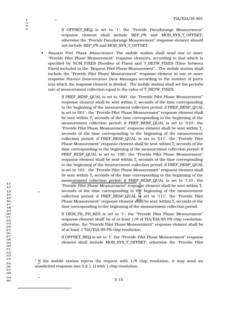
If OFFSET_REQ is set to ‘1’, the “Provide Pseudorange Measurement”
response element shall include REF_PN and MOB_SYS_T_OFFSET;
otherwise the “Provide Pseudorange Measurement” response element should
not include REF_PN and MOB_SYS_T_OFFSET.
• Request Pilot Phase Measurement: The mobile station shall send one or more
“Provide Pilot Phase Measurement” response elements, according to that which is
specified by NUM_FIXES (Number of Fixes) and T_BETW_FIXES (Time between
Fixes) included in the “Request Pilot Phase Measurement”. The mobile station shall
include the “Provide Pilot Phase Measurement” response element in one or more
response Posit ion Determin at ion Da ta Messages according to the number of parts
into which the response element is divided. The mobile station shall set the periodic
rate of measurement collection equal to the value of T_BETW_FIXES.
If PREF_RESP_QUAL is set to ‘000’, the “Provide Pilot Phase Measurement”
response element shall be sent within T 1 seconds of the time corresponding
to the beginning of the measurement collection period; if PREF_RESP_QUAL
is set to ‘001’, the “Provide Pilot Phase Measurement” response element shall
be sent within T 2 seconds of the time corresponding to the beginning of the
measurement collection period; if PREF_RESP_QUAL is set to ‘010’, the
“Provide Pilot Phase Measurement” response element shall be sent within T 3
seconds of the time corresponding to the beginning of the measurement
collection period; if PREF_RESP_QUAL is set to ‘011’, the “Provide Pilot
Phase Measurement” response element shall be sent within T 4 seconds of the
time corresponding to the beginning of the measurement collection period; if
PREF_RESP_QUAL is set to ‘100’, the “Provide Pilot Phase Measurement”
response element shall be sent within T 5 seconds of the time corresponding
to the beginning of the measurement collection period; if PREF_RESP_QUAL
is set to ‘101’, the “Provide Pilot Phase Measurement” response element shall
be sent within T 6 seconds of the time corresponding to the beginning of the
measurement collection period; if PREF_RESP_QUAL is set to ‘110’, the
“Provide Pilot Phase Measurement” response element shall be sent within T 7
seconds of the time corresponding to the beginning of the measurement
collection period; if PREF_RESP_QUAL is set to ‘111’, the “Provide Pilot
Phase Measurement” response element shall be sent within T 8 seconds of the
time corresponding to the beginning of the measurement collection period.
If DESI_PIL_PH_RES is set to ‘1’, the “Provide Pilot Phase Measurement”
response element shall9 be of at least 1/8 of TIA/EIA-95 PN chip resolution ;
otherwise, the “Provide Pilot Phase Measurement” response element shall be
of at least 1 TIA/EIA-95 PN chip resolution.
If OFFSET_REQ is set to ‘1’, the “Provide Pilot Phase Measurement” response
element shall include MOB_SYS_T_OFFSET; otherwise the “Provide Pilot
9 If the mobile station rejects the request with 1/8 chip resolution, it may send an
unsolicited response (see 3.2.1.1) with 1 chip resolution.

8/20/2019 TIA-EIA-IS 801 - 1999
http://slidepdf.com/reader/full/tia-eia-is-801-1999 34/138
TIA/EIA/IS-801
3-16
Phase Measurement” response element should not include
MOB_SYS_T_OFFSET.
• Request Location Response : The mobile station shall send one or more “Provide
Location Response” response elements, according to that which is specified by
NUM_FIXES (Number of Fixes) and T_BETW_FIXES (Time between Fixes) included
in the “Request Location Response”. The mobile station shall include the “Provide
Location Response” response element in one or more response Position
Determinat ion Data Messages according to the number of parts into which the
response element is divided. The mobile station shall set the periodic rate of
measurement collection equal to the value of T_BETW_FIXES.
If PREF_RESP_QUAL is set to ‘000’, the “Provide Location Response”
response element shall be sent within T 1 seconds of the time corresponding
to the beginning of the measurement collection period; if PREF_RESP_QUAL
is set to ‘001’, the “Provide Location Response” response element shall be
sent within T 2 seconds of the time corresponding to the beginning of the
measurement collection period; if PREF_RESP_QUAL is set to ‘010’, the
“Provide Location Response” response element shall be sent within T 3
seconds of the time corresponding to the beginning of the measurement
collection period; if PREF_RESP_QUAL is set to ‘011’, the “Provide Location
Response” response element shall be sent within T 4 seconds of the time
corresponding to the beginning of the measurement collection period; if
PREF_RESP_QUAL is set to ‘100’, the “Provide Location Response” response
element shall be sent within T 5 seconds of the time corresponding to the
beginning of the measurement collection period; if PREF_RESP_QUAL is set
to ‘101’, the “Provide Location Response” response element shall be sent
within T 6 seconds of the time corresponding to the beginning of the
measurement collection period; if PREF_RESP_QUAL is set to ‘110’, the
“Provide Location Response” response element shall be sent within T 7
seconds of the time corresponding to the beginning of the measurement
collection period; if PREF_RESP_QUAL is set to ‘111’, the “Provide Location
Response” response element shall be sent within T 8 seconds of the time
corresponding to the beginning of the measurement collection period.
If HEIGHT_REQ is set to ‘1’, the “Provide Location Response” response
element should include height information; otherwise, the “Provide Location
Response” response element should not include height information.
If CLK_COR_GPS_REQ is set to ‘1’, the “Provide Location Response” response
element should include clock correction for GPS time; otherwise, the “Provide
Location Response” response element should not include clock correction for
GPS time.
If VELOCITY_REQ is set to ‘1’, the “Provide Location Response” response
element should include velocity information; otherwise, the “Provide Location
Response” response element should not include velocity information.

8/20/2019 TIA-EIA-IS 801 - 1999
http://slidepdf.com/reader/full/tia-eia-is-801-1999 35/138
TIA/EIA/IS-801
3-17
• Request Time Offset Measu rement: The mobile station shall include a “Provide Time
Offset Measurement” response element in the response Position Determination
Data. If USE_TIME is set to ‘1’, the “Provide Time Offset Measurement” response
element shall include the offset information determined to be valid at the
ACTION_TIME. If USE_TIME is set to ‘0’, the “Provide Time Offset Measurement”
response element shall include the offset information determined to be valid at the
time the “Request Time Offset Measurement” is received by the mobile station. If
USE_TIME is set to ‘1’, the “Provide Time Offset Measurement” response element
shall be sent within 750 ms of ACTION_TIME. If USE_TIME is set to ‘0’, the “Provide
Time Offset Measurement” response element shall be sent within 750 ms of the
reception of the “Request Time Offset Measurement” request element.
• Request Cancellation : The mobile station shall cancel the outstanding request
element indicated by CANCEL_TYPE. The mobile station shall include a “Provide
Cancellation Acknowledgement” response element in the Posit ion Determin at ion Da ta
Message to indicate the successful cancellation of the outstanding request element.
If the mobile station has no outstanding request element of the type indicated by
CANCEL_TYPE, it shall set the NO_OUT_REQ flag in the “Provide Cancellation
Acknowledgment” response element. The “Provide Cancellation Acknowledgement”
response element shall be sent within 750 ms of the reception of the “Request
Cancellation” request element.
3.2.2.3.3.2
Base Station Response Elements Received
The mobile station should process and should make use of base station response elements.
Upon receiving a Posit ion Determin at ion Da ta Message , the mobile station should examine
the received response elements prior to processing the request elements.
If the mobile station receives “Provide GPS Almanac Correction” response element, the
mobile station shall process the response element as follows.
• If DELTA_XYZ_INCL is ‘0’, the mobile station shall set the values of DELTA_X,
DELTA_Y, DELTA_Z, DELTA_X_1ST, DELTA_Y_1ST and DELTA_Z_1ST to 0.
• If DELTA_CLOCK_INCL is ‘0’, the mobile station shall set the values of
DELTA_CLOCK and DELTA_CLOCK_1ST to 0.
3.2.2.3.4 Traffic Channel Setup
When a mobile station in the TIA/EIA-95-B Mobile Station Idle State intends to send
Posit ion Determina t ion Data Message on a Traffic Channel, the following procedures apply:
•
The mobile station shall send an Originat ion Message (see 6.7.1.3.2.4 of
TIA/EIA-95-B) containing no dialed digits and requesting Service Option 35 or
Service Option 36. The base station should complete an authentication Unique
Challenge-Response Procedure (see 6.3.12.1.5 of TIA/EIA-95-B) immediately after
assigning the traffic channel. The Unique Challenge-Response Procedure should be
completed successfully before the Posit ion Determina t ion Data Messages are sent to
the mobile station, and before the mobile-originated Posit ion Determin at ion Da ta
Messages are forwarded to other network entities.
8/20/2019 TIA-EIA-IS 801 - 1999
http://slidepdf.com/reader/full/tia-eia-is-801-1999 36/138
TIA/EIA/IS-801
3-18
• Call processing following the transmission of the Originat ion Message shall follow
the procedures defined in 6.6 of TIA/EIA-95-B. When the mobile station enters the
Conversat ion Substate, the mobile station may send the Posit ion Determin at ion Da ta
Messages in accordance with the procedures defined in the next section.
3.2.2.3.5
Mobile Position Message Origination in the Conversation Substate
3.2.2.3.5.1 Position Determination Data Message Transmission Requirements
When the mobile station is in the TIA/EIA-95-B Mobile Stat ion Conversat ion Subs tate and
needs to send one (or more) Posit ion Determina t ion Da ta Message(s) , the mobile station shall
form one (or more) Data Burst Message(s) (see 6.7.2.3.2.4 of TIA/EIA-95-B), setting
BURST_TYPE to ‘000101’ and send the Data Burst Message(s) on the Reverse Traffic
Channel. The mobile station shall set the MSG_NUMBER and NUM_MSGS fields to 1, and
shall set NUM_FIELDS field to the number of octets in the Posit ion Determina t ion Data
Message (see 3.2.4). The Data Bu rst Message contains the Position Determination Data in
the CHARi fields (see 6.7.2.3.2.4 of TIA/EIA-95-B). The mobile station shall set the
ACK_REQ Layer-2 field to ‘1’. If the only connected service option is Service Option 35 or
Service Option 36, the mobile station should enter the Release Substate with a mobile
station release indication (see 6.6.4.5 of TIA/EIA/95-B) when Posit ion Determin at ion Da ta
Messages have not been received or have not been sent during a period of time which is
implementation-dependent. If any service option in addition to Service Option 35 or Service
Option 36 is connected, the mobile station shall remain in the Conversation Substate, and
the mobile station should initiate Service Negotiation to drop Service Option 35 or Service
Option 36 when Posit ion Determina t ion Data Messages have not been received or have not
been sent during a period of time which is implementation-dependent. If the user needs to
initiate a call and Service Option 35 or 36 is the only service option connected, then the
mobile station should release the call for Service Option 35 or 36 if needed to connect the
user call.
3.2.2.3.5.2
Unsolicited Response Elements
Reserved
3.2.2.3.5.3 Request Elements
Reserved
3.2.3 Broadcast Procedures
Reserved
3.2.4 Reverse Link Message Format
The reverse link Posit ion Determina t ion Da ta Messages are summarized in Table 3.2.4-1.

8/20/2019 TIA-EIA-IS 801 - 1999
http://slidepdf.com/reader/full/tia-eia-is-801-1999 37/138
TIA/EIA/IS-801
3-19
Table 3.2 .4-1. Reverse Link Mes sages
Mes s age Nam e PD_MSG_TYPE
Posit ion Determinat ion Data
Message
‘00000000’
Reserved for future standardization ‘00000001’ through
‘10111111’
Available for manufacturer-specific
Posit ion Determinat ion Data
Message definition as specified in
TSB-58
‘11000000’ through
‘11111110’
Reserved ‘11111111’
The Position Determinat ion Data Message from mobile station to base station has the
following variable length format:
Fie ld Le n gth (bit s )
SESS_START 1
SESS_END 1
SESS_SOURCE 1
SESS_TAG 5
PD_MSG_TYPE (‘00000000’) 8NUM_REQUESTS 4
NUM_RESPONSES 4
The mobile station shall include NUM_REQUESTS
occurrences of the following record:
RESERVED 4
REQ_TYPE 4
REQ_PAR_LEN 8
REQ_PAR_RECORD 8 × REQ_PAR_LEN
The mobile station shall include NUM_RESPONSES
occurrences of the following record:

8/20/2019 TIA-EIA-IS 801 - 1999
http://slidepdf.com/reader/full/tia-eia-is-801-1999 38/138
TIA/EIA/IS-801
3-20
RESERVED 3
UNSOL_RESP 1
RESP_TYPE 4
RESP_PAR_LEN 8
RESP_PAR_RECORD 8 × RESP_PAR_LEN
SESS_START – Start-of-session indicator.
If the mobile station has previously sent or received a
Posit ion Determinat ion Data Message related to this
Posit ion Determinat ion Data Message (as defined in
2.2.1) it shall set this field to ‘0’; otherwise, it shall set
this field to ‘1’.
SESS_END – End-of-session indicator.
If the mobile station does not expect to receive or send
any more Posit ion Determina t ion Data Messages related
to this Posit ion Determina t ion Data Message (as defined
in 2.2.1) the mobile station shall set this field to ‘1’;
otherwise, it shall set this field to ‘0’. The criteria for
setting this field are implementation dependent.
SESS_SOURCE – Session-source indicator.10
If SESS_START is set to ‘1’ the mobile station shall set
this field to ‘1’; otherwise it shall set this field to the
same value as the SESS_SOURCE field that appeared
in a previously-received or previously-sent Position
Determina t ion Data Message that was related to this
Posit ion Determinat ion Data Message (as defined in
2.2.1).
10 This field indicates which side (mobile station or base station) initiated this session.

8/20/2019 TIA-EIA-IS 801 - 1999
http://slidepdf.com/reader/full/tia-eia-is-801-1999 39/138
TIA/EIA/IS-801
3-21
SESS_TAG – Session tag.
If SESS_START is set to ‘0’ the mobile station shall set
this field to the same value as the SESS_TAG field that
appeared in a previously-received or previously-sent
Posit ion Determin at ion Da ta Messa ge that was related
to this Posit ion Determina t ion Data Message (as defined
in 2.2.1); otherwise, the mobile station shall set this
field to one more (modulo 32) than the value it
assigned to this field in the latest Position
Determinat ion Data Message that it sent with
SESS_START set to ‘1’. If no such latest Position
Determina t ion Data Message exists, the mobile station
shall set this field to ‘00000’. The definition of “latest”
is implementation dependent.
PD_MSG_TYPE – Posit ion Determin at ion Da ta Message type.
The mobile station shall set this field to ‘00000000’.
NUM_REQUESTS – Number of request element parameter records.
The mobile station shall set this field to the number of
request element parameters records included in the
message.
NUM_RESPONSES – Number of response element parameter records.
The mobile station shall set this field to the number of
response element parameters records included in the
message.
RESERVED – Reserved bits.
The mobile station shall set this field to ‘0000’.
REQ_TYPE – Request element type.
The mobile station shall set this field to the value
shown in Table 3.2.4-2.

8/20/2019 TIA-EIA-IS 801 - 1999
http://slidepdf.com/reader/full/tia-eia-is-801-1999 40/138
TIA/EIA/IS-801
3-22
Table 3.2 .4-2. Request Eleme nt Type
Des cript io n REQ_TYPE
(binary)
Reserved ‘0000’
Request BS Capabilities ‘0010’
Request GPS Acquisition Assistance ‘0100’
Request GPS Location Assistance ‘0110’
Reserved ‘0111’
Request GPS Sensitivity Assistance ‘0101’
Request Base Station Almanac ‘0011’
Request GPS Almanac ‘1000’
Request GPS Ephemeris ‘1001’
Request GPS Navigation Message Bits ‘1010’
Request Location Response ‘0001’
Request GPS Almanac Correction ‘1011’
All other REQ_TYPE values are reserved.
REQ_PAR_LEN – Request element parameters length.
The mobile station shall set this field to the number of
octets included in the REQ_PAR_RECORD field.
REQ_PAR_RECORD – Request element parameters record.
The mobile station shall set this record as described in
3.2.4.1.
RESERVED – Reserved bits.
The mobile station shall set these bits to ‘000’.
UNSOL_RESP – Unsolicited response indicator.
If the response element is an unsolicited response
element, the mobile station shall set this field to ‘1’;
otherwise the mobile station shall set this field to ‘0’.
RESP_TYPE – Response element type.
The mobile station shall set this field to the value
shown in Table 3.2.4-3.

8/20/2019 TIA-EIA-IS 801 - 1999
http://slidepdf.com/reader/full/tia-eia-is-801-1999 41/138
TIA/EIA/IS-801
3-23
Table 3.2 .4-3. Respons e Elem en t Type
Des c ript ion RESP_TYPE
(binary)
Reject ‘0000’
Provide MS Information ‘0010’
Provide Autonomous Measurement Weighting Factors ‘0011’
Provide Pseudorange Measurement ‘0100’
Provide Pilot Phase Measurement ‘0101’
Provide Location Response ‘0001’
Provide Time Offset Measurement ‘0110’
Provide Cancellation Acknowledgement ‘0111’
All other RESP_TYPE values are reserved.
RESP_PAR_LEN – Response element parameters length.
The mobile station shall set RESP_PAR_LEN to the
number of octets included in the response element.
RESP_PAR_RECORD – Response element parameters record.
The mobile station shall set this record as described in
3.2.4.2.
3.2.4.1 Request Element Parameters Record
The mobile station shall set REQ_PAR_RECORD as described below 11.
If REQ_TYPE in Position Determin at ion Data Message is equal to ‘0010’, or if REQ_TYPE is
equal to ‘0101’, or if REQ_TYPE is equal to ‘1000’, the mobile station shall not include this
record. If REQ_TYPE in Position Determinat ion Data Message is equal to ‘0001’, or if
REQ_TYPE is equal to ‘0011’, or if REQ_TYPE is equal to ‘0100’, or if REQ_TYPE is equal to
‘0110’, or if REQ_TYPE is equal to ‘1001’, or if REQ_TYPE is equal to ‘1010’, or if REQ_TYPE
is equal to ‘1011’, the mobile station shall include the record REQ_PAR_RECORD and set
its fields as described below.
If REQ_TYPE is equal to ‘0100’ (Request GPS Acquisition Assistance), REQ_PAR_RECORD
shall include the following record:
11 A request element includes any parameters that directly specify the structure or contents
of the expected response. It does not include parameters that convey information about the
"state" (or status) of the mobile, or values of parameters stored in the mobile. If such
parameters are needed in support of the request, they can be conveyed in an unsolicited
response. (Note: "state" does not refer to the IS-95 state of the mobile; rather, it refers, in
general, to the internal status of the mobile).

8/20/2019 TIA-EIA-IS 801 - 1999
http://slidepdf.com/reader/full/tia-eia-is-801-1999 42/138
TIA/EIA/IS-801
3-24
Fie ld Le n gth (bit s )
DOPP _REQ 1
ADD_DOPP_REQ 1
CODE_PH_PAR_REQ 1
AZ_EL_REQ 1
RESERVED 4
DOPP _REQ – Doppler (0th order) term requested.
If Doppler (0th order) terms are requested, the mobile
station shall set this field to ‘1’; otherwise the mobile
station shall set this field to ‘0’.
ADD_DOPP_REQ – Additional Doppler terms requested.
If the Doppler (0th order) terms, the Doppler High-
Order terms and the Doppler search window terms are
requested, the mobile station shall set this field to ‘1’;
otherwise the mobile station shall set this field to ‘0’.
CODE_PH_PAR_REQ – Code phase parameters requested.
If the code phase parameters are requested, the mobile
station shall set this field to ‘1’; otherwise the mobile
station shall set this field to ‘0’.
AZ_EL_REQ – Azimuth and elevation angle requested.
If azimuth and elevation angle are requested, the
mobile station shall set this field to ‘1’; otherwise the
mobile station shall set this field to ‘0’.
RESERVED – Reserved bits.
The mobile station shall set this field to ‘0000’.
If REQ_TYPE is equal to ‘0110’ (Request GPS Location Assistance), REQ_PAR_RECORD
shall include the following record:
Fie ld Le n gth (bit s )
COORD_TYPE 1
RESERVED 7
COORD_TYPE – Coordinate type requested.
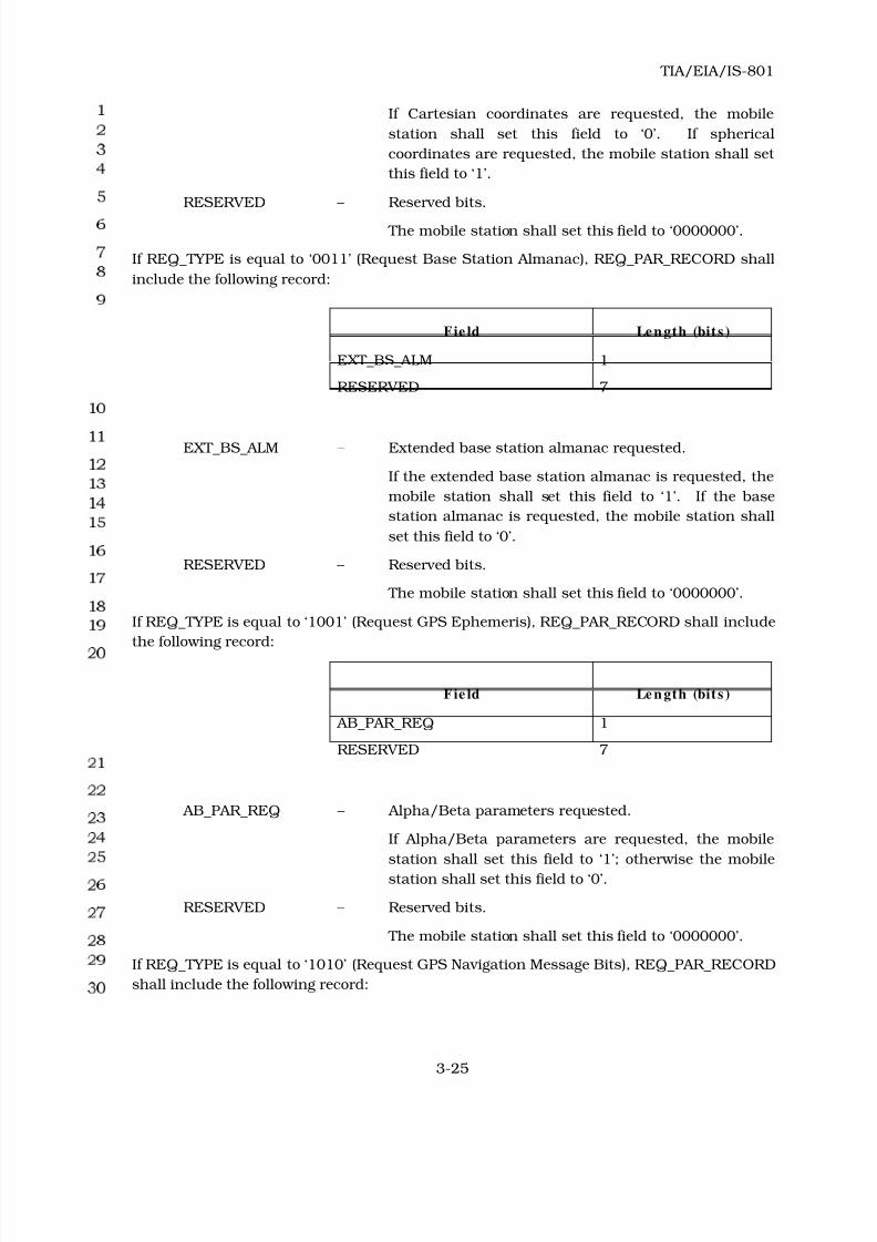
8/20/2019 TIA-EIA-IS 801 - 1999
http://slidepdf.com/reader/full/tia-eia-is-801-1999 43/138
TIA/EIA/IS-801
3-25
If Cartesian coordinates are requested, the mobile
station shall set this field to ‘0’. If spherical
coordinates are requested, the mobile station shall set
this field to ‘1’.
RESERVED – Reserved bits.
The mobile station shall set this field to ‘0000000’.
If REQ_TYPE is equal to ‘0011’ (Request Base Station Almanac), REQ_PAR_RECORD shall
include the following record:
Fie ld Le n gth (bit s )
EXT_BS_ALM 1
RESERVED 7
EXT_BS_ALM – Extended base station almanac requested.
If the extended base station almanac is requested, the
mobile station shall set this field to ‘1’. If the base
station almanac is requested, the mobile station shall
set this field to ‘0’.
RESERVED – Reserved bits.
The mobile station shall set this field to ‘0000000’.
If REQ_TYPE is equal to ‘1001’ (Request GPS Ephemeris), REQ_PAR_RECORD shall include
the following record:
Fie ld Le n gth (bit s )
AB_PAR_REQ 1
RESERVED 7
AB_PAR_REQ – Alpha/Beta parameters requested.
If Alpha/Beta parameters are requested, the mobile
station shall set this field to ‘1’; otherwise the mobile
station shall set this field to ‘0’.
RESERVED – Reserved bits.
The mobile station shall set this field to ‘0000000’.
If REQ_TYPE is equal to ‘1010’ (Request GPS Navigation Message Bits), REQ_PAR_RECORD
shall include the following record:

8/20/2019 TIA-EIA-IS 801 - 1999
http://slidepdf.com/reader/full/tia-eia-is-801-1999 44/138
TIA/EIA/IS-801
3-26
Fie ld Le n gth (bit s )
SUBF_4_5_REQ 1
RESERVED 7
SUBF_4_5_REQ – Subframes 4 and 5 requested.
If subframes 4 and 5 are requested, the mobile station
shall set this field to ‘1’; otherwise the mobile station
shall set this field to ‘0’.
RESERVED – Reserved bits.
The mobile station shall set this field to ‘0000000’.
If REQ_TYPE is equal to ‘0001’ (Request Location Response), REQ_PAR_RECORD shall
include the following record:
Fie ld Le n gth (bit s )
HEIGHT_REQ 1
CLK_COR_GPS_REQ 1
VELOCITY_REQ 1
RESERVED 5
HEIGHT_REQ – Height information requested.
If height information is requested, the mobile station
shall set this field to ‘1’; otherwise the mobile station
shall set this field to ‘0’.
CLK_COR_GPS_REQ – Clock correction for GPS time requested.
If clock correction for GPS time is requested, the
mobile station shall set this field to ‘1’; otherwise the
mobile station shall set this field to ‘0’.
VELOCITY_REQ – Velocity information requested.
If velocity information is requested, the mobile station
shall set this field to ‘1’; otherwise the mobile station
shall set this field to ‘0’.
RESERVED – Reserved bits.
The mobile station shall set this field to ‘00000’.
If REQ_TYPE is equal to ‘1011’ (Request GPS Almanac Correction), REQ_PAR_RECORD
shall include the following record:

8/20/2019 TIA-EIA-IS 801 - 1999
http://slidepdf.com/reader/full/tia-eia-is-801-1999 45/138
TIA/EIA/IS-801
3-27
Fie ld Len gth (bit s )
TOA 8
WEEK_NUM 8
TOA – Time of almanac.
The mobile station shall set this field to the time of
applicability of the almanac for which the correction is
requested, in units of 4096 s, in the range from 0 to
602,112 s.
WEEK_NUM – GPS week number.
The mobile station shall set this field to the 8 least
significant bits of the GPS week number of the
almanac for which the correction is requested. The
range for this field is from 0 to 255.
3.2.4.2 Response Element Parameters Record
The mobile station shall set RESP_PAR_RECORD as described below.
If RESP_TYPE in Position Determinat ion Data Message is equal to ‘0000’ (Reject),
RESP_PAR_RECORD shall include the following record:
Fie ld Le n gth (bit s )
REJ_REQ_TYPE 4
REJ_REASON 3
RESERVED 1
REJ_REQ_TYPE – Reject request type.
The mobile station shall set this field to the value of
the REQ_TYPE corresponding to the request element it
rejects. See Table 4.2.4-2.
REJ_REASON – Reject reason.
The mobile station shall set this field to the value
shown in Table 3.2.4.2-1.
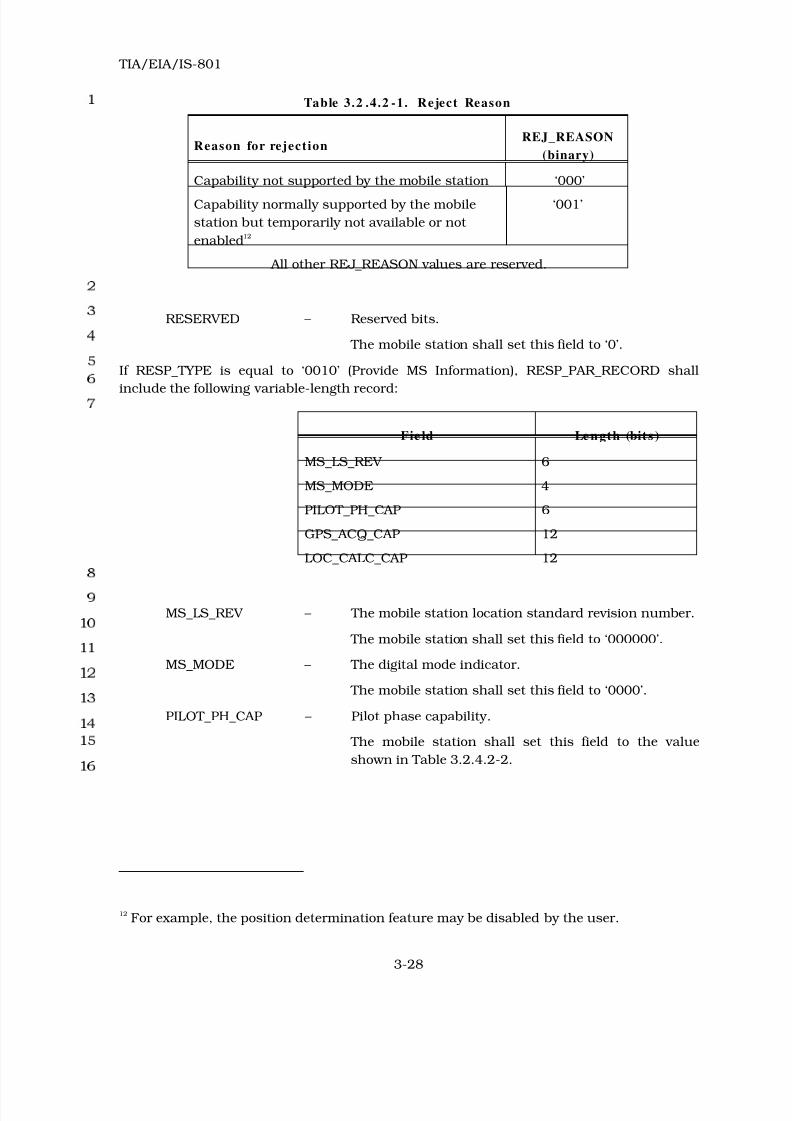
8/20/2019 TIA-EIA-IS 801 - 1999
http://slidepdf.com/reader/full/tia-eia-is-801-1999 46/138
TIA/EIA/IS-801
3-28
Table 3.2 .4.2 -1. Reject Reason
Reason for rejectionREJ_REASON
(binary)
Capability not supported by the mobile station ‘000’
Capability normally supported by the mobile
station but temporarily not available or not
enabled12
‘001’
All other REJ_REASON values are reserved.
RESERVED – Reserved bits.
The mobile station shall set this field to ‘0’.
If RESP_TYPE is equal to ‘0010’ (Provide MS Information), RESP_PAR_RECORD shall
include the following variable-length record:
Fie ld Le n gth (bit s )
MS_LS_REV 6
MS_MODE 4
PILOT_PH_CAP 6
GPS_ACQ_CAP 12
LOC_CALC_CAP 12
MS_LS_REV – The mobile station location standard revision number.
The mobile station shall set this field to ‘000000’.
MS_MODE – The digital mode indicator.
The mobile station shall set this field to ‘0000’.
PILOT_PH_CAP – Pilot phase capability.
The mobile station shall set this field to the value
shown in Table 3.2.4.2-2.
12 For example, the position determination feature may be disabled by the user.

8/20/2019 TIA-EIA-IS 801 - 1999
http://slidepdf.com/reader/full/tia-eia-is-801-1999 47/138
TIA/EIA/IS-801
3-29
Table 3.2 .4.2 -2. Pi lot Phase Capabil i ty
PILOT_PH
(binary)
IS-95 Pilot Phase Capability
‘000000’ Full Chip Measurement Capability
‘000001’ Half Chip Measurement Capability
‘000010’ Quarter Chip Measurement Capability
‘000011’ Eighth Chip Measurement Capability
‘000100’ One Sixteenth Chip Measurement Capability
All other PILOT_PH values are reserved.
GPS_ACQ_CAP – GPS acquisition capability.
GPS_ACQ_CAP consists of 12 bits, each of the LSB’s
represents one GPS acquisition capability. The
mapping of the bits is listed in Table 3.2.4.2-3. If a
GPS acquisition capability is supported, the mobile
station shall set the corresponding bit in
GPS_ACQ_CAP to ‘1’; otherwise the mobile station
shall set the corresponding bit to ‘0’. Bits 8-12 shall
be set to ‘00000’.
Table 3.2 .4 .2 -3. Mapping Table for GPS Acquis ition Capability
Corresponding Bi t in GPS_ACQ_CAP GPS Acquis i t ion Capabi li ty
Bit 1 (LSB) GPS Acquisition Assistance
Bit 2 GPS Sensitivity Assistance
Bit 3 GPS Almanac
Bit 4 GPS Ephemeris
Bit 5 GPS Navigation Message Bits
Bit 6 GPS Almanac Correction
Bit 7 GPS Autonomous Acquisition Capable
Bits 8 – 12 Reserved
LOC_CALC_CAP – Position calculation capability.
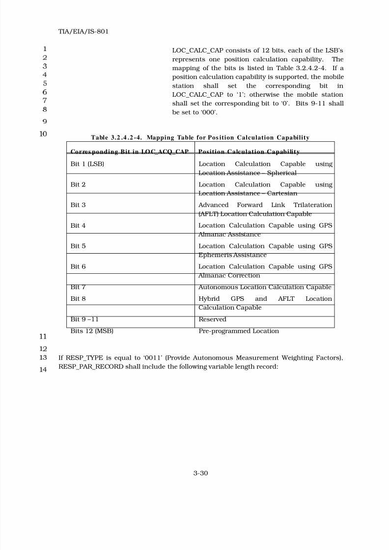
8/20/2019 TIA-EIA-IS 801 - 1999
http://slidepdf.com/reader/full/tia-eia-is-801-1999 48/138
TIA/EIA/IS-801
3-30
LOC_CALC_CAP consists of 12 bits, each of the LSB’s
represents one position calculation capability. The
mapping of the bits is listed in Table 3.2.4.2-4. If a
position calculation capability is supported, the mobile
station shall set the corresponding bit in
LOC_CALC_CAP to ‘1’; otherwise the mobile station
shall set the corresponding bit to ‘0’. Bits 9-11 shall
be set to ‘000’.
Table 3.2 .4 .2 -4. Mapping Table for Pos ition Calculation Capability
Corres ponding Bit in LOC_ACQ_CAP Posit ion Calculation Capabili ty
Bit 1 (LSB) Location Calculation Capable using
Location Assistance – Spherical
Bit 2 Location Calculation Capable using
Location Assistance – Cartesian
Bit 3 Advanced Forward Link Trilateration
(AFLT) Location Calculation Capable
Bit 4 Location Calculation Capable using GPS
Almanac Assistance
Bit 5 Location Calculation Capable using GPS
Ephemeris Assistance
Bit 6 Location Calculation Capable using GPS
Almanac Correction
Bit 7 Autonomous Location Calculation CapableBit 8 Hybrid GPS and AFLT Location
Calculation Capable
Bit 9 –11 Reserved
Bits 12 (MSB) Pre-programmed Location
If RESP_TYPE is equal to ‘0011’ (Provide Autonomous Measurement Weighting Factors),
RESP_PAR_RECORD shall include the following variable length record:

8/20/2019 TIA-EIA-IS 801 - 1999
http://slidepdf.com/reader/full/tia-eia-is-801-1999 49/138
TIA/EIA/IS-801
3-31
Fie ld Len gth (bit s )
TIME_REF_CDMA 14
DGPS 1
NUM_SV 4
GPS_WEIGHT 4
The mobile station shall include NUM_SV occurrences of the
following fields:
SV_PRN_NUM 6
INV_WEIGHT_FA 6
RESERVED 0 - 7 (as needed)
TIME_REF_CDMA – CDMA system time at the time the solution is valid.
The mobile station shall set this field to (t/50 mod
16384), where t is the CDMA system time in frames, as
defined in 1.2 of TIA/EIA-95-B, at the time the
solution is valid. This is the time at which the values
of the parameters reported in this response element
parameter record are valid.
DGPS – DGPS flag.
If differential GPS is used, the mobile station shall set
this field to ‘1’; otherwise the mobile station shall set
this field to ‘0’.
NUM_SV – Number of GPS satellites in solution.
The mobile station shall set this field to the number of
GPS satellites used to compute the solution, in the
range from 1 to 16, where the binary value of the field
conveys the number of satellites minus one.
GPS_WEIGHT – Ratio of GPS weight to total weight.
The mobile station shall set this field to the ratio of
GPS weight to total weight (GPS weight and pilot phase
weight) used to compute the solution, in the range
from 0 to 1, with a resolution of 1/15.

8/20/2019 TIA-EIA-IS 801 - 1999
http://slidepdf.com/reader/full/tia-eia-is-801-1999 50/138
TIA/EIA/IS-801
3-32
SV_PRN_NUM – Satellite PRN number.
The mobile station shall set this field to the value of
the PRN signal number for which the measured data is
valid. It is represented as an unsigned value in the
range from 1 to 37, where the binary value of the field
conveys the satellite PRN number minus one.
INV_WEIGHT_FA – Inverse of weighting factor.
The mobile station shall set this field to the inverse of
the weighting factor used for the satellite, in the range
from 0.5 m to 112 m. A “floating-point” representation
is used where the 3 most significant bits constitute the
exponent and the 3 least significant bits constitute the
mantissa as specified in Table 3.2.4.2-5.
Table 3 .2.4 .2-5. Inverse of Weightin g Factor Represen tation
Ex po n en t , X Man t is s a, YIndex value, i
= Y + 8 × X
Floating-Point
value, f i
Inverse Weighting
Fact or value, (m )
‘000’ ‘000’ 0 0.5 σ < 0.5
‘000’ ‘001’ 1 0.5625 0.5 ≤ σ < 0.5625
X Y 2 ≤ i ≤ 61 0.5×(1 + Y /8)×2X
f i- 1 ≤ σ < f
i
‘111’ ‘110’ 62 112 104 ≤ σ < 112
‘111’ ‘111’ 63 Not Applicable 112 ≤ σ
RESERVED – Reserved bits.
The mobile station shall add reserved bits as needed in
order to make the length of the response element
parameters record equal to an integer number of
octets. The mobile station shall set these bits to ‘0’.
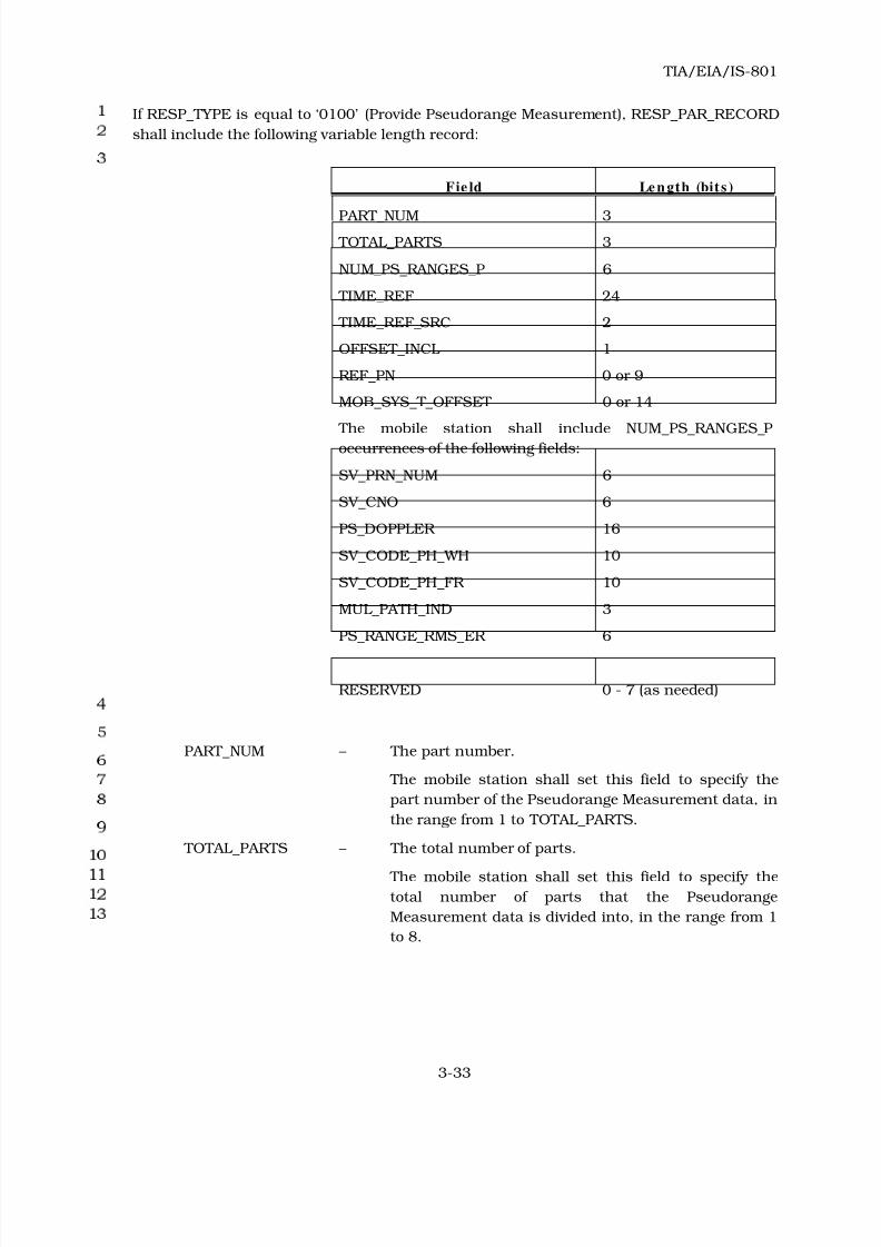
8/20/2019 TIA-EIA-IS 801 - 1999
http://slidepdf.com/reader/full/tia-eia-is-801-1999 51/138
TIA/EIA/IS-801
3-33
If RESP_TYPE is equal to ‘0100’ (Provide Pseudorange Measurement), RESP_PAR_RECORD
shall include the following variable length record:
Fie ld Le n gth (bit s )
PART_NUM 3
TOTAL_PARTS 3
NUM_PS_RANGES_P 6
TIME_REF 24
TIME_REF_SRC 2
OFFSET_INCL 1
REF_PN 0 or 9
MOB_SYS_T_OFFSET 0 or 14
The mobile station shall include NUM_PS_RANGES_P
occurrences of the following fields:
SV_PRN_NUM 6
SV_CNO 6
PS_DOPPLER 16
SV_CODE_PH_WH 10
SV_CODE_PH_FR 10
MUL_PATH_IND 3
PS_RANGE_RMS_ER 6
RESERVED 0 - 7 (as needed)
PART_NUM – The part number.
The mobile station shall set this field to specify the
part number of the Pseudorange Measurement data, in
the range from 1 to TOTAL_PARTS.
TOTAL_PARTS – The total number of parts.
The mobile station shall set this field to specify the
total number of parts that the Pseudorange
Measurement data is divided into, in the range from 1
to 8.

8/20/2019 TIA-EIA-IS 801 - 1999
http://slidepdf.com/reader/full/tia-eia-is-801-1999 52/138
TIA/EIA/IS-801
3-34
NUM_PS_RANGES_P – Number of pseudoranges in this part.
The mobile station shall set this field to the number of
pseudoranges included in this part of the response
element, in the range from 1 to 64, where the binary
value of the field conveys the number of satellites
minus one.
TIME_REF – The time of validity of the parameters reported in this
response element.
The mobile station shall set this field to
(t mod 14,400,000), where t is the time of validity in
units of 1 ms, based on the time reference specified by
TIME_REF_SRC (see Table 3.2.4.2-6). This is the time
at which the values of the parameters reported in this
response element parameter record are valid.
TIME_REF_SRC – Time reference source.
The mobile station shall set this field according to
Table 3.2.4.2-6.
Table 3 .2.4 .2-6. Time Reference Source
Time reference s ourceTIME_REF_SRC
(binary)
Mobile station time reference as defined in 6.1.5.1 of
TIA/EIA-95-B
‘00’
GPS time reference ‘01’
Other time reference ‘10’
Reserved ‘11’
OFFSET_INCL – Offset Included.
If the response element includes REF_PN and
MOB_SYS_T_OFFSET fields, then the mobile station
shall set this field to ‘1’; otherwise the mobile station
shall set this field to ‘0’.
REF_PN – Time reference PN sequence offset.
If the OFFSET_INCL field is set to ‘1’, then the mobile
station shall set this field to the PN sequence offset of
the pilot used by the mobile station to derive its time
reference, relative to the zero offset pilot PN sequence
in units of 64 PN chips; otherwise the mobile station
shall not include this field.

8/20/2019 TIA-EIA-IS 801 - 1999
http://slidepdf.com/reader/full/tia-eia-is-801-1999 53/138
TIA/EIA/IS-801
3-35
MOB_SYS_T_OFFSET– Mobile station system time offset.
If the OFFSET_INCL field is set to ‘1’, then the mobile
station shall set this field to the two’s complement
value of the offset between mobile station time
reference and time of occurrence of Reference PN, in
units of 1/16 TIA/EIA-95-B chips13, in the range from
-512 to +511.9375 TIA/EIA-95-B chips; otherwise the
mobile station shall not include this field. The sign of
this quantity shall be positive if the reference PN
occurs earlier than the mobile station time reference;
otherwise it shall be negative.
SV_PRN_NUM – Satellite PRN number.
The mobile station shall set this field to the value of
the PRN signal number for which the measured data is
valid. It is represented as an unsigned value in the
range from 1 to 37, where the binary value of the field
conveys the satellite PRN number minus one.
SV_CNO – Satellite C/N0.
The mobile station shall set this field to the value of
the satellite C/N0, as referenced to the antenna
connector 14, in units of 1 dB-Hz, in the range from 0 to
63 dB-Hz.
PS_DOPPLER – Pseudodoppler.
The mobile station shall set this field to the two’s
complement value of the measured satellite
pseudodoppler, in units of 0.2 Hz, in the range from
-6,553.6 Hz to +6,553.6 Hz.
SV_CODE_PH_WH – Satellite code phase – whole chips.
The mobile station shall set this field to the satellite
code phase measured as a number of GPS chips, in
units of 1 GPS chips, in the range from 0 to 1022
chips.
13 This field supports a maximum resolution of 1/16
th of a TIA/EIA-95-B chip. However,
mobile stations not capable of 1/16th chip measurement resolution are also supported by
this standard (See Table 3.2.4.2-2). Measurements made at lower resolutions are reported
in this field using 1/16th chip resolution.
14 If an active antenna is employed (i.e., one with a built-in amplifier and/or filter), then
C/N0 should be referenced to the antenna port prior to any amplifier or filter.

8/20/2019 TIA-EIA-IS 801 - 1999
http://slidepdf.com/reader/full/tia-eia-is-801-1999 54/138
TIA/EIA/IS-801
3-36
SV_CODE_PH_FR – Satellite code phase – fractional chips.
The mobile station shall set this field to the residual
satellite code phase, in units of 1/210
of GPS chips, in
the range from 0 to (210
-1)/210
GPS chips.
MUL_PATH_IND – Multipath indicator.
The mobile station shall set this field to the value
shown in Table 3.2.4.2-7.
Table 3.2 .4.2 -7 . Multipath Indicator
DescriptionTh res h o ld MUL_PATH_IND
(binary)
Not measured Not specified ‘000’
Low MP Error ≤ 5 m ‘001’
Medium 5 m < MP Error ≤ 43 m ‘010’
High MP Error > 43 m ‘011’
All other MUL_PATH_IND values are reserved.
PS_RANGE_RMS_ER – Pseudorange RMS error.
The mobile station shall set this field to the
pseudorange RMS error used for the satellite, in the
range from 0.5 m to 112 m. A “floating-point”
representation is used where the 3 most significant
bits constitute the exponent and the 3 least significant
bits constitute the mantissa as specified in Table
3.2.4.2-8.
Table 3 .2.4 .2-8. Pseudorange RMS Error Represent ation
Ex po n en t , X Man t is s a, YIndex value, i
= Y + 8 ×X
Floating-Point
value, f i
Pseudorange value,
P (m )
‘000’ ‘000’ 0 0.5 P < 0.5
‘000’ ‘001’ 1 0.5625 0.5 ≤ P < 0.5625
X Y 2 ≤ i ≤ 61 0.5×(1 + Y /8)×2X f i- 1 ≤ P < f
i
‘111’ ‘110’ 62 112 104 ≤ P < 112
‘111’ ‘111’ 63 Not Applicable 112 ≤ P

8/20/2019 TIA-EIA-IS 801 - 1999
http://slidepdf.com/reader/full/tia-eia-is-801-1999 55/138
TIA/EIA/IS-801
3-37
RESERVED – Reserved bits.
The mobile station shall add reserved bits as needed in
order to make the length of the response element
parameters record equal to an integer number of
octets. The mobile station shall set these bits to ‘0’.

8/20/2019 TIA-EIA-IS 801 - 1999
http://slidepdf.com/reader/full/tia-eia-is-801-1999 56/138
TIA/EIA/IS-801
3-38
If RESP_TYPE is equal to ‘0101’ (Provide Pilot Phase Measurement), RESP_PAR_RECORD
shall include the following variable length record:
Fie ld Le n gth (bit s )
TIME_REF_MS 24
OFFSET_INCL 1
MOB_SYS_T_OFFSET 0 or 14
REF_PN 9
PILOT_STRENGTH 6
BAND_CLASS 5
CDMA_FREQ 11
BASE_ID 16
SID 15
NID 16
PART_NUM 3
TOTAL_PARTS 3
NUM_PILOTS_P 6
The mobile station shall include NUM_PILOTS_P occurrences
of the following two-field record:
PILOT_PN_PHASE 19
RMS_ERR_PHASE 6
ADD_PILOTS_INCL 1
ADD_BAND_CLASS 0 or 5
ADD_CDMA_FREQ 0 or 11
NUM_ADD_PILOTS_P 0 or 6
If ADD_PILOT_INCL is set to ‘1’, the mobile station shall
include NUM_ADD_PILOTS_P occurrences of the following
two-field record:
ADD_PILOT_PN_PH 19
ADD_RMS_ERR_PH 6
RESERVED 0 - 7 (as needed)

8/20/2019 TIA-EIA-IS 801 - 1999
http://slidepdf.com/reader/full/tia-eia-is-801-1999 57/138
TIA/EIA/IS-801
3-39
TIME_REF_MS – The time of validity of the parameters reported in this
response element.
The mobile station shall set this field to
(t mod 14,400,000), where t is the time of validity in
units of 1 ms, based on mobile station time reference
as defined in 6.1.5.1 of TIA/EIA-95-B. This is the time
at which the values of the parameters reported in this
response element parameter record are valid.
OFFSET_INCL – Offset Included.
If the response element includes MOB_SYS_T_OFFSET
field, then the mobile station shall set this field to ‘1’;
otherwise the mobile station shall set this field to ‘0’.
MOB_SYS_T_OFFSET – Mobile station system time offset. See 6.1.5.1 of
TIA/EIA-95-B.
If the OFFSET_INCL field is set to ‘1’, then the mobile
station shall set this field to the two’s complement
value of the offset between mobile station time
reference and time of occurrence of Reference PN, in
units of 1/16 TIA/EIA-95-B chips, in the range from
-512 to +511.9375 TIA/EIA-95-B chips; otherwise the
mobile station shall not include this field. The sign of
this quantity shall be positive if the reference PN
occurs earlier than the mobile station time reference;
otherwise it shall be negative.
REF_PN – Time reference PN sequence offset.
The mobile station shall set this field to the PN
sequence offset of the pilot used by the mobile station
to derive its time reference, relative to the zero offset
pilot PN sequence in units of 64 PN chips.
PILOT_STRENGTH – Pilot strength.
This parameter conveys the Ec/Io of this pilot (as
specified in 6.6.6.2.2 of TIA/EIA-95-B), in the units of
0.5 dB, in the range from 0 to –31.5 dB. The mobile
station shall set this field to
-2 × 10 log10 PS,

8/20/2019 TIA-EIA-IS 801 - 1999
http://slidepdf.com/reader/full/tia-eia-is-801-1999 58/138
TIA/EIA/IS-801
3-40
where PS is the strength of the pilot used by the
mobile station to derive its time reference (see 6.1.5.1
of TIA/EIA-95-B), measured as specified in 6.6.6.2.2 of
TIA/EIA-95-B. If this value (-2 × 10 log10 PS) is less
than 0, the mobile station shall set this field to
‘000000’. If this value is greater than 63, the mobile
station shall set this field to ‘111111’.
BAND_CLASS – Band class.
The mobile station shall set this field to the CDMA
band class of the pilots that are reported in this
response element, as specified in TSB58-B.
CDMA_FREQ – Frequency assignment.
The mobile station shall set this field to the CDMA
Channel number, in the specified CDMA band class, of
the pilots that are reported in this response element,
as specified in 6.1.1.1 of TIA/EIA-95-B.
BASE_ID – Base Station Identification.
If the mobile station is on the Paging Channel, the
mobile station shall set this field to the base station
identification number obtained from the Paging
Channel that the mobile station is demodulating;
otherwise, the mobile station shall set this field to the
base station identification number obtained from the
Paging Channel that the mobile station last
demodulated.
SID – System Identification.
If the mobile station is on the Paging Channel, the
mobile station shall set this field to the system
identification number obtained from the Paging
Channel that the mobile station is demodulating;
otherwise, the mobile station shall set this field to the
system identification number obtained from the Paging
Channel that the mobile station last demodulated.

8/20/2019 TIA-EIA-IS 801 - 1999
http://slidepdf.com/reader/full/tia-eia-is-801-1999 59/138
TIA/EIA/IS-801
3-41
NID – Network Identification.
If the mobile station is on the Paging Channel, the
mobile station shall set this field to the network
identification number obtained from the Paging
Channel that the mobile station is demodulating;
otherwise, the mobile station shall set this field to the
network identification number obtained from the
Paging Channel that the mobile station last
demodulated.
PART_NUM – The part number.
The mobile station shall set this field to specify the
part number of the Pilot Phase Measurement data, in
the range from 1 to TOTAL_PARTS.
TOTAL_PARTS – The total number of parts.
The mobile station shall set this field to specify the
total number of parts that the Pilot Phase
Measurement data is divided into, in the range from 1
to 8.
NUM_PILOTS_P – Number of pilots in this part.
The mobile station shall set this field to the number of
pilots to be reported in this part of the response
element (not including additional pilots, as defined by
NUM_ADD_PILOTS_P).
The mobile station shall include NUM_PILOTS_P occurrences of the following pair of fields
for each pilot in the Active Set, and for each pilot in the Candidate or Neighbor Set whose
pilot strength is greater than T_DROP15, other than the pilot identified by the REF_PN field.
PILOT_PN_PHASE – Pilot measured phase.
The mobile station shall set this field to the phase of
the pilot PN sequence relative to the zero offset pilot PN
sequence of this pilot, in units of 1/16 TIA/EIA-95 PN
chips, in the range from 0 to 32,767.875 chips. The
pilot arrival time shall be the time of occurrence, as
measured at the mobile station antenna connector, of
the earliest arriving usable multipath component of
the pilot. See 6.6.6.2.4 of TIA/EIA-95-B.
15 T_DROP is defined in TIA/EIA-95-B.

8/20/2019 TIA-EIA-IS 801 - 1999
http://slidepdf.com/reader/full/tia-eia-is-801-1999 60/138
TIA/EIA/IS-801
3-42
RMS_ERR_PHASE – RMS error in phase measurement. This field
represents the mobile station’s best estimate of the
standard deviation of PILOT_PN_PHASE.
The mobile station shall set this field to a value in the
range from 1 m to 224 m. A “floating-point”
representation is used where the 3 most significant
bits constitute the exponent and the 3 least significant
bits constitute the mantissa as specified in Table
3.2.4.2-9.
Table 3 .2.4 .2-9. RMS Error in Pi lot Phase Measu rem ent Represe ntation
Ex po n en t , X Man t is s a, YInde x value, i
= Y + 8 ×X
Floating-Point
value, f i
RMS Error in Pilo t
Phase Measurement
Value, (m)
‘000’ ‘000’ 0 1 σ < 1‘000’ ‘001’ 1 1.125 1 ≤ σ < 1.125
X Y 2 ≤ i ≤ 61 (1 + Y /8)×2X
f i- 1 ≤ σ < f
i
‘111’ ‘110’ 62 224 208 ≤ σ < 224
‘111’ ‘111’ 63 Not Applicable 224 ≤ σ
ADD_PILOTS_INCL – Additional pilots included.
If this part of the response element includes additional
pilots belonging to a different CDMA channel number
or to a different CDMA band class, the mobile station
shall set this field to ‘1’; otherwise the mobile station
shall set this field to ‘0’.
ADD_BAND_CLASS – Additional band class.
If ADD_PILOTS_INCL is set to ‘1’, the mobile station
shall set this field to the CDMA band class of the
additional pilots that are reported in this part of the
response element, as specified in TSB58-B; otherwise
the mobile station shall not include this field.
ADD_CDMA_FREQ – Additional frequency assignment.
If ADD_PILOTS_INCL is set to ‘1’, the mobile station
shall set this field to the CDMA channel number, in
the specified CDMA band class, of the additional pilots
that are reported in the response element, as specified
in 6.1.1.1 of TIA/EIA-95-B; otherwise the mobile
station shall not include this field.

8/20/2019 TIA-EIA-IS 801 - 1999
http://slidepdf.com/reader/full/tia-eia-is-801-1999 61/138
TIA/EIA/IS-801
3-43
NUM_ADD_PILOTS_P – Number of additional pilots in this part.
If ADD_PILOTS_INCL is set to ‘1’, the mobile station
shall set this field to the number of additional pilots to
be reported in this part of the response element;
otherwise the mobile station shall not include this
field.
The mobile station shall include NUM_ADD_PILOTS_P occurrences of the following pair of
fields for pilots whose pilot strength is greater than T_DROP.
ADD_PILOT_PN_PH – Additional pilot measured phase.
The mobile station shall set this field to the phase of
the pilot PN sequence relative to the zero offset pilot PN
sequence of this pilot, in units of 1/16 TIA/EIA-95 PN
chips, in the range from 0 to 32,767.875 chips. The
pilot arrival time shall be the time of occurrence, as
measured at the mobile station antenna connector, of
the earliest arriving usable multipath component of
the pilot. See 6.6.6.2.4 of TIA/EIA-95-B.
ADD_RMS_ERR_PH – Additional pilot RMS error in phase measurement.
This field represents the mobile station’s best estimate
of the standard deviation of ADD_PILOT_PN_PH.
The mobile station shall set this field to a value
according to Table 3.2.4.2-9.
RESERVED – Reserved bits.
The mobile station shall add reserved bits as needed in
order to make the length of the response element
parameters record equal to an integer number of
octets. The mobile station shall set these bits to ‘0’.

8/20/2019 TIA-EIA-IS 801 - 1999
http://slidepdf.com/reader/full/tia-eia-is-801-1999 62/138
TIA/EIA/IS-801
3-44
If RESP_TYPE is equal to ‘0001’ (Provide Location Response), RESP_PAR_RECORD shall
include the following variable length record:
Fie ld Le n gth (bit s )
TIME_REF_CDMA 14
LAT 25
LONG 26
LOC_UNCRTNTY_ANG 4
LOC_UNCRTNTY_A 5
LOC_UNCRTNTY_P 5
FIX_TYPE 1
VELOCITY_INCL 1
VELOCITY_HOR 0 or 9HEADING 0 or 10
VELOCITY_VER 0 or 8
CLOCK_INCL 1
CLOCK_BIAS 0 or 18
CLOCK_DRIFT 0 or 16
HEIGHT_INCL 1
HEIGHT 0 or 14
LOC_UNCRTNTY_V 0 or 5
RESERVED 0 - 7 (as needed)
TIME_REF_CDMA – CDMA system time at the time the solution is valid.
The mobile station shall set this field to (t/50 mod
16384), where t is the CDMA system time in frames, as
defined in 1.2 of TIA/EIA-95-B, at the time the
solution is valid. This is the time at which the values
of the parameters reported in this response element
parameter record are valid.

8/20/2019 TIA-EIA-IS 801 - 1999
http://slidepdf.com/reader/full/tia-eia-is-801-1999 63/138
TIA/EIA/IS-801
3-45
LAT – Latitude.
The mobile station shall set this field to the two’s
complement value of the latitude, in units of 180/225
degrees, in the range from -90 degrees to +90×(1-2-24
)
degrees, referenced to the WGS-84 reference ellipsoid,
counting positive angles north of the equator and
negative angles south of the equator,
LONG – Longitude.
The mobile station shall set this field to the two’s
complement value of the longitude, in units of 360/226
degrees, in the range from -180 degrees to
+180×(1-2-25
) degrees, referenced to the WGS-84
reference ellipsoid, counting positive angles east of the
Greenwich meridian and negative angles west of the
Greenwich meridian.
LOC_UNCRTNTY_ANG– Angle of axis with respect to True North for position
uncertainty.
The mobile station shall set this field to the angle of
axis for position uncertainty, in units of 5.625 degrees,
in the range from 0 to 84.375 degrees, where 0 degrees
is True North and the angle increases toward the East.
LOC_UNCRTNTY_A – Standard deviation of axis along angle specified for
position uncertainty.
The mobile station shall set this field to represent the
standard deviation of axis along angle specified for
position uncertainty as specified in Table 3.2.4.2-10.
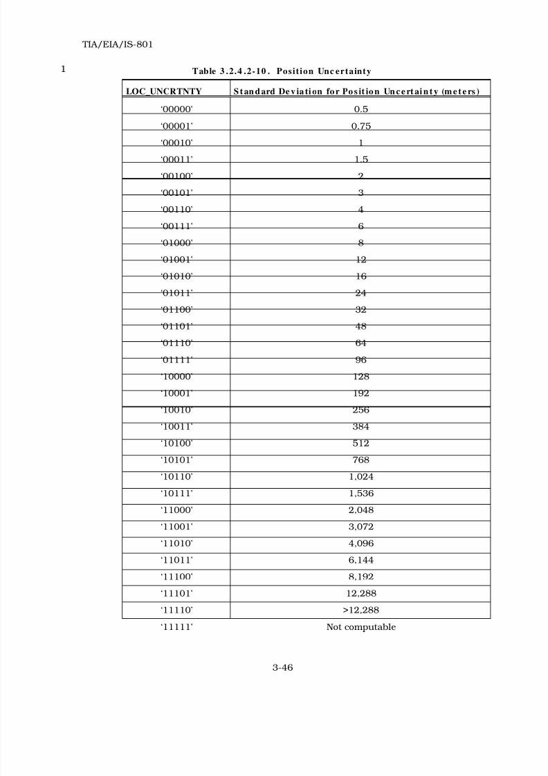
8/20/2019 TIA-EIA-IS 801 - 1999
http://slidepdf.com/reader/full/tia-eia-is-801-1999 64/138
TIA/EIA/IS-801
3-46
Table 3 .2.4 .2-10 . Posit ion Unc ertainty
LOC_UNCRTNTY S t an d ard De v ia ti on fo r Po s it io n Un c e rt ai n t y (m e t e rs )
‘00000’ 0.5
‘00001’ 0.75
‘00010’ 1
‘00011’ 1.5
‘00100’ 2
‘00101’ 3
‘00110’ 4
‘00111’ 6
‘01000’ 8
‘01001’ 12
‘01010’ 16
‘01011’ 24
‘01100’ 32
‘01101’ 48
‘01110’ 64
‘01111’ 96
‘10000’ 128
‘10001’ 192
‘10010’ 256
‘10011’ 384
‘10100’ 512
‘10101’ 768
‘10110’ 1,024
‘10111’ 1,536
‘11000’ 2,048
‘11001’ 3,072
‘11010’ 4,096
‘11011’ 6,144
‘11100’ 8,192
‘11101’ 12,288
‘11110’ >12,288
‘11111’ Not computable

8/20/2019 TIA-EIA-IS 801 - 1999
http://slidepdf.com/reader/full/tia-eia-is-801-1999 65/138
TIA/EIA/IS-801
3-47
LOC_UNCRTNTY_P – Standard deviation of axis perpendicular to angle
specified for position uncertainty.
The mobile station shall set this field to represent the
Standard Deviation of Axis Perpendicular to Angle
Specified for Position Uncertainty as specified in Table
3.2.4.2-10.
FIX_TYPE – Fix type.
The mobile station shall set this field to ‘0’ for 2D fix
and to ‘1’ for 3D fix.
VELOCITY_INCL – Velocity information included.
If velocity information is included in this response
element, the mobile station shall set this field to ‘1’. If
velocity information16 is not included in this response
element, the mobile station shall set this field to ‘0’.
VELOCITY_HOR – Horizontal velocity magnitude.
If VELOCITY_INCL is set to ‘1’, the mobile station shall
set this field to the horizontal velocity, in units of 0.25
m/s, in the range from 0 to 127.75 m/s; otherwise the
mobile station shall not include this field.
Note that this field is not included for cases in which
the measurement technique does not permit
calculation of value.
HEADING – Heading.
If VELOCITY_INCL is set to ‘1’, the mobile station shall
set this field to Heading, in units of 360/210 degrees, in
the range from 0 to 360×(1-2-10
) degrees; otherwise the
mobile station shall not include this field, where 0
degrees is True North and the angle increases toward
the East.
Note that this field is not included for cases in which
the measurement technique does not permit
calculation of value.
16 Velocity information includes the horizontal and vertical components of velocity, as well
as heading.

8/20/2019 TIA-EIA-IS 801 - 1999
http://slidepdf.com/reader/full/tia-eia-is-801-1999 66/138
TIA/EIA/IS-801
3-48
VELOCITY_VER – Vertical velocity.
If VELOCITY_INCL and FIX_TYPE are set to ‘1’, the
mobile station shall set this field to the two’s
complement value of Vertical Velocity, in units of 0.5
m/s, in the range from -64 m/s to +63.5 m/s;
otherwise the mobile station shall not include this
field.
Note that this field is not included for cases in which
the measurement technique does not permit
calculation of value.
CLOCK_INCL – Clock information included.
If clock information is included in this response
element, the mobile station shall set this field to ‘1’. If
clock information is not included in this response
element, the mobile station shall set this field to ‘0’.
CLOCK_BIAS – Clock bias.
If CLOCK_INCL is set to ‘1’, the mobile station shall set
this field to the clock bias in units of 1 ns, in the range
from -13,000 ns to +249,143 ns; otherwise the mobile
station shall not include this field. This parameter is
computed as true GPS time minus mobile station time
reference as defined in TIA/EIA-95.
Note that as part of a GPS fix, the computation yields
an estimate of the discrepancy between the time
specified by the local clock and true GPS time. This
parameter reports the discrepancy. The main cause of
this discrepancy is going to be the propagation delay
from the base station to the MS, which is always
positive. Accordingly, the range allowed for this
parameter is not symmetric.
CLOCK_DRIFT – Clock drift.
If CLOCK_INCL is set to ‘1’, the mobile station shall set
this field to the two’s complement value of the rate of
change of clock bias in units of ppb (ns/s), in the
range from -32768 ppb (ns/s) to +32767 ppb (ns/s);
otherwise the mobile station shall not include this
field.
HEIGHT_INCL – Height information included.
If height information is included in this response
element, the mobile station shall set this field to ‘1’;
otherwise, the mobile station shall set this field to ‘0’.

8/20/2019 TIA-EIA-IS 801 - 1999
http://slidepdf.com/reader/full/tia-eia-is-801-1999 67/138
TIA/EIA/IS-801
3-49
HEIGHT – Height.
If HEIGHT_INCL is set to ‘1’, the mobile station shall
set this field to the height above the WGS-84 reference
ellipsoid, in units of 1 meter, in the range from -500 m
to 15833 m; otherwise it shall not include this field.
LOC_UNCRTNTY_V – Standard deviation of vertical error for position
uncertainty.
If HEIGHT_INCL is set to ‘1’, the mobile station shall
include this field and set this field to represent the
Standard Deviation Vertical Error for Position
Uncertainty as specified in Table 3.2.4.2-10; otherwise
the mobile station shall not include this field.
Note that this field is not included for cases in which
the measurement technique does not permit
calculation of value.
RESERVED – Reserved bits.
The mobile station shall add reserved bits as needed in
order to make the length of the response element
parameters record equal to an integer number of
octets. The mobile station shall set these bits to ‘0’.
If RESP_TYPE is equal to ‘0110’ (Provide Time Offset Measurement), RESP_PAR_RECORD
shall include the following record:
Fie ld Le n gth (bit s )
TIME_REF_MS 24
REF_PN 9
MOB_SYS_T_OFFSET 14
RESERVED 1
TIME_REF_MS – The time of validity of the parameters reported in this
response element.
The mobile station shall set this field to
(t mod 14,400,000), where t is the time of validity in
units of 1 ms, based on mobile station time reference
as defined in 6.1.5.1 of TIA/EIA-95-B. This is the time
at which the values of the parameters reported in this
response element parameter record are valid.

8/20/2019 TIA-EIA-IS 801 - 1999
http://slidepdf.com/reader/full/tia-eia-is-801-1999 68/138
TIA/EIA/IS-801
3-50
REF_PN – Time reference PN sequence offset.
The mobile station shall set this field to the PN
sequence offset of the pilot used by the mobile station
to derive its time reference, relative to the zero offset
pilot PN sequence in units of 64 PN chips.
MOB_SYS_T_OFFSET– Mobile station system time offset.
The mobile station shall set this field to the two’s
complement value of the offset between mobile station
time reference and time of occurrence of Reference PN,
in units of 1/16 TIA/EIA-95 chips, in the range from
-512 to +511.9375 TIA/EIA-95 chips. The sign of this
quantity shall be positive if the reference PN occurs
earlier than the mobile station time reference;
otherwise it shall be negative.
RESERVED – Reserved bits.
The mobile station shall set this field to ‘0’.
If RESP_TYPE is equal to ‘0111’ (Provide Cancellation Acknowledgement),
RESP_PAR_RECORD shall include the following record:
Fie ld Le n gth (bit s )
CANCEL_TYPE_ACK 4
NO_OUT_REQ 1
RESERVED 3
CANCEL_TYPE_ACK – Cancellation type.
The mobile station shall set this field to the value of
CANCEL_TYPE included in the corresponding request
element (“Request Cancellation”).
NO_OUT_REQ – No outstanding request element.
If there is no outstanding request element of the type
indicated by CANCEL_TYPE_ACK, the mobile station
shall set this field to ‘1’; otherwise the mobile station
shall set this field to ‘0’.
RESERVED – Reserved bits.
The mobile station shall set this field to ‘000’.

8/20/2019 TIA-EIA-IS 801 - 1999
http://slidepdf.com/reader/full/tia-eia-is-801-1999 69/138
TIA/EIA/IS-801
4-1
4 BASE STATION PROCEDURES
4 .1 Analog Base S tation Proce dures
The analog base station procedures are defined in [7].
4 .2 CDMA Base S tatio n Proce dures
4.2.1
Position Determination Data Message Processing
4.2.1.1
Overview
The Posit ion Determina t ion Data Message sent by the base station is comprised of request
elements and response elements, as specified below.
Request elements sent by base station:
• Request MS Information
•
Request Autonomous Measurement Weighting Factors
•
Request Pseudorange Measurement
•
Request Pilot Phase Measurement
• Request Location Response
• Request Time Offset Measurement
•
Request Cancellation
Response elements sent by base station:
• Reject
• Provide BS Capabilities
• Provide GPS Acquisition Assistance
• Provide GPS Location Assistance – Spherical Coordinates
• Provide GPS Location Assistance – Cartesian Coordinates
• Provide GPS Sensitivity Assistance
• Provide Base Station Almanac
• Provide GPS Almanac
•
Provide GPS Ephemeris
• Provide GPS Navigation Message Bits
• Provide Location Response
•
Provide GPS Almanac Correction
The Posit ion Determina t ion Data Message received by the base station is also comprised of
request elements and response elements, as specified below.

8/20/2019 TIA-EIA-IS 801 - 1999
http://slidepdf.com/reader/full/tia-eia-is-801-1999 70/138
TIA/EIA/IS-801
4-2
Request elements received by base station:
• Request BS Capabilities
• Request GPS Acquisition Assistance
• Request GPS Location Assistance
•
Request GPS Sensitivity Assistance
• Request Base Station Almanac
• Request GPS Almanac
• Request GPS Ephemeris
•
Request GPS Navigation Message Bits
• Request Location Response
• Request GPS Almanac Correction
Response elements received by base station:
• Reject
• Provide MS Information
• Provide Autonomous Measurement Weighting Factors
•
Provide Pseudorange Measurement
• Provide Pilot Phase Measurement
• Provide Location Response
•
Provide Time Offset Measurement
•
Provide Cancellation Acknowledgement
Response elements sent by the base station may be generated in response to request
elements received by the base station or they may be generated as unsolicited response
elements. Every request element includes a REQ_TYPE (request element type) field that
uniquely identifies the request element (See Table 4.2.4-2). Every response element
includes a RESP_TYPE (response element type) field that uniquely identifies the response
element (See Table 4.2.4-3). Multiple response elements may be associated with a single
request element. Unsolicited response elements are sent with the UNSOL_RESP flag set to
‘1’ (see 4.2.4).
4.2.1.2 Requirements
Each Posit ion Determina t ion Data M essage shall contain at least one request element, or at
least one part of a response element, or both. No more than one request element of a
specific REQ_TYPE shall be included in a Posit ion Determina t ion Data Message . Each
request element shall be fully contained in a Posit ion Determina t ion Data Message . Some
response elements may be divided in parts (see 4.2.4.2). Each response element part shall
be fully contained in a Posit ion Determina t ion Data Message .

8/20/2019 TIA-EIA-IS 801 - 1999
http://slidepdf.com/reader/full/tia-eia-is-801-1999 71/138
TIA/EIA/IS-801
4-3
If the base station sends a response element in response to a received request element, it
shall comply with Table 4.2.1.2-1. A “Reject” shall not be sent as a response element to a
“Request BS Capabilities” request element.
If one or more response elements from the base station can be useful to the mobile station
in responding to a request from the base station, the base station should include all or part
of each response element and the request element in the same Posit ion Determinat ion Data
Message .
Upon receiving a Posit ion Determin at ion Da ta Message , the base station should examine the
received response elements prior to processing the request elements.
Table 4 .2 .1 .2 -1 . Response Elem ents Sen t in Response to Received Request Elemen ts
Reques t e lem e n t re ce ive d Pos s ible res pon s e e lem en ts
Request BS Capabilities Provide BS Capabilities
Reject Request GPS Acquisition Assistance
Provide GPS Acquisition Assistance
Reject
Provide GPS Location Assistance –
Spherical Coordinates And
Provide GPS Acquisition AssistanceRequest GPS Location Assistance
Provide GPS Location Assistance –
Cartesian Coordinates And
Provide GPS Acquisition Assistance
Reject Request GPS Sensitivity Assistance
Provide GPS Sensitivity Assistance
Reject Request Base Station Almanac
Provide Base Station Almanac
Reject Request GPS Almanac
Provide GPS Almanac
Reject Request GPS Ephemeris
Provide GPS Ephemeris
Reject Request GPS Navigation Message BitsProvide GPS Navigation Message Bits
Reject Request Location Response
Provide Location Response
Reject Request GPS Almanac Correction
Provide GPS Almanac Correction

8/20/2019 TIA-EIA-IS 801 - 1999
http://slidepdf.com/reader/full/tia-eia-is-801-1999 72/138
TIA/EIA/IS-801
4-4
No more than one request element shall be outstanding at any given time for each
REQ_TYPE. If an additional request element is received while there is an outstanding
request element of the same type, the additional request element shall be discarded. A
received (or sent) request element is considered outstanding until all of the corresponding
response elements or a “Reject” for the request element have been sent (or received).
Unsolicited response elements shall have the UNSOL_RESP flag set to ‘1’.
If a “Reject” constitutes the sent response element, its REJ_REQ_TYPE shall be set to the
REQ_TYPE of the corresponding request element.
4.2.2 Point-to-point Procedures
This section defines the procedures for the processing of mobile-terminated Position
Determina t ion Data Messages that are addressed to individual mobile stations and for the
processing of all mobile-originated Posit ion Determ inat ion Data Messages .
4.2.2.1
Control Channel Procedure
4.2.2.1.1 Mobile Position Message Origination
A base station supporting Position Determination shall accept and shall process Data Burst
Messages received on the CDMA Access Channel (see 6.7.1.3.2.3 of TIA/EIA-95-B). The
processing of TIA/EIA-95-B Layer-2 fields shall be in accordance with TIA/EIA-95-B. Data
Burst Messages used to transport Position Determination request and response elements
shall always be acknowledged (Layer 2) and the in-order delivery over the air interface shall
be guaranteed by the transmitting entities: Mobile station and base station.
The base station shall process all Data Burst Messages received on the Access Channel and
having the BURST_TYPE field set to ‘000101’.
The base station shall discard the message without further processing if one or more of the
following is true:
• MSG_NUMBER field is set to a value other than 1.
• NUM_MSGS field is set to a value other than 1.
•
NUM_FIELDS field is set to zero.
Otherwise, the base station shall process the Position Determination Data contained in the
CHARi fields of the received Data Burst Message (see 6.7.1.3.2.3 of TIA/EIA-95-B), as
described below.
4.2.2.1.1.1 Mobile Station Request Elements Received
If the base station does not support the requested capability, the base station shall respond
with a “Reject” response element with the appropriate reject reason, unless the mobile
station request element is “Request BS Capabilities”; otherwise, the base station shall
include the appropriate response elements in the response Position Determination Data

8/20/2019 TIA-EIA-IS 801 - 1999
http://slidepdf.com/reader/full/tia-eia-is-801-1999 73/138
TIA/EIA/IS-801
4-5
(see 4.2.4) as described below. The response Position Determination Data shall reside in
the CHARi fields of the response Data B urst Message (see 7.7.2.3.2.9 of TIA/EIA-95-B).17
• Request BS Capabil i ty: The base station shall respond with the “Provide BS
Capabilities” response element.
•
Request GPS Acquisit ion Assistance: The base station shall respond with the
“Provide GPS Acquisition Assistance” response element.
If DOPP_REQ is set to ‘1’, the “Provide GPS Acquisition Assistance” response
element shall include the Doppler 0th order term and ADD_DOPP_INCL flag;
otherwise, the “Provide GPS Acquisition Assistance” response element should
not include the Doppler 0th order term and ADD_DOPP_INCL flag.
If ADD_DOPP_REQ is set to ‘1’, the “Provide GPS Acquisition Assistance”
response element shall include the high-order Doppler and the Doppler
search window terms; otherwise, the “Provide GPS Acquisition Assistance”
response element should not include the high-order Doppler and the Doppler
search window terms.
If CODE_PH_PAR_REQ is set to ‘1’, the “Provide GPS Acquisition Assistance”
response element shall include the code phase parameters; otherwise, the
“Provide GPS Acquisition Assistance” response element should not include
the code phase parameters.
If AZ_EL_REQ is set to ‘1’, the “Provide GPS Acquisition Assistance” response
element shall include the azimuth and elevation angles; otherwise, the
“Provide GPS Acquisition Assistance” response element should not include
the azimuth and elevation angles.
• Request GPS Location As sist an ce: The base station shall respond with the “Provide
GPS Location Assistance – Spherical Coordinates” or with the “Provide GPS Location
Assistance – Cartesian Coordinates” response element. If COORD_TYPE is set to ‘1’,
the base station shall provide the “Provide GPS Location Assistance – Spherical
Coordinates” response element; otherwise, the base station shall provide the
“Provide GPS Location Assistance – Cartesian Coordinates” response element. The
base station shall also send the “Provide GPS Acquisition Assistance” response
element in the same Posit ion Determin at ion Data Message that contains the “Provide
GPS Location Assistance – Spherical Coordinates” response element or the “Provide
GPS Location Assistance – Cartesian Coordinates” response element. The value of
NUM_SV_P in each part of the “Provide GPS Location Assistance – Spherical
Coordinates” response element or the “Provide GPS Location Assistance – Cartesian
Coordinates” response element shall be the same as the value of NUM_SV_P in the
part of the “Provide GPS Acquisition Assistance” response element that appears in
the same Posit ion Determinat ion Data Message . The “Provide GPS Location
Assistance – Spherical Coordinates” response element or the “Provide GPS Location
Assistance – Cartesian Coordinates” response element shall have the satellite
17 The parameters discussed in this subsection are defined in 3.2.4.1.

8/20/2019 TIA-EIA-IS 801 - 1999
http://slidepdf.com/reader/full/tia-eia-is-801-1999 74/138
TIA/EIA/IS-801
4-6
related fields repeated in the same SV_PRN_NUM order as contained in the “Provide
GPS Acquisition Assistance” response element.
• Request GPS Sensitivit y Ass ista nce: The base station shall respond with a “Provide
GPS Sensitivity Assistance” response element in one or more response Position
Determinat ion Data Messages , according to the number of parts into which the
response element is divided.
• Request Base Stat ion Almana c : The base station shall respond with a “Provide Base
Station Almanac” response element in one or more response Posit ion Determin at ion
Data Messages , according to the number of parts into which the response element
is divided. If EXT_BS_ALM is set to ‘1’, the “Provide Base Station Almanac”
response element shall include the extended base station almanac; otherwise, the
“Provide Base Station Almanac” response element shall include the basic base
station almanac.
• Request GPS Alm anac: The base station shall respond with a “Provide GPS Almanac”
response element in one or more response Posit ion Determin at ion Da ta Messages ,
according to the number of parts into which the response element is divided.
• Request GPS Ephemeris: The base station shall respond with a “Provide GPS
Ephemeris” response element in one or more response Posit ion Determ inat ion Data
Messages , according to the number of parts into which the response element is
divided. If AB_PAR_REQ is set to ‘1’, the “Provide GPS Ephemeris” response element
shall include the Alpha and Beta parameters; otherwise, the “Provide GPS
Ephemeris” response element should not include the Alpha and Beta parameters.
• Request GPS Navigation Message Bits: The base station shall respond with a
“Provide GPS Navigation Message Bits” response element in one or more response
Posit ion Determin at ion Da ta Messages , according to the number of parts into which
the response element is divided. If SUBF_4_5_REQ is set to ‘1’, the “Provide GPS
Navigation Message Bits” response element shall include the subframes 4 and 5;
otherwise, the “Provide GPS Navigation Message Bits” response element shall not
include the subframes 4 and 5.
• Request Location Response : The base station shall respond with the “Provide
Location Response“ response element.
If HEIGHT_REQ is set to ‘1’, the Location response element should include
height information; otherwise, the “Provide Location Response” response
element should not include height information.
If CLK_COR_GPS_REQ is set to ‘1’, the “Provide Location Response” response
element should include clock correction for mobile station time; otherwise,
the “Provide Location Response” response element should not include clock
correction for mobile station time.
If VELOCITY_REQ is set to ‘1’, the “Provide Location Response” response
element should include velocity information; otherwise, the “Provide Location
Response” response element should not include velocity information.

8/20/2019 TIA-EIA-IS 801 - 1999
http://slidepdf.com/reader/full/tia-eia-is-801-1999 75/138
TIA/EIA/IS-801
4-7
• Request GPS Alm an ac Correction: The base station shall respond with a “Provide
GPS Almanac Correction” response element in one or more response Position
Determinat ion Data Messages , according to the number of parts into which the
response element is divided.
4.2.2.1.1.2
Mobile Station Response Elements Received
The base station should process and should make use of the mobile station response
elements. Upon receiving a Posit ion Determina t ion Data Message , the base station should
examine the received response elements prior to processing the request elements.
4.2.2.1.2 Mobile Position Message Termination
4.2.2.1.2.1 Position Determination Data Message Transmission Requirements
The requirements of this section apply when Posit ion Determinat ion Data Messages
addressed to individual mobile stations are to be sent by the base station andthe
destination mobile station is not on a Traffic Channel.
When the base station has to send one (or more) Posit ion Determina t ion Data Message(s) ,
and the addressed mobile station is not on a Traffic Channel, the base station shall
determine whether the Posit ion Determin at ion Data Message(s) is (are) suitable to be sent on
the Paging Channel.18 If the Posit ion Determina t ion Da ta Message(s) is (are) suitable, the
base station may form one (or more) Paging Channel Data B urst Messa ge(s) (see 7.7.2.3.2.9
of TIA/EIA-95-B), setting BURST_TYPE to ‘000101’. The base station shall set the
MSG_NUMBER and NUM_MSGS fields to 1, and shall set the NUM_FIELDS field to the
number of characters in the Posit ion Determin at ion Da ta Message(s) (as appropriate).
When a Posit ion Determina t ion Data Message is to be sent on the Paging Channel, the base
station shall send the message following the procedures specified in 7.6.2 of TIA/EIA-95-B.
The base station may send the Posit ion Determina t ion Data Message throughout the area
where the mobile is registered. Alternatively, the base station may page the mobile station
to determine which Paging Channel to use to communicate with the mobile; the base
station may use Service Option 35 or 36 in the Page Record; then, the base station may
send the Posit ion Determina t ion Data Message on the Paging Channel corresponding to the
Access Channel on which the mobile station responded. The base station may then send a
Release Ord er to the mobile station.
If the Posit ion Determin at ion Da ta Message(s) is (are) unsuitable for transmission on the
Paging Channel19, the base station shall send the Posit ion Determinat ion Data Message(s) on
the CDMA Traffic Channel, following the procedures defined in 4.2.2.3.
18 The criteria for suitability are implementation dependent.
19For example, the choice to use the Paging Channel or a Forward Traffic Channel, when
multiple Posit ion Determinat ion Data Messages are waiting to be transmitted, is
implementation dependent.

8/20/2019 TIA-EIA-IS 801 - 1999
http://slidepdf.com/reader/full/tia-eia-is-801-1999 76/138
TIA/EIA/IS-801
4-8
The base station shall set the ACK_REQ Layer-2 field to ‘1’. The base station shall
guarantee the in-order delivery of Posit ion Determina t ion Data Messages .
4.2.2.1.2.2 Unsolicited Response Elements
If “Provide GPS Acquisition Assistance” is sent as an unsolicited response element, the base
station shall set CODE_PH_PAR_INCL to ‘1’ and it shall include REFERENCE_PN,
SV_CODE_PH, SV_CODE_PH_INT, GPS_BIT_NUM and SV_CODE_PH_WIN.
If “Provide GPS Location Assistance – Spherical Coordinates” or the “Provide GPS Location
Assistance – Cartesian Coordinates” is sent as an unsolicited response element, the base
station shall also send “Provide GPS Acquisition Assistance” response element in the same
Posit ion Determina t ion Data Message . The value of NUM_SV_P in each part of the “Provide
GPS Location Assistance – Spherical Coordinates” response element or the “Provide GPS
Location Assistance – Cartesian Coordinates” response element shall be the same as the
value of NUM_SV_P in the part of the “Provide GPS Acquisition Assistance” response
element that appears in the same Posit ion Determina t ion Data Message . The “Provide GPS
Location Assistance – Spherical Coordinates” response element or the “Provide GPS
Location Assistance – Cartesian Coordinates” response element shall have the satellite
related fields repeated in the same SV_PRN_NUM order as contained in the “Provide GPS
Acquisition Assistance” response element.
4.2.2.1.2.3 Request Elements
A “Request Autonomous Measurement Weighting Factors” shall not be issued unless a
“Request Location Response” is issued in the same Posit ion Determina t ion Data Message .
4.2.2.2 Authentication Procedures
If the mobile station includes authentication information when sending an activation
origination, the base station should process the authentication data as required in 7.3.1 of
TIA/EIA-95-B. During the position determination session, the base station should invoke
signaling message encryption whenever available, as appropriate.
4.2.2.3
Traffic Channel Procedure
4.2.2.3.1
Message Encryption
To enhance the security of the position determination session and to protect sensitive
subscriber location information, the base station should enable message encryption as
appropriate (see 7.3.2 of TIA/EIA-95-B). Encryption of the Forward and Reverse CDMA
Traffic Channel messages is defined in Annex A of TIA/EIA-95-B.
4.2.2.3.2
Negotiation for the Position Determination Service Option
Negotiation for the Position Determination Service Option is only required when no other
service option is connected.
The Position Determination Service Option described by this standard shall use service
option number 35 and is called Service Option 35 when using Multiplex Option 1. The

8/20/2019 TIA-EIA-IS 801 - 1999
http://slidepdf.com/reader/full/tia-eia-is-801-1999 77/138
TIA/EIA/IS-801
4-9
Position Determination Service Option shall use service option number 36 and is called
Service Option 36 when using Multiplex Option 2.
The base station shall negotiate for Service Option 35 using service negotiation (see
4.2.2.3.2.1).
The base station shall negotiate for Service Option 36 using service negotiation (see
4.2.2.3.2.1).
4.2.2.3.2.1 Procedures Using Service Negotiation
The base station shall perform service negotiation for Service Option 35 or Service Option
36 as described in TIA/EIA-95-B. The negotiated service configuration shall include only
valid attributes for the negotiated service option consistent with those specified in Tables
3.2.3.1.2-1 and 3.2.3.1.2-2.
If the base station establishes a service configuration, as specified in a Service Connect
Message , that includes a service option connection using Service Option 35 or Service
Option 36, then the service option connection shall become part of the current service
configuration at the action time associated with the Service Connect Message . Service
Option 35 or Service Option 36 is considered to be connected when the current service
configuration includes a service option connection for it.
The base station shall not send a Service Option Contr ol Message for Service Option 35 or
Service Option 36.
4.2.2.3.3 Mobile Position Message Origination
For mobile-originated calls with no dialed digits in the Originat ion Message , the base station
should complete an authentication Unique Challenge-Response Procedure (see 6.3.12.1.5
of TIA/EIA-95-B) immediately after assigning the traffic channel. The Unique Challenge-
Response Procedure should be completed successfully before Posit ion Determin at ion Data
Messages are sent to the mobile station and before any mobile-originated Position
Determina t ion Data Messages are forwarded to other network entities.
A base station supporting Position Determination shall accept and shall process Data Burst
Messages received on the CDMA Reverse Traffic Channel (see 6.7.2.3.2.4 of TIA/EIA-95-B).
Processing of TIA/EIA-95-B Layer-2 fields shall be in accordance with TIA/EIA-95-B. Data
Burst Messages used to transport Position Determination request and response elements
shall always be acknowledged (Layer 2) and the in-order delivery over the air interface shall
be guaranteed by the transmitting entities: Mobile station and base station.
The base station shall process all Data Burst Messages received on the Reverse Traffic
Channel and having the BURST_TYPE field set to ‘000101’ (as assigned in TSB58-B). The
base station shall discard the message without further processing, if one or more of the
following is true:
• MSG_NUMBER field is set to a value other than 1.
• NUM_MSGS field is set to a value other than 1.
• NUM_FIELDS field is set to zero.

8/20/2019 TIA-EIA-IS 801 - 1999
http://slidepdf.com/reader/full/tia-eia-is-801-1999 78/138
TIA/EIA/IS-801
4-10
Otherwise, the base station shall process the Position Determination Data contained in the
CHARi fields of the received Data Bur st Message (see 6.7.2.3.2.4 of TIA/EIA-95-B), as
described in the next section.
If the only connected service option is Service Option 35 or Service Option 36, the base
station should release the traffic channel when no Posit ion Determin at ion Da ta Messa ges
have been received or have been sent during a period of time which is implementation-
dependent.
4.2.2.3.3.1 Mobile Station Request Elements Received
If the base station does not support the requested capability, the base station shall respond
with a “Reject” response element with the appropriate reject reason, unless the mobile
station request element is “Request BS Capabilities”; otherwise, the base station shall
include the appropriate response elements in the response Position Determination Data
(see 4.2.4) as described below. The response Position Determination Data shall reside in
the CHARi fields of the response Data Burst Message (see 7.7.3.3.2.4 of TIA/EIA-95-B).20
•
Request BS Capabil i ty: The base station shall respond with the “Provide BS
Capabilities” response element.
• Request GPS Acquisit ion Assistance: The base station shall respond with the
“Provide GPS Acquisition Assistance” response element.
If DOPP_REQ is set to ‘1’, the “Provide GPS Acquisition Assistance” response
element shall include the Doppler 0th order term and ADD_DOPP_INCL flag;
otherwise, the “Provide GPS Acquisition Assistance” response element should
not include the Doppler 0th order term and ADD_DOPP_INCL flag.
If ADD_DOPP_REQ is set to ‘1’, the “Provide GPS Acquisition Assistance”
response element shall include the high-order Doppler and Doppler search
window terms; otherwise, the “Provide GPS Acquisition Assistance” response
element should not include the high-order Doppler and Doppler search
window terms.
If CODE_PH_PAR_REQ is set to ‘1’, the “Provide GPS Acquisition Assistance”
response element shall include the code phase parameters; otherwise, the
“Provide GPS Acquisition Assistance” response element should not include
the code phase parameters.
If AZ_EL_REQ is set to ‘1’, the “Provide GPS Acquisition Assistance” response
element shall include the azimuth and elevation angles; otherwise, the
“Provide GPS Acquisition Assistance” response element should not include
the azimuth and elevation angles.
• Request GPS Location As sist an ce: The base station shall respond with the “Provide
GPS Location Assistance – Spherical Coordinates” or with the “Provide GPS Location
Assistance – Cartesian Coordinates” response elements. If COORD_TYPE is set to
20 The parameters discussed in this subsection are defined in 3.2.4.1.
8/20/2019 TIA-EIA-IS 801 - 1999
http://slidepdf.com/reader/full/tia-eia-is-801-1999 79/138
TIA/EIA/IS-801
4-11
‘1’, the base station shall provide the “Provide GPS Location Assistance – Spherical
Coordinates” response element; otherwise, the base station shall provide the
“Provide GPS Location Assistance – Cartesian Coordinates” response element. The
base station shall also send the “Provide GPS Acquisition Assistance” response
element in the same Posit ion Determin at ion Data Message that contains the “Provide
GPS Location Assistance – Spherical Coordinates” response element or the “Provide
GPS Location Assistance – Cartesian Coordinates” response element. The value of
NUM_SV_P in each part of the “Provide GPS Location Assistance – Spherical
Coordinates” response element or the “Provide GPS Location Assistance – Cartesian
Coordinates” response element shall be the same as the value of NUM_SV_P in the
part of the “Provide GPS Acquisition Assistance” response element that appears in
the same Posit ion Determinat ion Data Message . The “Provide GPS Location
Assistance – Spherical Coordinates” response element or the “Provide GPS Location
Assistance – Cartesian Coordinates” response element shall have the satellite
related fields repeated in the same SV_PRN_NUM order as contained in the “Provide
GPS Acquisition Assistance” response element.
•
Request GPS Sensitivit y Ass ista nce: The base station shall respond with a “Provide
GPS Sensitivity Assistance” response element in one or more response Position
Determinat ion Data Messages , according to the number of parts into which the
response element is divided.
• Request Base Stat ion Almana c : The base station shall respond with a “Provide Base
Station Almanac” response element in one or more response Posit ion Determin at ion
Data Messages , according to the number of parts into which the response element
is divided. If EXT_BS_ALM is set to ‘1’, the “Provide Base Station Almanac”
response element shall include the extended base station almanac; otherwise, the
“Provide Base Station Almanac” response element shall include the basic base
station almanac
• Request GPS Alm anac: The base station shall respond with a “Provide GPS Almanac”
response element in one or more response Posit ion Determin at ion Da ta Messages ,
according to the number of parts into which the response element is divided.
• Request GPS Ephemeris: The base station shall respond with a “Provide GPS
Ephemeris” response element in one or more response Posit ion Determina t ion Data
Messages , according to the number of parts into which the response element is
divided. If AB_PAR_REQ is set to ‘1’, the “Provide GPS Ephemeris” response element
shall include the Alpha and Beta parameters; otherwise, the “Provide GPS
Ephemeris” response element should not include the Alpha and Beta parameters.
•
Request GPS Navigation Message Bits: The base station shall respond with a
“Provide GPS Navigation Message Bits” response element in one or more response
Posit ion Determin at ion Da ta Messages , according to the number of parts into which
the response element is divided. If SUBF_4_5_REQ is set to ‘1’, the “Provide GPS
Navigation Message Bits” response element shall include the subframes 4 and 5;
otherwise, the “Provide GPS Navigation Message Bits” response element shall not
include the subframes 4 and 5.

8/20/2019 TIA-EIA-IS 801 - 1999
http://slidepdf.com/reader/full/tia-eia-is-801-1999 80/138
TIA/EIA/IS-801
4-12
• Request Location Response : The base station shall respond with the “Provide
Location Response” response element.
If HEIGHT_REQ is set to ‘1’, the “Provide Location Response” response
element should include height information; otherwise, the “Provide Location
Response” response element should not include height information
If CLK_COR_GPS_REQ is set to ‘1’, the “Provide Location Response” response
element should include clock correction for mobile station time; otherwise,
the “Provide Location Response” response element should not include clock
correction for mobile station time.
If VELOCITY_REQ is set to ‘1’, the “Provide Location Response” response
element should include velocity information; otherwise, the “Provide Location
Response” response element should not include velocity information.
• Request GPS Alm anac Correction: The base station shall respond with a “Provide
GPS Almanac Correction” response element in one or more response Position
Determinat ion Data Messages , according to the number of parts into which the
response element is divided.
4.2.2.3.3.2 Mobile Station Response Elements Received
The base station should process and should make use of the mobile station response
elements. Upon receiving a Posit ion Determina t ion Data Message , the base station should
examine the received response elements prior to processing the request elements.
4.2.2.3.4 Traffic Channel Setup
When a base station is to send Position Determination data on a Traffic Channel, and the
addressed mobile station is not on a Traffic Channel, the following procedures apply.
The mobile station address shall be used for messages sent over the paging channel. The
base station shall page the mobile station and establish a Traffic Channel using the
procedures defined in 7.6 of TIA/EIA-95-B. The base station shall request Service Option
35 or Service Option 36.
When the base station enters the Conversat ion Substate, the base station may send the
Posit ion Determinat ion Data Messages in accordance with the procedures defined in
4.2.2.3.5.
4.2.2.3.5 Mobile Station Message Termination in the Conversation Substate
4.2.2.3.5.1
Position Determination Data Message Transmission Requirements
The requirements of this section shall be followed when the addressed mobile station is in
the TIA/EIA-95-B Conversat ion Substa te of the Mobile Stat ion Control on the Traff ic Cha nnel
State .
The base station shall form one (or more) Data B urst Message(s) (see 7.7.3.3.2.4 of TIA/EIA-
95-B), setting BURST_TYPE to ‘000101’ and send the message(s) on the Forward Traffic
Channel. The base station shall set the MSG_NUMBER and NUM_MSGS fields to 1 and

8/20/2019 TIA-EIA-IS 801 - 1999
http://slidepdf.com/reader/full/tia-eia-is-801-1999 81/138
TIA/EIA/IS-801
4-13
shall set the NUM_FIELDS field to the number of octets in the Posit ion Determinat ion Data
message (see 4.2.4). The base station shall set the ACK_REQ Layer-2 field to ‘1’.
If the only connected service option is Service Option 35 or Service Option 36, the base
station should release the traffic channel when Posit ion Determin at ion Da ta Messages have
not been received or have not been sent during a period of time which is implementation-
dependent. If any service option in addition to Service Option 35 or Service Option 36 is
connected, the base station should initiate Service Negotiation to drop Service Option 35 or
Service Option 36 when Posit ion Determina t ion Da ta Messages have not been received or
have not been sent during a period of time which is implementation-dependent. After
sending a Posit ion Determina t ion Data Message , the base station should delay the traffic
channel release for a period of time sufficient to allow the mobile station to return any
requested acknowledgments.
4.2.2.3.5.2
Unsolicited Response Elements
If “Provide GPS Acquisition Assistance” is sent as an unsolicited response element, the base
station shall set CODE_PH_PAR_INCL to ‘1’ and it shall include REFERENCE_PN,
SV_CODE_PH, SV_CODE_PH_INT, GPS_BIT_NUM and SV_CODE_PH_WIN.
If “Provide GPS Location Assistance – Spherical Coordinates” or the “Provide GPS Location
Assistance – Cartesian Coordinates” is sent as an unsolicited response element, the base
station shall also send “Provide GPS Acquisition Assistance” response element in the same
Posit ion Determina t ion Data Message . The value of NUM_SV_P in each part of the “Provide
GPS Location Assistance – Spherical Coordinates” response element or the “Provide GPS
Location Assistance – Cartesian Coordinates” response element shall be the same as the
value of NUM_SV_P in the part of the “Provide GPS Acquisition Assistance” response
element that appears in the same Posit ion Determina t ion Data Message . The “Provide GPS
Location Assistance – Spherical Coordinates” response element or the “Provide GPS
Location Assistance – Cartesian Coordinates” response element shall have the satellite
related fields repeated in the same SV_PRN_NUM order as contained in the “Provide GPS
Acquisition Assistance” response element.
4.2.2.3.5.3 Request Elements
A “Request Autonomous Measurement Weighting Factors” shall not be issued unless a
“Request Location Response” is issued in the same Posit ion Determina t ion Data Message .
4.2.3
Broadcast Procedures
Reserved
4.2.4 Forward Link Message Format
The forward link Posit ion Determina t ion Data Messages are summarized in Table 4.2.4-1.

8/20/2019 TIA-EIA-IS 801 - 1999
http://slidepdf.com/reader/full/tia-eia-is-801-1999 82/138
TIA/EIA/IS-801
4-14
Table 4 .2 .4 -1. Forward Link Mes sage s
Mes s age Nam e PD_MSG_TYPE
Posit ion Determinat ion Data
Message
‘00000000’
Reserved for future standardization ‘00000001’ through
‘10111111’
Available for manufacturer-specific
Posit ion Determinat ion Data
Message definition as specified in
TSB-58
‘11000000’ through
‘11111110’
Reserved ‘11111111’
The Posit ion Determina t ion Data Message from base station to mobile station has the
following variable length message format:
Fie ld Le n gth (bit s )
SESS_START 1
SESS_END 1
SESS_SOURCE 1
SESS_TAG 5
PD_MSG_TYPE (‘00000000’) 8
NUM_REQUESTS 4
NUM_RESPONSES 4
The base station shall include NUM_REQUESTS occurrences
of the following record:
RESERVED 4
REQ_TYPE 4
REQ_PAR_LEN 8
REQ_PAR_RECORD 8×REQ_PAR_LEN
The base station shall include NUM_RESPONSES
occurrences of the following record:
RESERVED 3

8/20/2019 TIA-EIA-IS 801 - 1999
http://slidepdf.com/reader/full/tia-eia-is-801-1999 83/138
TIA/EIA/IS-801
4-15
UNSOL_RESP 1
RESP_TYPE 4
RESP_PAR_LEN 8
RESP_PAR_RECORD 8 × RESP_PAR_LEN
SESS_START – Start-of-session indicator.
If the base station has previously sent or received a
Posit ion Determinat ion Data Message related to this
Posit ion Determinat ion Data Message (as defined in
2.2.1) it shall set this field to ‘0’; otherwise, it shall set
this field to ‘1’.
SESS_END – End-of-session indicator.
If the base station does not expect to receive or send
any more Posit ion Determina t ion Data Messages related
to this Posit ion Determina t ion Data Message (as defined
in 2.2.1) the base station shall set this field to ‘1’;
otherwise, it shall set this field to ‘0’. The criteria for
setting this field are implementation dependent.
SESS_SOURCE – Session-source indicator.21
If SESS_START is set to ‘1’ the base station shall set
this field to ‘0’; otherwise it shall set this field to the
same value as the SESS_SOURCE field that appeared
in a previously-received or previously-sent Position
Determina t ion Data Message that was related to this
Posit ion Determinat ion Data Message (as defined in
2.2.1).
21 This field indicates which side (mobile station or base station) initiated this session.

8/20/2019 TIA-EIA-IS 801 - 1999
http://slidepdf.com/reader/full/tia-eia-is-801-1999 84/138
TIA/EIA/IS-801
4-16
SESS_TAG – Session tag.
If SESS_START is set to ‘0’ the base station shall set
this field to the same value as the SESS_TAG field that
appeared in a previously-received or previously-sent
Posit ion Determin at ion Da ta Messa ge that was related
to this Posit ion Determina t ion Data Message (as defined
in 2.2.1); otherwise, the base station shall set this field
to one more (modulo 32) than the value it assigned to
this field in the latest Posit ion Determinat ion Data
Message that it sent with SESS_START set to ‘1’. If no
such latest Posit ion Determinat ion Data Message
exists, the base station shall set this field to ‘00000’.
The definition of “latest” is implementation dependent.
PD_MSG_TYPE – Posit ion Determin at ion Da ta Message type.
The base station shall set this field to ‘00000000’.
NUM_REQUESTS – Number of request element parameter records.
The base station shall set this field to the number of
request element parameters record included in the
message.
NUM_RESPONSES – Number of response element parameter records.
The base station shall set this field to the number of
response element parameters record included in the
message.
RESERVED – Reserved bits.
The base station shall set this field to ‘0000’.
REQ_TYPE – Request element type.
The base station shall set this field to the value shown
in Table 4.2.4-2.

8/20/2019 TIA-EIA-IS 801 - 1999
http://slidepdf.com/reader/full/tia-eia-is-801-1999 85/138
TIA/EIA/IS-801
4-17
Table 4.2 .4-2. Request Eleme nt Type
DescriptionREQ_TYPE
(binary)
Reserved ‘0000’
Request MS Information ‘0010’
Request Autonomous Measurement Weighting Factors ‘0011’
Request Pseudorange Measurement ‘0100’
Request Pilot Phase Measurement ‘0101’
Request Location Response ‘0001’
Request Time Offset Measurement ‘0110’
Request Cancellation ‘0111’
All other REQ_TYPE values are reserved.
REQ_PAR_LEN – Request element parameters length.
The base station shall set this field to the number of
octets included in the REQ_PAR_RECORD field.
REQ_PAR_RECORD – Request element parameters record.
The base station shall set this record as described in
4.2.4.1.
RESERVED – Reserved bits.
The base station shall set these bits to ‘000’.
UNSOL_RESP – Unsolicited response indicator.
The base station shall set this field to ‘1’ if the
response element is an unsolicited response element;
otherwise the base station shall set this field to ‘0’.
RESP_TYPE – Response element type.
The base station shall set this field to the value shown
in Table 4.2.4-3.

8/20/2019 TIA-EIA-IS 801 - 1999
http://slidepdf.com/reader/full/tia-eia-is-801-1999 86/138
TIA/EIA/IS-801
4-18
Table 4.2 .4-3. Respons e Elem ent Type
DescriptionRESP_TYPE
(binary)
Reject ‘0000’
Provide BS Capabilities ‘0010’
Provide GPS Acquisition Assistance ‘0100’
Provide GPS Location Assistance – Spherical Coordinates ‘0110’
Provide GPS Location Assistance – Cartesian Coordinates ‘0111’
Provide GPS Sensitivity Assistance ‘0101’
Provide Base Station Almanac ‘0011’
Provide GPS Almanac ‘1000’
Provide GPS Ephemeris ‘1001’
Provide GPS Navigation Message Bits ‘1010’
Provide Location Response ‘0001’
Provide GPS Almanac Correction ‘1011’
All other RESP_TYPE values are reserved.
RESP_PAR_LEN – Response element parameters length.
The base station shall set RESP_PAR_LEN to the
number of octets included in the RESP_PAR_RECORD
field.
RESP_PAR_RECORD – Response element parameters record.
The base station shall set this record as described in
4.2.4.2.
4.2.4.1 Request Element Parameters Record
If REQ_TYPE in Position Determin at ion Data Message is equal to ‘0010’, or if REQ_TYPE is
equal to ‘0011’, the base station shall not include this record. If REQ_TYPE is equal to
‘0001’, or if REQ_TYPE is equal to ‘0100’, or if REQ_TYPE is equal to ‘0101’, or if REQ_TYPE
is equal to ‘0110’, or if REQ_TYPE is equal to ‘0111’, the base station shall include the
record REQ_PAR_RECORD and set its fields as described below.
If REQ_TYPE in Posit ion Determinat ion Data Message is equal to ‘0100’ (Request
Pseudorange Measurement), REQ_PAR_RECORD shall include the following fields:

8/20/2019 TIA-EIA-IS 801 - 1999
http://slidepdf.com/reader/full/tia-eia-is-801-1999 87/138
TIA/EIA/IS-801
4-19
Fie ld Len gth (bit s )
PREF_RESP_QUAL 3
NUM_FIXES 8
T_BETW_FIXES 8
OFFSET_REQ 1
RESERVED 4
PREF_RESP_QUAL – Preferred response quality.
The base station shall set this according to 3.2.2.1.1.1
and 3.2.2.3.3.1.
NUM_FIXES – Number of fixes.
The base station shall set this field to the requested
number of fixes, in the range from 1 to 255.
T_BETW_FIXES – Time between fixes.
The base station shall set this field to the requested
seconds between fixes, in the range from 0 to 255.
OFFSET_REQ – Offset requested.
If REF_PN and MOB_SYS_T_OFFSET are requested,
the base station shall set this field to ‘1’; otherwise the
base station shall set this field to ‘0’.
RESERVED – Reserved bits.
The base station shall set this field to ‘0000’.
If REQ_TYPE is equal to ‘0101’ (Request Pilot Phase Measurement), REQ_PAR_RECORD
shall include the following fields:
Fie ld Le n gth (bit s )
PREF_RESP_QUAL 3
NUM_FIXES 8
T_BETW_FIXES 8
OFFSET_REQ 1
DESI_PIL_PH_RES 1
RESERVED 3
PREF_RESP_QUAL – Preferred response quality.

8/20/2019 TIA-EIA-IS 801 - 1999
http://slidepdf.com/reader/full/tia-eia-is-801-1999 88/138
TIA/EIA/IS-801
4-20
The base station shall set this field according to
3.2.2.1.1.1 and 3.2.2.3.3.1.
NUM_FIXES – Number of fixes.
The base station shall set this field to the requested
number of fixes, in the range from 1 to 255.
T_BETW_FIXES – Time between fixes.
The base station shall set this field to the requested
seconds between fixes, in the range from 0 to 255.
OFFSET_REQ – Offset requested.
If MOB_SYS_T_OFFSET is requested, the base station
shall set this field to ‘1’; otherwise the base station
shall set this field to ‘0’.
DESI_PIL_PH_RES – Desired pilot phase resolution.
If at least one TIA/EIA-95 PN chip pilot phase
resolution is requested, the base station shall set this
field to ‘0’. If at least 1/8 TIA/EIA-95 PN chip pilot
phase resolution is requested, the base station shall
set this field to ‘1’.
RESERVED – Reserved bits.
The base station shall set this field to ‘000’.
If REQ_TYPE is equal to ‘0001’ (Request Location Response), REQ_PAR_RECORD shall
include the following fields:
Fie ld Le n gth (bit s )
PREF_RESP_QUAL 3
NUM_FIXES 8
T_BETW_FIXES 8
HEIGHT_REQ 1
CLK_COR_GPS_REQ 1
VELOCITY_REQ 1
RESERVED 2
PREF_RESP_QUAL – Preferred response quality.
The base station shall set this field according to
3.2.2.1.1.1 and 3.2.2.3.3.1.

8/20/2019 TIA-EIA-IS 801 - 1999
http://slidepdf.com/reader/full/tia-eia-is-801-1999 89/138
TIA/EIA/IS-801
4-21
NUM_FIXES – Number of fixes.
The base station shall set this field to the requested
number of fixes, in the range from 1 to 255.
T_BETW_FIXES – Time between fixes.
The base station shall set this field to the requested
seconds between fixes, in the range from 0 to 255.
HEIGHT_REQ – Height information requested.
If the height information is requested, the base station
shall set this field to ‘1’; otherwise the base station
shall set this field to ‘0’.
CLK_COR_GPS_REQ – Clock correction for GPS time requested.
If the clock correction for GPS time is requested, the
base station shall set this field to ‘1’; otherwise the
base station shall set this field to ‘0’.
VELOCITY_REQ – Velocity information requested.
If velocity information is requested, the base station
shall set this field to ‘1’; otherwise the base station
shall set this field to ‘0’.
RESERVED – Reserved bits.
The base station shall set this field to ‘00’.
If REQ_TYPE is equal to ‘0110’ (Request Time Offset Measurement), REQ_PAR_RECORD
shall include the following fields:
Fie ld Le n gth (bit s )
USE_TIME 1
ACTION_TIME 0 or 6
RESERVED 7 or 1 (as needed)
USE_TIME – Use action time indicator.
This field indicates whether an ACTION_TIME is
specified in this request element.
If an ACTION_TIME is specified in this message, the
base station shall set this field to ‘1’; otherwise, the
base station shall set this field to ‘0’.
ACTION_TIME – Action time.

8/20/2019 TIA-EIA-IS 801 - 1999
http://slidepdf.com/reader/full/tia-eia-is-801-1999 90/138
TIA/EIA/IS-801
4-22
If the USE_TIME field is set to ‘1’, the base station
shall set this field to the System Time, in units of 80
ms (modulo 64), at which the offset measurement is to
take effect. If the USE_TIME field is set to ‘0’ the base
station shall not include this field.
RESERVED – Reserved bits.
The base station shall add reserved bits as needed in
order to make the length of the request element
parameters record equal to an integer number of
octets. The base station shall set these bits to ‘0’.
If REQ_TYPE is equal to ‘0111’ (Request Cancellation), REQ_PAR_RECORD shall include
the following fields:
Fie ld Le n gth (bit s )
CANCEL_TYPE 4
RESERVED 4
CANCEL_TYPE – Cancellation type.
The base station shall set this field to the type of
request element to be cancelled, according to Table
4.4.1.1-1.
RESERVED – Reserved bits.
The base station shall set this field to ‘0000’.
4.2.4.2 Response Element Parameters Record
The base station shall set RESP_PAR_RECORD as described below.
If RESP_TYPE in Posit ion Determinat ion Data Message is equal to ‘0000’ (Reject),
RESP_PAR_RECORD shall include the following record:
Fie ld Le n gth (bit s )
REJ_REQ_TYPE 4REJ_REASON 3
RESERVED 1
REJ_REQ_TYPE – Reject request type.

8/20/2019 TIA-EIA-IS 801 - 1999
http://slidepdf.com/reader/full/tia-eia-is-801-1999 91/138
TIA/EIA/IS-801
4-23
The base station shall set this field to the value of the
REQ_TYPE corresponding to the request element it
rejects. See 3.2.4.
REJ_REASON – Reject reason.
The base station shall set this field to the value shown
in Table 4.2.4.2-1.
Table 4.2 .4.2 -1. Reject Reason
Reason for rejectionREJ_REASON
(binary)
Capability not supported by the base station ‘000’
Capability normally supported by the base station but
temporarily not available or not enabled
‘001’
All other REJ_REASON values are reserved.
RESERVED – Reserved bits.
The base station shall set this field to ‘0’.
If RESP_TYPE is equal to ‘0010’ (Provide BS Capabilities), RESP_PAR_RECORD shall
include the following fields:
Fie ld Le n gth (bit s )
BS_LS_REV 6
GPSC_ID 1
AFLTC_ID 1
APDC_ID 8
BS_LS_REV – The base station location standard revision number.
The base station shall set this field to ‘000000’.
GPSC_ID – GPS capability indicator.
If the base station can do all of the following:
• provide the “GPS Assist” response elements
(“Provide GPS Acquisition Assistance”; “Provide
GPS Location Assistance – Spherical Coordinates”;
“Provide GPS Location Assistance – Cartesian
Coordinates”; “Provide GPS Sensitivity Assistance”;

8/20/2019 TIA-EIA-IS 801 - 1999
http://slidepdf.com/reader/full/tia-eia-is-801-1999 92/138
TIA/EIA/IS-801
4-24
“Provide GPS Almanac”; “Provide GPS Ephemeris”;
“Provide GPS Navigation Message Bits”), and
• determine the position of the mobile station based
on information provided by the mobile station
through the GPS response elements (“Provide
Autonomous Measurement Weighting Factors”;
“Provide Pseudorange Measurement”), and
• accept a “Provide Location Response” response
element from the mobile station with autonomous
positioning technology,
then the base station shall set this field to ‘1’;
otherwise the base station shall set this field to ‘0’.
AFLTC_ID – Advanced forward link trilateration capability
indicator.
If the base station can do all of the following:
• provide the “Provide Base Station Almanac”
response element, and
• determine the position of the mobile station based
on information provided by the mobile station
through the “Provide Pilot Phase Measurement”
response element, and
• accept a “Provide Location Response” response
element from the mobile station with autonomous
positioning technology,
then the base station shall set this field to ‘1’;
otherwise the base station shall set this field to ‘0’.
APDC_ID – Autonomous position determination capability
indicator.
If the base station can do all of the following:
• determine the position of the mobile station
autonomously (i.e., without mobile station
involvement), and
•
accept a “Provide Location Response” response
element from the mobile station with autonomous
positioning technology,
then the base station shall set this field to a value
other than ‘00000000’ according to Table 4.2.4.2-2;
otherwise the base station shall set this field to
‘00000000’.

8/20/2019 TIA-EIA-IS 801 - 1999
http://slidepdf.com/reader/full/tia-eia-is-801-1999 93/138
TIA/EIA/IS-801
4-25
Table 4.2 .4.2 -2. Auton omo us Location Dete rminat ion Capabil ity in the Base Station
APDC_ID Loc at ion Dete rm in at ion Capabilit y
‘00000000’No Autonomous Location Determination
Capability
‘00000001’ – ‘11111111’ Autonomous Location Technology Identifier
If RESP_TYPE is equal to ‘0100’ (Provide GPS Acquisition Assistance), RESP_PAR_RECORD
shall include the following record:
Fie ld Le n gth (bit s )
NUM_SV 4
TIME_OF_APP 8
DOPP_INCL 1
ADD_DOPP_INCL 0 or 1
CODE_PH_PAR_INCL 1
REFERENCE_PN 0 or 10
AZ_EL_INCL 1
The base station shall include NUM_SV occurrences of the
following fields:
SV_PRN_NUM 6DOPPLER0 0 or 12
DOPPLER1 0 or 7
DOPPLER_WIN 0 or 3
SV_CODE_PH 0 or 10
SV_CODE_PH_INT 0 or 5
GPS_BIT_NUM 0 or 2
SV_CODE_PH_WIN 0 or 5
AZIMUTH 0 or 5
ELEVATION 0 or 3
RESERVED 0 - 7 (as needed)
NUM_SV – Number of GPS satellites.

8/20/2019 TIA-EIA-IS 801 - 1999
http://slidepdf.com/reader/full/tia-eia-is-801-1999 94/138
TIA/EIA/IS-801
4-26
The base station shall set this field to the number of
repeated data fields for all applicable satellites, in the
range from 1 to 16, where the binary value of the field
conveys the number of satellites minus one.
TIME_OF_APP – The CDMA system time reference for the GPS
Acquisition Assist information.
The base station shall set this field to the CDMA
system time reference, in units of 1.28 s, in the range
from 0 to 318.72 s.
DOPP_INCL – Doppler (0th order) term included.
If DOPPLER0 is included in this response element, the
base station shall set this field to ‘1’; otherwise the
base station shall set this field to ‘0’.
ADD_DOPP_INCL – Additional Doppler information included.
If DOPP_INCL is set to ‘1’, the base station shall
include this field and, if DOPPLER1 and
DOPPLER_WIN are included in this response element,
it shall set ADD_DOPP_INCL to ‘1’; if DOPPLER1 and
DOPPLER_WIN are not included in this response
element, it shall set ADD_DOPP_INCL to ‘0’. If
DOPP_INCL is set to ‘0’, the base station shall not
include this field.
CODE_PH_PAR_INCL – Code phase information included.
If code phase information is included in this response
element, the base station shall set this field to ‘1’. If
code phase information is not included in this
response element, the base station shall set this field
to ‘0’.
REFERENCE_PN – Reference PN.
If CODE_PH_PAR_INCL is set to ‘1’, the base station
shall include this field and set the most significant bit
of this field to ‘0’ and the 9 least significant bits of this
field to the PN sequence offset of the pilot used as time
reference by the base station for the SV_CODE_PH
information included in this element, relative to the
zero offset pilot PN sequence in units of 64 PN chips.
If the SV_CODE_PH information included in this
element does not use any pilot PN sequence as its
reference, then the base station shall set this field to
‘1000000000’. See Table 4.2.4.2-3. If
CODE_PH_PAR_INCL is set to ‘0’, the base station
shall not include this field.

8/20/2019 TIA-EIA-IS 801 - 1999
http://slidepdf.com/reader/full/tia-eia-is-801-1999 95/138
TIA/EIA/IS-801
4-27
Table 4.2 .4.2 -3 . Referen ce PN
REFERENCE_PN
(binary)
PN se quence offse t value
‘0xxxxxxxxx’ ‘xxxxxxxxx’
‘1000000000’ No Pilot PN sequence used as reference
All other REFERENCE_PN values are reserved.
AZ_EL_INCL – Azimuth and elevation angle included.
If azimuth and elevation angle are included in this
response element, the base station shall set this field
to ‘1’. If azimuth and elevation angle are not included
in this response element, the base station shall set
this field to ‘0’.
SV_PRN_NUM – The satellite PRN number.
The mobile station shall set this field to the value of
the PRN signal number for which the measured data is
valid. It is represented as an unsigned value in the
range from 1 to 37, where the binary value of the field
conveys the satellite PRN number minus one.
DOPPLER0 – The 0th order Doppler.
If DOPP_INCL is set to ‘1’, the base station shall set
this field to the two’s complement value of the 0th order
Doppler, in units of 2.5 Hz, in the range from -5120 Hz
to +5117.5 Hz; otherwise the base station shall not
include this field.
Note: Generally, this value is obtained from a
specification of the associated parameter that has a
larger number of bits of resolution. These values shall
be obtained by simple truncation without round-off.
DOPPLER1 – The 1st order Doppler.
If ADD_DOPP_INCL is included and set to ‘1’, the base
station shall set this field to the two’s complement
value of the 1st order Doppler, in units of 1/64 Hz/s, in
the range from -1 Hz/s to +63/64 Hz/s; otherwise the
base station shall not include this field.
DOPPLER_WIN – The Doppler search window.

8/20/2019 TIA-EIA-IS 801 - 1999
http://slidepdf.com/reader/full/tia-eia-is-801-1999 96/138
TIA/EIA/IS-801
4-28
If ADD_DOPP_INCL is included and ADD_DOPP_INCL
is set to ‘1’, the base station shall set this field to
represent the Doppler search window as specified in
Table 4.2.4.2-4; otherwise the base station shall not
include this field.
Table 4.2 .4 .2 -4. DOPPLER_WIN Parame te r Form at
DOPPLER_WIN Do pple r S earc h Win dow
‘000’ 200 Hz
‘001’ 100 Hz
‘010’ 50 Hz
‘011’ 25 Hz
‘100’ 12.5 Hz
All other values of DOPPLER_WIN are reserved.
SV_CODE_PH – The GPS code phase.
If CODE_PH_PAR_ INCL is set to ‘1’, the base station
shall include this field and set this field to the code
phase in GPS chip, in the range from 0 to 1022 GPS
chips; otherwise, the base station shall not include
this field.
SV_CODE_PH_INT – The integer number of code periods that have elapsed
since the latest GPS bit boundary.
If CODE_PH_PAR_INCL is set to ‘1’, the base station
shall set this field to number of the code periods that
have elapsed since the latest GPS bit boundary, in
units of C/A code period, in the range from 0 to 19;
otherwise the base station shall not include this field.
GPS_BIT_NUM – The two least significant bits of the bit number (within
the GPS frame) being currently transmitted.
If CODE_PH_PAR_INCL is set to ‘1’, the base station
shall set this field to represent the two least significant
bits of the bit number being received at TIME_OF_APP
in the range from 0 to 3; otherwise the base station
shall not include this field.
SV_CODE_PH_WIN – The total code phase window.
If CODE_PH_PAR_INCL is set to ‘1’, the base station
shall set this field to represent the two sided code

8/20/2019 TIA-EIA-IS 801 - 1999
http://slidepdf.com/reader/full/tia-eia-is-801-1999 97/138
TIA/EIA/IS-801
4-29
phase search window as specified in Table 4.2.4.2-5;
otherwise the base station shall not include this field.
Table 4 .2.4 .2-5. Code Phase Se arch Window Parame ter Format
SV_CODE_PH_WIN Code Phase Search Window
(GPS c hips )
‘00000’ 1023
‘00001’ 1
00010’ 2
‘00011’ 3
‘00100’ 4
‘00101’ 5‘00110’ 6
‘00111’ 8
‘01000’ 10
‘01001’ 12
‘01010’ 14
‘01011’ 18
‘01100’ 22
‘01101’ 26
‘01110’ 30
‘01111’ 38
‘10000’ 46
‘10001’ 54
‘10010’ 62
‘10011’ 78
‘10100’ 94
‘10101’ 110
‘10110’ 126
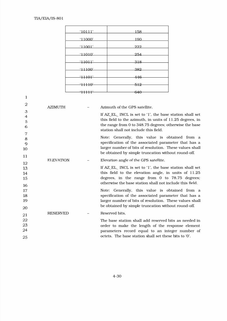
8/20/2019 TIA-EIA-IS 801 - 1999
http://slidepdf.com/reader/full/tia-eia-is-801-1999 98/138
TIA/EIA/IS-801
4-30
‘10111’ 158
‘11000’ 190
‘11001’ 222
‘11010’ 254‘11011’ 318
‘11100’ 382
‘11101’ 446
‘11110’ 512
‘11111’ 640
AZIMUTH – Azimuth of the GPS satellite.
If AZ_EL_ INCL is set to ‘1’, the base station shall set
this field to the azimuth, in units of 11.25 degrees, in
the range from 0 to 348.75 degrees; otherwise the base
station shall not include this field.
Note: Generally, this value is obtained from a
specification of the associated parameter that has a
larger number of bits of resolution. These values shall
be obtained by simple truncation without round-off.
ELEVATION – Elevation angle of the GPS satellite.
If AZ_EL_ INCL is set to ‘1’, the base station shall set
this field to the elevation angle, in units of 11.25
degrees, in the range from 0 to 78.75 degrees;
otherwise the base station shall not include this field.
Note: Generally, this value is obtained from a
specification of the associated parameter that has a
larger number of bits of resolution. These values shall
be obtained by simple truncation without round-off.
RESERVED – Reserved bits.
The base station shall add reserved bits as needed in
order to make the length of the response element
parameters record equal to an integer number of
octets. The base station shall set these bits to ‘0’.

8/20/2019 TIA-EIA-IS 801 - 1999
http://slidepdf.com/reader/full/tia-eia-is-801-1999 99/138
TIA/EIA/IS-801
4-31
If RESP_TYPE is equal to ‘0110’ (Provide GPS Location Assistance – Spherical Coordinates),
RESP_PAR_RECORD shall include the following record:
Fie ld Le n gth (bit s )
LAT_REF 20
LONG_REF 20
HEIGHT_REF 7
NUM_DLY 3
NUM_SV 4
The base station shall include NUM_DLY occurrences of the
following fields:
PILOT_PN 9
DLY_ONEWAY 11
The base station shall include NUM_SV occurrences of the
following fields:
DOPPLER0_LSB 4
SV_CODE_PH_FR 10
AZIMUTH_LSB 11
ELEVATION_LSB 11
RESERVED 0 - 7 (as needed)
LAT_REF – Reference latitude.
The base station shall set this field to the two’s
complement value of the latitude, in units of 180/220
degrees, in the range from -90 degrees to +90×(1-2-19
)
degrees, referenced to the WGS-84 reference ellipsoid,
counting positive angles north of the equator and
negative angles south of the equator.
LONG_REF – Reference longitude.
The base station shall set this field to the two’s
complement value of the longitude, in units of 360/220
degrees, in the range from -180 degrees to
+180×(1-2-19
) degrees, referenced to the WGS-84
reference ellipsoid, counting positive angles east of the
Greenwich meridian and negative angles west of the
Greenwich meridian.

8/20/2019 TIA-EIA-IS 801 - 1999
http://slidepdf.com/reader/full/tia-eia-is-801-1999 100/138
TIA/EIA/IS-801
4-32
HEIGHT_REF – Reference height.
The base station shall set this field to the reference
height , in units of 40 m, in the range from -400 m to
+4680 m.
Note that the reference height is defined as the height
above the WGS-84 reference ellipsoid.
NUM_DLY – Number of delays.
The base station shall set this field to the number of
repeated data fields for all applicable PN offsets, in the
range from 0 to 7.
NUM_SV – Number of GPS satellites.
The base station shall set this field to the number of
repeated data fields for all applicable satellites, in the
range from 1 to 16, where the binary value of the field
conveys the number of satellites minus one .
PILOT_PN – Pilot PN sequence offset index.
The base station shall set this field to the pilot PN
sequence offset for the base station, in units of 64
TIA/EIA-95 PN chips.
DLY_ONEWAY – One way delay.
The base station shall set this field to the one way
delay, in units of 1/16 TIA/EIA-95 PN chips, in the
range from 0 to 127.9375 chips.
DOPPLER0_LSB – The LSB’s of the 0th order term Doppler. This field is a
resolution extension of DOPPLER0 in a “Provide GPS
Acquisition Assistance” response element. When
appended to the bit representation DOPPLER0 in a
“Provide GPS Acquisition Assistance” response element
included in the same Posit ion Determinat ion Data
Message , it provides higher-resolution version of the
0th order term Doppler.
The base station shall set this field to the LSB’s of the
0th order Doppler, in units of 2.5/2
4 Hz, in the range
from 0 to 2.5×(1-2-4) Hz.
SV_CODE_PH_FR – The fractional chip of code phase. This field is a
resolution extension of SV_CODE_PH in “Provide GPS
Acquisition Assistance” response element. When
appended to the chip representation SV_CODE_PH in
“Provide GPS Acquisition Assistance” response

8/20/2019 TIA-EIA-IS 801 - 1999
http://slidepdf.com/reader/full/tia-eia-is-801-1999 101/138
TIA/EIA/IS-801
4-33
element, it provides higher-resolution version of the
code phase.
The base station shall set this field to the fractional
chip of code phase, in units of 2 -10 GPS chips, in the
range from 0 to (1- 2-10
) chips.
AZIMUTH_LSB – The LSB’s of the azimuth. This field is a resolution
extension of AZIMUTH in a “Provide GPS Acquisition
Assistance” response element. When appended to the
bit representation AZIMUTH in a “Provide GPS
Acquisition Assistance” response element included in
the same Posit ion Determinat ion Data Message , it
provides higher-resolution version of the azimuth.
The base station shall set this field to the LSB’s of the
azimuth, in units of 11.25/211 degrees, in the range
from 0 to 11.25×(1-2-11
) degrees.
ELEVATION_LSB – The LSB’s of the elevation angle. This field is a
resolution extension of ELEVATION in a “Provide GPS
Acquisition Assistance” response element. When
appended to the bit representation ELEVATION in a
“Provide GPS Acquisition Assistance” response element
included in the same Posit ion Determinat ion Data
Message , it provides higher-resolution version of the
elevation angle.
The base station shall set this field to the LSB’s of the
elevation angle, in units of 11.25/211 degrees, in the
range from 0 to 11.25×(1-2-11) degrees.
RESERVED – Reserved bits.
The base station shall add reserved bits as needed in
order to make the length of the response element
parameters record equal to an integer number of
octets. The base station shall set these bits to ‘0’.
If RESP_TYPE is equal to ‘0111’ (Provide GPS Location Assistance – Cartesian Coordinates),
RESP_PAR_RECORD shall include the following record:
Fie ld Le n gth (bit s )
NUM_DLY 3
NUM_SV 4
The base station shall include NUM_DLY occurrences of the
following fields:

8/20/2019 TIA-EIA-IS 801 - 1999
http://slidepdf.com/reader/full/tia-eia-is-801-1999 102/138
TIA/EIA/IS-801
4-34
PILOT_PN 9
DLY_ONEWAY 11
The base station shall include NUM_SV occurrences of the
following fields:
DOPPLER0_LSB 4
SV_COOR_X 27
SV_COOR_Y 27
SV_COOR_Z 27
RESERVED 0 - 7 (as needed)
NUM_DLY – Number of delays.
The base station shall set this field to the number of
repeated data fields for all applicable PN offsets, in the
range from 0 to 7.
NUM_SV – Number of GPS satellites.
The base station shall set this field to the number of
repeated data fields for all applicable satellites, in the
range from 1 to 16, where the binary value of the field
conveys the number of satellites minus one.
PILOT_PN – Pilot PN sequence offset index.
The base station shall set this field to the pilot PN
sequence offset for the base station, in units of 64
TIA/EIA-95 PN chips.
DLY_ONEWAY – One way delay.
The base station shall set this field to the One way
delay, in units of 1/16 TIA/EIA-95 PN chips, in the
range from 0 to 127.9375 chips.
DOPPLER0_LSB – This field is a resolution extension of DOPPLER0 in a
“Provide GPS Acquisition Assistance” response
element. When appended to the bit representation
DOPPLER0 in a “Provide GPS Acquisition Assistance”
response element included in the same Position
Determinat ion Data Message , it provides higher-
resolution version of the 0th order term Doppler.
The base station shall set this field to the LSB’s of the
0th order Doppler, in units of 2.5/24 Hz, in the range
from 0 to 2.5×(1-2-4) Hz.

8/20/2019 TIA-EIA-IS 801 - 1999
http://slidepdf.com/reader/full/tia-eia-is-801-1999 103/138
TIA/EIA/IS-801
4-35
SV_COOR_X – The X coordinate of the satellite in ECEF format.
The base station shall set this field to the two’s
complement of the X coordinate of the satellite, in
units of 0.4125 m, in the range from -0.4125×226 m to
0.4125×(226 - 1) m.
SV_COOR_Y – The Y coordinate of the satellite in ECEF format.
The base station shall set this field to the two’s
complement of the Y coordinate of the satellite, in
units of 0.4125 m, in the range from -0.4125×226 m to
0.4125×(226 - 1) m.
SV_COOR_Z – The Z coordinate of the satellite in ECEF format.
The base station shall set this field to the two’s
complement of the Z coordinate of the satellite, in
units of 0.4125 m, in the range from -0.4125×226 m to
0.4125×(226
- 1) m.
RESERVED – Reserved bits.
The base station shall add reserved bits as needed in
order to make the length of the response element
parameters record equal to an integer number of
octets. The base station shall set these bits to ‘0’.

8/20/2019 TIA-EIA-IS 801 - 1999
http://slidepdf.com/reader/full/tia-eia-is-801-1999 104/138
TIA/EIA/IS-801
4-36
If RESP_TYPE is equal to ‘0101’ (Provide GPS Sensitivity Assistance), RESP_PAR_RECORD
shall include the following record:
Fie ld Le n gth (bit s )
REF_BIT_NUM 11
NUM_DR_P 4
DR_SIZE 8
PART_NUM 3
TOTAL_PARTS 3
The base station shall include NUM_DR_P occurrences of the
following record of (NUM_SV_DR+2) fields:
NAV_MSG_BITS 2 × DR_SIZE
NUM_SV_DR 4
The base station shall include NUM_SV_DR occurrences of
the following field:
SV_PRN_NUM 6
RESERVED 0 - 7 (as needed)
REF_BIT_NUM – The reference bit number.
This parameter conveys the position of a particular bit
in the 1500-bit GPS frame to be called the “reference
bit”, which is the last bit of the first half of the
NAV_MSG_BITS field. The base station shall set this
field to the position of the reference bit in the range
from 0 to 1499.
NUM_DR_P – Number of data records in this part.
The base station shall set this field to specify the
number of repeated records in this part of the
response element, in the range from 0 to 15.
DR_SIZE – Data record size.
The base station shall set this field to specify the data
record size in 2-bit units, in the range from 0 to 510
bits.

8/20/2019 TIA-EIA-IS 801 - 1999
http://slidepdf.com/reader/full/tia-eia-is-801-1999 105/138
TIA/EIA/IS-801
4-37
PART_NUM – The part number.
The base station shall set this field to specify the part
number of the GPS Sensitivity Assistance data, in the
range from 1 to TOTAL_PARTS.
TOTAL_PARTS – The total number of parts.
The base station shall set this field to specify the total
number of parts that the GPS Sensitivity Assistance
data is divided into, in the range from 1 to 8.
NAV_MSG_BITS – Navigation message bits.
The base station shall set this field to specify the
Navigation message bits.
NUM_SV_DR – Number of GPS satellites in this data record.
The base station shall set this field to the number of
repeated data fields for all applicable satellites in this
data record, in the range from 1 to 16, where the
binary value of the field conveys the number of
satellites minus one.
SV_PRN_NUM – The satellite PRN number.
The mobile station shall set this field to the value of
the PRN signal number for which the measured data is
valid. It is represented as an unsigned value in the
range from 1 to 37, where the binary value of the field
conveys the satellite PRN number minus one.
RESERVED – Reserved bits.
The base station shall add reserved bits as needed in
order to make the length of the response element
parameters record equal to an integer number of
octets. The base station shall set these bits to ‘0’.
If RESP_TYPE is equal to ‘0011’ (Provide Base Station Almanac), RESP_PAR_RECORD shall
include the following record:

8/20/2019 TIA-EIA-IS 801 - 1999
http://slidepdf.com/reader/full/tia-eia-is-801-1999 106/138
TIA/EIA/IS-801
4-38
Fie ld Le n gth (bit s )
REF_PN 9
TIME_CRRCTION_REF 9
LAT_REF 23
LONG_REF 24
HEIGHT_REF 10
PART_NUM 3
TOTAL_PARTS 3
NUM_PILOTS_P 9
The base station shall include NUM_PILOTS_P occurrences of
the following six-field record:
PILOT_PN 9
TIME_CORRECTION 9
LOC_SAME_AS_PREV 1
DELTA_LAT 0 or 16
DELTA_LONG 0 or 16
HEIGHT 0 or 10
RESERVED 0 - 7 (as needed)
REF_PN – Pilot PN sequence offset of the reference base station.
The base station shall set this field to the pilot PN
sequence offset of the pilot transmitted by the
reference base station with respect to which locations
of other base stations are reported, relative to the zero
offset pilot PN sequence in units of 64 PN chips.
TIME_CRRCTION_REF– Reference time correction.
The base station shall set this field to the two’s
complement value of the reference time correction of
the base station transmitting pilot REF_PN in units of
1/16 TIA/EIA-95 PN chips, in the range from -16 to
+15.9375 chips.
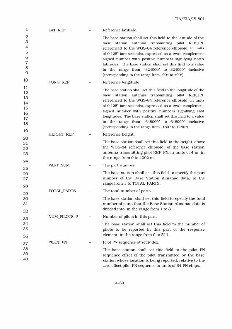
8/20/2019 TIA-EIA-IS 801 - 1999
http://slidepdf.com/reader/full/tia-eia-is-801-1999 107/138
TIA/EIA/IS-801
4-39
LAT_REF – Reference latitude.
The base station shall set this field to the latitude of the
base station antenna transmitting pilot REF_PN,
referenced to the WGS-84 reference ellipsoid, in units
of 0.125” (arc seconds), expressed as a two’s complement
signed number with positive numbers signifying north
latitudes. The base station shall set this field to a value
in the range from –324000” to 324000” inclusive
(corresponding to the range from -90° to +90°).
LONG_REF – Reference longitude.
The base station shall set this field to the longitude of the
base station antenna transmitting pilot REF_PN,
referenced to the WGS-84 reference ellipsoid, in units
of 0.125” (arc seconds), expressed as a two’s complement
signed number with positive numbers signifying east
longitudes. The base station shall set this field to a value
in the range from –648000” to 648000” inclusive
(corresponding to the range from -180° to +180°).
HEIGHT_REF – Reference height.
The base station shall set this field to the height, above
the WGS-84 reference ellipsoid, of the base station
antenna transmitting pilot REF_PN, in units of 4 m, in
the range from 0 to 4092 m.
PART_NUM – The part number.
The base station shall set this field to specify the part
number of the Base Station Almanac data, in the
range from 1 to TOTAL_PARTS.
TOTAL_PARTS – The total number of parts.
The base station shall set this field to specify the total
number of parts that the Base Station Almanac data is
divided into, in the range from 1 to 8.
NUM_PILOTS_P – Number of pilots in this part.
The base station shall set this field to the number of
pilots to be reported in this part of the response
element, in the range from 0 to 511.
PILOT_PN – Pilot PN sequence offset index.
The base station shall set this field to the pilot PN
sequence offset of the pilot transmitted by the base
station whose location is being reported, relative to the
zero offset pilot PN sequence in units of 64 PN chips.

8/20/2019 TIA-EIA-IS 801 - 1999
http://slidepdf.com/reader/full/tia-eia-is-801-1999 108/138
TIA/EIA/IS-801
4-40
TIME_ CORRECTION – The (GPS) reference time correction for Pilot PILOT_PN.
The base station shall set this field to the two’s
complement value of the reference time correction of
the base station antenna transmitting pilot PILOT_PN,
in units of 1/16 TIA/EIA-95 PN chips, expressed as a
two’s complement signed number in the range from
-16 to +15.9375 chips.
LOC_SAME_AS_PREV– Location same as the previous.
If the location of the base station antenna transmitting
this pilot PN is the same as the location of the previous
base station antenna, the base station shall set this
field to ‘1’; otherwise, the base station shall set this
field to ‘0’.
DELTA_LAT – The difference in the latitude of this base station
antenna and the latitude of the reference base station
antenna.
If LOC_SAME_AS_PREV is set to ‘0’, the base station shall
set this field to the difference in the latitude of the base
station antenna transmitting pilot PILOT_PN and the
latitude of the reference base station antenna (latitude
of base station antenna transmitting pilot PILOT_PN
minus latitude of reference base station antenna) with
both latitudes referenced to the WGS-84 reference
ellipsoid, in units of 0.125 s, expressed as a two’s
complement signed number in the range from -1024 s
to +1023.875 s; otherwise, the base station shall omit
this field.
DELTA_LONG – The difference in the longitude of this base station
antenna and the longitude of the primary base station
antenna.
If LOC_SAME_AS_PREV is set to ‘0’, the base station shall
set this field to the difference in the longitude of the
base station antenna transmitting PILOT_PN and the
longitude of the reference base station antenna
(longitude of base station antenna transmitting pilot
PILOT_PN minus longitude of reference base station
antenna) with both longitudes referenced to the
WGS-84 reference ellipsoid, in units of 0.125 s,
expressed as a two’s complement signed number in the
range from -1024 s to +1023.875 s; otherwise, the base
station shall omit this field.
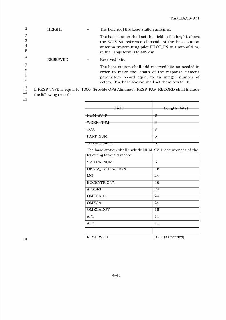
8/20/2019 TIA-EIA-IS 801 - 1999
http://slidepdf.com/reader/full/tia-eia-is-801-1999 109/138
TIA/EIA/IS-801
4-41
HEIGHT – The height of the base station antenna.
The base station shall set this field to the height, above
the WGS-84 reference ellipsoid, of the base station
antenna transmitting pilot PILOT_PN, in units of 4 m,
in the range form 0 to 4092 m.
RESERVED – Reserved bits.
The base station shall add reserved bits as needed in
order to make the length of the response element
parameters record equal to an integer number of
octets. The base station shall set these bits to ‘0’.
If RESP_TYPE is equal to ‘1000’ (Provide GPS Almanac), RESP_PAR_RECORD shall include
the following record:
Fie ld Le n gth (bit s )
NUM_SV_P 6
WEEK_NUM 8
TOA 8
PART_NUM 5
TOTAL_PARTS 5
The base station shall include NUM_SV_P occurrences of the
following ten-field record:
SV_PRN_NUM 5
DELTA_INCLINATION 16
MO 24
ECCENTRICITY 16
A_SQRT 24
OMEGA_0 24
OMEGA 24
OMEGADOT 16
AF1 11
AF0 11
RESERVED 0 - 7 (as needed)

8/20/2019 TIA-EIA-IS 801 - 1999
http://slidepdf.com/reader/full/tia-eia-is-801-1999 110/138
TIA/EIA/IS-801
4-42
NUM_SV_P – Number of satellites in this part.
The base station shall set this field to specify the
number of repeated records for all applicable satellites
in this part of response element, in the range from 1 to
64, where the binary value of the field conveys the
number of satellites minus one.
WEEK_NUM – The GPS week number of the almanac.
The base station shall set this field to the 8 least
significant bits of the GPS week number of the
almanac22 from which parameters in this message are
obtained. The range for this field is from 0 to 255.
TOA – The reference time of the almanac.
The base station shall set this field to specify the
reference time of the almanac22 from which parameters
in this message are obtained, in units of 4096 s, in the
range from 0 to 602,112 s.
PART_NUM – The part number.
The base station shall set this field to specify the part
number of the Almanac data, in the range from 1 to
TOTAL_PARTS.
TOTAL_PARTS – The total number of parts.
The base station shall set this field to specify the total
number of parts that the Almanac data is divided into,
in the range from 1 to 32.
SV_PRN_NUM – The satellite PRN number.
The mobile station shall set this field to the value of
the PRN signal number for which the measured data is
valid. It is represented as an unsigned value in the
range from 1 to 32, where the binary value of the field
conveys the satellite PRN number minus one.
DELTA_INCLINATION– Correction to inclination.
The base station shall set this field to the value
contained in the associated parameter of the specified
GPS almanac22
.
22 This parameter is as defined in ICD200
(http://www.navcen.uscg.mil/gps/geninfo/gpsdocuments/icd200/default.htm).

8/20/2019 TIA-EIA-IS 801 - 1999
http://slidepdf.com/reader/full/tia-eia-is-801-1999 111/138
TIA/EIA/IS-801
4-43
M0 – Mean anomaly at reference time.
The base station shall set this field to the value
contained in the associated parameter of the specified
GPS almanac22
.
ECCENTRICITY – Eccentricity.
The base station shall set this field to the value
contained in the associated parameter of the specified
GPS almanac22
.
A_SQRT – Square root of the semi-major axis.
The base station shall set this field to the value
contained in the associated parameter of the specified
GPS almanac22
.
OMEGA_0 – Longitude of ascending node of orbit plane at weekly
epoch.
The base station shall set this field to the value
contained in the associated parameter of the specified
GPS almanac22
.
OMEGA – Argument of perigee.
The base station shall set this field to the value
contained in the associated parameter of the specified
GPS almanac22
.
OMEGADOT – Rate of right ascension.
The base station shall set this field to the value
contained in the associated parameter of the specified
GPS almanac22
.
AF1 – Apparent satellite clock correction af1.
The base station shall set this field to the value
contained in the associated parameter of the specified
GPS almanac22
.
AF0 – Apparent satellite clock correction af0.
The base station shall set this field to the value
contained in the associated parameter of the specified
GPS almanac22
.
RESERVED – Reserved bits.
The base station shall add reserved bits as needed in
order to make the length of the response element
parameters record equal to an integer number of
octets. The base station shall set these bits to ‘0’.

8/20/2019 TIA-EIA-IS 801 - 1999
http://slidepdf.com/reader/full/tia-eia-is-801-1999 112/138
TIA/EIA/IS-801
4-44
If RESP_TYPE is equal to ‘1001’ (Provide GPS Ephemeris), RESP_PAR_RECORD shall
include the following record:
Fie ld Le n gth (bit s )
NUM_SV_P 4
PART_NUM 5
TOTAL_PARTS 5
AB_PAR_INCL 1
ALPHA_0 0 or 8
ALPHA_1 0 or 8
ALPHA_2 0 or 8
ALPHA_3 0 or 8
BETA_0 0 or 8
BETA _1 0 or 8
BETA _2 0 or 8
BETA _3 0 or 8
The base station shall include NUM_SV_P occurrences of the
following twenty-two-field record:
SV_PRN_NUM 5
IODE 8
C_RS 16
DELTA_N 16
M0 32
C_UC 16
ECCENTRICITY 32
C_US 16
A_SQRT 32
TOE 16
C_IC 16
OMEGA_0 32
C_IS 16
ANGLE_INCLINATION 32
C_RC 16
OMEGA 32
OMEGADOT 24

8/20/2019 TIA-EIA-IS 801 - 1999
http://slidepdf.com/reader/full/tia-eia-is-801-1999 113/138
TIA/EIA/IS-801
4-45
IDOT 14
TOC 16
AF2 8
AF1 16
AF0 22
RESERVED 0 - 7 (as needed)
NUM_SV_P – Number of satellites in this part.
The base station shall set this field to specify the
number of repeated records for all applicable satellites
in this part of the response element, in the range from
1 to 16, where the binary value of the field conveys the
number of satellites minus one.
PART_NUM – The part number.
The base station shall set this field to specify the part
number of the Ephemeris data, in the range from 1 to
TOTAL_PARTS.
TOTAL_PARTS – The total number of parts.
The base station shall set this field to specify the total
number of parts that the Ephemeris data is divided
into, in the range from 1 to 32.
AB_PAR_INCL – Inclusion of the alpha and beta parameters.
The base station shall set this field to ‘1’ if the alpha
and beta parameters are included in the response
element; otherwise the base station shall set this field
to ‘0’.
ALPHA_0 – Ionospheric correction parameter α0.
If AB_PAR_INCL is set to ‘1’, the base station shall set
this field to the value contained in the associated
parameter of the specified GPS ephemeris23; otherwise
the base station shall not include this field.
23 This parameter is as defined in ICD200
(http://www.navcen.uscg.mil/gps/geninfo/gpsdocuments/icd200/default.htm).

8/20/2019 TIA-EIA-IS 801 - 1999
http://slidepdf.com/reader/full/tia-eia-is-801-1999 114/138
TIA/EIA/IS-801
4-46
ALPHA_1 – Ionospheric correction parameter α1.
If AB_PAR_INCL is set to ‘1’, the base station shall set
this field to the value contained in the associated
parameter of the specified GPS ephemeris23; otherwise
the base station shall not include this field.
ALPHA_2 – Ionospheric correction parameter α2.
If AB_PAR_INCL is set to ‘1’, the base station shall set
this field to the value contained in the associated
parameter of the specified GPS ephemeris23; otherwise
the base station shall not include this field.
ALPHA_3 – Ionospheric correction parameter α3.
If AB_PAR_INCL is set to ‘1’, the base station shall set
this field to the value contained in the associated
parameter of the specified GPS ephemeris23; otherwise
the base station shall not include this field.
BETA_0 – Ionospheric correction parameter β0.
If AB_PAR_INCL is set to ‘1’, the base station shall set
this field to the value contained in the associated
parameter of the specified GPS ephemeris23; otherwise
the base station shall not include this field.
BETA_1 – Ionospheric correction parameter β1.
If AB_PAR_INCL is set to ‘1’, the base station shall set
this field to the value contained in the associated
parameter of the specified GPS ephemeris23
; otherwise
the base station shall not include this field.
BETA_2 – Ionospheric correction parameter β2.
If AB_PAR_INCL is set to ‘1’, the base station shall set
this field to the value contained in the associated
parameter of the specified GPS ephemeris23; otherwise
the base station shall not include this field.
BETA_3 – Ionospheric correction parameter β3.
If AB_PAR_INCL is set to ‘1’, the base station shall set
this field to the value contained in the associated
parameter of the specified GPS ephemeris23; otherwise
the base station shall not include this field.
SV_PRN_NUM – The satellite PRN number.
The mobile station shall set this field to the value of
the PRN signal number for which the measured data is
valid. It is represented as an unsigned value in the

8/20/2019 TIA-EIA-IS 801 - 1999
http://slidepdf.com/reader/full/tia-eia-is-801-1999 115/138
TIA/EIA/IS-801
4-47
range from 1 to 32, where the binary value of the field
conveys the satellite PRN number minus one.
IODE – Issue of data.
The base station shall set this field to the value
contained in the associated parameter of the specified
GPS ephemeris23.
C_RS – Amplitude of the sine harmonic correction term to the
orbit radius.
The base station shall set this field to the value
contained in the associated parameter of the specified
GPS ephemeris23.
DELTA_N – Mean motion difference from the computed value.
The base station shall set this field to the value
contained in the associated parameter of the specified
GPS ephemeris23.
M0 – Mean anomaly at the reference time.
The base station shall set this field to the value
contained in the associated parameter of the specified
GPS ephemeris23.
C_UC – Amplitude of the cosine harmonic correction term to
the argument of latitude.
The base station shall set this field to the value
contained in the associated parameter of the specified
GPS ephemeris23.
ECCENTRICITY – Eccentricity.
The base station shall set this field to the value
contained in the associated parameter of the specified
GPS ephemeris23.
C_US – Amplitude of the sine harmonic correction term to the
argument of latitude.
The base station shall set this field to the value
contained in the associated parameter of the specified
GPS ephemeris23.
A_SQRT – Square root of the semi-major axis.
The base station shall set this field to the value
contained in the associated parameter of the specified
GPS ephemeris23.

8/20/2019 TIA-EIA-IS 801 - 1999
http://slidepdf.com/reader/full/tia-eia-is-801-1999 116/138
TIA/EIA/IS-801
4-48
TOE – ephemeris reference time.
The base station shall set this field to the value
contained in the associated parameter of the specified
GPS ephemeris23.
C_IC – Amplitude of the cosine harmonic correction term to
the angle of inclination.
The base station shall set this field to the value
contained in the associated parameter of the specified
GPS ephemeris23.
OMEGA_0 – Longitude of ascending node of orbit plane at weekly
epoch.
The base station shall set this field to the value
contained in the associated parameter of the specified
GPS ephemeris23.
C_IS – Amplitude of the sine harmonic correction term to the
angle of inclination.
The base station shall set this field to the value
contained in the associated parameter of the specified
GPS ephemeris23.
ANGLE_INCLINATION– Inclination angle at the reference time.
The base station shall set this field to the value
contained in the associated parameter of the specified
GPS ephemeris23.
C_RC – Amplitude of the cosine harmonic correction term to
the orbit radius.
The base station shall set this field to the value
contained in the associated parameter of the specified
GPS ephemeris23.
OMEGA – Argument of perigee.
The base station shall set this field to the value
contained in the associated parameter of the specified
GPS ephemeris23.
OMEGADOT – Rate of right ascension.
The base station shall set this field to the value
contained in the associated parameter of the specified
GPS ephemeris23.

8/20/2019 TIA-EIA-IS 801 - 1999
http://slidepdf.com/reader/full/tia-eia-is-801-1999 117/138
TIA/EIA/IS-801
4-49
IDOT – Rate of inclination angle.
The base station shall set this field to the value
contained in the associated parameter of the specified
GPS ephemeris23.
TOC – Clock data reference time.
The base station shall set this field to the value
contained in the associated parameter of the specified
GPS ephemeris23.
AF2 – Apparent satellite clock correction af2.
The base station shall set this field to the value
contained in the associated parameter of the specified
GPS ephemeris23.
AF1 – Apparent satellite clock correction af1.
The base station shall set this field to the value
contained in the associated parameter of the specified
GPS ephemeris23.
AF0 – Apparent satellite clock correction af0.
The base station shall set this field to the value
contained in the associated parameter of the specified
GPS ephemeris23.
RESERVED – Reserved bits.
The base station shall add reserved bits as needed in
order to make the length of the response element
parameters record equal to an integer number of
octets. The base station shall set these bits to ‘0’.
If RESP_TYPE is equal to ‘1010’ (Provide GPS Navigation Message Bits),
RESP_PAR_RECORD shall include the following record:
Fie ld Le n gth (bit s )
NUM_SV_P 6
PART_NUM 5
TOTAL_PARTS 5
SUBF_4_5_INCL 1
SUBF_4_5 0 or 15000
The base station shall include NUM_SV_P occurrences of the
following two-field record:

8/20/2019 TIA-EIA-IS 801 - 1999
http://slidepdf.com/reader/full/tia-eia-is-801-1999 118/138
TIA/EIA/IS-801
4-50
SV_PRN_NUM 6
SUB_1_2_3 900
RESERVED 0 - 7 (as needed)
NUM_SV_P – Number of satellites in this part.
The base station shall set this field to the number of
repeated records for all applicable satellites in this part
of the response element, in the range from 1 to 64,
where the binary value of the field conveys the number
of satellites minus one.
PART_NUM – The part number.
The base station shall set this field to specify the part
number of the GPS Navigation Message Bits data, in
the range from 1 to TOTAL_PARTS.
TOTAL_PARTS – The total number of parts.
The base station shall set this field to specify the total
number of parts that the GPS Navigation Message Bits
data is divided into, in the range from 1 to 32.
SUBF_4_5_INCL – Inclusion of the additional parameters indicator.
The base station shall set this field to ‘1’ if the
subframes 4 and 5 are included in the response
element; otherwise the base station shall set this field
to ‘0’.
SUBF_4_5 – GPS subframes 4 and 5.
If SUBF_4_5_INCL is set to ‘1’, the base station shall
set this field to the contents of GPS navigation
message subframes 4 and 5; otherwise the base
station shall not include this field.
Note that the data shall be current as of the time of
transmission; time-dependent fields shall be
represented as they will occur in the next whole frame
(for subframes 1, 2 and 3) or in the next whole
superframe (for subframes 4 and 5) from the time the
request is received by the base station.
SV_PRN_NUM – The satellite PRN number.
The mobile station shall set this field to the value of
the PRN signal number for which the measured data is

8/20/2019 TIA-EIA-IS 801 - 1999
http://slidepdf.com/reader/full/tia-eia-is-801-1999 119/138
TIA/EIA/IS-801
4-51
valid. It is represented as an unsigned value in the
range from 1 to 37, where the binary value of the field
conveys the satellite PRN number minus one.
SUBF_1_2_3 – The subframes 1, 2 and 3.
The base station shall set this field to the contents of
GPS navigation message subframes 1, 2 and 3
transmitted by the satellite specified in the previous
field.
Note that the data shall be current as of the time of
transmission; time-dependent fields shall be
represented as they will occur in the next whole frame
(for subframes 1, 2 and 3) or in the next whole
superframe (for subframes 4 and 5) from the time the
request is received by the base station.
RESERVED – Reserved bits.
The base station shall add reserved bits as needed in
order to make the length of the response element
parameters record equal to an integer number of
octets. The base station shall set these bits to ‘0’.
If RESP_TYPE is equal to ‘0001’ (Provide Location Response), RESP_PAR_RECORD shall
include the following record:

8/20/2019 TIA-EIA-IS 801 - 1999
http://slidepdf.com/reader/full/tia-eia-is-801-1999 120/138
TIA/EIA/IS-801
4-52
Fie ld Le n gth (bit s )
TIME_REF_CDMA 14
LAT 25
LONG 26
LOC_UNCRTNTY_ANG 4
LOC_UNCRTNTY_A 5
LOC_UNCRTNTY_P 5
FIX_TYPE 1
VELOCITY_INCL 1
VELOCITY_HOR 0 or 9
HEADING 0 or 10
VELOCITY_VER 0 or 8
CLOCK_INCL 1
CLOCK_BIAS 0 or 18
CLOCK_DRIFT 0 or 16
HEIGHT_INCL 1
HEIGHT 0 or 14
LOC_UNCRTNTY_V 0 or 5
RESERVED 0 - 7 (as needed)
TIME_REF_CDMA – CDMA system time at the time the solution is valid.
The base station shall set this field to (t/50 mod
16384), where t is the CDMA system time in frames, as
defined in 1.2 of TIA/EIA-95-B, at the time the
solution is valid. This is the time at which the values
of the parameters reported in this response element
parameter record are valid.
LAT – Latitude.
The base station shall set this field to the two’s
complement value of the latitude, referenced to the
WGS-84 reference ellipsoid, in units of 180/225
degrees, in the range from -90 degrees to +90×(1-2-24
)
degrees, counting positive angles north of the equator
and negative angles south of the equator.

8/20/2019 TIA-EIA-IS 801 - 1999
http://slidepdf.com/reader/full/tia-eia-is-801-1999 121/138
TIA/EIA/IS-801
4-53
LONG – Longitude.
The base station shall set this field to the two’s
complement value of the longitude, referenced to the
WGS-84 reference ellipsoid, in units of 360/226
degrees, in the range from -180 degrees to
+180×(1-2-25) degrees, counting positive angles east of
the Greenwich meridian and negative angles west of
the Greenwich meridian.
LOC_UNCRTNTY_ANG– Angle of axis with respect to True North for position
uncertainty.
The base station shall set this field to the angle of axis
for position uncertainty, in units of 5.625 degrees, in
the range from 0 to 84.375 degrees, where 0 degrees is
True North and the angle increases toward the East.
LOC_UNCRTNTY_A – Standard deviation of axis along angle specified for
position uncertainty.
The base station shall set this field to represent the
standard deviation of axis along angle specified for
position uncertainty as specified in Table 4.2.4.2-6.
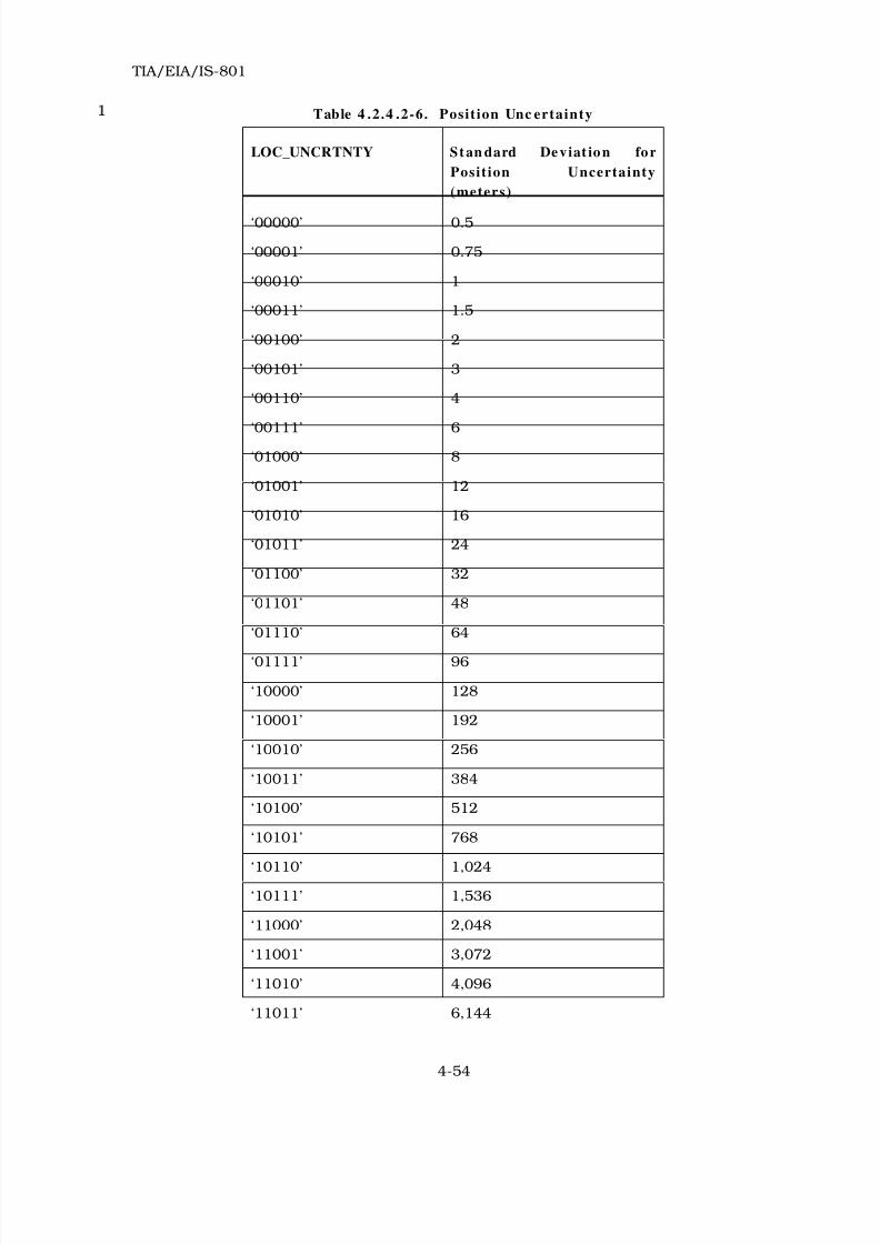
8/20/2019 TIA-EIA-IS 801 - 1999
http://slidepdf.com/reader/full/tia-eia-is-801-1999 122/138
TIA/EIA/IS-801
4-54
Table 4 .2.4 .2-6. Posit ion Unc ertainty
LOC_UNCRTNTY Stan dard Deviat ion for
Posit ion Uncertainty
(meters)
‘00000’ 0.5
‘00001’ 0.75
‘00010’ 1
‘00011’ 1.5
‘00100’ 2
‘00101’ 3
‘00110’ 4
‘00111’ 6
‘01000’ 8
‘01001’ 12
‘01010’ 16
‘01011’ 24
‘01100’ 32
‘01101’ 48
‘01110’ 64
‘01111’ 96
‘10000’ 128
‘10001’ 192
‘10010’ 256
‘10011’ 384
‘10100’ 512
‘10101’ 768
‘10110’ 1,024‘10111’ 1,536
‘11000’ 2,048
‘11001’ 3,072
‘11010’ 4,096
‘11011’ 6,144
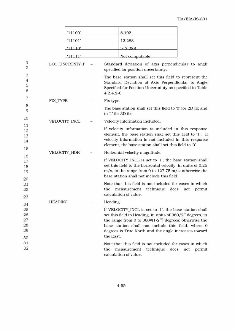
8/20/2019 TIA-EIA-IS 801 - 1999
http://slidepdf.com/reader/full/tia-eia-is-801-1999 123/138
TIA/EIA/IS-801
4-55
‘11100’ 8,192
‘11101’ 12,288
‘11110’ >12,288
‘11111’ Not computableLOC_UNCRTNTY_P – Standard deviation of axis perpendicular to angle
specified for position uncertainty.
The base station shall set this field to represent the
Standard Deviation of Axis Perpendicular to Angle
Specified for Position Uncertainty as specified in Table
4.2.4.2-6.
FIX_TYPE – Fix type.
The base station shall set this field to ‘0’ for 2D fix and
to ‘1’ for 3D fix.
VELOCITY_INCL – Velocity information included.
If velocity information is included in this response
element, the base station shall set this field to ‘1’. If
velocity information is not included in this response
element, the base station shall set this field to ‘0’.
VELOCITY_HOR – Horizontal velocity magnitude.
If VELOCITY_INCL is set to ‘1’, the base station shall
set this field to the horizontal velocity, in units of 0.25
m/s, in the range from 0 to 127.75 m/s; otherwise the
base station shall not include this field.
Note that this field is not included for cases in which
the measurement technique does not permit
calculation of value.
HEADING – Heading.
If VELOCITY_INCL is set to ‘1’, the base station shall
set this field to Heading, in units of 360/210 degrees, in
the range from 0 to 360×(1-2-10
) degrees; otherwise the
base station shall not include this field, where 0
degrees is True North and the angle increases toward
the East.
Note that this field is not included for cases in which
the measurement technique does not permit
calculation of value.
8/20/2019 TIA-EIA-IS 801 - 1999
http://slidepdf.com/reader/full/tia-eia-is-801-1999 124/138
TIA/EIA/IS-801
4-56
VELOCITY_VER – Vertical velocity.
If VELOCITY_INCL and FIX_TYPE are set to ‘1’, the
base station shall set this field to the two’s
complement value of Vertical Velocity, in units of 0.5
m/s, in the range from -64 m/s to +63.5 m/s;
otherwise the base station shall not include this field.
Note that this field is not included for cases in which
the measurement technique does not permit
calculation of value.
CLOCK_INCL – Clock information included.
If clock information is included in this response
element, the base station shall set this field to ‘1’. If
clock information is not included in this response
element, the base station shall set this field to ‘0’.
CLOCK_BIAS – Clock bias.
If CLOCK_INCL is set to ‘1’, the base station shall set
this field to the clock bias in ns, in the range from
-13,000 ns to +249,143 ns; otherwise the base station
shall not include this field. This parameter is
computed as true GPS time minus mobile station time
reference as defined in TIA/EIA-95.
Note that as part of a GPS fix, the computation yields
an estimate of the discrepancy between the time
specified by the local clock and true GPS time. This
parameter reports the discrepancy. The main cause of
this discrepancy is going to be the propagation delay
from the base station to the MS, which is always
positive. Accordingly, the range allowed for this
parameter is not symmetric.
CLOCK_DRIFT – Clock drift.
If CLOCK_INCL is set to ‘1’, the base station shall set
this field to the two’s complement value of the rate of
change of clock bias in units of ppb (ns/s), in the
range from -32768 ppb (ns/s) to +32767 ppb (ns/s);
otherwise the base station shall not include this field.
HEIGHT_INCL – Height information included.
If height information is included in this response
element, the base station shall set this field to ‘1’. If
HEIGHT is not included in this response element, the
base station shall set this field to ‘0’.

8/20/2019 TIA-EIA-IS 801 - 1999
http://slidepdf.com/reader/full/tia-eia-is-801-1999 125/138
TIA/EIA/IS-801
4-57
HEIGHT – Height.
If HEIGHT_INCL is set to ‘1’, the base station shall set
this field to the height, above WGS-84 reference
ellipsoid, in units of 1 meter, in the range from -500 m
to 15833 m; otherwise it shall not include this field.
LOC_UNCRTNTY_V – Standard deviation of vertical error for position
uncertainty.
If HEIGHT_INCL is set to ‘1’, the base station shall
include this field and set this field to represent the
Standard Deviation Vertical Error for Position
Uncertainty as specified in Table 4.2.4.2-6; otherwise
the base station shall not include this field.
Note that this field is not included for cases in which
the measurement technique does not permit
calculation of value.
RESERVED – Reserved bits.
The base station shall add reserved bits as needed in
order to make the length of the response element
parameters record equal to an integer number of
octets. The base station shall set these bits to ‘0’.
If RESP_TYPE is equal to ‘1011’ (Provide GPS Almanac Correction), RESP_PAR_RECORD
shall include the following record:
Fie ld Le n gth (bit s )
NUM_SV_P 4
REF_TIME 8
TOA 8
WEEK_NUM 8
PART_NUM 5
TOT_PARTS 5
The base station shall include NUM_SV_P occurrences of the
following fields:
SV_PRN_NUM 5
DELTA_XYZ_INCL 1
DELTA_X 0 or 15
DELTA_Y 0 or 15
DELTA_Z 0 or 15
DELTA_X_1ST
0 or 7
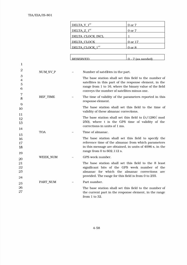
8/20/2019 TIA-EIA-IS 801 - 1999
http://slidepdf.com/reader/full/tia-eia-is-801-1999 126/138
TIA/EIA/IS-801
4-58
DELTA_Y_1ST
0 or 7
DELTA_Z_1ST
0 or 7
DELTA_CLOCK_INCL 1
DELTA_CLOCK 0 or 17
DELTA_CLOCK_1ST 0 or 8
RESERVED 0 - 7 (as needed)
NUM_SV_P – Number of satellites in the part.
The base station shall set this field to the number of
satellites in this part of the response element, in the
range from 1 to 16, where the binary value of the field
conveys the number of satellites minus one.
REF_TIME – The time of validity of the parameters reported in this
response element.
The base station shall set this field to the time of
validity of these almanac corrections.
The base station shall set this field to (t/1280 mod
250), where t is the GPS time of validity of the
corrections in units of 1 ms.
TOA – Time of almanac.
The base station shall set this field to specify the
reference time of the almanac from which parameters
in this message are obtained, in units of 4096 s, in the
range from 0 to 602,112 s.
WEEK_NUM – GPS week number.
The base station shall set this field to the 8 least
significant bits of the GPS week number of the
almanac for which the almanac corrections are
provided. The range for this field is from 0 to 255.
PART_NUM – Part number.
The base station shall set this field to the number of
the current part in the response element, in the range
from 1 to 32.

8/20/2019 TIA-EIA-IS 801 - 1999
http://slidepdf.com/reader/full/tia-eia-is-801-1999 127/138
TIA/EIA/IS-801
4-59
TOT_PARTS – Total parts.
The base station shall set this field to the total number
of parts that constitute the response element, in the
range from 1 to 32.
SV_PRN_NUM – The satellite PRN number.
The mobile station shall set this field to the value of
the PRN signal number for which the measured data is
valid. It is represented as an unsigned value in the
range from 1 to 32, where the binary value of the field
conveys the satellite PRN number minus one.
DELTA_XYZ_INCL – Correction for XYZ included.
The base station shall set this field to ‘1’ if delta XYZ
information is included in the message; otherwise it
shall set this field to ‘0’.24
DELTA_X – Correction for X coordinate.
If DELTA_XYZ_INCL is set to ‘1’ the base station shall
include DELTA_X and set this field to the two’s
complement value of the 0th order position correction X
term, in units of 0.5 m, in the range from -8192 m to
+8191.5 m; otherwise the base station shall not
include this field24.
DELTA_Y – Correction for Y coordinate.
If DELTA_XYZ_INCL is set to ‘1’ the base station shall
include DELTA_Y and set this field to the two’s
complement value of the 0th order position correction Y
term, in units of 0.5 m, in the range from -8192 m to
+8191.5 m; otherwise the base station shall not
include this field24.
DELTA_Z – Correction for Z coordinate.
If DELTA_XYZ_INCL is set to ‘1’ the base station shall
include DELTA_Z and set this field to the two’s
complement value of the 0th order position correction Z
term, in units of 0.5 m, in the range from -8192 m to
+8191.5 m; otherwise the base station shall not
include this field24.
24 See 3.2.2.1.1.2 and 3.2.2.3.3.2

8/20/2019 TIA-EIA-IS 801 - 1999
http://slidepdf.com/reader/full/tia-eia-is-801-1999 128/138
TIA/EIA/IS-801
4-60
DELTA_X_1ST – 1st order correction for X coordinate.
If DELTA_XYZ_INCL is set to ‘1’ the base station shall
include DELTA_X_1ST and set this field to the two’s
complement value of the 1st order position correction X
term, in units of 2.5 cm/s, in the range from -160
cm/s to +157.5 cm/s; otherwise the base station shall
not include this field.
DELTA_Y_1ST – 1st order correction for Y coordinate.
If DELTA_XYZ_INCL is set to ‘1’ the base station shall
include DELTA_Y_1ST and set this field to the two’s
complement value of the 1st order position correction Y
term, in units of 2.5 cm/s, in the range from -160
cm/s to +157.5 cm/s; otherwise the base station shall
not include this field.
DELTA_Z_1ST – 1
st
order correction for Z coordinate.
If DELTA_XYZ_INCL is set to ‘1’ the base station shall
include DELTA_Z_1ST and set this field to the two’s
complement value of the 1st order position correction Z
term, in units of 2.5 cm/s, in the range from -160
cm/s to +157.5 cm/s; otherwise the base station shall
not include this field.
DELTA_CLOCK_INCL – Correction for clock included.
The base station shall set this field to ‘1’ if delta clock
information is included in the message; otherwise it
shall set this field to ‘0’.
DELTA_CLOCK – Correction for clock.
If DELTA_CLOCK_INCL is set to ‘1’ the base station
shall include DELTA_CLOCK and set this field to the
two’s complement value of the delta clock 0th order, in
units of 1 ns, in the range from -65536 ns to
65535 ns; otherwise the base station shall not include
this field.
DELTA_CLOCK_1ST – 1st order correction for clock.
If DELTA_CLOCK_INCL is set to ‘1’ the base station
shall include DELTA_CLOCK_1ST and set this field to
the two’s complement value of the delta clock 1st order,
in units of 0.1 ppb, in the range from -12.8 ppb to
+12.7 ppb; otherwise the base station shall not include
this field.

8/20/2019 TIA-EIA-IS 801 - 1999
http://slidepdf.com/reader/full/tia-eia-is-801-1999 129/138
TIA/EIA/IS-801
4-61
RESERVED – Reserved bits.
The base station shall add reserved bits as needed in
order to make the length of the response element
parameters record equal to an integer number of
octets. The base station shall set these bits to ‘0’.

8/20/2019 TIA-EIA-IS 801 - 1999
http://slidepdf.com/reader/full/tia-eia-is-801-1999 130/138
TIA/EIA/IS-801
4-62
No text.

8/20/2019 TIA-EIA-IS 801 - 1999
http://slidepdf.com/reader/full/tia-eia-is-801-1999 131/138
TIA/EIA/IS-801
A-1
Ann ex A - TIMERS
The following table provides values for time limits given in the text.
Table A-1. Time Lim its
Time
LimitDe s cript ion Value Refe re n c es
T 1 Time limit for preferred quality of “Provide Pseudorange
Measurement”, “Provide Pilot Phase Measurement” and
“Provide Location Response” response elements when
PREF_RESP_QUAL = ‘000’
2 s 3.2.2.1.1.1
3.2.2.3.3.1
T 2 Time limit for preferred quality of “Provide Pseudorange
Measurement”, “Provide Pilot Phase Measurement” and
“Provide Location Response” response elements when
PREF_RESP_QUAL = ‘001’
4 s 3.2.2.1.1.1
3.2.2.3.3.1
T 3 Time limit for preferred quality of “Provide Pseudorange
Measurement”, “Provide Pilot Phase Measurement” and
“Provide Location Response” response elements when
PREF_RESP_QUAL = ‘010’
8 s 3.2.2.1.1.1
3.2.2.3.3.1
T 4 Time limit for preferred quality of “Provide Pseudorange
Measurement”, “Provide Pilot Phase Measurement” and
“Provide Location Response” response elements when
PREF_RESP_QUAL = ‘011’
16 s 3.2.2.1.1.1
3.2.2.3.3.1
T 5 Time limit for preferred quality of “Provide Pseudorange
Measurement”, “Provide Pilot Phase Measurement” and
“Provide Location Response” response elements whenPREF_RESP_QUAL = ‘100’
32 s 3.2.2.1.1.1
3.2.2.3.3.1
T 6 Time limit for preferred quality of “Provide Pseudorange
Measurement”, “Provide Pilot Phase Measurement” and
“Provide Location Response” response elements when
PREF_RESP_QUAL = ‘101’
64 s 3.2.2.1.1.1
3.2.2.3.3.1
T 7 Time limit for preferred quality of “Provide Pseudorange
Measurement”, “Provide Pilot Phase Measurement” and
“Provide Location Response” response elements when
PREF_RESP_QUAL = ‘110’
128 s 3.2.2.1.1.1
3.2.2.3.3.1
T 8 Time limit for preferred quality of “Provide Pseudorange
Measurement”, “Provide Pilot Phase Measurement” and
“Provide Location Response” response elements when
PREF_RESP_QUAL = ‘111’
256 s 3.2.2.1.1.1
3.2.2.3.3.1
T 9 The time limit for the mobile station to wait for a response
or a “Reject” to a sent request element
35 s 3.2.1.2

8/20/2019 TIA-EIA-IS 801 - 1999
http://slidepdf.com/reader/full/tia-eia-is-801-1999 132/138
TIA/EIA/IS-801
A-2
No text.

8/20/2019 TIA-EIA-IS 801 - 1999
http://slidepdf.com/reader/full/tia-eia-is-801-1999 133/138
TIA/EIA/IS-801
B-1
Ann ex B – REQUEST/ RESPONSE ELEMENT TYPES
Table B-1 . MS Request s and BS Respons es
Code REQUEST Elem ents s ent by MS Co de RESPONSE Elem ents s ent by BS
0000 Reserved 0000 Reject
0001 Request Location Response 0001 Provide Location Response
0010 Request BS Capabilities 0010 Provide BS Capabilities
0011 Request Base Station Almanac 0011 Provide Base Station Almanac
0100 Request GPS Acquisition Assistance 0100 Provide GPS Acquisition Assistance
0101 Request GPS Sensitivity Assistance 0101 Provide GPS Sensitivity Assistance
0110 Request GPS Location Assistance 0110 Provide GPS Location Assistance –
Spherical Coordinate
0111 Reserved 0111 Provide GPS Location Assistance –
Cartesian Coordinate
1000 Request GPS Almanac 1000 Provide GPS Almanac
1001 Request GPS Ephemeris 1001 Provide GPS Ephemeris
1010 Request GPS Navigation Message Bits 1010 Provide GPS Navigation Message Bits
1011 Request GPS Almanac Correction 1011 Provide GPS Almanac Correction
See Table 3.2.4-2. Request Element Type and Table 4.2.4-3. Response Element Type.
Table B-2 . MS Respon ses and BS Requests
Code RESPONSE Ele men ts sen t by MS Co de REQUEST Elem en ts sen t by BS
0000 Reject 0000 Reserved
0001 Provide Location Response 0001 Request Location Response
0010 Provide MS Information 0010 Request MS Information
0011 Provide Autonomous Measurement
Weighting Factor
0011 Request Autonomous Measurement
Weighting Factor
0100 Provide Pseudorange Measurement 0100 Request Pseudorange Measurement
0101 Provide Pilot Phase Measurement 0101 Request Pilot Phase Measurement
0110 Provide Time Offset Measurement 0110 Request Time Offset Measurement
0111 Provide Cancellation Acknowledgement 0111 Request Cancellation
See Table 3.2.4-3. Response Element Type and Table 4.2.4-2. Request Element Type.

8/20/2019 TIA-EIA-IS 801 - 1999
http://slidepdf.com/reader/full/tia-eia-is-801-1999 134/138
TIA/EIA/IS-801
B-2
No text.

8/20/2019 TIA-EIA-IS 801 - 1999
http://slidepdf.com/reader/full/tia-eia-is-801-1999 135/138
TIA/EIA/IS-801
C-1
Ann ex C – EXAMPLE POSITION DETERMINATION DATA MESS AGE
The following is an example of a mobile station originated Posit ion Determin at ion Data
Message . The example merely serves as an aid in understanding the format specified in the
body of the document. The example accommodates two mobile station requests, along with
a mobile station response (to a previous base station request to the mobile). The example
shows how the individual records (and fields) (i.e. REQ_TYPEs, REQ_PAR_RECORDs, etc.)
are built from the most significant bit (MSB) to the least significant bit (LSB), the length of
the individual records, and the ordering of the individual records within the final Position
Determina t ion Data Message . Finally, the entire bit string for the Posit ion Determin at ion
Data Message is constructed.
The Mobile requests the following information from the base station:
• GPS Acquisition Assistance
• GPS Almanac Correction
The mobile is also responding to a base station request for “Provide MS Information”
response element.
Individual fields of the Posit ion Determina t ion Data Message are listed in Table C-1. The
message begins with the PD_MSG_TYPE record and ends with a RESERVED record.
Table C-1 . Bit Field of the Pos it ion Dete rm ination Data Mess age
FIELD TYPE MSB → LSB COMMENTS
SESS_START 0 Not the first message of a session
SESS_END 1 The last message of a session
SESS_SOURCE 0 Base station originated the session
SESS_TAG 01100 Tag of the session
PD_MSG_TYPE 00000000 From Table 3.2.4-1
NUM_REQUESTS 0010 Making 2 requests
NUM_RESPONSES 0001 Making 1 response
REQ_TYPE 00000100 Request GPS Acquisition Assistance
REQ_PAR_LEN 00000001 indicates one octet in following
REQ_PAR_RECORD
REQ_PAR_RECORD 11110000 Requests DOPP_REQ, ADD_DOPP_REQ,
CODE_PH_PAR_REQ, AZ_EL_REQ + 4
RESERVED bits
REQ_TYPE 00001011 Request GPS Almanac Correction
REQ_PAR_LEN 00000010 Two octets in following REQ_PAR_RECORD

8/20/2019 TIA-EIA-IS 801 - 1999
http://slidepdf.com/reader/full/tia-eia-is-801-1999 136/138
TIA/EIA/IS-801
C-2
REQ_PAR_RECORD
TOA 10010011 Requested reference Time Of Almanac =
602112 s
WEEK_NUM 10101010 Requested WEEK_NUM = 170
UNSOL_RESP 0000 Reserved bits + including a response to an
earlier BSS request with the above requests
RESP_TYPE 0100 Provide MS Information
RESP_PAR_LEN 00000110 six octets in following REQ_PAR_RECORD
RESP_PAR_RECORD
MS_LS_LEV 000000 by definition
MS_MODE 0000 by definition
PILOT_PH_CAP 000000 set to indicate Full Chip Measurement Capability (Table 3.2.4.2-2)
GPS_ACQ_CAP 000000100001 set to indicate GPS Acquisition Assistance
and GPS Almanac Correction Capability
(Table 3.2.4.2-3)
LOC_CALC_CAP 000010100101 set to indicate Location Assistance-
Spherical, AFLT, GPS Almanac Correction,
Hybrid Position Calculation Capability
(Table 3.2.4.2-4)
Therefore the entire Posit ion Determina t ion Data Message consists of 16 octets or 128 bits
as follows:
MSB and beginning of message
↓
00000000001000010000010000000001111100000000
10110000001001011001001110101010000001000000
0110000000000000000000100001000010100101
↑
LSB end of message

8/20/2019 TIA-EIA-IS 801 - 1999
http://slidepdf.com/reader/full/tia-eia-is-801-1999 137/138

8/20/2019 TIA-EIA-IS 801 - 1999
http://slidepdf.com/reader/full/tia-eia-is-801-1999 138/138