~tic til£ cot!i - defense technical information centertic til£_ cot!i cold regions technical...
TRANSCRIPT

~TIC til£_ COt!i
COLD REGIONS TECHNICAL DIGEST No. 87-1, MARCH 1987
USA Cold Regions Research and Engineering LaboratoryHanover, New Hampshire 03755-1290
Electrical grounding
in cold regions
Karen Henry
Introduction Electrical grounding for temporary and permanent instal-lations in cold regions is complicated by the existence of fro-zen soil. This is because
. The electrical resistivity of frozen soil can be sev-eral orders of magnitude higher than unfrozen soil.
.Ar The contact resistance between the grounding ele<trodes and the soil, which is usually negligibleunder unfrozen conditions, can become significantif a veneer of ice forms on the electrode. .
*, It is difficult to drive grounding rods into frozen/ soil.The purpose of this digest is to describe the factors to con-sider when planning a grounding system for permanent andtemporary installations in regions of seasonal frost and per-mafrost. I,
Electrical Electrical conduction is the flow of an electrical charge inconductivity of response to a difference in electric potential. Electrical resis-earth material tivity Q is a measure of the difficulty of current flow through
a substance and is commonly expressed in ohm-centimetersThe a, 'thor, a civil (0-cm). It is related to the measured resistance R of an electri-
engineer, is a mem- cal system byber of CRREL's Civil
Engineering Research RABranch. Q = L
5 15 U20

2 COLD REGIONS TECHNICAL DIGEST NO. 87-1
200xl0o
160-
E Red Clay121
80-
1. Variation in resis- 4o
tivity of soils as a - oandy
function of water Loom
content. (After Tagg 0J O 20 301964.) Moisture Content (% by wt)
where A is the cross-sectional area of the conductor (cm'),and L is the length of the conductor (cm). Conductivity is thereciprocal of resistivity and is usually expressed in mhos permeter.
Low-frequency and DC current may flow through earthmaterials'by the movement of either ions or electrons. Con-duction by electrons is usually restricted to metals since mostother materials do not contain enough free electrons to carryelectricity. Electrical current in earth materials is usually car-ried by ions that are contained in water that is either in thespaces between particles or attached to particle surfaces. Theconductivity of most earth materials, then, is primarily afunction of the concentration and mobility of ions. Conse-quently the amount of water in a soil strongly influences con-ductivity, but only up to a water content of about 18% (Fig.1) (Tagg 1964). Electrical conductivity generally increaseswith decreasing grain size because finer-grained soil has moresurface area per unit volume and therefore holds more ad-sorbed water than coarse-grained soil. Very fine soils mayalso contain clay minerals holding diffuse layers of ions thatare free to migrate under the influence of an electric field,providing an additional electrical path.
The resistivity of frozen soil is generally controlled by tem-perature, ice volume and soil type (the influence of soil type isprobably largely due to grain size effects). Figure 2 shows the
ELECTRICAL GROUNDING IN COLD REGIONS 3
10"
Biotite Granite0.1% water
E
- Saturated0 " Sand Grovel
Fairbanks SiltI-
IOT 7
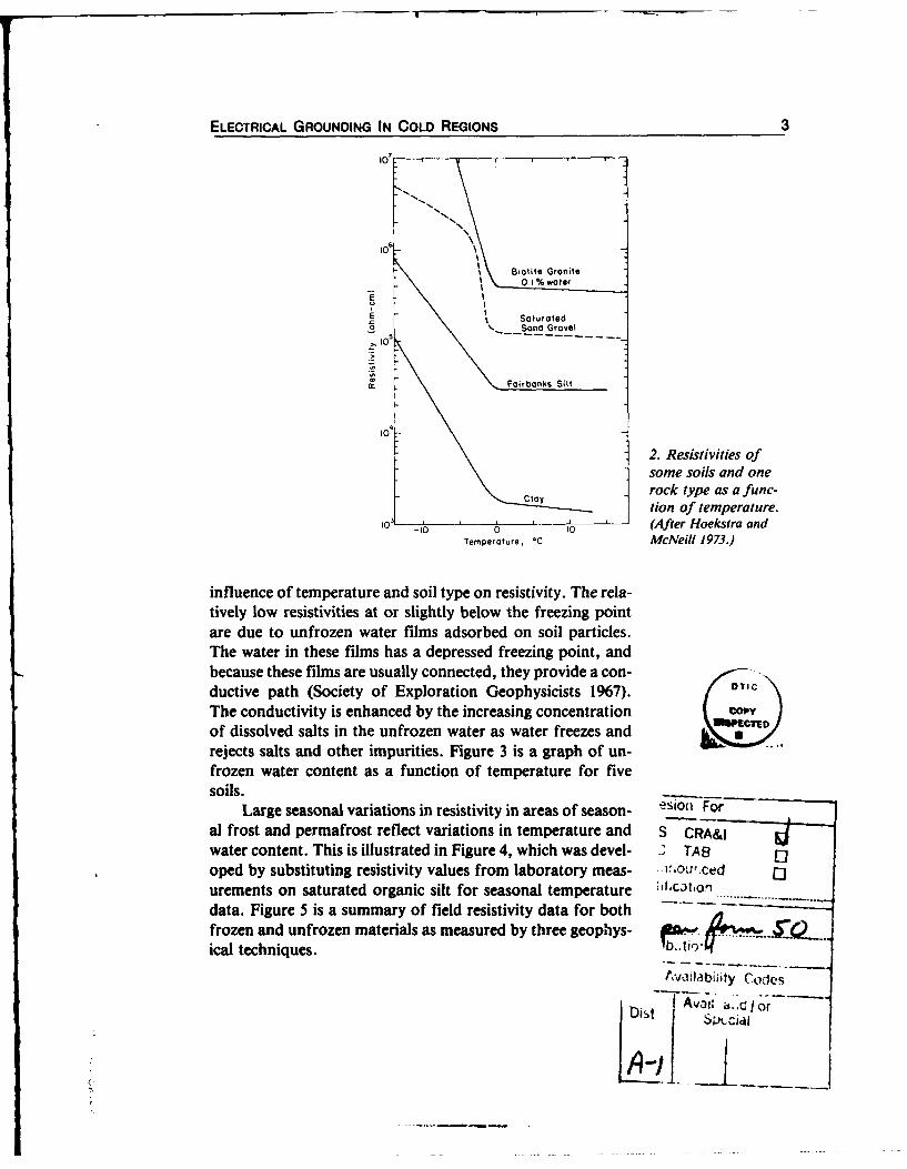
2. Resistivities ofsome soils and onerock type as a func-
tl tion of temperature.
-10 0 0 (After Hoekstra andTemperature, *C McNeill 1973.)
influence of temperature and soil type on resistivity. The rela-tively low resistivities at or slightly below the freezing pointare due to unfrozen water films adsorbed on soil particles.The water in these films has a depressed freezing point, andbecause these films are usually connected, they provide a con-ductive path (Society of Exploration Geophysicists 1967). OtIC
The conductivity is enhanced by the increasing concentration C_v_of dissolved salts in the unfrozen water as water freezes andrejects salts and other impurities. Figure 3 is a graph of un-frozen water content as a function of temperature for fivesoils.
Large seasonal variations in resistivity in areas of season- '1" For
al frost and permafrost reflect variations in temperature and S CRA&Iwater content. This is illustrated in Figure 4, which was devel- " TAB oped by substituting resistivity values from laboratory meas- '.Ou,,ced ourements on saturated organic silt for seasonal temperature ,t,.. o.data. Figure 5 is a summary of field resistivity data for both .frozen and unfrozen materials as measured by three geophys- L..ical techniques.
Ava&Iabiity Codes
D, a-cIdo

4 COLD REGIONS TECHNICAL DIGEST NO. 87-1
14C 1
A Wyoming entonite, naturalB KoolinitsC. Limonle
D W.Lebonon GrovellOiOom
1.20 E Fairbanks Silt
1.00
0, 0 .8 0
0
0 0.60
A0 .4o-
3. Unfrozen water 0.20
content as a function \ 0of temperature for N, 0 0
fine soils. (From .Anderson and Morgen- 0
stern 1973.) Temperature, C
0eq317M (00-
4. Annual tempera- 1 4 ,
ture data for Fair- 32qo£
banks, Alaska, trans- olated into equivalent "
resistivity values inohm-cm based on
laboratory measure-ments for saturated
organic silt. (From Ar- ' A" Se 0c NOv Dot J*i F*b MOF I Ap, ]
cone et al. 1979.)

ELECTRICAL GROUNDING IN COLD REGIONS 5
,AI6AMONS Ad GtLIA*C% .........
sm I I , I - -- -N -,AWSOANS 4 GOLDAGAIN
st Tv CLAVGAJKMA AN .. .. .
OAWAIN
.Novi t W. -T
UL T" SANO
SAAI*v St, IT.,PfLAISISELO W ... ... . . . .p.SAD, S"t r ff.' 'Sf0(lOv, OTtIrd - . Ie*
4TOOTO ON0C-- - -- --
A*6AA.$ AN GLI%*CE ..........
SILT -m -11 -m
FAIRGAKS Ad LST .....TIO..
___o_________ ________ - - I*A.TC 'NLIO
NN, _ _I_ _ iK'CL. A ..... a
Cl O A e , • •• eLi &."ON .......
03 t0
4 0 05 10
Apparent Resistivity (ohm-em)
5. Apparent resistivity of various materials measured with three techniques. (From Sellmann etal. 1976.)
The performance of a grounding installation depends pri- Evaluatingmarly on the resistivity of the soils at the grounding site. Large a sitelocal and regional variations in the resistivities of soils, partic-ularly in areas of frozen ground, make careful site study andselection a worthwhile means of assuring the best possibleground.
Areas where the ground is seasonally frozen but the deeper Permafrostsubsurface soils remain permanently unfrozen are knovn asareas of seasonal frost. Permafrost, or perennially frozenground, refers to areas where the ground temperatures re-main below 0°C (32*F) for at least two years (Muller 1947).Some sections of permafrost contain such large quantities ofice that it is impossible to obtain an acceptable ground.
Permafrost regions can be subdivided into zones of contin-uous and discontinuous permafrost. In the Northern Hemi-sphere the southern limit of discontinuous permafrost isroughly delineated by the 0°C mean annual isotherm (Fig. 6).The southern limit of continuous permafrost begins wherethe mean annual air temperature is several degrees lower (in

6 COLD REGIONS TECHNICAL DIGEST NO. 87-1
Ole~
C00
*4 404
WCALE IN STATUTE MILES
LEGEND_
~]AREA OF CONATINUOUS PERMAFROST = AREA OF DISCONTINUOUJS LAO SPORADIC PERMAFROST
~-., APPROXIMATE LIMIT OF TRIEES
NOTEPftebs W. ,,MONd, of p.w.fmoA NW AR Me*d we m" A .1 of.e Aec hed~ V e eme. .rly oo II fe *J£1 ce e.,CI
6. Permafrost zones in North America.
ermaJack POSS and Pitat
Peatra Soilck
burn /phgnr 1980)Thet existee of perafrSostasovriswihaliud n
coarstMs n etius pierafrSostzn.Smieurigsraefaue7. roilethouh padninadicnus permafrost reioscanbelpu inhfining unreton, owe-

ELECTRICAL GROUNDING IN COLD REGIONS 7
resistivity sites. Some examples, taken from several sources(Muller 1947, Kane and Slaughter 1973, Sherman 1973, Wil-liams and Everdingen 1973), are
" Trees with tap roots, such as pines, indicate thatpermafrost is either absent or deep.
" Willow groves generally indicate the presence ofgroundwater that freezes for only a short period.
* Tamarack, spruce and dwarfed and stunted birchesmay indicate a shallow permafrost table.
" Peat and moss usually indicate a relatively thinwater-bearing zone above permafrost.
* Lakes and rivers usually depress the permafrosttable locally and therefore may overlie unfrozenaquifers. Other local topographic depressions mayindicate areas of thaw.
" In the zone of discontinuous permafrost, it is likelythat the thawed material beneath many lakes mayhave a hydrologic (and thus electrical) connectionwith subpermafrost aquifers.
* In coastal areas, saline groundwater may be foundat shallow depths beneath bars, spits, beaches ordeltas.
Surface and subsurface investigations for construction pur-poses usually include soils analyses and determination of thedepth and thickness of the permafrost or the annually frozenzone or both. These data, as well as information about sur-face and groundwater supplies, are helpful in selectinggrounding sites.
Electrical geophysical methods that directly measure earth Geophysicalresistivity are useful in evaluating grounding sites. Two meth- measurementsods most likely to be useful are the DC resistivity method andthe electromagnetic method. For a review of all geophysicalmethods used in studying permafrost distribution, see Scottet al. (1978).
The DC resistivity method uses a current passed betweentwo end electrodes in a four-electrode array placed in astraight line in the ground; the resulting potential differenceis measured between the central two electrodes and indicatesan average resistivity. The depth to which an integrated aver-age of resistivity can be measured increases with increasedspacing of the electrodes; however, lateral resolution is lostwith increasing depth of penetration. Telford et al. (1976)
8 COLD REGIONS TECHNICAL DIGEST NO. 87-1
and the Society of Exploration Geophysicists (1967) describedcommon methods more completely.
Inductive electromagnetic methods use alternating currentsources to produce an electromagnetic field that induces eddycurrents in the ground. An induced field produced by the ed-dy currents is detected at a receiver. The difference in magni-tude between the induced fields and the inducing fields resultsfrom the conductivity of the earth. The depth of penetrationis controlled primarily by the spacing of the transmitter andthe receiver. Small, portable units are commercially availablefor studying near-surface lateral distribution of electrical re-sistivity, and these have been used for mapping the distribu-tion of shallow permafrost (Hoekstra et al. 1975, Arcone etal. 1979). These methods can be used year-round, whereasDC methods are difficult to use in the winter because of highcontact resistance at the electrodes.
Choosing Some grounding systems that have been used in cold regions
a grounding aremethod * Vertical rods driven into the earth,
" Arrays of many vertical rods," Horizontal strip electrodes buried in the earth," Direct electrical connection to the ocean,• Electrical connection to continuous metal well cas-
ings (water or petroleum)," Electrical connection to steel in reinforced concrete
foundations of buildings, and" Electrodes placed in the unfrozen beds of lakes and
streams.The first three methods are the most common.
Vertical The most common method of achieving an electrical groundrods is by driving one or more steel rods into the earth. In the sim-
plest case of a homogeneous earth and negligible contact re-sistance, the resistance to ground of a single electrode is esti-mated using the following equation (Tagg 1964):
g= -k I In±4 -1] (2)
where Rg = resistance to ground (ohms)Q = resistivity of the soil (ohm-cm)f = length of the rod (cm)
= radius of the rod (cm).
ELECTRICAL GROUNDING IN COLD REGIONS 9
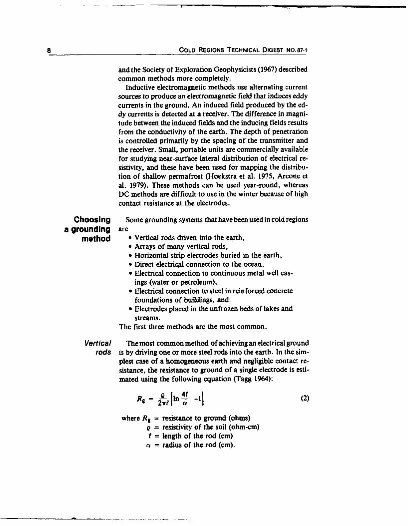
Equation 2 indicates that if both the rod length and radiusare increased by the same proportions, the length increasewill have a larger influence on lowering Rg than the increasein diameter, as demonstrated in Figure 8. Doubling the lengthof the rod will lower the resistance to ground by about 40%;much larger increases in the diameter are needed to producethe same results. In many cases it will be most practical to usea longer electrode, especially in seasonal frost areas wheremore conductive soils are likely to occur at depth.
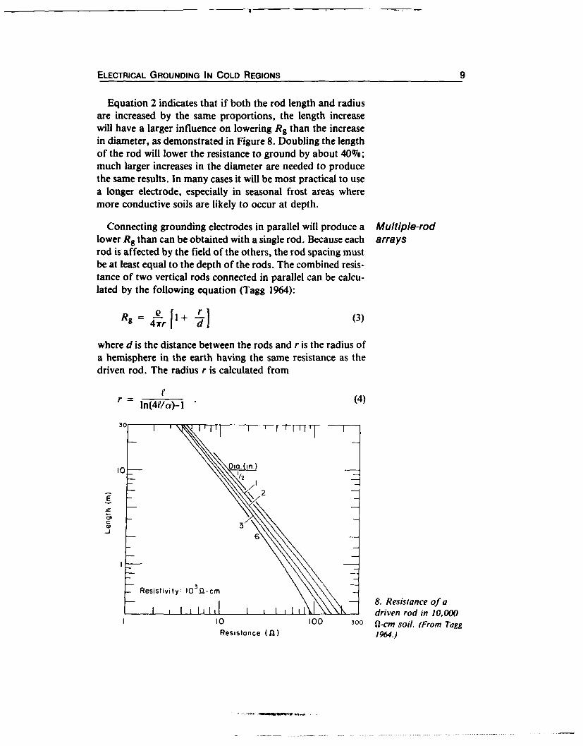
Connecting grounding electrodes in parallel will produce a Multiple-rodlower R9 than can be obtained with a single rod. Because each arraysrod is affected by the field of the others, the rod spacing mustbe at least equal to the depth of the rods. The combined resis-tance of two vertical rods connected in parallel can be calcu-lated by the following equation (Tagg 1964):
R _g _ 4 l 1~ + (3)
where d is the distance between the rods and r is the radius ofa hemisphere in the earth having the same resistance as thedriven rod. The radius r is calculated from
Cln(4f/a)-l (4)
I0- Dia. i.)
3
Resistivity: 10 3a-cm8. Resistance of adriven rod in 10,000
10 100 300 2-cm So il. (From TaggResistance (f)1964.)

10 COLD REGIONS TECHNICAL DIGEST NO. 87-1
300I I I I I
For 100,000 1-rcm Soil
Length of Rods in Soil = 350 cmDiam. of Rods = 1.6 cmDistance Between Rods = 350 cm
I 3 Rods are in an Equilateral Triangle
200 4 or More Rods are in a Hollow Square
0C
100
9. Resistance vs num- I I I I I I Iber of electrodes in 0 4 8 12 16 20 24 28 32 36 40100,000 Q-cm soil. Number of Rods
Connecting two grounding rods in parallel can decrease Rgby a factor of about two compared to a single rod. As thenumber of rods increases, the effect of each rod decreases(Fig. 9). For example, one hundred 1.3-cm ( -in.) diametergrounding rods arranged in a hollow square driven to a depthof 1.2 m (4 ft) with 1.2 m between each rod would decreaseRg by a factor of 30 compared to a single rod. Tagg (1964) de-scribed methods for calculating the resistances of large num-bers of electrodes connected in parallel in various configura-tions.
Horizontal Buried, horizontal wire or strip electrodes may be usedstrip electrodes when bedrock or permafrost is less than 2 m from the sur-
face.* In permafrost regions it would be most practical to in-stall the electrode during the summer when the active layer isthawed.
Table 1 lists equations for calculating the resistance of vari-ous configurations of buried wire. Table 2 gives examples ofthe results of these calculations. The resistance of buriedstrips can be approximated by performing the calculationsfor a wire of the same circumference.
* Buried plate or ring electrodes have also been used to achieve groundingbut have been found to be less practical than driven rods or buried wire orstrip electrodes. See Tagg (1964) for a discussion and resistance calculationsfor these grounding methods.

ELECTRICAL GROUNDING IN COLD REGIONS 11
Table 1. Earth resistances for buried wires of radius a at depth S12 (Tagg 1964).(Units should be consistent throughout the calculations.)
Configuration Resistance formula
Single wire Rg = (Q/4rL) In(4L/(x)-I + In[(2L + 'S' + 4L)/S] + S/2L- <'S' + 4L2/2LI(wire length = 2L)
Right-angle turn Rg = (Q/4rL)Iln(2L/(Y + ln(2L/S)-0.2372 + 0.2146(S/L) +(L = length of one arm) ).lO35(S'/L)-.O424(S/L 4
)1
Three-point star Rg = (g/67rL)jln(2L/) + ln(2L/S)-1.071-0.209(S/L) +(L = length of one arm) .238(S 2 /L)-.054(S'/L')j
Four-point star Rg = (e/8rL)lln(2L/a) + ln(2L/S) + 2.912-1.07J(S/L) +
0.645( SV L2)-0.145(S'/L ')1
Six-point star Rg = (o/127rL)ln(2L/) + ln(2L/S) + 6.8512-3.128(S/L) +
1.758(S/L 2)-O.490(S'/L')J
Eight-point star Rg = (Q/16rL)jln(2L/(x) + ln(2L/S) + 10.98-5.51(S/L) +
3.26(S 2/fL)- 1.17(S-/L')I
Table 2. Performance of various electrode configurations in10,000 fl-cm homogeneous earth. These values were calculatedusing the equations in this digest.
Electrode configuration Rg (Q)
Horizontal wire, 1.3 cm in diameter, 4 m long, buried 2 m deep. 17
Driven rod, 1.6 cm in diameter, driven to 3.5-m depth. 29
Two driven rods, 1.6 cm in diameter, connected in parallel, 282 m apart, driven to 2-m depth.
For a given length, a straight wire will have the lowest resis-tance. Resistance also decreases as the number of arms in aradial array increases, as shown in Figure 10.
In some regions of seasonal frost and permafrost, the pro- Conductivecedures for installing grounding rods have been experimental- backfillsly modified to reduce the resistance to ground. In experiments
described by Delaney et al. (1982) and Sellmann et al. (1984),vertical holes with diameters larger than grounding rods were

12 COLD REGIONS TECHNICAL DIGEST NO. 87-1
30 _T - r [T I Ip 00,00 Or~m
- 22 60lP 1,00r- -23 3 0o, cM
20-
10. Resistance vs 0- 1 2 0 o--
number of arms in a Length of each arm (L) 2.5m
radial-array horizon- Depth of burial (S/2) im
tal electrode. A one- I I I I I I Iarm array has a length 0 2 4 6 8 N0
of 2L. No of arms in radial array
excavated in permafrost either by shaped charges or by drill-ing. Grounding rods were then emplaced and the holes back-filled with a mixture of either soil, salt and water or just soiland water. Reference electrodes were driven into the groundfor comparison purposes.
The use of salt in the backfill material reduced Rg com-pared to the other backfill by amounts ranging from slight tonearly an order of magnitude. In marginally frozen silt (00 to-2°C), Rg decreased from about 1200 Q for a driven rod to145 12 for a vertical rod emplaced in an excavated hole andbackfilled (Sellmann et al. 1984). In very cold silt (-7 ° to-10°C), Rg decreased from 6700 0 to only 4500 12. Backfillingwith a mixture of soil and water without salt improved Rg on-ly during the thaw season. Since these experiments began sev-eral years ago, the values of Rg at some of the test sites havecontinued to lower. Salt may be migrating away from theelectrodes due to diffusion or infiltration or both and may becausing some thaw, thus increasing the "effective diameter"of the electrode (Sellmann et al. 1984).
The reduction in resistance by using this method probablydepends primarily on the permeability and the unfrozenwater content of the soil. If this is true, the technique is likelyto be most useful in permafrost regions where fine-grainedsoil is no more than a few degrees below freezing and wherecoarser-grained material has a low ice content and retainssome permeability when frozen. It should be especially usefulin regions where a significant seasonal thaw layer develops,creating favorable conditions for the migration of the salt(unless the material is very coarse and salts leach away). Inseasonal frost areas, the salts would be likely to leach awayrapidly in the summer. This technique may also improve aground by reducing the contact resistance between the elec-

ELECTRICAL GROUNDING IN COLD REGIONS 13
SEAONAL THAW 11. Configuration of4 L 1.:3 nearly horizontal
PEORIAIROSJT electrodes placed inthe thawed activelayer. (From Sellmannet al. 1984.)
trode and the surrounding soil because the salt prevents an icelayer from forming around the electrode.
One grounding option for temporary summer operations isto place nearly horizontal electrodes in the seasonally thawedlayer and pour salt solution onto the surface along each rod(Fig. 11). Sellmann et al. (1984) tested this method and con-cluded that it "may be applicable to winter installations if alarge quantity of salty water is used and a permeable organicsurface mat exists."
The common practice of pouring water (without salt)around an electrode once it is driven into the ground will havea variable effect on Rs. In regions of intense cold, it is likelythat the water will rapidly freeze around the electrode andcause high contact resistance. In regions of seasonal frost,this practice may lower Rg by washing fine soil particles, withunfrozen water on the surfaces, into contact with the elec-trode.
When expedient grounding is necessary and it is impossible Alternativesto install an electrode, the U.S. Army Corps of Engineers to grounding(1973) recommends that surface contact with the earth shouldbe made. This method is not likely to produce specified resis-tance-to-ground values, but it may be the best option underthe circumstances. If earth contact is impossible because ofice or snow cover, equipment should be bonded to reduce therisk that different electrical potentials will develop on eachpiece of equipment. The potential developed on the bondedsystem will be different from that of the earth, so an electricalhazard remains. With either surface contact or bonding, ex-tra precautions should include isolating the equipment andusing better electrical insulation.
14 COLD REGIONS TECHNICAL DIGEST NO. 87-1
Determining Calculations of Rg for regions of seasonal frost and perma-electrode frost should use a resistively layered earth model. Tagg (1964)
resistance theoretically considered the effect of the depth of groundingelectrodes in different thicknesses of horizontally layeredearth. He presented a method for calculating the resistance ofa vertical electrode in layered earth. Arcone (1977) calculatedresistances in one- and two-layered earth for vertical rods orhorizontal wires and compared the results to the theoreticalresults of Sunde (1949). Arcone showed that a horizontal wireis preferable to a vertical electrode for achieving the desiredRg for ground conditions similar to those expected in a per-mafrost setting. For example, if the earth is frozen below Im, the resistivity of the unfrozen layer is 10,000 fl-cm, andthe resistivity of the permafrost is 1,000,000 fl-cm, then a12-in-long, 5-cm-radius vertical grounding rod will have anRg of 900 Q. By comparison, a 0.125-cm-diameter horizontalwire that is 100 m long will have an Rg of about 100 R. A100-m-long electrode may seem impractical, but it is likely tobe more effective and easier to.install than a long rod driveninto permafrost. (1211
The resistance to ground should be measured to ensureadequate performance. A standard procedure for measuringR9 is the fall-of-potential method described by Tagg (1964).
Conclusions * The chance of finding and developing a low-resis-tance grounding site decreases greatly when movingtowards polar regions from the zone of seasonal frostto the discontinuous and continuous permafrostzones.
* Large seasonal variations in the resistance to groundcan be expected in areas of frozen ground. Groundingmay not be difficult during the summer but will likelybecome a problem when the surface layer freezes.
* The search for suitable grounding sites can be aidedby geophysical methods that locate low-resistivity(usually unfrozen) earth. A knowledge of an area'stopography, vegetation, and surface and ground-water sources can provide good information for lo-cating thawed zones and conductive soils for agrounding site.
* Multiple-rod grounding arrays or horizontal ground-ing configurations can be used to achieve a lower Rgthan with a single grounding rod.

ELECTRICAL GROUNDING IN COLD REGIONS 15
" Excavating a large-diameter hole, inserting a ground-ing rod and backfilling with a conductive backfill candecrease the resistance of a single driven rod.
" Inserting nearly horizontal grounding rods into anunfrozen surface layer and pouring salt water alongthe surface may produce an acceptable temporaryground.
" The ocean, steel reinforcing bars, metal well casingsand natural thaw zones beneath lakes and streams canprovide good grounding alternatives.
" It may be impossible to achieve an adequate grounddue to frozen earth or ice and snow cover. In thiscase, electrical hazards can be minimized by establish-ing surface contact with the earth or bonding all elec-trical equipment. In either case extra safety precau-tions Should be taken.
" More research is required to determine the actual ef-fect of unfrozen water content and temperatures on re-sistance-to-ground values and recommended ground-ing procedures in areas of seasonally frozen groundand permafrost.
Anderson, D.M. and N.R. Morgenstern (1973) Physics, Referenceschemistry, and mechanics of frozen ground: A review. InProceedings, Second International Conference on Perma-frost, Yakutsk, Siberia, North American Contribution, pp.257-288.Arcone, S.A. (1977) A computer program to determine theresistance of long wires and rods to nonhomogeneousground. USA Cold Regions Research and Engineering Lab-oratory, CRREL Report 77-2.Arcone, S.A., A.J. Delaney and P.V. Sellmann (1979) Ef-fects of seasonal changes and ground ice on electromagneticsurveys of permafrost. USA Cold Regions Research and En-gineering Laboratory, CRREL Report 79-23.Brown, R.J.E. (1977) Muskeg and permafrost. In Muskegand the Northern Environment in Canada (N.W. Radforthand C.O. Brawner, Ed.). Toronto: University of TorontoPress, pp. 148-163.Delaney, A.J., P.V. Sellmann and S.A. Arcone (1982) Im-proving electrical grounding in frozen materials. USA ColdRegions Research and Engineering Laboratory, Special Re-port 82-13.
16 COLD REGIONS TECHNICAL DIGEST NO. 87-1
Fisheries and Environment Canada (1973) Electromagneticprobing of permafrost. In Proceedings, Second InternationalConference on Permafrost, Yakutsk, Siberia, North Ameri-can Contribution, pp. 517-526.Hoekstra, P., P.V. Selimann and A. Delaney (1975) Groundand airborne resistivity surveys of permafrost near Fair-banks, Alaska. Geophysics, 40(4): 641-656.Kane, D.L. and C.W. Slaughter (1973) Recharge of a centralAlaska lake by subpermafrost groundwater. In Proceedings,Second International Conference on Permafrost, Yakutsk,Siberia, North American Contribution, pp. 458-461.Muller, S.W. (1947) Permafrost or Permanently FrozenGround and Related Engineering Problems. Ann Arbor,Michigan: J.W. Edwards.Scott, W.J., P.V. Sellmann and J.A. Hunter (1978) Geo-physics in the study of permafrost. In Proceedings, Third In-ternational Conference on Permafrost, Edmonton, July, vol.2, pp. 93-116.Sellmann, P.V., S.A. Arcone and A. Delaney (1976) Prelim-inary evaluation of new LF radiowave and magnetic induc-tion resistivity units over permafrost terrain. In Proceedings,Symposium on Permafrost Geophysics. National ResearchCouncil of Canada, Technical Memorandum 119.Selimann, P.V., A.J. Delaney and S.A. Arcone (1984) Con-ductive backfill for improving electrical grounding in frozensoils. USA Cold Regions Research and Engineering Labora-tory, Special Report 84-17.Sherman, R.G. (1973) A groundwater supply for an oil campnear Prudhoe Bay, arctic Alaska. In Proceedings, Second In-ternational Conference on Permafrost, Yakutsk, Siberia,North American Contribution, pp. 469-472.Society of Exploration Geophysicists (1967) Mining Geo-physics. Volume II: Theory. Tulsa, Oklahoma: The Societyof Exploration Geophysicists.Sunde, E.D. (1949) Earth Conduction Effects in Transmis-sion Systems. New York: D.V. Van Nostrand Company, Inc.Tagg, G.F. (1964) Earth Resistances. New York: PitmanPublishing Corporation.Telford, W.M., L.P. Gedart, R.E. Sheriff and D.A. Keys(1976) Applied Geophysics. New York: Cambridge Universi-ty Press.U.S. Army Corps of Engineers (1973) Grounding of powerand communications for tactical operations in arctic regions.

ELECTRICAL GROUNDING IN COLD REGIONS 17
U.S. Army Engineer District, Alaska.Washburn, A.L. (1980) Geocryology. New York: John Wiley.Williams, J.R. and R.O. van Everdingen (1973) Groundwaterinvestigations in permafrost regions of North America: A re-view. In Proceedings, Second International Conference onPermafrost, Yakutsk, Siberia, North American Contribu-tion, pp. 435-446.