tid-0073 0c 12-month-maint-kit 58015-01 bmk-ln...
TRANSCRIPT
12-Month Maintenance Kit #58015-01 for BMK LN (w/Separate Igniter & Injector) Technical Instruction Document TID-0073_0C
VD2: 10/07/14 AERCO International, Inc. 100 Oritani Dr. Blauvelt, New York 10913 Phone: 800-526-0288 Page 1 of 14
TECHNICAL INSTRUCTIONS
Latest Update: 10/07/2014
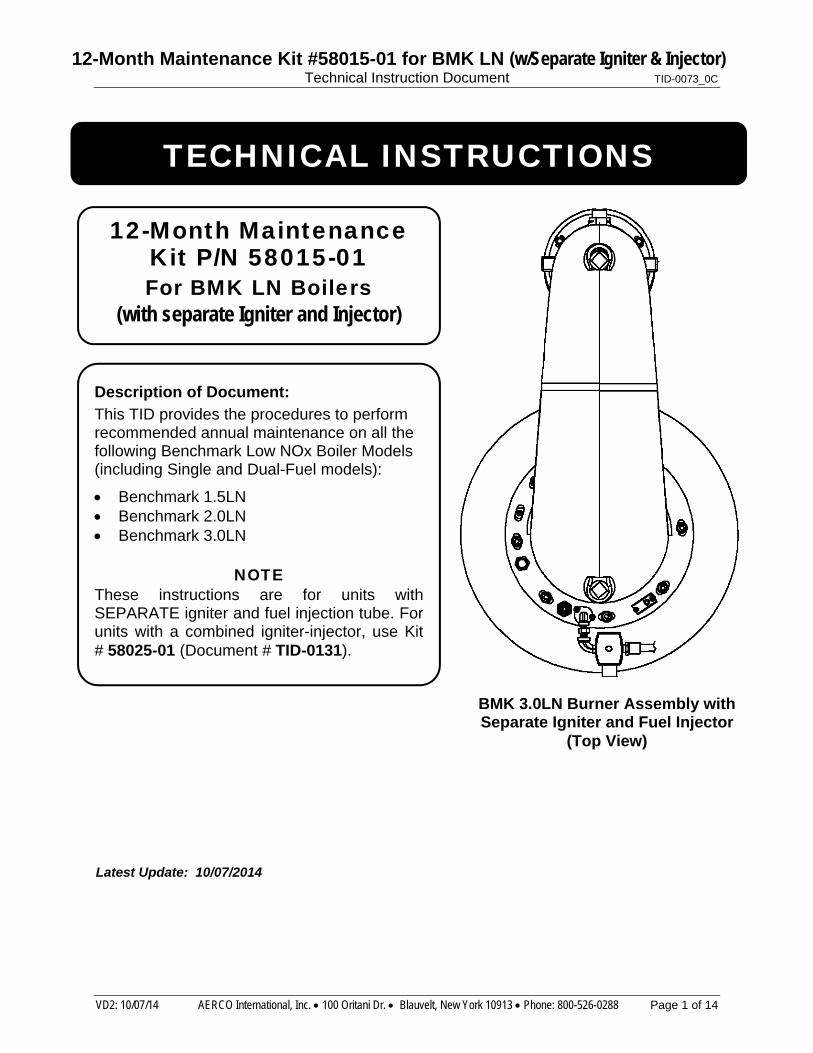
Description of Document: This TID provides the procedures to perform recommended annual maintenance on all the following Benchmark Low NOx Boiler Models (including Single and Dual-Fuel models):
Benchmark 1.5LN Benchmark 2.0LN Benchmark 3.0LN
NOTE These instructions are for units with SEPARATE igniter and fuel injection tube. For units with a combined igniter-injector, use Kit # 58025-01 (Document # TID-0131).
BMK 3.0LN Burner Assembly with Separate Igniter and Fuel Injector
(Top View)
12-Month Maintenance Kit P/N 58015-01 For BMK LN Boilers
(with separate Igniter and Injector)

12-Month Maintenance Kit #58015-01 for BMK LN (w/Separate Igniter & Injector) Technical Instruction Document TID-0073_0C
VD2: 10/07/14 AERCO International, Inc. 100 Oritani Dr. Blauvelt, New York 10913 Phone: 800-526-0288 Page 2 of 14
Disclaimer
The information contained in this manual is subject to change without notice from AERCO International, Inc. AERCO makes no warranty of any kind with respect to this material, including, but not limited to, implied warranties of merchantability and fitness for a particular application. AERCO International is not liable for errors appearing in this manual. Nor for incidental or consequential damages occurring in connection with the furnishing, performance, or use of this material.
Technical Support: (Mon–Fri, 8am-5pm EST)
1-800-526-0288
www.aerco.com
12-Month Maintenance Kit #58015-01 for BMK LN (w/Separate Igniter & Injector) Technical Instruction Document TID-0073_0C
VD2: 10/07/14 AERCO International, Inc. 100 Oritani Dr. Blauvelt, New York 10913 Phone: 800-526-0288 Page 3 of 14
TABLE OF CONTENTS
1. INTRODUCTION ............................................................................... 4
2. OVERVIEW OF THE REPLACEMENT PROCEDURES ....................... 4
3. CONTENTS OF 12-MONTH MAINTENANCE KIT (P/N 58015-01) ............ 4
3. TOOLS, TEST EQUIPMENT, & MATERIALS REQUIRED .................. 5
3.1 Tools ................................................................................................................ 5
3.2 Test Equipment ............................................................................................... 5
3.3 Expendable Materials ..................................................................................... 5
4. Preliminary Procedures .................................................................. 5
5. Benchmark Low NOx Burner Maintenance .................................... 6
5.1 Spark Igniter Replacement ............................................................................. 9
5.2 Flame Detector Replacement ......................................................................... 9
6. CONDENSATE TRAP MAINTENANCE .............................................. 9
7. FINAL REASSEMBLY AND TESTING ............................................. 12
7.1 Reassembly and Set-Up Following Annual Maintenance .......................... 12
7.2 Final Testing Following Annual Maintenance ............................................ 12
12-Month Maintenance Kit #58015-01 for BMK LN (w/Separate Igniter & Injector) Technical Instruction Document TID-0073_0C
VD2: 10/07/14 AERCO International, Inc. 100 Oritani Dr. Blauvelt, New York 10913 Phone: 800-526-0288 Page 4 of 14
1. INTRODUCTION This Technical Service Bulletin provides the procedures to perform recommended annual maintenance on the following Benchmark Low NOx Boiler Models:
Benchmark 1.5LN (Single and Dual-Fuel models)
Benchmark 2.0LN (Single and Dual-Fuel models)
Benchmark 3.0LN (Single and Dual-Fuel models)
NOTE This document applies ONLY to units featuring a SEPARATE igniter and fuel injector tube. For newer units, or retrofitted units, with combined igniter/injector, use Maintenance kit 58025-01 and the maintenance instructions in document TID-0131.
2. OVERVIEW OF THE REPLACEMENT PROCEDURES The recommended annual maintenance includes performing the following tasks on the Low NOx Burner and the Condensate Trap (24060) used on each Benchmark Low NOx Models:
Low NOx Burner: Replace igniter-injector and flame detector (with gasket)
Condensate Trap: Clean and inspect trap. Replace trap O-ring and orifice gasket
The replacement parts required to perform the recommended maintenance tasks are included in the Annual Maintenance Kit described in section 2.1.
3. CONTENTS OF 12-MONTH MAINTENANCE KIT (P/N 58015-01) The Annual Maintenance Kit for Benchmark Low NOx boilers is comprised of the following components:
Table 1: Annual Maintenance Kit, Part No. 58015-01
ITEM QTY PART NO. DESCRIPTION 1 1 GP-122435-S IGNITER
2 1 66034 FLAME DETECTOR
3 1 81048 FLAME DETECTOR GASKET
4 1 84017 CONDENSATE TRAP O-RING
5 1 81092 CONDENSATE TRAP ORIFICE GASKET
12-Month Maintenance Kit #58015-01 for BMK LN (w/Separate Igniter & Injector) Technical Instruction Document TID-0073_0C
VD2: 10/07/14 AERCO International, Inc. 100 Oritani Dr. Blauvelt, New York 10913 Phone: 800-526-0288 Page 5 of 14
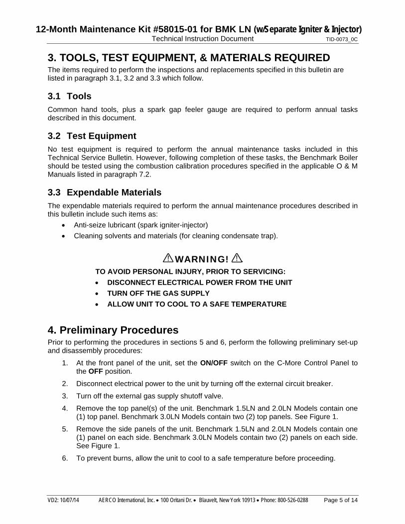
3. TOOLS, TEST EQUIPMENT, & MATERIALS REQUIRED The items required to perform the inspections and replacements specified in this bulletin are listed in paragraph 3.1, 3.2 and 3.3 which follow.
3.1 Tools Common hand tools, plus a spark gap feeler gauge are required to perform annual tasks described in this document.
3.2 Test Equipment No test equipment is required to perform the annual maintenance tasks included in this Technical Service Bulletin. However, following completion of these tasks, the Benchmark Boiler should be tested using the combustion calibration procedures specified in the applicable O & M Manuals listed in paragraph 7.2.
3.3 Expendable Materials The expendable materials required to perform the annual maintenance procedures described in this bulletin include such items as:
Anti-seize lubricant (spark igniter-injector)
Cleaning solvents and materials (for cleaning condensate trap).
WARNING!
TO AVOID PERSONAL INJURY, PRIOR TO SERVICING:
DISCONNECT ELECTRICAL POWER FROM THE UNIT
TURN OFF THE GAS SUPPLY
ALLOW UNIT TO COOL TO A SAFE TEMPERATURE
4. Preliminary Procedures Prior to performing the procedures in sections 5 and 6, perform the following preliminary set-up and disassembly procedures:
1. At the front panel of the unit, set the ON/OFF switch on the C-More Control Panel to the OFF position.
2. Disconnect electrical power to the unit by turning off the external circuit breaker.
3. Turn off the external gas supply shutoff valve.
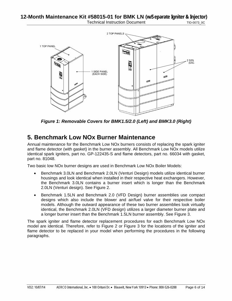
4. Remove the top panel(s) of the unit. Benchmark 1.5LN and 2.0LN Models contain one (1) top panel. Benchmark 3.0LN Models contain two (2) top panels. See Figure 1.
5. Remove the side panels of the unit. Benchmark 1.5LN and 2.0LN Models contain one (1) panel on each side. Benchmark 3.0LN Models contain two (2) panels on each side. See Figure 1.
6. To prevent burns, allow the unit to cool to a safe temperature before proceeding.
12-Month Maintenance Kit #58015-01 for BMK LN (w/Separate Igniter & Injector) Technical Instruction Document TID-0073_0C
VD2: 10/07/14 AERCO International, Inc. 100 Oritani Dr. Blauvelt, New York 10913 Phone: 800-526-0288 Page 6 of 14
Figure 1: Removable Covers for BMK1.5/2.0 (Left) and BMK3.0 (Right)
5. Benchmark Low NOx Burner Maintenance Annual maintenance for the Benchmark Low NOx burners consists of replacing the spark igniter and flame detector (with gasket) in the burner assembly. All Benchmark Low NOx models utilize identical spark igniters, part no. GP-122435-S and flame detectors, part no. 66034 with gasket, part no. 81048.
Two basic low NOx burner designs are used in Benchmark Low NOx Boiler Models:
Benchmark 3.0LN and Benchmark 2.0LN (Venturi Design) models utilize identical burner housings and look identical when installed in their respective heat exchangers. However, the Benchmark 3.0LN contains a burner insert which is longer than the Benchmark 2.0LN (Venturi design). See Figure 2.
Benchmark 1.5LN and Benchmark 2.0 (VFD Design) burner assemblies use compact designs which also include the blower and air/fuel valve for their respective boiler models. Although the outward appearance of these two burner assemblies look virtually identical, the Benchmark 2.0LN (VFD design) utilizes a larger diameter burner plate and a longer burner insert than the Benchmark 1.5LN burner assembly. See Figure 3.
The spark igniter and flame detector replacement procedures for each Benchmark Low NOx model are identical. Therefore, refer to Figure 2 or Figure 3 for the locations of the igniter and flame detector to be replaced in your model when performing the procedures in the following paragraphs.

12-Month Maintenance Kit #58015-01 for BMK LN (w/Separate Igniter & Injector) Technical Instruction Document TID-0073_0C
VD2: 10/07/14 AERCO International, Inc. 100 Oritani Dr. Blauvelt, New York 10913 Phone: 800-526-0288 Page 7 of 14
Figure 2: BMK 3.0LN Burner Assembly (Top and Isometric Views)
TOP VIEW
ISOMETRIC VIEW

12-Month Maintenance Kit #58015-01 for BMK LN (w/Separate Igniter & Injector) Technical Instruction Document TID-0073_0C
VD2: 10/07/14 AERCO International, Inc. 100 Oritani Dr. Blauvelt, New York 10913 Phone: 800-526-0288 Page 8 of 14
SPARKIGNITER
FLAMEDETECTOR
AIR/FUELVALVEBLOWER
BURNERPLATE
SPARKIGNITER FLAME
DETECTOR
BURNERPLATE
AIR/FUELVALVEBLOWER
BURNER
TOP VIEW
SIDE VIEW
Figure 3: Benchmark 1.5LN & 2.0LN Burner Assemblies

12-Month Maintenance Kit #58015-01 for BMK LN (w/Separate Igniter & Injector) Technical Instruction Document TID-0073_0C
VD2: 10/07/14 AERCO International, Inc. 100 Oritani Dr. Blauvelt, New York 10913 Phone: 800-526-0288 Page 9 of 14
5.1 Spark Igniter Replacement Spark igniter part no. GP-122435-S is removed and replaced as follows:
1. Refer to Figure 2 (Benchmark 3.0LN), or Figure 3 (Benchmark 1.5LN & 2.0LN) for the installed location of the spark igniter.
2. Disconnect the spark igniter cable.
3. Unscrew and remove the installed spark igniter.
4. Using a spark gap feeler gauge, check to ensure that the replacement spark igniter provided in the kit is gapped at 1/8".
5. Prior to installation, a high-temperature anti-seize compound must be applied to the to the igniter threads.
6. Refer to Figure 2 or 3 and install the replacement igniter in the appropriate location. Do Not over-tighten. A slight snugging up is sufficient.
7. Reconnect the spark igniter cable.
5.2 Flame Detector Replacement Flame detector, part no. 66034 and gasket, part no. 81048 are removed and replaced as follows:
1. Refer to Figure 2 (Benchmark 3.0LN & 2.0LN Venturi design), or Figure 3 (Benchmark 1.5LN & 2.0LN VFD design) for the installed location of the flame detector and gasket.
2. Disconnect the flame detector wire lead.
3. Unscrew and remove the installed flame detector and gasket.
4. Install the replacement flame detector and gasket provided in the maintenance kit.
5. Reconnect the flame detector wire lead.
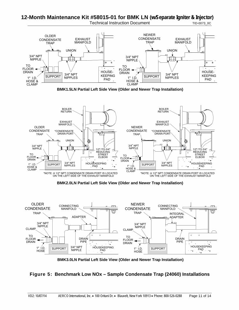
6. CONDENSATE TRAP MAINTENANCE Condensate trap, part no. 24060, is used with all Benchmark Low NOx Models. It is installed at the condensate drain of the exhaust manifold on Benchmark 1.5LN and 2.0LN models and at the drain of the connecting manifold on Benchmark 3.0 models.
NOTE As previously noted, there are two slightly different types of condensate traps that may be used in your configuration; an older style with a separate inlet adapter, and a newer style with a built-in adapter (see Figure 4). Maintenance is the same, except that the newer style does not need an orifice gasket (Step 6).
The condensate trap used on all BMK LN units should be inspected and cleaned as follows:
1. Disconnect the condensate trap from the exhaust manifold (Benchmark 1.5LN, or 2.0LN) or connecting manifold (Benchmark 3.0LN only) by loosening the hose clamps or fittings used in your installation. Figure 4 shows a sample connection for a Benchmark 2.0LN model.
2. Remove the connections on the inlet and outlet sides of the condensate trap, shown in Figures 4 and 5.

12-Month Maintenance Kit #58015-01 for BMK LN (w/Separate Igniter & Injector) Technical Instruction Document TID-0073_0C
VD2: 10/07/14 AERCO International, Inc. 100 Oritani Dr. Blauvelt, New York 10913 Phone: 800-526-0288 Page 10 of 14
3. Refer to Figure 4 and loosen the four (4) thumbscrews securing the cover on the condensate trap. Remove the cover.
4. Remove and discard the O-ring gasket currently installed in trap. It will be replaced with the new O-ring included in the maintenance kit during reassembly.
5. Remove the float (with float guide attached) from the condensate trap.
6. Remove and discard the currently installed orifice gasket from the older style trap. (This step is not necessary for newer style traps as they do not have this gasket). The new orifice gasket included in the maintenance kit will be installed into the older style traps during reassembly.
7. Thoroughly clean the trap and float. Also inspect the drain piping for blockage. If the trap cannot be thoroughly cleaned, replace the complete condensate trap.
8. Check the condensate drain opening on the manifold (Figure 5) to ensure it is clear of blockage.
Figure 4: Condensate Trap, Part No. 24060 Cross-Sectional View (Older and Newer)
9. After the above items have been inspected and thoroughly cleaned, install the new orifice
gasket, part no. 81092 provided in the maintenance kit.
10. Reinstall the float and float guide removed in step 5.
11. Install the new O-ring, part no. 84017 provided in the kit and replace the condensate trap cover by tightening the four (4) thumb-screws.
12. Reassemble all piping and hose connections to the condensate trap inlet and outlet.
13. Reconnect the condensate trap to condensate drain connection on the exhaust manifold (or connecting manifold for BMK 3.0LN).
INLET
O-RINGS(2)
OUTLET
BUILT-INADAPTER
3/4” NPTPORT
3/4” NPTPORT
3/4” NPTPORT
THUMB SCREW
ORIFICEGASKET
Older Style Trap Newer Style Trap
INLET
OUTLET
FLOATFLOAT
NOTE: There is no orifice gasket used in the new style Condensate Trap.
3/4” NPTPORT
THUMB SCREWS (4)
THUMB SCREWS (4)
O-RINGGASKET
COVER COVERFLOAT GUIDE FLOAT GUIDE
O-RINGGASKET
12-Month Maintenance Kit #58015-01 for BMK LN (w/Separate Igniter & Injector) Technical Instruction Document TID-0073_0C
VD2: 10/07/14 AERCO International, Inc. 100 Oritani Dr. Blauvelt, New York 10913 Phone: 800-526-0288 Page 11 of 14
Figure 5: Benchmark Low NOx – Sample Condensate Trap (24060) Installations
3/4" NPTNIPPLE
1" I.D.HOSE & CLAMP
EXHAUST MANIFOLD
EXHAUST MANIFOLD
OLDERCONDENSATE
NEWERCONDENSATE
TRAP
TOFLOORDRAIN
TRAP
3/4" NPTNIPPLES
UNION
HOUSE-KEEPING
PADSUPPORT
3/4" NPTNIPPLE
1" I.D.HOSE & CLAMP
TOFLOORDRAIN 3/4" NPT
NIPPLES
UNION
HOUSE-KEEPING
PADSUPPORT
TOFLOORDRAIN
3/4" NPTNIPPLE
1" I.D.HOSE & CLAMP
3/4" NPTNIPPLES
UNION
SUPPORT
EXHAUSTMANIFOLD
BOILERRETURN
1/2"-TO-3/4"REDUCING
STREETELBOW
TRAP
*NOTE: A 1/2" NPT CONDENSATE DRAIN PORT IS LOCATED ON THE LEFT SIDE OF THE EXHAUST MANIFOLD
*CONDENSATEDRAIN PORT
HOUSEKEEPING PAD
TOFLOORDRAIN
3/4" NPTNIPPLE
1" I.D.HOSE & CLAMP
3/4" NPTNIPPLES
UNION
SUPPORT
EXHAUSTMANIFOLD
BOILERRETURN
1/2"-TO-3/4"REDUCING
STREETELBOW
TRAP
*NOTE: A 1/2" NPT CONDENSATE DRAIN PORT IS LOCATED ON THE LEFT SIDE OF THE EXHAUST MANIFOLD
*CONDENSATEDRAIN PORT
HOUSEKEEPING PAD
OLDERCONDENSATE
NEWERCONDENSATE
TRAP
CONNECTING MANIFOLD
DRAIN PIPE
3/4" NPTNIPPLE
TOFLOORDRAIN
CLAMP
1" I.D.HOSE
ADAPTER
3/4" NPTNIPPLE
SUPPORT HOUSEKEEPING PAD
HOUSEKEEPING PAD
TRAP
CONNECTING MANIFOLD
DRAIN PIPE
TOFLOORDRAIN
CLAMP
1" I.D.HOSE
INTEGRALADAPTER
3/4" NPTNIPPLE
SUPPORT
OLDERCONDENSATE
NEWERCONDENSATE
BMK1.5LN Partial Left Side View (Older and Newer Trap Installation)
BMK2.0LN Partial Left Side View (Older and Newer Trap Installation)
BMK3.0LN Partial Left Side View (Older and Newer Trap Installation)

12-Month Maintenance Kit #58015-01 for BMK LN (w/Separate Igniter & Injector) Technical Instruction Document TID-0073_0C
VD2: 10/07/14 AERCO International, Inc. 100 Oritani Dr. Blauvelt, New York 10913 Phone: 800-526-0288 Page 12 of 14
7. FINAL REASSEMBLY AND TESTING Upon completion of all annual maintenance tasks, reassemble the unit and perform the tests specified in paragraphs 7.1 and 7.2.
7.1 Reassembly and Set-Up Following Annual Maintenance Following completion of the all required inspections and replacements, perform the following reassembly and setup procedures:
1. Turn ON the external circuit breaker to the unit.
2. At the front panel of the unit, set the ON/OFF switch on the C-More Control Panel to the ON position.
3. Press the LOW WATER LEVEL RESET button to reset the low water cutoff.
4. Press the CLEAR switch to reset the FAULT LED and clear any displayed error message.
5. Replace any sheet metal panels previously removed from the boiler.
7.2 Final Testing Following Annual Maintenance Upon completion of the annual maintenance procedures specified in this bulletin, perform the Combustion Calibration Tests specified in Chapter 4 of the applicable O & M Manual listed below:
BENCHMARK MODEL O & M MANUAL
Benchmark 1.5LN GF-120
Benchmark 1.5LN, Dual-Fuel GF-121
Benchmark 2.0LN GF-123
Benchmark 2.0LN, Dual-Fuel GF-127
Benchmark 3.0LN GF-116
Benchmark 3.0LN, Dual Fuel GF-117
12-Month Maintenance Kit #58015-01 for BMK LN (w/Separate Igniter & Injector) Technical Instruction Document TID-0073_0C
VD2: 10/07/14 AERCO International, Inc. 100 Oritani Dr. Blauvelt, New York 10913 Phone: 800-526-0288 Page 13 of 14
NOTES:
12-Month Maintenance Kit #58015-01 for BMK LN (w/Separate Igniter & Injector) Technical Instruction Document TID-0073_0C
VD2: 10/07/14 AERCO International, Inc. 100 Oritani Dr. Blauvelt, New York 10913 Phone: 800-526-0288 Page 14 of 14
© AERCO International, Inc., 2014
Change Log
Date Description Changed By
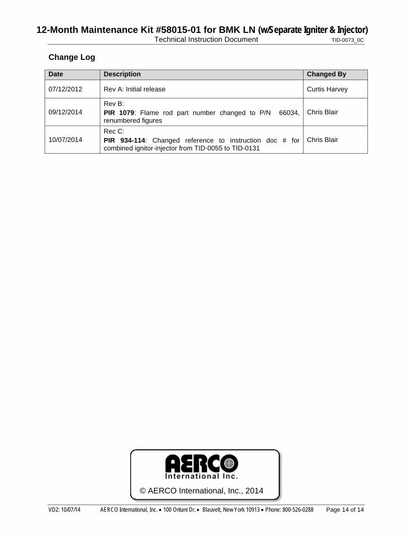
07/12/2012 Rev A: Initial release Curtis Harvey
09/12/2014 Rev B: PIR 1079: Flame rod part number changed to P/N 66034, renumbered figures
Chris Blair
10/07/2014 Rec C: PIR 934-114: Changed reference to instruction doc # for combined ignitor-injector from TID-0055 to TID-0131
Chris Blair