tidal turbine collision detection - ore.catapult.org.uk · tidal turbine collision detection a...
TRANSCRIPT

Tidal Turbine Collision Detection
A review of the state-of-the-art sensors and
imaging systems for detecting mammal
collisions
May 2016
Tidal Turbine Collision Detection PN000110-SRT-002
ORE Catapult
Document History
Author Revision Status
Revision Date Prepared by Checked by Approved by Revision History
V1.0 19/10/2015 Shrawan Jha
Rachael
Wakefield,
Gavin
Burrows
Derek Liddle Original
V2.0 16/12/2015 Shrawan Jha
Rachael
Wakefield,
Gavin
Burrows
Derek Liddle Revised
V3 9/3/16 Shrawan Jha
Rachael
Wakefield,
Gavin
Burrows
Revised
Field Detail
Report Title Tidal Turbine Collision Detection
Report Sub-Title A review of the state-of-the-art sensors and imaging systems for
detecting mammal collisions
Client/Funding Part public funding
Status Public
Project Reference PN000110
Document Reference PN000110-SRT-002

Tidal Turbine Collision Detection PN000110-SRT-002
ORE Catapult
ORE Catapult Revision Status
Revision Date Reviewed by Checked by Approved by Revision History
1.0 03/05/2016 V. Coy S.
Cheeseman P. MacDonald Final Issue
Disclaimer “The information contained in this report is for general information and is provided by CENSIS. Whilst we endeavour to keep the information up to date and correct, neither ORE Catapult nor CENSIS make any representations or warranties of any kind, express, or implied about the completeness, accuracy or reliability of the information and related graphics. Any reliance you place on this information is at your own risk and in no event shall ORE Catapult or CENSIS be held liable for any loss, damage including without limitation indirect or consequential damage or any loss or damage whatsoever arising from reliance on same.”

Tidal Turbine Collision Detection PN000110-SRT-002
ORE Catapult
Contents
1 Executive Summary ............................................................................................... 1
2 Introduction............................................................................................................. 3
3 Investigation Methodology .................................................................................... 4
4 Requirements for TTCD Systems .......................................................................... 6
4.1 System Description .......................................................................................... 6
4.2 Monitoring Requirements Informing Consenting Needs ................................... 9
5 Technologies ........................................................................................................ 12
5.1 Introduction .................................................................................................... 12
5.2 State-of-the-art of Relevant SIS Technologies ............................................... 12
5.3 System architecture ....................................................................................... 25
5.4 Summary of technologies reviewed ............................................................... 26
6 Conclusions .......................................................................................................... 29
7 Recommendations ............................................................................................... 33
8 Acknowledgements .............................................................................................. 37
Appendix 1 Technology Categories ...................................................................... 38
Appendix 2 List of Experts Consulted ................................................................... 39
Appendix 3 Knowledge Gap Study ........................................................................ 40
Appendix 4 Interview Notes ................................................................................... 42
Tidal Turbine Collision Detection PN000110-SRT-002
ORE Catapult
List of Tables
Table 1 TTCD Functional requirements ........................................................................ 11
Table 2 TTCD Environmental requirements .................................................................. 11
Table 3 Typical specs of some TTCD relevant off-the-shelf hydrophone products ....... 14
Table 4 Typical specs of some TTCD relevant off-the-shelf SONAR systems .............. 17
Table 5 Typical specs of the known off-the-shelf TTCD relevant camera products ...... 20
Table 6 TTCD requirements, relevant technologies and estimated TRL ...................... 28
Table 7 Applicability and maturity of relevant sensor technologies for detection needs 32
List of Figures
Figure 1: process flow of the investigation methodology ................................................ 4
Figure 2: a representative diagram indicating tidal turbine collision detection
requirements and sensors .............................................................................................. 6

Tidal Turbine Collision Detection PN000110-SRT-002
ORE Catapult
Abbreviations
ADCP Acoustic Doppler Current Profiler
CENSIS Centre for Sensor and Imaging Systems
DFKI Deutsche Forschungszentrum fur Kunstliche Intelligenz
DNV Det Norske Veritas
EIA Environmental Impact Assessment
EM Electromagnetic
EMF Electromagnetic Field
EMEC European Marine Energy Centre
ER Environmental Requirement
EU European Union
FAST Fundy Advanced Sensor Technology
FLOWBEC Flow and Benthic Ecology 4D
FP7 Seventh Framework Programme for Research
FR Functional Requirement
GUI Graphical User Interface
HD High Definition
HDD Hard Disk Drive
HRA Habitats Regulations Appraisal
IR Infrared
LED Light Emitting Diode
MEMS Microelectromechanical Systems
NERC Natural Environment Research Council
NOAA National Oceanic and Atmospheric Administration
Tidal Turbine Collision Detection PN000110-SRT-002
ORE Catapult
NPL National Physical Laboratory
OEM Original Equipment Manufacturer
ORJIP Offshore Renewables Joint Industry Programme
QTC Quantum Tunnelling Composites
ReDAPT Reliable Data Acquisition Platform for Tidal
SAMS Scottish Association for Marine Science
SIS Sensor and Imaging Systems
SMRU Sea Mammal Research Unit
SONAR Sound Navigation And Ranging
SpORRAn Scottish Offshore Renewables Research Framework
SSD Solid State Drive
TEL Tidal Energy Ltd
TRL Technology Readiness Level
TTCD Tidal Turbine Collision Detection
TVL Television Lines
UTOFIA Underwater Time of Flight Image Acquisition
UV Ultra Violet
WTKN Wave and Tidal Knowledge Network

Tidal Turbine Collision Detection PN000110-SRT-002
ORE Catapult Page 1 of 43
1 Executive Summary
This report presents the findings from a review of state-of-the-art sensing and imaging (SIS)
technologies relevant to Tidal Turbine Collision Detection (TTCD) application. The study
includes an assessment of the approximate technology readiness and the applicability of marine
animal collision detection technologies and devices being proposed, in testing and development
or already deployed in prototype tidal turbine projects.
There are a number of challenges in collecting the supporting evidence of marine animal
collision events; the principal challenge is the monitoring environment and the deployment and
operation of sensor systems in this. Highly energetic tidal flows are characterised by high levels
of noise from the turbine and from the moving water, variable levels of water turbidity and
abrasive materials moving at high velocities. Another challenge is the low maturity of some
applicable sensor technologies and the need in each case to collect a sufficient body of data in
a short time span to validate the technology design, conclude an optimal system and determine
with high certainty that a turbine blade has collided with, or nearly collided with a marine animal.
This report attempts to identify benefits, constraints, barriers to implementation, technology
readiness level (TRL1) and recommendations on the next steps to further development. The
report describes available and emerging sensor technologies against the following stated TTCD
detection needs:
proximity/collision warning
collision detection: object striking tidal turbine blade
post-event condition monitoring: identify and warn of structural damage to turbine blade (e.g.
hairline fracture)
post-event object identification: differentiate between animal or debris following impact
The SIS technologies explored in this report include hydrophones active sound navigation and
ranging (sonar), video camera and optical imaging, blade mounted strain gauges, blade-
mounted accelerometers, electromagnetic field sensors and tactile sensing technologies. Also
addressed are approaches to system architecture. The principal knowledge gap area is SIS to
monitor post collision events. The principal evidence gaps are data for sonar imaging and
tracking and blade collision impact. A collaborative mechanism to share relevant evidential SIS
data would be helpful in progressing the closure of some of these gaps. Seven areas for further
study have been suggested including the identified knowledge and evidence gaps, and also
suggests feasibility studies to explore emerging technologies that may have additional value in
TTCD. Financial resources remain a barrier to progression, with some tidal developments
reaching the point of implementation but lacking sufficient funding to deploy and run
1 The measure of technology readiness used in this report: high TRL (7-9; system test, launch and operations), medium TRL (4-6;
development of demonstrator to demonstration), low TRL (1-3; basic research to proof of feasibility)

Tidal Turbine Collision Detection PN000110-SRT-002
ORE Catapult Page 2 of 43
comprehensive trials with the application. A common test and development site that implements
some of the SIS that require further data input may help standardise experimental results and
provide an economically viable opportunity to trial new approaches and technologies..

Tidal Turbine Collision Detection PN000110-SRT-002
ORE Catapult Page 3 of 43
2 Introduction
Tidal turbine renewable energy developments require an Environmental Impact Assessment
(EIA) and also a Habitats Regulations Appraisal (HRA) before a Marine Licence and Section 36
(if the project is >1MW) are granted. Part of the consenting process includes the developer
taking measures to gather scientific evidence to identify the probability of marine mammals
colliding with their turbines. Evidence from tidal turbine deployment completed to date indicates
there are no known mammal collisions with a tidal device. The need for marine mammal
collision detection is identified as a priority by the Offshore Renewables Joint Industry
Programme (ORJIP) Ocean Energy2 in order for offshore marine energy array consenting to
become a viable proposition at scale.
Monitoring requirements vary from site-to-site, but can include:
animal behaviour around turbine structures (e.g. can they detect turbines, do they avoid
them, can they escape tidal stream, etc.),
quantification of number of collisions and near misses (accuracy of assumed or modelled
impact),
outcome of animal collisions (injury/damage to animal, without evidence each collision
assumed to be fatal),
identification of object/species types (vs. behaviour and impact).
Working towards the accumulation of monitoring evidence a significant level of research and
development of technologies for TTCD systems has been undertaken over the last decade.
Academia, developers and manufacturers within the UK are leading contributors. This body of
work has contributed to a number of TTCD system designs and approaches, which vary in
complexity and which can include more than a dozen functional requirements. There is
significant technology development on-going across a range of sensor technologies to meet
these functional requirements.
The following sections describe and explore the TTCD approaches made to date, starting with
the investigation approach adopted to capture information from relevant sources. What is clear
is that developers have adopted or intend to adopt broadly similar approaches, some more
comprehensive than others. Common to all is the assembly of a suite of TTCD devices that
work in tandem within a system to track a sequence of events, namely the identification of an
object of interest in the area, proximity of the object to the turbine and contact of the object with
the turbine blade. To this end the common approach is use of a combination of acoustic
sensors as proximity alerts (hydrophones and sonars) and imaging systems (imaging sonar and
video camera) to evidence what type of object has triggered the proximity sensors.
2 http://www.orjip.org.uk/oceanenergy/about

Tidal Turbine Collision Detection PN000110-SRT-002
ORE Catapult Page 4 of 43
3 Investigation Methodology
The starting point for this phase of the study was to take the findings of the Interim Report. The
study sought to articulate key technical requirements and environmental factors or constraints
for TTCD sensors systems.
Figure 1 process flow of the investigation methodology
Figure 1 illustrates the activities undertaken to expand on the Interim Report. Three strands of
investigation were pursued: (i) web-based research evaluated publicly available information
sources to identify expertise and assess any knowledge gaps, interrogation of applicable or
related technology company websites, search of databases of academic expertise and
publications, review of related available reports and contact made with related industry
organisations; (ii) internally at the Centre for Sensor and Imaging Systems (CENSIS) we
reviewed our academic landscape database and industry capability; (iii) further discussion with
TTCD system integrators explored initial technology ideas, their confidence in new technology
suggested and any integration considerations.
The outputs of these investigation activities were combined to create a matrix of demonstrated
or prospective technologies mapped against the four detection needs and their known maturity
level and relevance. This matrix evolved with time and was updated as more information
followed during interviews (section 6, Table 7).
The next stage was to identify and contact appropriate experts in each category of sensing
technology, i.e sonar, optical camera, hydrophone etc. Experts were sought from academia

Tidal Turbine Collision Detection PN000110-SRT-002
ORE Catapult Page 5 of 43
(relevant research groups) and industry (operational/environmental experience). Appendix 1
summarises the technologies selected and the basis for selection of related experts. At least
two individuals or organisations were identified against each technology category assuming not
all those contacted would be able to support a discussion on this topic. Geographical location
was not a constraint in this exercise; interviews included individuals and organisations in the
UK, Europe, Canada and USA.
Those experts willing to contribute to this study were interviewed mostly via telephone
conference calls but sometimes in face-to-face meetings or via email; Appendix 2 summarises
the interviews and consultations held. Each interview was structured around a questionnaire;
the questions were based upon technology applicability against one or more of the detection
needs and the capability of the product or technology proposed as a solution. As far as the
interviewees were willing to discuss, the consultation also captured any on-going improvements
or developments being made to the products or technologies or any significant or potentially
disruptive innovations. On concluding the discussions, interview notes were created and
communicated back to respondents for cross-verification of facts and figures. On verbal
agreement with the respondents these notes form a confidential aspect to this report. These
interview notes and subsequent research and analysis form the basis of this report.

Tidal Turbine Collision Detection PN000110-SRT-002
ORE Catapult Page 6 of 43
4 Requirements for TTCD Systems
4.1 System Description
4.1.1 Introduction
In order to provide evidence to help reduce uncertainty, supply chain partners in the marine
energy industry are in the process of developing TTCD systems to be deployed alongside
prototype turbines. Figure 2 is a representation of devices and approaches that have been
adopted/proposed wholly or partly by developers in their TTCD systems. Some of the sensors
are embedded in the turbine blades and others located around the turbine site. The typical
detection needs are also presented graphically. The detection needs as well as the SIS
technologies are elaborated in the following sections.
Figure 2 a representative diagram indicating tidal turbine collision detection requirements and sensors
4.1.2 Proximity Detection
Proximity is a relative term and during the course of the consultation this was used with respect
to three different scenarios within the TTCD system:
i) Proximity Warning Using Instrumentation
The principal proximity warning device is active sonar, which is sometimes supported by
passive sonar (hydrophones) and/or video camera. Ideally, a proximity sensor should provide
an alert about collision risk, derived from understanding animal movement and the closest point
to the blade where collision seems unavoidable. This ‘fine scale’ behaviour is not yet fully
understood.

Tidal Turbine Collision Detection PN000110-SRT-002
ORE Catapult Page 7 of 43
Proximity sensors have been used in different ways in TTCD. A signal that aligns with a set of
preprogramed criteria can be used (and has been demonstrated operationally by the MCT
project at Strangford Lough) to action a shut-down of the turbine to reduce the risk of mammals
in the proximity colliding with blades. A second example is a warning can be used to
automatically trigger a sequence of actions in other devices making up the TTCD system. An
approach proposed for a deployment at a site off the coast of Pembrokeshire will use a
proximity signal from an active sonar device to switch devices from standby/data re-write mode
into record and store mode. The purpose of this approach is to optimise the opportunity to
capture all available SIS data in context of a collision impact event.
The detection range of acoustic-based sensors and camera equipment limits the distance
between object and turbine at which a proximity alert is effective. Furthermore, active sonar has
to operate outwith the audible frequency ranges of marine animals to avoid altering the animals’
behaviour (attraction or exclusion) or causing their distress. The frequency ranges permissible
are not far ranging and range is further affected by water turbidity. In recognition of a potential
new market, sonar hardware has been enhanced by some Original Equipment Manufacturer
(OEMs) to deliver devices that meet the specific needs of TTCD. These have applied different
operational modes and highly advanced signal interpretation methods to identify relevant
objects.
As a general guide for active sonar the proximity range can be estimated as the volume of water
within a sphere of between 30 and 60m radius depending on device, operational mode and
water turbidity. The siting of the sonar device in the area is important, for example if the device
is located at the base of the turbine looking outwards and has a minimal proximity threshold of
30m, for a marine animal moving at a speed of 10m/s a sonar at the base of the device would
only have 3s to trigger an action; if that is the main function of the sonar. In this case they will
need to be placed further away from the device.
Passive acoustic systems (hydrophones) can capture sounds from marine animals over the
order of around 200m. However these are only useful for detecting some species during
vocalisation. Furthermore the distance of, and the direction in which an animal is moving is
challenging to pinpoint when they cease to vocalise. If the location of an animal is required,
multiple hydrophones are required.
Optical video camera systems have been used in proximity alert but have limitations. Camera
images are, like sonar, affected by water quality. Furthermore, artificial illumination is not
permissible in TTCD so insufficient daylight also contributes to image quality. The best use of
cameras is to observe the blades to capture an impact event, or deployed on the seabed to
ground truth data from hydrophones and active sonar systems
ii) Proximity Animal Behaviour
In relation to the question of whether marine animals are aware of and able to avoid turbine
blades, developers and the scientific community agree that understanding animal behaviour
Tidal Turbine Collision Detection PN000110-SRT-002
ORE Catapult Page 8 of 43
(movement and vocalisation) within the proximity (10m to 60m) of the turbine is the most
important, but as yet poorly understood area. Data from TTCD systems will contribute towards
this broader understanding. In this task multi-directional (or 3D) hydrophone systems, imaging
and tracking sonar and camera systems have been employed in for both species identification
and location.
The individual devices making up a TTCD system need not work in isolation and information
from tracking and imaging sonars, video and hydrophones can be combined to understand a
sequence of events and movement of animals in the vicinity of the turbine. Tracking the animals
will inform their general trajectory towards turbines with estimated velocities, and also if their
movement might be related to foraging, feeding or other. These will all be helpful in improving
understanding of behaviour.
iii) Proximity Near-Miss
Close proximity is defined as a separation of less than a few metres from the turbine blade. An
important gap in the tidal turbine field of knowledge is the understanding if marine mammals can
navigate through and around the blades without colliding with them. Every device in a TTCD
system is important in the determination of near miss. Imaging techniques, sonar, hydrophone
and camera, can be helpful to inform a near-miss event but generally the current technology
has difficulty to, or is unable to provide validation of it. This is where other parts of the TTCD
system situated on the blades will contribute. An impact sensor installed in the turbine blade, a
stress sensor at the root of the blade and video camera systems on the hub are approaches
made by developers to capture and validate the near-miss/collision impact moment.
4.1.3 Collision Detection
Developers are exploring at least one of three, different approaches to detect blade impact;
these are mechanical impact signatures, noise signatures and video image capture. Sonar
imaging cannot be used closer than 3 m to the blade as the cavitation and bubbles affect the
quality of the image.
The mechanical signatures of an impact event; for example a shock or a significant increase in
the bend or flex in a blade outwith its expected operating range may be registered using
accelerometer or strain gauge systems specifically designed for this purpose.
Hydrophones are being explored to detect the sound generated during an impact event that
propagates through seawater. Similarly, microphones attached inside the turbine body, which
may already be part of the condition are also being explored for the ability to capture the sound
of an impact. The TTCD system of a near scale demonstrator turbine to be deployed off the
Pembroke coast has been designed to integrate data from strain gauges at the blade root,
vibration from impacts via blade-mounted accelerometers and any changes in the drive train
operation that might be detectable during an impact event. Combined with data from camera
systems and active sonar the approach aims to link the moment of collision with an identified

Tidal Turbine Collision Detection PN000110-SRT-002
ORE Catapult Page 9 of 43
object in the proximity, or by the same inference by the absence of an impact signal, a near
miss event.
Arguably, while the corroborative mechanical and acoustic data is being accumulated by the
various test TTCD systems, aside from human observer, the only SIS method at this time that
can conclusively validate a near miss is video camera. However the developers and camera
specialists consulted for this study were in general agreement that a video camera has too
many limitations to work effectively over time as part of a TTCD system. Not all areas of the
blade might be visible in the operating conditions. Biofouling and abrasive currents would
eventually impair the lens, and to capture images at the required quality at night would require
artificial illumination which is not permissible.
Alternatives to video camera, the most direct and unambiguous SIS to detect an impact event
could be tactile sensing which detects physical contact between two objects. Although
integration of tactile sensors within the turbine blades may be a challenge for blade
manufacturers and OEMs, if strain gauge and accelerometer systems are found to be
inadequate, a feasibility to test this type of technology could be of value. The potential of tactile
sensing in TTCD is described in section 5.2.8.
4.1.4 Post-Event Object Identification
Few of the TTCD systems appear to incorporate a device to specifically identify a post collision
object. Instead it is planned this be informed through the combination of sensory inputs across
the entire TTCD system. Fast tidal flows, turbidity and turbulence generally mean that locating,
tracking and analysing objects downstream of the turbine following an impact with the turbine is
highly challenging and may be impossible with current technology. Human observation is likely
the only reliable input that can confirm post impact status of an animal with any degree of
confidence. However, by combining the information of movement detected by sonar, camera
and hydrophone it is envisaged that confirming an impact with a species of interest can be
determined with a high-level of confidence.
4.1.5 Post-impact Condition Monitoring
The condition monitoring of the turbine blade is one of the more mature technologies as it is of
primary importance to the asset integrity and therefore high on the turbine developers’ priorities.
Technologies here are inherited and modified from wind turbines and include fibre-optic strain
sensors embedded within the turbine blade and accelerometers at the base of the blade. These
provide information on motion and loads experienced by the blades during service.
4.2 Monitoring Requirements Informing Consenting Needs
Based on the understanding gained of TTCD systems during consultation with regulators,
researchers, OEMs and developers, Table 1 outlines the functional requirements and
corresponding sensing and monitoring needs identified as being important to build a strong
scientific evidence base to support future environmental consenting.
Tidal Turbine Collision Detection PN000110-SRT-002
ORE Catapult Page 10 of 43
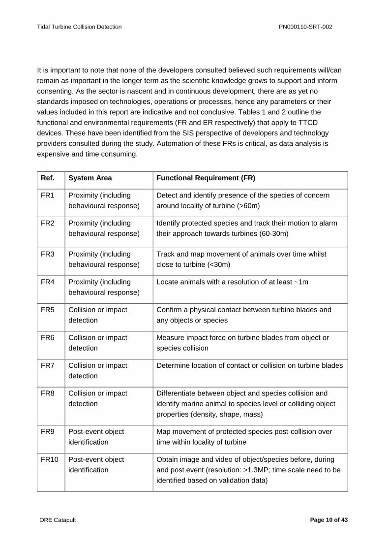
It is important to note that none of the developers consulted believed such requirements will/can
remain as important in the longer term as the scientific knowledge grows to support and inform
consenting. As the sector is nascent and in continuous development, there are as yet no
standards imposed on technologies, operations or processes, hence any parameters or their
values included in this report are indicative and not conclusive. Tables 1 and 2 outline the
functional and environmental requirements (FR and ER respectively) that apply to TTCD
devices. These have been identified from the SIS perspective of developers and technology
providers consulted during the study. Automation of these FRs is critical, as data analysis is
expensive and time consuming.
Ref. System Area Functional Requirement (FR)
FR1 Proximity (including
behavioural response)
Detect and identify presence of the species of concern
around locality of turbine (>60m)
FR2 Proximity (including
behavioural response)
Identify protected species and track their motion to alarm
their approach towards turbines (60-30m)
FR3 Proximity (including
behavioural response)
Track and map movement of animals over time whilst
close to turbine (<30m)
FR4 Proximity (including
behavioural response)
Locate animals with a resolution of at least ~1m
FR5 Collision or impact
detection
Confirm a physical contact between turbine blades and
any objects or species
FR6 Collision or impact
detection
Measure impact force on turbine blades from object or
species collision
FR7 Collision or impact
detection
Determine location of contact or collision on turbine blades
FR8 Collision or impact
detection
Differentiate between object and species collision and
identify marine animal to species level or colliding object
properties (density, shape, mass)
FR9 Post-event object
identification
Map movement of protected species post-collision over
time within locality of turbine
FR10 Post-event object
identification
Obtain image and video of object/species before, during
and post event (resolution: >1.3MP; time scale need to be
identified based on validation data)

Tidal Turbine Collision Detection PN000110-SRT-002
ORE Catapult Page 11 of 43
Ref. System Area Functional Requirement (FR)
FR11 Post-event condition
monitoring (animal)
Identify if animals suffer immediate fatal injury
FR12 Post-event condition
monitoring (turbine)
Identify critical changes to turbine performance after
collision event (e.g. bearing load) and health of sensors
Table 1 TTCD Functional requirements
Ref. Parameter Environmental Requirement (ER)
ER1 Ingress Protection IP68, Submersible to depth of 50m
ER2 Operating Temperature -10ºC to +40ºC (based on the typical operational range for
shallow water electrical equipment although acceptable
range is 4ºC to 20ºC)
ER3 Storage Temperature -20ºC to +30ºC
ER4 Mechanical Shock Critical for application
ER5 Vibration Critical for application
ER6 Hydrostatic Pressure Operates at twice submersible depth
ER7 Corrosion Seawater operation for 5 years
ER8 Bio-fouling Operation for 12 months without maintenance to remove
bio-fouling
ER9 Maintenance Minimum 12 month operation without preventative
maintenance
Table 2 TTCD Environmental requirements

Tidal Turbine Collision Detection PN000110-SRT-002
ORE Catapult Page 12 of 43
5 Technologies
5.1 Introduction
A TTCD system requires a number of complementary technologies to be employed to fulfil the
detection and monitoring requirements identified. To date there has been a significant body of
research and development that has contributed to approaches and device designs applicable
for TTCD. This section 5 describes the SIS technologies developed, tested and deployed to
date to fulfil some of the requirements described in Tables 1 and 2. These technologies can be
considered state-of-the-art in TTCD.
Also described in this section are existing and emerging SIS technologies identified has having
potential value in collision monitoring but which have not (knowingly) been explored in TTCD.
How devices are designed to work together as part of a whole TTCD system ‘architecture’ are
described in the last part of this section, together with a technology summary table.
5.2 State-of-the-art of Relevant SIS Technologies
5.2.1 Introduction
SIS technologies which have the capability to fulfil some of the TTCD requirements are
introduced in this section. Technology categories that were considered are outlined in Appendix
1, and include hydrophones, sonars, video camera, strain gauge and accelerometers, magnetic
and electric field sensing and tactile sensing. An introduction to each discusses capability
against detection requirements, parameters measured, technology readiness level and
remaining challenges or further improvements.
5.2.2 Hydrophone, microphone and use of sound data
Hydrophones are passive acoustic devices and used in TTCD to support marine mammal
identification and to varying degrees of accuracy, locate and track. Validation of mammal
presence near turbines is achieved by either/all of human observer, camera and sonar imaging.
Hydrophones are also used in turbine noise level assessment and to record mechanical noise
for health monitoring purposes. They may have the potential to pick up the noise of a blade
colliding with an object.
Hydrophones are capable of detecting marine mammals across several hundreds of km,
although the vocal range of most mammals is significantly less. OEMs and marine mammal
researchers are developing specialised detection algorithms that aim to differentiate between
different marine animal species. There is evidence these can also identify individuals from
within a group. Recent advancements demonstrate the possibility to locate mammal position in
real-time, used as part of a whale-tracking network off the west coast of Canada3.
3 Ocean Networks Canada (www.oceannetworks.ca/)

Tidal Turbine Collision Detection PN000110-SRT-002
ORE Catapult Page 13 of 43
Drifting hydrophones deployed from buoys are favoured for TTCD applications because tidal
sites have high background noise. These drift with the tidal current so as to minimise flow noise
around the sensor. High tidal noise may limit the application of mammal characterising and
tracking analytics in TTCD, similarly, while the devices have the potential to pick up the noise of
a blade colliding with an object, advanced signal filtering would be required to accommodate
background noise. Deployed from buoys near the turbine and signal filtering, blade impacts
might be 13iscernible. The higher frequency sound generated by wear of rotor bearings is quite
distinctive and can provide supplementary data in turbine condition monitoring. Microphones
situated inside the turbine housing are used to record the acoustic signals of the drive train.
Furthermore changes to loading on the blades may translate into changes in noise patterns in
the drive train. The potential to pick up blade collision events through changes in noise patterns
is being explored by at least one developer consulted.
The principal areas of hydrophone technology developments include: improved system design,
incorporation of processing power, user interfaces, and species identification algorithms with
tracking capabilities. This meets requirements FR 1 and FR2 (Table 1). By employing an array
of hydrophones accurate tracking of species to within 1m around the area close to the turbine
appears to be possible, thus meeting FR4 (Table 1).
Table 3 provides a sample of hydrophone products that have either been tested in TTCD or
used in marine mammal detection. Devices are generally built to the specifications of the
application including requirements for directionality and detection range. An appropriate
frequency range is just the most fundamental requirement, advanced signal processing adds
value to the hardware and additional benefits include on-board processing and the capability to
auto-adjust the system for optimal signal capture in real time.
Features including animal identification, classification and visualisation remain the niche areas
in hydrophones. In the tidal turbine monitoring context, hydrophone hardware is high TRL (8-9)
while animal classifying algorithms are still under development at medium TRL (3-5). Algorithms
are not deterministic but rather provide an indicative current, sufficient validation data set.
The next generation of hydrophones is likely to be more compact and require less power along
with the smart features. The miniature hydrophone array in Table 3 exemplifies this trend.
Regarding maintenance, a period of two years or above is required which is generally
achievable by the OEM. Of special note is the observation that Titanium housing appears to
discourage the formation of bio-fouling which will otherwise impair signal quality over time.
Company Ocean
Sonics
Teledyne
RESON
Jasco RTSYS
Jasco
Product Model icListen
HF/HF(L)
TC4032 Ocean
Sound
Meter
EA SDA
1000
AMAR G3

Tidal Turbine Collision Detection PN000110-SRT-002
ORE Catapult Page 14 of 43
Company Ocean
Sonics
Teledyne
RESON
Jasco RTSYS
Jasco
System
Description
A smart
digital
hydrophone
Analog
Hydrophon
e element
Customiza
ble
Hydropho
ne system
Hydropho
ne with
embedde
d
processor
Low power
autonomous
multichannel acoustic
recorder with 1-4
devices
Validation or
application in
National
Physical
Laboratory
(NPL),
Fundy
Advanced
Sensor
Technology
(FAST)
European
Marine
Energy
Centre
(EMEC)
PODs
N/A N/A Tested in harsh
conditions
Indicative lower
frequency (Hz)
10/1 5 17 3 1
Indicative upper
frequency
(kHz)
200 120 (250;
TC4034)
150 500 150
Communication
interface
Ethernet Analog Analog Ethernet Ethernet, RS-232/485
Internal Battery
life (h)
10 N/A N/A 94-140 Optional
Internal Data
Storage (GB)
128 N/A N/A 128/256
solid
state
drive
(SSD)
256 (SSD) – 1792
(hard disk drive)
Typical External
Power (W)
1 1 2.5 0.6-2.5 50 – 100
Supporting
Software
Yes (Lucy) N/A Yes yes AMARlink
Table 3 Typical specs of some TTCD relevant off-the-shelf hydrophone products

Tidal Turbine Collision Detection PN000110-SRT-002
ORE Catapult Page 15 of 43
Summary
Hydrophones are used in TTCD to support marine mammal identification and to varying
degrees of accuracy, locate and track their movement. Hydrophones and microphones are also
used in condition monitoring. Drifting hydrophones deployed from buoys are favoured for TTCD
applications because tidal sites have high background noise. Advanced signal filtering is
required for data analytics. Technology development trends include improved system design,
incorporation of processing power, user interfaces, and animal species identification algorithms
with tracking capabilities
Devices are generally built to the specifications of the application including requirements for
directionality and detection range. The next generation of hydrophones is likely to be more
compact and require less power along with the smart features.
5.2.3 SONAR
Sound Navigation And Ranging (SONAR) is an active acoustic technique used for decades in
underwater communications, navigation, object detection and imaging. Imaging sonar is a
powerful technique for TTCD and is a key component in collision risk assessment. The
technology continues to improve.
Imaging sonar works by generating pulses of sound waves (pings) at a desired frequency (from
low <1Hz) to ultrasonic (>20kHz), which are then reflected (echoed) by objects in the water. The
sonar device captures the reflections and interprets the signals into images. Resolution of an
image depends on frequencies used and the angle of the beam. The time delay between a ping
and an echo provides distance between the object and the detector. Multi-beam sonars are
used for a wider spatial coverage and for this a larger number of beams will mean a better
resolution.
There is an allowable frequency range imposed on sonar users. It is believed that sonar
operation below 250kHz can impact on the behaviour and wellbeing of marine mammals. Thus
all commercial sonar use is restricted to ranges in the order of 700KHz and above; much higher
frequencies than the hearing range of marine species4.
In TTCD applications sonar is primarily used to detect marine animals and objects larger than
1m in length at ranges of <60m in clear water to <15m in turbid water. The state-of-the-art sonar
systems have emerged out of research and development pilot projects such as Reliable Data
Acquisition Platform for Tidal (ReDAPT) and Flow and Benthic Ecology 4D (FLOWBEC). The
device design and the site inform configuration of the devices around the turbine. Devices can
be mounted on the main turbine structure looking outward, or on the seabed looking towards
the turbine. Pilot projects have demonstrated it is not possible to image objects closer than 3m
4 Updated acoustic threshold levels are proposed in a guide produced by the National Oceanic and Atmospheric Administration
(NOAA) Fisheries. They have compiled, interpreted, and synthesized the best available science to produce updated acoustic
threshold levels for the onset of both temporary and permanent hearing threshold shifts.
http://www.nmfs.noaa.gov/pr/acoustics/faq.htm

Tidal Turbine Collision Detection PN000110-SRT-002
ORE Catapult Page 16 of 43
to the blades due to the high level of turbulence and cavitation in the area. This means sonar is
not useful to validate a collision impact event.
State-of-the-art sonar in TTCD lies in advanced software that incorporates imaging and tracking
algorithms working with optimised frequencies and beam configurations. Different types of
marine animal are characterised by their shape and software to automate object identification is
in development. The capability of the software has been validated by manual observation in
40m of water depth. Although diving birds are generally too small to detect with the same
resolution, the approach is capable of identifying if they are present via the shape of the bubble
trails they create. In this sonar meets requirement FR2 in Table 1.
The closer the object is to the sonar the more resolution can be applied and target identification
is more probable. The mammal identification algorithms currently give prevalent false positives
about objects detected in the 45-60m range, however the sonar OEMs will be able to improve
this capability where they have opportunities to collect new data.
State-of-the-art tracking algorithms understand motion and can differentiate between inanimate
and living objects. The algorithm applies acoustic Doppler current profiler (ADCP) data about
current velocity and direction. Objects that move contrary to the current are identified as live
animals while those drifting with the current are classed as inanimate objects.
The future of sonar is a monitoring process that combines fast, wide area scans at low
resolution and small data packets and slower, narrow angle scans of higher volume data
packets. The system will automatically switch between these scanning modes; the wide
detection range will capture and live track a large number of objects at distance and the ADCP-
informed tracking algorithm interpret object motion into inanimate and living objects. At this point
the mode will switch to narrow angle to generate higher resolution image of a tracked object
identified as an animal to which the automated image analysis is applied.
Active sonar hardware is high at TRL9 and certified for two years operation without
maintenance. The object tracking and identification system is at medium TRL. More data,
further testing and algorithm refinement to prove reliable use in this application. Increasing
capability for on-board processing and machine learning is also important to create faster output
and full automation. The specifications of relevant sonar systems are outlined in Table 4.
In summary. Imaging sonar is a powerful technique for TTCD and is a key component in
collision risk assessment and primarily used to detect marine animals and objects larger than
1m. The detection range of sonar for TTCD applications is <60m in clear water to <15m in
turbid water. It is not possible to image objects closer than 3m to the blades due to the high
level of turbulence and cavitation in the area. This means sonar is not useful to validate a
collision impact event. State-of-the-art sonar systems deploy advanced imaging and tracking
algorithms and optimise frequencies and beam configurations. This approach can identify the
type of marine animal including seals, porpoises and diving birds. More pilot projects are

Tidal Turbine Collision Detection PN000110-SRT-002
ORE Catapult Page 17 of 43
required to improve the reliability and accuracy of the imaging and tracking software. With more
data sonar OEMs will be able to realise fully automated collision alert systems.
Company Tritech Coda Octopus DIDSON
Product Model Gemini 720i Echoscope II DIDSON 300 m
System Description Sonar system with
capability to detect
and track species
Compact and real-
time 3D acoustic
system
Dual Frequency Sonar
able to observe fish,
mammal, and
crustacean activity in
turbid water
Application in Tidal Energy Limited
(TEL) Deltastream
EMEC
Frequency (kHz) 720 150/ 250/ 375/ 500 700 – 1800 (Dual)
Number of beams 256 128 × 128 48 or 96
Range Maximum (m) 120 250/200/200/150 30 – 90
Range Minimum (m) 0.2 1 1
Effective Angular
resolution (°)
0.5 0.39, 0.39, 0.39,
0.23
0.4
Maximum Update/ping
rate (Hz)
30 20 -
Angular Coverage (°) 120 50 × 50 or 30 × 30 29
Auxiliary Sensor for Sound velocity Tilt -
Typical External
Power (W)
35 150 30
Supporting Software Gemini SeaTec
Software
(Species
detection)
Windows-based,
comprehensive real-
time display and
control software
Proprietary imaging
software
Table 4 Typical specs of some TTCD relevant off-the-shelf SONAR systems

Tidal Turbine Collision Detection PN000110-SRT-002
ORE Catapult Page 18 of 43
5.2.4 Video camera systems
Video footage has been used in TTCD to provide visual information of the turbine as part of a
health monitoring system and to ground truth data received from sonar devices (e.g. the
ReDAPT project). To capture the moment of contact the camera could be mounted on the
blades of the turbine, the nacelle or the support structure and have a clear view of the surface of
each blade along the whole length; a typical blade dimension is of the order of 10m length × 2m
width.
Very high tidal flows create risk to static camera systems through impact and erosion from fast
moving objects and sediments. Commercial underwater video camera equipment deployed in
TTCD systems are typically sourced from the subsea oil and gas market which produces robust
systems for low light, low contrast, highly turbid conditions. Other relevant expertise of OEMs in
this sector lies in ‘marinisation’ of camera equipment, which means pressure-tested housings
and lenses, wet connectors, power, and data management and communication protocols.
Artificial illumination is not permitted at tidal turbine sites as it can change the behaviour of
marine mammals. This means image capture is limited to daylight and not possible at night.
Tidal turbine sites are situated within the 200m depth sunlight zone of coastal waters and
providing it is a bright day and the water is relatively clear, daylight illumination is sufficient.
Using low light, high contrast video systems would help to maximise the available natural
illumination.
From consultations with tidal turbine developers, video is used to monitor objects and animal
species within visible range of the turbine. It can also be helpful to validate other sensor data or
contribute to machine vision for sonar. Camera visibility ranges from up to 50m, or less than
10m depending on turbidity and light level. A significant barrier to the practical application of
static, long term video cameras is biofouling of the lens. This can occur within days in some
cases. Finding good antifouling solutions is still a challenge for the market, however of note is a
recent, novel ultraviolet (UV)-based antifouling system5 which could benefit TTCD.
Despite the limitations, camera and optical imaging is the only technique at the present that has
the potential to provide clear visual evidence of the presence of animals in proximity, their
identification, their number and their interaction with the turbines; during the day.
State-of-the-art digital cameras utilise advanced detectors that have improved pixel resolution,
and higher data capture rates. Subsea camera OEMs are adopting these new technologies and
have demonstrated ultra-low light image capture, and multispectral stereo imaging to provide
depth perception and enhanced contrast for example, blue and green illumination/filtering.
Ultraviolet wavelengths are used to detect fluorescent tracers and other UV luminous materials.
The high absorption coefficient of infrared wavelengths in water limits the utility to close (a few
cm distance) thermography applications.
5 http://www.oceannetworks.ca/innovation-centre/smart-ocean-systems/technology-demos/aml-oceanographic-uv-antifouling-system
Tidal Turbine Collision Detection PN000110-SRT-002
ORE Catapult Page 19 of 43
For TTCD, it would be possible to develop systems that combine high resolution with ultra-low
light monochrome to provide optimal long range views in turbid, low light conditions, combined
with a high definition (HD) overlay clip when more detail is required.
Video generates large volumes of data. Cameras at tidal turbine sites are typically connected to
shore via the project’s subsea multiplex cable or dedicated data cable. In terms of real time data
retrieval, video data needs to be compressed as is too impractical to store. High efficiency
compression codecs allow streaming and recording of footage at the appropriate times. If high
definition video data needs to be sent continuously to shore, fibre-optic cables are the best
solution. These can transmit typically at 1Gbit/sec.
The footage captured of an impact event may be a clip lasting a few seconds among thousands
of hours of footage. A TTCD system that is able to predict a collision event can be used to
timestamp the video footage, saving time in video analysis. The time stamp can be created
either through proximity alerts or a risk alert calculated from analysing the trajectory of an
animal in the area. An alternative approach is to have a video system in continual overwrite and
only record during an alert trigger. This latter approach will be trialled as part of the TTCD
system of a turbine device to be deployed off the Pembrokeshire coast. The developer of the
site has designed a system architecture where a smart switching mechanism triggers the
sequential operation of passive and active acoustic and video devices to capture the progress
of an object throughout the monitoring zone from the first proximity alert to a confirmation of
blade contact.
Video devices with a wireless capability would extend the areas on and around the turbine that
could be monitored, allowing real time data to be communicated from very remote areas of the
site. Underwater wireless solutions are emerging at a rapid pace. Live transmission of video
images are possible through advanced data compression methods and signal modulation
protocols to increase the bandwidth of acoustic and optical modems6.
Notable developments in underwater imaging techniques emerging in the very near future are
machine vision, which will be applicable in automatic species identification akin to what is being
developed for sonar imaging. Also of note are time-of-flight and range gating methods applied to
laser imaging to significantly improve image quality over distance. This method also provides
positional data about an object7. This might be of benefit in blade impact monitoring however
the effect of laser based imaging on marine animals is unknown and would require exploration.
Because of their limitations, cameras are viewed as an optional component in a monitoring
system architecture. Primarily, they can meet the functional requirement FR10 in Table 1, and
may be useful in providing supporting evidence in functional requirements FR2, FR4, FR7 and
FR8. Underwater camera systems, which were noted used for tidal turbine monitoring, are listed
along with some of their properties in Table 5. These cameras in context of environmental
6 http://www.applied-ocean.com/see-horse-modem.html; http://www.sonardyne.com/products/all-products/instruments/1148-
bluecomm-underwater-optical-modem.html 7 http://www.utofia.eu/?page_id=13207

Tidal Turbine Collision Detection PN000110-SRT-002
ORE Catapult Page 20 of 43
monitoring are at high TRLs for camera technology and basic hardware, however algorithms
and image processing remains at low TRLs.
Company GIGE Vision ROVTECH Solutions KONGSBERG
Product Model MANTA G-201 (POE) Seacam OE14-370/371
Application in OpenHydro (EMEC) EMEC Monitoring POD Likely by a turbine
manufacturer (anti
biofouling)
System
Description
Low cost GigE Vision
cameras
Fixed focus underwater
video camera
Underwater video
camera with Zoom lens
(36:1) & Graphical User
Interface (GUI)
Features Auto gain, exposure and
white balance
21 high brightness white
light emitting diode
(LED) ring
Extended view angle,
addressable serial
control
Resolution 1624 × 1234 625 lines (400 television
lines (TVL))
625 or 525 lines
(PAL/NTSC)
(550 TVL)
Minimum
illumination
(lux)
- 1 1.7
Website link to
product
information
page or
specification
sheet
https://www.alliedvision.
com/en/products/camer
as/detail/g-201-
30fps/action/pdf.html
http://www.rovtechsoluti
ons.com/pdf/RSLfixedfo
cuscamera.pdf
http://www.bowtech.co.uk/iadmin/Uploads/productDocs/164/Explorer%20Pro.pdf
Table 5 Typical specs of the known off-the-shelf TTCD relevant camera products

Tidal Turbine Collision Detection PN000110-SRT-002
ORE Catapult Page 21 of 43
Summary
Video footage is used in TTCD as part of a health monitoring system and to ground truth object
detection data received from sonar devices. Optical systems are challenged in the high energy
tidal sites from physical damage and low light conditions. Artificial illumination is not possible in
TTCD and video footage cannot be taken at night. Despite the limitations, camera and optical
imaging is the only technique presently available that can provide clear visual evidence of
animals and their interaction with the turbines, including the validation of a blade collision event.
State-of-the-art in underwater video camera include advances in improved pixel resolution,
depth perception methods and wavelength filtering. Emerging technologies in laser imaging will
improve imaging in turbid water and provide metrological data about an object. Advances in
data compression codecs and underwater wireless technologies will enable live streaming from
more remote sites, or areas difficult to cable. There is opportunity to generate systems capable
of on-board, automatic image analysis, reducing the requirement to stream live video and
optimising the capture of collision risk evidence.
5.2.5 Blade mounted strain gauge
Bending or flexing of a turbine blade can be measured by a strain gauge installed at the base of
the blade to capture the bend moment or along the length of the blade. These sensors are used
for condition monitoring purposes. Developers are exploring both as potential indicators of
impact, used in conjunction with other sensors in the TTCD. Strain gauges can be electrical
requiring wiring, or optical using fibre optic technology.
State-of-the-art of fibre optic strain sensors distribute the sensor system along a turbine blade.
Every point along a single fibre can act as a sensor with a spatial resolution in the order of
millimetres. A single fibre can capture strain information from the entire blade. In contrast, in an
electrical strain sensor, every element will need a pair of connectors and cables. Fibre optic
systems are ideal for a complex mechanical system like a turbine where blades are rotating and
a minimal number of cables or wires is desired.
Out of all the TTCD requirements, the strain gauge can at best be helpful only for impact
detection, delivering functional requirements FR5 and FR6, Table 1. When an object or an
animal collides with a blade, a transient strain signal will be superimposed over the background
signal in the strain sensor. Thus an impact event may have a characteristic strain signature. The
sensor has most sensitivity to impacts in the horizontal direction than the in the vertical direction
due to high blade stiffness and loading on the blade from water pressure. Bend moment at the
base of the blade can provide additional data in this direction.
Frequency domain analysis is applied to identify impact signatures. Synchronously observing
the signal from all the strain sensors in a particular blade may provide an indication of the
possible impact location. It may also be possible to calculate the mass of an animal species or
object that has struck the blade.

Tidal Turbine Collision Detection PN000110-SRT-002
ORE Catapult Page 22 of 43
While the condition-monitoring application of a strain gauge system is considered a high TRL 7-
9, application in impact detection is low-medium for tidal turbines as the approach is still being
validated. Integration technology of strain gauge systems to turbine blade and rotor is estimated
at medium TRL. Of note is a start-up delivering embedded fibre optic sensors within
composites8 and developing whole structure integration methods of an order of magnitude
cheaper compared to current offerings. The value of fibre optic strain sensors for TTCD lies in
structural integration and smart detection algorithms that require validated data.
Assuming an achievable fibre optics structural integration with composite material blades, as is
being exemplified for wind turbines9, major challenges remain for tidal applications in the
delivery of power and telemetry and effective algorithms for ‘impact-signal’ extraction from the
noisy background.
Summary
Developers are exploring the use of strain gauges as impact detectors in test prototypes,
located at the root of the blade and along the length. Strain signals due to loading of the turbine
in a tidal flow dominates any impact signature in magnitude, however developers will apply
frequency domain analysis to identify the impact signature. Synchronously observing the signal
from all the strain sensors in a particular blade may provide an indication of the possible impact
location. It may also be possible to calculate the mass of an animal species or object that has
struck the blade. These systems are under test and presently their effectiveness is unknown.
5.2.6 Accelerometers
An accelerometer measures physical acceleration of the object that hosts the sensor.
Accelerometers can also be used to measure vibration in an object due to an impact. Micro-
electro-mechanical-systems (MEMS) along with on chip processing have enabled development
of extremely compact and robust accelerometer devices with a characteristic long life and
reliable performance. Accelerometers are being explored to detect collision impact in both wind
and tidal turbine blades. They appear to work well in wind turbine blades.
Accelerometers satisfy functional requirements FR5 and FR6, Table 1. Presently developers
differ in their opinion on the capability of accelerometers to reliably record impact events. Until
data begins to emerge from prototype devices with these sensors installed, the value of blade-
mounted accelerometers remains undefined.
A manufacturer of custom accelerometers for TTCD system to be deployed off the
Pembrokeshire coast was consulted as part of this study. The systems are presently at TRL 7-8
and once they can be validated in the working environment a TRL of 9 may be easily achieved.
By intelligently analysing the synchronous signals from a set of devices embedded in each
blade, and with intelligent processing in real time, the manufacturer and the developer expects
8 http://www.com-sens.eu 9 http://www.smartfiber-fp7.eu/

Tidal Turbine Collision Detection PN000110-SRT-002
ORE Catapult Page 23 of 43
these sensors will detect and register an impact event, and also provide information about the
structural health of the blade.
Similar to the strain gauge, an accelerometer signal may contain extractable data about size
and mass information about the objects colliding with the turbine blades. Furthermore, there
may be sufficient differences in the impact signals of drifting hard inanimate objects like wood
and the more flexible bulk of a live animal. Impact signatures may also be differentiated by body
mass which could indicate different species. Providing the sensor works as expected,
accelerometer based systems may provide high quality data of sufficient reliability to fulfil the
consenting requirements.
Summary
Accelerometers are already successfully embedded in, and appear to work with blades rotating
in air. If the accelerometer devices are successfully demonstrated in forthcoming prototype
TTCD systems, the requirement for a technology that can validate a collision event will be met.
One key point to note regarding accelerometers’ capability for collision detection is that they
require fewer sensing components and interconnections compared to camera and strain gauge
systems.
5.2.7 Magnetic and Electromagnetic Field Sensors
Electromagnetic fields (EMFs) are a combination of electric and magnetic fields and are emitted
by electrically charged objects including electronic devices. Living things generate EMFs by
greater or smaller extents through the natural electrical impulses conveyed in the nervous
system, static charge or the chemical reactions within the cells. Magnetic and EM field sensors
have not been part of any TTCD development project to date, however they may have value in
this application.
Magnetometers measure the minute disturbances in magnetic fields caused by the proximity of
electrically conductive materials. Magnetometer arrays situated on the seabed are used to
detect small underwater vessels, ROVs and divers or any objects that have detectable amounts
of conductive metals in them. Device manufacturers consulted for this study describe arrays
that can track the movement of an object; an example of the smallest object detectable by an
array is a diver, who is traceable at a distance of 9 to 10 m.
Magnetometers will not detect a turbine blade unless it has a structural magnetic metallic frame.
However if there is debris in the vicinity that lies within the detectability scope of a seabed array,
then it could likely be detected and tracked. Providing the tracking is in sync with the movement
of the blades and informed by ADCP data, a collision alert for relatively large, metal containing
objects may be feasible. The arrays would need to be embedded in concrete (or other non-
metallic matrix). Sensors on the market have Ethernet capability so can be wirelessly
networked. They require an external power source.
Tidal Turbine Collision Detection PN000110-SRT-002
ORE Catapult Page 24 of 43
Electric field (EF) sensors can differentiate between living and non-living objects and the view of
a specialist consulted for this study is that an EF sensor would interpret a marine animal as a
non-conducting object in the surrounding conducting sea water. It may be sensitive for animals
the size of a porpoise and larger. The detection range would be much less than 10m. These
assumptions would need to be tested.
EF sensors may be capable of detecting the EF signal pattern created by the rotating blades
and by virtue of this, detect an anomaly in the signal caused by an object in the proximity. This
could be an area worth further exploration.
EF systems can be passive or active. Active systems work by slightly electrifying the detection
zone area of water around the sensor; however this is known to affect the behaviour of fish, the
cause and types of marine species affected has not been fully investigated. EF providers
suggest blade mounted EF sensors
Summary
Magnetometers in a seabed array are already commercially available for the detection of metal-
containing objects. They may have some application in detecting non-living objects (that contain
some metal) on collision paths to the turbine. EF sensors can detect living animals and there
may be value in conducting a feasibility study to explore the sensitivity and specificity of these
approaches. Both technologies can be readily retrofitted
5.2.8 Tactile sensors
Tactile sensors detect a direct physical contact (touch) between two objects or surfaces. A
variety of different technologies have been adapted to tactile sensing. In TTCD, an appropriate
type of tactile sensor integrated into blades may have the capability to detect contact between
the blade and an object, including marine species.
Contact between objects can be measured by pressure sensors, sensors that detect optical
reflectivity (typically in the infrared wavelengths), or electronic skins comprising capacitive cells
which detect changes in small electric fields caused by two conductive objects coming into
close or actual contact.
Tactile sensing may have value in TTCD as the only approach that could potentially satisfy,
simultaneously the functional requirements FR5, FR6 and FR7, Table 1; i.e. demonstrate
physical contact and determine the location of the contact on the blade. Depending on the
technology used, it may also be possible to determine force at the point of contact.
Among the most relevant tactile sensing technologies for collision detection are the pressure
sensors applied in manipulator arms of robotic marine systems. These are at high TRL and
comprise a fibre optic detection method integrated with a fluid filled membrane that responds to
a pressure difference between the two sides of the membrane. Discussion with a tactile system
expert in subsea robotics confirmed a high confidence in the feasibility, capability and
Tidal Turbine Collision Detection PN000110-SRT-002
ORE Catapult Page 25 of 43
robustness of this technology in a TTCD application. This is based on existing success in
developing a subsea robotic tactile grip.
Although the technology promise is high, there are clear challenges in the integration of such
sensors within the turbine blade. Consultation with a turbine manufacturer on this issue
confirmed there would be an appetite to explore tactile sensors and turbine blade design if other
approaches currently being tested are unable to meet the functional requirements.
Alongside optical-pressure sensing, highly sensitive piezo-resistive/electric materials known as
quantum tunnelling composites (QTC) may also have value in TTCD. These are designed to
respond to a soft touch with a high sensitivity. A QTC manufacturer and device developer
consulted for this study suggested that these may have value in TTCD assuming they can be
developed for large magnitude impact forces.
Electronic skin, based on electric field sensing, is too immature to successfully integrate into
turbine blades.
Transfer of any of the tactile sensing technologies into a TTCD application would require an
initial desk study to indicate feasibility. However in the case of the optical sensor and pressure
membrane, the technology has already been validated at a depth of 6km so some of the
challenges may already be addressed10. There may be ways to optimise the viscosity of the
fluid filling the membrane, or provide an array of differential viscosities to address variable
pressures.
Summary
Tactile sensors may have value in TTCD, the pressure sensors used in robotic manipulator
arms are closest applicable sensors to test for feasibility. Hardware TRL is low but detection
algorithms developed for signal interpretation are medium to high TRL. The latter may be
quickly adapted to meet the impact detection requirements. Potential blade integration solutions
are unknown.
5.3 System architecture
System architecture describes how the different components of a TTCD system work and
operate together in an integrated sensing and imaging TTCD system comprising technologies,
electronic hardware and smart algorithms. The control centre of the system accepts and
analyses inputs from the various devices and interprets and communicates actionable data to
automated control systems or a human operator. The entire system may be called a ‘monitoring
system’.
Monitoring systems could be further integrated with the turbine operation and control system
creating an implementation path for precautionary actions such as shut down when mammals
are exhibiting high collision risk behaviour or are in a high risk proximity. However, essentially
10 http://robotik.dfki-bremen.de/en/research/projects/seegrip-1.html
Tidal Turbine Collision Detection PN000110-SRT-002
ORE Catapult Page 26 of 43
the monitoring system is not a part of the core turbine operational system; once the consenting
requirements are fulfilled for a particular development project most developers expect to partly
or wholly remove it.
Of the developer community consulted, there are fewer than 10 TTCD monitoring systems in
development, either in early or in advanced phases, including a mature system waiting
deployment by a leading developer in the UK. Many developers have adopted broadly similar
approaches, some more comprehensive than others, but all acknowledge that different systems
are required to work in tandem to track a certain sequence of events.
Further to devices and algorithms, a system can be designed in various ways to allow multiple
functionalities, such as single or multiple alarm zones. One developer has used three levels of
warning associating the animal size and behaviour with flow speed.
The physical configuration of TTCD devices relative to the turbine and blade plane also varies.
Developers have included cameras alongside active sonar devices to monitor the blades from
the seabed position and pointed in the direction of flow. Others have mounted cameras on the
hub to monitor the blades in opposite direction. The former provides the opportunity to correlate
the information from both sources and improve the identification algorithm.
Regarding the potential of a system architecture, it is worth considering the future benefits of
designing a monitoring system that can evolve into machine learning platform which applies
advanced pattern recognition to big data and has the ability to integrate new data streams as
required. This opens up future opportunities to streamline inspection and maintenance
schedules as this type of AI condition monitoring platform is continuously optimised and
provides increasingly certain prognostics over time.
5.4 Summary of technologies reviewed
The TTCD system requirements outlined in Tables 1 and 2 are indicative only but do identify
knowledge gaps. In general, most of the sensor and imaging devices are existing products, or
have been modified from an existing commercial design and therefore high TRL, though the
validation of the application in TTCD is ongoing in some cases, and therefore the specifications
of the prototypes in relation to TTCD are not fully complete.
Modified products or prototypes are fit for purpose in TTCD, most if not all would be expected to
meet the most commonly applied subsea technologies’ standards (such as DNV A203, API
17N, or ISO 208D 2008) which are used by subsea OEMs as these are the most relevant also
for TTCD devices. Certainly, those devices that have been developed in partnership with or
sourced from subsea OEMs will have been built to these standards.
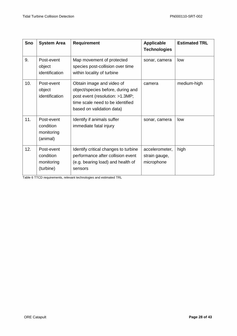
Table 6 outlines the functional requirement along with applicable technology category and
estimated TRL of the most advanced example within that category that has been designed for
TTCD. Technologies relevant to the detection needs are summarised in Table 7.

Tidal Turbine Collision Detection PN000110-SRT-002
ORE Catapult Page 27 of 43
Sno System Area Requirement Applicable
Technologies
Estimated TRL
1. Proximity
(including
behavioural
response)
Detect and identify presence of
the species of concern around
locality of turbine (>60 meters)
hydrophone high
2. Proximity
(including
behavioural
response)
Identify protected species and
track their motion to alarm their
approach towards turbines (60-30
meters)
sonar, camera,
hydrophone
medium-high
3. Proximity
(including
behavioural
response)
Track and map movement of
animals over time whilst close to
turbine (<30m)
sonar, camera high
4. Proximity
(including
behavioural
response)
Locate animals with a resolution
of at least ~1 m
sonar, camera high
5. Collision or
impact
detection
Confirm a physical contact
between turbine blades and any
objects or species
accelerometer
(tactile,
proximity)
high
(low)
6. Collision or
impact
detection
Measure impact force on turbine
blades from object or species
collision
accelerometer,
strain gauge
high
7. Collision or
impact
detection
Determine location of contact or
collision on turbine blades
accelerometer,
strain gauge
low
8. Collision or
impact
detection
Differentiate between object and
species collision and identify: (a)
marine animal to species level or
(b) object properties (density,
shape, mass)
a: sonar,
camera
b:
accelerometer
a: medium
b: low
Tidal Turbine Collision Detection PN000110-SRT-002
ORE Catapult Page 28 of 43
Sno System Area Requirement Applicable
Technologies
Estimated TRL
9. Post-event
object
identification
Map movement of protected
species post-collision over time
within locality of turbine
sonar, camera low
10. Post-event
object
identification
Obtain image and video of
object/species before, during and
post event (resolution: >1.3MP;
time scale need to be identified
based on validation data)
camera medium-high
11. Post-event
condition
monitoring
(animal)
Identify if animals suffer
immediate fatal injury
sonar, camera low
12. Post-event
condition
monitoring
(turbine)
Identify critical changes to turbine
performance after collision event
(e.g. bearing load) and health of
sensors
accelerometer,
strain gauge,
microphone
high
Table 6 TTCD requirements, relevant technologies and estimated TRL
Tidal Turbine Collision Detection PN000110-SRT-002
ORE Catapult Page 29 of 43
6 Conclusions
The key conclusions drawn from this review are as follows:
The Need: A TTCD system addressing the detection requirements outlined in Table 6 is an
essential mechanism through which the tidal energy sector will gather the necessary scientific
evidence on which to base future commercial tidal turbine projects and to inform marine
environment regulation.
Feasibility: Regulators are providing consent to a number of developers to explore, design and
demonstrate in pilot tests a variety of approaches and technologies to assess collision risk.
System Evolution: Each developer requires a TTCD solution that is relevant and particular to
the turbine design, the operating environment and the marine ecology of the proposed
deployment site. There are common components in all TTCD approaches to date.
Typical Architecture: A comprehensive TTCD system will include a combination of acoustic
sensors (hydrophones, and sonars incorporating ADCP data from the operational system),
imaging systems (sonar and cameras) and blade-mounted sensors (strain sensors,
accelerometers) and relevant condition monitoring data from the drive train. The integration of
these systems is critical, as is the capability and robustness of the associated.
Standard Design: As of now, an optimised TTCD system architecture, or best practice cannot
be determined until all data are interpreted from the different ongoing projects, and from the
pilots about to be deployed. It might be possible to generalise on some aspects of system
architecture and types of technologies used. Other aspects might need to remain site or device-
specific either due to the type of turbine, its configuration or the nature of the tidal site and the
animals that visit it.
Hydrophones: In comparison to active sonar devices, hydrophones have demonstrated less
utility in proximity monitoring as they only detect species that vocalise. The perceived value of
these devices lies in developing the signal interpretation capabilities to identify and locate, in
real time, marine animals through their vocalisations. Following the development of signal
interpretation capabilities, an estimation of population size in an area could potentially then be
made. Unfortunately not all marine animals vocalise all the time.
Sonar Systems: the state-of-the-art in active sonars includes the capability, through motion
tracking and advanced imaging algorithms, to identify with high certainty the presence of a seal
or porpoise in the zone of interest. The device can collect sufficient data to assess and issue a
“risk of collision” alert. Sonar hardware is mature and the most significant improvement to be
made relevant to TTCD is in advancing the imaging and tracking software to realise a fully
automated, intelligent system.

Tidal Turbine Collision Detection PN000110-SRT-002
ORE Catapult Page 30 of 43
Future Sonars: It could be anticipated that, providing the amount of corroborating data will be of
sufficient volume and diversity to train a machine vision package, sonar imaging is likely to
become the primary long term collision proximity alert and risk assessment tool. More real data
is required from different monitoring configurations and environments to improve the tracking
and image analysis algorithms. Advances in tracking software can provide more accurate and
earlier prognosis of collision risk. Sonar devices are certified for two years continuous use
before maintenance.
Camera Systems: In at least one TTCD system yet to be deployed and tested, video cameras
will be used to capture specific event-triggered information to support active and passive sonar
data in object identification and/or to correlate accelerometer, strain gauge and drive train data
with the blade making contact with an identified object. Time-of-flight and range gating methods
could be applied in the future to improve images captured in turbid waters. Key barriers for
optical systems in TTCD are the requirement for illumination in poor light or at night, and rapid
rates of lens bio-fouling. A UV light-based treatment system has been identified as a potential,
novel solution for the latter.
Blade Mounted/Embedded Sensors: Primarily for blade condition monitoring and secondarily as
a direct measure of blade impact events, some developers have integrated fibre strain sensors
and accelerometers embedded or mounted in blades. Strain gauges have been embedded at
the root of the blade to capture bend moment and along the edge to capture flex along the
length. A key challenge in blade mounted approaches like this will be the sensitivity range of the
systems, which should be wide to capture the full range of velocity, size, mass and hardness to
be representative of animal impact scenarios.
Accelerometers: Used as indicators of impact detection as well as turbine blade condition.
Features in favour of accelerometers include their compact size and the feasibility of integration
within blades. One sensor per blade is considered sufficient. For impact detection, the
accelerometer hardware is mature, but the signal processing algorithms need to be further
developed and validated as part of a TTCD system.
Tactile Sensing: An as yet unexplored technology within TTCD, but potentially of high relevance
for validating blade contact. A system would need to be a blade-mounted or embedded and
might worth exploring if accelerometers and strain gauges are found to not provide conclusive
validation of impact.
Automated Detection Algorithms: There is opportunity to advance both sonar and video imaging
systems by applying smart algorithms for image processing, including automated object
detection leading to, species identification and target tracking in real-time. For sonar imaging,
this is within reach, providing more data can be gathered to improve the machine learning
software. For video cameras there is emerging technology that will enable machine vision
underwater, the key components are fast capture of high resolution images and on-board
processing of key features. On-board processing of images in both sonar and video systems is
Tidal Turbine Collision Detection PN000110-SRT-002
ORE Catapult Page 31 of 43
of benefit because the transmission of large data sets is no longer necessary, and instead
actionable data is output real time, delivering an earlier risk alarm.
Historic Data: Faster development of an automated image processing system for sonar would
be aided by expanding the sonar image library of identifiable species. This could be achievable
through the collation of historic (and validated) data. This would require a diversity of data
collected by a range of sonar-turbine configurations and from across a variety of tidal turbine
sites. The same is also true about data collected from other sensor types.
Data Validation: Validation in the tidal turbine operating environment remains the largest hurdle
in further development of any applicable TTCD technology. However, there are financial factors
delaying the build or deployment of many of the systems that have received deployment
consent.
Future whole TTCD systems: Future architectures are likely to include advanced components
and features in addition to those summarised in section 5.3. As an example, real-time acoustic
data processing will be developed and integrated with the capability to extract acoustic impact
signatures from hydrophone data. The implementation of real-time, improved contrast
underwater imaging techniques is also likely. Automated target tracking can then be triggered
with digital zoom and automated high resolution recording during a high collision risk event.
Table 7 concludes the outcome of this study and reflects the perceived knowledge gaps
corresponding to relevant sensing technologies. The table also suggests the relevance of a
technology for TTCD, while acknowledging the maturity for potential utility to deliver what is
required in the TTCD operating environment. The following conclusions may be drawn from
table 7:
Sonars are highly relevant for proximity alerting, species and object identification, and there
are opportunities to further develop sonar image tracking and analysis algorithms for this
application.
Blade mounted sensors (accelerometers and strain gauges) have potential to detect
collisions. The approach is of medium to high maturity. Overlaying data with turbine condition
monitoring data may provide corroborating data (high maturity). However, this capability
needs to be validated for collision event detection in a TTCD application.
Underwater video cameras are relevant to all of the detection needs providing visibility
remains optimal and they are regularly maintained. There is capability for video to be further
developed in TTCD applications.
Tactile sensors are the most relevant method to detect a collision or touch event and are at
high maturity in the context of underwater robotic manipulators. The value of tactile sensing
in TTCD remains to be explored in the case where accelerometers and strain gauges are not
successful for reliable identification of an impact event. A support system is required to
determine what objects are detected.
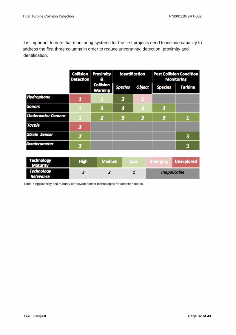
Tidal Turbine Collision Detection PN000110-SRT-002
ORE Catapult Page 32 of 43
It is important to note that monitoring systems for the first projects need to include capacity to
address the first three columns in order to reduce uncertainty: detection ,proximity and
identification.
Table 7 Applicability and maturity of relevant sensor technologies for detection needs
Tidal Turbine Collision Detection PN000110-SRT-002
ORE Catapult Page 33 of 43
7 Recommendations
In order to progress SIS technology development and also to close knowledge gaps in its
adoption into the TTCD application, the following next steps are suggested:
There are TTCD systems at different stages of development and with different capabilities
aimed at deployment in approved projects. It would be helpful if there were an overarching,
collaborative progress monitoring mechanism and historic data library to capture and store
the output for all consented projects and to help inform best practice and contribute towards
standardisation of a basic TTCD system. An open data library containing sensor data, test
and validation methods, implementation methodologies as well as more detailed information
on the sensing parameters, could improve or refine the general information accuracy and
confidence in identification or classification algorithms. This could be facilitated by existing
programmes including Ocean Energy Systems Annex IV11 and ORJIP Ocean Energy. Data
could be hosted on the Wave and Tidal Knowledge Network (WTKN).
Identification of financial resources to support consented projects with TTCD systems. This
could accelerate the system validation, first evidence collection and quick identification of
unknowns which may then be helpful for other projects. It may be possible that this initial set
of information is found to be sufficient to satisfy some of the key requirements and regulators
could relax consenting requirements. Identification of funding resources for other TTCD
oriented projects or systems will be helpful as well (EMEC pod, FLOWBEC platform). Full
understanding of what has been attempted to date and what has worked well and what has
not is also important.
Facilitate the formation of a collaborative group consisting of stakeholders and experts
across disciplines. There was a clear willingness from respondents consulted during this
study to support and contribute to future collaborative activities to benefit TTCD. This would
allow further pooling of knowledge and skills and encourage identification of technologies
and best practice. The key outputs from this group would be: (i) confirmation of sector
knowledge gaps, (ii) agreement on prioritisation of activities to close identified gaps; (iii)
refinement and standardisation of technical and environmental requirements; (iv) facilitation
of simpler engagement between experts across disciplines, for example between sensor
experts and marine biologists, by promoting a common language across relevant disciplines.
This could be facilitated under ORJIP Ocean Energy or Scottish Offshore Renewables
Research Framework (SpORRAn).
Electric field and magnetic field sensing technologies may have value in TTCD. Commercial
systems exist for other underwater tracking applications and the transfer to TTCD would
11 http://tethys.pnnl.gov/about-annex-iv

Tidal Turbine Collision Detection PN000110-SRT-002
ORE Catapult Page 34 of 43
require minimal development in hardware. Most effort would be required for signal analysis
and building a test system to demonstrate its feasibility.
There is a need for prototype TTCD or host turbine system that technology providers could
use to verify the performance of sensor technology. The challenge here is that prototype
systems will require deployment in a representative tidal environment where interaction with
marine mammals can be assessed. This could be a test turbine on an existing tidal site or
with other objects in test tank experimental research. The MeyGen Phase 1 project in the
Pentland Firth and the TEL’s Deltastream project in Ramsey Sound will both contribute to
understanding sensor performance.
Knowledge gaps across disciplines relevant to tidal energy project development and consenting
requirements have been investigated in the past decade and informed by different organisations
globally (Appendix 3). Project plans addressing some aspects of the knowledge gaps are
covered in available reviews. No evidence base or project plan exist that has successfully
demonstrated the ‘feasibility of collision detection’ or ‘verification of collision detection’, while
collision risk has consistently been identified as among the top priorities issues. Hence, projects
specific to collision detection are suggested here in order of priority:
Project-1 Further development and validation of existing and mature collision detection and monitoring systems such as EMEC’s pod, MeyGen’s FLOWBEC and TEL’s platforms
Objectives Push the next phase of development of evolving monitoring systems or mature systems ready for deployment and expand the initial evidence base
Deliverables ● Upgrade/refine/deploy monitoring systems at existing/consented TTCD test tidal sites
● Expand data collected at tidal sites ● Comparison and correlation of datasets to identify agreements and or sources of
errors ● Refine algorithms and improve system performance ● Identify best practice and mature technologies
Plan Supported by ORJIP Ocean Energy, Catapult will plan a workshop with developers to understand how data collection could be expanded and with technology developers to identify best practices and potential system improvements.
Project-2 Further development and validation of advanced collision monitoring system methodologies and algorithms
Objectives Design future system architecture for highly accurate collision monitoring
Deliverables ● Review the system architecture of existing monitoring systems down to subcomponent level in existing wind and tidal projects
● Identify common elements, need and scope of design standardisation within or across sectors
● Suggest design and protocols for standard standalone future system architectures ● Identify prospects for algorithm improvements and integration across projects ● Test and validate in suitable representative tidal site

Tidal Turbine Collision Detection PN000110-SRT-002
ORE Catapult Page 35 of 43
Project-2 Further development and validation of advanced collision monitoring system methodologies and algorithms
Plan A Catapult-led and ORJIP Ocean Energy-supported workshop with sector leaders is planned to determine where improvements can be made and what a test plan should contain and how it could be delivered.
Project-3 Further development and automation of tracking and image algorithms for sonar systems
Objectives Improve on current tracking and imaging software to realise a sonar proximity alert device capable of real time prognostic output of marine animal collision risk
Deliverables ● Identify tidal turbine deployment sites suitable to obtain validated sonar data ● Identify existing suitable sonar data that could be shared ● Improve algorithms and software ● Deploy improved system and validate at site
Plan Supported by ORJIP Ocean Energy, Catapult will plan a workshop with developers to understand the data that is being collected and can be made available and with technology developers to identify best practices and potential system improvements.
Project-4 Feasibility study of Range-gated Camera and Automated Image Analysis for Turbine Monitoring
Objectives Test value of range-gated technology in TTCD
Deliverables ● Identify key performance parameters at tidal sites and estimate a range of values ● Develop or refine the range-gated camera system for delivering imaging range that
is significantly better than standard cameras, by means of hardware improvements ● Develop real-time processing algorithms for automating the detection and inform
the event of interest
Plan This is planned to be an ORJIP Ocean Energy-supported call to complete a study into these technologies, delivered through the Catapult’s Innovation Challenges.
Project-5 Tactile Impact Detection for Turbine Blade Integration
Objectives Extended development of the existing tactile sensors in underwater robotics for turbine collision detection application
Deliverables ● Identify design specifications for the turbine blade integration and impact detection ● Design the tactile sensor cells for possible integration with blades ● Identify integration prospects with fibre optic sensors ● Explore issues and challenges regarding integration prospects with turbine blades
made of different materials ● Test the system in controlled environment
Plan This will form the basis of a Catapult Innovation Challenge to the market, which will be supported by the Catapult’s proactive identification of relevant funding sources and calls. A project submission will then be made with market partners.

Tidal Turbine Collision Detection PN000110-SRT-002
ORE Catapult Page 36 of 43
Project-6 Further development of blade-integrated accelerometer sensors as a standalone collision detector system
Objectives Exploit the full potential of accelerometer technology to provide a standard standalone sensor module for application in any tidal turbine collision monitoring
Deliverables ● Review the existing knowledge base to best inform the accelerometer-specific detection parameters and their possible range at different sites
● Theoretical estimation of physical and or design parameters ● Identification of commercially available sensor elements ● Development of detection algorithm and hardware for sensor element ● Integration of the full standalone system and test in controlled environment ● Integration with turbine blade and test in controlled environment
Plan This will form the basis of a Catapult Innovation Challenge to the market, which will be supported by the Catapult’s proactive identification of relevant funding sources and calls. A project submission will then be made with market partners.
Project-7 Sensitivity and specificity testing of magnetometers and electric field sensors
Objectives Explore the feasibility of magnetic and electric field sensing to provide complementary data to sonar imaging, tracking and blade collision events in a TTCD system.
Deliverables ● Identify key performance parameters at tidal sites and estimate a range of values ● Design a scaled version of a magnetometer array test system and electric field test
system including test protocols to validate sensitivity and specificity to track non-living and living objects, respectively
● Develop software and data processing approaches to link ADCP and turbine blade rotation data with magnetic tracking and electric field data
Plan This will form the basis of a Catapult Innovation Challenge to the market, which will be supported by the Catapult’s proactive identification of relevant funding sources and calls. A project submission will then be made with market partners.

Tidal Turbine Collision Detection PN000110-SRT-002
ORE Catapult Page 37 of 43
8 Acknowledgements
This feasibility study was undertaken and completed with funding support from Scottish Natural
Heritage and the Natural Environmental Research Council.

Tidal Turbine Collision Detection PN000110-SRT-002
ORE Catapult Page 38 of 43
Appendix 1 Technology Categories
Technologies Institutions Relevance and Qualification
Key Products, or research
Relevant Capabilities Reference by (optional)
Hydrophone Ocean Sonics
IC-Listen Smart devices SMRU
Sonar Tritech Gemini 720i SeaTech detection software
Web research
Coda-Octopus
Echoscope II Compact and real-time 3D detection
CENSIS, web search
Ultra-electronics
Devices and Detection algorithms
Advanced detection algorithms
EMEC (Participated in ReDAPT development)
Camera Odos Imaging
TOF camera range TOF & range-gating capabilities, Underwater Time of Flight Image Acquisition(UTOFIA) project partner
CENSIS
Tactile DFKI Gmbh Subsea robotics Largest European expert, underwater tactile capabilities
Web research
Peratech QTC composites Touch sensor applications
Personal knowledge
GU - Ravinder Dahiya
Electronic skin EU wise leading expertise
CENSIS research landscape
Strain Gauge Com & Sense
Embedded composite sensors
Fibre-optic embedded strain sensors for wind turbines
Smart Fibre (FP7) project partner
Accelerometer H-scientific Smart hardware, and detection algorithms
Developed custom devices for TEL
TEL)
Monitoring System Integration
TEL System integration Custom design of monitoring system
EMEC, SMRU, web research
Turbine Condition Monitoring
Andritz Turbines Turbine system development
ORE Catapult
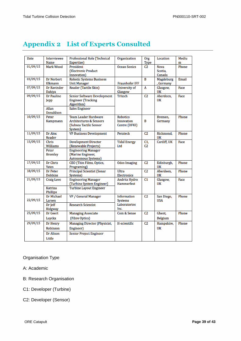
Tidal Turbine Collision Detection PN000110-SRT-002
ORE Catapult Page 39 of 43
Appendix 2 List of Experts Consulted
Organisation Type
A: Academic
B: Research Organisation
C1: Developer (Turbine)
C2: Developer (Sensor)

Tidal Turbine Collision Detection PN000110-SRT-002
ORE Catapult Page 40 of 43
Appendix 3 Knowledge Gap Study
Existing Reports (Title) Relevant Topical
Coverage
Owner
Agency
Authors Release
Date
Collision risks between marine
renewable energy devices and
mammals, fish and diving birds
- Report to the Scottish
Executive
Collision risk,
mitigations - Ecology
and Marine Biology
perspectives
Natural
Environment
Research
Council
(NERC)
Ben Wilson et
al )Scottish
Association
for Marine
Science
(SAMS))
03/2007
Marine Mammal Impacts
(Wave & Tidal Consenting
Position Paper Series)
Key Issues and
status NERC
C Sparling et
al (Sea
Mammal
Research Unit
(SMRU))
2013
Review of current knowledge of
underwater noise emissions
from wave and tidal stream
energy devices (Pentland Firth
and Orkney Waters Enabling
Actions Report)
Sub Sea Operational
Noise
The Crown
Estate
SP Robinson
& PA Lepper
(NPL)
08/2013
Report of the Workshop on
Interactions between Marine
Renewable Projects and
Cetaceans Worldwide
Collision Risk and
Management
Worldwide
Convention
on
Biological
diversity,
UN
Misc. 01/2014
Evaluating and Assessing the
Relative Effectiveness of
Acoustic Deterrent Devices
and other Non-Lethal Measures
on Marine Mammals (Report to
MS, Scottish Govt.)
Active acoustics as
deterrent, mammal
impact with vessels
Marine
Scotland
Alex Coram et
al (SMRU) 2014

Tidal Turbine Collision Detection PN000110-SRT-002
ORE Catapult Page 41 of 43
Consolidation of wave and tidal
EIA/HRA issues and research
priorities (Technical Report to
The Crown Estate)
Key EIA/HRA issues
and the current
research gaps
The Crown
Estate
Ian Hutchison
(Aquatera
Ltd)
01/2014

Tidal Turbine Collision Detection PN000110-SRT-002
ORE Catapult Page 42 of 43
Appendix 4 Interview Notes
Confidential; held by the ORE Catapult.

Tidal Turbine Collision Detection PN000110-SRT-002
ORE Catapult Page 43 of 43
Contact ORE Catapult Inovo 121 George Street Glasgow, G1 1RD
T +44 (0)333 004 1400 F +44 (0)333 004 1399
ORE Catapult National Renewable Energy Centre Offshore House Albert Street, Blyth Northumberland, NE24 1LZ
T +44 (0)1670 359 555 F +44 (0)1670 359 666
[email protected] Ore.catapult.org.uk