tie-rod type hydraulic cylinder - · pdf file10910 9531 17595 15439 27489 24024 42952 39487...
TRANSCRIPT
Series CHA
Nominal pressure: 3.5 MPaBore size (mm): 40, 50, 63, 80, 100, 125, 160
Series CHATie-rod Type Hydraulic Cylinder
1415
CHQ
CHK
CHN
CHM
CHS
CH2
CHA
D-
RelatedEquipment
CHA
CHA 40 100LLCHDA 40 100 M9BW
Cylinder stroke (mm)Refer to the standard stroke table onpage 1417.
Made to Order specificationsFor details, refer to page 1417.
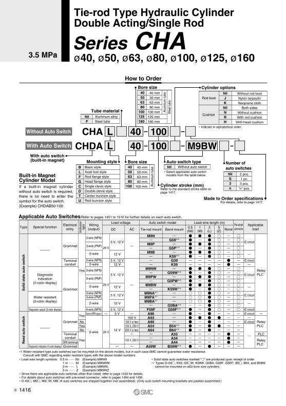
How to Order
∗ Lead wire length symbols: 0.5 m ······ Nil (Example) M9NW 1 m ······ M (Example) M9NWM 3 m ······ L (Example) M9NWL 5 m ······ Z (Example) M9NWZ∗ Since there are applicable auto switches other than listed, refer to page 1433 for details.∗ For details about auto switches with pre-wired connector, refer to pages 1494 and 1495.∗ D-A9, M9, M9W, M9A auto switches are shipped together (not assembled). (Only auto switch mounting brackets are packed assembled.)
∗1 Water resistant type auto switches can be mounted on the above models, but in such case SMC cannot guarantee water resistance. Consult with SMC regarding water resistant types with the above model numbers.
∗ Solid state auto switches marked "" are produced upon receipt of order.∗∗ Types D-G5, K59, G5W, K59W, G5BA, G59F, G5NT, B5, B64, and B59W
cannot be mounted on ø63 bore size cylinders.
Applicable Auto Switches/Refer to pages 1451 to 1510 for further details on each auto switch.
Pre-wiredconnector
3-wire (NPN equiv.)
2-wire
Load voltage Auto switch model
100 V100 V or less100 V, 200 V200 V or less
100 V, 200 V
ACDC
Lead wire length (m)Applicable
load
5 V
12 V24 V
Yes
NoYesNo
Yes
Yes
3-wire (NPN)
3-wire (PNP)
2-wire
3-wire (NPN)2-wire
3-wire (NPN)
3-wire (PNP)
2-wire
3-wire (NPN)3-wire (PNP)
2-wire
4-wire (NPN)
Ree
d a
uto
sw
itch
So
lid s
tate
au
to s
wit
ch
A96A93A90A54A64
A59W
B54∗∗B64∗∗A33A34A44
B59W∗∗
RelayPLC
RelayPLC
RelayPLC
24 V
24 V
Grommet
Terminalconduit
DIN terminalGrommet
Grommet
Terminalconduit
Grommet
Tie-rod mount Band mount
5 V, 12 V
12 V
5 V, 12 V12 V
5 V, 12 V
12 V
5 V, 12 V
12 V
5 V, 12 V
M9N
M9P
M9B
M9NW
M9PW
M9BW
M9NA∗1
M9PA∗1
M9BA∗1
F59F
G59∗∗
G5P∗∗
K59∗∗G39K39
G59W∗∗
G5PW∗∗
K59W∗∗
G5BA∗∗G59F∗∗
TypeElectrical
entry
Indi
cato
rlig
ht Wiring(output)
Special function 0.5(Nil)
1(M)
3(L)
5(Z) None
Diagnosticindication
(2-color display)
Water resistant(2-color display)
Diagnostic output (2-color display)
Diagnostic indication (2-color display)
IC circuit
IC circuit
IC circuit
IC circuit
IC circuitIC circuit
IC circuit
PLC
With auto switch(built-in magnet)
With Auto Switch
Without Auto Switch
Aluminum alloySteel tube
NilF
Tube material
Bore size40506380
100125160
40 mm 50 mm 63 mm 80 mm100 mm125 mm160 mm
Alu
min
um tu
beS
teel
tube
∗ Indicate in alphabetical order.
Cylinder optionsNilJKNilNRH
Without rod bootNylon tarpaulinNeoprene cloth
Both sidesWithout cushionWith rod cushion
With head cushion
Rod boot
Cushion
Number of auto switches
2 pcs.1 pc.3 pcs.
"n" pcs.
NilS3n
Without auto switchNilAuto switch type
∗ Select applicable auto switch models from the table below.
Bore size40506380
100
40 mm 50 mm 63 mm 80 mm100 mm A
lum
inum
tube
Mounting styleBLFGCDTU
Basic styleAxial foot styleRod flange styleHead flange styleSingle clevis styleDouble clevis styleCenter trunnion styleRod trunnion style
Built-in Magnet Cylinder ModelIf a built-in magnet cylinder without auto switch is required, there is no need to enter the symbol for the auto switch.(Example) CHDAB50-100
Tie-rod Type Hydraulic CylinderDouble Acting/Single Rod
Series CHAø40, ø50, ø63, ø80, ø100, ø125, ø1603.5 MPa
1416B
∗ Maximum ambient temperature for the rod boot itself.
Symbol
JK
Maximum ambient temperature
70�
110��
-XC22 Fluororubber seals
Symbol Specifications
Made to Order specificationsFor details, refer to page 1435.
Material
Nylon tarpaulin
Heat resistant tarpaulin
Bore size (mm)
40, 50, 63, 80, 100
40, 50, 63, 80, 100, 125, 160
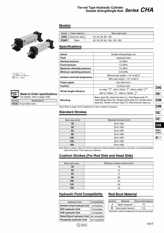
Model Tube material
Models
CHA
CHAF
Aluminum alloy
Steel
Action
Fluid
Nominal pressure
Proof pressure
Maximum allowable pressure
Minimum operating pressure
Ambient and fluid temperature
Piston speed
Cushion
Double acting/Single rod
Hydraulic fluid
3.5 MPa
5.0 MPa
3.5 MPa
0.25 MPa
Without auto switch: –10° to 80°CWith auto switch: –10° to 60°C
8 to 300 mm/s
Cushion seal
Note) Refer to page 1234 for definitions of terms related to pressure.
Specifications
Stroke length tolerance+0.8 0
+1.0 0
+1.25 0
+1.4 0
+1.8 0
to 100st , 100 to 250st , 250 to 630st
630 to 1000st , 1000 to 1500st
Basic style (B), Axial foot style (L), Rod flange style (F)Head flange style (G), Single clevis style (C), Double clevisstyle (D), Center trunnion style (T), Rod trunnion style (U)
Mounting
Rod Boot Material
Bore size (mm) Standard strokes (mm)
25 to 1000
25 to 1000
25 to 1000
25 to 1300
25 to 1500
50 to 1300
50 to 1500
40
50
63
80
100
125
160
Bore size (mm) Effective cushion stroke (mm)
15
15
17
20
20
20
22
Cushion Strokes (For Rod Side and Head Side)
40
50
63
80
100
125
160
Hydraulic Fluid Compatibility
Standard Strokes
Note) Refer to pages 1252 and 1253 to determine stroke limitation depending on the type of mounting brackets that will be used. Then make your selection.
Standard mineral hydraulic fluid
W/O hydraulic fluid
O/W hydraulic fluid
Water/Glycol hydraulic fluid
Phosphate hydraulic fluid
Compatible
Compatible
Compatible
Not compatible
Not compatible
Hydraulic fluid Compatibility
Series CHATie-rod Type Hydraulic CylinderDouble Acting/Single Rod
1417
CHQ
CHK
CHN
CHM
CHS
CH2
CHA
D-
RelatedEquipment
CHA
40
50
63
80
100
125
160
18
20
22.4
28
35.5
35.5
45
OUT
IN
OUT
IN
OUT
IN
OUT
IN
OUT
IN
OUT
IN
OUT
IN
1257
1002
1963
1649
3117
2723
5027
4411
7854
6864
12272
11282
20106
18516
1 1.5 2 2.5 3 3.5
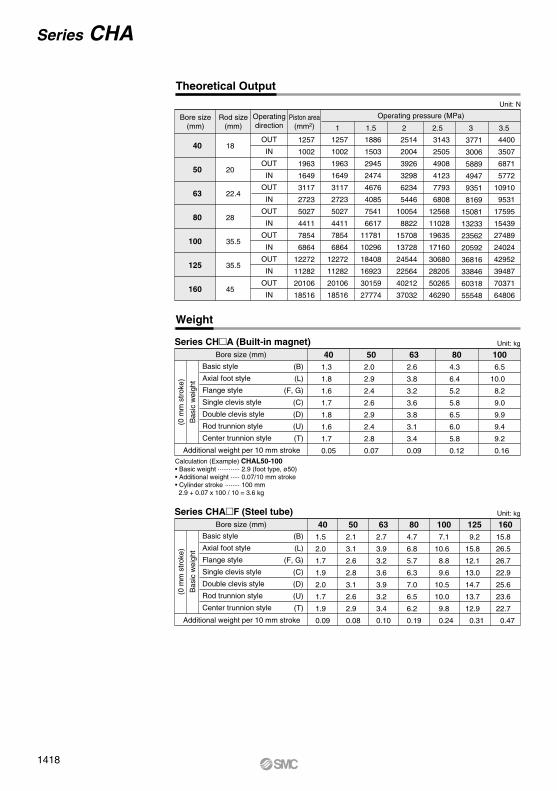
Series CHA (Built-in magnet)Bore size (mm)
Additional weight per 10 mm stroke
Unit: kg
1257
1002
1963
1649
3117
2723
5027
4411
7854
6864
12272
11282
20106
18516
1886
1503
2945
2474
4676
4085
7541
6617
11781
10296
18408
16923
30159
27774
2514
2004
3926
3298
6234
5446
10054
8822
15708
13728
24544
22564
40212
37032
3143
2505
4908
4123
7793
6808
12568
11028
19635
17160
30680
28205
50265
46290
3771
3006
5889
4947
9351
8169
15081
13233
23562
20592
36816
33846
60318
55548
4400
3507
6871
5772
10910
9531
17595
15439
27489
24024
42952
39487
70371
64806
Basic style
Axial foot style
Flange style
Single clevis style
Double clevis style
Rod trunnion style
Center trunnion style
(B)
(L)
(F, G)
(C)
(D)
(U)
(T)
(0 m
m s
trok
e)
Bas
ic w
eigh
t
Basic style
Axial foot style
Flange style
Single clevis style
Double clevis style
Rod trunnion style
Center trunnion style
(B)
(L)
(F, G)
(C)
(D)
(U)
(T)
(0 m
m s
trok
e)
Bas
ic w
eigh
t
401.3
1.8
1.6
1.7
1.8
1.6
1.7
0.05
502.0
2.9
2.4
2.6
2.9
2.4
2.8
0.07
632.6
3.8
3.2
3.6
3.8
3.1
3.4
0.09
804.3
6.4
5.2
5.8
6.5
6.0
5.8
0.12
1006.5
10.0
8.2
9.0
9.9
9.4
9.2
0.16
Series CHAF (Steel tube)Bore size (mm)
Additional weight per 10 mm stroke
Unit: kg
401.5
2.0
1.7
1.9
2.0
1.7
1.9
0.09
502.1
3.1
2.6
2.8
3.1
2.6
2.9
0.08
632.7
3.9
3.2
3.6
3.9
3.2
3.4
0.10
804.7
6.8
5.7
6.3
7.0
6.5
6.2
0.19
1007.1
10.6
8.8
9.6
10.5
10.0
9.8
0.24
1259.2
15.8
12.1
13.0
14.7
13.7
12.9
0.31
16015.8
26.5
26.7
22.9
25.6
23.6
22.7
0.47
Calculation (Example) CHAL50-100• Basic weight ············ 2.9 (foot type, ø50)• Additional weight ····· 0.07/10 mm stroke• Cylinder stroke ········ 100 mm 2.9 + 0.07 x 100 / 10 = 3.6 kg
Theoretical Output
Bore size(mm)
Piston area(mm2)
Rod size(mm)
Operatingdirection
Operating pressure (MPa)
Unit: N
Weight
Series CHA
1418
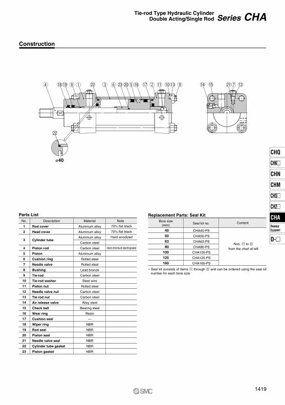
Construction
No.
1
2
3
4
5
6
7
8
9
10
11
12
13
14
15
16
17
18
19
20
21
22
23
Description Material Note
Parts List Replacement Parts: Seal Kit
Rod cover
Head cover
Cylinder tube
Piston rod
Piston
Cushion ring
Needle valve
Bushing
Tie-rod
Tie-rod washer
Piston nut
Needle valve nut
Tie-rod nut
Air release valve
Check ball
Wear ring
Cushion seal
Wiper ring
Rod seal
Piston seal
Needle valve seal
Cylinder tube gasket
Piston gasket
Aluminum alloy
Aluminum alloy
Aluminum alloy
Carbon steel
Carbon steel
Aluminum alloy
Rolled steel
Rolled steel
Lead bronze
Carbon steel
Steel wire
Rolled steel
Carbon steel
Carbon steel
Alloy steel
Bearing steel
Resin
—
NBR
NBR
NBR
NBR
NBR
NBR
70% flat black
70% flat black
Hard anodized
Hard chromium electroplated
Bore size(mm) Seal kit no.
CHA40-PS
CHA50-PS
CHA63-PS
CHA80-PS
CHA100-PS
CHA125-PS
CHA160-PS
Content
Nos. !7 to @2
from the chart at left
40
50
63
80
100
125
160
r
@2
!8!9 i q @2 e y @3@0t!6 !7 w !1 !0!3 @1!4 !2u!5o
ø40
∗ Seal kit consists of items !7 through @2 and can be ordered using the seal kit number for each bore size.
Series CHATie-rod Type Hydraulic CylinderDouble Acting/Single Rod
1419
CHQ
CHK
CHN
CHM
CHS
CH2
CHA
D-
RelatedEquipment
CHA
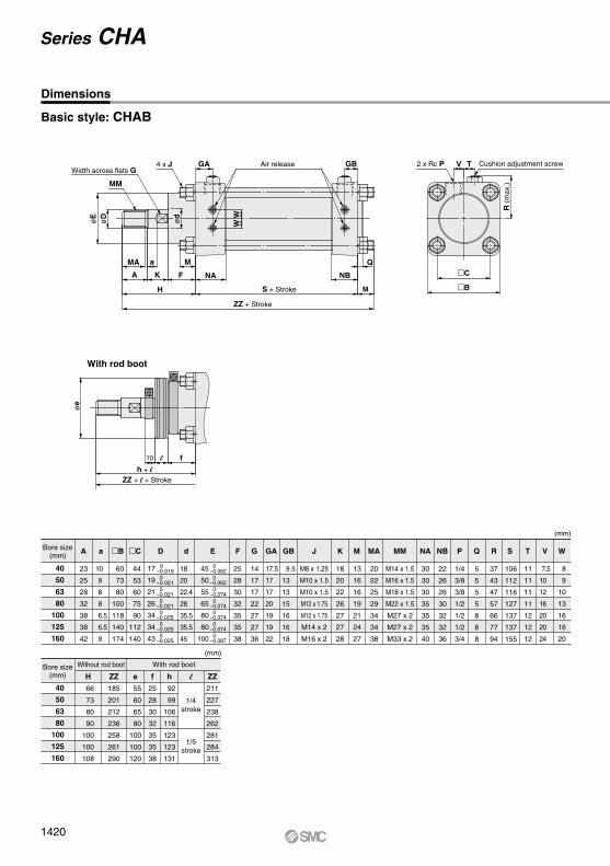
Basic style: CHAB
Bore size(mm)
A a dB C F G GA GB K M MA NA NB R SQ V WTPJ MM
(mm)
D
45
50
55
65
80
80
100
0–0.062 0–0.062 0–0.074 0–0.074 0–0.074 0–0.074 0–0.087
Bore size(mm) H
66
73
80
90
100
100
108
ZZ
185
201
212
236
258
261
290
ZZ
211
227
238
262
281
284
313
e
55
60
65
80
100
100
120
f
25
28
30
32
35
35
38
h
92
99
106
116
123
123
131
l
(mm)
Dimensions
1/4stroke
1/5stroke
Without rod boot With rod boot
MM
Width across flats G4 x J GA
WW
GBAir release
øD
øe
øE
MA
A K F NA NB
H S + Stroke M
Q
ZZ + Stroke
Ma
10 l fh + l
ZZ + l + Stroke
C
B
V2 x Rc P Cushion adjustment screwT
R (m
ax.)
With rod boot
0–0.018 0–0.021 0–0.021 0–0.021 0–0.025 0–0.025 0–0.025
17
19
21
26
34
34
43
ød
40
50
63
80
100
125
160
40
50
63
80
100
125
160
E
23
25
28
32
38
38
42
10
9
8
8
6.5
6.5
9
18
20
22.4
28
35.5
35.5
45
60
73
80
100
118
140
174
44
53
60
75
90
112
140
25
28
30
32
35
35
38
14
17
17
22
27
27
36
17.5
17
17
20
19
19
22
9.5
13
13
15
16
16
18
18
20
22
26
27
27
28
13
16
16
19
21
24
27
20
22
25
29
34
34
38
30
30
30
35
35
35
40
22
26
26
30
32
32
36
37
43
47
57
66
77
94
106
112
116
127
137
137
155
5
5
5
5
8
8
8
7.5
10
12
16
20
20
24
8
9
10
13
16
16
20
11
11
11
11
12
12
12
1/4
3/8
3/8
1/2
1/2
1/2
3/4
M8 x 1.25
M10 x 1.5
M10 x 1.5
M12 x 1.75
M12 x 1.75
M14 x 2
M16 x 2
M14 x 1.5
M16 x 1.5
M18 x 1.5
M22 x 1.5
M27 x 2
M27 x 2
M33 x 2
Series CHA
1420
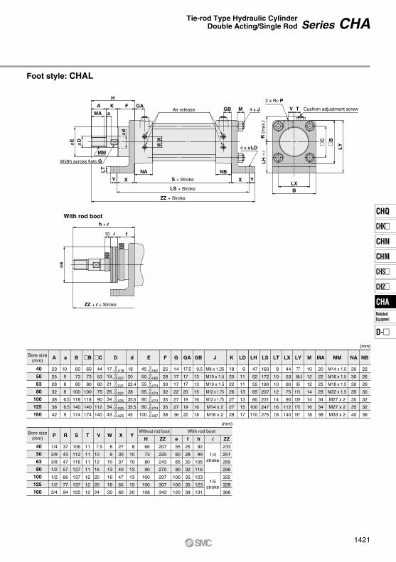
Foot style: CHAL
Bore size(mm)
A B
a dB
C
45
50
55
65
80
80
100
0–0.062 0–0.062 0–0.074 0–0.074 0–0.074 0–0.074 0–0.087
0–0.018 0–0.021 0–0.021 0–0.021 0–0.025 0–0.025 0–0.025
17
19
21
26
34
34
43
F G GA GB K LD LH
LT
LS LX
LY MA NA NBMMMJ
(mm)
D E
Bore size(mm)
P R X YS T V W
(mm)
H
66
73
80
90
100
100
108
ZZ
207
225
243
270
297
307
343
ZZ
233
251
269
296
322
328
366
e
55
60
65
80
100
100
120
f
25
28
30
32
35
35
38
h
92
99
106
116
123
123
131
l
Without rod boot With rod boot
H
øE
øe
øD
LT
WW
ød
C
R (m
ax.)
LH
±0.2
B
LY
A
MA
MM
Y X X Y
NA NB
MGB V
LXB
Ta
K F GA
S + Stroke
LS + Stroke
ZZ + Stroke
4 x øLD
4 x J
2 x Rc P
Cushion adjustment screwAir release
h + l
10 fl
ZZ + l + Stroke
With rod boot
40
50
63
80
100
125
160
40
50
63
80
100
125
160
23
25
28
32
38
38
42
60
73
80
100
118
140
174
10
9
8
8
6.5
6.5
9
18
20
22.4
28
35.5
35.5
45
60
73
80
100
118
140
174
44
53
60
75
90
112
140
25
28
30
32
35
35
38
14
17
17
22
27
27
36
17.5
17
17
20
19
19
22
9.5
13
13
15
16
16
18
18
20
22
26
27
27
28
9
11
11
13
13
15
17
47
52
55
65
80
100
110
8
10
10
12
14
16
18
160
172
190
207
231
247
275
44
53
60
75
90
112
140
77
88.5
95
115
139
170
197
20
22
25
29
34
34
38
30
30
30
35
35
35
40
22
26
26
30
32
32
36
M14 x 1.5
M16 x 1.5
M18 x 1.5
M22 x 1.5
M27 x 2
M27 x 2
M33 x 2
10
12
12
14
14
16
18
M8 x 1.25
M10 x 1.5
M10 x 1.5
M12 x 1.75
M12 x 1.75
M14 x 2
M16 x 2
1/4
3/8
3/8
1/2
1/2
1/2
3/4
37
43
47
57
66
77
94
27
30
37
40
47
55
60
8
10
10
13
13
15
20
106
112
116
127
137
137
155
11
11
11
11
12
12
12
7.5
10
12
16
20
20
24
8
9
10
13
16
16
20
Width across flats G
1/4stroke
1/5stroke
Series CHATie-rod Type Hydraulic CylinderDouble Acting/Single Rod
1421
CHQ
CHK
CHN
CHM
CHS
CH2
CHA
D-
RelatedEquipment
CHA
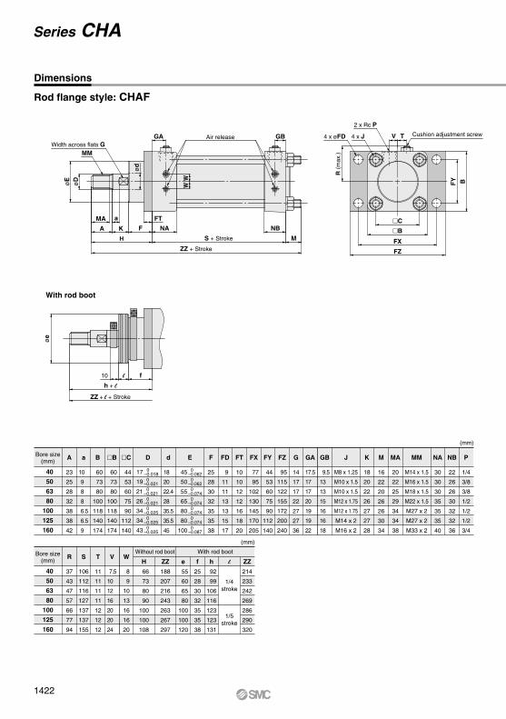
Rod flange style: CHAF
Bore size(mm)
A a dBB
C
F FD FT GB
FZ
FY
FX
G GA J K MMMA NB PNAM
(mm)
E D
Bore size(mm)
SR T V W
106
112
116
127
137
137
155
37
43
47
57
66
77
94
11
11
11
11
12
12
12
7.5
10
12
16
20
20
24
8
9
10
13
16
16
20
(mm)
23
25
28
32
38
38
42
10
9
8
8
6.5
6.5
9
18
20
22.4
28
35.5
35.5
45
60
73
80
100
118
140
174
60
73
80
100
118
140
174
44
53
60
75
90
112
140
25
28
30
32
35
35
38
9
11
11
13
13
15
17
10
10
12
12
16
18
20
9.5
13
13
15
16
16
18
95
115
122
155
172
200
240
44
53
60
75
90
112
140
77
95
102
130
145
170
205
14
17
17
22
27
27
36
17.5
17
17
20
19
19
22
M8 x 1.25
M10 x 1.5
M10 x 1.5
M12 x 1.75
M12 x 1.75
M14 x 2
M16 x 2
18
20
22
26
27
27
28
M14 x 1.5
M16 x 1.5
M18 x 1.5
M22 x 1.5
M27 x 2
M27 x 2
M33 x 2
20
22
25
29
34
34
38
22
26
26
30
32
32
36
1/4
3/8
3/8
1/2
1/2
1/2
3/4
30
30
30
35
35
35
40
16
22
20
26
26
30
34
H
66
73
80
90
100
100
108
ZZ
188
207
216
243
263
267
297
ZZ
214
233
242
269
286
290
320
e
55
60
65
80
100
100
120
f
25
28
30
32
35
35
38
h
92
99
106
116
123
123
131
l
Without rod boot With rod boot
Width across flats GMM
øE
øe
WW
R (m
ax.)
FY BøD
ød
GA GB
MA a FT
A K F NA NB
MH S + Stroke
ZZ + Stroke
Air release 4 x øFD 4 x J
2 x Rc P
V T Cushion adjustment screw
C
B
FX
FZ
10 fl
h + l
ZZ + l + Stroke
With rod boot
40
50
63
80
100
125
160
40
50
63
80
100
125
160
Dimensions
45
50
55
65
80
80
100
0–0.062 0–0.062 0–0.074 0–0.074 0–0.074 0–0.074 0–0.087
0–0.018 0–0.021 0–0.021 0–0.021 0–0.025 0–0.025 0–0.025
17
19
21
26
34
34
43
1/4stroke
1/5stroke
Series CHA
1422
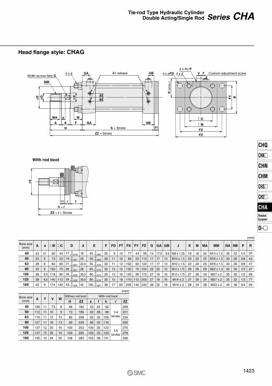
Head flange style: CHAG
Bore size(mm)
A
23
25
28
32
38
38
42
a
10
9
8
8
6.5
6.5
9
d
18
20
22.4
28
35.5
35.5
45
B
60
73
80
100
118
140
174
C
44
53
60
75
90
112
140
F
25
28
30
32
35
35
38
FD
9
11
11
13
13
15
17
FT
10
10
12
12
16
18
20
FX
77
95
102
130
145
170
205
G
14
17
17
22
27
27
36
FZ
95
115
122
155
172
200
240
FY
44
53
60
75
90
112
140
GA
17.5
17
17
20
19
19
22
GB
9.5
13
13
15
16
16
18
K
18
20
22
26
27
27
28
M
16
22
20
26
26
30
34
MM
M14 x 1.5
M16 x 1.5
M18 x 1.5
M22 x 1.5
M27 x 2
M27 x 2
M33 x 2
NA
30
30
30
35
35
35
40
P
1/4
3/8
3/8
1/2
1/2
1/2
3/4
R
37
43
47
57
66
77
94
NB
22
26
26
30
32
32
36
MA
20
22
25
29
34
34
38
J
M8 x 1.25
M10 x 1.5
M10 x 1.5
M12 x 1.75
M12 x 1.75
M14 x 2
M16 x 2
(mm)
E D
Bore size(mm)
S T V W
106
112
116
127
137
137
155
11
11
11
11
12
12
12
7.5
10
12
16
20
20
24
8
9
10
13
16
16
20
(mm)
H
66
73
80
90
100
100
108
ZZ
182
195
208
229
253
255
283
ZZ
208
221
234
255
276
278
306
e
55
60
65
80
100
100
120
f
25
28
30
32
35
35
38
h
92
99
106
116
123
123
131
lWithout rod boot With rod boot
øD
øe
øE
MM
Width across flats GGA4 x J Air release GB
WW
MA
A K
H
NA
S + Stroke
ZZ + Stroke
NBC
B
FX
FZ
F
Ma
V T2 x Rc P
4 x J4 x øFD
R (m
ax.)
Cushion adjustment screw
FY B
10 l f
h + l
ZZ + l + Stroke
With rod boot
FT
ød
40
50
63
80
100
125
160
40
50
63
80
100
125
160
45
50
55
65
80
80
100
0–0.062 0–0.062 0–0.074 0–0.074 0–0.074 0–0.074 0–0.087
0–0.018 0–0.021 0–0.021 0–0.021 0–0.025 0–0.025 0–0.025
17
19
21
26
34
34
43
1/4stroke
1/5stroke
Series CHATie-rod Type Hydraulic CylinderDouble Acting/Single Rod
1423
CHQ
CHK
CHN
CHM
CHS
CH2
CHA
D-
RelatedEquipment
CHA
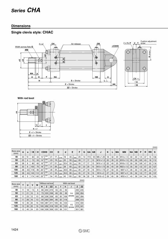
Single clevis style: CHAC
Width across flats G
Bore size(mm)
23
25
28
32
38
38
42
10
9
8
8
6.5
6.5
9
21
23
27
31
35
41
54
60
73
80
100
118
140
174
44
53
60
75
90
112
140
18
20
22.4
28
35.5
35.5
45
25
28
30
32
35
35
38
9.5
13
13
15
16
16
18
17.5
17
17
20
19
19
22
14
17
17
22
27
27
36
M8 x 1.25
M10 x 1.5
M10 x 1.5
M12 x 1.75
M12 x 1.75
M14 x 2
M16 x 2
20
22
25
29
34
34
38
32
35
40
45
50
55
65
18
20
22
26
27
27
28
22
26
26
30
32
32
36
1/4
3/8
3/8
1/2
1/2
1/2
3/4
30
30
30
35
35
35
40
15
18
20
22
24
26
30
106
112
116
127
137
137
155
37
43
47
57
66
77
94
M14 x 1.5
M16 x 1.5
M18 x 1.5
M22 x 1.5
M27 x 2
M27 x 2
M33 x 2
(mm)
Bore size(mm)
T
11
11
11
11
12
12
12
U
18
21
23
26
30
30
40
V
7.5
10
12
16
20
20
24
W
8
9
10
13
16
16
20
(mm)
H
66
73
80
90
100
100
108
Z
204
220
236
262
287
292
328
ZZ
219
238
258
284
311
318
358
Z
230
246
262
288
310
315
351
ZZ
245
264
284
310
334
341
381
e
55
60
65
80
100
100
120
f
25
28
30
32
35
35
38
h
92
99
106
116
123
123
131
lWithout rod boot With rod boot
12
14
16
18
20
22
25
+0.043 0+0.043 0+0.043 0+0.043 0+0.052 0+0.052 0+0.052 0
h + l
Z + l + Stroke
ZZ + l + Stroke
With rod boot
10 fl
øe
V T2 x Rc PCushion adjustment screw
øCDH9
CX ±0.3
C
B
R (m
ax.)
MA
A K F NA NB U
a
H L 0–0.3
RR
S + Stroke
Z + Stroke
ZZ + Stroke
GA GB4 x J Air release
W
ød
øD
øE
W
MM
40
50
63
80
100
125
160
40
50
63
80
100
125
160
A
�
a CXB C dDCDH9 E F GBGAG J MALK NB PNA RR SRMM
Dimensions
45
50
55
65
80
80
100
0–0.062 0–0.062 0–0.074 0–0.074 0–0.074 0–0.074 0–0.087
0–0.018 0–0.021 0–0.021 0–0.021 0–0.025 0–0.025 0–0.025
17
19
21
26
34
34
43
1/4stroke
1/5stroke
Series CHA
1424
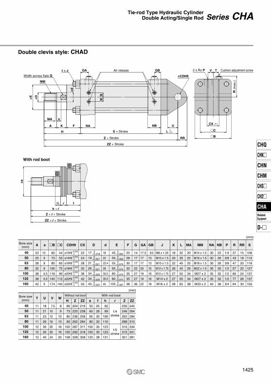
Double clevis style: CHAD
Bore size(mm)
A
23
25
28
32
38
38
42
a
10
9
8
8
6.5
6.5
9
CX
22
24
28
32
36
42
55
B
60
73
80
100
118
140
174
C
44
53
60
75
90
112
140
d
18
20
22.4
28
35.5
35.5
45
D E F
25
28
30
32
35
35
38
GB
9.5
13
13
15
16
16
18
GA
17.5
17
17
20
19
19
22
G
14
17
17
22
27
27
36
J
M8 x 1.25
M10 x 1.5
M10 x 1.5
M12 x 1.75
M12 x 1.75
M14 x 2
M16 x 2
MA
20
22
25
29
34
34
38
L
32
35
40
45
50
55
65
K
18
20
22
26
27
27
28
NB
22
26
26
30
32
32
36
P
1/4
3/8
3/8
1/2
1/2
1/2
3/4
NA
30
30
30
35
35
35
40
RR
15
18
20
22
24
26
30
S
106
112
116
127
137
137
155
R
37
43
47
57
66
77
94
MM
M14 x 1.5
M16 x 1.5
M18 x 1.5
M22 x 1.5
M27 x 2
M27 x 2
M33 x 2
(mm)
Bore size(mm)
T
11
11
11
11
12
12
12
U
18
21
23
26
30
30
40
V
7.5
10
12
16
20
20
24
W
8
9
10
13
16
16
20
(mm)
H
66
73
80
90
100
100
108
Z
204
220
236
262
287
292
328
ZZ
219
238
258
284
311
318
358
Z
230
246
262
288
310
315
351
ZZ
245
264
284
310
334
341
381
e
55
60
65
80
100
100
120
f
25
28
30
32
35
35
38
h
92
99
106
116
123
123
131
lWithout rod boot With rod boot
ø12H9
ø14H9
ø16H9
ø18H9
ø20H9
ø22H9
ø25H9
+0.043 0+0.043 0+0.043 0+0.043 0+0.052 0+0.052 0+0.052 0
øe
10 l f
h + l
Z + l + Stroke
ZZ + l + Stroke
With rod boot
2 x Rc P Cushion adjustment screwV T
R (m
ax.)
CX ±0.3
C
B
MA
A K
H
F NA NB U
RR
a
L 0–0.3S + Stroke
Z + Stroke
ZZ + Stroke
øCDH9
GBAir release
W
ød
øD
øE
W
GA4 x J
MM
40
50
63
80
100
125
160
40
50
63
80
100
125
160
Width across flats G
CDH9
45
50
55
65
80
80
100
0–0.062 0–0.062 0–0.074 0–0.074 0–0.074 0–0.074 0–0.087
0–0.018 0–0.021 0–0.021 0–0.021 0–0.025 0–0.025 0–0.025
17
19
21
26
34
34
43
1/4stroke
1/5stroke
Series CHATie-rod Type Hydraulic CylinderDouble Acting/Single Rod
1425
CHQ
CHK
CHN
CHM
CHS
CH2
CHA
D-
RelatedEquipment
CHA
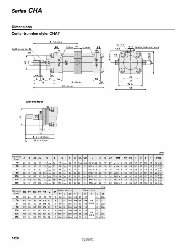
Center trunnion style: CHAT
Bore size(mm)
A
23
25
28
32
38
38
42
a
10
9
8
8
6.5
6.5
9
d
18
20
22.4
28
35.5
35.5
45
B
60
73
80
100
118
140
174
C
44
53
60
75
90
112
140
45
50
55
65
80
80
100
0–0.062 0–0.062 0–0.074 0–0.074 0–0.074 0–0.074 0–0.087
0–0.018 0–0.021 0–0.021 0–0.021 0–0.025 0–0.025 0–0.025
17
19
21
26
34
34
43
F
25
28
30
32
35
35
38
G
14
17
17
22
27
27
36
GA
17.5
17
17
20
19
19
22
GB
9.5
13
13
15
16
16
18
K
18
20
22
26
27
27
28
M
10
10
10
13
13
15
17
MA
20
22
25
29
34
34
38
NA
30
30
30
35
35
35
40
NB
22
26
26
30
32
32
36
S
106
112
116
127
137
137
155
T
11
11
11
11
12
12
12
R
37
43
47
57
66
77
94
Tde8P
1/4
3/8
3/8
1/2
1/2
1/2
3/4
J
M8 x 1.25
M10 x 1.5
M10 x 1.5
M12 x 1.75
M12 x 1.75
M14 x 2
M16 x 2
MM
M14 x 1.5
M16 x 1.5
M18 x 1.5
M22 x 1.5
M27 x 2
M27 x 2
M33 x 2
(mm)
E D
Bore size(mm)
W
8
9
10
13
16
16
20
H
66
73
80
90
100
100
108
Z
123
131
140
156
170
170
187.5
TX
70
83
90
112
140
170
212
TT
24
26
26
36
42
42
52
TR
R0.5
R0.5
R0.5
R2.5
R2.5
R2.5
R2.5
TY
65
78
86
106
130
162
200
TZ
95
108
115
162
204
234
284
V
7.5
10
12
16
20
20
24
ZZ
182
195
206
230
250
252
280
e
55
60
65
80
100
100
120
f
25
28
30
32
35
35
38
h
92
99
106
116
123
123
131
l Z
149
157
166
182
193
193
210.5
ZZ
208
221
232
256
273
275
303
(mm)
15
15
15
25
32
32
36
–0.032–0.059–0.032–0.059–0.032–0.059–0.040–0.073–0.050–0.089–0.050–0.089–0.050–0.089
Without rod boot With rod boot
MM
WWø
D
øE
GA TTAir release GB TVAir release
Z + 1/2 stroke2 x Rc P
Cushion adjustment screw4 x J
øT
De8
TY
øe
10 l f
h + l
ZZ + l + Stroke
Z + l + 1/2 stroke
MA a M
A K
H S + Stroke
ZZ + Stroke
F NA
M
NBB
TX
TZ
C
0–0.5
TR
R (m
ax.)
ød
With rod boot
40
50
63
80
100
125
160
40
50
63
80
100
125
160
Dimensions
Width across flats G
1/4stroke
1/5stroke
Series CHA
1426
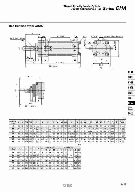
Rod trunnion style: CHAU
Width across flats G
Bore size(mm)
A
23
25
28
32
38
38
42
a
10
9
8
8
6.5
6.5
9
d
18
20
22.4
28
35.5
35.5
45
B
60
73
80
100
118
140
174
C
44
53
60
75
90
112
140
F
25
28
30
32
35
35
38
G
14
17
17
22
27
27
36
GA
17.5
17
17
20
19
19
22
GB
9.5
13
13
15
16
16
18
K
18
20
22
26
27
27
28
M
10
16
16
13
13
15
17
MA
20
22
25
29
34
34
38
NA
30
30
30
35
35
35
40
NB
22
26
26
30
32
32
36
S
106
112
116
127
137
137
155
T
11
11
11
11
12
12
12
R
37
43
47
57
66
77
94
P
1/4
3/8
3/8
1/2
1/2
1/2
3/4
J
M8 x 1.25
M10 x 1.5
M10 x 1.5
M12 x 1.75
M12 x 1.75
M14 x 2
M16 x 2
MM
M14 x 1.5
M16 x 1.5
M18 x 1.5
M22 x 1.5
M27 x 2
M27 x 2
M33 x 2
(mm)
E D
Bore size(mm)
W
8
9
10
13
16
16
20
H
66
73
80
90
100
100
108
Z
58
65
72
75
83
83
89
TX
70
83
90
112
140
170
212
TY
60
73
80
100
118
140
174
TR
R0.5
R0.5
R0.5
R2.5
R2.5
R2.5
R2.5
TT
16
16
16
30
34
34
38
TZ
95
108
115
162
204
234
284
V
7.5
10
12
16
20
20
24
ZZ
182
201
212
230
250
252
280
e
55
60
65
80
100
100
120
f
25
28
30
32
35
35
38
h
92
99
106
116
123
123
131
l Z
84
91
98
101
106
106
112
ZZ
208
227
238
256
273
275
303
(mm)
Without rod boot With rod boot
Z
GBGBTT V T
MM
øD
øe
øE
Z + l
h + lZZ + l + Stroke
10 l f
MA a
A K
H MS + Stroke
ZZ + Stroke
F NA NBB
TZ
C
WW
2 x Rc P4 x JAir release
TR
R (m
ax.)
TY
øT
De8
TX 0–0.5
ød
40
50
63
80
100
125
160
40
50
63
80
100
125
160
Tde8
Cushion adjustment screw
45
50
55
65
80
80
100
0–0.062 0–0.062 0–0.074 0–0.074 0–0.074 0–0.074 0–0.087
0–0.018 0–0.021 0–0.021 0–0.021 0–0.025 0–0.025 0–0.025
17
19
21
26
34
34
43
15
15
15
25
32
32
36
–0.032–0.059–0.032–0.059–0.032–0.059–0.040–0.073–0.050–0.089–0.050–0.089–0.050–0.089
1/4stroke
1/5stroke
Series CHATie-rod Type Hydraulic CylinderDouble Acting/Single Rod
1427
CHQ
CHK
CHN
CHM
CHS
CH2
CHA
D-
RelatedEquipment
CHA
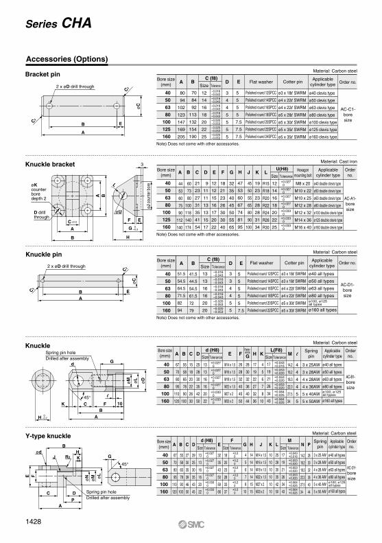
Accessories (Options)
Bracket pin
Knuckle bracket
2 x øD drill through
B
A
E
øC
C1
C1
3
øKcounterboredepth 2
D drillthrough
C ±0.3
G 0–0.3A
øU
F
H
E
A B
øJ c
ount
er b
oreL
B
Knuckle pin
Knuckle
2 x øD drill through
C1
C1
B E
A
øC
H 0–0.2
K C FB
A
10
l
Spring pin holeDrilled after assembly
Spring pin holeDrilled after assembly
d G
øM øL
øD
45°
Y-type knuckle
ødB
HKJ
E
øN
øM ø
LF
R2
C
G
D
PA
45°
Bore size(mm)
40
50
63
80
100
125
160
40
50
63
80
100
125
160
40
50
63
80
100
160
A
80
94
102
123
147
169
205
B
70
84
92
113
132
154
190
Size
12
14
16
18
20
22
25
D
3
4
4
5
5
5
5
E
5
5
5
5
7.5
7.5
7.5
Tolerance–0.016–0.043–0.016–0.043–0.016–0.043–0.016–0.043–0.020–0.053–0.020–0.053–0.020–0.053
C (f8)Flat washer Cotter pin Order no.
AC-C1-boresize
Applicablecylinder type
Polished round 12SPCC
Polished round 14SPCC
Polished round 16SPCC
Polished round 18SPCC
Polished round 20SPCC
Polished round 22SPCC
Polished round 24SPCC
ø3 x 18l SWRM
ø4 x 22l SWRM
ø4 x 22l SWRM
ø5 x 28l SWRM
ø5 x 30l SWRM
ø5 x 35l SWRM
ø5 x 35l SWRM
ø40 clevis type
ø50 clevis type
ø63 clevis type
ø80 clevis type
ø100 clevis type
ø125 clevis type
ø160 clevis type
Material: Carbon steel
Bore size(mm)
Bore size(mm)
Bore size(mm)
Material: Carbon steel
A
44
53
60
75
90
112
140
B
60
73
80
100
118
140
174
21
23
27
31
35
41
54
C F
18
21
23
26
30
30
40
12
12
15
16
17
20
22
E G
32
35
40
45
50
55
65
H
47
53
60
67
74
81
95
J
45
50
55
65
80
90
100
K
19
23
23
28
28
31
34
L
R15
R18
R20
R22
R24
R26
R30
Size
12
14
16
18
20
22
25
Tolerance
9
11
11
13
13
15
17
D
+0.027 0+0.027 0+0.027 0+0.027 0+0.033 0+0.033 0+0.033 0
Orderno.
AC-A1-boresize
Hexagonmounting bolt
U(H8)
M8 x 20
M10 x 22
M10 x 25
M12 x 28
M12 x 32
M14 x 36
M16 x 40
Applicablecylinder type
ø40 double clevis type
ø50 double clevis type
ø63 double clevis type
ø80 double clevis type
ø100 double clevis type
ø125 double clevis type
ø160 double clevis type
Material: Cast iron
40
50
63
80
100
160
Material: Carbon steel
40
50
63
80
100
160
Bore size(mm)
Material: Carbon steel
A
51.5
54.5
64.5
71.5
82
94
B
41.5
44.5
54.5
61.5
72
79
Size
13
13
16
16
20
20
D
3
3
4
4
5
5
E
5
5
5
5
5
7.5
Tolerance
C (f8)Order no.
AC-D1-boresize
Flat washer
Polished round 12SPCC
Polished round 14SPCC
Polished round 16SPCC
Polished round 18SPCC
Polished round 20SPCC
Polished round 22SPCC
Cotter pin
ø3 x 18l SWRM
ø3 x 18l SWRM
ø4 x 22l SWRM
ø4 x 22l SWRM
ø5 x 30l SWRM
ø5 x 30l SWRM
Applicablecylinder type
ø40 all types
ø50 all types
ø63 all types
ø80 all typesø100, ø125all types
ø160 all types
Refer-enceG
28
30
32
36
40
44
Tolerance+0.027 0+0.027 0+0.027 0+0.027 0+0.033 0+0.033 0
Orderno.
AC-B1-boresize
Springpin
3 x 25AW
3 x 28AW
4 x 28AW
4 x 36AW
5 x 40AW
5 x 50AW
Applicablecylinder type
ø40 all types
ø50 all types
ø63 all types
ø80 all typesø100, ø125all types
ø160 all types
d (H8) L(F8)
67
70
80
95
110
120
A
55
58
65
78
90
100
B
15
18
20
22
26
30
C
25
28
30
35
42
50
D
4
5
6
7
8
10
K
17
19
22
27
32
36
H
14.2
16.2
18.3
22.3
27.5
34
M
26
28
32
40
45
50
F
M14 x 1.5
M16 x 1.5
M18 x 1.5
M22 x 1.5
M27 x 2
M33 x 2
E
13
13
16
16
20
22
Size
Tolerance
d (H8)A B C D G L
FE KJH N
M
Size
+0.043+0.016+0.053+0.020+0.053+0.020+0.053+0.020+0.064+0.025+0.064+0.025
Tolerance
17
19
21
26
34
43
Size
4
4
4
4
5
5
l
67
70
80
95
110
120
55
58
65
78
90
100
27
30
35
39
46
50
13
13
16
16
20
22
32
35
43
50
59
66
18
20
23
28
33
37
4
5
6
7
8
10
14
14
14
14
15
15
10
10
10
10
10
10
25
28
30
35
42
50
17
19
21
26
34
43
14.2
16.2
18.3
22.3
27.5
34
M14 x 1.5
M16 x 1.5
M18 x 1.5
M22 x 1.5
M27 x 2
M33 x 2
29
25
30
35
43
45
+0.043+0.016+0.053+0.020+0.053+0.020+0.053+0.020+0.064+0.025+0.064+0.025
+0.2 0+0.2 0+0.2 0+0.2 0+0.2 0+0.2 0
+0.027 0+0.027 0+0.027 0+0.027 0+0.033 0+0.033 0
Orderno.
AC-3Y-boresize
Applicablecylinder type
ø40 all types
ø50 all types
ø63 all types
ø80 all typesø100, ø125all types
ø160 all types
P
28
30
32
36
40
44
Springpin
3 x 25 AW
3 x 28 AW
4 x 28 AW
4 x 36 AW
5 x 40 AW
5 x 50 AW
Tolerance ToleranceSizeSize
Note) Does not come with other accessories.
Note) Does not come with other accessories.
Note) Does not come with other accessories.
–0.016–0.043–0.016–0.043–0.016–0.043–0.016–0.043–0.020–0.053–0.020–0.053
Series CHA
1428
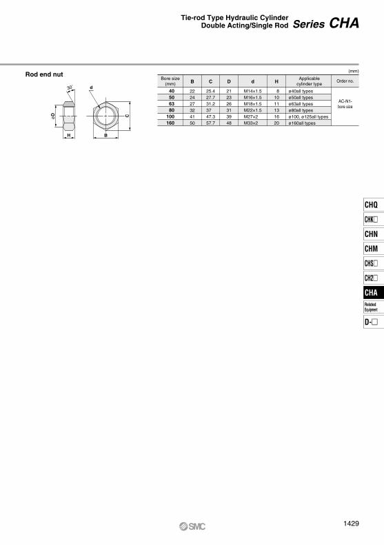
Rod end nutBore size
(mm) d
M14×1.5M16×1.5M18×1.5M22×1.5M27×2 M33×2
40 50 63 80100160
H
81011131620
B
222427324150
C
25.427.731.237 47.357.7
D
212326313948
(mm)
Order no.
AC-N1-bore size
Applicablecylinder type
ø40all typesø50all typesø63all typesø80all typesø100, ø125all typesø160all types
H
øD
30˚ d
B
C
Series CHATie-rod Type Hydraulic CylinderDouble Acting/Single Rod
1429
CHQ
CHK
CHN
CHM
CHS
CH2
CHA
D-
RelatedEquipment
CHA
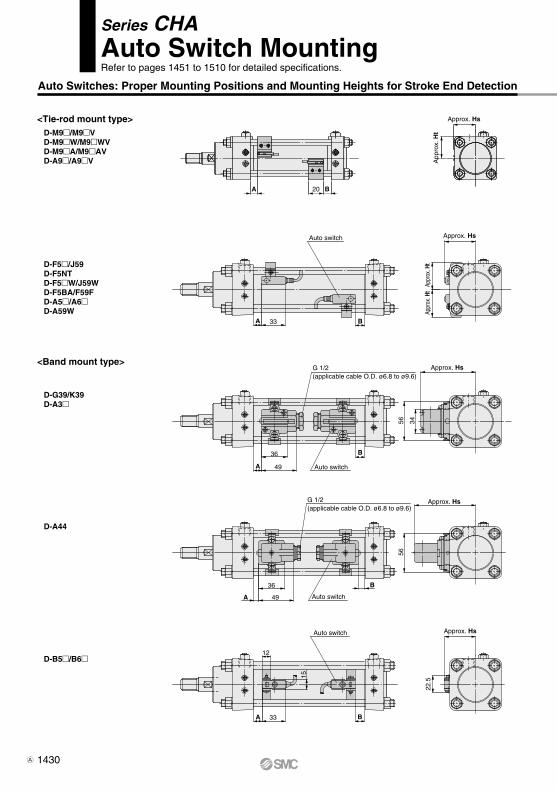
Auto Switches: Proper Mounting Positions and Mounting Heights for Stroke End Detection
D-F5/J59 D-F5NT D-F5W/J59W D-F5BA/F59F D-A5/A6 D-A59W
<Tie-rod mount type>
D-G39/K39 D-A3
<Band mount type>
D-A44
D-B5/B6
A 33
A 49
A B33
12
36
49A
36
B
B
Approx. Hs
Approx. Hs
Appr
ox. H
tAp
prox
. Ht
Auto switch
Auto switch
G 1/2(applicable cable O.D. ø6.8 to ø9.6)
G 1/2(applicable cable O.D. ø6.8 to ø9.6)
3456
Approx. Hs
56
Approx. Hs
22.5
15
Auto switch
Auto switch
B
D-M9/M9V D-M9W/M9WV D-M9A/M9AV D-A9/A9V
A B20
Approx. Hs
App
rox.
Ht
Series CHAAuto Switch MountingRefer to pages 1451 to 1510 for detailed specifications.
1430A
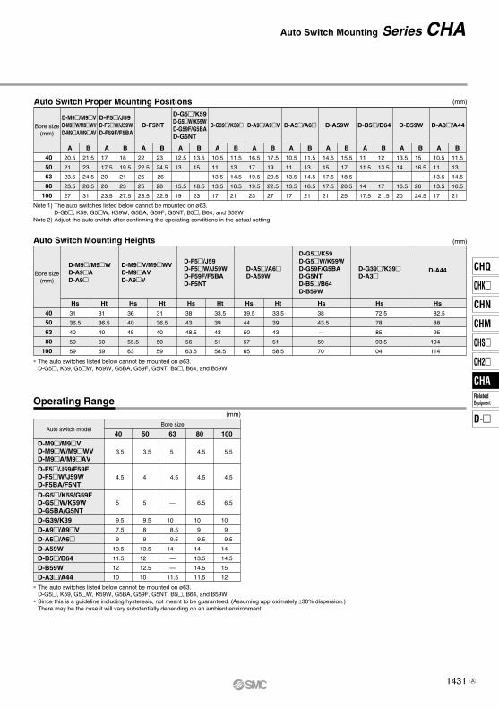
Auto Switch Mounting Heights
D-M9/M9WD-A9AD-A9
D-M9V/M9WV D-M9AV D-A9V
Bore size(mm)
D-F5/J59D-F5W/J59WD-F59F/F5BAD-F5NT
D-A5/A6D-A59W
D-G5/K59D-G5W/K59WD-G59F/G5BAD-G5NTD-B5/B64D-B59W
Hs
38
43.5
—
59
70
D-G39/K39D-A3
Hs
72.5
78
85
93.5
104
D-A44
Hs
82.5
88
95
104
114
Hs
31
36.5
40
50
59
40
50
63
80
100
Ht
31
36.5
40
50
59
Hs
36
40
45
55.5
63
Ht
31
36.5
40
50
59
Hs
38
43
48.5
56
63.5
Ht
33.5
39
43
51
58.5
Hs
39.5
44
50
57
65
Ht
33.5
39
43
51
58.5
Auto Switch Proper Mounting Positions
D-M9/M9VD-M9W/M9WVD-M9A/M9AV
Bore size(mm)
40
50
63
80
100
A
20.5
21
23.5
23.5
27
B
21.5
23
24.5
26.5
31
A
17
17.5
20
20
23.5
B
18
19.5
21
23
27.5
A
22
22.5
25
25
28.5
B
23
24.5
26
28
32.5
A
12.5
13
—
15.5
19
B
13.5
15
—
18.5
23
A
10.5
11
13.5
13.5
17
B
11.5
13
14.5
16.5
21
A
16.5
17
19.5
19.5
23
B
17.5
19
20.5
22.5
27
A
10.5
11
13.5
13.5
17
B
11.5
13
14.5
16.5
21
A
14.5
15
17.5
17.5
21
B
15.5
17
18.5
20.5
25
A
11
11.5
—
14
17.5
B
12
13.5
—
17
21.5
A
13.5
14
—
16.5
20
B
15
16.5
—
20
24.5
A
10.5
11
13.5
13.5
17
B
11.5
13
14.5
16.5
21
D-F5/J59D-F5W/J59WD-F59F/F5BA
D-F5NT
D-G5/K59D-G5W/K59WD-G59F/G5BAD-G5NT
D-G39/K39 D-A9/A9V D-A5/A6 D-A59W D-B5/B64 D-B59W D-A3/A44
Note 1) The auto switches listed below cannot be mounted on ø63.D-G5, K59, G5W, K59W, G5BA, G59F, G5NT, B5, B64, and B59W
Note 2) Adjust the auto switch after confirming the operating conditions in the actual setting.
∗ The auto switches listed below cannot be mounted on ø63.D-G5, K59, G5W, K59W, G5BA, G59F, G5NT, B5, B64, and B59W
Operating Range
∗ The auto switches listed below cannot be mounted on ø63.D-G5, K59, G5W, K59W, G5BA, G59F, G5NT, B5, B64, and B59W
∗ Since this is a guideline including hysteresis, not meant to be guaranteed. (Assuming approximately ±30% dispersion.)There may be the case it will vary substantially depending on an ambient environment.
Auto switch modelBore size
40 50
3.5
4.5
5
9.5
7.5
9
13.5
11.5
12
10
3.5
4
5
9.5
8
9
13.5
12
12.5
10
63
5
4.5
—
10
8.5
9.5
14
—
—
11.5
80
4.5
4.5
6.5
10
9
9.5
14
13.5
14.5
11.5
100
5.5
4.5
6.5
10
9
9.5
14
14.5
15
12
D-M9/M9VD-M9W/M9WVD-M9A/M9AV
D-F5/J59/F59FD-F5W/J59WD-F5BA/F5NT
D-G5/K59/G59FD-G5W/K59WD-G5BA/G5NT D-G39/K39D-A9/A9VD-A5/A6D-A59WD-B5/B64D-B59WD-A3/A44
(mm)
(mm)
(mm)
Series CHAAuto Switch Mounting
1431
CHQ
CHK
CHN
CHM
CHS
CH2
CHA
D-
RelatedEquipment
CHA
A
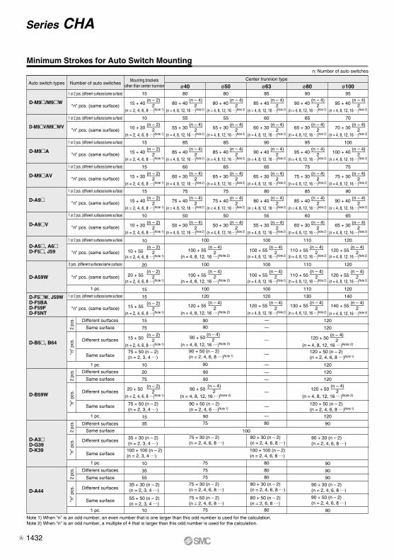
Minimum Strokes for Auto Switch Mountingn: Number of auto switches
Auto switch types
D-A5, A6D-F5, J59
D-A3D-G39D-K39
D-A44
D-F5W, J59WD-F5BAD-F59FD-F5NT
D-A59W
D-M9/M9W
D-M9V/M9WV
D-M9A
D-M9AV
D-A9
D-A9V
D-B5, B64
Center trunnion type
90
100
120 + 50
(n = 4, 8, 12, 16 …)Note 2)
(n – 4)2
120
120
120
120 + 50 (n – 2)(n = 2, 4, 6, 8 …)Note 1)
(n = 4, 8, 12, 16 …)Note 2)
ø100
120
120
140
120
120 + 55(n = 4, 8, 12, 16 …)Note 2)
(n – 4)2
120 + 55(n = 4, 8, 12, 16 …)Note 2)
(n – 4)2
140 + 55(n – 4)
2
ø80
110
110
130
110
110 + 55(n = 4, 8, 12, 16 …)Note 2)
(n – 4)2
110 + 55(n = 4, 8, 12, 16 …)Note 2)
(n – 4)2
130 + 55
(n = 4, 8, 12, 16 …)Note 2)
(n – 4)2
90 + 30 (n – 2)(n = 2, 4, 6, 8 …)
100 + 100 (n – 2)(n = 2, 4, 6, 8 …)
Mounting bracketsother than center trunnion
10
15
20
15
10
15
75
35
10
10
10 + 55(n – 2)
2
100 + 100 (n – 2)(n = 2, 3, 4 …)
20 + 55(n – 2)
2
15 + 55(n – 2)
2
15 + 50(n – 2)
2
(n – 2)2
75 + 50 (n – 2)(n = 2, 3, 4 …)
35 + 30 (n – 2)(n = 2, 3, 4 …)
35 + 30 (n – 2)(n = 2, 3, 4 …)
55 + 50 (n – 2)(n = 2, 3, 4 …)
35
55
ø50ø40
100
100
120
9090
100
90
75
75
75
100 + 55(n = 4, 8, 12, 16 …)Note 2)
(n – 4)2
100 + 55(n = 4, 8, 12, 16 …)Note 2)
(n – 4)2
120 + 55
(n = 4, 8, 12, 16 …)Note 2)
(n – 4)2
90 + 50
(n = 4, 8, 12, 16 …)Note 2)
(n – 4)2
90 + 50 (n – 2)(n = 2, 4, 6, 8 …)Note 1)
75 + 30 (n – 2)(n = 2, 4, 6, 8 …)
75 + 30 (n – 2)(n = 2, 4, 6, 8 …)
75 + 50 (n – 2)(n = 2, 4, 6, 8 …)
75
75
ø63
100
100
120
100
—
—
—
80
12090 —
80
80
—
100 + 55(n = 4, 8, 12, 16 …)Note 2)
(n – 4)2
100 + 55(n = 4, 8, 12, 16 …)Note 2)
(n – 4)2
120 + 55
(n = 4, 8, 12, 16 …)Note 2)
(n – 4)2
80 + 30 (n – 2)(n = 2, 4, 6, 8 …)
80 + 30 (n – 2)(n = 2, 4, 6, 8 …)
80 + 50 (n – 2)(n = 2, 6, 8 …)
—
80
80
90
90
90
90
90 + 30 (n – 2)(n = 2, 4, 6, 8 …)
90 + 50 (n – 2)(n = 2, 4, 6, 8 …)
2 pc
s."n
" pc
s.2
pcs.
"n"
pcs.
2 pc
s."n
" pc
s.
Number of auto switches
1 or 2 pcs. (different surfaces/same surface)
95
70
100
75
90
65
90
65
95
75
85
60
15
10
15
15
15
10
80
55
85
60
75
50
85
60
90
65
80
55
1 or 2 pcs. (different surfaces/same surface)
"n" pcs. (same surface)
1 or 2 pcs. (different surfaces/same surface)
"n" pcs. (same surface)
1 or 2 pcs. (different surfaces/same surface)
"n" pcs. (same surface)
1 or 2 pcs. (different surfaces/same surface)
"n" pcs. (same surface)
1 or 2 pcs. (different surfaces/same surface)
"n" pcs. (same surface)
1 or 2 pcs. (different surfaces/same surface)
"n" pcs. (same surface)
"n" pcs. (same surface)
95 + 40
70 + 30
100 + 40
75 + 30
90 + 40
65 + 30
(n = 4, 8, 12, 16 …)Note 2)
(n = 4, 8, 12, 16 …)Note 2)
(n = 4, 8, 12, 16 …)Note 2)
(n = 4, 8, 12, 16 …)Note 2)
(n = 4, 8, 12, 16 …)Note 2)
(n = 4, 8, 12, 16 …)Note 2)
(n – 4)2
(n = 4, 8, 12, 16 …)Note 2)
(n = 4, 8, 12, 16 …)Note 2)
(n = 4, 8, 12, 16 …)Note 2)
(n = 4, 8, 12, 16 …)Note 2)
(n = 4, 8, 12, 16 …)Note 2)
(n = 4, 8, 12, 16 …)Note 2)
(n – 4)215 + 40
10 + 30
15 + 40
15 + 30
15 + 40
10 + 30
(n = 2, 4, 6, 8 …)Note 1)
(n = 2, 4, 6, 8 …)Note 1)
(n = 2, 4, 6, 8 …)Note 1)
(n = 2, 4, 6, 8 …)Note 1)
(n = 2, 4, 6, 8 …)Note 1)
(n = 2, 4, 6, 8 …)Note 1)
(n = 2, 4, 6, 8 …)Note 1)
(n = 2, 4, 6, 8 …)Note 1)
(n = 2, 4, 6, 8 …)Note 1)
(n = 2, 4, 6, 8 …)Note 1)
(n – 2)2 80 + 40
55 + 30
85 + 40
60 + 30
75 + 40
50 + 30
(n = 4, 8, 12, 16 …)Note 2)
(n = 4, 8, 12, 16 …)Note 2)
(n = 4, 8, 12, 16 …)Note 2)
(n = 4, 8, 12, 16 …)Note 2)
(n = 4, 8, 12, 16 …)Note 2)
(n = 4, 8, 12, 16 …)Note 2)
(n – 4)2 85 + 40
60 + 30
90 + 40
65 + 30
80 + 40
55 + 30
(n = 4, 8, 12, 16 …)Note 2)
(n = 4, 8, 12, 16 …)Note 2)
(n = 4, 8, 12, 16 …)Note 2)
(n = 4, 8, 12, 16 …)Note 2)
(n = 4, 8, 12, 16 …)Note 2)
(n = 4, 8, 12, 16 …)Note 2)
(n – 4)2
(n – 4)2
(n – 4)2
(n – 2)2
(n – 4)2
(n – 4)2
(n – 4)2
(n – 4)2
(n – 2)2
(n – 4)2
(n – 4)2
(n – 4)2
(n – 4)2
(n – 2)2
(n – 4)2
(n – 4)2
(n – 4)2
(n – 4)2
(n – 2)2
(n – 4)2
(n – 4)2
(n – 4)2
(n – 4)2
(n – 2)2
(n – 4)2
80
55
85
65
75
50
80 + 40
55 + 30
85 + 40
65 + 30
75 + 40
50 + 30
(n = 4, 8, 12, 16 …)Note 2)
(n = 4, 8, 12, 16 …)Note 2)
(n = 4, 8, 12, 16 …)Note 2)
(n = 4, 8, 12, 16 …)Note 2)
(n = 4, 8, 12, 16 …)Note 2)
(n = 4, 8, 12, 16 …)Note 2)
(n – 4)2
(n – 4)2
(n – 4)2
(n – 4)2
(n – 4)2
(n – 4)2
(n – 4)2
2 pcs. (different surfaces/same surface)
"n" pcs. (same surface)
1 pc.
1 or 2 pcs. (different surfaces/same surface)
"n" pcs. (same surface)
1 pc.
1 pc.
1 pc.
Different surfaces
Same surface
Different surfaces
Same surface
Different surfaces
Different surfaces
Same surface
Same surface
D-B59W
120
120
20
75
15
75 + 50 (n – 2)(n = 2, 3, 4 …)
90 + 50 (n – 2)(n = 2, 4, 6 …)Note 1)
120 + 50 (n – 2)(n = 2, 4, 6, 8 …)Note 1)
20 + 50
(n = 2, 4, 6, 8 …)Note 1)
90
90
—
—
—
—
2 pc
s."n
" pc
s.
1 pc.
Different surfaces
Same surface
Different surfaces
Same surface
Different surfaces
Same surface
Different surfaces
Same surface
90 + 50
(n = 4, 8, 12, 16 …)Note 2)
(n – 4)2 120 + 50
(n = 4, 8, 12, 16 …)Note 2)
(n – 4)2
90 + 40
65 + 30
95 + 40
75 + 30
85 + 40
60 + 30
Note 1) When “n” is an odd number, an even number that is one larger than this odd number is used for the calculation.Note 2) When “n” is an odd number, a multiple of 4 that is larger than this odd number is used for the calculation.
Series CHA
1432A
• Mounting example for D-M9(V), M9W(V), M9A(V).
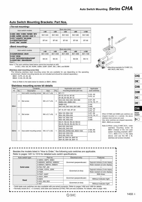
Auto Switch Mounting Brackets: Part Nos.
[Stainless steel mounting screw kits]The following stainless steel mounting screw kits are available for use depending on the operating environment. (Switch mounting bands are not included and should be ordered separately.)
BBA1 : D-F5, J5, A5, A6BBA3 : D-G5, K5, B5, B6
Note 2) Refer to the table below for details on BBA1, BBA3.
When D-F5BA and G5BA auto switches are shipped mounted on a cylinder, the above stainless steel screws are used. Also when switches are shipped separately, BBA1, BBA3 are included.
Note 3) When using D-M9A(V), order stainless mounting screw kit BBA1 instead of the iron auto switch mounting brackets (BA7-, BS5-) in the table above, and use the M4 x 6L stainless set screws included.
Auto switch modelsBore size (mm)
D-M9/M9V/M9W/M9WVD-M9A/M9AV/A9/A9VD-F5/J59/F5W/J59WD-F5BA/F59F/F5NTD-A5/A6/A59W
ø40
BA7-040
BT-04
ø50
BA7-063
BT-06
ø63
BA7-063
BT-06
ø80 ø100
BA7-080
BT-08
BA7-080
BT-08
Note 1) The auto switches listed below cannot be mounted on ø63.D-G5, K59, G5W, K59W, G5BA, G59F, G5NT, B5, B64, and B59W
∗ Solid state auto switches are also available with pre-wired connector. Refer to pages 1494 and 1495 for details.∗ Normally closed (N.C. = b contact), solid state auto switches (D-F9G, F9H) are also available. For details, refer to page 1463.
Besides the models listed in “How to Order,” the following auto switches are applicable.Refer to pages 1451 to 1510 for detailed auto switch specifications.
Auto switch type Part no. FeaturesElectrical entryD-M9NV, M9PV, M9BVD-M9NWV, M9PWV, M9BWVD-M9NAV, M9PAV, M9BAVD-F59, F5P, J59D-F59W, F5PW, J59WD-F5BAD-F5NT, G5NTD-A93V, A96VD-A90VD-A53, A56, B53D-A67
—Diagnostic indication (2-color display)Water resistant (2-color display)
—Diagnostic indication (2-color display)Water resistant (2-color display)
With timer—
Without indicator light—
Without indicator light
Grommet (perpendicular)
Grommet (in-line)
Grommet (perpendicular)
Grommet (in-line)
Solid state
Reed
<Tie-rod mounting>
Auto switch modelsBore size (mm)
D-G39/K39/A3/A44D-G5/K59D-G5W/K59W/G5BA/G59FD-G5NT/B5/B64/B59WNote 1)
ø40BD1-04M
BA-04
ø50BD1-05M
BA-05
ø63BD1-06M
—
ø80 ø100BD1-08M
BA-08
BD1-10M
BA-10
<Band mounting>
Stainless mounting screw kit details
BBA3 4 Auto switch mounting screws M4 x 0.7 x 22L 1
BA-01, BA-02, BA-32, BA-04BA-05, BA-06, BA-08, BA-10BA2-020, BA2-025BA2-032, BA2-040BA5-050, BHN2-025, BSG1-032BH2-040, BH2-050BH2-080, BH2-100BAF-32, BAF-04, BAF-05BAF-06, BAF-08, BAF-10
D-B5, B6D-G5, K5
Partno.
Contents
BBA1
DescriptionAuto switch mounting screws
Set screw
Set screw
Size
M4 x 0.7 x 8L
M4 x 0.7 x 6L
M4 x 0.7 x 8L
Pcs.No.
11
2
3
2
2
Applicable auto switchmounting bracket part nos.
Applicableauto switches
BT-BT-03, BT-04, BT-05BT-06, BT-08, BT-12
BT-16, BT-18A, BT-20
BA4-040, BA4-063, BA4-080BMB4-032, BMB4-050
BS4-125, BS4-160BS4-180, BS4-200BS5-125, BS5-160BS5-180, BS5-200
BMB5-032BA7-040, BA7-063, BA7-080
D-A5, A6D-F5, J5
D-A9D-M9
D-Z7, Z8D-Y5, Y6, Y7
D-A5, A6D-F5, J5
D-A9D-M9
D-Z7, Z8D-Y5, Y6, Y7
Series CHAAuto Switch Mounting
1433
CHQ
CHK
CHN
CHM
CHS
CH2
CHA
D-
RelatedEquipment
CHA
A
r
e
w
q
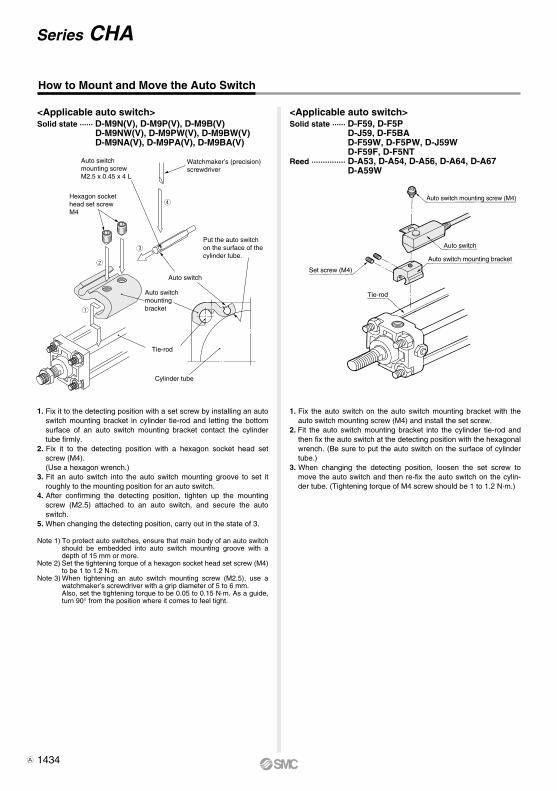
1. Fix it to the detecting position with a set screw by installing an auto switch mounting bracket in cylinder tie-rod and letting the bottom surface of an auto switch mounting bracket contact the cylinder tube firmly.
2. Fix it to the detecting position with a hexagon socket head set screw (M4).(Use a hexagon wrench.)
3. Fit an auto switch into the auto switch mounting groove to set it roughly to the mounting position for an auto switch.
4. After confirming the detecting position, tighten up the mounting screw (M2.5) attached to an auto switch, and secure the auto switch.
5. When changing the detecting position, carry out in the state of 3.
Note 1) To protect auto switches, ensure that main body of an auto switch should be embedded into auto switch mounting groove with a depth of 15 mm or more.
Note 2) Set the tightening torque of a hexagon socket head set screw (M4) to be 1 to 1.2 N·m.
Note 3) When tightening an auto switch mounting screw (M2.5), use a watchmaker’s screwdriver with a grip diameter of 5 to 6 mm.Also, set the tightening torque to be 0.05 to 0.15 N·m. As a guide, turn 90° from the position where it comes to feel tight.
<Applicable auto switch>Solid state ······ D-M9N(V), D-M9P(V), D-M9B(V)
D-M9NW(V), D-M9PW(V), D-M9BW(V)D-M9NA(V), D-M9PA(V), D-M9BA(V)
Watchmaker’s (precision) screwdriver
Hexagon socket head set screwM4
Auto switchmounting screwM2.5 x 0.45 x 4 L
How to Mount and Move the Auto Switch
1. Fix the auto switch on the auto switch mounting bracket with the auto switch mounting screw (M4) and install the set screw.
2. Fit the auto switch mounting bracket into the cylinder tie-rod and then fix the auto switch at the detecting position with the hexagonal wrench. (Be sure to put the auto switch on the surface of cylinder tube.)
3. When changing the detecting position, loosen the set screw to move the auto switch and then re-fix the auto switch on the cylin-der tube. (Tightening torque of M4 screw should be 1 to 1.2 N·m.)
<Applicable auto switch>Solid state ······ D-F59, D-F5P
D-J59, D-F5BAD-F59W, D-F5PW, D-J59WD-F59F, D-F5NT
Reed ··············· D-A53, D-A54, D-A56, D-A64, D-A67D-A59W
Auto switch
Set screw (M4)
Auto switch mounting bracket
Tie-rod
Auto switch mounting screw (M4)
Put the auto switch on the surface of the cylinder tube.
Cylinder tube
Tie-rod
Auto switchmounting bracket
Auto switch
Series CHA
1434A
XC22
Symbol
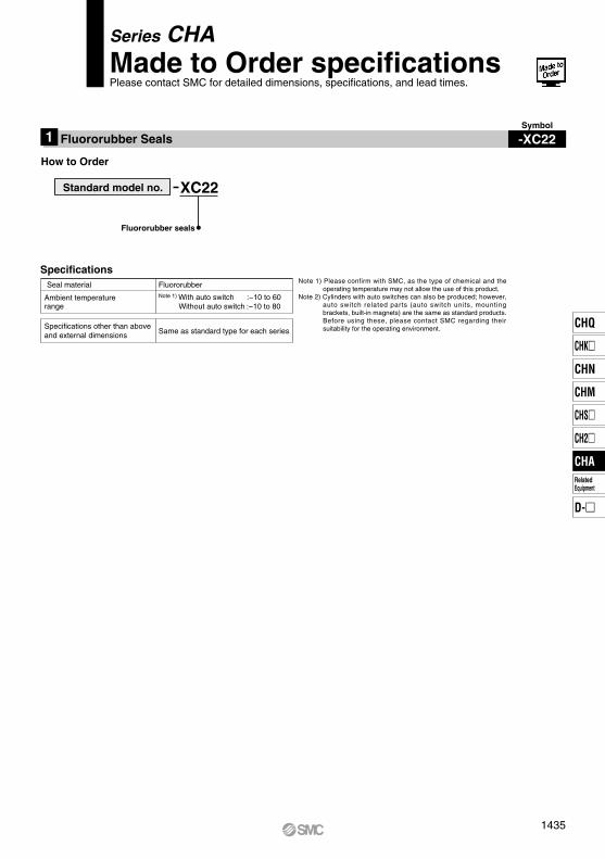
-XC22Fluororubber Seals1
How to Order
Ambient temperaturerange
Seal materialNote 1) With auto switch :−10 to 60�
Without auto switch :−10 to 80�
Fluororubber
Specifications other than aboveand external dimensions Same as standard type for each series
Standard model no.
Fluororubber seals
SpecificationsNote 1) Please confirm with SMC, as the type of chemical and the
operating temperature may not allow the use of this product.Note 2) Cylinders with auto switches can also be produced; however,
auto switch related parts (auto switch units, mounting brackets, built-in magnets) are the same as standard products. Before using these, please contact SMC regarding their suitability for the operating environment.
Series CHAMade to Order specificationsPlease contact SMC for detailed dimensions, specifications, and lead times.
1435
CHQ
CHK
CHN
CHM
CHS
CH2
CHA
D-
RelatedEquipment
CHA
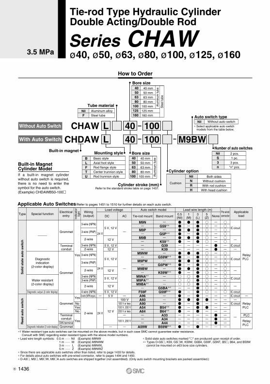
∗ Lead wire length symbols: 0.5 m ······ Nil (Example) M9NW 1 m ······ M (Example) M9NWM 3 m ······ L (Example) M9NWL 5 m ······ Z (Example) M9NWZ∗ Since there are applicable auto switches other than listed, refer to page 1433 for details.∗ For details about auto switches with pre-wired connector, refer to pages 1494 and 1450.∗ D-A9, M9, M9W, M9A auto switches are shipped together (not assembled). (Only auto switch mounting brackets are packed assembled.)
∗1 Water resistant type auto switches can be mounted on the above models, but in such case SMC cannot guarantee water resistance. Consult with SMC regarding water resistant types with the above model numbers.
∗ Solid state auto switches marked "" are produced upon receipt of order.∗∗ Types D-G5, K59, G5W, K59W, G5BA, G59F, G5NT, B5, B64, and B59W
cannot be mounted on ø63 bore size cylinders.
2 pcs.1 pc.3 pcs.
"n" pcs.
NilS3n
Number of auto switchesMounting styleBuilt-in magnet
CHAW 40 100LL
BLFTU
Basic styleAxial foot styleRod flange styleCenter trunnion styleRod trunnion style
Bore size40506380
100
40 mm 50 mm 63 mm 80 mm100 mm A
lum
inum
tube
Cylinder optionNilNRH
Both sidesWithout cushionWith rod cushion
With head cushion
Cushion
CHDAW 40 100 M9BW
Cylinder stroke (mm)Refer to the standard stroke table on page 1437.
Applicable Auto Switches/Refer to pages 1451 to 1510 for further details on each auto switch.
3-wire (NPN equiv.)
2-wire
Load voltage Auto switch model
100 V100 V or less100 V, 200 V200 V or less
100 V, 200 V
ACDC
Lead wire length (m)Applicable
load
5 V
12 V24 V
Yes
NoYesNo
Yes
Yes
3-wire (NPN)
3-wire (PNP)
2-wire
3-wire (NPN)2-wire
3-wire (NPN)
3-wire (PNP)
2-wire
3-wire (NPN)3-wire (PNP)
2-wire
4-wire (NPN)
Ree
d a
uto
sw
itch
So
lid s
tate
au
to s
wit
ch
A96A93A90A54A64
A59W
B54∗∗B64∗∗A33A34A44
B59W∗∗
RelayPLC
RelayPLC
RelayPLC
24 V
24 V
Grommet
Terminalconduit
DIN terminalGrommet
Grommet
Terminalconduit
Grommet
Tie-rod mount Band mount
5 V, 12 V
12 V
5 V, 12 V12 V
5 V, 12 V
12 V
5 V, 12 V
12 V
5 V, 12 V
M9N
M9P
M9B
M9NW
M9PW
M9BW
M9NA∗1
M9PA∗1
M9BA∗1
F59F
G59∗∗
G5P∗∗
K59∗∗G39K39
G59W∗∗
G5PW∗∗
K59W∗∗
G5BA∗∗G59F∗∗
TypeElectrical
entry
Indi
cato
rlig
ht Wiring(output)
Special function 0.5(Nil)
1(M)
3(L)
5(Z) None
Diagnosticindication
(2-color display)
Water resistant(2-color display)
Diagnostic indication (2-color display)
IC circuit
IC circuit
IC circuit
IC circuit
IC circuitIC circuit
IC circuit
PLC
With Auto Switch
Without Auto Switch
How to Order
Bore size40506380
100125160
40 mm 50 mm 63 mm 80 mm100 mm125 mm160 mm
Alu
min
um tu
beS
teel
tube
Aluminum alloySteel tube
NilF
Tube material
Without auto switchNilAuto switch type
∗ Select applicable auto switch models from the table below.
Pre-wiredconnector
Diagnostic output (2-color display)
Built-in Magnet Cylinder ModelIf a built-in magnet cylinder without auto switch is required, there is no need to enter the symbol for the auto switch.(Example) CHDAWB50-100
3.5 MPa
Tie-rod Type Hydraulic CylinderDouble Acting/Double Rod
Series CHAWø40, ø50, ø63, ø80, ø100, ø125, ø160
1436B
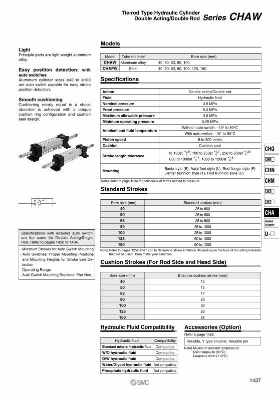
LightPrinciple parts are light weight aluminum alloy.
Easy position detection: with auto switchesAluminum cylinder sizes ø40 to ø100 are auto switch capable for easy stroke position detection.
Smooth cushioningCushioning nearly equal to a shock absorber is achieved with a unique cushion ring configuration and cushion seal design.
40
50
63
80
100
125
160
25 to 800
25 to 800
25 to 800
25 to 1000
25 to 1000
50 to 1000
50 to 1200
Bore size (mm)
40, 50, 63, 80, 100
40, 50, 63, 80, 100, 125, 160
Model Tube material
CHAW
CHAFW
Aluminum alloy
Steel
Refer to page 1428.
· Minimum Strokes for Auto Switch Mounting· Auto Switches: Proper Mounting Positions
and Mounting Heights for Stroke End De-tection
· Operating Range· Auto Switch Mounting Brackets: Part Nos.
Specifications with included auto switch are the same for Double Acting/Single Rod. Refer to pages 1430 to 1434.
Effective cushion stroke (mm)
15
15
17
20
20
20
22
40
50
63
80
100
125
160
Models
Specifications
Action
Fluid
Nominal pressure
Proof pressure
Maximum allowable pressure
Minimum operating pressure
Ambient and fluid temperature
Piston speed
Cushion
Double acting/Double rod
Hydraulic fluid
3.5 MPa
5.0 MPa
3.5 MPa
0.25 MPa
Without auto switch: –10° to 80°CWith auto switch: –10° to 60°C
8 to 300 mm/s
Cushion seal
Note) Refer to page 1234 for definitions of terms related to pressure.
Stroke length tolerance+0.8 0
+1.0 0
+1.25 0
+1.4 0
+1.8 0
to 100st , 100 to 250st , 250 to 630st
630 to 1000st , 1000 to 1200st
Basic style (B), Axial foot style (L), Rod flange style (F)Center trunnion style (T), Rod trunnion style (U)
Mounting
Bore size (mm) Standard strokes (mm)
Standard Strokes
Note) Refer to pages 1252 and 1253 to determine stroke limitation depending on the type of mounting brackets that will be used. Then make your selection.
Bore size (mm)
Cushion Strokes (For Rod Side and Head Side)
Hydraulic Fluid Compatibility
Standard mineral hydraulic fluid
W/O hydraulic fluid
O/W hydraulic fluid
Water/Glycol hydraulic fluid
Phosphate hydraulic fluid
Compatible
Compatible
Compatible
Not compatible
Not compatible
Hydraulic fluid Compatibility Knuckle, Y type knuckle, Knuckle pin
Accessories (Option)
Note) Maximum ambient temperature:Nylon tarpaulin (60°C)Neoprene cloth (110°C)
Series CHAWTie-rod Type Hydraulic CylinderDouble Acting/Double Rod
1437
CHQ
CHK
CHN
CHM
CHS
CH2
CHA
D-
RelatedEquipment
CHA
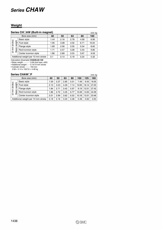
Series CHAW (Built-in magnet)Bore size (mm)
Additional weight per 10 mm stroke
Unit: kg
Unit: kg
Basic style
Foot style
Flange style
Rod trunnion style
Center trunnion style(0 m
m s
trok
e)
Bas
ic w
eigh
t
40 50 63 80 100
Series CHAWFBore size (mm)
Additional weight per 10 mm stroke
Basic style
Foot style
Flange style
Rod trunnion style
Center trunnion style(0 m
m s
trok
e)
Bas
ic w
eigh
t
40 50 63 80 100 125 160
Calculation (Example) CHAWL50-100• Basic weight ············ 3.08 (foot type, ø50)• Additional weight ····· 0.14/10 mm stroke• Cylinder stroke ········ 100 mm 3.08 + 0.14 x 100/10 = 4.48 kg
1.44
1.95
1.69
1.71
1.86
0.1
2.16
3.08
2.56
2.57
2.89
0.14
2.78
4.02
3.35
3.28
3.55
0.18
4.58
6.71
5.54
3.40
3.67
0.24
6.90
10.34
8.60
9.80
9.59
0.32
1.59
2.10
1.84
1.86
2.01
0.18
2.27
3.23
2.71
2.72
2.99
0.16
2.85
4.09
3.42
3.35
3.62
0.20
5.01
7.14
5.97
6.77
6.52
0.38
7.49
10.93
9.19
10.39
10.18
0.48
9.55
16.14
12.51
14.05
13.31
0.62
16.55
27.25
27.42
24.39
23.46
0.94
Weight
Series CHAW
1438
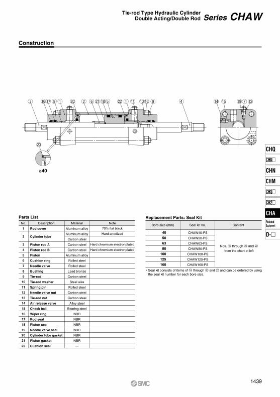
No.
1
2
3
4
5
6
7
8
9
10
11
12
13
14
15
16
17
18
19
20
21
22
Description Material Note
Parts List Replacement Parts: Seal Kit
Rod cover
Cylinder tube
Piston rod A
Piston rod B
Piston
Cushion ring
Needle valve
Bushing
Tie-rod
Tie-rod washer
Spring pin
Needle valve nut
Tie-rod nut
Air release valve
Check ball
Wiper ring
Rod seal
Piston seal
Needle valve seal
Cylinder tube gasket
Piston gasket
Cushion seal
Aluminum alloy
Aluminum alloy
Carbon steel
Carbon steel
Carbon steel
Aluminum alloy
Rolled steel
Rolled steel
Lead bronze
Carbon steel
Steel wire
Rolled steel
Carbon steel
Carbon steel
Alloy steel
Bearing steel
NBR
NBR
NBR
NBR
NBR
NBR
—
70% flat black
Hard anodized
Hard chromium electronplated
Hard chromium electronplated
Bore size (mm) Seal kit no.
CHAW40-PS
CHAW50-PS
CHAW63-PS
CHAW80-PS
CHAW100-PS
CHAW125-PS
CHAW160-PS
Content
Nos. !6 through @0 and @2
from the chart at left
40
50
63
80
100
125
160
e !6!7iq @0 w y@1!8t @2 q !1 !0!3 o r !4 !5 !9u!2
@0
ø40
Construction
∗ Seal kit consists of items of !6 through @0 and @2 and can be ordered by using the seal kit number for each bore size.
Series CHAWTie-rod Type Hydraulic CylinderDouble Acting/Double Rod
1439
CHQ
CHK
CHN
CHM
CHS
CH2
CHA
D-
RelatedEquipment
CHA
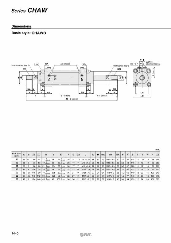
Basic style: CHAWB
Bore size(mm)
45
50
55
65
80
80
100
0–0.062 0–0.062 0–0.074 0–0.074 0–0.074 0–0.074 0–0.087
0–0.018 0–0.021 0–0.021 0–0.021 0–0.025 0–0.025 0–0.025
17
19
21
26
34
34
43
A
23
25
28
32
38
38
42
10
9
8
8
6.5
6.5
9
a d
18
20
22.4
28
35.5
35.5
45
B
60
73
80
100
118
140
174
C
44
53
60
75
90
112
140
F
25
28
30
32
35
35
38
G
14
17
17
22
27
27
36
GA
17.5
17
17
20
19
19
22
K
18
20
22
26
27
27
28
M
13
16
16
19
21
24
27
MA
20
22
25
29
34
34
38
NA
30
30
30
35
35
35
40
R
37
43
47
57
66
77
94
S
114
116
120
132
140
140
159
H
66
73
80
90
100
100
108
ZZ
246
262
280
312
340
340
375
V
7.5
10
12
16
20
20
24
W
8
9
10
13
16
16
20
T
11
11
11
11
12
12
12
P
1/4
3/8
3/8
1/2
1/2
1/2
3/4
J
M8 x 1.25
M10 x 1.5
M10 x 1.5
M12 x 1.75
M12 x 1.75
M14 x 2
M16 x 2
MM
M14 x 1.5
M16 x 1.5
M18 x 1.5
M22 x 1.5
M27 x 2
M27 x 2
M33 x 2
(mm)
E D
MA
MM
A K
H
F NA NA F K A
M MAaa M
H + StrokeS + Stroke
ZZ + 2 strokes
4 x J GA
øE
øD W
W
ød
Air release GA
MM
øDød
øE
R (m
ax.)
2 x Rc PCushion adjustment screw
T T
V V
C
B
40
50
63
80
100
125
160
Dimensions
Width across flats G Width across flats G
Series CHAW
1440
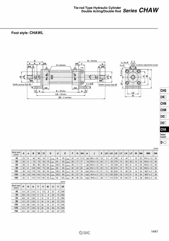
Foot style: CHAWL
Bore size(mm)
A
23
25
28
32
38
38
42
a
10
9
8
8
6.5
6.5
9
d
18
20
22.4
28
35.5
35.5
45
B
60
73
80
100
118
140
174
B
60
73
80
100
118
140
174
C
44
53
60
75
90
112
140
F
25
28
30
32
35
35
38
G
14
17
17
22
27
27
36
GA
17.5
17
17
20
19
19
22
K
18
20
22
26
27
27
28
M
10
12
12
14
14
16
18
MA
20
22
25
29
34
34
38
NA
30
30
30
35
35
35
40
R
37
43
47
57
66
77
94
P
1/4
3/8
3/8
1/2
1/2
1/2
3/4
S
114
116
120
132
140
140
159
X
27
30
37
40
47
55
60
V
7.5
10
12
16
20
20
24
W
8
9
10
13
16
16
20
T
11
11
11
11
12
12
12
J
M8 x 1.25
M10 x 1.5
M10 x 1.5
M12 x 1.75
M12 x 1.75
M14 x 2
M16 x 2
MM
M14 x 1.5
M16 x 1.5
M18 x 1.5
M22 x 1.5
M27 x 2
M27 x 2
M33 x 2
(mm)
E D
Bore size(mm)
45
50
55
65
80
80
100
0–0.062 0–0.062 0–0.074 0–0.074 0–0.074 0–0.074 0–0.087
0–0.018 0–0.021 0–0.021 0–0.021 0–0.025 0–0.025 0–0.025
17
19
21
26
34
34
43
H
66
73
80
90
100
100
108
ZZ
246
262
280
312
340
340
375
LT
8
10
10
12
14
16
18
LX
44
53
60
75
90
112
140
LY
77
88.5
95
115
139
170
197
LH
47
52
55
65
80
100
110
LD
9
11
11
13
13
15
17
LS
168
176
194
212
234
250
279
Y
8
10
10
13
13
15
20
(mm)
WW
HK F
Y X YXLXB
S + Stroke
LS + Stroke
ZZ + 2 strokes
GA
NA NA
AMA a
H + Stroke
FGA AMAa
ød
ød
øD
øEøD
øE
MMMM
T T
V V2 x Rc P
4 x J
R (m
ax.)
LH ±0
.2
C
B
LY
Air release
4 x øLD
LTLT
40
50
63
80
100
125
160
40
50
63
80
100
125
160
Width across flats G Width across flats G
Cushion adjustment screw
Series CHAWTie-rod Type Hydraulic CylinderDouble Acting/Double Rod
1441
CHQ
CHK
CHN
CHM
CHS
CH2
CHA
D-
RelatedEquipment
CHA
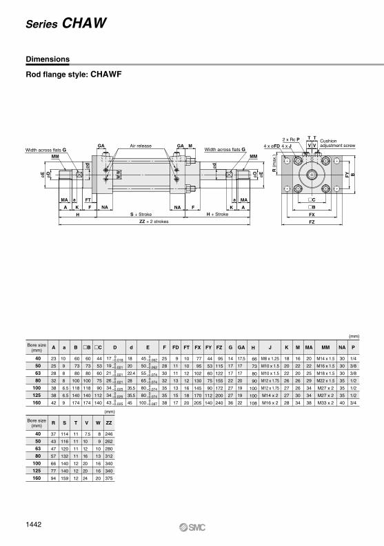
Rod flange style: CHAWF
Width across flats G
Bore size(mm)
A
23
25
28
32
38
38
42
a
10
9
8
8
6.5
6.5
9
d
18
20
22.4
28
35.5
35.5
45
B
60
73
80
100
118
140
174
B
60
73
80
100
118
140
174
C
44
53
60
75
90
112
140
F
25
28
30
32
35
35
38
G
14
17
17
22
27
27
36
GA
17.5
17
17
20
19
19
22
K
18
20
22
26
27
27
28
M
16
22
20
26
26
30
34
MA
20
22
25
29
34
34
38
P
1/4
3/8
3/8
1/2
1/2
1/2
3/4
R
37
43
47
57
66
77
94
W
8
9
10
13
16
16
20
FD
9
11
11
13
13
15
17
T
11
11
11
11
12
12
12
V
7.5
10
12
16
20
20
24
S
114
116
120
132
140
140
159
NA
30
30
30
35
35
35
40
J
M8 x 1.25
M10 x 1.5
M10 x 1.5
M12 x 1.75
M12 x 1.75
M14 x 2
M16 x 2
MM
M14 x 1.5
M16 x 1.5
M18 x 1.5
M22 x 1.5
M27 x 2
M27 x 2
M33 x 2
(mm)
E D
Bore size(mm)
H
66
73
80
90
100
100
108
ZZ
246
262
280
312
340
340
375
FZ
95
115
122
155
172
200
240
FX
77
95
102
130
145
170
205
FY
44
53
60
75
90
112
140
FT
10
10
12
12
16
18
20
(mm)
MA
A K
H
F NA NA F K A
MAaa FT
H + StrokeS + Stroke
ZZ + 2 strokes
øE
øD
ød
ød
øD
øE
R (m
ax.)
FY BW
W
MM
GA Air release GA M
MM
4 x øFD 4 x J2 x Rc P T T
V VCushion adjustment screw
C
B
FX
FZ
40
50
63
80
100
125
160
40
50
63
80
100
125
160
Dimensions
Width across flats G
45
50
55
65
80
80
100
0–0.062 0–0.062 0–0.074 0–0.074 0–0.074 0–0.074 0–0.087
0–0.018 0–0.021 0–0.021 0–0.021 0–0.025 0–0.025 0–0.025
17
19
21
26
34
34
43
Series CHAW
1442
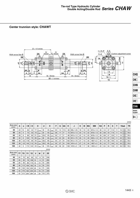
Center trunnion style: CHAWT
Width across flats G
Bore size(mm)
A
23
25
28
32
38
38
42
a
10
9
8
8
6.5
6.5
9
d
18
20
22.4
28
35.5
35.5
45
B
60
73
80
100
118
140
174
C
44
53
60
75
90
112
140
45
50
55
65
80
80
100
0–0.062 0–0.062 0–0.074 0–0.074 0–0.074 0–0.074 0–0.087
0–0.018 0–0.021 0–0.021 0–0.021 0–0.025 0–0.025 0–0.025
17
19
21
26
34
34
43
F
25
28
30
32
35
35
38
G
14
17
17
22
27
27
36
GA
17.5
17
17
20
19
19
22
K
18
20
22
26
27
27
28
M
10
10
10
13
13
15
17
MA
20
22
25
29
34
34
38
NA
30
30
30
35
35
35
40
R
37
43
47
57
66
77
94
S
114
116
120
132
140
140
159
V
7.5
10
12
16
20
20
24
W
8
9
10
13
16
16
20
P
1/4
3/8
3/8
1/2
1/2
1/2
3/4
J
M8 x 1.25
M10 x 1.5
M10 x 1.5
M12 x 1.75
M12 x 1.75
M14 x 2
M16 x 2
MM
M14 x 1.5
M16 x 1.5
M18 x 1.5
M22 x 1.5
M27 x 2
M27 x 2
M33 x 2
(mm)
E D TDe8
Bore size(mm)
Z
123
131
140
156
170
170
187.5
H
66
73
80
90
100
100
108
ZZ
246
262
280
312
340
340
375
T
11
11
11
11
12
12
12
TY
65
78
86
106
130
162
200
TZ
95
108
115
162
204
234
284
TT
24
26
26
36
42
42
52
TX
70
83
90
112
140
170
212
TR
R0.5
R0.5
R0.5
R2.5
R2.5
R2.5
R2.5
(mm)
Z + 1/2 stroke
GA GATTAir
releaseAir
release
MM
øD
øE
øD
øEW
W
MM
R (m
ax.)
TR
4 x J Cushion adjustment screw
2 x Rc P T T
V V
øTD
e8
TY
MA
A K
H S + Stroke H + Stroke
ZZ + 2 strokes
F NA
M
FNA
Ma MA
AB
TX
TZ
CK
a
ød
0–0.5
ød
40
50
63
80
100
125
160
40
50
63
80
100
125
160
Width across flats G
15
15
15
25
32
32
36
–0.032–0.059–0.032–0.059–0.032–0.059–0.040–0.073–0.050–0.089–0.050–0.089–0.050–0.089
Series CHAWTie-rod Type Hydraulic CylinderDouble Acting/Double Rod
1443
CHQ
CHK
CHN
CHM
CHS
CH2
CHA
D-
RelatedEquipment
CHA
A
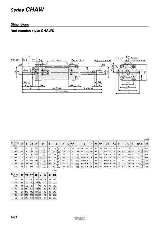
Rod trunnion style: CHAWU
Bore size(mm)
A
23
25
28
32
38
38
42
a
10
9
8
8
6.5
6.5
9
d
18
20
22.4
28
35.5
35.5
45
B
60
73
80
100
118
140
174
C
44
53
60
75
90
112
140
F
25
28
30
32
35
35
38
G
14
17
17
22
27
27
36
GA
17.5
17
17
20
19
19
22
K
18
20
22
26
27
27
28
M
10
13
15
13
13
15
17
MA
20
22
25
29
34
34
38
NA
30
30
30
35
35
35
40
R
37
43
47
57
66
77
94
S
114
116
120
132
140
140
159
V
7.5
10
12
16
20
20
24
W
8
9
10
13
16
16
20
T
11
11
11
11
12
12
12
P
1/4
3/8
3/8
1/2
1/2
1/2
3/4
J
M8 x 1.25
M10 x 1.5
M10 x 1.5
M12 x 1.75
M12 x 1.75
M14 x 2
M16 x 2
MM
M14 x 1.5
M16 x 1.5
M18 x 1.5
M22 x 1.5
M27 x 2
M27 x 2
M33 x 2
(mm)
E D TDe8
Bore size(mm)
TY
60
73
80
100
118
140
174
TZ
95
108
115
162
204
234
284
Z
58
65
72
75
83
83
89
H
66
73
80
90
100
100
108
ZZ
246
262
280
312
340
340
375
TT
16
16
16
30
34
34
38
TX
70
83
90
112
140
170
212
TR
R0.5
R0.5
R0.5
R2.5
R2.5
R2.5
R2.5
(mm)
T
V V
T
øTD
e8
TY
2 x Rc P
TR
R (m
ax.)
C
B
TZ
TX 0–0.5
MA a
A K F NA
H S + Stroke H + Stroke
NA F K A
MAa
øE
øD
ød
W
ød
øD
øE
W
MM
Z
TT GA Air release GA M 4 x J
MM
ZZ + 2 strokes
40
50
63
80
100
125
160
40
50
63
80
100
125
160
Dimensions
Width across flats G Width across flats GCushion adjustment screw
45
50
55
65
80
80
100
0–0.062 0–0.062 0–0.074 0–0.074 0–0.074 0–0.074 0–0.087
0–0.018 0–0.021 0–0.021 0–0.021 0–0.025 0–0.025 0–0.025
17
19
21
26
34
34
43
15
15
15
25
32
32
36
–0.032–0.059–0.032–0.059–0.032–0.059–0.040–0.073–0.050–0.089–0.050–0.089–0.050–0.089
Series CHAW
1444