tiger corporation 06020026 - support.tiger-mowers.comsupport.tiger-mowers.com/pdf/parts...
TRANSCRIPT

PARTS LISTING WITHMOUNTING AND OPERATINGINSTRUCTIONS
BENGALASSEMBLIES
NH TS6.1XX T4B 4 WHEEL DRIVE
06020026
Tiger Corporation3301 N. Louise Ave.
Sioux Falls, SD 571071-800-843-68491-605-336-7900
www.tiger-mowers.com
Current as of 1/ 26/2017

TO THE OWNER / OPERATOR / DEALERAll implements with moving parts are potentially hazardous. There is no substitute for a cautious,
safe-minded operator who recognizes the potential hazards and follows reasonable safety practices.The manufacturer has designed this implement to be used with all its safety equipment properlyattached to minimize the chance of accidents.
BEFORE YOU START!! Read the safety messages on the implement and shown in this manual.Observe the rules of safety and use common sense!
READ AND UNDERSTAND THIS MANUAL! Non–English speaking operators will need to GETTHE MANUAL TRANSLATED as needed!
Warranty Information: Read and understand the complete Warranty Statement found in this manual. Fill out theWarranty Registration form in full and return it within 90 days. Make certain the Serial Number of the machine isrecorded on the Warranty Card, and form that you retain.

FORWARD
This manual contains information about many features of the Tiger mowingand roadside maintenance equipment. Some of these include: Safety precautions,Assembly instructions, Operations, Maintenance and Parts. This manual will alsoassist you in the proper break-in, daily care, and troubleshooting of your newmower.
We recommend that you read carefully the entire manual before operating theunit. Also, time spent in becoming fully acquainted with its performance features,adjustments, and maintenance schedules will be repaid in a long and satisfactorylife of the equipment.
Troubleshooting - Please, before you call, help us to help you!Please look at the equipment to observe what is happening, then:• Classify the problem
• Hydraulic, electrical or mechanical - Read the trouble shooting section• Tractor or Truck chassis - Contact vehicle dealer
• If unable to correct the problem yourself, contact your local Tiger Dealer after gathering:
• Machine model _______________________• Serial number ________________________• Dealer name _________________________• Detailed information about the problem including results of troubleshooting
Attention Owner / Operator / Dealer: It is your obligation to read, and understand,the warranty information section located at the back of this manual denoting that thepurchaser understands the safety issues relating to this machine and has receivedand will read a copy of this manual.
If at any time, you have a service problem with your Tiger mower, Contactyour local dealer for service and parts needed.
MANUFACTURED BY: DISTRIBUTED BY:Tiger Corporation _____________________3301 N. Louise Ave. _____________________Sioux Falls, SD 57107 1-_____-_____-________1-800-843-6849 1-_____-_____-________1-605-336-7900www.tiger-mowers.com


TABLE OF CONTENTS
SAFETY SECTION_____________________________________ 1
ASSEMBLY / MOUNTING SECTION______________________ 2
OPERATION SECTION_________________________________ 3
MAINTENANCE SECTION______________________________ 4
PARTS SECTION______________________________________ 5
COMMON PARTS SECTION____________________________ 6
WARRANTY INFORMATION_____________________________ 7
This symbol means:CAUTION – YOUR SAFETY IS AT RISK!
When you see this symbol, read andfollow the associated instructions carefullyor personal injury or damage may result.
Tiger is a registered trademark.


Safety Section 1-1
© 2015 Alamo Group Inc.
SAFETY SECTION

SAFETYSA
FETY
GENERAL SAFETY INSTRUCTIONS AND PRACTICESA careful operator is the best operator. Safety is of primary importance to the manufacturer and should be tothe owner/operator. Most accidents can be avoided by being aware of your equipment, your surroundings,and observing certain precautions. The first section of this manual includes a list of Safety Messages that, iffollowed, will help protect the operator and bystanders from injury or death. Read and understand theseSafety Messages before assembling, operating or servicing this Implement. This equipment should only beoperated by those persons who have read the manual, who are responsible and trained, and who know howto do so responsibly.
The Safety Alert Symbol combined with a Signal Word, as seen below, is used throughout thismanual and on decals which are attached to the equipment. The Safety Alert Symbol means:“ATTENTION! BECOME ALERT! YOUR SAFETY IS INVOLVED!” The Symbol and Signal Wordare intended to warn the owner/operator of impending hazards and the degree of possible injuryfaced when operating this equipment.
Indicates an imminently hazardous situation that, if not avoided, WILL result in DEATH ORVERY SERIOUS INJURY.
Indicates an imminently hazardous situation that, if not avoided, COULD result in DEATHOR SERIOUS INJURY.
Indicates an imminently hazardous situation that, if not avoided, MAY result in MINORINJURY.
Identifies special instructions or procedures that, if not strictly observed, could result indamage to, or destruction of the machine, attachments or the environment.
NOTE: Identifies points of particular interest for more efficient and convenient operation or repair.
READ, UNDERSTAND, and FOLLOW the following Safety Messages. Serious injury ordeath may occur unless care is taken to follow the warnings and instructions stated in thisManual and in the Safety Messages on the implement. Always follow the instruction in thismanual and use good common sense to avoid hazards.
NOTE: If you want a translation of this safety section in one of the following Languages, please contact:Translations at 1502 E. Walnut Street Seguin, TX 78155; Fax: (830) 372-9529; Safety Section Translationsare available in Spanish, Portuguese, French, German, Russian. PN GS01
Practice all usual and customary safe working precautions and above all---remember safety is up to YOU. Only YOU can prevent serious injury or deathfrom unsafe practices.
BOOM Safety Section 1-2
© 2015 Alamo Group Inc.

SAFETYSA
FETY
Operator Safety
TO AVOID SERIOUS INJURY OR DEATH DO THE FOLLOWING:
• READ, UNDERSTAND and FOLLOW Operator's Manual instructions, Warnings and Safety Messages.• WEAR SAFETY GLASSES, safety shoes, hard hat, hearing protection and gloves when operating or repairing equipment• WEAR appropriate breathing respirator when operating in dusty conditions to avoid respiratory diseases.• DO NOT WEAR loose clothing or jewelry to avoid rotating parts entanglement injury.• DO NOT USE DRUGS or ALCOHOL before or while operating equipment. • DO NOT ALLOW anyone to operate equipment under the influence of drug or alcohol.• CONSULT medical professional for medication impairment side effects.• STAY CLEAR of hot surfaces such as Mufflers, hydraulic pumps, valves and tanks.• STAY ALERT, prolonged operation can cause fatigue, STOP and REST.
GENERAL OPERATING SAFETYVISIBILITY CONDITIONS WHEN MOWING:• OPERATE IN DAYLIGHT or with lights that gives at least 100 yards clear visibility.• BE ABLE TO SEE and identify passersby, steep slopes, ditches, drop-offs, overhead obstructions, power lines, debris and foreign
objects.• Avoid backing up while mowing, vision may be limited, severe damage or injury can occur.• DO NOT run tractor in enclosed building without adequate exhaust ventilation.
GROUND SPEED WHEN MOWING:• NORMAL SPEED range is between 1 to 2 mph(1-3 kph).• ADJUST MOWING SPEED for terrain conditions and grass type, density and cut height.• REDUCE MOWING SPEED when near steep slopes, ditches, drop-offs, overhead obstructions, power lines and to avoid debris
and foreign objects.
TRACTOR and MOWER• DO NOT operate the tractor or mower unless the equipment is maintained and operating properly.• DISCONTINUE OPERATION if tractor or mower electrical and hydraulic controls do no function properly.• DISCONTINUE OPERATION of the tractor if the braking or steering systems do not function properly.• DO NOT operate the tractor or mower if there are any hydraulic leaks.
INSECT INFESTATION• DO NOT operate in areas where bees or insects may attack unless you WEAR PROTECTIVE CLOTHING or use enclosed tractor
cab.PTO SPEED:• DO NOT EXCEED IMPLEMENT RATED PTO SPEED• AVOID exceeding rated PTO speeds that may result in broken drivelines or blade failures.
SAFETY SIGNS:• REPLACE missing, damaged or unreadable safety signs immediately. PN OSBM-01
BOOM Safety Section 1-3
© 2015 Alamo Group Inc.

SAFETYSA
FETY
CRUSHING HAZARDS
TO AVOID SERIOUS INJURY OR DEATH FROM FALLING OFF TRACTOR, EQUIPMENT RUN OVER,ROLLOVER AND CRUSHING BY FALLING WING OR IMPLEMENT:
• USE ROPS and SEAT BELT equipped tractors for mowing operations.• KEEP ROPS lock in up position.• ALWAYS BUCKLE UP seat belt when operating tractor and equipment.• ONLY OPERATE tractor and equipment while seated in tractor seat.
WHEN RAISING BOOM MOWER:• Raise or lower ONLY WHILE SEATED in tractor seat with seat belt buckled.• KEEP BYSTANDERS CLEAR of area TO AVOID crushing.• KEEP sufficient clearance around implement and wings TO AVOID contacting buildings or overhead power lines.
LIFTED Equipment can fall from mechanical or hydraulic failure or inadvertent Control Lever movement.TO AVOID EQUIPMENT FALLING while working near or under lifted boom, components andMower Head:
• SECURELY SUPPORT or block up raised equipment, wings and components. • BLOCK UP and securely support equipment before putting hands, feet or body under raised equipment or lifted compo-
nents.• KEEP BYSTANDERS CLEAR of raised boom or mower head until securely blocked up.WHEN PARKING Implement and Tractor:• LOWER Mower Head to the ground or BLOCK lifted parts before leaving equipment.• NEVER leave implement unattended in a raised position.
TO AVOID CHILDREN FALLING OFF OR BEING CRUSHED BY EQUIPMENT:
• NEVER ALLOW children to play on or around Tractor or Implement. • DO NOT operate without operator CAB or OVERHEAD protection. Falling limbs and debris can cause injuries. PN CHBM-01
BOOM Safety Section 1-4
© 2015 Alamo Group Inc.

SAFETYSA
FETY
CONNECTING OR DISCONNECTING IMPLEMENT SAFETY
TO AVOID SERIOUS INJURY OR DEATH FROM BEING CRUSHED BY TRACTOR ORIMPLEMENT:
WHEN connecting mower head to the boom:
• KEEP BYSTANDERS AWAY from tractor and mower.• Ensure there is enough room to lift and swing the boom with out hitting objectsBEFORE connecting and disconnecting the mower head or boom:
• STOP TRACTOR ENGINE, place transmission into park, engage parking brake and remove key.WHEN connecting and disconnecting the mower head or boom:
• DO NOT crawl or walk under raised mower head or boom. (Refer to Instructions in Operation Section)WHEN CONNECTING IMPLEMENT DRIVELINE:(If equipped)TO AVOID implement driveline coming loose during operation:
• LUBRICATE yoke spring locking collar to ensure it freely slides on PTO shaft.• SECURELY seat yoke locking balls in PTO shaft groove.• PUSH and PULL DRIVELINE on both the tractor and implement PTO SHAFTS to ensure it is SECURELY
ATTACHED.TO AVOID broken driveline during operations:
• CHECK driveline for proper length between PTO shaft and implement gearbox shaft.(Refer to Instructions in Operation Section)
• Drivelines too short can pull apart or disengage. • Drivelines too long can bottom out. • Bottoming driveline telescoping assembly will stop sliding and become solid. • Driveline bottoming can push through support bearings and break off PTO shaft.CONTACT DEALER if implement driveline does not match Tractor PTO shaft:
• DO NOT USE PTO ADAPTER.Using a PTO adapter can cause:
• Excessive vibration, thrown objects, blade and implement failures by doubling operating speed.• Increased working length exposing unshielded driveline areas and entanglement hazards. PN CDBM-01
BOOM Safety Section 1-5
© 2015 Alamo Group Inc.

SAFETYSA
FETY
THROWN OBJECTS HAZARDS
ROTARY MOWERS CAN THROW OBJECTS 300 FEET OR MORE UNDER ADVERSECONDITIONS.
TO AVOID SERIOUS INJURY OR DEATH TO OPERATOR OR BYSTANDERS FROM THROWN OBJECTS:• KEEP bystanders 300 feet awaySTOP MOWING IF PASSERSBY ARE WITHIN 300 FEET UNLESS:• All THROWN OBJECT SHIELDING including, Front and Rear Deflectors, Chains Guards, Steel Guards, Bands,
Side Skirts and Skid Shoes in place and in good condition when mowing. • Mower is close and parallel to ground without exposing blades.• MOWING AREA has been inspected and foreign materials and debris have been removed.• DO NOT shred or mow loose or previously cut material if BYSTANDERS are within 300 feet.• PASSERSBY are inside enclosed vehicle.INSPECT AREA FOR POTENTIAL THROWN OBJECTS BEFORE MOWING: • REMOVE debris, rocks, wire, cable, metal objects and other foreign material from area.
Wire, cable, rope, chains and metal objects can be thrown or swing outside deck with great velocity:1. MARK objects that cannot removed.2. AVOID these objects when mowing.
HIGH GRASS and WEED AREA INSPECTION:• INSPECT for and REMOVE any hidden large debris.• MOW at Intermediate height• INSPECT and remove remaining debris• MOW at final height.MOWER THROWN OBJECT SHIELDING: • KEEP all thrown object shielding including, Front and Rear Deflectors, Chains Guards, Steel Guards, Bands, Side
Skirts and Skid Shoes in place and in good condition when mowing.• DO NOT OPERATE with any thrown object shielding missing, damaged or removed.RIGHT OF WAY (Highway) MOWING• Stop mowing if any bystander comes within 300 feet of the mower. • No shielding is 100% effective in preventing thrown objects. To Reduce Possibility of Injury:
1. MAINTAIN MOWER SHIELDING, side skirts, skid shoes, and blades in good operational condition,2. RAISE CUTTING HEIGHT to 6 INCHES minimum,3. INSPECT AREA thoroughly before mowing to REMOVE potential THROWN OBJECT HAZARDS,4. NEVER ALLOW BLADES to CONTACT SOLID OBJECTS like wire, rocks, post, curbs, guardrails, or ground
while mowing. PN TOBM-01
BOOM Safety Section 1-6
© 2015 Alamo Group Inc.

SAFETYSA
FETY
THROWN OBJECTS HAZARDS (Continued)
MOWER OPERATION:• DO NOT exceed mower's rated Cutting Capacity or cut non-vegetative material.• USE ENCLOSED TRACTOR CABS when two or more mowers are operating in mowing area.• Do Not mow in areas where bees or insects may attack unless you WEAR PROTECTIVE CLOTHING or
use enclosed tractor cab.• ADJUST mower head close and parallel to ground without exposing blades.• ADJUST cutting HEIGHT to AVOID BLADE CONTACT with solid objects like wire, rocks, posts, curbs,
guard rails and fixed obstructions.• CLOSE Mower door and stop operating if bystanders come within 300 feet of the mower.• Keep mower door closed when cutting close to the ground.• Open door only to cut large brush or tree limbs. Close door immediately after cutting limb. • DO NOT push mower head down onto material to cut it, use the front tips of the mower blades to cut into
the material.• DO NOT operate mower when mower is in transport position.• STOP MOWING immediately if blades strike heavy objects, fixed structures, metal guard rails and
concrete structures:1. BLADES CAN FAIL from impact and objects can be thrown with great velocity.2. INSPECT and REPLACE any damaged blades.3. CHECK blade carrier and REPLACE if damaged.
• DO NOT mow in standing water TO AVOID possible BLADE FAILURE.• AVOID MOWING in reverse:
1. STOP PTO and back up mower.2. LOWER mower, engage PTO and mow forward.
• DISENGAGE mower head and wait until BLADES stop rotating before raising mower to transportposition.
• DO NOT ENGAGE PTO with mower in transport position.• STOP mowing when EXCESSIVE VIBRATION occurs:
1. STOP PTO and tractor ENGINE.2. INSPECT mower for vibration source.3. REPLACE any damage parts and bent or damaged BLADES. PN TOBM-02
BOOM Safety Section 1-7
© 2015 Alamo Group Inc.

SAFETYSA
FETY
RUN OVER HAZARDS
TO AVOID SERIOUS INJURY OR DEATH FROM FALLING OFF TRACTOR OREQUIPMENT RUN OVER:
• USE ROPS and SEAT BELT equipped tractors for mowing operations.
• KEEP ROPS locked in UP position.
• ONLY start tractor while seated in tractor seat.
• ALWAYS BUCKLE UP seat belt when operating tractor and equipment.
• ONLY OPERATE tractor and equipment while seated in tractor seat.
• NEVER ALLOW RIDERS on tractor or implement.
• When not mowing stow Boom and Mower head in transport location before moving.
WHEN MOUNTING AND DISMOUNTING TRACTOR: • ONLY mount or dismount when tractor and moving parts are stopped.• STOP ENGINE AND PTO, engage parking brake, lower implement, allow all moving parts to stop and
remove key before dismounting from tractor. PN ROBM-01
BOOM Safety Section 1-8
© 2015 Alamo Group Inc.
SAFETYSA
FETY
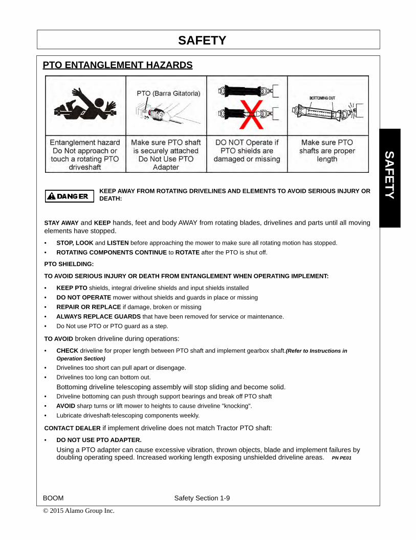
PTO ENTANGLEMENT HAZARDS
KEEP AWAY FROM ROTATING DRIVELINES AND ELEMENTS TO AVOID SERIOUS INJURY ORDEATH:
STAY AWAY and KEEP hands, feet and body AWAY from rotating blades, drivelines and parts until all movingelements have stopped.
• STOP, LOOK and LISTEN before approaching the mower to make sure all rotating motion has stopped.• ROTATING COMPONENTS CONTINUE to ROTATE after the PTO is shut off.
PTO SHIELDING:
TO AVOID SERIOUS INJURY OR DEATH FROM ENTANGLEMENT WHEN OPERATING IMPLEMENT:
• KEEP PTO shields, integral driveline shields and input shields installed • DO NOT OPERATE mower without shields and guards in place or missing• REPAIR OR REPLACE if damage, broken or missing• ALWAYS REPLACE GUARDS that have been removed for service or maintenance.• Do Not use PTO or PTO guard as a step.
TO AVOID broken driveline during operations:
• CHECK driveline for proper length between PTO shaft and implement gearbox shaft.(Refer to Instructions in Operation Section)
• Drivelines too short can pull apart or disengage. • Drivelines too long can bottom out.
Bottoming driveline telescoping assembly will stop sliding and become solid. • Driveline bottoming can push through support bearings and break off PTO shaft• AVOID sharp turns or lift mower to heights to cause driveline "knocking".• Lubricate driveshaft-telescoping components weekly.
CONTACT DEALER if implement driveline does not match Tractor PTO shaft:
• DO NOT USE PTO ADAPTER.Using a PTO adapter can cause excessive vibration, thrown objects, blade and implement failures by doubling operating speed. Increased working length exposing unshielded driveline areas. PN PE01
BOOM Safety Section 1-9
© 2015 Alamo Group Inc.

SAFETYSA
FETY
MOWER BLADE CONTACT HAZARDS
KEEP AWAY FROM ROTATING BLADES TO AVOID SERIOUS INJURY OR DEATH FROMBLADE CONTACT:
• STAY AWAY and KEEP HANDS, FEET and BODY AWAY from rotating blades, drivelines and parts until all moving elements have stopped.
• DO NOT put hands or feet under mower decks• STOP rotating BLADES disengage mower switch and PTO and wait for blade to stop rotating before raising mower
head.• DO NOT approach Sickle Bar head until Tractor Engine has been shut off.• STOP LOOK and LISTEN before approaching the mower to make sure all rotating motion has stopped. PN MBBM-01
BOOM Safety Section 1-10
© 2015 Alamo Group Inc.

SAFETYSA
FETY
HIGH PRESSURE OIL LEAK HAZARD
TO AVOID SERIOUS INJURY OR DEATH FROM HIGH PRESSURE HYDRAULIC OIL LEAKSPENERATING SKIN:
• DO NOT OPERATE equipment with oil or fuel leaks.• KEEP all hydraulic hoses, lines and connections in GOOD CONDITION and TIGHT before applying system
pressure. • RELIEVE HYDRAULIC PRESSURE before disconnecting lines or working on the system. • REMOVE and replace hose if you suspect it leaks. Have dealer test it for leaks.HIGH PRESSURE FLUID LEAKS CAN BE INVISIBLE.WHEN CHECKING FOR HYDRAULIC LEAKS AND WORKING AROUND HYDRAULIC SYSTEMS:• ALWAYS WEAR safety glasses and impenetrable gloves. • USE paper or cardboard to search for leaks.• DO NOT USE hands or body parts to search for leak.• KEEP hands and body AWAY from pin holes and nozzles ejecting hydraulic fluid.• Hydraulic fluid may cause gangrene if not surgically removed immediately by a doctor familiar with this form of injury.Use caution when removing Hydraulic Tank cap.• Tank contents maybe under pressure• Allow oil to cool before removing cap. • Relieve oil pressure before removing cap slowly.• Stay away from hot oil that may spray from tank. PN HPBM-01
BOOM Safety Section 1-11
© 2015 Alamo Group Inc.

SAFETYSA
FETY
ELECTRICAL & FIRE HAZARDS
TO AVOID SERIOUS INJURY OR DEATH FROM ELECTRICAL CONTACT WHENWORKING AROUND ELECTRICAL POWER LINES, GAS LINES AND UTILITY LINES:
• INSPECT mowing area for overhead or underground electrical power lines, obstructions, gas lines, cables and Utility, Municipal, or other type structure.
• KEEP all raised wings at a 10 feet or greater distance from all power lines and overhead obstructions.
• DO NOT allow mower to contact with any Utility, Municipal, or type of structures and obstructions.
• CALL 811 and 1-800-258-0808 for identify buried utility lines.
FIRE PREVENTION GUIDELINES while Operating, Servicing, and Repairing Mower and Tractor toreduce equipment and grass fire Risk:• EQUIP Tractor with a FIRE EXTINGUISHER• DO NOT OPERATE mower on a tractor equipped with under frame exhaust
• DO NOT SMOKE or have open flame near Mower or Tractor
• DO NOT DRIVE into burning debris or freshly burnt area
• AVOID FIRE IGNITION by not allowing mower blade to contact solid objects like metal or rock.
• DO NOT operate if oil is leaking. Repair oil leak and remove all accumulated oil before operating.
• CLEAR any grass clippings or debris buildup around mower hydraulic pumps, valves or tanks.
• SHUT OFF ENGINE while refueling. PN EFBM-01
BOOM Safety Section 1-12
© 2015 Alamo Group Inc.

SAFETYSA
FETY
TRANSPORTING HAZARDS
TO AVOID SERIOUS INJURY AND DEATH WHEN TOWING OR TRANSPORTING EQUIPMENT:
• KEEP transport speed BELOW 20 mph to maintain control of equipment.• REDUCE SPEED on inclines, on turns and in poor towing conditions.• DO NOT TOW with trucks or other vehicles.• USE only properly sized and equipped tractor for towing equipment.• FOLLOW all local traffic regulations.TRACTOR REQUIREMENTS FOR TOWING OR TRANSPORTING IMPLEMENTS: • ONLY TRANSPORT with tractor with ROPS in the raised position.• USE properly sized and equipped tractor that exceeds implement weight by at least 20%.• KEEP 20% of tractor weight on front wheels to maintain safe steering.BEFORE TRANSPORTING OR TOWING IMPLEMENT:TRACTOR INSPECTION:• CHECK steering and braking for proper operation and in good condition. • CHECK SMV sign, reflectors and warning lights for proper operation and visibility behind unit. • CHECK that your driving vision is not impaired by tractor, cab, or implement while seated in tractor seat.• ADJUST your operating position, mirrors, and implement transport for clear vision for traveling and traffic conditions.PREPARE IMPLEMENT FOR TRANSPORTING OR TOWING:• Store Boom and Mower in transport positions and engage transport locks if equipped.DETERMINE STOPPING CHARACTERISTICS OF TRACTOR AND IMPLEMENT FOR TRANSPORTING ORTOWING:BRAKING TESTS:• Stopping distance with implement attached may increase• Observe STOPPING distances increases with increased speeds.• DETERMINE the maximum safe transport speed that does not exceed 20 mph.• Reduce travel speed in wet or icy roads, stopping distances increase.DETERMINE MAXIMUM TURING SPEED BEFORE OPERATING ON ROADS OR UNEVEN GROUND:• TEST equipment in slowly increasing speed in turns to determine it can be operated at higher speeds.• USE REDUCED turning speeds in sharp turns to avoid equipment turning over.WHEN TOWING OR TRANSPORTING EQUIPMENT:• Always WEAR SEAT BELT when operating or transporting mower.• USE low speeds to avoid overturn with raised wings.• USE low speeds and gradual steering on curves, hills, rough or uneven surfaces and on wet roads. • TURN ON tractor FLASHING WARNING LIGHTS.• ALLOW clearance for implement swing while turning.KEEP raised boom mower 10 feet or greater distance from all power lines and overhead obstructions. PN THBM-01
BOOM Safety Section 1-13
© 2015 Alamo Group Inc.

SAFETYSA
FETY
HAZARDS WITH MAINTENANCE OF IMPLEMENT
AVOID SERIOUS INJURY OR DEATH FROM COMPONENT FAILURE BY KEEPING IMPLEMENT INGOOD OPERATING CONDITION IN PERFORMING PROPER SERVICE, REPAIRS ANDMAINTENANCE.
BEFORE PERFORMING SERVICE, REPAIRS AND MAINTENANCE ON THE IMPLEMENT:• STOP ENGINE AND PTO, engage parking brake, lower implement, allow all moving parts to stop and remove key before
dismounting from tractor. • PLACE implement on ground or securely block up raised equipment. Use large blocks on soft or wet soil.• PUSH and PULL Remote Hydraulic Cylinder lever to relieve hydraulic pressure.• DISCONNECT Pump solenoid valve or PTO driveline connection before servicing mower head.• WEAR SAFETY GLASSES, PROTECTIVE GLOVES and follow SAFETY PROCEDURES when performing service, repairs
and maintenance on the implement:• Always WEAR protective GLOVES when handling blades, knives, cutting edges or worn component with sharp edges.• Always WEAR GLOVES and SAFETY GLASSES when servicing hot components• AVOID CONTACT with hot hydraulic oil tanks, pumps, motors, valves and hose connection surfaces.• SECURELY support or BLOCK UP raised implement, framework and lifted components before working underneath equipment.• FOLLOW INSTRUCTIONS in maintenance section when replacing hydraulic cylinders to prevent component falling.• STOP any implement movements and SHUT-OFF TRACTOR engine before doing any work procedures.• USE ladder or raised stands to reach high equipment areas inaccessible from ground.• ENSURE good footing by standing on solid flat surfaces when getting on implement to perform work.• FOLLOW manufacturer's instructions in handling oils, solvents, cleansers, and other chemical agents.• DO NOT change any factory-set hydraulic calibrations to avoid component or equipment failures.• DO NOT modify or alter implement, functions or components.• DO NOT WELD or repair rotating mower components. These may cause vibrations and component failures being thrown from
mower. PERFORM SERVICE, REPAIRS, LUBRICATION AND MAINTENANCE OUTLINED IN IMPLEMENT MAINTENANCESECTION:• INSPECT for loose fasteners, worn or broken parts, leaky or loose fittings, missing or broken cotter keys and washers on pins, and
all moving parts for wear.• REPLACE any worn or broken parts with authorized service parts.• Inspect mower blade spindle to ensure bearing preload. If loose repair before operating.• LUBRICATE unit as specified by lubrication schedule• NEVER lubricate, adjust or remove material while it is running or in motion.• TORQUE all bolts and nuts as specified.BLADE INSPECTION:• Inspect blade carrier and blades daily.• Check blade and blade carrier BOLT TORQUE daily. Loose bolts can cause blade or blade bolt failures.• REPLACE, bent, damage, cracked and broken blades immediately with new blades.• AVOID blade failures and thrown broken blades. DO NOT straighten, weld, or weld hard-facing blades.SAFETY SHIELDS, GUARDS AND SAFETY DEVICES INSPECTION:• KEEP all Deflectors, Chain Guards, Steel Guards, Gearbox Shields, and PTO integral shields, Bands, Side Skirts and Skid Shoes
in place and in good condition.• REPLACE any missing, broken or worn safety shields, guards and safety devices.• Engine Exhaust, some of its constituents, and certain vehicle components contain or emit chemicals known to the state of California
to cause cancer, birth defects or other reproductive harm.• Battery posts, terminals and related accessories contain lead and lead compounds, chemicals known to the state of California to
cause cancer, birth defects or other reproductive harm. PN HMBM-01
BOOM Safety Section 1-14
© 2015 Alamo Group Inc.

SAFETYSA
FETY
PARTS INFORMATIONPARTS INFORMATION
Tiger mowers use balanced and matched system components for blade carriers, blades, cuttershafts, knives,knife hangers, rollers, drivetrain components, and bearings. These parts are made and tested to Tigerspecifications. Non-genuine "will fit" parts do not consistently meet these specifications. The use of “will fit”parts may reduce mower performance, void mower warranties, and present a safety hazard. Use genuineTiger mower parts for economy and safety. (SPTM-1)
SEE YOUR TIGER DEALER
BOOM Safety Section 1-15
© 2015 Alamo Group Inc.

SAFETYSA
FETY
Decal LocationNOTE: Tiger supplies safety decals on this product to promote safe operation. Damage to the decals mayoccur while in shipping, use, or reconditioning. Tiger cares about the safety of its customers, operators, andbystanders, and will replace the safety decals on this product in the field, free of charge (Some shipping andhandling charges may apply). Contact your Tiger dealer to order replacement decals.
Boom Arm
ITEM PART NO. QTY. TYPE DESCRIPTION
1. 02962764 5 WARNING Pinch Points2. 02965262 1 WARNING Hydraulic Oil Hazard3. 02962765 1 DANGER Crushing Hazard4. 1 LOGO Name
BOOM Safety Section 1-16
© 2015 Alamo Group Inc.

SAFETYSA
FETY
50” & 60” Rotary
ITEM PART NO. QTY. TYPE DESCRIPTION
1. 6T3237 1 WARNING Replace Blades2. 24028 1 WARNING Thrown Object Hazard 3. D637 1 WARNING Disconnect Hydraulic Solenoid4. 42399 2 REFLECT Red Reflector5. 4240006 1 REFLECT Amber Reflector6. D668 1 INSTRUCT Lubrication Chart7. 33224 1 DANGER Blades, Thrown Object8. D619 1 WARNING Blade Rotation9. 1 LOGO Made in the USA10. 1 LOGO Tiger Genuine Parts11. 22839 1 INSTRUCT Use Hand Grease Gun12. 32709 1 WARNING Use Genuine Tiger Parts13. 6T3221 1 INSTRUCT Lubrication Instructions14. nfs 1 SERIAL PLATE Serial Number Plate15. 06550058 1 INSTRUCT Blue Dot16. 06550057 1 INSTRUCT Red Dot17. 1 LOGO Name
BOOM Safety Section 1-17
© 2015 Alamo Group Inc.

SAFETYSA
FETY
50”& 63” Flail
ITEM PART NO. QTY. TYPE DESCRIPTION
1. 24028 1 DANGER Thrown Object Hazard,Deflectors2. 32709 1 WARNING Use Genuine Tiger Parts 3. 33224 1 DANGER Blades, Thrown Object4. D637 1 WARNING Disconnect Hydraulic Solenoid5. 1 LOGO Tiger Logo6. 00758194 1 WARNING Pinch Point Hazard7. 1 LOGO 50” Logo
1 LOGO 63” Logo8. D646 1 DANGER Guard Missing, Do Not Operate9. D655 1 INSTRUCT Lube Chart10. TB1011 1 DANGER Thrown Object Hazard, Shield11. 6T3236 1 LOGO Made in the USA12. 42399 2 REFLECT Red Reflector13. 4240006 1 REFLECT Amber Reflector14. nfs 1 SERIAL PLATE Serial Number Plate
BOOM Safety Section 1-18
© 2015 Alamo Group Inc.

SAFETYSA
FETY
BOOM Safety Section 1-19
© 2015 Alamo Group Inc.

SAFETYSA
FETY
BOOM Safety Section 1-20
© 2015 Alamo Group Inc.

SAFETYSA
FETY
BOOM Safety Section 1-21
© 2015 Alamo Group Inc.

SAFETYSA
FETY
BOOM Safety Section 1-22
© 2015 Alamo Group Inc.

SAFETYSA
FETY
BOOM Safety Section 1-23
© 2015 Alamo Group Inc.

SAFETY
BOOM Safety Section 1-24
© 2015 Alamo Group Inc.
SAFE
TY
Federal Laws and RegulationsThis section is intended to explain in broad terms the concept and effect of federal laws and regulations concerningemployer and employee equipment operators. This section is not intended as a legal interpretation of the law andshould not be considered as such.Employer-Employee Operator RegulationsU.S. Public Law 91-596 (The Williams-Steiger Occupational and Health Act of 1970) OSHA
This Act Seeks:“...to assure so far as possible every working man and woman in the nation safe and healthful workingconditions and to preserve our human resources...”
DUTIESSec. 5 (a) Each employer-(1) shall furnish to each of his employees employment and a place of employment which are free fromrecognized hazards that are causing or are likely to cause death or serious physical harm to his employees;(2) shall comply with occupational safety and health standards promulgated under this Act.(b) Each employee shall comply with occupational safety and health standards and all rules, regulations andorders issued pursuant to this Act which are applicable to his own actions and conduct.
OSHA Training RequirementsTitle 29, Code of Federal Regulations Part 1928.57(a)(6). www.osha.govOperator instructions. At the time of initial assignment and at least annually thereafter, the employer shallinstruct every employee who operates an agricultural tractor and implements in the safe operating practicesand servicing of equipment with which they are or will be involved, and of any other practices dictated by thework environment.Keep all guards in place when the machine is in operation;Permit no riders on equipmentStop engine, disconnect the power source, and wait for all machine movement to stop before servicing,adjusting, cleaning or unclogging the equipment, except where the machine must be running to be properlyserviced or maintained, in which case the employer shall instruct employees as to all steps and procedureswhich are necessary to safely service or maintain the equipment. Make sure everyone is clear of machinery before starting the engine, engaging power, or operating themachine.
Employer Responsibilities:To ensure employee safety during Tractor and Implement operation, it is the employer’s responsibility to:1. Train the employee in the proper and safe operation of the Tractor and Implement.2. Require that the employee read and fully understand the Tractor and Implement Operator’s manual.3. Permit only qualified and properly trained employees to operate the Tractor and Implement.4. Maintain the Tractor and Implement in a safe operational condition and maintain all shields and guards on the
equipment.5. Ensure the Tractor is equipped with a functional ROPS and seat belt and require that the employee operator
securely fasten the safety belt and operate with the ROPS in the raised position at all times.6. Forbid the employee operator to carry additional riders on the Tractor or Implement.7. Provide the required tools to maintain the Tractor and Implement in a good safe working condition and provide the
necessary support devices to secure the equipment safely while performing repairs and service.8. Require that the employee operator stop operation if bystanders or passersby come within 300 feet.Child Labor Under 16 Years of AgeSome regulations specify that no one under the age of 16 may operate power machinery. It is your responsibility toknow what these regulations are in your own area or situation. (Refer to U.S. Dept. of Labor, Employment StandardAdministration, Wage & Home Division, Child Labor Bulletin #102.)

Assembly Section 2-1
ASSEMBLY SECTION
NH TS6.1xx T4F - BENGAL

ASSEMBLY
Assembly Section 2-2
Before attempting to mount your Tiger mower, it is importantto read and understand all of the safety messages in the SafetySection of this manual.
Check complete shipment list against the packing list to make sure there are no shortages. Make certain the tractor model is the appropriate one for the mower received!
Always use a floor jack, hoist or fork lift to lift and raise heavy parts.
Read and understand the entire Assembly Section instructions before attempting to mountyour Tiger mower. Refer to the Parts Section of this manual for detailed illustrations to locate allparts. (ASM-C-0001)
TRACTOR PREPARATIONA. Remove right and left hand steps.
B. Disconnect battery cables from both batteries.
C. Remove engine side panels, or raise hood to access front pulley.
D. Remove plugs from tractor casting where mainframe and pump mount will be attached.
E. Remove any front weights and weight supports.
F. Raise the tractor onto jack-stands and remove the right and left rear wheels.
(ASM-C-0024)
CRANKSHAFT ADAPTERIf necessary, remove the four capscrews from the crankshaft pulley. Then install the crank-
shaft adapter to the pulley with capscrews and lockwashers as shown in the Parts Section.(ASM-NH-0050)

ASSEMBLY
Assembly Section 2-3
TS6.1XX T4F BATTERY RELOCATIONInstallation of the pump driveshaft requires that the battery be raised to allow the driveshaft to
pass beneath it from the crankshaft adapter to the pump. Disconnect and remove the battery from the well in the front of the tractor. Place the battery relocation assembly #06370267 in the battery well and secure through the bottom of the tractor casting as shown in the Parts Section. Run capscrew #21332 through the hole in the rear of the bottom level of relocation assembly #06370267 using insulated washers #06510260 above and below. Run new battery cable #06510299 from positive post on battery to capscrew. Connect new positive battery post to cap-screw. Connect the existing positive battery cable to the new post. Use the battery strap, cap-screws, flatwashers and u-nuts provided to secure the battery to the relocation assembly. See the Battery Relocation page in the Parts Section for more information. (ASM-NH-152 BATTERY TS6 1xx T4B)

ASSEMBLY
Assembly Section 2-4
TS6.1XX T4F COOLER HINGE REPLACEMENTInstallation of the pump driveshaft requires that the hinge on the tractor cooler be replaced to
allow the driveshaft to pass beneath it from the crankshaft adapter to the pump. Remove the hinge mount and pin and replace with the Tiger hinge mount (#06412375) and pin (#06420188) provided. (ASM-NH-152 COOLER HINGE TS6 1xx T4B)

ASSEMBLY
Assembly Section 2-5
FRONT PUMP MOUNTINGInstall the pump mounting bracket on the front of the tractor with capscrews and washers as
shown in the Parts Section illustration. DO NOT tighten fasteners at this time.Thread the pump driveshaft into the crankshaft adapter. The end with the splines should
match up with the coupler.Slide the splined drive shaft coupler onto the pump driveshaft. Install the pump onto the
mounting bracket. NOTE: The shaft is offset to one direction, the pump should be installed with the offset side on top. Install hardware for securing pump to the pump mount, DO NOT tighten.
Align pump so that splined coupling can be moved back and forth by hand. Tighten pump mounting bolts in succession, rechecking for spline coupling movement. Remove the pump mounting bracket bolts one at a time and apply a thread locking agent. Tighten these bolts in succession, again checking for free movement in the driveshaft. After all bolts are torqued, the end play on the driveshaft should be 1/16” to 1/8”, and the coupler should move freely with hand pressure. If end play is less than 1/16”, grind the end of the shaft to achieve the proper end play. If there is more than 1/4" of end play, return the shaft with specifications for a longer shaft.
CAUTION: DO NOT START THE TRACTOR UNTIL ALL HOSES ARE ATTACHED, TANKIS FILLED WITH PROPER OIL AND BALL VALVES ARE OPEN! STARTING AT THIS TIMEWILL CAUSE SERIOUS DAMAGE TO THE PUMP. (ASM-NH-0024)
ADJUSTING REAR WHEELSRaise rear of tractor onto jack-stands. Follow the instructions in the tractor owner’s
manual for adjusting tires and rims to 72” center for side mounted mowers and 79.8” for boommowers. NOTE: This may require switching the wheels to opposite sides of tractor. Also takenote of any width restrictions when transporting by trailer. (For ease of installation, it is best toleave the rear wheels removed during installation of the mower.) (ASM-NH-0051)

ASSEMBLY
Assembly Section 2-6
POLYCARBONATE SAFETY WINDOWNOTE: Installing a boom mower requires that all of the right side windows be replaced, or
protected with a polycarbonate window. This should be done before mounting the mainframe.
1. Disconnect gas shock at door. Remove the right side cab door/window glass from tractor cab by removing hinge pins. Also, remove rear right side window.
2. Remove the existing hardware, door handle and bar handle and discard factory glass door and window.
3. Place small bead of adhesive seal in the bottom of the trim lock bubble seal.
4. Install trim lock bubble seal on polycarbonate starting at the center bottom horizontal portion.
5. Install existing hardware removed from glass door and window on the polycarbonate.
6. Install the polycarbonate assembly in the cab with existing and supplied hardware as shown in the Parts Section.
7. Assemble corner bracket to the control stand inside the cab.
8. Locate and drill a Ø1/4” hole through polycarbonate, with a bit that is only used for polycar-bonate, to match the corner bracket.
9. Assemble the bracket and tighten the hardware to secure the polycarbonate.
10. Assemble the clamp in the upper front corner by the mirror.
11. Adjust the clamp to achieve a secure hold.
12. Replace the rear corner window with the hardware removed from the window.(ASM-NH-0101)
INSIDEVIEW

ASSEMBLY
Assembly Section 2-7
NH TS6.1xx T4B FENDER CUTInstallation of the wheel well tank requires modification of the left fender, as shown below.
Before cutting the fender, mask the uncut area to prevent scratches. Cut to the approximate size shown below. After cutting TrimLock may be applied to the edges. (ASM-NH TS6 130 FENDER CUT
MAINFRAME INSTALLATIONNOTE: Before installing the axle braces, upright and mainframe, remove the left hand steps. Loosen the fuel tank and slide out two or three inches to provide space to install the left upright plate.
With an overhead hoist and / or jack-stands, raise one side of the frame up to the correctly matching mounting holes. Install capscrews and other hardware to secure the sides of the mainframe to the tractor casting, as shown on the tractor mount kit page in the Parts Section. DO NOT tighten at this time. Remove the capscrews one at a time and apply a thread locking agent. Reinsert the capscrews and tighten / torque to values noted in the torque chart located in the Maintenance Section of this manual. (ASM-NH Mainframe Installation TS6 1xx T4F)

ASSEMBLY
Assembly Section 2-8
JOYSTICK SWITCHBOX MOUNTING The switchbox is to be secured to the joystick/switchbox stand. Refer to the Parts Section
for assembly and components needed. (ASM-NH-0137 TS6 1XX T4B)

ASSEMBLY
Assembly Section 2-9
SWITCHBOX WIRINGPower and ground are pulled from the tractor’s accessory socket using the keyed hot wire on
the supplied plug for power and the black wire for ground. Use a test light to verify whether the red or orange wire is the hot wire (hot when key is in the “on” position).
The switchbox is to be secured to the cable control bracket as shown in the Parts Section. (ASM-NH-0121 TS6 1XX T4B

ASSEMBLY
Assembly Section 2-10
NH TS6.1xx T4B SWAY BAR ARMSThe sway bar arms on the TS6.1xx T4B need to be repositioned. The sway bar anchor
should be rotated 180° on its longitudinal axis to place the pin stowage tang outboard. (ASM-NH
TS6 130 SWAY BAR ARMS

ASSEMBLY
Assembly Section 2-11
LIFT VALVE MOUNTINGThe lift valve mounting bracket and plate will be mounted on legs secured to the rear of the
axle braces. See the Parts Section for details on mounting information and hardware used. (ASM-NH-0066 NH T6 1XX T4F)

ASSEMBLY
Assembly Section 2-12
HOSE ROUTINGThe lift valve uses the tractor’s pressure, return and load sense ports. The pressure and
return ports are located at the rear of the tractor, below the installed lift valve mount. The load sense port is located beneath the tractor cab on the top block. (ASM-NH TS6 1XX T4F HOSE ROUTING

ASSEMBLY
Assembly Section 2-13
FILLING HYDRAULIC RESERVOIRRefer to the Maintenance Section for filling specifications and hydraulic oil requirements.
NOTE: Starting or running your Tiger mower before filling reservoir will causeserious damage to the hydraulic pump.
(ASM-C-0004hydro resrv)
INSTALLING O-RING FITTINGSInstalling straight, 45º and 90º O-rings requires that the O-ring and washer be up against the
swivel body. Insert the swivel and turn in until the swivel is pointed in the desired direction and O-ring contact is made. Hold swive l in set d irection with a wrench and turn the O-ring nut awayfrom the swivel body and carefully tighten. (ASM-C-0056)
INSTALLING NATIONAL PIPE FITTINGSWhenever installing a pipe fitting, wrap the threads clockwise (looking at the end) with teflon
tape. In this way, the tape will be tightened when installed. NOTE: It is not necessary to tape O-ring fittings, or those installed in swivels. (ASM-C-0088)
GENERAL HOSE INSTALLATIONRefer to the Parts Section for detailed information about hoses and fittings for this
application. (ASM-C-0011)
PREFORMED TUBE INSTALLATIONLay booms on floor so that the side with the clamp plates is up. Locate all tube clamp s and
install them loosely onto the clamp plates.Arrange the tubes and hoses as outlined in the Common Parts Section. In stall the tubes
closest to the boom arm first, being careful not to pinch the tubes. Place the other tubes outsideof the first tubes. Snug all clamp bolts, but do not tighten. Check all tubes for correct alignmentand that none are pinched or bent. The clamp bolts can now be tightened. (ASM-C-0085)
ACCUMULATOR INSTALLATIONInstall the accumulator bracket on the right mainframe mast or lift valve mount, if applicable,
with the capscrews, lockwashers and spacers, if applicable, as shown in the Parts Section. Install the accumulator in the bracket and secure with the hardware shown. Install fittings and hoses to the cylinder and control valve as shown in the Parts Section. Use teflon tape on all pipe fittings (except O-rings). (ASM-C-0012)
SOLENOID BRAKE VALVEInstall a solenoid valve on the mounting bracket with the supplied hardware as shown in the
Parts Section in this manual. While installing the fittings to the brake valve, the electrical coil onthe spool may have to be removed to make room. When reinstalling the coil, it is important touse no more than 5 ft. lbs. (or 60in. lbs.) torque. WARNING: OVER TORQUE TO THE COILWILL RESULT IN HYDRAULIC FAILURE OF SPOOL. (ASM-C-0025)

ASSEMBLY
Assembly Section 2-14
LIFT VALVE HOSE AND CABLE ROUTINGAttach two clamps to the right rear wheel well for proper hose/cable routing. Drill one hole for
each clamp. Use the lower rear corner of the wheel well as an origin for measuring. The holesshould be Ø10mm or Ø3/8” reamed to accept 3/8” hardware.
Measure from the back ed ge of the wheel well 13-1 /2” from the origin. Use a squ are tomeasure 3-1/2” up. Refer to the images below to see the first hole placement.
The second hole should run parallel to the bottom edge of the wheel well. Mark the hole 12”from the first hole and 3-1/2” from the bottom edge. Use the images below for reference.NOTE: DO NOT CUT INTO TUBES / HOSES / WIRES WHEN DRILLING THROUGH METAL OR PLASTIC!
Place as many hoses in the clamp as will fit without compromising pressure. Then securethe (2) HOSE CLAMP (06520013) to the holes drilled with (1 EACH) CAPSCREW,3/8” X 1”,NC(21630) and (1 EACH) NYLOCK NUT,3/8”,NC (21627). The hoses th at don’t fit into the clampare to be secured to the others with zip ties. For protection of hoses in contact with metal edges,wrap hoses with split hose sections and fasten with hose clamps or zip ties as needed.(ASM-NH-0067)

ASSEMBLY
Assembly Section 2-15
(ASM-C-0023)
WHEEL WELL HYDRAULIC TANK INSTALLATIONInstall all fittings and tubes into tank and tank filter as shown in the Parts Section
illustration. Insert tank sight glass onto the tractor side of the tank.Place the tank in the mounting bracket on the axle brace as shown in the Parts
Section. Secure the tank with the hardware provided.Install the filter gauge into the filter housing so that it points to the rear of the tractor
and is clearly visible to the operator. The tank breather cap is ready for use as the tank is filled. Some of these items may already be installed. (ASM-C-0103)

ASSEMBLY
Assembly Section 2-16
TEMPERATURE GAUGE MOUNTING (OPTIONAL)Mount the temperature gauge where it is clearly visible to the operator. Attach the green (-)
wire from the negative post on the gauge to a grounded bolt on the tractor frame. Remove paintif needed to make a good ground. Remove the pipe plug from the side of the hydraulic reservoirand install the temperature sensor using thread sealing tape. Run the white wire from the (s)sensor post of the gauge to the temperature sensor on the hydraulic reservoir tank. (ASM-C-0051)
WHEEL WEIGHT MOUNTINGFor all tractors using a boom mower, a wheel weight will be required for the rear left side
wheel. It will be necessary to mount the weight in the wheel using the long capscrews, lockwashers, flatwashers, spacers (if applicable), and hex nuts per the diagram in the Parts Section.
Installation is most easily done with a fork lift, inserting a fork in the center slot of the wheel weight. The head of the capscrews is to be toward the OUTSIDE of the weight, with flatwashers on both the inside and outside of the assembly.
The left rear tire may also be filled with a mixture of water and calcium chloride at about five pounds per gallon. Tire air pressure should be maintained according to the Maintenance Section. (ASM-C-0055)
SWIVEL BRACKET MOUNTINGInstall the boom swivel bracket onto the mainframe with the swivel pin. Secure the pin in
place using the capscrews, etc. through the hole in the boss and pin. NOTE: The head of thecapscrew must be toward the front of the tractor.
Install all new swivels and fit tings on the swi ng cylinder with swivel openings facing eachother. Fittings will vary in ty pe and direction dep ending on your application; refer to the Part sSection for more details.
Install bearings in the mainframe anchor for the swing cylinder. This may have already beendone for you.
Install the swing cylinder between the boom mounting bracket cylinder anchor and the boomswivel with the pins. Insert roll pins through the top and the bottom hole in the pins.
Attach hoses from the control valve to the swing cylinder. (ASM-C-0015)
MAIN BOOM INSTALLATIONUsing a hoist, install the boom swivel into the mainframe as shown in the Parts Section. Line up holes
in swivel and mainframe for large swivel pin and insert pin. Secure with hardware as shown.Attach the inner end of th e main boom to the swivel bracket with the cylinder anchors positioned
upward, and at a right angle to the tractor. Secure it with the horizontal hinge pin. Secure the hinge pin inthe boss with capscrews, etc. (see Parts Section).
Attach the butt end of the main boom cylinder to the swivel with the cylinder pin and roll pins shown inthe Parts Section.
Install the travel lock on the rod end of the main boom cylinder. This should be facing the butt end ofthe cylinder after installation.
Install the fittings and hoses to the main boom cylinder per Parts Section.
GREASE HINGE PIN ZERKS ON BOOM AFTER ASSEMBLY, ONCE UNDER LOAD WITH BOOMELEVATED, AND AGAIN AT REST WITH BOOM SUPPORTED. (ASM-C-0013)

ASSEMBLY
Assembly Section 2-17
DECK ATTACHMENTAttach the head to the se condary boom using the pin s and hardware shown in the Part s
Section. Install the deck pivot cylinder using the pins and hardware also shown in th e PartsSection.
Connect the fittings and hoses from the pivot cylinder to the small hoses or preformed tubeson the boom arm. Connect the fittings and hoses from the motor to the large hoses or preformedtubes on the boom arm. If attaching a rotary mower make sure that the hose with the red stripesticker is attached to the motor pressure port which is marked with a red dot sticker.
Connect all remaining hoses f rom the control valve t o the cylinders and/or hoses orpreformed tubes on the boom arm. (ASM-C-0086)
HOSE COVERINGSecure hoses together with zip ties wherever loose. Wrap the hoses between the main boom
and secondary boom with the hose cover provided. Wrap the hoses between the brake valveand the main boom with the hose cover provided. Wrap the hoses between the deck attachmentand the secondary boom with the hose cover provided. Where hoses may contact the frame orother edges, wrap with split hose and secure with hose clamps or zip ties. On non-cab units, thepressure and return hoses from the control valve will also need to be routed inside the protectivehose wrap. Cover the valve, valve fittings with the hose cover and secure with black stringprovided.. (ASM-C-0087)

ASSEMBLY
Assembly Section 2-18
OS AXLE BRACE MOUNTING The open stow axle braces are to be mounted under the rear axle of the tractor. The other
end of the axle brace mounts on the outside of the lower rear corner s of the mainframe. Afterattaching the boomrest, it should fit tightly and level under the tractor. Attach the axle brace(s) tothe mainframe with hardware shown in the Parts Section and tighten. Attach the axle braces tothe rear axle using the mounting hardware shown in the Parts Section, but DO NOT tighten.
OS BOOMREST MOUNTINGCarefully raise the open stow boomrest and align the holes with those of the axle brace. Now
install all attaching hardware, as shown in the Parts Section, loosely, to allow for the alignmentwith the left and right axle brace. Tighten / torque all hardware on the brace and the boomrest.Finally, add the boomrest plate to the boomrest as shown in the Parts Section. (ASM-JD-0246)

ASSEMBLY
Assembly Section 2-19
WEATHER-PACK / METRI-PACK ASSEMBLYThese instructions apply to both Weather-Pack and Metri-Pack connectors.
NOTE: Use the specific tool for the type of connector you are assembling.(ASM-C-0009)
ASSEMBLY
Assembly Section 2-20
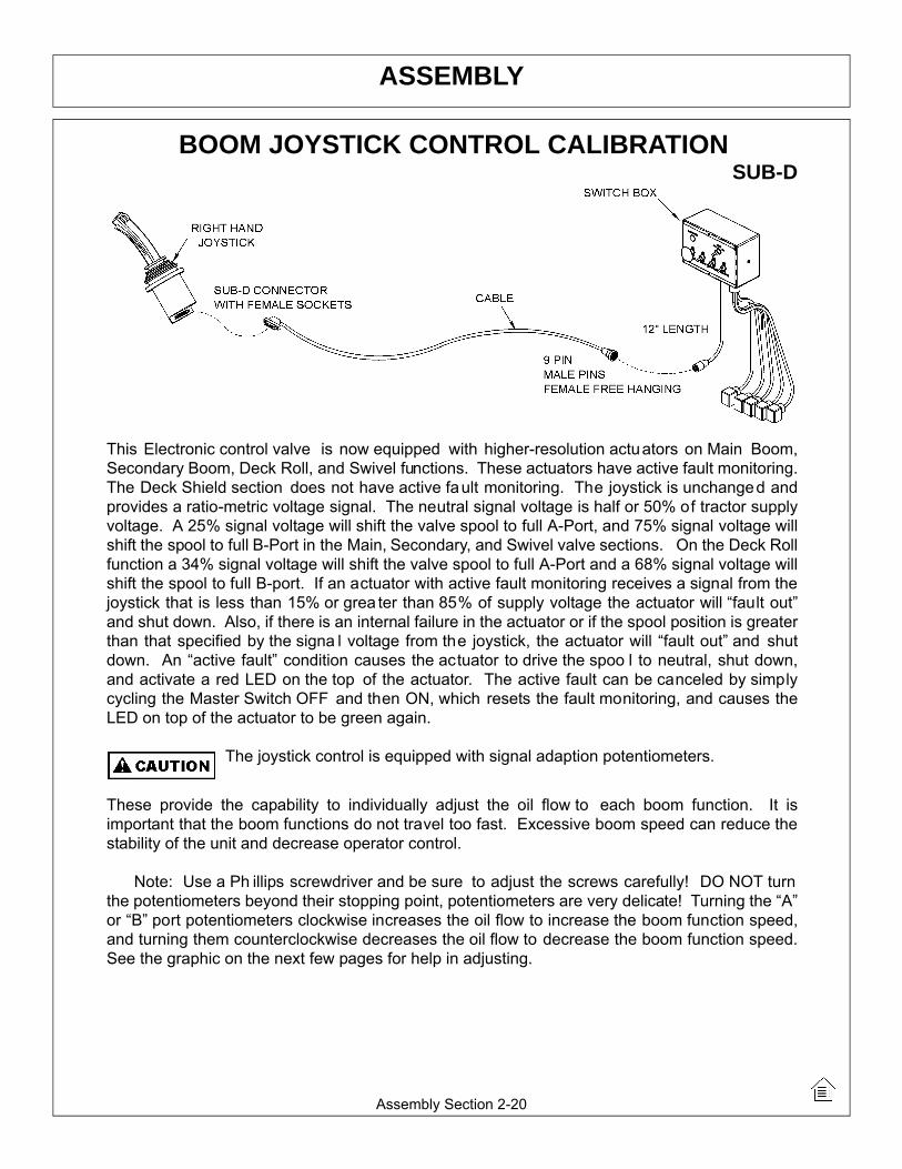
BOOM JOYSTICK CONTROL CALIBRATIONSUB-D
This Electronic control valve is now equipped with higher-resolution actuators on Main Boom,Secondary Boom, Deck Roll, and Swivel functions. These actuators have active fault monitoring.The Deck Shield section does not have active fault monitoring. The joystick is unchanged andprovides a ratio-metric voltage signal. The neutral signal voltage is half or 50% of tractor supplyvoltage. A 25% signal voltage will shift the valve spool to full A-Port, and 75% signal voltage willshift the spool to full B-Port in the Main, Secondary, and Swivel valve sections. On the Deck Rollfunction a 34% signal voltage will shift the valve spool to full A-Port and a 68% signal voltage willshift the spool to full B-port. If an actuator with active fault monitoring receives a signal from thejoystick that is less than 15% or grea ter than 85% of supply voltage the actuator will “fault out”and shut down. Also, if there is an internal failure in the actuator or if the spool position is greaterthan that specified by the signa l voltage from the joystick, the actuator will “fault out” and shutdown. An “active fault” condition causes the actuator to drive the spoo l to neutral, shut down,and activate a red LED on the top of the actuator. The active fault can be canceled by simplycycling the Master Switch OFF and then ON, which resets the fault monitoring, and causes theLED on top of the actuator to be green again.
The joystick control is equipped with signal adaption potentiometers.
These provide the capability to individually adjust the oil flow to each boom function. It isimportant that the boom functions do not travel too fast. Excessive boom speed can reduce thestability of the unit and decrease operator control.
Note: Use a Ph illips screwdriver and be sure to adjust the screws carefully! DO NOT turnthe potentiometers beyond their stopping point, potentiometers are very delicate! Turning the “A”or “B” port potentiometers clockwise increases the oil flow to increase the boom function speed,and turning them counterclockwise decreases the oil flow to decrease the boom function speed.See the graphic on the next few pages for help in adjusting.

ASSEMBLY
Assembly Section 2-21
BOOM JOYSTICK CONTROL CALIBRATION (CONTINUED)
Run tractor at normal operating RPM to adjust the settings as follows.
Set the dead band compensation potentiometer first.
Set the dead band compensation potentiometer at 50%, or halfway between full clockwise andfull counterclockwise.
Setting Signal Adaptation Potentiometers:
Disconnect the Deutsch connectors from the actuators of the valve. Use a V olt/Ohm meter tomeasure signal voltage and adjust the signal adapt ation potentiometers as needed. Pin #4 istractor supply voltage. Pin #1 is signal voltage from the joystick, and pin #3 is grou nd. First,measure supply voltage between pins 4 and 3. Then measure signal voltage between pins 1 and3 while indexing the joystick function fully in both the “A” and “B” port direction. Divide the signalvoltage by the supply voltage to get signal voltage as a % of supply voltage. This percent ageshould not be less than 25% or greater than 75% for the Main Boom, Secondary Boom, or Swivelfunction. This percent age should not be less than 30% or grea ter than 62% for the Deck Ro llfunction. Note these initial setting s for the Deck Roll function should prevent the spool fromshifting into float. After making this first adjustment to deck roll if the spool still goes into float,adjust the “B” port screw additionally counterclockwise.
Reconnect Deutsch connectors on control cables to actuators on Electronic valve. Ru n tractoruntil hydraulic system is at operating temperature. Now refine the adjustment s of the signaladaptation potentiometers for both “A” and “B” ports for all proportional functions to achieve thefollowing function times. Note: turning potentiometer clockwise increases the flow or the functionspeed, and turning them counterclockwise decreases the flow or the function speed. Note, ifduring this procedure the trim potentiometer is set to full counterclockwise but the function is stilltoo fast, use the mechanical stops at the manual actuator end of the valve section to further limitflow. Turn limit screw in or clockwise to limit flow. The upper limit screw limits flow to B-port, andthe lower limit screw limits flow to A-port. However DO NOT adjust th e limit screw on B-port ofdeck roll function. Limiting B-port will prevent float function.

ASSEMBLY
Assembly Section 2-22
BOOM JOYSTICK CONTROL CALIBRATION (CONTINUED)
MAIN BOOM: “A” Port, Boom Up: 8-10 Seconds(Note: Extend secondary boom completely; roll deck to be level with ground, and lower mainboom until deck is on ground. Now index main boom “up” function and determine the timerequired for main boom to rise completely.)
“B” Port, Boom Down: 6-8 Seconds(Note: Extend secondary boom completely, roll deck to be level with ground, and raise the mainboom to “full up”. Then index the main boom “down” function to determine the amount of timerequired for the deck to contact the ground. CAUTION: Stop the boom just as the deck contactsthe ground.)
SECONDARYBOOM: “A” Port, Boom Out: 8-10 Seconds(Position main boom full up, roll deck out until deck cylinder is fully retracted, and bringsecondary boom in completely. Then index the secondary boom “out” function and determine thetime required for boom to extend out completely.)
“B” Port, Boom In: 8-10 Seconds(Position the main boom full up, roll deck out until deck cylinder is fully retracted, and extendsecondary boom completely. Then index the secondary boom “in” function and determine thetime required for boom to come in.)
DECK ROLL: “A” Port, Deck Out: 7-9 Seconds(Raise main boom to vertical, extend secondary boom out slightly so that deck can be articulatedwithout contacting the main boom, and roll deck in until deck cylinder is completely extended.Then index the deck roll “out” function and determine the time required for the deck to roll out.)
“B” Port, Deck In: Target 7-9 Seconds (but DO NOT use Limit Screw)(Raise main boom to vertical, extend secondary boom out slightly so that deck can be articulatedwithout contacting the main boom, and roll deck out until deck cylinder is completely retracted.Then index the deck roll “in” function and determine the time required for the deck to roll in.)
BOOMSWIVEL: “A” Port, Boom Aft: 14-16 Seconds for 3PS, 3OS, SS(Extend booms completely; rotate head to be level with ground, lower main boom until deck isjust above ground, and swivel boom full forward. Then index the boom swivel “aft” function anddetermine the time required for the boom to swivel full aft. Use caution when doing this, stopboom before main boom contacts tire.)
“B” Port, Boom Forward: 14-16 Seconds for 3PS, 3OS, SS(Extend booms completely, rotate head to be level with ground, lower main boom until deck isjust above ground, and swivel boom aft until near tire. Then index the boom swivel “forward”function and determine the time required for the boom to swivel full forward.)(ASM-C-0082)

ASSEMBLY
Assembly Section 2-23
BOOM JOYSTICK DIAGRAM (ASM-C-0082A)

ASSEMBLY
Assembly Section 2-24
FINAL PREPARATION FOR OPERATIONPlace operator’s safety and operation decals on the steering column and side console where
they are clearly visible to the operator. These decals should be understood by each operator ofthe machine in conjunction with the Safety and Operation Sections of this book. The decals areto be ma intained in good condition as a reminder to the opera tor, and sh ould be replaced ifdamaged.
All bosses, pins and pivot points will need to be greased as instructed in the MaintenanceSection of this manual. The hydraulic reservoir can also be filled with the recommended fluid(see Maintenance Section) and the filter installed in the top of the tank. Double check all fittingsand fasteners BEFORE starting tractor. Also secure any loose hoses together with zip ties andwrap with split hoses where friction may occur on the hoses.
BEFORE starting or operating the tractor you must read and understand the Safety and Operation Sections of this manual completely.
BE SURE THE BALL VALVES ARE OPEN! Start tractor and allow instruments to stabilize.Using a piece of paper or cardboard as noted in the Safety and Maintenance Sections, check allfittings and connections for hydraulic leaks.
If a leak is found, you must shut down the tractor and set the cutter on the ground. Beforeattempting to fix the leak, you must actuate the lift valve handles several times to relieve anypressure in the lines.
Before operating the mower, the cutter head and boom should be slowly moved throughoutthe full range of motion. Watch for any condition that would cause pinching or excess stress onthe hoses. The steering and front axle travel sh ould also be carefully moved through their fullrange of motion. If any condition occurs in which the hoses contact the tires, the steering and /or front axle travel ma y need to be limited as de scribed in the tractor operator’s manual. Thisshould also be done if the tires rub, or are extremely close to any other part of the mower, suchas the hydraulic tank or draft beam. This may include adding shims or adjusting stop bolts in thetractor front to solve the problem. While checking motion, you should also check that the controlcircuits are connected according to the operator’s decal for the valve handles.
MOWER TESTINGTake the tractor to a place free of loose objects on the ground. Operate the cylinders through
their full range of motion again, to clear the lines of air. Follow the instructions in the OperationSection to operate the mower. Vibration of the mower should be minimal at all times. After a 5minute test run, the knife bolts should be retorqued, and retorqued once again after the first fewhours of operation.
If any parts of this Assembly Section, or any other section of this manual arenot clearly understood you must contact your dealer or the address on the front ofthis manual for assistance!(ASM-C-0010)

Operation Section 3-1
©2013 Alamo Group Inc.
OPERATION SECTION

OPERATIONO
PER
ATIO
N
TIGER BOOM MOWEROPERATING INSTRUCTIONS
Tiger Booms are manufactured with quality material by skilled workers. The Boom is designed to attach to atractor and operate various heads for a wide range of vegetative maintenance applications. The boom andheads are equipped with safety warning decals, protective deflectors, shields, and other safety features toprovide operator and passerby protection, however, no shielding is 100% accurate. ALL safety equipment andsafety warning decals must be maintained on the unit in good operational condition at all times.
It is the operator’s responsibility to be knowledgeable of all potential operating hazards and to take everyreasonable precaution to ensure oneself, others, animals, and property are not injured or damaged by theboom unit, tractor or a thrown object. Do not operate the boom and attached head if bystanders, passersby,pets or livestock are within 300 feet of the unit.
This section of the Operator’s Manual is designed to familiarize, instruct, and educate operators to the safe andproper use of the boom and attached head. Pictures contained in this section are intended to be used as avisual aid to assist in explaining the operation of a Boom and are not specific to a Boom. Some pictures mayshow shields removed to enhance visual clarity. NEVER operate the boom unit without all safety equipment inplace and in good operational condition. The operator must be familiar with the boom unit and tractoroperation and all safety practices before beginning operation. Proper operation, as detailed in this manual, willhelp ensure years of safe and satisfactory use of the Boom
READ AND UNDERSTAND THE ENTIRE OPERATING INSTRUCTIONS AND SAFETY SECTION OF THISMANUAL AND THE TRACTOR MANUAL BEFORE ATTEMPTING TO USE THE TRACTOR ANDIMPLEMENT. If you do not understand any of the instructions, contact your nearest authorized dealer for afull explanation. Pay close attention to all safety signs and safety messages contained in this manual andthose affixed to the implement and tractor. (OPS-U- 0001)
READ, UNDERSTAND, and FOLLOW the following Safety Messages. Serious injury ordeath may occur unless care is taken to follow the warnings and instructions stated in theSafety Messages. Always use good common sense to avoid hazards. (SG-2)
Si no lee ingles, pida ayuda a alguien que si lo lea para que le traduzca lasmedidas de seguridad. (SG-3)
Boom Operation Section 3-2
©2013 Alamo Group Inc.

OPERATIONO
PERATIO
N
1.OPERATOR REQUIREMENTSSafe operation of the unit is the responsibility of a qualified operator. A qualified operator has read andunderstands the implement and tractor Operator’s Manuals and is experienced in implement and tractoroperation and all associated safety practices. In addition to the safety messages contained in this manual,safety signs are affixed to the implement and tractor. If any part of the operation and safe use of thisequipment is not completely understood, consult an authorized dealer for a complete explanation.
If the operator cannot read the manuals for themselves or does not completely understand the operation of theequipment, it is the responsibility of the supervisor to read and explain the manuals, safety practices, andoperating instructions to the operator.
Safe operation of equipment requires that the operator wear approved Personal Protective Equipment (PPE)for the job conditions when attaching, operating, servicing, and repairing the equipment. PPE is designed toprovide operator protection and includes the following safety wear:
PERSONAL PROTECTIVE EQUIPMENT (PPE)
• Always Wear Safety Glasses• Hard Hat• Steel Toe Safety Footwear• Gloves• Hearing Protection• Close Fitting Clothing• Respirator or Filter Mask (depends on
operating conditions) (OPS-U- 0002)
NEVER use drugs or alcohol immediately before or while operating theTractor and Implement. Drugs and alcohol will affect an operator’salertness and coordination and therefore affect the operator’s ability tooperate the equipment safely. Before operating the Tractor or Implement,an operator on prescription or over-the-counter medication must consulta medical professional regarding any side effects of the medication thatwould hinder their ability to operate the Equipment safely. NEVERknowingly allow anyone to operate this equipment when their alertness orcoordination is impaired. Serious injury or death to the operator or otherscould result if the operator is under the influence of drugs or alcohol. (SG-27)
Boom Operation Section 3-3
©2013 Alamo Group Inc.

OPERATIONO
PER
ATIO
N
2.TRACTOR REQUIREMENTSIn addition to tractor horsepower and size required to operate the boom unit, the tractor must also be properlyequipped to provide operator protection, to alert approaching vehicle drivers of the tractor’s presence, and toensure tractor stability when mowing with the boom fully extended.
Tractor Requirements and Capabilities• ASAE approved Roll-Over Protective Structure (ROPS) or ROPS cab and seat belt.• Operator Protection ..........................Tractor must be equipped with protective structure such as
operatorcage or lexan window to protect operator from thrown object and falling objects• Tractor Safety Devices ....................Slow Moving Vehicle (SMV) emblem, lighting,• Tractor Ballast .................................As required to maintain at least 1500 lbs. on left rear tire2.1 ROPS and Seat BeltThe tractor must be equipped with a Roll-Over-Protective-Structure (ROPS) (tractor cab or roll-bar) and seatbelt to protect the operator from falling off the tractor, especially during a roll over where the driver could becrushed and killed. Only operate the tractor with the ROPS in the raised position and seat belt fastened.Tractor models not equipped with a ROPS and seat belt should have these life saving features installed by anauthorized dealer. OPS-U- 0003
Operate this Equipment only with a Tractor equipped with an approved roll-over-protective system (ROPS). Always wear seat belts. Serious injury oreven death could result from falling off the tractor--particularly during a turnoverwhen the operator could be pinned under the ROPS. (SG-7)
2.2 Operator Thrown Object ProtectionThe tractor must be equipped with protectiveequipment to shield the operator from falling andthrown objects. For cab tractors, the tractor mustbe equipped with an operator safety screen on itsright side or the right side windows must be fittedwith a shatter resistant safety window. For non-cab tractors, the tractor must be equipped with aROPS and operator protective safety cage thatprovides protection to the right and above theoperator seat. DO NOT remove the ROPS fromnon-cab tractors to equip a safety cage.
OPS-B- 0001
Boom Operation Section 3-4
©2013 Alamo Group Inc.

OPERATIONO
PERATIO
N
Never operate the Tractor and Mower Unit without an OPS (OperatorsProtective Structure) or Cab to prevent injury from objects thrown fromground or from overhead trimming. Stop mowing if workers or passersbyare within 300 feet. (SBM-9)
2.3 Tractor Lighting and SMV EmblemIf the tractor will be operated near or traveled on apublic roadway it must be equipped with properwarning lighting and a Slow Moving Vehicle (SMV)emblem which are clearly visible from the rear ofthe unit. Most tractor’s have different settings foroperating and transporting lighting. Refer to thetractor operator’s manual for using the tractor’slight switch and operating the turn signals.
OPS-B- 0017
Boom Operation Section 3-5
©2013 Alamo Group Inc.

OPERATIONO
PER
ATIO
N
2.4 Tractor BallastTo ensure tractor stability when operating on flat surfaces the left rear tractor tire MUST exert a minimumdown force (weight) of 1500 lbs. on the ground when the tractor is on level ground, its boom is fully extendedand the mower head is horizontal and two feet above the ground. For units which have the ability to operateon either side of the tractor, these requirements must also be met for the right side tire when the boom isextended to the left side as described above. A tractor that does not meet this criteria is DANGEROUS andshould not be operated as upset of the unit can occur resulting in possible serious injury and propertydamage. NOTE: All factory mounted units are tested and meet the ballast requirement before shipment;further testing is not required unless the unit is operated in a manner other than what is considered standardoperating conditions.
If the unit is operated on slopes greater than 5°,additional counterweight will be required.Operation of the unit on slopes greater than 11percent (6.4 degrees) is not recommended underany circumstances. On a tractor with a 96” outsideto outside tire spread, an 11 percent (6.4 degrees)slope occurs when one rear tractor tire is about 8”lower than the other rear tire. OPS-B- 0018
3.GETTING ON AND OFF THE TRACTORBefore getting onto the tractor, the operator must read and completely understand the implement and tractoroperator manuals. If any part of either manual is not completely understood, consult an authorized dealer fora complete explanation. OPS-U- 0007
Do not mount or dismount the Tractor while the tractor is moving. Mountthe Tractor only when the Tractor and all moving parts are completelystopped. (SG-12)
Boom Operation Section 3-6
©2013 Alamo Group Inc.

OPERATIONO
PERATIO
N
3.1 Boarding the TractorUse both hands and equipped handrails and steps for support when boarding the tractor. Never use controllevers for support when mounting the tractor. Seat yourself in the operator’s seat and secure the seat beltaround you.
Never allow passengers to ride on the tractor or attached equipment. Riders can easily fall off and beseriously injured or killed from falling off and being ran over. It is the operator’s responsibility to forbid all extrariders at all times. OPS-U- 0008
Never allow children to operate, ride on, or come close to the Tractor orImplement. Usually, 16-17 year-old children who are mature andresponsible can operate the implement with adult supervision, if theyhave read and understand the Operator’s Manuals, been trained inproper operation of the tractor and Implement, and are physically largeenough to reach and operate the controls easily. (SG-11)
Never allow children or other persons to ride on the Tractor or Implement.Falling off can result in serious injury or death. (SG-10)
Do not mount or dismount the Tractor while the tractor is moving. Mountthe Tractor only when the Tractor and all moving parts are completelystopped. (SG-12)
3.2 Dismounting the TractorBefore dismounting the tractor, idle the tractor engine down, disengage the head and retract the boom arm tothe transport position. Park the tractor on a level surface, place the transmission in neutral and set theparking brake. Shut down the tractor engine, remove the key, and wait for all motion to come to a completestop before exiting the operator’s seat. NEVER leave the seat until the tractor, its engine, and mower headmovement have come to a complete stop.
Use hand rails and extra steps when exiting the tractor. Be careful of your step and use extra caution whenmud, ice, snow, and other matter has accumulated on the steps and handrails. Never rush or jump off thetractor. OPS-B- 0002
BEFORE leaving the tractor seat, always set the parking brake and/or setthe tractor transmission in parking gear, disengage the PTO, stop theengine, remove the key, and wait for all moving parts to stop. Place thetractor shift lever into a low range or parking gear to prevent the tractorfrom rolling. Never dismount a Tractor that is moving or while the engineis running. Operate the Tractor controls from the tractor seat only. (SG-9)
Boom Operation Section 3-7
©2013 Alamo Group Inc.

OPERATIONO
PER
ATIO
N
4.STARTING THE TRACTORThe operator must have a complete understanding of the placement, function, and operational use of alltractor controls before starting the tractor. Review the tractor operator’s manual and consult an authorizeddealer for tractor operation instructions if needed.
Essential Tractor Controls:
• Locate the ignition key/switch • Locate the engine shut off control• Locate the hydraulic control levers • Locate the light control lever• Locate the brake pedals and clutch • Locate the PTO control • Locate the 3 point hitch control lever• Locate the boom operating controls (joystick or valve bank)
Before starting the tractor ensure the following:
• Conduct all pre-start operation inspection and service according to the tractor operator’s manual. • Make sure all guards, shields, and other safety devices are securely in place.• The parking brake is on. • The tractor transmission levers are in park or neutral. • The boom operating controls are in the neutral and off position.• The PTO control lever is disengaged.• The hydraulic remote control levers are in the neutral position.
Refer to the tractor owner’s manual for tractor starting procedures. Only start the tractor while seated andbelted in the tractor operator’s seat. Never bypass the ignition switch by short circuiting the starter solenoid.After the tractor engine is running, avoid accidental contact with the tractor transmission to prevent suddenand unexpected tractor movement. OPS-B- 0003
Never run the Tractor engine in a closed building or without adequate ventilation. Theexhaust fumes can be hazardous to your health. (SG-23)
Start tractor only when properly seated in the Tractor seat. Starting atractor in gear can result in injury or death. Read the Tractor operatorsmanual for proper starting instructions. (SG-13)
Boom Operation Section 3-8
©2013 Alamo Group Inc.

OPERATIONO
PERATIO
N
5.CONNECTING ATTACHING HEADS TO THE BOOM 1. Start by attaching the pivot bracket(3) to the boom(1)using pin(5) and hardware. Next attach the cylinder to thepivot bracket(3) using pin(8) and roll pins.
2. Then attach the dogleg(4) to the mower(2) using pin(7)and hardware.
3. Use a hoist to lower the boom(1) down to the mower(2).Insert the upper pin(6) through the end of the boom and themower. Attach with hardware.
4. Then align the dogleg(4) and the pivot bracket(3). Attachwith pin(9) and hardware.
5. Finally make sure all bolts, nuts, and pins are tightened torecommended torque. OPS-B- 0004_D
Avoid contact with hot surfaces including hydraulic oil tanks, pumps, motors, valves andhose connections. Relieve hydraulic pressure before performing maintenance or repairs.Use gloves and eye protection when servicing hot components. Contact with a hot surfaceor fluid can cause serious injury from burns or scalding. (SG-34)
Do not operate this Equipment with hydraulic oil or fuel leaking. Oiland fuel are explosive and their presence could present a hazard. Donot check for leaks with your hand! High-pressure oil streams frombreaks in the line could penetrate the skin and cause tissue damageincluding gangrene. To check for a hose leak, SHUT the unit ENGINEOFF and remove all hydraulic pressure. Wear oil impenetrable gloves,safety glasses and use Cardboard to check for evidence of oil leaks. Ifyou suspect a leak, REMOVE the HOSE and have it tested at a Dealer.If oil does penetrate the skin, have the injury treated immediately by aphysician knowledgeable and skilled in this procedure. (SG-15)
6.PRE-OPERATION INSPECTION AND SERVICEBefore each use, a pre-operation inspection and service of the implement and tractor must be performed.This includes routine maintenance and scheduled lubrication, inspecting that all safety devices are equippedand functional, and performing needed repairs. DO NOT operate the unit if the pre-operation inspectionreveals any condition affecting safe operation. Perform repairs and replacement of damaged and missingparts as soon as noticed. By performing a thorough pre-operation inspection and service, valuable down timeand repair cost can be avoided. OPS-U-0029
Boom Operation Section 3-9
©2013 Alamo Group Inc.
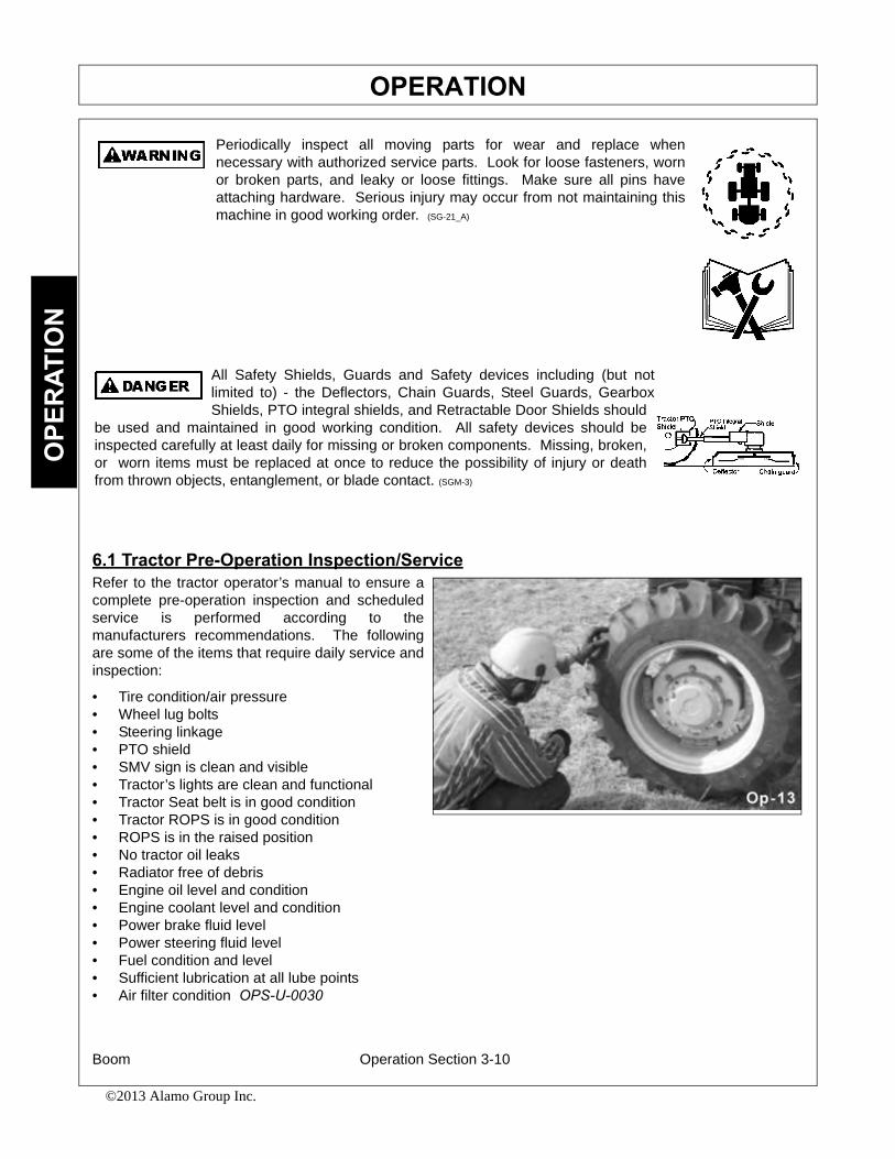
OPERATIONO
PER
ATIO
N
Periodically inspect all moving parts for wear and replace whennecessary with authorized service parts. Look for loose fasteners, wornor broken parts, and leaky or loose fittings. Make sure all pins haveattaching hardware. Serious injury may occur from not maintaining thismachine in good working order. (SG-21_A)
All Safety Shields, Guards and Safety devices including (but notlimited to) - the Deflectors, Chain Guards, Steel Guards, GearboxShields, PTO integral shields, and Retractable Door Shields should
be used and maintained in good working condition. All safety devices should beinspected carefully at least daily for missing or broken components. Missing, broken,or worn items must be replaced at once to reduce the possibility of injury or deathfrom thrown objects, entanglement, or blade contact. (SGM-3)
6.1 Tractor Pre-Operation Inspection/ServiceRefer to the tractor operator’s manual to ensure acomplete pre-operation inspection and scheduledservice is performed according to themanufacturers recommendations. The followingare some of the items that require daily service andinspection:
• Tire condition/air pressure• Wheel lug bolts • Steering linkage• PTO shield • SMV sign is clean and visible• Tractor’s lights are clean and functional• Tractor Seat belt is in good condition • Tractor ROPS is in good condition• ROPS is in the raised position• No tractor oil leaks • Radiator free of debris • Engine oil level and condition• Engine coolant level and condition • Power brake fluid level • Power steering fluid level • Fuel condition and level • Sufficient lubrication at all lube points• Air filter condition OPS-U-0030
Boom Operation Section 3-10
©2013 Alamo Group Inc.

OPERATIONO
PERATIO
N
6.2 Boom Unit Pre-Operation Inspection and ServiceInspect and service the boom arm and head prior to operation. Damaged and/or broken parts should berepaired and/or replaced immediately. To ensure the unit is ready for operation, conduct the following:OPS-B- 0020
FRAME ASSEMBLY
• Inspect condition of mounting frame weldment.• Inspect condition of Swivel Assy.• Ensure all bolts and screws are in position and
are properly torqued.• Ensure all pins are in place and fastened with
screws.• Ensure frame is properly mounted to tractor
and hardware is propely installed and tightened. OPS-B- 0021_D
Periodically inspect all moving parts for wear and replace whennecessary with authorized service parts. Look for loose fasteners, wornor broken parts, and leaky or loose fittings. Make sure all pins haveattaching hardware. Serious injury may occur from not maintaining thismachine in good working order. (SG-21_A)
The operator’s manual and safety signs affixed onthe unit contain important instructions on the safeand proper use of the equipment. Maintain theseimportant safety features on the implement in goodcondition to ensure the information is available tothe operator at all times.
• Ensure all safety signs are in place and legible. Replace missing, damaged, and illegible decals. OPS-U- 0011_A
Turret Frame Assy.
Boom Operation Section 3-11
©2013 Alamo Group Inc.

OPERATIONO
PER
ATIO
N
Relieve hydraulic pressure prior to doing any maintenance or repair work on the Implement.Place the Mower Head on the ground or securely supported on blocks or stands, disengagethe PTO, and turn off the engine. Push and pull the control Levers or Joystick several timesto relieve pressure prior to starting any maintenance or repair work. (SBM-6)
Never Leave the mower unattended while the head is in the raisedposition. The mower could fall causing serious injury to anyone whomight inadvertently be under the mower. (SBM-4)
BOOM ARM ASSEMBLY
• Inspect condition of each arm section weldment• Ensure all pins are in place.• Ensure all bolts, nuts and rollpins are properly
installed.• Check condition of bushings at boom pivot
points and hydraulic cylinder tangs.• Ensure each hydraulic cylinder is installed and
retained correctly. Ensure the proper size pins are used to retain the cylinders in place and are secured properly. OPS-B- 0022_D
Never attempt to lubricate, adjust, or remove material from the Implement while it is inmotion or while tractor engine is running. (SG-20)
HYDRAULIC LINE INSPECTION
• Check for hydraulic leaks along hoses, cylinders and fittings. IMPORTANT: DO NOT use your hands to check for oil leaks. Use a piece of heavy paper or cardboard to check for hydraulic oil leaks.
• Inspect the condition of the valve mounting.• Ensure fittings are properly connected. OPS-B- 0023_D
Boom Operation Section 3-12
©2013 Alamo Group Inc.
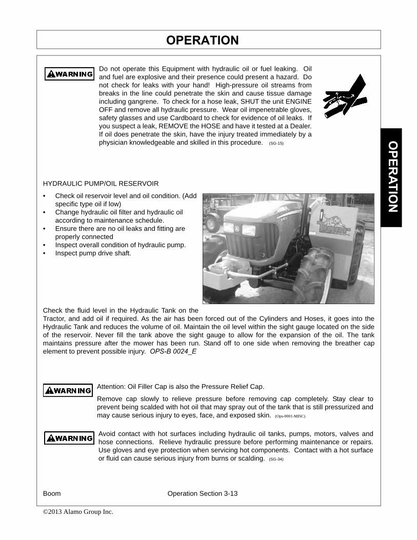
OPERATIONO
PERATIO
N
Do not operate this Equipment with hydraulic oil or fuel leaking. Oiland fuel are explosive and their presence could present a hazard. Donot check for leaks with your hand! High-pressure oil streams frombreaks in the line could penetrate the skin and cause tissue damageincluding gangrene. To check for a hose leak, SHUT the unit ENGINEOFF and remove all hydraulic pressure. Wear oil impenetrable gloves,safety glasses and use Cardboard to check for evidence of oil leaks. Ifyou suspect a leak, REMOVE the HOSE and have it tested at a Dealer.If oil does penetrate the skin, have the injury treated immediately by aphysician knowledgeable and skilled in this procedure. (SG-15)
HYDRAULIC PUMP/OIL RESERVOIR
• Check oil reservoir level and oil condition. (Add specific type oil if low)
• Change hydraulic oil filter and hydraulic oil according to maintenance schedule.
• Ensure there are no oil leaks and fitting are properly connected
• Inspect overall condition of hydraulic pump.• Inspect pump drive shaft.
Check the fluid level in the Hydraulic Tank on theTractor, and add oil if required. As the air has been forced out of the Cylinders and Hoses, it goes into theHydraulic Tank and reduces the volume of oil. Maintain the oil level within the sight gauge located on the sideof the reservoir. Never fill the tank above the sight gauge to allow for the expansion of the oil. The tankmaintains pressure after the mower has been run. Stand off to one side when removing the breather capelement to prevent possible injury. OPS-B 0024_E
Attention: Oil Filler Cap is also the Pressure Relief Cap.
Remove cap slowly to relieve pressure before removing cap completely. Stay clear toprevent being scalded with hot oil that may spray out of the tank that is still pressurized andmay cause serious injury to eyes, face, and exposed skin. (Ops-0001-MISC)
Avoid contact with hot surfaces including hydraulic oil tanks, pumps, motors, valves andhose connections. Relieve hydraulic pressure before performing maintenance or repairs.Use gloves and eye protection when servicing hot components. Contact with a hot surfaceor fluid can cause serious injury from burns or scalding. (SG-34)
Boom Operation Section 3-13
©2013 Alamo Group Inc.

OPERATIONO
PER
ATIO
N
Boom Operation Section 3-14
ROTARY HEAD INSPECTION
• Inspect blades and blade bolts for looseness and excessive wear. Rotate to 90° to make for checking easier. Replace damaged, worn, and missing blades as complete sets to maintain rotary balance.
• Ensure motor bolts and nuts are tightened to the appropriate torque.
• Ensure rubber deflectors are in position and not damaged. Replace worn, broken, and missing sections immediately.
• Ensure hydraulic lines are properly connected to the hydraulic motor. Check for hydraulic leaks along hoses and fittings. DO NOT use your hands to check for oil leaks. Use a piece of heavy paper or cardboard to check for hydraulic oil leaks.
• Inspect the condition of deck skid shoes and hardware. OPS-B- 0025
Do not put hands or feet under mower decks. Blade Contact can resultin serious injury or even death. Stay away until all motion has stoppedand the decks are securely blocked up. (SGM-09)
All Safety Shields, Guards and other safety devices including (but not limited to) -Deflectors, Steel Guards and Gearbox Shields must be used and maintained in goodworking condition. All safety devices should be inspected carefully at least daily for missingor broken components. Missing, broken, or worn items must be replaced at once to reducethe possibility of injury or death from thrown objects, entanglement, or blade contact. (SSM-07)
©2013 Alamo Group Inc.

OPERATIONO
PERATIO
N
Boom Operation Section 3-15
FLAIL HEAD INSPECTION
• Inspect blades and blade bolts for looseness and excessive wear. Rotate to 90° to make for checking easier. Replace damaged, worn, and missing blades as complete sets to maintain cuttershaft balance.
• Ensure rubber deflectors are in position and not damaged. Replace worn, broken, and missing sections immediately.
• Ensure the rollers are in good condition and rotate freely.
• Inspect that all bolts and screws are in position and are properly torqued.
• Ensure hydraulic lines are properly connected to the hydraulic motor. Check for hydraulic leaks along hoses and fittings. DO NOT use your hands to check for oil leaks. Use a piece of heavy paper or cardboard to check for hydraulic oil leaks.
• Inspect the condition of the drive belts.• Ensure the drive belt shields are in place and
in good repair.• Remove any grass or other debris which may
be wrapped around the cuttershafts ends.• Inspect the condition of deck skid shoes and
hardware. OPS-B- 0026_B
Do not put hands or feet under mower decks. Blade Contact can resultin serious injury or even death. Stay away until all motion has stoppedand the decks are securely blocked up. (SFL-2)
All Safety Shields, Guards and other safety devices including (but not limited to) -Deflectors, Steel Guards and Gearbox Shields must be used and maintained in goodworking condition. All safety devices should be inspected carefully at least daily for missingor broken components. Missing, broken, or worn items must be replaced at once to reducethe possibility of injury or death from thrown objects, entanglement, or blade contact. (SSM-07)
©2013 Alamo Group Inc.

OPERATIONO
PER
ATIO
N
6.3 Cutting Component InspectionInspect blade pan and blade assembly for the following: OPS-U-0031
Inspect the Blades daily for abnormal wear. REPLACE BOTH BLADES on that carrierIMMEDIATELY if either blade has:
• Become bent or deformed from it’s original shape or• Any cracks are visible, or • Deep gouges in the blade’s surface are present, or• Gouges or chipped areas in the cutting edge are larger than 1/2”(12.7mm), or • The material on the leading edge has been worn away by more than 1/2(12.7mm)”
Failure to replace abnormally worn blades may lead to catastrophic failure of the blades and ejection of thebroken part with tremendous force which may cause serious bodily injury or death. OPS-U-0032
Boom Operation Section 3-16
©2013 Alamo Group Inc.

OPERATIONO
PERATIO
N
Tractor PRE-OPERATION Inspection
Mower ID#________________ Make ____________________
Date: ________________ Shift ____________________
Before conducting the inspection, make sure the tractor engine is off, all rotationhas stopped and the tractor is in park with the parking brake engaged. Make surethe mower is resting on the ground or securely blocked up and all hydraulicpressure has been relieved.
Operator’s Signature:
Item Condition at Start of Shift
Specific Comments if not O.K.
The flashing lights function properlyThe SMV Sign is clean and visibleThe tires are in good condition with proper pressureThe wheel lug bolts are tightThe tractor brakes are in good conditionThe steering linkage is in good conditionThere are no visible oil leaksThe hydraulic controls function properlyThe ROPS or ROBS Cab is in good conditionThe seatbelt is in place and in good conditionThe 3-point hitch is in good conditionThe drawbar pins are securely in placeThe PTO master shield is in placeThe engine oil level is fullThe brake fluid level is fullThe power steering fluid level is fullThe fuel level is adequateThe engine coolant fluid level is fullThe radiator is free of debrisThe air filter is in good condition
DO NOT OPERATE an UNSAFE TRACTOR or MOWER
This Inspection Form may be freely duplicated for extra copies.
Boom Operation Section 3-17
©2013 Alamo Group Inc.

OPERATIONO
PER
ATIO
N
Boom PRE-OPERATION Inspection
Mower ID#________________ Make ____________________
Date: ________________ Shift ____________________
Before conducting the inspection, make sure the tractor engine is off, all rotation hasstopped and the tractor is in park with the parking brake engaged. Make sure themower is resting on the ground or securely blocked up and all hydraulic pressure hasbeen relieved.
Operator’s Signature:
Table 1:
Item Condition at Start of Shift
Specific Comments if not O.K.
The Operator’s Manual is in the tractorAll safety decals are in place and legibleThe mounting frame bolts are in place and tightThe boom connection bolts & pins are tightThere are no cracks in boomThe hydraulic cylinders pins are tightThe hydraulic pump hose connections are tightThe hydraulic valve controls function properlyThere are no leaking or damaged hosesThe hydraulic oil level is fullThere is no evidence of hydraulic leaksThe blades are not chipped, cracked or bentThe blade bolts are tightThe deflectors are in place and in good conditionThe boom shields are in place and in good conditionThe skid shoes are in good condition and tightThere are no cracks or holes in boom deckThe hydraulic motor mounting bolts are tightThe boom head spindle housing is tight and lubricated
DO NOT OPERATE an UNSAFE TRACTOR or MOWER
Boom Operation Section 3-18
©2013 Alamo Group Inc.

OPERATIONO
PERATIO
N
Cable Controlled MowersA control lever decal similar to the one shown below should be near the control valve to remind the operator ofthe lever functions.
The main control valve on the Tiger Boom Mowerhas four sections with tapered spools, located nearthe right side of the steering wheel. The malfunctionof a section of the valve does not necessitate thereplacement of the entire “bank”, only the faultysection. Each section of the valve controls a certainposition of the boom or deck. Seated in the operatorsseat, the controls from left to right are #1-primary(main) boom, #2-secondary boom, #3 -deck roll, #4-boom (swivel) swing), and #5- boom (safety) shield.
Boom Operation Section 3-19
©2013 Alamo Group Inc.

OPERATIONO
PER
ATIO
N
6.4 SwitchboxThe Safety Shield lever opens and closes the shieldlocated on the front of the cutter head. When movingat or near the ground, always have the shield in thclosed position. When mowing in the brush or intrees above ground level the shield may be openedfor easier cutting. Read and follow the warnings onthe decal shown below. Do not run the cutter headinto material larger than 6” diameter.
Boom Operation Section 3-20
©2013 Alamo Group Inc.

OPERATIONO
PERATIO
N
LEVER #1 MAIN BOOM
LEVER #2 SECONDARY BOOM
LEVER #3 DECK ROLL
Boom Operation Section 3-21
©2013 Alamo Group Inc.
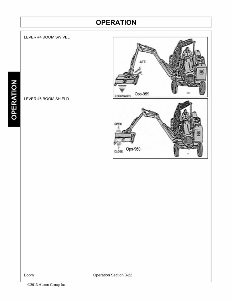
OPERATIONO
PER
ATIO
N
LEVER #4 BOOM SWIVEL
LEVER #5 BOOM SHIELD
Boom Operation Section 3-22
©2013 Alamo Group Inc.

OPERATIONO
PERATIO
N
7.Joystick Controlled MowersNOTE: DO NOT operate mower head while boom mower is in the boom rest, or in the storedposition! Red “Mower Run” light indicates mower is “ON”.
The boom functions are controlled by an electronic joystick. The Joystick Master Switch enables the joystickcontrol for controlling the boom motion functions. This switch is to be in the “OFF” position when starting thetractor and when boom is stowed for transporting the machine.
If the joystick control is not operating properly, turn the master switchto the “OFF” position.Install the manual valve handle onto valve and operate the functions individually to stow boom.After boom is stowed in rest, transport the unit to the maintenance facility and contact yourTiger dealer for assistance.
DO NOT attempt to operate the valve manually for mowing operations!
Note: Pushing manual valve handles “out” or “away” from the tractor cab will bring the mainboom “up”, secondary boom “out”, roll deck “out”, and swivel boom “aft”. Pulling manual handles toward cabwill let main boom “down”, bring secondary boom “in”, roll deck “in”, and swivel boom “forward”.
Boom Operation Section 3-23
©2013 Alamo Group Inc.

OPERATIONO
PER
ATIO
N
7.1 Switch Box and Joystick ControlThe diagrams below and on the next page show the functions that are performed through the use of thejoystick controller.
The Safety Shield switch opens and closes the shield located on the front of the cutter head. When moving ator near the ground, always have the shield in the closed position. When moving in brush or in trees aboveground level the shield may be opened for easier cutting. Read and follow the warnings on the decal shownbelow. Do not run the cutter into material larger than 6” diameter.
Boom Operation Section 3-24
©2013 Alamo Group Inc.

OPERATIONO
PERATIO
N
Joystick Control
JOYSTICK FWD/BACK MOVES MAIN BOOM
Boom Operation Section 3-25
©2013 Alamo Group Inc.
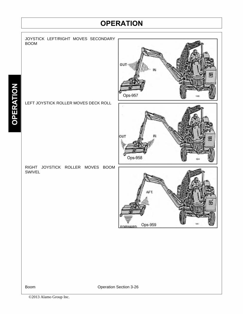
OPERATIONO
PER
ATIO
N
JOYSTICK LEFT/RIGHT MOVES SECONDARYBOOM
LEFT JOYSTICK ROLLER MOVES DECK ROLL
RIGHT JOYSTICK ROLLER MOVES BOOMSWIVEL
Boom Operation Section 3-26
©2013 Alamo Group Inc.

OPERATIONO
PERATIO
N
RIGHT JOYSTICK ROLLER WHILE PRESSINGBUTTON MOVES BOOM KNUCKLE ON A LEGALREAR STOW BOOM
SHIELD SWITCH(on switch box) OPERATESSAFETY SHIELD
8.DRIVING THE TRACTOR AND IMPLEMENTSafe tractor transport requires the operator to possess a thorough knowledge of the model being operatedand precautions to take while driving with an attached implement. Ensure the tractor has the capacity tohandle the weight of the boom and the tractor operating controls are set for safe transport. To ensure safetywhile driving the tractor with a boom, review the following.
Read all safety instructions. Decals on the Boom warn you of particular and multiple hazards. Some decalsare attached close to part of the Boom where there is a possible hazard. Read and make sure youunderstand the safety messages before you operate the implement. Keep all decals clean and readable.Replace lost or damaged decals, refer to safety section for more information.
Keep all person's well clear of mower since blades can throw objects with great velocity for a considerabledistance! KEEP CLEAR! OPS-B- 0005
Boom Operation Section 3-27
©2013 Alamo Group Inc.
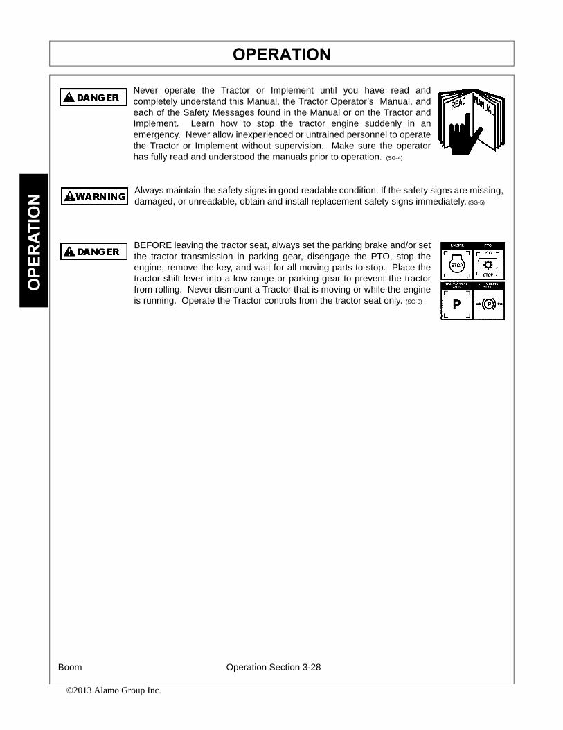
OPERATIONO
PER
ATIO
N
Never operate the Tractor or Implement until you have read andcompletely understand this Manual, the Tractor Operator’s Manual, andeach of the Safety Messages found in the Manual or on the Tractor andImplement. Learn how to stop the tractor engine suddenly in anemergency. Never allow inexperienced or untrained personnel to operatethe Tractor or Implement without supervision. Make sure the operatorhas fully read and understood the manuals prior to operation. (SG-4)
Always maintain the safety signs in good readable condition. If the safety signs are missing,damaged, or unreadable, obtain and install replacement safety signs immediately. (SG-5)
BEFORE leaving the tractor seat, always set the parking brake and/or setthe tractor transmission in parking gear, disengage the PTO, stop theengine, remove the key, and wait for all moving parts to stop. Place thetractor shift lever into a low range or parking gear to prevent the tractorfrom rolling. Never dismount a Tractor that is moving or while the engineis running. Operate the Tractor controls from the tractor seat only. (SG-9)
Boom Operation Section 3-28
©2013 Alamo Group Inc.

OPERATIONO
PERATIO
N
Transport only at speeds where you can maintain control of theequipment. Serious accidents and injuries can result from operating thisequipment at high speeds. Understand the Tractor and Implement and
how it handles before transporting on streets and highways. Make sure the Tractor steeringand brakes are in good condition and operate properly.
Before transporting the Tractor and Implement, determine the proper transport speeds foryou and the equipment. Make sure you abide by the following rules:
Test the tractor at a slow speed and increase the speed slowly. Apply the Brakes smoothlyto determine the stopping characteristics of the Tractor and Implement. As you increasethe speed of the Tractor the stopping distance increases. Determine the maximumtransport speed not to exceed 20 mph (30 kph) for transporting this equipment.
Test the equipment at a slow speed in turns. Increase the speed through the turn only afteryou determine that the equipment can be operated at a higher speed. Use extreme careand reduce your speed when turning sharply to prevent the tractor and implement fromturning over. Determine the maximum turning speed for you and this equipment beforeoperating on roads or uneven ground.
Only transport the Tractor and Implement at the speeds which allow you to properly controlthe equipment.
Be aware of the operating conditions. Do not operate the Tractor with weak or faulty brakesor worn tires. When operating down a hill or on wet or rain slick roads, the braking distanceincreases: use extreme care and reduce your speed. When operating in traffic always usethe Tractor’s flashing warning lights and reduce your speed. Be aware of traffic around youand watch out for the other guy. (SG-19)
8.1 Starting the TractorThe procedure to start the tractor is model specific.Refer to the tractor operator’s manual for startingprocedures for your particular tractor. Consult anauthorized dealer if the starting procedure isunclear. Ensure the 3-point control lever is in thelowered position and the PTO is disengaged beforestarting the tractor. OPS-U-0033
Boom Operation Section 3-29
©2013 Alamo Group Inc.
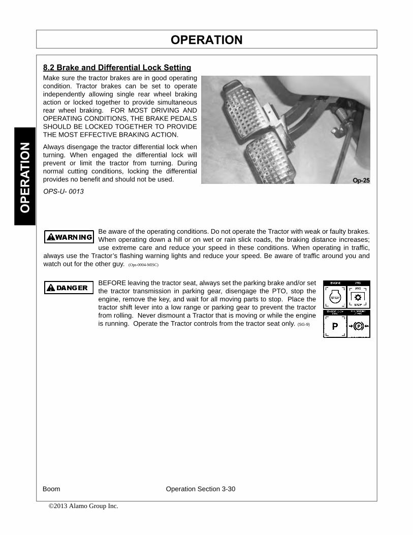
OPERATIONO
PER
ATIO
N
8.2 Brake and Differential Lock SettingMake sure the tractor brakes are in good operatingcondition. Tractor brakes can be set to operateindependently allowing single rear wheel brakingaction or locked together to provide simultaneousrear wheel braking. FOR MOST DRIVING ANDOPERATING CONDITIONS, THE BRAKE PEDALSSHOULD BE LOCKED TOGETHER TO PROVIDETHE MOST EFFECTIVE BRAKING ACTION.
Always disengage the tractor differential lock whenturning. When engaged the differential lock willprevent or limit the tractor from turning. Duringnormal cutting conditions, locking the differentialprovides no benefit and should not be used.
OPS-U- 0013
Be aware of the operating conditions. Do not operate the Tractor with weak or faulty brakes.When operating down a hill or on wet or rain slick roads, the braking distance increases;use extreme care and reduce your speed in these conditions. When operating in traffic,
always use the Tractor’s flashing warning lights and reduce your speed. Be aware of traffic around you andwatch out for the other guy. (Ops-0004-MISC)
BEFORE leaving the tractor seat, always set the parking brake and/or setthe tractor transmission in parking gear, disengage the PTO, stop theengine, remove the key, and wait for all moving parts to stop. Place thetractor shift lever into a low range or parking gear to prevent the tractorfrom rolling. Never dismount a Tractor that is moving or while the engineis running. Operate the Tractor controls from the tractor seat only. (SG-9)
Boom Operation Section 3-30
©2013 Alamo Group Inc.
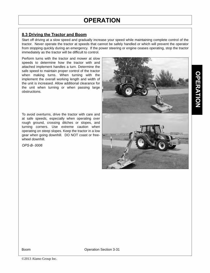
OPERATIONO
PERATIO
N
8.3 Driving the Tractor and BoomStart off driving at a slow speed and gradually increase your speed while maintaining complete control of thetractor. Never operate the tractor at speeds that cannot be safely handled or which will prevent the operatorfrom stopping quickly during an emergency. If the power steering or engine ceases operating, stop the tractorimmediately as the tractor will be difficult to control.
Perform turns with the tractor and mower at slowspeeds to determine how the tractor with andattached implement handles a turn. Determine thesafe speed to maintain proper control of the tractorwhen making turns. When turning with theimplement the overall working length and width ofthe unit is increased. Allow additional clearance forthe unit when turning or when passing largeobstructions.
To avoid overturns, drive the tractor with care andat safe speeds, especially when operating overrough ground, crossing ditches or slopes, andturning corners. Use extreme caution whenoperating on steep slopes. Keep the tractor in a lowgear when going downhill. DO NOT coast or free-wheel downhill.
OPS-B- 0006
Boom Operation Section 3-31
©2013 Alamo Group Inc.

OPERATIONO
PER
ATIO
N
Never Leave the mower unattended while the head is in the raisedposition. The mower could fall causing serious injury to anyone whomight inadvertently be under the mower. (SBM-4)
Always keep a careful lookout and use extreme care when workingaround overhead obstructions. Never allow the Mower head or boomwithin 10 feet of any power line. When working close to overheadpower lines consult your electric company for a safe code of operation.(SBM-7)
9.OPERATING THE BOOM UNIT AND ATTACHED HEADTHE OPERATOR MUST COMPLETELY UNDERSTAND HOW TO OPERATE THE TRACTOR ANDMOWER AND ALL CONTROLS BEFORE ATTEMPTING TO MOW. The operator must read and understandthe Safety and Operation Sections of this manual and the tractor operator’s manuals. These manuals mustbe read and explained to any operator who cannot read. Never allow someone to operate the unit withoutcomplete operating instructions.
To ensure safety to the operator, bystanders, and equipment and before starting any mowing operation. Theoperator must become familiar with the area to be mowed, and any obstacles and hazards contained within.Special attention should be paid to foreign debris, overhead obstructions, rough terrain, steep slopes,passersby and animals in the area.
Only operate the mower head from the tractor operator’s seat with the seatbelt securely fastened. Onlyoperate a boom and equipped head on cabbed tractor that is equipped with a polycarbonate safety-protectedright side window or a non cabbed tractor equipped with a ROPS and operator safety screen.
Avoid operating in the reverse direction when possible. In situations where the boom and mower must bebacked to access areas to be cut, make sure there are no persons or other foreign debris behind the tractor.When backing, operate the tractor at a much reduced ground speed to ensure complete control of the unit ismaintained. OPS-B- 0007
Do not mow with two machines in the same area except with Cab tractors with the windowsclosed. (SGM-11)
Mow only in conditions where you have clear visibility in daylight or with adequate artificiallighting. Never mow in darkness or foggy conditions where you cannot clearly see at least300 feet (90 m) in front and to the sides of the tractor and mower. Make sure that you canclearly see and identify passersby, steep slopes, ditches, drop-offs, overhead obstructions,power lines, debris and foreign objects. If you are unable to clearly see these type of itemsdiscontinue mowing. (SGM-01)
Boom Operation Section 3-32
©2013 Alamo Group Inc.

OPERATIONO
PERATIO
N
Avoid mowing in reverse direction when possible. Check to make sure there are nopersons behind the mower and use extreme care when mowing in reverse. Mow only at aslow ground speed where you can safely operate and control the tractor and mower.Never mow an area that you have not inspected and removed debris or foreign material.(SGM-08)
Never operate the mower head tilted down where the operator can see the blades of themower. The blade could throw an object toward the operator causing serious injury or
death. Never operate the mower without an Operator Protective Structure. Always wearsafety glasses and a hard hat. (Ops-0005-MISC)
9.1 Foreign Debris Hazards/Overhead ObstructionsAn area to be cut must first be inspected for objects that could be thrown or that could damage the machine.Walk through the area looking for fences, boulders, rocks, culverts, stumps or metal objects. Mark theinspected area with flags. If the area is dense and cannot be walked thoroughly it may be necessary to inspecta smaller area as well as possible, then trim away the part that has been inspected and can safely beremoved. Walk each new area again and repeat the inspection before cutting more away. Repeat as often asnecessary until the area is cleared. It can be damaging and/or dangerous to work the cutter in an area that hasnot been visually inspected.
Place DANGER signs at least 300 feet beyond the perimeter of the area to be worked, not just 300 feet fromwhere the machine started operating! It is convenient in many cases to work in 300 foot sections. Move thefirst Danger sign to the beginning of the freshly cleared area, place it, then take the first cutting area flag up tothe end of the freshly cleared area 300 feet away. Walk and inspect the next 300 feet and place the secondcutting area flag. Pick up the second DANGER sign, and take it a further 300 feet along the road or trail. Notethat in many cases the DANGER area will extend in front of and behind the machine as well as along eachside. Post signs accordingly. OPS-B- 0008
Extreme care should be taken when operating near loose objects suchas gravel, rocks, wire, and other debris. Inspect the area beforemowing. Foreign objects should be removed from the site to preventmachine damage and/or bodily injury or even death. Any objects thatcannot be removed must be clearly marked and carefully avoided by theoperator. Stop mowing immediately if blades strike a foreign object.Repair all damage and make certain rotor or blade carrier is balancedbefore resuming mowing. (SGM-05)
Many varied objects, such as wire, cable, rope, or chains, can become entangled in theoperating parts of the mower head. These items could then swing outside the housing atgreater velocities than the blades. Such a situation is extremely hazardous and could resultin serious injury or even death. Inspect the cutting area for such objects before mowing.Remove any like object from the site. Never allow the cutting blades to contact such items.(SGM-06)
Boom Operation Section 3-33
©2013 Alamo Group Inc.

OPERATIONO
PER
ATIO
N
Mow at the speed that you can safely operate and control the tractor and mower. Thecorrect mowing speed depends on terrain condition and grass type, density, and height ofcut. Normal ground speed range is from 2 to 5 mph(3-8 kph). Use slow mowing speedswhen operating on or near steep slopes, ditches, drop-offs, overhead obstructions, powerlines, or when debris and foreign objects are to be avoided. (SGM-07)
9.2 Operating Speed and Ground SpeedGround speed for mowing will depend upon the height, type, and density of vegetation to be cut. Do Notexceed 5 MPH while operating. Operate the mower at its full rated PTO speed to maintain blade speed for aclean cut. Refer to the tractor operator’s manual or the tractor instrument panel for the engine speed and gearto provide the required operating and desired ground speed. Make sure that the mower is operating at its fullrated speed before entering the vegetation to be cut. Always start and stop cutting blades with engine nearidle.
Ground speed is achieved by transmission gear selection and not by the engine operating speed. Theoperator may be required to experiment with several gear range combinations to determine the best gear andrange which provides the most ideal performance from the implement and most efficient tractor operation. Asthe severity of cutting conditions increase, the ground speed should be decreased. OPS-B- 0009
Mow at the speed that you can safely operate and control the tractor and mower. Thecorrect mowing speed depends on terrain condition and grass type, density, and height ofcut. Normal ground speed range is from 2 to 5 mph(3-8 kph). Use slow mowing speedswhen operating on or near steep slopes, ditches, drop-offs, overhead obstructions, powerlines, or when debris and foreign objects are to be avoided. (SGM-07)
9.3 Operating the Attached Mower HeadsThe boom can attach to and operate multiple heads one at a time for a wide range of vegetation controlapplications. The attached heads are designed for different applications. The head should be selected basedon the mowing application and the location that the unit is being operated.
Refer to the Assembly Section of this manual to ensure the head is properly attached to the boom hitch andhydraulic lines are properly connected. OPS-B- 0010
There are obvious and hidden potential hazards in the operation of thisMower. REMEMBER! This machine is often operated in heavy brushand in heavy weeds. The Blades of this Mower can throw objects ifshields are not properly installed and maintained. Serious injury or evendeath may occur unless care is taken to insure the safety of the operator,bystanders, or passersby in the area. Do not operate this machine withanyone in the immediate area. Stop mowing if anyone is within 300 feetof mower. (SGM-02)
Boom Operation Section 3-34
©2013 Alamo Group Inc.
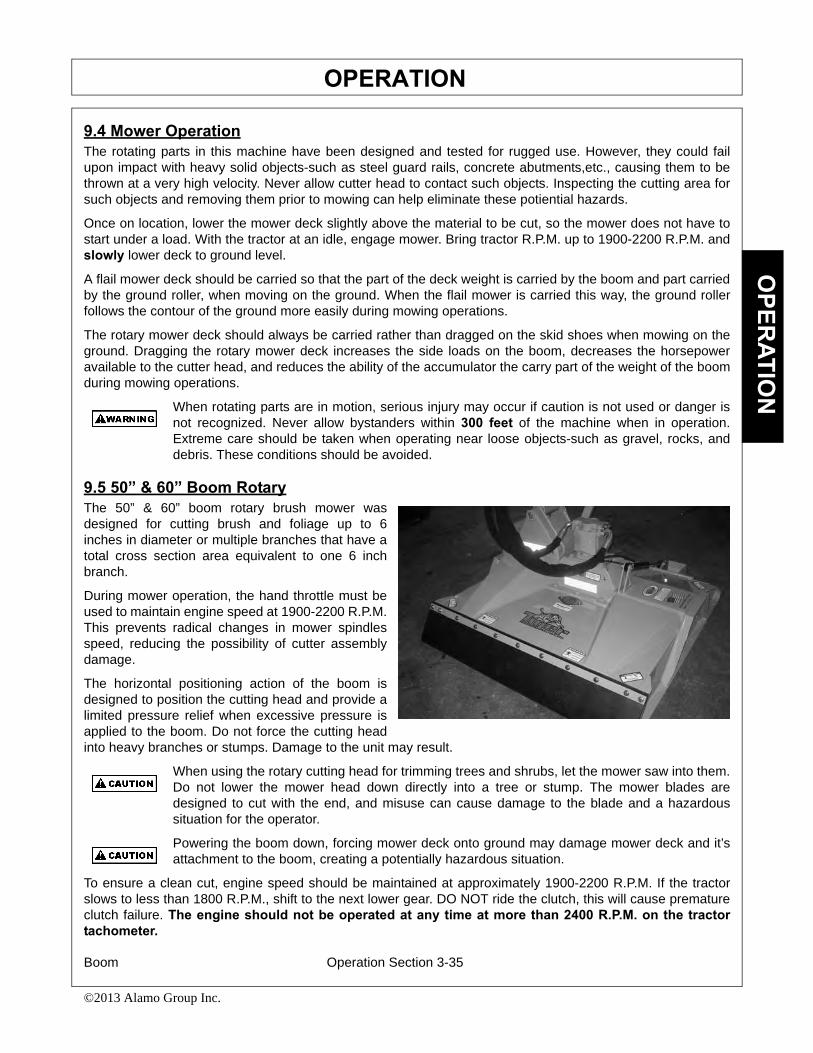
OPERATIONO
PERATIO
N
9.4 Mower OperationThe rotating parts in this machine have been designed and tested for rugged use. However, they could failupon impact with heavy solid objects-such as steel guard rails, concrete abutments,etc., causing them to bethrown at a very high velocity. Never allow cutter head to contact such objects. Inspecting the cutting area forsuch objects and removing them prior to mowing can help eliminate these potiential hazards.
Once on location, lower the mower deck slightly above the material to be cut, so the mower does not have tostart under a load. With the tractor at an idle, engage mower. Bring tractor R.P.M. up to 1900-2200 R.P.M. andslowly lower deck to ground level.
A flail mower deck should be carried so that the part of the deck weight is carried by the boom and part carriedby the ground roller, when moving on the ground. When the flail mower is carried this way, the ground rollerfollows the contour of the ground more easily during mowing operations.
The rotary mower deck should always be carried rather than dragged on the skid shoes when mowing on theground. Dragging the rotary mower deck increases the side loads on the boom, decreases the horsepoweravailable to the cutter head, and reduces the ability of the accumulator the carry part of the weight of the boomduring mowing operations.
When rotating parts are in motion, serious injury may occur if caution is not used or danger isnot recognized. Never allow bystanders within 300 feet of the machine when in operation.Extreme care should be taken when operating near loose objects-such as gravel, rocks, anddebris. These conditions should be avoided.
9.5 50” & 60” Boom RotaryThe 50” & 60” boom rotary brush mower wasdesigned for cutting brush and foliage up to 6inches in diameter or multiple branches that have atotal cross section area equivalent to one 6 inchbranch.
During mower operation, the hand throttle must beused to maintain engine speed at 1900-2200 R.P.M.This prevents radical changes in mower spindlesspeed, reducing the possibility of cutter assemblydamage.
The horizontal positioning action of the boom isdesigned to position the cutting head and provide alimited pressure relief when excessive pressure isapplied to the boom. Do not force the cutting headinto heavy branches or stumps. Damage to the unit may result.
When using the rotary cutting head for trimming trees and shrubs, let the mower saw into them.Do not lower the mower head down directly into a tree or stump. The mower blades aredesigned to cut with the end, and misuse can cause damage to the blade and a hazardoussituation for the operator.
Powering the boom down, forcing mower deck onto ground may damage mower deck and it’sattachment to the boom, creating a potentially hazardous situation.
To ensure a clean cut, engine speed should be maintained at approximately 1900-2200 R.P.M. If the tractorslows to less than 1800 R.P.M., shift to the next lower gear. DO NOT ride the clutch, this will cause prematureclutch failure. The engine should not be operated at any time at more than 2400 R.P.M. on the tractortachometer.
Boom Operation Section 3-35
©2013 Alamo Group Inc.

OPERATIONO
PER
ATIO
N
For cutting brush, it is usually best to stop the tractor and swivel the boom and mower into foilage. Thehorizontal positioning action of the boom is designed to position the cutting head and provide a limitedpressure relief when excessive pressure is applied to the boom.
DO NOT use excessive force when positioning cutting head into heavy branches or stumps.Damage to the unit may result. It is best to let the cutter head “eat away” slowly at heavy cuttingjobs.
If foliage falls on top of mower deck causing tractor to become unstable, move the boom“Forward” and “Out” to relieve tipping of the tractor. Lower mower deck to ground and shutdown unit. After all motion stops, remove foliage from mower deck.
The mower will operate more efficiently in tougher conditions and with less power if the knives are kept sharp.If the mower begins to vibrate, stop the tractor, check for wire wrapped in the spindle or damaged knives.When replacing knives, replace all knives with new knives to ensure proper balance so the mower will notvibrate. Severe vibration will result, if knives with unequal wear are used.
Begin a pass at the top side of the trees and work down with each consecutive pass. When cutting trees andshrubs, use a lower speed to allow the knives time to cut as well as mulch the foliage.
If bystanders approach within 300 feet while mower is in operation turn mower switch “OFF”immediately! After shutdown, never leave the tractor or allow bystanders to approach within 300FEET of the unit until all motion stops completely.
If cutter shaft jams and stops, turn mower switch to “OFF”, and swivel boom “AFT”. Normally this action willclear the cutter head. If not, roll mower deck until adjacent to the secondary boom, then lower boom to restmower deck on ground. Shut off the tractor, set parking break, allow all motion to cease. At that point it is safeto leave the tractor and clear the cutter heads manually.
Begin each pass at the top side of the trees and work down with each consecutive pass. Use a low speed toallow the cutting blades time to mulch as well as cut the foliage. When the initial pass has been made,disengage the mower, and return boom to a safe travel position. Return to starting point and make next pass,etc..
After the first day of operation, all bolts should be checked and tightened securely. This should be doneperiodically to ensure the bolts do not become loose and cause damage to the tractor or mower, or injury to theoperator.
Boom Operation Section 3-36
©2013 Alamo Group Inc.
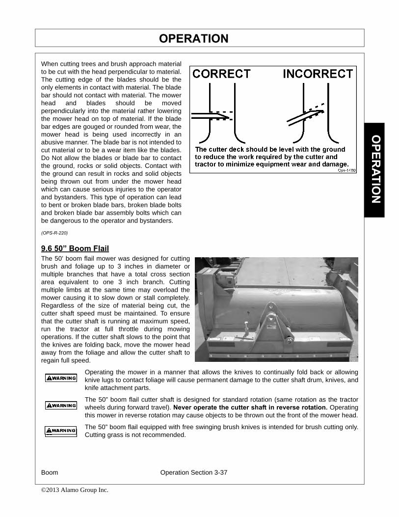
OPERATIONO
PERATIO
N
When cutting trees and brush approach materialto be cut with the head perpendicular to material.The cutting edge of the blades should be theonly elements in contact with material. The bladebar should not contact with material. The mowerhead and blades should be movedperpendicularly into the material rather loweringthe mower head on top of material. If the bladebar edges are gouged or rounded from wear, themower head is being used incorrectly in anabusive manner. The blade bar is not intended tocut material or to be a wear item like the blades.Do Not allow the blades or blade bar to contactthe ground, rocks or solid objects. Contact withthe ground can result in rocks and solid objectsbeing thrown out from under the mower headwhich can cause serious injuries to the operatorand bystanders. This type of operation can leadto bent or broken blade bars, broken blade boltsand broken blade bar assembly bolts which canbe dangerous to the operator and bystanders.
(OPS-R-220)
9.6 50” Boom FlailThe 50’ boom flail mower was designed for cuttingbrush and foliage up to 3 inches in diameter ormultiple branches that have a total cross sectionarea equivalent to one 3 inch branch. Cuttingmultiple limbs at the same time may overload themower causing it to slow down or stall completely.Regardless of the size of material being cut, thecutter shaft speed must be maintained. To ensurethat the cutter shaft is running at maximum speed,run the tractor at full throttle during mowingoperations. If the cutter shaft slows to the point thatthe knives are folding back, move the mower headaway from the foliage and allow the cutter shaft toregain full speed.
Operating the mower in a manner that allows the knives to continually fold back or allowingknive lugs to contact foliage will cause permanent damage to the cutter shaft drum, knives, andknife attachment parts.
The 50” boom flail cutter shaft is designed for standard rotation (same rotation as the tractorwheels during forward travel). Never operate the cutter shaft in reverse rotation. Operatingthis mower in reverse rotation may cause objects to be thrown out the front of the mower head.
The 50” boom flail equipped with free swinging brush knives is intended for brush cutting only.Cutting grass is not recommended.
Boom Operation Section 3-37
©2013 Alamo Group Inc.

OPERATIONO
PER
ATIO
N
Do not allow knives to cut down to the ground. Position ground roller to maintain knife arc at aminimum of 2 inches above the ground. Knife contact or lug contact with ground will causepermanent damage to cutter shaft, knives, and knife attachment parts.
9.7 63” Boom FlailThe 63” boom flail mower was designed for cuttinggrass. The cutter shaft speed must be maintainedfor proper cutting. To insure that the cutter shaft isrotating at maximum speed, run tractor at fullthrottle during mowing operations. If cutter shaftslows to the point that the knives are folding backagainst the cutter shaft, move the mower headaway from the foliage and allow the cutter shaft toregain full speed.
The rotating parts of this machine have been designed and tested for rugged use.However, the blades could fail upon impact with heavy, solid objects such as metal guardrails and concrete structures. Such impact could cause the broken objects to be thrownoutward at very high velocities. To reduce the possibility of property damage, seriousinjury, or even death, never allow the cutting blades to contact such obstacles. (SGM-4)
All Safety Shields, Guards and Safety devices including (but notlimited to) - the Deflectors, Chain Guards, Steel Guards, GearboxShields, PTO integral shields, and Retractable Door Shields should
be used and maintained in good working condition. All safety devices should beinspected carefully at least daily for missing or broken components. Missing, broken,or worn items must be replaced at once to reduce the possibility of injury or deathfrom thrown objects, entanglement, or blade contact. (SGM-3)
Many varied objects, such as wire, cable, rope, or chains, can become entangled in theoperating parts of the mower head. These items could then swing outside the housing atgreater velocities than the blades. Such a situation is extremely hazardous and could resultin serious injury or even death. Inspect the cutting area for such objects before mowing.Remove any like object from the site. Never allow the cutting blades to contact such items.(SGM-06)
Boom Operation Section 3-38
©2013 Alamo Group Inc.

OPERATIONO
PERATIO
N
9.8 Shutting Down the Attached Head- For Standard EquipmentTo shut down attached mower head, first bring thetractor to a complete stop. Decrease engine RPMto idle then disengage cutterhead. The mower headwill come to a complete stop within a suitableamount of time. Do not engage or disengage thecutterheads at a high RPM unless there is anemergency situation.
Park the tractor on a level surface, place thetransmission in park or neutral and apply theparking brake, shut down the engine, remove thekey, and wait for all motion to come to a completestop before exiting the tractor. OPS-B- 0011_D
BEFORE leaving the tractor seat, always set the parking brake and/or setthe tractor transmission in parking gear, disengage the PTO, stop theengine, remove the key, and wait for all moving parts to stop. Place thetractor shift lever into a low range or parking gear to prevent the tractorfrom rolling. Never dismount a Tractor that is moving or while the engineis running. Operate the Tractor controls from the tractor seat only. (SG-9)
Boom Operation Section 3-39
©2013 Alamo Group Inc.

OPERATIONO
PER
ATIO
N
10.TRACTOR, BOOM, AND ATTACHED HEAD STORAGEProperly preparing and storing the unit at the end of the season is critical to maintaining its appearance and tohelp ensure years of dependable service. The following are suggested storage procedures:
• Thoroughly clean all debris from boom and head to prevent damage from rotting grass and standing water.
• Lubricate all grease points and fill oil levels according to the maintenance lubrication schedule.
• Tighten all bolts to the proper torque. Ensure all pins and other hardware are in place.
• Check the boom arm and head for worn and damaged parts. Perform repairs and make replacements so that the mower will be ready for use at the start of the next season.
• Store the unit in a clean and dry location.• Use spray touch-up enamel where necessary
on bare metal surfaces to prevent rust and to maintain the appearance of the mower.
OPS-B- 0012_C
Never allow children to play on or around Tractor or Implement. Children can slip or fall offthe Equipment and be injured or killed. Children can cause the Implement to shift or fallcrushing themselves or others. (SG-25)
BEFORE leaving the tractor seat, always set the parking brake and/or setthe tractor transmission in parking gear, disengage the PTO, stop theengine, remove the key, and wait for all moving parts to stop. Place thetractor shift lever into a low range or parking gear to prevent the tractorfrom rolling. Never dismount a Tractor that is moving or while the engineis running. Operate the Tractor controls from the tractor seat only. (SG-9)
Perform service, repairs and lubrication according to the maintenance section. Ensure theunit is properly lubricated as specified in the lubrication schedule and all bolts and nuts areproperly torqued. Failure to properly service, repair and maintain this Implement in goodoperating condition could cause component failure and possible serious injury or evendeath. (SG-35)
11.TRANSPORTING THE TRACTOR AND IMPLEMENTInherent hazards of operating the tractor and implement and the possibility of accidents are not left behindwhen you finish working in an area. Therefore, the operator must employ good judgement and safe operationpractices when transporting the tractor and implement between locations. By using good judgement andfollowing safe transport procedures, the possibility of accidents while moving between locations can besubstantially minimized. OPS-U- 0017
Boom Operation Section 3-40
©2013 Alamo Group Inc.

OPERATIONO
PERATIO
N
11.1 Placing Boom Arm on Boom Arm Rest - For Standard EquipmentBefore transporting tractor between locations, idlethe tractor engine, disengage the attached head,and wait for all head motion to come to a completestop. Place the boom in its storage cradle restsupport and then turn the joystick master switch tothe OFF position.
• Retract Deck Roll cylinder completely.• Push Secondary cylinder approximately 1/2
way out.• Raise Main boom approximately to 60°.• Swing boom back slowly until it is straight
back.• For a 3-point boomrest or a single column
boomrest, position the secondary in the cradle. Carefully avoid pinching any hoses.
• For a open stow style boomrest, lower the Main boom onto rest and bring the Secondary boom in until it is sitting on the boomrest.
• For a Legal Stow style boomrest, retract the secondary and knuckle cylinders completely. Lower the Main boom onto rest. Slowly extend the secondary cylinder until the secondary boom contracts the side of the boomrest saddle. Next, slowly extend the knuckle cylinder until the secondary sets on the bottom part of the boomrest saddle.
The boom is now in the transport position. Turn on any electronic travel locks at the switchbox.
To remove the boom from the Boom Rest, first turn off any electronic travel locks at the switchbox then retractthe knuckle cylinder (if applicable) then swing the Secondary boom out. Raise the Main boom approximately 6inches. Swivel the boom forward to the desired position. OPS-B- 0013_D
Boom Operation Section 3-41
©2013 Alamo Group Inc.

OPERATIONO
PER
ATIO
N
11.2 Transporting on Public RoadwaysExtreme caution should be used when transporting the tractor and mower on public roadways. The tractormust be equipped with all required safety warning features including a SMV emblem and flashing warninglights to alert drivers of the tractor’s presence. Remember that roadways are primarily designed for automotivedrivers and most drivers will not be looking out for you, therefore, you must look out for them. Check your sideview mirrors frequently and remember that vehicles will approach quickly because of the tractor’s slowerspeed. Be extremely cautious when the piece of equipment that you are driving, is wider than the tractor tirewidth and/or extends beyond your lane of the road. OPS-B- 0014
The SMV (Slow-Moving Vehicle) emblem isuniversal symbol used to alert drivers of thepresence of equipment traveling on roadways at aslow speed. SMV signs are a triangular brightorange with reflective red trim for both easy dayand night visibility. Make sure the SMV sign isclean and visible from the rear of the unit beforetransporting the tractor and implement on a publicroadway. Replace the SMV emblem if faded,damaged, or no longer reflective. OPS-U- 0020
Make sure that all tractor flashing warning lights,headlights, and brake/taillights are functioningproperly before proceeding onto public roads.While newer model tractors have plenty of lightingto provide warning signals and operating lighting,most older models where only equipped withoperating lights. Consult an authorized tractordealer for lighting kits and modifications availableto upgrade the lighting on older tractor models.OPS-B-0015
Boom Operation Section 3-42
©2013 Alamo Group Inc.
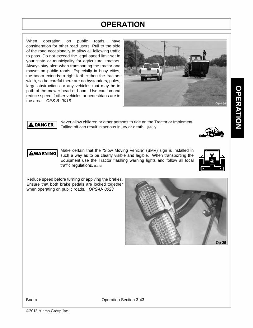
OPERATIONO
PERATIO
N
When operating on public roads, haveconsideration for other road users. Pull to the sideof the road occasionally to allow all following trafficto pass. Do not exceed the legal speed limit set inyour state or municipality for agricultural tractors.Always stay alert when transporting the tractor andmower on public roads. Especially in busy cities,the boom extends to right farther then the tractorswidth, so be careful there are no bystanders, poles,large obstructions or any vehicles that may be inpath of the mower head or boom. Use caution andreduce speed if other vehicles or pedestrians are inthe area. OPS-B- 0016
Never allow children or other persons to ride on the Tractor or Implement.Falling off can result in serious injury or death. (SG-10)
Make certain that the “Slow Moving Vehicle” (SMV) sign is installed insuch a way as to be clearly visible and legible. When transporting theEquipment use the Tractor flashing warning lights and follow all localtraffic regulations. (SG-6)
Reduce speed before turning or applying the brakes.Ensure that both brake pedals are locked togetherwhen operating on public roads. OPS-U- 0023
Boom Operation Section 3-43
©2013 Alamo Group Inc.
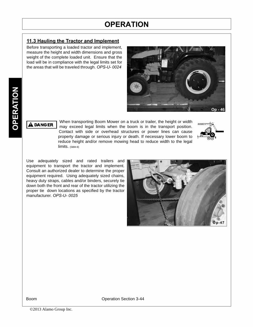
OPERATIONO
PER
ATIO
N
11.3 Hauling the Tractor and ImplementBefore transporting a loaded tractor and implement,measure the height and width dimensions and grossweight of the complete loaded unit. Ensure that theload will be in compliance with the legal limits set forthe areas that will be traveled through. OPS-U- 0024
When transporting Boom Mower on a truck or trailer, the height or widthmay exceed legal limits when the boom is in the transport position.Contact with side or overhead structures or power lines can causeproperty damage or serious injury or death. If necessary lower boom toreduce height and/or remove mowing head to reduce width to the legallimits. (SBM-8)
Use adequately sized and rated trailers andequipment to transport the tractor and implement.Consult an authorized dealer to determine the properequipment required. Using adequately sized chains,heavy duty straps, cables and/or binders, securely tiedown both the front and rear of the tractor utilizing theproper tie down locations as specified by the tractormanufacturer. OPS-U- 0025
Boom Operation Section 3-44
©2013 Alamo Group Inc.
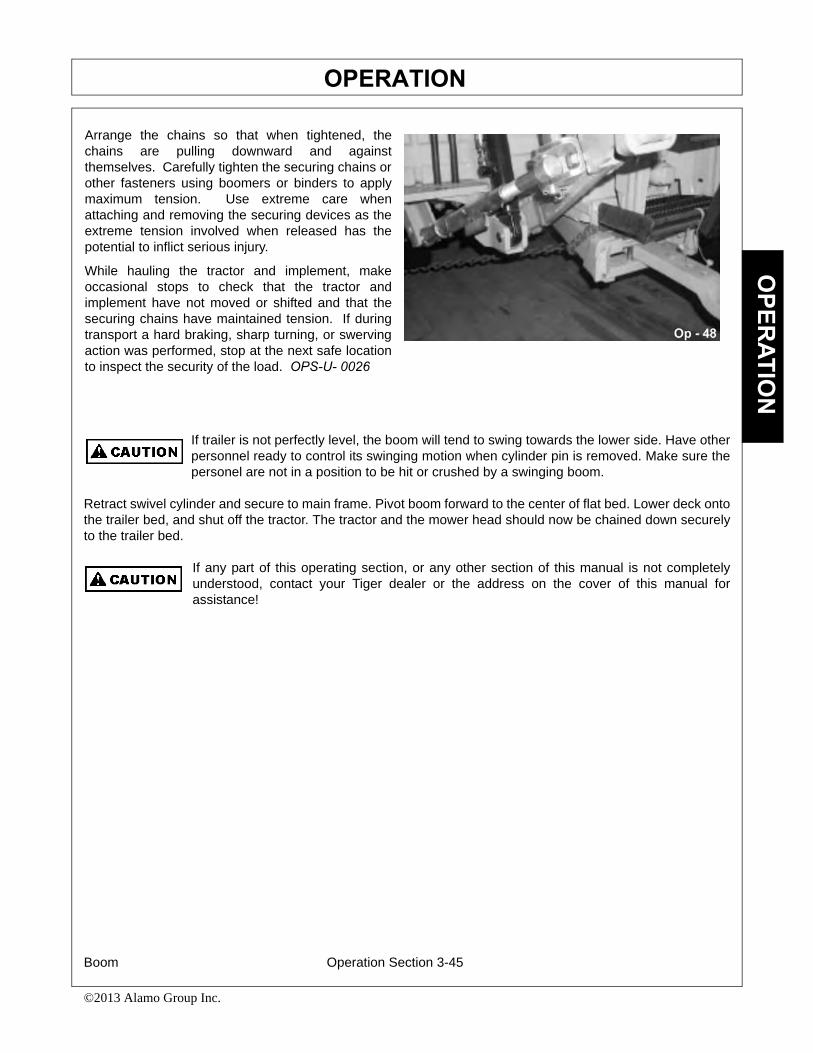
OPERATIONO
PERATIO
N
If trailer is not perfectly level, the boom will tend to swing towards the lower side. Have otherpersonnel ready to control its swinging motion when cylinder pin is removed. Make sure thepersonel are not in a position to be hit or crushed by a swinging boom.
Retract swivel cylinder and secure to main frame. Pivot boom forward to the center of flat bed. Lower deck ontothe trailer bed, and shut off the tractor. The tractor and the mower head should now be chained down securelyto the trailer bed.
If any part of this operating section, or any other section of this manual is not completelyunderstood, contact your Tiger dealer or the address on the cover of this manual forassistance!
Arrange the chains so that when tightened, thechains are pulling downward and againstthemselves. Carefully tighten the securing chains orother fasteners using boomers or binders to applymaximum tension. Use extreme care whenattaching and removing the securing devices as theextreme tension involved when released has thepotential to inflict serious injury.
While hauling the tractor and implement, makeoccasional stops to check that the tractor andimplement have not moved or shifted and that thesecuring chains have maintained tension. If duringtransport a hard braking, sharp turning, or swervingaction was performed, stop at the next safe locationto inspect the security of the load. OPS-U- 0026
Boom Operation Section 3-45
©2013 Alamo Group Inc.

OPERATIONO
PER
ATIO
N
Boom Operation Section 3-46
©2013 Alamo Group Inc.

Maintenance Section 4-1
©2015 Alamo Group Inc.
MAINTENANCE SECTION

MAINTENANCE
Boom Maintenance Section 4-2
©2015 Alamo Group Inc.
MA
INTE
NA
NC
E
General InstructionsTiger Mowers are designed for high performance and rugged durability, yet with simplified maintenance. Thepurpose of this section of the manual is to he lp the operator in the regular servicing of the mower. Regularmaintenance at the intervals mentioned will result in the maximum efficency and long life of the Tiger Mower.
When you purchase a Tiger Mower you also acquire another valuable asset, Tiger’s parts organization. Ourrapid and efficent service has guaranteed the customer satisfaction for many years. Tiger parts keep up withthe demands for efficiency, safety and endurance expected of the Tiger Mower.
Maintenance Precautions• Be sure end of grease gun and zerks are clean before using. Debris injected into bearings, etc. with grease
will cause immediate damage.
• DO NOT use a power grease gun to lubricate bearings. These require very small and exact amounts of lubrication. Refer to the detailed maintenance section for specific lubrication instructions. DO NOT over-grease bearings.
• Lexan windows should be washed with mild soap or detergent and lukewarm water, using a soft clean sponge or soft cloth. DO NOT use abrasive or alkaline cleaners or metal scrapers on lexan windows!
• Be alert to maintenance indicators such as the in-tank filter pressure gauge, hydraulic reservoir sight gauge, etc. Take the required action to correct any problems immediately.
• Release of energy from pressurized systems may cause inadvertent actuation of cylinders, or sudden release of compressed springs. Before disconnecting any hoses, relieve pressure by shutting tractor off, setting cutter on ground and actuating lift valve handles.
DO NOT use hands to check for suspected leaks in hydraulic hoses! Hydraulic fluid escapingunder pressure can have sufficient force to penetrate skin and cause serious injury. If fluid isinjected into skin, it must be surgically removed within a few hours or gangrene may result. Usea small p iece of wood or cardboard, not hands, to sear ch for pin hose leaks. Be sure allconnections are tight and hoses and lines are not damaged before applying pressure.
Break in PeriodIn addition to following the break-in instructions for your particular tractor, the in-tank hydraulic fluid filter shouldbe replaced after the fir st 50 hours of service. The reafter the filter should be replaced every 500 hours, oryearly, which ever comes first.
Re-torque wheel lugs after first five hours of operation and periodically thereafter. See torque specificationslisted in the tractor’s service manual for your particular model. Wheel lugs must always be re-torquedwhenever a wheel is removed and reinstalled.
Never work under the Implement, the fr amework, or any lif tedcomponent unless the Implement is securely supported or blocked upto prevent s udden or inadvertent falling which could cause seriousinjury or even death. (SG-14)

MAINTENANCE
Boom Maintenance Section 4-3
©2015 Alamo Group Inc.
MA
INTEN
AN
CE
Do not m odify or alter this Imple ment. Do not permit anyone to modify or alter thisImplement, any of its components or any Implement function. (SG-8)
Relieve hydraulic pressure prior to doing any maintenance or repair work on the Implement.Place the Mower Head on the ground or securely supported on blocks or stands, disengagethe PTO, and turn off the engine. Push and pull the control Levers or Joystick several timesto relieve pressure prior to starting any maintenance or repair work. (SBM-6)
Always disconnect the wire le ads from the mower pump solenoidbefore performing service on the Tractor or Mower. Use caution whenworking on the Tractor or Mower. T ractor engine must be stopped
before working on Mower or Tractor. The Mower Blades could inadvertently be turned onwithout warning and cause immediate dismemberment, injury or death. (SBM-12a)
MAINTENANCE OF CRANKSHAFT ADAPTER ASSEMBLY (RIGID ENGINE MOUNT TRACTORS ONLY) If replacement of components of the crankshaft adapter assembly is required, follow the assembly procedures shown below. Seat rubber grommet completely into counterbore, then seat steel grommet completely into rubber grommet while rubber grommet is supported.(ASM-JD-0051 CRANKSHAFT ADAPTER MAINTENANCE)

MAINTENANCE
Boom Maintenance Section 4-4
©2015 Alamo Group Inc.
MA
INTE
NA
NC
E
Regular Maintenance The intervals at which regular servicing should be done are based on hours of operation. Use the tractors hourmeter to determine when regular servicing is required.
Refer to the Det ailed Maintenance section for futher instructions on greasing. Copy and use the DailyMaintenance sheet located at the end of this section.
Daily or Every 8 HoursITEM SERVICE COMMENTS
Drive Shaft Yoke, U-Joint Grease Grease as instructed in& Stub Shaft detailed maintenance section
Pump Drive Shaft Coupler Check and Lube Insure driveshaft end play
Crankshaft Adapter Check rubber grommets Replace grommets if damaged or missing
Pivot Points Lubricate Inject grease until itappears at end
Hydraulic Fittings Check for leaks Tighten when needed. Do Not use hands to check for leaks, see maint. precautions
Knives Check Inspect for missing or damaged knives, change as needed.
Spindle mouting bolts Check Torque to 315 ft. lbs. lubricatedspindle to deck) Torque to 357 ft. lbs. dry
Knife mounting bolts Check Pre-lubricate threads with anti-seize(knife to disk or blade bar) torque to 800 ft. lbs.
Disk/Blade Bar mounting bolts Check Torque to 180 ft. lbs. lubricated(disk/blade bar to spindle) Torque to 204 ft. lbs. dry
Belts Check/Adjust Check if broken, tighten as required
Main Frame and Check Retorque bolts to torqueDeck specifications in this section
Hydraulic Fluid Level Check Add if required per fluid recommendations
Rear Flail Drive(if applicable) Lubricate Grease as instructed inBear Flange and Shaft Coupler detailed maintenance section
Cutter Shaft and Lubricate Grease as instructed in

MAINTENANCE
Boom Maintenance Section 4-5
©2015 Alamo Group Inc.
MA
INTEN
AN
CE
Ground Roller detailed maintenance section
WEEKLY OR EVERY 40 HOURSITEM SERVICE COMMENTS
Rotary Spindle Lubricate Every 40 hours or weekly
WEEKLY OR EVERY 50 HOURSITEM SERVICE COMMENTS
In Tank Hyd. Fluid Change Change after first 50 Filter hours only, then every10 micron filter) 500 hours or yearly
In-Line High Pressure Change Change after first 50Filter hours only, then every (10 micron filter) 500 hours or yearly
MONTHLY OR EVERY 150 HOURSITEM SERVICE COMMENTS
Hydraulic Fluid Level Check Add as needed
Hyd. Tank Breather Clean/Check/Replace Clean or replaceelement as required
Rear Tire Type Max P.S.I.480/80R38 2918.4-34 2618.4-38 26
YEARLY OR EVERY 500 HOURSITEM SERVICE COMMENTS
Spindle Grease ChangeHyd. Tank Fluid ChangeIn Tank Hyd. Fluid Filter Change(10 micron filter)
In-Line HP Filter Change or Change when indicated(10 micron filter) by restriction indicator.
Hyd. Tank Breather Change

MAINTENANCE
Boom Maintenance Section 4-6
©2015 Alamo Group Inc.
MA
INTE
NA
NC
E
TROUBLESHOOTINGSYMPTOMS CAUSE REMEDY
Vibration 1. Loose bolts 1. Check all bolts and tighten to recommended torque specs.
2. Cutter assembly 2a. Check for damaged blades, disc unbalanced or cuttershaft. Replace if needed.
2b. Check for wire, rope, etc. entangled in the cutter assembly
Mower will not lift 1. Hyd. Fluid Low 1. Check and refill hyd fluid
2. Leaks in line ROU 2. Tighten or replace fittings and hoses3. Faulty relief valve 3. Check pressure in line. Line
pressure in control valve should be at least 2500 P.S.I.
5. Faulty cylinder 5. Inspect, repair or replace cylinder
Mower will not start 1. Blown fuse 1. Check fuse between mower switch or run and ignition/replace
2. Ball valves closed 2. Make sure valves are open3. Low oil level 3. Check hyd. tank and fill4. Line leak 4. Check all fittings and lines,
re-tighten or replace5. Electronic 5a. Without the tractor running, turn solenoid faulty the mower switch to on. A low
audible click should be heard if the solenoid is engaging the solenoid spool. If click is not heard, leave switch in on position and with a screwdriver or other steel object, touch the small nut on the end of the solenoid. If the metallic object is not attracted to the nut, check the fuse and wiring for an open circuit. If the object is attracted but no “click” is heard, replace the solenoid.5b. Remove the four bolts holding the small block to the main block. Lift
and remove small block being careful not to damage O-rings/filter. Clean filter and re-install.5c. Remove large nut on side of large valve block. Remove spring, and use needle nose vise grip to pull spool from
block. Check block and spool for contaminants and scratches.
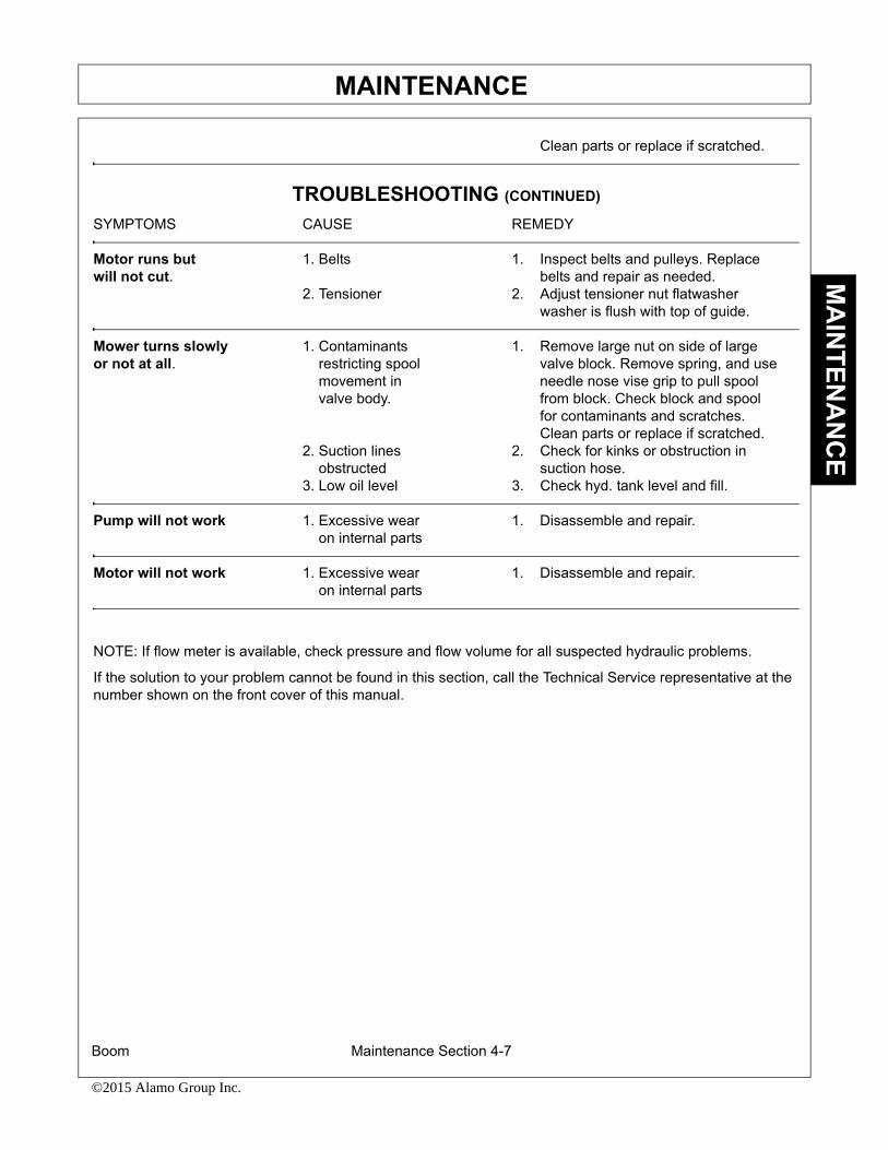
MAINTENANCE
Boom Maintenance Section 4-7
©2015 Alamo Group Inc.
MA
INTEN
AN
CE
Clean parts or replace if scratched.
TROUBLESHOOTING (CONTINUED)
SYMPTOMS CAUSE REMEDY
Motor runs but 1. Belts 1. Inspect belts and pulleys. Replacewill not cut. belts and repair as needed.
2. Tensioner 2. Adjust tensioner nut flatwasher washer is flush with top of guide.
Mower turns slowly 1. Contaminants 1. Remove large nut on side of largeor not at all. restricting spool valve block. Remove spring, and use
movement in needle nose vise grip to pull spool valve body. from block. Check block and spool
for contaminants and scratches. Clean parts or replace if scratched.
2. Suction lines 2. Check for kinks or obstruction in obstructed suction hose.3. Low oil level 3. Check hyd. tank level and fill.
Pump will not work 1. Excessive wear 1. Disassemble and repair. on internal parts
Motor will not work 1. Excessive wear 1. Disassemble and repair. on internal parts
NOTE: If flow meter is available, check pressure and flow volume for all suspected hydraulic problems.
If the solution to your problem cannot be found in this section, call the Technical Service representative at thenumber shown on the front cover of this manual.

MAINTENANCE
Boom Maintenance Section 4-8
©2015 Alamo Group Inc.
MA
INTE
NA
NC
E

MAINTENANCE
Boom Maintenance Section 4-9
©2015 Alamo Group Inc.
MA
INTEN
AN
CE
LUBRICATION RECOMMENDATIONSDescription Application General Specification Recomended
Mobil Lubricant
Tractor Hydraulics Reservoir JD-20C Mobilfluid 424MF M1135,M1141FNHM2C134D (FNH201)
Mower Hydraulics ReservoirCold Temperatures 0° F ISO 46 Anti-Wear-Low Temp Mobil DTE 15MStart-Up
Normal Temperatures JD-20C Mobilfluid 424 10° F Start-Up MF M1135,M1141
FNH M2C134D(FNH201)
Normal Temperatures ISO 46 Anti-Wear Mobil DTE 2515° F Start Up
High Operating Temp. ISO 100 Anti-Wear Mobil DTE 18MAbove 90° F
Flail Rear Gearbox Grease PAO Synthetic Extreme Mobil SHC 75W-90Pressure Gear Lube Mobil 1 Synthetic Gear
Cutter Shaft & Ground Grease Lithium-Complex Mobilgrease CM-SRoller Shaft(Flail) Gun Extreme Pressure
NLGI-ISO 320
Drive Shaft Coupler Grease Lithium-Complex Mobilgrease CM-S(Flail and Rotary) Gun Extreme Pressure
NLGI2-ISO 320
Drive Shaft Yoke, Grease Lithium-Complex Mobilgrease CM-SU-joint & Stub Shaft Gun Extreme Pressure
NLGI2-ISO 320
Boom Swivel Grease Lithium Complex Mobilgrease CM-SBoom Cylinder Pivots Gun Extreme pressure(Rotary & Flail Boom) NLGI2-ISO 320
Deck Boom Pivot & Grease Lithium Complex Mobilgrease CM-SDeck Stop Adjustment Gun Extreme PressureRotary & Flail) NLGI-ISO 320
Deck Spindle(Rotary) Grease Tiger Spindle Lubricant Mobilith SHC 220Gun part number 06540000

MAINTENANCE
Boom Maintenance Section 4-10
©2015 Alamo Group Inc.
MA
INTE
NA
NC
E
POLYCARBONATE CARE AND MAINTENANCEThe proprietry UV an d Abrasion Resistant Surface coating on SHIELDS SUPERCOATED polycarbonatesignificantly improves performance. Periodic cleaning using proper procedures and compatible cleaners arerecommended to prolong service life. Tiger Corp. polycarbonate is SUPERCOATED on both sides.
CLEANING THE SUPERCOAT HARD-COAT
1. Wash with a mild solution of soap or detergent and lukewarm water.
2. Using a soft cloth or sponge, gently wash the sheet to loosen dirt and grime and rinse well with clean water.
3. To prevent water spotting, thoroughly dry with chamois or cellulose sponge.
4. Avoid the use of abrasive cleaners, squeegees and/or other cleaning implements that may mar or gouge the coating.
CLEANING AGENTS W HICH HAVE BEEN FOUND TO BE COMPATIBLE UNDER LABORATORYCONDITIONS:
Aqueous Solutions of Soaps and Detergents
Windex(1) Top Job(2) Joy(2) Mr Clean(2)
Fantastik(3) Formula 409(4) Sumalight D12 Brucodecid
Organic Solvents
Butyl Cellosolve Kerosene Hexel, F.O. 554 Naphtha(VM&P grade)
Neleco-Placer Turco 5042
Alcohols
Methanol Isopropyl
All residual organic solvents should be removed with a secondary rinse.
GRAFFITI REMOVALButyl cellosolve (for removal of paints, marking pen inks, lipstick, etc.) The use of masking tape, adhesive tapeor lint removal tools work well for lifting off old weathered paints.
To remove labels, stickers, etc., the use of kerosene or VM&P naphtha is generally effective. When the solventwill not penetrate sticker material, apply heat (hair dryer) to soften the adhesive and promote removal.
IMPORTANT: If a material i s found to be incomp atible in a short-term test, it will usually be found to beincompatible in the field. The conv erse, however, is not always true. Favorable performance is no guaranteethat actual end-use conditions have been duplicated. Therefore, these results should be used as a guide onlyand it isrecommended that the user test the products under actual end-use conditions.

MAINTENANCE
Boom Maintenance Section 4-11
©2015 Alamo Group Inc.
MA
INTEN
AN
CE
RECOMMENDED FILLING INSTRUCTIONS FOR HYDRAULIC RESERVIORSWhen filling or checking the oil level, the unit shouldbe parked on a level surface., shut OFF, and allowsufficient time to cool to ambient temperature. Usecaution when removing the pressurized breather.Do not place face o ver opening when removingbreather.
If your reserv ior has two sight glasses: Thereservior should be filled to the top of the lowersight glass on the side of the tank. Do not overfill.The reservoir has been overfilled when oil is visiblein the upper sight glass. If tank has too much oil, theexcess may be expelled through the pressurizedbreather.
If your reservior has one sight glass/temperaturegage: The reservior should be filled to the centerof the sight glass on the side of the tank. Do notover-fill. If the t ank has too much oil, the excessmay be expelled through the pressurized breather.
DETAILED MAINTENANCEREPLACING IN-TANK HYDRAULIC FILTER:
Loosen the four bolts on the top cover of the filterhousing. Turn cover counter-clockwise until cover isfree. Remove and replace filter. Replace top coverand cover bolts in opposite order as removed.
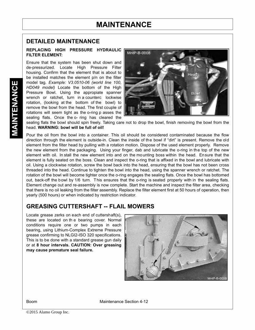
MAINTENANCE
Boom Maintenance Section 4-12
©2015 Alamo Group Inc.
MA
INTE
NA
NC
E
DETAILED MAINTENANCEREPLACING HIGH PRESSURE HYDRAULICFILTER ELEMENT:
Ensure that the system has been shut down andde-pressurized. Locate High Pressure Filterhousing. Confirm that the element that is about tobe installed matches the element p/n on the filtermodel tag. Example: V3.0510-06 (world line 100,HD049 model) Locate the bottom of the HighPressure Bowl. Using the appropiate spannerwrench or ratchet, turn in a counterc lockwiserotation, (looking at the bottom of the bowl) toremove the bowl from the head. The first couple ofrotations will seem tight as the o-ring p asses thesealing flats. Once the o- ring has cleared thesealing flats the bowl should spin freely. Taking care not to drop the bowl, finish removing the bowl from thehead. WARNING: bowl will be full of oil!
Pour the oil from the bowl into a container. This oil should be considered contaminated because the flowdirection through the element is outside-in. Clean the inside of the bowl if “dirt” is present. Remove the oldelement from the filter head by pulling with a rotation motion. Dispose of the used element properly. Removethe new element from the packaging. Using your finger, dab and lubricate the o-ring in the top of the newelement with oil. In stall the new element into and on the mounting boss within the head. Ensure that theelement is fully seated on the boss. Clean and inspect the o-ring that is affixed in the bowl and lubricate withoil. Using a clockwise rotation, screw the bowl back into the head, ensuring that the bowl has not been crossthreaded into the head. Continue to tighten the bowl into the head, using the spanner wrench or ratchet. Therotation of the bowl will become tighter once the o-ring engages the sealing flats. Once the bowl has bottomedout, back-off the bowl by 1/6 turn. This ensures that the o-ring is seated properly with in the sealing flats.Element change out and re-assembly is now complete. Start the machine and inspect the filter area, checkingthat there is no oil leaking from the filter assembly. Replace the filter element first at 50 hours of operation, thenyearly (500 hours) or when indicated by restriction indicator.
GREASING CUTTERSHAFT -- FLAIL MOWERSLocate grease zerks on each end of cuttershaft(s),these are located on th e bearing cover. Normalconditions require one or two pumps in eachbearing, using Lithium-Complex Extreme Pressuregrease confirming to NLGI2-ISO 320 specifications.This is to be done with a standard grease gun dailyor at 8 hour intervals. CAUTION: Over greasingmay cause premature seal failure.

MAINTENANCE
Boom Maintenance Section 4-13
©2015 Alamo Group Inc.
MA
INTEN
AN
CE
GREASING GROUND ROLLER SHAFT-- FLAILLocate grease zerks on eack end of roller tube atlower end of head. Normal conditions require one ortwo pumps in each bearing, using Lithium-ComplexExtreme Pressure grease conforming to NLGI2-ISO320 specifications. This is to be do ne with astandard grease gun daily or at 8 hour intervals.CAUTION: Over greasing may cause prematureseal failure.
ADJUSTING/CHECKING BELT TENSIONTo adjust belt tension or replace belts on flail cutterhead, remove four bolts that secure the belt coverand remove cover. The hex nuts shown below canbe adjusted to in crease/decrease the belt tensionas needed. (NOTE: Location of adjustment nutsmay vary on flail cutter heads.) Be sure to replacethe belt cover BEFORE operating mower!
TIGHTENING KNIFE BOLTS AND DISK BOLTS:After every 8 hours of operation or daily, the KnifeBolts and disk bolts should be tightened as follows:
Knife mounting bolts torque to 800 lubricated ft. lbs.
Disk mounting bolts (6ea.) torque to 204 dry or 180lubricated ft. lbs.

MAINTENANCE
Boom Maintenance Section 4-14
©2015 Alamo Group Inc.
MA
INTE
NA
NC
E
GREASING POINTS ON BOOM AND PIVOTLocate grease zerks on deck pivot ssembly, on thedeck end of secondary boom, at main/secondaryboom joint, and at swivel end of main boom. InjectLithium-Complex Extreme Pressure greaseconforming to NLGI2 -ISO 320 specifications untilgrease begins to protrude from ends.
DECK STOP ADJUSTMENTOn boom flail, loosen locking nut. Turn adjustmentbolt in, and run deck cylinder out to full extension.Adjust bolt out until the head just touches the boom,and tighten lock nut. NOTE: Bolt should not hitboom before cylinder reaches full travel.
GREASING SPINDLELocate grease fitting o n inside of deck hou sing.Inject Tiger Spindle Lubricant, part number06540000 into s pindle housing. Fill with lubricantuntil lubricant weeps out of to p spindle seal.Lubricate spindle weekly or every 40 hours of use.

MAINTENANCE
Boom Maintenance Section 4-15
©2015 Alamo Group Inc.
MA
INTEN
AN
CE
TIGHTENING SPINDLE BOLTSThe spindle mounting bolts should be checked andretorqued daily or every 8 hours of service. Torquethe (6) bolts shown below to 357 dry or 315 ft. lbs.lubricated.
GREASING PUMP DRIVE SHAFT COUPLERWith engine stopped, ensure driveshaft alignmentby grasping coupler and sliding back and forth.Coupler should slide freely with approximately 1/8”of end play. If coupler does not slide freely, inspectfor loose pump mount bolts, or damaged or loosecrankshaft adapter. Inject Lithium-ComplexExtreme Pressure grease conforming to NLGI2-ISO320 specifications into coupler until grease beginsto protrude from ends. Grease daily or every 8hours. Do not over grease.

MAINTENANCE
Boom Maintenance Section 4-16
©2015 Alamo Group Inc.
MA
INTE
NA
NC
E
DRIVESHAFT YOKE, U-JOINT STUB SHAFTWIth engine stopped, inject Lithium-Complexextreme pressure grease conforming to NLGI2-ISO320 specifications into universal joints and slip yokeuntil grease appears at the seal. Grease them dailyor every 8 hours.
GREASING THE BOOM SWIVELLocate the zerks on the main swivel boss (ifapplicable), main boom pivot boss (if ap plicable)and on both ends of th e boom swivel cyl inder.Inject Lithium-Complex Extreme Pressure greaseconforming to NLGI2-ISO 320 specification untilgrease begins to protrude from ends.

MAINTENANCE
Boom Maintenance Section 4-17
©2015 Alamo Group Inc.
MA
INTEN
AN
CE
GREASING BOOM CYLINDER(S) PIVOT POINTSLocate the zerk on the butt end tang of cylinder andon rod end tang. Inject Lithium-Complex ExtremePressure grease conforming to NLGI2-ISO 320specifications until grease begins to protrude fromends. This procedure is to be used on the mainboom cylinder, secondary boom cylinder, deckpivot, and swivel cylinders daily or at 8 hourintervals.
BALL VALVESThe ball valve at the hydraulic reservoir may needto be clo sed during certain maintenance or repairprocedures. THE BALL VALVES MUST BE OPEN(handle parallel with valve) WHEN TRACTOR ISRE-STARTED OR PUMP IS COUPLED TOMOTOR OR PTO! Failure to do s o will result incomponent failure!
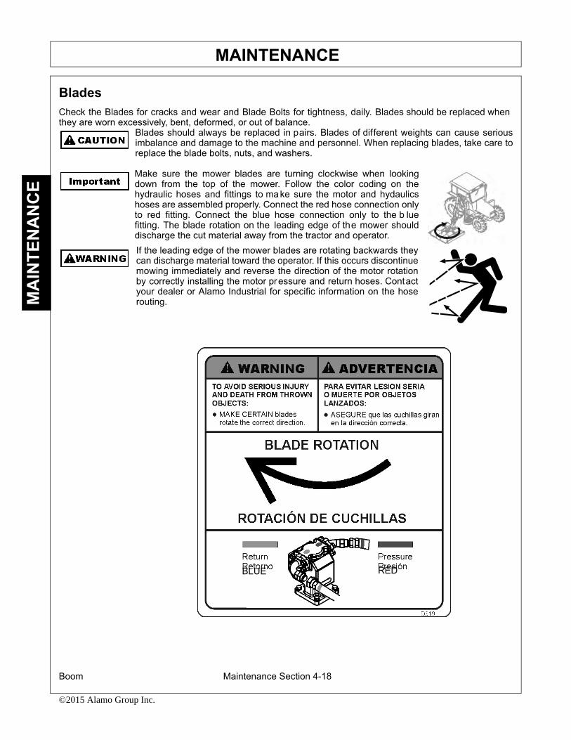
MAINTENANCE
Boom Maintenance Section 4-18
©2015 Alamo Group Inc.
MA
INTE
NA
NC
E
BladesCheck the Blades for cracks and wear and Blade Bolts for tightness, daily. Blades should be replaced whenthey are worn excessively, bent, deformed, or out of balance.
Blades should always be replaced in pairs. Blades of different weights can cause seriousimbalance and damage to the machine and personnel. When replacing blades, take care toreplace the blade bolts, nuts, and washers.
Make sure the mower blades are turning clockwise when lookingdown from the top of the mower. Follow the color coding on thehydraulic hoses and fittings to make sure the motor and hydaulicshoses are assembled properly. Connect the red hose connection onlyto red fitting. Connect the blue hose connection only to the b luefitting. The blade rotation on the leading edge of the mower shoulddischarge the cut material away from the tractor and operator. If the leading edge of the mower blades are rotating backwards theycan discharge material toward the operator. If this occurs discontinuemowing immediately and reverse the direction of the motor rotationby correctly installing the motor pressure and return hoses. Contactyour dealer or Alamo Industrial for specific information on the hoserouting.
BLUE RED

MAINTENANCE
Boom Maintenance Section 4-19
©2015 Alamo Group Inc.
MA
INTEN
AN
CE
ROTARY KNIFE REPLACEMENT1. Be sure you have a complete matching set of new knives for replacement.2. Remove knives and inspect holes for damage. Also watch for cracks in the disk (if applicable) around
the holes.3. Lube threads with anti-seize. Install bolts through knife and disk from bottom side of disk/blade bar.
Install new self-locking nuts and torque them to 800 ft. lbs.4. The knives should swing freely to absorb shocks from impact when striking objects.
WHEN CUTTING HEAVY BRUSH, KNIFE BOLTS SHOULD BE INSPECTED HOURLY ANDRETORQUED TO 800 LUBRICATED FT. LBS.
REPLACEMENT OF ROTARY DISK/BLADE BARFailure to follow the following warnings and instructions may result in serious injury ordamage to the equipment or property!
1. The bolts that attach the disk to the spindle must be grade 8. These 5/8 inch bolts are to be torqued to204 dry or 184 ft. lbs lubricated with Loctite 271.
2. A thread locking agent may be applied to threads of all mounting bolts before they are installed.3. Disks must be inspected daily for hairline cracks between spindle mounting bolts or around the
knife mounting bolts. These cracks indicate metal fatigue caused by severe abuse. If cracks arepresent the disk must be replaced.
4. Inspect the disk mounting bolts daily when checking tightness of knife mounting bolts. If a diskmounting bolt is loose, it must be removed, threads cleaned, fresh thread locking agent applied, andtightened to proper torque value.
5. If a knife mounting bolt is loose, the self locking nut must be replaced as a safety precaution. Lubricatethreads with an ti-seize. Install bolts through knife an d disk/blade bar from bottom side. Install selflocking nuts and torque them to 800 ft. lbs.

MAINTENANCE
Boom Maintenance Section 4-20
©2015 Alamo Group Inc.
MA
INTE
NA
NC
E
Flail Blades InspectionInspect the Blades daily for abnormal wear. REPLACE ALL BLADES on the carrier IMMEDIATELY if any blades have:
• Become bent or deformed from its original shape, or
• Wear inside the blade bolt hole, or
• Any cracks are visible, or
• Deep gouges in the blade’s surface are present, or
• Gouges or chipped areas in the cutting edge are larger than 1/4”(8mm), or
• The material on the leading edge has been worn away by more than 1/4”(8mm)
DO NOT straighten, sharpen, weld or hard-face blades
Failure to replace worn or damaged blades may lead to catastrophic failure of the blades and ejection of thebroken part with tremendous force which may cause serious bodily injury or death.
Always replace blades in sets
• Blades that are damaged may indicate severe service or abuse. If one blade is worn or damaged other blades on the same shaft will have been subjected to the same severe service or abuse.
• The Flail rotor turns at speeds exceeding 2000 RPM and is dynamically balanced at the factory. Differ-ences in blade weight between used blades with loss of material from gouges or wear as compared to new blades can cause severe vibration and damage to the Flail rotor. Always replace blades as complete sets.
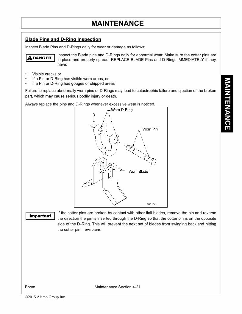
MAINTENANCE
Boom Maintenance Section 4-21
©2015 Alamo Group Inc.
MA
INTEN
AN
CE
Blade Pins and D-Ring InspectionInspect Blade Pins and D-Rings daily for wear or damage as follows:
Inspect the Blade pins and D-Rings daily for abnormal wear. Make sure the cotter pins arein place and properly spread. REPLACE BLADE Pins and D-Rings IMMEDIATELY if theyhave:
• Visible cracks or• If a Pin or D-Ring has visible worn areas, or• If a Pin or D-Ring has gouges or chipped areas
Failure to replace abnormally worn pins or D-Rings may lead to catastrophic failure and ejection of the brokenpart, which may cause serious bodily injury or death.
Always replace the pins and D-Rings whenever excessive wear is noticed.
If the cotter pins are broken by contact with other flail blades, remove the pin and reversethe direction the pin is inserted through the D-Ring so that the cotter pin is on the oppositeside of the D-Ring. This will prevent the next set of blades from swinging back and hittingthe cotter pin. OPS-U-0045

MAINTENANCE
Boom Maintenance Section 4-22
©2015 Alamo Group Inc.
MA
INTE
NA
NC
E
Flail Axe Blades InspectionInspect the Blades daily for ab normal wear. REPLACE ALL BLADES on the carrierIMMEDIATELY if any blades have:
• Become bent or deformed from its original shape, or• Oval shape wear inside the blade bolt hole, or• Any cracks are visible, or • Deep gouges in the blade’s surface are present, or• Gouges or chipped areas in the cutting edge are larger than 1/4”(8mm), or • The material on the leading edge has been worn away by more than 1/4”(8mm)
Failure to replace worn or damaged blades may lead to catastrophic failure of the blades and ejection of thebroken part with tremendous force which may cause serious bodily injury or death.
Always replace blades in sets
• Blades that are damaged may indicate severe service or abuse. If one blade is worn or damaged other blades on the same shaft will have been subjected to the same severe service or abuse.
• The Flail Axe rotor turns at speeds exceeding 2000 RPM and is dynamically balanced at the factory. Differences in blade weight between used blades with loss of material from gouges or wear, as compared to new blades, can cause severe vibration and damage to the Flail Axe rotor. Always replace blades as complete sets.
Use only genuine Alamo Industrial replacement blades, blade bolts and fasteners. Otherblades and bolts may not meet the requirements of Alamo Industrial and may fail duringoperation, resulting in the part failing and being thrown out from under the mower.
Never attempt to sharpen blades. OPS-U-0042

MAINTENANCE
Boom Maintenance Section 4-23
©2015 Alamo Group Inc.
MA
INTEN
AN
CE
Flail Axe Blade Bolt InspectionInspect Blade Bolts daily for wear or damage as follows:
Inspect the Blade Bolt da ily for abnormal wear. REPLACE ALL BL ADE BOLTS on thecarrier IMMEDIATELY if any bolts have:
• Visible cracks or• If the blade bolt is worn or any recessed area is visible on the bolt, or• If Blade Bolt has gouges or chipped areas. or• If Bushing fits loose in the Rotor Shaft.
Failure to r eplace abnormally worn bolts or bushings may lead to catastrophic failure of th e blades andejection of the broken part, which may cause serious bodily injury or death.
Always replace Blade Bolts with new bolts and new bushings whenever replacing the Blades. To tighten boltsand nuts, first apply thread lock to nut. Make sure to tighten bolts and nuts just enough to allow the blades toswing freely and not bend the cuttershaft lugs. If cuttershaft lugs are bent together because of over tighteningthe blades will not swing freely. OPS-U-0043

MAINTENANCE
Boom Maintenance Section 4-24
©2015 Alamo Group Inc.
MA
INTE
NA
NC
E
50” FLAIL KNIFE BLADE REPLACEMENT (Light Brush Grass) 1. If knives are damaged or badly worn, they will need to be replaced as a set. Replacing a single knife
can cause sever e knife can cause severe vibration and possible damage to the mower. The knifeshould not be welded on for any reason.
2. Always replace the knife bolts when replacing the knives. DO NOT REUSE THE KNIFE BOLTS ORNUTS.
3. Assemble knives, bushings, bolts and nuts as shown in Parts Section of the manual.4. Install the locking hex nut so that the flat face of the nut is towards the knife.5. Apply Loctite 271 or equivalent to threads.6. Torque nut to 50 ft. lbs. Knife must swing freely.
DO NOT re-use the locking hex nuts for mounting the knives. If hex nut becomes loose, orrequired removal for knife r eplacement or any other reason, they mu st be discarded andreplaced with new nuts.
50” FLAIL KNIFE BLADE REPLACEMENT (Medium Brush Grass) 7. If knives are damaged or badly worn, they will need to be replaced as a set. Replacing a single knife
can cause sever e knife can cause severe vibration and possible damage to the mower. The knifeshould not be welded on for any reason.
8. Always replace the knife bolts when replacing the knives. DO NOT REUSE THE KNIFE BOLTS ORNUTS.
9. Assemble knives, bushings, bolts and nuts as shown in Parts Section of the manual.10. Install the locking hex nut so that the flat face of the nut is towards the knife.11. Apply Loctite 271 or equivalent to threads.12. Torque nut to 120 ft. lbs. Knife must swing freely.
DO NOT re-use the locking hex nuts for mounting the knives. If hex nut becomes loose, orrequired removal for knife r eplacement or any other reason, they mu st be discarded andreplaced with new nuts.
50” FLAIL KNIFE BLADE REPLACEMENT (Heavy Duty Brush) 13. If knives are damaged or badly worn, they will need to be replaced as a set. Replacing a single knife
can cause sever e knife can cause severe vibration and possible damage to the mower. The knifeshould not be welded on for any reason.
14. Always replace the knife bolts when replacing the knives. DO NOT REUSE THE KNIFE BOLTS ORNUTS.
15. Assemble knives, bushings, bolts and nuts as shown in Parts Section of the manual.16. Install the locking hex nut so that the flat face of the nut is towards the knife.17. Apply Loctite 271 or equivalent to threads.18. Torque nut to 176 ft. lbs. Knife must swing freely.
DO NOT re-use the locking hex nuts for mounting the knives. If hex nut becomes loose, orrequired removal for knife r eplacement or any other reason, they mu st be discarded andreplaced with new nuts.

MAINTENANCE
Boom Maintenance Section 4-25
©2015 Alamo Group Inc.
MA
INTEN
AN
CE
63” BOOM FLAIL KNIFE REPLACEMENT1. If knives are damaged or badly worn, they will need to be replaced as a set. Replacing a single knife
can cause severe vibration and possible damage to the mower.2. Assemble knives, clevis, bolts and nuts as shown in part section of manual.3. Install locking hex nut so that the flat face of nut is towards the knife.4. Apply Loctite 271 or equivalent to threads.5. Torque nut to 35 FT. LBS. Knife must swing freely.
DO NOT re-use the locking hex nuts for mounting the knives. If hex nut become loose, orrequire removal for knife replacement or any other reason, they must be discarded andreplaced with new nuts.
Knives should not be welded on for any reason.
HEAVY DUTY SPINDLE ASSEMBLY INSTALLATION AND BEARING ADJUSTMENTWARNING! A press MUST be used to install bearing cups, bearing cones, and seals. DO NOT use a hammerto install races, bearings, or seals. The parts of assembly may be damaged.
NOTE: The grease zerk and gussets are located on the top side of the spindle housing. Be sure the spindle isassembled correctly.
Be sure to wear eye protection and other protective equipment as needed when working on spindle assembly.

MAINTENANCE
Boom Maintenance Section 4-26
©2015 Alamo Group Inc.
MA
INTE
NA
NC
E
THE SPINDLE ASSEMBLYSee the diagram below for identification of spindle parts, while servicing.
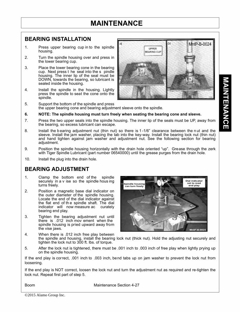
MAINTENANCE
Boom Maintenance Section 4-27
©2015 Alamo Group Inc.
MA
INTEN
AN
CE
BEARING INSTALLATION1. Press upper bearing cup in to the spindle
housing.2. Turn the spindle housing over and press in
the lower bearing cup.3. Place the lower bearing cone in the bearing
cup. Next press t he seal into the s pindlehousing. The inner lip of the seal must beDOWN, towards the bearing, so lubricant issealed inside the housing.
4. Install the spindle in the housing. Lightlypress the spindle to seat the cone onto thespindle.
5. Support the bottom of the spindle and pressthe upper bearing cone and bearing adjustment sleeve onto the spindle.
6. NOTE: The spindle housing must turn freely when seating the bearing cone and sleeve.7. Press the two upper seals into the spindle housing. The inner lip of the seals must be UP, away from
the bearing, so excess lubricant can escape.8. Install the b earing adjustment nut (thin nut) so there is 1 -1/6” clearance between the n ut and the
sleeve. Install the jam washer, placing the tab into the key-way. Install the bearing lock nut (thin nut)and hand tighten against jam washer and adjustment nut. See the following section for bearingadjustment.
9. Position the spindle housing horizontally with the drain hole oriented “up”. Grease through the zerkwith Tiger Spindle Lubricant (part number 06540000) until the grease purges from the drain hole.
10. Install the plug into the drain hole.
BEARING ADJUSTMENT1. Clamp the bottom end of the spindle
securely in a v ise so the spindle hous ingturns freely.
2. Position a magnetic base dial indicator onthe outer diameter of the spindle housing.Locate the end of the dial indicator againstthe flat end of th e spindle shaft. The dialindicator will now measure ac curatelybearing end play.
3. Tighten the bearing adjustment nut untilthere is .012 inch mov ement when thespindle housing is pried upward away fromthe vise jaws.
4. When there is .012 inch free play betweenthe spindle and housing, install the bearing lock nut (thick nut). Hold the adjusting nut securely andtighten the lock nut to 300 ft. lbs. of torque.
5. After the lock nut is tightened, there must be .001 inch to .003 inch of free play when lightly prying upon the spindle housing.
If the end play is correct, .001 inch to .003 inch, bend tabs up on jam washer to prevent the lock nut fromloosening.
If the end play is NOT correct, loosen the lock nut and turn the adjustment nut as required and re-tighten thelock nut. Repeat first part of step 5.

MAINTENANCE
Boom Maintenance Section 4-28
©2015 Alamo Group Inc.
MA
INTE
NA
NC
E
Boom Cylinder Removal and Replacement Instructions1. Clear the area of all personnel before lowering the boom mower head.2. From the tractor seat with your seat belt fastened around you, lower the boom mower head to the
ground. Extend the boom to the furthest reach and lower the mower head flat on the ground. DO NOT attempt to replace the cylinders with the boom in the raised or transport position.
3. Shut off the tractor, engage the parking brake, place the tractor transmission in the park position, and remove the key before dismounting.
4. Allow the system to cool to room temperature before removing any hydraulic components5. Wear safety glasses and impenetrable gloves when working with hydraulic hoses and fittings.6. Release all oil pressure from the hydraulic circuit by manually stroking each valve section with the trac-
tor engine off. Utilize the manual override function if the unit is equipped with an electric over hydraulic valve.
7. Utilize blocks, jack stands or a suitable over head hoist to support the weight of the boom section and remove pressure form the cylinder mounting pins.
8. Check to see that the cylinder to be replaced is not under pressure by moving the cylinder pins by hand. The pins should be loose and should slide from the pin bore easily. If the pins are tight and can-not be moved, the cylinder may be under pressure. Make sure the boom components are properly sup-ported and that the pressure is relived from the circuit.
9. Cylinder assemblies are heavy and can fall when the pins are removed. Support the hydraulic cylinder with a suitable hoist or jack.
10. Slowly loosen the hydraulic connections to the cylinder. Carefully unscrew hose fitting and allow any remaining pressure to bleed off. Use extreme care. Oil must be cool, and the technician should stand to the side to prevent exposure to any hydraulic oil. Always consult the Material Safety Data Sheet and wear any required Personal Protective Equipment. A catch pan may be required to retain any spilled oil.
11. Cap both ends of the fitting with suitably sized metal caps.12. Remove the cylinder pins starting with the ROD end cylinder pin. Make sure the cylinder is properly
supported, and remove the base end cylinder pin. The cylinder may be heavy-- use proper lifting tech-niques to lift and handle the cylinder. If needed, get assistance from another person to safely lift the cyl-inder from the machine.
13. Measure the distance between the cylinder pin holes and extend the new cylinder the correct length prior to attempting an installation.
14. Install the new cylinder in place and install both cylinder pins and retaining hardware.15. Remove the metal caps and re-install the hydraulic hoses.16. Check the hydraulic reservoir of the boom mower to ensure there is sufficient oil. Follow the manufac-
tures recommendations for proper oil type and filtering techniques and requirements to add oil to the system.
17. Clear the area of all persons prior to starting the tractor.18. Consult the Operator's Manual for instructions in regard to the proper operating procedure.19. From the tractor seat, with the seat belt fastened, operate the boom to ensure proper operation of the
boom function.20. From the tractor seat, with the seat belt fastened, operate the boom controls to fully extend and retract
the new cylinder several times to purge any trapped air from the system.21. From the tractor seat, with the seat belt fastened, look for signs of an oil leak. If an oil leak is observed,
shut the tractor down and follow the steps to remove pressure from the hydraulic circuit. Identify the source of the leak and resolve the issue.
22. Upon completion of the required repairs return to Step # 16 to recheck the cylinder for proper opera-tion.

MAINTENANCE
Boom Maintenance Section 4-29
©2015 Alamo Group Inc.
MA
INTEN
AN
CE
CUTTERSHAFT BEARING REPLACEMENT1. Remove existing cuttershaft, bearings and string guards.2. Make sure that the end knives on each end of the cuttershaft are oriented as shown.3. Apply anti-seize on cuttershaft as shown on next page.4. Install non-drive side bearing first.5. Install the top of the string guard on the non-drive side first. Use Loctite 271 or equvalent and
torque (95 ft-lb or 104ft-lb if you use an extension).6. Install the bearing and top string guard on the drive side.7. Center the cuttershaft between the string guards. Use Loctite 271 or equivalent and torque
(95ft-lb or 104ft-lb if you use an extension) the top string guard on the drive side.8. Install, use Loctite 271 or equivalent, and torque (95ft-lb or 104ft-lb if you use an extension)
the bottom string guard on both sides.9. Make sure the cuttershaft is centered. On the non-drive side, tighten one set screw in the bearing onto
the cuttershaft.10. Remove the other set screw and drill a 5/16” hole into the cuttershaft 3/16” deep through the hole in the
bearing. BE CAREFUL NOT TO DAMAGE THE THREADS IN THE BEARING HOLE.11. Replace the set screw in the bearing, use Loctite 271 or equivalent, and tighten onto the cuttershaft
through the new hole.12. Remove the other set screw and repeat the drilling procedure (Step 10). Replace the set screw as
stated in Step 11.13. Repeat steps 9 through 12 on the drive side.
14. Grease both bearings properly.
See illustration on next page

MAINTENANCE
Boom Maintenance Section 4-30
©2015 Alamo Group Inc.
MA
INTE
NA
NC
E

MAINTENANCE
Boom Maintenance Section 4-31
©2015 Alamo Group Inc.
MA
INTEN
AN
CE
DAILY MAINTENANCE SCHEDULEThe following services should be performed daily or every 8 hours of service, following the detailedmaintenance instructions in the operator’s manual.
_______ Pump driveshaft: If required with drive shaft/coupler check for end play and lubricate at zerks.
_______ Crankshaft adapter: If equipped with rubber grommets check condition, replace if missing or damaged.
_______ Pivot points: Inject grease until it appears at ends.
_______ Hydraulic fittings: Check for leaks with paper or cardboard. Tighten fittings o r replace hosesimmediately.
_______ Knives: Inspect for missing or damaged knives, change (only complete sets) as needed.
_______ Belts: Check/tighten/replace belts as needed.
_______ Mainframe/deck: Unless otherwise specified retorque bolts according to torque specifications in thissection.
_______ Hydraulic fluid level: Add, if required, per fluid recommendations.
_______ Rear flail drive, bearing flange and shaft couplers: Grease as instructed in the detailed maintenancesection.
_______ Cuttershaft and ground roller: Grease as instructed in the detailed maintenance section.
Service performed by:_______ Date:____/____/____ Hour
Meter:________
Maintenance Section
**This page may be copied and used as part of the daily maintenance routine.

MAINTENANCE
Boom Maintenance Section 4-32
©2015 Alamo Group Inc.
MA
INTE
NA
NC
E

PARTS SECTION
NH TS6.1XX T4B BENGAL 4WD

PART NAME INDEX
PARTS ORDERING GUIDE......................................................................................................................................................................... 3
TRACTOR MOUNT KIT.............................................................................................................................................................................. 4
TRACTOR MOUNT KIT - HYDRAULICS................................................................................................................................................. 6
BOOM MOUNT KIT..................................................................................................................................................................................... 8
ELECTRONIC PROPORTIONAL LIFT VALVE MOUNT...................................................................................................................... 10
JOYSTICK AND SWITCHBOX MOUNT................................................................................................................................................. 12
CABLE (MANUAL) LIFT VALVE - 5 SPOOL......................................................................................................................................... 14
5 SPOOL CABLE CONTROL MOUNT..................................................................................................................................................... 16
BATTERY RELOCATION......................................................................................................................................................................... 17
POLYCARBONATE................................................................................................................................................................................... 19
SINGLE COLUMN BOOMREST............................................................................................................................................................... 21
WHEEL WEIGHT....................................................................................................................................................................................... 23
©2016 Alamo Group Inc. Parts Section -2
NH TS6.1XX T4B BENGAL 4WD

PARTS ORDERING GUIDE
©2016 Alamo Group Inc. Parts Section -3
NH TS6.1XX T4B BENGAL 4WD
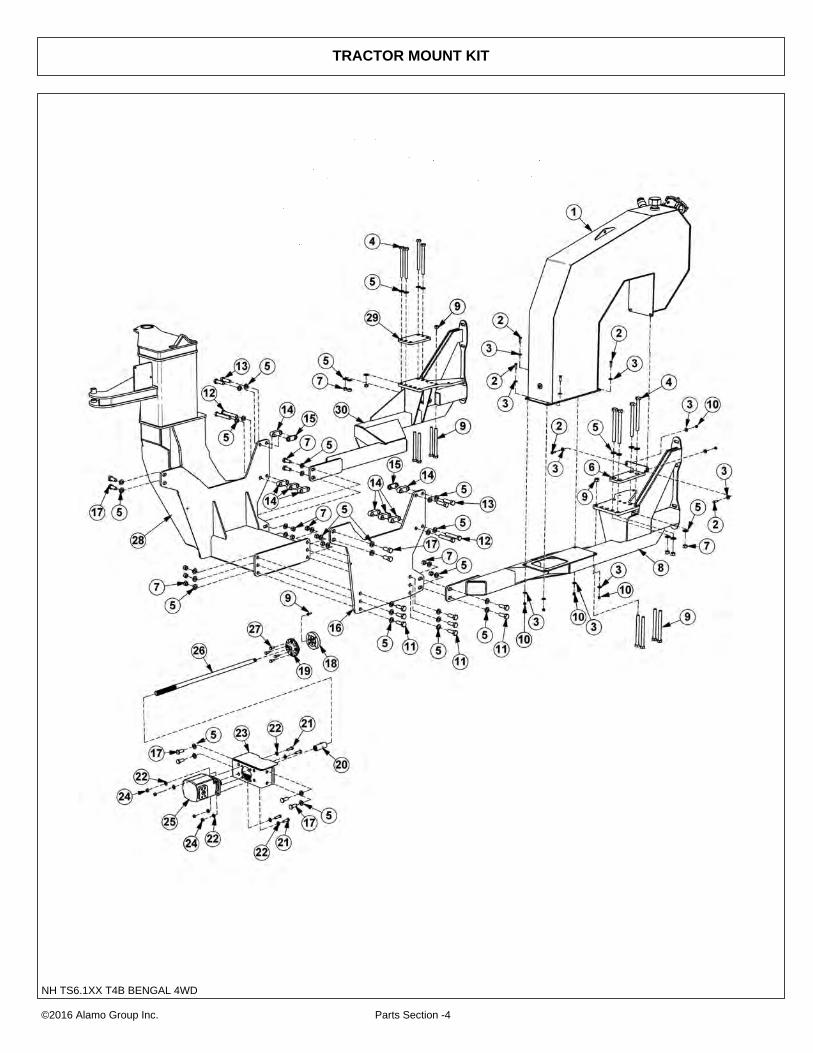
TRACTOR MOUNT KIT
©2016 Alamo Group Inc. Parts Section -4
NH TS6.1XX T4B BENGAL 4WD

TRACTOR MOUNT KIT
Continued...
ITEM PART NO. QTY. DESCRIPTION1 06700215 1 TANK,RES,ASSY
2 21631 8 CAPSCREW,3/8" X 1-1/4", NC
3 22016 16 FLATWASHER,3/8
4 21846 8 CAPSCREW,3/4` X 9", NC
5 33880 46 FLATWASHER,3/4"
6 06380082 1 TANK MNT ASSY
7 21825 18 HEX NUT,3/4", NC
8 06300280 1 AXL BRC,LH,TS6.1XX,T4B
9 _ _ _ _ _ _ - *EXISTING HARDWARE*
10 21627 8 NYLOCK NUT,3/8", NC
11 21833 10 CAPSCREW,3/4" X 2-1/4" NC
12 06530537 4 CAPSCREW,20MMX120MM2.5P,GR10.9
13 32285 4 CAPSCREW,20MMX75MM(2.5)GR10.9
14 06401630 2 SPACER,5/16"
15 06401627 8 SPACER,1"
16 06412357 1 UPRIGHT,LH,TS6.110,T4B
17 31731 8 CAPSCREW,20MMX50MM,(2.5),10.9
18 06420144 1 SPACER,CRNKSHFT,T6020
19 6T0389 1 ADPTR,DRV SHFT,NH,ASSY
20 6T0375B 1 COUPLING,14 SPLINE,W/ZERK
21 21732 4 CAPSCREW,1/2" X 1-3/4", NC
22 06533004 8 FLATWASHER,1/2"
23 06380042 1 MOUNT,PUMP
24 21725 4 HEX NUT,1/2", NC
25 23152 1 PUMP
26 06420187 1 DRIVESHAFT
27 06535000 4 CAPSCREW,7/16" X 1-1/4" CUTOFF
28 06300293 1 MAINFRAME
29 06401912 1 PLATE,CLAMP,AXLE
30 06300279 1 AXL BRC,RH,TS6.1XX,T4B
©2016 Alamo Group Inc. Parts Section -5
NH TS6.1XX T4B BENGAL 4WD
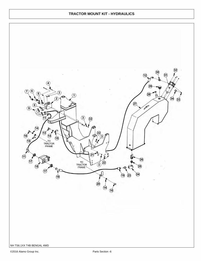
TRACTOR MOUNT KIT - HYDRAULICS
©2016 Alamo Group Inc. Parts Section -6
NH TS6.1XX T4B BENGAL 4WD

TRACTOR MOUNT KIT - HYDRAULICS
Continued...
ITEM PART NO. QTY. DESCRIPTION1 _ _ _ _ _ _ - MAINFRAME* REFER TO TRACTOR MOUNT PAGE*
2 06510083 1 VALVE,BRAKE,SOL,3000PSI
3 22016 5 FLATWASHER,3/8",GR8
4 21644 2 CAPSCREW,3/8" X 5" NC
5 33555 4 ADAPTER,1"MB X 1"MJ
6 06500754 1 HOSE, 1" X 105"
7 06500753 1 HOSE, 1" X 103"
9 06506012 2 U-TUBE, PREFORMED
10 34117 1 ELBOW,1"MB X 1"MJ,FORGED
11 06500581 1 HOSE, 1" X 97"
12 06500826 1 HOSE, 1" X 188"
13 31731 1 CAPSCREW,20MMX50MM,(2.5P),10.9
14 33880 3 FLATWASHER,3/4",GR 8
15 TB3012 2 CLAMP,CROSSOVER TUBE
16 24860 2 CAPSCREW,20MMX40MM(2.5P)10.9
17 TF4852 2 KIT,FLANGE,#20
18 23152 1 PUMP
19 06500780 1 HOSE,1-1/2" X 114"
20 06411136 1 CLAMP,HOSE,2.0
21 32382 1 BRACKET,HOSE
22 21632 1 CAPSCREW,3/8" X 1-1/2" NC
23 34710 1 ADAPTER,1-1/2"ORB X 1-1/2"MJ
24 06503084 1 ELBOW,1-1/2" FB X 1-1/2"FB
25 06503083 1 ADAPTER,1-1/2"ORB X 1-1/2"ORB
26 34309 1 BALL VALVE,1-1/2" FOR
27 _ _ _ _ _ _ - TANK ASSY*REFER TO TRACTOR MOUNT PAGE*
28 06505127 1 PLUG,SAE 3/4"
29 06505077 1 CAP,BREATHER,O-RING
30 34064 1 ADAPTER,1-1/4" MOR X 1"MJ
31 06505044 1 FLTR ASSY,IN-TANK CPLT,SAE10MP
32 21627 7 NYLOCK NUT,3/8" NC
33 6T0649 1 FILTER GAUGE
34 TF4888 1 STREET ELBOW,1/8" X 90°
©2016 Alamo Group Inc. Parts Section -7
NH TS6.1XX T4B BENGAL 4WD

BOOM MOUNT KIT
©2016 Alamo Group Inc. Parts Section -8
NH TS6.1XX T4B BENGAL 4WD

BOOM MOUNT KIT
Continued...
ITEM PART NO. QTY. DESCRIPTION1 ------ - MAINFRAME *REFER TO TRACTOR MOUNT KIT
2 21782 1 CAPSCREW,5/8" X 1-3/4",NC
3 21777 1 NYLOCK NUT,5/8",NC
4 32381 1 PIN,CAPPED
5 32322 2 BUSHING
6 06505186 1 CLAMP KIT
7 6T3211 2 GREASE ZERK,1/8"NPT
8 21677 3 NYLOCK NUT,7/16",NC
9 32380 2 PIN,1"
10 21683 2 CAPSCREW,7/16" X 2",NC
11 TB1023 2 ROLL PIN
12 06420100 1 PIN,1-1/4"
13 ------ - SPHERICAL BEARING *NOT FOR SALE
14 06700221 1 SWIVEL, T4F, BNGL, CPLT
15 06520250 1 BEARING,WASHER
16 32810 2 ADAPTER,ELBOW
17 06501029 1 CYLINDER,3" X 13.88"
18 06420022 1 PIN, 1/5" X 12"
19 21688 1 CAPSCREW, 7/16" X 3-1/4"
©2016 Alamo Group Inc. Parts Section -9
NH TS6.1XX T4B BENGAL 4WD

ELECTRONIC PROPORTIONAL LIFT VALVE MOUNT
©2016 Alamo Group Inc. Parts Section -10
NH TS6.1XX T4B BENGAL 4WD

ELECTRONIC PROPORTIONAL LIFT VALVE MOUNT
Continued...
ITEM PART NO. QTY. DESCRIPTION1 21727 4 NYLOCK NUT,1/2 NC
2 21733 4 CAPSCREW,1/2 X 2 NC
3 06340056 2 VLV MNT,LEG,TS6.1XX,T4B
4 06503167 1 ADAPTER,BANJO,3/4
5 33410 1 HOSE, 1/2" X 48"
6 06503059 1 ADAPTER,5/8MJX3/4BSPP
7 06500339 1 HOSE, 1/2" X 35"
8 21627 17 NYLOCK NUT,3/8 NC
9 22016 16 FLATWASHER,3/8,GR8
10 21632 1 CAPSCREW,3/8 X 1-1/2 NC
11 06500594 1 HOSE, 1/4" X 28"
12 06503029 1 TEE,RUN,1/2ORBX3/8MJX3/8MJ
13 24300 1 ACCUMULATOR
14 06500149 2 HOSE, 1/4" X 220"
15 21630 6 CAPSCREW,3/8 X 1 NC
16 23888 1 BRKT,ACCUMULATOR
17 06460072 1 BRKT,MNT,ACCUM,JD6R
18 06340057 1 VLV MNT,TS6.1XX,T4B
19 21631 10 CAPSCREW,3/8X1 1/4, NC,GR8
20 21579 4 CAPSCREW,5/16 X 3/4 NC
21 21987 4 LOCKWASHER,5/16
22 34622 1 PLATE,VALVE,REAR MNT
23 06502097 1 VLV,5SP,DF,PVEA,RS
24 33294 2 ELBOW,3/4MBX1/2MJ
25 33392 1 ADAPTER,5/16MBX3/8MJ
26 06500450 2 HOSE, 1/4" X 42"
27 32807 9 ADAPTER,5/8MBX3/8MJ
28 06503041 1 ADAPTER,5/8ORBX1/2FJX
29 06500687 6 HOSE, 1/4" X 268"
30 33382 1 ELBOW,1/2MBX1/2MJ
31 06510050 1 TRV LCK,METRIPACK COIL
32 33271 1 ADAPTER,1/2 MOR X 3/8 MJ
33 06500688 2 HOSE,1/4" X 288"
34 32901 2 ADAPTER,3/8 MOR X 3/8 MJ
35 3338806 1 TEE,SHUTTLE,3/8 FOR
36 06503166 1 ADAPTER,3/8MBX1/4FJX
©2016 Alamo Group Inc. Parts Section -11
NH TS6.1XX T4B BENGAL 4WD
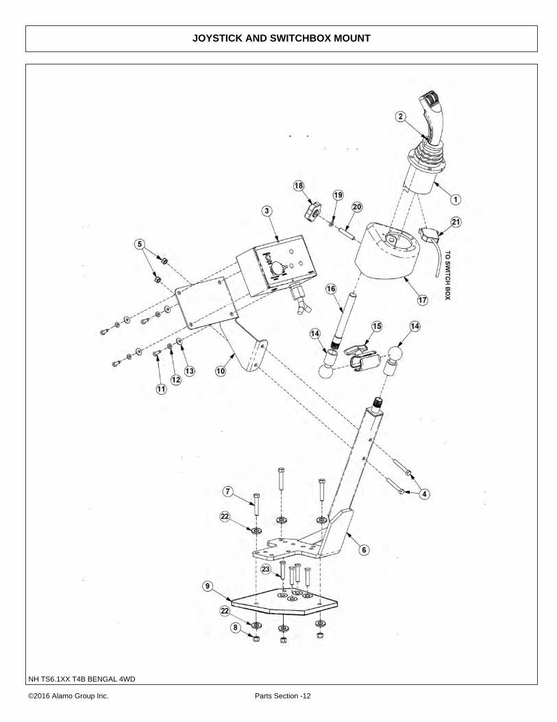
JOYSTICK AND SWITCHBOX MOUNT
©2016 Alamo Group Inc. Parts Section -12
NH TS6.1XX T4B BENGAL 4WD

JOYSTICK AND SWITCHBOX MOUNT
Continued...
ITEM PART NO. QTY. DESCRIPTION1 33691 1 JOYSTICK
2 32829 4 SCREW,MACHINE,10-32 X 3/4",FLATHD
3 06510196 1 SWITCH BOX,DF,SS,OS
4 21585 2 CAPSCREW,5/16" X 2-1/4",NC
5 21577 2 NYLOCK NUT,5/16",NC
6 06340011 1 MNT,STND,JOYSTICK
7 21631 3 CAPSCREW,3/8" X 1-1/4",NC, GR8
8 21627 3 NYLOCK NUT,3/8",NC
9 06380081 1 MNT, STND, CNTRL, TS6 1XX T4B
10 06340015 1 SWITCH BOX MNT
11 21529 4 CAPSCREW,1/4" X 3/4",NC
12 21986 4 LOCKWASHER,1/4"
13 22014 4 FLATWASHER,1/4"
14 06520041 2 MOUNT,RAM,BALL,1-1/2"
15 06520020 1 MOUNT,RAM,ARM
16 06340010 1 ROD,1/2"NPT X 7"
17 35033 1 CAN,JOYSTICK,ASSY
18 35204 1 KNOB,3/8",NC,INSERT
19 35206 1 HEX NUT,JAMB,3/8",NC
20 35205 1 SETSCREW,3/8" X 2",NC,KNURLED
21 33693 1 CBL,EXT,4FT,JOYSTICK
22 22015 6 FLATWASHER, 5/16"
23 06530108 4 CAPSCREW, 8MM X 70MM 1.25
©2016 Alamo Group Inc. Parts Section -13
NH TS6.1XX T4B BENGAL 4WD

CABLE (MANUAL) LIFT VALVE - 5 SPOOL
©2016 Alamo Group Inc. Parts Section -14
NH TS6.1XX T4B BENGAL 4WD

CABLE (MANUAL) LIFT VALVE - 5 SPOOL
Continued...
ITEM PART NO. QTY. DESCRIPTION1 21727 4 NYLOCK NUT,1/2 NC
2 21733 4 CAPSCREW,1/2 X 2 NC
3 06340056 2 VLV MNT,LEG,TS6.1XX,T4B
4 06503167 1 ADAPTER,BANJO,3/4
5 33410 1 HOSE,#8X48(8FJXX10FJX90) RETURN
6 06503059 1 ADAPTER,5/8MJX3/4BSPP
7 06500339 1 HOSE,#8X35(12FJX90X8FJX) PRESSURE
8 21627 17 NYLOCK NUT,3/8 NC
9 22016 16 FLATWASHER,3/8,GR8
10 21632 3 CAPSCREW,3/8 X 1-1/2 NC
11 06500594 1 HOSE,#4X28(4FJXX6FJX90) TRAC LOAD SENSE
12 06503029 1 TEE,RUN,1/2ORBX3/8MJX3/8MJ
13 24300 1 ACCUMULATER 1450 PSI PRECHARGE @70 F
14 06500149 2 HOSE,#4X220(6FJX90X6FJX)
15 21630 6 CAPSCREW,3/8 X 1 NC
16 23888 1 BRKT,ACCUMULATOR
17 06460072 1 BRKT,MNT,ACCUM,JD6R
18 06340057 1 VLV MNT,TS6.1XX,T4B
19 21631 10 CAPSCREW,3/8X1 1/4, NC,GR8
20 21633 2 CAPSCREW,3/8 X 1-3/4 NC GR8
21 32678 1 ADAPTER, 5/8ORB X 1/2FOR
22 34622 1 PLATE,VALVE,REAR MNT
23 06502038 1 VLV,5SP,HSC2, TRB, LS, RS
24 33293 1 ELBOW, 1/2MOR L X 1/2MJ
25 33383 1 ELBOW, 5/8MB X 1/2MJ
26 06500450 2 HOSE,#4X42(6FJXX6FJX90)
27 33271 6 ADAPTER,1/2MOR X 3/8MJ
28 21500 1 HEX NUT, 1/4 NF
29 06500687 6 HOSE,#4X268(5MJX6FJX90)
30 6T4411 1 CLEVIS, CABLE CONTROL
31 06510050 1 TRV LCK,METRIPACK COIL
33 06500688 2 HOSE,#4X288(6FJXX6FJX90)
34 32901 2 ADAPTER,3/8 MOR X 3/8 MJ
35 3338806 1 TEE,SHUTTLE,3/8 FOR
36 6503166 1 ADAPTER,3/8MBX1/4FJX
37 34296 2 RESTRICTOR .06
39 06502036 1 CHECK VALVE .06
40 6T3017 5 ROLL PIN, CABLE CONTROL
41 06505190 5 CABLE CONTROL 108"
©2016 Alamo Group Inc. Parts Section -15
NH TS6.1XX T4B BENGAL 4WD

5 SPOOL CABLE CONTROL MOUNT
ITEM PART NO. QTY. DESCRIPTION1 23865B 1 CBL CTRL MT BRKT
2 6T1251 5 CBL CTRL BOX,180 DEG
3 06510100 1 SWITCHBOX,BOOM
4 34496 1 BRKT,SWITCHBOX,UNI
5 34332 2 CAPSCREW,1/4" X 9-1/4",NC
6 21548 1 CAPSCREW,1/4" X 9",NC
7 21986 3 LOCKWASHER,1/4"
8 21525 3 HEX NUT,1/4",NC
9 06380081 1 MNT, STND, CNTRL, TS6 1XX T4B
10 22015 6 FLATWASHER, 5/16"
12 6T3951 2 SCREW,MACHINE 8/32" X 1/2",NC
13 06530108 4 CAPSCREW, 8MM X 70MM, 1.25
14 21627 3 NYLOCK NUT,3/8",NC
15 21631 3 CAPSCREW, 3/8" X 1-1/4" NC GR8
16 06505100 5 CBL,CNTRL,108
©2016 Alamo Group Inc. Parts Section -16
NH TS6.1XX T4B BENGAL 4WD

BATTERY RELOCATION
©2016 Alamo Group Inc. Parts Section -17
NH TS6.1XX T4B BENGAL 4WD

BATTERY RELOCATION
Continued...
ITEM PART NO. QTY. DESCRIPTION1 06530234 2 CAPSCREW, 1/4" X 10" NC
2 22014 2 FLATWASHER, 1/4"
3 35176 2 U-NUT, 1/4" 3/4" TO CENTER
4 06412376 1 BATTERY STRAP
5 06370267 1 RELOC, BATT, NH TS6 T4B
6 06512019 1 JUNCTION BLOCK, 3/8 STUD, RED
7 21587 1 CAPSCREW, 5/16" X 2-3/4" NC
8 22015 2 FLATWASHER, 5/16"
9 06412377 1 CLAMP, BATTERY, BTTM, TS6 T4B
10 21577 1 NYLOCK NUT, 5/16" NC
11 06510261 1 POST, BATT, POS
12 06530304 2 SCREW, MACHINE, 10-24 X 3/4"
13 24890 2 HEX NUT, 10-24, NYLOCK
©2016 Alamo Group Inc. Parts Section -18
NH TS6.1XX T4B BENGAL 4WD

POLYCARBONATE
©2016 Alamo Group Inc. Parts Section -19
NH TS6.1XX T4B BENGAL 4WD

POLYCARBONATE
Continued...
ITEM PART NO. QTY. DESCRIPTION1 31965 25 TRIMLOCK (IN FEET)
2 33477 1 ISOLATOR
3 21575 2 HEX NUT,5/16",NC
4 33478 1 ROD,THREADED,5/16" X 3"
5 32550 2 U-BOLT,ASSY
6 06490049 1 POLYCARBONATE,DOOR
7 21632 1 CAPSCREW,3/8" X 1-1/2",NC
8 22016 1 FLATWASHER,3/8"
9 21527 1 NYLOCK NUT,1/4",NC
10 22014 1 FLATWASHER,1/4"
11 06410672 1 BRACKET,BOTTOM
12 06537000 1 WASHER,NEOPRENE
13 06537001 1 WASHER,RUBBER
14 21533 1 CAPSCREW,1/4" X 1-3/4",NC
15 28583 4 CAPSCREW,8MM X 25MM,1.25P
16 06411620 1 BRACKET,TOP
17 06490050 1 POLYCARBONATE,REAR
18 22645 1 DECAL
©2016 Alamo Group Inc. Parts Section -20
NH TS6.1XX T4B BENGAL 4WD

SINGLE COLUMN BOOMREST
©2016 Alamo Group Inc. Parts Section -21
NH TS6.1XX T4B BENGAL 4WD

SINGLE COLUMN BOOMREST
Continued...
ITEM PART NO. QTY. DESCRIPTION1 ---- - MAINFRAME *REFER TO TRACTOR MOUNT KIT
2 ---- - AXLE BRACE, RH *REFER TO TRACTOR MOUNT KIT
3 06310074 1 BOOMREST, SINGLE COLUMN
4 06411166 1 SADDLE, T4, BENGAL
5 21725 4 HEX NUT, 1/2" NC
6 06533004 8 FLATWASHER, 1/2" SAE, GR8
7 21733 4 CAPSCREW, 1/2" X 2" NC
8 21825 8 HEX NUT, 3/4" NC
9 22021 16 FLATWASHER, 3/4"
10 21843 8 CAPSCREW, 3/4" X 6" NC
©2016 Alamo Group Inc. Parts Section -22
NH TS6.1XX T4B BENGAL 4WD

WHEEL WEIGHT
ITEM PART NO. QTY. DESCRIPTION1 32517 1 WHEEL WEIGHT, 1700#
2 06531000 3 HEX NUT, 7/8", NC
3 06530213 3 CAPSCREW, 7/8" X 16", NC, GR8
4 06533000 6 FLATWASHER, 7/8"
5 TB3278 3 SPACER
©2016 Alamo Group Inc. Parts Section -23
NH TS6.1XX T4B BENGAL 4WD

COMMON PARTS
BENGAL

NOTES
©2014 Alamo Group Inc. Parts Section
COMMON PARTS

PART NAME INDEX
PARTS ORDERING GUIDE......................................................................................................................................................................... 5BOOM ASSY - BENGAL 18 T4................................................................................................................................................................... 6BOOM ASSY BENGAL STANDARD 22 T4............................................................................................................................................. 8BOOM ASSY HYD BENGAL 22 T4.......................................................................................................................................................... 10BOOM ASSY BENGAL EXT 24 T4.......................................................................................................................................................... 12BOOM ASSY HYD BENGAL 24 T4.......................................................................................................................................................... 14BOOMREST - OPEN STOW...................................................................................................................................................................... 1650IN ROTARY MOWER ASSEMBLY...................................................................................................................................................... 1850IN ROTARY KNIVES AND DISH......................................................................................................................................................... 2050IN ROTARY BLADE BAR AND KNIVES............................................................................................................................................ 2160IN ROTARY MOWER ASSEMBLY...................................................................................................................................................... 2260IN ROTARY KNIVES AND DISH......................................................................................................................................................... 2460IN ROTARY BLADE BAR AND KNIVES............................................................................................................................................ 25ROTARY MOWER SPINDLE ASSEMBLY.............................................................................................................................................. 26BOOM ROTARY PIVOT ASSEMBLY...................................................................................................................................................... 2850IN FLAIL DRIVE ASSEMBLY.............................................................................................................................................................. 3050IN FLAIL MOWER ASSEMBLY........................................................................................................................................................... 3250IN FLAIL MOWER ASSY, PASS-THROUGH KNIVES...................................................................................................................... 3463IN FLAIL DRIVE ASSEMBLY.............................................................................................................................................................. 3663IN FLAIL MOWER ASSEMBLY........................................................................................................................................................... 38BOOM FLAIL PIVOT ASSEMBLY........................................................................................................................................................... 403IN X 13-7/8 IN WELDED CYLINDER BREAKDOWN......................................................................................................................... 423IN X 18IN WELDED CYLINDER BREAKDOWN................................................................................................................................. 433-1/2IN X 20IN WELDED CYLINDER BREAKDOWN.......................................................................................................................... 444IN X 20IN WELDED CYLINDER BREAKDOWN................................................................................................................................. 455IN X 20IN WELDED CYLINDER BREAKDOWN................................................................................................................................. 46NOTES......................................................................................................................................................................................................... 475 SPOOL ELECTRONIC VALVE - OPEN STOW,3PS............................................................................................................................ 485 SPOOL ELECTRONIC VALVE - SIDE STOW..................................................................................................................................... 50FRONT HYDRAULIC PUMP..................................................................................................................................................................... 5250IN AND 60IN ROTARY MOTOR BREAKDOWN............................................................................................................................... 54FLAIL MOTOR BREAKDOWN................................................................................................................................................................ 56RESERVOIR TANK FILTER ASSEMBLY............................................................................................................................................... 58PUMP AND GRILL GUARD OPTIONS.................................................................................................................................................... 59BOOM TRAVEL LOCK............................................................................................................................................................................. 60MANUAL LIFT VALVE SWITCH BOX................................................................................................................................................... 61MANUAL LIFT VALVE SCHEMATIC.................................................................................................................................................... 62ELECTRONIC LIFT VALVE SWITCH BOX........................................................................................................................................... 63ELECTRONIC LIFT VALVE SCHEMATIC............................................................................................................................................. 64SOLENOID SWITCH BOX AND WIRING............................................................................................................................................... 65
©2015 Alamo Group Inc. Parts Section 6-3
COMMON BENGAL T4

PART NAME INDEX
BRAKE VALVE ASSEMBLY.................................................................................................................................................................... 66BRAKE VALVE HYDRAULIC SCHEMATIC......................................................................................................................................... 67ELECTRICAL TROUBLESHOOTING GUIDE........................................................................................................................................ 68HYDRAULIC TROUBLESHOOTING GUIDE......................................................................................................................................... 69TROUBLESHOOTING............................................................................................................................................................................... 70TROUBLESHOOTING - CONTINUED..................................................................................................................................................... 71WHEEL WEIGHT - BENGAL 18............................................................................................................................................................... 72
©2015 Alamo Group Inc. Parts Section 6-4
COMMON BENGAL T4

PARTS ORDERING GUIDE
©2015 Alamo Group Inc. Parts Section 6-5
COMMON BENGAL T4

BOOM ASSY - BENGAL 18 T4
©2015 Alamo Group Inc. Parts Section 6-6
COMMON BENGAL T4

BOOM ASSY - BENGAL 18 T4
Continued...
ITEM PART NO. QTY. DESCRIPTION1 ---- - REAR STOW SWIVEL ASSY
2 06700167 - MAIN BOOM ASSY
--- 06310111 1 MAIN BOOM WELDMENT
3 06700168 - SECONDARY BOOM ASSY
---- 06310112 1 SECONDARY BOOM WELDMENT
4 6T3211 4 GREASE ZERK,1/8”
5 32321 2 BEARING, DX, 1-1/2" X 2"
6 06500499 2 HOSE,1/4" X 50"
7 06500500 2 HOSE,1/4" X 108"
8 06500502 2 HOSE,1/4" X 100"
9 06500713 1 HOSE,1" X 163"
10 06500714 1 HOSE,1" X 162"
11 06505116 2 CLAMP KIT
12 24724 2 SWIVEL,1MJ X 1FJX45
13 TB3010 3 BUSHING
14 TB1035 1 BUSHING,SPACER
15 35312 1 SET COLLAR
16 06510050 1 TRAVEL LOCK,METRIPACK COIL
17 31329 1 ADAPTER,1/2ORB X 1/2ORB ADJ
18 06501023 1 DECK ROLL CYLINDER,3" X 18"
19 06537021 6 ROLL PIN,5MM
20 TB1033 4 PIN,1”
21 6T3207 4 GREASE ZERK,1/4”
22 TB3033 1 CLEVIS WITH SPHERICAL BEARING
23 21677 2 NYLOCK NUT,7/16",NC
24 21688 2 CAPSCREW,7/16" X 3-1/4",NC
25 TB1025 1 PIN,1-1/2”
26 TB1036 1 PIN,1”
27 TF1143 1 PIN,LYNCH
28 06501024 1 SECONDARY CYLINDER,3-1/2" X 20"
29 06501022 1 MAIN CYLINDER,4" X 20"
30 06420100 1 PIN,1-1/4”
31 TB1023 2 ROLL PIN,7/32"
32 TB3013C 1 PIN,1-1/2"
©2015 Alamo Group Inc. Parts Section 6-7
COMMON BENGAL T4

BOOM ASSY BENGAL STANDARD 22 T4
©2015 Alamo Group Inc. Parts Section 6-8
COMMON BENGAL T4

BOOM ASSY BENGAL STANDARD 22 T4
Continued...
ITEM PART NO. QTY. DESCRIPTION1 ------ - SWIVEL ASSY *REFER TO TRACTOR MOUNT KIT
2 06700189 1 MAIN BOOM, T4
3 24517 1 SECONDARY BOOM ARM ASSY
4 32321 2 BEARING, DX, 1-1/2" X 2"
5 TB1044 2 BUSHING, 1-1/4”ID
7 06501020 1 CYLINDER, 5" X 20"
8 TB3010 3 BUSHING, 1”ID
9 TB1035 1 BUSHING,SPACER
10 6T3211 4 GREASE ZERK,1/8”
11 6T3207 3 GREASE ZERK,1/4
12 35312 1 SET COLLAR
13 06510050 1 TRAVEL LOCK,METRIPACK COIL
14 31329 1 ADAPTER,1/2ORB X 1/2ORB ADJ
15 06501022 1 CYLINDER, 4" X 20"
16 06501023 1 CYLINDER,3” X 18”
17 06537021 6 ROLL PIN,5MM
18 TB1033 1 PIN,1” X 4”
19 TB1036 1 PIN,1” X 4-11/16”
20 TF1143 1 PIN,LYNCH
21 21688 2 CAPSCREW,7/16” X 3-1/4”,NC
22 21677 2 NYLOCK NUT,7/16”,NC
23 6T3210 1 GREASE ZERK,1/8” X 90º
24 TB1025 1 PIN,1-1/2” X 12”
25 30172 1 CLEVIS,SPHERICAL
26 6T3014 2 ROLL PIN, 1/4" X 2"
27 TB1045B 2 PIN, PRIMARY CYLINDER
©2015 Alamo Group Inc. Parts Section 6-9
COMMON BENGAL T4

BOOM ASSY HYD BENGAL 22 T4
©2015 Alamo Group Inc. Parts Section 6-10
COMMON BENGAL T4

BOOM ASSY HYD BENGAL 22 T4
Continued...
ITEM PART NO. QTY. DESCRIPTION1 ------ - MAIN BOOM *REFER TO BOOM ARM ASSY
2 ------ - SECONDARY BOOM *REFER TO BOOM ARM ASSY
3 06500694 1 HOSE, 1/4" X 83"
4 --- 1 HOSE, 1/4" X 83"
5 06500695 1 HOSE, 1/4" X 138"
6 ---- 1 HOSE, 1/4" X 138"
7 06500696 1 HOSE, 1/4" X 112"
8 --- 1 HOSE, 1/4" X 112"
9 34645 1 HOSE, 1" X 182"
10 --- 1 HOSE, 1" X 182"
11 06505019 3 CLAMP KIT,3 SECTION
12 34102 2 TUBE,PRFRMD,SEC BOOM
13 2403306 2 TUBE,PRFRMD,SEC BOOM,HP
14 30111 2 CLAMP KIT,2 SECTION
©2015 Alamo Group Inc. Parts Section 6-11
COMMON BENGAL T4

BOOM ASSY BENGAL EXT 24 T4
©2015 Alamo Group Inc. Parts Section 6-12
COMMON BENGAL T4

BOOM ASSY BENGAL EXT 24 T4
Continued...
ITEM PART NO. QTY. DESCRIPTION1 ------ - SWIVEL ASSY *REFER TO TRACTOR MOUNT KIT
2 06700191 1 MAIN BOOM, EXT, T4
3 06700094 1 SECONDARY BOOM ARM ASSY, EXT, T4
4 32321 2 BEARING, DX, 1-1/2" X 2"
5 TB1044 2 BUSHING, 1-1/4”ID
7 06501020 1 CYLINDER, 5" X 20"
8 TB3010 3 BUSHING, 1”ID
9 TB1035 1 BUSHING,SPACER
10 6T3211 4 GREASE ZERK,1/8”
11 6T3207 3 GREASE ZERK,1/4
12 35312 1 SET COLLAR
13 06510050 1 TRAVEL LOCK,METRIPACK COIL
14 31329 1 ADAPTER,1/2ORB X 1/2ORB ADJ
15 06501022 1 CYLINDER, 4" X 20"
16 06501023 1 CYLINDER,3” X 18”
17 06537021 6 ROLL PIN,5MM
18 TB1033 1 PIN,1” X 4”
19 TB1036 1 PIN,1” X 4-11/16”
20 TF1143 1 PIN,LYNCH
21 21688 2 CAPSCREW,7/16” X 3-1/4”,NC
22 21677 2 NYLOCK NUT,7/16”,NC
23 6T3210 1 GREASE ZERK,1/8” X 90º
24 TB1025 1 PIN,1-1/2” X 12”
25 30172 1 CLEVIS,SPHERICAL
26 6T3014 2 ROLL PIN, 1/4" X 2"
27 TB1045B 2 PIN, PRIMARY CYLINDER
©2015 Alamo Group Inc. Parts Section 6-13
COMMON BENGAL T4

BOOM ASSY HYD BENGAL 24 T4
©2015 Alamo Group Inc. Parts Section 6-14
COMMON BENGAL T4

BOOM ASSY HYD BENGAL 24 T4
Continued...
ITEM PART NO. QTY. DESCRIPTION1 ------ - MAIN BOOM *REFER TO BOOM ARM ASSY
2 ------ - SECONDARY BOOM *REFER TO BOOM ARM ASSY
3 06500716 1 HOSE, 1/4" X 100"
4 --- 1 HOSE, 1/4" X 100 "
5 06500717 1 HOSE, 1/4" X 170"
6 ---- 1 HOSE, 1/4" X 170"
7 06500718 1 HOSE, 1/4" X 130"
8 --- 1 HOSE, 1/4" X 130"
9 06500715 1 HOSE, 1" X 198"
10 --- 1 HOSE, 1" X 198"
11 06505019 3 CLAMP KIT,3 SECTION
12 34103 2 TUBE,PRFRMD,SEC BOOM
13 30169 2 TUBE,PRFRMD,SEC BOOM,HP
14 30111 2 CLAMP KIT,2 SECTION
©2015 Alamo Group Inc. Parts Section 6-15
COMMON BENGAL T4

BOOMREST - OPEN STOW
©2015 Alamo Group Inc. Parts Section 6-16
COMMON BENGAL T4

BOOMREST - OPEN STOW
Continued...
ITEM PART NO. QTY. DESCRIPTION1 06310157 1 BOOMREST,OS
2 06410968 1 SADDLE
3 21732 4 CAPSCREW,1/2" X 1-3/4",NC
4 06533004 8 FLATWASHER,1/2",SAE
5 21725 4 HEX NUT,1/2",NC
6 21782 8 CAPSCREW,5/8" X 1-3/4",NC
7 33764 16 FLATWASHER,5/8",SAE
8 21775 8 HEX NUT,5/8",NC
9 24881 12 LOCKWASHER,20MM
10 27281 12 CAPSCREW,20MM X 60MM,2.5P
11 --- 1 AXLE BRACE,RH
12 ---- 1 AXLE BRACE,LH
©2015 Alamo Group Inc. Parts Section 6-17
COMMON BENGAL T4
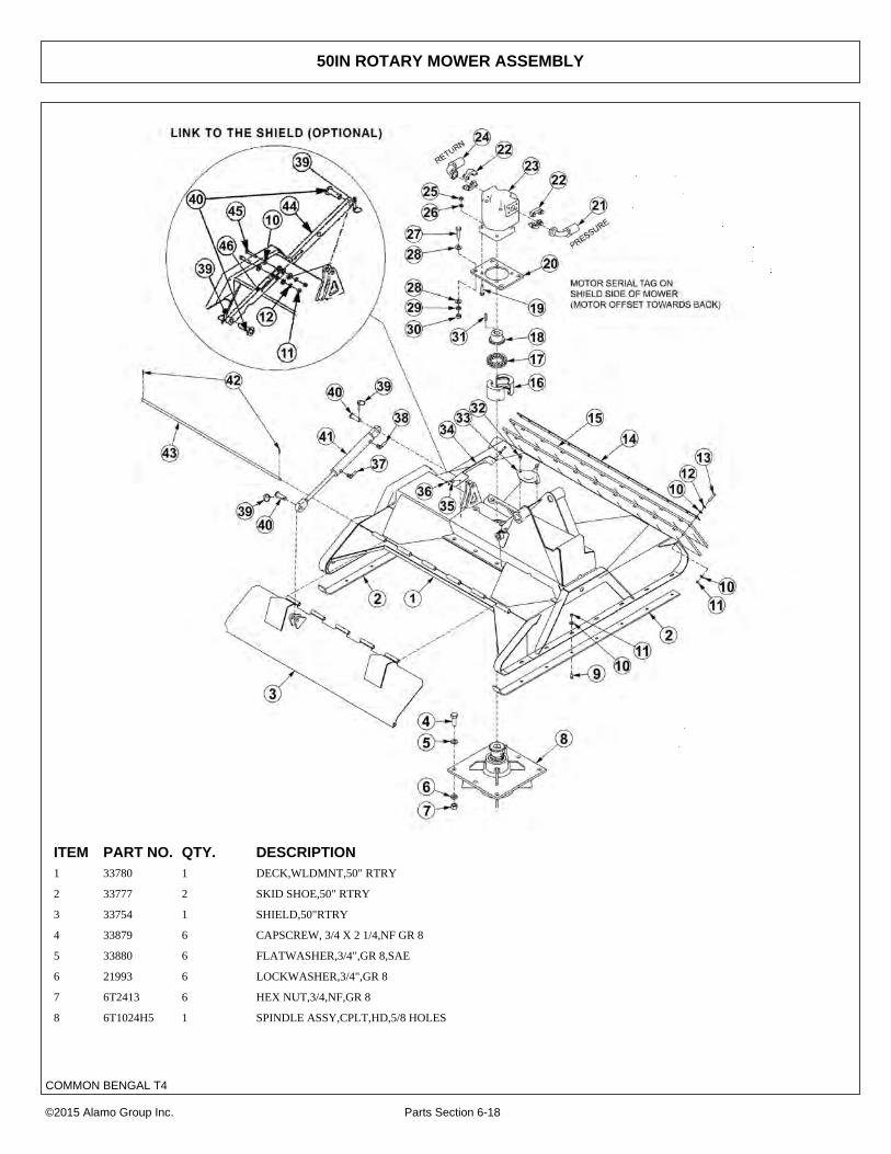
50IN ROTARY MOWER ASSEMBLY
ITEM PART NO. QTY. DESCRIPTION1 33780 1 DECK,WLDMNT,50" RTRY
2 33777 2 SKID SHOE,50" RTRY
3 33754 1 SHIELD,50"RTRY
4 33879 6 CAPSCREW, 3/4 X 2 1/4,NF GR 8
5 33880 6 FLATWASHER,3/4",GR 8,SAE
6 21993 6 LOCKWASHER,3/4",GR 8
7 6T2413 6 HEX NUT,3/4,NF,GR 8
8 6T1024H5 1 SPINDLE ASSY,CPLT,HD,5/8 HOLES
©2015 Alamo Group Inc. Parts Section 6-18
COMMON BENGAL T4

50IN ROTARY MOWER ASSEMBLY
Continued...
ITEM PART NO. QTY. DESCRIPTION9 6T2270 16 PLOW BOLT,3/8" X 1" NC
10 22016 33 FLATWASHER,3/8"
11 21625 20 HEX NUT,3/8",NC
12 21988 11 LOCKWASHER, 3/8"
13 21633 11 CAPSCREW, 3/8 X 1 3/4,NC
14 33774 1 FLAP RETAINER,50" RTRY
15 33775 2 FLAP,50" RTRY
16 6T1033 1 COUPLER COVER
17 6T1029 1 COUPLER CHAIN
18 21223 1 SPROCKET
19 21733 4 CAPSCREW, 1/2 X 2,NC
20 33776 1 MOTOR MOUNT,PLATE,50" RTRY
21 24490 1 HOSE - PRESSURE
--- 06500155 1 HOSE- PRESSURE (LRS ONLY)
22 TF4852 2 FLANGE KIT - #20
23 06504012 1 MOTOR
24 24489 1 HOSE - RETURN
--- 06500154 1 HOSE-RETURN (LRS ONLY)
25 21725 4 HEX NUT, 1/2" NC
26 06533004 4 FLATWASHER, 1/2"
27 6T2290 4 CAPSCREW,5/8X2,NF GR 8
28 33764 8 FLATWASHER,5/8",GR 8,SAE
29 21992 4 LOCKWASHER, 5/8
30 6T2408 4 HEX NUT, 5/8, NF
31 TF1124 1 SQUARE KEY
32 33881 2 CAPSCREW,FLG, 3/8 X 3/4,NC
33 33779 1 PLATE,COVER,KNF HOLE
34 06410439 1 COVER
35 22014 2 FLATWASHER,1/4
36 21530 2 CAPSCREW,1/4 X 1,NC
37 34187 1 HOSE 1/4” X 75”
38 34186 1 HOSE 1/4” X 66”
39 RD1032 2 LYNCH PIN
40 33984 2 PIN,SHIELD,50"
41 33785 1 1-1/2” X 8”, CYLINDER, WELDED
42 6T3017 2 ROLLPIN
43 33778 1 HINGE PIN,50" RTRY
44 33772 1 LINK, SHIELD 50” RTRY
45 21634 2 CAPSCREW, 3/8” X 2, NC
46 33773 1 LINK 2, SHIELD 50” RTRY
©2015 Alamo Group Inc. Parts Section 6-19
COMMON BENGAL T4

50IN ROTARY KNIVES AND DISH
ITEM PART NO. QTY. DESCRIPTION------ 06700089 - KIT,TRB50,DISK,W/BOLT KIT (INCLUDES ITEMS 1,3 & 7)
1 06770003 1 BLADE MOUNTING DISK
2 6T1023R 2 NYLOCK HEX NUT 1 1/8”
3 34878 2 SPACER
4 06538000 2 KNIFE MOUNTING BOLT
5 06521001 2 STANDARD KNIFE
6 33764 6 FLATWASHER
7 6T2259 6 CAPSCREW
------ 06770012 - BOLT KIT (INCLUDES ITEMS 6, 7 & LOCTITE)
8 06521002 2 GRASS KNIFE (OPTIONAL)
------ 6T1825 - LOCTITE - USED ON ALL DISK MOUNTING BOLTS
©2015 Alamo Group Inc. Parts Section 6-20
COMMON BENGAL T4

50IN ROTARY BLADE BAR AND KNIVES
ITEM PART NO. QTY. DESCRIPTION1 PT1018H5 1 SPINDLE,5/8HOLES,HD,WO/TABS
2 06400388 1 BAR,BLADE,TRB
3 06521001 2 KNIFE,TRB50,5/8
4 06538000 2 KNIFE MTG BOLT,5/8 SHOULDER
5 06533002 2 FLATWASHER,1 1/8,GR 8
6 6T1023R 2 KNIFE MTG NUT,1 1/8,NF,GR8
7 6T2259 6 CAPSCREW,5/8X1-3/4,NF,GR8
8 33764 6 FLATWASHER,5/8,GR 8,SAE
©2015 Alamo Group Inc. Parts Section 6-21
COMMON BENGAL T4

60IN ROTARY MOWER ASSEMBLY
ITEM PART NO. QTY. DESCRIPTION1 06320159 1 DECK,WLDMNT,60" RTRY
2 33777 2 SKID SHOE,RTRY
3 06320162 1 SHIELD,60"RTRY
4 33879 6 CAPSCREW, 3/4 X 2 1/4,NF GR 8
5 33880 6 FLATWASHER,3/4",GR 8,SAE
6 21993 6 LOCKWASHER,3/4",GR 8
7 6T2413 6 HEX NUT,3/4,NF,GR 8
8 6T1024H5 1 SPINDLE ASSY,CPLT,HD,5/8 HOLES
©2015 Alamo Group Inc. Parts Section 6-22
COMMON BENGAL T4

60IN ROTARY MOWER ASSEMBLY
Continued...
ITEM PART NO. QTY. DESCRIPTION9 6T2270 16 PLOW BOLT,3/8" X 1" NC
10 22016 33 FLATWASHER,3/8"
11 21625 20 HEX NUT,3/8",NC
12 21988 11 LOCKWASHER, 3/8"
13 21633 11 CAPSCREW, 3/8 X 1 3/4,NC
14 6T0823 1 FLAP RETAINER,60" RTRY
15 06520238 2 FLAP,60" RTRY
16 6T1033 1 COUPLER COVER
17 6T1029 1 COUPLER CHAIN
18 21223 1 SPROCKET
19 21733 4 CAPSCREW, 1/2 X 2,NC
20 33776 1 MOTOR MOUNT,PLATE,RTRY
21 24490 1 HOSE - PRESSURE
--- 06500155 1 HOSE-PRESSURE (LRS ONLY)
22 TF4852 2 FLANGE KIT - #20
23 6504011 1 MOTOR
24 24489 1 HOSE - RETURN
--- 06500154 1 HOSE-RETURN (LRS ONLY)
25 21725 4 HEX NUT, 1/2" NC
26 06533004 4 FLATWASHER, 1/2"
27 6T2290 4 CAPSCREW,5/8X2,NF GR 8
28 33764 8 FLATWASHER,5/8",GR 8,SAE
29 21992 4 LOCKWASHER, 5/8
30 6T2408 4 HEX NUT, 5/8, NF
31 TF1124 1 SQUARE KEY
32 33881 2 CAPSCREW,FLG, 3/8 X 3/4,NC
33 33779 1 PLATE,COVER,KNF HOLE
34 06410439 1 COVER
35 22014 2 FLATWASHER,1/4
36 21530 2 CAPSCREW,1/4 X 1,NC
37 34187 1 HOSE 1/4” X 75”
38 34186 1 HOSE 1/4” X 66”
39 RD1032 2 LYNCH PIN
40 33984 2 PIN,SHIELD
41 33785 1 1-1/2” X 8”, CYLINDER, WELDED
42 6T3017 2 ROLLPIN
43 06420139 1 HINGE PIN,60" RTRY
44 33772 1 LINK, SHIELD,RTRY
45 21634 2 CAPSCREW, 3/8” X 2, NC
46 33773 1 LINK 2, SHIELD,RTRY
47 06401245 2 SKID SHOE,TRB60
©2015 Alamo Group Inc. Parts Section 6-23
COMMON BENGAL T4

60IN ROTARY KNIVES AND DISH
ITEM PART NO. QTY. DESCRIPTION1 34876 1 BLADE MOUNTING DISH,60"
2 6T1023R 2 NYLOCK NUT,1-1/8",NF
3 34878 2 SPACER
4 34684 2 STANDARD GRASS KNIFE
5 34685 2 HIGH SUCTION GRASS KNIFE (OPTIONAL)
6 34497 2 KNIFE MOUNTING BOLT
7 25270 6 FLATWASHER,5/8",GR8,USS
8 6T2259 6 CAPSCREW,5/8" X 1-3/4",NF,GR8
--- 6T1825 1 LOCKTITE (USED ON ITEM 8)
---- 27167 1 BOLT KIT (ITEMS 7 & 8)
--- 33893 1 KNIFE KIT (ITEMS 2,4 & 6)
©2015 Alamo Group Inc. Parts Section 6-24
COMMON BENGAL T4

60IN ROTARY BLADE BAR AND KNIVES
ITEM PART NO. QTY. DESCRIPTION1 PT1018H5 1 SPINDLE
2 06400690 1 BAR,BLADE,RTRY60
3 6T1023R 2 KNIFE MTG NUT,1-1/8,NYLOCK,NF
4 06533002 2 FLATWASHER,1-1/8,GR8
5 06521001 2 KNIFE,TRB50,5/8
6 06538000 2 KNIFE MTG BOLT,5/8 SHOULDER
7 33764 6 FLATWASHER,5/8,GR 8,SAE
8 6T2259 6 CAPSCREW,5/8 X 1-3/4,NF,GR8
©2015 Alamo Group Inc. Parts Section 6-25
COMMON BENGAL T4

ROTARY MOWER SPINDLE ASSEMBLY
©2015 Alamo Group Inc. Parts Section 6-26
COMMON BENGAL T4

ROTARY MOWER SPINDLE ASSEMBLY
Continued...
ITEM PART NO. QTY. DESCRIPTION------ 6T1024H5 - SPINDLE ASSEMBLY COMPLETE
1 6T1031 1 SPROCKET
2 6T1016 1 BEARING LOCK NUT - THICK
3 22596 1 JAM WASHER
4 6T1015 1 BEARING ADJUSTMENT NUT - THIN
5 6T1014 1 BEARING ADJUSTMENT SLEEVE
6 6T1011 1 UPPER SEAL - SET OF 2
7 6T1012 1 BEARING CONE
8 6T1013 1 BEARING CUP
9 6T1010H 1 SPINDLE HOUSING
10 30570 1 FITTING STREET ELBOW
11 33990 1 GREASE ZERK
12 6T1013H 1 BEARING CUP
13 6T1012H 1 BEARING CONE
14 6T1011H 1 LOWER SEAL
15 6T1019 1 SPINDLE KEY
16 PT1018H5 1 SPINDLE
17 06503064 1 O-RING PLUG, 1/8”
------ 31771 - SPINDLE REBUILD KIT (INCLUDES ITEMS 2 - 8 AND 12 - 15)
©2015 Alamo Group Inc. Parts Section 6-27
COMMON BENGAL T4

BOOM ROTARY PIVOT ASSEMBLY
©2015 Alamo Group Inc. Parts Section 6-28
COMMON BENGAL T4

BOOM ROTARY PIVOT ASSEMBLY
Continued...
ITEM PART NO. QTY. DESCRIPTION1 TB1032 1 ROTARY PIVOT ASSY
2 TB1028 1 PIVOT ARM ASSY
3 TB1033 1 PIN,CLEVIS
4 06537021 2 ROLL PIN
5 TF3097 1 PIN
6 TB1030 1 PIN
7 33985 1 PIN
8 33986 1 PIN
9 21688 1 CAPSCREW,7/16 X 3-1/4,NC
10 21677 1 NYLOCK NUT,7/16 NC
11 21635 3 CAPSCREW,3/8 X 2-1/4
12 6T3207 3 GREASE ZERK
13 21627 3 NYLOCK NUT,3/8,NC
14 TB3010 3 BUSHING
15 ------ - SECONDARY BOOM *REFER TO BOOM ARM ASSY
16 ------ - CYLINDER *REFER TO BOOM ARM ASSY
17 ------ - ROTARY MOWER HEAD *REFER TO ROTARY DECK
©2015 Alamo Group Inc. Parts Section 6-29
COMMON BENGAL T4

50IN FLAIL DRIVE ASSEMBLY
©2015 Alamo Group Inc. Parts Section 6-30
COMMON BENGAL T4

50IN FLAIL DRIVE ASSEMBLY
Continued...
ITEM PART NO. QTY. DESCRIPTION1 06504132 1 MOTOR (M350-1 3/4" GEAR)
2 TF3006 1 BELT GUARD
3 TF3043 2 SHEAVE
4 TF3013 1 BUSHING
5 TF3011 1 BUSHING
6 TF3034 1 IDLER PULLEY
7 TF3205 1 IDLER ARM
8 TF3206 2 IDLER PULLEY SPACER
9 TF3605 1 IDLER ARM PIN WITH ZERK
10 6T3004 1 R - CLIP
11 PT3611A 1 CLEVIS
12 32481 1 THREADED ROD
13 TF3620 1 COMPRESSION SPRING
14 21789 1 CAPSCREW 5/8” X 3 1/2”
15 21992 1 LOCKWASHER 5/8”
16 21775 1 HEX NUT 5/8”
17 21732 5 CAPSCREW 1/2” X 1 3/4”
18 21990 4 LOCKWASHER 1/2”
19 21725 4 HEX NUT 1/2”
20 6T2418 1 LOCK NUT 1/2”
21 21630 4 CAPSCREW 3/8” X 1”
22 21988 4 LOCKWASHER 3/8”
23 22016 4 FLATWASHER 3/8”
24 21584 6 CAPSCREW 5/16” X 2”
25 21987 6 LOCKWASHER 5/16”
26 27938 1 FLATWASHER 1/2”
27 21700 2 HEX NUT 1/2” NF
28 TF3021 2 BELT
29 TF1125 1 SQUARE KEY
30 TF1025 1 SQUARE KEY MOTOR
31 TF4852 2 FLANGE KIT
32 34227 1 PREFORMED TUBE
33 31218 1 HOSE - RETURN
34 34331 1 HOSE - PRESSURE
35 24724 2 SWIVEL FITTING
36 ------ - CUTTER HEAD *REFER TO CUTTER HEAD ASSY
©2015 Alamo Group Inc. Parts Section 6-31
COMMON BENGAL T4
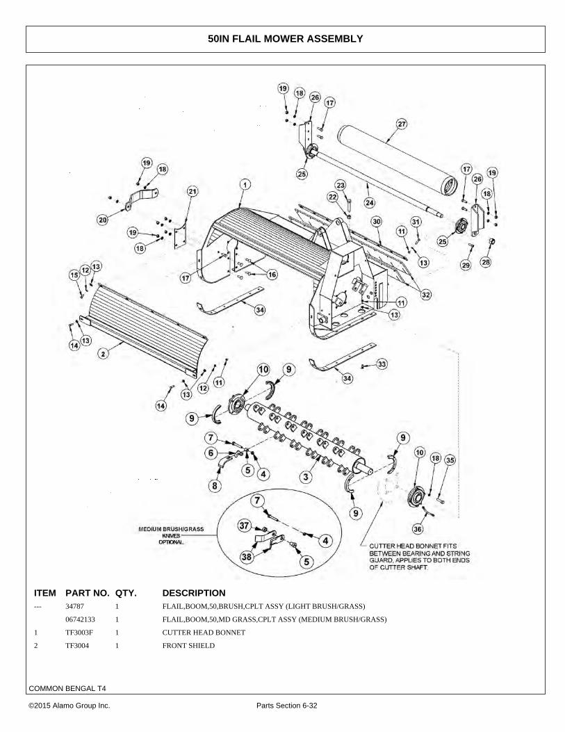
50IN FLAIL MOWER ASSEMBLY
ITEM PART NO. QTY. DESCRIPTION--- 34787 1 FLAIL,BOOM,50,BRUSH,CPLT ASSY (LIGHT BRUSH/GRASS)
06742133 1 FLAIL,BOOM,50,MD GRASS,CPLT ASSY (MEDIUM BRUSH/GRASS)
1 TF3003F 1 CUTTER HEAD BONNET
2 TF3004 1 FRONT SHIELD
©2015 Alamo Group Inc. Parts Section 6-32
COMMON BENGAL T4

50IN FLAIL MOWER ASSEMBLY
Continued...
ITEM PART NO. QTY. DESCRIPTION3 34783 1 TBF50 (LIGHT BRUSH/GRASS KNIFE ASSY)
---- 06700115 1 TBF50 (MEDIUM BRUSH/GRASS KNIFE ASSY)
4 6T2419 24 HEX NUT,9/16”,NC,STOVER
5 06420182 24 BUSHING
6 34782 24 CLEVIS (LIGHT BRUSH/GRASS KNIVES)
7 34786 24 CAPSCREW,9/16” X 3-1/2”,NC
8 34780 24 KNIFE (LIGHT BRUSH/GRASS CUTTING)
9 31204 2 STRING GUARD SET (2 PIECES PER SET)
10 TF1018 2 FLANGE BEARING,2-3/16”
11 21625 23 HEX NUT,3/8”,NC
12 21988 7 LOCKWASHER,3/8”
13 22016 30 FLATWASHER,3/8”
14 21631 2 CAPSCREW,3/8” X 1-1/4”,NC
15 21630 5 CAPSCREW,3/8” X 1”,NC
16 6T7031D 4 PLOW BOLT,1/2” X 1-1/2”,NC
17 21731 6 CAPSCREW,1/2” X 1-1/2”,NC
18 21990 18 LOCKWASHER,1/2”
19 21725 10 HEX NUT,1/2”,NC
20 TF1040 1 CUTTER SHAFT GUARD
21 TF3007A 1 COVER PLATE
22 21825 1 HEX NUT,5/8”,NC
23 21838 1 CAPSCREW,3/4” X 3-1/2”,NC
24 TF3406 1 GROUND ROLLER TIE ROD
25 TF1022 2 FLANGE BEARING,1-3/8”
26 TF3407 2 GROUND ROLLER ADJUSTMENT BRACKET
27 TF3405 1 GROUND ROLLER
28 6T1023R 2 NYLOCK NUT,1-1/8”,NF
29 6T2330 8 CAPSCREW,7/16” X 1-1/2”,SOCKET HEAD
30 TB1008 1 FLAP RETAINING BAR
31 21633 9 CAPSCREW,3/8” X 1-3/4”,NC
32 TB1006A 2 DEFLECTOR FLAP
33 6T2270 12 PLOWBOLT,3/8” X 1”,NC
34 TF3001 2 SKID SHOE
35 06530218 8 CAPSCREW,1/2” X 1-3/4”,NC
36 TF1032 1 FLANGE BEARING GREASE HOSE
37 06420183 24 SPACER (MEDIUM BRUSHGRASS KNIVES)
38 06521007 48 KNIFE (MEDIUM BRUSH/GRASS CUTTING)
©2015 Alamo Group Inc. Parts Section 6-33
COMMON BENGAL T4

50IN FLAIL MOWER ASSY, PASS-THROUGH KNIVES
©2015 Alamo Group Inc. Parts Section 6-34
COMMON BENGAL T4

50IN FLAIL MOWER ASSY, PASS-THROUGH KNIVES
Continued...
ITEM PART NO. QTY. DESCRIPTION--- 34172 1 FLAIL,BOOM,50,CPLT ASSY
1 TF3003F 1 CUTTER HEAD BONNET
2 TF3004 1 FRONT SHIELD
3 33717 1 TBF50,CUTTERSHAFT,PASS THRU KNIVES
4 TF3405 1 GROUND ROLLER
5 TF3406 1 GROUND ROLLER TIE ROD
6 TB1006A 2 DEFLECTOR FLAP
7 TB1008 1 FLAP RETAINING BAR
8 TF3001 2 SKID SHOE
9 TF3407 2 GROUND ROLLER ADJUSTMENT BRACKET
10 TF1022 2 FLANGE BEARING,1-3/8”
11 TF1018 2 FLANGE BEARING,2-3/16”
12 TF3007A 1 COVER PLATE
13 TF1040 1 CUTTER SHAFT GUARD
14 33858 24 SPACER,COLLAR
15 33857 24 SHOULDER,BUSHING
16 46399.01 24 KNIFE,FLAIL,FORGED
17 33854 24 CAPSCREW,5/8" X 4-1/2",NC
18 32674 24 HEX NUT,5/8",NC
19 21838 1 CAPSCREW,3/4” X 3-1/2”,NC
20 21825 1 HEX NUT,5/8”,NC
21 21732 8 CAPSCREW,1/2" X 1-3/4",NC
22 21731 6 CAPSCREW,1/2" X 1-1/2",NC
23 21990 18 LOCKWASHER,1/2”
24 21725 10 HEX NUT,1/2”,NC
25 6T2270 12 PLOWBOLT,3/8” X 1”,NC
26 21631 2 CAPSCREW,3/8” X 1-1/4”,NC
27 21630 5 CAPSCREW,3/8” X 1”,NC
28 21988 7 LOCKWASHER,3/8”
29 21625 23 HEX NUT,3/8”,NC
30 22016 30 FLATWASHER,3/8”
31 21633 9 CAPSCREW,3/8” X 1-3/4”,NC
32 6T7031D 4 PLOW BOLT,1/2” X 1-1/2”,NC
33 6T2330 8 CAPSCREW,7/16” X 1-1/2”,NC,SCKT HD
34 6T1023R 2 NYLOCK NUT,1-1/8”,NF
35 TF1032 1 FLANGE BEARING GREASE HOSE
36 31204 2 STRING GUARD SET (2 PIECES PER SET)
©2015 Alamo Group Inc. Parts Section 6-35
COMMON BENGAL T4

63IN FLAIL DRIVE ASSEMBLY
©2015 Alamo Group Inc. Parts Section 6-36
COMMON BENGAL T4

63IN FLAIL DRIVE ASSEMBLY
Continued...
ITEM PART NO. QTY. DESCRIPTION1 06504132 1 MOTOR (M350-1 3/4 GEAR)
2 32569 1 BELT GUARD
3 TF3044 1 UPPER SHEAVE
4 TF3040 1 LOWER SHEAVE
5 TF3013 1 BUSHING
6 28723 1 BUSHING
7 28679B 1 MOTOR CHANNEL
8 PT3611A 1 CLEVIS
9 40496 1 THREADED ROD
10 28702 2 BELT
11 TF3620A 1 TENSIONER SPRING
12 28572 1 SQUARE KEY
13 26142A 1 SQUARE KEY
14 TF4852 2 FLANGE KIT
15 30308 1 HOSE,1 X 69 - PRESSURE
16 30309 1 HOSE,1 X 78 - RETURN
17 24724 2 SWIVEL FITTING
18 TF1033 1 GREASE ZERK
19 27580 2 BUSHING
20 28682 1 MOTOR CHANNEL WASHER
21 21732 5 CAPSCREW 1/2” X 1 3/4”
22 21990 4 LOCKWASHER 1/2”
23 21725 4 HEX NUT 1/2”
24 6T2418 1 STOVER NUT 1/2”
25 21630 3 CAPSCREW 3/8” X 1”
26 22016 2 FLATWASHER 3/8”
27 21988 3 LOCKWASHER 3/8”
28 21584 6 CAPSCREW 5/16” X 2”
29 21987 6 LOCKWASHER 5/16”
30 27938 1 FLATWASHER 1/2”
31 21700 2 HEX NUT 1/2” NF
32 ------ - CUTTER HEAD *REFER TO MOWER ASSY
©2015 Alamo Group Inc. Parts Section 6-37
COMMON BENGAL T4

63IN FLAIL MOWER ASSEMBLY
©2015 Alamo Group Inc. Parts Section 6-38
COMMON BENGAL T4

63IN FLAIL MOWER ASSEMBLY
Continued...
ITEM PART NO. QTY. DESCRIPTION------ 06200271 - FLAIL,BOOM,63,GRASS,CPLT ASSY
1 28659H 1 CUTTER HEAD BONNET
2 28743 - CUTTER SHAFT / KNIFE ASSY STANDARD GRASS
------ 28642C 1 CUTTER SHAFT,63,STD
3 34011 36 FLAIL KNIFE MOUNTING BOLT
4 TF1020 36 FLAIL KNIFE MOUNTING CLEVIS
5 33713 72 FLAIL KNIFE - STANDARD
6 21677 36 NYLOCK NUT
7 28086A 2 SKID SHOE
8 27975A 1 CUTTER SHAFT GUARD
9 21725 14 HEX NUT 1/2”
10 21990 14 LOCKWASHER 1/2”
11 21731 6 CAPSCREW 1/2” X 1 1/2”
12 28650A 1 GROUND ROLLER
13 33863 2 STRING GUARD,STD
14 06533006 8 FLATWASHER,1/2",SAE,L9
15 28700 1 FLAP RETAINING BAR
16 21633 11 CAPSCREW 3/8” X 1 3/4”
17 21988 28 LOCKWASHER 3/8”
18 28701 2 DEFLECTOR FLAP
19 21625 28 HEX NUT 3/8”
20 TF1045B 2 GROUND ROLLER STUB SHAFT
21 6T2330 8 CAPSCREW 7/16” X 1 1/2” SOCKET HEAD
22 28735 2 ADJUSTABLE ROLLER BRACKET
23 06520028 2 BEARING,FLANGE,1-3/8,GRNDRLLR
24 06520029 2 O-RING
25 06520027 2 CAP,BEARING,GROUNDROLLER
26 06530001 12 CAPSCREW,SKT HD,8-32 X 1/2,SS
27 6T2331 8 CAPSCREW 7/16” X 1” SOCKET HEAD
28 6T2270 10 PLOW BOLT 3/8” X 1 1/4”
29 06530217 8 CAPSCREW 1/2” X 2”,L9
30 28683 2 FLANGE BEARING
31 TF1032 1 FLANGE BEARING GREASE HOSE
32 6T2615 7 FENDER WASHER 3/8”
33 6T2283 7 CARRIAGE BOLT 3/8” X 1”
34 28665A 1 BAFFLE (INSIDE UPPER REAR OF CUTTER HEAD)
©2015 Alamo Group Inc. Parts Section 6-39
COMMON BENGAL T4

BOOM FLAIL PIVOT ASSEMBLY
©2015 Alamo Group Inc. Parts Section 6-40
COMMON BENGAL T4

BOOM FLAIL PIVOT ASSEMBLY
Continued...
ITEM PART NO. QTY. DESCRIPTION1 TF3015 1 FLAIL PIVOT ASSY
2 TB1028 1 PIVOT ARM ASSY
3 TB1033 1 PIN CLEVIS
4 06537021 2 ROLL PIN
5 TF3097 1 PIN
6 TF3090 1 PIN
7 TB1024 1 PIN
8 TB1027 1 PIN
9 21688 1 CAPSCREW 7/16” X 3 1/4”
10 21677 1 NYLOCK NUT 7/16”
11 21635 3 CAPSCREW 3/8” X 2 1/4”
12 21627 4 NYLOCK NUT 3/8”
13 TB3010 3 BUSHING
14 6T3207 3 GREASE ZERK
15 ------ - SECONDARY BOOM *REFER TO BOOM ARM ASSY
16 ------ - CYLINDER - REFER TO BOOM ARM ASSY
17 ------ - FLAIL MOWER HEAD *REFER TO FLAIL ASSY
18 31723 1 CLAMP KIT,TBF50 (USED ON 50” FLAIL)
19 TB3031 2 DOUBLE HOSE CLAMP (USED ON THE 63” FLAIL)
20 21638 1 CAPSCREW 3/8” X 3”
21 35312 2 SPLIT COLLAR
©2015 Alamo Group Inc. Parts Section 6-41
COMMON BENGAL T4
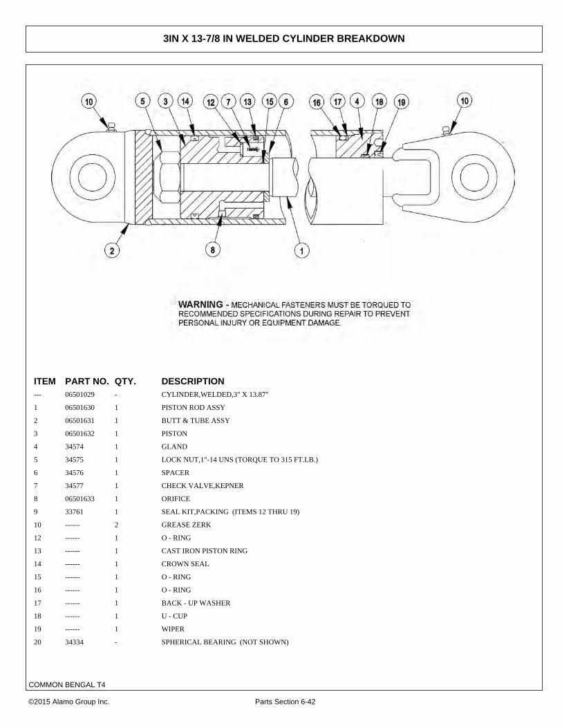
3IN X 13-7/8 IN WELDED CYLINDER BREAKDOWN
ITEM PART NO. QTY. DESCRIPTION--- 06501029 - CYLINDER,WELDED,3" X 13.87"
1 06501630 1 PISTON ROD ASSY
2 06501631 1 BUTT & TUBE ASSY
3 06501632 1 PISTON
4 34574 1 GLAND
5 34575 1 LOCK NUT,1"-14 UNS (TORQUE TO 315 FT.LB.)
6 34576 1 SPACER
7 34577 1 CHECK VALVE,KEPNER
8 06501633 1 ORIFICE
9 33761 1 SEAL KIT,PACKING (ITEMS 12 THRU 19)
10 ------ 2 GREASE ZERK
12 ------ 1 O - RING
13 ------ 1 CAST IRON PISTON RING
14 ------ 1 CROWN SEAL
15 ------ 1 O - RING
16 ------ 1 O - RING
17 ------ 1 BACK - UP WASHER
18 ------ 1 U - CUP
19 ------ 1 WIPER
20 34334 - SPHERICAL BEARING (NOT SHOWN)
©2015 Alamo Group Inc. Parts Section 6-42
COMMON BENGAL T4

3IN X 18IN WELDED CYLINDER BREAKDOWN
ITEM PART NO. QTY. DESCRIPTION------ 06501023 - HYDRAULIC CYLINDER COMPLETE
1 06501561 1 ROD
2 06501562 1 TUBE WELDMENT
3 06501552 1 PISTON
4 06501563 1 CYLINDER HEAD
5 06501554 1 CLEVIS
------ 06501564 - SEAL REPAIR KIT (ITEMS 6 THROUGH 12)
©2015 Alamo Group Inc. Parts Section 6-43
COMMON BENGAL T4

3-1/2IN X 20IN WELDED CYLINDER BREAKDOWN
ITEM PART NO. QTY. DESCRIPTION------ 06501024 - HYDRAULIC CYLINDER COMPLETE
1 06501565 1 ROD
2 06501566 1 TUBE WELDMENT
3 06501567 1 PISTON
4 06501568 1 CYLINDER HEAD
5 TB3033 - CLEVIS
------ 06501569 - SEAL REPAIR KIT (ITEMS 6 THROUGH 12)
©2015 Alamo Group Inc. Parts Section 6-44
COMMON BENGAL T4

4IN X 20IN WELDED CYLINDER BREAKDOWN
ITEM PART NO. QTY. DESCRIPTION------ 06501022 - HYDRAULIC CYLINDER COMPLETE
1 06501556 1 ROD
2 06501557 1 TUBE WELDMENT
3 06501558 1 PISTON
4 06501559 1 CYLINDER HEAD
5 6T0172 1 CLEVIS
5A 30172 - CLEVIS (FOR EXTENDED BOOM)
------ 06501560 - SEAL REPAIR KIT (ITEMS 6 THROUGH 12)
©2015 Alamo Group Inc. Parts Section 6-45
COMMON BENGAL T4

5IN X 20IN WELDED CYLINDER BREAKDOWN
ITEM PART NO. QTY. DESCRIPTION------ 06501020 - HYDRAULIC CYLINDER COMPLETE
1 06501544 1 ROD
2 06501545 1 TUBE WELDMENT
3 06501546 1 PISTON
4 06501547 1 CYLINDER HEAD
5 06501548 1 CLEVIS
------ 06501549 - SEAL REPAIR KIT (ITEMS 6 THROUGH 12)
©2015 Alamo Group Inc. Parts Section 6-46
COMMON BENGAL T4

NOTES
©2015 Alamo Group Inc. Parts Section 6-47
COMMON BENGAL T4

5 SPOOL ELECTRONIC VALVE - OPEN STOW,3PS
ITEM PART NO. QTY. DESCRIPTION------ 06502097 - VLV,5SP,32PVG,OPEN STOW, 3OS
1 06502074 1 END PLATE
1S 06505013 1 END PLATE SEAL KIT
2 ------ 5 BONNET
2S 06505042 1 BONNET SEAL KIT
2A 42197 1 MAIN BOOM BONNET
2B 42197 1 SECONDARY BOOM BONNET
2C 42197 1 DECK ROLL BONNET
2D 42197 1 BOOM SWIVEL BONNET
2E 42197 1 DECK SHIELD BONNET
©2015 Alamo Group Inc. Parts Section 6-48
COMMON BENGAL T4

5 SPOOL ELECTRONIC VALVE - OPEN STOW,3PS
Continued...
ITEM PART NO. QTY. DESCRIPTION3 34308 1 INLET SECTION
3S 06505013 1 INLET SECTION SEAL KIT
4 ------ 5 ELECTRONIC ACCUATOR
4A 06502101 1 MAIN BOOM ELECTRONIC ACCUATOR
4B 06502101 1 SECONDARY BOOM ELECTRONIC ACCUATOR
4C 06502100 1 DECK ROLL ELECTRONIC ACCUATOR
4D 06502101 1 BOOM SWIVEL ELECTRONIC ACCUATOR
4E 06502099 1 DECK SHIELD ELECTRONIC ACCUATOR
5 42202 1 TIE-BOLT KIT
6 ------ 5 SECTION
6S 06505013 1 SECTION SEAL KIT
6A 42698 1 MAIN BOOM SECTION
6B 42698 1 SEC BOOM SECTION
6C 06502076 1 DECK ROLL SECTION
6D 42698 1 BOOM SWIVEL SECTION
6E 06502077 1 SHIELD SECTION
7 ------ 5 SPOOL
7A 42697 1 MAIN BOOM SPOOL
7B 42697 1 SEC BOOM SPOOL
7C 4242106 1 DECK ROLL SPOOL
7D 06502073 1 BOOM SWIVEL SPOOL
7E 42201 1 DECK SHIELD SPOOL
8 ------ 10 ANTI CAV/SHOCK RELIEF
8A1 06502084 1 MAIN BOOM A PORT RELIEF
8A2 06502081 1 MAIN BOOM B PORT RELIEF
8B1 42296 1 SEC BOOM A PORT RELIEF
8B2 06502082 1 SEC BOOM B PORT RELIEF
8C1 42295 1 DECK ROLL A PORT RELIEF
8C2 06502082 1 DECK ROLL B PORT RELIEF
8D1 06502070 1 BOOM SWIVEL A PORT RELIEF
8D2 06502083 1 BOOM SWIVEL B PORT RELIEF
8E1 06502081 1 DECK SHIELD A PORT RELIEF
8E2 06502081 1 DECK SHIELD B PORT RELIEF
9 33459 1 HANDLE
©2015 Alamo Group Inc. Parts Section 6-49
COMMON BENGAL T4
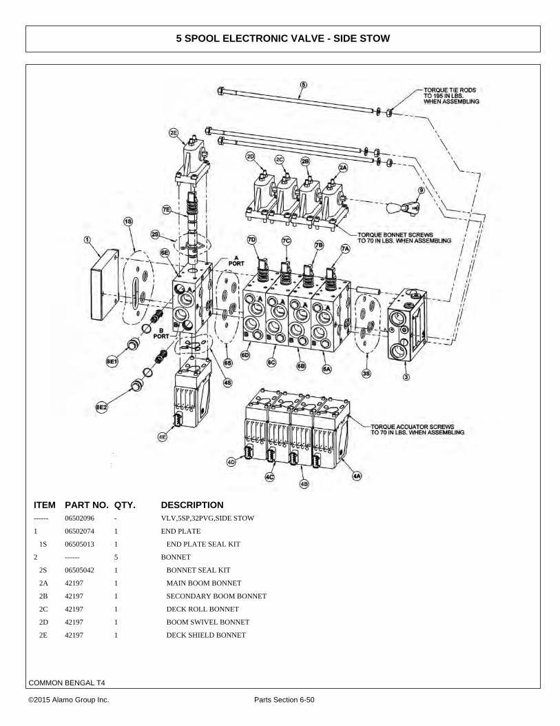
5 SPOOL ELECTRONIC VALVE - SIDE STOW
ITEM PART NO. QTY. DESCRIPTION------ 06502096 - VLV,5SP,32PVG,SIDE STOW
1 06502074 1 END PLATE
1S 06505013 1 END PLATE SEAL KIT
2 ------ 5 BONNET
2S 06505042 1 BONNET SEAL KIT
2A 42197 1 MAIN BOOM BONNET
2B 42197 1 SECONDARY BOOM BONNET
2C 42197 1 DECK ROLL BONNET
2D 42197 1 BOOM SWIVEL BONNET
2E 42197 1 DECK SHIELD BONNET
©2015 Alamo Group Inc. Parts Section 6-50
COMMON BENGAL T4

5 SPOOL ELECTRONIC VALVE - SIDE STOW
Continued...
ITEM PART NO. QTY. DESCRIPTION3 34308 1 INLET SECTION
3S 06505013 1 INLET SECTION SEAL KIT
4 ------ 5 ELECTRONIC ACCUATOR
4A 06502101 1 MAIN BOOM ELECTRONIC ACCUATOR
4B 06502101 1 SECONDARY BOOM ELECTRONIC ACCUATOR
4C 06502100 1 DECK ROLL ELECTRONIC ACCUATOR
4D 06502101 1 BOOM SWIVEL ELECTRONIC ACCUATOR
4E 06502099 1 DECK SHIELD ELECTRONIC ACCUATOR
5 42202 1 TIE-BOLT KIT
6 ------ 5 SECTION
6S 06505013 1 SECTION SEAL KIT
6A 42698 1 MAIN BOOM SECTION
6B 42698 1 SEC BOOM SECTION
6C 06502076 1 DECK ROLL SECTION
6D 42698 1 BOOM SWIVEL SECTION
6E 06502077 1 SHIELD SECTION
7 ------ 5 SPOOL
7A 42697 1 MAIN BOOM SPOOL
7B 42697 1 SEC BOOM SPOOL
7C 4242106 1 DECK ROLL SPOOL
7D 06502073 1 BOOM SWIVEL SPOOL
7E 42201 1 DECK SHIELD SPOOL
8 ------ 10 ANTI CAV/SHOCK RELIEF
8A1 42650 1 MAIN BOOM A PORT RELIEF
8A2 06502069 1 MAIN BOOM B PORT RELIEF
8B1 42650 1 SEC BOOM A PORT RELIEF
8B2 42295 1 SEC BOOM B PORT RELIEF
8C1 42296 1 DECK ROLL A PORT RELIEF
8C2 42295 1 DECK ROLL B PORT RELIEF
8D1 42295 1 BOOM SWIVEL A PORT RELIEF
8D2 42295 1 BOOM SWIVEL B PORT RELIEF
8E1 06502069 1 DECK SHIELD A PORT RELIEF
8E2 06502069 1 DECK SHIELD B PORT RELIEF
9 33459 1 HANDLE
©2015 Alamo Group Inc. Parts Section 6-51
COMMON BENGAL T4
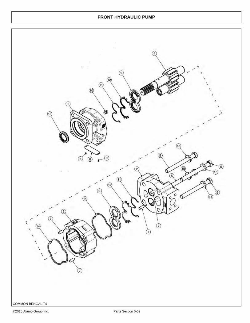
FRONT HYDRAULIC PUMP
©2015 Alamo Group Inc. Parts Section 6-52
COMMON BENGAL T4

FRONT HYDRAULIC PUMP
Continued...
ITEM PART NO. QTY. DESCRIPTION--- 23152 1 PUMP ASSEMBLY,1-3/4”,COMPLETE
1 22766 1 SHAFT END COVER
2 22779 1 PORT END COVER
3 22774 1 GEAR HOUSING,1-3/4”
4 22771 1 GEAR SET
5 23824 4 CAPSCREW
6 06504078 2 SCREW,DRIVE
7 22773 4 DOWEL PINS
8 06504077 1 NAMEPLATE
9 22770 2 THRUST PLATE
10 22767 1 PLUG
11 06504075 2 SEAL,BK-UP
12 06504074 2 SEAL,CHAN
13 22765 1 SEAL,LIP
14 06504076 2 SEAL,SQ-R
15 02961917 4 WASHER
--- 24150 1 SEAL KIT (INCLUDES 11, 12, 13 AND 14)
©2015 Alamo Group Inc. Parts Section 6-53
COMMON BENGAL T4

50IN AND 60IN ROTARY MOTOR BREAKDOWN
©2015 Alamo Group Inc. Parts Section 6-54
COMMON BENGAL T4

50IN AND 60IN ROTARY MOTOR BREAKDOWN
Continued...
ITEM PART NO. QTY. DESCRIPTION06504011 - MOTOR ASSEMBLY,TRB60
06504012 - MOTOR ASSEMBLY,TRB50
1 22790 1 HOUSING, SEC
2 06504088 1 HOUSING, PEC
3 06504062 1 HOUSING, GEAR,TRB60
------ 06504089 - HOUSING, GEAR,TRB50
4 06504090 1 SET, GEAR SHAFT
5 06504104 4 CAP SCREW,TRB60
------ 06504091 - CAP SCREW,TRB50
6 06504078 2 SCREW, DRIVE
7 06504092 1 KEY
8 06504093 4 PIN, DOWEL
9 06504094 1 NAME PLATE
10 06504095 2 THRPL
11 2961940 1 PLUG, ODT
12 2962200 1 RING, SNAP
13 06504096 1 O RING
14 6T5101 1 SEAL, LIP
15 06504097 1 SEAL, LIP
16 22797 2 SEAL, SQ-R
17 06504098 4 SEAL, SIDE CHAN
18 06504099 4 SEAL, END CHAN
19 06504100 2 SEAL, BK-UP
20 06504101 1 RTNR, SEAL
21 6T5809 2 CHECK ASS’Y
22 06504102 4 WASHER
------ 06504103 - SEAL KIT
©2015 Alamo Group Inc. Parts Section 6-55
COMMON BENGAL T4

FLAIL MOTOR BREAKDOWN
©2015 Alamo Group Inc. Parts Section 6-56
COMMON BENGAL T4

FLAIL MOTOR BREAKDOWN
Continued...
ITEM PART NO. QTY. DESCRIPTION* 06504132 - MOTOR ASSEMBLY 350 - TBF50, TBF63
1 06504141 1 SHAFT END COVER
2 06504040 1 PORT END COVER
3 06504041 1 GEAR HOUSING
4 06504117 1 MATCHED GEAR SET
5 TF4402 1 BALL BEARING
6 06504043 4 CAP SCREW
7 06504044 2 SET SCREW
8 06504028 1 KEY
9 06504045 4 DOWEL PIN
10 * 1 NAMEPLATE
11 763759 1 THRUSTPLATE
12 2961940 1 PLUG, ODT (0.25)
13 TF4401 1 SNAP RING
14 06504142 1 LIP SEAL
15 TF4410 2 GASKET SEAL
16 06504046 4 SIDE SEAL
17 06504047 4 END SEAL
18 TF4407 2 BACK-UP SEAL
19 06504122 1 SEAL RETAINER
20 6T5809 2 CHECK ASSEMBLY
21 2961917 4 WASHER
22 06504140 1 SHAFT
23 06504139 1 BREATHER
24 06504121 1 SPACER, BRG
25 06504119 1 SNAP RING
* 06504022 - SEAL KIT
©2015 Alamo Group Inc. Parts Section 6-57
COMMON BENGAL T4

RESERVOIR TANK FILTER ASSEMBLY
ITEM PART NO. QTY. DESCRIPTION------ 06505044 - FILTER ASSY SAE 10 MICRON
1 28583 4 CAPSCREW,8MM X 25MM(1.25 PITCH)
2 06505045 1 COVER
3 06505046 1 SEAL KIT
4 06505047 1 SPRING
5 06505048 1 BYPASS
6 35259 1 FILTER,10 MIC,RETURN LINE
7 06505049 1 CAN/BODY
©2015 Alamo Group Inc. Parts Section 6-58
COMMON BENGAL T4

PUMP AND GRILL GUARD OPTIONS
ITEM PART NO. QTY. DESCRIPTION1 32430 1 UNIVERSAL PUMP GUARD
2 32737 1 UNIVERSAL GRILL GUARD
3 21833 4 CAPSCREW,3/4" X 2-1/4",NC
4 22021 2 FLATWASHER,3/4"
5 21993 4 LOCKWASHER,3/4"
6 21825 4 HEX NUT,3/4",NC
©2015 Alamo Group Inc. Parts Section 6-59
COMMON BENGAL T4

BOOM TRAVEL LOCK
ITEM PART NO. QTY. DESCRIPTION1 06510050 1 HYDRAULIC TRAVEL LOCK VALVE
2 31329 1 ADAPTER - STANDARD BOOM
------ 31611 1 ADAPTER - EXTENDED BOOM
3 34532 1 SWITCH,TRAVEL LOCK
4 ------ - MAIN BOOM CYLINDER *REFER TO BOOM ASSY
5 ------ - HOSE / FITTINGS *REFER TO BOOM HYD ASSY
6 06510092 1 COIL ,TRAVEL LOCK
©2015 Alamo Group Inc. Parts Section 6-60
COMMON BENGAL T4

MANUAL LIFT VALVE SWITCH BOX
ITEM PART NO. QTY. DESCRIPTION1 06514012 1 SWBX,ALUM,BLK,06510100
2 35226 1 SWITCH,MOWER,COLEHERSEE
3 33811 1 SWITCH,MASTER/DECK FLOAT
4 34532 1 SWITCH,TRVL LCK
5 06514014 1 BREAKER,10A,SWBX
6 6T3923 1 INDICTATOR LIGHT,ON,RED
7 34540 1 STRAIN RELIEF,3/4,BLACK,NYLON
8 06550019 1 DECAL,SWTCHBX,BOOM,CG
9 02964063 1 KNOB,RED
10 35227 1 RELAY,DP,DT,12V,LY2F,35226
©2015 Alamo Group Inc. Parts Section 6-61
COMMON BENGAL T4

MANUAL LIFT VALVE SCHEMATIC
©2015 Alamo Group Inc. Parts Section 6-62
COMMON BENGAL T4

ELECTRONIC LIFT VALVE SWITCH BOX
ITEM PART NO. QTY. DESCRIPTION1 06510196 1 SWBX,ASSY
2 33811 2 SWITCH,MASTER/DECK FLOAT
3 33813 1 SWITCH,SFTY SHIELD
4 34532 1 SWITCH,TRVL LCK
5 34540 1 STRAIN RELIEF,3/4",BLACK,NYLON
6 6T3923 1 INDICTATOR LIGHT,ON,RED
7 06514006 1 BREAKER,15A,SWBX
8 06550044 1 DECAL,SWBX,06510047
9 35226 1 SWITCH,MOWER,COLEHERSEE
10 02964063 1 KNOB,RED
11 35227 1 RELAY,DP,DT,12V,LY2F,35226
©2015 Alamo Group Inc. Parts Section 6-63
COMMON BENGAL T4

ELECTRONIC LIFT VALVE SCHEMATIC
©2015 Alamo Group Inc. Parts Section 6-64
COMMON BENGAL T4

SOLENOID SWITCH BOX AND WIRING
ITEM PART NO. QTY. DESCRIPTION1 ------ - SWITCH BOX
2 RE37651 1 PLUG,AUX PWR
3 24204 - FUSE HOLDER,IN-LINE (OPTION)
4 6T3965 - FUSE,3AMP (OPTION)
5 6T3934 - TEMPERATURE GAUGE (OPTION)
6 6T3931 - TEMPERATURE SENSOR (OPTION)
©2015 Alamo Group Inc. Parts Section 6-65
COMMON BENGAL T4
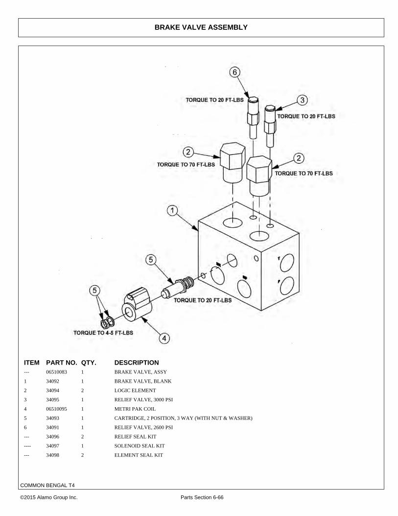
BRAKE VALVE ASSEMBLY
ITEM PART NO. QTY. DESCRIPTION--- 06510083 1 BRAKE VALVE, ASSY
1 34092 1 BRAKE VALVE, BLANK
2 34094 2 LOGIC ELEMENT
3 34095 1 RELIEF VALVE, 3000 PSI
4 06510095 1 METRI PAK COIL
5 34093 1 CARTRIDGE, 2 POSITION, 3 WAY (WITH NUT & WASHER)
6 34091 1 RELIEF VALVE, 2600 PSI
--- 34096 2 RELIEF SEAL KIT
---- 34097 1 SOLENOID SEAL KIT
--- 34098 2 ELEMENT SEAL KIT
©2015 Alamo Group Inc. Parts Section 6-66
COMMON BENGAL T4

BRAKE VALVE HYDRAULIC SCHEMATIC
©2015 Alamo Group Inc. Parts Section 6-67
COMMON BENGAL T4

ELECTRICAL TROUBLESHOOTING GUIDE
©2015 Alamo Group Inc. Parts Section 6-68
COMMON BENGAL T4

HYDRAULIC TROUBLESHOOTING GUIDE
©2015 Alamo Group Inc. Parts Section 6-69
COMMON BENGAL T4

TROUBLESHOOTING
©2015 Alamo Group Inc. Parts Section 6-70
COMMON BENGAL T4

TROUBLESHOOTING - CONTINUED
©2015 Alamo Group Inc. Parts Section 6-71
COMMON BENGAL T4

WHEEL WEIGHT - BENGAL 18
ITEM PART NO. QTY. DESCRIPTION1 30687 1 500# WHEEL WEIGHT
2 21956 4 CAPSCREW,3/4" X 13",NC
3 22021 8 FLATWASHER,3/4"
4 21993 4 LOCKWASHER,3/4"
5 21825 4 HEX NUT,3/4",NC
©2015 Alamo Group Inc. Parts Section 6-72
COMMON BENGAL T4

TIGER CORPORATIONWARRANTY INFORMATION
Tiger Corporation, 3301 N. Louise, Sioux Falls, South Dakota, warrants to the original Retail Customer, the new Tiger equipment is free of defects in material and workmanship. Any part of said equipment that in Tiger’s adjustment, show evidence of such defects will be repaired or replaced without charge, provided that the failure of part(s) shall have occurred within twelve (12) months from the date of delivery of said equipment to the Retail Customer. Expendable components such as knives, oil, chain sprockets, skid shoes, knife mounting disks and the like are excluded but not limited to this warranty.
The Retail Customer must pay the transportation cost to and from the Tiger Dealer’s service shop for warranty service. Warranty service will be performed by the Tiger Dealer from whom the equipment was purchased, in his service shop and during his regularly scheduled days and hours of operation.
All Tiger obligation under this warranty shall be terminated if the equipment is modified or altered in ways not approved in writing by Tiger, if repair parts other than genuine Tiger repair parts have been used, or if the equipment has bee subject to misuse, neglect, accident, improper maintenance or improper operation.
Tiger Corporation reserves the right to make improvements in design or changes in specification at any time without incurring any obligation to owners of equipment previously sold.
No agent or person has authority to alter, add to or waive the above warranties which are agreed to be in the only warranties, representations or promises, expressed or implied, as to the quality or performance of the products covered and which do not include any implied warranty of merchantability or fitness. In no event will Tiger be liable for incidental or consequential damages or injuries, including, but not limited to, loss of profits, rental or substitute equipment or other commercial loss.
THERE ARE NO WARRANTIES WHICH EXTENDBEYOND THOSE EXPRESSED HEREIN.
It is the Purchasers obligation to sign the warranty registration form AFTER he / she has Read and Understands the Operation and Safety Instructions stated within this manual.

ONE LAST WORDThis manual cannot possibly cover all of the
potentially hazardous situations you willencounter. By being familiar, though, with the
safety rules, operating and maintenanceinstructions in this manual you can help prevent
accidents. The objective of this manual is tohelp make you a better operator. Remember,
SAFETY IS YOU!
Your safety and the safety of those around youdepends on YOU. Common sense should
play a large role in the operation of this machine.
Since we at Tiger Corporation are constantly striving to improve out products, wereserve the right to change specifications or design at any time.

