till felix reichardt technical and economic assessment of ... · hörsaals ist durch das dynamische...
TRANSCRIPT

Till Felix Reichardt
Technical and Economic Assessment of Medium Sized
Solar-Assisted Air-Conditioning in Brazil
DISSERTAÇÃO DE MESTRADO
Dissertation presented to the Postgraduate Program in Urban and Environmental Engineering of the Departamento de Engenharia Civil, PUC-Rio as partial fulfillment of the requirements for the degree of Mestre m Engenharia Urbana e Ambiental (opção Profissional).
Advisor: Prof. Celso Romanel
Co-Advisor: Profa. Elizabeth Duarte Pereira
Rio de Janeiro January 2010

Till Felix Reichardt
Technical and Economic Assessment of Medium Sized
Solar-Assisted Air-Conditioning in Brazil
Dissertation presented to the postgraduate Program in Urban and Environmental Engineering of the Departamento de Engenharia Civil do Centro Técnico Científico da PUC-Rio, as partial fulfillment of the requirements for the degree of Mestre.
Prof. Celso Romanel Orientador, PUC-Rio
Profa. Elizabeth Duarte Pereira Co-Orientadora, Grupo Anima de Educação
Dr. Johannes Kissel GTZ-Brasil
Dr. Marcos Alexandre Teixeira GTZ-Brasil
Prof. Alcir de Faro Orlando Departamento de Engenharia Mecânica, PUC-Rio
Prof. José Eugênio Leal Coordenador Setorial do Centro
Técnico Científico, PUC-Rio
Rio de Janeiro, 25/01/2010
All rights reserved.
Till Felix Reichardt
Graduated in Environmental and Production Engineering from Technical University of Heilbronn, Germany, in 2006. Worked as a design engineer for the company Bartec Benke GmbH (Hamburg, Germany) during two years.
Bibliographic data
Reichardt, Till Felix
Technical and Economic Assessment of Medium Sized Solar-Assisted Air-Conditioning in Brazil / Till Felix Reichardt; advisor: Celso Romanel, co-advisor: Elizabeth Duarte Pereira; Rio de Janeiro: PUC, Departamento de Engenharia Civil, 2010.
135 f.: il. 29,7 cm
Dissertação (Mestrado em Engenharia Urbana e Ambiental) – Pontifícia Universidade Católica do Rio de Janeiro, Rio de Janeiro, 2010.
Bibliographic references included.
1. Engenharia Urbana e Ambiental – Teses 2. Ar condicionado solar. 3. Coletores solares térmicos. 4. Simulação da carga térmica de resfriamento. 5. Eficiência energética. 6. Estimativa econômica I. Romanel, Celso. II. Pereira, Elizabeth Duarte. III Pontifícia Universidade Católica do Rio de Janeiro. Departamento de Engenharia Civil IV. Título.
CDD 624
Ever bigger machines, entailing ever bigger
concentrations of economic power and exerting ever
greater violence against the environment, do not
represent progress: they are a denial of wisdom.
Wisdom demands a new orientation of science and
technology towards the organic, the gentle, the non-
violent, the elegant and beautiful.
E. F. Schumacher
Small Is Beautiful: a study of economics as if
people mattered

Acknowledgments
The author would like to thank Prof. Celso Romanel and Profa. Elizabeth Duarte
Pereira for their guidance and support, anyone at DAAD (especially Karin Führ)
for financial support during my master’s degree program in Rio de Janeiro, Brazil
Special thank to the GTZ team in Rio de Janeiro, especially to Dr. Johannes
Kissel, Dr. Marcos Teixeira and Andreas Nieters for their inspiration, discussion,
support and information.
Very grateful I am also for the collaboration with PROCEL, especially with
Andre Cleiman and Luciana Lopes Batista.
Katrin Spiegel (SolarNext), Ralf Kynast (Solvis), Bud Leavell (Yazaki), Christian
Zahler (Mirroxx), Luiz Alexandre Alves (Cumulus), Alexandre Lopes (Benco)
and Gabriel Neumeyer (Schüco) thanks for answering immediately a lot of
essential technical questions.
Finally, I would like to thank Robert Mack (engineering consultant) for an
excellent introduction in thermal building simulation and information about air-
conditioning and solar collectors.
Last but not least I would like to thank my family and Mariana Sales Fernandez
Dominguez for their support.

Resumo
Till Felix Reichardt, Romanel, Celso (Orientador); Pereira, E. (Co-orientadora). Análise técnica e econômica de sistemas de ar-
condicionado de médio porte assistido por energia solar térmica no Brasil. Rio de Janeiro, 2010. 135 p. Dissertação de Mestrado - Departamento de Engenharia Civil, Pontifícia Universidade Católica do Rio de Janeiro.
No Brasil, devido ao clima tropical, muita energia elétrica é utilizada em
sistemas de ar condicionado. Devido à excelente irradiação solar que incide na
maior parte do país, existem boas condições para atender esta grande demanda de
refrigeração através da utilização de sistemas de ar condicionado assistido por
energia solar térmica. Nesta dissertação, as mais importantes tecnologias que
utilizam a energia solar para a climatização foram verificadas quanto a sua
aplicabilidade técnica e econômica no Brasil, com foco em sistemas de médio
porte. Os princípios básicos para o dimensionamento de um sistema de
refrigeração solar são descritos e um estudo de caso é apresentado e discutido,
comparando-se um sistema de ar condicionado assistido por energia solar
(auditório em Guaratinguetá, São Paulo) com um sistema tipo split convencional.
No estudo deste caso, a dinâmica de simulação térmica de edifícios foi modelada
utilizando o programa Helios-PC. Também se analisa como a carga térmica de
resfriamento pode ser diminuída considerando-se uma temperatura adequada no
interior da edificação, de acordo com as normas brasileiras de conforto térmico,
como também pelo emprego de isolamento adequado na construção do edifício.
Palavras - chave Ar condicionado solar; Coletores solares térmicos; Simulação da carga
térmica de resfriamento; Eficiência energética; Estimativa econômica.

Abstract
Till Felix Reichardt, Romanel, Celso (Advisor), Pereira, Elizabeth Duarte (Co-advisor). Technical and economic assessment of medium sized Solar-
Assisted Air-Conditioning in Brazil. Rio de Janeiro, 2010. 135 p. M.Sc. Dissertation – Departamento de Engenharia Civil, Pontifícia Universidade Católica do Rio de Janeiro.
In Brazil a lot of electrical energy is used by building air-conditioning
because of the tropical climate. In many cases there is a general congruence of
solar irradiation and demand for building air-conditioning and solar thermal
cooling has the potential to satisfy a part of the rapidly growing cooling demand.
Due to excellent solar irradiance and a high cooling demand there exists in Brazil
good conditions for the use of solar-assisted air-conditioning. In this work the
most important solar cooling techniques and their suitability in Brazil are
discussed. The objective of the present study is to analyze the technical and
economic feasibility of medium sized solar-assisted air-conditioning in Brazil.
The energy saving potential of solar-thermal air-conditioning in comparison to
best practical solutions in Brazil using conventional split air-conditioning systems,
is shown based on a case study (auditorium in Guaratinguetá - São Paulo). The
economy of solar-assisted air-conditioning is thereby discussed. The basic
principles for the dimensioning of a system for solar cooling are described. The
auditorium in the case study is modelled by using the dynamic thermal building
simulation program Helios-PC. In this context it is, as well, demonstrated how the
cooling load could be decreased by adapting the indoor temperature according to
the Brazilian standards of thermal comfort and by using building insulation.
Keywords Solar cooling air-conditioning; Solar thermal collectors; Dynamic thermal
building simulation; Energy efficiency; Economic assessment.

Zusammenfassung
Till Felix Reichardt, Romanel, Celso (Betreuer); Pereira, Elizabeth Duarte (Zweitbetreuerin). Technical and economic assessment on medium sized
Solar-Assisted Air-Conditioning in Brazil. Rio de Janeiro, 2010. 135 S. – Abteilung Bauingenieurwesen, Departamento de Engenharia Civil, Pontifícia Universidade Católica do Rio de Janeiro.
In Brasilien wird aufgrund des tropischen Klimas, ein großer Anteil der
elektrischen Energie für die Kühlung von Gebäuden verwendet. Aufgrund des
stark wachsenden Klimakältebedarfs und der hervorragenden solaren
Einstrahlbeding ergeben sich gute Bedingungen für den Einsatz von
solarthermischer Klimakälteerzeugung. Hierbei stimmt das Angebot an solarer
Einstrahlung zeitlich weitgehend mit dem Klimakältebedarf überein. In der
vorliegenden Masterarbeit werden die wichtigsten Verfahren zur solaren
Kälteerzeugung und ihre Eignung in Brasilien erörtert. Daraufhin wird anhand
einer Fallstudie (Hörsaal in Guaratinguetá - São Paulo) überprüft, in wie weit
solarthermische Klimakälteerzeugung eine energieeffiziente Alternative
gegenüber Split-Kompaktklimageräten sein kann. Dabei wird anhand einer
thermischen Gebäudesimulation zur Kühllastberechnung ermittelt, wie hoch der
solare Deckungsgrad wäre. In diesem Kontext wird dargestellt, wie die Kühllast
durch die Anpassung der Raumtemperatur an die brasilianischen Normen für
thermischen Komfort und durch Gebäudeisolierung gesenkt werden könnte.
Abschließend wird die Wirtschaftlichkeit von solarthermischer
Klimakälteerzeugung im in Brasilien überprüft. Das thermische Verhalten des
Hörsaals ist durch das dynamische Gebäudesimulationsprogramm Helios-PC
abgebildet.
Schlüsselwörter Solares Kühlen; Klimaanlage; Solarkollektoren; Dynamische
Gebäudesimulation; Kühllast; Energieeffizienz; Wirtschaftlichkeitsberechnung.

Contents
1 Introduction 18
1.1. Objective 25
2 Technical overview of active techniques 26
2.1. Technologies applicable for solar-assisted air-conditioning 26
2.1.1. Chilled water systems 33
2.1.1.1. Absorption Chillers 34
2.1.1.2. Adsorption Chillers 40
2.1.1.3. Heat Rejection 44
2.1.2. Open cycle Processes 46
2.1.3. Solar thermal collector 50
2.2. Non- thermally driven application 55
2.2.1. Conventional Electricity driven vapour compression chiller 55
2.2.2. Photovoltaic driven compression cycle 57
3 Case Study 62
3.1. Background Information 63
3.1.1. Location and climate conditions 65
3.2. Simulation and Design 68
3.2.1. The thermal Load of the Building 68
3.2.1.1. Simulation Building Data 69
3.2.1.2. Results of the Simulation 74
3.2.1.2.1. Conclusion 77
3.2.2. Selection and Design of the equipment 79
3.2.2.1. The Cold Production Sub-System 80
3.2.2.2. The load sub-system – air-conditioning equipment 83
3.2.2.3. Heat production sub-system 87
3.2.2.3.1. Thermal solar collector comparison 87
3.2.2.3.2. Back-up and hot water storage 91
3.2.2.3.2.1. Electrically driven compression chiller back-up 92

3.2.2.3.2.2. Thermal gas driven back-up 93
3.2.2.4. Design and performance of the complete system 95
3.2.2.4.1. Conclusion 101
3.2.3. Economic assessment 104
3.2.3.1. Acquisition and operation cost calculation 104
3.2.3.2. Economic feasibility 107
3.2.4. Environmental benefits 109
3.2.5. Conclusion 110
4 Conclusion and recommendations 112
References 117
Appendix 120
A1 Specification for the Auditorium 120
A2 Technical Data and Information 128
A3 Solar collector Test certificates 130
A4 Quotations 134

List of figures
Figure 1.1 - Okura Act City Hotel in Hamamatsu, Japan ..................................................19 Figure 1.2 - Megacities of the tropical Belt ........................................................................20 Figure 1.3 - Applied electrically driven compression Air-Conditioning ..............................21 Figure 1.4 - World market sales rate in 2008 of split air-conditioners ..............................22 Figure 2.1 - General Scheme of the thermally driven cooling process ............................27 Figure 2.2 - Closed cycle system ......................................................................................28 Figure 2.3 - Open sorption cycle .......................................................................................29 Figure 2.4 - Thermodynamic principle of thermally driven cooling....................................29 Figure 2.5 - Theoretic limit of solar thermal driven cooling processes..............................31 Figure 2.6 - Example manufacturer Data ..........................................................................32 Figure 2.7 - Exemplary curves of the coefficient of performance COP.............................32 Figure 2.8 - Schematic drawing of an absorption chiller ..................................................34 Figure 2.9 - Vapour pressure as a function of vapour temperature ..................................35 Figure 2.10 - Detail function scheme of a single-effect Absorption chiller 36 Figure 2.11 - Typical capacity range of a absorption chillers........................................... 37 Figure 2.12 - Global solar radiation map of Brazil .............................................................38 Figure 2.13 - Examples of concentration solar thermal collectors ....................................39 Figure 2.14 - Two examples of absorption chiller .............................................................40 Figure 2.15 - Scheme of an adsorption chiller ..................................................................41 Figure 2.16 - Two Examples of adsorption chillers ...........................................................41 Figure 2.17 - Available adsorption chillers ........................................................................43 Figure 2.18 - Example on the demand for heat rejection..................................................44 Figure 2.19 - Typical scheme of an open wet cooling tower.............................................45 Figure 2.20 - Scheme of a solar thermally driven solid DEC system................................46 Figure 2.21 - Relative humidity of the air in relation to the max. Temp. .......................... 49 Figure 2.23 - Examples for different construction principles .............................................51

Figure 2.24 - Examples on solar collectors .......................................................................54 Figure 2.25 Schematic drawing of a vapour compression chiller......................................55 Figure 2.26 - Function scheme of a Split Air-conditioning system ....................................56 Figure 2.27 - Solar cooling possibilities.............................................................................58 Figure 2.28 - Comparison of COP´s and efficiency...........................................................59 Figure 2.29 - Surface and atmospheric temperatures ......................................................59 Figure 2.30 - Low/high albedo of a solar thermal collector and PV ..................................61 Figure 3.1 - Interaction in the design and layout ...............................................................63 Figure 3.2 - Location of Guaratinguetá in Brazil ...............................................................65 Figure 3.3 - Global solar radiation map.............................................................................66 Figure 3.4 - Brazilian south-eastern Megalopolis..............................................................67 Figure 3.5 - External/internal cooling loads (modified)......................................................69 Figure 3.6 - Snapshot of HELEX 2.1 Interface..................................................................72 Figure 3.7 - Predicted monthly cooling load......................................................................75 Figure 3.8 - Hourly cooling load pattern (hourly data).......................................................76 Figure 3.9 - “With Springer you are the one who makes the climate”...............................77 Figure 3.10 - Insulation with EPS Polystyrene plates in Germany....................................78 Figure 3.11 - Sub-systems and their components (modified) ...........................................80 Figure 3.11 - Performance characteristics of Yazaki WFC-SC10.....................................81 Figure 3.12 - Technical data wet cooling tower.................................................................83 Figure 3.13 - Generic classification of centralised air-conditioning...................................84 Figure 3.14 - Example of a Cooling panel.........................................................................86 Figure 3.15 - Cross-section of a typical simple fan-coil unit..............................................86 Figure 3.16 - Schematic illustration showing the inclination of the sun ............................88 Figure 3.17 - Definition of collectors areas........................................................................90 Figure 3.18 - Predicted performance of different solar collectors .....................................90 Figure 3.19 - Simplified scheme of a solar cooling system...............................................92 Figure 3.20a - Simple comparison of CO2 emissions.......................................................93 Figure 3.20b - In comparison to Figure 3.20a .................................................................. 93 Figure 3.21 - Simplified scheme of a solar cooling system...............................................94

Figure 3.22 - Snapshot of generic spreadsheet ................................................................97 Figure 3.23 - Predicted correlation between cooling demand/yield ..................................97 Figure 3.24 - Predicted correlation between cooling demand/yield ..................................98 Figure 3.25 - Predicted correlation between cooling demand/yield ..................................98 Figure 3.26 - Predicted daily demand and available yield (spring) ...................................99 Figure 3.27 - Predicted daily demand and available yield (summer) ................................99 Figure 3.28 - Predicted daily demand and available yield (autumn) ...............................100 Figure 3.29 - Predicted daily demand and available yield (winter) .................................100 Figure 3.30 - Predicted total monthly cooling demand and yield (Brazil) 101 Figure 3.31 - Predicted monthly demand and yield (UK) ................................................102 Figure 3.31 - Schematic diagram of the simulated solar cooling syst.............................103 Figure 3.32 - Example of an Solar-Assisted Air-conditioning application 103 Figure 3.33 - Acquisition and operation cost (Guaratinguetá) ........................................108 Figure 3.34 - Acquisition and operation cost (Minas Gerais) ..........................................108 Figure 4.1 - Typical electric driven screw chiller power curve.........................................115

List of tables
Table 2.1 - Cooling Capacity of Absorption- and Adsorption chiller..................................42 Table 3.1 - Monthly average climate data of Guaratinguetá ............................................66 Table 3.2 - U-values of the auditorium building model......................................................71 Table 3.3 - Internal thermal comfort (PNB-10, Brazil) .......................................................73 Table 3.4 - Cooling Load results without building insulation .............................................74 Table 3.5 - Cooling Load results with building insulation ..................................................75 Table 3.6 - Technical data of the Yazaki WFC-SC10 Absorption Chiller..........................81 Table 3.7 - Cooling water temperatures............................................................................82 Table 3.8 - Specific cooling capacities of different AC systems........................................84 Table 3.9 - Characteristic values and cost of solar collector typologies. ..........................89 Table 3.10 - Acquisition and specific costs .....................................................................105 Table 3.11 - Comparison of electricity consumption and operation cost ........................106 Table 3.12 - CO2 savings per year .................................................................................109

List of symbols
A area
a1 heat transfer coefficient
a2 temperature depending heat transfer coefficient
COPSol solar collector efficiency
Cw heat capacity of water
G solar irradiance at collector surface
hamb enthalpy ambient air
hsupply enthalpy air supply
m(t) water flow
msupply mass air flow
Pel electric power input
Q cooling capacity
Qcold useful cold
Qdrive driving heat
Qreg external regeneration heat
ta ambient temperature
TC low temperature
TH high temperature
Ti indoor temperature
tm average temperature solar collector
TM medium temperature
∆Τ temperature difference
η efficiency factor
η0 optical efficiency solar collector
ηcoll efficiency factor solar collector

List of acronyms and abbreviations
HVAC Heating, Ventilating and Air Conditioning
IR Infrared Radiation
Eletrobrás Brazilian energy company with headquarters in Rio de
Janeiro. The company produces and sells electricity. The
majority of the share capital is held by the Brazilian
government. It is the biggest energy company in Brazil as
well as in Latin America.
PROCEL Brazilian Energy Saving Program
UNESP São Paulo State University
GTZ German Technical Cooperation. The GTZ GmbH is an
international cooperation enterprise for sustainable
development with worldwide operations.
ASHRAE American Society of Heating, Refrigerating and Air-
Conditioning Engineers
INMETRO Brazilian Institute of Metrology, Standardization and
Industrial Quality
INMET Brazilian Institute of Meteorology
GREENSolar Is the only Brazilian laboratory which is testing solar
collectors for the INMETRO
DEC Desiccant Evaporative Cooling
Open cycle air-conditioning process.
Central components: sorptive air dehumidification, using
either solid or liquid sorption material; heat recovery unit;
return (and often supply) air humidifiers. Requires separate
supply and return air ducts.
COP Coefficient of Performance
Performance number of thermally driven chillers:
Ratio of (cold production) / (driving heat input) Used with
power units (kW/kW) to provide rated values, or with
energy units (kWh/kWh) to provide the performance during
longer periods.
EER Electrical Efficiency Ratio
Performance number of electrically driven compression
chillers: Ratio of (cold production) / (electricity input).
Used with power units (kW/kW) to provide rated values, or
with energy units (kWh/kWh) to provide the performance
during longer periods.

1 Introduction 18
1 Introduction
The use of solar thermal energy for air-conditioning in hot and sunny climate is a
promising new application of solar thermal collectors in buildings. The main
advantage is that in solar air conditioning applications cooling loads and solar
gains occur at the same time and on seasonal level.
In Brazil the energy demand for refrigeration and air-conditioning correspond to
approximately 15 % (134 TWh/year) of the total country energy use [1].
Around 48% of energy is consumed in commercial and public buildings due to air
conditioners, usually by driving electrical vapour compression chillers [2].
Solar cooling has the potential of significantly reducing the electricity
consumption, contribute fossil energy saving and electrical peak load reduction.
The solar array yields thermal load reduction of the building. Furthermore it
contributes in a positive way the urban microclimate through absorbing the solar
irradiation on the roofs. Last but not least Solar cooling decrease the ecological
footprint of tropical cities due to achieving carbon emission reduction and using
environmental friendly refrigerants.
Figure 1.1 shows a Hotel in Japan which is using solar energy for providing
HVAC and domestic hot water. The solar array provides shading. All of the
mechanical equipment is underneath the array.

1 Introduction 19
Figure 1.1 - Okura Act City Hotel in Hamamatsu, Japan. This building was designed with Solar energy in mind [3].
Many of the huge agglomerations, such as Rio de Janeiro and São Paulo, are
located in or at the boundaries of the inter-tropical zone and additionally in
developing countries. Figure 1.2 shows a comparison of global climatic map with
the population distribution.
The climatic advantages in the Tropics have led to the highest density of
population highest population growth [4].
More than a third of the world’s population live between the Tropic of Cancer and
the Tropic of Capricorn. The Tropical belt has become the most densely populated
and thus poorest region of the planet. Latin American and the Caribbean are the
most urbanized regions in the World [5].

1 Introduction 20
Figure 1.2 - Megacities of the tropical Belt (modified) [4].

1 Introduction 21
In tropical latitudes, the impact of urban climate is associated to more negative
effects on thermal comfort and the energy consumption of buildings than in the
cities of the temperate climate zones, due to higher solar radiation income [6].
On the existing high temperatures in the tropical occurs an further temperature
increase by the formation of the so called 'urban heat island' in created mainly by
the lack of vegetation, into the environment conducted waste heat (e.g. due to the
heat rejection of air-conditioning) and by the high solar radiation absorptance of
urban surfaces.
Predicted climate changes due to anthropogenic emissions will cause also an
increase in mean atmosphere temperatures and atmospheric IR radiation [7].
Taking all these facts into account the cooling demand increases and in future
more and more buildings will be air-conditioned. For these reasons the country’s
energy consumption increases mostly due to in the “small” and “medium” range
less-efficient applied split air-conditioners and package systems. Figure 1.3 shows
a typical building in Brazil with applied split air-conditioners.
Figure 1.3 - Applied electrically driven compression air-conditioning at a commercial building in Rio de Janeiro - Brazil.
The annual growth in Brazil of the cooling and air-conditioning market in terms
of capacity is expected the range of 4.5 GW/y (1.3 million TR/y) [1].

1 Introduction 22
This corresponds to the sales rate of room split air-conditioners and package
systems for capacities < 5 kW for South America in 2008, published by JARN [8].
Figure 1.4 - World market sales rate in 2008 of split air-conditioners and package systems in the capacity range < 5 kW (1.42 million TR). Source: JARN
In hot and humid regions the use of free cooling techniques are limited and can
not guarantee that the indoor comfort will be fulfilled all the time. To contribute a
sustainable urban development in Brazil, another energy-efficient cooling
technology must be implemented – the solar cooling.
By the growing environmental concerns and consistent effort in research and
product development the interest in solar air-conditioning technology has
increased in the last years. All over the World solar-assisted Air-Conditioning
demonstration projects are showing that the technologies are mature.
Until now, there is not a pilot project for solar air-conditioning of buildings in
Brazil.

1 Introduction 23
The Eletrobrás/PROCEL (Brazilian electricity Conservation Program) will
establish a centre for energy efficiency education in Guaratinguetá at the
University UNESP (Universidade Estadual Paulista) and has the intention to equip
the auditorium with a solar air-conditioning system.
The Project will be, likely realized in cooperation with the GTZ (german technical
cooperation) within the framework of the GTZ energy program for the purpose
supporting regenerative energies and energy efficiency in Brazil.
For the appropriate design of such a solar cooling system, the building must be
simulated by using local meteorically data to determine the correlation between
solar gain and cooling load.
Furthermore it must be analyzed which solar cooling technology is suitable under
the specific climatic conditions and if the alternative technology can compete
economically with conventional split air-conditioners.
The basis of this work is primarily a GTZ commissioned technology study “solar
cooling in Brazil” developed by Fraunhofer Institute of Solar Energy Systems ISE
(Germany).
The thesis is organized into the following main chapters:
The next chapter starts with a critical overview on existed solar cooling
technologies and their scope regarding the climate conditions in Brazil. It
describes the fundamentals of solar building cooling, function and their benefits.
In these chapter will be principally discussed the use of open cycle processes
(DEC) and Photovoltaic driven compression chillers in comparison to sorption
chilled water systems. Summarized, it intended to give the reader an introductory
technical background. It is followed a practical relevant case study.

1 Introduction 24
Chapter 3 includes the main focus of this work. First it informs about the intended
pilot-project in Guaratinguetá and gives some background knowledge regarding
building cooling and air-conditioning. It describes the building and the energy
simulation program Helios-PC which is used to simulate its thermal behaviour.
The next steps in this chapter are as follows:
• Comparing of different in Brazil available solar collectors
• Simulation of Correlation Solar gain / cooling demand
• Choice and design of the appropriate solar cooling technology
• Assessment of the economically viability in comparison to conventional
compressor Split Air-conditioning. Including the Assessment of two
different Back-up possibilities for Solar-assisted Air-Conditioning System:
a) back-up with Split Air-Conditioning b) thermally back-up with Gas
• Environmental benefits
Beside the Simulation and Design of solar cooling system it shows how the
cooling demand (thermal load) of the building could be reduced by changing the
indoor set temperature within the Brazilian standards (PNB-10) and by using
building insulation.
Finally Chapter 4 Conclusion and Recommendations presents the results obtained
and concludes the study, adding some general recommendations on solar-assisted
air-conditioning.
1 Introduction 25
1.1 Objective
The goal of this work is to verify if solar-assisted air-conditioning in the
“medium” capacity range can already be an alternative energy saving technology
for building air-conditioning in Brazil. In this context a Case Study - Auditorium
in Guaratinguetá - will be done, thus the following necessary question can be
answered:
- Which technology can be used and is available?
- Which is the best system for the given application under the conditions of
the specific-site?
- How is the correlation between solar gain and cooling demand?
- Is the use of solar-assisted air-conditioning feasible for the building?
- Which cold distribution is suitable under the specific climatic condition
(hot and humid climate)?
- Which solar collector is the most cost-effective on the Brazilian market?
- What dimensions of the solar collector area and other system components
results the best energy cost performance?
- Is another ecological and economical alternative feasible for example
active night-cooling?
- How can the high investment cost of solar cooling system be decreased?
- How it’s possible to decrease the cooling demand of a building and hence
the cooling capacity of the solar cooling system, which leads to lower
investment cost?
- Which back-up system is under the local energy prices (gas/electricity)
appropriate?
- Can solar assisted air conditioning already compete economically with in
the “small” and “medium” cooling capacity range often applied
conventional compressor Split Air-conditioning Systems?

2 Technical overview of active techniques 26
2 Technical overview of active techniques
This chapter describes the function of solar-assisted air-conditioning in buildings.
It is important to understand technical terms, operation parameters, different
concepts and their application scopes. This knowledge serves as basis for the right
selection of technology and their suitable components regarding the case study, or
rather, the pilot project in Guaratinguetá.
The definition choice “solar-assisted air conditioning” results from the fact that
these systems are not running completely self-sufficient, they always need some
sort of conventional energy source for their operation. e.g. for the fans or pumps.
But they economize a tremendous amount of energy in comparison to the
conventional electrical driven air conditioning system, because the main driving
energy is generated regenerative by the solar thermal collector field.
Air conditioning is the cooling and dehumidification of indoor air for thermal
comfort. In a broader sense, the term can refer to any form of cooling, heating,
ventilation, or disinfection that modifies the condition of air [9].
2.1 Technologies applicable for solar-assisted air-conditioning Because of the chosen Case study the cooling demand is around 15 -30 kW
(4,3 - 8,6 TR).
Therefore the focuses on the Technology overview are chillers in the small and
medium size capacity range. The classification “small” and “medium” depends on
the nominal chilling capacity, small application are below 20 kW (5,7 TR) and
medium size system range up to approx. 100 kW (29 TR).
2 Technical overview of active techniques 27
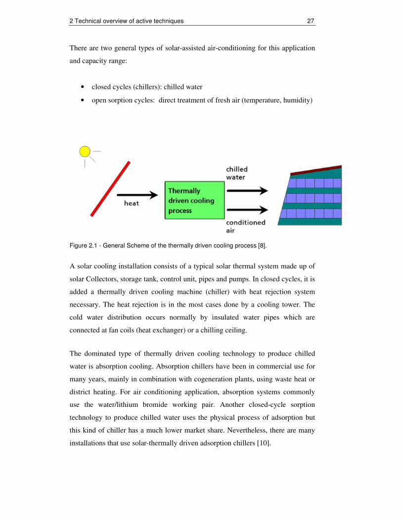
There are two general types of solar-assisted air-conditioning for this application
and capacity range:
• closed cycles (chillers): chilled water
• open sorption cycles: direct treatment of fresh air (temperature, humidity)
Figure 2.1 - General Scheme of the thermally driven cooling process [8].
A solar cooling installation consists of a typical solar thermal system made up of
solar Collectors, storage tank, control unit, pipes and pumps. In closed cycles, it is
added a thermally driven cooling machine (chiller) with heat rejection system
necessary. The heat rejection is in the most cases done by a cooling tower. The
cold water distribution occurs normally by insulated water pipes which are
connected at fan coils (heat exchanger) or a chilling ceiling.
The dominated type of thermally driven cooling technology to produce chilled
water is absorption cooling. Absorption chillers have been in commercial use for
many years, mainly in combination with cogeneration plants, using waste heat or
district heating. For air conditioning application, absorption systems commonly
use the water/lithium bromide working pair. Another closed-cycle sorption
technology to produce chilled water uses the physical process of adsorption but
this kind of chiller has a much lower market share. Nevertheless, there are many
installations that use solar-thermally driven adsorption chillers [10].

2 Technical overview of active techniques 28
Figure 2.2 - Closed cycle system, chiller water is produced in a closed loop for different decentral application or for supply air cooling [9]. Another type of technology which has chained increasing attention over the last
15 years is desiccant cooling technology (DEC). Using this technology, air is
conditioned directly. i.e. cooled and dehumidified. Desiccant cooling systems
exploit the potential of sorption materials, such as silica gel, for air
dehumidification. In an open cooling cycle, this dehumidification effect is
generally used for two purposes: to control the humidity of the ventilation air in
air-handling units and - if possible - to reduce the supply temperature of
ventilation air by evaporating cooling [10].
In that case, the cold distributions medium is conditioned Air, thus huge air ducts
and a double deck air handling unit inside the building are necessary. There is no
need of a cooling machine and a cooling tower but also a typical solar thermal
system to regenerate desiccant wheel of such an air handling unit.

2 Technical overview of active techniques 29
Figure 2.3 - Open sorption cycle: Supply air is directly cooled and dehumidified [8].
It must be mentioned that in both figures the required heat is supplied by a solar
thermal collector field.
For a better understanding of the thermally driven process and their efficiency it’s
important to describe the thermodynamic principle.
Figure 2.4 - Thermodynamic principle of thermally driven cooling [8].
Thermally driven chillers may be characterized by three temperature levels:

2 Technical overview of active techniques 30
• The cycle is driven with heat from a high temperature heat source,
e.g. solar collectors or waste heat.
• A low temperature level at which the chilling process is operated, hence
useful cold. This extracts heat from a low temperature heat source.
• A medium temperature level at which both, the heat rejected from the
chilled water cycle and the driving heat, have to be removed. For this heat
removal, in most cases a wet-cooling tower is used.
The two main equations to be taken into account for any thermally driven cooling
cycle are:
First the conservation of energy governing the energy flows in the three
temperature levels
medium high lowQ Q Q= + (Eq. 2.1)
and second the thermal Coefficient of Performance (COPth) giving the ratio of
useful cold per unit of driving heat.
Coldth
drive
Quseful coldCOP
driving heat Q= = (Eq. 2.2)
A key figure to characterise the energy performance of a refrigeration machine is
the Coefficient of Performance, COPth.
The COPth is a characteristic of the particular thermodynamic cycle used, but in
general is strongly dependent on the three temperature levels.
The theoretic limits of solar driven cooling can be calculated through the product
of the COPth of the cooling process and the solar collector efficiency:
sol th collCOP COP η= ⋅ (Eq. 2.3)

2 Technical overview of active techniques 31
Both systems in principle have a contrary characteristic: cooling processes
perform better with higher temperatures while lower temperatures are better for
the collectors. As a result, if both technologies are chosen, an optimum operation
temperature results from both characteristics [9].
Figure 2.5 - Theoretic limit of solar thermal driven cooling processes [11].
Figure 2.5 shows, that the optimal driving temperature of a solar driven cooling
system depends on the thermal performance of the cooling process and the
collector efficiency curve.
Beside the influence of the driving temperature regarding cooling machine
efficiency and the solar collector efficiency, the cooling tower performance has
also an influence of the COP and cooling power which shows the following
figure.

2 Technical overview of active techniques 32
Figure 2.6 - Example manufacturer Data; COP and Cooling Power [KW] in relation to the
heat rejection water temperature are shown as a function of the constant fan-coil cooling
water temperature for driving a fan-coil. Source: Solvis Energy Systems GmbH&Co.KG
In the next shown figure 2.7 is discussed in more detail performance curve of the
on the market available thermally driven chillers. The COP is between 0.5 to 0.8
in single-effect chillers, and till 1.4 in double-effect chiller. The different chiller
types will be discussed in the next chapter.
Figure 2.7 - Exemplary curves of the coefficient of performance COP for different sorption
chiller technologies and the limit curve for an ideal process. The curves are shown as a
function of the driving temperature and for a constant chilled and cooling water
temperature [10].
2 Technical overview of active techniques 33
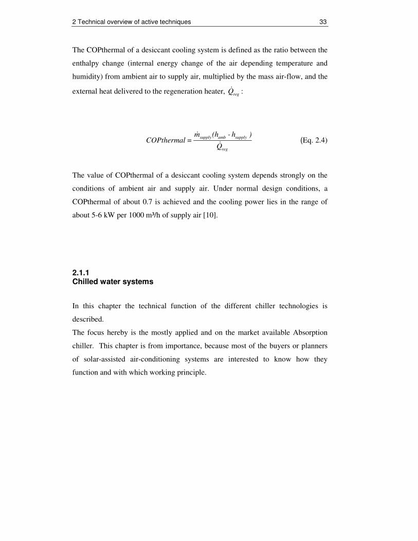
The COPthermal of a desiccant cooling system is defined as the ratio between the
enthalpy change (internal energy change of the air depending temperature and
humidity) from ambient air to supply air, multiplied by the mass air-flow, and the
external heat delivered to the regeneration heater, regQ& :
supply amb supply
reg
m (h - h )COPthermal =
Q
&
& (Eq. 2.4)
The value of COPthermal of a desiccant cooling system depends strongly on the
conditions of ambient air and supply air. Under normal design conditions, a
COPthermal of about 0.7 is achieved and the cooling power lies in the range of
about 5-6 kW per 1000 m³/h of supply air [10].
2.1.1 Chilled water systems
In this chapter the technical function of the different chiller technologies is
described.
The focus hereby is the mostly applied and on the market available Absorption
chiller. This chapter is from importance, because most of the buyers or planners
of solar-assisted air-conditioning systems are interested to know how they
function and with which working principle.

2 Technical overview of active techniques 34
2.1.1.1 Absorption Chillers Absorption chillers use heat instead of mechanical energy to provide cooling.
A thermal compression of the refrigerant is achieved by using a liquid
refrigerant/sorbent solution and a heat source, thereby replacing the electric power
consumption of a mechanical compressor.
For chilled water above 0°C, as it is used in air conditioning, a liquid H2O/LiBr
solution is typically applied with water as a refrigerant. Most systems use an
internal solution pump, but consume only little electric power.
The main components of absorption chillers are shown in the figure below:
Figure 2.8 - Schematic drawing of an absorption chiller producing chilled water [8].
In the next two figures the thermal absorption cycle process is shown:

2 Technical overview of active techniques 35
Figure 2.9 - Vapour pressure as a function of vapour temperature in an absorption Cooling cycle process [8].
Absorption cycles are based on the fact that the boiling point of a mixture is
higher than the corresponding boiling point of a pure liquid. A more detailed
description of the absorption cycle includes the following steps [10].
1. The refrigerant evaporates in the evaporator, thereby extracting heat from
a low-temperature heat source. This results in the useful cooling effect.
2. The refrigerant vapour flows from the evaporator to the absorber, where it
is absorbed in a concentrated solution. Latent heat of condensation and
mixing heat must be extracted by a cooling medium, so the absorber is
usually water-cooled using a cooling tower to keep the process going.
3. The diluted solution is pumped to the components connected to the driving
heat source (i.e. generator or desorber), where it is heated above its boiling
temperature, so that refrigerant vapour is released at high pressure. The
concentrated solution flows back to the absorber.

2 Technical overview of active techniques 36
4. The desorbed refrigerant condenses in the condenser, whereby heat is
rejected at an intermediate temperature level. The condenser is usually
water-cooled using a cooling tower top reject the “waste heat”.
5. The pressure of the refrigerant condensate is reduced and the refrigerant
flows to the evaporator through a expansion valve.
Figure 2.10 - Detail function scheme of a single-effect Absorption chiller. Source: Yazaki Energy Systems Inc.
The required heat source temperature is usually above 85°C and typical COP
values are between 0.6 and 0.8. Until a few years ago, the smallest machine
available was a Japanese product with a chilling capacity of 35 kW (10 TR).
Recently the situation has improved due to a number of chiller products in the
small and medium capacity range, which have entered the market. In general, they
are designed to be operated with low driving temperatures and thus applicable for
stationary solar collectors [7].
Thermax, a Indian company offers, also an 35 kW (10 TR) absorption chiller and
is in Brazil represented by the company Trane. But, Trane offers only single-
effect absorption chiller from a capacity of 70 kW (20 TR).

2 Technical overview of active techniques 37
The Germany Company EAW does until now not offer their chillers for the
Brazilian market, because of some operation problems.
In Brazil double-effect absorption chillers up to 700 kW (200TR) have already
been installed in big buildings like hotels or shopping centre. In this case they are
often driven with the waste heat of a cogeneration plant. Gas driven cogeneration
under using the waste heat for air conditioning is an effective way of energy use.
The generated electricity is self consumed. By the way, if the electric energy can
not completely self consumed, by > 200 kW excess energy, there is no problem to
find a purchaser. This issue is well treated in [12]. The Brazilian company TUMA
installs refrigeration system and solar water heating systems and deals with big
Absorption chillers from the Chinese company Broad.
Figure 2.11 shows some examples of market available Absorption chillers given,
sorted by the chiller capacity.
Figure 2.11 - Typical capacity range of hot water driven absorption chillers [7]. No claim to be complete.

2 Technical overview of active techniques 38
Double-effect machines with two generators require for higher temperatures
>140°C, but show higher COP values of > 1.0. The smallest available chiller of
this type shows a capacity of approx. 170 kW (49 TR). With respect to the high
driving temperature, this technology demands in combination with solar thermal
heat for concentration collector systems. This is an option for climates with high
fraction of direct irradiation [7].
Optimum conditions are given specially in the semiarid region in Brazil, like in
the states of Ceará, Piauí, Maranhão, Tocantins, Bahia and Goiás where a high
direct radiation exists, see figure 2.12.
Figure 2.12 - Global solar radiation map of Brazil. In the highlighted area it makes sense to apply tracked concentration collector. Source: Atlas Brasileiro de Energia Solar
Brazil has an average solar radiation of 5 kWh/m²/day and a cooling demand up to
200 W/m². In Europe, where the most solar cooling systems are in operation, the
average solar radiation is around 3 kWh/m²/day and the cooling demand is only
40..70 W/m².These facts show the good conditions for solar cooling applications
in Brazil.

2 Technical overview of active techniques 39
Tracked concentration collectors are suitable in this area for solar-assisted air-
conditioning, but it must be considered, that the installation, operation and
maintenance costs are higher. In Brazil high temperature collectors are not
available and there is no technical knowledge about installation and operation.
Figure 2.13 - Examples of 1-axis tracked concentration solar thermal collectors.
Left: Fresnel collector for hot water preparation up to 200°C. The mirrors are
tracked to focus the direct radiation towards the absorber, located above the mirror
area. Advantage: low sensitivity to high wing speeds and low space demand.
Source PSE, Germany. Right: Parabolic trough collector, developed by Button
Energy, Austria.
Generally, Solar-assisted air-conditioning systems in small and medium capacity
range use common stationary solar collectors. Guaratinguetá is not located in the
adequate area for using tracked concentration collectors and it will be a chiller
with approx. 20 till 35 kW (5,7 - 10 TR) cooling power applied. In this capacity
range there are no double-effect chillers available. For that reason double-effect
chiller driven by tracked concentration collectors will be not more discussed in
this work.

2 Technical overview of active techniques 40
Figure 2.14 - Two examples of absorption chiller. Left: A 35 kW (10 TR) Chiller from Yakazi, Japan and Right: A 10 kW (2.8 TR) developed by ClimateWell, Sweden.
2.1.1.2 Adsorption Chillers
Beside processes using a liquid sorbent, also machines using solid sorption
materials are also available. This material adsorbs the refrigerant, while it releases
the refrigerant under a heat input. A quasi continuous operation requires at least
two compartments with sorption material [7].
All on the market available Adsorption chillers use water as refrigerant and silica
gel as sorbent. The Figure 2.15 below shows the function scheme of such a
chiller.
2 Technical overview of active techniques 41
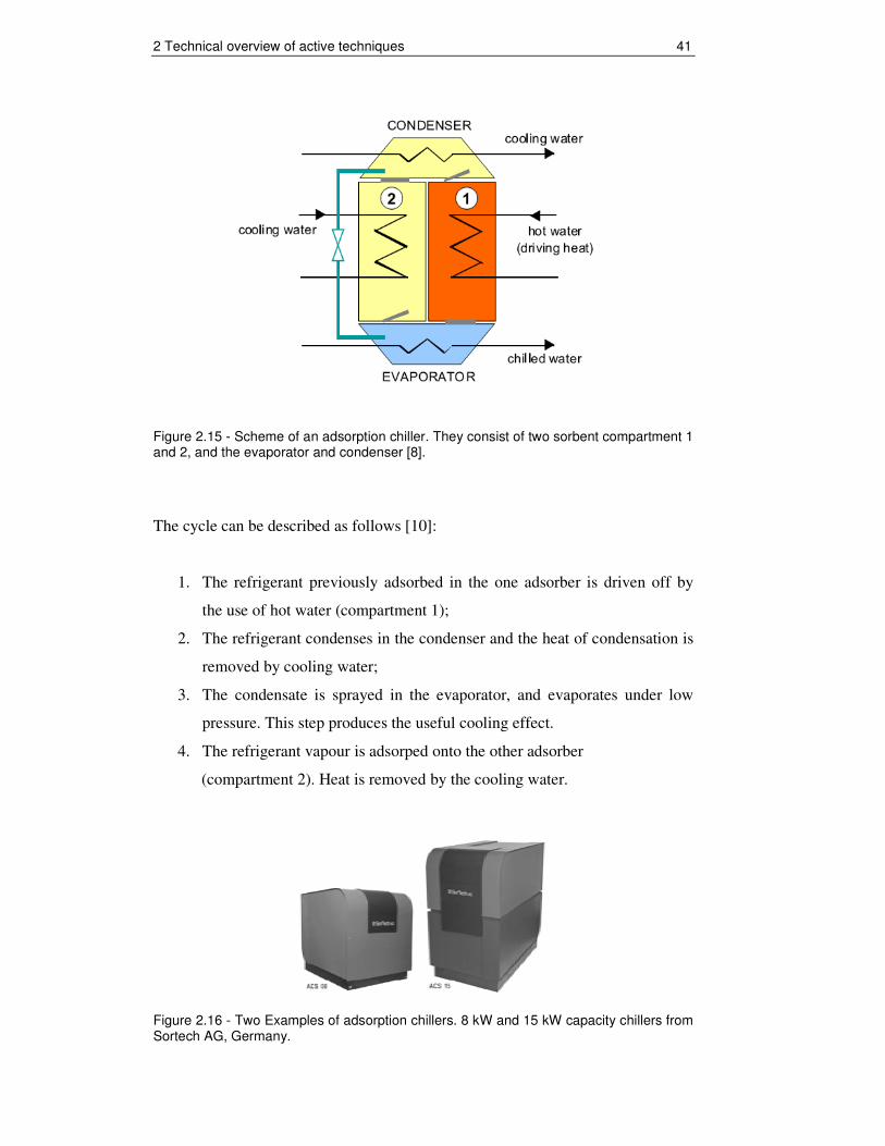
Figure 2.15 - Scheme of an adsorption chiller. They consist of two sorbent compartment 1 and 2, and the evaporator and condenser [8].
The cycle can be described as follows [10]:
1. The refrigerant previously adsorbed in the one adsorber is driven off by
the use of hot water (compartment 1);
2. The refrigerant condenses in the condenser and the heat of condensation is
removed by cooling water;
3. The condensate is sprayed in the evaporator, and evaporates under low
pressure. This step produces the useful cooling effect.
4. The refrigerant vapour is adsorped onto the other adsorber
(compartment 2). Heat is removed by the cooling water.
Figure 2.16 - Two Examples of adsorption chillers. 8 kW and 15 kW capacity chillers from Sortech AG, Germany.

2 Technical overview of active techniques 42
Advantageous are the absence of a solution pump and a noiseless operation.
The COP values of Adsorption chiller are around 0.6. The chiller start to run at
60°C hot water but with low performance, but at already at 75°C and a cooling
water (cooling tower) of 26°C the full power capacity is achieved.
Table 2.1, compares the performance of the Yakazi WFC-SC 10 (35kW/10TR)
Absorption chiller and the Sortech ACS-15 Adsorption Chiller (15kW/4.3TR) as
function of the driving and cooling water temperature.
Absorption Chiller (Yazaki WFC-SC10) 35 kW (10 TR)
Adsorption Chiller (Sortech ACS-15) 15 kW (4.3 TR)
Cooling Capacity Factor
Driving / Cooling Water
Temperature
Cooling Capacity Factor
Driving / Cooling Water
Temperature
0.5 75°C/26°C 1 75°C/26°C 1 80°C/26°C - -
1.2 85°C/26°C 1.1 85°C/26°C 1.42 95°C/26°C 1.27 95°C/26°C
1 88°C/31°C 0.8 88°C/31°C
0,65 80°C/31°C 0.7 80°C/31°C Table 2.1 - Cooling Capacity of an Absorption- and an Adsorption chiller in relation to driving- and cooling water Temperature. Source: Technical Data sheets
The Yakazi WFC-SC 10 (35kW/10TR) Absorption chiller starts to work at
approx. 75°C, but only with the half capacity. With an hot water temperature of
80°C and an cooling water temperature of 26°C the chiller run with full
performance, also at 88°C and a cooling water temperature of 31°C.
The cooling water of 26°C was chosen because a wet cooling tower can cool
down the water till 26°C by an ambient dry bulb temperature of 27°C and a
relative humidity of 60%, which meets the climate conditions from São Paulo
during the summer.
The lower limit temperature of the cooling water is usually 3°C to 5°C above the
wet-bulb temperature of air.
2 Technical overview of active techniques 43
A relative humidity of 80% and a dry-bulb temperature of 30°C can also be
reached; this corresponds to the summer temperature in Rio de Janeiro and a
cooling water temperature of 31°C (wet-bulb air temperature +5°C). In this case
the performance of the Absorption chiller is higher.
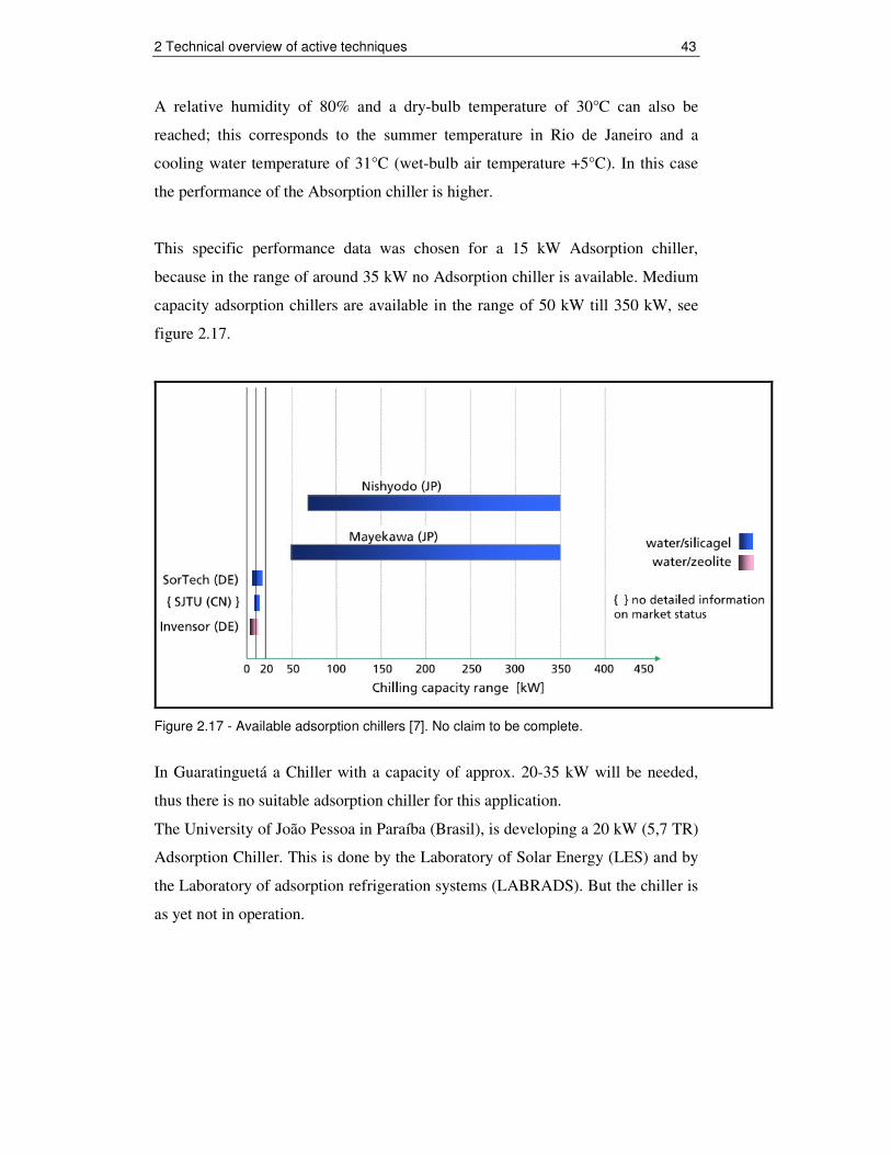
This specific performance data was chosen for a 15 kW Adsorption chiller,
because in the range of around 35 kW no Adsorption chiller is available. Medium
capacity adsorption chillers are available in the range of 50 kW till 350 kW, see
figure 2.17.
Figure 2.17 - Available adsorption chillers [7]. No claim to be complete.
In Guaratinguetá a Chiller with a capacity of approx. 20-35 kW will be needed,
thus there is no suitable adsorption chiller for this application.
The University of João Pessoa in Paraíba (Brasil), is developing a 20 kW (5,7 TR)
Adsorption Chiller. This is done by the Laboratory of Solar Energy (LES) and by
the Laboratory of adsorption refrigeration systems (LABRADS). But the chiller is
as yet not in operation.

2 Technical overview of active techniques 44
2.1.1.3 Heat Rejection
An important component of solar-assisted air-conditioning is the cooling tower for
the heat rejection. The cooling tower including cooling water circulation pump
consumes the most electrical energy and influences the chiller performance.
Figure 2.18 illustrates as an example the difference in the demand of heat
rejection between a conventional compression chiller and an ab-or adsorption
chiller system.
The higher demand of heat rejection in thermal chiller systems occurs through the
fact that the building extracted heat (“useful cold”) and the driving heat is charged
to the environment at ambient (medium) temperature level.
Figure 2.18 - Example on the demand for heat rejection in a conventional electrically driven compression chiller system (left) and in a (single-effect) thermally driven chiller system (right). In the comparison, the chilling capacity is 1 kW in both systems. Typical efficiency numbers have been used. Source: Tecsol
There are different possibilities and heat rejection technologies. Heat rejection by
use of ground water, sea water, river or spring water causes the lowest electricity
consumption, but is depends on the environment conditions. Basis for engineering
of such system was found by [13].

2 Technical overview of active techniques 45
The focus on this chapter is the most applied heat rejection technology - wet
cooling by means of open cooling towers. The Figure 2.19 below illustrates the
principle of such a heat rejection chiller:
The cooling water is sprayed on top of the cooling tower towards the filling
material, which increases the effective exchange area between air and cooling
water. The main cooling effect is obtained through evaporation of a small
percentage of the cooling water (typically < 5%); this loss has to be compensated
by fresh water supply. Then, the cooled water returns to the cooling circuit of the
chiller.
A fan removes the saturated air in order to keep the process running. The process
is very efficient in appropriate climates and in principle, the limitation
temperature of the returned cooling water is not far from the wet-bulb temperature
of the air (3° to 5°C above the wet-bulb temperature) [7].
Figure 2.19 - Typical scheme of an open wet cooling tower [10].
In Brazil wet cooling towers are available. The company International
Refrigeração from São Paulo is dealing with small capacity wet cooling towers
which could be applied. In the main region of Brazil wet cooling towers must be
applied because of tropic climate. Because of the high ambient humidity dry
cooling towers with evaporation effect are not suitable.

2 Technical overview of active techniques 46
2.1.2 Open cycle processes
Instead of chilled water, open cycles produce directly conditioned air. The cooling
effect bases on a combination of evaporation cooling with air dehumidification by
a desiccant (hydroscopic substance).
The components for such a cooling process, such as desiccant wheels, heat
recovery units, humidifiers, fans and water air heat exchangers are standard
components for air conditioning applications in buildings and factories since
many years.
Figure 2.20 shows the standard in a desiccant evaporative cooling system (DEC):
Figure 2.20 - Scheme of a solar thermally driven solid Desiccant Evaporative Cooling system (DEC), using rotating sorption and heat recovery wheels [8].

2 Technical overview of active techniques 47
The successive processes in the air stream are as follows:
1 � 2 sorptive dehumidification of supply air; the process is almost adiabatic and the air is heated by the adsorption heat released in the matrix of the sorption wheel
2 � 3 pre-cooling of the supply air in counter-flow to the return air from the building
3 � 4 evaporative cooling of the supply air to the desired supply air humidity by means of a humidifier
4 � 5 the heating coil is used only in the heating season for pre-heating of air 5 � 6 small temperature increase, caused by the fan 6 � 7 supply air temperature and humidity are increased by means of internal
loads 7 � 8 return air from the building is cooled using evaporative cooling close to
the saturation line 8 � 9 the return air is pre-heated in counter-flow to the supply air by means of a
high efficient air-to-air heat exchanger, e.g. a heat recovery wheel 9�10 regeneration heat is provided for instance by means of a solar thermal
collector system 10�11 the water bound in the pores of the desiccant material of the dehumidifier
wheel is desorbed by means of the hot air 11�12 exhaust air is removed to the environment by means of the return air fan.
The application of this cycle is limited to temperature climates, since the possible
dehumidification is not high enough to enable evaporative cooling of the supply
air at condition with far higher values of the humidity of ambient air [7].
Generally, desiccant evaporative cooling system makes sense in regions with
moderately hot and moderately humid climate and in buildings with a centralized
ventilation system. For the hot and humid climate in Brazil other configurations,
like pre-dehumidification of the supply air by electric compression chilling must
be applied. These configurations consuming on the other hand more electrical
energy, thus no alternative to closed chilled water systems.
A study of the LEPTIAB (2008), University in La Rochelle, France shows clearly
the limitations of the desiccant cooling technique regarding outside conditions. It
demonstrates that high outside temperature reduces significantly the performance
of the desiccant wheel.

2 Technical overview of active techniques 48
Regarding the outside humidity ratio even if the dehumidification increase with
increasing outside humidity ratio, we noticed that for outside temperature beyond
30°C the maximum dehumidification rate is 6 g/kg. Taking into account the
maximum humidity inside the building (e.g. 11.8 g/kg) and the humidification
across the supply humidifier we conclude that the maximum outside humidity
under which a desiccant system will operate efficiently is 14.5 g/kg [14].
11.8 g/kg indoor humidity corresponds to a relative humidity of 60% at 24°C and
14.5 g/kg to 55% at 30°C. In Guaratinguetá and in and the main regions of Brazil
the temperatures in summer are during the day often beyond 30°C and over 55%
relative humidity, normally around 70-80%. The next figures show the maximum
Temperature and relative humidity at the first day of the summer season 2009
from January till March.

2 Technical overview of active techniques 49
Figure 2.21 - Relative humidity of the air in relation to the maximum Temperature during the summer season 2009 from January till March chosen always the first day of the month at noon. Source: Brazilian national institute of meteorology (www.inmet.gov.br/html/clima.php).

2 Technical overview of active techniques 50
2.1.3 Solar thermal collector
A broad variety of solar thermal collectors is available and many of them are
applicable in solar cooling and air-conditioning systems. However, the
appropriate type of the collector depends on the selected cooling technology and
on the site conditions, i.e., on the radiation availability. General types of
stationary collectors are shown in Figure 2.22, construction principles of
improved flat-plate collectors and evacuated tube collectors are given in Figure
2.23. The use of cost-effective solar air collectors in flat plate construction is
limited to desiccant cooling systems, since this technology requires the lowest
driving temperatures (starting from approx. 50°C) and allows under special
conditions the operation without thermal storage. To operate thermally driven
chillers with solar heat, at least flat plate collectors of high quality (selective
coating, improved insulation, high stagnation safety) are to be applied [7].
Figure 2.22 - General types of stationary solar collectors [7].

2 Technical overview of active techniques 51
A wide range of concepts for evacuated tube collectors exist, e.g., collectors with
direct flow of the collector fluid through the absorber pipe, or with a heat pipes in
the tube. Also, the glass tube may either follow the traditional principle of a tube,
sealed on both ends, or may follow the thermos flask principle [7].
Figure 2.23 - Examples for different construction principles of stationary collectors [7].

2 Technical overview of active techniques 52
Top: flat-plate collector, applicable with good results in the temperature range up
to 90°C. The heat losses are minimised through improved insulation and an
additional convection barrier (teflon foil) between glass cover and absorber.
Source: S.O.L.I.D. Other manufacturers use a second glass cover and/or anti-
reflective coatings. Middle: two principles of evacuated tube collectors. On the
left, the ‘classical’ principle is shown, demanding for a vacuum tight sealing. On
the right, the thermos flask principle is shown. Source: ISE. Bottom: application
of the heat-pipe principle. The pipe is freeze protected and stagnation safe (but not
the collecting pipe).This collector type usually has the highest cost of evacuated
tube collectors [7].
The solar thermal market in Brazil is currently growing with an annual rate of
approx 20%, the cumulated installed area is given with 4,4 million m² by 2008
[8].
In the year 2008 there were 20 companies offering by the INMETRO (Brazilian
National Institute of Metrology, Industrial Standardization and Quality)
certificated solar thermal collectors. The most of this companies dealing with flat
plate collectors in the low temperate range for domestically water heating up to
60°C.
These types of collector have a low efficiency at high temperature, like 80-90°C
which is needed for driving a thermal chiller.
There are two companies in Brazil which are offering high quality Flat-Plate
collectors with a selected coating and an improved insulation and one company
who offers an evacuated tube collector.
These more efficiently collectors will be tested of their applicability due to
simulation with hourly climatic data to know their efficiency in dependency of the
ambient temperature, Solar irradiation and hot water temperature. Besides this, a
CPC collector without vacuum will be simulated. With these data the size of the
collector field can be dimensioned and the relation collectors cost and
performance can be de demonstrated.

2 Technical overview of active techniques 53
The results will be discussed in sub-section 3.2.2.3.1. Thermal solar collector
comparison.
At this point, it should be described how the colleted efficiency curve will be
calculated.
The collector efficiency curve (Eq. 2.1) obtained to EN 12975-2:2006 (European
standard):
2
0 1 2
( )m a m at t t ta a
G Gη η
− −= − − (Eq. 2.5)
with
η0 = optical efficiency
a1, a2 = collector heat-loss coefficients [W/(m²K)], [W/(m²K²)]
tm = collector temperature (average between input and output temperature) [°C]
ta = ambient temperature [°C]
G = solar irradiance at collector surface [W/m²]
The efficiency equation used by INMETRO Brazil is as follows:
0 1m at t
aG
η η−
= − (Eq. 2.6)
The second part of equation is not considered; this means that the second heat loss
coefficient which is a function of the temperature difference does not enter in the
efficiency calculation. The result is a linear efficiency curve. Practical
measurements on solar panels show that this linear description in some cases does
not adequately match the reality, thus large temperature differences between the
absorber and ambient, the heat losses does not increase linearly with the
temperature difference, due to higher amount of heat dissipation. This means, that
the a2-value is not constant, it’s a function of temperature difference.

2 Technical overview of active techniques 54
To capture this more realistic situation, the second approximation equation,
including an added a quadratic term should be used (see equation 2.5).
To compare Brazilian collectors with European collectors and to have a more
realistic approach of the efficiency behaviour the second a2-value is needed.
Through contacts to the GREENSolar (National Test laboratory at the PUC
University in Minas Gerais) the a2-values of the Brazilian collectors were
generated and for the Master Theses provided.
Figure 2.24 - Examples on solar collector, installed for solar cooling applications [7].
Note: Left: Flat-Plate CPC collector, installed at the National Energy Research
Centre in Lisbon Source: INETI and Right: Evacuated tube collector at the wine
storage building in Banyuls, France. Source: Tecsol

2 Technical overview of active techniques 55
2.2 Non- thermally driven application 2.2.1 Conventional electricity driven vapour compression chiller
The most common refrigeration process applied in air-conditioning is the vapour
compression cycle. Most of the cold production for air-conditioning of buildings
is generated with this type of machine. The process employs a chemical
refrigerant, e.g., R134a. A schematic drawing of the system is shown in Figure
2.25. In the evaporator, the refrigerant evaporates at a low temperature. The heat
extracted from the external water supply is used to evaporate the refrigerant from
the liquid to the gas phase. The external water is cooled down or – in other words
– cooling power becomes available. The key component is the compressor, which
compresses the refrigerant from a low pressure to a higher pressure (high
temperature) in the condenser [10].
Figure 2.25 Schematic drawing of a vapour compression chiller [10].
For a conventional, electrically driven vapour compression chiller, the COP is
defined as follows
Qc = cooling capacity [kW]
Pel = electric power input [kW]
c
el
QCOP
P=
2 Technical overview of active techniques 56
The COP of vapour compression chillers depends on the pressure difference
between evaporator and condenser and thus on the temperature difference
between the evaporator and the condenser. Higher temperature differences lead to
a reduced COP. Concepts that make lower temperature differences possible are
therefore beneficial since they reduce the energy consumption of the process [10].
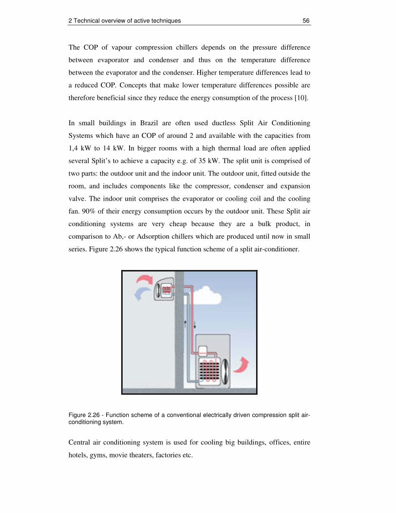
In small buildings in Brazil are often used ductless Split Air Conditioning
Systems which have an COP of around 2 and available with the capacities from
1,4 kW to 14 kW. In bigger rooms with a high thermal load are often applied
several Split’s to achieve a capacity e.g. of 35 kW. The split unit is comprised of
two parts: the outdoor unit and the indoor unit. The outdoor unit, fitted outside the
room, and includes components like the compressor, condenser and expansion
valve. The indoor unit comprises the evaporator or cooling coil and the cooling
fan. 90% of their energy consumption occurs by the outdoor unit. These Split air
conditioning systems are very cheap because they are a bulk product, in
comparison to Ab,- or Adsorption chillers which are produced until now in small
series. Figure 2.26 shows the typical function scheme of a split air-conditioner.
Figure 2.26 - Function scheme of a conventional electrically driven compression split air-conditioning system.
Central air conditioning system is used for cooling big buildings, offices, entire
hotels, gyms, movie theaters, factories etc.

2 Technical overview of active techniques 57
If the whole building is to be air conditioned an air-duct system must be installed.
The central air conditioning system is comprised of a huge compressor that has
the capacity to produce hundreds of tons of air conditioning. Cooling big halls,
malls, huge spaces, is usually only feasible with central conditioning units.
There are three types of vapour compression chillers:
Reciprocating compressors:
COP 2.0 – 4.7;
Chilling capacity 10 – 500 kW
Screw compressors:
COP 2.0 – 7.0;
Chilling capacity 300 – 2000 kW
Centrifugal compressors:
COP 4.0 – 8.0;
Chilling capacity 300 – 30000 kW.
2.2.2 Photovoltaic driven compression cycle
There is also the possibility to run a conventional air-conditioning system by a
photovoltaic system (PV).
Two technical solutions can be realized:
• A grid connected PV system generates independently on an annual
average a certain amount of the energy, consumed by the compression
chiller. At the moment the specific investment cost for 1 kW is around
3000 €. This match the specific investment of 1 kW solar thermally
generated cooling power. This is only the investment for the
considered material; the installation cost of a PV system is lower,
because there is no need of piping. But, there is no electricity feed in
regulation for PV generated energy in Brazil.

2 Technical overview of active techniques 58
• The PV system is direct connected to the compression chiller, thus it
can run without any grid connection. As yet there are only applications
in small capacity ranges. e.g. food or medicine storages, since special
components are necessary for this direct coupling. There exits no data
base of the investment costs, but there are probably equal or higher
then for small solar thermal driven cooling application.
Figure 2.27 - Solar cooling possibilities [8].
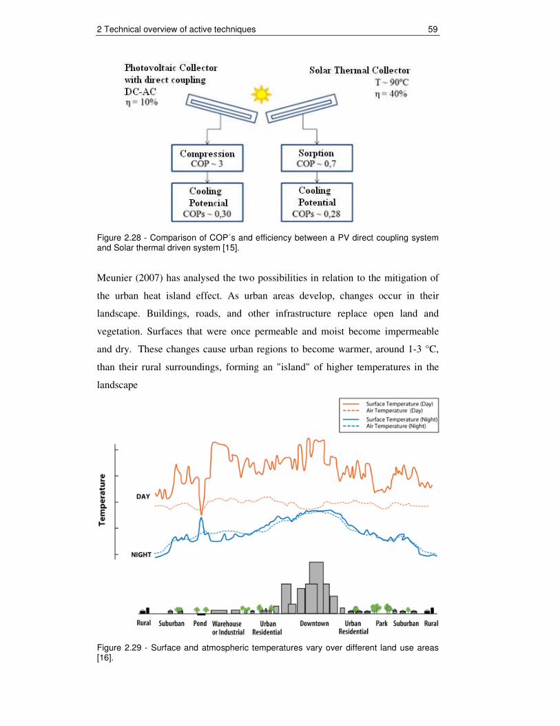
It’s important to note that the solar collector field has at all options more or less
the same size. The next figure shows a comparison between a PV direct coupling
system and Solar thermal driven system, indicating the COP and efficiency of
each system. Finally, solar thermally driven COP´s in the order of 0,28, compared
to 0,3 photovoltaic panel system / vapour compression. Here must be mentioned
that the COP of Solar/Sorption System can be increased by using a collector with
an higher efficiency, for example some special types of Evacuated Tube collectors
have an efficiency of max. 60% at 90°C water temperature. Normal Flat-Plate
collectors with selective coating have efficiency at this temperature level of only
40%.
2 Technical overview of active techniques 59
Figure 2.28 - Comparison of COP´s and efficiency between a PV direct coupling system and Solar thermal driven system [15].
Meunier (2007) has analysed the two possibilities in relation to the mitigation of
the urban heat island effect. As urban areas develop, changes occur in their
landscape. Buildings, roads, and other infrastructure replace open land and
vegetation. Surfaces that were once permeable and moist become impermeable
and dry. These changes cause urban regions to become warmer, around 1-3 °C,
than their rural surroundings, forming an "island" of higher temperatures in the
landscape
Figure 2.29 - Surface and atmospheric temperatures vary over different land use areas [16].

2 Technical overview of active techniques 60
The temperatures displayed above do not represent absolute temperature values or
any one particular measured heat island. Temperatures will fluctuate based on
factors such as seasons, weather conditions, sun intensity, and ground cover [16].
Higher temperatures in summer increase energy demand for cooling and add
pressure to the electricity grid during peak periods of demand. One study
estimates that the heat island effect is responsible for 5–10% of peak electricity
demand for cooling buildings in cities [17].
Meunier (2007) calculated the albedo and found out that thermal solar collectors
transfer to the ambient air 30% of incident radiation, while the photovoltaic
collector’s transfers 60%.
A portion of the incoming solar radiation is absorbed by the surface and a portion
is also reflected away. The proportion of light reflected from a surface is the
albedo. Albedo values range from 0 for no reflection to 1 for complete reflection
of light striking the surface. It can be expressed as a percentage (albedo multiplied
by 100). For instance, grass has an albedo of about 0.25. This means that of the
incoming solar radiation that strikes the grass, 25% of it is reflected away. On the
other hand, highly reflective surfaces like snow have an albedo upwards of 0.87,
or 87% of sunlight is reflected away. New concrete has an albedo of 55%, this
means that 55% of the solar radiation is reradiated and 45% is absorbed by the
concrete. This percentage of solar energy absorbed by the concrete is emitted
during absence of the sun and thus influences the urban microclimate in a
negative way through causing a higher temperature as normal.
According Meunier (2007) a thermal solar collector absorbs 70% of the incoming
solar energy [18]; this energy is used to generate cold water for air conditioning
and is not more emitted to the environment. PV collectors absorb only 40% of the
solar energy and reradiate the rest to the ambient air. Hence these facts solar
thermal systems are more potential to mitigate the urban heat island effect.

2 Technical overview of active techniques 61
Figure 2.30 - Right: Low albedo of a solar thermal collector, only 30% is reflected; the rest is absorbed by the collector heating up the fluid. Left: PV collector transfer 60% of incident radiation to ambient air.
PV systems will not further considered, because the focus is on thermal systems
and until now there are only existing PV direct coupling systems in very small
range e.g. stand alone solar cooling containers. Air conditioning of buildings is
still not realized with PV. Grid connected PV is also not to be promoted in Brazil.

3 Case Study 62
3 Case Study
In this chapter the performance of a solar-assisted air-conditioning in relation to
solar yield and building cooling is verified. This occurs on the bases of a case
study. The object of the case study is the intended auditorium at the UNESP
University in Guaratinguetá, which is likely to be equipped with a solar cooling
system. The previous chapter is used as a technical basis for selecting the
appropriate technology and their components.
At first, some background information about the project is given. Then the
auditorium is designed for specific climate conditions, - and building data
simulated. As well, it is shown how the cooling load (demand) through building
insulation and adaptation of the indoor air temperature can be decreased.
Thereafter, different collector types and as well on the Brazilian market available
collectors are simulated on their suitability and the cost-benefit ratio. The chapter
concludes with an assessment of the economically feasibility in comparison to
conventional compressor split air-conditioning system. Because of the demand of
a back-up system to cover the cooling load during cloudy days the economically
feasibility calculation of two back-up system is included, too. These are a
separated electric driven split air-conditioning system and a thermal gas back-up
which heats up the chiller driving water. Finally, the environmental benefit of the
solar-assisted air-conditioning system is demonstrated.
Figure 3.1 represents the interactions which must be considered during the
planning phase of a solar cooling system.

3 Case Study 63
Figure 3.1 - Interaction in the design and layout of a solar-assisted air-conditioning system, to be considered in the planning phase [7].
The proper design of a solar-assisted air-conditioning system and the choice of the
components interact to a high degree with the site conditions (climate conditions)
and with the demand for cooling (load conditions). As one of the most cost-
effective measures in the planning of an air-conditioning system is the reduction
of cooling loads [7].
3.1 Background Information
It’s intended to equip an auditorium of the planned centre for energy efficiency at
the UNESP University in Guaratinguetá with a solar assisted air-conditioning
system. The case study is used to provide the necessary theoretical base which is
for the realization of such an important project. The project is likely carried out
within the cooperation of the GTZ (german technical cooperation) and its main
partner, the Eletrobrás and its component PROCEL (Brazilian electricity
Conservation Program). The GTZ Energy program in Brazil has the task to
strengthen the role of renewable energy sources and efficiency.

3 Case Study 64
The Eletrobrás/PROCEL will establish a Centre of Energy Efficiency at the São
Paulo State University (UNESP). In this centre, the latest architectural and
technological energy saving measures will be applied. The research, training and
exhibition centre has a totally area of 1.500 square meters and receive estimated
up to 20.000 visitors per year. Visitors and students will be demonstrated how
energy can be efficiently used in buildings. Besides the function as a "show room"
it will contribute through education and research to the dissemination and
development of energy saving measures in Brazil.
As part of this project the Eletrobrás/PROCEL intends, as mentioned above, the
implementation of solar cooling. The pilot project will provide a clear
demonstration character and will be accessible to visitors. The application at the
UNESP University allows a high dissemination character and could attract the
attention of decision makers, planners, building services as well as end-users.
A monitoring plan will be created to collect the key performance parameters of
the pilot plant, thus a continuous monitoring can be carried out by the UNESP
University. The results and experiences of the pilot project will be conveyed to the
Brazilian society through publications in professional journals and lectures, events
and specialist institutions.
Should the project be successfully implemented, it will show that the "new"
technology reliably functions. Consequently, the pilot project can serve as a
multiplier for the whole country. Partnerships between e.g. a system provider of
solar-assisted air-conditioning systems, a refrigeration firm and thermal collector
manufacturers could arise. Last but not least it could bring some opportunities for
the development of these segments.
The time schedule of the centre for energy efficiency is as follows:
In September 2009 the project was tendered. The award of the tendering will be
decided until January 2010. Around one month later the construction starts. The
goal is complete the construction until the end of 2011.

3 Case Study 65
For the tender, it is required a specification for the integration of a solar-assisted
air-conditioning system in the auditorium (see appendix A1).
3.1.1 Location and climate conditions
Guaratinguetá is located in south-eastern Brazil. The municipality of
Guaratinguetá is located in the “Vale do Rio Paraíba do Sul”, in the eastern state
of Sao Paulo. The region is near the Tropic of Capricorn. The municipal seat has
the following geographic coordinates: 22°48'43" south latitude and 45°11'40" W,
distant 237km from Rio de Janeiro and 163km from São Paulo. Elevation: 530
meters.
Figure 3.2 - Location of Guaratinguetá in Brazil within the State of São Paulo
The relative humidity varies around 70%. The climate is tropical of altitude
(meaning hot and humid in the summer, hot and dry in winter).
The city is considered the hottest of the Paraíba Valley, has an average
temperature of 22,6 C°.

3 Case Study 66
Month Temperature °C
Umidity %
Pressure mb
Precipitation mm
January
25,7 69 950,5 197,7
February 26,3 63 951,4 152,1
March
25,0 69 951,9 214,2
April 22,8 68 953,8 81,7
May 20,6 70 955,1 60,6
June 18,6 68 957,0 35,2
July 18,6 66 957,9 24,4
August 20,0 63 965,5 22,8
September 21,3 64 955,2 65,8
October 23,2 65 952,6 91,4
November 24,6 68 951,5 144,9
December 24,8 71 950,3 212,9
Average 22,6 67 953,6 108,6
Table 3.1 - Monthly average climate data of Guaratinguetá 1962-1991 (modified) [19].
Figure 3.3 illustrates a global radiation map provided by the model BRAZIL-SR
for the south-east of Brazil. As can be seen, the highest levels of the overall solar
radiation for the month of March 2005 occur in the north of Minas Gerais with
around 6 kWh/m² and the lowest, around 4.75 kWh/m², in the southern state of
Sao Paulo. The solar radiation in Guaratinguetá lies with around 5.5 kWh/m² in
between.
Figure 3.3 - Global solar radiation map in March 2005 provided by the model BRAZIL-SR for the south-east of Brazil [20].

3 Case Study 67
Guaratinguetá has around 113.357 habitants and is one of the most important
commercial and tourist cities of the Paraíba Valley. Guaratinguetá lies between
the São Paulo and Rio de Janeiro in the Brazilian Megalopolis. Especially, São
Paulo is growing through the Paraíba Valley along the Via Dutra Highway toward
Rio de Janeiro: some people are already forecasting a megacity to be called São-
Rio.
Figure 3.4 - Brazilian south-eastern Megalopolis
Therefore the pilot project, would be established in an area where the population
density is the highest of Brazil, thus there exits, as well, a high dissemination
potential within this region. Finally, it could contribute to their sustainable
development, through minimizing CO2 emissions and avoiding hazardous
refrigerants.

3 Case Study 68
3.2 Simulation and design
3.2.1 The thermal load of the building
This chapter deals with the thermal behaviour of the building. It gives a statement
about the maximum cooling load and how it changes due to climate change during
one day or within one year. The cooling load is the amount of heat that must be
dissipated from the room or building to allow a temperature which corresponds to
the thermal comfort. Due to this information the solar congruence can be
investigated, this means the relation between building cooling demand and
cooling yield by solar irradiance. This simulation serves as basis for the
technology choice and economic assessment.
The Program HELIOS-PC from Econzept Energieplannung GmbH was used for
the dynamic building simulation. The thermal building simulation program
HELIOS-PC was developed in the year 1992 principally by the technical
University of Karlsruhe (Germany). It bases due to the user interface HELEX 2.1
for Windows on Excel macros.
Different factors have an influence of the building cooling load. A distinction is
made between external and internal cooling load cooling load. The internal
cooling load is the heat gain, inside the building through persons, machines and
lighting. Heat gains through the windows and walls (building envelope) are
called external cooling load.

3 Case Study 69
Figure 3.5 - External/internal cooling loads (modified) [21].
The specific building data which are used for the cooling load calculation are
listed in the following chapter.
3.2.1.1 Simulation building data
According the Architects from PROCEL the pretended Auditorium has a Floor
space of 150m² and a ceiling high of 3.25 m. It’s a one floor building, thus 150 m²
of free roof space for solar collectors are available. It has capacity for 100
Students. The building envelope is limited to U < 3,7 W/(m²*K) and there are no
windows. During the preparation of the master theses were no further data on the
building available.
Due to these appointments the necessary data’s are as follows:

3 Case Study 70
Hygienic Air change:
Because of providing sufficient air/oxygen for breathing the total volume of the
auditorium must be exchanged with fresh air from the enviroment. The from
outside taken air has always the condition of the present climate condition. The
hygienic air change rate is 30 m³/h per person, 100 Students relate to 3000 m³/h.
With an total volume of the auditorium of 487,5 m³ the hygienic air change rate is
6,15 1/h. The air change is continuous.
Internal Cooling load:
It’s assumed that the auditorium will be fully occupied from 8 h to 17 h, during
weekday. Therefore 100 Persons are present, seated and doing light work, thereby
can 80 W per Person calculated, accordingly 8 kW. The lighting load is 15 W/m²
by an area of 150m² the total lighting load 2,3 kW. 1,7 kW is for equipment and
appliances of the auditorium e.g. Laptops. According this assumption the total
internal load is 12 kW.
Building envelope (U-Values):
The Heat transfer U –Value is determined by the reciprocal of thermal resistances
of each component of a building envelope component.
Two cases are simulated:
A: auditorium without external wall insulation: U = 3,7 W/(m²*K) and
B: auditorium with externals wall insulation U = 0,24 W/(m²*K)
The next table shows the different simulation values regarding the constructional
compositions of the building envelope. It is assumed that the length of the
auditorium is 15 m and the width 10 m.

3 Case Study 71
Facade area
(North&South)
Facade area
(East&West)
Roof
Ground floor
basement
Area [m²]
-
65
(2x10x3,25)
97,5
(2x15x3,25)
150
150
A
Reinforced
concrete /18
Reinforced
concrete /18
Reinforced
concrete /15
EPS*/ 2
light-weight
concrete/ 6
Gravel-Sand /1m
Reinforced
concrete /18
Components
(Materials
from outside
to inside)/
thicknees
[cm]
B
Reinforced
concrete/15
with
EPS*/18
Reinforced
concrete /15
with
EPS*/18
Reinforced
concrete /15
EPS*/16
light-weight
concrete/ 6
Gravel-Sand /1m
EPS*/ 7
Reinforced
concrete /18
A
3,7
3,7
0,96
0,59
Heat transfer
U-values
[W/(m²*K)]
B
0,24
0,24
0,2
0,3
*EPS – expanded Polystyrene insulation plate
Table 3.2 - U-values of the auditorium building model
It must be mentioned that the energy transmissivity of the ground floor and roof
bases one a steady soil temperature of 20°C and a average outside temperature
between thermal solar collector field and the roof of 24°C. The roof of the
auditorium will be almost completely covered by collector field and equipment,
thus provide shading. Beside the roof shadowing, the building is unshaded and
has no windows or intermediate walls.
Figure 3.6 shows the Interface-mask of thermal simulation program HELEX 2.1
from the Helios-PC Software.

3 Case Study 72
Figure 3.6 - Snapshot of HELEX 2.1 Interface

3 Case Study 73
The thermal behaviour of the building will be assessed in an hourly annual, in an
hourly monthly and in hourly daily simulation figures. The simulation is realized
with three different indoor set point Temperatures of the auditorium. These are
20°C, 24°C and 26°C. In Brazil the air-conditioning systems are often oversized,
thus the indoor temperature is all over the year 18°C - 20°C. Therefore 20°C was
chosen to show how high is the cooling load and hence energy consumption in
comparison to an appropriate indoor temperatures of 24°C - 26°C. This
temperature range is in accordance with the Brazilian standards (PNB-10).
The indoor air temperature Ti is the most evident indicator of proper thermal
comfort, the temperature should be higher on lower activity level and lighter
clothing. For building cooling it is important that our body is capable to adapt to
seasonal conditions. Air humidity affects the latent heat transfer from the bodies
to the surrounding air. Therefore in case of higher temperatures the humidity has
to be lower [7].
External Temperature
Internal Conditions
dry-bulb temperature
[°C]
dry-bulb temperature
[°C]
wet-bulb temperature
[°C]
relative umidity
[%]
29
24,5 25,0 25,5 26,0
19,5 19,0 18,5 18,0
62,0 56,0 50,0 44,0
32
25,0 25,5 26,0 26,5
20,5 20,0 19,5 19,0
66,0 60,0 54,0 48,0
35
25,5 26,0 26,5 27,0
21,5 21,0 20,5 20,0
70,0 64,0 58,0 52,0
Table 3.3 - Internal thermal comfort conditions regarding the ambient summer temperatures (PNB-10, Brazil) [22].
To show the energy saving potential through building insulation a simulation is
realized with and with and without building insulation (U-Values see table 3.2
above). The building simulation developed by using Meteorological data from the
Meteonorm 5.1 software (edition 2003). There are hourly data of the ambient
temperature and horizontal global irradiation of one average year (8760 h) from
Guaratinguetá available.

3 Case Study 74
Meteonorm uses a database with long term monthly average measurement data
from different stations. In the recent software versions there are more than 7000
meteorological stations worldwide available. If no meteorological station is
available in the database for a desired site, meteorological data will be
interpolated based on the data of the nearest stations. In the Meteonorm 5.1
software are the Meteorological data from the year 1971 till 2003 collected.
The next chapter show the results of the simulation.
3.2.1.2 Results of the simulation
A: without insulation
Indoor set point
temperature Ti
[°C]
Maximum
Cooling Load
[kW]
Total annual
Cooling Load
[kWh]
Monthly
average
Cooling Load
[kWh]
Monthly
average Max.
Specific
Cooling Load
[W/m²]
20 30 59.663 4972 168
24 23,3 21.639 1803 103
26 19,4 10.169 847 86
Table 3.4 - Cooling Load results without building insulation
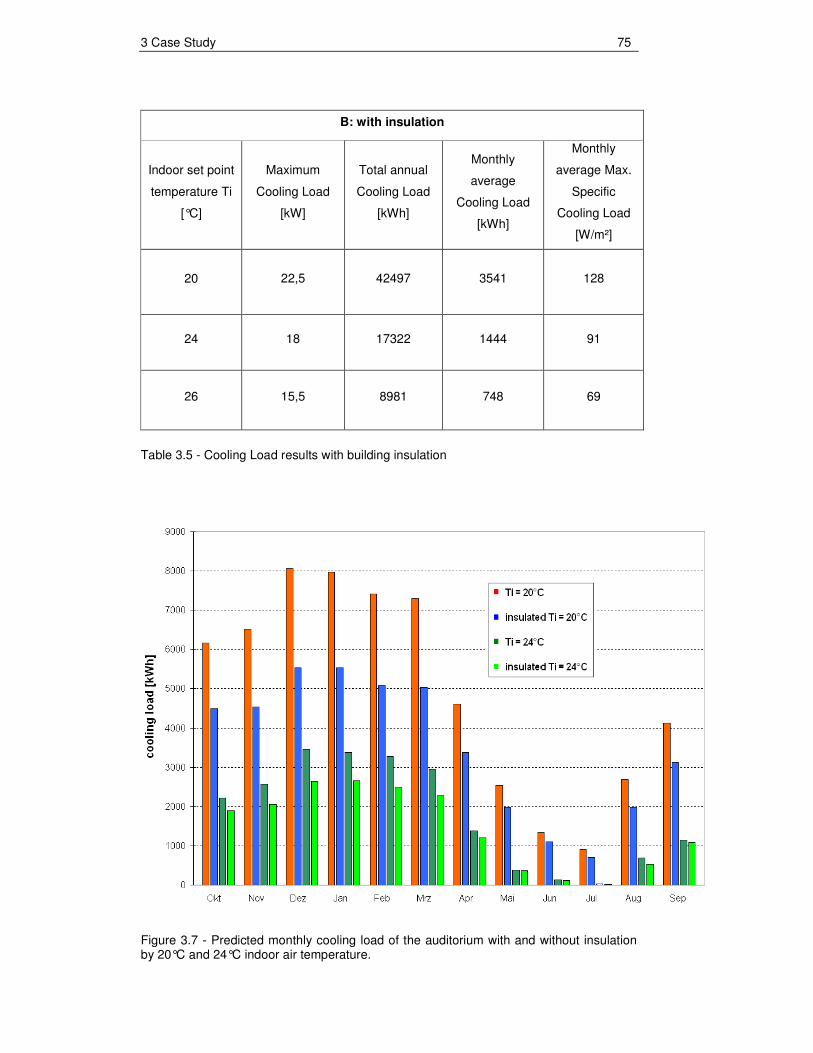
3 Case Study 75
B: with insulation
Indoor set point
temperature Ti
[°C]
Maximum
Cooling Load
[kW]
Total annual
Cooling Load
[kWh]
Monthly
average
Cooling Load
[kWh]
Monthly
average Max.
Specific
Cooling Load
[W/m²]
20
22,5 42497 3541 128
24 18 17322 1444 91
26 15,5 8981 748 69
Table 3.5 - Cooling Load results with building insulation
Figure 3.7 - Predicted monthly cooling load of the auditorium with and without insulation by 20°C and 24°C indoor air temperature.

3 Case Study 76
Figure 3.8 presents the typical daily thermal behaviour of the building during
summer. With an indoor air temperature of Ti = 20°C the maximum cooling Load
is 30 kW and at Ti = 24°C only 23 kW. In both cases the building is without
insulation. The normal cooling load range during the summer daytime is between
15 kW and 20 kW.
0
5
10
15
20
25
30
35
17.Dez 18.Dez 19.Dez
am
bie
nt
tem
per
atu
re [
°C]
0
5000
10000
15000
20000
25000
30000
35000
coo
ling
load
[W
]
T ambient Cooling Load Ti = 20°C Cooling Load Ti = 24°C
Figure 3.8 - Hourly cooling load pattern (hourly data) with Ti = 20°C and Ti = 24°C, at the predicted annual maximum ambient temperature of 32,7 °C (without insulation).

3 Case Study 77
3.2.1.2.1 Conclusion
It was established that the adjustment of the indoor air temperature within the
tolerance range of thermal comfort limits allows an enormous energy saving
potential for air-conditioned buildings.
At an indoor air temperature of Ti = 20°C the effect of building insulation
explicitly is noticeable and at 24°C and 26°C less. At this point it must be
highlighted that the auditorium has, due to the shadowing effect by the collector
field already a good "roof insulation", therefore, principally, the external walls
have an impact. However, in Brazil a building insulation would be profitable for
a long period, in the work of Carlos Gabriel Caruy (2009) payback times of two
month were calculated [23].
The economic feasibility of insulation for the auditorium was not calculated, since
it differ from the actual goal of this thesis. The focus of this work lies in the
economic analysis of a solar-assisted air-conditioning system.
Brazil has as yet no culture to improve the thermal comfort by building insulation.
Figure 3.9 is a funny room air-conditioner propaganda; it proposed that artificial
cooling of open air spaces (here the beach) would represent the most ineffective
use of electric energy (thus high expenses). Cooling the usually poorly insulated
indoor spaces in Brazil is about the same: a highly inefficient use of energy.
Figure 3.9 - “With Springer you are the one who makes the climate” Source: Mica Advertising Postcard 2004

3 Case Study 78
In this work the insulating effect was achieved principally due to 15 cm wide
polystyrene insulation plates at the exterior walls. This type of isolation is mainly
used for Houses in Germany. If in Brazil insulation would be applied, possible
mold growth by high air humidity must be considered. Fire prevention is also
always a very important point. In Brazil, natural alternative and CO2 neutral
insulation could be used e.g. coconut fibres, thus Brazilian natural recourses can
be utilized.
Figure 3.10 - Insulation with EPS Polystyrene plates in Germany. Source: www.netz-gemeinschaft.de/deetz/Tagebuch/Pict5379.jpg
Every building in Germany is insulated because of the high energy costs and
winter temperatures of 3°C averagely. During winter season the outside/inside
temperature difference is around ∆T = 17 K. The Temperature difference ∆T in
Brazil is during the summer around 10 K, which makes insulation economical.
In the next chapter the suitable air-conditioning system will be chosen, which
refers to the simulated cooling load at an indoor air temperature Ti = 24°C
(without building insulation).
By 29°C dry-bulb ambient temperature, a building indoor dry-bulb temperature of
24°C and < 65% relative humidity lies within the tolerance range of the Brazilian
thermal comfort standards.

3 Case Study 79
In Brazil lot of air-conditioned buildings maintains during summer an indoor
temperature of around 18-20°C. Such temperatures are resulted by an oversized
air-conditioning system and do not meet to the thermal comfort standard.
Refrigeration firms dimension often their systems through a rule of thumb,
calculate 3,5 kW (1 TR) cooling capacity for 15 square meters space, this
corresponds to a specific cooling load of 234 W/m². The Simulation has shown
that by an indoor temperature of 24°C the monthly average maximum specific
cooling load is only 103 W/m².
3.2.2 Selection and design of the equipment
In this chapter the appropriate technology will be chosen according the following
steps:
• Selection of the proper thermally driven cooling equipment and air-
conditioning system.
• Selection the proper type of solar collectors for the selected thermally
driven cooling equipment.
• Sizing of the solar collector field by a thermal simulation with regard to
energy and cost performance.
First of all it must be mentioned that due to the facts in sub-section 2.1.2 (Open
Cycle Processes) the appropriate technology is a closed cycle (chilled water)
system.
It consists of different sub- systems. According these sub-systems the next
chapters are structured.

3 Case Study 80
Figure 3.11 - Sub-systems and their components of a solar-assisted air-conditioning system (modified). Source: Solvis Energy Systems GmbH & CoKG
3.2.2.1 The cold production sub-system
The cooling demand peaks during the summer season is between 15 kW and 23
kW at an indoor air temperature of Ti = 24°C.
For this cooling Capacity range suits the (Yazaki WFC-SC10) 35 kW (10 TR)
single-effect LiBr-H2O Absorption Chiller. This Japanese chiller is often used in
solar cooling systems, because it has been for many years the smallest
manufactured absorption chiller. This chiller is worldwide available.
The cooling capacity of an Absorption chiller depends on two factors Hot water
driving temperature und cooling water inlet temperature. A performance curve
shows their influences of the cooling capacity.

3 Case Study 81
Figure 3.11 - Performance characteristics of Yazaki WFC-SC10 Absorption Chiller (Fancoil 7°C chilled water). Source: Yazaki Energy Systems Inc.
Model Yazaki WFC-SC10 SI unit
Cooling Capacity 35 kW
Heat Rejection – Cooling Tower Capacity
85,3
kW
COP 0,7 -
Cold water temperature in/out (chiller)
12,5 - 7,0 °C
Chilled water flow 5,508 m3/h
Hot water temperature in/out
(min. 75 ° C, max. 95 ° C) 88 - 83 °C
Hot water flow (min. 75 ° C, max. 95 ° C)
8,64 m3/h
Cooling water temperature in/out (chiller)
31 - 35 °C
Cooling water flow 18,36 m3/h
Table 3.6 - Technical data of the Yazaki WFC-SC10 Absorption Chiller. Source: Yazaki Energy Systems Inc.

3 Case Study 82
Further Technical data and information see appendix A2.
A COP of 0,7 and a capacity of 35 kW is reached by the chiller operation point at
88°C hot water inlet temperature and 31°C cooling water in inlet temperature. The
performance of the collector field regarding the hot water driving temperatures is
shown in the sub-section III.2.2.3 Heat production sub-system.
In Guaratinguetá the average relative humidity is around 70%. The cooling water
temperatures in relation to the dry-bulb air temperatures are as follows:
dry-bulb air temperature
[°C]
wet-bulb air temperature
[°C]
cooling water temperature (wet-bulb temperature + 5 K) [°C]
24 20 25 26 21,8 26,8 28 23,6 28,6 30 25,5 30,5 32 27,3 32,3
Table 3.7 - Cooling water temperature in relation to dry-bulb ambient air temperature and relative humidity of 70%.
The maximum cooling demand is normally during a dry-bulb temperature of
32°C. Due to this temperature the cooling water temperatures is around 32°C. The
advantage of the chosen chiller is that at this cooling water temperature and a hot
water temperature of only 82°C the chiller capacity is still 23 kW which meets
the maximum cooling demand at 24°C indoor dry-bulb air temperature.
The suitable wet cooling tower is available at the Brazilian company International
Refrigeração Ltda (www.internationalrefrigeracao.com.br). The Model F-32 must
be chosen for the Yazaki WFC-SC10 cooling water demand.

3 Case Study 83
Note: Temperature de Bulbo Úmido means wet-bulb temperature
Figure 3.12 - Technical data wet cooling tower from the Brazilian company Internacional Refrigeração Ltda.
3.2.2.2 The load sub-system – air-conditioning equipment
By the Chiller generated cold water load must distributed inside the building. The
cooling medium is water at 7°C for fan-coil operation or the second modus is
water with 18°C for the option to use a cooling ceiling.
To give a general overview of the generic classification of central Air-
conditioning system figure 3.14 is shown. Table 3.7 lists specific cooling
capacities of the different air- conditioning system. The maximum specific
cooling load of the building is 155 W/m² (23,3 kW) . This energy must be brought
into the building. According to the table for the auditorium only a fan-coil system
is recommended. A cooling ceiling can not be applied because it doesn’t bring the
necessary cooling load into building, as well not if the ceiling is 100% covered.

3 Case Study 84
Figure 3.13 - Generic classification of centralised air-conditioning systems [10].
Table 3.8 - Specific (max. possible) cooling capacities (W/m²) of different air-conditioning systems (see figure 3.14 above) [10]. *At higher ventilation rates **Values not known

3 Case Study 85
For cooling loads higher than 45 W/m² it must be chosen: air cooling based on
minimum required fresh air quantity (e.g. 30 to 50 m³/h per person) and secondary
cooling (water-based); e.g. system C (fan-coil) or A + D. The aim is to save costs
for ducting and energy for transportation of air and to avoid possible draughts
when introducing too much air into the room. Possible draught can be avoided by
using, for example, high-induction air outlets in the wall or swirl outlets in a
ceiling [10].
In tropical climate conditions the specific cooling capacity of a cooling ceiling is
as well limited, due to the high relative humidity. At a relative humidity of 70 -
80% only cold water of about 20°C can be used as medium, since temperatures
≤18°C falls below the dew point and create condensation at cooling panel. For
safety the water temperature in the cooling panels must be is always 2 K above
the dew point temperature. Therefore, ∆T is limited to 4 K at an indoor
temperature of 24°C. The maximum flow rate of cooling panel, here type Carat H-
84, is around 0.5 l/s. Due to a following calculation the possible cooling capacity
can be determined.
( ) wQ m t C T= ⋅ ⋅∆ (Eq. 3.1)
0,5 / 4186,8 / 4 8,3Q l s Ws kgK K kW= ⋅ ⋅ =
Cw – heat capacity of water
The maximum cooling load could of the auditorium could be only 8,3 kW, this
means the specific cooling at 150m² would be 55 W/m². As well, this calculation
demonstrates the limitation of active night-cooling applications within the tropics.
Active night-cooling exploit the colder night air temperatures to cool water due to
e.g. a wet cooling tower. During the day the stored chilled water circulates
through a cooling ceiling.
It must be added that the water temperature is limited by relative humidity and
temperature of the ambient air. The water temperature depends on wet-bulb
temperature +3-5 K. In tropical cities the relative humidity goes up to 80 - 90% at
night and only at the day it decreases to 60 -70%, however at an high air
temperature, hence to potential to cool the water till 15-20°C does not often exist.

3 Case Study 86
Figure 3.14 - Example of a Cooling panel Type Carat from Lindab Climate GmbH Source: Technical Data sheets
In Germany cooling ceilings are often applied due to lower noise emissions and
no energy consumption, despite higher investment costs. Only during 3% of
annual operation hours condensation occurs. Through an alarm system which
stops the water circulation condensation drops are avoided.
For the case study four Fan coil units were chosen; Model aquaris silent SP 50/51
from Schako Air distribution KG (www.schako.com). In Brazil fan-coils are a
standard product and applied in conventional air-conditioning systems.
Figure 3.15 - Cross-section of a typical simple fan-coil unit with one heat exchanger for air heating/cooling [10].

3 Case Study 87
3.2.2.3 Heat production sub-system
This chapter deals with the heat production sub-system. The hot water driving
temperature is provided principally by the thermal solar collector field. During
cloudy days a thermal driven Back-up system can be used, which heats up the hot
water storage due to a gas burner. Another way to secure the thermal comfort is to
apply a conventional electric driven Back-up system. In this chapter both types
are compared.
3.2.2.3.1 Thermal solar collector comparison
To find out the performance-cost relation of different collectors, it is important to
simulate these under the specific climate conditions.
The collector’s manufacturers usually specify only the maximum point of the
collector performance. This point is rather of theoretical importance. A
simulation with the specific hourly data at side tells us more about reality
behaviour and suitability.
To simulate the behaviour of the collector the solar efficiency equation is applied
(see sub-section 2.1.3 Solar thermal Collector Equation 2.1). The Simulation
depends on the hourly global irradiation, the hourly ambient air temperature and
the average collector hot water temperature. The hourly values are from the
Meteonorm database.
As average collector hot water temperature tm (average between input and output
temperature) were 85°C chosen. Because the operation point of the Chiller is at
88°C inlet temperature (collector output Temperature) and at around 83°C at the
outlet (collector input temperature). Thus results a ∆T, between average ambient
air temperature of ta = 25°C und average collector hot water temperature of tm =
85°C, of 60 K.
To simulate the solar irradiance G at the collector surface it is chosen the
horizontal global irradiance, which is composed of diffuse and direct radiation. In

3 Case Study 88
summer, the highest solar yield is reached due to a horizontal position of the
collector. As well during the summer season the highest cooling demand occurs.
Figure 3.16 - Schematic illustration showing the inclination of the sun to the Earth surface in Guaratinguetá [28].
Table 3.9 shows the characteristics and costs of the on Brazilian market available
and for solar-assisted air-conditioning applications useful collectors:
Collector Type
Evacuated
tube
stationary CPC*
(without vacuum)
Flat-plate (selective coating)
Flat-plate (selective coating)
Supplier Apricus Solar
Co., Ltd/ Fibratec
AO SOL, Lda BOSCH GmbH Cumulus S.A.
Ind. Com.
Model AP-30 CPC AO SOL
1.5
Bruderus Logasol SKN
3.0
CSC Premium 200
Aperture area of a single module [m²]
2,82 2,38 2,256 -
Gross area of a single module [m²]
4,14 2,69 2,398 1,95
Price of a single module [R$]
4081
Source: Fibratec Unasol Energias
Renováveis Brazil
1050,28
Source: Bosch Brazil
1148
Source: Quali Tek Aquecedores, Rio de Janeiro
η 0
conversion factor [-]
0,656 (aperture area)
0,628 (aperture area)
0,770 (aperture area)
0,755** (gross area)

3 Case Study 89
a1 heat transfer
coefficient [W/(m²K)]
2,063 (aperture area)
1,47 (aperture area)
3,681 (aperture area)
4,717** (gross area)
a2 Temperature
depending heat transfer coefficient
[W/(m²K²)]
0,006 (aperture area)
0,0220 (aperture area)
0,0173 (aperture area)
not available**
η (∆T=60K and G=500W/m²)
0,37 0,29 0,32
0,19
Equation 2.6
η
(∆T=60K and G=1000 W/m²)
0,51 0,46 0,55 0,47
Equation 2.6
Specific costs
€/m² (R$/m²) area referred to
the collector gross area.
985,75 R$/m²
223 €/m² (conversion
factor 2.7 R$/€)
602,1 R$/m²
437,98 R$/m²
574 R$/m²
*source of the data [10].
** according GREEN Solar PUC-Minas (Prof. Elizabeth Duarte Pereira) the a2-value of
the Cumulus CSC Premium 200 Collector is negative and thus only the Equation 2.6 (see
sub-section 3.1.3) can be applied. The INMETRO/PROCEL test procedure the efficiency
values are referring to the gross area of the collectors.
Table 3.9 - Characteristic values and cost of solar collector typologies.
Except the CPC collector all collectors are available in Brazil. Through inside
information the CPC collector will be at the Brazilian market in near future. The
efficiency values are taken from the each collector test report according EN
12975-2:2006. The test reports are in the appendix A3. The Cumulus CSC
Premium 200 Collector was tested according the Brazilian procedure, hence there
is no a2-Value and the referring collector area is the cross area, instead according
EN standard the aperture area. Therefore this collector can not be exactly
compared with the others. Nevertheless, the existing efficiency values and specific
cost demonstrates that this collector can not compete with the, as well economic,
Bosch Bruderus Logasol SKN 3.0 Collector. Because of that the Cumulus
collector is not in Simulation.
It must be mentioned that the collector’s efficiency-values have to be referred to
same collector area. If not, they can not be compared.

3 Case Study 90
Figure 3.17 - Definition of collector’s areas (to be multiplied by the length) [7]
0
200
400
600
800
1000
1200
19.Jan 20.Jan 21.Jan 22.Jan 23.Jan 24.Jan 25.Jan
sola
r yi
eld
[W
/m²]
0
5
10
15
20
25
30
35
amb
ien
t te
mp
erat
ure
[°C
]
horizontal solar irradiance Bosch Bruderus SKS 3.0 Flat-Plate Apricus AP-30 Evacuated Tube AO SOL CPC 1.5 T ambient
Figure 3.18 - Predicted performance of different solar collectors in Guaratinguetá during a hot summer week.

3 Case Study 91
The simulation demonstrates that the Bosch Bruderus SKN 3.0 Flat-Plate
collector at high solar irradiance and ambient temperature reaches the best result.
At lower ambient temperatures and solar irradiance the collector is equal to the
Apricus AP-30 Evacuated Tube collector, which costs the double.
Therefore the Bosch Bruderus SKN 3.0 Collector has the best performance-cost
relation of all simulated collectors and thus highly recommendable for the solar-
assisted air-conditioning project in Guaratinguetá.
3.2.2.3.2 Back-up and hot water storage
The main purpose of the storage in a solar-assisted air-conditioning system is to
overcome mismatches between solar gains and cooling loads. The most common
application is the integration of a hot water buffer tank in the heating cycle of the
thermally driven cooling equipment [10].
Another form is to store the excess cooling power in a cold storage unit.
There is one company, SolarNext AG, who offers for the pilot-project the
appropriate cold production sub-system including storage system. The offered
solar cooling ‘kit’ from the company SolarNext AG (see Appendix A4) contains
2000 litre cold water storage and a 2000 litre hot water storage. The hot water
flow (min. 75 °C, max. 95°C) driving the chiller at 8,64 m³/h and the cold water
flow 5,5 m³/h. Due to an rough estimation, a capacity of 15-20 kW can be
maintained within 2 hours. Provided that, the hot water tank has a total water
temperature of 95°C and the cold water tank of 7°C.
A solar cooling system can not cover cooling loads during very cloudy days or at
night, thus a back-up system is necessary.

3 Case Study 92
3.2.2.3.2.1 Electrically driven compression chiller back-up
For the auditorium in Guaratinguetá the back-up system consists of four split air
conditioning system with a total capacity of 35 kW (10 TR). There is no central
air conditioning system with one compression chiller foreseen.
In any case, the back-up system should be NOT a fossil fueled heat source, as this
option causes disadvantages in primary energy consumption and in greenhouse
gas emissions, compared to a conventional compression chiller based solution.
Thus, a non-regenerative based back-up system, where necessary, should consist
of an electrically driven compression chiller, as shown in the example sketch of
Figure below [8].
Figure 3.19 - Simplified scheme of a solar cooling system, assisted by a conventional electrically driven compression chiller. If cooling demand occurs during night, the compression chiller is operated (modified) [8].
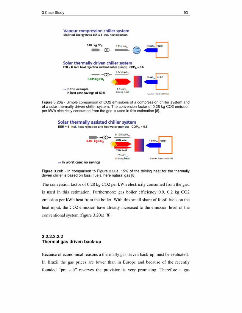
3 Case Study 93
Figure 3.20a - Simple comparison of CO2 emissions of a compression chiller system and of a solar thermally driven chiller system. The conversion factor of 0.28 kg CO2 emission per kWh electricity consumed from the grid is used in this estimation [8].
Figure 3.20b - In comparison to Figure 3.20a, 15% of the driving heat for the thermally driven chiller is based on fossil fuels, here natural gas [8].
The conversion factor of 0.28 kg CO2 per kWh electricity consumed from the grid
is used in this estimation. Furthermore: gas boiler efficiency 0.9, 0.2 kg CO2
emission per kWh heat from the boiler. With this small share of fossil fuels on the
heat input, the CO2 emission have already increased to the emission level of the
conventional system (figure 3.20a) [8].
3.2.2.3.2.2 Thermal gas driven back-up
Because of economical reasons a thermally gas driven back-up must be evaluated.
In Brazil the gas prices are lower than in Europe and because of the recently
founded “pre salt” reserves the prevision is very promising. Therefore a gas

3 Case Study 94
driven back-up could be an alternative to Conventional electrically driven
compression chiller back-up.
Figure 3.21 - Simplified scheme of a solar cooling system, assisted by a thermal gas back-up (modified) [8].
Before the economical feasibility calculation can be done, the gas demand must
be calculated:
The Yazaki WFC-SC10 absorption chiller needs a hot water flow of 8,64 m³/h for
35 kW cooling capacity . The necessary Temperature elevation is ∆T 5 K (88°C
chiller inlet and 83°C Chiller outlet). This results a energy demand of 50 kW (50
kW*COP 0,7 = 35kW or Q = m(t) * Cw ∆T = 2,4 l/s * 4186,8 Ws/kgK * 5K = 50
kW). A efficient gas-fired burner has an efficiency of 98%, to facilitate the
calculation 100% are assumed. The Energy demand for one day (9 h from 8 till
17 o’clock) is 450 kWh (9h*50kW).
The assumed calorific value for domestic gas is 11 kWh/m³, thus the consumption
is 41 m³/day (450 kWh/11 kWh/m³). Hence 1257 m³ in one month (30 days).
The domestic gas supplier in Guaratinguetá is the Comgas company from São
Paulo. 1 m³ domestic natural gas cost according a price table from 29.05.2009
(www.comgas.com.br/tarifas.asp) 6,14 R$/m³ incl. taxes. As yet there is no

3 Case Study 95
domestic gas supply in Guaratinguetá, thus gas cylinders must be applied. The
specific cost is assumed with 7 R$/m³. Therefore the totally cost for driving a 35
KW absorption one month is 8800 R$ (7 R$/m³*1257 m³).
In comparison a 35 kW (35kW / 2.57 COP = 13,6 kW) Split air conditioning
system consumes at the same time 3672 kWh with an electricity tariff in
Guaratinguetá of 0,38 R$/kWh incl. taxes. Source, information February 2008
ANEEL (national electric energy agency - www.aneel.gov.br/area.cfm?idArea=532).
This price was recently confirmed by the Edp Bandeirante Energia company. It
must be mentioned that the Brazilian ICMS tax for residential (mono-phase) tariff
about 200 kWh/month energy consumption is 25 % and not 12%.
Finally, the cost for driving one month a electric driven 35 kW split air-
conditioning system is 1395 R$ (3672 kWh*0,38 R$/kWh). Because of this result
a thermal back up system is until now not economically advantageous. The cost
for maintaining the cooling capacity of 35 kW due to heating up the driving water
for an single-stage absorption chiller is around 6 times higher than to generate the
same cooling capacity with an electric driven split air- conditioning system. It
must be added that the investment cost of a 35 kW split air-conditioning system is
estimated only the half than a 50 kW gas-fired system including water tank.
Normally, the gas burner is directly mounted at the water storage tank.
3.2.2.4 Design and performance of the complete system
According to the technical analyses the appropriate system consists of the Bosch
Bruderus Logasol SKN 3.0 collector and the Yazaki WFC-SC10 (35 kW) single-
stage absorption chiller. These are principal components and the main cost driver
of the acquisition.
First system providers are on the market, offering system sets with appropriate
selected system components. The SolarNext (Germany) company had offered a
complete solar cooling “kit” including the Yazaki WFC-SC10 chiller (quotation
see appendix A4). The advantage of a complete set is that the most important
components are already selected, such as heat rejection system, pumps, valves,
storages and special developed control unit etc. Therefore the planning costs

3 Case Study 96
decrease, due to higher standardisation. Another benefit is that the components are
fitting ideal together e.g. electricity consumption of the heat rejection system is
minimized due to a special controller. SolarNext offers a complete package for the
application in Guaratinguetá including commissioning in Brazil, but except the
collector system and cold distribution (load sub-system).
In the next step the collector area (A) must be calculated. For a first rough
estimation the following equation is applied.
Coll.( T, G)
ColdQA
G COP∆
=η ⋅ ⋅
(Eq. 3.2)
with
QCold = 35.000 W (max. cooling capacity)
ηColl.(∆T, G) = 0,55 (with ∆T = 60 K and G = 1100 W/m²)
G = 1100 W/m² (max. solar irradiance at collector surface)
COP = 0,7
the collector area is 83m² ~ 80m²
With these 80 m² collector field the correlation between building cooling load
(demand) and the cooling capacity (yield) will be simulated and the economic
viability calculation is done in chapter 3.2.3.
In the Excel sheet the cold capacity is calculated by the following equation:
ColdQ G A COPη= ⋅ ⋅ ⋅ (Eq. 3.3)
with
2
0 1 2
( )m a m at t t ta a
G Gη η
− −= − − (Eq. 2.6)
It is assumed that the COP is constant at 0,7, which accords to the chiller
operation point at 88°C water inlet temperature and 31°C cooling water
temperature. Therefore the in collector efficiency equation assumed Collector

3 Case Study 97
average water temperature (tm) is 85°C (88°C in / ca. 83°C out). The ambient
temperature (ta) and solar irradiance (G) is applied hourly.
Figure 3.22 - Snapshot of generic spreadsheet
0
5
10
15
20
25
30
35
40
19.Jan 20.Jan 21.Jan 22.Jan 23.Jan 24.Jan 25.Jan
[kW
]
0
5
10
15
20
25
30
35
[°C
]
Coolind Load Cooling Capacity T ambient
Figure 3.23 - Predicted correlation between cooling demand and cooling yield during a hot summer week in Guaratinguetá.

3 Case Study 98
0
5
10
15
20
25
1 2 3 4 5 6 7 8 9 10 11 12 13 14 15 16 17 18 19 20 21 22 23 24
[kW
]
0
5
10
15
20
25
30
35
[°C
]
Coolind Load Cooling Capacity T ambient
Figure 3.24 - Predicted correlation between cooling demand and cooling yield during one partly cloudy day.
0
5
10
15
20
25
30
35
40
1 2 3 4 5 6 7 8 9 10 11 12 13 14 15 16 17 18 19 20 21 22 23 24
[kW
]
0
5
10
15
20
25
30
35
[°C
]
Coolind Load Cooling Capacity T ambient
Figure 3.25 - Predicted correlation between cooling demand and cooling yield during a summer day with high solar irradiation (ca. 1100 W/m²).

3 Case Study 99
Figure 3.26 - Predicted daily demand and available yield of thermal energy during spring.
Figure 3.27 - Predicted daily demand and available yield of thermal energy during summer.
0
5
10
15
20
25
30
35
40
21.Dez 31.Dez 10.Jan 20.Jan 30.Jan 09.Feb 19.Feb 01.Mrz 11.Mrz 21.Mrz
[kW
] [°
C]
Cooling Capacity Coolind Load T ambient
0
5
10
15
20
25
30
35
40
01.Okt 11.Okt 21.Okt 31.Okt 10.Nov 20.Nov 30.Nov 10.Dez 20.Dez
[kW
] [°
C]
Cooling Capacity Coolind Load T ambient

3 Case Study 100
Figure 3.28 - Predicted daily demand and available yield of thermal energy during autumn.
Figure 3.29 - Predicted daily demand and available yield of thermal energy during winter.
0
5
10
15
20
25
30
35
40
22.Jun 02.Jul 12.Jul 22.Jul 01.Aug 11.Aug 21.Aug 31.Aug 10.Sep 20.Sep 30.Sep
[kW
] [°
C]
Cooling Capacity Coolind Load T ambient
0
5
10
15
20
25
30
35
40
22.Mrz 01.Apr 11.Apr 21.Apr 01.Mai 11.Mai 21.Mai 31.Mai 10.Jun 20.Jun
[kW
] [°
C]
Cooling Capacity Coolind Load T ambient

3 Case Study 101
0
500
1000
1500
2000
2500
3000
3500
4000
Jan Feb Mar Apr May Jun Jul Aug Sept Oct Nov Dec
coo
ling
dem
and
/ yi
eld
[kW
h] cooling demand (kWh)
potential cooling yield (kWh)
Figure 3.30 - Predicted total monthly cooling demand and available yield of thermal energy (8760 h). Solar yield is calculated with an constant daily average collector efficiency of 0,38 by 80 m² collector array and a constant Chiller COP of 0,7.
3.2.2.4.1 Conclusion
The figures have showed that the solar congruence regarding the cooling demand
is in general good. At night the building cooling load is often higher than the
cooling capacity and at noon the cooling capacity is around twice as much the
demand, around 30 kW - 35 kW (see figure 3.26). With such a cooling capacity
the auditorium could be air-conditioned until 20°C indoor temperature.
To utilize the excess thermal energy (hot/cold water) which occurs by an indoor
temperature of 24°C at noon, the storage system must be on these thermal energy
amount adapted. The SolarNext Solar Cooling Company recommends a 6000 l
cold water tank to secure the thermal comfort 24 h at a hot summer day with
maximum solar irradiance (see figure 3.25). Another way to adapt the solar
irradiance gradient is by positioning the solar collectors slightly more into the
west, thus the cooling demand would be more concordant to the solar yield.

3 Case Study 102
Due to a rough evaluation of solar yield/demand correlation it was investigated
that in around 30 days/year the sun not covers the cooling demand. Hence at these
days the back-up system must run to secure the thermal comfort.
During spring and summer the solar yield and the building cooling demand is very
congruence; only during their winter and autumn is more cooling power generated
than needed. At June and July is an artificial cooling due to a cooling machine
not necessary; at this time the free ventilation of 3000 m³/h is sufficient to
compensate the internal cooling load of 12 kW. During this time the ambient air
temperature at daytime is often below 24°C.
At the winter season it makes sense to utilise the thermal solar energy for water
heating. The hot water can be used for taking shower, cooking or washing
machines. At the UNESP University it could supply the refectory dishwashers.
Finally, it must be pointed out, that in comparison to normally solar thermal
application for space and water heating in Europe the solar coverage is
considerably superior.
Figure 3.31 - Predicted monthly demand and available yield of thermal energy (UK, Leicestershire) [24].

3 Case Study 103
The next figure shows a schematic diagram of the simulated solar-assisted air-
conditioning system for the pilot-project in Guaratinguetá. It notices that a lot of
pumps must be applied, as well, that the whole system is more complex than a
conventional Split Air-Conditioning System. The pumps and mainly the cooling
tower system consuming electric energy in the same way. In the next chapter will
be investigated whether a solar-assisted air-conditioning system is under specific
electricity cost in Brazil economic feasible.
Figure 3.31 - Schematic diagram of the simulated solar-assisted air-conditioning system for the pilot-project in Guaratinguetá.
Note: The author does not recommend one of the mentioned brands.
Figure 3.32 - Example of an Solar-Assisted Air-conditioning application in La Réunion, France (small island near Africa) [25]. This project was executed by Schüco International KG. At this picture the fan-coil units in the Auditorium (ca. 200 m²) are visible.

3 Case Study 104
3.2.3 Economic assessment
3.2.3.1 Acquisition and operation cost calculation
Before the economic feasibility can be calculated the Acquisition and operation
cost must be investigated. Below are actual cost tables (Tables 3.10 e 3.11) for the
applicable solar-assisted air-conditioning system and Split Air condition system
(data base 2009). It must be mentioned that under real conditions the COP
decreases, because of higher ambient air temperatures in summer estimated 10%
and degradation through on-off controlling.
The on-off types of controls are generally used in small-capacity units to maintain
the desired indoor temperatures and regulate capacity. For real systems using such
controls, it can be said that a pure steady state does not exist. Judge et al. (1996)
reported that on-off cycling of the system degrades the coefficient of performance
(COP) of the system to values below 75% of the steady-state values. Thus, the
transient characteristics are equally as important as the steady-state performance
from the point of actual energy efficiency of the systems [26].
The Electrolux Split Air-conditioner is labelled with energy-efficient class A
(PROCEL). The total cooling capacity of these four Split-conditioners is max. 35
kW (10 TR). This capacity was specified by two consulted refrigeration firms
Frygeltec Refrigeração Ltda and Benco Ltda. This value meet the thumb rule
calculate 1 TR (3.5 kW) for 15 m² room space (auditorium 150 m²). It is assumed
that the Split System runs daily 9 hours.
Cost calculations are without installation, planning and maintenance cost because
of no data base in Brazil. The installation cost can differ according to the site
conditions to a high degree. Certainly they are higher than for the conventional
system. The maintenance - and engineering cost are estimated higher, too. On the
other side a compressor unit of the conventional split air-conditioner has an
average lifetime of only 8 to 12 years by full use and a solar-assisted air-
conditioning plant of 20 years minimum.

3 Case Study 105
ACQUISITION COST [R$]
SPECIFIC COST [R$ per kW cooling
capacity]
Component
A: complete
solar cooling "kit"
B: individual
comp.
A: B:
Flate Plate collectors, 80 m² Bosch Bruderus Logasol SKN 3.0
37.234 (13.790 €)
37.234 (13.790 €)
1.064 1.064
SolarNext chillii ® Cooling Kit WFC35, incl.: 1 x Yazaki WFC-SC10 Absorption chiller 1 x wet cooling tower with auto accessories filling and emptying, and fan speed control 1 x hot water pump 1 x cooling water pump 1 x chillii ® System Controller HC incl. Temperature Sensors 1 x cold storage 2000 l without Insulation 1 set of sensors f. Chilled water storage 1 x pump f. cold distribution with accessories 1 x hot water storage 2000 l with insulation 1 set of sensors f. hot water storage 2 x changeover valve with actuator
126.700
(46.926 €)
18.225
(6.750 €)
estimated price for all these comp. except: chiller, cooling
tower and controller
3.620
1 x pump f. solar collector cuircit 945
(350 €) 945
(350 €)
4 x fan coil unit 10.268
(3840 €) 10.268
(3840 €) 293 293
Yazaki WFC-SC10 35 kW Absorption Chiller
43.501
(16.700 €) 1.242
wet cooling-tower F-32 Refrigeracao International
7.370
(2.729 €) 211
SolarNext chillii ® System Controller H 5.624
(2.083 €)
4 x Split Air-conditioner back-up* Electrolux SPLIT SE 30 F (30.000 BTU / 8,8 kW)
16.000 (5.926 €)
16.000 (5.926 €)
457 (169 €/KW)
457 (169 €/KW)
TOTAL 191.147
(70.772 €) 139.167
(52.178 €)
5.461 (2.022 €/KW)
3.976 (1473 €/KW)
Table 3.10 - Acquisition and specific costs per kW cooling capacity for two different system combinations.
Notes: a) Conversion factor 2,7 R$/€; b) * In accordance with PROCEL, as Back-up was
chosen a split-conditioning system, because of the possibility to compare both systems
by checking actual measuring data; c) A includes a complete cooling “kit” available by
SolarNext AG company in Germany; d) B includes the acquisition prices for individual
ordered components as the wet cooling tower, directly from a Brazilian company and the
chiller directly from Yazaki, Japan. At last the controller device from SolarNext, too.

3 Case Study 106
ELECTRICITY CONSUMPTION & OPERATION COST
Component
solar-assisted
air-conditioning system
conventional split air-
conditioning system
4 x water pumps 360 W
wet cooling-tower fan 280 W
Yazaki WFC-SC10 35 kW Absorption Chiller
210 W
4 x fan coil units 480 W
4 x Split Air-conditioner Electrolux SPLIT SE 30 F (30.000 BTU / 8,8 kW)**
13.600 W
TOTAL 1.330 W 13.600 W
1 Month (30 days x 9 h)
359 kWh 3.672 kWh
9 Months 3232 kWh 33.048 kWh
TOTAL 10 Months operating (1 year) *
with 1 Month split-air conditioning
back-up 6.904 kWh
36.720 kWh
Operation Cost (1 year) by 0,38 R$/kWh
(Guaratingueta Edp Bandeirante Energia)
2.624 R$ 13.954 R$
Operation Cost (1 year) by 0,598 R$/kWh
(Minas Gerais -Cemig) 4.106 R$ 21.959 R$
Table 3.11 - Comparison of electricity consumption and operation cost of a solar- assisted air-conditioning system and electrically driven compression vapour split air conditioning system.
Notes: a) * During two month there exists no cooling demand; b) ** The cooling capacity
is 8,8 kW by each Split Air conditioner; c) The electricity consumption of each Split is
3.396 kW, according technical data, thus resulting a theoretical COP of 2,6.

3 Case Study 107
3.2.3.2 Economic feasibility The next two figures show the difference acquisition cost and cost developing.
Beside the shown cost development due to the specific electricity cost in
Guaratinguetá, it is presented the cost gradient through a higher electric energy
price, which exists for example in Minas Gerais, where, as well, very good solar
irradiance occurs.
There are no interest rates of the investment capital or maintenance cost
considered, as well, no intended possible public subsidies and electricity cost
elevation. Regarding the interest rates must be mentioned the following point. If
there is a interest rate of only 1,5 % per year of the investment cost of 191.147 R$
the payback-time would be 5 years longer. This means a payback time of around
21 years, thus the system would not bring an income during the system lifespan.
The usual interest rate of such a credit in Brazil around 8,5 % per year. Hence it is
essential to become a credit with a very low interest rate, lower than 1,5 % per
year.
In Brazil, as yet there is no subsidy or tax relief for those who exploit renewable
energy. However, the Brazilian government just discussed a law (Lei 630/03)
which pretends a financially support. In Germany there are several solar thermal
energy incentives. For example the Reconstruction Loan Corporation (KfW) pays
30% of the solar cooling system investment, if the collector array is bigger than
40 m².

3 Case Study 108
Figure 3.33 - Acquisition and operation cost of solar-assisted air-conditioning system and conventional split air-conditioning system in Guaratinguetá.
Note: Operation cost are calculated with an electric price of 0,38 R$/kWh which
is the price in Guaratinguetá by supplier EDP-Bandeirante Energia SA.
Figure 3.34 - Acquisition and operation cost of solar-assisted air-conditioning system and conventional split air-conditioning system in Minas Gerais.

3 Case Study 109
Note: Operation cost are calculated with an electric price of 0,60 R$/kWh which
is the price in the Brazilian State of Minas Gerais by CEMIG (companhia
energética de Minas Gerais).
An important definition to evaluate the economic feasibility is the meaning of
“critical operation time”. Below “critical operation time” is understood the time as
from the solar-assisted air-conditioning system in relation to acquisition and
operation cost is cheaper than the conventional system. If the solar cooling system
within the lifetime (here 20 years) will be longer in operation than the critical
operation time, the firstly high cost of acquisition pays off.
3.2.4 Environmental benefits
The main motivation of solar cooling technology implementation and replacing
the conventional system is that they have a lower environmental impact. Any
primary energy savings result in CO2 reduction.
To estimate the corresponding specific CO2 emissions per kWh produced ‘cold’
(per 0.285 TR), a conversion factor of 0.28 kg CO2 per kWh electricity is applied
(average for the interconnected Brazilian electricity grid) [8].
The next table shows the CO2 savings per year.
Electricity consumption per year [kWh]
CO2-emissions [kg]
Solar assisted system
6.904* 1933 (1,9 tons)
Split Air- conditioning
36.720
10282 (10,3 tons)
CO2 Savings per year
8349 (8,3 tons)
*The calculation includes 1 month back-up operation by a split air-conditioning system.
Table 3.12 - CO2 savings per year calculated with the conversion factor of 0.28 kg CO2 per kWh electricity

3 Case Study 110
In addition to the CO2 savings, the usage of environmentally refrigerants must be
pointed out. They have no ozone-depleting or global warming potential. In the
conventional systems are often used the R-134a as refrigerant.
A negative point is the water consumption of the wet cooling-tower. However, the
water amount is very small in this case only 50 litres per day. This water could be
collected by rain and therefore it causes no negative environmental impact. In
order to complete the environmental impact evaluation of solar-assisted air-
conditioning system a complete life cycle analyses should be carried out, but this
would go beyond the scope.
3.2.5 Conclusion
This chapter has demonstrated that the acquisition cost of solar-assisted air-
conditioning is very high in comparison to the conventional system. By contrast
the running costs are significant lower, only 0,038 kWh electricity is sufficient to
generate1 kWh cooling power. To secure this cost it is important to apply always
high-efficient pumps and fans, the pumps and cooling tower fan should be speed
regulated.
Generally, in all calculated cases the solar cooling low operation cost compensate
the higher investment cost in a long term, especially in Minas Gerais at a higher
electricity price. The case study shows that solar cooling systems can be a
alternative option against electric split chillers, especially in areas with significant
cooling demand (high internal cooling load), solar irradiance, and electric prices.
As electric rates increase, solar cooling will become an even more economically
attractive option for building owners.
But, it must be mentioned if in Guaratinguetá on the high investment cost an
interest rate more than 1,5 % would be added, there would be no cost savings
during operation yield. Thus it is important that a financial support exists, for
example through low-interest credits or direct investment grant. As well, must be

3 Case Study 111
highlighted that that the economic feasibility is only given for buildings where the
cooling demand mostly occurs during the day.
The Payback times are 11 years with the higher SolarNext solar cooling “kit”
investment cost and the electricity cost in Minas Gerais and 16 years Payback due
to the lower electricity cost in Guaratinguetá.
In the onsite energy market for privately-owned buildings, paybacks of two to
three years are desirable; five to seven years are sometimes acceptable, and
anything over ten years is not economic. Payback periods for publicly owned
buildings (e.g. institutions such as schools, municipal buildings, federal
government buildings, jails, etc.) might be extended longer than for privately-
owned buildings [27].

4 Conclusion and recommendations 112
4 Conclusion and recommendations
The study has shown that for the pilot-project in Guaratinguetá the following
appropriate and cost-effective solar cooling technology can be applied:
• A closed chilled water cycle system with an integrated (Yazaki WFC-
SC10) 35 kW (10 TR) single-effect LiBr-H2O Absorption Chiller and a
wet-cooling tower.
• The cold distribution inside the auditorium by four fan coil units. A
cooling ceiling is not suitable because it brings nit the sufficient cooling
capacity into the building.
• A collector array of 80 m² with Bosch Bruderus Logasol SKN 3.0 (Flat-
Plate) has the best performance-cost relation.
• As back-up system should a conventional electrically driven compression
split air-conditioning system applied, because heating up the water with
gas for driving the single-effect absorption chiller causes six times higher
operation cost. Consequently, a thermal gas back-up can not be
recommended due to the gas prices in the necessary consumption range
and as well due to the negative CO2 balance.
Therewith the congruence between solar gain and cooling demand is good, thus
less collector surface is necessary and the investment cost decreases, it’s
important to clarify in advance which indoor set point temperatures are applicable
for the cooling demand calculation. According the Brazilian thermal comfort
standard (PNB-10) is 24°C indoor temperature by 29°C ambient temperature well
sufficient. With an indoor set temperature of 24°C, the cooling load can be
reduced in contrast to an indoor temperature of 20°C for more than half.
It was noted that it is important to verify before dimensioning of a solar cooling
system, or generally of a conventional air-conditioning system, too, which cooling

4 Conclusion and recommendations 113
demand is really necessary and how it can be reduced through alternative ways,
such as, shading measures, (night-) cooling with outside air, building insulation or
decreasing (lighting etc. ) the internal load.
Through the case study was the economic feasibility of the specified solar-assisted
air-conditioning checked and compared with a conventional electrically driven
compression split air-conditioning system. It turned out, that the low operation
cost can compensate the higher investment cost within the solar cooling system
life time of minimum 20 years.
In Guaratinguetá this happens after 12 years with a "tropicalizated" system in
which the components are provided individually mostly by the Brazilian market,
and after about 16 years by an application of a complete solar "kit" from
SolarNext AG, Germany (without solar collectors). In Minas Gerais would yield
payback times of 8 and 11 years since there is the price of electricity 60% higher
than in Guaratinguetá.
Consequently, solar assisted air-conditioning can compete with Split-Air
conditioning system, but only under the following conditions:
• No minor electricity prices than in Guaratinguetá (0,38R$/kWh)
• Cooling demand only during daytime thus application for offices,
universities or schools etc. Cinemas are not recommendable.
• Efficient pumps and fans applied
• Financial support for the acquisition through low-interest credits or direct
investment grant.
Finally, it must be mentioned that the payback periods are very high for privately-
owned buildings. On the other side private companies e.g. hotels could use this
technology to do “eco-facade/green marketing”. Solar air-conditioning is a

4 Conclusion and recommendations 114
renewable energy technology with an enormous marketing potential. It makes the
Sun generate chilled water.
By the demonstration project validation could be made against the simulation data
by checking actually measured data. A solar cooling pilot project could fill many
of the existent knowledge gaps, confirm the technical and economical feasibility
and perhaps become a precursor for a general implementation.
A Pilot-Project is the first step to disseminate this for Brazil “new” environmental
friendly technology. It must be made sure that quality of planning and installation
has a high level to ensure to later reliability of the system. A market barrier of the
implementation is not only the high investment cost, as well, a lack of knowledge.
Therefore it’s important to realize the first project in cooperation with experienced
firms. Hereby a know-how transfer to Brazilian companies who pretends to deal
with solar cooling is elementary. As well, a simple pre-design software tool for
Brazil must be introduced, thus local companies can dimension their systems. This
program should also consider the economic feasibility by the individual local
energy prices.
Last but not least, a recommendation regarding “solar cooling” integration in high
buildings. In Tropical Cities sufficient roof area for providing a whole skyscraper
with solar air-conditioning is often not given. Through a rough estimation can be
said that only for two stores enough roof space exists. Hence it is recommendable
to use an electrically driven compression central chiller to cover the latent cooling
loads and use a solar cooling system in side-stream to cover the highest cooling
loads during the day. Thus extra capacity generated by the sun occurs only when
the load is the greatest, and the energy source to drive it has no recurring cost.
The energy source is somewhat coincident with the greatest load, providing a
sensible means of Peak Shaving, keeping the electric chillers in their most
efficient mode during the hottest period of the day. And if the solar collectors are
placed on the roof, they will provide a reduced cooling load by shading the roof
[3].

4 Conclusion and recommendations 115
The next figure shows clearly that that most efficient mode of an electric chiller
lies between 25% and 75% of full load. If the chiller runs at full load it will waste
more energy kW per Tons of Refrigeration.
Figure 4.1 - Typical electric driven screw chiller power curve [3].
Brazil receives solar energy in the order of 10^13 MWh per year, which is about
50.000 times the country’s annual consumption of electricity. But, despite of this
optimum solar radiation condition, as yet only a small part of this energy is used.
The most electrical energy is generated by large-scale central hydropower plants,
whose sustainability is doubtful. The power supply is through the centrality of
power generation very interference-prone, which had showed the recently black-
out from 10. November 2009. As well, a lot of energy is wasted due to long way
energy transmission for example from Itaipu to São Paulo.
In future the Brazilian government intends to secure the country's electricity
supply by more nuclear power and fossil-fuelled thermal power stations.
Energy efficiency measures like solar cooling implementation can contribute to
less electric energy consumption. Certainly, it does not solve the country’s energy
problem, but if the whole country cooling demand would be supplied by solar
cooling systems more or less one large-scale power plant could be avoided.
Solar cooling technology is a way to provide building air-conditioning by using
local regenerative sun energy. The main advantage is that the cooling load and
solar gain occurs at the same time, an at least at seasonal level, which is by other

4 Conclusion and recommendations 116
regenerative energies often not the case. From central power plants used primary
energy can be saved and CO2 emissions can be minimized. Through a solar
cooling pilot Project in Guaratinguetá 8,3 tons CO2 could be saved per year and it
could open the way for a general application of this environmental technology in
Brazil.

References 117
References [1] Revista Brasil Energia (June 2005)
http://www.energiahoje.com/brasilenergia/noticiario/2005/06/01/268315/comgas-
quer-avancar-sobre-o-segmento-de-ar-refrigerado.html
[2] Lamberts, R. Energy Efficiency in Buildings in Brazil (March 1999): Towards
a Standard. Report presented to the International Energy Initiative. Florianópolis:
Núcleo de Pesquisa em Construção - Universidade Federal de Santa Catarina.
[3] Presentation “Effective Solar Chilled Water” (June 2009) by Bud Leavell
Yazaki Energy Systems Inc. Plano, Texas
[4] Kraas, F. (2003): Megacities as Global Risk Areas. (Petermanns
Geographische Mitteilungen 147 (4): 6-15.
[5] Un-Habitat (2001): Cities in a Globalizing World - Global Report on Human
Settlements
[6] Spangenberg, J. (2004): Improvement of urban climate in tropical metropolis,
Master´s Thesis - University of Applied Sciences Cologne (Institute for
Technologies in the Tropics)
[7] Solair (2009): Requirements on the design and configuration of small and
medium sized solar air-conditioning applications - Guidelines
[8] Fraunhofer Institute for Solar Energy Systems ISE (2009): Solar cooling in
Brazil - Technology study
[9] ASHRAE Terminology of HVAC&R, ASHRAE, Inc., Atlanta, 1991
[10] Henning, H. (2007) Solar-Assisted Air-Conditioning in Buildings - A
Handbook for Planners

References 118
[11] SOLATERM Project Report (September 2007) - Potential Analysis for a
New Generation of Solar Thermal Systems in the Southern Mediterranean
Countries
[12] Barja, G. (2006): A cogeração e sua inserção ao sistema elétrica, Dissertação
de Mestrado – Universidade de Brasília
[13] M. Filippi, G. Mutani, M. Perina (2001): The use of natural or artificial lakes
and ponds in HVAC Plant in Italy - 6th European Conference Solar Energy in
Architecture and Urban Planning
[14] P. Bourdoukan, E. Wurtz, P. Joubert and M. Spérandio (2008): Sensitivity
Analysis Of A Desiccant Wheel, Université de La Rochelle (LEPTIAB) and
Université de Savoie (Campus Scientifique)
[15] Riffel, D. (2008): Estudo Teórico e Experimental da Dinâmica e da
Otimização de Refrigeradores Térmicos por Adsorção, Tese de Doutorado -
Universidade Federal da Paraíba
[16] Environmental Protect Agency (EPA) ww.epa.gov/hiri/about/index.htm
[17] Akbari, H. (2005): Energy Saving Potentials and Air Quality Benefits of
Urban Heat Island Mitigation - Lawrence Berkeley National Laboratory
[18] Meunier, F. (2007): Oasis effect to mitigate heat island - 22nd IIR
International Congress of Refrigeration
[19] Lima, J. & Silva, E (2000): Climatologia na região de Guaratinguetá São
Paulo (Brasil) - XXVII Congresso Interamericano de Engenharia Sanitária e
Ambiental
[20] S. Silva, R. Guarnieri, F. Martins e E. Pereira (2007): Comparação de
estimativas de radiação solar fornecidas por interpolação kriging de dados de

References 119
superfície e por modelo físico alimentado com dados de satélite - Instituto
Nacional de Pesquisas Espaciais (INPE) Divisão de Clima e Meio Ambiente
(CPTEC)
[21] Kuchta-Schrader, C. (2004): Passive Kühlung
http://www4.architektur.tu-darmstadt.de/powerhouse/db/248,id_30,s_Papers.fb15
[22] Hagel, A. (2005): Análise computacional da demanda energética de
climatização de edifício, projeto de graduação - Universidade de Brasília
[23] Caruy, C. (2009): ABRALISO Economia de energia elétrica através de
isolamento das envoltórias em edifícios climatizados artificialmente - 6°
Congresso Brasileiro de Eficiência Energética São Paulo
[24] N.Shankland, K. Lomas, H. Eppel and B. Certmell (2001): Renewable
Energy technologies for low-energy public building - 6th European Conference
Solar Energy in Architecture and Urban Planning
[25] Köln, H. (2008): Entwicklung von Paketlösungen für solare Kühlung - 5.
Symposium “Solares Kühlen in der Praxis“
[26] Report in HVAC&R (May 2009): Transient characteristics of split air-
conditioning systems using R-22 and R-410A as refrigerants
[27] Hinrichs, D. (2006): Technical and economic assessment of solar thermal
absorption cooling systems in small commercial buildings - Sentech, Inc.
[28] Cunha, C. (2009): Aquecimento Solar - ABRAVA

Appendix 120
Appendix A1 Specification for the auditorium
Rio de Janeiro, 04/09/2009
Especificação de requisitos para a integração de um sistema de climatização solar no auditório do novo núcleo de eficiência energética da UNESP Por Dipl.-Ing. (FH) Till Felix Reichardt 1. Introdução Conforme reunião na Eletrobrás - Rio de Janeiro, junto com a GTZ, realizada no dia 19 de agosto de 2009 foram apresentadas as especificações de requisitos para a integração de um sistema de climatização solar no auditório do núcleo de eficiência energética da UNESP – Guaratinguetá/SP. A GTZ Brasil e a Eletrobrás/PROCEL são parceiros no programa ProFREE (Programa de Fontes Renováveis de Energia e Eficiência Energética) da GTZ que fortalece a Eficiência Energética e o uso de energias renováveis em prédios públicos. O aproveitamento da energia térmica para converter calor em frio é uma tecnologia que vem crescendo na Europa. A Agência Internacional de Energia (IEA) tem vários projetos envolvendo energia solar para fins de climatização e mostra que a tecnologia está madura para ser utilizada comercialmente. Nos países de clima tropical, como o Brasil, nos quais a demanda de resfriamento coincide com os períodos de maior intensidade de radiação solar, a implementação da climatização solar tende a ser uma realidade em futuro próximo. 1.1 Centro de Educação para Eficiência Energética O Centro de Educação para Eficiência Energética em Guaratinguetá no Estado de São Paulo pretende utilizar conceitos arquitetônicos e tecnológicos que exemplifiquem o uso eficiente e inteligente da energia, demonstrando aos visitantes que o planejamento de uma obra pode ser ecologicamente correto. Para oferecer condições de funcionalidade no espaço físico onde deverá ser instalada a sede do Centro de Educação para Eficiência Energética, serão feitos vários investimentos visando à obtenção de produto final com as características listadas a seguir:
1. Área total do Centro de Educação: até 1500 m²;

Appendix 121
2. Auditório ou Sala de Projeção: Área destinada à realização de eventos variados, tais como palestras, encontros, capacitações etc. Capacidade para cerca de 100 pessoas. Área aproximada: 150m2;
3. Biblioteca: Área aproximada de 50m2. Abrigará o acervo bibliográfico
sobre educação, de maneira geral, energia, meio ambiente, eficiência energética, de maneira específica. Além de apoio aos pesquisadores, a biblioteca tem a função de divulgar e disponibilizar materiais sobre o tema da Eficiência Energética;
4. Área de trabalho para professores e pesquisadores: Salas destinadas a
abrigar professores e pesquisadores envolvidos com as pesquisas do Centro de Educação. Composto por 5 salas de aproximadamente 50m2, devendo abrigar, em geral, 2 pesquisadores por sala. Com previsão de sistema de rede wireless;
5. Laboratório de Desenvolvimento: Espaço no qual serão alocadas as
estações de trabalho (móveis, computadores e softwares). Este laboratório abrigará programadores, alunos, bolsistas, pesquisadores e professores envolvidos com o desenvolvimento de softwares e materiais didáticos relacionados ao Centro de Educação. Área prevista de aproximadamente 200m2. Com previsão de uso de rede wireless;
6. Laboratório de Hardware: Laboratório para desenvolvimento de
equipamentos e dispositivos elétrico/eletrônicos relacionados aos objetivos do Centro de Educação. O laboratório tem como objetivo criar um ambiente adequado com ferramentas para o desenvolvimento dos dispositivos. Área de aproximadamente 100m2. Com previsão de rede wireless;
7. Laboratórios eletromecânico: laboratório destinado a elaboração de
equipamentos, maquetes, equipamentos eletromecânicos para demonstrações relacionadas à produção, transmissão e utilização da energia. Área aproximada de 100m2.
8. Hall de exposições: Área destinada a exposições e de divulgação dos
objetivos do Centro de Educação e suas atividades. Área de cerca de 400m2;
9. Sanitários: 2 conjuntos (masculino/feminino) sendo a área total deles de
cerca de 60m2;
10. Copa e área de serviços gerais: aproximadamente 50m2;
11. Recepção do Centro: Com uma área de aproximadamente 40m2, tem a função de realizar a triagem e orientação dos visitantes, bem como abrigar as funções administrativas do Centro de Educação.
12. Corredores, escada e espaços funcionais: aproximadamente 100 m2.
Appendix 122
1.2 Demanda de resfriamento e ar condicionado no Brasil
Os sistemas de resfriamento e ar condicionado (R&AC) são responsáveis por um elevado e crescente consumo de energia elétrica, sendo essa uma tendência mundial. Na Europa, por exemplo, o crescimento esperado é de 50% ao ano, nos próximos 15 anos (EECCAC, 2003). No Brasil, a mesma tendência pode ser observada. De acordo com a ABRAVA (2006), equipamentos de ar condicionado respondem por cerca de 40% da eletricidade consumida em um edifício comercial. Esse percentual chega a 50% nos aeroportos brasileiros, segundo dados divulgados pela INFRAERO (2006). O Jornal Mercantil (2008) divulga um crescimento para o setor de 12% ao ano. Os dados acima mostram a importância, tanto do ponto de vista energético, quanto econômico, dos sistemas de condicionamento de ar no país. Considerando o impacto desses sistemas na matriz energética nacional e o crescente custo da energia elétrica, o uso combinado de fontes térmicas para fins de climatização pode ser uma alternativa estratégica e economicamente viável.
2. Aplicação de climatização solar no auditório da UNESP/Guaratinguetá PROCEL avalia incluir no planejamento da obra do núcleo de eficiência energética um sistema de climatização solar, sendo esse o primeiro projeto piloto no Brasil. Está prevista climatização do auditório com energia solar térmica. O auditório tem uma capacidade para cerca de 100 pessoas e uma área aproximada de 150 m2. Para uma sala de 150m² estima-se uma potência de ar condicionado de aproximadamente 30 kW (8 TR). É importante ressaltar que, com mais detalhes sobre a carga térmica do auditório, é possível realizar cálculos para definir um valor mais preciso. Nesse momento do projeto os dados não estão disponíveis. O sistema apropriado seria de ciclo fechado com uma máquina de absorção movida a energia solar térmica obtida de coletores para temperaturas médias entre 75°C - 90°C. Essas coletares são disponíveis no mercado brasileiro. Também esse sistema pode ser utilizado em todas as regiões climáticas do Brasil. Além disso já existem empresas com experiência que oferecem sistemas compactos para a climatização, destinados a edifícios de pequeno e médio portes, com uma potência de resfriamento desde 7 kW (2.5 TR) até 70 kW (20 TR). O ciclo de absorção é de simples efeito (single effect chiller), utilizando o par água-brometo de lítio (H2O-LiBr) como refrigerante e absorvente. A máquina de absorção necessita no mínimo de 80°C de água quente na entrada para gerar o frio. Para o abastecimento da água frio (6°C – 9°C) no auditório, recomenda-se um sistema de ar condicionado cm “fan-coil”. Durante a tese de mestrado será investigado qual o sistema mais apropriado. Como sistema back-up foi proposto originalmente um sistema de ar-condicionado convencional (compressor elétrico).

Appendix 123
Os seguintes esquemas explicam o funcionamento do sistema (fonte: Solvis GmbH&CoKG, modificado):

Appendix 124
Figura 1: Sistema de ciclo fechado com uma máquina de absorção movido pela energia solar térmica. Fonte: Innovative Systems for Solar Air Conditioning of Buildings Dr. W. Kessling (modificado).
3. Especificação de requisitos Este capítulo trata das especificações de requisitos para a integração de um sistema de climatização solar no auditório, como descrito a seguir: - teto do prédio - o espaço físico - sistema hidráulico

Appendix 125
3.1 Recomendações para o teto do prédio:
• Área necessária para a instalação dos coletores: 125 m² (inclusive o espaço necessário entre os coletores.)
• O teto deve suportar o peso de todos os coletores solares no total de 2,6
toneladas. O peso foi estimado considerando-se o coletor plano CPC da empresa AoSol e o coletor plano da empresa Schüco.
• O teto tem que dispor de acesso para instalação, inspeção e manutenção
• O teto deve ser preferencialmente plano. Se inclinado, no máximo de 20°
e direcionado para o Norte geográfico, com uma área de 125 m².
• O teto deve ser livre de sombras dos outros prédios ou de vegetação. Para uma aplicação de climatização solar, a demanda da energia solar para resfriamento do auditório acontecerá principalmente no verão, portanto os coletores devem ser inclinados para receber os raios nessa época. Por isso recomenda-se um teto plano.
Figura 2: Ilustração esquemática mostrando a inclinação dos raios solares em relação à superfície da Terra para a cidade de São Paulo (modificado). Fonte: Abrava
Se o teto não estiver de acordo com as recomendações: - É necessário determinar se os coletores serão instalados diretamente sobre as telhas, apoiados em suportes inclinados instalados na laje, ou uma instalação especial ao lado do prédio deveria ser executada. Essa segunda alternativa demandaria mais custos e seria visualmente menos atrativa.

Appendix 126
Figura 3: Coletores apoiados em suporte inclinados Fonte: Abrava.
3.2 Recomendações para o sala de máquinas no prédio
Necessita-se de um espaço separado, com entrada individual para os componentes do sistema, como:
• maquina de absorção: ~1300mm x 1060mm x 2030mm • 2 reservatórios para água quente de 2000l • reservatório para água fria de 6000l • sistema de controle: ~ 352mm x 285mm x 96mm • 3 bombas d´água
Recomenda-se um espaço de 20 m² (4 m x 5 m x altura min. 2.5 m) com fornecimento de água, energia elétrica (210V, 60Hz, 3 fases) e sistema de drenagem.
3.3 Recomendações para o sistema hidráulico / elétrico
Para instalação dos sistemas hidráulico e elétrico serão necessárias três diferentes tubulações:
• Para interligar a máquina de absorção e o reservatório até o teto, onde serão instalados os coletores, serão necessários dois tubos de cobre com 40mm de diâmetro que, junto com seus isolamentos, resultam em um diâmetro total individual de 80 mm. Portanto, recomenda-se um canal de 200 mm x 120 mm para ser embutido no prédio. A distância não deve ser mais que 50 m.
• Para interligar a máquina de absorção até a torre de arrefecimento recomenda-se um canal de 200 mm x 120 mm. É importante ressaltar que a torre de arrefecimento deve ser localizada ao ar livre e abastecida com água (tubo PVC 1/2”) e energia elétrica (210V, 60Hz, 3 fases). Dimensões e peso aproximados da torre de arrefecimento: 4125 x 1145 x 950 mm e 340 kg.
• O último canal de tubos da máquina de absorção até o auditório tem a função de abastecer o auditório com água fria para a climatização pelo teto de resfriamento (cooling ceiling). Recomenda-se 200 mm x 120 mm.
As distâncias entre a sala de máquinas, teto com os coletores e auditório devem ser as menores possíveis.

Appendix 127
4. Procedimento A especificação de requisitos para a integração de um sistema de climatização solar no auditório deve ser encaminhada aos arquitetos da Eletrobrás responsáveis pela licitação. A conclusão da dissertação de mestrado esta prevista para o mês de janeiro de 2010, devendo incluir os seguintes pontos de estudo e discussão:
1. Análise dos fatores e respectivos custos 1.1 Verificar se é possível integrar componentes do mercado brasileiro
2. Estratégia para baixar os custos do investimento 3. Desenvolver um sistema para o auditório na UNESP
3.1 Dimensionamento e custos 4. Cálculos sobre o tempo de amortização e comparação com um sistema
convencional (compressor elétrico) 4.1 Comparação de um sistema solar com um back-up convencional e com um sistema de back-up a gás.
O orientador da dissertação é o Professor Celso Romanel da PUC do Rio de Janeiro, pertencente ao Departamento de Engenharia Civil. A co-Orientadora é a Professora Elizabeth Pereira, da PUC de Minas Gerais, e afiliada ao GREEN (Centro Brasileiro para Desenvolvimento da Energia Solar Térmica). 5. Agradecimentos Agradeço as empresas Schüco International KG , Solarnext AG e Solvis GmbH pelo apoio técnico. Ao PROCEL pela colaboração e à GTZ do Rio de Janeiro pela orientação técnica. Contatos: Till Reichardt ([email protected]) e
Andreas Nieters ([email protected])

Appendix 128
A2 Technical Data and Information

Appendix 129

Appendix 130
A3 Solar collector Test certificates

Appendix 131

Appendix 132
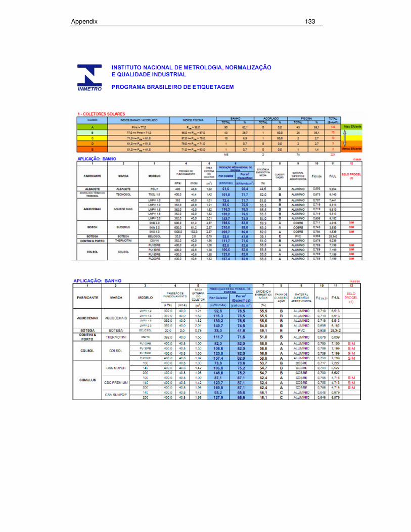
Appendix 133

Appendix 134
A4 Quotations

Appendix 135