tinyipfix aggregation in contiki - files.ifi.uzh.ch communication systems group ... 1.2 report...
TRANSCRIPT

TinyIPFIX Aggregation in Contiki
Livio SgierZurich, Switzerland
Student ID: 12-918-702
Supervisor: Dr. Corinna SchmittDate of Submission: May 9, 2017
University of ZurichDepartment of Informatics (IFI)Binzmühlestrasse 14, CH-8050 Zürich, Switzerland
INT
ER
NS
HIP
–C
omm
unic
atio
nS
yste
ms
Gro
up,P
rof.
Dr.
Bur
khar
dS
tille
r

InternshipCommunication Systems Group (CSG)Department of Informatics (IFI)University of ZurichBinzmühlestrasse 14, CH-8050 Zürich, SwitzerlandURL: http://www.csg.uzh.ch/

Abstract
TinyIPFIX is an application layer protocol to efficiently transmit data in a WirelessSensor Network. The core idea is to decouple the header information from the actualpayload in order to save valuable data transmission by sending them at different pre-set time intervals. This leads to a decrease of energy consumption compared to otherapplication layer protocols. There exists an implementation of TinyIPFIX on the popularoperating system Contiki. This work presents an extendible aggregation framework on topof TinyIPFIX with an implementation of two specific aggregation mechanisms: Messageand data aggregation. Additionally, CoMaDa, an adaptive configuration, managementand data handling framework, has been extended with Contiki support for manual deviceconfiguration and data visualization.
i

ii

Zusammenfassung
TinyIPFIX ist ein Protokoll der Anwendungsschicht, welches zum Ziel hat Daten in ei-nem Wireless Sensor Netzwerk effizient zu ubermitteln. Die Grundidee besteht darin, denHeader von den eigentlich zu ubertragenden Nutzdaten zu entkoppeln. Die Header Infor-mationen, sowie die Nutzdaten werden separat in einem festgelegten Zeitintervall gesendet.Die Umsetzung fuhrt in einem typischen Wireless Sensor Netzwerk verglichen mit ande-ren Protokollen der Anwendungsschicht zu einem insgesamt reduzierten Datentransfer,was zu weniger Energieverbrauch fuhrt. Es existiert eine Implementierung des TinyIP-FIX Protokoll fur das Betriebssystem Contiki. In dieser Arbeit wurde ein erweiterbaresFramework fur Aggregationsmechanismen entwickelt, welches auf TinyIPFIX beruht. Zweispezifische Mechanismen, Nachrichten- und Datenaggregation, wurden implementiert. Zu-satzlich wurde CoMaDa, ein Framework fur Konfigurationen, Management und Daten-aufbereitung fur Wireless Sensor Netze, durch die Moglichkeit erweitert Sensoren fur dasContiki Betriebssystem manuell uber eine grafische Benutzeroberflache zu konfigurierenund Daten durch verschiedene Visualisierungen grafisch darzustellen.
iii

iv

Acknowledgments
I would like to thank my supervisor, Dr. Corinna Schmitt, for her continuous assistanceand inputs throughout this work. Furthermore, I would like to thank Dr. Corinna Schmittand Prof. Burkhard Stiller, head of the Communication Systems Group at the Universityof Zurich, for making this internship possible.
v

vi
Contents
Abstract i
Zusammenfassung iii
Acknowledgments v
1 Introduction 1
1.1 Problem Statement . . . . . . . . . . . . . . . . . . . . . . . . . . . . . . . 2
1.2 Report Outline . . . . . . . . . . . . . . . . . . . . . . . . . . . . . . . . . 2
2 Technologies, Context and Related Work 3
2.1 Hardware Platforms . . . . . . . . . . . . . . . . . . . . . . . . . . . . . . 3
2.2 Contiki . . . . . . . . . . . . . . . . . . . . . . . . . . . . . . . . . . . . . . 4
2.3 Data Format TinyIPFIX . . . . . . . . . . . . . . . . . . . . . . . . . . . . 5
3 Design 9
3.1 Components and Hardware Deployment . . . . . . . . . . . . . . . . . . . 9
3.1.1 Border Router . . . . . . . . . . . . . . . . . . . . . . . . . . . . . . 11
3.1.2 Hardware Deployment . . . . . . . . . . . . . . . . . . . . . . . . . 11
3.2 Routing Support . . . . . . . . . . . . . . . . . . . . . . . . . . . . . . . . 11
3.3 Aggregation . . . . . . . . . . . . . . . . . . . . . . . . . . . . . . . . . . . 12
3.3.1 Message Aggregation . . . . . . . . . . . . . . . . . . . . . . . . . . 12
3.3.2 Data Aggregation . . . . . . . . . . . . . . . . . . . . . . . . . . . . 13
vii

viii CONTENTS
4 Implementation 15
4.1 Routing Implementation . . . . . . . . . . . . . . . . . . . . . . . . . . . . 15
4.1.1 Simple UDP API . . . . . . . . . . . . . . . . . . . . . . . . . . . . 15
4.1.2 Service Registration . . . . . . . . . . . . . . . . . . . . . . . . . . 16
4.2 Modular Aggregator Software Design . . . . . . . . . . . . . . . . . . . . . 17
4.3 CoMaDa Integration . . . . . . . . . . . . . . . . . . . . . . . . . . . . . . 18
5 Evaluation 21
5.1 Memory Footprint . . . . . . . . . . . . . . . . . . . . . . . . . . . . . . . 22
5.2 Performance . . . . . . . . . . . . . . . . . . . . . . . . . . . . . . . . . . . 22
5.3 Energy Consumption . . . . . . . . . . . . . . . . . . . . . . . . . . . . . . 23
5.4 Limitations . . . . . . . . . . . . . . . . . . . . . . . . . . . . . . . . . . . 24
6 Conclusion 25

Chapter 1
Introduction
Wireless Sensor Networks (WSNs) [1] are a branch of the Internet of Things (IoT). Tinydevices, equipped with sensors registering and measuring their surroundings, are formedto a network, called WSN. They are used for environmental and energy sensing as well asfor industrial monitoring, to name just a few of the vast number of application domains.They are often deployed in remote areas or away from fixed infrastructures and dependon mobile energy sources like batteries. The limited resources on wireless sensor nodesrequire specialized operating systems. Many of them exist, tailored specifically to sup-port the scarce resources available. Two of the most widespread and adopted operatingsystems are TinyOS [10] and Contiki [11]. The resource-efficient data collection protocolTinyIPFIX [2] was an approach to save on transmission (and therefore energy) by decou-pling the redundant meta information from the collected data, which is distinct for eachmeasurement. TinyIPFIX has been implemented on the TinyOS and Contiki operatingsystems [3, 4] in a memory-saving manner to allow more applications and functionalitiesto be run on top of it. One desirable functionality is support for aggregation. Literaturedistinguishes two kinds of aggregation, namely message aggregation and data aggregation[8]. Message aggregation is carried out by specified nodes in the network, which combineseveral incoming messages into one message before forwarding it to the next hop in or-der to reduce overall traffic. Data aggregation, also called data pre-processing, apply amathematical function on the input. Only the calculated output gets forwarded along thenetwork. Possibilities for mathematical functions include the average, maximum or mini-mum value on all specified data, e.g., the average temperature of all surrounding sensors.Aggregation support has already been implemented in TinyOS [8].CoMaDa is another component in this internship. It is a configuration, management anddata handling framework for WSNs [22]. It allows for manual configuration of sensorsand data visualizations of WSNs. CoMaDa is the gateway component in such networks,linking wireless and wired infrastructures together. Formally, it builds the bridge to theIoT.
1
2 CHAPTER 1. INTRODUCTION
1.1 Problem Statement
The design goal of TinyIPFIX is to reduce overall data transmission and energy consump-tion in a network by decoupling the header from the payload and transmitting them indifferent, pre-defined time intervals. The work done in [4] uses RPL [12] as an underlyingrouting protocol to transmit data from every node in the network towards the sink, e.g.,the Border Router. Aggregation support provides further optimizations in this regard.Certain nodes in the WSN act as aggregators, which do not forward all incoming dataright away but aggregate data from one or many sources before forwarding some aggre-gated form of the data towards the sink. The goal of this internship was to develop anaggregation framework on top of TinyIPFIX, which supports message and data aggrega-tion. Also, manual configuration and data visualizations is implemented in the TinyOSoperating system. It is a goal of this internship to integrate Contiki into CoMaDa suchthat the same features for TinyOS are available for Contiki.
1.2 Report Outline
The report is structured as follows: Section 2 broadly covers the building blocks usedin this report. Section 3 is concerned with the design of the different software compo-nents as well as the aggregation framework, followed by implementation details of thesoftware components, the aggregation framework and the CoMaDa integration in Section4. Section 5 evaluates the framework with regard to different properties, such as memoryfootprint, performance and energy consumption. Existing limitations in the system arealso mentioned. Finally, Section 6 presents a summary and draws a conclusion.

Chapter 2
Technologies, Context and RelatedWork
Several technologies were used in this project. This section introduces the most importantones ond puts them into perspective relative to each other. The physical layer is coveredfirst. Then the operating system Contiki is broadly introduced before the relevant softwareand algorithms are investigated in more detail.
2.1 Hardware Platforms
Two different hardware platforms were used in this work, namely TelosB [5] by Advantic-sys and OpenMote [6] by OpenMote Technologies. Both platforms can be seen in Figure2.1. They vary considerably in their hardware capabilities. The following two subsectionsfamiliarize with the relevant technical specification of both sensor node platforms.
Figure 2.1: Hardware platforms and a 5 CHF coin for scale
The TelosB sensor node used in this project is the MTM-CM5000-MSP model. It isbased on the original open-source TelosB platform design, developed and published by
3
4 CHAPTER 2. TECHNOLOGIES, CONTEXT AND RELATED WORK
the University of California, Berkeley. The microcontroller MSP430F1611 has a 16-bitRISC architecture and belongs to the Texas Instruments MSP430 family. It has 48 KBprogram flash memory and 10 KB RAM. The radio RF chip, Texas Instruments CC2420,is IEEE 802.15.4 compliant. The sensors on the TelosB sensor node are temperature,humidity and light. The sensor for measuring temperature and humidity is SensirionSHT11 and the sensor for light (visible & infrared range) is Hamamatsu S1087 Series.The sensor node also has a 2xAA battery holder. [5]Due to its scarce memory resources, the TelosB platform will be used for mere datacollection and will not be equipped with aggregation logic. Chapter 5 looks at the memoryfootprint of the different software components in more detail.
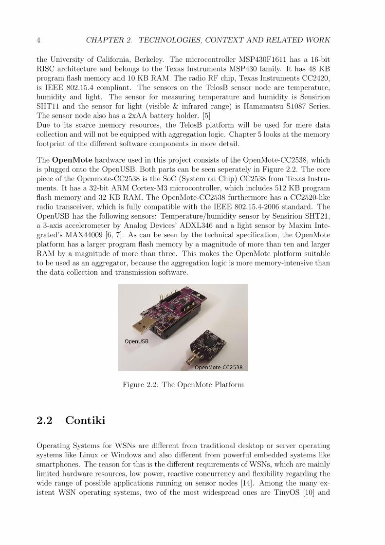
The OpenMote hardware used in this project consists of the OpenMote-CC2538, whichis plugged onto the OpenUSB. Both parts can be seen seperately in Figure 2.2. The corepiece of the Openmote-CC2538 is the SoC (System on Chip) CC2538 from Texas Instru-ments. It has a 32-bit ARM Cortex-M3 microcontroller, which includes 512 KB programflash memory and 32 KB RAM. The OpenMote-CC2538 furthermore has a CC2520-likeradio transceiver, which is fully compatible with the IEEE 802.15.4-2006 standard. TheOpenUSB has the following sensors: Temperature/humidity sensor by Sensirion SHT21,a 3-axis accelerometer by Analog Devices’ ADXL346 and a light sensor by Maxim Inte-grated’s MAX44009 [6, 7]. As can be seen by the technical specification, the OpenMoteplatform has a larger program flash memory by a magnitude of more than ten and largerRAM by a magnitude of more than three. This makes the OpenMote platform suitableto be used as an aggregator, because the aggregation logic is more memory-intensive thanthe data collection and transmission software.
Figure 2.2: The OpenMote Platform
2.2 Contiki
Operating Systems for WSNs are different from traditional desktop or server operatingsystems like Linux or Windows and also different from powerful embedded systems likesmartphones. The reason for this is the different requirements of WSNs, which are mainlylimited hardware resources, low power, reactive concurrency and flexibility regarding thewide range of possible applications running on sensor nodes [14]. Among the many ex-istent WSN operating systems, two of the most widespread ones are TinyOS [10] and

2.3. DATA FORMAT TINYIPFIX 5
Contiki [11]. This work is based on Contiki whose important properties are shortly sum-marized:Contiki is written in the C language and is based on an event-driven scheduler. Thescheduler dispatches events to running processes. Dispatched events run to completionand cannot be interrupted by the scheduler. The problem with purely event-driven pro-gramming models is the lack of blocking waits. This necessitates the use of state machinesto describe control flow. Programs written in state machines are difficult to write, main-tain and debug. Adam Dunkels came up with a programming abstraction that allowsfor blocking waits and thread-like programming while at the same time minimizes mem-ory overhead for each thread as much as possible. This reduces considerable complexityto write programs. The abstraction is called Protothread [15]. It allows for stack-lessthreads with minimal memory overhead of 2 Bytes per Protothread. Since Protothreadsare stack-less, preemption is not possible. To still allow preemptive multi-threading, pro-grams can be optionally linked with a library that sits on top of the event-driven kerneland supports preemption. Linking the library should be used carefully because of theadditional memory overhead.
2.3 Data Format TinyIPFIX
TinyIPFIX is an application-layer protocol designed for resource-constrained wireless sen-sor nodes to transmit data in a WSN. The name TinyIPFIX comes from the IPFIX pro-tocol, which stands for Internet Protocol Flow Information Export [20]. IPFIX is usedto transmit traffic flow information to facilitate services such as measurement, accountingand billing in IP networks. It does so by splitting information into template and datarecords. Information flows unidirectionally from exporting nodes towards collecting nodes.TinyIPFIX adapted the idea of splitting information into meta data and actual payloadand also incorporated the unidirectional, push-based flow of data within the network.Measurements [3] have shown that the transmission efficiency of TinyIPFIX compared toother approaches like Type-Length-Value [16] is promising.
A template record in the TinyIPFIX protocol uniquely describes the specific model of asensor by an indivdual Information Element Identifier and an Enterprise Number, whichare registered with the Internet Assigned Number Authority (IANA). This means thetemplate record represents the meta information for a sensor reading. This ensures in-teroperability and adaptability to other platforms. A template record always references aunique data record, which matches the sensor. Whether the Enterprise Number is set is
Figure 2.3: Template Record [2]

6 CHAPTER 2. TECHNOLOGIES, CONTEXT AND RELATED WORK
Figure 2.4: Template Set Header [2]
Figure 2.5: Data Set consisting of multiple Data Records [4]
optional and can be distinguished with the value of the first bit of the Information Ele-ment Identifier field. The Field Length field denotes the size of the sensor data in octets.Figure 2.3 shows the structure of a template record. Several template records make up atemplate set. On top of the resulting template set sits the template set header (Figure2.4), which denotes the data set ID it is referencing as well as the field count, which isthe total number of records in the set.
A data record only consists of the data itself. By knowing the 1-to-1 mapping between atemplate set and a data set no further information is necessary to uniquely attribute thedata to the corresponding sensor. The length of each data record is a multiple of one byte.Several data records combined result in a data set. An example set with variable sizeddata records can be seen in Figure 2.5. Data sets do not have a data set header becausea receiver has to receive a template set first, which references this data set to know howto interpret the data. A message header sits on every TinyIPFIX message. This headerlooks very different from the IPFIX header, but as stated before, IPFIX and TinyIPFIXhave other tasks to fulfill and, therefore, underlie different design desicions. Figure 2.6shows the TinyIPFIX message header with all corresponding fields.
The first two bits are two flags. If the first bit, denoted as A, is set, then the optionalExt. SetID (Extended Set ID) field is present in the header. The same logic appliesto the flag B and the optional Ext. Sequence Number field. The SetID lookup field is
Figure 2.6: TinyIPFIX Message Header [2]

2.3. DATA FORMAT TINYIPFIX 7
always present and gives information about what kind of information is being sent withthe actual TinyIPFIX message. The standard uses the following shortcuts: Value = 1means SetID = 2 and the message contains a template definition. Value = 2 means SetID= 256 and the message contains a data set for Template 256. Value = 0 and Value = 15are for special use and Value = 3-14 are reserved for future use.
The following chapter is concerned with the design decisions for the implementation ofthe aggregation framework under Contiki for the above-mentioned hardware platforms.

8 CHAPTER 2. TECHNOLOGIES, CONTEXT AND RELATED WORK
Chapter 3
Design
The aggregation framework is based on an existing TinyIPFIX implementation [4] forContiki and is inspired by the aggregation implementation in TinyOS [8]. This chapterfocuses on a high-level overview of the design decisions taken in this internship. Section 3.1introduces the different software components and their deployment on hardware. Section3.2 targets routing, specifically which data path TinyIPFIX messages take from collectorto sink. Section 3.3 is concerned with the design of message and data aggregation on topof TinyIPFIX.
3.1 Components and Hardware Deployment
There are three distinct software components present, namely Collector, Aggregator andBorder Router. The functionality of each of them is described in more detail.
A Collector on Contiki has been implemented in [4]. Its task is to periodically transmit itspre-defined template set and updated measurements from its sensors towards the BorderRouter. The Collector code has been extended in order to allow it to communicate withspecific Aggregator nodes via unicast.
Figure 3.1 shows the architecture of the software. As the node becomes alive, eitherby plugging 2xAA batteries into the battery holder or plugging it into a powered USBslot, the controller module initiates the networking module to set up a connection to theBorder Router and initalizes the TinyIPFIX system. The platform is known at compile-time. The platform is transparent in the way that TinyIPFIX itself is not aware ofthe platform being used. If TinyIPFIX requests a template set or a data set, then therequest is directly handled by the platform code. The advantage of this design is thatthe TinyIPFIX code never has to be modified and that only a few lines of code have tobe written for a new platform to be successfully integrated. In this example the TelosBplatform is active, but by recompiling with different command line options the OpenMoteor other, not yet implemented, platforms can be used.
The Aggregator receives incoming messages from the Collectors and stores them in RAM.It then aggregates the received measurements before sending them along.
9

10 CHAPTER 3. DESIGN
Figure 3.1: Collector Software Design
Figure 3.2 shows the components of the Aggregator software. As soon as the Aggregatorcomes to life, the controller module tasks the networking module to initialize two UDPconnections: one incoming connection to receive messages from the Collectors and oneoutgoing connection to forward the aggregated messages towards the Border Router. Theaggregation module, which will be further explained in the next subsection, is responsiblefor calculating the aggregated template set, which it periodically forwards to the net-working module by which it gets sent off to the Border Router. The networking moduleforwards all incoming messages to the aggregation module to apply aggregation on thedata sets. Thus, this communication is bidirectional. Only the data sets received fromthe Collectors are acted upon, the template sets are discarded. Finally, the aggregationmodule needs access to TinyIPFIX specific tasks such as message header creation.
Figure 3.2: Aggregator Software Design

3.2. ROUTING SUPPORT 11
3.1.1 Border Router
The Border Router is an application developed by Contiki developers [19]. It receivestemplate sets and aggregated messages from Aggregators only. It is programmed in away that it listens for all incoming messages, not only messages specifically sent to its IP.This is resource-consuming, but the Border Router is connected to a computer by defaultand, thus, does not depend on batteries or other mobile energy sources. The fact thatthe Border Router receives messages not only destined to its IP allows the Aggregatorto forward its outgoing messages to a default IP within the network. However, thereare downsides to this approach, which will be discussed in more detail in the evaluationchapter.
3.1.2 Hardware Deployment
Due to the differences in memory footprint and application logic, the simpler Collectorcomponent is deployed on the TelosB platform. As mentioned in [4], TelosB only supportsContiki versions up to 2.7 because of its constrained ROM space. OpenMote on theother hand supports more up-to-date and much improved versions [21] of the operatingsystem. Fortunately, the whole stack is backwards-compatible to version 2.7, which makesa heterogeneous deployment consisting of TelosB and OpenMote hardware possible. TheAggregator and Border Router are both deployed on OpenMote hardware. The increasedROM space of the OpenMote platform allows for larger aggregated messages.
3.2 Routing Support
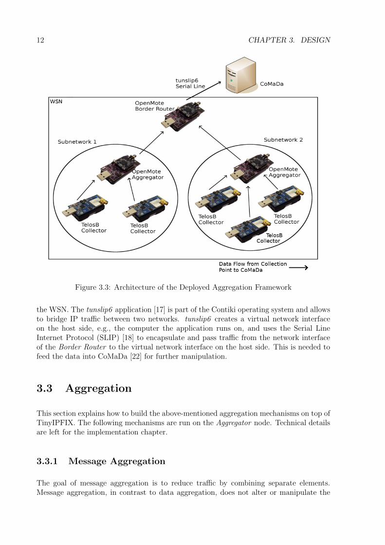
The implemented routing mechanism for this aggregation framework is static. This de-cision is based on the assumption that the nodes are at fixed positions throughout thedeployment. Furthermore, the most likely scenarios are measurements based on localitywhere a fixed mapping between Collectors and Aggregators is desirable, e.g., all sensorswithin a room communicate with an Aggregator responsible for that room. Even thoughdynamic routing adds flexibility, a static routing approach reduces overhead in both theCollector and the Aggregator compared to a dynamic approach. Figure 3.3 shows anarchitectural overview of the system with the components described in the previous sec-tion and the static routing in place. The Collectors communicate unidirectionally withthe Aggregator, i.e., the Collectors are not listening to incoming messages. Instead ofhardcoding the IP addresses of the Aggregator directly into the source code, the Collec-tors as well as their corresponding Aggregator subscribe to a service which groups themlogically into a subnetwork. The technical details follow in Section 4.2. The service regis-tration concept allows a dynamic replacement of the Aggregators without reprogrammingthe Collectors. The Aggregators listen on incoming messages from Collectors and sendthe aggregated messages to the Border Router, depending on the mode of aggregation aswell as pre-defined configuration constants set at compile-time. The single Border Routerreceives messages from the aggregation nodes only and does not send messages back into
12 CHAPTER 3. DESIGN
Figure 3.3: Architecture of the Deployed Aggregation Framework
the WSN. The tunslip6 application [17] is part of the Contiki operating system and allowsto bridge IP traffic between two networks. tunslip6 creates a virtual network interfaceon the host side, e.g., the computer the application runs on, and uses the Serial LineInternet Protocol (SLIP) [18] to encapsulate and pass traffic from the network interfaceof the Border Router to the virtual network interface on the host side. This is needed tofeed the data into CoMaDa [22] for further manipulation.
3.3 Aggregation
This section explains how to build the above-mentioned aggregation mechanisms on top ofTinyIPFIX. The following mechanisms are run on the Aggregator node. Technical detailsare left for the implementation chapter.
3.3.1 Message Aggregation
The goal of message aggregation is to reduce traffic by combining separate elements.Message aggregation, in contrast to data aggregation, does not alter or manipulate the

3.3. AGGREGATION 13
data but only combines them into a larger message. As described in Section 2.3, everyTinyIPFIX payload needs to have a corresponding template definition which needs to besent additionally to the payload in a separate message such that the receiver of the datacan correctly parse the payload. The Aggregator node is responsible for constructing theaggregation template. Since message aggregation is just the concatenation of individualmessages, the resulting template is just the concatenation of several times the individualtemplate set received from the Collector. The amount of concatenations corresponds tothe degree of aggregation (doa).To illustrate the mechanism, consider Figure 3.4: a) shows a template set with threetemplate records. This is the template that is sent from the Collector towards the Ag-gregator. b) shows an aggregated template set with a degree of aggregation equal to two,which is periodically broadcast from the Aggregator to the Border Router. As mentionedin Section 2.3, a template set header as well as a message header is placed on top of eachTinyIPFIX message. By aggregating individual messages, transmission density can be re-duced by including the header once for the aggregated template. As for the payload, theAggregator waits for the amount of data messages as specified in the degree of aggregationparameter from the Collectors within its subnetwork, concatenates them, calculates thecorresponding message header before sending the aggregated data message towards theBorder Router.
Figure 3.4: Message Aggregation
3.3.2 Data Aggregation
Data aggregation focuses on a subset of the data. In this internship one type of mea-surement is considered, but this can easily be extended to multiple measurements or thewhole template set itself. The following parameters are needed and set at compile-timefor data aggregation:
• Measurement Type: This value corresponds to the type of measurement or sensor

14 CHAPTER 3. DESIGN
that is aggregated. Examples include temperature, humidty or battery level, amongothers.
• Degree of Aggregation: This is similar to message aggregation. The degree ofaggregation is the amount of input messages the aggregation function operates on.
• Aggregation Function: This is a mathematical function which takes as input anumber of data messages, which is specified in the degree of aggregation parameter,and outputs a single value. Examples of aggregation functions include average, minor max, among others.In Figure 3.5, a) refers to the template set received from a Collector and b) showsthe aggregated template set. This template set is periodically sent to the BorderRouter. The measurement type in this example is element 2. Once the Aggregatorreceives the amount of data sets specified in the degree of aggregation parameter, itextracts the relevant data, aggregates them according to the specified aggregationfunction before calculating the message header and seding the aggregated messagetowards the Border Router.
Figure 3.5: Data Aggregation
Chapter 4
Implementation
This chapter is concerned with implementation details, ranging from Contiki libraries andservices, to the implementation of the aggregation framework to implementation detailsconcerning the CoMaDa integration.
4.1 Routing Implementation
This section is concerned with the technical implementation of the routing mechanism.The building blocks, the Simple UDP API on the network layer and the Service RegistryApp on the application layer are provided by the Contiki codebase.
4.1.1 Simple UDP API
Contiki provides a simplified UDP API, called Simple UDP API, which simplifies network-ing tasks for the programmer. The API is shortly introduced in the following paragraphs.
Interfacing with the Contiki UDP API requires a programmer to handle socket creation,binding and listening on the receiving end. Additionally, a server has to listen for atcpip event for all UDP connections and can distinguish between different UDP connec-tions only after the event has occured. The Simple UDP module simplifies this approachby using different user-defined callback functions for each distinct connection.
Listing 4.1: Registering a UDP connection
1 int simple_udp_register(struct simple_udp_connection *c,
2 uint16_t local_port,
3 uip_ipaddr_t *remote_addr,
4 uint16_t remote_port,
5 simple_udp_callback receive_callback);
15
16 CHAPTER 4. IMPLEMENTATION
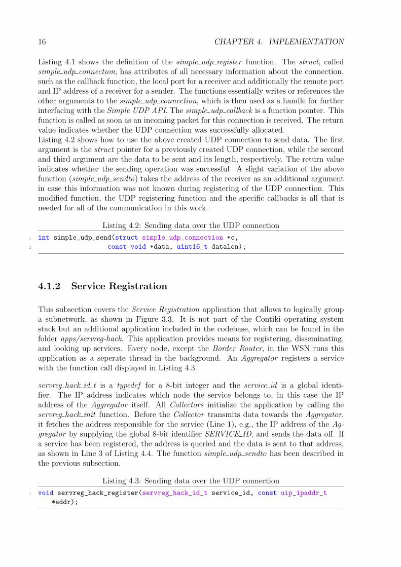
Listing 4.1 shows the definition of the simple udp register function. The struct, calledsimple udp connection, has attributes of all necessary information about the connection,such as the callback function, the local port for a receiver and additionally the remote portand IP address of a receiver for a sender. The functions essentially writes or references theother arguments to the simple udp connection, which is then used as a handle for furtherinterfacing with the Simple UDP API. The simple udp callback is a function pointer. Thisfunction is called as soon as an incoming packet for this connection is received. The returnvalue indicates whether the UDP connection was successfully allocated.Listing 4.2 shows how to use the above created UDP connection to send data. The firstargument is the struct pointer for a previously created UDP connection, while the secondand third argument are the data to be sent and its length, respectively. The return valueindicates whether the sending operation was successful. A slight variation of the abovefunction (simple udp sendto) takes the address of the receiver as an additional argumentin case this information was not known during registering of the UDP connection. Thismodified function, the UDP registering function and the specific callbacks is all that isneeded for all of the communication in this work.
Listing 4.2: Sending data over the UDP connection
1 int simple_udp_send(struct simple_udp_connection *c,
2 const void *data, uint16_t datalen);
4.1.2 Service Registration
This subsection covers the Service Registration application that allows to logically groupa subnetwork, as shown in Figure 3.3. It is not part of the Contiki operating systemstack but an additional application included in the codebase, which can be found in thefolder apps/servreg-hack. This application provides means for registering, disseminating,and looking up services. Every node, except the Border Router, in the WSN runs thisapplication as a seperate thread in the background. An Aggregator registers a servicewith the function call displayed in Listing 4.3.
servreg hack id t is a typedef for a 8-bit integer and the service id is a global identi-fier. The IP address indicates which node the service belongs to, in this case the IPaddress of the Aggregator itself. All Collectors initialize the application by calling theservreg hack init function. Before the Collector transmits data towards the Aggregator,it fetches the address responsible for the service (Line 1), e.g., the IP address of the Ag-gregator by supplying the global 8-bit identifier SERVICE ID, and sends the data off. Ifa service has been registered, the address is queried and the data is sent to that address,as shown in Line 3 of Listing 4.4. The function simple udp sendto has been described inthe previous subsection.
Listing 4.3: Sending data over the UDP connection
1 void servreg_hack_register(servreg_hack_id_t service_id, const uip_ipaddr_t
*addr);
4.2. MODULAR AGGREGATOR SOFTWARE DESIGN 17
Listing 4.4: Sending data over the UDP connection
1 uip_ipaddr_t addr = servreg_hack_lookup(SERVICE_ID);
2 if(addr != NULL)
3 simple_udp_sendto(...);
The renewed querying before every transmission adds overhead but simplifies the scenarioin which Aggregators get replaced. This way Collectors do not need to be reprogrammedand redeployed.
4.2 Modular Aggregator Software Design
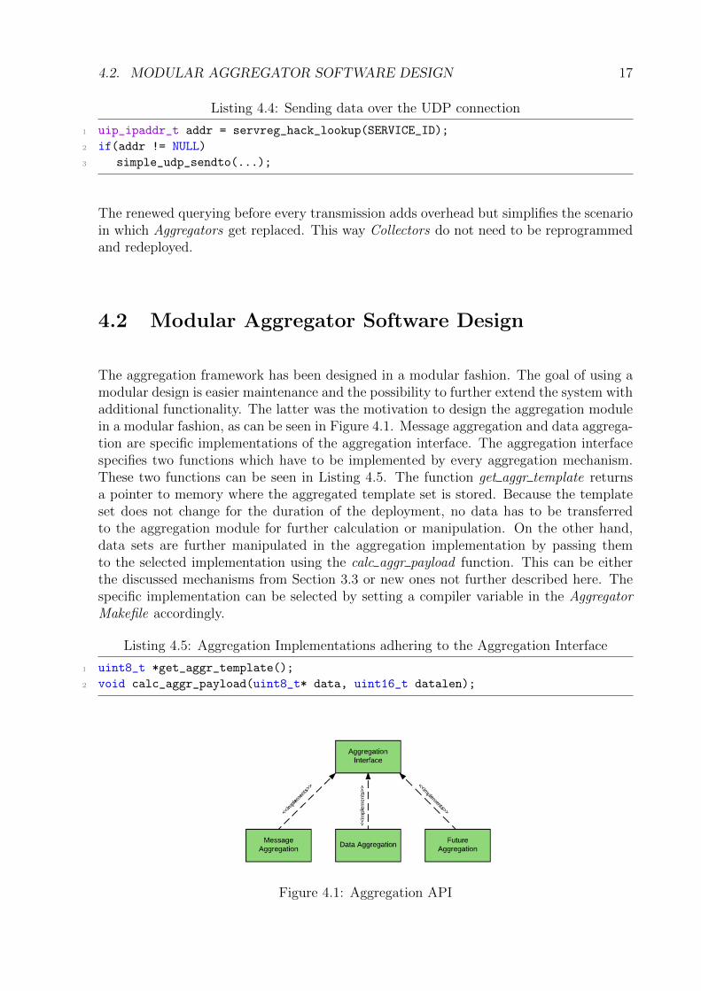
The aggregation framework has been designed in a modular fashion. The goal of using amodular design is easier maintenance and the possibility to further extend the system withadditional functionality. The latter was the motivation to design the aggregation modulein a modular fashion, as can be seen in Figure 4.1. Message aggregation and data aggrega-tion are specific implementations of the aggregation interface. The aggregation interfacespecifies two functions which have to be implemented by every aggregation mechanism.These two functions can be seen in Listing 4.5. The function get aggr template returnsa pointer to memory where the aggregated template set is stored. Because the templateset does not change for the duration of the deployment, no data has to be transferredto the aggregation module for further calculation or manipulation. On the other hand,data sets are further manipulated in the aggregation implementation by passing themto the selected implementation using the calc aggr payload function. This can be eitherthe discussed mechanisms from Section 3.3 or new ones not further described here. Thespecific implementation can be selected by setting a compiler variable in the AggregatorMakefile accordingly.
Listing 4.5: Aggregation Implementations adhering to the Aggregation Interface
1 uint8_t *get_aggr_template();
2 void calc_aggr_payload(uint8_t* data, uint16_t datalen);
Figure 4.1: Aggregation API

18 CHAPTER 4. IMPLEMENTATION
4.3 CoMaDa Integration
A further goal of this internship was to integrate the developed aggregation frameworkinto CoMada v1.1 for Contiki. This consists of two parts, namely manual configurationof the nodes as well as forms of live visualization for a deployed WSN.
Instead of compiling and deploying software for the nodes over the command line inter-face, a graphical user interface (GUI) is more comfortable when having to specify severalparameters. Figure 4.2 shows four buttons, each of which opens a new panel, letting theuser interact with the physically connected wireless nodes directly. Collector, Aggregatorand Border Router buttons let the user specify parameters and compile and deploy thesoftware components onto the connected hardware with one click. The Tunnel buttonlets a user start a virtual network interface to bridge the incoming traffic of the BorderRouter and feed it into CoMaDa for further processing. To illustrate the process of spec-ifying deployment parameters, Figure 4.3 displays the panel when the Aggregator buttonis clicked and the Data Aggregation radio button selected. As stated in Section 3.3.2 threeparameters can be specified which lets the user choose the Degree of Aggregation, Aggre-gation Function and Aggregated Sensor, the specific sensor which is to be aggregated.The specification of the subnetwork corresponds to Figure 3.3. The Collector panel hasan identical input field. The source code location points to the local path on which thesource for the specific software component resides. After specifying all parameters, theDeploy button is clicked, which compiles and deploys the software on the connected node.
New CoMaDa modules were developed to add live visualization for Contiki. The CoMaDaapplication is fairly modular, such that the process of adding new modules and drivers isstraightforward. The WSNFramework class is the entry point of the application and letsthe programmer choose which modules and drivers should be active before starting theapplication. As soon as the IP tunnel is started and the virtual network interface created,a live packet feed can be found under the Visualization → Data-Packets tab.Figure 4.4 shows two TinyIPFIX messages: The top message is the template set and thebottom message is the aggregated message using message aggregation with an aggregationdegree of 2. The node ID of the Aggregator is 38891 and can be seen in the first line ofthe aggregated message. The two Collectors with the node IDs 29066 and 22322 belongto the same subnetwork as the Aggregator. Figure 4.5 shows the template set for dataaggregation, followed by three consecutive aggregated messages. The parameters for thedata aggregation were set to Degree of Aggregation = 2, Aggregation Function = Averageand Aggregated Sensor = Temperature (cf. Figure 4.3).
Figure 4.2: CoMaDa Configuration Panel

4.3. COMADA INTEGRATION 19
Figure 4.3: CoMaDa Configuration Data Aggregation Panel
Figure 4.4: Message Aggregation Live Visualization in CoMaDa
Figure 4.5: Data Aggregation Live Visualization in CoMaDa

20 CHAPTER 4. IMPLEMENTATION

Chapter 5
Evaluation
This chapter measures several qualitative properties, such as memory footprint, energyconsumption and performance. Section 5.1 lists the measurement of the memory footprintsof all components and compares the numbers with other work. Section 5.2 is concernedwith performance of aggregated messages versus non-aggregated messages in terms oftransmission quantity. Section 5.3 looks at energy consumption. The chapter concludeswith limitations in the aggregation framework in Section 5.4.
Figure 5.1 shows a floor plan of the 2nd floor of the building at Binzmuhlestrasse 14, 8050Zurich. A heterogeneous WSN was deployed with all components listed in Section 3.1.The deployment consists of one Border Router, two Aggregators, and four Collectors. Thenumbers written next to each Aggregator and Collector correspond to the subnetwork theyare placed in, as shown in Figure 3.3. Collectors belonging to the same subnetwork takemeasurements in the same room, before forwarding the data via unicast connection to theircorresponding Aggregator. A measurement was run for 37 minutes with a transmissionsuccess rate of 100%.
Figure 5.1: Deployment Scenario
21

22 CHAPTER 5. EVALUATION
5.1 Memory Footprint
Since wireless sensor nodes are highly constrained in their memory, special care has to beput into optimized programming. As mentioned in Section 2.1, the hardware platformsused in this work differ greatly in their memory resources. The justification of whichsoftware component is placed on which hardware platform was given in Section 3.1: TheCollector is deployed on TelosB hardware, and the Aggregator as well as the Border Routerare placed on the OpenMote hardware. The code of the Collector is a modified versionof the implementation in [4]. The comparison of the memory footprint of the two imple-mentations can be seen in Table 5.1. The bottom row is the Collector implementation ofthis internship, while the middle row is the memory footprint from the implementationin [4]. The numbers are slightly different for ROM and RAM memory. This is because ofsome code restructuring done in this implementation as well as introduced overhead fromthe Service Registration application.
RAM [Byte] ROM [Byte]TelosB Maximum Memory [5] 10’000 48’000TinyIPFIX Collector from [4] 6’492 41’326TinyIPFIX Collector (cf. Section 3.1.1) 6’412 43’202
Table 5.1: Memory Footprint Comparison of Two TinyIPFIX Collectors on TelosB
An OpenMote node has much larger ROM and RAM sizes. Table 5.2 shows the physicalamount of memory available in the first row and the two software components and theirmemory consumption in the 2nd and 3rd row. It does not make much sense to compareTable 5.1 and Table 5.2 because TelosB and OpenMote are based on different underlyinghardware (cf. Section 2.1). However, fitting the Aggregator logic onto the TelosB mighthave been difficult. In contrast, aggressive optimizing of the code for the OpenMoteplatform is not necessary because the code uses just a small amount of the overall availablememory.
RAM [Byte] ROM [Byte]OpenMote Maximum Memory [6] 32’000 512’000Aggregator (cf. Section 3.3) 17’217 47’603Border Router [19] 18’672 49’440
Table 5.2: Memory Footprint of the Aggregator and Border Router [19] on OpenMote
5.2 Performance
In this section we consider the savings on transmission if aggregation is used. Specifically,we look at the communication path between the Aggregator and the Border Router andcompare the savings relatively to a mere forwarder of all incoming data, as seen in [4].

5.3. ENERGY CONSUMPTION 23
We look at data and message aggregation separately. The underlying design of bothaggregation methods was elaborated in Section 3.3.In the case of message aggreagtion, for templates as well as measurement data, thefollowing amount of Bytes are saved for DOA number of messages (DOA = degree ofaggregation, MSG HEADER SIZE = TinyIPFIX message header size in Bytes):
(DOA− 1)×MSG HEADER SIZE (5.1)
Assuming the following pre-set constants: DOA = 3, MSG HEADER SIZE = 3 Bytes,Data Set = 17 Bytes, Template Set = 64 Bytes, a total amount of 10% can be saved incase of a data set and 3% for template sets.
The numbers look a lot different for data aggregation. An additional parameter,SIZE AGGR DATA, describes the size of the aggregated data: For data sets, this corre-sponds to the size of the measurements to aggregate and for template sets, it correspondsto the template records to which the data to aggregate belongs to. The following numberof Bytes are saved for DOA number of messages (PL = Payload):
(DOA− 1)× (MSG HEADER SIZE + PL) + (PL− SIZE AGGR DATA) (5.2)
Considering the following pre-set constants: DOA = 4, MSG HEADER SIZE = 3 Bytes,Data Set = 17 Bytes, Template Set = 64 Bytes, SIZE AGGR DATA = 2 Bytes for datasets and 8 Bytes for template sets, a total amount of 93.75% transmission is saved fordata sets and 95.9% is saved for template sets.
Considering the fact that the energy cost for transmitting one bit is more than processing100 instructions on a Berkeley sensor node [23], transmission savings is very importantfor energy preservation, which makes the aggregation approach important for large-scaledeployments.
We just considered the transmission savings for the TinyIPFIX application layer. How-ever, using the aggregation framework presented not only leads to less data sent per packet,but also less packets travelling over the network in total. Specifically, only one packet inDOA number of received packets gets sent from the Aggregator to the Border Router. Theoverhead of each packet sent varies considerably, depending on the underlying protocolsused. Using a traditional IPv6/UDP header adds an overhead of 48 Bytes. Therefore,6LoWPAN [24] and other resource-saving protocols might be worth considering.
5.3 Energy Consumption
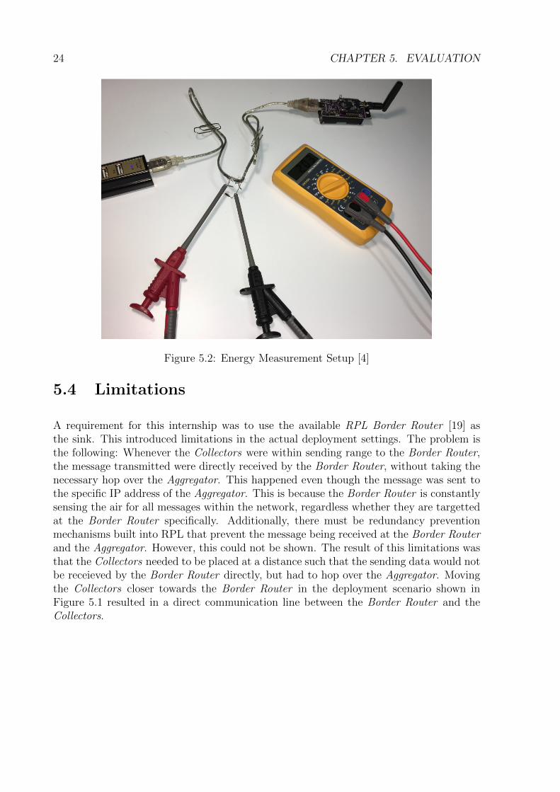
The energy measurement setup can be seen in Figure 5.2. A 10 Ohm resistor in com-bination with an applied voltage of 2V was used to measure the current flow. For theCollector running on the TelosB platform, the energy consumption in the idle state is 35.4mA. The same amount of current was drawn in the event of sending template and datasets, namely 36.8 mA. For the Aggregator running on the OpenMote platform, the idleenergy consumption is 39.2 mA and sending data, independent of template or aggregateddata sets, resulted in a current flow of 39.7 mA. Surprisingly, the Degree of Aggregationhad little effect on the energy consumption.
24 CHAPTER 5. EVALUATION
Figure 5.2: Energy Measurement Setup [4]
5.4 Limitations
A requirement for this internship was to use the available RPL Border Router [19] asthe sink. This introduced limitations in the actual deployment settings. The problem isthe following: Whenever the Collectors were within sending range to the Border Router,the message transmitted were directly received by the Border Router, without taking thenecessary hop over the Aggregator. This happened even though the message was sent tothe specific IP address of the Aggregator. This is because the Border Router is constantlysensing the air for all messages within the network, regardless whether they are targettedat the Border Router specifically. Additionally, there must be redundancy preventionmechanisms built into RPL that prevent the message being received at the Border Routerand the Aggregator. However, this could not be shown. The result of this limitations wasthat the Collectors needed to be placed at a distance such that the sending data would notbe receieved by the Border Router directly, but had to hop over the Aggregator. Movingthe Collectors closer towards the Border Router in the deployment scenario shown inFigure 5.1 resulted in a direct communication line between the Border Router and theCollectors.

Chapter 6
Conclusion
The scope of this work was two-fold: Firstly, to develop a lightweight and energy-savingaggregation framework for Contiki which is at the same time applicable to heterogeneousWSNs. Secondly, a CoMaDa integration of the aggregation framework to facilitate manualconfiguration and live visualization.
After the motivation for this project and a short introduction to the different technologiesthat came together in this project, several design decisions were presented and arguedfor. These consisted of the design aspects of which hardware platforms can and should beused for which software components. A high-level concept of the intra-WSN routing wasexplained and the concept of aggregation in general and message and data aggregationspecifically on top of TinyIPFIX was elaborated. The subsequent implementation chapterincorporated these design decisions into code and focused on the technical details, suchas specific Contiki APIs and libraries offered by Contiki that were leveraged in this work.Also, a modular concept for the aggregation framework was presented with explanationson how to easily incorporate custom aggregation techniques. The CoMaDa integrationcombined all moving parts and explained how the different software components can bedeployed on the hardware platforms with parameters that are entered over a GUI. Thelive visualization showed a live deployment for the different aggregation strategies.
The evaluation chapter considered the memory footprint in comparison to earlier work,the performance of all relevant software components, the energy consumption as well asthe limitations that were given by the assumptions of this internship.
One can think of future work building up on this aggregation framework. One examplewould be to develop a security architecture built on top of TinyIPFIX that leverages thepresented aggregation framework.
25

26 CHAPTER 6. CONCLUSION

Bibliography
[1] H. Karl, A. Willig: Protocols and Architectures for Wireless Sensor Networks, JohnWiley & Sons, ISBN: 978-0-470-09510-2, April 2005.
[2] C. Schmitt, B. Stiller, B. Trammell: TinyIPFIX for smart meters in constrainednetworks, Internet Draft, https://tools.ietf.org/html/draft-schmitt-ipfix-tiny-00, June2016.
[3] T. Kothmayr: Data collection in Wireless Sensor Networks for Au-tonomic Home Networking, http://kothmayr.net/wp-content/papercite-data/pdf/kothmayr2010bachelor.pdf, 2010.
[4] L. Sgier: Optimization of TinyIPFIX Implementation in Contiki and Realtime Visu-alization of Data, Software Project, Communication Systems Group, Department ofInformatics, University of Zurich, Zurich, Switzerland, October 2016.
[5] Advanticsys: TelosB Datasheet, http://www.advanticsys.com/shop/mtmcm5000msp-p-14.html, accessed May 8th, 2017.
[6] OpenMote: OpenMote-CC2538, http://www.openmote.com/hardware/openmote-cc2538-en.html, accessed May 8th, 2017.
[7] X. Vilajosana et al.: OpenMote: Open-Source Prototyping Platform for the IndustrialIoT, In Proceedings of the 7th EAI International Conference on Ad Hoc Networks(AdHocNets), San Remo, Italy, September 2015.
[8] B. Ertl: Data Aggregation using TinyIPFIX, Bachelor Thesis, Chair for Network Ar-chitectures and Services, Computer Science Department, Technische UniversitA¤tMunchen, Munchen, Germany, April 2011.
[9] N. Tsiftes, J. Eriksson, A. Dunkels: Low-Power Wireless IPv6 Routing with Con-tikiRPL, In Proceedings of ACM/IEEE IPSN’10, Stockholm, Sweden, April 2010.
[10] TinyOS Alliance: TinyOS, http://www.tinyos.net/, accessed March 2017.
[11] A. Dunkels, B. Gronvall, T. Voigt: Contiki - a Lightweight and Flexible OperatingSystem for Tiny Networked Sensors, In Proceedings of the 29th Annual IEEE Inter-national Conference on Local Computer Networks, pp. 455-462, 2004.
[12] T. Winter et al.: RPL: IPv6 Routing Protocol for Low-Power and Lossy Networks,RFC 6550, https://tools.ietf.org/html/rfc6550, March 2012.
27

28 BIBLIOGRAPHY
[13] A. Dunkels: Rime - A Lightweight Layered Communication Stack for Sensor Net-works, http://dunkels.com/adam/dunkels07rime.pdf, accessed May 8th, 2017.
[14] P. Levis et al.: TinsOS: An operating system for sensor networks, Ambient Intelli-gence, pp. 115-148, Springer, Berlin, 2005.
[15] A. Dunkels et al.: Protothreads: Simplifying Event-Driven Programming of Memory-Constrained Embedded Systems, In Proceedings of the 4th international conference onEmbedded networked sensor systems, SenSys ’06, pp. 29-42, New York, USA, 2006.
[16] Wikipedia: Type-length-value, https://en.wikipedia.org/wiki/
Type-length-value, accessed May 8th, 2017.
[17] A. Dunkels et al.: Tunslip6 Application, https://github.com/contiki-os/
contiki/blob/master/tools/tunslip6.c, accessed May 8th, 2017.
[18] J. Romkey: A nonstandard for transmission of IP datagrams over serial lines: SLIP,RFC 1055, https://tools.ietf.org/html/rfc1055, accessed May 8th, 2017.
[19] D. Kopf: rpl-border-router, https://github.com/lisgie/contiki/tree/master/
examples/ipv6/rpl-border-router, accessed May 8th, 2017.
[20] B. Claise et al.: Specification of the IP Flow Information Export (IPFIX) Protocolfor the Exchange of Flow Information, RFC 7011, https://tools.ietf.org/html/rfc7011, September 2013.
[21] A. Dunkels: Contiki 3.0 changelog, https://github.com/contiki-os/contiki/
issues/1197, accessed May 8th, 2017.
[22] C. Schmitt et al.: CoMaDa: An adaptive framework with graphical support for Con-figuration, Management, and Data handling tasks for wireless sensor networks, InProceedings of the 9th Conference on Network and Service Management, pp 211-218,October 2013.
[23] M. Zuniga, B. Krishnamachari: Integrating Future Large-scale Wireless Sensor Net-works with the Internet, Department of Electrical Engineering, University of SouthernCalifornia, Los Angeles, CA 90089, USA.
[24] J. Hui, P. Thubert: Compression Format for IPv6 Datagrams over IEEE 802.15.4-Based Networks, RFC 6282, https://tools.ietf.org/html/rfc6282, September2011.