tio2 hollow fibers with internal interconnected nanotubes ...mx.nthu.edu.tw/~chenhs/journal...
TRANSCRIPT

RSC Advances
COMMUNICATION
Publ
ishe
d on
12
Aug
ust 2
014.
Dow
nloa
ded
by N
atio
nal T
sing
Hua
Uni
vers
ity o
n 06
/09/
2014
05:
09:4
6.
View Article OnlineView Journal | View Issue
TiO2 hollow fibe
aDepartment of Materials Science and Engi
Hsinchu 300, Taiwan. E-mail: [email protected] and Chemical Laboratories, Indust
Kuan-Fu Road, Hsinchu 300, Taiwan
† Electronic supplementary informa10.1039/c4ra06807f
Cite this: RSC Adv., 2014, 4, 40482
Received 8th July 2014Accepted 8th August 2014
DOI: 10.1039/c4ra06807f
www.rsc.org/advances
40482 | RSC Adv., 2014, 4, 40482–404
rs with internal interconnectednanotubes prepared by atomic layer deposition forimproved photocatalytic activity†
Hsueh-Shih Chen,*a Po-Hsun Chen,a Jeng-Liang Kuo,b Yang-Chih Hsueha
and Tsong-Pyng Perng*a
TiO2 hollow fibers with internal interconnected nanotubes were
prepared by atomic layer deposition using a polysulfone–poly-
vinylpyrrolidone hollow fiber membrane as the template. The inter-
connected nanotubes form a titanium oxide network containing the
dual characteristics of nano-sized pores and channels with adjustable
spaces by the cycle number of the atomic layer deposition, and the
titanium oxide network further constructs a centimeter-long hollow
fiber. This unique macro–nano composite structure enables us to
construct a large scale nanoreactor, which has been demonstrated to
possess a higher performance (�33%) for photo-degrading the
organic water contaminants in a continuous flow than conventional
P25 TiO2 nanopowder under the same test conditions.
The synthesis of simple nanostructures such as nano-thin lms,nanorods/wires/tubes, and nanoparticles, has been well devel-oped over the past decades. Nanostructures with more complexmorphologies, that is, multi-level structures with diverse inte-riors such as core-in-hollow shell (yolk–shell),1 yolk-mesoporousshell,2,3 core/mesoporous shell,4 multishell/multiwall,5,6 andmultichamber/multichannel7,8 structures have recently beensynthesized and cataloged as a third-generation nano-structures.9 Some of these multilevel nanostructures have beendemonstrated to exhibit unconventional properties and benetsin various applications.1–4 Recent advances in the atomic layerdeposition (ALD) process enable researchers to prepare complexmetal oxide nanostructures using either natural or articialtemplates. As ALD is able to form a conformal coating withprecise control over the lm thickness at atomic scale on either2D or 3D substrates with a high aspect ratio, it has beenemployed to prepare protection layer,10 nanotube array,11,12
multiwalled nanotubes,13,14 hollow bers,15–17 and other complex
neering, National Tsing Hua University,
nthu.edu.tw; [email protected]
rial Technology Research Institute, Sec. 2,
tion (ESI) available. See DOI:
86
patterns.18–20 The ALD technique has largely extended theapplication of complex nanostructures in energy- and environ-mental-related areas, such as dye-sensitized solar cells,21,22
photonics,23 plasmonics,24 photocatalysis,25 self-cleaning lm.26
In this paper, we present a macro–nano composite structure:TiO2 hollow bers (HFs) composed of interconnected nano-tubes, which possess both intertubular pores and channelsinside the nanotubes. The HFs were synthesized by combiningALD with a polyvinylpyrrolidone (PVP) modied polysulfone(PSf) hollow ber membrane as the template and it possess anefficient photocatalytic degradation of organic water contami-nants in a continuous ow.
TiO2 HFs were prepared by the ALD process using a hydro-philic PSf–PVP hollow ber membrane as the template. Thesynthesis of the polymer membrane via the phase separationmethod can be found elsewhere.27,28 The PSf–PVP hollow bermembranes used in the present study were prepared at a factorylevel by the wet spinning process.29,30 The polymer precursorsolution contained 12–20 wt% PSf, 2–10 wt% PVP, and 70–86wt% n-methyl-pyrrolidone (NMP).
The use of the ALD technique to prepare metal oxide lms ornanotubes has been previously presented.11,12,31,32 The processhas shown high conformity and excellent repeatability. Tosynthesize TiO2 interconnected nanotubes that form hollowbers, TiCl4 and H2O were employed as precursors for Ti and O,respectively. The ALD of the TiO2 on the polymer hollow bermembranes was carried out with the length of pulse time:100 ms and 80 ms for TiCl4 and H2O, respectively. For allsyntheses, the temperature of the polymer template was main-tained at 100 �C. As-grown samples were annealed at 450 �C for2 h to form the anatase phase of the TiO2 hollow bers. For thedeposition of silver, the hollow bers were immersed in a 10�3
M silver nitrate solution for 10 min, followed by the illumina-tion of the solution with UV light of 100 W for 30 s to producesilver nanoparticles on TiO2. The photo-induced growth wasterminated by removing the UV lamp and pouring distilledwater into the solution. The samples were nally washed withdistilled water several times to remove residual silver nitrate.
This journal is © The Royal Society of Chemistry 2014
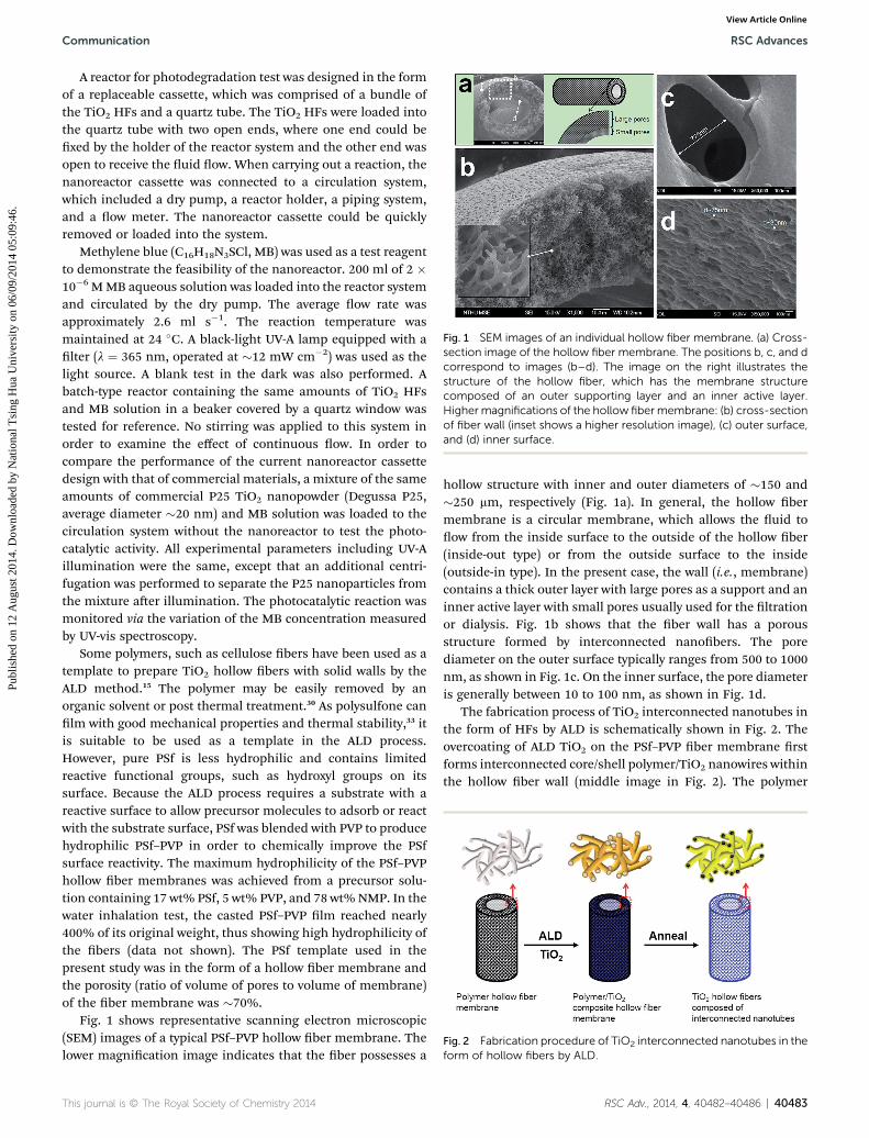
Fig. 1 SEM images of an individual hollow fiber membrane. (a) Cross-section image of the hollow fiber membrane. The positions b, c, and dcorrespond to images (b–d). The image on the right illustrates thestructure of the hollow fiber, which has the membrane structurecomposed of an outer supporting layer and an inner active layer.Higher magnifications of the hollow fibermembrane: (b) cross-sectionof fiber wall (inset shows a higher resolution image), (c) outer surface,and (d) inner surface.
Fig. 2 Fabrication procedure of TiO2 interconnected nanotubes in theform of hollow fibers by ALD.
Communication RSC Advances
Publ
ishe
d on
12
Aug
ust 2
014.
Dow
nloa
ded
by N
atio
nal T
sing
Hua
Uni
vers
ity o
n 06
/09/
2014
05:
09:4
6.
View Article Online
A reactor for photodegradation test was designed in the formof a replaceable cassette, which was comprised of a bundle ofthe TiO2 HFs and a quartz tube. The TiO2 HFs were loaded intothe quartz tube with two open ends, where one end could bexed by the holder of the reactor system and the other end wasopen to receive the uid ow. When carrying out a reaction, thenanoreactor cassette was connected to a circulation system,which included a dry pump, a reactor holder, a piping system,and a ow meter. The nanoreactor cassette could be quicklyremoved or loaded into the system.
Methylene blue (C16H18N3SCl, MB) was used as a test reagentto demonstrate the feasibility of the nanoreactor. 200 ml of 2 �10�6 MMB aqueous solution was loaded into the reactor systemand circulated by the dry pump. The average ow rate wasapproximately 2.6 ml s�1. The reaction temperature wasmaintained at 24 �C. A black-light UV-A lamp equipped with alter (l ¼ 365 nm, operated at �12 mW cm�2) was used as thelight source. A blank test in the dark was also performed. Abatch-type reactor containing the same amounts of TiO2 HFsand MB solution in a beaker covered by a quartz window wastested for reference. No stirring was applied to this system inorder to examine the effect of continuous ow. In order tocompare the performance of the current nanoreactor cassettedesign with that of commercial materials, a mixture of the sameamounts of commercial P25 TiO2 nanopowder (Degussa P25,average diameter �20 nm) and MB solution was loaded to thecirculation system without the nanoreactor to test the photo-catalytic activity. All experimental parameters including UV-Aillumination were the same, except that an additional centri-fugation was performed to separate the P25 nanoparticles fromthe mixture aer illumination. The photocatalytic reaction wasmonitored via the variation of the MB concentration measuredby UV-vis spectroscopy.
Some polymers, such as cellulose bers have been used as atemplate to prepare TiO2 hollow bers with solid walls by theALD method.15 The polymer may be easily removed by anorganic solvent or post thermal treatment.30 As polysulfone canlm with good mechanical properties and thermal stability,33 itis suitable to be used as a template in the ALD process.However, pure PSf is less hydrophilic and contains limitedreactive functional groups, such as hydroxyl groups on itssurface. Because the ALD process requires a substrate with areactive surface to allow precursor molecules to adsorb or reactwith the substrate surface, PSf was blended with PVP to producehydrophilic PSf–PVP in order to chemically improve the PSfsurface reactivity. The maximum hydrophilicity of the PSf–PVPhollow ber membranes was achieved from a precursor solu-tion containing 17 wt% PSf, 5 wt% PVP, and 78 wt%NMP. In thewater inhalation test, the casted PSf–PVP lm reached nearly400% of its original weight, thus showing high hydrophilicity ofthe bers (data not shown). The PSf template used in thepresent study was in the form of a hollow ber membrane andthe porosity (ratio of volume of pores to volume of membrane)of the ber membrane was �70%.
Fig. 1 shows representative scanning electron microscopic(SEM) images of a typical PSf–PVP hollow ber membrane. Thelower magnication image indicates that the ber possesses a
This journal is © The Royal Society of Chemistry 2014
hollow structure with inner and outer diameters of �150 and�250 mm, respectively (Fig. 1a). In general, the hollow bermembrane is a circular membrane, which allows the uid toow from the inside surface to the outside of the hollow ber(inside-out type) or from the outside surface to the inside(outside-in type). In the present case, the wall (i.e., membrane)contains a thick outer layer with large pores as a support and aninner active layer with small pores usually used for the ltrationor dialysis. Fig. 1b shows that the ber wall has a porousstructure formed by interconnected nanobers. The porediameter on the outer surface typically ranges from 500 to 1000nm, as shown in Fig. 1c. On the inner surface, the pore diameteris generally between 10 to 100 nm, as shown in Fig. 1d.
The fabrication process of TiO2 interconnected nanotubes inthe form of HFs by ALD is schematically shown in Fig. 2. Theovercoating of ALD TiO2 on the PSf–PVP ber membrane rstforms interconnected core/shell polymer/TiO2 nanowires withinthe hollow ber wall (middle image in Fig. 2). The polymer
RSC Adv., 2014, 4, 40482–40486 | 40483

RSC Advances Communication
Publ
ishe
d on
12
Aug
ust 2
014.
Dow
nloa
ded
by N
atio
nal T
sing
Hua
Uni
vers
ity o
n 06
/09/
2014
05:
09:4
6.
View Article Online
template can be removed by annealing the PSf–PVP/TiO2
composite hollow ber at an elevated temperature. The poresize of the ber membrane can be controlled by the thickness ofthe coating (i.e., ALD cycle number), while the inner diameter ofthe nanotubes can be determined by the polymer template.
Fig. 3a presents the ALD saturation curve of TiO2 on the PSf–PVP hollow ber membrane template. The weight increase inthe TiO2 deposited with 400 cycles saturates at about 0.12 s,showing that further increase in the precursor pulse time doesnot thicken the TiO2 coating, indicating a complete coverage ofthe precursor molecules, i.e., a typical ALD process. The growthrate of TiO2 is estimated to be�0.58 A per cycle according to theSEM and transmission electron microscopic (TEM) observa-tions, similar to that on Si substrates by the same ALD system,11
indicating that the PSf–PVP hollow ber is a suitable templatefor the ALD process. Fig. 3b shows the SEM image of the crosssection of the as-prepared TiO2 HFs prepared by 400 ALD cycles.It is morphologically the same as the PSf–PVP template thatshows great conformity to the ALD process. The polymertemplate is encapsulated by the TiO2 thin layer, shown by ahigher magnication image as shown in Fig. 3c.
The uniform coating in the interior of the hollow bermembrane indicates that the precursors are able to permeatethrough the pores inside the membrane and react with thetemplate surface. Aer annealing at 450 �C for 2 h, the polymertemplate was removed, leaving only TiO2 HFs, as shown inFig. 3d. The TiO2 hollow ber is composed of interconnectedTiO2 nanotubes, which possess not only intertubular nanopores
Fig. 3 (a) The ALD saturation curve of TiO2 on PSf–PVP fibermembrane. The TiCl4 pulse time was varied for depositing the 400cycles of TiO2, while the water pulse time was kept constant. (b) SEMimage of the cross section of the as-deposited PSf–PVP/TiO2 hollowfiber. (c) Higher magnification image of the fiber wall. The polymertemplate is slightly axially deformed in the cross section region after itwas cut (inset image). (d) Annealed at 450 �C for 2 h shows that theTiO2 hollow fiber contains three dimensional interconnected nano-tubes. The top right inset shows schematic nanopores among theinterconnected nanotubes and nanochannels inside the nanotubes.The lower left inset shows that the wall thickness is 23.5 nm.
40484 | RSC Adv., 2014, 4, 40482–40486
similar to those of the polymer template, but also additionalnanochannels within themselves (upper right inset in Fig. 3d).The wall thickness of the nanotubes is estimated to be 23.5 nm,corresponding to the 400 ALD cycles of TiO2. The features of theinterconnected nanotubes can be appreciated by the compar-ison of the micrographs from SEM and TEM. A representativeSEM micrograph with a higher magnication of TiO2 hollowbers prepared by 400 cycles of ALD and annealed at 450 �C isshown in Fig. 4a. It shows that the nanotubes are connectedwith each other and they form nanoscaled pores and channels.A portion of the sample was then examined by TEM, as shown inFig. 4b. The intertubular pores and channels inside the nano-tubes can be more clearly identied, and their dimensions aremeasured. For example, the diameters of two through channelsand the width of a through pore are measured to be approxi-mately 29 nm, 75 nm, and 320 nm, respectively (Fig. 4b). Thewall thickness of a single nanotube is measured to be 23.33 nm(Fig. 4c), which is consistent with that estimated from the SEM(Fig. 3d). In addition, the wall thickness is reduced to 5.48 nmwith 100 cycles of ALD (Fig. 4d). Compared with conventionalsolution methods,34–38 The ALDmethod offers the advantages ofmore precise control over the lm thickness and betteruniformity for metal oxide coating.
The TiO2 HFs are considered as a catalyst in the photo-catalytic reaction since they can be easily assembled to a largerbundle. In practical applications, such as water purication, apowder photocatalyst may not be cost effective as it needs anadditional solid–liquid separation process that increases therunning cost and time. A reactor with an immobilized photo-catalyst can solve this problem. However, the efficiency of a
Fig. 4 Electron micrographs of annealed TiO2 hollow fiberscomposed of interconnected nanotubes. (a) SEM image (400 cycles ofALD), (b) TEM image of interconnected nanotubes (400 cycles of ALD),(c) TEM image of a single nanotube (400 cycles of ALD), and (d) TEMimage of a single nanotube (100 cycles of ALD).
This journal is © The Royal Society of Chemistry 2014

Fig. 6 Average photodegradation rate curves of MB by TiO2 HFs, HFsdeposited with Ag, and P25 powder per surface area in a flow nano-reactor under 365 nm UV illumination (�12 mW cm�2). TiO2 HFs in aflow nanoreactor in dark (black curve) and a static nanoreactor con-taining TiO2 HFs (red curve) are used as references. The inset showsaverage photodegradation rate curves of TiO2 HFs and P25 with thesame weight.
Communication RSC Advances
Publ
ishe
d on
12
Aug
ust 2
014.
Dow
nloa
ded
by N
atio
nal T
sing
Hua
Uni
vers
ity o
n 06
/09/
2014
05:
09:4
6.
View Article Online
general reactor is normally poor as the catalysts have smallsurface areas. A feasible reaction system with a nanoreactorcassette containing TiO2 HFs is shown in Fig. 5a. In the design,a liquid is circulated by a pump to ow through the cassettenanoreactor continuously and ush the TiO2 HFs bundle fromthe top inlet. Each HF acts like a micro xed-bed reactor andprovides a superior contact area including the inner/outersurfaces of the hollow ber and the internal interconnectednanotubes, as schematically shown by the SEM image in Fig. 5b.Moreover, the nanostructured surface may exhibit a light-trap-ping effect because of the increasing traveling length of theincident light that can enhance the light absorption, and thusimprove the photocatalysis.39,40 The dimensions of the TiO2 HFscan be varied by the PSf–PVP template, which has beenproduced on a large scale (e.g., tens of meters) in our group.Therefore, a larger scale nanoreactor may be constructed andrealized through this hollow ber structure.
The photocatalytic property of the TiO2 HFs is comparedwith that of commercial P25 TiO2 powder. From BET analyses,the obtained surface area of the P25 nanopowder is 38.0 m2 g�1,whereas for the TiO2 HFs is 28.2 m2 g�1. To exclude the effect ofthe photolysis of MB below 350 nm or above 450 nm, a UV-Alamp with a wavelength at 365 nm and a lower intensity wasused. Fig. 6 shows the average photodegradation rate curves forthe TiO2 HFs and P25 with the same surface area and weight(inset). The TiO2 HFs in a ow nanoreactor have considerablybetter performance than those in a static batch reactor (reddotted curve), which is because of the improvement in the masstransfer of MB toward the HFs surface. For the same weight ofthe catalysts (inset), the TiO2 HFs have a photocatalytic perfor-mance close to the P25 TiO2 powder in the ow nanoreactoroperated with the same parameters. When silver is furtherloaded onto the TiO2 HFs, the nanoreactor exhibits a better
Fig. 5 (a) Image of the nanoreactor system containing a nanoreactorcassette. (b) Nanoreactor cassette containing TiO2 hollow fibersprepared with 400 cycles of ALD TiO2. (c) Image of the nanoreactorcassette when the system is operated (left). Schematic flow pathsthrough a TiO2 hollow fiber based on the SEM image (right).
This journal is © The Royal Society of Chemistry 2014
performance (�11.5%) than both P25 TiO2 powder and pureTiO2 HFs because silver can trap photoelectrons, which resultsin more holes to oxidize MB.11 If the photodegradation rate of acatalyst with the same surface area is considered, Fig. 6 exhibitsthat the TiO2 HFs have a higher photodegradation rate thancommercial P25 powder by �33% aer 6 h of operation. Theenhanced efficiency can be ascribed to improved reactionkinetics and motion connement effect for the MB moleculesowing within the intertubular nanopores and nanochannels ofthe HFs.41 For the former effect, the HFs can absorb only a smallamount of MB in a static solution in the dark until theabsorption is saturated. When they are under UV-A illumination(red curve) photodegradation takes place, but only leads to asmall decrease in the MB concentration. In the case of aushing ow, the MB may also enter the nanopores/nano-channels by forced permeation of the liquid for further reactionand faster kinetics, as already illustrated in Fig. 5b. For thelatter effect, as the dimensions of the nanopores/nanochannels(20–300 nm, estimated from SEM and TEM) are considerablysmaller than the diffusion length of MB (�100 mm), the motionof the MB molecules could be conned within the HFs, whichwould increase the probability of collision between the TiO2
surface and the MB molecules. Therefore, the TiO2 HFs have anenhanced photocatalytic ability compared with conventionalnanostructured catalysts.
A potential application of TiO2 HFs is for the purication ofdrinking water. In the current cassette design, where the HFsare directly loaded into the reactor to carry out the reaction, noadditional powder–liquid separation process is needed. Incontrast, solid photocatalysts, such as the P25 TiO2 nanopowderhave been proved to cause adverse potential effect to humanhealth.42 It is questionable to use such nanopowder for drinkingwater or other health-related applications. The development ofthe present TiO2 HFs-based nanoreactor system is still at the
RSC Adv., 2014, 4, 40482–40486 | 40485

RSC Advances Communication
Publ
ishe
d on
12
Aug
ust 2
014.
Dow
nloa
ded
by N
atio
nal T
sing
Hua
Uni
vers
ity o
n 06
/09/
2014
05:
09:4
6.
View Article Online
preliminary stage, and it is expected that the system can befurther improved. For example, in the present study the lampwas xed on one side of the nanoreactor such that that only afraction of the hollow ber bundles were illuminated by the UVlight (Fig. 5a). The photocatalysis may not be efficient becausethe decomposition of MB mainly takes place only within a fewmicrometers near the illuminated TiO2 surface.43 This may befurther improved by using a tubular UV lamp. Future studieswould be focused on the reaction kinetics of the nanoreactor inrelation to the ow rate, channel space/path, effect of contam-inant molecular size, reaction temperature/pressure, gaseousreaction, etc. The evaluation of a scale-up for the nanoreactorand its applications in water-splitting and gas reforming isunderway.
In summary, TiO2 HFs with internal interconnected nano-tubes have been synthesized by atomic layer deposition usinghydrophilic polysulfone–polyvinylpyrrolidone hollow bers asthe template. The nanostructured interconnected nanotubes,which possess both intertubular nanopores and nanochannelsform a titanium oxide network that further constructs a centi-meter-long hollow ber. A continuous ow nanoreactor con-taining TiO2 hollow ber bundles has been constructed. It hasshown good performance in the photocatalytic degradation ofMB. The nanoreactor is designed in the form of a cassette,which is replaceable and needs no additional solid–liquidseparation. Therefore, it is more time-efficient, cost-effective,and feasible for practical applications.
Notes and references
1 Y. Yin, R. M. Rioux, C. K. Erdonmez, S. Hughes,G. A. Somorjai and A. P. Alivisatos, Science, 2006, 304, 711.
2 J. C. Park, J. U. Bang, J. Lee, C. H. Ko and H. Song, J. Mater.Chem., 2010, 20, 1239.
3 P. M. Arnal, M. Comotti and F. Schuth, Angew. Chem., Int.Ed., 2006, 45, 8224.
4 S. H. Joo, J. Y. Park, C. K. Tsung, Y. Yamada, P. Yang andG. A. Somorjai, Nat. Mater., 2009, 8, 126.
5 M. Yang, J. Ma, C. L. Zhang, Z. Z. Yang and Y. F. Lu, Angew.Chem., Int. Ed., 2005, 44, 6727.
6 C. J. Jia, L. D. Sun, Z. G. Yan, Y. C. Pang, L. P. You andC. H. Yan, J. Phys. Chem. C, 2007, 111, 13022.
7 H. Y. Chen, Y. Zhao, Y. L. Song and L. Jiang, J. Am. Chem. Soc.,2008, 130, 7800.
8 Y. Zhao, X. Y. Cao and L. Jiang, J. Am. Chem. Soc., 2007, 129,764.
9 Y. Zhao and L. Jiang, Adv. Mater., 2009, 21, 3621.10 N. D. Hoivik, J. W. Elam, R. J. Linderman, V. M. Bright,
S. M. George and Y. C. Lee, Sens. Actuators, A, 2003, 103, 100.11 Y. C. Liang, C. C. Wang, C. C. Kei, Y. C. Hsueh, W. H. Cho
and T. P. Perng, J. Phys. Chem. C, 2011, 115, 9498.12 W. T. Chang, Y. C. Hsueh, S. H. Huang, K. I. Liu, C. C. Kei
and T. P. Perng, J. Mater. Chem. A, 2013, 1, 1987.13 C. Bae, Y. Yoon, H. Yoo, D. Han, J. Cho, B. H. Lee,
M. M. Sung, M. G. Lee, J. Kim and H. Shin, Chem. Mater.,2009, 21, 2574.
40486 | RSC Adv., 2014, 4, 40482–40486
14 D. Gu, H. Baumgart, T. M. Abdel-Fattah and G. Namkoong,ACS Nano, 2010, 4, 753.
15 S. W. Choi, J. Y. Park, C. Lee, J. G. Lee and S. S. Kim, J. Am.Ceram. Soc., 2011, 94, 1974.
16 J. T. Korhonen, P. Hiekkataipale, J. Malm, M. Karppinen,O. Ikkala and R. H. A. Ras, ACS Nano, 2011, 5, 1967.
17 Q. Peng, B. Gong and G. N. Parsons, Nanotechnology, 2011,22, 155601.
18 J. Huang, X. Wang and Z. L. Wang, Nano Lett., 2006, 6, 2325.19 M. Knez, A. Kadri, C. Wege, U. Gosele, H. Jeske and
K. Nielsch, Nano Lett., 2006, 6, 1172.20 M. Liu, X. Li, S. K. Karuturi, A. I. Y. Tok and H. J. Fan,
Nanoscale, 2012, 4, 1522.21 L. Liu, S. K. Karuturi, L. T. Su and A. I. Y. Tok, Energy Environ.
Sci., 2011, 4, 209.22 T. W. Hamann, A. B. F. Martinson, J. W. Elam, M. J. Pellin
and J. T. Hupp, J. Phys. Chem. C, 2008, 112, 10303.23 D. P. Gaillot, O. Deparis, V. Welch, B. K. Wagner,
J. P. Vigneron and C. J. Summers, Phys. Rev. E: Stat.,Nonlinear, So Matter Phys., 2008, 78, 031922.
24 S. D. Standridge, G. C. Schatz and J. T. Hupp, Langmuir, 2009,25, 2596.
25 Y.Gu,X.Liu,T.NiuandJ.Huang,Mater.Res.Bull., 2010,45, 536.26 C. J. W. Ng, H. Gao and T. T. Y. Tan, Nanotechnology, 2008,
19, 445604.27 H. A. Tsai, C. Y. Kuo, J. H. Lin, D. M. Wang, A. Deratani,
C. Pochat-Bohatier, K. R. Lee and J. Y. Lai, J. Membr. Sci.,2006, 278, 390.
28 J. T. Tsai, Y. S. Su, D. M. Wang, J. L. Kuo, J. Y. Lai andA. Deratani, J. Membr. Sci., 2010, 362, 360.
29 S. G. Li, G. H. Koops, M. H. V. Mulder, T. Boomgaard andC. A. Smolders, J. Membr. Sci., 1994, 94, 329.
30 J. J. Qin, J. Gu and T. S. Chung, J. Membr. Sci., 2001, 182, 57.31 C. C. Wang, C. C. Kei, Y. W. Yu and T. P. Perng, Nano Lett.,
2007, 7, 1566.32 C. C. Wang, C. C. Kei and T. P. Perng, Nanotechnology, 2011,
22, 365702.33 Y. Hwang and M. D. Edger, J. Polym. Sci., Part B: Polym. Phys.,
1996, 34, 2853.34 W. Ghadiri, N. Taghavinia, S. M. Zakeeruddin, M. Gratzel
and J. E. Moser, Nano Lett., 2010, 10, 1632.35 H. S. Chen, R. V. Kumar and B. A. Glowacki, Mater. Chem.
Phys., 2010, 122, 305.36 H. S. Chen, S. H. Huang and T. P. Perng, ACS Appl. Mater.
Interfaces, 2012, 4, 5188.37 H. S. Chen, R. V. Kumar and B. A. Glowacki, J. Sol–Gel Sci.
Technol., 2009, 51, 102.38 H. S. Chen, S. H. Huang and T. P. Perng, Surf. Coat. Technol.,
2013, 233, 140.39 C. J. Chang and S. T. Hung, Thin Solid Films, 2008, 517, 1279.40 C. J. Chang and E. H. Kuo, Colloids Surf., A, 2010, 363, 22.41 H. S. Chen, P. H. Chen, S. H. Huang and T. P. Perng, Chem.
Commun., 2014, 50, 4379.42 H. E. Jawad, A. R. Boccaccini, N. N. Ali and S. E. Harding,
Nanotoxicology, 2011, 5, 372.43 S. P. Albu, A. Ghicov, J. M. Macak, R. Hahn and P. Schmuki,
Nano Lett., 2007, 7, 1286.
This journal is © The Royal Society of Chemistry 2014