tiol111 io-link device transceivers with integrated … · diagnostics and control control logic...
TRANSCRIPT

DIAGNOSTICSand
CONTROL
CO
NT
RO
L LO
GIC
VOLTAGEREGULATOR
ILIM_ADJ
CUR_OK
EN
TX
VCC_OUT
PWR_OK
L+
CQ
L-TMP_OK
WAKE
RX
NFAULT
TIOL111-x
1 µF10 V
RSET
Microcontroller
0.1 µF100 V
10 N
10 N
Sensor Front-End IO-Link Master
Copyright © 2017, Texas Instruments Incorporated
Product
Folder
Order
Now
Technical
Documents
Tools &
Software
Support &Community
An IMPORTANT NOTICE at the end of this data sheet addresses availability, warranty, changes, use in safety-critical applications,intellectual property matters and other important disclaimers. PRODUCTION DATA.
TIOL111SLLSEV5B –JULY 2017–REVISED AUGUST 2018
TIOL111 IO-Link Device Transceivers with Integrated Surge Protection
1
1 Features1• 7-V to 36-V Supply Voltage• PNP, NPN or IO-Link Configurable Output
– IEC 61131-9 COM1, COM2 and COM3 DataRate Support
• Low Residual Voltage of 1.75 V at 250 mA• 50-mA to 350-mA Configurable Current Limit• Tolerant to ±65-V Transients < 100 µs• Reverse Polarity Protection of up to 55 V on L+,
CQ and L-• Integrated EMC Protection on L+ and CQ
– ±16 kV IEC 61000-4-2 ESD Contact Discharge– ±4 kV IEC 61000-4-4 Electrical Fast Transient– ±1.2 kV/500 Ω IEC 61000-4-5 Surge
• Fast Demagnetization of Inductive Loadsup to 1.5 H
• Large Capacitive Load Driving Capability• < 2-µA CQ Leakage Current• < 1.5-mA Quiescent Supply Current• Integrated LDO Options for up to 20 mA Current
– TIOL111: No LDO– TIOL111-3: 3.3-V LDO– TIOL111-5: 5-V LDO
• Overtemperature Warning and Thermal Protection• Remote Wake-up Indicator• Fault Indicator• Extended Ambient Temperature: –40°C to 125°C• 2.5 mm x 3 mm 10-pin VSON Package
2 Applications• IO-Link Sensors and Actuators• Factory Automation• Process Automation
3 DescriptionThe TIOL111 family of transceivers implements theIO-Link interface for industrial bidirectional, point-to-point communication. When the device is connectedto an IO-Link master through a three-wire interface,the master can initiate communication and exchangedata with the remote node while the TIOL111 acts asa complete physical layer for the communication.
These devices are capable of withstanding up to 1.2kV (500 Ω) of IEC 61000-4-5 surge and featureintegrated reverse polarity protection.
A simple pin-programmable interface allows easyinterfacing to the controller circuits. The outputcurrent limit can be configured using an externalresistor.
Fault reporting and internal protection functions areprovided for under voltage, over current and overtemperature conditions.
Device Information(1)
PART NUMBER PACKAGE BODY SIZE (NOM)TIOL111
VSON (10) 2.50 mm x 3.00 mmTIOL111-3TIOL111-5
(1) For all available devices, see the orderable addendum at theend of the data sheet.
Typical Application Diagram

2
TIOL111SLLSEV5B –JULY 2017–REVISED AUGUST 2018 www.ti.com
Product Folder Links: TIOL111
Submit Documentation Feedback Copyright © 2017–2018, Texas Instruments Incorporated
Table of Contents1 Features .................................................................. 12 Applications ........................................................... 13 Description ............................................................. 14 Revision History..................................................... 25 Pin Configuration and Functions ......................... 36 Specifications......................................................... 4
6.1 Absolute Maximum Ratings ...................................... 46.2 ESD Ratings.............................................................. 46.3 Recommended Operating Conditions....................... 46.4 Thermal Information .................................................. 56.5 Electrical Characteristics........................................... 56.6 Switching Characteristics .......................................... 76.7 Typical Characteristics .............................................. 8
7 Parameter Measurement Information .................. 98 Detailed Description ............................................ 11
8.1 Overview ................................................................. 118.2 Functional Block Diagrams ..................................... 11
8.3 Feature Description................................................. 128.4 Device Functional Modes........................................ 17
9 Application and Implementation ........................ 199.1 Application Information............................................ 199.2 Typical Application ................................................. 19
10 Power Supply Recommendations ..................... 2311 Layout................................................................... 24
11.1 Layout Guidelines ................................................. 2411.2 Layout Example .................................................... 24
12 Device and Documentation Support ................. 2512.1 Receiving Notification of Documentation Updates 2512.2 Community Resources.......................................... 2512.3 Trademarks ........................................................... 2512.4 Electrostatic Discharge Caution............................ 2512.5 Glossary ................................................................ 25
13 Mechanical, Packaging, and OrderableInformation ........................................................... 25
4 Revision History
Changes from Revision A (October 2017) to Revision B Page
• Added VIM to the Electrical Characteristics table.................................................................................................................... 5
Changes from Original (July 2017) to Revision A Page
• Changed From: 1.25 mW To: 125 mW in Equation 2 .......................................................................................................... 20

1VCC_IN/OUT
2NFAULT
3RX
4TX
5EN 6 ILIM_ADJ
7 L-
8 CQ
9 L+
10 WAKE
Thermal
Pad
Not to scale
3
TIOL111www.ti.com SLLSEV5B –JULY 2017–REVISED AUGUST 2018
Product Folder Links: TIOL111
Submit Documentation FeedbackCopyright © 2017–2018, Texas Instruments Incorporated
5 Pin Configuration and Functions
DMW Package10-Pin (VSON)
Top View
Pin FunctionsPIN
I/O DESCRIPTIONNAME NO.
IO-Link Interface
CQ 8 I/O IO-Link data signal (bidirectional)
L+ 9 POWER IO-Link supply voltage (24 V nominal)
L- 7 POWER IO-Link ground potential
Local Controller Interface
EN 5 I Driver enable input signal from the local controller. Logic low sets the CQ output at Hi-Z. Weak internal pull-down.
WAKE 10 OPEN-DRAIN Wake up indicator to the local controller. Connect this pin via pull-up resistor to VCC_IN/OUT.
RX 3 O Receive data output to the local controller
TX 4 I Transmit data input from the local controller. No effect if EN is low. Logic high sets low-side switch. Logic lowsets high-side switch. Weak internal pull-up.
Thermal Pad — — Connect to L- for optimal thermal and electrical performance
Internal LDO
VCC_IN/OUT 1 POWER 3.3-V or 5-V linear regulator output; external 3.3-V or 5-V logic supply for option without LDO.
Special Connect Pins
ILIM_ADJ 6 I Input for current limit adjustment. Connect resistor RSET between ILIM_ADJ and L-.
NFAULT 2 OPEN-DRAIN Fault indicator output signal to the microcontroller. A low level indicates either an over- current, anundervoltage supply or an overtemperature condition.

4
TIOL111SLLSEV5B –JULY 2017–REVISED AUGUST 2018 www.ti.com
Product Folder Links: TIOL111
Submit Documentation Feedback Copyright © 2017–2018, Texas Instruments Incorporated
(1) Stresses beyond those listed under Absolute Maximum Ratings may cause permanent damage to the device. These are stress ratingsonly, which do not imply functional operation of the device at these or any other conditions beyond those indicated under RecommendedOperating Conditions. Exposure to absolute-maximum-rated conditions for extended periods may affect device reliability. All voltages arewith reference to the L- pin, unless otherwise specified.
6 Specifications
6.1 Absolute Maximum Ratingsover operating free-air temperature range (unless otherwise noted) (1)
MIN MAX UNIT
Supply voltageSteady state voltage for L+ and CQ –55 55 VTransient pulse width < 100 µs for L+ and CQ –65 65 V
Voltage difference |V(L+) – V(CQ)| 55 VLogic supply voltage (TIOL111) VCC_IN –0.3 6 VInput logic voltage TX, EN, ILIM_ADJ –0.3 6 VOutput current RX, WAKE, NFAULT –5 5 mAStorage temperature, Tstg -55 170 °C
(1) JEDEC document JEP155 states that 500-V HBM allows safe manufacturing with a standard ESD control process.(2) Minimum 100-nF capacitor is required between L+ and L-. Minimum 1-µF capacitor is required between VCC_IN/OUT and L-.(3) Passing level is ±4500 V if the device is powered and EN=TX=HIGH.
6.2 ESD RatingsVALUE UNIT
V(ESD) Electrostatic discharge
Human-body model (HBM), per ANSI/ESDA/JEDECJS-001 (1) All pins ±4000
VContact discharge, per IEC 61000-4-2 (2) (3)
Pins L+, CQ andL-
±16000Electrical fast transient, per IEC 61000-4-4 (2) ±4000Surge protection with 500 Ω, per IEC 61000-4-5;1.2/50 μs (2) ±1200
6.3 Recommended Operating Conditionsover operating free-air temperature range (unless otherwise noted)
MIN NOM MAX UNITV(L+) Supply voltage 7 24 36 V
V(VCC_IN) Logic level input voltage (TIOL111 only)3.3 V configuration 3 3.3 3.6 V5 V configuration 4.5 5 5.5 V
RSET External resistor for CQ current limit 0 100 kΩ1/tBIT Data rate (Communication mode) 250 kbpsI(VCC_OUT) LDO output current (TIOL111-3 and TIOL111-5 only) 20 mATA Operating ambient temperature –40 125 °CTJ Junction temperature 150 °C

5
TIOL111www.ti.com SLLSEV5B –JULY 2017–REVISED AUGUST 2018
Product Folder Links: TIOL111
Submit Documentation FeedbackCopyright © 2017–2018, Texas Instruments Incorporated
(1) For more information about traditional and new thermal metrics, see the Semiconductor and IC Package Thermal Metrics applicationreport.
6.4 Thermal Information
THERMAL METRIC (1) TIOL111UNIT
DMW (10 Pins)RθJA Junction-to-ambient thermal resistance 68.1 °C/WRθJC(top) Junction-to-case (top) thermal resistance 60.1 °C/WRθJB Junction-to-board thermal resistance 40.6 °C/WψJT Junction-to-top characterization parameter 13.4 °C/WψJB Junction-to-board characterization parameter 40.7 °C/WRθJC(bot) Junction-to-case (bottom) thermal resistance 25.2 °C/W
(1) Current fault indication will be active. Current fault auto recovery will be de-activated.
6.5 Electrical Characteristicsover operating free-air temperature range (unless otherwise noted)
PARAMETER TEST CONDITIONS MIN TYP MAX UNIT
POWER SUPPLIES (L+)
I(L+) Quiescent supply currentEN = LOW, no load 1 1.5 mA
EN = HIGH, no load 2 2.7 mA
LOGIC-LEVEL INPUTS (EN, TX)
VIL Input logic low voltage 0.8 V
VIH Input logic high voltage 2 V
RPD Pull-down (EN) resistance 100 kΩ
RPU Pull-up (TX) resistance 200 kΩ
CONTROL OUTPUTS (WAKE, NFAULT)
VOL Output logic low voltage IO = 4 mA 0.5 V
IOZ Output high impedance leakage Output in Hi-Z, VO = 0 V or VCC_IN/OUT –1 1 µA
DRIVER OUTPUT (CQ)
VDS(ON)
High-side driver residual voltage
I = 250 mA 1.75 V
I = 200 mA 1.5 V
I = 100 mA 1.1 V
Low-side driver residual voltage
I = 250 mA 1.75 V
I = 200 mA 1.5 V
I = 100 mA 1.1 V
VIM
Voltage between CQ and L-during IO-Link Master wake-uppulse
High-side configuration, Rload = 26 Ω between CQ andL-, 18 V ≤ V(L+) ≤ 30 V 14.5 V
Low-side configuration, Rload = 24 Ω between CQ andL+, V(L+) = 20 V 4 V
Low-side configuration, Rload = 44 Ω between CQ andL+, V(L+) = 30 V 4 V
IOZ CQ leakage EN = LOW, 0 ≤ V(CQ) ≤ (V(L+) - 0.1 V) –2 2 µA
IO(LIM) Driver output current limit
RSET = 100 kΩ 35 50 70 mA
RSET = 0 kΩ 300 350 400 mA
RSET = OPEN (1) 300 350 400 mA

6
TIOL111SLLSEV5B –JULY 2017–REVISED AUGUST 2018 www.ti.com
Product Folder Links: TIOL111
Submit Documentation Feedback Copyright © 2017–2018, Texas Instruments Incorporated
Electrical Characteristics (continued)over operating free-air temperature range (unless otherwise noted)
PARAMETER TEST CONDITIONS MIN TYP MAX UNIT
(2) VTHH (min) = 5 V + (11/18) [V(L+) - 8 V](3) VTHH (max) = 6.5 V + (13/18) [V(L+) - 8 V](4) VTHL (min) = 4 V + (8/18) [V(L+) -8 V](5) VTHL (max) = 6 V + (11/18) [V(L+) -8 V]
RECEIVER INPUT (CQ)
V(THH) Input threshold “H”
V(L+) > 18 V
10.5 13 V
V(THL) Input threshold “L" 8 11.5 V
V(HYS)Receiver Hysteresis(V(THH) - V(THL))
0.75 V
V(THH) Input threshold “H”
V(L+) < 18 V
See Note (2) See Note (3) V
V(THL) Input threshold “L" See Note (4) See Note (5) V
V(HYS)Receiver Hysteresis(V(THH) - V(THL))
0.75 V
VOL RX output low voltage IOL = 4 mA 0.4 V
VOH RX output high voltage IOL = –4 mA VCC_IN/OUT–0.5 V
PROTECTION CIRCUITS
V(UVLO) L+ under voltage lockoutL+ falling; NFAULT = Hi-Z 6 V
L+ rising; NFAULT = LOW 6.5 V
V(UVLO,HYS) L+ under voltage hysteresis Rising to falling threshold 100 mV
V(UVLO_IN)VCC_IN under voltage lockout(No LDO option)
VCC_IN falling; NFAULT = Hi-Z 2.4 V
VCC_IN rising; NFAULT = LOW 2.5 V
V(UVLO,HYS)VCC_IN under voltage hysteresis(No LDO option) Rising to falling threshold 100 mV
T(WRN) Thermal warning
Die temperature TJ
125 °C
T(SDN) Thermal shutdown 150 160 °C
T(HYS) Thermal hysteresis for shutdown 10 °C
IREVLeakage current in reversepolarity
EN = LOW, TX=x; V(CQ) < V(L-) or V(CQ) > V(L+),up to |36 V| 50 µA
EN = LOW, TX=x; V(CQ) < V(L-) or V(CQ) > V(L+),up to |55 V| 80 µA
EN = HIGH, TX = LOW; V(CQ to L+) = 3 V 550 µA
EN = HIGH, TX = HIGH; V(CQ to L-) = -3 V 10 µA
LINEAR REGULATOR (LDO)
V(VCC_OUT) Voltage regulator outputTIOL111-5 4.75 5 5.25 V
TIOL111-3 3.13 3.3 3.46 V
V(DROP)
Voltage regulator drop-outvoltage(V(L+) – V(VCC_OUT))
ICC = 20 mA load currentTIOL111-5 1.9 V
TIOL111-3 2.3 V
REG Line regulation(dV(VCC_OUT)/dV(L+)) I(VCC_OUT) = 1 mA 1.7 mV/V
LREGLoad regulation(dV(VCC_OUT)/V(VCC_OUT))
V(L+) = 24 V, I(VCC_OUT) = 100 µA to 20 mA 1%
PSSR Power Supply Rejection Ratio 100 kHz, I(VCC_OUT) = 20 mA 40 dB

7
TIOL111www.ti.com SLLSEV5B –JULY 2017–REVISED AUGUST 2018
Product Folder Links: TIOL111
Submit Documentation FeedbackCopyright © 2017–2018, Texas Instruments Incorporated
(1) CQ output remains Hi-Z for this time(2) Noise suppression time is defined as the permissible duration of a receive signal above/below the detection threshold without detection
taking place.
6.6 Switching Characteristicsover operating free-air temperature range (unless otherwise noted)
PARAMETER TEST CONDITIONS MIN TYP MAX UNIT
SECTION NAME
tPLH, tPHL Driver propagation delay
See Figure 6See Figure 7See Figure 8RL = 2 kΩCL = 5 nFR(SET) = 0 Ω
600 800 ns
tP(skew)Driver propagation delay skew.|tPLH - tPHL | 100 ns
tPZH, tPZL Driver enable delay 4 µs
tPHZ, tPLZ Driver disable delay 4 µs
tr, tf Driver output rise, fall time 150 ns
|tr – tf| Difference in rise and fall time 50 ns
tWU1 Wake-up recognition begin
See Figure 10
45 60 75 µs
tWU2 Wake-up recognition end 85 100 135 µs
tpWAKE Wake-up output delay 140 µs
tSC Current fault blanking time 175 200 µs
tpSC Current fault indication delay 260 µs
tSCENCurrent fault driver re-enablewait time 15 ms
t(UVLO)CQ re-enable delay after UVLO(1)
V(UVLO) rising threshold crossing time toCQ enable time 10 30 50 ms
RECEIVER
tND Noise suppression time (2) 250 ns
tPLH, tPHL Receiver propagation delay See Figure 9 15-pF load on RX 150 300 ns

L+ Voltage (V)
Rec
eive
r T
hres
hold
(V
)
7 9 11 13 15 17 19 21 23 25 27 29 31 33 354
5
6
7
8
9
10
11
12
13
14
D005
VTHHVTHL
Load Current (mA)
Res
idua
l Vol
tage
(V
)
0 50 100 150 200 2500
0.2
0.4
0.6
0.8
1
1.2
1.4
1.6
D003
-40qC25qC125qC
RSET (k:)
I O(L
IM) (
mA
)
0 20 40 60 80 1000
50
100
150
200
250
300
350
400
D004
Low SideHigh Side
L+ Supply Voltage (V)
L+ S
uppl
y C
urre
nt (
mA
)
0 10 20 30 400
0.5
1
1.5
2
2.5
3
D001
En=HighEn=Low
Load Current (mA)
Res
idua
l Vol
tage
(V
)
0 50 100 150 200 2500
0.2
0.4
0.6
0.8
1
1.2
1.4
1.6
1.8
D002
-40qC25qC125qC
8
TIOL111SLLSEV5B –JULY 2017–REVISED AUGUST 2018 www.ti.com
Product Folder Links: TIOL111
Submit Documentation Feedback Copyright © 2017–2018, Texas Instruments Incorporated
6.7 Typical Characteristics
No Load TX = Open 25°C
Figure 1. Supply Current vs Supply Voltage Figure 2. Residual Voltage vs Load Current: High Side
Figure 3. Residual Voltage vs Load Current: Low Side Figure 4. Current Limit vs RSET
Figure 5. Receiver Threshold Boundaries
CQ
RX
50%
50%
tPLH tPHL
EN
CQ
50%
50%
tPZL tPLZ
20%
EN
CQ
50%
50%
tPZH tPHZ
80%
V(L+) / 2
VOH
TX = LOWTX = HIGH
VOL
V(L+) / 2
tr tf
VOH
VOL
80%
20%
80%
20%
TX
CQ
50%
50%
tPHL tPLH
VOL
VOH
VOL
CQ
VOH
CQ
CQTX
EN
RL CL
RL
L+
Copyright © 2016, Texas Instruments Incorporated
9
TIOL111www.ti.com SLLSEV5B –JULY 2017–REVISED AUGUST 2018
Product Folder Links: TIOL111
Submit Documentation FeedbackCopyright © 2017–2018, Texas Instruments Incorporated
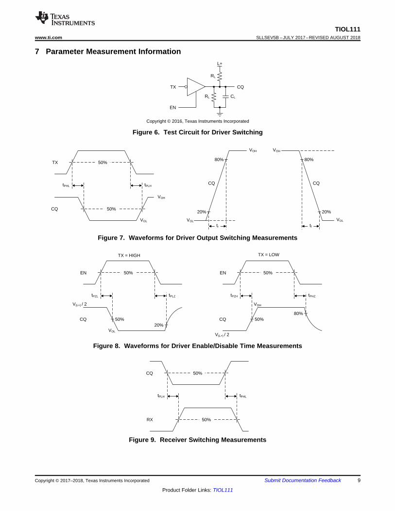
7 Parameter Measurement Information
Figure 6. Test Circuit for Driver Switching
Figure 7. Waveforms for Driver Output Switching Measurements
Figure 8. Waveforms for Driver Enable/Disable Time Measurements
Figure 9. Receiver Switching Measurements

CQ
RX
WAKE
NFAULThigh
tWU1 < t < tWU2
tpWAKE
CQ
RX
WAKE
NFAULT
high
> tSC
tpSC
CQ
RX
WAKE
NFAULT
high
high
< tWU1
a) Over-current due to transient b) Wake-up pulse from master c) Over-current due to fault condition
10
TIOL111SLLSEV5B –JULY 2017–REVISED AUGUST 2018 www.ti.com
Product Folder Links: TIOL111
Submit Documentation Feedback Copyright © 2017–2018, Texas Instruments Incorporated
Parameter Measurement Information (continued)
Figure 10. Overcurrent and Wake Conditions for EN = H, TX = H (Full Lines);and TX = L (Red Dotted Lines)

DIAGNOSTICS
and
CONTROL
CO
NT
RO
L
LO
GIC
ILIM_ADJ
CUR_OK
EN
TX
VCC_ IN
PWR_OK
L+
CQ
L-
TMP_OK
WAKE
RX
NFAULT
11
TIOL111www.ti.com SLLSEV5B –JULY 2017–REVISED AUGUST 2018
Product Folder Links: TIOL111
Submit Documentation FeedbackCopyright © 2017–2018, Texas Instruments Incorporated
8 Detailed Description
8.1 OverviewFigure 11 shows that the TIOL111 or TIOL111-x driver output (CQ) can be used in either push-pull, high-side, orlow-side configuration using the enable (EN) and transmit data (TX) input pins. The internal receiver converts the24-V signal on the CQ line to standard logic levels on the receive data (RX) pin. A simple parallel interface isused to receive/transmit data and status information between the slave and the local controller.
These devices have integrated IEC 61000-4-4/5 EFT and surge protection. In addition, tolerance to ±65-Vtransients enables flexibility to choose from a wider range of TVS diodes if an application requires higher levelsof protection. These integrated robustness features will simplify the system level design by reducing externalprotection circuitry.
TIOL111 or TIOL111-x transceivers implement protection features for overcurrent, overvoltage and over-temperature conditions. The devices also provide a current-limit setting of the driver output current using anexternal resistor.
The devices derive the low-voltage supply from the IO-Link L+ voltage (24 V nominal) via an internal linearregulator to provide power to the local controller and sensor circuitry.
8.2 Functional Block Diagrams
Figure 11. Block Diagram TIOL111

DIAGNOSTICSand
CONTROL
CO
NT
RO
LLO
GIC
VOLTAGEREGULATOR
ILIM_ADJ
CUR_OK
EN
TX
VCC_OUT
PWR_OK
L+
CQ
L-TMP_OK
WAKE
RX
NFAULT
Copyright © 2016, Texas Instruments Incorporated
12
TIOL111SLLSEV5B –JULY 2017–REVISED AUGUST 2018 www.ti.com
Product Folder Links: TIOL111
Submit Documentation Feedback Copyright © 2017–2018, Texas Instruments Incorporated
Functional Block Diagrams (continued)
Figure 12. Block Diagram TIOL111-x
8.3 Feature Description
8.3.1 Wake Up DetectionThe TIOL111 may be operated in IO-Link mode or Standard Input / Output (SIO) mode. If the device is in SIOmode and the master node wants to initiate communication with the device node, the master drives the CQ lineto the opposite of its present state, and will either sink or source the wake up current (≥ 500 mA) for the wake-upduration (typically 80 μs) depending on the CQ logic level as per the IO-Link specification. The TIOL111 detectsthis wake-up condition and communicates to the local microcontroller via the WAKE pin. The IO-Linkcommunication specification requires the device node to switch to receive mode within 500 μs after receiving thewake-up signal.
For overcurrent conditions shorter or longer than a valid wake-up pulse, the WAKE pin remains in a high-impedance (inactive) state. This is illustrated in Figure 10.
8.3.2 Current Limit ConfigurationThe output current can be configured with an external resistor on ILIM_ADJ pin. The maximum settable currentlimit is 300 mA. This maximum setting specifies a minimum of 300 mA over temperature and voltage.
Output disable due to current fault and current fault auto recovery features can be disabled by floating ILIM_ADJpin. However, the current fault indication is still active in this configuration. This feature is useful when drivinglarge capacitances.
Table 1. Current Limit Configuration
ILIM_ADJ Pin Condition CQ Current Limit NFAULT Indication DuringFault
Output Disable and AutoRecovery
RSET resistor to L- Variable Yes YesConnected to L- 300 mA Yes Yes
OPEN 300 mA Yes No

T > TWRN
CQ at IO(LIM)
for tWU1 < t < tWU2
and RX ≠TX
for
t>
tSC
Wake
WAKE = L
CUR_OK = Z
Driver = ON
LDO = ON
Receive
Only
CUR_OK = Z
WAKE = Z
Driver = OFF
LDO = ON
Receive and
Transmit
CUR_OK = Z
WAKE = Z
Driver = ON
LDO = ON
Current
Fault
WAKE = Z
CUR_OK = L
Driver = OFF
LDO=ON
ThermalWarning
CUR_OK = Z
TMP_OK = L
WAKE = Z
Driver = EN/EN*
LDO = ON
T>
TW
RN
Thermal
Shutdown
CUR_OK = Z
TMP_OK = L
WAKE = Z
Driver = OFF
LDO = ON
T>
TS
D
T<
(TS
D+
TH
YS)
Current
Fault Recovery
WAKE = Z
CUR_OK = L
Driver = ON for tsc
LDO=ON
t=
tSC
EN
CQ
at IO
(LIM
)
CQ at I and T < TO(LIM) WRN
CQ
at I O
(LIM
)
CQat I
O(LIM)
CQ
NO
Tat I O
(LIM
)
13
TIOL111www.ti.com SLLSEV5B –JULY 2017–REVISED AUGUST 2018
Product Folder Links: TIOL111
Submit Documentation FeedbackCopyright © 2017–2018, Texas Instruments Incorporated
8.3.3 Current Fault Detection, Indication and Auto RecoveryIf the output current at CQ exceeds the internally-set current limit IO(LIM) for a duration longer than tSC, theNFAULT pin is driven logic low to indicate a fault condition. The output is turned off, but the LDO continues tofunction. The output periodically retries to check if the output is still in the over current condition. In this mode,the output is switched on for tSC in tSCEN intervals. Current fault auto recovery mode can be disabled by settingILIM_ADJ = OPEN. See Table 5. Toggling EN will clear NFAULT.
8.3.4 Thermal Warning, Thermal ShutdownIf the die temperature exceeds T(WRN), the NFAULT flag is held low indicating a potential over temperatureproblem. When the TJ exceeds T(SDN), The output is disabled but the LDO remains operational. As soon as thetemperature drops below the temperature threshold (and after T(HYS)), the internal circuit re-enables the driver,subject to the state of the EN and TX pins.
8.3.5 Fault Reporting (NFAULT)NFAULT is driven low if either a current fault condition is detected, die temperature has exceeded T(WRN) orsupply has dropped below the UVLO threshold. NFAULT returns to high-impedance as soon as all three faultconditions clear.
NFAULT = [CUR_OK && PWR_OK && TMP_OK]
Figure 13. Device State Diagram

14
TIOL111SLLSEV5B –JULY 2017–REVISED AUGUST 2018 www.ti.com
Product Folder Links: TIOL111
Submit Documentation Feedback Copyright © 2017–2018, Texas Instruments Incorporated
8.3.6 Transceiver Function Tables
Table 2. Driver FunctionEN TX CQ COMMENT
L / Open X Hi-Z Device is in ready-to-receive stateH L H CQ is sourcing current (high-side drive)H H / Open L CQ is sinking current (low-side drive)
Table 3. Receiver FunctionCQ VOLTAGE RX COMMENTV(CQ) < V(THL) H Normal receive mode, input low
V(THL) < V(CQ) < V(THH) ? Indeterminate output, may be either high or lowV(THH) < V(CQ) L Normal receive mode, input high
Open ? Indeterminate output, may be either high or low
Table 4. Wake-Up Function (tWU1 < t < tWU2)EN TX CQ CURRENT WAKE COMMENT
L / Open X X Z Device is in ready-to-receive state
H H / Open | I(CQ) | ≥ 500 mA L Device receives high-level wake-up request from IO-Link Master
H L | I(CQ) | ≥ 500 mA L Device receives low-level wake-up request from IO-Link Master
Table 5. Current Limit Indicator Function (t > tSC)EN TX CQ CURRENT NFAULT COMMENT
H H / Open| I(CQ) | > IO(LIM) L CQ current exceeds the set limit for over tSC
| I(CQ) | < IO(LIM) Z Normal operation
H L| I(CQ) | > IO(LIM) L CQ current exceeds the set limit for over tSC
| I(CQ) | < IO(LIM) Z Normal operationL / Open X X Z Driver is disabled, Current limit indicator is inactive
8.3.7 The Integrated Voltage Regulator (LDO)The TIOL111-3 and TIOL111-5 each have an integrated linear voltage regulator (LDO) which can supply powerto external components. The voltage regulator is specified for L+ voltages in the range of 7 V to 36 V withrespect to L-. The LDO is capable of delivering up to 20 mA.
The LDO is designed to be stable with standard ceramic capacitors with values of 1 μF or larger at the output.X5R- and X7R-type capacitors are best because they have minimal variation in value and ESR over temperature.Maximum ESR should be less than 1 Ω. With tolerance and dc bias effects, the minimum capacitance to ensurestability is 1 μF.
The voltage regulator has an internal 35-mA current limit to protect against initial startup inrush current due tolarge decoupling capacitors and accidental short circuit conditions.
8.3.8 Reverse Polarity ProtectionReverse polarity protection circuitry protects the devices against accidental reverse polarity connections to theL+, CQ and L- pins. The maximum voltage between any of the pins may not exceed 55 V DC at any time.
Figure 14 and Figure 15 shows all the possible connection combinations.

TIOL 111
L+
CQ
L-
DC
RLTIOL 111
L+
CQ
L-
DC
RL
TIOL 111
L+
CQ
L-
DC
RLTIOL 111
L+
CQ
L-
DC
RL
TIOL 111
L+
CQ
L-
DC
RLTIOL 111
L+
CQ
L-
DC
RL
Correct
Configuration
Copyright © 2017, Texas Instruments Incorporated
Reverse Polarity ProtectedFault Conditions
Reverse Polarity ProtectedFault Conditions
Reverse Polarity ProtectedFault Conditions
Reverse Polarity ProtectedFault Conditions
Reverse Polarity ProtectedFault Conditions
15
TIOL111www.ti.com SLLSEV5B –JULY 2017–REVISED AUGUST 2018
Product Folder Links: TIOL111
Submit Documentation FeedbackCopyright © 2017–2018, Texas Instruments Incorporated
Figure 14. High-Side Driver Configuration

TIOL 111
L+
CQ
L-
DC
RLTIOL 111
L+
CQ
L-
DC
RL
TIOL 111
L+
CQ
L-
DC
RLTIOL 111
L+
CQ
L-
DC
RL
TIOL 111
L+
CQ
L-
DC
RLTIOL 111
L+
CQ
L-
DC
RL
Correct
Configuration
Copyright © 2017, Texas Instruments Incorporated
Reverse Polarity ProtectedFault Conditions
Reverse Polarity ProtectedFault Conditions
Reverse Polarity ProtectedFault Conditions
Reverse Polarity ProtectedFault Conditions
Reverse Polarity ProtectedFault Conditions
16
TIOL111SLLSEV5B –JULY 2017–REVISED AUGUST 2018 www.ti.com
Product Folder Links: TIOL111
Submit Documentation Feedback Copyright © 2017–2018, Texas Instruments Incorporated
Figure 15. Low-Side Driver Configuration

Decoupling
Network
R
EUT
L+
L-
CQ
> 100 nF
Combination
wave
Generator
Pro
tect
ion
Equ
ipm
ent
Aux
iliar
yE
quip
men
t
17
TIOL111www.ti.com SLLSEV5B –JULY 2017–REVISED AUGUST 2018
Product Folder Links: TIOL111
Submit Documentation FeedbackCopyright © 2017–2018, Texas Instruments Incorporated
8.3.9 Integrated Surge Protection and Transient Waveform ToleranceThe L+ and CQ pins of the device are capable of withstanding up to 1.2 kV of 1.2/50 – 8/20 μs IEC 61000-4-5surge with a source impedance of 500 Ω. The surge testing should be performed with a minimum 100 nF supplydecoupling capacitor between L+ and L-, and 1 µF between VCC_IN/OUT and L-.
External TVS diodes may be required for higher transient protection levels. The system designer should ensurethat the maximum clamping voltage of the external diodes should be < 65 V at the desired current level. Thedevice is capable of withstanding up to ±65-V transient pulses < 100 µs.
1.2/50 – 8/20 µs CWGR = 500 Ω
Figure 16. Surge Test Setup
8.3.10 Power Up Sequence (TIOL111)VCC_IN and L+ domains can be powered up in any sequence. In the event of L+ is powered and VCC_IN is not,the CQ pin will remain in high impedance.
8.3.11 Undervoltage Lock-Out (UVLO)The device enters UVLO if the L+ voltage falls below V(UVLO). (For the device without the integrated LDO, thedevice monitors VCC_IN in addition to L+. UVLO happens if either supply falls below the threshold.)
As soon as the supply falls below V(UVLO), NFAULT is pulled low, the LDO is turned off and the CQ output isdisabled (Hi-Z). Receiver performance is not specified in this mode.
When the supply rises above V(UVLO), NFAULT returns to Hi-Z (given no other fault conditions present) and theLDO will be enabled immediately. The CQ output is turned on after T(UVLO) delay.
8.4 Device Functional ModesThese devices can operate in three different modes.
8.4.1 NPN Configuration (N-Switch SIO Mode)Set TX pin high (or open) and use EN pin as control for realizing the function of an N-switch (low-sideconfiguration) on CQ.
8.4.2 PNP Configuration (P-Switch SIO Mode)Set TX pin low and use EN pin as control for realizing the function of a P-switch (high-side configuration) on CQ.

18
TIOL111SLLSEV5B –JULY 2017–REVISED AUGUST 2018 www.ti.com
Product Folder Links: TIOL111
Submit Documentation Feedback Copyright © 2017–2018, Texas Instruments Incorporated
Device Functional Modes (continued)8.4.3 Push-Pull, Communication ModeSet EN pin high and toggle TX as control for realizing the function of a push-pull output on CQ. Table 6, Table 7and Table 8 summarize the pin configurations to accomplish the functional modes.
Table 6. NPN ModeEN TX CQ
L / Open H / Open Hi-ZH H / Open N-Switch
Table 7. PNP ModeEN TX CQ
L / Open L Hi-ZH L P-Switch
Table 8. Push-Pull, Communication ModeEN TX CQ
L / Open X Hi-ZH H N-SwitchH L P-Switch

DIAGNOSTICSand
CONTROL
CO
NT
RO
L LO
GIC
VOLTAGEREGULATOR
ILIM_ADJ
CUR_OK
EN
TX
VCC_OUT
PWR_OK
L+
CQ
L-TMP_OK
WAKE
RX
NFAULT
TIOL111-x
1 µF10 V
RSET
Microcontroller
0.1 µF100 V
10 N
10 N
Sensor Front-End IO-Link Master
Copyright © 2017, Texas Instruments Incorporated
19
TIOL111www.ti.com SLLSEV5B –JULY 2017–REVISED AUGUST 2018
Product Folder Links: TIOL111
Submit Documentation FeedbackCopyright © 2017–2018, Texas Instruments Incorporated
9 Application and Implementation
NOTEInformation in the following applications sections is not part of the TI componentspecification, and TI does not warrant its accuracy or completeness. TI’s customers areresponsible for determining suitability of components for their purposes. Customers shouldvalidate and test their design implementation to confirm system functionality.
9.1 Application InformationWhen TIOL111 is connected to an IO-Link master through a three-wire interface (Figure 17), the master caninitiate communication and exchange data with a remote node with the TIOL111 IO-Link transceiver acting as acomplete physical layer for the communication.
9.2 Typical Application
Figure 17. Typical Application Schematic
9.2.1 Design RequirementsTIOL111 and TIOL111-x IO-Link transceivers can be used in slave devices communicating with an IO-Linkmaster, or as standard digital outputs to either sense or drive a wide range of sensors and loads. Table 9 showsrecommended components for a typical system design.
Table 9. Design ParametersPARAMETERS VALUE
Input voltage range (L+) 24 V, 30 V (max)Output current (CQ) 200 mA
Output voltage (VCC_OUT), Pick TIOL111-5 5 VMaximum LDO output current (IVCC(OUT)) 5 mAPull-up resistors for NFAULT and WAKE 10 kΩ
L+ decoupling capacitor 0.1 µF / 100 VLDO output capacitor 1 µF / 10 V
ILIM_ADJ resistor (RSET) 10 kΩMaximum Ambient Temperature, TA 105 °C

L
)O LIM(
VR
I
SCO LIMLOAD
L
I x[ ]tC
V
6,FI=T = 6#FI=T + ¿6 = 105°% + 38.3°% = 143.3°%
¿6 = 6, F 6# = 2& x E,# = 562.5 I9 T 68.1°%/9 = 38.3°%
2& = 2&12 + 2&.&1 = 437.5 I9 + 125 I9 = 562.5 I9
2&.&1 = k8.+ F 88%%_176o x +8%%_176 = :30F 5;V x 5 mA = 125 mW
2&12 = 8&5(10) T +1(.+/) = 1.758 T 250 I# = 437.5 I9
20
TIOL111SLLSEV5B –JULY 2017–REVISED AUGUST 2018 www.ti.com
Product Folder Links: TIOL111
Submit Documentation Feedback Copyright © 2017–2018, Texas Instruments Incorporated
9.2.2 Detailed Design Procedure
9.2.2.1 Maximum Junction Temperature CheckFor a 200 mA current limit:• The maximum driver output current limit, IO(LIM) = 250 mA (allowed for current limit tolerance).• The maximum voltage drop is given with VDS(ON) = 1.75 V.
This causes a power consumption of:
(1)
For a 5 mA LDO current output,
(2)
Total power dissipation,(3)
Multiply this value with the Junction-to-ambient thermal resistance of θJA = 68.1°C/W (taken from the ThermalInformation table) to receive the difference between junction temperature, TJ, and ambient temperature, TA:
(4)
Add this value to the maximum ambient temperature of TA = 105°C to receive the final junction temperature:
(5)
As long as TJ-max is below the recommended maximum value of 150°C, no thermal shutdown will occur.However, thermal warning may occur as the junction temperature is greater than TWRN.
Note that the modeling of the complete system may be necessary to predict junction temperature in smallerPCBs and/or enclosures without air flow.
9.2.2.2 Driving Capacitive LoadsThese devices are capable of driving capacitive loads on the CQ output. Assuming a pure capacitive load withoutseries/parallel resistance, the maximum capacitance that can be charged without triggering current fault can becalculated as:
(6)
Higher capacitive loads can be driven if a series resistor is connected between the CQ output and the load.Capacitive loads can be connected to L- or L+.
9.2.2.3 Driving Inductive LoadsThe TIOL111 family is capable of magnetizing and demagnetizing inductive loads up to 1.5H. These devicescontain internal circuitry that enables fast demagnetization when configured as either P-switch or N-switch mode.
In P-switch configuration, the load inductor L is magnetized when the CQ output is driven high. When the PNP isturned off, there is a significant amount of negative inductive kick back at the CQ pin. This voltage is clampedinternally at about -75 V.
Similarly in N-switch configuration, the load inductor L is magnetized when the CQ output is driven low. When theNPN is turned off, there is a significant amount of positive inductive kick back at the CQ pin. This voltage isclamped internally at about 75 V.
The equivalent protection circuits are shown in Figure 18 and Figure 19. The minimum value of the resistive loadR can be calculated as:
(7)

L
R
CQ
TIOL111
L+
Copyright © 2016, Texas Instruments Incorporated
L
TIOL 111
R
CQ
L+
Copyright © 2016, Texas Instruments Incorporated
21
TIOL111www.ti.com SLLSEV5B –JULY 2017–REVISED AUGUST 2018
Product Folder Links: TIOL111
Submit Documentation FeedbackCopyright © 2017–2018, Texas Instruments Incorporated
Figure 18. P-Switch Mode Figure 19. N-Switch Mode

5 V
/div
30
0 m
A/d
iv4
V/d
iv
Time 50 Ps/div
6 V
/div
30
0 m
A/d
iv4
V/d
iv
Time 10 ms/div
70
0 m
V/d
iv3
00
mA
/div
4 V
/div
Time 50 Ps/div
10
V/d
iv1
0 V
/div
3 V
/div
Time 10 ms/div
4 V
/div
8 V
/div
4 V
/div
Time 1 Ps/div
10
V/d
iv1
0 V
/div
3 V
/div
Time 10 ms/div
22
TIOL111SLLSEV5B –JULY 2017–REVISED AUGUST 2018 www.ti.com
Product Folder Links: TIOL111
Submit Documentation Feedback Copyright © 2017–2018, Texas Instruments Incorporated
9.2.3 Application Curves
125 kHz
Figure 20. CQ in Communication Mode Figure 21. CQ Power Up Delay, Low Side Mode
Figure 22. CQ Power Up Delay, High Side Mode Figure 23. CQ in Current Fault, Low Side Mode
Figure 24. CQ in Current Fault, High Side Mode Figure 25. CQ in Current Fault Auto Recovery,Low Side Mode

2 V
/div
40
V/d
iv
Time 10 ms/div
3 V
/div
8 V
/div
2 V
/div
Time 20Ps/div
2 V
/div
40
V/d
iv
Time 10 ms/div
3 V
/div
6 V
/div
30
0 m
A/d
iv4
V/d
iv
Time 10 ms/div
8 V
/div
2 V
/div
Time 20Ps/div
23
TIOL111www.ti.com SLLSEV5B –JULY 2017–REVISED AUGUST 2018
Product Folder Links: TIOL111
Submit Documentation FeedbackCopyright © 2017–2018, Texas Instruments Incorporated
Figure 26. CQ in Current Fault Auto Recovery,High Side Mode
Figure 27. IO-Link WAKE, Low Side Mode
Figure 28. IO-Link WAKE, High Side Mode
1.5-H Inductor With 100 Ω RSET = OPEN
Figure 29. CQ Driving, Low Side Mode
1.5-H Inductor With 100 Ω RSET = OPEN
Figure 30. CQ Driving, High Side Mode
10 Power Supply RecommendationsThe TIOL111 and TIOL111-x transceivers are designed to operate from a 24-V nominal supply at L+, which canvary by +12 V and -17 V from the nominal value to remain within the device's recommended supply voltagerange of 7 V to 36 V. This supply should be buffered with at least a 100-nF/100-V capacitor.

L+
NFAULT
RX
WAKE
1uF/10V
100nF/
50V
RSETExposed Thermal
Pad Area
VIA to Layer 2: Power Ground Plane (L-)
VIA to Layer 3: 24V Supply Plane (L+)
VIA to Layer 4: Regulated Supply Plane (VCC_IN/OUT)
CQ
L-
L+
CQ
L-
TX
EN
ILIM
_A
DJ
VCC_IN
/OUT
Use Multiple Vias
for L+ and L-
24
TIOL111SLLSEV5B –JULY 2017–REVISED AUGUST 2018 www.ti.com
Product Folder Links: TIOL111
Submit Documentation Feedback Copyright © 2017–2018, Texas Instruments Incorporated
11 Layout
11.1 Layout Guidelines• Use of a 4-layer board is recommended for good heat conduction. Use layer 1 (top layer) for control signals,
layer 2 as power ground layer for L-, layer 3 for the 24-V supply plane (L+), and layer 4 for the regulatedoutput supply (VCC_IN/OUT).
• Connect the thermal pad to L- with maximum amount of thermal vias for best thermal performance.• Use entire planes for L+, VCC_IN/OUT and L- to assure minimum inductance.• The L+ terminal must be decoupled to ground with a low-ESR ceramic decoupling capacitor. The
recommended minimum capacitor value is 100 nF. The capacitor must have a voltage rating of 50 V minimum(100 V depending on max sensor supply fault rating) and an X5R or X7R dielectric.
• The optimum placement of the capacitor is closest to the transceiver’s L+ and L- terminals to reduce supplydrops during large supply current loads. See Figure 31 for a PCB layout example.
• Connect all open-drain control outputs via 10 kΩ pull-up resistors to the VCC_IN/OUT plane to provide adefined voltage potential to the system controller inputs when the outputs are high-impedance.
• Connect the RSET resistor between ILIM_ADJ and L-.• Decouple the regulated output voltage at VCC_IN/OUT to ground with a low-ESR, ≥ 1-μF, ceramic decoupling
capacitor. The capacitor should have a voltage rating of 10 V minimum and an X5R or X7R dielectric.
11.2 Layout Example
Figure 31. Layout Example

25
TIOL111www.ti.com SLLSEV5B –JULY 2017–REVISED AUGUST 2018
Product Folder Links: TIOL111
Submit Documentation FeedbackCopyright © 2017–2018, Texas Instruments Incorporated
12 Device and Documentation Support
12.1 Receiving Notification of Documentation UpdatesTo receive notification of documentation updates, navigate to the device product folder on ti.com. In the upperright corner, click on Alert me to register and receive a weekly digest of any product information that haschanged. For change details, review the revision history included in any revised document.
12.2 Community ResourcesThe following links connect to TI community resources. Linked contents are provided "AS IS" by the respectivecontributors. They do not constitute TI specifications and do not necessarily reflect TI's views; see TI's Terms ofUse.
TI E2E™ Online Community TI's Engineer-to-Engineer (E2E) Community. Created to foster collaborationamong engineers. At e2e.ti.com, you can ask questions, share knowledge, explore ideas and helpsolve problems with fellow engineers.
Design Support TI's Design Support Quickly find helpful E2E forums along with design support tools andcontact information for technical support.
12.3 TrademarksE2E is a trademark of Texas Instruments.
12.4 Electrostatic Discharge CautionThis integrated circuit can be damaged by ESD. Texas Instruments recommends that all integrated circuits be handled withappropriate precautions. Failure to observe proper handling and installation procedures can cause damage.
ESD damage can range from subtle performance degradation to complete device failure. Precision integrated circuits may be moresusceptible to damage because very small parametric changes could cause the device not to meet its published specifications.
12.5 GlossarySLYZ022 — TI Glossary.
This glossary lists and explains terms, acronyms, and definitions.
13 Mechanical, Packaging, and Orderable InformationThe following pages include mechanical, packaging, and orderable information. This information is the mostcurrent data available for the designated devices. This data is subject to change without notice and revision ofthis document. For browser-based versions of this data sheet, refer to the left-hand navigation.

PACKAGE OPTION ADDENDUM
www.ti.com 24-Aug-2018
Addendum-Page 1
PACKAGING INFORMATION
Orderable Device Status(1)
Package Type PackageDrawing
Pins PackageQty
Eco Plan(2)
Lead/Ball Finish(6)
MSL Peak Temp(3)
Op Temp (°C) Device Marking(4/5)
Samples
TIOL1113DMWR ACTIVE VSON DMW 10 1500 Green (RoHS& no Sb/Br)
CU NIPDAU Level-2-260C-1 YEAR -40 to 125 TL1113
TIOL1113DMWT ACTIVE VSON DMW 10 250 Green (RoHS& no Sb/Br)
CU NIPDAU Level-2-260C-1 YEAR -40 to 125 TL1113
TIOL1115DMWR ACTIVE VSON DMW 10 1500 Green (RoHS& no Sb/Br)
CU NIPDAU Level-2-260C-1 YEAR -40 to 125 TL1115
TIOL1115DMWT ACTIVE VSON DMW 10 250 Green (RoHS& no Sb/Br)
CU NIPDAU Level-2-260C-1 YEAR -40 to 125 TL1115
TIOL111DMWR ACTIVE VSON DMW 10 1500 Green (RoHS& no Sb/Br)
CU NIPDAU Level-2-260C-1 YEAR -40 to 125 TL111
TIOL111DMWT ACTIVE VSON DMW 10 250 Green (RoHS& no Sb/Br)
CU NIPDAU Level-2-260C-1 YEAR -40 to 125 TL111
(1) The marketing status values are defined as follows:ACTIVE: Product device recommended for new designs.LIFEBUY: TI has announced that the device will be discontinued, and a lifetime-buy period is in effect.NRND: Not recommended for new designs. Device is in production to support existing customers, but TI does not recommend using this part in a new design.PREVIEW: Device has been announced but is not in production. Samples may or may not be available.OBSOLETE: TI has discontinued the production of the device.
(2) RoHS: TI defines "RoHS" to mean semiconductor products that are compliant with the current EU RoHS requirements for all 10 RoHS substances, including the requirement that RoHS substancedo not exceed 0.1% by weight in homogeneous materials. Where designed to be soldered at high temperatures, "RoHS" products are suitable for use in specified lead-free processes. TI mayreference these types of products as "Pb-Free".RoHS Exempt: TI defines "RoHS Exempt" to mean products that contain lead but are compliant with EU RoHS pursuant to a specific EU RoHS exemption.Green: TI defines "Green" to mean the content of Chlorine (Cl) and Bromine (Br) based flame retardants meet JS709B low halogen requirements of <=1000ppm threshold. Antimony trioxide basedflame retardants must also meet the <=1000ppm threshold requirement.
(3) MSL, Peak Temp. - The Moisture Sensitivity Level rating according to the JEDEC industry standard classifications, and peak solder temperature.
(4) There may be additional marking, which relates to the logo, the lot trace code information, or the environmental category on the device.
(5) Multiple Device Markings will be inside parentheses. Only one Device Marking contained in parentheses and separated by a "~" will appear on a device. If a line is indented then it is a continuationof the previous line and the two combined represent the entire Device Marking for that device.

PACKAGE OPTION ADDENDUM
www.ti.com 24-Aug-2018
Addendum-Page 2
(6) Lead/Ball Finish - Orderable Devices may have multiple material finish options. Finish options are separated by a vertical ruled line. Lead/Ball Finish values may wrap to two lines if the finishvalue exceeds the maximum column width.
Important Information and Disclaimer:The information provided on this page represents TI's knowledge and belief as of the date that it is provided. TI bases its knowledge and belief on informationprovided by third parties, and makes no representation or warranty as to the accuracy of such information. Efforts are underway to better integrate information from third parties. TI has taken andcontinues to take reasonable steps to provide representative and accurate information but may not have conducted destructive testing or chemical analysis on incoming materials and chemicals.TI and TI suppliers consider certain information to be proprietary, and thus CAS numbers and other limited information may not be available for release.
In no event shall TI's liability arising out of such information exceed the total purchase price of the TI part(s) at issue in this document sold by TI to Customer on an annual basis.

TAPE AND REEL INFORMATION
*All dimensions are nominal
Device PackageType
PackageDrawing
Pins SPQ ReelDiameter
(mm)
ReelWidth
W1 (mm)
A0(mm)
B0(mm)
K0(mm)
P1(mm)
W(mm)
Pin1Quadrant
TIOL1113DMWR VSON DMW 10 1500 178.0 13.5 2.75 3.35 1.05 8.0 12.0 Q2
TIOL1113DMWT VSON DMW 10 250 178.0 13.5 2.75 3.35 1.05 8.0 12.0 Q2
TIOL1115DMWR VSON DMW 10 1500 178.0 13.5 2.75 3.35 1.05 8.0 12.0 Q2
TIOL1115DMWT VSON DMW 10 250 178.0 13.5 2.75 3.35 1.05 8.0 12.0 Q2
TIOL111DMWR VSON DMW 10 1500 178.0 13.5 2.75 3.35 1.05 8.0 12.0 Q2
TIOL111DMWT VSON DMW 10 250 178.0 13.5 2.75 3.35 1.05 8.0 12.0 Q2
PACKAGE MATERIALS INFORMATION
www.ti.com 6-Aug-2018
Pack Materials-Page 1
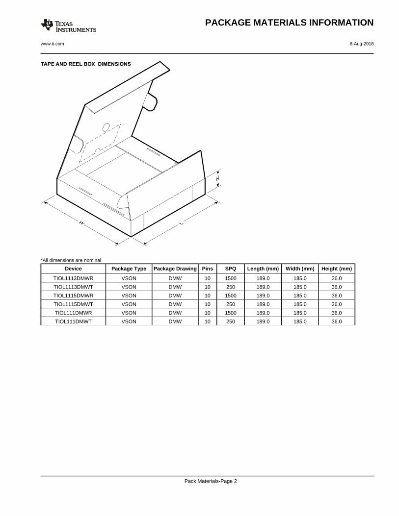
*All dimensions are nominal
Device Package Type Package Drawing Pins SPQ Length (mm) Width (mm) Height (mm)
TIOL1113DMWR VSON DMW 10 1500 189.0 185.0 36.0
TIOL1113DMWT VSON DMW 10 250 189.0 185.0 36.0
TIOL1115DMWR VSON DMW 10 1500 189.0 185.0 36.0
TIOL1115DMWT VSON DMW 10 250 189.0 185.0 36.0
TIOL111DMWR VSON DMW 10 1500 189.0 185.0 36.0
TIOL111DMWT VSON DMW 10 250 189.0 185.0 36.0
PACKAGE MATERIALS INFORMATION
www.ti.com 6-Aug-2018
Pack Materials-Page 2

www.ti.com
PACKAGE OUTLINE
C
10X 0.290.19
1.95 0.1
10X 0.4750.275
2X2
1.65 0.1
8X 0.5
1 MAX
0.050.00
B 3.12.9
A
2.62.4
(0.2) TYP
VSON - 1 mm max heightDMW0010APLASTIC SMALL OUTLINE - NO LEAD
4223225/A 08/2016
PIN 1 INDEX AREA
SEATING PLANE
0.08 C
1
5 6
10
(OPTIONAL)PIN 1 ID
0.1 C A B0.05 C
THERMAL PADEXPOSED
11
SYMM
SYMM
NOTES: 1. All linear dimensions are in millimeters. Any dimensions in parenthesis are for reference only. Dimensioning and tolerancing per ASME Y14.5M. 2. This drawing is subject to change without notice. 3. The package thermal pad must be soldered to the printed circuit board for thermal and mechanical performance.
SCALE 4.000

www.ti.com
EXAMPLE BOARD LAYOUT
0.07 MINALL AROUND
0.07 MAXALL AROUND
(1.65)
8X (0.5)
(2.825)
10X (0.24)
10X (0.575)
(1.95)
(R0.05) TYP
( 0.2) VIATYP
(0.575)
(0.725)
VSON - 1 mm max heightDMW0010APLASTIC SMALL OUTLINE - NO LEAD
4223225/A 08/2016
SYMM
1
5 6
10
SYMM
LAND PATTERN EXAMPLESCALE:20X
11
NOTES: (continued) 4. This package is designed to be soldered to a thermal pad on the board. For more information, see Texas Instruments literature number SLUA271 (www.ti.com/lit/slua271).5. Vias are optional depending on application, refer to device data sheet. If any vias are implemented, refer to their locations shown on this view. It is recommended that vias under paste be filled, plugged or tented.
SOLDER MASKOPENINGSOLDER MASK
METAL UNDER
SOLDER MASKDEFINED
METALSOLDER MASKOPENING
SOLDER MASK DETAILS
NON SOLDER MASKDEFINED
(PREFERRED)

www.ti.com
EXAMPLE STENCIL DESIGN
10X (0.24)
10X (0.575)
8X (0.5)
(0.87)
2X (1.5)
(2.825)
(R0.05) TYP
(0.535)
VSON - 1 mm max heightDMW0010APLASTIC SMALL OUTLINE - NO LEAD
4223225/A 08/2016
NOTES: (continued) 6. Laser cutting apertures with trapezoidal walls and rounded corners may offer better paste release. IPC-7525 may have alternate design recommendations.
SOLDER PASTE EXAMPLEBASED ON 0.125 mm THICK STENCIL
EXPOSED PAD 11
81% PRINTED SOLDER COVERAGE BY AREA UNDER PACKAGESCALE:25X
SYMM1
5 6
10
SYMM
METALTYP
11

IMPORTANT NOTICE
Texas Instruments Incorporated (TI) reserves the right to make corrections, enhancements, improvements and other changes to itssemiconductor products and services per JESD46, latest issue, and to discontinue any product or service per JESD48, latest issue. Buyersshould obtain the latest relevant information before placing orders and should verify that such information is current and complete.TI’s published terms of sale for semiconductor products (http://www.ti.com/sc/docs/stdterms.htm) apply to the sale of packaged integratedcircuit products that TI has qualified and released to market. Additional terms may apply to the use or sale of other types of TI products andservices.Reproduction of significant portions of TI information in TI data sheets is permissible only if reproduction is without alteration and isaccompanied by all associated warranties, conditions, limitations, and notices. TI is not responsible or liable for such reproduceddocumentation. Information of third parties may be subject to additional restrictions. Resale of TI products or services with statementsdifferent from or beyond the parameters stated by TI for that product or service voids all express and any implied warranties for theassociated TI product or service and is an unfair and deceptive business practice. TI is not responsible or liable for any such statements.Buyers and others who are developing systems that incorporate TI products (collectively, “Designers”) understand and agree that Designersremain responsible for using their independent analysis, evaluation and judgment in designing their applications and that Designers havefull and exclusive responsibility to assure the safety of Designers' applications and compliance of their applications (and of all TI productsused in or for Designers’ applications) with all applicable regulations, laws and other applicable requirements. Designer represents that, withrespect to their applications, Designer has all the necessary expertise to create and implement safeguards that (1) anticipate dangerousconsequences of failures, (2) monitor failures and their consequences, and (3) lessen the likelihood of failures that might cause harm andtake appropriate actions. Designer agrees that prior to using or distributing any applications that include TI products, Designer willthoroughly test such applications and the functionality of such TI products as used in such applications.TI’s provision of technical, application or other design advice, quality characterization, reliability data or other services or information,including, but not limited to, reference designs and materials relating to evaluation modules, (collectively, “TI Resources”) are intended toassist designers who are developing applications that incorporate TI products; by downloading, accessing or using TI Resources in anyway, Designer (individually or, if Designer is acting on behalf of a company, Designer’s company) agrees to use any particular TI Resourcesolely for this purpose and subject to the terms of this Notice.TI’s provision of TI Resources does not expand or otherwise alter TI’s applicable published warranties or warranty disclaimers for TIproducts, and no additional obligations or liabilities arise from TI providing such TI Resources. TI reserves the right to make corrections,enhancements, improvements and other changes to its TI Resources. TI has not conducted any testing other than that specificallydescribed in the published documentation for a particular TI Resource.Designer is authorized to use, copy and modify any individual TI Resource only in connection with the development of applications thatinclude the TI product(s) identified in such TI Resource. NO OTHER LICENSE, EXPRESS OR IMPLIED, BY ESTOPPEL OR OTHERWISETO ANY OTHER TI INTELLECTUAL PROPERTY RIGHT, AND NO LICENSE TO ANY TECHNOLOGY OR INTELLECTUAL PROPERTYRIGHT OF TI OR ANY THIRD PARTY IS GRANTED HEREIN, including but not limited to any patent right, copyright, mask work right, orother intellectual property right relating to any combination, machine, or process in which TI products or services are used. Informationregarding or referencing third-party products or services does not constitute a license to use such products or services, or a warranty orendorsement thereof. Use of TI Resources may require a license from a third party under the patents or other intellectual property of thethird party, or a license from TI under the patents or other intellectual property of TI.TI RESOURCES ARE PROVIDED “AS IS” AND WITH ALL FAULTS. TI DISCLAIMS ALL OTHER WARRANTIES ORREPRESENTATIONS, EXPRESS OR IMPLIED, REGARDING RESOURCES OR USE THEREOF, INCLUDING BUT NOT LIMITED TOACCURACY OR COMPLETENESS, TITLE, ANY EPIDEMIC FAILURE WARRANTY AND ANY IMPLIED WARRANTIES OFMERCHANTABILITY, FITNESS FOR A PARTICULAR PURPOSE, AND NON-INFRINGEMENT OF ANY THIRD PARTY INTELLECTUALPROPERTY RIGHTS. TI SHALL NOT BE LIABLE FOR AND SHALL NOT DEFEND OR INDEMNIFY DESIGNER AGAINST ANY CLAIM,INCLUDING BUT NOT LIMITED TO ANY INFRINGEMENT CLAIM THAT RELATES TO OR IS BASED ON ANY COMBINATION OFPRODUCTS EVEN IF DESCRIBED IN TI RESOURCES OR OTHERWISE. IN NO EVENT SHALL TI BE LIABLE FOR ANY ACTUAL,DIRECT, SPECIAL, COLLATERAL, INDIRECT, PUNITIVE, INCIDENTAL, CONSEQUENTIAL OR EXEMPLARY DAMAGES INCONNECTION WITH OR ARISING OUT OF TI RESOURCES OR USE THEREOF, AND REGARDLESS OF WHETHER TI HAS BEENADVISED OF THE POSSIBILITY OF SUCH DAMAGES.Unless TI has explicitly designated an individual product as meeting the requirements of a particular industry standard (e.g., ISO/TS 16949and ISO 26262), TI is not responsible for any failure to meet such industry standard requirements.Where TI specifically promotes products as facilitating functional safety or as compliant with industry functional safety standards, suchproducts are intended to help enable customers to design and create their own applications that meet applicable functional safety standardsand requirements. Using products in an application does not by itself establish any safety features in the application. Designers mustensure compliance with safety-related requirements and standards applicable to their applications. Designer may not use any TI products inlife-critical medical equipment unless authorized officers of the parties have executed a special contract specifically governing such use.Life-critical medical equipment is medical equipment where failure of such equipment would cause serious bodily injury or death (e.g., lifesupport, pacemakers, defibrillators, heart pumps, neurostimulators, and implantables). Such equipment includes, without limitation, allmedical devices identified by the U.S. Food and Drug Administration as Class III devices and equivalent classifications outside the U.S.TI may expressly designate certain products as completing a particular qualification (e.g., Q100, Military Grade, or Enhanced Product).Designers agree that it has the necessary expertise to select the product with the appropriate qualification designation for their applicationsand that proper product selection is at Designers’ own risk. Designers are solely responsible for compliance with all legal and regulatoryrequirements in connection with such selection.Designer will fully indemnify TI and its representatives against any damages, costs, losses, and/or liabilities arising out of Designer’s non-compliance with the terms and provisions of this Notice.
Mailing Address: Texas Instruments, Post Office Box 655303, Dallas, Texas 75265Copyright © 2018, Texas Instruments Incorporated