tire radii and vehicle trajectory estimation using a ...650838/fulltext01.pdf · both the state...
TRANSCRIPT

Technical report from Automatic Control at Linköpings universitet
Tire Radii and Vehicle TrajectoryEstimation Using a Marginalized ParticleFilter
Christian Lundquist, Emre Özkan, Fredrik GustafssonDivision of Automatic ControlE-mail: [email protected], [email protected],[email protected]
17th October 2011
Report no.: LiTH-ISY-R-3029Submitted to IEEE Transactions on Intelligent Transportation Systems
Address:Department of Electrical EngineeringLinköpings universitetSE-581 83 Linköping, Sweden
WWW: http://www.control.isy.liu.se
AUTOMATIC CONTROLREGLERTEKNIK
LINKÖPINGS UNIVERSITET
Technical reports from the Automatic Control group in Linköping are available fromhttp://www.control.isy.liu.se/publications.

Abstract
Measurements of individual wheel speeds and absolute position from aglobal navigation satellite system (GNSS) are used for high-precision es-timation of vehicle tire radii in this work. The radii deviation from itsnominal value is modeled as a Gaussian process and included as noise com-ponents in a vehicle model. The novelty lies in a Bayesian approach toestimate online both the state vector of the vehicle model and noise pa-rameters using a marginalized particle �lter. No model approximations areneeded such as in previously proposed algorithms based on the extendedKalman �lter. The proposed approach outperforms common methods usedfor joint state and parameter estimation when compared with respect to ac-curacy and computational time. Field tests show that the absolute radiuscan be estimated with millimeter accuracy, while the relative wheel radiuson one axle is estimated with submillimeter accuracy.
Keywords: marginalized particle �lter, tire radius, conjugate prior, noiseparameter estimation.

JOURNAL OF LATEX CLASS FILES, VOL. 6, NO. 1, JANUARY 2007 1
Tire Radii and Vehicle Trajectory Estimation Usinga Marginalized Particle Filter
Christian Lundquist, Emre Ozkan, Member, IEEE, and Fredrik Gustafsson, Senior Member, IEEE,
Abstract—Measurements of individual wheel speeds and ab-solute position from a global navigation satellite system (GNSS)are used for high-precision estimation of vehicle tire radii in thiswork. The radii deviation from its nominal value is modeled as aGaussian process and included as noise components in a vehiclemodel. The novelty lies in a Bayesian approach to estimate onlineboth the state vector of the vehicle model and noise parametersusing a marginalized particle filter. No model approximationsare needed such as in previously proposed algorithms based onthe extended Kalman filter. The proposed approach outperformscommon methods used for joint state and parameter estimationwhen compared with respect to accuracy and computational time.Field tests show that the absolute radius can be estimated withmillimeter accuracy, while the relative wheel radius on one axleis estimated with submillimeter accuracy.
Index Terms—marginalized particle filter, tire radius, conju-gate prior, noise parameter estimation.
I. INTRODUCTION
T IRE pressure monitoring has become an integral partof todays’ automotive active safety concept [1]. With
the announcement of the US standard (FMVSS 138) and theEuropean standard (ECE R-64) vehicle manufacturer mustprovide a robust solution to early detect tire pressure loss. Adirect way to measure the tire pressure is to equip the wheelwith a pressure sensor and transmit the information wirelessto the vehicle body. In the harsh environment that the tiresare exposed to, e.g., water, salt, ice and heat, the sensors areerror-prone. Furthermore, the pressure sensors in each wheel isexpensive and their existence complicates the wheel changes.Therefore, indirect solutions have been introduced on themarket lately, see e.g., [2]. In this paper an indirect approachis presented where the tire radius is estimated simultaneouslywith the vehicle trajectory. This is done under the assumptionthat there is a relation between a reduction in tire radius andtire pressure.
The indirect approach presented in [2] is only based onthe wheel speed sensors and it is shown how a tire pressureloss in one wheel leads to a relative radii error between thewheels. In later publications GPS measurements have also beenincluded to improve the radius estimation and even makeit possible to estimate the absolute radius of one tire. Theeffective tire radius is estimated using a simple least-squares
The authors gratefully acknowledge the fundings from the Swedish Re-search Council under the Linnaeus Center CADICS and under the frameproject grant Extended Target Tracking (621-2010-4301).
The authors are with the Department of Electrical Engineering, Divisionof Automatic Control, Linkoping University, SE-581 83 Linkoping, Sweden,(e-mail: [email protected]; [email protected]; [email protected]).
Manuscript received April 19, 2005; revised January 11, 2007.
regression technique in [3]. A non-linear observer approachto estimate the tire radius is presented in [4], and a secondorder sliding mode observer is used to estimate the tire radiusin [5], [6]. A simultaneous maximum likelihood calibrationand sensor position and orientation estimation approach formobile robots is presented in [7], where among other pa-rameters the wheel radii are estimated. An observer basedfault detection algorithm, which detects tire radius errors usingyaw rate measurement and a bicycle model of the vehicle, isdescribed in [8]. An extended Kalman filter based approach ispresented in [9], where the tire radius is estimated via verticalchassis accelerations.
In the present contribution the difference between thenominal and the actual value of the tire radius is modeledas a Gaussian stochastic process, where both the mean andthe covariance are unknown and time varying. The vehicledynamics and the measurements are described by a generalstate space model and the noise statistics are treated as theunknown parameters of the model. Hence the joint estimationof the state vector and the unknown model parameters basedon available measurements is required. Such a problem ishard to treat as both the state estimation and the parameterestimation stages affects the performance of the other. Thestructure of this nonlinear problem with biased and unknownnoise requires utilizing approximative algorithms. The particlefilter (PF) provides one generic approach to non-linear non-Gaussian filtering. Probably the most common way to handle ajoint parameter and state estimation problem is by augmentingthe state vector with the unknown parameters and redefinethe problem as a filtering problem, see e.g., [9]–[11]. Theapproach has some major disadvantages as it requires artificialdynamics for the static parameters and it leads also to anincrease in the state dimension which is not preferable forparticle filters. This is particularly important to stress inautomotive applications, where the computational cost mustbe kept low. In this work, an efficient Bayesian method isproposed for approximating the joint density of the unknownparameters and the state based on the particle filters and themarginalization concept, introduced in [12]. The statistics ofthe posterior distribution of the unknown noise parameters ispropagated recursively conditional on the nonlinear states ofthe particle filter. An earlier version of this work was presentedin [13], and the current, significantly improved version alsoincludes comparisons with other methods.
The proposed method is implemented and tested on realvehicle data. The state augmentation technique is also im-plemented and tested, both using the PF and the extendedKalman Filter (EKF) variants. Furthermore, a method where
JOURNAL OF LATEX CLASS FILES, VOL. 6, NO. 1, JANUARY 2007 2
the unknown noise enters in the measurement signal insteadof, as proposed, in the input signal is presented for comparison.The proposed method, the two augmented state methods andthe measurement noise method are compared with respectto estimation accuracy and robustness. The proposed methodoutperforms the competitors both in the simulations and thereal data.
The paper is outlined as follows. The problem is formulatedtogether with the vehicle model and with the description of thesensors in Section II. The estimation procedure and the filterapproach is described in Section III. The proposed method iscompared to common and similar methods described in theliterature, and these are summarized and put into the contextin Section IV. Results based on real data collected with aproduction type passenger car are presented in Section V. Thework is concluded in Section VI.
II. MODEL
The aim of this work is to jointly estimate the vehicle trajec-tory and the unknown tire radius errors based on the availablemeasurements in a Bayesian framework. Furthermore, the aimis to find appropriate models that can be recast into the generalstate space model
xk+1 = f(xk,uk) + g(xk,uk)wk, (1a)yk = h(xk,uk) + d(xk,uk)ek. (1b)
This model suits our noise parameter marginalized particlefilter framework.
A four wheeled vehicle model, which is used to estimatethe unknown variables given the velocity and the positionmeasurements, is introduced in this section. More specifically,the angular velocities of the wheels and GPS positions areconsidered as the inputs and the measurements, respectively.It is assumed that the unknown wheel radii affect the vehiclestate trajectory through the wheel speed sensors. The statevector is defined as the planar position and the heading angleof the vehicle,
x =[x y ψ
]T. (2)
The discrete time motion model for the evolution of the stateis given as,
xk+1 = xk + T vk cosψk (3a)yk+1 = yk + T vk sinψk (3b)
ψk+1 = ψk + T ψk, (3c)
where vk is the vehicle longitudinal velocity, ψk is the yawrate of the vehicle and T is the sampling time.
Furthermore, the angular velocities of the wheels ωi, i =1 . . . 4, which are measured by the ABS sensors at each wheel,can be converted to virtual measurements of the absolutelongitudinal velocity and yaw rate as described in [14], [15].Assuming a front wheel driven vehicle with slip-free motionof the rear wheels the virtual measurements become
vvirt =ω3r + ω4r
2(4a)
ψvirt =ω4r − ω3r
LT, (4b)
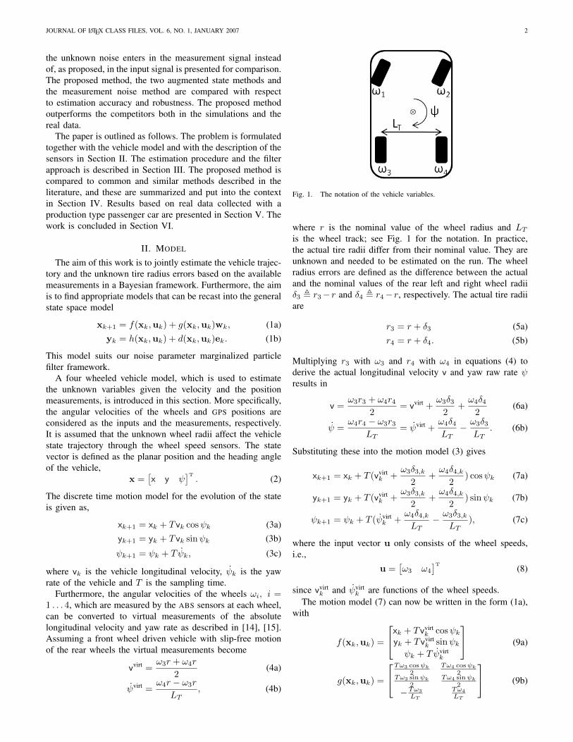
Fig. 1. The notation of the vehicle variables.
where r is the nominal value of the wheel radius and LTis the wheel track; see Fig. 1 for the notation. In practice,the actual tire radii differ from their nominal value. They areunknown and needed to be estimated on the run. The wheelradius errors are defined as the difference between the actualand the nominal values of the rear left and right wheel radiiδ3 , r3−r and δ4 , r4−r, respectively. The actual tire radiiare
r3 = r + δ3 (5a)r4 = r + δ4. (5b)
Multiplying r3 with ω3 and r4 with ω4 in equations (4) toderive the actual longitudinal velocity v and yaw raw rate ψresults in
v =ω3r3 + ω4r4
2= vvirt +
ω3δ32
+ω4δ4
2(6a)
ψ =ω4r4 − ω3r3
LT= ψvirt +
ω4δ4LT− ω3δ3
LT. (6b)
Substituting these into the motion model (3) gives
xk+1 = xk + T (vvirtk +
ω3δ3,k2
+ω4δ4,k
2) cosψk (7a)
yk+1 = yk + T (vvirtk +
ω3δ3,k2
+ω4δ4,k
2) sinψk (7b)
ψk+1 = ψk + T (ψvirtk +
ω4δ4,kLT
− ω3δ3,kLT
), (7c)
where the input vector u only consists of the wheel speeds,i.e.,
u =[ω3 ω4
]T(8)
since vvirtk and ψvirt
k are functions of the wheel speeds.The motion model (7) can now be written in the form (1a),
with
f(xk,uk) =
xk + T vvirtk cosψk
yk + T vvirtk sinψk
ψk + T ψvirtk
(9a)
g(xk,uk) =
Tω3 cosψk
2Tω4 cosψk
2Tω3 sinψk
2Tω4 sinψk
2
−Tω3
LT
Tω4
LT
(9b)
JOURNAL OF LATEX CLASS FILES, VOL. 6, NO. 1, JANUARY 2007 3
where the process noise term wk is defined as,
wk =
[δ3,kδ4,k
]∼ N (µk,Σk) = N
([µ3,k
µ4,k
],
[Σ3,k 0
0 Σ4,k
]).
(9c)
The process noise, or the tire radius error, is described by twoparameters, the mean value µ and the covariance Σ for the leftand the right wheel. Intuitively the mean value corresponds tothe slow time variations from the nominal tire radius, whilethe variance corresponds to the fast variations due to tirevibrations. One interpretation is that the mean value µ modelsthe change in the wheel radii due to abrasion, tire pressurechanges and effects of cornering, and the covariance Σ canaccount for the vibrations arising from an uneven road surface.An interesting special case is when Σ3 = Σ4, which representshomogeneous road conditions, in comparison with split roadsurface when Σ3 6= Σ4.
The measurement model (1b) defines the relation betweenthe GPS position and the state variables as follows.
yk =[xGPSk yGPS
k
]T(10a)
h(xk,uk) = h(xk) =
[1 0 00 1 0
]xk (10b)
d(xk,uk) = I (10c)
where I is the identity matrix and the measurement noise isassumed to be Gaussian with zero mean and known constantcovariance R, i.e.,
ek =[ex ey
]T= N (0, R), R = ΣGPSI2. (10d)
Other sensor measurements are also plausible to include in themeasurement vector, at the cost of a more complex model. Forinstance, using a yaw rate gyro to measure the third state, alsorequires to model the drifting offset in the sensor. The steeringangle can also be converted to yaw rate, but it suffers fromdynamic lag and other dynamic states of the vehicle.
The unknown parameters θ are the radii error biases andthe covariances,
θk , {µ3,k, µ4,k,Σ3,k,Σ4,k} . (11)
The unknown parameters are all subject to change in time.The underlying evolution model for the mean and covariance,i.e. p(µk|µk−1) and p(Σk|Σk−1) are also unknown. We lateruse forgetting factor principle on the statistics to account forthis factor.
In the following section the joint estimation of the unknownparameters and the state is described in a Bayesian framework.
III. PARAMETER AND STATE ESTIMATION
This section focuses on the evaluation of the joint densityp(xk,θk|y1:k) of the state variable xk defined in (2) andthe parameters θk defined in (11), conditioned on all mea-surements y1:k from time 1 to k. In order to simplify thecalculations, the target density is decomposed into conditionaldensities as follows
p(xk,θk|y1:k) = p(θk|x0:k,y1:k)p(x0:k|y1:k). (12)
The resulting two densities are estimated recursively. Theimplementation of the estimation algorithm is described inthree steps. In Section III-A we define the approximationsmade to derive the state trajectory p(x0:k|y1:k) and in Sec-tion III-B we describe the estimation of the sufficient statisticsof the parameter distribution p(θk|x0:k,y1:k). The predictedtrajectory is derived conditional on the parameter estimates andthe estimation of the joint density and the marginal density ofthe states p(x0:k|y1:k) is finalized in Section III-C.
A. State Trajectory
The state trajectory p(x0:k|y1:k) is approximated by anempirical density of N particles as follows:
p(x0:k|y1:k) ≈N∑i=1
w(i)k δ(x0:k − x
(i)0:k) (13)
where x(i)0:k is a trajectory sample and w
(i)k is its related
weight. The approximated state trajectory (13) is propagatedwith a particle filter, using the sequential importance samplingscheme. In this scheme, at any time k, first the samples, whichare also denoted by particles, are generated from a proposaldistribution q(xk|x(i)
0:k−1,y1:k) by using the particles fromtime k− 1. Then the weight update step follows the samplingstep. The weights are updated according to
w(i)k ∝
p(yk|xk)p(xk|x0:k−1,y1:k−1)
q(xk|x0:k−1,y1:k)w
(i)k−1. (14a)
In the sampling step one can use the state prediction densityas the proposal density while generating the samples. Theposterior distribution of the unknown parameters can be usedin computing the state prediction density p(xk|x0:k−1,y1:k−1)according to
p(xk|x0:k−1,y1:k−1)
=
∫p(xk|xk−1,θ)p(θ|x0:k−1,y1:k−1)dθ. (15)
The estimation of the parameters is described in the nextsection, and we will therefore return to this equation inSection III-C and give the final expression.
B. Parameter Estimation
In the factorization of the joint density given in equation(12), the distribution of the unknown parameters (which cor-responds to the first term) is computed conditional on therealization of the state trajectory and the measurements. Fora specific realization of the trajectory, the posterior densitycan also be written conditional on the realization of the noiseterms
p(θk|x(i)0:k,y1:k) = p(θk|w(i)
0:k). (16)
It can be decomposed into a likelihood function and a prioraccording to Bayes rule
p(θk|w0:k) ∝ p(wk|θk)p(θk|w0:k−1). (17)
The likelihood function p(wk|θk) is assumed to be multivari-ate Gaussian in this work, as previously mentioned in (9c),
JOURNAL OF LATEX CLASS FILES, VOL. 6, NO. 1, JANUARY 2007 4
and the mean µk and the covariance Σk are consideredunknown parameters θ. In this case a Normal-inverse-Wishartdistribution defines a conjugate prior1 p(θk|w0:k−1). Normal-inverse-Wishart distribution defines a hierarchical Bayesianmodel given as
wk|µk,Σk ∼ N (µk,Σk) (18a)µk|Σk ∼ N (µk|k, γk|kΣk|k) (18b)
Σk ∼ iW(νk|k,Λk|k) (18c)
∝ |Σk|−12 (ν+d+1) exp
(−1
2Tr(Λk|kΣ−1
k )
)(18d)
where iW(.) denotes the inverse Wishart distribution and ddenotes the dimension of the noise vector wk. The statisticsSw,k , {γk, µk, νk,Λk} can according to [16], [17] berecursively updated as follows. The measurement update is
γk|k =γk|k−1
1 + γk|k−1(19a)
µk|k = µk|k−1 + γk|k(wk − µk|k−1) (19b)νk|k = νk|k−1 + 1 (19c)
Λk|k = Λk|k−1 +1
1 + γk|k−1(µk|k−1 −wk)(µk|k−1 −wk)T
(19d)
where the statistics of the predictive distributions are given bythe time update step according to
γk|k−1 =1
λγk−1|k−1 (20a)
µk|k−1 = µk−1|k−1 (20b)νk|k−1 = λνk−1|k−1 (20c)Λk|k−1 = λΛk−1|k−1. (20d)
The scalar real number 0 ≤ λ ≤ 1 is the forgetting factor. Theforgetting factor here helps in the estimation of the dynamicvariables. The statistics relies on roughly the measurementswithin the last h = 1
1−λ frames/time instances. That allows thealgorithm to adapt the changes in the noise statistics in time.Such an approach is appropriate when the unknown parametersare slowly varying, and the underlying parameter evolution isunknown.
C. Noise Marginalization
Let us now return to the state prediction in (15). Oneimportant advantage of using the conjugate priors reveals itselfhere as it is possible to integrate out the unknown noiseparameters as they follow Normal-inverse-Wishart distribution.The integrand in (15) is the product of a Gaussian distributionand a NiW distribution and the result of the integral is aStudent-t distribution which can be evaluated analytically. Thepredictive distribution of wk becomes a multivariate Student-t
1A family of prior distributions is conjugate to a particular likelihoodfunction if the posterior distribution belongs to the same family as the prior.
density, according to
p(wk|Vk−1, νk−1) = St(µk|k−1,Λk|k−1, νk|k−1 − d+ 1)
(21a)
∝∣∣∣∣1 +
1
νk|k−1 − d+ 1wT
kΛ−1k|k−1wk
∣∣∣∣− 12 (νk|k−1+1)
(21b)
with wk , wk − µk|k−1 and with νk|k−1 − d + 1 degreesof freedom. The Student-t distribution is located at µk|k−1
with the scale parameter Λk|k−1, and these statistics aregiven in (20). Furthermore, if the state transition densityp(xk|x0:k−1,y1:k−1) is used as the proposal distributionq(xk|x(i)
0:k−1,y1:k), then the the weight update equation (14)reduces to,
w(i)k = w
(i)k−1p(yk|x
(i)k ). (22)
In the implementation, the noise is first sampled from (21)and used in (1a) in order to create samples x
(i)k . The samples
from (21) can be used directly in the statistics update (19).The pseudo code of the algorithm used in the simulations isgiven in Table I.
In the proposed method, each particle i keeps its ownestimate for the parameters θ(i) of the unknown process noise.In the importance sampling step, the particles use their ownposterior distribution of the unknown parameters. The weightupdate of the particles is made according to the measurementlikelihood. The particles are keeping the unknown parameters,and those which best explain the observed measurement se-quence will survive in time.
The marginal posterior density of the unknown parameterscan be computed by integrating out the states in the jointdensity
p(θ|y1:k) =
∫p(θ|x0:k,y1:k)p(x0:k|y1:k)dx0:k
≈N∑i=1
ω(i)k p(θ|x(i)
0:k,y1:k). (23)
Then the estimate of the unknown parameters could be com-puted according to a chosen criterion. As an example, ac-cording to the minimum mean square error (MMSE) criterion,the noise mean and variance estimates at time k could becomputed as
µk =
N∑i=1
ω(i)k µ
(i)k (24a)
Σk =
N∑i=1
ω(i)k
ν(i)k − d+ 1
ν(i)k − d− 1
Λ(i)k , (24b)
where the weights are inherited from the particles.
IV. MODELS FOR COMPARISON
In order to evaluate the performance of the proposed methodit will be compared with two other methods. These twomethods are described in this section followed by the resultsand discussions in Section V. The three methods are based onthe same type of information and model. All of them can be

JOURNAL OF LATEX CLASS FILES, VOL. 6, NO. 1, JANUARY 2007 5
TABLE IPSEUDO CODE OF THE ALGORITHM
Initialization:1: for each particle i = 1, .., N do2: Sample w
(i)0 from (21)
3: Compute x(i)0 from (1a)
4: Set initial weights ω(i)0 = 1
N
5: Set initial noise statistics S(i)w,0 corresponding to each particle
6: end forIterations:
7: for k = 1, 2, . . . do8: for For each particle i = 1, .., N do9: Predict noise statistics S(i)
w,k|k−1using (20)
10: Sample w(i)k|k−1
from (21)
11: Compute x(i)k|k−1
from (1a)12: update the weights:
w(i)k = w
(i)k−1p(yk|x
(i)k )
13: Update noise statistics S(i)w,k using (19)
14: end for15: Normalize weights, w(i)
k =w
(i)k∑N
i=1 w(i)k
.
16: Compute Neff = 1∑Ni=1(w
(i)k
)2.
17: If Neff ≤ η, Resample the particles.18: Compute state estimate x =
∑Ni=1 w
(i)k x
(i)k
19: Compute the parameter estimates using (24)20: end for
described by the general state space model (1), however, theorder and the definition of the model components and variablesvary between them. The approach presented in the precedingsections will be denoted as marginalized particle filter processnoise (MPF-PN) estimation.
A model where the state vector is augmented with theparameters is described in Section IV-A, followed by a modelwhere the parameters appear in the measurement noise, insteadof in the process noise, in Section IV-B. The augmented statespace model in Section IV-A can be implemented using both aPF and a Kalman filter, i.e., summing up to in total four differ-ent filters implementations to compare. The characteristics ofthe four different methods are summarized in Section IV-C.Finally, Section IV-D discusses the velocity measurements,which are used as inputs in the system.
A. Augmented State Vector
One common approach in joint state and parameter es-timation is to augment the state vector with the unknownparameters [10]. In this case the state vector is defined as
x =[x y ψ µ3 µ4 Σ3 Σ4
]T. (25)
The motion model (7) contains the variables δ3 and δ4 and inorder to express the motion model using the state variables therelation in (9c) is considered, i.e., δ3 = µ3 +
√Σ3N (0, 1) and
vice versa for δ4. The state space model can again be writtenin the general form (1) with the components according to
f(xk,uk) =
xk + T(vvirtk +
ω3µ3,k+ω4µ4,k
2
)cosψk
yk + T(vvirtk +
ω3µ3,k+ω4µ4,k
2
)sinψk
ψk + T(ψvirtk −
ω3µ3,k−ω4µ4,k
LT
)µ3,k
µ4,k
00
(26a)
g(xk,uk) =
Tω3
√Σ3,k
2 cosψk Tω4
√Σ4,k
2 cosψk 0 0
Tω3
√Σ3,k
2 sinψk Tω4
√Σ4,k
2 sinψk 0 0
T−ω3
√Σ3,k
LTTω4
√Σ4,k
LT0 0
0 0 I2 00 0 0 I2
(26b)
wk =[wTn wT
µ,k wT
Σ,k
]T(26c)
where wn = N (0, I2). The process noises wµ,k is zero meanGaussian noise. i.e.,
wµ = N (0, Q). (26d)
In order to preserve the positive definite property, the followingMarkovian model with Inverse-Gamma distribution is used topropagate the unknown variances
p(Σ3,k|Σ3,k−1) = iΓ(α3,k, β3,k) (27a)p(Σ4,k|Σ4,k−1) = iΓ(α4,k, β4,k). (27b)
The parameters α and β are chosen such that the mean valueis preserved and the standard deviation is equal to 5 percentof the previous value of the parameter.
E{Σ3,k|Σ3,k−1} = Σ3,k−1 (28a)E{Σ4,k|Σ4,k−1} = Σ4,k−1 (28b)
Std{Σ3,k|Σ3,k−1} = 0.05Σ3,k−1 (28c)Std{Σ4,k|Σ4,k−1} = 0.05Σ4,k−1. (28d)
Finally, the components of the measurement model (1b) are
yk =[xGPSk yGPS
k
]T(29a)
h(xk,uk) = h(xk) =
[1 0 0 0 00 1 0 0 0
]xk (29b)
d(xk,uk) = d = I2 (29c)
and the measurement noise is zero mean and the covarianceis assumed to be constant, i.e.,
ek =[ex ey
]T= N (0, R), R = ΣGPSI2. (29d)
The input signals are the same as defined in (8). Since theunknown parameters are included in the state vector, there isno need to marginalize the noise parameters. Standard particlefilter is used to estimate the state. This method will be referredto as augmented particle filter (AUG-PF). The filtering problemcan also be solved with nonlinear Kalman filter (KF) basedalgorithms such as extended KF (EKF) or unscented KF (UKF),and this method will be referred to as augmented Kalman filter(AUG-KF).

JOURNAL OF LATEX CLASS FILES, VOL. 6, NO. 1, JANUARY 2007 6
B. Measurement Noise Estimation
In the fourth method the bias terms are assumed to appearin the noise again, but in this case they will appear in themeasurement noise instead of the process noise, as in SectionII. Hence, this method is referred to as marginalized particlefilter measurement noise (MPF-MN). The motion model iswritten as in (3), but since the radii error now appears in themeasurement model, the state vector must be augmented withthe yaw rate and velocity, i.e.,
x =[x y ψ ψ v
]T. (30)
The motion model, in (3), is augmented with the two additionalstates and the components of the motion model (1a) become
f(xk,uk) = f(xk) =
xk + T vk cosψkyk + T vk sinψkψk + T ψk
ψkvk
(31a)
g(xk,uk) = g(xk) =
0 00 00 0T 00 T
(31b)
with the zero mean measurement noise w with constantcovariance
wk =
[wψ
wv
]= N (0, Q), Q = diag(σ2
δ3 , σ2δ4). (31c)
The measurement model is now nonlinear and the componentsin (1b) are
yk =[xGPS yGPS ψvirt
k vvirtk
]T(32a)
h(xk,uk) = h(xk) =[x y ψ v
]T(32b)
g(xk,uk) = g(uk) =
1 0 01 0 00 − ω3
LT
ω4
LT
0 ω3
2ω4
2
(32c)
where the noise is
ek =[ex ey δ3,k δ4,k
]T= N (µk,Σk) (32d)
µk =[0 0 µ3,k µ4,k
]T(32e)
Σk = diag([Σx,k,Σy,k,Σ3,k,Σ4,k]) (32f)
The algorithm described in Section III applies to solve theestimation problem.
In this model the process noise parameters are known butthe measurement noise parameters are to be estimated. Thesame approach described in Section III also applies to thismodel. At the sampling stage, the state prediction distributioncan be used as the importance distribution. Then the weightupdate equation simplifies to,
w(i)k = w
(i)k−1p(yk|x0:k,y1:k−1), (33)
TABLE IISUMMARY OF ESTIMATION METHODS
Method ωi ψvirt, vvirt ψ, v θ nx ny nu
MPF-PN u u - w 3 2 2AUG-PF/ AUG-KF u u - x 7 2 2MPF-MN u y x e 5 4 0
likewise the equation (22). The likelihood computation can bedone by marginalizing the unknown noise parameters, as it isdone for the process noise in equation (15)
p(yk|x0:k,y1:k−1)
=
∫p(yk|xk,θ)p(θ|x0:k−1,y1:k−1)dθ. (34)
The resulting distribution is again a Student-t distribution,whose parameters can again be computed by conditioning onthe realization of the measurement noise terms according to
e(i)k = d†(x
(i)k ,uk)(y
(i)k − h(x
(i)k ,uk)), (35)
The sufficient statistics update equations follow the samepattern. Here, † denotes the pseudo-inverse.
C. Summarizing the Four Methods
The four methods are summarized in Table II. The wayin which a variable is treated in the model is describedin the table. A variable can be considered input u, output(measurement) y, state x, process noise w or measurementnoise e. The dimension of the state vector, the input vectorand the measurement vector are nx, nu and ny , respectively.Note that the proposed method MPF-PN is the one with thesmallest state dimension.
D. Wheel Velocity
The principle for rotational speed sensors is that a toothedwheel is attached to the rotating shaft. The teeth are alsoreferred to as cogs, and the number of cogs are denotedNcog. A magnet attached to one side causes a variation inthe magnetic field that can be sensed by a Hall sensor. Thevariation is converted to a square wave signal with constantamplitude, where each edge corresponds to one edge of thetoothed wheel.
The time between two or more edges is then registered andconverted into angular speed as follows. The angle betweeneach tooth is 2π
Ncog. The time when tooth ` is passing is denoted
τ`, and the corresponding angle is denoted ϕ` = ` 2πNcog
. Theangular speed ω(kT ) at time kT , where T is the samplingtime and k is the time step number, can now be approximatedas
ω(kT ) =2π(`k − `k−1)
Ncog(τ`k − τ`k−1). (36)
Here, τ`k denotes the time when the last cog `k passed beforetime τ = kT . Note that the angle can be recovered bysumming ω(kT ) over time.
In the motion model (7) the angular speed ω is multipliedwith the sample time T , which gives an angle. However, sincethe sensor initially measures the number of cogs passed in a

JOURNAL OF LATEX CLASS FILES, VOL. 6, NO. 1, JANUARY 2007 7
Fig. 2. The test vehicle of Linkoping University is logging standard CANdata. The vehicle is in addition equipped with a GPS receiver, an IMU and anoptical velocity sensor.
certain time according to equation (36) there is no need totransform it into an angular velocity. It is more efficiently toinstead use
Tωk =2π(`k − `k−1)
NcogT, (37)
where `k−`k−1 is the number of cogs passed in the samplingtime T . More details about sampling and quantization effectsin wheel speed sensors are described in [18].
V. RESULTS
In the experiments, the measurements were collected witha passenger car equipped with standard vehicle sensors, suchas wheel speed sensors, and a GPS receiver, see Fig. 2.The vehicle is further equipped with an additional and moreaccurate IMU, besides the standard IMU already mounted inthe car, and an optical velocity sensor. These two additionalsensors were used to calibrate the setup, but were not furtherused to produce the results presented.
In regions where the car moves at low velocities, the steeringwheel angle measurement was utilized as follows, in order toavoid quantization problems of the wheel cogs
xk+1 = xk + T (vvirtk +
ω3δ32
+ω4δ4
2) cosψk (38a)
yk+1 = yk + T (vvirtk +
ω3δ32
+ω4δ4
2) sinψk (38b)
ψk+1 =
{ψk + T (ψvirt
k + ω4δ4LT− ω3δ3
LT) if v > γ
ψk + TδF (vvirtk + ω3δ3
2 + ω4δ42 )/lb if v < γ
(38c)
The GPS measurements of the 12 km test round is shownas a red solid line in Fig. 3. It is overlayed by the estimatedtrajectory, which is black-white dashed. The photo is a veryaccurate flight photo (obtained from the Swedish mapping,cadastral and land registration authority), which can be used asground truth to visualize the quality of the trajectory estimate.The round took about 18 min to drive and it starts and ends in
x [m]
y [m
]
500 1000 1500 2000
500
1000
1500
2000
2500
Fig. 3. The red line is GPS position measurements and the black-whitedashed line is the estimated driven trajectory. The experiment starts andends at a roundabout in the upper right corner. ( c©Lantmateriet MedgivandeI2011/1405, reprinted with permission)
urban area of Linkoping, in the upper right corner in Fig. 3.The test vehicle is driving clockwise, first on a small ruralroad, and then on the left side of the figure entering a straightnational highway, before driving back to urban area on thetop of the figure. The test was performed two times, firstwith balanced tire pressure and thereafter with unbalanced tirepressure, where the pressure of the rear left tire was releasedto be approximately 50% of the right tire pressure.
For the first round the pressure of the rear wheel tires wasadjusted to be equal 2.8 bar on both tires. The estimatedparameters, i.e., the mean and the covariance for the left andthe right wheel are shown in the Fig. 4a and 4b, respectively.It is clearly visible that the radius error is similar for the leftand the right wheel and and all the methods perform wellin estimating the mean values µ3 and µ4 except the MPF-MN method, which makes a jump around time t = 540. Theperformances of the methods differ in estimating the radiuserror difference between the left and right wheels which isshown in Fig. 5. The proposed method, MPF-PN, performs thebest among the four estimators. The AUG-PF, and MPF-MNmethods produce more erratic estimates than the MPF-PN andthe AUG-KF. The peak value of the estimation error of MPF-PNis smaller than that of AUG-KF.
For the second round the pressure of the rear left tire wasreleased to 1.5 bar. Comparing Fig. 6a with Fig. 6b it is visiblethat the pressure reduction leads to a smaller µ3 than µ4 value.

JOURNAL OF LATEX CLASS FILES, VOL. 6, NO. 1, JANUARY 2007 8
100 200 300 400 500 600 700 800 900 1000 1100−0.04
−0.03
−0.02
−0.01
0
0.01
0.02µ 3 [m
]
100 200 300 400 500 600 700 800 900 1000 110010
−15
10−10
10−5
100
105
Σ 3
time [s]
MPF−PNAUG−PFAUG−KFMPF−MN
(a) Left Wheel
100 200 300 400 500 600 700 800 900 1000 1100−0.04
−0.03
−0.02
−0.01
0
0.01
0.02
µ 4 [m]
100 200 300 400 500 600 700 800 900 1000 110010
−10
10−5
100
105
Σ 4
time [s]
MPF−PNAUG−PFAUG−KFMPF−MN
(b) Right Wheel
Fig. 4. Tire radius error of the left and right rear wheels, in Fig. (a) and(b), respectively. The upper plot in each sub figure shows the mean values µand the lower plot the covariance estimates Σ. These plots show the situationwith balanced wheel pressure, and the radius error in Fig. (a) and (b) is verysimilar. The black solid line is the MPF-PN estimate, the gray solid line is theAUG-PF estimate, the black dashed line is the AUG-KF estimate and the graydashed line is from the MPF-PN.
The behavior of the algorithms are similar to the balanced case.The difference among the methods can be observed better inFig. 7, where the difference between the left and the right tireradii errors µ3 − µ4 is shown. Here again, The AUG-PF, andMPF-MN methods produce more erratic estimates. The MPF-PNand the AUG-PF produces smoother estimates and the MPF-PNresults are better than AUG-KF. All four methods reach a valueof a relative difference of approximately 1.5 mm.
In order to analyze the methods numerically an artificialdata set, which simulates a pressure drop, has been created.The data set with balanced wheels is used as a basis for thatpurpose, and an artificial wheel speed is computed accordingto
ω4 = ω4r
r + δ4(39)
100 200 300 400 500 600 700 800 900 1000 1100−1.5
−1
−0.5
0
0.5
1
1.5x 10
−3
time [s]
µ 3−µ 4 [m
]
100 200 300 400 500 600 700 800 900 1000 1100−1.5
−1
−0.5
0
0.5
1
1.5x 10
−3
time [s]
µ 3−µ 4 [m
]
AUG−PFAUG−KF
MPF−PNMPF−MN
Fig. 5. The figure shows the tire radius error difference between the left andthe right rear wheels, for the situation with balanced wheel pressures. Sincethe pressure is equal in the left and the right wheel the radius differencebetween them is zero as expected.
where the artificial tire radius error is given by
δ4 =
{−kδmax
K2k < K2
δmax k ≥ K2
. (40)
The virtual measurements (4) are recalculated based on theartificial wheel speed as follows.
vvirt =ω3r + ω4r
2(41a)
¯ψvirt =
ω4r − ω3r
LT. (41b)
For the example presented here, the values δmax =−2.5 · 10−3m and K2 = 5808 where chosen. The simulatedtire radii difference versus time, and its estimates are plottedin Fig. 8. Here again the MPF-PN produces the minimum rootmean square error (RMSE) among all methods. Further, wecompare the average RMSE of the algorithms over 100 MonteCarlo (MC) runs and present the change in the RMSE whilevarying the number of particles.
Next results are based on 100 MC runs for all methods(except for AUG-KF, which is deterministic). The effects ofchanging the number of particles is examined in Fig. 9. TheMC runs are repeated for 100, 500, 1000, and 5000 particlesand the average RMSE of the difference between µ3 and µ4 iscompared. This is performed under the assumption that µ3−µ4
is equal to the artificially added error, according to (40), whichserves as the true value. In Fig. 9 the average RMSE are plottedwith respect to the different number of particles. The proposedMPF-PN estimate has the smallest RMSE, and for instance theRMSE for 100 particles corresponds to the same RMSE of theAUG-PF using 500 particles. The AUG-KF approach produceshere the worst RMSE.
Some of the methods are sensitive to divergence when thenumber of particles becomes to small. For this reason thedivergence rate is analyzed for the three PF based methodsand plotted with respect to the number of particles in Fig. 10.

JOURNAL OF LATEX CLASS FILES, VOL. 6, NO. 1, JANUARY 2007 9
100 200 300 400 500 600 700 800 900 1000−0.04
−0.03
−0.02
−0.01
0
0.01
0.02µ 3 [m
]
100 200 300 400 500 600 700 800 900 100010
−15
10−10
10−5
100
105
Σ 3
time [s]
MPF−PNAUG−PFAUG−KFMPF−MN
(a) Left Wheel
100 200 300 400 500 600 700 800 900 1000−0.04
−0.03
−0.02
−0.01
0
0.01
0.02
µ 4 [m]
100 200 300 400 500 600 700 800 900 100010
−10
10−5
100
105
Σ 4
time [s]
MPF−PNAUG−PFAUG−KFMPF−MN
(b) Right Wheel
Fig. 6. Tire radius error of the left and right rear wheels, in Fig. (a) and (b),respectively. The upper plot in each sub figure shows the mean values µ andthe lower plot the covariance estimates Σ. These plots show the situation withunbalanced wheel pressure, and as expected the radius error of the left wheelin Fig. (a) is larger than the error of the right wheel in (b). The black solidline is the MPF-PN estimate, the gray solid line is the AUG-PF estimate, theblack dashed line the AUG-KF estimate and the gray dashed line the MPF-PNestimate.
The algorithms are run on the complete 18 min data set andif the simulation diverges during one MC run it is counted andcompared to the total number of 100 MC runs. In the figure itis shown that the proposed MPF-PN approach and the AUG-KFapproach always converges, whereas the AUG-PF and the MPF-MN approaches converges for all 100 MC runs when using atleast 1000 particles.
Finally the average runtime per sample of a single MC runare given in Table III. Here it is obvious that the proposedprocess MPF-PN method and the AUG-PF estimate are inthe same order of complexity, since the computation timesare similar. The AUG-KF approach is in the same order ofmagnitude as the AUG-PF with 100 particles, but as seen inFig. 9, with a much worse RMSE. The MPF-MN is by far the
100 200 300 400 500 600 700 800 900 1000−3
−2.5
−2
−1.5
−1
−0.5
0x 10
−3
time [s]
µ 3−µ 4 [m
]
100 200 300 400 500 600 700 800 900 1000−3
−2.5
−2
−1.5
−1
−0.5
0x 10
−3
time [s]
µ 3−µ 4 [m
]
AUG−PFAUG−KF
MPF−PNMPF−MN
Fig. 7. The figure shows the tire radius error difference between the leftand the right rear wheels, for the situation with unbalanced wheel pressures.The pressure of the left wheel is reduced by 50%, which leads to a radiusreduction of about 1.5 mm.
100 200 300 400 500 600 700 800 900 1000 1100−3
−2.5
−2
−1.5
−1
−0.5
0x 10
−3
time [s]
µ 3−µ 4 [m
]
100 200 300 400 500 600 700 800 900 1000 1100−3
−2.5
−2
−1.5
−1
−0.5
0x 10
−3
time [s]
µ 3−µ 4 [m
]
MPF−PNMPF−MNtrue
AUG−PFAUG−KFtrue
Fig. 8. The figure shows the tire radius error difference between the leftand the right rear wheels, for the situation with artificial wheel radii error of−2.5 mm. The example is aimed at simulating a slow puncture. The resultingestimates are close to the expected values.
slowest method.
VI. CONCLUSION
In this study, we address the problem of joint estimation ofunknown tire radii and the trajectory of a four wheeled vehiclebased on GPS and wheel angular velocity measurements. Theproblem is defined in a Bayesian framework and an efficientmethod that utilizes marginalized particle filters is proposedin order to accomplish the difficult task of joint parameterand state estimation. The algorithm is tested on real dataexperiments. The results show that it is possible to estimaterelative tire radius difference within sub-millimeter accuracy.

JOURNAL OF LATEX CLASS FILES, VOL. 6, NO. 1, JANUARY 2007 10
102
103
0
1
2
3
4
5
6
7x 10
−3
Number of particles
RM
SE
MPF−PNAUG−PFAUG−KFMPF−MN
Fig. 9. RMSE over number of particles. Note that, the proposed MPF-PNapproach has the same RMSE value for 100 particles as the AUG-PF has for500 particles.
102
103
0
10
20
30
40
50
60
70
Number of particles
Div
erge
nce
rate
[%]
MPF−PNAUG−PFAUG−KFMPF−MN
Fig. 10. Divergence rate over number of particles. The proposed MPF-PNapproach did not diverge at any of the MC runs, however the AUG-PF convergesonly if more that 1000 particles are used.
VII. ACKNOWLEDGMENTS
The authors would like to thank Kristoffer Lundahl, atthe vehicular systems division at Linkopings University, forassisting with the data collection.
REFERENCES
[1] S. Velupillai and L. Guvenc, “Tire pressure monitoring [applications ofcontrol],” IEEE Control Systems Magazine, vol. 27, no. 6, pp. 22–25,Dec. 2007.
[2] N. Persson, S. Ahlqvist, U. Forssell, and F. Gustafsson, “Low tirepressure warning system using sensor fusion,” in Proceedings of theAutomotive and Transportation Technology Congress, ser. SAE paper2001-01-3337, Barcelona, Spain, Oct. 2001.
[3] S. Miller, B. Youngberg, A. Millie, P. Schweizer, and J. Gerdes, “Calcu-lating longitudinal wheel slip and tire parameters using gps velocity,” inIEEE American Control Conference, vol. 3, Jun. 2001, pp. 1800–1805.
TABLE IIICOMPUTATION TIME [MS]
Number of particlesMethod 100 500 1000 5000MPF-PN 0.39 0.70 1.1 5.9AUG-PF 0.41 0.77 1.2 7.4AUG-KF – – 0.35 – –MPF-MN 6.2 29 56 290
[4] C. Carlson and J. Gerdes, “Consistent nonlinear estimation of longitu-dinal tire stiffness and effective radius,” IEEE Transactions on ControlSystems Technology, vol. 13, no. 6, pp. 1010–1020, Nov. 2005.
[5] N. M’sirdi, A. Rabhi, L. Fridman, J. Davila, and Y. Delanne, “Secondorder sliding mode observer for estimation of velocities, wheel sleep,radius and stiffness,” in IEEE American Control Conference, Jun. 2006,pp. 3316–3321.
[6] H. Shraim, A. Rabhi, M. Ouladsine, N. M’Sirdi, and L. Fridman,“Estimation and analysis of the tire pressure effects on the comportmentof the vehicle center of gravity,” in International Workshop on VariableStructure Systems, Jun. 2006, pp. 268–273.
[7] A. Censi, L. Marchionni, and G. Oriolo, “Simultaneous maximum-likelihood calibration of odometry and sensor parameters,” in Proceed-ings of the IEEE International Conference on Robotics and Automation,Pasadena, Canada, May 2008, pp. 2098–2103.
[8] S. Patwardhan, H.-S. Tan, and M. Tomizuka, “Experimental results ofa tire-burst controller for ahs,” Control Engineering Practice, vol. 5,no. 11, pp. 1615–1622, 1997.
[9] V. Ersanilli, P. Reeve, K. Burnham, and P. King, “A continuous-timemodel-based tyre fault detection algorithm utilising a Kalman stateestimator approach,” in Proceedings of the 7th Workshop on AdvancedControl and Diagnosis, Zielona Gora, Poland, Nov. 2009.
[10] J. Liu and M. West, “Combined parameter and state estimation insimulation-based filtering,” in Sequential Monte Carlo Methods inPractice, A. Doucet, N. D. Freitas, and N. Gordon, Eds. Springer,2001.
[11] S. Julier and H. Durrant-Whyte, “Process models for the high-speednavigation of road vehicles,” in Proceedings of the IEEE InternationalConference on Robotics and Automation, vol. 1, May 1995, pp. 101–105.
[12] S. Saha, E. Ozkan, F. Gustafsson, and V. Smidl, “Marginalized particlefilters for Bayesian estimation of Gaussian noise,” in Proceedings of theInternational Conference on Information Fusion, Edinburgh, Scotland,Jul. 2010.
[13] E. Ozkan, C. Lundquist, and F. Gustafsson, “A Bayesian approach tojointly estimate tire radii and vehicle trajectory,” in Proceedings of theIEEE Conference on Intelligent Transportation Systems, WashingtonDC, USA, Oct. 2011.
[14] F. Gustafsson, S. Ahlqvist, U. Forssell, and N. Persson, “Sensor fusionfor accurate computation of yaw rate and absolute velocity,” in Proceed-ings of the SAE World Congress, ser. SAE paper 2001-01-1064, Detroit,MI, USA, Apr. 2001.
[15] F. Gustafsson, Statistical Sensor Fusion. Lund, Sweden: Studentlitter-atur, 2010.
[16] V. Peterka, “Bayesian system identification,” Automatica, vol. 17, no. 1,pp. 41–53, Jan. 1981.
[17] M. Karny, Optimized Bayesian Dynamic Advising: Theory and Algo-rithms. London: Springer, 2006.
[18] F. Gustafsson, “Rotational speed sensors: Limitations, pre-processingand automotive applications,” IEEE Instrumentation & MeasurementMagazine, vol. 13, no. 2, pp. 16–23, Mar. 2010.

Avdelning, Institution
Division, Department
Division of Automatic ControlDepartment of Electrical Engineering
Datum
Date
2011-10-17
Språk
Language
� Svenska/Swedish
� Engelska/English
�
�
Rapporttyp
Report category
� Licentiatavhandling
� Examensarbete
� C-uppsats
� D-uppsats
� Övrig rapport
�
�
URL för elektronisk version
http://www.control.isy.liu.se
ISBN
�
ISRN
�
Serietitel och serienummer
Title of series, numberingISSN
1400-3902
LiTH-ISY-R-3029
Titel
TitleTire Radii and Vehicle Trajectory Estimation Using a Marginalized Particle Filter
Författare
AuthorChristian Lundquist, Emre Özkan, Fredrik Gustafsson
Sammanfattning
Abstract
Measurements of individual wheel speeds and absolute position from a global navigationsatellite system (GNSS) are used for high-precision estimation of vehicle tire radii in thiswork. The radii deviation from its nominal value is modeled as a Gaussian process andincluded as noise components in a vehicle model. The novelty lies in a Bayesian approachto estimate online both the state vector of the vehicle model and noise parameters usinga marginalized particle �lter. No model approximations are needed such as in previouslyproposed algorithms based on the extended Kalman �lter. The proposed approach outper-forms common methods used for joint state and parameter estimation when compared withrespect to accuracy and computational time. Field tests show that the absolute radius can beestimated with millimeter accuracy, while the relative wheel radius on one axle is estimatedwith submillimeter accuracy.
Nyckelord
Keywords marginalized particle �lter, tire radius, conjugate prior, noise parameter estimation.