title 14 housing and construction … · n. stabilization, stabilized means qualified soils that...
TRANSCRIPT
TITLE 14 HOUSING AND CONSTRUCTIONCHAPTER 7 BUILDING CODES GENERALPART 4 2009 NEW MEXICO EARTHEN BUILDING MATERIALS CODE 14.7.4.1 ISSUING AGENCY: Construction Industries Division of the Regulation and Licensing Department.[14.7.4.1 NMAC - Rp, 14.7.4.1 NMAC, 1-28-11] 14.7.4.2 SCOPE: This rule applies to all earthen building materials contracting work performed in New Mexico onor after January 28, 2011, that is subject to the jurisdiction of CID, unless performed pursuant to a permit for which anapplication was received by CID before that date.[14.7.4.2 NMAC - Rp, 14.7.4.2 NMAC, 1-28-11] 14.7.4.3 STATUTORY AUTHORITY: NMSA 1978 Section 60-13-9 and 60-13-44.[14.7.4.3 NMAC - Rp, 14.7.4.3 NMAC, 1-28-11] 14.7.4.4 DURATION: Permanent.[14.7.4.4 NMAC - Rp, 14.7.4.4 NMAC, 1-28-11] 14.7.4.5 EFFECTIVE DATE: January 28, 2011, unless a later date is cited at the end of a section.[14.7.4.5 NMAC - Rp, 14.7.4.1 NMAC, 1-28-11] 14.7.4.6 OBJECTIVE: The purpose of this rule is to establish minimum standards for earthen building materialsconstruction in New Mexico.[14.7.4.6 NMAC - Rp, 14.7.4.1 NMAC, 1-28-11] 14.7.4.7 DEFINITIONS: A. Amended soil means improving an unqualified soil to a qualified state with the addition of other soils oramendments. B. Amendments means additive elements to soil, such as lime, portland cement, fly ash, etc. which are“dry-mixed” into the main soil body as a percentage of total weight to achieve stabilization. C. Buttress means a projecting structure providing lateral support to a wall. The buttress shall beincorporated into the foundation and wall system. (Refer to figure 1 of the earthen building figures supplement). D. CEB means compressed earth block. E. Count Rumford fireplace means a fireplace with a typically square opening with coved sides and ashallow firebox depth of at least twelve (12) inches, but no shallower than one third (1/3) of the width of the firebox. Thefireback is vertical and does not slant forward. The throat is located at least twelve (12) inches above the lintel and is anozzle, rounded or streamlined so as to preserve laminar flow of the dilution air through the throat and with a cross-sectionalarea large enough to insure the elimination of all products of combustion. F. Keyway means a groove on the vertical rammed earth wall surface for interlocking purposes. Refer tofigure 3 of the earthen building figures supplement). G. Lift means a course of rammed earth, placed within the forms, and then compacted. H. Nailer means any material rammed into the wall that serves as an attachment device. Refer to figure 4 ofthe earthen building figures supplement). I. Optimum moisture means sufficient water (generally no more than ten (10) percent) mixed into the soil toattain sufficient compaction. J. psi means pounds per square inch. K. Qualified soil means any soil, or mixture of soils, that attains 300 psi compression strength and attains 50psi. modulus of rupture. L. Rammed earth means qualified soil that is mechanically or manually consolidated to full compaction. M. Round-cap nails means fasteners that include nails or screws in combination with caps of at least three-fourths (3/4) inches diameter or three-fourths ( ¾) inch square. N. Stabilization, stabilized means qualified soils that pass the wet strength test under ASTM D1633-00 orcontain a minimum of six (6) percent portland cement by weight. Stabilization is achieved through the use of amendments. O. Wet strength compression test means an approved testing laboratory process in which a fully curedrammed earth cylinder is completely submerged in water a minimum of four hours according to ASTM D1633-00, thensubjected to a compression test.[14.7.4.7 NMAC - Rp, 14.7.4.7 NMAC, 1-28-11; A, 9-1-13]
14.7.4 NMAC http://www.nmcpr.state.nm.us/nmac/parts/title14/14.007.0004.htm
1 of 30 10/21/2013 12:16 PM
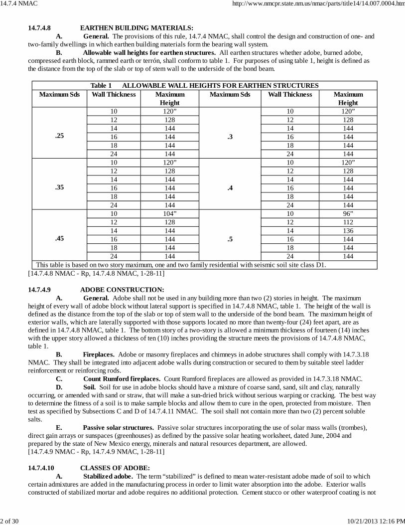
14.7.4.8 EARTHEN BUILDING MATERIALS: A. General. The provisions of this rule, 14.7.4 NMAC, shall control the design and construction of one- andtwo-family dwellings in which earthen building materials form the bearing wall system. B. Allowable wall heights for earthen structures. All earthen structures whether adobe, burned adobe,compressed earth block, rammed earth or terrón, shall conform to table 1. For purposes of using table 1, height is defined asthe distance from the top of the slab or top of stem wall to the underside of the bond beam.
Table 1 ALLOWABLE WALL HEIGHTS FOR EARTHEN STRUCTURESMaximum Sds Wall Thickness Maximum
HeightMaximum Sds Wall Thickness Maximum
Height
.25
10 120”
.3
10 120”12 128 12 12814 144 14 14416 144 16 14418 144 18 14424 144 24 144
.35
10 120”
.4
10 120”12 128 12 12814 144 14 14416 144 16 14418 144 18 14424 144 24 144
.45
10 104”
.5
10 96”12 128 12 11214 144 14 13616 144 16 14418 144 18 14424 144 24 144
This table is based on two story maximum, one and two family residential with seismic soil site class D1.[14.7.4.8 NMAC - Rp, 14.7.4.8 NMAC, 1-28-11] 14.7.4.9 ADOBE CONSTRUCTION: A. General. Adobe shall not be used in any building more than two (2) stories in height. The maximumheight of every wall of adobe block without lateral support is specified in 14.7.4.8 NMAC, table 1. The height of the wall isdefined as the distance from the top of the slab or top of stem wall to the underside of the bond beam. The maximum height ofexterior walls, which are laterally supported with those supports located no more than twenty-four (24) feet apart, are asdefined in 14.7.4.8 NMAC, table 1. The bottom story of a two-story is allowed a minimum thickness of fourteen (14) incheswith the upper story allowed a thickness of ten (10) inches providing the structure meets the provisions of 14.7.4.8 NMAC,table 1. B. Fireplaces. Adobe or masonry fireplaces and chimneys in adobe structures shall comply with 14.7.3.18NMAC. They shall be integrated into adjacent adobe walls during construction or secured to them by suitable steel ladderreinforcement or reinforcing rods. C. Count Rumford fireplaces. Count Rumford fireplaces are allowed as provided in 14.7.3.18 NMAC. D. Soil. Soil for use in adobe blocks should have a mixture of coarse sand, sand, silt and clay, naturallyoccurring, or amended with sand or straw, that will make a sun-dried brick without serious warping or cracking. The best wayto determine the fitness of a soil is to make sample blocks and allow them to cure in the open, protected from moisture. Thentest as specified by Subsections C and D of 14.7.4.11 NMAC. The soil shall not contain more than two (2) percent solublesalts. E. Passive solar structures. Passive solar structures incorporating the use of solar mass walls (trombes),direct gain arrays or sunspaces (greenhouses) as defined by the passive solar heating worksheet, dated June, 2004 andprepared by the state of New Mexico energy, minerals and natural resources department, are allowed.[14.7.4.9 NMAC - Rp, 14.7.4.9 NMAC, 1-28-11] 14.7.4.10 CLASSES OF ADOBE: A. Stabilized adobe. The term “stabilized” is defined to mean water-resistant adobe made of soil to whichcertain admixtures are added in the manufacturing process in order to limit water absorption into the adobe. Exterior wallsconstructed of stabilized mortar and adobe requires no additional protection. Cement stucco or other waterproof coating is not
14.7.4 NMAC http://www.nmcpr.state.nm.us/nmac/parts/title14/14.007.0004.htm
2 of 30 10/21/2013 12:16 PM
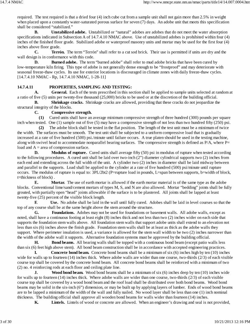
required. The test required is that a dried four (4) inch cube cut from a sample unit shall not gain more than 2.5% in weightwhen placed upon a constantly water-saturated porous surface for seven (7) days. An adobe unit that meets this specificationshall be considered “stabilized.” B. Unstabilized adobe. Unstabilized or “natural” adobes are adobes that do not meet the water absorptionspecifications indicated in Subsection A of 14.7.4.10 NMAC above. Use of unstabilized adobes is prohibited within four (4)inches of the finished floor grade. Stabilized adobe or waterproof masonry units and mortar may be used for the first four (4)inches above floor grade. C. Terrón. The term “Terrón” shall refer to a cut sod brick. Their use is permitted if units are dry and thewall design is in conformance with this code. D. Burned adobe. The term “burned adobe” shall refer to mud adobe bricks that have been cured bylow-temperature kiln firing. This type of adobe is not generally dense enough to be “frostproof” and may deteriorate withseasonal freeze-thaw cycles. Its use for exterior locations is discouraged in climate zones with daily freeze-thaw cycles.[14.7.4.10 NMAC - Rp, 14.7.4.10 NMAC, 1-28-11] 14.7.4.11 PROPERTIES, SAMPLING AND TESTING: A. General. Each of the tests prescribed in this section shall be applied to sample units selected at random ata ratio of five (5) units per twenty-five thousand (25,000) bricks to be used or at the discretion of the building official. B. Shrinkage cracks. Shrinkage cracks are allowed, providing that these cracks do not jeopardize thestructural integrity of the blocks. C. Compressive strength. (1) Cured units shall have an average minimum compressive strength of three hundred (300) pounds per squareinch when tested. One (1) sample out of five (5) may have a compressive strength of not less than two hundred fifty (250) psi. (2) The adobe block shall be tested in the flat position. The length of the test unit must be a minimum of twicethe width. The surfaces must be smooth. The test unit shall be subjected to a uniform compressive load that is graduallyincreased at a rate of five hundred (500) psi./minute until failure occurs. A true platen should be used in the testing machine,along with swivel head to accommodate nonparallel bearing surfaces. The compressive strength is defined as P/A, where P=load and A = area of compression surface. D. Modulus of rupture. Cured units shall average fifty (50) psi in modulus of rupture when tested accordingto the following procedures. A cured unit shall be laid over two-inch (2”) diameter cylindrical supports two (2) inches fromeach end and extending across the full width of the unit. A cylinder two (2) inches in diameter shall be laid midway betweenand parallel to the supports. Load shall be applied to the cylinder at a rate of five hundred (500) psi/minute until ruptureoccurs. The modulus of rupture is equal to: 3PL/2bt2 (P=rupture load in pounds, L=span between supports, b=width of block,t=thickness of block) . E. Mortar. The use of earth mortar is allowed if the earth mortar material is of the same type as the adobeblocks. Conventional lime/sand/cement mortars of types M, S, and N are also allowed. Mortar “bedding” joints shall be fullygrouted, with partially open “head” joints allowable if the surface is to be plastered. All joints shall be lapped at leasttwenty-five (25) percent of the visible block length. F. Use. No adobe shall be laid in the wall until fully cured. Adobes shall be laid in level courses so that thetop of any course shall be at the same height above the stem around the structure. G. Foundations. Adobes may not be used for foundations or basement walls. All adobe walls, except asnoted, shall have a continuous footing at least eight (8) inches thick and not less than two (2) inches wider on each side thatsupports the foundation stem walls above. All foundation stem walls that support adobe units shall extend to an elevation notless than six (6) inches above the finish grade. Foundation stem walls shall be at least as thick as the adobe walls theysupport. Where perimeter insulation is used, a variance is allowed for the stem wall width to be two (2) inches narrower thanthe width of the adobe wall it supports. Alternative foundation systems must be approved by the building official. H. Bond beams. All bearing walls shall be topped with a continuous bond beam (except patio walls lessthan six (6) feet high above stem). All bond beam construction shall be in accordance with accepted engineering practices. I. Concrete bond beam. Concrete bond beams shall be a minimum of six (6) inches high by ten (10) incheswide for walls up to fourteen (14) inches thick. Where adobe walls are wider than one course, two-thirds (2/3) of each visiblecourse top shall be covered by the concrete bond beam. All concrete bond beams shall be reinforced with a minimum of two(2) no. 4 reinforcing rods at each floor and ceiling plate line. J. Wood bond beam. Wood bond beams shall be a minimum of six (6) inches deep by ten (10) inches widefor walls up to fourteen (14) inches thick. Where adobe walls are wider than one course, two-thirds (2/3) of each visiblecourse top shall be covered by a wood bond beam and the roof load shall be distributed over both bond beams. Wood bondbeams may be solid in the six-inch (6”) dimension, or may be built up by applying layers of lumber. Ends of wood bond beamsare to be lapped a minimum of the width of the wall and fully nailed. No wood layer shall be less than one (1) inch nominalthickness. The building official shall approve all wooden bond beams for walls wider than fourteen (14) inches. K. Lintels. Lintels of wood or concrete are allowed. When an engineer’s drawing and seal is not provided,
14.7.4 NMAC http://www.nmcpr.state.nm.us/nmac/parts/title14/14.007.0004.htm
3 of 30 10/21/2013 12:16 PM
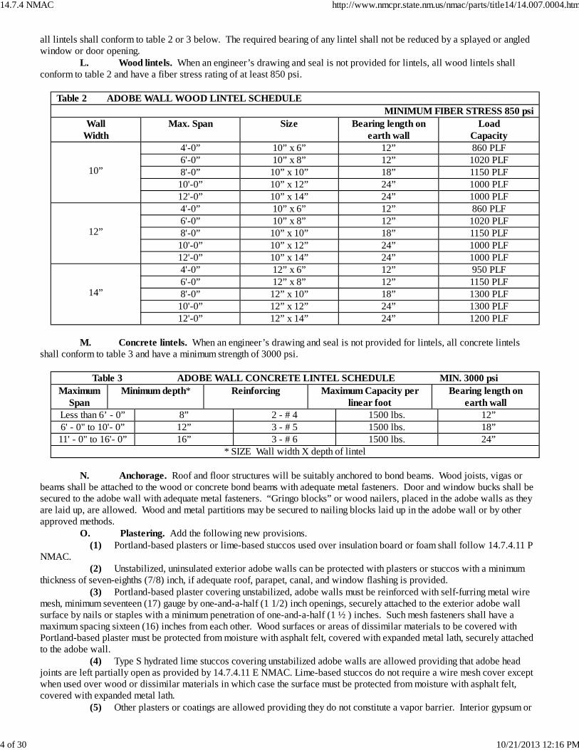
all lintels shall conform to table 2 or 3 below. The required bearing of any lintel shall not be reduced by a splayed or angledwindow or door opening. L. Wood lintels. When an engineer’s drawing and seal is not provided for lintels, all wood lintels shallconform to table 2 and have a fiber stress rating of at least 850 psi.
Table 2 ADOBE WALL WOOD LINTEL SCHEDULEMINIMUM FIBER STRESS 850 psi
WallWidth
Max. Span Size Bearing length onearth wall
LoadCapacity
10”
4'-0” 10” x 6” 12” 860 PLF6'-0” 10” x 8” 12” 1020 PLF8'-0” 10” x 10” 18” 1150 PLF
10'-0” 10” x 12” 24” 1000 PLF12'-0” 10” x 14” 24” 1000 PLF
12”
4'-0” 10” x 6” 12” 860 PLF6'-0” 10” x 8” 12” 1020 PLF8'-0” 10” x 10” 18” 1150 PLF
10'-0” 10” x 12” 24” 1000 PLF12'-0” 10” x 14” 24” 1000 PLF
14”
4'-0” 12” x 6” 12” 950 PLF6'-0” 12” x 8” 12” 1150 PLF8'-0” 12” x 10” 18” 1300 PLF
10'-0” 12” x 12” 24” 1300 PLF12'-0” 12” x 14” 24” 1200 PLF
M. Concrete lintels. When an engineer’s drawing and seal is not provided for lintels, all concrete lintelsshall conform to table 3 and have a minimum strength of 3000 psi.
Table 3 ADOBE WALL CONCRETE LINTEL SCHEDULE MIN. 3000 psiMaximum
SpanMinimum depth* Reinforcing Maximum Capacity per
linear footBearing length on
earth wallLess than 6’ - 0” 8” 2 - # 4 1500 lbs. 12”6' - 0" to 10'- 0” 12” 3 - # 5 1500 lbs. 18”11' - 0" to 16'- 0” 16” 3 - # 6 1500 lbs. 24”
* SIZE Wall width X depth of lintel N. Anchorage. Roof and floor structures will be suitably anchored to bond beams. Wood joists, vigas orbeams shall be attached to the wood or concrete bond beams with adequate metal fasteners. Door and window bucks shall besecured to the adobe wall with adequate metal fasteners. “Gringo blocks” or wood nailers, placed in the adobe walls as theyare laid up, are allowed. Wood and metal partitions may be secured to nailing blocks laid up in the adobe wall or by otherapproved methods. O. Plastering. Add the following new provisions. (1) Portland-based plasters or lime-based stuccos used over insulation board or foam shall follow 14.7.4.11 PNMAC. (2) Unstabilized, uninsulated exterior adobe walls can be protected with plasters or stuccos with a minimumthickness of seven-eighths (7/8) inch, if adequate roof, parapet, canal, and window flashing is provided. (3) Portland-based plaster covering unstabilized, adobe walls must be reinforced with self-furring metal wiremesh, minimum seventeen (17) gauge by one-and-a-half (1 1/2) inch openings, securely attached to the exterior adobe wallsurface by nails or staples with a minimum penetration of one-and-a-half (1 ½ ) inches. Such mesh fasteners shall have amaximum spacing sixteen (16) inches from each other. Wood surfaces or areas of dissimilar materials to be covered withPortland-based plaster must be protected from moisture with asphalt felt, covered with expanded metal lath, securely attachedto the adobe wall. (4) Type S hydrated lime stuccos covering unstabilized adobe walls are allowed providing that adobe headjoints are left partially open as provided by 14.7.4.11 E NMAC. Lime-based stuccos do not require a wire mesh cover exceptwhen used over wood or dissimilar materials in which case the surface must be protected from moisture with asphalt felt,covered with expanded metal lath. (5) Other plasters or coatings are allowed providing they do not constitute a vapor barrier. Interior gypsum or
14.7.4 NMAC http://www.nmcpr.state.nm.us/nmac/parts/title14/14.007.0004.htm
4 of 30 10/21/2013 12:16 PM
mud plasters may be applied directly to the wall, provided that adobe head joints have been left partially open. Expandedmetal lath shall be used around window and door openings. If desired, exterior adobe walls may be protected with mudplaster. Alternative plastering or coating systems shall be submitted for approval by the building official. P. Wall insulation. Add the following new provisions. (1) Insulating boards or foams not exceeding two (2) inches in thickness may be adhered to the exterior of theadobe wall. When insulation board is used, round-cap nails shall attach it to the adobe wall, with nails placed to avoid bedjoints between courses. Cap nails shall have a maximum spacing of sixteen (16) inches from each other. Additionally, capnails shall secure the rigid insulation boards around their perimeter edges, with nails spaced no less than twelve (12) inchesapart. All cap nails shall penetrate a minimum of two (2) inches into the adobe wall. Insulating boards or foams shall not beused to form architectural shapes exceeding two (2) inches in thickness. (2) Insulations exceeding two (2) inches in thickness may be used providing they do not form a vapor barrier.Their weight shall be supported by the stem wall below and contained within vertical furring strips, securely attached to theadobe wall. A sectional, scaled drawing for the proposed insulation scheme must be submitted for review by the buildingofficial. Q. Parapets. Add the following new provisions. (1) Plastered parapets, whether of adobe or frame construction, shall require a seamless but permeablewaterproof cover or weather barrier, capping the entire parapet and wrapping over each side. The cover shall extend past thebond beam a minimum of four (4) inches on the wall side. On the roof side, the cover shall properly lap any rising roof felts ormembranes and be properly sealed. A layer of expanded metal lath shall be installed over the cover before plaster or stucco isapplied. The lath shall extend past the bond beam on the wall side a minimum of five (5) inches and on the roof side, the samedistance as the cover below, allowing for plaster stops or seals. No penetrating fasteners are allowed on the horizontal surfaceof parapets. (2) Exposed parapets of adobe shall be laid in level courses of fully stabilized block and mortar. Bed and headjoints shall be fully grouted and tightly tooled. Bedding joints at bond beams and around vents and canales shall be fullygrouted and tightly tooled. The horizontal top of exposed adobe parapets shall be covered with a minimum three-fourths (3/4)inch layer of fully stabilized mortar, troweled to conform with the parapet. Waterproof sealers are allowed, providing they arepermeable. Other parapet covers, such as flagstone, Spanish mission tile or cement mortar are allowed providing they aresecurely attached to the parapet. A scaled, sectional drawing shall be provided to the building official showing the attachmentscheme.[14.7.4.11 NMAC - Rp, 14.7.4.11 NMAC, 1-28-11] 14.7.4.12 RAMMED EARTH CONSTRUCTION: A. General. The following provisions shall apply. (1) Rammed earth shall not be used in any building more than (2) stories in height. The height of every wall oframmed earth without lateral support is specified in 14.7.4.8 NMAC table 1. The height of the wall is defined as the distancefrom the top of the slab or top of stem wall to the underside of the bond beam. (2) Exterior rammed earth walls shall be a minimum of eighteen (18) inches in thickness. Exception: Exteriorwalls that are also designed as solar mass walls (trombe) as defined by the passive solar heating worksheet, dated June 2004and prepared by the state of New Mexico energy, minerals and natural resources department, are allowed and shall beminimum thickness of ten (10) inches, not to exceed twelve (12) inches. They shall be fully attached to or integrated with anyadjacent structural wall and topped with a bond beam that fully attaches them to the bond beam of any adjacent structural wallas described in 14.7.4.17 NMAC. (3) Interior rammed earth walls shall be a minimum of twelve (12) inches in thickness. (4) The first lift of rammed earth walls shall be of stabilized rammed earth or minimum 2500 psi concrete,rising not less than three and one half (3 ½) inches above finish floor level. Unstabilized rammed earth walls must be coveredto prevent infiltration of moisture from the top of the wall at the end of each workday and prior to wet weather conditions,whether the walls are contained within forms or not. (5) Fully stabilized rammed earth walls may be left unprotected from the elements. (6) In no case shall a rammed earth wall be reduced in thickness with back to back channels or nailers. Channels or nailers rammed on both sides of a running wall shall not be opposite each other to avoid an hourglassconfiguration in the wall section. Channels or nailers on both sides of a running wall shall be separated from each othervertically at a distance no less than the rammed earth wall thickness. (Refer to figure 4 of the earthen building figuressupplement). (7) An architect or engineer registered in the state of New Mexico shall design and seal structural portions oftwo-story residential rammed earth construction documents. (8) The general construction of the building shall comply with all provisions of the 2009 New MexicoResidential Building Code (NMRBC), unless otherwise provided for in this rule. (9) Passive solar structures incorporating the use of solar mass walls (trombe), direct gain arrays or sunspaces
14.7.4 NMAC http://www.nmcpr.state.nm.us/nmac/parts/title14/14.007.0004.htm
5 of 30 10/21/2013 12:16 PM
(greenhouses) as defined by the passive solar heating worksheet, dated June 2004 and prepared by the state of New Mexicoenergy, minerals and natural resources department, are allowed. B. Fireplaces. Adobe or masonry fireplaces and chimneys in rammed earth structures shall comply with14.7.3.18 NMAC. They shall be integrated into adjacent rammed earth walls during construction or secured to them bysuitable steel ladder reinforcement or reinforcing rods. C. Count Rumford fireplaces. Count Rumford fireplaces are allowed as provided in 14.7.3.18 NMAC. D. Stop work. The building inspector shall have the authority to issue a “stop work” order if the provisionsof this section are not complied with. E. Lateral support. Lateral support shall occur at intervals not to exceed twenty-four (24) feet. Rammedearth walls eighteen (18) inches to less than twenty-four (24) inches thick shall be laterally supported with any one orcombination of the following: A rammed earth wall of bond beam height that intersects the running wall with at least sixty (60)degrees of support (refer to a figure 5 of the earthen building figures supplement); an adobe wall of bond beam height and atleast ten (10) inches in width that intersects with and attaches to the running wall with at least sixty (60) degrees of support(refer to figure 5 of the earthen building figures supplement); a minimum twenty 20 gauge steel frame or wood frame wall offull height that intersects with and attaches to the running wall with ninety (90) degrees of support, that is properly cross-braced or sheathed (refer to figure 6 of the earthen building figures supplement); a buttress configuration that intersects therunning wall at ninety (90) degrees, of adobe or rammed earth. The buttress base must project a minimum of three (3) feet (orthirty-three (33) percent of the wall height) from the running wall and support at least seventy-five (75) percent of the total wallheight (refer to figure 7 of the earthen building figures supplement). The thickness of a rammed earth buttress shall be at leasteighteen (18) inches. The thickness of an adobe buttress shall be a minimum fourteen (14) inches. Rammed earth walls greaterthan twenty-four (24) inches in thickness are self-buttressing and do not require lateral support provided their design adheres to14.7.4.8 NMAC table 1 and the other applicable provisions of this rule. F. Openings. Door and window openings shall be designed such that the opening shall not be any closer to anoutside corner of the structure as follows. (1) In rammed earth walls eighteen (18) inches to less than twenty-four (24) inches thick, openings shall not belocated within three (3) feet of any corner of the structure. (Refer to figure 8 of the earthen building figures supplement). Exception: Openings may be located within three (3) feet of any corner provided a buttress extending at least three (3) feetfrom the structure supports the corner. A continuous footing below and a continuous bond beam above, shall be providedacross such openings. (2) Rammed earth walls greater than twenty-four (24) inches thick are self-buttressing, with no specialconsideration for placement of openings within the area of the wall. G. Piers. Rammed earth piers supporting openings shall measure no less than three (3) square feet in areaand no dimension shall be less than eighteen (18) inches. (Refer to figures 9-A and 9-B of the earthen building figuressupplement).[14.7.4.12 NMAC - Rp, 14.7.4.12 NMAC, 1-28-11; A, 9-1-13] 14.7.4.13 FOUNDATIONS: A. General. Foundation construction shall comply with applicable provisions of the 2009 New MexicoResidential Building Code, and the following: a minimum of three (3) continuous #4 reinforcing rods are required in concretefootings supporting rammed earth walls. Footings shall be a minimum of ten 10 inches in thickness. Concrete footings andconcrete stem walls supporting rammed earth walls shall be a minimum of 2500 psi. Stem walls shall be the full width of thewall supported above or wider to receive forming systems. Stem walls shall rise above exterior grade a minimum of six (6)inches. B. Perimeter insulation. For the purposes of placement of perimeter insulation, rammed earth walls mayoverhang the bearing surface up to the thickness of the perimeter insulation, but in no case greater than two (2) inches. C. Keyway. A key way shall be provided where the rammed earth wall meets the foundation system. Thekeyway shall be established at the top of the stem a minimum of two (2) inches deep by six (6) inches wide formed at the timeof the pour, and shall run continuously around the structure to include any intersecting rammed earth wall sections. Therammed earth wall shall be fully rammed into this keyway (refer to figure 2 of the earthen building figures supplement). Exception: Placement of vertical reinforcing rods extending a minimum twelve (12) inches into the rammed earth wall. Thevertical rods shall be minimum #4, imbedded into the concrete and spaced forty-eighty (48) inches on center, maximum. D. Concrete grade beam. Rubble filled foundation trench designs with a reinforced concrete grade beamabove are allowed to support rammed earth wall construction. An architect or engineer registered in the state of New Mexicoshall certify the grade beam/rubble-filled trench design portion.[14.7.4.13 NMAC - Rp, 14.7.4.13 NMAC, 1-28-11; A, 9-1-13] 14.7.4.14 RAMMED EARTH SOIL SPECIFICATIONS: A. General. The soil shall not contain rock more than one-and-a-half (1 1/2) inch in diameter. The soil shall
14.7.4 NMAC http://www.nmcpr.state.nm.us/nmac/parts/title14/14.007.0004.htm
6 of 30 10/21/2013 12:16 PM
not contain clay lumps more than one-half (1/2) inch in diameter. The soil shall be free of all organic matter. The soil shall notcontain more than two (2) percent soluble salts. B. Soil compressive strength. Prior to the start of construction, fully-cured rammed earth soil samples shallbe tested at an approved testing laboratory for compressive strength. The ultimate compressive strength of all rammed earthsoil, stabilized or non-stabilized, shall be a minimum three-hundred (300) psi. The compressive strength report shall besubmitted with the permit application. This report may be waived if the builder provides certification of compliance. Thecertification must be dated within one year of the date on the application for the building permit. Samples tested shall berepresentative of soil to be used on the project for which the permit application is submitted. C. Stabilized rammed earth soil. The following shall apply to stabilization of rammed earth soil: Asphaltemulsion may not be used for stabilization of rammed earth soil. Thorough mixing of additives to the soil may be achieved byany method that assures a complete blending to a uniform color and texture. Stabilized soil is suitable soil that contains six (6)percent or more portland cement by weight or that passes ASTM D1633-00. Samples tested shall be representative of soil tobe used on the project for which the permit application is submitted. The compressive strength report shall be submitted withthe permit application. Laboratory testing shall indicate rammed earth samples attained a minimum of two-hundred (200) psi.after seven (7) days. If a different soil is provided at any time during construction, it must meet the minimum requirementsoutlined above, prior to use in the structure. D. Unstabilized rammed earth soil. Unstabilized rammed earth soil is that containing less than six (6)percent portland cement by weight or that fails to pass ASTM D1633-00. The exterior of such walls shall be protected withapproved stucco systems or other method approved by the building official. Refer to 14.7.4.19 NMAC for weather-resistivebarrier requirements. E. Amended soil. The following guidelines shall apply when amending soils to attain a qualified soil. Soilshall not contain rock greater than one-and-a-half (1 1/2) inch in diameter. Soil shall not contain clay lumps greater thanone-half (1/2) inch diameter. Soil shall be free of organic matter. Soil shall not contain more than two (2) percent solublesalts. Soils to be mixed shall be sufficiently dry to blend completely to one uniform color and texture. The amended soil shallbe tested prior to use as per Subsection B of 14.7.4.14 NMAC. F. Forming systems. The forming system shall be adequate to contain the material under compaction. It shallbe properly plumbed and braced to withstand the soil pressures as well as construction activity on and around it. G. Placement of material, compaction and curing. (1) No amount of portland cement stabilized soil will be mixed that will not be placed in the wall system withinsixty (60) minutes of its preparation. (2) Lifts of prepared soil shall be placed in the forms in relatively even layers not to exceed 8 inches in depth. Each lift shall then be rammed to full compaction. (3) Optimum moisture content as determined to meet minimum compressive strength shall be maintained forstabilized and unstabilized walls. (4) Work will progress, lift-by-lift, until the work approaches bond beam height. (5) Forms may be stripped immediately after ramming is completed for a section of wall, providing ramming ofadjacent sections does not affect the structural integrity of completed walls. (6) Portland cement stabilized walls not in forms shall be lightly spray-cured with water at least five (5) spacedtimes during daylight hours. This procedure shall continue for at least three (3) days starting from the time that the wall isexposed to the elements. Exception: Rammed earth walls left in forms three (3) or more days shall not require water-spraycuring. H. Placement of attachment materials. (1) Nailers: Nailers incorporated into the rammed earth wall shall be installed as follows (Refer to figure 4 ofthe earthen building figures supplement); the rammed earth wall shall not be reduced in thickness with back-to-back nailers. To avoid an hourglass configuration in the wall section, nailers on either side of a running wall shall not be opposite eachother. Nailers on either side of a running wall shall be separated from each other vertically a distance not less than the rammedearth wall thickness. Nailers shall be placed onto the wall such that the narrow dimension of the nailer is exposed on the raceof the wall prior to ramming. Nailers shall be cured and sealed against moisture penetration prior to installation in forms. Thenailers shall not extend the full depth of the wall. Box wood nailers are not allowed. (Refer to figure 11 of the earthen buildingfigures supplement). The nailer shall be no more than two (2) inches by four (4) inches by its length. (2) Channels: Channels may be incorporated into the rammed earth wall as follows (Refer to figure 2 of theearthen building figures supplement); To avoid an hourglass configuration in the wall section, channels on either side of arunning wall shall not be opposite each other. (Refer to figure 4 of the earthen building figures supplement). Channels shall beno more than two (2) inches by four (4) inches by their length in dimension. Vertical channels shall not be placed closer thantwelve (12) inches to a rammed earth wall finished edge or corner.[14.7.4.14 NMAC - Rp, 14.7.4.14 NMAC, 1-28-11] 14.7.4.15 NICHOS OR OTHER SHAPED VOIDS:
14.7.4 NMAC http://www.nmcpr.state.nm.us/nmac/parts/title14/14.007.0004.htm
7 of 30 10/21/2013 12:16 PM
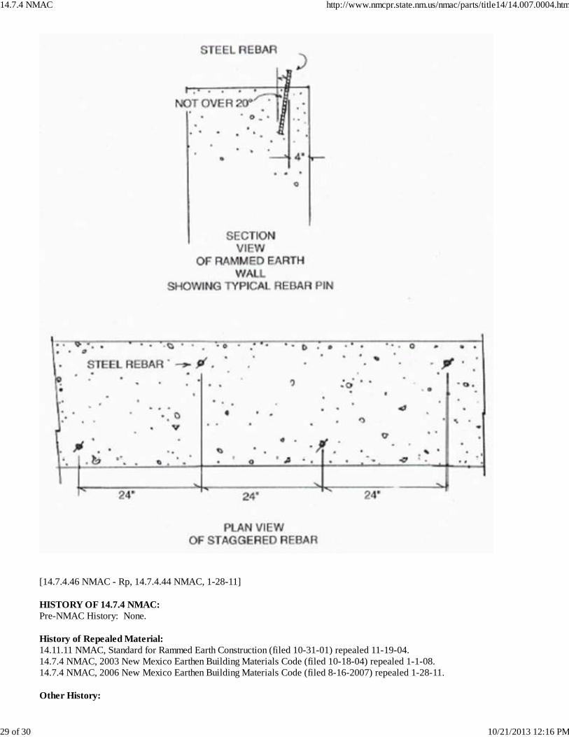
A. General. The depth of voids shall not exceed 8 inches. The width of the void shall be as defined inSubsections B and C of 14.7.4.15 NMAC below. B. Voids in stabilized rammed earth walls. Voids shall not exceed two (2) feet in width. Voids greater thantwo (2) feet in width require a lintel or half-circle arched opening. Refer to 14.7.4.18 NMAC for lintel requirements. C. Voids in unstabilized rammed earth walls. Voids shall not exceed one (1) foot in width. Voids greaterthan one (1) foot in width require a lintel or half-circle arched opening of stabilized rammed earth material. Refer to 14.7.4.18NMAC for lintel requirements.[14.7.4.15 NMAC - Rp, 14.7.4.15 NMAC, 1-28-11] 14.7.4.16 ATTACHMENTS AND CONNECTIONS: A. General. Attachment and connection methods of alternate wall construction to rammed earth walls aredescribed as follows. The building official may approve other attachment and connection methods. In no case shall two walltypes be butted to each other without consideration for attachment or connection. B. Attachment of a rammed earth wall to a rammed earth wall. A keyway, at least six (6) inches wide bythree (3) inches deep shall be formed vertically at the center of the wall section from stem top to underside of bond beam. Theconnecting wall shall be rammed into the keyway. (Refer to figure 3 of the earthen building figures supplement). C. Attachment of a load-bearing adobe wall to a rammed earth wall. Where adobe is deployed as aninterior wall that will be incorporated into the rammed earth wall for lateral support, the adobe shall measure a minimum of ten(10) inches in thickness. Steel ladder reinforcement shall be rammed into the wall at the intersection with the adobe wall. Thereinforcement may be bent against the forms during the ramming process. After ramming is complete and forms removed, thereinforcement shall be incorporated into the adjoining adobe coursing, every four (4) courses minimum. (Refer to figure 12 ofthe earthen building figures supplement). As an alternative, a keyway, not to exceed the depth of the adobe wall, nor one-third(1/3) the depth of the rammed earth wall, shall be formed into the rammed earth wall. The adobe shall be incorporated into thekeyway. (Refer to figure 13 of the earthen building figures supplement). D. Attachment of a loadbearing wood or steel frame wall to a rammed earth wall. A half-inch (1/2)minimum diameter anchor bolt with four (4) inch hook, set in a linear vertical pattern, a maximum of twenty-four (24) incheson-center. The anchor bolt shall be embedded at least twelve (12) inches into the earth wall with the threaded end protrudingsufficiently to pass through and attach the adjoining vertical wall stud. The washer and nut shall be tightened just prior tosheathing the frame wall. As an alternative, eighteen (18) gauge by two (2) inch minimum galvanized strap tie, grouted into theconcrete bond beam (or secured to the wood bond beam or wood top plate), securely nailed to the top plate of the frame wall. The remainder of the vertical stud shall be attached to the rammed earth wall with thirty-D (30D) nails or screws embedded aminimum of three (3) inches into the adjacent wall at eight (8) inches on center vertically. (Refer to figure 14 of the earthenbuilding figures supplement). E. Attachment of a door or window unit to a rammed earth wall. The unit shall be attached to nailerswithin the opening or nailed or screwed directly into the rammed earth wall. The nail or screw shall penetrate at least three(3) inches into the rammed earth wall. Heavier units may utilize stronger attachments, such as anchor bolts, T-bolts, steel pins,etc., embedded into the rammed earth wall. F. Attachment of foam or rigid insulation to a rammed earth wall. Insulating boards or foams notexceeding two (2) inches in thickness may be adhered to the exterior of the rammed earth wall. When insulation board is used,round-cap nails, capped concrete nails or capped screws shall attach it to the rammed earth wall. Cap nails or screws shallhave a maximum spacing of sixteen (16) inches from each other. Additionally, cap nails or screws shall secure the insulationboards around their perimeter edges with nails or screws spaced no less than twelve (12) inches apart. All cap nails orscrews shall penetrate a minimum of two (2) inches into the rammed earth wall. All insulation fasteners shall be corrosionresistant. Insulating boards or foams shall not be used to form architectural shapes exceeding two (2) inches in thickness. G. Attachment of cabinetry to a rammed earth wall. Deck screws shall penetrate a minimum of three (3)inches through cabinetry and into a nailer, eight (8) inches on center maximum, or; deck screws with a least three (3) inchminimum penetration through cabinetry and into the rammed earth wall. Screws shall be placed horizontally, eight (8) incheson center maximum, on the top and bottom of cabinetry. As an alternative, all-thread rods or other attachment devices, suitablefor attachment of cabinetry through the rammed earth wall. H. Attachment of concrete bond beam to a rammed earth wall. Number four (4) reinforcing bar shall bedriven into the uncured wall top. The reinforcing bar shall be set at a maximum twenty degree angle along both edges of thewall, staggered no more than twenty-four (24) inches on-center and no closer than four (4) inches from the exterior faces of thewall. The reinforcing bar shall extend a minimum of twelve (12) inches into the rammed earth wall and four (4) inches into theconcrete bond beam. (Refer to figure 16 of the earthen building figures supplement). I. Attachment of wood bond beam to a rammed earth wall. One-half (1/2) inch anchor bolts with four (4)inch base hooks shall be rammed into the wall. The bolts shall be staggered a maximum of forty-eight (48) inches on-centeralong both edges of the wall, staggered no closer than six (6) inches from the exterior faces of the wall. The bolt shall extend aminimum of eighteen (18) inches into the rammed earth wall.[14.7.4.16 NMAC - Rp, 14.7.4.16 NMAC, 1-28-11; A, 9-1-13]
14.7.4 NMAC http://www.nmcpr.state.nm.us/nmac/parts/title14/14.007.0004.htm
8 of 30 10/21/2013 12:16 PM
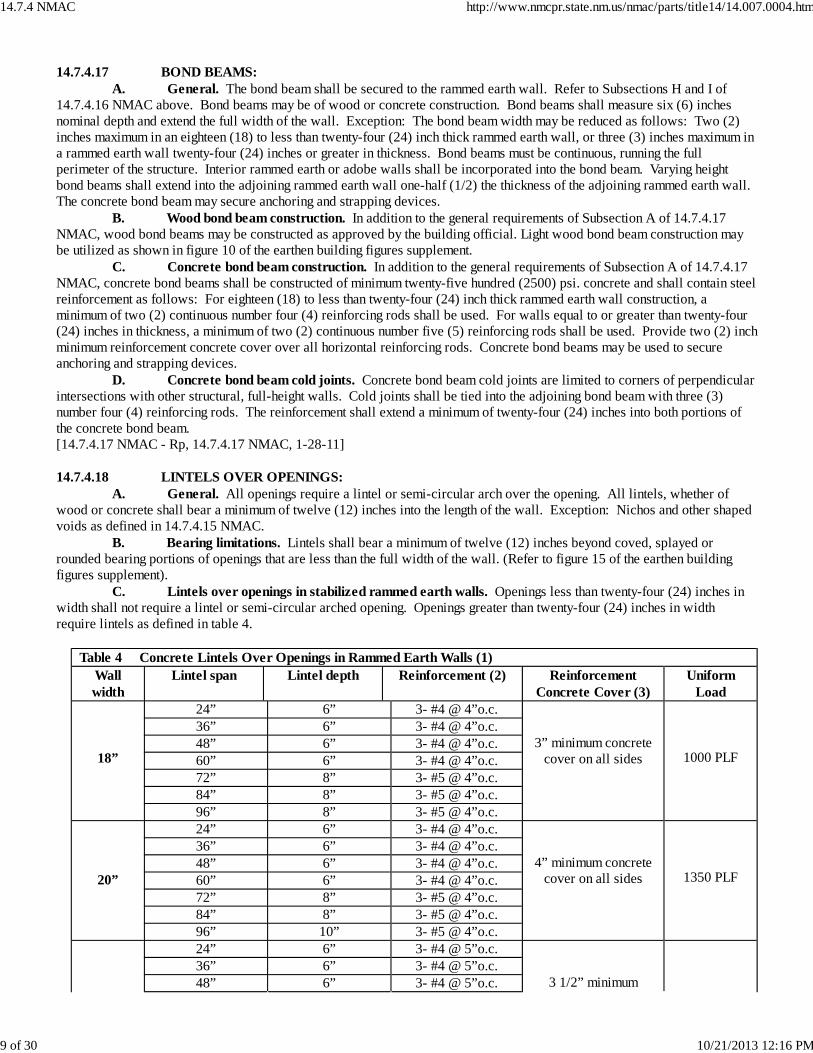
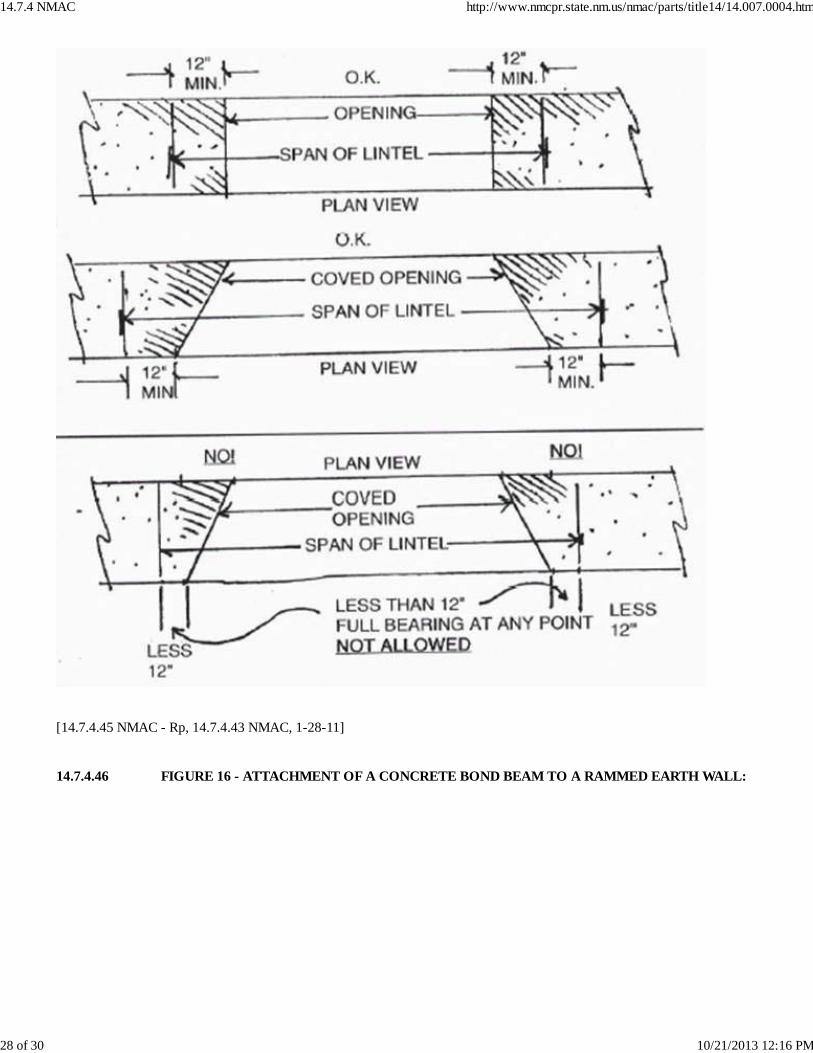
14.7.4.17 BOND BEAMS: A. General. The bond beam shall be secured to the rammed earth wall. Refer to Subsections H and I of14.7.4.16 NMAC above. Bond beams may be of wood or concrete construction. Bond beams shall measure six (6) inchesnominal depth and extend the full width of the wall. Exception: The bond beam width may be reduced as follows: Two (2)inches maximum in an eighteen (18) to less than twenty-four (24) inch thick rammed earth wall, or three (3) inches maximum ina rammed earth wall twenty-four (24) inches or greater in thickness. Bond beams must be continuous, running the fullperimeter of the structure. Interior rammed earth or adobe walls shall be incorporated into the bond beam. Varying heightbond beams shall extend into the adjoining rammed earth wall one-half (1/2) the thickness of the adjoining rammed earth wall. The concrete bond beam may secure anchoring and strapping devices. B. Wood bond beam construction. In addition to the general requirements of Subsection A of 14.7.4.17NMAC, wood bond beams may be constructed as approved by the building official. Light wood bond beam construction maybe utilized as shown in figure 10 of the earthen building figures supplement. C. Concrete bond beam construction. In addition to the general requirements of Subsection A of 14.7.4.17NMAC, concrete bond beams shall be constructed of minimum twenty-five hundred (2500) psi. concrete and shall contain steelreinforcement as follows: For eighteen (18) to less than twenty-four (24) inch thick rammed earth wall construction, aminimum of two (2) continuous number four (4) reinforcing rods shall be used. For walls equal to or greater than twenty-four(24) inches in thickness, a minimum of two (2) continuous number five (5) reinforcing rods shall be used. Provide two (2) inchminimum reinforcement concrete cover over all horizontal reinforcing rods. Concrete bond beams may be used to secureanchoring and strapping devices. D. Concrete bond beam cold joints. Concrete bond beam cold joints are limited to corners of perpendicularintersections with other structural, full-height walls. Cold joints shall be tied into the adjoining bond beam with three (3)number four (4) reinforcing rods. The reinforcement shall extend a minimum of twenty-four (24) inches into both portions ofthe concrete bond beam.[14.7.4.17 NMAC - Rp, 14.7.4.17 NMAC, 1-28-11] 14.7.4.18 LINTELS OVER OPENINGS: A. General. All openings require a lintel or semi-circular arch over the opening. All lintels, whether ofwood or concrete shall bear a minimum of twelve (12) inches into the length of the wall. Exception: Nichos and other shapedvoids as defined in 14.7.4.15 NMAC. B. Bearing limitations. Lintels shall bear a minimum of twelve (12) inches beyond coved, splayed orrounded bearing portions of openings that are less than the full width of the wall. (Refer to figure 15 of the earthen buildingfigures supplement). C. Lintels over openings in stabilized rammed earth walls. Openings less than twenty-four (24) inches inwidth shall not require a lintel or semi-circular arched opening. Openings greater than twenty-four (24) inches in widthrequire lintels as defined in table 4.
Table 4 Concrete Lintels Over Openings in Rammed Earth Walls (1)Wallwidth
Lintel span Lintel depth Reinforcement (2) ReinforcementConcrete Cover (3)
UniformLoad
18”
24” 6” 3- #4 @ 4”o.c.
3” minimum concretecover on all sides
1000 PLF
36” 6” 3- #4 @ 4”o.c.48” 6” 3- #4 @ 4”o.c.60” 6” 3- #4 @ 4”o.c.72” 8” 3- #5 @ 4”o.c.84” 8” 3- #5 @ 4”o.c.96” 8” 3- #5 @ 4”o.c.
20”
24” 6” 3- #4 @ 4”o.c.
4” minimum concretecover on all sides
1350 PLF
36” 6” 3- #4 @ 4”o.c.48” 6” 3- #4 @ 4”o.c.60” 6” 3- #4 @ 4”o.c.72” 8” 3- #5 @ 4”o.c.84” 8” 3- #5 @ 4”o.c.96” 10” 3- #5 @ 4”o.c.
24” 6” 3- #4 @ 5”o.c.
3 1/2” minimum
36” 6” 3- #4 @ 5”o.c.48” 6” 3- #4 @ 5”o.c.
14.7.4 NMAC http://www.nmcpr.state.nm.us/nmac/parts/title14/14.007.0004.htm
9 of 30 10/21/2013 12:16 PM
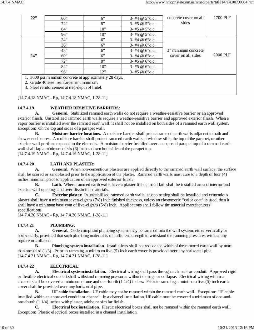
22” concrete cover on allsides
1700 PLF60” 6” 3- #4 @ 5”o.c.72” 8” 3- #5 @ 5”o.c.84” 10” 3- #5 @ 5”o.c.96” 10” 3- #5 @ 5”o.c.
24”
24” 6” 3- #4 @ 6”o.c.
3” minimum concretecover on all sides
2000 PLF
36” 6” 3- #4 @ 6”o.c.48” 6” 3- #4 @ 6”o.c.60” 6” 3- #4 @ 6”o.c.72” 8” 3- #5 @ 6”o.c.84” 10” 3- #5 @ 6”o.c.96” 12” 3- #5 @ 6”o.c.
1. 3000 psi minimum concrete at approximately 28 days. 2. Grade 40 steel reinforcement minimum. 3. Steel reinforcement at mid-depth of lintel.
[14.7.4.18 NMAC - Rp, 14.7.4.18 NMAC, 1-28-11] 14.7.4.19 WEATHER RESISTIVE BARRIERS: A. General. Stabilized rammed earth walls do not require a weather-resistive barrier or an approvedexterior finish. Unstabilized rammed earth walls require a weather-resistive barrier and approved exterior finish. When avapor barrier is installed over the rammed earth wall, it shall not be installed on both sides of a rammed earth wall system. Exception: On the top and sides of a parapet wall. B. Moisture barrier locations. A moisture barrier shall protect rammed earth walls adjacent to bath andshower enclosures. A moisture barrier shall protect rammed earth walls at window sills, the top of the parapet, or otherexterior wall portions exposed to the elements. A moisture barrier installed over an exposed parapet top of a rammed earthwall shall lap a minimum of six (6) inches down both sides of the parapet top.[14.7.4.19 NMAC - Rp, 14.7.4.19 NMAC, 1-28-11] 14.7.4.20 LATH AND PLASTER: A. General. When non-cementious plasters are applied directly to the rammed earth wall surface, the surfaceshall be scored or sandblasted prior to the application of the plaster. Rammed earth walls must cure to a depth of four (4)inches minimum prior to application of an approved exterior finish. B. Lath. Where rammed earth walls have a plaster finish, metal lath shall be installed around interior andexterior wall openings and over dissimilar materials. C. Exterior plaster. In unstabilized rammed earth walls, stucco netting shall be installed and cementiousplaster shall have a minimum seven-eighths (7/8) inch finished thickness, unless an elastomeric “color coat” is used, then itshall have a minimum base coat of five-eighths (5/8) inch. Applications shall follow the material manufacturers’specifications.[14.7.4.20 NMAC - Rp, 14.7.4.20 NMAC, 1-28-11] 14.7.4.21 PLUMBING: A. General. Code compliant plumbing systems may be rammed into the wall system, either vertically orhorizontally, provided that such plumbing material is of sufficient strength to withstand the ramming pressures without anyrupture or collapse. B. Plumbing system installation. Installations shall not reduce the width of the rammed earth wall by morethan one-third (1/3). Prior to ramming, a minimum five (5) inch earth cover is provided over any horizontal pipe.[14.7.4.21 NMAC - Rp, 14.7.4.21 NMAC, 1-28-11] 14.7.4.22 ELECTRICAL: A. Electrical system installation. Electrical wiring shall pass through a channel or conduit. Approved rigidor flexible electrical conduit shall withstand ramming pressures without damage or collapse. Electrical wiring within achannel shall be covered a minimum of one and one-fourth (1 1/4) inches. Prior to ramming, a minimum five (5) inch earthcover shall be provided over any horizontal pipe. B. UF cable installation. UF cable may not be rammed within the rammed earth wall. Exception: UF cableinstalled within an approved conduit or channel. In a channel installation, UF cable must be covered a minimum of one-and-one-fourth (1 1/4) inches with plaster, adobe or similar finish. C. Electrical box installation. Plastic electrical boxes shall not be rammed within the rammed earth wall. Exception: Plastic electrical boxes installed in a channel installation.
14.7.4 NMAC http://www.nmcpr.state.nm.us/nmac/parts/title14/14.007.0004.htm
10 of 30 10/21/2013 12:16 PM
[14.7.4.22 NMAC - Rp, 14.7.4.22 NMAC, 1-28-11] 14.7.4.23 COMPRESSED EARTH BLOCK CONSTRUCTION (CEB): A. General. Compressed earth block shall not be used in any building more than (2) stories in height. Theheight of every wall of compressed earth block without lateral support shall be defined in Subsection B of 14.7.4.8 NMAC,table 1. The height of the wall is defined as the distance from the top of the slab or top of stem wall to the underside of thebond beam. Heights for exterior walls, which are laterally supported with those supports located no more than twenty-four(24) feet apart, are defined in Subsection B of 14.7.4.8 NMAC, table 1. The bottom story of a two-story is allowed a minimumthickness of fourteen (14) inches with the upper story allowed a thickness of ten (10) inches, providing the structure meets theprovisions of Subsection B of 14.7.4.8 NMAC, table 1. Passive solar structures incorporating the use of solar mass walls(trombe), direct gain arrays or sunspaces (greenhouses) as defined by the passive solar heating worksheet, dated June 2004 andprepared by the state of New Mexico energy, minerals and natural resources department, are allowed. B. Fireplaces. Adobe or masonry fireplaces and chimneys in compressed earth block structures shall complywith 14.7.3.18 NMAC. They shall be integrated into adjacent compressed earth block walls during construction or secured tothem by suitable steel ladder reinforcement or reinforcing rods. C. Count Rumford fireplaces. Count Rumford fireplaces are allowed as designated in 14.7.3.18 NMAC. D. Stop work. The building inspector shall have the authority to issue a “stop work” order if the provisionsof this section are not complied with. E. Stabilized compressed earth blocks. The term “stabilized” is defined to mean a block with certainadmixtures that retains minimum strength requirements as specified in Subsection J of 14.7.4.23 NMAC after saturation inwater. Saturation is defined as a minimum four (4) hours of submersion in water as defined in ASTM D1633-00. F. Unstabilized compressed earth blocks. Unstabilized blocks are defined as not meeting the minimumstrength requirements as defined in Subsection J of 14.7.4.23 NMAC after saturation in water. Use of unstabilized compressedearth blocks is prohibited within four (4) inches of the finished floor grade. Stabilized compressed earth blocks, pouredconcrete, or waterproof masonry units and mortar may be used for the first four (4) inches above floor grade. G. Materials. The material must be a mineral soil with the aggregate content not exceeding one (1) inch indiameter. The material shall not contain more than two (2) percent soluble salts. H. Testing. Each of the tests prescribed in this section shall be applied to sample units selected at random offive (5) units per building project prior to construction. Test may be waived if block manufacturer provides certification ofcompliance. The certification must be dated within one year of the date on the application for the building permit. I. Shrinkage cracks. Shrinkage cracks are allowed, providing that these cracks do not jeopardize thestructural integrity of the blocks. J. Compressive strength. Cured units shall have a minimum compressive strength of three hundred (300)pounds per square inch when tested. The compressed earth block shall be tested in the flat position. The length of the test unitmust be a minimum of twice the width. The surfaces must be smooth. The test unit shall be subjected to a uniform compressiveload that is gradually increased at a rate of five hundred (500) psi/minute until failure occurs. A true platen should be used inthe testing machine, along with swivel head to accommodate nonparallel bearing surfaces. The compressive strength is definedas P/A, where P = load and A - area of compression surface. K. Modulus of rupture. Units shall have a minimum compressive strength of fifty (50) pounds per squareinch in modulus of rupture when tested according to the following procedures: A cured unit shall be laid over two-inch (2”)diameter cylindrical supports two (2) inches from each end and extending across the full width of the unit. A cylinder two (2)inches in diameter shall be laid midway between and parallel to the supports. Load shall be applied to the cylinder at a rate offive hundred (500) psi/minute until rupture occurs. The modulus of rupture is equal to: 3PL/2bt2 (P= rupture load in pounds,L= span between supports, b= width of block, t= thickness of block).[14.7.4.23 NMAC - Rp, 14.7.4.23 NMAC, 1-28-11] 14.7.4.24 MORTAR: A. General. The use of earth mortar is allowed if the earth mortar material is compatible with thecompressed earth blocks. Conventional lime/sand/cement mortars of Types M, S, and N are also allowed. Mortar “bedding”joints shall be fully grouted. Head joint mortar is not required provided that the blocks are initially laid in contact. Partiallyopen “head” joints are allowed if the surface is to be plastered. All joints shall be lapped at least twenty-five (25) percent ofthe visible block length. B. Slip mortars. Liquid mud slip mortar is allowed, providing it is made of a compatible soil that isscreened to eliminate aggregate larger than one-eighth (1/8) inch in diameter. Water may be substituted for slip or othermortars, providing adequate adhesion is demonstrated. C. Stacking. “Dry stacking” of compressed earth blocks is allowed providing that adequate adhesion isdemonstrated, the wall is to be stuccoed or plastered and the wall is not less than ten (10) inches in thickness. D. Use. Compressed earth block may be cured prior to use or laid directly from the press into the wall in an
14.7.4 NMAC http://www.nmcpr.state.nm.us/nmac/parts/title14/14.007.0004.htm
11 of 30 10/21/2013 12:16 PM
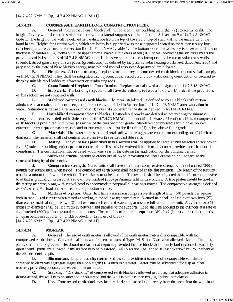
uncured state. Compressed earth block shall be laid in level courses so that the top of any course shall be at the same heightabove the stem around the structure. E. Foundations. Compressed earth blocks may not be used for foundations or basement walls. F. Footings. All compressed earth block walls shall have a continuous footing at least ten (10) inches thick.The footing width must be a minimum of thirty-three (33) percent greater than the wall width, but not less than two (2) incheson each side. The stem wall must be centered on the footing. G. Stem walls. All stem walls that support CEB units shall extend to an elevation not less than eight (8)inches above the exterior finish grade. Stem walls shall be as thick as the exterior wall. Where perimeter insulation is used, avariance is allowed for the stem wall width to be two (2) inches smaller than the width of the CEB wall it supports. H. Concrete grade beam. Rubble-filled foundation trench designs with a reinforced concrete grade beamabove are allowed to support CEB construction. An architect or engineer registered in the state of New Mexico shall certifythe grade beam/rubble-filled trench design portion. Other alternative foundation systems must be approved by the buildingofficial.[14.7.4.24 NMAC - Rp, 14.7.4.24 NMAC, 1-28-11] 14.7.4.25 BOND BEAMS: A. General. All bearing walls shall be topped with a continuous bond beam (except patio walls less than six(6) feet high above stem). All bond beam construction shall be in accordance with accepted engineering practices. B. Concrete bond beam. Concrete bond beams shall be a minimum of six (6) inches high by ten (10) incheswide for walls up to fourteen (14) inches thick. Where CEB walls are wider than one course, two-thirds (2/3) of each visiblecourse top shall be covered by the concrete bond beam. All concrete bond beams shall be reinforced with a minimum of two(2) no. 4 reinforcing rods at each floor and ceiling plate line. C. Wood bond beam. Wood bond beams shall be a minimum of six (6) inches deep by ten (10) inches widefor walls up to fourteen (14) inches thick. Where CEB walls are wider than one course, two-thirds (2/3) of each visiblecourse top shall be covered by a wood bond beam and the roof load shall be distributed over both bond beams. Wood bondbeams may be solid in the six inch (6”) dimension, or may be built up by applying layers of lumber. Ends of wood bond beamsare to be lapped in minimum of the width of the wall and fully nailed. Galvanized metal straps or perforated metal straps, 18gauge minimum and twelve (12) inches long, may be used to join the ends of wood bond beam members. Full nailing of strapsis required. No wood layer shall be less than one (1) inch nominal thickness. The building official shall approve all woodenbond beams for walls wider than fourteen (14) inches.[14.7.4.25 NMAC - Rp, 14.7.4.25 NMAC, 1-28-11] 14.7.4.26 LINTELS: A. General. Lintels of wood or concrete are allowed. The bearing length of any lintel shall not be reducedby an angled or splayed window or door opening. Other lintel designs are accepted providing that engineering is submitted forreview by the building official. B. Wood lintels. When an engineer’s drawing and seal is not provided for lintels, all wood lintels shallconform to table 5 and have a fiber stress rating of at least 850 psi.
Table 5 CEB WALL WOOD LINTEL SCHEDULEMINIMUM FIBER STRESS 850 PSI
WallWidth
Max. Span Size Bearing length onearth wall
LoadCapacity
10”
4'-0” 10” x 6” 12” 860 PLF6'-0” 10” x 8” 12” 1020 PLF8'-0” 10” x 10” 18” 1150 PLF10'-0” 10” x 12” 24” 1000 PLF12'-0” 10” x 14” 24” 1000 PLF
12”
4'-0” 10” x 6” 12” 860 PLF6'-0” 10” x 8” 12” 1020 PLF8'-0” 10” x 10” 18” 1150 PLF10'-0” 10” x 12” 24” 1000 PLF12'-0” 10” x 14” 24” 1000 PLF
14”
14”
4'-0” 12” x 6” 12” 950 PLF6'-0” 12” x 8” 12” 1150 PLF8'-0” 12” x 10” 18” 1300 PLF10'-0” 12” x 12” 24” 1300 PLF
14.7.4 NMAC http://www.nmcpr.state.nm.us/nmac/parts/title14/14.007.0004.htm
12 of 30 10/21/2013 12:16 PM
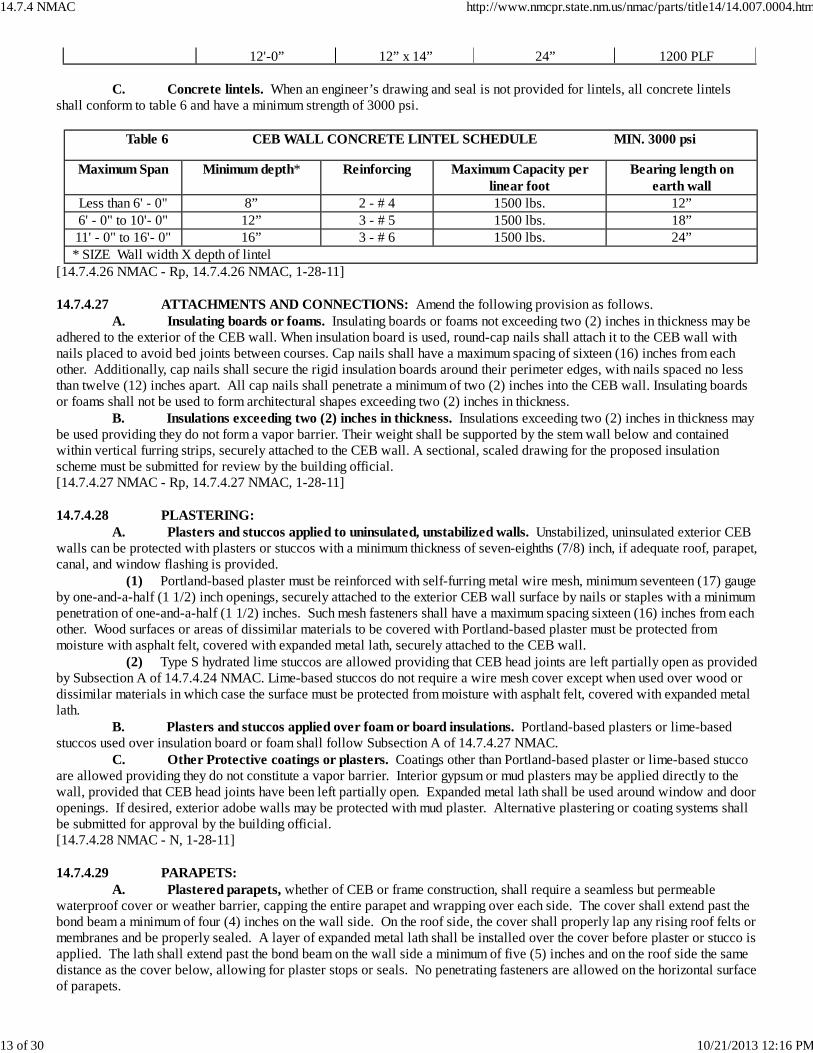
12'-0” 12” x 14” 24” 1200 PLF C. Concrete lintels. When an engineer’s drawing and seal is not provided for lintels, all concrete lintelsshall conform to table 6 and have a minimum strength of 3000 psi.
Table 6 CEB WALL CONCRETE LINTEL SCHEDULE MIN. 3000 psi
Maximum Span Minimum depth* Reinforcing Maximum Capacity perlinear foot
Bearing length onearth wall
Less than 6' - 0" 8” 2 - # 4 1500 lbs. 12”6' - 0" to 10'- 0" 12” 3 - # 5 1500 lbs. 18”11' - 0" to 16'- 0" 16” 3 - # 6 1500 lbs. 24”* SIZE Wall width X depth of lintel
[14.7.4.26 NMAC - Rp, 14.7.4.26 NMAC, 1-28-11] 14.7.4.27 ATTACHMENTS AND CONNECTIONS: Amend the following provision as follows. A. Insulating boards or foams. Insulating boards or foams not exceeding two (2) inches in thickness may beadhered to the exterior of the CEB wall. When insulation board is used, round-cap nails shall attach it to the CEB wall withnails placed to avoid bed joints between courses. Cap nails shall have a maximum spacing of sixteen (16) inches from eachother. Additionally, cap nails shall secure the rigid insulation boards around their perimeter edges, with nails spaced no lessthan twelve (12) inches apart. All cap nails shall penetrate a minimum of two (2) inches into the CEB wall. Insulating boardsor foams shall not be used to form architectural shapes exceeding two (2) inches in thickness. B. Insulations exceeding two (2) inches in thickness. Insulations exceeding two (2) inches in thickness maybe used providing they do not form a vapor barrier. Their weight shall be supported by the stem wall below and containedwithin vertical furring strips, securely attached to the CEB wall. A sectional, scaled drawing for the proposed insulationscheme must be submitted for review by the building official.[14.7.4.27 NMAC - Rp, 14.7.4.27 NMAC, 1-28-11] 14.7.4.28 PLASTERING: A. Plasters and stuccos applied to uninsulated, unstabilized walls. Unstabilized, uninsulated exterior CEBwalls can be protected with plasters or stuccos with a minimum thickness of seven-eighths (7/8) inch, if adequate roof, parapet,canal, and window flashing is provided. (1) Portland-based plaster must be reinforced with self-furring metal wire mesh, minimum seventeen (17) gaugeby one-and-a-half (1 1/2) inch openings, securely attached to the exterior CEB wall surface by nails or staples with a minimumpenetration of one-and-a-half (1 1/2) inches. Such mesh fasteners shall have a maximum spacing sixteen (16) inches from eachother. Wood surfaces or areas of dissimilar materials to be covered with Portland-based plaster must be protected frommoisture with asphalt felt, covered with expanded metal lath, securely attached to the CEB wall. (2) Type S hydrated lime stuccos are allowed providing that CEB head joints are left partially open as providedby Subsection A of 14.7.4.24 NMAC. Lime-based stuccos do not require a wire mesh cover except when used over wood ordissimilar materials in which case the surface must be protected from moisture with asphalt felt, covered with expanded metallath. B. Plasters and stuccos applied over foam or board insulations. Portland-based plasters or lime-basedstuccos used over insulation board or foam shall follow Subsection A of 14.7.4.27 NMAC. C. Other Protective coatings or plasters. Coatings other than Portland-based plaster or lime-based stuccoare allowed providing they do not constitute a vapor barrier. Interior gypsum or mud plasters may be applied directly to thewall, provided that CEB head joints have been left partially open. Expanded metal lath shall be used around window and dooropenings. If desired, exterior adobe walls may be protected with mud plaster. Alternative plastering or coating systems shallbe submitted for approval by the building official.[14.7.4.28 NMAC - N, 1-28-11] 14.7.4.29 PARAPETS: A. Plastered parapets, whether of CEB or frame construction, shall require a seamless but permeablewaterproof cover or weather barrier, capping the entire parapet and wrapping over each side. The cover shall extend past thebond beam a minimum of four (4) inches on the wall side. On the roof side, the cover shall properly lap any rising roof felts ormembranes and be properly sealed. A layer of expanded metal lath shall be installed over the cover before plaster or stucco isapplied. The lath shall extend past the bond beam on the wall side a minimum of five (5) inches and on the roof side the samedistance as the cover below, allowing for plaster stops or seals. No penetrating fasteners are allowed on the horizontal surfaceof parapets.
14.7.4 NMAC http://www.nmcpr.state.nm.us/nmac/parts/title14/14.007.0004.htm
13 of 30 10/21/2013 12:16 PM
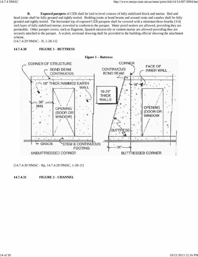
B. Exposed parapets of CEB shall be laid in level courses of fully stabilized block and mortar. Bed andhead joints shall be fully grouted and tightly tooled. Bedding joints at bond beams and around vents and canales shall be fullygrouted and tightly tooled. The horizontal top of exposed CEB parapets shall be covered with a minimum three-fourths (3/4)inch layer of fully stabilized mortar, troweled to conform to the parapet. Water proof sealers are allowed, providing they arepermeable. Other parapet covers, such as flagstone, Spanish mission tile or cement mortar are allowed providing they aresecurely attached to the parapet. A scaled, sectional drawing shall be provided to the building official showing the attachmentscheme.[14.7.4.29 NMAC - N, 1-28-11] 14.7.4.30 FIGURE 1 - BUTTRESS
Figure 1 – Buttress:
[14.7.4.30 NMAC - Rp, 14.7.4.28 NMAC, 1-28-11] 14.7.4.31 FIGURE 2 - CHANNEL
14.7.4 NMAC http://www.nmcpr.state.nm.us/nmac/parts/title14/14.007.0004.htm
14 of 30 10/21/2013 12:16 PM
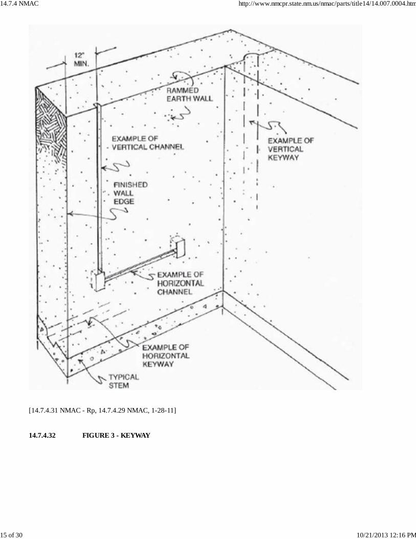
[14.7.4.31 NMAC - Rp, 14.7.4.29 NMAC, 1-28-11] 14.7.4.32 FIGURE 3 - KEYWAY
14.7.4 NMAC http://www.nmcpr.state.nm.us/nmac/parts/title14/14.007.0004.htm
15 of 30 10/21/2013 12:16 PM
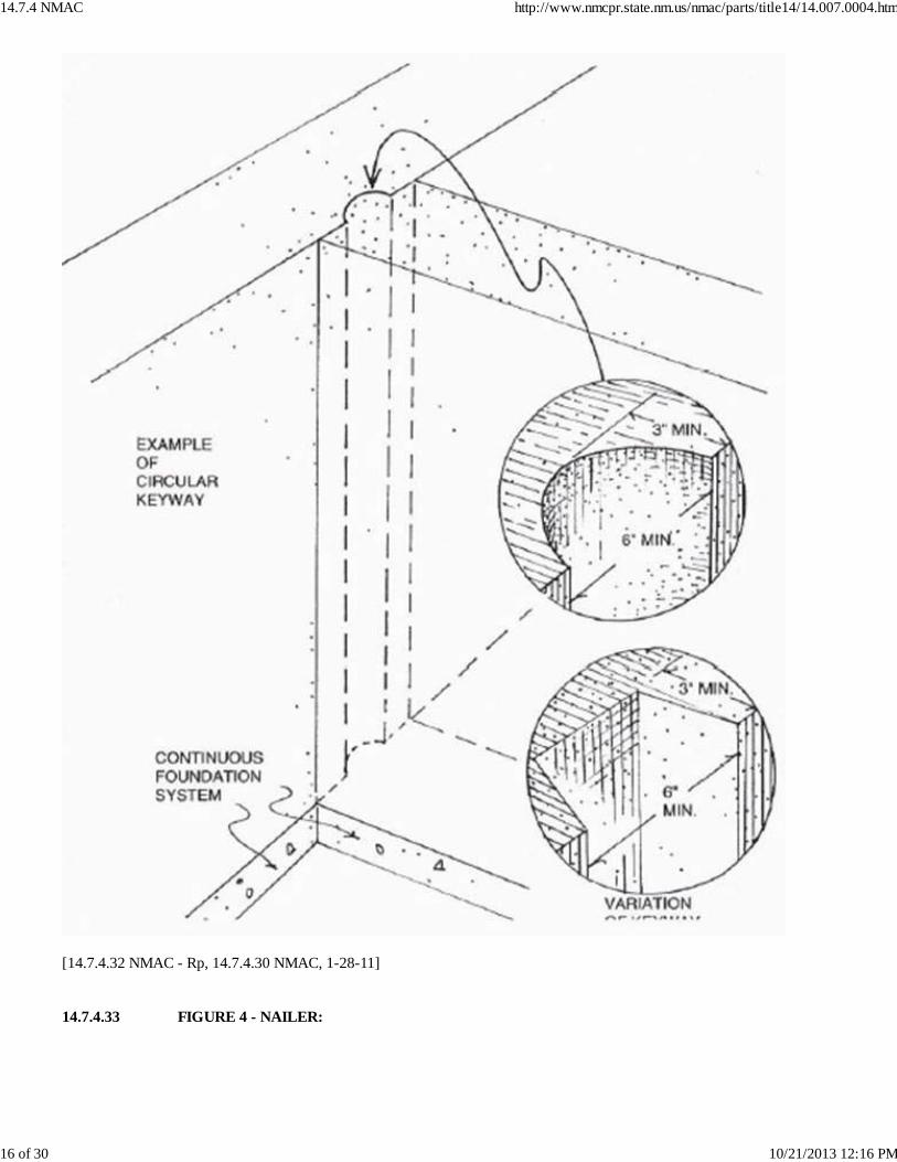
[14.7.4.32 NMAC - Rp, 14.7.4.30 NMAC, 1-28-11] 14.7.4.33 FIGURE 4 - NAILER:
14.7.4 NMAC http://www.nmcpr.state.nm.us/nmac/parts/title14/14.007.0004.htm
16 of 30 10/21/2013 12:16 PM
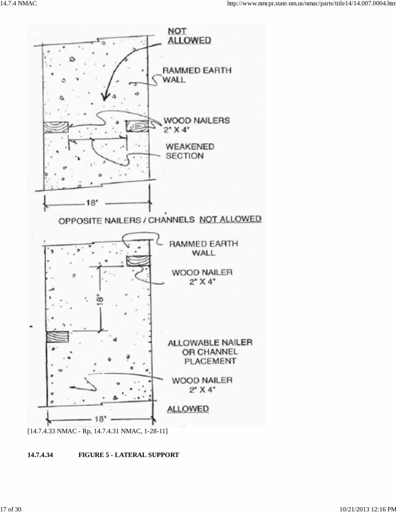
[14.7.4.33 NMAC - Rp, 14.7.4.31 NMAC, 1-28-11] 14.7.4.34 FIGURE 5 - LATERAL SUPPORT
14.7.4 NMAC http://www.nmcpr.state.nm.us/nmac/parts/title14/14.007.0004.htm
17 of 30 10/21/2013 12:16 PM
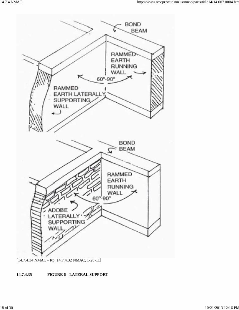
[14.7.4.34 NMAC - Rp, 14.7.4.32 NMAC, 1-28-11] 14.7.4.35 FIGURE 6 - LATERAL SUPPORT
14.7.4 NMAC http://www.nmcpr.state.nm.us/nmac/parts/title14/14.007.0004.htm
18 of 30 10/21/2013 12:16 PM
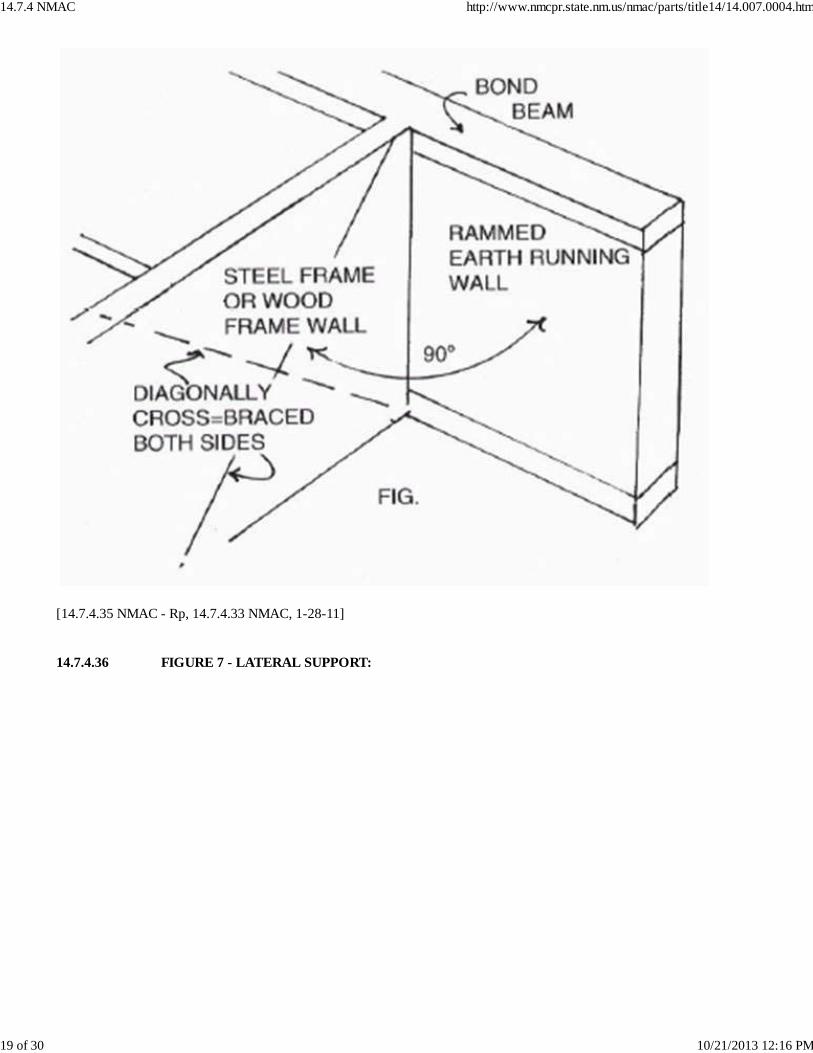
[14.7.4.35 NMAC - Rp, 14.7.4.33 NMAC, 1-28-11] 14.7.4.36 FIGURE 7 - LATERAL SUPPORT:
14.7.4 NMAC http://www.nmcpr.state.nm.us/nmac/parts/title14/14.007.0004.htm
19 of 30 10/21/2013 12:16 PM
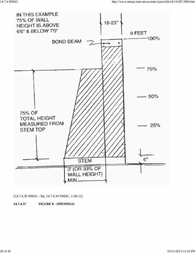
[14.7.4.36 NMAC - Rp, 14.7.4.34 NMAC, 1-28-11] 14.7.4.37 FIGURE 8 - OPENINGS:
14.7.4 NMAC http://www.nmcpr.state.nm.us/nmac/parts/title14/14.007.0004.htm
20 of 30 10/21/2013 12:16 PM
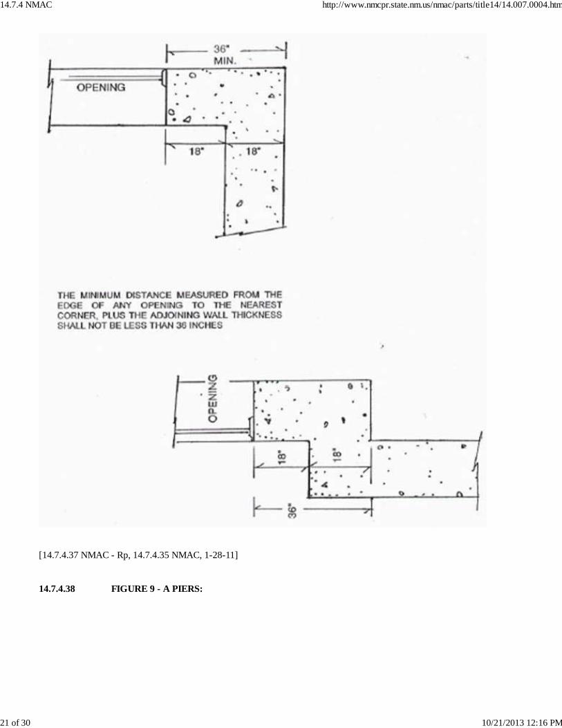
[14.7.4.37 NMAC - Rp, 14.7.4.35 NMAC, 1-28-11] 14.7.4.38 FIGURE 9 - A PIERS:
14.7.4 NMAC http://www.nmcpr.state.nm.us/nmac/parts/title14/14.007.0004.htm
21 of 30 10/21/2013 12:16 PM
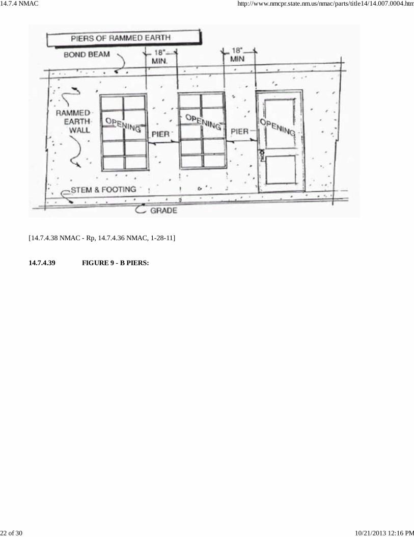
[14.7.4.38 NMAC - Rp, 14.7.4.36 NMAC, 1-28-11] 14.7.4.39 FIGURE 9 - B PIERS:
14.7.4 NMAC http://www.nmcpr.state.nm.us/nmac/parts/title14/14.007.0004.htm
22 of 30 10/21/2013 12:16 PM
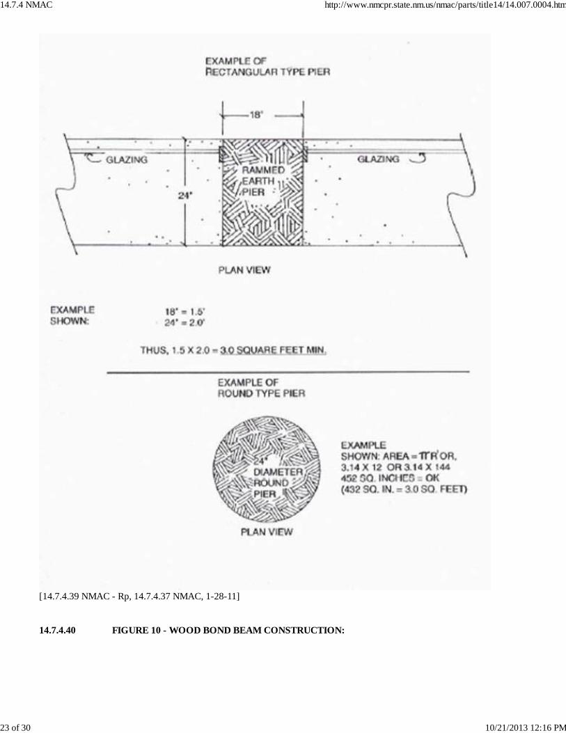
[14.7.4.39 NMAC - Rp, 14.7.4.37 NMAC, 1-28-11] 14.7.4.40 FIGURE 10 - WOOD BOND BEAM CONSTRUCTION:
14.7.4 NMAC http://www.nmcpr.state.nm.us/nmac/parts/title14/14.007.0004.htm
23 of 30 10/21/2013 12:16 PM
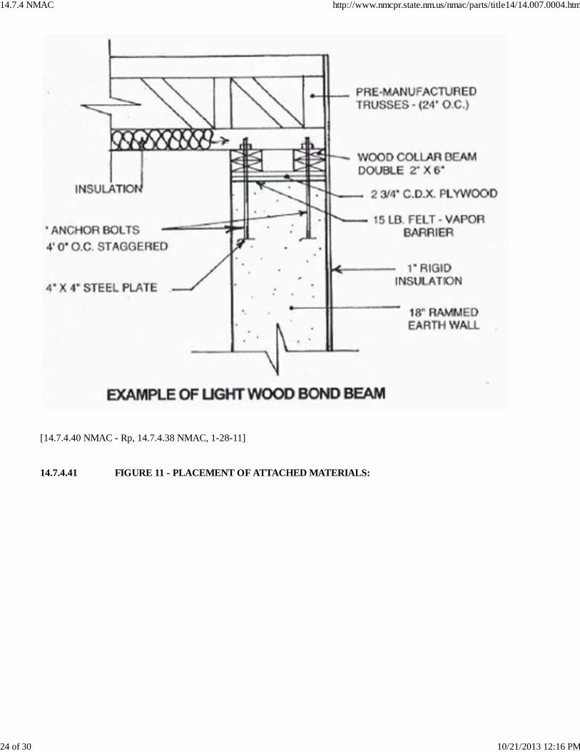
[14.7.4.40 NMAC - Rp, 14.7.4.38 NMAC, 1-28-11] 14.7.4.41 FIGURE 11 - PLACEMENT OF ATTACHED MATERIALS:
14.7.4 NMAC http://www.nmcpr.state.nm.us/nmac/parts/title14/14.007.0004.htm
24 of 30 10/21/2013 12:16 PM
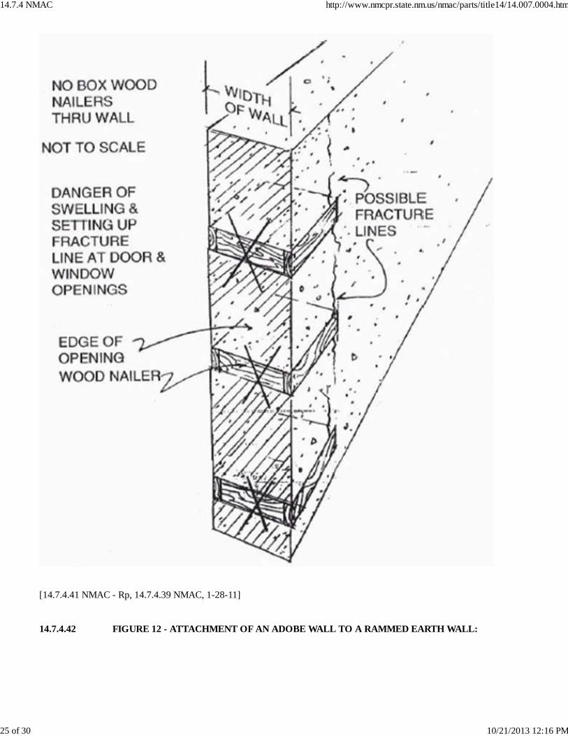
[14.7.4.41 NMAC - Rp, 14.7.4.39 NMAC, 1-28-11] 14.7.4.42 FIGURE 12 - ATTACHMENT OF AN ADOBE WALL TO A RAMMED EARTH WALL:
14.7.4 NMAC http://www.nmcpr.state.nm.us/nmac/parts/title14/14.007.0004.htm
25 of 30 10/21/2013 12:16 PM
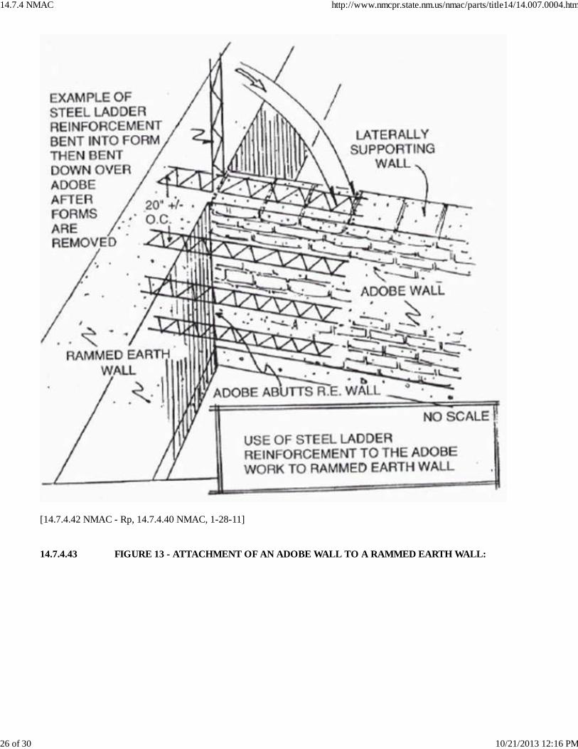
[14.7.4.42 NMAC - Rp, 14.7.4.40 NMAC, 1-28-11] 14.7.4.43 FIGURE 13 - ATTACHMENT OF AN ADOBE WALL TO A RAMMED EARTH WALL:
14.7.4 NMAC http://www.nmcpr.state.nm.us/nmac/parts/title14/14.007.0004.htm
26 of 30 10/21/2013 12:16 PM
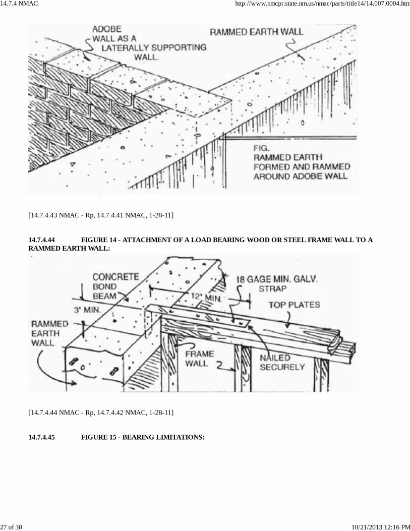
[14.7.4.43 NMAC - Rp, 14.7.4.41 NMAC, 1-28-11] 14.7.4.44 FIGURE 14 - ATTACHMENT OF A LOAD BEARING WOOD OR STEEL FRAME WALL TO ARAMMED EARTH WALL:
[14.7.4.44 NMAC - Rp, 14.7.4.42 NMAC, 1-28-11] 14.7.4.45 FIGURE 15 - BEARING LIMITATIONS:
14.7.4 NMAC http://www.nmcpr.state.nm.us/nmac/parts/title14/14.007.0004.htm
27 of 30 10/21/2013 12:16 PM
[14.7.4.45 NMAC - Rp, 14.7.4.43 NMAC, 1-28-11] 14.7.4.46 FIGURE 16 - ATTACHMENT OF A CONCRETE BOND BEAM TO A RAMMED EARTH WALL:
14.7.4 NMAC http://www.nmcpr.state.nm.us/nmac/parts/title14/14.007.0004.htm
28 of 30 10/21/2013 12:16 PM
[14.7.4.46 NMAC - Rp, 14.7.4.44 NMAC, 1-28-11] HISTORY OF 14.7.4 NMAC:Pre-NMAC History: None. History of Repealed Material:14.11.11 NMAC, Standard for Rammed Earth Construction (filed 10-31-01) repealed 11-19-04.14.7.4 NMAC, 2003 New Mexico Earthen Building Materials Code (filed 10-18-04) repealed 1-1-08.14.7.4 NMAC, 2006 New Mexico Earthen Building Materials Code (filed 8-16-2007) repealed 1-28-11. Other History:
14.7.4 NMAC http://www.nmcpr.state.nm.us/nmac/parts/title14/14.007.0004.htm
29 of 30 10/21/2013 12:16 PM

14.11.11 NMAC, Standard for Rammed Earth Construction (filed 10-31-01) renumbered and replaced by 14.7.4 NMAC, 2003New Mexico Earthen Building Materials Code (which did not include figures previously filed in 14.11.11 NMAC), effective11-19-04.14.7.4 NMAC, 2003 New Mexico Earthen Building Materials Code (filed 10-18-04) was replaced by 14.7.4 NMAC, 2006New Mexico Earthen Building Materials Code (which includes figures previously filed in 14.11.11 NMAC), effective 1-1-08.14.7.4 NMAC, 2006 New Mexico Earthen Building Materials Code (filed 8-16-07) was replaced by 14.7.4 NMAC, 2009New Mexico Earthen Building Materials Code, effective 1-28-11.
14.7.4 NMAC http://www.nmcpr.state.nm.us/nmac/parts/title14/14.007.0004.htm
30 of 30 10/21/2013 12:16 PM