title in aces division 01 robins afb general...
TRANSCRIPT

UHHZ160050 INDEX OF SPECIFICATIONS
INDEX OF SPECIFICATIONS
Page 1 of 4
DATE: 19 January 2017
Title in ACES
NUMBER TITLE PAGES
Division 01 – ROBINS AFB – General Requirements
01005 Statement of Work 01005-1 thru 01005-11
01020 (Design-build) Construction Design Performance 01020-1 thru 01020-23Requirements
Appendix A - Fire Protection and Life Safety Analysis No. of pages = 3
01030 (Design-build) Design after Award 01030-1 thru 01030-15
01040 Site Requirements 01040-1 thru 01040-13
01300 Submittals and Contractor-Furnished Items 01300-1 thru 01300-9
01310 CADD As-Built Drawings 01310-1 thru 01310-5
01501 Temporary Services - Contractor 01501-1 thru 01501-5
01502 Temporary Utilities and Services for Continued Occupancy 01501-1 thru 01501-5
01540 Green Procurement 01540-1 thru 01540-12
Attachment 3 No. of pages = 3
01560 Environmental Requirements 01560-1 thru 01560-32
01572 Construction & Demolition Waste Management 01572-1 thru 01572-6
01580 Safety Requirements 01580-1 thru 01580-6
01600 Product Requirements 01600-1 thru 01600-3
01700 Execution Requirements 01700-1 thru 01700-6
01730 Operations and Maintenance Data 01730-1 thru 01730-6
Edit Div. 02 – 46 specifications from UFGS to encompass work scope required for this project. Utilize
the latest release of the applicable sections required. Below are the minimum specifications required –
add other UFGS specifications as required. See also requirements of Procedural Guide for Designers.
Division 02 – Existing Conditions
02 41 00 Demolition X-X thru X-X
Division 03 - Concrete
03 11 13.00 10 Structural Cast-in-Place Concrete Forming X-X thru X-X
03 20 00.00 10 Concrete Forming X-X thru X-X
03 33 00.00 10 Cast-in-Place Concrete X-X thru X-X
Division 04
04 20 00 Unit Masonry X-X thru X-X

UHHZ160050 INDEX OF SPECIFICATIONS
INDEX OF SPECIFICATIONS
Page 2 of 4
Division 05 - Metals
05 50 13 Miscellaneous Metal Fabrications X-X thru X-X
05 52 00 Metal Railings X-X thru X-X
05 12 00 Structural Steel X-X thru X-X
05 40 00 Cold Formed Metal Framing X-X thru X-X
Division 06 – Wood, Plastics and Composites
06 10 00 Rough Carpentry X-X thru X-X
Division 07 - Thermal and Moisture Protection
07 61 14.00 20 Steel Standing Seam Roofing X-X thru X-X
07 42 13 Metal Wall Panels X-X thru X-X
07 21 16 Mineral Fiber Blanket Insulation X-X thru X-X
07 92 00 Joint Sealants X-X thru X-X
Division 08 - Openings
08 11 13 Steel Doors and Frames X-X thru X-X
08 33 23 Overhead Coiling Doors X-X thru X-X
08 71 00 Door Hardware X-X thru X-X
08 81 00 Glazing X-X thru X-X
08 91 00 Metal Wall Louvers X-X thru X-X
Division 09 - Finishes
09 51 00 Acoustical Ceilings X-X thru X-X
09 90 00 Paints and Coatings X-X thru X-X
Division 10 - Specialties
10 44 16 Fire Extinguishers X-X thru X-X
10 14 00.20 Interior Signage X-X thru X-X
Division 11 - 14
UHHZ160050 INDEX OF SPECIFICATIONS
INDEX OF SPECIFICATIONS
Page 3 of 4
Division 21 – Fire Suppression
21 13 13.00.10 Wet Pipe Sprinkler System, Fire Protection X-X thru X-X
Division 22 – Plumbing
22 00 00 Plumbing, General Purpose X-X thru X-X
Division 23 – Heating, Ventilation and Air Conditioning
23 00 00 Air Supply, Distribution, Ventilation and Exhaust Systems X-X thru X-X
23 03 00.00 20 Basic Mechanical Materials and Methods X-X thru X-X
23 05 93 Testing, Adjusting, and Balancing for HVAC X-X thru X-X
23 82 00.00 20 Terminal Heating and Cooling Units X-X thru X-X
Division 25
Division 26 – Electrical
26 20 00 Interior Distribution System X-X thru X-X
26 28 01.00 10 Coordinated Power System Protection X-X thru X-X
26 41 00 Lightning Protection System X-X thru X-X
26 51 00 Interior Lighting X-X thru X-X
26 56 00 Exterior Lighting X-X thru X-X
Division 27 – Communications
Division 28 – Electronic Safety and Security
28 31 64.00 10 Fire Detection and Alarm System, Addressable X-X thru X-X
Division 31 – Earthwork
31 00 00 Earthwork X-X thru X-X
31 31 16 Soil Treatment for Subterranean Termite Control X-X thru X-X
31 32 11 Soil Surface Erosion Control X-X thru X-X
Division 32 – Exterior Improvements
32 11 23 Aggregate and/or Graded Aggregate Base Course X-X thru X-X
UHHZ160050 INDEX OF SPECIFICATIONS
INDEX OF SPECIFICATIONS
Page 4 of 4
32 12 16 Hot Mix Asphalt for Roads X-X thru X-X
Division 33 – Utilities
33 30 00 Sanitary Sewers X-X thru X-X
Division 34 – 48
TOTAL NUMBER OF PAGES (Including Index) = 164
<<<<< END OF INDEX >>>>>

UHHZ160050 ___ STATEMENT OF WORK - 01005
Statement of Work
Page 1 of 11
PART 1 – GENERAL
1.01 STATEMENT OF WORK: This is a general overview of the Design-Build project. Also see
Section 01020, Construction Design and Performance Requirements, and 01030, Design after Award.
A. Location: Accomplish work at Robins AFB, Georgia
B. Price: The original contracted price shall include special work times for utility outages and
repair of damages.
C. Contract Documents: Follow details shown by the specifications and drawings, current
version of the Robins AFB Facility Standards, UFCs, ETLs, applicable UFGS sections and
building code requirements.
D. Liquidated Damages will be applicable for this task order. If the contractor fails to complete
the work within the time specified in the contract, the Contractor shall pay Liquidated Damages
to the Government in the amount of $332.99 for the first day of delay, and $269.02 per day for
each subsequent calendar day of delay until the work is completed or accepted.
E. Design Phase Requirement: North wing of building will be vacated during construction, but
south wing shall be in full operation. Contractor shall identify all hazards during the design
phase that may have an adverse effect on building occupants, equipment, building systems, etc.
in the south wing during the construction phase. (For example: Project that includes working on
roof over occupied space: cutting insulation, replacement of existing screws can cause dust
particulates and other airborne particles that may be a hazard for personnel and/or equipment
below.) Contractor shall provide design to contain all hazards to building occupants, equipment,
building systems, etc. for contractor to utilize during the construction phase.
F. Project Scope, Objectives and Criteria: This is a Design-Build contract for both Design and
Construction. The general scope of the work includes the following:
1. Scope:
a. General Scope: Renovate north section of Bldg. 673 to accommodate C5
noseplug workload. Roof and wall panel work shall be limited to the north
section with transitions as required to tie into the south section. Lightning
protection work shall be for the entire building. Work requiring utility outages
shall be confined to non-standard working times (nights and/or weekends) to
prevent disruptions to flash jet operations. Provide all additional work as required
for a functional usable facility.
b. Existing Conditions: Bldg. 673 consists of two wings. The north wing is
currently used as a warehouse and is the area for renovation. The south wing is
currently used as a production area for flash-jet operations. Roof insulation at the
north wing has sustained water damage primarily at the eaves and needs to be

UHHZ160050 ___ STATEMENT OF WORK - 01005
Statement of Work
Page 2 of 11
removed. Roof panels on the north wing have probably also been damaged
(hidden) as a result.
c. Abatement of Hazardous Materials: No hazardous materials have been
identified within the scope of this work.
d. Demolition:
1) Remove existing handicap ramp within the building.
2) Remove existing metal roof, roof accessories, roof insulation and lightning
protection for the north wing. Check existing lightning system on the
south wing and the entire lightning ground system for compliance,
removing any items that require reworking/replacement.
3) Remove north building exterior wall panels, exhaust fan, personnel door
and one overhead door. Remove north endwall structure and foundation
as required to restructure for new overhead door and personnel door.
4) Remove wall insulation and wall panels for remaining walls on the
renovation area (north section of building).
5) Remove existing lighting. Remove existing conductors from air switch to
transformer. Remove existing conductors/conduit/switchgear/transformer
as required for new service. Remove any conduit/conductors/devices
which are not required to remain in place (do not abandon in-place).
6) Remove existing eyewash fountain/shower.
7) Remove sufficient existing floor slab and exterior pavements as required
for the installation of new plumbing and sanitary sewer.
8) Remove existing sanitary sewer as required for the ramps.
9) Clean existing structural components in Production Area (base bid).
Protect all existing work to remain from damage.
10) Remove existing pavement on the east side as required to install new
Mechanical Room landing and steps. Removal shall include pavements
requiring re-sloping to prevent ponding adjacent to new ramps and steps.
11) Remove existing pavement on the west side of the building sufficient for
installation of the new handicap ramp, canopy and north vehicle ramp.

UHHZ160050 ___ STATEMENT OF WORK - 01005
Statement of Work
Page 3 of 11
12) Clean and remove paint at existing metal railings at vehicle ramps and all
existing bollards adjacent to renovated area (interior and exterior).
Provide smooth surface properly prepared for repainting.
13) Provide all additional work required for demolition of miscellaneous items
as shown on the drawings and in conjunction with the overall work scope.
Also note items required for Alternates 1 and 2 as appropriate.
e. New Work:
1) Construct new vehicle ramp on north end of building.
2) Install new concrete handicap ramp with railings and awning on west side.
3) Install new concrete landing, steps and railings on east side of building at
Mechanical Room.
4) Construct new PPE and Personal Locker rooms within the building. New
rooms will include heat, cooling, lighting, electrical, plumbing
(w/fixtures), fire alarm (incl. strobes/horns) and fire suppression. Rooms
will have lay-in ceiling with cleanable fiberglass panels. Roof of rooms
shall be metal purlins with prefinished PBR metal roof panels and trim
(provide flashing for weathertight system). Fire alarm and suppression
shall be connected to existing system (requires NICET IV professional for
design). Construction shall be properly sealed to allow for required
positive and/or negative pressures (see also Section 01020).
5) Install new overhead and underground plumbing as required to service
new plumbing fixtures. Patch concrete slab and pavements as required to
match existing.
6) Install new metal roof (approx. 6,000 sf), substructure (to match existing
south roof slope), roof accessories and insulation. All roof insulation shall
have exposed white PSKP scrim. Substructure shall be painted to match
existing structural steel.
7) Install new wall panels and insulation on renovated north section of
building. All wall insulation shall have exposed white PSKP scrim.
8) Install lightning protection system for the north wing and install
new/replacement components on the south wing roof and grounding
system for a complete fully compliant system. Install additional
grounding components as needed for full code compliance. Installation
shall have 3rd party certification.

UHHZ160050 ___ STATEMENT OF WORK - 01005
Statement of Work
Page 4 of 11
9) Install new north building exterior endwall and footings to accommodate
OH and personnel doors.
10) Install new overhead coiling door and personnel door on north end of
building.
11) Install new electrical service (conductors/conduit/transformer/etc.), power
and lighting.
12) Relocate existing sanitary sewer as required for ramps.
13) Install new emergency eyewash/shower. Unit shall be CSA certified to
meet ANSI Z358.1 with water and drain connections.
14) Patch and repair all damage to existing pavements, including any re-
sloping necessary to prevent ponding adjacent to new ramps and steps
(replace with like material).
15) Provide all additional work required for a complete renovation as shown
on the drawings and in conjunction with the overall work scope. Also
note items required for Alternates 1 and 2.
G. Bid Schedule and Alternates:
1. General: The alternates below will be applied to the Base Bid and are shown on the
Bid Form. Alternates 1 and 2 are mutually exclusive – only one of the two will be
executed (at least one of these is required for a complete project). These alternates apply
only to the HVAC for the main Production Area. HVAC requirements for the PPE and
Locker Rooms are included in the Base Bid (units shall be sized to accomplish air
pressure requirements of 01020, 9.3.5). Alternates for this project are listed below.
2. Alternate 1- Ventilation and Heat Only: Remove all existing intake louvers, exhaust
fan and heaters. Install new exhaust fans with louvers, guards and exterior rain shrouds.
Install new motorized intake louvers interlocked with exhaust fan for ventilation.
Interlock ventilation system with fire alarm system. Ventilation requirements shall be
calculated for the new area use requirements (increased capacity, both size and number of
units, may be required). Install new radiant heaters.
3. Alternate 2 – Heating and Cooling: Remove all existing intake louvers, exhaust fan
and heaters. Install new DX split unit heat pump system with emergency heat strips and
associated ductwork/dampers for even distribution. Close openings left from the removal
of louvers and exhaust fan with metal wall panels, framing and insulation (provide all
required flashings).
H. Project Requirements:

UHHZ160050 ___ STATEMENT OF WORK - 01005
Statement of Work
Page 5 of 11
1. The contractor shall provide the technical knowledge and skill necessary to perform
services to meet standards set forth in this Statement of Work for base facilities, equipment and
systems and at a minimum meet manufacturer’s requirements.
2. All stored equipment shall be stored and protected in accordance with manufacturer’s
printed instructions.
3. This project will require daily reports to be filled out daily and submitted to the
project manager on a weekly basis. Daily reports at a minimum shall contain the following
information,
Amount and type of work accomplished
Materials delivered to the site
Weather conditions and impact to work and schedule
Labor workforces on site
Construction equipment on site
Safety inspection performed and violations noted
Any outstanding issues, i.e. delays, RFIs, etc.
4. All items shall be installed in accordance with the manufacturer’s printed installation
instructions unless the Base Facility Standards, specifications, drawings, contract clauses,
schedule, attachments, manufacturer’s requirements, and other contract documents are more
stringent. The most stringent requirement shall be met at no additional cost to the Government.
If meeting the more stringent requirement will void the manufacturer’s warranty the contractor
shall notify the Contracting Officer and the inspector prior to voiding the warranty.
5. Coordination shall be required between different disciplines.
I. Evacuation: Before fencing off the construction area, notify the Contracting Officer
in writing 30 days before ready to start so that Contracting Officer’s Representative and Project
Manager can notify appropriate personnel.
J. Physical Security:
1. The contractor shall be responsible for safeguarding all government personnel and
property being modified or adjacent to the new work. The contractor shall identify any existing
problems in writing prior to start work.
2. At the close of each work day, all government facilities, equipment, and materials
shall be secured and back in operation unless agreed on prior to the work starting. The
contractor shall be responsible for controlling access into an area that has been turn over to them
for construction.
K. Contractor Operations: Comply with Occupational Safety and Health Administration
(OSHA), Corps of Engineers Safety Manual (EM 385-1-1), the contract safety provisions will be

UHHZ160050 ___ STATEMENT OF WORK - 01005
Statement of Work
Page 6 of 11
listed in the Appendix ‘C’, Air Force Occupational Safety and Health (AFOSH) Standards, and
National Fire Protection Association (NFPA) standards.
1. Contractor Employees:
a. Compliance with OSHA and other applicable laws and regulations for the
protection of contractor employees is the obligation of the contractor.
b. The contractor shall furnish to each of his/her employees a place of
employment that is free from recognized hazards.
c. The contractor shall brief his/her employees on the safety requirements of this
contract and on hazards associated with prescribed tasks.
d. This contract shall in no way require persons to work in surroundings or under
working conditions that are unsafe or dangerous to their health.
e. The contractor must coordinate and perform work so as not to impact the
safety of government employees or cause damage to government property.
f. This requires providing personnel with protective equipment and associated
safety equipment as may be necessary.
g. The contractor must also protect government personnel from hazards
generated by the work.
2. Contractor Badges: All employees to enter Robins AFB shall have government
provided badges. Contact the Project Manager/Badging Agent for the current badge application
form. Badge request shall be submitted a minimum of 10 days prior to the employee’s arrival.
All badges shall be returned to the Project Manager/Badging Agent at the end of the contract or
pay a $50.00 fine.
3. Fire Reporting:
a. Brief all workers and subcontractors as to the location of telephone and fire
alarm pull stations.
b. Report all fires as soon as discovered. The fire reporting number for on Base
phones is 911. The fire reporting number for off Base phones is 478-222-2900. The caller
should give his or her name and location of what is on fire. Also, give any other information that
may be requested by the Fire Department dispatcher. Stay on the telephone until the dispatcher
has obtained all necessary information.
4. Work shall be performed to, but not be limited to, the requirements set forth by the
following:
a. Robins AFB – Base Facility Standards (last edition)
b. Occupational Safety and Health Administration (OSHA)
c. All other applicable federal, state and local codes to ensure the system(s) are
installed in accordance with manufacturer’s specifications.
d. Air Force Occupational Safety and Health (AFOSH)
e. National Fire Protection Association
f. UFC 3-600-01 – Fire Protection Engineering for Facilities

UHHZ160050 ___ STATEMENT OF WORK - 01005
Statement of Work
Page 7 of 11
g. The contractor shall perform all work to conform to the standards of the
government listed in paragraph above and per manufacturer specifications/ requirements.
h. Equipment and materials provided by the contractor shall match/meet or
exceed the specified equipment and material.
i. The contractor shall correct work not meeting these specifications at no
additional expense to the government.
j. The contractor shall coordinate work between the different disciplines.
5. Permits & Utility Outages:
a. It shall be the contractor’s responsibility to attend permit and outage request
meetings.
b. Before any “hot work” is performed on the job, an AF Form 592, USAF
Welding, Cutting, or Brazing Permit, must be obtained and displayed at the work site for the
duration of the permit.
c. Permits can be obtained by contacting the Civil Engineer Construction
Inspector/Army Corp Project Engineer assigned to the job. The Fire Alarm Dispatch Center can
be reached at 478-926-3487 or 478-926-3488.
d. Permits will be returned to the fire department, Bldg. 377 Fire Station Number
1, on the day they expire.
e. Adequate number and type of portable fire extinguishers, supplied by the
contractor, will be as close to the work as possible. At least a 10 lb ABC type fire extinguisher
shall be located at close proximity to the work being performed. In certain circumstances, one or
two 20 lb ABC type fire extinguishers will be required for hazardous locations. The fire
inspector issuing the welding/burning permit will determine the required level of protection at
the time of permit issuance.
f. A digging permit will be required before any digging, driving of stakes or post
starts.
g. Digging Permits are obtained on Monday at 0800 hours of each week at
building 1555 break area. If Monday falls on a holiday, the permits will be issued on Tuesday
following that Monday.
h. Utility Outages will be signed off on during the weekly outage meeting held
on Wednesdays at 1000 hours in building 1555. Request utility outages in writing to the Base
Civil Engineer, with a copy to the Contracting Officer a minimum of 21 days before the
proposed outage.
i. Outages shall be scheduled at the Government’s convenience and may be at
times other than normal working hours. For example, the times may be on weekends or during
the second and third shifts (including holidays, holiday weekends, and work curtailment days).
These are at no additional cost to the Government.
j. These hours are subject to change.
6. Superintendent: A full time Superintendent is required for this delivery order.
a. The Superintendent shall be a non-working superintendent. The
superintendent shall be on site at all times when any contractor or subcontractor personnel are on

UHHZ160050 ___ STATEMENT OF WORK - 01005
Statement of Work
Page 8 of 11
site. The superintendent must be on site at all times and available to the Government and be
totally aware all aspects of the project.
b. The contractor shall provide the Contracting Officer a letter designating a
competent person as site superintendent. The letter shall state that the superintendent has full
authority to act for the Contractor and will be the primary Point of Contact for the Government.
The Government reserves the right to disapprove the proposed superintendent.
c. The Government through the Contracting Officer or Technical Representative
of the Contracting Officer (CEA Project Manager) reserves the right to shut down all Contractor
site activities if the superintendent is not on site at such times. Site work shall not resume until
the superintendent has returned to the site. Several violations of this requirement are cause for
termination for default.
7. Site, Maintenance, Clean-up and Restoration:
a. Maintain the work site in a neat, orderly and safe manner.
b. Remove scrap, waste and excess materials promptly. Provide signs,
barricades and lights as required to protect base personnel.
c. Do not allow trash and debris to accumulate and become unsightly. Sweep up
and collect in contractor-maintained disposal containers daily. Dispose of collected debris
weekly as a minimum.
d. Restore the project site to its final condition as required by the contract as
soon as possible.
e. After Beneficial Occupancy acceptance, cut all grassed areas a minimum of
(1) one time.
8. Rejected Work: If work performed by the contractor or a subcontractor does not meet
the plans, specifications, national standards, Base Standards, applicable codes, industry
standards, or acceptable workmanship the contractor shall accomplish the rework at no
additional cost to the government. Rework will be rescheduled for the next normal workday.
9. Equipment Damaged by Contractor: The contractor shall take before and after
photographs of the work site. If project site is located on the Airfield, the Contractor must obtain
from the Project Manager an Airfield Photo Authorization Letter. Prior to starting work the
contractor shall photograph, annotate, and bring to the attention of the inspector any noticeable
damage to equipment, ceilings, walls, doors and frames, furniture, floors etc. The location of the
annotated and photographs shall be well defined. If the damage is not documented then the
contractor shall be responsible for the repairs. The contractor shall jointly verify the status of the
fire alarm panel with the inspector prior to work starting. The contractor shall be responsible for
the repair of any of the above damaged in the process of performing their work. The repairs
shall utilize original manufacturer’s approved parts and comply with manufacturer’s printed
instructions/specifications. When the contractor finishes the repair, the equipment shall function
within acceptable manufacturer’s printed instructions/specifications. This shall be accomplished
at no cost to the Government.

UHHZ160050 ___ STATEMENT OF WORK - 01005
Statement of Work
Page 9 of 11
10. Contract Qualifications: The contractor shall ensure that all employees performing
work under this contract have all applicable licenses and certification to work on the item(s) in
question. At a minimum, the contractor shall hold all applicable license(s) required by the state
for the type of work being accomplished. Supporting documentations shall be provided if
requested. At any time, work performed by a non-qualified person(s) may be rejected as
noncompliance and may not be acceptable.
1.02 CONTINUED OCCUPANCY:
A. Access: Building 673, north wing is vacated. However, the south wing (flash-jet shop) is
occupied and shall remain in full operation during the entire duration of the project. The contractor will
be given full access to the project area (north wing).
B. The work area is not in a restricted area.
C. Beneficial Occupancy: The Government reserves the right to take beneficial occupancy of
parts of the project area before the total project completion date. This is not final acceptance, and
identified deficiencies must still be corrected.
1.03 HOURS OF OPERATION:
A. Standard Work Hours: The contractor shall perform the services required under this contract
during the following hours: MON – FRI, 0730 –1600, except federal holidays and as noted herein. The
contractor may be allowed to work, with prior approval of the contracting officer representative,
extended hours to ensure timely completion of work at no additional cost to the government. Permission
to work extended/alternate hours shall be requested in writing a minimum of 5 days prior to when the
alternate work hours are desired. The Government reserves the right to deny the contractor’s request.
B. Holidays: The contractor is not required to work on the following days without written
approval: New Year’s Day, Martin Luther King Day, Presidents Day, Memorial Day, Independence
Day, Labor Day, Columbus Day, Veterans Day, Thanksgiving Day, and Christmas Day. If the holiday
falls on a Saturday, it is observed on Friday. If the holiday falls on Sunday, it is observed on Monday.
Permission to work on holidays shall be requested in writing a minimum of 5 days prior to when the
alternate work hours are desired. The Government reserves the right to deny the contractor’s request.
C. All references to days mean consecutive calendar days unless otherwise noted.
1.04 SUBMITTALS:
A. General: Provide the following submittals in accordance with instructions found in Section
01300, Submittals and Contractor Furnished Items. The contractor may submit manufacturer’s data in
lieu of the required certificate of compliance if he desires. The government requires manufacturer’s data
if an “X” appears under the “Mfg. Data Required” column.

UHHZ160050 ___ STATEMENT OF WORK - 01005
Statement of Work
Page 10 of 11
B. All materials required for this delivery order shall be submitted as required per Section
01300. Form 66, in coordination with the final approved specifications, shall be completed by the
Design/Build A-E and included with the Final Design.
1.05 GOVERNMENT FURNISHED PROPERTY: Will not be provided in this project.
1.06 GOVERNMENT REPRESENTATIVES:
A. The contractor shall not make any changes to or deviate from the requirements listed in the
SOW unless approved in writing by the Contracting Officer.
B. The government project manager (PM) for the contract is David Trescott, 78 CEG/CENMP,
478-926-8838. The government construction inspector for the contract is Don Green, 78 CEG/CENME,
478-926-6960.
PART 2 - PRODUCTS
A. Sole Source Products - No sole source products are required.
B. Design Basis
1. Roof System: MBCI, Double Lok (3” trapezoidal standing seam (mechanically field
seamed), double lock).
2. Overhead Coiling (rolling steel service) Door: Overhead Door Co., Model 625.
3. Emergency eyewash/shower: Haws Drench Shower with Face/Eyewash.
4. CMU insulation: Core-Fill 500.
PART 3 – EXECUTION
3.01 COMMENCEMENT OF WORK
A. Construction Prohibition: Do not order any materials or start any construction until the
Contracting Officer has approved all related submittals.
B. Noncompliance Impacts: Any contractor costs resulting from noncompliance with these
requirements are the sole expense of the contractor. Noncompliance shall not be cause for contract
extensions or other considerations, but they may be cause for the Government to charge the contractor
for liquidated damages for all negative impacts upon the Government.
3.02 COORDINATION: The superintendent (or contractor on-site project manager) shall coordinate
work between different disciplines.

UHHZ160050 ___ STATEMENT OF WORK - 01005
Statement of Work
Page 11 of 11
A. Avoid conflicts between new mechanical, electrical, architectural, and civil systems. Also,
avoid conflicts between new work and existing structural or physical aspects or features of the facility.
Request guidance from the Contracting Officer, and then perform such work at no additional cost to the
Government.
B. Locations shown are approximate and may be moved if approved in writing by the
Contracting Officer. Show such variations on as-built drawings and do them at no
additional cost to the Government.
C. Manufacturers' recommendations and/or requirements, if more stringent than the
specifications and drawings, shall be followed at no additional cost to the Government.
3.03 AS-BUILTS: Also see Section 01300 (01310) for submittal items such as As-Builts that apply
to all projects.
<<<<< END OF SECTION >>>>>

UHHZ160050 (DESIGN-BUILD) CONSTRUCTION PERFORMANCE REQUIREMENTS - 01020
(DESIGN-BUILD) CONSTRUCTION PERFORMANCE REQUIREMENTS 01020 - 1 of 23
INDEX 1. GENERAL 2. PROJECT DESCRIPTION 3. DESIGN REQUIREMENTS 4. SPACE REQUIREMENTS 5. CIVIL DESIGN 6. GEOTECHNICAL DESIGN 7. ARCHITECTURAL DESIGN 8. STRUCTURAL DESIGN 9. MECHANICAL DESIGN 10. ELECTRICAL DESIGN 1. GENERAL 1.1 Commencement of Work Immediately after notification of contract award, contact the Contracting Officer to set up the Pre-performance (Kickoff) Meeting at Robins AFB. The Contracting Officer or Project Manager normally will schedule to meet within 14 days after contract award. The usual attendees are the same as would be invited to a Pre-construction conference for a design-bid-build contract. See Section 01030. 1.2. Regulatory, Reference Requirements, Technical Criteria and Standards: See Robins Air Force Base Facility Standards, latest version. Use latest versions of all referenced UFC’s, UFGS specification sections, codes and other applicable criteria. 2. PROJECT DESCRIPTION 2.1. See Section 01005, Paragraph 1.01. 2.2. If additional land survey data is required beyond what the Government has provided, it will be the responsibility of the Contractor to obtain that survey data. 3. DESIGN REQUIREMENTS Design submittals will be as indicated in SECTION 01030, DESIGN SUBMITTAL REQUIREMENTS. Initial submittals establish the design and construction schedule. The contractor shall prepare complete construction documents for all work to be constructed in conformance with these drawings and specifications. Materials and equipment shall be limited to those specified except that where no specific material and equipment is specified or no basis of design is identified, the Contractor shall use materials and equipment in accordance with Robins Air Force Base Facility Standards (BFS), Unified Facilities Criteria (UFC), Air Force Instructions (AFI) and those identified in the standard unedited Unified Facilities Guide Specifications (UFGS). If specific materials are not identified in any of the above criteria, then the Contractor will use materials accepted within the construction industry and in compliance with these drawings and specifications.

UHHZ160050 (DESIGN-BUILD) CONSTRUCTION PERFORMANCE REQUIREMENTS - 01020
(DESIGN-BUILD) CONSTRUCTION PERFORMANCE REQUIREMENTS 01020 - 2 of 23
Materials selected shall be of high quality, durable and easily maintained. The Contractor shall be responsible for the professional quality, code compliance, technical accuracy, and coordination of all designs, drawings, specifications, and other documents or publications upon which the designs and construction are based. All Design Drawings, specifications and calculations shall be prepared and stamped by a registered Architect/professional engineer in the State of GA. Existing drawings will be provided for the existing building. Contractor shall be responsible for verifying all existing conditions and dimensions, and for providing all elements required for a complete project. 4. SPACE REQUIREMENTS 4.1. General Industrial type personnel will occupy the facility. The intent of the design is to provide an industrial area required to support the C5 nose plug maintenance activities. These activities include general maintenance space, sanding booth and personal protective equipment (PPE) area. Support services (i.e. breakroom, restrooms, etc.) are located within the southern section of the facility and are considered as sufficient without modification. The contractor’s A-E (designer of record) is responsible for conducting a complete analysis of the design using all applicable life safety and building codes, UFCs and other applicable requirements referenced in this RFP in order to provide a fully code and regulation compliant final design. All additional elements for compliance with the applicable codes (i.e. egress requirements, fire rated walls, etc.) shall be considered as included within this contract. The A-E shall be solely responsible for interpreting the applicable requirements and providing a code compliant final design. 4.2. Approximately 5 personnel will occupy this section of the facility. Total occupancy is 8 personnel for the facility. 5. CIVIL DESIGN 5.1. Technical Criteria and Standards 5.1.1. All referenced material under this title in Paragraph 1. 5.2. Site Development 5.2.1. Site Survey Due to the limited sitework scope of this project, no site surveys have been performed beyond the information provided on the as-built drawings and Geobase drawings provided with this RFP. The contractor will review these documents and visually inspect the site to determine the existing conditions affecting this project. The proposal shall include all work necessary to perform the work outlined herein accommodating the existing conditions.

UHHZ160050 (DESIGN-BUILD) CONSTRUCTION PERFORMANCE REQUIREMENTS - 01020
(DESIGN-BUILD) CONSTRUCTION PERFORMANCE REQUIREMENTS 01020 - 3 of 23
During the design phase, contractor shall perform, at a minimum, the site surveys listed below: Subsurface Utility Exploration: Subsurface exploration shall involve, at a minimum, electromagnetic
detection, ground penetrating radar (GPR) and potholing to determine both vertical elevation and horizontal location of utilities. Locations shall correspond with the geospatial requirements of the Robins GeoBase office.
Geotechnical soil borings to determine structural soil capacity and presence of soil contaminates. Confirmation of all existing conditions and dimensions, and incorporating adjustments as necessary
into the design.
5.2.2. Demolition 5.2.2.1. Demolish and remove from site existing building elements as required to achieve design intent. 5.2.3. Erosion Control The design shall include an Erosion Control Plan in accordance with the State of Georgia "Manual for Erosion and Sediment Control", latest revision at time of contract award. Prior to construction, the Contractor shall provide an Erosion Control Package, which meets all state and local requirements. In addition, all necessary permits shall be obtained by the Contractor and complied with throughout all phases of construction. Any violation to such permits will result in the immediate shutdown of work until corrective measures have been taken at the Contractor's expense. 5.2.4. Curb and Gutters - Omitted 5.3. Pavement Design Concrete and bituminous pavement design will be as required for the installation of the new ramps and repair of existing bituminous pavement affected by the work. Existing paved roads and parking areas will be utilized for this project and will be repaired and/or replaced as required if damaged during construction. 5.4. Removal and Disposal There are no approved waste areas within the limits of Robins Air Force Base. All waste, except for scrap metal, shall be disposed of off-base at the Contractor’s expense. 5.4.1. Disposal Sites Off-base disposal of dry debris (nonhazardous waste) may be at any approved local site. Hazardous waste must be disposed of at sites that meet EPA landfill requirements, and are approved by the Contracting Officer. 5.4.2. Scrap Metal

UHHZ160050 (DESIGN-BUILD) CONSTRUCTION PERFORMANCE REQUIREMENTS - 01020
(DESIGN-BUILD) CONSTRUCTION PERFORMANCE REQUIREMENTS 01020 - 4 of 23
All scrap metal shall be recycled thru the base recycling center. Contact John Carter (475-283-6542) for more information and to arrange for pick-up/drop-off /roll-offs. 5.5. Borrow Area Borrow material shall be obtained from off-base sources and non-Government controlled areas. Approved materials shall be those classified in ASTM D 2487 as GC, GM, SW, SP, SM, SC, ML, and CL and shall be free of trash, debris, roots or other organic matter or stones larger than 3" in any dimension. These requirements shall be addressed in the specifications developed by the Contractor. 5.6. Contractor's Storage Yard If approved by the Contracting Officer, the Contractor will be allowed limited space to put an office and/or storage trailer for this contract. The location will be as identified by the Technical Representative within 5 miles of project site. Items for this contract stored for the project on Base are the responsibility of the Contractor. Replace all such items stolen, vandalized, damaged, or otherwise unusable at no additional cost to the Government. Site shall be kept clean and orderly. 5.7. Haul Route See Drawings. 5.8. Grading A digging permit from the Base is required prior to any excavation operations. Re-grading is required to the extent necessary to prevent ponding of water due to the installation of the ramps and equipment pad. Any survey, testing or mapping required for the design or construction of the project shall be the responsibility of the Contractor. 5.9. Storm Runoff and Drainage System Reference Section 01560 and the Base Facility Standards for design and permitting requirements. 5.10. Utilities Show all existing utilities (size and approximate location) on the submittal drawings. Surveying required for this project is the responsibility of the Contractor. The Contractor shall obtain a digging permit, including utility verification, from the Base Civil Engineer’s office. The locations of the existing underground utilities as shown on the base utility map are not accurate, so if the project involves any exterior work on utilities or structures, include the following requirement on the design/shop drawings:
“ The contractor’s project designers/engineers shall schedule and meet with the Civil Engineering utility shop personnel at the project site and locate their underground utility lines and buried structures that might be affected by any digging/excavation on the site plans during the design phase”.
UHHZ160050 (DESIGN-BUILD) CONSTRUCTION PERFORMANCE REQUIREMENTS - 01020
(DESIGN-BUILD) CONSTRUCTION PERFORMANCE REQUIREMENTS 01020 - 5 of 23
5.10.1. Water Distribution System – Omitted. Water supply/plumbing for new fixtures will be connected to the existing domestic water system within the building. 5.10.2. Sanitary Sewer System The existing sanitary system currently extends to a manhole in the area to receive the new ramp. Relocate the existing sewer line with new manhole(s) and cleanout(s) as required to bypass the area under the existing and new ramps. Remove/fill/permanently seal sanitary sewer section as required to install the new ramp. The Contractor shall provide new building sewer connection to a manhole in such a manner that all sewer lines can be maintained easily without major disruption to building occupants. The Contractor shall mark all sewer lines with a copper tracer wire directly above all nonmetallic piping with plastic marking tape to provide means of determining alignment of pipe by metal detecting equipment. Plastic pipe and hub-less pipe are not allowed under concrete floor slabs. The minimum size sanitary sewer outside the building 5 feet line is 6 inches and the minimum size sanitary between manholes is 8 inches. The maximum length of building sewer without a manhole is 100 feet. 5.10.2.1. Temporary Sewer System Temporary pipeline by-pass and pump station(s) may be required to keep adjacent facilities in service while work is progressing on this contract. Temporary pumps shall be rated sufficiently to provide a working system. 5.10.2.2. Sewer Line Sizes and Velocities Sewer building service lines shall have a minimum diameter of 6 inches and lateral and mains shall be a minimum diameter of 8 inches. Lines shall be designed for a minimum velocity of 2 ft/sec for the average daily flow rate and 2.5 ft/sec for the peak flow rate. Lines shall not exceed a maximum velocity of 10 ft/sec. Pipe, 8" in diameter, shall have a minimum slope of 0.4 percent. 5.10.2.3. Ground Cover and Cleanouts Sanitary sewer lines shall have a minimum of 2 feet of cover to provide frost protection. Cleanouts shall be provided at each facility 5-foot line. The cleanouts shall be of the two-way type, which allows cleaning in either direction. 5.10.2.4. Manholes Manholes shall be provided where sewer lines exceed 100 feet in length from the facility to the sewer main line. Manhole shall be provided where there is a change in direction of sewer on lateral and main. Manholes shall also be provided on main lines at 300 feet spacing. A fixed siderail ladder shall be provided for manhole depths greater than 12 feet. The word "Sanitary Sewer" shall be cast in manhole covers. Vehicle loading is H-20.

UHHZ160050 (DESIGN-BUILD) CONSTRUCTION PERFORMANCE REQUIREMENTS - 01020
(DESIGN-BUILD) CONSTRUCTION PERFORMANCE REQUIREMENTS 01020 - 6 of 23
5.10.2.5. Materials Concrete pipe is not a viable option due to the corrosive nature of the soil. 5.10.2.6. Manning’s Formula For gravity flow line, Manning's formula shall be used: V = (1.486/n) R 2/3 S 1/2 where, 'n' values smaller than 0.013 shall not be permitted despite manufacturers' reports of 'n' values between 0.009 and 0.011. 5.10.2.7. Utility Trenching and Location All utilities shall be installed in accordance with the ROBINS AFB FACILITY STANDARD. Water and sanitary sewer lines shall not be installed in the same trench. Minimizing utility locations under the street is preferable. A digging permit from the Base is required prior to beginning any excavation. 5.11. Fencing 5.11.1. Contractor Yard, Omitted 5.12. Landscaping General landscaping will be designed in accordance with Base Facility Standard. Also after construction, all disturbed areas shall be seeded with either Centipede or Bermuda grass if planted between April and August. Use Penntine or Falcon fescue if planted between September and March. Areas surrounding the perimeter of the new facility shall be sodded. 5.13. Calculations Provide design calculations for the following: 5.13.1. Water System, Omitted 5.13.2. Storm Drainage, Omitted 5.13.3. Sanitary Sewer
a. Sanitary Sewer (average and peak flows demands and velocities) b. Profiles
6. GEOTECHNICAL DESIGN Geotechnical Soil Borings: Provide a minimum of 1 soil boring to determine the existing soil structural characteristics for the ramp addition (north side of building). Structural characteristics shall include structural testing and recommended design criteria. Provide soil borings by a geotechnical engineer registered in the State of Georgia.

UHHZ160050 (DESIGN-BUILD) CONSTRUCTION PERFORMANCE REQUIREMENTS - 01020
(DESIGN-BUILD) CONSTRUCTION PERFORMANCE REQUIREMENTS 01020 - 7 of 23
7. ARCHITECTURAL DESIGN
7.1. Scope and Objectives
Renovate north section of Bldg. 673 (approx. 6,000 square feet) for use as maintenance area for C5 noseplug operations. Major architectural components for this project are shown on the attached drawings, included within Section 01005 and as stated below.
Exterior metal building roof and wall replacement outlined below shall be designed by an engineer registered in the state of Georgia. Design shall be in accordance with the American Institute of Steel Construction, IBC 2015, ASCE 7-10 and MBMA requirements. Ultimate wind speed shall be set as Category IV (per UFC 3-301-01, minimum 120 mph) and Exposure C (ASCE 7-10) . Manufacturer shall have IAS AC472 accreditation through MBMA. All components for wall and roof shall be provided by a single source (one manufacturer) and shall be in accordance with warranty requirements.
7.2. Exterior Construction
7.2.1. Exterior Walls
Existing exterior wall consists of metal building wall panels over girts and insulation. Remove existing metal wall panels, personnel door, northwest overhead door and exhaust fan on the north endwall of the building. Restructure existing endwall to meet new opening configuration (structural steel and foundations). Install new prefinished metal wall panels, trim, flashings, etc. to match existing. Wall panels shall be PBR with major ribs at 12” o.c., minimum 1 ¼” high. Finish on exposed wall panels and trim shall be Kynar 500 or Hylar 5000 polyvinylidene fluoride (PVDF) factory finish with a 20 year NDL material warranty. Provide new wall insulation, R=19 with white scrim, type PSKP, basis of design – Lamtec WMP50. All seams shall be taped (stapling not allowed). All components shall be provided by same manufacturer as roof.
On remainder of exterior building walls within the production area, remove existing wall panels and insulation. Install new metal PBR wall panels. Install new wall insulation as required for a total R = 19. Scrim on new insulation facing the interior shall be type PSKP, basis of design - Lamtec WMP50. Scrim shall be completely sealed on all edges and around all penetrations for a continuous vapor barrier. All seams shall be taped (stapling not allowed).
On exterior walls, existing structural framing members are required to be cleaned to remove existing dirt and mildew. Cleaning/pressure washing shall be performed as to not damage existing paint coatings or equipment to remain.
7.2.2. Windows, Omitted
7.2.3. Roof
Remove existing standing seam metal roof and insulation over the 6,000 sf renovated area, and any associated flashing. Protect all existing components scheduled to remain (i.e. electrical equipment, fire

UHHZ160050 (DESIGN-BUILD) CONSTRUCTION PERFORMANCE REQUIREMENTS - 01020
(DESIGN-BUILD) CONSTRUCTION PERFORMANCE REQUIREMENTS 01020 - 8 of 23
alarm, etc.) from damage. Install new sub-structural as required to match the roof slope of the south building section. Install new insulation, minimum R=30, with PSKP scrim, basis of design – Lamtec WMP50. All seams shall be taped (stapling not allowed). Install insulation such that a maximum of 6” (or less per roof manufacturer’s recommendations) is compressed between the roofing panels and substructure. Provide roof expansion/transition joint between new and existing roof to remain. Roof finish and color shall be in accordance with the ROBINS AFB BASE FACILITY STANDARD. Roof system shall be minimum 24 gauge industrial metal roof with 3” minimum height trapezoidal mechanically seamed standing seam roof panels, 360° mechanical seam shall be seamed onsite (90°/180°/270° seams not allowed) with maximum panel width of 24 inches. Install system with thermal insulation blocks. Panels shall have intermediate low profile ribs, flat pans not allowed. New roof shall have a Kynar 500 or Hylar 5000 polyvinylidene fluoride (PVDF) factory finish. New metal roofing shall be designed and installed in a manner that requires no field fabrication of panels in direction of installation (i.e. panels shall be installed on correct module and rake trim fasteners in flat of roof panels shall not be acceptable). Fabrication length shall be as required to extend over new wall panels. All roof components (including flashing, trim, penetrations and insulation) shall be provided by the roof manufacturer in accordance with the warranty requirements.
New roof system shall be provided in accordance with the provisions of UFGS 07 61 14.00 20 Steel Standing Seam Roofing, UFC 3-110-03 (special emphasis on Appendix D for inspections) and the BFS.
All required warranties shall be single source from the roof manufacturer. Roof system warranty shall be a true 20 year single source NDL (no dollar limit) covering materials and labor (limit to original purchase price will not be allowed). Warranty shall cover weather-tightness, design wind speeds, and finish of the roofing and flashing components. Sample of warranty, along with manufacturer's certification for the installer, will be submitted with the material submittal for approval. A certified roof installer (certified by the manufacturer of the roof system) shall be on-site at all times while roof system is being installed. Prior to acceptance, the manufacturer shall perform the necessary roof inspections (minimum 1 within 3 days of starting roof construction, 1 intermediate and 1 after completion) as required to determine that installation is per the manufacturer’s instructions (written reports are required) and issue a letter (with final inspection report) to that effect. COR must be present during final inspection (provide minimum 3 working day notification). Roof shall not be accepted without this letter. Warranty will not include the following exclusions:
a. Wind uplift different from the design (per IBC 2015/ASCE 7- 10).b. Workmanship or exclusion of manufacturer during the installer’s warranty.c. Manufacturers’ warranties that require periodic inspections or repairs at the Government’s
expense to maintain the warranty are not permitted..d. Exclusions will not conflict with the warranty requirements listed in UFC 3-110-03, Appendix
D.
Repairs that become necessary because of defective materials and workmanship while roofing is under warranty shall be performed within 7 days after notification, unless additional time is approved by the Contracting Officer. Failure to perform repairs within the specified period of time will constitute grounds for having the repairs performed by others and the cost billed to the manufacturer.

UHHZ160050 (DESIGN-BUILD) CONSTRUCTION PERFORMANCE REQUIREMENTS - 01020
(DESIGN-BUILD) CONSTRUCTION PERFORMANCE REQUIREMENTS 01020 - 9 of 23
Existing structural roof framing members are required to be cleaned to remove existing dirt and mildew. Protect all existing components scheduled to remain (i.e. electrical equipment, fire alarm, etc.) from damage during cleaning operations. Cleaning/pressure washing shall be performed as to not damage existing paint coatings or equipment. 7.2.4. Gutters and Downspouts Gutters and downspouts will not be required due to the large number of trees on the east side. Provide all eave flashings and trim as required for a weathertight enclosure. 7.2.5. Exterior Doors 7.2.5.1 Personnel Doors Provide new insulated galvanized exterior hollow metal door and frame in the north endwall. Provide door hardware including panic device w/cylinder, closer, butts, threshold and weatherstripping. Door shall have vertical vision lite. Door, frame and hardware shall meet the requirements of the appropriate UFGS sections and the Robins BFS. 7.2.5.2 Overhead Coiling Door Provide new insulated overhead coiling door, size as shown on drawing. Door will be heavy duty service door with an electric operator with push button controls (requires continuous pressure for operation), door shroud and required safety devices. Any wireless electronic control components shall be fully disabled or removed. Provide manual chain operation for operation during power outages. Door shall meet the requirements of the UFGS specification section and the Robins BFS. 7.2.6. Louvers Provide louvers as required for the operation of the HVAC system and to prevent entry of water into the building. Provide rain hoods for new louvers. Louvers and hoods shall be finished with paint finish to meet ROBINS AFB BASE FACILITY STANDARD. 7.2.7. Expansion and Control Joints Provide new expansion and control joints as required. 7.2.8. Termiticide Provide termiticide treatment at new construction in contact with grade. 7.2.9. Miscellaneous Metals 7.2.9.1 General: Miscellaneous metals shall consist of steel pipe railings, angles, plates, anchors, etc. required for a complete facility.

UHHZ160050 (DESIGN-BUILD) CONSTRUCTION PERFORMANCE REQUIREMENTS - 01020
(DESIGN-BUILD) CONSTRUCTION PERFORMANCE REQUIREMENTS 01020 - 10 of 23
7.2.9.2 Steel Pipe Railings: Railings shall be fabricated from galvanized steel pipe meeting the requirements of IBC 2015, NFPA 101, DoD ABA and UFGS. Railings shall be painted.
7.2.10. Wood
Pressure/fire treated wood shall be used for miscellaneous nailers, blocking etc. Maximum moisture content when delivered and when installed is 19%. Wood nailers shall not be used in metal roof construction.
7.2.11. Painting and Coatings
a. Existing prefinished metal building wall panels and trim do not require repainting.
b. Railings and miscellaneous metals: Paint shall be alkyd industrial enamel, eggshell finish, 3coat system (primer/intermediate/top). Clean existing railings and metals to remain asrequired for proper adhesion per manufacturer's instructions.
7.3. Interior Construction
In general, items called out below do not list colors, textures, and architectural form aspects. The contractor's designer shall provide a Structural Interior Design (SID) submittal per Section 01030 to show the coordinated design of these aspects into an architecturally pleasing whole. The Government reserves the right to redirect the designer on these design elements after the first submittal.
7.3.1. Interior, Non-Relocatable Partitions
New interior partitions for PPE area and Personal Locker room shall be painted 8" CMU (enclose all 4 sides). Height shall be sufficient for 9 ft. ceiling heights. CMU shall have 2 component foam block insulation, Class A fire rated meeting ASTM E-84, basis of design – Core-fill 500.
7.3.2. Interior Surface of Exterior Wall
The interior surface of exterior walls shall be exposed PSKP white scrim with exposed structural.
7.3.3. Toilets, Omitted
7.3.4. Fireproofing and Firestopping
New construction shall be fireproofed and firestopped as required to be in conformance with code requirements.
7.3.5. Interior Doors and Frames
Interior doors and frames will be galvanized hollow metal. Provide door hardware including privacy set lever hardware, closers, butts, and silencers. Doors shall have vertical vision lite. Doors, frames and hardware shall meet the requirements of the appropriate UFGS sections and the Robins BFS

UHHZ160050 (DESIGN-BUILD) CONSTRUCTION PERFORMANCE REQUIREMENTS - 01020
(DESIGN-BUILD) CONSTRUCTION PERFORMANCE REQUIREMENTS 01020 - 11 of 23
7.3.6. Fire Extinguishers and Cabinets Provide new fire extinguishers as required by code. Extinguishers shall be on brackets. 7.3.7. Sealants Provide sealants and caulking per manufacturer’s recommendations. 7.3.8. Ceilings PPE and Personal Locker Rooms shall be constructed with cold formed metal framing ceiling structure with metal PBR roof panels, minimum 20 psf live load. Although not exposed to weather, treat roof as weathertight system (use EPDM washers on fasteners), minimum slope ½” per ft.. Install R19 batt insulation in the ceiling/roof supported independently from the suspended ceiling. Provide trim and flashings as required to conceal edges of roof panels and framing. Provide new 2’ x 2’ cleanable moisture/mold resistant fiberglass ceiling tiles within the PPE and Personal Locker Rooms (provide with hold-down clips). Seal ceiling assembly as required for positive and negative pressures required under HVAC systems. Main production area ceilings shall be exposed white PSKP insulation scrim. 7.3.9. Corner Guards, Omitted 7.4. Interior Finishes. 7.4.1. Carpet, Omitted. 7.4.2. Painting and Coatings
a. PPE Area and Personal Locker Room walls: Paint all exposed CMU walls inside and outside. Paint shall be 3 coat (primer/intermediate/top) high performance acrylic over block filler.
b. PPE Area and Personal Locker Room floors: 2 part epoxy floor finish. Prepare concrete in accordance with manufacturer's requirements.
c. Railings, new structural members (endwall components) and miscellaneous metals: Paint shall be alkyd industrial enamel, eggshell finish, 3 coat system (primer/intermediate/top). Clean existing railings and metals to remain as required for proper adhesion per manufacturer's instructions.
8. STRUCTURAL DESIGN 8.1. General

UHHZ160050 (DESIGN-BUILD) CONSTRUCTION PERFORMANCE REQUIREMENTS - 01020
(DESIGN-BUILD) CONSTRUCTION PERFORMANCE REQUIREMENTS 01020 - 12 of 23
The structural criteria established herein shall be used for structural loading, design, and installation of all structural systems and foundations, including manufacturing, erection, supervision, testing, and quality assurance of the complete installation. All structural calculations and drawings shall be checked and stamped by a registered Professional Civil Engineer, registered in the state of the project location. The structural work generally consists of design, using the DESIGN LOADS AND DESIGN CRITERIA below, and of construction of, but not limited to:
a. Foundations. b. Load Bearing and Non-loadbearing Walls. c. Vertical Framing Members. d. Horizontal Framing Members, including roof decks and diaphragms, roof beams and joists,
floor beams and slabs. e. Interconnection Details, including all fastening requirements. f. Special Conditions, such as expansion, construction, and control joints, and changes in floor
levels. g. Attachment provisions for architectural, mechanical, and electrical elements.
8.2. References Current editions of the codes and specifications listed in the ROBINS AFB, Base Facility Standards. 8.3. Design Criteria Design shall meet the following criteria and the minimum load standards presented herein. 8.4. Design Loads 8.4.1. Dead Loads The structural system shall be designed and constructed to safely support all dead loads, permanent or temporary, including but not limited to self-weight, partitions, insulation, ceiling, floor covering, and all equipment that is fixed in position. 8.4.2. Vertical Live Loads 8.4.2.1. Roofs shall be designed to support live load, snow loads, including drifting snow, sliding snow, and rain or snow, and support wind loads including components and cladding in accordance with the ROBINS AFB, Base Facility Standards. Snow loads full or unbalanced shall govern where such loadings will result in larger members at connections. 8.4.2.2. If the design roof snow loading is less than 20 psf, a minimum roof live loading for construction and maintenance of 20 psf shall be used for design of the structure. This roof live loading is in lieu of and not in addition to the snow loading. However, unbalanced snow loads, sliding and drifting snow (in particular areas), or wind loads may be the controlling load case for particular elements. 8.5. Seismic Design

UHHZ160050 (DESIGN-BUILD) CONSTRUCTION PERFORMANCE REQUIREMENTS - 01020
(DESIGN-BUILD) CONSTRUCTION PERFORMANCE REQUIREMENTS 01020 - 13 of 23
Design for seismic shall be in accordance with the ROBINS AFB, Base Facility Standards. 8.6. Wind Design Design for wind shall be in accordance with the ROBINS AFB, Base Facility Standards, with a minimum Basic Design Wind Speed, V (mph) of 120, corresponding to a 3-second peak gust wind speed at 33' above ground. 8.7. Construction Tolerances Allowable variations from level, or specified slopes, shall be as follows:
a. For overall length, or surface of 10 feet or less: plus or minus 1/8 inch. b. Up to 25 feet: plus or minus 1/4 inch. c. Up to 50 feet: plus or minus 3/8 inch.
8.8. Embedded Steel Nonstructural steel (handrails, etc.) embedded in concrete shall be galvanized steel, with the embedded area coated with two thick coats of coal-tar epoxy to just above grade before placing them. All damaged galvanized areas shall be repaired prior to embedment. 8.9. Structural System
a. All structural mill sections or welded built-up plate sections shall be designed in accordance with the the ROBINS AFB, Base Facility Standards. The overall structural system shall be selected based on durability, maintainability, and cost-effectiveness
b. All cold-formed steel structural members shall be designed in accordance with the AISC “Specification for the Design of Cold-Formed Steel Structural Members, Latest Edition.
c. Structural Framing Systems shall be in accordance with the American Institute of Steel Construction (AISC) and applicable commercial standards for pre-engineered metal buildings.
8.10. Foundation System The foundation system shall be determined from the following system types:
a. Continuous spread footings and stem walls with concrete slab-on-grade floor slabs.
b. Spread footings and grade beams with concrete slab-on-grade floor slabs.
c. Foundations for interior and exterior columns shall be isolated spread footings. 8.11. Design Criteria

UHHZ160050 (DESIGN-BUILD) CONSTRUCTION PERFORMANCE REQUIREMENTS - 01020
(DESIGN-BUILD) CONSTRUCTION PERFORMANCE REQUIREMENTS 01020 - 14 of 23
8.11.1. Serviceability 8.11.1.1. Foundation Settlement Strength An adequate level of protection against structural failure due to uniform and/or differential foundation settlement or general shear shall be provided. 8.11.1.2. Vertical Deflection of Suspended Horizontal Framing Members Building serviceability shall not be impaired by vertical deflections. The sum of the instantaneous vertical deflections due to live load plus long-term sustained load deflections shall not exceed the span divided by:
a. 240 at roofs b. 360 at floors c. 600 at masonry lintels for masonry walls
8.11.1.3. Horizontal deflection shall not exceed standard limits when the structure is subjected to the required seismic or wind loads. 8.11.1.4. Ultimate Strength of Structural Elements An adequate level of protection against structural failure under extreme loads shall be provided. The Contractor shall check the usual loading conditions for normal factors of safety and the extreme loading conditions, if present, for appropriate (unusual) factors of safety to provide levels of protection appropriate for the conditions. 8.11.2. Durability/Time Reliability 8.11.2.1. Structural components shall be protected from condensed moisture that could impair their structural adequacy through deterioration. 8.11.2.2. Special attention shall be given to protection against corrosion or oxidation of metals, decay of wood and wood base materials, spilling of concrete, leaching of mortar, and deterioration of adhesives. Prevention of these hazards shall be especially important. 8.11.2.3. The materials used in structural elements, components, and assemblies shall be resistant to or protected from damage by exposure to normal climatic conditions. 8.12. General Design Criteria 8.12.1. The design drawings shall contain in the General Notes a list of the design loading criteria, a list of the strengths of the engineering materials used, the design soil values, and any other data that would be pertinent to remodeling and/or future additions. 8.12.2. Walls mostly below grade that are supported laterally by diaphragms at or near the top and bottom, shall be designed using loadings based on at rest soil pressures.

UHHZ160050 (DESIGN-BUILD) CONSTRUCTION PERFORMANCE REQUIREMENTS - 01020
(DESIGN-BUILD) CONSTRUCTION PERFORMANCE REQUIREMENTS 01020 - 15 of 23
8.12.3. Diaphragms shall have continuous chord members on all edges and shall have direct positive connection for transferring load to all members of the main lateral force resisting system. 8.12.4. Metal deck shall be of the gauge and configuration to meet the loading and wind uplift requirements specified. 8.13. Concrete Design 8.13.1. General All walls, columns, beams, and slabs shall be constructed of reinforced cast-in-place concrete with a minimum compressive strength of 4000 PSI at 28 days. Footings shall be constructed of reinforced cast-in-place concrete with a minimum compressive strength of 3000 PSI at 28 days. 8.13.2. Testing of concrete work shall be done at the Contractor's expense by an independent testing laboratory at least once a day during concrete placement. Tests shall include air, slump, and strength. 8.13.3. Forms Provide plywood, metal, metal-framed, aluminum, reinforced fiberglass, or plywood-faced forms, to provide continuous, straight, smooth, exposed surfaces. 8.13.4. Reinforcing Materials Reinforcing Bars: ASTM A 615, Grade 60. 8.13.5. Concrete Materials
a. Cement: ASTM C 150, Type I-II Portland cement. b. Fine Aggregate: ASTM C 33. c. Coarse Aggregate: ASTM C 33. d. Air-Entraining Admixture: ASTM C 260. e. Flowing Concrete Admixture: ASTM C 1017, Type 1 or 2. f. Calcium Chloride shall not be permitted. g. Fly Ash: ASTM C 618, Class "F". Fly ash is required per GPP requirements unless determined as detrimental to concrete strength (certification by structural engineer will be required). However, fly ash content shall not exceed 20 percent of cement content or 200 lbs. of fly ash per cubic yard of concrete.
8.13.6. Vapor Barrier Provide vapor barrier under all slab-on-grade floors. Vapor barrier shall be polyethylene sheet not less than 10mil thick. Provide a 4" thick capillary water barrier under the vapor barrier (modify only if directed otherwise by the soils report). 8.13.7. Curing Compound

UHHZ160050 (DESIGN-BUILD) CONSTRUCTION PERFORMANCE REQUIREMENTS - 01020
(DESIGN-BUILD) CONSTRUCTION PERFORMANCE REQUIREMENTS 01020 - 16 of 23
Liquid type membrane-forming curing compound complying with ASTM C 309, Type I, Class A or B. Compound shall be compatible with flooring adhesives to be used. 8.13.8. Ready-Mix Concrete ASTM C 94. 8.13.9. Slabs 8.13.9.1. Slabs supported on ground shall have a minimum 4000-PSI concrete, 28-day compressive strength, and shall be reinforced. 8.13.9.2. Slabs will be placed in lane fashion. Areas of sections bounded by crack control joints will not exceed 225 sq. ft., and distance between crack control joints shall not exceed 15 feet. 8.13.9.2.1. Provide contraction joints, either formed or saw cut or cut with a jointing tool, to a depth of 1/4 of the slab thickness. Sawed joints shall be completed within 4 to 12 hours after concrete placement. Reinforcement will be interrupted 2 inches (clear each side) at sawed or impressed crack control joints. Bars shall be mid-depth and starting 2 inches from edge of slab. The ends of crack control and corners of isolation joints will meet at a common point so far as practical. Provide crack control re-entrant bars at all slab inside corners, including at doorways interrupted by masonry. Floor slab isolation joint shall be 30-pound felt. 8.13.9.2.2. Provide construction joints only at approved locations. Continue reinforcement across joints, unless otherwise indicated. 8.13.9.3. Expansion Joints Stop reinforcing at joint and provide smooth slip dowels across the joint. Dowels shall be ASTM A 36 material. Provide a bond breaker isolation joint where all concrete slabs abut a vertical surface (foundation walls). 8.13.9.4. When thickened slabs are employed under column bases or partitions, crack control joints shall be offset from the thickened areas. Re-entrant corners in slabs will be reinforced with a minimum of one No. 4 diagonal bar. 8.13.9.5. Slabs supported on ground shall conform to the minimum requirements for slab-on-grade: 8.13.9.5.1. Slabs-on-Grade Slabs shall be a minimum of 4 inches thick with 0.18 percent reinforcement. 8.13.9.5.2. Horizontal runs of conduits and pipes shall not be embedded in slabs supported by ground. Vertical penetrations shall conform to ACI 318-11. Aluminum conduit and pipes shall not be embedded in any concrete structure. 8.14 Concrete Finishing

UHHZ160050 (DESIGN-BUILD) CONSTRUCTION PERFORMANCE REQUIREMENTS - 01020
(DESIGN-BUILD) CONSTRUCTION PERFORMANCE REQUIREMENTS 01020 - 17 of 23
8.14.1 Slabs: Provide troweled finish for all interior slabs, broom finish for exterior walks. 8.14.2 Exposed Concrete: Provide smooth parge coating on all exposed vertical concrete surfaces. 8.15. Masonry Design 8.15.1. Joints shall be 3/8 inch, tooled concave, Type "N" mortar. 8.15.2. Concrete masonry units shall have a minimum compressive strength (f'm) of 1500 PSI. 8.16. Structural Steel Design 8.16.1. The detailing of structural steel framing, if any, including connections, shall be complete. All weld types, weld locations, bolting layouts, bolt sizes, connection plates, member sizes and locations, and stiffener plate sizes and locations shall be shown. 8.16.2. All members, elements, and connections that are a part of the main vertical and/or lateral force resisting system must be completely detailed. 8.17. Slab-on-grade: Finished floor elevation shall be minimum 6 inches above adjacent grade level. 9. MECHANICAL DESIGN 9.1. General The heating, ventilation, and air conditioning (HVAC), plumbing systems, and fire suppression system shall be as described herein and/or as mentioned in the description of work. Reference Section 01005 for description for HVAC alternates for heat/ventilation only and heat/AC/ventilation. Design methods for the various mechanical, plumbing, and fire suppression materials and methods shall be in accordance with the current editions of the codes and specifications listed below: 9.2. Criteria References UFC 1-200-01 General Building Requirements UFC 3-400-10N Design: Mechanical Engineering UFC 3-410-1 Heating, Ventilating, and Air Conditioning UFC 3-420-01 Design Plumbing UFC 3-600-01 Fire Protection IBC International Building Code IMC International Mechanical Code IPC International Plumbing Code IFGC International Fuel Gas Code UFC 4-010-01 DOD Antiterrorism Standards for Buildings NFPA National Fire Protection Association ASHRAE Standards ACGIH Industrial Ventilation Manual Recommended Practice

UHHZ160050 (DESIGN-BUILD) CONSTRUCTION PERFORMANCE REQUIREMENTS - 01020
(DESIGN-BUILD) CONSTRUCTION PERFORMANCE REQUIREMENTS 01020 - 18 of 23
Robins AFB Base Facility Standards 9.3. HVAC Design Criteria Design heating, ventilation, and air conditioning in accordance with ASHRAE design standards. Provide all heat load and cooling load calculations based on ASHRAE fundamental handbook and determined the proper HVAC systems with the highest efficiency rating and best performance value based on DOE recommendations and standards. 8” Natural Gas line is available within 300 feet of the building. 9.3.1 When providing thermostat(s). Thermostat shall have a programmable automatic changeover for temperature set points during fall to winter and winter to spring seasons.
9.3.2 When providing a heat pump in the central Georgia area, heat pump shall be design with supplemental electric heat strip for winter heating.
9.3.3 Provide additional 5% safety factor for HVAC load calculations. 9.3.4 Indoor thermostat set points shall be as follows: Administrative/Clean room/Decontaminated room: Summer: 78 degree DB and dehumidification is not required. Winter: 70 degree DB and humidification is not required. Bay Area: Summer: 81 degree DB and dehumidification is not required. Winter: 65 degree DB and humidification is not required. 9.3.5 Indoor space air pressurization shall be as follows:
a. Decontaminated room: slightly negative pressure. b. Clean room: normal atmospheric pressure c. Bay area: normal atmospheric pressure
9.4 Plumbing Design Criteria Design plumbing systems in accordance with IPC and Base Facility Standards. 9.5 Fire Suppression Design Criteria Design fire suppression in accordance with UFC 3-600-01 and Based Facility Standards. 10. ELECTRICAL DESIGN 10.1. Codes and Standards

UHHZ160050 (DESIGN-BUILD) CONSTRUCTION PERFORMANCE REQUIREMENTS - 01020
(DESIGN-BUILD) CONSTRUCTION PERFORMANCE REQUIREMENTS 01020 - 19 of 23
The design and construction of the electrical systems shall be in compliance with: (1) NFPA Codes, (2) the rules and recommendations of ANSI C2, (3) as required herein, and (4) ROBINS AFB BASE FACILITY STANDARD. 10.2. Specific Instructions 10.2.1. The work included in this section shall consist of furnishing all labor, materials, equipment, supervision, and services necessary to complete all electrical work as indicated on the drawings and described herein. The work includes the following principal items:
a. Power Distribution system. b. Lighting system. c. Fire Alarm and Detection system d. Grounding system. e. Lightning protection system d. Voice/Data systems. f. CATV system. – N/A g. PA system.- N/A
10.2.2. Design shall include development of construction drawings clearly indicating all devices, wiring and functional requirements necessary to provide systems which comply with user needs as determined in correspondence and meetings with the users during the design phase. The D-B drawing package indicates quantities of outlets, fixtures, and devices to be as expected. Exact requirements regarding quantities, types and locations shall be determined during the final design phase. 10.3. Electrical Design Criteria The intent of this project is to provide power, lighting, and miscellaneous systems for an open shop type construction. All such conduits and cables shall be installed in the ceilings to provide maximum flexibility as possible. Provide flexible whips 4 feet in length. The design contractor shall finalize design drawings and add all necessary details to result in a complete and usable system. 10.3.1. Electrical Work for HVAC Systems 10.3.1.1. General Provide all materials, labor, and supervision for power requirements to run installed mechanical equipment. 10.3.2. Site Electrical The point of connection to the Robins AFB primary electrical and communication systems will be as shown in concept on the renovation floor plan, Sheet A-102. This site plan does not relieve the Design/Builder of the requirement to visit the site and coordinate work with the Base. 10.3.3. Electrical Service

UHHZ160050 (DESIGN-BUILD) CONSTRUCTION PERFORMANCE REQUIREMENTS - 01020
(DESIGN-BUILD) CONSTRUCTION PERFORMANCE REQUIREMENTS 01020 - 20 of 23
10.3.3.1 Pad Mounted Transformer A new concrete pad and pad mounted transformer will be required for this project. A-E shall perform load calculations of existing and new electrical usage requirements and size transformer per the ROBINS AFB FACILITY STANDARD. 10.3.3.2 – Service Entrance Existing air switch is 12,470/7,200 V, grounded Wye. Replace existing conductors from the air switch to the transformer. Conductors shall be #2 AWG with neutral. Reference ROBINS AFB FACILITY STANDARD for additional information. Install underground service consisting of new conductors and conduit from transformer to building as required for new service. 10.3.4. Lighting Assume 100 percent demand for all lighting loads. 10.3.4.1. Illumination Levels Calculate lighting levels based upon IES (Illuminating Engineering Society) and UFC 03-530-01 for average and maintained levels. Average and maintained level is defined as a calculated foot-candle level taking into consideration all depreciation light loss factors (LLF). 10.3.4.2. Fixtures Fixtures shall comply with Robins AFB Base Facility Standard. Parabolic fixtures are not allowed. Layout of lighting fixtures in open shop areas shall be spaced to provide uniform distribution of light. For LED lighting application, perform Building Life Cycle Cost (BLCC) analysis (10 year payback) and meeting LED lighting requirements as per the ETL 12-15. 10.3.4.3. Switching Occupancy Sensors for lighting the large open shop areas shall be located in such location as to providing the most on-time lighting much as possible during production or occupancy and shall be arranged in logical groupings or zones. Panelboard circuit breakers shall not be used for switching. 10.3.4.4. Emergency Lighting Illuminated exit signs and emergency lighting shall be provided for all emergency exits and passageways as required by the NFPA Life Safety Code No. 101. In areas with fluorescent or LED lighting, use fixtures with emergency ballasts and battery packs per the ROBINS AFB FACILITY STANDARD.

UHHZ160050 (DESIGN-BUILD) CONSTRUCTION PERFORMANCE REQUIREMENTS - 01020
(DESIGN-BUILD) CONSTRUCTION PERFORMANCE REQUIREMENTS 01020 - 21 of 23
10.3.5. Power 10.3.5.1. Switchboard/Panelboards Switchboard/Panelboards (480/277V) shall have a separately mounted main circuit breaker. Provide spare capacity of 25 percent in the service and distribution equipment and wiring; provide 30 percent spare pole spaces in distribution, lighting, and appliance panelboards. Branch circuit panelboards shall have 200% rated neutrals. Service and distribution equipment and branch circuit panelboards shall be of the circuit breaker type. Panelboards will be surface. 10.3.6. System Characteristics System characteristics shall be 480/277 volt, 3 phase, 4-wire, with solidly grounded wye. Dry type transformers shall be provided for 208/120-volt loads. Transformers shall be K-rated per the Electrical Section of the Robins AFB Base Facility Standard. 10.3.7. Transient Voltage Surge Suppression (TVSS) Transient Voltage Surge Suppression (TVSS) shall be provided at the main service equipment and at each panelboard. TVSS shall conform to the ROBINS AFB FACILITY STANDARD. 10.3.8. Electrical Disconnects 10.3.8.1. Electrical disconnects shall be installed adjacent to equipment and accessible to equipment operators for the following equipment: Motors and equipment as required by the NEC and OSHA requirements. 10.3.9. Wiring Devices 10.3.9.2. Mounting and Location 10.3.9.2.1. Devices located in the same approximate position on one section of wall, floor, column, etc. shall be grouped to create a functional and pleasing appearance. Similar outlet groups throughout the job shall be similarly grouped. Unless necessary otherwise, groups shall be developed as follows where applicable:
a. Devices at different levels shall be aligned vertically. b. Devices at the same level shall, where possible, be grouped using sectional gang boxes, except that individual dimmer switches shall be installed in an individual 2-gang box. Devices or device groups occurring in architectural features, i.e., wall sections, etc. shall be accurately centered in the feature(s), unless functionally required otherwise. Wall switches shall be located on the strike side of a door, 6 inches from the door opening, unless otherwise functionally required.
10.3.9.3. Toggle Switches
UHHZ160050 (DESIGN-BUILD) CONSTRUCTION PERFORMANCE REQUIREMENTS - 01020
(DESIGN-BUILD) CONSTRUCTION PERFORMANCE REQUIREMENTS 01020 - 22 of 23
Refer to requirements in the ROBINS AFB FACILITY STANDARD. 10.3.9.4. Standard Receptacles Refer to requirements in the ROBINS AFB FACILITY STANDARD. 10.3.9.5. Weatherproof Receptacles Provide these on the exterior walls, two on each wall of production area, spaced symmetrically (6 receptacles total). 10.3.9.6. Ground Fault Circuit Interrupter (GFCI) Outlets
a. GFCI outlets are to be used for 20-amp convenience type outlets in the following areas: Outdoors, wet locations, bathrooms, and other locations as required by the National Electric Code or OSHA. b. Ground Fault Circuit Interrupted (GFCI) receptacles shall be UL listed as providing protection for personnel against line-to-ground shock hazard. The GFCI device shall continuously monitor current in the two-phase conductors and shall interrupt the circuit for a current differential of more than a predetermined value to the outlet(s). The device shall be solid state with test button and indicator, a reset button, all properly labeled and with printed instructions. The GFCI receptacle shall be the end-of-line or feed-thru type as appropriate to the installation.
10.4. Outlet requirements General-purpose receptacles shall be provided as follows:
a. One duplex receptacle at each column. Existing outlets may be used but must be circuited for a maximum of 2 outlets per 20A circuit. b. One duplex receptacle at midpoint between each pair of columns. c. Two duplex receptacles in each of the PPE and Personal Locker Rooms (total 4 outlets). d. Four duplex receptacles on the production side of the PPE/Personal Locker Room walls. f. All receptacles shall be circuited for 2 receptacles maximum on 20A circuit.
10.5. Special Power Requirements. N/A 10.6. Fire Alarm and Detection 10.6.1. This facility has an existing fire alarm system and must be protected from damage due to the work, moisture or water during the roof/wall replacement and structural frame cleaning processes. Functional testing will be required in conjunction with the CE alarm shop prior to start of the work. 10.7. System Grounding

UHHZ160050 (DESIGN-BUILD) CONSTRUCTION PERFORMANCE REQUIREMENTS - 01020
(DESIGN-BUILD) CONSTRUCTION PERFORMANCE REQUIREMENTS 01020 - 23 of 23
10.7.1. Provide grounding per the ROBINS AFB FACILITY STANDARD. Note the additional measures required due to high soil resistivity. 10.7.2. Provide special grounding for these systems: (describe as needed for SIPRNET and NIPRNET systems, lightning protection, electronic and computer areas, electrostatic discharge workstations, etc., if they need more than the basic level of grounding, especially with regard to maximum ohm levels.) 10.8. Lightning Protection Provide a lightning protection system per the ROBINS AFB FACILITY STANDARD. Perform visual examination and functional testing of the existing system during the design phase to identify any existing deficiencies. Notify the contracting officer of the deficiencies in writing, separating those areas that are and are not directly affected by the work (i.e. disturbed or replaced by the work scope). Deficiencies not directly affected by the work will be negotiated accordingly. Prior to acceptance of the work, the entire building lightning protection system shall be certified by a 3rd party in accordance with UFC 3-575-01 requirements and ROBINS AFB FACILITY STANDARD. 10.9. Voice/Data System Work 10.9.1. The Contractor shall provide 4 – 1” conduits and outlet boxes to extend to the common wall of the north and south building wings and penetrate the wall above the admin. area for data. Locations for outlet boxes shall be determined during the final design (proposal to assume location anywhere within the renovated area). Work shall comply with the ROBINS AFB FACILITY STANDARD. 10.10. CATV System and T-Net System – N/A. 10.11. PA System – N/A
<<<<< END OF SECTION >>>>>

UHHZ160050 (DESIGN-BUILD) CONSTRUCTION PERFORMANCE
REQUIREMENTS – APP A
(DESIGN-BUILD) CONSTRUCTION PERFORMANCE REQUIREMENTS – APP A
01020 APP A - 1 of 3
FIRE PROTECTION/LIFE SAFETY CODE ANALYSIS
(THIS IS A SAMPLE ONLY)
THIS SAMPLE CONTAINS REFERENCES TO OLDER CODES – EDIT AS REQUIRED FOR
THIS PROJECT AND CURRENT APPLICABLE CODES)
ALL CODES SHALL BE LATEST EDITION
EXCEPT USE IBC EDITION AS PER CURRENT UFC 1-200-01
NOTE TO CONTRACTOR’S DESIGNER: A preliminary Fire Protection/Life Safety code analysis has
not been performed as a part of this RFP. It shall be the contractor’s responsibility during bidding,
based on information included within the RFP, to include all components required to satisfy these
requirements (contractor should consult with their intended A-E as needed). This shall constitute as
normal cost of business required for bidding and shall not obligate the Govt. RFIs may be submitted
requesting information on existing conditions and intended usage. Bid shall include all cost necessary to
comply with these requirements.
REFERENCES:
Unified Facilities Code (UFC) 3-600-01 on Fire Protection
Engineering Circular EC 1110-1-92, Classification of Type of Construction, 21 June 2000
International Building Code (IBC) 2003
NFPA 101, Life Safety Code, 2000
NFPA 10, Standard for Portable Fire Extinguishers, 1998
BUILDING DESCRIPTION:
One Story Building, Approximately 41,000 Square Feet
AUTOMATIC SPRINKLER SYSTEM (UFC 3-600-01): Required
UBC OCCUPANCY:
Warehouse, Records: S-1 Moderate Hazard Storage
DCO, Cable Vault: F-1 Moderate Hazard Industrial
Battery Room: H-3 Hazardous (high physical hazard)
All Other Spaces: B Business
NFPA 101 OCCUPANCY:
Warehouse, Records: Storage (Chapter 42)
DCO, Cable Vault: Special Purpose Industrial (Para 40.1.4.1(b))
All Other Spaces: Business (Chapter 38)
CONSTRUCTION TYPE (UBC Table 5-B): Type V-N
Construction may be of any materials allowed by UBC, nonrated.
References: 505.2 Unlimited area increase – 60’ yards all sides
504.3 exc 2 H Occupancy less than 10% of building area

UHHZ160050 (DESIGN-BUILD) CONSTRUCTION PERFORMANCE
REQUIREMENTS – APP A
(DESIGN-BUILD) CONSTRUCTION PERFORMANCE REQUIREMENTS – APP A
01020 APP A - 2 of 3
EXTERIOR WALL AND OPENING PROTECTION (UBC Table 5-A):
No requirements based on location on property.
FIRE RATED SEPARATIONS:
Battery Room: One Hour (UBC Table 3-B)
Shaft enclosures: One Hour (UBC Table 6-A)
Vertical openings: One Hour (NFPA 101 8.2.5.2).
Mechanical, Generator rooms: One Hour (NFPA 101 8.4.1.1).
Records, Warehouse: One Hour (UFC 3-600-01)
ATTIC DRAFT STOPS (UFC 3-600-01):
Unsprinklered attic spaces at combustible roof construction: Draft stops of gypsum board on wood or
metal framing required to divide space into areas not exceeding 3,000 square feet.
OCCUPANT LOAD (NFPA 101, Table 7.1.3.2):
Occupancy Area Occupant Load
Storage 3070 6
Industrial 5700 4
Business 32,230 323
TOTAL 41,000 333
EGRESS REQUIREMENTS (NFPA 101)
CAPACITY (Table 7.3.3.1): Level Components and Ramps: 333(0.2)=67 inches
MINIMUM CORRIDOR WIDTH (38.2.3.2): 44 inches
NUMBER OF EXITS (7.4.1, 40.2.4.1 exc, 42.2.4.1 exc 2):
Two required at Business
One permitted at Storage if reached in Common Path distance
One permitted at Industrial if reached in Common Path distance
MAXIMUM DEAD END (38.2.5.2, 40.2.5.2, 42.2.5.3 exc):
50 feet at Business, Industrial
100 feet at Storage
MAXIMUM COMMON PATH OF TRAVEL (38.2.5.3, 40.2.5.3, 42.2.5.4 exc): 100 feet
MAXIMUM TRAVEL DISTANCE (38.2.6, 40.2.6.1 exc 1, 42.2.6.2):
300 feet at Business
250 feet at Industrial
400 feet at Storage
INTERIOR FINISHES:
WALL AND CEILING FINISHES (UFC 3-600-01):
Class A in Exits and Exit Passageways.
Class A, B or C all other areas.
Class A materials shall not exceed FS 25 and SD 50.
Class B materials shall not exceed FS 75 and SD 100.
Class C materials shall not exceed FS 200 and SD 200.

UHHZ160050 (DESIGN-BUILD) CONSTRUCTION PERFORMANCE
REQUIREMENTS – APP A
(DESIGN-BUILD) CONSTRUCTION PERFORMANCE REQUIREMENTS – APP A
01020 APP A - 3 of 3
Cellular Plastics not permitted.
FLOOR FINISHES (NFPA 101 38.3.3.3, 10.2.8.2):
No requirements.
PORTABLE FIRE EXTINGUISHERS (NFPA 10):
Maximum travel to fire extinguisher: 75 feet

UHHZ160050 (DESIGN-BUILD) DESIGN AFTER AWARD - 01030
(DESIGN-BUILD) DESIGN AFTER AWARD 01030 - 1 of 15
REVISED 10-May-2013
1. GENERAL 2. SCOPE OF SERVICES 3. ADMINISTRATIVE INFORMATION 4. DESIGN RESPONSIBILITIES AND DOCUMENTATION 5. AREAS COVERED IN THE PROCEDURAL GUIDE FOR AE’S 6. ORDER OF PRECEDENCE FOR DESIGN CRITERIA 7. MEETINGS AND DESIGN SUBMITTALS 1. GENERAL 1.1 End Product: The requirements within this section establish the design efforts of the successful Contractor, following Design Notice to Proceed. The design shall provide a final useable product that conforms to the descriptions in Sections 01005 and 01020. 1.2. Delays caused by the Contractor in completion of the design phases are not a valid cause for extending the completion date for the entire project. 2. SCOPE OF SERVICES 2.1. General: The Architect-Engineer (AE) employed by the Contractor shall perform all the services and furnish all materials required for the production and subsequent delivery to the Contracting Officer of field investigations, surveys, design calculations, drawings, specifications, cost estimates, and electronic files as stated in these Specifications. AE shall also verify all existing conditions, including existing field measurements for incorporation within the design package. 2.2. Design Objectives 2.2.1. In general, the requirements presented are design objectives. The Architect-Engineer is encouraged to suggest changes where they would not seriously deviate from the overall requirements and would result in (1) improved performance or (2) greater environmental sustainability in arriving at the results. Read and follow Air Force standards such as Engineering Technical Letters, applicable chapters of Unified Facilities Criteria (UFC) 1-200-01 on General Building Requirements, UFC 1-200-02 on High Performance and Sustainable building Requirements, UFC 3-600-1 on Fire Protection Engineering, , UFC 4-010-01 on Antiterrorism Standards, and applicable sections of the RAFB Base Facility Standards.
2.2.2. Project Specifications: A. Preparation of Specifications:
1. The designer shall use Robins AFB Division 1 and UFGS specs to develop the specs included in this package, in accordance with the outline in the contract and Robins Air Force Base Facility Standards. Contact the Contracting Officer or Base Project Manager after Notice to Proceed (NTP) to obtain a CD or e-mail containing all of the Robins AFB Division 1 and Robins Air Force Base Facility Standards. 2. The Government has provided with the contract package an index of specifications for Divs. 02-46 for this contract. Provided are all of the sections anticipated for the design.

UHHZ160050 (DESIGN-BUILD) DESIGN AFTER AWARD - 01030
(DESIGN-BUILD) DESIGN AFTER AWARD 01030 - 2 of 15
REVISED 10-May-2013
3. Division 1: The Government has edited certain Division 1 sections, and they are included in the contract.
a. To edit one of the Division 1 Sections already in the contract, such as Environmental Section, 01560, submit the request in a separate letter/e-mail directly to the Base Project Manager. Either spell out the requested change, or provide a complete edited Section that shows tracked changes. The Base Project Manager will then reply to the Contractor with approval/disapproval details on the proposed edits. Include the revised Section in the Specifications package. Also, include the Base Project Manager's reply in the Design Analysis. b. Include other available Division 1 Sections when practical, edited as needed. Ensure that they do not conflict with the Sections already in the contract, since the contract Sections take precedence.
4. Divisions 02-46:
a. The contractor must provide properly edited versions for the required sections in Divisions 02 through 46. The specs either are as provided or shall be taken from the Unified Facilities Guide Specifications (UFGS) package. If a suitable UFGS or Govt. spec. is not available for the required material/system, a suitable specification consistent with industry standards may be used but will be subject to approval by the Project Manager. b. Editing of Divisions 02 through 46 shall remove references to materials/systems that are not a part of the scope of the project. Leaving these within the spec. will cause confusion as to the materials/systems intended. Example: If a project contains metal studs only, Section 06 10 00 Rough Carpentry should not have references to wood studs. c. Add or delete RAFB Division 1 Sections from Divs 02-46 as needed for the design effort. All such additions and/or deletions shall be documented in the Design Analysis and are subject to approval/disapproval by 78 CEG/CENMP Project Manager.
B. Material Submittals:
1. The specification sections listed in the outline contain lists of material submittals. The contractor shall provide all applicable material submittals as listed. 2. It is best to provide the material submittals with the design packages to avoid delays in the Government granting approval for the contractor to start site work. Where material submittals are provided with design packages, each material submittal shall have its own AF Form 3000 and will require additional time beyond the design submittal review. Material submittals made at other times must use AF Form 3000 and may have a 4-week turnaround.
2.2.3. Pointers on Design Negotiation A. Formal Conferences: We expect the design firm to send only one to two persons to each formal review meeting on Preliminary and Final Designs.

UHHZ160050 (DESIGN-BUILD) DESIGN AFTER AWARD - 01030
(DESIGN-BUILD) DESIGN AFTER AWARD 01030 - 3 of 15
REVISED 10-May-2013
B. Direct design fees shall not exceed 6.0% of construction cost, since we have provided the design concept in Sections 01005 and 01020. C. Visits and involvement by design firm personnel after the approval and base signing of Corrected Final documents are to be covered out of design firm overhead, at design firm expense, as is customary in the industry. D. The Government will not pay for the design firm pre-construction work. This is also to be covered out of the design firm's overhead.
3. ADMINISTRATIVE INFORMATION 3.1. Contract Administration Authority 3.1.1. Authority: The Contracting Officer in Base Operational Contracting, AFSC/PZIOC, is responsible for the administration of this contract. The Contracting Officer has designated the Office of the Civil Engineer as the design and technical surveillance representative for this contract. 3.1.2. Design Guidance: Only the Contracting Officer can make changes in the description of the scope and provisions of this contract. No other verbal or written instructions by Government personnel carry any such authority. On many design-build projects, the user personnel may attempt to provide additional guidance and/or requests to the design firm during the design stages, especially when design firm personnel visit the work site. Further, the design firm personnel often request clarifications directly to the user personnel. Neither of these are acceptable actions. Only the Office of the Civil Engineer is authorized to provide design guidance, not the user personnel, and only in those cases where the directions do not constitute a "change" to the contract. 3.1.3. Changes without Proper Authority: The contractor must direct all concerns about contract changes to the Contracting Officer in writing, especially if they appear to involve an increase or decrease in scope that may require a formal contract change and adjustments in contract cost. If the contractor does not follow these requirements before acting on any such directions or instructions by other than the Contracting Officer, then the contractor takes such actions at its own expense. 3.2. Design Fee Payments 3.2.1. When to Bill: Do not bill for any design work until the action (such as a review conference) has been completed or held for that phase. 3.2.2. Decision: The Base Project Manager will decide whether each stage has been accomplished satisfactorily. 3.2.3. Fee payment guidelines: These are for the design portion of the contract without phasing:
Prefinal/Preliminary Conference Met 60% of design cost First Final Conference Met 80% of design cost Final CADD, Word Proc Disks verified by Base as correct 100% of design cost

UHHZ160050 (DESIGN-BUILD) DESIGN AFTER AWARD - 01030
(DESIGN-BUILD) DESIGN AFTER AWARD 01030 - 4 of 15
REVISED 10-May-2013
(After Corrected Final signed by Design Flight Chief and others on base) 3.3. Channels for Obtaining Information 3.3.1. Point of Contact: The Office of the Civil Engineer will appoint a Base Project Manager for this work. The Base Project Manager will provide technical support to the Contracting Officer and serves as the primary point of contact for the AE on all technical matters, and all work performed by the AE on base will be coordinated with the Base Project Manager. 3.3.2. Coordination of Work: Except as specified herein, all requests for information necessary to do this work shall be made to the Contracting Office and Base Project Manager or his supervisor. The AE shall maintain at all times close liaison with that office by appropriate means to assure maximum coordination of the work. 3.3.3. User Personnel Contact: At no time are user personnel authorized to provide design or construction criteria or information directly to the contractor's design firm and construction crew. 3.4. Government Furnished Information: The Office of the Civil Engineer will furnish applicable data, drawings, and information as available for the described work. 4. DESIGN RESPONSIBILITIES AND DOCUMENTATION 4.1. General Regardless of any review, acceptance, or approval by the Government, the AE is responsible for the professional and technical quality of all designs, drawings, specifications, and other material produced under this contract. The design shall comply with good engineering practice as determined by the Office of the Civil Engineer. The AE is also responsible for the professional quality and adequacy of the service and materials furnished and for compliance with design criteria specified by the Government for use under this contract. 4.2. Conferences and Meetings 4.2.1. Periodic Design Progress Meetings: During the design phase of the contract, the contractor's representative and the lead designer shall meet as specified with the PZIOC representative, the CENMP project manager, and the CENME construction manager to discuss progress in accordance with the approved schedule. These meetings may be combined with the design review meetings if the contractor makes the request to the Contracting Officer at least one week ahead of the date for the design review meeting. 4.2.2. Meeting Records: The Contractor (or AE) shall provide to the Contracting Officer and 78 CEG/CENMP a written record of all conferences and meetings held between the Government and the contractor's design firm during which the technical design of the project is discussed. The primary items to note are decisions made and action items with responsible person noted and date due. These written records of conferences and meetings held between the Government and the AE shall not constitute a "Notification of Change" as described by the changes clause of the contract. Provide as and when noted in Section 01300. For additional record purposes, either the Contractor or the Government may elect to audiotape the meeting.

UHHZ160050 (DESIGN-BUILD) DESIGN AFTER AWARD - 01030
(DESIGN-BUILD) DESIGN AFTER AWARD 01030 - 5 of 15
REVISED 10-May-2013
4.3. Personnel Safety The design shall meet all applicable safety requirements of the US Army Corps of Engineers Safety and Health Requirements Manual (EM 385-1) and the Occupational Safety and Health Act (OSHA). The construction specifications and drawings provided shall specify the OSHA standards in detail or by explicit reference; e.g., (1) Handrails and guardrails will be provided as required by OSHA standards 1910.23 or (2) Ladders will be constructed in accordance with OSHA standard 1910.27. 4.4. Life Safety Analysis As applicable, the design for new or renovated facilities shall include a life safety analysis. See sample in 01020 Appendix A. 4.5. ATFP Analysis As applicable, the design for new or renovated facilities shall include an ATFP analysis. Within renovation work, analysis will only denote compliance with ATFP requirements. No ATFP deficiencies will be included as these could be constituted as classified information. See sample in 01020 Appendix B. 4.6. Asbestos or Lead Paint The Government is not aware of any materials containing asbestos or lead paint in the existing building. However, the potential for encountering these materials remains. The AE shall notify the Contracting Officer immediately upon discovery of any suspect material. The Government will sample the material and take corrective action as required. Any further action by the AE will be covered by the Changes clause of the contract. 5. AREAS COVERED IN THE PROCEDURAL GUIDE FOR AE'S 5.1. Site Investigations 5.1.1 Follow the details noted in the Procedural Guide for AE’s for site investigations by visiting the project site prior to commencing design and performing all fieldwork necessary to determine the existing conditions at the site of the work. 5.1.2. Take load readings on electrical or mechanical equipment to verify existing load conditions. The AE shall furnish temporary metering as necessary for this purpose. 5.1.3. The AE shall take digital photos as necessary to assist in determining existing conditions and scope of demolition. Use digital cameras, and provide electronic copies of all photos to the Base Project Manager. If the AE desires to take photos in or enter a controlled area, a 48-hour notice is required to allow the Government to arrange escorts for taking photos or gaining access to the controlled area. 5.2. Design Analysis Provide a comprehensive design analysis as detailed in the Procedural Guide for AE’s.

UHHZ160050 (DESIGN-BUILD) DESIGN AFTER AWARD - 01030
(DESIGN-BUILD) DESIGN AFTER AWARD 01030 - 6 of 15
REVISED 10-May-2013
5.3 Interior Design 5.3.1. Structural Interior Design 5.3.2. Comprehensive Interior Design 5.4 Documentation Requirements Follow the Procedural Guide for AE’s sections for letters and forms, specifications, and drawings. 6. ORDER OF PRECEDENCE FOR DESIGN CRITERIA The Drawings included with the contract specifications for this project are intended to show the initial concept as conceived by Government personnel. They are provided to help clarify design objectives and are intended to be used as complementary with the documents below. Where there appear to be conflicts between various standards, follow this order of precedence: 6.1. First: Section 01020, Construction Design Performance Requirements, is intended to identify specific project requirements. In cases of criteria conflict, Section 01020 holds precedence over all other criteria mentioned or referenced. Project specifications define minimum material quality requirements for material and installation. The contract drawings furnished by the Government are complementary to the Specifications. 6.2. Second: Follow any edited specifications included with the contract documents. 6.3. Third: Follow the Procedural Guide for Architect-Engineer Firms (Procedural Guide for AE’s). This covers site investigations, design analyses, interior design, and documentation requirements for specifications and drawings. 6.4. Fourth: Follow the Robins AFB Facility Standard and Architectural Compatibility Standard. These define technical requirements for all construction at Robin AFB. In many cases, they also specify criteria for project drawings and specifications. They also reference the federal and national standards for compliance. 6.5. Fifth: Use the latest versions of Unified Facility Guide Specifications (UFGS) to edit for project. 6.6. Sixth: Areas not covered by the above shall be governed by the most severe DOD, Air Force, federal, or other national standard. 6.7. The Base Project Manager may grant waivers to these criteria. Request the waivers in writing for a decision, and then document them in the design analysis. Waivers are not valid until documented in an approved design analysis. 7. MEETINGS AND DESIGN SUBMITTALS 7.1. Project Pre-performance (Kickoff) Meeting

UHHZ160050 (DESIGN-BUILD) DESIGN AFTER AWARD - 01030
(DESIGN-BUILD) DESIGN AFTER AWARD 01030 - 7 of 15
REVISED 10-May-2013
7.1.1. Immediately after notification of contract award, contact the Contracting Officer to set up the Pre-performance (Kickoff) Meeting at Robins AFB. The Contracting Officer or Project Manager normally will schedule to meet within 14 days after contract award. The usual attendees are the same as would be invited to a Pre-construction conference for a design-bid-build contract.
7.1.2. Checklist: Use the attached Kickoff Meeting Checklist to help prepare the items to bring to the meeting.
7.1.3. Items for Contractor to address at the Kickoff Meeting will include as a minimum the following:
A. Present a copy of the Kickoff Meeting Checklist to the Base Project Manager. B. Discuss the submittal, for approval, of the contractor's records on negotiations between the Government and Contractor before award. C. Provide a project timeline schedule at the Kickoff meeting for CO or COR review and/or approval.
D. Set up a time/day each month for the design progress meeting, per paragraph 4.2.1. E. Discuss the format for the meeting records per paragraph 4.2.2. F. Make request for any additional documents needed by the Contractor at this time. J. Discuss at Contractor request any clarifications and fine-tuning of the details of the contract requirements.
7.1.4. Negotiations: Provide a submittal, for approval, of the contractor's records on negotiations between the Government and Contractor before award, if such negotiations took place. If no such records are submitted and approved, then all future conflicts over the negotiation results shall be decided by most stringent project requirements. 7.1.5. Schedule: Submit for approval a comprehensive project timeline schedule. The Bidder/Contractor and AE shall determine and submit the written schedule of plans with numbers of days for each step in the process for the design submittals and subsequent construction to ensure they meet the time schedule for the entire project.
A. Notice to Proceed: The Government will not give the contractor notice to proceed (NTP) until the Contracting Officer approves the schedule at or after this post-award meeting on Pre-performance. B. Material/Design: The Contractor shall have approved submittals before ordering any equipment under this contract. If equipment is ordered prior to receiving approval, it will be solely at the Contractor’s risk. C. Base Design Approval: The following individuals or their alternates are responsible for signing the drawings for base approval of the design drawings.

UHHZ160050 (DESIGN-BUILD) DESIGN AFTER AWARD - 01030
(DESIGN-BUILD) DESIGN AFTER AWARD 01030 - 8 of 15
REVISED 10-May-2013
Title Office Person Engineering Section Official 78 CEG/CENMP Stefanie Dawson Design Project Manager 78 CEG/CENMP David Trescott Constructability Official 78 CEG/CENME Don Green Fire Department Official 78 CES/CEXFP (Fire Dept.) Lupe Diaz D. Typical Schedule Dates: The Government's estimated time schedule is attached as an Appendix to Section 01300. The total time of the contract is as set forth in the Appendix, unless the Contracting Officer chooses to alter the contract times through issuing amendments after inputs from bidders at least 10 days before bid opening.
7.1.6. Preaward Submittals: In addition to bringing the approved schedule to the Kickoff meeting, also bring copies of the approved design firm submittal and subcontractor submittal. 7.1.7. Promised Documents: At least three workdays before the meeting, advise the Project Manager of any additional items needed for the design effort. 7.1.8. Clarifications and Fine Tuning: Use the meeting to ask any questions needed to begin the design effort in earnest. Make site visits or contacts with base personnel as may be helpful. 7.2. Preparations before Submitting a Design Package 7.2.1. Contact the Project Manager to obtain a time and date for the review conference. 7.2.2. After scheduling the review conference, deliver hardcopies and a CD to the contracting officer, notifying both the contracting officer and the Base Project Manager of the delivery by e-mail. Provide submittal with an AF Form 3000 listing the deliverables. Specific requirements for deliverables are listed below for each package. 7.2.3. Except for First Final Design packages, allow 14 calendar days after the date each package is delivered to the Base Project Manager for adequate design review by Base personnel. Written review comments will be e-mailed or placed into the off-base postal system by the end of the 14 days. Time does not include additional time needed for material submittals submitted with a design package. 7.2.4. For First Final Design packages, allow 21 days for the same actions described above. 7.3. Delivering Packages Provide the items in ( ) if changes were made because of review comments or designer revisions. Ask for and follow the Base Project Manager’s directions when unsure whether to send a particular revision. 7.4. Prefinal/Preliminary Design 7.4.1. Consider the design provided by the Government as already completed to 35% design. 7.4.2. Prepare a preliminary design featuring the items listed below. This should correspond to the AE taking the design from the percentage already completed by the Government to being about 60 – 70% complete on drawings and specifications, and 90 – 100% complete on the design analysis. Drawing and

UHHZ160050 (DESIGN-BUILD) DESIGN AFTER AWARD - 01030
(DESIGN-BUILD) DESIGN AFTER AWARD 01030 - 9 of 15
REVISED 10-May-2013
specification completeness shall be interpreted as including all major components to convey a full understanding of the design intent and shall include all major building components. 7.4.3. Prior to this submission, the AE shall have held an internal design review to confirm all inter-discipline design assumptions made during the course of the design (e.g. has the Mechanical Engineer properly determined wall construction in heating/cooling calculations?). Include this internal review in the design analysis. 7.4.4. Contact the Project Manager to obtain a time and date for the review conference. 7.4.5. After that, send a notification of shipment by e-mail to the Base Project Manager and Contracting Officer. Send deliverables as noted below. 7.4.6. Allow 14 calendar days after the date each package is delivered to the Base Project Manager for adequate design review by Base personnel. Written review comments will be e-mailed or placed into the off-base postal system by the end of the 14 days.
NOTE: If the Government decides that the design submittal was inadequate, then the Contracting Officer/Design Flight Chief reserves the right to direct the contractor to resubmit an adequate design package.
7.4.7. Send the entire package as listed below to the Contracting Officer (do not send directly to the Project Manager). The Contracting Officer will log the AF3000 with the design package in and transfer to the Project Manager. Deliverables are as follows: Qty Description 1 set 11”x17” Drawings, hardcopy, bound. 1 set 11”x17” Drawings, hardcopy, unbound (clipped together). 1 set 22”x34” Full size drawings, hardcopy, bound 1 set Specifications, hardcopy, bound 1 set Specifications, hardcopy, unbound (clipped together) 1 Preliminary DA, hardcopy, bound. 1 Preliminary DA, hardcopy, unbound (clipped together). 1 CD with electronic files of items above, all documents in pdf format NOTE: The Base Project Manager will advise the other designers in his/her office of the review conference via e-mail. 7.5. First Final Design 7.5.1. Obtain written approval from the CENMP Chief before proceeding with this next design package. 7.5.2. After approval to proceed, prepare a final design based upon the review comments. This work shall be in a form considered to be 100% complete. 7.5.3. Prior to this submission, the AE shall have held an internal design review to confirm all inter-discipline design assumptions made during the course of the design (e.g., has the Mechanical Engineer properly determined wall construction in heating/cooling calculations?). Include this internal review in the design analysis.

UHHZ160050 (DESIGN-BUILD) DESIGN AFTER AWARD - 01030
(DESIGN-BUILD) DESIGN AFTER AWARD 01030 - 10 of 15
REVISED 10-May-2013
7.5.4. Contact the Project Manager to obtain a time and date for the review conference. 7.5.5. After that, send a notification of shipment by e-mail to the Base Project Manager and Contracting Officer. Send deliverables as noted below. 7.5.6. Allow 21 calendar days after the date each package is delivered to the Base Project Manager for adequate design review by Base personnel. Written review comments will be e-mailed or placed into the off-base postal system by the end of the 21 days.
NOTE: If the Government decides that the design submittal was inadequate, then the design chief of CENMP reserves the right to direct the contractor to resubmit an adequate design package. This may be due to the lack of annotated review comments, an incomplete submittal, or non-incorporation of review comments.
7.5.7. Send the entire package as listed below to the Contracting Officer (do not send directly to the Project Manager). The Contracting Officer will log the AF3000 with the design package in and transfer to the Project Manager. Deliverables are as follows: Qty Description 1 set 11”x17” Drawings, hardcopy, bound. 1 set 11”x17” Drawings, hardcopy, unbound (clipped together). 1 set 22”x34” Full size drawings, hardcopy, bound 1 set Specifications, hardcopy, bound 1 set Specifications, hardcopy, unbound (clipped together) 1 Preliminary DA, hardcopy, bound. 1 Preliminary DA, hardcopy, unbound (clipped together). 1 CD with electronic files of items above, all documents in pdf format NOTE: The Base Project Manager will advise the other designers in his/her office of the review conference via e-mail. 7.6. Corrected Final Design 7.6.1. Obtain written approval from the CENMP Project Manager before proceeding with this next design package. 7.6.2. After approval to proceed, prepare and submit the corrected final design package. 7.6.3. Prior to this submission, the AE shall have held an internal design review to confirm all inter-discipline design assumptions made during the course of the design (e.g. has the Mechanical Engineer properly determined wall construction in heating/cooling calculations?). Include this internal review in the design analysis. 7.6.4. The above submittal will be reviewed without a formal conference at the Office of the Civil Engineer. Written review comments are not anticipated, but if they are, they will be provided at or within three workdays after the submittal is received.

UHHZ160050 (DESIGN-BUILD) DESIGN AFTER AWARD - 01030
(DESIGN-BUILD) DESIGN AFTER AWARD 01030 - 11 of 15
REVISED 10-May-2013
NOTE: If the Government decides that the design submittal was inadequate, then the design chief of CENMP OR CENME reserves the right to direct the contractor to resubmit an adequate design package. This may be due to the lack of annotated review comments, an incomplete submittal, or non-incorporation of review comments.
7.6.5 Send the entire package as listed below to the Contracting Officer (do not send directly to the Project Manager). All drawing sheets shall be stamped and signed by a registered architect (RA, architectural drawings) or a registered professional engineer (PE, all other drawings). The Contracting Officer will log the AF3000 with the design package in and transfer to the Project Manager. Deliverables are as follows: Qty Description 1 set 11”x17” Drawings, hardcopy, bound. 1 set 11”x17” Drawings, hardcopy, unbound (clipped together). 1 set 22”x34” Full size drawings, hardcopy, bound 1 set Specifications, hardcopy, bound 1 set Specifications, hardcopy, unbound (clipped together) 1 Preliminary DA, hardcopy, bound. 1 Preliminary DA, hardcopy, unbound (clipped together). 1 set Miscellaneous forms, filled/signed, hardcopy, unbound (clipped together) 2 CD with electronic files of items above, all documents in pdf format. Also provide
drawings in dwg (CAD) format and specifications in docx (MS Word) format. 7.7. Formal Approval of Design Documents 7.7.1. After the CENMP Project Manager has accepted the corrected final design package with the PE/RA stamped and signed drawings, the Base Project Manager must obtain a set of approval signatures on a project approval sheet. All final design and as-built drawings and package shall be stamped and signed by a registered architect/ registered professional engineer who is specialized in the field of his professional practice. Provide electronic copy of specifications, drawings, etc. as required. Electronic drawings shall be in AutoCad 2013 version file. 7.7.2. Allow the Government 14 days for processing the signatures.
NOTE: The CENMP Project Manager reserves the right to direct the contractor to make further corrections due to non-incorporation of review comments or just-discovered design errors and omissions.
7.7.3. After the base personnel have placed their approval signatures on the project approval sheet, the Base Project Manager will inform the Contracting Officer and retain that sheet and the PE/RA stamped and signed drawings set in the CENMP official project folder (case file). 7.7.4. The Contracting Officer will then give the Contractor formal Notice to Proceed (NTP) for construction. The contractor shall then proceed with construction in accordance with the approved design package. 7.8. Abbreviations

UHHZ160050 (DESIGN-BUILD) DESIGN AFTER AWARD - 01030
(DESIGN-BUILD) DESIGN AFTER AWARD 01030 - 12 of 15
REVISED 10-May-2013
The above listings of submittal attachments use the following abbreviations: Letters/Memos: AF3000 Form AF3000 listing all deliverables for submittal (i.e. CD, Specs – HC bound, DD –
11”x17” binder clipped, etc.) Narratives/Packages: KO Forms Kick-Off Meeting Forms (after contract award)
Contractor’s Kick-off Meeting Checklist Project Timeline AF3064
DR Forms Design Review Forms
Contractor’s Design Submittal Checklist DA Design Analysis
Includes following bookmarks: Project scope, Discipline narratives, Discipline calculations, LEED narrative, LEED Scoring Sheet, Comprehensive interior design objectives (if CID is provided), Meeting minutes and Annotated comments (include all previous minutes and comments) Hardcopy format – 8 ½ x 11, tabbed, bound (binder clipped and punched where
noted) Electronic formats – single PDF (w/bookmarks) and MS Word (2010)
Specs Specifications
Includes all divisions (with Div.1 base specs including SOW sections) Hardcopy format (HC)– 8 ½ x 11, tabbed, bound (binder clipped and punched
where noted) Electronic formats (CD)– single PDF file (w/bookmarks) individual MS Word files (2010)
Specs(Draft) Specs in original form with deletions crossed out and inserts indicated or attached. This aids the base reviewers in tracking what is to be deleted as well as added. Recommend using “Track Changes” in MS Word.
SID Structural Interior Design package. Scan or photograph (without flash) color board for
electronic version. CID Comprehensive Interior Design package (if required by SOW). Scan or photograph
(without flash) color samples for electronic version. DD Design Drawings

UHHZ160050 (DESIGN-BUILD) DESIGN AFTER AWARD - 01030
(DESIGN-BUILD) DESIGN AFTER AWARD 01030 - 13 of 15
REVISED 10-May-2013
Civil, architectural, life safety, mechanical, plumbing, electrical, fire protection, fire alarm, communications and all other applicable design drawings. Hardcopy format (HC) – Full sized, ANSI D, 22”x34” Half sized (50% reduction), 11”x17” (binder clipped and
punched where noted) Electronic formats (CD) – single PDF (w/bookmarks) Autocad 2013 format (dwg)
DFL Design Furniture Layout – Floor plan with desk/furniture layout marked up by user (if applicable)
RD Base record drawings/as-builts (include all drawings in DD incorporating changes) CF Forms Corrected Final Forms
AF 2519 Welding and Safety Checklist, ODS Ozone Depleting Substance Certification
<<<<< END OF NARRATIVE SECTION >>>>> Kickoff Meeting and Design Submittal Checklists follow.

UHHZ160050 (DESIGN-BUILD) DESIGN AFTER AWARD - 01030
(DESIGN-BUILD) DESIGN AFTER AWARD 01030 - 14 of 15
REVISED 10-May-2013
CONTRACTOR’S KICKOFF MEETING CHECKLIST Project: Enter check mark or date below. In general, these items must be accomplished or prepared before the meeting.
Check/Date No. Item
1 Contact the Contracting Officer immediately after award to set up this meeting.
2 Prepare (if applicable) a record of last-minute negotiations for presentation
and approval.
3 Bring a project timeline schedule at the Kickoff meeting for CO or COR review and/or approval.
4 Bring the 2 Forms 3064 as directed in Section 01300.
5 Request from the Base Project Manager of any additional documents needed,
such as: drawings title block, signature block, master specs, drawings standards, record drawings, and transmittal letter masters.
6 Prepare to discuss needed clarifications and ask questions to proceed with
the project.
7 Prepare to record major discussion points and decisions made at the meeting in order to provide a written copy of meeting minutes with 3 days.
8 All design packages are to be delivered to the Contracting Officer with AF
Form 3000, in accordance with approved project schedule.
9 Set up the dates and times for the monthly progress meetings.
10 Other:

UHHZ160050 (DESIGN-BUILD) DESIGN AFTER AWARD - 01030
(DESIGN-BUILD) DESIGN AFTER AWARD 01030 - 15 of 15
REVISED 10-May-2013
CONTRACTOR’S DESIGN SUBMITTAL CHECKLIST Project: Submittal Stage (Check One): Preliminary First Final Corrected Final Enter check mark or date below. If not applicable, put "N/A."
Check/Date No. Item
1 Prepared this design submittal per the specs, drawings, and Procedural Guide for AE firms (includes descriptions of what should be in the Preliminary and Final Designs.)
2 Included all the attachments listed in spec section 01030.
3 Included a Design Analysis with outline per the Procedural Guide for AE
firms.
4 Included copies of all meeting records in the Design Analysis.
5 Addressed all review comments from past submittals along with placing annotated comments in the Design Analysis.
6 Used Robins AFB Division 1 and UFGS specs to develop the specs included
in this package, in accordance with the outline in the contract and Robins Air Force Base Facility Standards.
7 Set up the time and date of the review conference with the Contracting
Officer or Project Manager before sending the design package.
Date:
9 Completed internal design review of this package on date shown.
10 Applicable material submittals are included with this package.
11 A revised schedule is included.
12 Understand the contractor cannot start field/site work until notified that all
applicable base personnel have signed the corrected final drawings and Notice To Proceed has been issued for construction.
UHHZ160050 SITE REQUIREMENTS - 01040
REVISION DATE 31 JULY 2014
SITE REQUIREMENTS
01040 - 1 of 13
PART 1 - GENERAL
1.01 SPECIAL REQUIREMENTS:
A. Controlled Areas (General): Omitted, project is not in a controlled area.
B. Airfield Zone Waivers: Omitted, project is not within the airfield zone.
C. Airfield Zone Site Requirements: Omitted, project is not within the airfield zone.
D. MFH projects: Omitted, project is not an MFH project.
E. AMC/Joint STARS Area: Omitted, project is not in this area.
F. Electronic Warfare Complex (Bldg 229): Omitted, project is not in this area.
G. Avionics Complex: Omitted, project is not in this area.
1.02 UTILITY REQUIREMENTS
A. Outages: Request utility outages in writing to the Base Civil Engineer, with a copy to the
Contracting Officer, a minimum of 21 days before the proposed outage. These will be scheduled
at Government convenience and may be at times other than normal working hours. For example,
the times may be on weekends or during the second and third shifts (including holidays, holiday
weekends, and work curtailment days). These are at no additional cost to the Government.
B. Metering.
1. Credit Unions, banks, public schools and other non-Federal organizations at their expense
furnish, install, operate and maintain all facilities required to obtain service, including suitable metering
and regulating equipment and service connections to the government’s utility system.
2. For DoD agencies, including MWR activities and Air National Guard Units; Defense Base
Operating Fund activities; non-DoD Federal agencies, including post office facilities; occupants of
privately owned mobile homes located on Air Force installations; government civilian employee renting
quarters owned or controlled by the Air Force; and occupants of military housing projects insured by the
government under Title 12 U.S.C., Sections 1701 and 810, install meters on all:
a. New facilities or renovated facilities, using applicable constructions funds.
b. Existing facilities at government expense when the total cost to install the meter does
not exceed the estimated gross revenue for 1 year. For energy management purposes, install permanent
or temporary meters at government expenses, regardless of gross revenue for 1 year, on new or existing
individual buildings, structures, appliances, or equipment. For installing meters on existing facilities,
the Base Civil Engineer budgets for and prioritizes installing meters using fund sources that include
Operations and Maintenance; Research, Development, Test and Evaluation; Military Family Housing
(P713 or P722); Medical Support Facilities; and, DBOF facilities.
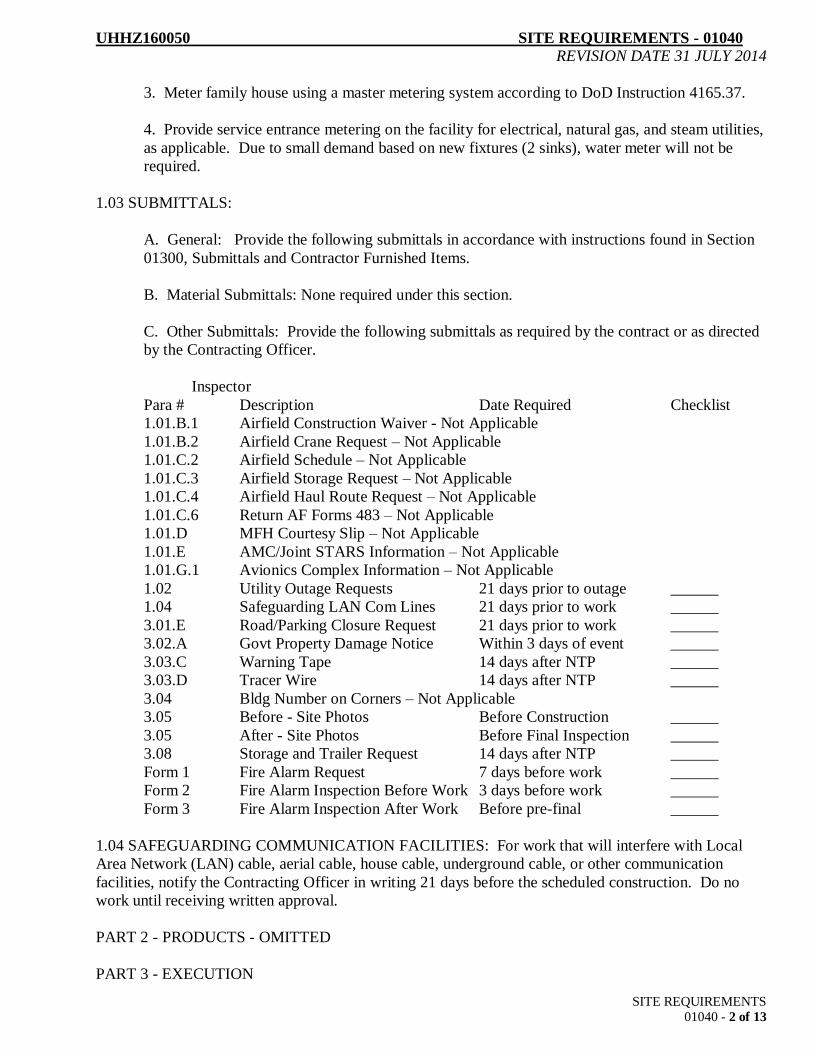
UHHZ160050 SITE REQUIREMENTS - 01040
REVISION DATE 31 JULY 2014
SITE REQUIREMENTS
01040 - 2 of 13
3. Meter family house using a master metering system according to DoD Instruction 4165.37.
4. Provide service entrance metering on the facility for electrical, natural gas, and steam utilities,
as applicable. Due to small demand based on new fixtures (2 sinks), water meter will not be
required.
1.03 SUBMITTALS:
A. General: Provide the following submittals in accordance with instructions found in Section
01300, Submittals and Contractor Furnished Items.
B. Material Submittals: None required under this section.
C. Other Submittals: Provide the following submittals as required by the contract or as directed
by the Contracting Officer.
Inspector
Para # Description Date Required Checklist
1.01.B.1 Airfield Construction Waiver - Not Applicable
1.01.B.2 Airfield Crane Request – Not Applicable
1.01.C.2 Airfield Schedule – Not Applicable
1.01.C.3 Airfield Storage Request – Not Applicable
1.01.C.4 Airfield Haul Route Request – Not Applicable
1.01.C.6 Return AF Forms 483 – Not Applicable
1.01.D MFH Courtesy Slip – Not Applicable
1.01.E AMC/Joint STARS Information – Not Applicable
1.01.G.1 Avionics Complex Information – Not Applicable
1.02 Utility Outage Requests 21 days prior to outage ______
1.04 Safeguarding LAN Com Lines 21 days prior to work ______
3.01.E Road/Parking Closure Request 21 days prior to work ______
3.02.A Govt Property Damage Notice Within 3 days of event ______
3.03.C Warning Tape 14 days after NTP ______
3.03.D Tracer Wire 14 days after NTP ______
3.04 Bldg Number on Corners – Not Applicable
3.05 Before - Site Photos Before Construction ______
3.05 After - Site Photos Before Final Inspection ______
3.08 Storage and Trailer Request 14 days after NTP ______
Form 1 Fire Alarm Request 7 days before work ______
Form 2 Fire Alarm Inspection Before Work 3 days before work ______
Form 3 Fire Alarm Inspection After Work Before pre-final ______
1.04 SAFEGUARDING COMMUNICATION FACILITIES: For work that will interfere with Local
Area Network (LAN) cable, aerial cable, house cable, underground cable, or other communication
facilities, notify the Contracting Officer in writing 21 days before the scheduled construction. Do no
work until receiving written approval.
PART 2 - PRODUCTS - OMITTED
PART 3 - EXECUTION

UHHZ160050 SITE REQUIREMENTS - 01040
REVISION DATE 31 JULY 2014
SITE REQUIREMENTS
01040 - 3 of 13
3.01 DIGGING/EXCAVATION REQUIREMENTS: The Drawings show underground utilities and
structures as presently shown on the best available record drawings of the site, and these may have some
inaccuracies. The information is provided for general bidding purposes only. Actual locations and
quantities must be determined at the site while obtaining the form below.
A. Digging/Excavation Permit (Obtained on Base): Digging permits are obtained at 0800
Monday mornings, only, in Building 1555. The Contractor, along with the technical
representative, shall meet with Civil Engineering utility personnel at this time to make all
necessary arrangements for the excavation permit before any digging. The Contractor will be
given instructions on how to prepare and properly complete Digging/Excavation Permit. This
includes coordination before beginning any work involving digging/excavation and location of
buried structures and utility lines. Before getting signatures, provide a drawing indicating the
full extent of digging/excavation (width/depth/length of trench or hole). Civil Engineering utility
personnel will meet with the Contractor at the site and locate their underground utility lines and
buried structures that might be affected by any digging/excavation. Do not do any digging until
all parties have approved the permit (three day maximum). The digging/excavation permit shall
be effective only for the time period indicated by the final signature authority.
B. Re-coordination of the Digging/Excavation Permit with all organizations and the technical
representative shall be required for any additional time required after expiration of the original
time period. No digging/excavation shall be done after l600 hours on weekdays or anytime on
weekends unless prior approval is obtained.
C. Location of Buried Structures and Utility Lines: Accurately locate and stake buried
structures and utility lines indicated.
D. Excavation, trenching, and backfilling: Excavate to the required depth by hand digging
within three (3) feet either side of the buried structures or utility line. Do not use motorized
equipment within these parameters. Only open those trenches for which material is ready for
replacement. As soon as approved by the technical representative, backfill trenches as required
by the drawings or specifications. As a minimum, replace topsoil and grass the disturbed area by
seeding and watering.
E. Damage: The contractor is responsible for any damage to underground structures and utility
lines identified on the drawings and any identified and marked in the field as a result of obtaining
the digging/excavation permit. If any underground utility is damaged, notify the technical
representative immediately.
F. Cutting of Roads, Streets, and Paved Parking Areas:
1. Mark, barricade, and illuminate construction work on or near roads or streets
which may present a traffic hazard in accordance with the Manual on Uniform Traffic Control
Devices (MUTCD) 2000. Closures of streets, parking lots, and other traffic areas will not be
permitted unless approved by the Contracting Officer after written request 30 days before the
scheduled closure.
2. Road cuts shall be backfilled immediately after completion of associated utility
work. When the road is reopened, the cut shall be filled with temporary or permanent materials

UHHZ160050 SITE REQUIREMENTS - 01040
REVISION DATE 31 JULY 2014
SITE REQUIREMENTS
01040 - 4 of 13
to a smooth condition, or metal plates or other approved methods shall be employed to prevent
discomfort or damage to vehicular traffic. Road cuts shall be permanently closed within 5
working days unless approved otherwise by the Contracting Officer. Provide advance signage
warning motorists of the condition in accordance with the MUTCD. Repair streets as shown on
the drawings.
3.02 REPAIR OF WORK AND MATERIAL: Carefully lay out cutting, channeling, chasing, or drilling
of finish or structure or other surfaces for the installation of equipment or material to avoid damaging
Government property or adjacent materials not involved in the project. If Contractor personnel or
equipment inadvertently damage such items, then follow the procedures below. Failure to follow the
notification procedures below shall be considered a serious violation of the contract.
A. Notify the Contracting Officer by telephone immediately and confirm within 3 days with a
typed letter if damage to Government property occurs. The Government reserves the right to
require the Contractor to work overtime and purchase material for repair before the end of the
workday at no additional cost to the Government.
B. Repair damage to building or equipment to match existing as directed by the Contracting
Officer with skilled workmen of the trades involved at no additional cost to the Government.
C. Repair Fire Resistant Assemblies that have been violated before the end of the day. In the
event the work is incomplete, provide fire-rated gypsum board to cover holes 2-inch and greater
in any dimension.
D. Reconnect Disconnected Equipment before the end of the day and insure that it is operating.
E. Existing Equipment and Material to remain or to be relocated is the property of the
Government. However, the Contractor is responsible for items to remain.
F. Labels on equipment plates with information shall be properly protected before any operation
that could damage or cover the label.
G. Fire Alarm: This contract involves work requiring existing fire alarm equipment either to
remain or to be removed and reinstalled. The Contractor shall comply with the requirements of
the inspection forms in the Appendix at the end of this section. One form is to notify the
appropriate personnel that work is being accomplished on fire alarm systems. The other forms
are used to establish the conditions of the system components prior to and following the
contractor’s work.
3.03 IDENTIFYING UNDERGROUND LINES AND STRUCTURES:
A. Regardless of statements in other Spec sections, provide tracer wires and warning tapes over
buried underground utilities and structures. Follow these requirements if the other Spec sections are less
detailed and stringent.
B. These include all underground items such as utility lines, oil/water separators, fuel and water
storage tanks, and utility pits and manholes with tops below grade.

UHHZ160050 SITE REQUIREMENTS - 01040
REVISION DATE 31 JULY 2014
SITE REQUIREMENTS
01040 - 5 of 13
C. Provide a warning tape of standard industrial width and thickness with imprinted words
identifying the type of utility line or structure below it. Place along the length (and width if
not a utility line) of the protected item at one-foot depth below grade.
D. For buried non-metallic lines and structures also provide a tracer wire placed just above them, so
conventional locating equipment may be used to locate the lines or structures. These items may be made
of plastic, fiberglass, or similar non-metallic material. Design basis of the tracer wire is BMS Heavy
Tracer Wire by Utilitronics, PO Box 480, Stoughton, MA 02072 - phone 1-800-245-8850. Use no less
than #12 AWG copper solid wire, 5/64” HMWPE insulation, with white color.
3.04 BUILDING NUMBER: Omitted.
3.05 SITE PHOTOGRAPHS:
A. General: Take "before" and "after" color photographs of the work site on a digital camera
with a resolution for each picture of at least 60 KB compressed image. Provide for approval on a
CD-RW/DVD disk at least 24 views chosen by the Technical Representative of the Contracting
Officer (TRCO) before construction. Provide additional views as directed to show the full extent
of the work. Provide for approval an identical set of "after" views.
B. Underground Utilities: For projects where there is trenching for any underground utilities,
even if just laterals from outside equipment into mech-elec rooms, take an additional set of as-
built photos after construction for approval before final inspection. These must cover the entire
length of the trenching with a view to showing nearby landmarks to enable a person to locate the
line in the field in the future by using the photos after the disturbed soil is no longer visible.
3.06 SITE MAINTENANCE, CLEAN UP, AND RESTORATION:
A. Maintain the work site in a neat, orderly, and safe manner. Cut grass regularly to maintain
site to base standards.
B. Remove scrap, waste, and excess materials promptly. Provide signs, barricades, and lights as
required to protect base personnel.
C. Do not allow trash and debris to accumulate and become unsightly. Sweep up and collect in
contractor-maintained disposal containers daily. Dispose of collected debris weekly as a
minimum.
D. Store materials on site in a neat and orderly manner.
E. Restore the project site to its final condition as required by the contract as soon as possible.
F. Do not open trenches or excavations until material is on-hand or scheduled to arrive within
three days. Close excavations or ditches as soon as the work has been placed, inspected, and
accepted by the Government.
3.07 CRANES, BOOM-TRUCKS, ETC.: Any tall equipment, such as a crane or boom-truck, must be
lowered when not in use, especially at the end of each work day. If used at night, then operate the
appropriate lighting at the peak element.

UHHZ160050 SITE REQUIREMENTS - 01040
REVISION DATE 31 JULY 2014
SITE REQUIREMENTS
01040 - 6 of 13
3.08 STORAGE AND OFFICE AREA: Submit a request for approval if the Contractor desires a
storage area or storage/office trailer(s) on Base. If approved, the Contractor will be allowed limited land
area to put an office and/or storage trailer and storage area, but only for this contract. The location will
be as identified by the Technical Representative within the Base perimeter.
A. Trailers: All contractor trailers must be identified with a professionally lettered and neat sign
giving the name and phone number of both the trailer rental company and the contractor.
Trailers must be in good repair and give a presentable appearance. Trailers used as Field Offices
shall be anchored with rods and cable or by steel straps to ground anchors. The anchor system
shall be designed to withstand high winds and must meet applicable state or local standards for
anchoring mobile homes. Minimum 1 each corner.
B. Items stored for the project on Base are the responsibility of the Contractor. Replace all such
items acquired for this contract that are stolen, vandalized, damaged, or otherwise unusable - at
no additional cost to the Government. The Contractor may install a temporary fence in the
manner and of the type that is acceptable to the Contracting Officer.
C. This site shall be kept clean and orderly, or the Contracting Officer may require the
Contractor to evacuate the site before the end of the contract.
3.09 PROJECT CONSTRUCTION SIGNAGE: See Robins AFB Facility Standards, Part 4B.
3.10 ROOF WARRANTY BUILDING SIGNAGE: Submit a copy for approval of the Contractor’s
proposed roof warranty building signage in accordance with example below to be mounted on corner of
building. If approved, the Contractor will install roof warranty signage at location as identified by the
Contracting Officer’s Technical Representative.
ROOF WARRANTY SIGN EXAMPLE
SIZE TO BE 8 ½” HIGH X 11” WIDE. SIGN TO BE ¼” REYNOBOND MATERIAL WITH VINYL
BACKGROUND (FEDERAL STANDARD (FED-STD) 595B COLOR, STANDARD BROWN –
10100) AND VINYL LETTERING (FED-STD 595A COLOR, WHITE - #17875). LETTERING TO
BE BLOCK STYLE, WITH ARIAL FONT.

UHHZ160050 SITE REQUIREMENTS - 01040
REVISION DATE 31 JULY 2014
SITE REQUIREMENTS
01040 - 7 of 13
<<<<< END OF SECTION >>>>>
Appendix follows:
Form 1 – Fill out and submit to get approval to work on a fire alarm system.
Form 2 – Fill out and submit to document existing conditions of a fire alarm system to be worked on.
Form 3 – Fill out and submit to document conditions of a fire alarm system after contractor work is
completed.

UHHZ160050 SITE REQUIREMENTS - 01040
REVISION DATE 31 JULY 2014
SITE REQUIREMENTS
01040 - 8 of 13
FIRE ALARM SYSTEM INSPECTION
COMPONENTS EXISTING TO REMAIN OR TO BE REMOVED AND REINSTALLED
PART 1. Prior to construction start DONE (Contractor to Initial/Date)
A. Schedule testing of all fire alarm components not scheduled for demolition (at Government's
convenience-minimum 72-hours notice required)
Person Notified (at CENME)
B. List all persons attending test:
* Fire Alarm Shop (CEOFA)
* Contractor Superintendent
Construction Management (CENME)
** Sub-Contractor Foreman
* Required Personnel
** This shall be the person(s) directly overseeing any removal and re-installation of fire alarm
equipment.
C. Inspection (CENME Inspector to check one of the following)
(All parties to initial below):
All existing components in the project area have been tested and are working properly
All components have been tested and the following are not working properly. (Specify
equipment, quantity, and location; e.g., 2 smoke detectors in northwest quadrant of Room 102.):
Acknowledgments:
CEOFA ______________ CENME _____________ Contractor ______________
Sub-Contractor ________________ Others: _________________

UHHZ160050 SITE REQUIREMENTS - 01040
REVISION DATE 31 JULY 2014
SITE REQUIREMENTS
01040 - 9 of 13
Page 1 of 2
FIRE ALARM SYSTEM INSPECTION
(COMPONENTS EXISTING TO REMAIN OR TO BE REMOVED AND REINSTALLED)
PART 2. At completion of work: DONE (Contractor to Initial/Date)
(before Prefinal inspection)
A. Schedule testing of all fire alarm components not scheduled for demolition (at Government's
convenience-minimum 72-hours notice required)
Person Notified (at CENME)
B. List all persons attending test:
* Fire Alarm Shop (CEOFA)
* Contractor Superintendent
Construction Management (CENME)
** Sub-Contractor Foreman
* Fire Department (CEXFP)
* Required Personnel
**This shall be the person(s) directly overseeing any removal and re-installation of fire alarm
equipment.
C. Inspection Results (to check by CENME Inspector all parties to initial below):
_______Passed: All components have been tested and the system has been returned to its
original condition.
NOTE: Minor failures referenced below are defined as only one or two components having been
improperly reconnected or damaged and which can be readily repaired. Any damage to wiring, conduit
or alarm panels, or more than one or two components, is a major failure on the part of the Contractor.
Failed (Minor): All components have been tested and the system has not been returned to
its original condition. The following items must be repaired, replaced, or reconnected as necessary to
restore their operation, at no additional cost to the Government, and those items retested.
UHHZ160050 SITE REQUIREMENTS - 01040
REVISION DATE 31 JULY 2014
SITE REQUIREMENTS
01040 - 10 of 13
Page 2 of 2
Failed (Major): All components have been tested and the system has not been returned to
its original condition. The following items must be repaired, replaced, or reconnected as necessary to
restore their operation, at no additional cost the Government, and those items retested.
Acknowledgments:
CEOFA ______________ CENME _____________ Contractor ______________
Sub-Contractor ________________ Others: _________________
NOTE: The contractor shall reimburse the Government for any failed (major) test at the current shop
rate (between $30.00 and $50.00) per person hour, including one (1) hour per person travel and
preparation time. This does not include the CENME Inspector. We estimate between 2 and 4 people
will be required.

UHHZ160050 SITE REQUIREMENTS - 01040
REVISION DATE 31 JULY 2014
SITE REQUIREMENTS
01040 - 11 of 13

UHHZ160050 SITE REQUIREMENTS - 01040
REVISION DATE 31 JULY 2014
SITE REQUIREMENTS
01040 - 12 of 13

UHHZ160050 SITE REQUIREMENTS - 01040
REVISION DATE 31 JULY 2014
SITE REQUIREMENTS
01040 - 13 of 13
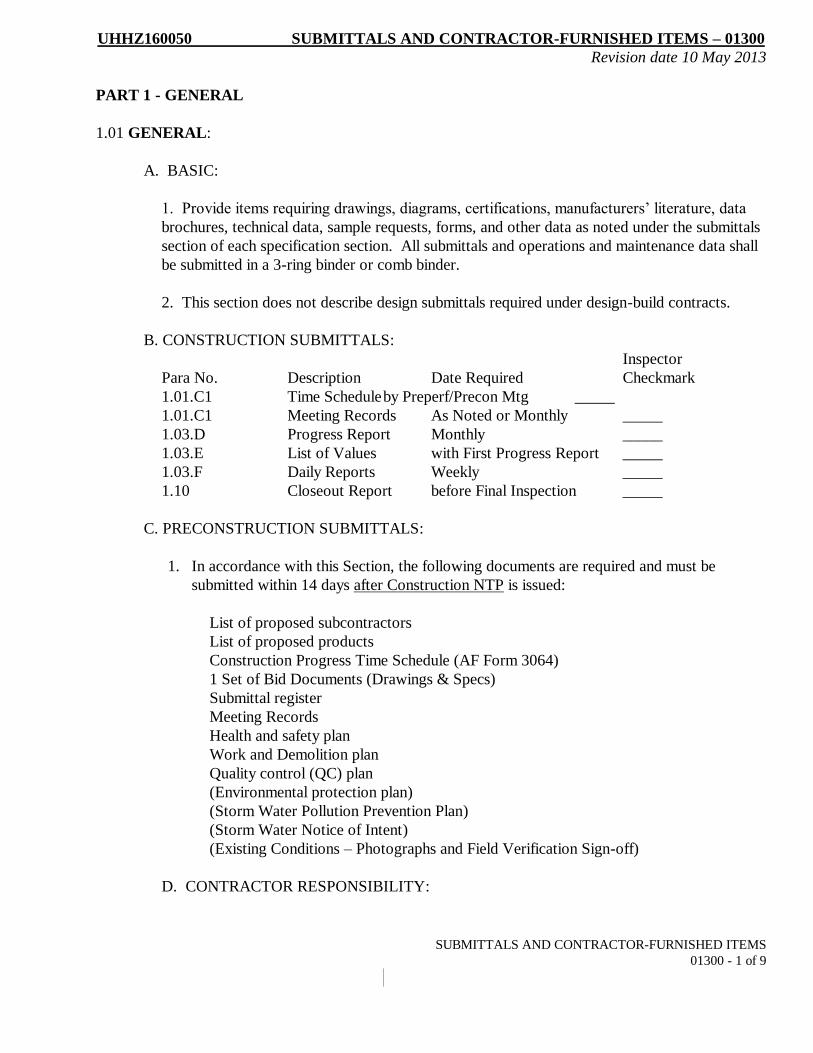
UHHZ160050 SUBMITTALS AND CONTRACTOR-FURNISHED ITEMS – 01300
Revision date 10 May 2013
SUBMITTALS AND CONTRACTOR-FURNISHED ITEMS
01300 - 1 of 9
PART 1 - GENERAL
1.01 GENERAL:
A. BASIC:
1. Provide items requiring drawings, diagrams, certifications, manufacturers’ literature, data
brochures, technical data, sample requests, forms, and other data as noted under the submittals
section of each specification section. All submittals and operations and maintenance data shall
be submitted in a 3-ring binder or comb binder.
2. This section does not describe design submittals required under design-build contracts.
B. CONSTRUCTION SUBMITTALS:
Inspector
Para No. Description Date Required Checkmark
1.01.C1 Time Schedule by Preperf/Precon Mtg _____
1.01.C1 Meeting Records As Noted or Monthly _____
1.03.D Progress Report Monthly _____
1.03.E List of Values with First Progress Report _____
1.03.F Daily Reports Weekly _____
1.10 Closeout Report before Final Inspection _____
C. PRECONSTRUCTION SUBMITTALS:
1. In accordance with this Section, the following documents are required and must be
submitted within 14 days after Construction NTP is issued:
List of proposed subcontractors
List of proposed products
Construction Progress Time Schedule (AF Form 3064)
1 Set of Bid Documents (Drawings & Specs)
Submittal register
Meeting Records
Health and safety plan
Work and Demolition plan
Quality control (QC) plan
(Environmental protection plan)
(Storm Water Pollution Prevention Plan)
(Storm Water Notice of Intent)
(Existing Conditions – Photographs and Field Verification Sign-off)
D. CONTRACTOR RESPONSIBILITY:

UHHZ160050 SUBMITTALS AND CONTRACTOR-FURNISHED ITEMS – 01300
Revision date 10 May 2013
SUBMITTALS AND CONTRACTOR-FURNISHED ITEMS
01300 - 2 of 9
1. Review, Corrections, or Comments made on the Submittals do not relieve the contractor from
compliance with the requirements of the Drawings, Specifications, Addendums, and Contract
Documents. By entering into this contract, the contractor agrees that the purpose of submittals
is to demonstrate to the contracting officer that the contractor understands the design concept
and that he demonstrates his understanding by indicating which equipment and material he
intends to furnish, install, and use. Review of shop drawing will be general only for basic
conformance with the design concept. The Government’s review of such drawings, schedules,
or cuts shall not relieve the contractor from the responsibility for correcting all errors of any
sort contained in the submittals.
2. The contractor is responsible for confirming and correlating all quantities and dimensions;
selecting proper fabrication processes, construction methods and installation techniques;
coordinating this work with that of all other trades; and performing all work in a safe,
workmanlike and satisfactory manner.
3. The Government has not stipulated dates for turning in material submittals, unless noted
elsewhere in the specifications. The contractor must manage his/her material and equipment
lead times for obtaining approval in sufficient time to complete work on schedule.
1.02 SUBMITTALS: Provide the following submittals as required by the contract or as directed
by the Contracting Officer.
Inspector
Para # Description Date Required Check Mark
1.05 A Superintendent Data As Directed ___
1.08 Equipment List 30 Days before Prefinal ___
1.03 SUBMITTAL INSTRUCTIONS: Each Specification Section lists the submittal requirements unique
to it. The following apply to all sections.
A. SUBMITTAL FORMS: Material submittals shall be made using AF Form 3000. For design-
build (DB) projects, all design submittals only require a transmittal letter. Material submittals
included with DB design packages do not require the use of the AF Form 3000, but they are
considered part of the design package.
B. MATERIAL SUBMITTALS:
1. COMPLETE SUBMISSIONS: All items requiring submittals for each section shall be
provided at one time. Partial submittals will be returned without approval. No time extensions
will be granted for failure to comply. In some instances the specifications may require certain
items from one or more specifications sections to be submitted at one time. For example,
condensing units and air handler submittals may be required to be provided together.
2. SUBMITTAL CHECKLIST: The contractor shall complete a copy of the checklist
provided in the submittals paragraph of each specification section. This checklist shall be

UHHZ160050 SUBMITTALS AND CONTRACTOR-FURNISHED ITEMS – 01300
Revision date 10 May 2013
SUBMITTALS AND CONTRACTOR-FURNISHED ITEMS
01300 - 3 of 9
provided with each submittal. Submittal information shall be arranged in order to correspond
with each checklist.
3. TIME: The Contractor shall have approved submittals before ordering any equipment
under this contract. If equipment is ordered prior to receiving approval, it will be solely at the
Contractor’s risk. Under no circumstances will material be installed prior to approval of
submittals. There will be no time schedule for providing material submittals unless noted
elsewhere in the specifications. The Contractor will be required to manage his
materials/equipment lead times and obtain approval in sufficient time to complete the work on
schedule. Disapproval of incomplete or unsatisfactory submittals shall not be grounds for
contract extensions. Other submittals such as as-builts, test reports, etc., shall be provided as
indicated.
4. MANUFACTURER’S DATA: When the specifications contain an “X” under the
“Manufacturer’s Data Required” field of the submittals paragraph checklist, then the
submission of manufacturer’s data is required. If an “X” is in the “Certificate of Compliance”
field, then it becomes the Contractor’s option to submit manufacturer’s data or a Certificate of
Compliance as detailed below.
5. EXCEPTIONS: If any material proposed for use on this contract deviates from the
specifications, the Contractor shall submit those proposed deviations for approval along with
detailed justification. All exceptions and deviations shall be described in detail with each
product submittal. Cost will not be considered a justification for taking exceptions unless a
credit is offered to the Government.
6. SUBSTITUTIONS: Products provided by manufacturers other than those specified as the
“design basis” shall be considered substitutions.
a. All features of items submitted as substitutions are implied to be in full compliance
with Specifications and Drawings if not specifically noted as "Exceptions."
b. Where a design basis is referenced in Specifications and Drawings, substitutions must
meet or exceed the salient features of the design basis as determined by the Technical
Representative of the Contracting Officer. Exceptions to design basis characteristics
must be clearly noted as "Exceptions." Note: The Federal Acquisition Regulations
place the burden of proving the substitute as equal or better on the contractor.
c. Changes required to accommodate approved substitution shall be made at no
additional cost to the Government. For example, an approved motor substitution may
require upsized electrical cable and conduit.
7. Certificate of Compliance: The Contractor may, at his option, submit a “Certificate of
Compliance” (COC) in lieu of providing manufacturer’s catalog cuts/data. Only one
COC will be required per specification section. Submit three copies of each COC
package. The COC must be signed by the contractor and either the supplier or the
UHHZ160050 SUBMITTALS AND CONTRACTOR-FURNISHED ITEMS – 01300
Revision date 10 May 2013
SUBMITTALS AND CONTRACTOR-FURNISHED ITEMS
01300 - 4 of 9
manufacturer. The COC letter is attached at the end of this specification section. The
letter must be completed in full.
C. OTHER SUBMITTALS: Other submittals such as samples, test results, spare parts, etc.,
shall be provided as required by each specification section. Provide 4 copies of each unless
directed otherwise. Upon request contractor shall provide any other submittals as required by the
COR.
D. CONSTRUCTION REPORTS
1. PROJECT TIME SCHEDULE
a. Submit a schedule for the entire contract at the Kickoff (Preperformance or
Preconstruction) Meeting, or before that meeting if so directed elsewhere in these
specifications.
(1). The schedule for the entire contract may be submitted in Microsoft
Project format if the contractor so chooses. The Government will also accept
similar sequence patterns shown in Word or Excel if they are properly developed
and displayed.
(2). If there are several projects in one contract, submit a separate
schedule for each project at the same time.
b. Include timelines for design (as applicable), mobilization, start site work,
separate timelines for each discipline and subcontractor, prefinal and final inspection
times, punchlist completion, and demobilization.
c. The contracted total allotted time and the Government's estimate for each
part of the schedule are included in the attachment to this specification.
(1). The attached schedule includes days after award for holding the Pre-
performance or Preconstruction Meeting and for one resubmittal of documents
provided by the Contractor at the meeting.
(2). No (design or) construction work may begin until the Contracting
Officer has approved the schedule.
(3). Resubmit if and as directed by the Contracting Officer. (Also, see
section 01030 if this is a design-build project.)
(4). If the approval process takes longer than the amount of days allotted,
that will not result in a time extension for the entire contract.
2. PROJECT PAY SCHEDULE

UHHZ160050 SUBMITTALS AND CONTRACTOR-FURNISHED ITEMS – 01300
Revision date 10 May 2013
SUBMITTALS AND CONTRACTOR-FURNISHED ITEMS
01300 - 5 of 9
a. Also submit at the Kickoff (Pre-performance or Pre-construction) Meeting
time schedule(s) on AF Form 3064 that show(s) the percentage completion timeline.
This establishes the pay schedule.
(1). Ensure the Form 3064 matches up with the Project Time Schedule
described above, even if that requires two or more pages of the Form 3064.
(2). Also ensure the price percentages match up with the approved price
proposal at each step on the timeline.
(3). For design-build projects, submit two separate 3064’s for design and
construction. Follow the Schedule described above for dates, and use the price
proposal to get your percentages. Invoices during construction shall show 100%
design that was paid, and the current percent complete on the construction part.
Show that the sum of design and construction subtotals adds up to the grand total
for each design-build project.
3. MEETING RECORDS:
a. Whenever the contractor meets with Government representatives to discuss
outstanding issues or details, the contractor shall prepare a written meeting record of
major decisions made and of action items, noting person responsible and date due for
each item. These will stand as accepted by the Government unless contradicted by
Government personnel who attended the meeting.
b. No decisions made constitute a contract change - the Contracting Officer
handles these in separate contract modification packages.
c. Meeting records are due by e-mail or fax to all offices represented at the
meeting by no later than two workdays after the meeting.
d. The Contracting Officer considers any resolved issues, decisions, or
identified action items to the benefit of the Contractor without these written records to
have never happened, since they were not documented and accepted by the
Government.
e. For additional record purposes, either the Contractor or the Government
may elect to audiotape the meeting.
4. PROGRESS REPORTS:
a. Prepare and submit a monthly progress report (AF Form 3065) for each
project and the entire contract on a monthly basis.

UHHZ160050 SUBMITTALS AND CONTRACTOR-FURNISHED ITEMS – 01300
Revision date 10 May 2013
SUBMITTALS AND CONTRACTOR-FURNISHED ITEMS
01300 - 6 of 9
b. Obtain coordination signature on the monthly progress reports from the
Technical Representative of the Contracting Officer (CENME Inspector) before
submitting to the Contracting Officer.
E. LIST OF VALUES: Include for approval with the first monthly progress report a breakout of
net costs for each item of work for the project. These are costs that include materials, labor,
equipment, overhead and profit, etc. to be prorated against each item. These numbers are for
use by the base to improve future estimates.
F. LOG BOOKS:
1. Keep daily logs of the activities of the prime contractor and subcontractor
employees. The logs shall include the following:
a. Date
b. Number of people on the job site and skills for each
c. List of construction equipment on the job site
d. Types of work accomplished and how much
e. Materials delivered to the job site
f. Problems and their impacts that arose with the site, the Inspector, facility
users, subcontractors, and the weather.
2. Provide a copy of this daily log (or the original) to the Technical Representative
of the Contracting Officer (CENME Inspector) weekly.
1.04 RETURN AND DISAPPROVAL OF SUBMITTALS: This is a routine project. The Contracting
Officer will return submittals made with AF Form 3000 to the Contractor within 14 days after receipt,
using the AF Form 3000 to show approval or disapproval. Resubmit revisions of disapproved submittals
within 14 days after receipt of disapproval, again using AF Form 3000. Disapproval shall not be cause
for time extension.
1.05 SUPERINTENDENT:
A. When requested, provide name and qualifications for review. Designate a competent person
who shall have full authority to act for the Contractor and who shall be the primary contact
with the Government until project acceptance. The superintendent is a non-working site
supervisor/manager who shall be on site at all times when any Contractor personnel are on
site. The “site” is defined as the location where construction work is being done. The
Government through the Contracting Officer or Technical Representative of the Contracting
Officer (CENME Inspector) reserves the right to shut down all Contractor site activities if the
superintendent is not on site at such times. Site work shall not resume until the superintendent
has returned to the site. Several violations of this requirement are cause for termination for
default.

UHHZ160050 SUBMITTALS AND CONTRACTOR-FURNISHED ITEMS – 01300
Revision date 10 May 2013
SUBMITTALS AND CONTRACTOR-FURNISHED ITEMS
01300 - 7 of 9
B. If the FAR clause requiring the formal Superintendent is not included in the contract, then the
Contractor shall have a designated work leader or foreman on site during all occasions when there are
two or more personnel on site. There shall always be “someone in charge” who has authority to act for
the Contractor at all such times, even if the person is just the most senior of the laborers on site.
1.06 TURN-IN OF IDENTIFIED EQUIPMENT, SPARE PARTS, TOOLS, AND OTHER
MATERIALS: Items in the Submittals section of each Specification Section (or elsewhere) that are
indicated for turn-in to the Government shall be delivered as directed, or at least before prefinal
inspection. Obtain receipts from Government employees receiving the materials and deliver them to the
Contracting Officer before prefinal inspection.
1.07 AS-BUILT DRAWINGS: Submit CADD as-built project drawings for approval, as detailed in
Section 01310. The Government will not make Final Payment to the Contractor until these are fully
accepted and approved.
1.08 PROVIDE EQUIPMENT LIST to Contracting Officer.
A. Indicate the make, model number, and warranty expiration date of equipment installed by
Contractor. The Technical Representative will inform the Contractor which equipment should be on list.
After the Government approves the list, complete the GSA Forms 274 obtained from Technical
Representative, and then place these labels on the equipment in the list before prefinal inspection.
B. If any of the equipment needs repair during the warranty period, prior to the expiration date,
the Contractor Officer will notify the contractor of the problem. Also, the Contracting Officer’s Technical
Representative will be notified to accompany the Contractor to the equipment. The contractor shall
provide a service ticket to the Contracting Officer and Technical Representative to indicate the corrective
action taken to remediate the problem with the equipment.
1.09 FINAL INSPECTION ONLY: If the Contracting Officer elects to have only a final inspection, turn
in prefinal inspection submittals before the final inspection.
1.10 CLOSEOUT REPORT
A. Record: Keep a record of all new equipment, facility square footage, utility runs, and items
that may be considered “real property” which are purchased and installed under the contract,
separated by project for multiple project contracts. Upon request, the Technical Representative
of the Contracting Officer (CEG Inspector) may be willing to provide any engineering records
available to assist in this effort.
B. New Items: Include the following information in this record:
1. Equipment type and description
2. Sizes and parameters (i.e. tonnage, KW, dimensions, etc.)
3. Quantities

UHHZ160050 SUBMITTALS AND CONTRACTOR-FURNISHED ITEMS – 01300
Revision date 10 May 2013
SUBMITTALS AND CONTRACTOR-FURNISHED ITEMS
01300 - 8 of 9
4. Model and Serial numbers
C. Demolished Items: Also include similar information for equipment removed, relocated to
another facility, or disposed of at Government request. Do not include like-for-like
replacements.
D. Submit for approval before Final Inspection.
<<<<< END OF SECTION >>>>>
Certificate Follows.

UHHZ160050 SUBMITTALS AND CONTRACTOR-FURNISHED ITEMS – 01300
Revision date 10 May 2013
SUBMITTALS AND CONTRACTOR-FURNISHED ITEMS
01300 - 9 of 9
MATERIALS CERTIFICATE OF COMPLIANCE
Project(s) UHHZ ___________, (Title)___________________________________________
Contract Number: ___________________
Specification Section (or Drawing) Number: __________________
Prime Contractor: __________
Sub Contractor: __________
Material Supplier: __________
Contractor Certification: I hereby certify that I and/or personnel under my direct supervision and/or
control have reviewed all proposed materials for the above contract. I further certify that the submittal
has been reviewed for completeness and accuracy and that all materials submitted will comply with the
drawings and specifications in every respect unless specifically noted as an “exception taken” on the
attached submittal checklist.
Signature: _______________________
Title: _______________________
Company:_______________________
Date: _______________________
Attachment:
Submittal Checklist for Spec or Drawing Listed Above

UHHZ160050 CADD AS-BUILT DRAWINGS - 01310
Revision date 18 February 2014
CADD AS-BUILT DRAWINGS
01310 - 1 of 5
PART 1 - GENERAL
1.01 GENERAL:
1. Basic: Submit as-built project drawings for approval at 50% construction completion stage
(hard copy), 75% construction completion stage (hard copy), and final (hard copy and electronic) as
noted below.
2. As noted in Section 01300, the Government will not make 50% construction completion
payment, 75% construction completion payment, and Pre-Final Payment to the Contractor until these
are fully accepted and approved.
1.02 SUBMITTALS: Provide the following submittals as required by the contract or as directed by the
Contracting Officer.
Inspector
Para # Description Date Required Check Mark
3.02.2. As-Built Redlines 50% completion ___
3.02.2. As-Built Redlines 75% completion ___
3.02.5.a As-Builts Redlines, Soft Copies 100% completion,
Prior to Pre-Final ___
3.02.5.7 As-Built Resubmittals As Directed ___
3.07 GIS for Facs. and Utils. By Pre-Final ___
PART 2 - PRODUCTS - OMITTED
PART 3 - EXECUTION
3.01 Contractor Receiving CADD Files:
1. CADD Files will be provided after contract award and at Contractor request to the
Contracting Officer Representative (COR), normally after the mid-point of construction to ensure any
contract modifications are shown on the final design drawings.
2. The Government will provide an electronic copy of the final design drawings and associated
files to the Contractor at that point. The electronic copies will consist of the CADD files on CD
standard format. The CADD files will be in the AutoCAD 2013 version.
3.02 Submittals:
1. Acceptance and Quality Review by Government: The Government places a high value on the
accuracy and detail provided in these as-builts. The contract shall not be considered complete until the
as-built information is approved and accepted in its entirety.
2. 50% and 75% completion Submittal (Hardcopy Only): Submit for approval at 50% and 75%
completion (with AF Form 3000) a full set of hardcopy contract drawings with “redline” changes
indicated on the drawings. The as-built hard copy shall show all red lines in red color.
a. Mark all drawings as “50% AS-BUILT” or “75% AS-BUILT” as applicable in the
revisions block of the title block area.

UHHZ160050 CADD AS-BUILT DRAWINGS - 01310
Revision date 18 February 2014
CADD AS-BUILT DRAWINGS
01310 - 2 of 5
b. If no changes to the drawings are required, submit the hardcopy drawings with "no
changes, xx% submittal" printed in large red letters on the title sheet (replace "XX" with the
percentage of the submittal).
c. Do not submit drawings with stray markings or sketches made in the field which are
not red and are not intended to convey as-built information. Do not create new drawings to
convey as-built conditions. Submit all redline information on an otherwise clean sheet of "hard
copy" contractor drawings. Reproduction of a clean set is the responsibility of the contractor.
3. The Inspector will evaluate the submittal for correctness and completeness and either approve
or disapprove them via notation on the AF Form 3000. If the submittal is disapproved, it will be
returned to the contractor, along with directions for corrections. Incorporate these corrections into the
drawings and resubmit with AF Form 3000 for approval.
4. After receipt of the Inspector’s approval and prior to updating the drawings electronically,
contact the Inspector and make contact with the As-built Coordinator for the originating design office to
discuss technical issues associated with preparing the final as-built drawings.
5. Final Inspection Set
a. Submit (with AF Form 3000) prior to Pre-Final Inspection a 11” x 17” redline as-built
drawings for approval, along with a full set of electronic drawing files (sheet files and model
files) provided by the Government per para. 3.01.2 above, modified electronically to reflect the
reflect the redline changes made on the hardcopy drawings. Accomplish all changes to the
electronic drawing files according to industry standard CADD drawing practices acceptable to
the Government. . The as-built hard copy shall show all red lines in red color.
b. Maintain the file names and naming pattern of the files as provided by the
Government.
c. Label the drawings as “Final As-built” in the revision block area of the electronic
drawings.
d. Retain the existing georeferenced model file and sheet file structure originally used to
produce the drawings to create the final drawings. Maintain the links of the reference (model)
files. For example, if the floor plan was a model file, any changes to the floor plan shall be
accomplished on the model file. If utility lines were a part of the sheet file, the changes shall be
made to the sheet file.
e. Also submit PDF format files of all drawings readable with Adobe Acrobat Reader.
Format files are to be printed at a 1:1 scale on the original size sheet (no enlargement or
reduction will be allowed for accurate plotting to the original size sheet).
6. The Inspector and As-built Coordinator will reevaluate for correctness and completeness and
then provide either approval or further directions for corrections to the Contractor.
7. Resubmit (with AF Form 3000) complete submittals as directed until the Government
provides full approval.

UHHZ160050 CADD AS-BUILT DRAWINGS - 01310
Revision date 18 February 2014
CADD AS-BUILT DRAWINGS
01310 - 3 of 5
3.03 Format:
1. Provide electronic copies of the design drawings and as-built drawings in AutoCAD 2013
version.
2. Drawing elements shall be retained in original format. Raster elements may remain raster,
and vector elements shall remain vector.
3. Make all changes in the colors and levels that match those in the original drawings that were
provided by the Government.
4. Notes shall be legible and changes shall be shown clearly indicating differences, however
minor, between actual construction and project drawings. Include corrections to underground utilities
and unforeseen site conditions discovered during performance of contract.
5. Update the indexes of the electronic files to reflect any changes.
3.04 Utility Data: Provide the following exterior utility information as “smart lines” when already on
the original drawing files. If smart lines were not used, then provide a separate file in Microsoft Word
or Excel format with the following data, as a minimum, for each segment of utility lines:
Size
Material
Depth
Date Installed (Normally to coincide with warranty date)
3.05 Accuracy of Dimensions for Site Drawings: Locate all significant exterior features and utility
lines within a one (1) foot accuracy for purposes of as-built submission, even if not changed during
construction.
1. The locating may be accomplished by traditional survey methods or by global positioning
system (GPS) satellite equipment supplemented by traditional methods where required.
2. Locations may be from existing buildings or from base monument system. Any existing
structures used as a survey reference must be checked for conformity to NAD 83 surveying coordinates.
3. Recognize that the base maps which are often the basis for the contract site plans have been
prepared from aerial photographs and as such show the roofline instead of the building structure line.
3.06 Qualified Firms for CADD and GPS Support: The Contractor may use any commercial firm or in-
house resources to accomplish the requirements. In some cases we used an Architect-Engineer (A-E)
firm to design the project, and in those cases they are noted on the Drawings and may be used if desired.
If requested, the Inspector will also provide names of other firms the Government believes should be
capable of providing the services required, based upon base personnel experience with them.
3.07 GIS Submittals for Facilities and Utilities: This project also requires data and CADD drawing info
for updating the Robins AFB GIS/Geobase data system.
UHHZ160050 CADD AS-BUILT DRAWINGS - 01310
Revision date 18 February 2014
CADD AS-BUILT DRAWINGS
01310 - 4 of 5
1. GIS Software: The Robins AFB GIS utilizes the ESRI Suite of GIS products. Deliverables to
RAFB must be compatible with ArcGIS 10.0 or newer.
2. IGDS File Format - IGDS Graphic File Format: All graphic files are to be supplied in
Autocad 2013.dwg file format. The symbology of graphic features must comply to Tri-Service Spatial
Data Specifications (TSDDS) Version 2.40.
3. Spatial Data Specification (*)
a. Coordinate System/Projection:
State Plane, Georgia West
Mapping units resolution of 1,000 UOR’s per foot
Storage Minimum Point X,Y = 0,0
b. Geodetic Vertical Datum
System: State Plane Coordinate System
Geodetic Datum: North American Datum 1983 (NAD83)
Ellipsoid: “GRS80”
c. Note that a contractor should contact 78 CEG/CENME (Joshua Winters) POC for a
copy of the 78 CEG/CENME GIS project design file that contains all the required NAD83
projection specifications.
4. Object ID Values for Attribute Tables: Contractor needs to contact the 78 CEG/CENME GIS
Coordinator to ensure that Object ID values for attribute tables do not already exist in the 78
CEG/CENME GIS.
5. Delivery Media
a. The delivery media will be on CD-ROM. The volume name on the delivery media
should match the data set name documented in the Delivery Media Metadata. The abstract
should point to the Delivery Media Metadata file.
b. The delivery media must be labeled with the following:
Volume name
Date - Record for the creation of the Data Set Contract Number and Work Order
Number
Project Name
Name of Contractor preparing the data set
c. NOTE: The TSSDS standard may be obtained by calling Bobby Carpenter at
(601)634-4572 or sending e-mail at [email protected]. The Tri-Service Commission
operates an internet web page at http://mr2wes.army.mil. For further information on 78
CEG/CENME’s implementation of the TSSDS, please contact the 78 CEG/CENME GIS
Coordinator, Joshua Winters.

UHHZ160050 CADD AS-BUILT DRAWINGS - 01310
Revision date 18 February 2014
CADD AS-BUILT DRAWINGS
01310 - 5 of 5
3.08 GIS Submittals for Environmental Systems: Omitted.
<<<<< END OF SECTION >>>>>

UHHZ160050 TEMPORARY SERVICES - CONTRACTOR - 01501
TEMPORARY SERVICES - CONTRACTOR
01501 - 1 OF 5
PART 1 - GENERAL
1.01 GENERAL: Electricity required for contractor convenience will be provided at no charge. Other
utilities will be provided as available, also at no charge. Telephone hookups are contractor responsibility.
A. These requirements are general in nature and are not intended to override safety requirements.
B. Provide all equipment required for temporary utilities (such as transformers, poles,
disconnects, etc.) hookup to base system and after final inspection remove equipment before final
acceptance.
1.02 OMITTED:
1.03 SUBMITTALS:
A. General: Provide the following submittals in accordance with instructions found in Section
01300, Submittals and Contractor Furnished Items. The contractor may submit manufacturer’s
data in lieu of the required certificate of compliance if he desires. The Government requires
manufacturer data if an “X” appears under the “Mfg. Data Required” column.
B. Material Submittals: Omitted.
C. Other Submittals: Provide the following submittals as required by the contract or as directed
by the Contracting Officer.
Inspector
Para# Description Date Required
Checklist
1.04 A Temp HVAC Shop Drwgs 14 days prior ___
1.04 B.1 Temp Elect Shop Drwgs 14 days prior ___
1.04 B.2 Notification of Need before start of work ___
1.04 B.3 Notification of Installation 15 days prior ___
1.04 B.4 Notification of Removal 15 days prior ___
1.04 REQUIRED INFORMAITON:
A. Heating and Ventilating: The contractor shall submit shop drawings for approval indicating
the methods and equipment to be used to maintain the space temperature.
B. Electrical:
1. Shop Drawing of Temporary Service Entrance: The routing, point of connection, size
of pipe(s), and method of support for the temporary service mast shall be submitted for
approval before installation.
2. Notification of Need: Contractor shall submit typed letter to indicate the need for
Government furnished electrical hook-up to his service before work begins.
UHHZ160050 TEMPORARY SERVICES - CONTRACTOR - 01501
TEMPORARY SERVICES - CONTRACTOR
01501 - 2 OF 5
3. Notification of Installation: Contractor shall notify the Contracting Officer fifteen (15)
days before electrical hook-up of Service. The pole shall be set before notification.
4. Notification of Removal: Contractor shall notify the Contracting Officer fifteen (15)
days before electrical disconnection of Service. The Service shall be removed before final
inspection.
PART 2 - PRODUCTS - Omitted
PART 3 - EXECUTION
3.01 DOMESTIC WATER:
A. General: Where required for the convenience of the contractor or as required to maintain
continued occupancy of the work area, the contractor shall provide temporary water service of
adequate capacity. At all points of tie-in to existing lines, the contractor shall provide a cut-off
valve to isolate temporary lines from existing.
B. Insulation: Where temporary water service lines are exposed to the weather, they shall be
insulated to prevent freezing from 1 November through 31 March.
C. Disinfection: Where temporary lines will be used for drinking water, they shall be flushed and
disinfected before being placed into service.
D. Removal: All temporary water lines shall be removed before final inspection. The shut-off
valve at the point of tie-in to the existing line shall remain unless indicated otherwise. Provide a
six (6) inch section of pipe on the downstream side of valve and cap.
E. Temporary Restrooms: Where construction work renders existing restrooms unusable and
alternate facilities are not within a reasonable distance as determined by the Contracting Officer,
the Contractor shall provide a minimum of one portable toilet for each 15 people of each sex. As
a minimum, one toilet shall be provided for each sex. Temporary facilities shall be maintained by
the Contractor and located where directed by the Contracting Officer.
3.02 HEATING AND VENTILATING:
A. General: Where temperature control is necessary for the contractor's comfort, the contractor
may provide temporary heating and/or air conditioning
B. Utilities: All utilities available on the site such as chilled water, steam, and electricity may be
used by the contractor in conjunction with temporary heating and/or air conditioning equipment.
C. Removal of Temporary Equipment: Before final acceptance, the contractor shall remove all
equipment used to provide temporary heating and/or air conditioning.
3.03 ELECTRICAL SERVICE:

UHHZ160050 TEMPORARY SERVICES - CONTRACTOR - 01501
TEMPORARY SERVICES - CONTRACTOR
01501 - 3 OF 5
A. Pole: Contractor shall set a pole with rigid steel mast feeding a panelboard with a NEMA 3R
or 4X enclosure. The pole and mast shall be set in accordance with Article 230 of National
Electrical Code(NEC).
B. Locks: The Service panelboard provided by the contractor shall be locked at all times when
work is not being accomplished at job site. In all cases when the service is locked, the main
breaker shall be turned off.
C. Shut-off: The existing panelboard which is used to feed the temporary circuits may require
installation of necessary breakers at no additional cost to the Government. The contractor shall
turn off each breaker feeding a temporary circuit connected when he is not at the work site.
1. Label: A piece of red tape shall be placed on each of the contractor's circuits when
they are turned off. A notice shall be mounted within one (1) foot of panelboard stating
correct operating procedure (turn breakers off when not in use) and warnings
(Government personnel should not turn on breaker no.'s with red tape on them.)
D. Clearance: All temporary branch circuits not in conduit shall be mounted at least 10' AFF.
E. Remote disconnects: In each room with some type of divider between the temporary service
and location of outlets, provide a separate disconnect. This disconnect shall be visible and
mounted approximately 4' AFF. Disconnect shall be of the safety switch type. Disconnects shall
be lockable in the off position.
1. Shut-off: The remote disconnect shall be turned to "off" position when circuits are not
in use.
2. Label: The disconnect shall be painted in stripes 1-1/2" wide running diagonally at a
30-degree angle from left lower corner to right upper corner. Stripes shall be alternate
colors of red, yellow, and black.
F. Feeders shall be protected by approved overcurrent devices (fuses or circuit breakers) and
originate from approved distribution centers. Overcurrent protection devices and connection shall
be enclosed in approved cabinets or boxes. Provide a readily accessible, manually operated switch
for each incoming supply circuit.
3.04 WIRING:
A. Rules: Wiring shall conform to NEC Article 305, and the following:
1. Wiring passing through work areas shall be covered or elevated to protect it from
damage which would create a hazard to employees. Worn or frayed electric cables shall
not be used. Wiring shall be fastened at ceiling height or 8-feet, whichever is higher, every
10 ft. No conductor shall be laid on the floor.
B. Branch circuits shall originate in a standard power outlet, disconnect, or panelboard.
Conductors shall be permitted within multiconductor cord and cable assemblies (no open
conductors may be used). All conductors shall be protected by overcurrent devices at their
ampacity per NEC 310-16.

UHHZ160050 TEMPORARY SERVICES - CONTRACTOR - 01501
TEMPORARY SERVICES - CONTRACTOR
01501 - 4 OF 5
C. Extension Cords: The use of a number of short extension cords to reach the power source is
not acceptable. A single extension cord should be used in all cases. Flexible extension cords shall
be of the hard usage (SF, SJO, SJT, and SJTO) or extra-hard usage (S, SO, SJ and STO) types
and listed by Underwriters Laboratories. The size shall not be less than #14 AWG, and length
shall be 50 ft or less. Protect them against accidental damage caused by traffic, sharp corners,
projections, and pinching in doors or elsewhere. They shall not be fastened with staples, hung
from nails, or suspended by wire.
D. Splices do not have to be in a junction box. Splice using wire caps. The wire caps shall be
offset from one another, and cables assembled compressed with a layer of plastic tape applied
continuously with 30% overlap from one end of spliced area to the other.
3.05 OUTLETS:
A. 15- and 20-ampere attachment plugs and connectors shall be constructed so that there are no
current-carrying parts except the prongs, blades, or pins. The cover for wire terminations shall be
mechanically secured or an integral part of the attachment plug or connector. Plugs and
receptacles shall have the proper NEMA configuration (such as 5-15R) for the voltage, phase,
and amperage ratings for which they will be used. Receptacles should be marked to show
operating voltage. Plugs and receptacles shall not be interchangeable between circuits with
different voltage and current ratings. No dual voltage receptacles or attachment plugs shall be
used. All receptacles shall be of an approved grounding type, grounded by connection to a
separate grounding conductor.
B. Attachment plugs for use in work areas shall be so constructed that they will endure rough use
and be equipped with a suitable cord grip to prevent strain on the terminal screws. Attachment
plugs or other connectors supplying equipment at more than 300 volts shall be of the skirted type
or otherwise so designed to confine the arcs.
3.06 LIGHTING:
A. Temporary lights shall be equipped with heavy-duty electric cords with connections and
insulation maintained in safe condition. Temporary lights shall not be suspended by their electric
cords unless cords and lights are so designed. Temporary festoon lighting strings shall be made
with cords having lamp sockets and connections protected by insulating coverings. Handlamps of
the portable type shall be of the molded composition or other type approved for the purpose.
Brass-shell paper-lined lampholders shall not be used. Temporary lighting shall be connected to a
ground fault interrrupter outlet. A ground wire shall be provided for all temporary lighting
circuits unless there are no exposed metal parts of the lighting fixture.
B. Special: Lighting on barricades, fences, or sidewalk coverings shall be encased in metal
raceway.
C. Guards: Temporary lights shall be equipped with guards to prevent accidental contact with
the bulb. Guards are not required when the reflector construction has a deeply recessed bulb.
Handlamps shall be equipped with a handle and a substantial guard over the bulb attached to the
handholder or the handle. Do not use exposed empty light sockets and broken bulbs.

UHHZ160050 TEMPORARY SERVICES - CONTRACTOR - 01501
TEMPORARY SERVICES - CONTRACTOR
01501 - 5 OF 5
D. Lighting Levels: Temporary lighting systems which are installed to provide illumination
during construction work shall furnish sufficient illumination for safe working conditions. Special
attention should be given to illumination at stairways, ladders, floor openings, basements and
other hazardous locations.
<<<<<END OF SECTION>>>>>

UHHZ160050 TEMPORARY UTILITIES AND SERVICES
FOR CONTINUED OCCUPANCY – 01502
TEMPORARY UTILITIES AND SERVICES FOR CONTINUED OCCUPANCY
01502 - 1 of 2
PART 1 - GENERAL
1.01 GENERAL
A. The contractor shall provide temporary utilities and services, as required, to maintain
continued occupancy in the building during construction at no additional cost to the Government.
B. Temporary utilities shall include lighting, heating, air conditioning, electrical power, domestic
water, waste, and any other service normally available in the occupied area(s) that will be
disconnected to allow the contractor's work to proceed.
C. Temporary utilities shall not be required where the interruptions to normal service are limited
to times the building will be unoccupied.
D. Utilities: All utilities available at the site such as steam, electricity, and chilled water may be
used by the contractor in conjunction with his temporary services.
PART 2 PRODUCTS - OMITTED
PART 3 EXECUTION
3.01 DOMESTIC WATER:
A. Required when service will be interrupted for over 4 hours in more than (25%) of the building.
3.02 HEATING/AIR CONDITIONING:
A. General: Temporary heating shall be provided from 1 October to 31 March. Temporary air
conditioning shall be provided from 1 April to 30 September.
B. Heating shall be provided to maintain 65 degrees F in administrative areas and 55 degrees F in
shop areas.
C. Air conditioning is required only within administrative areas. Temperature shall not exceed 85
degrees F in any location.
D. Shop Drawings: The contractor shall submit shop drawings for approval indicating the
methods and equipment to be used to maintain the space temperature within limits, points of
connection, size of pipe(s) and method of support.
E. Removal of temporary equipment: At the completion of the contract or when permanent
equipment is made functional the contractor shall remove all temporary equipment. Pipe
connections shall be terminated as close to tie-in as practical with a valve, six (6) inch section of
pipe and cap. Show on as-builts.
3.03 ELECTRICAL SERVICES

UHHZ160050 TEMPORARY UTILITIES AND SERVICES
FOR CONTINUED OCCUPANCY – 01502
TEMPORARY UTILITIES AND SERVICES FOR CONTINUED OCCUPANCY
01502 - 2 of 2
A. Temporary service shall be required prior to the disconnection of existing service to any area
occupied by Government personnel.
<<<<<END OF SECTION>>>>>

UHHZ160050 GREEN PROCUREMENT - 01540
GREEN PROCUREMENT
01540 - Page 1 of 12
PART 1 GENERAL
1.1 GREEN PROCUREMENT & POLLUTION PREVENTION
Green Procurement is a mandatory component of the Air Force pollution prevention program. The
AF Installation Pollution Prevention Program Guide includes this goal for Green Procurement: "100%
of all products purchased each year in each of U.S. EPA's 'Guideline Item' categories shall contain
recycled materials meeting U.S. EPA's Guideline Criteria." Currently, reporting of green procurement
purchases is limited to contracts having a total value greater than $100,000 which include the
purchase of any amount of U.S. EPA-designated items. This document contains guidelines for
implementing the RCRA, EO, DOD, and Air Force requirements.
1.2 AUTHORITY AND REFERENCES
A. The Resource Conservation and Recovery Act (RCRA), Section 6002 (42 U.S.C. 6962)
B. The Farm Security and Rural Investment Act (FSRIA), Section 9002 (7 U.S.C. 8102)
C. Executive Order (EO) 13423, Strengthening Federal Environmental, Energy, and
Transportation Management.
D. Title 40, Code of Federal Regulations (CFR), Part 247, Comprehensive Procurement
Guideline for Products containing Recovered Material.
E. Title 7, Code of Federal Regulations (CFR), Part 2902, Guidelines for Designating
Biobased Products for Federal Procurement.
F. Federal Acquisition Regulations (FAR)
1.3 SUBMITTALS
Government approval is required for submittals with a "GA" designation. Submittals having an "FIO"
designation are For Information Only. The following shall be submitted in accordance with Section
01300 SUBMITTAL PROCEDURES:
SD-01 Data
Product Data; GA|CD
The Contractor shall submit manufacturer's material specifications, installation instructions, physical
characteristics, etc, to show that the product meets project and specification requirements.
SD-13 Certificates
Product Certificates; GA|CD
The Contractor shall submit documentation certifying that products meet or exceed the specified
requirements.

UHHZ160050 GREEN PROCUREMENT - 01540
GREEN PROCUREMENT
01540 - Page 2 of 12
SD-14 Samples
Product Samples; GA|CD
The Contractor shall submit samples of the product intended for use for project record.
1.4 DEFINITIONS
A. GREEN PROCUREMENT: The purchase of environmentally preferable products
manufactured from recycled, reclaimed, and/or biobased materials.
B. ACQUISITION: The acquiring by contract with appropriated funds for supplies or services
(including construction) by and for the use of the Federal Government through purchase or
lease, whether the supplies or services are already in existence or must be created,
developed, demonstrated, and evaluated. Acquisition begins at the point when agency needs
are established and includes the description of requirements to satisfy agency needs,
solicitation and selection of sources, award of contracts, contract financing, contract
performance, contract administration, and those technical and management functions
directly related to the process of fulfilling agency needs by contract.
C. Biobased Products: As defined by FSRIA, "biobased products" are products determined by
the U.S. Secretary of Agriculture to be commercial or industrial goods (other than food or
feed) composed in whole or in significant part of biological products, forestry materials, or
renewable domestic agricultural materials, including plant, animal, or marine materials.
Made from renewable plant and animal sources, biobased products are generally safer for
the environment than their petroleum-based counterparts. They are usually biodegradable or
recyclable.
D. CONTRACTOR: The prime contractor, subcontractors, material suppliers, and equipment
suppliers who provide the products that will be used in the construction of this project.
E. ENVIRONMENTALLY PREFERABLE: Products or services having a lesser or reduced
effect on human health and the environment when compared to competing products or
services, serving the same purpose. This comparison may consider raw materials
acquisition, production, manufacturing, packing, distribution, reuse, operation,
maintenance, or product or service disposal. (Section 201, EO 12873)
F. EPA DESIGNATED ITEM: An item that is or can be made with recovered material; that is
listed by the Environmental Protection Agency (EPA) in a procurement guideline (40CFR,
part 427); and for which EPA has advised purchasing recommendations in a related
Recovered materials Advisory Notice (RMAN). (FAR 23.402)
G. EXECUTIVE AGENCT OR AGENCY: An executive agency as defined in 5 U.S.C. 105.
For the purpose of this order, military departments, as defined in 5 U.S.C. 102 are covered
under the auspices of the Department of Defense.
H. FORM: The Green Procurement Reporting Form found at the end of this section.

UHHZ160050 GREEN PROCUREMENT - 01540
GREEN PROCUREMENT
01540 - Page 3 of 12
I. POLLUTION PREVENTION: Source reduction as defined in the Pollution Prevention Act of
1990 (42 U.S.C. 13102), and other practices that reduce or eliminate the creation of
pollutants through (a) increased efficiency in the use of raw materials, energy, water, or
other resources; or (b) protection of natural resources by conservation.
J. POSTCONSUMER MATERIAL: A material or finished product that has served its intended
use and has been discarded for disposal or recovery, having completed its life as a
consumer item. "Post-consumer material" is a part of the broader category of "recovered
material".
K. PROCUREMENT: The purchase and providing of products to be used in the construction of
this project.
L. PRODUCT: Materials and equipment that will be used in the construction of this project.
M. RECOVERED MATERIALS: Waste materials and by-products which have been recovered
or diverted from solid waste, but such term does not include those materials and by-
products generated from, and commonly reused within, an original manufacturing process.
(Section 205, EO 12873 and FAR 23.402)
N. RECYCLABILITY: The ability of a product or material to be recovered from or otherwise
diverted from the solid waste stream for the purpose of recycling. (Section 206, EO 12873)
O. RECYCLING: The series of activities, including collection, separation, and processing by
which products or other materials are recovered from the solid waste steam for use in form
of raw materials in the manufacture of new products other than fuel for producing heat or
power by combustion. (Section 207, EO 12873)
P. RECYCLED MATERIAL: A material utilized in place of raw or virgin material in product
manufacturing consisting of materials derived from post-consumer waste, industrial scrap,
material derived from agricultural wastes, and other items, all of which can be used in new
product manufacturer. (EPA Guidelines & OFPP Policy Letter 92-4)
Q. RECYCLED PRODUCT: A recycled product is one made completely or partially from
waste materials or by-products recovered or diverted from the solid waste stream.
R. SOLID WASTE: Garbage, refuse, sludges and other discarded materials including those
from industrial, commercial, and agricultural operations, and from community activities.
This excludes solids or dissolved materials in domestic sewage or other significant
pollutants in water resources, such as silt, dissolved or suspended solids in industrial waste
water effluents, dissolved materials in irrigation return flow, etc. (EPA Guidelines)
S. SPECIFICATION(S): A clear and accurate description of the technical requirements for
materials, products, or services including the minimum requirement for materials' quality
and construction and any equipment necessary for an acceptable product. In general,
specifications are in the form of written descriptions, drawings, prints, commercial
designations, industry standards, and other descriptive references.

UHHZ160050 GREEN PROCUREMENT - 01540
GREEN PROCUREMENT
01540 - Page 4 of 12
T. UNREASONABLE PRICE: If the cost of the recycled content product exceeds the cost of a
non-recycled item, the Air Force considers the cost to be unreasonable. (Air Force Green
Procurement Plan)
U. VERIFICATION: Procedures used by procuring agencies to confirm both vendor estimates
and certifications of the percentages of recovered materials contained in the products
supplied to them or to be used in the performance of a contract. (EPA Guidelines)
V. WASTE PREVENTION: Any change in the design, manufacturing, purchase, or use of
materials or products (including packaging) to reduce their amount or toxicity before they
are discarded. Waste prevention also refers to the reuse of products or materials.
W. WASTE REDUCTION: Preventing or decreasing the amount of waste being generated
through waste prevention, recycling, or purchasing recycled and environmentally preferable
products.
1.5 REGULATORY BACKGROUND
Section 6002 of RCRA requires federal agencies to give preference in the acquisition process to
products and practices that conserve and protect natural resources and the environment. EO 12873
requires federal agencies to expand waste prevention and recycling programs, implement green
procurement programs for the United States Environmental Protection Agency (EPA) -designated
items, and procure other environmentally preferable products and services. The stated purpose of the
Green Procurement Program is to stimulate the market for recovered materials. As a result of EO
12873, the EPA issued the Comprehensive Procurement Guidelines (CPGs) that have established the
mandatory procurement by federal agencies of 36 items produced with recovered materials. The EPA
has also issued Recovered Material Advisor Notices (RMANs) to accompany the CPGs and provide
detailed information on the designated items. Section 9002 of The Farm Security and Rural
Investment Act (FSRIA) was signed into law in 2002. A goal of that legislation is to increase the
government’s purchase and use of biobased products. In addition to lessening our national
dependence on foreign oil, use of biobased materials promotes economic development by creating
new jobs in rural communities and providing new markets for farm commodities. Please direct all
questions regarding the plan to the Contracting Officer's Representative for forwarding to the 78
CEG/CEV Environmental Division, 478-327-4173.
1.6 APPLICABILITY
These procedures apply to Contractors employed in the construction of projects at Robins AFB,
GA. For additional information on GPP, visit the following website, http://afenvsymp.ecatts.com/start.
You will have to register first using the following registration password: symposium. Please direct all
questions regarding the plan to the Contracting Officer's Representative for forwarding to the 78
CEG/CEIEC Environmental division, 478-327-4173.
1.7 DOD AND AIR FORCE REQUIREMENTS
Green Procurement programs are required of all Air Force (USAF) installations. Department of
Defense (DOD) Instruction 4715.4, Pollution Prevention, calls for program establishment in

UHHZ160050 GREEN PROCUREMENT - 01540
GREEN PROCUREMENT
01540 - Page 5 of 12
accordance with RCRA, EO 13423, and EO 12873. Green Procurement is also addressed in Air Force
Instruction (AFI) 32-7080, Pollution Prevention Program, and the 24 July 1995 Air Force Pollution
Prevention Strategy. The Strategy sets program goals, and the AFI provides program guidance.
1.8 EXEMPTIONS
1.8.1 EPA Recommendations
The U.S. EPA recommends minimum content levels for those items listed in the attached GREEN
PROCUREMENT REPORTING FORM. These levels are mandatory for Air Force procurements
unless one of the following exemptions applies. RCRA provides the following exemptions from the
requirement to purchase EPA-designated items:
1. The product is not available from a sufficient number of sources to maintain a satisfactory
level of competition (i.e., available from two or more sources).
2. The product is not available within a reasonable period of time.
3. The product does not meet the performance standards in applicable specifications or fails to
meet reasonable performance standards of the procuring agency.
4. The product is not available at a reasonable price. For Air Force purposes, "unreasonable
price" is defined as follows: If the price of the recycled-content product exceeds the cost of
a non-recycled item, then the price is considered unreasonable.
1.8.2 Contractor Responsibility
The Contractor is responsible for completion of the Form with respect to the work and products being
provided. The Prime Contractor is responsible for insuring that all sub-contractors comply with this
order. Each contractor shall provide written documentation to support his/her decision not to acquire
items meeting the minimum content levels. This documentation shall be forwarded to the Contracting
Officer for review and approval. In the event the documentation fails to support the contractor's
findings, the Contracting Officer's Representative shall return the documentation to the Contractor
citing the reason(s) for disapproval. The Contractor shall resubmit and address the deficiencies.
1.9 U.S. EPA DESIGNATED ITEMS
The 54 U.S. EPA-designated items are listed below. Not all of these materials may be required in
the construction of this project. Please refer to the drawings and specifications. The attached
GREEN PROCUREMENT REPORTING FORM shall be used to demonstrate compliance with the
stated procurement requirements.
PAPER PRODUCTS
1. All paper and paper products, excluding building and construction paper grades.
VEHICULAR PRODUCTS

UHHZ160050 GREEN PROCUREMENT - 01540
GREEN PROCUREMENT
01540 - Page 6 of 12
2. Lubricating oils containing re-refined oil, including engine lubricating oils, hydraulic fluids,
diesel fuel additives, and gear oils, but excluding marine and aviation oils.
3. Tires, excluding airplane tires.
4. Reclaimed engine coolants, excluding coolants used in non-vehicular applications
CONSTRUCTION PRODUCTS
5. Building insulation products.
6. Structural fiberboard products for applications other than building insulation.
7. Laminated paperboard products for applications other than building insulation.
8. Cement and concrete, including products such as pipe and block, containing fly ash.
9. Cement and concrete, including concrete products such as pipe and block, containing ground-
granulated blast furnace (GGBF) slag.
10. Carpet made of polyester fiber for use in low- and medium-wear applications.
11. Floor tiles containing recovered rubber or plastic.
12. Patio blocks containing recovered rubber or plastic.
25. Shower and restroom dividers/partitions containing recovered steel or plastic.
26. Reprocessed and consolidated latex paint for specific uses.
37. Carpet cushion.
38. Flowable fill.
39. Railroad grade crossing surfaces.
TRANSPORTATION PRODUCTS
13. Traffic barricades used in controlling or restricting vehicular traffic.
14. Traffic cones used in controlling or restricting vehicular traffic.
27. Parking stops.
28. Channelizers used as temporary traffic control devices.
29. Delineators used as temporary traffic control devices.
30. Flexible delineators used as temporary traffic control devices.
PARK AND RECREATION PRODUCTS
15. Playground surfaces containing recovered rubber or plastic.
16. Running tracks containing recovered rubber or plastic.
31. Plastic fencing.
40. Park benches and picnic tables.
41. Playground equipment.
LANDSCAPING PRODUCTS
17. Hydraulic mulch products containing recovered paper or recovered wood.
18. Compost made from yard trimmings, leaves, and/or grass clippings.
32. Garden and soaker hoses containing recovered rubber or plastic.
33. Lawn and garden edging containing recovered rubber or plastic.
42. Food waste compost.
43. Plastic lumber landscaping timbers and posts.

UHHZ160050 GREEN PROCUREMENT - 01540
GREEN PROCUREMENT
01540 - Page 7 of 12
NON-PAPER OFFICE PRODUCTS
19. Office recycling containers.
20. Office waste receptacles.
16. Plastic desktop accessories.
22. Toner cartridges.
23. Binders.
24. Plastic trash bags.
34. Printer ribbons (re-inked ribbons or re-inking equipment/service for ribbons).
35. Plastic envelopes.
44. Solid plastic binders.
45. Plastic clipboards.
46. Plastic file folders.
47. Plastic clip portfolios.
48. Plastic presentation folders.
MISCELLANEOUS PRODUCTS
36. Pallets
49. Sorbents.
50. Industrial drums.
51. Awards and plaques.
52. Mats.
53. Signage, including sign supports and posts.
54. Manual-grade strapping.
55. Water Tank Coatings.
1.10 INTENT
The intent of this section is to increase the awareness of all Contractors as to the availability of
products manufactured from, or that contain recycled and/or biobased materials, thereby increasing
the use of these products in the construction of this project.
The various sections of the specifications contain references to products to be used in the construction
of this project. The listed product may or may not be manufactured from or contain recycled or bio-
based materials. Therefore, all contractors, subcontractors, equipment suppliers, and material
suppliers are responsible for compliance with this specification; particularly the paragraph entitled
DOD AND AIR FORCE REQUIREMENTS and those items/products listed on the GREEN
PROCUREMENT REPORTING Form. Recycled and/or biobased products shall be used wherever
possible subject to the exemptions as per the paragraph entitled EXEMPTIONS. Substitution of
recycled/biobased materials or recycled/biobased products for specified products are subject to the
provisions of the paragraph entitled SUBMITTALS.
1.11 RECYCLED OR RECOVERED PRODUCTS
Those construction materials identified on the Form at the end of this section.

UHHZ160050 GREEN PROCUREMENT - 01540
GREEN PROCUREMENT
01540 - Page 8 of 12
1.12 QUALITY ASSURANCE
Companies specializing in the manufacture of products that comply with the requirements of this
section shall have a minimum of three (3) years documented experience.
PART 2 PRODUCTS
2.1 PARTIAL LIST OF PRODUCT SOURCES & INFORMATION
The following is a partial list of companies that manufacturer products using recycled/biobased
materials. This partial list is presented to establish a standard of quality and does not infer that other
manufacturers do not qualify. All products intended for use on this project, whether listed below or
not, shall be submitted to the Contracting Officer's Representative.
GENERAL DATA
1. GreenSpec Binder, Environmental Building News, www.ebuild.com
2. Certified Forest Products Council, www.cerifiedwood.org/
3. Wiley Series in Sustainable Design, www.wiley.com/
4. The Carpet and Rug Institute, www.carpet-rug.com/
5. Information, McGraw-Hill, [email protected]
6. Florida Directory of Recycled Product Vendors,
www.2.dep.state.fl.us/waste/programs/rbac/downloads/rbac_dir.pd
7. Oikos Green Building Source, News, searchable products data base, library, www.oikos.com
8. Green Design Network, News, publications, databases, www.greendesign.net
9. Green Works Recycled Content7 Product Guide, detailed vendors directory,
www.metrokc.gov/greenworks/recycontent.htm
DIVISION 3 - CONCRETE
1. GranCem, granulated blast-furnace slag, www.grancem.com/
2. Syndesis, cement-based, pre-cast product workable with wood tools, www.syndesisinc.com/
DIVISION 4 - MASONRY
1. Heble Building Systems, autoclaved aerated concrete blocks, www.heble.com/
2. Ytong Florida Ltd., autoclaved aerated concrete blocks, www.ytong-usa.com/
DIVISION 6 - CARPENTRY
1. Avonite, solid surfacing, www.avonite.com/
2. Chemical Specialties, wood treatment, www.treatedwood.com/
3. Homasote Company, structural fiberboard, www.homasote.com/
4. Isoboard, fiberboard composed of straw fibers and non-toxic resins, www.isoboard.com/
5. TrusJoist Mac Millan, engineered wood products, www.homasote.com/
DIVISION 7 - THERMAL & MOSITURE PROTECTION

UHHZ160050 GREEN PROCUREMENT - 01540
GREEN PROCUREMENT
01540 - Page 9 of 12
1. Duro-Last Roofing, recycled PVC walkway pads, 1-800-248-0280
2. Johns Manville, Insulation products, www.jm.com/
3. Majestic Skylines, rubber-based slate-look roofing for steep roofs,
www.majesticskylines.com/
4. Owens-Corning, insulation products, www.owenscorning.com/
DIVISION 8 - DOORS & WINDOWS
1. Marvin Window & Door, windows, some meeting "Energy Star Label", www.marvin.com/
2. Pella, energy efficient windows, www/pella.com/
DIVISION 9 - FINISHES
1. Armstrong World Industries, Inc.-Flooring Systems, www.armstrong-floors.com/
2. Armstrong World Industries, Inc.-Ceiling Systems, www.ceilings.com/
3. Benjamin Moore & Co., VOC free acrylic interior latex paint, www.benjaminmoore.com/
4. CanFibre Group Ltd., all-green medium-density fiberboard, www.canfibre.com
5. Chemrex Inc., low-e interior paint, www.chemrex.com/
6. Collins & Aikman Floor coverings, carpet with 100% post-consumer backing,
www.powerbond.com/
7. DesignTex, Inc., polyester panel fabric made from 100% PET fiber, www.dtex.com/
8. Dodge-Regupol, Inc., 100% recycled rubber-flooring, www.regupol.com/
9. Eco-sensitive modular tile, vinyl tile with 100% recycled carpet-backing,
www.powerbond.com/
10. Environmental Stone Products, stone manufactured from 100% recycled glass,
www.environmentalstone.com/
11. Glidden: residential interior latex paints 100% free of VOC, www.icipaintstores.com/
12. Homasote Inc., sound barrier, www.homasote.com/
13. Isoboard Enterprises, Inc. panel made from wheat straw and non-toxic resins, 1-503-242-
7345
14. Marley-Flexco Co., flooring made form 95% recycled truck and bus tires,
www.marleyflexco.com/
15. The Mat Factory, Inc., interlocking roll-up tiles made from 100% postconsumer tire rubber
and PVC plastic from electric cable covers, 1-949-645-3122
16. Permafirm Pad Co., carpet pads made from almost 100% recycled content, 1-800-344-6977
17. Sherwin Williams, VOC compliant paints and enamels, www.sherwin.com/
18. SierraPine Limited, formaldehyde-free particleboard and medium density fiberboard
containing recycled/recovered wood fiber, www.sierrapine.com/
19. Summittville Tiles, impervious porcelain tiles using feldspar tailings,
www.summitville.com/
20. Tectum, natural-fiber acoustical ceiling and wall panels, www.tectum.com/
21. Tiles with natural fibers, tiles made of a bio-alloy material and natural fibers,
www.maderatile.com
22. USG Interiors, Inc., synthetic gypsum board, www.usg.com/
23. Decorative Architectural Tiles, floor, counter & wall tile made from 100 % postconsumer
glass, 1-808-8857812
24. Forbo, linoleum flooring utilizing renewable resources, www.forbo.com/

UHHZ160050 GREEN PROCUREMENT - 01540
GREEN PROCUREMENT
01540 - Page 10 of 12
DIVISION 10 - SPECIALTIES
1. The Access Store, modular ramping system made from 100% recycled rubber,
www.accessstoe.com/
2. BP Solar, photovoltaic modules and systems, www.bp.com/bpsolar/index
3. Mecho Shade Systems, interior shadecloths, www.mechoshade.com/
4. R Control, structural insulated panel (SIP), www.mechoshade.com/
DIVISION 12 - FURNISHINGS
1. Guilford of Maine, fabric from 100% recycled materials, www.terratex.com/
2. Phenix Biocomposites, tabletops made from soy based products free of petrochemicals, 1-
800-324-8187
3. Safe Solutions, LLC, furniture manufactured from waste wood, 1-970-247-3333
DIVISION 14 - CONVEYING SYSTEMS
1. Montgomery KONE, AC girlies elevators, www.montgomery-kone.com/
DIVISION 16 - ELECTRICAL
1. Advance Transformer Company, linear reactor ballast, www.advancetransformer.com/
2. Artemide Inc., energy efficient cold-cathode lighting, www.artemide.com/
3. Edison Price Lighting, track mounted metal-halide PAR 30 &38 lamps, 1-212-521-6995
4. Leviton Manufacturing Corporation, Inc., occupancy sensors, www.leviton.com/
5. Phillips Lighting, energy efficient compact fluorescent lamps, www.phillips.com/lighting
6. Osram Sylvania, mercury-free lamps and energy efficient fluorescent lamps,
www.osramsylvania.com/
7. Sensor Switch, lighting control occupancy sensors, www.sensorswitch.com/
8. Venture Lighting, pulse-start high performance lamp-ballast system,
www.venturelighting.com/
PART 3 EXECUTION
3.1 INSTALLATION
All products shall be installed per manufacturer's instructions.
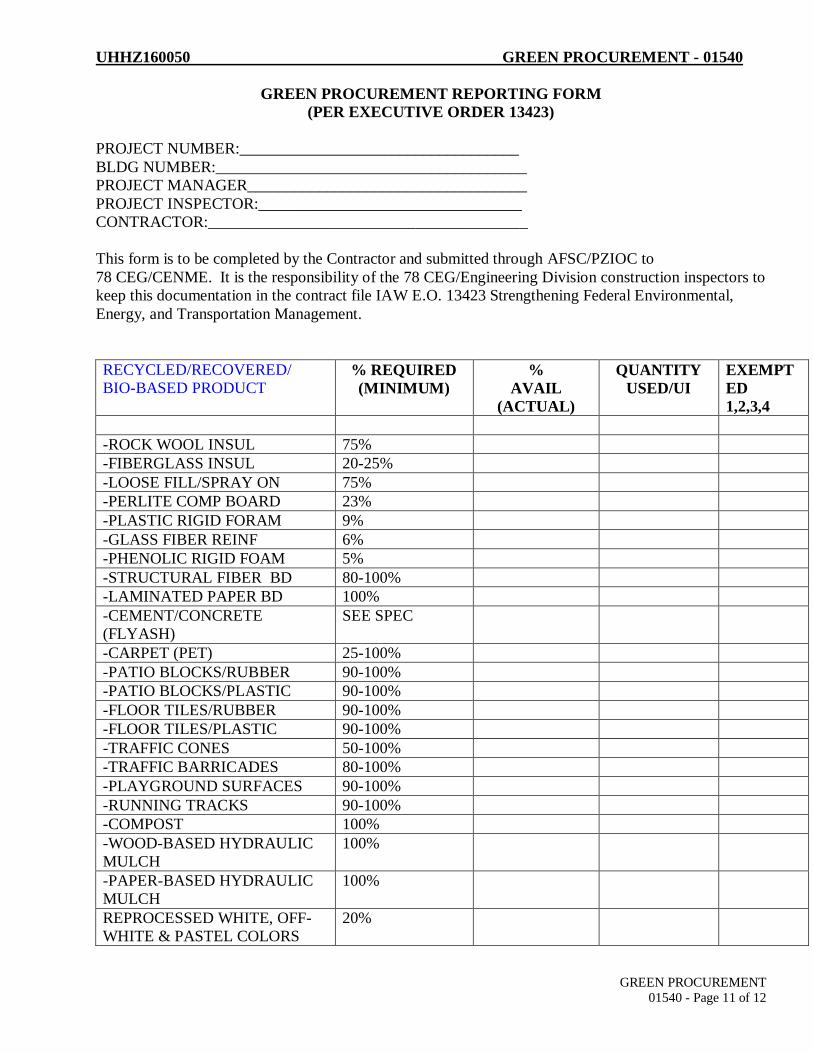
UHHZ160050 GREEN PROCUREMENT - 01540
GREEN PROCUREMENT
01540 - Page 11 of 12
GREEN PROCUREMENT REPORTING FORM
(PER EXECUTIVE ORDER 13423)
PROJECT NUMBER:___________________________________
BLDG NUMBER:_______________________________________
PROJECT MANAGER___________________________________
PROJECT INSPECTOR:_________________________________
CONTRACTOR:________________________________________
This form is to be completed by the Contractor and submitted through AFSC/PZIOC to
78 CEG/CENME. It is the responsibility of the 78 CEG/Engineering Division construction inspectors to
keep this documentation in the contract file IAW E.O. 13423 Strengthening Federal Environmental,
Energy, and Transportation Management.
RECYCLED/RECOVERED/
BIO-BASED PRODUCT % REQUIRED
(MINIMUM)
%
AVAIL
(ACTUAL)
QUANTITY
USED/UI
EXEMPT
ED
1,2,3,4
-ROCK WOOL INSUL 75%
-FIBERGLASS INSUL 20-25%
-LOOSE FILL/SPRAY ON 75%
-PERLITE COMP BOARD 23%
-PLASTIC RIGID FORAM 9%
-GLASS FIBER REINF 6%
-PHENOLIC RIGID FOAM 5%
-STRUCTURAL FIBER BD 80-100%
-LAMINATED PAPER BD 100%
-CEMENT/CONCRETE
(FLYASH)
SEE SPEC
-CARPET (PET) 25-100%
-PATIO BLOCKS/RUBBER 90-100%
-PATIO BLOCKS/PLASTIC 90-100%
-FLOOR TILES/RUBBER 90-100%
-FLOOR TILES/PLASTIC 90-100%
-TRAFFIC CONES 50-100%
-TRAFFIC BARRICADES 80-100%
-PLAYGROUND SURFACES 90-100%
-RUNNING TRACKS 90-100%
-COMPOST 100%
-WOOD-BASED HYDRAULIC
MULCH
100%
-PAPER-BASED HYDRAULIC
MULCH
100%
REPROCESSED WHITE, OFF-
WHITE & PASTEL COLORS
20%

UHHZ160050 GREEN PROCUREMENT - 01540
GREEN PROCUREMENT
01540 - Page 12 of 12
REPROCESSED GREY,
BROWN, EARTHTONES &
OTHER DARK COLORS
50-99%
CONSOLIDATED LATEX
PAINT
100%
PLASTIC/RUBBER PARKING
STOPS
100%
CONCRETE CONTAINING
COAL FLY ASH PARKING
STOPS
20-40%
CONCRETE CONTAINING
GGBF
PARKING STOPS
25-70%
PLASTIC SHOWER &
RESTROOM
DIVIDERS/PARTITIONS
20-100%
MOBILE EQUIPMENT
HYDRAULIC FLUIDS
44-100%
ROOF COATINGS 20-100%
DIESEL FUEL ADDITIVES 90-100%
PENETRATING LUBRICANTS 68-100%
CERTIFICATION
I hereby certify the Statement of Work/Specifications for the requisition/procurement of all materials
listed on this form comply with EPA standards for recycled/recovered materials content.
_______________ _______________
Contractor Inspector
The following exemptions may apply to the non-procurement of recycled/recovered content materials:
1) The product does not meet appropriate performance standards
2) The product is not available within a reasonable time frame
3) The product is not available competitively (from two or more sources)
4) The product is only available at an unreasonable price (compared with a comparable non-
recycled content product.)

B-13
Recovered Materials Determination Form (RMDF) User’s Guide
1. PURPOSE OF FORM. The “Recovered Materials Determination Form” (RMDF) is used to
clearly identify items listed in the Comprehensive Procurement Guidelines (CPG) that are
included in a procurement action, require the consideration of energy efficiency and
environmentally preferable purchasing (EPP) for the procurement action, and document the use
of applicable exemptions taken for the CPG items identified.
2. OPR. All organizations procuring items through avenues other than the Government-wide
Purchase Card (GPC).
3. OCR. Contracting, CE /Operations, CE /Construction, CE /SABER, and CE /Materiel
Acquisition.
4. APPLICABILITY. The RMDF applies to all procurement actions (other than GPC
purchases) that include items that are listed in the CPG, Biobased, Energy Star®, or FEMP Low
Standby Power programs.
5. INTENT FOR USE.
a. GPC holders will not complete this form and will use the “GPC Purchasing
Considerations and Guidelines Log” instead. The RMDF is included in the Robins AFB
Environmental Protection specification. The Environmental Protection specification will be
included in all service and construction contracts as well as all work orders greater than $2,500
that will be completed in-house.
b. Contractors and CE Operations shop personnel (for in-house job and work orders
regardless of project cost) will be responsible for completing an RMDF if any of the mandatory
EPP items are required. For CPG items where exemptions are identified during project/contract
performance, an amended RMDF must be completed documenting the exemption. The OCR
organizations listed above will be responsible for verifying the completed RMDFs.
c. If the procurement action does not include any CPG, Biobased, Energy Star®, or FEMP
Low Standby Power items, complete the Green Procurement Statement instead.
6. FILING PROCEDURE. If applicable, the RMDF and any amended RMDFs will be
provided to contracting with the Purchase Request (PR) package and will be maintained in the
contract file.

B-15
RAFB GPP PLAN ATTACHMENT 3 Recovered Materials Determination Form
Instructions
This form is to be completed by the procurement originator when EPA or USDA -designated
items included in the Green Procurement Program are being procured from outside vendors.
Current information regarding whether products count as “U.S. EPA-designated” or what the
required recycled content for the item is, refer to the product descriptions on U.S. EPA’s Website
at www.epa.gov/cpg/products.htm. Information pertaining to USDA products can be found at
www.biopreferred.gov. The completed form becomes part of the contracting office contract
file.
PR No./ Project No._______________________________________________
The EPA or USDA designated items being procured are:
Construction Products
___Building insulation products ___Carpet and carpet cushion
Cement and concrete containing: ___coal fly ash ___ground granulated blast
furnace slag ___cenospheres ___silica flume
___Consolidated and reprocessed latex paint
___Floor tiles ___Flowable fill (backfill) ___Laminated paperboard ___Modular threshold ramps ___Nonpressure pipe ___Patio blocks ___Railroad grade crossing surfaces ___Roofing Materials ___Shower and restroom
dividers/partitions ___Structural fiberboard
Landscaping Products
___Compost made from yard trimmings or food waste
___Garden and soaker hoses ___Hydraulic mulch ___Lawn and garden edging ___Plastic lumber landscaping
timbers and posts
Non-Paper Office Products
___Binders, clipboards, file folders, clip portfolios, and presentation folders
___Office furniture ___Office recycling containers ___Office waste receptacles ___Plastic desktop accessories ___Plastic envelopes ___Plastic trash bags ___Printer ribbons ___Toner cartridges
Paper and Paper Products
___Commercial/industrial sanitary tissue products ___Miscellaneous papers (tray liners) ___Newsprint ___Paperboard and packaging products ___Printing and writing papers
Park and Recreation Products
___Park benches and picnic tables ___Plastic fencing ___Playground equipment ___Playground surfaces ___Running tracks
Transportation Products
___Channelizers ___Delineators and flexible delineators ___Parking stops ___Traffic barricades ___Traffic cones
Vehicular Products
___Engine Coolants ___Rebuilt vehicular parts ___Re-refined lubricating oils
___Retread tires
Miscellaneous Products
___Awards and plaques ___Bike racks ___Blasting grit ___Industrial drums ___Manual-grade strapping ___Mats ___Pallets ___Signage ___Sorbents
Bio-Based Products
___Mobile Equipment Hydraulic Fluids ___Urethane Roof Coatings ___Water Tank Coatings ___Diesel Fuel Additives ___Penetrating Lubricants ___Bedding, Linens, and Towels

B-16
RAFB GPP PLAN ATTACHMENT 3 –Cont.
Recovered Materials Procurement Determination
___ EPA recycled-content requirements have been met for this procurement action.
**** OR ****
___ The following EPA designated guideline item is included in the specifications for project
number , however, compliance with EPA standards is not attainable.
Item:
I have determined that the EPA guidelines were considered and determined inapplicable, based
on the following:
_____ Item is not available within a reasonable period of time.
Need date: _____________________ Date available: ______________________
Item fails to meet a performance standard in the specifications.
Describe the standard and why it is needed: _____
_____________________________________________________________________________
_____________________________________________________________________________
Describe how the guideline item fails to meet the standard: ________________________
______________________________________________________________________________
______________________________________________________________________________
_____ Item is not available from 2 or more sources.
Market research was performed by calling ____(insert number) vendors, but only
________________________________ (enter name) was able to supply the item.
_____ Item was only available at an unreasonable price (i.e., recycled item is more expensive).
Price of recycled item: ______________ Price of non-recycled item: _______________
This determination is made in accordance with FAR 23.405(c).
Comments_____________________________________________________________________
______________________________________________________________________________
______________________________________________________________________________
________________________________________ ____________
Technical OPR - Signature and Office Symbol Date
Title/Role ______________________________
________________________________________ ____________
Concurrence - Contracting Officer Date

UHHZ160050 ENVIRONMENTAL REQUIREMENTS - 01560
Environmental Requirements for Robins Air Force Base

01560 - Environmental Requirements Rev Date: September 2015
Page 2 of 32
Table of Contents Table of Contents ................................................................................................................................................ 2
PART 1 GENERAL .............................................................................................................................................. 5
1.1 GENERAL SCOPE ................................................................................................................................... 5
1.2 CONTRACTOR RESPONSIBILITY ............................................................................................................. 6
1.2.1 Environmental Management Systems (EMS) Awareness Training.................................................. 6
1.3 NO NOTICE INSPECTIONS ..................................................................................................................... 6
1.4 SUBMITTALS ......................................................................................................................................... 7
1.4.1 General Submittals ....................................................................................................................... 7
1.4.2 Material Submittals ...................................................................................................................... 7
1.4.3 Other Submittals........................................................................................................................... 7
PART 2 EXECUTION .......................................................................................................................................... 8
2.1 DISPOSAL OF WASTE/EXCESS MATERIAL ............................................................................................... 8
2.1.1 General ......................................................................................................................................... 8
2.1.2 Solid Waste Handling .................................................................................................................... 8
2.1.3 Solid Waste Disposal ..................................................................................................................... 9
2.1.4 Reporting of Disposal and Recycling ............................................................................................ 10
2.1.5 Submittals, Notifications, and Approvals ..................................................................................... 11
2.2 SPECIAL WASTES OR HAZARDOUS MATERIALS .................................................................................... 12
2.2.1 General ....................................................................................................................................... 12
2.2.2 Hazardous Waste ........................................................................................................................ 12
2.2.3 Asbestos Containing Materials .................................................................................................... 13
2.2.4 Lead Paint ................................................................................................................................... 14
2.2.5 Polychlorinated Biphenyls (PCB) ................................................................................................. 15
2.2.6 Ozone Depleting Substances (ODS) and Controlled Substances Restriction ................................. 16
2.2.7 Hazardous Materials (HazMat) .................................................................................................... 17
2.2.8 Submittals, Notifications, and Approvals ..................................................................................... 18
2.3 AIR QUALITY ....................................................................................................................................... 20
2.3.1 General ....................................................................................................................................... 20
2.3.2 Open Burning ............................................................................................................................. 20
2.3.3 ODS ............................................................................................................................................ 20
2.3.4 Generators ................................................................................................................................. 20

01560 - Environmental Requirements Rev Date: September 2015
Page 3 of 32
2.3.5 Submittals, Notifications, and Approvals ..................................................................................... 21
2.4 PESTICIDES (INSECTICIDES, FUNGICIDES, HERBICIDES, ETC.) ................................................................ 21
2.4.1 General ....................................................................................................................................... 21
2.4.2 Licenses ...................................................................................................................................... 21
2.4.3 Handling ..................................................................................................................................... 21
2.4.4 Submittals, Notifications, and Approvals ..................................................................................... 21
2.5 STORAGE TANKS ................................................................................................................................. 22
2.5.1 General ....................................................................................................................................... 22
2.6 THREATENED AND ENDANGERED SPECIES OF PLANTS AND WILDLIFE ................................................. 22
2.6.1 General ....................................................................................................................................... 22
2.7 WETLANDS ......................................................................................................................................... 22
2.7.1 General ....................................................................................................................................... 22
2.8 GREEN PROCUREMENT PROGRAM (GPP) ............................................................................................ 22
2.8.1 General: ...................................................................................................................................... 22
2.9 PRESERVING HISTORICAL AND ARCHAEOLOGICAL RESOURCES ........................................................... 23
2.9.1 General ....................................................................................................................................... 23
2.9.2 Archaeological Finds ................................................................................................................... 23
2.10 PROTECTION OF WATER AND LAND RESOURCES ................................................................................ 23
2.10.1 General ....................................................................................................................................... 23
2.10.2 Stormwater Management during Construction ........................................................................... 23
2.10.3 Post Construction Stormwater Management .............................................................................. 24
2.10.4 Prohibition of Illegal Discharges .................................................................................................. 24
2.10.5 Prohibition of Illicit Connections ................................................................................................. 25
2.10.6 Spills ........................................................................................................................................... 25
2.10.7 Tree Protection and New Landscaping ........................................................................................ 25
2.10.8 Restoration of Landscape Damage .............................................................................................. 26
2.10.9 Submittals, Notifications, and Approvals ..................................................................................... 26
2.11 BACKFLOW PREVENTION DEVICES (BPDs) ........................................................................................... 28
2.11.1 General ....................................................................................................................................... 28
2.11.2 Coordination ............................................................................................................................... 28
2.11.3 Installation.................................................................................................................................. 28
2.11.4 Inspection and Testing ................................................................................................................ 28

01560 - Environmental Requirements Rev Date: September 2015
Page 4 of 32
2.11.5 Submittals, Notifications, and Approvals ..................................................................................... 28
Forms
SPECIAL WASTE ACCEPTANCE APPLICATION (SWAA) .......................................................................................... 29
WASTE SHIPMENT TRACKING DOCUMENT ......................................................................................................... 30
WASTE MANAGEMENT REPORT (MONTHLY)...................................................................................................... 31

01560 - Environmental Requirements Rev Date: September 2015
Page 5 of 32
PART 1 GENERAL
1.1 GENERAL SCOPE
This Section provides the requirements necessary to ensure that all projects are in environmental compliance.
Environmental Management, 78 CEG/CEIE, is the organization responsible for management of base
environmental concerns. Contact program managers in 78 CEG/CEIE at (478) 327-8104 or (478) 926-9645 or
electronically [email protected].
1.1.1 The following programs have the potential to be impacted by contracts: solid and hazardous
wastes, toxics, water quality, air quality, natural resources, storage tanks, cultural resources,
pollution prevention, hazardous materials, and fuels.
1.1.2 All contracts performed on Robins Air Force Base (AFB) are bound by all Federal, State of Georgia,
Houston County, Department of Defense (DoD), and Air Force laws, regulations, and policies and
subject to no-notice inspections by these regulators and officials. Robins AFB operates under the
requirements of 10 regulatory permits and over 20 management plans. The following table
identifies applicable Air Force Instructions (AFI) related to this document that also requires
compliance.
Air Force Instructions
AFI 32-1053 Integrated Pest Management Program
AFI 32-1067 Water and Fuel System
AFI 32-7040 Air Quality Compliance and Resource Management
AFI 32-7042 Waste Management
AFI 32-7044 Storage Tank Environmental Compliance
AFI 32-7064 Integrated Natural Resources Management
AFI 32-7065 Cultural Resources Management
AFI 32-7086 Hazardous Materials Management
1.1.3 A digging permit obtained from the 78th Civil Engineer Group is required for all projects where
excavation or other forms of ground penetration may be required to complete the task. This permit
process is the method used by the Base to coordinate the required work with key base activities and
to identify potentially hazardous work conditions; in an attempt to protect personnel, prevent
accidental damage to Base assets, and ensure the proper restoration of the excavated site upon
completion.

01560 - Environmental Requirements Rev Date: September 2015
Page 6 of 32
1.2 CONTRACTOR RESPONSIBILITY
Comply with all applicable Federal, State of Georgia, any laws and regulations from other states where disposal
might occur, and local laws and regulations concerning environmental compliance and pollution prevention.
Ensure all products produced or generated under contract shall meet all stated performance objectives and shall
not violate in any manner the Environmental Requirements of any applicable local, state, or federal entity
including the DoD.
1.2.1 Environmental Management Systems (EMS) Awareness Training: All contractor personnel working
on Robins AFB who perform activities on the installation are required to complete Air Force-
provided initial EMS Awareness Training. It is the responsibility of the Prime Contractor to ensure
that all sub-contractors, vendors, and employees complete this training prior to beginning work on
Robins AFB. Notification of training completion shall be sent to both the Robins AFB Contracting
Officer (CO) to be maintained in the contract file and Environmental Management, 78 CEG/CEIE,
([email protected]) for tracking purposes. Failure to provide documentation of EMS
Training may result in termination of the contract.
EMS training is provided by Environmental Management at (478) 327-8104 or (478) 926-9645.
Contractors have two options to satisfy the mandatory EMS Awareness Training requirement.
Contractors that do not have a Common Access Card must exercise Option 2.
a. Option 1 (Preferred Option): The Air Force version of EMS Awareness Training is available
through the Advanced Distributed Learning Service (ADLS) website:
https://golearn.adls.af.mil/kc/rso/login/ADLS_login.asp. EMS Awareness Training is located
under the Miscellaneous tab. This option is only available to contractors who have a CAC
and takes approximately 10 minutes to complete.
b. Option 2: Contractor requests a copy of the Robins EMS Awareness Training Power Point
Presentation from Environmental Management. The request should be sent to the
Environment Management Workflow Box at the following email address,
[email protected]. Once the presentation is received, the contractor is
responsible for ensuring that all his/her employees view the training.
1.3 NO NOTICE INSPECTIONS
78 CEG/CEIE will conduct no-notice inspections to ensure compliance with all Environmental
Requirements. Written documentation of any findings from such an inspection will be forwarded to the
CO by the inspector. The CO will follow-up with the Contractor on all findings of non-compliance
reported by the inspector. A finding of non-compliance with any of the Environmental Requirements
may result in the issuance of a work stoppage by the CO until documentation of compliance is submitted
and accepted by both 78 CEG/CEIE and the CO. No-notice inspections are frequently conducted by
federal and state regulators.

01560 - Environmental Requirements Rev Date: September 2015
Page 7 of 32
1.4 SUBMITTALS
1.4.1 General Submittals: Provide the following submittals in accordance with instructions found in this
document. The contractor may submit manufacturer’s data in lieu of the required certificate of
compliance if desired. The Government requires manufacturer’s data if an “X” appears under the
“Mfg. Data Required” column.
1.4.2 Material Submittals: Not required under this section.
1.4.3 Other Submittals: Provide the following submittals as required by the contract or as directed by the
CO.
*** IMPORTANT >> Designer, edit list below to project requirements***
Inspector Para #
Description Submittal Timeframe Check Mark
1.2 Notify 78 CEG/CEIE of Digging Beginning of project, before digging
☐
2.1.3 c Landfill License Prior to dumping ☐
2.1.3 c. i. Special Waste Acceptance Application 5 days prior to dumping ☐
2.1.3 c. ii. Waste Shipment Tracking Monthly by the 5th ☐
2.1.3 d. Commencement Notice Prior to dumping ☐
2.1.3 d. 2.1.4 2.1.5 a. vi.
Waste Management Report Landfill Receipts
Monthly by the 5th and prior to final payment
☐
2.1.5 a. 2.1.5 a. ii.
Solid Waste Disposal Plan 10 days prior pre-con. conf.
☐
2.2.3.b. GA EPD Asbestos Abatement or Demolition Project Notification Form
15 days prior to starting work
☐
2.2.2 2.2.8 a. ii.
Hazardous Waste/Hazardous Material List Prior to starting work ☐
2.1.3 c. i. 2.2.1 2.2.3 a. i.
Asbestos Removal Info As required ☐
2.1.3 c. i. 2.2.4 a. i.
Lead Compliance/Training/Sampling Prior to starting work At the end of the project
☐
2.2.8 b. i. Refrigerant Technician Certification Prior to starting work ☐
2.2.8 b. ii. Refrigerant Appliance List Within 7 days ☐
2.2.8. b. ii. Sub-bullets
Refrigerant Maintenance Repair Log Within 7 days ☐
2.2.8 b. iii. Refrigerant Equipment Certification Within 7 days ☐
2.2.8 b. iii. Refrigerant Purchase Documentation Within 7 days ☐
2.3.4 Generators Prior to order ☐

01560 - Environmental Requirements Rev Date: September 2015
Page 8 of 32
Inspector Para #
Description Submittal Timeframe Check Mark
2.3.5 Air Permit Data 6 months prior to construction start date
☐
2.4.2 Pesticide List At end of project ☐
2.4.2 Pest Control License Prior to pest control ☐
2.5.1 Underground Storage Tank Removal 45 days after Notice to Proceed
☐
2.10.7 d. Landscaping Plan Prior to beginning work ☐
2.7.9 a. i. Erosion, Sediment, and Pollution Control Plan
60 percent design package
☐
2.7.9 a. Notice of Intent – NPDES Permit 14 days prior to site work ☐
2.7.9 a. ii. Permits/Fees Copies – NPDES Permit 14 days prior to site work ☐
2.7.9 a. iii. Notice of Termination – NPDES Permit After final stabilization at site
☐
2.7.3 2.7.9 b.
Post Construction Stormwater Management Plan and Calculations
60 percent design package
☐
2.7.3 2.7.9 c.
Post Construction Operation and Maintenance Plan
60 percent design package
☐
2.8.5 a. Backflow Device Location Prior to installation ☐
2.8.5 b. Backflow Prevention Device Test Report After BPD installation ☐
2.8.5 c. Use of fire hydrant/penetrate water mains
Prior to start of work ☐
PART 2 EXECUTION
2.1 DISPOSAL OF WASTE/EXCESS MATERIAL
2.1.1 General: The Contractor shall take a proactive, responsible role in the management of non-hazardous solid
waste and require all subcontractors, vendors, and suppliers to participate in the effort. Non-hazardous
Solid Waste, as defined in Code of Federal Regulations (CFR) 261.2, dispositioned for disposal shall be
removed from the base in accordance with all Federal, State of Georgia, and local codes and requirements.
Every effort shall be made to segregate individual waste streams and divert waste from any landfill by
reusing or recycling materials. Direct all non-hazardous solid waste inquiries to 78 CEG/CEIEC Solid Waste
Program Manager, (478) 327-9283 or (478) 926-9645.
2.1.2 Solid Waste Handling: All persons engaged in solid waste handling, including solid waste collection and
transportation, or operations of solid waste handling facilities or disposal sites, shall have a solid waste
handling permit or permit by rule letter. The provisions of Georgia Environmental Protection Division (GA
EPD) regulations concerning proper handling of solid waste and applicable prohibitions shall govern. All

01560 - Environmental Requirements Rev Date: September 2015
Page 9 of 32
materials and equipment not turned in to the Government is considered property of the contractor and
must be properly removed by the end of the project.
2.1.3 Solid Waste Disposal: Use one or more of the following methods to divert/dispose of non-hazardous solid
waste. All materials to be disposed of in other than a sanitary landfill must be kept segregated at the project
site from those materials which are allowed only in a sanitary landfill.
a. Reuse (diversion): First consideration of waste shall be given to salvage for reuse to be used in the
original form. Sale or donation of waste suitable for reuse shall be considered. Salvaged materials
shall not be used in this project unless approved by the CO. Materials defined as “recovered
materials” are excluded from regulation as solid wastes.
b. Recycling (diversion): Waste material not suitable for reuse but having value as a recyclable
material shall be recycled whenever practical and economically feasible. Materials destined for
recycling must meet the definition of non-hazardous wastes under federal/state solid waste
regulations. Recyclable metal materials shall remain the property of the government and be
recycled through the Robins AFB Qualified Recycling Program (QRP). To coordinate
removal/collection of scrap wire and metal, please contact QRP Manager Casey Lucas at (478) 327-
9283 or Alternate QRP Manager Darryl Mercer at (478) 256-7032.
c. Sanitary Landfill (disposal): All solid waste may be disposed of in a sanitary landfill properly licensed
by the State of Georgia. Provide proof that any Georgia municipal solid waste disposal facility
receiving Robins AFB waste is operated by someone who has obtained the certification required by
the Georgia Solid Waste Management Act, O.C.G.A. 12-8-24.1. If a landfill other than Houston
County Landfill is used, provide a copy of the landfill license.
i. If the presence of lead based paint, asbestos, or other hazardous materials are suspected,
an analysis of the suspected material shall be performed by a certified lab approved by the
State. If the Toxic Characteristic Leaching Procedure (TCLP) results for lead are greater than
5 mg/L, the waste shall be disposed of as hazardous waste in a Subtitle C permitted facility--
not a Subtitle D permitted facility such as the Houston County Landfill. If the lab analysis for
asbestos is positive, the permission for landfill disposal is required and waste must be
dispositioned through the Special Waste Acceptance Application (SWAA) process. Houston
County Landfill currently does not require a SWAA if there is no presence of lead based
paint, asbestos, or other non-hazardous Special Waste or hazardous materials suspected.
ii. SWAA Process: The results of the tests/lab analysis as well as the completed top and middle
portion of the SWAA must be submitted to 78 CEG/CEIEC Solid Waste Program Manager for
approval and signature. The 78 CEG/CEIEC Solid Waste Program Manager will be the signing
authority as the generator on the SWAA form. 78 CEG/CEIEC will email the completed form
to the County’s landfill consultant for disposal acceptance/approval and for issuance of
Special Waste Profile Number. The Special Waste Profile Number must be used on the
Waste Shipment Tracking Document. The Waste Shipment Tracking Document and SWAA
are both attached at the end of the document. Allow a minimum of three working days for
78 CEG/CEIEC to process the SWAA form and to obtain the profile number. The 78
CEG/CEIEC Solid Waste Program Manager will issue the completed SWAA back to the
contractor via email. The Contractor must certify that no hazardous waste was introduced

01560 - Environmental Requirements Rev Date: September 2015
Page 10 of 32
into the waste while in his custody. The contractor must provide a Waste Shipment
Tracking Document with each disposal load when required by Houston County. These forms
must also be included in contract documents.
d. Inert Waste Landfill (disposal): Materials not likely to cause production of leachate of
environmental concern may be disposed of in an inert waste landfill. Only earth and earth-like
products, concrete, cured asphalt concrete, rock, bricks, yard trimmings, and land clearing debris
such as stumps, limbs, and leaves are acceptable for disposal in an inert waste landfill. A copy of the
written notice of commencement of operation by the landfill as given to the GA EPD and a copy of
the landfill license or permit by rule letter issued by the GA EPD must be provided to the Base
Engineering Division (78 CEG/CEN) Project Manager and maintained in the contract documents.
The weights of inert waste disposed in the landfill must be documented in the monthly waste
management report, provided to the 78 CEG/CEN Project Manager, and then forwarded to the 78
CEG/CEIEC Solid Waste Program Manager.
e. Construction/Demolition Disposal Site (disposal): Materials will be recycled where practical.
Recyclable metal materials (scrap metal, wire, motors, etc) shall remain the property of the
government and will be recycled through the Robins AFB QRP. To coordinate removal/collection of
scrap metal materials, please contact QRP Manager Casey Lucas at (478) 327-9283, Alternate QRP
Manager Darryl Mercer at (478) 256-7032, or 78 CEG/CEIE Front Office at (478) 327-8104 or (478)
926-9645. Other construction and demolition (C&D) waste, including but not limited to wood,
paper, cardboard can be recycled through the base recycling program or through another
appropriate recycling avenue. Materials that can go in an inert waste landfill may be recycled
according the rules of the State of Georgia, disposed of in an inert landfill, or lastly in the landfill. If
the wastes are being disposed of at a landfill other than the Houston County Landfill, provide the
landfill license to the 78 CEG/CEN Project Manager. Refer to Section 2.1.4 regarding proper
reporting of disposal and recycling (weights). For construction and demolition wastes, a minimum
of 60 percent by weight of the total project solid waste shall be diverted from the landfill.
f. Solid Waste Disposal Outside of Georgia: No solid waste can be disposed of outside the state of
Georgia without prior written approval of the CO. The contractor shall provide sufficient
information as determined by the CO to allow verification of compliance with the law.
2.1.4 Reporting of Disposal and Recycling: Robins AFB is required to report the amount (weight) of solid waste
and C&D debris which is dispositioned by reuse, recycle, or disposal. Each month, the Contractor shall
record the amounts of reused, recycled, and disposed materials on the Waste Management Report
(attached at the end of the document). Weights shall be cumulative from the start of each month and shall
reflect the total amount of material disposed or recycled during the month. The report should reflect the
method of disposal for the material generated from the project. Weights of material disposed of in a
sanitary or C&D landfill shall be reported based on the weight tickets. Material disposed of in other types of
landfills, which do not have weight scales, may be estimated. The weight of materials reused and or
recycled may be estimated. Use a good faith effort to obtain the most accurate estimate possible. The
Contractor shall also provide the cost to landfill or divert/recycle the C&D debris on the Waste Management
Report. A copy of the Waste Management Report shall be turned in to the 78 CEG/CEN Project Manager by
the 5th of the following month and prior to final payment. The 78 CEG/CEN Project Manager shall forward

01560 - Environmental Requirements Rev Date: September 2015
Page 11 of 32
the Waste Management Report to the 78 CEG/CEIEC Solid Waste Program Manager. If there are any
questions, the Solid Waste Program Manager contact information is:
Casey Lucas
Email: [email protected]
Phone: (478) 327-9283 or (478) 926-9645
2.1.5 Submittals, Notifications, and Approvals: The following submittals, notifications, and approvals are required
to maintain compliance:
a. Solid Waste Disposal Plan: The Contractor shall provide a Solid Waste Disposal Plan stating how all
materials leaving Robins AFB shall be disposed of and recycled no later than15 days after notice to
proceed and not less than 10 days before the preconstruction meeting prior to starting work. The
Solid Waste Disposal Plan shall include actions that will be taken to reduce solid waste generation,
specific approaches to be used in recycling/reuse of materials, waste management and storage
information, and anticipated net cost savings.
i. The plan shall certify that the Contractor shall manage, dispose, and recycle all materials in
compliance with all Federal, State of Georgia, and local laws. The plan shall address the disposal
of each item in Sections 2.1.1 through 2.2.8 as applicable. The plan shall designate an employee
who shall be responsible for verifying that all materials removed from Robins AFB are disposed
of in accordance with the above referenced laws. Non-hazardous solid waste shall be broken
down into individual types, i.e., asphalt, concrete, wood, brick, etc. to facilitate recycling of
recovered materials.
ii. Provide a copy of the Solid Waste Disposal Plan to the CO and to the 78 CEG/CEN Project
Manager. The 78 CEG/CEN Project Manager will forward to 78 CEG/CEIEC prior to review and
approval 10 days prior to the Pre-construction Conference or 15 calendar days prior to the start
of disposal operations if no pre-construction conference is held.
iii. Identify each landfill and recycler to be used. A copy of all landfill permits shall be provided
unless the Houston County landfill is used.
iv. Provide a copy of a Solid Waste Handling Permit or permit-by-rule letter, issued by GA EPD,
which allows the Contractor to handle solid wastes, including solid waste collection and
transportation. A copy of the EPD permit-by-rule letter is required for the inert waste landfill
being used.
v. Establish and maintain a Daily Waste Disposal and Recycling Log. Each load of materials that
leaves Robins AFB shall be accounted for in the log. The log shall list the load number, bill of
sale number/date or other record for recycling, as well as the name of the contract employee
who verified that the material was disposed of properly, along with details as to how verification
was accomplished.
vi. Keep evidence of proper disposal and recycling of construction debris as well as provide this
evidence to the 78 CEG/CEN Project Manager. Examples of evidence include dump tickets from

01560 - Environmental Requirements Rev Date: September 2015
Page 12 of 32
a licensed sanitary landfill, copies of current landfill permits from the State of Georgia (unless
Houston County landfill is used), manifest, bill of sale, or other record for recycling. The
evidence shall be obtained the workday after the load is carried off and provided by the 5th of
each month on the Waste Management Report.
vii. Prior to final payment, 78 CEG/CEIEC Solid Waste Program Manager must have received all
monthly waste tracking reports. Attach a copy or duplicate of the Waste Shipment Tracking
Document for each load transported for disposal and recycling.
b. Building Demolition: Submit copies of GA EPD demolition notification to CO and the 78 CEG/CEN
Project Manager. The 78 CEG/CEN Project Manager will forward to the 78 CEG/CEIEC Solid Waste
Program Manager 15 days prior to starting work and prior to submittal to the GA EPD for review,
and submit final copies with copy of any payment made to GA EPD.
2.2 SPECIAL WASTES OR HAZARDOUS MATERIALS
2.2.1 General: The Contractor must comply with all applicable federal, state, and local requirements concerning
use of hazardous materials and hazardous waste. If there should be a conflict between environmental
regulation/ordinances/statues and the contract’s specifications, the contractor shall, in writing, contact the
CO for a written determination. Disposal of all non-hazardous Special Wastes, such as asbestos, requires
submittal of a SWAA to obtain a Profile Number for use on the Waste Shipment Tracking Document as
described in 2.1.3.c.
2.2.2 Hazardous Waste: Hazardous Waste is defined as waste meeting the requirements of 40 CFR 261.3. 78
CEG/CEIER Hazardous Waste Program Manager makes all hazardous waste determinations for waste
generated on Robins AFB. The Contractor must provide all data necessary to determine the regulatory
status of waste to 78 CEG/CEIER. Activities requiring large quantities of disposal must be coordinated prior
to beginning work in order to ensure a sufficient number of hazardous waste containers are available. The
Contractor must ensure personnel have completed hazardous waste training prior to generating hazardous
waste. All hazardous and universal wastes generated on Robins AFB must be disposed of through 78
CEG/CEIER at building 359. Direct all inquiries to the 78 CEG/CEIER Hazardous Waste Program Manager.
a. Paints, sealants, solvents, rags, or any other hazardous material(s) destined for disposal must be
managed as a hazardous waste unless they have been determined not to be via Safety Data Sheet
(SDS) or laboratory sampling. 78 CEG/CEIER is the only organization authorized to make a hazardous
waste determination.
b. Waste generated from the project itself (e.g. lead-based paint removed from walls, contaminated
soil, sludge from tank cleaning, etc.) must be turned-in to Building 359 for disposal.
c. High-intensity discharge (HID) and fluorescent lamps and tubes or switches containing mercury must
be recycled as universal waste. Labeled containers must be requested through 78 CEG/CEIER at
building 359 prior to job start.
d. Batteries used in emergency and exit lights that contain lead must be recycled. These batteries
must be turned-in to building 359 with no cost for disposal.
e. Disposal Procedures for Hazardous and Universal Waste:

01560 - Environmental Requirements Rev Date: September 2015
Page 13 of 32
i. Payment for waste disposal will be made through the property/building organizations
Department of Defense Activity Address Code (DODAAC) account. Since all regulated
wastes must be disposed of through DLA-DS, a valid DODAAC is essential to prevent contract
operation delays. This step must be completed prior to requesting waste containers and
labels. Authorization to use the organizations DODAAC also indicates there are sufficient
funds available to pay for waste disposal generated from the project.
ii. Obtain labels and containers prior to job start from building 359 and place the labels on
containers suitable for shipping per Department of Transportation (DOT) guidelines.
Fluorescent lamps/tubes may be placed in the original boxes the tubes came in or in boxes
designed to prevent breakage. Take care not to break any universal waste lamps/tubes. If
any are broken, they must be treated as spilled hazardous waste and turned-in to building
359 immediately.
NOTE: Rolloff boxes to contain waste for large projects must be requested at least 2 weeks in advance.
iii. Accumulate hazardous waste under either the satellite accumulation rules (<55 gallons
total, no time limit, 3 day limit to turn-in full drums) or 90-day rules (no quantity limit, use
up to 90 days in the field, other 40 CFR 262.34(a)(1)(i) requirements apply). Turn-in
containers to building 359 when full or approaching time limit(s).
iv. The contractor is responsible for maintaining regulatory compliance for all regulated waste
under their control. Responsibility for site compliance does not end until the waste is
accepted by 78 CEG/CEIER for disposal.
v. Do not abandon waste at the job site.
2.2.3 Asbestos Containing Materials:
a. Asbestos Work/Removal: The Contractor shall provide 15 working day notification to the CO and 78
CEG/CEIEC Toxics Program Manager and 10 working day notification to GA EPD prior to the start of
any work involving asbestos. Copies of all notifications, GA EPD approval, and landfill disposal
receipts and waste shipment tracking forms must be provided to the CO and 78 CEG/CEIEC Toxics
Program Manager.
i. Provide a written plan to the 78 CEG/CEN Project Manager and the 78 CES/CEIER
Asbestos/Toxic Operations Manager. Provide description of work to be performed and work
procedures to comply with rules and regulations. Provide employee training program
certification that contractor personnel involved in removal and handling of asbestos has
received asbestos training, respiratory protection, and medical surveillance program
information.
b. Building Demolition: Follow guidance above regarding notification procedures. This may also apply
to the modification of a building, and is considered demolition when the removal of a load-bearing
wall occurs. For more information, visit: http://epd.georgia.gov/asbestos-notification-requirements
or coordinate with 78 CEG/CEIEC Solid Waste Program Manager or the 78 CEG/CEN Project
Manager. The GA EPD Asbestos Abatement or Demolition Project Notification Form for asbestos
renovation, encapsulation, or demolition can be at the website noted above.

01560 - Environmental Requirements Rev Date: September 2015
Page 14 of 32
c. Do not use any products containing asbestos.
d. Prior to the start of any demolition, renovation, or digging, determine if asbestos is in the area of
construction. If there is no known asbestos in the project area, proceed as normal. If the contractor
discovers any material suspected to be asbestos, bring it to the CO’s attention immediately. Stop all
work in that area until directed to proceed.
i. Known Asbestos, not written in the contract: If asbestos is in the area of construction,
describe where it is located. There should not be any work done in the area involving
asbestos if it was not written in the contract. If any asbestos is accidentally damaged, notify
78 CES/CEIER Asbestos/Toxic Operations Manager at (478) 327-8518, Bioenvironmental
Engineering, 78 AMDS/SGPB at (478) 327-7555, and 78 CEG/CEIEC Toxics Program Manager
at (478) 327-3976 immediately. After they inspect the damage, the contractor shall repair it
and remove debris in accordance with the following regulations, at no additional cost to the
Government:
29 CFR 1910.1001
40 CFR 61.145
40 CFR 61.150
AFOSH Standard 161-4
Georgia Air Quality Rules, Section 391-3-1-02(9)(b)1
2.2.4 Lead Paint:
General: The contractor shall take precautions to protect contract and government employees from
exposure to lead dust hazards during C&D projects in accordance with 29 CFR 1926.62, Occupational, Safety,
and Health Administration (OSHA) Lead in Construction Standard. All painted surfaces including painted
surfaces covered by other materials such as wall paper may contain varying levels of lead. All lead based
paint abatement work shall only be performed in the areas shown by the required specifications and shall
be in accordance with Unified Facilities Guide Specifications (UFGS).
a. For all projects (Major Abatement projects; Housing or Childcare Facilities; Maintenance, Repair, and
Minor Construction Projects): All painted surfaces, including painted surfaces covered by other
materials such as wall paper, may contain varying levels of lead. The disposal of all debris containing
lead paint shall be handled as a hazardous waste until a determination has been made otherwise
based on test results. For hazardous waste, the contractor shall provide DOT approved drums and
collect the waste in the drums. The drums shall be sealed, properly labeled, and turned in to the
government for disposal.
i. Provide a written plan as required by OSHA Standard 29 CFR 1926.62 to the 78 CEG/CEN
Project Manager and the 78 CEG Toxics Operations Manager. Provide description of work to
be performed and work procedures to comply with rules and regulations. Provide
certification that contractor personnel involved in removal and handling of lead based paint

01560 - Environmental Requirements Rev Date: September 2015
Page 15 of 32
has received training in accordance with OSHA Lead Standards and medical surveillance
program information. At the end of the project, provide results of air sample testing to
demonstrate worker safety.
2.2.5 Polychlorinated Biphenyls (PCB): Do not use equipment or components containing PCB’s. This includes
ballasts and capacitors for fluorescent and HID lighting.
a. Disposal Procedures for Fluorescent lighting ballasts and HID lighting capacitors containing PCB’s:
i. Fluorescent lighting ballasts and HID lighting capacitors must be managed and disposed of
as toxic waste unless the label states they do not contain PCB’s. Ballasts and capacitors with
no markings are assumed to contain PCB. Ballasts and capacitors marked as non-PCB are
handled as standard solid waste.
ii. Gather HID capacitors and fluorescent ballasts into separate containers and place them into
labeled, suitably sized DOT-approved containers per 49 CFR 173.202. (Typical sizes are 1, 5,
10, 30, and 55 gallons) Labels and containers may be obtained from building 359, 78
CEG/CEIER, (478) 926-1176.
iii. If any are broken, they must be treated as spilled hazardous material. Contact 78
CEG/CEIER, (478) 926-1176 for disposal instructions.
iv. Dispose of sealed non-leaking capacitors through DLA-DS, (478) 926-5162. Do not keep any
of the full or partially full containers at the construction site for more than 30 days. Provide
DD Form 1348 obtained from building 359 prior to contacting DLA-DS for disposal.
b. Disposal Procedures for all other PCB containing materials, including but not limited to: plastics
(such as plastic insulation from wire or cable; radio, television and computer casings; vehicle parts;
or furniture laminates); preformed or molded rubber parts and components; applied dried paints,
varnishes, waxes or other similar coatings or sealants; caulking; asbestos:
i. Prior to the start of any demolition, renovation, or digging, determine if PCB containing
materials are in the area of construction. If the contractor discovers any material he/she
suspects to contain PCBs, or if lab results indicate PCB-containing materials, the material
shall be managed as PCB hazardous waste.
ii. Notify 78 CEG/CEIER Hazardous Waste Support at (478) 926-1176 that a project area
contains PCB materials. Building 359 will provide the necessary containers for collection as
well as a DD Form 1348 for completion.
iii. Upon completion of DD Form 1348, the containers will be picked up directly by DLA-DS. The
DLA-DS POC is Darlene Smith, (478) 926-5162. If DLA-DS is not available to pick up PCB
containing materials, notify 78 CEG/CEIER Hazardous Waste Support at (478) 926-1176 for
alternate disposal procedures.
iv. PCB waste will always be transported using a hazardous waste manifest which must be
signed by a 78 CEG/CEIE representative. Payment for waste disposal will be made through a
01560 - Environmental Requirements Rev Date: September 2015
Page 16 of 32
valid DODAAC account. This step must be completed prior to requesting waste containers
and labels. See section 2.2.8.c, page 19 for instructions on obtaining a DODAAC.
2.2.6 Ozone Depleting Substances (ODS) and Controlled Substances Restriction:
a. Unless the requiring activity has obtained prior Senior Acquisition Official (SAO) approval,
contractors may not provide any service or product with any specification, standard, drawing, or
other document that requires the use of a Class I ODS in the test, operation, or maintenance of any
system, subsystem, item, component, or process or provide any specification, standard, drawing, or
other document that establishes a test, operation, or maintenance requirement that can only be
met by use of a Class I ODS.
[Air Force Federal Acquisition Regulation Supplement (AFFARS) Part 5352.223-9000, Elimination of Use of
Class I Ozone Depleting Substances (ODS)]
For the purposes of Air Force policy, the following products are Class I ODS:
i. Halons: 1011, 1202, 1211, 1301, and 2402;
ii. Chlorofluorocarbons (CFCs): CFC-11, CFC-12, CFC-13, CFC-111, CFC-112, CFC-113, CFC-114,
CFC-115, CFC-211, CFC-212, CFC-213, CFC-214, CFC-215, CFC-216, and CFC-217, and the
blends R-500, R-501, R-502, and R-502; and
iii. Carbon Tetrachloride, Methyl Chloroform, and Methyl Bromide
NOTE: Materials that use one or more of these Class I ODSs as minor constituents do not meet the Air Force
definition of a Class I ODS. [AFFARS Part 5352.223-9000, Elimination of Use of Class I ODS].
b. Class II ODS usage requires prior approval through the Air Force (AF) Form 3952 Authorization
Process. [Air Force Instruction (AFI) 32-7086, Hazardous Materials Management]
i. Do not develop or modify any existing weapon or facility system scheduled to remain in the
AF inventory beyond 1 January 2020 in any manner that requires or adds requirements for
Class II ODS in their operations or maintenance.
ii. For exceptions to this Class II ODS policy, the requiring activity must receive SAO approval,
using the same process as Class I ODS Contract approvals, or, for installation Real Property
air conditioning and refrigeration equipment, the requiring activity must obtain approval
authority from the Base Civil Engineer (BCE). [AFI 32-7086, Hazardous Materials
Management]
iii. For the purposes of Air Force policy, the following products are Class II ODS:
Hydrochlorofluorocarbons (HCFCs): HCFC-21, HCFC-22, HCFC-31, HCFC-121, HCFC-122,
HCFC-123, HCFC-124, HCFC-131, HCFC-132, HCFC-133, HCFC-141b, HCFC-142b, HCFC-151,
HCFC-221, HCFC-222, HCFC-223, HCFC-224, HCFC-225ca, HCFC-225cb, HCFC-226, HCFC-231,
HCFC-232, HCFC-233, HCFC-234, HCFC-235, HCFC-241, HCFC-242, HCFC-243, HCFC-244,
HCFC-251, HCFC-252, HCFC-253, HCFC-261, HCFC-262, HCFC-271 [AFI 32-7086, Hazardous
Materials Management, Table 4.2]

01560 - Environmental Requirements Rev Date: September 2015
Page 17 of 32
c. The Contractor shall label products which contain or are manufactured with ODS in the manner and
to the extent required by 42 United States Code (U.S.C.) 7671j(b), (c), and (d) and 40 CFR Part 82,
Subpart E, as follows:
Warning
Contains (or manufactured with, if applicable) *_______, a substance(s) which harm(s) public health and
environment by destroying ozone in the upper atmosphere.
* The Contractor shall insert the name of the substance(s). [Federal Acquisition Regulation (FAR) Part
52.223-11, ODS]
d. The Contractor shall comply with the applicable requirements of Sections 608 and 609 of the Clean
Air Act (42 U.S.C. 7671g and 7671h) as each or both apply to this contract. [FAR Part 52.223-12,
Refrigeration Equipment and Air Conditioners]
2.2.7 Hazardous Materials (HazMat):
a. HazMat Definition: The term HazMat includes all items (including medical supply items, but
excluding drugs in their finished form and pharmaceuticals in individually-issued items) covered
under Emergency Planning and Community Right-to-Know Act (or other federal, state, or local)
tracking requirement, the OSHA Hazard Communication (HAZCOM) Standard, and all Class I and
Class II ODS. It does not include munitions or hazardous waste.
b. HazMat Exemptions: The OSHA HAZCOM Standard [29 CFR 1910.1200(b)(6)(ix)] excludes “Any
consumer product or hazardous substance, as those terms are defined in the Consumer Product
Safety Act (15 U.S.C. 2051 et seq.) and Federal Hazardous Substances Act (15 U.S.C. 1261 et seq.)
respectively, where the employer can show that it is used in the workplace for the purpose intended
by the chemical manufacturer or importer of the product, and the use results in a duration and
frequency of exposure which is not greater than the range of exposures that could reasonably be
experienced by consumers when used for the purpose intended.” OSHA further states in a 14 April
2005 interpretation letter that office cleaning products utilized with the same frequency and
duration as that of a normal consumer would fall under the HAZCOM Standard exemption for
consumer products in 29 CFR 1910.1200(b)(6)(ix). Based on the OSHA HAZCOM Standard
exemption, consumer products that are used at Robins AFB in such a way that the duration and
frequency of use are the same as that of a consumer are not required to be included in the
employer’s HAZCOM program. If unsure if the item meets the exemption, contact the HazMat Cell
c. Lead Acid Batteries: OSHA determined that lead acid batteries are hazardous chemicals because of
their potential chemical exposure risks and physical hazards. As a result, lead acid batteries are
classified as HazMat and do not fall under the article exemption because they have the potential to
leak, spill or break during normal conditions of use.
d. Aerosol Products: All aerosol products are classified as HazMat.

01560 - Environmental Requirements Rev Date: September 2015
Page 18 of 32
e. The storage and usage of all HazMat must be tracked in the Air Force Standardized Tracking System.
If the contractor does not have access to a government-furnished computer and cannot access the
Air Force Standardized Tracking System, the contractor must report data on the HazMat stored and
used during the performance of the contract at a minimum of weekly to the HazMat Cell and in the
format specified. The Contractor should coordinate the submittal of HazMat data with the HazMat
Cell prior to the beginning of work.
f. Each HazMat container must have an Air Force-approved bar code tracking label affixed, with the
exception of kits. The tracking label shall be generated from the Air Force Standardized Tracking
System and must be for the same manufacturer, same product and same size item. Substitutions
are not allowed. HazMat that has been broken down into smaller “child” containers from the
original “parent” container must have a packaging label affixed in addition to the bar code tracking
label. If the contractor does not have access to a government-furnished computer and cannot
access the Air Force Standardized Tracking System, the contractor must coordinate with the HazMat
Cell the printing of bar code labels for all HazMat items.
g. All HazMat must be authorized prior to use. The material is authorized by stock number for the
using organization or contractor. Authorizations are good for three years. At the end of the three
year period, the user must re-new the authorization. HazMat items cannot be issued in the Air
Force Standardized Tracking System to an employee without an active, valid authorization. The
contractor must submit an Air Force Form 3952 (or the electronic equivalent through the Air Force
Standardized Tracking System) for the authorization to use the HazMat.
h. Contractors must submit a “Hazardous Material Purchase Request for Contractors” form prior to
transporting any hazardous material onto Robins AFB. Contact the HazMat Cell for the “Hazardous
Material Purchase Request for Contractors” form, [email protected]. This form must be
completed for all hazardous materials purchased by contractors for use on Robins AFB and approval
must be granted prior to transportation onto Robins AFB. The purpose of this form is to ensure
compliance with AFI 32-7086 and OSHA HAZCOM, ensuring that hazardous materials are approved
for use prior to transportation onto Robins AFB and a current SDS is available in the Air Force
Standardized Tracking System. Once approval is given, the contractor is permitted to transport
hazardous materials onto Robins AFB. The contractor must track the hazardous materials in the Air
Force Standardized Tracking System.
i. Contractors must maintain compliance with the Robins AFB Hazardous Material Management Plan
and AFI 32-7086. A copy of the plan can be obtained by contacting the HazMat Cell.
j. Contractors should contact the HazMat Cell ([email protected] ) with specific HazMat
questions.
2.2.8 Submittals, Notifications, and Approvals: The following submittals, notifications, and approvals are required
to maintain compliance:
a. HAZCOM Program: The Contractor must submit a written HAZCOM program to the CO when
hazardous materials or chemicals are to be used or demolished. This HAZCOM plan must include
the following information:
i. List of each work activity/process required to use/demolish hazardous materials/chemicals.

01560 - Environmental Requirements Rev Date: September 2015
Page 19 of 32
ii. List of hazardous materials/chemicals used.
iii. SDS for each hazardous material/chemical used. The SDS must be the most current SDS
available from the manufacturer. SDSs from third party SDS sites are not allowed.
iv. HazMat Listing and Air Force Form 3952 for each HazMat: Provide the CO with SDS and the
list of hazardous materials/chemicals prior to starting work. Each SDS must be accompanied
with a completed Air Force Form 3952, detailing the intended use of the hazardous material.
The same procedure should be followed for additional hazardous material brought on base
during the performance of the contract. The CO will forward the list of hazardous materials,
Air Force Form 3952s and SDSs to the HazMat Cell for review and approval. HazMats are
not permitted for transportation onto Robins AFB or use on Robins AFB until approval is
given by 78 CEG/CEIEC. A completed, signed, approved Air Force Form 3952 is required for
every hazardous material used on Robins AFB.
v. Written procedures for handling of any hazardous waste generated.
b. ODS and Controlled Substances Restriction:
i. The Contractor shall provide the name, address, telephone number, and technician
certification of each person who will service, repair, maintain and/or dispose of any
equipment containing and/or using a refrigerant (Class I ODS, Class II ODS, or non-ozone
depleting substance) to 78 CEG/CEIEC.
ii. The Contractor shall provide a list of appliances located on base that have a capacity of 50
pounds or more of a Class I or Class II refrigerant to 78 CEG/CEIEC. Include the following
information for each appliance:
◦ The type of appliance, i.e., commercial refrigeration appliance, industrial process
refrigeration appliance, comfort cooling appliance, or other type of refrigeration
appliance;
◦ The location of each appliance;
◦ The manufacturer, serial number, or other method of identification;
◦ The amount of the full charge of refrigerant, the type of refrigerant used, and the
date full charge was determined.
◦ For maintenance, service, repair, and/or disposal of base appliances containing 50
pounds or more of a Class I or Class II refrigerant, provide records, work logs, service
tickets, invoices, and supporting documentation to 78 CEG/CEIEC. The
documentation required should contain the following:
◦ The date and type of service performed, i.e., repair, maintenance and/or disposal;
◦ The date any leak was discovered;
◦ A complete, detailed description of any service performed;

01560 - Environmental Requirements Rev Date: September 2015
Page 20 of 32
◦ The amount of refrigerant added at the completion of each service performed;
◦ Dates and results of the initial and follow-up verification tests; and
◦ The name of the technician who performed the work.
iii. For any equipment used to recover or recycle refrigerants on base, provide the following
information to 78 CEG/CEIE:
◦ A copy of any invoice or other record documenting the purchase or rental of such
equipment, including the type of equipment, the manufacturer’s name, the
equipment model number, year manufactured, and any associated serial number;
and
◦ A copy of the equipment certification sent to US EPA.
iv. For any purchases or acquisitions of refrigerant used for any service on base, provide copies
of records, including, but not limited to, receipts, invoices, purchase orders, or bills of lading
to 78 CEG/CEIE. The information should include the name, address and telephone number
of each person, agent, or business entity from whom the facility purchased refrigerant.
c. DODAAC Account: After the Preconstruction Conference, the Contractor must have a valid DODAAC
or work with the CO to obtain a DODAAC account number to pay DLA-DS for disposals.
i. After contract award, work with 78 CEG/CEIER Hazardous Waste Disposal/Turn-in
personnel, (478) 926-1176, to discuss how to obtain containers and container labels. The
Contracting Official Technical Representative must apply or update a DODAAC through the
Air Force DODAAC manager at https://dodaac.wpafb.af.mil/.
ii. Wait until the DODAAC account number is validated to begin generating regulated waste
items to avoid long-term storage issues.
2.3 AIR QUALITY
2.3.1 General: The contractor will perform value engineering for each project requiring specification or
installation of equipment for control of regulated air pollutants. These analyses will ensure that the
proposed control technology meets air quality compliance requirements. New sources require utilization of
Maximum Achievable Control Technology to reduce emissions of hazardous air pollutants.
2.3.2 Open Burning: Open burning operations are prohibited on base and shall not be used. Open burning is any
outdoor fire which emits products of combustion directly into the open air without passing through a stack,
chimney, or duct.
2.3.3 ODS are restricted from use. Comply with paragraph 2.2.8.b.
2.3.4 Generators: Projects which will put generators into operation (new or replacement units) will require
certification from the manufacturer of the unit that all Federal Standards for the performance of Stationary
Compression Ignition Internal Combustion Engines are met. This certification must be submitted and

01560 - Environmental Requirements Rev Date: September 2015
Page 21 of 32
approved by the CO and 78 CEG/CEIEC Air Quality Program Manager prior to ordering and delivery of the
unit.
2.3.5 Submittals, Notifications, and Approvals: The following submittals, notifications, and approvals are required
to maintain compliance:
a. Air Permit – Emission Sources: According to GA EPD Rules for Air Quality Control, Chapter 391-3-1-
.03, any person prior to beginning the construction or modification of any facility which may result
in air pollution shall obtain a permit for the construction or modification of such facility. The
contractor shall submit the required data to complete the permit application form as early in the
planning process as possible, at least within six months of the start date. Since an approved permit
to construct is mandatory prior to start of construction, the contractor shall not install the
equipment until the permit has been approved and Government approval of the contractor's
submittal has been obtained. Contractor shall anticipate nine months to one year from air source
data submittal for this to occur. Direct all inquiries to the 78 CEG/CEIEC Air Program Manager.
b. Notify the 78 CEG/CEIEC Air Program Manager of any decommissioning or replacement of
sources/equipment that emit air pollution.
2.4 PESTICIDES (INSECTICIDES, FUNGICIDES, HERBICIDES, ETC.)
2.4.1 General: The Contractor shall use only United States Environmental Protection Agency (US EPA) approved
pesticides, insecticides, fungicides, herbicides, etc., and report pounds of active ingredient used for each
pesticide to the 78 CEG/CEIEC Natural Resources Program Manager at the end of the project. The
Contractor shall abide by the principles of Integrated Pest Management, implementing physical methods to
control pests as the primary strategy. Chemical methods of control should only be used as a last resort, and
the chemicals used should be the most environmentally benign available. The contractor shall contact 78
CEG/CEIEC before using pesticides, herbicides, etc., in order to ensure that the chemical they plan to use is
on the list of products that have been approved for use on Robins AFB.
2.4.2 Licenses: The Contractor must possess a pest control operator’s license and a list of all chemicals to be used.
Use only a pest control operator licensed in the State of Georgia to apply these chemicals.
2.4.3 Handling: The Contractor must ensure proper delivery, storage, handling, and disposal of all chemicals.
a. Pesticides, insecticides, fungicides, and herbicides are classified as HazMat and must be managed as
HazMat.
2.4.4 Submittals, Notifications, and Approvals: The following submittals, notifications, and approvals are required
to maintain compliance:
a. The Contractor must submit a list of all pesticides to be used and amount (pounds) of active
ingredients used to 78 CEG/CEIEC Natural Resources Program Manager so that coordination of all
pesticide usage can be coordinated with Base Entomology Shop, 78 CES/CEOIE.
b. Proof of License: The contractor must submit a copy of the pest control operator’s license to the CO
and 78 CEG/CEIEC.

01560 - Environmental Requirements Rev Date: September 2015
Page 22 of 32
2.5 STORAGE TANKS
2.5.1 General: Underground storage tank (UST) installation should be a last resort and require approval by 78
CEG/CEIEC Tank Program Manager; aboveground storage tanks are preferred. Contracts not associated with
direct tank removal, replacement, or addition must still identify the presence of any tanks, oil/water
separators (OWS), and associated piping in the construction area. Coordinate any actions before removal
and installation with 78 CEG/CEIEC to meet GA EPD notification requirements prior to work start. Direct all
inquiries to the 78 CEG/CEIEC Tanks Program Manager.
2.5.2 Tank Removal or Closure: The Contractor shall provide information to the CO so that 78 CEG/CEIEC can
submit notification to the GA EPD concerning the installation or removal of tanks. Allow at least 45 days
after the Notice to Proceed before starting the removal process for tanks. The removal process must be
completed within 90 days to comply with GA EPD regulations. Ensure contractor performs proper UST
closure in accordance with Georgia Rules 391-3-15-.11. Cleanup requirements in 40 CFR 280.60-67 and 391-
3-15-.09 apply. Additional information can be found at US EPA Rules:
http://www.epa.gov/OUST/ustsystm/close.htm
2.5.3 Tank Addition or Replacement: For the installation of a new tank, submit the following to the 78 CEG/CEIEC
Tanks Program Manager: manufacturer, date of manufacture, size (how many gallons), model, and serial
number for the tank. All signage and markings on the new tank need to be stenciled in accordance with AFI
23-204, Task Order 37-1-1, and Military Standard 601.
2.5.4 Septic Tanks: The installation of septic tanks or systems is not allowed on Robins AFB.
2.6 THREATENED AND ENDANGERED SPECIES OF PLANTS AND WILDLIFE
2.6.1 General: One state-protected species of plants occurs on Robins AFB, as well as eight other species
considered to be rare. The Contractor shall not clear vegetation on project sites without prior approval from
78 CEG/CEIEC. Rare wildlife species such as Bald Eagles and Wood Storks are occasionally seen on base. The
Contractor shall not harm wildlife of any kind. Most wildlife species found on base are protected by law,
including birds, bats, land turtles, non-venomous snakes, and game species such as deer. If the Contractor
encounters problems with wildlife, notify the CO. The CO shall contact the 78 CEG/CEIEC Natural Resources
Program Manager to determine the best solution for each problem. The CO will ensure that the
Contractors’ actions do not injure rare species and/or their habitats.
2.7 WETLANDS
2.7.1 General: Wetlands delineation has been completed on base and wetland boundaries are currently
identified with markers. However, markers can, in some instances, be missing or not readily visible, and
wetlands often do not contain water throughout the year, so they may not be apparent. When in doubt,
verify that the site in question is or is not a wetland by contacting 78 CEG/CEIEC. These areas shall not be
filled, dredged, or disturbed in any way. Comply with water and land protection sections outlined in this
Specification to prevent construction site sediments and runoff from entering wetlands.
2.8 GREEN PROCUREMENT PROGRAM (GPP)
2.8.1 General: GPP is a mandatory federal acquisition program that focuses on the purchase and use of
environmentally preferable and biobased products and services. Air Force GPP Policy includes the

01560 - Environmental Requirements Rev Date: September 2015
Page 23 of 32
purchasing of Energy and Water Efficient Products; Alternative Fuels and Fuel Efficiency; Biobased Products;
Non-Ozone Depleting Substances; Priority Chemicals; and Environmentally Preferable Products. GPP
requirements apply to all acquisitions including services and new requirements. Federal Acquisition
Requirement 23.404(b) applies and requires 100% of US EPA designated product purchases contain
recovered materials, unless the item cannot be acquired: competitively within a reasonable timeframe;
meeting reasonable performance standards; or at a reasonable price.
2.9 PRESERVING HISTORICAL AND ARCHAEOLOGICAL RESOURCES
2.9.1 General: When a building or archaeological site determined eligible for the National Register of Historic
Places is within a project area, the Contractor shall take adequate measures to prevent adverse impact to
the cultural resource. This may include the development of a mitigation plan, consultation with the Georgia
State Historic Preservation Office, the Advisory Council on Historic Preservation, and 12 culturally affiliated
Native American tribes.
a. Coordination: The Contractor shall provide 78 CEG/CEIE with all the project information to prevent
adverse impacts to the building or archaeological site. The Contractor shall contact 78 CEG/CEIEC
Cultural Resources Program Manager at the beginning of the project prior to beginning any work.
b. Discoveries: When cultural resources are inadvertently discovered during construction, project
personnel are directed to avoid the site of discovery and immediately contact the 78 CEG/CEIEC
Cultural Resources Program Manager. All work in the area of discovery must stop until it can be
investigated. 78 CEG/CEIE will send a qualified representative to the site and the resource will need
to be recorded and evaluated and the effects mitigated as necessary.
2.9.2 Archaeological Finds: All archaeological finds are the property of Robins AFB. Do not remove or disturb
finds without the CO's written authorization. Archaeological Finds are artifacts, ecofacts, or modifications to
the landscape that are associated with past human activity and are a minimum of 50 years old.
2.10 PROTECTION OF WATER AND LAND RESOURCES
2.10.1 General: The Contractor shall not take any action that will adversely affect the existing Water Quality
Standards classification of any streams, rivers, lakes, wetlands, or reservoirs within or adjacent to the project
site or which would otherwise contribute to the pollution of these water resources. No fuel, oils,
bituminous, calcium chloride, acids, construction waste, or otherwise harmful materials shall be permitted
to enter these water resources. Land resources shall be preserved in their present condition or restored to a
condition that appears natural and does not detract from the appearance of the surrounding area. If
restoration is to be accomplished, the Contractor shall submit an appropriate restoration plan and receive
base approval from 78 CEG/CEIE on the proposed mitigation procedures.
2.10.2 Stormwater Management during Construction: All land disturbances shall be conducted in accordance with
the Georgia Erosion and Sediment Control Act, the Rules of the State of Georgia, and if applicable, the
Georgia General Permit for Discharge of Stormwater Associated with Construction Activity. The Contractor
shall implement procedures and practices to eliminate or minimize stormwater pollution during
construction activities in accordance with the Engineering Technical Letter (ETL) 03-1: Stormwater
Construction Standards. The Contractor shall not allow any debris to get into the storm drainage system.
Chemicals, fuels, oils, lubricants, greases, or scrap metal stored on construction sites shall have containment

01560 - Environmental Requirements Rev Date: September 2015
Page 24 of 32
and/or cover to prevent stormwater contact. No materials shall be discharged into a drain, ditch, or ground
surface that could result in pollution of stormwater runoff. Minimum control measures shall be
implemented to prevent degradation of water quality downstream resulting from any construction activity.
Construction activities such as concrete truck washing, cleaning of painting equipment, equipment fueling,
and general site housekeeping will require implementation of specific best management practices (BMP) to
prevent stormwater contamination. For information on BMPs contact the 78 CEG/CEIEC Water Quality
Program Manager.
2.10.3 Post Construction Stormwater Management: The Contractor shall design and implement control measures
for stormwater runoff from new development and redevelopment projects that includes the creation or
addition of 5,000 square feet or greater of new impervious surface area, or that involves land disturbing
area activity of 5,000 square feet of land or greater in accordance with the: Stormwater Local Design
Manual for Houston County, Georgia (LDM); Georgia Stormwater Management Manual (GSMM); and
Section 438 of the 2007 Energy Independence and Security Act (EISA).
A Post Construction Stormwater Management Plan (i.e., Hydraulics and Hydrology Report, EISA 438 Design
Analysis, etc., including related narratives and calculations) shall be submitted by the Contractor to
document appropriate and effective control measures are included in the project. The Plan shall be
submitted through the established design review process.
The Contractor shall use the following guidance when developing post construction stormwater
management systems: Unified Facilities Criteria (UFC) 3-210-10, Low Impact Development Manual; US EPA
841-B-09-001: Technical Guidance on Implementing the Stormwater Runoff Requirements for Federal
Projects under Section 438 of the Energy Independence and Security Act; LDM; GSMM; and ETL 08-6: Design
of Surface Drainage Facilities.
The Contractor shall develop a Post Operation and Maintenance (O&M) Plan for all designed post-
construction BMPs to ensure the storm water control measures will function as designed. The O&M Plan
shall be submitted through the design review process.
2.10.4 Prohibition of Illegal Discharges: The Contractor shall not discharge or cause to be discharged into the
municipal storm drain system or watercourses any materials, including but not limited to pollutants or
waters containing any pollutants that cause or contribute to a violation of applicable water quality
standards, other than stormwater.
The commencement, conduct, or continuance of any illegal discharge to the storm drain system is
prohibited except as described below:
a. The following discharges are exempt from discharge prohibitions established by this requirement:
water line flushing or other potable water sources, landscape irrigation or lawn watering, diverted
stream flows, rising groundwater, groundwater infiltration to storm drains, uncontaminated
pumped ground water, foundation or footing drains (not including active groundwater dewatering
systems), crawl space pumps, air conditioning condensation, springs, natural riparian habitat or
wetland flows, swimming pools (if dechlorinated - typically less than one part per million chlorine),
firefighting activities, and any other water source not containing pollutants.

01560 - Environmental Requirements Rev Date: September 2015
Page 25 of 32
b. Discharges specified in writing by 78 CEG/CEIEC Water Program Manager as being necessary to
protect public health and safety.
c. Dye testing is an allowable discharge, but requires a written notification to and approval from 78
CEG/ CEIEC Water Program Manager prior to the time of the test.
d. The prohibition shall not apply to any non-stormwater discharge permitted under an National
Pollution Discharge Elimination System (NPDES) permit, waiver, or waste discharge order issued to
the discharger and administered under the authority of the Federal Environmental Protection
Agency, provided that the discharger is in full compliance with all requirements of the permit,
waiver, or order and other applicable laws and regulations, and provided that written approval has
been granted for any discharge to the storm drain system.
2.10.5 Prohibition of Illicit Connections:
a. The construction, use, maintenance or continued existence of illicit connections to the storm drain
system is prohibited.
b. This prohibition expressly includes, without limitation, illicit connections made in the past,
regardless of whether the connection was permissible under law or practices applicable or
prevailing at the time of connection.
c. The Contractor is considered to be in violation of this requirement if the Contractor connects a line
conveying non-stormwater discharges to the stormwater conveyance system, or allows such a
connection to continue.
2.10.6 Spills: Prevent the spill of chemicals, fuels, oils, grease, bituminous materials, waste washings, herbicides,
cement drainage, or any other hazardous materials, including broken fluorescent or HID lamps and tubes.
Immediately report all spills to the Base Fire Department, 778 CES/CEX, and emergency number 911. Ensure
to report all emergency information, including name, telephone number, location of spill, and type and
amount of material spilled. Notify the CO of the spill immediately following initial reporting to the Fire
Department and 911. The contractor shall be responsible for containment of all spills. The contractor is
responsible for maintain spill containment and cleanup equipment and materials onsite that are appropriate
for the materials being stored and in sufficient quantities to provide containment for the volume of material
used and stored. Under no circumstances should anyone attempt to handle a spill situation for which they
have not been trained.
The Contractor is responsible for the cleanup of material(s) spilled as well as any soil, grass, etc. that has
absorbed spill materials. Ensure complete and thorough clean-up of materials spilled by testing water
and/or soil (full analytical tests are required). No spill residue shall be transported off Robins AFB without
specific approval from the CO. Spills involving large quantities and/or requiring special protective clothing
and/or breathing devices to facilitate clean up may require action by the Base Spill Response Team. When
the Base Spill Response Team is utilized, the Contractor shall provide support, as appropriate, for
containment and clean-up of spills. The contractor is responsible for all fees associated with the Base Spill
Response Team.
2.10.7 Tree Protection and New Landscaping:

01560 - Environmental Requirements Rev Date: September 2015
Page 26 of 32
a. Trees marked for removal on approved plans and drawings shall have existing identification tags
removed (if present) and forwarded to the CO. Except in areas marked on the plans to be cleared,
do not deface, injure, destroy, remove, or cut trees or shrubs without authority from the CO and 78
CEG/CEIEC Natural Resources Program Manager. In cases where construction necessitates the
removal of a large number of trees, 78 CEG/CEIEC will need to first evaluate whether or not a
logging contract is warranted (to be arranged by CEIEC), as per AFI 32-7064 it is inappropriate to give
away forest resources which have significant value.
b. In general, trees shall be protected from either excavation or filling within the root zone closer than
the normal drip line of the tree. No ropes, cables, or guys shall be fastened to, or attached to any
existing trees for anchorage unless specifically authorized by the CO. The contractor shall not allow
vehicles to be routinely parked within the drip zone of trees which are designated for protection,
nor will equipment be staged under these trees. The Contractor shall in any event be responsible
for any damage resulting from such use.
c. Where, in the opinion of the CO, trees may possibly be defaced, bruised, injured, or otherwise
damaged by the Contractor's equipment, blasting, dumping, or other operations, the CO may direct
the Contractor to adequately protect such trees by placing boards, planks, plastic fence, or poles
around them. When directed by the CO, construct barriers to protect trees from earthwork
operations. Rocks that are displaced into uncleared areas shall be removed. Monuments, markers,
and works of art shall be similarly protected before beginning operations near them.
d. The Contractor shall submit all landscaping plans to the 78 CEG/CEIEC Natural Resources Program
Manager for review and approval before implementation. Plans shall emphasize the use of native
plant and tree species whenever possible, and shall include provisions for conserving water use and
minimizing the need for pesticide and herbicide use. Brown Top Millet is not authorized for use at
Robins AFB.
2.10.8 Restoration of Landscape Damage: Surface Drainage: Surface drainage from cuts and fills within the
construction limits and from borrow and waste disposal areas, shall be held in suitable sedimentation ponds
or shall be graded to control erosion. Temporary erosion and sediment control measures such as berms,
dikes, drains, or sedimentation basins, shall be provided and maintained until permanent drainage and
erosion control measures are completed and operating. The area of bare soil exposed by construction
operations at any time shall be held to a minimum. Stream crossings by fording with equipment shall be
limited to control turbidity. Fills and waste areas shall be constructed by select placement to eliminate
adjacent streams.
Stabilization of permanent steep slopes shall be accomplished as soon as possible to establish vegetation.
Apply mulch (no more than 2-3 inches in depth) immediately after finished grading is completed, regardless
of season, and delay seeding and fertilizing until the season most favorable for germination.
2.10.9 Submittals, Notifications, and Approvals: The following submittals, notifications, and approvals are required
to maintain compliance:
a. Permit for Stormwater Management during Construction: If the project will disturb one (1.0) acre or
more of land surface, coverage under NPDES General Permit GAR 100001, GAR 100002, or GAR
100003 shall be obtained through the submission of a Notice of Intent (NOI) to the GA EPD district

01560 - Environmental Requirements Rev Date: September 2015
Page 27 of 32
office. Provide the following as a minimum in complying with all applicable local, state, and federal
laws:
i. The Contractor shall submit an Erosion, Sediment, and Pollution Control (ESPC) Plan signed
and stamped by a Georgia Professional Engineer with Level 2 Certification from the Georgia
Soil and Water Conservation Commission to 78 CEG/CEIE for review and approval prior to
submitting the NOI to GA EPD. The ESPC Plan shall be developed using the Robins AFB ESPC
Plan Template and meet or exceed the requirements of the respective applicable permit and
the current edition of the Manual for Erosion and Sediment Control in Georgia.
ii. The Contractor shall submit a completed NOI to be covered by a NPDES Permit for
stormwater discharge associated with construction activity to 78 CEG/CEIE for review and
approval prior to submitting the NOI to GA EPD. After 78 CEG/CEIE approval of the ESPC
Plan, the Contractor shall submit the NOI form and pay permit fees to both GA EPD and
Houston County Public Works Department, at least 14 days prior to any site work.
iii. The Contractor is responsible for compliance with the NPDES Permit and shall perform all
permit-required tasks, including inspections, monitoring, and recordkeeping until such time
the site achieves final stabilization. Final payment shall not be performed until the site
achieves final stabilization as defined by the NPDES Permit. Special attention must be
provided to consider the timing of project completion to ensure permanent vegetation is
established (i.e., projects may require over-wintering with temporary grass until the spring
growing season, when permanent grass (Bermuda/Centipede) shall be applied to the site
after raking and fertilization. The Contractor shall submit a 78 CEG/CEIE reviewed and
approved Notice of Termination (NOT) to the GA EPD after final stabilization is achieved and
there is no discharge associated with construction activities. All records shall be maintained
for a period of three years from the date the NOT is submitted. All NPDES Permit-required
records shall be provided to 78 CEG/CEIEC Water Quality Program Manager.
b. Post Construction Stormwater Management Plan: The Contractor shall submit a Post Construction
Stormwater Management Plan including narrative and calculations for sizing of all post construction
BMPs. The Plan shall be submitted for all new development or redevelopment greater than 5,000
square feet (of impervious area or land disturbance). This Plan typically includes a Hydraulic and
Hydrology Report, Design Analysis, and EISA Compliance requirements, and related narrative,
figures, and drawings. The design shall meet the minimum stormwater management standards of
the GSMM and Section 438 of EISA. The Plan shall be submitted as part of the project design
documents for the 60 percent design (i.e., intermediate design) submittal.
c. Post Construction Operation and Maintenance Plan: The Contractor shall submit an Operation and
Maintenance Plan for all designed permanent BMPs. The Plan shall include at minimum a
description and drawing of the BMP, a schedule of recommended inspection and maintenance
activities, and any other required information to ensure proper and effective operation of the BMP
through its designed operational period.

01560 - Environmental Requirements Rev Date: September 2015
Page 28 of 32
2.11 BACKFLOW PREVENTION DEVICES (BPDS)
2.11.1 General: All BPDs must be installed in accordance with current Uniform Plumbing Code (Section 603.3.4)
and AFI 32-1067. BPDs must be selected to address the level of hazard and installed in locations that are
readily accessible for inspection and maintenance. All BPDs must be installed by Georgia-certified BPD
technicians. Direct all inquiries to Bioenvironmental Engineering, 78 AMDS/SGPB, (478) 327-7555.
2.11.2 Coordination: The Contractor shall coordinate with Government Project Manager to ensure
Bioenvironmental Engineering has assigned the level of hazard and identified the appropriate BPD for the
application prior to purchase of BPDs.
2.11.3 Installation: The Contractor shall coordinate the BPD installation location with the Government Project
Manager to ensure the installation location is accessible and meets space requirements for inspection and
maintenance.
2.11.4 Inspection and Testing: The Contractor shall provide an inspection/testing of the BPD(s) in accordance with
the manufacturer’s instructions for the particular device or using procedures recognized by the tester’s
certifying agency. At a minimum, all devices shall be tested after installation, cleaning, repair, or relocation.
2.11.5 Submittals, Notifications, and Approvals: The following submittals, notifications, and approvals are required
to maintain compliance:
a. The Contractor must coordinate location of BPDs with the Backflow Prevention Program Manager
prior to installation.
b. The Contractor must submit a copy of BPD Test Report to the Backflow Prevention Program
Manager.
c. The Contractor must obtain approval to use fire hydrants or to penetrate water mains from 78
AMDS/SGPB, Bioenvironmental Engineering at (478) 327-7555 and Civil Engineering Plumbing Shop
(478) 468-2399 or (478) 327-8969. Use only lead free materials with the drinking water system, for
solder no more than 0.2 percent and for pipes/fittings no more than 8 percent per 40 CFR 141.43.
---- END OF NARRATIVE SECTION ----
NOTE: Copies of the SWAA form, its tracking document, and monthly waste management report form follow.

01560 - Environmental Requirements Rev Date: September 2015
Page 29 of 32
Houston County MSW Landfill Profile No:
2018 Kings Chapel Road (Assigned by Houston County) Perry, Georgia 31069
Telephone: (478) 987-0089 Fax: (478) 987-0102
SPECIAL WASTE ACCEPTANCE APPLICATION (SWAA)
Generator Name: Contact:
Address: Telephone: Fax:
Description of Waste:
Source / Location of Waste:
Waste Quantity: Cubic Yards ☐ Tons ☐
Frequency of Disposal: Daily ☐ Weekly ☐ Monthly ☐ One Time ☐ Other
LABORATORY DATA (Please attach a hard copy of laboratory test data)
Physical Properties: Physical State: Solid ☐ Semisolid ☐ Liquid ☐ Color:
Halogenated Organics: mg/kg Flash Point: ☐F Odor: Yes ☐ No ☐
Water Content: % by Weight Paint Filter Test Passed ☐ Failed ☐
Reactive: No ☐ Yes ☐ With H2S mg/kg HCN mg/kg Others mg/kg
pH Value: (S.U.) Infectious: Yes ☐ No: ☐
Chemical Properties (TCLP): (Concentrations in mg/l)
Arsenic m-Cresol Hexachlorobenzene Pyridine
Barium p-Cresol Hexacholorobutadiene Selenium
Benzene Total Cresol Hexachloroethane Silver
Cadmium 2,4-D Lead Tetrachloroethene
Carbon Tetrachloride 1,4 Dichlorobenzene Lindane Toxaphene
Chlordane 1,2 Dichloroethane Mercury Trichloroethene
Chlorobenzene 1,1 Dichloroethylene Methoxychlor 2,4,5 Trichlorophenol
Chloroform 2,4 Dinitrotoluene Methyl Ethyl Ketone 2,4,6 Trichlorophenol
Chromium Endrin Nitrobenzene 2,4,5TP (Silvex)
o-Cresol Heptachlor (a hydroxide) Pentachlorophenol Vinyl Chloride
None of the above constituents exceed TCLP disposal limits Others (List)
Other Information: Delivery method: Bulk ☐ Other
Regulatory Agency Approval Received: Yes ☐ No ☐ Permit Number
Material Safety Data Sheet Provided: Yes ☐ No ☐
Generator's Certification Statement
"I certify under penalty of law that this document and all attachments were prepared under my direction and supervision in accordance with a system designed to assure that qualified personnel properly gathered and evaluated the information
submitted. To the best of my knowledge, the material described above is not classified as hazardous waste under current
regulations, and I agree to notify Houston County MSW Landfill if such classification changes. The attached information provided is true and accurate to the best of my knowledge."
Signature of Authorizing Agent Date
Name of Agent (Typed or Printed) Title

01560 - Environmental Requirements Rev Date: September 2015
Page 30 of 32
Houston County MSW Landfill Profile No:
2018 Kings Chapel Road (Assigned to SWAA) Perry, Georgia 31069
Telephone: (478) 987-0089
WASTE SHIPMENT TRACKING DOCUMENT
Generator Name: Contact:
Address:
Telephone: Fax:
Description of Waste:
Location of Waste:
Date Shipped: Quantity Shipped:
Certification: I certify the waste described above is the waste represented by the Special Waste Acceptance Application
(SWAA) of the same Profile Number and no regulated hazardous waste has been introduced into the waste.
Generator's Signature: Date:
Transporter: Contact:
Address:
Telephone:
Certification: I certify no regulated hazardous waste was introduced into the waste while in my custody:
Hauler's Signature: Date:
Waste Disposal Site: Houston County MSW Landfill
Quantity Received:
Certification: I certify receipt and proper disposal of the Special Waste Profiled materials covered by this manifest.
Operator’s Printed Name:
Operator’s Signature: Date:

01560 - Environmental Requirements Rev Date: September 2015
Page 31 of 32
WASTE MANAGEMENT REPORT (MONTHLY)
Contract Number Government Inspector:
Contractor Project # Title:
Contractor POC: Date:
Phone No:
I. MSW Landfill Disposal II. C&D Landfill Disposal III. Inert Landfill Disposal
Quantity (tons): Quantity (tons): Quantity (tons): Landfill Site: Landfill Site: Landfill Site:
Tip fee/ton ($/ton): Tip fee/ton ($/ton): Tip fee/ton ($/ton):
*Total cost of disposal ($): *Total cost of disposal ($): *Total cost of disposal ($):
*Total cost/ton ($/ton): *Total cost/ton ($/ton): *Total cost/ton ($/ton):
IV. Alternatives to Landfilling (Recycling Strongly Encouraged)
Type of Material
Quantity
(pounds
or tons) Destination
* Handling &
Transportation
Cost ($)
*Expected
Revenue & Tip
Fee Earnings ($) * Net Cost ($)
*Cost if
Landfilled ($)
* Comparison
Cost
(+)/Savings (-)
Cardboard
Dimensional wood
Beverage containers
Land debris
Concrete
CMU
Asphalt
Metals - all types
Gypsum board
Paint
Carpet
Insulation
Glass
Cast stone
Wood materials
Electric cable
PVC piping
Rubber flooring
Raised flooring
IV. Total net cost (+) or savings (-) from all alternatives to landfilling all project waste
V. Means of keeping recyclables free of contamination
All similar materials will be grouped together based on the requirements of the recycling center.
All dissimilar materials will be kept in separate containers/bins in order to avoid contamination.
VI. Meetings to be held to address waste management
At regularly scheduled job site coordination/progress meetings and at job safety meetings, waste management requirements will be
discussed to clarify any confusion with craftspeople.
* Optional

01560 - Environmental Requirements Rev Date: September 2015
Page 32 of 32
<<<<< END OF ENVIRONMENTAL REQUIREMENTS >>>>>
Author: HEIDI L. SCHWINGLE, 78 CEG/CEIEC, 478-327-8287
Reviewer:
Approval: ________________________________________________________
Stefanie Dawson, 78 CEG/CENMP, 478-327-2948
Revision History
30 Sep 2015: Updated and re-formatted per Environmental Management, 78 CEG/CEIE

UHHZ160050 CONST. & DEMOLITION WASTE MANAGEMENT - 01572
CONSTRUCTION & DEMOLITION WASTE MANAGEMENT
01572 - PAGE 1of 6
PART 1 GENERAL
1.1 REFERENCES
The publications listed below form a part of this specification to the extent referenced. The
publications are referred to within the text by the basic designation only.
ASTM INTERNATIONAL (ASTM)
ASTM E 1609 (1994; R 2001) Development and Implementation of a
Pollution Prevention Program
U.S. GREEN BUILDING COUNCIL (USGBC)
LEED (2006; R 2007) Leadership in Energy and Environmental
Design(tm) Green Building Rating System for New
Construction (LEED-NC)
1.2 GOVERNMENT POLICY
Government policy is to apply sound environmental principles in the design, construction and use of
facilities. As part of the implementation of that policy the Contractor shall: (1) practice efficient
waste management when sizing, cutting, and installing products and materials and (2) use all
reasonable means to divert construction and demolition waste from landfills and incinerators and to
facilitate their recycling or reuse. A minimum of 75 percent by weight of total project solid waste
shall be diverted from the landfill.
1.3 MANAGEMENT
Develop and implement a waste management program in accordance with ASTM E 1609 and as
specified. Take a pro-active, responsible role in the management of construction and demolition
waste and require all subcontractors, vendors, and suppliers to participate in the effort. The
Environmental Manager, as specified in Section 01 35 40.00 20 Environmental Management, shall be
responsible for instructing workers and overseeing and documenting results of the Waste
Management Plan for the project. Construction and demolition waste includes products of demolition
or removal, excess or unusable construction materials, packaging materials for construction products,
and other materials generated during the construction process but not incorporated into the work. In
the management of waste consideration shall be given to the availability of viable markets, the
condition of the material, the ability to provide the material in suitable condition and in a quantity
acceptable to available markets, and time constraints imposed by internal project completion
mandates. The Contractor is responsible for implementation of any special programs involving
rebates or similar incentives related to recycling of waste. Revenues or other savings obtained for
salvage, or recycling accrue to the Contractor. Appropriately permit firms and facilities used for
recycling, reuse, and disposal for the intended use to the extent required by federal, state, and local
regulations. Also, provide on-site instruction of appropriate separation, handling, recycling, salvage,
reuse, and return methods to be used by all parties at the appropriate stages of the project.
UHHZ160050 CONST. & DEMOLITION WASTE MANAGEMENT - 01572
CONSTRUCTION & DEMOLITION WASTE MANAGEMENT
01572 - PAGE 2of 6
1.4 SUBMITTALS
Government approval is required for submittals with a "G" designation; submittals not having a "G"
designation are [for Contractor Quality Control approval.][for information only. When used, a
designation following the "G" designation identifies the office that will review the submittal for the
Government.] The following shall be submitted in accordance with Section 01 33 00 SUBMITTAL
PROCEDURES:
SD-01 Preconstruction Submittals; Waste Management Plan.
SD-11 Closeout Submittals; Records
1.5 MEETINGS
Conduct Construction Waste Management meetings. After award of the Contract and prior to
commencement of work, schedule and conduct a meeting with the Contracting Officer to discuss the
proposed Waste Management Plan and to develop a mutual understanding relative to the details of
waste management. At a minimum, environmental and waste management goals and issues shall be
discussed at the following additional meetings:
a. Pre-bid meeting.
1.6 WASTE MANAGEMENT PLAN
A waste management plan shall be submitted within 15 days after notice to proceed and not less
than 10 days before the preconstruction meeting. The plan shall demonstrate how the project
waste diversion goal shall be met and shall include the following:
a. Name of individuals on the Contractor's staff responsible for waste prevention and
management.
b. Actions that will be taken to reduce solid waste generation, including coordination with
subcontractors to ensure awareness and participation.
c. Description of the regular meetings to be held to address waste management.
d. Description of the specific approaches to be used in recycling/reuse of the various materials
generated, including the areas on site and equipment to be used for processing, sorting, and
temporary storage of wastes.
e. Characterization, including estimated types and quantities, of the waste to be generated.
f. Name of landfill and/or incinerator to be used and the estimated costs for use, assuming that
there would be no salvage or recycling on the project.
g. Identification of local and regional reuse programs, including non-profit organizations such as
schools, local housing agencies, and organizations that accept used materials such as materials
exchange networks and Habitat for Humanity. Include the name, location, and phone number for
each reuse facility to be used, and provide a copy of the permit or license for each facility.

UHHZ160050 CONST. & DEMOLITION WASTE MANAGEMENT - 01572
CONSTRUCTION & DEMOLITION WASTE MANAGEMENT
01572 - PAGE 3of 6
h. List of specific waste materials that will be salvaged for resale, salvaged and reused on the
current project, salvaged and stored for reuse on a future project, or recycled. Recycling
facilities that will be used shall be identified by name, location, and phone number, including a
copy of the permit or license for each facility.
i. Identification of materials that cannot be recycled/reused with an explanation or justification,
to be approved by the Contracting Officer.
j. Description of the means by which any waste materials identified in item (h) above will be
protected from contamination.
k. Description of the means of transportation of the recyclable materials (whether materials will
be site-separated and self-hauled to designated centers, or whether mixed materials will be
collected by a waste hauler and removed from the site).
l. Anticipated net cost savings determined by subtracting Contractor program management costs
and the cost of disposal from the revenue generated by sale of the materials and the incineration
and/or landfill cost avoidance.
Revise and resubmit Plan as required by the Contracting Officer. Approval of Contractor's Plan will
not relieve the Contractor of responsibility for compliance with applicable environmental regulations
or meeting project cumulative waste diversion requirement. Distribute copies of the Waste
Management Plan to each subcontractor, the Quality Control Manager, and the Contracting Officer.
1.7 RECORDS
Records shall be maintained to document the quantity of waste generated; the quantity of waste
diverted through sale, reuse, or recycling; and the quantity of waste disposed by landfill or
incineration. [Records shall be kept in accordance with the LEED Reference Guide and using the
LEED Letter Template.] Quantities may be measured by weight or by volume, but must be consistent
throughout. List each type of waste separately noting the disposal or diversion date. Identify the
landfill, recycling center, waste processor, or other organization used to process or receive the solid
waste. Provide explanations for any waste not recycled or reused. With each application for payment,
submit updated documentation for solid waste disposal and diversion, and submit manifests, weight
tickets, receipts, and invoices specifically identifying the project and waste material. The records
shall be made available to the Contracting Officer during construction, and a copy of the records shall
be delivered to the Contracting Officer upon completion of the construction.
1.8 REPORTS
Provide quarterly reports and a final report to the Contracting Officer. Quarterly and final reports
shall include project name, information for waste generated this quarter, and cumulative totals for the
project. Each report shall include supporting documentation to include manifests, weight tickets,
receipts, and invoices specifically identifying the project and waste material. Include timber harvest
and demolition information, if any.

UHHZ160050 CONST. & DEMOLITION WASTE MANAGEMENT - 01572
CONSTRUCTION & DEMOLITION WASTE MANAGEMENT
01572 - PAGE 4of 6
1.9 COLLECTION
Separate, store, protect, and handle at the site identified recyclable and salvageable waste products in
a manner that maximizes recyclability and salvagability of identified materials. Provide the necessary
containers, bins and storage areas to facilitate effective waste management and clearly and
appropriately identify them. Provide materials for barriers and enclosures around recyclable material
storage areas which are nonhazardous and recyclable or reusable. Locate out of the way of
construction traffic. Provide adequate space for pick-up and delivery and convenience to
subcontractors. Recycling and waste bin areas are to be kept neat and clean, and recyclable materials
shall be handled to prevent contamination of materials from incompatible products and materials.
Clean contaminated materials prior to placing in collection containers. Use cleaning materials that are
nonhazardous and biodegradable. Handle hazardous waste and hazardous materials in accordance
with applicable regulations and coordinate with Section 01560 ENVIRONMENTAL
REQUIREMENTS CHECKLIST and 01572 CONSTRUCTION AND DEMOLITION WASTE
MANAGEMENT. Separate materials by one of the following methods:
1.9.1 Source Separated Method.
Waste products and materials that are recyclable shall be separated from trash and sorted as described
below into appropriately marked separate containers and then transported to the respective recycling
facility for further processing. Deliver materials in accordance with recycling or reuse facility
requirements (e.g., free of dirt, adhesives, solvents, petroleum contamination, and other substances
deleterious to the recycling process). Separate materials into the following category types as
appropriate to the project waste and to the available recycling and reuse programs in the project area:
a. Land clearing debris.
b. Asphalt.
c. Concrete and masonry.
d. Metal (e.g. banding, stud trim, ductwork, piping, rebar, roofing, other trim, steel, iron, galvanized,
stainless steel, aluminum, copper, zinc, lead brass, bronze).
(1) Ferrous.
(2) Non-ferrous.
e. Wood (nails and staples allowed).
f. Debris.
g. Glass (colored glass allowed).
h. Paper.
(1) Bond.

UHHZ160050 CONST. & DEMOLITION WASTE MANAGEMENT - 01572
CONSTRUCTION & DEMOLITION WASTE MANAGEMENT
01572 - PAGE 5of 6
(2) Newsprint.
(3) Cardboard and paper packaging materials.
i. Plastic.
(1) Type 1: Polyethylene Terephthalate (PET, PETE).
(2) Type 2: High Density Polyethylene (HDPE).
(3) Type 3: Vinyl (Polyvinyl Chloride or PVC).
(4) Type 4: Low Density Polyethylene (LDPE).
(5) Type 5: Polypropylene (PP).
(6) Type 6: Polystyrene (PS).
(7) Type 7: Other. Use of this code indicates that the package in question is made with a
resin other than the six listed above, or is made of more than one resin listed above, and
used in a multi-layer combination.
j. Gypsum.
k. Non-hazardous paint and paint cans.
l. Carpet.
m. Ceiling tiles.
n. Insulation.
o. Beverage containers.
1.9.2 Co-Mingled Method.
Waste products and recyclable materials shall be placed into a single container and then transported to
a recycling facility where the recyclable materials are sorted and processed.
1.9.3 Other Methods.
Other methods proposed by the Contractor may be used when approved by the Contracting Officer.
1.10 DISPOSAL
Control accumulation of waste materials and trash. Recycle or dispose of collected materials off-site
at intervals approved by the Contracting Officer and in compliance with waste management

UHHZ160050 CONST. & DEMOLITION WASTE MANAGEMENT - 01572
CONSTRUCTION & DEMOLITION WASTE MANAGEMENT
01572 - PAGE 6of 6
procedures. Except as otherwise specified in other sections of the specifications, disposal shall be in
accordance with the following:
1.10.1 Reuse.
First consideration shall be given to salvage for reuse since little or no re-processing is necessary for
this method, and less pollution is created when items are reused in their original form. Coordinate
reuse with the Contracting Officer. Sale or donation of waste suitable for reuse shall be
considered.
1.10.2 Recycle.
Waste materials not suitable for reuse, but having value as being recyclable, shall be made available
for recycling. All fluorescent lamps, HID lamps, and mercury-containing thermostats removed from
the site shall be recycled. Arrange for timely pickups from the site or deliveries to recycling facilities
in order to prevent contamination of recyclable materials.
1.10.3 Compost
Consider composting on site if a reasonable amount of compostable material will be available.
Compostable materials include plant material, sawdust, and certain food scraps.
1.10.4 Waste.
Materials with no practical use or economic benefit shall be disposed at a landfill or incinerator.
1.10.5 Return
Set aside and protect misdelivered and substandard products and materials and return to supplier for
credit.
PART 2 PRODUCTS
Not used.
PART 3 EXECUTION
Not used.
<<<<<END OF SECTION>>>>>

UHHZ160050 SAFETY REQUIREMENTS - 01580
SAFETY REQUIREMENTS
01580 - 1 of 6
PART 1 - GENERAL
1.01 CONTRACTOR OPERATIONS: This section establishes requirements to ensure the safety of
Government and other personnel not directly or indirectly under the employment of the Contractor.
Comply with standards maintained by Occupational Safety and Health Administration (OSHA), Corps of
Engineers Safety Manual (EM 385-1-1), Air Force Occupational Safety and Health (AFOSH) Standards,
and National Fire Protection Association (NFPA). Copies of the Corps of Engineers Safety and Health
Requirements Manual, EM 385-1-1, may be obtained from the local Corps of Engineers office,
Department of the Army, US Army Corps of Engineers, Washington, DC 20314-1000, or US
Government Printing Office, Washington, DC 20314.
A. CONTRACTOR EMPLOYEES: Compliance with OSHA and other applicable laws and
regulations for the protection of Contractor employees is the obligation of the Contractor. This
contract is not intended in any way to require persons to work in surroundings or under working
conditions that are unsafe or dangerous to their health.
B. Coordinate and perform work so as not to impact the safety of Government or non-
Contractor personnel, or cause damage to government property. This requires providing
appropriate safety devices to be utilized in and around the work areas to perform the job safely
and protect others from hazards generated by the work.
1.02 SUBMITTALS:
A. General: Provide the following submittals in accordance with instructions found in Section
01300, Submittals and Contractor Furnished Items.
B. Material Submittals: None required under this section.
C. Other Submittals: Provide the following submittals as required by the contract or as directed
by the Contracting Officer.
Inspector
Para # Description Date Required Checklist
3.01.c. Fire Reporting If Fire ______
3.02 AF Form 592, Weld/Cut Permit Before Work ______
3.09 Hazard Communication Before Work ______
3.11 Injury/Mishap Reports By 1 hour after ______
1.03 OSHA INSPECTIONS: Department of Labor (DOL) OSHA inspectors may arrive at Contractor
work sites without formal notification in the event of an employee complaint or a no-notice inspection.
The DOL has the right to stop or delay work and/or issue costly fines due to noncompliance with safety
requirements. Any costs borne by such actions are the sole responsibility of the Contractor.
PART 2- PRODUCTS: Omitted
PART 3- EXECUTION
3.01 FIRE REPORTING: Report all fires as soon as discovered. The fire reporting number on or off
Base is 911. The caller should give his or her name and location of what is on fire. Also, give any other

UHHZ160050 SAFETY REQUIREMENTS - 01580
SAFETY REQUIREMENTS
01580 - 2 of 6
information that may be requested by the Fire Department dispatcher. Stay on the telephone until the
dispatcher has obtained all necessary information.
3.02 OPERATIONS INVOLVING WELDING, CUTTING, BRAZING, AND OPEN FLAME are
carefully controlled at Robins AFB due to several fires caused by such operations.
A. Start no such work until the Technical Representative of the Contracting Officer has been
notified, the site has been inspected, the operation approved by the authorized Fire Inspector, and
an AF Form 592 (Welding, Cutting, and Brazing Permit) has been approved by the Fire Inspector.
Do not contact the Fire Department directly.
B. Observe caution and provide welding, cutting, brazing, and open flame equipment in
accordance with NFPA 51B, OSHA 1926.350 through 1926.354, and AFOSH Standard 91-5.
The foreman at the work area must retain the AF Form 592 for the duration of the work.
C. Perform a fire watch to inspect the work area and adjacent areas for the evidence of fire for at
least one-half hour after completion of the welding, cutting, brazing, or open flame. More than
one fire watch may be required. Fire watch personnel shall sign the AF Form 592 acknowledging
the completion of the inspection for each occurrence of welding, cutting, and brazing work. The
AF Form 592 shall be returned to the Fire Department, Bldg 377, by one hour after the fire watch
is completed. If "after inspection" is required by the Fire Department, call (478)926-2145 or 926-
3487 before leaving the site. Two "after-inspections" will be made by the Fire Department for
work involving roofs.
D. No tar pots or kettles shall be used until checked and approved by the Fire Department. After
Fire Department approval is obtained, the pots or kettles shall be under constant supervision by a
qualified operator when operated. The pots or kettles shall be positioned at least 25 feet from the
building where work is being performed. Adequate fire extinguishers shall be placed within 25
feet and accessible to each pot or kettle. Base fire department also requires a minimum of two 20
lb multi-purpose dry chemical extinguishers at each area of tar application.
E. Roofing mops have been implicated in some roofing fires. The suspected cause is spontaneous
combustion of the mop after immersing in hot asphalt/tar because of chemicals used in the
manufacture of the mop. Because of this, Contractors shall store all mops or rags soaked in
roofing materials away from the building and any other combustible materials so that no damage
may result from an incident of this type. At no time, shall mops or rags soaked with tar be left
unattended on the roof. Used mops and rags shall not be in contact with combustibles and will be
removed from the premises at the end of each daily work period.
F. Smoking shall not be permitted on the roof or within the vicinity of the tar kettle, fuel source,
or any combustible material. Refer to NFPA 1, NFPA 241, and RAFBI 32-2001 for further
instructions on tar kettle operations and torch applied roofing material operations.
3.03 FIRE HYDRANTS/HOSES
A. Fire hydrants shall not be used without prior approval of the Plumbing Shop, 926-2215. If
permission is granted for use of a fire hydrant, the Contractor must furnish a gate valve to fit the 2
1/2" outlet and a proper hydrant wrench. Each time a hydrant is to be opened or used, it must be
opened slowly to prevent a water surge, and it must be opened to the full "open" position. When

UHHZ160050 SAFETY REQUIREMENTS - 01580
SAFETY REQUIREMENTS
01580 - 3 of 6
closing the hydrant, close it slowly to prevent a water surge. (The Plumbing Shop will advise the
Fire Department that the hydrant is being used).
B. The Fire Department will not loan equipment; e.g., fire hoses, nozzles, or hydrant wrenches.
C. No vehicles or equipment shall be parked or stored within 15 feet of a fire hydrant.
3.04 FIRE PROTECTION ALARM SYSTEMS
A. Extreme care must be taken when working around or near any fire protection/detection alarm
systems. Accidental contact with components of these systems or the production of steam,
smoke, vapors, or dust could cause activation, damage, or false alarm by the Fire Department.
B. At any time a fire protection/detection alarm system hampers the accomplishment of contract
work, call 926-5098 and 926-3487 for assistance.
3.05 DEBRIS
A. The accumulation of all debris inside a building shall be kept to a minimum during
construction.
B. Piles of debris awaiting removal outside any facility shall not be placed in fire lanes or within
25 feet of the facility.
C. When debris is dropped through holes, from roofs, etc., protective chutes or proper barricades
shall be used to protect personnel. Signs warning of the hazards of falling material shall be posted
at each level. Warning signs and barricades must be erected before the work requiring the
signs/barricades begins.
D. Walkways, roadways and sidewalks shall be kept clear of building material, equipment, or
other obstructions caused by the Contractor operation. Protective barriers and warning signs
shall be installed.
3.06 PORTABLE HEATERS AND LIGHTING
A. All temporary heat that is provided by portable electric heaters must be approved by Factory
Mutual (FM) or Underwriters Laboratory (UL). Heaters shall be kept away from combustible or
flammable materials.
B. All extension cords used must be of sufficient gauge to operate heaters and lighting without
heating the cord or plug.
C. All unnecessary electrical appliances shall be unplugged at the end of the workday.
D. Only explosion proof electrical fixtures and appliances shall be used in areas where flammable
vapors are present.
3.07 FLAMMABLE AND COMBUSTIBLE LIQUIDS

UHHZ160050 SAFETY REQUIREMENTS - 01580
SAFETY REQUIREMENTS
01580 - 4 of 6
A. All flammable liquids shall be stored in suitable metal containers only.
B. Store other flammable materials properly.
C. Gasoline or any other low flash point flammable liquid shall not be used for cleaning purposes
or to start fires.
D. Static bonding wires shall be properly attached before combustible or flammable liquid is
transferred from one vessel to another. This includes vehicles, portable gasoline driven
equipment, etc.
E. Smoking or the use of spark or flame producing equipment in areas where flammable liquids
are being used or stored is strictly prohibited.
3.08 FIRE EXTINGUISHERS: The Contractor is responsible for providing an adequate number of fire
extinguishers. Extinguishers shall be suitably placed, distinctly marked, readily accessible, and maintained
in a fully charged and operable condition.
3.09 HAZARD COMMUNICATION: In any contract where hazardous materials are involved, the
Contractor must comply with 29CFR 1910.1200, Hazard Communication. Contractors must provide 78
AMDS/SGPB the Material Safety Data Sheets (MSDSs) for each chemical used at least 5 working days
prior to start date. This includes, but is not limited to, all solvents, paints, adhesives, sealants, coatings,
primers, mastics, etc. MSDSs must be the most current available. MSDS’s are available for hazardous
materials that Contractor personnel may come into contact with on RAFB. Contact your Contracting
Officer for assistance.
3.10 CONFINED SPACE ENTRY: In recent years, there have been increased injuries and mishaps in
confined spaces. The Contractor assumes full responsibility for performing all work in and around a
confined space in a safe manner and IAW CFR 1910.146. Protect Robins Air Force Base and other
personnel by supplying barricades, warning signs, and traffic control measures as necessary.
3.11 INJURIES/MISHAP REPORTING: The Contractor shall report mishaps or incidents exceeding
$1,000 (material + labor) and all injuries to any personnel, including Contractor employees, within one
(1) hour by phone to the Contracting Officer during normal day shift hours. This report shall contain all
available facts. Mishaps/Incidents occurring at other times of the day shall be reported as soon as
possible the next normal workday. Immediately secure the mishap scene and damaged property, then
impound pertinent maintenance and training records until released through the Contracting Officer by the
WR-ALC Safety Office, whose sole function in such cases is to ensure the safety of Government property
and non-Contractor personnel.
3.12 MOTOR VEHICLES: The Contractor shall comply with AFI 91-207 regarding the use of safety
belts and other protective devices during vehicle operations while on Base. No vehicle shall be stopped,
parked, or left standing on any road or adjacent thereto or in any area in such a manner as to endanger
the vehicle, other vehicles, equipment, or personnel using or passing that road or area. Roads shall be
swept if spillage occurs during hauling. For chemical spills, see the Environmental Requirements section
of the specifications. Ensure safe operating condition of all Contractor-owned vehicles. Unsafe and
unserviceable vehicles shall be removed from service immediately. Personnel engaged in vehicle
operations on the Flightline and industrial areas shall be trained and certified in Flightline procedures by
78 OSS/OSAB at 926-2114. Schedule this training with adequate lead-time so as not to interfere with
UHHZ160050 SAFETY REQUIREMENTS - 01580
SAFETY REQUIREMENTS
01580 - 5 of 6
contract schedules. Certification shall be annotated on AF Form 483, Certificate of Competency, and
must be in the possession of the vehicle operator when operating a vehicle on the Flightline or industrial
areas. Furnish a trained and certified vehicle operator/escort for all infrequent vehicle operations such as
material deliveries. The certified escort can be a passenger or operate a lead vehicle no further than three
(3) vehicle lengths in front of the escorted vehicle. Ensure that all Subcontractors comply with these
requirements.
3.13 EXCAVATIONS: In all excavations where any personnel may be exposed to danger from moving
ground, protection shall be provided by means of a shoring system, sloping of the ground, or some other
equivalent means. All trenches over five feet deep in either hard and compact or soft and unstable soil
shall be sloped, shored, sheeted braced or otherwise supported. Trenches less than five feet in depth shall
also be effectively protected when hazardous ground movement may be expected. Additional
information/requirements may be found in 29 CFR 1926 and EM 385-1-1.
3.14 PROTECTIVE BARRIERS/WARNING SIGNS: When it is necessary to barricade an area for
excavation, open manholes, overhead work, or the protection of personnel from hazardous operations,
moving equipment or cranes, barricades are to be provided by the Contractor. Barricades must be
erected before the work begins. If the barricades are in a roadway or walkway, blinking lights must be
used during the hours of darkness. Barricades and associated equipment shall be kept neat and orderly at
all times. When the work is complete, the barricades must be removed immediately from the job site.
Kerosene lamps and open flame pots shall not be used for or with warning signs or devices. Additional
information/requirements may be found in 29 CFR 1926 and EM 385-1-1. Provide as required safety
signs at job sites, such as MEN WORKING ABOVE, DO NOT WATCH WELDER, and NO
SMOKING.
3.15 PROTECTIVE EQUIPMENT: The Contractor is responsible for the use of appropriate personal
protective equipment by his and subcontractor employees and guests. The Government recommends
voluntary use of the standards in EM 385-1-1.
3.16 TOOLS AND EQUIPMENT
A. LADDERS/SCAFFOLDS: Use standard ladders that are structurally rigid, sound, equipped
with approved safety shoes, and free of cracks. Metal ladders shall not be used near or for
electric service. All ladders shall be tied off at the top and bottom as necessary. Special purpose
job ladders may be constructed if they are properly designed and built IAW 29 CFR 1926.
Scaffolds and platforms shall have handrails and toe boards. Additional information/requirements
may be found in EM 385-1-1.
B. HAND TOOLS/ELECTRICAL TOOLS, PNEUMATIC TOOLS/COMPRESSED AIR: The
Contractor is responsible for ensuring that all hand tools used by his or subcontractor personnel
are used IAW applicable safety standards, especially 29 CFR 1910 and 1926.
C. ELECTRICAL WIRING AND EQUIPMENT: All electrical wiring and equipment shall be a
type listed by UL or another recognized listing agent. All temporary electrical wiring shall be
adequately installed and placed to avoid physical damage from other operations and comply with
29 CFR 1926.405. Temporary wiring shall be removed immediately upon completion of
construction or the purpose for which the wiring was installed. All extension cords shall be of the
three-wire type and kept in a good state of repair. Splices shall be avoided, but if they are made,
they must comply with 29 CFR 1926.405. All portable electrical appliances and equipment shall

UHHZ160050 SAFETY REQUIREMENTS - 01580
SAFETY REQUIREMENTS
01580 - 6 of 6
be unplugged at the end of each workday. Only explosion-proof electrical fixtures and appliances
shall be used in areas where explosive vapors might be present. Additional
information/requirements may be found in EM 385-1-1.
3.17 CONTROL OF HAZARDOUS ENERGY (Lockout/Tagout): Authorized personnel shall ensure
the control of all hazardous energy (active or stored) when servicing and maintaining equipment or
machines. Power shall be disconnected and all energy isolating devices will be locked out and/or tagged
out before starting work. The authorized person will verify the isolation and deenergization.
3.18 FOREIGN OBJECT DAMAGE (FOD) PREVENTION FOR FLIGHTLINE PROJECTS: Air
Force aircraft are easily damaged by loose objects on the Flightline. When working or driving through
such areas, the Contractor shall establish and maintain an effective FOD prevention program. The
program must be followed as an integral part of the overall project execution to prevent damage from
construction-generated debris to aircraft operating near or within the construction area. Prevent the
spread of debris to areas outside of the construction site as well as controlling and removing debris within
the site as required by aircraft operations. Also, all vehicles must stop at FOD checkpoints. The vehicle
operator will visually inspect all tires (check the tire threads for rocks or other debris) to ensure all
trapped items between the tire threads are removed and disposed of properly to prevent the loose objects
from being carried onto the Flightline.
<<<<< END OF SECTION >>>>>

UHHZ160050 PRODUCT REQUIREMENTS - 01600
Product Requirements 01600 - 1 of 3
PART 1 GENERAL
1.1 SECTION INCLUDES
A. Products.
B. Product delivery requirements.
C. Product storage and handling requirements.
D. Product options.
E. Product substitution procedures.
F. Equipment electrical characteristics and components.
1.2 PRODUCTS
A. Furnish products of qualified manufacturers suitable for intended use. Furnish products of
each type by single manufacturer unless specified otherwise.
1.3 PRODUCT DELIVERY REQUIREMENTS
A. Transport and handle products in accordance with manufacturer's instructions.
B. Promptly inspect shipments to ensure products comply with requirements, quantities are
correct, and products are undamaged.
C. Provide equipment and personnel to handle products by methods to prevent soiling,
disfigurement, or damage.
1.4 PRODUCT STORAGE AND HANDLING REQUIREMENTS
A. Store and protect products in accordance with manufacturers' instructions.
B. Store with seals and labels intact and legible.
C. Store sensitive products in weather tight, climate controlled, enclosures in an
environment favorable to product.
D. For exterior storage of fabricated products, place on sloped supports above ground.
E. Provide bonded off-site storage and protection when site does not permit on-site storage
or protection.
F. Cover products subject to deterioration with impervious sheet covering. Provide
ventilation to prevent condensation and degradation of products.

UHHZ160050 PRODUCT REQUIREMENTS - 01600
Product Requirements 01600 - 2 of 3
G. Store loose granular materials on solid flat surfaces in well-drained area. Prevent mixing
with foreign matter.
H. Provide equipment and personnel to store products by methods to prevent soiling,
disfigurement, or damage.
I. Arrange storage of products to permit access for inspection. Periodically inspect to verify
products are undamaged and are maintained in acceptable condition.
1.5 PRODUCT OPTIONS
A. Products Specified by Reference Standards or by Description Only: Any product meeting
those standards or description.
B. Products Specified by Naming One or More Manufacturers: Products of one of
manufacturers named and meeting specifications, no options or substitutions allowed.
C. Products Specified by Naming One or More Manufacturers with Provision for
Substitutions: Submit request for substitution for any manufacturer not named in
accordance with the following article.
1.6 PRODUCT SUBSTITUTION PROCEDURES
A. Instructions to Bidders specify time restrictions for submitting requests for Substitutions
during bidding period to requirements specified in this section.
B. Substitutions may be considered when a product becomes unavailable through no fault of
Contractor.
C. Document each request with complete data substantiating compliance of proposed
Substitution with Contract Documents.
D. A request constitutes a representation that Bidder:
1. Has investigated proposed product and determined that it meets or exceeds quality
level of specified product.
2. Will provide same warranty for Substitution as for specified product.
3. Will coordinate installation and make changes to other Work that may be required
for the Work to be complete with no additional cost to Owner.
4. Waives claims for additional costs or time extension that may subsequently
become apparent.
5. Will reimburse Government for review or redesign services associated with re-
approval by authorities having jurisdiction.
E. Substitutions will not be considered when they are indicated or implied on Shop Drawing
or Product Data submittals, without separate written request, or when acceptance will
require revision to Contract Documents.
F. Substitution Submittal Procedure:

UHHZ160050 PRODUCT REQUIREMENTS - 01600
Product Requirements 01600 - 3 of 3
1. Submit three copies of request for Substitution for consideration. Limit each
request to one proposed Substitution.
2. Submit Shop Drawings, Product Data, and certified test results attesting to
proposed product equivalence. Burden of proof is on proposer.
3. Contracting Officer will notify Contractor in writing of decision to accept or
reject request.
PART 2 PRODUCTS
2.1 EQUIPMENT ELECTRICAL CHARACTERISTICS AND COMPONENTS
A. Wiring Terminations: Furnish terminal lugs to match branch circuit conductor quantities,
sizes, and materials indicated. Include lugs for terminal box.
PART 3 EXECUTION
Not Used.
<<<<<END OF SECTION>>>>>

UHHZ160050 EXECUTION REQUIREMENTS – 01700
Execution Requirements 01700 - 1 of 6
PART 1 GENERAL
1.1 SECTION INCLUDES
A. Closeout procedures.
B. Final cleaning.
C. Starting of systems.
D. Demonstration and instructions.
E. Testing, adjusting and balancing.
F. Protecting installed construction.
G. Project record documents.
H. Operation and maintenance data.
I. Manual for materials and finishes.
J. Manual for equipment and systems.
K. Spare parts and maintenance products.
L. Product warranties and product bonds.
M. Maintenance service.
1.2 CLOSEOUT PROCEDURES
A. Submit written certification that Contract Documents have been reviewed, Work has been
inspected, and that Work is complete in accordance with Contract Documents and ready
for Architect/Engineer's review.
B. Provide submittals to Contracting Officer required by authorities having jurisdiction.
C. Submit final Application for Payment identifying total adjusted Contract Sum, previous
payments, and sum remaining due.
D. Owner will occupy all portions of building as specified in Section 01100.
1.3 FINAL CLEANING
A. Execute final cleaning prior to final project assessment.

UHHZ160050 EXECUTION REQUIREMENTS – 01700
Execution Requirements 01700 - 2 of 6
B. Clean interior and exterior glass, surfaces exposed to view; remove temporary labels,
stains and foreign substances, polish transparent and glossy surfaces, vacuum carpeted
and soft surfaces.
C. Clean equipment and fixtures to sanitary condition with cleaning materials appropriate to
surface and material being cleaned.
D. Replace filters of operating equipment.
E. Clean debris from roofs, gutters, downspouts, and drainage systems.
F. Clean site; sweep paved areas, rake clean landscaped surfaces.
G. Remove waste and surplus materials, rubbish, and construction facilities from site.
1.4 STARTING OF SYSTEMS
A. Coordinate schedule for start-up of various equipment and systems.
B. Notify Contracting Officer seven days prior to start-up of each item.
C. Verify each piece of equipment or system has been checked for proper lubrication, drive
rotation, belt tension, control sequence, and for conditions which may cause damage.
D. Verify tests, meter readings, and specified electrical characteristics agree with those
required by equipment or system manufacturer.
E. Verify wiring and support components for equipment are complete and tested.
F. Execute start-up under supervision of applicable Contractors' personnel in accordance
with manufacturers' instructions.
G. When specified in individual specification Sections, require manufacturer to provide
authorized representative to be present at site to inspect, check, and approve equipment or
system installation prior to start-up, and to supervise placing equipment or system in
operation.
H. Submit a written report in accordance with Section 01300 that equipment or system has
been properly installed and is functioning correctly.
1.5 DEMONSTRATION AND INSTRUCTIONS
A. Demonstrate operation and maintenance of products to RAFB maintenance personnel two
weeks prior to date of final inspection.
B. For equipment or systems requiring seasonal operation, perform demonstration for other
season within six months.

UHHZ160050 EXECUTION REQUIREMENTS – 01700
Execution Requirements 01700 - 3 of 6
C. Utilize operation and maintenance manuals as basis for instruction. Review contents of
manual with Owner's personnel in detail to explain all aspects of operation and
maintenance.
D. Demonstrate start-up, operation, control, adjustment, trouble-shooting, servicing,
maintenance, and shutdown of each item of equipment at agreed time at equipment
location.
E. Prepare and insert additional data in operations and maintenance manuals when need for
additional data becomes apparent during instruction.
F. Required instruction time for each item of equipment and system is specified in
individual sections.
1.6 TESTING, ADJUSTING AND BALANCING
A. Independent firm will perform services specified in Section 15950.
B. Reports will be submitted by independent firm to Contracting Officer indicating
observations and results of tests and indicating compliance or non-compliance with
requirements of Contract Documents.
1.7 PROTECTING INSTALLED CONSTRUCTION
A. Protect installed Work and provide special protection where specified in individual
specification sections.
B. Provide temporary and removable protection for installed products. Control activity in
immediate work area to prevent damage.
C. Provide protective coverings at walls, projections, jambs, sills, and soffits of openings.
D. Protect finished floors, stairs, and other surfaces from traffic, dirt, wear, damage, or
movement of heavy objects, by protecting with durable sheet materials.
E. Prohibit traffic or storage upon waterproofed or roofed surfaces. When traffic or activity
is necessary, obtain recommendations for protection from waterproofing or roofing
material manufacturer.
F. Prohibit traffic from landscaped areas.
1.8 PROJECT RECORD DOCUMENTS
A. Maintain on site one set of the following record documents; record actual revisions to the
Work:
1. Drawings.
2. Specifications.
3. Addenda.
4. Change Orders and other modifications to the Contract.

UHHZ160050 EXECUTION REQUIREMENTS – 01700
Execution Requirements 01700 - 4 of 6
5. Reviewed Shop Drawings, Product Data, and Samples.
6. Manufacturer's instruction for assembly, installation, and adjusting.
B. Ensure entries are complete and accurate, enabling future reference by Contracting
Officer’s Representative.
C. Store record documents separate from documents used for construction.
D. Record information concurrent with construction progress, not less than weekly.
E. Specifications: Legibly mark and record at each product section description of actual
products installed, including the following:
1. Manufacturer's name and product model and number.
2. Product substitutions or alternates utilized.
3. Changes made by Addenda and modifications.
F. Record Drawings and Shop Drawings: Legibly mark each item to record actual
construction including:
1. Measured depths of foundations in relation to finish [first] [main] floor datum.
2. Measured horizontal and vertical locations of underground utilities and
appurtenances, referenced to permanent surface improvements.
3. Measured locations of internal utilities and appurtenances concealed in
construction, referenced to visible and accessible features of the Work.
4. Field changes of dimension and detail.
5. Details not on original Contract drawings.
G. Submit documents to Contracting Officer with claim for final Application for Payment.
1.9 OPERATION AND MAINTENANCE DATA
A. Submit data bound in 8-1/2 x 11 inch text pages, three D side ring binders with durable
plastic covers.
B. Prepare binder cover with printed title "OPERATION AND MAINTENANCE
INSTRUCTIONS", title of project, and subject matter of binder when multiple binders
are required.
C. Internally subdivide binder contents with permanent page dividers, logically organized as
described below; with tab titling clearly printed under reinforced laminated plastic tabs.
D. Drawings: Provide with reinforced punched binder tab. Bind in with text; fold larger
drawings to size of text pages.
1.10 MANUAL FOR EQUIPMENT AND SYSTEMS
A. Submit two copies of preliminary draft or proposed formats and outlines of contents
before start of Work. Architect/Engineer will review draft and return one copy with
comments.

UHHZ160050 EXECUTION REQUIREMENTS – 01700
Execution Requirements 01700 - 5 of 6
B. For equipment, or component parts of equipment put into service during construction and
operated by Owner, submit documents within ten days after acceptance.
C. Submit one copy of completed volumes 15 days prior to final inspection. Draft copy be
reviewed and returned [after final inspection], with Architect/Engineer comments. Revise
content of document sets as required prior to final submission.
D. Submit two sets of revised final volumes in final form within 10 days after final
inspection.
E. Each Item of Equipment and Each System: Include description of unit or system, and
component parts. Identify function, normal operating characteristics, and limiting
conditions. Include performance curves, with engineering data and tests, and complete
nomenclature and model number of replaceable parts.
F. Panelboard Circuit Directories: Provide electrical service characteristics, controls, and
communications; typed.
G. Include color coded wiring diagrams as installed.
H. Operating Procedures: Include start-up, break-in, and routine normal operating
instructions and sequences. Include regulation, control, stopping, shut-down, and
emergency instructions. Include summer, winter, and special operating instructions.
I. Maintenance Requirements: Include routine procedures and guide for preventative
maintenance and trouble shooting; disassembly, repair, and reassembly instructions; and
alignment, adjusting, balancing, and checking instructions.
J. Include servicing and lubrication schedule, and list of lubricants required.
K. Include manufacturer's printed operation and maintenance instructions.
L. Include sequence of operation by controls manufacturer.
M. Include original manufacturer's parts list, illustrations, assembly drawings, and diagrams
required for maintenance.
N. Include control diagrams by controls manufacturer as installed.
O. Include Contractor's coordination drawings, with color coded piping diagrams as
installed.
P. Include charts of valve tag numbers, with location and function of each valve, keyed to
flow and control diagrams.
Q. Include list of original manufacturer's spare parts, current prices, and recommended
quantities to be maintained in storage.
R. Include test and balancing reports as specified in Section 01400.

UHHZ160050 EXECUTION REQUIREMENTS – 01700
Execution Requirements 01700 - 6 of 6
S. Additional Requirements: As specified in individual product specification sections.
T. Include listing in Table of Contents for design data, with tabbed dividers and space for
insertion of data.
1.11 SPARE PARTS AND MAINTENANCE PRODUCTS
A. Furnish spare parts, maintenance, and extra products in quantities specified in individual
specification sections.
1.12 PRODUCT WARRANTIES AND PRODUCT BONDS
A. Obtain warranties and bonds executed in duplicate by responsible subcontractors,
suppliers, and manufacturers, within ten days after completion of applicable item of
work.
B. Execute and assemble transferable warranty documents and bonds from subcontractors,
suppliers, and manufacturers.
C. Verify documents are in proper form, contain full information, and are notarized.
D. Co-execute submittals when required.
E. Include Table of Contents and assemble in three D side ring binder with durable plastic
cover.
F. Submit prior to final Application for Payment.
G. Time Of Submittals:
1. For equipment or component parts of equipment put into service during
construction with Owner's permission, submit documents within ten days after
acceptance.
2. Make other submittals within ten days after Date of Substantial Completion, prior
to final Application for Payment.
3. For items of Work for which acceptance is delayed beyond Date of Substantial
Completion, submit within ten days after acceptance, listing date of acceptance as
beginning of warranty or bond period.
PART 2 PRODUCTS
Not Used.
PART 3 EXECUTION
Not Used.
<<<<<END OF SECTION>>>>>

UHHZ160050 OPERATIONS AND MAINTENANCE DATA - 01730
OPERATIONS AND MAINTENANCE DATA
01730 - 1of 6
PART 1 GENERAL
1.01 NOT USED
1.02 SUBMITTALS:
A. GENERAL: Provide the following submittals in accordance with instructions found in Section
01300, Submittals and Contractor Furnished Items. The contractor may submit manufacturer’s
data in lieu of the required certificate of compliance if he desires. Manufacturer’s data is
required by the government if an “X” appears under the “Mfg. Data Required” column.
B. MATERIAL SUBMITTALS: Not required under this section.
C. OTHER SUBMITTALS: Provide the following submittals as required by the contract or as
directed by the Contracting Officer.
Inspector’s
Para # Description Date Required Checklist
1.51 Data Package As Directed ______
1.03 SUBMISSION OF OPERATION AND MAINTENANCE DATA:
A. Submit operation and maintenance (O&M) data which is specifically applicable to this contract
and a complete and concise depiction of the provided equipment or product. Data containing
extraneous information to be sorted through to find applicable instructions will not be accepted.
Present information in sufficient detail to clearly explain user O&M requirements at the system,
equipment, component, and subassembly level. Include an index preceding each submittal.
Submit in accordance with Section 01300, "Submittals."
B. Quantity: Unless specified otherwise in the AF Form 66, submit four copies of the
manufacturers' information specified herein for the components, assemblies, subassemblies,
attachments, and accessories. The items for which O&M data is required are listed in the
technical sections which specify that particular item.
C. Package Content: For each product, system, or piece of equipment requiring submission of
O&M data, submit the package required in the individual technical section. Package content
shall be as required in the paragraph herein entitled "Schedule of Operations and Maintenance
Data Packages."
1.3.3 Delivery:
Submit O&M data to the Contracting Officer for review and acceptance; submit data specified for a
given item within 30 calendar days after the item is delivered to the contract site.
1.3.4 Changes to Submittals
UHHZ160050 OPERATIONS AND MAINTENANCE DATA - 01730
OPERATIONS AND MAINTENANCE DATA
01730 - 2of 6
Manufacturer-originated changes or revisions to submitted data shall be furnished by the Contractor
if a component of an item is so affected subsequent to acceptance of the O&M data. Changes,
additions, or revisions required by the Contracting Officer for final acceptance of submitted data,
shall be submitted by the Contractor within 30 calendar days of the notification of this change
requirement.
1.4 TYPES OF INFORMATION REQUIRED IN O&M DATA PACKAGES
1.4.1 Operating Instructions
Include specific instructions, procedures, and illustrations for the following phases of operation:
1.4.1.1 Safety Precautions
List personnel hazards and equipment or product safety precautions for all operating conditions.
1.4.1.2 Operator Prestart
Include requirements to set up and prepare each system for use.
1.4.1.3 Startup, Shutdown, and Postshutdown Procedures
Include a control sequence for each of these operations.
1.4.1.4 Normal Operations
Include control diagrams with data to explain operation and control of systems and specific
equipment.
1.4.1.5 Emergency Operations
Include emergency procedures for equipment malfunctions to permit a short period of continued
operation or to shut down the equipment to prevent further damage to systems and equipment.
Include emergency shutdown instructions for fire, explosion, spills, or other foreseeable
contingencies. Provide guidance on emergency operations of all utility systems including valve
locations and portions of systems controlled.
1.4.1.6 Operator Service Requirements
Include instructions for services to be performed by the operator such as lubrication, adjustments,
and inspection.
1.4.1.7 Environmental Conditions
Include a list of environmental conditions (temperature, humidity, and other relevant data) which are
best suited for each product or piece of equipment and describe conditions under which equipment
should not be allowed to run.

UHHZ160050 OPERATIONS AND MAINTENANCE DATA - 01730
OPERATIONS AND MAINTENANCE DATA
01730 - 3of 6
1.4.2 Preventive Maintenance
Include the following information for preventive and scheduled maintenance to minimize corrective
maintenance and repair.
1.4.2.1 Lubrication Data
Include lubrication data, other than instructions for lubrication in accordance with paragraph entitled
"Operator Service Requirements":
a. A table showing recommended lubricants for specific temperature ranges and applications.
b. Charts with a schematic diagram of the equipment showing lubrication points, recommended
types and grades of lubricants, and capacities.
c. A lubrication schedule showing service interval frequency.
1.4.2.2 Preventive Maintenance Plan and Schedule
Include manufacturer's schedule for routine preventive maintenance, inspections, tests and
adjustments required to ensure proper and economical operation and to minimize corrective
maintenance and repair. Provide manufacturer's projection of preventive maintenance man-hours on
a daily, weekly, monthly, and annual basis including craft requirements by type of craft.
1.4.3 Corrective Maintenance
Include manufacturer's recommendations on procedures and instructions for correcting problems and
making repairs.
1.4.3.1 Troubleshooting Guides and Diagnostic Techniques
Include step-by-step procedures to promptly isolate the cause of typical malfunctions. Describe
clearly why the checkout is performed and what conditions are to be sought. Identify tests or
inspections and test equipment required to determine whether parts and equipment may be reused or
require replacement.
1.4.3.2 Wiring Diagrams and Control Diagrams
Wiring diagrams and control diagrams shall be point-to-point drawings of wiring and control circuits
including factory-field interfaces. Provide a complete and accurate depiction of the actual job
specific wiring and control work. On diagrams number electrical and electronic wiring and
pneumatic control tubing and the terminals for each type, identically to actual installation numbering.
1.4.3.3 Maintenance and Repair Procedures
Include instructions and list tools required to restore product or equipment to proper condition or
operating standards.

UHHZ160050 OPERATIONS AND MAINTENANCE DATA - 01730
OPERATIONS AND MAINTENANCE DATA
01730 - 4of 6
1.4.3.4 Removal and Replacement Instructions
Include step-by-step procedures and list required tools and supplies for removal, replacement,
disassembly, and assembly of components, assemblies, subassemblies, accessories, and attachments.
Provide tolerances, dimensions, settings and adjustments required. Instructions shall include a
combination of text and illustrations.
1.4.3.5 Spare Parts and Supply Lists
Include lists of spare parts and supplies required for maintenance and repair to ensure continued
service or operation without unreasonable delays. Special consideration is required for facilities at
remote locations. List spare parts and supplies that have a long lead time to obtain.
1.4.3.6 Corrective Maintenance Man-Hours
Include manufacturer's projection of corrective maintenance man-hours including craft requirements
by type of craft. Corrective maintenance that requires participation of the equipment manufacturer
shall be identified and tabulated separately.
1.4.4 Appendices
Provide information required below and information not specified in the preceding paragraphs but
pertinent to the maintenance or operation of the product or equipment. Include the following:
1.4.4.1 Parts Identification
Provide identification and coverage for all parts of each component, assembly, subassembly, and
accessory of the end items subject to replacement. Include special hardware requirements, such as
requirement to use high-strength bolts and nuts. Identify parts by make, model, serial number, and
source of supply to allow reordering without further identification. Provide clear and legible
illustrations, drawings, and exploded views to enable easy identification of the items. When
illustrations omit the part numbers and description, both the illustrations and separate listing shall
show the index, reference, or key number which will cross-reference the illustrated part to the listed
part. Parts shown in the listings shall be grouped by components, assemblies, and subassemblies.
a. Manufacturer's Standard Commercial Practice: The parts data may cover more than
one model or series of equipment, components, assemblies, subassemblies,
attachments, or accessories, such as a master parts catalog, in accordance with the
manufacturer's standard commercial practice.
b. Other Than Manufacturer's Standard Commercial Practice: End item manufacturer may add a
cross-reference to implement components' assemblies and parts requirements when
implementation in manual form varies significantly from the style, format, and method of
manufacturer's standard commercial practice. Use the format in the following example:
End Item Actual

UHHZ160050 OPERATIONS AND MAINTENANCE DATA - 01730
OPERATIONS AND MAINTENANCE DATA
01730 - 5of 6
Manufacturer's Manufacturer's Name Actual Manufacturer
Alphanumeric Sequence and FSCM Part No.
100001 John Doe & Co. 00000 2000002
1.4.4.2 Warranty Information
List and explain the various warranties and include the servicing and technical precautions prescribed
by the manufacturers or contract documents to keep warranties in force.
1.4.4.3 Personnel Training Requirements
Provide information available from the manufacturers to use in training designated personnel to
operate and maintain the equipment and systems properly.
1.4.4.4 Testing Equipment and Special Tool Information
Include information on test equipment required to perform specified tests and on special tools
needed for the operation, maintenance, and repair of components.
1.4.4.5 Contractor Information
Provide a list that includes the name, address, and telephone number of the General Contractor and
each subcontractor installing the product or equipment. Include local representatives and service
organizations most convenient to the project site. Provide the name, address, and telephone number
of the product or equipment manufacturers.
1.5 SCHEDULE OF OPERATION AND MAINTENANCE DATA PACKAGES
Furnish the O&M data packages specified in individual technical sections. The required information
for each O&M data package is as follows:
1.5.1 Data Package
a. Safety precautions
b. Normal operations
c. Emergency operations
d. Environmental conditions
e. Lubrication data
f. Preventive maintenance plan and schedule
g. Trouble shooting guides and diagnostic techniques

UHHZ160050 OPERATIONS AND MAINTENANCE DATA - 01730
OPERATIONS AND MAINTENANCE DATA
01730 - 6of 6
h. Wiring diagrams and control diagrams
i. Maintenance and repair procedures
j. Removal and replacement instructions
k. Spare parts and supply list
l. Parts identification
m. Warranty information
n. Testing equipment and special tool information
o. Contractor information
<<<<<END OF SECTION>>>>>