title institution mtp-77 jun 68 note 42p. · pub date jun 68. note 42p. edrs price ... 10 binary...
TRANSCRIPT

DOCUMENT RESUME
ED 047 732 LI 002 612
AUTHO2 Porter, J. I),
TITLE Digital Computer Principles.INSTITUTION Mitre Corp., Bedford, Mass.REPORT NO MTP-77PUB DATE Jun 68NOTE 42p.
EDRS PRICEDESCRIPTORS
IDENTIFIERS
EDRS Price MF-$0.65 HC-$3.29*Computers, *Computer Science, Cost Effectiveness,*Digital Computers, Electronic Data Processing,Information Processing, *Information Storage, *InputOutput, Management EducationPEP, *Prepare Educational Planners
ABSTRACTThis paper provides a brief history cf computers. It
explains tasic computer principles and compares computercapabilities. Subjects such as input/output, binary logic, storage,and cost are also discussed. (Author)

U.S. DEPARTMENT OF HEALTH, EDUCATION& WELFARE
OFFICE OF EDUCATIONTHIS DOCUMENT HAS BEEN
REPRODUCEDEXACTLY AS RECEIVED FROM THE PERSON OnORGANIZATION ORIGINATING IT. POINTS OFVIEW OR OPINIONS STATED DO NOT NECES-aAnoLi ,,Cr'NEoCNI UHICIAL OttICE. OF ELIU.CATION POSITION OR POLICY.
re%
OPERATION PEP EXECUTIVE INFORMATION SYSTEMS1.1
DIGITAL. C P I' T Ell PRINCIPES
J. D. Porter
June 196,
Thl ,:per h. t,en Tiflpfel di
tp. C3lkic. w.c lire&eing th, ,tiNe lorno,n, c, uIn on, 'inn 3 purl niTIC1N rir I J,. ,.0.
1, e,nt i.tf wleawd for: tI,
4
m.rp-77
THE
MITREiscausaanmonoBt CFO MO %I SSA.:...1( ,

.M.1`421:
A BST:ACT
This paper provides a brief history of computers. It explains basic
computer principles and compares computer capabilities. Subjects such asinput:output, binary logic, storage, and cost are also discussed.
ill
2

ACKNOWLEDGMENT
This paper was developed from a series of orientation lectures oncomputer principles and computer capabilities presented by the author tosenior United States Government personnel as a part of the Executive Orien-tation Program sponsored by The MITRE Corporation jointly with the Elec-tronic Systems Division of the U. S. Air Force Systems Cammand.
iv
3

SECTION I
SECTION II
SECTION III
SECTION IV
..,"==i1MSEraerT140314s
TABLE or CONTENTS
INTRODUCTIONms-roitySCUPE PAPER
1
yy
fl
M ETHoDS or COMPUTATION 4
DIGITAL COMPUTATION 4ANALOG COMPUTATIONANALOG Vs DIGITAL
WHAT DOES :\ COMPUTER DO?
AUTOMATIC DIGITAL COMPUTATION 11
MACHINE INPUT 11BINARY LOGIC 12
MACHINE STORAGE AND MANIPULATION 19MACHINE OUTPUT 22SUMMARY OF AUTOMATIC DIGITAL
COM POTATION 23
SECTION V COMPUTER COMPARISONS 26COST 26APPLICATIONSTORAG 30INPUT/OUTPUT DEVICE:; 32
SECTION VI WHY USE DIGITAL COMPUTERS? 34
A

LIST OF ILLUSTRATIONS
Figure No. 13agi:
1 The Babbage Analytical Machine1
2 Analog vs Digital Computation 4
3 A Iluman-oriented Data. Processing System 7
4 Notebook Program es
5 Computer Block Diagrlm 10
6 Input Equipment 11
7 Bistable Elements 12
5 Sequence of Bits 13
9 Binary Counting 14
10 Binary Notation vs Decimal Notation 15
11 Fixed and Floating Point Numbers 16
12 Non-numerical Data 17
13 Storage Unit 19
14 Typical Cor.iput er Wo re I 20
15 Control and Arithmetic Units 21
16 Output 23
17 Actual Digital Computer 24
lb Advanced Computer Block Diagram 25
19 Serial and Parallel Adders 27
20 Computer Applications 25
21 Sr.mple Storage Devices :l0
22 Input/Output Devices 32

6
SECTION I
INTRODUCTION
HISTORY
Man has always striven to develcp tools to expand the r; age of his
control, partly to reduce his expenditure of energy but even more to increase
his productivity. The abacus was an early tool in the hands of the Chinese
merchant to increase the sy eed and accuracy of the computations needed in
the control of his affairs. As early as 1642, Blaise Pascal developed an
adding machine employing ratchet-driven number wheels. In 1830, Charles
Babbage designed an "Analytical Engine," a section of which is shown in
Figure that was designed to sequence automatically through a fleck of
Figure I . The Babbage "Analytical Engine"
preponched cards carrying out c calculation with no human intervention. The
idea of using cards in this way had been devised by Jacquard in France at the
end of the seventeenth century to control a loom in weaving complex patterns.
However, to make these ideas work required equipment that was far more
sophisticated than was availal le at the time. Even today, our ideas and
aspirations for using the equipment keep outstripping the capabilities of the
equipment. This distinction between the tools available and how we use them
is important to keep in mind. The equipment is often referred to as the
h:..dware and the way we use it (our plans, programs, etc.) is called, by
ontrast, softwar..
Computing hardware took its first big step forward in our own electrical
age, the twentieth century. The first computing machines were electro-
mechanical. The desk calculator is a good example of such a machine.
World War II with its technology explosion, which perhaps the literal
explosion of the atomic bomb best symbolizes, called for increased speed
in calculating hardware. Scientists :net the need with electronic equipment,
in which vacuum tubes re, :aced electromagnetic switches and increased the
speed of computers a thousandfold. Vacuum tubes hate since been replaced
by transistors. Beyond the electronic breakthroughs, probably the single
most significant hardware development that made possible today's rapid
advances in the application of digital computers was the capability of storing
internally to the computer the complete set of instructions and data needed to
solve a particular problem. Computers with this capability are called intern-
ally stored program computers.
SCOPE OF PAPER
The purpose of this presentation is to convey, to the exert!? who
will use them, a feel for the new computing tools that scientists and engineers
have provided him tor improved planning and management. I have begun with a

brief historical look at computer development. I shall continue by answering
the question, "What is a digital computer?" emphasizing the elements and
functions that are common to all computers and describing some of the majordifferences that are evolving among them.
3

SECTION II
METHODS OF COMPUTATION
I have twice used the term digiial computer. Two basic computation
methods exist, digital and analog. Figure 2 illustrates these.
Figure 2. Analog vs Digital Computation
DIGITAL COMPUTATION
The simplest method for computing makes use of a device with which
most of us are equipped by nature the digits of our hands, whence the name
digital computer was derived.
The method involved is one id counting. For I'VinIPIC. to add two and
direly:, one can count the corre-qvinding digits of his 1,,inds :is shown in the
figure to obtain the ansv..1. lwe. Sinul,alk, In. counting (bows, one can side

tract. Other processes can be built up from this basic one for example,
multiplication by repetitive addition and differentiation by approximating with
small differences.
ANALOG COMPUTATION
The second basic method of computin*, is to make use of a physical
process that is similar or analogous to the computation desired. For exam-
ple, if we place two sticks end-to-end, the length of the combination is the
sum of the lengths of each stick. This physical representation is used in the
slide rule shown in Figure 2. Capitalizing on the fact that we can multiply
two numbers by adding their logarithms, we provide in the slide rule a
simple means for multiplying two numbers together. If %e represent the
logarithms of the numbers as the lengths of two sticks and slide one stick
over another, the product will be represented by the sum of the two individ-
ual lengths. In much the same manner, electronic analog computers use
electrical currents or voltages to represent the quantities to be manipulated.
ANALOG VERSUS DIGITAL
Note that in the analog method the results are obtained essentially by a
process of measurement. Therefore, the results are limited by the precision
of the physical devices involved. Usually this means three- or four-place
precision. To obtain greater precision would require rebuilding the device.
In contrast, the digital computer allows almost unlimited precision, if we are
willing to take the time to carry more digits in our numbers.
There are many problems involving processes, such as differentiation
and integration, that are readily handled on an analog device. Front an
engineer's point of view, the analog computer may permit a closer tie to
physical reality. For example, changing a certain potcntiometer may be
analogous to increasing the wind velocity. On the other hand, there are many
problems that are difficult if not impossible to process on an analog computer.
5

Processes that involve discrete sequences of events and individual Items,
such as occur in payroll or logistics applications, are more readily handled
with digital equipment.
There are nIso installations, called hybrid systems, that combine analog
and digital computers. However, the discussions in this presentation will ix
concerned only with digital computers.
ti
1

SECTION III
WHAT DOES A COMPUTER DO?
A computer is a data processing system.. Data are led into it; it manip-
ulates the data, perhaps drawing on other data stored within it for the manipu-
lation; it records the results of the manipulation; and finally it puts out the
results of its manipulation. Let us for the limner.: consider the data proc-
essing system shown In Figure 3, which is human rather than machine
oriented.
HERE'SPROBLEM
278..100
CONTRO1.1
SECONDARYSTORAGE "?
ARITHMETICELE T
WE NEED.277RUSH 110.0r
IN A HURRY'?
STORAGE
Figure 3. A Human- oriented Dan) Processing System
The system in Figure 3 consists basically of an in-basket, an operator,
a desk calculator, a notebook, a reference library, and an out-basket. The
probtem may come to the system in the form of pages to be inserted into roe
notebook. The operator carries out the procedures described on the note-
book pages, transferring numbers from the notebook to the desk calculator,
7
'12

pushing buttons on the calculator to carry out the required operations,
writing intermediate results from the desk calculator hack into the notebook,
and finally, at appropriate times, arranging the results in the specified form
to he delivered as output.
During the calculation the operator may have need to look up certain
quantities in tables, such as sine or log tables, stored in his bookcase. This
bookcase makes available to the operator large amounts of information, far
more than he could store in his notebook. However, when he has to find a
quantity in the bookcase, he must interrupt his sequence of computation and
spend relatively more time in finding that quantity than he would have if the
quantity had been written in his notebook.
If the operator In this system were very naive (as naive, say, as a
computer, which has often been characterized as a high-speed moron), a
page in his notebook might appear as shown in Figure 4.
Figure 4. Notebook Program
ti
13

Here I have described the steps for adding three numbers together. The
numbers have been written on lines 369, :167, and :tss. The operator would
begin with the instruction on line 375. Note how we would quickly learn to
abbreviate the instruction "Add M from line 366" to "Add 366." It is clear
that we do n,,t wish to add 366 but rather the number that has been written on
line 366. The operator proceeds sequentially over lines 377 and 376, forming
the desired sum and finally writing the answer on line 389. lie would then
proceed carrying out instructions on lines 380, etc.. until finally on line 363
he may be instructed to begin a new manipulation, In Figure 4, if we assume
that our numbers have been changed, we might instruct the operator to return
to line 375 and repeat the calculation.
In general, then, the system will be provided with the procedures to be
followed as a set of instructions and data. Note that each instruction consists
essentially of an operation (such as ADD) and an operand (such as "0 from line
396"). After a particular problem has been completed, the system can process
a new problem by having a new set of instructions and data placed in the note-
book.
Returning to Figure 3, if we desired to speed up the process we might
begin by replacing the desk calculator by an electronic device. Even if we
could carry out the arithmetic operations in millionths of a second, we would
still be limited by the speed at which the instruction and data could be read
from the notebook. If we replaced the notebook by an electronic device, we
would still be limited by the time required by the human operator to determine
which operation was called for by the instruction and to push the appropriate
buttons on the desk calculator. If we replaced the desk calculator, notebook,
and operator by electronic devices, our overall computation time would still
be limited by the time required to transfer the instructions and data to our
system and by the time required to transfer the properly formatted results
to the customer.
9
14

In other words, if we want to speed up this whole process, we must
consider mechanizing five basic elements to which we can assign the more
functional names of input, output, storage, control, and arithmetic units, as
shown in Figure 5.
11 -
tr$:;kR6f,J
memo Mom wen' AMMO'
Figure 5. Computer Block Diagram

......2111101.01.Al
SECTION IV
AUTOMATIC DIGITAL COMPUTATION
The discussion in the preceding section accurately portrays the mannerin which a computer works, but it drastically oversimplifies the operation.We approach closer to the true complexity of automatic digital computationwhen we deal with such problems as: What is the internal language of the
computer? How are data and instructions stored and manipulated? and, Matmethods do we have for input and output tr, and from the machine?
MACHINE INPUT
Figure 6 illustrates some of the many possible inputs to a computer.Where the input is prepared directly by people, the input device may be a
tape reader, card reader, keyboard, a set of switches, etc. The input data
p0 4
TYPNN.1
CHARACTERKEYBOARD SHAPES
CHARACTER MAGNETIC ORCOWVERMON OPTICAL
CHARACTERRECOGNITION
BINARYSIGNALS
CONSPLECGNTROL
fBINARY SIGNALS
Figure 6. Input Equipment
II
AM

may be kept in various forms or media such as paper or magnetic tape,
punched cards, magnetic inked characters, and so forth. If the Input data is
coming from other machines, the input equipment may include analog-to-digital
converters. Whatever the input, somewhere in the process the input must be
translated into the machine's own internal language, a language based on binary
logic.
BINARY LOGIC
The simplest, most reliable way to operate most electronic components
"0" STATE
IBM PUNCHED CARD
"1" STATE
MAGNETIC CORE
RELAY OR SWITCH
TUBE OR TRANSISTOR
ELECTRICAL PULSES
Figure 7. Bistabie Elements
In a simple switch we can have either an on or an off position. In a
magnetic core we can have either a clockwise or a counterclockwise polariza-
tion. A tube or transistor can be either conducting or not, and so forth. If
we think in terms of input to a computer, a hole in a punched card can bring
about a conducting state in a switch or transistor, what we call the one (11
12
17
I
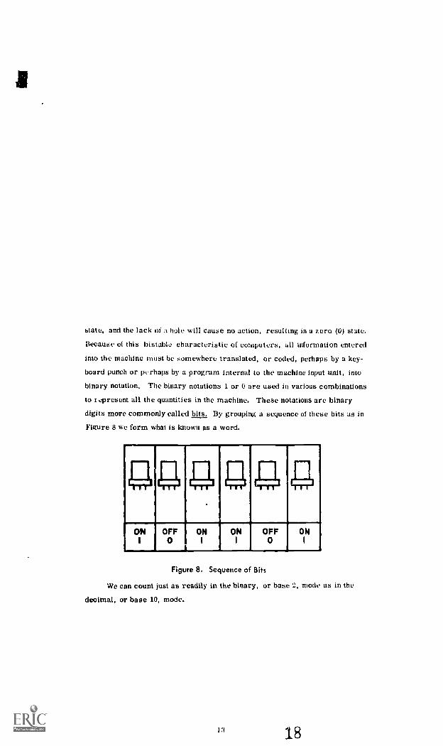
state, and the lack of a hole will cause no action, resulting in a zero (0) state.
Because of this Instable characteristic of computers, all information entered
into the machine must be somewhere translated, or coded, perhaps by a key-
board punch or perhaps by a program internal to the machine input unit, into
binary notation. The binary notations 1 or 0 are used in various combinations
to present all the quantities in the machine. These notations are binary
digits more commonly called bits. By grouping a sequence of these bits as in
Figure 8 we form what is known as a word.
ONI
OFF0
ONI
I
ONI
OFF0
ONI
Figure 8. Sequence of Bits
We can count just as readily in the binary, or base 2, mode as in the
decimal, or base 10, mode.
13 18

Figure 9 shows a comparison of numbers from both systems. The
decimal system operates with 10 digits, from 0 to 9. To indicate numbers
larger than nine, we shift place in the number 10. Place is shifted again at
100, 1,000, and so forth, or in other words at each power of ten. The
binary system operates with only two figures, a 1 and a 0; therefore this
system is based upon a power of 2, and the progression of the powers of 2
determines the value of any bit position. That is, the place shifts occur at
the binary equivalents of 2, 4, 8, 16, 32, and so forth.
Figure 9. Binary Counting
14
9

That we can represent numbers as readily In the binary system as in
the decimal system is shown in Figure 10, where binary notation is on the
left and decimal on the right. The binary notation In Figure 10 can also be
expressed as follows, reading from left to right: (1 x 26) + (1 x 25) + (1 x 24) +
(1 x 23) + (1 x 22) + (0 x 21) + (1 x 2o) or (1 x 64) + (1 x 32) + (1 x 16) + (1 x 8)
+ (1 x 4) + (0 x 2) + (1 x 11.
Figure 10. Binary Notation vs Decimal Notation
To human beings the binary system seems awkward. For a machine,
however, able to switch between two stable states at electronic speed, the
binary system allows a much simpler design and implementation.
The most common form of data encountered in our early uses of com-
puters was numerical. A number has two basic characteristics, its sign
and its magnitude. To handle the sign, we need only allocnte One particular
bit, usually the first one with, for example, 1 for plus and 0 for minus. On
the other haml, representing the mapitude involves indicating where the
binary point is kw
15

Since all bits look alike, in the early days of computers it was simplest
to assume that all numbers were either less than or greater than one. That
is, the binary point was assumed to be fixed either at the left end of the num-
ber (just after the sign bit) or at the right end. Such numbers are referred to
as fixed-point numbers. In preparing a problem for solution on a computer,
one of the more difficult tasks was keeping track of the binary point. For ex-
ample, the sum of 10 and 1 is quite different from the sum of 1.0 and 1. This
led to the allocation of a set of bits as shown in Figure II to indicate that the
true locatio3 of the binary point it. so many places either to the right or left
of the indicated Ersition. In the example of Figure 11, the binary point should
be moved four places to the left, which can also be shown as an exponent with
a power of -4. Such numbers are referred to as floating-point numbers.
AS A FIXED POINT NUMBER:Si MAGNITUDE0 100000010000000000000011 I I 1000C9001
+ .25195324060
AS A FLOATINGPOINT NUMBER:SIN FRACTION EXPONENT
OOI0000001000000000000001 100001 00+.25195324 2-4
Figure 11. Fixed and Floating Point Numbers
10

When computers came to be applied to non-numerical problems, the
machine binary language took many forms to satisfy the needs of the data
being processed. In Figuri. 12, I have Indic, Tod few examples of such
representations. In the top line of Fist. e 1: , we owe a d' rect !representation
ALPHABETIC DATA:
O T 0 N1
1001101310010101001i 100110 100101
ALPHAMERIC DATA:
T I W
1010 0111010 110 010111I 2
000001 00 0 0109
0010 01
PACKED DATA:EISKILL I
EMPLOYEE NO. IK CODE SALARY
10011 01 01110001111010 0110110 010110000
Figure 12. Non - numerical Data
17
22

of alphabetic information, the word Boston. With six bits we have 14 distinct
configurations (or codes) available. Hence we can arbitrarily associate a
unique set of six bits (commonly called a byte) with each of the 26 letters of
the alphabet, with the ten decimal digits, and with 28 other special characters
such as plus signs, minus signs, equal signs, punctuation marks, and so forth.
In the second line of Figure 12, 1 have portrayed an example of an alphameric
entry, that is, an entry that combines both alphabetical and numerical data.
In the third line we have an example of how information can be condensed
or "packed" into a word. We can, as in this example, arbitrarily decide that
the 15th bit in an entry will represent an employee's sex; thus we need only
one bit, a 1 or a 0, to represent either "male" or "female," However, if we
wanted to print out the sex of an employee, the computer would first have to
determine whether the 15th bit was a 1 or a 0 and then select from a different
section of storage a representation of the desired words in the form shown in
the first line of Figure 12; that is, after seeing the bit 1, it would select the
bytes for "male," The machine would then send the bytes for "male" to an
output printer where they would serve as a signal to print the actual sex,II
In the foregotng I have briefly summarized the binary system that serves
the machine as its internal language. Let us now turn to the machine itself to
see how it stores and manipulates its bits and bytes.
18
23

MACHINE sToRAGE AND MANIPULATItiN
The storage unit or memory of a computer can be considered, as shown
in Figure 13, to be subdivided into a set of cubby-holes or "cells" (also called
memory locations). The contents of each of these cells are a sequence of bits
which is called a word. -Ne have seen, the term byte has been introduced
to refer to small groups, usually 6 or 8, of consecutive bits treated as a unit
for character representation and other purposes. The size of the word varies
,
,;
Figure 13. Storage Unitamong different computers, with 16, t6, 48, and 64 bits being the most com-
mon. Note that a cell corresponds to a line in the notebook I discussed earlier
in the human-oriented system. dust as %%e numbered the lines of our notebook,
we associate with each cell a number which e call the cell's address in much
the same manner as %% y our homes.
lU
24

Also shown in Figure 13 is a switch that is used to select the cell that
corresponds to a specified address, allowing the computer to read a word into
or out oi the selected cell. Designers are expending much effort in the develop-
ment (0 techniques that will permit the computer to select a cell on the basis
of a logical comparison of the contents of that cell with a specified bit pattern.
A storage with this capability is called content-addressed or associative.
In our earlier discussion of a semi-automatic digital computation, we
noted that we had to provide our system with a complete set of instructions
and data. In the discussion associated with Figures 11 and 12, we have seen
how a binary word can be used to represent data. In Figure 14 we can see
how a binary word can be used to represent an instruction. As an instruction,
it tells the computer what operation is to be performed - for example, add or
subtract - and where the number to be operated upon is to be found. In the
simplest form, as shown in the figure, only one operand is identified in an
instruction. Such a logic is chalacterized as single-address. In multi-
address machines it may be possible to specify two operands, where the
answer is to be stored, and/or where the next instruction is to be located.
More generally, by allocating the bits in an instruction, one can pack more
information into an instruction, such as address modifiers, etc. By allocating
more bits for the operation code, a particular machine can offer a wider range
of operations.AS IT APPEARS IN MEMORY:
001000000100000000000000111110000100
AS AN INSTRUCTION :OPERATION
001 0000001 00000000000SUS
ADDRESS0001111100001001
3972
Figure 14. Typical Computer Word
20
25

--*
The question of how a word is to be interpreted is decided by the control
element, as shown in Figure 15. When the control element takes a word from
storage, it treats it as an instruction, separating and decoding the operation
portion in order to direct the other elements of the computer system. When
the arithmetic unit is directed to select a word from storage (by the address
of the operand) it then treats that word as data and operates upon it, as
directed by the operation selected. As indicated in Figure 15, the arithmetic
IMMO OWN. .1=1111,11111* IMO MED MEM
ARITHMETICADD, SUBTRACT, MULTIPLY,
DIVIDE, COMPARE, SHIFT, ETC..
Figure
ICONTROL
TAKES THE NEXT
INSTRUCTION FROM
STORAGE , THEN
DIRECTS ALL OTHER
ELEMENTS.IMM 01111 1111. 0/110
1 5 . Control and Arithmetic Unitsunit can carry out a number of operations, both arithmetic and logical. In
some computers the arithmetic and control units are considered functionally
together and called the processing unit.
As indicated above, to solve a problem the computer must be supplied
with a complete set of instructions and data. kVe call this information a coded
program, or more loosely a program. After the program has been read into
the computer and stored, the control element is told where to find the first
Instruction; that is, it is given the address of the first %sorcl to be treated as an
21

instruction. The control element then proceeds sequentially through storage,
taking words from successive cells and carrying out instructions until it
encounters a so-called jump or transfer of control instruction. Such an in-
struction may unconditionally cause the control element to go to another
section of storage and proceed sequentially from there. Or, the program may
call for a conditional transfer depending on a preset option. The computer's
power is increased manyfold by its ability to transfer to different stored
sequences according to preset conditional criteria. To illustrate simply: a
computer's program may call for it to multiply two numbers, x times y. After
the product, z, is found it can be compared to another number, w. If z is
Less than w, the computer follows one sequence of instructions; if equal,
another. The programmer can set up vast numbers of these simple conditions
in a long complicated program and thus the computer can carry out very com-
plex decisions at very high speeds. Programmers have used this simple
operation to carry out highly sophisticated strategies under dynamic operating
conditions. Of course, it is most important that in making these comparisons
and selecting the appropriate course of action, the programmer or analyst be
aware of the criteria and corresponding courses of action.
MACHINE OUTPUT
During the input phase of automatic computation the programmer's
language had to be translated into the machine's internal binary language. In
the output stage the machine's internal language must be translated back into
a languaga readily understood by the user. Depending upon the user's demands,
the output can be quite simple or quite sophisticated. For example, a printout
might merely list a series of numbers: 22.42, 36.44, 85.92, etc. However,
22
27
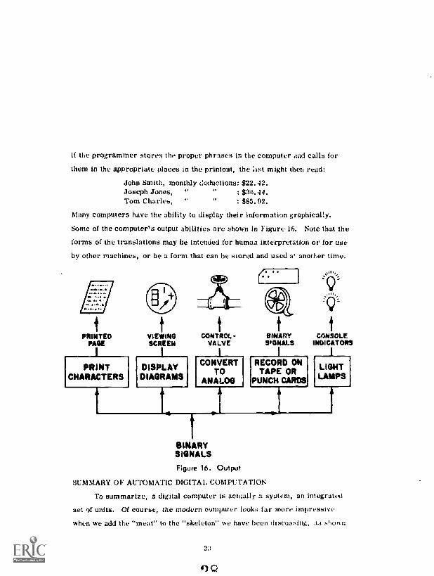
if the programmer stores the proper phrases in the computer and calls for
them in the appropriate places in the printout, the :1st might then read:
John Smith, monthly deductions: $22. 42.Joseph Jones, " : $36.44.Tom Charles, 1/ $85. 92.
Many computers have the ability to display their information graphically.
Some of the computer's output abilities are shown in Figure 16. Note that the
forms of the translations may be intended for human interpretation or for use
by other machines, or be a form that can be stored and used a' another time.
PRINTEDPAGE
PRINTCHARACTERS
tVIEWINGSCREEN
DISPLAYDIAGRAMS
4
CONTROL -VALVE
CONVERTTO
ANALOG
.1
BINARYWs:MALE
RECORD ONTAPE OR
PUNCH CARDS
BINARYSIGNALS
Figure 16. Output
SUMMARY OF AUTOMATIC DIGITAL COMPUTATION
To summarize, a digital computer is actually a syetcm, an integrated
set of units. 01 course, the modern computer looks far more impressive
when we add the "meat" to the "skeleton" we have been discussing, as sl;own
V
CONSOLEINDICATORS
LIGHTLAMPS
2:
Q

in Figure 17. Nevertheless, the basic components that we discussed are still
recognizable in the figure. As we indicated in Figures 6 and 16, magnetic
tapes can be used as either input or output. However, they may also be used
to store large amounts of data or special programs in a manner similar to the
notebooks that were kept in the bookcase of Figure 3. Such auxiliary or
secondary storage is characterized by large capacity and low cost but relative-
ly slow availability. That is, in using such secondary storage the overall
computing time may be lengthened. As we will disc tss later, other devices
such as magnetic disks and drums are also used for secondary storage.
Figure 17. Actual Digital Computer
As time goes on, the basic organization of computers can be expected
to change. Some of these changes arc part of the natural evolution of computer
design logic, such as the overlap of operations, the use of program interrupts
tor more f 4fletent use of in output, and auxiliary storage, etc. Some
changes are Induced by doo desire to make more efficient us, of computer
2,1

elements. For example, a relatively small computer program can tie up the
whole computer even though only a relatively small section of storage is used.
One way of handling this problem is shown In Figure IS. In this computer
organization it is possible to process simultaneously a number of smallser
problems, or portions of a larger problem, in the small peripheral computers,
permitting them access to the larger central processor and memory as needed.
PVIIITNIRALCONTROL
PROCESSOR
PCONISOULLCONTROL
PROCESSOR
PtINPNERALCONTROL
P ROCESSOR
P eRPMERALCONTROL
PROCESSOR
PERPNERALCONTROL
PRocassoa
CENTRat.PROCESSOR
PCORNER. PCMPRIRRLCONTROL CONTROL
PROCESSOR PROCESSOR
PERIPNERALONTROL
PROCESSOR
PitiewteeLcorrect
PROCESSOR
PINOW:1104.COVIROL
PROCESSOR
Figure 18. Advanced Computer Block Diagram
25
30

SECTION V
COMPUTER COMPARISONS
As a result of technical development, market requirements, competition,
and varied applications, computer makers today offer the user a wide variety
of digital computers. At present approximately 60,000 electronic digital com-
puters have been built in the United States, with approximately 25,000 more
on order. By 1970 the federal government's annual bill fir computing equip-
ment is expected to exceed two billion dollars. In this section I will lay down
some general ground rules for comparing computers. My criteria will be
cost, applicatirn, storage, and input/output equipment.
COST
Perhaps the simplest way to classify computers is by coat. Generally,
"You get what you pay for." That you can rent digital computers from a few
hundred dollars a month (e.g., PDP-5, Monrobot xl) to a few hundred thou-
sand a month (e.g., CDC 6600) Indicates the wide variety available.
Of course, for the higher rentals you get increased speed and computing
potential. It is interesting to note that as the price of equipment goes up, the
cost per unit of computation goes down. Consequently, in general, it will cost
less to do a particular job on a mere "expensive" computer. This statement
must be qualified by assuming that the job in question pays on a pro rata basis
and that the job requires an insignificant amount of manual intervention.
A simple example of the trade-off between cost and processing speed is
apparent In the distinction between serial and parallel processing units. For
example, as shown in Figure 19, two numbers can be added together a digit at
a time. This would involve simply a one - digit: adder. One could feed the digits
one at a time, taking proper account of carries, storing each resultant digit in
the answer. Such a process is obviously much slower than a howler that can
26

25,632+ 75,124
96,766
2 5 6
7 3
6
2
Figure 19. Serial and Parallel Addersadd all of the corresponding digits of the two numbers simultaneously, noting
the carries, and then adding in the carries to obtain the sum In basically two
steps. This latter process requires a more expensive adder but greatly speeds
up the process. Since it operates on all of the digits at the same time (th/t is,
In parallel) it is called katrallel processor in contrast to a serial processor
that operates on the digits one at a time. Serial and parallel concepts appear
in the machine logic in other areas besides the arithmetic units, such as, for
example, in the transmission of words fr,..m one location to another. This
may be done serially (one bit at a time) or in parallel with a separate trans-
mission path for each bit. In the most modern computers one even finds
instructions being executed in parallel (e. g., six at a time in the CDC 6600), in
contrast with the basic serial execution of most other computers. In computers,
as in Christmas tree lights, parallel circuitry adds to the cost but improves
the operational performance manyfold.

APPLICATION
Another basic differentiation among computers has been in the type of
application, as shown in Figure 20. In the early development la; computers,
SCIENTIFIC
BUSINESS
REAL -TIMETIME BETWEEN EVENTS
RESPONSE TIME
ON-LINE DATA PROCESSING
Figure 20. Computer Applicotionsa distinction was made between computers designed for scientific and those
for business applications. Scientific problems require large amounts of
computation with relatively small amounts of input and output data. On the
other hand, business applications involve large amounts of data, relatively
small amounts of calculations, with large amounts of output in the form of
reports or updated files. Computers were designed for one or the other set
of requirements. Even today among our lower and medium-priced computers,
this distinction is present. However, in our higher priced, more sophisticated
computers, and in new lines of computers now being announced, this distinction
is disappearing. These computers combine high-speed processing capability
with the ability to process large amounts of input data, and can turn out large
amounts of output data.
Real-time application has added yet a third dimension to the ity au use
computers. "Real-time" is an ill - defined word, in that different computer
people mean different things by it. ity "real-time," 1, nie.in that the results

must be available from the computer in a time consistent with the occurrence
of events and with the desired responses. In the previous two classes of appli-
cations we were concerned with the amount of information to be processed and
with the complexity of the processing. However, scientific and early business
requirements placed little restriction on the time required, so that it was not
uncommon to allow a computer to grind away overnight carrying out some
lengthy calculations (e. g. , tables of functions).
However, a number of applications such as teaching systems, process
control applications, and guidance and control for various transportation
systems require that the computed results be ready within predetermined time
limits. The time between events, such as the time required to initiate cor-
rective actions, normally determines these limits,
The availability of computer systems that can respond in real-time has
opened up a large area of on-line data processing systems that enter informa-
tion into the data processor as the data is generated and provide outputs as
they are required. Such applications have placed even more difficult require-
ments on the available storage and input/output devices. Progress in this area
has made possible the use of multiple access to the con.puter, an operation
known as time-sharing. In time-sharing, a number of users at remote con-
soles share the central computer facility. Time-sharing lowers expenses for
individual computer users in iiist it allows them to be on-line to a computer
around the clock but to pay only for the computation time they actually use.
From the computer installation's 'mint -of -view, the availability of a number
of diverse users may make it possible to justify a larger centralized facility
and to use that facility more efficiently.
One possible Interesting result of this evolution may be a shift in man-
agement use of computers away from repetitious printing of compendious
29
34

reports. 'Alien a user is limited to batch-procesNing, that is, when, generally
speaking, he must get on the machine and run his entire program or large
portions of his prot2,-ram and then get off the machine, he is inclined to want
comprehersive printouts in order not to be misr.ing any imormation that may
he ..-eded. In an online situation, if users can learn to trust computers and
the accessibility of information in a computer system, perhaps they will come
to consider the computer itself a randy repository of essential information
which is rapidly accessible when and as needed.
STORAGE
Many materials have been employed e.. the development of storage
devices, but magnetic materials have been used most widely. Figure 21 com-
pares some of the more common storage devices in use today. The table
entries must be given as ranges and should be considered only as repre-
sentative. in the past, disks, drums, and tapes have provided the more com-
mon forms of mass storage. Recent developments have extended the capacity
directly addressable core storage, making it available for auxiliary mass
storage.
1_ I 1sTORAGE I APPROXI MAI e. RANDOM DATA I Y P I CAi:
DEVICE ! MAXIMUM ACCESS TIME TRANSFER RATE COSTCAPACITY
_i
i
L(MEGABITS) ! (SECONDS) (MEGABITS/SEC.) (S/BIT)
MAGNETIC !1 0.5 -8.0 .
CORES10
MILLIONTHS :
4 -64 5-50
1- -IMAGNETIC i
58 0.02 1.2DRUM
0.09 O.'__ t --f-
MAGNETIC ;
DISC1800 ' 0.15 1.2
--i- I --r-0.02-03
-'-' ---iMAGNETIC ' I
L TAPE 160 0.8 0 0 i1
'
Figure 21. Sample Storage Devices
30
35

The third column in Figure 21 indicates the access time required to
place information into or obtain information from the various storage devices.
Two situations can be distinguished. The first is called random access and
the second sequen I access. In random access, the access time is independ-
ent of the location of the information most recently obtained from or placed in
storage. We often use the term in a relative way, in that access via drum
storage is considered less random than access via magnetic cores, but more
random than magnetic discs. Magnetic core storage, through a coordinate
system, allows the computer to go directly to the core holding the bit of
information it wants. Drums and discs involve the positioning of read-write
heads and the revolution of drums or discs, and therefore, rather obviously,
their access time is not completely independent of the location of the informa-
tion most recently stored or requested. Magnetic tape, where the computer
must search through the contents of a tape in sequence looking for the informa-
tion it seeks, is at the other end of the access time scale from core storage
and is a good example of sequential access.
The third column of Figure 21 lists the random access times for the
various magnetic storage devices. Note that the time for magnetic cores is
listed in microseconds, the times for the others in seconds. Core memory
gives the user a tremendous advantage in access time. However, once you
have found your place in memory, the data transfer rates, noted in the fourth
column of Figure 21, are quite good for all the devices.
A comparison of the third column with the fifth column, cost, indicates
the trade-offs involved. The cost of core memory is many times higher than
that of the other methods. Tape memory, with its much slower access time,
is also fa and away the cheapest method. Of course, several memory devices
can be incorporated in one machine. Remember our early, human-oriented
example. The notebook represented central storage; the bookcase, bulk
31
36

storage. A compater might represent a compromise in that its central storage
is handled by core storage and its bulk storage by drum, disc, or tape.
There are many other storage devices available today, including gloss
delay lines and photographic material as well as other magnetic materials.
Also, many other factors most be considered, such as reliability and inter-
connectability. However, the information presented in Figure 21 should
serve as an indication that computing systems can differ significantly just in
the choice of storage devices.
INPUT/OUTPUT DEVICES
Figure 22 indicates some of the representative input/output devices
available today.
Figure 22. Input/Output Devices
37

storage. A computer might represent a compromise in that its central storage
is handled by core storage and its bulk storage by drum, disc, or tape.
There are many other storage devices available today, including glass
delay lines and photographic material as well as other magnetic materials.
Also, many other factors must be considered, such as reliability and inter-
connectability. However, the information presented in Figure 21 should
serve as an indication that computing systems can differ significantly just in
the choice of storage devices.
INPUT/OUTPUT DEVICES
Figure 22 indicates some of the representative input/output devices
available today.
Figure 22. Input/Output Devices
:52
38

As time goes on, old devices are improved and new ones developed. Two
of the new input devices not shown in the figure are character-recognition
readers and light guns or pencils. The light gun is a device designed to work
with a cathode ray tube. With the gun you can point to acceptable words or
phrases displayed on the tube and build your own programming statements.
Engineers and linguists are currently working on the problem of allowing the
user to talk directly to the machine, but the problems in this area are still
considerable. In output, however, audible devices are already available,
working with an extremely limited set of words and phrases.
As in storage, many trade-offs involving operating characteristics
versus cost are involved in input/output devices. As is to be expected, the
equipment providing the fastest transfer rates and the more sophisticated
responses costs more. Some are very expensive, in some cases costing more
than the processing and storage units.
33
39

SECTION VI
WHY USE DIGITAL COMPUTERS?
The obvious advantage to computer operation is speed. Increased com-
puting speed provides more timely results, makes possible quick response
times, provides the capability of executing, automatically, long, complex
sequences of operations, and of processing involved formulae, and makes
possible the evaluation of alternative procedures and plans.
Moreover, digital computers have also tremendously increased relia-
bility. Analysts have estimated that a person operating a dcsk calculator can
be expected to make an error on the average of once every thousand operations.
On the other hand, digital computers, particularly the new solid state
machines, usually run error-free for many days at a time; in one hour a large
computer can perform over a billion operations. Advances in computer tech-
nology will continue to improve the reliability of our equipment. Also, re-
ductions in machine down-time increase the equipment availability, in con-
trast to the availability of the individual worker who loses time because of
illness and the ever-decreasing work day.
As we discussed, under storage devices, the digital computer has the
ability to store and process large amounts of information. There has been an
explosion in the amount of data available in today's government and industrial
systenis. With the proliferation of sensor and effector devices, the improve-
ment in communication systems, and the development of new processing
requirements, the digital computer has been called upon to provide the data
processing capacity needed. Our present-day space program, as an example,
would be impossible without computers.
Computers are flexible. The range of problems that a piece of hardware
can handle is Increased simply by reading a new program Into the machine,
34
40

Every time a new program has been checked out and added to the machinc's
library, a new capability has been added to the machine. For a Dimple ex-
ample, once a computer has been programmed to solve standard deviation
problems, all the user need do ever after Is provide the data and ask the
computer to work the standard deviation problem. The computer's software
provides much of the machine's flexibility, and, as might be expected, is
expensive, often as expensive as the hardware itself.
Computers have emancipated mankind Irom the slavery of performing
repetitive, routine calculations by hand. Computers provide a most important
tool for assisting man in creative areas such as planning, design, and complex
decision making.
Computers can reduce processing costs. In many cases the extent of
the savings has been masked by the extension of the computer process to
provide new results and services that were not available in the manual system.
The use of new storage media associated with the computer processing has
reselted in significant savings to many companies in the floor space formerly
de,oted to data files.Finally, there is the whole area of improved system performance now
available to our system designers. In a sense, it is the realization of the
aggregate of the attributes discussed above that has opened new vistas of
applications.
We can conclude our discussion by noting that despite exaggerations,
disappointments, misuse, and misunderstandings, comptaers are here to stay.
Computers have proved themselves in areas characterized by short response
time and routine calculations. For jobs requiring an almost instantaneous
processing of large amounts of data, manual systems, no matter how large a
manpower effort we may expend, cannot satisfy the requirements. For routine
engineering calculations, the cost reduction ratio may be of the order of 1tI6,
41

For routine business data processing, such as might be encountered in insur-
ance premium billing, the cost reduction ratio has been found to be on the
order of 103 to 104. In language translation, it has been found that computers
can just about match a human translntor, although in both cases some post-
editing may be required. At the moment, in the area of pattern recognition
and decision-making we find applications where man is still far ahead of the
digital computer.
Obviously, however, we cannot consider the present state of computers
as static. As the coat of manpower goes up, and the cost of computers,
because of steadily improving hardware and software, goes down, we can
expect computers to move into more non-routine areas, Already, computers
are encroaching into such areas as bionics, neurophysiolog3., linguistics.
decision theory, and others. The computer age Is really only at its beginning.
36
42