(title of the thesis)* - university of calgary | home · 4.2.2 client-server architecture with...
TRANSCRIPT

UCGE Reports Number 20205
Department of Geomatics Engineering
A Software Engine for the Rapid Development of Mobile Asset Management Systems
(URL: http://www.geomatics.ucalgary.ca/links/GradTheses.html)
by
Suen Man Lee
October 2004

UNIVERSITY OF CALGARY
A Software Engine for the Rapid Development of Mobile Asset Management Systems
by
Suen Man Lee
A THESIS
SUBMITTED TO THE FACULTY OF GRADUATE STUDIES
IN PARTIAL FULFILMENT OF THE REQUIREMENTS FOR THE
DEGREE OF MASTERS OF SCIENCE
DEPARTMENT OF GEOMATICS ENGINEERING
CALGARY, ALBERTA
OCTOBER, 2004
© Suen Man Lee 2004

iii
Abstract
Developments in computing, location and wireless technologies have caused great
advances in the field of Location Based Services (LBS). A particular subset of LBS,
Mobile Asset Management Systems (MAMS) has attracted the attention of industry
because of its potential for improving productivity, safety and security. However,
obstacles remain that have hindered the adoption of MAMS by corporations. These
obstacles include the large number of technologies and providers that are available, plus
the isolated nature of MAMS development that creates duplication of effort and
resources. This research has focused on creating a development platform that offers the
fundamental functionality required by MAMS, enabling developers to use it as a
foundation for their applications while reducing duplication of efforts. This platform is
created using Java and leverages object-oriented application frameworks to realize
advantages in maintenance and ease of integration for developers. It offers two-way
communication and control capabilities in conjunction with remote sensors and a
widespread cellular network. Data management and storage capabilities are provided and
access to assets is available through the Internet with just a browser. The location of
assets can be overlaid against maps in vector and raster form. Testing was successfully
conducted using vehicles in multiple locations in Canada and the USA.

iv
Table of Contents Approval Page..................................................................................................................... ii Abstract .............................................................................................................................. iii Table of Contents............................................................................................................... iv List of Tables ..................................................................................................................... vi List of Figures ................................................................................................................... vii List of Symbols and Abbreviations ................................................................................... ix Chapter 1 Introduction ........................................................................................................ 1
1.1 Background ............................................................................................................... 1 1.2 Objectives.................................................................................................................. 6 1.3 Thesis Outline ........................................................................................................... 7
Chapter 2 Mobile Asset Management Systems .................................................................. 9 2.1 MAMS for Industry and Individuals......................................................................... 9 2.2 Assets ...................................................................................................................... 12 2.3 MAMS Requirements ............................................................................................. 13 2.4 MAMS Architecture................................................................................................ 14 2.5 Internet-based MAMS............................................................................................. 16 2.6 Existing MAMS Applications................................................................................. 20
2.6.1 One-Way MAMS Applications ........................................................................ 21 2.6.2 Two-way MAMS Applications ........................................................................ 32 2.6.3 Real World MAMS Summary.......................................................................... 36 2.6.4 Desirable MAMS Traits ................................................................................... 37
Chapter 3 MAMS Hardware and Software Technologies ................................................ 41 3.1 Wireless Communication ........................................................................................ 41
3.1.1 Radio................................................................................................................. 41 3.1.2 AMPS/CDPD ................................................................................................... 43 3.1.3 Aeris.NET MicroBurst ..................................................................................... 44 3.1.4 Next Generation Cellular Networks ................................................................. 47
3.2 Data Acquisition...................................................................................................... 48 3.3 Asset Data Management and Storage...................................................................... 51 3.4 Spatial Data ............................................................................................................. 52
3.4.1 Vector Data....................................................................................................... 52 3.4.2 Raster Data ....................................................................................................... 53
3.5 Object-Oriented Programming................................................................................ 56 3.5.1 Object-Oriented Application Frameworks ....................................................... 57 3.5.2 OO and MAMS ................................................................................................ 59
3.6 Client-Server System Architecture.......................................................................... 60 3.6.1 System Partitioning and Multi-Tier Architectures ........................................... 61 3.6.2 Middleware....................................................................................................... 61 3.6.3 Message-Oriented Middleware......................................................................... 62 3.6.4 Remote Procedure Call..................................................................................... 62
3.7 Dynamic Internet Content Presentation Technologies............................................ 63 3.7.1 Common Gateway Interface............................................................................. 63

v
3.7.2 Server Extensions ............................................................................................. 64 3.7.3 Server-Side Scripting........................................................................................ 65 3.7.4 Java Dynamic Internet Content Presentation Technologies ............................. 66 3.7.5 Java Applets...................................................................................................... 68 3.7.6 Java Servlets and ServerPages.......................................................................... 68
Chapter 4 Platform Methodologies and Architecture ....................................................... 71 4.1 Process..................................................................................................................... 71
4.1.1 Determining Platform Specifications ............................................................... 71 4.1.2 Platform Definition........................................................................................... 72 4.1.3 Platform Development...................................................................................... 72 4.1.4 Prototype System Development ....................................................................... 73 4.1.5 Platform Refinement......................................................................................... 74
4.2 System Architecture ................................................................................................ 74 4.2.1 Platform and Application Layer ....................................................................... 75 4.2.2 Client-Server Architecture with Partitioning.................................................... 76
Chapter 5 MAMS Platform Implementation .................................................................... 78 5.1 Java Technologies and MAMSDev......................................................................... 78
5.1.1 Java Framework................................................................................................ 78 5.1.2 High Level Java Components........................................................................... 80
5.2 MAMSDev Modules ............................................................................................... 81 5.2.1 Communication Module ................................................................................... 81 5.2.2 Data Module ..................................................................................................... 86 5.2.3 Application Module.......................................................................................... 93
5.3 Common Client-Server Protocol............................................................................. 97 5.4 Scripting .................................................................................................................. 98 5.5 Server Implementation ............................................................................................ 98
Chapter 6 Application Prototype Development.............................................................. 101 6.1 Implementation...................................................................................................... 102 6.2 Client Application ................................................................................................. 106 6.3 Field Testing.......................................................................................................... 113 6.4 System Testing ...................................................................................................... 116
6.4.1 Single-Client Performance ............................................................................. 116 6.4.2 System Limit Testing...................................................................................... 118
Chapter 7 Conclusions and Recommendations............................................................... 123 7.1 Conclusions ........................................................................................................... 123 7.2 Recommendations ................................................................................................. 126
References....................................................................................................................... 127

vi
List of Tables
Table 2.1: Real World MAMS Sumary ............................................................................ 37 Table 3.1: FleetLink Remote Sensor Specifications
(http://www.fleetmind.com/flash/components/flash.html)........................................ 49 Table 3.2: Asset-Link Specifications (http://www.csi-
wireless.com/products/documents/NewAssetLink.pdf) ............................................ 50 Table 5.1: Communication Module Capabilities .............................................................. 82 Table 5.2: Data Module Specifications............................................................................. 87 Table 6.1: Single-Client Performance Metrics ............................................................... 117 Table 6.2: Summary of the Server Attributes with Simulated Users.............................. 121

vii
List of Figures
Figure 1.1: Potential Areas for LBS ................................................................................... 2 Figure 1.2: Estimated Global LBS Revenue....................................................................... 3 Figure 2.1: MAMS Architecture....................................................................................... 16 Figure 2.2: Internet-based MAMS Architecture............................................................... 19 Figure 2.3: Telus User Component (www.telusgeomatics.com)...................................... 22 Figure 2.4: Telus User Component Reports (www.telusgeomatics.com) ........................ 23 Figure 2.5: FleetLink Data Acquisition (www.fleetmind.com)........................................ 25 Figure 2.6: FleetLink Asset Data (www.fleetmind.com) ................................................. 26 Figure 2.7: FleetLink Asset Activities (www.fleetmind.com) ......................................... 26 Figure 2.8: MEMS Data Acquisition [Ramsaran, 2000] .................................................. 27 Figure 2.9: MEMS User Component ................................................................................ 29 Figure 2.10 Seamless Internet/Radio Data Transmission ................................................. 31 Figure 2.11: IMEMS: Web-based User Component......................................................... 32 Figure 2.12: DirecTrack User Interface [DirecTrack, 2003] ............................................ 34 Figure 2.13: Tellicate User Component [Tellicate, 2003] ................................................ 35 Figure 2.14: Tellicate User Component Reports [Tellicate, 2003]................................... 36 Figure 3.1: Aeris.Net MicroBurst Coverage Area
(http://www.aeris.net/aeris_web/products_coverage.html)....................................... 45 Figure 3.2: CSI Asset-Link Sensor (www.csi-wireless.com) ........................................... 49 Figure 3.3: MapQuest Service Example (http://www.mapquest.com) ............................. 55 Figure 3.4: Microsoft MapPoint Service Example (http://mappoint.msn.com) ............... 56 Figure 3.5: Common MAMS Elements ............................................................................ 59 Figure 3.6: CGI Request Process [Hunter & Crawford, 1998]......................................... 64 Figure 3.7: Server Extension Request Process (Hunter & Crawford, 1998) .................... 65 Figure 3.8: Servlet Request Process (Hunter & Crawford, 1998) .................................... 69 Figure 4.1: Development Platform from Start to Finish ................................................... 71 Figure 5.1: Use of Java Technologies In MAMSDev....................................................... 80 Figure 5.2: MAMSDev Implementation Architecture (Vector Maps) ............................. 99 Figure 5.3: MAMSDev Implementation Architecture (Raster Maps) ............................ 100 Figure 6.1: iVCAMS3 Architecture (Vector Maps)........................................................ 103 Figure 6.2: iVCAMS3 Architecture (Raster Maps)......................................................... 103 Figure 6.3: iVCAMS3 Login Screen............................................................................... 106 Figure 6.4: iVCAMS3 Main Screen with Calgary Raster Map....................................... 107 Figure 6.5: iVCAMS3 Main Screen with Calgary Vector Map ...................................... 107 Figure 6.6: Fort Lauderdale Vector and Raster Map ...................................................... 108 Figure 6.7: North America Vector and Raster Map........................................................ 109 Figure 6.8: Typical iVCAMS3 User Session Using Vector Maps .................................. 110 Figure 6.9: iVCAMS3 Overview Map ............................................................................ 111 Figure 6.10: Historical Information Regarding a Specific Asset.................................... 112 Figure 6.11: Vehicle Management Tool ......................................................................... 113

viii
Figure 6.12: Tracking an Asset....................................................................................... 114 Figure 6.13: Roundtrip Latency of Pages to Assets........................................................ 116 Figure 6.14: Graph of CPU and Network Usage at Two Message Loads ...................... 119

ix
List of Symbols and Abbreviations
AMPS Advance Mobile Phone Service AS Page Server ASP Active Server Pages AVL Automatic Vehicle Location CAD Computer Aided Design CDPD Cellular Digital Packet Data CGI Common Gateway Interface CS Client-Server CSMA/CD Carrier Sense Multiple Access/Collision Detection DS Data Server FCC Federal Communications Commission FOCC Forward Control Channels GIF Graphic Interchange Format GIS Geospatial Information Systems GPRS General Packet Radio Service GPS Global Positioning System HTML Hypertext Markup Language HTTP Hypertext Transfer Protocol IMAMS Internet-based Mobile Asset Management Systems IMEMS Internet-based Mobile Equipment Management System ISAPI Internet Server Application Program Interface iVCAMS3 Internet-based Vehicle Control And Monitoring System for Safety and
Security JDBC Java Database Connectivity JPG Joint Photographic Experts Group JSP Java ServerPages JVM Java Virtual Machine LBS Location Based Services MAMS Mobile Asset Management Systems MAMSDev MAMS Development Platform MEMS Mobile Equipment Management System MIN Mobile Identification Numbers MLSS Multi-Layer Storage Scheme MOM Message-Oriented Middleware ODBC Open Database Connectivity

x
OO Object-oriented PNG Portable Network Graphics RECC Reverse Control Channels RPC Remote Procedure Call RTT Radio Transmission Technology TCP/IP Transmission Control Protocol/Internet Protocol UHF Ultra High Frequency WWW World Wide Web

1
Chapter 1
Introduction
1.1 Background
Developments in widespread, robust yet inexpensive location and wireless
communication technologies have resulted in an explosion of activities in the field of
Location Based Services (LBS). Timely and relevant information enables informed
decision-making and benefits productivity, safety and security. A particular subset of
LBS, known as Mobile Asset Managements Systems (MAMS) have garnered significant
interest from corporations desiring more efficient means of managing their asset fleets.
As assets move and perform their assigned tasks, corporations using a MAMS can
effectively monitor how they are being used, how often they are idling and find the most
optimal route for their assets to take. Modern mining operations involve hundreds of
support equipment such as lightplants, heaters, welding units, electrical generators,
graders, dozers and trucks [Ramsaran, 2000]. The location, maintenance and scheduling
of available equipment at a mining site are critical to day–to-day operations, since a
typical open-pit mining operation can easily cover an area of 40,000 hectares in size.
Each piece of equipment therefore has to be at the right place, at the right time and in
working condition to prevent any downtime in operations [Gao & Ramsaran, 2000].
Downtime for mining industries is costly to production and can result in millions of
dollars of losses [Carter, 1999]. Other promising applications for MAMS include

2
personal vehicle monitoring and security systems because of the large number of
automobiles that are stolen or are involved in accidents each year.
The impetus for LBS came out of the demands of the United State’s FCC (Federal
Communications Commission) for cellular operators to be able to provide the position of
any cellular devices operating on their network to public emergency services, accurate to
within 125 meters, as part of the FCC’s Enhanced 911 program [Prasad, 2001]. While the
deployment of systems actually capable of meeting the FCC requirements by the original
deadline of October 2001 has been troubled by technological obstacles and cost [FCC,
2003], the new technologies that have been developed to try to meet the FCC demands
have also given arise to new opportunities. Technologies developed originally for
positioning within a cellular network or phone designed for emergency location have
formed the basis for exciting new developments enabling innovative applications. Figure
1.1 [Prasad, 2001] shows some of the areas that LBS could be potentially used for.
Figure 1.1: Potential Areas for LBS
There are also many possible applications for MAMS. Devices integrating wireless and
positioning capabilities could be attached to corporate vehicles and assets for monitoring.
Resource operations and corporations with large asset fleets would be the primary
3
beneficiaries here. MAMS could also form the basis of services targeting individuals by
providing nearby points of interests or relevant information on demand, using location-
aware cellular phones or other wireless devices. The sheer number of applications that
can utilize a MAMS are expected to drive the expansion of the MAMS and LBS market
[Prasad, 2001; EUROPA, 2003] and have attracted significant attention from industry,
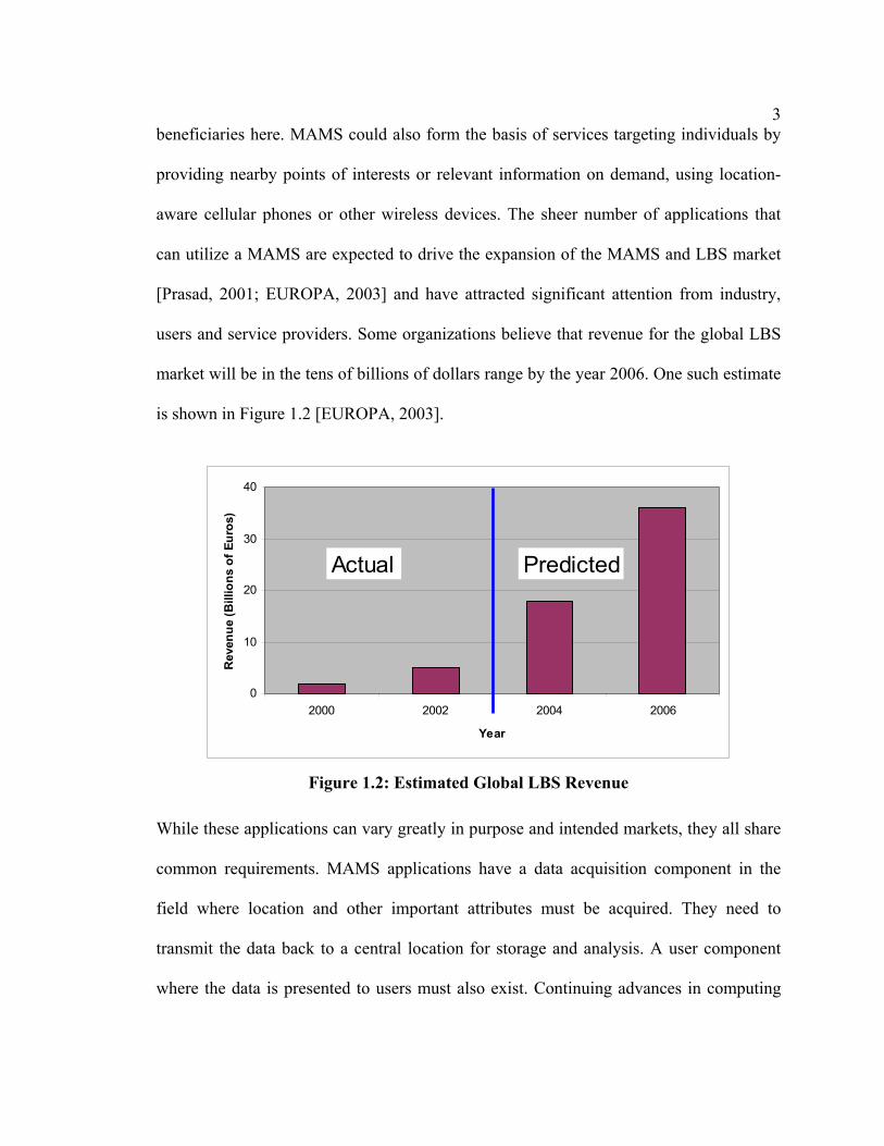
users and service providers. Some organizations believe that revenue for the global LBS
market will be in the tens of billions of dollars range by the year 2006. One such estimate
is shown in Figure 1.2 [EUROPA, 2003].
0
10
20
30
40
2000 2002 2004 2006
Year
Rev
enue
(Bill
ions
of E
uros
)
Actual Predicted
Figure 1.2: Estimated Global LBS Revenue
While these applications can vary greatly in purpose and intended markets, they all share
common requirements. MAMS applications have a data acquisition component in the
field where location and other important attributes must be acquired. They need to
transmit the data back to a central location for storage and analysis. A user component
where the data is presented to users must also exist. Continuing advances in computing

4
technology enables more and more computing power to be packaged into smaller
devices. Accurate positions can now be determined quickly and inexpensively by using
GPS (Global Positioning System). GPS is an all-weather, globally available radio
navigation system originally developed by the United States for military purposes but has
now become an important component in numerous scientific and civilian applications.
The United State’s commitment to maintaining GPS as a freely accessible system for the
foreseeable future along with the usefulness of accurate position information ensures that
the number of GPS-based applications will continue to grow. GPS receiver technology
has also advanced to the point where they can be placed onto a microchip, enabling the
creation of integrated devices ideally suited for data acquisition on mobile vehicles. Such
devices now have the computing power to get positions from GPS, monitor key vehicle
attributes and intelligently respond to events such as emergencies.
As the nature of MAMS involves with remote assets that are on the move and users
needing to receive asset data in a timely manner for the most effective and safe utilization
of assets, the data must be transmitted using wireless communication technology.
Wireless technologies have now become ubiquitous in everyday life, from widely
available cellular networks for voice and data traffic to wireless networking for
convenient access to the Internet. Numerous wireless options can be used, depending on
the bandwidth, availability and cost requirements of the MAMS. This availability of an
existing wireless communication infrastructure has enabled MAMS to be deployed by
service providers without the need to build their own wireless systems and thereby save
time and money. By using wireless communication to connect mobile assets with a
5
central office site, the latency can be reduced to seconds [Liu, 2002].
However, once at the office, the data still needs to be provided to the user. One solution
to this problem is the Internet. In recent years, the Internet has become a popular method
for sending data to users because of its platform independence and global reach. Remote
Internet access is also now possible through multiple wireless sources. By using an
Internet-based method for accessing asset data, advantages can be realized by simplifying
the storage of asset data at only one or just a small number of centralized sources, which
aids administrators and allows for changes and new data to propagate through the system
quickly. Users can also be confident that they have the most up-to-date information.
There are numerous technologies involved in a MAMS. There are also functionality that
overlaps between different MAMS applications. This offers an opportunity for a
platform, supplying a suite of useful functionality that can simplify the use of the many
technologies and provide common functions. Without such a platform, there would be
significant waste of time and resources because each new MAMS being developed would
be forced to recreate these common requirements repeatedly. Developers would also need
to deal with a multitude of heterogeneous technologies. These challenges have hindered
the quicker adoption of MAMS by industry. A platform dedicated for MAMS
development would solve many of these challenges by providing a foundation where
many of the common requirements are provided and working with the various
technologies is simplified. This platform will follow object-oriented principles so it can
be used in as many potential MAMS applications as possible and allow developers to
further expand and customize it to meet their needs.

6
1.2 Objectives
In this thesis, the concept of a software engine in support of MAMS has been
investigated. This software engine is location aware and helps augment MAMS
development by providing critical functionality required in MAMS applications, allowing
developers to reuse these functionality and maximize their time and resources on the
unique aspects of their applications. While MAMS are the primary application for the
engine, it will remain flexible enough so that it could also be extended to other LBS
activities in the future. This engine, known as MAMSDev, will act as a development
platform by offering a complete suite of important low-level functions that developers
can utilize as an important foundation for their MAMS applications. MAMSDev builds
and expands upon the existing work done previously by Liu in creating a wireless
framework Liu, 2002] and by Ramsaran in creating a mobile equipment management
system [Ramsaran, 2000]. MAMSDev expands upon Liu’s wireless framework to
include functionality to aid all aspect of MAMS, from asset to users. It also expands upon
Ramsaran’s work by taking advantage of newer technologies and supporting multiple
potential MAMS applications, instead of focusing on specifically for a single mining
company. MAMSDev will undergo real-world testing using existing commercial
equipment and networks with interested industrial partners. Major objectives in this
research include:
1) Investigating the requirements and specifications of MAMS and examine existing
MAMS applications for their pros and cons. The results will be used to create a
development platform to meet these requirements.

7
2) Investigating enterprise capable, client-server technologies plus available sensor
and wireless communication technologies suitable for use in MAMS and
integration into MAMSDev.
3) Development of communication capabilities for MAMSDev to interface with
selected remote sensors and wireless technologies.
4) Development of data storage and management capabilities for MAMSDev to
handle incoming asset data.
5) Development of an Internet accessible Web Client component for MAMSDev.
The Web Client will be used for data serving to remote users and support
simultaneous access. Supported data will include geospatial data in vector and
raster format plus non-spatial data retrieved from databases.
6) Development of a prototype system performing real-world MAMS tasks that
utilizes the new platform for its foundation. This prototype system will help
evaluate the value of the platform and provide useful experience and feedback to
improve the platform further.
1.3 Thesis Outline
Chapter 2 will review the concept of MAMS and their benefits of improved productivity,
safety and security for corporations and individuals. Their requirements and their general
architectures are also examined. The Chapter will also look at a number of real-world
MAMS in order to discover beneficial aspects that should be part of MAMSDev.
Chapter 3 will examine various software and hardware technologies that could be utilized
8
in a MAMS and therefore would be of interest for a platform, such as MAMSDev, which
is targeted for MAMS development. This Chapter will also examine object-oriented
application frameworks and how it improves the reusability of MAMSDev.
Chapter 4 will discuss the developmental process of MAMSDev and the fundamental
architecture and philosophies that were followed throughout its development.
Chapter 5 will detail the actual implementation of MAMSDev and its various
components. Problems encountered will be discussed, as well as solutions that were used
to overcome the problems.
Chapter 6 presents an actual real-world application that was developed using
MAMSDev. The system’s goals and purposes will be presented, along with the details of
how MAMSDev is used to achieve a system that meets its goals.

9
Chapter 2
Mobile Asset Management Systems
Advancements in LBS have led to the emergence of a wide range of MAMS applications
that are beneficial for many industries. Such systems have already gained attention from
corporations with large asset fleets seeking to maximize the efficient and safe usage of
their vehicles and equipment by providing up-to-date location information. They have
also emerged as a viable commercial business, enabling providers to sell location services
to consumers. A powerful new development has been the recognition that instead of
having just a one-way flow of information from the asset to the user, benefits can be
realized from having two-way interaction between assets and users. With two-way
capability, it is possible to remotely issue commands and control assets in real-time,
creating a true management system for assets and enabling new and innovative services
for the future.
2.1 MAMS for Industry and Individuals
MAMS can be used for corporations, individuals and governments. For corporations,
delays or shutdowns in an operation due to equipment not being at the right place or
unexpected failures can result in the loss of profits. Even worse, failures that result in
injury, loss of life or environmental damage can result in severe harm to corporate image
and incur long-term legal costs. Investments spent on systems such as a MAMS are an
ideal way to improve the bottom-line as they provide methods for predicting and

10
preventing asset failure [Kane, 2002]. However, many previous MAMS implementations
remained limited to simply acquiring equipment locations only. Furthermore, information
generated from assets in the field would be stored in centralized data warehouses that
typically did not have remote methods for accessing the data [Bistroem & Ray, 1999]. A
more useful system would provide additional data and functionality beyond only
locations, to become a complete solution for operational decision-making and be able to
provide the solution to all end users, whether they are working at the centralized office or
in the field. For an example of where this capability can be beneficial, assets operating
over a large work area may be left idling in the field due to the inconvenience of
manually turning them on and off. It could become possible to shut them off remotely by
issuing the command to onboard sensors linked to the asset’s electrical systems or engine.
Being able to remotely shutdown or turn on an asset reduces costs by allowing idle assets
to be turned off, saving fuel, wear and tear and reducing pollution. The last benefit is
especially important in light of ever-toughening pollution and environmental protection
regulations. A MAMS can also be used for monitoring commercial fleet vehicles, such as
those for long haul trucking and public transit. Recent studies have indicated that over
one million fleet vehicles in the United States were equipped with GPS-based location
system by 2003 and had doubled from 2000 [Driscoll, 2003].
MAMS can also be used to provide location-based services to individuals or
corporations. The most common and visible of these services are for vehicles and are
commonly referred to as telematics applications. Telematics refers to a combination of
telecommunications and computing technologies in the monitoring, processing and

11
relaying of vehicle locations [Honeywill, 2002]. Automotive telematics services integrate
cellular and/or satellite telecommunication technologies, location technologies such as
GPS with the electronics and computers onboard automobiles to provide navigational,
safety and security services [Allan (1), 2003].
The most common use of telematics currently involves vehicle navigation. Navigation
systems have become popular in luxury vehicles in the North American market. In
foreign markets, such as in Japan and Europe, where cities tend to be more difficult to
navigate compared to cities in North America, they have become commonplace in all
types of vehicles. Navigational systems are usually divided into autonomous systems and
call center systems. For autonomous navigation, vehicles are equipped with an onboard
GPS receiver, along with a CD or DVD based computer system containing maps of the
driving area. Using the GPS-determined position of the car, the computer system
provides audio and/or visual directions to the driver. With call center guidance, drivers
interact with a call center for navigational assistance. The GPS receiver remains on the
car, but there is no onboard map data. The vehicle’s location is sent to the center and a
human operator guides the driver to their intended destination through a cellular voice
link. An advantage of this system is that there is less distraction for the driver compare to
the autonomous system, which can reduce the chances of accidents occurring [Allan (1),
2003]. In addition to navigation, a call center can provide additional useful services for
their clients, such as conceriege services and safety monitoring, with safety being an
especially compelling selling feature of telematics [Allan (2), 2003]. OnStar, a popular
call center based service, handled 500 stolen vehicle requests, 5000 emergencies, 13,000

12
roadside assistance requests, 27,000 door unlock requests and 220,000 requests for
directions on a monthly basis in 2003 [Allan (1), 2003]. Future developments in
telematics could result in a more automated control center, whereby systems in the
vehicle communicate directly with control centers. Other possible advances include
systems that offer drivers the capability to interact with the vehicle and other services
through the Internet.
Finally, a MAMS could find its way into government usage. The cost of maintaining the
road infrastructure for vehicles and trucks is costly and there are new plans in Europe to
utilize telematics and MAMS technologies to implement a pay-per-use system [Vicenti,
2002]. Drivers that drive more, use busier roads or drive at busy periods of the day will
be charged more. Programs have already been initiated by the Swiss and German
governments for trucks to be installed with telematics hardware [Vicenti, 2002].
2.2 Assets
When referring to assets in the context of MAMS, an asset is anything that has inherent
value, or value due to having knowledge of location and other information for a
corporation. A wide variety of assets can be managed with a MAMS. The most common
uses of MAMS generally have assets of corporate-owned vehicles such as in trucking
fleets. In a resource mining operation, there are a variety of vehicles and equipment each
with different capabilities, requirements and tasks. For an electrical utility, many of its
assets are immobile distribution substations and other electrical network infrastructure
along with mobile units that perform maintenance and repairs [Bistroem and Ray, 1999].

13
For telematics service providers, the managed assets of interest are those owned by
clients who have purchased services for their assets.
2.3 MAMS Requirements
To be an effective tool for industry, a MAMS must be capable of aiding in or even
performing operational decision-making. It must be able to differentiate between
dissimilar assets while seamlessly handling spatial and non-spatial data. To have such
capabilities, a MAMS must have an open modular architecture and a seamless flow of
information. An open architecture is needed because a MAMS must be capable of
collecting and storing information from the field and process data from a variety of
databases for performing data retrieval, manipulation, analysis, presentation and decision-
making functions. By being open, a MAMS can be more readily integrated with other
applications [Ramsaran, 2000]. One of the major problems that have faced corporations
in creating MAMS is the short life cycle of new technology investments, resulting in a
poor return on their investment and difficulties in integration of different technologies
and end-user training [Peck & Murphy, 1997]. A seamless information flow is required
because information pertaining to the mobile assets need to be collected from the field,
stored into pre-assigned databases, accessed, manipulated and edited by a variety of
users. All these steps must be done in a timely manner in order to contribute to the
operational decision-making process. Advanced wireless communication, mobile
computing along with Internet technologies has now made it possible to have a
continuous information flow [Gao & Ramsaran, 2000].

14
A MAMS must be capable of addressing a number of problems in order to be a credible
system capable of aiding the operational decision-making process. Such problems include
[Lee & Gao, 2002]:
The location data of assets, by itself is usually not particularly valuable for most
MAMS applications; rather it is additional asset attributes combined with location
that is valuable. These additional attributes depend on the application and could
possibly include temporal, asset performance and status data. The monitored asset
data also needs to have timely availability. The system must be capable of
receiving, organizing and distributing these additional data and there must be
acquisition capabilities that can provide the desired data from the assets. Accurate
real-time data is an important foundation of an effective MAMS (Kane, 2002).
The system must provide functions and services that allow users, after making
decisions, to update the relevant databases.
2.4 MAMS Architecture
In most work environments where a MAMS would be used, the environment can be
separated into three domains, that of the Field, Office and User. The Field domain
consists of all the in-field assets. The Office domain consists of the systems used to store
the asset data. The User domain is the users and workers who require access to the asset
data to perform their jobs. The architecture of MAMS has four distinct components that
span across these domains. These components are described in the following [Ramsaran,
2000; Gao & Ramsaran, 2000]:

15
Mobile component – data acquisition by people and sensors in the field (Field
domain).
Wireless Communication component – communication between the Mobile
component and central servers for data warehousing (Field, Office and User
domains).
Data Management and Service component – data processing, management and
service provision (Office domain).
Decision Making component – analysis and presentation of data for decision-
making purposes (User and Office domains).
Figure 2.1 shows graphically how the different components and domains are connected
with a typical MAMS architecture where the User domain remains inside the Office
domain so all decision-making tasks have to be done within the Office. Potential users in
the field are therefore outside of the User domain so they do not have access to the asset
data or the decision-making capabilities of MAMS, even though they are likely to be the
ones that benefit from a MAMS the most.

16
Field Domain Office Domain
User Domain
Data Management
Decision Making
Mobile Component
Wireless Component
Decision Making
Figure 2.1: MAMS Architecture
2.5 Internet-based MAMS
New MAMS should be developed with the requirements of Section 2.3 in mind. Such
MAMS would have an open architecture and seamless information flow, be able to utilize
technologies such as GPS for location and GIS for data management and analysis. Radio
is commonly used to provide real-time wireless communication between mobile assets in
the Field and Office servers. However, the limitation of these types of MAMS is that
asset information and services can only be provided to users physically connected to it or
near the Office systems since there are no means to provide access to data or tools for
remote users. This restricts the usefulness of a MAMS for many potential applications
since users who need to access the system’s data and analysis tools may be located
geographically far away from the physical location of the MAMS. For instance, modern
energy exploration corporations with operations throughout the world require such
systems to be accessible from any location and by multiple levels of users that can range

17
from field employees to users at a corporate office. As well, radio requires specialized
infrastructure and hardware, which can increase the cost of deploying a MAMS.
To overcome these problems, the concept of an Internet-based MAMS (IMAMS) has
been investigated [Gao & Lee, 2003]. IMAMS combined the conventional MAMS with
Internet technologies, offering new capabilities due to a number of benefits for using the
Internet in MAMS. One benefit is that a wireless Internet infrastructure is readily
available. Cellular providers now offer direct Internet connection capabilities for both
their analog and digital networks. The Internet also has advantages in reliability and
speed as even data transmissions using older wireless Internet methods are more reliable
and faster than using radio transmissions [Park & Gao, 2002]. Next generation cellular
networks will offer even more data bandwidth. Wireless Internet technologies can be
used to augment or replace radio as the primary means of field data transmission. The
Internet is also an effective means of publishing data to users through the World Wide
Web (WWW), or commonly called the Web for short. The Internet bridges the physical
distances between content and viewers by enabling access to text and graphic content
from anywhere in the world. Internet content can be dynamically generated and
interacted with by users. The Internet is also platform independent, enabling a variety of
hardware and software platforms to view the content.
The main deficiencies in the Internet that remain include a lack of access in many remote
areas, privacy and security issues and limited bandwidth. For Canada, where cellular
networks have poor coverage outside of populated areas, this can be a problem but can be
overcome in the future as cellular networks expand in coverage area. Companies can also

18
setup their own wireless Internet network with existing hardware as well if they have a
relatively small work area like in a mining operation. Privacy and security has been a
major concern for the Internet for a long time and is important given the sensitive nature
of asset data. Limited bandwidth will also restrict the design of a MAMS, as it would not
be possible to send large amounts of data to a remote user. Most processing would need
to be done at a central site.
When transforming MAMS into an Internet-based system, the architectural changes that
can occur include enhancements to the existing methods of communications in the
Wireless Communication component with Internet methods. As well, the User domain is
extended outside of the Office domain so that decision-making tasks can be performed
either locally at the Office or remotely in the Field. The User domain is extended via the
addition of the Web component. The new architecture of IMAMS is shown in Figure 2.2.
By comparing Figure 2.2 with Figure 2.1, it is apparent that in order to convert to an
Internet-based architecture, the Wireless component will require modification and the
development of a new Web component will be needed. For the Web component, standard
Internet content creation and presentation technologies can be employed to provide users
with access to real-time asset information and decision-making capabilities.

19
Field Domain Office Domain
User Domain
Data Management
Decision Making
Mobile Component
Wireless Component (Radio/Internet)
Decision Making
User Domain
Decision Making
Web Component
Figure 2.2: Internet-based MAMS Architecture
While it is possible to alter MAMS to support a remote user domain without resorting to
the use of Internet technologies, several obstacles would have to be overcome. Such
obstacles include the building of a radio infrastructure for the work area. This may be
feasible for resource corporations whose assets are concentrated into relatively small
areas where short distances between radio modems would be the norm, but radio will not
be practical for other corporations with assets scattered across whole provinces or
countries. By comparison, Internet access is already available through cellular networks
with speeds ranging up to broadband levels. Connective hardware, such as modems,
interface cards and routers, are readily available, standardized and inexpensive. The
Internet also enables access from any location, not just in the Office or at the work area.
This is a great advantage because multiple levels of users, ranging from field employees
to users at faraway corporate offices, can all access the same system and use it for their
own purposes. A second obstacle is the necessity of developing applications that can use
radio as a data link. The communication protocols used for the Internet are well known

20
and numerous libraries are available to convert data into a form that can travel across the
Internet. Using a radio link on the other hand would likely necessitate custom
transmission protocols and add unnecessary work. Users can use wireless Internet
services to access data and services at the local office or at remote locations, resulting in
a seamless transition between local and remote workspaces [Lee & Gao, 2002]. By
providing the most up-to-date information and make it widely available, users are able to
make better decisions regarding assets and ensure that they are used optimally
[Ramsaran, 2000]. This will help reduce the cost and time for corporations to deploy a
MAMS and improve the portability of the system technology, making the benefits even
more compelling. These reasons are why using the Internet with MAMS is the best
solution for enabling a remote user domain for providing all users the information they
require and as alternate method for communication with the field. MAMSDev itself is
heavily influenced by the design and architecture of Internet-based MAMS and
incorporates many ideas and design choices from it.
2.6 Existing MAMS Applications
In MAMS applications, a common element is that the location of assets is monitored. For
some application, only asset locations are monitored but with more powerful and useful
MAMS applications, additional asset attributes are monitored as well. Finally, having a
two-way capability with assets enhances the usefulness of a MAMS even more as
decisions can be quickly sent to assets and workers and be acted upon.

21
2.6.1 One-Way MAMS Applications
The simplest form of MAMS is a one-way system that monitors only asset locations and
uses asset location as the primary source of information for decision-making purposes.
An example of such a system is Telus’s AVL services.
The Telus AVL system utilizes a GPS modem for its Mobile component, which
integrates a GPS receiver with a modem that enables wireless communication using
cellular networks such as Telus’s digital cellular network [Telus, 2004]. The GPS
receiver automatically determines the asset’s location and sends it back at predetermined
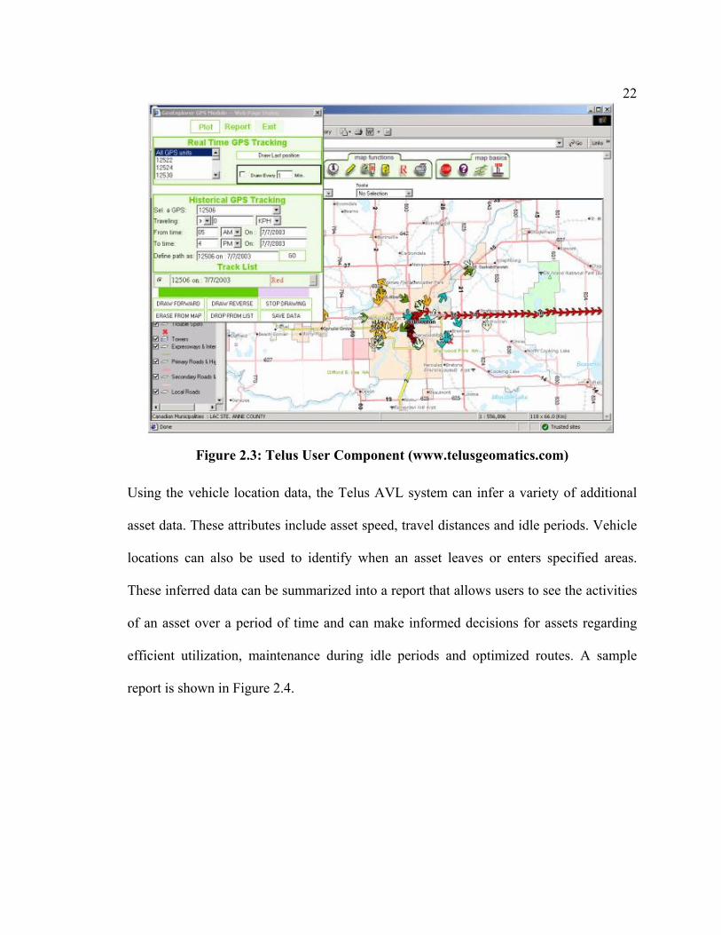
intervals. Asset data is sent to a Telus server where it is stored. The User Component is
an Internet-based application called GeoExplorer, which integrates map data with asset
data. GeoExplorer is shown in Figure 2.3. The asset data can be overlaid with a variety of
map data, including street networks and corporate buildings and infrastructure. The map
data could come in the form of raster or vector data [Telus, 2004].
22
Figure 2.3: Telus User Component (www.telusgeomatics.com)
Using the vehicle location data, the Telus AVL system can infer a variety of additional
asset data. These attributes include asset speed, travel distances and idle periods. Vehicle
locations can also be used to identify when an asset leaves or enters specified areas.
These inferred data can be summarized into a report that allows users to see the activities
of an asset over a period of time and can make informed decisions for assets regarding
efficient utilization, maintenance during idle periods and optimized routes. A sample
report is shown in Figure 2.4.

23
Figure 2.4: Telus User Component Reports (www.telusgeomatics.com)
Because the Telus AVL system only uses asset locations, there is a limit on how much
information it can provide to users for making decisions. While attributes such as speed,
travel distances and idle times can be inferred from asset locations, they remain estimated
values only and can be inaccurate. As well, with only one-way capabilities, all decisions
that users make cannot be sent to the asset in real-time and instead must go through other
methods which may be slower, causing a disconnect in the information flow of the
MAMS. A final limitation of the current Telus AVL system is the asset data is hosted on
Telus’s own server, it is not possible to have the data be sent directly to a client’s own
server where they could use it for their own purposes, such as setting up their own
custom reports or data mining methods.
Being able to monitor additional attributes increases the usefulness of a MAMS. For
example, rather than using only the asset locations to roughly estimate travel distance and

24
fuel consumption, a better option is to use an odometer and fuel tank sensor to get the
actual values. Other important attributes such as temperatures, pressures and weights
cannot be inferred from an asset’s location at all. These attributes can be vital for
analyzing how well assets are being utilized and to predict when they need maintenance.
A multi-attribute MAMS therefore has a great advantage in providing relevant data for
informed decisions.
An example of such a multi-attribute system is FleetLink, a MAMS that tracks the
location and additional attributes of mobile assets and sends the data back to a central
office. One application that FleetLink is used for is in the area of waste management
[Fleetmind, 2004]. FleetLink can track the locations of waste pickup vehicles, plus the
engine RPMs, vehicle speed and actual fuel consumption. For data acquisition, FleetLink
uses a device that integrates vehicle monitoring and location capabilities, using a GPS
receiver, to acquire the waste vehicle attributes automatically. FleetLink’s data
acquisition hardware is also capable of wireless communication using radio and cellular
networks. Information regarding the specifics of the pickup of waste for clients is also
tracked. This however is done manually, with the driver inputting the pickup task
information via a terminal. The combined monitored asset data can be sent in real-time
back to a central office if a wireless network is available or stored into memory until the
waste vehicle returns to its base. The data acquisition hardware can be seen in Figure 2.5,
the onboard device is on the left while the terminal is on the right.

25
Figure 2.5: FleetLink Data Acquisition (www.fleetmind.com)
Once the waste vehicle information is at the office, office workers can use it in a variety
of ways to improve their operation. FleetLink’s User Component is targeted at managers
at a central office. With vehicle locations available, the route taken by the waste vehicle
as it performs its job can be plotted onto mapping software and examined to see if a more
optimal route exists [Fleetmind, 2004]. The engine RPMs and vehicle speeds data can
also be used to analyze how optimal the route is, by seeing how often the waste vehicle is
idling and how fast it can go at different sections of the route. A sample FleetLink's
report can be seen in Figure 2.6. It is also possible to check on drivers and to ensure that
they are not wasting time. Having detailed information relating to the pickup is useful in
ensuring that all required tasks are completed and client inquiries can be answered with
accurate information [Fleetmind, 2004]. Figure 2.7 shows a report detailing the activities
of the waste vehicle and its driver.

26
Figure 2.6: FleetLink Asset Data (www.fleetmind.com)
Figure 2.7: FleetLink Asset Activities (www.fleetmind.com)
A limitation of the FleetLink system is that the mapping component is not included; any
company using FleetLink must purchase it separately from another software vendor and
ensure that the location data can be transferred from FleetLink into the mapping software.
In addition, the system is meant for workers in a central office to use, the drivers have no
way of accessing it. Drivers could not use the system for route guidance or updates
regarding their daily tasks while they were out driving their waste vehicles.
Another example of a one-way, multi-attribute MAMS is MEMS (Mobile Equipment
Management System), which helps the resource industry in managing and maintaining
key assets. The primary purpose of MEMS was monitoring lightplants, which are

27
equipment designed to light up work areas and allow for night work [Ramsaran, 2000].
MEMS collected information regarding the maintenance and fuel status of these support
equipment. For the Mobile component, data acquisition was done by field workers
performing manual inspection of the lightplant. Position and time information was
obtained from a separate GPS receiver. The lightplant inspection report was entered into
a custom application by a field worker and then tagged with its position and time of
measurement, which was obtained from the GPS receiver. The application, running on a
conventional Windows-based laptop was also connected to a radio modem, which was
the chosen implementation for the Wireless component of MEMS. The asset data was
sent through the radio modem back to the Office for long-term storage. The data
acquisition hardware and software can be seen in Figure 2.8.
Figure 2.8: MEMS Data Acquisition [Ramsaran, 2000]
Once a server located at a central office had received the data, it was stored into
databases. Users were able to retrieve, view, maintain, edit and analyze data and
eventually make informed decisions regarding the lightplants using the User Component
of MEMS. Administrators were able to perform maintenance on the databases, ensuring

28
that there were no errors in the records. Maintenance workers could use this component
to view the current statuses of all lightplants in the field, allowing for an up-to-date view
of the fleet at a glance. Lightplants could be tracked over time, by viewing its historical
conditions and locations as past information is kept. This historical information is useful
in improving the efficient utilization of the lightplants.
The User Component also offered the option of viewing the lightplants in a graphical
form. This tool utilized ESRI MapObjects, which is a set of mapping software
components that add dynamic mapping and geospatial information capabilities to
Windows applications. The current and/or historical data could be overlaid on top of the
work area map, which is stored in the form of vector data. The lightplant points could be
queried for further information. Basing this component on MapObjects allowed many
GIS functions designed for map manipulation, such as zooming and panning, and data
querying to be used with the lightplant data. A sample screen of this graphical tool is
show in Figure 2.9.

29
Figure 2.9: MEMS User Component
The User Component also provides decision-making functionality. The goal of the
decision-making functions is to provide a set of procedures, that when followed
ultimately results in efficient utilization of assets, through the deployment of assets at the
right locations and at the right time and in working condition [Ramsaran, 2000]. For
maintenance personnel, lightplants in need of refueling can be quickly found using
preexisting queries that filter assets based on the time since the last refueling date and
their observed fuel consumption. These selected lightplants can be scheduled for
refueling at the earliest opportunity, reducing any possibility of downtime. The service
history can also be seen for each individual lightplant, which allows for the tracking of
the lightplants’s condition over time and seeing when previous maintenance had taken
place. By proactively scheduling maintenance checks and refueling, downtimes due to

30
preventable failures can be significantly reduced which will improve the productivity of
the entire resource mining operation.
A major limitation of MEMS was the use of manual data acquisition, which is costly, as
it requires a worker to perform the inspections. This also limits the frequency that data
can be collected from the lightplant, making it difficult for tasks such as route tracking
and determining idle and busy periods. The one-way nature of the system also meant that
scheduling decisions could not be sent to the lightplants immediately.
As MEMS was only a conventional, non-Internet based MAMS system, it therefore did
not utilize the Internet and was subject to the problems inherent to such systems such as
limited wireless communication options and limited access to the User Component. The
next stage in the development of MEMS was to make it fully Internet-based, through the
addition of wireless Internet methods to transmit lightplant data from the Field back to
the Office and a new Internet accessible client component to allow users access to data
and tools from outside of the physical area of the Office domain. This new Internet-based
system was called IMEMS (Internet-based Mobile Equipment Management System).
IMEMS offered the choice of wireless Internet or radio methods to communicate with
the Office. Application developers can switch between either transmission method
without the need to make any changes to code or data. Important performance and
security functions such as compression and encryption were also available. The options
that were available in this framework can be seen in Figure 2.10.

31
Application Data
Compression
Encryption
Conversion
CDPD
Cellular
Ethernet
Radio
Internet
Figure 2.10 Seamless Internet/Radio Data Transmission
The User Component in MEMS has also been converted into an Internet application to
allow a high level of data analysis functionality to be accessible by remote users while
requiring only a browser and an Internet connection. The purpose of the IMEMS Web
Client is the same as the original MEMS; to provide users with an interface that
facilitates access to the data stored but this time over the Internet and only requiring an
Internet browser. There was no need for further third-party software such as Map
Objects. The interface of the IMEMS Web Client can be seen in Figure 2.11 and has
many similarities with the earlier MapObjects-based application. While IMEMS offered
improvements in many areas, it still shared the same problems in terms of using manual
data acquisition and one-way capabilities inherent in MEMS.

32
Figure 2.11: IMEMS: Web-based User Component
2.6.2 Two-way MAMS Applications
Two-way MAMS are more useful because users can make decisions that can be sent back
to the asset in near real-time. Such systems can be used for on-the-fly route optimizations
or changes to the route due to accidents or new tasks that must be performed.
Like for one-way MAMS, two-way MAMS that use only asset locations are limited in
terms of the types of applications that they could be used for. It is adequate though for
many asset security applications. This is because security applications utilize a “geo-
fence”, which designates an area where an asset must be. If the asset leaves the geo-
fence, then it can be assumed that the asset has been stolen and authorities can be
notified. The asset can broadcast its location continuously for rapid recovery. Geo-fences

33
can be set to a small area around the asset when an asset is parked or to a larger area,
allowing the asset to move freely within a work area but not out of it. The market for
asset security is large, especially for automobiles. It is estimated by the National
Insurance Crime Bureau of the USA that 1.2 million automobiles were stolen in 2002.
DirecTrack is one such security system and is a subscription service that works with
third-party alarm systems that have GPS and cellular capabilities. These alarm systems
can be purchased by individuals or corporations to place on their assets with automobiles
being the most commonly protected assets [DirecTrack, 2003]. DirecTrack is Web-based,
allowing users to access the service through the Internet. It follows the basic MAMS
architecture, with the alarm system acting as a data acquisition component and cellular
networks as the wireless link between the field and a central office. Vehicle data is stored
at the central office and users access it through the Internet. Users log into the services
through the Internet and then are able to locate their vehicle on a map. Users can also
view the previous location of their vehicles in text form. It offers two-way capabilities by
allowing users to locate their vehicle on demand, giving them peace of mind in knowing
their vehicle is where it is supposed to be. If the vehicle is stolen, recovery is also easier
and faster. The user interface of DirecTrack can be seen in Figure 2.12.

34
Figure 2.12: DirecTrack User Interface [DirecTrack, 2003]
The limitation of DirecTrack is that it only utilizes vehicle positions so it is limited in
terms of additional functionality. Tellicate is another security system that shares the same
basic architecture as DirecTrack but has the advantage of being a multi-attribute two-way
MAMS. This offers more utility to clients and makes it a more useful system. Along with
position, Tellicate can monitor the vehicle’s odometer, speed and also report emergencies
or alarms that are issued by the onboard vehicle sensor. These emergencies and alarms
can occur when the vehicle’s alarm is triggered, when the vehicle is traveling faster than
a preset limit or when the vehicle has gone outside of the geo-fence [Tellicate, 2003].
Tellicate, being a two-way system also allows users to issue commands back to their
vehicle. Like DirecTrack, users can locate their vehicle on demand but they can also
command the Tellicate onboard sensor to go into Continuous Tracking mode, where it
will send the vehicle locations at regular intervals. Finally, the user can also unlock the

35
door of their vehicle remotely [Tellicate, 2003]. Tellicate’s User Component can be seen
in Figure 2.13.
Figure 2.13: Tellicate User Component [Tellicate, 2003]
Like many of the previously examined MAMS, Tellicate also allows users to view the
historical information regarding a vehicle. An example of such a report can be seen in
Figure 2.14. The historical information for Tellicate consists of a vehicle’s previous
locations as well as alarms and confirmation of the successful completion of user issued
commands.

36
Figure 2.14: Tellicate User Component Reports [Tellicate, 2003]
The primary limitation of Tellicate and DirecTrack is their targeted focus on only
vehicles. The information that is monitored is inadequate for assets being used in mining
and only providing street maps would be inadequate for remote work areas where street
maps are only available to company operating the work area. Capabilities like unlocking
doors may also not be necessary.
2.6.3 Real World MAMS Summary
A summary of the examined real world MAMS’s capabilities and implementation is
show in Table 2.1.

37
Table 2.1: Real World MAMS Sumary
Two-way capable?
Data Acquisition Monitored attributes
Wireless component
User Component
Telus AVL No Remote sensor Location only Cellular Internet-based
FleetLink No Remote sensor + manual input
Location, speed, engine parameters
Cellular, radio Local office only
MEMS No Manual input + GPS receiver
Location, vehicle conditions
Radio Local office only
IMEMS No Manual input + GPS receiver
Location, vehicle conditions
Radio, Internet Internet-based
DirecTrack Yes Remote sensor Location, only Cellular Internet-based
Tellicate Yes Remote sensor Location, speed, alarms and emergencies
Cellular Internet-based
2.6.4 Desirable MAMS Traits
After the examination of various real world MAMS, common features were found and
traits that offer benefits have been discovered. These features and traits should form a
part of MAMSDev, the Platform that is being created in this thesis for MAMS
development. One other aspect of the examined MAMS noticed was that they all focused
on specific applications and would be difficult, if not impossible, for users to modify the
MAMS to better suit their needs. A platform that allowed a high level of customization
would be unique and extremely beneficial by allowing users to tailor a MAMS to their
specific needs and not be stuck with a proprietary system using only specific software,
hardware and monitored attributes.
38
The two-way, multiple attribute MAMS is the ideal MAMS. Not only does it offer the
most functionality and usefulness, it is also the superset of all other types of MAMS,
allowing it cover a wide range of potential applications and scale to any combination of
one or two-way and single or multi-attribute as needed. MAMSDev therefore should
target two-way, multi-attribute MAMS.
The best choice for data acquisition is remote integrated sensors that are placed onboard
an asset. Remote sensors allow data to be obtained at much higher frequency than is
possible using manual inspection. They can be set to acquire data automatically from a
variety of asset sources, including locations, engine parameters and alarm statuses at
preset intervals, in any condition and at all times. Many remote sensors also allow two-
way MAMS with the option of control where users can issue commands and have the
sensor perform the assigned task and report the results in near real-time. With current
technology, small and compact integrated sensors that include GPS, wireless
communication and computing capabilities are now available. The small footprint of
these sensors enables them to placed, or hidden, into a wide variety of assets for use in
asset tracking, monitoring and security.
Using wireless communication to send asset data back to a central site was also
commonly used in real-world MAMS. This is beneficial because it is the best choice for
getting asset data back to users in the fastest time possible, giving users the confidence
that they have the most up-to-date information possible for decision-making. Without
wireless communication, the asset data could not be entered into a MAMS until it
returned to a central site, which could interrupt the flow of information by a day or even

39
longer as there are assets that stay out in the field for long or indefinite periods of time.
Data management and storage was a key component of every examined MAMS.
Typically, the asset data was stored into databases and useful reports were generated from
the data. Providing text reports that gave relevant information to users regarding an asset
was a feature that was found on several of MAMS. Such reports offered a summarized
overview of assets that allowed users the ability to see the current conditions of the asset,
including its location and attributes that were being tracked by the system and would be
of relevance to the user. Other reports provided historical information for an asset,
allowing users to view the trend of various asset conditions for maintenance and repair
purposes. These types of reports were an important part of the real-world MAMS and
MAMSDev should offer functions that help in the creation of such reports. MEMS and
IMEMS also offered direct access to the raw data and databases for maintenance reasons.
Some MAMS, such as Telus, DirecTrack and Tellicate stored the databases on their
server while MEMS, IMEMS and FleetLink allowed the databases to be held on
company servers. Having the databases managed by another company reduces equipment
and support costs for the MAMS user but it also makes it difficult to access the raw data
for custom data analysis and mining purposes. MAMSDev should be capable of
supporting both form of database management for more flexibility.
An Internet-based User Component is a feature used in several of the examined real-
world MAMS, like that of Internet-based MAMS described in Section 2.5. It enables
access to the asset data for as many users as possible. Users that are at the office or those
in remote areas all have access and the only requirement is that an Internet connection is

40
available. The Internet is a hardware and software independent network so that a variety
of computing devices could be used as the client hardware.
Several of the examined MAMS also featured graphical map data integrated into the User
Component and allowed asset data to be overlaid onto the map data. Being able to place
asset locations to the context of city streets or work areas is an important part of the
decision-making process. The map data could also be used to provide addresses and
directions for route guidance as well as hold a database of points of interests. Map data
can come in a variety of forms and can be provided by third parties or be owned by the
company that operates the MAMS.

41
Chapter 3
MAMS Hardware and Software Technologies
In every MAMS, there are a large number of varied technologies at work. Useful asset
information must be obtained and transmitted back to a central office site, using a
wireless network. The asset data must be stored, managed and then presented to users in a
useful fashion. In this chapter, technologies that could be used in a MAMS are
investigated for their benefits and drawbacks.
3.1 Wireless Communication
While data could be potentially stored for later upload, wireless transmission of data is
the best solution for providing up-to-date and relevant information to users. Having the
shortest latency possible from the time the data is acquired and the user viewing the data
is critical for informed decision-making and necessary for gaining the maximum benefits
from the MAMS.
3.1.1 Radio
Radio modems that broadcast in the UHF commercial band between the frequencies of
450 to 470 MHz of the radio band have become a popular tool for providing wireless
communication for applications such as asset management, as well as high accuracy GPS
services. There are no service costs for airtime usage and the deployment of a radio

42
system is done by purchasing enough modems to cover the work area.
However, some drawbacks exist that make it a less than ideal solution for MAMS. This
particular UHF radio band is highly crowded and can result in noise and interference. The
channel separation used by such modems is only 12.5 KHz, which can result in
significant cross-channel interference and reduced data transmission speed and reliability
[Park & Gao, 2002]. These problems also reduce the effective range of radio modems,
which in best-case situations is only as good as the line-of-sight with a neighboring
modem. For worst-case scenarios, such as in an urban environment, the effective range of
a radio modem drops to a few kilometers only and require additional modems for
effective coverage. As well, radio modems do not provide a direct connection to the
Internet, so it is not suitable for extending the User domain outside of the Office.
There are additional problems associated with their use in a MAMS. For example, the
Pacific Crest RFM96 radio modems have been used previously for some MAMS
applications. When the modems are active, data collisions can occurs if they send a
message simultaneously on the same radio frequency. To avoid this problem, the modems
use the Carrier Sense Multiple Access/Collision Detection (CSMA/CD) protocol
[Ramsaran, 2000]. This protocol, also used in Ethernet networks, defines how the radio
modems react to avoid collisions. With CSMA/CD, the modem monitors the frequency if
it is being used. If it is being used when a modem needs to send a message, the modem
waits a random amount of time before checking again. If the frequency remains
unavailable, the wait time is increased until the frequency finally becomes free
[Ramsaran, 2000]. In a busy MAMS with a large number of assets, the amount of

43
collisions could become a problem by delaying the transmission of asset data.
3.1.2 AMPS/CDPD
Due to the widespread coverage of cellular networks, wireless access to the Internet is
now available in large portions of Canada, even in remote areas. The Internet is a global
network utilizing multiple routes and methods for data transmission for high reliability
and its transmission range is not constrained by physical factors like radio. AMPS/CDPD
(Advance Mobile Phone Service/Cellular Digital Packet Data) is a common and mature
method for wireless access to the Internet in North America [Park & Gao, 2002]. AMPS
was the first-generation cellular telephone system developed during the 1970s. AMPS is
an analog system and uses a frequency of 900 MHz. CDPD is a specification for
supporting wireless access to the Internet using the AMPS network.
Data transmission via a Wireless Internet connection is also a much more reliable than
that via radio. For example, CDPD is a packet-switched data service that transmits data at
a rate of up to 19.2 Kb/s and has full duplex capability, so packets can be sent and
received at the same time [NovAtel, 2001]. Like other Internet connections, data is
transmitted using TCP/IP, the primary communication protocol of the Internet. TCP/IP
offers built-in redundancy, error checking and other reliability measures to ensure the
data that arrives at the destination matches the data that was sent out. CDPD uses
authentication measures and encryption of data packets for better security of sensitive
data. The connection is “always-on” as there are no interruptions, need to dial-in or to
wait for other transmissions to complete first. A dense transmission tower network is

44
already in existence, allowing for constant and consistent signal power across a wide area
and cellular technology is used to assign neighboring transmission towers different
frequencies in AMPS to avoid frequency collision. Finally, the channel separation is set
to 30 KHz, a much larger channel separation than that used in the UHF commercial band
and helps reduce cross-channel interference [Park & Gao, 2002].
3.1.3 Aeris.NET MicroBurst
This wireless data communication product offered by Aeris.Net is a low-cost solution for
applications that require widespread availability and high reliability but only have small
message sizes. The Aeris.Net service, known as MicroBurst, is similar to CPDP in that it
utilizes the analog portion of existing cellular networks to transfer data. However, this is
the only aspect that these two services share in common.
The major advantage that MicroBurst has over CDPD is its availability. A CDPD
subscriber is tied to a specific CDPD provider and the areas where their coverage exists.
While there are roaming agreements between different providers, the overall coverage of
CDPD is not great outside of urban areas in North America. Aeris, on the other hand has
made agreements with major cellular providers in North and Central America, allowing
MicroBurst subscribers the seamless use of multiple networks covering much of North
America. For a company whose asset fleet may be spread over a nationwide or continent-
wide area, working with one service provider that can provide coverage almost anywhere
in North America is beneficial through simplified access and billing. In Figure 3.1, the
coverage area of the MicroBurst service can be seen for the United States, Mexico and

45
Canada. Coverage is available for nearly the entire geographical area of the continental
USA. The majority of the populated areas of Canada and Mexico are also covered.
Figure 3.1: Aeris.Net MicroBurst Coverage Area
(http://www.aeris.net/aeris_web/products_coverage.html)
Aeris.Net’s MicroBurst service is not a wireless Internet service like CDPD. Rather it is a
hybrid service that relays messages issued by a MicroBurst-enabled remote sensor from
the AMPS cellular network onto the Internet to asset owners. MicroBurst utilizes the
Forward Control Channels (FOCC) and the Reverse Control Channels (RECC) of an
AMPS cellular network [Aeris.Net (2), 2004]. FOCC messages are transmitted from the
cellular switch to the MicroBurst-enabled devices. RECC messages are transmitted from
the MicroBurst-enabled devices back to the cellular switch. These RECC messages are
then sent to the Aeris.Net central hub, which finally relays the messages through the
Internet back to the asset owners. Together, they enable two-way communication and

46
control with assets.
FOCC messages, otherwise known as pages in MicroBurst terminology, are sent to
devices that are onboard assets and are meant to trigger responses from the device or to
get the device to perform a desired operation [Aeris.Net (1), 2004]. Each MicroBurst-
enabled device can have up to 10 Mobile Identification Numbers (MIN) [Aeris.Net (1),
2004]. Each MIN can be used to trigger a different event or operation on the device.
FOCC messages are initiated by the asset’s owner or users, who send the page in a
MicroBurst specific format to Aeris.Net’s central hub. Aeris.Net then sends out the page
as a FOCC message to the desired device.
MicroBurst-enabled remote sensors send responses and data back to Aeris.Net’s central
hub via the RECC messages. Each message packet’s data is encoded into a number
string. Once the number string is received at the central Aeris.Net center, the number
string is finally relayed to the asset’s owner through the Internet [Aeris.Net (1), 2004]. To
obtain data in real-time, the asset’s owner must be continuously connected to Aeris.Net
through the Internet. Otherwise, Aeris.Net will store the data until the owner connects
with the server. The maximum length of a number string is 32 digits for a maximum of
100 bits for data only [Aeris.Net (1), 2004]. While the data bandwidth of the MicroBurst
service is limited in comparison to CDPD, it is still possible, through efficient usage of
each available bit in the number string, to send useful amounts of data through a
MicroBurst message packet. Splitting large amounts of data across multiple message
packets is also possible. From experience, MicroBurst is most commonly used in
applications such as vehicle tracking, security systems and remote asset monitoring.

47
3.1.4 Next Generation Cellular Networks
Continued developments and upgrades to cellular networks have created digital networks
that offer greater bandwidth capabilities than previous analog-based Wireless Internet
methods. Ultimately, all of the areas currently covered by analog will be upgraded to
digital, thus providing the necessary infrastructure for these advanced digital Internet
services. Some of the new digital services, such as GPRS (General Packet Radio Service)
and RTT (Radio Transmission Technology) have already been introduced by cellular
providers in Canada. These services work similarly to CDPD, with the same benefits of
having a continuous connection and built-in encryption and authentication, but with
speeds of about 56 Kb/s instead of 19.2 Kb/s. As these new digital networks grow, it is
expected that CDPD coverage will be gradually withdrawn from the market. For
example, a major Canadian telecommunication company has stated that it will completely
transition away from CDPD as of February 28, 2006 and support only its next generation
digital data network [http://www.telusmobility.com/ab/business_solutions/cdpd.shtml].
However, at this time the coverage area of various next generation digital networks are
inferior to older, analog-based data services such as Aeris.Net’s MicroBurst and devices
that support the new networks are only beginning to appear. This makes the next
generation networks not yet suitable for MAMS in terms of linking assets with the
Office. However, their improved performance is ideal for extending the User domain
outside of the Office for users that are within the coverage area of these networks.
48
3.2 Data Acquisition
Two data acquisition methods are commonly used in a MAMS. These methods are
manual inspection and automated remote sensors. The manual inspection method relies
on visual inspection by workers of assets. This was the data acquisition method used by
two of the MAMS examined in Section 2.6. While manual data acquisition is usable for
MAMS, remote sensors have the advantage of always being at the asset and ready to
provide information. The examination of real-world MAMS in Section 2.6 shows that
remote sensors have advantages in terms of when and how often they can acquire data
over manual inspection. Newer remote sensors even integrate several different sensors
into a single package to monitor multiple attributes and trends that cannot be detected by
an infrequent inspection. The majority of the examined MAMS utilized remote sensors.
FleetLink was a MAMS that utilized remote sensors. The FleetLink remote sensor
consists of a GPS receiver, inputs and outputs for connecting with asset sensors and the
ability to send the monitored asset data using cellular networks or radio. Table 3.1 lists
relevant specifications of the FleetLink remote sensor.

49
Table 3.1: FleetLink Remote Sensor Specifications (http://www.fleetmind.com/flash/components/flash.html)
GPS Receiver 8 channel, continuous tracking
1 Hz
<130s to first location after power-on
Data Acquisition 31 inputs/outputs
Data Delivery Wireless cellular
Radio
The CSI Asset-Link is another remote sensor and like FleetLink, combines cellular
communication, GPS technologies and the ability to monitor asset attributes. Asset-Link
sensors utilize an onboard high-sensitivity GPS receiver chip to provide location data and
supports data transmission through several different wireless methods. These methods
include AMPS and GPRS. Figure 3.2 has a picture e of the Asset-Link sensor.
Figure 3.2: CSI Asset-Link Sensor (www.csi-wireless.com)
However, the Asset-Link has greater “intelligence” that makes it more flexible and useful
for mobile asset management compared to FleetLink. It supports programmable geo-
fences, allowing the Asset-Link to be used in security applications such as DirecTrack
and Tellicate. The Asset-Link also supports programmable exceptions, which allows it to
act automatically when monitored attributes reach preprogrammed values. Finally, the

50
Asset-Link also has two-way capability, allowing commands to be sent via cellular
networks enabling the Asset-Link to be used in all types of MAMS. The Asset-Link will
also report the results of the command, including if it has been completed successfully or
not. This is extremely useful because not knowing whether a command was received or
completed successfully is just as bad as the command not being received by the asset
[Segal, 1996]. The Asset-Link is small, so it can be easily hidden in an asset and has low
power consumption. Table 3.2 lists some of the Asset-Link’s relevant specifications.
Table 3.2: Asset-Link Specifications (http://www.csi-wireless.com/products/documents/NewAssetLink.pdf)
GPS Receiver 12 channel, continuous tracking
1 Hz
<50s to first location after power-on
10m 2D RMS
Data Acquisition 8 inputs/outputs
50 geo-fences
32 programmable exceptions
Data Delivery Wireless cellular
On-board storage for up to 10,000 records
Size and weight Length:155mm
Width: 103mm
Height: 26mm
Weight: 360g
Power Consumption
Sleep: <0.1W
Typical: <1W
Transmit: <7W

51
3.3 Asset Data Management and Storage
In a real world MAMS, large amounts of data can be generated. For example, a recent
Alberta Government MAMS project for tracking snowplows estimated that it would
handle 550 snowplows each sending about 3000 messages daily back to a central office
[Alberta Transportation, 2004]. This results in approximately 1.65 million new records
every day and 50 million records per month. This requires a well-designed database
management system to store and manage and to achieve fast query performance. With the
wide variety of hardware and software platforms available for computer servers, desktops
and mobile computing devices, technologies that offer standardized methods for
accessing and manipulating databases are also important.
ODBC (Open Database Connectivity) is a technology that makes enables access to many
types of databases from an application. The only requirement is that both the application
and the database are ODBC compliant. ODBC provides a standardized set of
specifications that ensures that an ODBC compliant application can “speak” to an ODBC
compliant database in a manner that the database understands and vice versa [MSDN,
2004]. ODBC also ensures that data that is received back from the database is in a form
that the application can use. This allows different database products, ranging from a
simple, inexpensive database product like Microsoft Access to enterprise level products
from Oracle or Microsoft SQL Server to be used in a MAMS without needing major
changes. ODBC is also programming language independent and is supported on the
Microsoft Windows, Macintosh and several UNIX platforms [MSDN, 2004].

52
SQL (Structured Query Language) is a programming language that can be used to obtain,
add, delete and modify information from databases. Many databases are SQL-compliant,
which means they conform to the SQL standards and should respond identically when
given the same SQL query [Brockwood, 2001]. Similar to ODBC, SQL allows different
database products to be used without needing to change existing SQL queries. ODBC and
SQL work together in providing a standardized method for applications in getting data
from a database in a usable form and follow the same ideas as those of OO programming
in terms of black box objects. The application and databases are black boxes to one
another in the sense that one does not know the other’s implementation details. They only
communicate using a standard public interface, in this case ODBC and SQL. How the
database performs the SQL query is hidden from the application while the application’s
use of the queried results is hidden from the database.
3.4 Spatial Data
Spatial data are available in vector and raster formats. Vector data are popular in GIS and
CAD applications and for companies who produce their own data, such as the resource
industry. Spatial data in raster form are commonly used for street maps.
3.4.1 Vector Data
From Section 2.6, Telus, MEMS and IMEMS all used or supported vector data for their
User Component. Vector data stores spatial information in the form of points, lines and
areas. Each of these elements is encoded using data that describe its magnitude, direction

53
and connectivity [CAD Resources, 2000]. These three MAMS supported vector data
because they targeted resource and mining companies. Such companies typically create
their own infrastructure of roads and buildings to support their operations and the vector
data is already available, as it has been created as part of the infrastructure planning and
building process.
One of the most widely used form of vector data is the ESRI Shape format popularized in
ESRI’s GIS products. It supports various types of data, including polygons, polylines,
lines and points and can handle 3D features as well but ultimately each different type can
be reduced to a collection of points. For example, to represent a line in the Shape format,
only two points are needed. One point contains the coordinates of the start of the line and
the other has the coordinates for the end of the line. A Shape file contains the vector
features in a binary file plus an associated simple flat database, which contains the
attributes of the features [ESRI, 1998]. ESRI Shape has several advantages. First, a large
amount of spatial data is already available in this format. Second, ESRI Shape is an open
format as ESRI provides the technical specifications for the format, making it easy to
develop software to use Shape data. Finally, there are also software converters that can
convert spatial data in other CAD formats into Shape.
3.4.2 Raster Data
In DirecTrack and Tellicate, two MAMS that were examined in Section 2.6, the map data
that they used was in raster form and was provided by a third party. Raster data consists
of a grid of cells that cover an area of interest and each cell is the smallest unit of

54
information possible [CAD Resources, 2000]. There are providers of raster data that
cover much of the world with detailed maps that go down to the street level of detail.
Such providers include Microsoft MapPoint Web Service and MapQuest and their
products are deployed using the Internet. Using a third party to provide spatial data offers
the advantage for companies of gaining access to high quality spatial data at low upfront
cost. There is no need to acquire and maintain spatial data or have to store vast amounts
of spatial data onto their computer systems [Microsoft, 2004]. They also offer services as
geo-coding, travel directions and finding nearby points of interest, services that are of
great interest to individuals and companies that operate within the standard street and
highway networks of cities and countries.
MapQuest offers comprehensive coverage of over twenty countries in North America,
Europe and Latin America plus more than a hundred major cities in the rest of the world.
MapQuest also provides a database of two million points of interest in North America
and 770,000 in Western Europe [MapQuest, 2004]. MapQuest can be used for mapping,
geo-coding, routing and finding nearby points of interests. Accessing MapQuest is done
through the Internet with clients accessing a main MapQuest server and MapQuest
provides class libraries for developers to aid in connecting to MapQuest. MapQuest is
supported on several platforms, including Microsoft Windows, Sun Solaris and Red Hat
Linux. Multiple programming languages are also supported, including Java and C++
[MapQuest, 2004]. MapQuest uses a proprietary HTTP (HyperText Transfer Protocol)
based protocol for client to server communication [MapQuest, 2004]. HTTP is the
primary protocol for communication used on the Internet. An example of the MapQuest

55
service is shown in Figure 3.3.
Figure 3.3: MapQuest Service Example (http://www.mapquest.com)
Microsoft MapPoint also offers street level maps of Canada and the United States. There
is also extensive street level coverage of Europe and major cities in Mexico and South
America. The road coverage totals 8.8 million kilometers in North and South America
and 4.6 million kilometers in Europe with a global database of 15 million points of
interest [Microsoft, 2004]. MapPoint can also be used for mapping, geo-coding, routing
and finding nearby points of interests. MapPoint is primarily targeted at the Microsoft
Windows platform and its development tools and languages. However, other platforms
can be supported because the MapPoint service is accessed over the Internet and
communication is done using open and standardized protocols [Microsoft, 2004]. There
also exists class libraries and sample code for Java. Like MapQuest, MapPoint uses an
HTTP based protocol to transfer map data. A sample application that uses MapPoint’s
raster data is shown in Figure 3.4.

56
Figure 3.4: Microsoft MapPoint Service Example (http://mappoint.msn.com)
After examining both services, MapPoint was found to be better. While MapQuest and
MapPoint offer comparable levels of spatial data and services, MapPoint had superior
developer support. Sample code and documentation for using Java with MapPoint was
readily available and MapPoint offers a free 45-day account for developers to test their
service. There is also an affordable one-year account available that offers developers
unlimited access for development as well as 50,000 transactions for commercial usage.
3.5 Object-Oriented Programming
The goal of this thesis is to create a new software development platform that can be easily
utilized for MAMS. To be a true platform, it must offer a full suite of functionality
dedicated to MAMS. This functionality has to be easily reused by third-party developers
for a variety of MAMS applications. In this regard, the Object-Oriented (OO) philosophy
57
and OO application frameworks in particular, is suitable for MAMSDev as it promotes
and facilitates reusable and maintainable software. High reusability results in better
software that can be more easily modified, extended and maintained [Berard, 2000]. OO
has the potential, if used in an effective manner, to reduce software development times,
while increasing feature levels and reliability. Maintainable software is essential because
it has been estimated that 80% of the cost of software over its lifetime is incurred for
maintenance and it is rare that any complex software is maintained by the original
author(s) for its entire life cycle [Fei, 2001]. In this chapter, a brief examination of OO
will be conducted and principals and ideas that are important to the creation of
MAMSDev will be discussed.
3.5.1 Object-Oriented Application Frameworks
OO application frameworks are a form of reusable software. They can be used in any
application that is relevant to the intended purpose of the framework while requiring only
a minimal effort [Biddle, 1995]. A common definition used by Ralph Johnson for a
framework is that they are “a reusable design of all or part of a system that is
represented by a set of abstract classes and the way their instances interact”. Their
purpose is to be “the skeleton of an application that can be customized by an application
developer” [Johnson, 1992]. A framework typically has existing objects and data already
targeted for specific real-world applications. In essence, a framework is an already semi-
complete application, which can be taken by developers to create a complex and fully
complete application [Johnson & Foote, 1988]. Because a framework is already semi-

58
complete, a framework is typically targeted at specific fields.
OO application frameworks are an integral part of application development nowadays
because of the complexities and cost associated with any large application development
nowadays. To create a new application from scratch that not only works, but is also
efficient and portable across a diverse array of hardware architectures and operating
systems is simply not possible without significant investments of time, money and human
resources [Fayad, 1997]. By using application frameworks, costs can be greatly reduced
by not having to recreate core components. Another benefit of using an application
framework is a reduction of errors and bugs in completed software because the
framework would have already been heavily optimized and debugged by the framework
provider, which can also reduce development times [Fayad, 1997].
Not only do application frameworks promote reusability, they also help improve the
modularity and extensibility of systems. Modularity occurs because of information hiding
and encapsulation, resulting in classes or groups of classes whose interface methods
remain stable while their actual implementations can be volatile. Changes to code or
implementation also remain local to a specific classes or group, resulting in fewer
unintended system effects when changes are made within a class’s private details.
Extensibility allows applications to be developed beyond the initial scope of the
application framework. This is done by adding specific methods in the framework, which
custom applications can extend. Application-specific processing can be done without
needing to access or alter any of the framework code.

59
3.5.2 OO and MAMS
Many of the concepts in OO will be followed and utilized during the course of
developing MAMSDev. Developing a reusable MAMS-targeted OO application
framework is highly beneficial for MAMS development for a number of reasons. While
the purpose of MAMS applications can vary greatly due to the numerous fields that such
systems could be used for, there are common elements that remain, thus allowing
opportunities for reuse. All MAMS need some form of data collection from assets and the
data must be uploaded to one or more central locations. Once the asset data has been
received, then it must be entered into a database management system for long-term
storage. Finally, users need to access the data, such as through a software interface, so
that they can manage and analyze the data in an effective manner. These common
elements can also be seen in Figure 3.5.
Asset Data Collection Wireless
User Front-End Users
Monitor and/ or Control
Office Back-End Database
ManagementSystem
Figure 3.5: Common MAMS Elements
MAMSDev will be developed as an application framework as it best fits the needs of
MAMS development. MAMSDev can become the skeleton of a new MAMS, providing
the infrastructure and allowing the developer to concentrate their resources on the custom

60
aspects of their application. OO also allows for a modular structure for the Development
Platform, helping to segregate dissimilar elements from another. This has the benefits of
allowing developers to select only the elements they wish to use from MAMSDev.
3.6 Client-Server System Architecture
A common model found in computing is the Client-Server (CS) architecture. The CS
architecture utilizes servers that contain data resources and may perform some or all of
the data processing function. The Client’s primary purpose is to present data and
processing results from the Server to users but may also process data depending on the
CS design used. The CS design is further split into additional subcategories, depending
on the fatness or thinness of the client layer. The thin client is a lightweight application,
which only displays data and processing results retrieved from the server. On the other
side of the spectrum, there is the fat or thick client where by most processing functions
are on the client side and only the data is retrieved from the server. Between these two
extremes, there are also hybrid clients who split the processing workload between the
server and client [Peng & Tsou, 2003].
Internet-based MAMS follow the CS concept as asset data management, storage and
most processing is done at a central server. The Web-based User Component acts like a
thin client, as its primary purpose is to display asset data to users and needs to run on less
powerful, mobile devices. Many other Internet web services follow the same CS concept,
including MapQuest and MapPoint.

61
3.6.1 System Partitioning and Multi-Tier Architectures
In some CS architectures, system partitioning is also used to split the server layer
logically into three basic elements, that of data, application logic and presentation. These
partitions are independent but remain capable of communicating and working with one
another [Peng & Tsou, 2003]. Multi-tier or n-tier architecture breaks an application into
multiple levels of layers held at physically separate locations. The previously mentioned
client-server architecture is in fact also a two-tier architecture, having separated the
application into separate client and server layers. The server layer acts as an interface
between the client and data. Increasing higher tier architectures split the server layer into
more and more layers and the complexities of a higher tier architecture increase as well.
System partitioning and multi-tier architectures while similar in idea differ in how they
divide the client and server layers. Partitioning refers only to the logical separation of the
client and server layers, while a multi-tier architecture refers to the actual physical
separation of the client and server layers and the hardware and software configurations
used to support the physically separate layers [Peng & Tsou, 2003].
3.6.2 Middleware
Usually, in between the server and the client is a Middleware layer. This layer serves as a
translation layer between servers and clients and helps to hide the organization of
computers, databases and networks on the server side [Peng & Tsou, 2003]. A
middleware layer implementation commonly takes the form of standardized methods for

62
communication between the server and the client. An observation that can be made is the
concept of Middleware is very similar to encapsulation in OO programming and offers
much of the same benefits. The only difference is that instead of hiding the
implementation details of classes from one another, now the implementation details of
entire server-side and client-side systems are hidden from each other, with the separate
systems communicating using a standard public interface.
3.6.3 Message-Oriented Middleware
Message-Oriented Middleware (MOM) is a middleware system based upon a message-
queuing system. A client makes requests that are stored into a queue, which will be
retrieved by the server in the future to process. The results are then stored back into the
queue, which will be retrieved by the client. The asynchronous nature of MOM means
that a real-time persistent connection between the client and the server is unnecessary. If
no connection is available, messages can be delayed from sending and stored into a
queue. Once a connection can be made, the entire queue of messages can be sent out
[Peng & Tsou, 2003].
3.6.4 Remote Procedure Call
Unlike MOM, Remote Procedure Call (RPC) uses a real-time direct and synchronous
connection between the server and the client. The client calls remote procedures on the
server, which the server services and sends the results back to the client. The client must
remain connected to the server until it receives the response back, therefore locking the

63
client from performing any other operations. RPC is generally used in situations when an
immediate response from the server is necessary [Peng & Tsou, 2003].
3.7 Dynamic Internet Content Presentation Technologies
For much of the Internet, content is stored as static web pages and a standard web server
application, such as Apache or Microsoft IIS, is all that is required to handle requests
from users. However, a MAMS is not static as there are assets that are moving and
frequently sending back new data. A Web-based User Component would need to offer
dynamic content creation capabilities and be able to display to users real-time
information. Popular technologies that are currently used today include Common
Gateway Interface, Server Extension and server-side scripting.
3.7.1 Common Gateway Interface
One of the oldest method for creating dynamic content is the Common Gateway Interface
(CGI) technique, which utilizes an external program along with a web server. The web
server would pass requests for dynamic content to this external CGI application, which
performs any necessary processing and returns the results back to the web server to send
back to the requesting user’s browser software. An advantage is that CGI applications can
be written in almost any language, as long as the application implements CGI’s
standardized method of communication with the web server. CGI is also generally
browser independent as the output consists only of HTML and images that nearly all
browsers can interpret. However, a large disadvantage is the life cycle of a CGI request.

64
Each request requires that the web server create a new process for the CGI program, a
time and computer resource consuming process. Even when requests are made for the
same CGI application, separate CGI processes must be created. This greatly limits
performance and scalability [Hunter & Crawford, 1998]. As well, since the output that
CGI produces must be HTML-compatible to ensure compatibility with Internet browsers
also means that only text information and static images can be created dynamically for
viewing. Figure 3.6 shows how the CGI request process works.
Figure 3.6: CGI Request Process [Hunter & Crawford, 1998]
3.7.2 Server Extensions
Server extensions created using APIs, including Microsoft’s Internet Server API (ISAPI),
are improvements upon CGI by creating proprietary server extensions that allow
developers to enhance the functionality of web servers. This allows the web server to
process requests directly, instead of resorting to an external program. Performance and
scalability is high, as server extensions often use optimized C or C++ libraries. Server
extensions also avoid the expensive process of continuously creating and destroying new
processes as in CGI.

65
However, there are several disadvantages to server extensions. One is potential security
and stability issues, while the other is platform independence. As any server extensions
will be running in the same process as the web server, a crashed server extension can
cause the crash of the rest of the web server. Poor security in the extension could result in
unauthorized access to secure data in other Internet content served by the web server or
elsewhere on the host computer. As these server extension APIs are generally tied to a
single web server product, which themselves may only run on certain operating systems,
portability and platform independence becomes difficult if not impossible. Figure 3.7
shows how server extensions operate.
Figure 3.7: Server Extension Request Process (Hunter & Crawford, 1998)
3.7.3 Server-Side Scripting
Another method to create dynamic content is through server-side scripting. Rather than
writing a full-blown application or extension to handle dynamic content, small sections of
code can be embedded into a web page directly, in between the HTML code. The HTML
code is used to define the static sections of the web page, while the scripting code is used
to for dynamic sections. Such code can be written in many different languages and

66
popular languages include JavaScript, VBScript or Jscript, all languages that have an easy
to learn syntax. The code is read and executed by the web server whenever the web page
is requested. Popular server-side scripting techniques include Active Server Pages (ASP),
which is included in Microsoft’s IIS web server product, Perl and PHP. Scripting is easy
to implement but is limited typically to dynamic text and simple graphics.
3.7.4 Java Dynamic Internet Content Presentation Technologies
Java was introduced in 1995 as a brand new platform that promised to revolutionize how
software applications were created. A key part of the platform was the Java programming
language, which had many similarities to C++ in syntax and idea. Among the initial
advantages touted by Java over existing programming languages were:
The ability to write code once and have it run anywhere, no matter the hardware
or software platform and without any additional effort.
Designed from the ground up for object-oriented programming.
Better inherent system security and safer memory management compared to the
C/C++ programming languages.
Allow full-fledged applications to run completely within an Internet browser.
Developing server-side applications for dynamic and interactive Internet content.
Usable on a wide range of consumer devices.
While the current situation of Java has not lived up to the expectations generated by
Java’s introduction nearly a decade ago, it has been highly successful in several niches
and the whole Java Platform now consists of the Java programming language, compilers,

67
interpreters, tools, libraries and integrated development environments. Java in recent
years has become heavily used for Internet and server-type applications, as Java offers a
wide range of technologies well suited for such applications, such as in the area of Web
applications and services. As well, Java being designed from its beginning to be an OO
development language makes it a suitable choice for developing MAMSDev. This
platform consists of a powerful programming language and offers numerous low-level
classes, which are of great utility for performing fundamental operations such as string
and binary data handling. Higher-level Java components are typically used as building
blocks for end-user applications.
To achieve its high level of platform independence and the ability to “write once, run
anywhere”, the source code of a Java application is not compiled from source code into
machine specific code, like in C or C++. Rather they are compiled into an intermediate,
non-machine specific level of code, called byte codes. Whenever a Java application is
run, its byte codes are used by a Java Virtual Machine (JVM) to compile at run-time into
the final machine specific code. The JVM is specific to each platform so that the
specifications and optimization requirements of the platform is handled by the JVM. The
JVM usually also provides the built-in classes and libraries of the Java Platform, so that
developers of a Java application need not provide any of these classes in their application
package, helping to reduce its size. This is especially useful for Internet applications by
minimizing download times.
Like Java, the Internet has always been platform-independent, allowing content to be
created, stored and viewed on a wide spectrum of platforms. Not surprisingly, these

68
similarities has resulted in great success for Java in Internet application development and
spawned many Java technologies designed to aid in the creation, serving and presentation
of content through the Internet and for Internet-based enterprise applications. Three Java
technologies, namely Applets, Servlets and Java ServerPages, have features that are
especially useful for the serving and presentation of asset data to users in a MAMS. Since
each technology has their own specific strengths and targeted areas of use, they are
described in detail separately in the following sections.
3.7.5 Java Applets
An Applet is a Java application designed specifically to work within the confines of an
Internet browser. An Applet is used whenever complex or graphical information needs to
be presented as it has all the capabilities of a Java application, such as a graphical user
interface. However, as the Applet runs on the remote user’s computer, it is a client-side
process and is therefore barred by Java security practice from accessing resources on the
server directly. To get access to these resources, some application must be available on
the server that can respond to the Applet’s request and provide it with the resources it
needs. For this task, the Servlet is used.
3.7.6 Java Servlets and ServerPages
A Servlet is also a Java application, but one that resides on a server and listens for
requests from the outside. Potential requests could be initiated by Applets. A Java Server
Engine or a fully Java Servlet enabled web server is needed to properly operate Servlets.

69
As seen in Figure 3.8, a Servlet uses different child threads to handle different incoming
request. Creating only a new child thread, which can share global memory with other
child threads of the Servlet, is much faster and consumes less computer resources than
creating a new separate process in CGI, thus providing an effective solution for dynamic
content that is also high performing and scalable. Child threads also have local variables
that are only visible within a thread context, so that data meant for one client does not go
to another client and clients do not interfere with each other in any way.
Figure 3.8: Servlet Request Process (Hunter & Crawford, 1998)
Java ServerPages (JSP) is Java’s answer for server-side scripting. A JSP file is simply a
normal web page that contains HTML code intermixed with Java source code and the
web page has an extension of JSP to identify it. The JSP, like Servlets are processed by a
Java Server Engine. When a JSP file is called by a user, it is executed by the server
engine. After execution, the results are outputted as HTML code in place of the Java
source code in the JSP and sent to the user for display. Because the JSP is a server-side
application, it also has access to all the resources that are available on the server-side.
They are considered a special form of the Servlet. The advantage that JSP has over other

70
server-side scripting methods is that JSP allows the full use of the Java Platform class
libraries, which are much more extensive as compared to any other scripting language.
Any new development in Java is automatically available to JSP and Servlets and greatly
enhances the reuse of software and code. Another advantage is that JSPs are precompiled,
as compared to most other scripting methods, which are typically compiled per request.
This benefits response time and performance. While JSPs can communicate with existing
Servlets and makes requests to them, JSPs still are primarily designed to handle simple
dynamic content, such as querying databases and returning the results in a tabular form
and consisting primarily of text. Servlets, being a more general form of the JSP can
transfer any form of data to a requester, including complex class objects containing
desired data. The class is transformed into a binary stream and sent to the user
application. The user application casts the binary data back into the original class object
and use it directly. The only requirement is that this class must be part of the source code
of both the Servlet and Web Client and be identical.

71
Chapter 4
Platform Methodologies and Architecture
In this chapter, the process in developing the theoretical design and capabilities of
MAMSDev will be described. This stage is important in ensuring a smooth
developmental process when the actual implementation of MAMSDev is conducted.
4.1 Process
The process to create the Development Platform is shown in Figure 4.1. Input and
requirements given by industrial partners were achieved first before development began.
Development Prototype Refinement Specification Definition
Figure 4.1: Development Platform from Start to Finish
4.1.1 Determining Platform Specifications
The motivation for MAMSDev is to act as a foundation for real world MAMS, to help
reduce duplication of effort and resources. Therefore, it would need to work in a fashion
demanded by the real world. The examination of existing real-world MAMS that was
described in Section 2.6 was also to determine the common and desirable functions that
would be part of MAMSDev. The key feature of MAMSDev is that it will provide a
complete set of basic functions used in a MAMS, from asset to user but is structured in a

72
way that allows developers to pick and choose which functions they needs. This allows
them the freedom to develop their MAMS to best meet their needs and not be locked into
a specific configuration that they would be if they used the real world MAMS examined
previously. In cooperation with industry, specifications were drawn up for hardware,
infrastructure and software systems that MAMSDev would have to support in an
operational environment. Specifications were also created for the encoding, storage and
management of geospatial and non-spatial data.
4.1.2 Platform Definition
With these specifications and requirements determined, MAMSDev’s architecture was
defined and the components and features that were necessary were identified. Vital at this
definition stage was creating a platform that is reusable, modular, extensible and open in
order for MAMSDev to be embraced and used by third-party developers.
4.1.3 Platform Development
With the architecture defined, the MAMSDev architecture details and implementation
were the next areas focused on. Initially, a beta but still fully functional version was
created, building on existing research and software developments to achieve the desired
Platform architecture. Java was heavily utilized, as it is an ideal programming language
for achieving the desired OO principals of reusability, modularity, extensibility and
openness for MAMSDev. These are the key requirements for MAMSDev becoming a
successful application framework for MAMS development. Reusability results in less
73
duplication of efforts and reduced development times; both factors are important for
time-to-market considerations. Modularity improves application quality and stability by
localizing the impact of code changes and reduces the effort needed to maintain code.
Code extensibility allows developers to extend Platform components beyond their initial
limits without altering the inner workings of MAMSDev. An open structure allows for
reuse of MAMSDev across a spectrum of related applications and data sets and be
integrated with products from other vendors. Java also has a number of feature-rich
libraries that significantly help in areas of communication, data management and content
presentation for greatly reduced development effort and time.
4.1.4 Prototype System Development
A Prototype System that interoperates with industrial partner’s specified hardware,
wireless, software and data requirements was created to assess the value of MAMSDev.
It meets the specifications and requirements given by industrial partners and validated the
value of MAMSDev. The procedure used to create the system is as follows.
1) Creating the Prototype System that satisfies a need or application for our
industrial partners while utilizing MAMSDev for its foundation.
2) Reliability and robustness is of vital importance in any enterprise application,
especially in a MAMS with its remote, hard to access hardware, significant
automated operations and consequences to profits caused by undiscovered bugs or
system downtime. Significant testing of the Prototype System was necessary and
using varying numbers of clients and sensors to stress test the prototype. This also

74
helped isolate and eliminate bottlenecks in the system, improving performance.
The testing also established guidelines for sensor, hardware and software needs
that future developers can use in building new MAMS applications.
3) An important factor for the adoption of MAMSDev is the ease of use of Web
Clients and administration. Usage tests conducted with project researchers,
industrial partners and outside people were used to gather comments and
criticisms regarding the user interface to help create one that is intuitive to use but
still offering the necessary functionality and tools. The dynamic nature of a
MAMS also requires administrative tools that allow MAMS administrators to
register new clients and assets quickly. The testing period helped clarify what
types of tools were necessary and enabled MAMSDev to become more easily
configurable.
4.1.5 Platform Refinement
Lessons learnt from the prototype system development and testing stages were
propagated back into MAMSDev to refine it into a stable, high performing and flexible
engine capable of commercial use. All features and functions were well documented to
allow for use by third-party MAMS application developers.
4.2 System Architecture
MAMSDev can be described as having two distinct layers. The first is the Platform
Layer, which contains the basic fundamental operations provided by MAMSDev. The

75
other layer is the Application Layer, which contains both the functions that interface
between the Platform Layer and third-party MAMS application as well as the unique
application functions.
4.2.1 Platform and Application Layer
Classes in the Platform Layer are fully realized classes that provide the important low-
level foundations that are useful in different MAMS applications. These classes will be
typically used without modification on the part of the developer. The Application Layer
is where the custom functionality of individual MAMS application is enabled and
interfaces with the Platform Layer.
MAMSDev provides many existing functions already for the Application Layer, which
have been created based on the experiences of previous prototype system developments
and the examination of real world MAMS. Functions in the Application Layer can be
grouped into three types. There are abstract classes, which are the super-classes that
define the minimum functionality and behavior for child classes to be compatible with
MAMSDev. These act as a template for developers to create compatible classes to
interface with MAMSDev. The second level of classes is considered concrete, as they
provide concrete and fully realized examples of the abstract classes. The concrete classes
are fully featured enough to be used in a MAMS application without modification.
Finally, there is the custom level of classes, which are classes that have been sub-classed
from the first two levels of classes by developers and then modified to have custom
functionality and behavior or to work with brand new classes created by the developer.

76
4.2.2 Client-Server Architecture with Partitioning
MAMSDev’s design is a flexible one in that it can have either a CS or a multi-tier
architecture. This is because it has separated the server-side layers into different and
independent modules. MAMSDev utilizes system partitioning in order to achieve
modularity and better potential performance and scalability through distribution of the
modules across different servers if necessary. The partition scheme follows the standard
practice of separating data, logic and presentation but further subdivides the data and
logic partitions for greater modularity. The modules can all run on a single server,
resulting in a standard CS system with the presentation modules running at the client
computer, while the application logic and data run on the server. The modules can also be
separated across several servers, resulting in a multi-tier system whereby the application
logic and data can be split across several physically different servers for enhanced
performance. The CS/multi-tier design is well suited for the architecture of MAMS
because it fits with the segregated architecture of MAMS. The Office domain acts
naturally as a server, containing all asset data, plus the management and analysis tools.
The User domain acts as the client, allowing users to view data and utilize tools from the
server via the Web component. Data acquisition systems are also clients that must
connect back to the servers at the Office domain. MAMSDev acts as the middleware,
joining all domains together in a transparent manner. It provides the methods for data
handling, application logic and presentation.
By having central sites where mobile assets send their data consistently to and where
users can access the data from, it greatly simplifies matters for users. Their client

77
software does not have to concern themselves with how the Office domain is setup or
how different databases are integrated and which servers have what data. The client
software only needs to contact the server in a standardized manner and it will receive the
most current version of the requested data.
A thin client is the preferred choice for most MAMS applications due to the remote
nature of common applications. Most processing is done at the server and all the data and
Web component software is stored at the server as well. This reduces the processing
requirements of the client computer, allowing smaller and more mobile computers to be
used by users in the field [Park and Gao, 2002]. To access the Web component, a user
only needs a connection to the Internet and a recent graphical web browser. No asset or
system data or Web component software needs to be preloaded. This ensures that when
users access the Web component, they will work with up-to-date asset data and system
tools. This is an appealing feature and results in great flexibility not only to the users but
also to the service providers in terms of system revision and update. With a fat client, the
majority of data processing is done at the client while data remains at the server. A fat
client is not suitable for MAMS type applications because of the large size of asset data.
Large amounts of asset data would have to be first sent to the client for processing,
making it unfeasible for use in remote work areas where the data would travel over a
wireless Internet connection.

78
Chapter 5
MAMS Platform Implementation
From Chapter 2, the examination of existing real-world MAMS helped identify the
beneficial capabilities that should exist in a MAMS development platform. Chapter 3
examined the technologies that could be used to implement the capabilities of
MAMSDev and to enable it to be easily reusable. Following the initial development
process used in Chapter 4, the actual implementation of MAMSDev was started. Using
the research conducted in Chapters 2, the most suitable technologies from Chapter 3 were
chosen to be included in MAMSDev and details on how they are utilized will be
presented in this chapter.
5.1 Java Technologies and MAMSDev
The MAMSDev Platform is written and based upon Java because of its OO support and
its platform-independent characteristics. Java’s extensive library of useful classes allows
it to be used as an application framework for building MAMSDev. As a framework, Java
provides the necessary tools for network and Internet communication, data storage and
data presentation.
5.1.1 Java Framework
It is common for OO application frameworks to be built upon one or more frameworks

79
and this is the case for MAMSDev as well, using the Java Platform for its foundations.
MAMSDev takes advantage of the feature-rich, optimized and tested Java Platform. A
primary area where Java is used as a framework for MAMSDev is for network
communications and file input/output operations. Java also offers extensive networking
functions that MAMSDev benefits from for networking and Internet. Java also has
functionality for working with databases. Java is compatible with ODBC, the
standardized protocol for communicating and working with databases. This compatibility
is enabled by using JDBC (Java Database Connectivity). JDBC is the standard method
for Java programming to connect with a wide variety of databases. JDBC consists of two
elements, the API and the JDBC driver. The API is used by application developers and
the JDBC driver is used to connect a Java application to a database. The JDBC API is
used for creating SQL statements that perform queries and updates. It is also used to
process the results of the SQL statements. The JDBC driver is used to connect to a
database, typically in the form of a JDBC-ODBC bridge. In this form, the JDBC driver
translates database queries in the Java application into the ODBC format and sent to a
database. Once the database is finished with the application’s queries, the driver then
translates the results back into a format recognizable by the application. This allows
database queries to be called from within a Java application and the results from database
operations are sent back to the Java application where the results can be stored into
variables for use or processing in the application. JDBC enables database to be thought of
as objects and collections in the source code, rather than as tables and records. This way
of thinking is useful in reducing the amount of code that needs to be changed whenever

80
databases are changed or replaced. Finally, Java is also used for developing the
functionality in MAMSDev for presenting data to users over the Internet. The main Java
technologies used for data presentation are Java Applets, Servlets and JSP.
5.1.2 High Level Java Components
High-level Java components are used as the building blocks for major functions of
MAMSDev. Applets and Servlets form a partner relationship in MAMSDev’s Web
Client, with Applets being the front-end of this relationship, as it interfaces with users
and presents asset data and tools. Servlets acts as the back-end, residing on the server and
receiving requests from the Applet and responding with the desired data or results. JSP
has been used to display asset data in a tabular form. The asset information are not hard
coded into the JSP source page, rather snippets of Java code are written to automatically
retrieved the asset attributes from databases whenever the JSP is run. In this way, users
can be assured that the data they see is the most current. Figure 5.1 shows how these Java
technologies are used for the presentation of asset data to users.
JSP
Servlet Applet Graphical Information
Text Information
Figure 5.1: Use of Java Technologies In MAMSDev

81
5.2 MAMSDev Modules
MAMSDev features numerous useful functions for a MAMS application. These
functions have been separated into data, application logic and presentation partitions and
are further subdivided into independent module, as they are referred to in Platform
documentation and this thesis. They consist of the Communication, Data and Application
Modules. These modules can be used fully by a developer or just partially or even
customized depending on a developer’s needs. Much of the configuration for the modules
is done with configuration files and databases, thus allowing for significant customization
without any need to change the code. While these modules are logically separated, they
can be deployed on the same server or be physically distributed across different servers.
A physical separation can realize improvements for scalability and performance while
still working seamlessly with each other.
5.2.1 Communication Module
The Communication Module contains the functionality to make and maintain the
connections to assets. The current implementation of the Communication Module has the
capability to interact with CSI Asset-Link sensors using the Aeris.Net MicroBurst
wireless data service. These two technologies were chosen because they best meet the
specifications given by industry partners. The Communication Module is part of the
Platform Layer; there is no need for developers to modify the source code. The only
configuration required is to input settings regarding the IP address of the Aeris.Net
servers and account settings to login to Aeris.Net’s servers. Table 5.1 summarizes the

82
capabilities of the Communication Module.
Table 5.1: Communication Module Capabilities
Features Description
Connecting, authentication
and reconnection
Makes initial connection with Aeris.Net servers,
provides the proper authentication and
automatically reconnects if interruptions occur.
Automatic Message Response Responds to any inquiries sent by the Aeris.Net
server and issues regular messages to the
Aeris.Net server to maintain connection.
Message Decoding/Encoding Aeris.Net message packets are encoded in a
binary form; the Module decodes the packet back
into the original human-readable form. Messages
to be sent to the Aeris.Net server are also encoded
into the necessary binary form.
The Communication Module connects to the servers at Aeris.Net’s central hub using the
Internet with network socket connections. Two connections are made; one connection is
to the Aeris.Net Data (DS) Server; this server relays messages sent from a remote
Microburst-enabled sensor back to the Office. The other connection is with the Aeris.Net
Page (AS) Server; the AS Server relays the commands or pages sent by users to the
sensors and assets. The Java implementation of a network socket is “blocking”, or in
other words, stop all activity in the thread or process that the socket is running in while
waits for new data to be sent from the Aeris.Net server. This feature helps reduce
processor utilization since a non-blocking implementation would require a continuous
loop to constantly check on the state of the socket and determine if any new data has been

83
received. This continuous, endless loop would consume a significant amount of processor
time. However, by blocking, the socket is only activated when data is received and as this
is done automatically, there is no need to waste any computer time in a loop or additional
coding efforts to check for data availability. The disadvantage of blocking is that it
completely halts the execution of its thread whenever it waits. Therefore, any socket
connection must be placed into their individual thread so as not to interfere with the rest
of the Communication Module, as well as other MAMSDev modules and processes
running on the Office server.
The Communication Module is also responsible for maintaining a continuous connection
to the servers at the Aeris.Net central hub. These servers send regular “pings” to any
connection that is made to it, to ensure that the connection is still valid. If no
acknowledgement message is sent back, then the connection will be terminated. As well,
other messages that are initiated by the Aeris.Net server usually require an
acknowledgment or it will disconnect. The Communication Module has the necessary
logic to recognize the message type and to return a suitable response or
acknowledgement back to the servers to ensure the connection is not terminated. For
messages sent from an asset, the raw data is extracted from the Aeris.Net message and
passed onto the Data Module for further processing.
While there are a large number of unique message types that are used on the Aeris.Net
MicroBurst service, all share a common format and binary encoding method. Each type
has a header and limiter plus the actual message contents in between. The message
contents include the metadata, such as the message length, message identification number

84
to distinguish its message type and the message body. As the messages share a similar
structure, then it is natural to implement the different Aeris.Net message types as objects
in MAMSDev by implementing Java classes to represent each message type.
A generic message class is implemented, acting as the overall parent or super-class on
which all concrete Aeris.Net message classes will be based upon. This parent class
defines certain basic and common behaviors for encoding and decoding the message
contents to and from binary, which is relevant to all message classes. Further generic
message classes subclass from the parent. These additional levels of generic message
classes will be differentiated based on the message’s purposes, such as responses and data
messages. They are more specific than the original parent and further add to or enhance
the behaviors of the class. Ultimately, each Aeris.Net message type has their own
concrete message class, supporting unique behaviors and functionality but inheriting
from previous generic parent classes to reuse as much existing code as possible.
When a message is received from either of the Aeris.Net servers, the parent message
class is first instantiated and given the message’s binary data to decode. The
implementation of the decode function at the parent level is limited to decoding only the
first few bytes to determine exactly what type of message it is. Once the message type is
found, the parent class is cast into the identified message’s associated concrete class and
the rest of binary data can be decoded into the raw message body using the concrete
message class’ fully implemented decode functions.
When a message is required to be sent to the Aeris.Net servers, the message must first be
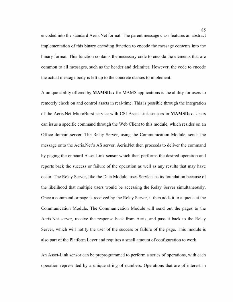
85
encoded into the standard Aeris.Net format. The parent message class features an abstract
implementation of this binary encoding function to encode the message contents into the
binary format. This function contains the necessary code to encode the elements that are
common to all messages, such as the header and delimiter. However, the code to encode
the actual message body is left up to the concrete classes to implement.
A unique ability offered by MAMSDev for MAMS applications is the ability for users to
remotely check on and control assets in real-time. This is possible through the integration
of the Aeris.Net MicroBurst service with CSI Asset-Link sensors in MAMSDev. Users
can issue a specific command through the Web Client to this module, which resides on an
Office domain server. The Relay Server, using the Communication Module, sends the
message onto the Aeris.Net’s AS server. Aeris.Net then proceeds to deliver the command
by paging the onboard Asset-Link sensor which then performs the desired operation and
reports back the success or failure of the operation as well as any results that may have
occur. The Relay Server, like the Data Module, uses Servlets as its foundation because of
the likelihood that multiple users would be accessing the Relay Server simultaneously.
Once a command or page is received by the Relay Server, it then adds it to a queue at the
Communication Module. The Communication Module will send out the pages to the
Aeris.Net server, receive the response back from Aeris, and pass it back to the Relay
Server, which will notify the user of the success or failure of the page. This module is
also part of the Platform Layer and requires a small amount of configuration to work.
An Asset-Link sensor can be preprogrammed to perform a series of operations, with each
operation represented by a unique string of numbers. Operations that are of interest in

86
real-world applications include requests for current positions, unlocking doors, arming
and unarming alarm systems, enabling or disabling engine ignition, speed limiters and
continuous tracking. The configured operation and their numbered command strings are
stored into the sensor database as the configuration can be unique for different sensors
and/or asset combinations. For security reasons, the actual command strings and sensor
identification numbers are never shown to users. Only users with sufficient security
credentials have the ability to activate these commands.
5.2.2 Data Module
The Data Module is responsible for serving data from geospatial sources, such as vector
data store in ESRI Shape files or raster image data, to local or remote users through the
Internet. It features a highly optimized code base and the ability to provide simultaneous
multi-user access. This module is responsible for receiving the raw asset data from the
Communication Module, to store into databases and serve the asset data to users. Its
primary purpose is to serve requests from the MAMSDev Web Client, though third-party
applications can be compatible as well. It can be configured using external configuration
files, so that the source code does not need to be changed and allows for rapid setup of
new MAMS applications and projects. The Data Module is composed of both Platform
and Application components. The two main classes that belong to the Application Layer
are the class involving the database management and the Servlet. Template versions of
both classes exist which can used as is, or as a guide for customization to meet specific
needs. Specifications for the Data Module are summarized in Table 5.2.

87
Table 5.2: Data Module Specifications Geospatial Vector Data support ESRI SHP datasets
Geospatial Raster Data support GIF/PNG/JPG
Non-Spatial Data Asset and geospatial information stored into databases and accessed through standard ODBC protocol
Features Automatic support of simultaneous multi-user access
Performance Optimization Vector data caching into server memory
High performance hierarchical storage scheme
Non-visible data culling
Data sharing among users for reduced memory requirements
The Data Module works in conjunction with the Communication Module. The
Communication Module decodes the Aeris.Net message into the original raw number
string before passing it to the Data Module. The Data Module then decodes the number
string into meaningful information, based on the configuration set in the remote sensor
and stores the information into databases. A separate component within the Data Module
is used to handle the database management aspects. Because the database is among the
most variable aspect in a MAMS, any changes in asset, or collected asset information
would have to be reflected in the database. This use of information hiding or
encapsulation helps minimizes the effect that any changes to the asset data collection
would have to the whole Data Module. The database classes finally decode the number
string into usable information. The classes also have the necessary queries and update
functions to work directly with databases.
The Data Module is expected to work in a one-to-many environment. This is an
environment where multiple users are expected to access the module at any given time.

88
The Java Servlet technology fits this requirement well, given its seamless handling of
multi-user access. It also makes it possible for only one instance of the Data Module to
handle all the clients, thus minimizing its memory footprint on its server. When the Data
Module is initialized, it determines what type of spatial data it is handling. If it is vector
data, it opens the associated vector data stored in the ESRI Shape file, to decode into an
array of separate vector features. An ESRI Shape file can contain point, line, polyline or
polygon features. While these different types of features utilize slightly different
encoding schemes, the process of decoding and storage is similar. Therefore, in this
situation, it is also beneficial to follow OO principals and create a parent class for a
generic ESRI Shape feature, then subclass new concrete classes for each type of vector
features. After the array of vector features is created, it is then broken apart into a Multi-
Layer Storage Scheme (MLSS), which is an important optimization to reduce the search
time for a given request and improve response times. This storage scheme works by
having several levels that cover the entire vector map area and is similar to pyramidal
schemes used for large raster data in many GIS and image processing software packages
where each level contains the same image but at a different level of resolution. However,
in the case of the MLSS, each level contains geospatial features of varying size, with no
feature being duplicated between the levels. Furthermore, each level partitions the map
area into certain cell size, with lower levels having smaller cell dimensions and a greater
number of cells than at higher levels. The topmost level has only one cell that contains
the entire map. As each vector feature is decoded from the ESRI Shape file, its boundary
coordinates is then checked to find the smallest cell in the storage scheme that it fits into.

89
By sorting the vector features into different cells, most client requests will only need to
search through a fraction of the vector data set. The MLSS is fully customizable; the
number of levels, the number of cell partitions in the horizontal and vertical can be
adjusted to match the density characteristics of a particular dataset.
All of the decoding, storage and request functions are built into the concrete Shape
feature classes. As the Data Module is built upon Servlet foundation, the vector data is
stored into global memory, so that threads created to service requests from multiple users
share the vector data and thereby reduce memory usage. The vector data is persistent in
memory, even after client threads have been destroyed once requests have been serviced.
This ensures that the time and processor consuming procedure of decoding the ESRI
Shape file only occurs once during the Data Module’s initialization phase. This is unlike
the life cycle of CGI, which would have to undergo the vector data decoding process for
every request had it been used to implement the Data Module.
For the handling of raster data provided by Microsoft MapPoint Web Service, the Data
Module maintains a connection with the MapPoint server. Data received from assets via
the Communication Module is stored into relational databases. The database system
currently used has been Microsoft Access, but all transactions with databases between
MAMSDev and the databases involve the ODBC standard protocol, which will allow
different database software packages to be readily used instead of Microsoft Access. As
the format of the tables and data used will likely vary between different MAMS
implementations, certain requirements are placed on how the database is structured to
maintain the OO design philosophy in MAMSDev. A database wrapper class, acting as

90
the database management system, is also required to encapsulate the inner workings of a
particular database and communicates with the rest of the modules in MAMSDev
through standard public interface methods.
Requests for spatial or non-spatial data are received by the Data Module through the
Servlet communication method. All forms of user request follow a standard protocol,
which indicate the type of request and other associated information required by the server
to perform the request. The server then performs the request and then packages the
requested data into a single message and sends it back to the user. After receiving a
request, the Servlet performs the operations necessary to accomplish the request and
sends the results back to the requesting Applet [Lee & Gao, 2002].
Within an ESRI Shape file, only the geometry or coordinates of the vector data are
available. The vector data’s attribute information, such as name or feature type, is stored
into a separate relational database. A database query must also be conducted for any
vector data request from the client. Once the list of vector data to be sent back to the
client is determined, the module then precedes to query the database for the selected
vector feature’s information. The combined data is then sent to the client. To streamline
this process, a preprocessing requirement is necessary when using Shape files. Rather
than use the original database, which still uses the legacy dBASE format, the information
in the database is imported into a modern relational database, such as Microsoft Access
for better performance, new querying features and ease of editing and maintenance. The
new database also must contain certain queries that will be used by MAMSDev to query
for information. The queries are used as the interface, allowing the actual structure of the

91
database to be hidden from MAMSDev.
In order to reduce the size of the vector data that is transmitted to the Web Client, several
optimization techniques are applied. These steps are able to provide a significant
reduction in size, but there is still enough information remaining for the Web Client to
reconstitute the data in a graphical form viewable by the user. These optimizations are:
1) Since only a fraction of a work area would be viewed by a user at a given time,
culling of the vector data can be performed, as it is only necessary to send the
visible vector data to the Web Client.
2) The concrete classes derived from the parent generic ESRI Shape class is used to
store and manage vector data. These classes feature the necessary functions and
data structures to query through the entire set of vector data efficiently. However,
these functions are not necessary for the Web Client and causes significant
overhead while the data structures greatly increasing the size of the data being
sent to the user. Therefore, the vector data instead is transformed from a complex
form into much simpler standard arrays with greatly reduced memory overhead.
3) For the final optimization, the vector data is compressed using the GZIP
compression algorithm to reduce the size even further.
Even when the selected map is in vector form, raster images are stilled used for
performance reasons, as vector data consumes a large amount of space and displaying the
entire vector data would not be feasible with current wireless Internet means. A raster
image of the entire selected map area is much smaller in space. Raster and vector data are
used to complement each other in MAMSDev as they compliment each other’s strengths

92
and weaknesses. Vector data, as mentioned previously, are large and therefore it is not
possible to display the entire set of data without consequences for performance and
download time. Raster data while capable of providing a low data size for large
overviews of a work area, is poorer at resolving details or showing views of the map area
at resolutions other than its native level. When zooming in on raster data, it can be resized
but with distortions and lacking in detail. A pyramidal scheme is also commonly used,
where an extremely large and detailed original image map is set at the bottom level and
the higher levels use lower detail versions of the map area. When zooming, the displayed
image can use the nearest level to resample from, thus providing a less distorted, more
detailed image. However, this procedure is complex and requires significant
preprocessing and storage for the various levels and it is not always possible to have the
necessary high-resolution raster image of the work area. Geospatial features stored in a
vector form like in an ESRI Shape file, on the other hand, can be resolved to virtually
infinite levels of precision thanks to the fact that vector data is stored in coordinate space.
By re-projecting the vector features from coordinate space to the pixel coordinates of the
display, there is no need for resampling or interpolation and the features remain sharp and
detailed even at high zoom levels.
To request raster data of a specific area using MapPoint Web Service, the parameters for
the coordinate center of the desired area and the width of the map in kilometers are
passed to the MapPoint server from the client. The raster data is returned in the form of a
GIF image stored in the form of a byte array. The metadata that is returned are the
coordinate center and extents of the map image, the map scale and view distance. The

93
byte array and metadata are then sent to the requesting client.
Configuration of the Data Module can be done through two methods. The primary
method is through adding parameters into a standard text based configuration file used
for each Servlet. The second supported method is to have the configuration file provide
the location of a separate configuration file, which would be parsed by the Data Module.
These configuration methods provide the Data Module with important parameters such as
the location of the vector data, the ODBC name of associated databases and the
coordinates of the desired map extent. In this way, different projects can be created using
the same template Data Module and without the need to modify the source code or to
write any additional code.
5.2.3 Application Module
Similar to several real world MAMS examined previously, a Web Client is the method
for users to interface and work with the data. Recognizing the advantages of an Internet
accessible software component in which users access the MAMS by using just an Internet
browser and data was stored on a central server; the Application Module has been
developed based on the same principles. The Application Module consists of a server
component and the Web Client, which enables users access to data and tools. Whenever a
user connects to the Application Module through a browser, the Web Client is
downloaded and executed on the user’s computer. By centralizing the storage and
distribution of the Web Client, benefits can be realized through reduced support and

94
administrative costs. Administrators need only to apply updates and bug fixes to the
Application Module code base held at the central server. Users can also be confident that
they are using the latest version of the Web Client whenever they connect to the
Application Module, as the Web Client will be updated if necessary and without
requiring any user intervention. The Application Module is the embodiment of the Web
component that was outlined in the description of the IMAMS architecture in Section 2.5.
The basis of the Web Client is the Java Applet. Basing the Web Client on an Applet
foundation allows for the creation of a software application that offers graphical user
interface that would be familiar to users. It also enables the application to run on multiple
platforms without any need to rewrite the source code. The Web Client itself is also
broken into several separate components to make it easier for future customization. This
module is primarily considered a part of the Application Layer, though there are some
classes that can serve as a skeleton to reduce development effort. In the Web Client,
information about assets can also be provided in text and tabular form using JSPs to
query the Data Module’s database for current or historical information.
These Web Client components include a Toolbar component, a Statusbar component and
a Map component plus a Parent Shell. The Toolbar controls the Web Client as it is
responsible for receiving inputs from users and controlling the application based on the
inputs. The Parent Shell contains the majority of the Web Client’s logic. It also links all
the other components together, passing controls and notifications the Map component and
for communicating with MAMSDev server-side modules. The Statusbar component is
used to display text information passed to it from either the Map or Toolbar components.

95
The Map component is used to display the spatial data graphically. Both the Statusbar
and Map components help present information and processing results to the user.
For the Web Client, all of the user accessible tools appear to be part of the Toolbar, at
least as seen from the user’s point of view. However, the implementations of these
functions are actually in the Parent Shell. The Toolbar is only used to activate the proper
functions in the Parent Map. The tools that have been created include typical GIS-type
functions for map viewing and manipulation as well as for viewing and querying
geospatial and non-spatial information. These functions interface with the Data Module
and retrieve data from it. Another category of functions is used for asset control, which
sends user-issued commands to the Remote Asset Control Relay Server. The type of
control functions available vary depending on the asset and the configuration of the
onboard remote sensor but typically include positioning, tracking and safety and security
related controls. The current configuration of the remote sensor and asset combination is
part of the information stored into the database dedicated to assets. This database is
queried by the Web Client to determine which command functions, if any, to show to a
user when a certain asset is selected.
In addition to asset information that can be queried using the Web Client, information
regarding the current address of assets or nearby streets can also be queried using the
geo-referencing tools in the Web Client. Each vector feature has metadata that includes
the necessary identification numbers that allow the Parent Shell to request extended
information regarding the feature. When the map is in raster form, then the mouse click is
converted into the geographical coordinates and sent to MapPoint server for geo-coding.

96
While the Web Client can run on a multitude of platform, there are still certain
requirements that must be met in order for a computer to run the Web Client properly.
The major requirement is that the client computer must have a recent Java Virtual
Machine (JVM) available. A JVM is necessary in order to run the Java based Web Client
and to provide the built-in Java classes that are used by the application, so that the
downloaded application can be as small as possible. The JVM is also necessary to run
any other Java applications. Fortunately, JVMs are offered by numerous providers for
multiple platforms and operating systems. The version developed by Sun is the most
popular and featured-filled, which is not surprising since Java is Sun’s creation. It is
freely available for download from Sun’s website.
When a user first accesses the Application Module, the Web Client is downloaded onto
the user’s computer, compiled and executed within the Internet browser environment.
Once the initialization processes are complete, the Web Client is in a blank state with no
data or parameters stored in the Web Client’s memory. It must then request an initial set
of parameters from the Application Module back at the Office server. This first set of
parameters provides important details regarding the map and data that would be needed
for the rest of the client session. It provides the access addresses for the Data and Relay
Server modules, the coordinate extent of the selected map area as well as information
regarding other map data sources that are available from the Data Modules.
When a vector data message is received from the Data Module, the Parent Shell passes
the message to the Map component. The contents of a vector data message includes the
coordinate extent of the new visible area, the vector feature type (polygons, polylines,

97
etc.), metadata regarding each distinct vector feature’s class as well as any assets that are
within the visible area. The Map decodes the packed vector and asset data into an array of
coordinates, converting from coordinate space to the display space using the coordinate
extent of the visible area. Each vector feature is drawn onto the display using Java
drawing functions and features can be differentiated by color using their associated
metadata if it is available. When a raster map is received from the Data Module, the
binary data is converted into an image and drawn by the Web Client. There is also
metadata providing important details regarding the map, such as the scale, the coordinate
extent and mathematical parameters to convert between pixel coordinates and
geographical coordinates accurately.
5.3 Common Client-Server Protocol
One of the main benefits offered by MAMSDev is its ability to act as middleware. By
acting as a middleware layer, the complexities of sever-side implementations can be
hidden from the Web Client. MAMSDev uses the RPC middleware method to allow Web
Clients to make requests on the server-side.
To act as a middleware, a common protocol was created in order to enable and server to
be able to communicate with one another and allow the Web Clients to be able to access
server-side data and other resources. Having a common protocol achieves the desired
middleware capabilities through the isolation of client and server systems. This allows
development of server systems and the Web Client to be separate and not dependent on
each other in any way. As long as both systems conform to the standardized message

98
formats, then they will communicate properly. The client-side invokes requests through
the RPC method. RPC is the middleware method used because the operations of a
MAMS Web Client typically demand immediate response, such as for map viewing.
5.4 Scripting
A scripting engine has also been implemented into MAMSDev. This scripting engine can
be used to modify the behavior of the server-side and client-side modules by changing
parameters held in text-based configuration files. In this way, a new MAMS can be
quickly developed by using pre-existing templates and modifying the configuration files.
Developers do not always have to modify and compile the source code in order to deploy
their MAMS.
Scriptable Data Module - by using the scripting engine, the Data Module can be
switched to provide different maps and default geographical parameters.
Scripting Application Module - the type of tools and functions that is accessible
through the Application Module can also be modified via scripting. This enables a
single MAMS to be easily transformed from one application to another, or to
allow easy configuration changes of units. The scripts are held at the Server and
passed onto the Web Client to generate the tools dynamically.
5.5 Server Implementation
In Figure 5.2, the architecture of a vector map MAMS implementation using MAMSDev
is shown. The modular nature of MAMSDev is seen, separated based on the principles

99
outlined earlier in this chapter. The Asset Message Listener and the Page Relay Server
represents the Communication Module and are responsible for receiving asset messages
and sending asset pages respectively. The System DBMS and Vector Data Sets represent
the Data Module. The System DBMS decodes, stores and manages the asset data as well
as other system information such as users and sensors. It is also used by the
Communication Modules to log messages for data mining purposes. The Vector Data
Sets each contain a separate and unique data set of a particular geographic region. The
Servlet Manager and the Web Client running on the client side computer represent the
Application module. The Servlet Manager provides important metadata that informs the
Web Client on how to access the Vector Data Sets.
Figure 5.2: MAMSDev Implementation Architecture (Vector Maps)
The raster version is shown in Figure 5.3; the primary change that has occurred is that the
Servlet Manager now acts as an intermediary between the Web Client and the map data

100
that is being held on raster map server.
Figure 5.3: MAMSDev Implementation Architecture (Raster Maps)

101
Chapter 6
Application Prototype Development
A prototype system, named as iVCAMS3 (Internet-based Vehicle Control And
Monitoring System for Safety and Security) was created as a demonstration application
for vehicle control and monitoring and to highlight the advantages of MAMSDev for
developing a MAMS. This system offered monitoring and controlling of vehicles for
safety and security purposes. The corporation’s business activities targeted a market area
covering the United States and Mexico, including remote areas. This limited the type of
wireless technologies that could be used. Even CDPD access would not always be
available, let alone newer wireless Internet technologies. The best option was the
Aeris.Net MicroBurst service, as it would work with the more widespread AMPS analog
cellular networks. Therefore, it was selected as the wireless method for communicating
with remote sensors. The CSI Asset-Link 200, with its integrated data acquisition
capabilities and built-in MicroBurst support, was an ideal choice as the remote sensors
for use in data acquisition. Its small size, sensitive GPS and cellular antennas enabled it
to be easily hidden, which is ideal for security applications. The Asset-Link’s ability to
control vehicle operations is also of great benefit by allowing iVCAMS3 to offer useful
remote control features. iVCAMS3 meets the requirements of a MAMS in that it
monitors attributes including vehicle locations, speed, heading and alarm statuses and
enables users to make decisions that are updated into the system seamlessly.

102
6.1 Implementation
Several regions were used for the testing of iVCAMS3. These regions included Calgary,
Edmonton, Fort Lauderdale (Florida), Phoenix (Arizona) and a region covering Montreal
and the New England region of the USA. The detailed street network of Calgary,
Edmonton and Florida as well as a major road and highway network of North America
were used. Up-to-date street network data sets of Calgary, Edmonton and Florida are
available from sources such as Statistics Canada and the Florida government. These data
sets, stored in the ESRI Shape format, offer extremely high levels of detail and even
included minor side streets and alleyways. However, finding detailed road data sets of
North America proved to be a much greater challenge. Ultimately, separate highway
datasets for Canada, the United States and Mexico obtained from a variety of sources had
to be combined together to form a single North American dataset and only has highways
and major roads. Microsoft MapPoint was used to provide the detailed street network of
all the testing regions in raster form.
For the iVCAMS3 implementation, only one computer was used as the Office domain
server. This resulted in MAMSDev being used in its Client/Server form with all of its
logic and modules running on a single server. The server consisted of dual 500 MHz
Pentium III Xeons with 1 GB of memory and running the Microsoft Windows NT 4.0
Server operating system. Asset data, sensor configurations and other related information
was stored into Microsoft Access databases. Apache Tomcat 5.0 was used as the Java
Server Engine for handling the JSP and Servlet requests and also as the web server.

103
The next two figures show the realized implementation of the theoretical system
displayed in Figure 5.2. In Figure 6.1, the architecture of iVCAMS3 when used with
vector based maps from ESRI Shape files is displayed, while Figure 6.2 shows the
architecture for when raster based maps from Microsoft MapPoint is used.
Figure 6.1: iVCAMS3 Architecture (Vector Maps)
Figure 6.2: iVCAMS3 Architecture (Raster Maps)

104
The Web Client as developed for iVCAMS3 was tested on various desktops and laptops.
Since the most intensive computing operations are done at the server-side, the Web
Client’s processor and memory requirements are not high. The Web Client is designed
for a display size of 1024 x 768 pixels in dimension or higher. This minimum display size
is necessary in order to show all the information and available tools. Moreover, this
resolution is commonly found on laptops. The testing platforms consisted of a Sony Vaio
Z505 laptop equipped with a Pentium III 750 MHz processor and several desktop
computers of various speeds.
Through testing, it was determined that the configuration storage scheme most suitable
for a wide range of data sets was a three-layer pyramid. The bottom layer was divided
into 31 x 31 cells, the middle layer was divided into 2 x 2 and the top layer has only one
cell. This particular configuration results in cells that overlap each other, so that no cell of
one layer shares the same border edge as a cell in a lower or upper layer. This
overlapping reduces the likelihood of a small vector feature that straddles the border of a
cell in multiple layers. This configuration resulted in a balanced storage of the vector
data, with each cell having similar numbers of features thus promoting quick and
consistent response times for queries.
The CSI Asset-Link sensor was selected as the sensor to be placed onboard the vehicles.
It can completely act as the data acquisition component of a MAM and has two-way
capabilities making it suitable for use with iVCAMS3. Because of its small size, the
Asset-Link sensors can be discretely hidden into vehicles, making it an effective alarm
and monitoring system. Its low power consumption ensures that it does not detrimentally

105
affect the performance or usability of a monitored asset, even if the asset is put into
storage or is inactive for weeks or months.
Despite the data limitations of MicroBurst, it is still possible to encode useful information
such as location, speeds, heading, battery voltage and engine status into one or several
number strings. The sensor can also send multiple types of messages. This can increase
the number of attributes that can be monitored as each message type can contain unique
information. Industrial partners provided the configuration setting of the CSI Asset-Link
sensors, which were also used to configure the database management component of the
Data Module. The configured capabilities of the sensor were also needed to customize the
Application Module to provide the necessary tools to access the available asset data and
control the asset. The information that the sensor could send back were:
Asset locations in the form of latitude and longitude.
Asset speed, heading and odometer readings.
Alerts for low battery voltage, emergencies and speed violations.
Acknowledgements to pages and commands.
The sensor accepted the following commands:
Request for current position.
Start continuous tracking and automatically send back its position every 5 minutes
for one hour.
Unlock the door of the asset connected to the sensor.
Enable or disable a 75-mile per hour speed limit. When the speed limit is enabled,
the sensor will automatically send a speed violation alert back to the server.

106
6.2 Client Application
Access to iVCAMS3 is obtained using an Internet browser like Microsoft Internet
Explorer and Java. The first step is to login to the iVCAMS3 as shown in Figure 6.3.
Figure 6.3: iVCAMS3 Login Screen
The main screen of iVCAMS3 can be seen in the top figure in Figure 6.4 and has an
interface that is similar to GIS and mapping applications. There is a large display
dedicated to displaying map data and asset locations in a graphical form. For this figure, a
map of Calgary, in raster form provided by MapPoint, is being displayed. The right side
of the client is used for tools to manipulate map and asset data and to issue pages to
assets. Figure 6.5 shows the vector version of the Calgary while Figure 6.6 and Figure 6.7
show the raster and vector maps of Fort Lauderdale and North America respectively.

107
Figure 6.4: iVCAMS3 Main Screen with Calgary Raster Map
Figure 6.5: iVCAMS3 Main Screen with Calgary Vector Map

108
Figure 6.6: Fort Lauderdale Vector and Raster Map

109
Figure 6.7: North America Vector and Raster Map
Figure 6.8 shows a session where the user has zoomed into a small area around an asset

110
while working with an ESRI Shape dataset of the Calgary street network. In addition, a
small map overview screen appears when a user is zoomed in, to give an indication of
where they are on the map. This overview is seen in Figure 6.9. Also observable in
Figure 6.8 on the Toolbar is the Vehicle Control tools. This is a list of commands that a
user can issue to their asset. For iVCAMS3, it offers the capability to locate on demand,
perform continuous tracking of the asset’s position or unlocking of the vehicle’s doors.
Figure 6.8: Typical iVCAMS3 User Session Using Vector Maps

111
Figure 6.9: iVCAMS3 Overview Map
Along with the graphical information, it is also possible to get asset information in text
form. These functions call JSPs to query the Data Module databases for current or
historical information regarding an individual asset or the entire fleet and present the
information in a separate window. An example of this function can be seen in the
following figure where historical information for a particular asset is shown. It is possible
to filter the information shown by the type and age of the messages.

112
Figure 6.10: Historical Information Regarding a Specific Asset
Users can also view and edit the detailed information for their vehicle using the Vehicle
Management tool. This vehicle information includes the serial number, or ESN, of the
Asset-Link sensor onboard the vehicle and information regarding the vehicle itself such
as the make, model and license plate of the vehicle. The vehicle owner’s contact
information is also included. This information can be modified by the user using the Web
Component and any modifications are updated to the iVCAMS3 database immediately.
Finally, iVCAMS3 also has the capability to email a message to the user at the provided
email address whenever an alert is received automatically. The option to enable or disable

113
this function is found here. The Vehicle Management tool is shown in Figure 6.11.
Figure 6.11: Vehicle Management Tool
6.3 Field Testing
Field-testing was conducted to ensure that iVCAMS3 could successfully receive
messages from Asset-Link equipped assets using the MicroBurst network and send
commands back. Asset-Link sensors were placed onto cars in Calgary, Edmonton, Fort
Lauderdale, Phoenix and Eastern Canada/USA. During the tests, pages were issued to the
Asset-Link sensors for their locations. Their locations were sent back to the server and
instantly updated into iVCAMS3 and plotted onto the map. The accuracy of the location
data was confirmed with the drivers of the cars and when plotted against a map, was

114
accurate. Other commands, such as remote unlocking of doors, were also tested and were
successfully received by the sensors and the drivers verified that the correct operations
were performed. In Figure 6.12, the results of tracking an asset are shown. This figure
shows the current position of the asset, which is indicated by the red dot with the sensor
ID number above it (top left). Previous positions, indicated by blue outlined beige
squares are also shown (primarily in the bottom left).
Figure 6.12: Tracking an Asset
The total time necessary to complete all the steps in paging an asset was also monitored
during the course of tests. Paging an asset consists of the following steps:
1) A user issuing a page for a selected asset by selecting the desired operation
through the Web Client.

115
2) The server receiving the page and relaying it onto the Aeris.Net AS server.
3) The Aeris.Net AS server then communicating with the Asset-Link sensor onboard
the asset using MicroBurst.
4) The sensor performing the necessary operations and sending an acknowledgement
message to the Aeris.Net DS server indicating the success or failure of the
operation.
5) The Aeris.Net DS server relays the message to the server for decoding and
storage.
The measured times for 28 pages, from the moment the user issues the command to the
moment that the server receives the results back from the Aeris.Net DS server, are shown
in Figure 6.13. These pages were sent to two assets; one asset traveling between Calgary
and Edmonton at highway speeds while the second asset was in Fort Lauderdale, Florida
and stationary. The pages were sent equally distributed through a 24 hour period. The
average time for roundtrip of a page was found to be 9.25s, with a maximum time of 16s,
which was reached by only one of the pages. The standard deviation was 2s. The majority
of the message travel time is spent between Steps 3-5 with the time taking by Steps 1 and
2 on the order of tenths of seconds.

116
Roundtrip Latency of Pages to Assets
0
2
4
6
8
10
12
14
16
18
0 5 10 15 20 25 30
Late
ncy
(s)
Figure 6.13: Roundtrip Latency of Pages to Assets
6.4 System Testing
System testing was conducted to quantify the computing requirements of an implemented
MAMS such as iVCAMS3 and the limit to the number of assets and users it can support.
6.4.1 Single-Client Performance
The first set of tests were performed with only one client accessing iVCAMS3. Of
interest was the memory usage at the server, initialization time of the Data Module and
typical response times for client queries. Memory usage was measured by Window’s
PerfMon utility, while built-in timing functions were used in iVCAMS3 to provide time
measurements. In the following table, performance and resource usage metrics are

117
reported for iVCAMS3 displaying the Calgary street network, which consists of 50,319
individual vector features taking 8.06 MB of hard drive space.
The Web Client was tested with Microsoft’s Internet Explorer browser, as well as the
Mozilla browser, an open-source browser heavily based on Netscape. These two
browsers are used by the vast majority of Internet users. The JVM used for both the client
and server modules of iVCAMS3 was version 1.4 of the Sun JVM. Table 6.1 lists the
results of this test.
Table 6.1: Single-Client Performance Metrics Server-side memory usage <36 MB of RAM total
Client-side memory usage <33 MB of RAM total
Server-side initialization time <20 seconds to build MLSS
<11 seconds to retrieve street network attributes from database
Typical response times for client queries 16-40 ms, for all zoom levels
Typical data transmission size per query 5-10 KB at high zoom levels
20-40 KB at moderate zoom levels
<400 KB at lowest allowable zoom level
It can be seen that the memory usage is quite low on the server side, consuming a total of
36MB and this value includes the memory used by the web server, the Calgary street
network data, Data Module and server portion of the Application Module. The
initialization time is also quick, taking roughly half a minute to complete. This
initialization time also only occurs when iVCAMS3 is accessed for the first time and
subsequent accesses do not have the initialization time at all. For the client side, the Web
Client takes about 33MB of memory, which is acceptable for desktop, and laptop

118
hardware. Response times are in the tens of milliseconds range, which is low enough to
make iVCAMS3 feel responsive and is consistent even with changing zoom levels. The
data size of each request at moderate zoom levels is small and can be handled by the
commonly available wireless Internet networks. At the lowest possible zoom level, where
more of the map is displayed on screen, the data bandwidth requirements become much
higher. This would cause problems even on the fastest wired Internet connection.
Restricting the ability of users to use such zoom levels is one way to avoid this problem,
as is the use of raster maps that have consistent data sizes regardless of the zoom level.
6.4.2 System Limit Testing
To test the theoretical limits on the system, in terms of number of units and clients that
can be supported, simulation testing was performed using several different computer
systems acting as the Server. Simulation allowed for the precise control of variables,
which is necessary to quantify the limits of MAMSDev.
In its development tools, Aeris.Net provided software that simulates the Aeris.Net AS
and DS servers. This enables developers to create fully tested and compatible
applications before using it with the real Aeris.Net MicroBurst network. The simulated
server software is customizable and can be modified to send messages at a user-defined
rate. In this way, we can simulate a different number of units by varying the frequency
that messages are sent out by the simulated Aeris.Net server. We can then determine the
limitations of the system in terms of the number of units and assets that it can support, by
monitoring the CPU and network bandwidth usage using PerfMon. These monitored

119
attributes are displayed in Figure 6.14. The test server consisted of an Intel Pentium III
933MHz system with 512MB of RAM and running the Microsoft Windows 2000
operating system. A different server on a private network was used for all simulation
testing in order to minimize any unexpected external factors from affecting the simulation
results. It was not possible to isolate the real server in the same way, as it was open to the
Internet and performed important network management tasks.
Simulated Asset Testing
0
5
10
15
20
25
30
Time
CPU
Usa
ge (%
)
0
5
10
15
20
25
30
KB/
s Re
ceiv
ed 131 Msgs/s64 Msgs/s131 Msgs Bandwidth64 Msgs Bandwidth
Figure 6.14: Graph of CPU and Network Usage at Two Message Loads
Using an assumption that an asset will send a message once every 30s, like in the snow
plow system desired by Alberta Transportation in Section 3.3, 64 messages per second
therefore approximate a fleet of about 1900 assets and 131 messages per second
representing about 3900 assets. From the results of Figure 6.14, we can see that the CPU
usage for even 3900 assets is not taxing the server, as it only ranges from 20% to 25%.
For 1900 assets, the CPU usage is lower and ranges from 7% to 15%. As for network
bandwidth usage, the simulation results shows that this should not be a major concern as
the usage is 15KB/s and 29KB/s for 1900 and 3900 assets respectively and well within

120
the limits of even home broadband Internet connections.
The second simulation test aimed to determine the maximum number of clients that could
be supported by the Web Client. A client simulator application was written to try to
mimic the behavior of a real human user while using the system. Several simulations
were run, with the number of simulated clients varied and important performance
attributes from the server logged.
The client computers were connected to the server over a Fast Ethernet local network, to
eliminate any influence in the results due to network speeds. The Calgary street network
dataset, consisting of 50,319 individual vector features, was used for the simulation. A
summary of the monitored attributes is presented in Table 6.2 and these attributes were:
Memory usage – the amount of memory used by the System on the server.
CPU usage – the percentage of the server’s processing time used by the System
on servicing requests from users.
Responses per second – the number of responses handled per second.
Average Response Time – the average time needed to service a request.
90th Percentile Response Time – the threshold response time where 90% of all
responses were serviced.
1s Percentile Response Time (s) – the percentage of responses which were
serviced within 1s or less. The value of 1s was chosen because it represented a
time period where a user would still find the system responsive.
Average Bandwidth Usage – the amount of network bandwidth being used by the
server per second

121
Table 6.2: Summary of the Server Attributes with Simulated Users
Number Memory % CPU Responses Avg. Response 90th Percentile 1s Percent Avg. Bandwidth
of Users Usage (MB) Usage per second Time (s) Response Time (s) Rank Usage (KB/s) 20 70.3 5.3 0.421 0.262 0.746 94.2% 22.6 35 70.5 8.7 0.749 0.250 0.750 95.0% 36.7 50 72.6 12.4 1.115 0.306 0.829 92.7% 51.9 70 75.8 17.8 1.561 0.455 1.031 89.5% 73.7 90 85.2 25.6 1.935 0.948 1.817 83.8% 91.3
From the results presented in the table, it can be seen that the system is capable of scaling
with increasing number of users. Memory usage remains low even up to 90 users and
only increases at a slow rate with more users. Between 70 and 90 users, the stress on the
server starts to increase at a faster rate. CPU usage increases at a nearly constant rate
between 20 and 70 users but this rate grows faster between 70 and 90 users. This is also
reflected in the attributes that deal with response times, which show a noticeable
degradation in performance as well. This reason for this behavior is currently unknown.
In summary, supporting even a large asset fleet does not require significant CPU or
networking resources. Therefore, much of the CPU and networking bandwidth can be
allocated to the client side. This is important since the Web Client is more demanding of
CPU usage and network bandwidth. The server that was used, despite being more than
three years old, was able to support an asset fleet of thousands and up to 90 users. With
modern servers that are many times more powerful, iVCAMS3 would be capable of
working in extremely large real-world operations supporting thousands of assets and
hundreds of simultaneous users.
iVCAMS3 was able to solve the problems posed in Section 2.3. It monitored a vehicle’s

122
location plus additional attributes important for safety and security. The combined data is
sent back using a wireless network for timely availability to users and iVCAMS3 can
automatically contact users when key events occur. Users are able to make decisions
using built-in tools, which can be sent immediately to the vehicle. Such decisions are
automatically updated into databases, so that the current status of a vehicle is always up-
to-date when other users view it.

123
Chapter 7
Conclusions and Recommendations
The focus of this thesis has been on creating a new development platform that will aid in
the deployment of Mobile Asset Management Systems. Numerous software and hardware
technologies were investigated in the course of the thesis and those found to be most
useful for creating the platform or for MAMS in general were selected. A fully complete
platform, known as MAMSDev was then developed and is capable of addressing all the
important concerns in MAMS, including asset data acquisition, transmission and
handling and analysis as well as unique capabilities for user access to asset data.
MAMSDev was used as a basis for the development of a prototype MAMS known as
iVCAMS3. This system was built based on the requirements of industrial partners and
tested in the field with actual vehicles equipped with onboard remote sensors over several
regions of North America.
7.1 Conclusions
The major findings obtained and the tasks completed in the course of the thesis are as
follows.
1) Creating a new Development Platform, called MAMSDev dedicated to MAMS is
an extremely useful new approach to MAMS. It reduces the resources, time and
cost needed to deploy a MAMS, enhancing the benefits of the MAMS.
2) The use of an object-oriented application framework was deemed the ideal

124
structure for a useful platform as it improves reusability.
3) MAMS requirements for software and hardware were determined and suitable,
functional technologies were found for implementation into a platform.
4) A fully functional and complete platform called MAMSDev was created based on
object-oriented application frameworks and Java for ease of reuse and
extensibility. It features a modular design separating the important functions of a
MAMS, that of communication, data management and user interaction into
independent modules. This modularity enables developers the flexibility to use all
or only certain capabilities of the Platform. MAMSDev is fully documented and
manuals have been created to aid in the deployment of a MAMS based on it.
5) MAMSDev provides data management and storage capabilities through its Data
Management module. The specific details of database structures and asset
attributes that are monitored are abstracted, allowing developers to modify their
data storage and handling methods to match their field operations with little
impact to the rest of the MAMS.
6) MAMSDev enables remote access to assets and their data to users over the
Internet using its Application Module. This is a great benefit because many field
workers, who would benefit greatly from access to asset data, were unable to do
so without being physically at the same location as the data. Access is simple,
requiring only a modern Internet browser and the freely available Sun Java
Runtime Environment. Two-way capabilities are possible, enabling users to
control assets and opening up exciting new uses for MAMS.
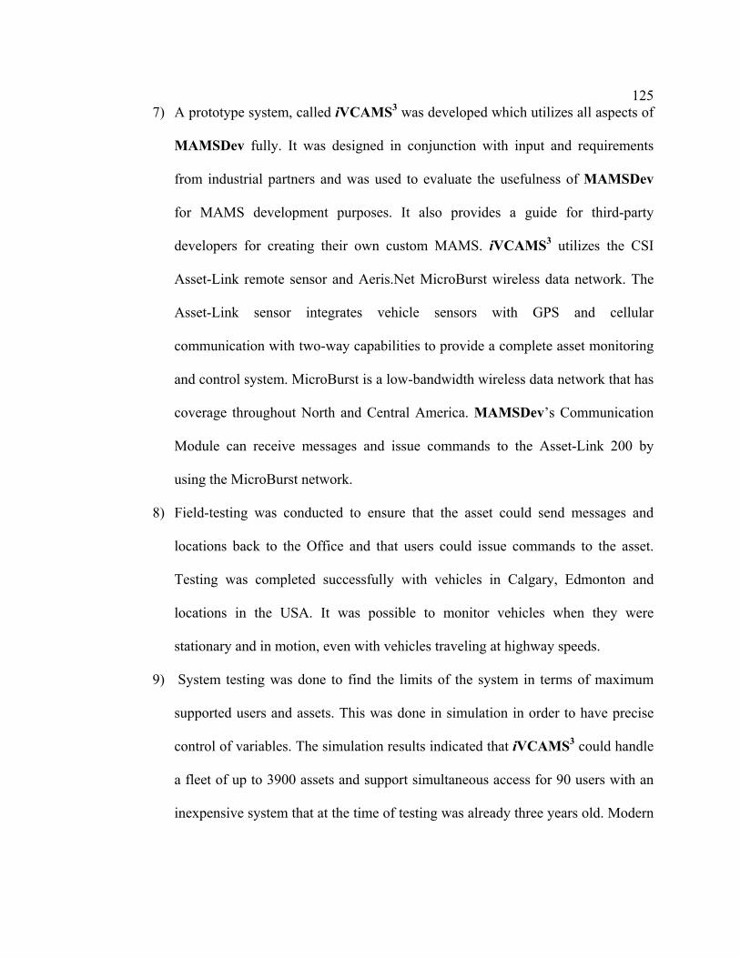
125
7) A prototype system, called iVCAMS3 was developed which utilizes all aspects of
MAMSDev fully. It was designed in conjunction with input and requirements
from industrial partners and was used to evaluate the usefulness of MAMSDev
for MAMS development purposes. It also provides a guide for third-party
developers for creating their own custom MAMS. iVCAMS3 utilizes the CSI
Asset-Link remote sensor and Aeris.Net MicroBurst wireless data network. The
Asset-Link sensor integrates vehicle sensors with GPS and cellular
communication with two-way capabilities to provide a complete asset monitoring
and control system. MicroBurst is a low-bandwidth wireless data network that has
coverage throughout North and Central America. MAMSDev’s Communication
Module can receive messages and issue commands to the Asset-Link 200 by
using the MicroBurst network.
8) Field-testing was conducted to ensure that the asset could send messages and
locations back to the Office and that users could issue commands to the asset.
Testing was completed successfully with vehicles in Calgary, Edmonton and
locations in the USA. It was possible to monitor vehicles when they were
stationary and in motion, even with vehicles traveling at highway speeds.
9) System testing was done to find the limits of the system in terms of maximum
supported users and assets. This was done in simulation in order to have precise
control of variables. The simulation results indicated that iVCAMS3 could handle
a fleet of up to 3900 assets and support simultaneous access for 90 users with an
inexpensive system that at the time of testing was already three years old. Modern

126
servers would increase the limits significantly to the point where large real-world
operations are possible.
7.2 Recommendations
While MAMSDev currently is fully functional, there are still areas that can be improved.
New additions can also be added in the future to further enhance the value and usefulness
of MAMSDev. These include:
1) Improved security – in the real world, system and data security is a critical issue.
Future research should look ways of securing access to only authorized users and
into encryption to protect asset and user data.
2) Enhanced scripting capabilities - MAMSDev can be improved with increased
scripting capabilities to modify and customize more aspects of a MAMS built
with MAMSDev. The existing scripting capabilities are beneficial, enabling
modifications to be made without modifying and re-compiling the source code.
3) Keeping abreast of new technological developments – in order to remain a useful
tool for developers, MAMSDev will need to be updated as new technologies for
computing, location and other data acquisition and wireless communication
become available.
4) More hardware and software testing – test with modern servers and enterprise
level databases and web serving software in order to see how MAMSDev works
with a computer system and software that a company would use. Testing with
additional hardware could also determine what is bottlenecking performance that
was found in Section 6.4.2.

127
References
Aeris.Net (2004). “Product & Services FAQ”.
http://www.aeris.net/aeris_web/products_faq.html. Last viewed August 1, 2004. (1)
Aeris.Net (2004). “Product & Services: MicroBurst™”.
http://www.aeris.net/aeris_web/products_microburst_technical.html. Last viewed
August 1, 2004. (2)
Alberta Transportation (2004). “Request For Proposal: Automated Vehicle Location
Systems (Avls) For Snowplow Trucks”. http://www.purchasingconnection.ca. Last
viewed July 10, 2004.
Allan, Roger (2003). “Onstar System Puts Telematics On The Map”. Electronic Design,
Vol. 51 Issue 7, p49, March 31, 2003. (1)
Allan, Roger (2003). “Telematics Set To Accelerate In The Fast Lane”. Electronic
Design, Vol. 51 Issue 13, p76, June 16, 2003. (2)
Berard, E. V (2000). "Motivation for an Object-Oriented Approach to Software
Engineering". http://www.itmweb.com/essay554.htm. Last viewed February 15, 2004.
Biddle, R., E. Tempero and P. Andreae (1995). "Object-Oriented Programming and
Reusability". Technical Report CS-TR-95/6, Department of Computer Science,
Victoria University of Wellington, 1995.
Bistroem, M. and T. Ray (1999). “Operational Mobile GIS in Energy Distribution”. GEO
Asia Pacific August/September 1999, pp. 36-38.

128
Brockwood, Ted (2001). “Simple SQL: Part 1”.
http://www.databasejournal.com/sqletc/article.php/1383471. Last viewed July 10,
2004.
CAD Resources (2000). “What is CAD”. http://www.cadresources.com.au/cad.htm. Last
viewed July 15, 2004.
Carter, J.(1999). “Mine Maintenance Equipment.” Unpublished report for Syncrude
Canada Ltd., Mildred Lake, Alberta, Canada.
CSI-Wireless (2004). “Asset Management Products”. http://www.csi-
wireless.com/products/am_asset_link.shtml. Last viewed July 12, 2004.
DirecTrack (2003). “DirecTrack”. http://www.directed.stage.televoke.net. Last viewed
March 24, 2003.
Driscoll, C.J. & Associates (2003). U.S. Fleet AVL Market News Release, March 10,
2003.
Ellis, J. R (2004). "Objectifying Real-Time Systems". SIGS Book, 2004.
ESRI (1998). “ESRI ShapeFile Technical Description. An ESRI White Paper”. July,
1998.
EUROPA (2003). “Europa – Energy and Transport – Galileo Applications –
Telecommunications”.
http://europa.eu.int/comm/dgs/energy_transport/galileo/applications/telecom_en.htm.
Last viewed August 5, 2004.
Fayad, M. and D. C. Schmidt (1997). "Object-Oriented Application Frameworks".

129
Communications of the ACM, Special Issue on Object-Oriented Application
Frameworks, Vol. 40, No. 10, October 1997.
FCC (2003). “FCC: Enhanced 911”. http://www.fcc.gov/911/enhanced/. Last viewed
February 10, 2004.
Fei, C (2001). “A Java Implementation for Open GIS Simple Feature Specification”.
M.Sc thesis, October 2001, The University of Calgary.
Fleetmind (2004). “Fleetmind: Products: Fleetlink Waste Market”.
http://www.fleetmind.com/wi/flash.html. Last viewed July 20, 2004.
Gao, Y. and R. Ramsaran (2000). “Mobile Asset Management toward Operational
Decision-Making”. ION GPS 2000, Sept. 19-22, 2000, Salt Lake City, Utah, USA.
Gao, Y. and S. Lee (2003). “Mobile Asset Data Acquisition and Decision-Making over
the Internet”. Geomatica, Vol. 57, No. 1. pp. 363-374, 2003.
Hoffmann-Wellenhof, B., H. Lictenegger and J. Collins (1997). “GPS, Theory and
Practice 4th Edition”. Springer Wien New York, Austria, 1997.
Honeywill, Tristan (2002). “The Relaying Race”. Professional Engineering, Vol. 15 Issue
4, page 55, February 27, 2002.
Hunter, J. and W. Crawford (1998). “Java™ Servlet Programming”. O’Reilly &
Associates, California, 1998.
Johnson, R.E. and B. Foote (1998). “Design Reusable Classes”. Journal of Object-
Oriented Programming June/July 1988.

130
Johnson, R.E (1992). “Documenting Frameworks using Patterns”. Proceedings of
OOPSLA '92, ACM SIGPLAN Notices, volume 27-10, pages 63--76, 1992.
Kane, L (2002). “Asset Management Begins In The Field”. Hydrocarbon Processing,
Vol. 81, No. 1, p13, January 2002.
Lee, S. and Y. Gao (2002). “Mobile Asset Tracking and Management Over the Web”.
Second Symposium on Geodesy for Geotechnical and Structural Engineering. May
21-24, 2002, Berlin, Germany.
Lee, S. and Y. Gao (2004). “A Platform For Rapid Deployment Of Mobile Asset
Management Systems”. XXth ISPRS Congress. July 15-20, 2004, Istanbul, Turkey.
Liu, Z (2002). “A Java-Based Wireless Framework for Location-Based Services
Applications”. M.Sci. thesis, June 2002, UCGE Reports No. 20161, The University of
Calgary.
MapQuest (2004). “Advantage API Product White Paper”.
http://www.mapquestsolutions.com/products/MapQuestAdvantageAPI_WhitePaper_0
71504.pdf. Last viewed March 20, 2004.
Microsoft (2004). “Microsoft MapPoint Web Service Fact Sheet”.
http://download.microsoft.com/download/8/8/a/88a0da3f-fbb0-4eff-a121-
8ca1a925c40e/MWS%20V3.5%20-%20FactSheet%20FINAL.pdf. Last viewed
August 8, 2004.
MSDN (2004). “ODBC Programmer’s Reference”.
http://msdn.microsoft.com/library/default.asp?url=/library/en-

131
us/odbc/htm/odbcwhat_is_odbc_.asp. Last viewed July 20, 2004.
Novatel Wireless (2001). “What is CDPD?”.
http://www.novatelwireless.com/company/cdpd.html. Last viewed January 15, 2004.
Park, M. and Gao, Y (2002). “Development of an Internet-Based Mobile Equipment
Management System”. Proceedings of FIG XXII International Congress, Washington,
D.C. USA, April 19-26, 2002.
Peck, J. and M. Murphy (1997). “Mining Enters the Information Age”. Automin 7, 7th
Canadian Symposium on Mining Automation, pp. 17-23. September 17-19, 1997, Fort
McMurray, Alberta.
Peng, Z. and M. Tsou (2003). “Internet GIS – Distributed Geographic Information
Services For The Internet And Wireless Networks”. John Wiley & Sons, New Jersey,
2003.
Prasad, M (2001). "Location Based Services".
http://www.gisdevelopment.net/technology/lbs/techlbs003pf.htm. Last viewed April 5,
2004.
Ramsaran, R (2000). “Development of a Mobile Equipment Management System”.
M.Eng. thesis, October 2000, UCGE Reports No. 20146, The University of Calgary.
Roberts, D. and R. Johnson (1996). “Evolving Frameworks: A Pattern Language for
Developing Object-Oriented Frameworks”. Proceedings of Pattern Languages of
Programs, Allerton Park, Illinois, September 1996.
Schmidt, D (2000). “Introductions to Patterns and Frameworks”. November, 2000.

132
Vanderbilt University.
Segal, M (1996). “On The Road, Not Out Of Touch”. Satellite Communications, August
1996, pp. 39-48.
Tellicate (2003). “GPS Locators”. http://www.tellicate.com. Last viewed May 9, 2004.
Telus Geomatics (2004). “Automated Vehicle Location | GeoExplorer”.
http://www.telusgeomatics.com/tgmain/geoexplorer/AVL/avl-overview.htm. Last viewed
August 8, 2004.
Vicenti, A (2002). “Telematics Gets Personal”. Automotive Engineer, Jul/Aug2002, Vol.
27 Issue 7, page 43.