title readout of the atomtronic quantum interference
TRANSCRIPT

Title Author(s)
Source
Readout of the atomtronic quantum interference device Tobias Haug, Joel Tan, Mark Theng, Rainer Dumke, Leong-Chuan Kwek and Luigi Amico Physical Review A, 97, 013633
Published by American Physical Society
Copyright © 2018 American Physical Society
This document may be used for private study or research purpose only. This document or any part of it may not be duplicated and/or distributed without permission of the copyright owner.
The Singapore Copyright Act applies to the use of this document.
Citation: Haug, T., Tan, J., Theng, M., Dumke, R., Kwek, L. C., & Amico, L. (2018). Readout of the atomtronic quantum interference device. Physical Review A, 97, 013633. http://dx.doi.org/10.1103/PhysRevA.97.013633
This document was archived with permission from the copyright owner.

PHYSICAL REVIEW A 97, 013633 (2018)
Readout of the atomtronic quantum interference device
Tobias Haug,1 Joel Tan,1 Mark Theng,1 Rainer Dumke,1,2 Leong-Chuan Kwek,1,3,4,5 and Luigi Amico1,3,6,7,8
1Centre for Quantum Technologies, National University of Singapore, 3 Science Drive 2, Singapore 117543, Singapore2Division of Physics and Applied Physics, Nanyang Technological University, 21 Nanyang Link, Singapore 637371, Singapore
3MajuLab, Centre National de la Recherche Scientifique, UNS-NUS-NTU International Joint Research Unit, UMI 3654 Singapore, Singapore4Institute of Advanced Studies, Nanyang Technological University, 60 Nanyang View, Singapore 639673, Singapore
5National Institute of Education, Nanyang Technological University, 1 Nanyang Walk, Singapore 637616, Singapore6Dipartimento di Fisica e Astronomia, Via Santa Sofia 64, 95127 Catania, Italy
7Consiglio Nazionale delle Ricerche, MATIS-IMM and Istituto Nazionale di Fisica Nucleare, Sezione di Catania,Via Santa Sofia 64, 95127 Catania, Italy
8LANEF “Chaire d’excellence,” Universitè Grenoble-Alpes and Centre National de la Recherche Scientifique, F-38000 Grenoble, France
(Received 9 August 2017; published 30 January 2018)
A Bose-Einstein condensate confined in ring shaped lattices interrupted by a weak link and pierced by aneffective magnetic flux defines the atomic counterpart of the superconducting quantum interference device: theatomtronic quantum interference device (AQUID). In this paper, we report on the detection of current states inthe system through a self-heterodyne protocol. Following the original proposal of the NIST and Paris groups,the ring-condensate many-body wave function interferes with a reference condensate expanding from the centerof the ring. We focus on the rf AQUID which realizes effective qubit dynamics. Both the Bose-Hubbard andGross-Pitaevskii dynamics are studied. For the Bose-Hubbard dynamics, we demonstrate that the self-heterodyneprotocol can be applied, but higher-order correlations in the evolution of the interfering condensates are measuredto readout of the current states of the system. We study how states with macroscopic quantum coherence can betold apart analyzing the noise in the time of flight of the ring condensate.
DOI: 10.1103/PhysRevA.97.013633
I. INTRODUCTION
Atomtronics exploits the progress in quantum technologyto realize atomic circuits in which ultracold atoms are manip-ulated in versatile laser generated or magnetic guides [1–7].Although atomtronic circuit quantum devices and simulatorsmay be of a radically different type from current technology,a fruitful starting point in the current research has been con-sidering an ultracold matter-wave analog of known quantumelectronic systems. With this logic, ring-shaped condensatesinterrupted by one or several weak links and pierced by an ef-fective magnetic flux [8] have been studied in analogy with thesuperconducting quantum interference devices (SQUIDs) ofmesoscopic superconductivity [9–11]. Such systems, dubbedatomtronic quantum interference devices (AQUIDs), withenhanced control of noise and low decoherence, enclose agreat potential both for basic science and technology. Inparticular, for AQUIDs with weak barriers and weak atom-atom interaction, hysteresis effects were evidenced [12]. In thiscase, the system can serve to study the dynamics of vorticesin a quantum fluid with a new twist [13]. Such study may giveimportant contributions to long-standing problems in quantumturbulence [14]. For stronger interactions and higher barriers,AQUIDs were demonstrated to be governed by an effectivetwo-level system (qubit) dynamics [15–20].
In this paper, we consider AQUIDs in which a singleweak link is present (that, in analogy with quantum electronicdevices, defines the rf AQUID); additionally, a lattice potentialalong the azimuthal angle is applied [17,18]. The resultingdevice can be indeed considered as the cold atom analog of themany-Josephson-junction fluxonium [21].
Depending on the conditions of the system (atomic den-sity, atom-atom interaction, external effective magnetic flux,strength of the weak link), the flow of atoms in AQUIDs entailsphysical mechanisms that may be very different in nature. Inthe simplest situation, the current is made of atoms in a definite(azimuthal) angular momentum state. By tuning the effectivemagnetic field suitably, it is, however, possible to put eachparticle in the ring in a superposition state of two angularmomentum states. Finally, in the qubit dynamics regime, thecurrent states are indeed many-particle entangled states withmacroscopic quantum coherence made of symmetric and an-tisymmetric combinations of the clockwise and anticlockwiseflowing states (cat states) [22].
Although the existence of the atomic current flowing inAQUIDs can be detected by standard time-of-flight measure-ment of the ring condensate [18], the analysis of the specificfeatures of the flowing states needs a more sophisticatedconfiguration. Specifically, the ring condensate is allowed tointerfere with a second condensate confined with a Gaussian-shaped laser beam in the center of ring. Such a condensate setsthe reference for the phase winding of the ring condensate. Byin situ measurement of the two interfering condensates, sucha protocol provides, indeed, the self-heterodyne detection ofthe phase of the wave function of the particles trapped in thering potential. With such an approach, it was demonstrated thatboth the orientation and the intensity of the current states can bedetected [23–25] (see also [26]). Very recently, it was suggestedthat similar information can be obtained by analyzing theDoppler shift of the phonon modes caused by shrinking theflowing condensate [27]. In such analysis the ring condensate
2469-9926/2018/97(1)/013633(12) 013633-1 ©2018 American Physical Society

HAUG, TAN, THENG, DUMKE, KWEK, AND AMICO PHYSICAL REVIEW A 97, 013633 (2018)
was assumed to be in the hydrodynamic Gross-Pitaevskiiregime (weak interaction).
The readout of the current states in the AQUID is veryimportant to be carried out for quantum simulation. At thesame time, it is a crucial step to fill for any applicationof the AQUID for quantum computing. In this paper, we applythe self-heterodyne approach to read out the current states in rfAQUIDs made of a ring lattice of condensates interrupted by asingle weak link. We study the systems both in Gross-Pitaevskiiand Bose-Hubbard (BH) regimes. In the latter one, appropriatefor stronger atom-atom interactions, we demonstrate that thestandard measurement of the time evolution of the statisticalaverage of particle density does not reveal the main propertiesof the current states (orientation and intensity of the flow).The readout of the current states, instead, can be done byconsidering the averaged density-density correlations in twodifferent positions of the condensates. At the same time, ouranalysis provides a way to detect states with macroscopicquantum coherence made of superpositions of clockwise andand anticlockwise flows.
The paper is structured as follows. In Sec. II, we summarizethe main physical properties of the rf AQUID together withthe models we exploit to describe the system. In Sec. III, wedescribe the protocol leading to the heterodyne detection ofthe phase in ring condensates. Similarities and differencesbetween the Gross-Pitaevskii and Bose-Hubbard dynamicsare discussed. In Sec.IV, we present the results we achieve.Discussions, comments, and remarks are presented in Sec.V.In the Appendices, we provide supplementary results on theBose-Hubbard and Gross-Pitaevskii dynamics, and provide theanalytical calculations for the noninteracting system we usedto benchmark our results.
II. THE ATOMTRONIC QUANTUMINTERFERENCE DEVICE
The relevant physics of the system is captured by the Bose-Hubbard Model. The Hamiltonian reads
HBH =M∑i=1
[U
2ni(ni − 1) + �ini
− Ji(e−i2π�/M a†
i+1ai + H.c.)
](1)
where ai (a†i ) are bosonic annihilation (creation) operators on
the ith site of a ring with length M and ni = a†i ai is the corre-
sponding number operator. Periodic boundaries are imposed,meaning that aM ≡ a0. The parameter U takes into accountthe finite scattering length for the atomic two-body collisionson the same site, U = 4πh2a0
∫dx|w(x)|4/m,w(x) being the
Wannier functions of the lattice, m the mass of atoms, and a0
the scattering length. To break the translational symmetry, thereare two possible ways. One way is that the hopping parametersare all equal, Ji = J , except in one weak-link hopping i0 whereJi0 = J ′. The other alternative, which we choose in this paper,is to place a potential barrier at a single site �i = � and at allother sites the potential is set to zero, with Ji = J,∀i. The twooptions show qualitatively the same physics [18]. The ring ispierced by an artificial (dimensionless) magnetic flux �, which
can be experimentally induced for neutral atoms as a Coriolisflux by rotating the lattice at constant velocity [9,28], or as asynthetic gauge flux by imparting a geometric phase directlyto the atoms via suitably designed laser fields [8,29,30].The presence of the flux � in Eq. (1) has been taken intoaccount through the Peierls substitution: Ji → e−i2π�/MJi .The Hamiltonian (1) is manifestly periodic in � with period 1.In the absence of the weak link, the system is also rotationallyinvariant and therefore the particle-particle interaction energydoes not depend on �. The many-body ground-state energy,as a function of �, is therefore given by a set of parabolasintersecting at the frustration points �n = (n + 1
2 ) [31,32]. Thepresence of the weak link breaks the axial rotational symmetryand couples different angular momenta states, thus lifting thedegeneracy at �n (see Appendix E). This feature sets the qubitoperating point [17,18].
It is worth noting that the interaction U and the weak-linkstrength induce competing physical effects: the weak link setsa healing length in the density as a further spatial scale; theinteraction tends to smooth out the healing length effect. Asa result, strong interaction tends to renormalize the weak linkenergy scale [18,33].
Assuming that the quantum dynamics of the system can bedescribed by the quantum dynamics of the phase of the bosonsai ∼ √
neiφi , the effective dynamics of the AQUID is governedby [17]
Heff = Hsyst + Hbath + Hsyst-bath (2)
with
Hsyst = Un2 + 12ELϕ2 − EJ cos(ϕ − 2π�), (3)
in which ϕ is the phase slip across the weak link, EL = J/M ,and EJ = J ′. For δ
.= EJ /EL � 1,Hsyst describes a particlein a double-well potential with the two minima well separatedfrom the other features of the potential. The two parameters,U and J ′/J , allow control of the two level system. The twolocal minima of the double well are degenerate for � = 1
2 .The minima correspond to the clockwise and anticlockwisecurrents in the AQUID.
In the weak interaction regime and coherence length in thecondensate much larger than the lattice spacing, the many-bodywave-function eigensolution of Eq. (1) can be considered asa product of coherent single-particle wave functions (suchconditions could be met for a sufficiently shallow lattice). Thisis the limit in which the system’s dynamics can be simplifiedto obey the Gross-Pitaevskii equation (GPE). Incidentally, weobserve that, by construction, the Gross-Pitaevskii Bose fluidcannot contain N particle entanglement (as, e.g., cat stateentanglement). The kind of coherence possibly encoded in thesystem in such a regime, instead, may arise by superpositionstates of single particles. The Gross-Pitaevskii equation reads
ih∂tψ(r) =(
− h2
2m∇2 + V (r) + g|ψ(r)|2 − ��0Lz
)ψ(r),
(4)
where ψ(r) is the so-called condensate wave function. Thefunction V (r) denotes the external trap potential, N is thetotal number of atoms, g = 4πh2a0N
mis the coupling constant,
a0 is the scattering length, N is the number of atoms, � is
013633-2

READOUT OF THE ATOMTRONIC QUANTUM … PHYSICAL REVIEW A 97, 013633 (2018)
the effective flux imparted by the rotation of the weak link,Lz = −ih(x∂y − y∂x) is the angular momentum operator, and�0 = h
mR2 is the characteristic frequency and flux quantum ofthe ring.
We model the trap with a ring Gaussian potential. Modulat-ing the potential with an azimuthal envelope allows us to add alattice and a weak link. We assume a strong confinement of thecondensate in the z direction, restricting the nontrivial dynam-ics to two dimensions in the x-y plane. The full expression forthe potential in polar coordinates is
V (r,φ) = V0Vring(r)
[1 + ηl sin2
(M
2φ
)− ηwe
− φ2
ξ2w
], (5)
where r and φ are the radial and azimuthal coordinates, V0
is the strength of the trap, and Vring(r) = −e− (r−R)2
ξ2r is a ring
Gaussian potential with ring radius R and ring potential widthξr. The second term in the brackets adds a lattice with n sitesand relative strength ηl. The third term adds a weak link ofrelative strength ηw and angular size ξw.
We solve the normalized two-dimensional GPE, andparametrize the interaction nonlinearity with a dimensionlessparameter β [34]. The scattering length is then a0 = βσz
2√
2πN,
where σz is the characteristic length of a harmonic confine-ment in the z direction. For 87Rb atoms (a0 ≈ 100aBohr),ring radius R = 10 μm, σz = 0.2R,N = 103, and radialconfinement σr = 0.083R we find β = 13.3. The cor-responding density of atoms in the ring is approxi-mately n = N
2π2σr2σzR= 2.4×1012cm−3. In the Bose-Hubbard
regime, the lattice depth is increased such that each lat-tice site is well localized. Then, the following approx-imations for the Bose-Hubbard parameters can be used:J = 4√
πErs
3/4 exp(−2s1/2) and U = 8√πkLa0Ers
3/4, with the
recoil energy Er = h2k2L
2m, the lattice depth V0, kL = π
alattice, the
lattice constant alattice, and the ratio s = V0Er
[35]. For rubidiumatoms, R = 10 μm, number of lattice sites M = 14, ands = 10, we find J/h = 4.1 Hz and U/J = 1.46.
III. INTERFEROMETRIC DETECTIONOF THE CURRENT STATES
As discussed in the previous section, the atomic current isprovided by an imparted phase gradient of the wave functionalong the ring condensate. To read out the direction and theintensity of the current in our lattice system, we follow thelogic originally applied in a series of works carried out bythe Maryland and Paris groups to map out the circulatingstates in continuous ring-shaped condensates [9,12,23,24,36].Accordingly, the ring condensate is made to interfere with aGaussian condensate at rest, located at the center, fixing thereference for the phase of the wave function. The combinedwave function evolves in time, interferes with itself, and finallyis measured. The number of spirals gives the total number ofrotation quanta.
In the actual experiment, the condensate is imaged throughin situ measurements. In this way, the current direction andmagnitude are well visible as a spiral pattern. The position ofthe spirals depends on the relative phase between the ring andthe central condensate ψ = ψring + eiφψc.
In the theoretical explanations provided so far, the mean-field Gross-Pitaevskii equation was applied, which assumesthat the combined system is a simple product of one particleproblems in a coherent state and in a superposition of particlesbeing in the ring and in the central condensate. In such astate, the particle number is not conserved, and thus accordingto the uncertainty between phase and particle number thephase is well defined. The relative phase is simply a freeparameter, chosen at random (the randomness being generatedby experimental imperfections during the preparation).
However, these assumptions are not generically fulfilled. Inthe experiment, the ring and central condensate are, indeed,well separated for an extended period of time (thus the coher-ence between the two is lost) and each of them has conservedparticle numbers. They can be described as product states oftwo Fock states |�〉 = |�r〉 ⊗ |�c〉. Thus, there is no a prioridefined phase between the two. A definite phase can arise whenthe information about the particle number is erased. Indeed,even if the two condensates do not have a phase relation, adistinct, random phase results when the positions of most of theparticles are measured [37,38]. In this measurement procedure,the information of from which condensate the particles camefrom is erased. This implies that the relative phase is not aproperty of the two condensates (or a local hidden parameter),but is determined only when the measurement is performed.
In the following, we consider two separate cases inwhich the ring lattice is governed by Gross-Pitaevskii orBose-Hubbard models.
A. Bose-Hubbard dynamics
The ring wave function is calculated by solving the groundstate of the Bose-Hubbard Hamiltonian, while the centralcondensate is simply a single decoupled site with Nc particles.In a single experimental run, the spirals will be visible fora good condensate with high number of particles. Froma theoretical point of view, such single-shot results couldbe generated by obtaining the many-body eigenfunctionsof Eq. (1), combining them with the wave function of thecentral condensate and simulating the detection sequence ofall particles of the expanding wave function [37,38]. In ourcase, however, the latter approach does not produce the spiralpatterns because the numerics are limited to a small number ofparticles. To overcome this limitation, we resort to expectationvalues, which experimentally corresponds to taking averagedresults over many experimental runs. Such an approach couldbe particularly helpful for systems in which the visibility insingle-shot experiments is low. The dynamics of the densityn(r,t) = ψ†(r,t)ψ(r,t) is initialized assuming that the bosonicfield operator of the system is ψ(r) = ∑
n wn(r)an, wherewn(r) are a set of Wannier functions forming a completebasis [39,40]. In our calculation, we approximate the fullbasis for wave functions living in the ambient space on whichthe condensate expands with the set of Wannier functionscomposed of Gaussians peaked at the ring lattice sites andat its center (the Gaussian approximation for the Wannierfunctions is a well-verified approximation for single site wavefunctions—see Refs. [41,42]). For the free evolution (we areindeed in a dilute limit) we assume that each particle at site n
013633-3

HAUG, TAN, THENG, DUMKE, KWEK, AND AMICO PHYSICAL REVIEW A 97, 013633 (2018)
expands in two dimensions as
wn(r,t) = 1√π
σn
σ 2n + iht
m
e− (r−rn)2
2(σ2n + iht
m ) , (6)
where σn is the width of the condensate located at the nthsite. The dynamics of the condensates is then approximated asψ(r,t) = ∑
n wn(r,t)an. We observe that such approximationworks well in the situations in which the optical lattice isassumed to be sufficiently dense in the space in which thecondensate is released (as in the release from large three-dimensional optical lattices). In our case, we checked that thescheme works for large ring lattices and, at intermediate size,in the large number of particles limit (see Appendix C). Inparticular, we checked that the long time limit of the approx-imated density 〈n(r,t)〉 = 〈ψ†(r,t)ψ(r,t)〉 coincides with thetime-of-flight expansion calculated by Fourier transformingthe initial wave function.
Generically, it is assumed that a single-shot experimentwith many particles (self-average), and the average over manyrealizations would yield the same result. Here, however, this isnot the case as every realization of the experiment has a randomphase. This phase results in an interference pattern, which isaveraged out over many repetitions. Indeed, we find that thedensity operator alone does not show any interference effects.This is consistent with the reasoning given at the beginningof the section: As the relative phase between ring and centralcondensate is determined randomly upon measurement, theexpectation value of the density operator will average overdifferent realizations of the spiral interference pattern, washingout the information on the current configuration structure.As the ring and central condensate are uncoupled, there isno uncertainty on whether a measured particle came fromthe ring or the central condensate. Accordingly, the densityoperator, measuring a single-particle property only, cannot giveinformation on the interference between two condensates. Thisis confirmed by Fig. 9. However, if we measure two or moreparticles, information about the particle origin is lost [37,38],as the measured particles could be either from the ring or fromthe central condensate. As the particle number distributionbetween ring and central condensate becomes uncertain, phasecertainty is gained.
As we shall demonstrate below, we, indeed, observe an in-terference pattern in higher-order density-density correlations.We calculate the density-density covariance [37,38,43,44]:
cov(r,r′,t) = 〈n(r,t)n(r′,t)〉 − 〈n(r,t)〉〈n(r′,t)〉. (7)
We also define the root of the density covariance which has thesame unit as the density to improve the contrast of the measuredinterference pattern:
σ (r,r′,t) = sgn[cov(r,r′,t)]√
|cov(r,r′,t)|. (8)
B. Gross-Pitaevskii dynamics
In the mean-field Gross-Pitaevskii description, the relativephase of two well-separated condensates (e.g., ring and centralcondensate ψ = ψring + eiφψc) is a free parameter, in contrastto the Bose-Hubbard model. This phase factor shifts the spiralsin the azimuthal direction in the interferometric expansion.In experiment, this phase factor is determined randomly for
each realization of the condensate, and thus will average outthe spirals over many experimental runs. In the following, weconsider the result of a single realization with a specific valueof φ.
The ground state of the condensate in the ring potentialis found by imaginary time evolution of the Gross-Pitaevskiiequation. After that, the Gaussian central cloud is added, thepotential is turned off, and both ring and central condensatefreely expand.
From [25], an approximate formula for the expanding ringcondensate (for zero interaction while expanding) is given by
ψring(r,θ,t)=(e− (r−R)2
2σr(t)2 ϕr(θ )+e− (r+R)2
2σr(t)2 ϕr(θ+π ))/(N (t)
√r),
(9)
with θ the angle in polar coordinates, N (t) a normaliza-tion factor, ϕr(θ ) the initial angular wave function, andσr(t)2 = σ 2
r + ihtm
. Here, σr is the initial width of the radialprofile of the wave function. Equation (9) is valid for time
scales τB t τS(r), where τB = mσ 2r
hand τS(r) = mrR
h. τB
is the time scale of the initial ballistic expansion of the ringcloud, while τS(r) is the time scale when the cloud acquires itsfar-field behavior (it begins to look like its initial momentumdistribution).
When t < τBr+Rσr
, the second term is negligible. Inter-ference with the expanding central cloud results in spiralfringes. We define the characteristic time when fringes appearτ = mRσr/h. The shape of the fringes thus allows us to readout the phase profile of the initial state. As it is discussed below,the weak link induces a discontinuity in the phase of the initialstate, resulting in the appearance of phase slips which cause adiscontinuity in the spirals.
When t > τBr+Rσr
, the second term becomes significant andinterferes with the first term, resulting in the appearance of ad-ditional circular bands. Eventually, as t → ∞, the condensateevolves towards the Fourier transform of the initial state, whichcorresponds to the initial momentum distribution [45].
Consistently with this theorem, we find that for sufficientlyweak interactions and large time scales, the condensate at longtimes matches the momentum profile of the original wavefunction. We find that when the central cloud is coexpandedwith the ring condensates, then the shape of the combinedcondensates at intermediate time scales shows a characteristicspiral pattern which reveals the phase winding.
IV. RESULTS
Our first goal will be pointing out the difference betweenthe Gross-Pitaevskii and Bose-Hubbard dynamics. Then, wewill discuss the specific spiral pattern arising when the effec-tive magnetic field is fixed to the degeneracy point � = 1
2 .Previous studies suggest that the spiral pattern displays aspecific discontinuity at the position of the weak link. Sucha discontinuity, however, may reflect different states in termsof their entanglement.
A. Bose-Hubbard interferometric measurement
The first conclusion comes from the analysis of the timeevolution of the density expectation value after the interference
013633-4

READOUT OF THE ATOMTRONIC QUANTUM … PHYSICAL REVIEW A 97, 013633 (2018)
-1
0
1
y/R
-1
0
1
-1 0 1x/R
0
1
-1
0
1
0
1
-1
0
1
0
1
-1
0
1
y/R
-1
0
1
y/R
-1 0 1x/R
-1 0 1x/R
-1 0 1x/R
-1 0 1x/R
-1 0 1x/R
-1 0 1x/R
-1 0 1x/R
U/J
=0
U/J
=1
U/J
=5
t=0.0τ t=0.3τ t=0.6τ t=1.2τ(a) (b)
FIG. 1. Density distribution (a) 〈n(r)〉 and root of density-density covariance (b) σ (r,r′ = {0,R/2}) of expanding atoms at timest = 0, 0.3τ, 0.6τ, 1.2τ , with τ = mRσr/h. Calculated using Bose-Hubbard model, no interaction during expansion. Data in color andnormalized to one. From top to bottom: U = 0, U/J = 1, U/J = 5. Seven particles, M = 14 ring sites, ring radius R. Width of central andring cloud is σr = 2R/L and potential barrier � = J ,� = 3, 25% of atoms in central condensate. Barrier at x = 0, y = −R. At intermediatetimes, we observe some spiral-like structure at the edges. This is not due to interference with the central condensate, but a residue of the ringlattice condensate interfering with itself.
with the central condensate: Consistently with the reasoningreported above, we observe that no spiral appears in thedensity in Fig. 1(a). In contrast, a clear spiral pattern arisesin the density-density covariance σ (r,r′) in Fig. 1(b). Wechoose r′ = {x ′ = 0,y ′ = R/2} such that it maximizes thespiral visibility.
Now, we present the results at the degeneracy point � = 12 –
Fig. 2. In this case, a step in the spirals at the weak link site(here at the center bottom) is clearly visible for intermediatetimes.
Although the interferometric pictures look similar (seeFig. 9 for the evolution of the density), different interactionslead to current states that may be very different in nature.For U = 0, the current is in a nonentangled superpositionstate, whereas for interaction U = J the current is in a highlyentangled NOON state. Below, we shall see how additionalinformation on the states can be grasped analyzing the noisein the momentum distribution of the ring condensate. Indeed,the noise for zero momentum depends strongly on the spe-cific entanglement between the clockwise and anticlockwiseflows. In the case of an entangled cat state all atoms havetogether either zero or one momentum quanta. A projectivemeasurement will collapse the wave function to all atomsin either the zero or one momentum state. Averaging overmany repeated measurements will result in erratic statics ofthe measurements. In contrast, in nonentangled single-particlesuperpositions, each particle has independently either zero orone momentum quantum. A single projective measurementwill result in on average half the atoms having zero and halfthe atoms having one rotation quantum. Therefore, fluctuationsaveraged over many measurements will be low. We define thenoise of the momentum distribution:
σk(k) =√
〈n(k)n(k)〉 − 〈n(k)〉〈n(k)〉. (10)
-1
0
1
y/R
-1
0
1
-1
0
1
-1
0
1
-1
0
1
y/R
-1
0
1
y/R
-1 0 1x/R
-1 0 1x/R
-1 0 1x/R
U/J=0 U/J=1 U/J=5
t=0.
0τt=
0.3τ
t=0.
6τt=
1.2τ
-1
0
1
y/R
-1
0
1
FIG. 2. Root of density-density covariance σ (r,r′ = {0,R/2}) ofexpanding atoms at times t = 0, 0.3τ, 0.6τ, 1.2τ , with τ = mRσr/h.Calculated using Bose-Hubbard model. From left to right:U = 0, U/J = 1, U/J = 5. Flux � = 1
2 at the degeneracy point,other parameters same as in Fig. 1. The discontinuity in the bottom ofthe spirals at intermediate times t = 0.3τ and 0.6τ shows that the ringcondensate is in a superposition of zero and one rotation quantum.
013633-5
HAUG, TAN, THENG, DUMKE, KWEK, AND AMICO PHYSICAL REVIEW A 97, 013633 (2018)
2 0 2log U/J10
2
0
2
0.5
1.0
log
Λ/J
10
0.4 0.5 0.62
0
2
log
Λ/J
10
0.5
1.0(a) (b)
FIG. 3. Momentum noise σk(k = 0) (in color, normalized to one)plotted for potential barrier � against (a) on-site interaction U
(� = 12 ) and (b) flux � (U/J = 1). Momentum noise is extracted
from the time-of-flight image after long expansion. Only the ringis expanded, without central condensate. The black line shows thecritical point where depletion at the potential barrier is 1% of theaverage particle number per site. Above the line the potential barriersite is depleted. Other parameters are M = 11 ring sites and 5particles.
Having in mind a time-of-flight experiment, the optimal pointto measure the noise is at k = 0, as at this point the densityis maximal for zero rotation quanta, and zero for one or morerotation quanta. We plot the noise of the time-of-flight imageat k = 0 without a central condensate in Fig. 3. We see that themomentum noise is minimal in a certain parameter regime inFig. 3(a). This area can provide a guide for the Gross-Pitaevskiilimit of the Bose-Hubbard model. It is given by U/J 1and �/J > cU/J , where c is some constant. As soon as theinteraction becomes larger than the energy gap induced bythe potential barrier, the noise increases. This indicates thedeviation from the Gross-Pitaevskii regime. Here, entangledphase winding states of zero and one winding quantum appear.For large interaction, the noise decreases again, however itremains higher than in the Gross-Pitaevskii regime. As weelaborate further in Sec. V, information about the entanglementis also hidden in the number of particles at the site of thepotential barrier [18]. The noise is maximal at the degeneracypoint and when barrier and interaction are on the same order.Changing the flux away from the degeneracy point decreasesthe noise.
B. Gross-Pitaevskii interferometric measurement
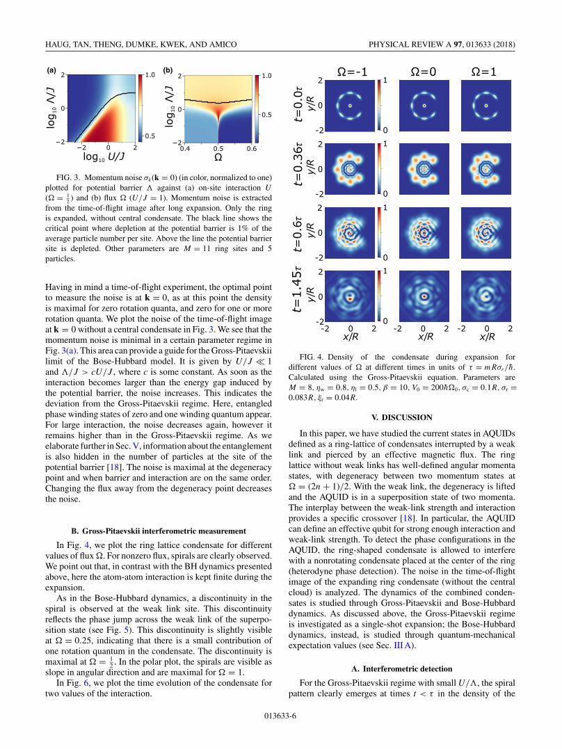
In Fig. 4, we plot the ring lattice condensate for differentvalues of flux �. For nonzero flux, spirals are clearly observed.We point out that, in contrast with the BH dynamics presentedabove, here the atom-atom interaction is kept finite during theexpansion.
As in the Bose-Hubbard dynamics, a discontinuity in thespiral is observed at the weak link site. This discontinuityreflects the phase jump across the weak link of the superpo-sition state (see Fig. 5). This discontinuity is slightly visibleat � = 0.25, indicating that there is a small contribution ofone rotation quantum in the condensate. The discontinuity ismaximal at � = 1
2 . In the polar plot, the spirals are visible asslope in angular direction and are maximal for � = 1.
In Fig. 6, we plot the time evolution of the condensate fortwo values of the interaction.
-2
0
2
y/R
y/R
y/R
-2 0 2x/R x/R x/R
Ω=-1 Ω=0 Ω=1
t=0.
0τt=
0.36τ
t=0.
6τt=
1.45τ
y/R
0
1
0
1
0
1
0
1
-2
0
2
-2
0
2
-2
0
2
-2 0 2 -2 0 2
FIG. 4. Density of the condensate during expansion fordifferent values of � at different times in units of τ = mRσr/h.Calculated using the Gross-Pitaevskii equation. Parameters areM = 8, ηw = 0.8, ηl = 0.5, β = 10, V0 = 200h�0, σc = 0.1R, σr =0.083R, ξr = 0.04R.
V. DISCUSSION
In this paper, we have studied the current states in AQUIDsdefined as a ring-lattice of condensates interrupted by a weaklink and pierced by an effective magnetic flux. The ringlattice without weak links has well-defined angular momentastates, with degeneracy between two momentum states at� = (2n + 1)/2. With the weak link, the degeneracy is liftedand the AQUID is in a superposition state of two momenta.The interplay between the weak-link strength and interactionprovides a specific crossover [18]. In particular, the AQUIDcan define an effective qubit for strong enough interaction andweak-link strength. To detect the phase configurations in theAQUID, the ring-shaped condensate is allowed to interferewith a nonrotating condensate placed at the center of the ring(heterodyne phase detection). The noise in the time-of-flightimage of the expanding ring condensate (without the centralcloud) is analyzed. The dynamics of the combined conden-sates is studied through Gross-Pitaevskii and Bose-Hubbarddynamics. As discussed above, the Gross-Pitaevskii regimeis investigated as a single-shot expansion; the Bose-Hubbarddynamics, instead, is studied through quantum-mechanicalexpectation values (see Sec. III A).
A. Interferometric detection
For the Gross-Pitaevskii regime with small U/�, the spiralpattern clearly emerges at times t < τ in the density of the
013633-6

READOUT OF THE ATOMTRONIC QUANTUM … PHYSICAL REVIEW A 97, 013633 (2018)
0
1
2
r/R
0 1 2θ/π
Ω=0 Ω=0.25 Ω=0.5t=
0.0τ
t=0.
36τ
t=0.
6τt=
1.45τ
0
1
0
1
0
1
0
1
Ω=0.75 Ω=1
0
1
2
r/R
0
1
2
r/R
0
1
2
r/R
FIG. 5. Density of expanding atoms in polar coordinates with radius r and polar angle θ for increasing � across the degeneracy point. Otherparameters as in Fig. 4.
expanding condensates, for both vanishing and intermediateinteraction (Figs. 4 and 6). At increasing times, the spiral iswashed out and replaced by a ring-shaped density, which corre-sponds to the Fourier transform. The lattice acts as an azimuthalmodulation of the density along the ring. This leaves a lattice-shaped imprint in the time-of-flight image, retaining the dis-tinctive spiral features and phase slips. For larger interactions(compared with �), the regime well described by the Bose-Hubbard model, the readout is studied through expectationvalues defined by the average of many condensate expansions.In this case, we found that the spiral evolution is not displayedby density, but by the density-density covariance (Fig. 1).
We found no significant dependence between the time scalesof the expansion and the effective flux.
B. Degeneracy point
The degeneracy at the effective magnetic flux � = (2n +1)/2 is reflected by a specific discontinuity of the spiralpattern at the weak link (a phase jump) (Figs. 2 and 5).For the Bose-Hubbard model, we found that for strongerinteractions, the discontinuity of the spirals becomes slightlysmaller (see Fig. 2 at t = 0.6τ ). This trend is consistent withthe renormalization that the interaction implies on the strengthof the local barrier [18].
While for small interactions the Gross-Pitaevskii equationproduces reasonable superposition states, we find that, withincreasing interaction, an instability occurs at the degeneracypoint: In a situation in which we should observe an equalsuperposition of zero and one phase winding, we observe thatthe system tends to acquire zero (or one) phase winding, in-stead. This marks the breakdown of the underlying mean-fieldapproximation of the Gross-Pitaevskii equation. In the timeevolution, we observe this effect as a vanishing discontinuityof the spiral at the weak link for increasing interactions (seeFig. 8). In fact, the Bose-Hubbard model correctly describesthis regime of strong interactions. We found that, because ofthe two-level system effective physics, the noise in the timeof flight of the ring condensate, without the central cloud, isparticularly pronounced at the degeneracy points (Fig. 3). Thisphenomenon would allow us to detect the degeneracy pointin the ring condensate, without resorting to the heterodynedetection protocol.
C. Macroscopic quantum coherence
With increasing interaction, we can define three regimes ofentanglement [46]: At the degeneracy point � = 1
2 , for inter-action smaller than the energy gap created by the weak link,
013633-7

HAUG, TAN, THENG, DUMKE, KWEK, AND AMICO PHYSICAL REVIEW A 97, 013633 (2018)
-2
0
2y/R
y/R
y/R
-2 0 2x/R x/R
β=0 β=1t=
0.0 τ
t=0.
36τ
t=0.
6τt=
1.45τ
y/R
0
1
0
1
0
1
0
1
-2
0
2
-2
0
2
-2
0
2
-2 0 2
FIG. 6. Density of the condensate during expansion for interac-tion β = 0 (left) and β = 1 (right) at the degeneracy point � = 1
2 .Other parameters as in Fig. 4.
we observe one-particle superposition states |�〉 ∝ (|l = 0〉 +|l = 1〉)N , where N is the number of particles and l is theangular momentum of the atom. This regime is well describedby the Gross-Pitaevskii equation. When the interaction andthe weak-link energy gap are on the same order, the near-degenerate many-body states mix and entangled NOON statesare formed |�〉 ∝ |l = 0〉N + |l = 1〉N . Increasing interactionfurther will fermionize the system. With interaction, angularmomentum of each atom individually is not conserved, how-ever the center-of-mass angular momentum K of the wholecondensate is. Then, the ground state is a superposition of|�〉 ∝ |K = 0〉 + |K = N〉.
This entanglement can be observed in the noise of the mo-mentum distribution (Fig. 3). The ring atoms (without centralcondensate) are freely expanded until the density distributionof the atoms corresponds to the momentum distribution k of theinitially prepared state. For a nonentangled superposition state,the momentum states have a binomial distribution and the noiseat k = 0 is minimal (the Gross-Pitaevskii regime) and is givenby σ GP
k (k = 0) ∝ √N/4. For a completely entangled NOON
state, it is maximal and given by σ NOONk (k = 0) ∝ N/4. The
ratio of the two extrema is√
N . Thus, with increasing particlenumber these two types of states are clearer to distinguish.
For zero on-site interaction, the site at the potential barrieris always depleted at the degeneracy point for any valueof potential barrier strength. However, when the interactionexceeds a critical value, particles start occupying the site [18].This is plotted as a black line in Fig. 3. For small interactionthe critical value has a linear relationship between U and �
[18]. The filling of the potential barrier site indicates the onsetof entanglement between different flux quanta. The depletionfactor can be measured by a lattice-site resolved absorptionmeasurements.
In summary, the readout of the AQUID can be done byanalysis of the density (GPE) or by density-density covariance(BH) of the ring condensate interfering with a cloud fixing aphase reference (heterodyne detection protocol). The super-position state is reflected by a specific discontinuity of thephase pattern. The entanglement of the state can be studied bylooking at the expansion of the ring condensate (without thecentral cloud) by two witnesses. First is the degree of depletionat the potential barrier corresponding to the weak link. For aweak barrier (compared to the interaction), when the barriersite fills up, this indicates the onset of entanglement. Secondis the noise in the time-of-flight image. The noise becomesmaximal for a highly entangled NOON state. It is minimal for aone-particle superposition state, and intermediate for center-ofmass superpositions.
We believe that our findings are well within the currentexperimental know-how of the field.
ACKNOWLEDGMENTS
The Grenoble LANEF framework (ANR-10-LABX-51-01)is acknowledged for its support with mutualized infrastructure.We thank National Research Foundation Singapore and theMinistry of Education Singapore Academic Research FundTier 2 (Grant No. MOE2015-T2-1-101) for support.
APPENDIX A: ADDITIONAL GPE DATA
In this section, we provide additional evidence for thedynamic calculated with the Gross-Pitaevskii equation.
In Fig. 7, we plot the time evolution of ring and centralcloud condensate against different lattice depths ηl at thedegeneracy point. We see that at intermediate times t = 0.6τ
the spiral position jump at the weak-link site at the centerright. This feature is due to the jump of phase at the weaklink and is independent of lattice depth. With increasing latticedepth, the time-of-flight image acquires a lattice structureas well.
In Fig. 8, we plot the time evolution of the condensateat the degeneracy point for different values of interaction β.Whereas for low interaction we see initially the characteristicdiscontinuity, for strong interaction it is suppressed. The timeevolution for strong interaction shows no spiral and thus nophase winding. This is because the GPE mean field breaksdown when the interaction energy is large compared to theenergy gap induced by the weak link. Depending on the initialconditions, either zero or one phase winding is observed in thiscase.
013633-8

READOUT OF THE ATOMTRONIC QUANTUM … PHYSICAL REVIEW A 97, 013633 (2018)
-2
0
2
y/R
y/R
y/R
-2 0 2x/R x/R x/R
t=0.0τη
=0
l
0
1
0
1
0
1-2
0
2
-2
0
2
-2 0 2 -2 0 2
t=0.6τ t=1.45τη
=0.
5l
η=
1l
FIG. 7. Density of the condensate during expansion for differentlattice depths ηl solved with the GPE equation. Parameters are � = 1
2 ,
β = 10, all others as in Fig. 4.
APPENDIX B: ADDITIONAL BOSE-HUBBARD DATA
In this section, we provide additional data for the Bose-Hubbard simulations. First, we plot the density of expandedatoms for different values of interaction at the degeneracy pointin Fig. 9. The corresponding density-density covariance isplotted in the main text in Fig. 2. The density of expanded atomsat longer times has some characteristic features dependingon the interaction. For interaction energy smaller than thepotential barrier, the center shows a characteristic bright anddark spot. For stronger interaction, it becomes a single, blurredspot. At the degeneracy point we observe a superposition ofcounterflowing current states. Interaction modifies the many-body entanglement (as described in Sec. V C), which changesthe characteristic time-of-flight pattern. After a long enoughfree expansion, the atom density assumes the initial momentumdistribution.
Finally, we look at the transition across the degeneracy pointfor different values of � close to the degeneracy point. InFig. 10, we plot the density and the density-density covariance.At intermediate times, this graph shows how the discontinuityof the spirals develops close to the degeneracy point � = 0.5.
APPENDIX C: DENSITY-DENSITY COVARIANCE
We define the density operator n(r,t) = ψ†(r,t)ψ(r,t),represented by the Wannier functions ψ(r) = ∑
n wn(r)an.This defines a proper density if the operators at differentpositions commute. The commutator of the density operator is
[n(r),n(r′)]
=∑n,m
[α(r,r′)w∗n(r′)wm(r) − α∗(r,r′)w∗
n(r)wm(r′)]a†nam,
-2
0
2
y/R
y/R
y/R
-2 0 2x/R x/R
β=20 β=60
t=0.
0τt=
0.36τ
t=0.
72τ
t=1.
45τ
y/R
0
1
0
1
0
1
0
1
-2
0
2
-2
0
2
-2
0
2
-2 0 2
FIG. 8. Density of the condensate with the Gross-Pitaevskiiequation during expansion for ηw = 0.7, β = 20 (left) and ηw = 0.3,
β = 60 (right). Other parameters as in Fig. 4.
with α(r,r′) = ∑n wn(r)w∗
n(r′). The density operators willcommute in general only when α(r,r′) = δ(r − r′), whichmeans that the Wannier functions form a complete basis. Then,the density-density correlator is
n(r)n(r′) =∑
i,j,n,m
wi(r)∗wj (r)wn(r′)∗wm(r′)a†i aj a
†nam.
(C1)
We now restrict ourselves to a limited number N of Wannierfunctions, which we fill with particles (denoted as aj ), and the
rest M is empty (denoted as bx). Then we get
n(r)n(r′) =N∑
i,j,n,m
wi(r)∗wj (r)wn(r′)∗wm(r′)a†i aj a
†nam
+N∑i,j
M∑x
wi(r)∗wx(r)wx(r′)∗wj (r′)a†i bx b
†x aj .
If we now only calculate the N Wannier functions (firstterm) and ignore the second term, the density operatorsat different positions do not commute. As a result, the
013633-9

HAUG, TAN, THENG, DUMKE, KWEK, AND AMICO PHYSICAL REVIEW A 97, 013633 (2018)
-1
0
1
y/R
-1
0
1
y/R
-1
0
1
y/R
-1 0 1x/R
-1 0 1x/R
-1 0 1x/R
U/J=0 U/J=1 U/J=5
t=0.
0τt=
0.3τ
t=0.
6τt=
1.2τ
-1
0
1
y/R
0
1
0
1
0
1
0
1
FIG. 9. Density of expanded atoms for different interaction andexpansion times for the Bose-Hubbard model. Parameters are thesame as in Fig. 2. Interaction U in units of J . At intermediate time,we observe some spiral-like structure at the edges. This is not theinterference with the central condensate, but a residue of the ringlattice interfering with itself.
density-density correlator acquires a complex part. However,if we assume that the particle number P is very large, then thefirst term scales as P 2, while the second scales as P (as bx b
†x =
1). Thus, neglecting the Wannier functions corresponding toempty sites will yield a smaller error with increasing particlenumber. We confirmed numerically that with increasing par-ticle number the relative size of the imaginary part becomesnegligible (calculated for up to 14 000 particles by truncatingthe Hilbert space). We find that the shape of the density-densitycovariance and the density do not change significantly forincreasing particle number.
APPENDIX D: TIME-OF-FLIGHT ANALYTICSWITHOUT INTERACTION
When the condensate is released during time-of-flightanalysis, the spatial distribution approaches the momentumdistribution of the initial condensate wave function. In this sec-tion, we show this relationship. The free-particle Schrödingerequation (we set h = 1,m = 1)
i∂t |ψ〉 = 12 p2|ψ〉 (D1)
has the following propagator:
K(x,t ; x ′) =∫
p
〈x|p〉〈p|x ′〉e− 12 ip2t dp
=∫
p
ei(p·x− 12 ip2t)〈p|x ′〉dp, (D2)
〈x ψ(t)〉 =∫
p
eit( 1tp·x− 1
2 p2)〈p ψ0〉dp. (D3)
In the limit where t → ∞, we can find an analytic solutionusing the method of steepest descent. Identifying the uniquesaddle point
∇p
(1
tp · x − 1
2p2
)= 0 ⇒ p = x
t(D4)
we arrive at the solution
|〈x ψ(t)〉| = 1
N
∣∣∣∣⟨p = x
t
∣∣∣∣ψ0
⟩∣∣∣∣ (D5)
where N is a normalization factor.
APPENDIX E: PERTURBATION THEORY ANALYSISCLOSE TO THE DEGENERACY POINT
An approximate solution to the ground-state energies ofthe noninteracting system can be found using degenerateperturbation theory. We start by idealizing the trap potentialof Eq. (5). We assume that the potential highly confines thecondensate to a quasi-one-dimensional system and the weaklink is a delta function:
V = −V0δ(r − R)[1 − ηδ(θ )]. (E1)
We consider only the azimuthal part of the Hamiltonian andgauge away the constant term V0. We can then write the weaklink as a perturbation to the rotating-frame Hamiltonian:
H = H0 + H ′,
H0 = − 12∂2
θ + i�∂θ , (E2)
H ′ = V0ηδ(θ ).
When � = 12 , the degenerate ground states of the exactly
solvable Hamiltonian H0 with energy Eg = 0 are
|0〉 = 1√2π
, |1〉 = 1√2π
eiθ . (E3)
We can then write the perturbation H ′ as a matrix in |0〉 and |1〉:
H ′ = V0η
[1 1
1 1
]. (E4)
This matrix has eigenvalues
E′0 = 0, E′
1 = 2V0η (E5)
and corresponding eigenvectors
|0′〉 = 1√2
[1
−1
], |1′〉 = 1√
2
[1
1
](E6)
013633-10

READOUT OF THE ATOMTRONIC QUANTUM … PHYSICAL REVIEW A 97, 013633 (2018)
-1
0
1
y/R
-1
0
1
-1 0 1x/R
0
1
-1
0
1
0
1
-1
0
1
0
1
-1
0
1
y/R
-1
0
1
y/R
-1 0 1x/R
-1 0 1x/R
-1 0 1x/R
-1 0 1x/R
-1 0 1x/R
-1 0 1x/R
-1 0 1x/R
Ω=
0.51
Ω=
0.50
5
t=0.0τ t=0.3τ t=0.6τ t=1.2τ(a) (b)
Ω=
0.5
-1
0
1
y/R
Ω=
0.49
5
-1
0
1
y/R
Ω=
0.49
0
1
0
1-1
0
1
-1
0
1
FIG. 10. Density (a) and root (b) of density-density covariance σ (r,r′ = {0,R/2}) of expanding atoms at different times for different valuesof flux across the degeneracy point for the Bose-Hubbard model. Parameters are seven particles, M = 14 ring sites, ring radius R, width ofcentral and ring cloud σr = 2R/M, � = J , U/J = 0.5 and 25% of atoms in central condensate. Barrier at x = 0, y = −R.
resulting in the spectrum
E0 = Eg + E′0 = 0, E1 = Eg + E′
1 = 2V0η. (E7)
When the weak link is not a delta function, but has a finitewidth, a small correction appears in the off-diagonal elementsof H ′. For a narrow Gaussian weak link with width ξ 2π
the perturbation becomes
H ′ = V0η1√
2πξ 2e− θ2
2ξ2 ,
and we get the matrix elements
H ′ = V0η
⎡⎣ 1 e− ξ2
2
e− ξ2
2 1
⎤⎦. (E8)
This matrix has the same eigenvectors, but with eigenvalues
E′0 = V0η
(1 − e− ξ2
2), E′
1 = V0η(1 + e− ξ2
2). (E9)
In the limit ξ → 0, the result corresponds to the one with thedelta function. A broader weak link reduces the energy gapinduced by the weak link.
[1] R. Dumke, M. Volk, T. Müther, F. B. J. Buchkremer, G. Birkl,and W. Ertmer, Phys. Rev. Lett. 89, 097903 (2002).
[2] G. Birkl, F. Buchkremer, R. Dumke, and W. Ertmer,Opt. Commun. 191, 67 (2001).
[3] M. Schlosser, S. Tichelmann, J. Kruse, and G. Birkl,Quant. Info. Proc. 10, 907 (2011).
[4] K. Henderson, C. Ryu, C. MacCormick, and M. G. Boshier,New J. Phys. 11, 043030 (2009).
[5] M. Keil, O. Amit, S. Zhou, D. Groswasser, Y. Japha, and R.Folman, J. Mod. Opt. 63, 1840 (2016).
[6] L. Amico and A. M. G. Boshier, in R. Dumke, Roadmap onQuantum Optical Systems, Vol. 18 (Journal of Optics, 2016)p. 093001.
[7] L. Amico, G. Birkl, M. Boshier, and L.-C. Kwek, New J. Phys.19, 020201 (2017).
[8] J. Dalibard, F. Gerbier, G. Juzeliunas, and P. Öhberg, Rev. Mod.Phys. 83, 1523 (2011).
[9] K. C. Wright, R. B. Blakestad, C. J. Lobb, W. D.Phillips, and G. K. Campbell, Phys. Rev. Lett. 110, 025302(2013).
[10] A. Ramanathan, K. C. Wright, S. R. Muniz, M. Ze-lan, W. T. Hill, C. J. Lobb, K. Helmerson, W. D.Phillips, and G. K. Campbell, Phys. Rev. Lett. 106, 130401(2011).
[11] C. Ryu, P. W. Blackburn, A. A. Blinova, and M. G. Boshier,Phys. Rev. Lett. 111, 205301 (2013).
013633-11

HAUG, TAN, THENG, DUMKE, KWEK, AND AMICO PHYSICAL REVIEW A 97, 013633 (2018)
[12] S. Eckel, J. G. Lee, F. Jendrzejewski, N. Murray, C. W. Clark,C. J. Lobb, W. D. Phillips, M. Edwards, and G. K. Campbell,Nature (London) 506, 200 (2014).
[13] A. I. Yakimenko, Y. M. Bidasyuk, M. Weyrauch, Y. I.Kuriatnikov, and S. I. Vilchinskii, Phys. Rev. A 91, 033607(2015).
[14] M. S. Paoletti and D. P. Lathrop, Annu. Rev. Condens. MatterPhys. 2, 213 (2011).
[15] D. W. Hallwood, K. Burnett, and J. Dunningham, New J. Phys.8, 180 (2006).
[16] D. Solenov and D. Mozyrsky, Phys. Rev. Lett. 104, 150405(2010).
[17] L. Amico, D. Aghamalyan, F. Auksztol, H. Crepaz, R. Dumke,and L. C. Kwek, Sci. Rep. 4, 4298 (2014).
[18] D. Aghamalyan, M. Cominotti, M. Rizzi, D. Rossini, F. Hekking,A. Minguzzi, L. C. Kwek, and L. Amico, New J. Phys. 17,045023 (2015).
[19] D. Aghamalyan, N. Nguyen, F. Auksztol, K. Gan, M. M. Valado,P. Condylis, L. Kwek, R. Dumke, and L. Amico, New J. Phys.18, 075013 (2016).
[20] A. C. Mathey and L. Mathey, New J. Phys. 18, 055016 (2016).[21] V. E. Manucharyan, J. Koch, L. I. Glazman, and M. H. Devoret,
Science 326, 113 (2009).[22] A. J. Leggett, Progr. Theoret. Phys. Suppl. 69, 80 (1980).[23] S. Eckel, F. Jendrzejewski, A. Kumar, C. J. Lobb, and G. K.
Campbell, Phys. Rev. X 4, 031052 (2014).[24] L. Corman, L. Chomaz, T. Bienaimé, R. Desbuquois, C.
Weitenberg, S. Nascimbene, J. Dalibard, and J. Beugnon,Phys. Rev. Lett. 113, 135302 (2014).
[25] R. Mathew, A. Kumar, S. Eckel, F. Jendrzejewski, G. K.Campbell, M. Edwards, and E. Tiesinga, Phys. Rev. A 92,033602 (2015).
[26] T. Roscilde, M. F. Faulkner, S. T. Bramwell, and P. C.Holdsworth, New J. Phys. 18, 075003 (2016).
[27] A. Kumar, N. Anderson, W. D. Phillips, S. Eckel, G. K.Campbell, and S. Stringari, New J. Phys. 18, 025001 (2016).
[28] A. L. Fetter, Rev. Mod. Phys. 81, 647 (2009).[29] A. E. Leanhardt, A. Görlitz, A. P. Chikkatur, D. Kielpinski,
Y. Shin, D. E. Pritchard, and W. Ketterle, Phys. Rev. Lett. 89,190403 (2002).
[30] Y.-J. Lin, R. L. Compton, K. Jimenez-Garcia, J. V.Porto, and I. B. Spielman, Nature (London) 462, 628(2009).
[31] A. Leggett, in Granular Nanoelectronics, NATO ASI Ser. B 251(Plenum, New York, 1991), p. 297.
[32] D. Loss, Phys. Rev. Lett. 69, 343 (1992).[33] M. Cominotti, D. Rossini, M. Rizzi, F. Hekking, and A.
Minguzzi, Phys. Rev. Lett. 113, 025301 (2014).[34] W. Bao, D. Jaksch, and P. A. Markowich, J. Comput. Phys. 187,
318 (2003).[35] W. Zwerger, J. Opt. B 5, S9 (2003).[36] S. Moulder, S. Beattie, R. P. Smith, N. Tammuz, and Z.
Hadzibabic, Phys. Rev. A 86, 013629 (2012).[37] Y. Castin and J. Dalibard, Phys. Rev. A 55, 4330 (1997).[38] W. Mullin, R. Krotkov, and F. Laloë, Am. J. Phys. 74, 880
(2006).[39] E. Altman, E. Demler, and M. D. Lukin, Phys. Rev. A 70, 013603
(2004).[40] F. Gerbier, S. Trotzky, S. Fölling, U. Schnorrberger, J.
Thompson, A. Widera, I. Bloch, L. Pollet, M. Troyer, B.Capogrosso-Sansone et al., Phys. Rev. Lett. 101, 155303 (2008).
[41] J. Slater, Phys. Rev. 87, 807 (1952).[42] M. L. Chiofalo, M. Polini, and M. P. Tosi, Eur. Phys. J. D 11,
371 (2000).[43] S. Fölling, F. Gerbier, A. Widera, O. Mandel, T. Gericke, and
I. Bloch, Nature (London) 434, 481 (2005).[44] M.-K. Kang and U. R. Fischer, Phys. Rev. Lett. 113, 140404
(2014).[45] I. Bloch, J. Dalibard, and W. Zwerger, Rev. Mod. Phys. 80, 885
(2008).[46] A. Nunnenkamp, A. M. Rey, and K. Burnett, Phys. Rev. A 84,
053604 (2011).
013633-12