title : tcs software development plan · sdd software design document sdp software development plan...
TRANSCRIPT

TCS Software Development Plan
Doc No. SALT-1700BP0009 Issue B
1
APPROVAL SHEET
TITLE : TCS Software Development Plan
DOCUMENT NUMBER : 1700BP0009 ISSUE: C
SYNOPSIS : This document defines the development process andschedule of the TCS software.
KEYWORDS : Telescope Control System, Software Quality, TelescopeControl
PREPARED BY : Gerhard Swart
APPROVED : Gerhard SwartSALT Systems Engineer
Kobus MeiringSALT Project Manager Engineer
DATE : March 2002

TCS Software Development Plan
Doc No. SALT-1700BP0009 Issue B
2
This issue is only valid when the above signatures are present.Printed: 16/09/03 13:43

TCS Software Development Plan
Doc No. SALT-1700BP0009 Issue B
3
ACRONYMS AND ABBREVIATIONS
ATP Acceptance Test ProcedureATR Acceptance Test ReportBITE Built-in Test EquipmentBMS Building Management System (formally called the Environmental
Control Computer)CCD Charge-coupled Device (Camera)CDR Critical Design RviewCOTS Commercial off the shelfHET Hobby-Eberly TelescopeI/O Input/Output (Device)ICD Interface Control DossierMMI Man-Machine InterfaceMTBF Mean Time Between FailuresMTTR Mean Time to RepairOEM Original Equipment ManufacturerPC Personal ComputerPDR Preliminary Design ReviewPFIS Prime Focus Imaging SpectrographPI Principal Investigator (Astronomer)PLC Programmable-Logic ControllerRT Real-timeSA SALT AstronomerSALT Southern African Large TelescopeSDD Software Design DocumentSDP Software Development PlanSO SALT OperatorSPCT Single-point Communication TestSRS Software Requirement SpecificationSW SoftwareTBC To Be ConfirmedTBD To Be DeterminedTCS Telescope Control SystemVI Virtual Instrument (Labview function)

TCS Software Development Plan
Doc No. SALT-1700BP0009 Issue B
4
DEFINITIONS

TCS Software Development Plan
Doc No. SALT-1700BP0009 Issue B
5
TABLE OF CONTENTS
1 Scope ..........................................................................................................62 Referenced Documents.............................................................................63 Description of Software to be Developed................................................64 Development Sequence and Schedule....................................................74.1 Requirements Analysis.............................................................................................................104.2 Software Specification Review (PDR)......................................................................................114.3 Software Design .........................................................................................................................114.4 Software Critical Design Review (CDR) ..................................................................................114.5 Software Coding and Debug.....................................................................................................114.6 Software Code Reviews............................................................................................................124.7 Module Testing...........................................................................................................................124.8 Software Testing........................................................................................................................124.9 Integrated HW and SW Testing.................................................................................................124.10 Subsystem Commissioning and Integration........................................................................124.11 Software handover.....................................................................................................................12
5 Software Safety ........................................................................................145.1 Safety certificate.........................................................................................................................145.2 Communication Integrity ..........................................................................................................145.3 Initialisation..................................................................................................................................145.4 Start-up and Shut Down Procedure ........................................................................................14
6 Generic Software Requirements.............................................................156.1 Naming and Tagging Conventions ..........................................................................................156.2 Remote Initialisation ..................................................................................................................156.3 Data................................................................................................................................................156.4 Software cyclic execution.........................................................................................................156.5 Data time stamping ....................................................................................................................156.6 Modular Design...........................................................................................................................156.7 Measuring Units..........................................................................................................................166.8 Data resolution............................................................................................................................166.9 I/O Validation................................................................................................................................166.10 Synchronisation..........................................................................................................................166.11 Unused Code...............................................................................................................................166.12 Software Comments .................................................................................................................166.13 Self-changing code.....................................................................................................................176.14 Manual Operation........................................................................................................................176.15 Communication methods.........................................................................................................17
7 Specific TCS Software Requirements ....................................................187.1 Operating Systems ....................................................................................................................187.2 Development Software..............................................................................................................187.3 Application Software..................................................................................................................187.4 Man-Machine Interfaces............................................................................................................18
8 Deliverables..............................................................................................199 Configuration Control .............................................................................20

TCS Software Development Plan
Doc No. SALT-1700BP0009 Issue B
6
1 Scope
This document specifies the development process for all software that forms part the TelescopeControl System (TCS) of the Southern African Large Telescope (SALT). It indicates the applicablespecifications, development process and specific coding and documentation practices that areapplicable, based on the SALT Software Standard.
The purpose of the TCS software is to co-ordinate the various subsystems to perform the requiredtelescope functions, based on operator commands while providing feedback to the operator andmaintaining system safety. It integrates information and control so that the operator and astronomer canconcentrate on the observations being performed rather the operation of the telescope.
The TCS software comprises several different applications running on various computers.
2 Referenced Documents
The following documents are referenced in this standard.
1700AS0001 TCS Specification1000AA0030 SALT Safety Analysis1000AB0044 SALT Labview Coding Standard1000BS0010 SALT Software Standard1000AS0040 SALT Operational Requirement
3 Description of Software to be Developed
The requirements of the TCS software are defined in the TCS Specification referenced in section 2. The TCScomprises the following computers and application software. Only the software in bold is new applicationsoftware that is covered by the development plan.
a. SALT Operator Workstation• SALT Operator MMI Software (designated SOMMI). This is the main operator interface
to SALT.• Labview Data Socket (part of the standard Labview Application)• Internet Explorer or Netscape Web Browsers• This machine also contains applications that are not strictly part of the TCS, as they are
developed by the suppliers of the various telescope subsystems. They are generically referredto as “Subsystem MMI’s”.
• Observation Planning tool (see next paragraph)b. SALT Astronomer Workstation
• SALT Astronomer MMI Software (designated SAMMI). This is the main astronomerinterface to SALT.
• Labview Data Socket (part of the standard Labview Application)• Internet Explorer or Netscape Web Browsers• This machine also contains applications that are not strictly part of the TCS, as they are
developed by the suppliers of the various telescope instruments. They are generically referredto as “Instrument MMI’s”
• Observation Planning Tool (also used on the PI Computer). This software allows oneto simulate certain telescope operations to determine the feasibility of anobservation and to interact with the Observation Planning and Star CatalogueDatabases (see Data Processor).

TCS Software Development Plan
Doc No. SALT-1700BP0009 Issue B
7
c. TCS Server• SALT TCS Server application• Labview Data Socket (part of the standard Labview Application)
d. Data Processor• Observation Planning database and query engine. This database interacts with the
Observation Planning Tool, SOMMI and SAMMI, to exchange information regardingplanned observations.
• Star catalogue query engine. This database provides information used by SOMMI andSAMMI to display fiducial overlays on the Acquisition and Guidance displays, toassist field identification by the users.
• Web Server. This provides the Astronomer, Operator and PI with an interface toretrieve and organise science and telescope data. The observation planning toolinterface to the databases may be routed through this server. All tools required bythe PI’s also need to be downloadable from here.
• Science database. This is the organised storage and retrieval of all instrumentconfiguration, calibration, science and telescope data pertaining to scienceobservations made.
• Data Parser and Unparser (also used on the PI Computer). This software compressesdata to/from the PI in order to minimise internet bandwidth requirements.
• Star catalogue information (from existing catalogues)e. Event Logger
• Event Logger application. This software is used to record, retrieve and display user-defined events, based on data flowing between the TCS components and thetelescope subsystems. A second function is to display telescope status and failureinformation that is vital to both the Astronomer and Operator.
• Weather display. This application receives telescope environmental information anddisplays this to the operator and astronomer, with alarms where appropriate.
• Weather web server (standard Labview application)f. PI Computer(s) (located off-site)
• Observation Planning Tool (see SALT Operator Workstation for details)• Data unparser (see Data Processor for details)• Data manipulation and reduction tools
g. Data Reduction PC• This will be very similar to the PI computer, but will be located at SALT.
4 Development Sequence and Schedule
Figure 1 indicates the generic software development sequence contained in the Software Standard(please ignore. This has been tailored for the development of the TCS software and provisional dateshave been added, as shown in Figure 2. A detailed schedule will be maintained by the TCS SubsystemManager, as required.
The software development is shown in two phases, separating the critical software required to starttelescope commissioning, from software that is required later, for operation.
TCS Software Development Plan
Doc No. SALT-1700BP0009 Issue B
8
Figure 1: Generic Software Development Process

TCS Software Development Plan
Doc No. SALT-1700BP0009 Issue B
9
Figure 2: Tailored TCS Sequence and Schedule
TCS Software Development Plan
Doc No. SALT-1700BP0009 Issue B
10
4.1 Requirements Analysis
Determining the true requirements of the software is an important activity that must not beunderestimated.
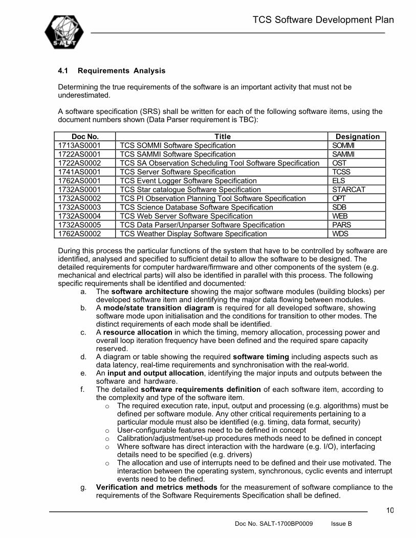
A software specification (SRS) shall be written for each of the following software items, using thedocument numbers shown (Data Parser requirement is TBC):
Doc No. Title Designation1713AS0001 TCS SOMMI Software Specification SOMMI1722AS0001 TCS SAMMI Software Specification SAMMI1722AS0002 TCS SA Observation Scheduling Tool Software Specification OST1741AS0001 TCS Server Software Specification TCSS1762AS0001 TCS Event Logger Software Specification ELS1732AS0001 TCS Star catalogue Software Specification STARCAT1732AS0002 TCS PI Observation Planning Tool Software Specification OPT1732AS0003 TCS Science Database Software Specification SDB1732AS0004 TCS Web Server Software Specification WEB1732AS0005 TCS Data Parser/Unparser Software Specification PARS1762AS0002 TCS Weather Display Software Specification WDS
During this process the particular functions of the system that have to be controlled by software areidentified, analysed and specified to sufficient detail to allow the software to be designed. Thedetailed requirements for computer hardware/firmware and other components of the system (e.g.mechanical and electrical parts) will also be identified in parallel with this process. The followingspecific requirements shall be identified and documented:
a. The software architecture showing the major software modules (building blocks) perdeveloped software item and identifying the major data flowing between modules.
b. A mode/state transition diagram is required for all developed software, showingsoftware mode upon initialisation and the conditions for transition to other modes. Thedistinct requirements of each mode shall be identified.
c. A resource allocation in which the timing, memory allocation, processing power andoverall loop iteration frequency have been defined and the required spare capacityreserved.
d. A diagram or table showing the required software timing including aspects such asdata latency, real-time requirements and synchronisation with the real-world.
e. An input and output allocation, identifying the major inputs and outputs between thesoftware and hardware.
f. The detailed software requirements definition of each software item, according tothe complexity and type of the software item.o The required execution rate, input, output and processing (e.g. algorithms) must be
defined per software module. Any other critical requirements pertaining to aparticular module must also be identified (e.g. timing, data format, security)
o User-configurable features need to be defined in concepto Calibration/adjustment/set-up procedures methods need to be defined in concepto Where software has direct interaction with the hardware (e.g. I/O), interfacing
details need to be specified (e.g. drivers)o The allocation and use of interrupts need to be defined and their use motivated. The
interaction between the operating system, synchronous, cyclic events and interruptevents need to be defined.
g. Verification and metrics methods for the measurement of software compliance to therequirements of the Software Requirements Specification shall be defined.

TCS Software Development Plan
Doc No. SALT-1700BP0009 Issue B
11
h. Software coding constraints that will enhance software maintainability, reliability andtestability shall be defined (e.g. particular data structures, non-use of certain languagefeatures).
i. The operational Man-Machine-Interface (if applicable) shall be defined in a detailedfashion.
4.2 Software Specification Review (PDR)
Prior to starting the software design, the Software Requirement Specification shall be reviewed bythe development team and the SALT Team. The purpose of the review is to verify that the softwarerequirements have been correctly derived from the Subsystem Specification, check that adequateanalysis has been performed in defining the software requirements and to co-ordinate the softwarerequirements between TCS parts.
4.3 Software Design
Prior to coding the software, it is essential to structure and design the software to meet not only thefunctional requirements of the SRS, but also the maintainability, reliability and testability requirements.The output of the Software Design process will be in various forms, but the major design aspectsshall documented in one or more Software Design Documents (SDD). At least the following shall beaddressed:
a. A high-level design description, describing the overall integration and interaction of themodules how this relates to the software states and modes.
b. An updated copy of the software architecture diagram.c. A detailed functional-flow and data-flow diagram, showing all the software modules
and the precise data flowing between them. The implementation of specific timing,synchronisation and interrupts requirements shall be illustrated. For Labview software,the mechanism of data flow (i.e. wires or VI server calls) shall be identified.
d. The software design of each module must be provided. This shall indicate the specificdata inputs, outputs, processing and timing requirements for that module and shall givespecific formula’s and algorithms that are to be executed. Details of global variables,interrupt operation, timing implementation and shall be defined. The design shall bedocumented in pseudo-code, flow diagrams or English narrative.
4.4 Software Critical Design Review (CDR)
Prior to full-scale software coding, the software design shall be reviewed by the supplierdevelopment team and the client. The purpose of the review is to verify that the requirements of theSRS and other implicit requirements have been adequately and efficiently addressed in the design. It isan opportunity for the development team to co-ordinate the hardware, software and equipmentdesigns and to ensure that non-functional requirements such as maintainability, testability andreliability are adequate.The CDR shall address the overall software design (architecture, data flow, timing) and detaileddesign of each module.
4.5 Software Coding and Debug
During this process the software code for each module is generated according to the design definedin the SDD. Specific coding standards, metrics and conventions are applied (as defined elsewhere inthis document) and software comments inserted.
In parallel with the software coding process, a Software Acceptance Test Procedure (ATP) is definedand documented by the developer. Tests shall be defined to verify that the software complies witheach requirement of the SRS. This document shall subject to approval by the client.

TCS Software Development Plan
Doc No. SALT-1700BP0009 Issue B
12
4.6 Software Code Reviews
The source code of each completed module is reviewed by the development team to check theappropriateness of software style, efficiency and to co-ordinate interfacing modules. The appropriatemethod of testing each module shall be agreed. The client may at his discretion attend such reviews.A record shall be kept of each review and the comments recorded. The implementation of suchcomments shall be verified during module testing.
4.7 Module Testing
Software modules shall be individually tested prior to integration with the other modules, to anappropriate level. Testing a module may use either a simple stub simulating interfaces to other modulesor another module (or group of modules) that has already been tested. The results of each moduletest shall be recorded, albeit informally.
4.8 Software Testing
Tested modules are incrementally integrated together and progressively checked. When all thesoftware has been integrated, the tests defined in the Software ATP shall be executed wherepossible. The precise hardware and software configuration tested shall be defined. From this pointforward, all software changes shall be logged. A TCS Server simulator shall be used to verify thecommunications interface to each computer prior to delivery of that computer and its software by thedeveloper. A communication test using the simulator shall be part of each computer item’s ATP.
At this point the software shall be fully under Configuration Control (see section 9) and all softwarechanges managed.
4.9 Integrated HW and SW Testing
Incorporated into 4.8.
4.10 Subsystem Commissioning and Integration
The next step of the process is to progressively integrate the software with other parts of the TCS.This Commissioning is complete when the TCS ATP, which verifies the performance of the TCSagainst its specification, has been passed.
The final step of the process, during which the final aspects of the software items performance isverified, is the System Integration, when all the subsystems are integrated to form an operatingTelescope. Only when the SALT System ATP has been successfully completed, can each SW item besaid to be complete.
4.11 Software handover
During step 4.10, the responsibility for maintenance of the software is transferred from the originaldeveloper to the maintenance crew. At this point, a formal “Software Handover” shall occur, when a“snap-shot” of the software configuration is taken and a package compiled that contains the“delivered software”. See section 8. This delivered software package shall contain a full definition ofthe latest software configuration, including the following:
a. A Version Definition – a table indicating the current revision numbers of each of thesoftware modules of each software item
b. The Software Configuration Definition – an electronic copy of all configuration data foroperating systems, firmware, set-up data, calibration constants, user-defined parameters

TCS Software Development Plan
Doc No. SALT-1700BP0009 Issue B
13
etc.c. The Software Source Code of the present software versiond. Original legal copies of the operating systems, compilers, tools, utilities that are required
to maintain the softwaree. Final copies of Operating, Maintenance and Calibration procedures where applicablef. A final version of the Safety Certificate

TCS Software Development Plan
Doc No. SALT-1700BP0009 Issue B
14
5 Software Safety
5.1 Safety certificate
A Safety Certificate shall be issued for the TCS. The certificate shall identify all the software itemsthat form part of the TCS. A pro-forma of the software certificate can be found in the SALT SafetyAnalysis listed in section 2.
5.2 Communication Integrity
Communication integrity between subsystems and all equipment items shall be monitored by all itemsreceiving data. Failure to receive correct data or failure to receive any data from a particular deviceshall be reported the operator via the Event Logger or the SOMMI as appropriate.
Detection of communication failure shall be facilitated by using the “Validity Word” in the communicatedLabview data, or a similar method for non-Labview Software.
Each software item shall fail in a safe fashion if it does not receive the required data. Gradualdegradation of system performance should be allowed where possible.
5.3 Initialisation
All TCS commands shall be in a safe state when un-initialised or switched off. Similarly, un-initialisedinputs (e.g. from other subsystems) shall not cause incorrect responses from the software.
The following initialisation sequence shall be followed by all software:a. Switch all outputs to a safe state (e.g. motors, OFF)b. Indicate “Initialisation State” to the operatorc. Check the integrity of the processing hardware and memory using simple arithmetic checksd. Check communication with and correctness of peripheral devices (if applicable)e. Verify the correctness of configuration data and then initialise variables accordinglyf. Check communication with interfacing computersg. If all operations are successful, report “System Okay” to the operator and enter into a “ready”
state, where after the state will be determined by switches, commands, data etc. If operationsa. to e. are not successful, report “System Start Failure” and indicate the type of failureencountered. If communications with another computer cannot be established, this should bereported.
5.4 Start-up and Shut Down ProcedureDuring Start-up and Shut Down, preventative measures shall be taken to handle processconditions as well as Inputs and Outputs in a safe manner.

TCS Software Development Plan
Doc No. SALT-1700BP0009 Issue B
15
6 Generic Software Requirements
6.1 Naming and Tagging Conventions
Each SW component shall be uniquely identified with a sensible name. File extensions native to theprogramming language used, shall be adhered to (i.e. Labview files *.vi, *.glb, *.ctl and *.rtm)
All variables, memory and block naming shall be clear, logical and understandable. A uniformconvention shall be used throughout an item, preferably using whole English words. Wherecompilers/interpreters do not support long variable names, a consistent abbreviation may be used,with a clear definition in the appropriate documentation.
Naming conventions will be agreed during the Software PDR.
6.2 Remote Initialisation
It shall be possible to trigger the initialisation sequence described in 5.3 remotely via the normalcommunication to an item. (e.g. The operator must be able to send a “reset” command across theEthernet to any computer to trigger initialisation). This is not applicable to MMI applications.
6.3 Data
A set of Critical Data, over and above data required for functional operation, shall be agreed with theclient for each computer item. This data set shall be updated at a rate of at least 1Hz and be sent tothe Event Llogger:
• Item Mode• Item Health Status• Fault list
This Data Set will be finalised during the Critical Design Review.
Where internal variables may assist diagnostics, their values should also be transmitted to the EventLogger.
6.4 Software cyclic execution
After the completion of initialisation, the code of a SW item shall execute in a cyclic fashion, at aconstant rate, commensurate with the control bandwidth/frequency/latency required.
6.5 Data time stamping
Time-critical data will be agreed with each supplier and identified as such in the ICD. All such datashall be time-stamped in an agreed fashion to facilitate synchronisation of subsystems.
6.6 Modular Design
Software shall be designed in a scalable and modular fashion. All software modules (i.e. LabviewVI’s, procedure and functions – see SALT Labview Coding Standard) shall be designed to minimisetheir data interfaces and to group functions that belong together, keeping in mind future growth andhardware upgrades. Compliance to these requirements shall be demonstrated at the PDR, CDR andcode reviews. In particular, the following types of functions shall be in independent modules:
• Input/Output hardware communication drivers• Input/Output scaling from hardware units (e.g. 1024bits) to/from engineering units.• Initialisation sequences
TCS Software Development Plan
Doc No. SALT-1700BP0009 Issue B
16
• User configuration sequences• Equipment mode/state control• Mathematical/control algorithms• Data storage and retrieval• Data communication• Fault monitoring and reporting
Identical software functions shall not be repeated in different areas but rather grouped together as ashared function or procedure.
6.7 Measuring Units
The SI metric system shall be used for all processing except for angles, which shall be in Radians.The units of information displayed on MMI displays shall be in “human-friendly” units and will beagreed during the CDR.
6.8 Data resolution
The selection of data types and resolution shall be commensurate with the data accuracy required toperform the desired functions.
6.9 I/O Validation
N/A.
6.10 Synchronisation
Two methods of synchronisation are allowed, the selection of which shall be commensurate with thetime accuracy requirements and shall be subject to approval during the PDR.
a. Network synchronisation: An NTP server will provide accurate GPS time to all subsystemsrequesting this via Ethernet. The accuracy of this time should be better than 150ms andwould be suitable for most applications.
b. Hardware synchronisation: A precision hardware time signal (e.g. 1 pulse-per-second and10MHz) will be made available to all items requiring very accurate time (e.g., TrackerComputer, Payload Computer and Instrument Computers). A computer input reads this signaland synchronises SW functions accordingly.
6.11 Unused Code
All unused code and variables shall be removed from the software.
6.12 Software Comments
Over and above the software development documentation, the following documentation shall formand integral part of the software code in the form of comments or function help:
• Each software module shall have a header or associated “help” definition describing thefollowing:
o The name and purpose of the moduleo The inputs and outputs of the module and their typeso A detailed description of the functions performed by the module. (This may be English
narrative or pseudo-code).• A definition/description of local and global variables used in the module• English description of the actions performed by SW code. As a guideline give one line of
comments per two lines of code for text-based software. For Labview software each VI shallhave help information defined, as indicated in the first bullet.

TCS Software Development Plan
Doc No. SALT-1700BP0009 Issue B
17
6.13 Self-changing code
Self-changing code shall not be allowed.
6.14 Manual Operation
N/A.
6.15 Communication methods
Communication between computers on the Ethernet network, shall be TCP/IP-based Data socketcommunication or http://, as agreed.
A central database (ICD) shall identify the source, destination, type and update frequency of eachparameter. Communications software for Labview items will be provided by SALT, according to therequired data types.

TCS Software Development Plan
Doc No. SALT-1700BP0009 Issue B
18
7 Specific TCS Software Requirements
7.1 Operating Systems
The following Operating are proposed, but this needs to be agreed on a case-by-case basis:• SO Workstation : Windows 2000 Professional• SA Workstation: Windows 2000 Professional• TCS Server: Windows 2000 Professional• Event Logger: Windows 2000 Professional• Data Processor: Linux (type TBD)• PI Computer: SW must be portable to Windows 98, Windows 2000, Windows NT and Linux
7.2 Development Software
The following development environments are proposed but needs to be agreed on a case-by-casebasis:
• SOMMI: Labview 6• SAMMI: Labview 6• TCS Server: Labview 6• Event Logger and Event Reporter : Labview 6• Star catalogue database engine: SQL, C• Observation Planning Tool(s): Labview 6 and C• Science Database: SQL, C• Web Server: ??• Data Parser/Unparser: C• Weather Display: Labview 6
7.3 Application Software
The SALT Labview Coding Standard shall be applied to all Labview software. The SoftwareEngineering Primer in “Labview Power Programming” and “Internet Applications in Labview” arerecommended reading.
7.4 Man-Machine Interfaces
All MMI’s shall be subject to approval by the Project Scientist.

TCS Software Development Plan
Doc No. SALT-1700BP0009 Issue B
19
8 Deliverables
Unless agreed otherwise, at least the following items shall be delivered for each software item.a. Original documentation and electronic media of all the bought-out software installed on the
computer (including operating systems and device drivers).b. Original documentation and electronic media of the software development environment in which the
software was developed (e.g. compilers, version control tools etc.), unless agreed otherwise.c. Development environment and operating system configuration data (e.g. memory map set-ups,
compiler directives, copy of Linux configuration files, Windows INI files, registry files) on CD-ROM.d. Documentation as described in section 4 (if applicable according to Table 1), including the following:
• Software Requirement Specification• Software Design Document• Software Code Review report/minutes• Software Acceptance Test Procedure• Software Acceptance Test Report
e. All application software source code, compiled software, installation software and configurationinformation on CD-ROM.
f. Calibration, Maintenance and operating procedures if applicableg. A Version Definition (See section 9)
The following will be available for the TCS as a whole:h. A final version of the Safety Certificatei. A Software Development Plan (this document)j. Acceptance Test Procedure and Report

TCS Software Development Plan
Doc No. SALT-1700BP0009 Issue B
20
9 Configuration Control
Each SW Item shall be uniquely identified by the SALT configuration number and name defined in section4.1. Each software module shall also be uniquely identified.
During the software coding, testing and integration process, maintain the Labview version control tool shallbe used, whereby each software module has a revision number reflecting changes made. Changes afterinitial SW integration shall be controlled and documented. Every update to that module shall result in achange in the revision number of that module. Modules of previous revisions shall not be overwritten ordestroyed but kept for recovery purposes.
The integrated software comprising many modules (i.e. the SW Item), shall also have a unique versionnumber at critical stages in the process (e.g. at Software Testing, delivery etc.). A document (the VersionDefinition) shall be maintained which records the included modules and their revision numbers making upeach version of a SW Item.
The following numbering scheme is preferred for revisions and versions:
Example: Tracker Payload SW Version 2.32 comprises the following modules- Module A: Initialisation Revision 5- Module B: Hardware set-up Revision 31- Module C: Mode control Revision 29- ……………
Where the number before the dot is incremented with major changes to the software or to mark asignificant event (e.g. software delivery) and the number after the digit changes with minormodifications.