title: the long spanned bridge for deflection-restricted ... · japan railway construction,...
TRANSCRIPT
Challenge E: Bringing the territories closer together at higher speeds
Title: The long spanned bridge for deflection-restricted high speed rail
-SANNAI-MARUYAMA Bridge-
Shinichi TAMAI
Deputy Director of Design Division
Japan Railway Construction, Transport and
Technology Agency
Yokohama, Japan
Kenji SHIMIZU
Deputy Director of High Speed Rail Team
Japan International Transport Institute
Tokyo, Japan
1. INTRODUCTION
The Japan Railway Construction, Transport and Technology Agency (JRTT) is a public
corporation exclusively in charge of the construction of SHINKANSEN high speed rail projects in Japan.
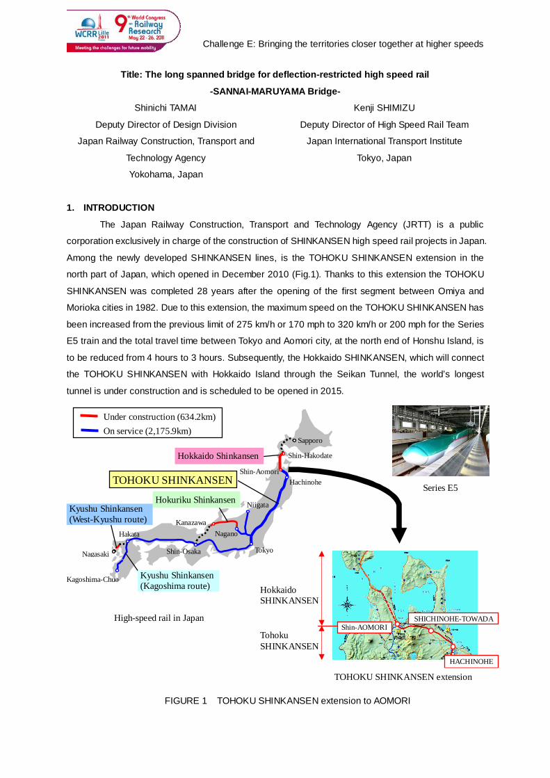
Among the newly developed SHINKANSEN lines, is the TOHOKU SHINKANSEN extension in the
north part of Japan, which opened in December 2010 (Fig.1). Thanks to this extension the TOHOKU
SHINKANSEN was completed 28 years after the opening of the first segment between Omiya and
Morioka cities in 1982. Due to this extension, the maximum speed on the TOHOKU SHINKANSEN has
been increased from the previous limit of 275 km/h or 170 mph to 320 km/h or 200 mph for the Series
E5 train and the total travel time between Tokyo and Aomori city, at the north end of Honshu Island, is
to be reduced from 4 hours to 3 hours. Subsequently, the Hokkaido SHINKANSEN, which will connect
the TOHOKU SHINKANSEN with Hokkaido Island through the Seikan Tunnel, the world’s longest
tunnel is under construction and is scheduled to be opened in 2015.
On service (2,175.9km) Under construction (634.2km)
Hakata
Shin-Osaka
Kanazawa Nagano
Niigata
Tokyo
Hachinohe Shin-Aomori
Shin-Hakodate
Sapporo
Nagasaki
TOHOKU SHINKANSEN
Hokkaido Shinkansen
Hokuriku Shinkansen Kyushu Shinkansen (West-Kyushu route)
Kyushu Shinkansen (Kagoshima route)
Kagoshima-Chuo
FIGURE 1 TOHOKU SHINKANSEN extension to AOMORI
Hokkaido SHINKANSEN
Tohoku SHINKANSEN
Shin-AOMORI
HACHINOHE
SHICHINOHE-TOWADA
Series E5
High-speed rail in Japan
TOHOKU SHINKANSEN extension
Challenge E: Bringing the territories closer together at higher speeds
As a feature of rail infrastructure design, it is important to not only support heavy trains, but
also to provide enough rigidity for the structure as needed. Especially in high speed rail, the quantity of
deflection must be strictly controlled within the limit of maintaining the safety and stability of the running
train. Based on this situation, the Railway Technology Standards have designated a
performance-oriented design for railway structures. Because the running safety and comfort are
important elements of a railways performance, these standards are to be checked at the same level as
a structures’ safety and serviceability.
While the restriction of deformation becomes more severe, the surrounding conditions around
the construction site also become severe due to the limited flexibility of the route for high speed train
operation, which needs a larger curve radius and a less steep gradient. This makes the span of a
bridge longer and designers must consider the two contradicting conditions of less deformation and
longer span simultaneously.
This paper presents the required performance characteristics for bridges on high speed rail
lines and outlines the issues regarding long-spanned concrete bridges, by presenting the case study of
the SANNAI-MARUYAMA Bridge as an example of a successful solution.
2. REQUIRED PERFORMANCE CHARACTERISTICS FOR HIGH SPEED RAIL BRIDGES
In the Railway Technology Standards, the required performance characteristics are sorted into
three categories, safety, serviceability, and repairability. The Standards also show the items of
performance which are required for satisfaction of the required performance characteristics and also
the check indexes for the required items.
Table 1 shows the relation between the required performance characteristics, items of
performance, and check indexes for bridges. Rupture, fatigue, and damage are common to all
structures including railway bridges and these conditions are checked by common methods. On the
other hand, running safety and comfort are unique and important for high speed rail bridges and need
further explanation in this paper.
Running safety and comfort should be evaluated by the alteration of the axle load or vibration
acceleration and finally by the trial run. However, in the phase of design, deformation or deflection of
the bridge are used as the indexes for these checks.
The limit of deformation or deflection is set as the ratio with the span length. The longer the
span, the larger the limit for deformation or deflection. In the longest bridges the limit sometimes
exceeds 100 mm. Such a large value is doubtful as an acceptable index.
Furthermore, on the long span bridge there might be mutual interaction between the train and
the rail track. In such a case it is impossible to calculate the deformation and deflection due to the
dynamic effects of the train load by the static analysis.
The Railway Technical Research Institute, Japan has developed the dynamic analysis code for
solving these issues. In this system the train and the whole of the structure are modeled by the multiple
degree of freedom model and thereby a simulation of a trial run becomes available. This system can
Challenge E: Bringing the territories closer together at higher speeds
also output the value of wheel-levitation which causes derailment and the train body acceleration which
relates to the passengers’ comfort. These values are directly used for the check.
The limit of deformation and deflection for the check of running safety and comfort needs the
precondition of the minimization of initial track irregularity which occurs before the passing of the train.
Regular maintenance is needed to secure the precondition.
Initial track irregularity is the same as initial bridge irregularity because the slab track is directly
connected to the structure. The causes of initial irregularity are temperature (sometimes partially by the
sunshine) and shrinkage and creep of concrete itself. These are time- or season-related phenomenon.
Although these phenomena have been known for a long time, recent longer spans make the absolute
value larger and this results in negative effects to the running safety and comfort.
It is possible to check the running safety and comfort with the condition which is input to the
dynamic analysis described above. However, because the deformation of the bridge is a time- or
season-related phenomenon, the running safety and comfort are also time- or season-related . This is
not preferable for reliability of the revenue from high speed rail operations. Therefore, in the high speed
rail, we should make the best effort to reduce time- or season-related deformation and at the same
time to control the deformation caused by passing trains.
The limit of initial track irregularity is 7mm in 40m-chord to keep a certain degree of comfort.
Therefore, the time- or season-related deformation of bridges needs to be limited within the same
value.
3. DESIGN OF SANNAI-MARUYAMA BRIDGE
3.1 General
The SANNAI-MARUYAMA Bridge on the TOHOKU SHINKANSEN extension was constructed
Table 1 Required performance for high speed rail bridges (1
Required performance Items of performance Check indexes
Safety
Rupture Member force at ultimate limit state
Fatigue Variable stress of reinforcement
Running safety Wheel levitation, Axle load
*Displacement, Deflection
Public safety Durability of concrete
Serviceability Comfort
Body acceleration
*Displacement, Deflection
Appearance Crack width
Recoverability Damage Member force under over-load
Member load or deflection under seismic load
*Indirect check index for conventional method
Challenge E: Bringing the territories closer together at higher speeds
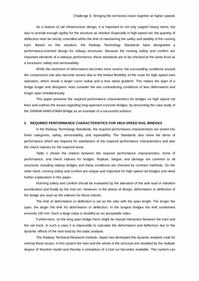
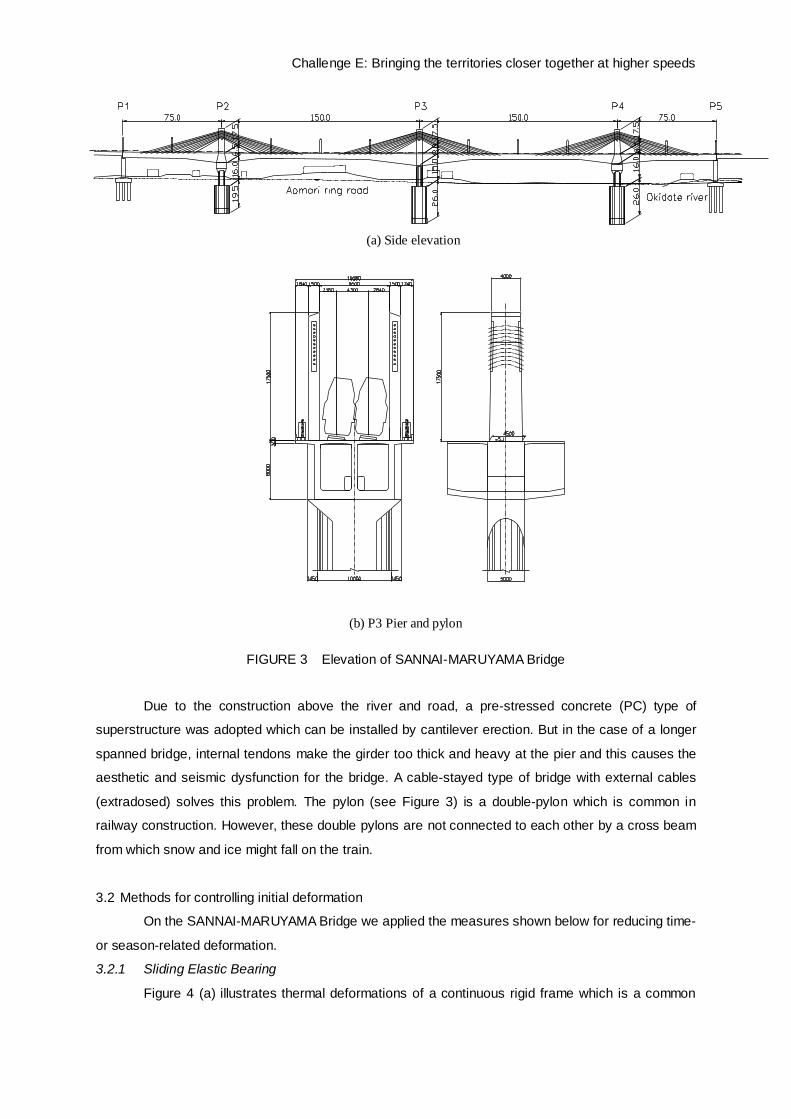
to cross a broad highway, river, and reservoir near the famous Sannai-maruyama archeological site
(Fig.2). It consists of two 75m spans and two 150m spans of extradosed bridges. The 150m span is the
longest among the Shinkansen structures in Japan. The specifications of the SANNAI-MARUYAMA
Bridge are shown below:
Type of Structure: Extradosed Bridge with 4 continuous spans
Type of Foundation: Pneumatic caisson
Total length: 450m
Span: 74.18m+150m+150m+74.18m
Height of Pylon: 17.5m
Material of stay cable: Epoxy coated strand
Design load: Axle load 17 tons of Shinkansen rolling stock
Elevation of the bridge and P3 pier and pylon are shown Figure 3.
Sannai-maruyama archeological site
FIGURE 2 Location of SANNAI-MARUYAMA bridge
P1 P2 P3
P4 P5
Okidate reservoir
Aomori ring road Okidate Rv.
Sannai-maruyama archeological site
Challenge E: Bringing the territories closer together at higher speeds
Due to the construction above the river and road, a pre-stressed concrete (PC) type of
superstructure was adopted which can be installed by cantilever erection. But in the case of a longer
spanned bridge, internal tendons make the girder too thick and heavy at the pier and this causes the
aesthetic and seismic dysfunction for the bridge. A cable-stayed type of bridge with external cables
(extradosed) solves this problem. The pylon (see Figure 3) is a double-pylon which is common in
railway construction. However, these double pylons are not connected to each other by a cross beam
from which snow and ice might fall on the train.
3.2 Methods for controlling initial deformation
On the SANNAI-MARUYAMA Bridge we applied the measures shown below for reducing time-
or season-related deformation.
3.2.1 Sliding Elastic Bearing
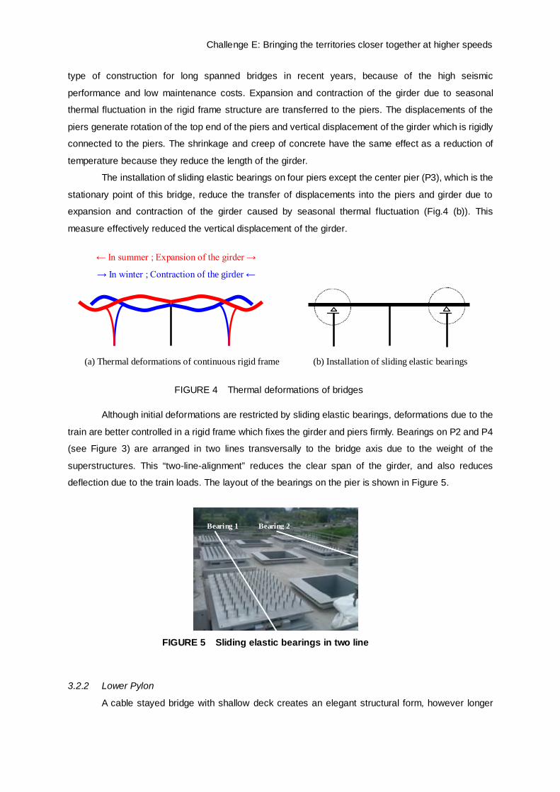
Figure 4 (a) illustrates thermal deformations of a continuous rigid frame which is a common
(b) P3 Pier and pylon
(a) Side elevation
FIGURE 3 Elevation of SANNAI-MARUYAMA Bridge
Challenge E: Bringing the territories closer together at higher speeds
type of construction for long spanned bridges in recent years, because of the high seismic
performance and low maintenance costs. Expansion and contraction of the girder due to seasonal
thermal fluctuation in the rigid frame structure are transferred to the piers. The displacements of the
piers generate rotation of the top end of the piers and vertical displacement of the girder which is rigidly
connected to the piers. The shrinkage and creep of concrete have the same effect as a reduction of
temperature because they reduce the length of the girder.
The installation of sliding elastic bearings on four piers except the center pier (P3), which is the
stationary point of this bridge, reduce the transfer of displacements into the piers and girder due to
expansion and contraction of the girder caused by seasonal thermal fluctuation (Fig.4 (b)). This
measure effectively reduced the vertical displacement of the girder.
Although initial deformations are restricted by sliding elastic bearings, deformations due to the
train are better controlled in a rigid frame which fixes the girder and piers firmly. Bearings on P2 and P4
(see Figure 3) are arranged in two lines transversally to the bridge axis due to the weight of the
superstructures. This “two-line-alignment” reduces the clear span of the girder, and also reduces
deflection due to the train loads. The layout of the bearings on the pier is shown in Figure 5.
3.2.2 Lower Pylon
A cable stayed bridge with shallow deck creates an elegant structural form, however longer
FIGURE 5 Sliding elastic bearings in two line
Bearing 1 Bearing 2
(a) Thermal deformations of continuous rigid frame (b) Installation of sliding elastic bearings
← In summer ; Expansion of the girder →
→ In winter ; Contraction of the girder ←
FIGURE 4 Thermal deformations of bridges
Challenge E: Bringing the territories closer together at higher speeds
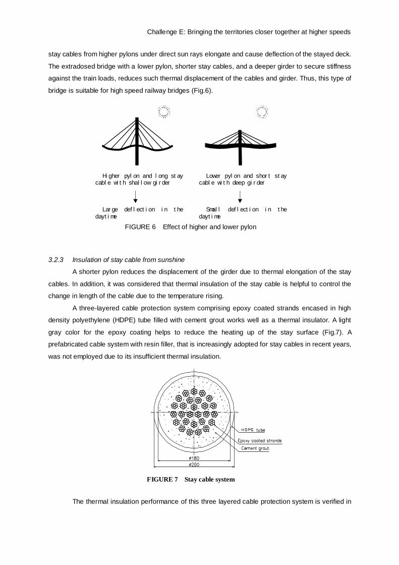
stay cables from higher pylons under direct sun rays elongate and cause deflection of the stayed deck.
The extradosed bridge with a lower pylon, shorter stay cables, and a deeper girder to secure stiffness
against the train loads, reduces such thermal displacement of the cables and girder. Thus, this type of
bridge is suitable for high speed railway bridges (Fig.6).
3.2.3 Insulation of stay cable from sunshine
A shorter pylon reduces the displacement of the girder due to thermal elongation of the stay
cables. In addition, it was considered that thermal insulation of the stay cable is helpful to control the
change in length of the cable due to the temperature rising.
A three-layered cable protection system comprising epoxy coated strands encased in high
density polyethylene (HDPE) tube filled with cement grout works well as a thermal insulator. A light
gray color for the epoxy coating helps to reduce the heating up of the stay surface (Fig.7). A
prefabricated cable system with resin filler, that is increasingly adopted for stay cables in recent years,
was not employed due to its insufficient thermal insulation.
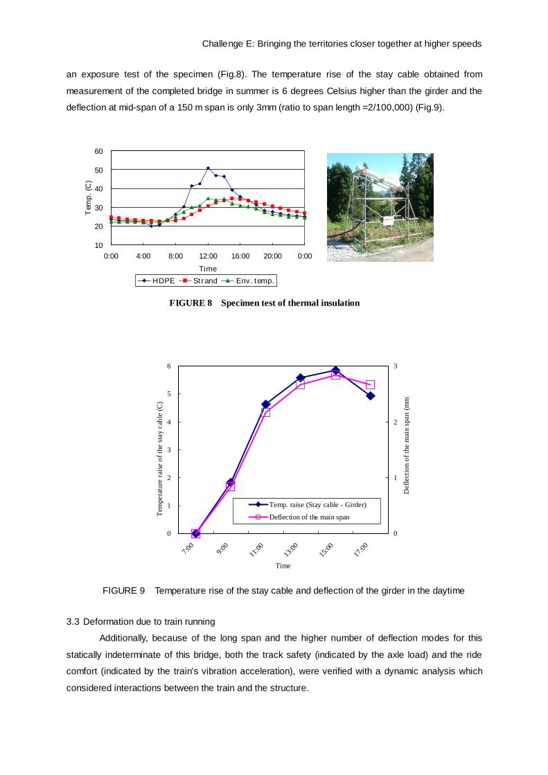
The thermal insulation performance of this three layered cable protection system is verified in
FIGURE 7 Stay cable system
Higher pylon and long stay cable with shallow girder
Large deflection in the
daytime
Lower pylon and short stay cable with deep girder
Small deflection in the
daytime
FIGURE 6 Effect of higher and lower pylon
Challenge E: Bringing the territories closer together at higher speeds
an exposure test of the specimen (Fig.8). The temperature rise of the stay cable obtained from
measurement of the completed bridge in summer is 6 degrees Celsius higher than the girder and the
deflection at mid-span of a 150 m span is only 3mm (ratio to span length =2/100,000) (Fig.9).
3.3 Deformation due to train running
Additionally, because of the long span and the higher number of deflection modes for this
statically indeterminate of this bridge, both the track safety (indicated by the axle load) and the ride
comfort (indicated by the train’s vibration acceleration), were verified with a dynamic analysis which
considered interactions between the train and the structure.
FIGURE 9 Temperature rise of the stay cable and deflection of the girder in the daytime
0
1
2
3
4
5
6
7:00
9:00
11:00
13:00
15:00
17:00
Time
Tem
pera
ture
rais
e of
the
stay
cab
le (C
)
0
1
2
3
Def
lect
ion
of th
e m
ain
span
(mm
)
Temp. raise (Stay cable - Girder)
Deflection of the main span
FIGURE 8 Specimen test of thermal insulation
10
20
30
40
50
60
0:00 4:00 8:00 12:00 16:00 20:00 0:00Time
Tem
p. (C
)
HDPE Strand Env. temp.

Challenge E: Bringing the territories closer together at higher speeds
As shown in section 2. , there might be mutual interaction between the train and the rail track
on the long span bridge. Therefore, for the SANNAI-MARUYAMA Bridge, train running was simulated
by a dynamic analysis with consideration of mutual interaction between the train and the bridge after
setting the dimensions of the parts whose deformation or deflection satisfies the conventional limit on
the basis of a static analysis. Running safety was checked for the required reduction of the axle load
and comfort was checked for the resulting train body acceleration. For the initial analysis, the limit is
within the axle load reduction ratio of 37% and the resulting body acceleration was 2.0m/s2. The
reduction of axle load was 9.0% and the body acceleration was 0.44m/s2 after final analysis. The
simulation using a dynamic analysis was checked visually by the animated image (Fig.10).
3.4 Other techniques
3.4.1 Verification of fatigue resistance of stay cable
The acceptable value of stay cables to resist repeated loading due to the live load is commonly
controlled by limiting the maximum tension in the cable to 60% for road bridges. However, for high
speed rail the condition is very severe due to the fact that heavy trains are passing frequently.
Therefore the bridge was designed with an acceptable value of maximum tension in the stay cable of
40%. The calibration analysis for fatigue failure due to strain alteration accompanying train running with
consideration of the effects of secondary bending due to sag in the cable and deformation of the girder,
demonstrated that the ratio of strain amplitude/fatigue strength of the PC cable, is 0.58 during a 100
year design life, which was considered to be sufficiently safe.
3.4.2 Economical deviation saddle
The installation of an economical deviation saddle is a new technique which has been used for
this bridge.
The conventional deviation saddle on the pylon enables the replacement of the stay cables by
a dual tube system. In the case of this bridge, the replacement of stay cables is unnecessary as the
limiting stay cable stress level, has been designed to be less than 40% of the tensile strength for the
serviceability limit state and a fatigue performance service life of 100 years has been achieved in the
design. An innovative simple and economical mono tube system deviation saddle has been newly
developed in this project to replace the conventional dual tube system. Mono and dual tube deviation
saddle systems are shown in Figure 11. The mono tube deviation system was verified under ultimate
FIGURE 10 Animated image of dynamic analysis
Challenge E: Bringing the territories closer together at higher speeds
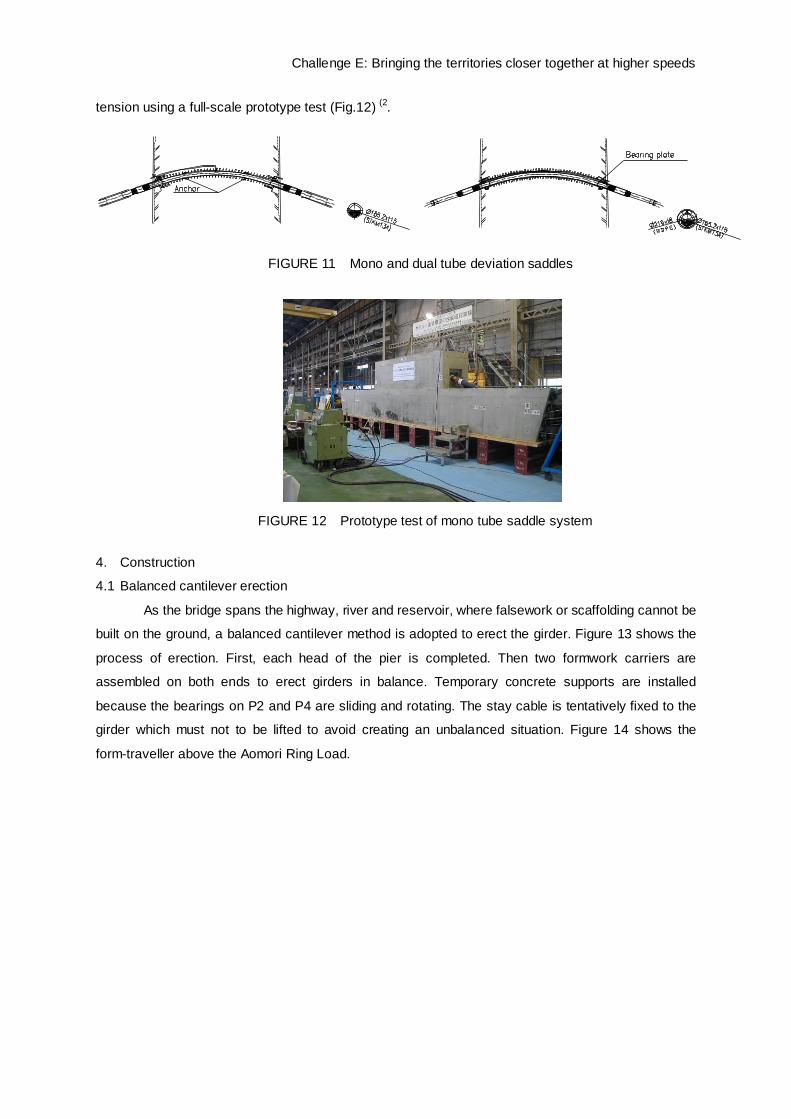
tension using a full-scale prototype test (Fig.12) (2.
4. Construction
4.1 Balanced cantilever erection
As the bridge spans the highway, river and reservoir, where falsework or scaffolding cannot be
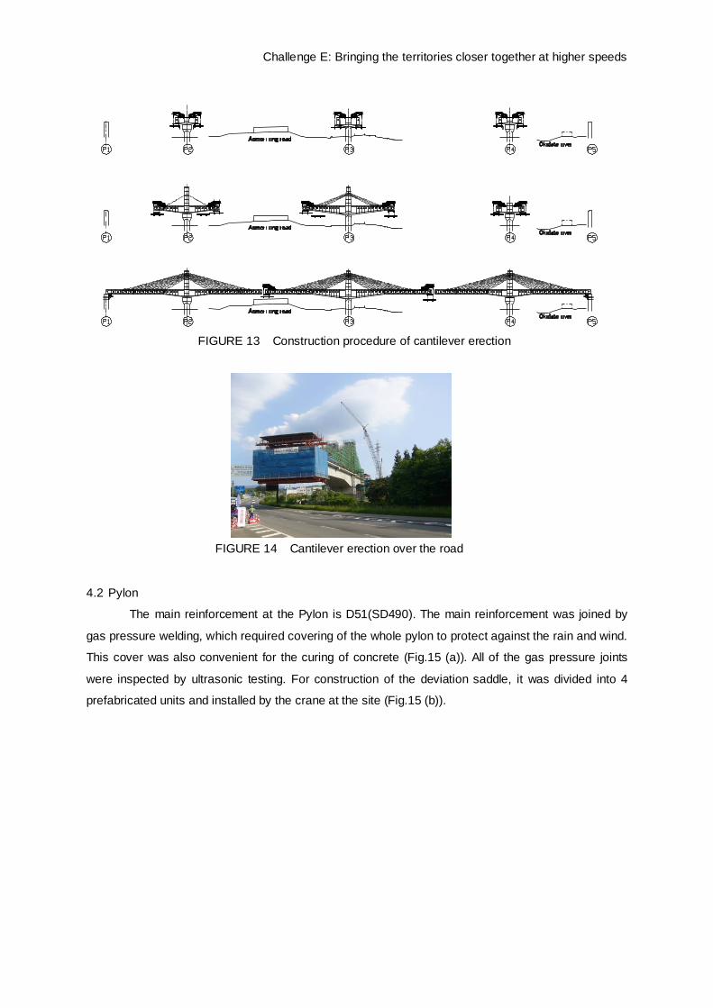
built on the ground, a balanced cantilever method is adopted to erect the girder. Figure 13 shows the
process of erection. First, each head of the pier is completed. Then two formwork carriers are
assembled on both ends to erect girders in balance. Temporary concrete supports are installed
because the bearings on P2 and P4 are sliding and rotating. The stay cable is tentatively fixed to the
girder which must not to be lifted to avoid creating an unbalanced situation. Figure 14 shows the
form-traveller above the Aomori Ring Load.
FIGURE 12 Prototype test of mono tube saddle system
FIGURE 11 Mono and dual tube deviation saddles
Challenge E: Bringing the territories closer together at higher speeds
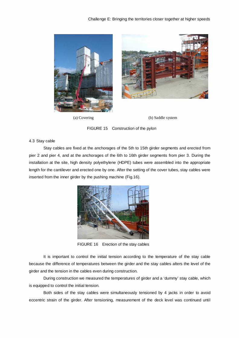
4.2 Pylon
The main reinforcement at the Pylon is D51(SD490). The main reinforcement was joined by
gas pressure welding, which required covering of the whole pylon to protect against the rain and wind.
This cover was also convenient for the curing of concrete (Fig.15 (a)). All of the gas pressure joints
were inspected by ultrasonic testing. For construction of the deviation saddle, it was divided into 4
prefabricated units and installed by the crane at the site (Fig.15 (b)).
FIGURE 14 Cantilever erection over the road
FIGURE 13 Construction procedure of cantilever erection
Challenge E: Bringing the territories closer together at higher speeds
4.3 Stay cable
Stay cables are fixed at the anchorages of the 5th to 15th girder segments and erected from
pier 2 and pier 4, and at the anchorages of the 6th to 16th girder segments from pier 3. During the
installation at the site, high density polyethylene (HDPE) tubes were assembled into the appropriate
length for the cantilever and erected one by one. After the setting of the cover tubes, stay cables were
inserted from the inner girder by the pushing machine (Fig.16).
It is important to control the initial tension according to the temperature of the stay cable
because the difference of temperatures between the girder and the stay cables alters the level of the
girder and the tension in the cables even during construction.
During construction we measured the temperatures of girder and a ‘dummy’ stay cable, which
is equipped to control the initial tension.
Both sides of the stay cables were simultaneously tensioned by 4 jacks in order to avoid
eccentric strain of the girder. After tensioning, measurement of the deck level was continued until
FIGURE 16 Erection of the stay cables
FIGURE 15 Construction of the pylon
(a) Covering (b) Saddle system
Challenge E: Bringing the territories closer together at higher speeds
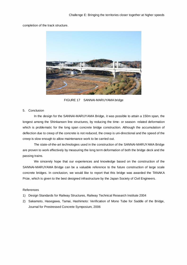
completion of the track structure.
5. Conclusion
In the design for the SANNAI-MARUYAMA Bridge, it was possible to attain a 150m span, the
longest among the Shinkansen line structures, by reducing the time- or season- related deformation
which is problematic for the long span concrete bridge construction. Although the accumulation of
deflection due to creep of the concrete is not reduced, the creep is uni-directional and the speed of the
creep is slow enough to allow maintenance work to be carried out.
The state-of-the-art technologies used in the construction of the SANNAI-MARUYAMA Bridge
are proven to work effectively by measuring the long term deformation of both the bridge deck and the
passing trains.
We sincerely hope that our experiences and knowledge based on the construction of the
SANNAI-MARUYAMA Bridge can be a valuable reference to the future construction of large scale
concrete bridges. In conclusion, we would like to report that this bridge was awarded the TANAKA
Prize, which is given to the best designed infrastructure by the Japan Society of Civil Engineers.
References
1) Design Standards for Railway Structures, Railway Technical Research Institute 2004
2) Sakamoto, Hasegawa, Tamai, Hashimoto: Verification of Mono Tube for Saddle of the Bridge,
Journal for Prestressed Concrete Symposium, 2006
FIGURE 17 SANNAI-MARUYAMA bridge