tk-3401d - kenwood
TRANSCRIPT
UHF DIGITAL TRANSCEIVER
USER MANUAL
TK-3401D
B5A-0037-30 (E, T)


i
THANK YOUWe are grateful you have chosen KENWOOD for your dPMR446 applications.
OPERATING CONDITIONSOpen locations (no obstructions) : Up to 9.0 km
Note: ◆ The above range is based on fi eld testing and may vary with your
operating conditions and individual transceiver.
◆ Digital technology provides superior clarity in extended coverage. As RF signal strength weakens with distance, analog reception becomes increasingly noisy and intermittent. dPMR's low BER improves reception in fringe areas, thereby “effectively” increasing coverage as much as twenty percent over analog.
NOTICES TO THE USERRefer service to qualifi ed technicians only.
Safety: It is important that the operator is aware of, and understands, hazards common to the operation of any transceiver.
Firmware CopyrightsThe title to and ownership of copyrights for fi rmware embedded in KENWOOD product memories are reserved for JVC KENWOOD Corporation.

ii
Turn the transceiver power off in the following locations:• In explosive atmospheres (infl ammable gas, dust particles, metallic
powders, grain powders, etc.).• While taking on fuel or while parked at gasoline service stations.• Near explosives or blasting sites.• In aircraft. (Any use of the transceiver must follow the instructions
and regulations provided by the airline crew.)• Where restrictions or warnings are posted regarding the use of
radio devices, including but not limited to medical facilities.• Near persons using pacemakers.
PRECAUTIONS• Do not charge the transceiver and battery pack when they are
wet.• Ensure that there are no metallic items located between the
transceiver and the battery pack.• Do not use options not specifi ed by KENWOOD.• If the die-cast chassis or other transceiver part is damaged, do
not touch the damaged parts.• If a headset or headphone is connected to the transceiver,
reduce the transceiver volume. Pay attention to the volume level when turning the squelch off.
• Do not place the microphone cable around your neck while near machinery that may catch the cable.
• Do not place the transceiver on unstable surfaces.• Ensure that the end of the antenna does not touch your eyes.• When the transceiver is used for transmission for many hours,
the radiator and chassis will become hot. Do not touch these locations when replacing the battery pack.
• Do not immerse the transceiver in water.• Always switch the transceiver power off before installing optional
accessories.• The charger is the device that disconnects the unit from the AC
mains line. The AC plug should be readily accessible.

iii
• Do not disassemble or modify the transceiver for any reason.• Do not place the transceiver on or near airbag equipment while the
vehicle is running. When the airbag infl ates, the transceiver may be ejected and strike the driver or passengers.
• Do not transmit while touching the antenna terminal or if any metallic parts are exposed from the antenna covering. Transmitting at such a time may result in a high-frequency burn.
• If an abnormal odor or smoke is detected coming from the transceiver, switch the transceiver power off immediately, remove the battery pack from the transceiver, and contact your KENWOOD dealer.
• Use of the transceiver while you are driving may be against traffi c laws. Please check and observe the vehicle regulations in your area.
• Do not expose the transceiver to extremely hot or cold conditions.• Do not carry the battery pack (or battery case) with metal objects,
as they may short the battery terminals.• Danger of explosion if the battery is incorrectly replaced; replace
only with the same type.• When attaching a commercial strap to the transceiver, ensure
that the strap is durable. In addition, do not swing the transceiver around by the strap; you may inadvertently strike and injure another person with the transceiver.
• If a commercially available neck strap is used, take care not to let the strap get caught on nearby machine.
• When operating the transceiver in areas where the air is dry, it is easy to build up an electric charge (static electricity). When using an earphone accessory in such conditions, it is possible for the transceiver to send an electric shock through the earphone and to your ear. We recommend you use only a speaker/microphone in these conditions, to avoid electric shocks.

iv
Information concerning the battery pack:The battery pack includes fl ammable objects such as organic solvent. Mishandling may cause the battery to rupture producing fl ames or extreme heat, deteriorate, or cause other forms of damage to the battery. Please observe the following prohibitive matters.
• Do not disassemble or reconstruct battery! The battery pack has a safety function and protection circuit to
avoid danger. If they suffer serious damage, the battery may generate heat or smoke, rupture, or burst into fl ame.
• Do not short-circuit the battery! Do not join the + and – terminals using any form of metal (such
as a paper clip or wire). Do not carry or store the battery pack in containers holding metal objects (such as wires, chain-necklaces or hairpins). If the battery pack is short-circuited, excessive current will fl ow and the battery may generate heat or smoke, rupture, or burst into fl ame. It will also cause metal objects to heat up.
• Do not incinerate or apply heat to the battery! If the insulator is melted, the gas release vent or safety function is
damaged, or the electrolyte is ignited, the battery may generate heat or smoke, rupture, or burst into fl ame.
• Do not leave the battery near fi re, stoves, or other heat generators (areas reaching over 80°C/ 176°F)!
If the polymer separator is melted due to high temperature, an internal short-circuit may occur in the individual cells and the battery may generate heat or smoke, rupture, or burst into fl ame.
• Avoid immerse the battery in water or get it wet by other means!
If the battery’s protection circuit is damaged, the battery may charge at extreme current (or voltage) and an abnormal chemical reaction may occur. The battery may generate heat or smoke, rupture, or burst into fl ame.
• Do not charge the battery near fi re or under direct sunlight! If the battery’s protection circuit is damaged, the battery may
charge at extreme current (or voltage) and an abnormal chemical reaction may occur. The battery may generate heat or smoke, rupture, or burst into fl ame.
v
• Use only the specifi ed charger and observe charging requirements!
If the battery is charged in unspecifi ed conditions (under high temperature over the regulated value, excessive high voltage or current over regulated value, or with a remodeled charger), it may overcharge or an abnormal chemical reaction may occur. The battery may generate heat or smoke, rupture, or burst into fl ame.
• Do not pierce the battery with any object, strike it with an instrument, or step on it!
This may break or deform the battery, causing a short-circuit. The battery may generate heat or smoke, rupture, or burst into fl ame.
• Do not jar or throw the battery! An impact may cause the battery to leak, generate heat or smoke,
rupture, and/or burst into fl ame. If the battery’s protection circuit is damaged, the battery may charge at an abnormal current (or voltage), and an abnormal chemical reaction may occur. The battery may generate heat or smoke, rupture, or burst into fl ame.
• Do not use the battery pack if it is damaged in any way! The battery may generate heat or smoke, rupture, or burst into
fl ame.• Do not solder directly onto the battery! If the insulator is melted or the gas release vent or safety function
is damaged, the battery may generate heat or smoke, rupture, or burst into fl ame.
• Do not reverse the battery polarity (and terminals)! When charging a reversed battery, an abnormal chemical reaction
may occur. In some cases, an unexpected large amount of current may fl ow upon discharging. The battery may generate heat or smoke, rupture, or burst into fl ame.
• Do not reverse-charge or reverse-connect the battery! The battery pack has positive and negative poles. If the battery
pack does not smoothly connect with a charger or operating equipment, do not force it; check the polarity of the battery. If the battery pack is reverse-connected to the charger, it will be reverse-charged and an abnormal chemical reaction may occur. The battery may generate heat or smoke, rupture, or burst into fl ame.

vi
• Do not touch a ruptured and leaking battery! If the electrolyte liquid from the battery gets into your eyes, wash
your eyes with fresh water as soon as possible, without rubbing your eyes. Go to the hospital immediately. If left untreated, it may cause eye-problems.
• Do not charge the battery for longer than the specifi ed time! If the battery pack has not fi nished charging even after the
regulated time has passed, stop it. The battery may generate heat or smoke, rupture, or burst into fl ame.
• Do not place the battery pack into a microwave or high pressure container!
The battery may generate heat or smoke, rupture, or burst into fl ame.
• Keep ruptured and leaking battery packs away from fi re! If the battery pack is leaking (or the battery emits a bad odor),
immediately remove it from fl ammable areas. Electrolyte leaking from battery can easily catch on fi re and may cause the battery to generate smoke or burst into fl ame.
• Do not use an abnormal battery! If the battery pack emits a bad odor, appears to have different
coloring, is deformed, or seems abnormal for any other reason, remove it from the charger or operating equipment and do not use it. The battery may generate heat or smoke, rupture, or burst into fl ame.
1
CONTENTSUNPACKING AND CHECKING EQUIPMENT ......................................1PREPARATION .....................................................................................2ORIENTATION .......................................................................................8BASIC OPERATIONS .........................................................................10CHANNEL SETUP MODE...................................................................11KEY ASSIGNMENT MODE .................................................................20BACKGROUND OPERATIONS ..........................................................24VOICE OPERATED TRANSMISSION (VOX) ......................................25ALL RESET MODE .............................................................................26TROUBLESHOOTING GUIDE ............................................................27
UNPACKING AND CHECKING EQUIPMENT
Carefully unpack the transceiver. If any of the items listed below are missing or damaged, fi le a claim with the carrier immediately.
SUPPLIED ACCESSORIES• Battery charger/ AC adapter (KSC-35S) ................................1• Li-ion Battery pack (KNB-45L) ................................................1• Cap .........................................................................................1• Locking bracket .......................................................................1• Belt clip (KBH-10) ...................................................................1• Screw (M3 x 8 mm) ................................................................2• User guide ..............................................................................1Note:
◆ Refer to “PREPARATION” {page 2} for accessory installation instructions.

2
PREPARATION
INSTALLING/ REMOVING THE BATTERY PACK
◆ Do not short the battery terminals or dispose of the battery by fi re.◆ Never attempt to remove the casing from the battery pack.◆ Install the battery pack after cleaning the battery pack contacts
and the transceiver terminals.
1 Align the battery pack with the back of the transceiver, then press the battery pack and transceiver fi rmly together until the release latch on the base of the transceiver locks.
2 To remove the battery pack, lift the safety catch on the base of the transceiver, then press the release latch underneath the safety catch.
3 While pressing the release latch, pull the battery pack away from the transceiver.

3
Indicator
• Make sure the metal contacts of the battery pack mate securely with the charger terminals.
• The indicator lights red and charging begins.
4 When charging is completed, the indicator fl ashing green. Remove the battery pack or the transceiver from the charging slot of the charger.• It takes approximately 3 hours to charge the battery pack.
• When the charger will not be used for a long time, unplug the AC adapter from the AC outlet.
Note:◆ When an abnormality occurs during charging, the indicator performs
as follows:Flashing Red: The battery pack is either defective or the battery pack contacts are not properly mated with those of the charger.Alternates Flashing Green and Orange: The battery pack has not satisfi ed the charging start temperature. Remove the battery pack from the charger and wait until it reaches a normal temperature before charging it again.
◆ The ambient temperature should be between 5°C and 40°C while charging is in progress. Charging outside this range may not fully charge the battery.
CHARGING THE BATTERY PACKThe battery pack is not charged at the factory; charge it before use. ATTENTION:
◆ Always switch OFF a transceiver equipped with a battery pack before inserting the transceiver into the charger.
1 Plug the AC adapter cable into the jack located on the rear of the charger.
2 Plug the AC adapter into an AC outlet.3 Slide a battery pack or a transceiver equipped with a
battery pack into the charging slot of the charger.

4
INSTALLING THE BELT CLIP
Do not use glue which is designed to prevent screw loosening when installing the belt clip, as it may cause damage to the transceiver. Acrylic ester, which is contained in these glues, may crack the transceiver’s back panel.
Belt clip
If necessary, attach the belt clip using the two supplied M3 x 8 mm screws.Note:
◆ If the belt clip is not installed, its mounting location may get hot during continuous transmission or when left sitting in a hot environment.
◆ The battery pack life is over when its operating time decreases even though it is fully and correctly charged. Replace the battery pack.
◆ While operating the transceiver using a Li-ion battery pack in areas of an ambient temperature of –10°C and lower, operating time may be shortened.
BATTERY LIFEThe operating times listed in the table below are measured under the following cyclic conditions:Calculated using 5% transmit time, 5% receive time, and 90% standby time.
Battery Type
Operating Time/ Hours (Approx.)Digital Mode Analog Mode
Battery SaverOn
Battery SaverOff
Battery SaverOn
Battery SaverOff
KNB-45L
Supplied battery16 H 14H 18H 14H
KNB-69L
Optional battery22 H 18H 24H 18H

5
INSTALLING THE CAP OVER THE SPEAKER/ MICROPHONE JACKS Install the cap over the speaker/ microphone jacks when not using an optional speaker/ microphone or headset.Note:
◆ To keep the transceiver water resistant, you must cover the speaker/ microphone jacks with the supplied cap.
1 Place the cap over the jacks so that the locking tabs insert into the transceiver grooves.
2 While holding the cap in place, push it towards the bottom of the transceiver until the tabs on the cap click into place.• To remove the cap, hold the top of the cap in
place with your fi nger while inserting a 2 mm or smaller fl at blade screwdriver under the bottom of the cap. Slowly slide the screwdriver in until its tip touches the tab inside the cap, then gently pry the cap up (handle of screwdriver moving away from the transceiver) to remove the cap.

6
INSTALLING THE OPTIONAL SPEAKER/ MICROPHONE (OR HEADSET)Note:
◆ The transceiver is not fully water resistant when using a speaker/ microphone or headset.
1 Insert the speaker/ microphone (or headset) plugs into the speaker/ microphone jacks of the transceiver.
2 Place the locking bracket over the speaker/ microphone (or headset) plugs so that the locking tabs insert into the transceiver grooves.• Push down on the locking bracket to
slide it into place.
3 While holding the locking bracket in place, push it towards the bottom of the transceiver until the tabs on the bracket click into place.• To remove the locking bracket, push
the bracket up from the base.
7
SWITCHING THE AUDIO OUTPUTIt is necessary to switch the audio output if you listen only through the earphone (2.5).1 Switch the transceiver power OFF.2 Press and hold the PTT switch and Side 2 key while turning
the transceiver power ON.3 Continue to hold the PTT switch and Side 2 key until a
beep sounds. • Repeat steps 1 to 3 to switch the audio output.
• When the audio output is switched to earphone, you will hear the beep from the earphone; and a beep will sound from the speaker when the audio output is switched to built-in speaker.
8
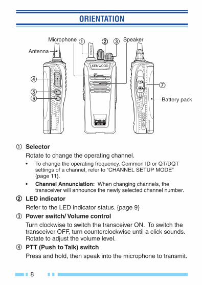
ORIENTATION
Battery pack
Selector Rotate to change the operating channel.
• To change the operating frequency, Common ID or QT/DQT settings of a channel, refer to “CHANNEL SETUP MODE” {page 11}.
• Channel Annunciation: When changing channels, the transceiver will announce the newly selected channel number.
LED indicator Refer to the LED indicator status. {page 9}
Power switch/ Volume control Turn clockwise to switch the transceiver ON. To switch the
transceiver OFF, turn counterclockwise until a click sounds. Rotate to adjust the volume level.
PTT (Push to Talk) switch Press and hold, then speak into the microphone to transmit.
Antenna
Microphone Speaker

9
Side 1 key Press and hold to activate its programmable function. The default setting is [Zone].
• For function descriptions and details on how to change the function of the Side 1 key, refer to “KEY ASSIGNMENT MODE” {page 20}.
Side 2 key Press to activate its programmable function. The default setting is [Squelch Off Momentary].
• For function descriptions and details on how to change the function of the Side 2 key, refer to “KEY ASSIGNMENT MODE” {page 20}.
Speaker/ microphone jacks Insert the Speaker/ microphone or Headset plug into this
jack.
LED Indicator Status
Indicator Color Meaning
Flashes blue Digital mode
Flashes orange Analog mode
Lights red Transmitting
Lights green Receiving a call
Blinks red Battery power is low
Blinks green Scanning
Blinks red/orange The selected channel has not been programmed and cannot be used.

10
BASIC OPERATIONS
1 Turn the Power switch/ Volume control clockwise to switch the transceiver power ON.• A beep will sounds.
2 Press the key programmed with the [Monitor] or [Squelch Off] (Side 2 key default) function to hear background noise, then rotate the Power switch/ Volume control to adjust the volume.
3 Rotate the Selector to select your desired channel.• When you receive an appropriate signal, you
will hear audio from the speaker.
4 To make a call, press and hold the PTT switch, then speak into the microphone using your normal speaking voice.• Hold the microphone approximately 3 to 4 cm
(1.5 inches) from your lips.
5 Release the PTT switch to receive.
Note: ◆ When the battery pack voltage becomes too low, transmission will
stop and an alert tone will sound.
11
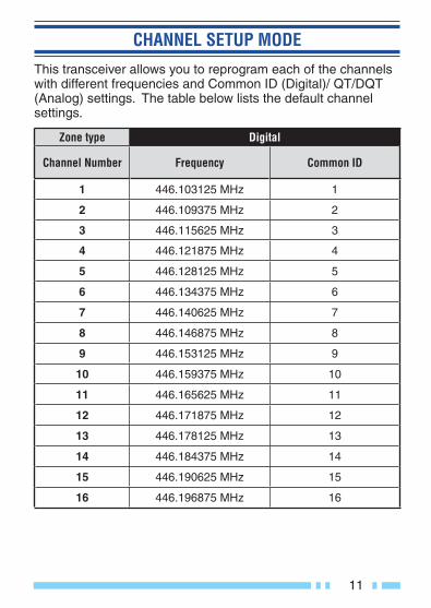
CHANNEL SETUP MODE
This transceiver allows you to reprogram each of the channels with different frequencies and Common ID (Digital)/ QT/DQT (Analog) settings. The table below lists the default channel settings.
Zone type Digital
Channel Number Frequency Common ID
1 446.103125 MHz 1
2 446.109375 MHz 2
3 446.115625 MHz 3
4 446.121875 MHz 4
5 446.128125 MHz 5
6 446.134375 MHz 6
7 446.140625 MHz 7
8 446.146875 MHz 8
9 446.153125 MHz 9
10 446.159375 MHz 10
11 446.165625 MHz 11
12 446.171875 MHz 12
13 446.178125 MHz 13
14 446.184375 MHz 14
15 446.190625 MHz 15
16 446.196875 MHz 16

12
Zone type Analog
Channel Number Frequency QT/DQT
1 446.00625 MHz 94.8 Hz
2 446.09375 MHz 88.5 Hz
3 446.03125 MHz 103.5 Hz
4 446.06875 MHz 79.7 Hz
5 446.04375 MHz 118.8 Hz
6 446.01875 MHz 123.0 Hz
7 446.08125 MHz 127.3 Hz
8 446.05625 MHz 85.4 Hz
9 446.00625 MHz 107.2 Hz
10 446.09375 MHz 110.9 Hz
11 446.03125 MHz 114.8 Hz
12 446.06875 MHz 82.5 Hz
13 446.04375 MHz D132N
14 446.01875 MHz D155N
15 446.05625 MHz D134N
16 446.08125 MHz D243N
Note: ◆ You must fi rst select an operating frequency for a channel before
you can select a Common ID (Digital)/ QT/DQT (Analog) setting for that same channel.

13
ZONE SELECTIONTo change the operating zone:1 With the transceiver power OFF, press and hold the PTT
switch and Side 1 key while turning the transceiver power ON.• Continue to hold the PTT switch and Side 1 key until the LED
lights orange and the transceiver announces “Self”.
2 Release the PTT switch and Side 1 key.• The transceiver announces Zone number (1 or 2).
3 Press the Side 1 or Side 2 key to select the zone number.• A voice announcement will inform you of the currently selected
zone number.
4 Press the PTT switch to set the zone number.• A beep will sound.
• A voice announcement will inform you of the currently selected zone type (Digital/ Analog).
5 Press the Side 1 or Side 2 key to select the zone type.• A voice announcement will inform you of the currently selected
zone type.
• Proceed to the next step if you are not changing the zone type.
6 Press the PTT switch to save the setting.• A beep will sound if there is no change in the zone type. The
transceiver will move to the Frequency Setting and announces “Channel”.
• If the zone type is changed, the transceiver announces “Confi rm”.
7 Press the PTT switch and Side 1 key.• All channel frequencies, Common ID and QT/DQT values in
the selected zone will be restored to the default value.
• The transceiver will move to the Frequency Setting.
Note: ◆ The transceiver will automatically return to normal operation if no
action is performed for 5 seconds.

14
CHANNEL OPERATING FREQUENCIESTo change the operating frequency of a channel:1 Follow the operating steps in Zone Selection to select the
zone.2 Rotate the Selector to your desired channel.
• The transceiver announces Channel number.
3 Press and release the PTT switch.• A beep will sound and the transceiver announces Table
number.
4 Press the Side 1 or Side 2 key to increment/ decrement the Table number, to select the new channel frequency.• Table numbers and their corresponding operating frequencies
are provided in the table {page 15}.• A voice announcement will inform you of the currently selected
Table number.
5 Press the PTT switch to save the setting.• A beep will sound.
• Repeat steps 2 to 5 to set up another channel.
6 Turn the transceiver power OFF and then ON again to activate the new settings.
Note: ◆ The transceiver will automatically return to normal operation if no
action is performed for 5 seconds.

15
Frequency TableDigital
Table Number Operating Frequency Table
Number Operating Frequency
1 446.103125 MHz 17 446.003125 MHz
2 446.109375 MHz 18 446.009375 MHz3 446.115625 MHz 19 446.015625 MHz4 446.121875 MHz 20 446.021875 MHz5 446.128125 MHz 21 446.028125 MHz6 446.134375 MHz 22 446.034375 MHz7 446.140625 MHz 23 446.040625 MHz8 446.146875 MHz 24 446.046875 MHz9 446.153125 MHz 25 446.053125 MHz
10 446.159375 MHz 26 446.059375 MHz11 446.165625 MHz 27 446.065625 MHz12 446.171875 MHz 28 446.071875 MHz13 446.178125 MHz 29 446.078125 MHz14 446.184375 MHz 30 446.084375 MHz15 446.190625 MHz 31 446.090625 MHz16 446.196875 MHz 32 446.096875 MHz
AnalogTable
Number Operating Frequency Table Number Operating Frequency
1 446.00625 MHz 9 446.10625 MHz2 446.01875 MHz 10 446.11875 MHz3 446.03125 MHz 11 446.13125 MHz
4 446.04375 MHz 12 446.14375 MHz
5 446.05625 MHz 13 446.15625 MHz6 446.06875 MHz 14 446.16875 MHz7 446.08125 MHz 15 446.18125 MHz8 446.09375 MHz 16 446.19375 MHz

16
COMMON ID SETTINGS (DIGITAL)To change the Common ID settings of a channel of Digital:1 Follow the operating steps in Zone Selection to select the
zone type (digital).2 Rotate the Selector to your desired channel.
• The transceiver announces Channel number.
3 Press the Side 1 or Side 2 key to select Common ID setup.• The transceiver announces “ID” and “Channel” alternately with
each press of the Side 1 or Side 2 key.
4 Press and release the PTT switch.• A beep will sound and the transceiver announces Common ID
number (1-255).
5 Press the Side 1 or Side 2 key to set the channel and select the Common ID .• The transceiver announces Common ID number.
• Press and hold the Side 1 or Side 2 key to increment/ decrement the Common ID number by 10 at a time.
• A voice announcement will inform you of the currently selected Common ID number.
6 Press the PTT switch to save the setting.• A beep will sound.
• Repeat steps 2 to 6 to set up another channel.
7 Turn the transceiver power OFF and then ON again to activate the new settings.
Note: ◆ The transceiver will automatically return to normal operation if no
action is performed for 5 seconds.

17
QT/ DQT SETTINGS (ANALOG)Quiet Talk (QT) and Digital Quiet Talk (DQT) are functions that reject undesired signals on your channel. You will hear a call only when you receive a signal that contains a matching QT tone or DQT code. If a call containing a different tone or code is received, squelch will not open and you will not hear the call. Likewise, when transmitting using QT or DQT, the receiving station must have a matching tone or code to hear your call.Be aware that other parties can still hear your calls if they set up their transceiver with the same tone or code.The default QT/DQT settings for each channel are provided in the table {page 18}.To change the QT/DQT settings of a channel of Analog:1 Follow the operating steps in Zone Selection to select the
zone type (analog).2 Rotate the Selector to select the channel to change.
• The transceiver announces Channel number.
3 Press the Side 1 or Side 2 key to select the QT/DQT setup.• The transceiver announces “QT/DQT” and “Channel”
alternately with each press of the Side 1 or Side 2 key.
4 Press and release the PTT switch.• A beep will sound and the transceiver announces QT/DQT
number.
5 Press the Side 1 or Side 2 key to increment/ decrement the Tone number, to select the new tone or code.• QT/DQT table numbers and their corresponding tones/ codes
are provided in the table {page 18}.• Press and hold the Side 1 or Side 2 key to increment/
decrement the Tone number by 5 at a time.
• A voice announcement will inform you of the currently selected Tone number.

18
6 Press the PTT switch to save the setting.• A beep will sound.
• Repeat steps 2 to 6 to set up another channel.
7 Turn the transceiver power OFF and then ON again to activate the new settings.
Note: ◆ The transceiver will automatically return to normal operation if no
action is performed for 5 seconds.
QT/DQT Table
QT/DQT Number
QT/DQT Setting
QT/DQT Number
QT/DQT Setting
QT/DQT Number QT/DQT Setting
1 67.0 Hz 14 107.2 Hz 27 D132N
2 71.9 Hz 15 110.9 Hz 28 D155N
3 74.4 Hz 16 114.8 Hz 29 D134N
4 77.0 Hz 17 118.8 Hz 30 D243N
5 79.7 Hz 18 123.0 Hz 31 D311N
6 82.5 Hz 19 127.3 Hz 32 D346N
7 85.4 Hz 20 131.8 Hz 33 D315N
8 88.5 Hz 21 136.5 Hz 34 D351N
9 91.5 Hz 22 141.3 Hz 35 D423N
10 94.8 Hz 23 146.2 Hz 36 D664N
11 97.4 Hz 24 151.4 Hz 37 D431N
12 100.0 Hz 25 156.7 Hz 38 D723N
13 103.5 Hz 26 162.2 Hz 0 OFF
Note: ◆ The Tone numbers corresponding to the QT/DQT values can be
changed by your dealer.
19
CHANNEL CONFIRMATION MODETo confi rm your channel settings:1 With the transceiver power OFF, press and hold the PTT
switch while turning the transceiver power ON.• Continue to hold the PTT switch until the LED lights orange
and the transceiver announces “Confi rm”.
2 Release the PTT switch.• The transceiver announces the channel table number and Tone
number of the selected channel.
3 Rotate the Selector to your desired channel within 5 seconds, otherwise the operation will cancel.• The transceiver announces the channel table number and Tone
number of the current channel.
Note: ◆ The transceiver will automatically return to normal operation if no
action is performed for 5 seconds.

20
KEY ASSIGNMENT MODE
This transceiver allows you to reprogram the Side 1 and Side 2 keys with any of the functions listed in the table below. Explanations on the use of each function are provided under “PROGRAMMABLE FUNCTIONS” {page 22}.
Table Number Function Name Digital Analog
0 None (no function) ✓ ✓
1 Calling Alert ✓ ✓
2 Key Lock ✓ ✓
3 Monitor ✓ ✓
4 Monitor Momentary ✓ ✓
5 Scan/ Scan Temporary Delete*1 ✓ ✓
6 Scrambler N/A ✓
7 Squelch Off N/A ✓
8 Squelch Off Momentary N/A ✓
9 Zone ✓ ✓
✓ : Available
N/A: Not Available*1 : Press and hold this key for 2 seconds will activate the Scan
Temporary Delete function.
To change the functions of the Side 1 and Side 2 keys:
1 With the transceiver power OFF, press and hold the Side 1 and Side 2 keys while turning the transceiver power ON.• Continue to hold the Side 1 and Side 2 keys until the LED
lights orange and the transceiver announces “Setup”.

21
2 Release the key.• If you continue to hold both keys, or if you release both keys,
the operation will cancel in 5 seconds.
3 Press and hold the key to be reprogrammed (either the Side 1 or Side 2 key).• The transceiver will announce “Table zero”.
4 Release the key.5 Press the Side 1 or Side 2 key to increment/ decrement the
number, to select the new key function.• Table numbers and their corresponding functions are provided
in the table {page 20}.• A voice announcement will inform you of the currently selected
Table number.
6 Press the PTT switch to save the setting.• A beep will sound and the transceiver will announce the new
Table number.
7 Turn the transceiver power OFF and then ON again to activate the new settings.
Note: ◆ The transceiver will automatically return to normal operation if no
action is performed for 5 seconds.

22
PROGRAMMABLE FUNCTIONS■ Calling Alert
Calling alert tones help identify yourself to party members and inform them that you are calling. Your dealer can set up your transceiver with 1 of 10 calling alert tones. If each party member uses a different tone, it is easy to know who is calling. To make a call, press and hold the PTT switch, then press the key programmed as Calling Alert.• Release the key to end the tone.
■ Key LockPress and hold this key for 2 second to lock/ unlock the transceiver keys.The following keys/ functions can still be used when Key Lock is active:Key Lock, Monitor, Monitor Momentary, PTT, Squelch Off, Squelch Off Momentary, and Volume.
■ MonitorOn digital mode, momentarily press this key to deactivate Common ID signaling. Press the key again to return to normal operation. Squelch will open with any dPMR446 signals received regardless of the Common ID setting.On analog mode, momentarily press this key to deactivate QT or DQT signaling. Press the key again to return to normal operation.
■ Monitor MomentaryOn digital mode, press and hold this key to deactivate Common ID signaling. Release the key to return to normal operation. Squelch will open with any dPMR446 signals received regardless of the Common ID setting.On analog mode, press and hold this key to deactivate QT or DQT signaling. Release the key to return to normal operation.

23
■ ScanPress this key to start scanning the transceiver channels.Priority Scan: The Priority channel is a channel that is given fi rst priority to while scanning. The Priority channel is set by your dealer.Revert Channel: During Scan, pressing the PTT switch will automatically select the transceiver’s Revert channel and you will begin transmitting. Your dealer can program the Revert channel using one of the following methods:• Last Called + Selected• Selected• Selected + Talkback• Priority • Priority + Talkback
■ Scan Temporary DeleteWhen Scan pauses at an undesired channel, you can remove that channel from the scanning sequence by pressing and holding this key for 2 seconds.
■ ScramblerThe Scrambler function allows you to hold a conversation in complete privacy. When the Scrambler function is activated, any other party that is listening to your channel will be unable to understand your conversation.
■ Squelch OffMomentarily press this key to hear background noise. Press the key again to return to normal operation.
■ Squelch Off Momentary (Side 2 key default)Press and hold this key to hear background noise. Release the key to return to normal operation.
■ Zone (Side 1 key default)Press and hold to select the Digital mode and Analog mode.
24
BACKGROUND OPERATIONS
TIME-OUT TIMER (TOT)The Time-out Timer prevent callers from using a channel for an extended duration. If you continuously transmit for the duration programmed by your dealer (default is 60 seconds), transmission will stop and an alert tone will sound. To stop the tone, release the PTT switch.
BATTERY SAVERWhen activated by your dealer, the Battery Saver function decreases the amount of power used after no signal is present and no operations are being performed for 5 seconds. When a signal is received or an operation is performed, Battery Saver turns off.Note:
◆ Battery Saver is disabled during a call on digital mode. ◆ While the Battery Saver is operating, the LED may fl ash green
when receiving a QT/DQT signal which does not match the QT/DQT tone/code set up in your transceiver.
LOW BATTERY WARNINGWhile operating the transceiver, the Low Battery Warning sounds an alert tone every 30 seconds and the LED indicator blinks red when the battery needs recharged or replaced.
CHANNEL ANNUNCIATIONWhen changing the channel, the transceiver will announce the newly selected channel number. Likewise, the transceiver will announce the current channel after you turn the transceiver power ON. (Channel Annunciation can be activated or deactivated by your dealer.)
25
VOICE OPERATED TRANSMISSION (VOX)
VOX operation allows you to transmit hands-free. VOX can only be used if you are using a supported headset. To activate VOX and set the VOX Gain level, perform the following steps:1 Connect the headset to the transceiver .
• The VOX function does not activate when a headset is not connected to the accessory terminal of the transceiver.
2 With the transceiver power OFF, press and hold the Side 1 key while turning the transceiver power ON.
3 Continue to hold the Side 1 key until a beep sounds.• The LED indicator lights turn orange.
• When the Side 1 key is released, the transceiver will announces the VOX Gain level.
4 Press the Side 1 key to set the VOX Gain level, from 1 (least sensitive) to 10 (most sensitive).• Press the Side 2 key to enable or disable the VOX function
for the current channel (you can change this setting for each channel by selecting a channel with the Selector). When turned ON, a beep sounds. When turned OFF, a double beep sounds.
5 Press the PTT switch to save the setting.• A beep will sound.
• The transceiver announces the new VOX Gain level.
6 Turn the transceiver power OFF and then ON again to activate VOX.
Note:◆ If a headset is connected to the transceiver while the VOX function is
switched ON and the VOX Gain level is confi gured to a higher, more sensitive level, louder received signals may cause the transceiver to start transmission.
◆ The transceiver will automatically return to normal operation if no action is performed for 20 seconds.

26
ALL RESET MODE
At some point in time, you may desire to reset the transceiver settings to their default values. This function will reset all channels to their default frequencies and Common ID (Digital)/ QT/DQT (Analog), the VOX function to its default status, and all keys to their default functions.To reset the transceiver:1 With the transceiver power OFF, press and hold the PTT
switch, the Side 1 key, and the Side 2 key while turning the transceiver power ON.• Continue to hold the keys for 2 seconds, until the LED lights
orange.
2 Release the keys.• The transceiver beep sounds and returns to normal operation.
• If the keys are released before the LED lights orange, All Reset Mode will cancel.
27
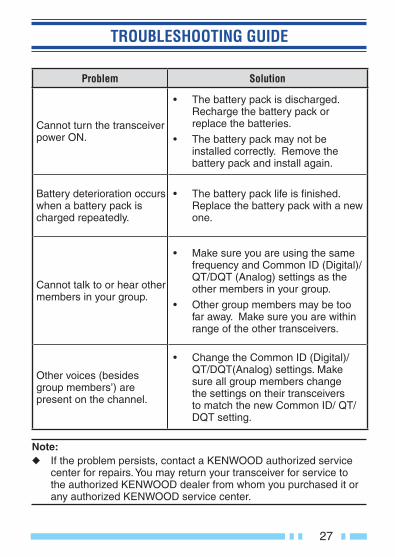
TROUBLESHOOTING GUIDE
Problem Solution
Cannot turn the transceiver power ON.
• The battery pack is discharged. Recharge the battery pack or replace the batteries.
• The battery pack may not be installed correctly. Remove the battery pack and install again.
Battery deterioration occurs when a battery pack is charged repeatedly.
• The battery pack life is fi nished. Replace the battery pack with a new one.
Cannot talk to or hear other members in your group.
• Make sure you are using the same frequency and Common ID (Digital)/ QT/DQT (Analog) settings as the other members in your group.
• Other group members may be too far away. Make sure you are within range of the other transceivers.
Other voices (besides group members’) are present on the channel.
• Change the Common ID (Digital)/ QT/DQT(Analog) settings. Make sure all group members change the settings on their transceivers to match the new Common ID/ QT/DQT setting.
Note: ◆ If the problem persists, contact a KENWOOD authorized service
center for repairs. You may return your transceiver for service to the authorized KENWOOD dealer from whom you purchased it or any authorized KENWOOD service center.

© 2017