tl101009 telma maintenance manual
TRANSCRIPT

Maintenance Manual
TL101009-FEB12

CONGRATULATIONS. Your vehicle is equipped with a TELMAFrictionless Braking System. Permanently connected to the driveline of yourvehicle, it provides you with essential safety, cost effectiveness, accurate andreliable braking, and is ready to function under all circumstances. TELMAsupplies your vehicle with an additional braking system that works along withyour service brakes. You will benefit from improved braking resulting inincreased safety and substantial savings on brakes, tires and route times.
Using your TELMA will reduce the use of the service brakes, which as a result,remain cool and fully effective for the occasions on which they are reallyneeded – such as emergency stops. Read this guide before getting behind thewheel. It will tell you how to make the most of your TELMA.
CONTENTSPage
THEORY OF OPERATION Foundation Brakes & TELMA 1How They Work 1
COMPONENT Types of TELMA Mounts 2IDENTIFICATION Foot Switches 2
Speed Switch 3ABS Interface 4Relay Box 5Dashboard Indicator 5
CONTROLS Brake Pedal Application 6Hand Control 6Off-Throttle Control 6
GENERAL Routine Maintenance Checklist 7MAINTENANCE Washing 8
Air Gap Verification 8
ELECTRICAL Important Notes About MAINTENANCE Grounding the System 9
Relay Box Contacts 9Relay Box Diodes 10Amperage Check 10Resistance Check 11Universal Wiring Diagram 12
REPAIR & SPARE PARTS Driveline Component Parts 13Driveline Coil Replacement 14Focal Component Parts 15Focal Coil Replacement 16
WARRANTY STATEMENT 17

THEORY OF OPERATION
Foundation Brakes & TELMAWhat are foundation brakes designed to do?
Stop the vehicle within a certain distanceHold the vehicle in place when stopped
What is the TELMA designed to do?Provide additional brakingProvide braking without wearProvide braking without fadeProvide extended foundation brake life
How They Work
2 The TELMA is permanently connected to the drive shaft [1].2 The TELMA contains two rotating discs called rotors [3 ] and a stationary
component called the stator [2]. The rotors rotate at the same speed asthe drive shaft. The stator is mounted between the two rotors and haseight coils [4 ].
2 When the TELMA is activated, current flows through the coils whichinduces a magnetic field that passes through the rotors. This magneticfield produces "eddy currents" within the rotors which slows the motionof the drive shaft, thus decelerating the vehicle. There is no physical contact (friction) within the TELMA and, therefore, no wear.
2 The system is configured so that it will be applied gradually in four stages.The four stages reflect 25%, 50%, 75% and 100% of TELMA power that is applied.
2 The system is air-cooled. The heat generated by the rotors is dissipateddirectly to the air through the rotor vanes [5], therefore the system is saidto be self-regulating (the heat absorbed equals the heat dissipated).
[1]
[2]
[3]
[4 ]
1
[5]
THEORY O
F O
PERATIO
N

2
COMPONENT IDENTIFICATION
Types of TELMA MountsThere are two types of TELMAs: adriveline mount and a focal mount.There is no difference in their operation;the difference is where the TELMA ismounted. The driveline unit is mountedwithin the driveline, between thetransmission and the rear axle. The focalis mounted directly to the rear axle.
Air Brake Foot ControlPressure SwitchesThe pressure switches are activated when the brake pedal is applied. Eachpressure switch assembly contains four switches, two in each side of themanifold. These switches are factory calibrated to trigger at 3, 5, 7 and 10 psiof brake pedal pressure. The air supplied to the pressure switch is connecteddirectly to the braking system primary delivery line. The electrical connectionis made to the main TELMA wiring harness.
Pressure TransducerThe air pressure transducer is connected to the primary delivery line of thebraking system to activate the retarder. The pressure transducer outputs ananalog (variable voltage) signal that can only be used with the Telma ControlModule (TRCM). Each stage of the Telma can be activated at differentpressures through the TRCM configuration software.
COMPONENT IDENTIFICATIO
N
Driveline Mount Focal Mount
Air Switch Manifold (TID11012) Air Pressure Transducer(TIG31065)
NOTE: TRCM is required touse the TIG31065.
3 & 5 psi switchTID31055
7 & 10 psi swichTID31056
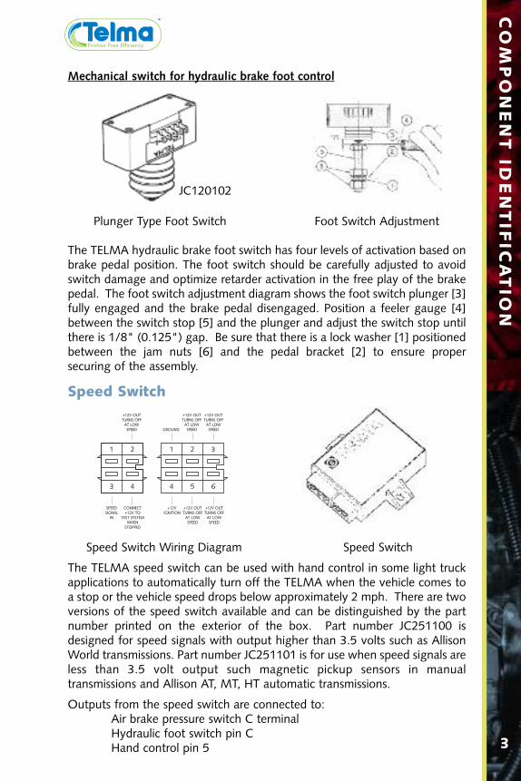
Mechanical switch for hydraulic brake foot control
Plunger Type Foot Switch Foot Switch Adjustment
The TELMA hydraulic brake foot switch has four levels of activation based onbrake pedal position. The foot switch should be carefully adjusted to avoidswitch damage and optimize retarder activation in the free play of the brakepedal. The foot switch adjustment diagram shows the foot switch plunger [3]fully engaged and the brake pedal disengaged. Position a feeler gauge [4]between the switch stop [5] and the plunger and adjust the switch stop untilthere is 1/8" (0.125") gap. Be sure that there is a lock washer [1] positionedbetween the jam nuts [6] and the pedal bracket [2] to ensure propersecuring of the assembly.
Speed Switch
Speed Switch Wiring Diagram Speed Switch
The TELMA speed switch can be used with hand control in some light truckapplications to automatically turn off the TELMA when the vehicle comes toa stop or the vehicle speed drops below approximately 2 mph. There are twoversions of the speed switch available and can be distinguished by the partnumber printed on the exterior of the box. Part number JC251100 isdesigned for speed signals with output higher than 3.5 volts such as AllisonWorld transmissions. Part number JC251101 is for use when speed signals areless than 3.5 volt output such magnetic pickup sensors in manual transmissions and Allison AT, MT, HT automatic transmissions.
Outputs from the speed switch are connected to: Air brake pressure switch C terminalHydraulic foot switch pin CHand control pin 5 3
COMPONENT ID
ENTIFICATIO
N
1 2
3 4
1 2 3
4 5 6
+12V OUTTURNS OFFAT LOWSPEED
+12V OUTTURNS OFFAT LOWSPEED
CONNECT +12V TO
TEST SYSTEMWHEN
STOPPED
SPEEDSIGNAL
IN
+12V OUTTURNS OFFAT LOWSPEED
+12V OUTTURNS OFFAT LOWSPEED
+12V OUTTURNS OFFAT LOWSPEED
+12VIGNITION
GROUND
JC120102

4
COMPONENT IDENTIFICATIO
N
The TRCM is a new control module with modernized architecture andfeatures such as PC interface for diagnostics and configuration as well as theability to obtain speed, ABS, and other information by listening to the vehicleCAN bus.
TIG31062
Telma Control Module (TRCM)
The TELMA system is equipped with an electronic interface designed to workwith your vehicle’s Anti-Lock Braking System (ABS). During an ABS event (anABS event is defined as any wheel lock-up) the TELMA will automatically turnoff, allowing the ABS to control the brakes without interference from TELMA.After the ABS event, the TELMA will reactivate progressively to assure properbraking. There are two versions of the ABS Interface available and can bedistinguished by the part number printed on the exterior of the box. Part numberJC241105 is designed for speed signals with output higher than 3.5 volts suchas Allison World transmissions. Part number JC251103 is for use when speedsignals are less than 3.5 volt output such as magnetic pickup sensors in manualtransmissions and Allison AT, MT, HT automatic transmissions.
NOTE:If the vehicle’s ABS warning light remains on, the TELMA may notoperate. When the ABS warning light is on, there is a problem withthe ABS. The ABS must be serviced before the TELMA will operate.Refer to TL105089 for more information about the ABS Interface.
ABS
ABS InterfaceABS Wiring Harness Connections
1522
2324
251
46
78
911
13
(ABS Control) Ground in except in ABS Event
(ABS Working) +12 V in with no ABS Malfunction
Speed Signal In
+12 V to Relay Box Terminal 1
+12 V to Relay Box Terminal 2
+12 V to Relay Box Terminal 3
+12 V to Relay Box Terminal 4
+12 V Ignition In
Ground In
Ground in 25% TELMA Effect (Stage 1)
Ground in 50% TELMA Effect (Stage 1)
Ground in 75% TELMA Effect (Stage 1)Ground in Full TELMA Effect (Stage 1)
ABS Interface
TRCM Pin Layout
NOTE: ABS Interface is no longer available, refer to TL105089 for more information.

5
COMPONENT ID
ENTIFICATIO
N
IMPORTANT! The lights indicate that the TELMA is operating. Theyshould never illuminate when the vehicle is stopped or when the brakesare not applied. If this occurs discontinue operation and drive the vehicle to the maintenance facility for immediate repair.
Dashboard Indicator Wiring Connections
Relay BoxThe relay box is a high strength thermoplastic enclosure that contains fourrelays mounted on a black plastic chassis.The box measures approximately 7-1/2” x4-3/4" x 4". Please refer to the wiring diagram section of this manual for complete terminal connections. The relaybox distributes battery power to theTELMA in four stages, and is usuallymounted on the frame rail between the
batteries and the TELMA. Battery power is connected to the relay assembly at the "+" terminal. When voltage is applied to terminals 1, 2, 3and 4, their respective relays close. This switches battery power to terminalsI, II, III and IV respectively. The "M" terminal is to ground the relay assembly and dissipate the reverse voltage spike that occurs when each stageis deactivated. The "S" terminal receives battery power whenever any relayis closed. The relay box should always mount in a vertical position with thewiring coming out of the bottom.
Dashboard IndicatorA dashboard indicator is the driver’s main indication of the TELMA’s function.This indicator contains four separate lights within the display that are con-nected directly to the relay outputs which illuminate as the unit is activated.Each light corresponds to one of the four stages of the unit. The lights willilluminate in succession as the TELMA is being activated.
PIN 1PIN 4
PIN 2 PIN 3PIN 5
PIN 1 = To Relay Box Terminal IPIN 2 = To Relay Box Terminal IIPIN 3 = To Relay Box Terminal IIIPIN 4 = To Relay Box Terminal IVPIN 5 = To Relay Box Terminal M
6
CONTROLS
CONTROLS
The TELMA Frictionless Braking System contains several components that the driver needs to understand in order to operate the vehicle safely and effectively. Listed below are the major components and their functionwithin the TELMA system. The TELMA system may be activated by severaldifferent methods. It may be necessary to determine which type of controlsyour vehicle is equipped with.
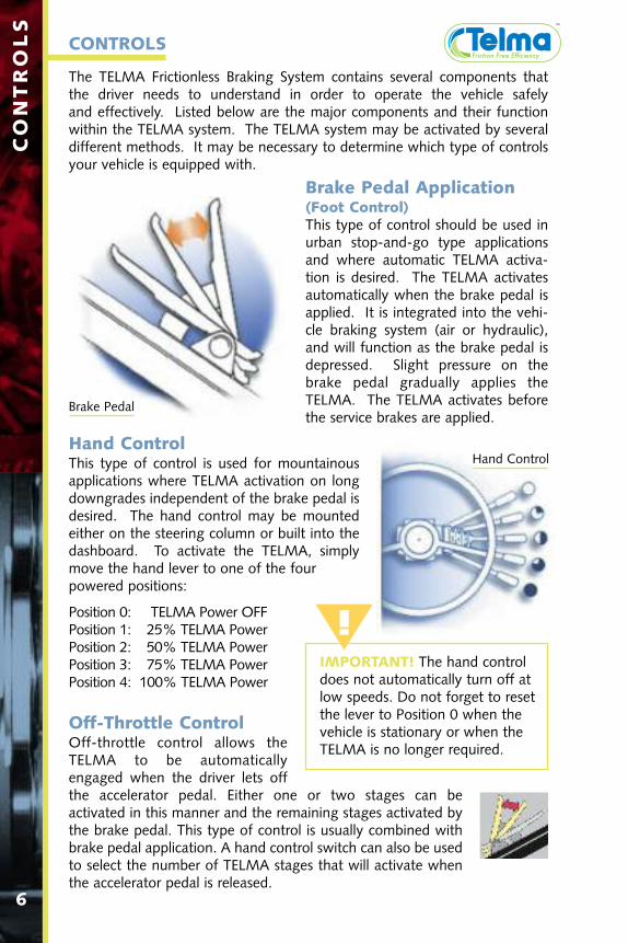
Brake Pedal Application (Foot Control)This type of control should be used inurban stop-and-go type applicationsand where automatic TELMA activa-tion is desired. The TELMA activatesautomatically when the brake pedal isapplied. It is integrated into the vehi-cle braking system (air or hydraulic),and will function as the brake pedal isdepressed. Slight pressure on thebrake pedal gradually applies theTELMA. The TELMA activates beforethe service brakes are applied.
Hand ControlThis type of control is used for mountainousapplications where TELMA activation on longdowngrades independent of the brake pedal isdesired. The hand control may be mountedeither on the steering column or built into thedashboard. To activate the TELMA, simplymove the hand lever to one of the four powered positions:
Position 0: TELMA Power OFFPosition 1: 25% TELMA PowerPosition 2: 50% TELMA PowerPosition 3: 75% TELMA PowerPosition 4: 100% TELMA Power
Off-Throttle ControlOff-throttle control allows theTELMA to be automaticallyengaged when the driver lets offthe accelerator pedal. Either one or two stages can be activated in this manner and the remaining stages activated bythe brake pedal. This type of control is usually combined withbrake pedal application. A hand control switch can also be usedto select the number of TELMA stages that will activate whenthe accelerator pedal is released.
IMPORTANT! The hand control does not automatically turn off at low speeds. Do not forget to reset the lever to Position 0 when the vehicle is stationary or when the TELMA is no longer required.
Brake Pedal
Hand Control
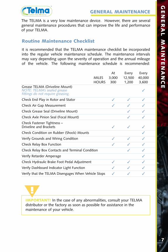
Routine Maintenance Checklist
It is recommended that the TELMA maintenance checklist be incorporatedinto the regular vehicle maintenance schedule. The maintenance intervalsmay vary depending upon the severity of operation and the annual mileageof the vehicle. The following maintenance schedule is recommended:
At Every EveryMILES 3,000 12,500 40,000HOURS 300 1,200 3,600
Grease TELMA (Driveline Mount)NOTE: TELMA’s sealed grease fittings do not require greasing.
Check End Play in Rotor and Stator
Check Air Gap Measurement
Check Grease Seal (Driveline Mount)
Check Axle Pinion Seal (Focal Mount)
Check Fastener Tightness – Driveline and Brackets
Check Condition on Rubber (Shock) Mounts
Verify Grounds and Wiring Condition
Check Relay Box Function
Check Relay Box Contacts and Terminal Condition
Verify Retarder Amperage
Check Hydraulic Brake Foot Pedal Adjustment
Verify Dashboard Indicator Light Function
Verify that the TELMA Disengages When Vehicle Stops
7
GENERAL M
AINTENANCE
IMPORTANT! In the case of any abnormalities, consult your TELMA distributor or the factory as soon as possible for assistance in the maintenance of your vehicle.
GENERAL MAINTENANCE
The TELMA is a very low maintenance device. However, there are severalgeneral maintenance procedures that can improve the life and performanceof your TELMA.

Washing
Driveline Units Focal Units
The TELMA should be pressure washed periodically. Visually inspect the unitto verify that it is clean and free of debris. If washing is necessary,please follow these guidelines:
2 Maximum pressure = 360 psi.2 Maximum temperature = 180º F.2 Keep washer tip at least 10" from the TELMA at all times.2 Coils should not be subjected to continuous direct pressure.2 Concentrate the stream on the rotors and air gap locations (as shown
above).2 Do not wash the unit immediately after use.2 Do not use detergents or degreasing agents.2 Do not wash the unit if it is not necessary.
Air Gap VerificationThe air gap distance between the rotors and the pole shoes is very importantin the proper functioning of the TELMA. If the air gaps are too large, the unitwill not provide the driver with the full braking power and efficiency that theTELMA is capable of. If the air gaps are too small, the rotors may interferewith the pole shoes and lead to unnecessary wear and premature failure ofthe TELMA or its components. The following checks should only be performed when the TELMA is cool. To verify the air gaps, use a feeler gaugeto check clearances between the rotor and pole shoes at four points on eachrotor. Refer to the individual TELMA data sheet for correct air gap spacing.
Driveline Units Focal Units8
GENERAL M
AINTENANCE

9
ELECTRICAL M
AINTENANCE
ELECTRICAL MAINTENANCE
Important Notes About Grounding the System
2 A defective TELMA ground can cause poor performance.2 A defective relay box ground can cause relay and dashboard light failure.2 All ground circuits must return to battery negative with the correct wire size.2 Relay box ground wire size must be:
_____minimum 10 gauge for TELMAs up to 20 amps per stage._____minimum 8 gauge for TELMAs up to 45 amps per stage._____minimum 6 gauge for TELMAs above 45 amps per stage.
2 TELMA ground wire size must be:_____minimum 4 gauge for TELMAs up to 20 amps per stage._____minimum 2 gauge for TELMAs up to 45 amps per stage._____minimum 00 gauge for TELMAs above 45 amps per stage.
2 All ground points must be attached to a bare metal surface.
Relay Box Contacts
Contact Replacement & AdjustmentLong fixed contact without fuse (31A)• Remove the two screws (31D) to
replace the long fixed contact (31A)without fuse on the left.
• Replace the contact and reinstall thescrews.
• Adjust the contact until there is agap of 0.106". Tighten the screws(31D).
Short fixed contact with fuse (32A)• Remove the nut (32F), washers (32D
and 32E) and the fuse (32G).• Replace the contact and reinstall
fasteners.• Adjust the contact until there is a gap
of 0.106”. Tighten the nut (32F).
Note: Replace contacts whenever they become pitted or burned. Alwaysreplace moving and fixed contacts as a complete set.
Fuse ReplacementA spare fuse is located on the lower screw on the left side (not shown).• Loosen the nuts (32F) • Remove all hardware (32D and 32E) and replace the fuse• Reinstall hardware and adjust the contact until there is a gap of 0.106"• Tighten the nuts.
Note: The fuse should only fail if there is a short circuit. Check the wiring orretarder for a short before installing a new fuse.
32A
32C
32D32E
32F
31D
31A
32G

10
ELECTRICAL M
AINTENANCE
Relay Box DiodesA set of four protective diodes is installedon the underside of the relay assembly.These diodes protect the relays fromreverse voltage spikes and arcing thatoccurs when the TELMA is deactivated.Severe contact burning and repeateddashboard indicator light failure suggeststhat one of these diodes may have failedor the relay box is not grounded correctly.
Amperage CheckIf a noticeable reduction in the TELMA braking force is reported, it may benecessary to check the amperage draw and resistance to verify that theTELMA is operating correctly. Record the results in the chart provided on thenext page. A procedure to check this amperage draw follows:
Tools Needed: Inductive clamp-on ammeter 0-400 amps
2 Clamp the ammeter around the main power cable connected to the "+"terminal of the relay box.
2 Start engine and run at fast idle if equipped.2 Close each relay individually and record the amps and voltage.2 Amp value for each stage should be similar to each other and close to
the published specifications for your retarder. 2 If there is a wide variance between stages, check the condition of the
relay contacts and the wiring connections.2 If amps for all stages are similar but too low, check the main retarder
ground connection as well as all other wiring connections.2 If the amps are zero for one or more stages, check for a blown relay fuse.
A blown fuse indicates a short circuit in the wiring or retarder. Diagnoseand repair before replacing the fuse.
2 Refer to retarder technical data sheet for amperage specifications.
Note: Refer to your retarder technical data sheet for proper amperage valueand note any variance from the nominal temperature (68° F).
Rear view of relay cardassembly in JD331121

Resistance CheckTools Needed:
Digital ohmmeter with a 0.01 ohm accuracy on a scale of 0-3 ohms
2 Disconnect the TELMA from the relay box terminals (I, II, III, IV).2 Connect the ohmmeter with one lead on one terminal of the connecting
block and the other lead on the TELMA ground stud. Read each resistance and note each abnormal stage compared with the valuesindicated on the specification sheet for driveline or focal units.
2 Connect the ohmmeter to position 1 and 2; 1 and 3; 1 and 4; 2 and 3;2 and 4; and 3 and 4 of the TELMA. In each case, you should read a resistance value corresponding to the sum of the stages measured in the previous step. This procedure determines if the stages of the TELMA are shorted. If they are shorted, trace the short and replace thedamaged wires.
2 Now that the defective stages of the TELMA have been identified,disconnect all the coils associated with these stages and check individually the resistance of each coil.
Note: Refer to technical characteristics sheet OC441210 (consult www.telmausa.com) for proper resistance value and note any variance fromthe nominal temperature (68° F).
2 Change all defective coils (see coil replacement section of this manual).2 Check the resistance per stage (as mentioned above).2 Repair the TELMA and relay box in case of any damage.2 Finally, check all amperage draws according to the technical
characteristics sheet 0C441210.
Chart of Check Results
Resistance Current Voltage Observation(Ω) Draw (A) (V) (current drop,
voltage drop or anomaly)
Resistance of the ohmmeter wires
Theoretical values per circuit
Stage 1
Stage 2
Stage 3
Stage 411
ELECTRICAL M
AINTENANCE

12
ELECTRICAL M
AINTENANCE
Universal Wiring DiagramThe following wiring diagram is Telma’s universal air brake diagram. This diagram may not be fully applicable to your vehicle; it is for reference useonly. Please contact your TELMA distributor or the factory to obtain a wiringdiagram that fully describes your system. Go to www.telmausa.com foradditional diagrams.
Note: Above diagram for reference only, please download latest wiring diagrams from www.telmausa.com
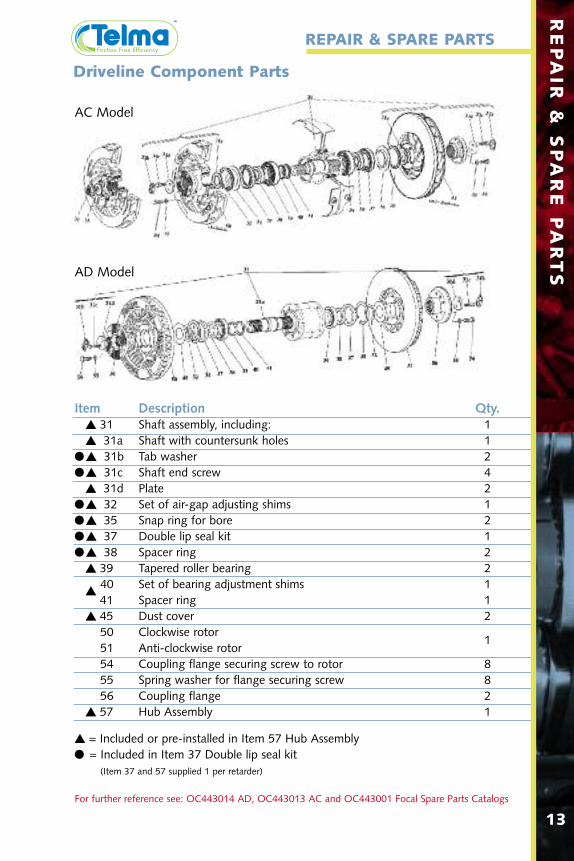
Item Description Qty. 31 Shaft assembly, including: 1 31a Shaft with countersunk holes 1
31b Tab washer 2 31c Shaft end screw 4
31d Plate 2 32 Set of air-gap adjusting shims 1 35 Snap ring for bore 2 37 Double lip seal kit 1 38 Spacer ring 2
39 Tapered roller bearing 240 Set of bearing adjustment shims 1
41 Spacer ring 1
45 Dust cover 250 Clockwise rotor51 Anti-clockwise rotor
1
54 Coupling flange securing screw to rotor 855 Spring washer for flange securing screw 856 Coupling flange 2
57 Hub Assembly 1
13
REPAIR &
SPARE PARTS
REPAIR & SPARE PARTS
= Included or pre-installed in Item 57 Hub Assembly = Included in Item 37 Double lip seal kit
(Item 37 and 57 supplied 1 per retarder)
For further reference see: OC443014 AD, OC443013 AC and OC443001 Focal Spare Parts Catalogs
Driveline Component Parts
AC Model
AD Model

Item Description Qty.1 Balanced rotor assembly, including: 11a Clockwise rotor 11b Counterclockwise rotor 12 Set of rotor fasteners, including: 12a Shoulder studs 4 or 8*2b/2c All metal lock nuts 8 or 16*3 Set of stator air-gap adjusting shims 14 Set of rotor air-gap adjusting shims 15 Stator assembly 16 Pole shoe plate 17 Socket cap screw M10 x 1.5 88 90º countersunk screw M14 x 2 89 Coil assembly, including: 89a Pressure washer 19b Coil end protective cover 19c Upper coil end insulator 19d Pole insulator 19e Impregnated coil 19f Lower coil insulator 19g Protective washer 19h External protective sleeve 110 Stator securing screw 811 Trep washer 8
*Consult www.telmausa.com for quantity needed for specific model number.
For further reference see: OC443014 AD, OC443013 AC and OC443001 Focal Spare Parts Catalogs14
REPAIR &
SPARE PARTS
Focal Component PartsTightening torque22 lb-ft (30 Nm)
Tightening torque89 lb-ft (120 Nm)
Tightening torque65 lb-ft (82 Nm)
Tightening torque37 lb-ft (50 Nm)
Tightening torque37 lb-ft (50 Nm)

Tightening torque37 lb-ft (50 Nm)
15
REPAIR &
SPARE PARTS
Driveline Coil ReplacementThe following procedure will instruct the technician on how to replace afaulty coil. The identification of the faulty circuit may be carried out on thevehicle by means of the electrical check procedure. The TELMA should beremoved from the vehicle to replace a coil.
1. Removing a damaged coil:• Remove the cover of the junction block which corresponds to the
faulty coil.• Disconnect the faulty coil after having carefully marked the position of
each wire (red and blue sleeves).• Remove the pole shoe securing screw (23).• Remove the pole shoe (24), the pressure washer (21) and the faulty
coil or coil assembly (20).2. Cleaning the stator:
• Remove all traces of varnish, insulating material, Araldite and corrosionfrom the pole, the pole shoe and the stator.
3. Fitting the new coil:• Take the pole insulator (20c) and position it around the pole.• Fit the new coil over the pole and pole insulator.• Position the upper coil end insulator (20b), the stainless protective
washer (20a) and the pressure washer (21) over the pole and coil.• Secure the pole shoe (24) with the screw (23).• Check to see that the coil does not rotate. If the coil does rotate,
disassemble to the pressure washer and add an additional pressure washer and reassemble to lock the coil into place.
• Reconnect the coil wires to the terminals during disassembly (red andblue sleeves).
• Install the contact washers (6 mm diameter) and tighten the M6 nutsto 3.7 lb-ft (5 Nm).
• To protect the connecting and junction block terminal against corrosionuse a dielectric grease or an automotive electrical connection sealant.
• Refit the cover of the junction block, the locking tab and the nut to3 lb-ft (4 Nm).
• Deform the locking tab to avoid rotation of the nut.
AC Model AD Model

16
REPAIR &
SPARE PARTS
Focal Coil Replacement
Please refer to the diagram on the previous page.1. Removing a damaged coil:
• Mark the position of the pole shoe plate (6) with regard to the connecting block of the stator.
• Unlock the eight socket cap screws (7) and remove the pole shoe plate.• Cut the internal wiring as close as possible to the coil terminal.• Unlock and remove the countersunk screw (8) which secures the pole
and coil assembly to the stator housing.• Mark the position of the pole with regard to the housing in order to refit
it in its original position, and remove the pole and coil assembly.• Separate the coil from the pole by using a press.
2. Cleaning the stator:• Remove all traces of varnish, insulating material, Araldite and corrosion
from the pole, the pole shoe and the stator.• Reassemble the pole on the stator in its genuine position using the new
screw (8), tightening torque = 89 lb-ft (120 Nm).• Paint protective varnish, part no. VH 510 440, red color, on the inner
side of the stator housing.3. Fitting the new coil:
• The repair coil assemblies of the present generation are fitted with crimpconnectors and can be connected directly.
• Prior to the crimping of the crimp connector, remove the insulatingvarnish from approximately 0.20" (5 mm) of the coil wire.
• Fit the coil end insulation washer (9f) and the pole insulator (9d) aroundthe pole.
• Install the coil over the pole.• Position the upper coil end insulator (9c), if necessary.• Next, fit the stainless protective cover (9b) and the pressure washer (9a)
over the coil and pole.• Relocate the pole shoe plate (6) in its original position and secure it with
new screws (7), tightening torque = 37 lb-ft (50 Nm).• Slide a VITON sleeve on both wires of the new coil.• Remove approximately 0.20" (5 mm) from the ends of the connecting
wires.• Follow the marks made during the disassembly process and install the
ends of the connecting wires inside the crimp connectors of the coil andcrimp the connector.
• Slide the VITON sleeve over the connector and heat shrink it.• Using a brush, liberally coat these connections with varnish, part no.
VH 510 440, red color.• Depending on the type of wiring protection (sealed or impregnated),
bond the terminal connections with silicone compound, part no. VH 510 130 or clamp them with the small cable securing plates.

WARRANTY
Telma warrants to customers that the product shall be free from defects in materialsand workmanship and will confirm to applicable specifications. TRI shall, at itsoption, repair correct or replace any product or part thereof which is defective inworkmanship of material: provided, however, that TRI is given prompt written noticeof any failure (setting forth the alleged defect and pertinent delivery dates showingthat the product is covered under the warranty) occurring within the lesser of a) two(2) years after the date of delivery to the first user of OEM product into which theproduct is installed of b) thirty (30) months from original delivery of the product. ThisWarranty does not cover a product or component thereof which fails, malfunctions oris damaged as a result of (i) improper installation, modification or repair, (ii) accident,abuse or improper or insufficient maintenance including deviation from approvedlubricants or change intervals. In addition, this warranty does not cover normal wearand tear. This Warranty does not apply to products of components thereof notmanufactured or supplied by TRI or to products of components thereof on vehiclesoperated outside the United States, Canada and Mexico. The warranty period forrepairs or replacements is limited to the greater of 1) three (3) months or twenty-fourthousand (24,000) miles, whichever shall occur first or 2) the expiration of date ofthe original warranty. THE EXPRESSED WARRANTIES HEREIN ARE IN LIEU OFALL OTHER WARRANTIES, GUARANTEES, PROMISES, AFFIRMATIONSOR REPRESENTATIONS, EXPRESSED OR IMPLIED, INCLUDING, WITHOUTLIMITATION, WARRANTIES OF MERCHANTABILITY AND FITNESS FOR ANYPARTICULAR PURPOSE OR USE. TELMA SHALL NOT BE LIABLE FOR ANYINCIDENTAL, COLLATERAL, SPECIAL OR CONSEQUENTIAL LOSS, DAMAGE ORINJURY OF ANY NATURE INCLUDING, WITHOUT LIMITATION, SALES OR USE OFTHE PRODUCTS WHETHER OR NOT OCCASIONED BY TELMA’S NEGLIGENCE OROTHERWISE.

2
Telma Incorporatedwww.telmausa.com800.797.7714
TL101009-FEB12