tla 700 series logic analyzer 070-9775-04 documents/tektronix (tek... · warranty tektronix...
TRANSCRIPT

User Manual
TLA 700 SeriesLogic Analyzer
070-9775-04
This document supports application software version 2.0 and above.

Copyright � Tektronix, Inc. All rights reserved. Licensed software products are owned by Tektronix or its suppliers andare protected by United States copyright laws and international treaty provisions.
Use, duplication, or disclosure by the Government is subject to restrictions as set forth in subparagraph (c)(1)(ii) of theRights in Technical Data and Computer Software clause at DFARS 252.227-7013, or subparagraphs (c)(1) and (2) of theCommercial Computer Software – Restricted Rights clause at FAR 52.227-19, as applicable.
Tektronix products are covered by U.S. and foreign patents, issued and pending. Information in this publication supercedesthat in all previously published material. Specifications and price change privileges reserved.
Printed in the U.S.A.
Tektronix, Inc., P.O. Box 1000, Wilsonville, OR 97070–1000
TEKTRONIX and TEK are registered trademarks of Tektronix, Inc.
MagniVu is a trademark of Tektronix, Inc.
Windows and Windows 95 are trademarks of Microsoft Corporation.

WARRANTY
Tektronix warrants that the products that it manufactures and sells will be free from defects in materials and workmanshipfor a period of one (1) year from the date of shipment. If a product proves defective during this warranty period, Tektronix,at its option, either will repair the defective product without charge for parts and labor, or will provide a replacement inexchange for the defective product.
In order to obtain service under this warranty, Customer must notify Tektronix of the defect before the expiration of thewarranty period and make suitable arrangements for the performance of service. Customer shall be responsible forpackaging and shipping the defective product to the service center designated by Tektronix, with shipping charges prepaid.Tektronix shall pay for the return of the product to Customer if the shipment is to a location within the country in which theTektronix service center is located. Customer shall be responsible for paying all shipping charges, duties, taxes, and anyother charges for products returned to any other locations.
This warranty shall not apply to any defect, failure or damage caused by improper use or improper or inadequatemaintenance and care. Tektronix shall not be obligated to furnish service under this warranty a) to repair damage resultingfrom attempts by personnel other than Tektronix representatives to install, repair or service the product; b) to repairdamage resulting from improper use or connection to incompatible equipment; c) to repair any damage or malfunctioncaused by the use of non-Tektronix supplies; or d) to service a product that has been modified or integrated with otherproducts when the effect of such modification or integration increases the time or difficulty of servicing the product.
THIS WARRANTY IS GIVEN BY TEKTRONIX IN LIEU OF ANY OTHER WARRANTIES, EXPRESS ORIMPLIED. TEKTRONIX AND ITS VENDORS DISCLAIM ANY IMPLIED WARRANTIES OFMERCHANTABILITY OR FITNESS FOR A PARTICULAR PURPOSE. TEKTRONIX’ RESPONSIBILITY TOREPAIR OR REPLACE DEFECTIVE PRODUCTS IS THE SOLE AND EXCLUSIVE REMEDY PROVIDED TOTHE CUSTOMER FOR BREACH OF THIS WARRANTY. TEKTRONIX AND ITS VENDORS WILL NOT BELIABLE FOR ANY INDIRECT, SPECIAL, INCIDENTAL, OR CONSEQUENTIAL DAMAGES IRRESPECTIVEOF WHETHER TEKTRONIX OR THE VENDOR HAS ADVANCE NOTICE OF THE POSSIBILITY OF SUCHDAMAGES.


WARRANTY
Tektronix warrants that the media on which this software product is furnished and the encoding of the programs on themedia will be free from defects in materials and workmanship for a period of three (3) months from the date of shipment.If a medium or encoding proves defective during the warranty period, Tektronix will provide a replacement in exchangefor the defective medium. Except as to the media on which this software product is furnished, this software product isprovided “as is” without warranty of any kind, either express or implied. Tektronix does not warrant that the functionscontained in this software product will meet Customer’s requirements or that the operation of the programs will beuninterrupted or error-free.
In order to obtain service under this warranty, Customer must notify Tektronix of the defect before the expiration of thewarranty period. If Tektronix is unable to provide a replacement that is free from defects in materials and workmanshipwithin a reasonable time thereafter, Customer may terminate the license for this software product and return this softwareproduct and any associated materials for credit or refund.
THIS WARRANTY IS GIVEN BY TEKTRONIX IN LIEU OF ANY OTHER WARRANTIES, EXPRESS ORIMPLIED. TEKTRONIX AND ITS VENDORS DISCLAIM ANY IMPLIED WARRANTIES OFMERCHANTABILITY OR FITNESS FOR A PARTICULAR PURPOSE. TEKTRONIX’ RESPONSIBILITY TOREPLACE DEFECTIVE MEDIA OR REFUND CUSTOMER’S PAYMENT IS THE SOLE AND EXCLUSIVEREMEDY PROVIDED TO THE CUSTOMER FOR BREACH OF THIS WARRANTY. TEKTRONIX AND ITSVENDORS WILL NOT BE LIABLE FOR ANY INDIRECT, SPECIAL, INCIDENTAL, OR CONSEQUENTIALDAMAGES IRRESPECTIVE OF WHETHER TEKTRONIX OR THE VENDOR HAS ADVANCE NOTICE OFTHE POSSIBILITY OF SUCH DAMAGES.


TLA 700 Series Logic Analyzer User Manual i
Table of Contents
General Safety Summary xi. . . . . . . . . . . . . . . . . . . . . . . . . . . . . . . . . . . .
Preface xiii. . . . . . . . . . . . . . . . . . . . . . . . . . . . . . . . . . . . . . . . . . . . . . . . . . . Related Documentation xiii. . . . . . . . . . . . . . . . . . . . . . . . . . . . . . . . . . . . . . . . . . . . Contacting Tektronix xv. . . . . . . . . . . . . . . . . . . . . . . . . . . . . . . . . . . . . . . . . . . . . .
Getting StartedGetting Started 1–1. . . . . . . . . . . . . . . . . . . . . . . . . . . . . . . . . . . . . . . . . . . . Product Description 1–1. . . . . . . . . . . . . . . . . . . . . . . . . . . . . . . . . . . . . . . . . . . . . . . Installation 1–2. . . . . . . . . . . . . . . . . . . . . . . . . . . . . . . . . . . . . . . . . . . . . . . . . . . . . . Powering On the Logic Analyzer 1–2. . . . . . . . . . . . . . . . . . . . . . . . . . . . . . . . . . . . . Powering Off the Logic Analyzer 1–3. . . . . . . . . . . . . . . . . . . . . . . . . . . . . . . . . . . . Connecting Probes to the Target System 1–3. . . . . . . . . . . . . . . . . . . . . . . . . . . . . . . Approaching the Windows 1–6. . . . . . . . . . . . . . . . . . . . . . . . . . . . . . . . . . . . . . . . . . Programmatic Control 1–17. . . . . . . . . . . . . . . . . . . . . . . . . . . . . . . . . . . . . . . . . . . . . Backing Up User Files 1–17. . . . . . . . . . . . . . . . . . . . . . . . . . . . . . . . . . . . . . . . . . . . . Portable Mainframe Front Panel Controls 1–18. . . . . . . . . . . . . . . . . . . . . . . . . . . . . . For Further Information 1–20. . . . . . . . . . . . . . . . . . . . . . . . . . . . . . . . . . . . . . . . . . . .
Operating BasicsSampling and Digitizing a Signal 2–1. . . . . . . . . . . . . . . . . . . . . . . . . . . . . . . . . . . . LA Module Block Diagram 2–2. . . . . . . . . . . . . . . . . . . . . . . . . . . . . . . . . . . . . . . . . DSO Module Block Diagram 2–4. . . . . . . . . . . . . . . . . . . . . . . . . . . . . . . . . . . . . . . . Logic Analyzer Physical Model 2–5. . . . . . . . . . . . . . . . . . . . . . . . . . . . . . . . . . . . . . Logic Analyzer Conceptual Model 2–6. . . . . . . . . . . . . . . . . . . . . . . . . . . . . . . . . . . Intermodule Interactions and Time Correlation 2–7. . . . . . . . . . . . . . . . . . . . . . . . . . Listing-Data Concepts 2–8. . . . . . . . . . . . . . . . . . . . . . . . . . . . . . . . . . . . . . . . . . . . . Microprocessor Support 2–9. . . . . . . . . . . . . . . . . . . . . . . . . . . . . . . . . . . . . . . . . . . . High-Level Language (HLL) Support 2–10. . . . . . . . . . . . . . . . . . . . . . . . . . . . . . . . . Waveform Data Concepts 2–11. . . . . . . . . . . . . . . . . . . . . . . . . . . . . . . . . . . . . . . . . . . Performance Analysis Concepts 2–17. . . . . . . . . . . . . . . . . . . . . . . . . . . . . . . . . . . . . Comparing Acquired Data Against Saved Data 2–18. . . . . . . . . . . . . . . . . . . . . . . . . . Repetitive Acquisitions 2–19. . . . . . . . . . . . . . . . . . . . . . . . . . . . . . . . . . . . . . . . . . . . TLA 700 Programmatic Interface (TPI) 2–20. . . . . . . . . . . . . . . . . . . . . . . . . . . . . . . Symbol Support 2–21. . . . . . . . . . . . . . . . . . . . . . . . . . . . . . . . . . . . . . . . . . . . . . . . . .
ReferenceSetup 3–1. . . . . . . . . . . . . . . . . . . . . . . . . . . . . . . . . . . . . . . . . . . . . . . . . . . . . Starting From the System Window 3–1. . . . . . . . . . . . . . . . . . . . . . . . . . . . . . . . . . . Setting Up the LA Module 3–3. . . . . . . . . . . . . . . . . . . . . . . . . . . . . . . . . . . . . . . . . . Setting Up the Trigger Program 3–12. . . . . . . . . . . . . . . . . . . . . . . . . . . . . . . . . . . . . . Setting Up the DSO Module 3–24. . . . . . . . . . . . . . . . . . . . . . . . . . . . . . . . . . . . . . . . System Trigger 3–30. . . . . . . . . . . . . . . . . . . . . . . . . . . . . . . . . . . . . . . . . . . . . . . . . . . Arming Modules 3–31. . . . . . . . . . . . . . . . . . . . . . . . . . . . . . . . . . . . . . . . . . . . . . . . . Intermodule and External Signaling 3–32. . . . . . . . . . . . . . . . . . . . . . . . . . . . . . . . . . Merging Modules 3–34. . . . . . . . . . . . . . . . . . . . . . . . . . . . . . . . . . . . . . . . . . . . . . . . .

Table of Contents
ii TLA 700 Series Logic Analyzer User Manual
Saving and Loading Setups, Triggers, and Data 3–35. . . . . . . . . . . . . . . . . . . . . . . . . System Options 3–39. . . . . . . . . . . . . . . . . . . . . . . . . . . . . . . . . . . . . . . . . . . . . . . . . . Menu Shortcut Keys 3–40. . . . . . . . . . . . . . . . . . . . . . . . . . . . . . . . . . . . . . . . . . . . . . .
Acquisition 3–41. . . . . . . . . . . . . . . . . . . . . . . . . . . . . . . . . . . . . . . . . . . . . . . . Starting and Stopping Acquisition 3–41. . . . . . . . . . . . . . . . . . . . . . . . . . . . . . . . . . . . Viewing Acquisition Activity 3–43. . . . . . . . . . . . . . . . . . . . . . . . . . . . . . . . . . . . . . . If the Logic Analyzer Does Not Trigger 3–44. . . . . . . . . . . . . . . . . . . . . . . . . . . . . . .
Display 3–47. . . . . . . . . . . . . . . . . . . . . . . . . . . . . . . . . . . . . . . . . . . . . . . . . . . Opening an Existing Data Window 3–48. . . . . . . . . . . . . . . . . . . . . . . . . . . . . . . . . . . Opening a Saved Data Window 3–49. . . . . . . . . . . . . . . . . . . . . . . . . . . . . . . . . . . . . . Aligning Saved Data with Current Data 3–49. . . . . . . . . . . . . . . . . . . . . . . . . . . . . . . Creating a New Data Window 3–50. . . . . . . . . . . . . . . . . . . . . . . . . . . . . . . . . . . . . . . General Purpose Data Window Shortcut Keys 3–51. . . . . . . . . . . . . . . . . . . . . . . . . .
Waveform Window 3–53. . . . . . . . . . . . . . . . . . . . . . . . . . . . . . . . . . . . . . . . . Types of Waveforms 3–54. . . . . . . . . . . . . . . . . . . . . . . . . . . . . . . . . . . . . . . . . . . . . . . Reading the Waveform Indicators 3–56. . . . . . . . . . . . . . . . . . . . . . . . . . . . . . . . . . . . Cursor Measurements 3–58. . . . . . . . . . . . . . . . . . . . . . . . . . . . . . . . . . . . . . . . . . . . . . Jumping to Specific Data Locations 3–59. . . . . . . . . . . . . . . . . . . . . . . . . . . . . . . . . . Searching Data 3–60. . . . . . . . . . . . . . . . . . . . . . . . . . . . . . . . . . . . . . . . . . . . . . . . . . . Locking Windows 3–61. . . . . . . . . . . . . . . . . . . . . . . . . . . . . . . . . . . . . . . . . . . . . . . . MagniVu Data 3–62. . . . . . . . . . . . . . . . . . . . . . . . . . . . . . . . . . . . . . . . . . . . . . . . . . . Comparing Waveform Data 3–63. . . . . . . . . . . . . . . . . . . . . . . . . . . . . . . . . . . . . . . . . Adjusting the Waveform Data View 3–65. . . . . . . . . . . . . . . . . . . . . . . . . . . . . . . . . . Customizing the Waveform Window Data 3–68. . . . . . . . . . . . . . . . . . . . . . . . . . . . . Exporting Waveform Data 3–68. . . . . . . . . . . . . . . . . . . . . . . . . . . . . . . . . . . . . . . . . . Printing Waveform Data 3–69. . . . . . . . . . . . . . . . . . . . . . . . . . . . . . . . . . . . . . . . . . . Waveform Window Shortcut Keys 3–70. . . . . . . . . . . . . . . . . . . . . . . . . . . . . . . . . . . .
Listing Window 3–71. . . . . . . . . . . . . . . . . . . . . . . . . . . . . . . . . . . . . . . . . . . . Reading the Listing Window Indicators 3–71. . . . . . . . . . . . . . . . . . . . . . . . . . . . . . . . Jumping to Specific Data Locations 3–73. . . . . . . . . . . . . . . . . . . . . . . . . . . . . . . . . . Measuring Listing Data 3–75. . . . . . . . . . . . . . . . . . . . . . . . . . . . . . . . . . . . . . . . . . . . Comparing Listing Data 3–75. . . . . . . . . . . . . . . . . . . . . . . . . . . . . . . . . . . . . . . . . . . . Searching Data 3–77. . . . . . . . . . . . . . . . . . . . . . . . . . . . . . . . . . . . . . . . . . . . . . . . . . . Locking Windows 3–78. . . . . . . . . . . . . . . . . . . . . . . . . . . . . . . . . . . . . . . . . . . . . . . . MagniVu Data 3–79. . . . . . . . . . . . . . . . . . . . . . . . . . . . . . . . . . . . . . . . . . . . . . . . . . . Adjusting the Listing Data View 3–79. . . . . . . . . . . . . . . . . . . . . . . . . . . . . . . . . . . . . Customizing the Listing Window Data Area 3–81. . . . . . . . . . . . . . . . . . . . . . . . . . . . Exporting Listing Data 3–82. . . . . . . . . . . . . . . . . . . . . . . . . . . . . . . . . . . . . . . . . . . . . Printing Listing Data 3–85. . . . . . . . . . . . . . . . . . . . . . . . . . . . . . . . . . . . . . . . . . . . . . Listing Window Shortcut Keys 3–86. . . . . . . . . . . . . . . . . . . . . . . . . . . . . . . . . . . . . .
Source Window 3–87. . . . . . . . . . . . . . . . . . . . . . . . . . . . . . . . . . . . . . . . . . . . Creating a Source Window 3–88. . . . . . . . . . . . . . . . . . . . . . . . . . . . . . . . . . . . . . . . . Reading the Source Window Indicators 3–89. . . . . . . . . . . . . . . . . . . . . . . . . . . . . . . . Jumping to Specific Data Locations 3–90. . . . . . . . . . . . . . . . . . . . . . . . . . . . . . . . . . Moving Through Source Files 3–92. . . . . . . . . . . . . . . . . . . . . . . . . . . . . . . . . . . . . . . Searching for Source Data 3–95. . . . . . . . . . . . . . . . . . . . . . . . . . . . . . . . . . . . . . . . . . Adjusting the Source Data View 3–96. . . . . . . . . . . . . . . . . . . . . . . . . . . . . . . . . . . . . Customizing the Source Window Data Area 3–97. . . . . . . . . . . . . . . . . . . . . . . . . . . . Locating Source Files 3–97. . . . . . . . . . . . . . . . . . . . . . . . . . . . . . . . . . . . . . . . . . . . . . Printing Source Data 3–99. . . . . . . . . . . . . . . . . . . . . . . . . . . . . . . . . . . . . . . . . . . . . . Source Window Shortcut Keys 3–100. . . . . . . . . . . . . . . . . . . . . . . . . . . . . . . . . . . . . .

Table of Contents
TLA 700 Series Logic Analyzer User Manual iii
Histogram Window 3–101. . . . . . . . . . . . . . . . . . . . . . . . . . . . . . . . . . . . . . . . . Measuring Histogram Data 3–102. . . . . . . . . . . . . . . . . . . . . . . . . . . . . . . . . . . . . . . . . Creating a Histogram Window 3–103. . . . . . . . . . . . . . . . . . . . . . . . . . . . . . . . . . . . . . . Adjusting the Histogram Data View 3–104. . . . . . . . . . . . . . . . . . . . . . . . . . . . . . . . . . Customizing the Histogram Window Data Area 3–105. . . . . . . . . . . . . . . . . . . . . . . . . Exporting Histogram Data 3–106. . . . . . . . . . . . . . . . . . . . . . . . . . . . . . . . . . . . . . . . . . Printing Histogram Data 3–107. . . . . . . . . . . . . . . . . . . . . . . . . . . . . . . . . . . . . . . . . . . Histogram Window Shortcut Keys 3–108. . . . . . . . . . . . . . . . . . . . . . . . . . . . . . . . . . .
AppendicesAppendix A: Specifications A–1. . . . . . . . . . . . . . . . . . . . . . . . . . . . . . . . . . . Characteristic Tables A–1. . . . . . . . . . . . . . . . . . . . . . . . . . . . . . . . . . . . . . . . . . . . . . TLA 704 Color Portable Mainframe Characteristics A–8. . . . . . . . . . . . . . . . . . . . . . TLA 711 Color Benchtop Chassis Characteristics A–12. . . . . . . . . . . . . . . . . . . . . . . . TLA 711 Color Benchtop Controller Characteristics A–15. . . . . . . . . . . . . . . . . . . . . TLA 700 Series Logic Analyzer Module Characteristics A–17. . . . . . . . . . . . . . . . . . TLA 700 Series Digitizing Oscilloscope Module Characteristics A–24. . . . . . . . . . . .
Appendix B: TLA 700 Symbol File Format B–1. . . . . . . . . . . . . . . . . . . . . TSF Headers B–2. . . . . . . . . . . . . . . . . . . . . . . . . . . . . . . . . . . . . . . . . . . . . . . . . . . . . TSF Pattern Symbols B–3. . . . . . . . . . . . . . . . . . . . . . . . . . . . . . . . . . . . . . . . . . . . . . TSF Range Symbols B–4. . . . . . . . . . . . . . . . . . . . . . . . . . . . . . . . . . . . . . . . . . . . . . .
Appendix C: User Service C–1. . . . . . . . . . . . . . . . . . . . . . . . . . . . . . . . . . . . General Care C–1. . . . . . . . . . . . . . . . . . . . . . . . . . . . . . . . . . . . . . . . . . . . . . . . . . . . . Module Self Calibration C–1. . . . . . . . . . . . . . . . . . . . . . . . . . . . . . . . . . . . . . . . . . . . Preventive Maintenance C–2. . . . . . . . . . . . . . . . . . . . . . . . . . . . . . . . . . . . . . . . . . . . In Case of Problems C–4. . . . . . . . . . . . . . . . . . . . . . . . . . . . . . . . . . . . . . . . . . . . . . . Repacking for Shipment C–4. . . . . . . . . . . . . . . . . . . . . . . . . . . . . . . . . . . . . . . . . . . .
Appendix D: Probe and Connector Information D–1. . . . . . . . . . . . . . . . . P6417 Probe Information D–1. . . . . . . . . . . . . . . . . . . . . . . . . . . . . . . . . . . . . . . . . . . P6434 Probe Information D–2. . . . . . . . . . . . . . . . . . . . . . . . . . . . . . . . . . . . . . . . . . . Benchtop Mainframe Remote On/Standby Switch D–3. . . . . . . . . . . . . . . . . . . . . . .
GlossaryIndex

Table of Contents
iv TLA 700 Series Logic Analyzer User Manual
List of FiguresFigure 1–1: Portable and benchtop mainframes 1–1. . . . . . . . . . . . . . . . . Figure 1–2: On/Standby switch locations 1–2. . . . . . . . . . . . . . . . . . . . . . .
Figure 1–3: P6417 17-channel probe 1–4. . . . . . . . . . . . . . . . . . . . . . . . . . . Figure 1–4: P6434 high-density probe connections 1–5. . . . . . . . . . . . . . .
Figure 1–5: Window usage control flow 1–6. . . . . . . . . . . . . . . . . . . . . . . .
Figure 1–6: System window 1–7. . . . . . . . . . . . . . . . . . . . . . . . . . . . . . . . . . Figure 1–7: DSO Setup window 1–8. . . . . . . . . . . . . . . . . . . . . . . . . . . . . . .
Figure 1–8: LA Setup window 1–8. . . . . . . . . . . . . . . . . . . . . . . . . . . . . . . . Figure 1–9: LA Trigger window 1–9. . . . . . . . . . . . . . . . . . . . . . . . . . . . . . .
Figure 1–10: Trigger library 1–10. . . . . . . . . . . . . . . . . . . . . . . . . . . . . . . . . . Figure 1–11: DSO Trigger window 1–10. . . . . . . . . . . . . . . . . . . . . . . . . . . .
Figure 1–12: Listing window 1–11. . . . . . . . . . . . . . . . . . . . . . . . . . . . . . . . .
Figure 1–13: Waveform window 1–12. . . . . . . . . . . . . . . . . . . . . . . . . . . . . . Figure 1–14: Histogram window 1–13. . . . . . . . . . . . . . . . . . . . . . . . . . . . . .
Figure 1–15: Source window 1–14. . . . . . . . . . . . . . . . . . . . . . . . . . . . . . . . . Figure 1–16: Comparing regular and MagniVu data 1–15. . . . . . . . . . . . .
Figure 1–17: Save and Load operations in the File menu 1–16. . . . . . . . . . Figure 1–18: Using a property sheet to customize the display 1–17. . . . . .
Figure 1–19: Portable mainframe front panel 1–18. . . . . . . . . . . . . . . . . . . Figure 1–20: GlidePoint pad 1–18. . . . . . . . . . . . . . . . . . . . . . . . . . . . . . . . .
Figure 1–21: Locations of external connectors 1–19. . . . . . . . . . . . . . . . . . .
Figure 2–1: Acquiring a digital signal (LA module) 2–1. . . . . . . . . . . . . .
Figure 2–2: Acquiring an analog signal (DSO module) 2–2. . . . . . . . . . . . Figure 2–3: Block diagram of the LA module acquisition and
storage 2–2. . . . . . . . . . . . . . . . . . . . . . . . . . . . . . . . . . . . . . . . . . . . . . . . Figure 2–4: Block diagram of the DSO module acquisition and
storage 2–5. . . . . . . . . . . . . . . . . . . . . . . . . . . . . . . . . . . . . . . . . . . . . . . .
Figure 2–5: Logic analyzer physical model 2–6. . . . . . . . . . . . . . . . . . . . . . Figure 2–6: Logic analyzer conceptual model 2–7. . . . . . . . . . . . . . . . . . .
Figure 2–7: Listing data 2–8. . . . . . . . . . . . . . . . . . . . . . . . . . . . . . . . . . . . . Figure 2–8: Listing window with analog data 2–9. . . . . . . . . . . . . . . . . . . .
Figure 2–9: Listing data using a microprocessor support package 2–9. . Figure 2–10: High-level source code 2–10. . . . . . . . . . . . . . . . . . . . . . . . . . .
Figure 2–11: Source code viewed as acquired data 2–11. . . . . . . . . . . . . . . Figure 2–12: Waveform data 2–11. . . . . . . . . . . . . . . . . . . . . . . . . . . . . . . . .
Figure 2–13: Using the DSO module to capture a runt pulse 2–13. . . . . . .

Table of Contents
TLA 700 Series Logic Analyzer User Manual v
Figure 2–14: LA module sampling resolution 2–14. . . . . . . . . . . . . . . . . . . .
Figure 2–15: Aliasing 2–15. . . . . . . . . . . . . . . . . . . . . . . . . . . . . . . . . . . . . . . . Figure 2–16: LA module triggering on a glitch 2–16. . . . . . . . . . . . . . . . . .
Figure 2–17: DSO module triggering on a glitch 2–17. . . . . . . . . . . . . . . . . Figure 2–18: Viewing the performance of code with a Histogram
window 2–18. . . . . . . . . . . . . . . . . . . . . . . . . . . . . . . . . . . . . . . . . . . . . . . .
Figure 2–19: Using color to show memory differences in a Listing window 2–19. . . . . . . . . . . . . . . . . . . . . . . . . . . . . . . . . . . . . . . . . . . . . . . .
Figure 2–20: Defining repetitive setups 2–20. . . . . . . . . . . . . . . . . . . . . . . . . Figure 2–21: Using symbols in a trigger program 2–21. . . . . . . . . . . . . . . .
Figure 2–22: Waveforms using pattern symbols 2–23. . . . . . . . . . . . . . . . . Figure 2–23: Listing data using range symbols 2–23. . . . . . . . . . . . . . . . . .
Figure 2–24: Symbols dialog box 2–24. . . . . . . . . . . . . . . . . . . . . . . . . . . . . .
Figure 2–25: Load Symbol Options dialog box 2–25. . . . . . . . . . . . . . . . . .
Figure 3–1: System window 3–1. . . . . . . . . . . . . . . . . . . . . . . . . . . . . . . . . . Figure 3–2: Opening a Waveform window from the System window 3–2
Figure 3–3: The LA module Setup window 3–3. . . . . . . . . . . . . . . . . . . . . Figure 3–4: Setup window with the QSTART support package 3–4. . . . .
Figure 3–5: Selecting channels for memory compare 3–5. . . . . . . . . . . . . Figure 3–6: Enabling data compare 3–6. . . . . . . . . . . . . . . . . . . . . . . . . . .
Figure 3–7: Channel grouping table in the Setup window 3–10. . . . . . . . .
Figure 3–8: The Activity Indicators dialog box 3–11. . . . . . . . . . . . . . . . . . Figure 3–9: Probe Thresholds dialog box 3–12. . . . . . . . . . . . . . . . . . . . . . .
Figure 3–10: LA module Trigger window 3–13. . . . . . . . . . . . . . . . . . . . . . . Figure 3–11: Trigger window structure 3–14. . . . . . . . . . . . . . . . . . . . . . . . .
Figure 3–12: Overview portion of LA Trigger window 3–15. . . . . . . . . . . . Figure 3–13: Trigger detail portion of LA Trigger window 3–15. . . . . . . .
Figure 3–14: Using trigger storage 3–23. . . . . . . . . . . . . . . . . . . . . . . . . . . .
Figure 3–15: DSO Setup window 3–25. . . . . . . . . . . . . . . . . . . . . . . . . . . . . . Figure 3–16: DSO Setup window vertical input settings 3–27. . . . . . . . . . .
Figure 3–17: DSO Setup window Horizontal settings 3–28. . . . . . . . . . . . . Figure 3–18: Signals property page 3–32. . . . . . . . . . . . . . . . . . . . . . . . . . . .
Figure 3–19: Merging modules 3–34. . . . . . . . . . . . . . . . . . . . . . . . . . . . . . . . Figure 3–20: Logic analyzer conceptual model 3–35. . . . . . . . . . . . . . . . . .
Figure 3–21: Saving a system with data 3–36. . . . . . . . . . . . . . . . . . . . . . . . Figure 3–22: Load System Options dialog box 3–37. . . . . . . . . . . . . . . . . . .
Figure 3–23: Saving a file in a personalized trigger library 3–38. . . . . . . .
Figure 3–24: Defining setups for Repetitive mode 3–43. . . . . . . . . . . . . . . .

Table of Contents
vi TLA 700 Series Logic Analyzer User Manual
Figure 3–25: The Status Monitor 3–43. . . . . . . . . . . . . . . . . . . . . . . . . . . . . .
Figure 3–26: The Listing and Waveform windows 3–47. . . . . . . . . . . . . . . Figure 3–27: Opening a data window 3–48. . . . . . . . . . . . . . . . . . . . . . . . . .
Figure 3–28: New Data Window wizard 3–50. . . . . . . . . . . . . . . . . . . . . . . . Figure 3–29: Waveform window 3–53. . . . . . . . . . . . . . . . . . . . . . . . . . . . . .
Figure 3–30: Waveform types 3–54. . . . . . . . . . . . . . . . . . . . . . . . . . . . . . . . .
Figure 3–31: Magnitude waveform 3–55. . . . . . . . . . . . . . . . . . . . . . . . . . . . Figure 3–32: Range readouts 3–55. . . . . . . . . . . . . . . . . . . . . . . . . . . . . . . . .
Figure 3–33: Waveform window cursors and marks 3–56. . . . . . . . . . . . . . Figure 3–34: Using the Go To dialog box to jump to the
system trigger 3–59. . . . . . . . . . . . . . . . . . . . . . . . . . . . . . . . . . . . . . . . . . Figure 3–35: Using the Overview Mark bar to jump to a
data location 3–59. . . . . . . . . . . . . . . . . . . . . . . . . . . . . . . . . . . . . . . . . . .
Figure 3–36: Defining search criteria 3–61. . . . . . . . . . . . . . . . . . . . . . . . . . Figure 3–37: Lock Windows dialog box 3–61. . . . . . . . . . . . . . . . . . . . . . . .
Figure 3–38: MagniVu data 3–62. . . . . . . . . . . . . . . . . . . . . . . . . . . . . . . . . . Figure 3–39: Adding a MagniVu data source to a data window 3–63. . . . .
Figure 3–40: Selecting compare data colors in the Waveform Window property page 3–64. . . . . . . . . . . . . . . . . . . . . . . . . . . . . . . . . . .
Figure 3–41: Viewing LA compare data in a Waveform window 3–65. . . . Figure 3–42: Add Waveform dialog box 3–66. . . . . . . . . . . . . . . . . . . . . . . .
Figure 3–43: Waveform with a glitch 3–67. . . . . . . . . . . . . . . . . . . . . . . . . .
Figure 3–44: Property page 3–68. . . . . . . . . . . . . . . . . . . . . . . . . . . . . . . . . . Figure 3–45: Listing window 3–71. . . . . . . . . . . . . . . . . . . . . . . . . . . . . . . . .
Figure 3–46: Listing window cursors and marks 3–72. . . . . . . . . . . . . . . . . Figure 3–47: Using the Go To dialog box to jump to the
system trigger 3–74. . . . . . . . . . . . . . . . . . . . . . . . . . . . . . . . . . . . . . . . . . Figure 3–48: Using the Overview Mark bar to jump to a
data location 3–74. . . . . . . . . . . . . . . . . . . . . . . . . . . . . . . . . . . . . . . . . . .
Figure 3–49: Selecting compare data colors in the Listing Window property page 3–76. . . . . . . . . . . . . . . . . . . . . . . . . . . . . . . . . . .
Figure 3–50: Viewing LA compare data in a Listing window 3–77. . . . . . . Figure 3–51: Defining search criteria 3–78. . . . . . . . . . . . . . . . . . . . . . . . . .
Figure 3–52: Lock Windows dialog box 3–79. . . . . . . . . . . . . . . . . . . . . . . . Figure 3–53: Add Column dialog box 3–80. . . . . . . . . . . . . . . . . . . . . . . . . .
Figure 3–54: Export Data dialog box 3–82. . . . . . . . . . . . . . . . . . . . . . . . . . Figure 3–55: Export Data Options dialog box 3–83. . . . . . . . . . . . . . . . . . .
Figure 3–56: Source window 3–87. . . . . . . . . . . . . . . . . . . . . . . . . . . . . . . . .
Figure 3–57: Source window cursors and marks 3–89. . . . . . . . . . . . . . . . .

Table of Contents
TLA 700 Series Logic Analyzer User Manual vii
Figure 3–58: Using the Go To dialog box to jump to the cursor location 3–91. . . . . . . . . . . . . . . . . . . . . . . . . . . . . . . . . . . . . . . . . .
Figure 3–59: Using the Overview Mark bar to jump to a data location 3–91. . . . . . . . . . . . . . . . . . . . . . . . . . . . . . . . . . . . . . . . . . .
Figure 3–60: Source window controls 3–92. . . . . . . . . . . . . . . . . . . . . . . . . .
Figure 3–61: Defining source search criteria 3–96. . . . . . . . . . . . . . . . . . . .
Figure 3–62: Source Files property page 3–98. . . . . . . . . . . . . . . . . . . . . . . . Figure 3–63: Histogram window 3–101. . . . . . . . . . . . . . . . . . . . . . . . . . . . . .
Figure 3–64: Selecting the data source for the Histogram window 3–102. . Figure 3–65: Measuring events with the Histogram window 3–103. . . . . . .
Figure 3–66: Export Histogram dialog box 3–106. . . . . . . . . . . . . . . . . . . . . Figure 3–67: ASCII histogram data file 3–107. . . . . . . . . . . . . . . . . . . . . . . .
Figure A–1: Front and side views of TLA 704 Color Portable Mainframe A–11. . . . . . . . . . . . . . . . . . . . . . . . . . . . . . . . . . . . . . . . . . . . .
Figure A–2: Front view and side view of standard Benchtop chassis A–14Figure A–3: Front view and side view of Benchtop chassis with
Rackmount Option A–14. . . . . . . . . . . . . . . . . . . . . . . . . . . . . . . . . . . . . .
Figure D–1: P6417 probe footprints D–1. . . . . . . . . . . . . . . . . . . . . . . . . . .
Figure D–2: P6417 probe podlet clearance D–1. . . . . . . . . . . . . . . . . . . . . . Figure D–3: Connector used for remote On/Standby switch D–3. . . . . . .
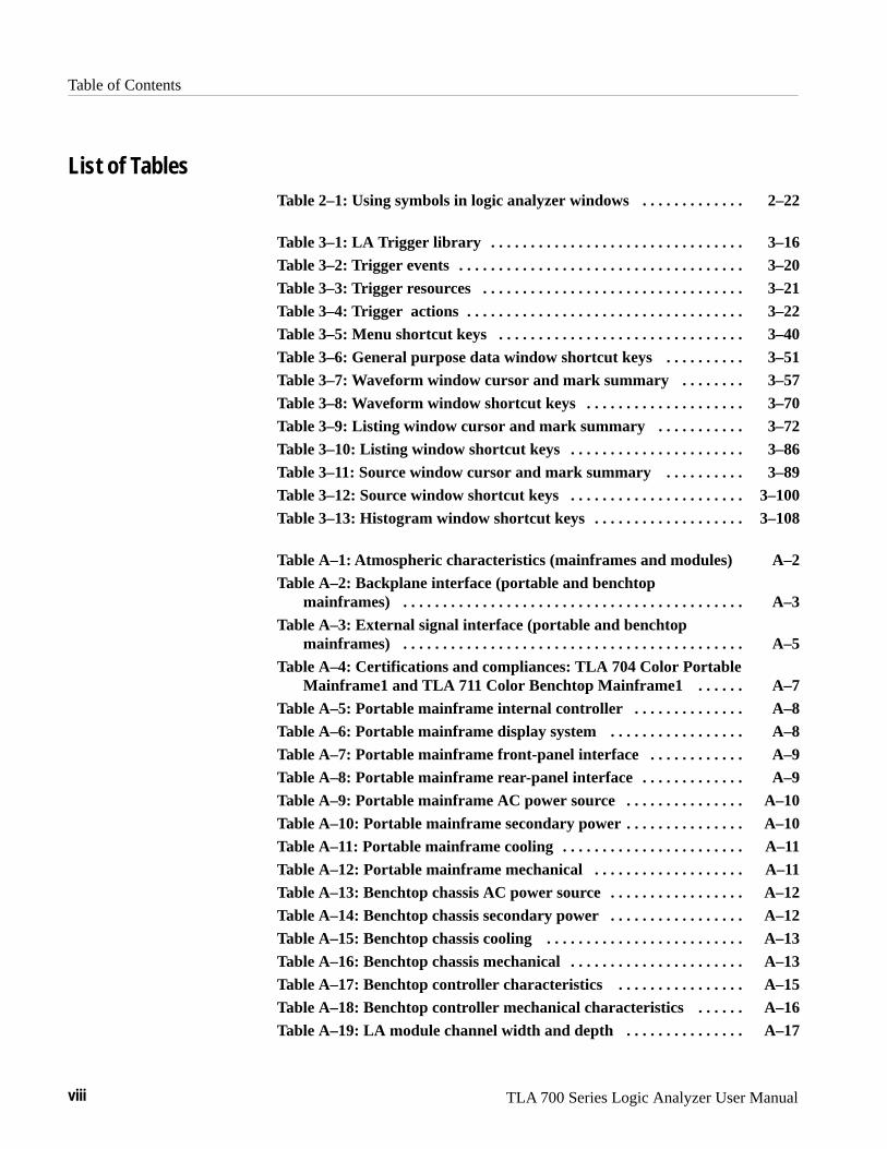
Table of Contents
viii TLA 700 Series Logic Analyzer User Manual
List of TablesTable 2–1: Using symbols in logic analyzer windows 2–22. . . . . . . . . . . . .
Table 3–1: LA Trigger library 3–16. . . . . . . . . . . . . . . . . . . . . . . . . . . . . . . . Table 3–2: Trigger events 3–20. . . . . . . . . . . . . . . . . . . . . . . . . . . . . . . . . . . .
Table 3–3: Trigger resources 3–21. . . . . . . . . . . . . . . . . . . . . . . . . . . . . . . . .
Table 3–4: Trigger actions 3–22. . . . . . . . . . . . . . . . . . . . . . . . . . . . . . . . . . . Table 3–5: Menu shortcut keys 3–40. . . . . . . . . . . . . . . . . . . . . . . . . . . . . . .
Table 3–6: General purpose data window shortcut keys 3–51. . . . . . . . . . Table 3–7: Waveform window cursor and mark summary 3–57. . . . . . . .
Table 3–8: Waveform window shortcut keys 3–70. . . . . . . . . . . . . . . . . . . . Table 3–9: Listing window cursor and mark summary 3–72. . . . . . . . . . .
Table 3–10: Listing window shortcut keys 3–86. . . . . . . . . . . . . . . . . . . . . .
Table 3–11: Source window cursor and mark summary 3–89. . . . . . . . . . Table 3–12: Source window shortcut keys 3–100. . . . . . . . . . . . . . . . . . . . . .
Table 3–13: Histogram window shortcut keys 3–108. . . . . . . . . . . . . . . . . . .
Table A–1: Atmospheric characteristics (mainframes and modules) A–2Table A–2: Backplane interface (portable and benchtop
mainframes) A–3. . . . . . . . . . . . . . . . . . . . . . . . . . . . . . . . . . . . . . . . . . .
Table A–3: External signal interface (portable and benchtop mainframes) A–5. . . . . . . . . . . . . . . . . . . . . . . . . . . . . . . . . . . . . . . . . . .
Table A–4: Certifications and compliances: TLA 704 Color PortableMainframe1 and TLA 711 Color Benchtop Mainframe1 A–7. . . . . .
Table A–5: Portable mainframe internal controller A–8. . . . . . . . . . . . . . Table A–6: Portable mainframe display system A–8. . . . . . . . . . . . . . . . .
Table A–7: Portable mainframe front-panel interface A–9. . . . . . . . . . . . Table A–8: Portable mainframe rear-panel interface A–9. . . . . . . . . . . . .
Table A–9: Portable mainframe AC power source A–10. . . . . . . . . . . . . . .
Table A–10: Portable mainframe secondary power A–10. . . . . . . . . . . . . . . Table A–11: Portable mainframe cooling A–11. . . . . . . . . . . . . . . . . . . . . . .
Table A–12: Portable mainframe mechanical A–11. . . . . . . . . . . . . . . . . . . Table A–13: Benchtop chassis AC power source A–12. . . . . . . . . . . . . . . . .
Table A–14: Benchtop chassis secondary power A–12. . . . . . . . . . . . . . . . . Table A–15: Benchtop chassis cooling A–13. . . . . . . . . . . . . . . . . . . . . . . . .
Table A–16: Benchtop chassis mechanical A–13. . . . . . . . . . . . . . . . . . . . . .
Table A–17: Benchtop controller characteristics A–15. . . . . . . . . . . . . . . . Table A–18: Benchtop controller mechanical characteristics A–16. . . . . .
Table A–19: LA module channel width and depth A–17. . . . . . . . . . . . . . .

Table of Contents
TLA 700 Series Logic Analyzer User Manual ix
Table A–20: LA module clocking A–17. . . . . . . . . . . . . . . . . . . . . . . . . . . . .
Table A–21: LA module trigger system A–19. . . . . . . . . . . . . . . . . . . . . . . . Table A–22: LA module input parameters (with P6417 Probe) A–21. . . . .
Table A–23: LA module MagniVu feature A–21. . . . . . . . . . . . . . . . . . . . . . Table A–24: Merged LA modules A–22. . . . . . . . . . . . . . . . . . . . . . . . . . . . .
Table A–25: LA module data handling A–22. . . . . . . . . . . . . . . . . . . . . . . .
Table A–26: LA module mechanical A–23. . . . . . . . . . . . . . . . . . . . . . . . . . . Table A–27: DSO module signal acquisition system A–24. . . . . . . . . . . . . .
Table A–28: DSO module timebase system A–27. . . . . . . . . . . . . . . . . . . . . Table A–29: DSO module trigger system A–27. . . . . . . . . . . . . . . . . . . . . . .
Table A–30: DSO module front-panel connectors A–29. . . . . . . . . . . . . . . . Table A–31: DSO module certifications and compliances A–29. . . . . . . . .
Table A–32: DSO module mechanical A–30. . . . . . . . . . . . . . . . . . . . . . . . .

Table of Contents
x TLA 700 Series Logic Analyzer User Manual

TLA 700 Series Logic Analyzer User Manual xi
General Safety Summary
Review the following safety precautions to avoid injury and prevent damage tothis product or any products connected to it. To avoid potential hazards, use thisproduct only as specified.
Only qualified personnel should perform service procedures.
Use Proper Power Cord. Use only the power cord specified for this product andcertified for the country of use.
Connect and Disconnect Properly. Do not connect or disconnect probes or testleads while they are connected to a voltage source.
Ground the Product. This product is grounded through the grounding conductorof the power cord. To avoid electric shock, the grounding conductor must beconnected to earth ground. Before making connections to the input or outputterminals of the product, ensure that the product is properly grounded.
Observe All Terminal Ratings. To avoid fire or shock hazard, observe all ratingsand marking on the product. Consult the product manual for further ratingsinformation before making connections to the product.
The common terminal is at ground potential. Do not connect the commonterminal to elevated voltages.
Do not apply a potential to any terminal, including the common terminal, thatexceeds the maximum rating of that terminal.
Use Proper AC Adapter. Use only the AC adapter specified for this product.
Do Not Operate Without Covers. Do not operate this product with covers or panelsremoved.
Use Proper Fuse. Use only the fuse type and rating specified for this product.
Avoid Exposed Circuitry. Do not touch exposed connections and componentswhen power is present.
Do Not Operate With Suspected Failures. If you suspect there is damage to thisproduct, have it inspected by qualified service personnel.
Do Not Operate in Wet/Damp Conditions.
Do Not Operate in an Explosive Atmosphere.
Keep Product Surfaces Clean and Dry.
Provide Proper Ventilation. Refer to the manual’s installation instructions fordetails on installing the product so it has proper ventilation.
To Avoid Fire or Personal Injury

General Safety Summary
xii TLA 700 Series Logic Analyzer User Manual
Terms in this Manual. These terms may appear in this manual:
WARNING. Warning statements identify conditions or practices that could resultin injury or loss of life.
CAUTION. Caution statements identify conditions or practices that could result indamage to this product or other property.
Terms on the Product. These terms may appear on the product:
DANGER indicates an injury hazard immediately accessible as you read themarking.
WARNING indicates an injury hazard not immediately accessible as you read themarking.
CAUTION indicates a hazard to property including the product.
Symbols on the Product. The following symbols may appear on the product:
Protective Ground(Earth) Terminal
CAUTIONRefer to Manual
Double Insulated
WARNINGHigh Voltage
Symbols and Terms

TLA 700 Series Logic Analyzer User Manual xiii
Preface
This manual contains operating information for the TLA 700 Series LogicAnalyzer. The manual consists of the following sections:
� Chapter 1: Getting Started. Provides basic information about using the logicanalyzer.
� Chapter 2: Operating Basics. Describes some logic analyzer concepts.
� Chapter 3: Reference. Describes how to configure and operate the logicanalyzer.
� Appendix A: Specifications. Lists the environmental, physical, and electricalproperties of the logic analyzer and LA module probes.
� Appendix B: TLA 700 Symbol File Format. Provides information on thecontents of symbol files using the TLA 700 Symbol File format.
� Appendix C: User Service. Provides user service information.
� Appendix D: Probe and Connector Information. Provides logic analyzerprobe and connector information.
Related DocumentationIn addition to this user manual, the following documentation is available for yourTLA 700 Series Logic Analyzer:
� The TLA 700 Series Logic Analyzer Installation Manual provides installa-tion information for the TLA 700 Series Logic Analyzer.
� The online help provides information about the TLA 700 Series userinterface and the TLA 700 Programmatic Interface (TPI). To view the onlinehelp, select Help Topics from the Help menu.
� The online release notes provide last-minute product and software informa-tion not included in this manual. Refer to Release Notes on page 1–21 forinformation on viewing the release notes.
� A series of microprocessor support instruction manuals provide operatingand service instructions for the individual microprocessor support packages.
� The TLA 700 Series TLA 7QS QuickStart Training Manual provides trainingexercises to help you learn key features of the TLA 700 Series LogicAnalyzer. The training manual is designed to be used with the TLA 7QSQuickStart training board.

Preface
xiv TLA 700 Series Logic Analyzer User Manual
� The TLA 700 Series TLA 7QS QuickStart Technical Reference Manualprovides technical and service information for the TLA 7QS QuickStarttraining board.
� The TLA 700 Series Performance Verification and Adjustment TechnicalReference Manual provides performance verification and adjustmentprocedures for the major components of the TLA 700 Series Logic Analyzer.The manual includes the performance verification and adjustment software.
� The TLA 711 Color Benchtop Chassis Service Manual provides board-levelservice information for the benchtop chassis.
� The TLA 711 Color Benchtop Controller Service Manual provides board-level service information for the benchtop mainframe controller module.
� The TLA 704 Color Portable Mainframe Service Manual provides board-level service information for the portable mainframe.
� The TLA 700 Series Logic Analyzer Modules TLA 7Lx and TLA 7Mx ServiceManual provides board-level service information for the LA modules.
� The TLA 700 Series DSO Modules TLA 7Dx and TLA 7Ex Service Manualprovides board-level service information for the DSO modules.
� The P6434 Mass Termination Probe Instructions provides instructions forusing the P6434 probes.

Preface
TLA 700 Series Logic Analyzer User Manual xv
Contacting Tektronix
ProductSupport
For application-oriented questions about a Tektronix measure-ment product, call toll free in North America:1-800-TEK-WIDE (1-800-835-9433 ext. 2400)6:00 a.m. – 5:00 p.m. Pacific time
Or, contact us by e-mail:[email protected]
For product support outside of North America, contact yourlocal Tektronix distributor or sales office.
ServiceSupport
Contact your local Tektronix distributor or sales office. Or, visitour web site for a listing of worldwide service locations.
http://www.tek.com
For otherinformation
In North America:1-800-TEK-WIDE (1-800-835-9433)An operator will direct your call.
To write us Tektronix, Inc.P.O. Box 1000Wilsonville, OR 97070-1000U.S.A.

Preface
xvi TLA 700 Series Logic Analyzer User Manual

Getting Started


TLA 700 Series Logic Analyzer User Manual 1–1
Getting Started
This chapter provides basic information about using the logic analyzer. There isinformation about the physical instrument and introductory information abouthow to operate it. Once you have a basic grasp of this information, proceed tothe next chapter, Operating Basics, for a conceptual model of how the logicanalyzer works.
Product DescriptionThe TLA 700 Series Logic Analyzer is a configurable instrument that combinesa high-performance logic analyzer with a digitizing storage oscilloscope. Thereare two mainframe styles, portable and benchtop, as shown in Figure 1–1.
Figure 1–1: Portable and benchtop mainframes
Several logic analyzer (LA) modules are available, in various combinations ofchannel width and memory depth. All provide simultaneous state and timingmeasurements through a single probe.
The LA module implements a feature called MagniVu, an acquisition technologythat enables each of the LA modules to offer 500 picosecond timing resolutionon all channels. MagniVu data is always available for all channels and requiresno additional probing.

Getting Started
1–2 TLA 700 Series Logic Analyzer User Manual
The digitizing storage oscilloscope (DSO) module incorporates digital real-timesignal acquisition. DSO module data is tightly correlated with data from othermodules, for displays and for intermodule triggering and signalling.
The user interface is built on the familiar Windows 95 operating system. Inaddition to using an interface you probably already know, this means that youcan install any PC-compatible, third-party hardware and software on theinstrument.
InstallationInstallation information for the TLA 700 Series mainframe, modules, andsoftware is located in the TLA 700 Series Logic Analyzer Installation Manual.
Powering On the Logic AnalyzerPower on the logic analyzer as follows:
1. Press the On/Standby switch to power on the logic analyzer (see Figure 1–2for the switch location).
2. Wait for the logic analyzer to complete power-on self-tests, start Windows,and start the TLA 700 application.
Figure 1–2: On/Standby switch locations

Getting Started
TLA 700 Series Logic Analyzer User Manual 1–3
Powering Off the Logic AnalyzerThe portable mainframe has a built-in soft power-off function that safely powersoff the mainframe when you press the On/Standby switch. If you have thebenchtop mainframe, you must power off the mainframe using the Windows 95shutdown process before depressing the On/Standby switch.
You can set the shutdown mode in the Mainframe Utilities tool in the Win-dows 95 control panel.
CAUTION. When powering off the benchtop mainframe, use the Windows 95 shutdown procedure. Powering down the benchtop mainframe prematurely cancorrupt the software on the hard disk.
Connecting Probes to the Target SystemThe logic analyzer connects to the target system through probes. The LA probesallow you to connect to the target system in several different ways as shown inthe following illustrations. You can use the color-coded probe channels to mapthe hardware connections to the channel settings in the LA Setup window. EachLA probe group consists of eight channels that can be individually named in theLA Setup menu.
Connect the probes to the logic analyzer by matching the color-coded label to thelabel on the LA module. To provide a secure connection to the LA module, youcan optionally use the probe retainer bracket with the probe connector.
The P6417 probes provide a means to connect to the target system for mostapplications. Figure 1–3 shows different ways to connect the probe to the targetsystem.
Note the location of the ground connections for the probe:
� The individual podlets have the ground (GND) engraved on the podlet.
� When you use the 8-channel leadsets, the ground lead is a single blackconnector. Make sure you connect the ground side of the 8-channel lead setto the ground side of the 8-channel podlet holder.
Refer to Appendix D: Probe and Connector Information for information ondimensions for the P6417 probes.
General PurposeConnections

Getting Started
1–4 TLA 700 Series Logic Analyzer User Manual
Figure 1–3: P6417 17-channel probe

Getting Started
TLA 700 Series Logic Analyzer User Manual 1–5
The P6434 Mass Termination Probe allows you to connect 34 LA channels to amicroprocessor probe adapter or directly to the target system. To connect to thetarget system directly, you must include compatible Mictor connectors in yourcircuit board design.
Figure 1–4 shows two ways of connecting the LA module to a target system. Formore information on the P6434 Mass Termination Probe and how to connect it toyour target system, refer to the P6434 Mass Termination Probe Instructions.
Figure 1–4: P6434 high-density probe connections
Both the P6417 and the P6434 probes can be connected to microprocessoradapters. Refer to the documentation that comes with your microprocessordisassembler package for details about connecting the probes to the microproces-sor adapters and to the target system.
High-Density ProbeConnections
MicroprocessorConnections

Getting Started
1–6 TLA 700 Series Logic Analyzer User Manual
Approaching the WindowsTypically, you use the windows in this application as shown in Figure 1–5.
ÎÎÎÎÎÎÎÎÎÎ
ÎÎÎÎÎÎÎÎÎÎÎÎÎÎÎÎÎÎÎÎÎÎÎÎÎÎÎÎÎÎ
ÎÎÎÎÎÎÎÎÎÎÎÎÎÎÎÎÎÎÎÎÎÎÎÎÎÎÎÎÎÎ
ÎÎÎÎÎÎÎÎÎÎÎÎÎÎÎÎÎÎÎÎÎÎÎÎÎÎÎÎÎÎ
ÎÎÎÎÎÎÎÎÎÎÎÎÎÎÎÎÎÎÎÎÎ
ÎÎÎÎÎÎÎÎÎÎÎÎÎÎÎÎÎÎÎÎÎÎÎÎÎÎÎÎ
ÎÎÎÎÎÎÎÎÎÎÎÎÎÎÎÎÎÎÎÎÎÎÎÎÎÎÎÎ
1 Go to the System window. This is the main access point to the other windows. 2 Use the Setup windows
to configure the modules.
3 From the LA Trigger window, load a trigger program from the library and customize it for your application.
4 Click the Run toolbar button to acquire data.
5 View data in the data windows.
Figure 1–5: Window usage control flow

Getting Started
TLA 700 Series Logic Analyzer User Manual 1–7
The System window is your point-of-entry into the logic analyzer, and functionsas the overall control center.
You can perform the following functions from the System window:
� Open module and data windows by clicking their buttons. To select a modulewithout opening its windows, click inside the icon (but not on its buttons).
� Create new data windows through the New Data Window wizard. You cancreate Histogram windows for performance analysis operations and Sourcewindows to track the execution of source code. You can also createadditional Listing and Waveform windows.
� Use the System window for an overview of how the modules and datawindows relate to one another. Relationships between modules (if any) arealways shown; to view which modules are associated with a data window,you must select the module icon.
� View which modules provide data to each window by clicking the windowname.
� Enable and disable modules by clicking their On/Off buttons.
� Save and load files containing setup, trigger, and data information, by meansof selections from the File menu.
Figure 1–6: System window
System Window

Getting Started
1–8 TLA 700 Series Logic Analyzer User Manual
Before you acquire and display data, you must first configure the modules usingthe module Setup windows. Each module has its own Setup and Triggerwindow; each is set up individually. Generally, you should configure the Setupwindows before the Trigger windows, because some of the Setup windowsettings affect Trigger window selections.
Figure 1–7: DSO Setup window
Figure 1–8: LA Setup window
Setup Windows

Getting Started
TLA 700 Series Logic Analyzer User Manual 1–9
Both modules have their own Trigger windows. The primary purposes of theTrigger windows are to specify the trigger conditions.
LA Trigger Window. The LA Trigger window is the heart of the logic analyzer.You can use the Trigger window to define the conditions when the logic analyzeracquires and stores data. See Figure 1–9.
Figure 1–9: LA Trigger window
You can define simple or complex trigger programs one step at a time todetermine how the logic analyzer finds the data you are interested in.
Trigger Windows

Getting Started
1–10 TLA 700 Series Logic Analyzer User Manual
Another common method for setting up a trigger program is to load a triggerprogram from the trigger library (see Figure 1–10). You can then alter the triggerprogram details as necessary.
Figure 1–10: Trigger library
DSO Trigger Window. The DSO Trigger window lets you define how to trigger theDSO on analog and digital signals.
Figure 1–11: DSO Trigger window

Getting Started
TLA 700 Series Logic Analyzer User Manual 1–11
You can use data windows to display and analyze acquired data from the LA orDSO modules. The most common data windows are the Listing windows andWaveform windows. These are the two default windows for a logic analyzer witha DSO module and a LA module installed.
To display and evaluate complex logic analyzer data, you can create other typesof data windows using the New Data Window wizard (such as the Histogramwindow and the Source window). Refer to Creating a New data Windowbeginning on page 3–50 for information on creating data windows.
You can have as many data windows as you want to display different data ordifferent views of the same data.
Listing Windows. Listing windows (see Figure 1–12) display LA data in lists orcolumns.
Figure 1–12: Listing window
You can perform the following functions in Listing windows:
� Place user marks to flag specific data samples for evaluation.
� Use the scroll bars to move through the data or jump to a specific point inthe data by clicking the Go To toolbar button and selecting a mark.
� Search for a data event by clicking the Define Search button in the toolbar.
� Move columns by clicking on their labels to select them, and then draggingthem to a new location.
� Add columns by clicking the Add Column toolbar button.
Data Windows
Getting Started
1–12 TLA 700 Series Logic Analyzer User Manual
� Split the window into two panes for viewing data that is offscreen.
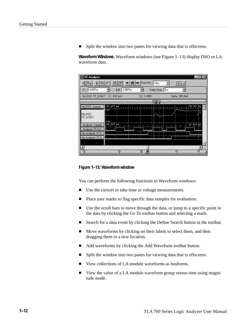
Waveform WIndows. Waveform windows (see Figure 1–13) display DSO or LAwaveform data.
Figure 1–13: Waveform window
You can perform the following functions in Waveform windows:
� Use the cursors to take time or voltage measurements.
� Place user marks to flag specific data samples for evaluation.
� Use the scroll bars to move through the data, or jump to a specific point inthe data by clicking the Go To toolbar button and selecting a mark.
� Search for a data event by clicking the Define Search button in the toolbar.
� Move waveforms by clicking on their labels to select them, and thendragging them to a new location.
� Add waveforms by clicking the Add Waveform toolbar button.
� Split the window into two panes for viewing data that is offscreen.
� View collections of LA module waveforms as busforms.
� View the value of a LA module waveform group versus time using magni-tude mode.

Getting Started
TLA 700 Series Logic Analyzer User Manual 1–13
Histogram Window. Histogram windows (see Figure 1–14) display LA data ashistograms. You use Histogram windows to evaluate the performance ofsoftware; this is also known as performance analysis.
Figure 1–14: Histogram window
You can perform the following functions in Histogram windows:
� Use the scroll bars to move through the data.
� Sort histogram data by ranges, counts, or percentages.
� Change the magnification of histogram bars to view the data in greaterdetail.
� Split the window into two panes for viewing data that is off screen.
� View various statistics on the acquired data.

Getting Started
1–14 TLA 700 Series Logic Analyzer User Manual
Source Windows. Source windows (see Figure 1–15) display source data. Youcan track the execution of source code based on the data displayed in a Listingwindow.
Figure 1–15: Source window
You can perform the following functions in Source windows:
� Step through source code statements.
� Turn source code line numbers on or off.
� Place user marks to flag specific data samples for evaluation.
� Use the scroll bars to move through the data, or jump to a specific point inthe data by clicking the Go To toolbar button and selecting a mark.
� Search for source code statements by clicking the Define Search button inthe toolbar.
� Determine whether there is any acquired data for the corresponding sourcefile displayed in the Source window.

Getting Started
TLA 700 Series Logic Analyzer User Manual 1–15
The LA modules have MagniVu data acquisition as a standard feature. MagniVuacquisition offers 500 picosecond high-resolution timing simultaneous with200 MHz state on all channels through the same probes; no double-probing isrequired. The example shown in Figure 1–16 shows regular data and MagniVudata for the same channels. You can easily add MagniVu data with the AddWaveform toolbar button.
Figure 1–16: Comparing regular and MagniVu data
Once you set up the logic analyzer to your satisfaction you will probably want tosave the setup for future use. You can save setup information in two ways, as asaved system file or as a saved module file.
Saved system files contain setup and trigger information for each module as wellas system level information (such as repetitive properties) and data windows forthe logic analyzer. Saved module files contain setup and trigger information foronly the module specified. In both cases you have the option of saving acquireddata with the files.
Execute Save and Load operations from the File menu. For module Save or Loadoperations, you must first go to the module Setup or Trigger window.
Save the setups and data in a folder where you can easily retrieve them. Forexample, you may want to save the data in the My Documents folder or within afolder of your own choosing. You should not save the data in a location that maybe difficult to find or in a location (such as the Windows System folder) that maycause problems with your operating system.
MagniVu Data
Saving and LoadingSetups and Data

Getting Started
1–16 TLA 700 Series Logic Analyzer User Manual
Avoid using file name extensions other than the default ones supplied by thesystem. The logic analyzer may not recognize saved setups with nonstandard filename extensions.
Saved system and module files both contain trigger program information. Whenyou load a trigger from the LA Trigger window, you can select a saved system ormodule file as the source. When you do so, the logic analyzer extracts only thetrigger information from the file and loads it to the module.
Figure 1–17: Save and Load operations in the File menu
You can customize your data windows. Using property sheets, you can controldata window display parameters. Also, many screen elements, such as wave-forms, columns, and marks, have their own property sheets.
Open data window property sheets by clicking the Properties toolbar button inthe data window. Open screen element property sheets by double-clicking on theelement or its label.
Customizing the Display

Getting Started
TLA 700 Series Logic Analyzer User Manual 1–17
Figure 1–18: Using a property sheet to customize the display
Programmatic ControlIn addition to controlling the logic analyzer from the user interface, you can usethe TLA 700 Programmatic Interface (TPI) to control the logic analyzer from aseparate program running on the logic analyzer or on a remote host. Informationfor using TPI is included as part of the TLA 700 online help. An online TPI usermanual (available in PDF format) can be printed from the logic analyzer.
Backing Up User FilesYou should back up your user files on a regular basis. Use the Windows Back Uptool to back up files stored on the hard disk. The Back Up tool is located in theSystem Tools folder in the Accessories folder. Start the tool and determine whichfiles and folders you want to back up. Use the Windows online help forinformation on using the Back Up tool.
In particular, you should frequently back up your user-generated files. For thelogic analyzer, the user-generated files consist of saved system and module files,which have a .tla file name extension.

Getting Started
1–18 TLA 700 Series Logic Analyzer User Manual
Portable Mainframe Front Panel ControlsThe portable version of the mainframe has front panel controls which you canoperate the logic analyzer without the mouse or keyboard.
Scrolls data horizontally.
Changes the height ofselected waveform
(Waveform window only).
Scrolls data vertically.
Changes the value in a selectedbox (such as sample rate or
memory depth). With a cursorselected, the knob controls cursor
position. Does not scroll data.
Changes Time/Div inthe Waveform window.
Moves the display pointerand selects objects. SeeGlidePoint Pad for moreinformation.
Figure 1–19: Portable mainframe front panel
For the portable mainframe, you can use the front panel keys as an alternative tothe detachable keyboard. Most keys and key combinations are available via thefront panel.
For key combinations, it is not necessary to hold down more than one key at atime. For example, you can press SHIFT in the hexadecimal keypad, and thenpress a QWERTY key to accomplish a Shift+key combination. The same is truefor other key combinations, such as CTRL and ALT keys.
For the portable mainframe, you can use the GlidePoint pad as an alternative tothe mouse. To move the pointer, slide your finger lightly over the surface of thepad. Tap the surface to simulate a click of the left mouse button, or use thecontrol buttons to select the type of operation.
Figure 1–20: GlidePoint pad
Keys
GlidePoint Pad

Getting Started
TLA 700 Series Logic Analyzer User Manual 1–19
The mainframe external connectors are shown in Figure 1–21. The followingconnections are available:
� System Trigger In and System Trigger Out, used to receive or send a triggerfrom/to an external source.
� External Signal In and External Signal Out, used to receive or send a signalfrom/to an external source.
� Accessory connections.
For information about the accessory connections, refer to the TLA 700 SeriesLogic Analyzer Installation Manual.
PCMCIAPC cards (2)
SVGA OUT port
COM port
LPT printer port
SYSTEM TRIG IN
SYSTEM TRIG OUT
EXTERNAL SIG IN
EXTERNAL SIG OUT
PCMCIAPC cards (2)
SVGA OUT port
COM port
LPT printer port
SYSTEM TRIG IN
SYSTEM TRIG OUT
EXTERNAL SIG IN
EXTERNAL SIG OUT
Portable mainframe (rear view)
Benchtop mainframe (front view)
Figure 1–21: Locations of external connectors
External Connectors

Getting Started
1–20 TLA 700 Series Logic Analyzer User Manual
For Further InformationIn addition to the information in this manual, you may want to refer to otherdocumentation for this TLA 700 Series Logic Analyzer.
The online help gives detailed information about the logic analyzer and itsmodules. Look in the online help for details about user interface selections thatare not described in this manual. The online help also has basic operatinginformation for microprocessor support products.
To access online help, go to the Help menu, or click the toolbar buttons shown:
Click for Topic help.
Click for What’s This? help on selected object.
Help Topics. Help topics tell you how to perform tasks and describe softwarefeatures and selections shown on the screen. There are two types of help topics,overview topics and task topics.
Overview topics describe application features, such as windows. Overview topicsmay also describe concepts. Overview topics are available through the Helpmenu and through Help buttons in dialog boxes. From the Help menu, click HelpTopics, and locate the topic using the Contents or Index tab. The Help onWindow selection in the Help menu provides overview help for the currently-se-lected window.
Task topics provide procedure information about how to perform specific tasks.Task topics are available through the Help menu. From the Help menu, clickHelp Topics, and locate the topic using the Contents or Index tab.
What’s This? Help. What’s This? help provides a short description of the controlor screen feature selected. First click the What’s This? button on the toolbar, andthen click the item of interest. For further information about the item, go to theTopic help.
TPI Online Help. Select Help on TPI from the drop-down help menu forinformation on using the TLA 700 Programmatic Interface. You can also printhard copies of the TPI help from a PDF file.
Online Help

Getting Started
TLA 700 Series Logic Analyzer User Manual 1–21
Windows 95 Online Help. Information about Windows features is availablethrough the Windows help system. Access Windows help as you would with anyWindows application:
1. Go to the Windows 95 toolbar and click Start.
2. Select Help.
The online Release Notes contain information about this release of the logicanalyzer application. Check the Release Notes for information such as softwarecompatibility and software version differences from last release.
To access the Release Notes, follow these steps:
1. Go to the Windows 95 toolbar and click Start.
2. Select Programs → Tektronix TLA 700 → TLA 700 Release Notes.
Refer to Related Documentation on page xiii for a list of documentation for yourTLA 700 Series Logic Analyzer.
Release Notes
Additional RelatedDocumentation

Getting Started
1–22 TLA 700 Series Logic Analyzer User Manual

Operating Basics


TLA 700 Series Logic Analyzer User Manual 2–1
Operating Basics
This chapter provides an overview of the TLA 700 logic analyzer and basic logicanalyzer concepts.
To acquire and display signals from the target system, the logic analyzer mustperform a complex series of actions. For the most part, these actions aretransparent. However, it can be helpful to understand how the logic analyzeroperates. This knowledge can influence how you approach a logic analysisproblem.
Sampling and Digitizing a SignalAcquisition is the process of sampling the input signal, digitizing it to convert itinto digital data, and assembling it into a waveform record. The order andmethod of accomplishing these functions is different between the LA and DSOmodules.
The LA module converts incoming data into ones and zeros using a comparatorwith a user-selectable threshold voltage. If the incoming signal is above thethreshold voltage, it is converted to a one; if it is below the threshold voltage, itis converted to a zero. After digitizing the data, the LA module samples it atregular time intervals. The sampled and digitized points are stored in memoryalong with corresponding timing information. (See Figure 2–1.)
0 0
1
Input signal
Digital values
Sample clock
1 1
0
1 1
0 0
1 1
0
1
0 0
Threshold voltage
Figure 2–1: Acquiring a digital signal (LA module)
The DSO module samples the voltage level of the signal at regular intervals, andthen converts the sampled analog data into 8-bit digital values. (See Figure 2–2.)The sampled and digitized points are stored in memory along with correspondingtiming information.

Operating Basics
2–2 TLA 700 Series Logic Analyzer User Manual
+5.5 V+5.0 V
+6.0 V
0 V
+2.0 V2.5 V
0 V 0 VSample clock
Analog signal
Digital values
Figure 2–2: Acquiring an analog signal (DSO module)
LA Module Block DiagramThe LA module is the key element of the instrument. Functionally, the LA mod-ule can be divided into several blocks, as shown in Figure 2–3. Refer to thefigure as you read about the functional blocks.
ProbesData fromtarget
system
Comparator
Thresholdvoltage
Memory
Trigger
Sampler
ClockInternal (asynchronous) or
External (synchronous)
Figure 2–3: Block diagram of the LA module acquisition and storage
Clocks control when data is sampled. Naturally, the point at which you sampledata has a great deal to do with the type and quality of data you acquire. For theLA module, there are two primary approaches to clocking, external (synchro-nous) clocking and internal (asynchronous) clocking.
External (Synchronous) Clocking. This clocking mode is called an external orsynchronous clock because the clock is external to the logic analyzer, and issynchronized to the target system.
Clocking

Operating Basics
TLA 700 Series Logic Analyzer User Manual 2–3
The signal you chose as the external clock to the logic analyzer should be thesame signal that controls the activity of the other signals you want to observe.For example, to observe the output states of a counter chip, you might use theclock input to the counter chip to act as the external clock source to the logicanalyzer. With this setup, each clock pulse to the counter chip could also be usedto clock data from the counter’s output lines into the logic analyzer. As anotherexample, to record the data being written to a latch, you could use the load signalto the latch as the external clock source to the logic analyzer.
Internal (Asynchronous) Clocking. Much activity can occur in the target systembetween system clock signals. Using the LA module’s internal (asynchronous)clock, you can view all activity in the target system, not just the data available atthe target system clock signal.
Internal clocking is the best choice when you are primarily interested in thetiming aspects of the data. Internal clocking is a natural choice for waveformtiming analysis. It is important to note, however, that the value of internalclocking is not limited to just displaying waveforms. For a detailed picture ofdata activity both during and between state changes, use internal clocking. Forexample, when you use internal clocking you are able to acquire and displayglitch information in either the Waveform or Listing windows.
When you start an acquisition, the logic analyzer begins sampling data from theprobes. Then, each time a sample clock occurs, data is sampled. Sampled data isthen sent to the trigger functional block and to the main memory.
The trigger program looks at sampled data for specific events and then takes aspecified action. The trigger program can look for events, such as data values,data ranges, or signals from another module. You can also use internal countersto trigger when the counter reaches a specified value.
When the trigger condition is satisfied, the LA module enables its posttriggerdelay counter to allow the posttrigger portion of the acquisition memory to fillbefore stopping acquisition.
The trigger function block includes storage qualification that looks at sampleddata. If the storage conditions are met, a storage qualifier signal enables sampleddata to pass into the acquisition memory as qualified data. Any unqualified datasamples are excluded.
Acquiring Data
Triggering and StorageQualification

Operating Basics
2–4 TLA 700 Series Logic Analyzer User Manual
The acquisition memory works like a circular buffer, storing every qualified datasample until the entire memory is full. After that, each new data sampleoverwrites the oldest existing sample. This process continues until the triggerevent is found and the posttrigger delay counter reaches the specified value(based on the trigger position selection), which stops acquisition. Duringacquisition, you can monitor the progress of the data storage process using theStatus Monitor.
After storing the data you can display the acquired data in the Listing orWaveform data windows.
DSO Module Block DiagramThe DSO module adds analog analysis capability to the instrument. Functionally,the DSO module can be divided into several blocks, as shown in Figure 2–4.Refer to the figure as you read about the functional blocks.
A probe interface detects the attenuation factor of each probe. This information isused to set the vertical scale.
When you start an acquisition, the DSO module begins sampling data from theprobes. Each time a sample clock occurs, data is sampled. Signals from theprobes go to the attenuators/preamp functional block, which is responsible forinput coupling, termination, bandwidth, offset, and full scale range. The DSOmodule always uses internal clocking.
From the attenuators/preamp, signals are sent to the acquisition unit and triggerfunctional blocks.
The acquisition unit functional block samples the input signals and convertsthem to digital data.
The DSO trigger looks at sampled data for a specific event. The trigger can lookfor various types of events, such as glitches, setup and hold violations, runtpulses, or signals from another module.
When the trigger event is found, the DSO module enables its posttrigger delaycounter to allow the posttrigger portion of the acquisition memory to fill beforestopping acquisition. When triggered, the DSO module performs its specifiedtrigger action (for example, triggering all modules).
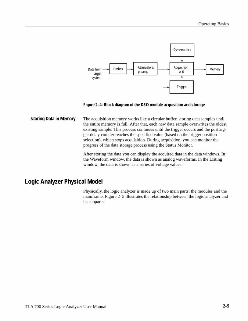
Storing Data in Memory
Probes
Acquiring Data
Acquisition Unit
Triggering
Operating Basics
TLA 700 Series Logic Analyzer User Manual 2–5
ProbesData fromtarget
system
Memory
Trigger
Attenuators/preamp
Acquisition unit
System clock
Figure 2–4: Block diagram of the DSO module acquisition and storage
The acquisition memory works like a circular buffer, storing data samples untilthe entire memory is full. After that, each new data sample overwrites the oldestexisting sample. This process continues until the trigger occurs and the posttrig-ger delay counter reaches the specified value (based on the trigger positionselection), which stops acquisition. During acquisition, you can monitor theprogress of the data storage process using the Status Monitor.
After storing the data you can display the acquired data in the data windows. Inthe Waveform window, the data is shown as analog waveforms. In the Listingwindow, the data is shown as a series of voltage values.
Logic Analyzer Physical ModelPhysically, the logic analyzer is made up of two main parts: the modules and themainframe. Figure 2–5 illustrates the relationship between the logic analyzer andits subparts.
Storing Data in Memory

Operating Basics
2–6 TLA 700 Series Logic Analyzer User Manual
Module 1
Mainframe
Mechanical housingDisplay
Module 2 Module n
Communications busController
Logic Analyzer
Disk drives
Power supply
User interface software
ModuleProbesFirmware
ModuleProbesFirmware
ModuleProbesFirmware
Low-level software
Figure 2–5: Logic analyzer physical model
Logic Analyzer Conceptual ModelConceptually, the logic analyzer is made up of two main parts: the modules andthe system. From the operational perspective, a module encompasses the setup,trigger, and data associated with the physical LA or DSO module installed in thelogic analyzer. See Figure 2–6. The system refers to the setup and data for thewhole logic analyzer, including all the modules.
Some actions occur at the module level, some at the system level. For example,you can save either module or system files. When you save a module, you saveall the setup and trigger information for that module. (You also have the optionof saving the data for that module.) When you save a system, you save all thesetup information for the system, including data window display settings, and allthe module information, as well.

Operating Basics
TLA 700 Series Logic Analyzer User Manual 2–7
SetupTriggerData
Module 1
System
Data WindowsGeneral Settings
Module 2 Module n
SetupTriggerData
SetupTriggerData
Figure 2–6: Logic analyzer conceptual model
Intermodule Interactions and Time CorrelationEach module has its own setup, trigger, and clocking functions. (LA modulesmay include microprocessor support as part of their setup.) Each module alsoacquires and stores its own data.
When you start an acquisition, all modules start acquiring data together.(Exceptions are when one module has been programmed to arm another or whena module has been turned off.) Modules stop acquiring data individually,according to their trigger programming. You also have the option of setting thelogic analyzer to operate in repetitive mode, in which the modules acquire dataand update the data windows continually until you manually stop the acquisition.
Modules readily communicate with one another by means of their triggerprograms. You can specify functions such as the following:
� Trigger all modules (system trigger)
� One module arms another
� Modules respond to events declared by another module (internal signals)
After the modules have captured and stored data, you can view the data in aListing or Waveform window. All data is time-correlated in the display,regardless of its source. Due to the precise time stamp information stored withthe data, and the tightly-integrated communications between modules, the logicanalyzer interleaves data acquired from various sources. Because time stampinformation is always stored with the data, you can also compare saved data andcurrent data with no loss of accuracy.
MagniVu data is also time-correlated with regular data. Because MagniVu data isalways present, you can easily compare a normal acquisition with its MagniVucounterpart.

Operating Basics
2–8 TLA 700 Series Logic Analyzer User Manual
Listing-Data ConceptsIn many cases, you will use the logic analyzer to observe the data flow in thetarget system. The data recorded by the logic analyzer can be displayed in alisting format, as shown in Figure 2–7.
Listing data is a table of sequential operations performed by the target system. Inthe Listing window, each data sample is displayed sequentially. Because eachdata sample includes time stamp information, it is a straightforward process todisplay acquisitions from multiple data sources. Samples from all specified datasources are interleaved in chronological order. For clarity, each line in the tablerepresents a single data sample from a single data source.
You control the presentation of the data by selecting the display radix of thecolumns. You can also make other format selections such as font size, color, andcolumn width.
Figure 2–7: Listing data
You can include data acquired by the DSO module in the Listing window. TheListing window in Figure 2–8 shows DSO module Channel 1 data as discretevoltage levels. As with any module, the data samples from the DSO module aretime-correlated with the other data and appear on separate lines.
Operating Basics
TLA 700 Series Logic Analyzer User Manual 2–9
Figure 2–8: Listing window with analog data
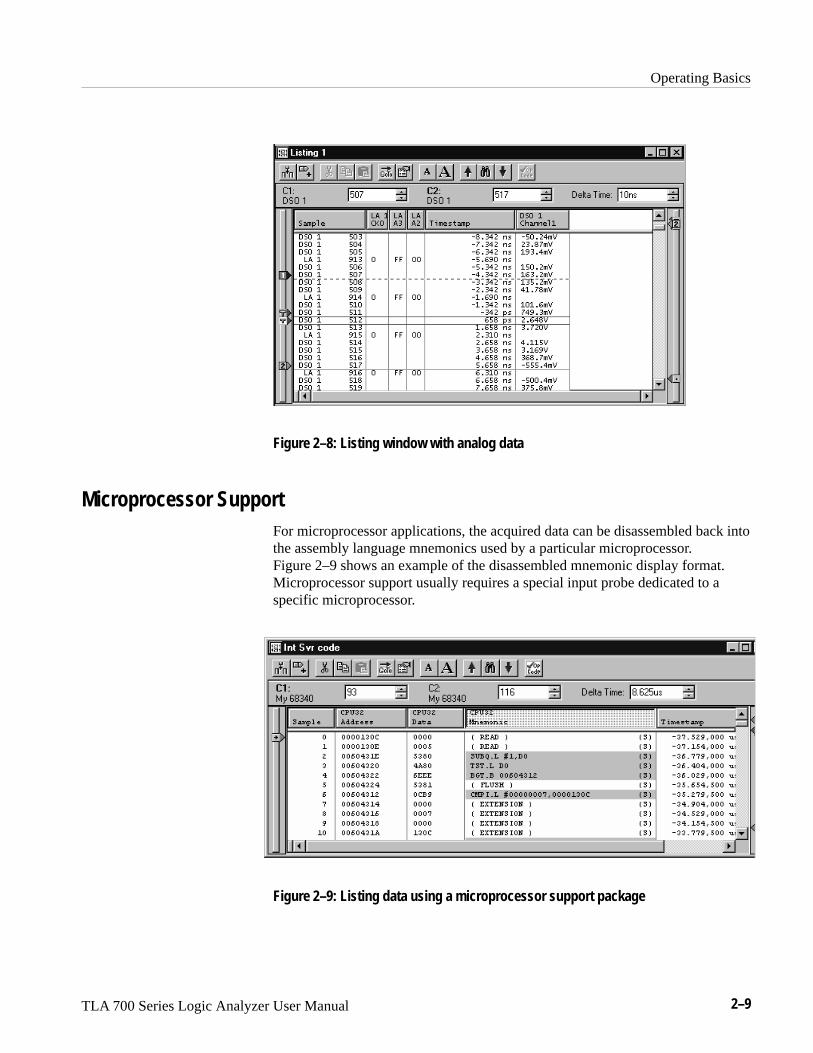
Microprocessor SupportFor microprocessor applications, the acquired data can be disassembled back intothe assembly language mnemonics used by a particular microprocessor.Figure 2–9 shows an example of the disassembled mnemonic display format.Microprocessor support usually requires a special input probe dedicated to aspecific microprocessor.
Figure 2–9: Listing data using a microprocessor support package

Operating Basics
2–10 TLA 700 Series Logic Analyzer User Manual
The logic analyzer provides support for a wide variety of different microproces-sors. Microprocessor support packages include the software, probe adapters, anddocumentation.
High-Level Language (HLL) SupportYou can correlate the high-level language (HLL) source code that you wrote withyour code as it was executed on your target system and acquired by the logicanalyzer. The correlation is based on symbolic information which is extractedfrom your object file or load module. You configure the logic analyzer to accessyour source files.
You can step through each executed source statement in the Source window andview the results in a correlated Listing window. You can also set user-definedmarks as break points within the code and then trace the execution of the codebetween the marks. Figure 2–10 shows an example of viewing source code in aSource window, while Figure 2–11 on page 2–11 shows the actual acquired datain an associated Listing window.
Figure 2–10: High-level source code
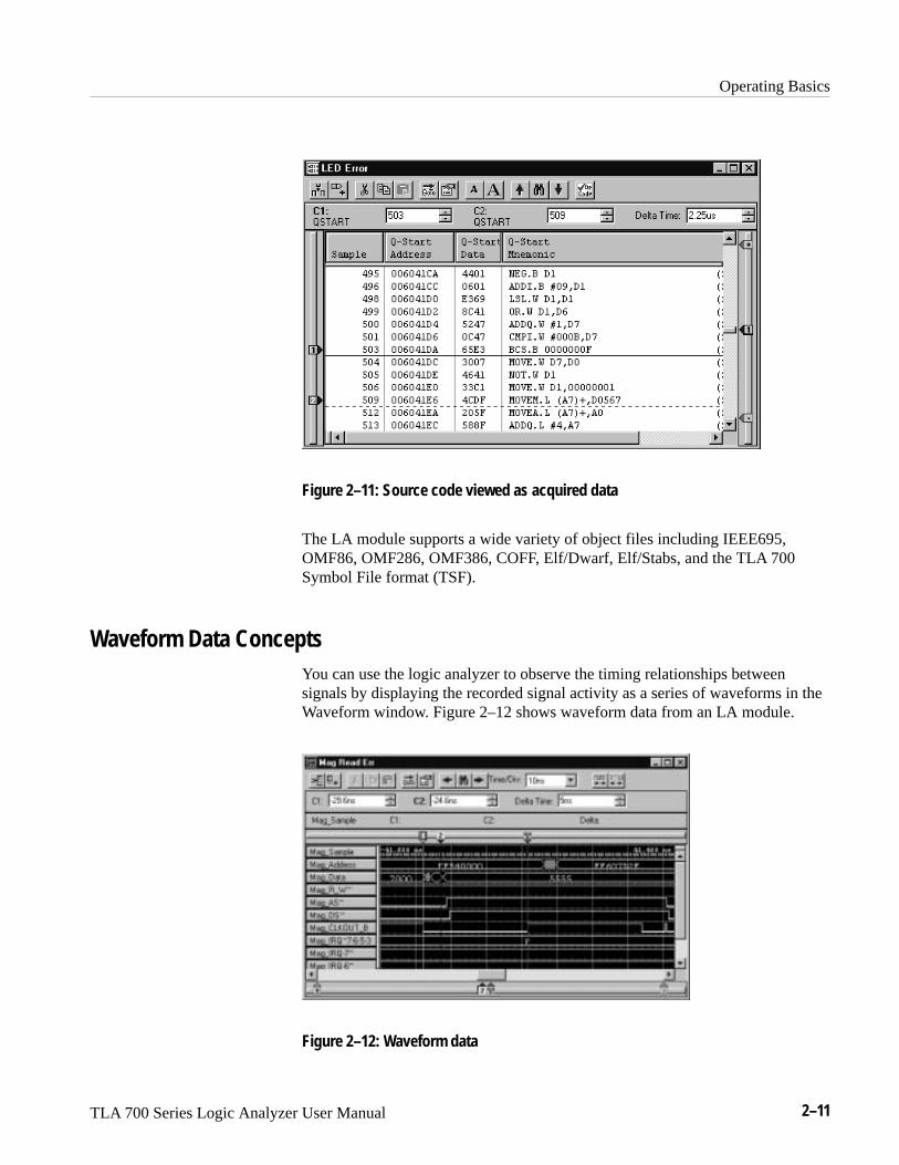
Operating Basics
TLA 700 Series Logic Analyzer User Manual 2–11
Figure 2–11: Source code viewed as acquired data
The LA module supports a wide variety of object files including IEEE695,OMF86, OMF286, OMF386, COFF, Elf/Dwarf, Elf/Stabs, and the TLA 700Symbol File format (TSF).
Waveform Data ConceptsYou can use the logic analyzer to observe the timing relationships betweensignals by displaying the recorded signal activity as a series of waveforms in theWaveform window. Figure 2–12 shows waveform data from an LA module.
Figure 2–12: Waveform data
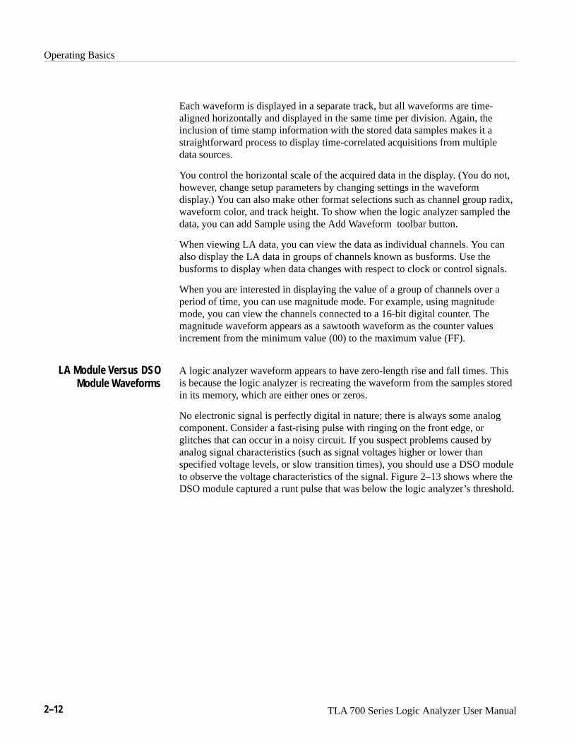
Operating Basics
2–12 TLA 700 Series Logic Analyzer User Manual
Each waveform is displayed in a separate track, but all waveforms are time-aligned horizontally and displayed in the same time per division. Again, theinclusion of time stamp information with the stored data samples makes it astraightforward process to display time-correlated acquisitions from multipledata sources.
You control the horizontal scale of the acquired data in the display. (You do not,however, change setup parameters by changing settings in the waveformdisplay.) You can also make other format selections such as channel group radix,waveform color, and track height. To show when the logic analyzer sampled thedata, you can add Sample using the Add Waveform toolbar button.
When viewing LA data, you can view the data as individual channels. You canalso display the LA data in groups of channels known as busforms. Use thebusforms to display when data changes with respect to clock or control signals.
When you are interested in displaying the value of a group of channels over aperiod of time, you can use magnitude mode. For example, using magnitudemode, you can view the channels connected to a 16-bit digital counter. Themagnitude waveform appears as a sawtooth waveform as the counter valuesincrement from the minimum value (00) to the maximum value (FF).
A logic analyzer waveform appears to have zero-length rise and fall times. Thisis because the logic analyzer is recreating the waveform from the samples storedin its memory, which are either ones or zeros.
No electronic signal is perfectly digital in nature; there is always some analogcomponent. Consider a fast-rising pulse with ringing on the front edge, orglitches that can occur in a noisy circuit. If you suspect problems caused byanalog signal characteristics (such as signal voltages higher or lower thanspecified voltage levels, or slow transition times), you should use a DSO moduleto observe the voltage characteristics of the signal. Figure 2–13 shows where theDSO module captured a runt pulse that was below the logic analyzer’s threshold.
LA Module Versus DSOModule Waveforms

Operating Basics
TLA 700 Series Logic Analyzer User Manual 2–13
Figure 2–13: Using the DSO module to capture a runt pulse
The accuracy of the waveform recreated from the sampled data depends on thesample clock rate used to record the incoming signals. This is due to the fact thatthe waveform re-created by the logic analyzer is based on the sampled signalsstored in its memory. If the sample clock rate is too low, the recorded data willproduce an inaccurate display. Figure 2–14 shows how the sample clock rate canaffect an LA module waveform.
Insufficient DSO module sampling resolution can result in aliasing. Forinformation about aliasing, see page 2–14.
Sampling Resolution

Operating Basics
2–14 TLA 700 Series Logic Analyzer User Manual
Displayed waveform
Sample clock
Original waveform
Displayed waveform
Sample clock
Original waveform
Example 1: Slow sample clock
Example 2: Fast sample clock
Figure 2–14: LA module sampling resolution
There is an important trade-off between the resolution of the recorded signal andits duration in terms of elapsed time. Because the total number of samples thatcan be recorded by the logic analyzer is fixed by the depth of the logic analyz-er’s acquisition memory, increasing the sample clock rate provides better signalresolution at the expense of reducing the duration of the captured signal. That is,a faster sample clock rate will record a smaller portion of the signal, but withbetter resolution.
For the LA module it is important to remember that you have an additional toolto offset the signal resolution/signal duration relationship. By using the MagniVudata feature, you can view high-resolution data centered about the LA moduletrigger. This allows you to zoom in on the data of particular interest while stillmaintaining visibility of a more extended signal duration.
Under certain conditions, an analog waveform can be aliased on screen. When awaveform aliases, it appears on screen with a frequency lower than the actualwaveform being input or it appears unstable. Aliasing occurs because theinstrument cannot sample the signal fast enough to construct an accuratewaveform record. (See Figure 2–15.)
Signal Resolution andSignal Duration
Preventing Aliasing

Operating Basics
TLA 700 Series Logic Analyzer User Manual 2–15
Actual high-frequencywaveform
Apparent low-frequencywaveform due to aliasing
Sampled points
Figure 2–15: Aliasing
To check for aliasing, increase the sampling rate (decrease the clock sampleperiod) in the module Setup window. If the shape of the displayed waveformchanges drastically or becomes stable at a faster clock sample period setting,your waveform was probably aliased.
Although the principles of sampling theory define a minimum sample rate of 2X,a good rule of thumb is to choose a sample clock rate five times faster than thespeed of the fastest signal being measured. A faster sample clock rate results in amore accurate reconstructed waveform.
Waveforms are rarely displayed at an exact one sample point per pixel. Wave-forms are usually displayed in a compressed or expanded format. As a generalrule, waveforms are compressed when the time per pixel is greater than the timeper sample clock. Waveforms are expanded when the time per pixel is less thanthe time per sample clock.
For compressed DSO module waveforms, the display shows the lowest andhighest point that occupy a given pixel column joined by a vertical line. Forexpanded waveforms, the display points between the actual sample points arecalculated.
For expanded DSO module waveforms, Sin(x)/x interpolation computes thedisplay points between the actual values acquired.
The LA module provides high-speed timing support through MagniVu data. TheMagniVu data is stored in a separate memory that is parallel to the mainmemory. All data from the sampler goes directly to the MagniVu memory. TheMagniVu memory also works like a circular buffer. Unlike the acquisitionmemory, the MagniVu memory does not qualify data storage through the triggerfunction block.
MagniVu data is continuously acquired on all channels at the fastest sample rateof 500 ps. Like normal acquisition data, MagniVu data can be displayed in theListing or Waveform data windows. The MagniVu data is centered on theLA module trigger in the data window. For additional information, see MagniVuData on page 3–62.
Displaying Waveforms
High-Speed Timing

Operating Basics
2–16 TLA 700 Series Logic Analyzer User Manual
One of the logic analyzer’s most useful features is its ability to detect and triggeron signal glitches. A glitch is a signal that makes a transition through thethreshold voltage two or more times between successive sample clocks. Becauseglitches are often signal transitions that occur intermittently, they can causecircuit malfunctions that are extremely difficult to diagnose.
Although you could try using a very fast sample clock rate to ensure that younever miss any glitches, a better solution is to use the glitch-detection feature.The logic analyzer can trigger on a glitch, either alone or in combination withother signal events. This capability is useful for catching intermittent glitchesthat might not occur very often, or only when a particular operation is takingplace.
You can capture noise spikes and pulse ringing using the glitch capture feature.Figures 2–16 and 2–17 show data captured by triggering on a glitch. In theWaveform window, a glitch captured by an LA module is indicated by a band ofcolor. (See Figure 2–16. For clarity, an arrow identifies the glitch in the figure.)
You must select internal clocking to use the glitch detection feature.
Figure 2–16: LA module triggering on a glitch
Detecting Glitches

Operating Basics
TLA 700 Series Logic Analyzer User Manual 2–17
Figure 2–17: DSO module triggering on a glitch
Performance Analysis ConceptsFor performance analysis applications, you can use the Histogram window toview the performance of your software. The actual data is displayed as horizontalbars in a histogram.
You may want to use the Histogram window to see which one of your softwareroutines is taking up most of the CPU time. Or, you can use the Histogramwindow to measure the amount of time used by a particular subroutine. You canuse a symbol file to view each of the routines by name.
Figure 2–18 shows an example of the Histogram window where the StopLiteroutine is taking up most of the computer resources.

Operating Basics
2–18 TLA 700 Series Logic Analyzer User Manual
Figure 2–18: Viewing the performance of code with a Histogram window
Comparing Acquired Data Against Saved DataYou can use the LA module to compare acquired data against saved referencedata. Use the LA Setup menu to define the data channels that you want to useduring the compare operations. You can further define the number of samplesthat you want to compare as well as data alignment offset.
In the Listing and Waveform windows, you can use color to quickly identify thecompared data. You can set up one color to show where the acquired data doesnot equal the reference data. You can use another color to show where theacquired data equals the reference data.
Figure 2–19 shows a Listing window during a memory compare operation;notice that some of the data under the LA 2 A2 column appears in a differentcolor, indicating that there were differences between the acquired data and thereference data.

Operating Basics
TLA 700 Series Logic Analyzer User Manual 2–19
Figure 2–19: Using color to show memory differences in a Listing window
Repetitive AcquisitionsUse the Repetitive acquisition features of the logic analyzer to automaterepetitive and time-consuming tasks. For example, you can specify the numberof times that you want the logic analyzer to acquire data. With each acquisition,you can save the data to a file for analysis. You can also set up the logic analyzerto open a file or execute a program when all of the acquisitions have beencompleted.
You can set up the LA module to acquire and compare the acquisition dataagainst known reference data. The LA module can continue acquiring data untilthere is a mismatch between the acquisition data and the reference data.
Figure 2–20 shows an example of such a setup where the acquired data isexported to a file for each acquisition. When a data-mismatch occurs the logicanalyzer stops acquiring data and exports the data to a file. The faulty data cannow be analyzed by another application.

Operating Basics
2–20 TLA 700 Series Logic Analyzer User Manual
Figure 2–20: Defining repetitive setups
TLA 700 Programmatic Interface (TPI)Using the TLA 700 Programmatic Interface (TPI) you can control a TLA 700series logic analyzer from a separate user program from the logic analyzer itselfor from a remote computer. The interface is based on the Component ObjectModel (COM). You can use any programming language or programmingenvironment that supports the Component Object Model, such as MicrosoftVisual C++ and Microsoft Visual Basic.
Using TPI, you can control various aspects of the logic analyzer. You can loadand save system and module setups. You can extract information from the logicanalyzer, such as LA module counter and timer values, configuration informa-tion, LA module data, and DSO module data for analysis by other applications.
The TLA 700 Programmatic Interface comes with its own online help (selectHelp on TPI from the Help menu in the TLA application). For your convenience,the information contained in the TPI help file is also available in PortableDocument Format (PDF) in the C:\Program Files\TLA 700\System directory.The file name is tpi.pdf. You will need the Adobe Acrobat Reader application toview or print tpi.pdf. If you do not have Adobe Acrobat Reader on yourmachine, you can download a free copy from the Adobe site at http://www.a-dobe.com/acrobat/.

Operating Basics
TLA 700 Series Logic Analyzer User Manual 2–21
Symbol SupportSymbols simplify tasks, such as setting up triggers or identifying specific valueswithin the data. When you program a trigger or view data, it is cumbersome toremember which numeric channel group values correspond to particular machineinstructions or code modules. The logic analyzer makes this task more manage-able by allowing you to assign symbolic names or mnemonics to group values.
For example, you might assign the symbol WRITE to the control bus event thatcauses the target system to write to a memory location. Then, if you wanted totrigger when a write cycle occurs, you could enter WRITE in the trigger programin place of the actual data value. You could also choose to have WRITE appearin the Listing window for quick identification of the instruction.
In Figure 2–21, the example shows a trigger program which uses the symbolSYSTEM_RESET as part of the trigger clause.
Figure 2–21: Using symbols in a trigger program
You can use symbol files with a Source window and an associated Listingwindow to track the execution of source code. The symbol file provides theinformation to associate a line of source code to an address in a Listing window.When you move a cursor in one window, the symbol file provides the necessaryinformation to move the cursor to the correct location in the other window.
Often, the application software will define symbols for you. For example, whenyou load a microprocessor support package, symbols are also loaded (typically,to the control group). These symbols represent data values that correspond to buscycle types. Other software applications produce range symbol files which youcan load (typically, these files are loaded to the address group).
To use symbols, you must first load or create one or more symbol files thatdefine the symbols. Symbol files contain symbol names and their associated datavalues. You can use symbol files created by another application, edit symbol filesfrom other applications, or you can create your own symbol files using a texteditor.
Symbol Files
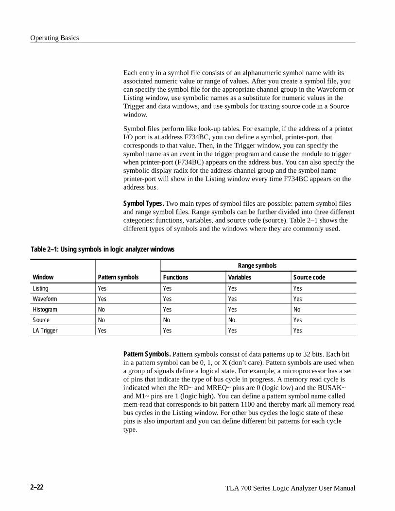
Operating Basics
2–22 TLA 700 Series Logic Analyzer User Manual
Each entry in a symbol file consists of an alphanumeric symbol name with itsassociated numeric value or range of values. After you create a symbol file, youcan specify the symbol file for the appropriate channel group in the Waveform orListing window, use symbolic names as a substitute for numeric values in theTrigger and data windows, and use symbols for tracing source code in a Sourcewindow.
Symbol files perform like look-up tables. For example, if the address of a printerI/O port is at address F734BC, you can define a symbol, printer-port, thatcorresponds to that value. Then, in the Trigger window, you can specify thesymbol name as an event in the trigger program and cause the module to triggerwhen printer-port (F734BC) appears on the address bus. You can also specify thesymbolic display radix for the address channel group and the symbol nameprinter-port will show in the Listing window every time F734BC appears on theaddress bus.
Symbol Types. Two main types of symbol files are possible: pattern symbol filesand range symbol files. Range symbols can be further divided into three differentcategories: functions, variables, and source code (source). Table 2–1 shows thedifferent types of symbols and the windows where they are commonly used.
Table 2–1: Using symbols in logic analyzer windows
Wi a e y b l
Range symbols
Window Pattern symbols Functions Variables Source code
Listing Yes Yes Yes Yes
Waveform Yes Yes Yes Yes
Histogram No Yes Yes No
Source No No No Yes
LA Trigger Yes Yes Yes Yes
Pattern Symbols. Pattern symbols consist of data patterns up to 32 bits. Each bitin a pattern symbol can be 0, 1, or X (don’t care). Pattern symbols are used whena group of signals define a logical state. For example, a microprocessor has a setof pins that indicate the type of bus cycle in progress. A memory read cycle isindicated when the RD~ and MREQ~ pins are 0 (logic low) and the BUSAK~and M1~ pins are 1 (logic high). You can define a pattern symbol name calledmem-read that corresponds to bit pattern 1100 and thereby mark all memory readbus cycles in the Listing window. For other bus cycles the logic state of thesepins is also important and you can define different bit patterns for each cycletype.

Operating Basics
TLA 700 Series Logic Analyzer User Manual 2–23
Figure 2–22 shows pattern symbols used in a Waveform window.
Figure 2–22: Waveforms using pattern symbols
Range Symbols. Range symbols define a range of 32-bit addresses represented bya contiguous set of integers, marked by specific lower and upper bounds. Thedifferent types of range symbols are discussed in detail under TLA 700 SymbolFile Format beginning on page 0–1.
When defining a range symbol file, do not overlap ranges of values. If rangesoverlap, they may not be recognized. For example, if SYM1 covers the range1000–3FFF, and SYM2 covers 2000–2FFF, then the values in range 2000–2FFFmay be recognized as either SYM1 or SYM2, and the values in the range3000–3FFF may not be recognized as SYM1 at all.
The range symbols shown in Figure 2–23 define subroutine boundaries.
Figure 2–23: Listing data using range symbols

Operating Basics
2–24 TLA 700 Series Logic Analyzer User Manual
Use the Symbols dialog box to provide an overview of all currently loadedsymbol files (see Figure 2–24). You can display information on all symbol filescurrently used by the logic analyzer.
The following status information is available for each currently-loaded symbolfile:
� The last time the file was loaded into the TLA 700 application software. Italso includes error and warning messages associated with the last load.
� When the file was last modified. The logic analyzer also displays a messageif the file may need to be reloaded (such as when the file is modified after itwas first loaded).
� The format of the loaded file.
� If the file can be unloaded or if the file is currently in use. Symbol files canonly be unloaded if no data windows or setups are using them.
Figure 2–24: Symbols dialog box
Symbols Dialog Box

Operating Basics
TLA 700 Series Logic Analyzer User Manual 2–25
The following content information is displayed in the Symbols dialog box:
� Whether the file is a pattern symbol file or a range symbol file. If the file is arange file, this field also lists the types of symbols loaded.
� The number of symbols loaded from the file. Symbol files can have anunlimited number of symbols. The number of symbols is limited by theamount of memory. When you load a symbol file, the symbols are placed inmemory. Because symbol files consume memory, you should unload unusedsymbol files to keep memory available for your main application.
� The number of source files referenced by source code symbols loaded fromthe file.
� The minimum and maximum address values and offset information.
Click the Load button (see Figure 2–24) to open the Select Symbol File dialogbox and load a new symbol file. You can browse the file system for the symbolfile. If the symbol file is a range file, you can click the Options button in theSelect Symbol File dialog box to open the Load Symbols Options dialog box.
Click the Export button to save the current file as a TSF-format symbol file. Youcan view the exported symbol file with applications such as Wordpad. Edit thesymbol file by saving it under a new name and using a text editor. Save theedited file in text format. You can then load the edited symbol file.
Use the Load Symbols Options dialog box (see Figure 2–25) to specify optionsfor range symbol files before loading them into the system.
Figure 2–25: Load Symbol Options dialog box
Load Symbol OptionsDialog Box
Operating Basics
2–26 TLA 700 Series Logic Analyzer User Manual
Select one or more of the symbols types to load. If you want to use the symbolfile with the Source window, you should be sure to select Source Code symbols.
You can enter a decimal number for the maximum number of symbols to load.The maximum number of symbols that you can load is limited only by theamount of memory available. The file loads symbols until the specifiedmaximum number of symbols is reached. Additional symbols are ignored, evenif they fall within the Bound 1 and Bound 2 range limits.
The Bound 1 and Bound 2 fields define the range of symbol addresses that willbe loaded. You can enter any hexadecimal values from 0 through FFFFFFFF.Symbols with values outside of these limits are ignored and will not be loaded.
NOTE. If the lower bound of the range symbol is within the Bound 1 and Bound 2limits and the higher bound is not, the entire symbol will be valid. However, ifthe higher bound is within the Bound 1 and Bound 2 limits and the lower boundis not, the entire symbol will be ignored.
Select either Default Offset or Custom Offset to apply an offset to the symbolvalues. If you select Default Offset, the default offset is read from the source fileand applied to each symbol in the file as it is loaded. If you select CustomOffset, you can add or subtract the specified offset value to each symbol in thefile as it is loaded. You can choose any 32-bit hexadecimal value from 0 toFFFFFFFF.
When you enter bound values, enter the values without an offset value. If yourapplication adds an offset, you must subtract the offset value before you enter thebound values.

Reference


TLA 700 Series Logic Analyzer User Manual 3–1
Setup
This section describes how to set up the logic analyzer (LA) and DSO modules,and how to load an LA module trigger program.
For further details, particularly about selections available to you in windows anddialog boxes, please refer to the online help.
Starting From the System WindowThe System window gives an overview of the logic analyzer configuration,arming, and triggering relationships. The System window also indicates whetherLA modules are merged to increase the number of channels. See Figure 3–1.
A black arrow from one module to another indicates that one module is set up toarm another. Figure 3–1 shows the merged LA module arming the DSO module.
A module that is programmed to cause a system trigger has an indicator symbolon the right edge of the module graphic.
Overlapped icons indicatingmerged modules
Arm indicator
System trigger indicator
Data source indicator
Figure 3–1: System window

Setup
3–2 TLA 700 Series Logic Analyzer User Manual
You can use the System window as a quick navigation tool.
� To open a module Setup or Trigger window from the System window, clickthe Setup or Trigger button in the module icon.
� To open a data window from the System window, click the data windowbutton. See Figure 3–2.
Figure 3–2: Opening a Waveform window from the System window
If you are not using a module, you can disable it by clicking the module’s On/Offbutton. When you disable a module, make sure that no other trigger programsdepend on that module’s output.
You can rename the windows by selecting the current window labels andovertyping. Names must be unique and are limited to the space available.
If you are unsure which physical module is represented by an icon, double-clickon the icon to open its System Properties page. This property page listsinformation about the module, including the mainframe slot numbers in which itis installed. (Slot numbers are indicated on the mainframe.)
Opening Other Windowsfrom the System Window
Disabling Modules
Renaming Windows
Identifying Modules

Setup
TLA 700 Series Logic Analyzer User Manual 3–3
Setting Up the LA ModuleThe primary function of the Setup window is to configure the LA module forcompatibility with the target system. This is where you specify channel groups,set thresholds, and select the sample clock rate. Additional selections configurethe LA module for best compatibility with the type of data you want to acquire.
Before you acquire and display data, you must first set up the LA module usingthe LA Setup and Trigger windows. Together, these windows determine the datato be acquired.
Each module has its own Setup window and Trigger window, each is set upindividually. Generally, you should configure the Setup window before theTrigger window, because some of the Setup window settings affect Triggerwindow selections.
� To open the LA module Setup window, go to the System window and clickthe LA module Setup button.
Figure 3–3: The LA module Setup window
NOTE. If you intend to use merged modules, turn to page 3–34 for informationbefore you proceed with the setup procedure.

Setup
3–4 TLA 700 Series Logic Analyzer User Manual
If you intend to use a microprocessor support package, load it before completingthe entries in the Setup window. The microprocessor support package configuresthe Setup window for you.
� To load a microprocessor support package, go to the File menu, click LoadSupport Package, select the support package you want to load, and then clickLoad.
After loading the microprocessor support package, the LA Setup window showsthe channel definitions, channel groups, and clocking requirements for themicroprocessor support package. Figure 3–4 shows an example of the LA Setupwindow after loading the QSTART support package.
Figure 3–4: Setup window with the QSTART support package
For information about microprocessor support packages, refer to the online helpand to the instruction manual that came with your microprocessor supportpackage.
If you intend to do performance analysis with your LA module, you need todefine the channel and clocking setups in the Setup window. You may also wantto load a microprocessor support package which contains the predefined channelsetups and clocking setups.
Memory Compare allows you to compare the current acquisition data of an LAmodule against a known reference data. You can quickly view data differencesand similarities in a Listing or Waveform window using user-defined colors.
Microprocessor SupportSetup
Performance AnalysisSetups
Memory Compare

Setup
TLA 700 Series Logic Analyzer User Manual 3–5
Selecting Channels for the Memory Compare. Choose the channels that you wantto compare in the LA Setup window by selecting Channel Compare in the TableShows box (see Figure 3–5). You can then compare all data channels, specificchannel groups, or individual channels by selecting the appropriate channels inthe Probe Channels/Names table.
Figure 3–5: Selecting channels for memory compare
After selecting the channels that you want to compare, click the Define Comparebutton in the lower-right corner of the Setup window to define the compareactions.

Setup
3–6 TLA 700 Series Logic Analyzer User Manual
Defining Memory Compare Parameters. Select Enable Data Compare in theCompare Definition dialog box as shown in Figure 3–6. Select the reference datasource in the box; if the data source that you are interested in does not appear inthe list, click Add Data Source to browse for the data source in the file system.
Figure 3–6: Enabling data compare
After you select the data source, define the amount of data that you want tocompare against. You can compare all data or a portion of the data by filling inthe appropriate information. You can also define the alignment of the data byfilling in the appropriate information. A summary of your setup displays at thebottom of the dialog.
NOTE. After defining the compare setup, remember to select Show Compare inthe Listing Window or Waveform Window property page
Guidelines for Memory Compare. There are a few guidelines that you should beaware of when using memory compare:
� You must enable the memory compare in the Compare Definition dialog box(see Figure 3–6).
� Acquisition modules and reference modules must be the same width.
� Specify the color of compare data in the Listing Window or WaveformWindow property sheet, or use the default colors.
� You can search for data differences or data equalities.

Setup
TLA 700 Series Logic Analyzer User Manual 3–7
� You can use memory compare with repetitive acquisitions.
� You can compare only the main LA data, you cannot compare glitch data,disassembler group data, or MagniVu data.
NOTE. Although you cannot compare disassembler group data directly, you cancompare the raw nondisassembled data by using the channel groups as definedin the Setup window. To view these channel groups in a Listing window, use theAdd Column toolbar button to add the channel group to the window.
Use Clocking to specify the clock(s) used to sample data. Select one of two basicclocking modes, Internal (asynchronous) or External (synchronous). A thirdchoice, Custom, is available if a microprocessor support package has beenloaded. Your clocking choice determines further clocking selections.
Internal Clocking. Internal (asynchronous) clocking uses the LA module’s internalclock to determine when to sample data. Typically, internal clocking is used fortiming analysis (waveform data).
When you select Internal clocking, the only additional selection to make is theclock rate in the next field.
Because the internal clock signal is asynchronous to the target system, be carefulto select a sample period that is considerably faster than the data rate of yourtarget system.
External Clocking. External (synchronous) clocking synchronizes data samplingwith the clock of the target system so you can be more selective about the datayou sample. This type of clocking is best for software analysis (listing data).
When you select External clocking, you have the option of further selections todefine the sample clock. You can create clocking equations in the Clockingdialog box. Clocking equations qualify when data is sampled. The equationsconsist of a Boolean combination of events, linking clock and qualifier lines.Data is sampled and stored in memory only when this clock equation is true.
Clocking

Setup
3–8 TLA 700 Series Logic Analyzer User Manual
Advanced Clocking. Advanced clocking is available only if you select Externalclocking. Use advanced clocking to set up multiple-phase clocking, probedemultiplexing, and other clocking controls. Multiple-phase clocking specifiestwo different sample clock equations and assigns an equation to separate probegroups to clock in sample data. You can also sample data from different channelgroups at different points in time relative to the sample clock through a variablesetup and hold window.
Custom Clocking. Custom clocking is used only with microprocessor supportpackages. Custom clocking enables and disables a variety of microprocessor-spe-cific clock cycle types (such as DMA cycles).
For more information, see the instructions that came with your microprocessorsupport package.
Use Acquire to select the acquisition mode. The acquisition mode determines thedata to store. You can store channel data only, glitch data, or blocks of dataaround requested samples.
Normal Mode. Normal mode stores only the requested channel data.
Blocks Mode. Blocks mode stores a block of approximately 60 samples aroundeach qualified sample. In Blocks mode, only channel data is stored. If you storeblocks they will override other forms of data qualification. All samples in theblock are always stored.
Glitch Mode (Internal Clocking Mode Only). Glitch mode captures glitch data andregular data for each data channel. You must select internal clocking for Glitchmode to be available.
Glitch mode limits memory depth to half of the maximum depth and limits thesample period to 10 ns or greater.
Selecting the AcquisitionMode

Setup
TLA 700 Series Logic Analyzer User Manual 3–9
Use Memory Depth to specify the total number of samples acquired by the LAmodule. If you do not require full memory depth, select a lesser value becauseyou will have less data to search to find the data of interest.
For a given memory depth there is a tradeoff between the clock sample rate anddata record length. (A faster sample rate provides a shorter time window, butwith higher resolution.)
NOTE. If you select Glitch mode, the maximum memory depth is limited to onehalf the normal value.
Use channel grouping to organize the LA probe channels to match the configura-tion of the target system. Depending on your application, match the channelgroups to the address and data buses, or other channels of interest. Then namethe channel groups for easy identification.
Any number of groups can be created. Each group can contain any combinationof module channels; the application does not restrict you from repeating channelsfrom various groups.
When using group range events (range recognizers), the probe groups and probechannels must be used in hardware order. That is, probes must be used from themost-significant probe group to the least-significant probe group based on thefollowing order:
C3 C2 C1 C0 E3 E2 E1 E0 A3 A2 D3 D2 A1 A0 D1 D0 Q3 Q2 Q1 Q0 CK3CK2 CK1 CK0
The probe channels must be used from the most-significant channel to theleast-significant probe channel based on the following order:
7 6 5 4 3 2 1 0
If a microprocessor support package is loaded, the channel groups are defined foryou.
Setting Memory Depth
Channel Grouping

Setup
3–10 TLA 700 Series Logic Analyzer User Manual
NOTE. If a microprocessor support package is loaded, you should not change ordelete the default channel groups. Doing so can cause an inaccurate analysis.You can still add and delete new channel groups.
Channel groups defined in the channel grouping table are used in other displaysand setup controls. The order of the groups in this table determines the order ofpresentation in other parts of the application.
Figure 3–7: Channel grouping table in the Setup window
Channel Group Name. Each channel group must have a name. You can use thedefault name, or you can enter another name, as long as it is unique within themodule. There is no limit to the number of groups you can create.
For each group name, you must list all the probe channels that make up thegroup. The group names are listed in the left column of the table. The individualprobe channels that make up each group are listed in the right column of thetable. The center column of the table lists the number of channels in a group(where a zero refers to bit 0). For example in Figure 3–7, the Address group ismade up of 32 channels, with channel 31 as the most-significant bit (A3-7) andchannel 0 as the least-significant bit (A0-0).
Probe Channels/Names Table. Use the Probe Channels/Names Table to enternames for individual channels, add and remove channels from a group, or changepolarity of individual channels.

Setup
TLA 700 Series Logic Analyzer User Manual 3–11
Use the Activity Indicators dialog box to show the real-time signal activity at theLA module probe tip without having to acquire data. The activity symbolsindicate whether the signals at the probe tip are high, low, or changing. SeeFigure 3–8.
� In the LA Setup window, click Show Activity.
Figure 3–8: The Activity Indicators dialog box
If the activity indicators show no activity, the problem could be that there is nosignal voltage, an incorrect threshold voltage level, or the channel lead is notconnected. If all the channels associated with a probe are inactive, check theprobe connections to the LA module.
You can leave the Activity Indicators dialog box open while you set up otherwindows, such as setting up the Trigger window or adding channels to theWaveform or Listing window. This dialog box is useful for verifying that clocksare active in external clocking and for troubleshooting complex clock setups.
Activity Indicators

Setup
3–12 TLA 700 Series Logic Analyzer User Manual
Use Set Thresholds to set the input threshold voltage settings for probe channels,clocks, and qualifiers of the LA module. Changes are immediately executed evenduring acquisition. Figure 3–9 shows the Set Thresholds dialog box.
Initially, the Probe Thresholds box contains values that are set in the Preset pageof the Options Property sheet.
Figure 3–9: Probe Thresholds dialog box
Setting Up the Trigger ProgramThe primary function of the LA Trigger window (see Figure 3–10) is to constructa trigger program. You also use the Trigger window to select how and when tostore data.
A trigger program is a series of events and actions that define when to triggerand store data. The trigger program filters acquired data to find a specific dataevent, or series of data events. The trigger program can accept information fromother modules or send signals external to the logic analyzer.
Setting Probe Thresholds

Setup
TLA 700 Series Logic Analyzer User Manual 3–13
Trigger programs range from the simple to the extremely complex. They are thekey to logic analyzer operation, which is to acquire the desired data in acquisi-tion memory and to display the data for viewing. One method for setting up atrigger program is to load a trigger program from the trigger library. You canthen alter the trigger program details as necessary. Once you become familiarwith trigger programming, you can also create trigger programs without the helpof the trigger library. For more information, see Trigger Library on page 3–16.
Before you work in the Trigger window, you should already have configured theLA module Setup window because some of the Setup window settings affectTrigger window selections.
Figure 3–10 shows a Trigger window with a trigger program loaded from thetrigger library.
Figure 3–10: LA module Trigger window
A trigger program is made up of one or more states (up to 16). Only one state isactive at a time.
Each state is made up of one or more clauses. If you use more than four triggerevent resources in a state, you can have up to four clauses per state. If you havefour or fewer trigger event resources in a state, you can define up to 16 clausesper state. Clauses are made up of two parts: an If statement, that defines the dataevent of interest, and the Then statement, which specifies the action taken whenthe If statement is true. You can define up to eight events per If statement and upto eight trigger actions per Then statement.
Trigger Program Structure

Setup
3–14 TLA 700 Series Logic Analyzer User Manual
During each sample clock cycle, all clauses within the active state simultaneous-ly evaluate each data sample. Clauses are evaluated from top (State #1, IF-ThenClause #1) to bottom. When one of the clauses goes true (the event defined in theIf statement occurs), then the logic analyzer performs the action(s) specified inthe Then statement. There are several actions to choose from, includingtriggering the system and transferring control of the trigger program to anotherstate.
NOTE. If multiple clauses are true in the same clock cycle, only the earliestclause in the sequence to go true will have its action(s) executed.
The Trigger window summarizes the trigger program. The Overview shows thegeneral structure of the trigger program. The Trigger Detail, at the right of thewindow, summarizes activity within individual program states. You can click theIf/Then button in the Trigger Detail to open the Clause Definition dialog box,which is where the actual trigger programming takes place.
Overview Trigger Detail
Figure 3–11: Trigger window structure
Trigger Window Structure

Setup
TLA 700 Series Logic Analyzer User Manual 3–15
Overview. The Overview portion of the Trigger window shows the relationship ofthe states. See Figure 3–12. This example shows a branch occurring in State 2.This example also shows that a trigger (note the trigger indicator) occurs inState 2 and an Arm occurs.
To view the details in a particular state, double-click on the State button in theOverview.
Figure 3–12: Overview portion of LA Trigger window
You can view the progress of the trigger states during acquisition using theStatus Monitor. (See Status Monitor on page 3–43.)
Trigger Detail. The Trigger Detail portion, at the right of the Trigger window,shows summary information about the clauses within the states. See Fig-ure 3–13. For lengthy trigger programs, click on the State buttons in theOverview to jump to the corresponding Trigger Details.
Figure 3–13: Trigger detail portion of LA Trigger window

Setup
3–16 TLA 700 Series Logic Analyzer User Manual
Click on the If/Then button to open the Clause Definition dialog box forcomplete information about the clause.
One advantage of a logic analyzer is that you can create sophisticated triggerprograms so that you can carefully qualify and store only the relevant data.However, configuring such trigger programs can be time-consuming.
The TLA 700 Series Logic Analyzer simplifies this process with its triggerlibrary. It provides a list of trigger programs to fit most needs. The triggerprogramming is partially done for you.
To use the trigger library, select a trigger program that is close to what yourequire, and then alter the program as necessary. Once you have customized thetrigger, you can save it along with the rest of your setup using the Save Moduleor Save System function. You can later retrieve the saved trigger program aloneor with the related saved module or system information.
Table 3–1 lists the programs in the trigger library and a brief description of eachlibrary item.
Table 3–1: LA Trigger library
File name Description
TrigOnA Trigger on the first occurrence of Event A.
TrigOnAafterN Wait for Event A. Trigger after the specified number ofevents.
TrigOnNthA Trigger after Event A has occurred a specified number oftimes.
TrigOnNthAorB Trigger after Event A or Event B has occurred a specifiednumber of times.
TrigOnAthenB Trigger if Event B eventually follows Event A
TrigOnAimedB Trigger if Event B immediately follows Event A.
TrigOnAthenBresetC Wait for Event A. If Event C occurs before Event B, thenreset and wait for Event A again. Otherwise, trigger whenEvent B occurs.
TrigOnAtoBltNCs Trigger on Event C if Event C occurs less than or equal tothe specified number of times between Event A andEvent B.
TrigOnAtoBgtNCs Trigger on Event C if Event C occurs more than thespecified number of times between Event A and Event B.
TrigOnAthenBinN Trigger when Event B occurs within a specified number ofevents of Event A.
Trigger Library

Setup
TLA 700 Series Logic Analyzer User Manual 3–17
Table 3–1: LA Trigger library (Cont.)
File name Description
TrigOnAinRange Trigger when the group event occurs within specifiedupper and lower ranges.
TrigOnGlitch Trigger on glitches; valid only with Internal clocking.
TrigOnSetHold Trigger on setup and hold violations; valid only withExternal or Custom clocking.
TrigOnAtoBinT Trigger when Event B follows Event A within the specifiedtime.
TrigOnAtoBafterT Trigger when Event B follows Event A after the specifiedtime.
CountA Count the occurrences of Event A. This program does nottrigger the LA module.
CountAorB Count the occurrences of Event A or Event B. Thisprogram does not trigger the LA module.
CountCfromAtoB Count the occurrences of Event C between Event A andEvent B. This program does not trigger the LA module.
AccumCfromAtoB Accumulate the total counts of Event C between Event Aand Event B. This program does not trigger the LAmodule.
AccumTfromAtoB Accumulate the total time between Event A and Event B.This program does not trigger the LA module.
AccumTinRange Accumulate the total time spent within the specified rangein Event A. This program does not trigger the LA.
AccumToutRange Accumulate the total time spent outside the specifiedrange in Event A. This program does not trigger the LA.
TimeBetweenAandB Measure the delay between Event A and Event B. Thisprogram does not trigger the LA module.
TimeInRange Measure the time spent within a specific range of events.This program does not trigger the LA module.
TimeOutRange Measure the time spent outside a specific range of events.This program does not trigger the LA module.
StoreOnA Store nothing except occurrences of Event A. Thisprogram does not trigger the LA module.
StoreOnAorB Store nothing except occurrences of Event A or Event B.This program does not trigger the LA module.
StoreFromAtoB Store nothing except the samples between Event A andEvent B. This program does not trigger the LA module.

Setup
3–18 TLA 700 Series Logic Analyzer User Manual
Table 3–1: LA Trigger library (Cont.)
File name Description
StoreExceptAtoB Store everything except those samples between Event Aand Event B. This program does not trigger the LAmodule.
StoreInRange Store nothing except samples within specified ranges ofEvent A. This program does not trigger the LA module.
TrigOnSignal Trigger the LA module on a signal from another module.
SendSignal Send a signal to another module when Event A occurs.
TrigSysOnA Trigger the system when Event A occurs.
To load a trigger program from the trigger library, follow these steps:
1. From the Trigger window, click the Load Trigger toolbar button.
2. From the Load LA Trigger dialog box, click Browse Library.
3. Select a trigger program from the list.
4. Click Open to apply the selection.
5. Click Load to load the trigger program into the module.
Once you load the trigger program, customize it for your application.
6. Click the If/Then button to open the Clause Definition dialog box. This iswhere you specify trigger program details.
7. Change the Clause Definition selections to fit your application. Start with thefirst box in the If statement; the selection you make affects other selections.Enter appropriate values in the address and data boxes.
Loading a Trigger from theTrigger Library

Setup
TLA 700 Series Logic Analyzer User Manual 3–19
8. If you want additional clauses, you can add to the If or Then statementsusing the Add button, as shown in the following figure.
9. Click OK to complete the clause definition.
10. Check the trigger program summary in the Trigger window.

Setup
3–20 TLA 700 Series Logic Analyzer User Manual
Use trigger events to define the If portion of the event clause in the triggerprogram. Table 3–2 lists the trigger events available.
Table 3–2: Trigger events
Event Description
Word Tests the channel groups for the word values defined inthe Word definition dialog box.
Group Tests a specified channel group for a specific value, arange of values, or a value change.
Channel Tests the specified channel for a value or a value change.
Glitch Detects glitches in channel groups as defined in the GlitchDetect dialog box. Only available with internal (asynchro-nous) clocking.
Setup & Hold fault Tests setup and hold parameters as defined in the Setupand Hold Event dialog box. Not available as an event withinternal (asynchronous) clocking.
Counter and timer events Tests the specified counter or timer value. Timer eventsare only supported by LA Modules with serial numbersB020000 or higher.
Signal Looks for one of the four internal system signals. Only onesignal event is available in a trigger program.
Anything All sampled data makes this event true.
Nothing All sampled data makes this event false.
You can use up to 16 unique trigger resources (not including counters and timers)in a trigger program to define the events and actions. A trigger resource can beused more than once in a trigger program. However, some events use more thanone trigger resource. Table 3–3 lists the trigger resources and any interactionsthat may occur when you use them.
Trigger Events
Trigger Resources

Setup
TLA 700 Series Logic Analyzer User Manual 3–21
Table 3–3: Trigger resources
Resource Operator Interactions and restrictions
Word =, Is Not One trigger resource across all definedchannel groups.
Group
Word recognizer =, Is Not One trigger resource per channelgroup.
Range recognizer <, <=, >=, >, Is In,Is Not In
Three trigger resources per channelgroup.
Change detector Changes One trigger resource per group event,one change detector allowed in atrigger program, not available whentransitional storage is used.
Channel
Word recognizer = One trigger resource per channelgroup.
Change detector Goes, Doesn’t go One trigger resource, one changedetector allowed in a trigger program,not available when transitional storageis used.
Glitch One trigger resource, only availablewith internal (asynchronous) clocking.
Setup & Hold Fault One trigger resource, only availablewith external (synchronous) or customclocking.
Counter >, <= 0 trigger resources, 2 counters or2 timers.Maximum width 51 bitsMaximum clocking 250 MHzMaximum count 251
Counter 1 and 2 events conflict withTimer 1 and 2 events respectively.
Timer >, <= 0 trigger resources, 2 counters or2 timersMaximum width 51 bitsMaximum clocking 250 MHzMaximum time 2,000,000 S
(23 days)
Counter 1 and 2 events conflict withTimer 1 and 2 events respectively.

Setup
3–22 TLA 700 Series Logic Analyzer User Manual
Table 3–3: Trigger resources (Cont.)
Resource Interactions and restrictionsOperator
Signal (Signal in) Is True, Is False One trigger resource, uses one of foursystem signals. Only one signal eventis available in a trigger program.
Anything 0 trigger resources. Used as a place-holder. Not available with the ORconjunction.
Nothing 0 trigger resources. Used as a place-holder with the OR conjunction.
After defining the events in the If (event) portion of the clause, you can selectone or more trigger actions to complete the clause. Table 3–4 lists the triggeractions available for your trigger program.
Table 3–4: Trigger actions
Action Description
Trigger Triggers the current module. When you use Trigger in thetrigger program, you cannot use Trigger All Modules.
Trigger All Modules Also known as a System trigger. This signal is alsoavailable at the System Trigger Out connector. When youuse Trigger All Modules in the trigger program, you cannotuse Trigger.
Go To Passes the program flow to a different trigger state. Youcan only use one Go To action in the clause definition.
Counter and Timer actions Starts, stops, resets, or clears counters or timers.Counter 1 and 2 actions conflict with Timer 1 and 2actions respectively. Counter/timer actions may conflictwith counter/timer event usage.
Set and Clear Signal Sets or clears one of the four internal system signals. Youcan use only one Set or Clear in a trigger program. TheSet or Clear Signal is mutually exclusive with the ArmModule action.
Arm Module Sends an Arm signal to another module. The othermodule begins running its trigger program. You can armonly one module in a trigger program. However, you canuse actions throughout the trigger program. Arm Moduleis mutually exclusive with Set and Clear Signal actions.
Store Sample Stores exactly one sample. Not available in Start/Stopstorage mode.
Trigger Actions
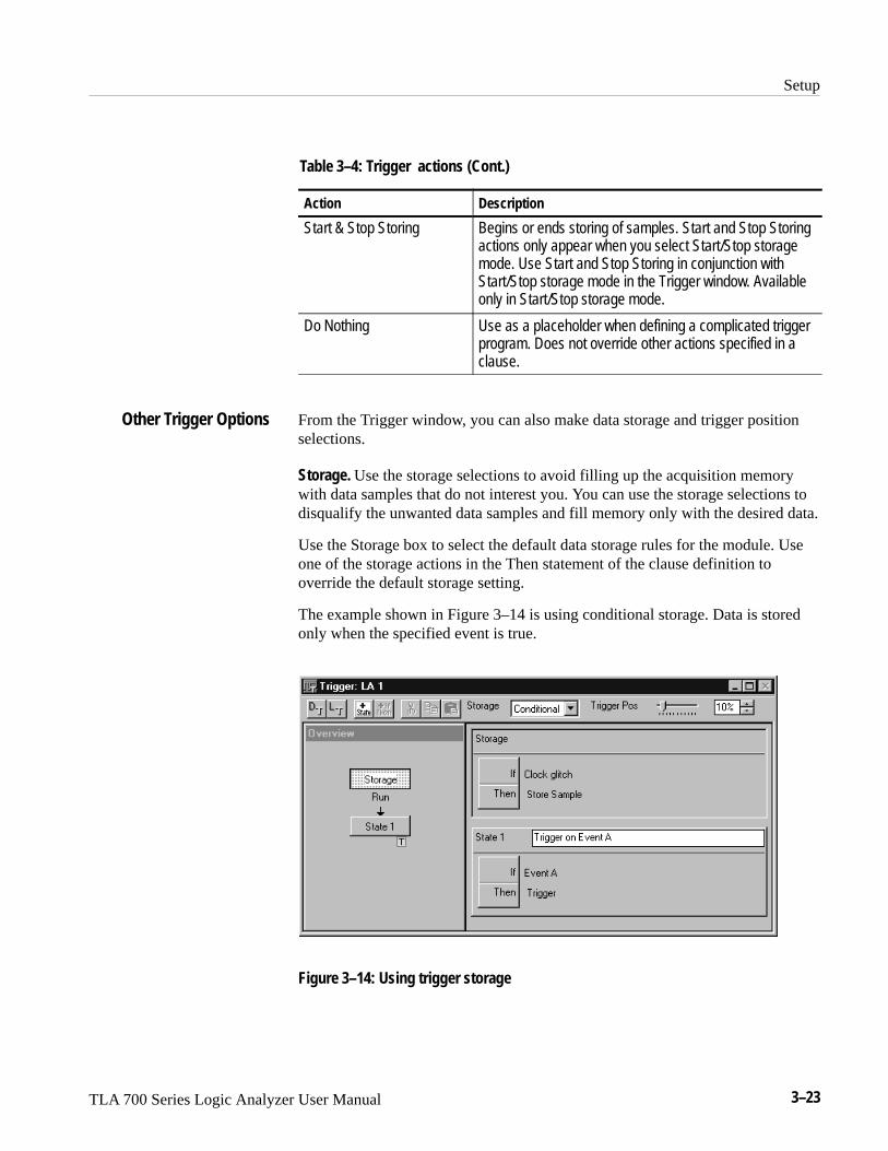
Setup
TLA 700 Series Logic Analyzer User Manual 3–23
Table 3–4: Trigger actions (Cont.)
Action Description
Start & Stop Storing Begins or ends storing of samples. Start and Stop Storingactions only appear when you select Start/Stop storagemode. Use Start and Stop Storing in conjunction withStart/Stop storage mode in the Trigger window. Availableonly in Start/Stop storage mode.
Do Nothing Use as a placeholder when defining a complicated triggerprogram. Does not override other actions specified in aclause.
From the Trigger window, you can also make data storage and trigger positionselections.
Storage. Use the storage selections to avoid filling up the acquisition memorywith data samples that do not interest you. You can use the storage selections todisqualify the unwanted data samples and fill memory only with the desired data.
Use the Storage box to select the default data storage rules for the module. Useone of the storage actions in the Then statement of the clause definition tooverride the default storage setting.
The example shown in Figure 3–14 is using conditional storage. Data is storedonly when the specified event is true.
Figure 3–14: Using trigger storage
Other Trigger Options
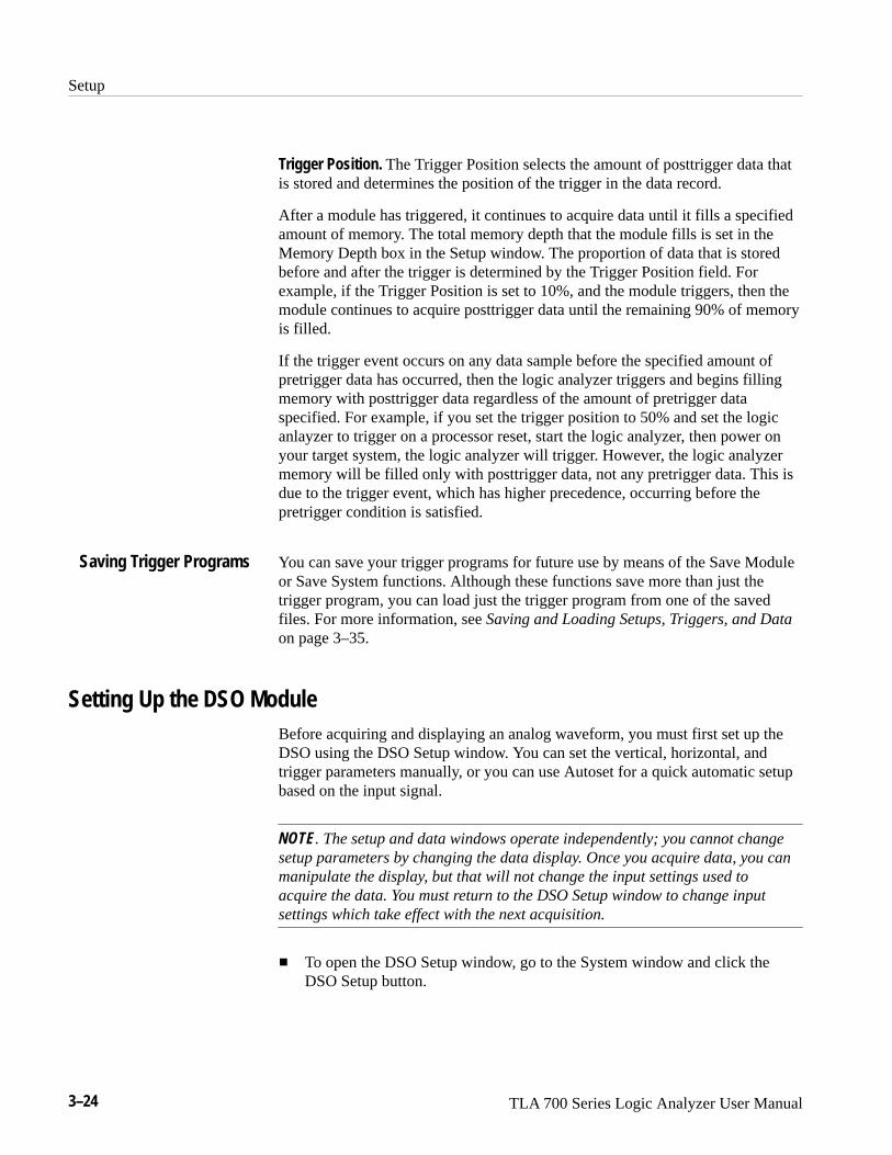
Setup
3–24 TLA 700 Series Logic Analyzer User Manual
Trigger Position. The Trigger Position selects the amount of posttrigger data thatis stored and determines the position of the trigger in the data record.
After a module has triggered, it continues to acquire data until it fills a specifiedamount of memory. The total memory depth that the module fills is set in theMemory Depth box in the Setup window. The proportion of data that is storedbefore and after the trigger is determined by the Trigger Position field. Forexample, if the Trigger Position is set to 10%, and the module triggers, then themodule continues to acquire posttrigger data until the remaining 90% of memoryis filled.
If the trigger event occurs on any data sample before the specified amount ofpretrigger data has occurred, then the logic analyzer triggers and begins fillingmemory with posttrigger data regardless of the amount of pretrigger dataspecified. For example, if you set the trigger position to 50% and set the logicanlayzer to trigger on a processor reset, start the logic analyzer, then power onyour target system, the logic analyzer will trigger. However, the logic analyzermemory will be filled only with posttrigger data, not any pretrigger data. This isdue to the trigger event, which has higher precedence, occurring before thepretrigger condition is satisfied.
You can save your trigger programs for future use by means of the Save Moduleor Save System functions. Although these functions save more than just thetrigger program, you can load just the trigger program from one of the savedfiles. For more information, see Saving and Loading Setups, Triggers, and Dataon page 3–35.
Setting Up the DSO ModuleBefore acquiring and displaying an analog waveform, you must first set up theDSO using the DSO Setup window. You can set the vertical, horizontal, andtrigger parameters manually, or you can use Autoset for a quick automatic setupbased on the input signal.
NOTE. The setup and data windows operate independently; you cannot changesetup parameters by changing the data display. Once you acquire data, you canmanipulate the display, but that will not change the input settings used toacquire the data. You must return to the DSO Setup window to change inputsettings which take effect with the next acquisition.
� To open the DSO Setup window, go to the System window and click theDSO Setup button.
Saving Trigger Programs
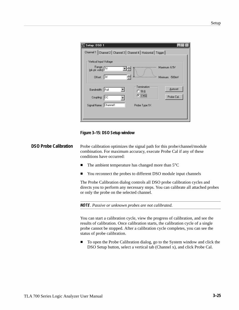
Setup
TLA 700 Series Logic Analyzer User Manual 3–25
Figure 3–15: DSO Setup window
Probe calibration optimizes the signal path for this probe/channel/modulecombination. For maximum accuracy, execute Probe Cal if any of theseconditions have occurred:
� The ambient temperature has changed more than 5°C
� You reconnect the probes to different DSO module input channels
The Probe Calibration dialog controls all DSO probe calibration cycles anddirects you to perform any necessary steps. You can calibrate all attached probesor only the probe on the selected channel.
NOTE. Passive or unknown probes are not calibrated.
You can start a calibration cycle, view the progress of calibration, and see theresults of calibration. Once calibration starts, the calibration cycle of a singleprobe cannot be stopped. After a calibration cycle completes, you can see thestatus of probe calibration.
� To open the Probe Calibration dialog, go to the System window and click theDSO Setup button, select a vertical tab (Channel x), and click Probe Cal.
DSO Probe Calibration

Setup
3–26 TLA 700 Series Logic Analyzer User Manual
NOTE. You should execute the DSO module self calibration if the ambientoperating temperature has changed more than 5�C since last calibration. Also,you should execute the self calibration once a week if vertical settings of 50 mVfull scale or less are used. Perform self calibration after a 30 minute warm up.
To open the Self Calibration property page, go to the System menu and selectCalibration and Diagnostics. Click Self Calibration.
Use Autoset when you need to see a signal in a circuit, but do not know thesignal amplitude or frequency. Autoset automatically chooses the DSO setupvalues based on the input signal at the time you clicked the Autoset button.
Autoset works best on repetitive signals that do not have a DC offset component.If the Autoset setup does not display the waveform as you want it, you can easilychange the setup manually.
To set the DSO input values based on the input signal:
1. Go to the System window and click the DSO Setup button.
2. Click Autoset from any page of the DSO Setup window.
The Autoset selections apply to all input channels, the horizontal setup, andthe trigger setup, regardless of which Autoset button was clicked.
3. If the signal changes, or you move the probe to another signal, click Autosetagain to reset the setup values.
Autoset affects only the DSO setup; it does not affect data window settings. Youmay need to adjust data window settings for optimum display of the data.
Use the vertical controls to adjust vertical input voltage parameters. SeeFigure 3–16.
� To open the page containing the vertical controls, go to the System windowand click the DSO Setup button and then select one of the Channel tabs.
Autoset
Vertical Controls

Setup
TLA 700 Series Logic Analyzer User Manual 3–27
Figure 3–16: DSO Setup window vertical input settings
For best vertical resolution, set the range just slightly larger than the expectedinput signal. Autoset automatically sets the vertical range for the signal,assuming a 0 VDC offset.
Offset. Offset is the offset voltage applied to the probe. If Range is changed usingthe preset values, then Range also sets the Offset. The Offset default is 3 V forTTL signals.
Bandwidth. Bandwidth is the range of frequencies that can be acquired anddisplayed accurately. Your bandwidth selection sets the upper limit of frequen-cies that will be acquired and displayed. Bandwidth filters reduce unwantednoise and aliasing.
Coupling. Coupling selects how the input signal is coupled to the vertical inputchannel.

Setup
3–28 TLA 700 Series Logic Analyzer User Manual
Horizontal settings control the rate at which the data is sampled and the amountof data acquired. See Figure 3–17.
� To open the horizontal page, go to the System window, click the DSO Setupbutton, and then select the Horizontal tab.
Figure 3–17: DSO Setup window Horizontal settings
Sample Period. The Sample Period sets the interval between successive samplesin a waveform record. Choose a sample period that is fast enough that thewaveform will not be aliased, and slow enough to provide the waveform recordlength that you need. For repetitive waveforms, you should set the sample periodto at least 5� faster than that of the waveform. (Sample period ≤ 1�5 waveformperiod.)
Memory Depth. The Memory Depth sets the total number of data samples to beacquired. If you do not need to use the full memory depth to acquire the data ofinterest, select a smaller memory depth to get faster acquisitions.
The DSO Trigger page contains all controls for setting DSO trigger events andactions. Threshold changes are recognized and executed immediately duringacquisitions. Execution of all other controls are delayed until the next acquisi-tion.
� To open the Trigger setup page, go to the System window and click the DSOTrigger button.
Select a trigger event from the list of event types, and then modify it for yourapplication.
Horizontal Controls
Trigger

Setup
TLA 700 Series Logic Analyzer User Manual 3–29
Event Type. Event Type selects the type of event the DSO will recognize as atrigger. Choose from the list of trigger event types. The following figure showstwo of the available trigger event selections.
Mode. Mode selects whether the DSO waits for a trigger (Normal) or forces atrigger after a set length of time has passed without a trigger (Auto).
Action. Action selects what happens when a trigger is recognized. Choose from alist of actions. Actions include triggering the DSO, triggering all modules, ortriggering and arming another module.

Setup
3–30 TLA 700 Series Logic Analyzer User Manual
Trigger Position. Trigger position sets the amount of data in the data record thatoccurs before the trigger.
� To set the Trigger Position, use the slider or enter a numeric value, as shownbelow.
Event-Based Selections. Depending on the trigger event you choose, otherselections may become available. Refer to the online help for further informa-tion.
System TriggerThe system trigger is a global trigger event that forces all untriggered modules toarm immediately and trigger. Only one system trigger occurs per acquisition.When displaying data, the logic analyzer uses the system trigger as the primaryreference point for the acquisition. The data windows show the system triggerand all module triggers. Module triggers can be forced by the system trigger orspecified by module trigger programs.
The system trigger can be generated from any of several sources. Often, thesystem trigger is specified in a module’s trigger program. Any module canspecify the system trigger as a trigger action (Trigger All Modules). However,modules can specify trigger actions other than system triggers, and the systemtrigger does not have to originate from a module. The logic analyzer can alsoaccept a system trigger generated by an external source. External system triggersare input through the SYSTEM TRIG IN connector. Regardless of the source ofthe system trigger, all modules must respond.
It is not uncommon to have a condition where the acquisition completed, butwhere an explicit system trigger did not occur. (This means that there was neitheran external system trigger, nor a system trigger generated internally by a moduletrigger program.) To ensure that a time reference exists for the acquisition, thelogic analyzer must designate a system trigger. If no system trigger is generatedduring an acquisition (the modules are internally triggered), the logic analyzerdesignates the latest-occurring module trigger as the system trigger.

Setup
TLA 700 Series Logic Analyzer User Manual 3–31
NOTE. If an acquisition does not complete, due to one or more modules notreceiving a trigger or not completing posttrigger acquisition, then you canmanually stop the acquisition by clicking the Stop button. Clicking the Stopbutton effectively generates a system trigger and completes the acquisition.
The system trigger is a latched event and it resets to a false state betweenacquisitions. The external system trigger input uses real-time gating and is onlyactive (capable of latching system triggers) during the actual acquisition period.
The logic analyzer can also send an internally-generated system trigger out to thetarget system or to other test equipment through the SYSTEM TRIG OUTconnector. All the external signal inputs and outputs operate at TTL levels. Theconnectors are located at the rear of the portable mainframe and at the front ofthe benchtop mainframe. For more information about external signalingcapabilities, see Intermodule and External Signaling on page 3–32.
Arming ModulesUsing the arm feature, you can use one module to control when another moduleaccepts triggers. When module A arms module B, this means that module B doesnot begin looking for a trigger until it receives an arm signal.
Arming is accomplished through trigger actions. For the LA module, arming isspecified in the Clause Definition dialog box; for the DSO module, arming isspecified in the Trigger page. A module can arm any one of the other modules.The designated module can be armed by only one module. The same armingaction can, however, appear multiple times within the same trigger program.
Arms are latched events which, once set, cannot be cleared until the acquisitionis completed.
NOTE. For a single module, arming and internal signaling are mutuallyexclusive. You cannot simultaneously arm modules and set signals. You can testfor a set signal (for example, If Signal X Is True), but you must designate anexternal signal for this purpose; otherwise you will be unable to set the signalwhen using the arming feature.

Setup
3–32 TLA 700 Series Logic Analyzer User Manual
Intermodule and External SignalingThe logic analyzer has four internal signals that you can use to set up triggerconditions between modules, or to send or receive signals external to the logicanalyzer. Use the Signals property page, shown in Figure 3–18, in conjunctionwith the module trigger programs to configure these signals for your application.The trigger programs determine when the signals occur. The Signals propertypage specifies characteristics of the signals.
NOTE. Be careful to observe the bandwidth and latency specifications whenusing internal and external signals. Refer to Tables 3–15 and 3–16 on pages A–3and A–5 for information.
� To open the Signals property page, go to the System menu and click SystemConfiguration. Then select the Signals tab.
Figure 3–18: Signals property page
All LA modules can set and clear any of the four internal signals. The DSO canset but not clear any signal. The logical output of these signals can be used as anevent in other modules’ trigger programs. You can also connect the internalsignals to the External Signal In and External Signal Out connectors on themainframe, so that you can use an external signal as a trigger event or send asignal out when a trigger condition is met.
Internal Signals

Setup
TLA 700 Series Logic Analyzer User Manual 3–33
Internal signaling is for users with special trigger programming requirements.Internal signaling adds flexibility to trigger programming, but also addscomplexity. When using internal signaling you must take care that the signals arecorrectly set and cleared, and that the trigger programs for all modules arecompatible with regard to signal usage. Also, you must have correctly set theinternal signal attributes in the Signals property page.
Internal signaling is accomplished through trigger actions specified in the ClauseDefinition dialog box and the DSO Trigger page.
NOTE. Arming and internal signaling are mutually exclusive. You cannotsimultaneously arm modules and set signals. You can test for a set signal (forexample, If Signal X Is True), but unless you have designated an external signalfor this purpose, you will be unable to set the signal when using the armingfeature.
Signal Logic Function. To use internal signals, you must select which internalsignal logic function is appropriate for your trigger program. Signals 1 and 2(high speed) can be asserted by only one module each. For signals 3 and 4, themodules can be wired-OR or wired-AND. Selecting the OR function means thatany module can assert the signal. Selecting AND means that all modules mustset the signal for it to be asserted. The same logic applies to clearing signals.
The logic function applies only at a module level, not to multiple set/clearstatements within a single module.
NOTE. Be careful when using wired-AND internal signals. If your triggerdepends on an internal signal, all modules must set the signal for it to beasserted, or the trigger will not occur. If you change your trigger program,remember to update the logic function settings accordingly.
The logic analyzer can send and receive signals to/from the target system usingthe External Signal In and External Signal Out connectors on the mainframe. Usethe External Signal In function to include a signal from your target system aspart of the trigger setup. Use the External Signal Out function to send a signal tothe target system or other test equipment when a trigger condition is met.
The connection from the module to the external connector is made by one of thefour internal signals. You must designate which internal signal is to be used forthis purpose.
External Signals

Setup
3–34 TLA 700 Series Logic Analyzer User Manual
The external signal connectors are located at the rear of the portable mainframeand at the front of the benchtop mainframe. The external signals all operate atTTL logic levels.
Merging ModulesYou can merge two LA modules to increase channel width. Such a mergedmodule functions as a single unit and the data it acquires is automaticallytime-correlated. This is useful when analyzing buses or devices with a high pincount. In addition, some microprocessor support packages require mergedmodules.
Modules must have the same maximum state speed and must be physicallyconnected in the mainframe before they can be merged by software. Modulesmust be adjacent and connected as described in the TLA 700 Series LogicAnalyzer Installation Manual.
When LA modules are merged, only one set of clock channels needs to beconnected to the target system to acquire data. This makes it easier to connectand reduces capacitive loading.
Modules that have been physically connected in the mainframe, and are thereforecapable of being merged, are shown in the Merge Modules property page with amerge button. See Figure 3–19.
� To open the Merge Modules property page, go to the System menu and clickSystem Configuration. Then select the Merge Modules tab. To merge orunmerge modules, click the merge button between the module icons.
Merge button
Figure 3–19: Merging modules

Setup
TLA 700 Series Logic Analyzer User Manual 3–35
NOTE. After the modules have been physically merged, you should run theself-calibration procedure on the modules as a merged pair. To run the self-cal-ibration procedure, go to the System menu and select Calibration and Diagnos-tics. Click Self Calibration.
You can unmerge the modules at any time for independent operation. You do nothave to remove the hardware connection between the modules.
In setup and data windows, merged module probe names use the followingconvention: master module probe names are displayed normally, and slavemodule probe names are prepended with an S.
Saving and Loading Setups, Triggers, and DataOnce you set up the logic analyzer to your satisfaction, you will probably wantto save the setup for future use. You can save setup information in two ways, asaved system file or a saved module file.
Refer to the Logic Analyzer Conceptual Model described on page 2–6. Themodules consist of the setup, trigger, and data associated with the physical LA orDSO module installed in the logic analyzer. The system consists of the setup anddata for the whole logic analyzer, including all the modules and all datawindows. See Figure 3–20.
When you save a module, you save all the setup and trigger information for thatmodule. When you save a system, you save all the setup information for thesystem, including data window display settings, and all the module information,as well. In either case, you have the option of saving acquired data.
SetupTriggerData
Module 1
System
Data WindowsGeneral Settings
Module 2 Module n
SetupTriggerData
SetupTriggerData
Figure 3–20: Logic analyzer conceptual model

Setup
3–36 TLA 700 Series Logic Analyzer User Manual
Determine whether you want to save the information from just the module or forall modules. Select Save System or Save Module accordingly. If you want tosave the data in addition to the setup and trigger information, select SaveAcquired Data.
You execute Save operations from the File menu.
NOTE. When saving systems or modules, be aware that the data is by far thelargest component of the save file. If the data is not important, you can savesignificant disk space by saving the file without saving the data.
Saved system and module file names have a .tla file name extension (file-name.tla). The initial default location for saved files is C:\My Documents.
Figure 3–21: Saving a system with data
The logic analyzer stores all the setup, trigger, and data information in just twotypes of files: saved module and saved system. However, the logic analyzer canextract different types of information individually from these files. From a savedmodule file, you have the option of loading any of the following:
� An LA module trigger program
� A module setup and trigger program
� Saved data from the module (accomplished by opening a saved data window;see Opening a Saved Data Window on page 3–49)
Saving System andModule Files
Loading Saved Systemand Module Files

Setup
TLA 700 Series Logic Analyzer User Manual 3–37
From a saved system file, you can load any of the following:
� Any of the previous module-related choices
� Full system setup, including data windows
� Saved data from one or more modules
You execute Load operations from the File menu. For module Load operations,you must first go to the module Setup or Trigger window before accessing theFile menu.
Loading a System. When you load a system you load the full system setup, whichincludes setup, data, and trigger information for the logic analyzer and allinstalled modules. If the saved system file included data, the data windows andsaved data are also loaded.
There may be situations where you attempt to load a saved system with adifferent module configuration than your current system. The Load SystemOptions dialog box displays informing you of the differences. To load a modulefrom the saved system, drag the module icon from the top of the dialog box to amodule icon in the bottom of the dialog box. Figure 3–22 shows an example ofthe Load System Options dialog box.
Figure 3–22: Load System Options dialog box
Loading a Setup and a Trigger Program. When you execute a Load System orLoad Module operation, you load a saved setup and its related trigger program(s)to the logic analyzer (system) or specified module.

Setup
3–38 TLA 700 Series Logic Analyzer User Manual
Loading Saved Data. You can load saved data using the Load Data Windowselection in the Window menu. See Opening a Saved Data Window onpage 3–49 for more information.
Loading a Saved Trigger. You can load an LA module trigger without loading afull setup. Saved system and module files both contain trigger programinformation. When you load a trigger from the LA Trigger window, you canselect a saved system or module file as the source. When you do so, the logicanalyzer extracts only the trigger information from the file and loads it to themodule.
Creating a Personalized Trigger Library. To create your own trigger library, followthese steps:
1. Create a folder in a convenient location. For example, create a folder namedProject Trigger Library in the folder My Documents. The path name wouldbe as follows:
���� ����� ������� �� ����� � ������
2. Go to the Trigger window containing the trigger program you want to save.
3. Go to the File menu and select Save Module As.
4. In the Save As dialog box, navigate to your trigger library folder.
5. Name the new file, and use the Comment box to enter descriptive comments.See Figure 3–23.
6. Make sure that Save Acquired Data is not selected.
7. Click Save.
Figure 3–23: Saving a file in a personalized trigger library

Setup
TLA 700 Series Logic Analyzer User Manual 3–39
To return the logic analyzer to its default condition, go to the File menu and clickDefault System.
System OptionsThe logic analyzer provides several property pages where you can set or changesystem options. To access the system options, select Options from the Systemmenu and choose the property page you are interested in.
� Use the Color property page to create, remove, and modify color schemes.
� Use the Defaults property page to specify the defaults throughout theTLA 700 application. The settings you enter will be the default settings whenyou create new data windows.
� Use the Preference property page to specify user preferences, such aschanging the color of the Run or Stop buttons or hiding the Status bar.
� Use the Presets property page to view and modify preset names and valuessuch as probe threshold voltages and DSO vertical range or vertical offsetvalues.
� Use the Start-Up property page to select which system setup (such as aprevious system or a saved system setup) to open after you power on thelogic analyzer.
� Use the System Source Files property page to define the location of sourcefiles and suffixes used to create new Source windows.
Loading Default Settings

Setup
3–40 TLA 700 Series Logic Analyzer User Manual
Menu Shortcut KeysYou can use the shortcut keys listed in Table 3–5 to manipulate menus and editwindows. You should also refer to the discussions of short cut keys in the onlinehelp or under the section for the individual data windows.
Table 3–5: Menu shortcut keys
Desired action Key combination
File menu
Return system to the default setups CTRL + D
Load a saved system CTRL + O
Save a system setup CTRL + S
Print the active window CTRL + P
Edit menu
Cut a selected item to the clipboard CTRL + X
Copy a selected item to the clipboard CTRL + C
Paste items from the clipboard CTRL + V
Undo edit CTRL + Z
Data menu
Search backward CTRL + B
Search forward CTRL + F
System menu
Display the Status Monitor CTRL + M
Run or Stop CTRL + R
Window menu
Create a new data window CTRL + N

TLA 700 Series Logic Analyzer User Manual 3–41
Acquisition
After you set up the logic analyzer you are ready to acquire the data.
When you start an acquisition, all modules start acquiring data together.(Exceptions are when one module has been programmed to arm another or whena module has been turned off.) Modules stop acquiring data individually,according to their trigger programming.
Starting and Stopping AcquisitionYou control acquisition from the Control bar, shown below:
Starts/stops acquisition
Selects Repetitive orSingle-run mode
Displays Status Monitor
1. In the Control bar, click Run to start acquisition.
2. Wait for the logic analyzer to trigger and display data, or click Stop tomanually stop acquisition.
There are two ways to acquire data: Single-run or Repetitive mode. WithinRepetitive mode, you can specify the following three conditions:
� Save Module and Data
� Stop if Compare with Reference is Equal or Not Equal
� Stop After N Acquisitions
When comparing acquisition data against reference data, you can view the resultsin either a Listing window or in a Waveform window.

Acquisition
3–42 TLA 700 Series Logic Analyzer User Manual
In Single-run mode, the logic analyzer automatically stops acquiring anddisplays data when it fulfills the setup conditions. Use Single-run mode whenyou want to find and display a specific event.
During acquisition, the logic analyzer monitors the data, looking for the eventsyou specified in the Trigger windows. When the specified events occur, the logicanalyzer responds according to the selections you made in the Setup and Triggerwindows.
In Repetitive mode, the logic analyzer keeps acquiring data until you click Stopor until it fulfills the stop conditions.
You can use Repetitive mode as follows:
� To observe the same waveform or listing for a period of time
� To stop after a set number of acquisitions for a period of time and look fordifferences
After each acquisition you can have the logic analyzer do the following tasks:
� Save the system or module setups and data
� Export the data to separate files or overwrite the same file
� Compare the LA acquisition data against data in another LA module or asaved LA module file
� To open a file or execute a set of defined tasks after the acquisition iscomplete. For example, you can run a WIndows 95 command such assending email or paging you that the logic analyzer has stopped.
Select Repetitive Properties from the System menu to select the different optionsfor the Repetitive mode. Figure 3–24 shows an example of the RepetitiveProperties dialog box.
NOTE. You can minimize the time between acquisitions by specifying compareconditions under the LA Setup window, deleting (not just minimizing) all datawindows, and then starting the logic analyzer. When the logic analyzer fulfillsthe compare conditions, you can create a new data window with the New DataWindow wizard to view the data.
Single Run Mode
Repetitive Mode

Acquisition
TLA 700 Series Logic Analyzer User Manual 3–43
Figure 3–24: Defining setups for Repetitive mode
Viewing Acquisition ActivityWhile the logic analyzer is acquiring data, you can check its progress to see howmuch data it has acquired or to view channel activity.
Use the Status Monitor for a brief summary of acquisition, trigger, and datastorage progress. See Figure 3–25.
� In the Control bar, click Status.
Figure 3–25: The Status Monitor

Acquisition
3–44 TLA 700 Series Logic Analyzer User Manual
The Status Monitor is also useful to debug a trigger program. From the StatusMonitor you can view the current status of various resources of the logicanalyzer during acquisition. However, be aware that rapid changes in triggerstate, counter values, timer values, and the internal signals cannot be accuratelydisplayed in real time in the Status Monitor.
If the Logic Analyzer Does Not TriggerIf the logic analyzer does not trigger, then you should check the following:
� Check that your target system is powered on.
� Check the System window to verify that required modules are turned on.
� If the module has correctly clocked data, acquired the specified events,triggered, but has not stopped, the module probably has not acquired enoughadditional data to fill acquisition memory. Click Stop to manually stop theacquisition, and then change the module Memory Depth (reduce) or TriggerPosition (increase).
The following conditions apply to the LA module only:
� Check the Status Monitor for an external clock warning. If the LA is notreceiving an external clock, the Status Monitor displays the followingmessage: External Clock Source Idle.
� Check for signal activity at the probe tip. If there is no activity, then checkthe probe connections.
Check the clock signal to make sure that the LA module is actually clockingdata. Problems with the clock signal can impact setups using externalclocking, custom clocking (microprocessor support packages only), orstorage qualification.
� Similar to the previous item, check clock qualifier signals and clockingequations.
� Check the threshold voltages for probes and clocks.
� If the module is correctly clocking data and the data events have occurred,but the trigger program did not generate a trigger, then you should check thetrigger program itself. The trigger program might not be reaching the statethat generates the trigger. Use the Status Monitor to track trigger programprogress and identify the state in which trigger progress stops.
LA Module

Acquisition
TLA 700 Series Logic Analyzer User Manual 3–45
� Check the complexity of your trigger program. If your trigger program is toonarrowly defined, or over-specified, the trigger program might not acquirethe desired data or might not trigger. A less-specific trigger program mightacquire the desired data and will also verify that you have set up the properclocking and threshold levels.
The following condition applies to the DSO module only:
� Check the trigger Mode setting. If Mode is set to Normal, and the data doesnot meet the trigger conditions, the module will not trigger. (Conversely, ifMode is set to Auto, the module will trigger after a set length of time, even ifthe specified data does not occur.)
The following conditions apply only if you are using arming or intermoduletriggering:
� Internal signal logic function. If your trigger depends on setting an internalsignal, and that signal has been set to Wired-And, all modules in the systemmust set the signal or it cannot assert.
� If any modules are turned off, check that the trigger program is not waitingfor input from an inactive module.
DSO Module
Arming or IntermoduleTriggering

Acquisition
3–46 TLA 700 Series Logic Analyzer User Manual

TLA 700 Series Logic Analyzer User Manual 3–47
Display
To view acquired data, open one of the data windows. The Listing window andthe Waveform window are the data windows that you will use for most applica-tions; see Figure 3–26. You can also create Source windows to use withhigh-level language support applications or Histogram windows to use withperformance analysis applications. You can have multiple data windows todisplay different data or different views of the same data.
Figure 3–26: The Listing and Waveform windows
Setup window and data window controls act independently of one another.Controls in the Setup windows affect how the modules acquire data. Controls inthe data windows affect how the acquired data is displayed.

Display
3–48 TLA 700 Series Logic Analyzer User Manual
Opening an Existing Data WindowThe System window shows the relationship between the modules and the datawindows.
� To open a data window, go to the System window and click a data windowbutton. See Figure 3–27.
� To see which modules supply data to a data window, go to the Systemwindow and click the data window label.
Figure 3–27: Opening a data window

Display
TLA 700 Series Logic Analyzer User Manual 3–49
Opening a Saved Data WindowTo open a window displaying data from a saved system file, do the following:
1. Go the Window menu and select Load Data Window.
2. Click Browse to search for the file or enter a path to the file in the text box.
NOTE. The saved file must be a saved system file.
3. Once the file is found, click Open.
4. Select the data window to load.
5. Click OK.
6. If the data window name is not unique, you will be prompted for a newname. Enter a name and click OK.
Aligning Saved Data with Current DataSaved data and current data are time-correlated by aligning their system triggers.You can manually adjust this alignment using the Time Alignment dialog box.To access the Time Alignment dialog box, go to the Data menu and select TimeAlignment, as shown below.

Display
3–50 TLA 700 Series Logic Analyzer User Manual
Creating a New Data WindowUse the New Data Window wizard to create a new data window for the data youwant to display. You can select data from any module, a saved system file, orsaved module file. See Figure 3–28.
Figure 3–28: New Data Window wizard
Create a new data window as follows:
1. Click the New Data Window icon in the toolbar.
2. Select the appropriate Window Type and click Next.
NOTE. The contents of the New Data Window wizard will vary depending on thetype of data window that you are creating.
3. For each page in the wizard, enter the required information and click Next.
4. On the last page, enter the name for the data window or use the default nameand then click Finish.
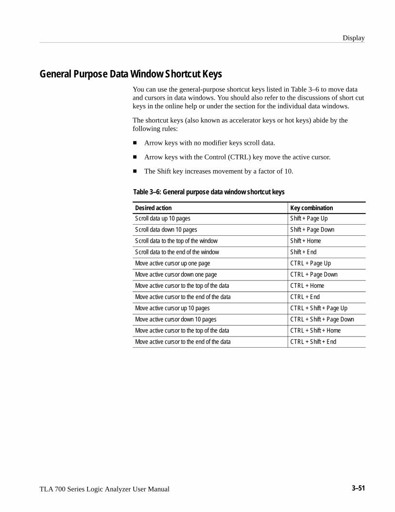
Display
TLA 700 Series Logic Analyzer User Manual 3–51
General Purpose Data Window Shortcut KeysYou can use the general-purpose shortcut keys listed in Table 3–6 to move dataand cursors in data windows. You should also refer to the discussions of short cutkeys in the online help or under the section for the individual data windows.
The shortcut keys (also known as accelerator keys or hot keys) abide by thefollowing rules:
� Arrow keys with no modifier keys scroll data.
� Arrow keys with the Control (CTRL) key move the active cursor.
� The Shift key increases movement by a factor of 10.
Table 3–6: General purpose data window shortcut keys
Desired action Key combination
Scroll data up 10 pages Shift + Page Up
Scroll data down 10 pages Shift + Page Down
Scroll data to the top of the window Shift + Home
Scroll data to the end of the window Shift + End
Move active cursor up one page CTRL + Page Up
Move active cursor down one page CTRL + Page Down
Move active cursor to the top of the data CTRL + Home
Move active cursor to the end of the data CTRL + End
Move active cursor up 10 pages CTRL + Shift + Page Up
Move active cursor down 10 pages CTRL + Shift + Page Down
Move active cursor to the top of the data CTRL + Shift + Home
Move active cursor to the end of the data CTRL + Shift + End

Display
3–52 TLA 700 Series Logic Analyzer User Manual

TLA 700 Series Logic Analyzer User Manual 3–53
Waveform Window
Use the Waveform window to display and evaluate acquisition data. You candisplay both DSO waveforms and logic analyzer waveforms. Each windowcontains a data area, waveform labels, marks and several toolbars that allow youto measure and manipulate your waveforms. See Figure 3–29 for an example.
Each waveform is displayed independently within its own track. Waveformscannot be overlapped.
For the LA module, data values for each channel are shown as a digital(two-state) waveform. Logic level low is drawn as a thick line; logic high as athin line. For the DSO module, data values for each channel are displayed as ananalog waveform.
Figure 3–29: Waveform window

Waveform Window
3–54 TLA 700 Series Logic Analyzer User Manual
Types of WaveformsThere are several types of waveforms that can be shown in the Waveformwindow, as shown in Figure 3–30.
DSO waveform
Single-channel LA waveformSample clock waveform
Busform LA waveforms
Figure 3–30: Waveform types
Busforms display the value of an LA module channel group.
����� ����� ������� ���� ������ � ��� �� ����� �
Magnitude waveforms plot the numeric value of a channel group on a verticalaxis over a period of time. For example, you can use magnitude waveforms withA/D and D/A applications for viewing the RGB components of a digitized videosignal. Figure 3–31 shows such a component.
Busforms
Single-Channel LAWaveforms
Magnitude Waveforms
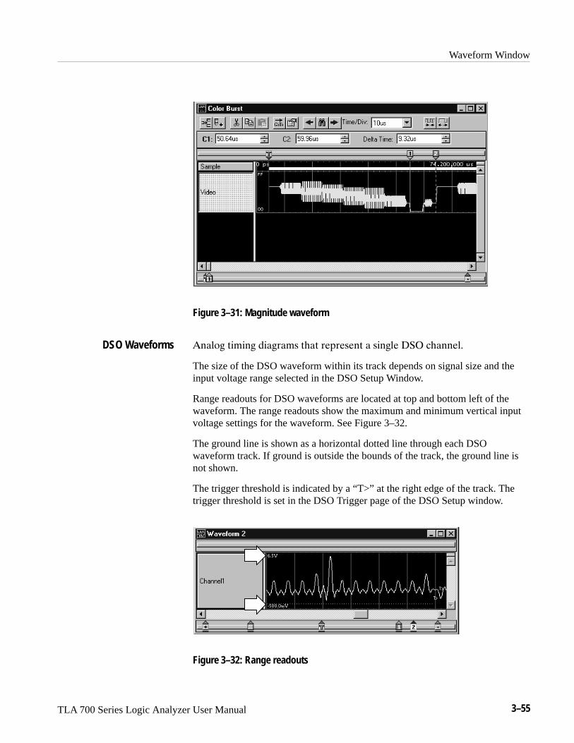
Waveform Window
TLA 700 Series Logic Analyzer User Manual 3–55
Figure 3–31: Magnitude waveform
������ � � �� ������ ���� ������ � � ��� ��� �������
The size of the DSO waveform within its track depends on signal size and theinput voltage range selected in the DSO Setup Window.
Range readouts for DSO waveforms are located at top and bottom left of thewaveform. The range readouts show the maximum and minimum vertical inputvoltage settings for the waveform. See Figure 3–32.
The ground line is shown as a horizontal dotted line through each DSOwaveform track. If ground is outside the bounds of the track, the ground line isnot shown.
The trigger threshold is indicated by a “T>” at the right edge of the track. Thetrigger threshold is set in the DSO Trigger page of the DSO Setup window.
Figure 3–32: Range readouts
DSO Waveforms
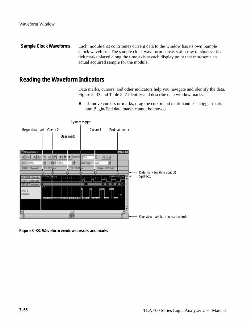
Waveform Window
3–56 TLA 700 Series Logic Analyzer User Manual
Each module that contributes current data to the window has its own SampleClock waveform. The sample clock waveform consists of a row of short verticaltick marks placed along the time axis at each display point that represents anactual acquired sample for the module.
Reading the Waveform IndicatorsData marks, cursors, and other indicators help you navigate and identify the data.Figure 3–33 and Table 3–7 identify and describe data window marks.
� To move cursors or marks, drag the cursor and mark handles. Trigger marksand Begin/End data marks cannot be moved.
System trigger
Cursor 1
User mark
Data mark bar (fine control)
Overview mark bar (coarse control)
Begin data mark End data mark
Split box
Cursor 2
Figure 3–33: Waveform window cursors and marks
Sample Clock Waveforms

Waveform Window
TLA 700 Series Logic Analyzer User Manual 3–57
Table 3–7: Waveform window cursor and mark summary
Mark Name Description
System trigger The system trigger is the reference point for the acquisition. Timing and locationinformation is relative to the system trigger. Trigger marks cannot be moved.
Under some conditions the system trigger associated with a module’s data mightnot be displayed in the data window. If the system trigger was caused by anothermodule, whose data is not included in the current display, then the system triggeris not shown. Nevertheless, all time measurements still relate to that systemtrigger, even if it is not shown.
The system trigger associated with the current data is called the active systemtrigger. The system trigger associated with saved data is called the referencesystem trigger. The active system trigger is indicated by a yellow T; the referencesystem trigger is indicated by a gray T.
Module trigger The point at which the module triggered. Trigger marks cannot be moved.
Begin data / end data The start and end of a module’s data record. These data marks cannot be moved.
Cursors 1 and 2 Moveable marks used for visual reference and for data measurements.
User mark User-created marks. Use marks to make specific data more easy to identify andfind.
You can mark interesting data that you may want to refer back to at a later time.To add a user mark, follow these steps:
1. In the System window, click the Waveform window icon.
2. From the Edit menu select Add Mark. The mark appears at the center of thedisplay, has default properties, and is selected.
3. Move the mark to the desired location by dragging its handle.
NOTE. You cannot add a mark if you have not acquired data.
Sometimes, marks can be stacked on top of one another. To send a mark to theback, follow these steps:
1. Select a mark you know is on top of another one.
2. Click the right mouse button and select Send To Back.
Adding a Mark to aWaveform Window
Sending Stacked Marks tothe Back

Waveform Window
3–58 TLA 700 Series Logic Analyzer User Manual
Cursor MeasurementsUse the cursors to take time and voltage measurements. You take time andvoltage measurements in the Waveform window, as shown below.
The following steps describe how to take a time measurement. Use the samemethod to take a voltage measurement for the DSO module. (Magnitude on anLA module waveform is expressed as a 1 or a 0.)
1. In the Waveform window, select a waveform.
2. Move Cursor 1 to the location on the waveform that you want to measure.
3. Read the time from the C1 readout on the measurement bar.
4. Move Cursor 2 to another location on the waveform that you want tomeasure.
5. Read the time from the C2 readout on the measurement bar.
6. Read the time difference between the two waveform locations from the Deltareadout on the measurement bar.
Cursor time is relative to the active system trigger.

Waveform Window
TLA 700 Series Logic Analyzer User Manual 3–59
Jumping to Specific Data LocationsYou can use the Go To dialog box to jump to a new position by selecting anycurrent mark or waveform. See Figure 3–34.
� To open the Go To dialog box, open a Waveform window and click theGo To toolbar button, as shown in Figure 3–34.
Figure 3–34: Using the Go To dialog box to jump to the system trigger
You can also use the Overview Mark bar to quickly jump to another location. Ifyou do not click on a mark, clicking in the Overview Mark bar scrolls to thatlocation.
Figure 3–35: Using the Overview Mark bar to jump to a data location

Waveform Window
3–60 TLA 700 Series Logic Analyzer User Manual
Searching DataUse the Define Search dialog box to search for specific data within the currentWaveform window. Searches are specific to the selected data source and beginfrom the active cursor.
To search for a specific event in a Waveform window, follow these steps:
1. Open a Waveform window and click the Define Search toolbar button, asshown.
2. Select the Data Source. See Figure 3–36.
3. Select the appropriate name.
4. Select the Condition.
5. Enter the Value, if appropriate.
6. Click Search Fwd or Search Back. The first occurrence is marked bycursor 1.
You can search any data source available to the current data window, but Searchcan only search one data source at a time. For additional searches of the sameevent, click the Search Forward and Search Back arrow buttons in the toolbar.
NOTE. Data that is hidden cannot be found by the search function. For example,if you turn off a waveform in the Waveform property page by unchecking ShowWaveform, the search function cannot search for data for that waveform.

Waveform Window
TLA 700 Series Logic Analyzer User Manual 3–61
Figure 3–36: Defining search criteria
Locking WindowsLocking windows provides an easy method to compare data from two differentwindows. Use the Lock Windows dialog box, shown in Figure 3–37, to selecthow windows are locked together.
� To open the Lock Windows dialog box, go the System window and click thebutton for the data window you want to open. Go to the View menu andselect Lock Windows.
Figure 3–37: Lock Windows dialog box

Waveform Window
3–62 TLA 700 Series Logic Analyzer User Manual
MagniVu DataThe LA modules have MagniVu data acquisition as a standard feature. MagniVudata acquisition offers 500 picosecond high-speed timing simultaneous with200 MHz state on all channels through the same probe; no double probing isrequired. The record length for MagniVu data is 2000 samples. MagniVu data iscentered on the LA module trigger. Figure 3–38 shows an example of MagniVudata.
You can view MagniVu data in both Listing and Waveform windows.
In Figure 3–38, the top waveforms were acquired at the fastest normal samplerate. The MagniVu waveforms, in the lower part of the display, were acquiredthrough the same probe channels at the same time as the top waveforms.
Take a close look at the difference in the acquired data. First view the regulardata acquisition, which was sampled at 4 ns. The regular acquisition captured theaddress bus as it made the transition from 34 to 44. The data shows an invalidaddress of 74, and indicates that the invalid address lasts for the entire 4 nssample period. At the next sample, the address is shown correctly as 44.
Now view the MagniVu data acquisition, which was sampled at 500 ps. TheMagniVu data shows the same address bus transition from 34 to the invalidaddress of 74, before settling to the correct address of 44. Note, however, that theindicated settling time is different. The MagniVu data shows that the address bustook approximately 500 ps to complete the transition, and shows the address busas 44 approximately 3.5 ns earlier than did the regular acquisition data.
Figure 3–38: MagniVu data

Waveform Window
TLA 700 Series Logic Analyzer User Manual 3–63
To display MagniVu data, load the MagniVu data source as follows:
1. Open a data window that contains acquired data.
2. Click Add Column or Add Waveform.
3. Select the MagniVu data source. If the source you want is not listed, clickAdd Data Source and add the one you want to the list. See Figure 3–39.
4. Click Add. The column or waveform appears in the data window.
Figure 3–39: Adding a MagniVu data source to a data window
Comparing Waveform DataWhen comparing data against reference data, you can highlight data that is equalto or not equal to the reference data.
NOTE. Before you can display compare data, you must define the compareparameters in the Define Compare Dialog box in the LA Setup window. Refer toMemory Compare beginning on page 3–4 for information on setting up thecompare parameters.

Waveform Window
3–64 TLA 700 Series Logic Analyzer User Manual
The following steps describe how to display compare data in the Waveformwindow.
1. Open a Waveform window and click the Properties toolbar button, as shown.
2. Select the Waveform Window property page.
3. Select Show Compare and select one of the colors for when data does notequal the reference data (Acq!=Ref).
If you want to highlight data that does equal the reference data, selectAcq=Ref and the appropriate color (see Figure 3–40).
Figure 3–40: Selecting compare data colors in the Waveform Window property page
4. Click OK.
The data differences or equalities will be highlighted in colors you specified,similar to Figure 3–41.
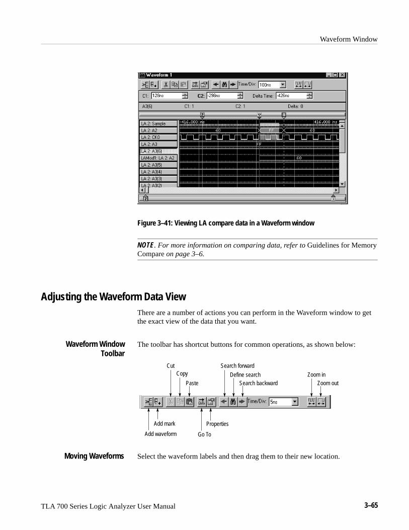
Waveform Window
TLA 700 Series Logic Analyzer User Manual 3–65
Figure 3–41: Viewing LA compare data in a Waveform window
NOTE. For more information on comparing data, refer to Guidelines for MemoryCompare on page 3–6.
Adjusting the Waveform Data ViewThere are a number of actions you can perform in the Waveform window to getthe exact view of the data that you want.
The toolbar has shortcut buttons for common operations, as shown below:
Add waveform
Add mark
CutCopy
Paste
Go To
Properties
Search backwardDefine search
Search forward
Zoom inZoom out
Select the waveform labels and then drag them to their new location.
Waveform WindowToolbar
Moving Waveforms

Waveform Window
3–66 TLA 700 Series Logic Analyzer User Manual
Click the toolbar Add Waveform button to open the Add Waveform dialog box.Then select the data source and its associated group or channel to add it to thedisplay.
To select a group, first select By Group. (See Figure 3–42.) Then, from the list,select a group name indicated by a the + symbol. Default groups are displayed asbusforms. (You can also choose to display a group as a magnitude waveform.Double-click the waveform label. From the waveform properties page, clickOptions and select Magnitude.)
To select individual channels, first select By Probe. Then, from the list, select thechannel(s). If you have named individual channels in the LA Setup window, youcan select By Name to list just those channels.
If the data source you want is not listed, click Add Data Source and find andselect the source. (The data source can be an installed module or a saved modulefile.) See Figure 3–42.
New waveforms are added after the selected waveforms or after all waveforms ifnone are selected.
Figure 3–42: Add Waveform dialog box
Select the waveform labels, then click the Cut toolbar button.
Adding a New Waveformor a Data Source
Deleting Waveforms

Waveform Window
TLA 700 Series Logic Analyzer User Manual 3–67
Drag the waveform label border as shown.
To change the height of a waveform, double-click on the waveform label to openthe Waveform property page. Enter a new value or use the spinbox controls tochange the value in the Height box.
In addition to adjusting the height using the Waveform property page, you canselect the waveform, and adjust the waveform from the front-panel Size controlon the portable mainframe.
Change the displayed time per division using the Time/Div toolbar control. For aquick change, use the Zoom In and Zoom Out toolbar buttons. You can continueto click the toolbar buttons until you reach the desired horizontal scale.
You can cut, copy, and paste waveforms and marks.
Glitches are indicated on a waveform by a block of color behind the waveform.See Figure 3–43. Turn the glitch display on or off from the Waveform windowproperty page.
NOTE. To view glitches in a data window, you must enable Glitch storage in theSetup window before acquiring data.
Glitch
Figure 3–43: Waveform with a glitch
Rename a waveform by returning to the Setup window and changing the channelor channel group name.
Changing Waveform LabelWidth
Changing WaveformHeight
Changing the DisplayedTime/Div
Cut, Copy, and Paste
Viewing Glitches
Naming Waveforms
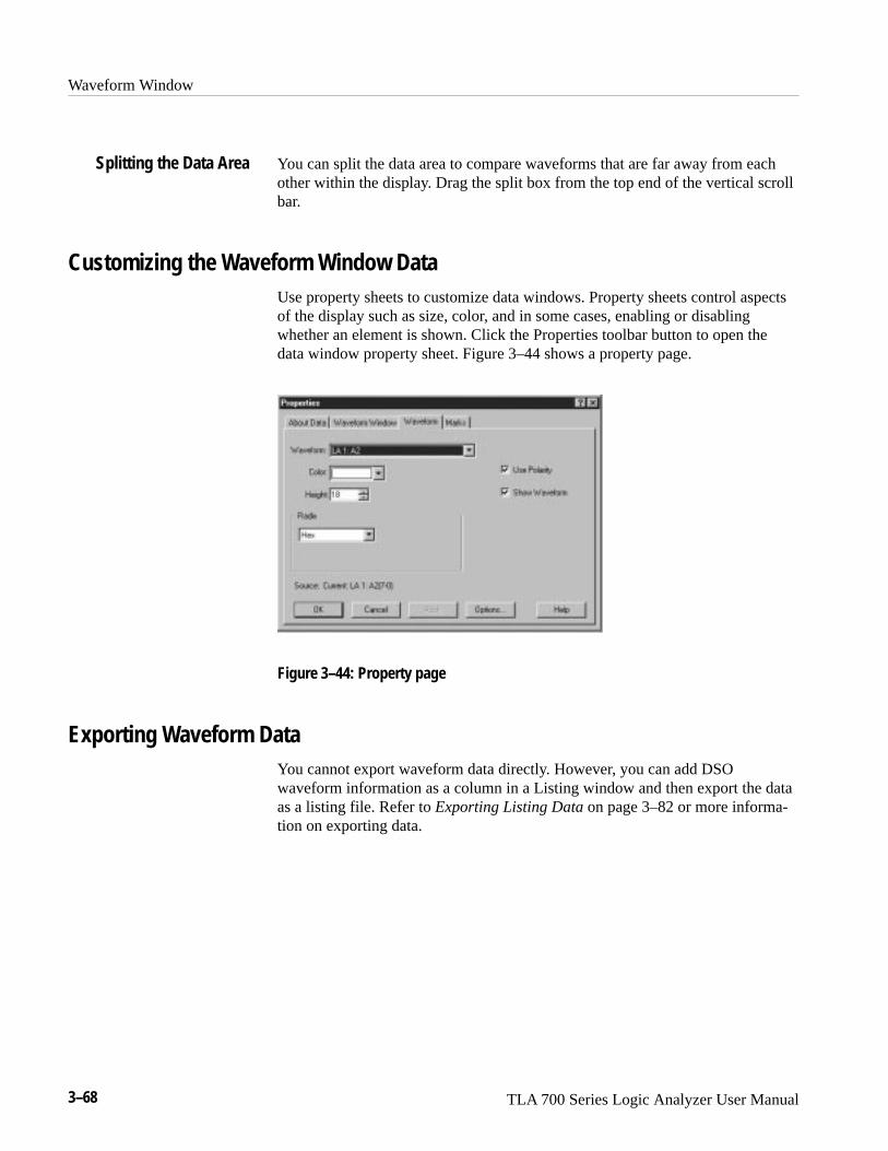
Waveform Window
3–68 TLA 700 Series Logic Analyzer User Manual
You can split the data area to compare waveforms that are far away from eachother within the display. Drag the split box from the top end of the vertical scrollbar.
Customizing the Waveform Window DataUse property sheets to customize data windows. Property sheets control aspectsof the display such as size, color, and in some cases, enabling or disablingwhether an element is shown. Click the Properties toolbar button to open thedata window property sheet. Figure 3–44 shows a property page.
Figure 3–44: Property page
Exporting Waveform DataYou cannot export waveform data directly. However, you can add DSOwaveform information as a column in a Listing window and then export the dataas a listing file. Refer to Exporting Listing Data on page 3–82 or more informa-tion on exporting data.
Splitting the Data Area

Waveform Window
TLA 700 Series Logic Analyzer User Manual 3–69
Printing Waveform DataYou can print a hardcopy of the Waveform window or you can print the image toa file. You can print a single page, a range of pages, or you can print a range ofdata between two marks or cursors.
1. Go to the File menu and select Print.
2. Select Print to File, or select your printer in the window.
3. Select the print range and click OK.
When you click OK a confirmation message displays, informing you of thenumber of approximate pages that will be printed.
4. Click OK again to confirm your actions.
5. To interrupt printing at any time, press ESC.
The contents of the window will be sent to the printer or to the specified file.

Waveform Window
3–70 TLA 700 Series Logic Analyzer User Manual
Waveform Window Shortcut KeysYou can use the general-purpose shortcut keys listed in Table 3–8 to move dataand cursors in the Waveform window. You should also refer to the discussions ofshort cut keys in the online help or under the section for the individual datawindows.
The shortcut keys (also known as accelerator keys or hot keys) abide by thefollowing rules:
� Arrow keys with no modifier keys scroll data.
� Arrow keys with the Control (CTRL) key move the active cursor.
� The Shift key increases movement by a factor of 10.
Table 3–8: Waveform window shortcut keys
Desired action Key combination
Go to next trigger CTRL + T
Display Go To dialog box CTRL + G
Move Cursor 1 to the center of the window CTRL + 1
Move Cursor 2 to the center of the window CTRL + 2
Zoom in CTRL + I
Zoom out CTRL + U
Add a mark CTRL + K
Add a waveform CTRL + W
Scroll data left 50 pixels Shift + Left arrow
Scroll data right 50 pixels Shift + Right arrow
Move active cursor left five pixels CTRL + Left arrow
Move active cursor right five pixels CTRL + Right arrow
Move active cursor left 50 pixels CTRL + Shift + Left arrow
Move active cursor right 50 pixels CTRL + Shift + Right arrow

TLA 700 Series Logic Analyzer User Manual 3–71
Listing Window
Use the Listing window to view and evaluate acquisition data. Data is presentedas tabular text in columns that represent channel groups. Other columns aresample numbers and time stamp values. See Figure 3–45 for an example.
This window displays the amount of data you specified in Setup and Triggerwindows. Each row in the table consists of data sampled on one acquisitioncycle, and is assigned a sample number. Sample numbers are relative to thebeginning of memory.
Figure 3–45: Listing window
Reading the Listing Window IndicatorsData marks, cursors, and other indicators help you navigate and identify the data.Figure 3–46 and Table 3–9 identify and describe data window marks.
� To move cursors or marks, drag the cursor and mark handles. Trigger marksand Begin/End data marks cannot be moved.

Listing Window
3–72 TLA 700 Series Logic Analyzer User Manual
Module trigger
System trigger
Cursors
User mark
Data mark bar(fine control)
Split box
End data mark
Overview mark bar(coarse control)
Figure 3–46: Listing window cursors and marks
Table 3–9: Listing window cursor and mark summary
Mark Name Description
System trigger The system trigger is the reference point for the acquisition. Timing and locationinformation is relative to the system trigger. Trigger marks cannot be moved.
Under some conditions the system trigger associated with a module’s data mightnot be displayed in the data window. If the system trigger was caused by anothermodule, whose data is not included in the current display, then the system triggeris not shown. Nevertheless, all time measurements still relate to that systemtrigger, even if it is not shown.
The system trigger associated with the current data is called the active systemtrigger. The system trigger associated with saved data is called the referencesystem trigger. The active system trigger is indicated by a yellow T; the referencesystem trigger is indicated by a gray T.
Module trigger The point at which the module triggered. Trigger marks cannot be moved.
Begin data / end data The start and end of a module’s data record. These data marks cannot be moved.
Cursors 1 and 2 Moveable marks used for visual reference and for data measurements.
User mark User-created marks. Use marks to make specific data more easy to identify andfind.

Listing Window
TLA 700 Series Logic Analyzer User Manual 3–73
You can mark interesting data that you may want to refer back to at a later time.To add a user mark, follow these steps:
1. In the System window, click the Listing window icon.
2. From the Edit menu select Add Mark. The mark appears at the center of thedisplay, has default properties, and is selected.
3. Move the mark to the desired location by dragging its handle.
NOTE. You cannot add a mark if you have not acquired data.
Sometimes, marks can be stacked on top of one another. To send a mark to theback, follow these steps:
1. Select a mark you know is on top of another one.
2. Click the right mouse button and select Send To Back.
Jumping to Specific Data LocationsYou can use the Go To dialog box to jump to a new position by selecting anycurrent mark or waveform. See Figure 3–47 on page 3–74.
� To open the Go To dialog box, open a data window and click the Go Totoolbar button, as shown in Figure 3–47.
Adding a Mark to a ListingWindow
Sending Stacked Marks tothe Back

Listing Window
3–74 TLA 700 Series Logic Analyzer User Manual
Figure 3–47: Using the Go To dialog box to jump to the system trigger
You can also use the Overview Mark bar (see Figure 3–48) to quickly jump toanother location. If you do not click on a mark, clicking in the Overview Markbar scrolls to that location.
Figure 3–48: Using the Overview Mark bar to jump to a data location

Listing Window
TLA 700 Series Logic Analyzer User Manual 3–75
Measuring Listing DataUse the cursors to take time measurements. You take time measurements in theListing window, as shown below.
The following steps describe how to take a time measurement.
1. In the Listing window, move Cursor 1 to the location that you want tomeasure.
2. Read the time from the C1 readout on the measurement bar. Cursor time isrelative to the active system trigger.
3. Move Cursor 2 to another location that you want to measure.
4. Read the time from the C2 readout on the measurement bar.
5. Read the time difference between the two locations from the Delta readouton the measurement bar.
Comparing Listing DataWhen comparing data against reference data, you can highlight data that is equalto or not equal to the reference data.
NOTE. Before you can display compare data, you must define the compareparameters in the Define Compare dialog box in the Setup window. Refer toMemory Compare beginning on page 3–4 for information on setting up thecompare parameters.
The following steps describe how to display compare data in the Listing window.
1. Open a Listing window and click the Properties toolbar button, as shown.
2. Select the Listing Window property page.

Listing Window
3–76 TLA 700 Series Logic Analyzer User Manual
3. Select Show Compare, and select one of the colors for when data does notequal the reference data (Acq!=Ref). See Figure 3–49.
4. If you want to highlight data that does equal the reference data, selectAcq=Ref and the appropriate color.
Figure 3–49: Selecting compare data colors in the Listing Window property page
5. Click OK.
The data differences or equalities will be highlighted in colors you specified,similar to Figure 3–50.
NOTE. For more information on comparing data, refer to Guidelines for MemoryCompare on page 3–6.
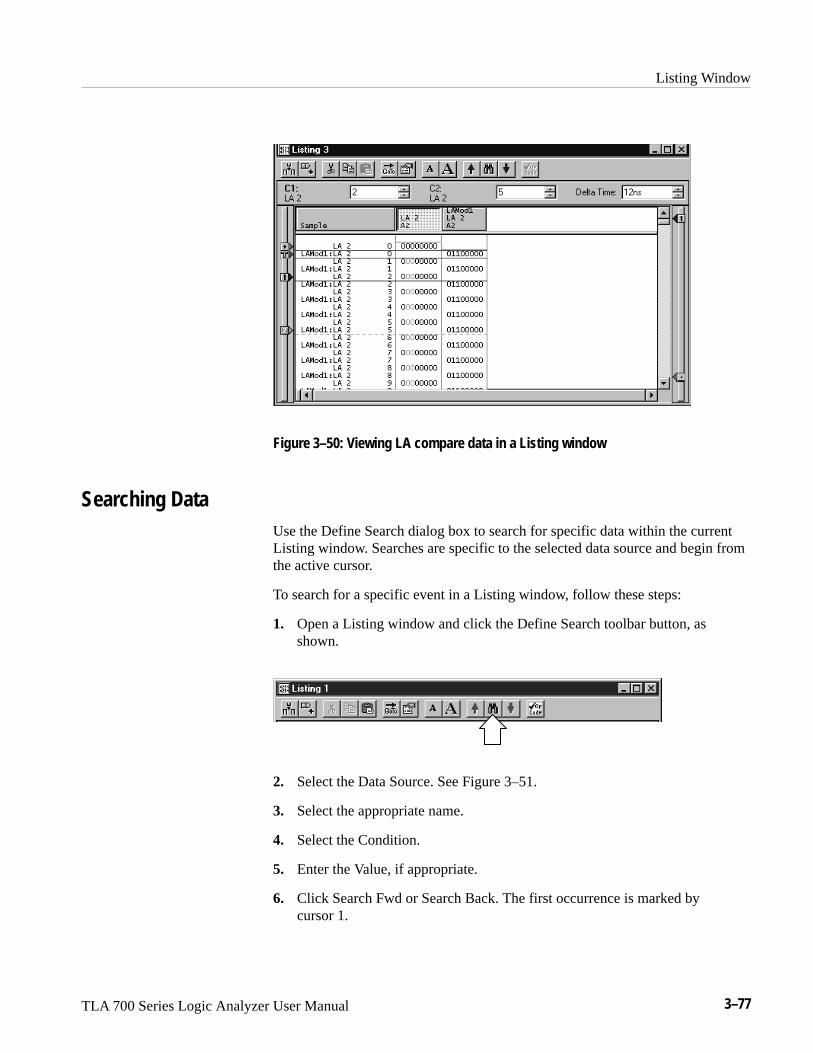
Listing Window
TLA 700 Series Logic Analyzer User Manual 3–77
Figure 3–50: Viewing LA compare data in a Listing window
Searching DataUse the Define Search dialog box to search for specific data within the currentListing window. Searches are specific to the selected data source and begin fromthe active cursor.
To search for a specific event in a Listing window, follow these steps:
1. Open a Listing window and click the Define Search toolbar button, asshown.
2. Select the Data Source. See Figure 3–51.
3. Select the appropriate name.
4. Select the Condition.
5. Enter the Value, if appropriate.
6. Click Search Fwd or Search Back. The first occurrence is marked bycursor 1.

Listing Window
3–78 TLA 700 Series Logic Analyzer User Manual
You can search any data source available to the current data window, but Searchcan only search one data source at a time. For additional searches of the sameevent, click the Search Forward and Search Back arrow buttons in the toolbar.
NOTE. Data that is hidden cannot be found by the search function. For example,if you turn off a column display in the Column properties page by uncheckingShow Column, you cannot search for data in that column.
Figure 3–51: Defining search criteria
Locking WindowsLocking windows provides an easy method to compare data from two differentwindows. Use the Lock Windows dialog box, shown in Figure 3–52, to selecthow windows are locked together.
� To open the Lock Windows dialog box go the System window and click thebutton for the data window you want to open. Go to the View menu andselect Lock Windows.

Listing Window
TLA 700 Series Logic Analyzer User Manual 3–79
Figure 3–52: Lock Windows dialog box
MagniVu DataThe LA modules have MagniVu data acquisition as a standard feature. MagniVudata acquisition offers 500 picosecond high-speed timing simultaneous with200 MHz state on all channels through the same probe; no double probing isrequired. The record length for MagniVu data is 2000 samples.
You can view MagniVu data in both Listing and Waveform windows. For moreinformation on MagniVu data, refer to MagniVu Data beginning on page 3–62.
Adjusting the Listing Data View
There are a number of actions you can perform in the Listing window to get theexact view of the data that you want.
The toolbar has shortcut buttons for common operations, as shown below.
Add columnAdd mark
CutCopy
PasteGo To
Properties
SearchFont size
Click the Font Size toolbar buttons, shown in the previous figure. You cancontinue to click the toolbar buttons until the text reaches the desired size. Youcan also set the font to a specific size in the Listing Window property sheet.
Listing Window Toolbar
Changing the Display FontSize

Listing Window
3–80 TLA 700 Series Logic Analyzer User Manual
Select the column labels and then drag them to their new location.
Click the toolbar Add Column button to open the Add Column dialog box. Thenselect the data source and its associated group or channel to add it to the display.If the data source you want is not listed, click Add Source and find and select thesource. The data source can be an installed module or a saved module file. SeeFigure 3–53.
New columns are added after (to the right of) the selected columns or after allcolumns if none are selected.
Figure 3–53: Add Column dialog box
Select the column labels, then click the Cut toolbar button.
Double-click the column label to open the Column Properties page. Enter a newvalue for the column width. If you have a portable mainframe, you can alsochange the column width by selecting the column label and use the front panelScale control to set the width.
You can cut, copy, and paste columns and marks. You can also copy textual datafrom the listing to the clipboard. From there you can paste it to other areas, suchas the Define Search dialog box or the Clause Definition dialog box in theTrigger window.
Moving Columns
Adding a New Column orData Source
Deleting Columns
Changing Column Width
Cut, Copy, Paste

Listing Window
TLA 700 Series Logic Analyzer User Manual 3–81
To change a column radix in the Listing window, double-click the column labelto open the Column Properties page. Select a new radix. To select the Symbolicradix, you must have loaded a symbol table. See Symbol Support beginning onpage 2–21 for information about using symbols and symbol table files.
Qualification gaps indicate that data samples were not stored due to storagequalification or Don’t Store trigger actions.
Qualification gaps are indicated with a horizontal gray line above the first dataafter the gap. Turn qualification gaps on or off from the Listing Window propertypage.
Glitches are indicated by highlighted text of the complete sample for all radixesexcept binary, octal, and hexadecimal. In those radixes, only the glitch bits arehighlighted. Turn glitches on or off from the Listing Window property page.
NOTE. To view glitches in a data window, you must enable Glitch storage in theLA Setup window before acquiring data.
Rename a column by returning to the LA Setup window and changing thechannel group name.
For microprocessor support packages, you can change the disassembly formatused in the Listing window. Use the Disassembly property page to select thedisplay format of disassembly groups. You must have a support package loadedfor this page to be active.
You can split the data area to compare columns that are far away from each otherwithin the display. Drag the split box from the left end of the horizontal scrollbar.
Customizing the Listing Window Data AreaUse property sheets to customize data in the Listing window. The property sheetscontrol aspects of the listing display such as size, color, and in some cases,enabling or disabling whether an element is shown. Click the Properties toolbarbutton to open the Listing Window property sheet. Then select one of theproperty sheets to change the data you are interested in.
Changing Radixes
Viewing QualificationGaps
Viewing Glitches
Naming Columns
Changing theDisassembly Format
Splitting the Data Area

Listing Window
3–82 TLA 700 Series Logic Analyzer User Manual
Exporting Listing DataUse the Export Data dialog box to export data from the current listing window toa text file or to a binary file. This is a way to print a copy of a complete or partiallisting. Figure 3–54 shows the Export Data dialog box.
Figure 3–54: Export Data dialog box
You can export the following listing data:
� All listing data from the acquisition
� Listing and DSO voltage measurement from a Listing window
� A range of listing data between two selected marks
� A range of listing data between two samples

Listing Window
TLA 700 Series Logic Analyzer User Manual 3–83
If you want to export data to a text file, click Options to define the format of thedata in the Export Data Options dialog box (see Figure 3–55). The data is savedin a text file with the .txt file name extension.
Figure 3–55: Export Data Options dialog box
Use the Export Data Options dialog box to customize the listing data for a textfile. You can specify the field delimiter to separate the listing columns. You canalso specify that measurement units should be included with the data. If youexport the data without unit characters, the time stamp values are in picosecondsand the DSO values are listed in volts.
To export listing data, follow these steps:
1. In the System window, select a Listing window.
2. Go to the File menu and select Export Data.
3. In the Export Data dialog box, select the folder to which you want to exportdata. Otherwise, leave the default of My Documents.
4. Click Options to specify any export options for the text data and then clickOK.
5. Enter a name for the exported file.
6. Specify the export range.
7. Click Save.
You can also export the listing data as a binary file with a .tbf (TLA 700 BinaryFormat) file name extension. This option is only available if the data window isfrom a single data source. You can export any data that appears in a Listingwindow, including DSO and MagniVu data. This option is useful when you writeapplications that need to use binary data. It is also faster than exporting an ASCIIfile and the file size is often smaller.
Exporting Data to anASCII File
Exporting Data as aBinary File

Listing Window
3–84 TLA 700 Series Logic Analyzer User Manual
LA Module Binary Export File Format. The LA module binary data is exported as astream of bytes with the following characteristics:
� The binary data uses big-endian fields (the most-significant bit is theleft-most bit).
� Each group column field is zero-padded on the most-significant end to thenearest byte.
� Sample numbers and mnemonics groups are not exported.
� Time stamp data is seven bytes wide and represents the number of picosec-onds since the start of the acquisition.
� The left-most column in the Listing window display corresponds to the firstexported field of a sample.
� The first sample in the Listing window appears at the beginning of theexported file.
� MagniVu data follows the same guidelines as regular listing data.
DSO Module Binary Export File Format. The DSO module binary data (when usedin a Listing window) is exported as a stream of bytes with the followingcharacteristics:
� The binary data uses little-endian fields (the most-significant bit is theright-most bit).
� Each channel field is a 16-bit value.
� Sample numbers, mnemonics groups, and time stamp values are notexported.
� The left-most column in the Listing window display corresponds to the firstexported field of a sample.
� The first sample in the Listing window appears at the beginning of theexported file.
� DSO data values are in twos-compliment format.
� The formula used for converting a DSO channel field into a voltage is:
�������� � � ��� �� ����� � ���� � �� ���� ������ �
������ � ������ �� �����

Listing Window
TLA 700 Series Logic Analyzer User Manual 3–85
Printing Listing DataYou can print a hardcopy of the Listing window or you can print the image to afile. You can print a single page, a range of pages, or you can print a range ofdata between two marks or cursors.
1. Go to the File menu and select Print.
2. Select Print to File, or select your printer in the window.
3. Select the print range and click OK.
When you click OK a confirmation message displays, informing you of theapproximate number of pages that will be printed.
4. Click OK again to confirm your actions.
5. To interrupt printing at any time, press ESC.
The contents of the window will be sent to the printer or to the specified file.
NOTE. The print selection prints a copy of the current Listing window. If youwant to print a text file, use the Export Data option to save the Listing windowcontents to a file and then send that file to a printer.

Listing Window
3–86 TLA 700 Series Logic Analyzer User Manual
Listing Window Shortcut KeysYou can use the general-purpose shortcut keys listed in Table 3–10 to move dataand cursors in the Listing window. You should also refer to the discussions ofshort cut keys in the online help or under the section for the individual datawindows.
The shortcut keys (also known as accelerator keys or hot keys) abide by thefollowing rules:
� Arrow keys with no modifier keys scroll data.
� Arrow keys with the Control (CTRL) key move the active cursor.
� The Shift key increases movement by a factor of 10.
Table 3–10: Listing window shortcut keys
Desired action Key combination
Go to next trigger CTRL + T
Display Go To dialog box CTRL + G
Move Cursor 1 to the center of the window CTRL + 1
Move Cursor 2 to the center of the window CTRL + 2
Add a mark CTRL + K
Add a column CTRL + L
Scroll data up 10 samples Shift + Up arrow
Scroll data down 10 samples Shift + Down arrow
Move active cursor up one sample CTRL + Up arrow
Move active cursor down one sample CTRL + Down arrow
Move active cursor up 10 samples CTRL + Shift + Up arrow
Move active cursor down 10 samples CTRL + Shift + Down arrow

TLA 700 Series Logic Analyzer User Manual 3–87
Source Window
Use the Source window to display the high-level language (HLL) source codethat you wrote correlated to your code as it was executed by your target systemand acquired by the logic analyzer. The logic analyzer links the Source andListing windows, and provides additional tools to help you view the tools anddata. See Figure 3–56 for an example of a Source window.
The data area of the Source window lists the content of the source file includingline numbers for each source code statement. The path name of the file displaysimmediately above the source data.
Figure 3–56: Source window
You can use controls to step through data, move between user-defined marks,and scroll through data. These controls directly affect the active cursor in theassociated Listing window and indirectly affect the active cursor in the Sourcewindow.

Source Window
3–88 TLA 700 Series Logic Analyzer User Manual
Creating a Source WindowBefore creating a Source window you should load a microprocessor supportpackage. You should also set up the Listing window you will use with the Sourcewindow.
Create a new Source window with the New Data Window wizard as follows:
1. Click the New Data Window icon in the toolbar.
2. Select Source and click Next.
3. Select an existing Listing window.
4. Click Next.
5. Select the name of the Listing window, the data source, and the listingcolumn (normally an address column).
6. Enter the name of the symbol file or click Symbol File to browse the filesystem for the symbol file.
The symbol file contains all of the information for the source window, suchas function, variable, and source code symbols.
7. Click Next.
8. Enter a name for the Source window or use the default name.
9. Click Finish.
10. If the Source File Locator dialog box appears, enter the path name for thesource file or click Browse to look for the file listed in the dialog box.
11. The new Source window will display the contents of the source file.

Source Window
TLA 700 Series Logic Analyzer User Manual 3–89
Reading the Source Window IndicatorsData marks, cursors, and other indicators help you navigate and identify the data.Figure 3–57 and Table 3–11 identify and describe data window marks.
� To move cursors or marks, drag the cursor and mark handles.
Cursor
User mark
Data mark bar(fine control)
Overview mark bar(coarse control)
Figure 3–57: Source window cursors and marks
Table 3–11: Source window cursor and mark summary
Mark Name Description
Cursors 1 and 2 Moveable marks used for visual reference and for data measurements.
User mark User-created marks. Use marks to make specific data more easy to identify andfind.

Source Window
3–90 TLA 700 Series Logic Analyzer User Manual
To add a user mark to a Source window, follow these steps:
1. In the System window, click the Source window icon.
2. Point the mouse at the source statement where you want to add the mark.
3. Right-click the mouse and select Add Mark. The mark appears in the display,has default properties, and is selected.
4. If necessary, move the mark to the desired location by dragging its handle.
NOTE. You cannot add a mark if there is no data.
Sometimes, marks can be stacked on top of one another. To send a mark to theback, follow these steps:
1. Select a mark you know is on top of another one.
2. Click the right mouse button and select Send To Back.
Jumping to Specific Data LocationsYou can use the Go To dialog box to jump to a new position by selecting anycurrent mark or waveform. See Figure 3–58.
� To open the Go To dialog box, open a data window, and click the Go Totoolbar button, as shown in Figure 3–58.
Adding a Mark to a SourceWindow
Sending Stacked Marks tothe Back

Source Window
TLA 700 Series Logic Analyzer User Manual 3–91
Figure 3–58: Using the Go To dialog box to jump to the cursor location
You can also use the Overview Mark bar to quickly jump to another location. Ifyou do not click on a mark, clicking in the Overview Mark bar scrolls to thatlocation.
Figure 3–59: Using the Overview Mark bar to jump to a data location

Source Window
3–92 TLA 700 Series Logic Analyzer User Manual
Moving the cursor between statements in the Source window does not necessari-ly move the cursor in the same direction in the Listing window. This can happen,for example, if the statement in the new location was executed both before andafter the statement in the old location, such as when the statement is in a loop.The Scan Listing box sets the scan direction in a Listing window when youmove the cursor in the Source window.
Moving Through Source FilesThere are several ways of moving through the data in source files. You can movethrough source files from the Source window or from the Listing window. Whenyou move a cursor in one window, the corresponding cursor in the other windowalso moves.
Use the Step Forward or the Step Backward buttons (see Figure 3–60) to stepthrough source statements in execution order in the Source window. You can alsouse the Next Mark or the Previous Mark buttons to jump to the next or previousexecuted source statement that has a user-defined mark.
Use the cursor controls in either window to move the cursors. You can also movethe cursors in either window by clicking and dragging the cursor handles or byadjusting the cursor spin box controls.
StepForward
StepBackward
ActiveCursor
NextMark
PreviousMark
Figure 3–60: Source window controls

Source Window
TLA 700 Series Logic Analyzer User Manual 3–93
Source-relative cursor positioning refers to updating the Listing window cursorpositioning as a result of changing the position of the active cursor in the Sourcewindow.
When you move the Source window cursor to a new statement, the Sourcewindow determines the address range of the source statement based on informa-tion from the loaded symbol file. The Source window uses the setting of theScan Listing mode to determine the search direction in the Listing window. TheListing window searches the acquisition data for a matching address. When thematching address is found, the active cursor in the Listing window is moved tothe matching sample.
If the Source window cursor is moved to a non-executable statement, such as acomment, the address of the next executable statement is used.
Listing-relative cursor positioning refers to updating the Source window cursorposition of the active cursor in the Listing window.
When you move the Listing window cursor to a new sample, the active Sourcewindow cursor attempts to move to a corresponding source statement in theSource window. The Source window uses information from the loaded symbolfile to convert the address of the Listing cursor position to a source file name andstatement (line number) location. The Source window then updates the activeSource window cursor position and displays the corresponding source statement.
Use the Step Forward and Step Backward buttons to trace the execution order ofsource statements. Click the Step Forward button to move to the next executedsource statement. Click the Step Backward button to move to the previousexecuted source statement.
When you click the Step Forward or Step Backward buttons, the Source windowtells the Listing window to search forward or backward beginning at the activeListing cursor for the next or previous executed source statement. When a matchis found, the Listing window positions the active Listing cursor to the matchingsample. The Source window converts the address to a file name and line number,and then updates the active Source cursor position to the corresponding sourcestatement. The statement may be located in a source file that is different than theoriginal displayed file. In this case, the new file is displayed and the cursor isplaced on the proper statement.
A single line in the Source window may consist of more than one statement, forexample:
��� � ���� � � ���� �� � ����
Source-Relative CursorPositioning
Listing-Relative CursorPositioning
Step Forward and StepBackward Buttons
Source Window
3–94 TLA 700 Series Logic Analyzer User Manual
The next executed statement in the Listing window may appear on the same linein the Source window as the current statement. However, the next executedstatement may also appear on a different line (before or after the currentstatement), or in a different file. Click the Step Forward and Step Backwardbuttons to move the cursor between statements in execution order.
The ability of the Source window to discriminate between multiple statements onthe same line depends on the amount of information provided by the code-gen-eration tools. If there is enough information to identify multiple statements perline, the Source window cursors will include character highlighting to identifyindividual statements on a line.
Use the Next Mark and Previous Mark buttons to move the active cursor in theSource window to the next or previous executed user-defined mark position (ifany marks have been defined). Next and previous refer to the execution sequenceand not to the position of the mark in the window.
The Next Mark and Previous Mark buttons operate similar to the Step Forwardand Step Backward buttons. However, rather than stepping through everyexecuted statement, you can define marks in the Source window as breakpointsand then step between marks in execution order to move though the source code.
When you click the Next Mark or Previous Mark buttons, the Source windowtells the Listing window to search for addresses corresponding to the markedsource statements. When a corresponding sample is found, the Listing windowpositions its active cursor to the matching sample. The Source window convertsthe address to a file name and line number. It then updates the active Sourcecursor position and displays the corresponding source statement.
If the code-generation tools provide column information for symbol files, youcan mark individual statements of multiple-statement lines in the source code.You can then use the Next Mark and Previous Mark buttons to step between themarks and highlight the individual statements.
The Next Mark and Previous Mark buttons are not active if there are no marksdefined in the Source window.
The active cursor readout displays the address of the source statement at theactive cursor. The address shown is the low address bound. The radix of theaddress is always hexadecimal. If you position the cursor on a non-executablestatement, such as a comment or white space, the address of the next executablestatement is displayed.
Use the active cursor readout to jump to a new location in the source file. Enteran address in this field and the active cursor moves to the correspondingstatement. If you enter an address that does not correspond directly to the addressof a source statement, the next statement will be used and the address is adjusted.
Next Mark and PreviousMark Buttons
Active Cursor Readout

Source Window
TLA 700 Series Logic Analyzer User Manual 3–95
You can copy and paste the readout value into other locations such as in theevent portion of the Clause Definition dialog in the LA Trigger window.
There are situations when you move the cursor in the Listing window to alocation where there is no corresponding source statement. The cursor in theSource window remains at the current location and changes the color of theSource window to signify an uncorrelated state exists between the Source andListing windows. When this happens, you can click the Step Forward or the StepBackward buttons to search for an executable source line in the Listing window;this correlates the active cursors in both windows.
Clicking the buttons forces the Listing window to search for a data sample thatcorresponds to the next or previous line of executed source code. The line ofexecuted code may be in a different source file. If this happens, the Sourcewindow displays the required file or prompts you for a path name. The ability tolocate source files depends on the Search Path List and Suffix List defined in theSource Files property page.
Searching for Source DataUse the Define Search dialog box to search for specific text patterns. You cansearch the current source file or search all of the source files identified by theloaded symbol file.
To search for a specific data pattern in a Source window, follow these steps:
1. Open a Source window and click the Define Search toolbar button, asshown.
2. Select All Files or This File. See Figure 3–61.
3. Enter the text pattern.
4. Click Search Fwd or Search Back. The first occurrence is marked by theactive cursor.
You can search for any text pattern including leading and embedded white space;trailing white space is ignored.
Uncorrelated State

Source Window
3–96 TLA 700 Series Logic Analyzer User Manual
When searching for data in multiple files, the search operation follows the orderof files listed in the Source Window property page in the Displayed Source Filelist. When you search for data in all files and one or more of the files cannot befound, the Source File Locator dialog box displays, asking you to specify thelocation of the file.
If the search is not completed in a set amount of time, the Search Progress dialogbox shows the status of the search. You can let the search continue, or you canclick Abort to stop the search.
Figure 3–61: Defining source search criteria
Adjusting the Source Data View
There are a number of actions you can perform in the Source window to get theexact view of the data that you want.
The toolbar has shortcut buttons for common operations.Source window Toolbar

Source Window
TLA 700 Series Logic Analyzer User Manual 3–97
Font SizeAdd mark Search
Cut
Copy
Paste
Go To
Properties
Click the Font Size toolbar buttons, shown in the previous figure. You cancontinue to click the toolbar buttons until the text reaches the desired size. Youcan also set the font to a specific size in the Source window property sheet.
You can cut, copy, and paste columns and marks. You can also copy text data tothe clipboard. From there you can paste it to other areas, such as the DefineSearch dialog box or the Clause Definition dialog box in the Trigger window.
Turn source line numbers on or off by clicking Line Number Column in theView menu.
Customizing the Source Window Data AreaUse property sheets to customize data in the Source window. The property sheetscontrol aspects of the source display such as source files, text size, colors, tabspacing, and source file locations. Click the Properties toolbar button to open theSource window property sheet. You can also click the label above the data areato open the property sheet. Then select one of the property sheets to change thedata you are interested in.
Locating Source FilesYou can define the location of source files with the Source Files property page(see Figure 3–62 on page 3–98). Use the property page to list the locations ofsource files as well as possible file suffixes that can be attached to the file names(used for compilers that do not include the file suffixes). A similar property page(System Source Files property page) is used as a default list of locations ofsource files and suffixes. The logic analyzer uses this list every time you create anew source window.
The Source window uses the file path and file suffix in combination to locate thecorrect source file. It searches for the file name in each directory indicated by thefile path list in the order specified. If a file name does not have a suffix, thensuffixes from the suffix list are tried until a match is found or all file path andsuffix combinations are exhausted.
Changing the Display FontSize
Cut, Copy, Paste
Turning Line Numbers Onor Off

Source Window
3–98 TLA 700 Series Logic Analyzer User Manual
Figure 3–62: Source Files property page
When specifying the search path, you can use an asterisk (*) as the finalcomponent of a search path directory. For example, if you specify the followingpath, C:\MySources\*, the MySources directory and all directories (one leveldeep) within MySources will be searched. However, you cannot use the asteriskas a general-purpose wild card character. For example, the use of an asterisk inC:\MySources\*\* or C:\MySources\abc* is invalid.
You must specify the complete absolute (not relative) path name for the file inthe Search Path List. Otherwise, the Source window will not locate the sourcefile. Make sure that the source file you are looking for has a unique file name.When searching for source files it is possible to load the wrong file if there isanother file with the same name in the directories specified by the search path.The Source window always loads the first file that matches the search criteria.
Because some compilers do not include a source file suffix, you may also need tospecify the correct file suffixes in the file suffix list (examples of correct filesuffixes are: .c .cpp, and .s). The Source window will always load the first filethat matches the criteria in the file suffix list.
The logic analyzer searches for files using both lists from top to bottom.Therefore, you should place the most likely search path or file suffix at thebeginning of the lists.
The search path lists and the suffix lists in the Source Files property page arevalid only for the current Source window. If you want to save the settings asdefaults, click Save settings as application defaults. The settings will be saved toSystem Source Files property page and will be used each time you create a newSource window.

Source Window
TLA 700 Series Logic Analyzer User Manual 3–99
Printing Source DataYou can print a hardcopy of the Source window or you can print the image to afile. You can print a single page, a range of pages, or you can print a range ofdata between two marks or cursors.
1. Go to the File menu and select Print.
2. Select Print to File, or select your printer in the window.
3. Select the print range and click OK.
When you click OK a confirmation message displays, informing you of theapproximate number of pages that will be printed.
4. Click OK again to confirm your actions.
5. To interrupt printing at any time, press ESC.
The contents of the window will be sent to the printer or to the specified file.

Source Window
3–100 TLA 700 Series Logic Analyzer User Manual
Source Window Shortcut KeysYou can use the general-purpose shortcut keys listed in Table 3–12 to move dataand cursors in the Source window. You should also refer to the discussions ofshort cut keys in the online help or under the section for the individual datawindows.
The shortcut keys (also known as accelerator keys or hot keys) abide by thefollowing rules:
� Arrow keys with no modifier keys scroll data.
� Arrow keys with the Control (CTRL) key move the active cursor.
� The Shift key increases movement by a factor of 10.
Table 3–12: Source window shortcut keys
Desired action Key combination
Display Go To dialog box CTRL + G
Move Cursor 1 to the center of the window CTRL + 1
Move Cursor 2 to the center of the window CTRL + 2
Add a mark CTRL + K
Scroll data up 10 lines Shift + Up arrow
Scroll data down 10 lines Shift + Down arrow
Move active cursor up one line CTRL + Up arrow
Move active cursor down one line CTRL + Down arrow
Move active cursor up 10 lines CTRL + Shift + Up arrow
Move active cursor down 10 lines CTRL + Shift + Down arrow

TLA 700 Series Logic Analyzer User Manual 3–101
Histogram Window
Use the Histogram window to set up, capture, and display performance analysisdata from an LA module channel group, counter, or timer. You can use theHistogram window to determine the level of activity within various functions orsubroutines, analyze how memory is used, or determine the relative executiontime of subroutines or program modules.
Histogram data is presented as a list of ranges and corresponding histogram barsshowing the distribution of the ranges. See Figure 3–63 for an example.
Figure 3–63: Histogram window
The histogram data is based on all acquisition data (All Samples) or on the datawithin a defined set of ranges (Matched Samples).

Histogram Window
3–102 TLA 700 Series Logic Analyzer User Manual
Measuring Histogram DataThere are two basic ways of using the Histogram window to analyze data. One isto provide a graphic overview of the address activity of software execution. Theother is to use counters or timers to measure specific events.
If you want to use counters or timers to measure events, you set up the countersor timers in the Trigger window. You can then select the data source in the NewData Window wizard when you create a Histogram window. You can also selectthe data source for an existing Histogram window from the Data Source propertypage as shown in Figure 3–64.
Figure 3–64: Selecting the data source for the Histogram window
To provide an overview of the address activity of a software routine, you define aset of ranges (either numeric, logarithmic, or symbolic). You can set up theTrigger window to look for data within the defined ranges. The data is processedand displayed in the Histogram window for the current acquisition. If you set upthe logic analyzer to repetitively acquire data, the sampling errors will decreaseover time as you acquire more data. The resultant data provides a stable displayin the Histogram window where you can view the overall activity of thesoftware.
You can use this method of analyzing data to determine which sections of codeare being accessed or not accessed. You can also determine the overall time spentin a routine with respect to other areas of code. Figure 3–63 is an example ofviewing address activity in a software application using symbolic ranges.
Viewing Address Activityfor Channel Groups
(Range Overview)

Histogram Window
TLA 700 Series Logic Analyzer User Manual 3–103
To measure an event, you define a starting point, a target event, a counter or atimer, and a stopping point in the LA Trigger window. Use the Data Sourceproperty page to select the counter or timer as the data source for your analysis.When you acquire data, the Histogram window displays the minimum, maxi-mum, and average value of the counter or timer data as shown in Figure 3–65.
Figure 3–65: Measuring events with the Histogram window
Creating a Histogram WindowBefore creating the Histogram window you should define the channel setups andclocking in the Setup window. You should also define your trigger program inthe Trigger window. If you want to measure an event, you should define thetrigger events and set up the appropriate counter and timer actions. If you want touse symbols, you should make sure that you load the symbol file.
You can create a new Histogram window with the New Data Window wizard asfollows:
1. Click the New Data Window icon in the toolbar.
2. Select Histogram and click Next.
3. Select Data from an LA in the System.
Measuring Counter orTimer Events
(Single Event)

Histogram Window
3–104 TLA 700 Series Logic Analyzer User Manual
4. Click Next.
5. If you want to do an overview of address groups, select Group and theaddress group that you want to monitor.
6. If you want to measure an event, select Counter/Timer and the counter ortimer that you defined in the Trigger window.
7. Click Next.
8. Enter a name for the Histogram window or use the default name.
9. Click Finish.
Adjusting the Histogram Data View
There are a number of actions you can perform in the Histogram window to getthe exact view of the data that you want.
The toolbar has shortcut buttons for common operations as shown below.
Stop AnalyzingClear Counts
Font Size
Properties
Click the Font Size toolbar buttons, shown in the previous figure. You cancontinue to click the toolbar buttons until the text reaches the desired size. Youcan also set the font to a specific size in the Histogram Window property sheet.
Click the Clear Counts toolbar button to reset all ranges and percentages to zero.
Click the Stop Analyzing toolbar button to stop analyzing the current acquisi-tion. This button is inactive when there is no current acquisition in process.
Select the column label separator and drag it to change the width of a column.
Sort ranges, counts, and percentages by clicking on the column labels. Click thecolumn label to toggle the sort between increasing and decreasing values.
Histogram WindowToolbar
Changing the Display FontSize
Clearing HistogramCounts
Stopping Analysis
Sizing Columns
Sorting Data withinColumns

Histogram Window
TLA 700 Series Logic Analyzer User Manual 3–105
Select Scale from the View menu. Select a new magnification value from the listand click OK. You can also click on the percentage column label and select amagnification value.
Ranges displayed in the Histogram window are based on the values you select inthe Ranges property page. You can define ranges as follows:
� Linear generation. The ranges are divided linearly between two bounds.
� Log generation. The ranges are divided logarithmically between two bounds.
� Symbols. The ranges are defined by the values in a loaded symbol file. Youcan use the same loaded symbol table as in other windows.
You can split the data area to compare ranges that are far away from each otherwithin the display. Drag the split box from the top of the horizontal scroll bar.
Customizing the Histogram Window Data AreaUse property sheets to customize data in the Histogram window. The propertysheets control aspects of the Histogram display such as ranges, bounds, font size,color, and data source information. Click the Properties toolbar button to openthe property sheets. Then select one of the specific property sheets you areinterested in.
Here are some guidelines for using and customizing the Histogram window.
� You can analyze live LA data or saved LA data (reference data).
� Data is accumulated until you explicitly clear the data.
� There is no limit to the number of symbolic ranges for histogram data.
� You can use up to 32 bits of data in a address group.
� You can enable or disable channel group polarity.
� You can change colors for the foreground, background, and histogram barsas needed.
� You can change the data font size as necessary to view the data.
Changing HistogramMagnification
Defining HistogramRanges
Splitting the Data Area
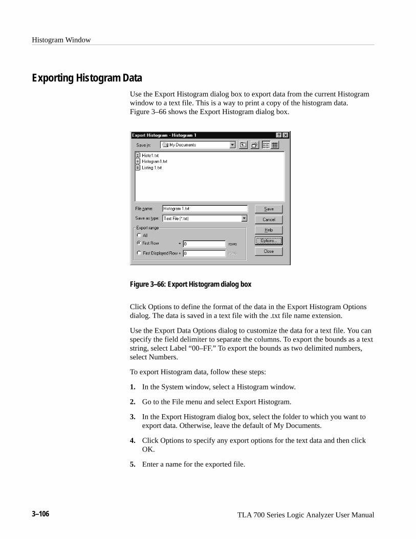
Histogram Window
3–106 TLA 700 Series Logic Analyzer User Manual
Exporting Histogram DataUse the Export Histogram dialog box to export data from the current Histogramwindow to a text file. This is a way to print a copy of the histogram data.Figure 3–66 shows the Export Histogram dialog box.
Figure 3–66: Export Histogram dialog box
Click Options to define the format of the data in the Export Histogram Optionsdialog. The data is saved in a text file with the .txt file name extension.
Use the Export Data Options dialog to customize the data for a text file. You canspecify the field delimiter to separate the columns. To export the bounds as a textstring, select Label “00–FF.” To export the bounds as two delimited numbers,select Numbers.
To export Histogram data, follow these steps:
1. In the System window, select a Histogram window.
2. Go to the File menu and select Export Histogram.
3. In the Export Histogram dialog box, select the folder to which you want toexport data. Otherwise, leave the default of My Documents.
4. Click Options to specify any export options for the text data and then clickOK.
5. Enter a name for the exported file.

Histogram Window
TLA 700 Series Logic Analyzer User Manual 3–107
6. Specify the export range.
7. Click Save.
Figure 3–67 shows an example of an exported histogram file. The file wasviewed with WordPad.
Figure 3–67: ASCII histogram data file
Printing Histogram Data
You can print a hardcopy of the Histogram window or you can print the image toa file. You can print a single page, a range of pages, or all pages.
1. Go to the File menu and select Print.
2. Select Print to File, or select your printer in the window.
3. Select the print range and click OK.
When you click OK, a confirmation message displays, informing you of theapproximate number of pages that will be printed.
4. Click OK again to confirm your actions.
5. To interrupt printing at any time, press ESC.
The contents of the window will be sent to the printer or to the specified file.

Histogram Window
3–108 TLA 700 Series Logic Analyzer User Manual
Histogram Window Shortcut KeysYou can use the general-purpose shortcut keys listed in Table 3–13 to move dataand cursors in the Histogram window. You should also refer to the discussions ofshort cut keys in the online help or under the section for the individual datawindows.
The shortcut keys (also known as accelerator keys or hot keys) abide by thefollowing rules:
� Arrow keys with no modifier keys scroll data.
� The Shift key increases movement by a factor of 10.
Table 3–13: Histogram window shortcut keys
Desired action Key combination
Scroll data up 10 ranges Shift + Up arrow
Scroll data down 10 ranges Shift + Down arrow

Appendices


TLA 700 Series Logic Analyzer User Manual A–1
Appendix A: Specifications
This chapter lists the specifications for the logic analyzer and its modules. Thefirst section lists specifications that are common to the mainframes or modules.The following sections list specifications that are specific to individual logicanalyzer components.
Characteristic TablesAll specifications are guaranteed unless noted Typical. Typical characteristicsdescribe typical or average performance and provide useful reference informa-tion. Specifications that are marked with the � symbol are checked directly (orindirectly) in the TLA 700 Series Performance Verification and AdjustmentTechnical Reference Manual. The specifications apply to all versions of the logicanalyzer mainframe or module unless otherwise noted.
For mainframes and modules, the performance limits in this specification arevalid with these conditions:
� The logic analyzer must be in an environment with temperature, altitude,humidity, and vibration within the operating limits described in thesespecifications.
� The logic analyzer must have had a warm-up period of at least 30 minutes.
For modules, the performance limits in this specification are valid with theseconditions:
� The modules must be installed in a TLA 700 Series Logic AnalyzerMainframe.
� The module must have been calibrated/adjusted at an ambient temperaturebetween +20�C and +30�C.
� The module must have had its signal-path-compensation routine (self cal-ibration) last executed after at least a 30 minute warm-up period.
� After the warm-up period, the DSO module must have had its signal-path-compensation routine (self cal) last executed at an ambient temperaturewithin ±5�C of the current ambient temperature.

Appendix A: Specifications
A–2 TLA 700 Series Logic Analyzer User Manual
Table A–1: Atmospheric characteristics (mainframes and modules)
Characteristic Description
Temperature:Operating and Non-Operating
Operating (no media in floppy disk drive)+5�C to +50�C, 15�C/hour maximum gradient, non-condensing (derated 1�C per 1000 feetabove 5000 foot altitude)
Non-operating (no media in floppy disk drive)–20�C to +60�C, 15�C/hour maximum gradient, non-condensing.
Relative Humidity:Operating and Non-Operating
Operating (no media in floppy disk drive)20% to 80% relative humidity, non-condensing. Maximum wet bulb temperature: +29�C(derates relative humidity to approximately 22% at +50�C).
Non-operating (no media in floppy disk drive)8% to 80% relative humidity, non-condensing. Maximum wet bulb temperature: +29�C (deratesrelative humidity to approximately 22% at +50�C).
Altitude:Operating and Non-Operating
Operating:To 10,000 feet (3040 meters), (derated 1�C per 1000 feet (305 meters) above 5000 feet (1524 meters) altitude)
Non-operating:40,000 feet (12190 meters).

Appendix A: Specifications
TLA 700 Series Logic Analyzer User Manual A–3
Table A–2: Backplane interface (portable and benchtop mainframes)
Characteristic Description
Slots
Portable mainframe 4
Benchtop mainframe 13
� CLK10 Frequency 10 MHz ±100 PPM
Relative Time Correlation Error1,2 (Typical)
LA to LA “MagniVu” data 2 ns
LA to LA “normal” data utilizing an internal clock3 1 LA sample – 0.5 ns
LA to LA “normal” data utilizing an external clock 2 ns
LA “MagniVu” to DSO data 3 ns
LA to DSO “normal” data utilizing an internal clock3,4 1 LA sample + 1 ns
LA to DSO “normal” data utilizing an external clock4 3 ns
DSO to DSO4 3 ns
System Trigger and External Signal Input Latencies5,6 (Typical)
External System Trigger Input to LA Probe Tip7 –271 ns
External Signal Input to LA Probe Tip via Signal 3, 48 –212 ns + Clk
External Signal Input to LA Probe Tip via Signal 1, 28, 9 –208 ns + Clk
External System Trigger Input to DSO Probe Tip7 –27 ns
System Trigger and External Signal Output Latencies6 (Typical)
LA Probe Tip to External System Trigger Out3 380 ns + SMPL
LA Probe Tip to External Signal Out via Signal 3, 43
OR function 371 ns + SMPL
AND function 383 ns + SMPL
LA Probe Tip to External Signal Out via Signal 1, 23,9
normal function 381 ns + SMPL
inverted logic on backplane 384 ns + SMPL
DSO Probe Tip to External System Trigger Out 70 ns
DSO Probe Tip to External Signal Out via Signal 3, 4
OR function 68 ns
AND function 78 ns
DSO Probe Tip to External Signal Out via Signal 1, 29
normal function 71 ns
inverted logic on backplane 71 ns

Appendix A: Specifications
A–4 TLA 700 Series Logic Analyzer User Manual
Table A–2: Backplane interface (portable and benchtop mainframes) (Cont.)
Characteristic Description
Inter-Module Latencies6 (Typical)
LA to DSO Inter-module System Trigger3,7 358 ns + SMPL
LA to LA Inter-module System Trigger3,7 68 ns + SMPL
LA to DSO Inter-Module ARM3 360 ns + SMPL
LA to LA Inter-Module ARM3,8 108 ns + SMPL + Clk
LA to LA Inter-Module via Signal 1, 23,8, 9 120 ns + SMPL + Clk
LA to LA Inter-Module via Signal 3, 43,8 116 ns + SMPL + Clk
DSO to DSO Inter-module System Trigger7 50 ns
DSO to LA Inter-module System Trigger7 –236 ns
DSO to LA Inter-Module ARM8 –192 ns + Clk
DSO to DSO Inter-Module ARM 59 ns
DSO to LA Inter-Module via Signal 1, 28, 9 –179 ns + Clk
DSO to LA Inter-Module via Signal 3, 48 –184 ns + Clk1 Includes typical jitter, slot-to-slot skew, and probe-to-probe variations to provide a “typical” number for the measurement.
Assumes standard accessory probes are utilized.
2 For time intervals longer than 1 �s between modules, add 0.01% of the difference between the absolute time measure-ments to the relative time correlation error to account for the inaccuracy of the CLK10 source.
3 SMPL represents the time from the event at the probe tip inputs to the next valid data sample of the LA module. In theNormal Internal clock mode, this represents the delta time to the next sample clock. In the MagniVu Internal clock mode,this represents 500 ps or less. In the External clock mode, this represents the time to the next master clock generated bythe setup of the clocking state machine, the system-under-test supplied clocks, and the qualification data.
4 The DSO module time correlation is measured at the maximum sample rate on one channel only.
5 All system trigger and external signal input latencies are measured from a falling-edge transition (active true low) withsignals measured in the wired-OR configuration.
6 Latencies are based on typical portable mainframe configurations consisting of two LA modules or an LA module plus aDSO module. Latencies are system-configuration-dependent and may vary slightly with module loading.
7 In the Waveform window, triggers are always marked immediately except when delayed to the first sample. In the Listingwindow, triggers are always marked on the next sample period following their occurrence.
8 “Clk” represents the time to the next master clock at the destination logic analyzer. In the asynchronous (or internal)clock mode, this represents the delta time to the next sample clock beyond the minimum async rate of 4 ns. In thesynchronous (or external) clock mode, this represents the time to the next master clock generated by the setup of theclocking state machine and the supplied system under test clocks and qualification data.
9 Signals 1 and 2 (ECLTRG0, 1) are limited to a “broadcast” mode of operation, where only one source is allowed to drivethe signal node at any one time. That single source may be utilized to drive any combination of destinations.

Appendix A: Specifications
TLA 700 Series Logic Analyzer User Manual A–5
Table A–3: External signal interface (portable and benchtop mainframes)
Characteristic Description
System Trigger Input TTL compatible input via rear panel mounted BNC connectors (portable mainframe) or front panelmounted SMB connectors (benchtop mainframe)
Input Levels VIH VIL
TTL compatible input. ≥ 2.0 V ≤ 0.8 V
Input Mode Falling edge sensitive, latched (active low)
Minimum Pulse Width 12 ns
Active Period Accepts system triggers during valid acquisition periods via real-time gating, resets system triggerinput latch between valid acquisition periods
Maximum Input Voltage 0 to +5 Volt peak
External Signal Input TTL compatible input via rear panel mounted BNC connectors (portable mainframe) or front panelmounted SMB connectors (benchtop mainframe)
Input Destination Signal 1, 2, 3, 4
Input Levels VIH VIL
TTL compatible input. ≥ 2.0 V ≤ 0.8 V
Input Mode Active (true) low, level sensitive
Input Bandwidth1
Signal 1, 2 Signal 3, 4
50 MHz square wave minimum10 MHz square wave minimum
Active Period Accepts signals during valid acquisition periods via real-time gating
Maximum Input Voltage 0 to +5 Volt peak
System Trigger Output TTL compatible output via rear panel mounted BNC connectors (portable mainframe) or frontpanel mounted SMB connectors (benchtop mainframe)
Source Mode Active (true) low, falling edge latched
Active Period Outputs system trigger state during valid acquisition period, resets system trigger output to falsestate between valid acquisitions
Output Levels VOH
VOL
50 Ohm back terminated TTL-compatible output ≥4 V into open circuit ≥ 2 V into 50 Ohm to ground
≥ 0.7 V sinking 10 ma
Output Protection Short-circuit protected (to ground)

Appendix A: Specifications
A–6 TLA 700 Series Logic Analyzer User Manual
Table A–3: External signal interface (portable and benchtop mainframes) (Cont.)
Characteristic Description
External Signal Output TTL compatible outputs via rear panel mounted BNC connectors (portable mainframe) or frontpanel mounted SMB connectors (benchtop mainframe)
Source Selection Signal 1, 2, 3, 4, or 10 MHz clock
Output Modes Level Sensitive
User definableActive (true) low or active (true) high
Output Levels VOH
VOL
50 Ohm back terminated TTL output ≥ 4 V into open circuit ≥ 2 V into 50 Ohm to ground
≤ 0.7 V sinking 10 ma
Output Bandwidth2
Signal 1, 2 Signal 3, 4
50 MHz square wave minimum10 MHz square wave minimum
Active Period Outputs signals during valid acquisition periods, resets signals to false state between validacquisitions
Outputs 10 MHz clock continuously
Output Protection Short-circuit protected (to ground).
Intermodule Signal LineBandwidth Signal 1, 2 (ECLTRG 0,1) Signal 3, 4 (ECLTRG 0,1)
Minimum bandwidth up to which the intermodule signals are specified to operate correctly
50 MHz square wave minimum 10 MHz square wave minimum
1 The Input Bandwidth specification only applies to signals to the modules; it does not apply to signals applied to theExternal Signal Input and sent back to the External Signal Output.
2 The Output Bandwidth specification only applies to signals from the modules; it does not apply to signals applied to theExternal Signal Input and sent back to the External Signal Output.
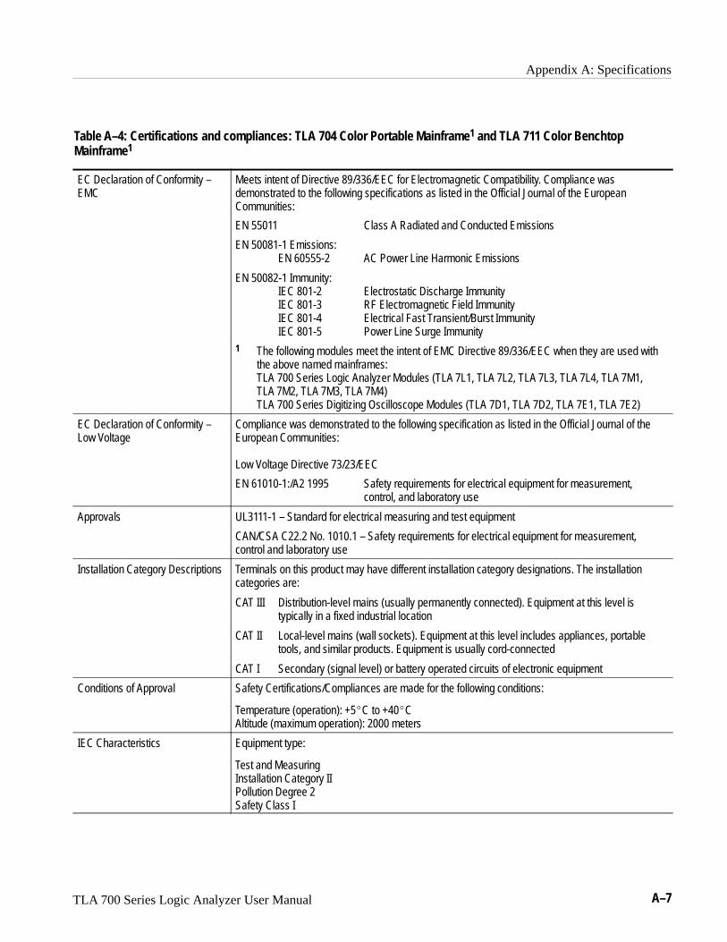
Appendix A: Specifications
TLA 700 Series Logic Analyzer User Manual A–7
Table A–4: Certifications and compliances: TLA 704 Color Portable Mainframe1 and TLA 711 Color BenchtopMainframe1
EC Declaration of Conformity –EMC
Meets intent of Directive 89/336/EEC for Electromagnetic Compatibility. Compliance wasdemonstrated to the following specifications as listed in the Official Journal of the EuropeanCommunities:
EN 55011 Class A Radiated and Conducted Emissions
EN 50081-1 Emissions:EN 60555-2 AC Power Line Harmonic Emissions
EN 50082-1 Immunity:IEC 801-2 Electrostatic Discharge ImmunityIEC 801-3 RF Electromagnetic Field ImmunityIEC 801-4 Electrical Fast Transient/Burst ImmunityIEC 801-5 Power Line Surge Immunity
1 The following modules meet the intent of EMC Directive 89/336/EEC when they are used withthe above named mainframes:TLA 700 Series Logic Analyzer Modules (TLA 7L1, TLA 7L2, TLA 7L3, TLA 7L4, TLA 7M1,TLA 7M2, TLA 7M3, TLA 7M4) TLA 700 Series Digitizing Oscilloscope Modules (TLA 7D1, TLA 7D2, TLA 7E1, TLA 7E2)
EC Declaration of Conformity –Low Voltage
Compliance was demonstrated to the following specification as listed in the Official Journal of theEuropean Communities:
Low Voltage Directive 73/23/EEC
EN 61010-1:/A2 1995 Safety requirements for electrical equipment for measurement, control, and laboratory use
Approvals UL3111-1 – Standard for electrical measuring and test equipment
CAN/CSA C22.2 No. 1010.1 – Safety requirements for electrical equipment for measurement,control and laboratory use
Installation Category Descriptions Terminals on this product may have different installation category designations. The installationcategories are:
CAT III Distribution-level mains (usually permanently connected). Equipment at this level is typically in a fixed industrial location
CAT II Local-level mains (wall sockets). Equipment at this level includes appliances, portable tools, and similar products. Equipment is usually cord-connected
CAT I Secondary (signal level) or battery operated circuits of electronic equipment
Conditions of Approval Safety Certifications/Compliances are made for the following conditions:
Temperature (operation): +5�C to +40�CAltitude (maximum operation): 2000 meters
IEC Characteristics Equipment type:
Test and MeasuringInstallation Category IIPollution Degree 2Safety Class I

Appendix A: Specifications
A–8 TLA 700 Series Logic Analyzer User Manual
TLA 704 Color Portable Mainframe Characteristics
Table A–5: Portable mainframe internal controller
Characteristic Description
Processor Intel 133 MHz Pentium PC-AT configuration, with an Intel 82430HX (Triton II) chip set
Main Memory EDO DRAM
Style Two 72-pin SIMMs, gold-plated
Loading Symmetric, 2-SIMM minimum (64 bits)
Speed 60 ns
Installed Configurations 16-MByte minimum, 32-MByte maximum
Cache Memory 256 Kbyte, level 2 (L2) write-back cache
Flash BIOS 512 Kbyte
Real-Time Clock and CMOS SetupsNVRAM (Typical)
Real-Time clock/calendar, with typical 10-year life. Standard and advanced PC CMOS setups:see BIOS specification. Year 2000 compliant.
Floppy Disk Drive Standard 3.5 inch, 1.44 Mbyte, double-sided PC-compatible high-density floppy disk drive
Hard Disk Drive Standard PC-compatible with ATA/Enhanced Integrated Device Electronics (EIDE) interface
Capacity MIN configuration: 1.4 GByteMAX configuration: 2.1 GByte Subject to change; these are the storage capacities valid at product introduction
Table A–6: Portable mainframe display system
Characteristic Description
Classification Standard PC graphics accelerator technology (bitBLT-based); capable of supporting both internalcolor LCD display and external color SVGA/XGA monitor
Display Memory DRAM-based frame-buffer memory
Size 1 MByte
Width 32-bit
Display Selection Hardware sense of external SVGA monitor during BIOS boot sequence; defaults to internal colorLCD display; automatically switches to external SVGA monitor, if attached
Dual (simultaneous) display of external SVGA monitor and internal color LCD is possible viaspecial “simulscan” CMOS setup, as long as internal and external displays operate at sameresolution (limited to 640x480 on current TFT LCD) and display rates
Dynamic Display Configuration 1 (DDC1) support for external SVGA monitor is provided
External Display Drive 1 SVGA/XGA-compatible analog output port

Appendix A: Specifications
TLA 700 Series Logic Analyzer User Manual A–9
Table A–6: Portable mainframe display system (Cont.)
Characteristic Description
Display Size User selected via Windows 95
Resolution (Pixels) Colors DDC1640x480 256 yes640x480 64K yes640x480 16.8M no800x600 256 yes800x600 64K yes1024x768 256 yes
Internal Display
Classification Thin Film Transistor (TFT) 10.4 inch active-matrix color LCD display; CCFL backlight; intensitycontrollable via software
Resolution 640 pixels horizontal by 480 pixels
Color Scale 262,144 colors (6-bit RGB)
Table A–7: Portable mainframe front-panel interface
Characteristic Description
QWERTY Keypad ASCII keypad to support naming of files, traces, and keyboard equivalents of pointing deviceinputs for menus
HEX Keypad HEX keypad supporting standard DSO and LA entry functions
Special Function Knobs Various functions
Integrated Pointing Device GlidePoint touchpad
Mouse Port PS/2 compatible mouse port utilizing a mini-DIN connector
Keyboard Port PS/2 compatible keyboard port utilizing a mini-DIN connector
Table A–8: Portable mainframe rear-panel interface
Characteristic Description
Parallel Interface Port (LPT) 36-pin high-density connector supports standard Centronics mode, Enhanced Parallel Port(EPP), or Microsoft high-speed mode (ECP)
Serial Interface Port (COM A) 9-pin male sub-D connector to support RS-232 serial port.
SVGA Output Port (SVGA OUT) 15-pin sub-D SVGA connector
Type I and II PC Card Port Standard Type I and II PC-compatible PC card slot
Type I, II, and III PC Card Port Standard Type I, II, and III PC-compatible PC card slot

Appendix A: Specifications
A–10 TLA 700 Series Logic Analyzer User Manual
Table A–9: Portable mainframe AC power source
Characteristic Description
Source Voltage and Frequency 90–250 VRMS, 45–66 Hertz, continuous range CAT II100–132 VRMS, 360–440 Hertz, continuous range CAT II
Fuse Rating
90 V - 250 V Operation(159-0046-00)
UL198/CSA C22.20.25 in × 1.25 in, Fast Blow, 8 A, 250 V
90 V - 250 V Operation(159-0381-00)
IEC 127/Sheet 15 mm × 20 mm, Fast Blow, 6.3 A, 250 V
Maximum Power Consumption 600 W line power maximum
Steady-State Input Current 6 ARMS maximum
Inrush Surge Current 70 A maximum
Power Factor Correction Yes
On/Standby Switch and Indicator Front Panel On/Standby switch, with LED indicator located next to switch
The power cord provides main power disconnect.
Table A–10: Portable mainframe secondary power
Characteristic Description
� DC Voltage Regulation
(Combined System, voltage avail-able at each slot) Voltage Vmin, Vnom, Vmax
+24 V 23.28 V, 24.24 V, 25.20 V
+12 V 11.64 V, 12.12 V, 12.60 V
+5 V 4.875 V, 5.063 V, 5.250 V
–2 V –2.10 V, –2.00 V, –1.90 V
–5.2 V –5.460 V, –5.252 V, –5.044 V
–12 V –12.60 V, –12.12 V, –11.64 V
–24 V –25.20 V, –24.24 V, –23.28 V

Appendix A: Specifications
TLA 700 Series Logic Analyzer User Manual A–11
Table A–11: Portable mainframe cooling
Characteristic Description
Cooling System Forced air circulation (negative pressurization) utilizing six fans operating in parallel
Cooling Clearance 2 inches (51 mm), sides and rear; unit should be operated on a flat, unobstructed surface
Table A–12: Portable mainframe mechanical
Characteristic Description
Overall Dimensions (See Figure A–1 for overall chassis dimensions)
Height (with feet) 9.25 in (235 mm)
Width 17.0 in (432 mm)
Depth 17.5 in (445 mm)
Weight 30 lbs 12 oz (13.9 kg) with no modules installed, 2 dual-wide slot covers, and empty pouch
Shipping configuration 60 lbs 13 oz (27.58 kg) minimum configuration (no modules), with all standard accessories
86 lbs 9 oz (39.26 kg) full configuration, with 2 TLA 7M4 modules and standard accessories(including probes)
17.0 in(432 mm)
9.25 in(235 mm)
17.5 in(445 mm)
Figure A–1: Front and side views of TLA 704 Color Portable Mainframe

Appendix A: Specifications
A–12 TLA 700 Series Logic Analyzer User Manual
TLA 711 Color Benchtop Chassis Characteristics
Table A–13: Benchtop chassis AC power source
Characteristic Description
Source Voltage 90–250 VRMS, 45–66 Hertz, continuous range CAT II100–132 VRMS, 360–440 Hertz, continuous range CAT II
Maximum Power Consumption 1350 W line power (the maximum power consumed by a fully loaded 13-slot instrument)
Fuse Rating(Current and voltage ratings andtype of fuse used to fuse the sourceline voltage)
90 V – 132 VACRMS OperationHigh-power/Low Line(159-0379-00)
Safety: UL198G/CSA C22.2, Size: 0.25 in × 1.25 in, Style: Slow acting, Rating: 20 A/250 V
103 V – 250 VACRMS Operation(159-0256-00)
Safety: UL198G/CSA C22.2, Size: 0.25 in × 1.25 in, Style: No. 59/Fast acting, Rating: 15 A/250 V
207 V – 250 VACRMS Operation(159-0381-00)
Safety: IEC 127/Sheet 1,Size: 5 mm × 20 mm, Style: Fast acting “F”, high-breaking capacity, Rating: 6.3 A/250 V
Inrush Surge Current 70 A maximum
Steady State Input Current 15 ARMS maximum at 90 VACRMS 6.3 ARMS maximum at 207 VACRMS
Power Factor Correction Yes
ON/Standby Switch and Indicator Front Panel On/Standby switch with integral power indicator
Table A–14: Benchtop chassis secondary power
Characteristic Description
� DC Voltage Regulation
(Combined System, voltage avail-able at each slot) Voltage Vmin, Vnom, Vmax
+24 V 23.28 V, 24.24 V, 25.20 V
+12 V 11.64 V, 12.12 V, 12.60 V
+5 V 4.875 V, 5.063 V, 5.250 V

Appendix A: Specifications
TLA 700 Series Logic Analyzer User Manual A–13
Table A–14: Benchtop chassis secondary power (Cont.)
Characteristic Description
–2 V –2.10 V, –2.00 V, –1.90 V
–5.2 V –5.460 V, –5.252 V, –5.044 V
–12 V –12.60 V, –12.12 V, –11.64 V
–24 V –25.20 V, –24.24 V, –23.28 V
Table A–15: Benchtop chassis cooling
Characteristic Description
Cooling System Forced air circulation system (positive pressurization) utilizing a single low-noise centripetal(squirrel cage) blower configuration with no removable filters
Blower Speed Control Rear panel switch selects between full speed and variable speed. Slot exhaust temperature andambient air temperature are monitored such that a constant delta temperature is maintainedacross the module with the highest exit air temperature at the minimum operational blower speed
Slot Activation Installing a module activates the cooling for the corresponding occupied slots by opening the air flowshutter mechanism. Optimizes cooling efficiency by only applying airflow to modules that are installed
Delta Temperature ReadoutSensitivity
100 mV/°C with 0°C corresponding to 0 V output
Temperature Sense Range –10°C to +90°C, Delta temperature ≤ 50°C
Clearance 2 in (51 mm), rear, top, and sides of chassis
Table A–16: Benchtop chassis mechanical
Characteristic Description
Overall Dimensions (See Figure A–2 for overall chassis dimensions)
Standard Chassis
Height (with feet) 14.25 in (362.0 mm)
Width 16.75 in (425.5 mm)
Depth 26.5 in (673.1 mm)
Chassis with Rackmount
Height 14.0 in (355.6 mm)
Width 18.9 in (480.1 mm)
Depth 29.4 in to 34.4 in (746.8 mm to 873.8 mm)
Weight
Minimum configuration with benchtop controller and slot covers 62 lbs 2 oz (28.18 kg)

Appendix A: Specifications
A–14 TLA 700 Series Logic Analyzer User Manual
Table A–16: Benchtop chassis mechanical (Cont.)
Characteristic Description
Typical configuration with 2 LA, 1 DSO, and controller 77 lbs 14 oz (35.32 kg)
Shipping configuration 118 lbs (53.52 kg) minimum configuration (no modules) withbenchtop controller and all standard accessories
175 lbs (79.38 kg) fully configured with benchtop controller,3 LA modules, 2 DSO modules, and all standard accessories
Rackmount kit adder 20 lbs (9.1 kg)
Module Size 13 plug-in slots
14.25 in(362.0 mm)
16.75 in (425.5 mm)
26.5 in (673.1 mm)
Figure A–2: Front view and side view of standard Benchtop chassis
18.9 in (480.1 mm)
29.4 in (746.7 mm) Min to34.4 in (873.8 mm) Max
14.0 in(355.6 mm)
Figure A–3: Front view and side view of Benchtop chassis with Rackmount Option

Appendix A: Specifications
TLA 700 Series Logic Analyzer User Manual A–15
TLA 711 Color Benchtop Controller Characteristics
Table A–17: Benchtop controller characteristics
Characteristic Description
Processor Intel Pentium 133 MHz PC-AT configuration with an Intel 82430HX (Triton II) chip-set
Main Memory EDO DRAM
Style 2-72 pin SIMMs, gold plated
Loading Symmetrical, 2-SIMM minimum (64-Bits)
Speed 60 ns
Installed Configuration 16 MByte minimum configuration32 MByte maximum configuration
Cache Memory 256 Kbyte, level 2 (L2) write-back cache
Flash BIOS 512 Kbyte
Real-Time Clock and CMOS Setups NVRAM(Typical)
Real-Time clock/calendar, with typical 10-year life. Standard and advanced PC CMOSsetups: see BIOS specification. Year 2000 compliant.
Floppy Disk Drive Standard 3.5 inch, 1.44 Mbyte, double-sided, PC-compatible high-density floppy diskdrive
Hard Disk Drive Standard PC-compatible with ATA/Enhanced Integrated Device Electronics (EIDE)interface
Capacity MIN configuration: 1.4 GByteMAX configuration: 2.1 GByte Subject to change; these are the storage capacities valid at product introduction
Display Classification Standard PC graphics accelerator technology (bitBLT based) capable of drivingexternal color VGA, SVGA, or XGA monitors
Display Memory DRAM based frame-buffer memory.
Width 32 Bit
Size 1 MByte
Display Drive One VGA, SVGA, or XGA compatible analog output port
Display Size User selected via Windows 95.
Resolution (Pixels) Colors DDC1640x480 256 yes640x480 64 K yes640x480 16.8 M no800x600 256 yes800x600 64 K yes1024x768 256 yes
Mouse Port Front panel mounted PS2 compatible mouse port utilizing a mini-DIN connector
Keyboard Port Front panel mounted PS2 compatible keyboard port utilizing a mini-DIN connector

Appendix A: Specifications
A–16 TLA 700 Series Logic Analyzer User Manual
Table A–17: Benchtop controller characteristics (Cont.)
Characteristic Description
Parallel Interface Port (LPT) 36-pin high-density connector supports standard Centronics mode, Enhanced ParallelPort (EPP), or Microsoft high-speed mode (ECP)
Serial Interface Port (COM) The serial port utilizing a 9-pin male sub-D connector to support an RS232 serial port
SVGA Output Port (SVGA) The SVGA port utilizing a 15-pin sub-D SVGA connector
Type I and II PC Card Port Standard Type I and II PC compatible PC card slot
Type I, II, and III PC Card Port Standard Type I, II, and III PC compatible PC card slot
Table A–18: Benchtop controller mechanical characteristics
Characteristic Description
Weight 5 lb. 3 oz. (2.34 kg)
Size Standard dual-wide, VXI C-size enclosure
Overall dimensions
Height 10.32 in (262 mm)
Width 2.39 in (61 mm)
Depth 14.7 in (373 mm)
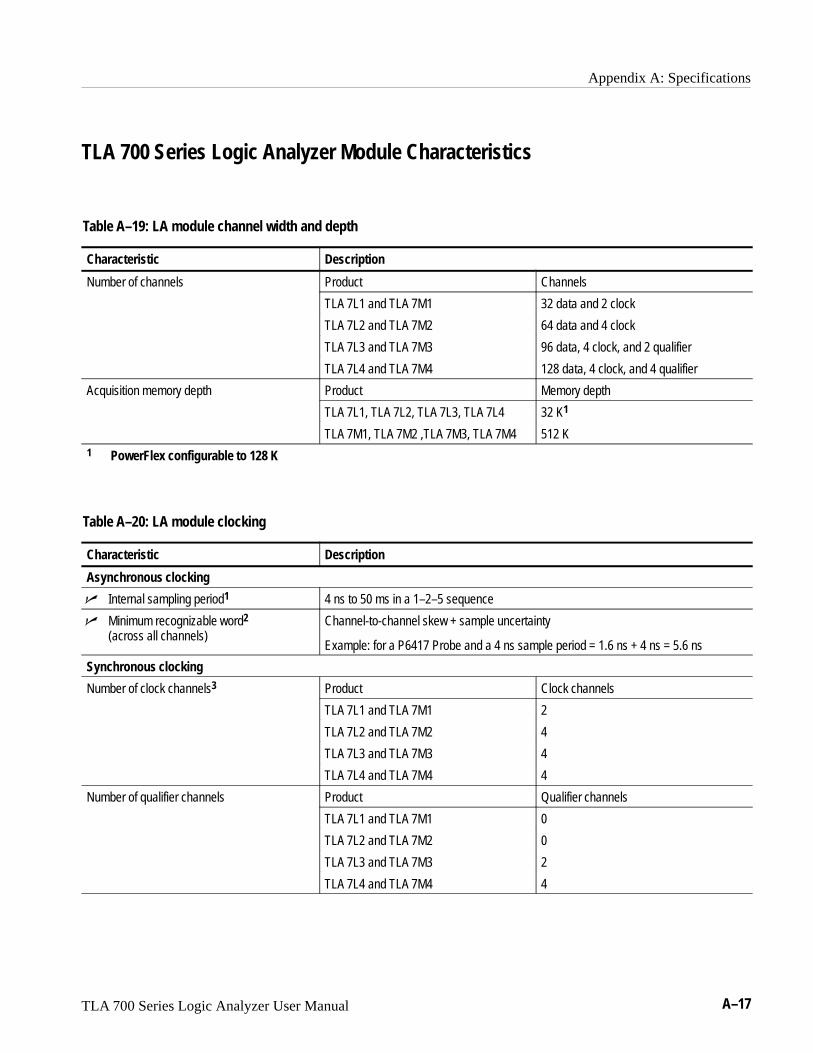
Appendix A: Specifications
TLA 700 Series Logic Analyzer User Manual A–17
TLA 700 Series Logic Analyzer Module Characteristics
Table A–19: LA module channel width and depth
Characteristic Description
Number of channels Product Channels
TLA 7L1 and TLA 7M1 32 data and 2 clock
TLA 7L2 and TLA 7M2 64 data and 4 clock
TLA 7L3 and TLA 7M3 96 data, 4 clock, and 2 qualifier
TLA 7L4 and TLA 7M4 128 data, 4 clock, and 4 qualifier
Acquisition memory depth Product Memory depth
TLA 7L1, TLA 7L2, TLA 7L3, TLA 7L4 32 K1
TLA 7M1, TLA 7M2 ,TLA 7M3, TLA 7M4 512 K1 PowerFlex configurable to 128 K
Table A–20: LA module clocking
Characteristic Description
Asynchronous clocking
� Internal sampling period1 4 ns to 50 ms in a 1–2–5 sequence
� Minimum recognizable word2
(across all channels)Channel-to-channel skew + sample uncertainty
Example: for a P6417 Probe and a 4 ns sample period = 1.6 ns + 4 ns = 5.6 ns
Synchronous clocking
Number of clock channels3 Product Clock channels
TLA 7L1 and TLA 7M1 2
TLA 7L2 and TLA 7M2 4
TLA 7L3 and TLA 7M3 4
TLA 7L4 and TLA 7M4 4
Number of qualifier channels Product Qualifier channels
TLA 7L1 and TLA 7M1 0
TLA 7L2 and TLA 7M2 0
TLA 7L3 and TLA 7M3 2
TLA 7L4 and TLA 7M4 4

Appendix A: Specifications
A–18 TLA 700 Series Logic Analyzer User Manual
Table A–20: LA module clocking (Cont.)
Characteristic Description
� Setup and hold window size (data and qualifiers)
Maximum window size = Maximum channel-to-channel skew + (2 x sample uncertainty) + 0.4 ns
Maximum setup time = User interface setup time + 0.6 nsMaximum hold time = User interface hold time + 0.4 ns
Max. setup time for slave module of merged pair = User Interface setup time + 0.8 nsMax. hold time for slave module of merged pair = User Interface hold time + 0.7 ns
Example: for P6417 Probe and user interface setup & hold of 2.0/0.0 typicalMaximum setup time = 2.0 ns + 0.6 ns = 2.6 nsMaximum hold time = 0.0 ns + 0.4 ns = 0.4 ns
Setup and hold window size (data andqualifiers) (Typical)
Channel-to-channel skew (typical) + (2 x sample uncertainty)
Example: for P6417 Probe = 1 ns + (2 x 500 ps) = 2 ns
Setup and hold window range The setup and hold window can be moved for each channel group from +8.5 ns (Ts) to–7.0 ns (Ts) in 0.5 ns steps (setup time). Hold time follows the setup time by the setupand hold window size.
� Maximum synchronous clock rate4 200 MHz in full speed mode (5 ns minimum between active clock edges)
100 MHz in half speed mode (10 ns minimum between active clock edges)
Demux clocking
Demux Channels (TLA 7L3 ,TLA 7L4, TLA 7M3, TLA 7M4)
Channels multiplex as follows:A3(7:0) to D3(7:0)A2(7:0) to D2(7:0)A1(7:0) to D1(7:0)A0(7:0) to D0(7:0)
(TLA 7L1, TLA 7L2, TLA 7M1, TLA 7M2) Channels multiplex as follows:A3(7:0) to C3(7:0)A2(7:0) to C2(7:0)A1(7:0) to D1(7:0) TLA 7L2 and TLA 7M2 onlyA0(7:0) to D0(7:0) TLA 7L2 and TLA 7M2 only
Time between DeMux clock edges4 (Typical)
5 ns minimum between DeMux clock edges in full-speed mode10 ns minimum between DeMux clock edges in half-speed mode
Time between DeMux store clock edges4
(Typical)10 ns minimum between DeMux master clock edges in full-speed mode20 ns minimum between DeMux master clock edges in half-speed mode
Clocking state machine
Pipeline delays Each channel group can be programmed with a pipeline delay of 0 through 3 activeclock edges.
1 It is possible to use storage control and only store data when it has changed (transitional storage).
2 Applies to asynchronous clocking only. Setup and hold window specification applies to synchronous clocking only.
3 Any or all of the clock channels may be enabled. For an enabled clock channel, either the rising, falling, or both edgescan be selected as the active clock edges. The clock channels are stored.
4 Full and half speed modes are controlled by PowerFlex options and upgrade kits.

Appendix A: Specifications
TLA 700 Series Logic Analyzer User Manual A–19
Table A–21: LA module trigger system
Characteristic Description
Triggering Resources
Word/Range recognizers 16 word recognizers. The word recognizers can be combined to form full width, doublebounded, range recognizers. The following selections are available:
16 word recognizers 0 range recognizers13 word recognizers 1 range recognizer10 word recognizers 2 range recognizers7 word recognizers 3 range recognizers4 word recognizers 4 range recognizers
Range recognizer channel order From most-significant probe group to least-significant probe group: C3 C2 C1 C0 E3E2 E1 E0 A3 A2 D3 D2 A1 A0 D1 D0 Q3 Q2 Q1 Q0 CK3 CK2 CK1 CK0
Missing channels for modules with fewer than 136 channels are omitted. Whenmerged, the range recognition extends across the two modules; the master1 modulecontains the most-significant groups.
Glitch detector2,3 Each channel group can be enabled to detect a glitch
Minimum detectable glitch pulse width(Typical)
2.0 ns (single channel with P6417 probe)
Setup and hold violation detector2,4 Each channel group can be enabled to detect a setup and hold violation. The range isfrom 8 ns before the clock edge to 8 ns after the clock edge. The range can beselected in 0.5 ns increments. The setup and hold violation of each window can beindividually programmed.
Transition detector2, 5 Each channel group can be enabled or disabled to detect a transition between thecurrent valid data sample and the previous valid data sample.
Counter/Timers6, 7 2 counter/timers, 51 bits wide, can be clocked up to 250 MHz. Maximum count is 251
Maximum time is 9.0076 seconds or 104 days
Signal In 1 A backplane input signal
Signal In 2 A backplane input signal
Trigger In A backplane input signal that causes the main acquisition and the MagniVu acquisitionto trigger if they are not already triggered
Active trigger resources8 16 maximum (excluding counter/timers)
Trigger States 16
� Trigger State sequence rate Same rate as valid data samples received, 250 MHz maximum
Trigger Machine Actions
Main acquisition trigger Triggers the main acquisition memory
Main trigger position Trigger position is programmable to any data sample (4 ns boundaries)
Increment counter Either of the two counter/timers used as counters can be incremented.
Start/Stop timer Either of the two counter/timers used as timers can be started or stopped.

Appendix A: Specifications
A–20 TLA 700 Series Logic Analyzer User Manual
Table A–21: LA module trigger system (Cont.)
Characteristic Description
Reset counter/timer Either of the two counter/timers can be reset. When a counter/timer used as a timerand is reset, the timer continues in the started or stopped state that it was in prior tothe reset.
Signal out A signal sent to the backplane to be used by other modules
Trigger out A trigger out signal sent to the backplane to trigger other modules
Storage Control
Global storage Storage is allowed only when a specific condition is met. This condition can use any ofthe trigger machine resources except for the counter/timers. Storage commandsdefined in the current trigger state will override the global storage control.
Global storage can be used to start the acquisition with storage initially turned on(default) or turned off.
By event Storage can be turned on or off; only the current sample can be stored. The eventstorage control overrides any global storage commands.
Block storage9 When enabled, 31 samples are stored before and after the valid sample.
Glitch violation storage The acquisition memory can be enabled to store glitch violation information with eachdata sample when asynchronous clocking is used. The probe data storage size isreduced by one half (the other half holds the violation information). The fastestasynchronous clocking rate is reduced to 10 ns.
1 For merged modules, the master module is the module installed in the lower-numbered slot.
2 Each use of a glitch detector, setup and hold violation detector, or transition detector requires a trade-off of one wordrecognizer resource.
3 Any glitch is subject to pulse width variation of up to the channel-to-channel skew specification + 0.5 ns.
4 Any setup value is subject to variation of up to 1.6 ns; any hold value is subject to variation of up to 1.4 ns.
5 This mode can be used to create transitional storage selections where all channels are enabled.
6 Counters and timers can be set, reset, or tested and have zero reset latency.
7 Timers can be tested with TLA 7Lx and TLA 7Mx Modules with serial numbers B020000 and higher and TLA 700 SeriesSoftware Version 1.10 and higher.
8 Word recognizers are traded off one-by-one as Signal In 1, Signal In 2, glitch detection, setup and hold detection, ortransition detection resources are added.
9 Block storage is disallowed when glitch storage or setup and hold violation is enabled.

Appendix A: Specifications
TLA 700 Series Logic Analyzer User Manual A–21
Table A–22: LA module input parameters (with P6417 Probe)
Characteristic Description
� Threshold Accuracy ±100 mV
Threshold range and step size Setable from +5 V to –2 V in 50 mV steps
Threshold channel selection 16 threshold groups assigned to channels. Each probe has two threshold settings, onefor the clock/qualifier channel and one for the data channels.
� Channel-to-channel skew ≤ 1.6 ns maximum (When merged, add 0.5 ns for the slave module.)
Channel-to-channel skew (Typical) ≤ 1.0 ns typical (When merged, add 0.3 ns for the slave module.)
Sample uncertainty
Asynchronous: Sample period
Synchronous: 500 ps
Probe input resistance (Typical) 20 k�
Probe input capacitance (Typical) 2 pF maximum
Minimum slew rate (Typical) 0.2 V/ns
Maximum operating signal 6.5 Vp-p–3.5 V absolute input voltage minimum6.5 V absolute input voltage maximum
Probe overdrive ±250 mV or ±25% of signal swing minimum required beyond threshold, whichever isgreater±4 V maximum beyond threshold
Maximum nondestructive input signal to probe ±15 V
Minimum input pulse width signal(single channel) (Typical)
2 ns
Delay time from probe tip to input probeconnector (Typical)
7.33 ns
Table A–23: LA module MagniVu feature
Characteristic Description
MagniVu memory depth 2016 samples per channel
MagniVu sampling period Data is asynchronously sampled and stored every 500 ps in a separate high resolutionmemory.

Appendix A: Specifications
A–22 TLA 700 Series Logic Analyzer User Manual
Table A–24: Merged LA modules
Characteristic Description
Number of modules that can be mergedtogether
Two adjacent modules regardless of channel widths and memory depths (TLA 7L3,TLA 7L4, TLA 7M3, TLA 7M4 only)
Number channels after merge The sum of the data channels of both modules plus the CLK/QUAL channels (activeclocks for the merge system) of the master module plus the CLK/QUAL channels(nonactive stored clock channels to the merge system)
Merge system acquisition depth Channel depth is equal to the smaller depth of the two modules.
Number of clock and qualifier channels aftermerge
Same number of clock and qualifier channels on the master module. The clock andqualifier channels on the slave module have no effect on clocking and are only stored.
Merge system triggering resources Triggering resources are the same as a single module except that the widths of theword/range recognizers, setup and hold violation detector, glitch detector, andtransition detector are increased to the merged channel width.
Table A–25: LA module data handling
Characteristic Description
Nonvolatile memory retention time (Typical) Battery is integral to the NVRAM. Battery life is > 10 years.

Appendix A: Specifications
TLA 700 Series Logic Analyzer User Manual A–23
Table A–26: LA module mechanical
Characteristic Description
Slot width Requires 2 mainframe slots
Weight 5 lbs 10 oz. (2.55 kg) for TLA 7L4 or TLA 7M48 lbs (3.63 kg) for TLA 7L4 or TLA 7M4 packaged for domestic shipping
Overall dimensions
Height 10.32 in (262 mm)
Width 2.39 in (61 mm)
Depth 14.7 in (373 mm)
Probe cables
P6417 length 6 ft (1.8 m)
Mainframe interlock 1.4 ECL keying is implemented

Appendix A: Specifications
A–24 TLA 700 Series Logic Analyzer User Manual
TLA 700 Series Digitizing Oscilloscope Module Characteristics
Table A–27: DSO module signal acquisition system
Characteristic Description
� Accuracy, DC Gain ±1.5% for full scale ranges from 20 mV to 100 V
±2.0% for full scale ranges <19.9 mV
� Accuracy, Internal Offset1 Full Scale Range Setting Offset Accuracy
10 mV – 1 V
1.01 V – 10 V
10.1 V – 100 V
±[(0.2% × | offset |) + 1.5 mV + (6% × fullscale range)]
±[(0.25% × | offset |) + 15 mV + (6% × fullscale range)]
±[(0.25% × | offset |) + 150 mV + (6% × fullscale range)]
� Analog Bandwidth, DC–50 � Coupled Full Scale Range Setting Bandwidth2
10.1 V – 100 V DC – 500 MHz (TLA7E1 and TLA7E2)DC – 500 MHz (TLA7D1 and TLA7D2)
100 mV – 10 V DC – 1 GHz (TLA7E1 and TLA7E2)DC – 500 MHz (TLA7D1 and TLA7D2)
50 mV – 99.5 mV DC – 750 MHz (TLA7E1 and TLA7E2)DC – 500 MHz (TLA7D1 and TLA7D2)
20 mV – 49.8 mV DC – 600 MHz (TLA7E1 and TLA7E2)DC – 500 MHz (TLA7D1 and TLA7D2)
10 mV – 19.9 mV DC – 500 MHz (TLA7E1 and TLA7E2)DC – 500 MHz (TLA7D1 and TLA7D2)
Bandwidth, Analog, Selections 20 MHz, 250 MHz, and FULL on each channel
Calculated Rise Time (Typical)3
ic l ll- i t rise times re s o i t eFull Scale Range Setting TLA7E1 and TLA7E2
TLA7D1 andTLA7D2
Typical full-bandwidth rise times are shown in thechart to the right 10.1 V – 100 V
100 mV – 10 V
50 mV – 99.5 mV
20 mV – 49.8 mV
10 mV – 19.9 mV
900 ps
450 ps
600 ps
750 ps
900 ps
900 ps
900 ps
900 ps
900 ps
900 ps
Crosstalk (Channel Isolation) ≥300:1 at 100 MHz and ≥100:1 at the rated bandwidth for the channel’s sensitivity(Full Scale Range) setting, for any two channels having equal sensitivity settings
Digitized Bits, Number of 8 bits

Appendix A: Specifications
TLA 700 Series Logic Analyzer User Manual A–25
Table A–27: DSO module signal acquisition system (Cont.)
Characteristic Description
Effective Bits, Realtime Sampling (Typical) Input Frequency TLA7E1 andTLA7E2 5 GS/s (each Channel)
TLA7D1 and TLA7D2 2.5 GS/s (each Channel)
10.2 MHz 6.2 bits 6.2 bits
98 MHz 6.1 bits 6.1 bits
245 MHz 6.0 bits 6.0 bits
490 MHz 5.7 bits 5.7 bits
990 MHz 5.2 bits N/A
Frequency Limit, Upper, 20 MHz BandwidthLimited (Typical)
20 MHz
Frequency Limit, Upper, 250 MHz BandwidthLimited (Typical)
250 MHz
Input Channels, Number of Product Channels
TLA7E2 Four
TLA7D2 Four
TLA7E1 Two
TLA7D1 Two
Input Coupling DC, AC, or GND4
Input Impedance, DC–1 M� Coupled 1 M� ±0.5% in parallel with 10 pF ±3 pF
Input Impedance Selections 1 M� or 50 �
Input Resistance, DC–50 � Coupled 50 � ±1%
Input VSWR, DC–50 � Coupled ≤1.3:1 from DC – 500 MHz, ≤1.5:1 from 500 MHz – 1 GHz
Input Voltage, Maximum, DC–1 M�, AC–1 M�,or GND Coupled
300 VRMS but no greater than ±420 V peak, Installation category II, derated at20 dB/decade above 1 MHz
Input Voltage, Maximum, DC–50 � or AC–50 �
Coupled5 VRMS, with peaks ≤ ±25 V
Lower Frequency Limit, AC Coupled (Typical) ≤10 Hz when AC–1 M� Coupled; ≤200 kHz when AC–50 � Coupled5
� Random Noise Bandwidth Selection RMS Noise
Full ≤(350 �V + 0.5% of the full scale Setting)
250 MHz ≤(165 �V + 0.5% of the full scale Setting)
20 MHz ≤(75 �V + 0.5% of the full scale Setting)
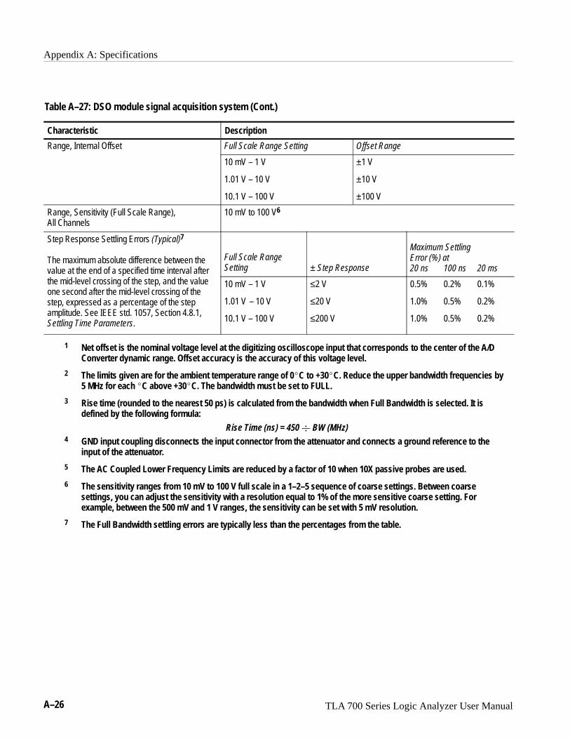
Appendix A: Specifications
A–26 TLA 700 Series Logic Analyzer User Manual
Table A–27: DSO module signal acquisition system (Cont.)
Characteristic Description
Range, Internal Offset Full Scale Range Setting Offset Range
10 mV – 1 V
1.01 V – 10 V
10.1 V – 100 V
±1 V
±10 V
±100 V
Range, Sensitivity (Full Scale Range), All Channels
10 mV to 100 V6
Step Response Settling Errors (Typical)7
The maximum absolute difference between thevalue at the end of a specified time interval aftert e mi -level crossi o t e ste t e v l e
Full Scale Range Setting ± Step Response
Maximum Settling Error (%) at20 ns 100 ns 20 msv l e t t e e o s eci ie time i terv l ter
the mid-level crossing of the step, and the valueone second after the mid-level crossing of thestep, expressed as a percentage of the stepamplitude. See IEEE std. 1057, Section 4.8.1,Settling Time Parameters.
10 mV – 1 V
1.01 V – 10 V
10.1 V – 100 V
≤2 V
≤20 V
≤200 V
0.5% 0.2% 0.1%
1.0% 0.5% 0.2%
1.0% 0.5% 0.2%
1 Net offset is the nominal voltage level at the digitizing oscilloscope input that corresponds to the center of the A/DConverter dynamic range. Offset accuracy is the accuracy of this voltage level.
2 The limits given are for the ambient temperature range of 0�C to +30�C. Reduce the upper bandwidth frequencies by5 MHz for each �C above +30�C. The bandwidth must be set to FULL.
3 Rise time (rounded to the nearest 50 ps) is calculated from the bandwidth when Full Bandwidth is selected. It isdefined by the following formula:
Rise Time (ns) = 450 � BW (MHz)4 GND input coupling disconnects the input connector from the attenuator and connects a ground reference to the
input of the attenuator.
5 The AC Coupled Lower Frequency Limits are reduced by a factor of 10 when 10X passive probes are used.
6 The sensitivity ranges from 10 mV to 100 V full scale in a 1–2–5 sequence of coarse settings. Between coarsesettings, you can adjust the sensitivity with a resolution equal to 1% of the more sensitive coarse setting. Forexample, between the 500 mV and 1 V ranges, the sensitivity can be set with 5 mV resolution.
7 The Full Bandwidth settling errors are typically less than the percentages from the table.

Appendix A: Specifications
TLA 700 Series Logic Analyzer User Manual A–27
Table A–28: DSO module timebase system
Characteristic Description
Range, Extended Realtime Sampling Rate 5 S/s to 10 MS/s in a 1–2.5–5 sequence
Range, Realtime Sampling Rate Products Limits
TLA7E1 andTLA7E2
25 MS/s to 5 GS/s on all channels simultaneously in a1–2.5–5 sequence
TLA7D1 andTLA7D2
25 MS/s to 2.5 GS/s on all channels simultaneously in a1–2.5–5 sequence
Record Length 512, 1024, 2048, 4096, 8192, and 15000
� Long Term Sample Rate ±100 ppm over any ≥ 1 ms interval
Table A–29: DSO module trigger system
Characteristic Description
� Accuracy (Time) for Pulse Glitch orP lse Wi t ri eri
Time Range AccuracyPulse Width Triggering
2 ns to 500 ns
520 ns to 1 s
±(20% of Setting + 0.5 ns)
±(104.5 ns + 0.01% of Setting)
� Accuracy (DC) for Edge Trigger Level, DCCoupled
±( ( 2% × | Setting) | ) + 0.03 of Full Scale Range + Offset Accuracy) for signalshaving rise and fall times ≥20 ns
Range (Time) for Pulse Glitch and Pulse WidthTriggering
2 ns to 1 s
Range, Trigger Level Source Range
Any Channel ±100% of full scale range
Range, Trigger Point Position Minimum: 0%
Maximum: 100%
Resolution, Trigger Level 0.2% of full scale for any Channel source
Resolution, Trigger Position One Sample Interval at any Sample Rate
Sensitivities, Pulse-Type Runt Trigger (Typical) 10% of full scale, from DC to 500 MHz, for vertical settings >100 mV full scale and≤10 V full scale at the BNC input
Sensitivities, Pulse-Type Trigger Width andGlitch (Typical)
10% of full scale for vertical settings >100 mV full scale and ≤10 V full scale at theBNC input

Appendix A: Specifications
A–28 TLA 700 Series Logic Analyzer User Manual
Table A–29: DSO module trigger system (Cont.)
Characteristic Description
� Sensitivity, Edge-Type Trigger, DC Coupled The minimum signal levels required for stable edge triggering of an acquisition whenthe trigger source is DC-coupled
Products Trigger Source Sensitivity
TLA7E1 and TLA7E2 Any Channel 3.5% of Full Scale Rangefrom DC to 50 MHz, in-creasing to 10% of FullScale Range at 1 GHz
TLA7D1 and TLA7D2 Any Channel 3.5% of Full Scale Rangefrom DC to 50 MHz, in-creasing to 10% of FullScale Range at 500 MHz
Sensitivity, Edge-Type Trigger, Not DC Coupled(Typ c )
Trigger Coupling Typical Signal Level for Stable Triggering(Typical)
AC Same as the DC-coupled limits forfrequencies above 60 Hz; attenuatessignals below 60 Hz
High Frequency Reject One and one-half times the DC-coupledlimits from DC to 30 kHz; attenuatessignals above 30 kHz
Low Frequency Reject One and one-half times the DC-coupledlimits for frequencies above 80 kHz;attenuates signals below 80 kHz
Noise Reject Three times the DC-coupled limits
Time, Minimum Pulse or Rearm, and Minimumr sitio ime or P lse- e ri eri
For vertical settings >100 mV and ≤10 V at the BNC inputTransition Time, for Pulse-Type Triggering(Typical) Pulse Class Minimum Pulse Width Minimum Rearm Width(Typical)
Glitch 1 ns 2 ns + 5% of Glitch WidthSetting
Width 1 ns 2 ns + 5% of Width UpperLimit Setting
Trigger Position Error, Edge Triggering (Typical) Acquisition Mode Trigger Position Error1
Sample ±(1 Sample Interval + 1 ns)
1 The trigger position errors are typically less than the values given here. These values are for triggering signalshaving a slew rate at the trigger point of ≥5% of full scale/ns.

Appendix A: Specifications
TLA 700 Series Logic Analyzer User Manual A–29
Table A–30: DSO module front-panel connectors
Characteristic Description
� Probe Compensator, Output VoltageThe Probe Compensator output voltage inpeak-to-peak Volts
0.5 V (base–top) ± 1% into a ≥ 50 � load
Table A–31: DSO module certifications and compliances
EC Declaration of Conformity –Low Voltage
Compliance was demonstrated to the following specification as listed in the Official Journal of theEuropean Communities:
Low Voltage Directive 73/23/EEC
EN 61010-1:/A2 1995 Safety requirements for electrical equipment for measurement, control, and laboratory use
Approvals UL3111-1 – Standard for electrical measuring and test equipment
CAN/CSA C22.2 No. 1010.1 – Safety requirements for electrical equipment for measurement,control and laboratory use
Safety Certification of Plug-in orVXI Modules
For modules (plug-in or VXI) that are safety certified by Underwriters Laboratories, UL Listingapplies only when the module is installed in a UL Listed product.
For modules (plug-in or VXI) that have cUL or CSA approval, the approval applies only when themodule is installed in a cUL or CSA approved product.
Installation Category Descriptions Terminals on this product may have different installation category designations. The installationcategories are:
CAT III Distribution-level mains (usually permanently connected). Equipment at this level is typically in a fixed industrial location
CAT II Local-level mains (wall sockets). Equipment at this level includes appliances, portable tools, and similar products. Equipment is usually cord-connected
CAT I Secondary (signal level) or battery operated circuits of electronic equipment
Conditions of Approval Safety Certifications/Compliances are made for the following conditions:
Temperature (operation): +5�C to +40�CAltitude (maximum operation): 2000 meters
IEC Characteristics Equipment type:
Test and MeasuringInstallation Category IIPollution Degree 2Safety Class I

Appendix A: Specifications
A–30 TLA 700 Series Logic Analyzer User Manual
Table A–32: DSO module mechanical
Characteristic Description
Slot width Requires 2 mainframe slots
Weight Products Weight
TLA7D1 and TLA7E1 2.44 kg (5.38 lbs)
TLA7D2 and TLA7E2 2.55 kg (5.63 lbs)
Weight, shipping Products Weight
TLA7D1 and TLA7E1 6.35 kg (14 lbs)
TLA7D2 and TLA7E2 7.71 kg (17 lbs)
Overall Dimensions Height: 262.05 mm (10.32 in)
Width: 60.66 mm (2.39 in)
Depth: 373.38 mm (14.70 in)

TLA 700 Series Logic Analyzer User Manual B–1
Appendix B: TLA 700 Symbol File Format
The logic analyzer can extract range symbol information directly from objectfiles in the following formats:
� OMF86
� OMF286
� OMF386
� IEEE695
� COFF
� ELF/DWARF
� ELF/STABS
For users whose code-generation tools do not generate these file formats, theTLA 700 Symbol File (TSF) format (a text format) can be used. The TSF formatis used by the logic analyzer when it exports symbol files. The logic analyzer canalso read files in this format.
TLA 700 symbol files consist of alphanumeric symbol names and associated datavalues. The files contain a header line and lines defining the symbol names andvalues. Fields on a line are separated with white space (blank spaces or tabs).The formats for the pattern symbol files and the various range symbol filesdiffer; if you need to use pattern symbols and range symbols, you use separatefiles.
Both TLA 700 range and pattern symbol files have a .tsf file name extension(filename.tsf).
The first few lines of a TSF symbol file are typically comment lines describingwhen and how the file was generated.
� ������ �) �"� ����
� �$��&�� "! �$���)� ��) � � � � �& � ����
� �$" ����� ����#'���%&�$&�&���#%�(�
All lines in a TSF file that begin with a pound sign (#) character are treated ascomments, unless the very next character is a plus sign (+). The plus signsignifies a file reader directive. (An example of a file reader directive “#+” canbe seen in the header definition below.) The pound sign character can alsoinitiate a comment on the end of a symbol definition or other uncommentedlines. All text between the pound sign and the end of the line is treated as acomment and ignored.

Appendix B: TLA 700 Symbol File Format
B–2 TLA 700 Series Logic Analyzer User Manual
TSF HeadersA TSF header identifies the file format version to potential file readers. Itspecifies whether the file contains pattern or range symbols, the radix used tospecify symbol values, and an optional offset amount to be added to each symbolvalue (for range symbol files).
The TSF Header is a file directive which means that the following informationbegins with the special character combination of a pound sign character followedimmediately by a plus sign (#+). This is not a comment line. The specialcharacter sequence is used to mark instructions to the file reader; these instruc-tions are called “file directives.”
The following examples show sample file headers for a pattern symbol file and arange symbol file. The first two lines are comments included for readability; theyare not required as part of the file header.
� �� "��$ �&!� ��#!��& ����% ��� ����%
�
�� ��"#� � ������� ������ ��� ���
� �� "��$ �&!� ��#!��& ����% ��� ����% ���#�$
�
�� ��"#� � ������� ���� ��� ��� ��������
The File Format Version number contains three fields. The first two fields are theformat major and minor version numbers. The logic analyzer will only read TSFfiles where the major and minor version number of the file is less than or equalto that of the TLA 700 application itself. The third field is the build number ofthe application which generated the TSF file. The value of the third field isignored when the file is read.
The File Format Version number is followed by a key word, PATTERN orRANGE, which signifies the type of symbols to be found in the file. TSF filescan contain either type of symbols, but no single file can contain both. Theheader specifies the type for all symbols in the file.
The Display Radix field sets the default radix that will be used to display thenumeric symbol value. For range symbol files this field must be one of the keywords: HEX, DEC, OCT, or BIN. For pattern symbol files, only the key words:HEX, OCT, or BIN are allowed.
The File Radix field specifies the radix used by the symbol values in this file.Like the Display Radix field, the File Radix field must be one of the key words:HEX, DEC, OCT, or BIN for range symbol files, or HEX, OCT, or BIN forpattern symbol files.

Appendix B: TLA 700 Symbol File Format
TLA 700 Series Logic Analyzer User Manual B–3
The Offset field specifies an offset value and is applicable only to range symbolfiles. The offset value is specified in the radix indicated by the File Radix field.This offset value will be added to the lower and upper bounds of each rangesymbol that is read from the file. The offset is a 32-bit value, so it can have anyvalue between 0x00000000 and 0xFFFFFFFF. If the sum of the offset and arange symbol bound value exceeds the 32-bit limit of 0xFFFFFFFF, theoverflow bit is discarded. Negative offsets are specified by using a twoscomplement value for the offset.
TSF Pattern SymbolsEach pattern symbol in a TSF pattern file consists of two fields. The first field isthe symbol name, and the second is the symbol pattern. The symbol name is asequence of ASCII characters of up to 220 characters in length, although it isimpractical to display symbol values much longer than 32 characters. Symbolnames longer than 220 characters will be truncated during loading. Thecharacters in a symbol name can be any character with an ASCII value between0x21 (the exclamation point character (!)) and 0x7E (the tilde character (~)). Youcan use symbol names with embedded spaces by enclosing the Symbol Name indouble quotes.
� ������ ������
� ���� ������
� ������ ��������
�� ��������
�� ��������
��� ��������
���� ����� ��������
The symbol pattern consists of numerals in the radix specified by the File Radixfield in the header, and Xs signifying “don’t-care” values. The number of bitsrepresented by each character position in the pattern depends on the selectedradix. For a radix of HEX, each character represents 4 bits. For an OCT radix,each character represents 3 bits; and for a BIN radix, each character representsone bit.
Symbol order in a TSF pattern file is important. When selecting the symbol todisplay for a particular value, the logic analyzer scans the list of pattern symbolsfrom top to bottom. It selects the first symbol for which all non-don’t-care bits ofthe symbol match the corresponding bits of the target symbol.

Appendix B: TLA 700 Symbol File Format
B–4 TLA 700 Series Logic Analyzer User Manual
TSF Range SymbolsThere are three different types of range symbols: function, variable and source.Each of these three types define a range of 32 bit addresses associated with someentity. Variable range symbols define the beginning and ending addresses wherethe value of a variable is located in memory. Function range symbols define thebeginning and ending addresses where instructions that implement a function arelocated in memory. Source range symbols are similar to function range symbols,except that the address range for a source symbol describes the location of theinstructions that implement just one source statement. (Source symbols alsocontain file name, line number, and an optional column range that define thelocation of the source code associated with the symbol.)
Each of the three types of range symbols appear in a separate section of the file.Each section begins with a file directive indicating the type of symbols thatfollow. The sections may appear in any order, and can be broken up andseparated by other sections if necessary. The first section might be variables,followed by functions, then followed by another variable section. Each section isalso optional, however some TLA 700 applications are unable to use the symbolfile if the appropriate type of symbols are not present. For example, the Sourcewindow is only able to correlate with a Listing window if the symbol filecontains source symbols.
Range symbol names follow the same rules as pattern symbol names. Thesymbol name is a sequence of ASCII characters of up to 220 characters in length,although it is impractical to display symbol values much longer than 32characters. Symbol names longer than 220 characters will be truncated duringloading. The characters in a symbol name can be any character with an ASCIIvalue between 0x21 (the exclamation point character (!)) and 0x7E (the tildecharacter (~)). You can use symbol names with embedded spaces by enclosingthe Symbol Name in double quotes.
Range symbol address ranges can overlap, however, this sometimes producesunexpected results. When overlaps occur, and the logic analyzer needs to converta numeric value to a symbol, it must to choose between the overlappingsymbols. When choosing between overlapping symbols, the logic analyzerassigns a precedence order to the symbol types. Function symbols have thehighest precedence, followed by variable symbols, and then source symbols.

Appendix B: TLA 700 Symbol File Format
TLA 700 Series Logic Analyzer User Manual B–5
The file directive “#+ Function” introduces the function symbol section of a TSFRange file. The file directive tells the file reader that the following symbolsrepresent functions, as opposed to variables or source statements. If no symboltype file directive is given, the function symbol type is assumed.
�� �("�'�#"
� �*!�# ��!� �#) ����
� ������������������������������ �������� ��������
��&$ �* �""�% ������ �����
�(� ���"(& ����� �����
��&$ �*���!�"( ����� �������
Function symbols consist of three fields: the symbol name, the lower bound, andthe upper bound.
The lower and upper bound values are each 32-bit values, defined by numerals inthe radix specified by the File Radix field in the file header. These values definethe lower and upper limits of the range of addresses occupied by the instructionswhich implement a function. Both values are inclusive, which means that thespecified range includes both of the bound values, as well as all of the addressesbetween them.
The file directive “#+ Variable” introduces the variable symbol section of a TSFRange file. The file directive tells the file reader that the following symbolsrepresent variables, as opposed to functions or source statements. If no symboltype file directive is given, the function symbol type is assumed.
�� ��%��� �
� �*!�# ��!� �#) ����
� ������������������������������ �������� ��������
!�"( �������� ��������
(&�%��"(� �������� ��������
��" �'& �������� �������
Variable symbols consist of three fields: the symbol name, the lower bound, andthe upper bound. Variable symbols are just like function symbols except thatthey define the address range occupied by a variable, instead of function. Thelower and upper bound values of a variable symbol are inclusive, meaning thatthey are themselves a part of the range. For variables occupying only a singlebyte in memory, the lower and upper bound values are equal.
TSF Function Symbols
TSF Variable Symbols

Appendix B: TLA 700 Symbol File Format
B–6 TLA 700 Series Logic Analyzer User Manual
The file directive “#+ Source” introduces the source symbol section of a TSFrange file. The file directive tells the file reader that the following symbolsrepresent source statements, as opposed to functions or variables. The source filedirective must be followed by a file name which specifies the name of the sourcefile containing the following source statements. Each new set of symbols for aunique source file must be introduced with an additional source file directive tospecify the file name for those symbols. If no symbol type file directive is given,the function symbol type is assumed.
�� �"'$�� %&"#��&�
� ��!� �"( ���� ��� �!� �) �"� �� �
� ���� �������� �������� ��� ��� �����������
�� ������� ������� � � � %&"#��&������
� ������� ������ � �� � %&"#��&������
�� ������ ������� � �� � %&"#��&�������
�� ������� ������ � �� � %&"#��&�������
� ������� ������� � �� � %&"#��&��� ���
� ������� ������� � �� � %&"#��&������
� ������� ������� � �� � %&"#��&������
� ������� ������� � �� � %&"#��&������
������� ������� � �� � %&"#��&�����
������� ������ � �� � %&"#��&�� ���
� ������� ������ � �� � %&"#��&������
� ������ ������� � �� � %&"#��&������
������� ������� � � � %&"#��&�� ��
������ ����� � �� � %&"#��&�� ��
�� ����� ������ � �� � %&"#��&�������
�� ������ ������ � � � %&"#��&������
�� ������ ������ � � � %&"#��&������
�� ������ ������ � � � %&"#��&������
�� ������� ������� � �� � %&"#��&�������
�� ������� ������� � �� � %&"#��&�������
�� ������� ������� � �� � %&"#��&�������
�� ������� ����� � � � � %&"#��&������
The source symbols section consists of five fields for each source statement: linenumber, lower address bound, upper address bound, beginning column value,and ending column value.
Source symbols do not have a name in the same sense as function or variablesymbols, because there is no name associated with each of the executablestatements in a source file. Instead, a source symbol has a file name, specified inthe source directive, and a line number. The line number specifies the line of thesource file that contains the source statement. Line numbers are always indecimal regardless of the file radix in the header.
TSF Source Symbols

Appendix B: TLA 700 Symbol File Format
TLA 700 Series Logic Analyzer User Manual B–7
The lower and upper bound values for a source symbol are similar to those offunction and variable symbols. For source symbols, these bounds represent therange of addresses occupied by the instructions that implement a single sourcestatement. The bound values are defined in the file radix specified in the headerand can range in value from 0x00000000 to 0xFFFFFFFF. The lower and upperbound addresses are inclusive, just like other symbols. A source symbol for aninstruction occupying a single memory location has matching lower and upperbound values.
The beginning and ending column fields of a source statement are optional.When present, and non-zero, they define the beginning and ending columnposition for the source statement. In other words, the beginning and endingcolumn values define the location of the statement in the line. This is especiallyuseful when there are multiple statements on a single line, because it makes itpossible to define a separate symbol for each statement. When the columninformation is not present, or is set to zero, the symbol is assumed to correspondto the entire line.
Only a few compilers generate column information, but when the information ispresent, in the symbol file, the logic analyzer uses the column information toprovide highly accurate source code correlation. The example source symbols onthe previous page show typical column values. In most cases, only one of thecolumn values is non-zero. This is because those lines contain only onestatement, and the compiler specified only the column at which the statementended. Some compilers specify only the beginning column position for suchlines, in which case the beginning value would be non-zero and the ending valuezero.
Note that there are three symbols corresponding to line 59 of the file. Line 59 ofthe original source file contains the following statement:
��� �� � �� � � ���� �� � ����
This one line contains three separate statements. The first statement is theinitialization �� � ��, the second statement is the test �� � ���� �� �, andthe third statement is the increment �����. Although all three statements appearon the same line, each generates a separate set of instructions, and the symbols inthe example define unique address ranges for each. This enables the Sourcewindow to accurately indicate which of the three statements on the line isassociated with any given address.
Each of the source symbols in the example includes a comment at the end of theline showing a symbol name. Since this is a comment, it is ignored by thesymbol file reader, and is optional. When symbol files are exported by the logicanalyzer, they contain comments that show the derived symbol name created bythe logic analyzer itself. The name is a concatenation of the symbol file name,line number, and column number (if present). This is the symbol value that thelogic analyzer will display for addresses that fall within the lower and upperbounds of a source symbol.

Appendix B: TLA 700 Symbol File Format
B–8 TLA 700 Series Logic Analyzer User Manual
TLA 700 Series Logic Analyzer User Manual C–1
Appendix C: User Service
This appendix describes general care and service procedures for the logicanalyzer. Additional information, such as user troubleshooting procedures andreplacing LA module probe podlets, is located in the TLA 700 Series LogicAnalyzer Installation Manual.
Mainframe and module service troubleshooting procedures are located in theservice manuals (see the Preface for a list of manuals).
General CareProtect the instrument from adverse weather conditions. The instrument is notwaterproof.
Do not store or leave the portable mainframe where the LCD display will beexposed to direct sunlight for long periods of time.
CAUTION. To avoid damage to the instrument, do not expose it to sprays, liquids,or solvents.
Module Self CalibrationUse the Self Calibration property page to run self calibration procedures forinstalled modules and merged modules. For all modules, you should run theseprocedures after repair. At a minimum, you should run these procedures once ayear. For the DSO module you should also run these procedures if the ambientoperating temperature has changed more than 5�C since last calibration or once aweek if vertical settings of 50 mV full scale or less are used.
Perform self calibration after a 30 minute warm up.
� To run the self-calibration procedure, go to the System menu and selectCalibration and Diagnostics. Click Self Calibration.
NOTE. For merged modules, you should run the self-calibration procedure on themodules as a merged pair.

Appendix C: User Service
C–2 TLA 700 Series Logic Analyzer User Manual
Preventive MaintenanceOnce a year the electrical performance should be checked and the instrumentaccuracy certified (calibrated). This service should be performed by a qualifiedservice technician using the procedures outlined in the TLA 700 Series Perfor-mance Verification and Adjustment Technical Reference Manual.
Preventive maintenance mainly consists of periodic cleaning. Periodic cleaningreduces instrument breakdown and increases reliability. You should clean theinstrument as needed, based on the operating environment. Dirty conditions mayrequire more frequent cleaning than computer room conditions.
The TLA 704 Portable Mainframe display is a soft plastic display and must betreated with care during cleaning.
CAUTION. Improper cleaning agents or methods can damage the flat paneldisplay.
Do not use abrasive cleaners or commercial glass cleaners to clean the displaysurface.
Do not spray liquids directly on the display surface.
Do not scrub the display with excessive force.
Clean the flat panel display surface by gently rubbing the display with aclean-room wipe (such as Wypall Medium Duty Wipes, #05701, available fromKimberly-Clark Corporation).
If the display is very dirty, moisten the wipe with distilled water or a 75%isopropyl alcohol solution and gently rub the display surface. Avoid using excessforce or you may damage the plastic display surface.
Clean the exterior surfaces of the mainframe with a dry, lint-free cloth or asoft-bristle brush. If dirt remains, use a cloth or swab dampened with a 75%isopropyl alcohol solution. A swab is useful for cleaning in narrow spacesaround the controls and connectors. Do not use abrasive compounds on any partof the mainframe.
Flat Panel DisplayCleaning
Exterior Mainframe

Appendix C: User Service
TLA 700 Series Logic Analyzer User Manual C–3
CAUTION. Avoid getting moisture inside the mainframe during external cleaning;and use only enough solution to dampen the cloth or swab.
Do not wash the front-panel On/Standby switch. Cover the switch while washingthe mainframe.
Use only deionized water when cleaning. Use a 75% isopropyl alcohol solutionas a cleanser and rinse with deionized water.
Do not use chemical cleaning agents; they may damage the instrument. Avoidchemicals that contain benzene, toluene, xylene, acetone, or similar solvents.
The floppy disk drive requires routine maintenance to operate at maximumefficiency. The disks can be damaged if dirt and dust accumulate on therecording surfaces. To prevent damage, the disks should be properly stored intheir protective containers where they will not be exposed to dust or dirt. Inaddition, the head should be cleaned periodically.
You will need a 3.5-inch floppy disk head-cleaning kit for routine maintenance.Perform the routine maintenance as follows:
� Clean the face of the floppy disk drive monthly with a dampened cloth.
CAUTION. Do not allow moisture to enter the disk drive. When power is applied,the internal components may be damaged.
� Clean the head monthly. Follow the instructions provided with the head-cleaning kit.
Clean the exterior surfaces of the monitor, keyboard, and mouse with a dry,lint-free cloth or a soft-bristle brush. A swab is useful for cleaning in narrowspaces around the controls and connectors. Do not use abrasive compounds onany part of the instrument.
CAUTION. Avoid getting moisture inside the terminal during external cleaning;and use only enough solution to dampen the cloth or swab.
Use only deionized water when cleaning. Use a 75% isopropyl alcohol solutionas a cleanser and rinse with deionized water.
Do not use chemical cleaning agents; they may damage the instrument. Avoidchemicals that contain benzene, toluene, xylene, acetone, or similar solvents.
Floppy Disk Drive
External Monitor,Keyboard, and Mouse

Appendix C: User Service
C–4 TLA 700 Series Logic Analyzer User Manual
In Case of ProblemsThe logic analyzer runs power-on diagnostics every time you power on theinstrument. You can view the results of the diagnostics by selecting Calibrationand Diagnostics from the System menu. You can run more detailed diagnosticsby selecting Extended diagnostics. Here you can run all tests, loop on one ormore tests, or loop on a test until a failure occurs.
Refer to the chapter In Case of Problems in the TLA 700 Series Logic AnalyzerInstallation Manual for information about software and hardware problems thatyou might encounter.
Repacking for ShipmentIf a mainframe or module is to be shipped to a Tektronix field office for repair,attach a tag to the mainframe or module showing the owner’s name and address,the serial number, and a description of the problem(s) encountered and/or servicerequired. If you are returning a module, always return both the module and theprobes so that the entire unit can be tested.
When packing an instrument for shipment, use the original packaging. If it isunavailable or not fit for use, contact your Tektronix representative to obtain newpackaging.

TLA 700 Series Logic Analyzer User Manual D–1
Appendix D: Probe and Connector Information
P6417 Probe Information
.700
.100
.100
.100
.900 Max
.150.400Max
.050
.100
.100 Max
.150.400Max
0 7
GND
0 7
GND GND
CLK
.100
.700
.200 Min
.150 Min
16 Channels plus oneclock – grouping footprint
16 Channels plus oneclock – pin spacing
8 Channel probe footprint
Single podlet footprint
A0A2C0C2D0D2E0E2
Orange probeBrown probe
Gray probeWhite probe
Yellow probeBlue probe
Violet probeGreen probe
A1A3C1C3D1D3E1E3
CK1CK0Q1CK3CK2Q0Q2Q3
Section names Clock channel
Figure D–1: P6417 probe footprints
1.75 in(44 mm)
Figure D–2: P6417 probe podlet clearance

Appendix D: Probe and Connector Information
D–2 TLA 700 Series Logic Analyzer User Manual
P6434 Probe InformationThe P6434 Mass Termination probes are available as an option to the TLA 700Series Logic Analyzer. For information on using this probe refer to the P6434Mass Termination Probe Instructions (Tektronix part number 070-9793-01 orhigher).
You can also access a PDF file for design guideline instructions at the followingweb site:
�������������� ������������������ ��
Use the following instructions to access the PDF files at the above web site:
1. Click Application Support Files.
2. Scroll to the TLA7xx Files Area.
3. Click p6434.pdf to download the design-in guideline titled Mass Termina-tion Probe Document.
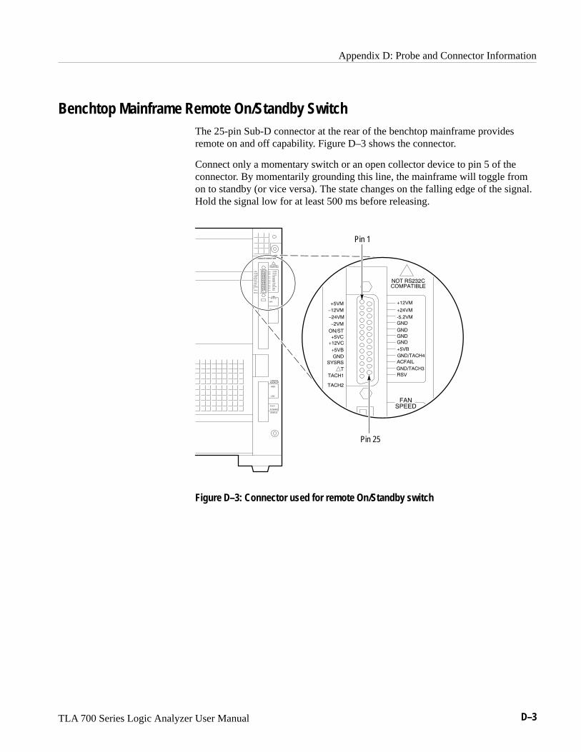
Appendix D: Probe and Connector Information
TLA 700 Series Logic Analyzer User Manual D–3
Benchtop Mainframe Remote On/Standby SwitchThe 25-pin Sub-D connector at the rear of the benchtop mainframe providesremote on and off capability. Figure D–3 shows the connector.
Connect only a momentary switch or an open collector device to pin 5 of theconnector. By momentarily grounding this line, the mainframe will toggle fromon to standby (or vice versa). The state changes on the falling edge of the signal.Hold the signal low for at least 500 ms before releasing.
Pin 25
Pin 1
Figure D–3: Connector used for remote On/Standby switch

Appendix D: Probe and Connector Information
D–4 TLA 700 Series Logic Analyzer User Manual

Glossary


TLA 700 Series Logic Analyzer User Manual Glossary–1
Glossary
AC couplingA DSO mode that blocks the DC component of a signal but passes thedynamic (AC) component of the signal. Useful for observing an AC signalthat is normally riding on a DC signal.
AcquisitionThe process of sampling signals from input channels, processing the results,and displaying the data.
Active moduleThe module highlighted by the pointer in the System window.
AliasingThe condition that occurs when data is sampled at a rate slower than the rateat which data changes. When this happens, misleading data is displayedbecause the instrument misses the changes in data that occurred betweensample points. Data pulses that fall between samples meet the technicaldefinition of a glitch and are stored and displayed as glitches. See alsoasynchronous acquisition and glitch.
For DSO data, the displayed waveform may appear to be untriggered andmuch lower in frequency. For complex waveforms, distortion occurs due tothe impact of aliasing on the high-order harmonics.
All samplesA Histogram window term. The total number of data samples analyzed.
ArmTo specify when the module should begin looking for a trigger.
AssertTo cause a signal or line to change from its logic false state to its logic truestate.
Asynchronous acquisitionAn acquisition that is made using a clock signal generated internally by thelogic analyzer. This clock is unrelated to the clock in the system under test,and you can set it to a different rate. You should use an asynchronous clockrate that is five to ten times faster than your data rate to avoid aliasing. Seealso Aliasing.

Glossary
Glossary–2 TLA 700 Series Logic Analyzer User Manual
AttenuationThe degree the amplitude of a signal is reduced when it passes through anattenuating device such as a DSO probe or attenuator (the ratio of the inputmeasure to the output measure). For example, a 10X probe attenuates, orreduces, the input voltage of a signal by a factor of 10.
ClauseA trigger program term. The combination of one or more events (Ifstatements) or actions (Then statements). When the Event is satisfied, theaction is performed. See also State.
Clock cycleA clock sequence that includes both high- and low-going transitions.
Clock equationThe Boolean combination of events needed to generate a storage clock. Youcan define a variety of clock inputs and link them using Boolean operators.Data will be sampled and stored in memory only when this clock equation istrue.
Clock qualificationThe process of filtering out irrelevant data by combining an acquisition clockwith one or more bus signals.
Clock qualifierAn external signal that acts as a gate for the acquisition clock. When theexternal signal is false, the acquisition clock is not allowed to load acquireddata into the acquisition memory.
COFF file formatsThe COFF (Common Object File Format) format contains a number ofvariations and extensions, such as ECOFF and XCOFF. This flexibilityenables it to be used with a wide variety of different microprocessors. Somecode-generation tool vendors also extend this format in non–standard waysthat may make their files unreadable by the TLA 700 logic analyzers.
CounterA trigger program device that records occurrences of an event.
CursorsPaired markers that you can use to make measurements between two datalocations.
Custom clockingCustom clocking is used only with microprocessor support packages.Custom clocking can enable and disable a variety of microprocessor-specificclock cycle types (such as DMA cycles).

Glossary
TLA 700 Series Logic Analyzer User Manual Glossary–3
Data differencesHighlighted data in a Listing or Waveform window that indicate that thereare differences between the acquired data and saved data during a compareoperation.
Data equalitiesHighlighted data in a Listing or Waveform window that indicate that thereare no differences between the acquired data and saved data during acompare operation.
Data sampleThe data logged in during one occurrence (or one cycle) of the acquisitionclock. A data sample contains one bit for every channel.
Data windowA window used to display acquired data. There are two types of datawindows, Listing windows and Waveform windows.
DC couplingA DSO mode that passes both AC and DC signal components to the DSOcircuit. Available for both the trigger system and the vertical system.
Delta measurementThe difference between two points in memory. For example, the voltagedifference between the two cursors in a selected waveform.
DemultiplexTo identify and separate multiplexed signals (for instance, some signals froma microprocessor). To separate different signals sharing the same line andorganize those signals into useful information.
Digital real-time signal acquisitionA digitizing technique that samples the input signal with a sample frequencyof four to five times the DSO bandwidth. Combined with sin(x)/x interpola-tion, all frequency components of the input up to the bandwidth areaccurately displayed.
DigitizingThe process of converting a continuous analog signal such as a waveform toa set of discrete numbers representing the amplitude of the signal at specificpoints in time.
Don’t careA symbol (X) used in place of a numeric character to indicate that the valueof a channel or character is to be ignored.
EdgeA signal transition from low to high, or high to low.

Glossary
Glossary–4 TLA 700 Series Logic Analyzer User Manual
Edge triggerTriggering that occurs when the module detects the source passing through aspecified voltage level in a specified direction (the trigger slope).
Event conditionEvent conditions are a logical combination of trigger events within a singleclause. If you set up a logical AND statement, all event conditions in theclause must be fulilled before the clause can execute the action. If you set upa logical OR statement, any one of the event conditions can be fulfilledbefore the clause can execute the action.
External clockA clock external to the logic analyzer and usually synchronous with thesystem under test.
Internal signalAn internal communication line that can be set as a marker. An internalsignal can be used as either an event or an action in a trigger program. Whenused as an event, the internal signal is tested for true/false value like anyother event; when used as an action, the signal can simply be set or clearedas the result of a condition being satisfied.
GlitchAn unintentional signal that makes a transition through the threshold voltagetwo or more times between successive sample clock cycles. Noise spikes andpulse ringing are examples of glitches.
Ground (GND) couplingA DSO coupling option that disconnects the input signal from the verticalsystem.
Histogram windowA data window used to observe the performance of software routines.
IEEE695 file formatThis object file format refers to the IEEE695 specification. This format isused primarily by compilers for a wide variety of Motorola microprocessorsand compatible microprocessors from other vendors. This format providesfor the inclusion of column information in source symbols, but not allcompilers use this capability.
Internal clockA clock mode in which the sampling of input logic signals occurs asynchro-nously to the activity of the system under test.
InterpolationDisplay method used to connect the sample points acquired and display themas a continuous waveform. The logic analyzer uses sin(x)/x interpolation todisplay DSO signals.

Glossary
TLA 700 Series Logic Analyzer User Manual Glossary–5
Linear generationA Histogram window term. The histogram ranges are evenly distributedfrom the highest range boundary to the lowest range boundary.
Listing windowA data window used to observe the data flow in the system under test. Theacquired data is displayed in a listing (tabular text) format.
Log generationA Histogram window term. The histogram ranges are distributed over alogarithmic scale.
MagniVu dataHigh-speed data stored in a special memory.
Matched samplesA Histogram window term. The total number of data samples analyzed thatmatched a defined range. These samples exclude any samples outside of thedefined ranges.
Merge modulesTo physically or logically join two LA modules together to form a singlemodule with greater channel width.
Microprocessor supportOptional microprocessor support software that allows the logic analyzer todisassemble data acquired from microprocessors.
Mnemonic disassemblyA display format for data acquired from a microprocessor or a data bus. Alogic analyzer decodes bus activity and displays it in formats such as: cycletypes, instruction names, and interrupt levels. Advanced forms of mnemonicdisassembly can detect queue flushes, and provide a display that resemblesthe original assembly language source code listing.
ModuleThe unit that plugs into a mainframe, providing instrument capabilities suchas logic analysis.
Module trigger (trigger)A trigger specific to a single module. When a module trigger occurs, themodule continues to acquire data until the specified amount of posttriggerdata is acquired, and then stops.
OMF86 file formatA file format that holds symbolic information and executable images for an8086 or equivalent microprocessor. It is also used for code intended to run on80286, 80386, or higher-level microprocessors in real or 8086-compatiblemode.

Glossary
Glossary–6 TLA 700 Series Logic Analyzer User Manual
OMF286/386 file formatsThese file formats hold symbolic informaton and executable images for80286 80386, or equivalent microprocessors. They are also used forexecutable images intended to run on the 8086 or other microprocessors inthe 80x86 families.
PodletA circuit contained in a flex lead and attached to a probe that providessquare-pin connections to the circuit under test for one data acquisitionchannel and a ground pin.
PretriggerThe specified portion of the data record that contains data acquired beforethe trigger event.
Probe adapterA microprocessor-specific lead set that connects the LA module probe to asystem under test.
Qualification gapQualification gaps indicate that data samples were not stored due to storagequalification or Don’t Store trigger actions. In a Listing window, qualifica-tion gaps are indicated by a horizontal gray line. In a Waveform window,qualification gaps are indicated by a blank vertical gap.
Range recognizerA trigger term. Use range recognizers to trigger the logic analyzer on rangesof data.
Record lengthThe specified number of samples in an acquisition.
Sample clockThe clock signal that determines the points in time when the modulesamples data. A sample clock can be set up to occur at regular intervalsspecified by an internal clock (asynchronous acquisition), or to occur when aBoolean expression combining an external clock and qualifier signals is“true” (synchronous acquisition).
Sample rateThe frequency at which data is logged into the logic analyzer.
SamplingThe process of capturing an input signal, such as a voltage, at a discretepoint in time and holding it constant so that it can be quantized.
SkewThe relative time difference between input channels, specified in terms ofone edge relative to another. Also, the misrepresentation of data caused byparallel channels with different propagation delays.

Glossary
TLA 700 Series Logic Analyzer User Manual Glossary–7
Source WindowA data window where you can view the execution of source code.
Standby (STBY)The off-like state when the instrument in not in use. Some circuits are activeeven while the instrument is in the standby state.
StateA trigger program term. A step in a trigger program, made up of one or moreclauses. See also clause.
Storage qualificationThe process of filtering out data that has been acquired but which you do notwant to store in acquisition memory. This allows you to avoid filling up yourmodule’s acquisition memory with irrelevant data samples.
Symbolic range generationA Histogram window term. The histogram ranges are defined in a rangesymbol file. The highest and lowest ranges depend on the maximum andminimum boundaries for the ranges defined in the symbol file.
Symbolic radixA format that allows you to substitute mnemonics (names) for radix numbersin the Trigger and data windows.
Synchronous acquisitionAn acquisition that is made using a clock signal generated external to thelogic analyzer. This clock is usually the clock in the system under test. Theexternal clock is usually synchronous with the system under test and may ormay not be periodic.
System trigger (trigger all)An overriding command to all modules that causes them to stop looking fora trigger, and to acquire their posttrigger data, regardless of whether theyhave been armed or have fulfilled their own trigger conditions. The systemtrigger also functions as the primary reference point for the entire dataacquisition. In data windows, timing and location information is relative tothe system trigger.
Time correlationThe tracking of independent events captured by different modules andindicating how they relate to each other in time. Specifically, the chronolog-ical interleaving of data from different modules into a single display. Showsreal-time interactions between independently clocked circuits.
Time stampA separate clock value stored with each acquisition cycle.
TimerA trigger program device that records elapsed time.

Glossary
Glossary–8 TLA 700 Series Logic Analyzer User Manual
Threshold voltageThe voltage to which the input signals are compared.
TriggerAn event or condition that leads to the end of an acquisition cycle. Whenstarted, the instrument continuously acquires data from a system under testuntil the trigger occurs. After triggering, the instrument continues to acquiredata until the post-fill requirement is met.
Trigger libraryA collection of predefined trigger programs for the LA module. You can loadan individual program into the Trigger window and modify it for yourrequirements.
Trigger positionWhere the trigger resides in acquisition memory. Electing to place the triggerin the center of memory means that half of the acquisition consists of datathat occurred after the trigger.
Trigger programA series of conditions, similar to software code, that defines the data youwant to capture and view. The trigger program also specifies actions for dataevents. The trigger program filters acquired data to find a specific data event,or series of data events. The trigger program can accept information fromother modules, or send signals external to the logic analyzer.
UnassertTo cause a signal or line to change from its logic true state to its logic falsestate.
Waveform windowA data window used to observe timing relationships in the system under test.The acquired data is displayed as a series of waveforms.
Word recognizerA trigger term. Word recognizers are specific patterns of data or words. Useword recognizers to trigger the logic analyzer on specific data combinations.

Index

TLA 700 Series Logic Analyzer User Manual Index–1
IndexSymbols.tbf format
DSO module data, 3–84LA module data, 3–84
AAC coupling, Glossary–1Accelerator keys
general purpose data window, 3–51Histogram window, 3–108Listing window, 3–86menu keys, 3–40Source window, 3–100Waveform window, 3–70
Acquisition, 2–1, 3–41, Glossary–1asynchronous, 2–3, Glossary–1DSO module, 2–1LA module, 2–1MagniVu data, 3–62, 3–79mode, 3–8module relationship, 2–7synchronous, 2–2, Glossary–7
Active Cursor readout, 3–94Active module, Glossary–1Activity Indicators dialog box, 3–11Add Column dialog box, 3–80Add Waveform dialog box, 3–66Advanced clocking, 3–8Aliasing, 2–14, Glossary–1
bandwidth filters, 3–27Aligning data, 3–49All samples, Glossary–1Arm, Glossary–1
arming modules, 3–31indicator, 3–1
Assert, Glossary–1Asynchronous acquisition, 2–3, Glossary–1
See also Internal clockAttenuation, 2–4, Glossary–2Autoset, 3–26
BBandwidth, DSO module setup, 3–27Basic concepts, 2–1Binary data, exporting, 3–83Block diagram
DSO module, 2–4, 2–5LA module, 2–2
Blocks mode, 3–8Busforms, 2–12, 3–54
CCalibration
See also Self calibrationDSO probe, 3–25
Change detectors, 3–21Channel activity, 3–11Channel group, 3–9
adding/removing channels, 3–10hardware order, 3–9name, 3–10, 3–67, 3–81polarity of channels, 3–10probe thresholds, 3–12
Clause, 3–13, Glossary–2Clause Definition dialog box, 3–18, 3–23, 3–31Cleaning, C–2
LCD display, C–2Clock, 2–2
advanced, 3–8custom, 3–8cycle, Glossary–2DSO module, 3–28equation, 3–7, Glossary–2external, 2–2, 3–7, Glossary–4internal, 2–3, 3–7, Glossary–4multiple-phase, 3–8problems, 3–44qualification, Glossary–2qualifier, Glossary–2sample clock, 3–7, 3–28, Glossary–6sample clock waveform, 3–56sample rate vs. memory depth, 3–9
COFF file formats, Glossary–2Color in data windows, 3–39, 3–68, 3–81, 3–97, 3–105Column
adding, 3–80changing width, 3–80cut, copy, and paste, 3–80cutting, 3–80moving, 3–80naming, 3–81order, 3–10
Columns, sizing histograms, 3–104Compare data, displaying, 3–63, 3–75

Index
Index–2 TLA 700 Series Logic Analyzer User Manual
Comparinglisting data, 3–75waveform data, 3–63
Comparing data, 2–18Connectors
See also External signalsexternal, 1–19Remote On/Standby switch, D–3
Contacting Tektronix, xvCopying text, 3–80, 3–97Correlation. See Time correlationCounter, Glossary–2Coupling, 3–27Creating a Histogram window, 3–103Creating a Source window, 3–88Cursors, 3–56, 3–58, 3–71, 3–75, 3–89, 3–92,
Glossary–2Custom clock, 3–8Custom clocking, Glossary–2Cutting
columns, 3–66, 3–80columns, marks, 3–80marks, 3–97waveforms, marks, 3–67
DData, exporting, 3–82, 3–106Data differences, Glossary–3Data equalities, Glossary–3Data marks, 3–56, 3–57, 3–71, 3–73, 3–89, 3–90Data sample, Glossary–3Data source, adding, 3–66, 3–80Data window, 1–11, 3–47, Glossary–3
marks, cursors, and indicators, 3–71splitting the data area, 3–81
Data, saving and loading. See Saved filesDC coupling, Glossary–3Default settings, 3–39Deleting. See CuttingDelta measurement, 3–58, 3–75, Glossary–3Demultiplex, Glossary–3
clock setting, 3–8Diagnostics, C–4Differences. See Data differencesDigital real-time signal acquisition, Glossary–3Digitizing, 2–1, Glossary–3Digitizing storage oscilloscope module. See DSO
moduleDisabling modules, 3–2
Disassembly format, changing, 3–81Documentation list, xiiiDon’t care, Glossary–3DSO, data, viewing in a Listing window, 2–8DSO module
acquisition, 2–1block diagram, 2–4description, 1–2export binary data, 3–84horizontal controls, 3–28self calibration, C–1setup, 3–24trigger controls, 3–28vertical controls, 3–26
DSO probe calibration, 3–25DSO setup, Autoset, 3–26DSO Setup window, 3–24DSO Trigger window, 1–10, 3–28
EECOFF. See COFF file formatsEdge, Glossary–3Edge trigger, Glossary–4Equalities. See Data equalitiesEquation. See Clock, equationEvent condition, Glossary–4Exporting
binary data, 3–83histogram data, 3–106listing data, 3–82text data, 3–83
Exporting data, 3–82Extended diagnostics, C–4External
clock, 2–2, 3–7, Glossary–4signal connectors, 1–19, 3–30signals, 3–30, 3–32, 3–33
FFile name extension
saved files, 3–36symbol files, B–1
Font in Histogram window, 3–104Font in Listing window, 3–79Font in Source window, 3–97Front panel controls, 1–18Function symbols, B–5
Index
TLA 700 Series Logic Analyzer User Manual Index–3
GGap, qualification, 3–81, Glossary–6General maintenance, C–1GlidePoint pad, 1–18Glitch, 2–16, 3–8, Glossary–4
glitch mode, 3–8Listing window, 3–81Waveform window, 3–67
Go To dialog box, 3–59, 3–73, 3–90Ground (GND) coupling, Glossary–4Ground line indicator in DSO waveforms, 3–55
HHelp, online, 1–20High-level language, 2–10, 3–87High-speed timing. See MagniVu dataHistogram ranges
defining, 3–105linear generation, 3–105log generation, 3–105symbols, 3–105
Histogram window, 1–13, 2–17, 3–101, Glossary–4accelerator keys, 3–108changing font size, 3–104clearing counts, 3–104columns, 3–104creating, 3–103customizing the display, 3–105exporting data, 3–106hot keys, 3–108magnification, 3–105measuring events, 3–103printing, 3–107shortcut keys, 3–108sorting data, 3–104splitting the data area, 3–105stopping analysis, 3–104viewing address activity, 3–102
Horizontal controlsDSO setup, 3–28Waveform window, 3–67
Hot keysgeneral purpose data window, 3–51Histogram window, 3–108Listing window, 3–86menu keys, 3–40Source window, 3–100Waveform window, 3–70
IIEEE695 file format, Glossary–4Installation, 1–2Intermodule signals, 3–32Internal clock, 2–3, 3–7, Glossary–4Internal signal, 3–32, 3–45, Glossary–4Interpolation, 2–15, Glossary–4
JJumping to specific data locations, 3–59, 3–73, 3–90
KKeypad, 1–18
LLA module
acquisition, 2–1block diagram, 2–2description, 1–1export binary data, 3–84self calibration, C–1setup, 3–3trigger setup, 3–12
LA Setup window, 3–3LA Trigger window, 1–9, 3–12
window structure, 3–14Label. See NamingLibrary, trigger, 3–16
creating your own trigger library, 3–38Linear generation, 3–105, Glossary–5Listing window, 1–11, 3–71, Glossary–5
See also Data windowaccelerator keys, 3–86changing font size, 3–79columns, 3–80cursors, 3–75customizing the display, 3–81disassembly format, 3–81exporting binary data, 3–83exporting data, 3–82exporting text data, 3–83hot keys, 3–86jumping to specific data locations, 3–73locking data windows together, 3–78printing, 3–85

Index
Index–4 TLA 700 Series Logic Analyzer User Manual
qualification gaps, 3–81searching data, 3–77shortcut keys, 3–86viewing DSO data, 2–8
Listing-data concepts, 2–8Load Symbol Options dialog box, 2–25Load System Options dialog box, 3–37Loading a trigger program, 3–18Loading symbol files, 2–25Locking windows, 3–61, 3–78Log generation, 3–105, Glossary–5Logic analyzer
basic concepts, 2–1conceptual model, 2–6description, 1–1physical model, 2–5specifications, A–1
Logic analyzer module. See LA module
MMagnifying data in Histogram windows, 3–105Magnitude mode, 2–12Magnitude waveforms, 3–54MagniVu data, 1–15, 2–7, 2–14, 2–15, 3–62, 3–79,
Glossary–5Mainframe utilities, 1–3Manuals list, xiiiMarks, 3–56, 3–57, 3–71, 3–73, 3–89, 3–90
cut, copy, and paste, 3–67, 3–80, 3–97using the mark bar to jump to a new location, 3–59,
3–74, 3–91Matched samples, Glossary–5Measuring counter or timer events in Histogram
windows, 3–103Measuring using cursors, 3–58, 3–75Memory compare, 3–4
channel setups, 3–5guidelines, 3–6
Memory depth, 2–14, 3–9, 3–28See also Storage qualification
Merge modules, 3–34, Glossary–5self calibration, 3–35, C–1
Microprocessor support, 3–4, 3–81, Glossary–5channel grouping, 3–9custom clock, 3–8
Mnemonic disassembly, Glossary–5Module, 2–5, 2–6, Glossary–5
arming another module, 3–31disabling, 3–2identifying slot number, 3–2intermodule interactions, 2–7
joining two LA modules. See Merge modulesself calibration, 3–34, C–1time correlation, 2–7turning on/off, 3–2
Module trigger, Glossary–5Multiple-phase clocking, 3–8
NNaming
channel groups, 3–10columns, 3–81merged module probe names, 3–35waveforms, 3–67windows, 3–2
New Data Window wizard, 3–50Next Mark and Previous Mark buttons, 3–94Normal acquisition mode, 3–8
OOffset
DSO module, 3–27range symbols, 2–26, B–2
OMF286/386 file formats, Glossary–6OMF86 file format, Glossary–5On/Standby switch, 1–2Online help, 1–20Options, system, 3–39
PPattern symbols, 2–22, B–3PC card connector, 1–19Performance analysis, 2–17Podlet, Glossary–6Pointing device, 1–18Polarity, LA channels, 3–10Power-off procedure, 1–3Power-on diagnostics, C–4Power-on procedure, 1–2Pretrigger, Glossary–6Preventive maintenance, C–2
cleaning, C–2disks, floppy disk drive, C–3LCD display, C–2
PrintingHistogram window, 3–107Listing window, 3–85Source window, 3–99Waveform window, 3–69

Index
TLA 700 Series Logic Analyzer User Manual Index–5
Probe adapter, Glossary–6Probe calibration, DSO module, 3–25Probe channel activity, 3–11Probe Channels/Names table, 3–10Probe podlet, Glossary–6Probe thresholds
DSO vertical input, 3–26LA channels, 3–12
Programmatic control, 1–17Property sheets, 3–68, 3–81, 3–97, 3–105
QQualification
clock, Glossary–2gaps, 3–81, Glossary–6storage, 2–3, 3–23, Glossary–7
Qualifier, clock, Glossary–2
RRadix, 3–81
binary, glitch display, 3–81changing, 3–81symbolic, 2–21, 3–81, Glossary–7
Range readouts in DSO waveforms, 3–55Range recognizer, Glossary–6Range recognizers, 3–9, 3–21Range symbols, 2–22, B–4Record length, 3–9, 3–23, 3–28, Glossary–6Remote On/Standby switch, D–3Renaming. See NamingRepacking for shipment, C–4Repetitive acquisition, 3–42Run/Stop button, 3–41
SSample
clock, 2–2, 2–14, 3–7, 3–56, Glossary–6data, Glossary–3period, DSO, 3–28rate, 2–13, 2–14, Glossary–6
Sampling, Glossary–6Sampling and digitizing a signal, 2–1Sampling resolution, 2–13Saved files, 1–15, 3–35, 3–36
backing up, 1–17file name extension, 3–36loading, 3–36
saved data, 3–38
saved trigger, 3–38setups and trigger programs, 3–37system file, 3–37
module and system, 2–6saving, 3–36trigger programs, 3–24
Saving setups, triggers, or data. See Saved filesScan Listing box, 3–92Searching data, 3–60, 3–77, 3–95Self calibration, 3–35, C–1Service, user, preventive maintenance, C–2Setup window, 1–8, 3–1
See also DSO Setup window; LA Setup windowSetups, saving and loading. See Saved filesShipping, C–4Shortcut keys
general purpose data window, 3–51Histogram window, 3–108Listing window, 3–86menu keys, 3–40Source window, 3–100Waveform window, 3–70
Signals property page, 3–32Sin(x)/x interpolation, 2–15Single-run acquisition, 3–42Skew, Glossary–6Slot numbers, 3–2Sorting data in Histogram windows, 3–104Source Files property page, 3–97Source symbols, B–6Source window, 1–14, 3–87, Glossary–7
accelerator keys, 3–100buttons, 3–93, 3–94changing font size, 3–97creating, 3–88cursors, 3–92customizing the display, 3–97hot keys, 3–100jumping to specific data locations, 3–90marks, cursors, and indicators, 3–89printing, 3–99scan listing, 3–92searching data, 3–95shortcut keys, 3–100Source Files property page, 3–97
Specifications, A–1Splitting the data area, 3–68, 3–81, 3–105Standby (STBY), Glossary–7Starting and stopping acquisition, 3–41State, 3–13, Glossary–7State display. See Listing windowStatus bar, hiding, 3–39

Index
Index–6 TLA 700 Series Logic Analyzer User Manual
Status Monitor, 3–43Step Forward and Step Backward buttons, 3–93Storage qualification, 2–3, 3–23, Glossary–7Storing data, 2–4, 2–5Support package. See Microprocessor supportSymbol files
function symbols, B–5loading, 2–25pattern symbols, B–3range, B–4source symbols, B–6variable symbols, B–5viewing the status, 2–24
Symbolic radix, 2–21, Glossary–7Symbolic range generation, Glossary–7Symbols
function symbols, B–5histogram ranges, 3–105pattern symbols, B–3range, B–4source symbols, B–6variable symbols, B–5
Symbols and symbol files, 2–21file name extension, B–1TLA 700 symbol file format (TSF), B–1
Symbols dialog box, 2–24Synchronous acquisition, 2–2, Glossary–7
See also External clockSystem defaults, 3–39System options, 3–39System trigger, 3–30, 3–49, Glossary–7System window, 1–7, 3–1, 3–48
TTechnical support, xvTektronix binary format, 3–84Tektronix, contacting, xvText data, exporting, 3–83Threshold voltage, Glossary–8Thresholds
DSO vertical input, 3–26indicator in DSO waveform, 3–55LA channels, 3–12
Time Alignment dialog box, 3–49Time correlation, 2–7, 2–12, 3–49, Glossary–7Time per div in Waveform window, 3–67Time stamp, 2–8, Glossary–7
Timer, Glossary–7Timing display. See Waveform windowTLA 700 symbol file format, B–1Toolbar
LA Trigger window, 3–18Listing window, 3–79, 3–104Source window, 3–96Waveform window, 3–65
Touch pad, 1–18TPI, 1–17, 2–20Trigger, 2–3, Glossary–8
clause, 3–13, Glossary–2DSO module, 2–4DSO module setup, 3–28indicator, 3–1, 3–15LA trigger actions, 3–22LA trigger events, 3–20LA trigger resources, 3–20LA Trigger window configuration, 3–12library, 3–16
creating your own trigger library, 3–38position, 3–24, 3–30, Glossary–8problems, 3–44program, 3–12, Glossary–8
debugging, 3–44loading, 3–18saving, 3–24setting/clearing signals, 3–32structure, 3–13
state, 3–13storage qualification, 3–23system, 3–30, 3–49, Glossary–7
external signal, 1–19, 3–30Trigger library, Glossary–8Trigger program, saving and loading. See Saved filesTrigger window. See DSO Trigger window; LA Trigger
windowTroubleshooting, C–4
logic analyzer does not trigger, 3–44TSF pattern file header, B–2TSF range file header, B–2
UUnassert, Glossary–8User service
general maintenance, C–1preventive maintenance, C–2

Index
TLA 700 Series Logic Analyzer User Manual Index–7
VVariable symbols, B–5Vertical controls, DSO setup, 3–26
WWaveform data concepts, 2–11Waveform window, 1–12, 3–53, Glossary–8
See also Data windowaccelerator keys, 3–70cursors, 3–58customizing the display, 3–68hot keys, 3–70jumping to specific data locations, 3–59locking data windows together, 3–61marks, cursors, and indicators, 3–56printing, 3–69searching data, 3–60shortcut keys, 3–70splitting the data area, 3–68zoom, 3–67
Waveformsadding, 3–66busforms, 3–54changing height, 3–67changing horizontal scale, 3–67changing width, 3–67compression/expansion in display, 2–15cut, copy, paste, 3–67cutting, 3–66DSO ground line indicator, 3–55DSO range readouts, 3–55DSO trigger threshold indicator, 3–55DSO waveforms, 2–12, 3–55LA waveforms, 2–12magnitude, 3–54
magnitude waveforms, 2–12moving, 3–65naming, 3–67sample clock waveforms, 3–56sin(x)/x interpolation, 2–15single-channel LA waveforms, 3–54types, 3–54
Weld modules. See Merge modulesWindow
data window, 1–11, 3–47, Glossary–3creating a new data window, 3–50opening a saved data window, 3–49
DSO Setup window, 3–24DSO Trigger window, 1–10, 3–28Histogram window, 1–13, 3–101LA Setup window, 3–3LA Trigger window, 1–9, 3–12Listing window, 1–11, 3–71, Glossary–5locking data windows together, 3–61, 3–78opening, 3–2, 3–48overview, 1–6renaming, 3–2Setup window, 1–8Source window, 1–14, 3–87System window, 1–7, 3–1, 3–48Waveform window, 1–12, 3–53, Glossary–8
Word recognizer, Glossary–8Word recognizers, 3–21
XXCOFF. See COFF file formats
ZZoom, 3–67

Index
Index–8 TLA 700 Series Logic Analyzer User Manual