télécom bretagne - imt...
TRANSCRIPT

N° d’ordre : 2010telb0166
SSoouuss llee sscceeaauu ddee ll’’UUnniivveerrssiittéé eeuurrooppééeennnnee ddee BBrreettaaggnnee
Télécom Bretagne
En habilitation conjointe avec l’Université de Rennes 1
Ecole Doctorale – MATISSE
A Model-driven Feature-based Approach to Runtime Adaptation of Distributed Software Architectures
Thèse de Doctorat
Mention : Informatique
Présentée par An Phung-Khac
Département : Informatique
Equipe : CAMA
Directeur de thèse : Antoine Beugnard
Soutenue le 15 novembre 2010
Jury : M. Jean-Marc Jézéquel, Professeur, Université Rennes 1 (Président) M. Gordon Blair, Professeur, Lancaster University, UK (Rapporteur) Mme. Laurence Duchien, Professeur, Université Lille 1 (Rapporteur) M. Salah Sadou, Maître de conférences, Université Bretagne Sud (Examinateur) M. Antoine Beugnard, Professeur, Télécom Bretagne (Directeur) M. Jean-Marie Gilliot, Maître de conférences, Télécom Bretagne (Co-encadrant) Mme. Maria-Térésa Segarra, Maître de conférences, Télécom Bretagne (Co-encadrant)


Acknowledgements
First and foremost, I would like to sincerely thank my advisors, AntoineBeugnard, Jean-Marie Gilliot, and Maria-Teresa Segarra, for guiding me atevery step throughout my Ph.D., for everything I have learned about researchbecause of them, and for their sense of humour. More than four years ago, Iknew nothing about research. Antoine Beugnard picked me up at the old Brestairport at midnight under the typical rain in Brittany, brought me to TelecomBretagne, introduced me into the research world where I have learned manythings.
I would like to thank Prof. Laurence Duchien and Prof. Gordon Blair forspending time to review my thesis. Their comments and suggestions helpedme to significantly improve my thesis. I would also like to thank my otherthesis committee members, Prof. Jean-Marc Jezequel and Prof. Salah Sadoufor examining my thesis.
Many thanks to my friends, and particularly to Dang Xuan Ha and JanetOrmerod, for checking English of the manuscript and articles. Thanks toChantal-Eveline Kabore and Jean-Baptiste Lezoray for the collaboration andbeing coauthors. Thanks to Pham Nguyen Cuong, Ali Hassan, Pham QuyetThang, and Trinh Anh Tuan for interesting discussions. Thanks to all my friendsfor sharing every moment here in Finistere - the End of the Earth. Thanks toeveryone in Departement Informatique, particularly to Armelle Lannuzel whohelped me with paperwork.
Finally, my deepest gratitude goes towards my parents, my wife, and every-one in my big family. They are the ones who support me unconditionally andin every moment, good or bad.


Abstract
Runtime software adaptation implies the ability of software systems to changeat runtime in order to adapt to operating environments. By a runtime adapta-tion, an adaptive software system moves from a consistent variant to anotherone. Developing such a system is difficult due to complex tasks such as buildingconsistent variants and defining adaptation actions that need to be performedto change the running system variant. In the context of distributed softwaresystems, distributed adaptation actions may need to be coordinated, the devel-opment thus becomes much more challenging.
This thesis proposes an approach to facilitating the development of adaptivedistributed applications, called the adaptive medium approach. We particularlyaddress the following challenges: (1) building consistent variants of the applica-tion; (2) transferring data between the variants; (3) modeling the modularity,the commonality, and the variability of the variants; (4) supporting automaticadaptation planning; (5) coordinating distributed adaptation actions; and (6)automating the development. In our approach, adaptations are realized by re-configuring the running application at the level of software components. Adap-tation actions such as component additions and removals are performed usingreflection technologies supported by underlying component platforms. These ac-tions are planned and executed by an adaptation controller that is externalizedfrom the functional part of the application. On the other hand, the approachrelies on a high-level abstraction of the distributed application, which is refinedthrough a process combining (1) model-driven engineering to allow the genera-tion of architectural variants and architectural models of these variants, and (2)system family engineering to enable the management the variants’ variability.The architectural models and the variability one are then used by the external-ized adaptation controller to automatically plan and execute adaptations.
Keywords: Software Architecture, Dynamic Adaptation, Model-DrivenEngineering, System Family Engineering


Resume
L’adaptation dynamique de logiciels definit la capacite des applications dese modifier elles-memes en cours d’execution afin de s’adapter au contexte. Lorsd’une adaptation, une application passe alors d’une variante a une autre. Ledeveloppement d’une telle application est difficile du fait de taches complexescomme la construction des variantes coherentes et la definition des change-ments necessaires pour changer la variante d’execution de l’application. Dansle contexte des applications distribuees, les actions distribuees d’adaptationdoivent de plus etre coordonnees, le developpement n’en est que plus difficile.
Cette these propose une approche qui facilite le developpement des applica-tions distribuees adaptables dynamiquement, appelee l’approche medium adap-table. L’etude du developpement de telles applications nous a amene a nousconcentrer sur les verrous suivants : (1) support de la construction des va-riantes coherence de l’application ; (2) transfert des donnees entre les variantesde l’application lors de l’adaptation ; (3) modelisation de la modularite, de lasimilitude, et de la variabilite des variantes ; (4) planification automatique desadaptations ; (5) coordination des adaptations distribuees ; et (6) automatisa-tion du developpement. Dans cette approche, les adaptations sont realisees enreconfigurant l’application au niveau de composants. Les actions d’adaptationtelles que les ajouts et les enlevements des composants sont effectuees en utili-sant les technologies de reflexion fournies par des plateformes de composants.Ces actions sont planifiees et executees par un controleur de l’adaptation qui estexternalisee de la partie fonctionnelle de l’application. Par ailleurs, l’approcherepose sur une abstraction de haut niveau de l’application distribuee, qui est raf-finee au travers d’un processus combinant (1) l’ingenierie dirigee par les modelespour permettre la generation des variantes architecturales et des modeles ar-chitecturaux de ces variantes, et (2) l’ingenierie des lignes de produits pourpermettre la gestion de la variabilite des variantes. Les modeles architecturauxet celui de variabilite sont ensuite utilises par le controleur d’adaptation pourplanifier et executer automatiquement les adaptations.
Mots-cles : architecture logicielle, adaptation dynamique, l’ingenierie di-rigee par les modeles, l’ingenierie des lignes de produits

Contents
Resume en francais 1
1 Introduction . . . . . . . . . . . . . . . . . . . . . . . . . . . . . . 1
2 Etat de l’art . . . . . . . . . . . . . . . . . . . . . . . . . . . . . . 3
2.1 Notions de base . . . . . . . . . . . . . . . . . . . . . . . . 3
2.2 Travaux connexes . . . . . . . . . . . . . . . . . . . . . . . 4
3 Approche medium adaptable . . . . . . . . . . . . . . . . . . . . 6
4 Processus de developpement des mediums adaptables . . . . . . . 10
5 Prototype . . . . . . . . . . . . . . . . . . . . . . . . . . . . . . . 13
6 Conclusion . . . . . . . . . . . . . . . . . . . . . . . . . . . . . . 14
1 Introduction 17
1.1 Problem Statement . . . . . . . . . . . . . . . . . . . . . . . . . . 17
1.2 Challenges and Key Issues . . . . . . . . . . . . . . . . . . . . . . 19
1.2.1 Six Challenges . . . . . . . . . . . . . . . . . . . . . . . . 19
1.2.2 Two Key Issues . . . . . . . . . . . . . . . . . . . . . . . . 21
1.3 Overview of the Solution . . . . . . . . . . . . . . . . . . . . . . . 22
1.3.1 Adaptive Medium Approach . . . . . . . . . . . . . . . . 22
1.3.2 Adaptive Medium Development Process . . . . . . . . . . 26
1.3.3 Claims . . . . . . . . . . . . . . . . . . . . . . . . . . . . . 27
1.4 Contributions of the Thesis . . . . . . . . . . . . . . . . . . . . . 28
1.4.1 Contributions of the Adaptive Medium Approach . . . . . 28
1.4.2 Adopted Concepts and Solutions . . . . . . . . . . . . . . 29
i

ii CONTENTS
1.5 Scope of the Thesis . . . . . . . . . . . . . . . . . . . . . . . . . . 29
1.6 Structure of the Thesis . . . . . . . . . . . . . . . . . . . . . . . . 30
2 State of the Art 33
2.1 Chapter Overview . . . . . . . . . . . . . . . . . . . . . . . . . . 33
2.2 Software Adaptation . . . . . . . . . . . . . . . . . . . . . . . . . 34
2.2.1 Terminologies . . . . . . . . . . . . . . . . . . . . . . . . . 34
2.2.2 Software Adaptation and Evolution . . . . . . . . . . . . 37
2.2.3 Adaptation Control . . . . . . . . . . . . . . . . . . . . . 38
2.2.3.1 Adaptation Activities . . . . . . . . . . . . . . . 38
2.2.3.2 Adaptation Control Architecture . . . . . . . . . 40
2.2.4 Architecture-based Adaptation . . . . . . . . . . . . . . . 41
2.2.4.1 Software Architecture . . . . . . . . . . . . . . . 41
2.2.4.2 Definition of Architecture-based Adaptation . . 41
2.2.4.3 On the Role of Modularity . . . . . . . . . . . . 42
2.2.4.4 On the Role of Commonality and Variability . . 43
2.2.5 Distributed Adaptation . . . . . . . . . . . . . . . . . . . 43
2.2.6 Discussion . . . . . . . . . . . . . . . . . . . . . . . . . . . 44
2.3 Automating Software Development . . . . . . . . . . . . . . . . . 44
2.3.1 Model-Driven Engineering . . . . . . . . . . . . . . . . . . 45
2.3.1.1 Modeling and Model-Driven Engineering . . . . 45
2.3.1.2 Model-Driven Architecture . . . . . . . . . . . . 45
2.3.1.3 Domain-Specific Modeling . . . . . . . . . . . . 46
2.3.2 System Family Engineering . . . . . . . . . . . . . . . . . 47
2.3.2.1 Generative Software Development . . . . . . . . 47
2.3.2.2 Domain Engineering and Application Engineering 48
2.3.2.3 Modeling Commonality and Variability . . . . . 49
2.3.2.4 Feature Modeling Method . . . . . . . . . . . . . 49
2.3.3 Discussion . . . . . . . . . . . . . . . . . . . . . . . . . . . 50
2.4 Related Work in Adaptive Software Development . . . . . . . . . 51

CONTENTS iii
2.4.1 A List of Related Approaches . . . . . . . . . . . . . . . . 52
2.4.2 Supporting Consistent Architectures . . . . . . . . . . . . 52
2.4.3 Transferring System State . . . . . . . . . . . . . . . . . . 56
2.4.4 Modeling Commonality and Variability . . . . . . . . . . 57
2.4.5 Supporting Automatic Adaptation Planning . . . . . . . . 60
2.4.6 Supporting Distributed Adaptations . . . . . . . . . . . . 62
2.4.7 Automating the Development of Adaptive Software . . . . 64
2.4.8 Limitations of the Related Approaches . . . . . . . . . . . 65
2.5 The Medium Approach . . . . . . . . . . . . . . . . . . . . . . . . 68
2.5.1 The Medium Concept . . . . . . . . . . . . . . . . . . . . 69
2.5.1.1 Definition . . . . . . . . . . . . . . . . . . . . . . 69
2.5.1.2 Examples . . . . . . . . . . . . . . . . . . . . . . 70
2.5.2 Medium Refinement . . . . . . . . . . . . . . . . . . . . . 73
2.5.2.1 Medium Refinement Principles . . . . . . . . . . 73
2.5.2.2 Modeling and Transformations . . . . . . . . . . 75
2.5.2.3 Medium Refinement Process . . . . . . . . . . . 78
2.5.3 Discussion . . . . . . . . . . . . . . . . . . . . . . . . . . . 80
2.6 State-of-the-Art Summary . . . . . . . . . . . . . . . . . . . . . . 80
3 Adaptive Medium Approach 81
3.1 Chapter Overview . . . . . . . . . . . . . . . . . . . . . . . . . . 81
3.2 The Adaptive Medium Approach . . . . . . . . . . . . . . . . . . 82
3.2.1 Approach Overview . . . . . . . . . . . . . . . . . . . . . 82
3.2.2 Adaptive Medium Development Process . . . . . . . . . . 88
3.3 Developing the Adaptation Medium . . . . . . . . . . . . . . . . 88
3.3.1 Specifying the Adaptation Medium . . . . . . . . . . . . . 89
3.3.2 Planning and Executing Adaptations . . . . . . . . . . . . 93
3.3.3 Discussion . . . . . . . . . . . . . . . . . . . . . . . . . . . 100
3.4 Generating Functional Medium Variants . . . . . . . . . . . . . . 100
3.4.1 The Generation Overview . . . . . . . . . . . . . . . . . . 101

iv CONTENTS
3.4.2 Architecture View . . . . . . . . . . . . . . . . . . . . . . 104
3.4.3 Process View . . . . . . . . . . . . . . . . . . . . . . . . . 104
3.4.4 MCV View . . . . . . . . . . . . . . . . . . . . . . . . . . 105
3.4.5 Modeling Data Transfer . . . . . . . . . . . . . . . . . . . 108
3.4.6 Modeling Reconfiguration Constraints . . . . . . . . . . . 110
3.4.7 Discussion . . . . . . . . . . . . . . . . . . . . . . . . . . . 111
3.5 Composing the Adaptive Medium . . . . . . . . . . . . . . . . . . 112
3.5.1 Adaptive Medium Architecture . . . . . . . . . . . . . . . 112
3.5.2 Discussion . . . . . . . . . . . . . . . . . . . . . . . . . . . 113
3.6 Approach Summary and Discussion . . . . . . . . . . . . . . . . . 113
3.6.1 Approach Summary . . . . . . . . . . . . . . . . . . . . . 114
3.6.2 Multiple Adaptive Mediums Applications . . . . . . . . . 115
3.6.3 Challenges Revisited and Discussion . . . . . . . . . . . . 115
4 Adaptive Medium Development Process 119
4.1 Chapter Overview . . . . . . . . . . . . . . . . . . . . . . . . . . 119
4.2 Development Process Overview . . . . . . . . . . . . . . . . . . . 120
4.2.1 Facilities for Developing Adaptive Mediums . . . . . . . . 120
4.2.2 Adaptive Medium Development Activities . . . . . . . . . 121
4.3 File Sharing Adaptive Medium . . . . . . . . . . . . . . . . . . . 123
4.4 Step 1: Specification . . . . . . . . . . . . . . . . . . . . . . . . . 124
4.4.1 Specifying the Functional Medium Abstraction . . . . . . 125
4.4.2 Specifying the Implementation Architecture . . . . . . . . 126
4.4.3 Identifying Concerns and Solutions . . . . . . . . . . . . . 126
4.4.4 Summary . . . . . . . . . . . . . . . . . . . . . . . . . . . 134
4.5 Step 2: Transformation . . . . . . . . . . . . . . . . . . . . . . . 134
4.5.1 Defining Solution Introduction Transformations . . . . . . 134
4.5.2 Creating Solution Models . . . . . . . . . . . . . . . . . . 136
4.5.3 Summary . . . . . . . . . . . . . . . . . . . . . . . . . . . 139
4.6 Step 3: Generation . . . . . . . . . . . . . . . . . . . . . . . . . . 140

CONTENTS v
4.6.1 Refining the Early MCV Model . . . . . . . . . . . . . . . 141
4.6.2 Feature-based Modularization . . . . . . . . . . . . . . . . 151
4.6.3 Data Transfer Model . . . . . . . . . . . . . . . . . . . . . 156
4.6.4 Medium Reconfiguration Constraints Model . . . . . . . . 158
4.6.5 Defining the Generation Process Model . . . . . . . . . . 161
4.6.6 Executing the Main Transformation . . . . . . . . . . . . 164
4.6.7 Summary . . . . . . . . . . . . . . . . . . . . . . . . . . . 164
4.7 Step 4: Composition . . . . . . . . . . . . . . . . . . . . . . . . . 165
4.8 Adaptation in the Adaptive Medium . . . . . . . . . . . . . . . . 166
4.8.1 Adaptation Plans . . . . . . . . . . . . . . . . . . . . . . . 166
4.8.2 Transferring Data . . . . . . . . . . . . . . . . . . . . . . 167
4.8.3 Feature-based Adaptation Planning . . . . . . . . . . . . 169
4.8.4 Fine-grained Adaptations . . . . . . . . . . . . . . . . . . 169
4.9 Development Process Summary and Discussion . . . . . . . . . . 171
4.9.1 Development Process Summary . . . . . . . . . . . . . . . 171
4.9.2 Model-Driven Architecture and Feature Modeling . . . . . 172
4.9.3 Discussion . . . . . . . . . . . . . . . . . . . . . . . . . . . 174
5 Prototype 177
5.1 Chapter Overview . . . . . . . . . . . . . . . . . . . . . . . . . . 177
5.2 Adaptive Medium Development Framework . . . . . . . . . . . . 178
5.2.1 Framework Overview . . . . . . . . . . . . . . . . . . . . . 178
5.2.2 Basic Facility . . . . . . . . . . . . . . . . . . . . . . . . . 180
5.2.3 Concern Catalogue . . . . . . . . . . . . . . . . . . . . . . 181
5.2.4 Using Basic Facility and Concern Catalogue . . . . . . . . 182
5.2.5 Adaptation Medium Implementations . . . . . . . . . . . 182
5.2.6 Composition Program . . . . . . . . . . . . . . . . . . . . 183
5.3 An Adaptation Medium Implementation . . . . . . . . . . . . . . 184
5.3.1 Identifying Concerns and Solutions . . . . . . . . . . . . . 184
5.3.2 Generating the Adaptation Medium Component Model . 188

vi CONTENTS
5.3.3 Implementing the Adaptation Medium . . . . . . . . . . . 189
5.3.3.1 Fractal Component Model . . . . . . . . . . . . 189
5.3.3.2 Adaptation Medium Implementation Architecture190
5.3.3.3 Adaptation Plans . . . . . . . . . . . . . . . . . 194
5.3.3.4 Discussion . . . . . . . . . . . . . . . . . . . . . 197
5.4 Case Study 1: File Sharing Adaptive Medium . . . . . . . . . . . 197
5.4.1 Step 1: Specification . . . . . . . . . . . . . . . . . . . . . 197
5.4.2 Step 2: Transformation . . . . . . . . . . . . . . . . . . . 198
5.4.3 Step 3: Generation . . . . . . . . . . . . . . . . . . . . . . 198
5.4.4 Step 4: Composition . . . . . . . . . . . . . . . . . . . . . 202
5.4.5 Adaptation . . . . . . . . . . . . . . . . . . . . . . . . . . 202
5.4.6 Summary . . . . . . . . . . . . . . . . . . . . . . . . . . . 203
5.5 Case Study 2: Reservation Adaptive Medium . . . . . . . . . . . 203
5.5.1 Step 1: Specification . . . . . . . . . . . . . . . . . . . . . 203
5.5.2 Step 2: Transformation . . . . . . . . . . . . . . . . . . . 207
5.5.3 Step 3: Generation . . . . . . . . . . . . . . . . . . . . . . 207
5.5.4 Step 4: Composition . . . . . . . . . . . . . . . . . . . . . 213
5.5.5 Summary . . . . . . . . . . . . . . . . . . . . . . . . . . . 213
5.6 Evaluation . . . . . . . . . . . . . . . . . . . . . . . . . . . . . . . 213
5.6.1 Execution Conditions . . . . . . . . . . . . . . . . . . . . 213
5.6.2 Quantitative Analysis . . . . . . . . . . . . . . . . . . . . 214
5.6.2.1 Supporting Consistent Architectures . . . . . . . 214
5.6.2.2 Supporting Data Transfer . . . . . . . . . . . . . 214
5.6.2.3 Modeling Commonality and Variability . . . . . 214
5.6.2.4 Supporting Automatic Adaptation Planning . . 216
5.6.2.5 Supporting Distributed Adaptation . . . . . . . 217
5.6.2.6 Automating the Development . . . . . . . . . . . 217
5.6.3 Qualitative Analysis . . . . . . . . . . . . . . . . . . . . . 218
5.7 Prototype Summary and Discussion . . . . . . . . . . . . . . . . 221

CONTENTS vii
6 Conclusion 223
6.1 Contribution Summary . . . . . . . . . . . . . . . . . . . . . . . . 223
6.2 Limitations . . . . . . . . . . . . . . . . . . . . . . . . . . . . . . 226
6.3 Perspectives . . . . . . . . . . . . . . . . . . . . . . . . . . . . . . 228
6.3.1 Improving the Approach . . . . . . . . . . . . . . . . . . . 228
6.3.2 Generalizing the Approach . . . . . . . . . . . . . . . . . 230
6.3.3 Remark . . . . . . . . . . . . . . . . . . . . . . . . . . . . 230
A Publications 233
B Implementation Details 235
2.1 Feature Refinement Transformation . . . . . . . . . . . . . . . . . 235
2.2 Feature-based Adaptation Planning Function . . . . . . . . . . . 235
2.3 Basic Facility Package . . . . . . . . . . . . . . . . . . . . . . . . 235
2.4 Concern Catalogue Package . . . . . . . . . . . . . . . . . . . . . 240
Bibliography 241

viii CONTENTS

List of Figures
1 Approche medium adaptable . . . . . . . . . . . . . . . . . . . . 7
2 Processus de developpement des mediums adaptables . . . . . . . 11
2.1 Generic control loop model (from [Dobson 06]) . . . . . . . . . . 39
2.2 External adaptation control (from [Garlan 04]) . . . . . . . . . . 40
2.3 The MDA pattern (from [OMG 03]) . . . . . . . . . . . . . . . . 46
2.4 Two engineering processes (from [Czarnecki 00]) . . . . . . . . . 48
2.5 A sample feature model (from [Czarnecki 07]) . . . . . . . . . . . 49
2.6 Description of the file sharing application using medium . . . . . 70
2.7 Description of the reservation medium . . . . . . . . . . . . . . . 71
2.8 A video conferencing application using several mediums . . . . . 72
2.9 Architecture and process views of the medium refinement . . . . 74
2.10 Four abstraction levels of the medium . . . . . . . . . . . . . . . 76
2.11 An example of transformation . . . . . . . . . . . . . . . . . . . . 77
3.1 The overall adaptive medium approach . . . . . . . . . . . . . . . 83
3.2 The adaptive medium composition target . . . . . . . . . . . . . 89
3.3 Description of the adaptation medium . . . . . . . . . . . . . . . 91
3.4 Adaptation medium model at the high abstraction level . . . . . 92
3.5 Adaptation medium model after introducing managers . . . . . . 92
3.6 A view of the adaptation control loop (adapted from [Buisson 06]) 93
3.7 Distributed adaptation execution processes . . . . . . . . . . . . 95
3.8 Relations between V1 and V2 on a functional manager instance 96
ix

x LIST OF FIGURES
3.9 Require-constraints between adaptation actions . . . . . . . . . . 97
3.10 A meta-model of local adaptation plans . . . . . . . . . . . . . . 98
3.11 A meta-model of adaptation coordination plans . . . . . . . . . . 99
3.12 Overview of the generation of functional medium variants . . . . 101
3.13 Views of the generation process of functional medium variants . . 103
3.14 Example of global adaptation . . . . . . . . . . . . . . . . . . . . 105
3.15 Data transfer modeling principle . . . . . . . . . . . . . . . . . . 109
3.16 Adaptive medium architecture . . . . . . . . . . . . . . . . . . . 113
4.1 Activities in the development process of an adaptive medium . . 122
4.2 Class diagram of the FS medium at level 0 . . . . . . . . . . . . . 125
4.3 Class diagram of the FS medium at level 1 . . . . . . . . . . . . . 127
4.4 Data management concern usage pattern . . . . . . . . . . . . . . 129
4.5 Early MCV model of the FS medium . . . . . . . . . . . . . . . . 131
4.6 Early MCV meta-model . . . . . . . . . . . . . . . . . . . . . . . 133
4.7 Simple data placement solution meta-model . . . . . . . . . . . . 135
4.8 Simple data placement models . . . . . . . . . . . . . . . . . . . 137
4.9 Data annotation meta-model . . . . . . . . . . . . . . . . . . . . 138
4.10 Solution reconfiguration constraints meta-model . . . . . . . . . . 140
4.11 Example of derived solution features . . . . . . . . . . . . . . . . 143
4.12 Derived affect-constraints . . . . . . . . . . . . . . . . . . . . . . 144
4.13 A primitive design concern is affected . . . . . . . . . . . . . . . 145
4.14 Multiple affect-constraints . . . . . . . . . . . . . . . . . . . . . . 146
4.15 Fine-grained MCV meta-model . . . . . . . . . . . . . . . . . . . 147
4.16 FS medium fine-grained MCV model . . . . . . . . . . . . . . . . 150
4.17 Generic medium model at the component-implementation level . 151
4.18 Typical mappings from features to components . . . . . . . . . . 154
4.19 A variant of the sharer manager . . . . . . . . . . . . . . . . . . . 155
4.20 Data transfer meta-model . . . . . . . . . . . . . . . . . . . . . . 157
4.21 Extract of the FS medium data transfer model . . . . . . . . . . 159

LIST OF FIGURES xi
4.22 Medium reconfiguration constraints meta-model . . . . . . . . . . 160
4.23 Design concerns and design solutions for the FS medium . . . . . 162
4.24 Generation process meta-model . . . . . . . . . . . . . . . . . . . 163
4.25 Component diagram of the adaptive manager . . . . . . . . . . . 165
4.26 Generic structure of adaptation plans . . . . . . . . . . . . . . . 167
4.27 An example of data transfer . . . . . . . . . . . . . . . . . . . . . 168
4.28 Relation between MCV model and generation process model . . . 174
5.1 Tailored transformations . . . . . . . . . . . . . . . . . . . . . . . 181
5.2 Decomposition of the adaptation medium abstraction . . . . . . 185
5.3 Early MCV model of the adaptation medium . . . . . . . . . . . 186
5.4 The model of AMIV1 at the class-implementation level . . . . . 188
5.5 The adaptive manager component structure in Fractal . . . . . . 191
5.6 A sequence diagram of the adaptation medium implementation . 193
5.7 Structure of local adaptation plans in AMIV1 . . . . . . . . . . . 195
5.8 Structure of adaptation coordination plans . . . . . . . . . . . . . 196
5.9 Process model for generating file sharing medium variants . . . . 199
5.10 Two FS medium variants at the component-implementation level 201
5.11 Reservation medium model at the high abstraction level . . . . . 204
5.12 Reservation medium model after introducing managers . . . . . . 205
5.13 The reservation medium early MCV model . . . . . . . . . . . . 206
5.14 The reservation medium fine-grained MCV model . . . . . . . . . 208
5.15 Process model for generating reservation medium variants . . . . 209
5.16 Component models of three reservation medium variants . . . . . 211
5.17 Comparison of fine-grained and coarse-grained adaptations . . . 216
B.1 Feature refinement transformation . . . . . . . . . . . . . . . . . 236
B.2 Feature-based adaptation planning function . . . . . . . . . . . . 237
B.3 Basic meta-models and transformations in the framework . . . . 238
B.4 Meta-models and transformations in the concern catalogue . . . 240

xii LIST OF FIGURES
List of Tables
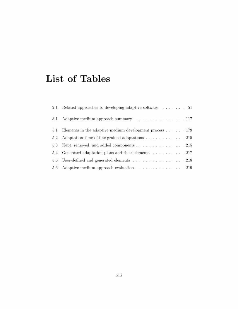
2.1 Related approaches to developing adaptive software . . . . . . . 51
3.1 Adaptive medium approach summary . . . . . . . . . . . . . . . 117
5.1 Elements in the adaptive medium development process . . . . . . 179
5.2 Adaptation time of fine-grained adaptations . . . . . . . . . . . . 215
5.3 Kept, removed, and added components . . . . . . . . . . . . . . . 215
5.4 Generated adaptation plans and their elements . . . . . . . . . . 217
5.5 User-defined and generated elements . . . . . . . . . . . . . . . . 218
5.6 Adaptive medium approach evaluation . . . . . . . . . . . . . . 219
xiii

xiv LIST OF TABLES

Resume en francais
Sommaire
1 Introduction . . . . . . . . . . . . . . . . . . . . . . . 1
2 Etat de l’art . . . . . . . . . . . . . . . . . . . . . . . . 3
3 Approche medium adaptable . . . . . . . . . . . . . 6
4 Processus de developpement des mediums adaptables 10
5 Prototype . . . . . . . . . . . . . . . . . . . . . . . . . 13
6 Conclusion . . . . . . . . . . . . . . . . . . . . . . . . 14
1 Introduction
Les applications informatiques sont omnipresentes dans notre environne-ment. Celles-ci doivent desormais pouvoir fonctionner sans s’interrompre dansdes contextes tres variables, et cela, dans l’ideal, meme si une modificationde structure interne est requise. Ce contexte variable comprend aussi bien desdispositifs et des reseaux que le comportement de l’environnement et de l’utilisa-teur. On parle ainsi d’adaptation dynamique pour caracteriser les applicationspouvant changer leur comportement a l’execution en s’adaptant au contexted’execution courant. Plusieurs travaux recents proposent des approches dedieesau developpement de telles applications. Cependant, ces approches n’englobentpas encore la complexite du developpement d’une application adaptative, par-ticulierement lorsqu’elles sont distribuees, et de nombreuses taches delicatesrestent encore a la charge des developpeurs. Nous avons identifie six verrous quiresument cette complexite dans le contexte du developpement d’applicationsdistribuees :
– V1 - Supporter la coherence des variantes : Dans une adaptation, uneapplication remplace sa variante courante d’execution par une autre va-riante. Ces variantes doivent etre coherentes, c’est-a-dire que l’applicationdoit continuer a fonctionner correctement apres l’adaptation.
1

2 Resume en francais
– V2 - Transferer l’etat : Une adaptation reussie doit permettre le transfertd’etat de la variante remplacee a la variante remplacante.
– V3 - Modeliser la modularite, la similitude et la variabilite : Afin de rem-placer de maniere plus fine la variante courante par une autre variante,l’application doit pouvoir conserver les parties communes aux deux va-riantes et remplacer uniquement les parties differentes de celles-ci. A cettefin, la modularite, la similitude et la variabilite des variantes doivent etreexplicitement modelisees.
– V4 - Automatiser la planification de l’adaptation : L’application doit pou-voir planifier automatiquement ses adaptations. L’ensemble des actionsd’adaptation qui permettent de modifier l’application et de transfererl’etat doit etre defini automatiquement.
– V5 - Supporter des adaptations distribuees : Une adaptation distribueese decompose en plusieurs processus distribues pour gerer l’adaptationsur les differents sites. Ce type d’adaptation est difficile car elle necessitela coordination des processus distribues et le transfert de l’etat entre lessites.
– V6 - Automatiser le processus de developpement : Un processus de develop-pement d’applications adaptatives permettant de gerer les verrous prece-dents est necessairement complexe. L’automatisation d’un tel processusest donc indispensable.
Nous proposons dans le cadre de ce travail une approche appelee mediumadaptable qui permet de relever ces differents verrous. L’approche est elaboreeen se basant sur deux principes :
– P1 - Une abstraction de haut niveau : L’application adaptable est specifieea un haut niveau d’abstraction, permettant d’integrer l’aspect de distribu-tion. Cette abstraction de l’application peut ainsi etre utilisee pour guiderla construction des variantes, modeliser la modularite, la similitude et lavariabilite, et egalement les informations utiles a la planification des adap-tations comme les contraintes sur les actions d’adaptation et les operationsde transfert de donnees.
– P2 - Un processus automatise : Les taches sont partiellement automatiseesgrace a l’ingenierie dirigee par les modeles.
Ces deux principes d’abstraction et d’automatisation ont deja fait l’objetde travaux au sein de notre equipe. Nous etendons ainsi l’abstraction d’ap-plication distribuee appelee medium definie par Eric Cariou [Cariou 03] pourconstruire une abstraction d’application distribuee adaptable appelee mediumadaptable. Le processus de raffinement de mediums propose par Evelyne Kabore

2. Etat de l’art 3
[Kabore 08a] est egalement repris en introduisant 1) la modelisation de la modu-larite, de la similitude et de la variabilite des differentes variantes de medium, 2)la modelisation du transfert de donnees entre les variantes, et 3) la modelisationdes contraintes entre les actions d’adaptation. L’ajout de ces modeles permetde preciser le processus de raffinement de differentes variantes, l’automatisationde la generation de ces variantes ainsi que les liens entre celles-ci, ce qui permetde generer des plans d’adaptation necessaires.
Le reste de ce document est organise comme suit. La section 2 resume lestravaux connexes. La section 3 decrit l’approche medium adaptable. La section 4formule un processus de developpement des mediums adaptables. La section 5presente un prototype du framework dedie au processus. Enfin, la section 6conclut le document.
2 Etat de l’art
Dans cette section, nous presentons quelques notions de base, puis nouseffectuons une revue de travaux connexes.
2.1 Notions de base
Nous reumons ici quelques notions cles autour de l’adaptation dyanmiquepour mieux preciser le cadre de ce travail.
Adaptation dynamique
L’adaptation dynamique est la capacite des applications a se modifier elles-memes pendant leur execution afin de s’adapter aux changements de contexte[Oreizy 99]. Par rapport a l’adaptation statique dans laquelle les applicationssont arretees et recompilees afin d’integrer des modifications, l’adaptation dy-namique permet d’augmenter la disponibilite des applications et de reduire lecout d’exploitation des adaptations.
Activites de controle d’adaptation
Dans une application adaptable, les activites de controle d’adaptation com-prennent typiquement l’observation des changements du contexte et de l’etatde l’application, la decision d’adaptation en fonction de ces observations, la pla-nification des actions d’adaptation a realiser, et finalement l’execution de cesactions [Buisson 06].
4 Resume en francais
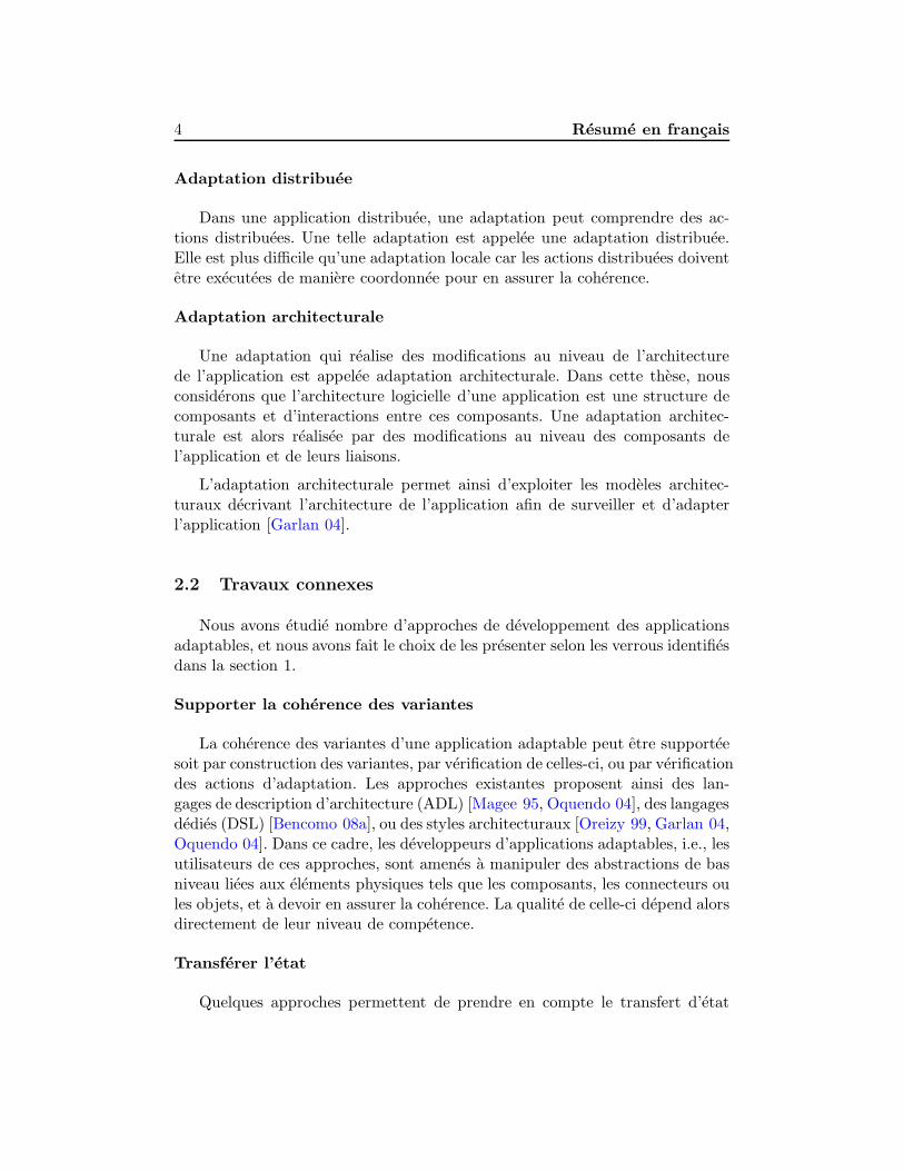
Adaptation distribuee
Dans une application distribuee, une adaptation peut comprendre des ac-tions distribuees. Une telle adaptation est appelee une adaptation distribuee.Elle est plus difficile qu’une adaptation locale car les actions distribuees doiventetre executees de maniere coordonnee pour en assurer la coherence.
Adaptation architecturale
Une adaptation qui realise des modifications au niveau de l’architecturede l’application est appelee adaptation architecturale. Dans cette these, nousconsiderons que l’architecture logicielle d’une application est une structure decomposants et d’interactions entre ces composants. Une adaptation architec-turale est alors realisee par des modifications au niveau des composants del’application et de leurs liaisons.
L’adaptation architecturale permet ainsi d’exploiter les modeles architec-turaux decrivant l’architecture de l’application afin de surveiller et d’adapterl’application [Garlan 04].
2.2 Travaux connexes
Nous avons etudie nombre d’approches de developpement des applicationsadaptables, et nous avons fait le choix de les presenter selon les verrous identifiesdans la section 1.
Supporter la coherence des variantes
La coherence des variantes d’une application adaptable peut etre supporteesoit par construction des variantes, par verification de celles-ci, ou par verificationdes actions d’adaptation. Les approches existantes proposent ainsi des lan-gages de description d’architecture (ADL) [Magee 95, Oquendo 04], des langagesdedies (DSL) [Bencomo 08a], ou des styles architecturaux [Oreizy 99, Garlan 04,Oquendo 04]. Dans ce cadre, les developpeurs d’applications adaptables, i.e., lesutilisateurs de ces approches, sont amenes a manipuler des abstractions de basniveau liees aux elements physiques tels que les composants, les connecteurs oules objets, et a devoir en assurer la coherence. La qualite de celle-ci depend alorsdirectement de leur niveau de competence.
Transferer l’etat
Quelques approches permettent de prendre en compte le transfert d’etat

2. Etat de l’art 5
entre variantes. Cependant, les fonctions de transfert des donnees necessitentsouvent un prise en charge manuelle par le developpeur [Lee 06, Geihs 09].
Modeliser la modularite, la similitude et la variabilite
Pour pouvoir affiner le changement entre variantes, il est necessaire de pou-voir decomposer l’applicaton en sous-modules. Le terme « modularite » renvoiedonc a cet aspect de separation. Dans ce cadre, il est alors necessaire de pou-voir identifier explicitement les elements a conserver et ceux a echanger, lestermes « similitude » et « variabilite » renvoient a l’identification des modulesdifferents (resp. communs) des variantes de l’application.
La separation des preoccupations et l’ingenierie logicielle a base de compo-sants sont des approches importantes pour supporter la modularite logicielle.Les preoccupations d’une application sont separees, puis reifiees au travers demodules appeles composants logiciels. Plusieurs modeles de composants ontainsi ete proposes, notamment CCM, COM et Fractal. Dans certains cas, il n’estpas possible de decliner des preoccupations en composants, par exemple pourcause d’inter-croisement de preoccupations. La technologie des aspects (AOP)propose alors une alternative pour assurer la separation au travers d’aspectsqui seront tisses dans l’application desiree [Kiczales 97, Pessemier 08]. Malgretout, les chercheurs dans ce domaine n’ont pas encore resolu des verrous tels quel’interaction entre aspects. Le probleme de la modularite n’est donc pas encorecompletement resolu.
La variabilite est une notion importante dans le domaine des lignes deproduits. En considerant les variantes d’une application adaptable comme lesmembres d’une ligne de produits, des approches de modelisation de la varia-bilite dans ce domaine peuvent etre utilisees pour modeliser les applicationsadaptables. Les exemples comprennent la modelisation des features [Lee 06,Morin 09a, Cetina 09] ou le modele orthogonal de variabilite [Bencomo 08a].Cependant, ces approches supposent que les features peuvent etre directementlies aux composants ou aux aspects. Le cas general ou les aspects ou compo-sants ne pourraient pas separes n’est donc pas pris en compte. Autrement dit,ces approches n’abordent pas la modularite dans sa globalite.
Automatiser la planification d’adaptation
Quelques approches supportent la planification d’adaptation en utilisantles informations de developpement. Les plans d’adaptation peuvent ainsi etregeneres en comparant les configurations de features [Cetina 09] ou les modelesarchitecturaux [Garlan 04, Bencomo 08a]. Cependant, dans ces approches, lesliens entre leurs elements et les composants logiciels sont definis manuellement.

6 Resume en francais
La correction des plans revient donc aux developpeurs.
Supporter des adaptations distribuees
L’adaptation distribuee est particulierement difficile de par la necessite d’as-surer la coordination des actions distribuees. Ce probleme est aborde dansquelques approches telles qu’ACEEL [Chefrour 05] et CACTUS [Chen 01]. Ce-pendant, dans ces approches, la coordination des actions distribuees est baseesur une politique de coordination definie par les developpeurs. Or, la definitiond’une telle politique reste une tache difficile.
Automatiser le processus de developpement
Le developpement d’une application adaptable peut etre partiellement au-tomatise en faisant appel a l’ingenierie dirigee par les modeles et/ou a des tech-nologies de lignes de produits [Oquendo 04, Bencomo 08a]. Dans ce contexte,la generation de code et la reutilisation des artefacts logiciels tels que les com-posants sont adoptees. Cependant, le niveau d’automatisation reste insuffisant.En effet les developpeurs doivent specifier l’application adaptable au niveaud’abstraction de composants physiques et donc gerer eux-memes l’architecturedistribuee.
Conclusion
La specification a un haut niveau d’abstraction des applications adaptablesapparait comme une approche prometteuse pour depasser les limitations desapproches existantes. Le raffinement au niveau des composants physiques peutalors s’integrer au processus et ainsi etre automatisee. Ce sont les points-cles del’approche de medium adaptable [Phung-Khac 08, Phung-Khac 10].
3 Approche medium adaptable
La figure 1 decrit le principe de l’approche de medium adaptable, qui s’ar-ticule autour d’une abstraction de haut niveau, du raffinement, et de la compo-sition au niveau de l’implementation.
L’abstraction de haut niveau
L’abstraction de haut niveau retenue dans le cadre de notre approche pourspecifier une application adaptable est le medium - une abstraction de commu-nication dediee aux applications distribuees [Cariou 03].

3. Approche medium adaptable 7
yx
? 1 1 ?
Médiumd’adaptation
Composition
Médiumfonctionnel
Médium adaptable avec le contrôle centralisé d’adaptation
(Niveau d’implémentation)
Composant client
x y
x y x y
*1*
distribuée centralisée
Médium adaptable (Haut niveau d’abstraction)
Variante 1 Variante m
adapter surveiller
… …
Raffinement Raffinement
Variante 1 Variante n
Modèlesarchitecturaux
Modèles facilitant l’adaptation
Composants physiques
Entité logique, agrégation des entités physiques
Entité logique,une abstraction
Lien abstrait
Lien physique à distance
Lien physique local
embaqués dans
Fig. 1 – Approche medium adaptable

8 Resume en francais
Un medium est une abstraction de la communication fonctionnelle distribueedans une application. L’application est donc specifiee comme une interconnexiond’un medium et des composants clients. Au niveau de l’implementation, l’abs-traction est reifiee par une agregation des composants physiques appeles des ges-tionnaires. Cette agregation est appelee le medium au niveau d’implementation.
En utilisant le medium, l’application adaptable est specifiee comme une in-terconnexion d’un medium adaptable et de quelques composants clients. Commele montre la figure 1, le medium adaptable en tant qu’abstraction se composede deux parties : le medium fonctionnel et le medium d’adaptation. Tandis quele premier encapsule la partie fonctionnelle distribuee de l’application, le secondencapsule les fonctionnalites permettant l’adaptation ainsi que la coordinationdes actions distribuees utilisees pour reconfigurer le premier. Ainsi, le mediumd’adaptation utilise les modeles architecturaux des variantes du medium fonc-tionnel pour adapter le medium fonctionnel lors de son execution.
La generation des variantes du medium fonctionnel
Le medium fonctionnel en tant qu’abstraction est raffine au niveau de l’imple-mentation en utilisant le processus de raffinement de medium [Kabore 08a].Ce processus est construit en identifiant dans un premier temps une suitede preoccupations. Pour chaque preoccupation, une transformation est definie.Cette transformation permet d’introduire une solution a la preoccupation dansle medium, et de le rendre ainsi plus concret a chaque etape. A cette fin, un meta-modele de solution et deux meta-modeles de medium sont definis (appeles meta-modeles de medium source et cible). La transformation introduit donc un modelede solution conforme au meta-modele de solution dans un modele de mediumde source conforme au meta-modele de medium de source, et puis, genere unmodele de medium de cible. En definissant pour chaque preoccupation plusieurssolutions differentes, il est ainsi possible, grace au processus de raffinement, degenerer des variantes differentes du medium au niveau de son implementation.Chaque variante d’implementation est alors une agregation des gestionnairesfonctionnels.
En vue de gerer finement les differentes variantes et leurs transitions, nousetendons le processus de raffinement de medium en ajoutant trois modeles :
– Le modele de modularite, de similitude et de variabilite : Ce modele estune extension d’un modele de features [Kang 90, Czarnecki 00]. Dans cemodele, les preoccupations et leurs solutions sont representees comme desfeatures. Les solutions pour une preoccupation sont representees commeun groupe de features attache au feature representant cette preoccupation.Ce modele permet donc de decrire les variantes, la similitude et la varia-
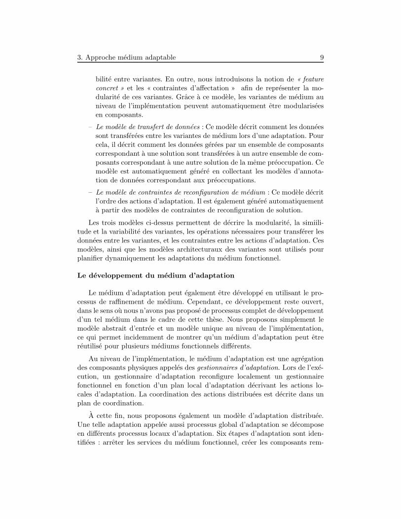
3. Approche medium adaptable 9
bilite entre variantes. En outre, nous introduisons la notion de « featureconcret » et les « contraintes d’affectation » afin de representer la mo-dularite de ces variantes. Grace a ce modele, les variantes de medium auniveau de l’implementation peuvent automatiquement etre modulariseesen composants.
– Le modele de transfert de donnees : Ce modele decrit comment les donneessont transferees entre les variantes de medium lors d’une adaptation. Pourcela, il decrit comment les donnees gerees par un ensemble de composantscorrespondant a une solution sont transferees a un autre ensemble de com-posants correspondant a une autre solution de la meme preoccupation. Cemodele est automatiquement genere en collectant les modeles d’annota-tion de donnees correspondant aux preoccupations.
– Le modele de contraintes de reconfiguration de medium : Ce modele decritl’ordre des actions d’adaptation. Il est egalement genere automatiquementa partir des modeles de contraintes de reconfiguration de solution.
Les trois modeles ci-dessus permettent de decrire la modularite, la simiili-tude et la variabilite des variantes, les operations necessaires pour transferer lesdonnees entre les variantes, et les contraintes entre les actions d’adaptation. Cesmodeles, ainsi que les modeles architecturaux des variantes sont utilises pourplanifier dynamiquement les adaptations du medium fonctionnel.
Le developpement du medium d’adaptation
Le medium d’adaptation peut egalement etre developpe en utilisant le pro-cessus de raffinement de medium. Cependant, ce developpement reste ouvert,dans le sens ou nous n’avons pas propose de processus complet de developpementd’un tel medium dans le cadre de cette these. Nous proposons simplement lemodele abstrait d’entree et un modele unique au niveau de l’implementation,ce qui permet incidemment de montrer qu’un medium d’adaptation peut etrereutilise pour plusieurs mediums fonctionnels differents.
Au niveau de l’implementation, le medium d’adaptation est une agregationdes composants physiques appeles des gestionnaires d’adaptation. Lors de l’exe-cution, un gestionnaire d’adaptation reconfigure localement un gestionnairefonctionnel en fonction d’un plan local d’adaptation decrivant les actions lo-cales d’adaptation. La coordination des actions distribuees est decrite dans unplan de coordination.
A cette fin, nous proposons egalement un modele d’adaptation distribuee.Une telle adaptation appelee aussi processus global d’adaptation se decomposeen differents processus locaux d’adaptation. Six etapes d’adaptation sont iden-tifiees : arreter les services du medium fonctionnel, creer les composants rem-

10 Resume en francais
placants, initialiser les composants remplacants, transferer les donnees, enleverles composants remplaces, et redemarrer les services du medium fonctionnel.Nous proposons aussi un meta-modele de plan d’adaptation local et un meta-modele de plan de coordination.
La composition du medium adaptable
Le medium adaptable au niveau de l’implementation est compose d’unevariante du medium fonctionnel et d’une variante du medium d’adaptation.Tandis que le premier est la variante initiale et sera remplacee par une autrevariante pendant l’execution afin d’adapter le medium fonctionnel au contexted’execution, le second est stable et sert de plateforme de controle d’adapta-tion. A ce niveau d’implementation, le medium adaptable est une agregationdes gestionnaires adaptables, chacun se composant d’un d’un gestionnaire fonc-tionnel et d’un gestionnaire d’adaptation. Le medium d’adaptation embarqueles differents modeles necessaires a la planification dynamique des adaptations,a savoir les modeles architecturaux des variantes du medium fonctionnel, lemodele de la modularite et la variabilite des variantes, ainsi que le modele detransfert de donnees, et le modele de contraintes de reconfiguration du medium.
4 Processus de developpement des mediums adap-
tables
Le processus de developpement permet de raffiner l’abstraction de hautniveau et d’assurer la composition finale permettant le deploiement. La fi-gure 2 decrit le processus de developpement des mediums adaptables. Nous yavons identifie quatre roles differents pour les developpeurs, correspondant a desmetiers differents et permettant de bien mettre en exergue les elements du pro-cessus sur lesquels il est possible de capitaliser pour promouvoir la reutilisation.Quatre etapes du developpement sont retenues permettant de mettre en evidenceles collaborations entre ces differents roles.
Les roles des developpeurs
Pour mettre en avant les differents aspects du processus de developpement,nous avons retenu quatre roles pour les developpeurs participant au processusde developpement d’un medium adaptable : l’expert de medium, le concepteurde solutions, le concepteur de processus, et le concepteur d’application.
Les taches de l’expert de medium et du concepteur de solutions concernentprincipalement les aspects d’ingenierie de domaine du processus, c’est-a-dire

4. Processus de developpement des mediums adaptables 11
Ingénierie de domaine Ingénierie d’application
Expertde médium
Concepteur de solutions
Concepteur de processus
Concepteur d’application
Eta
pe 1
:
Spécific
ation
Eta
pe 2
:
Tra
nsfo
rmation
Eta
pe 3
:
Généra
tion
Eta
pe 4
:
Com
positio
n
Générer le médium niveau 1
Identifier les préoc. et les solutions en définissant un modèle MSV-initial
Identifier les va-riantes de médium
Valider
Oui
Non
Nouvelles préoc.
?
Nouvelles solutions
?
Pour une préoc.: Définir 1
transformation Définir 1 méta-
modèle de solution Définir 2 méta-
modèles de médium
Définir 1 méta-modèle de décision
Oui
Non Pour une solution: Définir un modèle
de solution Définir un modèle
de contr. dereconf. de solution
Ajouter des infos au modèle d’annotation de données
Identifier les contraintes des features et les features concrètes
Générer un modèle MSV-raffiné
Oui
Non
Définir un modèle de processus
Générer les variantes niveau 4, 1 modèle de transfert de données,1 modèle de contr. de reconf. de médium
Composer lemédium adaptable
Catalogue
préserver
réutilis
er
Identifier le médium niveau 0
Fig. 2 – Processus de developpement des mediums adaptables

12 Resume en francais
les aspects de developpement concernant la reutilisation et la capitalisation. Ilsdefinissent des modeles generiques, tant au niveau du processus que des elementsde solutions correspondant aux differentes preoccupations. Le concepteur deprocessus et le concepteur d’application se peoccupent quant a eux des aspectsd’ingenierie d’application du processus. Ainsi le premier propose un processussous forme de suites de preoccupations correspondant a un type d’applicationdonne, et selectionne les variants pertinentes. Le second se concentre sur ledeveloppement d’un medium adaptable pour une application donnee.
Les etapes du processus
Comme indique sur la figure 2, le processus se decompose en quatre etapes :specification, transformation, generation, et composition.
– Specification : Le concepteur d’application commence par definir le modelede medium fonctionnel souhaite au niveau d’abstraction le plus haut. Leconcepteur de processus derive un modele de medium fonctionnel plusconcret dans lequel les gestionnaires abstraits sont introduits, en utili-sant une transformation initiale. A partir de la, le concepteur de pro-cessus et le concepteur d’application identifient les preoccupations et lessolutions auxquelles ils s’interessent. Ces preoccupations et solutions sontdecrites par un modele de modularite, de similitude et de variabilite (ap-pele « MSV-initial »). Les preoccupations et solutions sont identifiees apartir d’un catalogue des preoccupations reutilisables.
– Transformation : Cette etape permet de completer eventuellement le ca-talogue des preoccupations et solutions disponibles. Si une preoccupationidentifiee n’existe pas dans le catalogue, l’expert de medium doit alorsdefinir un meta-modele de solution, deux meta-modeles de medium etimplementer une nouvelle transformation. Il definit egalement un meta-modele de decision qui permet de parametrer la transformation. L’ajoutde solution dans le catalogue, que ce soit suite a l’ajout d’une nouvellepreoccupation ou pour elargir les options d’une preoccupation existanteest realise par le concepteur de solution qui definit le nouveau modele desolution, et ajoute les operations de transfert de donnees de ce modelede solution selon le modele d’annotation de donnees correspondant a lapreoccupation. Il definit egalement le modele de contraintes de reconfigu-ration de la solution.
– Generation : Les preoccupations et les solutions candidates etant iden-tifiees et disponibles, le concepteur de processus identifie les features con-cretes et les contraintes entre les features. Il utilise ensuite une trans-formation pour raffiner le modele MSV-initial issu de la specification.Le resultat est un modele qui precise la modularite et la variabilite des

5. Prototype 13
variantes du medium fonctionnel, appele le modele « MSV-raffine ». Leconcepteur de processus definit alors un modele de processus qui decritl’ordre d’execution des transformations pour generer les variantes. Fina-lement, il utilise une transformation pour generer ces variantes au niveaude l’implementation ou les composants sont decrits. Ces composants sontrelies aux caracteristiques du modele MSV-raffine. Un modele de trans-fert de donnees et un modele de contraintes de reconfiguration de mediumsont aussi generes par cette transformation, pour permettre la realisationde l’adaptation dynamique.
– Composition : Le concepteur d’application choisit une variante de mediumd’adaptation et une variante initiale pour le medium fonctionnel. Il utilisealors un programme de composition pour construire le medium adaptableau niveau de l’implementation.
L’organisation des roles et des etapes presentees ci-dessus permet de clari-fier le developpement des mediums adaptables. Cette organisation permet, deplus, d’augmenter le niveau de reutilisation et, ainsi, d’augmenter progressive-ment le niveau d’automatisation du processus de developpement des mediumsadaptables.
5 Prototype
Nous avons construit un prototype du framework de developpement desmediums adaptables, integrant un ensemble de fonctionnalites de base permet-tant la mise en œuvre du processus de developpement, une variante du mediumd’adaptation, et un programme de composition.
– L’ensemble des fonctionnalites de base : Il comprend les meta-modeles etles transformations utilises pour generer les variantes de tout medium. Ilintegre notamment les meta-modeles de medium aux differents niveauxd’abstraction, un meta-modele de MSV-initial, un meta-modele de MSV-raffine, un meta-modele de processus, un meta-modele d’annotation dedonnees et un meta-modele de contraintes de reconfiguration. Ces meta-modeles sont utilises par les transformations suivantes : une transfor-mation d’introduction des gestionnaires, une transformation de raffine-ment de modele MSV-initial, une transformation de modularisation etune transformation principale qui execute le modele de processus. Lesmeta-modeles et les transformations sont definis en utilisant le canevas demeta-modelisation Kermeta [Triskell].
– Une variante du medium d’adaptation : Le modele d’implementation decette variante a ete genere en utilisant les fonctionnalites de base definies

14 Resume en francais
precedemment. Les langages cibles sont Java et Fractal [Bruneton 06].
– Le programme de composition : Ce programme est developpe en Java. Lacomposition est realisee de maniere directe, en utilisant l’ADL de Fractalet l’implementation Julia [Bruneton 06].
Ce prototype a ete utilise pour developper deux mediums adaptables : unmedium adaptable de reservation de sieges et un de partage de fichiers. Desscenarios d’adaptation ont ete deployes pour pouvoir valider l’approche.
6 Conclusion
Contributions
Dans cette these, nous proposons une approche de developpement des ap-plications distribuees adaptables, appelee l’approche medium adaptable. Uneapplication distribuee adaptable y est d’abord specifiee a un haut niveau d’abs-traction en utilisant une abstraction appelee le medium adaptable. L’aspectfonctionnel et l’aspect d’adaptation sont separes a ce niveau abstrait sous formede deux abstractions appelees respectivement medium fonctionnel et mediumd’adaptation. Nous utilisons ensuite un processus de raffinement pour genererdes variantes d’implementation de chaque medium. Finalement, le mediumadaptable au niveau d’implementation est compose a partir d’une variante dumedium fonctionnel et d’une variante du medium d’adaptation. Alors que la va-riante du medium fonctionnel peut etre remplacee par une autre variante lors deson execution afin de l’adapter au contexte d’execution, la variante du mediumd’adaptation est stable et sert d’infrastructure de controle d’adaptation. Afind’adapter le medium fonctionnel, le medium d’adaptation utilise des modelesoriginaux d’architecture de variantes du medium fonctionnel, un modele de mo-dularite, de similitude et de variabilite de ces variantes, un modele de transfertde donnees entre ces variantes, et un modele de contraintes de reconfiguration.Ces modeles sont automatiquement generes par le processus de raffinement demedium.
Grace a l’abstraction de haut niveau, au processus de raffinement base surles techniques de modeles et la modelisation des features, a la modelisation detransfert de donnees, et a la modelisation des contraintes de reconfiguration,l’approche medium adaptable permet de resoudre les six verrous identifies dansla section 1.

6. Conclusion 15
Perspectives
L’approche medium adaptable ouvre plusieurs perspectives. Au niveau duprocessus le choix des preoccupations pourrait etre caracterise par une approchedefinie par des proprietes non-fonctionnelles. Celles-ci pourraient alors etre ex-ploitees pour caracteriser les choix de solutions, et ainsi servir de base a la prisede decision de l’adaptation.
La modelisation de differentes plate-forme cibles dans le processus pour-rait permettre un deploiement sur d’autres plateformes de composants, voired’integrer une dimension d’heterogeneite dans l’adaptation.
Finalement, pour augmenter les capactites d’adaptation de l’approche, ilpourrait etre interessant de permettre l’ajout de preoccupations a l’execution.Pour cela, il sera sans doute necessaire de raffiner l’analyse des relations et desinteractions entre preoccupations.

16 Resume en francais

Chapter 1
Introduction
Contents
1.1 Problem Statement . . . . . . . . . . . . . . . . . . . 17
1.2 Challenges and Key Issues . . . . . . . . . . . . . . . 19
1.3 Overview of the Solution . . . . . . . . . . . . . . . . 22
1.4 Contributions of the Thesis . . . . . . . . . . . . . . 28
1.5 Scope of the Thesis . . . . . . . . . . . . . . . . . . . 29
1.6 Structure of the Thesis . . . . . . . . . . . . . . . . . 30
1.1 Problem Statement
Runtime software adaptation implies the ability of software systems to changeat runtime in order to adapt to varying operating environments [Oreizy 98].Runtime adaptation is becoming essential for an important class of softwaresystems that need to be available under varying conditions. A dynamicallyadaptive software system embeds the necessary mechanisms to ensure runtimeadaptation without external intervention.
Component-Based Software Engineering (CBSE) is an important paradigmin software engineering that promises many benefits like increased productiv-ity, reusability, and shorter time-to-market. Software components are softwareunits that encapsulate functions or data and have interfaces. Many componentmodels have been proposed, such as EJB, CCM, OSGi, Fractal, and SOFA.Each of them provides its own facilities for software development [Lau 07]. Inaddition to these original benefits, CBSE promotes runtime adaptation by sup-porting dynamic reconfigurations of software systems at the level of software
17

18 1. Introduction
components. Such reconfigurations are realized using facilities of componentmodels such as dynamic updates, additions and removals of components.
CBSE also facilitates architecture-based adaptation that uses an architec-tural model to monitor and adapt a running system [Garlan 04]. The architec-tural model that describes the structure and interaction of the system’s compo-nents, allows to observe the system at the model level and to act accordingly.Among adaptation approaches (such as architecture-based and parametric-basedadaptations [Cheng 09]), the architecture-based adaptation is emerging and be-ing widely used in adaptive software development.
From the viewpoint of system variability, through an architecture-basedadaptation, a software system moves from an architectural variant to anotherone. These architectural variants must be consistent, i.e., the system must beable to work properly after the adaptation. For example, in a component-basedsoftware system where components collaborate to realize system’s services, thesecomponents must be able to collaborate properly after the adaptation.
Particularly, in the context of distributed software systems, an adaptationmay consist of processes that need to be performed in distributed sites (oftencalled distributed adaptation). Each adaptation process performed in one siteconsists of adaptation actions for reconfiguring components in this site1. Usu-ally, constraints between distributed actions may exist. For example, startinga component in a site may require starting another component in another sitepreviously. Therefore, these distributed actions need to be coordinated in orderto ensure the consistency of the system after the adaptation.
When an adaptation is realized by replacing the running variant by anotherone, the replacement variant must be initialized with the state of the replacedone [Oreizy 08]. This task of state transfer is crucial to ensure the correctness ofthe adaptation. However, in distributed software systems, such an initializationmay require data transfer across sites which are complex and time-consuming.Supporting state transfer becomes more difficult.
Adaptations relying on reconfigurations of software systems at the level ofsoftware components require these software systems to be modularized intotheir components first. Moreover, to facilitate such an adaptation, componentssubject to change should be easily identified [Oreizy 08]. When moving froman architectural variant to another one, the system must be able to identifythe common and different components between the two architectural variants,then keeps the common components and replaces the different ones. From thispoint of view, when the architectural variants have fine-grained modularity, the
1In this thesis, “adaptation actions” are understood as “actions for reconfiguring a softwaresystem in order to adapt it”.
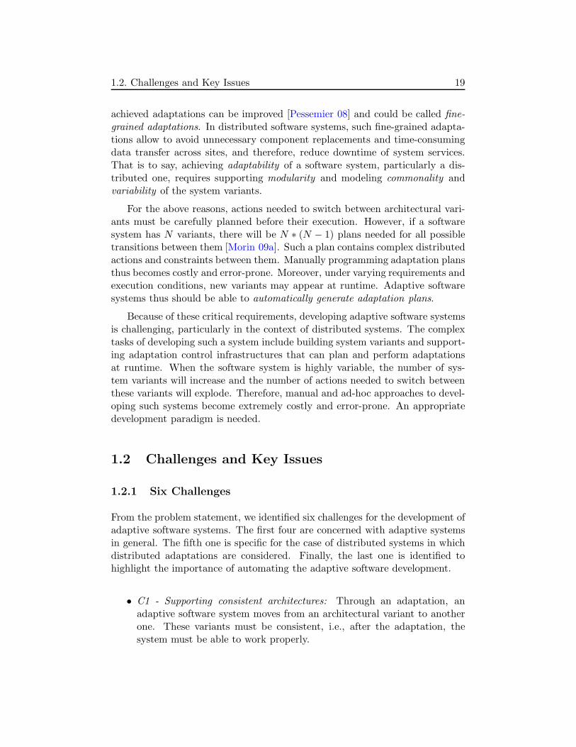
1.2. Challenges and Key Issues 19
achieved adaptations can be improved [Pessemier 08] and could be called fine-grained adaptations. In distributed software systems, such fine-grained adapta-tions allow to avoid unnecessary component replacements and time-consumingdata transfer across sites, and therefore, reduce downtime of system services.That is to say, achieving adaptability of a software system, particularly a dis-tributed one, requires supporting modularity and modeling commonality andvariability of the system variants.
For the above reasons, actions needed to switch between architectural vari-ants must be carefully planned before their execution. However, if a softwaresystem has N variants, there will be N ∗ (N − 1) plans needed for all possibletransitions between them [Morin 09a]. Such a plan contains complex distributedactions and constraints between them. Manually programming adaptation plansthus becomes costly and error-prone. Moreover, under varying requirements andexecution conditions, new variants may appear at runtime. Adaptive softwaresystems thus should be able to automatically generate adaptation plans.
Because of these critical requirements, developing adaptive software systemsis challenging, particularly in the context of distributed systems. The complextasks of developing such a system include building system variants and support-ing adaptation control infrastructures that can plan and perform adaptationsat runtime. When the software system is highly variable, the number of sys-tem variants will increase and the number of actions needed to switch betweenthese variants will explode. Therefore, manual and ad-hoc approaches to devel-oping such systems become extremely costly and error-prone. An appropriatedevelopment paradigm is needed.
1.2 Challenges and Key Issues
1.2.1 Six Challenges
From the problem statement, we identified six challenges for the development ofadaptive software systems. The first four are concerned with adaptive systemsin general. The fifth one is specific for the case of distributed systems in whichdistributed adaptations are considered. Finally, the last one is identified tohighlight the importance of automating the adaptive software development.
• C1 - Supporting consistent architectures: Through an adaptation, anadaptive software system moves from an architectural variant to anotherone. These variants must be consistent, i.e., after the adaptation, thesystem must be able to work properly.

20 1. Introduction
• C2 - Transferring system state: Adaptive software systems must be ableto maintain their state through adaptations. When replacing the runningvariant by another one, state of the former must be transferred to thelatter.
• C3 - Modeling commonality and variability: Approaches to developingadaptive software systems should include the modeling of commonalityand variability of system variants. On the other hand, this challengeimplicitly includes supporting modularity. In component-based softwaresystems, modularity is concerned with how such a system is modular-ized into its components, while commonality and variability refer to thecommon and different components between any two variants. Supportingfine-grained modularity enables to achieve fine-grained adaptations. Onthe other hand, commonality and variability modeling facilitates theseadaptations.
• C4 - Supporting automatic adaptation planning: Adaptive software sys-tems should be able to plan adaptations automatically. In component-based systems, an adaptation plan contains actions for replacing compo-nents and transferring states among them. Instead of requiring softwareengineers to program adaptation plans, the systems should be able toautomatically generate these plans. Such automatic adaptation planningability can reduce development cost and ease the integration of new vari-ants at runtime.
• C5 - Supporting distributed adaptations: In a distributed system, an adap-tation may consist of distributed processes that need to be performed indistributed sites. This type of adaptation is called distributed adaptationand makes the first four challenges more difficult to overcome.
• C6 - Automating the development: Many tasks of the development ofadaptive software systems are highly complex. Automating these tasks,particularly those whose complexity degrees depend on systems variability(such as building variants; modeling commonality and variability; andprogramming adaptation actions), can significantly reduce developmentcosts.
The first four challenges are strongly related to each other. For example,challenges for supporting consistent variants (C1) and supporting state transfer(C2) are related to ensuring the correctness of adaptations. Likewise, sup-porting automatic adaptation planning (C4) is concerned with the modelingof commonality and variability (C3). By identifying these four challenges, we

1.2. Challenges and Key Issues 21
highlight different aspects to be considered when developing adaptive softwaresystems.
Challenge C5 can be considered as a “cross-cutting” challenge of the firstfour ones. First, supporting consistent architectures for distributed adaptations(C5 and C1) requires to coordinate adaptation actions in distributed sites inorder to avoid mismatching between these components, and thereby, enable thecomponents to collaborate properly after adaptations. Second, supporting statetransfer in distributed adaptations (C5 and C2) is more challenging due to datatransfer across sites. In this case, modeling commonality and variability (C5 andC3) are particularly advantageous to avoid unnecessary replacements of com-ponents and data transfer required by these replacements. Finally, automaticplanning of distributed adaptations (C5 and C4) is also more challenging be-cause in addition to generating actions of an adaptation plan, the system mustgenerate a coordination plan that is used to coordinate distributed actions.
1.2.2 Two Key Issues
To address these challenges, we advocate two key issues for the development ofadaptive software systems:
1. Need of a high-level abstraction: An approach to developing adaptive soft-ware systems should provide a high-level abstraction for specifying thewhole adaptive (distributed) software system. Such an abstraction canfacilitate software engineers to specify the system, and then, serves as abasis for analyzing system modularity, modeling commonality and vari-ability, and building consistent architectural variants.
2. Need of an appropriate, highly-automated development process: The ap-proach should provide an appropriate, highly-automated development pro-cess. By appropriate, we mean that the process can use the high-level ab-straction as a basis for realizing its promised advantages, including specify-ing the adaptive software system, analyzing system modularity, modelingsystem commonality and variability, and building consistent architecturalvariants. Moreover, the development process should be highly-automatedin order to reduce complex tasks of developers, including the developmentof architectural variants and planning adaptations.
These two key issues also correspond to limitations of the state-of-the-artaddressed in this thesis. The key issues and the challenges will be used toanalyze related approaches, describe contributions of our research, and discussresults.

22 1. Introduction
1.3 Overview of the Solution
This thesis proposes an approach to developing adaptive distributed applica-tions,2 called the adaptive medium approach. The approach addresses the sixchallenges and proposes solutions regarding the two key issues previously iden-tified.
Our approach is component-based, i.e., the adaptations rely on reconfigu-ration at the software component level [McKinley 04]; architecture-based, i.e.,architectural models are used for monitoring and adapting the running appli-cation [Oreizy 99]; and external-control-based, i.e., the adaptation control partis externalized from the functional part of the adaptive application [Garlan 04].The choice of these approaches (i.e., component-based, architecture-based, andexternal-control-based) is founded on their advantages such as making the de-velopment easier and promoting reuse. They will be discussed in Chapter 2.
From the development process point of view, this approach is model-based,i.e., models and transformations are used to automate the development [OMG 10];system-family-based, i.e., application variants can be considered as members ofa system family [Bencomo 08a] and domain and application engineering pro-cesses are separated [Czarnecki 00]; and feature-based, i.e., feature modeling isused to scope the application variants [Kang 90]. These approaches (i.e., model-based, system-family-based, and feature-based) enable to highly automate thedevelopment process of adaptive distributed applications. These approacheswill be presented in Chapter 2.
1.3.1 Adaptive Medium Approach
To address the six identified challenges, we propose solutions (to the develop-ment of adaptive distributed applications) regarding the two key issues. Tothis end, the adaptive medium approach is based on the medium approach thatincludes 1) an abstraction of communication for specifying distributed applica-tions [Cariou 03] and 2) a process for refining this abstraction [Kabore 08a]:
• A medium is a high-level abstraction of functional communication in adistributed application. According to the medium approach, a distributedapplication is specified as an interconnection of one or several medium(s)and client components. Each medium provides communication servicesto several client components that are usually located in distributed sites.A medium can be considered as a traditional component in the sense
2We distinguish application software from software systems in general.

1.3. Overview of the Solution 23
that it is reusable in similar contexts. It is also called a communicationcomponent.
A medium is specified as a single software entity that can be developed in-dependently from other mediums or client components. At the implemen-tation level, it is reified by a set of (to-be-)distributed components calledmanagers. Each manager is aware of the others. It “brings” communica-tion services to a client component and hides the inter-managers commu-nication away from the client component. To differentiate the managercomponents from the client components, the set of manager componentsis also called medium. From here, the term “medium” does not refer toany specific level of abstraction, while “medium abstraction” and “mediumimplementation” refer to the medium at the high abstraction level and theimplementation level, respectively.
• The medium refinement process corresponds to a set of successive refine-ment steps intended to develop a concrete implementation of a mediumabstraction. Each step corresponds to a design decision in which a solu-tion is introduced into the medium for a considered design concern. Inthis way, each step makes the medium more concrete, thus leading to aparticular implementation of it.
The introduction of solutions in the refinement process is automated usingmodel transformations. A transformation introduces a solution model intoa source medium model and generates a target medium model. Thesetransformations are compliant to the Model-Driven Architecture (MDA)pattern in which a Platform-Independent Model (PIM) is refined into aPlatform-Specific Model (PSM) by introducing a Platform Model (PM).
The medium approach allows to encapsulate distributed functional com-munication of an application into consistent software entities (called mediums),and then, to manipulate them. When considering adaptations in this distributedapplication, the specification using mediums allows to encapsulate distributedadaptations into these mediums. This is the start point of the adaptive mediumapproach.
In this thesis, we extend the medium approach so that the medium refine-ment process allows to introduce different solutions for each design concern,leading to several concrete implementations of the medium abstraction, calledmedium implementation variants (or medium variants for short). Adapting adistributed application thus consists in changing the running implementationvariant(s) of its medium(s). A medium that is able to change its running variantin order to adapt to changes in the operating environment is called an adap-
tive medium. Similarly to a medium, an adaptive medium is called adaptive

24 1. Introduction
medium abstraction and adaptive medium implementation at the high abstrac-tion level and the implementation level, respectively.
In the next paragraphs, we summarize the adaptive medium approach infour activities: specifying the adaptive medium abstraction as a compositionof an adaptation medium and a functional medium, developing the adaptationmedium, generating functional medium variants, and composing the adaptivemedium implementation.
Specifying the Adaptive Medium Abstraction
We propose to specify the adaptive medium abstraction as a compositionof two medium abstractions: the adaptation medium abstraction and the func-tional medium abstraction. While the former represents adaptation behaviorsof the adaptive medium, the latter encapsulates functional ones.
From this specification, the adaptation medium will be developed as areusable adaptation control infrastructure, while the medium refinement processwill be used and extended to generate implementation variants of the functionalmedium. Together with these functional medium variants, their architecturalmodels and other models facilitating adaptations are also generated. At run-time, the adaptation control infrastructure uses the generated models to monitorand adapt the functional medium implementation. An adaptation is carried outby replacing the running variant of the functional medium by another one.
The key point of the specification is that, using the medium approach, wecan specify adaptive distributed applications in which a distributed adaptationcontrol infrastructure monitors and adapts distributed functional components.
Developing the Adaptation Medium
The adaptation medium abstraction presented above is then developed asa distributed adaptation control infrastructure that is reusable for every func-tional medium. Moreover, according to the medium approach, the adaptationmedium may also have several implementation variants. Each of them is a logi-cal aggregation of distributed adaptation managers. These managers collaborateat runtime to monitor and adapt the functional medium implementation.
In this thesis, we are interested in facilitating and automating planning andexecuting adaptations. Therefore, we propose principles for 1) specifying theadaptation medium abstraction and 2) describing how adaptation plans can begenerated and executed. Such a plan is global and consists of i) some localadaptation plans containing local adaptation actions for each manager and ii)an adaptation coordination plan describing how to coordinate these actions.

1.3. Overview of the Solution 25
Generating Functional Medium Variants
This activity is concerned with the process of generating implementationvariants of the functional medium abstraction. The key requirements are that1) it must be highly automated and 2) it must enable and ease the generationof adaptation plans.
To this end, we have extended the original medium refinement process([Kabore 08a]) so that alternative solutions are introduced for each considereddesign concern. The process thus (semi)automatically generates different func-tional medium variants thanks to model transformations. That is, instead ofbeing interested in the MDA-based refinement process that generates a softwareproduct at the implementation level, we extend this process in order to generatedifferent products as members of a product family [Czarnecki 00].
To automate adaptation planning, we propose the following solutions:
First, we introduce a feature-based solution for modeling functional mediumvariants’ modularity, variability, and commonality (called MCV modeling). Todevelop an adaptive medium, an MCV model as an extended feature model[Kang 90] describes how functional medium variants can be modularized intocomponents regarding identified concerns and solutions, and which componentsare the common/different ones between any two variants. Concerns and solu-tions are represented as features of the MCV model and these features will bemapped to components of the variants. A feature refinement step tackles thecases of interleaved concerns, thus better supporting modularity. By allowingcomparisons of two feature configurations corresponding to any two functionalmedium variants, this MCV model facilitates the generation of fine-grainedadaptation plans.
Second, we append to the end of the original medium refinement process arefinement step in which functional medium variants at the (class-)implementa-tion level are automatically modularized into the component-implementationlevel (or component level). This solution is strongly integrated with the MCVmodeling. The modularization uses the MCV model to modularize functionalmedium variants (i.e., generate components of these functional medium vari-ants). On the other hand, it completes the MCV model by mapping the gener-ated components to features.
Finally, we propose to model data transfer between the variants and re-configuration constraints on components of the variants. A data transfer modelis generated by the process based on basic data manipulation operations de-scribed in introduced solution models. Likewise, a reconfiguration constraintsmodel is also generated based on basic constraints described in these solutionmodels. The data transfer model and the reconfiguration constraints one allow

26 1. Introduction
to identify actions for the data transfer between functional medium variantsand constraints between adaptation actions.
Therefore, beyond generating architectural models, the process also gen-erates other models what could be called adaptation-facilitating models thatfacilitate planning, executing, and coordinating distributed adaptations.
Composing the Adaptive Medium Implementation
Finally, the target adaptive medium implementation is built as the composi-tion of an adaptation medium variant and a functional medium variant. Whilethe latter can be replaced at runtime, the former is stable and serves as an in-frastructure for monitoring (i.e., changes on the functional medium such as theinstances of managers are reported to the adaptation medium) and adapting(i.e., reconfiguring the running functional medium variant to achieve the targetone) the latter.
To reconfigure the running functional medium variant, the adaptation me-dium uses reflection technologies supported by component platforms and pro-gramming languages. Actions for reconfiguring the functional medium variantare automatically generated and planned by using the architectural models ofthe functional medium variants and the adaptation-facilitating models.
1.3.2 Adaptive Medium Development Process
From the adaptive medium approach summarized above, we formulate an adap-tive medium development process. To develop an adaptive medium, the processconsists of four main steps:
• Specifying the functional medium abstraction and identifying concernsand desired solutions.
• Implementing transformations. Each transformation introduces a solu-tion model for a concern into a source medium model and generates atarget medium model. To this end, corresponding to each transforma-tion, there are two medium meta-models, a solution meta-model, and adecision meta-model. The last one allows software engineers to partici-pate in the transformation. Each transformation should have operationsfor checking constraints of source and target medium models.
• Generating functional medium variants by executing transformations in asuitable order. This order is represented by a process model.
1.3. Overview of the Solution 27
• Composing the adaptive medium implementation by selecting a reusableimplementation of the adaptation medium and an initial variant of thefunctional medium.
These steps are ensured by four main roles of the software engineers whoparticipate in the development process: medium expert, solution designer, pro-cess designer, and application designer. While the first two roles are concernedwith the domain engineering (i.e., development for reuse), the two others areinvolved in the application engineering (i.e., development with reuse). Thesesoftware engineers use an adaptive medium development framework that 1) con-tains basic elements that are used for the development of every adaptive medium(such as basic medium meta-models, adaptation medium implementations, pro-cess meta-model, and MCV meta-model), 2) contains elements that are tailoredbut reusable for several adaptive mediums that share common features (such astransformations, tailored medium meta-models, solution meta-models, and com-ponents), and 3) supports defining elements that are specific for each adaptivemedium (such as medium models, the process model, and custom components).
Thanks to the separation of software engineers’ roles and software elementsas presented above, the adaptive medium development process can be highlyautomated.
1.3.3 Claims
We claim that the adaptive medium approach enables to overcome the sixidentified challenges of the development of adaptive distributed applications.First, the medium refinement process with (informally) verified transforma-tions, the data transfer modeling, and the reconfiguration constraints modelingenable to support consistent architecture variants (challenge C1). Second, thedata transfer modeling allows data transfer between the variants (challengeC2). Third, the modularization step and the feature-based MCV modelingallow to support modularity and model commonality and variability of func-tional medium variants (challenge C3). Fourth, the architectural models andadaptation-facilitating models that are generated by the process enable au-tomatic generation of adaptation plans (challenge C4). Fifth, a distributedadaptation is coordinated by the adaptation medium that uses distributed localplans and an adaptation coordination plan, all being automatically generated(challenge C5). Finally, by using model transformations and separating the de-velopment into domain engineering and application engineering, the adaptivemedium development process is highly automated (challenge C6).
28 1. Introduction
1.4 Contributions of the Thesis
First, we present the contributions of the adaptive medium approach to the do-main of adaptive software development, in comparison with related approaches.Then, we clarify the contributions of this thesis by explaining which conceptsand solutions in the adaptive medium approach are adopted from other ap-proaches.
1.4.1 Contributions of the Adaptive Medium Approach
By a survey of a number of related approaches in Chapter 2, we found thatthere exist different approaches that support some of the identified challenges.However, to the best of our knowledge, no existing approach supports all thesix challenges. Furthermore, we argue that, in comparison with the relatedapproaches, the adaptive medium approach better supports some of the chal-lenges.
The main contributions of the adaptive medium to the domain of adaptivesoftware development are the followings:
• A high-level abstraction for specifying adaptive distributed applications:This abstraction called adaptive medium abstraction encapsulates dis-tributed functional communication and distributed adaptations of the tar-get adaptive application, that are also represented as a functional mediumabstraction and an adaptation medium abstraction, respectively.
• A highly automated development process that allows to generate functionalmedium variants: Within the process, the MCV modeling approach al-lows to support fine-grained adaptations. Moreover, together with thevariants, their architectural models and other adaptation-facilitating mod-els are also generated. These models allow to automatically generateadaptation plans, each one consisting of local adaptation plans and anadaptation coordination plan. These adaptation plans also contain ac-tions for transferring data between the functional medium variants andconstraints between adaptation actions.
• A prototype of an adaptive medium development framework that supportsthe development process of adaptive mediums: This framework also in-cludes a prototype of the adaptation medium, that is used as a reusabledistributed adaptation control infrastructure. The prototype is imple-mented using the Kermeta meta-programming environment [Triskell], theFractal component model [Bruneton 06], and Java.

1.5. Scope of the Thesis 29
In comparison with the related approaches, the level of abstraction raisedby the adaptive medium approach is higher. While existing approaches usuallysupport abstractions at the level of components and connectors, the adaptivemedium approach raises an abstraction at the level of the whole application.This abstraction is higher and encompasses all the lower-level abstractions (in-cluding component, connector, architectural style, design pattern, etc.). To-gether with the systematic model-based refinement process, our abstractionfacilitates and better automates the development of adaptive distributed appli-cations.
1.4.2 Adopted Concepts and Solutions
The adaptive medium approach employs and extends many existing researchresults. The medium abstraction proposed by Cariou [Cariou 02] and the ex-ternal adaptation control approach proposed by Garlan et al. [Garlan 04] arecombined in the adaptive medium abstraction. The adaptive medium develop-ment process reuses the whole medium refinement process proposed by Kabore[Kabore 08a]. In the adaptive medium development process, feature modelingproposed by Kang et al. [Kang 90] is also extended to build MCV models.
In the prototype, we reuse the transformations and their related elements(such as meta-models) implemented in Kermeta by Kabore [Kabore 08a].
The adaptive medium approach is also inspired by many points of viewof existing approaches, including 1) facilitating adaptation by leveraging theidentification of components subject to change and the data transfer [Oreizy 08];2) compositional adaptation based on component technologies and reflectiontechnologies [McKinley 04]; 3) modeling variability of application variants thatare considered as members of a system family [Bencomo 08a]; and 4) separationof adaptation activities in the adaptation control loop with an explicit planner[Buisson 06].
1.5 Scope of the Thesis
Non-functional Evolution to Support Adaptation
From the viewpoint of software evolution, the approach presented in thisthesis supports non-functional evolution of adaptive distributed applications.Through an adaptation, the functional services provided by the application aremaintained with another architecture that has other non-functional properties.

30 1. Introduction
Distributed Adaptation
One of the main focuses of this thesis is to deal with some particular prob-lems of dynamic distributed adaptations, such as coordinating distributed adap-tation actions and transferring data across sites when adapting distributed ap-plications. Distributed adaptations imply adaptations across distributed sites ofan application.
Planning and Executing Distributed Structural Modifications
Adaptation activities typically include: detecting environment changes, mak-ing adaptation decisions, planning, and executing necessary modifications onthe application [Oreizy 99]. The work described in this thesis focuses on thetwo last activities: planning and executing modifications. In particular, weare interested in structural modifications, i.e., modifications on the componentstructures of adaptive applications. This kind of modifications is also calledreconfiguration [Heimbigner 02]. By systematically exploiting the informationof the development process, the work facilitates and automates the generationof adaptation plans that contain distributed actions for realizing these modifica-tions and information for coordinating them. Although the design informationcan be exploited to make adaptation decisions, this activity as well as the oneof detecting execution environment changes, are out of scope of this thesis.
Data Transfer
Although in challenge C2 we mention “state transfer”, this thesis only sup-ports transferring functional data, as a part of the system state [Hofmeister 93],when realizing adaptations. Other parts of the system state such as runtime val-ues of variables are not taken into account. However, we prefer to use the term“state transfer” in this challenge in order to be more general, especially whendiscussing the related approaches. Moreover, supporting the transfer of largeamounts of functional data leads to the challenges of supporting fine-grainedadaptations to reduce time used for data transfer. These challenges are alsoaddressed in this thesis (challenges C2 and C5).
1.6 Structure of the Thesis
The remainder of the thesis is organized as follows:
• Chapter 2 defines the terminologies used in this thesis and presents back-ground in adaptive software development. Then, the related approaches

1.6. Structure of the Thesis 31
are discussed regarding identified challenges in order to justify the twokey issues.
• Chapter 3 presents the adaptive medium approach.
• Chapter 4 formulates the adaptive medium development process. Theadaptive medium approach is also discussed in detail.
• Chapter 5 describes a prototype of the adaptive medium developmentframework and illustrates how it is used.
• Chapter 6 concludes the thesis and presents perspectives.
• Appendix A includes a list of published papers concerning the adaptivemedium approach.
• Appendix B contains some implementation details.

32 1. Introduction

Chapter 2
State of the Art
Contents
2.1 Chapter Overview . . . . . . . . . . . . . . . . . . . . 33
2.2 Software Adaptation . . . . . . . . . . . . . . . . . . 34
2.3 Automating Software Development . . . . . . . . . . 44
2.4 Related Work in Adaptive Software Development . 51
2.5 The Medium Approach . . . . . . . . . . . . . . . . . 68
2.6 State-of-the-Art Summary . . . . . . . . . . . . . . . 80
2.1 Chapter Overview
This chapter describes concepts and principles that are relevant to this thesis,and then, discusses some related approaches.
Section 2.2 first presents terminologies in software adaptation. Then, thissection describes fundamental approaches in software adaptation including ex-ternal adaptation control and architecture-based adaptation. This section alsoclarifies 1) the difference between distributed adaptation from other types ofadaptations in distributed software systems, and 2) the relation between soft-ware adaptation and software evolution.
Section 2.3 summarizes approaches to automating software development,including Model-Driven Engineering and System Family Engineering.
Section 2.4 presents some related approaches to developing adaptive softwarethat are relevant to our approach. Then, by discussing the limitations of theseapproaches regarding the six challenges identified in Section 1.1, we justify thetwo key issues identified in Section 1.2.
33

34 2. State of the Art
Section 2.5 presents the medium abstraction and its model-based refinementprocess for developing distributed software systems [Cariou 03, Kabore 08a].This medium abstraction and its refinement process are extended in our ap-proach to developing adaptive software.
Finally, Section 2.6 summarizes the chapter.
2.2 Software Adaptation
2.2.1 Terminologies
The Oxford Dictionary of Science defines adaptation as “Any change in thestructure or functioning of an organism that makes it better suited to its envi-ronment”.
According to this definition, we consider software adaptation as any modifi-cation in a software system that makes it better suited to its changing operatingenvironment1. The operating environment includes anything observable suchas user input, hardware devices, resources availability, and network architec-ture [Oreizy 99]. Particularly, adaptations are needed when the environmentchanges. In the presence of these changes, the system needs to be modified inorder to adapt to the new conditions of the environment [Cheng 09]. Throughsuch an adaptation, the software moves from a variant to another one.
Next, to clarify the above interpretation, we discuss some terminologies thatare widely used in the domain of software adaptation.
Adaptive and Adaptable Software Systems
The use of these terminologies concerns the question of how the softwaresystem is adapted, by itself or by another software entity. While in the formercase the system is called adaptive or self-adaptive software system [Cheng 09,Oreizy 99, Morin 09b], the system in the latter case is called adaptable softwaresystem [Buisson 06].
In fact, there does not exist a clear separation between adaptive and self-adaptive systems. An adaptive software system is called self-adaptive when theself- aspect, i.e., the degree of autonomy, is highlighted. While the term self-adaptive is preferred in the software intensive system domain (e.g., robotic andcritical control embedded systems), the term adaptive is more general and isalso popular in application software and middleware domains. Self-adaptive is
1We use the term modification instead of change in order to distinguish it from changes inthe operating environment when necessary.

2.2. Software Adaptation 35
close to autonomic computing where self-* properties of software systems are ad-dressed, such as self-managing, self-healing, self-optimizing, and self-configuring[Salehie 09].
Concerning adaptive software, there exist another terminology that is widelyused: reflective software. As defined by Bobrow et al. [Bobrow 93], reflectionimplies the ability of a software system to observe and reason about its own state(introspection), and to modify its own execution (intercession). Reflection isdescribed as an important mechanism for the development of adaptive software[Blair 00, McKinley 04].
In this thesis that focuses on supporting adaptation of application software,we use the terms adaptive and adaptable to refer to the software with supportedadaptation features.
Static and Dynamic Adaptations
The difference between static and dynamic adaptations resides in the ques-tion of when the modifications in the software are realized. If these modificationsare realized at design, implementation or deployment time, the adaptation iscalled static adaptation. Otherwise, with modifications at runtime, the adapta-tion is called dynamic adaptation or runtime adaptation.
More precisely, Buckley et al. [Buckley 05] distinguished software changesat compile-time, load-time, and run-time. However, compile-time and run-time changes are called static and dynamic changes respectively, while load-time change is considered as the third type. This classification is used forsoftware changes in general, including those in software maintenance, evolution,refactoring, etc. In this thesis, in addition to dynamic or runtime adaptation,we also use the term static adaptation to refer to adaptation at compile-time orload-time (or deployment-time), as it has been widely accepted in the domainof software adaptation [Parlavantzas 05, Oreizy 08].
As described by Oreizy et al. [Oreizy 08], dynamic adaptation is increasinglyused, particularly in software intensive systems where continuous availability isa critical requirement. On the other hand, static adaptation is also needed tomeet the demands of a variety of application domains [Blair 00]. For exam-ple, Seriai et al. [Seriai 06] addressed static adaptation when they proposedrefactoring-based solutions for transforming a centralized software componentinto a distributed one, thus adapting the component (at deployment time) todifferent applications. Both types of adaptation are important for the devel-opment of adaptive software. Improving adaptability requires supporting bothstatic and dynamic modification [Parlavantzas 05].
In some research projects (such as [Morin 09b]), the term dynamically adap-

36 2. State of the Art
tive software implicitly implies the adaptive software that are continuouslyavailable during adaptations. We believe that such continuous availability isnot always achieved. Therefore, we prefer the simple, informal definition byOreizy et al. [Oreizy 98] in which dynamic adaptation is described as realizingmodifications in a software without recompiling it. In comparison with staticadaptations, dynamic ones enable to keep runtime information and significantlyreduce downtime of services provided by the software.
Configurable and Reconfigurable
Heimbigner et al. defined configurability as “the ability to modify the struc-ture of a system to place it into a variety of configurations” in which a con-figuration is understood as the interconnections of components in the system[Heimbigner 02]. Since the concept of configurability is quite general and impliesboth static and dynamic structural modifications, some researchers highlightedthe runtime aspect of configurability by using the term reconfigurability. Asmentioned by Blair et al. [Blair 98], software systems can support runtimeadaptation by both modification of modules and dynamic reconfiguration.
In this thesis, while the phrase “modifications of a software system” mayrefer to both structural and behavioral modifications, “reconfigurations of a soft-ware system” implies only structural modifications of the system. However, inthis chapter, especially in the discussion of the related approaches (Section 2.4),these phrases are not always distinguished since they are used by several authorsinterchangeably.
Functional and Non-Functional Adaptations
We use the term functional adaptation to call the adaptations in whichthe software system functionality is modified, i.e., system services provided toend-users are changed after the adaptations. The adaptations are called non-functional adaptations otherwise.
However, the term functionality is understood differently by some otherresearchers. Parlavantzas [Parlavantzas 05] and Bencomo [Bencomo 08a] usedthe notion of extensibility to refer to the ability of adaptive software to “addnew functionality”. According to the authors, to improve adaptability, software(precisely, middleware platforms) should support extensibility that is particu-larly desirable when dealing with adaptive systems “as it guarantees that theset of potential platform variants is not a priori fixed” [Bencomo 08a].
The above notion of extensible/non-extensible adaptations seems similar tothe one of functional/non-functional adaptations. However, they are definedfrom different points of view. While in the former, the authors consider both

2.2. Software Adaptation 37
business logic and adaptation logic as “functionality”, we only consider businesslogic as functionality. In non-functional adaptations from our point of view,all the architectural variants implement the same services, but the number ofvariants are not obligatorily limited. A non-functional adaptation thus can beextensible or non-extensible.
On the other hand, extensible/non-extensible adaptations [Parlavantzas 05,Bencomo 08a] correspond to open/closed adaptations [Oreizy 99]. While newbehaviors can be introduced at runtime in an open-adaptive software system, aclosed-adaptive one has a limited number of adaptive behaviors. According tothis definition, a non-functional adaptation can be open or closed.
Therefore, we also use the terms extensible/non-extensible or open/closedadaptations (as synonyms), in addition to functional/non-functional adapta-tions.
2.2.2 Software Adaptation and Evolution
Software Evolution
Chapin et al. [Chapin 01] defined software evolution as “The application ofsoftware maintenance activities and processes that generate a new operationalsoftware version with a changed customer-experienced functionality or proper-ties from a prior operational version”. On the other hand, in the IEEE 1219Standard for Software Maintenance [IEEE 99], software maintenance is definedas “the modification of a software product after delivery to correct faults, toimprove performance or other attributes, or to adapt the product to a modi-fied environment”. These definitions imply that software evolution is related toactivities after delivery of the software. Similarly, Bennett et al. [Bennett 00]defined software evolution as a particular phase in the software maintenanceprocess that refers to post-delivery activities in the software life cycle.
Beyond that view from which evolution is considered as part of maintenance,in the Lehman’s laws of software evolution [Lehman 01], the term software evo-lution is used in a way that stresses the difference with the post-delivery ac-tivities of maintenance. Increasingly, the importance of supporting softwareevolution in the pre-delivery stages is well acknowledged [Abran 04].
In this thesis, we adopt the view of Mens [Mens 08] in which the termsoftware evolution is used “as opposed to maintenance, because of the negativeconnotation of the latter. Maintenance seems to indicate that the software itselfis deteriorating, which is not the case. It is changes in the environment or userneeds that make it necessary to adapt the software.”

38 2. State of the Art
Software Adaptation and Evolution
Software adaptation is strongly related to software evolution. In order toadapt to changing operating environments, software systems evolve. Throughadaptations, new operational versions of the systems are generated.
In the work of Oreizy et al. [Oreizy 99], software adaptation and evolutionare described as two simultaneous processes in adaptive software. While the evo-lution process is seen as “the consistent application of change over time”, theadaptation process is “the cycle of detecting changing circumstances and plan-ning and deploying responsible modifications”. At the implementation level,the two processes share the central element of enacting changes and collectingobservations. The adaptation process then focuses on the control loop of ana-lyzing observations, planning changes, and deploying change descriptions. Onthe other hand, the evolution process focusses on i) mechanisms employed tomodify the software system and ii) controls of changes to maintain the systemconsistency and integrity.
Generally, software adaptation and evolution share the common task modi-fying software. Therefore, in many projects, the authors used these two termsinterchangeably when focussing on the aspect of software changes [Buckley 05,Salehie 09]. Although this thesis is mainly concerned with modifications of soft-ware systems, we adhere to software adaptation as it is our long-term researchvision.
2.2.3 Adaptation Control
2.2.3.1 Adaptation Activities
Adaptation activities of an adaptive software system include observing changesof the operating environment, analyzing these changes to making adaptationdecisions, and realizing the decisions.
Figure 2.1 describes the generic model of an autonomic control loop for adap-tive software systems [Dobson 06]. According to this control loop, an adaptivesystem collects information reflecting the system and environment state fromsources such as network sensors and user context. Next, the system analyzesthe collected data and decides whether, when, and how it should adapt. Finally,the system acts to realize the adaptation decision.
This autonomic control loop model has been widely used in adaptive soft-ware systems [Cheng 09, Salehie 09]. As discussed by Cheng et al. [Cheng 09],using feedback loops to partially automate the software adaptation process con-forms to the observation of Lehman that is highlighted in his work on managing

2.2. Software Adaptation 39
Figure 2.1: Generic control loop model (from [Dobson 06])
software evolution [Lehman 98]: “The software process constitutes a multilevel,multiloop feedback system and must be treated as such if major progress in itsplanning, control, and improvement is to be achieved.”
Oreizy et al. [Oreizy 99] also proposed a feedback loop for managing adap-tations. The loop includes collecting observations, evaluating and monitor-ing observations, planning changes, deploying change descriptions, and enact-ing changes. In comparison to the generic one described by Dobson et al.[Dobson 06], this loop stresses the importance of maintaining system consis-tency and integrity when performing adaptations. Moreover, this loop clarifiesthe aspect of observation planning that refers to the choice of necessary ob-servers to collect observations.
As pointed out by Muller et al. [Muller 08], the general activities of a con-trol loop are acknowledged in the literature, but the feedback aspect is usuallyhidden. For example, Buisson [Buisson 06] proposed an adaptation canvas in-cluding observer, decider, planner and executor. In the design of this canvas,the feedback from the executor to the observer is implicit.
In this thesis, since we focus on the activities of planning and performingadaptation actions, we adopt the viewpoint of Buisson in which the adaptationplanner is explicit.

40 2. State of the Art
2.2.3.2 Adaptation Control Architecture
The adaptation control architecture of an adaptive software system can be in-ternal or external.
In the internal one, implementations of the system business logic and adap-tation logic are not clearly separated. Built-in adaptation capabilities of theinternal adaptation control disperse the application logic throughout the sys-tem, make it difficult to modify and maintain, and make reuse nearly impossible[Garlan 04].
By contrast, external adaptation control, that uses external model to mon-itor and modify the system dynamically (Figure 2.2), allows to separate func-tional and adaptation behaviors of the system. Therefore, software architectscan systematically focus on designing solutions for adaptation. The approachfacilitates employing and modifying adaptation mechanisms, enables reuse ofthe adaptation controls and reduce costs of the adaptive software development.This approach has been widely used and promoted in supporting dynamic adap-tation [Valetto 03, Garlan 04, Floch 06, Bencomo 08a, Oreizy 08].
System
Control
Adapt Monitor
Figure 2.2: External adaptation control (from [Garlan 04])
As discussed by McKinley et al. [McKinley 04], the external adaptation con-trol architecture relies on the separation of concerns and reflection technologies.Separation of concerns, particularly the aspect-oriented programming approach,allows software architects to separate the concern/aspect of adaptation from thebusiness logic of an adaptive system, and design solutions for it. Reflection isthen used as the technology for composing/weaving the adaptation solutionsand the business logic to derive the target adaptive software system.
2.2. Software Adaptation 41
2.2.4 Architecture-based Adaptation
2.2.4.1 Software Architecture
Garlan and Perry [Garlan 95] define software architecture as “[t]he structure ofthe components of a program/system, their interrelationships, and principlesand guidelines governing their design and evolution over time”.
More recently, in the book Software Architecture in Practice [Bass 97], thefollowing definition was proposed: “The software architecture of a program orcomputing system is the structure or structures of the system, which comprisesoftware elements, the externally visible properties of those elements, and therelationships among them”.
Since software evolve, defining software architecture has been receiving in-terests from software scientists. For example, in the website of Software En-gineering Institute (Carnegie Mellon University)2, various definitions are avail-able, including those from prominent or influential books and papers, as wellas those from the software architecture community. These definitions share dif-ferent views on software architecture such as organization of components, lifecycle, evolution, and interaction of components.
In ARCHWARE [Morrison 07], structural and behavioral viewpoints of soft-ware architecture are separated. This separation highlights the importance ofthe system behavior. Precisely, in addition to the system structure describingcomponents and connectors, the system behavior referring to actions executedby the system and interaction among components and connectors is highlighted.Structural and behavioral adaptations are therefore distinguished.
In this thesis, we adopt the simple view in which the architecture of a soft-ware system refers to its structure of components and connectors [Clements 03].
2.2.4.2 Definition of Architecture-based Adaptation
In some approaches [Oreizy 99, Garlan 04], architecture-based adaptation is seenas using an architectural model as a basis to monitor and adapt a running sys-tem. The architectural model represents the structure of system’s componentsand interaction between the components. This type of adaptation is facilitatedby the external adaptation control architecture.
Similarly, Cheng et al. [Cheng 09] described architecture-based adaptationby distinguishing it from other types of adaptation. According to this, “[m]anytypes of adaptation techniques have been developed: architecture-based adap-
2http://www.sei.cmu.edu

42 2. State of the Art
tation that is mainly concerned with structural changes at the level of softwarecomponents, parametric-based adaptation that leverages policy files or inputparameters to configure the software components, aspect-oriented-based adap-tation that changes the source code of a running system via dynamic source-codeweaving, and so on”. This informal classification of adaptation types allows tounderstand architecture-based adaptation according to the nature of modifica-tions realized in the adaptive software.
As previously discussed, structural modifications of components refer to re-configurations [Heimbigner 02]. In this sense, runtime architecture-based adap-tation is strongly related to dynamic reconfiguration.
From another point of view, McKinley et al. [McKinley 04] summarizedapproaches to compositional adaptation that “exchanges algorithmic or struc-tural system components with others that improve a program’s fit to its currentenvironment”. This type of adaptation relies on dynamic recomposition of thesoftware during execution. This recomposition is supported by technologiesof separation of functional and adaptation concerns, computational reflection,component-based design, and middleware. We consider the compositional adap-tation as another view of architecture-based adaptation from which differentaspects are highlighted.
Architecture-based adaptation has been increasingly adopted and promotedby researchers in the domain of adaptive software. Using the architecturalmodel allows to represent the system’s global perspective, behaviors, and prop-erties. This information is useful to reason about the system state and planningmodifications. Furthermore, the architectural model makes the organization ofsystem’s components and constraints explicit, it thus enables to validate mod-ifications on the system as well as maintain system consistency and integrity[Oreizy 98, Cheng 05, Morin 09b]
2.2.4.3 On the Role of Modularity
According to the above views, architecture-based adaptation relies on softwarecomponent platforms that provide facilities for dynamically reconfiguring soft-ware systems by removing/loading/inserting components. Consequently, thistype of adaptation requires modularization of software systems into their com-ponents.
Software modularity is a long-term research topic that is strongly related toseparation of concerns. To facilitate the development of a software system, thesystem is divided into distinct modules that overlap in functionality as little aspossible. However, modularization of software is not always efficiently realizedsince concerns are often interleaved [Tarr 99]. Recently, research approaches

2.2. Software Adaptation 43
in Aspect-Oriented Programming (AOP [Kiczales 97]) have proposed better so-lutions to software modularity. These approaches facilitate separating cross-cutting concerns, called aspects, and weaving aspects’ implementations in thedesired application. Several approaches enable aspect-oriented components thatinteract each other via weaving-interfaces [Ubayashi 07, Pessemier 08]. Never-theless, the AOP research community is dealing with many challenges, suchas overcoming conflicts between aspects (called aspect interferences) [Aksit 09].That is to say, software modularity is increasingly improved, but it is still farfrom resolved.
2.2.4.4 On the Role of Commonality and Variability
Through an adaptation process, an adaptive software system moves from a vari-ant (called source variant) to another one (called target variant). In architecture-based adaptation, the variants are architectural ones that represent differentstructures of components and interactions between them. To realize such anadaptation, a simple solution is to remove all the source variant’s componentsand insert all the target variant’s components. However, this solution maybe costly due to time-consuming state transfer between the two variants, par-ticularly in large-scale distributed software systems that require data transferacross sites when transferring state. To overcome this limitation, the systemmust be able to identify the common and different parts (including compo-nents, their structures and interactions) of the two variants, then keeps thecommon parts and replaces only the different ones, thus achieving fine-grainedadaptations. To this end, solutions for the development of adaptive softwaresystems should include modeling commonality and variability of the systems[Lee 06, Morin 08, Bencomo 08b, Cetina 09]
2.2.5 Distributed Adaptation
In this thesis, a distributed adaptation refers to a global adaptation processconsisting of distributed adaptation processes that need to be performed coor-dinately.
For example, consider a system for sharing files among distributed machines.This system can use various data placement strategies such as centralized server,distributed servers, or peer-to-peer. When user requirements or network condi-tions change, the system may need to evolve by switching between two versionsusing two different strategies in order to adapt to the requirements or the condi-tions. To this end, one possible solution is to replace, on every site, the softwarecomponents implementing the former strategy by those implementing the latter

44 2. State of the Art
one. The replacement of the running components in each site (called a localadaptation process) may consist of several steps such as creating the targetcomponents, initializing them, transferring data from the source componentsto the target ones, removing the source components, and starting the targetones. When realizing the global adaptation, all the local steps in all sites needto be performed coordinately. This global adaptation is called a distributedadaptation.
Supporting distributed adaptations of an application, i.e., developing anadaptive distributed application, has several challenges (Section 1.2). This topichas been received investigations from some research efforts such as ACEEL[Chefrour 05], MADAM [Geihs 09], CACTUS [Chen 01], and the approach byEnsink et al. [Ensink 04]. These approaches will be discussed in Section 2.4.
2.2.6 Discussion
We have presented above terminologies used in this thesis as well as conceptsand principles that are relevant to the thesis. By describing fundamental ap-proaches (such as architecture-based adaptation, compositional adaptation, andthe external adaptation control architecture) and their advantages, we justifyour choice of applying these approaches in the adaptive medium one.
We have also discussed the roles of modularity, commonality, and variabil-ity in supporting architecture-based adaptation. Supporting modularity andmodeling commonality and variability could be a leverage point for achievingfine-grained adaptations and facilitating adaptation planning.
When describing the concepts and approaches, there exist two dimensionsof separation of concerns. The first one is the separation of adaptation andfunctional concerns in order to support external adaptation control [Garlan 04,McKinley 04]. The second one is the separation of different functional (or busi-ness logic) concerns in order to achieve modularity. As discussed above, bothdimensions are important for the development of architecture-based adaptivesoftware systems.
2.3 Automating Software Development
This section discusses two approaches to automating software development, in-cluding Model-Driven Engineering and System Family Engineering. We high-light Model-Driven Architecture (MDA) and Generative Software Development(GSD) as parts of these approaches, respectively. In the adaptive medium ap-proach, solutions in MDA and GSD are explored to develop adaptive distributed

2.3. Automating Software Development 45
applications.
2.3.1 Model-Driven Engineering
2.3.1.1 Modeling and Model-Driven Engineering
“We use models when we think about problems, and when we talk to each other,and when we construct mechanisms, and when we try to understand phenomena,and when we teach. In short, we use models all the time.” [Ludewig 03]
In many definitions, a model is usually considered as an abstraction, adescription, or a specification of (some aspects of) a system [Czarnecki 00,France 07b]. The system may or may not exist at the time the model is cre-ated. Models are created to serve particular purposes such as representing ahuman understandable description of some aspects or representing informationthat can be mechanically analyzed [France 07b]. Models are better than theimplementing code for answering questions about the software system and itsworld portion that are of interest to stakeholders [Czarnecki 00].
Model-Driven Engineering (MDE) refers to software development approachesin which abstract models are created, and then, transformed to concrete im-plementation systematically. In the MDE vision, models are used as primaryartifacts of development [France 07b]. As summarized by Schmidt [Schmidt 06],MDE technologies combine 1) domain-specific modeling languages (DSML) whosetype systems formalize the application structure, behavior, and requirementswithin particular domains; and 2) transformation engines and generators thatanalyze certain aspects of models and then synthesize various types of artifacts,such as source code or alternative model representations.
2.3.1.2 Model-Driven Architecture
Model-Driven Architecture (MDA) is an MDE approach proposed by the ObjectManagement Group (OMG) [OMG 10]. The main goal of MDA is to allow soft-ware engineers to model applications independently of specific platforms suchas programming language and middleware. An application model representedas a Platform-Independent Model (PIM) are transformed into Platform-SpecificModel (PSM), and then, to executable source code for the target platform.
Figure 2.3 describes the MDA pattern in which a PIM is transformed into aPSM by a transformation. The empty rectangle represents the necessary infor-mation that will be put into the PIM by the transformation to obtain the PSM.Generally, there are various transformation approaches for transforming a PIM

46 2. State of the Art
PIM
PSM
Transformation
Figure 2.3: The MDA pattern (from [OMG 03])
into a PSM [OMG 03]. In a model merging transformation, the information maybe a Platform Model (PM) that is merged into the PIM. On the other hand, ina meta-model mapping transformation, the information can be a Transforma-tion Specification (TS) in terms of a mapping between Platform-IndependentMeta-model and Platform-Specific Meta-model.
In the medium refinement process, Kabore proposed to automate a develop-ment process by applying MDA-based transformations successively. We reuseand extend this solution in the adaptive medium approach presented in thisthesis.
2.3.1.3 Domain-Specific Modeling
Domain-specific modeling (DSM) is a software engineering methodology for de-veloping software systems, based on textual or graphical domain-specific model-ing languages (DSMLs). DSMLs tend to support higher-level abstractions thangeneral-purpose modeling languages, therefore they require less effort and fewerlow-level details to specify a given system.
DSMLs are defined as meta-models which describe the relationships amongconcepts in a domain and specify the semantics and constraints associated withthe domain concepts. Software engineers use DSMLs to build applications usingelements of the type system captured by the meta-models [Schmidt 06].
DSM also includes the idea of code generation. Executable source code of thetarget applications can be fully generated from domain-specific models thanksto generators. DSM thus can significantly improve productivity [Kelly 08].

2.3. Automating Software Development 47
2.3.2 System Family Engineering
System family engineering (also known as product family engineering, productline engineering, or domain engineering [Withey 96, Frakes 05]) seeks to exploitthe commonalities among systems from a given problem domain while managingsystematically the variabilities among them. New system variants can be rapidlycreated based on reusable assets such as common architectures or components[Czarnecki 00]. System family engineering thus significantly automate systemdevelopment and reduce time-to-market and cost of the development.
Although the terms system family engineering, product family engineering,and software product line (SPL) engineering are used interchangeably by manyresearchers (such as Gomaa in [Gomaa 07]), some others prefer to distinguishone from another. For example, in some approaches [Withey 96, Czarnecki 00,Bencomo 08a], system/product family engineering is considered as technology-oriented, while SPL engineering is market-oriented. That is, systems/productsin a family share common technical properties and can be built from a commonset of assets, while products of an SPL share a common and managed set offeatures that satisfy the specific needs of a selected market. System/productfamily engineering is thus more general and encompasses SPL engineering.
2.3.2.1 Generative Software Development
Generative software development is a system family approach which focuses onautomating the creation of family members. A system can be automaticallygenerated from its specification written in domain-specific languages (DSLs)[Czarnecki 00].
A key concept of generative software development is the mapping from prob-lem space to solution space. While the former is a set of domain-specific ab-stractions that are used to specify the desired system-family member, the latterconsists of implementation-oriented abstractions which are used to generateimplementations of the system specifications using abstractions of the former.There are (at least) two different views at this mapping: configuration and trans-formational. In the configuration view, the abstractions of the problem spacecorrespond to domain-specific concepts and features, and those of the solutionspaces correspond to elementary implementation components. The mappingthen consists in creating a configuration of features and mapping it to a con-figuration of components. In the transformational view, the problem space isrepresented by a domain-specific language and the solution space is representedby an implementation language. The mapping is then a transformation thattakes a program in a domain-specific language and yields its implementation

48 2. State of the Art
in the implementation language [Czarnecki 00]. In both views, the mappingbetween spaces can be automated thanks to transformation engines and gener-ators that synthesize various types of artifacts such as source code or models[Schmidt 06].
2.3.2.2 Domain Engineering and Application Engineering
To make reuse possible, software engineering is divided into two parts: domainengineering to find and implement the common features and application engi-neering to produce the individual systems [Harsu 02]. These are also two maindevelopment processes in system family engineering in general, and generativesoftware development in particular [Czarnecki 00].
������
�����
������
����� ������ ����������� �����
�����
�� ��
����� ����
������
������� ��� ���
���� ������ ���
���� ��
����
������
����
���� ��
���� ���
����
������
���� ���
����
���
�����������
� ����������� ��
��������
����������
����������
���
��� �������
�������� ��� �������� ���
������ �����������
������
� �������� ��
� ���
������
�����������
� ���
������ �����
�����
�����������
�����
�����
�����
��������
� ���
�� ���
�������
���
�����
������ ��
��� ���
�
Figure 2.4: Two engineering processes (from [Czarnecki 00])
Figure 2.4 describes the two development process, domain engineering andapplication engineering, and relations between them. Both processes includeanalysis, design, and implementation activities. But the domain engineeringprocess is concerned with the development of reusable assets such as compo-nents, generators, DSLs, analysis and design models; whereas the applicationengineering one refers to the development of concrete applications using thereusable assets. In other words, while domain engineering is “development forreuse”, application engineering is “development with reuse”. As shown in thefigure, the two processes feed on each other. Domain engineering supplies ap-
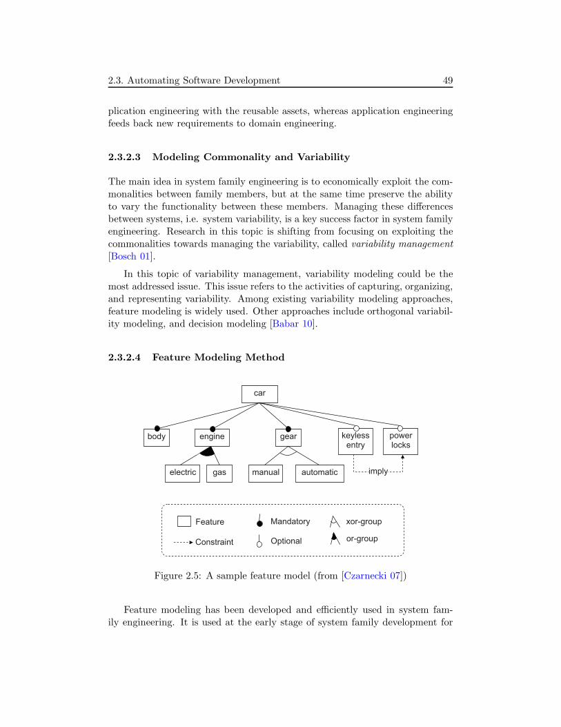
2.3. Automating Software Development 49
plication engineering with the reusable assets, whereas application engineeringfeeds back new requirements to domain engineering.
2.3.2.3 Modeling Commonality and Variability
The main idea in system family engineering is to economically exploit the com-monalities between family members, but at the same time preserve the abilityto vary the functionality between these members. Managing these differencesbetween systems, i.e. system variability, is a key success factor in system familyengineering. Research in this topic is shifting from focusing on exploiting thecommonalities towards managing the variability, called variability management[Bosch 01].
In this topic of variability management, variability modeling could be themost addressed issue. This issue refers to the activities of capturing, organizing,and representing variability. Among existing variability modeling approaches,feature modeling is widely used. Other approaches include orthogonal variabil-ity modeling, and decision modeling [Babar 10].
2.3.2.4 Feature Modeling Method
body
car
Feature xor-groupMandatory
Optional
gear keylessentry
powerlocks
gaselectric manual automatic
engine
or-group
imply
Constraint
Figure 2.5: A sample feature model (from [Czarnecki 07])
Feature modeling has been developed and efficiently used in system fam-ily engineering. It is used at the early stage of system family development for

50 2. State of the Art
scoping system family by providing a basis for capturing commonality and vari-ability of system family members. It is also applied in many domains such astelecom systems and embedded systems [Czarnecki 05b].
The feature modeling method allows to capture and manage commonalitiesand variabilities of system families. Originally proposed as part of Feature-Oriented Domain Analysis (FODA) [Kang 90], during the last twenty years,different forms of feature models have been developed, such as FORM, PLUSS,FeatuRSEB, and GP (Generative Programming) feature model [Kang 10]. Fig-ure 2.5 includes an example of the GP feature model basic form [Czarnecki 00].In this form, a feature model contains a root feature that is decomposed intomandatory or optional solitary features, or grouping features as or-groups orxor-groups. The feature model also contains imply/exclude constraints. Later,Czarnecki developed the GP-extended and cardinality-based forms of featuremodels [Czarnecki 05a].
2.3.3 Discussion
Model-Driven Engineering and System Family Engineering are closely related,especially in the use of DSLs to represent models/specifications in both ap-proaches. The main difference between these two approaches may be the focusof the latter on system families [Czarnecki 00].
From the point of view of automating the software development, compar-ing Model-Driven Engineering and System Family Engineering approaches couldlead to comparing Model-Driven Architecture and Generative Software Develop-ment. By focusing on achieving platform independence, MDA can be consideredas an approach supporting system families with respect to technical variation,while GSD supports both technical and application-domain variability.
In this thesis, we combine solutions in MDA and GSD to develop adaptivedistributed applications. The solutions include the MDA pattern, the featuremodeling, and the separation of domain engineering and application engineering.Moreover, model transformations that are concerned with both approaches areused to automate the development process.
In addition to highlight Model-Driven Architecture and Generative SoftwareDevelopment that are used in this thesis, by summarizing these two main ap-proaches to automating software development, we also prepare a basis for thediscussion of related approaches in adaptive software development. In this do-main, the issue of automating the development of adaptive software is one ofour main interests.

2.4. Related Work in Adaptive Software Development 51
2.4 Related Work in Adaptive Software Development
This section discusses related approaches in adaptive software development thatare relevant to our approach. First, we present a list of related approachesand main interests of each approach, regarding the six challenges identified inChapter 1. Then, we describe these approaches by relating them with thesechallenges. Finally, we summarize the approaches and their limitations in orderto justify the two key issues addressed in this thesis.
Approach C1 C2 C3 C4 C5 C6
ACEEL [Chefrour 05] X
ARCHWARE [Oquendo 04] X X X
CACTUS [Chen 01] X
Cetina et al. [Cetina 09] X X
DARWIN [Magee 95] X
[Crane 95, Georgiadis 02] X
DIVA [Morin 08, Morin 09b, Morin 09a] X X X X
DYNACO [Buisson 06] X
Ensink et al. [Ensink 04] X
FAC [Pessemier 08] X
FScript [David 09] X
[Bennour 09] X
GENIE [Bencomo 08a] X X X X
Gomaa et al. [Gomaa 07] X X X
Lee et al. [Lee 06] X X X
MADAM [Floch 06, Geihs 09]X X X X X X
MUSIC [Rouvoy 08]
MADCAR [Grondin 08] X
Oreizy et al. [Oreizy 99] X
Taylor et al. [Taylor 09] X
Parra et al. [Parra 10] X X
PRISMA [Soria 07] X
RAINBOW [Garlan 04] X
Trinidad et al. [Trinidad 07] X
Vandewoude et al. [Vandewoude 05] X
Zhang et al. [Zhang 06] X X X X
Table 2.1: Related approaches to developing adaptive software

52 2. State of the Art
2.4.1 A List of Related Approaches
In Chapter 1, we have identified six challenges when developing adaptive soft-ware systems:
• C1 - Supporting consistent architectures
• C2 - Transferring system state
• C3 - Modeling commonality and variability
• C4 - Supporting automatic adaptation planning
• C5 - Supporting distributed adaptations
• C6 - Automating the development
Table 2.1 includes a list of approaches to developing adaptive software sys-tems that are relevant to our approach. The first column (Approach) includesnames and references of the approaches. For each approach, a check mark (X)at one of the six columns from C1 to C6 implies that (one of) main interest(s)of this approach is related to the challenge identified by the column. Whenan approach is related to several challenges, one underlined check mark (X)indicates where the approach is mainly discussed.
These approaches will be discussed in the next sections by relating themwith the six challenges.
2.4.2 Supporting Consistent Architectures
This section briefly describes some related approaches that support consistentarchitectures of the adaptive software through adaptations.
Through an adaptation, an adaptive software system moves from an archi-tectural variant to another one. These variants must be consistent, i.e., afterthe adaptation, the system must be able to work properly. Supporting consis-tent architectures is thus a critical requirement for the development of adaptivesoftware systems.
However, this requirement is not always in the focus of existing approaches,particularly in those that aim to support wide classes of adaptive software. Inthese approaches, software engineers work with concepts at low levels of abstrac-tion such as objects, components, and connectors. Since these approaches aimto provide generic solutions, no or few constraints on architectures of software
2.4. Related Work in Adaptive Software Development 53
systems are defined. The correctness of architectural variants thus depends onsoftware engineers [Buisson 06] or it is partially supported [Geihs 09, David 09].
Supporting consistent architectures of adaptive software systems can consistof three types: building architectures, verifying architectures, and verifying/-controlling modifications on architectures. In the first type, abstractions suchas design patterns, architecture styles, and architecture description languages(ADLs) are provided to build software architectures. In the second type, verifi-cation techniques such as model checking and testing techniques are supportedto verify the consistency of the architectures after adaptations. In the last type,adaptation process is carefully controlled, for example by using transactions, toensure the correctness of adaptations. These three types can be considered asthree tasks in supporting consistent architectures of adaptive software throughadaptations. An adaptive software development approach may focus on one,two, or all the three tasks.
ADL-based Approaches
First, we discus some approaches that support consistent architectures ofadaptive software systems by relying on ADLs.
In Darwin [Magee 95], Magee et. al. provided the Darwin ADL for thespecification of distributed architectures. In this ADL, operational semanticscapture dynamic structures as the elaboration of components and their bind-ings. Organization of components and connectors may change in the systemarchitecture dynamically. By using the π-calculus, Milner’s calculus of mobileprocesses, the evolving structures of Darwin are modeled, thus allowing to ana-lyze the correctness of the Darwin program elaboration process. The approachprovides notations for specifying and constructing dynamic distributed softwarearchitectures [Crane 95, Magee 96]. Later, Darwin was also modeled in Alloy[Jackson 02] in order to express the structural constraints of Darwin applica-tions [Georgiadis 02], and then, use the Aloca tool [Jackson 00] to generate andverify specifications of self-organizing systems.
In ARCHWARE [Oquendo 04, Morrison 07], the authors also provided anADL (ARCHWARE-ADL) for building consistent architectures of evolving soft-ware systems. ARCHWARE-ADL is a formal ADL based on the higher-ordertyped π-calculus. This ADL has a set of layers to address requirements ofactive architectures (dynamic architectures with focus on both structural andbehavioral viewpoints). Among these layers, an architectural style layer allowsspecification of components and connectors. Architectural styles are then usedto specify evolving architectures. Constraints on styles can be defined by ananalysis layer. By presenting concepts and formal notations together with re-
54 2. State of the Art
flective technologies, the approach can support active architectures, and then,dynamic evolution. The correctness of architectures is then formally verified.
In DIVA [Morin 09b, Morin 09a], Morin et al. provided four meta-models:DSPL (Dynamic Software Product Line), context, reasoning, and architecture.A DSPL model is a feature model that describes system’s variability. A contextmodel specifies the system’s environment. A reasoning model expresses theselection of DSPL’s features according to the context. An architecture modeldescribes component-based architectures, including concepts for reconfigurationsuch as component binding. The four meta-models thus can be seen as DSMLs(Domain Specific Modeling Language) that allow to generate configurations andreconfiguration scripts. The configurations are verified to ensure the correctnessof the system. Precisely, they must ensure the constraints such as cardinalityand imply/exclude constraints defined in the DSPL model.
In Genie [Bencomo 08a], a structure variability DSML is supported. ThisDSML can be considered as an ADL that allows to build architectures of adap-tive software systems. The DSML also allows to define invariants that will bechecked when performing adaptations.
Style-based Approaches
In the domain of developing adaptive software, architectural styles are widelyused to support consistent architectures of adaptive software systems [Oreizy 99,Garlan 04, Oquendo 04, Taylor 09].
In ArchStudio [Oreizy 98, Oreizy 99], Oreizy et al. proposed an approachto support runtime adaptation that uses the C2 architecture style [Taylor 95].An adaptation is realized via changes in the architectural model of the C2 soft-ware system. In this approach, an adaptation management process is organizedtogether with an evolution management one that is reified by an architectureevolution manager. This manager allows to maintain system consistency bychecking modifications of components and connectors at the architecture leveland mapping between the architecture and the running system.
While Taylor et al. focused in using specific architectural style (i.e., C2) in[Oreizy 99], the authors of RAINBOW [Garlan 04, Cheng 08] proposed to usedifferent architectural styles to develop adaptive software. First, the approachprovides the RAINBOW infrastructure that is reusable for many adaptive sys-tems. Then, it enables to define vocabulary of element types of a style, designrules, properties characterizing style elements, analyses that can be performedon systems built in this style, and operators implying a set of style-specific op-erations for modifying elements of the systems. Therefore, the approach allowsto specify software systems by using different architectural styles and perform

2.4. Related Work in Adaptive Software Development 55
modifications on these systems. By leveraging Acme (a general purpose ADLthat supports extensible styles for different domains, and extensible propertiesand analyses) architectural constraints can be defined, thus enabling a modelmanager to detect constraint violation and trigger adaptation, and thereby,ensuring the consistency of the adaptive software.
Supporting construction and verification of adaptive software architecturesby general purpose architectural styles are increasingly used. In addition toRAINBOW and ARCHWARE, Gomaa et al. [Gomaa 07] used architecturalpatterns to build software architectures. For each architectural pattern, thereis a corresponding configuration pattern which describes how the software archi-tecture is dynamically adapted. Taylor et al. have also recently investigated thisresearch direction of using multiple architectural styles in BASE [Taylor 09], inaddition to supporting specific architectural style (C2) in their prior work.
Other Approaches
Zhang et al. [Zhang 06] proposed a model-driven approach to designing andvalidating dynamically adaptive software systems. In this work, the authorsdefine an adaptive system as a set of simple adaptive systems. Each of thesimple adaptive systems is defined by a source system, a target system, andtransitions responsible for moving from the source system to the target system.These systems, particularly their behavioral aspect, are modeled using state-based modeling languages such as process algebras (e.g., Petri nets) and UMLstate diagram. Thanks to formal verification techniques, the correctness of allthe simple systems are checked, thus ensuring the correctness of the adaptivesystems during and after adaptations.
In addition to approaches such as ArchStudio and RAINBOW that em-phasize the aspect of ensuring the correctness of adaptation actions duringadaptations, David et al. [David 09] provided FPath and FScript, languagesfor querying and reconfiguring Fractal components [Bruneton 06], respectively.While FPath is a domain-specific language for introspection of Fractal com-ponents, FScript is a scripting language that supports reliable complex recon-figuration of these components by allowing transactional reconfigurations. InMADAM [Floch 06, Geihs 09] (and also in its follow-up project called MUSIC[Rouvoy 08]), the authors proposed an approach to the development of adaptivesoftware, based on a component framework and an abstract adaptation model.The component framework describes a composition of different component types.Each type is a variation point where various component implementations can beplugged in. Adaptability is achieved by plugging in component implementationsthat conform to component types. Platform-independent adaptation modelsspecified by software engineers are automatically transformed into adaptation

56 2. State of the Art
code that will be used by the MADAM adaptation middleware to reconfigurecomponent-based applications at runtime. Consistency of application architec-tures can be partially supported by checking consistency of adaptation models.
Discussion
Among the three types of supporting consistent architectures identified fromour point of view, building consistent architectures is the most important onebecause the two other types are only useful when the consistent architecturesare built. However, this is still a difficult task for software engineers. Althoughmany approaches provide abstractions (such as component and connectors),languages, and styles for assisting the development of adaptive software, soft-ware engineers need to be expert to compose these abstractions and/or styles inorder to achieve consistent architectural specifications of the software systems.We identify here the lack of a high-level, global abstraction (of software system)that encompasses all the lower-level abstractions such as component, connector,and architectural style.
2.4.3 Transferring System State
When an adaptive software system moves from a source variant to a target oneto realize an adaptation, the successful adaptation must enable the latter variantto be initialized with the state of the former. This task of state transfer is criticalto ensure the correctness of the system through adaptations. This challenge isthus strongly related to the one of supporting consistent architectures.
In some approaches, the importance of the state transfer is well recognizedand partially supported [Zhang 06, Geihs 09]. These approaches allow to spec-ify functions for state transfer. These functions will be then implemented bysoftware engineers.
In MADCAR [Grondin 08], Grondin et al. proposed a component assem-bling engine that supports runtime adaptation of component-based applicationsby dynamic (re)assembling of components. State transfer between componentsis also supported. In this approach, the application state is defined as theset encompassing values of all variable’s attributes. The approach then allowssoftware engineers to specify state transfer between components as a model ofstate transfer net. This model is constrained by some rules provided by theapproach. Similarly, Vandewoude et al. [Vandewoude 05] provided a number ofsteps that assist software engineers with the issue of state transfer. Thanks tostate export and import operations that are manually implemented at designtime, state transfer can be performed at runtime.

2.4. Related Work in Adaptive Software Development 57
In ARCHWARE [Oquendo 04, Morrison 07], the problem of state transferis also addressed. The approach supports hyper-code that is a representationof an active executing graph linking source code and existing values. Thereby,it allows state and shared data to be preserved during evolution.
Recently, the challenge of transferring state in runtime adaptations is alsoaddressed by Taylor et al. in [Taylor 09]. The authors proposed the BASEframework for evaluating, comparing, and combining techniques for adapta-tion. Among the aspects used to this end, transferring state is described as animportant one. For example, the framework shows that the REST architecturalstyle [Fielding 02] allows to externalize component state, thus facilitating statetransfer when realizing runtime adaptations.
Discussion
Transferring system state in runtime adaptations is critical to ensure theircorrectness. Although existing approaches recognize the importance of thistask, these approaches usually help software engineers to manually define statetransfer actions.
2.4.4 Modeling Commonality and Variability
This challenge implicitly includes supporting modularity. Modularity implieshow the system is modularized into modules such as components. Commonalityand variability allow to identify common and different modules/components ofsystem variants/versions/configurations.
Supporting Modularity
Recently, several projects have investigated solutions to enhance modularityof software systems, and then, supporting better evolution and adaptation. Inthis topic, aspect-oriented-based approaches are emerging.
In FAC [Pessemier 08], Pessemier et al. presented an approach to supportevolution of software systems using components and aspects. Implementationof an aspect is modularized and represented as an aspect component that canbe connected to traditional components by aspect bindings. These concepts aresupported by a component platform called Fractal Aspect Component (FAC).Thanks to facilities provided by the platform, software systems’ evolution canbe realized by modifying components, including aspect ones.
Also supporting aspect-oriented components, Ubayashi et al. [Ubayashi 07]provided a weaving information hiding mechanism called weaving-interface.
58 2. State of the Art
This mechanism enables to manipulate aspects as traditional components. Thisis technically supported by a prototype called ccJava that is a translator toAspectJ. This approach is thus effective for software modularity and evolution.
Differently from FAC and ccJava, in PRISMA [Soria 07], Costa et al. usedaspect components to separate different aspects of a component type, and then,allowed performing adaptations of its instances in the running system. Thisapproach is suitable for systems in which each component instance is not awareof changes in the others, but all the instances need to adapt their behaviors.The authors called this non-synchronized, multi-threads adaptation. Thanks toaspect components, PRISMA promotes modularity, and then, maintenance andadaptation of adaptive software.
Supporting Commonality and Variability
As discussed in Section 2.3.2, commonality and variability are the termswidely used in SPL engineering. While configuring software products in SPLengineering is similar to static (re)configuration and adaptation of software sys-tems, DSPL engineering shares similarity with engineering of dynamically adap-tive software [Bencomo 08c]. This explains why many recent research effortshave exploited solutions and techniques in SPL engineering for the developmentof adaptive software systems, particularly to support and model commonalityand variability of the system variants.
Parra et al. [Parra 10] proposed an approach to dynamic composition ofsoftware products. This approach combines MDE and AOM (Aspect-OrientedModeling). The authors used feature models to represent variability of theproducts. Corresponding to each feature, a high-level aspect-like model of com-ponents is specified. A universal transformation weaves aspect models of a fea-ture configuration to derive a software product. Thanks to feature and aspectmodels, this approach enables modeling variability and modularity.
In MADAM, as described in Section 2.4.2, software systems are developedusing a reference architecture and adapted by the MADAM adaptation mid-dleware. The development of such a software system can be realized thanks toSPL techniques [Geihs 06, Floch 06] and MDE [Geihs 09] that enable to identifydifferent variation points. Each point indicates several component variants of acomponent type that is described as an element of a composition plan. By thisapproach, MADAM allows to define variability models that are used to realizeadaptations.
Goma et al. [Gomaa 07] considered the different versions of an evolutionarysystem as members of a software product line. After implementation, the systemand the model co-exist and co-evolve. Feature models are used to model com-

2.4. Related Work in Adaptive Software Development 59
monality and variability of the evolving system. Technically, variation pointsrely on plug-compatible components (i.e., one component can connect to differ-ent components) or component interface inheritance.
Similarly, Trinidad et al. [Trinidad 07] considered an adaptive software sys-tem as a dynamic software product in the domain of DSPL. They also usedfeature models to capture variability of the system. By assuming that a featurecorresponds to a component, the authors mapped features of a feature modelinto components of the corresponding adaptive software system, and then, builtdynamic architecture of the system.
More recently, Cetina et al. [Cetina 09] presented an approach to autonomiccomputing, in the context of the development of a smart-home application.This approach uses a feature model to model commonality and variability ofthe system, producing the target system at design time, and then, planning andperforming system reconfiguration at runtime.
Lee et al. [Lee 06] proposed an approach to develop dynamically reconfig-urable products in Product Line Engineering. This approach highlights featureand feature binding analysis, i.e., 1) using feature models to model variabilityof software products and 2) identifying feature binding units and binding time.A feature binding unit is a set of service features, each one represents a majorfunctionality of the system that can be removed or added as a unit. The ap-proach then provides a set of guidelines for designing products and components.For example, one of these guidelines emphasizes the identification of architec-tural components for the feature binding units. Therefore, by a feature modelrepresenting system variability, dynamic adaptation can be realized by remov-ing/adding architectural components corresponding to feature binding units ofthe feature model.
In addition to feature models, other variability modeling methods are alsoused. In Genie [Bencomo 08a], a development approach for adaptive softwaresystems based on MDD and system family engineering, Bencomo separated sys-tem structural variability and environment and context variability, and then,proposed two corresponding DSMLs for building architectural models and vari-ability models of adaptive software systems. These models were used to partiallygenerate adaptive software by using generative techniques. In this approach,variability models are represented as orthogonal variability models [Pohl 05].
Differently from the approaches above to supporting and modeling vari-ability, Morin et al. [Morin 09b] addressed the problem of managing crosscut-ting dimensions of variability in adaptive software systems. In this case, thenumber of configurations of an adaptive software system and the transitionsbetween these configurations may be a combinatorial explosion. Thanks toAspect-Oriented Modeling (AOM), the authors were able to organize different

60 2. State of the Art
dimensions of variability as aspect models. These aspect models could later bedynamically woven into an architectural model of the system at runtime. Thissolution of using AOM to manage dynamic variability is also used in DIVAproject [Morin 08, Morin 09a], together with feature models. Aspect modelsrepresenting design variants associated with features are woven into a base ar-chitectural model representing the commonality of an adaptive software system,and then they are used to generate complete configurations of the system.
Discussion
Modeling commonality and variability of software systems facilitates adap-tations by explicitly describing system variation points where modifications canbe realized. Typically, commonality and variability modeling techniques in soft-ware product lines such as feature models and orthogonal variability models areemployed to explicitly model commonality and variability of adaptive software.However, these approaches usually ignore the modularity of software systems.For example, in some approaches [Cetina 09, Morin 09a], the authors assumedthat a feature in a feature model can be directly mapped to (a set of) com-ponents. In fact, this mapping is not always feasible, for example, when thefeature corresponds to a concern that is interleaved by some other ones. In thiscase, implementations of all these concerns may be included in a component,but this solution decreases modularity of the software system, and therefore,leads to coarse-grained adaptations.
As described above, some approaches support better modularity by intro-ducing aspect components into frameworks (such as FAC [Pessemier 08]). How-ever, existing adaptation approaches that are usually platform-independent cannot benefit from these results because aspect components are platform- andlanguage-specific and are not widely supported. Moreover, aspect-oriented sep-aration of concerns is not completely resolved [Aksit 09].
2.4.5 Supporting Automatic Adaptation Planning
This section briefly presents related approaches that support automatic adap-tation planning of adaptive software.
Enabling adaptive software systems to automatically plan adaptations canbe seen as a consequence of modeling commonality and variability. When adapt-ing a system by moving it from a variant (source) to another one (target),software systems can automatically compare the two variants to identify com-ponents to be modified. For example, Morin et al. [Morin 09b] provided an al-gorithm that generates a diff and a match models specifying the differences and

2.4. Related Work in Adaptive Software Development 61
the similarities of any source and target architectural models. Similarly, in DIVA[Morin 09a], reconfiguration scripts are automatically generated by comparingconfigurations and using model-driven development. In Genie [Bencomo 08a],the adaptation planning is partially automated. The environment and contextvariability model contains transition diagrams that allow software engineers toplan adaptations at a high-level abstraction, and then, use generative techniquesto generate reconfiguration policies. Also exploiting commonality and variabilitymodels, Cetina et al. [Cetina 09] proposed an interesting planning method thatuses graphs and feature models. From a feature model representing common-ality and variability of variants of an adaptive software system, reconfigurationstates are generated, each corresponds to a selection of features. These statesare then represented as a graph that allows to visualize all the possible tran-sitions, and then, automatically generate reconfiguration plans. In some otherapproaches such as [Lee 06], the authors also exploited feature models to sup-port automatic planning changes in dynamic software products.
In MADAM, the adaptation planning task is partially automated. Thisapproach requires software engineers to encode variation and selection criteriathat will be used by the MADAM middleware to derive a variant for a spe-cific context at runtime [Floch 06]. Through model transformations, abstractadaptation models defined by software engineers are automatically transformedinto adaptation code that will be used by the MADAM middleware to realizeadaptations [Geihs 09].
Some other approaches support adaptation planning by highlighting the roleof the planner in the adaptation process. For example, Oreizy et al. [Oreizy 99]organized the adaptation process with an adaptation planner that plans ob-servations and changes needed to realize adaptations. The authors also rec-ommended implementations for this planner that is specific for C2-style appli-cations. In DYNACO [Buisson 06], Buisson proposed a dynamic adaptationcanvas including an observer, a decider, a planner, and an executor. By provid-ing a generic model for planning adaptation, this approach supports differentadaptation planning methods such as searching paths in a graph.
Discussion
Generally, existing approaches to planning adaptations are based on ar-chitectural models of software systems that are manually defined by softwareengineers. Particularly, state transfer actions as part of adaptation plans areusually implemented manually.

62 2. State of the Art
2.4.6 Supporting Distributed Adaptations
This section discusses some approaches related to the challenge of supportingdistributed adaptations. Such an adaptation consists of distributed processesthat need to be performed coordinately.
In ACEEL [Chefrour 05], Chefrour addressed the problem of coordinatingmultiple adaptations of distributed components that cooperate in a distributedapplication. To this end, an application coordinator is introduced into the ap-plication. This coordinator is distributed among sites where the applicationis deployed. On each site, a local coordinator manages the local adaptationsby coordination services. The services include those for 1) reaching agreementbetween local coordinators on adaptation actions to be performed and 2) syn-chronizing these actions. These services are realized using coordination policiesprovided by software engineers.
Distributed adaptation is also one of the main interests of the MADAMproject. Geihs et al. [Geihs 09] presented different aspects of distributed adap-tation, including distributed context management for distributed adaptationdecision-making and distributed reconfiguration. All nodes involved in a dis-tributed adaptation need to run the MADAM middleware. One node acts asthe master and the others as the slaves. The master node makes adaptationdecisions and deploy reconfiguration actions to the slave nodes. Distributedadaptations thus rely on a centralized adaptation management.
As discussed previously, Magee et al. [Magee 95] proposed Darwin ADLfor the specification of dynamic distributed software architectures. In SysMan[Crane 95], changes in a software system specified using Darwin notations aremanaged by a configuration manager. These changes include, for example, in-sertion of a new component or changing connections between components. Theconfiguration managers manage the overall view of the system structure (interms of components and their interconnections) by ensuring that an executingsystem conforms to its architectural specification. Therefore, adaptations sup-ported by this approach include distributed adaptation. Later, Georgiadis etal. [Georgiadis 02] modeled Darwin in Alloy in order to express the structuralconstraints, and then, verify specifications of self-organizing systems thanksto the Aloca automated tool. Unlike SysMan that uses explicit configurationstructural management, this approach allows components to appear or disap-pear dynamically, i.e., there is no overall management control of the systemstructure. Instead of preserving architectural specification in terms of compo-nents and their interconnections, the distributed configuration managers man-age constraints (that imply the way components may be composed) in orderto preserve architectural properties implied by system specification. Thereby,

2.4. Related Work in Adaptive Software Development 63
self-organizing architectures can be achieved.
In CACTUS [Chen 01], Chen et al. dealt with the challenge of coordinatingdistributed adaptations. This approach considers a distributed adaptation asthe one in a distributed adaptive component (DAC) that is a set of (distributed)adaptive components (AC), one per site. Such a DAC is used in a multi-layersystem (network, middleware, application) where an AC receives/sends mes-sages from/to another AC (of another DAC) at a higher or lower layer. Theapproach then focuses on a protocol for adapting each AC (i.e., replacing theold component by a new one) and coordinating distributed adaptation actions,including replacing components and transferring messages.
The protocol proposed in CACTUS is completely manual. It requires pro-grammers to write complex, explicit communication and synchronization of dis-tributed adaptations. This limitation was addressed by Ensink et al. [Ensink 04].The authors proposed a sophisticated and transparent algorithm to coordinatedistributed adaptations. Programmers specify criteria for when an adaptationmust happen. These criteria are then used by a compiler that inserts calls to theruntime system. These calls initiate and terminate the coordination process.
Among approaches to supporting consistent architectures of adaptive soft-ware systems presented previously, FScript is a scripting language for reliablereconfiguration of Fractal components [David 09]. This language is extended fordistributed systems [Bennour 09]. For each Fractal component, a reconfigura-tion controller is introduced. This controller includes a Script interpreter thatallows remote scripts execution. Distributed adaptation of a Fractal-component-based application thus can be realized as the adaptation of a composite com-ponent representing the whole application.
Discussion
As presented above, distributed adaptation is addressed by only few ap-proaches. Generally, the approaches support distributed adaptations 1) directlyby defining protocols for coordinating distributed adaptation actions or 2) indi-rectly by supporting consistent architectures. In the former case, the protocolsalways rely on coordination policies defined manually by software engineers. Inthe latter case, the approaches rely on system specifications or constraints, oradaptation actions that are manually defined by software engineers. Typically,this limitation shows that a high-level, global abstraction is needed to spec-ify distributed software systems, and then, generate information to coordinatedistributed modifications.

64 2. State of the Art
2.4.7 Automating the Development of Adaptive Software
This section discusses the approaches that support (partially) automated de-velopment of adaptive software systems. Generally, these approaches use tech-nologies in the domains of model-driven development and/or system familyengineering.
For example, by using domain specific modeling languages (DSMLs), sys-tems’ source code can be fully generated from domain specific models. Softwaresystems can also be built by reusing components/implementations in libraries.Typically, in Genie [Bencomo 08a], by supporting structural variability DSML,components and component configurations are automatically generated. More-over, by the environment and context variability DSML, reconfiguration policiesare also generated. Also supporting generation of component configurations,Morin et. al used an aspect-oriented modeling (AOM) approach [Morin 09a].In this approach, feature models are used to model the variability of the tar-get system. Then, associated with features, aspect models of components aredefined and later woven into an architectural model of the system to generatesystem configurations.
As previously mentioned, AOM and feature modeling are also combinedin the approach presented by Parra et al. [Parra 10]. Aspect models are au-tomatically weaved to derive dynamic software products according to featureconfigurations. This approach also tackles the issues of feature interactions andaspect model dependencies.
In ARCHWARE [Oquendo 04], the authors provided an ADL, an architec-ture analysis language, and an architecture refinement language. These lan-guages allows to define architectural styles, create architecture descriptions andanalysis as instances of these styles, and then, refine architectures. The last re-finement that is code generation allows to generate full system implementationfrom architectural models.
The MADAM project [Floch 06] also supports partial automation of thedevelopment thanks to model-driven architecture. The approach supports aUML profile for adaptive software that will be used by software engineers tomodel the architecture of the target adaptive software system. The result is aset of architectural models that include description of both the variability andproperty annotations. From these UML models, transformations are used topartially generate code of the system implementations.
In the approach proposed by Zhang et al. [Zhang 06], from specificationthat describes behaviors of an adaptive system by using Petri net, the imple-mentation of the system can be partially generated by using model-driven de-velopment. Functionality of the system and operations for adapting the system,

2.4. Related Work in Adaptive Software Development 65
including transferring state, are manually implemented.
In addition to these approaches that mainly rely on generative techniques,some other approaches automate the development of adaptive software systemsfocusing on reuse of software assets such as components. These approachestypically include the ones that support dynamic/adaptive software product lines[Lee 06, Gomaa 07].
Discussion
The approaches presented above allow to partially automate the develop-ment process of adaptive software systems by using model-driven developmentor generative techniques. As described previously in the challenge of support-ing consistent architectures, these approaches usually provide abstractions suchas component and connector, and/or architecture style and architecture de-scription languages. The lack of a high-level, global abstraction for specifyingsoftware systems consequently requires software engineers to spend more effortsin the development process of these software systems.
2.4.8 Limitations of the Related Approaches
By relating a number of existing approaches to developing adaptive softwaresystems, we have described how these approaches respond to the challengesidentified in Section 1.1.
Limitations of the Related Approaches
As discussed in the six previous sections, the related approaches share somelimitations, including the followings:
• Building consistent architectures of adaptive software is a difficult task.Software engineers often use abstractions such as component and connec-tor, domain-specific languages, architecture description languages, and/orarchitectural styles for specifying software systems (to be made adaptive).This task requires software engineers to be expert to use these facilitiesand compose the whole software system.
• Operations for transferring state are implemented manually. Usually, ex-isting approaches require software engineers to manually implement op-erations for state transfer such as state export and import. In many ap-proaches, software engineers have to directly map interfaces or variablesfrom/to which state elements (such as data item and variable value) aretransferred.
66 2. State of the Art
• Modeling commonality and variability ignores modularity. Existing ap-proaches to modeling commonality and variability often assume that soft-ware systems (to be made adaptive) are well modularized into components,concerns that interleave each other are thus ignored. Consequently, thismay lead to coarse-grained adaptations.
• Planning adaptation relies on models that strongly depend on softwareengineers. Existing approaches support planning adaptations by relyingon system architectural models and state transfer actions that are definedand implemented manually.
• Coordinating distributed adaptations relies on information provided bysoftware engineers. Similarly to planning adaptation, coordinating dis-tributed adaptations in existing approaches also relies on informationprovided directly by software engineers. The information includes, forexample, coordination policies or architectural constraints of distributedcomponents.
• The level of automation is low. As a consequence of the above limitations,software engineers must spend effort in many tasks of the adaptive soft-ware development, such as specifying system architectures, implementingoperations for state transfer, and providing information to coordinate dis-tributed adaptations.
Key Issues Revisited
From our point of view, to overcome these limitations, the two key issuesidentified in problem statement (Section 1.1) should be taken into account:
• Need of a high-level abstraction: An approach to developing adaptive soft-ware systems should provide a high-level abstraction for specifying thewhole (distributed) adaptive software system. Such an abstraction canfacilitate software engineers to specify the system, and then, serves as abasis for analyzing system modularity, modeling commonality and vari-ability, and building consistent architecture variants.
• Need of an appropriate, highly-automated development process: The ap-proach then should provide an appropriate, highly-automated develop-ment process. By appropriate, we mean the process can use the high-level abstraction as a basis for realizing its promised advantages, includ-ing specifying the adaptive software system, analyzing system modularity,
2.4. Related Work in Adaptive Software Development 67
modeling system commonality and variability, and building consistent ar-chitectural variants. Moreover, the development process should be highly-automated in order to reduce complex tasks of software engineers, includ-ing the development of architecture variants and planning adaptations.
Taking into account these two key issues, we adopt the medium as an ab-straction and extend its refinement process to develop adaptive distributed soft-ware systems. Using this abstraction, software engineers only need to specifythe distributed software system (to be made adaptive) at a high level of ab-straction. Then, the specification as a model is transformed to implementationlevel by the extended refinement process. Although software engineers mustparticipate in some tasks of the process, results of the most complex tasks,such as meta-modeling and implementing model transformations, are reusable.These tasks are facilitated by facilities including the reusable results and somegeneric meta-models and transformations. Moreover, the process also producesinformation that enables the adaptive software system to automatically gener-ate adaptation plans at runtime. Such a plan includes actions for reconfiguringdistributed components and transferring data between these components. Inthe plan, these actions are specified to be executed in a coordinated manner.
Some Particular Comparisons
Among the related approaches presented above, GENIE, MADAM, RAIN-BOW, and ARCHWARE are particularly relevant in comparison with the adap-tive medium approach.
In GENIE [Bencomo 08a], Bencomo also identified key issues including “[t]helevel of abstraction at which software engineers operate is low, [p]our softwareautomation levels, [l]ack of a structured management of variability.” First, bythe first issue, the author implied that software engineers operate at the levelof source code, and then, raised the structural variability abstraction level inwhich models describing components and connectors are manipulated. GENIEalso includes another abstraction level called environment and context variabil-ity that allows to map architectural variants to context variants. From our pointof view, these abstraction levels are still low, the models are directly definedby software engineers. In the adaptive medium approach, system models atthe software component level can be generated from a higher-level abstraction,through a model-based refinement process. Software engineers’ tasks can bethen reduced and design information of the refinement process can be exploitedfor adaptation planning. By adopting a particular high-level abstraction, theadaptive medium approach is less generic, but more automated. Second, whileGENIE uses separated orthogonal variability models, our approach uses feature

68 2. State of the Art
models that are integrated in the refinement process. Finally, GENIE does notsupport distributed adaptations and state transfer.
In ARCHWARE [Oquendo 04] and RAINBOW [Cheng 08], system archi-tectural models can be built from user-defined architectural styles. These ap-proaches thus raise an abstraction level that is higher than the component-and-connector one, what could be called style level, thus facilitating softwareengineers to build system architectures. From our point of view, again, theseapproaches do not support a high abstraction level where the whole system isspecified. This high-level abstraction is important, not only to automate thesystem development, but also to identify architectural variants of the system.Moreover, these approaches do not particularly support distributed adaptation.
MADAM [Geihs 09] is relevant to adaptive medium in terms of addressedchallenges. This approach supports building architectural variants, modelingvariability, planning adaptation, distributed adaptation, and automating thedevelopment. However, since MADAM is a general purpose approach, thesechallenges are only partially supported. For example, the highest-level abstrac-tion is component and component plan and variability model relies on variationpoints corresponding to component types. Moreover, in MADAM, operationsfor state transfer are manually implemented by software engineers.
Conclusion
We have presented above some related approaches to developing adaptivesoftware that are relevant to our approach. By discussing limitations of theseapproaches regarding the six identified challenges, we justified the two identifiedkey issues concerning the need of 1) a high-level global abstraction for thespecification of distributed software systems and 2) an automated developmentprocess using this abstraction. To tackle these issues, we used and extendedthe medium abstraction and its model-based refinement process [Cariou 03,Kabore 08a].
2.5 The Medium Approach
This section presents the medium approach to the development of distributedapplications. The approach includes
• a high-level abstraction called medium for specifying and implementingdistributed applications ([Cariou 02, Cariou 03]), and
• a model-based process for (semi)automatically refining the medium ab-

2.5. The Medium Approach 69
straction through different abstraction levels to the implementation level([Kabore 08a, Kabore 08b]).
2.5.1 The Medium Concept
2.5.1.1 Definition
High-level Abstraction
Medium is a high-level abstraction of functional communication in a dis-tributed application. The application is specified as an interconnection of oneor several medium(s) and client components that are usually located in dis-tributed sites. Each medium provides communication services for some clientcomponents. In an application, the mediums allow to separate the application’sparts containing distributed communication from those that implement localfunctions. As a component, a medium is reusable in similar contexts.
Implementation Architecture
A medium is called a software component in the sense that it is defined byprovided and required interfaces. The particularity of the medium resides in thefact that it is dedicated to distributed communication, and therefore, by natureit has a distributed implementation. A medium is not a deployment unit, but alogical architectural unit built to be distributed. At the implementation level,a medium is a logical aggregation of (to-be-)distributed components called rolemanagers (or managers for short). Each client component is then connected toa manager that represents the whole aggregation by hiding the communicationbetween the managers away from the client component. The medium’s providedand required interfaces are implemented by the managers. They are calledmedium services and component services, respectively.
In order to differentiate the manager components from the client ones, thelogical aggregation of the manager components is also called the medium. There-fore, the term “medium” does not refer to any specific level of abstraction, while“medium abstraction” and “medium implementation” refer to the medium at thehigh abstraction level and the implementation one, respectively.

70 2. State of the Art
2.5.1.2 Examples
File Sharing Medium
Consider a simple file sharing (FS in short) application that is used forsharing files among distributed users. Each file managed by the application hasan identifier (FileId) and several properties such as keywords and file types.This application has some normal users and a super user. A normal user caninsert files into the system, get a copy of any shared file, and search for sharedfiles according to file properties he is interested in. In addition to the functionsfor a normal user, the super user can remove files from the system.
Super User
Sites 1..n
Site 0
NormalUser
Remover
Sharer
Sharer
Middleware
Logical aggregation of role manager components
NormalUser
Super User
Sharer
Sharer
Remover
remove(FileId)
insert(File,FileProperty[])getACopy(FileId) File search(FileProperty) FileId[]
Abstraction of communication
File Sharing Medium
File Sharing Medium
Files
(a)
(b)
Figure 2.6: Description of the file sharing application using medium
Figure 2.6(a) presents a specification of the FS application using the mediumapproach. This specification includes a FS medium as an abstraction of com-munication between client components implementing user interfaces for normaland super users. The FS medium at this high abstraction level is described as a

2.5. The Medium Approach 71
logical component that manages data including shared files and file properties,and provides data services.
There are two roles within the communication represented by the medium:Sharer and Remover. The super user plays a Sharer role and a Remover role,and each normal user plays a Sharer role. The FS medium provides the insert,getACopy and search services to the sharers. These services are used to inserta file and its properties into the system, getting a copy of a file, and searchingfor the files. Likewise, the medium provides the remove service to the removerfor removing files. The medium does not require any service.
Figure 2.6(b) describes the implementation architecture of the FS medium.The medium is now an aggregation of the SharerManager component and theRemoverManager component. The provided services of the medium identifiedin the high abstraction level are implemented by these manager components.
Reservation Medium
Figure 2.7 presents another example of an application for airplane seat reser-vation. An airline company offers its seats and several travel agencies sell theseseats. Passengers reserve or cancel reservations via any travel agency. In everyagency, the number of available seats is always updated. The specification ofthe application in the figure includes a medium called reservation medium.
Travelagency
Airlinecompany
ReserverSource
distribute(ReserveId[])reserve() ReserveId cancel(ReserveId)
Abstraction of communication
Observer
update(Integer)
Reservation Medium
available: ReserveId[]
Figure 2.7: Description of the reservation medium
Within the medium, the airline company plays a Source role, and a travelagency plays a Reserver and an Observer roles. The medium manages dataincluding a set of available seats, each has an identifier (ReserveId), and pro-vides and requires services. First, the medium provides an interface for theairline company to distribute the airplane seats. Second, the medium provides

72 2. State of the Art
an interface for every travel agency to reserve a seat and cancel reservations.Finally, for each travel agency, the medium requires an interface to update theset of available seats this set changes. The reservation application is then builtby interconnecting the medium and the client components.
This specification allows the medium to be reusable in similar contexts asa software component. For example, it can be reused in an application used tomanage a parking lot. When entering or exiting the parking lot (Source role)via an access (Reserver role), a car takes or frees a place (reserve and cancelservices, respectively). At each access, a panel (Observer role) displays thenumber of available places.
Video Conferencing Application using Multiple Mediums
Generally, different mediums can be identified in a distributed application.For example, Figure 2.8 depicts the specification of a video conferencing appli-cation that includes a vote medium and some video broadcast mediums, one perparticipant.
Participant1
Participant2
Participant3
VoteMedium
Video Broadcast Medium 2
Video Broadcast Medium 1
Video Broadcast Medium 3
ProposerProposer
Proposer
Voter
VoterVoter
Client
Client
Client
Client
ClientClientServer
Server
Server
Figure 2.8: A video conferencing application using several mediums
Although multiple mediums can exist in a distributed application, the mediumapproach allows each medium to be manipulated as a single software entity anddeveloped independently from other mediums and client components.

2.5. The Medium Approach 73
2.5.2 Medium Refinement
In [Kabore 08a], Kabore proposed a process for refining the medium from thehigh abstraction level to the implementation level. This refinement process is(semi)automated thanks to model transformations.
2.5.2.1 Medium Refinement Principles
The principle of the refinement is to separate design concerns of the mediumat the high abstraction level, then step by step introduce solutions for theseconcerns into the medium. The medium at the high abstraction level is thenrefined through different abstraction levels into the one at the implementationlevel.
To detail this refinement process, first, we present an architecture view in-cluding the architectures of the medium at the different abstraction levels. Then,we describe a process view explaining how model-based techniques are employedto automate the refinement process. Both views are depicted in Figure 2.9.
Architecture View
In the refinement process, a medium is transformed through four abstractionlevels:
• Level 0 - High-level abstraction. This is the source level of the refinementprocess. At this level, the medium is the abstraction of the communica-tion between client components. The interfaces, including medium andcomponent services, between the medium and the client components areidentified.
• Level 1 - Manager introduction. The medium at level 0 is refined byintroducing role managers. These managers represent the distributed im-plementation architecture of the medium.
• Level 2 - Solution introduction. This level includes the medium architec-ture during the introduction of design solutions. The abstraction elementstill exists, it represents the design concerns that have not been considered.
• Level 3 - Implementation. This is the target level of the refinement process.All the solutions are introduced so that no abstraction part is present inthe medium. Each role manager contains implementable classes and itcan be modularized as a component.

74 2. State of the Art
Process View
As described in Figure 2.9, the refinement process is constituted by succes-sive model transformations. Such a transformation refines a medium model atan abstraction level into another one at the next-lower abstraction level. Eachmedium model conforms to a medium meta-model.
x y
x y MM1MMM1
SM1-1
SM1-2
MM2-1SM2-1
SM2-2
SM2-3
MM2-2
MMM2-1
SMM1
SMM2
Architecture view Process view
Mediummeta-model
Solutionmeta-model for concern
C1
Solutionmodel
MM3
MMM2-2
MMM3 Medium model at impl. level (L3)
…
xor
xor
xor
L1: Manager intro.
L3: Impl.
Meta-model
Model
Transformation
in
out
conforms to
Abstrac-tion
Aggrega-tion
Physical
describe
C2
MM0MMM0 x y
L0: High-lev. abstr.
Medium model at the high abstraction level (L0)
x y
L2: Solution intro.
T0
T1
T2
T1
Figure 2.9: Architecture and process views of the medium refinement
First, the T0 transformation generates the medium model at level 1 (MM1 )by introducing managers into the medium model at level 1 (MM0 ).
Next, the refinement of MM1 to MM3 (medium model at the implementa-

2.5. The Medium Approach 75
tion level) is realized through successive transformations. Each transformationintroduces a solution model for a design concern. Corresponding to each de-sign concern, a solution meta-model and several solution models are defined.For example, transformation T1 introduces solution model SM1-1 or SM1-2conforming to solution meta-model SMM1 for concern C1 into medium modelMM1 and generates medium model MM2-1. Because there exist several designsolutions for a design concern, each transformation in the refinement processmay be applied several times to generate different medium variants at the im-plementation level (level 3).
2.5.2.2 Modeling and Transformations
Medium Models
Figure 2.10 includes generic structures of medium models at the four ab-straction levels. The medium models are represented as extensions of UMLclass diagrams.
First, at level 0, the medium as an abstraction is described by the <Medium-Name> class. The medium is associated with roles represented by the <RoleNa-me> class. The “?” multiplicity type in this generic structure will be translatedinto a concrete multiplicity type such as “1..∗” in a specific medium. Themedium and its roles implement and/or use medium services and componentservices that are represented as interfaces.
At level 1, for each role, a role manager class (<RoleName>Manager) isintroduced. The medium at is level is an aggregation of role manager classesthat are containers of the medium implementation. Next, at level 2, elementsof solution models are introduced. During the introduction of solution models,the element representing the medium as an abstraction still exists. This ele-ment represents the design concerns that are not dealt with yet. This elementalso includes elements (of the solution models that have been introduced intothe medium model) which are not yet located on a specific role manager. Anexample explaining this case will be presented in the next section.
Finally, at level 3, the element representing the medium as an abstractiondisappears. Each role manager class is also a composition of other classes thatare elements of the solution models introduced into the medium model. Between<RoleName>Manager and Class, in addition to the composition link, thereexists an association link. This represents the fact that one or several classesmay be implemented and deployed independently from role manager classes.For example, the reservation system may need a server to store all the data.
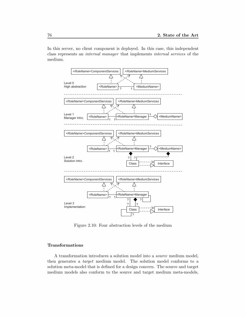
76 2. State of the Art
In this server, no client component is deployed. In this case, this independentclass represents an internal manager that implements internal services of themedium.
<MediumName> ?
11
1<RoleName>Manager <RoleName>
1
InterfaceClass
?
Level 0 High abstraction
Level 1 Manager intro.
Level 2 Solution intro.
<MediumName>
11
InterfaceClass
?
?Level 3 Implementation
?
?
?
?
<RoleName>MediumServices <RoleName>ComponentServices
<RoleName>Manager <RoleName>
<RoleName>MediumServices <RoleName>ComponentServices
<RoleName>Manager <RoleName> <MediumName> ?
<RoleName>MediumServices <RoleName>ComponentServices
<RoleName>MediumServices <RoleName>ComponentServices
<RoleName> 1
?
Figure 2.10: Four abstraction levels of the medium
Transformations
A transformation introduces a solution model into a source medium model,then generates a target medium model. The solution model conforms to asolution meta-model that is defined for a design concern. The source and targetmedium models also conform to the source and target medium meta-models,

2.5. The Medium Approach 77
respectively.
AbstractType *
Medium
Property
AbstractType
*
dataType
*
1
AbstractType
AbstractTypeServices
AbstractTypeModel
1
1
(a) Source medium
(c) Decision (b) Solution
(b) Target medium
Transformation
data
11<RoleName>Manager <RoleName> <MediumName>
?
<RoleName>MediumServices <RoleName>ComponentServices
11<RoleName>Manager <RoleName> <MediumName>
?
<RoleName>MediumServices <RoleName>ComponentServices
in
in
in
out
Figure 2.11: An example of transformation. This figure describes the trans-formation that introduces an abstract type solution into the medium model.Generic and simplified structures of the four involved models (source medium,target medium, solution, and decision ones) are presented.
For example, Figure 2.11a describes the simplified structure of a mediummodel at level 2. If the medium at level 0 includes the management of a data set(for example, the reservation medium manages the set of available identifiers),a concern of abstract type could be identified. Figure 2.11(b) represents thegeneric structure of solution models for this design concern3. To introduce anabstract type model into a medium model, a transformation is implemented.This transformation uses a decision model (Figure 2.11(c)) that indicates thedata set and the data type to be introduced. According to this model, the
3This model is simplified. In [Kabore 08a], it also contains a model of properties that isused for verification issues.

78 2. State of the Art
transformation merges the abstract type solution model into the source mediummodel and generates the target medium model (Figure 2.11(d)).
Generally, for a transformation, a decision meta-model is defined, a decisionmodel conforming to this meta-model will contain the decisions of the designer.The decision meta-model thus can be seen as a user interface of the transfor-mation.
In the terminologies of Model-Driven Architecture (MDA), the source me-dium model can be considered as a Platform-Independent Model (PIM) whilethe target one is a Platform-Specific Model (PSM). The solution model is thena Platform Model (PM).
2.5.2.3 Medium Refinement Process
In [Kabore 08a], Kabore formulated a medium refinement process (alternativelycalled medium development process). This process describes how software en-gineers can participate in the development of a medium.
Four Roles for Medium Engineers
The term “medium engineers” refers to people who participate in the de-velopment of the medium. Kabore identified four roles for medium engineers,according to the requirements of their knowledge in the medium concept andmodel based techniques.
• Application designer: The application designer defines the medium modelat level 0.
• Process designer: The process designer identifies design concerns and de-sign solutions, and then, executes transformations in a suitable order togenerate the medium model at the implementation level. To this end, theprocess designer also defines decision models (that conform to decisionmeta-models defined by the medium expert).
• Medium expert: The medium expert defines medium meta-models andsolution meta-models, and implements transformations. Each transfor-mation includes a decision meta-model.
• Solution designer: The solution designer defines different solution modelsthat conform to solution meta-models defined by the medium expert.
In the medium development process, Kabore focused on the design activity

2.5. The Medium Approach 79
of the development. The source code of a medium at level 3 can be completedby reusable software components or generated by code generators [Kelly 08].
Catalogue of Mediums and Concerns
When identifying concerns and solutions for the development of a medium,the process designer uses a catalogue that contains reusable concerns and so-lutions. This catalogue also contains reusable mediums such as reservation,voting, video streaming, publish/subscribe, and file sharing4.
In addition to reusable mediums, the catalogue also contains reusable con-cerns. For each of these concerns, a solution meta-model, several solution mod-els conforming to this meta-model, and a transformation with a decision meta-model are provided. When required concerns and/or solutions do not existin the catalogue, the medium expert and/or the solution designer will definenecessary meta-models, models, and transformations.
Three Refinement Steps
The refinement process consists of three steps: specification, transformation,and generation.
• Specification: The application designer defines the medium by identifyingits roles and interfaces, and then, define the medium model at level 0.
The process designer uses the generic manager introduction transforma-tion to generate the medium model at level 1. From this model, theprocess designer identifies concerns and solutions.
• Transformation: If a concern identified by the process designer does notexist in the catalogue, the medium expert defines a solution meta-modeland implements a transformation for this concern.
Similarly, if a solution identified by the process designer does not existin the medium catalogue, the solution designer defines a solution modelconforming to the corresponding solution meta-model.
• Generation: The process designer defines the order in which transforma-tions are applied, and then, executes them to generate the medium modelat level 3.
Kabore developed a prototype using the Kermeta meta-programming envi-ronment [Triskell]. The medium, solution, and decision meta-models are rep-
4http://departements.telecom-bretagne.eu/info/medium

80 2. State of the Art
resented as Ecore meta-models [Eclipse]. Transformations are implemented inthe Kermeta language.
2.5.3 Discussion
We have presented above the medium approach to developing distributed ap-plications, including the medium abstraction and the MDA-based refinementprocess. The medium approach is particularly relevant for the developmentof adaptive distributed applications. First, the medium abstraction allows toencapsulate distributed communication in a distributed application, and then,separate distributed adaptations from local ones. Second, the medium refine-ment process can be easily extended in order to generate different mediumimplementation variants. Finally, the medium abstraction and its model-basedrefinement process highly automate the development. In the next chapter, wewill present how the medium approach is extended in the adaptive mediumapproach to developing adaptive distributed applications.
2.6 State-of-the-Art Summary
In this chapter, we have presented terminologies in the domain of softwareadaptation that are used in this thesis. We have also described fundamentalapproaches and points of view that inspire the adaptive medium approach, suchas architecture-based adaptation, external adaptation control, and adaptationcontrol loop.
Then, we have discussed the related approaches and their limitations re-garding the six identified challenges in order to justify the two key issues. Wesuggest that to better overcome the challenges, a high-level abstraction and ahighly automated development process for specifying and developing adaptivedistributed software systems should be investigated.
Finally, we have presented background on the medium approach that includea high-level abstraction and a model-based refinement process for the specifi-cation and development of distributed applications. The medium approach isreused and extended in this thesis in the adaptive medium approach that willbe presented in the next chapter.

Chapter 3
Adaptive Medium Approach
Contents
3.1 Chapter Overview . . . . . . . . . . . . . . . . . . . . 81
3.2 The Adaptive Medium Approach . . . . . . . . . . . 82
3.3 Developing the Adaptation Medium . . . . . . . . . 88
3.4 Generating Functional Medium Variants . . . . . . 100
3.5 Composing the Adaptive Medium . . . . . . . . . . 112
3.6 Approach Summary and Discussion . . . . . . . . . 113
3.1 Chapter Overview
This chapter introduces the adaptive medium approach to developing adap-tive distributed applications. This approach supports architecture-based adap-tations relying on an external adaptation control architecture and reflectiontechnologies supported by component platforms and programming languages.In the literature, this type of adaptation is also called compositional adaptation[McKinley 04].
As explained in Chapter 2, we extended the medium approach, includingthe medium high-level abstraction and its refinement process, to tackle the twoidentified issues: high-level abstraction and highly automated process.
When considering the key issues and the fundamental approaches for thedevelopment of adaptive distributed applications, there were two main questionsthat led us to extend the medium abstraction and its refinement process:
81

82 3. Adaptive Medium Approach
• Question 1: What is the abstraction of an adaptive distributed applica-tion?
The abstraction must allow to specify distributed architectures of the func-tional part, the adaptation control part, and the whole adaptive applica-tion as the composition of these two parts.
• Question 2: How does the development process allow the adaptation con-trol part to monitor and adapt the functional one?
This question can be decomposed into two sub-questions of 1) how thedevelopment of the functional part makes it understandable and recon-figurable by the adaptation control one, and 2) how the development ofthe adaptation control part enables it to understand and reconfigure thefunctional one. In other words, question 2 concerns supporting the appli-cation’s reflectivity that consists of introspection and intercession abilities.
This chapter gives answers to both questions, and then, explains why inour approach the two identified key issues are investigated and the medium ap-proach is extended. First, Section 3.2 presents how to use the adaptive mediumto specify adaptive distributed applications. An adaptive distributed applica-tion is specified using an adaptive medium that is composed of a functionalmedium and an adaptation medium. Next, Section 3.3 shows how the adapta-tion medium can be developed as a reusable adaptation control infrastructurefor different adaptive mediums. Section 3.4 describes the principles of the gen-eration of the functional medium implementation variants. Together with thesevariants, their architectural models and adaptation-facilitating models are alsogenerated. Section 3.5 explains how the adaptive medium is composed fromthe implementations of the adaptation medium and the functional one. Thanksto the architectural models and the adaptation-facilitating ones, the adapta-tion medium can understand and reconfigure the functional one, then adaptsit. Finally, Section 3.6 summarizes and discusses the approach.
3.2 The Adaptive Medium Approach
3.2.1 Approach Overview
Figure 3.1 shows an overview of the adaptive medium approach to the develop-ment of adaptive distributed applications [Phung-Khac 08, Gilliot 11], based onthe medium approach. For the sake of simplicity, we consider single adaptivemedium applications only. An adaptive distributed application is then spec-ified as an interconnection of distributed client components and an adaptive
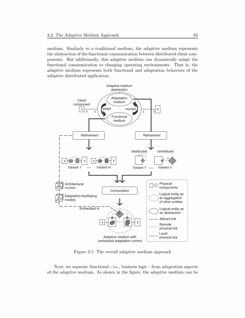
3.2. The Adaptive Medium Approach 83
medium. Similarly to a traditional medium, the adaptive medium representsthe abstraction of the functional communication between distributed client com-ponents. But additionally, this adaptive medium can dynamically adapt thefunctional communication to changing operating environments. That is, theadaptive medium represents both functional and adaptation behaviors of theadaptive distributed application.
yx
? 1 1 ?
Adaptationmedium
Composition
Functional medium
Adaptive medium withcentralized adaptation control
Clientcomponent
x y
x y x y
*1*
distributed centralized
Adaptive medium abstraction
Variant 1 Variant m
adapt monitor
… …
Refinement Refinement
Variant 1 Variant n
Architecturalmodels
Adaptation-facilitating models
Physicalcomponents
Logical entity asan aggregationof other entities
Logical entity asan abstraction
Abtract link
Remotephysical link
Localphysical link
Embedded in
Figure 3.1: The overall adaptive medium approach
Next, we separate functional - i.e., business logic - from adaptation aspectsof the adaptive medium. As shown in the figure, the adaptive medium can be

84 3. Adaptive Medium Approach
seen as a composition of a functional medium and an adaptation medium. Theadvantages of separating and externalizing adaptation from business logic suchas facilitating architecture-based adaptation and promoting reuse have beenpresented in Section 2.2.
In order to reify the adaptive medium abstraction, we use and extend themedium refinement process to develop the adaptation medium and generatefunctional medium’s architectural variants. As these variants are generated byintroducing different solutions for each considered design concern, they can becharacterized by the non-functional properties or user requirements that guidedthe choices of the solutions. Each variant can be well-suited to some situationsof the operating environment or responds to certain user requirements. Hence,the functional medium can be adapted to the changing operating environmentby replacing its running variant.
The original medium refinement process was proposed to refine a mediumabstraction into a medium implementation as a single software product. Whenextending the medium refinement process by allowing the introduction of differ-ent solutions for each concern in order to generate different functional mediumimplementation variants, we adhere to the domain of System Family Engineer-ing. The different medium implementation variants can be considered as mem-bers of a product family.
Once the functional medium implementation variants are generated, variantreplacements are realized by the adaptation medium. To this end, the adapta-tion medium uses the following models:
• Architectural models describing the architecture of functional mediumvariants. These models include a runtime architectural model that re-flects the running variant state.
• Adaptation-facilitating models generated during the development of thefunctional medium variants.
These models allow the adaptation medium to automatically generate adap-tation plans.
Developing the Adaptation Medium
The adaptation medium is generic for every functional medium. It im-plements typical adaptation activities of adaptive software systems: detectingenvironment changes, making adaptation decisions, planning and executing nec-essary adaptation actions on the systems [Oreizy 99]. However, because this

3.2. The Adaptive Medium Approach 85
thesis mainly focuses on supporting automatic planning and executing neces-sary adaptation actions on the functional medium in order to adapt it, theactivities of observing operating environment and making adaptation decisionsare not included in the adaptation medium presented in the thesis.
When adapting a functional medium, the adaptation medium performsadaptation steps including creating the replacement components of the tar-get functional medium variant, transferring data from the replaced componentsto the replacement ones, removing the replaced ones, and activating the re-placement ones. Because the functional medium is distributed, every step mayconsist of distributed adaptation actions that need to be coordinated. Addi-tionally, there may exist constraints between executions of these actions, i.e.,an action may need to be performed before another one. These actions are or-ganized in an adaptation plan that is generated automatically by analyzing thearchitectural models and the adaptation-facilitating models. This adaptationplan is composed of local adaptation plans and an adaptation coordination plan.
By applying the medium approach, we can design and implement differentarchitectural variants of the adaptation medium. For instance, Variant 1 of theadaptation medium in Figure 3.1 implements a distributed adaptation controlstrategy and is composed of distributed adaptation managers. Likewise, Vari-ant n implements a centralized one and is composed of a centralized adaptationmanager and distributed adaptation manager proxies. These architectures sup-port different composition strategies for the target adaptive medium. This canbe seen as the static adaptability of the composition. That is, the compositioncan be statically adapted to operating environments and user requirements.
Generating Functional Medium Variants
We extend the medium refinement process [Kabore 08a] to generate archi-tectural variants of the functional medium. Through the process, the functionalmedium at level 0 is refined by successive transformations into the one at level3. Instead of introducing a solution for each concern as in the original refine-ment process, we allow the introduction of different solutions for a concern.Therefore, different medium variants can be generated.
In the original medium refinement process, Kabore focused on automatingthe development process thanks to model transformations. Such a transfor-mation weaves a design solution model into a medium model, both are repre-sented as UML class diagrams. At the implementation level, the UML classdiagram of a medium variant can be modularized into components, one permanager. A manager is then a primitive component, i.e., it is not separatedinto sub-components. As a result, if these variants are used to build the adap-

86 3. Adaptive Medium Approach
tive medium, when performing an adaptation, the whole manager on each sitemust be replaced. As discussed in the problem statement, this adaptation isnot fine-grained and may be costly, particularly in distributed applications.
Considering functional medium variants as members of a product family,we adopt the feature modeling approach [Kang 90] for scoping the functionalmedium, i.e., describing which concerns and solutions are included in the func-tional medium. Moreover, to support fine-grained adaptations, we also take intoaccount the aspect of modeling the modularity of the variants. Then, for thegeneration of variants of a functional medium, we define a model of modularity,commonality, and variability. The model, called medium MCV model, is anextension of the basic form of feature models [Czarnecki 00]. It describes thedecomposition of the medium into design concerns and design solutions that areconsidered as features. At the beginning of the adaptive medium developmentprocess, the MCV model is used to facilitate the identification of design con-cerns and design solutions. Next, feature refinement rules are used to refine theMCV model, thus making it able to describe modularity of functional mediumvariants. The MCV model is then used by a modularization transformationthat automatically modularizes functional medium variants into components.These components are also mapped into features of the MCV model in order tofacilitate adaptation planning.
Additionally, we also propose a data transfer model. This model that isbuilt through the generation process is used to identify operations for thedata transfer between medium variants’ components when realizing adapta-tions [Phung-Khac 10]. Similarly, reconfiguration constraints models that arealso built through the process allow to identify constraints between adaptationactions.
The MCV model, the data transfer model, and the reconfiguration con-straints model significantly facilitate adaptations. They enables the adaptationmedium to automatically plan adaptations at runtime. In addition to thesemodels that are called adaptation-facilitating models, the adaptation planningalso needs architectural models describing the components, interfaces, and com-ponent structures of medium variants (Figure 3.1).
3.2. The Adaptive Medium Approach 87
Composing the Adaptive Medium
The target adaptive medium is composed from the implementation of thefunctional medium and the adaptation one. To compose the adaptive medium,a functional medium variant and an adaptation medium one are selected. Atruntime, the adaptation medium variant will be kept stable and forms an in-frastructure for changing the running functional medium variant. Thanks tothe extensibility of the refinement process (i.e., new design solutions can beintroduced), new variants of the functional medium can be integrated into theadaptive medium at runtime. Since an adaptation medium variant is stablewithin an adaptive medium, it is called an adaptation medium implementation.
From a technical point of view, the composition relies on reflection technolo-gies of component platforms and programming languages. These technologiesserve as a leverage point for weaving the functional and the adaptation aspectsof the adaptive medium [McKinley 04, David 03]. Additionally, the compositionof adaptive mediums has another leverage point: the medium approach. Thisapproach including a communication abstraction and its refinement process al-lows the adaptation medium to deeply understand the functional medium inorder to adapt it. This deep understanding does not require the presence of thefunctional medium implementation when developing the adaptation one. There-fore, it facilitates the development and the reuse of the adaptation medium, andleverages the composition of adaptive mediums.
Discussion
According to the terminologies identified in the background (Section 2.2),the distributed adaptation supported in our approach is non-functional, butextensible. The variants of the functional medium have different non-functionalproperties but provide the same functionality. This functionality is prede-fined by specifying medium services and component services that are unchangedthrough adaptations. On the other hand, adaptations are realized by replac-ing the running functional medium variant by another one. The latter can bepredefined in the refinement process or introduced by extending the process atruntime.
The medium approach plays an important role in the adaptive medium one.The different solutions for each design concern and different design decisionsallow to support the variability of the medium in order to realize adaptations.On the other hand, the medium as a predefined abstraction and the decomposi-tion of the medium into design concerns are the invariants of the medium thatserves as a basis to preserve system integrity.

88 3. Adaptive Medium Approach
3.2.2 Adaptive Medium Development Process
From the idea presented above, we develop the adaptation medium as a reusableinfrastructure and formulate a development process of adaptive mediums thatincludes the generation of functional medium variants and the composition ofthe adaptive medium. This adaptive medium development process is sup-ported by an adaptive medium development framework that includes genericand reusable meta-models, models, transformations, programs, and implemen-tations of the adaptation medium.
In the process, we identify four roles for software engineers including appli-cation designer, process designer, medium expert, and solution designer. Theseroles are based on those in the original medium refinement process (Section 2.5).Moreover, considering functional medium variants as members of a system fam-ily, we separate software assets (such as meta-models, models, and transforma-tions) and software engineers’ activities into domain engineering and applicationengineering processes as in the system family engineering. This clear separationcan ease the development, promote reuse, and improve automation.
The remainder of this chapter provides the principles of the adaptationmedium development, the functional medium variants generation, and the adap-tive medium composition. The detailed adaptive medium development processwill be presented in Chapter 4.
3.3 Developing the Adaptation Medium
This section presents the development principles of the adaptation medium.Thanks to the medium refinement process, different variants of the adaptationmedium can be developed, therefore, providing more choices for the compositionof the adaptive medium.
According to the medium approach, the number of variants and their ar-chitectures and implementations depend on the identified design concerns anddesign solutions. These concerns and solutions reflect interests of software en-gineers in employing existing technologies or developing new technologies sup-porting adaptations. As this thesis focuses on the functional medium variantsdevelopment that facilitates and automate the adaptation planning and exe-cution, we do not put any constraint on how concerns and solutions for theadaptation medium are identified. First, we specify the adaptation medium atlevel 0 (high-level abstraction) and level 1 (manager introduction). Then, wedescribe how the adaptation medium plans and executes adaptation actions onthe functional medium.
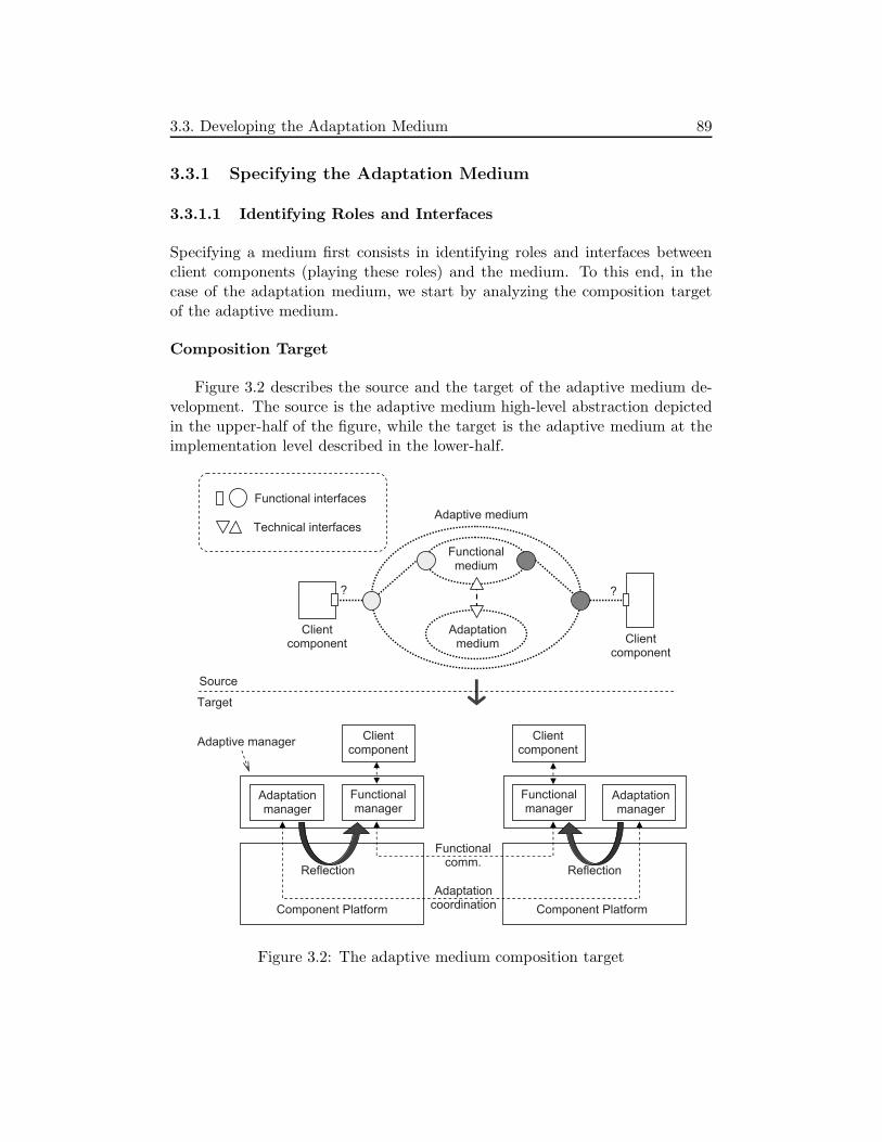
3.3. Developing the Adaptation Medium 89
3.3.1 Specifying the Adaptation Medium
3.3.1.1 Identifying Roles and Interfaces
Specifying a medium first consists in identifying roles and interfaces betweenclient components (playing these roles) and the medium. To this end, in thecase of the adaptation medium, we start by analyzing the composition targetof the adaptive medium.
Composition Target
Figure 3.2 describes the source and the target of the adaptive medium de-velopment. The source is the adaptive medium high-level abstraction depictedin the upper-half of the figure, while the target is the adaptive medium at theimplementation level described in the lower-half.
Adaptationmedium
Functionalmedium
Adaptive medium
? ?
Functional interfaces
Technical interfaces
Adaptationmanager
Adaptationmanager
Clientcomponent
Clientcomponent
Component Platform Component Platform
Functionalmanager
Functionalmanager
Clientcomponent Client
component
Reflection Reflection
Source
Target
Adaptationcoordination
Functionalcomm.
Adaptive manager
Figure 3.2: The adaptive medium composition target

90 3. Adaptive Medium Approach
The adaptive medium high-level abstraction is composed of the functionalmedium abstraction and the adaptation one. While the functional medium re-alizes the functional communication between client components by implement-ing its functional interfaces, the adaptation medium adapts the functional onethrough an adaptation technical interface.
This specification relies on the nature of the medium concept:
“a medium is an abstraction of communication”.
According to this definition, the three above mediums are specified:
• The adaptive medium is the abstraction of the communication betweendistributed components of the adaptive application in general,
• The functional medium is the abstraction of the communication betweendistributed components of the adaptive application to realize the applica-tion’s functional services, and
• The adaptation medium is the abstraction of the communication be-tween distributed components of the adaptive application to coordinatedistributed adaptation actions.
In the adaptive medium at the implementation level, the functional mediumabstraction is reified by a logical aggregation of distributed manager compo-nents called functional managers. Likewise, the adaptation medium is a logicalaggregation of distributed adaptation managers. The composition of a func-tional manager and an adaptation manager is called an adaptive manager. Atthis level, the functional interfaces described in the source are represented bystandard interfaces supported by the component platform, while the technicalinterfaces are translated to reflection functions provided by the platform thatallow the adaptation managers to reconfigure the corresponding functional ones.
Identified Roles and Interfaces
Figure 3.3 describes roles and interfaces between client components and theadaptation medium. As shown in the figure, there exists only one type of rolecalled AdaptableComponent. Each functional manager thus plays an Adaptable-Component role and is called an adaptable component within the adaptationmedium. That is, the functional managers need to be adapted by adaptationservices of the adaptation medium. However, unlike traditional medium rolescorresponding to client components (e.g., the source or reserver role of the reser-vation medium) that are directly connected to medium manager components

3.3. Developing the Adaptation Medium 91
(e.g., by binding interfaces), the adaptable components use the adaptation ser-vices in a passive way. More precisely, they are reconfigured by the adaptationservices, via the component platforms in which they are deployed.
Adaptationmedium
*
stop(Component)start(Component)add(Component)remove(Component)connect(Interface, Interface) disconnect(Interface)invoke(Operation)
Adaptable Component
Figure 3.3: Description of the adaptation medium
From a technical point of view, the AdaptableComponent role can be re-placed by the (local) component platform that provides reflection functionsfor the adaptation medium. The functions allow to stop, start, add, remove,connect, disconnect components and to invoke data transfer operations. Theimplementation of these functions thus depends on the component platformused to implement and deploy the functional medium. On the other hand, thecomponent platform chosen for developing the adaptive medium must providesuch functions.
3.3.1.2 Adaptation Medium Models
High-level Abstraction (Level 0)
Figure 3.4 includes the model of the adaptation medium at the high abstrac-tion level, i.e., level 0. The model is described as a UML class diagram.
In the figure, the adaptation medium abstraction is represented by the Adap-tationMedium abstraction class and the adaptable components are representedby the AdaptableComponent class. The former requires the services includedin the ReflectionServices interface that is provided by the latter. In fact, therealization link between AdaptableComponent and ReflectionServices is not atraditional one between a class and an interface in standard UML2. This canbe seen as a conceptual realization that will be reified when implementing theadaptation medium by using a particular component platform.
The AdaptationMedium class also contains the models attribute that repre-sents a set of models, including architectural models of functional medium vari-

92 3. Adaptive Medium Approach
1..*<<abstraction>>
Adaptation Medium
<<role>> AdaptableComponent
<<interface>> ReflectionServices
stop(Component) start(Component) add(Component) remove(Component)connect(Interface, Interface) disconnect(Interface) invoke(Operation)
Model 1
1..*
+models
Figure 3.4: Adaptation medium model at the high abstraction level
ants and adaptation-facilitating models. As described previously, these modelsare the basis for the adaptation medium to realize adaptations.
The models set also includes a runtime (architectural) model that describesthe runtime architecture of the functional medium. This model is built from thedesign-time architectural model of the running functional medium variant andruntime information such as manager cardinality. This runtime model is usedto monitor the running functional medium. Changes in the running variant arereported to the adaptation medium to update the runtime model.
Implementation Architecture (Level 1)
1..*
<<interface>> ReflectionServices
1 1 <<role>> AdaptableComponent
Adaptation Manager
<<abstraction>> Adaptation
Medium Model
1..*
+models
Figure 3.5: Adaptation medium model after introducing managers
Figure 3.5 describes the adaptation medium model at level 1. A role managercalled adaptation manager is introduced (class AdaptationManager). When
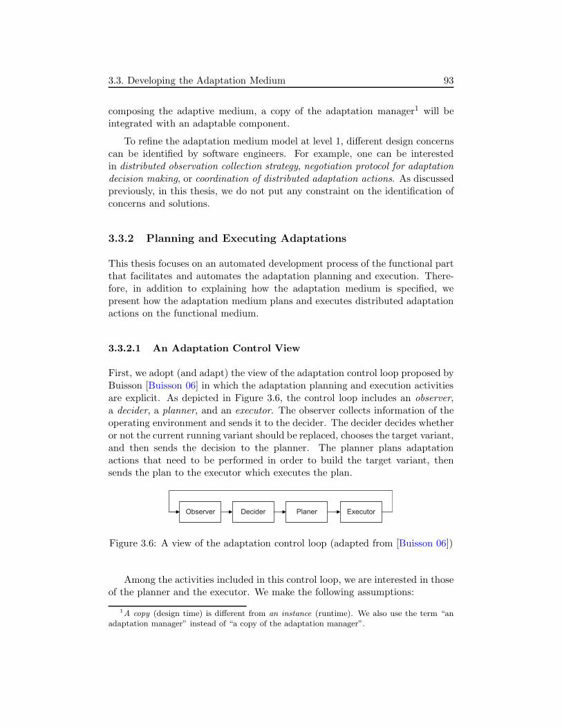
3.3. Developing the Adaptation Medium 93
composing the adaptive medium, a copy of the adaptation manager1 will beintegrated with an adaptable component.
To refine the adaptation medium model at level 1, different design concernscan be identified by software engineers. For example, one can be interestedin distributed observation collection strategy, negotiation protocol for adaptationdecision making, or coordination of distributed adaptation actions. As discussedpreviously, in this thesis, we do not put any constraint on the identification ofconcerns and solutions.
3.3.2 Planning and Executing Adaptations
This thesis focuses on an automated development process of the functional partthat facilitates and automates the adaptation planning and execution. There-fore, in addition to explaining how the adaptation medium is specified, wepresent how the adaptation medium plans and executes distributed adaptationactions on the functional medium.
3.3.2.1 An Adaptation Control View
First, we adopt (and adapt) the view of the adaptation control loop proposed byBuisson [Buisson 06] in which the adaptation planning and execution activitiesare explicit. As depicted in Figure 3.6, the control loop includes an observer,a decider, a planner, and an executor. The observer collects information of theoperating environment and sends it to the decider. The decider decides whetheror not the current running variant should be replaced, chooses the target variant,and then sends the decision to the planner. The planner plans adaptationactions that need to be performed in order to build the target variant, thensends the plan to the executor which executes the plan.
Observer Decider Planer Executor
Figure 3.6: A view of the adaptation control loop (adapted from [Buisson 06])
Among the activities included in this control loop, we are interested in thoseof the planner and the executor. We make the following assumptions:
1A copy (design time) is different from an instance (runtime). We also use the term “anadaptation manager” instead of “a copy of the adaptation manager”.

94 3. Adaptive Medium Approach
• An adaptation decision sent to the planner indicates the running and thetarget functional medium variants.
• Once the decision is sent, the quiescent state [Zhang 06] of the wholesoftware system is achieved in order to be able to execute adaptation.
By making these assumptions, we focus on the activities of planning andexecuting adaptation actions. In particular, we are interested in planning andexecuting distributed adaptations. Such an adaptation consists of adaptationprocesses executed in distributed sites.
3.3.2.2 Distributed Adaptation Processes
A distributed adaptation is called also a global adaptation process (or global pro-cess). In the space dimension, such a process is composed of some local adap-tation processes (or local processes) performed simultaneously in distributedsites. On the other hand, in the time dimension, the global process consists ofsome global adaptation steps (or global steps). A local process consists of cor-responding local adaptation steps (or local step). Each local step is constitutedby successive adaptation actions (or actions).
In Figure 3.7, each horizontal arrow represents a process. The upper-mostone is the global process corresponding to the whole adaptive medium. Thisglobal process consists of n distributed local processes corresponding to adaptivemanager instances of the adaptive medium.
The figure describes an adaptation in which Variant 1 (V1 ) as the runningvariant of the functional medium is replaced by Variant 2 (V2 ). We propose 6global steps through which the adaptation is realized:
• Step 1: Stop medium services
• Step 2: Load and connect V2 ’s components
• Step 3: Initialize V2 ’s components (i.e., invoke custom functions to func-tionally initialize the components)
• Step 4: Transfer data from V1 to V2
• Step 5: Disconnect and remove V1 ’s components
• Step 6: Start medium services

3.3. Developing the Adaptation Medium 95
Generally, adaptation actions of a local step must be performed after finish-ing all those of the previous global step. The 6 global steps are thus separatedby synchronization barriers represented by vertical bars in the figure.
A manager instance may not participate in one or several adaptation step(s).There are the following typical cases:
c
Manager 1 (local process)
Manager i
Manager j
Manager k
Manager l
…
…
V1
V1
V1
V1
V1
V2
V2
V2
V2
Synchronization
LS1
Local/global adaptation steps:LS1/GS1: Stop local/all medium services LS2/GS2: Load and connect V2’s local/all components LS3/GS3: Initialize V2’s local/all components LS4/GS4: Transfer local/all data from V1 to V2 LS5/GS5: Disconnect and remove V1’s local/all components LS6/GS6: Start local/all medium services
tProcess
Medium (global process)
Variant 1 Adaptation Variant 2
LS1
LS1
LS1
LS2
LS2
LS2
LS3
LS3
LS3
LS4
LS4
LS5
LS5
LS5
LS6
LS6
LS6
LS6
GS1 GS2 GS3 GS4 GS5 GS6
Start performing modifications usable = false
Finish performing modifications usable = true
LS1
Manager m V2
LS2 LS3 LS6
Manager n V1 V2LS1
LS4 LS5
LS6
Figure 3.7: Distributed adaptation execution processes
• A manager (instance) participates in all the steps (e.g., manager 1 in thefigure). In this case, the adaptation requires addition and initializationof target (V2 ’s) components, removal of source (V1 ’s) components, and

96 3. Adaptive Medium Approach
data transfer from the source to the target components. That is, V2 andV1 have different components on this manager (Figure 3.8(a) and (b)).
• A manager only participates in steps 1, 2, 3, 5, and 6 (e.g., manager i).No data transfer or component removal action is realized. That is, V2and V1 have different components on this manager (Figure 3.8 (a) and(b)), but the to-be-removed source components do not manage data.
• A manager only participates in steps 1, 2, 3, and 6 (e.g., manager j ).No data transfer or component removal action is realized. That is, V2encompasses V1 on this manager (Figure 3.8(c)).
• A manager only participates in steps 1, 4, 5, and 6 (e.g., manager k).No component addition or initialization action is realized. That is, V1encompasses V2 on this manager (Figure 3.8(d)).
• A manager only participates in steps 1, 4, and 5 (e.g., manager l). Thatis, the manager is only concerned with V1 (this case is not expressed inFigure 3.8). This case requires a special solution for data transfer sincethe local data managed by the V1 ’s components can not be written toanother local component of V2.
• A manager only participates in steps 2, 3, and 6 (e.g., manager m). Thatis, the manager is only concerned with V2 (this case is not expressed inFigure 3.8).
• A manager only participates in steps 1 and 6 (e.g., manager n). That is,V1 and V2 share the whole manager component (Figure 3.8(e)).
(a)
V1 V2 V1 V2
V1 V2 V2 V1 V1, V2
(b)
(c) (d) (e)
Figure 3.8: Relations between V1 and V2 on a functional manager instance
In a particular global step, an action in a local step on a manager mayneed to be performed before or after the ones on some other managers (Fig-ure 3.9). For example, when loading and connecting components of a centralized

3.3. Developing the Adaptation Medium 97
data management implementation, depending on the way these components areimplemented, the sever component may need to be deployed before the clientones. These constraints are an important issue when planning and executingthe distributed adaptation processes. The constraints can be represented in anadaptation coordination plan that describes how to coordinate the execution oflocal adaptation plans.
Ax1Manager x Ax2 Ax3 Ax4 Ax5
Ay1 Ay2 Ay3 Ay4Manager y
LS
LS
Adaptationaction
Localadaptationstep
Require-constraint
LS
Figure 3.9: Require-constraints between adaptation actions
3.3.2.3 Local Adaptation Plan
Figure 3.10 presents a meta-model of local adaptation plans. Such a plan con-sists of some of the six local steps presented above. While the first and the laststeps are mandatory, the other ones are optional. Each step contains an or-dered list of actions corresponding to reflection functions (ReflectionFunction)provided by the chosen component platform. As described in the figure, Re-flectionFunction is an abstract class. It will be extended by concrete reflectionfunctions, depending on the component platform chosen for implementing theadaptive medium.
For each manager instance related to variants V1 or V2 of the adaptivemedium (the two variants may not have the same set of manager instances),a local adaptation plan is used. All these plans are executed coordinately byusing the coordination plan.

98 3. Adaptive Medium Approach
Local AdaptationPlan
LS1
<<abstract>> RefectionFunction
LS2
LS3
LS4
LS5
LS6
0..1
0..1
0..1
1
0..1
1
1..*1..*1..*
1..*
1..* 1..*
Local adaptation steps:LS1: Stop local medium services LS2: Load and connect V2’s local components LS3: Initialize V2’s local components LS4: Transfer local data from V1 to V2 LS5: Disconnect and remove V1’s local components LS6: Start local medium services
{ordered}
{ordered}
{ordered}
{ordered}
{ordered}
{ordered}
+action +action +action
+action +action +action
Figure 3.10: A meta-model of local adaptation plans
3.3.2.4 Adaptation Coordination Plan
We propose a meta-model of adaptation coordination plans in Figure 3.11. Acoordination plan contains from 2 to 6 global adaptation steps (depending oneach adaptation), each step has a list of participant manager instances. In thefigure, class ManagerInstance represents a manager instance related to at leastone of two variants V1 and V2. Every manager instance is associated with alocal adaptation plan.
An adaptation coordination plan may also contain a set of require-constraintsrepresenting the execution order of adaptation actions on different manager in-stances, but in the same global adaptation step. A requiring action must beperformed after a required action. Consequently, an adaptation is not realizableif there exists a cycle of require-constraints.
3.3.2.5 Generating Adaptation Plans
In an adaptive medium, the local adaptation plans and the adaptation coordi-nation plan can be generated automatically at runtime by the planner. Whenreceiving an adaptation decision, the planner analyzes the architectural models

3.3. Developing the Adaptation Medium 99
of the functional medium variants and the adaptation-facilitating models, thengenerates local adaptation plans and a coordination plan.
Coordination Plan
GS1
Manager Instance
GS2
GS3
GS4
GS5
GS6
0..1
0..1
0..1
1
0..1
1
1..*1..*1..*
1..*
1..* 1..*
Global adaptation steps:GS1: Stop medium services GS2: Load and connect V2’s components GS3: Initialize V2’s components GS4: Transfer data from V1 to V2 GS5: Disconnect and remove V1’s components GS6: Start medium services
+participant
+participant
+participant
+participant
+participant
+participant
Local AdaptationPlan
1
Require Constraint
<<abstract>> RefectionFunction
10..*+requiring
+required
0..*
0..*
1
1
Figure 3.11: A meta-model of adaptation coordination plans
As described in Section 3.4, the architectural model of a functional mediumvariant describes components and component structure of the variant. Thesecomponents are mapped to features of the MCV model - an adaptation-facilitatingmodel. By comparing two feature configurations corresponding to the two func-tional medium variants, the planner can identify components to be added andremoved as well as interfaces to be connected and disconnected. Moreover, theadaptation-facilitating models also include a data transfer model that allowsthe planner to identify data transfer actions. Finally, a medium reconfigurationconstraints model enables the planner to identify require-constraints betweenadaptation actions.

100 3. Adaptive Medium Approach
3.3.3 Discussion
In this section, we have specified the adaptation medium at the high abstrac-tion level and the manager introduction level. We have also presented howadaptations can be planned and executed by discussing distributed adaptationprocesses and proposing a local adaptation plan meta-model and an adaptationcoordination plan meta-model.
Since implementing the adaptation medium as an adaptation control infras-tructure is not the main focus of this thesis, we do not constrain the identifi-cation of design concerns and design solutions as well as the refinement of theadaptation medium. As a result, all the concepts used above such as the plannerand the executor are abstractions. Each concept can be a component or a setof distributed components, depending on each implementation variant of theadaptation medium. For example, in Chapter 5 (Prototype), we will present aprototype of the adaptation medium in which the executor abstraction is reifiedby distributed executor components.
In this thesis, the activities of operating environment observation and adap-tation decision making are not in the focus. In our laboratory, recent researchprojects in these topics have been investigated. For example, in [Beugnard 09],Beugnard et al. proposed to integrate context observers within components.Additionally, Mallet et al. [Mallet 08] presented a framework supporting com-parative analysis of extra-functional properties of architectural styles used todesign distributed applications. These comparative analysis can make explicitthe selection of styles. Clearly, these results could be applied for the operat-ing environment observation and adaptation decision making in the adaptationmedium. However, this requires further investigations.
By not constraining the identification of concerns and solutions, we tendto be more general in the development of the adaptation medium. Also to thisend, the local adaptation plan meta-model and the adaptation coordination planmeta-model are still abstract. For example, RefectionFunction as an abstractclass allows to adopt different component platforms. Nevertheless, separationof adaptation steps, other than the six ones proposed above, can be applicable.Moreover, different strategies for realizing an adaptation step can be possible.
3.4 Generating Functional Medium Variants
This section presents the generation of functional medium variants. The vari-ants’ architectural models and the adaptation-facilitating models are also gen-erated.

3.4. Generating Functional Medium Variants 101
First, we give an overview of the generation. Next, different views of gener-ation including architecture, process, and MCV (modularity, commonality, andvariability modeling) ones are presented. Then, we describe the modeling ofdata transfer and reconfiguration constraints.
3.4.1 The Generation Overview
The generation of functional medium variants is the development of the func-tional part of the target adaptive application. This target application will becomposed from this part and the adaptation control one. To support this com-position, the development of the functional part should enable the functionalpart to be understandable (introspection) and reconfigurable (intercession) bythe adaptation control one. These two properties of the functional part devel-opment can be ensured thanks to the medium architecture and an extension ofthe original medium refinement process.
MCV modeling as extended
feature modeling [Kang 90]
Medium refinement process
[Kaboré 08a]
Automatic modularization of medium variants
features
Medium variants models at component level
in
in
out
Medium [Cariou 03]
describe
Figure 3.12: Overview of the generation of functional medium variants. In ad-dition to reusing the original medium refinement process (the rounded rectanglein white), extensions are introduced (the two rounded rectangles in gray).
Figure 3.12 provides an overview of the generation of functional mediumvariants, including the following principles:
• The original medium refinement process is fully reused. But instead ofgenerating a functional medium implementation, this process generatesdifferent functional medium implementation variants from the medium atthe high abstraction level. Each variant is represented as a UML classdiagram.

102 3. Adaptive Medium Approach
• We introduce a step called modularization through which these mediumvariants are modularized into their components. The goal of this step isto make the functional part of the target adaptive application, i.e., thefunctional medium variants, technically reconfigurable thanks to facilitiesof component platforms. In other words, this supports intercession in theadaptive medium.
• We also introduce an MCV model as an extended feature model that allowsto represent the modularity, commonality, and variability of the functionalmedium variants. By modeling modularity of the medium variants, theMCV model enables to automate the modularization. Moreover, by de-scribing commonality and variability of these variants, the MCV modelallows to identify common and different components of any two variants,then identify components subject to change when reconfiguring a mediumvariant to achieve another one.
In addition to the functional medium variants, the results of the generationalso include 1) architectural models describing the architectures of functionalmedium variants and 2) adaptation-facilitating models that facilitate adapta-tions. The latter models include a MCV model whose features are mapped tocomponents of the functional medium variants, a data transfer model, and amedium reconfiguration constraints model. At runtime, these models are usedby the adaptation medium to monitor and adapt the functional one. In otherwords, all these models make the functional medium understandable by theadaptation medium, thus supporting the introspection in the adaptive medium.
To detail these principles of the generation, we present
• an architecture view describing different architectures of the functionalmedium through different abstraction levels of the generation process, thearchitectures include those in the original medium refinement process andthe one at the component level;
• a process view explaining how these architectures are automatically trans-formed from one to another by using model transformations, the transfor-mations also include those of the original medium refinement process andthe modularization one; and
• an MCV view presenting the model of the medium modularity, common-ality, and variability that leverages these transformations and serves as abasis for adaptation planning.
These three views of the generation process are described in Figure 3.13.
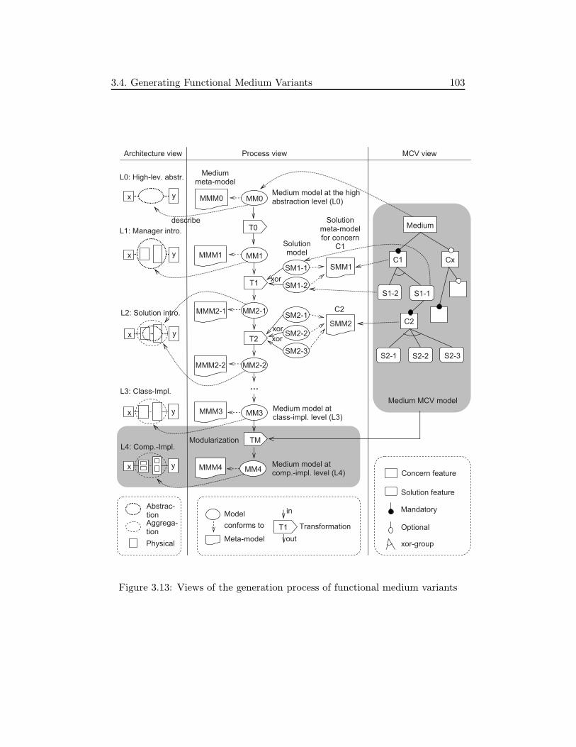
3.4. Generating Functional Medium Variants 103
x y
x y MM1MMM1
SM1-1
SM1-2
MM2-1SM2-1
SM2-2
SM2-3
MM2-2
MMM2-1
SMM1
SMM2
Architecture view Process view
Mediummeta-model
Solutionmeta-model for concern
C1Solutionmodel
MM3
MMM2-2
MMM3
C1
S1-2 S1-1
Medium
Cx
C2
S2-1 S2-2 S2-3
MCV view
MM4MMM4
Medium model at class-impl. level (L3)
Medium model at comp.-impl. level (L4)
…
xor
xor
xor
Medium MCV model
Modularization
L1: Manager intro.
L3: Class-Impl.
Concern feature
Solution feature
xor-group
Mandatory
Optional
Meta-model
Model
Transformation
in
out
conforms to
Abstrac-tionAggrega-tion
Physical
describe
x y
L4: Comp.-Impl.
C2
MM0MMM0 x y
L0: High-lev. abstr.
Medium model at the high abstraction level (L0)
x y
L2: Solution intro.
T0
T1
T2
TM
T1
Figure 3.13: Views of the generation process of functional medium variants

104 3. Adaptive Medium Approach
Moreover, we also present
• a description of the data transfer modeling and
• a description of the reconfiguration constraints modeling.
3.4.2 Architecture View
In the generation process, the functional medium is refined through differentabstraction levels, from the high abstraction level to the implementation level.According to the original medium refinement process, there are four abstractionlevels of the medium architectures: high-level abstraction, manager introduc-tion, solution introduction, and implementation. When employing this pro-cess to support architecture-based adaptation that is concerned with structuralmodifications at the level of components, we call the implementation level in theoriginal medium refinement process class-implementation level and introduce anew level called component-implementation level or level 4.
Figure 3.13 depicts the five refinement levels, i.e., five abstraction levelsof the medium through the refinement process. The high abstraction level isthe uppermost and the component-implementation is the lowermost. At thecomponent-implementation level, each manager component of the medium ismodularized into sub-components. Implementation of a design concern may beidentified as a group of such manager sub-components, depending on whetherthe design concern is modular or not. This architecture allows to replace thesolution for a design concern independently of the other design concerns.
3.4.3 Process View
To generate the functional medium variants at level 4, we introduce a modular-ization transformation. As described by Figure 3.13, in addition to the transfor-mations of the original refinement described in Figure 2.9, the modularizationtransformation called TM refines the medium model at level 3 into another oneat level 4. According to the separation of concerns of the medium and proper-ties of the design concerns, this transformation separates implementations of thedesign concerns into sub-components of the managers. The properties includemodularity of the concerns and constraints between concerns. The organizationand properties of the concerns are represented by the MCV model that is thenused as an input of TM.
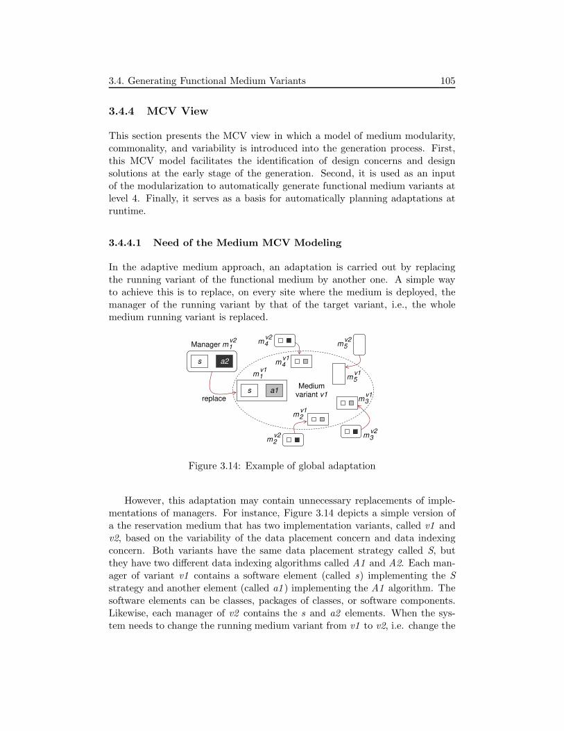
3.4. Generating Functional Medium Variants 105
3.4.4 MCV View
This section presents the MCV view in which a model of medium modularity,commonality, and variability is introduced into the generation process. First,this MCV model facilitates the identification of design concerns and designsolutions at the early stage of the generation. Second, it is used as an inputof the modularization to automatically generate functional medium variants atlevel 4. Finally, it serves as a basis for automatically planning adaptations atruntime.
3.4.4.1 Need of the Medium MCV Modeling
In the adaptive medium approach, an adaptation is carried out by replacingthe running variant of the functional medium by another one. A simple wayto achieve this is to replace, on every site where the medium is deployed, themanager of the running variant by that of the target variant, i.e., the wholemedium running variant is replaced.
s a1
s a2
Mediumvariant v1
Manager
replace
m1
v2 m4
v2
m4
v1
m1
v1
m2
v1
m3
v1
m5
v1
m5
v2
m3
v2
m2
v2
Figure 3.14: Example of global adaptation
However, this adaptation may contain unnecessary replacements of imple-mentations of managers. For instance, Figure 3.14 depicts a simple version ofa the reservation medium that has two implementation variants, called v1 andv2, based on the variability of the data placement concern and data indexingconcern. Both variants have the same data placement strategy called S, butthey have two different data indexing algorithms called A1 and A2. Each man-ager of variant v1 contains a software element (called s) implementing the Sstrategy and another element (called a1 ) implementing the A1 algorithm. Thesoftware elements can be classes, packages of classes, or software components.Likewise, each manager of v2 contains the s and a2 elements. When the sys-tem needs to change the running medium variant from v1 to v2, i.e. change the

106 3. Adaptive Medium Approach
indexing algorithm but keep the data placement strategy, an adaptation can beperformed by replacing all the managers of v1 by the corresponding managersof v2. This adaptation includes the replacements of the s elements that are notnecessary, but time-consuming due to data transfer between them.
In order to avoid such unnecessary replacements of the elements, anotheradaptation can be used: in every site where the medium is deployed, the a1element can be replaced by the a2 one while keeping the s element. Clearly,this adaptation can avoid transferring data of the s elements, and as a result,this can reduce the downtime of the medium services.
Supporting the second adaptation, what could be called fine-grained adap-tation, requires the following important properties of the functional medium:
• Modularity : The separation of concerns must allow the modularizationof not only the functional medium into its manager components, but alsothe manager components into their sub-components.
• Commonality and Variability : The functional medium modeling methodmust enable to identify the common components as well as the differentcomponents of any two medium variants.
Moreover, the modularity, commonality, and variability should be well mod-eled. When performing adaptation, the MCV modeling should make the com-ponents subject to change identifiable.
3.4.4.2 The Medium MCV Modeling Approach
To systematically support fine-grained adaptations, we propose a modelingmethod that combines the modeling of the medium modularity, commonality,and variability. This method includes an MCV model that is an extension ofthe basic form of feature models [Czarnecki 00].
As discussed in Section 2.3.2, the feature modeling method allows to cap-ture and manage commonalities and variabilities of system families. Originallyproposed as part of Feature-Oriented Domain Analysis (FODA) [Kang 90], fea-ture modeling has been developed and efficiently used in software product-lineengineering. It is also applied in many domains such as telecom systems andembedded systems [Czarnecki 05b]. In this research, we use feature modelingto deal with commonalities and variabilities of medium variants. Extensionsare provided to combine the modularity modeling with the method. By usingfeature models, the feature-based configuration method can be used to configurefunctional medium variants as well as to analyze evolutions between them.

3.4. Generating Functional Medium Variants 107
The use of the medium MCV model can be separated into three steps: iden-tification of design concerns and design solutions, modularization, and planningadaptations.
Identification of Concerns and Solutions as Features
In the basic form [Czarnecki 00], a feature model has mandatory or op-tional solitary features, grouping features as or-groups or xor-groups, and imply-/exclude-constraints.
In the MCV model, design concerns are represented as features includingsolitary and grouping ones (and called concern features), design solutions fora design concern are grouping features (called solution features) represented aschild features of the concern feature. The root of the MCV model is then thefunctional medium abstraction as a concern feature that is decomposed intoother features. Feature groups as variant points represent the variability of themedium.
In the original medium refinement process, the choice of a design concerndepended on the solution chosen for the previous design concern. However, inthe original medium refinement process, the reasons for such decisions were notexplicit. This may make the identification of design concerns and design so-lutions complex for the process designer, particularly in the case of large-scalesoftware systems. By visualizing the decomposition of concerns and solutionswith different decomposition semantics (mandatory, optional, etc.) and con-straints (imply, exclude), the MCV model significantly facilitates the task ofidentifying concerns and solutions.
Feature-based Modularization
Since an important goal of separation of concerns is to divide a softwareinto distinct parts that overlap in functionality as little as possible, after theearly step of decomposing the functional medium abstraction, the MCV model(called early MCV model) captures the organization of the medium’s concernsthat is close to the modularization of the medium. The MCV model thus canbe useful to automatically modularize the medium.
To this end, we propose an approach to map features to software compo-nents. This approach includes the concepts of concrete concern feature, affect-constraint, and derived solution feature.
• A design concern is called concrete if its implementation can be modular-ized into individual components. When a design concern is not concrete,the decomposition of features represented by the MCV model allows to

108 3. Adaptive Medium Approach
identify the components where the concern’s implementation is nested.
• A design concern affects another one if the implementation of the formerhas an impact on that of the latter. If the feature representing the affectingconcern has a xor-group of child solution features, a corresponding xor-group of derived solution features are created and associated with thefeature representing the affected concern as its child feature xor-group.Imply-constraints between original solution features and correspondingderived features are then defined. These constraints mean that if theimplementation variant of the affecting concern is changed (i.e., solutionfor this concern is changed), the implementation variant of the affectedconcern must be changed accordingly.
The MCV model in which these above concepts are identified can be used toautomatically modularize the functional medium variants at level 3, and gen-erate the ones at level 4. This MCV model called fine-grained MCV model isobtained by refining the early one. This refinement is realized by a transforma-tion called feature refinement that implements four refinement rules.
The modularization is then realized automatically by a transformation calledfeature-based modularization that uses the fine-grained MCV model as an input.
The concepts of concrete concern feature, affect-constraint, derived solutionfeature, and feature refinement rules will be detailed in the next chapter.
Feature-based Adaptation Planning
At runtime, the adaptation medium uses the architectural models to performadaptations. These models describe the components and the component struc-tures of the functional medium variants. To plan such an adaptation, the adap-tation medium uses the fine-grained MCV model whose features are mappedto components of functional medium variants. By comparing two feature con-figurations corresponding to source and target functional medium variants, anadaptation plan (that consists of an adaptation coordination plan and some lo-cal adaptation plans) can be generated. The planning function is implementedin the adaptation medium and is thus called feature-based adaptation planning.This aspect of automatically generating adaptation plans will also be detailedin the next chapter.
3.4.5 Modeling Data Transfer
As described in Section 3.3, a global adaptation process is realized through sixsteps, one is transferring data from the source (functional medium) variant to
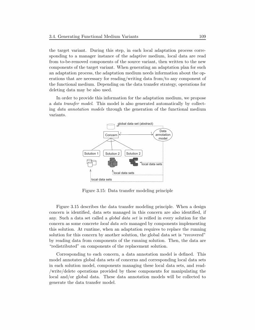
3.4. Generating Functional Medium Variants 109
the target variant. During this step, in each local adaptation process corre-sponding to a manager instance of the adaptive medium, local data are readfrom to-be-removed components of the source variant, then written to the newcomponents of the target variant. When generating an adaptation plan for suchan adaptation process, the adaptation medium needs information about the op-erations that are necessary for reading/writing data from/to any component ofthe functional medium. Depending on the data transfer strategy, operations fordeleting data may be also used.
In order to provide this information for the adaptation medium, we proposea data transfer model. This model is also generated automatically by collect-ing data annotation models through the generation of the functional mediumvariants.
Concern
Solution 1 Solution 2 Solution 2
Data annotation
model
local data sets
local data sets
local data sets
global data set (abstract)
1 1
Figure 3.15: Data transfer modeling principle
Figure 3.15 describes the data transfer modeling principle. When a designconcern is identified, data sets managed in this concern are also identified, ifany. Such a data set called a global data set is reified in every solution for theconcern as some concrete local data sets managed by components implementingthis solution. At runtime, when an adaptation requires to replace the runningsolution for this concern by another solution, the global data set is “recovered”by reading data from components of the running solution. Then, the data are“redistributed” on components of the replacement solution.
Corresponding to each concern, a data annotation model is defined. Thismodel annotates global data sets of concerns and corresponding local data setsin each solution model, components managing these local data sets, and read-/write/delete operations provided by these components for manipulating thelocal and/or global data. These data annotation models will be collected togenerate the data transfer model.
110 3. Adaptive Medium Approach
The data annotation models are defined by the solution designer when defin-ing solution models. Here, we assume that every component that manages dataimplements read/write/delete operations for manipulating local and/or globaldata.
3.4.6 Modeling Reconfiguration Constraints
The objective of modeling reconfiguration constraints is to provide informationfor the adaptation medium to identify require-constraints between adaptationactions when planning adaptations. “Action A requires action B” means A mustbe executed after the execution of B is finished. As described in Section 3.3,different synchronization barriers exist that separate the six adaptation steps.Therefore, require-constraints only exist between adaptation actions in the sameglobal step. Moreover, these constraints typically exist between components ofthe same solution model.
Similar to the data transfer modeling, reconfiguration constraints betweenelements of every solution model are also annotated. These annotations will becollected later when generating variants of the functional medium. To thisend, corresponding to each solution, a model of reconfiguration constraintsis defined. This model describes require-constraints between actions such asloading/removing, connecting/disconnecting, and initializing components or ob-jects. These actions are related to reconfiguration activities of the solution,therefore, the model of constraints is called solution reconfiguration constraintsmodel. These constraints are necessary not only for reconfiguration, but also forthe deployment of the solution. Consequently, they should be provided togetherwith the solution model. The solution reconfiguration constraints model thuscan be considered as a part of the solution model.
When generating variants of a functional medium, all the reconfigurationconstraints models of all the solution models are collected to generate a mediumreconfiguration constraints model. This model will be used by the adaptationmedium at runtime to plan adaptations.
In the presence of the reconfiguration constraints, solution introductiontransformations in the medium refinement process are also adapted. Such atransformation should include operations for checking whether a solution isvalid in terms of its constraints. Precisely, its constraints must not form anycycle.

3.4. Generating Functional Medium Variants 111
3.4.7 Discussion
We have presented above the generation of functional medium variants, theirarchitectural models, and adaptation-facilitating models. The generation ex-tends the medium refinement process. The key extension is the MCV modelingthat is strongly related to the modularization step. Other extensions includethe data transfer modeling and the reconfiguration constraints modeling.
On the Concept of Modularity
The MCV model is fully integrated with the original medium refinementprocess. It facilitates the refinement process by visualizing and constraining de-sign concerns and solutions. Moreover, the MCV model is used as a key inputof the modularization transformation naturally appended to the refinement. Byrepresenting commonality and variability, the MCV model also enables betteridentification of common and different components of medium variants gener-ated from the refinement process.
In fact, the commonality and the variability are only useful when the mod-ularity is well supported. Unfortunately, despite of being a long-term researchactivity, modularization of software is not always efficiently realized since con-cerns are often interleaved [Tarr 99]. Recently, research approaches in Aspect-Oriented Programming (AOP [Kiczales 97]) have proposed better solutions tosoftware modularity, such as aspect components [Ubayashi 07, Pessemier 08].Nevertheless, researchers in the AOP research community are dealing with theirown challenges such as aspect interference [Aksit 09]. Separation of concerns isthus still far from resolved. That is to say, the fine-grained adaptation is notalways realized efficiently. In the worst case where the manager componentsare not separable into smaller ones, the whole medium will be replaced whenperforming adaptations. We call these adaptations coarse-grained adaptations.
Our approach is component-platform-independent, the concept of modular-ity could be personalized according to the target component platform chosenfor the development.
On the Automation Degree of the Approach
The adaptive medium approach is highly automated thanks to a (very) high-level abstraction and its automated refinement process. However, the approachstill requires some manual tasks, including annotating (but not implementing)operations for data transfer and indicating solution reconfiguration constraints.These tasks are assigned to the solution designer. By defining data annotationmodels and reconfiguration constraints models for only a limited number of

112 3. Adaptive Medium Approach
solutions and concerns, the approach can support adaptation planning for alarge number of functional medium variants that are built by multiplying andcombining solutions. Moreover, the activities of defining data annotation modelsand reconfiguration constraints models are organized as activities of the domainengineering process. Results of these activities are reusable. That is, thesemanual tasks do not importantly affect the automation degree of the approach.
3.5 Composing the Adaptive Medium
In this section, we present the architecture of the adaptive medium implemen-tation that is composed of the adaptation medium and functional medium im-plementation.
3.5.1 Adaptive Medium Architecture
Figure 3.16 presents the architecture of the adaptive medium at the componentlevel. The adaptive medium is represented as a logical aggregation of distributedcomponents called adaptive managers. Each adaptive manager is composed ofa functional manager component of the selected functional medium variant andan adaptation manager component of the selected adaptation medium imple-mentation. While the functional manager components collaborate to realizefunctional medium services, the adaptation managers collaborate to coordinatethe adaptation actions on the functional manager components when perform-ing adaptation. Each adaptation manager directly reconfigures the functionalmanager it is associated with.
The figure also depicts model manager components, one per adaptationmanager. These components are the implementation that manages the modelsset described as an attribute of the adaptation medium class in the UML classdiagram in Figure 3.4. Again, we do not put any constraint on this implemen-tation.
As presented in Section 3.3, the model managers manage the architecturalmodels of functional medium variants and the adaptation-facilitating models.The architectural models include a runtime one that is built based on the archi-tectural model of the running functional medium variant. This runtime modelalso contains runtime information of the system such manager cardinality andthe localization of manager instances. Runtime changes on the running variantare reported to the model manager. On the other hand, all the models are usedby the adaptation medium to adapt the running functional medium.

3.6. Approach Summary and Discussion 113
Adaptation
Manager
Functional
Manager
Functional
Manager
Adaptation
Manager
Site 1 Site 2
Adaptive manager Adaptive manager
Functional
communication
Adaptation
coordination
Adaptive medium
Model
Manager
Model
Manager
Figure 3.16: Adaptive medium architecture
3.5.2 Discussion
Components are made to be composed. A simple way to compose componentsis to define a new component from the assembly of the others. It consistsin a “simple” juxtaposition of components that are linked together thanks tocomposing connectors. The composition semantics is highly dependent on thesemantics of the connectors.
Beyond that simple assembly, our composition approach which could becalled an integration consists in a weaving of components that relies on a deepunderstanding of their architecture. This understanding relying on the mediumarchitecture and process promotes the separation of the functional and the adap-tation aspects of the target adaptive distributed application, allows focussingon designing solution of each aspect, and reinforces the integration of thesesolutions.
3.6 Approach Summary and Discussion
This section summarizes the adaptive medium approach, discusses the case ofmultiple adaptive medium applications, and revisits the six challenges and thetwo key issues to explain how the adaptive medium approach responds to thechallenges.

114 3. Adaptive Medium Approach
3.6.1 Approach Summary
We have presented the adaptive medium approach to developing adaptive dis-tributed applications. The approach can be summarized by the following keypoints:
• The medium abstraction is extended to specify the adaptive medium ab-straction. In addition to functional behaviors of the original medium, weintroduce adaptation behavior into the medium, then, make it becomean adaptive medium. The adaptation behavior is also encapsulated intoan adaptation medium. The adaptive medium is thus composed of thefunctional medium and the adaptation one.
• The adaptation medium is developed as an adaptation control infrastruc-ture that is reusable for every functional medium. Thanks to the mediumapproach, several implementations of the adaptation medium can be built.
• The medium refinement process is extended to generate different func-tional medium implementation variants. An adaptation is realized bychanging the running variant of the functional medium.
• The feature modeling method is extended to build MCV models. Sucha model is used for the generation of a functional medium’s implemen-tation variants. The model represents the modularity, commonality, andvariability of these variants. It is used in the generation to automate themodularization of the variants into components. It is also used at runtimeto automate the adaptation planning.
• Data transfer modeling and reconfiguration constraints modeling are pro-posed to support the automatic generation of adaptation plans. Such aplan is composed of local adaptation plans and an adaptation coordina-tion plan. The local adaptation plans contain actions such as adding,removing, starting, stoping, initializing, reading and writing data from/tocomponents. The adaptation coordination plan contains constraints be-tween the actions of the local adaptation plans.
The adaptive medium approach is inspired by some fundamental approachesin software adaptation, such as architecture-based adaptation and externaliza-tion of adaptation control.
From another point of view, the adaptive medium approach combines Model-Driven Architecture and Generative Software Development. The MDA patternhas been extended in the medium refinement process that is (semi)automated

3.6. Approach Summary and Discussion 115
thanks to model transformations. Moreover, functional medium variants areconsidered as product members of a product family. Feature-based variabilitymodeling is extended to capture modularity, commonality, and variability ofthe variants. Domain engineering and application engineering processes areseparated to improve reuse and automation.
3.6.2 Multiple Adaptive Mediums Applications
For the sake of simplicity, in the adaptive medium approach presented above,we consider single adaptive medium applications only.
As presented in Section 2.5, a distributed application may be built by in-terconnecting several mediums and client components. Each medium providescommunication services for some client components. Accordingly, an adaptiveapplication may be also built as an interconnection of several adaptive mediumsand client components. Each adaptive medium provides functional communica-tion services to some client components. Moreover, each adaptive medium canchange its running implementation variant to adapt to changes of the operatingenvironment.
This case does not require any modification in the development of adaptivemedium presented above. Indeed, in an application using several (functional)mediums, each medium is specified as a single entity and is developed indepen-dently from other mediums and client components. There does not exist anycommunication between different mediums. Therefore, the activities of plan-ning and executing adaptation actions on a functional medium do not affectthose on any other medium.
However, since the adaptive mediums of an application operate in the sameenvironment or in environments that are strongly related, the activities of ob-serving operating environment(s) and making adaptation decisions may requirecoordination between the observers/deciders of different adaptive mediums.This coordination is also required when the whole application has some globalobjectives that entail global adaptation policies.
When considering multiple mediums applications, an interesting case is thata medium can be a role of another medium. This case raises a higher level ofsoftware composition. Nevertheless, this is not in the focus of this thesis.
3.6.3 Challenges Revisited and Discussion
In the adaptive medium approach, we have investigated the two identified keyissues by extending the medium as an abstraction and the medium refinement
116 3. Adaptive Medium Approach
process. To explain this choice, we proposed the two questions correspondingto the two key issues, and then, presented the adaptive medium approach inthe way that answers these questions. We argue that the approach overcomesthe six challenges identified in Chapter 1.
The challenges and questions are summarized as follows:
• Challenge C1: Supporting consistent architectures of the system.
• Challenge C2: Transferring system state.
• Challenge C3: Modeling commonality and variability.
• Challenge C4: Supporting automatic adaptation planning.
• Challenge C5: Supporting distributed adaptations.
• Challenge C6: Automating the development of adaptive software.
• Question Q1 (corresponding to key issue K1): What is the abstraction ofan adaptive distributed application?
• Question Q2 (corresponding to key issue K2): How does the developmentprocess allow the adaptation control part to understand and reconfigurethe functional one?
The adaptive medium approach responds to the questions and challengesby combining different solutions. By Table 3.1, we conclude this chapter bydescribing the proposed solutions along with the questions and challenges theyaddress. We also distinguish reused solutions, our contributions as extensionsof existing solutions, and our contributions as new solutions.

3.6. Approach Summary and Discussion 117
Solution C1 C2 C3 C4 C5 C6 Note
Q1/K1 - Abstraction
Medium as anX X X
Reusesabstraction [Cariou 03]
Adaptive mediumX X X
Extends [Cariou 03]as an abstraction and [Garlan 04]
Q2/K2 - Process
Original mediumX X
Reusesrefinement process [Kabore 08a]
MCV modeling X X XExtends[Kang 90]
AutomatedX X New
modularization
Data transferX X X X X New
modeling
ReconfigurationX X X X New
constraints modeling
The whole adaptiveX X X X X X New
medium approach
Table 3.1: Adaptive medium approach summary

118 3. Adaptive Medium Approach

Chapter 4
Adaptive Medium
Development Process
Contents
4.1 Chapter Overview . . . . . . . . . . . . . . . . . . . . 119
4.2 Development Process Overview . . . . . . . . . . . . 120
4.3 File Sharing Adaptive Medium . . . . . . . . . . . . 123
4.4 Step 1: Specification . . . . . . . . . . . . . . . . . . 124
4.5 Step 2: Transformation . . . . . . . . . . . . . . . . . 134
4.6 Step 3: Generation . . . . . . . . . . . . . . . . . . . 140
4.7 Step 4: Composition . . . . . . . . . . . . . . . . . . 165
4.8 Adaptation in the Adaptive Medium . . . . . . . . . 166
4.9 Development Process Summary and Discussion . . 171
4.1 Chapter Overview
In this chapter, we formulate the adaptive medium development process withdetailed steps in which tasks of adaptive medium engineers are clarified. Thanksto this process, the adaptive medium approach presented in the previous chapteris clarified.
First, Section 4.2 provides an overview of the process, including a descriptionof four roles for adaptive medium engineers and four steps of the developmentprocess. Next, Section 4.3 presents the example of the file sharing adaptivemedium used to illustrate the process. Then, Sections 4.4, 4.5, 4.6, 4.7 detail
119

120 4. Adaptive Medium Development Process
the four development steps using this example. Then, Section 4.8 describes howadaptations are realized in adaptive mediums. Finally, Section 4.9 summarizesthe development process and gives some discussions.
4.2 Development Process Overview
First, we briefly describe the facilities that support the development process.Then, we show how the facilities are used by presenting activities of differentsoftware engineers involved in the development process.
4.2.1 Facilities for Developing Adaptive Mediums
We identified four roles for adaptive medium engineers, based on the four rolesfor medium engineers in the medium approach (Section 2.5). The identifiedroles include application designer, process designer, medium expert, and solutiondesigner. In the development process of an adaptive medium, they collaborateto develop the target adaptive medium implementation by using the followingfacilities:
• A basic facility that contains a set of basic meta-models and transforma-tions, including 1) five medium meta-models at the five abstraction levelspresented in the architecture view of the functional medium variants gen-eration process (Section 3.4), 2) early and fine-grained MCV meta-models,3) the manager introduction, the feature refinement, and the feature-basedmodularization transformations, and 4) a main transformation that exe-cutes all the necessary transformations to generate functional mediumvariants at level 4.
• A concern catalogue that contains reusable design concerns and designconcern usage patterns. For each concern, a solution meta-model anda solution introduction transformation are provided (Section 2.5). Theconcern catalogue may also contain concern usage patterns describing howconcerns and solutions could be used.
• A set of adaptation medium implementations, each one is reusable forevery adaptive medium. This set is extensible.
• A composition program that composes the target adaptive medium imple-mentation from a functional medium variant and an adaptation mediumimplementation.
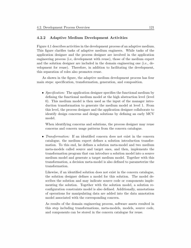
4.2. Development Process Overview 121
4.2.2 Adaptive Medium Development Activities
Figure 4.1 describes activities in the development process of an adaptive medium.This figure clarifies tasks of adaptive medium engineers. While tasks of theapplication designer and the process designer are involved in the applicationengineering process (i.e, development with reuse), those of the medium expertand the solution designer are included in the domain engineering one (i.e., de-velopment for reuse). Therefore, in addition to facilitating the development,this separation of roles also promotes reuse.
As shown in the figure, the adaptive medium development process has fourmain steps: specification, transformation, generation, and composition.
• Specification: The application designer specifies the functional medium bydefining the functional medium model at the high abstraction level (level0). This medium model is then used as the input of the manager intro-duction transformation to generate the medium model at level 1. Fromthis level, the process designer and the application designer collaborate toidentify design concerns and design solutions by defining an early MCVmodel.
When identifying concerns and solutions, the process designer may reuseconcerns and concern usage patterns from the concern catalogue.
• Transformation: If an identified concern does not exist in the concerncatalogue, the medium expert defines a solution introduction transfor-mation. To this end, he defines a solution meta-model and two mediummeta-models called source and target ones, and then, implements thetransformation program that can introduce a solution model into a sourcemedium model and generate a target medium model. Together with thistransformation, a decision meta-model is also defined to parameterize thetransformation.
Likewise, if an identified solution does not exist in the concern catalogue,the solution designer defines a model for this solution. The model de-scribes the solution and may indicate source code or components imple-menting the solution. Together with the solution model, a solution re-configuration constraints model is also defined. Additionally, annotationsof operations for manipulating data are added into the data annotationmodel associated with the corresponding concern.
As results of the domain engineering process, software assets resulted inthis step including transformations, meta-models, models, source code,and components can be stored in the concern catalogue for reuse.

122 4. Adaptive Medium Development Process
Domain engineering Application engineering
Medium expert Solution designer Process designer Application designer
Ste
p 1
:
Specific
ation
Ste
p 2
:
Tra
nsfo
rmation
Ste
p 3
:
Ge
ne
ratio
n
Ste
p 4
:
Com
positio
n
Identify medium at level 0
Generate medium at level 1
Identify concerns and solutions by defining an early MCV model
Identify medium variants
OK?
Yes
No
Newconcerns
?
Newsolutions
?
For each concern: Define 1
transformation Define 1 solution
meta-model Define 2 medium
meta-models Define 1 decision
meta-model
Yes
No For each solution: Define a
solution model Define a solution
reconf. constr. model
Add information into data anno-tation model
Identify feature constraints and feature properties
Generate a fine-grained MCV model
Yes
No
Define a process model
Generate medium variants at level 4, a data transfer model, a medium reconf. constr. model
Composeadaptive medium implementation
Concerncatalogue
preserve for reuse
pla
n t
o r
euse
Figure 4.1: Activities in the development process of an adaptive medium

4.3. File Sharing Adaptive Medium 123
• Generation: The process designer identifies affect-constraints between fea-tures of the early MCV model and concrete features. Then, he uses thefeature refinement transformation to generate a fine-grained MCV model.
Next, the process designer defines an explicit generation process modelthat indicates all the necessary transformations. This model is used bythe main transformation to generate functional medium variants at thelevel of component-implementation (level 4). A data transfer model anda medium reconfiguration constraints model are also generated automati-cally by collecting information of the related data annotations models andsolution reconfiguration constraints models, respectively.
• Composition: The application designer selects an implementation variantof the adaptation medium and the initial one of the functional medium,and then, uses the composition program to compose the target adaptivemedium implementation.
The separation of roles for adaptive medium engineers makes the develop-ment easier. The application designer and the process designer do not need tobe aware of model transformation techniques, they just need to specify the func-tional medium at level 0, choose existing design concerns and design solutions,and possibly send requests to the medium expert or the solution designer whenthe needed concerns or solutions do not exist. Although this separation assignsmost of the complex tasks to the medium expert, the result of these tasks arereusable. Therefore, the development process does not require a permanenteffort of the medium expert and the solution designer.
The remainder of this chapter details these four steps using an illustrativeexample. In each step, we clarify the concepts and tasks mentioned above.
4.3 File Sharing Adaptive Medium
Consider the file sharing application using the FS medium described in Sec-tion 2.5.1.2. There may exist several application implementation variants inwhich data are managed differently.
For example, when the FS application is deployed in a client-server system, acentralized variant can be used. In this variant, data are placed on a centralizedserver. User-side application’s parts can connect to the server to insert, searchfor, get, or remove data.
When the number of users increases, the server with limited transmissioncapacity may not be able to respond to numerous requests from clients. To

124 4. Adaptive Medium Development Process
resolve this problem, a distributed servers architecture can be used ([Chan 01]).Data are now distributed over some servers, with or without replication. Thisarchitecture helps to divide the requests coming from clients among these dis-tributed servers.
Another variant concerns a peer-to-peer approach where a shared file canbe placed at the sharers that are considered as peers. Data for localizing sharedfiles may be placed on a centralized server, distributed among some servers,or also distributed among peers using advanced peer-to-peer algorithms such asDHT and CAST [Dabek 03]. A user at a peer can connect to the server(s) or usepeer-to-peer algorithms to search for files he is interested in, ask the server(s)where the files are, and directly get these files from the peers where they areshared. This distribution of data among peers is used in some real-world FSsystems such as eMule [eMule].
As discussed above, each of these variants can be appropriate for some spe-cific conditions of the operating environment or user requirements. When theseconditions or requirements change, the FS application may need to switch froma variant to another one in order to adapt to new conditions. Moreover, thisadaptation should be performed dynamically to reduce the downtime of appli-cation services. It is therefore interesting to develop an FS adaptive applicationthat can change dynamically its running variant.
The variants presented above are mainly concerned with the communica-tion between distributed components of the application to manage shared data.Since this communication is abstracted as the FS medium (described in Fig-ure 2.6), the FS adaptive application thus can be specified as the interconnec-tion of the distributed sharer and remover client components and an FS adaptivemedium.
In the following sections, we use this example to present precisely the foursteps of the adaptive medium development process.
4.4 Step 1: Specification
This step includes the following tasks:
• specifying the functional medium abstraction by defining the functionalmedium model at level 0,
• specifying the target implementation architecture of the functional mediumby introducing managers into the medium model at level 0, then generat-ing the one at level 1,

4.4. Step 1: Specification 125
• identifying concerns and solutions by defining an early MCV model inwhich concerns and solutions are represented as features, and identifyingthe desired functional medium variants as feature configurations in thisearly MCV model.
While the first task is realized by the application designer, the second oneis realized by the process designer. The last one is also realized by the processdesigner, but its result is validated by the application designer.
4.4.1 Specifying the Functional Medium Abstraction
Identifying the functional medium abstraction consists in identifying the bor-der that separates the functional medium and the client components in thedistributed application. This includes identifying medium’s roles (type of clientcomponents) and services that are provided and required by the medium. Theidentification of the FS medium has been presented previously in Section 4.3.
1
1..*<<abstraction>>
FileSharing Medium
File Object
Sharer
Remover +files
<<interface>> RemoverMediumServices
Boolean remove(FileId)
File Property
FileId *
1
-ow
nin
gId
s
+fileId
+fileProperties
*
*
<<interface>> SharerMediumServices
FileId insert(FileObject,FileProperty[]) FileObject getACopy(FileId) FileId[] search(FileProperty)
Figure 4.2: Class diagram of the FS medium at level 0
After identifying roles and medium’s provided and required services, theapplication designer defines a medium model at level 0. Figure 4.2 shows thismedium model that is described as a UML class diagram, called FSL0. Inthe diagram, the FileSharingMedium class represents the FS medium as an

126 4. Adaptive Medium Development Process
abstraction that provides the SharerMediumServices and RemoverMediumSer-vices interfaces to the Sharer and Remover classes representing the two roles,respectively.
When sharing a file, the sharer uses the insert service provided by the FSmedium to insert the file as well as properties of this file into the system. Themedium also provides the search service that returns an identifier list of the filesthat match some given properties. If the user is interested in a file, he can geta copy of this file using the getACopy service. Similarly, the remover can usethe remove service to remove any file from the system.
As presented in the figure, the FS medium manages two data sets: the filesset of shared files and the fileProperties set of the shared files’ properties. TheFileObject class represents a file that has an identifier (fileId) implemented bythe FileId class. The FileProperty class describes a file property that containsa property type and a property value, each file property object (instance of theclass) has a list of file identifiers indicating the files that have this property(owningIDs).
4.4.2 Specifying the Implementation Architecture
Once the functional medium model at level 0 is defined, the process designer usesthe manager introduction transformation to generate the functional mediummodel at level 1. This model conforms to the medium meta-model at level 1(Figure 2.10).
Figure 4.3 describes the FS medium model at level 1, called FSL1. In thismodel, the SharerManager and RemoverManager classes have been inserted.These classes allow early localization of medium services, and then, prepare thelocalization of the services’ implementations.
4.4.3 Identifying Concerns and Solutions
After generating the functional medium model at level 1, the process designeridentifies design concerns and solutions by defining an early MCV model inwhich they are represented as features, called concern features and solutionfeatures. The features representing the solutions for a concern are organized asa child feature xor-group of the feature representing that concern. Within theearly MCV model, the terms “a concern” and “a solution” refer to a concernfeature and a solution feature, respectively.
When identifying concerns and solutions for the FS adaptive medium, aconcern usage pattern available in the concern catalogue has been reused.

4.4. Step 1: Specification 127
SharerManager
1
1..*
<<interface>> SharerMediumServices
<<interface>> RemoverMediumServices
Remover Manager
Sharer
Remover
1 1
1 1 File
Object +files
File Property
FileId *
1
-ow
nin
gId
s
+fileId
+fileProperties
*
*
<<abstraction>> FileSharing
Medium
Figure 4.3: Class diagram of the FS medium at level 1
4.4.3.1 Data Management Concern Usage Pattern
Figure 4.4 presents a concern usage pattern (called data management concernusage pattern) as an early MCV model. The management of a data set is called<data>DataManagement where <data> implies the name of the data set tobe managed. This data management is considered as a design concern andis represented as the root concern feature (f0). It is decomposed into otherfeatures representing the following concerns and solutions:
• <data>AbstractType: This design concern is related to the implementa-tion of the abstract type for representing the data management. Thischoice determines the provided services of the data management.
This concern is represented as a mandatory solitary feature (f2) that isa child feature of the root. Solutions for this design concern such as List(f5) and Tree (f6) are represented as xor-group solution features.
• <data>DataPlacement : This design concern is related to the question ofhow the data are placed among distributed sites. While the implemen-tation of the data management (root) concern provides a variable set ofdata services according to the selected abstract type solution, the imple-mentation of the data placement provides a minimum set of data services(such as insert and remove a data item) for the data placement.

128 4. Adaptive Medium Development Process
This concern is represented as a mandatory solitary feature (f1), anotherchild feature of the root.
Solutions for this concern are separated into two categories, representedby two concern features f3 and f4 that form a child feature xor-group off1. While the first category contains simple data placement solutions, thesecond one includes advanced distributed algorithms.
The simple data placement category contains the following solutions: 1)the CentralizedServer (f7) in which the data are placed on a centralizedserver, 2) the DistributedServers solution (f8) in which the data are dis-tributed among some distributed servers, and 3) the Peers solution (f9)in which the data are placed on every peer where the data managementis deployed.
The advanced algorithm category contains Chord (f10) and Pastry (f11).In the medium approach, Kabore proposed a meta-model of distributedalgorithms and an associated transformation. The meta-model is based onan abstraction of distributed hash tables (DHT) described in [Dabek 03].In this project, Dabek et al. specified a common API for the DHT ab-straction and two other ones called CAST (group anycast and multicast)and DOLR (distributed object location and routing) - three key abstrac-tions built on structured peer-to-peer overlays. Thanks to this commonAPI, different distributed algorithms can be defined by using a commonmeta-model.
Among the five data placement solutions described above, f8 and f9 raisea new concern: the placement of the data used to localize <data>’s dataitems. In the DistributedServers solution, these data may be necessarywhen the number of servers is large, the feature representing the newconcern for this solution is then optional (f12). On the other hand, thesedata are always required in the Peers solution, the feature representingthe new concern is thus mandatory (f13).
• <<data>LocalizationData>DataPlacement : This concern is duplicatedand represented by f12 and f13 in the early MCV model. It is an adaptedversion of the <data>DataPlacement concern. However, the Distributed-Servers solution (f17) does not raise any new concern, and the Peers onedoes not exist.
In an early MCV model, a concern is called composite if it is directly decom-posed into other concerns (e.g., f0 and f1), or primitive otherwise (e.g., f2, f3,and f4). A primitive concern is always decomposed into solutions as its childgrouping features. For a primitive concern, a solution introduction transforma-

4.4. Step 1: Specification 129
tion is provided. But such a transformation can be used for several primitiveconcerns.
<data> DataManagement
<data> DataPlacement
<data> AbstractType
Tree
Centralized Server
List
Distributed Servers
Peers
<<data>LocalizationData> DataPlacement
<data> AdvancedAlgorithm
Concern feature
Solution feature
xor-group mandatory
optional
<data> SimpleDataPlacement
<<data>LocalizationData> DataPlacement
<<data>LocalizationData> AdvancedAlgorithm
Centralized Server
Distributed Servers
<<data>LocalizationData> SimpleDataPlacement
Chord Pastry
Chord Pastry
f0
f1 f2
f3 f4
f7 f8 f9
f5 f6
f10 f11
f12 f13
f14 f15
f16 f17f18 f19
Figure 4.4: Data management concern usage pattern
For example, in the early MCV model of the concern usage pattern de-scribed above, 3 transformations (i.e., abstract type, simple data placement,and advanced algorithm introduction transformations) are defined for 7 primi-tive concerns, including f2, f3, f4, f14, f15, and 2 child concern features of f12
that are not depicted in the figure. In a particular medium, this pattern can becustomized for reuse.

130 4. Adaptive Medium Development Process
4.4.3.2 Application of the Pattern to the FS Medium
This section presents how the process designer could identify concerns and so-lutions for the FS medium. When adopting the adaptive medium developmentprocess, the process designer may have other separations of concerns as well asother choices of solutions.
The data management concern usage pattern presented above can be reusedfor the FS system. Indeed, from the description of the FS system in Section 4.3,we can identify two data sets: files and fileProperties. Although these two setsare strongly related, they have different particularities such as the size of dataitems. Therefore, they should be managed separately in order to support flexibleevolutions and adaptations of the medium. The data management concern usagepattern thus can be applied for the management of these two data sets.
Figure 4.5 depicts the early MCV model of the FS medium. The FS medium,represented as the root feature (f0), is decomposed into two mandatory concernfeatures: <files>DataManagement (f1) and <fileProperties>DataManagement(f21). Unlike the former that employs the whole data management concern us-age pattern, our choice for the latter excludes the <<data>LocalizationData>-DataManagement concern because we consider that data items of filePropertiesare usually small.
Generally, in an early MCV model, exclude- and/or imply-constraints be-tween features may be defined. For example in Figure 4.5, if the process designerconsiders that it is not necessary to place file properties in distributed sites whenshared files are placed on a centralized server, feature f8 can imply feature f28.However, in the early MCV model of the FS medium, we do not define anyimply- or exclude-constraint.
When defining the early MCV model, global data sets associated with theconcern features are also explicitly identified. In the early MCV model of theFS medium, the files data set is associated with features f0, f1, f3, f6, andf7; the fileProperties data set is associated with f0, f21, f22, f24, and f25;the <files>LocalizationData data set is associated with f14, f15, and f16; andanother data set is associated with f13 and its two child concern features thatare not depicted in the figure.
4.4.3.3 Identifying Functional Medium Variants
After identifying design concerns and solutions as features of the early MCVmodel, the process designer identifies desired functional medium variants asfeature configurations. Such a configuration forms a subtree of the MCV model.It contains features selected from the early MCV model according to semantics

4.4. Step 1: Specification 131
<fileProperties> DataManagement
FileSharing Medium
<files>DataManagement
<files>DataPlacement
<files>AbstractType
Tree List
<fileProperties> DataPlacement
<fileProperties> AbstractType
List Tree
Chord Pastry
<fileProperties> AdvancedAlgorithm
<fileProperties> SimpleDataPlacement
f28 f29
Centralized Server
Distributed Servers
Centralized Server
Distributed Servers
Peers
<<files>LocalizationData> DataPlacement
<<files>LocalizationData> DataPlacement
<<files>LocalizationData> AdvancedAlgorithm
Distributed Servers
<<files>LocalizationData> SimpleDataPlacement
Chord Pastry
f8 f9 f10 f11 f12
f13 f14
f15
f17 f18f19
Centralized Server
f0
f1
f2
f3
f4
<files>AdvancedAlgorithm
<files>SimpleDataPlacement
f6 f7
Chord Pastry
f5
f16
f20
f21
f22 f23
f24
f25
f26 f27
f30 f31
Figure 4.5: Early MCV model of the FS medium

132 4. Adaptive Medium Development Process
of the model’s notations.
For example in Figure 4.5, feature configuration {f0, f1, f2, f3, f5, f6, f10,f14, f16, f19, f21, f22, f23, f25, f26, f30} corresponds to the FS medium variantin which the files and fileProperties sets are represented as abstract lists, sharedfiles are distributed among peers, and file localization data and file propertiesare managed using the Chord algorithm. We called this FS medium variantFSV 1.
4.4.3.4 Early MCV Meta-model
Feature Meta-Model
As discussed in Section 2.3.2.4, there exist various research projects thatproposed different forms of feature models that are adapted to the needs ofthese projects. In this thesis, we use and extend the basic form of featuremodels described by Czarnecki in [Czarnecki 00]. In their basic form, featuremodels contain mandatory or optional solitary features, grouping features asor-groups or xor-groups, and imply-/exclude-constraints.
The upper-half of Figure 4.6 describes the basic feature meta-model. Abasic feature model is a tree of features. The root of the tree represents theroot feature. Each node of the tree corresponds to a feature that can be de-composed into other features by decompositions. From a source feature, such adecomposition may derive a solitary feature or a group of features, called targetfeature(s). The relation between the source feature and the target one(s) is thena parent-child relation in the tree of features. A solitary feature can be manda-tory or optional and a feature group can be or-group or xor-group. Between twofeatures, there may exist constraints including imply- and exclude-constraints.
Early MCV Meta-Model
The lower-half of Figure 4.6 expresses the early MCV meta-model. In the fig-ure, the EarlyMCVModel class represents a medium MCV model as an extendedfeature model. It contains design concerns and design solutions as features. Themedium is the root concern feature of the MCV model. The MediumVariantclass represents a medium variant that indicates a feature configuration.
When identifying a concern or a solution, the process designer also specifyto which role manager(s) (RoleManager) this concern or this solution is related.For example, in the early MCV model of FS medium, all the concerns and solu-tions are related to both sharer and remover managers. Additionally, the globaldata sets (GlobalData) must be explicitly identified. Precisely, each concern

4.4. Step 1: Specification 133
includes zero to many sets. Such a set may be cloned or divided into subsetsin other concerns. For instance, in the FS medium early MCV model, each offive concerns f0, f1, f3, f6, and f7 includes a global data set named files. Theset included in each concern (except f0) is cloned from the one included in theparent concern.
+source
Feature
FeatureModel
Decomposition
GroupingFeature Decomposition
SolitaryFeature Decomposition
+ isMandatory + /isOptional
Constraint
Imply Exclude
+source
+target
+out
+in
1
1..*
0..*
0..1
+ target
1
1+out 0..*
0..*
+in
1..* +feature +decomposition 0..*
0..* +constraint
OrGroup
Xor Group
1
1
{subsetsfeature}
+root
+in 0..1
+target
EarlyMCVModel
{redefines root}
1..*
+feature
Design Concern
DesignSolution
+solution
1..*
1Medium
1
+concern
Role Manager
1..*
1..*
+variant +configuration
+medium
Medium Variant
+manager 1..*
+role
+role
0..*
0..*
Global Data
0..*
+globalData 0..*
0..*+subset
+cloned
Figure 4.6: Early MCV meta-model (lower-half) as an extension of a featuremeta-model (upper-half)
By extending the feature model as presented above, the early MCV modelcan describe how the functional medium is decomposed into design concerns aswell as how the choice of solutions for a concern may vary. It also explicitlydescribes how global data sets are specified. Moreover, the early MCV modelallows to identify target medium variants as feature configurations.

134 4. Adaptive Medium Development Process
4.4.4 Summary
We have presented the detailed activities in the specification step of the adap-tive medium development process. We have described the specifications of thefunctional medium at level 0 and level 1. We have also explained how thefeature modeling method is used at this early stage of the adaptive mediumdevelopment. Thanks to the method embodied in the early MCV model, theprocess designer can express the separation of concerns, the identification ofdesign solutions and medium variants in a visualized and structured way. Inother words, the early MCV model serves as a means to facilitate the activitiesin the specification step.
4.5 Step 2: Transformation
This step includes two tasks:
• defining solution introduction transformations and
• creating solution models.
The first one is realized by the medium expert and the second one by thesolution designer.
4.5.1 Defining Solution Introduction Transformations
The medium expert defines a solution introduction transformation correspond-ing to each concern that does not exist in the catalogue. This transformationintroduces a solution for this concern into the medium, and therefore, makesthe medium more concrete. To this end, the medium expert defines a solutionmeta-model and two medium meta-models called source and target ones, andthen, implements the transformation program. This transformation approachis proposed by Kabore in [Kabore 08a].
In the FS adaptive medium development, the medium expert may define3 transformations corresponding to the abstract type, advanced algorithm, andsimple data placement primitive concerns. In the remainder of this section,we describe the simple data placement introduction transformation in order toillustrate the methodology.
Simple Data Placement Introduction Transformation
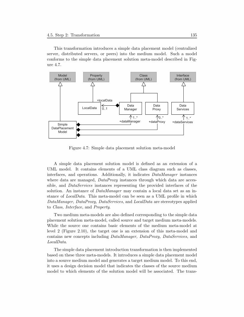
4.5. Step 2: Transformation 135
This transformation introduces a simple data placement model (centralizedserver, distributed servers, or peers) into the medium model. Such a modelconforms to the simple data placement solution meta-model described in Fig-ure 4.7.
DataManager
Class (from UML)
1..*
SimpleDataPlacement
Model
Interface(from UML)
0..*
Data Proxy
DataServices
Model (from UML)
1..*
+dataProxy +dataServices +dataManager
LocalData
Property (from UML)
0..1
+localData
Figure 4.7: Simple data placement solution meta-model
A simple data placement solution model is defined as an extension of aUML model. It contains elements of a UML class diagram such as classes,interfaces, and operations. Additionally, it indicates DataManager instanceswhere data are managed, DataProxy instances through which data are acces-sible, and DataServices instances representing the provided interfaces of thesolution. An instance of DataManager may contain a local data set as an in-stance of LocalData. This meta-model can be seen as a UML profile in whichDataManager, DataProxy, DataServices, and LocalData are stereotypes appliedto Class, Interface, and Property.
Two medium meta-models are also defined corresponding to the simple dataplacement solution meta-model, called source and target medium meta-models.While the source one contains basic elements of the medium meta-model atlevel 2 (Figure 2.10), the target one is an extension of this meta-model andcontains new concepts including DataManager, DataProxy, DataServices, andLocalData.
The simple data placement introduction transformation is then implementedbased on these three meta-models. It introduces a simple data placement modelinto a source medium model and generates a target medium model. To this end,it uses a design decision model that indicates the classes of the source mediummodel to which elements of the solution model will be associated. The trans-

136 4. Adaptive Medium Development Process
formation thus includes a design decision meta-model that can be seen as itsuser interface. Thanks to this interface, the process designer introduces parame-ters’ values when executing the transformation. This makes the transformationmore flexible and reusable in similar contexts. For example when generating FSmedium variants, the simple data placement introduction transformation can beused for the <files>DataPlacement, <<files>LocalizationData>DataPlacement,and <fileProperties>DataPlacement concerns. The solution meta-model, thesolution models, the medium meta-models, the decision meta-model, and thetransformation can be reused without any customization. Each time the trans-formation is executed, only a custom decision model is required.
4.5.2 Creating Solution Models
The solution designer creates a solution model corresponding to each solutionthat does not exist in the concern catalogue. He may also create a solutionreconfiguration constraints model and add information into a data annotationmodel.
Figure 4.8 includes the CentralizedServer, DistributedServers, and Peers so-lution models conforming to the meta-model presented in Figure 4.7. All thesemodels implement a common interface containing data services (<data>DataSe-rvices).
• CentralizedServer : In this solution model, class <data>Server representsthe server that manages all the data. This class provides an interface(<data>InternalServices) for the proxies represented by class <data>Proxy.
• DistributedServers: This solution model describes more than one serverand several proxies. Each server manages a subset (localData) of theglobal data set (i.e., no data replication), and a server can connect to otherservers through interface <data>InternalServices to access data managedby these servers.
• Peers: This solution model includes a symmetric implementation. Eachpeer (<data>Peer) manages a subset of the global data set, provides in-ternal services for other peers, and provides data services of the commoninterface. In fact, different data distribution policies may be implementedfor this solution. However, for the sake of simplicity, we ignore this vari-ation.

4.5. Step 2: Transformation 137
1
+server
<<DataManager>> <data>Server
<<DataProxy>> <data>Proxy
Data
<<DataServices>> <data>PlacementDataServices
<<interface>> <data>InternalServices
+data 1..*
+proxy
2..*
+server <<DataManager>>
<data>Server <<DataProxy>>
<data>Proxy Data
+localData 1..*
+proxy
1..*
1..*
1..*
<<DataManager>> <available>Peer
Data
+localData
1..*
1..*
<<DataServices>> <data>PlacementDataServices
<<interface>> <data>InternalServices
(b)
(a)
(c)
+ add(Item) + remove(ItemId) …
+ add(Item) + remove(ItemId) …
+ add(Item) + remove(ItemId) …
+ addLocal(Item) + removeLocal(ItemId) …
<<DataServices>> <data>PlacementDataServices
<<interface>> <data>InternalServices
+ add(Item) + remove(ItemId) …
+ addLocal(Item) + removeLocal(ItemId) …
Figure 4.8: Simple data placement models: a) centralized server data placement,b) distributed servers data placement, and c) peers data placement

138 4. Adaptive Medium Development Process
4.5.2.1 Defining Data Annotation Model
A data annotation model is defined for each primitive concern in which at leastone data set is identified. It conforms to a generic data annotation meta-model.This model contains annotations describing how data are managed and can bemanipulated in every solution for this design concern.
Design Concern
Design Solution
Operation Annotation0..1
1
Global Data
SolutionModel
+accessPoint
Class (From UML)
1..*
1..*
DataAnnotation Model
1
DataAccessPoint
Interface(from UML)
Operation (From UML)
0..1
0..10..1
1
1
1
1
1..*
1..*
1
+globalData +concern
+solution
1..*
+readGlobal
+readLocal
+deleteGlobal
+writeGlobal +accessPoint
+globalData +concern
+solution
ce
( )
C ode
( )
( )
+implemented
( )
ode
Figure 4.9: Data annotation meta-model (concepts of other meta-models are ingray)
Figure 4.9 describes the generic data annotation meta-model. The modelindicates a design concern and all the solutions for this concern. In this concern,one or several sets of data may need to be managed. These sets are abstract andrepresented by instances of GlobalData. In a solution, each set can be accessiblethrough some data access points (DataAccessPoint), each one indicates a setof operations. The data annotation model for a concern thus allows to “link”different data managements (in different solutions for this concern) of the sameglobal data set. Thereby, it facilitates transferring data between these solutions.
A DataAccessPoint instance includes a set of OperationAnnotation instancesthat are linked to the necessary operations, the interfaces containing these op-erations, and the classes implementing these interfaces. For example, the Dis-tributedServers solution in Figure 4.8 contains two data access points corre-sponding to two classes <data>Server and <data>Proxy. In a data accesspoint, the indicated operations include readLocal, readGlobal, writeGlobal, and
4.5. Step 2: Transformation 139
deleteGlobal. Operation readLocal returns a local data item managed directlyby the object where it is invoked. On the other hand, operation readGlobalreturns a data item of the global data set, operation writeGlobal allows to writea data item to the global data set, and operation deleteGlobal enables to deletea data item from the global data set. Thanks to these operations, different datatransfer strategies can be elaborated. For example, to transfer data managedby components of a solution to those of another solution, all the related nodes(where the components are deployed) can participate in the data transfer byreading local data of the replaced components and writing them to the replace-ment components. Another strategy is that only one node participates in thedata transfer by reading global data from the replaced components and writingthem to the replacement ones. This issue of data transfer will be presented indetail in Section 4.8.
The data annotation model corresponding to a concern is step by step com-pleted by the solution designer. When defining a solution model conformingto the solution meta-model for this design concern, the solution designer addsdata annotations into the data annotation model.
4.5.2.2 Defining Solution Reconfiguration Constraints Models
A solution reconfiguration constraints model may be defined for each solution(if there exist constraints). This model conforms to a generic solution reconfig-uration constraints meta-model described in Figure 4.10.
As described in the figure, a solution reconfiguration constraints model con-tains a set of require-constraints, each one indicates a requiring action and arequired action. The meta-model defines five types of actions: creating, starting,stopping, removing an object, and calling a method. In fact, all these actionsare related to method calls. Precisely, creating and removing an object are re-lated to calling construction and deconstruction methods. On the other hand,starting and stoping an object are related to method calls that activate anddeactivate object’s services while keeping the object running. By defining thesetypes of actions, constraints on objects of a solution can be easily transformedinto those on components of the medium variants at level 4.
4.5.3 Summary
We have presented the transformation step of the adaptive medium developmentprocess. In addition to defining solution introduction transformations as in theoriginal medium refinement process [Kabore 08a], we introduce a data anno-tation meta-model and a solution reconfiguration constraints meta-model, and

140 4. Adaptive Medium Development Process
SolutionReconfiguration ConstraintsModel
<<abstract>> ModelElement
Require Constraint
<<abstract>> RefectionFunction
0..1
0..*+requiring
+required
0..*
0..*
1
1
Solution Model
1
1..*
1..*
CreateObject
StartObject
StopObject
Remove Object
MethodCall
Figure 4.10: Solution reconfiguration constraints meta-model
describe how models conforming to these meta-models can be defined. This stepprovide important materials (including medium meta-models, medium models,solution meta-models, solution models, data annotation models, solution re-configuration constraints models, and model transformations) to generate func-tional medium implementation variants and adaptation-facilitating models.
4.6 Step 3: Generation
The main goal of this step is to generate functional medium variant modelsat level 4 and adaptation-facilitating models including a complete fine-grainedMCV model, a data transfer model, and a medium reconfiguration constraintsmodel.
To this end, the early MCV model is first refined in order to generate a fine-grained MCV model that is usable for the modularization transformation. Thistransformation is executed many times to transform functional medium modelsfrom level 3 to level 4. In such an execution, this transformation also linkscomponents of the generated medium model to features of the fine-grained MCVmodel, and thereby, completes this fine-grained MCV model. To execute all thenecessary transformations, an explicit generation process model is defined.
In this section, we present the refinement of the early MCV model. Next,we describe the modularization transformation. Then, we explain how data

4.6. Step 3: Generation 141
annotations are collected to build the data transfer model, and how solution re-configuration constraints are collected to build the medium reconfiguration con-straints model. Finally, we present the generation process model and describethe main transformation that generates functional medium variant models atlevel 4 and adaptation-facilitating models.
4.6.1 Refining the Early MCV Model
As a result of the specification step, the early MCV model contains “raw”information that needs to be refined in order to be usable for the modularization.While the modularization needs to identify components, the early MCV modelcontains features being design concerns and design solutions. Although a maingoal of separation of concerns is to separate software to modules, design concernsare not always and evidently corresponding to components because they caninterleave each other [Tarr 99]. By the refinement of the early MCV model, wetackle this problem in order to provide a mapping between the (fine-grained)MCV model’s features and medium variants’ components.
The refinement of the early MCV model is realized automatically by a fea-ture refinement transformation that transforms the early MCV model into thefine-grained MCV model. In the following sections concerning the feature re-finement, the term “MCV model” refers to the one that is being refined. It isnot fine-grained yet, but is not an early one since new concepts are introduced.
First, the refinement requires the process designer to identify concrete con-cerns and affect-constraints between concern features of the MCV model. Then,from these affect-constraints, derived solution features are automatically gener-ated and introduced into the MCV model. The MCV model containing thesenew concepts is called the fine-grained MCV model.
4.6.1.1 Identifying Concrete Design Concerns
Among the design concerns included in the MCV model, some are concrete andthe others are not. A concern is called concrete if its implementation can bemodularized into individual components. For instance, the implementation ofthe FileSharingMedium (f0) concern is modularized into its manager compo-nents. Similarly, the implementation of the <files>DataPlacement (f3) concerncan be modularized into distributed components, each one may manage localdata and all of them collaborate to realize the selected data placement solution.These two concerns are then called concrete. On the other hand, the implemen-tation of a not-concrete design concern is not separable into components. It istangled in components of other concrete design concerns.

142 4. Adaptive Medium Development Process
We also define some constraints for the identification of concrete concerns.First, the root concern feature is always concrete. Second, if a concern feature isconcrete, all of its grouping concern features, if any, are concrete. For example,in the FS medium early MCV model depicted in Figure 4.5, if f3 is concrete,f6 (<files>SimpleDataPlacement) and f7 (<files>AdvancedAlgorithm) are alsoconcrete. This is because when a concern grouping feature is selected for afeature configuration, it can be seen as the representation of the parent concernfeature that is concrete.
According to these principles, the process designer identifies all the concreteconcerns in the MCV model. In fact, this information is necessary to modularizemedium variants and is not required by the feature refinement transformation,but they facilitate the identification of affect-constraints.
4.6.1.2 Identifying Affect-constraints
A design concern called fm affects another design concern called fn if the im-plementation of fm has an impact on the implementation of fn. Consequently,when performing adaptation, changing the implementation of fm requires tochange the implementation of fn.
For example, the <files>AbstractType design concern (f2) may affect the<files>DataManagement one (f1) since the former defines the set of data ser-vices provided by the latter. By contrast, <files>DataPlacement (f3) does notaffect <files>DataManagement (f1) because the latter uses a minimum set ofdata services provided by the former and does not take into account how thedata are placed.
Once affect-constraints between features of the MCV model are identified,the feature refinement transformation generates derived solution features andimply-constraints.
4.6.1.3 Generating Derived Solution Features
In addition to modeling modularity, an important goal of identifying affect-constraints is to make the medium’s variability described in the MCV modelmore explicit. In the early MCV model, medium variability is represented byvariation points corresponding to the feature groups in the model. Nevertheless,as discussed above, the implementation of the <files>DataManagement concern(f1) also needs to be changed when the implementation of the <files>Abstract-Type concern (f2) is changed since the latter concern affects the former one.That is, a concern that does not have child feature group(s) can be also avariation point.

4.6. Step 3: Generation 143
To introduce these new variation points into the MCV model, we use theconcept of derived solution feature. First, for each affect-constraint, if the af-fecting concern feature has a xor-group of original child solution features (i.e.,the features that exist in the early MCV model), a xor-group of derived solutionfeatures is generated. This new group is introduced into the MCV model as achild feature xor-group of the affected concern feature. The affected concernfeature and the derived solution features are organized as a complex feature inthe MCV model. Then, imply-constraints between the derived solution featuresand the original ones are created.
The generation of derived solution features is realized by the refinementtransformation implemented using four generation rules.
4.6.1.4 Four Rules for Generating Derived Solution Features
We have identified four generation rules for four cases that are usual andmeaningful for the modeling of modularity, commonality, and variability of themedium: 1) a composite design concern is affected, 2) derived affect-constraints,3) a primitive design concern is affected, and 4) multiple affect-constraints.
<files>DataManagement
<files>DataPlacement
<files>AbstractType
List
imply
affect
imply
Tree
derive derive
f1
f2 f3
f5 f4
f1(5) f1(4)
Feature
FeatureModel
1..* +feature
1
{subsetsfeature}
+root
+ isComplex
(a) (b)
Figure 4.11: Example of derived features (derived solution features are in gray)

144 4. Adaptive Medium Development Process
Rule 1 - A Composite Design Concern is Affected
An example of this case is described in Figure 4.11(a). The figure includes anextract of the FS medium fine-grained MCV model. The <files>AbstractTypefeature (f2) affects the <files>DataManagement one (f1). Corresponding tothe f4 and f5 child grouping features of f2, two derived solution features (f1(4)
and f1(5)) are generated and introduced into the model as a child feature xor-group of the affected concern feature (f1). Feature <files>DataManagement(f1) becomes a complex feature. To represent complex features, class Featurein the MCV meta-model is organized as an extension of class FeatureModel(Figure 4.11(b)).
After introducing derived solution features, imply-constraints are also intro-duced. For example, the figure depicts two imply-constraints: f4 implies f1(4)
and f5 implies f1(5). These constraints represent the impacts of the affectingconcern’ implementation on the affected concern’s implementation.
Rule 2 - Derived Affect-constraints
affectaffect
/affect {derived}
imply
imply imply imply
f1f4f5
f2 f3f4(2) f4(3)f5(2) f5(3)
Figure 4.12: Derived affect-constraints
In the MCV model, an affect-constraint can be derived from other ones. Forexample, Figure 4.12 describes three concern features in which f1 affects f4 andf4 affects f5. As a result, f1 affects f5, i.e., the affect-constraint depicted in thefigure from f1 to f5 is derived from the two others. In this case, if f1 has originalsolutions, derived solutions of f4 and f5 will be generated. For example, thefigure depicts four gray elements that are derived solutions generated accord-ing to these three affect-constraints. The figure also depicts imply-constraintsbetween these derived solution features and the original ones.
Deriving affect-constraints is important to the variability modeling. Thisallows to infer affect-constraints that are not explicit, and consequently, to in-troduce other variation points into the MCV model.

4.6. Step 3: Generation 145
Rule 3 - A Primitive Design Concern is Affected
An example of this case is described in Figure 4.13. Concern feature f1
affects concern feature f4, both concern features are primitive and have originalchild solution features. This case is not particular from the viewpoint of gener-ating derived solution features, but it shows the difference between original andderived solution features and the advantage of using complex features.
affect
imply imply
f4(2)
f7f6f5
f4
f3f2
f1
f4(3)
Figure 4.13: A primitive design concern is affected
In the example, because of being affected, f4 becomes a complex featurewhere f4 has two child feature xor-groups, one contains original solution features(f5, f6, and f7) and one contains derived solution features (f4(2) and f4(3)).Thanks to the concept of complex feature, these two groups are organized intwo different variation dimensions. In fact, by using only the basic form offeature models, i.e., without the concept of complex feature, derived and originalsolution features can be organized as child grouping features of the same concernfeature, but in different groups. For example, f4(2) and f4(3) can form anothergroup of child grouping features of f4 in addition to the one containing f4’soriginal solutions (f5, f6, and f7). However, the semantics of these two kinds ofsolutions are different. While an original solution for a design concern representsan implementation of the concern and is linked to the solution model describingthis implementation, a derived solution for this design concern only describesthe fact that implementing any (original) solution for the concern must take intoaccount the impact of the affecting concern’s implementation. Therefore, thecomplex features allow to keep the original structure of the early MCV modeland represent the new structure of the fine-grained one.
When a primitive concern is affected, since this concern already correspondsto a variation point in the MCV model, the generation of derived solutions doesnot introduce any new variation point into the MCV model. Nevertheless, thisgeneration multiplies the number of implementation variants of the concern. For

146 4. Adaptive Medium Development Process
example, the f4 design concern in Figure 4.13 has three original solutions. In theearly MCV model, each of these solutions is used to represent an implementationvariant of the design concern. But when affect-constraints and derived solutionsare introduced, implementing these solutions must take into account the twoderived solutions. Therefore, f4 may have six different implementation variants.
Rule 4 - Multiple Affect-constraints
As illustrated in Figure 4.14, a design concern can be affected by morethan one primitive design concern. In this case, corresponding to each affectingdesign concern, a child feature xor-group of the affected one containing derivedsolution features is generated.
imply imply imply imply imply
affect affectf1
f2 f3
f4
f5 f6 f7f8
f8(7)f8(6)f8(5)
f8(3)f8(2)
Figure 4.14: Multiple affect-constraints
When selecting a feature configuration, a derived solution feature of eachgroup is selected. The multiple affect-constraints also multiply the numberof implementation variants of the affected design concern. For instance, inFigure 4.14, because of being affected by the two other concerns, f8 has sixpossible implementations.
The four rules presented above are implemented in the feature refinementtransformation. Appendix 2.1 gives a more detailed description of this trans-formation.
4.6.1.5 Fine-grained MCV Meta-Model
Figure 4.15 describes the fine-grained MCV meta-model. In comparison to theearly one, four new concepts are introduced: concrete design concern, affect-constraint, derived design solution, and complex feature.
• Concrete design concerns are represented by class ConcreteDesignConcernthat is an extension of class DesignConcern. An instance of this class (i.e.,

4.6. Step 3: Generation 147
+provided
Design Concern
+solution
1..*
1
Medium
Interface(from UML)
Fine-grained MCVModel
0..*
+required
0..*Medium Variant
RoleManager
Manager Component
1..*
+variant
1..*
MediumModel(Level4)
+role
1..*
1..*
1..*
+variant
+derived
1..*+subcomp
0..*
Component (from UML)
+owning
0..*
1..*
1
Concrete Design
Concern
SolutionModel
1
1
1..*
{redefines root}
+medium
Affect
+affecting
{redefines source} 1
+affected{redefines target}
1
+owned
+required +provided
+concern
+configuration
+role
0..*
Design Solution
+isOriginal +/isDerived
+feature
+source
Feature
FeatureModel
Decomposition
Constraint
Imply Exclude
+source +out
1 0..*
+ target
1
1+out 0..*
0..*
+in
1..* +feature +decomposition 0..*
0..* +constraint 1
{subsetsfeature}
+root + isComplex
GroupingFeature Decomposition
SolitaryFeature Decomposition
+ isMandatory + /isOptional
OrGroup
Xor Group
1 +in 0..1
+target
+role 0..*
+target
1..*
0..1+in
Global Data
0..*
0..*
0..*+subset
+cloned +globalData
Figure 4.15: Fine-grained MCV meta-model (four new concepts in comparisonto the early one are framed by bold-border rectangles, referenced concepts fromother meta-models are gray-filled)

148 4. Adaptive Medium Development Process
a design concern) will be linked to components and interfaces generatedby the modularization transformation.
• Affect-constraints are represented by class Affect that is an extension ofclass Constraint. An affect-constraint indicates an affecting concern andan affected one.
• Derived solution features are represented using attribute isDerived of classDesignSolution.
• Complex features are represented by attribute isComplex of class Feature.Moreover, class Feature is an extension of class FeatureModel. A complexfeature is thus a feature model that contains the root being the featureitself and derived solution features.
In addition to the new concepts presented above, links between elementsof a fine-grained MCV model and medium variant models at level 4 are alsointroduced.
Each instance of the MediumVariant class will be linked to a medium modelat level 4 that is a UML component diagram of the medium variant. Thismedium model contains manager components, including role manager and in-ternal manager ones. Every role manager component of this medium model islinked to an instance of the RoleManager class. Thereby, the fine-grained MCVmodel describes how the functional medium’s variants are modularized into themanager components’ variants.
As a component, a manager contains sub-components. A sub-componentis called an owned component of a design solution if the classes realizing thiscomponent are part of the corresponding solution model. Moreover, if thisdesign solution is a child grouping feature of a concrete concern feature, thesub-component is called derived component of this design concern. Thereby,the fine-grained MCV model expresses how the manager components’ variantsare modularized into their sub-components’ variants regarding the organizationof the design concerns and design solutions.
Each design concern is linked to a set of role managers and internal manager.This association represents the fact that a design concern is not obligatorilyrelated to all the role managers. An implementation of a design concern thusmay be included in only several managers.
In the fine-grained MCV model, an instance of the MediumVariant classindicates a feature configuration, including both original and derived solutionfeatures. The mapping between the features of a configuration and the com-ponents of a medium variant allows the adaptation medium to analyze two

4.6. Step 3: Generation 149
configurations in order to identify common and different components betweentwo medium variants when planning adaptations.
4.6.1.6 Example: FS Medium Fine-grained MCV Model
Figure 4.16 describes the fine-grained MCV model of the FS medium. Thismodel is obtained by using the feature refinement transformation presentedabove to refine the FS medium early MCV model described in Figure 4.5.
As depicted in the figure, in addition to the elements of the early MCVmodel, the fine-grained one contains new elements including 4 affect-constraints,8 derived solution features, 8 imply-constraints, and 3 complex features.
The new elements concerning the affect-constraints from f2 to f1 and fromf23 to f21 have been explained previously. The other new elements are con-cerned with the affect-constraints from f2 and f23 to f0. Precisely, the abstracttype used to represent the files set defines the data services provided by thefile data management. Consequently, the FS medium’s basic functions (repre-sented by the root feature) that uses the data services provided by the file datamanagement must be adapted to the selected solution for the abstract type.Therefore, f2 affects both f1 and f0. Likewise, f23 affects both f21 and f0.
Since both f2 and f23 affect f0, the feature refinement rule for multipleaffect-constraints applied. f0 thus becomes a complex feature containing twoxor-groups of derived solution features.
In the presence of derived solution features, the identified medium vari-ants indicated by feature configurations must be updated by introducing thenecessary derived solution features into each configuration. For example, theconfiguration for FSV 1 presented in the FS medium early MCV model also con-tains f1(5), f0(5), f21(26), and f0(26) in addition to f0, f1, f2, f3, f5, f6, f10, f14,f16, f19, f21, f22, f23, f25, f26, and f30.
4.6.1.7 Feature Refinement Summary
We have presented the step of refining the early MCV model. The result ofthis step is the fine-grained MCV model that better describes modularity, com-monality, and variability of the functional medium. In comparison to the earlyone, the fine-grained MCV model contains more variation points and more con-straints between its variation points. The model’s concern features also includeconcrete concern features that allow to identify whether their implementationscan be modularized into components. This additional information allows toautomate the modularization of medium variants.

150 4. Adaptive Medium Development Process
<fileProperties> DataManagement
FileSharingMedium
<files>DataManagement
<files>DataPlacement
<files>AbstractType
Tree List
<fileProperties> DataPlacement
<fileProperties> AbstractType
List Tree
Chord Pastry
<fileProperties> AdvancedAlgorithm
<fileProperties> SimpleDataPlacement
f28 f29
Centralized Server
Distributed Servers
Centralized Server
Distributed Servers
Peers
<<files>LocalizationData> DataPlacement
<<files>LocalizationData> DataPlacement
<<files>LocalizationData> AdvancedAlgorithm
Distributed Servers
<<files>LocalizationData> SimpleDataPlacement
Chord Pastry
f8 f9 f10 f11 f12
f13 f14
f15
f17 f18f19
Centralized Server
f0
f1
f2
f3
f4
<files>AdvancedAlgorithm
<files>SimpleDataPlacement
f6 f7
Chord Pastry
f5
f16
f20
f21
f22f23
f24
f25
f26 f27
f30 f31
f1(4)
imply imply
imply imply
imply imply
affect
imply
affect
imply
f1(5) f21(26) f21(27)
f0(4) f0(27)
concrete
concrete concrete
concrete
concrete
concrete concrete
f0(26)f0(5)
affectaffect
concrete
concrete
concrete concrete
concrete concrete
Figure 4.16: FS medium fine-grained MCV model

4.6. Step 3: Generation 151
The modularization transformation will also complete the fine-grained MCVmodel by introducing links between features of this model and medium variants’components. Thereby, it makes the fine-grained MCV model usable to plan fine-grained adaptations.
4.6.2 Feature-based Modularization
This section describes the modularization transformation of medium variants.The fine-grained MCV model is used to automate the modularization transfor-mation of medium variants from level 3 to level 4, i.e., from class-implementationsto component-implementations (transformation TM in Figure 3.13). The mod-ularization of a medium variant is realized by analyzing the correspondingfeature configuration in the fine-grained MCV model, therefore, we called itfeature-based modularization.
First, we describe the generic structure of medium models at level 4. Then,we present activities in the modularization of a functional medium variant, in-cluding 1) creating and structuring components of the variant and 2) identifyingrealization classes of these components.
4.6.2.1 Medium Models at Level 4
<RoleName> <RoleName>
Manager
?
?
?
?<InternalServiceName> Manager
1<RoleName>Manager <RoleName>
1
InterfaceClass
?
?
?
?
?
Level 3 Class-implementation
Level 4 Component-Implementation
<RoleName>MediumService<RoleName>ComponentServices
Figure 4.17: Generic medium model at the component-implementation level

152 4. Adaptive Medium Development Process
As described in the process view of the functional medium variants genera-tion, the modularization transforms a medium model at level 3 conforming tothe medium meta-model at level 3 to a medium model at level 4 conforming tothe medium meta-model at level 4. While medium models from level 0 to level3 are represented as UML class diagrams, the ones at level 4 are represented asUML component diagrams.
Figure 4.17 shows the generic UML component diagram of medium modelsat level 4. The medium meta-model at this level is defined by extending someelements of the UML meta-model that define the UML component diagram.At this level, a role is represented by a client component (<RoleName>). Themedium is a logical aggregation of manager components, including role managercomponents and internal manager ones. Generally, a role manager componentprovides an interface containing medium services for a client component and/orrequires an interface containing component services provided by the client com-ponent.
4.6.2.2 Creating and Structuring Components
A medium model at level 4 is created for each medium variant model at level3 that corresponds to a feature configuration. As a component diagram, thismodel describes manager components and their sub-components. To create andstructure these components, the modularization transformation analyzes thefeature configuration of the medium variant.
Components of the medium model at level 4 are created and structuredaccording to the following principles:
• If f is a concrete concern, a corresponding component will be created (ineach related role manager).
• For a concrete concern feature and its child solitary concrete concern fea-tures, a composite component corresponding to the parent feature andsub-components corresponding to the child features are created.
• For a concrete concern feature and its (selected) child or-grouping concreteconcern features, a composite component corresponding to the parent fea-ture and sub-components corresponding to the child features are created.
• For a concrete concern feature and its (selected) child xor-grouping con-crete concern feature, only one component is created in each related rolemanager.
4.6. Step 3: Generation 153
More precisely, the transformation visits the subtree corresponding to theconfiguration from the root feature, down to the leaves. For each concern calledf , components are created as follows:
• If f is the root, for each role manager identified in the medium model atlevel 1 (i.e., after the introduction of target implementation architecture),a role manager component is created. These components provide mediumservices and require component services that are identified in the mediummodel at level 0 (i.e., high abstraction).
• If f is concrete, some components are created, one per role manager relatedto f ’s selected solution. These components contain an implementation off corresponding to the selected solution.
Two examples are the cases of features f2 and f3 in Figure 4.18(a). In themanager depicted in the figure, component f2.f5 is created for feature f2
with solution f5. Likewise, component f3.f7 is created for feature f3 withsolution f7.
• If f is composite, the component created for f contains sub-componentscreated for f ’s descendant concrete concerns, if any.
An example is the case of feature f1 in Figure 4.18(a). In this case, corre-sponding to feature f1, in each related manager, primitive component f1
and composite component f1 are created. While the primitive one con-taining the implementation of concern f1’s basic functions, the compositeone contains the primitive one and components created for feature f1’schild concrete concern feature(s) (i.e., components f2.f5 and f3.f7).
• If f is affected by other features, when implementing the componentscreated for f , derived solution features must be taken into account.
An example is the case of feature f1 in Figure 4.18(b). In this case,primitive component f1.{f1(7) + f1(5)} is created for feature f1.
• If f is not concrete, the implementation of f is nested in the componentscreated for the closest ancestor concrete concern feature of f .
An example is the case of feature f3 in Figure 4.18(b). Implementation ofthis concern feature with the f7 solution feature is nested in componentf1.{f1(7) + f1(5)} is created for feature f1.
Interfaces of the primitive components and some composite components canbe identified according to those specified in the medium model at level 3. Onthe other hand, interfaces of several composite components are not specified in

154 4. Adaptive Medium Development Process
this medium model, they will be then created as empty interfaces that will bemanually implemented.
Generally, there exist connections between components created for childand parent concern features (e.g., components f1 and f2.f5 in Figure 4.18(a)).Connections between components created for sibling concern features may alsoexist, depending on the medium model at level 3 (e.g., components f2.f5 andf3.f7 in Figure 4.18(a)).
concretef2
f4 f5
f1concrete
concretef3
f6 f7
f1
f1
f3.f7
f2
f4 f5
f1concrete
f3
f6 f7
f1(6) f1(7)
imply
f1
(a)
(b)
f1.{f1(7)+f1(5)}f1(4) f1(5)
imply
imply imply
affectaffect
f2.f5
f2.f5
In manager i
In manager i
In manager j
In manager j
concrete
Figure 4.18: Typical mappings from features to components (two gray zonesrepresent two feature configurations)
Example: A Component Diagram of the Sharer Manager
Figure 4.19 depicts the UML component diagram of the sharer manager ofvariant FSV 1 described in the FS medium early and fine-grained MCV model.This sharer manager is represented as a composite component. It is included inthe medium model at level 4 of variant FSV 1. This FS medium variant model atlevel 4 is generated automatically by the modularization transformation usingthe fine-grained MCV model and the rules presented above. In the figure, each

4.6. Step 3: Generation 155
component has a label indicating the feature(s) based on which the componentis created.
<files>List-<fileProperties> List-SharerManager- Impl
SharerManager
<files>DataManagement
<files>DataPlacement
Chord-<<files> Localization Data>DataPlacement- Impl
List-<fileProperties> Data Management- Impl
Chord- <fileProperties> Data Placement- impl
<fileProperties>DataManagement
List-<files>DataManagement- Impl
Peers- <files>DataPlacement- Impl
Share
r clie
nt
com
po
nent
f0
f0.{f0(5)+f0(26)}
f1.f1(5)
f1
f3.f10 f14.f19
f3
f21
f21.f21(26) f22.f30
Figure 4.19: A variant of the sharer manager
After creating and structuring components of functional medium variantmodels at level 4, the modularization transformation links these components tofeatures of the fine-grained MCV model. These links will allow analyzing MCVmodel’s subtrees to identify components to be replaced/added/removed whenplanning fine-grained adaptations.
4.6.2.3 Identifying Realization Classes
The medium variant models at level 4 described above contain componentswithout contents, i.e., without classes that realize the components. To generateexecutable components, the modularization transformation thus needs to mapclasses of the medium variant models at level 3 to components of the ones atlevel 4. This mapping activity is also realized automatically by analyzing thefine-grained MCV model. The following rules are applied:

156 4. Adaptive Medium Development Process
• For a medium variant model at level 4, realization classes of its componentsare identified from the corresponding medium variant model at level 3.
• The realization class of a role manager component is the class representingthis role manager in the corresponding medium variant model at level 3.
• For a concrete concern feature called f, realization classes of componentscreated for f, if any, are identified by analyzing the solution model corre-sponding to the selected original solution for f.
Generally, when this solution model is introduced into the medium model,the solution’s main classes are “contained” directly or indirectly in somerole manager classes. This containment is represented by compositionassociations. These classes are then identified as realization classes of thecomponents created for f.
If this solution model contains classes that are not contained in anyrole manager class, internal manager components being realized by theseclasses are created and introduced into the medium variant model at level4.
4.6.2.4 Modularization Summary
We have presented the modularization of functional medium variants using thefine-grained MCV model. Thanks to the fine-grained MCV model, mediumvariant models at the component-implementation level are automatically gen-erated from those at the class-implementation level. The modularization alsolinks components of these medium models to the features of the fine-grainedMCV model and thereby completes the fine-grained MCV model and makes itusable for fine-grained adaptation planning.
4.6.3 Data Transfer Model
The main transformation also generates a data transfer model by collectingdata annotations from data annotation models corresponding to the involvedconcerns.
The lower-half of Figure 4.20 describes the data transfer meta-model. Weinclude the data annotation meta-model (that is presented previously in Sec-tion 4.5) in the upper-half of the figure to ease the description of how a datatransfer model is built from data annotation models.
As described in the figure, a data transfer model is technically organized as
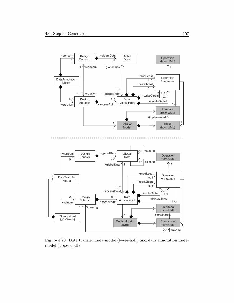
4.6. Step 3: Generation 157
Design Concern
Design Solution
Operation Annotation0..1
1
Global Data
SolutionModel
+accessPoint
Class (from UML)
1..*
1..*
DataAnnotation Model
1
DataAccessPoint
Interface(from UML)
Operation (from UML)
0..1
0..1
0..1
1
1
1
1
1..*
1..*
1
+globalData +concern
+solution
1..*
+readGlobal
+readLocal
+deleteGlobal
+writeGlobal +accessPoint
+globalData +concern
+solution
Design Concern
Design Solution
Operation Annotation0..1
Global Data
+accessPoint
Component (from UML)
0..*
Fine-grained MCVModel
DataAccessPoint
Interface(from UML)
Operation (from UML)
0..1
0..10..1
1
1
1
1
1..*
0..*
+globalData
+readGlobal
+readLocal
+deleteGlobal
+writeGlobal +accessPoint
+globalData
+implemented
+provided
MediumModel (Level4)
0..*
DataTransfer Model
+concern
+solution
0..*
1
1..*
0..* +owned
+owning
1
0..*
0..* +subset
+cloned
Figure 4.20: Data transfer meta-model (lower-half) and data annotation meta-model (upper-half)

158 4. Adaptive Medium Development Process
part of the fine-grained MCV model1. It indicates the concern features that 1)correspond to variation points of the fine-grained MCV model and 2) includeglobal data (specified in the early MCV model). For example, in the case ofthe FS medium fine-grained MCV model (Figure 4.16), the data transfer modelindicates concern features f3, f6, f7, f13, and f14, f15, f16, f22, f24, f25, andtwo child features of f13 that are not depicted in the figure. The files, fileProp-erties, and two <files>LocalizationData global data sets are indicated by theseconcern features. Instances of the DataAccessPoint and OperationAnnotationclasses are also introduced into the data transfer model, according to the dataannotation models for the simple data placement concern and the advanced al-gorithm concern. While an annotation in the data annotation model indicatesan operation and the implementing class, the corresponding annotation in thedata transfer model indicates an operation and the implementing component.
By the data transfer model described above, the operations for transferringglobal data sets from a functional medium variant to another one can be easilyidentified.
Example: FS Medium Data Transfer Model
Figure 4.21 includes an extract of the data transfer model for the FS medium.The XMI representation is simplified. This model indicates 12 concern featuresand 17 solution features of the fine-grained MCV model. Each solution containssome data access points.
4.6.4 Medium Reconfiguration Constraints Model
Together with the data transfer model, the main transformation also generatesa medium reconfiguration constraints model. This model is built by collect-ing constraints of solution reconfiguration constraints models corresponding toinvolved solutions.
Similarly to the description of the data transfer meta-model, we describe themedium reconfiguration constraints meta-model in the lower-half of Figure 4.22,together with the solution reconfiguration constraints meta-model in the upper-half of the figure.
As described in the figure, the medium reconfiguration constraints modelis also organized as part of the fine-grained MCV model2. For each solutionfeature, every require-constraint of the corresponding solution reconfiguration
1However, we consider them as two separated models.2Similarly to the data transfer model, we also consider the medium reconfiguration con-
straints model and the fine-grained MCV model as two separated models.

4.6. Step 3: Generation 159
1 <DataTransferModel name=”FSMedium”>
3 < !−−12 concerns−−>
<DesignConcern name=” f i l eDataPlacement” f ea tu r e=” f3 ”>5 <globalData name=” f i l e ”>
<cloned name=” f6 . f i l e ”/>7 <cloned name=” f7 . f i l e ”/>
</ globalData>
9 </DesignConcern>
<DesignConcern name=” f i l eSimpleDataPlacement ” f ea tu r e=” f6 ”>11 <globalData name=” f i l e ”/>
<s o l u t i o n name=” f i l eC e n t r a l i z e d S e r v e r ” f ea tu r e=” f8 ”/>13 <s o l u t i o n name=” f i l eD i s t r i b u t e d S e r v e r s ” f ea tu r e=” f9 ”/>
<s o l u t i o n name=” f i l e P e e r s ” f ea tu r e=” f10 ”/>15 </DesignConcern>
<DesignConcern name=” f i l eAdvancedAlgor i thm ” f ea tu r e=” f7 ”>17 <globalData name=” f i l e ”/>
<s o l u t i o n name=” f i l eCho rd” f ea tu r e=” f11 ”/>19 <s o l u t i o n name=” f i l e P a s t r y ” f ea tu r e=” f12 ”/>
</DesignConcern>
21 . . .
23 < !−−17 s o l u t i on s−−>
<DesignSolution name=” f i l eC en t r a l i z e dS e r v e r ” f ea tu r e=” f8 ”>25 . . .
</DesignSolution>
27 <DesignSolution name=” f i l eD i s t r i b u t e d S e r v e r s ” f ea tu r e=” f9 ”><concern name=” f i l eSimpleDataPlacement ” r e f=” f6 ”/>
29 <DataAccessPoint name=” serverPo int ”><readLocal operat i on=” . . . ” i n t e r f a c e=” . . . ”
31 component=”Variant1 . SharerManager . fi leDataManagement .f i l eDataPlacement . D i s t r ibutedServer −f i l eDataPlacement−Impl ”/>
33 <readGlobal . . . />
<wr i teGloba l . . . />
35 <de l e teGloba l . . . />
</DataAccessPoint>
37 <DataAccessPoint name=” serverPo int ”>< !−−s im i l a r access po in t in another var iant−−>
39 . . .</DataAccessPoint>
41 . . .<DataAccessPoint name=”proxyPoint ”> . . .</DataAccessPoint>
43 . . .</DesignSolution>
45 <DesignSolution name=” f i l e P e e r s ” f ea tu r e=” f10 ”> . . .</DesignSolution>
<DesignSolution name=” f i l eCho rd” f ea tu r e=” f11 ”> . . . </DesignSolution>
47 <DesignSolution name=” f i l e P a s t r y ” f ea tu r e=” f12 ”> . . . </DesignSolution>
. . .49
</DataTransferModel>
Figure 4.21: Extract of the FS medium data transfer model

160 4. Adaptive Medium Development Process
Require Constraint
<<abstract>> RefectionFunction
1
0..*+requiring
+required
0..*
0..*
1
1
Design Solution
1..*
0..*
0..*
+owning
+owned
Fine-grained MCVModel
Component (from UML)
Interface(from UML)
Operation (from UML)
MediumReconfiguration ConstraintsModel
In the fine-grained MCV model
0..*
0..*
In a medium model Level 4
SolutionReconfiguration ConstraintsModel
<<abstract>> ModelElement
Require Constraint
<<abstract>> RefectionFunction
0..1
0..*+requiring
+required
0..*
0..*
1
1
Solution Model
1
1..*
1..*
CreateObject
StartObject
StopObject
Remove Object
MethodCall
CreateComponent
StartComponent
StopComponent
Remove Component
MethodCall
Figure 4.22: Medium reconfiguration constraints meta-model (lower-half) andsolution reconfiguration meta-model (upper-half)
4.6. Step 3: Generation 161
constraints model is multiplied, one copy per medium variant containing thissolution, and introduced into the medium reconfiguration constraints model.
When introducing require-constraints into the medium reconfiguration con-straints model, actions constrained by these constraints are transformed fromcreating, starting, stopping, and removing objects into creating, starting, stop-ping, and removing components, respectively.
By the medium reconfiguration constraints model as presented above, require-constraints between actions in an adaptation can be automatically generated.
4.6.5 Defining the Generation Process Model
In order to execute the main transformation, the process designer defines ageneration process model that indicates all the solution introduction transfor-mations needed to generate functional medium variants at level 3 from the oneat level 1. This process tree model guides the main transformation to gener-ate the functional medium variant models as well as the adaptation-facilitatingmodels.
4.6.5.1 Generation Process
As described in the medium refinement process, the execution of model transfor-mations is ordered. In fact, the transformation for a design concern is reusablein similar mediums, i.e., it is flexible enough to be usable in several orders ofconcerns. However, it uses a decision model that partially describes how tointegrate the introduced solution model into the medium model. For example,this decision model indicates with which class(es) of the medium model a classof the introduced solution should be associated. Therefore, with a particulardesign goal of the process designer, the order of the primitive concerns must bedefined.
Figure 4.23 shows the design decisions to generate FS medium variants.Each primitive concern represented by a horizontal dashed line where severalsolutions for this concern are represented by round nodes. In the figure, thedesign concerns are arranged from the top to the bottom in the order thatdesign decisions will be made. Each node in a line corresponds to a designdecision where the solution at this node is selected for the design concern atthis line, i.e., the corresponding solution model is introduced into the mediummodel by the transformation for the corresponding concern. The uppermostnode and the next one denote the medium at level 0 and level 1, respectively.
Transformations needed to generate a medium variant are then a chain of

162 4. Adaptive Medium Development Process
successive design decisions. In Figure 4.23, we depict three chains of designdecisions corresponding to three FS medium variants. For example, the chainrepresented by dashed arrows corresponds to variant FSV 1 that is presentedpreviously in the FS medium early and fine-grained MCV models. Its sharermanager component diagram has been also previously presented in Figure 4.19.
High-levelabstraction
Managerintroduction
<files> AbstractType
<files> SimpleDataPlacement
Distributedservers
Centralized server
Chord
List Tree
Peers
Pastry
ChordPastry<fileProperties>AdvancedAlgorithm
List Tree<fileProperties>AbstractType
<<files>LocalizationData> AdvancedAlgorithm
<<files> Localization Data>Data Placement
<fileProperties>Data
Management
<files>Data Management
<<files>LocalizationData> SimpleDataPlacement
<fileProperties>SimpleDataPlacemen
FSV3 FSV2 FSV1
ChordPastry<files> AdvancedAlgorithm
Centralized server
Distributedservers
Centralizedserver
Distributedservers
Figure 4.23: Design concerns and design solutions for the FS medium
When spreading design decisions of all the decision chains corresponding toall the desired medium variants, the generation process becomes a tree of designdecisions.

4.6. Step 3: Generation 163
4.6.5.2 Generation Process Meta-model
Figure 4.24 includes the generation process meta-model. The DecisionPointclass represents a node in the tree where decisions are made. Making sucha decision consists in executing a transformation that is represented by theTransformationExecution class.
Process Model
Design Concern
Design Solution
+concern
+solution
1..*
1
DecisionPoint
+decision
1..*
1
+solution
0..10..1
0..*
+child
+parent Medium Model
DesignSolution Model
1
Transformation Execution
0..1
+output
+ transformation
1
+input
{ordered} +trEx
1
1..*+trEx
+decision
+concern
1..*
DesignDecisionModel
+decisionModel 0..1
Fine-grained MCVModel
1
1
DataAnnotation Model
0..1
{subsets decision} +root
SolutionReconf. Constr.Model
1
1
Figure 4.24: Generation process meta-model
In fact, the first transformation (i.e., the manager introduction) has beenexecuted by the process designer in step 1 (specification) to generate the mediummodel at level 1 that is needed for step 2 (modeling). On the other hand, everymedium variant model at level 3 is systematically transformed into a mediummodel at level 4 by the modularization transformation. Therefore, the processmodel contains only at its nodes the solution introduction transformations usedto refine the medium model at level 1 to ones at level 3. Exceptionally, the rootof the decision tree is not linked to any transformation. In fact, it could belinked to the manager introduction transformation but this transformation hasbeen previously executed.
Each transformation indicated in the generation process model deals witha primitive design concern (DesignConcern) that has at least one design solu-

164 4. Adaptive Medium Development Process
tion (DesignSolution). Each solution corresponds to a design solution model(DesignDecisionModel) that will be used by the transformation. Similarly, thetransformation uses a design decision model (DesignDecisionModel) as inputthat is defined by the process designer. Additionally, the transformation re-ceives a medium model (MediumModel) as input and generates another one asoutput.
The process model also indicates the fine-grained MCV model. This modelis used as input of the feature-based modularization to modularize mediumvariant models at level 3. Through the modularization, the fine-grained MCVmodel is also completed.
In addition to guiding the generation of functional medium variants, theprocess model is also used for step by step collecting data annotation modelsand solution reconfiguration constraints model to generate the data transfermodel and the medium reconfiguration constraints model.
4.6.6 Executing the Main Transformation
The main transformation is executed by the process designer. It is executedstep by step, according to transformation executions described in the processmodel. After finishing each transformation execution, a more concrete mediummodel is generated. Based on this medium model, the process designer definesa decision model for the next transformation execution, and then, launches thistransformation execution.
Once all the transformation executions indicated by the process model arefinished (i.e., all the medium variant models at level 3 are generated), the maintransformation launches the modularization transformation to generate mediumvariant models at level 4. Then, the main transformation generates adaptation-facilitating models.
4.6.7 Summary
We have presented step 3 of the adaptive medium development process. Thetasks of this step include refining the early MCV model, defining the generationprocess model, and then, generating functional medium variant models at level4 and the adaptation-facilitating models.
We have detailed the refinement of the early MCV model, the feature-basedmodularization, the constructions of the data transfer model and the mediumreconfiguration constraints model, and the process model that guides the gen-eration.

4.7. Step 4: Composition 165
4.7 Step 4: Composition
Once the functional medium variants at the component-implementation levelare generated, the application designer uses a composition program to generatethe target adaptive medium implementation.
At the component-implementation level, the adaptive medium is a logicalaggregation of distributed adaptive manager components. Such an adaptivemanager is composed of an adaptation manager of the adaptation medium anda (role or internal) functional manager of the functional medium. At runtime,the adaptation managers collaborate to reconfigure the functional managers byusing the reflection services supported by the used component platform.
Adaptation
Manager
Functional
Manager
AdaptableComponent
AdaptiveManager
Observ
er
Clie
nt
com
po
nent
Model
Manager
Figure 4.25: Component diagram of the adaptive manager
Figure 4.25 includes a generic UML component diagram of adaptive man-agers. In this diagram, AdaptableComponent is an “empty component” thatreserves a place for a functional manager. Thanks to AdaptableComponent, alocal executor of the adaptation manager can be implemented generically forevery functional manager.
As described in the figure, the AdaptationManager component contains amodel manager (ModelManager). Distributed model managers collaborate tomanage the following models:
• the architectural models of functional medium variants including 1) design-time architectural models of these variants and 2) a runtime architectural

166 4. Adaptive Medium Development Process
model of the running one.
• the adaptation-facilitating models including 1) the complete fine-grainedMCV model whose features are linked to components of functional mediumvariants, 2) the data transfer model, and 3) the medium reconfigurationconstraints model.
At runtime, changes in the functional medium are reported to the modelmanagers. For example, when manager component instances join or leave thesystem, the runtime architectural model needs to be updated.
New architectural models may be added to the adaptation medium at run-time when new functional medium variants are built. This also requires toupdate the fine-grained MCV model, the data transfer model and the mediumreconfiguration constraints model.
4.8 Adaptation in the Adaptive Medium
This section describes how the target adaptive medium can automatically planfine-grained adaptations at runtime. First, we describe the generic forms ofadaptation plans. Next, we detail how data are transferred using operationsannotated by the data transfer model. Then, we present the adaptation plan-ning function that generates adaptation plans containing adaptation actions,including data transfer actions. Finally, we use some sample adaptations of theFS adaptive medium to describe fine-grained adaptations.
4.8.1 Adaptation Plans
For an adaptation, an adaptation coordination plan and some local adapta-tion plans are generated. The generic forms of these plans are described inFigure 4.26.
As described in the figure, a local adaptation plan contains actions executedin an adaptive manager instance. The actions are separated into six local adap-tation steps that have been previously described in Section 3.3.2. Each actionmay require other actions in other adaptive manager instances (requiredAc-tions). Inversely, it may be required by other actions (requiringActions).
On the other hand, an adaptation coordination plan contains six globalsteps. In each step, the coordination plan indicates the adaptive manager in-stances that participate in the step, and require-constraints between local ac-tions.

4.8. Adaptation in the Adaptive Medium 167
<coordinationPlan . . .>2 <g l o b a l S t e p i>
< !−− i = 1 to 6 :4 1) s topping medium se r v i c e s ,
2) c r ea t i n g replacement components ,6 3) i n i t i a l i z i n g replacement components ,
4) t r an s f e r r i n g data ,8 5) removing rep laced components , and
6) r e s t a r t i n g medium s e r v i c e s−−>
10 <pa r t i c i p an t s . . . />
< !−− l i s t o f adapt i ve manager i n s t anc e s −−>
12 <con s t r a i n t r equ i r i ng=”{ act i on id }” r equ i r ed=”{ act i on id }”/>. . .
14 </ g l o b a l S t e p i></coordinationPlan>
16
<localAdaptationPlan adaptiveManager Instance=”{ i d }” . . .>18 < l o c a l S t e p i> < !−− i = 1 to 6−−>
<pa r t i c i p an t s>20 . . .
< !−− l i s t o f adapt i ve manager i n s t anc e s −−>
22 </ pa r t i c i p an t s><act i on ac t i on Id=”{ i d }” . . .>
24 <r equ i r edAct i ons . . . />
<r equ i r i ngAct i on s . . . />
26 </ act i on>
</ l o c a l S t e p i>28 </ localAdaptationPlan>
Figure 4.26: Generic structure of adaptation coordination plans and local adap-tation plans
4.8.2 Transferring Data
While actions in global adaptation steps 1, 2, 3, 5, 6 are simple (Figure 3.7),actions for data transfer in step 4 are quite complex.
Precisely, the data transfer step is composed of two actions: transferring localdata and transferring global data. To illustrate these actions, we use the exampledescribed in Figure 4.27. In this figure, an adaptive medium is composed of fiveadaptive manager instances that correspond to five functional manager instancesfm1, fm2, fm3, fm4, and fm5. To perform an adaptation, a solution called A isreplaced by another solution called B. A is implemented by the group of fourblack components (a1, a2, a3, and a5 ). B is implemented by the group of fourgray components (b1, b2, b3, and b4 ). Both solutions manage the same globaldata set. In each solution, this set is distributed differently among the fourcomponents of the solution. In this adaptation, the black components will bereplaced by the gray ones. Data are also transferred between these components.
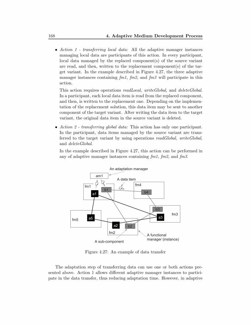
168 4. Adaptive Medium Development Process
• Action 1 - transferring local data: All the adaptive manager instancesmanaging local data are participants of this action. In every participant,local data managed by the replaced component(s) of the source variantare read, and then, written to the replacement component(s) of the tar-get variant. In the example described in Figure 4.27, the three adaptivemanager instances containing fm1, fm2, and fm3 will participate in thisaction.
This action requires operations readLocal, writeGlobal, and deleteGlobal.In a participant, each local data item is read from the replaced component,and then, is written to the replacement one. Depending on the implemen-tation of the replacement solution, this data item may be sent to anothercomponent of the target variant. After writing the data item to the targetvariant, the original data item in the source variant is deleted.
• Action 2 - transferring global data: This action has only one participant.In the participant, data items managed by the source variant are trans-ferred to the target variant by using operations readGlobal, writeGlobal,and deleteGlobal.
In the example described in Figure 4.27, this action can be performed inany of adaptive manager instances containing fm1, fm2, and fm3.
fm4fm1
fm2
fm3
b4b1
b3
b2
A functionalmanager (instance)
A sub-component
fm5 a5
a1
am1A data item
a3
a2
An adaptation manager
Figure 4.27: An example of data transfer
The adaptation step of transferring data can use one or both actions pre-sented above. Action 1 allows different adaptive manager instances to partici-pate in the data transfer, thus reducing adaptation time. However, in adaptive

4.8. Adaptation in the Adaptive Medium 169
manager instances where the writeGlobal operation is not available (e.g., com-ponent instance a5 in the example), local data can not be transferred by thisaction. Moreover, action 1 is not applicable in the case where data items arereplicated. In these cases, action 2 can complement or replace action 1.
These two data transfer actions are based on the four basic operations (i.e.,readLocal, readGlobal, writeGlobal, and deleteGlobal) that are naturally pro-vided in any data management solution. Therefore, generally, the adaptivemedium approach does not require software engineers to manually implementadaptation operations.
4.8.3 Feature-based Adaptation Planning
As described previously, thanks to the fine-grained MCV model, common anddifferent components of two medium variants can be easily identified. Moreover,the data transfer model and the medium reconfiguration constraints model allowto identify operations needed to transfer data between variants and constraintsbetween adaptation actions, respectively. These models thus serve as an impor-tant basis for fine-grained adaptation planning.
The plan of a fine-grained adaptation consists of actions for the reconfigu-ration of the source functional medium variant (i.e., the running one) in orderto achieve the target functional medium variant. The common components arekept and only the different components are replaced. Planning such a fine-grained adaptation thus principally consists in identifying the different com-ponents between the two medium variants, the operations needed to transferdata between them, and constraints between adaptation actions. As presentedin Section 3.3, the plan is composed of some local adaptation plans, one permanager instance, and an adaptation coordination plan. While a local plancontains actions for the reconfiguration of the corresponding functional man-ager instance, the adaptation coordination plan contains information for thecoordination of the executions of local plans.
This adaptation planning is realized by comparing two feature configurationscorresponding to the two medium variants. It is then called feature-based adap-tation planning. It is implemented as a function of the adaptation medium. Amore detailed description of the planning function is presented in Appendix 2.2.
4.8.4 Fine-grained Adaptations
We use the term fine-grained adaptations as opposed to coarse-grained adapta-tions - the adaptations that are realized by replacing the whole running func-
170 4. Adaptive Medium Development Process
tional medium variant.
Consider three FS medium variants FSV 1, FSV 2, and FSV 3 that are previ-ously described by three decision chains in Figure 4.23.
• Variant FSV 1: Both files and fileProperties sets are represented as lists,i.e., the List abstract type is used. Files are placed on peers and theirlocalization data are managed using Chord. File properties are also man-aged using Chord.
• Variant FSV 2: The files set is represented as a list and the filePropertiesone is represented as a tree. Files are managed using DistributedServersplacement and their localization data are managed using Chord. Fileproperties are also managed using Chord.
• Variant FSV 3: Both files and fileProperties sets are represented as trees.Files are managed using Peers placement and their localization data aremanaged using CentralizedServer. File properties are also managed usingCentralizedServer.
When an adaptation is realized by changing the FS medium running variantfrom FSV 1 to FSV 3. In the sharer manager, the component implementingthe Peers solution for file placement can be kept. All the other componentsare replaced. That is, file localization data and file property data need to betransferred.
An interesting adaptation is the one realized changing the FS mediumrunning variant from FSV 1 to FSV 2. In the generation process model (Fig-ure 4.23), these two variants have two common Chord solutions, one for thefile localization data placement concern and one for the file properties place-ment concern. However, only the components created for the second one arekept. This is because when moving from FSV 1 to FSV 2, files are moved frompeers to some distributed servers. Consequently, file localization data of FSV 1
can not be used in FSV 2. This case is supported in the adaptive medium ap-proach. Indeed, as described in the FS fine-grained MCV model (Figure 4.16),the <<files>LocalizationData>DataPlacement concern is duplicated and repre-sented as features f13 and f14. Thereby, when comparing the two feature config-urations corresponding to FSV 1 and FSV 2, the Chord solution for the manage-ment of file localization data is not considered as a common feature. Moreover,components created for these two features are included as sub-components of theones created for the <files>DataPlacement concern (f3), new file localizationdata will be derived by the components implementing the DistributedServerssolution.
4.9. Development Process Summary and Discussion 171
In comparison to the corresponding coarse-grained adaptation, the fine-grained one from FSV 1 to FSV 3 is efficient in terms of reducing adaptationtime since components managing shared files are kept. On the other hand, theone from FSV 1 to FSV 2 is less efficient because the amount of kept data, i.e.,the file property data, is much smaller.
By the two adaptations presented above, we show how fine-grained adapta-tions can be planned. These adaptations allow to keep common components ofthe sources and target functional medium variants, thus avoiding unnecessarydata transfer. The efficiency of fine-grained adaptations depends on each adap-tation. Generally, when the number of design concerns and design solutionsincreases, the medium becomes more complex, fine-grained adaptations will bemore important. Moreover, in addition to reducing adaptation time, automat-ing the planning of such complex adaptations also significantly reduces tasks ofthe development.
4.9 Development Process Summary and Discussion
We have presented the four steps of the adaptive medium development process.This section summarizes these steps and gives some discussions on the process.
4.9.1 Development Process Summary
The development of an adaptive medium is realized as follows:
1. Step 1: Specification
(a) The application designer specifies the functional medium by defininga medium model at level 0.
(b) The process designer uses the manager introduction transformationto generate a medium model at level 1.
(c) The process designer and the application designer identify designconcerns design solutions by defining an early MCV model. Concernsand solutions are represented as features of this model, and targetmedium variants are represented as feature configurations. Existingconcerns, solutions for these concerns, and concern usage patterns inthe concern catalogue can be reused.
2. Step 2: Transformation
172 4. Adaptive Medium Development Process
(a) For each identified design concern that does not exist in the cata-logue, the medium expert
• defines a solution meta-model,
• implements a model transformation that can introduce a solutionmodel conforming to this solution meta-model into the mediummodel, and
• defines a decision meta-model that allows to introduce decisionsof the process designer into the transformation.
(b) For each design solution that does not exist in the catalogue, thesolution designer
• defines a solution model,
• adds data annotations in the solution if any into the data anno-tation model associated with the corresponding design concern,and
• creates a solution reconfiguration constraints model if there existconstraints for the reconfiguration of the solution.
3. Step 3: Generation
(a) The process designer identifies concrete concern features and affect-constraints between features of the early MCV model, and then,uses the feature refinement transformation to generate a fine-grainedMCV model.
(b) The process designer creates a generation process model. This modelindicates the transformations that need to be executed to generatefunctional medium variant models at level 4.
(c) The process designer uses the main transformation to execute trans-formations according to the generation process model. The maintransformation generates functional medium variant models at level4 and adaptation-facilitating models.
4. Step 4: Composition
(a) The application designer uses the composition program to gener-ate the target adaptive medium implementation from an adaptationmedium implementation and a functional medium variant.
4.9.2 Model-Driven Architecture and Feature Modeling
This section gives a reflection on the adaptive medium development process.We discuss the relation between the generation process model and the MCV

4.9. Development Process Summary and Discussion 173
model. While the former model is mainly concerned with the medium refinementapproach proposed by Kabore [Kabore 08a] that is based on the MDA paradigm,the latter model being based on the feature modeling is introduced in thisthesis to model variability of functional medium variants. As discussed in thebackground on approaches to automating software development (Section 2.3),MDA is an important paradigm in MDE and the feature modeling is a wellaccepted approach to modeling variability of software system families. Therelation between the process model and the MCV model thus shows how theMDA paradigm and the feature modeling are combined in our approach.
From the viewpoint of modeling variability, decision points of the processmodel can be considered as variation points. On the other hand, the MCVmodel also represents variation points by its feature groups. There seems toexist redundancy when using both models. Nevertheless, the two models arefully integrated and complement each other.
Indeed, when identifying a medium variant, the process designer makes somedesign decisions that correspond to the selection of solutions for this variant.Using only the process model as in the original medium refinement process,information for design decision making are not explicit. For example, the in-formation can be “when a centralized data placement is selected, localizationdata are not necessary”. The decision making thus relies on knowledge of theprocess designer. Thanks to the MCV model with notations including differentkinds of feature decompositions and constraints, this information is visualizedand made explicit. Moreover, by supporting composite design concerns, theMCV model enables to step by step decompose the medium into primitive con-cerns. Therefore, the MCV model significantly facilitates the identification ofconcerns, solutions, and variants.
On the other hand, the process model allows to describe design decisionsand the order in which the medium variants are built. The process model alsodescribes how these variants are built by indicating the to-be-applied transfor-mations and their execution order. This information is not described by theMCV model.
Figure 4.28 presents an integration view of the two models. While the pro-cess model is mainly concerned with the transformation issue, the MCV modelfocuses on representing modularity, commonality, and variability. The variationpoints of the two models are the points where these two models are “weaved”together. Combining these two models allows to support the automated devel-opment process of medium variants with well-modeled modularity, commonality,and variability, that are important to support fine-grained adaptations.
This integration view shows that the MCV model and the process modelare fully integrated and complement each other. Each model has its own im-

174 4. Adaptive Medium Development Process
portant place in the adaptive medium development process. In other words, inthe approach, the MDA paradigm and the feature modeling method are fullyintegrated.
High-levelabstraction
Managerintroduction
Distributedservers
Centralized server
Chord
List Tree
Peers
Pastry
ChordPastry
List Tree
FSV3 FSV2 FSV1
ChordPastry
Centralized server
Distributedservers
Centralized server
Distributedservers
FS
me
diu
m
File
ma
na
ge
me
nt
File
pla
ce
me
nt
File
pro
pe
rty
ma
na
ge
me
nt
File
pro
pe
rty
pla
ce
me
nt
File
lo
caliz
atio
n
da
ta p
lace
me
nt
Figure 4.28: Relation between MCV model and generation process model
4.9.3 Discussion
We have summarized in Table 3.1 (Chapter 3) solutions involved in the adap-tive medium approach. Among these solutions, the medium abstraction andrefinement are presented in Chapter 2, and the adaptive medium abstraction isdescribed in Chapter 3.

4.9. Development Process Summary and Discussion 175
This chapter details the other solutions including 1) the MCV modeling,2) the automated modularization, 3) the data transfer modeling, and 4) thereconfiguration constraints modeling. All the solutions are described togetherin a structured way in order to formulate the adaptive medium developmentprocess. Thanks to these detailed descriptions, we explain more precisely howthe solutions respond to the identified challenges as previously claimed in Ta-ble 3.1.

176 4. Adaptive Medium Development Process

Chapter 5
Prototype
Contents
5.1 Chapter Overview . . . . . . . . . . . . . . . . . . . . 177
5.2 Adaptive Medium Development Framework . . . . 178
5.3 An Adaptation Medium Implementation . . . . . . 184
5.4 Case Study 1: File Sharing Adaptive Medium . . . 197
5.5 Case Study 2: Reservation Adaptive Medium . . . 203
5.6 Evaluation . . . . . . . . . . . . . . . . . . . . . . . . . 213
5.7 Prototype Summary and Discussion . . . . . . . . . 221
5.1 Chapter Overview
This chapter describes a framework prototype supporting the adaptive mediumdevelopment process, called the adaptive medium development framework.
First, Section 5.2 introduces facilities involved in the framework includinga basic facility and a concern catalogue that are used for the generation offunctional medium variants. The framework also contains implementations ofthe adaptation medium and a composition program that composes the desiredadaptive medium implementation.
Next, Section 5.3 details an adaptation medium implementation. This adap-tation medium implementation is developed using the facilities provided by theframework.
Then, Sections 5.5 and 5.4 illustrate the adaptive medium approach by de-scribing the development of the file sharing adaptive medium and the reservation
177

178 5. Prototype
adaptive medium using the framework, respectively.
Section 5.6 evaluates the adaptive medium approach by providing quanti-tative and qualitative analyses. The quantitative one is based on developmentresults and execution results of some adaptations in the FS adaptive medium.Both analyses are presented regarding the six identified challenges in order tojustify the thesis contribution.
Finally, Section 5.7 summarizes the framework prototype.
5.2 Adaptive Medium Development Framework
The framework consists of the following facilities:
• A basic facility containing meta-models and transformations that are usedto generate variants at level 4 of every medium.
• A concern catalogue containing concerns that are reused to generate vari-ants at level 4 of some mediums in which the concern is identified.
• A set of adaptation medium implementations, each one is reusable forevery adaptive medium.
• A composition program that builds the desired adaptive medium imple-mentation from a functional medium variant and an adaptation mediumimplementation.
First, we present an overview of all the elements concerning the adaptivemedium development, including the elements of the above facilities and thosegenerated or created when using these facilities to develop an adaptive medium.Next, we detail the basic facility and the concern catalogue. Then, we describehow these two facilities are used to generate medium variants. Finally, we brieflypresent the adaptation medium implementations and the composition program.
5.2.1 Framework Overview
Table 5.1 summarizes elements involved in the adaptive medium developmentprocess. The elements including transformations, meta-models, models, andprograms are classified in three categories: basic for every adaptive medium (i.e.,always used), tailored and reusable for some adaptive mediums (i.e., sometimesused), tailored and specific for each adaptive medium (i.e., once used). While theelements in the first category, except the adaptation medium implementations

5.2. Adaptive Medium Development Framework 179
Transformations (Kermeta)
Meta-models (Ecore meta-models)
Models(EMF models)
Implementations(Java/Fractal)
Do
ma
in e
ng
ine
erin
g
Basic
ele
ments
used f
or
every
adaptive m
ediu
m
Manager introductiontransformation
Feature refinementtransformation
Modularization transformation
Main transformation
5 medium meta-models(levels 0 to level 4)
Early MCV meta-model
Fine-grained MCV meta-model
Data annotation meta-model
Data transfer meta-model
Solution reconf. constr. meta-model
Medium reconf. constr. meta-model
Process meta-model
An implement-tation of the adaptationmedium
Composition program
Tailo
red e
lem
ents
reusable
for
som
e a
daptive m
ediu
ms
N transforma-tions, each one corresponds to a concern
2N medium meta-models, each one is an extension of the basic medium meta-model at level 2
N solution meta-models, each one corresponds to a concern
N decision meta-models
N groups of solution models, each group corresponds to a concern
Data annotation models, zero or one per concern
Solution reconf. constraints models, zero or one per solution model
Concern usage pattern models as early MCV models
Reusable components and code (indicated by solutionmodels)
Applic
ation e
ngin
eerin
g
Tailo
red o
r genera
ted e
lem
ents
specific
for
each a
daptive m
ediu
m
A medium model level 0 (tailored)
An early MCV model (tailored)
A fine-grained MCV model (generated)
A process model (tailored)
A data transfer model (generated)
A medium reconf. constraints model (generated)
Medium models level 1 to level 4 (generated)
Decision models (tailored)
Custom components and code
Table 5.1: Elements including transformations, meta-models, models, and im-plementations in the adaptive medium development process

180 5. Prototype
and the composition program, are included in the basic facility, those in thesecond category are included in the concern catalogue that is extensible. As theelements in these two categories are developed for reuse, they are involved inthe domain engineering process, whereas the elements in the third category areconcerned with application engineering one.
In Chapter 4, we have presented an activity view of the adaptive mediumdevelopment process, regarding the domain engineering and the application en-gineering processes (Figure 4.1). Table 5.1 complements that view by describingthe elements involved in the adaptive medium development process.
In our prototype, we use Kermeta - an Eclipse-based meta-programmingenvironment based on a Domain Specific Language (DSL) optimized for meta-model engineering [Triskell]. Kermeta features, including 1) model and meta-model prototyping and simulation, and 2) model transformation, are particu-larly useful for our prototype. Kermeta is built as an extension of EMOF, i.e.any EMOF compliant model is a valid Kermeta program and conversely. UsingKermeta, meta-models are defined as Ecore meta-models and their models arerepresented as EMF models (described in XMI). The transformations are thenimplemented by using the Kermeta language.
Finally, implementations of the adaptation medium, the composition pro-gram, components of the functional medium (reused from libraries or custom)are in Java. The components are implemented using the Julia implementationof the Fractal component model [Bruneton 06].
In the next sections, we will give more details concerning the elements de-scribed in Table 5.1.
5.2.2 Basic Facility
The basic facility includes some meta-models: five basic medium meta-modelsat the five abstraction levels, the process meta-model, the data transfer meta-model, the early and fine-grained MCV meta-models, and the solution recon-figuration constraints meta-model. Additionally, it also provides the followingbasic transformations: manager introduction, modularization, feature refine-ment, and main transformations.
The above meta-models and the transformations have been described indetail in Chapter 4. Some implementation details are also provided in Ap-pendix 2.3.

5.2. Adaptive Medium Development Framework 181
5.2.3 Concern Catalogue
The concern catalogue contains tailored meta-models, models, and transforma-tions that are reusable for some adaptive mediums that share common concernsand solutions. For each reusable design concern, a solution introduction trans-formation, a source and a target medium meta-models, a solution meta-model,and a decision meta-model are stored in the catalogue.
MM2-iMMM2-i
SMi-1
SMi-2
MM2-i’
SMj-1
SMj-2
SMj-3
MM2-j’
MMM2-i’
SMMi
SMMj
MMM2-j’
xor
xorxor
Meta-model
Model
MMM = Medium meta-model MM = Medium model SMM = Solution meta-model SM = Solution model
in
out
conforms to
Ti
Tj
T
MM2-jMMM2-j
MMM2
extends Transformation
Basic
Tailored
Figure 5.1: Tailored transformations
Figure 5.1 depicts two solution introduction transformations. Ti introducesa solution model conforming to solution meta-model SMMi (for concern Ci) intomedium model MM2-i conforming to medium meta-model MMM2-i, and then,generates medium model MM2-i’ conforming to medium meta-model MMM2-i’.Likewise, Tj is used to deal with concern Cj.
In [Kabore 08a], a solution introduction transformation such as Ti or Tjalso includes verification operations. A medium model is checked whether itselements and structure satisfy a property model associated with the correspond-ing medium meta-model. This property model contains structural propertiesrepresented in OCL (Object Constraint Language). These properties are then

182 5. Prototype
used as pre- and post-conditions of the transformation to verify the source andthe target medium models.
When Ti and Tj are reused as successive transformations (Ti before Tj )in the development of an adaptive medium, MMM2-i’ and MMM2-j must beidentical. To this end, these two meta-models and their property models aremerged. If there exist conflicts when merging these meta-models, for exampleconflicts of property models’ invariants, these transformations can not be usedsuccessively. The merging of the meta-models can be fully automated by usingsignature-based meta-model composition techniques [France 07a].
In addition to the meta-models and the transformations mentioned above,the concern catalogue also contains tailored models, including solution models,data annotation models, and solution reconfiguration constraints models.
Additionally, to facilitate the reuse of concerns and solutions included inthe catalogue, concern usage patterns as early MCV models are also stored forreuse. During the development process of an adaptive medium, at the stepof identifying concerns and solutions, the process designer may customize andinclude concern usage pattern(s) into his early MCV model.
5.2.4 Using Basic Facility and Concern Catalogue
The last category described in Table 5.1 includes the elements that are specificfor each adaptive medium. These elements are created or generated by usingthe basic facility and the concern catalogue presented above.
In the development of an adaptive medium, the application designer andthe process designer create a medium model at level 0, an early MCV model,a process model, and some decision models. Thanks to the framework, someother models are automatically generated, including a fine-grained MCV model,a data transfer model, a medium reconfiguration constraints model, and mediummodels at different abstraction levels.
5.2.5 Adaptation Medium Implementations
The adaptive medium development framework contains a set of adaptationmedium implementations. These implementations are considered as adapta-tion control infrastructures that are reusable for every adaptive medium. Theseimplementations are well-suited to different operating environments and/or ap-plication designer requirements, thus providing more choices for the compositionof the desired adaptive medium implementation. This set of adaptation mediumimplementations is extensible, i.e., new implementations can be developed and

5.2. Adaptive Medium Development Framework 183
added into this set.
In this framework prototype, we have used the basic facility to develop anadaptation medium implementation. We have used the Julia implementationof the Fractal component model. Section 5.3 will detail the development of thisadaptation medium implementation.
5.2.6 Composition Program
The composition program implemented in Java composes the target adaptivemedium from a functional medium variant and an adaptation medium imple-mentation selected by the application designer.
The tasks of the composition program are realized as follows:
• From the selected functional medium variant model and its Fractal model,an implementation of the functional medium is generated as Java Fractalcomponents. Reusable Java Fractal components and Java code from li-braries can be also used. Custom components and code may be required,depending on each adaptive medium.
• The generated Java Fractal implementation of the functional mediumis then integrated together with the implementation of the adaptationmedium that is also a Fractal implementation. Each role or internal man-ager component of the functional medium is integrated with an adaptationmanager component of the adaptation medium, thus forming an adaptivemanager component. The logical aggregation of all the adaptive managersis the target adaptive medium implementation.
• The composition program also embeds the fine-grained MCV model andall the medium variants models at level 4 into the (folders managed by)the model manager of the adaptation medium (Figure 4.25).
In fact, the composition program can be considered as a special transfor-mation. While the transformations used to transform the medium model fromlevel 0 to level 4 are model-to-model transformations, the composition programis mainly concerned with integrating source code into the medium models inorder to transform these models into executable implementations.

184 5. Prototype
5.3 An Adaptation Medium Implementation
In Chapter 3, we have presented development principles of the adaptationmedium, including the specification and the adaptation planning and execution.By using the medium approach, different adaptation medium implementationvariants can be developed.
This section describes an adaptation medium implementation variant thatis developed using the basic facility presented above. It is implemented by usingthe Julia implementation of Fractal.
First, we identify design concerns and solutions. Next, we explain how thebasic facility is used to generate a model of the adaptation medium at theimplementation level. Finally, we discuss some implementation issues.
5.3.1 Identifying Concerns and Solutions
From the viewpoint of adaptation activities, we adopt the control loop pro-posed by Buisson ([Buisson 06]) in which an observer, a decider, a planner andan executor are separated (Section 2.2). However, to simplify the adaptationmedium, we exclude the observer from our architecture, i.e., we assume thatthe adaptation medium can always receive events from the changing operatingenvironment.
In [Buisson 06], the control loop was proposed to adapt centralized softwareentities. According to the loop, the decider analyzes events received from theobserver to make decision and sends the decision to the planner. Then, theplanner elaborates an adaptation plan containing necessary actions to modifythe adaptable entity. Finally, the plan is executed by the executor. Becausethis loop is designed to adapt centralized software entities, the four entities ofthe control loop are specified as physical components. However, the adaptationmedium adapts distributed software entities, each control loop’s entity thusmay consist of distributed sub-entities. Therefore, we first specify these fourentities as abstractions at the high abstraction level, then refined them to theimplementation level using the medium refinement process.
As presented in Section 3.3, a global adaptation process includes distributedprocesses that need to be coordinated. In order to generalize the coordinationat the high abstraction level, we introduce an abstraction called the coordinatorinto the adaptation medium abstraction. The coordinator encapsulates theadaptation coordination in the adaptive medium.
As described in Figure 5.2, the adaptation medium consists of four abstrac-tions: decider, planner, executor and coordinator. In this abstraction, commu-

5.3. An Adaptation Medium Implementation 185
Decider Planner
Coordinator
decision plan
decision
decision plan
plan
Executor
adapt
Adaptation medium
Functional medium
Figure 5.2: Decomposition of the adaptation medium abstraction
nication between the decider, the planner, and the executor are realized via thecoordinator. In addition to this communication, the coordinator also provideservices to synchronize distributed processes.
5.3.1.1 Design Concerns
Corresponding to the four abstractions described in Figure 5.2, we identify fourconcerns: making adaptation decisions, planning adaptations, executing adapta-tions, and coordinating adaptations. These concerns correspond to the questionsof how these abstractions are reified, i.e., how the corresponding adaptation ac-tivities are designed and implemented. From the point of view of the mediumrefinement process, these concerns correspond to the refinement steps throughwhich the adaptation medium model at level 1 (Figure 3.5) is refined to level 4.Through these steps, the decider, planner, executor, and coordinator abstrac-tions are reified by sub-components of the adaptation manager.
In addition to the four concerns presented above that correspond to someactivities of the adaptation control loop, we also identify the concern of modelmanagement. As described in the adaptation medium abstraction (Figure 3.4),the adaptation medium manages and uses a set of models. These models includethe architectural models of the functional medium variants, a runtime model ofthe running variant, and the adaptation-facilitating models. The managementof these models by the adaptation medium may have several implementations.

186 5. Prototype
5.3.1.2 Design Solutions
Figure 5.3 shows the early MCV model of the adaptation medium. For eachidentified design concern, we propose one or several solutions. Each solutionindicates an implementation architecture (such as centralized or distributed) ofthe corresponding concern.
Adaptation Medium
Making Decisions
Simple Centr.Assym.
Centr.Symm.
Distri-buted
Centr.Assym.
Centr.Symm.
Executing Adaptations
Coordinating Adaptations
imply
Model Management
Centr.Symm.
Planning Adaptations
concrete concrete concrete concrete concrete
concrete
Figure 5.3: Early MCV model of the adaptation medium
• Making adaptation decisions: Since we are particularly interested in plan-ning and executing adaptation actions, making adaptation decision is notin the focus. Therefore, we propose a solution called the Simple solu-tion for the concern of making adaptation decisions. In this solution, theadaptation medium includes a single software entity (class/component)implementing the decider abstraction. We assume that 1) a decision sentby this entity indicates a source and a target functional medium variantsand 2) from the moment the decision is sent, a quiescent state of the sys-tem is achieved, i.e., an adaptation could be safely performed [Zhang 06].
• Planning adaptations: We propose two solutions for the concern of plan-ning adaptations: CentralizedAsymmetric and CentralizedSymmetric. Inthe former solution, the adaptation medium contains one adaptation man-ager instance that has a planner manager planning every adaptation. Onthe other hand, in the latter solution, each adaptation manager instancehas a planner manager instance and one will be dynamically selected atruntime to plan an adaptation.
• Executing adaptations: We propose the Distributed solution for the con-cern of executing adaptations. In each adaptation manager, an executor

5.3. An Adaptation Medium Implementation 187
manager directly reconfigures the corresponding manager component ofthe functional medium.
• Coordinating adaptations: We propose two solutions for the concern of co-ordinating adaptations: CentralizedAsymmetric and CentralizedSymmet-ric. In both solutions, each adaptation manager contains a coordinatormanager. At runtime, only one coordinator manager instance acts as mas-ter and the others act as slaves. However, while the master coordinatorin the CentralizedAsymmetric solution is fixed, the one in the Central-izedSymmetric solution can be dynamically selected to coordinate eachadaptation.
• Model management: This concern can be seen as a distributed data man-agement, the data management concern usage pattern described in Fig-ure 4.4 thus can be reused. However, for the sake of simplicity, we usea solution called the CentralizedSymmetric solution for this concern. Inthis solution, each adaptation manager has a model manager. Among allthe model manager instances, one is configured as a server where modelsare stored.
As described in the adaptation medium early MCV model, the Central-izedSymmetric solution for planning adaptations implies the CentralizedSym-metric solution for coordinating adaptations. This constraint is defined sincewe consider that the planner manager selection is part of the adaptation coordi-nation. Therefore, when the CentralizedSymmetric solution for planning adap-tation is selected, the CentralizedSymmetric solution for coordinating adapta-tions must be also selected. For each adaptation, when a coordinator managerinstance is selected as the master coordinator, the planner manager instancein the adaptation manager instance containing this master coordinator is alsochosen for planning the adaptation.
5.3.1.3 Discussion
The concerns and the solutions identified above are just our choices for the de-velopment of the adaptation medium prototype in this thesis. Other separationsof concerns and/or other design solutions can also be possible.
By these concerns and solutions, we show that several implementation vari-ants of the adaptation medium can be developed. These variants may be well-suited to different operating environments or requirements of the applicationdesigner. We have developed the variant in which the CentralizedSymmetricsolutions for planning adaptations and coordinating adaptation are selected

188 5. Prototype
(called AMIV1 - Adaptation Medium Implementation Variant 1). The devel-opment of this variant will be detailed in the next section.
5.3.2 Generating the Adaptation Medium Component Model
We used the basic facility presented above to generate the implementation modelof AMIV1. To this end, we implemented four transformations that introducesolution models for the concerns of planning, executing, coordinating adapta-tions and model management. These transformations and the correspondingmedium and solution meta-models are relatively simple. For a real adaptationmedium, design solutions could be more detailed. For example, modeling ofdifferent protocols for the selection/election of the master coordinator could betaken into account. The data management concern usage pattern could also bereused for the model management concern.
The adaptation medium early MCV model is also the fine-grained MCVmodel since no affect-constraint exists. All the concerns are concrete, i.e., im-plementations of these concerns can be modularized into individual components.The four transformations can be executed in any order.
1
1 1 <<role>> AdaptableComponent
Model Manager
Adaptation Manager
<<interface>> ReflectionServices
Decider
1
Executor Manager
1
Planner Manager
1
*
1..*
Coordinator Manager
1
Figure 5.4: The model of AMIV1 at the class-implementation level
Figure 5.4 includes the model of AMIV1 at the (class-)implementation levelas a UML class diagram. In this diagram, the adaptation medium abstrac-tion is reified by a set of adaptation managers, each one is composed of aplanner manager, an executor manager, a coordinator manager, and a modelmanager. These classes (PlannerManager, ExecutorManager, Coordination-Manager, ModelManager) are introduced into the adaptation medium modelat level 1 (Figure 5.4) by the four transformations. The diagram also containsa class representing the simple decider (Decider) that is manually introduced.

5.3. An Adaptation Medium Implementation 189
This adaptation medium model at the class-implementation level is thenautomatically transformed into a model at level 4 and a Fractal model consistingof Fractal ADL files by using the modularization transformation.
5.3.3 Implementing the Adaptation Medium
In this section, we describe how the generated Fractal model of the functionalmedium is implemented.
5.3.3.1 Fractal Component Model
Fractal is a hierarchical component model. A Fractal component can be seen asbeing composed of a content and a membrane. The content consists of a finiteset of sub-components, while the membrane can have external and internal inter-faces that are only accessible from outside components and its sub-components,respectively. The Fractal component model also provides bindings for com-ponent connection. A binding typically binds a client interface (i.e., requiredinterface) and a server interface (i.e., provided interface). In addition to thesefeatures, Fractal supports composite binding and shared component that allowflexible design and implementation of Fractal-based applications.
Fractal is a reflective component model. The membrane of a componentalso contains interfaces called controllers that allow to introspect and reconfig-ure the component’s content. By these controllers, the membrane superposesa control behavior to the behavior of the component’s sub-components, includ-ing suspending, checkpointing and resuming activities of these sub-components.Furthermore, controllers play the role of interceptors that are used to export anexternal interface of a component as an external interface of the parent com-ponent, intercept oncoming and outgoing operation invocations of the exportedinterface, and add additional behavior to the handling of such invocations. Con-trollers thus can be understood as meta-objects as they appear in reflectivesystems [Bruneton 06].
As a reflective and hierarchical component model, Fractal is particularlysuitable for implementing adaptation and functional mediums. To implementAMIV1, we use the Julia Java implementation of Fractal, a small and powerfulframework which relies on a combination of interceptors and mixins for the pro-gramming of reflective features of components. The adaptation medium can alsomodify the functional medium by using Java Reflection. Moreover, by support-ing Fractal ADL, Julia facilitates automatic transformation of medium mod-els as component-platform-independent models into executable Fractal compo-nents.

190 5. Prototype
5.3.3.2 Adaptation Medium Implementation Architecture
Component Structure
Figure 5.5 includes the adaptive manager component structure of an adap-tive medium using AMIV1. As shown in the figure, an adaptive manager iscomposed of an adaptation manager and an adaptable component.
As described in the figure, the adaptation manager is represented as a Fractalcomposite component called AdaptationManager. This component is composedof four sub-components, including CoordinatorManager, PlannerManager, Ex-ecutorManager, and ModelManager. While the adaptation manager and itssub-components are “real” components that contain contents, the Adaptable-Component component is an “empty” component being only a Fractal com-ponent membrane. This membrane reserves a place to integrate a functionalmanager component.
The sub-components of the adaptation manager connect each other throughbindings. The planner manager and the executor manager are directly con-nected to the coordinator manager. Each coordinator manager also providesan interface that can be used by the simple decider (interface 9). This simpledecider is included in an adaptation manager. The planner and executor man-agers do not connect since adaptation plans are sent from a planner managerto some concerned executor managers via the coordinator.
All the three components including the coordinator manager, the plannermanager, and the executor manager use model management services of themodel manager. While these three components use full model services concern-ing all architectural models and adaptation-facilitating models, the adaptablecomponent uses only the runtime model services concerning the runtime archi-tectural model of the running functional medium variant.
The membrane of the adaptation manager contains interfaces used for 1)the distributed communication between model managers (interfaces 1 and 2),2) the distributed communication between coordinator managers (interfaces 3and 4), 3) the functional distributed communication between functional mediummanagers (interfaces 5 and 6), and 4) the communication between the adaptivemedium and the client components (interfaces 7 and 8). The distributed com-munication between components are implemented using Java RMI.
In order to adapt the functional manager component according to a localadaptation plan, the adaptation manager uses the ContentController interfaceof the adaptable component’s membrane (interface 16). This interface enablesto introspect and reconfigure the content of the adaptable component, i.e., the

5.3. An Adaptation Medium Implementation 191
PlannerManager
ModelManager
ExecutorManager
CoordinatorManager
AdaptiveManager
FunctionalManager
9
1013 12 11
14
15
16
4
8
6
1,2 Inter-model-managers communication services 3,4 Inter-coordination-managers communication services 5,6 Inter-functional-medium-managers communication services 7,8 Medium services and component services 9 Decision services (may be connected to a decider) 10,11 Executors coordination services 12,13 Planners coordination services 14 Model services (including runtime model services) 15 Runtime model services only 16 Content controller
A Fractal component
ControllerRequired interface Provided interface
AdaptableComponent
2
3
7
5
1AdaptationManager
Figure 5.5: The adaptive manager component structure in Fractal

192 5. Prototype
functional manager. Moreover, Java Reflection is also used to execute functionsto initialize the functional manager and manipulate data managed by its sub-components.
The logical aggregation of all adaptive managers forms the desired adaptivemedium. At runtime, only one adaptation manager instance of the adaptivemedium contains the simple decider.
Component Interaction
Figure 5.6 includes one possible sequence diagram describing the interac-tion between components in the adaptation medium implementation. The com-ponents include coordinator managers (CMs), a planner manager (PM), andexecutor managers (EM). The model managers are not described.
First, in the phase of planning adaptation, the selected CM receives an adap-tation decision sent from the simple decider via the local CM being connectedto the decider. The selected CM then sends a request for adaptation plans tothe selected PM in the same adaptation manager and gets the plans, includinglocal adaptation plans and an adaptation coordination plan. All the local plansare sent to the corresponding local CMs, each one then forwards the receivedplan to the connected local EM.
Next, in the phase of executing adaptation, the selected CM sends mes-sages to local CMs according to the adaptation coordination plan to performsequentially the six global adaptation steps. Each local CM sends the receivedmessage to the connected local EM. This EM performs the corresponding localadaptation steps by executing actions described in the local adaptation plan. Ifan action (for example Action k) requires one or some other action(s) in otherprocess(es), the local step is blocked and the local EM sends a message to theselected CM via the connected local CM. When the required actions are done,the selected CM sends a message to the local EM to release the local adaptationstep. On the other hand, if Action k is required by one or some other action(s),after modifying the functional manager component according to Action k, thelocal EM informs the selected CM that Action k is done. Thereby, the localadaptation processes can be executed coordinately.
We have implemented AMIV1 according to the sequence diagram describedabove. In fact, other diagrams can be possible. For example, the selected CMis not obligated to send local adaptation plans to the local EMs after receivingthese plans, it can later send each action to the local EMs.

5.3. An Adaptation Medium Implementation 193
localEM:ExecutorManager
adapt(V1,V2)
done
selectedPM:PlannerManager
getPlans(V1,V2)
plans
* [all] localPlan(i)
loop
[j = 1 to 6]
loop
* [all] execute(Step j)
Generate local adaptation plans and a coordination plan
localCM:CoordinatorManager
selectedCM:CoordinatorManager
Directlyconnected
localPlan
blocked(Action k)
execute(Step j)
wait(…)
[actions in Step j]
opt [Action k requires other action(s)]
blocked(EM i, Action k)
release release
donedone
done(Action k)
opt [Action k is required by other action(s)]
done(EM i, Action k)
execute
(Actio
n k
)
Local adaptation process is blocked at Action k
modifyFM()
Figure 5.6: A sequence diagram of the adaptation medium implementation

194 5. Prototype
5.3.3.3 Adaptation Plans
Local Adaptation Plans
Figure 5.7 presents the generic structure of local adaptation plans imple-mented in AMIV1. In comparison to the generic structure of local adaptationplans presented in Section 4.8, this plan is specific in terms of component plat-form. Precisely, it is used to adapt Fractal components. Such a plan is associ-ated with an adaptive manager instance. It also indicates the adaptive managerinstance that contains the selected CM, and the source and the target functionalmedium variants. The plan is used by the local EM of the associated adaptivemanager instance to perform the local adaptation process. Typically, a localadaptation plan consists of six ordered steps including stopMediumServices, cre-ateTargetVariant, initializeTargetVariant, transferData, removeSourceVariant,and restartMediumServices.
Each of the six steps comprises a list of ordered actions that are executedby the local EM. Each action is identified by an identifier (actionID). The ac-tions typically include 1) creating a Fractal component from a Fractal ADL file,2) starting/stoping a Fractal component, 3) starting/stoping a Fractal com-ponent’s interface (i.e., making the interface accessible/unaccessible), 4) bind-ing/unbinding two interfaces of two Fractal components, 5) removing a Fractalcomponent, 6) calling a Java method (to initialize a component), and 7) trans-ferring data. In the plan, each action is provided with necessary informationthat enables the local EM to execute the action by using reflective functions ofthe Fractal component model and Java Reflection.
In a step, every action may require other actions of other local adaptationprocesses executed by other local EMs. Inversely, it may be required by otheractions. At the end of each step, the local adaptation process must be synchro-nized with other ones before performing the next step. That is, the adaptationmust be performed global step by global step.
Adaptation Coordination Plan
Figure 5.8 describes the generic structure of adaptation coordination plans(also called coordination plans). A coordination plan is used to coordinatedistributed adaptation processes of an adaptation. In AMIV1, it is used by theCM that is dynamically selected for each adaptation.
Typically, a coordination plan consists of the six global steps. For each step,the coordination plan indicates 1) the adaptive manager instances that partici-pate in this step, 2) constraints between actions of local adaptation processes,

5.3. An Adaptation Medium Implementation 195
<localAdaptationPlan adaptiveManager Instance=”{ i d }”2 sour ceVar i ant=”{name}” targetVar i ant=”{name}”
coord inator=”{ adaptive manager i n s tance ( conta in ing s e l e c t e d CM) id }”>4
<stopMediumServices>
6 <s t o p I n t e r f a c e a c t i on Id=”{ i d }” i t f=”mediumServices”comp=”adaptableComponent ”>< !−− i t f : i n t e r f a c e ; comp: component−−>
8 <synchron i ze s tep=” s1 ”/></stopMediumServices>
10
<createTargetVariant>
12 <createComponent ac t i on Id=”{ i d }” comp=”{name}” adl=”{ f i l e }”/> . . .<bind ac t i on Id=”{ i d }” c l i e n t I t f=”{name}” s e r v e r I t f=”{name}”/> . . .
14 <synchron i ze s tep=” s2 ”/></createTargetVariant>
16
<initializeTargetVariant>
18 <startComponent ac t i on Id=”{ i d }” comp=”{name}”/> . . .<cal lMethod ac t i on Id=”{ i d }” method=”{name}” returnType=”{ type }”
20 i t f=”{name}” i t f S i g n a tu r e=”{ s i gn .} ” comp=”{name}”><r equ i r ed ac t i on Id=”{ i d }”/><r equ i r i ng ac t i on Id=”{ i d }”/> . . .
22 < !−−Every ac t ion may inc lude r e qu i r e cons t r a i n t ( s )−−>
</ cal lMethod> . . .24 <synchron i ze s tep=” s3 ”/>
</ initializeTargetVariant>
26
<transferData>
28 < l o c a lT r an s f e r act ionID=”{ i d }” globalDataSet=”{name}”><readItemFromLocalData operName=”{name}” returnType=”{ type }”
30 i t f=”{name}” i t f S i g n a t u r e=”{ s i gn .} ” comp=”{name}”/><writeItemIntoGlobalData . . .>
32 <parameter operName=”{name}” type=”{ type }”/></wr i teItemIntoGlobalData>
34 <deleteItemFromGlobalData . . . />
</ l o c a lT r an s f e r>36 <g l oba lT r an s f e r act ionID=”{ i d }” globalDataSet=”{name}”>
<readItemFromGlobalData . . . />
38 <writeItemIntoGlobalData . . . />
<deleteItemFromGlobalData . . . />
40 </ g l oba lT r an s f e r> . . .<synchron i ze s tep=” s4 ”/>
42 </transferData>
44 <removeSourceVariant>
<unbind ac t i on Id=”{ i d }” c l i e n t I t f=”{name}”/> . . .46 <bind act ionID=”{ i d }” . . . /> . . .
<stopComponent ac t i on Id=”{ i d }” comp=”{name}”/> . . .48 <removeComponent ac t i on Id=”{ i d }” comp=”{name}”/> . . .
<synchron i ze s tep=” s5 ”/>50 </removeSourceVariant>
52 <restartMediumServices>
<s t a r t I n t e r f a c e a c t i on Id=”{ i d }” i t f=”mediumServices”54 comp=”adaptableComponent ”/>
<synchron i ze s tep=” s6 ”/>56 </restartMediumServices>
</ localAdaptationPlan>
Figure 5.7: Structure of local adaptation plans in AMIV1

196 5. Prototype
1 <coordinationPlan sour ceVar i ant=”{name}” targetVar i ant=”{name}”coord inator=”{ adaptive manager i n s tance ( conta in ing s e l e c t e d CM) id }”>
3
<stopMediumServices pa r t i c i p an t s=” a l l ”>5 <con s t r a i n t r equ i r i ng=”{ act i on id }” r equ i r ed=”{ act i on id }”/>
. . . < !−−Other cons t r a i n t s−−>
7 <synchron i ze s tep=” s1 ”/></stopMediumServices>
9
<createTargetVariant pa r t i c i p an t s=”some”>11 <pa r t i c i pan t adaptiveManager Instance=”{ i d }”/>
. . . < !−−Other pa r t i c i p an t s−−>
13 <con s t r a i n t r equ i r i ng=”{ act i on id }” r equ i r ed=”{ act i on id }”/>. . .
15 <synchron i ze s tep=” s2 ”/></createTargetVariant>
17
<initializeTargetVariant pa r t i c i p an t s=”some”>19 <pa r t i c i pan t adaptiveManager Instance=”{ i d }”/>
. . .21 <con s t r a i n t r equ i r i ng=”{ act i on id }” r equ i r ed=”{ act i on id }”/>
. . .23 <synchron i ze s tep=” s3 ”/>
</ initializeTargetVariant>
25
<transferData pa r t i c i p an t s=”some”>27 <t r ans f e rGloba lDataSet globalDataSet=”{name}”>
< l o c a lT r an s f e rPa r t i c i p an t29 name=”{ adaptive manager i n s tance id }”/>
. . .31 <g l oba lT r an s f e rPa r t i c i pan t
name=”{ adaptive manager i n s tance id }”/>33 < !−−Only one par t i c i pan t f o r g l o b a l t r an s f e r−−>
</ trans f e rGloba lDataSet>35 . . . < !−−Transfer o ther g l o b a l data s e t s−−>
<con s t r a i n t r equ i r i ng=”{ act i on id }” r equ i r ed=”{ act i on id }”/>37 . . .
<synchron i ze s tep=” s4 ”/>39 </transferData>
41 <removeSourceVariant pa r t i c i p an t s=”some”><pa r t i c i pan t adaptiveManager Instance=”{ i d }”/>
43 . . .<con s t r a i n t r equ i r i ng=”{ act i on id }” r equ i r ed=”{ act i on id }”/>
45 . . .<synchron i ze s tep=” s5 ”/>
47 </removeSourceVariant>
49 <restartMediumServices pa r t i c i p an t s=” a l l ”><con s t r a i n t r equ i r i ng=”{ act i on id }” r equ i r ed=”{ act i on id }”/>
51 . . .<synchron i ze s tep=” s6 ”/>
53 </restartMediumServices>
55 </coordinationPlan>
Figure 5.8: Structure of adaptation coordination plans

5.4. Case Study 1: File Sharing Adaptive Medium 197
and 3) a synchronization point at the end of this step. While the first and thelast steps (i.e., starting and stoping medium services) require participation ofall the adaptive manager instances of the adaptive medium, there may be onlysome instances that participate in each of the other steps.
Transferring Data
As described in the generic structure of local adaptation plans, to transfereach global data set, the transferData step includes two ordered actions: local-Transfer and globalTransfer. These two local actions correspond to two globalactions indicated in the generic structure of adaptation coordination plans. Thelist of participants of the transferData step depends on each action. In somecauses, transferring a global data set requires only one of these two actions(Section 4.8.2)
5.3.3.4 Discussion
We implemented AMIV1 according to the design described above. We providedbasic functions of planning, executing, and coordinating distributed adaptationsin order to illustrate the adaptive medium approach. Some other aspects whichcould be interesting such as restoring an adaptive application from adaptationfaults have not been considered.
5.4 Case Study 1: File Sharing Adaptive Medium
In Chapter 4, we have used the FS adaptive medium as an illustrative example.This section gives more details on the development of this adaptive mediumusing the adaptive medium framework presented above.
5.4.1 Step 1: Specification
This step consists in defining the FS medium model at level 0, generating theFS medium model level 1, and defining the early MCV model. These threemodels have been described in Figures 4.2, 4.3, and 4.5, respectively.
When defining the early MCV model using the framework, to simplify thedevelopment, we exclude the optional concern feature representing the manage-ment of file localization data when files are placed on distributed servers (i.e.,feature f13 in Figure 4.5).

198 5. Prototype
5.4.2 Step 2: Transformation
To generate the file sharing medium variants, three solution transformationsare used: abstract type introduction (T1 ), simple data placement introduc-tion (T2 ), and advanced algorithm introduction (T3 ). These transformationshave been described as part of the data management concern usage pattern inSection 4.5.
5.4.3 Step 3: Generation
The generation of FS medium variants have been partially presented in Chap-ter 4. We have described the generation of the fine-grained MCV model, thedata transfer model, and the medium reconfiguration constraints model (Sec-tion 4.6). In this section, we provide an explicit generation process model de-scribing transformations, show some FS medium variants, and discuss imple-mentation issues.
5.4.3.1 Process Model
Figure 5.9 includes the generation process model of the FS medium variants.The model describes how the three transformations (T1, T2, and T3 ) are exe-cuted to generate FS medium variants. Transformation executions are separatedinto two phases corresponding to the refinement of the file and file property datamanagement concerns.
In the first phase, transformation T1 is first executed 2 times to introducethe Tree and List solutions for the files set’s abstract type concern. This trans-formation generates 2 FS medium models (M2.1 and M2.2 ). Next, for eachmodel, transformation T2 is executed 3 times to introduce the Centralized-Server, DistributedServers, and Peers solutions for the files placement concern,and transformation T3 is executed 2 times to introduce the Chord and Pastrysolution for the placement of these data using advanced distributed algorithms.Finally, for the medium models which include the Peers solution for the filesplacement concern, T2 and T3 are also used several times to introduce solu-tions for the simple data placement and advanced algorithm concerns of thelocalization data.
After the first phase, 16 FS medium variants (in terms of file management)are generated. For each one, the three transformations are executed to generate8 FS medium implementation variants. Thereby, 128 implementation variantscan be generated. Systematically, each variant is modularized by applying themodularization transformation.
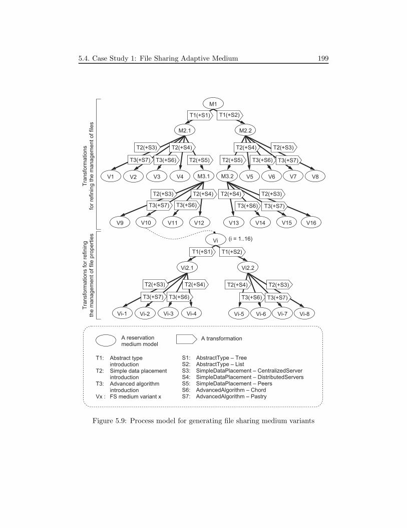
5.4. Case Study 1: File Sharing Adaptive Medium 199
M1
M2.1 M2.2
V1 V3 V4 V5 V6 V8M3.1 M3.2
V9 V11 V12 V13 V14 V16
T2(+S3)
T3(+S6)
T2(+S4) T2(+S4)
T3(+S6)
T2(+S3)
T2(+S3)
T3(+S6)
T2(+S4)
T3(+S6)
T2(+S3)
T1(+S1) T1(+S2)
T1: Abstract type introduction
T2: Simple data placement introduction
T3: Advanced algorithm introduction
Vx : FS medium variant x
A reservation medium model
T2(+S4)
T2(+S5)T2(+S5)
V2
T3(+S7)
V7
T3(+S7)
V15
T3(+S7)
V10
T3(+S7)
Vi2.1 Vi2.2
T1(+S1) T1(+S2)
Vi-1 Vi-3 Vi-4
T2(+S3)
T3(+S6)
T2(+S4)
Vi-2
T3(+S7)
Vi-5 Vi-6 Vi-8
T2(+S4)
T3(+S6)
T2(+S3)
Vi-7
T3(+S7)
Vi (i = 1..16)
Tra
nsfo
rma
tio
ns
for
refin
ing
th
e m
an
ag
em
en
t o
f file
s
Tra
nsfo
rma
tio
ns f
or
refin
ing
the
ma
na
ge
me
nt
of
file
pro
pe
rtie
s
S1: AbstractType – Tree S2: AbstractType – List S3: SimpleDataPlacement – CentralizedServer S4: SimpleDataPlacement – DistributedServers S5: SimpleDataPlacement – Peers S6: AdvancedAlgorithm – Chord S7: AdvancedAlgorithm – Pastry
A transformation
Figure 5.9: Process model for generating file sharing medium variants

200 5. Prototype
5.4.3.2 FS Medium Variants
Figures 5.10 includes the component models of two FS medium variants: V8-8and V9-8 in the process model.
In variant V8-8, both files and fileProperties sets are implemented usingthe List abstract type. The data of each set are placed on a centralized server(components c11 and c7 ). On the other hand, in variant V9-8, the files set isimplemented as a Tree and its data are placed on every roles manager instancesthat are considered as peers (component c11 ). Files are localized by localizationdata placed on a centralized server (component c13 ).
In these two variants, we do not detail the structure of the remover manager(component c1 ). The structure of this component is similar to that of thesharer manager. However, the implementation of the two root components (c3is the root of c2 ) are different since they provide different services. In fact, thestructure of these role managers will be different if the some features such as f0
are related to only one role manager. As explained in Section 4.4, we relate allthe features to both remover and sharer managers to simplify the development.In this chapter, we will describe another case study in which some features arerelated to various role managers (Section 5.5).
5.4.3.3 Implementation
We have implemented three FS medium variants including variants V8-8 andV9-8 described above and variant V12-8. The last one is similar to second one,except that file localization data in the last one are replicated in some distributedservers. The component model of variant V12-8 thus can be achieved from thatof variant V9-8 by replacing the multiplicity type “1” of component c13 (theserver) by “1..*”. The implementation of components c13 and c12 (proxy)must also be replaced.
For each of the three variants, only some components such as c3, c5, and c9must be directly implemented. Some other components such as c6 and c7 areimplemented as part of solutions (e.g., CentralizedServer and Peers), and then,are reusable several times.
The variants are implemented using the Julia implementation (in Java) ofthe Fractal component model. Distributed communication are implemented byusing Java RMI.

5.4. Case Study 1: File Sharing Adaptive Medium 201
c3: <files>List-<fileProperties>List-Impl
c2: SharerManager
c8: <files>DataManagement
c10: <files>Proxy c9: List-<files>Data Management-Impl
c1:RemoverManager
1..*
1
f0.{f0(5)+f0(26)}
f1.f1(5) f3.f8
f0
f1
f3.f8
c11: <files>Server (Internal manager)
Variant
V8-8
: F
iles a
nd f
ile p
ropert
ies a
re p
laced o
n t
wo c
en
traliz
ed s
erv
ers
1 1..*f0
c4: <fileProperties>DataManagement
c6: <fileProperties>Proxy c5: List-<fileProperties>Data Management-Impl
1..*
f21.f21(26) f22.f28
f22.f28
c7: fileProperties> Server(Internal manager)
1
f21
c3: <files>Tree-<fileProperties>List-Impl
c2: SharerManager
c1:RemoverManager
1
f0.{f0(4)+f0(26)}
f0
f14.f17
c13: <<files> LocalizationData>Server (Internal manager)
Variant
V9-8
: F
ile p
ropert
ies a
re p
laced o
n a
centr
aliz
ed s
erv
er,
file
s a
re p
laced
on p
eers
, file
lo
caliz
ation d
ata
are
pla
ced o
n a
ce
ntr
aliz
ed s
erv
er.
1 1..*f0
c4: <fileProperties>DataManagement
c6: <fileProperties>Proxy c5: List-<fileProperties>Data Management-Impl
1..*
f21.f21(26) f22.f28
f22.f28
c7: fileProperties> Server(Internal manager)
1
f21
c8: <files>DataManagement
c10: <files>DataPlacement
c12: <<files> Localization Data>Proxy
c9: Tree- <files>DataManagement- Impl
c11:<files>Peer
f3
f1
f1.f1(4)f3.f10 f14.f17
Figure 5.10: Two FS medium variants at the component-implementation level

202 5. Prototype
5.4.4 Step 4: Composition
To compose the FS adaptive medium implementation, we select variant V8-8as the initial variant. The adaptive medium is then composed by introducingeach manager component of this variant into an empty adaptive manager ofAMIV1. The adaptive medium implementation is then a set of adaptive man-agers, including 2 adaptive role managers and 2 adaptive internal managers.This integration is realized easily using Fractal ADL supported by Julia.
5.4.5 Adaptation
In the FS adaptive medium, adaptations are fine-grained and automaticallyplanned. For example, consider the two following adaptations:
• Adaptation 1 (V8-8 to V9-8): The abstract type of the files set is changedfrom List to Tree. The data placement of the files is changed from Cen-tralizedServer to Peers. Consequently, file localization data are requiredand the CentralizedServer data placement solution is selected to managethese data.
• Adaptation 2 (V12-8 to V9-8): The DistributedServers data placementsolution for file localization data is replaced by the CentralizedServer one.
Reconfiguration
In all the two adaptations, the management of file properties is unchanged.Therefore, components c4 and c7 are kept.
In adaptations 1, since the abstract type of the files et is changed, compo-nents c3 and c9 corresponding to concern features affected by the abstract typeconcern are replaced. Similarly, the file data placement solution for are changedfrom Peers to CentralizedServer, components c10 and c11 of variant V8-8 aretherefore replaced by components c10 and c13 of variant V9-8.
On the other hand, in adaptation 2, since the Peers solution for file place-ment is unchanged, components c10 and c11 are kept, only the components im-plementing the DistributedServers solution for file localization data placementare replaced by components c12 and c13 implementing the CentralizedServersone.
All the above reconfigurations of components are easily identified for ana-lyzing the FS medium fine-grained MCV model.

5.5. Case Study 2: Reservation Adaptive Medium 203
Data Transfer
In an adaptation, data managed by replaced components are transferred tothe replacement ones. That is, files are transferred from the centralized serverto peers in adaptation 1. On the other hand, in adaptations 2, files are keptand only the file localization data are transferred.
5.4.6 Summary
We have presented above some more details of the FS adaptive medium de-velopment using the medium development framework prototype. The develop-ment includes a process that can generate 128 FS medium variants using threetransformations, 3 solution meta-models and 7 solution models. Among thesevariants, we have implemented 3 variants in Java and Fractal.
We have also described 4 fine-grained adaptations based on the 3 FS mediumvariants. Execution results of these adaptation will be provided and analyzedlater in the evaluation.
5.5 Case Study 2: Reservation Adaptive Medium
This section presents the reservation adaptive medium that is built based onthe reservation medium (Section 2.5.1.2). To illustrate the adaptive mediumapproach, we highlight the specification and generation development steps (steps1 and 3). Activities and results in the other steps that are similar to those ofthe file sharing adaptive medium development will be not presented.
5.5.1 Step 1: Specification
5.5.1.1 Reservation Medium Abstraction
Figure 5.11 shows the reservation medium model at level 0. The reservationmedium as a communication abstraction is represented by class Reservation-Medium. The Source, Reserver, and Observer classes represent three roles. Areservation system has only one source instance, one to many reserver instances,and zero to many observer instances. The airplane seat reservation application(Figure 2.7) is only one case where the reservation medium is used. In this case,a reserver instance is always associated with an observer instance.
The reservation medium is specified by its provided and required interfaces.Precisely, it provides the SourceMediumServices and ReserverMediumServices
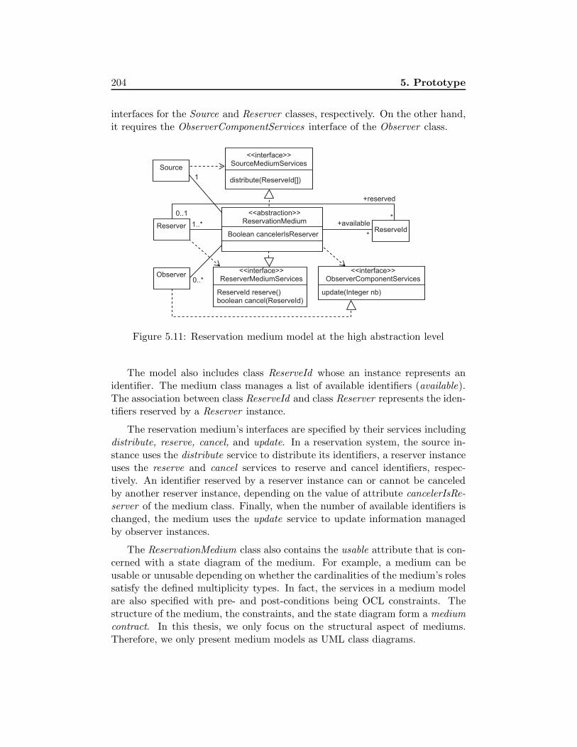
204 5. Prototype
interfaces for the Source and Reserver classes, respectively. On the other hand,it requires the ObserverComponentServices interface of the Observer class.
1..*
1
<<abstraction>> ReservationMedium
Boolean cancelerIsReserver ReserveId
+reserved
Source
Reserver +available
*
*
<<interface>> SourceMediumServices
distribute(ReserveId[])
<<interface>> ReserverMediumServices
ReserveId reserve() boolean cancel(ReserveId)
Observer <<interface>>
ObserverComponentServices
update(Integer nb)
0..*
0..1
Figure 5.11: Reservation medium model at the high abstraction level
The model also includes class ReserveId whose an instance represents anidentifier. The medium class manages a list of available identifiers (available).The association between class ReserveId and class Reserver represents the iden-tifiers reserved by a Reserver instance.
The reservation medium’s interfaces are specified by their services includingdistribute, reserve, cancel, and update. In a reservation system, the source in-stance uses the distribute service to distribute its identifiers, a reserver instanceuses the reserve and cancel services to reserve and cancel identifiers, respec-tively. An identifier reserved by a reserver instance can or cannot be canceledby another reserver instance, depending on the value of attribute cancelerIsRe-server of the medium class. Finally, when the number of available identifiers ischanged, the medium uses the update service to update information managedby observer instances.
The ReservationMedium class also contains the usable attribute that is con-cerned with a state diagram of the medium. For example, a medium can beusable or unusable depending on whether the cardinalities of the medium’s rolessatisfy the defined multiplicity types. In fact, the services in a medium modelare also specified with pre- and post-conditions being OCL constraints. Thestructure of the medium, the constraints, and the state diagram form a mediumcontract. In this thesis, we only focus on the structural aspect of mediums.Therefore, we only present medium models as UML class diagrams.

5.5. Case Study 2: Reservation Adaptive Medium 205
5.5.1.2 Implementation Architecture
Figure 5.12 describes the reservation medium model at level 1 after introducingSourceManager, ReserverManager, and ObserverManager. The introduction ofthese classes is realized automatically by the manager introduction transforma-tion.
1..*
1
<<abstraction>> Reservation
Medium ReserveId
+reserved
Source Manager
Reserver Manager
+available
*
*
<<interface>> SourceMediumServices
distribute(ReserveId[])
<<interface>> ReserverMediumServices
ReserveId reserve() boolean cancel(ReserveId)
Observer Manager
<<interface>> ObserverComponentServices
update(Integer nb) 0..*
Source
Reserver
Observer
1 1
1 1
1 1
0..1
Figure 5.12: Reservation medium model after introducing managers
At this level, the reservation medium is a composition of role managers.The provided and required interfaces of the medium is now represented as thoseof the introduced role managers. Since each role manager is associated with arole, the link between class ReserveId and class Reserver that allows to identifyidentifiers reserved by each reserver instance is now associated with the reservermanager.
5.5.1.3 Concerns and Solutions
From the reservation medium model at level 1, we identified concerns and so-lution as described in the early MCV model (Figure 5.13).
The main problem in the reservation medium is the management of theavailable identifiers. Therefore, the data management concern usage pattern(Figure 4.4) can be reused. Precisely, for the management of the available dataset, we reused 1) the AbstractType concern with the List and Tree solutions;2) the SimpleDataPlacement concern with the CentralizedServer, Distributed-Servers, and Peers solutions; and 3) the AdvancedAlgorithm with the Chord so-

206 5. Prototype
lution. Second, for the placement of the <<available>LocalizationData> dataset, we reused the SimpleDataPlacement concern with the CentralizedServerand DistributedServers solutions, and the AdvancedAlgorithm with the Chordsolution.
<reserved> DataManagement
Reservation Medium
SourceManager, ReserverManager, ObserverManager
ReserverManager
<available> DataManagement
Reserver Manager
<available> DataPlacement
<available> AbstractType
Tree
Centralized Server
List
Distributed Servers
Peers
<<available>Localization Data>DataPlacement
<available> AdvancedAlgorithm
<available> SimpleDataPlacement
<<available>LocalizationData> AdvancedAlgorithm
Centralized Server
Distributed Servers
<<available>Localization Data>SimpleDataPlacement
Chord
f3 f4
f5 f6
f9 f10 f11
f7 f8
f13
f14 f15
f16 f17 f18
Chord
f12
f0
f1 f2
Figure 5.13: The reservation medium early MCV model
In addition to the available identifiers management, the reservation mediumalso requires the management of reserved identifiers of each reserver manager in-stance. This local data management is represented by the <reserved>DataMa-nagement concern feature. We consider this concern as a simple concern thatdoes not have variable implementations.
Each concern or solution feature of the early MCV model is linked to the

5.5. Case Study 2: Reservation Adaptive Medium 207
role managers where the corresponding concern or solution is considered. In thereservation medium early MCV model, while the ReservationMedium compositeconcern feature is linked to all the three role managers, the other features areonly linked to the reserver manager. That is, the available identifiers are onlydistributed among the reserver manager instances of the reservation medium.
When defining the early MCV model, elements representing global data setsare also created for some concern features. Precisely, 5 elements representing theavailable data set are associated with features f0, f2, f3, f5, and f6. Similarly, 3elements representing the <available>LocalizationData data set are associatedwith f13, f14, and f15. No element representing the reserved data set since thisis a local data set.
From this early MCV model, 12 feature configurations corresponding to 12variants of the reservation medium are identified.
5.5.2 Step 2: Transformation
Since the data management concern usage pattern is reused, the three relatedtransformations are also reused. The transformations include the introductionsof abstract type, simple data placement, and sophisticated algorithm.
5.5.3 Step 3: Generation
In this section, we describe the reservation medium fine-grained MCV modeland the generation process model.
5.5.3.1 Fine-grained MCV Model
Figure 5.14 shows main elements of the reservation medium fine-grained MCVmodel, including concern and solution features, derived features, and affect- andimply-constraints.
As described in the figure, <available>AbstractType (f4) affects <available>-DataManagement (f2). This is because each solution for the f4 concern providesa different set of data services that is implemented by every solution for f2.Moreover, f4 also affects ReservationMedium (f0) since different data servicesrequire to implement the reservation medium functions differently.
On the other hand, <available>SimpleDataPlacement (f5) and <available>-AdvancedAlgorithm (f6) affect ReservationMedium (f0). Precisely, the functionsof the source, reserver, and observer managers are implemented according tothe selected solutions of f5 and f6. For example, when the CentralizedServer

208 5. Prototype
<reserved> DataManagement
Reservation Medium
<available> DataManagement
<available> DataPlacement
<available> AbstractType
Tree
Centralized Server
List
Distributed Servers
Peers
<<available>Localization Data>DataPlacement
<available> AdvancedAlgorithm
<available> SimpleDataPlacement
<<available>LocalizationData> AdvancedAlgorithm
Centralized Server
Distributed Servers
<<available>LocalizationData> SimpleDataPlacement
Chord
f3 f4
f5 f6
f9 f10 f11
f7 f8
f13
f14 f15
f16 f17 f18
Chord
f12
f0
f1 f2
f0(9)
concrete
concrete concrete
concrete
concrete
affect
imply
imply
imply
imply
imply
affect
imply
f0(10) f0(11) f0(12)
f2(7) f2(8)
f0(7) f0(8)
imply
imply
affectaffect
Figure 5.14: The reservation medium fine-grained MCV model

5.5. Case Study 2: Reservation Adaptive Medium 209
solution is selected, the source manager directly sends its identifiers to the server.Similarly, when the Peers solution is selected, the source manager sends itsidentifiers to reserver managers using the distribution policy implemented inthe Peers solution.
For the above affect-constraints, derived features and imply-constraints aregenerated, as depicted in the figure. Additionally, concrete features are alsoidentified (described in the figure by using the concrete labels).
M1
M2.1 M2.2
V1 V2 V3 V4 V5 V6M3.1 M3.2
V7 V8 V9 V10 V11 V12
T2(+S3)
T3(+S6)
T2(+S4) T2(+S4)
T3(+S6)
T2(+S3)
T2(+S3)
T3(+S6)
T2(+S4)
T3(+S6)
T2(+S3)
T1(+S1) T1(+S2)
T1: Abstract type introduction
T2: Simple data placement introduction
T3: Advanced algorithm introduction
Vx : Reservation medium variant x
A reservation medium model A transformation
S1: AbstractType – Tree
S2: AbstractType – List
S3: SimpleDataPlacement – CentralizedServer
S4: SimpleDataPlacement – DistributedServers
S5: SimpleDataPlacement – Peers
S6: AdvancedAlgorithm – Chord
T2(+S4)
T2(+S5)T2(+S5)
Figure 5.15: Process model for generating reservation medium variants

210 5. Prototype
5.5.3.2 Process Model
Figure 5.15 includes the generation process model of the reservation adaptivemedium. Similarly to the one of the FS medium, the three solution introductiontransformations in the data management concern usage pattern are applied.
As described in Figure 5.15, these three solution introduction transforma-tions are executed 16 times to generate 12 reservation medium variant modelsat level 3 (V1 to V12 ). Systematically, each model is then transformed intoanother one at level 4 by applying the modularization transformation.
5.5.3.3 Reservation Medium Variants
The process model presented above is used by the main transformation to gen-erate the 12 reservation medium variant models at level 4. In this section,we describe the component models of variants V6, V11, and V12 as examples(Figure 5.16).
• Variant V6: In this variant, the set of available identifiers is representedusing the List abstract type. The identifiers are placed on a centralizedserver that corresponds to an instance of component InternalManager-Server-CentralizedServer-<available>Data Placement-Impl (c9 ). This com-ponent is an internal manager. Each reserver manager instance thencontains an instance of component RM-Proxy-CentralizedServer-<availab-le>DataPlacement-Impl (c8 ) that allows to access to data placed on theserver.
• Variant V11: In this variant, the set of available identifiers is representedusing the List abstract type. The identifiers are placed on reserver man-ager instances that are considered as peer nodes. Data for localizing theseidentifiers are distributed among these nodes using the Chord solution.
• Variant V12: In this variant, the set of available identifiers is representedusing the Tree abstract type. The identifiers are also placed on reservermanager instances that are considered as peer nodes, but the data forlocalizing the identifiers are distributed among these nodes using the Cen-tralizedServer solution.
The runtime reservation medium contains one source manager instance, oneto many reserver manager instances, zero to many observer manager instances.In the case of variant V6, the runtime medium also contains one componentinstance corresponding to the centralized server where identifiers are placed.

5.5. Case Study 2: Reservation Adaptive Medium 211
c4: RM- CentralizedServer- List-Impl
c3: ReserverManager (RM)
c6: RM-<available>DataManagement
c8: RM-Proxy- CentralizedServer- <available> DataPlacement-Impl
c7: RM- List-<available>Data Management-Impl c2: Observer
Manager-Centralized Server-List-Impl
c1: SourceManager -CentralizedServer-List-Impl
1..*
1
c5: RM-<reserved> DataManagement- Impl
f0.{f0(9)+f0(8)}
f2.f2(8) f3.f9
f0
f2
f1f0.{f0(9)+f0(8)}
f0.{f0(9)+f0(8)}
f3.f9
c9: Internal Manager-Server-CentralizedServer-<available>Data Placement-Impl
c4: RM- Peers-List-Impl
c3: ReserverManager (RM)
c6: RM-<available> DataManagement
c8: RM-<available>DataPlacement
c10: RM-Chord- <<available> LocalizationData>DataPlacement- Impl
c7: RM-List- <available> DataManagement- Impl
c9: RM-Peers- <available> DataPlacement- Impl
c5: RM-<reserved> DataManagement-Impl
c1: Source Manager-Peers-List-Impl
c2: Observer Manager-Peers-List-Impl
f3
f0
f2
f1f0.{f0(11)+f0(8)}
f2.f2(8)f3.f11 f13.f18
f0.{f0(11)+f0(8)}
f0.{f0(11)+f0(8)}
Variant
V6:
a L
ist
of
availa
ble
ide
ntifiers
pla
ced o
n a
Ce
ntr
aliz
edS
erv
er
1..*
1
0..*
1..*
1..*
1
0..*
1..*
c4: RM- Peers-Tree-Impl
c3: ReserverManager (RM)
c6: RM-<available> DataManagement
c8: RM-<available>DataPlacement
c10: RM-Proxy-CentralizedServer-<<available> LocalizationData> DataPlacement- Impl
c7: RM-Tree- <available> DataManagement- Impl
c9: RM-Peers- <available> DataPlacement- Impl
c5: RM-<reserved> DataManagement-Impl
c1: Source Manager-Peers-Tree-Impl
c2: Observer Manager-Peers-Tree-Impl
f3
f0
f2
f1f0.{f0(11)+f0(8)}
f2.f2(8)f3.f11 f13.f18
f0.{f0(11)+f0(8)}
f0.{f0(11)+f0(8)}
1..*
1
0..*
1..*
c11: Internal Manager-Server-Centralized Server-<<available> LocalizationData> DataPlacement- Impl
f13.f18
1..*
1
Variant
V11:
a T
ree o
f availa
ble
id
entifiers
pla
ced o
n P
eers
and localiz
ed
by O
penC
hord
Variant
V12:
a L
ist
of
availa
ble
ide
ntifiers
pla
ced o
n P
ee
rs
and t
he
ir localiz
ation d
ata
are
pla
ce
d o
n a
Centr
aliz
edS
erv
er
Figure 5.16: Component models of three reservation medium variants
212 5. Prototype
Likewise, variant V12 comprises one component instance corresponding to thecentralized server where identifiers’ localization data are placed.
Each component in the figure is depicted with a label representing the linkedfeature(s). For example, in the reserver manager of variant V11, componentRM-Peers-List-Impl (c4 ) is linked to the root feature (f0) of the fine-grainedMCV model. This component is dedicated for the Peers solution of the iden-tifiers placement (as feature f0 is affected by feature f3). It is connected to 1)composite component RM-<available>DataManagement (c6 ) corresponding toconcrete concern feature f2 and 2) component RM-<reserved>DataManagement-Impl (c5 ) corresponding to concrete concern feature f1. If a concern featurehas one or several child feature groups, all the selected solution features areincluded in the label (e.g., f3.f11 and f0.}f0(11) + f0(8)}).
In the component models described in Figure 5.16, interfaces for inter-managers communication are not depicted. Generally, each (sub-)componentof a manager may be connected to some other components (of other managers)that are derived form the same solution model. Additionally, the interfaces forconnecting the manager and the model managers are also not depicted.
5.5.3.4 Data Transfer Model
The generated data transfer model for the reservation adaptive medium is sim-ilar to the one for the FS adaptive medium, which is previously presented inFigure 4.21.
The data transfer model describes how to transfer the set of available identi-fiers that has been identified in variation-point concerns <available>DataPlace-ment (f3), <available>SimpleDataPlacement (f5), and <available>Advanced-Algorithm (f6). Similarly, the data transfer model also describes how to trans-fer the set of available identifiers’ localization data that has been identified invariation-point concerns f13, f14, and f15. Precisely, the data transfer model in-dicates read/write/delete operations of the components implementing solutionsto these concerns.
5.5.3.5 Medium Reconfiguration Constraints Model
The medium reconfiguration constraints model is also generated by collectingsolution reconfiguration constraints models. In the data management concernusage pattern, we define only one solution configuration constraints model forthe CentralizedServer solution to the <data>DataPlacement concern. Con-straints in this model indicate that all the client objects must be started afterthe server one.

5.6. Evaluation 213
The constraints of this model are introduced into the medium reconfigu-ration constraints model by the main transformation. They are customizedfor the two CentralizedServer solutions to the <available>DataPlacement and<<available>LocalizationData>DataPlacement concerns.
5.5.4 Step 4: Composition
The composition of the reservation adaptive medium implementation is verysimple. Manager components of a reservation medium implementation variantare embedded into empty adaptation manager component of AMIV1.
5.5.5 Summary
We have presented above the development of the reservation adaptive medium.This adaptive medium is an interesting example in terms of illustrating thefeature refinement and modularization. Differently from the FS medium MCVmodel, in the reservation medium one, features are related to various role man-agers. This requires to identify some affect-constraints when refining the earlyMCV model. Moreover, the component structures of role managers are conse-quently different from each other.
On the other hand, in terms of adaptation, the reservation adaptive mediumis similar to the FS adaptive medium. Therefore, we did not describe anyadaptation in this adaptive medium. The adaptation experiment thus will onlybe realized on the FS adaptive medium.
5.6 Evaluation
This section evaluates the adaptive medium approach based on the develop-ment and execution results of the FS adaptive medium. First, we describe theexecution conditions. Then, we provide quantitative and qualitative analyses.
5.6.1 Execution Conditions
We have executed the 2 fine-grained adaptations of the FS adaptive mediumwhich have been presented in Section 5.4.5. We have also executed the 2 corre-sponding coarse-grained adaptations (i.e., the adaptations that are performedby replacing the whole application implementation) in order to compare the twotypes of adaptation. The FS adaptive medium was deployed on 14 PCs IntelDuo 2 Core 3GHz running Linux 2.6.32 connected by 100 Mbit Ethernet. 10
214 5. Prototype
PCs are used to deploy 10 sharers and 4 PCs are used to deploy 1 remover anddata servers. In variant V12-8, file localization data items are replicated on twoservers.
In this FS adaptive medium, each shared file is represented by a runtimestring of 10.000 characters randomly generated.
5.6.2 Quantitative Analysis
In the following sections, we analyze the development and execution results. Theanalysis is presented regarding the six identified challenges in order to evaluatethe adaptive medium approach in terms of overcoming the challenges.
5.6.2.1 Supporting Consistent Architectures
By consistent architectures, we mean that the components of the running ap-plication must properly work after adaptation. In the case of the FS adaptivemedium, the medium worked properly after the each fine-grained adaptation.
However, this result does not allow us to conclude that consistent architec-tures are fully ensured. In fact, overcoming this challenge is difficult to justifyquantitatively based on the development and execution results. This challengewill be revisited later in the qualitative analysis.
5.6.2.2 Supporting Data Transfer
After any of the 2 fine-grained adaptations, the target FS medium variant wasfully initialized with data of the source variant. The data include files, fileproperties, and file localization data. In adaptations 1, files are transferredfrom 1 server of variant V8-8 to 10 peers of variant V9-8. On the other hand,in adaptations 2, file localization data are transferred from 2 servers of variantV12-8 to 1 server of variant V9-8. File properties are kept.
Table 5.2 includes adaptation time of the 2 fine-grained adaptations. Eachadaptation was executed 11 times with different numbers of files, ranged from0 to 5.000. Adaptation 1 was be able to transfer all these files and adaptation2 was be able to transfer all the file localization data items, one per file.
5.6.2.3 Modeling Commonality and Variability
The goal of modeling commonality and variability is to support fine-grainedadaptations. In order to show the advantages of modeling commonality and

5.6. Evaluation 215
No. files Adaptation 1 Adaptation 2
0 0,48 0,66
500 4,11 1,81
1000 8,09 3,37
1500 13,50 6,12
2000 21,64 9,05
2500 32,76 14,41
3000 46,22 19,90
3500 61,24 27,74
4000 79,46 36,12
4500 100,81 44,03
5000 120,55 56,46
Table 5.2: Adaptation time (s) of fine-grained adaptations
variability in the adaptive medium approach, we compare the 2 fine-grainedadaptations with the 2 corresponding coarse-grained adaptations in terms of 1)keeping common components through adaptations and 2) reducing adaptationtime.
Keeping Common Components
Table 5.3 shows the advantage of fine-grained adaptations in terms of keepingcommon (runtime) components. Precisely, in adaptations 1 and 2, 40% and 81%components are kept, respectively. This allows to reduce adaptation actions,and particularly, reduce adaptation time.
Adaptation Kept comp. Removed comp. Added comp.
Adaptation 1 23 (40%) 34 (60%) 45
Adaptation 2 56 (81%) 13 (19%) 12
Table 5.3: Kept, removed, and added components in fine-grained adaptations
Reducing Adaptation Time
Figure 5.17 includes two charts in which the two fine-grained adaptationsare compared with the corresponding coarse-grained adaptations.
These results show that both fine-grained adaptations reduce adaptationtime. In both fine-grained adaptations, the file properties managed by commoncomponents are not transferred, while they are transferred in the correspondingcoarse-grained adaptations.

216 5. Prototype
The results also show that adaptation 2 better reduce adaptation time. Thisis because in this adaptation, files are kept and only file localization data whichare smaller than files are transferred.
Thanks to all the results described above, we have shown the advantages ofmodeling commonality and variability in the adaptive medium approach.
0
20
40
60
80
100
120
140
160
0 2000 4000 6000
Ad
ap
tatio
n tim
e (
s)
Adaptation 1
Coarse-grained
Fine-grained
0
20
40
60
80
100
120
140
160
180
0 2000 4000 6000
Ad
ap
tatio
n tim
e (
s)
Adaptation 2
Coarse-grained
Fine-grained
(files)
(files)
Figure 5.17: Comparison of fine-grained and coarse-grained adaptations
5.6.2.4 Supporting Automatic Adaptation Planning
Table 5.4 describes the numbers of generated adaptation plans and their ele-ments in the two fine-grained adaptation.
In adaptation 1, 1 coordination plan and 13 local adaptation plans are gener-ated. The coordination plan indicates participants of each step and 11 require-constraints related to the initialization of the CentralizedServer solution, whilethe 13 local adaptation plans contain 228 adaptation actions.

5.6. Evaluation 217
In adaptation 2, 1 coordination plan containing 11 require-constraints and14 local adaptation containing 78 adaptation actions are generated. In com-parison to adaptation 1, adaptation 2 generates one more local adaptation plansince variant V12-8 has two servers on which file localization data items arereplicated. On the other hand, the numbers of removed and added componentsin adaptation 2 is much smaller than in adaptation 1, the number of adaptationactions is also smaller.
Both adaptations are fully automated.
AdaptationCoordination Require- Local adaptation Adaptation
plans constraints plans actions
Adaptation 1 1 11 13 228
Adaptation 2 1 11 14 78
Table 5.4: Generated adaptation plans and their elements
5.6.2.5 Supporting Distributed Adaptation
Both adaptations 1 and 2 are distributed. In each adaptation, the distributedadaptation actions mentioned above are separated into 6 adaptation steps. Allthe local adaptation processes (13 in adaptation 1 and 14 in adaptation 2)are synchronized at the beginning and the end of each step. The adaptationactions are also executed with respect to the 11 require-constraints included inthe adaptation coordination plan.
5.6.2.6 Automating the Development
Table 5.5 compares user-defined and generated software assets in the develop-ment of the FS adaptive medium.
According to these results, we can see that the adaptive medium develop-ment is highly automated. Thanks to the development framework containingbasic meta-models and transformations, software engineers need to define 3meta-models, 27 models, and 3 transformations in order to generate 128 vari-ants as component diagrams containing 1.536 components. Moreover, the 3transformations, the 3 meta-models, and 7 models are reusable for the develop-ment of other adaptive mediums.
These numbers of generated diagrams (128) and components (1.506) are alsothose that developers would need to defined in manual development. This illus-trates the advantage of the adaptive medium approach in terms of automatingthe development.

218 5. Prototype
User-defined Generated
- 1 medium model - 128 component diagrams- 1 early MCV models - 1.536 components- 1 process models- 3 solution meta-models (*)- 7 solution models (*)- 3 transformations (*)- 17 decision models
Table 5.5: User-defined and generated elements in the FS adaptive mediumdevelopment ((*) - reusable for the development of other adaptive mediums)
5.6.3 Qualitative Analysis
Table 3.1 summarizes solutions involved in the adaptive medium approach alongwith the challenges they address. The solutions include the medium abstrac-tion, the adaptive medium abstraction, the medium refinement process, theMCV modeling, the modularization, the data transfer modeling, and the recon-figuration constraints modeling. In Chapter 4, we have detailed these solutions.Moreover, in this chapter, we have presented a prototype, two case studies, andexperiment results. This enables us to answer the question of how good thesolutions are in terms of overcoming the identified challenges. The answer isdescribed in Table 5.6.
In Table 5.6, “+” stands for “the solution is moderately good in terms ofovercoming this challenge”, and “++” stands for “the solution is very good interms of overcoming this challenge” (or “the challenge is very well supportedby this solution”).
We consider a solution “moderately good” or “very good” with regard to therelated approaches. Depending on each challenge, “moderately good” and “verygood” may also refer to “partially” and “fully”, respectively. In the remainderof this section, we will discuss each solution more precisely.
Supporting Consistent Architectures
The adaptive medium approach supports consistent architectural variantsof adaptive applications (concerning challenge C1 ) thanks to 1) the mediumabstraction that is used as a basic architecture to build all the variants, 2)the adaptive medium abstraction that serves as a basis to integrate adapta-tion control and the functional medium, 3) the medium refinement process with(semi-formally) verified transformations, and 4) the reconfiguration constraintsmodeling that supports the coordination of distributed adaptations. However,
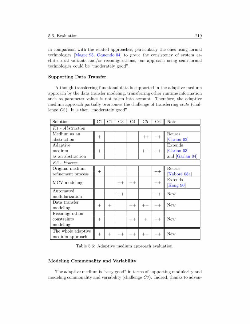
5.6. Evaluation 219
in comparison with the related approaches, particularly the ones using formaltechnologies [Magee 95, Oquendo 04] to prove the consistency of system ar-chitectural variants and/or reconfigurations, our approach using semi-formaltechnologies could be “moderately good”.
Supporting Data Transfer
Although transferring functional data is supported in the adaptive mediumapproach by the data transfer modeling, transferring other runtime informationsuch as parameter values is not taken into account. Therefore, the adaptivemedium approach partially overcomes the challenge of transferring state (chal-lenge C2 ). It is then “moderately good”.
Solution C1 C2 C3 C4 C5 C6 Note
K1 - Abstraction
Medium as an+ ++ ++
Reusesabstraction [Cariou 03]
Adaptive+ ++ ++
Extendsmedium [Cariou 03]as an abstraction and [Garlan 04]
K2 - Process
Original medium+ ++
Reusesrefinement process [Kabore 08a]
MCV modeling ++ ++ ++Extends[Kang 90]
Automated++ ++ New
modularization
Data transfer+ + ++ ++ ++ New
modeling
Reconfiguration+ ++ + ++ Newconstraints
modeling
The whole adaptive+ + ++ ++ ++ ++ New
medium approach
Table 5.6: Adaptive medium approach evaluation
Modeling Commonality and Variability
The adaptive medium is “very good” in terms of supporting modularity andmodeling commonality and variability (challenge C3 ). Indeed, thanks to advan-

220 5. Prototype
tages of the feature modeling method, commonality and variability are modeled.On the other hand, by 1) combining the feature modeling and the separation offunctional concerns and then 2) proposing affect-constraints and derived solu-tions, the modularity of functional medium variants is better supported. Whilesome related approaches use black-box components as primitive software as-sets, the adaptive medium approach allows using both black-box componentsand reusable or custom source code thanks to the automated modularization.
Supporting Automatic Adaptation Planning
The challenge of supporting automatic adaptation planning (challenge C4 )is also “very well” overcome by the adaptive medium approach. Although thereconfiguration constraints modeling only provides require-constraints betweenactions concerning elements inside one solution model, the generation of adapta-tion plans is fully automated. This automation is achieved by relying principallyon the fine-grained MCV modeling that describes commonality and variabilityof functional medium variants, and is linked to components of these variants.Moreover, the data transfer and reconfiguration constraints modeling only re-quires software engineers to annotate some information (such as data transferoperations) instead of programming it.
Supporting Distributed Adaptation
Distributed adaptations (challenge C5 ) are “very well” supported thanksto 1) the distributed nature of the medium abstraction as well as the adap-tive medium abstraction and 2) the modeling of data transfer across sites andreconfiguration constraints between distributed actions.
Automating the Development
Finally, combining all the solutions, the adaptive medium development ishighly automated (challenge C6 ). While some related approaches allow softwareengineers to operate at the abstraction level of components and connectors, themedium approach provides 1) the medium abstraction at a higher abstractionlevel and 2) a (semi-)automated process for refining this abstraction into theabstraction level of components and connectors. Therefore, the development ofadaptive mediums “very well” automated.

5.7. Prototype Summary and Discussion 221
5.7 Prototype Summary and Discussion
In this chapter, we have described a prototype of the adaptive medium de-velopment framework. The framework includes 1) a basic facility containingbasic meta-models and transformations used in the development of every adap-tive medium, 2) a concern catalogue containing tailored meta-models, models,and transformations that may be reused in the development of several adap-tive mediums sharing common features, 3) an implementation of the adaptationmedium, and 4) a composition program allowing to compose the target adap-tive medium implementation. We have also presented the file sharing and thereservation adaptive mediums that are built using the framework.
An important part of this chapter is the evaluation of the adaptive mediumapproach based on the experiment results. The results have been analyzed re-garding the six identified challenges, and thereby, justified the thesis contribu-tions. The evaluation also includes a qualitative analysis in which the adaptivemedium approach has been compared with related work in terms of overcomingthe challenges.

222 5. Prototype

Chapter 6
Conclusion
6.1 Contribution Summary
This thesis has proposed an approach to developing adaptive distributed ap-plications, called the adaptive medium approach. We have also formulated anadaptive medium development process that is supported by an adaptive mediumdevelopment framework.
Our approach relies on the medium high-level abstraction and the highly-automated medium refinement process, that correspond to the two key issuesidentified in Chapter 1. We argue that the adaptive medium approach over-comes the six challenges (also identified in Chapter 1) for the development ofadaptive software systems: 1) supporting consistent architectures, 2) transfer-ring system state, 3) modeling commonality and variability (and supportingmodularity), 4) supporting automatic adaptation planning, 5) supporting dis-tributed adaptations, and 6) automating the development of adaptive softwaresystems.
Adaptive Medium Approach
The adaptive medium approach is architecture-based, i.e., architectural mod-els are used to monitor and adapt the running application. Additionally, theadaptation control is externalized. These fundamental approaches significantlyfacilitate the development of adaptive software.
The adaptive medium approach can be summarized from two points of view:architecture and process.
223
224 6. Conclusion
• Architecture: From this point of view, the adaptive medium approachprovides two important architectures including the adaptive medium high-level abstraction and the adaptive medium implementation architecture.
At the high-level abstraction, an adaptive distributed application is spec-ified as an interconnection of an adaptive medium abstraction and clientcomponents. The adaptive medium abstraction encapsulates functionalcommunication between the client components. Moreover, it can dynami-cally reconfigure its internal architecture in order to move from an imple-mentation variant to another one, that can be more appropriate for theoperating environment conditions. According to the external adaptationcontrol architecture, the adaptive medium abstraction is a composition oftwo other abstractions: a functional medium and an adaptation medium.While the functional medium encapsulates functional communication inthe application, the adaptation medium represents the coordination ofdistributed adaptation actions.
At the implementation level, the functional medium abstraction is rei-fied by a set of functional manager components. On the other hand, theadaptation medium abstraction is reified by a set of adaptation managercomponents. The adaptive medium implementation is then composed byintegrating each functional manager with an adaptation manager. Whilethe functional managers collaborate to realize the functional communica-tion of the application, the adaptation managers collaborate to reconfigurethe functional managers when necessary.
• Process: The adaptive medium approach includes a generation processthat allows to generate different implementation variants of a mediumfrom its high-level abstraction. This process is model- and feature-based.
The generation process is based on the MDA pattern. From the mediumhigh-level abstraction, different design concerns are identified. The gen-eration process is constituted by successive transformations. Each trans-formation transforms a concern-independent medium model to a concern-specific medium model. Thanks to the introduction of different solutionsfor each concern, the generation process transforms a medium model atthe high-abstraction level into different medium variant models at theimplementation level.
On the other hand, the generation process is complemented by using andextending feature models. We have proposed an MCV modeling approach:modeling the modularity, commonality, and variability of the mediumvariants. The MCV modeling and the model-based approaches are fullyintegrated. More precisely, concerns and solutions are represented as fea-tures of an MCV model being an extended feature model. The features

6.1. Contribution Summary 225
representing the solutions for a concern are represented as a xor-group as-sociated to the feature representing that concern. The MCV model thusfacilitates the identification of concerns and solutions. It is then used toautomate the modularization of medium variants into components. Tothis end, we have provided sophisticated rules for mapping features tocomponents. An MCV model thus can describe the modularity of mediumvariants and allows to identify common and different components of anytwo medium variants.
Additionally, the process also includes a data transfer modeling solutionthat allows to identify operations needed to transfer data between mediumvariants. Moreover, a reconfiguration constraints modeling solution en-ables to represent constraints between actions needed to perform adapta-tion.
Thanks to the generation process, implementation variants of the func-tional medium as well as the adaptation medium are generated. While avariant of the adaptation medium is selected as a stable adaptation controlinfrastructure, a variant of the functional one is selected as the initial vari-ant that can be reconfigured at runtime in order to achieve another vari-ant. Moreover, the generation process also generates architectural modelsof the functional medium variants and adaptation-facilitating models (in-cluding an MCV model whose features are linked to the components ofthe functional medium variants, a data transfer model, and a medium re-configuration constraints model). These models are used by the selectedadaptation medium variant to automatically plan distributed adaptationsat runtime.
The medium concept and the model-based refinement process were originallyproposed in [Cariou 03] and [Kabore 08a], respectively. The main contributionsof this thesis in the adaptive medium approach thus include
• the adaptive medium high-level abstraction and implementation architec-ture that are based on the medium concept,
• the introduction of the MCV modeling into the model-based refinementprocess,
• the data transfer modeling, and
• the reconfiguration constraints modeling.

226 6. Conclusion
Adaptive Medium Development Process
We have formulated an adaptive medium development process. The processis composed of four steps including specification, transformation, generation,and composition. In the process, four roles of software engineers are identified:medium expert, solution designer, process designer, and application designer.The steps and the roles are identified with regard to the domain engineering andapplication engineering processes in system family engineering, thus promotingreuse.
Adaptive Medium Development Framework
The adaptive medium development process is supported by an adaptivemedium development framework. In this thesis, we have presented a frameworkprototype that consists of the following elements:
• A basic facility containing basic transformations and meta-models.
• A medium catalogue containing tailored transformations, meta-models,and models.
• An implementation variant of the adaptation medium.
• A composition program.
The basic facility, the adaptation medium implementation, and the compo-sition program are used for the development of every adaptive medium. On theother hand, elements of the concern catalogue is reused in the development ofsome adaptive mediums whose functional mediums share common concerns andsolutions.
To illustrate the adaptive medium approach and the development process,we have shown two examples including the FS adaptive medium and the reser-vation adaptive medium.
6.2 Limitations
Our approach has several limitations. First, it requires to use the medium thatis a specific abstraction. Second, the feature refinement and the modularizationdepend on the process designer and are not verified. Third, it lacks a processto support runtime variability.

6.2. Limitations 227
Using a Specific Abstraction
The development of any adaptive distributed application using the adap-tive medium approach always adopts the medium abstraction. This high-levelabstraction allows to automate the development process, and then, use informa-tion generated by the process to automate runtime adaptations. However, thisspecific abstraction may restrict the application of the approach. In particu-lar, the medium abstraction has a specific border that separates the applicationfunctionality into two parts, one reified by the set of manager components andthe other is reified by the client components. If the development of an adaptiveapplication requires to use some black-box components and these componentscross the medium border, the adaptive medium approach will not be applicable.
In fact, the medium abstraction is an abstract component model that en-compasses many other lower-level (i.e., the implementation level) componentmodels such as CCM, OSGi, and Fractal. Therefore, this is not a limitation interms of platform support, but only from the functionality reuse point of view.This limitation can be seen as the “cost” of gaining the high-level automation.
Lack of Modularization Verification
In the adaptive medium development process, the feature refinement is fullybased on knowledge of the process designer. Main tasks include identifyingconcrete concern features and affect-constraints. The result is the fine-grainedMCV model that is then used for the modularization transformation. However,in this transformation, the fine-grained MCV model is not verified to ensurethat it is usable for the modularization.
Lack of a Process to Support Runtime Variability
By runtime variability, we refer to new variants of the functional mediumthat appear at runtime. In the adaptive medium approach, we support newvariants containing new solutions, i.e., solutions that have not been identifiedin the first step of the adaptive medium development process. However, newvariants containing new concerns are not allowed due to possible impacts ofthese new concerns on the existing ones. In other words, the adaptive mediumapproach lacks a runtime process that enables to analyze relations betweenthese design concerns. Such a process could significantly improve the runtimevariability support of the adaptive medium approach.

228 6. Conclusion
6.3 Perspectives
The adaptive medium approach can be improved by further investigations.Moreover, some research aspects of the approach can be generalized to tackleother research challenges.
6.3.1 Improving the Approach
Modeling Platforms
The generated functional medium variants described in the adaptive mediumdevelopment process are platform-independent. In the development frameworkprototype, we have introduced the generation of Julia Fractal components fromthe variant models, but this is only one choice of platform to illustrate theprocess. Modeling platforms in order to support different ones could be aninteresting perspective [Lezoray 10].
There are some challenges when dealing with this issue. First, the conceptof “modularity” may be differently reified in the modeled platforms. For exam-ple, while Julia supports traditional Fractal components, FAC supports bothtraditional and aspect-oriented Fractal components. The choice of the platformthus may affect the development process. In particular, it may affect the featurerefinement step in which concrete concerns and affect-constraints are identified.Second, modeling a platform also requires to model reflective functions of theplatforms possibly the supported programming language, and then, to modeladaptation plans. Finally, adaptation medium variants supporting differentcomponent platforms should be developed.
Verifying Modularization
The limitation of the adaptive medium approach concerning the modular-ization verification opens this interesting perspective. It consists in verifyingthe feasibility of the modularization transformation with given inputs. Theinputs include a fine-grained MCV model and a medium model as a class dia-gram. To this end, we believe that the medium model should include propertiesconcerning the concept of modularity. These properties could be considered asconstraints based on which the fine-grained MCV model could be checked.
Supporting Safer Adaptation
In the adaptive medium approach, the issue of recovering the application
6.3. Perspectives 229
from adaptation failure was not taken into account. In fact, during an adap-tation, many reasons such as the disconnection of some nodes may make theadaptation failed. The application state before starting the adaptation shouldbe recovered.
A promising direction is to support transactional adaptation. For exam-ple, David [David 09] supported transactional adaptation of Fractal componentwith FScript. This result may be reused in the adaptive medium to supporttransactional adaptation of adaptive mediums. To this end, some issues suchas distributed adaptation and data transfer require further investigation.
Exploiting Non-functional Properties of Design Decisions
Enabling adaptation decisions is important in adaptive software develop-ment. This adaptation activity is closely related to the construction of func-tional medium variants. In the adaptive medium approach, non-functionalproperties that guide design decisions in the generation process of functionalmedium variants can be used to characterize these variants, and then, to makeadaptation decisions. Recently, research results in the topic of modeling andanalyzing non-functional properties of architectures for guiding architectural de-cisions have been presented [Mallet 08]. However, applying these results for theadaptation decision-making issue in the context of adaptive mediums requiresfurther investigation.
Towards A Runtime Development Process
A runtime development process complementing the adaptive medium onecould be useful in terms of supporting runtime variability, as discussed in thesecond limitation. Such a process allows to introduce new design concernsinto the functional medium at runtime, thus more flexibly supporting runtimevariability.
The most challenging issue in this runtime process is to analyze the impactsof the new concerns on the existing ones, and then, propose a mapping betweenimpacts and changes to the architecture of the functional medium.
Supporting Continuous Availability
In this thesis, runtime adaptations refers to the adaptations that are real-ized without recompiling the running system. However, continuous availabilityof system services is not always achieved. In particular, when an adaptationrequires time-consuming data transfer across sites, the system services will notbe available during data transferring time. Responses to incoming requests

230 6. Conclusion
will be delayed. On the other hand, some critical software systems need to becontinuously available under varying operating environments. Developing sucha system could be a difficult task. A possible solution could be enabling co-habitation of two medium variants and transparently transferring data betweenthem.
6.3.2 Generalizing the Approach
Supporting Functional Evolutions
Introduction of the new concerns into the running functional medium is alsorelated to supporting functional evolutions, i.e., functionality of the functionalmedium is modified by adaptations. However, the issue of impact analysis dis-cussed above may become more challenging in the case of supporting functionalevolutions. In this case, every concern can be changed or affected, including themedium as the root concern feature of the MCV model.
A promising research direction toward this perspective is to investigate so-lutions for mediums composition. As previously discussed in Section 3.6, amedium can be composed of several other mediums. The functionality of amedium thus could be extended using the composition solutions.
Towards Model-driven Feature-based Software Adaptation
The generation process relying on the MDA pattern and the feature mod-eling method could be generalized to support runtime adaptations of softwaresystems in general (as opposed to distributed applications). To this end, solu-tions such as adaptation control platforms, adaptation plans, and data transferstrategies must be adapted.
On the other hand, sophisticated feature models such as the cardinality-based one [Czarnecki 05a] should be used. These feature models are able tobetter express concerns, solutions, and relations between them. Moreover, map-ping between features and components (or software artifacts in general) shouldbe refined.
6.3.3 Remark
As discussed above, the adaptive medium approach opens many interestingperspectives. Some of them such as modeling platforms and supporting model-driven feature-based adaptations are clearly feasible. Nevertheless, for some

6.3. Perspectives 231
other perspectives such as continuous availability and functional evolutions, thequestion of whether or not the corresponding challenges can be overcome is stillopen.

232 6. Conclusion
Appendix A
Publications
The following papers concerning the adaptive medium approach have been pub-lished:
1. Jean-Marie Gilliot, An Phung-Khac, Antoine Beugnard, and Maria-TeresaSegarra. L’ingenierie dirigee par les modeles pour la conception d’applica-tions a architectures reparties adaptables. Revue Techniques et SciencesInformatiques (TSI), Vol. 30, Jan. 2011.
2. An Phung-Khac, Jean-Marie Gilliot, Maria-Teresa Segarra, Antoine Beug-nard, and Eveline Kabore. Modelling Changes and Data Transfers forArchitecture-based Runtime Evolution of Distributed Applications. In Pro-ceedings of the 4th European Conference on Software Architecture (ECSA),Emerging Research track, Copenhagen, Denmark, August 2010
3. Jean-Baptiste Lezoray, Maria-Teresa Segarra, An Phung-Khac, Jean-MarieGilliot, Antoine Beugnard, Andre Thepaut. A Design Process EnablingAdaptation and Customization of Services for the Elderly. In Proceed-ings of the International Workshop on Ambient Assisted Living, Valancia,Spain, 2010
4. An Phung-Khac, Jean-Marie Gilliot, Maria-Teresa Segarra. Une architec-ture de composants repartis adaptables. In Journees du GDR Genie de laProgrammation et du Logiciel (GPL), Pau, France, Mars 2010
5. An Phung-Khac, Jean-Marie Gilliot, Maria-Teresa Segarra. Une architec-ture de composants repartis adaptables. In Proceedings of the Conferencefrancophone sur les architectures logicielles (CAL), Nancy, France, Mars2009
233

234 A. Publications
6. An Phung-Khac, Maria-Teresa Segarra, Jean-Marie Gilliot, Antoine Beug-nard. Architecture-based Refinement Process to Support Distributed Dy-namic Adaptation. In Proceedings of the Autonomous and SpontaneousNetworks Symposium, Paris, France, November 2008
7. An Phung-Khac, Antoine Beugnard, Jean-Marie Gilliot, Maria-TeresaSegarra. A Model-driven Architecture-based Approach to Adaptable andEvolvable Distributed Collaborations. In Doctoral Symposium of the 11thACM/IEEE International Conference on Model Driven Engineering Lan-guages and Systems (MoDELS), Toulouse, France, September 2008
8. An Phung-Khac, Maria-Teresa Segarra, Jean-Marie Gilliot, Antoine Beug-nard. Dynamic Composition and Adaptation in Adapt-medium. In Pro-ceedings of the 1st Workshop on Autonomic and SELF-Adaptive Systems(WASELF), Gijon, Spain, October 2008
9. An Phung-Khac, Antoine Beugnard, Jean-Marie Gilliot, Maria-TeresaSegarra. Model-driven Development of Component-based Adaptive Dis-tributed Applications. In Proceedings of the 23rd ACM Symposium on Ap-plied Computing (SAC), track on Dependable and Adaptive DistributedSystems, Fortaleza, Brazil, Mars 2008
10. An Phung-Khac, Antoine Beugnard, Jean-Marie Gilliot, Maria-TeresaSegarra. A model of self-adaptive distributed components. In Proceed-ings of the 4th Workshop on Coordination and Adaptation Techniques forSoftware Entities (WCAT), Berlin, Germany, July 2007

Appendix B
Implementation Details
This appendix includes some implementation details.
2.1 Feature Refinement Transformation
Figure B.1 includes java-like code of the feature refinement transformation.Functional refine transforms the mcv MCV model in which affect-constraintsare identified into a fine-grained one.
2.2 Feature-based Adaptation Planning Function
Figure B.2 includes java-like code of the feature-based adaptation planning func-tion. We only present the identification of local adaptation plans’ actions forremoving, adding, and replacing components. The identification of constraintsand the construction of the adaptation coordination plan is not described. Theorganization of the actions in 6 adaptation steps as described in Section 3.3 isalso not explicit.
2.3 Basic Facility Package
The basic facility includes some meta-models and transformations. The Ker-meta packages of these basic meta-models and transformations are describedin Figure B.3. Kermeta is built as an extension of EMOF. An Ecore meta-model thus can be converted into a Kermeta program and inversely. Therefore,the meta-models and the transformations are represented in the same way as
235

236 B. Implementation Details
1 function r e f i n e (mcv ) : void begin
3 /∗ S t ar t wi th pr im i t i v e des i gn concern ,t ha t have o r i g i n a l de s i gn s o l u t i on ( s ) ∗/
5 for dc in mcv . getPr imit iveDes ignConcerns ( ) do begin
7 /∗ f o r ( each ) dc which i s a pr im i t i v e des i gn concerns ,v i s i t a l l t he des i gn concerns d i r e c t l y and i n d i r e c t l y
9 a f f e c t e d by dc ∗/DesignConcern [ ] queue = mcv . getAf fectedDes ignConcerns ( dc )
11 DesignConcern [ ] v i s i t e d = {}while not queue . isEmpty ( ) do begin
13 DesignConcern f = queue . removeFir st ( )
15 // f becomes a complex f e a t u r e i f i t i s a f f e c t e di f f . isComplex = fa l se then begin
17 f . isComplex = true
( FeatureModel ) f . r oot = ( DesignConcern ) f19 end i f
21 // Introduce der i ved des i gn s o l u t i on si f not ( FeatureModel ) f . conta insDer ivedDes i gnSo lut i on s ( dc )
23 then begin
xg = new XorGroup ( )25 ( FeatureModel ) f . addDecomposition ( xg )
xg . sour ce = f27
for ds in mcv . g e tOr i g i na lDe s i gnSo l u t i on s ( f ) do begin
29 i d s = new Des ignSo lut i on ( )i d s . i sDer ived = true
31 ( FeatureModel ) f . addFeature ( i d s )xg . t a r g e t . add ( i d s )
33 // Create imply−cons t r a i n t smcv . cr eate ImplyCons tra int ( ids , ds )
35 mcv . cr eate ImplyCons tra int ( ds , i d s )// Add der i ved s o l u t i on s in to con f i g u ra t i on s
37 for c f g in mcv . g e tA l lCon f i gu r a t i on s ( ) do
i f c f g . conta ins ( ds ) then c f g . add ( i d s )39 end for
end i f
41
v i s i t e d . add ( f )43 for adc in mcv . getAf fectedDes ignConcerns ( f ) do
i f (not queue . conta ins ( adc ) ) and
45 (not v i s i t e d . conta ins ( adc ) ) then queue . add ( adc )end while
47 end function
Figure B.1: Feature refinement transformation

2.3. Basic Facility Package 237
1 function generatePlan ( v1 , v2 ) : Plan begin
// ge t 2 f e a t u r e con f i g u ra t i on s from the f ine−grained MCV model3 con f i g1 = mcv . getFeatur eConf i gurat i on ( v1 )
con f i g2 = mcv . getFeatur eConf i gurat i on ( v2 )5 for i = 1 to nb of managers do plan . l o ca lP l an [ i ] = {}
7 // Breadth− f i r s t search to compare the two con f i g u ra t i on sDesignConcern [ ] queue = {mcv . root }
9 while not queue . isEmpty ( ) do begin
DesignConcern f = queue . removeFir st ( )11 for dc in mcv . getNextDesignConcerns ( f ) do begin
/∗ The method getNextDesignConcerns ( f ) re turns13 c l o s e s t descendant concern f e a t u r e s o f f ∗/
15 // Add des i gn concerns to the queue f o r next comparisonsi f con f i g1 . has ( dc ) and con f i g2 . has ( dc ) then queue . add ( dc )
17
// Add a removal ac t ion in to the r e s u l t19 i f ( con f i g1 . has ( dc ) ) and (not con f i g2 . has ( dc ) ) then begin
for i in mcv . getRelatedManagers ( v1 , dc ) do
21 component = mcv . getContainingComponent ( v1 , i , dc )plan . l o ca lP l an [ i ] . add (new RemovalAction ( component ) )
23 end for
end i f
25
// Add an addi t i on ac t ion in to the r e s u l t27 i f (not con f i g1 . has ( dc ) ) and ( con f i g2 . has ( dc ) ) then
for i in mcv . getRelatedManagers ( v2 , dc ) do
29 component = mcv . getContainingComponent ( v2 , i , dc )plan . l o ca lP l an [ i ] . add (new Addit ionAction ( component ) )
31 end for
end i f
33 end for
35 // Add a replacement ac t ion in to the r e s u l ti f ( dc . isComplex ( )
37 and ( con f i g1 . g e tSe l e c t edDer i v edSo l u t i on s ( dc )<> con f i g2 . g e tSe l e c t edDer i v edSo l u t i on s ( dc ) ) )
39 or ( dc . i sPr imi t i veDes i gnConcern ( )and ( con f i g1 . g e tSe l e c t edOr i g i n a l So l u t i on ( dc )
41 <> con f i g2 . g e tSe l e c t e dO r i g i n a l So l u t i o n ( dc ) ) ) then begin
for i in mcv . getRelatedManagers ( v1 , v2 , dc ) do
43 rAction = new ReplacementAction ( )rAction . sour ce = mcv . getContainingComponent ( v1 , i , dc )
45 rAction . t a r g e t = mcv . getContainingComponent ( v2 , i , dc )i f dc . hasGlobalData ( ) then
47 rAction . opers = mcv . getOpers ( v1 , v2 , i , dc )plan . l o ca lP l an [ i ] . add ( rAction )
49 end for
end i f
51 end while
return plan53 end function
Figure B.2: Feature-based adaptation planning function

238 B. Implementation Details
Ecore packages. Each transformation package then imports the meta-modelswhose instances are manipulated by it (due to the complexity of the importdependencies, they are not depicted in the figure).
uml
coreConcepts
basicMediumMetamodelsprocessMetamodel
dataAnnotationMetamodel mcvMetamodels
managerIntroTransfo
mainTransfo
featureRefinementTransfo modularizationTransfo
solutionReconfigurationConstraintsMetamode
basicFacility
Figure B.3: Basic meta-models and transformations in the adaptive mediumdevelopment framework
Basic Meta-models
Figure B.3 describes the basic facility package that is composed of the fol-lowing sub-packages:
• coreConcepts: This package contains core concepts shared among basicmeta-models as well as tailored meta-models (e.g., the concepts includemedium model, medium, role manager, solution model, concern, solu-tion). These meta-models are defined by extending a simplified UML

2.3. Basic Facility Package 239
meta-model based on Ecore.
• basicMediumMetamodels: This package contains five medium meta-modelscorresponding to five abstraction levels in the generation process of thefunctional medium variants (Figure 2.10 and Figure 4.17). These meta-models are used to implement basic transformations and define tailoredmedium meta-models.
• processMetamodel: This package contains the process meta-model de-scribed previously in Figure 4.24.
• dataAnnotationMetamodel: This package contains the data annotationmeta-model described previously in Figure 4.9.
• solutionReconfigurationConstraintsMetamodel: This package contains thesolution reconfiguration constraints meta-model described previously inFigure 4.10.
• mcvMetamodels: This packages contains the early and the fine-grainedMCV meta-models, depicted previously in Figure 4.6 and Figure 4.15,respectively. Technically, the data transfer meta-model and the mediumreconfiguration constraints meta-models are defined as parts of the MCVmeta-models.
As described in the figure, the coreConcepts package is imported by theother meta-model packages.
Basic Transformations
The basic facility package also includes the following basic transformations:
• managerIntroTransfo: This package contains the manager introductiontransformation. It is implemented using the medium meta-models at level0 and level 1. Main actions include creating new role manager classesand modifying associations between roles, role managers, medium, andinterfaces.
• modularizationTransfo: This package contains the modularization trans-formation. Each time this transformation is executed, it automaticallytransforms a medium model at level 3 into one at level 4. This trans-formation implements the modularization rules presented previously inSection 4.6.2.

240 B. Implementation Details
• featureRefinementTransfo: This package contains the feature refinementtransformation that implements the refinement rules presented previouslyin Section 4.6.1.4.
• mainTransfo: This package contains the main transformation. It uses asinput a process model to generate medium variant models and adaptation-facilitating models. The process meta-model has been presented previ-ously in Figure 4.24.
2.4 Concern Catalogue Package
coreConceptsbasicMediumMetamodels
basicFacility
tailoredMediumMetamodels solutionMetamodels
solutionIntroTransfo
decisionMetamodels
concernCatalogue
uml
Figure B.4: Meta-models and transformations in the concern catalogue
Figure B.4 describes packages of the tailored meta-models and transfor-mations in the adaptive medium development (package concernCatalogue) andrelations between these packages and those of the basic facility. These packagesare stored in the concern catalogue for reuse.

2.4. Concern Catalogue Package 241
• tailoredMediumMetamodels: This package contains medium meta-models,a source and a target models for a design concern. Each of these meta-models is an extension of the basic medium meta-model at level 2.
• solutionMetamodels: This package contains solution meta-models, one perdesign concern. Each solution is represented as a UML class diagram.These meta-models share core concepts included in the coreConcepts pack-age.
• decisionMetamodels: This package contains decision meta-models, one perdesign concern. This package also imports the Core concept package.

242 B. Implementation Details

Bibliography
[Abran 04] Alain Abran, Pierre Bourque, Robert Dupuis, James W.Moore & Leonard L. Tripp, editors. Guide to the softwareengineering body of knowledge - SWEBOK. IEEE Press, Pis-cataway, NJ, USA, 2004. 37
[Aksit 09] Mehmet Aksit, Arend Rensink & Tom Staijen. A Graph-Transformation-Based Simulation Approach for AnalysingAspect Interference on Shared Join Points. In Proceedingsof the 8th ACM international conference on Aspect-orientedsoftware development, pages 39–50, New York, NY, USA,2009. ACM. 43, 60, 111
[Babar 10] M.A. Babar, Lianping Chen & F. Shull. Managing Variabilityin Software Product Lines. IEEE Software, vol. 27, no. 3,pages 89–91, 94, may-june 2010. 49
[Bass 97] Len Bass, Paul Clements & Rick Kazman. Software archi-tecture in practice. Addison-Wesley Professional, 1st edition,December 1997. 41
[Bencomo 08a] Nelly Bencomo. Supporting the Modelling and Generation ofReflective Middleware Families and Applications using Dy-namic Variability. PhD thesis, Lancaster University, March2008. 4, 5, 6, 22, 29, 36, 37, 40, 47, 51, 54, 59, 61, 64, 67
[Bencomo 08b] Nelly Bencomo, Gordon Blair, Carlos Flores & Pete Sawyer.Reflective Component-based Technologies to Support DynamicVariability. In Proceeding of the 2nd Workshop on Variabil-ity Modelling of Software-intensive Systems (VaMoS08), Ger-many, 2008. 43
[Bencomo 08c] Nelly Bencomo, Peter Sawyer, Gordon S. Blair & Paul Grace.Dynamically Adaptive Systems are Product Lines too: Using
243

244 BIBLIOGRAPHY
Model-Driven Techniques to Capture Dynamic Variability ofAdaptive Systems. In Proceedings of the 2nd InternationalWorkshop on Dynamic Software Product Lines (DSPL 2008),pages 23–32, Limerick, Ireland, 2008. 58
[Bennett 00] Keith H. Bennett & Vaclav T. Rajlich. Software Maintenanceand Evolution: A Roadmap. In Proceedings of the Workshopon Future of Software Engineering, pages 73–87, New York,NY, USA, 2000. ACM. 37
[Bennour 09] Boutheina Bennour, Ludovic Henrio & Marcela Rivera. AReconfiguration Framework for Distributed Components. InProceedings of the 2009 ESEC/FSE workshop on Softwareintegration and evolution @ runtime, pages 49–56, New York,NY, USA, 2009. ACM. 51, 63
[Beugnard 09] Antoine Beugnard, Sophie Chabridon, Denis Conan, ChantalTaconet, Fabien Dagnat & Eveline Kabore. Towards Context-aware Components. In Proceedings of the first internationalworkshop on Context-aware software technology and applica-tions (CASTA), pages 1–4, New York, NY, USA, 2009. ACM.100
[Blair 98] G. S. Blair, G. Coulson, P. Robin & M. Papathomas. AnArchitecture for Next Generation Middleware. In Proceedingsof the IFIP International Conference on Distributed SystemsPlatforms and Open Distributed Processing, pages 191–206,London, UK, 1998. Springer-Verlag. 36
[Blair 00] Gordon S. Blair, Lynne Blair, Valerie Issarny, Petr Tuma &Apostolos Zarras. The Role of Software Architecture in Con-straining Adaptation in Component-based Middleware Plat-forms. In IFIP/ACM International Conference on Distributedsystems platforms, pages 164–184, Secaucus, NJ, USA, 2000.Springer-Verlag. 35
[Bobrow 93] Daniel G. Bobrow, Richard P. Gabriel & Jon L. White. CLOSin Context: the Shape of The Design Space. pages 29–61,1993. 35
[Bosch 01] Jan Bosch, Gert Florijn, Danny Greefhorst, Juha Kuusela,J. Henk Obbink & Klaus Pohl. Variability Issues in Soft-ware Product Lines. In Revised Papers from the 4th Inter-national Workshop on Software Product-Family Engineering,pages 13–21, London, UK, 2001. Springer-Verlag. 49

BIBLIOGRAPHY 245
[Bruneton 06] Eric Bruneton, Thierry Coupaye, Matthieu Leclercq, VivienQuema & Jean-Bernard Stefani. The FRACTAL ComponentModel and its Support in Java. Software: Practice and Expe-rience, vol. 36, no. 11-12, pages 1257–1284, 2006. 14, 28, 55,180, 189
[Buckley 05] Jim Buckley, Tom Mens, Matthias Zenger, Awais Rashid &Gunter Kniesel. Towards a Taxonomy of Software Change.Journal of Software Maintenance and Evolution: Researchand Practice, vol. 17, no. 5, 2005. 35, 38
[Buisson 06] Jeremy Buisson. Adaptation dynamique de programmes etcomposants paralleles. PhD thesis, INSA de Rennes, 25September 2006. ix, 3, 29, 34, 39, 51, 53, 61, 93, 184
[Cariou 02] Eric Cariou, Antoine Beugnard & Jean-Marc Jezequel. AnArchitecture and a Process for Implementing Distributed Col-laborations. In Proceedings of the 6th IEEE InternationalEnterprise Distributed Object (EDOC 2002), pages 132–143,Lausanne, Switzerland, September 2002. IEEE Computer So-ciety. 29, 68
[Cariou 03] Eric Cariou. Architecture des applications distribuees utilisantdes mediums de communication. PhD thesis, INFO - Dept.Informatique (Institut Telecom-Telecom Bretagne), LIT -Laboratoire d’informatique des telecommunications (InstitutTelecom-Telecom Bretagne), UR1 - Universite de Rennes 1,2003. 2, 6, 22, 34, 68, 117, 219, 225
[Cetina 09] Carlos Cetina, Pau Giner, Joan Fons & Vicente Pelechano.Autonomic Computing through Reuse of Variability Modelsat Runtime: The Case of Smart Homes. Computer, vol. 42,no. 10, pages 37–43, 2009. 5, 43, 51, 59, 60, 61
[Chan 01] S.-H. Gary Chan & Fouad Tobagi. Distributed Servers Archi-tecture for Networked Video Services. IEEE/ACM Transac-tion on Networking, vol. 9, no. 2, pages 125–136, 2001. 124
[Chapin 01] Ned Chapin, Joanne E. Hale, Khaled Md. Kham, Juan F.Ramil & Wui-Gee Tan. Types of Software Evolution and Soft-ware Maintenance. Journal of Software Maintenance, vol. 13,no. 1, pages 3–30, 2001. 37
[Chefrour 05] Djalel Chefrour. Developing ComponentBased Adaptive Ap-plications in Mobile Environments. In Proceedings of the 2005
246 BIBLIOGRAPHY
ACM symposium on Applied computing, pages 1146–1150,New York, NY, USA, 2005. ACM Press. 6, 44, 51, 62
[Chen 01] Wen-Ke Chen, Matti A. Hiltunen & Richard D. Schlicht-ing. Constructing Adaptive Software in Distributed Sys-tems. In Proceedings of the 21st International Conferenceon Distributed Computing Systems (ICDCS), pages 635–643,Phoenix, Arizona, USA, 2001. 6, 44, 51, 63
[Cheng 05] Shang-Wen Cheng, David Garlan & Bradley R. Schmerl.Making Self-Adaptation an Engineering Reality. In Proceed-ings of the Workshop on Self-star Properties in Complex In-formation Systems, pages 158–173, Bertinoro, Italy, 2005. 42
[Cheng 08] Shang-Wen Cheng. Rainbow: Cost-Effective SoftwareArchitecture-Based Self-Adaptation. PhD thesis, CarnegieMellon University, May 2008. 54, 68
[Cheng 09] Betty H. C. Cheng, Rogerio de Lemos, Holger Giese, PaolaInverardi, Jeff Magee, Jesper Andersson, Basil Becker, NellyBencomo, Yuriy Brun, Bojan Cukic, Giovanna Di MarzoSerugendo, Schahram Dustdar, Anthony Finkelstein, CristinaGacek, Kurt Geihs, Vincenzo Grassi, Gabor Karsai, Hol-ger M. Kienle, Jeff Kramer, Marin Litoiu, Sam Malek, Raf-faela Mirandola, Hausi A. Muller, Sooyong Park, Mary Shaw,Matthias Tichy, Massimo Tivoli, Danny Weyns & Jon Whit-tle. Software Engineering for Self-Adaptive Systems: A Re-search Roadmap. In Software Engineering for Self-AdaptiveSystems, pages 1–26, 2009. 18, 34, 38, 41
[Clements 03] Paul Clements, Felix Bachmann, Len Bass, David Garlan,James Ivers, Reed Little, Robert Nord & Judith Stafford.Documenting software architectures: Views and beyond.Addison-Wesley, Boston, MA, 2003. 41
[Crane 95] Steve Crane, Naranker Dulay, Halldor Fossa, Jeff Kramer,Jeff Magee, Morris Sloman & Kevin P. Twidle. Configura-tion Management for Distributed Software Services. In Pro-ceedings of the 1995 IFIP/IEEE International Symposium onIntegrated Network Management, pages 29–42, 1995. 51, 53,62
[Czarnecki 00] Krzysztof Czarnecki & Ulrich Eisenecker. Generative pro-gramming: Methods, tools, and applications. Addison-

BIBLIOGRAPHY 247
Wesley Professional, June 2000. ix, 8, 22, 25, 45, 47, 48,50, 86, 106, 107, 132
[Czarnecki 05a] Krzysztof Czarnecki, Simon Helsen & Ulrich W. Eisenecker.Formalizing Cardinality-based Feature Models and Their Spe-cialization. Software Process: Improvement and Practice,vol. 10, no. 1, pages 7–29, 2005. 50, 230
[Czarnecki 05b] Krzysztof Czarnecki, Simon Helsen & Ulrich W. Eisenecker.Staged Configuration Through Specialization and MultilevelConfiguration of Feature Models. Software Process: Improve-ment and Practice, vol. 10, no. 2, pages 143–169, 2005. 50,106
[Czarnecki 07] Krzysztof Czarnecki & Andrzej Wasowski. Feature Diagramsand Logics: There and Back Again. In Proceedings of the 11thInternational Software Product Lines Conference (SPLC),pages 23–34, Kyoto, Japan, 2007. ix, 49
[Dabek 03] Frank Dabek, Ben Y. Zhao, Peter Druschel, John Kubia-towicz & Ion Stoica. Towards a Common API for Struc-tured Peer-to-Peer Overlays. In Proceedings of the 2nd In-ternational Workshop on Peer-to-Peer Systems, pages 33–44,Berkeley, CA, USA, February 2003. 124, 128
[David 03] Pierre-Charles David & Thomas Ledoux. Towards a Frame-work for Self-Adaptive Component-Based Applications. InJean-Bernard Stefani, Isabelle Demeure & Daniel Hagimont,editors, Proceedings of Distributed Applications and Inter-operable Systems 2003 DAIS2003), volume 2893, pages 1–14,Paris, 2003. Federated Conferences, Springer-Verlag. 87
[David 09] Pierre-Charles David, Thomas Ledoux, Marc Leger & ThierryCoupaye. FPath and FScript: Language Support for Navi-gation and Reliable Reconfiguration of Fractal Architectures.Annales des Telecommunications, vol. 64, no. 1-2, pages 45–63, 2009. 51, 53, 55, 63, 229
[Dobson 06] Simon Dobson, Spyros Denazis, Antonio Fernandez, Do-minique Gaıti, Erol Gelenbe, Fabio Massacci, Paddy Nixon,Fabrice Saffre, Nikita Schmidt & Franco Zambonelli. A Sur-vey of Autonomic Communications. ACM Transaction onAutonomous and Adaptive Systems, vol. 1, no. 2, pages 223–259, 2006. ix, 38, 39

248 BIBLIOGRAPHY
[Eclipse] Eclipse. The Eclipse Foundation. Eclipse modeling framework(EMF). http://www.eclipse.org/modeling/emf/. 80
[eMule] eMule. http://www.emule-project.net. 124
[Ensink 04] Brian Ensink & Vikram S. Adve. Coordinating Adapta-tions in Distributed Systems. In Proceedings of The 24thInternational Conference on Distributed Computing Systems(ICDCS 2004), pages 446–455, Hachioji, Tokyo, Japan, 2004.IEEE Computer Society. 44, 51, 63
[Fielding 02] Roy T. Fielding & Richard N. Taylor. Principled Design ofthe Modern Web Architecture. ACM Transactions on InternetTechnology, vol. 2, no. 2, pages 115–150, 2002. 57
[Floch 06] Jacqueline Floch, Svein Hallsteinsen, Erlend Stav, FrankEliassen, Ketil Lund & Eli Gjorven. Using Architecture Mod-els for Runtime Adaptability. IEEE Software, vol. 23, no. 2,pages 62–70, 2006. 40, 51, 55, 58, 61, 64
[Frakes 05] William B. Frakes & Kyo Kang. Software Reuse Research:Status and Future. IEEE Transaction on Software Engineer-ing, vol. 31, no. 7, pages 529–536, 2005. 47
[France 07a] Robert B. France, Franck Fleurey, Raghu Reddy, BenoitBaudry & Sudipto Ghosh. Providing Support for Model Com-position in Metamodels. In Proceedings of the 11th IEEEInternational Enterprise Distributed Object Computing Con-ference (EDOC), pages 253–266, Annapolis, Maryland, USA,2007. 182
[France 07b] Robert B. France & Bernhard Rumpe. Model-driven Develop-ment of Complex Software: A Research Roadmap. In Work-shop on the Future of Software Engineering, pages 37–54,Minneapolis, MN, USA, 2007. 45
[Garlan 95] David Garlan & Dewayne E. Perry. Introduction to the Spe-cial Issue on Software Architecture. IEEE Transaction onSoftware Engineering, vol. 21, no. 4, pages 269–274, 1995. 41
[Garlan 04] David Garlan, Shang-Wen Cheng, An-Cheng Huang, BradleySchmerl & Peter Steenkiste. Rainbow: Architecture-BasedSelf-Adaptation with Reusable Infrastructure. Computer,vol. 37, no. 10, pages 46–54, 2004. ix, 4, 5, 18, 22, 29, 40, 41,44, 51, 54, 117, 219

BIBLIOGRAPHY 249
[Geihs 06] Kurt Geihs, Mohammad Ullah Khan, Roland Reichle, ArnorSolberg, Svein Hallsteinsen & Simon Merral. Modeling ofComponent-Based Adaptive Distributed Applications. In Pro-ceedings of the 2006 ACM symposium on Applied Computing(SAC’06), pages 718–722. ACM Press, 2006. 58
[Geihs 09] K. Geihs, P. Barone, F. Eliassen, J. Floch, R. Fricke, E. Gjor-ven, S. Hallsteinsen, G. Horn, M. U. Khan, A. Mamelli, G. A.Papadopoulos, N. Paspallis, R. Reichle & E. Stav. A Compre-hensive Solution for Application-level Adaptation. Software:Practice and Experience, vol. 39, no. 4, pages 385–422, 2009.5, 44, 51, 53, 55, 56, 58, 61, 62, 68
[Georgiadis 02] Ioannis Georgiadis, Jeff Magee & Jeff Kramer. Self-organisingSoftware Architectures for Distributed Systems. In Proceed-ings of the First Workshop on Self-Healing Systems, pages33–38, Charleston, South Carolina, USA, 2002. 51, 53, 62
[Gilliot 11] Jean-Marie Gilliot, An Phung-Khac, Antoine Beugnard &Maria-Teresa Segarra. L’ingenierie dirigee par les modelespour la conception d’applications a architectures repartiesadaptables. revue Techniques et Sciences Informatiques (TSI),vol. 30, Januray 2011. to appear. 82
[Gomaa 07] Hassan Gomaa & Mohamed Hussein. Model-Based SoftwareDesign and Adaptation. In Proceedings of the 2007 Interna-tional Workshop on Software Engineering for Adaptive andSelf-Managing Systems, page 7, Washington, DC, USA, 2007.IEEE Computer Society. 47, 51, 55, 58, 65
[Grondin 08] Guillaume Grondin, Noury Bouraqadi & Laurent Vercouter.Component Reassembling and State Transfer in MaDcAr-Based Self-adaptive Software. In Proceedings of the 46thInternational Conference on Objects, Models, Components,Patterns (TOOLS EUROPE 2008), volume 11 of LNBIP,pages 258–277, Zurich, Switzerland, Jun 2008. Springer-Verlag. 51, 56
[Harsu 02] Maarit Harsu. A Survey on Domain Engineering. Technicalreport, Tampere University of Technology, Institute of Soft-ware Systems, 2002. 48
[Heimbigner 02] Dennis Heimbigner & Alexander L. Wolf. Intrusion Man-agement Using Configurable Architecture Models. Technical

250 BIBLIOGRAPHY
report, University of Colorado, Department of Computer Sci-ence, 2002. 30, 36, 42
[Hofmeister 93] Christine Ruth Hofmeister. Dynamic Reconfiguration of Dis-tributed Applications. PhD thesis, College Park, MD, USA,1993. 30
[IEEE 99] IEEE. Standard IEEE Std 1219-1999 on Software Mainte-nance. Volume 2. IEEE Press, 1999. 37
[Jackson 00] Daniel Jackson, Ian Schechter & Ilya Shlyakhter. Alcoa: theAlloy Constraint Analyzer. In Proceedings of the 22nd Inter-national Conference on on Software Engineering, pages 730–733, Limerick, Ireland, 2000. 53
[Jackson 02] Daniel Jackson. Alloy: a Lightweight Object Modelling Nota-tion. ACM Transaction on Software Engineering and Method-ology, vol. 11, no. 2, pages 256–290, 2002. 53
[Kabore 08a] Eveline Kabore. Contribution a l’automatisation d’un pro-cessus de construction d’abstractions de communication partransformations successives de modeles. PhD thesis, INFO- Dept. Informatique (Institut Telecom-Telecom Bretagne),LIT - Laboratoire d’informatique des telecommunications (In-stitut Telecom-Telecom Bretagne), 2008. 3, 8, 22, 25, 29, 34,68, 69, 73, 77, 78, 85, 117, 134, 139, 173, 181, 219, 225
[Kabore 08b] Eveline Kabore & Antoine Beugnard. Implementing a DataDistribution Variant with a Metamodel, Some Models anda Transformation. In Proceedings of the 8th IFIP Interna-tional Conference on Distributed Applications and Interoper-able Systems (DAIS’08), Lecture Notes in Computer Science,Oslo, Norway, June 2008. Springer-Verlag. 69
[Kang 90] K. C. Kang, S. G. Cohen, J. A. Hess, W. E. Novak & A. S.Peterson. Feature-Oriented Domain Analysis (FODA) Fea-sibility Study. Technical report, Carnegie Mellon University,Software Engineering Institute, November 1990. 8, 22, 25, 29,50, 86, 106, 117, 219
[Kang 10] Kyo C. Kang. FODA: Twenty Years of Perspective on Fea-ture Modeling. In Proceedings of the 4th International Work-shop on Variability Modelling of Software-Intensive Systems,page 9, Austria, 2010. 50
BIBLIOGRAPHY 251
[Kelly 08] Steven Kelly & Juha-Pekka Tolvanen. Domain-specific mod-eling: Enabling full code generation. Wiley-IEEE ComputerSociety Press, March 2008. 46, 79
[Kiczales 97] Gregor Kiczales, John Lamping, Anurag Mendhekar, ChrisMaeda, Cristina Videira Lopes, Jean-Marc Loingtier & JohnIrwin. Aspect-Oriented Programming. In Proceeding of the11th European Conference on Object-Oriented Programming,pages 220–242, Jyvaskyla, Finland, 1997. Springer. 5, 43, 111
[Lau 07] Kung-Kiu Lau & Zheng Wang. Software Component Models.IEEE Transactions on Software Engineering, vol. 33, no. 10,pages 709–724, 2007. 17
[Lee 06] Jaejoon Lee & Kyo C. Kang. A Feature-Oriented Approach toDeveloping Dynamically Reconfigurable Products in ProductLine Engineering. In Proceedings of the 10th Internationalon Software Product Line Conference, pages 131–140, Wash-ington, DC, USA, 2006. IEEE Computer Society. 5, 43, 51,59, 61, 65
[Lehman 98] M. m. Lehman. Software’s Future: Managing Evolution.IEEE Software, vol. 15, no. 1, pages 40–44, 1998. 39
[Lehman 01] Meir M. Lehman & Juan F. Ramil. Rules and Tools for Soft-ware Evolution Planning and Management. Annals of Soft-ware Engineering, vol. 11, no. 1, pages 15–44, 2001. 37
[Lezoray 10] Jean-Baptiste Lezoray, Maria-Teresa Segarra, An Phung-Khac, Jean-Marie Gilliot, Antoine Beugnard & AndreThepaut. A Design Process Enabling Adaptation and Cus-tomization of Services for the Elderly. In Proceedings of theInternational Workshop on Ambient Assisted Living, 2010.228
[Ludewig 03] Jochen Ludewig. Models in Software Engineering. Softwareand System Modeling, vol. 2, no. 1, pages 5–14, 2003. 45
[Magee 95] Jeff Magee, Naranker Dulay, Susan Eisenbach & Jeff Kramer.Specifying Distributed Software Architectures. In Proceedingsof the 5th European Software Engineering Conference, pages137–153, London, UK, 1995. Springer-Verlag. 4, 51, 53, 62,219
252 BIBLIOGRAPHY
[Magee 96] Jeff Magee & Jeff Kramer. Dynamic Structure in SoftwareArchitectures. In Proceedings of the 4th ACM SIGSOFTSymposium on Foundations of Software Engineering, pages3–14, San Francisco, California, USA, 1996. 53
[Mallet 08] Julien Mallet & Siegfried Rouvrais. Style-Based Model Trans-formation for Early Extrafunctional Analysis of DistributedSystems. In Proceedings of the 4th International Conferenceon Quality of Software-Architectures (QoSA), pages 55–70,Berlin, Heidelberg, 2008. Springer-Verlag. 100, 229
[McKinley 04] Philip K. McKinley, Seyed Masoud Sadjadi, Eric P. Kasten &Betty H.C. Cheng. Composing Adaptive Software. Computer,vol. 37, no. 7, pages 56–64, 2004. 22, 29, 35, 40, 42, 44, 81,87
[Mens 08] Tom Mens. Introduction and Roadmap: History and Chal-lenges of Software Evolution. In Tom Mens & Serge De-meyer, editors, Software Evolution, pages 1–11. Springer-Verlag, 2008. 37
[Morin 08] Brice Morin, Franck Fleurey, Nelly Bencomo, Jean-MarcJezequel, Arnor Solberg, Vegard Dehlen & Gordon Blair.An Aspect-Oriented and Model-Driven Approach for Man-aging Dynamic Variability. In Proceedings of the 11th In-ternational Conference on Model Driven Engineering Lan-guages and Systems, pages 782–796, Berlin, Heidelberg, 2008.Springer-Verlag. 43, 51, 60
[Morin 09a] Brice Morin, Olivier Barais, Jean-Marc Jezequel, FranckFleurey & Arnor Solberg. [email protected] to Support Dy-namic Adaptation. IEEE Computer, vol. 42, no. 10, pages44–51, 2009. 5, 19, 51, 54, 60, 61, 64
[Morin 09b] Brice Morin, Olivier Barais, Gregory Nain, & Jean-MarcJezequel. Taming Dynamically Adaptive Systems with Modelsand Aspects. In Proceeding of the 31st International Confer-ence on Software Engineering (ICSE’09), Vancouver, Cana-day, May 2009. 34, 35, 42, 51, 54, 59, 60
[Morrison 07] Ronald Morrison, Dharini Balasubramaniam, FlavioOquendo, Brian Warboys & R. Mark Greenwood. An ActiveArchitecture Approach to Dynamic Systems Co-evolution.In Proceeding of the 1st European Conference on SoftwareArchitecture, pages 2–10, Aranjuez, Spain, 2007. 41, 53, 57

BIBLIOGRAPHY 253
[Muller 08] Hausi Muller, Mauro Pezze & Mary Shaw. Visibility of Con-trol in Adaptive Systems. In Proceedings of the 2nd interna-tional workshop on Ultra-large-scale software-intensive sys-tems, pages 23–26, New York, NY, USA, 2008. ACM. 39
[OMG 03] OMG. Object Management Group. MDA Guide Version1.0.1. http://www.omg.org/cgi-bin/doc?omg/03-06-01, 2003.ix, 46
[OMG 10] OMG. Object Management Group. Model-Driven Architec-ture. http://www.omg.org/mda, 2010. 22, 45
[Oquendo 04] Flavio Oquendo, Brian Warboys, Ron Morrison, Regis Din-deleux, Ferdinando Gallo, Hubert Garavel & Carmen Occhip-inti. ArchWare: Architecting Evolvable Software. In Proceed-ings of the 1st European Workshop on Software Architecture(EWSA’04), LNCS, pages 257–271, St Andrews, UK, May2004. 4, 6, 51, 53, 54, 57, 64, 68, 219
[Oreizy 98] Peyman Oreizy, Nenad Medvidovic & Richard N. Taylor.Architecture-based Runtime Software Evolution. In Proceed-ings of the 20th international conference on Software engi-neering, pages 177–186, Washington, DC, USA, 1998. IEEEComputer Society. 17, 36, 42, 54
[Oreizy 99] Peyman Oreizy, Michael M Gorlick, Richard N Taylor,Dennis Heimbigner, Gregory Johnson, Nenad Medvidovic,Alex Quilici, David S Rosenblum & Alexander L Wolf. An.Architecture-Based Approach to Self-Adaptive Software. IEEEIntelligent Systems, vol. 14, pages 54–62, 1999. 3, 4, 22, 30,34, 37, 38, 39, 41, 51, 54, 61, 84
[Oreizy 08] Peyman Oreizy, Nenad Medvidovic & Richard N. Taylor.Runtime Software Adaptation: Framework, Approaches, andStyles. In Proceedings of the 30th International Conferenceon Software Engineering, Germany, 2008. 18, 29, 35, 40
[Parlavantzas 05] Nikos Parlavantzas. Constructing Modifiable Middleware withComponent Frameworks. PhD thesis, Lancaster University,2005. 35, 36, 37
[Parra 10] Carlos Parra, Anthony Cleve, Xavier Blanc & LaurenceDuchien. Feature-based Composition of Software Architec-tures. In Proceedings of the 4th European Conference on

254 BIBLIOGRAPHY
Software Architecture, Copenhagen, Danemark, August 2010.51, 58, 64
[Pessemier 08] Nicolas Pessemier, Lionel Seinturier, Laurence Duchien &Thierry Coupaye. A Component-Based and Aspect-OrientedModel for Software Evolution. International Journal of Com-puter Applications in Technology, vol. 31, no. 1/2, pages 94–105, 2008. 5, 19, 43, 51, 57, 60, 111
[Phung-Khac 08] An Phung-Khac, Antoine Beugnard, Jean-Marie Gilliot& Maria-Teresa Segarra. Model-Driven Development ofComponent-based Adaptive Distributed Applications. In Pro-ceedings of the 23rd ACM Symposium on Applied Computing(SAC’2008), track on Dependable and Adaptive DistributedSystems (DADS), Fortaleza, Ceara, Brazil, March 2008. ACMPress. 6, 82
[Phung-Khac 10] An Phung-Khac, Jean-Marie Gilliot, Maria-Teresa Segarra,Antoine Beugnard & Eveline Kabore. Modelling Changesand Data Transfers for Architecture-based Runtime Evolu-tion of Distributed Applications. In Proceedings of the 4thEuropean Conference on Software Architecture, Copenhagen,Danemark, August 2010. 6, 86
[Pohl 05] Klaus Pohl, Gunter Bockle & Frank J. van der Linden. Soft-ware product line engineering: Foundations, principles andtechniques. Springer-Verlag New York, Inc., Secaucus, NJ,USA, 2005. 59
[Rouvoy 08] Romain Rouvoy, Frank Eliassen, Jacqueline Floch, Svein O.Hallsteinsen & Erlend Stav. Composing Components andServices Using a Planning-Based Adaptation Middleware. InProceeding of the 7th International Symposium on SoftwareComposition, pages 52–67, Budapest, Hungary, 2008. 51, 55
[Salehie 09] Mazeiar Salehie & Ladan Tahvildari. Self-adaptive Software:Landscape and Research Challenges. ACM Transaction onAutonomous and Adaptive Systems, vol. 4, no. 2, pages 1–42, 2009. 35, 38
[Schmidt 06] Douglas C. Schmidt. Guest Editor’s Introduction: Model-Driven Engineering. IEEE Computer, vol. 39, no. 2, pages25–31, 2006. 45, 46, 48
BIBLIOGRAPHY 255
[Seriai 06] Abdelhak Seriai, Gautier Bastide & Mourad Oussalah. HowTo Generate Distributed Software Components From Central-ized Ones? Journal of Computer, vol. 1, no. 5, pages 40–52,2006. 35
[Soria 07] Cristobal Costa Soria, Jennifer Perez & Jose A. Carsı. Dy-namic Adaptation of Aspect-Oriented Components. In Pro-ceedings of the 10th International Symposium on Component-Based Software Engineering, pages 49–65, Medford, MA,USA, 2007. 51, 58
[Tarr 99] Peri Tarr, Harold Ossher, William Harrison & Stanley Sut-ton. N Degrees of Separation: Multi-Dimensional Separationof Concerns. In Proceedings of the 21st International Confer-ence on Software Engineering, pages 107–119, Los Angeles,California, United States, 1999. ACM. 42, 111, 141
[Taylor 95] Richard N. Taylor, Nenad Medvidovic, Kenneth M. An-derson, E. James Whitehead Jr. & Jason E. Robbins. AComponent- and Message-based Architectural Style for GUISoftware. In Proceedings of the 17th International Confer-ence on Software Engineering, pages 295–304, New York, NY,USA, 1995. ACM. 54
[Taylor 09] Richard N. Taylor, Nenad Medvidovic & Peyman Oreizy. Ar-chitectural Styles for Runtime Software Adaptation. In Pro-ceedings of Joint Working IEEE/IFIP Conference on SoftwareArchitecture (WICSA) and European Conference on SoftwareArchitecture (ECSA), pages 171–180, Cambridge, UK, 2009.51, 54, 55, 57
[Trinidad 07] Pablo Trinidad, Antonio Ruiz Cortes, Joaquın Pena & DavidBenavides. Mapping Feature Models into Component Modelsto Build Dynamic Software Product Lines. In Proceeding ofthe 1st International Workshop on Dynamic Software ProductLine, pages 51–56, Kyoto, Japan, 2007. 51, 59
[Triskell] IRISA Triskell. Kermeta. http://www.kermeta.org/. 13, 28,79, 180
[Ubayashi 07] Naoyasu Ubayashi, Akihiro Sakai & Tetsuo Tamai. AnAspect-Oriented Weaving Mechanism Based on Componentand Connector Architecture. In Proceedings of the twenty-second IEEE/ACM international conference on Automated

256 BIBLIOGRAPHY
software engineering, pages 154–163, New York, NY, USA,2007. ACM. 43, 57, 111
[Valetto 03] Giuseppe Valetto & Gail Kaiser. Using Process Technology toControl and Coordinate Software Adaptation. In Proceedingsof the 25th International Conference on Software Engineering,pages 262–272, Washington, DC, USA, 2003. IEEE ComputerSociety. 40
[Vandewoude 05] Yves Vandewoude & Yolande Berbers. Component StateMapping for Runtime Evolution. In Proceedings of the 2005International Conference on Programming Languages andCompilers, pages 230–236, Las Vegas, Nevada, USA, June2005. 51, 56
[Withey 96] James Withey. Investment Analysis of Software Assetsfor Product Lines. Technical Report CMU/SEI-96-TR-010,Software Engineering Institute, Carnegie Mellon University,Pittsburgh, Pennsylvania 15213, November 1996. 47
[Zhang 06] Ji Zhang & Betty H. C. Cheng. Model-Based Development ofDynamically Adaptive Software. In Proceedings of the IEEEInternational Conference on Software Engineering (ICSE06),Shanghai, China, May 2006. IEEE. 51, 55, 56, 64, 94, 186