tm 1-1520-248-cl - us army aviationusarmyaviation.com/documents/oh-58d/oh58dcl1.pdftm 1-1520-248-cl...
TRANSCRIPT

TM 1-1520-248-CL
TECHNICAL MANUAL
OPERATOR’S ANDCREWMEMBER’S
CHECKLIST
ARMYOH-58D
HELICOPTER
This manual supersedes TM 55-1520-248-CL,
dated 31 MARCH 1992, including all changes.
DISTRIBUTION STATEMENT A: Approved
for public release: distribution is unlimited.
HEADQUARTERSDEPARTMENT OF THE ARMY
30 APRIL 1999

TM 1-1520-248-CL C1
CHANGE HEADQUARTERS DEPARTMENT OF THE ARMY
NO. 1 WASHINGTON, D.C., 15 June 2000
Operator’s and Crewmember’sChecklist
Army OH-58D Helicopter
DISTRIBUTION STATEMENT A: Approved for publicrelease; distribution is unlimited
TM 1-1520-248-CL, 30 April 1999, is changed as follows:
1. Remove and insert pages as indicated below. New orchanged text material is indicated by a vertical bar in themargin. An illustration change is indicated by aminiature pointing hand.
Remove pages Insert pages
N-5 and N-6 N-5 and N-6N-11 and N-12 N-11 and N-12E-1 through E-4 E-1 through E-4E-13 and E-14 E-13 and E-14P-1 and P-2 P-1 and P-2P-17 through P-22 P-17 through P-22
2. Retain this sheet in front of manual for referencepurposes.

Official: ERIC K. SHINSEKI General, United States Army Chief of Staff
JOEL B. HUDSON Administrative Assistant to the Secretary of the Army
TM 1-1520-248-CL
0010902
DISTRIBUTION: To be distributed in accordance with Initial Distribution Number (IDN) 311434,requirements for TM 1-1520-248-CL.
C 1
By Order of the Secretary of the Army:
GENERAL INFORMATIONAND SCOPE
SCOPE. This checklist contains the checks to beaccompl ished dur ing normal and emergencyprocedures, and performance.
GENERAL INFORMATION. The check l i s tcons is ts o f th ree par ts : normal p rocedures ,emergency procedures, and performance.
NOTE
This check l i s t does no t rep lace theamplified version of the procedures in theoperators manual (TM 1-1520-248-10), butis a condensed version of each procedure.
Normal Procedures Pages. The contents of then o r m a l p r o c e d u r e s o f t h i s m a n u a l a r e acondensation of the amplified checklist appearing inthe normal procedures or crew duties portion of theapplicable operators manual. A thru-flight checklist isprov ided in th is sec t ion and cons is ts o f theasterisked Thru-Flight items from Chapter 8 of theoperators manual. In addition to thru-flight, thischecklist may be used for combat/tactical operationswhen authorized by the commander.
Emergency Procedures Pages. The requirementsof this section of the condensed checklist manual( C L ) a r e i d e n t i c a l t o t h o s e f o r t h e n o r m a lprocedures, except that the information is drawnf rom the ampl i f ied checks in the emergencyprocedures portion of the operators manual. Theemergency requirements are subdivided into 10classifications as follows: engine; propeller/rotorPROP or ROTOR); fire; fuel; electrical (ELECT);hydraulic (HYD); landing and ditching (LDG/DTCH);flight controls (FLT CONT); bail out or ejection(BAILOUT)(EJECT), i f appl icable; and missionequ ipment (MSN/EQPT) , as app l i cab le . Theunder l ined i tems are the s teps tha t must beperformed immediately without reference to thechecklist.
i

TM 1-1520-248-CL
Performance Pages. This section consists ofcharts, tables, and checklists for use during preflight,takeoff, cruise, landing, and shutdown.
Symbols Preceding Numbered Steps.
* Indicates performance of steps ismandatory for all thru-flights and combat/tactical flights
(N) Indicates performance of step is mandatoryfor night flights.
Indicates a detailed procedure for this stepis located in the performance section of thecondensed checklist.
(I) Indicates mandatory check for instrumentflights.
(O) Indicates if installed.
Indicates duties which are normally the4.responsibility of the copilot.
REPORTING ERRORS AND RECOMMENDINGIMPROVEMENTS. You can help improve thismanual. If you find any mistakes or if you know of away to improve the procedures, please let us know.Mail you letter, DA Form 2028 (RecommendedChanges to Publications and Blank Forms), or DAForm 2028-2 located in the back of the applicableAircraft Operator’s Manual direct to Commander, USArmy Av ia t ion and Miss i le Command, ATTN:AMSAM-MMC-LS-LP, Redstone Arsenal, AL 35898-5230. A reply will be furnished to you.
ii

TM 1-1520-248-CL
HELICOPTER AND SYSTEMS
BEFORE EXTERIOR CHECK
WARNING
Do not preflight until armament systemsare safe.
O* 1. Weapons systems Safe.
* 2. LASER ARM/STBY/OFF switch OFF.
3. Publications Check as required.
* 4. Covers, locking devices, tiedowns, andg r o u n d i n g c a b l e s R e m o v e d a srequired and secure.
5. Main rotor blades Check.
* 6. Ignition keylock switch On.
WARNING
Weapons can be inadvertently fired whilethe a i rc ra f t i s on the ground i f theMASTER switch is in the ARMED position,electrical power is applied to the aircraft,a n d e i t h e r t h e i n t e g r a t e d S y s t e mProcessor (ISP) has fai led or the ISPcircuit breaker is pulled.
Weapons can be inadvertently firedwhile the aircraft is on the ground if theMASTER switch is in the ARMED position,electrical power is applied to the aircraft,and either the R MCPU has failed or the RMCPU circuit breaker is pulled.
7. Cockpit (power on) Check.
8. Cockpit right side Check.
N-1

TM 1-1520-248-CL
EXTERIOR CHECK
FORWARD FUSELAGE RIGHT SIDE
O 1. Crew door Check.
2. Static port Check.
CAUTION
Absence of lateral rocking motion about aftcrosstube center mounting bolt couldresult in ground resonance and airframestructural damage.
3. Landing gear Check.
4. Underside of fuselage Check.
5. Fuel sample Drain and check.
INTERMEDIATE FUSELAGE RIGHT SIDE
O* 1. Weapons system Check.
2. UWP Check.
CAUTION
Cargo shal l not be placed in avionicscompartment.
3. Avionics compartment Check.
4. Fuel Check, cap secure.
* 5. Hydraulic servos and flight controls Check.
6. Transmission cowling Check.
* 7. Transmission Check.
N-2
TM 1-1520-248-CL
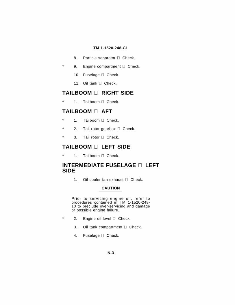
8. Particle separator Check.
* 9. Engine compartment Check.
10. Fuselage Check.
11. Oil tank Check.
TAILBOOM RIGHT SIDE
* 1. Tailboom Check.
TAILBOOM AFT
* 1. Tailboom Check.
* 2. Tail rotor gearbox Check.
* 3. Tail rotor Check.
TAILBOOM LEFT SIDE
* 1. Tailboom Check.
INTERMEDIATE FUSELAGE LEFTSIDE
1. Oil cooler fan exhaust Check.
CAUTION
Prior to servicing engine oi l , refer toprocedures contained in TM 1-1520-248-10 to preclude over-servicing and damageor possible engine failure.
* 2. Engine oil level Check.
3. Oil tank compartment Check.
4. Fuselage Check.
N-3

TM 1-1520-248-CL
CAUTION
T o p r e v e n t d a m a g e t o e l e c t r i c a lcomponents all equipment placed in aftelectrical compartment shall be clear ofe lec t r i ca l components and proper lysecured.
5. Aft electrical compartment Check.
* 6. Engine compartment Check.
* 7. Transmission Check.
8. Particle separator Check.
* 9. Hydraulic reservoir Check fluid level.
10. Transmission cowling Check.
FUSELAGE TOP
1. Engine exhaust Check.
2. Anticollision light Check.
3. Engine inlet plenum window Checkcondition.
4. Hydraulic reservoir Check.
5. Hydraulic servos and flight controls Check.
6. Transmission oi l f i l ler Check capsecure.
* 7. Swashplate and flight controls Check.
* 8. Main rotor system Check.
O* 9. MMS Check.
N-4

C1
TM 1-1520-248-CL
FORWARD FUSELAGE LEFTSIDE
CAUTION
Cargo shal l not be placed in avionicscompartment.
1. Avionics compartment Check.
2. UWP Check.
O* 3. Weapons systems Check.
4. Landing gear Check.
5. Underside of fuselage Check.
O 6. Crew door Check.
7. Cockpit left side Check.
FUSELAGE FRONT
1. Static port Check.
2. Fuselage Check.
3. Crew or passenger briefing Complete.
BEFORE STARTING ENGINE PILOT
* 1. Seat belt, shoulder harness, inertia reel Fasten and check.
* 2. Overhead panel equipment and switches Check.
3. Ins t rument pane l ins t ruments andswitches Check and set.
N-5

C1
TM 1-1520-248-CL
4. Flight controls and switches Checkand set.
O* 5. BATT 2 switch BATT 2.
* 6. BATT 1 switch BATT 1.
WARNING
When helicopter is loaded with rockets, donot use external power. Electromagneticinterference from external source maycause accidental firing of rockets.
* 7. GPU Connect as required (DC only).
* 8. C a u t i o n , w a r n i n g , a n d a d v i s o r ymessages and audio Check.
* 9. FADEC AUTO/MAN switch CheckAUTO.
10. S t a n d b y a l t i m e t e r S e t t o f i e l delevation.
11. MPD Test and set.
BEFORE STARTING ENGINE COPILOT (AS REQUIRED)
* 1. Seat belt, shoulder harness, and inertiareel Fasten and check.
2. Ins t rument pane l ins t ruments andswitches Check and set.
3. Flight controls Check.
ENGINE START
* 1. Fireguard Posted (if available)
* 2. Rotor blades Clear and untied.
* 3. Engine start Accomplish.
N-6

TM 1-1520-248-CL
* 4. XMSN OIL pressure and ENG OILpressure Within limits.
ENGINE RUNUP PILOT
CAUTION
To prevent damage to the DC chargingsystem; when second battery is installed.Do not ini t ial ly charge both batteriessimultaneously.
O* 1. BATT 2 switch OFF.
* 2. DC GEN switch DC GEN.
* 3. AC GEN switch AC GEN.
* 4. ESNTL BUS switch RUN.
* 5. GPU Disconnect (if used).
6. DTS/MDU Mission load as required.
* 7. NAV ALIGN Initiate as required.
8. RADALT Check.
9. FADEC system Check.
* 10. Standby flight instruments Set.
11. MPD BIT/RST switch Check.
* 12. SCAS Engage.
O 13. ESC Check.
14. Flight controls Check.
* 15. C a u t i o n , w a r n i n g , a n d a d v i s o r ymessages Review.
* 16. Throttle Open.
N-7

TM 1-1520-248-CL
* 17. RPM trim switch Adjust to 100% NR.
18. ENG ANTI ICE Check.
19. PITOT HTR Check.
O* 20. Weapons systems Initialize and checkas required.
O 21. ASE Check as required.
O 22. A D S S C h e c k a n d s e t i f u s e i santicipated.
O* 23. Dual battery charging Complete.
O* 24. Grounding cable and ejector rack pins Removed.
ENGINE RUNUP CPG/PILOT
1. DTS/MDU Mission load as required.
* 2. NAV align Initiate as required.
O 3. ASE Switches on as required.
4. Avionics Configure.
O* 5. MMS startup checks Complete asrequired.
O 6. AVTR Initialize and set as desired.
7. Navigation systems Configure asrequired.
8. ATHS/IDM Configure as required.
O* 9. Weapons systems Initialize and checkas required.
O 10. ASE Check as required.
O 11. MMS boresight Complete as required.
N-8

TM 1-1520-248-CL
BEFORE TAKEOFF
* 1. Avionics As required.
* 2. NR 100%.
* 3. FADEC AUTO/MAN switch AUTO.
* 4. Systems Check.
O* 5. ACP Switches set.
WARNING
If the copilot cyclic is to be used as a flightcontrol, the cyclic shall be engaged.
* 6. Copilot cyclic Engaged as required.
* 7. Crew, passengers, mission equipment,seat belts and armor side panels Check.
HOVER CHECK
1. Engine and transmission instruments Check.
2. Power assurance check Perform onthe first flight of the day.
3. Flight instruments Check and set.
4. Hover power check Accomplish asrequired.
BEFORE LANDING (COPILOT/PILOTAS REQUIRED)
1. LASER OFF/STBY/ARM switch Asrequired.
O 2. MMS Stowed as required.
N-9

TM 1-1520-248-CL
3. ACP Switches set.
4. Landing light Set as required.
O 5. IR JAMMER switch Set as required.
AFTER LANDING CHECK
1. Landing light OFF as required.
2. Transponder STBY as required.
3. ASE Set as required.
ENGINE SHUTDOWN
1. Flight controls Cyclic centered, pedalsneutral, collective down.
2. FORCE TRIM switch FORCE TRIM.
3. Present position Store or record asrequired.
O 4. AVTR STOP, MANUAL Unthread, asrequired.
5. MMS OFF before reducing RPM below95% NP.
6. Throttle Reduce to idle for 2 minutes.
7. BATT 1/BATT 2 Check.
O 8. AC GEN switch OFF.
9. FUEL BOOST switch OFF.
O 10. ASE OFF.
11. Standby attitude indicator Caged.
12. SCAS PWR OFF.
13. DTS/MDU Mission store as desired.
N-10
C1
TM 1-1520-248-CL
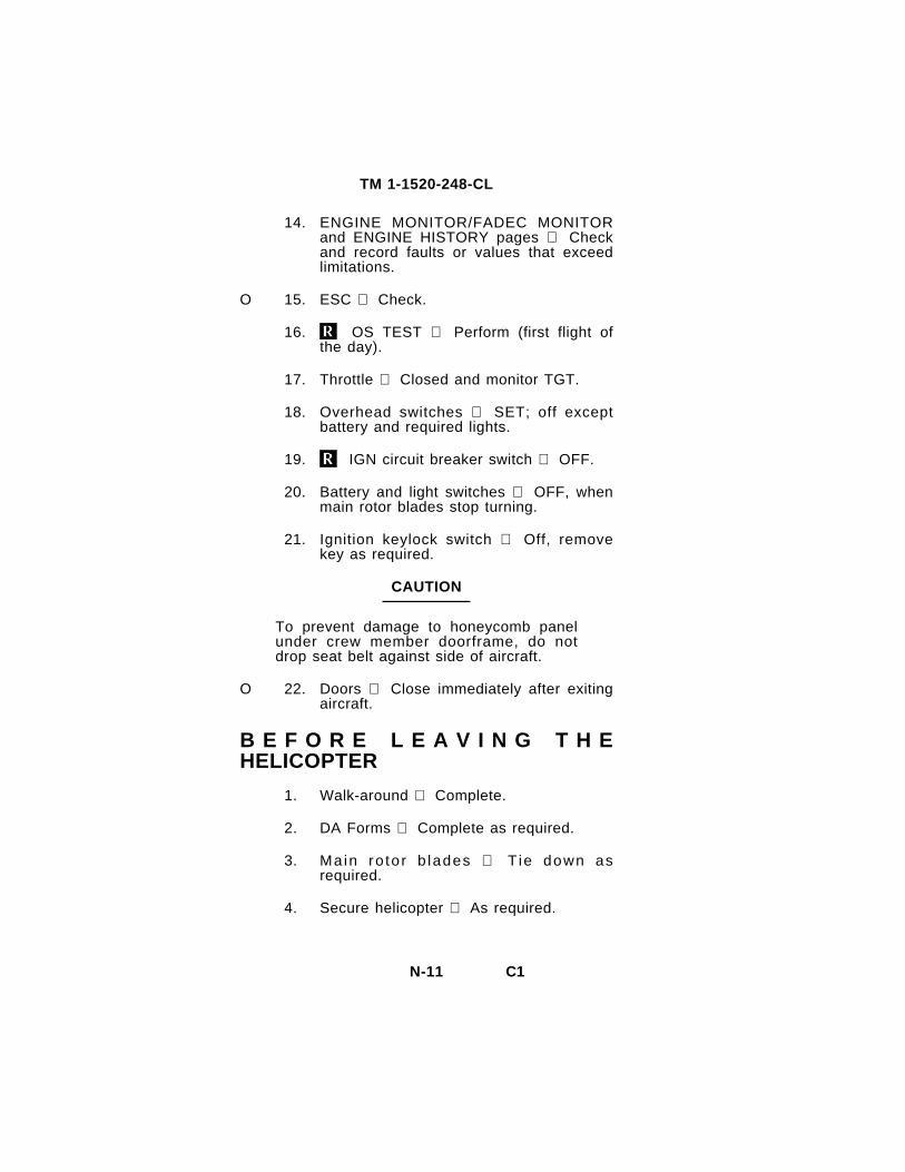
14. ENGINE MONITOR/FADEC MONITORand ENGINE HISTORY pages Checkand record faults or values that exceedlimitations.
O 15. ESC Check.
16. OS TEST Perform (first flight ofthe day).
17. Throttle Closed and monitor TGT.
18. Overhead switches SET; off exceptbattery and required lights.
19. IGN circuit breaker switch OFF.
20. Battery and light switches OFF, whenmain rotor blades stop turning.
21. Ignition keylock switch Off, removekey as required.
CAUTION
To prevent damage to honeycomb panelunder crew member doorframe, do notdrop seat belt against side of aircraft.
O 22. Doors Close immediately after exitingaircraft.
B E F O R E L E A V I N G T H EHELICOPTER
1. Walk-around Complete.
2. DA Forms Complete as required.
3. Main ro to r b lades T ie down asrequired.
4. Secure helicopter As required.
N-11

TM 1-1520-248-CL
THROUGH-FLIGHT CHECKLIST
BEFORE EXTERIOR CHECK
O 1. Weapons systems Safe.
2. LASER ARM/STBY/OFF switch OFF.
3. Covers, locking devices, tiedowns, andg r o u n d i n g c a b l e s R e m o v e d a srequired and secured.
4. IGN keylock switch On.
EXTERIOR CHECK
O 1. Weapons systems Check.
2. Hydraulic servos and flight controls Check.
3. Transmission Check.
4. Engine compartment Check.
5. Tailboom Check.
6. Tailboom Check.
7. Tail rotor gearbox Check.
8. Tail rotor Check.
9. Tailboom Check.
10. Engine oil level Check.
11. Engine compartment Check.
12. Transmission Check.
13. Hydraulic reservoir Check fluid level.
14. Swashplate and flight controls Check.
N-12

TM 1-1520-248-CL
15. Main rotor system Check.
O 16. MMS Check.
O 17. Weapons systems Check.
BEFORE STARTING ENGINE PILOT
1. Seat belt, shoulder harness, inertia reeland lock Fasten and check.
O 2. BATT 2 switch BATT 2.
3. BATT 1 switch BATT 1.
4. GPU Connect as required (DC only).
5. C a u t i o n s , w a r n i n g a n d a d v i s o r ymessages and audio Check.
6. FADEC AUTO/MAN switch CheckAUTO.
BEFORE STARTING ENGINE COPILOT/PILOT (AS REQUIRED)
1. Seat belt, shoulder harness, inertia reeland lock Fasten and check.
ENGINE START
1. Fireguard Posted.
2. Rotor blades Clear and untied.
3. Engine start Accomplish.
4. XMSN OIL pressure and ENG OILpressure Within limits.
N-13

TM 1-1520-248-CL
ENGINE RUNUP PILOT
O 1. BATT 2 switch OFF.
2. DC GEN switch DC GEN.
3. AC GEN switch AC GEN.
4. ESNTL BUS switch RUN.
5. GPU Disconnect (if used).
6. NAV ALIGN Initiate as required.
7. Standby flight instruments Set.
8. SCAS Engage.
9. C a u t i o n , w a r n i n g , a n d a d v i s o r ymessages Review.
10. Throttle OPEN.
11. RPM trim switch Adjust to 100% NR.
O 12. Weapons system initialize and checkas required.
O 13. Dual battery charging Complete.
O 14. Grounding cable and ejector rack pins Remove.
ENGINE RUNUP COPILOT/PILOT
1. NAV align Initiate as required.
O 2. MMS startup checks Complete asrequired.
O 3. Weapons systems Initialize and checkas required.
N-14

TM 1-1520-248-CL
BEFORE TAKEOFF
1. Avionics As required.
2. NR 100%.
3. FADEC AUTO/MAN switch AUTO.
4. Systems Check.
O 5. ACP Switches set.
WARNING
If the copilot cyclic is to be used as a flightcontrol, the cyclic shall be engaged.
6. Copilot cyclic Engaged as required.
7. Crew, passengers, mission equipment,seat belts and armor side panels Check.
N-15/(N-16 blank)


TM 1-1520-248-CL
E N G I N E R E S T A R T - D U R I N GFLIGHT (FADEC AUTOMATIC MODE)
1. Establish autorotational descent.
LAND AS SOON AS POSSIBLE.
Col lect ive Reduce.
ENG ANTI ICE and HTR switches - ON.
LAND AS SOON AS POSSIBLE.
2.
ENGINE COMPRESSOR STALL
1.
2.
3.
ENGINE OVERSPEED
1.
2.
3.
If rpm cannot be controlled manually:
4. AUTOROTATE.
5. EMER SHUTDOWN.
ENGINE OVERSPEED
1. Collective - Increase.
2. LAND AS SOON AS POSSIBLE.
Collective - Increase.
Throt t le-Adjust .
LAND AS SOON AS POSSIBLE.
2. FADEC MANUAL OPERATION -Perform.
If RPM cannot be controlled manually:
3. AUTOROTATE.
4. EMER SHUTDOWN - Accomplish.
E-2

ENGINE
1.
2.
3.
TM 1-1520-248-CL
UNDERSPEED
Collective - Adjust.
Throttle - Check open.
RPM + trim switch - Increase (+).
If underspeed condition still exists:
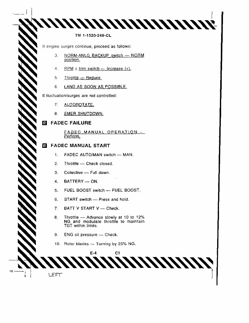
4. NORM ANLG BACKUP switch - ANLGBACKUP position.
5. Throttle and collective - Adjust.
6. LAND AS SOON AS PRACTICABLE.
If engine rpm cannot be maintained within limits:
7. LAND AS SOON AS POSSIBLE.
ENGINE UNDERSPEED
1. Collective - Adjust.
2. Throttle - Check open.
3. RPM ± trim switch - Increase (+).
If underspeed condition still exists:
4 . F A D E C M A N U A L O P E R A T l O N -Perform.
ENGINE SURGES/FUEL CONT CAUTIONM E S S A G E / U N E X P L A I N E D E N G I N EFLUCTUATIONS
In event of FUEL caut ion message or enginefluctuations/surging proceed as follows:
1. NORM-ANLG BACKUP switch -BACKUP.
2. LAND AS SOON AS PRACTICABLE.
E-3

TM 1-1520-248-CL
11. START switch - Release by 55% NG.
12 . XMSN OIL p ressu re and ENG OILpressure - Within limits.
HIGH OIL TEMP ENG CAUTION MESSAGE
1. Adjust helicopter heading into wind, ortransition to forward flight.
If engine oil temperature exceeds 120 °C (248 °F),or if engine oil temperature exceeds 107 to 120 °C(224 to 248 °F) for more than 10 seconds:
2. LAND AS SOON AS POSSIBLE.
R O T O R S , T R A N S M I S S I O N S , A N DDRIVE SYSTEMS MALFUNCTIONS
MAIN DRIVESHAFT FAILURE
1. AUTOROTATE - Throttle full open.
2. EMER SHUTDOWN after landing.
CLUTCH FAILS TO DISENGAGE
1. Throt t le - Open
2. LAND AS SOON AS POSSIBLE.
CLUTCH FAILS TO RE-ENGAGE
1.
2.
FIRE
ABORT START/HOT START/RESIDUALFIRE
1.
AUTOROTATE.
EMER SHUTDOWN.
START switch - ON and hold until TGTis less than 200 °C.
E-5

TM 1-1520-248-CL
2. Throttle - Close,
ENGINE/FUSELAGE/ELECTRlCAL FIRE -GROUND
EMER SHUTDOWN,
ENGINE/FUSELAGE FIRE - LOW/CRUISEALTITUDE
If power-on landing:
1. LAND AS SOON AS POSSIBLE.
2. EMER SHUTDOWN after landing.
If power-off landing:
3. AUTOROTATE.
4. EMER SHUTDOWN.
ELECTRICAL FIRE - FLIGHT
1.
2.
AC and DC GEN switches -OFF.
LAND AS SOON AS POSSIBLE.
3. EMER SHUTDOWN after landing.
A N D F U M E E L I M I N A T I O N
1. VENT PULL knobs - PULL.
2. R and L DEFOG BLWR switches - ON.
3. COMPT BLWR switch - ON.
FUEL SYSTEM MALFUNCTIONS
FUEL BOOST PUMP FAILURE
1. FUEL BOOST switch - OFF.
2. Descend below 8,000 feet PA.
E-6
TM 1-1520-248-CL
3. LAND AS SOON AS PRACTICABLE.
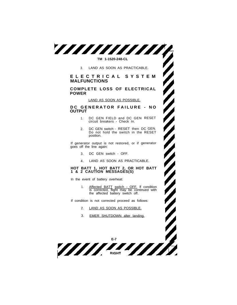
E L E C T R I C A L S Y S T E MMALFUNCTIONS
COMPLETE LOSS OF ELECTRICALPOWER
LAND AS SOON AS POSSIBLE.
D C G E N E R A T O R F A I L U R E - N OOUTPUT
1. DC GEN FIELD and DC GEN RESETcircuit breakers - Check In.
2. DC GEN switch - RESET then DC GEN.Do not hold the switch in the RESETposition.
If generator output is not restored, or ifgoes off the line again:
generator
3. DC GEN switch - OFF.
4. LAND AS SOON AS PRACTICABLE.
HOT BATT 1, HOT BATT 2, OR HOT BATT1 & 2 CAUTlON MESSAGES(S)
In the event of battery overheat:
1. Affected BATT switch - OFF. lf conditionis corrected, flight may be continued withthe affected battery switch off.
If condition is not corrected proceed as follows:
2. LAND AS SOON AS POSSlBLE.
3. EMER SHUTDOWN alter landing.
E-7

TM 1-1520-248-CL
AC GEN FAIL CAUTION MESSAGE
In the event of AC generator failure:
1. AC GEN switch - OFF, then AC GEN.
If generator output is not restored, or generator failsagain:
2. AC GEN switch -OFF.
3. LAND AS SOON AS PRACTICABLE.
AUDIO DISTRIBUTION UNIT (ADU)FAILURE
1. Transmit and receive on plain FM-l.
2. LAND AS SOON AS PRACTICABLE.
EGI FAILURE
1. EGI DC circuit breaker - Out.
2. EGI DC circuit breaker - In.
3. Last known present position - Enter.
4. Execute a MANUAL EGI alignment.
If EGI functionally is not restored or fails again:
6. EGI DC c i rcui t breaker out .
GPS DIVERGENT
It abnormal system operation continues:
1. I N S m o d e o f n a v i g a t i o n - S e l e c t .Compare reported position to that of aknown waypoint as soon as possible.
If position error is evident:
E-8
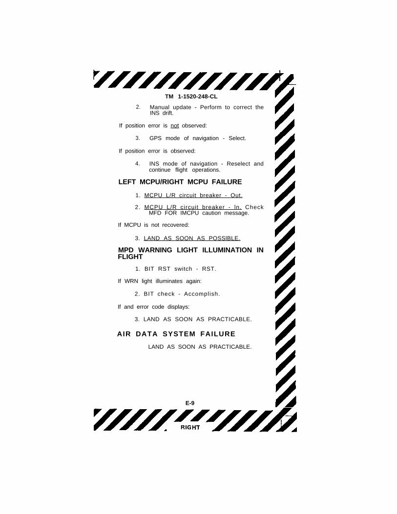
TM 1-1520-248-CL
2. Manual update - Perform to correct theINS drift.
If position error is not observed:
3. GPS mode of navigation - Select.
If position error is observed:
4. INS mode of navigation - Reselect andcontinue flight operations.
LEFT MCPU/RIGHT MCPU FAILURE
1. MCPU L/R circuit breaker - Out.
2. MCPU L/R circuit breaker - ln. CheckMFD FOR IMCPU caution message.
If MCPU is not recovered:
3. LAND AS SOON AS POSSlBLE.
MPD WARNING LIGHT ILLUMINATION INFLIGHT
1. BIT RST switch - RST.
If WRN light illuminates again:
2. BIT check - Accomplish.
If and error code displays:
3. LAND AS SOON AS PRACTICABLE.
AIR DATA SYSTEM FAILURE
LAND AS SOON AS PRACTICABLE.
E-9

TM 1-1520-248-CL
H Y D R A U L I C S Y S T E MMALFUNCTIONS
HYDRAULIC POWER FAILURE
1. Airspeed - Adjust.
2. HYD SYS circuit breaker - Out; checkfor restoration of hydraulic power.
If hydraulic power is not restored:
3. HYD SYS circuit breaker - In.
4 . HYD SYS switch - OFF.
WARNING
Do not return the HYD SYS switch to theHYD SYS position for the remainder of theflight. THis prevents any possibility ofsurge in the hydraulic system creatingsudden, unexpected control movements.
5. LAND AS SOON AS PRACTICABLE (atan area which wi l l permit a run-onlanding).
LANDING AND DITCHING
LANDING IN TREES
A landing in tree; should be made when no otherl a n d i n g a r e a i s a v a i l a b l e . I n a d d i t i o n t oaccomplishing engine failure emergency procedures,select a landing area containing the least number oftrees of minimum height. Decelerate to minimumforward speed at treetop level and descend into thetrees vertically. Apply all remaining collective prior tothe main rotor contracting the trees.
E-10

TM 1-1520-248-CL
DITCHING - POWER ON1. Doors - Jettison at hover.
2. CPG or passenger - Exit.
3. H o v e r a s a f e d i s t a n c e a w a y f r o mpersonnel.
4. AUTOROTATE. Apply a l l remainingcollective es the helicopter enters thewater. Maintain a level attitude as thehelicopter sinks and until it begins to roll.Apply cyclic in the direction of the roll.
5. Pilot - Exit when main rotor stops.
DITCHING - P O W E R O F F1. AUTOROTATE.
2. Doors - Jettison as the helicopter entersthe water.
3. CPG or passenger and pilot - Exit whenmain rotor stops.
FLIGHT CONTROLFLIGHT CONTROL MALFUNCTIONS
1. LAND AS SOON AS POSSIBLE.
2. EMER SHUTDOWN after landing.
S T A B I L I T Y A N D C O N T R O LA U G M E N T A T I O N S Y S T E M ( S C A S )FAILUREIn the event of a SCAS disengagement proceed asfollows:
1. Affected SCAS channel - Attempt toreengage.If SCAS can not be reengaged:
2. LAND AS SOON AS PRACTICABLE.
LIGHTNING STRIKELAND AS SOON AS POSSIBLE.
IN-FLIGHT WIRE STRIKELAND AS SOON AS POSSIBLE.
MISSILE UNLATCHED1. Avoid nose low attitudes and excessive
bank angles.
2. LAND AS SOON AS PRACTICABLE.
E-11

TM 1-1520-248-CL
MISFIRE - 2.75-INCH ROCKET
1. Position the aircraft so that rocket isoriented downrange for a period of tenminutes.
2. Upon land ing the a i r c ra f t - No t i f yexplosive ordnance disposal.
ROCKET/MISSILE - HANGFIRE
1. JETTISON switch(es) - Activate.
2. LAND AS SOON AS POSSIBLE.
RUNAWAY GUN
1. Orient gun in a safe direction.
2. MASTER switch - STBY.
3. Allow gun to fire out.
4. Gun switch - SAFE.
CARGO HOOK FAILS TO RELEASEELECTRICALLY
1. Maintain tension on sling.
2 . P u l l E M E R C A R G O R E L E A S E P U L Lhandle
E-12
TM 1-1520-248-CL
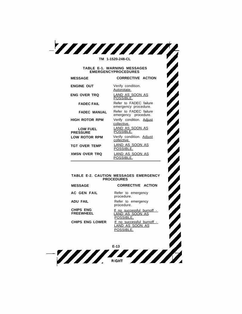
TABLE E-1. WARNING MESSAGESEMERGENCYPROCEDURES
MESSAGE CORRECTIVE ACTION
ENGINE OUT
ENG OVER TRQ
FADEC FAIL
FADEC MANUAL
HIGH ROTOR RPM
LOW FUELPRESSURELOW ROTOR RPM
TGT OVER TEMP
XMSN OVER TRQ
Verify condition.Autorotate.
LAND AS SOON ASPOSSIBLE.
Refer to FADEC failureemergency procedure.Refer to FADEC failureemergency procedure.Verify condition. Adjustcollective.LAND AS SOON ASPOSSIBLE.
Verify condition. Adjustcollective.LAND AS SOON ASPOSSIBLE.
LAND AS SOON ASPOSSIBLE.
TABLE E-2. CAUTION MESSAGES EMERGENCYPROCEDURES
MESSAGE
AC GEN FAIL
ADU FAIL
CORRECTIVE ACTION
Refer to emergencyprocedure.
Refer to emergencyprocedure.
CHIPS ENGFREEWHEEL
lf no successful burnoff -LAND AS SOON ASPOSSIBLE,
CHIPS ENG LOWER If no successful burnoff -LAND AS SOON ASPOSSIBLE.
E-13

TM 1-1520-248-CL
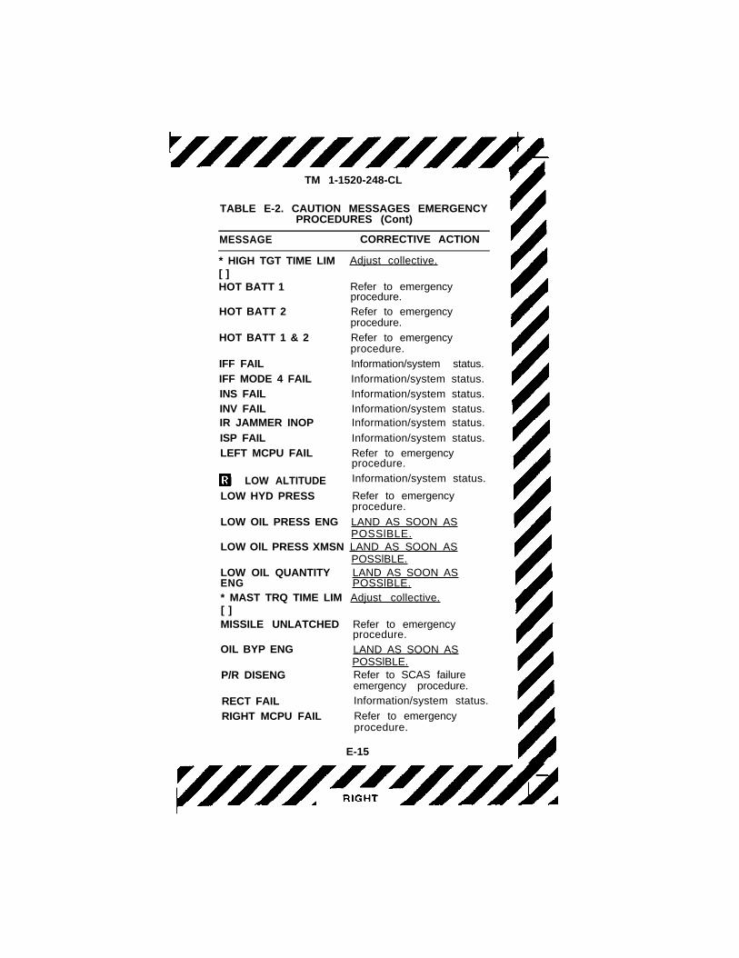
TABLE E-2. CAUTION MESSAGES EMERGENCYPROCEDURES (Cont)
MESSAGE CORRECTIVE ACTION
* HIGH TGT TIME LIM[ ]HOT BATT 1
HOT BATT 2
HOT BATT 1 & 2
IFF FAIL
IFF MODE 4 FAIL
INS FAILINV FAILIR JAMMER INOP
ISP FAIL
LEFT MCPU FAIL
LOW ALTITUDE
LOW HYD PRESS
LOW OIL PRESS ENG
Adjust collective.
Refer to emergencyprocedure.Refer to emergencyprocedure.
Refer to emergencyprocedure.
Information/system status.
Information/system status.
Information/system status.Information/system status.Information/system status.
Information/system status.
Refer to emergencyprocedure.
Information/system status.
Refer to emergencyprocedure.
LAND AS SOON ASPOSSlBLE.
LOW OlL PRESS XMSN LAND AS SOON ASPOSSlBLE.
LOW OIL QUANTITYENG* MAST TRQ TIME LIM[ ]MISSILE UNLATCHED
OIL BYP ENG
P/R DISENG
RECT FAIL
RIGHT MCPU FAIL
LAND AS SOON ASPOSSlBLE.Adjust collective.
Refer to emergencyprocedure.
LAND AS SOON ASPOSSlBLE.Refer to SCAS failureemergency procedure.Information/system status.
Refer to emergencyprocedure.
E-15

TM 1-1520-248-CL
TABLE E-2. CAUTION MESSAGES EMERGENCYPROCEDURES (Cont)
MESSAGE CORRECTIVE ACTION
SCAS DISENG Refer to SCAS failureemergency procedure.
*TGT 5 MIN LIM [ ] Adjust collective.*TGT 30 MIN LIM [ ] Adjust collective.
WEAPONS FAIL Information/system status.
YAW DISENG Refer to SCAS failureemergency procedure.
NOTE
* The time displayed in brackets is acumulative time not dependant on a given
time period. Up to 99 seconds can bedisplayed.
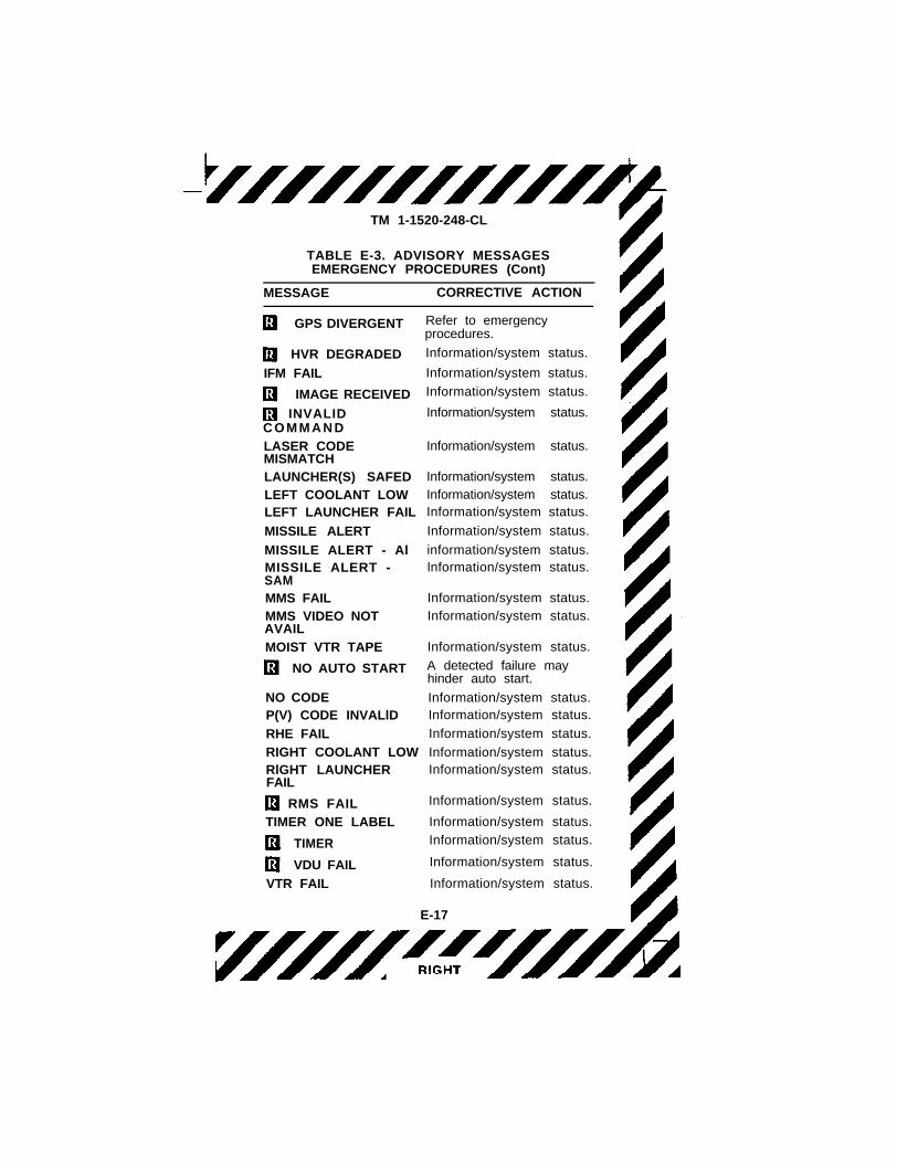
TABLE E-3. ADVISORY MESSAGESEMERGENCYPROCEDURES
MESSAGE CORRECTIVE ACTION
ALARM ONE LABEL
ALARM
ASE FAIL
CARGO HOOK ARMEDCODE NOT ACCEPTED
DATA LOADER FAIL
DTS FAILEGI BATT LOW
FADEC DEGRADE
FADEC MAINT
FUEL CONTROL
GPS FAIL
Information/system status.Information/system status.
Information/system status.
Information/system status.Information/system status.
Information/system status.
Information/system status.Refer to emergencyprocedure.
Refer to emergencyprocedure.
FADEC requiresmaintenance action.Information/system status.
information/system status.
E-16
TM 1-1520-248-CL
TABLE E-3. ADVISORY MESSAGESEMERGENCY PROCEDURES (Cont)
MESSAGE
GPS DIVERGENT
HVR DEGRADED
IFM FAIL
IMAGE RECEIVED
INVALIDC O M M A N D
LASER CODEMISMATCHLAUNCHER(S) SAFEDLEFT COOLANT LOWLEFT LAUNCHER FAIL
MISSILE ALERT
MISSILE ALERT - AlMISSILE ALERT -SAMMMS FAILMMS VIDEO NOTAVAIL
MOIST VTR TAPE
NO AUTO START
NO CODEP(V) CODE INVALlD
RHE FAIL
RIGHT COOLANT LOWRlGHT LAUNCHERFAIL
RMS FAIL
TIMER ONE LABEL
TIMER
VDU FAIL
VTR FAIL
CORRECTIVE ACTION
Refer to emergencyprocedures.
Information/system status.
Information/system status.
Information/system status.
Information/system status.
Information/system status.
Information/system status.Information/system status.Information/system status.
Information/system status.
information/system status.lnformation/system status.
Information/system status.Information/system status.
Information/system status.
A detected failure mayhinder auto start.
Information/system status.Information/system status.
Information/system status.
Information/system status.Information/system status.
Information/system status.
Information/system status.
Information/system status.
Information/system status.
Information/system status.
E-17

TM 1-1520-248-CL
TABLE E-3. ADVISORY MESSAGESEMERGENCY PROCEDURES (Cont)
ZERO
WPN NOT ACTIONED Information/system status.
WPN NOT ARMED Information/system status.
WPN NOT SELECTED Information/system status.
MESSAGE CORRECTIVE ACTION
VTR HEAD Information/system status.
CONTAMINATED
VTR TAPE FULL Information/system status.
WEAPONS FAILInformation/system status.
WEDGE CONSTANT Information/system status.
E-18

C1
TM 1-1520-248-CL
ENGINE START
CAUTION
• To prevent damage to engine, if theF U E L C O N T c a u t i o n m e s s a g e i sdisplayed on the MFD, do not start theengine.
• To prevent damage to engine, if autoacceleration occurs when the throttle isopened, abort start.
• To prevent damage to engine, if theBATT V falls below 10 volts during thestarting cycle, abort the start. The CDS,engine instruments, and ESC will notfunction properly.
• To prevent damage to engine, i f i tbecomes apparent that temperaturelimits will be exceeded before 55% NGis attained, abort start.
NOTE
• I f BATT V goes below 20 volts, theMFDs will temporarily go blank; this isnormal. Monitor TGT and NG. CDS andESC will function properly. Continuestart.
• BATT V may go below 14 volts duringthe initial starting cycle; however, BATTV must be at least 14 volts prior toadvancing the thrott le. The 14-voltrequirement is to ensure proper voltagefor the engine system.
a. START switch Press and hold. Starttime.
b. BATT V and START V Check above10 volts.
c. TGT 150 °C or less.
P-1

TM 1-1520-248-CL
d. Throttle Advance slowly at 12% NGand modulate throttle to maintain TGTwithin limits. Slowly advance to idleafter TGT has decreased from initialpeak.
e. TGT Increasing and within limits.
f. ENG oil pressure Check.
g. Rotor blades Beginning to turn by25% NG.
h. START switch Release at 55% NG.
i. NG Check stabilized at idle (63 to65%).
NOTE
For cold temperature starts, if ENG OILand/or XMSN OIL pressures are abovelimits, or ENG OIL and/or XMSN OILtemperatures are below l imits, do notaccelerate engine above idle.
ENGINE START (AUTOMATICMODE)
a. AUTO/MAN switch Check AUTO.
P-2

TM 1-1520-248-CL
CAUTION
To prevent a hot start, if the NO AUTOadvisory is displayed on the MFD, do nota t tempt an au tomat ic s ta r t , un lessmessage is de le ted when th ro t t le i sadvanced to the idle detent.
NOTE
The START switch must be activatedwithin 60 seconds of advancing the throttleor the engine will not start. This is a safetyfeature to prevent inadvertent automaticstarting of engine. Clearing of this safetyfeature requires the pi lot to place thethrottle in the cutoff position, cycle theFADEC circuit breaker switch OFF thenON, then reinitiate the start sequence.
b. Throttle Open to idle detent.
P-3

TM 1-1520-248-CL
CAUTION
• To prevent damage to engine , if theBATT V falls below 10 volts during thestarting cycle, abort start. The CDS,engine instruments, and ECU will notfunction properly
• BATT V may go below 14 volts duringthe initial staring cycle, hover, BATT Vmust be at least 14 volts by the time NGreaches 10%. If this requirement is notm e t , a b o r t s t a r t , t o p r e v e n t t h epossibility of a hot start. The voltagerequirement is to ensure proper voltagefor the engine ignition system.
• To prevent damage to engine, i f i tbecomes apparent that temperaturelimits will be exceeded before 55% NGis attained, abort start.
NOTE
If BATT V goes below 20 volts, MFDs willtemporari ly go blank; this is normal.Monitor TGT and NG. CDS and FADECcontrol will function properly. Continuestart.
c. START switch Press for 2 secondsthen release.
d. BATT V and START V Check.
e. TGT Increasing and within limits.
f. ENG oil pressure Check.
g. Rotor blades Turning by 25% NG.
h. START V Decreased to near 0 at50% NG.
i. NG Check stabilized at idle, (63 to65%).
P-4

TM 1-1520-248-CL
CAUTION
If starter is still engaged at idle (indicatedby START V not near 0) the throttle mustbe closed, and after TGT is below 200 °Cthe battery switch(es) must be turned offto prevent damage.
NOTE
For cold temperature starts, if ENG OIland/or XMSN OIL pressures are abovelimits or ENG OIL and/or XMSN OILtemperatures are below l imits, do notaccelerate engine above idle.
BEFORE STARTING ENGINE MMSSWITCHES SET COPILOT
CAUTION
• When MMS is operating but not beingused, the sight shall be slaved FWD toprevent the payload assembly fromcontacting and damaging the azimuthand elevation stops.
• Turn MMS mode select switch off i fM M S f a i l s t o r e s p o n d t o c o n t r o lcommands.
1. LASER ARM/STBY/OFF switch OFF.
2. FIRST/LAST switch As desired.
3. VIDEO MMS SYM INTEN toggle switch MAN.
4. VIDEO GAIN toggle switch As desired.
5. VIDEO LEVEL toggle switch AUTO.
6. OPR mode select switch OFF.
7. ALFGL switch OFF.
P-5

TM 1-1520-248-CL
8. TIS INTEG switch OFF.
9. LMC switch OFF.
10. ALE switch OFF.
ENGINE RUN-UP MMS STARTUPCHECKS COPILOT
1. MMS key Press.
NOTE
• MMS run-up requires 3-phase AC powerfrom the AC generator or external ACpower. Prior to turning the MMS on,verify required power is available.
• When MMS select switch is set toPREFLT, the sys tem immedia te lychecks the output of the LOS CONTswitch on the copilot cyclic control gripand supplies an opposite bias in orderto zeroize the LOS output. Pressing theLOS switch during the first 5 secondsafter power turn-on may induce an errorinto the bias calculation and cause theMMS to drift.
2. OPR mode select switch PREFLT.
3. GRAY SCALE key Select, adjust asdesired, deselect.
4. OPR mode select switch FWD.
5. MNL/SLAVE switch Press. ObserveMMS slews FWD.
6. Laser codes Check; enter as required.
7. MMS cur ren t laser code se lec tappropriate code as required.
P-6

TM 1-1520-248-CL
MMS MANUAL BORESIGHT
A manual boresight is recommended prior to the firstautomatic boresight on a power cycle, when LOSreticle shifts off target upon FOV or sensor change,or when a REBORESIGHT message remains afterautomatic boresight. If any of the previous conditionsexists, accomplish a manual boresight as follows:
NOTE
• if required, TIS setup procedure shouldbe performed prior to obtain proper TISpicture.
• MMS is boresighted automatically in TVNFOV and TIS NFOV only. Manualboresighting can be accomplished inwide or narrow. Each sensor should beboresighted in WFOV prior to NFOV.
• Only one senor FOV can be boresightedat a time in BRST MAN. To boresighteach, it is necessary to deselect BRSTMAN, select the other sensor and/orFOV, then reselect BRST MAN.
1. OPR mode select switch PREFLT.
2. LASER ARM/STBY/OFF switch ARM.
3. TV/TIS switch Select desired sensor.
4. FOV SEL switch Select desired field ofview.
5. BRST MAN key Press. Resolut iontarge t appears fo r approx imate ly 6seconds then disappears. Check clearand in focus.
6. LASER fire switch Press and hold.Adjust LOS reticle until it is centered overthe laser spot by adjusting the LOSCONT switch. Then release LASER fireswitch.
P-7

TM 1-1520-248-CL
7. BRST MAN Press to deselect manualboresight.
8. Repeat steps 3 through 7. as required toboresight each sensor and field of view.
9. LASER ARM/STBY/OFF switch Set asrequired.
MMS AUTOMATIC BORESIGHT
NOTE
• If required, TIS setup procedures shouldbe performed prior to boresighting toobtain proper TIS picture.
• TIS HOT message may remain as anadvisory message. Disregard i f TISpicture meets operational requirements.
1. FOV SEL switch Select narrow field ofview for both TV and TIS sensors.
2. OPR mode select switch PREFLT.
3. LASER ARM/STBY/OFF switch ARM.
4. BRST AUTO key Press. Resolutiontarge ts fo r each senor appear fo rapproximately 6 seconds each, thendisappear. Check clear and in focus.
5. LASER fire switch Press and holdb e f o r e s e c o n d r e s o l u t i o n t a r g e tdisappears.
6. TV and TIS Verify laser spot size (TV1/16 - 1/8 inch, TIS 2-3 lines for MSP, 3-4 l ines for IMSP).Verify target gatedisplays sizes and tracks laser spot.There should be no jitter and spot should
P-8

TM 1-1520-248-CL
be centered in the gate. (fig. 4-16 and 4-17)
NOTE
If REBORESIGHT appears after selectingan operating mode, accomplish manualboresight.
7. BRST COMPLETE message Appearsin status block.
8. LASER fire switch Release.
9. LASER ARM/STBY/OFF switch OFF.
NOTE
After selecting an operational mode, if theR E B O R E S I G H T m e s s a g e r e m a i n s ,accomplish a manual boresight.
SINCGARS SET AND CHECK
NOTE
• SINCGARS AN/ARC-201 radio may notbe configured for 1 minute while radiocompletes BIT and initializes frequencypresets.
• SINCGARS AN/ARC-201D radiomay not be configured for 1 minutewhile radio completes BIT and initializesfrequency presets.
• P r o c e d u r e s f o r c o n f i g u r i n g b o t hSINCGARS radios are typical.
1. COMM key (or DSPL SEL switch) COMM page displays.
2. L-1/L-5 Press to select FM radio.
3. R-5 Press to access FM control page.
P-9

TM 1-1520-248-CL
4. SC/FH key Press to select singlechannel or frequency hop.
5. EMER T/R key Press to select currentSC or emergency frequency.
6. PWR key Press to select IFM powerlevel.
NOTE
• KYBD wi l l no t d isp lay when FH isselected since frequencies/channelscannot be changed in FH mode.
• ERR will display when channel enteredis not in frequency list or if enteredfrequency is out of range for the radio.
7. KYBD key Press to activate MFK forentering radio channels from frequencylist or manual frequencies.
8. TOD key Press to retrieve the radiosTOD. A cursor will appear allowing entryof a new TOD. All leading and trailingzeros must be entered. If no new TOD isentered then rad ios w i l l re ta in thedisplayed TOD.
NOTE
SQL displays and squelch function isactivated only when SC mode is selected.
9. SQL key Press to select squelch asdesired.
10. OSET/MEMBER/CONTROL key Pressto select as desired. Selects frequencyof fse t fo r cur ren t p rese t o r manua lfrequency when operating in the SCm o d e . M E M B E R o r C O N T R O L i sselected when operating the FH mode.
11. FREQ LIST key Press to se lec tfrequency list.
P-10

TM 1-1520-248-CL
12. FH DATA PAGE 2 key Press to load,edit, and select frequency hop data page2 when FH mode is selected.
13. ERF RCV/SEND key Press to selectas desired. ERF SEND retrieves FH datafrom radio permanent memory and sendsdata to net members when in CONTROLmode. ERF RCV configures radio toreceive a remote fill from net controllerwhen in MEMBER mode.
NOTE
When helicopter is on the ground thelegend for L-2 is LOAD COMSEC orMODE 23.
14. HSET/LSET key Press to se lec th o p s e t d i s p l a y o r l o c k s e t d i s p l a yinformation.
15. C H k e y s P r e s s t o i n c r e m e n t /decrement displayed fill channel codereceived from radio. Displayed channelcode received from radio. Displayedchannel number is channel in which thehopset is stored and hopset used forf r e q u e n c y h o p p i n g w h e n F H d a t aselected is HSET. Displayed channelnumber is the first digit of lockout setwhen FH data selected is LSET.
NOTE
This channel number is not to be confusedwith operational frequency channel of theradio. This channel is for selection anddisplay of FH parameter only.
16. HSET EDIT key Press to changeexist ing channel code or create newcode. Code d isp lays nex t to HSETchannel number.
17. ZEROIZE/LATE NET (R-1) ZEROIZEclears all data stored in the RT, includingall preset SC frequencies and FH data.
P-11

TM 1-1520-248-CL
When pressed ZEROIZE will flash; pressR-1 again to ZEROIZE. ZEROIZE is onlyavailable when the helicopter is on theg r o u n d . L A T E N E T a l l o w s t h e R Tcontaining all fill data, but whose clock isout of sync, to join a net. To activateLATE NET, se lec t appropr ia te FHchannel (L-3/L-4) and press R-1; LATENET will box until the RT has received anew t ime sync . LATE NET is on lyavailable when the helicopter is off theground.
NOTE
While LATE NET is boxed, transmission byother members of the net causes theradio’s time to synchronize.
18. COPY HSET (R-2) Allows one channelto be copied to another. When presseddisplay wil l change to FROM CH=, astored channel is entered from the MFK,the cursor changes to TO CH=, anddesired destination channel is enteredfrom the MFK.
19. FILL (R-3) Al lows TSEC variable,HSET variables and LSET variables to beloaded to the RT while the helicopter ison the ground. To load, connect f i l ldevice to RT, select desired variable onfill device, and turn fill device power on.Press R-3, which will box FILL, and allowthe RT to interrogate fill device. TheTSEC variable is loaded by selectingmanua l (M) channe l a t L -3 /L -4 andpressing FILL. Once TSEC variable isl o a d e d , l e g e n d C O L D w i l l a p p e a radjacent to channel indicator when Mchanne l i s se lec ted . I f an HSET isinterrogated, then that HSET wil l bestored with displayed HSET channelnumber. If an LSET is interrogated, thenLSET channel number associated withLSET will be stored and displayed. Aftercomplete, turn fill device power off andremove from RT. FH will not function if filldevice is left attached to RT.
P-12

TM 1-1520-248-CL
20. C L E A R ( R - 4 ) C l e a r s i n d i v i d u a lc h a n n e l s . W h e n p r e s s e d , d i s p l a ychanges to CH=; select channel to becleared and enter on MFK.
NOTE
• ERR wil l appear adjacent to R-4 i fcurrent HSET channel is entered.
• C a n n o t c l e a r c u r r e n t l y s e l e c t e dchannels.
ASE CHECK
Operation AN/APR-39A(V)1
1. WPN ASE or WEAPON SEL switch Position to ASE.
2. ASE SET-UP/BIT page Verify appearson CPG MFD.
NOTE
• The user defined module (UDM) must beinstalled in the AN/APR-39A(V)1 prior toaircraft power up. If the UDM is notinstalled, the radar warning indicator willdisplay a “p” after an initial BIT. Anaudio message will annunciate “APR-39failure.” Any subsequent strobe displayson the indicator should be consideredunreliable.
• If the AN/APR-39A(V)1 radar detectingsystem is not installed, the legend to theright of L-1 will be blank.
3. PULSE RADAR WARN PWR OFF.Verify displayed on the first line to theright of L-1.
4. FULL and TERSE Verify displayed onthe third line to the right of L-1.
P-13

TM 1-1520-248-CL
NOTE
AN/APR-39A(V)1 mode is controlled by L-1. Successive presses of L-1 cause theAN/APR-39A mode to toggle betweenFULL and TERSE modes.
5. L-1 Press until the system is set to theFULL mode as indicated by the boxedFULL.
6. RADAR WARN circuit breaker/switch In/WARN. Verify that the legend to theright of L-1 changes to PULSE RADARWARN PWR ON and VOICE APR-39power up should be heard AVR-2 PWRON should also be present.
NOTE
Allow one minute for system warmup.
7. R-1 Press to initiate system BIT.
8. SELF-TEST SET VOLUME 1 through 12 Verify synthetic voice count is heardon the headset.
9. Volume Adjust audio level while countis taking place and verify proper volumecontrol operation.
10. RWR system indicator Verify displaysthe numbers of operational flight program(OFP) and emitter identi f icat ion data(EID).
NOTE
If a fault is noted, the display shall showtwo tr iangles for the aft and forwardlocation, with the faulty receiver blinking.
11. Ind ica tor Ver i fy fo rward and a f treceivers triangles appear at 6 and 12o’clock.
P-14

TM 1-1520-248-CL
12. Asterisk Verify appearance in all fourquadrants along with the system receiverstatus. They represent AVR-2A sensors.
13. APR-39 OPERATIONAL Heard on theICS headset at the end of Successfulself-test operation.
14. APR-39 FAILURE Heard on the ICSheadset at the end of successful self-testoperation.
15. “+” symbol After completion of self-test, should be displayed at the center ofthe indicator.
16. L-1 Select TERSE.
17. R-1 Press to initiate self-test.
18. SELF-TEST SET VOLUME 5 through 1 Verify synthetic voice short countheard on the ICS headset.
19. Display Verify symbology same as inFULL mode.
NOTE
• If the ISP fails the AN/APR-39A(V)1 willdefault to FULL mode. Audio will bepresent but at reduced amplitude. ASESET-UP/BIT page will display whateverwas present at the time the ISP failed.
• If the R MCPU fails the AN/APR-39A(V)1 wil l default to FULL mode.Audio will be present but at reducedamplitude. ASE SET-UP/BIT page willdisplay whatever was present at thetime the R MCPU failed.
P-15

TM 1-1520-248-CL
Operation AN/APR-44
NOTE
• I f the ISP fai ls the AN/APR-44 wil ldefault to ON. Audio will still be presentbut at reduced amplitude. No advisorieswill display with the ISP failed.
• If the R MCPU fails the AN/APR-44will default to ON. Audio will still bepresent but at reduced amplitude. Noadvisories will display with the R MCPUfailed.
1. RADAR DETR circuit breaker/switch In/DETR. Allow 1 minute warmup.
2. CW RADAR WARN PWR Check ONdisplays.
3. Volume Adjust as required.
4. Headset Verify low pitch tone followedby brief high pitch tone and momentarydisplay of MISSILE ALERT Al andMISSILE ALERT SAM advisories.
Operation AN/AVR-2A
The AN/AVR-2A is checked simultaneously with theAN/APR-39A(V)1 system. Once system bit iscompleted the system is ready for operation.
P-16

C1
TM 1-1520-248-CL
NOTE
If the ISP/ R MCPU fails, the AN/AVR-2A wil l operate in the backup defaultmode. While operating in the default modethe AN/AVR-2A will continue to providen o r m a l f u n c t i o n w i t h t h e f o l l o w i n gexceptions: current system power statuswill not be displayed on the ASE SET-UP/BIT page. Aural warning will be reduced inamplitude.
1. RADAR WARN circuit breaker/switch In/RADAR. Allow 1-minute warmup.
2. AVR-2A PWR Check ON displays.
3. PULSE RADAR WARNING BIT key P r e s s . F o u r a s t e r i s k s w i l l a p p e a rsimultaneously. A faulty AN/AVR-2Aquadrant is shown as a flashing asterisk.No audio announcement is associatedwith the AN/AVR-2A self-test.
4. BRIL control Rotate, check indicatorillumination.
5. Volume Adjust as required.
Operation AN/ALQ-144
1. ASE SEL switch Press. ASE SET-UP/BIT page displays.
P-17

C1
TM 1-1520-248-CL
NOTE
• ASE SET-UP/BIT page may be selectedby pressing the WPN ASE button on theCPG auxiliary panel.
• A N / A L Q - 1 4 4 i s a n a c t i v e I Rcountermeasure system that is separatefrom the AN/APR-44 radar warningsystem.
2. IR JAMMER BASE switch IR JAMMER(ON).
3. IR JAMMER XMTR switch XMTR(ON).
4. MFD Check ON-IR JAMMER PWRdisplays.
5. A f te r a min imum of 15 minu tes o foperation, IR JAMMER BASE switch BASE (OFF).
6. I R J A M M E R X M T R s w i t c h I RJAMMER (OFF).
7. MFD Check OFF-IR JAMMER PWRdisp lays , a f te r 1 -minu te coo l downperiod.
WEAPONS SYSTEMS CHECK
.50 CALIBER MACHINE GUN
EXTERIOR CHECK
1. Ejector rack Check; impulse cartridgesinstalled.
2. Ammunition can Check.
O 3. Ammunition Properly loaded.
4. Ammunition can cover Closed andlocked.
P-18

TM 1-1520-248-CL
5. Feed chute Check.
6. Electrical connectors Secure.
7. Cover Open.
8. Bolt Forward.
9. Feed mechanism Aligned.
10. First round Curved portion againststripper with double loop link toward gun.
11. Cover Closed and locked.
WARNING
The gun is now loaded. Personnel shouldavoid passing directly in front of the gun.
12. Gun Check.
ENGINE RUNUP
1. MASTER switch STBY.
2. PDU BIT Accomplish.
3. W E A P O N S E L s w i t c h S e l e c tWEAPONS PAGE.
4. L-3 Press. Enter number of roundsloaded.
5. WEAPON SEL switch Select gun.
6. GUN switch RECOCK (str ips f irstround out and chambers round).
P-19

C1
TM 1-1520-248-CL
NOTE
Ground personnel should hold up roundand link to indicate proper ammunitionfeeding.
2.75 INCH ROCKETS
EXTERIOR CHECK
1. Ejector rack Check; impulse cartridgesinstalled.
O 2. Rockets As required.
3. Launcher Check . Check lanyardattached.
4. Electrical connectors Check.
O 5. Fuze umbilical Connected.
ENGINE RUNUP
1. MASTER switch STBY.
2. PDU BIT Accomplish.
3. W E A P O N S E L s w i t c h S e l e c tWEAPONS PAGE.
4. R-5 Press to select WEAPONS BIT/SET-UP PAGE.
5. R-4 Press to select ROCKET TYPESby ZONE MENU.
6. W A R H E A D E n t e r Z O N E A t y p efollowed by ZONE B type.
7. R-5 Press to return to WEAPONSPAGE.
8. L-4 Press to enter AIRBURST FUZE/CUE DISTANCE as required.
P-20
C1
TM 1-1520-248-CL
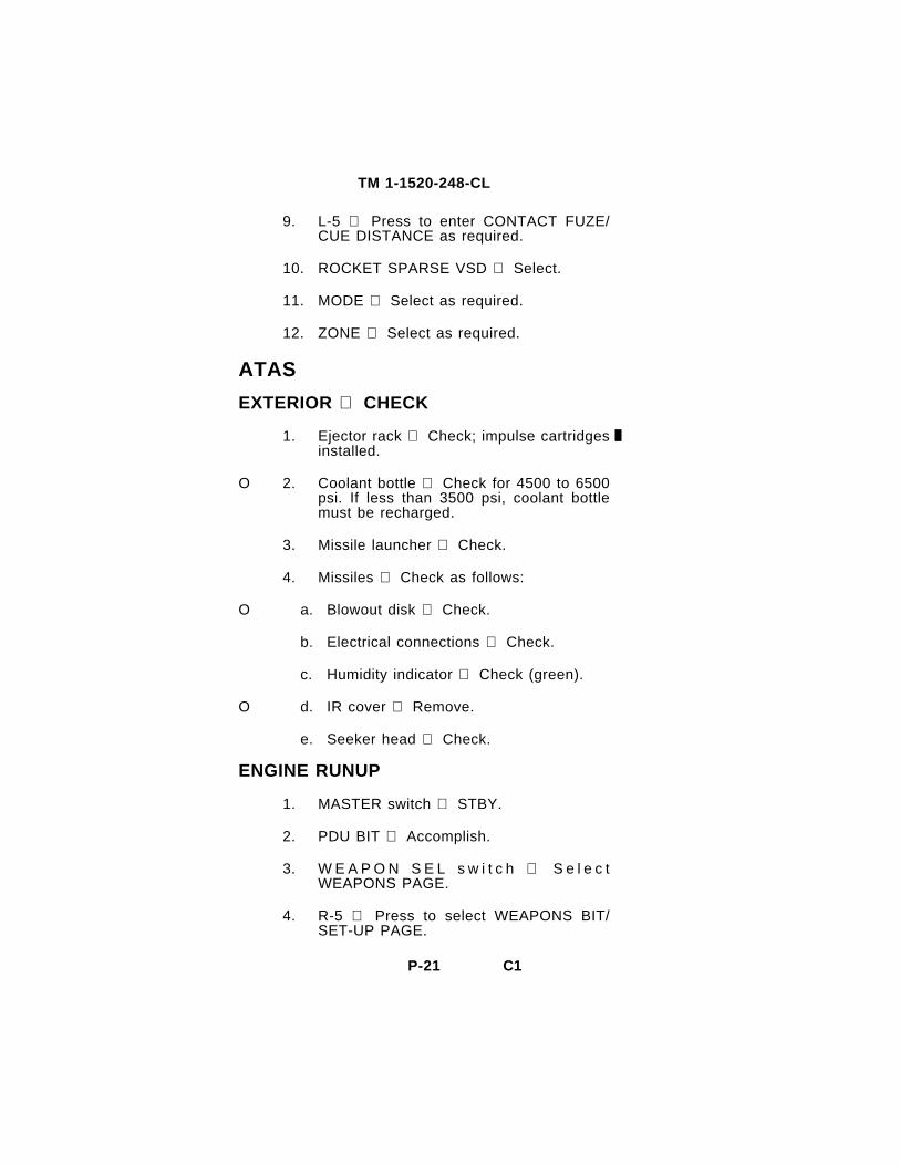
9. L-5 Press to enter CONTACT FUZE/CUE DISTANCE as required.
10. ROCKET SPARSE VSD Select.
11. MODE Select as required.
12. ZONE Select as required.
ATAS
EXTERIOR CHECK
1. Ejector rack Check; impulse cartridgesinstalled.
O 2. Coolant bottle Check for 4500 to 6500psi. If less than 3500 psi, coolant bottlemust be recharged.
3. Missile launcher Check.
4. Missiles Check as follows:
O a. Blowout disk Check.
b. Electrical connections Check.
c. Humidity indicator Check (green).
O d. IR cover Remove.
e. Seeker head Check.
ENGINE RUNUP
1. MASTER switch STBY.
2. PDU BIT Accomplish.
3. W E A P O N S E L s w i t c h S e l e c tWEAPONS PAGE.
4. R-5 Press to select WEAPONS BIT/SET-UP PAGE.
P-21

C1
TM 1-1520-248-CL
5. ATAS BIT Press.
HELLFIRE
1. Ejector rack Check; impulse cartridgesinstalled.
2. Missile launcher Check as follows:
a. SAFE/ARM switch SAFE.
b. U m b i l i c a l c o n n e c t o r C h e c kconnected to launcher. Pullaway cableconnected to rack and connector.
c. Missiles Check missile security onrail and that holdback release handle isin the LATCH position.
3. Rails Check as follows:
a. Grounding straps Check.
b. Electrical cover plate Down (if missilenot installed).
CAUTION
If only one missile is loaded on a launcher,the miss i le sha l l be loaded on theoutboard launcher rail.
c. Miss i le load conf igura t ion Permission requirement.
d. Swaybrace and jamnuts Check.
O 4. Missiles Check as follows:
P-22

TM 1-1520-248-CL
WARNING
If deice cover (environmental protectivecover) is installed, aircraft doors must beinstalled and vents placed in the closedposition to prevent injury to personnel fromshattered frangible dome.
a. Seeker dome Clean and undamaged.
b. Deice dome cover Check dome coverinstallation on missiles and harnessconnection to launcher rail.
c. S t rakes /w ings /cont ro l sur faces Check.
d. Missile body Check.
ENGINE RUNUP
1. MASTER switch STBY.
2. W E A P O N S E L s w i t c h S e l e c tWEAPONS PAGE.
NOTE
• The laser codes are entered into thesystem from the MFK onto the LaserCode List page on the MMS. No twoaddresses should have the same lasercode.
• When entering codes into the HMS thefirst digit must be 1, the second, thirdand fourth digits can be any numberfrom 1 through 8. The system will notaccept the numbers 9 and 0.
3. R-1 Press to enter PRI/ALT lasercodes.
4. R-5 Press to select WEAPONS BIT/SET-UP PAGE.
P-23

TM 1-1520-248-CL
5. R-1 Press to enter MISSILE PERCODE data.
6. L-1 Press to perform HELLFIRE BIT.
AIRBORNE CALIBRATION
NOTE
• Airborne calibration should be checkedfor proper accuracy on every f l ight.Airborne calibration is performed only ifprepoint target is not visible in narrowfield of view.
• Surveyed locations are much better thanones whose coordinates are read from amap.
1. Target waypoint Enter and select asfly-to waypoint in the FLIGHT PLAN.
2. E n s u r e t h e n a v i g a t i o n s y s t e m i saccurate.
3. Helicopter Position at hover at least 3km from target being used, with thetarget visible in the MMS.
4. MMS mode select switch PREFLT.
5. SETUP key Press.
6. AIRBORNE CAL key Press to displaythe AIRBORNE CALIBRATION Page.
7. C lear key Press , as requ i red toeliminate existing airborne cal values.
8. Store key Press as required.
9. TV or TIS narrow field-of-view Selectand point track the target.
10. Target Position helicopter to put targetgreater than 90° to the right of helicopter.
P-24

TM 1-1520-248-CL
11. TGT RIGHT key Press.
12. Target Perform a right pedal turn at nomore than 5° per second to posit iontarget greater than 90° to the left ofhelicopter.
13. TGT LEFT Press.
14. STORE key Press to load theseva lues in to nonvo la t i le memory , asdesired.
15. MMS mode select switch PREPNT.Prepoint the target with wide field of viewselected and verify airborne cal accuracyby veri fying that the target is withinnarrow field of view area.
NOTE
• Failure of airborne cal are usually veryobvious. When step 15 is completed andthe target is not even close, sequencethrough the flight plan back to correcttarget and repeat airborne cal beginningat step 3.
• If step 15 reveals the target is close butnot within narrow FOV or if an azimutherror exists but elevation is good, anEGI heading error could be the cause. Inthis event, repeat the entire airborne calbeginning at step 1.
MANUAL DRIFT COMPENSATION
1. MMS mode select switch PREFLT.
2. SETUP key Press.
3. MDC key Press to ON.
P-25

TM 1-1520-248-CL
CAUTION
Ten to 200 seconds can be used and thelonger sample will provide more accuratedata. During the sampling period, the MMSLOS will continue to drift. Do not allowMMS to contact stops.
4. MDC key Press to OFF.
5. MMS mode select switch FWD.
6. MNL/SLAV switch FWD mode.
7. MNL/SLAV switch Press to entermanual track mode.
8. LOS drift Check. If drift has not beencorrected, call maintenance.
P-26

TM 1-1520-248-CL
Figure 1. Power Assurance Charts (T703-AD-700B/250-C30R)(Sheet 1 of 3)
P-27

TM 1-1520-248-CL
Figure 1. Power Assurance Charts (T703-AD-700B/250-C30R/1)(Sheet 2 of 3)
P-28

TM 1-1520-248-CL
Figure 1. Power Assurance Charts (250-C30R/3) (Sheet 3 of 3)
P-29/(P-30 blank)
TM 1-1520-248-CL
By Order of the Secretary of the Army:
Official: ERIC K. SHINSEKI
General, United States Army Chief of Staff
JOEL B. HUDSON Administrative Assistant to the Secretary of the Army 9921604
Distribution: To be distributed in accordance with Initial Distribution Number IDN 311434, requirements for TM 1-1520-248-CL.

SOMETHING WRONG
FIGURE
Operator’s manual MH60K Helicopter15 June 1992
P.S.- - IF YOUR OUTFIT WANTS TO KNOW ABOUT YOURRECOMMENDATION, MAKE A CARBON COPY OF THISAND GIVE TO YOUR HEADQUARTERS.
PAGE
TM 1-1520-250-10
PARA-
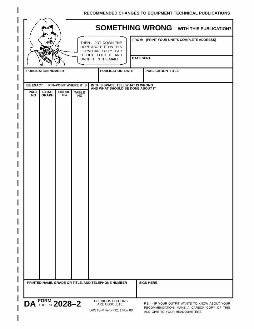
RECOMMENDED CHANGES TO EQUIPMENT TECHNICAL PUBLICATIONS
WITH THIS PUBLICATION?
FROM: (PRINT YOUR UNIT’S COMPLETE ADDRESS)
DATE SENT
PUBLICATION NUMBER PUBLICATION DATE PUBLICATION TITLE
BE EXACT PIN--POINT WHERE IT IS
NO GRAPH NOTABLE
NO
IN THIS SPACE, TELL WHAT IS WRONGAND WHAT SHOULD BE DONE ABOUT IT:
PRINTED NAME, GRADE OR TITLE, AND TELEPHONE NUMBER SIGN HERE
DA 2028--2FORM1 JUL 79
PREVIOUS EDITIONSARE OBSOLETE.
DRSTS-M verprint2, 1 Nov 80
THEN . .JOT DOWN THEDOPE ABOUT IT ON THISFORM, CAREFULLY TEARIT OUT, FOLD IT ANDDROP IT IN THE MAIL!

FOLD BACK
FILL IN YOURUNITS ADDRESS
DEPARTMENT OF THE ARMY
OFFICIAL BUSINESS
COMMANDERU.S. ARMY AVIATION AND MISSILE COMMANDATTN: AMSAM-MMC-LS-LPREDSTONE ARSENAL, AL 35898-5230
TE
AR
ALO
NG
PE
RF
OR
AT
ED
LINE
REVERSE OF DA FORM 2028--2 Reverse of DRSTS-M Overprint 2,
1 Nov 80
FIGUREPARA-
THEN . .JOT DOWN THEDOPE ABOUT IT ON THISFORM, CAREFULLY TEARIT OUT, FOLD IT ANDDROP IT IN THE MAIL!
P.S.- - IF YOUR OUTFIT WANTS TO KNOW ABOUT YOURRECOMMENDATION, MAKE A CARBON COPY OF THISAND GIVE TO YOUR HEADQUARTERS.
PAGE
RECOMMENDED CHANGES TO EQUIPMENT TECHNICAL PUBLICATIONS
WITH THIS PUBLICATION?
FROM: (PRINT YOUR UNIT’S COMPLETE ADDRESS)
DATE SENT
PUBLICATION NUMBER PUBLICATION DATE PUBLICATION TITLE
BE EXACT PIN--POINT WHERE IT IS
NO GRAPH NOTABLE
NO
IN THIS SPACE, TELL WHAT IS WRONGAND WHAT SHOULD BE DONE ABOUT IT:
PRINTED NAME, GRADE OR TITLE, AND TELEPHONE NUMBER SIGN HERE
DA 2028--2FORM1 JUL 79
PREVIOUS EDITIONSARE OBSOLETE.
DRSTS-M verprint2, 1 Nov 80
SOMETHING WRONG
FOLD BACK
FILL IN YOURUNITS ADDRESS
DEPARTMENT OF THE ARMY
OFFICIAL BUSINESS
COMMANDERU.S. ARMY AVIATION AND MISSILE COMMANDATTN: AMSAM-MMC-LS-LPREDSTONE ARSENAL, AL 35898-5230
TE
AR
ALO
NG
PE
RF
OR
AT
ED
LINE
REVERSE OF DA FORM 2028--2 Reverse of DRSTS-M Overprint 2,
1 Nov 80

PIN: 077453-001