tm 10-3930-623-12 technical manual …tm 10-3930-623-12 warning dangerous chemicals are used in this...
TRANSCRIPT

TM 10-3930-623-12
TECHNICAL MANUAL
OPERATOR'S AND ORGANIZATIONALMAINTENANCE MANUAL
TRUCK, FORK LIFT; 4000 LB CAPACITY;144 IN. LIFT; GASOLINE ENGINE DRIVEN
(BAKER MODEL FJF-040; ARMY MODEL MHE-211)FSN 3930-935-7963
This copy is a reprint which includes current pages fromChanges 1 and 2.
HEADQUARTERS, DEPARTMENT OF THE ARMY
MARCH 1971

TM 10-3930-623-12
WARNING
DANGEROUS CHEMICALS
are used in this equipment.
SERIOUS INJURY OR DEATH
may result if personnel fail to observe these safety precautions. Avoid contactwith the battery electrolyte. If the solution comes in contact with the skin, rinse thearea immediately with clear water to avoid skin burns. Do not smoke or use anopen flame in the vicinity when servicing batteries as hydrogen gas, an explosiveis generated. Use only distilled water to maintain battery electrolyte level.
WARNING
FIRE OR EXPLOSION HAZARD
SERIOUS INJURY OR DEATH
may result if personnel fail to observe these safety precautions. Do not fill fueltank while engine is running. Provide metallic contact between the fuel containerand fuel tank to prevent a static spark from igniting fuel. Wipe or flush anyspillage.
WARNING
ASPHYXIATION DANGER
The engine exhaust gases contain carbon monoxide, which is a colorless,odorless, and poisonous gas.
DEATH
or nausea may result if personnel fail to observe safety precautions. Do notoperate the forklift truck in a closed building without providing adequateventilation.
WARNING
Operation of this equipment presents a noise hazard to personnel in the area. Thenoise level exceeds the allowable limits for unprotected personnel. Wear ear muffsor ear plugs which were fitted by a trained professional.

TM 10-3930-623-12C2
CHANGE HEADQUARTERSDEPARTMENT OF THE ARMY
No. 2 WASHINGTON, DC, 8 April 1974
Operator and Organizational Maintenance Manual
TRUCK, FORK LIFT; 4000 LB CAPACITY;144 IN. LIFT; GASOLINE ENGINE DRIVEN
(BAKER MODEL FJF-040; ARMY MODEL MHE-211)FSN 3930-935-7963
TM 10-3930-623-12, 17 March 1971, is changed as follows:Inside Front Cover. Add the following warning to the list of safety precautions:
WARNING
Operation of this equipment presents a noise hazard to personnel in the area. Thenoise level exceeds the allowable limits for unprotected personnel. Wear ear muffsor ear plugs which were fitted by a trained professional.
Page 1-1. Paragraph 1-2 is superseded as follows:
1-2. Recommendation for Maintenance Publications Improvements
You can help to improve this manual by calling attention to errors and by recommending improvements. Your letter or DAForm 2028 (Recommended Changes to Publications and Blank Forms) should be mailed direct to: Commander, USArmy Troop Support Command, ATTN: AMSTS-MPP, 4300 Goodfellow Blvd., St. Louis, MO 63120. A reply will befurnished direct to you.Page 4-1. Immediately after Section IV title, add the following warning:
WARNING
Operation of this equipment presents a noise hazard to personnel in the area. Thenoise level exceeds the allowable limits for unprotected personnel. Wear ear muffsor ear plugs which were fitted by a trained professional. (Refer to TB MED 251)
1

TM 10-3930-623-12
By Order of the Secretary of the Army:
CREIGHTON W. ABRAMSGeneral, United States Army
Official: Chief of Staff
VERNE L. BOWERSMajor General, United State ArmyThe Adjutant General
Distribution:To be distributed in accordance with DA Form 12-25A (qty rqr block No. 894), Organizational maintenance
requirements for Warehouse Equipment.
2

TM 10-3930-623-12C1
CHANGE HEADQUARTERSDEPARTMENT OF THE ARMY
No. 1 WASHINGTON, D.C., 16 May 1972
Operator and Organizational Maintenance Manual
TRUCK, FORK LIFT; 4000 LB CAPACITY;144 IN. LIFT; GASOLINE ENGINE DRIVEN
(BAKER MODEL FJF-040; ARMY MODEL MHE-211)FSN 3930-935-7963
TM 10-3930-623-12, 17 March 1971, is changed as follows:Page 3-1. Paragraph 3-3.1 is added as follows:
3-3.1. Maintenance and Operating Supplies
A list of maintenance and operating supplies required for initial operation of the fork lift truck are contained in table 3-1;
TAGO 3460A

TM 10-3930-623-12
Table 3-1. Maintenance and Operating Supplies
(4) (5)Quantity Quantity
(1) (2) Required RequiredComponent Federal (3) F/Initial F/8 Hrs (6)Application Stock No. Description Operation Operation Notes
Crankcase Oil lubricating (1) (1) Includes quantity of oil to fill engine9150-265-9435(2) OE 30 5 qt (1), (3) oil system as follows:9150-265-9428(2) OE 10 5 qt (1), (3) 4 qt-crankcase9150-242-7603(2) OES 5 qt (1), (3) 1 qt-oil filter
Hydraulic Brake Cylin-der
Brake Fluid: Automotive, 1 galloncan as follows
(2) See C9100 - IL for additional dataand requisitioning procedures
9150-252-6375(2) HBA 1/2 PT (3) (3) See current LO for grade applicationand replenishment intervals (LO 10 -3930-623-12).
Hydraulic Reservoir Oil Lubricating: 55 gallon drum asfollows:
(4) Fuel tank capacity
9150-265-9430(2) OE 10 12 1/2 gal (3)9150-242-7605(2) OES 12 1/2 gal (3)
Radiator WaterAntifreeze, 5 gallon can as follows: as
6850-224-8730 Ethylene Glycol, type 1 13 qtAntifreeze: 5 gallon drum as follows:
6850-174-1806 Arctic grade 13 qt
Fuel Tank Fuel, Gasoline: Bulk as follows:9130-160-1818(2) Automotive Combat 91A 12.7 gal (4)9130-160-1830(2) Automotive Combat 91C 12.7 gal (4)
Transmission and Dif- Type A Automatic Transmission Fluid 16 qt (3)ferential Suffix A, 1 qt. can
9150-698-2382
Grease Points Grease, Automotive and Artillery: 5lb. cans as follows:
9150-190-0905(2) GAA
2

TM 10-3930-623-12
Page B-1. Appendix B is superseded as follows:
APPENDIX BBASIC ISSUE ITEMS UST AND ITEMSTROOP INSTALLED OR AUTHORIZED
Section I. INTRODUCTION
B-1. ScopeThis appendix lists items required by the operator foroperation of the fork lift truck.
B-2. GeneralThis list is divided into the following sections:
a. Basic Issue Items List-Section II. Notapplicable.
b. Items Troop Installed or Authorized List SectionIII. A list of items in alphabetical sequence, which at thediscretion of the unit commander may accompany thefork lift truck. These items are NOT subject to turn-inwith the fork lift truck when evacuated.
B-3. Explanation of ColumnsThe following provides an explanation of columns in thetabular list of Basic Issue Items List, Section II, andItems Troop Installed or Authorized, Section III.
a. Source, Maintenance, and RecoverabilityCode(s) (SMR) :
(1) Source Code, indicates the source for thelisted item. Source codes are:
Code ExplanationP Repair parts, special tools and test equipment
supplied from GSA/DSA or Army supply systemand authorized for use at indicated maintenancelevels.
P2 Repair parts, special tools and test equipmentwhich are procured and stocked for insurancepurposes because the combat or militaryessentiality of the end item dictates that aminimum quantity be available in the supplysystem.
(2) Maintenance Code, indicates the lowestlevel of maintenance authorized to install the listed item.The maintenance level code is:
Code ExplanationC Crew/Operator
(3) Recoverability Code, indicates whetherunserviceable items should be returned for recovery orsalvage. Items not coded are nonrecoverable.Recoverability codes are:
Code ExplanationR Applied to repair parts (assemblies and
components), special tools and test equipmentwhich are considered economically reparable atdirect and general support maintenance levels.
S Repair parts, special tools, test equipment andassemblies which are economically reparable atDSU and GSU activities and which normally arefurnished by supply on an exchange basis.
b. Federal stock number. This column indicatesthe Federal stock number assigned to the item and willbe used for requisitioning purposes.
c. Description. This column indicates the Federalitem name and any additional description of the itemrequired.
d. Unit of measure (U/M). A 2 character alphabeticabbreviation indicating the amount or quantity of the itemupon which the allowances are based, e.g., ft, ea, pr,etc.
e. Quantity furnished with equipment (BIIL only).This column indicates the quantity of an item furnishedwith the equipment.
f. Quantity authorized (Items troop installed orauthorized only). This column indicates the quantity ofthe item authorized to be used with the equipment.
g. Illustration (BIIL only). This column is divided asfollows:
(1) Figure number. Indicates the figurenumber of the illustration in which the item is shown.
(2) Item number. Indicates the calloutnumber used to reference the item in the illustration.
3

TM 10-3930-623-12
Section III. ITEMS TROOP INSTALLED OR AUTHORIZED LIST
(3)(1) (2) Description (4) (5)
SMR Federal stock Ref No. & Mfr Usable Unit of Qty AuthCode number on code on code meas
7510-889-3494 BINDER, LOOSE LEAF EA 1
7520-559-9618 CASE, MAINTENANCE AND OPERATING EA 1
I MANUALS
4210-889-2221 EXTINGUISHER, FIRE EA 1
By Order of the Secretary of the Army:
W. C. WESTMORELAND,General, United States Army,
Official: Chief of Staff.
VERNE L. BOWERS,Major General, United States Army,The Adjutant General.
Distribution:To be distributed in accordance with DA Form 12-25A (qty rqr block No. 894) organizational maintenance
requirements for Warehouse.
4

TM 10-3930-623-12
WARNING
OPERATING HAZARD
SERIOUS INJURY OR DEATH
to the operator or personnel may result if operator does not observe these safetyprecautions and is not alert at all times while operating the forklift truck. Useextreme care when high tiering. Position elevated load with slight back tilt of mastdirectly over loading spot, then tilt mast forward to stack. Use caution whenapproaching doorways, aisles, intersections or other workers. Always travel withmast tilted back and fork raised Just high enough to clear any uneven floorconditions. Avoid sudden starting and stopping. Reduce speed on turns. Knowthe rated capacity of the fork lift truck and do not overload it. Never pick up a loaduntil certain it can be carried safely. Make sure the load is steady before lifting andkeep the load against the carriage rest. When transporting bulky loads, travel inreverse. Always descend ramps in reverse when carrying load. Do not butt loadswith the forks or with the rear of the truck.
WARNING
MAINTENANCE HAZARD
SERIOUS INJURY OR DEATH
to personnel may result if the fork lift is not blocked securely before crawlingunder the fork lift truck.
The format of this manual is not in accordance with established Department of Army specifications because of the shortleadtime involved. The technical content has been furnished by the equipment manufacturer and augmented with aMaintenance Allocation Chart (MAC), Basic Issue Items List (BIIL) to assure that it provides the essential data needed tooperate and maintain the equipment.

TM 10-3930-623-12
TECHNICAL MANUAL
NO. 10-3930-623-12 HEADQUARTERSDEPARTMENT OF THE ARMY
WASHINGTON, D.C., 17 March 1971
Operator's and Organizational Maintenance Manual
TRUCK, FORK LIFT, 4000 LB CAPACITY,144 IN. LIFT, GASOLINE ENGINE DRIVEN
(BAKER MODEL FJF-040; ARMY MODEL MHE-211)FSN 3930-935-7963
Section Page
I INTRODUCTION AND GENERALDESCRIPTION ......................................... 1-1
1-1 Introduction ....................................... 1-11-3 General Description ............................ 1-11-7 Detailed Description ............................ 1-31-37 Electrical System Components ........... 1-9
II TABLE OF SPECIFICATIONS ...................... 2-1
III PREPARATION FOR USE ........................... 3-13-1 Visual Examination ............................. 3-13-3 Services upon Receipt ....................... 3-1
IV OPERATION............................................... 4-14-1 Principles of Operation ........................ 4-14-3 Engine .............................................. 4-14-12 Fuel System ....................................... 4-24-16 Ignition System................................ 4-2.14-24 Cooling System .................................. 4-34-30 Charging System ................................ 4-54-42 Drive Axle and Transmission ............... 4-54-53 Operating Instructions ...................... 4-8.14-56 Operating Procedures and
Techniques ...................................... 4-114-60 General Loading and
Driving Procedures ........................... 4-114-64 Safety Precautions ............................ 4-12
V INSPECTION, MAINTENANCE ANDLUBRICATION ......................................... 5-1
5-1 Scope of Section ................................ 5-15-3 Preventive Maintenance Services ........ 5-15-9 Engine Maintenance ........................... 5-25-12 Fuel System Maintenance ................ 5-2.4
Section Page
5-15 Cooling System Maintenance.............. 5-35-27 Electrical System Maintenance ............ 5-45-39 Chassis Maintenance ....................... 5-155-42 Lubrication ....................................... 5-155-44 Troubleshooting ............................... 5-155-46 Test Equipment ............................... 5-27
VI REMOVAL AND INSTALLATIONOF ASSEMBLIES ..................................... 6-1
6-1 General ............................................. 6-16-4 Overhead Guard ................................. 6-16-7 Counterweight ................................... 6-16-10 Seat Assembly .................................. 6-16-13 Sheet Metal ....................................... 6-16-21 DELETED
6-25 Tilt Cylinder Assemblies ..................... 6-36-28 Lift Chains ......................................... 6-56-31 DELETED6-34 DELETED6-37 DELETED6-40 DELETED6-43 Control Valve ..................................... 6-56-46 Electrical System................................ 6-66-59 Radiator ............................................ 6-86-62 Power Train..................................... 6-8.16-64 Fuel Filter, Fuel Pump
and Carburetor ............................... 6-8.16-67 Water Pump ....................................... 6-96-70 Steering Gear .................................... 6-96-74 Hydraulic Brake Master Cylinder6-77 Brake Pedal...................................... 6-136-80 Exhaust Hose................................... 6-136-83 Intake And Exhaust Manifold ............. 6-136-87 Return Line Filter Installation ............. 6-13
APPENDIX A Maintenance Allocation Chart* .............A-1APPENDIX B Basic Issue List...................................B-1
i

TM 10-3930-623-12
LIST OF ILLUSTRATIONS
Number Page
i FJF-040 Fork Lift Truck..................................................................................................................iv1-1 Deleted1-2 Typical Engine, Front and Rear Views ............................................................................................1-21-3 Charging System Basic Schematic.................................................................................................1-31-4 Hydraulic System Diagram ............................................................................................................1-41-5 Steering System Arrangement........................................................................................................1-51-6 Power Steering Gear Operation......................................................................................................1-71-7 Transmission, Showing Pressure Passages ....................................................................................1-81-8 Transmission Hydraulic Diagram ....................................................................................................1-91-9 Drive Axle, Exploded View .............................................................................................................1-101-10 Uprights, Carriage and Fork ...........................................................................................................1-111-11 Electrical Schematic ......................................................................................................................1-121-12 Instrument Panel ...........................................................................................................................1-133-1 Check Points before Use...............................................................................................................3-24-1 Four Stroke Engine Cycle ..............................................................................................................4-14-1.1 Fuel Tank Removal and Installation ................................................................................................4-2.24-2 Ignition System Schematic.............................................................................................................4-34-3 Wiring Diagram .............................................................................................................................4-44-4 Differential Diagram.......................................................................................................................4-64-5 Transmission Power Flow..............................................................................................................4-74-6 Wheel Brake Layout ......................................................................................................................4-8.34-6.1 Front Drive Axle Complete, Exploded View .....................................................................................4-8.44-6.2 Hand Brake Control Installation, Exploded View ..............................................................................4-94-7 Instruments and. Controls .............................................................................................................4-105-1 Tensioning Alternator Belt..............................................................................................................5-25-2 Cylinder Head Tightening Sequence...............................................................................................5-25-2.1 Accelerator Linkage, Removal and Installation.................................................................................5-2.55-3 Measuring Tappet Clearance .........................................................................................................5-35-4 Flywheel Timing Marks ..................................................................................................................5-55-5 Breaker Plate................................................................................................................................5-65-6 Breaker Point Adjustment ..............................................................................................................5-75-7 Measuring Spark Plug Gap ............................................................................................................5-75-8 Measuring Brush Spring Tension ...................................................................................................5-85-9 Deleted5-10 Deleted5-11 Deleted5-12 Alternator Test Setup.....................................................................................................................5-115-13 Deleted5-14 Test Equipment .............................................................................................................................5-266-1 Fork Lift Truck Components ...........................................................................................................6-26-2 Hydraulic System Layout ..............................................................................................................6-46-2.1 Hydraulic Hoist and Tilt Control Valve, Exploded View.....................................................................6-4.16-3 Engine Mounted Electrical Units.....................................................................................................6-76-4 Neutral Safety Switch Adjustment ...................................................................................................6-86-5 Steering Gear Removal..................................................................................................................6-106-6 Hydraulic Brake Master Cylinder and Pedal Assembly,
Exploded View..........................................................................................................................6-126-7 Exhaust Hose, Muffler and Exhaust Pipe, Exploded View.................................................................6-146-8 Engine Assembly ..........................................................................................................................6-156-9 Hydraulic System Line Filter, Exploded View...................................................................................6-16
ii

TM 10-3930-623-12
Figure i. FJF-040 Fork Lift Truck
iii/iv

TM 10-3930-623-12
SECTION I
INTRODUCTION AND GENERAL DESCRIPTION
1-1. INTRODUCTION.
1. Scope. These instructions are published for the information and guidance of personnel to whom the forklift truck isissued. information is provided on the operation, preventive maintenance services, and organizational maintenance of theequipment, accessories, and components.
2. Demolition and Administrative Storage
a. For information on the administrative storage of this equipment, refer to TM 740-90-1.
b. For information on the demolition of this equipment, refer to TM 750-244-3..
3. Maintenance Forms and Records. Maintenance forms, records, and reports which are to be used by maintenancepersonnel at all maintenance levels are listed in and prescribed by TM 38-750.
1-2. Recommendation for Maintenance Publications Improvements
You can help to improve this manual by calling attention to errors and by recommending improvements. Your letter or DAForm 2028 (Recommended Changes to Publications and Blank Forms) should be mailed direct to: Commander, USArmy Troop Support Command, ATTN: AMSTS-MPP, 4300 Goodfellow Blvd., St. Louis, MO 63120. A reply will befurnished direct to you.
1-3. GENERAL DESCRIPTION.
1-4. The Model FJF-040 fork lift truck is a front loading unit rated to handle loads to 4000 pounds at 24 inch load centers.Pneumatic tires permit satisfactory operation of the truck off paved surfaces.
1-5. Handling of loads is accomplished by engaging the two 40 inch fork prongs with the load. The forks are mounted ona hydraulically operated mast assembly which can raise the load to a height of twelve feet for stacking of commoditieshandled. The mast is tiltable ten degrees rearward to cradle the load when traveling, to three degrees forward to facilitatedisengaging the load when depositing it. Travel speed of the trucks is limited to about 12 miles per hour loaded, or 14miles per hour empty, by an engine speed governor. Steering is power assisted. Arrangement of the controls conformsto general industrial truck standards, permitting ready use by operators with previous fork lift experience.
1-1

TM 10-3930-623-12
Figure 1-2. Typical Engine, Front and Rear Views
1-2

TM 10-3930-623-12
1-6. The forklift trucks are powered by Continental FS-244 Military Standard engines rated at 82.3 horsepowerwhen operating at 2800 revolutions per minute.
1-7. DETAILED DESCRIPTION.
1-8. ENGINES (See figure 1-2). Differences betweenthe engines used in the trucks are mainly in partsdimensions. The details given in subsequentparagraphs apply to all trucks unless otherwise stated.
1-9. The full pressure lubrication system includes agear-type oil pump with adjustable bypass valve tomaintain suitable pressure through all speeds, and areplaceable element oil filter.
1-10. The fuel system includes a mechanical diaphragmfuel pump, driven by the engine camshaft, a singleventuri updraft carburetor, and a mechanical governorwhich limits the maximum speed of the engine by closingthe carburetor throttle valve when the engine reachesthe governed speed. The carburetor air cleaner uses adisposable paper filter element.
1-11. ALTERNATOR. The alternator is an ac generatordesigned and constructed to give long service with aminimum of maintenance. The rotor is mounted on aball bearing at the drive end, and a roller bearing at theslip ring end, and each bearing has a grease supplywhich eliminates the need for periodic lubrication. Twobrushes are used to carry current through the two sliprings to the field coil which is mounted on the rotor. Thebrushes are extra long and under normal operatingconditions will provide long periods of service. Thestator windings are assembled on the inside of alaminated core that forms part of the frame. Six rectifiesdiodes, mounted in the slip ring end frame, areconnected to the stator windings. The six diodes changethe ac voltage to de voltage which appears at the BATterminal on the alternator. A capacitor, or condenser,mounted in the end frame protects the diodes from highvoltages. Current output of the alternator is self-limitingby design to its rated maximum, regardless of speed orexternal circuit conditions. An externally mountedvoltage regulator limits the operating voltage to aspecified value through the full speed range of thealternator. Figure 1-3 shows a schematic view of thealternator and regulator.
1-12. VOLTAGE REGULATOR. The transistor is anelectrical device made of semiconductor materials whichis used as a switch to control the alternator field currentin order that alternator voltage can be limited to a propervalue. Figure 1-3 is a greatly simplified diagram of thealternator and regulator circuit. A brief description of theoperation follows:
1. When the ignition switch is closed, batteryvoltage supplies current through the emitter (E) andcollector (C) of the transistor to the field coil of thealternator. This emitter-collector circuit is complete sincethe transistor is turned "on" by a higher voltage on theemitter than on the base (B), which permits emitter-basecurrent to flow. The flow of current to the field circuit
Figure 1-3. Charging System Basic Schematic
of the alternator provides the magnetic field for thealternator. When the engine is started, the alternatorbuilds up voltage. This causes current to flow to chargethe battery and/or power accessories.
2. As alternator speed increases or the accessoryload decreases, alternator voltage builds up to apredetermined value at which the regulator is set oradjusted. The electrical control portion of the regulatorthen places a higher voltage on the base of the transistorthan is impressed upon the emitter, and the transistor isturned "off". With no current flow in the emitter-collectorcircuit, there is no current flow in the field coil of thealternator. As a result, alternator voltage drops belowthe setting or adjustment of the regulator.
3. Then the electrical control portion of theregulator places a lower voltage on the base of thetransistor than that on the emitter, and the transistor isagain turned "on". With current flow again in theemitter-collector and field coil circuit, the magnetic fieldis reestablished in the alternator, and alternator voltagecan again build up to the setting of the regulator.
4. Thus, the switching "on" and "off' of thetransistor regulates the amount of field current suppliedto the alternator. The frequency of this switching isdependent primarily upon the accessory load andalternator speed. Under certain conditions the "on" and"off" cycle is repeated as much as 7,000 times persecond.
1-3

TM 10-3930-623-12
5. A zener diode, driver transistor, capacitor, andresistors act together as the electrical control portion ofthe regulator to electrically switch the output transistor"on" and "off". A thermistor provides a temperaturecompensated voltage setting which is matched to thecharging requirement characteristics of the battery.
1-13. STARTING SYSTEM. The trucks are fitted with aDelco-Remy enclosed shift starter motor using asolenoid shifted overrunning clutch drive. The starter isoperated from the instrument panel by a push buttonswitch. A neutral safety switch operated by thetransmission shift linkage is installed in the startercontrol circuit. This switch is closed only when thetransmission is in neutral, to permit starting at that time.The trucks also have a starter lockout relay in the controlcircuit to prevent accidental operation of the starter while
the engine is running.
1-14. IGNITION SYSTEM. The ignition system is aconventional high tension battery powered system,modified to meet radio interference shieldingrequirements, or radio interference suppressed, Thesystem includes an ON-OFF switch on the instrumentpanel; a high tension coil, which transforms the lowvoltage of the battery to voltage high enough to jump thespark plug gap, providing ignition; a distributor whichtimes the occurrence of the spark at the cylinder anddirects each-high voltage pulse to the proper cylinder infiring order of the engine; a set of spark plugs and allconnecting leads.
1-15. DELETED
Figure 1-4. Hydraulic System Diagram
1-4

TM 10-3930-623-12
1-16. The distributor times the occurrence of the ignitionspark in relation to the engine by a set of breaker pointsoperated by an engine-driven cam. Variations in timingunder changing speed are accomplished through acentrifugally operated spark advance mechanism in thedistributor. The timed high voltage impulses are fedthrough the center terminal of the distributor cap to therotor inside. The rotor then directs the high voltage toeach spark plug wire (arranged from cap to spark plugsin proper engine firing order) in sequence, to spark eachspark plug at the proper time.
1-17. HYDRAULIC PUMP. Hydraulic pressure forsteering, hoisting, and tilting of the uprights is suppliedby an engine-driven hydraulic pump. This pump ismounted at the left rear side of the engine, driven by agear which engages the camshaft timing gear. Thepump is a gear type positive displacement pump.
1-18. UPRIGHT CARRIAGE AND FORK ASSEMBLYHYDRAULIC SYSTEM (See figure 1-4). Using pressurefrom the engine-driven hydraulic pump, this systemcontrols raising of the forks and fore and aft tilting of theuprights. The control valve assembly permits theoperator to direct pressure to the hoist cylinder forraising the forks, or to the tilt cylinders to adjust theangle of the uprights and forks.
1-19. The flow divider (priority) valve directs the pump
output to both the power steering system and the controlvalve assembly inlet port. A relief valve in the flowdivider valve limits hydraulic pressure in the powersteering system. This relief valve cracks open at 700 psiand is fully open at 1050 psi.
1-20. The control valve assembly is a two-spool fluidcontrol valve with a control handle for each spool. Theinboard control handle and spool control the raising andlowering of the forks by applying or releasing hydraulicpressure to the hoist cylinder. The outboard controlhandle and spool control tilting of the upright carriage.Each control handle has two actuating positions with acenter neutral position. A pilot operated relief valvelimits system pressure to 1500 psi. The hoist cylinder isa two-stage single-acting unit, raised by applying fluidpressure, and lowered by releasing pressure to permitgravity return of the elevated parts. The tilt cylinders aredouble-acting cylinders.
1-21. POWER STEERING GEAR. The power steeringgear unit is basically a Saginaw recirculating ballsteering gear to which has been added a torquesensitive valving arrangement, and in which the ball nuthas been redesigned to act as a hydraulic piston. Thevalve (see figure 1-6) is an open-center rotary three-wayvalve, with a grooved spool to
Figure 1-5. Steering System Arrangement
1-5

TM 10-3930-623-12
direct hydraulic pressure as required for either right or left turnassist. The spool is attached to the valve body at one end, andthrough a torsion bar to the steering gear stub shaft at theother end. Turning the steering wheel will steer the wheelswithout power assistance, through the torsion bar, spool andvalve body, until more than about three pounds pull at the rimof the steering wheel is required. At this amount of resistancethe torsion bar twists, shifting the spool in the valve body, tovalve hydraulic fluid as required to supplement steering effortin the direction in which the wheel is turned, as diagrammed infigure 1-6. Note that the rack-piston nut is geared directly tothe pitman shaft. Power assistance is proportional to demand,and ceases when reduction in torsional load permits the torsionbar to return the valve spool to neutral. Hydraulic power istaken from the truck main hydraulic pump via a pressurereducing priority valve on the main hydraulic pump, connectedby tubing directly to the steering gear housing.
1-22. STEERING AXLE ASSEMBLY (See figure 1-5). Thesteering axle assembly is mounted on two neoprene blockslocated to permit a degree of movement to the axle necessaryto pass over irregular surfaces. The steering axle layout, andits relationship to the power steering system is shown in figure1-5.
1-23. Two equal length tie rods connect a center-mountedbellcrank to each of the steering knuckles. Steering axle kingpins are mounted in true vertical position to provide similarsteering characteristics in either forward or reverse travel. Thepneumatic tired wheels of the steering axle are not fitted withbrakes.
1-24. TRANSMISSION (See figures 1-7 and 1-8). Thetransmission is a power-shifted single ratio forward andreverse unit. A torque converter transmits engine output to thetransmission input shaft. The transmission is mounted directlyto the engine and drive axle. No intervening drive shaft isused. Shifting between forward and reverse is accomplishedby engagement of either a forward or reverse wet clutch in theunit. These clutches are engaged by hydraulic pressureselected by a control valve.
1-25. The clutches are contained in one large balanced drumassembly, and the plates drive concentric shafts. The outershaft has a gear mounted on it which is in direct mesh with theoutput gear on the output shaft. This transmits forward rotationto the output shaft. A gear on the inner shaft drives the outputshaft through an idler gear to give reverse drive. The maincase is of two piece construction and the rear half contains aheavy diaphragm midwall which forms one side of a straddlemounting for the output gear and shaft. Oil passages areinternal except for the lines to the transmission oil cooler. Theoil supply is common for the torque converter, transmission,and drive axle, including the drive wheel bearings.
1-26. An internal gear pump driven by the torque converterhub supplies oil to the torque converter through a meteringorifice and to a control valve assembly in the transmissionhousing. Oil delivered to the torque converter maintainscirculation through the converter to the oil cooler, or heatexchanger in the engine radiator.
1-27. Additional oil from the pump is used by the control valveto provide forward or reverse directional control to the vehicle.The control valve includes a pressure regulator valve, a brakepedal operated inching valve, a forward and reverse clutchsupply valve, and a forward and reverse selector valve, withneutral position. These four valves are essentially in series inthe control circuit. Regulated pump pressure is delivered tothe inching valve, which can either deliver it through, orpartially or completely shut off this pressure as the operatorrequires, for inching operations while maintaining high enginespeed for hoisting. Pressure on the brake pedal controls thedegree of clutch slippage for inching, while the position of theselector valve determines which clutch will be engaged.
1-28. DRIVE AXLE (See figure 1-9). This assembly is adouble-reduction drive axle, bolted directly to the front of thetransmission. The output shaft of the transmission includes thedrive pinion gear which mates with the ring gear of thedifferential assembly to provide the first reduction. Internalgears at the outer end of the first drive axles drive sun gears togive the second stage reduction to the final drive axles and thewheels.
1-29. The hydraulic brake assemblies at each wheel are pedalactuated as service brakes and handle operated bymechanical linkage as parking brakes. A self-adjusting featureeliminates periodic adjustment to compensate for lining wear.The brake master cylinder is a conventional automotive type,connected to a wheel cylinder at each front wheel by hydrauliclines. The service brake shoes serve also as parking brakes,being actuated by linkage from the hand brake lever next to theoperator's seat. The operator can adjust any slack from theparking brake linkage by turning a knurled knob at the top ofthe parking brake lever.
1-30 UPRIGHT CARRIAGE AND FORK ASSEMBLY (Seefigure 1-10). The upright carriage and fork assembly consistsof four main items which are described in the followingparagraphs.
1-31. OUTER UPRIGHT. This item is a welded one-pieceassembly attached to the frame of the vehicle. It encloses thehydraulic hoist cylinder and inner upright assembly. The outerupright is pivot mounted on the frame to permit tilting by the tiltcylinder of the entire carriage and fork assembly as necessary.
1-32. INNER UPRIGHT. This item is a one-piece weldedassembly mounted within the outer upright. The hydraulichoist cylinder, mounted in the base of the outer upright, isattached at the top to the inner upright crossmember. Theinner upright is raised by the hydraulic cylinder.
1-33. CROSSHEAD ASSEMBLY. The crosshead assembly ismounted on the top end of the hoist cylinder primary plunger.Chains, secured at one end to the hoist primary cylinder, passover rollers on the crosshead assembly and are secured to thelift carriage assembly. Raising the hoist cylinder primaryplunger raises the crosshead assembly to hoist the lift carriageand forks by the chain.
1-6

TM 10-3930-623-12
Figure 1-6. Power Steering Gear Operation
1-7

TM 10-3930-623-12
Figure 1-7. Transmission, Showing Pressure Passages
1-8

TM 10-3930-623-12
1-34. LIFT CARRIAGE ASSEMBLY. The lift carriageassembly is mounted on rollers between the outer andinner uprights, which serve as guide tracks for it. Theforks are mounted on the lift carriage, traveling up anddown with it.
1-35. FRAME. The basic structure of the fork lift truck isthe one-piece welded frame, to which all componentsand major assemblies of the truck are attached. Therunning gear is attached to the underside of the frame,the hoisting mechanism is mounted at the frame frontend, and a one-ton counterweight is fastened to the backof the frame. Since the frame houses much of themechanism for the truck, access openings for serviceand maintenance are provided at appropriate locations.
1-36. SHEET METAL. The operator's seat is mountedon top of a hinged compartment cover. A manuallyoperated latch at the front of this cover permits raising
the cover for access to the engine compartment fromabove. A radiator cover plate is bolted to thecounterweight. The operator's pedal controls, thesteering column, and electrical leads to the instrumentsand switches are mounted on or through a floor plate.For minor service of components beneath the floor plate,a small cover is located above the transmission dipstickand fill tube, and the brake system master cylinder. Thefloor plate can be removed for more extensivemaintenance.
1-37. ELECTRICAL SYSTEM COMPONENTS.
1-38. The following paragraphs contain descriptions ofelectrical system components for the truck, exceptingthose units previously described in connection with theengine assembly. (See figure 1-11).
Figure 1-8. Transmission Hydraulic Diagram
1-9

TM 10-3930-623-12
1-39. SPOTLIGHT ASSEMBLY. The sealed-beamspotlight is mounted on the left hand hoist upright. Thislight is operated by a toggle switch mounted on theinstrument housing.
1-40. COMBINATION TAIL AND STOP LIGHTASSEMBLY. The tail and stop light assembly ismounted within a steel guard on the upper rear of theengine compartment. The taillight operates when thespotlight is turned on. The stop light is operated by thebrake light switch when the-foot brakes are used.
1-41. IGNITION SWITCH. The ignition switch ismounted on the instrument panel. Setting the ignitionswitch to ON position energizes the ignition system andinstrument panel gages.
1-42. SENDING UNITS. Three sending units on thetruck actuate instruments on the instrument panel. Thefuel gage sending unit is mounted atop the fuel tank.This unit consists of a float mounted on an arm attachedto a sliding contact. The position of the arm isproportional to the quantity of fuel. The slider shorts outturns of a resistance winding to change the current in thegauge circuit proportional to the fuel level, which isregistered on the instrument.
Figure 1-9. Drive Axle, Exploded View
1-10

TM 10-3930-623-12
Figure 1-10. Uprights, Carriage and Fork
1-11

TM 10-3930-623-12
Figure 1-11. Electrical Schematic
1-12

TM 10-3930-623-12
1-43. The oil pressure sending unit is connected into thepressure side of the lubricating oil system. This unitcontains a coil, the resistance of which varies withpressure. Actuating current to the instrument passesthrough this resistance coil which varies the current, andthus the indication, in proportion to the pressure on thesending unit.
1-44. The water temperature sending unit is threadedinto the engine cylinder head to sense and respond toengine coolant temperature. This unit contains atemperature sensitive resistance coil which regulates theflow of actuating current to the engine temperature gagein proportion to engine coolant temperature (see figure1-2).
1-45. INSTRUMENT PANEL (See figure 1-12). Theinstrument panel assembly incorporates the usualstandard instruments in a compact group. The engineoperation hourmeter is used to determine when periodicservice operations are due. in addition to controlling theignition system, the ignition switch energizes theinstruments, and the starter circuit up to the starterbutton. The light switch operates the spot light andtaillight.
1-46. The fuses in the fuse holder protect the variouselectrical circuits of the truck. Refer to the wiringdiagram (figure 1-11) for identification of each fuse.
1-47. The instrument voltage regulator is a small voltagedivider which reduces system voltage to six volts forinstrument power.
Figure 1-12. Instrument Panel'
1-13/14

TM 10-3930-623-12
SECTION II
TABLE OF SPECIFICATIONS
1. GENERAL 2. DELETED
Type of Vehicle ...................................... Fork Lift Truckgasoline engine powered
Rated Capacity ............................4000 lb at 24 in. fromheel of fork
Lift Type ..................................telescopic upright boom,tiltable 3 deg forward, 10 deg
backward from upright
Lift Elevation (Max.) ...........................................144 in.
Fork Data .......................4 in. wide prongs, 40 in. long.............................................. Adjustable from 9 to 38 in.
Wheels ............................................ 4 drive wheels and2 steerable wheels
Tires .....................................pneumatic, size 7.00 x 12(drive axle), and 6.90/6.00
x 9 (steering axle)
Vehicle Turning Radius ...................90 in. min. outsideturning radius
Vehicle Top Speed ............................................12 mph
Overall Dimensions
Height (Forks Fully Lowered) .......................91 in.
Height (Forks Fully Raised) .......................192 in.
Width..........................................................63 in.
Length (Less Forks) ....................................91 in.Vehicle Weight (Group A & C Trucks) ........8165 lb
Ground Clearance (Minimum) ................................ 3 in.
Attachments .................................. overhead guard andload safety rack
2-1/2-2

TM 10-3930-623-12
3. ENGINE
Type .............................. Continental Model No. FS244
Number of Cylinders ..................................................6
Bore and Stroke ..................................3-7/16 x 4-3/8 in.
Displacement ................................................ 244 cu in.
Compression Ratio................................................ 6.9:1
Brake Horsepower ..............................82.3 at 2800 rpm
Torque (Ft Lb) ......................................192 at 1200 rpm
Max. Oil Pressure
Hot at 1800 rpm........................................30 to 40 psi
Min. Oil Pressure ........................................7 psi at idle
Firing Order ................................................ 1-5-3-6-2-4
Oil Capacity
Crankcase........................................................... 4 qt
Filter .................................................................. 1 qt
Total .................................................................. 5 qt
Valve Clearance
Intake........................................................... 0.014 in.
Exhaust ....................................................... 0.014 in.
Water Capacity
Engine ......................................................... 6-1/2 qt
Engine and Radiator ......................................... 13 qt
Weight (Bare Engine) ..........................................516 lb
ENGINE OVERHAUL TOLERANCES AND WEARLIMITS IN INCHES EXCEPT AS NOTED
Cylinder Block
Cylinder Out-of-Round......................................0.0005
Cylinder Taper ................................................0.0005
Crankshaft and Bearings
Main Bearing Journal Dia .....................2.2442/2.2451
Additional Wear ................................................0.001
Connecting Rod Journal Dia..................2.0594/2.0601
Additional Wear ................................................0.001
Main Bearing Clearance........................0.0008/0.0028
Bearing Thickness ................................0.0948/0.0953
Additional Wear ..............................................0.0005
2-3

TM 10-3930-623-12
Crankshaft End Thrust ............................. 0.002/0.006
Main Bearing Size (Case Hole) .............2.4365/2.4372
Out-of-Round...................................................0.0005
Taper .............................................................0.0005
Runout .............................................................0.002
Connecting Rods and Bearings
Bearing Thickness ...............................0.0623/0.0628
Bearing Length ........................................ 1.057/1.067
Side Play................................................. 0.006/0.010
Connecting Rod Bend.............................. 0.000/0.002
Crankshaft Journal to Connecting
Rod Bearing Clearance ......................... 0.0008/0.003
Connecting Rod Twist ............................. 0.000/0.002
Pin Bushing Inside Dia ........................0.859310.8596
Pin Bushing Outside Dia........................ 0.9165/09185
Bearing Outside Dia .............................2.1865/2.1870
Pin Bushing Length......................................1.17/1.19
Pin Bushing Thickness .........................0.0345/0.0365
Bearing Inside Din.................................2.0609/2.0624
Pistons
Ring Land Clearance................................ 0.028/0.035
Skirt Clearance................................................0.0015
Taper of Skirt .......................................0.0005/0.0015
Pin Hole Dia .........................................0.8593/0.8596
Piston Pins
Pin Dia ................................................0.8591/0.8593
Additional Wear ................................................0.001
Desired Fit in Bushing ..........................0.0000/0.0005
Desired Fit in Piston at 70 Deg F ...........0.0001/0.0003
Pin Length .............................................. 2.738/2.753
Piston Rings
Cylinder Dia..........................................3.4375/3.4395
Width-Top Chrome & 2nd Groove Rings ... 0.0930/0.0940
Width-3rd & 4th Groove Rings ..............0.1545/0.1555
Thickness-Top Chrome Ring ................... 0.162/0.172
Thickness-2nd, 3rd & 4th Groove Rings.................0.143/0.153
Gap Clearance-All Rings .......................... 0.010/0.020
Side Clearance-Top Ring ......................... 0.002/0.004
Side Clearance-2nd Ring ......................0.0015/0.0035
Side Clearance-3rd & 4th Rings ............... 0.001/0.003
Weight Compressed-Top, 3rd & 4th Rings .......7-1/2 lb
Weight Compressed-2nd Ring ........................6-1/2 lb
Camshaft
Front Journal Size ................................1.8715/1.8725
Additional Wear (All Journals) ............................0.002
Intermediate Front Journal Size ............1.8085/1.8095
Intermediate Rear Journal Size .............1.7457/1.7465
Rear Journal Size ................................1.2465/1.2475
Valve Lift, All Valves ..........................................0.248
End Thrust ............................................. 0.005/0.009
Camshaft Bushings
Clearance (All) ........................................ 0.002/0.004
Additional Wear (All) .........................................0.002
Inside Dia (Front) .................................1.8745/1.8755
Inside Dia (Intermediate Front) ..............1.8115/1.8125
Inside Dia (Intermediate Rear)...............1.7495/1.7502
Inside Dia (Rear) ..................................1.2495/1.2505
Valves and Springs (Intake)
Stem Dia .............................................0.3405/0.3415
Additional Wear ................................................0.002
Head Dia ................................................ 1.495/1.505
Overall Length .....................................5.1745/5.2895
Valve Face Desired............................................0.124
Tappet Clearance (Hot) .....................................0.014
2-4

TM 10-3930-623-12
Stem to Guide Clearance .....................0.0017/0.0037
Additional Wear ................................................0.002
Valve Seat Angle ............................................45 deg
Valve Seat Width Desired ..................................0.066
Valve Spring Free Length................................. 2-1/16
Valve Spring Outside Dia ...................................31/32
Valve Spring Wire Size ......................................0.142
Spring Length (Valve Closed) .........................1-45/64
Valve Spring Load at Closed Length............... 47/53 lb
Valves and Springs (Exhaust)
Stem Dia .............................................0.3405/0.3415
Additional Wear ................................................0.002
Head Dia ................................................ 1.307/1.317
Overall Length .....................................5.1745/5.2895
Valve Face .......................................................0.124
Tappet Clearance (Hot) .....................................0.014
Stem in Guide Clearance ......................0.0037/0.0057
Valve Seat Angle ............................................45 deg
Valve Seat Width ..............................................0.085
Valve Spring Free Length................................. 2-1/16
Valve Spring Outside Dia ...................................31/32
Valve Spring Wire Size ......................................0.142
Spring Length (Valve Closed) ..........................145/64
Valve Spring Load at Closed Length............... 50/53 lb
Valve Tappets
Tappet Dia ............................................ 0.999/0.9995
Tappet Clearance in Guide .................... 0.0015/0.005
Valve Guides
Distance From Top of Block to
Top of Guide ..................................................1-15/32
Stem Hole Dia (Intake) .........................0.3432/0.3442
Stem Hole Dia (Exhaust) ......................0.3452/0.3462
Additional Wear (All) .......................................0.0015
Length ............................................................ 2-5/16
Outside Dia .........................................0.6565/0.6575
Valve Timing
Intake Valves Open BeforeTop Dead Center ........................................4-1/2 deg
Crankshaft Rotation Piston Travel,Top of Block to Top of Piston at 4-1/2Deg Before fop Dead Center ............................0.0134
Timing Gears
Backlash................................................. 0.001/0.003
Cylinder Head
Max. Warpage Crosswise..................................0.003
Max. Warpage Lengthwise ................................0.004
Oil Pump
Clearance Between End of GearTeeth and Body ...................................... 0.002/0.004
Backlash to Camshaft Gear ...............................0.003
Lash Between Gears ............................... 0.001/0.003
4. FUEL SYSTEM
Carburetor
Make ...............................................................Zenith
Type ........................................... updraft, single bore
Adjustments
Idle Mixture Screw ......................... 1 to 1.5 turns open
Idle Speed Screw......................450 to 500 engine rpm
Fuel Pump
Pressure (Static) ..................................1.5 to 2.25 psi
Capacity (Minimum) ............................... 1 pt per min.
Fuel Tank Capacity .........................................12.7 gal.
Governor Setting .................................2500 engine rpm
5. TRANSMISSION
Make .................................................................. Baker
2-5

TM 10-3930-623-12
Type ................................single-speed with forward andreverse constant mesh, power-shifted by
selective engagement of clutches in oil
Ratio ............................................... 1.19 to 1 reduction
Input ............................................ from torque converter
Output ................................direct to drive axle ring gear
Clutches ......................................2 self-adjusting singlecork-faced disks
Fluid (Group C Trucks) ....................................... OE 10
Capacity............................................................... 16 qt
(Includes Drive Axle and Torque Converters)
6. DRIVE AXLE
Make................................................Rockwell-Standard
Reduction Gearing ................ double-reduction, ring andpinion plus internal-to-sun gears
Reduction Overall ......................................... 17.27 to 1
Number of Wheels ......................................................6
Tire Size......................................................... 7.00 x 12
Pressure ........................................................ 100 psi
Brake (Service)...................hydraulic drum type, internalexpanding shoes, self-adjusting
Brake (Parking) ..................... uses service brakes, leveroperated through linkage
to wheels
Brake Drum Size................................... 11.5 in. x 2.5 in.
Wheels ................................... individually demountabledisk type
7. STEERING AXLE
Manufacturer ...................................................... Baker
King Pin Geometry ..............................................neutral
Tire Size................................................... 6.90/6.00 x 9
Pressure ........................................................ 100 psi
8. POWER STEERING
Make .............................................................. Saginaw
Type ...........................................................rotary valve
Power Source................................ main hydraulic pumppriority valve
9. HYDRAULIC SYSTEM
Fluid Capacity of Reservoir ........................... 12-1/2 gal.
Fluid................................................................... OE 10
System Relief Valve Setting ............................ .1800 psi
Pump
Make...................................... Tyrone PVP2-150 AND
Drive ..................................... from engine timing gear
Type .................................................................. gear
Tilt Cylinders
Make ............................................................... Baker
Type ....................................................double-acting
Hoist Cylinder
Make................................................................ Baker
Type ........................... single-acting 2-stage, pressurehoist, gravity return
10. ELECTRIC SYSTEM
Voltage.........................................................12 volts dc
Engine Ignition System............. Delco-Remy battery-coil-distributor type; radio
interference suppressed
Alternator
Make and Model
....................................................Delco-Remy 1100858
Ground Polarity ............................................... negative
Test Specifications (All Trucks)
Field Current at 80 Deg F ........................2.2 to 2.6 ampand 12 Volts
Cold Output at 14 Volts .................. 21 amp at 2000 rpm30 amp at 5000 rpm
Rated Hot Output ..............................................32 amp
2-6

TM 10-3930-623-12
Voltage Regulator
Make and Model .......................Delco-Remy 1116381
Ground Polarity ............................................ negative
Test Specifications
Field Relay Closing Voltage ....................2 to 4 volts
Voltage Setting .................. 14.1 to 14.8 at 65 deg F
13.9 to 14.7 at 85 deg F
13.7 to 14.5 at 105 deg F
13.6 to 14.3 at 125 deg F
13.4 to 14.2 at 145 deg F
13.2 to 14.0 at 165 deg F
13.1 to 13.8 at 185 deg F
Spark Plugs ..................................... Champion XD 16
Thread Size .................................................14 mm
Gap .......................................................... 0.025 in.
Distributor
Make and Model
....................................................Delco-Remy 1112672
Rotation (Top View) ........................... counterclockwise
(All Trucks)
Test Specifications (All Trucks)
Point Opening .............................................. 0.021 in.
Cam Angle ............................................ 22 to 26 deg
Centrifugal Advance in
Distributor Deg and Rpm .................0.3 deg to 2.3 degat 300 rpm (start)
3 deg to 5 degat 400 rpm
5.5 deg to 7.5 degat 800 rpm
7.5 deg to 9.5 degat 1100 rpm
Starter Motor
Make and Model
....................................................Delco-Remy 1107244
No-Load Test Specifications (All Trucks)(Test Values Include Solenoid)
Current Draw at 9 Volts .......................... 53 amp min.
69 amp max.
Speed ................................................... 6400 rpm min.
8600 rpm max.
Starter Lockout Relay
Make and Model ..........................Delco-Remy 1115885
2-7/8

TM 10-3930-623-12SECTION III
PREPARATION FOR USE
3-1. VISUAL EXAMINATION.
3-2. Examine the truck exterior for visiblediscrepancies, such as loose fasteners, dirt, physicaldamage or missing parts.3-3. SERVICES UPON RECEIPT.3-3.1. Maintenance and Operating SuppliesA list of maintenance and operating supplies required forinitial operation of the fork lift truck are contained in table3-1.3-4. ENGINE OIL. Before starting the engine, raiseengine compartment cover and check the oil level in thecrankcase. The oil fill pipe and bayonet type dipstick arelocated on the right side of the crankcase (see figure 3-1).Add oil as necessary (LO 10-3930-623-12) to bring thelevel to the upper mark on the dipstick. Use a grade ofoil appropriate to the lowest expected temperature.Never operate the truck with the oil level below the LOWmark on the dipstick, nor add oil so that the level will beabove the upper mark on the dipstick.3-5. COOLING SYSTEM. Check that the radiator draincock at the bottom of the radiator and cylinder blockdrain cock are closed. Fill cooling system with water, or,if below freezing temperatures are expected, with amixture of ethylene glycol, inhibited, meeting therequirements of Federal Specification O-A-548A inproportions to provide protection to the lowest expectedtemperature.
NOTEIf extreme cold is expected, fill thecooling system (after completedraining of water) with Arctic typeantifreeze meeting the requirementsof Specification MIL-C-11755. Thiswill protect the cooling systemagainst frost damage to -65 degreesF. Start the engine and permit it toreach operating temperature (about180 degrees F), as indicated by thegage on the instrument cluster. Atoperating temperature the coolingsystem will be under slight pressure.Inspect radiator, water pump, andhose connections for leaks at thistime.
3-6. FUEL SYSTEM. Fill the fuel tank through the fuelfill (Appendix B). The engine will operate on highergrades of automotive gasoline, but does not requirethem.
CAUTIONDo not use aromatic blend aviationgasoline. Components of the fuelsystem are not designed for aromaticfuels and damage to the system willprobably result.
3-7. BRAKE SYSTEM. Check level, of brake fluid inbrake master cylinder (for access, remove plug at leftside of truck floorplate). Maintain level of fluid to within1/4 inch of top of filler hole with nonpetroleum basehydraulic brake fluid meeting the requirements ofFederal Specification W-H-910. Check operation ofhand brake.3-8. BATTERY (see figure 3-1). Check electrolytelevel. Add distilled or mineral-free water as needed.
CAUTIONDo not use water in the battery whichhas been treated by a water softener.Such water is usually harmful to lead-acid type batteries.
Check specific gravity of electrolyte with a batteryhydrometer to learn if battery is sufficiently charged foruse. If temperature corrected specific gravity is lessthan 1.225 (half charged), recharge battery from anexternal source. Full charge is indicated by, a reading of1.260 to 1.280 in each cell.3-9. HYDRAULIC SYSTEM TANK. TANK ISLOCATED ON LEFT SIDE OF TRUCK. RAISE HOODCOVER FOR ACCESS TO GAGE AND FILLER TUBE.WITH FORK FULLY LOWERED, REMOVE BREATHERCAP FROM TANK AND CHECK QUANTITY OF FLUID.REPLENISH AS NECESSARY WITH HYDRAULICFLUID MEETING THE REQUIREMENTS OF(LO 10-3930-623-12.3-10. TRANSMISSION. With engine idling, andtransmission in neutral, check level of transmission fluidwith transmission dipstick. Add only type A automatictransmission fluid suffix A, (LO 10-3930-623-12).
NOTEExtra fluid (4 quarts) is added to thetransmission before shipment fromthe factory. Drain oil as necessary tobring level down to FULL mark ondipstick before using truck.
CAUTIONIf truck has been serviced for Arcticconditions (to -65 degrees F) useonly the transmission fluid given onLO 10-3930-623-12. Do not mix thetwo types of transmission fluidsrecommended for different climaticconditions.
3-1

TM 10-3930-623-12
Table 3-1. Maintenance and Operating Supplies
(4) (5)Quantity Quantity
(1) (2) Required RequiredComponent Federal (3) F/Initial F/8 Hrs (6)Application Stock No. Description Operation Operation Notes
Crankcase Oil lubricating (1) (1) Includes quantity of oil to fill engine9150-265-9435(2) OE 30 5 qt (1), (3) oil system as follows:9150-265-9428(2) OE 10 5 qt (1), (3) 4 qt-crankcase9150-242-7603(2) OES 5 qt (1), (3) 1 qt-oil filter
Hydraulic Brake Cylin-der
Brake Fluid: Automotive, 1 galloncan as follows
(2) See C9100 - IL for additional dataand requisitioning procedures
9150-252-6375(2) HBA 1/2 PT (3) (3) See current LO for grade applicationand replenishment intervals (LO 10 -3930-623-12).
Hydraulic Reservoir Oil Lubricating: 55 gallon drum asfollows:
(4) Fuel tank capacity
9150-265-9430(2) OE 10 12 1/2 gal (3)9150-242-7605(2) OES 12 1/2 gal (3)
Radiator WaterAntifreeze, 5 gallon can as follows: as
6850-224-8730 Ethylene Glycol, type 1 13 qtAntifreeze: 5 gallon drum as follows:
6850-174-1806 Arctic grade 13 qt
Fuel Tank Fuel, Gasoline: Bulk as follows:9130-160-1818(2) Automotive Combat 91A 12.7 gal (4)9130-160-1830(2) Automotive Combat 91C 12.7 gal (4)
Transmission and Dif- Type A Automatic Transmission Fluid 16 qt (3)ferential Suffix A, 1 qt. can
9150-698-2382
Grease Points Grease, Automotive and Artillery: 5lb. cans as follows:
9150-190-0905(2) GAA
3-1A

TM 10-3930-623-12
Figure 3-1. Check Points Before Use
3-2

TM 10-3930-623-12
3-11. OPERATIONAL CHECKOUT.
3-12. STEERING GEAR. Start engine and check forsatisfactory operation of power steering system.
3 13. LIGHTS. Turn on ignition switch and checkoperation of stop light by pressing brake pedal. Turn onspotlight; taillight should light at the same time.
3-14. CHARGING SYSTEM. Start engine and operateat fast idle of 1000 to 1200 rpm. Ammeter should at firstindicate a high (up to 20 amperes) rate of charge,gradually decreasing as the battery is recharged to nearzero charging rate.
3-15. ENGINE. Check engine as follows:
1. Run engine until stable operating temperature isreached (about 180 degree F).
2. Check that oil pressure is steady at between 20and 30 pounds at and above a fast idle speed, andremains above seven pounds at normal slow idle speed.
3. Listen for any unusual sounds indicating amalfunction or potential trouble.
3-16. TRANSMISSION. OPERATE TRUCK INFORWARD AND REVERSE DIRECTIONS, CHECKINGFOR SATISFACTORY PERFORMANCE. CHECKTHAT INCHING VALVE IS FULLY CLOSED WHENBRAKES ARE RELEASED TO ASSURE FULLAPPLICATION OF CLUTCHES. IF VALVE IS NOTFULLY CLOSED, ADJUST AS FOLLOWS:
1. ADJUST PEDAL STOP TO WHERE BRAKE ARM1/8 INCH UNDERNEATH FLOOR BOARD.
2. ADJUST INCHING VALVE ADJUSTING SCREWUNTIL PEDAL ARM DOES NOT RETURN TO FULLSTOP REST POSITION.
3. ADJUST PEDAL STOP ADJUSTING SCREWAPPROXIMATELY 3/4 TO ONE TURN LONGER SOTHAT PEDAL WILL NOT REST ON INCHING VALVEOR CAUSE IMPROPER PRESSURE.
4. APPLY SUFFICIENT BRAKING PRESSURE TOPEDAL AND ADJUST MASTER CYLINDER PUSH RODTO POSITION INCHING VALVE in THE FULLEXTENDED POSITION.
5. TIGHTEN ALL LOCK NUTS.
3-17. HYDRAULIC SYSTEM. With a substantial loadhoisted on the forks, operate tilt cylinders to tilt uprightthrough full fore and aft range. Raise and lower theloaded fork through its full limit of travel. Observe forany malfunctioning at any stage of operation. With. loadraised and control in neutral position, check for anycreep-down of the loaded fork. After test, inspecthydraulic system for leaks.
3-3/4

TM 10-3930-623-12SECTION IV
OPERATION
WARNINGOperation of this equipment presents a noise hazard to personnel in the area. Thenoise level exceeds the allowable limits for unprotected personnel. Wear ear muffsor ear plugs which were fitted by a trained professional. (Refer to TB MED 251)
4-1. PRINCIPLES CF OPERATION.
4-2. In the first part of this section, the principles ofoperation of the major assemblies of the fork lift truck willbe explained.
4-3. ENGINE.
4-4. The engine used in the truck (see figure 1-2) is asix cylinder, four stroke cycle gasoline engine ofconventional L-head design, with battery and coilignition. One updraft carburetor supplies fuel-air mixtureto all cylinders through a manifold. Exhaust from allcylinders is delivered to a common exhaust system byan exhaust manifold. A camshaft in the engine block,driven by the crankshaft through gears, turns at halfcrankshaft speed to operate (and time) the valves andignition distributor, and drive the oil pump and fuel pump,The camshaft drive gear is positioned in relation to thecrankshaft so valves and ignition will operate at thecorrect time in relation to piston travel which is controlledby the crankshaft. Hence, the expression "timing" of thevalves or ignition. Note that two revolutions of thecrankshaft cause only one revolution of the camshaft,which results in two upstrokes and two downstrokes ofeach piston to complete a cycle.
4-5. In the following explanation, a cycle of onecylinder will be discussed. What is said of one cylinderis true of each of the others; however, consider that eachpiston (in firing order) lags behind the one ahead of it by120 degrees of crankshaft rotation.
4-6. FOUR-STROKE CYCLE (see figure 4-1).
4-7. INTAKE STROKE. The piston begins its intakestroke at the top of its travel in the cylinder with thecamshaft opening the intake valve for that cylinder. Theintake stroke is a downstroke of the piston, which withthe intake valve open produces a suction from thecylinder through the valve and intake manifold to thecarburetor. This suction draws a charge of air andvaporized gasoline into the cylinder. At the end of theintake stroke, the intake valve closes, Since the exhaustvalve is also closed at this time, the full charge (incompressible gaseous form) is trapped in the cylinderready to be compressed.
4-8. COMPRESSION STROKE. As the crankshaftcontinues to turn the piston returns upward to compressthe fuel charge in the cylinder to about one-seventh itsvolume at the end of the intake stroke.
NOTEThe higher the degree ofcompression (compression ratio) themore energy will be obtained from agiven quantity of fuel. Thecompression ratio of the engine islimited by the grade of fuel for whichthe engine is designed, and is ashigh as practical for this application.
Figure 4-1. Four Stroke Engine Cycle4-1

TM 10-3930-623-12
When the piston reaches the top of its travel on thecompression stroke, both valves remain closed, and thecompressed fuel charge is ignited by the spark plug. Atthis time, the power stroke begins.
4-9. POWER STROKE. Both valves remain closedthrough this stroke. A spark, timed and delivered to thespark plug by the distributor, has ignited the compressedfuel charge. Burning the fuel charge raises its pressureto about four times the pressure in the cylinder beforeignition occurred, exerting a strong downward push onthe piston, thereby turning the crankshaft to power thevehicle. Some of this power, of course, also carries theother pistons through their nonpower producing strokes.At the bottom of piston travel on the power stroke, theexhaust valve is opened to permit escape of the burnedfuel during the next exhaust stroke.
4-10. EXHAUST STROKE. The burned fuel charge isnow worthless and must be disposed of to make roomfor a fresh charge on the next (intake) stroke. The pistonnow is pushed up by the connecting rod and crankshaft,pushing out the burned gas through the valve to theexhaust manifold. When the piston has reached the topof its exhaust stroke, the engine has completed onecycle.
4-11. Since a! this stage one cylinder, piston and intakeand exhaust valve have completed a full cycle, each ofthe others has also completed a full cycle. The cycledescribed is repeated as long as the engine is running,once for each two revolutions of the crankshaft.
4-12. FUEL SYSTEM.
4-13. The fuel system consists of the fuel tank, themechanical fuel pump (actuated by an eccentric on thecamshaft) and the carburetor, with their connecting fuellines. The fuel pump transfers gasoline as needed fromthe fuel pump to the carburetor.
4-13.1. FUEL TANK.
1. Removal. Refer to figure 4-1.1 and remove thefuel tank as follows:
a. Disconnect the fuel line (1) from the fuelshutoff valve (7).
b. Drain fuel tank; remove drain plug (2) locatedon fuel tank bottom and drain fuel into a suitablecontainer.
c. Loosen jam nut (10) and unscrew fuel fillercap assembly (8) from fuel tank (6). Remove capassembly by lifting until screen clears top of fuel fillertube.
d. Disconnect wire from the sending unit (13)terminal.
e. Remove 4 nuts (3) and washers (4 & 5) whichsecure the fuel tank to the side of the truck body.
f. Move the bottom of the fuel tank toward thecenter of the truck and clear the support plate. Lowerfuel tank until fuel filler tube clears opening in truck bodyand lift tank from truck.
2. Installation. Reverse removal procedure andinstall the fuel tank.
4-14. CARBURETOR. The updraft carburetor used onthis vehicle is a device for simultaneously vaporizingliquid gasoline and mixing it with air being drawn into theengine in a ratio suitable for use as fuel. The carburetorincludes a throttle valve, controlled by the acceleratorpedal, which governs the amount of fuel (air-fuelmixture) admitted to the engine to control speed andpower of the engine. The carburetor is mounted on aflanged opening of the engine's intake manifold. Aseach intake stroke takes place, air is drawn through thecarburetor bore and intake manifold to the intake valveof the cylinder on the intake stroke. As the incoming airpasses through the carburetor bore, it picks up aquantity of gasoline (proportional to the amount ofpassing air) to form the fuel mixture burned by theengine. The carburetor throttle valve is positioned in thepath of the air-fuel mixture, opening and closing to admitmore or less fuel to the engine, as required.
4-15. ENGINE SPEED GOVERNOR. The governor isrequired to limit engine speed to 2500 rpm, withoutlimiting power output below this speed. The throttlevalve is opened through a spring operated by thecarburetor linkage. The governor responds to enginespeed only, to override the tension of this spring andlimit throttle opening regardless of gas pedal position.However, should load increase while the engine isoperating at governed speed, the governor will react tothe resulting drop in speed immediately to permit thethrottle valve to open wider, increasing available power.This process would be reversed if load decreased whileoperating at governed speed. In actual operation therewill be a difference of about 200 rpm between unloadedand fully loaded governed speed, to provide a workingrange within limits of the governor's sensitivity.
1. Adjustmenta. Connect a tachometer to the engine to read
engine rpm.b. Start and warm up engine to operating
temperature.c. Loosen locknut on speed adjust screw (fig.
6-8) and adjust screw down to increase governedspeed, and up to decrease speed. Adjust governor tolimit engine speed to 2500 rpm.
4-2

TM 10-3930-623-12
d. Tighten locknut to retain governor setting. Ifengine speed surges at governed speed, loosen locknuton surge adjust screw, and turn screw in until surgeceases.
4-16. IGNITION SYSTEM.
4-17. The ignition system (figure 4-2) consists of theignition coil, condenser, ignition distributor, ignitionswitch, low and high tension wiring, spark plugs, and asource of electrical energy (battery or alternator). Theignition system has the function of producing highvoltage surges and directing them to the spark plugs inthe engine cylinders. The sparks must be timed toappear at the plugs at the correct instant near the end ofthe compression stroke with relation to piston position.The spark ignites the fuel-air mixture under compressionso that the power stroke follows in the engine.
4-18. FUNCTION OF DISTRIBUTOR. The distributorhas three functions. First, it opens and closes the lowtension circuit between the source of electrical energyand the ignition coil so that the primary winding issupplied with intermittent, timed, surges of current. Eachsurge of current builds up a magnetic field in the coil.The distributor then opens its circuit so that the magneticfield will collapse and cause the coil to induce a highvoltage surge. Second, the distributor has to time thesesurges with regard to the engine requirements. Third,the distributor directs the high voltage surge through thedistributor rotor, cap and high tension wiring to the sparkplug of the cylinder which is ready to fire.
4-19. There are two circuits through the ignitiondistributor. One of these is the primary circuit whichincludes the distributor contact points and condenser.The other is the secondary or high tension circuit whichincludes the distributor cap and rotor.
4-20. The primary circuit is opened and closed by thecontact points and the breaker cam. The cam is rotatedby the distributor shaft. The shaft is driven by gearing onthe engine camshaft, The distributor shaft and breakercam are rotated at one-half engine speed and thebreaker cam has the same number of lobes as there arecylinders in the engine. As each breaker cam lobepasses under the breaker-lever rubbing block, the pointsare opened so that a high voltage surge is induced in theignition coil. Thus, with every breaker cam revolution,one spark will be produced for each engine cylinder.Since each cylinder fires every other revolution in a four-stroke cycle engine, each cylinder will fire once for everytwo crankshaft revolutions or every single distributorbreaker cam revolution.
4-2.1

TM 10-3930-623-12
1. Fuel line2. Drain plug3. Nut4. Lockwasher5. Washer6. Fuel tank7. Fuel shutoff valve8. Filler cap assembly9. Gasket
10. Jam nut11. Screw12. Lockwasher13. Sending unit14. Gasket
Figure 4-1.1. Fuel tank components, exploded view.
4-2.2

TM 10-3930-623-12
4-21. The capacitor is 'connected across the distributorcontact points to produce a quick collapse of themagnetic field in the coil so that a high voltage will beproduced. In doing this, the capacitor protects thedistributor contact points from arcing. After the hightension surge is induced in the coil, it is conductedthrough the coil high tension lead to the center terminalof the distributor cap (figure 4-2). From there it passesdown to the rotor and to the outer cap electrode underwhich the rotor segment is positioned at the moment thatthe surge occurs. This outer terminal is connected by ahigh tension lead to the spark plug in the cylinder whichis ready to fire. The cap, rotor and high tension leadsform a system which distributes the high voltage surgesto the spark plugs.4-22. SPARK ADVANCE. The timing of the spark topiston position in the cylinder must vary if best engineperformance is to be obtained. Thus, at high speed, thespark must occur at the plug earlier in the compressionstroke in order to give the fuel-air mixture ample time toignite, burn and give up its power to the piston as itstarts down on the power stroke.4-23. CENTRIFUGAL ADVANCE MECHANISM. Thedistributor centrifugal advance mechanism advances thebreaker cam ahead of the distributor shaft (and thus thecamshaft, crankshaft and pistons). This mechanismconsists of an advance cam which is integral with thebreaker cam, a pair of advance weights, springs and aweight base which is integral with the distributor shaft.Different spark advance is required on different engines
through their speed ranges. The centrifugal advance forany particular engine is determined by operating thatengine at wide-open throttle on a dynamometer andvarying the spark advance at each engine speed untilthe advance is found which will give maximum power atthat speed. Centrifugal advance weights, and weightsprings are designed to supply this advance through theengine speed range. Some centrifugal advance curvesare straight lines when shown in graph form relatingspeed to degrees of advance. In others the sparkadvance does not increase proportionally with enginespeed increase so that the curve breaks or "dog-legs" atsome intermediate speed. Maximum advance providedfor some engines is only a few degrees. Other enginescan use as much as 42 degrees advance (spark occurs42 degrees of engine crankshaft rotation before pistonreaches top dead center) at high speed. Maximumadvance for the distributor used on this truck is 15degrees to 19 degrees (crankshaft) obtained at 2000engine rpm.4-24. COOLING SYSTEM.4-25. In liquid cooling systems, the heat from thecylinders is transferred to a liquid contained in jacketssurrounding the cylinders. This liquid then passesthrough a radiator designed to expose as large an areaas possible to the air. Air
Figure 4-2. Ignition System Schematic
4-3

TM 10-3930-623-12
is circulated over the radiating surface by an engine-driven fan. The heat is carried away by this air stream.Liquid cooling systems usually are designed to maintaina coolant temperature of about 180 degrees F. It isdesirable that normal operating temperatures bereached as quickly as possible. In liquid coolingsystems, the circulation of the water can be delayed bymeans of a thermostatically opened valve until normaltemperatures are reached.
4-26. PUMP CIRCULATING SYSTEM. The pumpcirculating system uses a centrifugal pump to circulatethe water, to provide efficient cooling. The water pump,driven by a V-belt, maintains circulation in the coolingsystem.
4-27. RADIATOR. The purpose of the radiator is to coolwater received from the engine. The radiator consists ofan upper and lower tank and a core. In order to providerapid dissipation of heat, the radiator is made of copper.Water from the engine enters the radiator through the
upper connection. The radiator core divides the waterinto thin streams which flow into the bottom tank. Inpassing through the core, the water gives up heat,transferring it through the metal conductors of the core tothe air stream blown through the core by the fan. Anoverflow pipe connected to the upper tank permitsexcess water or steam to escape. A baffle platesoldered inside the upper tank above the radiator-intakeopening directs the flow of the water toward the radiatorcore.
4-28. FAN. The fan is centrally located ahead of theradiator core and forces the air through the radiator.
4-29. THERMOSTAT. Normal minimum watertemperatures in the cooling system are automaticallymaintained by a thermostatic valve that remains closed,to prevent coolant circulating through the radiator, untilthe
Figure 4-3. Wiring Diagram4-4

TM 10-3930-623-12
desired temperature is reached. This thermostat islocated in the cylinder head water outlet connection.
1. Removal
a. Drain cooling system (para 5-17).
b. Remove hose clamps (fig. 3-1) and upperhose. Remove hose clamp and bypass tube from elbowon cylinder head water outlet connection.
c. Remove two nuts, washers, and removecylinder head water outlet connection and gasket. Liftthermostat from cavity in cylinder head.
2. Installation. Reverse removal procedure andinstall thermostat.
4-4.1

TM 10-3930-623-12
4-30. CHARGING SYSTEM.4-31. The charging system includes the battery, alternator,regulator, ammeter, and necessary wiring to connect thesecomponents.4-32. The continuous output alternator consists of twomajor parts, a stator and a rotor. The stator is composed ofa large number of windings assembled on the inside of alaminated core that is attached to the frame. The rotorrevolves within the stator on bearings located in each endframe. Two brushes are required to carry current throughthe two slip rings to the field coils wound concentric with theshaft of the rotor. Six rectifier diodes are mounted in theslip ring end frame and are joined to the stator windings atthree internally located terminals.4-33. Diodes are mounted in heat sinks to provideadequate heat dissipation. The six diodes replace theseparately mounted rectifier as used in other types ofapplication. The diodes change the alternating current todirect current.4-34. The transistor regulator is an assembly composedprincipally of transistors, diodes, resistors, a capacitor, anda thermistor to form a completely static voltage regulatingunit in Combination with a field relay.4-35. The transistor is an electrical device which limits thealternator voltage to a preset value by controlling thealternator field current. The diodes, capacitor and resistorsact together to aid the transistors in controlling thealternator voltage. This is the only function that theregulator performs in the charging circuit. The thermistorprovides a temperature-compensated voltage setting. Awiring diagram of this regulator's internal circuit is shown inFigure 4-3, on the wiring diagram for the truck.4-36. The voltage at which the alternator operates isdetermined by the regulator adjustment. The regulatorvoltage setting can be adjusted externally by removing apipe plug in the cover and turning the adjusting arm insidethe regulator. This procedure is explained in the followingsection, and permits regulator adjustments withoutremoving the cover.4-37. The field relay in the regulator is a single pole, singlethrow normally open relay, the coil of which is energized atthe time the ignition switch is turned ON. On closing, thisrelay connects the truck battery voltage to the alternatorfield circuit, energizing the field circuit. Note that thealternator field has no residual magnetism, therefore thefield cannot be self-excited, but depends on battery powerto function.4-38. Self-discharge of the battery to ground through thealternator is prevented by the natural function of thealternator rectifiers, which permit current flow in thecharging direction, but block reverse current flow quiteeffectively.
4-39. Numerous models of similar 'appearing alternatorsand regulators exist which have no practicalinterchangeability with original equipment, since theirinternal construction may differ in electrical values. In thecourse of maintenance, replace only with parts of identicalpart numbers as the original equipment.4-40. TEMPERATURE COMPENSATION. Reference tothe test specifications in Section 2 of this manual will showthat the regulated voltage will decrease slightly with anyincrease in temperature. This design considerationpresumes that both battery and regulator temperature willwarm up at a similar rate as the truck engine warms up.Since a cold battery can be safely charged at a higher ratethan a warm one, the initial charging voltage applied to acold battery is decreased as the truck engine andaccessories warm up with operation. The thermistor in theregulator is the temperature sensitive component whichcontrols this aspect of voltage regulation.4-41. CHARGING SYSTEM POLARITY. The componentsof the charging system are suitable for use only in a 12 voltsystem in which the battery negative terminal is grounded.If a replacement battery, for example, is installed with filepolarity reversed, (positive terminal grounded), the truckengine will start and run, but the solid state components ofthe charging system would probably be ruined before theengine could be shut off. This also applies should it benecessary to connect a jumper battery to the truck for anemergency start. Always check battery polarity carefullybefore making connections.4-42. DRIVE AXLE AND TRANSMISSION.4-43. The drive axle (see figure 1-9) of the fork lift truckincludes an axle housing, differential assembly, twoaxleshafts with integrally machined spur reduction gears,mating with internal sun) gears providing second rage ofspeed reduction, and hydraulic self-adjusting brakeassemblies at the wheel ends.4-44. DIFFERENTIAL ASSEMBLY. This item of the driveaxle is similar in design and function to equipment found inthe drive axle of practically all automotive equipment. Thepurpose of the differential is to provide equal power to eachdriving wheel, while permitting the outside wheel in anyturning maneuver to travel further than the inside wheel.This provision is necessary since the wheel on the outsideof a turn must travel in a larger circle than the inside wheel.4-45. CONSTRUCTION. Figure 4-4 shows theconstruction of a typical differential assembly schematically.The pinion gear shown in the picture is actually the outputshaft of the transmission, and not part of the drive axleassembly, but must be considered to understand the powerflow to the wheels.4-46. FUNCTION. The gears and shafts of the differentialare carried in a housing or cage mounted between the twoshafts in the rear axle housing. Differential gearing can bethought of as a special form of planetary gearing. The rear
4-5

TM 10-3930-623-12
axle drive ring gear does not drive the axle shaftsdirectly. Instead, it drives the differential cage to which itis secured. The differential pinions, which are smallbevel gears, are mounted in the cage on small shafts, sothat they drive the side gears which are splined to or area part of the axleshafts. If the differential is thought of asa kind of planetary gear train, the side gears areconsidered to take the place of the planetary sun andannular gears. However, instead of being one inside theother, the side gears are the same size and face eachother. They are bevel gears. When the cage revolves,the pinions, which mesh with the side gears, drive theside gears together with the cage as one unit. Whenone of the side gears is stopped, the cage which is thedriving member drives the other side gear by the forcesexerted on the pinions by the first gear, in the same waythat a planetary cage and pinions drive the remainingmember when one member is held stationary.
4-47. GEAR RATIO. The gear reduction for differentialgearing is computed in the same way that it is computedfor planetary gears. In the planetary train, when drivenby the cage, the reduction is equal to the number ofteeth in the stationary gear added to the number of teethin the driven gear. The same thing is true in thedifferential. The computation is greatly simplified, andthere are always twice as many teeth in both gears asthere are in either one by itself. It does not matter howmany teeth each side gear has; when one of themstops, the other one always goes twice as fast. Whenthe vehicle is being turned, the side gear on the slowside allows the pinions to run by or walk around. Thenumber of teeth passed on the slow side gear arepassed on the pinion which drives the fast side gearahead by the same number of teeth. Thus, if one wheelspeeds up 10 percent, the other slows down 10 percent.and vice versa.
Figure 4-4. Differential Diagram
4-6

TM 10-3930-623-12
4-48. TRANSMISSION (see figures 1-7 and 1-8).Engine power is delivered to the transmission through atorque converter between the engine flywheel and thetransmission input shaft. Refer to paragraphs 1-24through 1-27 for a description of the mechanicalarrangement of the transmission. Figure 4-5 shows howengagement of either the forward or reverse clutchdirects the power flow through the transmission to drivethe truck. Hydraulic control of the transmission isaccomplished as follows:
4-49. Control Oil. Oil is directed from the transmissionoil pump to a regulating valve which regulates mainpressure and bypasses excess oil to the lubricationcircuit. Oil under main pressure then flows to the inchingvalve which is controlled through linkage by the brakepedal in the operator's compartment. Depressing thebrake pedal allows the inching control valve to moveoutward, gradually blocking main pressure feed to thepump valve located in the main valve body adjacent tothe inching valve. The end
Figure 4-5. Transmission Power Flow
4-7

TM 10-3930-623-12
of the pump valve is also fed from an orifice directly bymain pressure which positions the pump valve so that oilfrom the inching valve can flow through it to the selectorvalve.4-50. Converter Oil. Converter oil flow comes directlyfrom the oil pump outlet, but is reduced in pressure inpassing through an orifice to get into the converter. Exitoil from the converter goes to a bypass valve located inthe converter oil, out line. This bypass valve directs theoil to the sump in case of a clogged oil cooler or cloggedcooler lines and provides a safety feature againstextreme internal converter pressures caused byaccidental restrictions. Oil from the cooler is directed tothe lubrication circuit which maintains a flow of cooled oilunder pressure to the clutch plates and bearings in thetransmission.4-51. WHEEL BRAKES (see figure 4-6). The wheels ofthe drive axle are fitted with a set of drum-and-shoe typebrakes. The design and principles of operation of thesebrakes are simple, and generally similar to the mostcommonly used automotive hydraulic brakes. The brakeassembly at each wheel consists of the followingprincipal parts:
1. Backing plate (7) on which the nonrotating parts ofthe brake mechanism are mounted. The backing plate isanchored to the reduction gear housing, and cannotrotate.
2. Two lined brake shoes (16) mounted on thebacking plate. The shoes are anchored at one end sothey can pivot slightly on the anchor point, and areseparated at the other end by a hydraulic cylinder (15)which spreads them in operation, to press them againstthe brake drum (4).
3. A hydraulic cylinder (15) (called the wheel cylinderto distinguish it from the pedal actuated master cylinder)is fastened to the backing plate.
a. Removal.(1) Block up front of truck so weight is taken
from front wheels.(2) Drain oil from power axle.(3) Disconnect brake hoses (2 and 3, fig. 6-6 )
from elbows (4).(4) Disconnect parking brake linkage at
parking brake lever(2, fig. 4-6.1).(5) Remove cotter pin (3) and nut (4) and
remove parking brake lever (2) from brake lever and pinassembly (45).
(6) Remove screws (22) and washers (23)and separate sections of final drive gear case (47) fromaxle housing (61).
(7) Remove cotter pin (25), nut (26) andwasher (27) and pull wheels, brake drum, brake drumseal, gasket, and final drive shaft from axle housing asan assembly.
(8) Disassemble hydraulic brake assemblyas follows:
(a) Press outer of two spring retainers (2)inward to compress springs (1) and turn it 90 degrees tofree retainer and spring from spring rod (3). Removeitems 1, 2 and 3 from assembly.
(b) Spread brake shoes (6) apart at top,enough to permit them to be removed from packing plate(17) with springs still attached. Remove brake shoesand springs (4 and 5). Lever (7) will be freed at thesame time.
(c) Remove two brake push rods (8), dustboots (11), pistons (12), cups (13), and spring (14) ateach brake. Remove two screws and washers (9 and10) and take wheel cylinder (15) and spacer (16) frombacking plate (17). Remove and discard felt seal (18).
b. Cleaning and Inspection.(1) Wipe the brake shoes with a clean dry
cloth. Clean all other parts with dry cleaning solvent(Federal Specification P-D-680) and dry thoroughly.
(2) Inspect brake lining for graze, grease or oilsoaked condition, and wear. Inspect wheel cylinder borefor rust pits or scoring. Replace cylinders which can notbe reconditioned with light honing. Inspect rubber cupsand boots for cracks or deterioration. Replace brakeshoes if lining is glazed, grease or oil soaked, or if liningthickness is less than 1/8 inch. Replace defective wheelcylinder cups and boots if cylinder can be honedeffectively. If wheel cylinder is badly pitted, replacecylinder assembly.
c. Repair. Repairs consist of replacement of thebrake shoes in matched sets on both wheels and rebuildor replacement of the wheel cylinder. Rebuild kits areavailable to replace the internal parts of the wheelcylinder. Brake shoes are always replaced in full sets tomaintain equal braking.
4-8

TM 10-3930-623-12
NOTEDiscoloration of wheel cylinder boremay be polished out with crocuscloth. Pits or scratches require useof a hone.
d. Installation. Reverse removal procedure andinstall the power axle assembly. Refer to LO 10-3930-623-12 for lubrication requirements for the power axleassembly. Bleed the service brake system (para 5-41).
e. Brake shoe adjustment. With front wheelsraised from floor, turn front cam bolt until brakeshoedrags on drum, then back off cam until wheel is just freeto turn. Repeat at rear cam bolt.
4. Spring (18, fig. 4-6) to retain the shoes in placeand retract them from contact with the drum when thebrakes are released.
5. A brake drum (4) to which the final drive axle andwheel are bolted. The drum is the rotating part of theassembly.
6. Parking brake mechanism to spread the brakeshoes mechanically. This system is actuated by thehand brake lever, cables, and linkage.
a. Removal. Refer to figure 4-6.2.
1. Release hand brake lever.
2. Remove headed pin (26) and cotter pin (27)connecting brake cable equalizer plate link (25) to leverassembly (29).
3. Remove screws (19) attaching brake lever(29) to mounting bracket (18).
b. Installation and Adjustment.
NOTEAdjustment knob of brake levershould be turned fullycounterclockwise before installing.
1. Install hand brake lever (29) to bracket (18)with screws (19 and washers (18).
2. Adjust knob of brake lever (29) until a hardpull is required to pull the lever "over center". If pin in
the brake lever slide plate slot is in the top half of the slotor the cables are loose over the pulleys (12) when thebrake is released, readjust cable length at upper end ofclevis.
NOTEIf the knob cannot be rotated, grip thelower knurled bank with pliers andthe upper band with second pair andunscrew top half of knob. Makeadjustment with lower nut and lockwith upper half.
4-52. Foot pressure on either brake pedal moves aplunger in the master cylinder to create hydraulicpressure in the brake system. This pressure istransmitted through tubing and fittings (14) to eachwheel cylinder to spread the brake shoes until theycontact the interior friction surface of the drums. Thefriction, or drag, between the shoes and the drum,brakes the front wheels, and slows or stops the truck.
4-53. OPERATING INSTRUCTIONS.
4-54. INSTRUMENTS AND CONTROLS. In addition tothe instruments and controls (switches) on theinstrument panel (see figure 1-12) the following controlsare provided for operation of the fork lift truck (see figure4-7):
1. Engine choke control on the instrument panel atthe right of the driver's seat. Used principally whenstarting a cold engine.
2. Steering wheel with the horn button in the center.
3. Hand brake lever. This control actuates, throughsupplementary mechanical linkage, the service brakeshoes at the wheels. The hand brake is primarily aparking brake. If the truck's foot brake is pressed duringapplication of the parking brake, less effort will berequired at the handle for a given degree of brakeapplication.
4. Accelerator pedal for controlling engine speed.
5. Double brake pedal. Pressure on either pedaloperates the inching valve and applies the brakes, asfollows:
4-8.1

TM 10-3930-623-12
a. If the transmission is in either drive rangeslight brake pedal travel bypasses a portion of ClutchApply pressure to the applied clutch, permitting clutchslippage for close quarter inching operations.
b. Further pedal travel dumps all Clutch Applypressure, effectively neutralizing the transmission even ifthe selector is in a Drive position. The operator can theninch in under a load, pick it up without shifting to neutral,and take it away with minimum operation of controls.Further pressure on the pedal beyond inching appliesthe brakes.
6. Shift lever. This lever is used to shift thetransmission into FORWARD, NEUTRAL, or REVERSE.Design of the transmission permits power shiftingbetween FORWARD and REVERSE at any speed,without using brakes, if the operation being performedrequires it.
7. Hoist control lever. With the truck engine running,drawing this lever rearward directs hydraulic pressure tothe hoist cylinder to raise the forks. In center position,the hoist cylinder is locked in whatever position it was atthe time the control was placed in that position. Movingthe lever forward releases the hydraulic fluid in the hoistcylinder to permit lowering the forks by gravity. Thecontrol can be manipulated by the operator to select therate of raising or lowering as desired.
8. Tilt control lever. When moved forward, thiscontrol tilts the uprights and forks OUT to facilitatepicking up certain types of load, and in (when movedrearward) for security in carrying a load.
4-8.2

TM 10-3930-623-12
1. Wheel Retaining Bolt2. Drum Retaining Bolt3. Final Drive Axle4. Brake Drum5. Backing Plate Retaining Screw6. Backing Plate Retaining Nuts7. Backing Plate8. Studs9. Locating Dowel Pin
10. Reduction Gear Housing11. Parking Brake Outer Lever12. Parking Brake Lever and Pin13. Bleeder Screw14. Brake Lines and Fittings15. Wheel Hydraulic Cylinder16. Brake Shoe17. Brake Shoe Retainer18. Brake Shoe Retracting Spring
Figure 4-6. Wheel Brake Layout
4-8.3

TM 10-3930-623-12
1. Wheel Bolt 42. Stud 57. Washer 72. Ring Gear2. Parking Brake Lever 43. Stud 58. Tapered Bushing 73. Rivet3. Cotter Pin 44. Pin 59. Stud 74. Pipe Plug4. Castellated Nut 45. Brake Lever and Pin 60. Roller Bearing Cup 75. Housing Oil Drain Plug5. Parking Brake Rod, RH Assembly 61. Axle Housing 76. Final Drive Housing6. Spring Pin 46. Packing 62. Gasket7. Brake Bleeder Screw 47. Final Drive Gear Case 63. Gasket8. Brake Tube Assembly (Actuating) 48. Gasket 64. Bearing Cone and Rollers9. Brake Tube Assembly (Bleed) 49. Bearing Retainer 65. Case Assembly10. Elbow 50. Screw 66. Screw11. Adapter 51. Washer 67. Side Bevel Gear12. Gasket 52. Axle Shaft 68. Thrust Washer13. Bleeder Tube Adapter 53. Axle shaft Bearing (Side Gear)14. Brake Line Fitting Retainer 69. Thrust Washer (Spider15. Screw 54. Bearing Bevel Gear)16. Nut 55. Nut 70. Bevel Gear (Spider)17. Washer 56. Washer 71. Differential Spider18. Washer19. Bleeder Screw Fitting20. Screw21. Washer22. Screw23. Washer24. Internal Gear (Final Drive)25. Cotter Pin26. Nut27. Washer28. Roller Bearing Inner
Cone and Rollers29. Inner Bearing Cup30. Final Drive Shaft31. Screw32. Gasket33. Bearing Outer Cone
and Rollers34. Outer Bearing Cup35. Brake Drum36. Brake Drum Seal37. Brake Assembly38. Screw39. Washer40. Nut41. Washer
Figure 4-6.1. Front Drive Axle Complete, Exploded View4-8.4

TM 10-3930-623-12
1. LH Brake Cable2. RH Brake Cable3. U-Bolt4. Nut5. Lock Washer6. LH Brake Cable Clamp7. Retractor Spring8. Clevis Pin9. Spring Bracket10. Nut11. Lock Washer12. Pulley Sheave13. Screw14. Flat Washer15. Nut16. Screw17. Lock Washer18. Bracket19. Screw20. Lock Washer21. Equalizer Plate22. Straight Pin23. Cotter Pin24. Flat Washer25. Link26. Pin27. Cotter Pin28. Cross Link29. Hand Brake Lever
Assembly
Figure 4-6.2. Hand Brake Control Installation, Exploded View
4-9

TM 10-3930-623-12
Figure 4-7. Instruments and Controls
4-10

TM 10-3930-623-12
4-55. STARTING THE FORK LIFT TRUCK. Start theengine of the truck as follows:
1. Position shift lever in NEUTRAL (center of foreand aft travel) position. Shift lever must be in NEUTRALto close neutral safety switch and complete startercircuit.
2. Draw out engine choke control fully.3. Turn on ignition switch (figure 1-12).4. Press starter button on instrument housing to
crank engine until it starts, while holding throttle slightlyopen with accelerator pedal.
5. As soon as engine starts, push choke control backin as far as possible without causing rough running ofthe engine. As the engine warms up, return chokecontrol to fully in position. It is required only in startingand possibly during engine warmup.
NOTEIf engine cannot be started in fifteenseconds of cranking effort,discontinue trying to start it anddetermine the reason for failure tostart. Section V contains a list of themost commonly met service troublesand remedies. Refer to this listbefore requesting assistance from ahigher maintenance level.
6. When engine starts, note that oil pressure gage oninstrument cluster indicates at least 35 pounds pressure.If pressure is low or erratic, stop engine immediately andcheck oil level.
7. To stop engine, turn off ignition switch.
4-56. OPERATING PROCEDURES AND TECHNIQUES.4-57. SHIFTING. Shifting from forward to reverse orreverse to forward is accomplished by moving thetransmission shift lever in the direction the operatorwishes to travel. The vehicle can be power shifted fromforward to reverse or vice versa. It is not necessary tobring the truck to a complete stop to perform forward-reverse shifting operation.4-58. SERVICE BRAKES AND INCHING CONTROL.Inching control provides a convenient method of eitherpartially or completely disengaging engine power fromthe drive axle to obtain high engine rpm for rapid liftingspeeds while inching the vehicle. Two service brakepedals, on a common shaft and located for either left orright foot operation operate the inching valve. Theoperator can use his left foot for operating the inchingcontrol and brake, and his right foot to accelerate theengine for high speed lifting. The first part of the brakepedal stroke controls inching. Depressing pedal reducesoil pressure to the clutches. Further depressing of thepedal cuts off oil pressure and actuates the servicebrakes.
4-59. SHUTTLE TYPE OPERATION WITH POWERSHAFTING. For additional speed in shuttle typeoperations, the operator can go from forward to reversewithout bringing his truck to a stop with the brakes. Thispower shifting procedure enables the operator to shiftinto the opposite direction at the precise time thatreverse movement is desired. As a result, in manyoperations, loading or unloading can be accomplished inless time, since delays due to shifting are avoided. Bypower shifting, the expert operator can snatch loadswithout using his brakes as follows:
1. Have forks correctly spaced for pallet.2. Approach pallet with forks at correct height to
enter pallet. As forks enter pallet, shift into reversedirection.
3. Just as vehicle reverses, operate hoist levermomentarily.
4. Truck will stop, pick up load and then reversesmoothly and quickly.
5. With practice. the operator can determine theprecise moment to power shift and operate hoist controlsfor a smooth loading and reversal.
4-60. GENERAL LOADING AND DRIVING PROCEDURES.4-61. LOADING. Observe the following procedures andprecautions:
1. Never, under any circumstances, attempt tooperate a fork lift truck with a load so heavy that steeringbecomes uncertain.
2. The forks should be positioned so that load iscentered.
3. Spread the forks apart when carrying wide loads.4. Never attempt to use one fork only to lift a load.
Using one fork may twist, strain or permanently damagethe truck.
5. Make sure that the load is placed as far back onthe forks as possible. If the load is placed out near thetips of the forks, the rated capacity of the truck will begreatly reduced. This procedure is especially importantwith long loads, to prevent loss of traction on the trailingwheels.
6. Do not tilt load out beyond vertical position of mastwhen elevated.
7. Always tilt the mast back to cradle the load beforehoisting it.
8. If the load is not on a pallet or is round in shape,tilt the mast out, and slide the forks under the load, thentilt mast in before hoisting.
9. When hoisting or tilting, shift into neutral, or applyinching control.
4-11
TM 10-3930-623-12
4-62. STEERING. Observe the following proceduresand precautions:
1. Turns should be made smoothly and gradually.Avoid sudden turns which may cause loss of control orspilling of the load.
2. A loaded fork truck usually steers easier than anempty one. The truck operator should accustom himselfto these changes in steering.
3. Do not go around corners too fast, especiallywhen there is no load on forks, as truck may overturn.
4. When turning sharp corners, start from the insidecorner rather than from the middle of the aisle.
5. The operator should accustom himself to thepeculiarities of rear wheel steering. Allowance must bemade for the tail swing and "free turning" tendencies ofthe vehicle.
4-63. DRIVING AND TRANSPORTING THE LOAD.Observe the following procedures and precautions:
1. While traveling, keep the mast tilted back.
2. Raise the load only high enough to clearobstructions while traveling. Do not carry the load sohigh as to cause instability.
3. When traveling unloaded, always keep the forks ina low position.
4. Back the fork lift truck down steep inclines so thatthe load will not slip off the forks.
5. Always reduce speed gradually, as sudden stopsare unnecessarily hard on the truck, and the load mayfall forward.
6. Observe instruments to insure proper vehicleoperation.
7. Always set parking brake when leaving the truck.
8. Do not activate starter with engine running.
4-64. SAFETY PRECAUTIONS.
4-65. In addition to the general rules of good drivingpractice that apply to use of any vehicle, such asobserving posted regulatory signs and rules, certainspecial rules apply to the operation of a fork lift truck.Observance of these rules will minimize the chance ofpersonal injury and damage to equipment. The followingsafety precautions apply to the use of the fork lift truck.
1. Never stand or pass under elevated loads.
2. Always back down inclines.
3. Always check the height of doorways andoverhead obstructions for adequate boom and loadclearance.
4. Loaded or empty, drive with the forks raised toabout six inches ground clearance, and with the boomtilted backwards.
5. Never put arms or legs between the uprights.
6. Transport no unauthorized riders.
7. Use two trucks for one load only if the operation isauthorized and supervised by a competent third person.
8. Brake and turn the truck gently to avoid upset orlosing the load.
9. Never use only one fork prong for hoisting to avoidtwisting the uprights and related parts.
10. Report any defect in the truck or its operation toresponsible authority immediately. Do not continue touse a truck with a defect unless specifically authorized todo so.
4-12

TM 10-3930-623-12
SECTION V
INSPECTION, MAINTENANCE AND LUBRICATION
5-1. SCOPE OF SECTION.
5-2. This section contains instructions for periodicinspection of the fork lift truck, maintenance which canbe performed with commonly available hand tools,lubrication instructions, and a table of the servicetroubles most likely to be encountered, and theirremedies. No special tools are required to accomplishany of the operations in this manual.
5-3. PREVENTIVE MAINTENANCE SERVICES. Toensure that the fork lift truck is ready for operation at alltimes, it must be inspected systematically so that defectsmay be discovered and corrected before they result inserious damage or failure. The necessary preventivemaintenance checks and services to be performed arelisted as described in paragraphs 5-4 and 5-8. The itemnumbers indicate the sequence of minimum inspectionrequirements. Defects discovered during operation ofthe unit will be noted for future correction, to be made assoon as operation has ceased. Stop operationimmediately if a deficiency is noted during operationwhich would damage the equipment if operation werecontinued. All deficiencies and shortcomings will berecorded together with the corrective action taken (onDA Form 2028) at the earliest possible opportunity.
5-4. PREVENTIVE MAINTENANCE CHECKS ANDSERVICES. Refer to table 5-3 and perform thepreventive maintenance checks and services on the forklift truck.
5-5. DELETED
5-6. EIGHT HOUR OPERATIONAL INSPECTION(ROAD TEST). Road tests on the fork lift truck shouldalso be conducted following maintenance and serviceoperations. Periodic road tests should also bescheduled if the vehicle is subjected to infrequent use.The road test should provide sufficient operational timeto insure proper operation of the vehicle. Beforeattempting to drive the vehicle, but while the engine isoperating, check the operation of the brakes, steeringwheel, truck lighting system and hydraulic system inaccordance with their respective operating instructions.When the engine is started, observe the indicatinginstruments and perform inspection as described in thesubsequent steps:
1. Observe the oil pressure gage (figure 1-12)
which should normally indicate a pressure of 20 to 30 psiat governed speed when engine is warm. If there is nooil pressure indication, or the pressure is unsteady afterthe engine has operated for 30 seconds, stop the engineand determine the cause. With engine fully warmed up,oil pressure should never be below 7 psi at idle speed.
2. When the engine is started, the ammeter willnormally indicate a high charging rate and then graduallyreturn to a slight charging rate. If a discharge indicationor absence of indication is noted, stop the engine andinvestigate the cause.
3. The normal engine temperature range (afterwarm-up) should be between 165 degrees to 190degrees F. If the temperature gage indicatestemperature outside these limits, stop the engine andinvestigate the cause. Low coolant level is the mostcommon cause of overheating, while a defectivethermostat will cause overcooling.
4. Operation. Check engine at various speeds forevidence of overheating, lubricant leakage and otherabnormal conditions. Note any excessive noise orvibration of the engine over its entire speed range.
5. Transmission. Place the fork lift truck in motionand check operation of transmission in forward andreverse. The transmission shift lever should slidesmoothly into position without a tendency to slip out ofgear. Note any excessive vibration of shift lever whendecelerating or accelerating the vehicle.
6. Service and Hand Brakes. Test operation ofservice brakes at start of road test while traveling atvarious vehicle speeds. Brake action should be positiveand applied equally to both front wheels. Note anymushiness or creeping of the brake pedal or tendency ofthe wheels to lock, pull to one side or produce unusualnoises. Test the hand brake with the vehicle on anincline, noting if the brakes hold the vehicle satisfactorily.
7. Steering. Check the steering wheel travel forhard steering, poor return to center and noises.
8. Upright Assembly Hydraulic System (see figure1-4). Check the hydraulic system by testing operation ofboth the tilt and hoist cylinders through their completerange of movement. Pushing the control valve handlemarked HOIST
5-1

TM 10-3930-623-12
back raises the forks to the extreme top of the uprightassembly. Slowly push lever forward and allow the forksto bottom by gravity. If, in raising the hoist, the lever isnot returned to neutral when top is reached, the overloadbypass in the control valve will open automatically anddetour the flow of oil back to the reservoir tank. Thisaction is indicated by a buzzing sound which is normal.Note if there is any tendency for channels to bind and besure there is complete freedom of the crossheadassembly, both up and down. In testing of the tiltoperation, when lever marked TILT is pulled back to itsextreme, the forks should tilt up and back. When theTILT lever is pushed forward, the forks should tilt out anddown. Both tilting actions are accomplished by hydraulicpressure. Note any tendency fox either the hoist or tiltaction to hesitate or mush.
5-7. WEEKLY INSPECTION. Perform the dailyinspection. In addition:
1. Remove the pleated paper air cleaner element.Clean it by tapping it lightly on floor, then carefullyblowing surface dust from the exterior with compressedair.
CAUTION
Do not blow high pressure airstreamat close range to the element. Do notwet the element for cleaning or anyother reason.
Figure 5-1. Tensioning Alternator Belt
Figure 5-2. Cylinder Head Tightening Sequence
2. Check fan belt tension. At firm thumb pressureat center of the long span, belt should yield 3/4-inchminimum and one-inch maximum. Adjust tension asnecessary by repositioning IDLER BELT TENSION (Fig.6-8).
3. Check lubrication requirements (refer to LO10-3930-623-12 )
5-8. QUARTERLY PREVENTIVE MAINTENANCESERVICES. Before this inspection, clean the truck,including the engine, transmission, drive and steeringaxles and hoist mechanism, Use a steam cleaner or anapproved type engine cleaning solution. After cleaning,relubricate exposed parts of hoisting mechanism inaccordance with instructions LO 10-3930-623-12:inspect according to table 5-3 and as follows:
1. Perform eight hour visual and operationalinspections, and weekly inspection.
2. Inspect all grease-fitting lubricated parts forsigns of wear.
3. Remove and inspect engine spark plugs. Cleanor replace, if necessary. Inspect condition of all ignitionwiring.
4. Remove distributor cap (but not wiring to cap).Inspect interior for dirt accumulation or burned lines onplastic surface.
5. Inspect distributor point gap, and condition ofpoints. If points are serviced (adjusted, cleaned, orreplaced), check ignition timing with a timing light.
5-9. ENGINE MAINTENANCE.
5-2

TABLE 5-3 PREVENTIVE MAINTENANCE CHECKS AND SERVICES
INTERVALOPERATOR ORG.
DAILY
B - BEFORE OPERATION A - AFTER OPERATION M - MONTHLY
D - DURING OPERATION W - WEEKLY Q - QUARTERLYM Q
ITE
MN
UM
BE
R
B D A W ITEM TO BE INSPECTED PROCEDURE REFERENCE
TM 10-3930-623-12
1 1 Engine oil level Check engine oil levels para 3-4Add oil as necessary.
2 2 Cooling system Verify coolant level in para 3-5radiator. Add coolant asnecessary.
3 3 7 Fuel tank Fill fuel tank to proper para 3-6level
4 4 Tires Inspect for cuts and damage. para 5-5Inflate to 100 psi
5 5 1 10 Controls and Inspect for damage and paras 3-12instruments insecure mounting. Check thru 3-17,
for proper indication and 5-6
6 6 8 2 11 Body Inspect the truck for damage, para 5-5loose parts, general appear-ance, cleanliness andlubrication of the hoistingmechanism
7 9 3 12 Brake system Check level of fluid in para 3-7brake master cylinder. Addfluid as necessary.
5-2.1

TABLE 5-3 (continued) PREVENTIVE MAINTENANCE CHECKS AND SERVICES
INTERVALOPERATOR ORG.
DAILY
B - BEFORE OPERATION A - AFTER OPERATION M - MONTHLY
D - DURING OPERATION W - WEEKLY Q - QUARTERLYM Q
ITE
MN
UM
BE
R
B D A W ITEM TO BE INSPECTED PROCEDURE REFERENCE
TM 10-3930-623-12
8 10 4 13 Battery Check electrolyte level in para 3-8each cell. Add distilledwater until level is 3/8inch above plates. Removecorrosion from batterycable terminals
9 11 5 14 Hydraulic oil Check fluid level. Replenish para 3-9reservoir as necessary.
10 12 6 15 Transmission fluid Check transmission fluid para 3-10level level. Add fluid as
necessary.
11 13 7 16 Alternator and fan Check for proper deflection paras 5-7.2,belt tension between pulleys and 5-26
12 14 8 17 Air cleaner Remove air cleaner element para 5-7.1and clean
13 9 18 Lubrication Refer to LO 10-3930-623-12requirements and lubricate fork lift
truck accordingly
14 19 Grease-fitting Inspect all grease-fittinglubricated parts lubricated parts for signs
of wear. Notify directsupport personnel of wornparts.
5-2.2

TABLE 5-3 (continued) PREVENTIVE MAINTENANCE CHECKS AND SERVICES
INTERVALOPERATOR ORG.
DAILY
B - BEFORE OPERATION A - AFTER OPERATION M - MONTHLY
D - DURING OPERATION W - WEEKLY Q - QUARTERLYM Q
ITE
MN
UM
BE
R
B D A W ITEM TO BE INSPECTED PROCEDURE REFERENCE
TM 10-3930-623-12
15 20 Spark plugs Remove and inspect engine para 5-32spark plugs. Clean orreplace if necessary.Inspect condition of allignition wiring
16 21 Ignition distributor Inspect the distributor para 5-31assembly for cracks, carbonstreaks, corroded terminalsand dirt.
Check distributor point gap para 5-8 and 5-31and condition of the points.
5-2.3

TM 10-3930-623-12
5-10. CYLINDER HEAD
1. Removal.
a. Drain cooling system (para 5-17).
b. Remove hose clamps (fig. 3-1), bypass tube,upper hose, thermostat housing and gasket.
c. Remove lead to temperature transmitter, andremove transmitter.
d. Remove distributor and spark plug cables (para6-53).
e. Remove spark plugs.
f. Tag all head capscrews and key location tocylinder head.
g. Remove cylinder head capscrews and washers.Lay ignition coil and bracket along side of engine.
h. Lift off cylinder head from engine. Remove anddiscard head gasket.
2. Cleaning.
a. Scrape carbon from inside of combustionchamber area with carbon scraper, or use a wire brush.Do not scratch surface when scraping.
b. Scrape or brush gasketed surfaces of cylinderhead and block to remove gasket paste residue. Wipeboth surfaces with a cloth dampened with dry cleaningsolvent (Fed. Spec. P-S-661).
3. Installation.
a. Position new cylinder head gasket on block.
b. Position cylinder head on block and startcapscrews. Replace ignition coil with bracket and liftingeye bracket under proper capscrews.
c. Tighten capscrews following sequence shown infigure 5-2. Torque capscrews to 75 ft-lbs.
5-11. INTAKE AND EXHAUST VALVE TAPPETADJUSTMENT.
1. Start engine and allow it to run until normaloperating temperature is reached. Stop engine, removevalve cover (see figure 1-2) and cover gasket.
2. Start engine and insert feeler gage between valvetappet and valve stem. (See figure 5-3.) Adjust tappetuntil the clearance on the intake and exhaust is asspecified for the engine in Section 2.
3. Repeat the above adjustment procedures on allvalve tappets. Stop the engine and inspect all visiblevalve components for wear or weakness.
4. Install valve cover assembly and a new covergasket.
5-12. FUEL SYSTEM MAINTENANCE.
5-13. CARBURETOR ADJUSTMENT. With the fork lifttruck on level ground, turn the idle mixture adjustingneedle with the fingers until it is barely seated, then backoff exactly one turn. Start engine and run until normaloperating temperature is reached. Adjust idle speedscrew as required to obtain an idle speed of 450 to 500rpm.
NOTE
Do not seat the idle adjusting needletoo tightly since the tip of the needlewill groove and prevent smoothengine idling. Discard groovedneedle and install new idle adjustingneedle as necessary.
5-13.1. ACCELERATOR LINKAGE.
1. Removal.
a. Unhook spring (8, fig. 5-2.1), release clips (9 &10) and remove accelerator rod (11).
b. Remove cotter pin (1), unsnap pedal fromaccelerator rod (7) and remove pedal.
c. Remove nut (3), rasher (4), and rod (5).
d. Remove 2 cotter pins (14), 2 washers (15), andremove accelerator lever assembly (16).
2. Installation. Reverse removal procedure and installthe accelerator linkage.
5-2.4

TM 10-3930-623-12
1. Cotter pin2. Accelerator pedal3. Nut4. Washer5. Ball Joint6. Nut7. Accelerator rod8. Spring
9. Clip10. Clip11. Accelerator rod12. Nut13. Screw14. Cotter pin15. Washer16. Accelerator lever assembly
Figure 5-2.1. Accelerator pedal and linkage, exploded view.
5-2.5

TM 10-3930-623-12
3. Adjustment.
a. Adjust governor linkage (para 4-15).
b. Loosen nut (12, fig. 5-2.1) and press acceleratorpedal to floor board. Adjust screw (13) until maximumengine RPM (para 4-15) is reached.
c. Release accelerator pedal and tighten nut (12)while holding screw (13) with another wrench.
5-14. AIR CLEANER SERVICING. Refer to paragraph5-7.
5-15. COOLING SYSTEM MAINTENANCE.
5-16. CLEANING. To clean the cooling system of scale,rust or sludge, use engine cooling system cleaningcompound and inhibitor meeting the requirements ofMilitary Specification MIL-C-10597. Be sure to flushsystem thoroughly after cleaning as the cleaner containsa strong acid which, if not completely removed, mayattack the parts of the cooling system.
CAUTION
Do not pour cold coolant into theradiator when engine temperature isabove 200 degrees F.
5-17. Draining System. Operate the engine at a fastidle until normal engine operating temperature isreached. A fast idle (about 1000-1200 rpm) will stir upany loose rust, scale or other formations in the coolingsystem. Stop engine and remove radiator filler cap.Open cylinder block and radiator drain cocks and allowcooling system to drain.
5-18. Cleaning System. Close radiator and cylindercocks. Be sure temperature of engine is below 200degrees F. Pour cleaning compound into radiator and fillcoolant system with water. Install pressure type cap onradiator. Start engine and operate it at fast idle untilsolution is heated to at least 180 degrees F. Use acardboard to cover radiator, if necessary, but do notallow the solution to boil. Continue to operate the engine
at least 30 minutes. Stop the engine, remove radiatorcap, open radiator and cylinder block drain cocks andallow system to drain completely.
5-19. Neutralizing Cleaner in System. Close radiatorand cylinder block drain cocks. Pour inhibitor intoradiator, fill system with clean, fresh water and installradiator cap. Start engine at a fast idle, using radiatorcover, if necessary, to bring engine operatingtemperature to at least 180 degrees F. Continue tooperate engine for at least ten minutes. Removeradiator cap, open radiator and cylinder block draincocks and allow system to drain completely.
5-20. Flushing System. Close radiator and cylinderblock drain cocks, Fill system with clean, fresh water andinstall radiator cap. Start engine and operate at a fastidle, using radiator cover as necessary to bring engineoperating temperature to at least 180 degrees F.Continue to operate engine for at least five minutes.Remove radiator cap, open radiator and cylinder blockdrain cocks and allow system to drain. If water isdiscolored to any extent, repeat this flushing operation.
CAUTION
Do not flush system by inserting ahose in the radiator with the enginerunning and drain cocks open. Thisprocedure will close the thermostatand stop circulation of coolantthrough the engine.
Figure 5-3. Measuring Tappet Clearance
5-3

TM 10-3930-623-12
5-21. Cleaning Radiator. Clean the radiator cap byspraying a stream of water (hot, if possible) through theholes in the valve cage while moving the valve up anddown with a pencil or a blunt wooden instrument. Cleanout dirt, trash and insects imbedded in the air passagesof the radiator, using compressed air or a stream ofwater. Do not use steam.
CAUTION
Do not hold air or water hose tooclose to radiator or use too great apressure as damage to the radiatormay result. Clean out any stoppagein drain cocks with a soft wire.
5-22. Filling System. Close radiator and cylinder blockdrain cocks. Fill system to suit climate conditions asfollows: If the prevailing temperature is above 32degrees F, partially fill the system with clean, freshwater. Add corrosion inhibitor compound and fill systemwith water until coolant is evident at radiator opening. Ifthere is a possibility that temperatures below 32 degreesF will be encountered, add anti-freeze as required tosafeguard cooling system from freezing at lowestexpected temperature. Fill with coolant to level of fillerneck, install radiator cap, start engine and operate at fastidle until temperature gage shows normal operatingtemperature. Stop engine and check coolant level. Addcoolant, if necessary.
5-23. LEAKAGE TESTS. Air in the cooling system orexhaust gas leaking into the system causes rapidcorrosion and rust formations which will eventually clogthe system and cause overheating and loss of coolant.Air may be drawn into the system due to low liquid levelin the radiator, leaky water pump or loose fittings.Exhaust may be blown into the coolant system, past thecylinder head gasket or through cracks in the cylinderhead and crankcase.
5-24. Air Suction Test. Completely fill radiator withcoolant. Drain out one and one-half pints of coolant toprevent overflow during test. Be sure radiator cap is ingood condition and will make an air-tight seal. Attach alength of rubber tubing to the end of the overflow tube,being certain the connection is air-tight. Operate engineuntil temperature gage stops rising and remainsstationary. Without changing engine speed, put end ofrubber tube in bottle of water. Be sure there are nokinks or sharp bends to restrict air flow. Watch for airbubbles in the water as an indication that air is enteringthe cooling system. Correct the condition by tighteningcylinder head bolts, water pump mounting bolts, hoseclamps and all fittings. Replace all hose that is cracked,swollen or otherwise deteriorated.
5-25. Head Gasket Leakage Test. Start test with a coldengine. Remove thermostat housing and reinstallthermostat housing without thermostat or water outlet
hose. Add water to level of housing outlet. Disconnectdrive belt from fan and water pump pulley. Start engine,accelerate several times and watch for bubbles inthermostat housing. The appearance of bubbles or thesudden rise of liquid when accelerating is evidence ofhead gasket leakage into cooling system. Make testquickly before coolant reaches boiling point as steam willgive misleading results. Correct the condition byreplacing cylinder head gasket and repeat test. Ifleakage is still evident, a cracked cylinder head,requiring replacement, is indicated. Install thermostat;and connect radiator hose. Fill radiator. Install andadjust fan and alternator drive belt.
NOTE
The cooling system must be free ofrust and scale to maintain efficiencyof the system. The use of corrosioninhibitor compound reducescorrosion and formation of scale.inhibitors are not cleaners and do notremove rust or scale already formed.Treating the cooling system with theinhibitor consists of adding thecompound to the coolant. Theinhibitor should be renewedperiodically, especially if the systemhas been cleaned or flushed.
5-26. FAN BELT ADJUSTMENT (fig. 6-8). Loosencapscrew attaching idler pulley mounting bracket toslotted adjusting arm bracket. Loosen capscrewattaching idler pulley bracket to adjusting arm and moveidler pulley either way to obtain correct belt tension. Alight pressure applied to belt midway between fan pulleyand water pump must produce a 3/4 to 1 inch beltdeflection. When properly adjusted, tighten capscrewattaching bracket to arm.
5-27. ELECTRICAL SYSTEM MAINTENANCE.
5-28. IGNITION TIMING. Timing the ignition system sothe spark occurs at each plug at the correct point inpiston travel may be done by either of two methods: (a)using a spark plug triggered timing light with the enginerunning, or; (b) static timing, with the engine not running.Either method requires observation of a timing mark onthe flywheel through an observation hole in the top offlywheel housing (see figure 1-2).
5-29. USING TIMING LIGHT.
1. Connect timing light according to the specificinstructions for the timing light being used. Timing lightlead to spark plug may be connected to either number 1or number 6 spark plug. Remove cover from timingmark hole (see figure 1-2).
2. Start engine and run it at slow idle speed (400 rpmor less). Direct flash from timing light into hole in top offlywheel housing (see figure 1-2) to light timing markeach time it passes hole. Mark will appear to stand stillalthough engine is running. Shade area if needed toincrease visibility.
5-4

TM 10-3930-623-12
3. If timing mark does not appear centered in hole,loosen distributor clamp bolt just enough to permitrotation by hand of the entire distributor with a slightdrag. While observing timing mark with light, turndistributor in its mounting hole until timing mark iscentered in hole.
4. Retighten distributor clamp bolt, and rechecktiming.
5-30. STATIC TIMING METHOD. The followinginstructions presume the timing needs only minoradjustment. If the distributor has been removed from theengine, refer to the instructions for reinstallation of thedistributor in Section 6; otherwise, proceed as follows:
1. Remove spark plug from number 1 cylinder. Withignition switch OFF, seal plug hole with thumb, andcrank engine (or turn it slowly by turning the fan by hand)until pressure can be felt at plug hole. This pressureindicates piston is coming up on compression stroke.
2. Continue to turn engine slowly until timing mark isseen through hole in flywheel housing as shown in figure54. Center mark in hole.
3. Remove distributor cap, loosen distributor clampbolt, and turn distributor counterclockwise until breakerpoints are definitely closed.
4. Turn ignition switch ON. Turn distributor bodyclockwise slowly until exact position is reached at whichbreaker points separate. Do not over travel beyond thispoint. Reaching this position will be indicated by one ormore of the following:
a. A slight spark can be seen at the points ifdistributor cap is removed.
b. The ammeter reading (discharge) will decreasesuddenly.
c. With distributor cap installed and spark plug endof number one plug wire held about 1/8 inch fromcylinder head, a spark will be seen.
Figure 5-4. Flywheel Timing Marks
5. Tighten distributor clamp bolt, reinstall spark plugand plug wire.
5-31. DISTRIBUTOR MAINTENANCE.
1. Contact Point Cleaning. Dirty contact points shouldbe dressed with a few strokes of a clean, fine-cut contactfile. The file should not be used for other metals andshould not be allowed to become greasy or dirty. Neveruse emery cloth to clean contact points. Contactsurfaces, after considerable use, may not appear brightand smooth, but this is not necessarily an indication thatthey are not functioning satisfactorily. Do not attempt toremove all roughness nor dress the point surfaces downsmooth; merely remove scale or dirt. Badly burned orpitted contact points should be replaced and the causeof trouble determined so it can be eliminated. Highresistance or loose connections in the condenser circuit,oil or foreign materials on the contact surfaces, improperpoint adjustment or high voltages may cause oxidizedcontact points. Check for these conditions where burnedcontacts are experienced. An out-of-balance conditionin the ignition system, often the result of too much or toolittle condenser capacity, is indicated where point pittingis encountered.
2. Contact Point Replacement.
a. Release distributor cap hold-down screws,remove cap and place it out of work area.
b. Remove rotor.
c. Disconnect primary and condenser lead wiresfrom contact point terminal (see figure 5-5).
d. Remove contact set attaching screw, lift contactpoint set from breaker plate.
e. Clean breaker plate of oil smudge and dirt.
f. Place new contact point assembly in position onbreaker plate, install attaching screw.
CAUTION
Carefully wipe protective film frompoint set prior to installation.
NOTE
Pilot on contact set must engagematching hole in breaker plate.
g. Connect primary and condenser lead wires toterminal on contact point set.
h. Check and adjust points for proper alignmentand breaker arm spring tension. Use an aligning tool tobend stationary contact support if points need alignment.
5-5

TM 10-3930-623-12
Figure 5-5. Breaker Plate
NOTE
The contact point pressure must fallwithin specified limits. Weak tensionwill cause chatter resulting in arcingand burning of the points and anignition miss at high speed, whileexcessive tension will cause unduewear of the contact points, cam andrubbing block. Breaker arm springtension should be 19-23 ounces. Thecontact point pressure should bechecked with a spring scale, Thescale should be hooked to thebreaker lever and the pull exerted at90 degrees at the breaker lever. Thereading should be taken just as thepoints separate. The pressure can beadjusted by bending the breakerlever spring. If the pressure isexcessive, it can be decreased bypinching the spring carefully. Toincrease pressure, the lever must beremoved from the distributor so thespring can be bent away from thelever. Avoid excessive springdistortion.
i. Set point opening to 0.021 inch as shown infigure 5-6.
j. Reinstall rotor, position and lock distributor capto housing.
k. Start engine and test dwell and ignition timingusing standard shop equipment as instructed by theequipment maker.
5-32. SPARK PLUG SERVICING (see figure 5-7).
1. Clean spark plugs with standard spark plugcleaning equipment. If the electrodes are excessivelyburned, install new spark plugs.
2. Using a round feeler gage, check for proper gapbetween the spark plug electrodes. Adjust the gap to0.025 inch by bending the side electrode only. Do notattempt to bend the center electrode for any reason.
5-33. DELETED
5-6

TM 10-3930-623-12
Figure 5-6. Breaker Point Adjustment
Figure 5-7. Measuring Spark Plug Gap
5-7

TM 10-3930-623-12
5-34. CHARGING SYSTEM MAINTENANCE.
1. Battery. Daily, check fluid level of battery. Ifnecessary, add distilled water until water reachesrequired level to cover plates. Keep battery clean. Ifnecessary, flush corrosion from top with solution ofbaking soda and water. This will neutralize batteryacids. Make sure battery cables are securelyconnected. In subfreezing temperatures, run engine forat least 30 minutes after adding water to battery toassure that water will mix with acid and will not freeze. Ifcondition of battery is in doubt, check each cell with ahydrometer to check if individual cells are faulty.Recharge battery after properly filling with distilled waterand recheck with hydrometer after charging. If cell orcells continue to show low readings, replace battery.
CAUTION
This truck uses an alternator insteadof a dc generator. Specialprecautions must be taken to preventreversal of polarity when changing,charging, or boosting battery. Referto paragraph 5-35 for specialinstructions.
Figure 5-8. Measuring Brush Spring Tension
2. Wiring and Terminals. Check wiring for crackedand frayed insulation. Reposition wiring whoseinsulation is being damaged by rubbing or contact withsurrounding objects. Tape or replace damagedelectrical leads. Protect wiring from being saturated withlubricants. Keep terminals clean and free of corrosion.Check ground cable of battery frequently for corrosionand deterioration.
3. Regulator. Test regulator settings periodically withgood test equipment. In case of battery over orundercharge, test and if necessary adjust or replaceregulator before replacing battery.
4. Alternator Drive Belt Tension. Maintain alternatordrive belt tension so that drive belt can be deflected one-half inch by finger pressure at midpoint between driveand driven pulleys. To adjust tension, loosen cap screwthat holds adjusting strap to alternator (see figure 5-1)and loosen bolts that hold alternator to mountingbracket. To tighten, use bar to pry alternator away fromengine to achieve correct tension; then tighten adjustingstrap cap screw. Tighten mounting bolts.
5-35. ALTERNATOR.
1. Alternator Precautions. Since this truck is providedwith an alternator some special maintenanceprecautions are necessary. Note that alternator andregulator circuits have negative ground. Take specialcare that following procedures are used. Failure tofollow these procedures will result in burned out diodesand/or alternator windings.
a. When installing battery, always make absolutelysure negative terminal of battery is grounded.
b. When connecting booster battery, make certainto connect negative battery terminals together andpositive battery terminals together.
c. When connecting charger to battery, connectcharger positive lead to positive battery terminal andcharger negative lead to negative battery terminal.
d. Never operate alternator on open circuit. Makesure all connections in circuit are secure.
e. Do not short across or ground any alternatorterminals or regulator terminals.
2. Alternator Removal, Installation, and Test.
a. Remove alternator from truck (para 6-51).Clean alternator with cloth dampened with cleaningsolvent. Dry thoroughly. Do not allow solvent to enteralternator.
5-8/9/10

TM 10-3930-623-12
b. Inspect alternator for cracked housing, bentshaft, or damaged drive pulley. Turn shaft by hand; itshould rotate freely with no catching or binding. Replaceor repair damaged alternator.
c. Alternator Test.
(1) Connect assembled alternator as shownin figure 5-12. Make sure negative terminal is connectedto ground. Adjust load rheostat to obtain specifiedoutput of 14 volts. Check amperage at 2000 alternatorrpm or 1000 engine rpm (cold); it should be 21 amperes.Check amperage at 5000 alternator rpm or 2500 enginerpm (cold); it should be 30 amperes. Operate alternatoruntil it is at operating temperature. Check outputamperage; it should be 32 amperes.
(2) If output is not as specified, replacealternator.
d. Alternator Installation.
(1) Position alternator on mounting bracket;secure with mounting bolt.
(2) Loosely attach alternator to adjusting strapwith cap screw. Move alternator down and slip beltsover pulley. Adjust belt tension as directed in paragraph5-34d. and tighten cap screw on adjusting strap.Connect alternator as
Figure 5-12. Alternator Test Setup
5-11

TM 10-3930-623-12
shown in wiring diagram, figure 1-11. Observe allprecautions given in paragraph 5-35 to prevent damageto diodes and windings.
5-36. SETTING VOLTAGE REGULATOR TOBATTERY NEEDS.
1. The desired voltage regulator setting is one whichkeeps the battery in a satisfactory state of charge (3/4charge or more) without causing excessive batteryovercharge (as evidenced by excessive battery waterusage). However, if operating service conditions areabove or below average, the voltage regulator settingmust be adjusted or tailored to adapt it to the battery andtype of service conditions. Either of two conditions maypersistently exist which indicate the need for adjustingthe regulator setting: either battery is being overcharged,or battery remains undercharged. Corrections should bemade as follows:
a. If the battery uses too much water at the normalsetting, reduce the voltage setting approximately 0.3 voltand check for decreased battery water usage over areasonable period. If necessary, repeat this processuntil the battery remains charged with a minimum use ofwater.
b. If the battery is consistently undercharged(evidenced by inability to crank the engine) at the normalsetting, increase the voltage setting 0.3 volt and checkfor improved condition over a reasonable service period.If necessary, repeat this process until the batteryremains charged with a minimum use of water.
2. Batteries which do not respond to the voltagesettings within the specified range of this regulatorusually will be found to be batteries used in vehicles thatare operated consistently at low speeds or that haveadded electrical loads to the original electrical system, orbatteries that have been improperly activated.
a. When a vehicle is operated consistently at lowspeed and/or electrical loads have been added to theoriginal electrical system, the battery may remainundercharged even with the regulator placed in itsmaximum setting. Under these conditions, alternatoroutput or charging time may be insufficient to offset theelectrical load on the battery. Periodic recharging of thebattery from an outside source of replacement of theoriginal alternator with a special extra-output alternatorwill be required in these cases.
b. Replacement batteries suspected of havingbeen improperly activated should be removed for acomplete check. If the specific gravity at full charge isless than 1.230 in any cell, the battery has either beenimproperly activated or is worn out and, in either case,will give poor performance. If the specific gravity isabove 1.310 in any cell, the battery has either been filledwith electrolyte of too high specific gravity or electrolytehas been added in place of water. Either situation isharmful to the battery and will cause early failure.
3. Voltage Adjustment. To adjust the voltageregulator setting, remove the access plug from theregulator. Then for an undercharged battery insertscrewdriver into slot and turn clockwise one notch (0.3volt) to increase the setting. For an overcharged battery,turn counterclockwise one notch (0.3 volt) to decreasesetting. Then check for an improved battery conditionover a service period of reasonable length. If necessary,repeat the above procedure for a higher or lower setting.
4. Removal.
a. Disconnect negative battery cable from batterypost (para 6-47).
b. Tag and disconnect alternator and battery leadsat the voltage regulator (fig. 6-3 ).
c. Remove capscrews and lockwashers thatsecure the regulator to the mounting bracket and removeregulator.
5. Installation. Reverse removal procedure and installthe voltage regulator.
5-37. BATTERY SPECIFIC GRAVITY TEST. Specificgravity testing of the battery electrolyte determines thestate of charge in each battery cell. Use a hydrometerand thermometer, correcting the hydrometer reading fortemperature. A corrected specific gravity reading of1.260 to 1.280 in each cell indicates a fully chargedbattery. A specific gravity reading of 1.2220 or less ineach cell indicates that the battery must be recharged orreplaced.
NOTE
A temperature corrected specificgravity measurement is obtained byadding 0.004 to the actualhydrometer reading for each 10degrees F the electrolyte is above 80degrees F, or subtracting 0.004 fromthe actual hydrometer reading foreach 10 degrees F the electrolyte isbelow 80 degrees F.
5-38. BATTERY CLEANING. The top of the batterymust be kept clean. Tighten vent plugs and cleanbattery with a brush dipped in a solution of baking sodaand water, followed by a thorough rinse with clear water.If terminals and cable clamps are corroded, disconnectcables and clean in same manner as battery.
5-12/13/14

TM 10-3930-623-12
5-39. CHASSIS MAINTENANCE.
5-40. STEERING LINKAGE ADJUSTMENT (see figure1-5).
1. Road test truck to see that equal turning angle isobtained in either direction of turn.
2. If turning angle is not equal, adjust by raising truckand adjusting length of drag link as given below.Lengthening drag link increases angle in left turn;shortening it increases angle in right turn within the limitsof range permitted by the stops on the steering axle.
3. Loosen both clamps shown on figure 1-5, at theends of the drag link without disconnecting the tie rodends.
NOTE
Tie rod ends on drag link haveopposing threads (one right-handthreaded, the other left-handthreaded). Do not remove them frompitman arm or steering axle for thisadjustment.
4. Turn drag link as necessary (to screw tie rod endsin or out) until turn angle is equal in either direction ofturn, and retighten clamps to secure adjustment.
5-41. BLEEDING SERVICE BRAKE SYSTEM. Thehydraulic brake system must be bled to expel air thatenters when the lines have been broken ordisconnected. The need is generally indicated byspringy or spongy brake pedal action.
1. Remove fill cap from brake master cylinder andconnect a pressure brake bleeder to the master cylinder.Be sure the brake bleeder tank contains enough of thespecified brake fluid, and enough air pressure tocomplete the job.
2. Clean the bleeder screws (13, figure 4-6) at eachwheel. Attach one end of bleeder hose to bleeder screwand place other end of hose in clean container partiallyfilled with hydraulic brake fluid. Be sure end of hose issubmerged in the hydraulic fluid.
3. Turn bleeder screw counterclockwise three-quarters of a turn. Hydraulic fluid containing air bubblesshould be forced through the bleeder hose intocontainer.
4. Continue until the fluid flows in a steady solidstream without air bubbles. Close bleeder screw byturning in clockwise direction. Remove bleeder hose.
5. Repeat the bleeding procedure at the other wheel.Replace filler cap. Hydraulic brake fluid bled from thebrake system must not be reused.
CAUTION
Hydraulic brake fluid bled from thebrake system must not be reused.
5-42. LUBRICATION.
5-43. LO 10-3930-623-10 for the fork lift truck gives thetype of lubricant, lubricating time interval and location oflubricating points. The service intervals specified in theLO are for normal operation where moderatetemperature, humidity and atmospheric conditionsprevail. Reduce the service intervals when operating thetruck under unusual conditions to compensate forabnormal or extreme conditions.
5-44. TROUBLESHOOTING.
5-45. The following table contains troubleshootinginformation concerning troubles that may beencountered on the fork lift truck. Each symptom isfollowed by a listing of possible causes and suggestedremedies. To isolate the possible cause, proceed in asystematic manner to determine the faulty component.
5-15

TM 10-3930-623-12
TABLE 5-1. SERVICE TROUBLES AND REMEDIES
Trouble Probable Cause Remedy
ENGINE
ENGINE WILL NOT Defective battery Replace or chargeTURN WHENSTARTER BUTTON Loose terminals Clean and tightenIS PRESSED
Damaged or defective cables Replace cables
Defective starter solenoid switch Replace switch
Defective starting motor Replace starting motor
Incorrect oil viscosity (cold Drain and refill with proper gradeweather) for temperature
Mechanical seizure of parts Replace parts
Defective neutral safety switch Replace switch
Defective frequency sensing relay Replace frequency sensing relay(Group C Trucks)
ENGINE WILL NOT Stripped starting motor drive Replace starting motorTURN, STARTINGMOTOR TURNS Stripped flywheel ring gear Replace flywheel ring gear
ENGINE TURNS BUT Starting operation overlooked See starting instructionsWILL NOT START
Defective coil Replace coil
Defective condenser Replace condenser
Defective points Replace points
Defective rotor Replace rotor
Ignition switch Replace or repair switch
Defective spark plugs Replace spark plugs
Defective spark plug cables Replace cables
Weak battery Replace or charge
Damaged battery cables Replace cables
Loose or corroded battery terminals Clean and tightenor connections
Loose connections on ignition switch Clean and tighten
Improper distributor timing Time distributor
Improper valve timing Retime valves
Plugged fuel line Disconnect and clean
5-16

TM 10-3930-623-12
TABLE 5-1. SERVICE TROUBLES AND REMEDIES (Cont'd)
Trouble Probable Cause Remedy
ENGINE (Cont'd)
ENGINE TURNS BUT Clogged fuel filter Remove and cleanWILL NOT START(Cont'd) Lack of fuel Fill fuel tank
ENGINE SLUGGISH, Defective spark plugs Replace or clean and regap,MISSES, BACKFIRES tighten properly
Spark plug wires off, faulty or Replace correctlymisplaced
Breaker points dirty or improper gap Dress clean and regap
Distributor rotor corroded, pitted Clean or replaceor dirty
Spark retarded Adjust distributor timing
Distributor advance not operating Clean and adjust or replace asproperly necessary
Worn distributor shaft Replace
Weak condenser Replace
Weak coil Replace
High tension cable grounded or loose Tighten or replace
Low tension cable grounded or loose Tighten or replace
Rich carburetor mixture Adjust carburetor
Lean carburetor mixture Adjust carburetor
Dirty or restricted air cleaner Clean
Water in fuel Drain entire fuel system andrefuel
Fuel pump malfunction Replace or correct
Leak in intake manifold or gasket Tighten or replace
Cylinder head loose Tighten head
Cylinder head warped Replace
Cylinder head gasket leaking Tighten or replace
Valves out of adjustment Adjust tappets
5-17

TM 10-3930-623-12
TABLE 5-1. SERVICE TROUBLES AND REMEDIES (Cont'd)
Trouble Probable Cause Remedy
ENGINE (Cont'd)
ENGINE SLUGGISH,MISSES, BACKFIRES(Cont'd)
Valve timing incorrect Correct timing
Overheating Check cause and correct
Restricted exhaust Remove obstruction and correct
ENGINE OVERHEATS Insufficient coolant Add coolant
Late ignition timing Check timing adjustment
Improper valve timing Check valve adjustment
Thermostat defective Replace
Water pump not working properly Replace pump
Fan not working properly Check fan mounting
Fan belt slipping or broken Adjust or replace as necessary
Lack of oil Fill crankcase to proper level
Exhaust pipe restricted Clean and remove restrictionENGINE TEMPER- Defective thermostat ReplaceATURE TOO LOW(OVERCOOLING) Weather or climatic conditions too Cover radiator sufficiently to
cold to allow thermostat to hold bring coolant into proper rangetemperature or use winter front
ENGINE NOISES
SHARP PING Wrong ignition timing Adjust ignition timing
Wrong grade of fuel Fill tank with proper gradeof fuel
Excessive carbon deposits Clean
5-18

TM 10-3930-623-12
TABLE 5-1. SERVICE TROUBLES AND REMEDIES (Cont'd)
Trouble Probable Cause Remedy
ENGINE NOISES (Cont'd)
CONTINUOUS Lack of lubrication at alternator, LubricateSQUEAL OR SQUEAK water pump or distributor
INTERMITTENT Loose fan belt Tighten belt properlySQUEAL OR SQUEAK
LOW OIL PRES- Insufficient oil Fill crankcase properlySURE INDICATION
Oil too thin Drain and refill with propergrade of oil
Oil line leaking Tighten connections or replaceoil line
Pump screen clogged Clean or replace
Restricted oil line Clean or replace
Defective pressure gage Replace gage
Oil pump defective Replace
EXCESSIVE OIL Leak in oil lines Tighten or replaceCONSUMPTION
Leaking oil seal Replace seal
Defective gasket Replace gasket
IGNITION SYSTEM
NO SPARK Defective breaker points Adjust or replace points
Defective coil Replace coil
Defective ignition wiring Test wiring; replace as necessary
Defective high tension cables Test and replace as necessary
Defective spark plugs Replace
Defective ignition switch Replace switch
Defective condenser Replace condenser
Defective distributor cap Clean or replace as necessary
Defective rotor Replace rotor
Discharged battery Charge batteryHIGH SPEED MISS Spark plug gap too wide Clean and regap or replace
5-19

TM 10-3930-623-12
TABLE 5-1. SERVICE TROUBLES AND REMEDIES (Cont'd)
Trouble Probable Cause Remedy
IGNITION SYSTEM (Cont'd)
HIGH SPEED MISS Breaker points improperly adjusted Regap points, dress or replace(Cont'd) as necessary
Weak condenser Replace condenser
Weak coil Replace coil
Weak spring on points Replace points
SLOW SPEED MISS Defective breaker points Adjust or replace as necessary
Spark advanced too far Adjust timing
Spark plug gaps too small Clean and adjust or replaceas necessary
Fouled spark plugs Clean and adjust or replaceas necessary
Weak coil Replace coil
ALTERNATOR NOT Defective alternator Replace alternatorCHARGING
Brushes not making proper contact Clean and adjust or replaceas necessary
Defective alternator regulator Replace
ALTERNATOR OUT- Loose or worn drive belt Tighten or replacePUT LOW ORERRATIC Alternator loose Tighten mounting screw
Defective commutator Clean or replace as necessary
IMPROPER AM- Battery discharged Check battery and charge ifMETER INDICA- necessaryTION
Loose cable connections Check connections at terminalsof battery, ammeter, alternatorand voltage regulator
Defective ammeter Replace
Alternator not operating Replace
Defective alternator regulator Replace
FUEL SYSTEM
FUEL DOES NOT Restricted fuel lines or filter Clean or replaceREACH CARBURET-OR Loose or broken fuel lines Tighten or replace
Defective fuel pump Replace pump
5-20
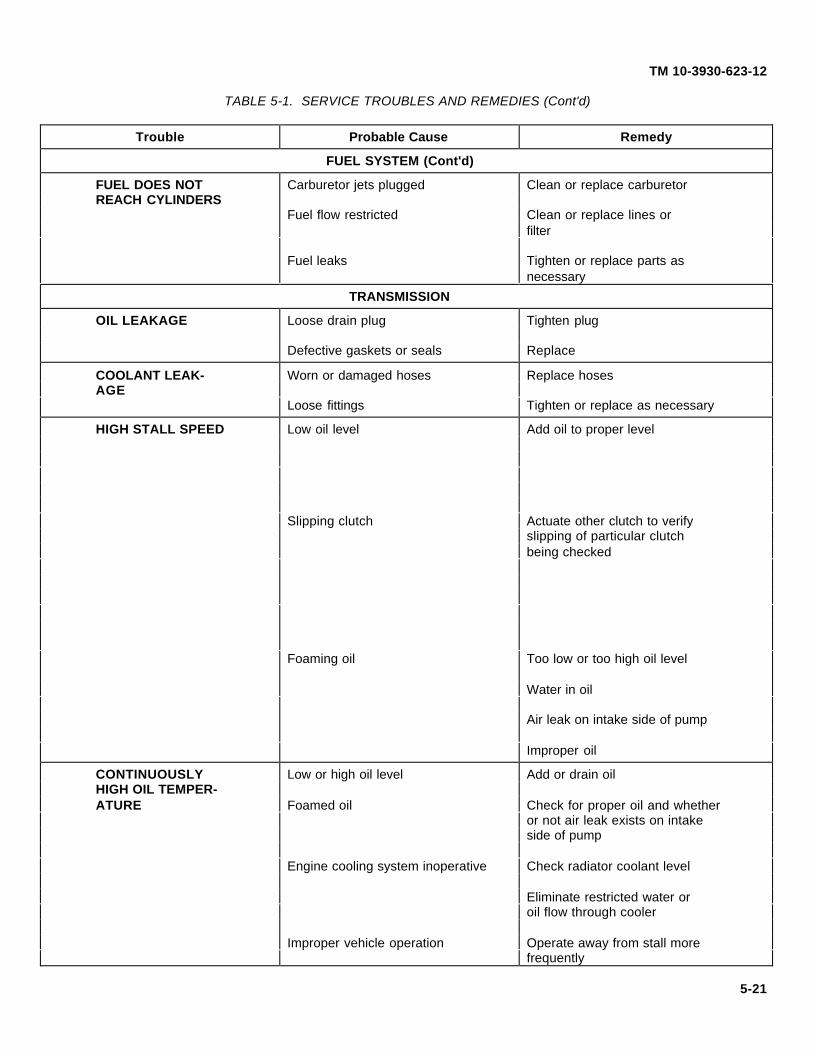
TM 10-3930-623-12
TABLE 5-1. SERVICE TROUBLES AND REMEDIES (Cont'd)
Trouble Probable Cause Remedy
FUEL SYSTEM (Cont'd)
FUEL DOES NOT Carburetor jets plugged Clean or replace carburetorREACH CYLINDERS
Fuel flow restricted Clean or replace lines orfilter
Fuel leaks Tighten or replace parts asnecessary
TRANSMISSION
OIL LEAKAGE Loose drain plug Tighten plug
Defective gaskets or seals Replace
COOLANT LEAK- Worn or damaged hoses Replace hosesAGE
Loose fittings Tighten or replace as necessary
HIGH STALL SPEED Low oil level Add oil to proper level
Slipping clutch Actuate other clutch to verifyslipping of particular clutchbeing checked
Foaming oil Too low or too high oil level
Water in oil
Air leak on intake side of pump
Improper oil
CONTINUOUSLY Low or high oil level Add or drain oilHIGH OIL TEMPER-ATURE Foamed oil Check for proper oil and whether
or not air leak exists on intakeside of pump
Engine cooling system inoperative Check radiator coolant level
Eliminate restricted water oroil flow through cooler
Improper vehicle operation Operate away from stall morefrequently
5-21

TM 10-3930-623-12
TABLE 5-1. SERVICE TROUBLES AND REMEDIES (Cont'd)
Trouble Probable Cause Remedy
TRANSMISSION (Cont'd)
CONTINUOUSLY Low oil flow through converter Converter pressure regulatorHIGH OIL TEMPER- valve stuck in near closed positionATURE (Cont'd)
SLOW OR ERRATIC Improper shift linkage arrangement Free linkage and adjustCLUTCH ENGAGE- or adjustmentMENT
Low main pressure Main pressure regulator valvestuck. Clean, check springs,free up in valve bore
Internal oil leaks Check other clutches
Check shaft seal rings
LOW CLUTCH Worn main pump Inspect pump and replace if wornPRESSURES ANDSLOW ENGAGE- Low oil level Add oilMENT AT IDLE
Leak on intake side of main pump Check intake line
LOSS OF POWER Cold oil Warm and recheck
Parking brake on Release parking brake
HYDRAULIC PUMP
LOW PUMP Hose leaks Tighten or replace hoses and/orPRESSURE clamps as necessary
Truck engine malfunction Refer to engine troubleshooting
Low fluid level Add sufficient fluid of propertype
UNDUE PUMP Clogged CleanVIBRATION
Loose mounting Tighten
5-22

TM 10-3930-623-12
TABLE 5-1. SERVICE TROUBLES AND REMEDIES (Cont'd)
Trouble Probable Cause Remedy
UPRIGHT ASSEMBLY HYDRAULIC SYSTEM
NO MOVEMENT OFUPRIGHT ASSEMBLY
Excessive fluid leakage Correct and replenish fluidsupply
Truck engine malfunction Refer to engine troubleshooting
EXCESSIVE "DRIFT"OF HOIST AND TILTCYLINDERS
Leakage at hydraulic lines and Inspect and correct as necessaryfittings
HOIST CYLINDER Leakage at hydraulic lines and Inspect and correct as necessaryWILL NOT MAIN- fittingsTAIN RAISED PO-SITION WITH LOAD
EXCESSIVE HY- Leakage in lines and fittings Repair, replace or tighten looseDRAULIC FLUID fittings and linesCONSUMPTION
WILL NOT LIFT Excessive fluid leakage Check fittings, lines and cylindersFULL RATEDLOAD Low fluid level Add sufficient fluid of proper type
Incorrect pressure relief Correct pressure
BRAKES
EXCESSIVE PEDAL Linings worn Replace brake shoesTRAVEL
Fluid low in master cylinder Replenish fluid and check for leaks
Air in system Bleed hydraulic system
Pedals improperly adjusted Adjust linkage
WEAK BRAKING Oil on linings Replace liningACTION
Incorrect lining Replace lining
HARSH BRAKING Brake lining greased soaked Replace liningACTION
Brake backing plate loose Tighten or replace
BRAKE RELEASES Hydraulic fluid congealed Drain, flush and replace withSLOWLY proper brake fluid
Master cylinder improperly adjusted Drain, clean or adjust as necessary
5-23

TM 10-3930-623-12
TABLE 5-1. SERVICE TROUBLES AND REMEDIES (Cont'd)
Trouble Probable Cause Remedy
BRAKES (Cont'd)
BRAKE RELEASES Retraction of brake shoes prevented Clean, adjust or replace asSLOWLY (Cont'd) by weak return springs or dirt necessary
TRUCK PULLS TO Brake linings grease or oil soaked Replace brake linings andONE SIDE correct source of grease or
oil leakage
BRAKES DRAG Mineral base oil in brake system Drain and flush system, replaceparts and service brake system
Linings grease soaked Replace brake liningsSTEERING
DIFFICULT STEER- Steering gear out of adjustment Readjust steering gearING OR WANDERING
Damaged drag link Replace
Excessive leakage of fluid Check for leaks, correct and fillwith proper fluid
FLUCTUATING Faulty operation of relief valves Flush and refill system. IfPRESSURE condition still exists, overhaul
valve assembly
LOSS OF SYSTEM Slippage of pump drive, other pump Check pump and pump drive gearPRESSURE malfunction
CYLINDER PISTON Cramping of linkage Replace unit and readjust pitmanROD BINDING OR arm stopsSTICKING
CHATTER CONDI- Loose mountings or linkage Make certain all ball studTIONS mounting and other linkage is
Relief valve set too low tight. Check pitman arm stops tobe certain the arm strikes the
Insufficient pump flow stops slightly before the steeringknuckles contact the stops on theaxle. Set relief valve at least150 psi higher than normal steeringrequirements of the vehicle. Bleedair from system. Insufficient pumpflow at idle speeds can be correctedby increasing engine idle rpm
UNSATISFACTORY Air in system Replace cylinder packingsSTEERING INEITHER DIRECTION Excessive wear in steering cylinder Replace cylinder
Incorrect system pressure Reset pressure
5-24

TM 10-3930-623-12
TABLE 5-1. SERVICE TROUBLES AND REMEDIES (Cont'd)
Trouble Probable Cause Remedy
STEERING (Cont'd)
UNSATISFACTORY Worn pump Replace pump. Check to be sure airSTEERING IN is not entering system through poorEITHER DIRECTION threads, hoses, pump seals, O-rings,(Cont'd) gaskets, and loose connections.
Excessively worn cylinders resultin leakage past the piston. Correctby replacing cylinder. Set reliefvalve at least 150 psi higher thannormal steering requirements of thevehicle. Repair or replace pump.
ELECTRICAL EQUIPMENT
LAMPS WILL NOT Loose connections Check and correctLIGHT
Burned out lamp Replace lamp
Defective switch Replace switch
Blown fuse Replace fuse
ENGINE HOUR- Defective engine hourmeter ReplaceMETER DOES NOTOPERATE Loose electrical connections Check and correct
Defective engine hourmeter sending Replaceunit
5-25

TM 10-3930-623-12
Figure 5-14. Test Equipment
5-26

TM 10-3930-623-12
5-46. TEST EQUIPMENT.
5-47. The test equipment listed in Table 5-2 andillustrated in figure 5-14 will support all test proceduresgiven in this manual. All necessary accessories andadapters are furnished with test sets, together with
complete operating instructions and detailed proceduresfor performing the tests specified in this manual. Listingof these test sets does not exclude use of other suitableequipment in the Federal Supply System as available, ifit will do the required job.
TABLE 5-2. TEST EQUIPMENT LIST
Type Alternate typedesignation designation Fig. no. Nomenclature Use
*PDT PDT-5 5-14 Portable Para. 5-31Distributor
FSN IY4910- FSN 4910- Tester272-7970 392-2939
VAT-25 LVR-3A 5-14 Volt Ampere Para. 5-35No FSN FSN 4910- Tester
092-9136
X-45A X-47 5-14 Power Timing Light Para. 5-29FSN 4910- FSN 4910-839-9749 500-2135
*Type designations assigned by Sun Electric Corp., Chicago, Ill. Manufacturer's Federal Supply Code No. 82386.
5-27/28

TM 10-3930-623-12
SECTION VI
REMOVAL AND INSTALLATION OF ASSEMBLIES
6-1. GENERAL.
6-2. This section contains instructions for the removaland installation of major assemblies of the fork lift truck(see figure 6-1). Minor repair and adjustmentinstructions related to removal and replacement are alsogiven to the extent such work could be performed withthe tools and equipment normally available to the usingfacility.
6-3. In general the instructions are arranged for removalof exterior parts and assemblies first thus giving accessto interior assemblies. Instructions for removal of interiorassemblies will assume that interfering external partshave been removed as far as necessary to proceed withthe next job to be done.
6-4. OVERHEAD GUARD.
6-5. REMOVAL. Remove one large bolt, flat washerand lock washer entering each leg of the guard (seefigure 6-1) from below the point of attachment to theframe and counterweight, and lift off the overhead guard.
6-6. INSTALLATION. Position the overhead guard onthe truck, and align the threaded bore of at least one legwith the corresponding hole in the truck with a drift ordowel to. Install one bolt, flat washer and lock washer atthis point but do not tighten. Repeat at other three legs,and after all bolts are started in threads, tighten bolts.
6-7. COUNTERWEIGHT.
6-8. REMOVAL. Arrange a hoist to relieve the weight(one ton) of the counterweight on the attaching bolts,and remove three bolts, nuts, and washers which attachthe counterweight to the frame. Hoist counterweight freeof frame.
6-9. INSTALLATION. Position counterweight to framewith suitable hoisting device, and attach to frame withthree bolts, nuts, and washers.
6-10. SEAT ASSEMBLY.
6-11. REMOVAL.1. Raise engine compartment cover (see figure
6-1), and latch it in open position.2. from underside of cover, remove four nuts and
washers which attach seat guide tails to cover. Seatassembly can slow be lifted free of truck.
6-12. INSTALLATION.1. With engine cover lowered, position seat on
cover so attaching studs enter corresponding holes incover.
2. Hold seat in position and raise cover to openposition.
3. Install four nuts and washers on studs.
6-13. SHEET METAL.
6-14. The sheet metal used on the truck is subject tominor repair to the extent of removing dents ordeformations, and replacing defective latches. Followconventional sheet metal repair practice in straighteningand refinishing. Replace items damaged beyondpractical repair.
6-15. ENGINE COMPARTMENT COVER REMOVAL.Raise engine compartment cover (see figure 6-1) fully.Relieve the weight of the engine cover on the attachingparts at the bottom of the hinge arms which are nowsupporting the cover. A small hoist or light line may beattached to the overhead guard for this purpose.Carefully pry torsion spring ears away from boss onlower arms to release remaining torsion, remove nuts,washers and screws holding arms to frame bracket andtake cover and hinge arms from truck.
6-16. ENGINE COMPARTMENT COVERINSTALLATION. Support cover above mountingbrackets on frame, and position hinge arms to permitinstallation of attaching screw, nuts and washers. Installall attaching parts in any convenient order, then tightenthem after all are installed and hinge arms are aligned.With cover in fully raised position, pry ears of torsionspring into position under bosses on lower hinge arms.Lower cover and verify proper operation and alignmentof installation.
6-17. RADIATOR COVER REMOVAL. With enginecompartment cover raised, support radiator cover (seefigure 6-1) at the front end and remove the four buttonhead screws "which attach it to the top of thecounterweight.
6-18. RADIATOR COVER INSTALLATION. Withengine compartment cover raised, align holes in radiatorcover with corresponding holes in top of counterweightand install four button head screws.
6-19. FLOOR PLATE REMOVAL.1. Raise engine compartment cover and remove
the nuts, lock washers and plain wasters at the rearcorners of the floor plate.
6-1

TM 10-3930-623-12
Figure 6-1. Fork Lift Truck Components
6-2

TM 10-3930-623-12
2. Remove the two screws at the front corners ofthe floor plate, and pull accelerator pedal free of thethrottle linkage. The pedal has a molded rubber socketmating with a ball formed on the end of the linkage rodfor a friction fit.
3. Raise the rear edge of the floor plate, and drawit clear of the brake pedals and steering gear.
6-20. FLOOR PLATE INSTALLATION.
1. Lay floor plate in position on truck frame, withthrottle linkage in position for connection to acceleratorpedal.
2. Install attaching parts previously removed andpress ball at end of throttle linkage into socket inunderside of accelerator pedal. Wetting socket willmake installation of ball easier, but do not use oil.
6-21. DELETED
6-22. DELETED
6-23. DELETED
6-24. DELETED
6-25. TILT CYLINDER ASSEMBLIES.
6-26. REMOVAL.
WARNING
Before disconnecting tilt cylinders,tilt uprights back and tie in place, toprevent it falling forward while tiltcylinders are disconnected.
1. Remove truck floor plate for access to tiltcylinders. Disconnect both hoses at each tilt cylinder.
2. Remove lock screws (see figure 6-2) and pinsattaching tilt cylinders to outer uprights and the truckframe. Remove tilt cylinders from truck.
6-27. INSTALLATION.
1. Attach rear end of each tilt cylinder to truckframe with pins and lock screws removed previously.Reconnect tilt cylinder hoses.
2. Operate tilt control to bring plungers fully into tiltcylinders as far as they will go. Check that mountingpins will enter both plunger yoke holes and mountingholes on uprights at the same time without extendingone plunger
6-3

TM 10-3930-623-12
Figure 6-2. Hydraulic System Layout
6-4

TM 10-3930-623-12
1. Acorn Nut2. Preform Packing3. Nut4. Setscrew5. Relief Valve Cap6. Preform Packing7. Back-Up Ring8. Preform Packing9. Spring10. Pilot Plunger11. Plunger Seat12. Plunger Spring13. Plunger Screen14. Poppet Plunger15. Poppet Seat16. Check Valve Cap17. Preform Packing18. Check Valve Spring19. Check Valve Poppet20. Spool Cap21. Lever Pivot Bracket22. Retainer Plate23. Screw24. Lock Washer25. Wiper Ring26. Packing Retainer27. Preform Packing28. Retainer Ring29. Spring Seat30. Spool Spring31. Packing Retainer32. Identification Plate33. Drive Screw34. Pipe Plug35. Pipe Plug36. Pipe Plug37. Control Valve Body
Figure 6-2.1. Hydraulic Hoist and Tilt Control Valve, Exploded View
6-4.1

TM 10-3930-623-12
more than the other. Install pins and lock screws, andfree mast from tie-down arrangement.
3. If one plunger yoke extends more than the otherone, so that tilting to either extreme of travel would twistthe uprights, loosen clamp bolt on one plunger yoke andscrew yoke in or out on shaft threads as necessary toequalize the extension of both shafts.
CAUTION
Pad jaws of wrench used to holdplunger shaft so plated surface willnot be damaged.
6-28. LIFT CHAINS.
6-29. REMOVAL. Lower carriage onto supportingblocks to relieve the weight on the chains(see figure 1-10). With upright carriage and forkassembly completely bottomed, release chains athydraulic hoist cylinder by removing two adjustingscrews and four nuts. Unhook chains at lift carriageassembly and pull free of unit.
6-30. INSTALLATION. Feed chains over rollers ofcrosshead assembly, and hook in position in carriageassembly. Install adjusting screws through chain endsinto hydraulic hoist assembly and install four nuts.Relubricate chain (see LO 10-3930-623-12).
Adjust chains as follows:
1. Lower carriage until hoist cylinder bottoms.
2. Adjust chain adjusting nuts until slack isremoved from both chains and chains are taut.
3. Be certain load is shared equally by both chains.
6-31. DELETED
6-32. DELETED
6-33. DELETED
6-34. SPOTLIGHT.
6-35. REMOVAL. Disconnect electrical cables fromspotlight. Remove two nuts, bolts and washersattaching spotlight to left side of uprights. Removespotlight.
6-36. INSTALLATION. Mount spotlight in position onbracket welded to upright and fasten in place with twobolts, washers and nuts. Reconnect electrical wiring.
6-37. THRU 6-42 DELETED
6-43. CONTROL VALVE.
6-44. REMOVAL.
1. Disconnect and tag each hose to the controlvalve (see figure 6-2). Cap or plug hoses to keep outdirt.
2. Remove three nuts, lock washers and throughbolts which attach valve to mounting bracket.
3. Raise valve and return line high enough topermit turning valve, and unscrew it from return line pipeto remove valve from truck.
4. If returning valve for exchange, strip valve of alfittings and save them for reuse on installation of newvalve.
6-5

TM 10-3930-623-12
6-45. INSTALLATION.
1. If installing a replacement valve, install fittingsremoved from original valve, if they are serviceable.
2. Screw return line pipe into return opening in sideof valve.
3. Connect all hoses to valve fittings as tagged.
4. Mount valve to mounting bracket with throughbolts, lock washers and nuts. Start engine to pressurizesystem, and operate valve through all its functions,checking for leaks as each line is under pressure.
5. Adjustment. Sluggish operation of tilt and liftcylinders may result from improper adjustment of thecontrol valve relief valve. Adjust as follows:
a. Remove pipe plug (36, fig. 6-2.1) andinstall suitable 9-3000 psi gage having ¼ NPT malethreads.
b. Start engine (para 4-55) and operate TILTcontrol (para 4-53) until mast reaches limit of travel.Hold lever in operating position and-note line pressure.Pressure should be 1650 psi.
c. If pressure is not correct, remove cap nut(1) and loosen locknut (3).
d. To raise pressure, turn setscrew (4)clockwise and to reduce line pressure turn setscrewcounterclockwise.
6-46. ELECTRICAL SYSTEM.
6-47. BATTERY REMOVAL.
1. Loosen nuts which clamp cable terminals tobattery posts (see figure 3-1 ) and remove cables fromposts. Do not remove caution tag from negative cableterminal.
2. Remove nuts securing battery holddown angle,remove holddown angle and hook bolts. Carefully lift outbattery.
CAUTION
If battery top is wet, there is probablyelectrolyte present which is corrosiveto metals and destructive to clothing.Avoid contact and rinse battery freelywith clear water.
6-48. BATTERY INSTALLATION. Since chargingsystem components of this truck could be damaged ifthe battery is connected in reverse polarity, be careful toidentify the battery posts before reconnecting cables.The ground cable is to be connected to the negativepost.
1. Install holddown angle and hook bolts, andtighten nuts on hook bolts only snug enough to holdbattery in place. Do not draw them tight enough to exertsignificant pressure on the battery case.
2. Connect battery cables to posts.
6-49. STARTER MOTOR REMOVAL.
1. Disconnect one cable at the battery to preventshorting of tools against truck frame.
2. Disconnect and tag all electrical leads at thestarter solenoid (see figure 1-2).
3. Remove starter motor mounting screws andwashers, and take starter motor from flywheel housing.
6-50. STARTER MOTOR INSTALLATION.
1. Position starter motor at mounting pad onflywheel housing.
2. Install mounting bolts and washers and tighten.
3. Reconnect leads to starter solenoid.
4. Reconnect battery cable at battery.
6-51. ALTERNATOR REMOVAL.
1. Disconnect wiring harness and ground lead atfront of alternator.
2. Remove attaching screw at adjusting strap (seefigure 1-2) and screws at mounting bracket, and lift offalternator.
6-52. ALTERNATOR INSTALLATION.
1. Position alternator on mounting bracket andinstall screws attaching alternator to mounting bracketand adjusting strap.
2. Install drive belt on alternator pulley, and adjustbelt tension as given in paragraph 5-34(4).
3. Reconnect wiring harness and ground lead toalternator.
6-53. DISTRIBUTOR REMOVAL. The following stepsanticipate timing the distributor on installation.
1. Remove cover from timing mark hole(see figure1-2) and crank engine until timing mark is aligned withpointer.
6-6

TM 10-3930-623-12
2. Remove two distributor cap holddown screws,remove cap and place a chalk mark on the cylinder headcorresponding to the position of the rotor tip. From thispoint the crankshaft must not be turned until thedistributor is reinstalled.
3. Disconnect the primary lead (see figure 6-3) atthe distributor, loosen the clamp bolt which holds thedistributor and lift off the distributor.
6-54. DISTRIBUTOR INSTALLATION.
1. Install distributor in engine so rotor tip points tochalk mark placed on head at removal.
2. Tighten clamp bolt at base of distributor, connectprimary wire from coil to distributor, and install cap.
3. Start engine, and finish timing distributoras given in paragraphs 5-29 and 5-30.
6-55. NEUTRAL SAFETY SWITCH REMOVAL. Thisassembly is mounted on the top of the transmission,directly in front of the control valve, where it is operatedby the shifting linkage. The switch assembly consists ofa mounting bracket, a striker plate with detent, and asensitive switch, arranged to interrupt the starter circuitwhen the transmission is not in the neutral position.Remove the unit as follows:
1. Remove the truck floor plate.
2. Disconnect the two electrical leads at the switch.
Figure 6-3. Engine Mounted Electrical Units
6-7

TM 10-3930-623-12
3. Disconnect the shift linkage and control valveplunger from the pivoted lever plate which operates theroller of the sensitive switch.
4. Remove the attaching screws which hold thebracket to the top of the transmission and take the unitfrom the truck.
6-56. NEUTRAL SAFETY SWITCH ADJUSTMENT. Ifthe sensitive switch has been removed from theassembly, it must be adjusted before putting it intoservice. To adjust, proceed as follows:
1. With the switch roller contacting the flat area ofthe striker plate, out of the detent, as shown in figure6-4, adjust the switch position just to the point where aclick is heard in the switch.
2. At this point measure the distance between theswitch body and the roller arm with a feeler gage.
3. Move the switch 3/32 inch toward the strikerplate, as measured with a feeler gage at the same pointas in step 2. above, and lock sensitive switch in position.
6-57. NEUTRAL SAFETY SWITCH INSTALLATION.
1. Attach the mounting bracket to the transmissionwith attaching parts previously removed.
2. Connect the shift linkage and control valveplunger to the lever plate.
3. Connect the two electrical leads to the terminalsof the switch and check that the starter can only beenergized when the shift, lever is in the neutral position.When adjustment has been checked as satisfactory,replace truck floor plate.
6-58. ENGINE MOUNTED ELECTRICALCOMPONENTS, REMOVAL AND INSTALLATION.These units not previously covered are shown in figure6-3. Since all attaching parts and connecting leads areexposed, and no special techniques are involved,remove and replace them using the obvious procedures.
1. Procedure for Testing Ignition Coil.
2. Test the coil for grounded or open circuits byusing a test lamp as follows:
a. Check primary circuit by placing the testpoints on the two primary terminals. If the lamp does notlight the primary circuit is open and the coil must bereplaced.
b. Check the secondary circuit by placingone test point in the high tension terminal and the othertest point on one of the primary terminals. The lamp willnot light but sparks will be noted as the test point isrubbed over the terminal. If no sparks occur thesecondary circuit is open and the coil must be replaced.
6-59. RADIATOR.
6-60. REMOVAL.
1. Remove radiator cover plate fromcounterweight.
2. Drain coolant and disconnect all hoses atradiator. Slide hose clamps down hoses for storage ifthe clamps are reusable.
3. Remove two screws, and four washers securingthe radiator at each side and take the radiator carefullyfrom the truck.
Figure 6-4. Neutral Safety Switch Adjustment6-8

TM 10-3930-623-12
6-61. INSTALLATION.
1. Carefully place radiator in position, and installmounting screws and washers.
2. Reconnect engine-to-radiator hoses,transmission to-radiator hoses, close engine and radiatordrain cocks, and replace coolant.
6-62. POWER TRAIN.
6-63. Removal and installation of the power train, whichincludes the power axle, transmission and the engine, isordinarily not within the capacity of equipment availableto the using facility. Should a component of the powertrain have to be removed, refer the truck to a suitablyequipped overhaul facility.
6-64. FUEL FILTER, FUEL PUMP ANDCARBURETOR.
6-45. REMOVAL. Before starting removal of any fuelsystem units, shut off the fuel supply by dosing the valveat the point that the fuel line is connected to the top ofthe fuel tank,
1. Disconnect the fuel line at the filter inlet, thenunscrew the filter (see figure 1-2) from the fittingconnecting it to the fuel pump.
2. Remove and save all reusable fittings as workproceeds. Disconnect the pump-to-carburetor fuel line,remove the two nuts and washers which attach thepump to the engine crankcase and take off the pump.Discard the pump mounting gasket. Drain remaininggas from pump in a safe place.
3. Remove spring clips at carburetor end of throttleand governor linkage, and disconnect linkage atcarburetor. Loosen hose clamp at carburetor andremove air intake hose. Loosen, but do not removechoke cable housing screw, and choke wire screw atchoke valve lever arm. Set choke cable aside.
4. Remove the two nuts and washers holding thecarburetor to the intake manifold, remove carburetor anddrain fuel from the carburetor. Manifold-to-carburetorgasket may be saved for reuse if it is in good condition.
6-65.1. FUEL PUMP TEST.
1. Static pressure test.a. Disconnect fuel pump-to-carburetor line at
carburetor.
b. Install adapter and T-fitting in opening andattach a pressure gage rubber tubing to the line.
c. Run engine at 500 revolutions per minuteor until fuel remaining in carburetor is used.
d. The reading on the gage is the staticpressure of the fuel pump and should be 31/2 to 5pounds per square inch. Since inaccurate readings mayresult if a longer hose is used, the length of hose on thepressure gage should not exceed 6 inches.
e. Replace pump if static pressure testshows an under pressure or an overpressure reading.
2. Capacity test. The capacity test is designed tomeasure amount of fuel that the pump will deliver inexcess of fuel needed to operate engine at idling speed.
a. Disconnect fuel pump-to-carburetor line atcarburetor and attach T-fitting in carburetor inletopening.
b. Attach fuel line to T-fitting.
c. Start engine and count time necessary tofill 1-pint measure with fuel from remaining opening in T-fitting. Adequate fuel delivery is available when 1 quartflows in 1 minute or less at 500 revolutions per minute.
3. Bench test.
a. Clamp fuel pump in vise. If vise jaws haveserration’s, use brass shims to protect gasket surface ofpump flange.
b. Connect mercury manometer or suitablevacuum gage to intake side of pump.
c. Actuate cam lever a full stroke at 60strokes per minute. The pump should pull at least 10inches of mercury. If it does not, replace pump.
6-8.1

TM 10-3930-623-12
6-66. INSTALLATION.
1. Place gasket on mounting flange of carburetor(see figure 1-2), position carburetor against intakemanifold and install attaching lock washers and nuts.Tighten nuts evenly and snugly to prevent air leak.
2. With choke button on instrument panel pushedfully in, and choke valve held fully open, connect chokelinkage to carburetor.
3. Reconnect throttle and governor linkage, andinstall inlet elbow fitting. Attach air intake hose tocarburetor air intake.
4. Using a new gasket at the mounting flange,attach fuel pump to crankcase with nuts and lockwashers. Install pump-to-carburetor fuel line, andfittings.
5. Screw fuel filter onto pump inlet fitting, connectfuel line from tank, open fuel shutoff valve at tank andcheck installation for fuel leaks. Start engine and checkoperation of linkage.
6-67. WATER PUMP.
6-68. REMOVAL.
1. Remove the radiator cover, drain the coolingsystem, and disconnect the coolant bypass hose (seefigure 1-2) at top of pump.
2. Remove truck radiator (paragraph 6-60), toprotect it against damage during work.
3. Remove cap screws and lock washers attachingbelt tension idler and alternator adjusting straps to waterpump. Slack off adjustments and remove both drivebelts.
4. Remove nuts, cap screws and lock washersholding pump to engine block, lift off pump and discardused gasket.
6-69. INSTALLATION.
1. Using a new gasket, replace pump on front ofengine and attach with nuts, cap screws and lockwashers. Loosely replace both drive belts.
2. Attach alternator and belt tension idler adjustingstraps to pump, adjust tension of both belts tospecifications, and tighten holddown nuts.
3. Reinstall radiator, connect hoses, refill coolingsystem and check for leaks.
6-70. STEERING GEAR.
6-71. It is not necessary for any repair operation toremove both the steering gear and the steering columnat the same time. These items can be separated at theflange shown in figure 6-5, permitting removal only of theitem needing service without disturbing the other item.
6-72. REMOVAL. Refer to the following steps only asfar as necessary to remove the desired assembly.
1. Remove the truck floor plate, and loosen thepinch bolt which clamps the split bore of the flexiblecoupling to the splined stub shaft of the gear (see figure6-5).
2. To remove the steering column:
a. Uncouple the horn wire which extendsfrom the grommet in the lower part of the mast jacket.
b. Remove two screws attaching shift leversupport to steering column, and move shift lever aside.
6-9

TM 10-3930-623-12
Figure 6-5. Steering Gear Removal
6-10

TM 10-3930-623-12
c. Remove screws, nuts and washersattaching steering column support bracket to instrumentpanel, and lift steering column from splined stub shaft onsteering gear.
3. To remove the steering gear:
a. Remove nut and washer, and pull tie rodend on drag link from tapered hole in pitman arm.
NOTE
It may be necessary to use a puller toseparate tie rod end and pitman arm.Do not use a hammer on tie rod end,so threads will not be damaged.
b. Disconnect pressure and return hoses atsteering gear. Cap hoses and plug ports in gear to keepout dirt.
c. Remove screws and washers at gearmounting bracket, and take gear from truck.
6-73. INSTALLATION.
1. To install the steering column:
a. Hold steering gear in installed position,with flexible coupling engaged with gear stub shaft, andattach steering column to instrument panel with steering
column support bracket. Tighten pinch bolt in flexiblecoupling.
b. Reinstall shift lever support on steeringcolumn, and reconnect horn wire at connector underinstrument panel.
2. To install the steering gear:
a. Place steering gear in position atmounting bracket, entering stub shaft splines into flexiblecoupling, and install mounting screws and lock washersthrough bracket into gear.
b. Carefully turn steering wheel to oneextreme of travel, then counting the number of turns,turn it to the opposite limit. Now turn wheel to midpointof travel (straight ahead travel position). Pitman armshould now be pointing straight down. If it is not, pullarm from sector gear shaft and reposition arm to pointstraight down with gear in straight ahead position.
c. Install pressure and return hoses in gear,and attach drag link tie rod end to pitman arm with lockwasher and nut. Replace truck floor plate, and road testoperation of steering.
6-74. HYDRAULIC BRAKE MASTER CYLINDER.
6-75. REMOVAL.1. Remove truck floor plate (para 6-19) and
disconnect tube (1, fig. 6-6) at fitting (29).
2. Unscrew push rod. (33 add clevis (24).
3. Remove screws (22) and washers (23) and takemaster cylinder from truck.
6-76. INSTALLATION.
1. Install master cylinder on bracket (21) withscrews (22) and washers (23).
2. Connect push rod clevis (24) to brake pedalassembly (11) with pin (17) and cotter pin (18).
3. Connect brake tubing (1) to master cylinder.
4. Replace truck floor plate (para 6-20).
5. Bleed brake system (para 5-41).
6-11

TM 10-3930-623-12
1. Brake Tube2. Brake Tube3. Brake Tube4. Elbow5. Retractor Spring6. Screw7. Nut8. Pedal Pad9. Nut
10. Lock Washer11. Brake Pedal
12. Trunnion Bolt13. Trunnion Bolt14. Nut15. Washer16. Cotter Pin17. Headed Pin18. Cotter Pin19. Screw20. Lock Washer21. Master Cylinder
Bracket
22. Screw23. Lock Washer24. Push Rod Clevis25. Nut26. Stop Light Switch27. Connector Bolt28. Washer29. Brake Fitting30. Washer31. Filler Cap32. Gasket
33. Push Rod34. Push Rod Boot35. Retaining Ring36. Stop Plate37. Master Cylinder
Piston38. Piston Cup39. Spring40. Check Valve41. Master Cylinder
Body
Figure 6-6. Hydraulic Brake Master Cylinder and Pedal Assembly, Exploded View
6-12

TM 10-3930-623-12
6-77. BRAKE PEDAL.
6-78. REMOVAL,
1. Remove hydraulic brake master cylinder(para 6-74).
2. Remove pedal retractor spring (5, fig. 6-6),
3. Remove brake pedal (11) by removing trunnionbolts (12 and 13) and headed pin (17) to master cylinderpush rod.
6- 79 INSTALLATION.1. Reverse removal procedure and install the brake
pedal assembly.
2. Adjust brake pedal stop screw (6) to provide a1/8 inch free movement of push rod (33) before contactand resistance of piston (37) is felt. This should providenecessary 1¼ inch "free" movement at pedal pad (8).
6-80. EXHAUST HOSE.
6-81. REMOVAL.1. Remove clamps (1 & 3, fig. 6-7) from exhaust
hose (7).
2. Remove 2 screws (4), lockwashers (5), andwashers (6), from exhaust hose bracket.
3. Slide exhaust hose from exhaust pipe (10) andthen remove curved portion of pipe from muffler (2).
6-82. INSTALLATION. Reverse removal procedure andinstall the exhaust hose.
6-83. INTAKE AND EXHAUST MANIFOLDASSEMBLY.
6-84. REMOVAL.
1. Remove exhaust hose (para 6-80).
2. Remove air inlet tube (fig. 6-8), accelerator rod,fuel line, governor control rod and choke cable fromcarburetor.
3. Remove two nuts and lockwashers attachingcarburetor to intake manifold. Remove carburetor withgasket.
4. Remove eleven nuts and washers holdingmanifold assembly to cylinder block.
5. Remove positive crankcase ventilation valve andtubing assembly.
6. Remove manifold assembly and gasket fromengine.
6-85. INSTALLATION. Refer to paragraph 6-81 andreverse removal procedures to install intake and exhaustmanifolds.
6-86. RETURN LINE FILTER ASSEMBLY. Assemblefilter by-pass valve parts (3, 4, 5 and 6, fig. 6-8) to filterhead (8) with machine screw (1) and nut (2).
NOTE
Filter element is left off until the filterhead is installed to provide sufficientclearance.
6-87. RETURN LINE FILTER INSTALLATION.
1. Install street elbow (fig. 6-2) into filter assemblyoutlet port and control valve to filter pipe into the inletport.
2. Tighten elbow until it is face down and installhose adapter.
3. Install filter and pipe with valve adapter in controlvalve.
NOTE
Tighten assembly with wrench onflats of filter head. Do not use filterelement as lever to tighten joints.
4. Install clamps and hose between filter outlet andhydraulic system reservoir tank.
5. Install new filter element (7, fig. 6-9). Coatelement seal with OE-engine oil. Tighten hand tight andthen tighten one-half turn.
6-13

TM 10-3930-623-12
1. Clamp2. Muffler3. Clasp4. Screw5. Lockwasher6. Washer7. Exhaust hose8. Nut9. Washer
10. Exhaust pipe11. Gasket pipe
Figure 6-7. Muffler, exhaust pipe and exhaust hose, exploded view.
6-14
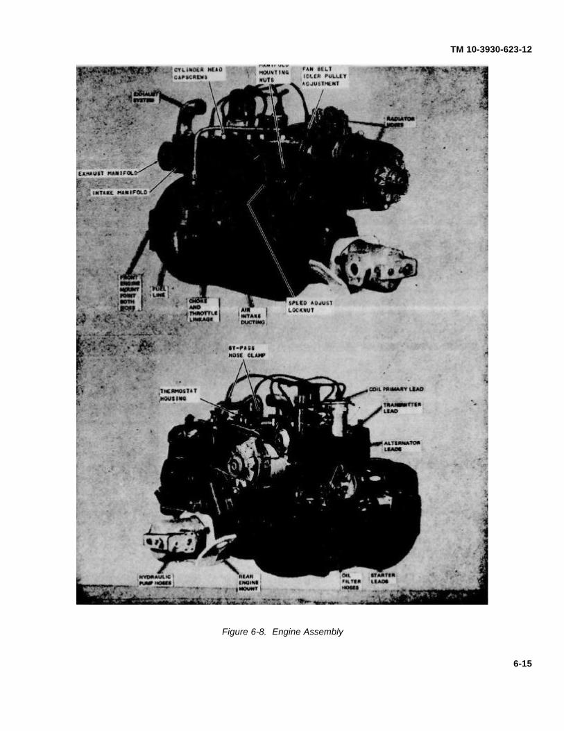
TM 10-3930-623-12
Figure 6-8. Engine Assembly
6-15

TM 10-3930-623-12
Figure 6-9. Hydraulic System Line Filter, Exploded View
6-16

TM 10-3930-623-12
APPENDIX A
MAINTENANCE ALLOCATION CHART
Section I. INTRODUCTION
A-1. General
a. This section provides a general explanation of all maintenance and repair functions authorized at variousmaintenance levels.
b. Section II designates overall responsibility for the performance of maintenance functions on the identified enditem or component. The implementation of the maintenance functions upon the end item or component will be consistentwith the assigned maintenance functions.
c. Section III lists the special tools and test equipment required for each maintenance function as referenced fromSection II. Not Applicable .
d. Section IV contains supplemental instructions, explanatory notes and or illustrations required for a particularmaintenance function. Not Applicable.
A-2. Explanation of Columns in Section II.
a. Group Number. Column 1. The assembly group is a numerical group assigned to each assembly in a top downbreakdown sequence. The applicable assembly groups are listed on the MAC in disassembly sequence beginning withthe first assembly removed in a top down disassembly sequence.
b. Assembly Group. Column 2. This column contains a brief description of the components of each assemblygroup.
c. Maintenance Functions. Column 3. This column lists the various maintenance functions (A through K) andindicates the lowest maintenance category authorized to perform these functions. The symbol designations for thevarious maintenance categories are as follows:
C - Operator or crew
O - Organizational maintenance
F - Direct support maintenance
H - General support maintenance
D - Depot maintenance
A-1

TM 10-3930-623-12
The maintenance functions are defined as follows:
A - INSPECT. To determine serviceability of an item by comparing its physical, mechanical, and electricalcharacteristics with established standards.
B - TEST. To verify serviceability and to detect electrical or mechanical failure by use of test equipment.
C - SERVICE. To clean, to preserve, to charge, and to add fuel, lubricants, cooling agents, and air. If it is desiredthat elements, such as painting and lubricating, be defined separately, they may be so listed.
D - ADJUST. To rectify to the extent necessary to bring into proper operating range.
E - ALIGN. To adjust specified variable elements of an item to bring to optimum performance.
F - CALIBRATE. To determine the corrections to be made in the readings of instruments or test equipment usedin precise measurement. Consists of the comparison of two instruments, one of which is a certified standard of knownaccuracy, to detect and adjust any discrepancy in the accuracy of the instrument being compared with the certifiedstandard.
G - INSTALL. To set up for us e in an operational environment such as an emplacement, site, or vehicle.
H - REPLACE. To replace unserviceable items with serviceable like items.
I - REPAIR. Those maintenance operations necessary to restore an item to serviceable condition throughcorrection of material damage or a specific failure. Repair may be accomplished at each category of maintenance.
J - OVERHAUL. Normally, the highest degree of maintenance performed by the Army in order to minimize timework in process is consistent with quality and economy of operation. It consists of that maintenance necessary to restorean item to completely serviceable condition as prescribed by maintenance standards in technical publications for eachitem of equipment. Overhaul normally does not return an item to like new, zero mileage, or zero hour condition.
A-2

TM 10-3930-623-12
K - REBUILD. The highest degree of materiel maintenance. It consists of restoring equipment as nearly aspossible to new condition in accordance with original manufacturing standards. Rebuild is performed only when requiredby operational considerations or other paramount factors and then only at the depot maintenance category. Rebuildreduces to zero the hours or miles the equipment, or component thereof, has been in use.
L - SYMBOLS. The uppercase letter placed in the appropriate column indicates the lowest level at which thatparticular maintenance function is to be performed.
d. Tools and Equipment. Column 4. This column is provided for referencing by code the special tools and testequipment, (Section III) required to perform the maintenance functions (Section II).
e. Remarks. Column 5. This column is provided for referencing by code the remarks (Section IV) pertinent to themaintenance functions.
A-3. Explanation of Columns in Section III.
a. Reference Code. This column consists of a number and a letter separated by a dash. The number referencesthe T&TE requirements column on the MAC. The letter represents the specific maintenance function the item is to beused with. The letter is representative of columns A through K on the MAC.
b. Maintenance Category. This column shows the lowest level of Maintenance authorized to use the special tool ortest equipment.
c. Nomenclature. This column lists the name or identification of the tool or test equipment.
d. Tool Number. This column lists the manufacturer's code and part number, or Federal Stock Number of tools andtest equipment.
A-4. Explanation of Columns in Section IV.
a. Reference Code. This column consists of two letters separated by a dash, both of which are references toSection II. The first letter references column 5 and the second letter references a maintenance function, column 3, Athrough K.
b. Remarks. This column lists information pertinent to the maintenance function being performed, as indicated onthe MAC, Section II.
A-3

TM 10-3930-623-12
SECTION II - MAINTENANCE ALLOCATION CHART
(1) (2) (3)MAINTENANCE FUNCTIONS
(4) (5)
A B C D E F G H I J K
GR
OU
P N
O.
FUNCTIONAL GROUP
INS
PE
CT
TES
T
SE
RV
ICE
AD
JUS
T
ALI
GN
CA
LIB
RA
TE
INS
TALL
RE
PLA
CE
RE
PA
IR
OV
ER
HA
UL
RE
BU
ILD TOOLS AND
EQUIPMENT REMARKS
01 UPRIGHT, CARRIAGE, AND FORKASSEMBLY
Fork, lift O O
Upright assembly O F F
Chain O O O
Carriage assembly F F
02 TILT AND HOIST CYLINDERS
Tilt cylinders O O F
Hoist cylinder O F F
03 GUARD, COUNTERWEIGHT, FLOOR,ENGINE COVER AND SEAT
Guard O F
Counter weight O O
Floor O O
A-4

TM 10-3930-623-12
SECTION II - MAINTENANCE ALLOCATION CHART
(1) (2) (3)MAINTENANCE FUNCTIONS
(4) (5)
A B C D E F G H I J K
GR
OU
P N
O.
FUNCTIONAL GROUP
INS
PE
CT
TES
T
SE
RV
ICE
AD
JUS
T
ALI
GN
CA
LIB
RA
TE
INS
TALL
RE
PLA
CE
RE
PA
IR
OV
ER
HA
UL
RE
BU
ILD TOOLS AND
EQUIPMENT REMARKS
03 GUARD, COUNTERWEIGHT, FLOOR,ENGINE COVER AND SEAT -CONTINUED
Engine cover O O O F
Seat O
04 EXHAUST SYSTEM
Muffler O F
Pipe O O
05 RADIATOR, HOSE AND TRANS-MISSION COOLER LINES
Radiator F C O F
Hose C
Cooler lines C O
A-5

TM 10-3930-623-12
SECTION II - MAINTENANCE ALLOCATION CHART
(1) (2) (3)MAINTENANCE FUNCTIONS
(4) (5)
A B C D E F G H I J K
GR
OU
P N
O.
FUNCTIONAL GROUP
INS
PE
CT
TES
T
SE
RV
ICE
AD
JUS
T
ALI
GN
CA
LIB
RA
TE
INS
TALL
RE
PLA
CE
RE
PA
IR
OV
ER
HA
UL
RE
BU
ILD TOOLS AND
EQUIPMENT REMARKS
06 BATTERY AND CABLES
Battery O O C O
Cables O O
07 LIGHTS
Stoplight, taillight C O O
Spot light C C O O
08 AIR CLEANER AND HOSE
Air cleaner C O
Hose O O
A-6

TM 10-3930-623-12
SECTION II - MAINTENANCE ALLOCATION CHART
(1) (2) (3)MAINTENANCE FUNCTIONS
(4) (5)
A B C D E F G H I J K
GR
OU
P N
O.
FUNCTIONAL GROUP
INS
PE
CT
TES
T
SE
RV
ICE
AD
JUS
T
ALI
GN
CA
LIB
RA
TE
INS
TALL
RE
PLA
CE
RE
PA
IR
OV
ER
HA
UL
RE
BU
ILD TOOLS AND
EQUIPMENT REMARKS
09 WHEELS, TIRES, HUBS AND STEER-ING AXLE ASSEMBLY-CONTINUED
Wheels (Dual and single) O O
Hubs O F
Bearings and seals O O F
Tires, tubes O O O
Tie rod O O O
Drag link O O
Axle O F F
10 HAND BRAKE AND SHIFTINGMECHANISM
Hand Brake assembly O O
Cables O O
Shifting mechanism O O
A-7

TM 10-3930-623-12
SECTION II - MAINTENANCE ALLOCATION CHART
(1) (2) (3)MAINTENANCE FUNCTIONS
(4) (5)
A B C D E F G H I J K
GR
OU
P N
O.
FUNCTIONAL GROUP
INS
PE
CT
TES
T
SE
RV
ICE
AD
JUS
T
ALI
GN
CA
LIB
RA
TE
INS
TALL
RE
PLA
CE
RE
PA
IR
OV
ER
HA
UL
RE
BU
ILD TOOLS AND
EQUIPMENT REMARKS
11 BRAKES, CYLINDERS AND DRIVEAXLE ASSEMBLY
Brake shoes O O
Master cylinder O O F
Wheel cylinder O O
Pedal O O
Axle assembly (drive) O F F
Differential F F H
12 ACCELERATOR PEDAL AND LINKAGE
Pedal O O
Linkage O O
13 STEERING WHEEL, COLUMN, ANDPOWER STEERING GEAR
Wheel O O
A-8

TM 10-3930-623-12
SECTION II - MAINTENANCE ALLOCATION CHART
(1) (2) (3)MAINTENANCE FUNCTIONS
(4) (5)
A B C D E F G H I J K
GR
OU
P N
O.
FUNCTIONAL GROUP
INS
PE
CT
TES
T
SE
RV
ICE
AD
JUS
T
ALI
GN
CA
LIB
RA
TE
INS
TALL
RE
PLA
CE
RE
PA
IR
OV
ER
HA
UL
RE
BU
ILD TOOLS AND
EQUIPMENT REMARKS
13 STEERING WHEEL, COLUMN, ANDPOWER STEERING GEAR-CONTINUED
Column F F
Steering gear O F F
Horn button assembly O O O
Valve F F
14 HYDRAULIC PUMP, CONTROL VALVEAND TRANSMISSION CONTROLVALVE
Pump, hydraulic F F
Valve, control O O F
Valve, transmission control O F F
A-9

TM 10-3930-623-12
SECTION II - MAINTENANCE ALLOCATION CHART
(1) (2) (3)MAINTENANCE FUNCTIONS
(4) (5)
A B C D E F G H I J K
GR
OU
P N
O.
FUNCTIONAL GROUP
INS
PE
CT
TES
T
SE
RV
ICE
AD
JUS
T
ALI
GN
CA
LIB
RA
TE
INS
TALL
RE
PLA
CE
RE
PA
IR
OV
ER
HA
UL
RE
BU
ILD TOOLS AND
EQUIPMENT REMARKS
15 CONTROL LEVERS, FILTER, ANDHOSE ASSEMBLIES
Control levers and linkage O O
Hose assemblies O O F
Filter, hydraulic O O
16 ALTERNATOR, AND STARTING MOTOR
Alternator O O F
Starting motor F O F
17 TRANSMISSION
Transmission assembly F C F F H D
Torque converter O F
Friction clutch assembly F F F
A-10

TM 10-3930-623-12
SECTION II - MAINTENANCE ALLOCATION CHART
(1) (2) (3)MAINTENANCE FUNCTIONS
(4) (5)
A B C D E F G H I J K
GR
OU
P N
O.
FUNCTIONAL GROUP
INS
PE
CT
TES
T
SE
RV
ICE
AD
JUS
T
ALI
GN
CA
LIB
RA
TE
INS
TALL
RE
PLA
CE
RE
PA
IR
OV
ER
HA
UL
RE
BU
ILD TOOLS AND
EQUIPMENT REMARKS
18 ENGINE
Engine assembly O O C O F O H D
Cylinder head O F
Crankshaft H D
Flywheel assembly F H
Valve, engine O F F
Gears, timing F F
Breather O O
Filter, oil O O
Pump, oil F F
Manifold O O
Carburetor O O F
Fuel pump O O O
A-11

TM 10-3930-623-12
SECTION II - MAINTENANCE ALLOCATION CHART
(1) (2) (3)MAINTENANCE FUNCTIONS
(4) (5)
A B C D E F G H I J K
GR
OU
P N
O.
FUNCTIONAL GROUP
INS
PE
CT
TES
T
SE
RV
ICE
AD
JUS
T
ALI
GN
CA
LIB
RA
TE
INS
TALL
RE
PLA
CE
RE
PA
IR
OV
ER
HA
UL
RE
BU
ILD TOOLS AND
EQUIPMENT REMARKS
18 ENGINE - CONTINUED
Governor O F F
Thermostat O O
Water pump O O
Belts, Fan and/or alternator O O
Distributor O O O
Spark plugs O O O O
Ignition coil O O
Battery O C O
Cables, battery O O
A-12

TM 10-3930-623-12
SECTION II - MAINTENANCE ALLOCATION CHART
(1) (2) (3)MAINTENANCE FUNCTIONS
(4) (5)
A B C D E F G H I J K
GR
OU
P N
O.
FUNCTIONAL GROUP
INS
PE
CT
TES
T
SE
RV
ICE
AD
JUS
T
ALI
GN
CA
LIB
RA
TE
INS
TALL
RE
PLA
CE
RE
PA
IR
OV
ER
HA
UL
RE
BU
ILD TOOLS AND
EQUIPMENT REMARKS
19 FUEL TANK ASSEMBLY AND FUELLINE
Tank, fuel C O H
Fuel line O O O
20 HYDRAULIC TANK LINES ANDFITTINGS
Tank, hydraulic O F
Breather, oil tank O O
Lines and fittings O O O
21 FRAME AND ATTACHING PARTS
Frame O H H
Engine cover supports O O
Instrument panel and gages O O
A-13

TM 10-3930-623-12APPENDIX B
BASIC ISSUE ITEMS UST AND ITEMSTROOP INSTALLED OR AUTHORIZED
Section I. INTRODUCTION
B-1. ScopeThis appendix lists items required by the operator foroperation of the fork lift truck.
B-2. GeneralThis list is divided into the following sections:
a. Basic Issue Items List-Section II. Notapplicable.
b. Items Troop Installed or Authorized List SectionIII. A list of items in alphabetical sequence, which at thediscretion of the unit commander may accompany thefork lift truck. These items are NOT subject to turn-inwith the fork lift truck when evacuated.
B-3. Explanation of ColumnsThe following provides an explanation of columns in thetabular list of Basic Issue Items List, Section II, andItems Troop Installed or Authorized, Section III.
a. Source, Maintenance, and RecoverabilityCode(s) (SMR) :
(1) Source Code, indicates the source for thelisted item. Source codes are:
Code ExplanationP Repair parts, special tools and test equipment
supplied from GSA/DSA or Army supply systemand authorized for use at indicated maintenancelevels.
P2 Repair parts, special tools and test equipmentwhich are procured and stocked for insurancepurposes because the combat or militaryessentiality of the end item dictates that aminimum quantity be available in the supplysystem.
(2) Maintenance Code, indicates the lowestlevel of maintenance authorized to install the listed item.The maintenance level code is:Code ExplanationC Crew/Operator
(3) Recoverability Code, indicates whetherunserviceable items should be returned for recovery orsalvage. Items not coded are nonrecoverable.Recoverability codes are:
Code ExplanationR Applied to repair parts (assemblies and
components), special tools and test equipmentwhich are considered economically reparable atdirect and general support maintenance levels.
S Repair parts, special tools, test equipment andassemblies which are economically reparable atDSU and GSU activities and which normally arefurnished by supply on an exchange basis.
b. Federal stock number. This column indicatesthe Federal stock number assigned to the item and willbe used for requisitioning purposes.
c. Description. This column indicates the Federalitem name and any additional description of the itemrequired.
d. Unit of measure (U/M). A 2 character alphabeticabbreviation indicating the amount or quantity of the itemupon which the allowances are based, e.g., ft, ea, pr,etc.
e. Quantity furnished with equipment (BIIL only).This column indicates the quantity of an item furnishedwith the equipment.
f. Quantity authorized (Items troop installed orauthorized only). This column indicates the quantity ofthe item authorized to be used with the equipment.
g. Illustration (BIIL only). This column is divided asfollows:
(1) Figure number. Indicates the figurenumber of the illustration in which the item is shown.
(2) Item number. Indicates the calloutnumber used to reference the item in the illustration.
Section III. ITEMS TROOP INSTALLED OR AUTHORIZED LIST(3)
(1) (2) Description (4) (5)SMR Federal stock Ref No. & Mfr Usable Unit of Qty AuthCode number on code on code meas
7510-889-3494 BINDER, LOOSE LEAF EA 1
7520-559-9618 CASE, MAINTENANCE AND OPERATING EA 1
I MANUALS
4210-889-2221 EXTINGUISHER, FIRE EA 1B-1

By Order of the Secretary of the Army:
W. C. WESTMORELAND,General, United States Army,
Official: Chief of Staff.
KENNETH G. WICKHAM,Major General, United States Army,The Adjutant General
Distribution:To be distributed in accordance with DA Form 12-25, Sec I (Qty rqr Block #194) Organizational maintenance
requirements for Truck, Fork, Lift: Gasoline.
¶ U.S. GOVERNMENT PRINTING OFFICE: 1971-431104-5194

TM 10-3930-623-12T
M 10-3930-623-12 T
RU
CK
, FO
RK
LIF
T; 4000 L
B C
AP
AC
ITY
; 144 IN. L
IFT
;-1971G
AS
OL
INE
EN
GIN
E D
RIV
EN
PIN: 028320-002

This fine document...
Was brought to you by me:
Liberated Manuals -- free army and government manuals
Why do I do it? I am tired of sleazy CD-ROM sellers, who take publicly available information, slap “watermarks” and other junk on it, and sell it. Those masters of search engine manipulation make sure that their sites that sell free information, come up first in search engines. They did not create it... They did not even scan it... Why should they get your money? Why are not letting you give those free manuals to your friends?
I am setting this document FREE. This document was made by the US Government and is NOT protected by Copyright. Feel free to share, republish, sell and so on.
I am not asking you for donations, fees or handouts. If you can, please provide a link to liberatedmanuals.com, so that free manuals come up first in search engines:
<A HREF=http://www.liberatedmanuals.com/>Free Military and Government Manuals</A>
– SincerelyIgor Chudovhttp://igor.chudov.com/
– Chicago Machinery Movers