tm 11-6625-2632-14-1
TRANSCRIPT

TM 11-6625-2632-14-1
TECHNICAL MANUAL
OPERATOR’S, ORGANIZATIONAL, DIRECT
SUPPORT, AND GENERAL
SUPPORT MAINTENANCE MANUAL
RADIO
TEST SET
AN/PRM-32A
(NSN 6625-01-013-9900)
HEADQUARTERS, DEPARTMENT OF THE ARMYDECEMBER 1978

W A R N I N G
The fumes of TRICHLOROETHANE are toxic. Provide thorough ventilationwhenever it is used; avoid prolonged or repeated breathing of vapor. Do notuse near an open flame or hot surface. Do not use near an open flame or hot sur-face, trichloroethane is nonflammable but heat converts the fumes to a highlytoxic phosgene gas the inhalation of which could result in serious injury ordeath. Prolonged or repeated skin contact with trichloroethane can cause skininflammation. When necessary, use gloves, sleeves and aprons which thesolvent cannot penetrate.
TM 11-6625-2632-14-1
TECHNICAL MANUAL HEADQUARTERSDEPARTMENT OF THE ARMY
No. 11-6625-2632-14-1 WASHINTON , DC, 29 December 1978
CHAPTER 1.Section I.
II.
CHAPTER 2.Section I.
II.
III.
IV.
Operator’s, OrganizationaI, Direct Support, and
General Support Maintenance Manual
R A D I O T E S T S E T A N / P R M - 3 2 A
( N S N 6 6 2 5 - 0 1 - 0 1 3 - 9 9 0 0 )
REPORTING OF ERROESYou can improve this manual by recommending improvements using DA
Form 2028-2 located in the back of the manual. Simply tear out the self-addressed form, fill it out as shown on the sample, fold it where shown, anddrop it in the mail.
lf there are no blank DA form 2028-2 in the back of your manual, use thestandard DA Form 2028 (Recommended Changes to Publications and BlankForms) and forward it to Commander, US Army Communications and Elec-tronics Materiel Readiness Command, ATTN: DRSEL-ME-MQ, Fort Mon-mouth, NJ 07703. A reply will be furnished direct to you.
Paragraph
INTRODUCTIONGeneralscope . . . . . . . . . . . . . . . . . . . . . . . . . . . . . . . . . . . . . . . . . . . . . . . . . . . . . . . . . . . . . . . . . . . . . 1-1Indexes of publications . . . . . . . . . . . . . . . . . . . . . . . . . . . . . . . . . . . . . . . . . . . . . . . 1-2Forms and records . . . . . . . . . . . . . . . . . . . . . . . . . . . . . . . . . . . . . . . . . . . . . . . . . . . . . . . . . 1-3Destruction of Army materiel to prevent enemy use . . . . . . . . . . . . . . . . . . . . . 1-4Administrative storage . . . . . . . . . . . . . . . . . . . . . . . . . . . . . . . . . . . . . . . . . . . . . . . . 1-5Calibration . . . . . . . . . . . . . . . . . . . . . . . . . . . . . . . . . . . . . . . . . . . . . . . . . . . . . . . . . . . . . . . 1-6Reporting equipment improvement recommendations . . . . . . . . . . . . . . . . . . . . . . . . . . . 1-7Description and dataPurpose and use . . . . . . . . . . . . . . . . . . . . . . . . . . . . . . . . . . . . . . . . . . . . . . . 1-8Description . . . . . . . . . . . . . . . . . . . . . . . . . . . . . . . . . . . . . . . . . . . . . . . . . . . . . . . . . . . . . . 1-9Tabulated data . . . . . . . . . . . . . . . . . . . . . . . . . . . . . . . . . . . . . . . . . 1-10Items comprising inoperable Radio Test Set AN/PRM-32A. . . . . . . . . . . . . . . . . . . . . . 1-11Additional equipment required . . . . . . . . . . . . . . . . . . . . . . . . . . . . . . . . . . . . . . . . . . . . . . . 1-12
OPERATING INSTRUCTIONSService upon receipt of equipmentGeneral . . . . . . . . . . . . . . . . . . . . . . . . . . . . . . . . . . . . . . . . . . . . . . . . . . . . . . . . . . . . . . . . . 2-1Unpacking . . . . . . . . . . . . . . . . . . . . . . . . . . . . . . . . . . . . . . . . . . . . . . . . . . . . . . . . . . . . . . . . . 2-2Checking unpacked equipment . . . . . . . . . . . . . . . . . . . . 2-3Installation instructions . . . . . . . . . . . . . . . . . . . . . . . . . . . . . . . . . . . . . . . . . . . . . . . . . . 2-4Controls and instrumentsDamage from improper settings. . . . . . . . . . . . . . . . . . . . . . . . . . . . . . . . . . . . . . . . . . . . 2-5Operator’s controls . . . . . . . . . . . . . . . . . . . . . . . . . . . . . . . . . . . . . . . . . . . . . . . . . . . . . . . . 2-6Operation under usual conditionsIntroduction . . . . . . . . . . . . . . . . . . . . . . . . . . . . . . . . . . . . . . . . . . . . . . . . . . . . . . . 2-7Test setup . . . . . . . . . . . . . . . . . . . . . . . . . . . . . . . . . . . . . . . . . . . . . . . . . . . . . . . . . . . . . . 2-8AN/PRC-90Tests . . . . . . . . . . . . . . . . . . . . . . . . . . . . . . . . . . . . . . . . . . . . . . . . . . . . . 2-9AN/PRC-106Tests . . . . . . . . . . . . . . . . . . . . . . . . . . . . . . . . . . 2-10Operation under unusual conditionsIntroduction . . . . . . . . . . . . . . . . . . . . . . . . . . . . . . . . . . . . . . . . . . . . . . . . . . . . . . . 2-11
Page
1-11-31-31-31-31-31-3
1-31-31-41-41-4
2-12-12-12-1
2-12-1
2-22-22-42-6
2-7
i

TM 11-6625-2632-14-1
CHAPTER 3.Section I.
II.
III.
IV.
CHAPTER 4.
CHAPTER 5.Section I.
II.
III
IV.
APPENDIX A.
B.Section I.
II.III.IV.
Figure
1-12-12-24-15-15-25-35-45-55-65-7
Procedure after testing .... . . . . . . . . . . . . . . . . . . . . . . . . . . . . . . . . . . . . . . . . . . . . . . . . .Lubrication after testing. . . . . . . . . . . . . . . . . . . . . . . . . . . . . . . . . . . . . . . . . . . . . .
ORGANIZATIONAL MAINTENANCETools, test equipment and materialsScope of maintenance . . . . . . . . . . . . . . . . . . . . . . . . . . . . . . . . . . . . . . . . . .Tools and test equipment required. . . . . . . . . . . . . . . . . . . . . . . . . . . . . . . . . . . .Materials required for maintenance . . . . . . . . . . . . . . . . . . . . . . . .Repainting and refinishingTouchup painting instructions . . . . .Painting and refinishing precautions. . . . . . . . . . . . . . . . . . . . . . . . . . . . . . . . . . . . . . .Preventive maintenance checks and servicesGeneral . . . . . . . . . . . . . . . . . . . . . . . . . .CIeaning . . . . . . . . . . . . . . . . . . . . . . . . . . . . . . . . . . . . . . . . . . . .Organizational troubleshooting.. . . . . . . . . . . .MaintenanceGeneral . . . . . . . . . . . . . . . . . . . . . . . . . . . . . . . . . . .Replacement procedures . . . . . . . . . . . . . . . . . . . . . . . .
FUNCTlONING OF EQUIPMENTIntroduction . . . . . . . . . . . . . . . . . . . .Functioning of equipment . . . . . . . . . . . . . . . . . . . . .
GENRAL SUPPORT MAlNTENANCE GeneralScope of maintenance . . . . . . . . . . . . . . . .Tools and test equipment required . . . . . . . . . . . . . . .Physical inspection . . . . . . . . . . . . . . . . . . . . . . . . . . . . . . . . . . . . . . . .TroubleshootingGeneral . . . . . . . . . . . . . . . . . . . . . . . . . . . . . . . . . . . . .Checkout procedures . . . . . . . . . . . . . . . . . . . . . . . . . . . . . . . . . . . . . .Troubleshooting procedures. . . . .Maintenance of Radio Test Set AN/PRM-32A General . . . . . . . . . . . . . . . . . . . . . . . . . . . . . . . . . . .Removal of major components... . . . . . . . . . . . . . . . . . . . . . . .Repair procedures . . . . . . . . . . . . . . . . . . . . . . . . . . . . . . . . . . . . . . . . . . . . .Fabrication of replacement parts. . . . . . . . . . . . . . . . . . . . . . . . . . . . . . . . . . . .Replacement of major components . . . . . . . . . . . . . .Testing and calibrationTesting . . . . . . . . . . . . . . . . . . . . . . . . . . . . . . . . . . . . . . . . . . . . .Calibration . . . . . . . .
REFERENCES
MAINTENANCE ALLOCATIONIntroductionMaintenance allocation chartTool and test equipment requirementsRemarks
LIST OF ILLUSTRATIONS
Title
Radio Test Set AN/PRM-32A . . . . . . . . . . . . . . . . . . . . . . . . . . . . . . . . . . . . . . . . . . . . . . . . .Antenna removal.. . . . . . . . . . . . . . . . . . . . . . . . . . . . . . . . . . . . . . . . . . . . . . . .Test set operational test, setup.. . . . . . . . . . . . . . . . . . . . . . . . . . . . . . . . . . . . . . . . .Radio Test Set AN/PRM-32A, schematic diagram . . . . . . . . . . . . . . . . . . . . . . . . . . . . . .Radio Test Set AN/PRM-32A, parts identification. . . . . . . . . . . . . . . . . . . . . . . . . . . . . .Cover assembly parts identification . . . . . . . . . . . . . . . . . . . . . . . . . . . . . . . . . . . .Panel assembiy parts identification. . . . . . . . . . . . . . . . . . . . . . . . . . . . .Case assembly parts identification . . . . . . . . . . . . . . . . . . . . . .Shielded box assembly parts identification . . . . . . . . . . . . . . . . . . . . . . . . . . . .Radio Test Set AN/PRM-32A, wiring diagram . . . . . . . . . . . . . . . . . . . . . . . . . . . .Rubber channel fabrication details . . . . . . . . . . . . . . . . . . . . . . . . . . . . . . . .
Paragraph2-122-13
3-13-23-3
3-43-5
3-63-73-8
3-93-10
4-14-2
5-15-25-3
5-45-55-6
5-75-85-95-105-11
5-125-13
Page2-72-8
3-13-13-1
3-13-1
3-23-23-3
3-33-3
4-14-1
5-15-15-1
5-25-25-2
5-35-35-115-115-12
5-135-13
Page
1-22-32-4 4-25-45-55-65-75-85-105-11
ii

5-8FO-1
Table No.
1-11-22-13-15-15-25-3
TM 11-6625-2632-14-1
PageAntenna wire fabrication details . . . . . . . . . . . . . . . . . . . . . . . . . . . . . . . . . . . . . . . . . . . . . . . . 5-12MIL-STD resistor, inductor, and capacitor color code markings. . . . . . . . . . . .
LIST OF TABLES
Title
Radio Teat Set AN/PRM-32A Characteristics. . . . . . . . . . . . . . . . . . . . . . . . . . . . . . . . . .Items Comprising an Operable Radio Test Set AN/PRM-32A. . . . . . . . . . . . . . . . . . . . . .Radio Test set AN/PRM-32A Controls, Indicators, and Connectors . . . . . . . . . . . . . . . .Organizational Preventive Maintenance Checks and Services . . . . . . . . . . . . . . . . . . . . . . . .Physical Inspection . . . . . . . . . . . . . . . . . . . . . . . . . . . . . . . . . . . . . . . . . . . . . . . . . . . .Operational Check . . . . . . . . . . . . . . . . . . . . . . . . . . . . . . . . . . . . . . . . . . . . . . . . . . . . . . . . . . .Troubleshooting Procedure. . . . . . . . . . . . . . . . . . . . . . . . . . . . . . . . . . . . . . . . . . . . . . . . . . .
P
1-41-42-23-25-15-25-3
iii


TM 11-6625-2632-14-1
C H A P T E R 1
I N T R O D U C T I O N
S e c t i o n I . G E N E R A L
1-1. Scope instructions for operating, organizational main-a. This manual covers operation, organizational, tenance, testing and servicing procedures, and
and general support maintenance of Radio Test Set general support maintenance and repair of RadioAN/PRM-32A (fig. 1-1). The manual includes Test Set AN/PRM-32A (test set).
1-1

TM 11-6625-2632-14-1
Figure 1-1. Radio Test Set AN/PRM-32A.
1-2

6. The maintenance allocation chart (MAC)appears in appendix B; the repair parts list iscontained in TM 11-6625-2632-24P-1.
1-2. Indexes of Publicationsa DA Pam 310-4. Refer to the latest issue of
DA Pam 3104 to determine whether there are newedit ions, changes, or additional publications pert-aining to the equipment.
b. DA Pam 310-7. Refer to DA Pam 310-7 todetermine whether there are modification workorders (MWO’s) pertaining to the equipment.
1-3. Forms and Recordsa. Reports of Maintenance and Unsatisfactory
Equipment. Maintenance forms, records andreports which are to be used by maintenancepersonnel at all maintenance levels are listed inand prescribed by TM 38-750.
b. Report of Packaging and Handling Deficien-ties. Fill out and forward DD Form 6 (PackagingImprovement Report) as prescr ibed in AR700-58/NAVSUPINST 4030.29/AFR 71-13/MCOP4030.29A, and DLAR 4154.8.
c. Discrepancy in Shipment Report (DISREP)(SF 361). Fill out and forward Discrepancy inshipment Report (DISREP) (SF 361) as prescribedin AR 55-38/NAVSUPINST 4610.33B/AFR75-18/MCO P4610.19C and DLAR 4500.15.
1-4. Destruction of Army Materiel to PreventEnemy Use.
Requirements for destruct ion wi l l be thoseprescribed in TM 750-244-2.
1-5. Administrative Storage.a. General. Electronics equipment that is placed
in administrative storage should be capable ofbeing ready for use within a 24-hour period. Selectthe best available site for storage. Separate stored
TM 11-6625-2632-14-1
equipment from equipment in use. Conspicuouslymark the area “Administrative Storage. ”
b. Maintenance Services. Before the Radio TestSet AN/PRM-32A is placed in administrativestorage, perform the procedures in table 3-1 of thismanual. Faulty equipment should not be placed instorage. If equipment fails test, troubleshoot usingthe procedures in paragraph 5-6 of this manual.Further, clean the equipment so that it is free ofdirt, grease, and other contaminants using theprocedures in paragraph 3-7 of this manual.Remove dust and damaged paint by scraping, wirebrushing, sanding or buffing. Sand to a smoothfinish and spot paint as ‘necessary. See TB43-0118.
c. Removal from storage. When the Radio TestSet AN/PRM-32A is removed from storage, itmust be tested to insure that it is operatingsatisfactorily for use in the field. Test it by usingthe procedures in table 3-1 of this manual.
1-6. Calibration.Radio Test Set AN/PRM-32A is simple to use butmust be properly calibrated. Calibration is per-formed at general support maintenance, asprescribed in TB 43-180.
1-7. Reporting Equipment Improvement Recom-mendations (EIR)
EIR’s will be prepared using Standard Form 368(Quality Deficiency Report). Instructions forpreparing EIR’s are provided in TM 38-750, TheArmy Maintenance Management System. EIR’sshould be mailed directly to Commander, U.S.Army Communications and Electronics MaterielReadiness Command, ATTN: DRSEL-ME-MQ,Fort Monmouth, NJ 07703. A reply will be fur-nished directly to you.
Sect ion I I . D E S C R I P T I O N A N D D A T A
1-8. Purpose and UseRadio Test Set AN/PRM -32A is the primary pieceof test equipment used to check out Radio SetAN/PRC-90 and Radio Set AN/PRC-106 (theAN/PRC-106 is not in Army inventory at thistime) at organizational maintenance. Two cablea s s e m b l i e s a n d t w o A d a p t e r s , T e s tMX-8802/PRC-90 (connec to r adap te rs ) a reprovided for attachment of the test set to the radiosets being tested. One radio set under test servesas a transmitter and the other as a receiver. Thetest set seines as a fully-shielded test path bet-ween the two radios. Ther is no interference withoperating channels during testing. Indications onthe meter of the test set show the operatingcondition of the radio sets under test.
1-9. Description(fig. 1-1)
Radio Test Set AN/PRM 32A is a self-containedunit built into an aluminum case and hinged cover.The cover is used to store the two cable assemblies(a below), two connector adapters (b below), awrench used to remove the antennas from radiosets under test and an instruction book. The coveris secured with an elbow catch when the test set isnot in use. Two BNC connectors, one on each sideof the test set, are provided to connect the test setto the radio sets under test. Two jack caps areattached to the case to seal the connectors fromdirt and moisture when they are not being used.The test set is self-contained and requires nobatteries or other power source. It is made ready
1-3

TM 11-6625-2632-14-1
for use at any time by releasing the elbow catchand opening the hinged cover. The panel of thetest set contains a meter, used to indicate thecondition of the radio under test; a switch, used tomatch the operating frequency of the test set tothe operating frequency of the transmitting radiounder test; and two calibration potentiometers,used for calibration of test set.
a. Cable Assemblies. The cable assemblies are rfcoaxial type cables terminated with male BNCconnectors. The cables are identical and arecomposed of RG-58A/U cable and UG-88C/Uconnectors. The cables are approximately 7-½inches long.
b. Connector Adapters. The connector adaptersare used to adapt the radio under test to theconnectors on the cable assemblies. One end of theconnector adapters is terminated with a femaleBNC connector, the other end is externallythreaded with a 3/8-24 UNF-2A thread. Thethreaded end mates with the antenna thread of theradio under test, the female BNC end mates themale BNC connector on the cable assemblies.
1-10. Tabulated DataTabulated data for Radio Test Set AN/PRM-32Aare given in table 1-1.
Table 1-1. Radio Test SetAN/PRM 32A Characteristics
Operating range:Temperature . . . . . . . . . . . . . . . . . .+5°C to+40°CAltitude . . . . . . . . . . . . . . . . . . . . ..Sea level to 12,000 feetHumidity . . . . . . . . . . . . . . . . . ...95% maximum
Dimensions:Height . . . . . . . . . . . . . . . . . . . . . . .3 inchesLength . . . . . . . . . . . . . . . . . . . . . ..5 inchesWidth . . . . . . . . . . . . . . . . . . . . . . .4 inches
Weight, complete . . . . . . . . . . . . . . . . . 1.74 poundsoperating frequencies:
AN/PRC-90 Tests . . . . . . . . . . ...243.0 MHz and 282.8 MHzAN/PRC-106 tests. . . . . . . . .121.5 MHz and 243.0 MHz
power required . . . . . . . . . . . . . . . . . ..None
1-11. Items Comprising an Operable Radio TestSet AN/PRM-32A
The items in table 1-2 make up an operable RadioTest Set AN/PRM-32A.
1-12. Additional Equipment RequiredNo additional equipment is required for use withRadio Test Set AN/PRM-32A.
Table 1-2. Items Comprising an Operable Radio Test Set AN/PRM-32A
NSN Item Quantity Common name
6625-01-013-9900 Radio Test Set AN/PRM-32A . . . . . . . . 1 . . . . . . . . . . . . . . . Test Setconsisting of
Wrench, Spanner . . . . . . . . . . . . . . . . . . . 1 . . . . . . . . . . . . . . . Spanner wrenchBook, Instruction . . . . . . . . . . . . . . . . . . . 1 . . . . . . . . . . . . . . . Instruction bookCable Assembly . . . . . . . . . . . . . . . . . . . 2 . . . . . . . . . . . . . . . Cable
5820-00-478-7054 Adapter, Test MX-8802/PRC-90 .. . . . . . . . 2 . . . . . . . . . . . . . . . Connector adapter
1-4

TM 11-6625-2632-14-1
C H A P T E R 2
O P E R A T I N G I N S T R U C T I O N S
S e c t i o n I . S E R V I C E U P O N R E C E I P T O F E Q U I P M E N T
2-1. GeneralRadio Test Set AN/PRM-32A is packaged forshipment in a standard moisture-proof container.It requires no special treatment upon receiptexcept removal by the operator from the package.There are no special siting or shelter requirementsto be considered. It is available for use at anytime. It should be used in a location as free frommoisture, mud, dirt, and snow as possible, but canbe used under such conditions if necessary.
2-2. UnpackingRadio Test Set AN/PRM-32A is packaged forshipment in a corrugated carton that is ap-proximately 6 inches long by 6 inches high by 4inches wide. The corrugated carton is sealed on thetop with tape. The test set is w-rapped withcellulose padding and inserted in a plastic bagbefore being inserted in the corrugated carton. Toremove the test set from the corrugated cartonperform the following:
a. Carefully slit the tape securing the cover ofthe corrugated carton.
b. Lift the top flaps of the corrugated cartonand remove the plastic bag containing the test set.
c. Open the plastic bag and remove the wrappedtest set.
d. Unwrap the test set.e. Perform the procedures in paragraph 23.
2-3. Checking Unpacked Equipmenta. Inspect the equipment for damage incurred
during shipment. If the equipment has beendamaged, report the damage in accordance withinstructions on DD Form 6 (para. 1-3).
b. Check the equipment against the componentlisting and the packing slip to see if the shipmentis complete. Report all discrepancies in accordancewith paragraph 1-3. The equipment should beplaced in service even though a minor assembly orpart that does not affect proper functioning ismissing.
c. Check to see whether the equipment has beenmodified. (Equipment which has been modified willhave the MWO number on the identification plateon the top of the cover.) Check also to see whetherall currently applicable MWO’s have been applied.(Current MWO’s applicable to the equipment arelisted in DA Pam 310-7.)
d. For dimensions, weight and volume of thepackaged item see SB 38-100.
2-4. Installation InstructionsThere are no installation requirements for RadioTest Set AN/PRM-32A. No prel iminary ad-justments, external connections, or circuitalignments are required.
S e c t i o n I l . C O N T R O L S A N D I N S T R U M E N T S
2-5. Damage From Improper Settings Set AN/PRM 32A are identified m table 2-1 andNo Damage will result from improper settings. shown in figure 2-2.
2-6. Operator’s ControlsOperator’s controls and indicators on Radio Test
2-1

TM 11-6625-2632-14-1
Table 2-1. Radio Test Set AN/PRM-32A Controls, Indicators, and Connectors
NOTEThis table covers only items used by the operator; items used by higher category maintenance personal are covered in in-structions for the appropriate maintenance category.
Control, indicator, or connector Function
Meter Indicates power level of transmitted radio signal.Frequency selector switch (2-position rotary switch) Selects operating frequency.
SW Pos Function121.5 MHz Matches the meter circuit to 121.5 MHz.243.0/282.8 Matches the meter circuit to 243.0 or 282.8 MHz.
TRANSMITTER connector Connects to transmitting radio under test.RECElVER connector Connects to receiving radio under test.Connector adapters (two provided) Adapts radio under test to connectors on cable assemblies.Cable assemblies (two provided) Connects radio under test to test set.
S e c t i o n I l l . O P E R A T I O N U N D E R U S U A L C O N D I T I O N S
2-7 IntroductionThe tes t se t can tes t a s ing le rad io fo rtransmission or it can test a radio for reception ofa signal being transmitted by an identical radio.The recommended procedure is to connect twoidentical radios to the test set. The radio beingused as a transmitter must be tested first, then theother radio is tested as a receiver. After the tworadios have been tested, transpose the two radiosand repeat the tests.2-8. Test Setup
a. Select a test area which is as free of moisture,
dust, salt spray, snow, or other contaminants aspossible. Testing can be performed in the presenceof such contaminants, but it is best to avoid thesecondit ions. Remove the wrench, connectoradapters, and cable assemblies stored in the coverof the test set.
b. Check that both radio sets to be tested contain batteries in good condition.
c. Remove antennas (fig. 2-1) from both radiosets to be tested. Use wrench supplied with testset i f required (used only with AN/PRC-90equipped with quarter wave antenna).
2-2

TM 11-6625-2632-14-1
Figure 2-1. Antenna removal.
CAUTION test adapters finger tight only.Do not lose sealing washer from antenna. f. Using cable assemblies supplied with the test
d. Remove the jack caps from the test set set, connect one radio set to the TRANSMITTERTRANSMITTER and RECEIVER connectors. connector on the test set and the other radio set to
e. Install a connector adapter in each of the the RECEIVER connector (fig. 2-2).radio antenna jacks. Avoid cross threading. Seat
2-3

TM 11-6625-2632-14-1
Figure 2-2 Test set operational test setup.
2-9. AN/PRC-90 Testsa. General
(1) Perform the procedures out l ined inparagraph 24.
(2) Perform the AN/PRC-90 tests in the orderindicated.
b. Beacon Transmitter, Beacon Monitor, andBattery Test.
(1) Set the frequency selector switch on thetest set to 243.0/282.8.
(2) Set the function switch of the transmittingradio set to transmit a beacon signal at 243.0MHz.
(3) Meter should indicate in green area t oindicate beacon power output and battery is good.If meter indicates in the red area, beacon power
output is not satisfactory. Install new battery intransmitting radio set.
(4) Repeat the procedure in (2) above. If meternow indicates in green area, the problem has beencorrected. If meter indicates in red area, the radioset is not suitable for use and higher categorymaintenance of the transmitting radio is required.
(5) A beacon tone should be barely audible inthe speaker of the transmitting radio. If thebeacon tone is not audible, higher categorymaintenance of the transmitting radio is required.
c. MCW Transmitter Test.(1) Set the function switch of the transmitting
radio to transmit VOICE/MCW at 243.00 MHz.(2) Press and Hold the MCW button of the
radio set and observe the meter of the test set.
2-4

TM 11-6625-2632-14-1
Release the MCW button.(3) If the meter, on the test set, indicated in
the green area when the MCW button was pressed,MC W output power is satisfactory. If the meterindicated in the red area, MCW output power isinsu f f i c ien t , h igher ca tegory repa i r o f thetransmitting radio is required.
d. Transmitter 243.0 MHz Voice Test.(1) press and hold the PUSH-TO-TALK
button on the transmitting radio set.(2) Whistle a steady clear tone into the
microphone of the transmitting radio set from adistance of 2 to 3 inches and observe the meter onthe test set. Release the PUSH-TO-TALK button.
(3) If meter indicated in the green area brieflyduring whistle, voice power out-put is satisfactory.
NOTEIt is normal for the meter indication to fallback into the red area if the microphone isnot held close to the mouth for full soundvolume.(4) If meter indicated in the red area
throughout the test, voice power output is notsatisfactory. Repeat the test carefully. If meterstill does not indicate in the green area, highercategory repair of the transmitt ing radio isrequired.
e. Transmitter 282.8 MHz Voice Test.(1) Set the function switch of the transmitting
radio set to transmit voice at 282.8 MHz.NOTE
To turn the knob of the function switch tothe VOICE 282.8 posit ion, press thebutton in the center of the knob whileturning the knob in a counterclockwisedirection.(2) Press and hold the PUSH-TO-TALK
button on the transmitting radio set.(3) Whistle a steady clear tone into the
microphone of the transmitting radio set from adistance of 2 to 3 inches and observe the meter onthe test set. Release the PUSH-TO-TALK button.
(4) If meter indicated in the green area brieflyduring whistle, voice power output is satisfactory.
NOTEIt is normal for the meter indication to fallback into the red area if the microphone isnot held close to the mouth for full soundvolume.(5) If meter indicated in the red area
throughout the test, voice power output is notsatisfactory. Repeat the test carefully. If meterstill does not indicate in the green area, highercategory repair of the transmit t ing radio isrequired.
f. Receiver 243.0 MHz Test.NOTE
The transmitting radio must pass the testsin b through e above before the receivertests are performed.(1) Set the volume control of the transmitting
radio to minimum and the function switch totransmit a-beacon signal at 243.0 MHz.
(2) Set the function switch of the receivingradio to receive a beacon signal at 243.0 MHz andthe volume control to maximum.
(3) A beacon signal should be heard from thespeaker of the receiving radio. If beacon signal isnot heard, install new battery in receiving radio.
(4) Repeat the procedures in (1) and (2) above.If beacon signal can not be heard, the receivingradio is unsuitable for use and higher categorymaintenance is required.
NOTEThe presence of an audible Interferingsignal from the speaker caused by a nearby243.0 MHz transmitter generally will be anindication of satisfactory performance. Thismay not be a true indication if the in-terfering transmitter is of unusually highpower or its antenna is located within 100feet .
g. Receiver 282.8 MHz Test.(1) Set the volume control of the. transmitting
radio to minimum and the function switch totransmit a voice signal at 282.8 MHz.
NOTETo turn the knob of the function switch tothe VOICE 282.8 posit ion, press thebut ton in the center of the knob whileturning the knob in a counterclockwisedirection.(2) Set the function switch of the receiving
radio to receive a voice signal at 282.8 MHz andthe volume control to maximum.
(3) Press the PUSH-TO-TALK button on thetransmitting radio. A reduction in noise level fromthe speaker of the receiving radio indicates asatisfactory 282.8 MHz receiver.
(4) Complete lack of noise, or no change innoise level indicates the receiving radio is un-suitable for use and higher category repair isrequired.
NOTEThe presence of an audible interferingsignal from the speaker caused by a nearby282.8 MHz transmitter generally will in-dicate a satisfactory receiver. This may notbe a true indication if the interferingtransmitter is of unusually high power orits antenna is located within 100 feet.
2-5

TM 11-6625-2632-14-1
h. Earphone Test.(1) Perform the procedures given in g (1) and
(2) above.(2) Observe the noise level from the speaker of
the receiving radio.(3) Plug the earphone connector into the
earphone jack of the receiving radio. The speakerof the receiving radio should now be silent and thereceiver noise should be clearly in the earphone.
(4) If the earphone does not operate properly,check the earphone connection for dirty contacts.If cIeaning the contacts does not correct theproblem, replace the earphone. If operation is stillunsatisfactory. the receiving radio is unsuitable foruse and higher category repair is required.
i. Completion of Tests.(1) Satisfactory completion of the tests in b
through h above assures the transmitting radio setis operating properly as a transmitter and thereceiving radio set is operating properly as areceiver.
(2) Interchange the two radio sets and repeatthe test procedures in paragraphs b through habove. Satisfactory completion of the tests assuresboth radio sets are operating properly.
(3) Disconnect the cable assemblies from theradio sets.
(4) Remove the test adapters from the radiosets.
(5) Check that the threads of the antennas andantenna jacks are free of moisture, dirt or othercontaminants.
CAUTIONDo not overtighten or the plastic threadson the antenna will be damaged.(6) Install the antennas and antenna sealing
washers. Avoid cross threading. Use only enoughtorque to compress the sealing washer slightly.
(7) Replace test set i tems removed inparagraphs 2-8 a and d.
2-10. AN/PRC-106 Testsa. General.
(1) Perform the procedures outlined inparagraph 2-8.
(2) Perform the AN/PRC 106 tests in theorder indicated.
b. 243.0 MHz Beacon Transmitter, BeaconM o n i t o r , a n d B a t t e r y T e s t . P e r f o r m t h eprocedures outlined in paragraph 2 9b.
c. 243.0 MHz Voice Transmit Test.(1) press and hold the PUSH-TO-TALK
button on the transmitting radio set.(2) Whistle a steady clear tone into the
microphone of the transmitting radio set from adistance of 2 to 3 inches and observe the meter onthe test set. Release the PUSH-TO-TALK button.
(3) If meter indicated in the green area brieflyduring whistle, voice power output is satisfactory.
NOTEIt is normal for the meter indication to fallback into the red area if the microphone isnot held close to the mouth for full soundvolume.(4) If meter indicated in the red area through-
out the test, voice power output is not satisfac-tory. Repeat the test carefully. If meter still doesnot indicate in the green area, higher categoryrepair of the transmitting radio is required.
d. 121.5 MHz Beacon Transmit and BeaconMonitor Test.
(1) Set the frequency selector on the test setto 121.5 MHz.
(2) Set the transmitting radio set to transmita beacon signal at 121.5 MHz.
(3) Meter should indicate in green area toindicate beacon power output is good. If meterindicates in red area, the radio set is not suitablefor use and higher category maintenance isrequired .
(4) A beacon tone should be barely audible inthe speaker of the transmitting radio. If thebeacon tone is not audible, higher categorymaintenance of the transmitting radio is required.
e. 121.5 MHz Voice Transmit Test.(1) Press and hold the PUSH-TO-TALK
but ton on the transmitting radio set.(2) Whistle a steady clear tone into the
microphone of the transmitting radio set from adistance of 2 to 3 inches and observe the meter onthe test set. Release the PUSH-TO-TALK button.
(3) If meter indicated in the green area brieflyduring whistle, voice power output is satisfactory.
NOTEIt is normal for the meter indication to fallback into the red area if the microphone isnot held close to the mouth for full soundvolume.(4) If meter indicated in the red area
throughout the test, voice power output is notsatisfactory. Repeat the test carefully. If meterstill does not indicate in the green area, highercategory repair of the transmitt ing radio isrequired.
f. 243.0 MHz Receiver Test.NOTE
The transmitting radio must pass the testsin b through e above before the receivertests are performed.(1) Set the volume control of the transmitting
radio to minimum and the function switch totransmit a beacon signal at 243.0 MHz.
(2) Set the function switch of the receiving
2-6

radio to receive a beacon signal at 243.0 MHz andthe volume control to maximum.
(3) A beacon signal should be heard from thespeaker of the receiving radio. If beacon signal isnot heard, install new battery in receiving radio.
(4) Repeat the procedures in (1) and (2) above.If beacon signal can be heard from the speaker ofthe receiving radio, the problem has beencorrected. If beacon signal can not be heard, thereceiving radio is unsuitable for use and highercategory maintenance is required.
NOTEThe presence of an audible interferingsignal from the speaker caused by a nearby243.0 MHz transmitter generally will be anindication of satisfactory performance. Thismay not be a true indication if the in-terfering transmitter is of unusually highpower or its antenna is located within 100feet .
g. Earphone Test.(1) Plug the earphone connector into the
earphone jack of the receiving radio. The speakerof the receiving radio should now be silent and thebeacon should be heard clearly in the earphone.
(2) If the earphone does not operate properly,check the earphone connection for dirty contacts.If cleaning the contacts does not correct theproblem, replace the earphone. If operation is stillunsatisfactory, the receiving radio is unsuitable foruse and higher category repair is required.
(3) Disconnect earphone from receiving radioset.
h. 121.5 MHz Receiver Test.(1) Set the volume control of the transmitting
radio to minimum and the function switch totransmit a beacon signal at 121.5 MHz.
(2) Set the function switch of the receivingradio to receive a beacon signal at 121.5 MHz and
TM 11-6625-2632-14-1
the volume control to maximum.(3) A beacon signal should be heard from the
speaker of the receiving radio. If beacon signal cannot be heard, the receiving radio is unsuitable foruse and higher category maintenance is required.
NOTEThe presence of an audible interferingsignal from the speaker caused by a nearby121.5 MHz transmitter generally will be anindication of satisfactory performance. Thismay not be a true indication if the in-terfering transmitter is of unusually highpower or its antenna is located within 100feet.
i. Completion of Tests.(1) Satisfactory completion of the tests in b
through h above assures the transmitting radio setis operating properly as a transmitter and thereceiving radio set is operating properly as areceiver.
(2) Interchange the two radio sets and performthe test procedures in paragraphs b through habove. Satisfactory completion of the tests assuresboth radio sets are operating properly.
(3) Disconnect the cable assemblies from theradio sets.
(4) Remove the test adapters from the radiosets.
(5) Check that the threads of the antennas andantenna jacks are free of moisture, dirt or othercontaminants.
CAUTIONDo not overtighten or the plastic threadson the antenna will be damaged.(6) Install the antennas and antenna sealing
washers. Avoid cross threading. Use only enoughtorque to compress the sealing washer slightly.
(7) Replace test set i tems removed inparagraph 2-8 a and d.
S e c t i o n I V . O P E R A T I O N U N D E R U N U S U A L C O N D I T I O N S
2-11. IntroductionRadio Test Set AN/PRM 32A is designed to beresistant to damage from moisture, cold, heat,dust, sand, and snow. Consequently Radio TestSet AN/PRM-32A can be used for testing theradio sets under severe field conditions. However,screw threads, switches, and knobs may bedamaged from excessive contamination. Alwaysselect a test area which is as free of moisture, saltspray, dust, sand, snow, mud or other con-taminants as possible. Under severe conditions,provide some form of shelter for the test area. If
no other shelter is available, a poncho held overthe unite under test will reduce the amount ofcontamination from foreign matter.
2-12. Procedure After TestingAfter testing is completed under severe conditions,wipe the screw threads on the antenna and radio,and the sealing washer, carefully with a clean, dryc lo th to reduce the con tamina t ion be fo rereassembling the antennas on the radio sets. Wipeoff the connectors before sealing with the jackcaps. Wipe off the connector adapters, cable
2-7

TM 11-6625-2632-14-1
assemblies and spanner wrench before closing the required. Under extreme conditions, such as thecover on the test set. After the cover is closed on presence of salt spray, dust, sand, snow, or mud,the test set it is not likely to be damaged by wipe a very light oil over the surfaces of the two contaminant. connectors to prevent damage to them.
2-13. Lubrication After TestingNo lubrication of Radio Teat Set AN/PRM-32A is
2-8

TM 11-6625-2632-14-1
C H A P T E R 3
O R G A N I Z A T I O N A L M A I N T E N A N C E
NOTE
The operator will perform the organizational maintenance procedures itemized in thischapter. All other test set repairs will be referred to general support category.
S e c t i o n I . T O O L S , T E S T E Q U I P M E N T , A N D M A T E R I A L S
NOTEPreventive maintenance for commanders iscontained in DA Pam 750-1.
3-1. Scope of MaintenanceThe maintenance duties of the operator are toperform a prescribed sequence of preventivemaintenance checks and services. The preventivemaintenance procedures are the systematic care,servicing, and inspection of equipment to preventthe occurrence of trouble and to reduce downtimeby detecting and correcting the onset of trouble.These checks and services are to maintain Armyelectronic equipment in a combat serviceable andmission ready condition.
a. Touchup Painting (para 3-4).b. Preventive maintenance checks and services
(para 3-6).c. Cleaning (para 3-7).d. Troubleshooting (para 3-8).e. Repairs (para 3-9.
3-2. Tools and Test Equipment RequiredTools and test equipment required required for
organizational maintenance are listed below. Repairparts and special tools are listed in TM11-6625-2632-24P-1, and the maintenanceallocation chart, appendix B of this manual.
a. TooIs. Tool Ki t , Electronic EquipmentTK-101/G.
b. Test Equipment. No test equipment isrequired for organizational maintenance.
3-3 Materials Required for Maintenancea. Trichloroethane (NSN 6810-00-292-9625).b. Camel-hair brush (NSN 8020-00-260-1306).c. Lint free cloth (NSN 8305-00-267-3015).d. Sandpaper, fine (NSN 5350-00-264-3485).e. Dishwashing compound or detergent.f. Fungus removal solution (NSN 6850-00-
142- 9247).g. Primer, zinc chromate.h. Paint, grey, gloss (color number 16473 per
Fed Std 595).
Sect ion I I . R E P A I N T I N G A N D R E F I N I S H I N G
3-4. Touchup Painting Instructions e. Apply one coat of topcoat to the area to bea. The outside of the case and cover of Radio painted. Allow to dry thoroughly. Refer to the
Test Set AN/PRM-32A should be repainted if applicable cleaning and refinishing practicesthey become scratched or blistered. specified in TB 43-0118.
b. Thoroughly clean the AN/PRM-32A (para 3-5. Painting and Refinishing Precautions3-7). Allow to dry thoroughly.
c. Remove rust and corrosion from metal sur-Do not paint any of the areas-listed below.
faces by sanding them lightly with fine sandpaper.a. Identification plates.b. Rubber channel.
d. Apply one coat of primer to bare metal c. Elbow catch.surfaces. d. Interior surfaces.
3-1

TM 11-6625-2632-14-1
S e c t i o n I I I . P R E V E N T I V E M A I N T E N A N C E C H E C K S A N D S E R V I C E S
3 - 6 . G e n e r a l of and minimum inspection required. DefectsTo insure that the AN/PRM 32A is always ready discovered during operation of the unit will befor operation, it must be inspected systematically noted for future correction to be made as soon asso that defects may be discovered and corrected operation has ceased. Stop operation immediatelybefore they result in serious damage or failure. The if a deficiency is noted during operation which necessary preventive maintenance checks and would damage the equipment. Record allservices to be performed are listed and described in deficiencies together withtable 3-1. The item numbers indicate the sequence taken.
Table 3-1. Organizational Preventive Maintenance Checks and ServicesA-MonthlyTotal task-hours required: 1.6
Item Item to be inspectedNumber Procedure
the corrective action
WorkTime(T/H)
1
2
3
4
5
6
7
8
9
1011
WRENCHOpen cover and inspect to be sure wrench is in place in cover. If wrench is not present, order through normalsupply channels.
CASEInspect all surfaces for dirt, grease, dents, or cracks. Clean all exposed surfaces with a clean, dry, lint-freecloth. Do not use cleaning solvents. Wipe off dirt or grease which has collected. Wipe the surface of the rubberchannel carefully so it will continue to act as a seal (para 3-7).
WARNINGThe fumes of TRICHLOROETHANE are toxic. Provide thorough ventilation whenever it is used; avoidprolonged or repeated breathing of vapor. Do not use near an open flame or hot surface, trichloroethane isnonflammable but heat converts the fumes to a highly toxic phosgene gas the inhalation of which couldresult in serious injury or death. Prolonged or repeated skin contact with trichloroethane can cause skin in-flammation. When necessary, use gloves, sleeves and aprons which the solvent cannot penetrate.
CABLESInspect cables for dirt, cracks, loose connections, or evidence of deterioration of the covering. Replace defec-tive cables. Order through normal supply channels.
CONNECTOR ADAPTERInspect connector adapters to be sure they are present and mated properly on ends of both cable connectors.If they are damaged, or are not present, replace them.
METERInspect meter for cracks in cover, missing cover, or dirt lodged under cover.
TEST SETWith cover open inspect test set to be sure all visible components are in place. Inspect for loose or dirt y con-nections, worn or deteriorated parts, or missing parts.Clean all exposed components with a clean, dry, lint-free cloth. Do not use cleaning solvents. Wipe off dirt orgrease which has collected (para 3-7).Test set operation (fig. 2-1 and 2-2). Connect the transmitter cable to a Radio Set AN/PRC-90 known to beoperating properly and the receiver cable to a second Radio Set AN/PRC-90 known to be operating properly(para 2-8) and perform the 243.0 MHz receiver check (para 2-9f). Test set meter should indicate in the greenarea. If it does not, refer the test set to general maintenance for repair.Test set operation (fig. 2-1 and 2-2). Connect the transmitter cable to a Radio Set AN/PRC-106 (if available)known to be operating properly and the receiver cable to a second Radio Set AN/PRC-106 known to beoperating properly (para 2-8) and perform the 121.5 MHz receiver check (para 2-10h). Test set meter shouldindicate in the green area. If it does not, refer the test set to general support maintenance for repair.If paint of case or cover is damaged, repaint as required (para 3-4).If know is broken or loose, replace knob (para 3-10).
0.2
0.10.2
0.1
0.2
0.1
0.1
0.1
0.1
0.1
0.20.1
3-7. Cleaning dirt. If dirt is difficult to remove, dampen thea. Cleaning at the organizational category will cloth with warm water and, if necessary, use a
consist of wiping the exterior of the case with a mild soap.clean, lint-free cloth to remove moisture and loose
3-2

TM 11-6625-2632-14-1
WARNING sleeves and aprons which the solventThe fumes of TRICHLOROETHANE are cannot penetrate.tox ic . P rov ide thorough ven t i l a t ion b. Remove grease or fungus from the exteriorwhenever it is used; avoid prolonged or surfaces with a clean cloth dampened (not wet)repeated breathing of vapor. Do not use with trichloroethane.near an open f lame or hot surface; 3-8. Organizational Troubleshootingtrichloroethane is nonflammable but heat Troubleshooting at the organizational category isconverts the fumes to a highly toxicphosgene gas the inhalation of which could
confined to a visual indication of possible or actualtrouble and is based on the monthly preventive
result in serious injury or death. Prolonged maintenance checks and equipment performanceo r r e p e a t e d s k i n c o n t a c t w i t h during use. Any malfunction that is beyond thet r i ch lo roe thane can cause sk in in -flammation. When necessary, use gloves,
scope of organizational maintenance to correctshall be referred to general support categorymaintenance personnel.
S e c t i o n I V . M A I N T E N A N C E
3-9. GeneralOrganizational maintenance is limited to:
a. Replacing defective or missing connectoradapters.
b. Replacing defect ive or missing cableassemblies.
c. Replacing defective or missing spannerwrench.
d. Replacing defective or missing knob onfrequency selector switch.
3-10. Replacement Procedures(fig. 1-1)
a. Connector Adapter Replacement.(1) Open elbow catch securing test set cover.(2) Open test set cover.(3) Remove defective connector adapter from
its storage position in the test set cover.(4) Place new connector adapter in its storage
position in the test set cover.(5) Close test set cover.(6) Secure test set cover with elbow catch.
b. Cable Assembly Replacement.(1) Perform the procedures given in a(1) and
(2) above.(2) Remove defective cable assembly from its
storage position in the test set cover.(3) place new cable assembly in its storage
position in the test set cover.(4) perform the procedures given in a(5) and
(6) above.c. Spanner Wrench Replacement.
(1) Perform the procedures given in a(1) and(2) above.
(2) Remove defective spanner wrench from itsstorage position in the test set cover.
(3) Place new spanner wrench in its storageposition in the test set cover.
(4) Perform the procedures given in a(5) and(6) above.
d. Frequency Selector Switch Knob Replace-ment.
(1) Perform the procedures given in a(1) and(2) above.
(2) Loosen set screws and remove knob bypulling knob off of frequency selector switch shaft.
(3) Reinstall new knob by pushing knob on tofrequency selector switch shaft and tighten the setscrews.
(4) Perform the procedures given in a(5) and(6) above.
3-3


TM 11-6625-2632-14-1
C H A P T E R 4
F U N C T I O N I N G O F E Q U I P M E N T
4-1. Introduction possible. It also provides a meter indication ofIn use Radio Test Set AN/PRM-32A is connected signal strength as visible evidence that a signal isbetween two Radio Sets AN/PRC-90 or being transmitted.AN/PRC-106. One radio set transmits and the 4-2. Functioning of Equipmentother receives the transmitted signal through the (fig. 4-1)test set. The test set performs two functions. Itattenuates the signal level from the transmitting
a. The signal from the transmitting radio set is
radio set so that only a weak signal is applied to passed through TRANSMITTER connector A2J1
the antenna of the receiving radio set. This permitsto feed thru (A2A2E1) that acts as an internal
more sensitive testing than would otherwise be transmitting antenna, and to a detector circuit.
4 - 1
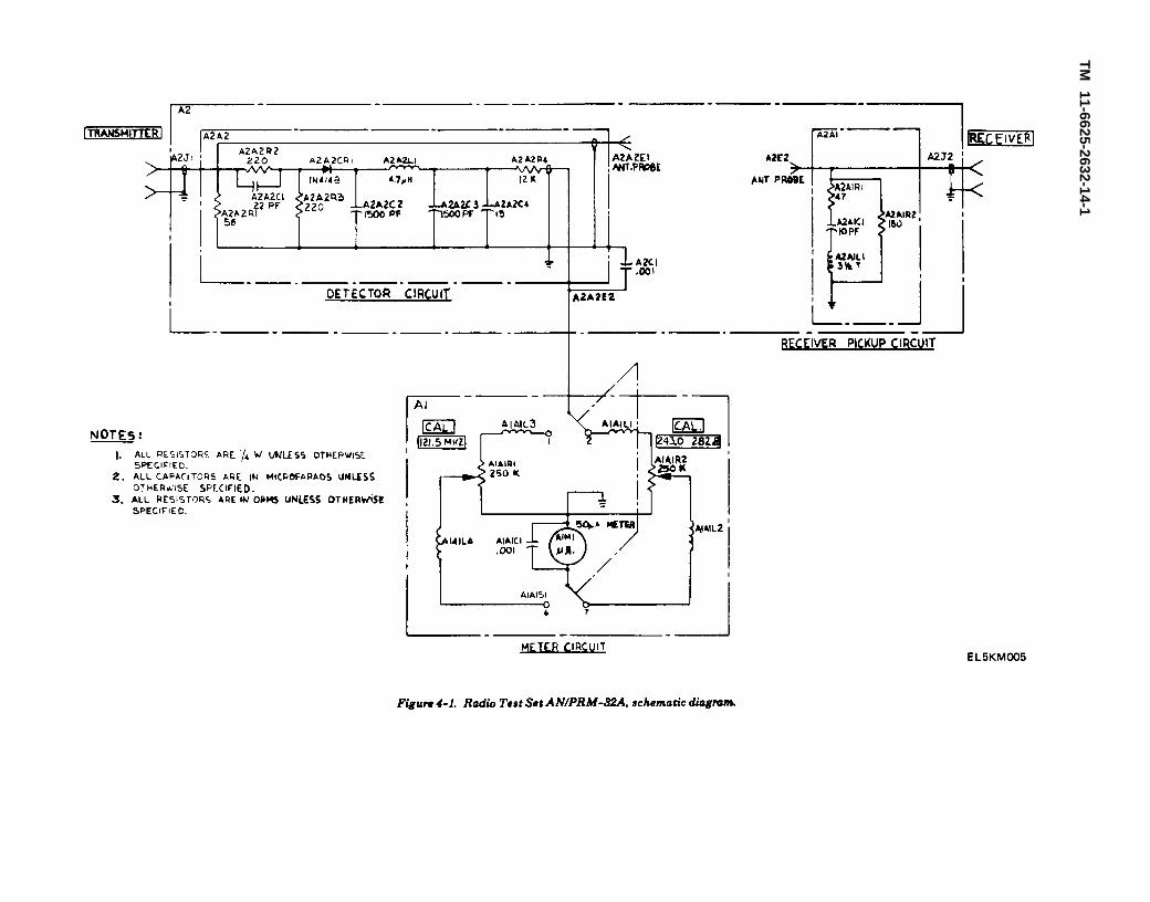
Figure 4-1.
TM
11-6625-2632-14-1

TM 11-6625-2632-14-1
b. The detector circuit, which is a halfwave
rectifying circuit, applies a dc level which iSproportional to signal strength, through switchA1A1S1 to meter A1M1 in parallel with variableresistor A1A1R1 or A1A1R2. The var iableresistors are adjusted during calibration so that dcammeter A1M1 registers in the green portion of itsdial, marking when the signal from the trans-mitting radio set is at an acceptable level. Theattenuation of the detector circuit is different at121.5 MHz and 243.0/282.8 MHz so when switchA1A1S1 is set to 121.5 MHz, A1A1R1 is in
parallel with the meter and when the switch is setto 243.0/282.8, A1A1R2 is in parallel with themeter.
c. The output from the feedthru (A2A2E1) thatacts as an internal transmitting antenna is pickedup by the internal antenna probe (A2E2) which islocated approximately 2-1/4 inches away. The rfsignal level at antenna probe A2E2 is attenuatedby the pickup circui t and coupled throughRECEIVER connector A2J2 to the radio set undertest .
4-3


TM 11-6625-2632-14-1
C H A P T E R 5
G E N E R A L S U P P O R T M A I N T E N A N C E
Sect ion I .
5-1. Scope of MaintenanceThe maintenance duties of general support per-sonnel are detailed in this chapter. The proceduresare presented in a logical order. Do not performany maintenance not specifically defined in thischapter or in chapter 3. The test set must becalibrated after any parts in the detector, receiver,or meter circuit have been replaced. After partshave been replaced, refer to the cal ibrat ionrequirements shown in paragraph 5-12. Themaintenance duties of general support personnelare outlined be lO W. A W iring diagram of the testset is presented in figure 5-6. Refer to figure FO-1for resistor, inductor, and capacitor color codemarkings.
a.b.c .
e .d.
fg.h.
Physical inspection (para 5-3).Checkout (para 5-5).Troubleshooting (para 5-6).Removal of components (para 5-8).Repair (para 5-9).Fabrication of replacement parts (pars 5-10).Replacement of components (pare 5-11).Testing after repair (para 5-12).
Tools and Test Equipment Required5-2.Tools and test equipment required for general
G E N E R A L
support maintenance are listed below. Repair partsand special tools are listed in TM11-6625-2632-24P-1, and the maintenanceallocation chart, appendix B of this manual.
a . Took . Too l K i t , Electronic EquipmentTK-100/G (NSN 5180-00-605-0079).
b. Test Equipment.( 1 ) R a d i o S e t A N / P R C - 9 0 ( N S N
5820-00-782-5308).( 2 ) M u l t i m e t e r A N / U S M - 2 2 3 ( N S N
6625-00-999-7465).
5-3. Physical InspectionThe purpose of visual inspection is to locate faultswithout testing of components. Many faults m a ybe detected by sight, touch, or smell. All visualsigns should be analyzed to help localize the faultto a particular part. Inspect the teat set carefullyfor obvious defects. Inspection procedures areshown in table 5-1. Partial disassembly (panelassembly removal, para 5-8) will be required sothat the electronic components on the back of thepanel can be examined. After correction of anyelectronic component defects found by inspection,reassemble the test set and refer to the calibrationrequirements in paragraph 5-12.
Table 5-1. Physical Inspection
Step No. Test Procedure Performance Standard
1 Inspect all controls and mechanical assemblies forIoose or missing screw, bolts, and nuts.
2 Inspect all metal parts and wiring for dirt, rust, andcorrosion.
3 Inspect for Ioose or missing parts, and cracked orbroken parts.
4 Inspect for frayed or broken lnsulation, broken wires, and bare wires or burned insulation.
5 Inspect for shorted wires, or wires in contact withmetal parts of panel.
Screws, bolts, and nuts must be tight, with none missing.
Metal parts and wiring must be clean and free of rust andcorrosion.All parts must be intact, without cracks, with no loose con-nections, and no parts missing.All wires must be securely soldered, with no breaks.
There must be no bare wires, or burned or brokeninsulation.
There must be no shorted wires, and no wires in contactwith metal parts of case.
5-1

TM 11-6625-2632-14-1
S e c t i o n I I . T R O U B L E S H O O T I N G
5-4. GeneralTroubleshooting at general support maintenancecategory consists of verifying and localizingtroubles in defective equipment. It also includes acheckout of new equipment for proper operationbefore use. Troubleshooting by general supportmaintenance personnel is performed using theoperational check specified in table 5-2. Refer totroubleshooting procedures (para 5-6) forcorrective measures. Replace defective components.
5-5. Checkout ProceduresCheckout procedures are intended to localize themalfunction or determine that no malfunctionexists. Perform the checkout procedures shown intable 5-2. If the test set gives weak or normalindications in this procedure, proceed to testingand calibration (para 5-12 and 5-13). If an ab-normal indication appears, record the procedure atwhich a malfunction occurred and proceed to the
corresponding procedure in the troubleshooting procedure. After repair, perform the completecheckout procedure to be sure the test set isfunctioning properly. After completion of checkoutprocedure, refer to the calibration requirements shown in paragraph 5-13.
5-6. Troubleshooting ProceduresTroubleshooting procedures are intended to isolatethe faulty part when a malfunction has beendetermined to exist through operational checks.When the operational checks of table 5-2 havebeen performed to localize the malfunction to aspecific circuit, perform the appropriate procedureof the troubleshooting procedure in table 5-3 tode te rmine wh ich par t needs rep lacement .Replacement procedures are described in paragraph5-11. Component identification is shown in figures5-1 through 5-5.
Table 5-2. Operational Check
Step Action
1 Using connector adapters. connect thetest set cables to antenna jacks oftwo Radio Sets AN/PRC-90 orAN/PRC-106 known to beoperating properly (Para 2-8).
2 Set function switch of transmittingradio to BCN 243.0 and VOLSwitch to minimum
3 Set function switch of receivingradio to VOICE/MCW 243.0 andVOL switch to MAX.
4 If two Radio Sets AN/PRC-106are avilable, set function switch oftransmitting radio to BCN 121.5
and VOL switch to minimum.5 Set function switch of receiving
radio to VOICE/MCW 121.5 andVOL switch to MAX.
Normal indication If indication is abnormal
a. Audible beacon tone in speaker ofreceiving radio. Proceed to b below.
b. Observe test set meter. Needleshould indicate in green area of dialmarking.
a Audible beacon tone in speaker ofreceiving radio. Proceed to b.below.
b. Observe test set meter. Needleshould indicate in green area of dialmarking.
a. Malfunction is in cables orreceiver antenna coupler circuit.Refer to table 5-3, step 2.
b. Malfunction is in detector circuitor meter circuit. Refer to table 5-3,step 3.
a. Malfunction is in cables orreceiver antenna coupler circuit.Refer to table 5-3, step 2.
b. Malfunction is in detector circuitor meter circuit. Refer to table 5-3,
step 3.
5-2

TM 11-6625-2632-14-1
Table 5-3. Troubleshooting Procedure
Step Action Normal indication If indication in abnormal
1 Partially disassemble test set toremove panel from case (refer topara 5-8a).
2 With test set connected, andswitches set as in step 3 or step 5(as applicable) of table 5-2, observetest set meter.
3 Using bench testing check:a. Continuity of transmitter and
receiver cables, connectorsA2J1 and A2J2, and receiverwire.
b. Resistance values of individualcomponents
Meter indication in green area ofdial marking.
See figure 4-1, schematic diagram,for values. See figure 5-6, wiringdiagram for physical connections.
Proceed to step 3 below.
Replace faulty part.NOTE
If a part is replaced.calibration of test setis required (refer topara 5-13).
S e c t i o n I l l . M A I N T E N A N C E O F R A D I O T E S T S E T A N / P R M - 3 2 A
5-7. GeneralAdjustment and calibration of the AN/PRM-32Ais included in calibration procedures (para 5-13).Repair is achieved by replacement of defectivecomponents. Partial disassembly is required toremove the panel assembly for troubleshooting and
repair. Further disassembly may be required ifcomponents must be removed and replaced. Theprocedures for removing and replacing those partswhich are replaceable are described b e l o w .Procedures are presented in a logical order and
should be performed only to the extent required togain access to parts requiring replacement. Figures5-1 through 5-5 identify the component parts ofthe test set. Refer to figure 4-1 for the test setschematic diagram and figure 5-6 for a wiringdiagram of the test set.
5-8. Removal of Major Componentsa. Removal of Panel Assembly (fig. 5-1).
(1) Open the elbow catch and open cover (14).(2) Remove items stored in the cover.
5-3

TM 11-6625-2632-14-1
Figure 5-1. Radio Test Set AN/PRM-32A parts identification.
5-4

TM 11-6625-2632-14-1
Key to fig. 5-1:1 Connector Adapter CP12 Test Set Assembly3 Cable Assembly W14 Connector W1P1 and W1P25 RF Cable6 Screw7 Identification Plate8 Panel Assembly Al
9 Rubber Channel10 Case Assembly A211 Hinge Bar12 Screw13 Rubber Bumper14 Cover Assembly15 Identification Plate16 Spanner Wrench
1 Cover 6 Instruction Book Holder2 Elbow Catch 7 Rubber Channel3 Screw 8 Screw4 Washer 9 Rubber Bumper5 Nut 10 Hinge
Figure 5-2 Cover assembly parts identification.
5-5

Figure 5-3
TM
11-6625-2632-14-1
5-6

TM 11-6625-2632-14-1
Key to fig. 5-3:
Figure 5-4. Case assembly parts identification.
5-7

Figure 5-5.
TM
11-6625-2632-14-1
5-8

TM 11-6625-2632-14-1
(3) Carefully peel off rubber channel (9).(4) Remove four screws (6) and carefully lift
panel assembly A1 (8) out of case assembly A 2(10).
(5) Tag and unsolder wire from feedthruterminal A2A2E2 (4, fig. 5-5).
b. Removal of Cover Assembly and Parts (fig.5 -1 and 5-2).
(1) Remove panel assembly (a above).(2) Remove two screws (12, fig. 5-1), rubber
bumpers (13) and hinge bar (11).(3) Lift off cover assembly (14).(4) Remove instruction book holder (6, fig.
5-2) by removing two screws (8), two rubberbumpers (9) and hinge (10).
c. Removal of Meter A1M1.(1) Remove panel assembly (a above).(2) Tag wires and unscrew terminal nuts (not
illustrated) from meter A1M1 (3, fig. 5-3). Removeterminal lugs (11) with capacitor A1A1C1 (12) andwires attached.
(3) Unscrew mounting ring (part of 3) andremove meter (3) from panel.
d. Removal of Mounting Bracket Assembly andParts.
(1) Remove panel assembly (a above).(2) Tag wires and unscrew terminal nuts from
meter A1M1 (3, fig. 5-3). Remove terminal lugs(11) with capacitor A1A1C1 (12) and wires at-tached.
(3) Tag and unsolder wire from feedthruterminal A2A2E2 (4, fig. 5-5).
(4) Loosen set screws and remove knob (5, fig.5-3) by pulling off.
(5) Remove two screws (2), washers (7),spacers (6), nuts (8) and terminal lug (10).
(6) Remove mounting bracket assembly (9).
(7) Tag wires at switch A1A1S1 (13). Unsolderwires. Remove nut (part of 13) and washer (part of13) and remove switch (13).
(8) Tag wires at variable resistor A1A1R1 orA1A1R2 (15). Unsolder wires. Remove locknut(part of 15) and remove variable resistor (15).
e. Removal of Shielded Box Assembly.(1) Remove panel assembly (a above).(2) Remove the bar (4, fig. 5-4) above the
shielded box assembly A2A2 (3).(3) Remove four screws (not called out)
securing cover (not called out) of shielded boxassembly A2A2 (3) and open cover.
(4) Tag and unsolder wire from TRANS-MITTER connector A2J1 (19).
(5) Close cover of shielded box assemblyA2A2. Secure cover with four screws removed in(3) above. One screw also secures terminal lug (1).
(6) Remove four screws (18). RemoveTRANSMITTER connector A2J1 (19) with onejack cap (10).
(7) Tag and unsolder wire from feedthruterminal A2A2E2 (4, fig. 5-5).
(8) Remove shielded box assemble A2A2 (3,fig. 5-4) with capacitor A2C1 (2) and terminal lug(1).
f. Removal of Mounting Plate Assembly.(1) Remove shielded box assembly (e above).(2) Remove four screws securing cover of
shielded box assembly A2A2 (3, fig. 5-4) and opencover.
(3) Tag and unsolder wire from feedthruterminal A2A2E1 (6, fig. 5-5).
(4) Remove two screws (7), washers (3), nuts(2) and spacers (5).
(5) Remove mounting plate assembly (13).
5-9

TM 11-6625-2632-14-1
Figure 5-6. Radio Test Set AN/PRM-32A, wiring diagram.
5-10

TM 11-6625-2632-14-1
5-9. Repair Procedures a. A rubber channel can be made using the dataRepair of physical damage to the case, cover or in figure 5-7.panel of Radio Test Set AN/PRM-32A consists b. An antenna wire can be made using the dataof straightening out dents and repainting. in figure 5-8.
c. The fish paper (7, fig. 5-4) is cut from 0.0155-10. Fabrication of Replacement PartsThe following parts may be fabricated locally by
inch thick paper per MIL-I-695, Type F. The fishpaper is cut to a 1-inch by 3/4-inch rectangle.
general support personnel.
Figure 5-7. Rubber Channel Fabrication Details.
5-11

TM 11-6625-2632-14-1
Figure 5-8. Antenna Wire Fabrication Details
5-11. Replacement of Major Componentsa. Replacement of Mounting Plate Assembly.
(1) Insert two screws (7, fig. 5-5) i n t omounting plate assembly (13). The screw heads goon the same side as diode A2A2CR1 (11).
(2) Slip spacer (5) over threads of each screw(7).
(3) Apply thread sealing compound, MIL-S- 22473C, grade AVV, to screws (7). Insert screws(7) through holes in box (1) and secure withwashers (3) and nuts (2).
(4) Untag and resolder wires from mountingplate assembly to feedthru terminals A2A2E2 andA2A2E1 (4 and 6).
(6) Install cover of shielded box assemblyA2A2 (3, fig. 5-4) and secure with four screws.One screw also secures terminal lug (1).
5-12
b. Replacement of Shielded Box Assembly,(1) Place shielded box assembly A2A2 (3, fig,
5-4) in case (17).(2) Insert TRANSMITTER connector A2J1
(19) through case (17) into shielded box assemblyA2A2 (3). Apply thread seal ing compound,MIL-S-22473C, grade AVV, to screws (18) andsecure TRANSMITTER connector A2J1 (19) withfour screws (18). One screw also secures jack cap(10).
(3) Untag and resolder wire from mountingbracket assembly (9, fig. 5-3) to feedthru terminalA2A2E2 (4, fig. 5-5).
(4) Remove four screws securing cover ofshielded box assembly A2A2 (3, fig. 5-4) and open cover.
(5) Untag and resolder wire from mounting

TM 11-6625-2632-14-1
plate assembly (13, fig. 5-5) to TRANSMITTERconnector A2J1 (19, fig. 5-4).
(6) Close cover of shielded box assembly.Secure cover with four screws removed in (4)above. One screw also secures terminal lug (1).
(7) Replace the bar (4) above the shielded boxassembly A2A2 (3).
c. Replacement of Mounting Bracket Assemblyand Parts.
(1) Remove locknut (supplied with variableresistor) f rom var iable resistor A1A1R1 orA1A1R2 (15, fig. 5-3).
(2) Insert variable resistor (15), with lock-washer and mounting nut (supplied with variableresistor) attached, in bracket (16).
(3) Thread locknut, removed in (1) above, onvariable resistor (15). Locknut is to be finger tightonly to secure variable resistor (15). Secure bytightening mounting nut.
(4) Untag and resolder wires to variableresistor (15).
(5) Remove mounting nut and washer (sup-plied with switch) from switch A1A1S1 (13).
(6) Insert switch (13) in bracket (16) andsecure with mounting nut and washer removed in(5) above.
(7) Untag and resolder wires to switch (13).(8) Insert two screws (2) through plate (1).(9) Place spacer (6) on each screw. Apply
thread sealing compound, MIL-S-22473C, gradeAVV, to threads of screws (2).
(10) set mounting bracket assembly (9) inplace and secure with washers (7) and two nuts (8).
(11) Place terminal lug (10) on nearest screw(2) and secure with nut (8).
(12) Push knob (5) on shaft of switch A1A1S1(13) and tighten set screws.
(13) Untag and resolder wire on feedthruterminal A2A2E2 (4, fig. 5-5).
(14) Untag wires and place terminal lugs (11,fig. 5-3), with capacitor A1A1C1 (12) and wires
attached, on terminals of meter A1M1 (3). Securewith terminal nuts from meter.
d. Replacement of Meter A1M1.(1) Insert meter A1M1 (3, fig. 5-3) in plate (1)
and secure with mounting ring (part of 3).(2) Untag wires and place terminal lugs (11),
with capacitor A1A1C1 (12) and wires attached, onterminals of meter A1M1 (3). Secure with terminalnuts from meter.
e. Replacement of Cover Assembly and Parts.(1) Insert one screw (8, fig. 5-2) through each
of two rubber bumpers (9).(2) Insert screws (8), with rubber bumpers (9)
attached, through elongated holes m hinge (10).Apply sealing compound, MIL-S-22473C, gradeAVV, to threads of screws (8). Do not get sealingcompound on rubber bumpers (9).
(3) Insert screws (8), with rubber bumpers (9)and hinge (10) attached, through cover (1) and intoinstruction book holder (6). Tighten screws.
(4) Place robber bumpers (13, fig. 5-1) onscrews (12) and insert screws in hinge on coverassemb ly (14 ) . App ly sea l ing compound ,MIL-S-22473C, grade AVV, to threads of screws(12). Do not get sealing compound on rubberbumpers (13).
(5) Set cover assembly in place on caseassembly A2 (10) and thread screws into hinge bar(11). Tighten screws.
f. Replacement of Panel Assembly.(1) Untag and resolder wire from mounting
bracket assembly (9, fig. 5-3) to feedthru terminalA2A2E2 (4, fig. 5-5).
(2) Set panel assembly A1 (8, fig. 5-1) inposition in case assembly A2 (10) and secure withfour screws (6).
(3) Carefully scrape any adhesive residue fromrim of case assembly A2 (10). Secure rubberchannel (9) to case assembly A2 (10) with Scotch-Grip Industrial Adhesive No. 847 or equivalent.
S e c t i o n I V . T E S T I N G A N D C A L I B R A T I O N
5-12. Testing 5-5) to make sure that Radio Test Set AN/PR-The test set must be calibrated dafter repair or M-32A is functioning properly.replacement of electronic components, refer to 5-13. Calibrationparagraph 5-13. After cal ibrat ion has been The adjustment of antenna A2E2 and Calibrationcompleted, perform the checkout procedures (para of the test set meter are performed in accordance
with TB 11-6625-2632-35-1.
5-13


TM 11-6625-2632-14-1
A P P E N D I X A
R E F E R E N C E S
The following publications contain information applicable to the maintenanceof Radio set AN/PRM-32A.
DA Pam 310-4
DA Pam 310-7SB 11-573
SB 38-100
SC 5180-91-CL-R13
SC 5180-91-CL-S21
TB 43-0118
TB 43-180TM 38-750TM 740-90-1TM 750-244-2
Index of Technical Manuals, Technical Bulletins, Supply Manuals(type 7, 8, and 9), Supply Bulletins, and Lubrication Orders.
US Army Equipment Index of Modification Work Orders.Painting and Preservation Supplies Available for Field Use for
Electronics Command Equipment.Preservation, Packaging, Packing and Marking Materials, Supplies,
and Equipment Used by the Army.sets, Kits, and Outfits Components List: Tool Kit, Electronic
Equipment TK-101/G.Sets, Kits, and Outfits Components List: Tool Kit, Electronic
Equipment TK-100/G.Field Instructions for Painting and Preserving Electronics Command
Equipment. Including Camouflage Pattern Painting of ElectricalEquipment Shelters.
Calibration Requirements for the Maintenance of Army Materiel.The Army Maintenance Management System (TAMMS).Administrative Storage of Equipment.Procedures for Destruction of Electronic Materiel to Prevent Eneny
Use (Electronics Command).
A-1


TM 11-6625-2632-14-1
A P P E N D I X B
M A I N T E N A N C E A L L O C A T I O N
Sect ion I . I N T R O D U C T I O N
B-1. Generala. This appendix provides a summary of the
maintenance operations for the AN/PRM-32A. Itauthorizes categories of maintenance for specificmaintenance functions on repairable items andcomponents and the tools and equipment requiredto perform each function. This appendix may beused as an aid in planning maintenance operations.
b. Maintenance o f av ion ics equ ipment i schanging to three categories of maintenance. Thesemaintenance categories are Aviation Unit Main-tenance (AVUM); Aviation Intermediate Main-tenance (A VIM); and Depot Maintenance. AVUMwill replace organizational maintenance, andAVIM will replace direct and general supportmaintenance. In the interim, as maintenance unitsare reorganized into three categories of main-tenance activities, this publication will be used byAVUM or organizational and AVIM or generalsupport maintenance personnel for the maintenanceof the avionics equipment. The maintenanceallocation chart (MAC) can be adapted to thethree-category maintenance concept where the codeO represents AVUM, the code F represents AVIM,and D represents depot maintenance.
B-2. Maintenance FunctionMaintenance functions will be limited to anddefined as follows:
a. Inspect. To determine the serviceability of anitem by comparing its physical, mechanical, and/or electrical characteristics with establishedstandards through examination.
b. Test. To verify serviceability and to detectincipient failure by measuring the mechanical orelectrical characteristics of an item and comparingthose characteristics with prescribed standards.
c. Service. Operations required periodically tokeep an item in proper operating condition, i.e., toclean (decontaminate), to preserve, to drain, topaint, or to replenish fuel, lubricants, hydraulicfluids, or compressed air supplies.
d. Adjust. To maintain, within prescr ibedlimits, by bringing into proper or exact position, orby setting the operating characteristics to thespecified parameters.
e. Align. To adjust specified variable elementsof an item to bring about optimum or desiredperformance.
f. Calibrate. To determine and cause correctionsto be made or to be adjusted on instruments ortest measuring and diagnostic equipments used inprecision measurement. Consists of comparisons oftwo instruments one of which is a certifiedstandard of known accuracy, to detect and adjustany discrepancy in the accuracy of the instrumentbeing compared.
g. Install. The act of emplacing, seating, orfixing into position an item, part, module (com-ponent or assembly) in a manner to allow theproper functioning of the equipment or system.
h. Replace. The act of substituting a serviceablelike type part, subassembly, or module (componentor assembly) for an unserviceable counterpart.
i . Repair . The appl icat ion of maintenanceservices (inspect, test, service, adjust, align,calibrate, replace) or other maintenance actions(we ld ing , g r ind ing , r i ve t ing , s t ra igh ten ing ,facing, remachining, or resurfacing) to restoreserviceablility to an item by correcting specificdamage, fault, malfunction, or failure in a part,subassembly, module (component or assembly),end item, or system.
j. Overhaul. That maintenance effort (ser-vice/action) necessary to restore an item to acompletely serviceable/operational condition asprescribed by maintenance standards (i.e., DM-WR) in appropr iate technical publ icat ions.Overhaul is normal ly the highest degree ofmaintenance performed by the Army. Overhauldoes not normally return an item to like newcondition.
k. Rebuild. Consists of those services/actionsnecessary for the restoration of unserviceableequipment to a like new conditon in accordancewith original manufacturing standards. Rebuild isthe highest degree of materiel maintenance appliedto Army equipment. The rebuild operation includest h e a c t o f r e t u r n i n g to zero those agemeasurements (hours, miles, etc.) considered inclassifying Army equipments/components.
B-1

TM 11-6625-2632-14-1
B-3. Column Entriesa. Column 1, Group Number. Column 1 lists
group numbers, the purpose of which is to identifycomponents, assemblies, subassemblies, andmodules with the next higher assembly.
b. Column 2, Component/Assembly. Column 2contains the noun names of components, assem-blies, subassemblies, and modules for whichmaintenance is authorized.
c. Column 3, Maintenance Functions. Column 3lists the functions to be performed on the itemlisted in column 2. When items are listed withoutmaintenance functions, it is solely for purpose ofhaving the group numbers in the MAC and RP-STL coincide.
d. Column 4, Maintenance Category. Column 4specifies, by the listing of a “ worktime” figure inthe appropriate subcolumn(s), the lowest level ofmaintenance authorized to perform the functionlisted in column 3. This figure represents theactive time required to perform that maintenancefunction at the indicated category of maintenance.If the number or complexity of the tasks withinthe listed maintenance function vary at differentmaintenance categories, appropriate ‘‘ worktime”figures will be shown for each category. Thenumber of task-hours specified by the ‘‘ worktime”figure represents the average time required torestore an item (assembly, subassembly, com-ponent, module, end item or system) to a ser-conditions. This time includes preparation time,troubleshoot ing t ime, and qual i ty assuran-ce/qualityce/quality control time in addition to the timerequired to perform the specific tasks identified forthe maintenance functions authorized in themaintenance allocation chart. Subcolumns ofcolumn 4 are as follows:
e. Column 5, Tools and Equipment. Column 5specifies by code, those common tool sets (notindividual tools) and special tools, test, and support equipment required to perform thedesignated function.
f. Column 6, Remarks. Column 6 contains analphabetic code which leads to the remark insection IV, Remarks, which is pertinent to the item opposite the particular code.
B-4. Tool and Test Equipment Requirements (sectI I I )
a. Tool or Test Equipment Reference Code. Thenumbers in this column coincide with the numbersused in the tools and equipment column of theMAC. The numbers indicate the applicable tool ortest equipment for the maintenance functions.
b. Maintenance Category. The codes in thiscolumn indicate the maintenance category allocatedthe tool or test equipment.
c. Nomenclature. This column lists the nounname and nomenclature of the tools and testequipment required to perform the maintenancefunctions.
d. National/NATO Stock Number. This columnlists the National/NATO stock number of thespecific tool or test equipment.
e . T o o l N u m b e r . c o l u m n l i s t s t h emanufacturer’s part number of the tool followed bythe Federal Supply Code for manufacturers(5-digit) in parentheses.
B-5. Remarks (sect IV)a. Reference Code. This code refers to the
appropriate item in section II, column 6.b. Remarks. This column provides the required
explanatory information necessary to clarify itemsappearing in section II.
C–Operator/Crew-Not applicable.O—Organizat ional—Aviat ion Unit Main-
tenance (AVUM)F—Direct Support/General Support in Aviation
Intermediate Maintenance (AVIM)H–Not applicable.D–Depot
(Next printed page is B-3)
B-2
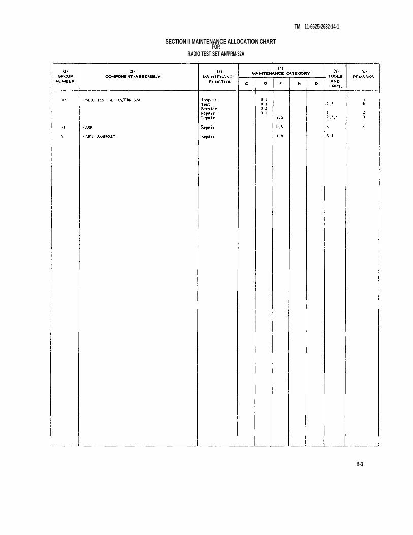
TM 11-6625-2632-14-1
SECTION II MAINTENANCE ALLOCATION CHARTFOR
RADIO TEST SET AN/PRM-32A
B-3

TM 11-6625-2632-14-1
B-4
SECTION III. TOOL AND TEST EQUIPMENT REQUIREMENTS FOR
RADIO TEST SET AN/PRM-32A
TOOL OR TEST EQUIPMENT
REF CODE
MAINTENANCE
CATEGORY
NOMENCLATURE
NATIONAL/NATO STOCK NUMBER
TOOL NUMBER
1
2
3
4
O
F
F
F
TOOL KIT, ELECTRONIC EQUIPMENT TK-101/G
RADIO SET AN/PRC-90
TOOL KIT, ELECTRONIC EQUIPMENT TK-100/G
MULTIMETER AN/USM-223
5180-00-064-5178
5825-00-782-5308
5180-00-605-0079
6625-00-999-7465

TM 11-6625-2632-14-1
RADIO TEST SET AN/PRM-32A
SECTION IV. REMARKS
B-5


By Order of the Secretary of the Army:
Official:J.C. PENNINGTON
Brigadier General, United States ArmyThe Adjutant General
BERNARD W. ROGERSGeneral United States Army
Chief of Staff
DISTRIBUTION:To be distributed in accordance with DA Form 12-31, Operator
maintenance requirements for All Fixed and Rotor Wing Aircraft.
*U.S. GOVERNMENT PRINTING OFFlCE: 1993 - 342-421/61931


Figure FO-1. MIL-STD resistor, inductor, and capacitor color code marking


PIN :037755-000

This fine document...
Was brought to you by me:
Liberated Manuals -- free army and government manuals
Why do I do it? I am tired of sleazy CD-ROM sellers, who take publicly available information, slap “watermarks” and other junk on it, and sell it. Those masters of search engine manipulation make sure that their sites that sell free information, come up first in search engines. They did not create it... They did not even scan it... Why should they get your money? Why are not letting you give those free manuals to your friends?
I am setting this document FREE. This document was made by the US Government and is NOT protected by Copyright. Feel free to share, republish, sell and so on.
I am not asking you for donations, fees or handouts. If you can, please provide a link to liberatedmanuals.com, so that free manuals come up first in search engines:
<A HREF=http://www.liberatedmanuals.com/>Free Military and Government Manuals</A>
– SincerelyIgor Chudovhttp://igor.chudov.com/
– Chicago Machinery Movers