tm-300 - dataioinfo.dataio.comdataioinfo.dataio.com/pdf/manuals/ps200_300/tape...
TRANSCRIPT

TM-300SMD Taping Machine
OPERATOR’S MANUAL

TM-300 Document List (Standard) 61170915.fm Page 1 of 1
Section
Chapter 1
Chapter 2
Exploded View
Index
Addendum
TM-300 ManualDocument List
Document Description
This Document
Declaration of Conformity
Table of Contents
TM-300 Options
TM-300 I/O Connector
Safety Instructions
Operation Instructions
1 of 1
Page 2 of 2
Software Modification
Cover Page
File Name
61170915.fm
61170210.fm
61171013.fm
61170310.fm
61170410.fm
61170511.fm
61170613.fm
61269310.cdr
61201910.fm
61170710.fm
61170810.fm

DECLARATION OF CONFORMITY
Model: TM-300Serial: _______________
Date: _______________
This product complies with the following European Union Directives:
89/392/EEC Machinery as amended by 91/368/EEC, 93/44/EEC
89/336/EEC Electromagnetic Compatibility as amended by 92/31/EEC, 93/68/EEC
The following standards were used to verify compliance with the Directives:EN292, EN23742, EN60204
Approved by:
Engineering
ISO 9001 #46361Certified by BVQI

TM-300 Table of Contents 61171013.fm Page 1 of 1
TM-300 Manual
Table of Contents
TM-300 Options .......................................................................................................1 of 1TM-300 I/O Connector .............................................................................................1 of 1
Chapter 1: Safety Instructions.................................................................................1Safety Introduction .......................................................................................2Marking Definitions ......................................................................................3Safety Instructions .......................................................................................4
Chapter 2: Operator’s Instructions..........................................................................5Assembling Procedure.................................................................................6
Completed Mechanical Assembly................................................................8Description ...................................................................................................9 Counter Controls..........................................................................................14Setting the Counter ......................................................................................15Controller Operation.....................................................................................16Software Download Procedure ....................................................................17Setup ...........................................................................................................19Operation ....................................................................................................25Maintenance ................................................................................................27
Exploded View .........................................................................................................1 of 1TM-300 Index...........................................................................................................2 of 2TM-300 Addendum ..................................................................................................1 of 1TM-300 Document List.............................................................................................1 of 1
TM-300 Options 61170310.fm Page 1 of 1
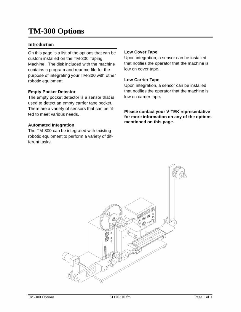
TM-300 Options
Introduction
On this page is a list of the options that can be custom installed on the TM-300 Taping Machine. The disk included with the machine contains a program and readme file for the purpose of integrating your TM-300 with other robotic equipment.
Empty Pocket DetectorThe empty pocket detector is a sensor that is used to detect an empty carrier tape pocket. There are a variety of sensors that can be fit-ted to meet various needs.
Automated IntegrationThe TM-300 can be integrated with existing robotic equipment to perform a variety of dif-ferent tasks.
Low Cover TapeUpon integration, a sensor can be installed that notifies the operator that the machine is low on cover tape.
Low Carrier Tape Upon integration, a sensor can be installed that notifies the operator that the machine is low on carrier tape.
Please contact your V-TEK representative for more information on any of the options mentioned on this page.
TM-300 I/O Connector 61170410.fm Page 1 of 1
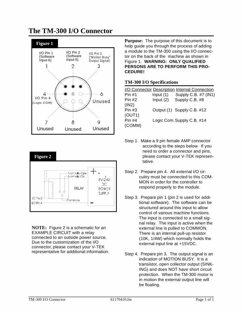
Purpose: The purpose of this document is to help guide you through the process of adding a module to the TM-300 using the I/O connec-tor on the back of the machine as shown in Figure 1. WARNING: ONLY QUALIFIED PERSONS ARE TO PERFORM THIS PRO-CEDURE!
TM-300 I/O Specifications
I/O Connector Description Internal ConnectionPin #1 Input (1) Supply C.B. #7 (IN1)Pin #2 Input (2) Supply C.B. #8 (IN2)Pin #3 Output (1) Supply C.B. #12 (OUT1)Pin #4 Logic Com.Supply C.B. #14 (COMM)
Step 1. Make a 9 pin female AMP connector according to the steps below. If you need to order a connector and pins, please contact your V-TEK represen-tative.
Step 2. Prepare pin 4. All external I/O cir-cuitry must be connected to this COM-MON in order for the controller to respond properly to the module.
Step 3. Prepare pin 1 (pin 2 is used for addi-tional software). The software can be structured around this input to allow control of various machine functions. The input is connected to a small sig-nal relay. The input is active when the external line is pulled to COMMON. There is an internal pull-up resistor (10K, 1/4W) which normally holds the external input line at +15VDC.
Step 4. Prepare pin 3. The output signal is an indication of MOTION BUSY. It is a transistor, open collector output (SINK-ING) and does NOT have short circuit protection. When the TM-300 motor is in motion the external output line will be floating.
The TM-300 I/O Connector
5
1 2 3
4 6
7 8 9
I/O Pin 3
I/O Pin 4Common
Normally Ope nNormally Clo s
RELAY
5V-24V
DC
POWER
SUPPLY
�
�
U nused
UnusedUnusedUnused
I/O P in 4(Logic COM)
I/O P in 3(“M otion B usy ”O utpu t S ig na l)
I/O Pin 2(Software Input-5)
I/O Pin 1(SoftwareInput-6)
NOTE: Figure 2 is a schematic for an
Figure 2
Figure 1
EXAMPLE CIRCUIT with a relay connected to an outside power source.Due to the customization of the I/Oconnector, please contact your V-TEKrepresentative for additional information.

TM-300 Safety Instructions 61170511.fm Page 1 of 27
Chapter 1
Safety Instructions
This chapter describes the procedures you must follow to safely operate the TM-300. Read all instructions before operating the TM-300 and keep them for future reference.
Chapter 1Safety Instructions
Safety Introduction ..............................................2Marking Definitions .............................................3Safety Instructions ..............................................4

TM-300 Safety Instructions 61170511.fm Page 2 of 27
In this document you will find:* important safety guidelines to follow when operating the equipment.* important definitions of safety markings.
WARNING: Read the provided manuals thoroughly before attempting to operate this machine.
Customers who intend to service and maintain the TM-300 themselves must only have quali-fied personnel perform those procedures. Qualified personnel are considered to be those persons who have the proper technical training, have experience to work on this equipment, and are aware of the hazards to which they will be exposed. The Service Man-ual is intended to be a supplement to training (NOT A REPLACEMENT).
ATTENTION: Place the TM-300 on a stable, flat surface before operating.
The intended use of the TM-300 Taping Machine is to place Surface Mount compo-nents into carrier tape. Use of this equipment in any other fashion may lead to personal injury.
The safety guidelines provided on the follow-ing pages are intended to educate the user on all safety issues in order to operate the TM-300 in a safe manner.
Pay close attention to these statements as they contain important information on avoiding potential hazards to yourself or to the equip-ment.
Safety Introduction

TM-300 Safety Instructions 61170511.fm Page 3 of 27
WARNING: Always observe the following safety guidelines when operating the TM-300. Do not, under any circumstances, remove or obstruct any warning or instruction labels on the TM-300.
AttentionThis mark is placed on the equipment near the adjustment, danger, or danger zone.
Dangerous VoltageIndicates hazards arising from dangerous volt-age.
High TemperatureIndicates a hot surface.
Open Book
Refer to the manual before performing mainte-nance on the TM-300.
Crushed HandThis mark is placed near areas that can cause personal injury or damage to the equipment if unsafe practices are used.
Marking Definitions

TM-300 Safety Instructions 61170511.fm Page 4 of 27
Customers who intend to service and maintain the TM-300 themselves must have only quali-fied personnel perform those procedures. Qualified personnel are considered to be those persons who have the proper technical training, have experience to work on this equipment, and are aware of the hazards to which they will be exposed. The TM-300 pan-els should never be removed with power applied to the unit. Refer to the Operator Manual for instructions before changing Power Switch settings, changing fuses, or removing any panels.
Caution should be taken when removing the sealer from the TM-300. The body of the sealer can maintain a high temperature long after shut down. Procedure for removing the Sealer is as follows:
Turn the POWER switch to the OFF position.Shut off the air supply to the TM-300.
Dangerous voltage is present. Before servic-ing:
Turn the POWER switch to the OFF position.Shut off the air supply to the TM-300.Disconnect the incoming power cord to the TM-300.
Dangerous voltage is present. Follow the pro-cedure below before removing this cover for service or maintenance:
Turn the POWER switch to the OFF position.Disconnect the incoming power cord to the TM-300.
TM-300 Safety Instructions

TM-300 Operation Instructions 61170613.fm Page 5 of 27
Chapter 2
TM-300 Operation Instructions
This chapter describes the procedures you must follow to operate the TM-300. Read all instruc-tions before operating the TM-300 and keep for future reference.
Chapter 2Contents
Assembling Procedure ........................................6Completed Mechanical Assembly .......................8Description ..........................................................9Counter Controls.................................................14Setting the Counter .............................................15Controller Operation............................................16Software Download Procedure ...........................17Setup...................................................................19Operation ............................................................25Maintenance .......................................................27
TM-300 Operation Instructions 61170613.fm Page 6 of 27
Cover Tape Guide #1 (Ref. E)
Loosen the screw holding the tape guide (5/32” allen wrench) and position at a 45° angle. Tighten screw.
Feed Reel Support Arm (Ref. F)
Remove the black knob from the loading track support arm (right side). Slide the feed reel support arm onto the threaded rod, position it at about 45°, and secure with the black knob.
Control Module Base Plate (Ref. G)
Slide the base plate into the control module pedestal (Ref. K).
Control Module (Ref. H)
Place the control module on the control mod-ule base plate. Connect all cables to the matching connectors. (See External Connec-tions, Page 9-10).
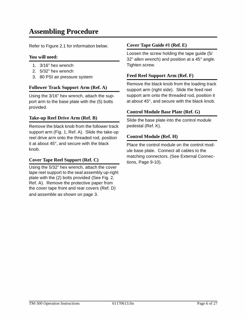
Assembling Procedure
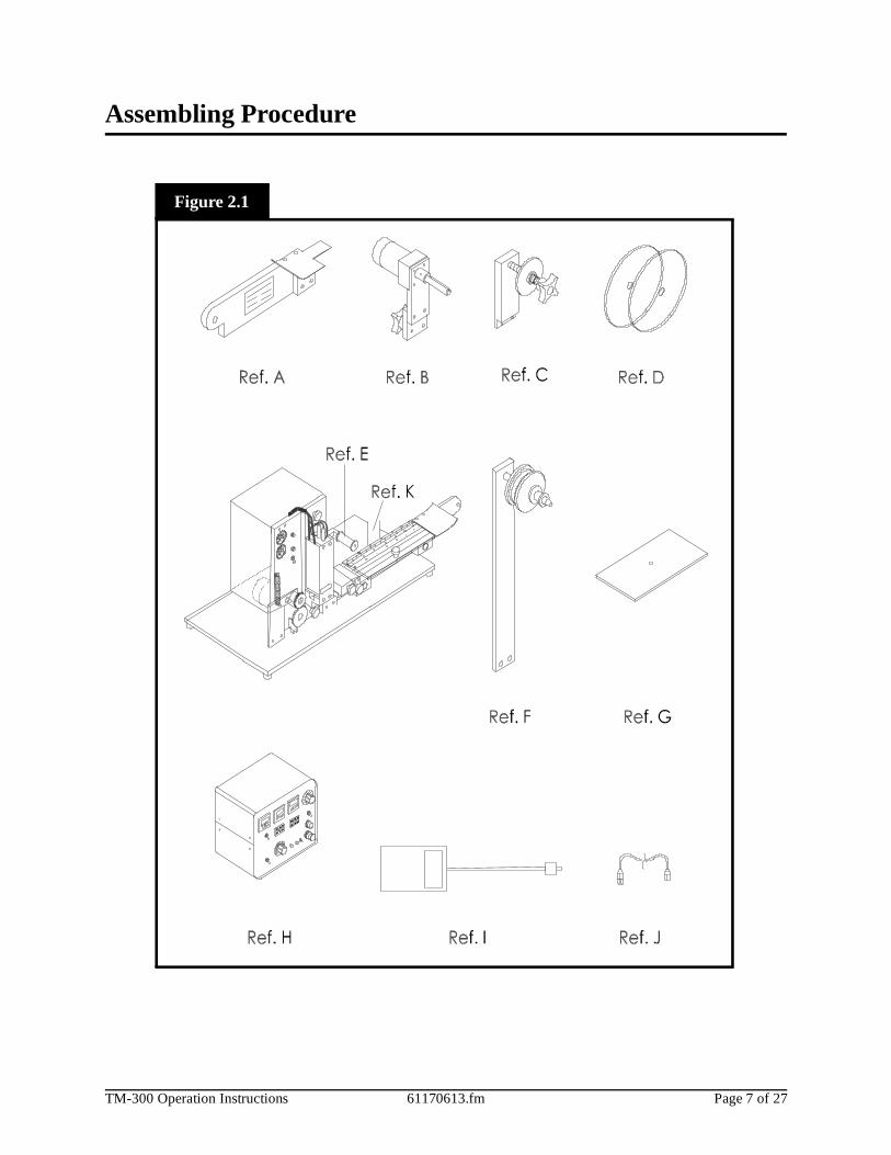
Refer to Figure 2.1 for information below.
You will need:
1. 3/16” hex wrench2. 5/32” hex wrench3. 80 PSI air pressure system
Follower Track Support Arm (Ref. A)
Using the 3/16” hex wrench, attach the sup-port arm to the base plate with the (5) bolts provided.
Take-up Reel Drive Arm (Ref. B)
Remove the black knob from the follower track support arm (Fig. 1, Ref. A). Slide the take-up reel drive arm onto the threaded rod, position it at about 45°, and secure with the black knob.
Cover Tape Reel Support (Ref. C)
Using the 5/32” hex wrench, attach the cover tape reel support to the seal assembly up-right plate with the (2) bolts provided (See Fig. 2, Ref. A). Remove the protective paper from the cover tape front and rear covers (Ref. D) and assemble as shown on page 3.
TM-300 Operation Instructions 61170613.fm Page 7 of 27
Assembling Procedure
Figure 2.1

TM-300 Operation Instructions 61170613.fm Page 8 of 27
Completed Mechanical Assembly
Figure 2.2
TM-300 Operation Instructions 61170613.fm Page 9 of 27
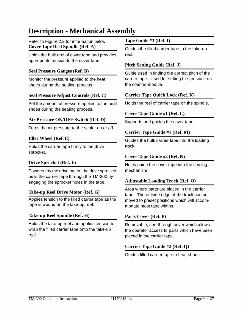
Refer to Figure 2.2 for information below.Cover Tape Reel Spindle (Ref. A)
Holds the bulk reel of cover tape and provides appropriate tension to the cover tape.
Seal Pressure Gauges (Ref. B)
Monitor the pressure applied to the heat shoes during the sealing process.
Seal Pressure Adjust Controls (Ref. C)
Set the amount of pressure applied to the heat shoes during the sealing process.
Air Pressure ON/OFF Switch (Ref. D)
Turns the air pressure to the sealer on or off.
Idler Wheel (Ref. E)
Holds the carrier tape firmly to the drive sprocket.
Drive Sprocket (Ref. F)
Powered by the drive motor, the drive sprocket pulls the carrier tape through the TM-300 by engaging the sprocket holes in the tape.
Take-up Reel Drive Motor (Ref. G)
Applies tension to the filled carrier tape as the tape is wound on the take-up reel.
Take-up Reel Spindle (Ref. H)
Holds the take-up reel and applies tension to wrap the filled carrier tape onto the take-up reel.
Description - Mechanical AssemblyTape Guide #3 (Ref. I)
Guides the filled carrier tape to the take-up reel.
Pitch Setting Guide (Ref. J)
Guide used in finding the correct pitch of the carrier tape. Used for setting the prescale on the counter module.
Carrier Tape Quick Lock (Ref. K)
Holds the reel of carrier tape on the spindle.
Cover Tape Guide #1 (Ref. L)
Supports and guides the cover tape.
Carrier Tape Guide #1 (Ref. M)
Guides the bulk carrier tape into the loading track.
Cover Tape Guide #2 (Ref. N)
Helps guide the cover tape into the sealing mechanism.
Adjustable Loading Track (Ref. O)
Area where parts are placed in the carrier tape. The outside edge of the track can be moved to preset positions which will accom-modate most tape widths.
Parts Cover (Ref. P)
Removable, see-through cover which allows the operator access to parts which have been placed in the carrier tape.
Carrier Tape Guide #2 (Ref. Q)
Guides filled carrier tape to heat shoes.

TM-300 Operation Instructions 61170613.fm Page 10 of 27
Description - Mechanical Assembly
Cover Tape Guide #3 (Ref. R)
Adjustable guide for precisely positioning the cover tape over the carrier tape prior to sealing.
Heat Sealer Assembly (Ref. S)
Controls the heat shoes with three variables: time, temperature, and pressure. The assem-bly is interchangeable for different tape widths.
Count Sensor (Ref. T)
Optical sensor which provides count pulses for the counter module.
Drive Motor (Ref. U)
AC motor which powers the drive sprocket.
Idler Arm (Ref. V)
Holds the sealed tape against the drive sprocket.
Seal Assembly / Motor Upright Plate (Ref. W)
Supports the air pressure gauges, seal assembly, and drive motors.
Follower Track Support Arm (Ref. X)
Supports the follower track, carrier tape guide #3, and take-up reel drive arm.
TM-300 Operation Instructions 61170613.fm Page 11 of 27
Decsription - Operating Controls
F ig ure 2 .3
PST + ENT
RST-
COUNTER
0 1 2 3 0 1 2
TAPE SPEED PITCH
INNER SEAL OUTER SEAL
.25
.30
.35
.40
.45
.50
.55.60 .65
.70
.75
.80
.85
.90
.95
1.0
DWELL
START
STOP
SEAL
ON
OFF
OFF
OFF
ON
ON
TENSION
FWD REV
JOG
RUN
REF. A
REF. B
REF. C
REF. D
REF. E
REF. F
REF. G
REF.H
REF. I
REF. K
REF. JREF. L
REF. M
REF. N
REF. O
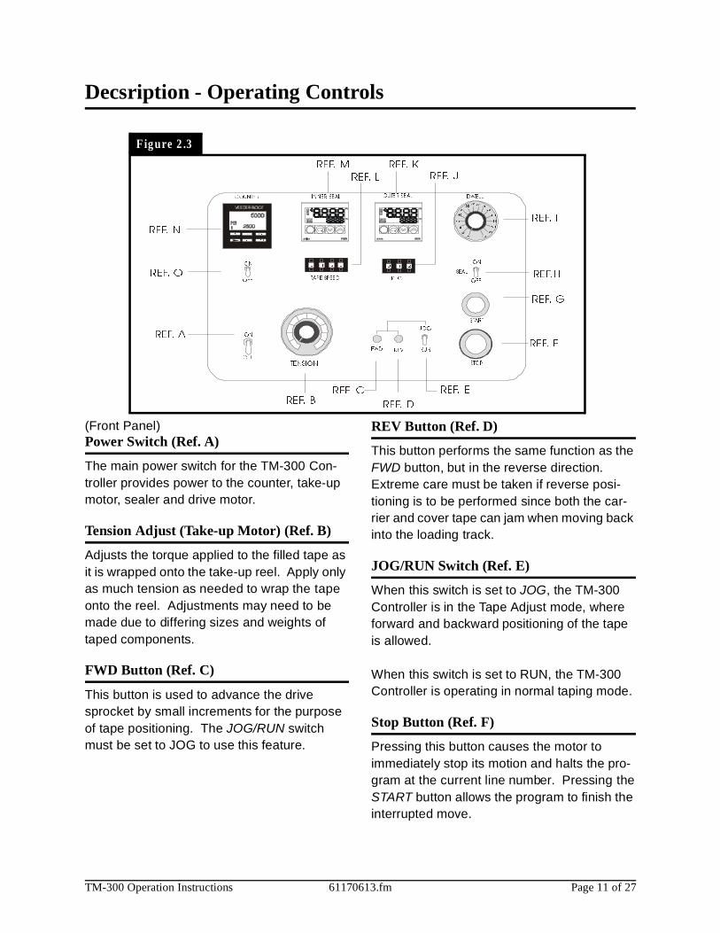
(Front Panel)Power Switch (Ref. A)
The main power switch for the TM-300 Con-troller provides power to the counter, take-up motor, sealer and drive motor.
Tension Adjust (Take-up Motor) (Ref. B)
Adjusts the torque applied to the filled tape as it is wrapped onto the take-up reel. Apply only as much tension as needed to wrap the tape onto the reel. Adjustments may need to be made due to differing sizes and weights of taped components.
FWD Button (Ref. C)
This button is used to advance the drive sprocket by small increments for the purpose of tape positioning. The JOG/RUN switch must be set to JOG to use this feature.
REV Button (Ref. D)
This button performs the same function as the FWD button, but in the reverse direction. Extreme care must be taken if reverse posi-tioning is to be performed since both the car-rier and cover tape can jam when moving back into the loading track.
JOG/RUN Switch (Ref. E)
When this switch is set to JOG, the TM-300 Controller is in the Tape Adjust mode, where forward and backward positioning of the tape is allowed.
When this switch is set to RUN, the TM-300 Controller is operating in normal taping mode.
Stop Button (Ref. F)
Pressing this button causes the motor to immediately stop its motion and halts the pro-gram at the current line number. Pressing the START button allows the program to finish the interrupted move.

TM-300 Operation Instructions 61170613.fm Page 12 of 27
Description - Operating Controls (cont.)
Start Button (Ref. G)
This button starts execution from the current program line number. Pressing the START button after a RESET will start execution at the first program line. Pressing the START button after an Emergency Stop (E-Stop) will start the program at the line where the E-Stop was detected.
Seal (Ref. H)
When set to ON, the seal is enabled.When set to OFF, the seal is disabled.
Dwell (Ref. I)
The dwell knob is used to set the amount of time the heat seal shoes remain on the cover tape. There are 16 Dwell settings ranging from 0.25 to 1.00 seconds in 0.05 second intervals.
Temperature Controls (Ref. K and M)
The temperature controls set the temperature of the heat shoes to a level that will cause the heat sensitive adhesive on the cover tape to melt. There are two separate controls:
Inner Seal (Ref. M)This is the seal head closest to the sprocket side of the carrier tape.
Outer Seal (Ref. K)This is the seal head closest to the out-side edge of the carrier tape as viewed facing the machine.
Pitch (Ref. J)
The PITCH control is used to set software parameters which control the drive sprocket motor and the counter. For the TM-300 Con-troller, PITCH refers to the distance (mm) between pocket centers in the carrier tape.
The current factory default settings allow the following PITCH settings:
4mm, 8mm, 12mm, 16mm, 20mm, 24mm, and 32mm.
Tape Speed (Ref. L)
This set of 4 Thumbwheel switches is used to determine tape velocity. Speeds are entered in pps (pulses per second) units. A new speed may be selected whenever motion is not in progress.
(Note: Acceleration/deceleration, and ramp-ing profiles can be changed via software by downloading programs with these parameters varied).
Counter (Ref. N)
The counter keeps an accurate count of the number of parts taped. The counter will auto-matically keep an accurate parts count for any tape pitch (pocket width). For counter opera-tion, refer to the SETTING COUNTER section of this manual.
Count (Ref. O)
In the ON position, the counter is enabled.In the OFF position, the counter is disabled.To set the target temperature, simply use the Increment and Decrement keys to adjust the set point display (Ref. C).

TM-300 Operation Instructions 61170613.fm Page 13 of 27
Description - Operating Controls (cont.)
F igu re 2 .4
(Rear Panel)Serial/Parallel Switch (Ref. A)
When this switch is set to SERIAL, new soft-ware programs can be downloaded from a personal computer (PC) to the TM-300 Con-troller. For reliable operation, this switch should be set to PARALLEL when operating in normal RUN or STEP/JOG mode. When downloading software, this switch must be set to the SERIAL position.
Reset (Ref. B)
Pressing this button will stop current program execution and reset the program line pointer to the first line of the current program.
NOTE: The START button must be pressed to restart program execution after Reset is acti-vated.
RS-232 Conector (Ref. C)
This port allows communication between an IBM compatible PC and the TM-300.
FSW (Ref. D)
This connector connects the footswitch to the TM-300 controller.
Peripheral (Ref. E)
This connector provides connections from the TM-300 Controller to motors on the machine.
Fuse (Ref. F)
The TM-300 uses a 1.5 Amp, 250 Volt, type 3AG fuse.
115VAC (AC Power Input) (Ref. G)
This is a 115VAC, 50-60 HZ input for AC power.
Sealer (Ref. H)
Connects the heat seal assembly to the tem-perature controllers.
I/O (Input/Output) (Ref. I)
This connector is reserved for future use. It provides TWO logic level Inputs, one Motion Busy Output, and a circuit Common, for future hardware/software flexibility.
Air Regulator (Not Shown)
Connects the TM-300 to the air supply and regulates the air pressure.

TM-300 Operation Instructions 61170613.fm Page 14 of 27
Counter Controls
F igu re 2 .5
F igure 2 .6
Counter Module (Figure 2.5)
PST-Preset SelectThis key can be used to select data to be dis-played when the PGM input is active, although for normal operation of the TM-300 this key is not used.
Next DigitThis key selects one digit of data to be
changed. The first keypress will select the left-most digit; additional presses will select digits further to the right. The chosen digit will flash twice per second. That digit may then be changed with the + and - keys
+/- Increment/DecrementThe (+) key will change the selected (flashing) digit of Preset or Program Data by adding 1 to it. Rollover occurs from 9 back to 0. The (-) key similarily subtracts 1, and will roll under from 0 to 9. Holding either key down will cause the digit to change repeatedly about twice per second.
RST (Reset)The counter is reset to 0 when this key is pressed.
ENT (Enter)This key transfers edited Preset or Program Data to nonvolatile memory. The newly selected value is not used until the ENTER key is pressed. During normal operation a ten second timer is in effect. If a Preset has been changed but not entered, the Preset Data will revert back to its old value after ten seconds of inactivity.
Count Enable Switch (Figure 2.6)
The Count Enable Switch has two positions: up and down.
UpIn this position, the counter will be in its normal operating mode. The count value will incre-ment as the tape moves through the TM-300, dependent on the setting of the Prescale value (Pitch Setting).
DownIn this position, the counter will be disabled. The TM-300 will function normally but the count value will not increase.

TM-300 Operation Instructions 61170613.fm Page 15 of 27
Setting the Counter
F igu re 2 .7Changing the End Count Value
The Preset Data value is the end count, or tar-get value, for the current job. The machine will cease operation when the counter module reaches this value. To continue tape move-ment, press the RESET button on the counter module.
This diagram shows the sequence for entering new values in the Preset Data. This proce-dure can be done with the Count Enable Switch in either the UP or Down position.
Use the NEXT DIGIT key to select one digit to change. The selected digit begins to flash.
Change the selected digit with the + and - keys.
When all of the digits have been correctly set, press the ENTER key to store the new value in memory.

TM-300 Operation Instructions 61170613.fm Page 16 of 27
Startup Procedure
Turn the TM-300 Controller POWER switch to ON. Press the START button to begin pro-gram execution.
Run Mode
The Run Mode is the normal mode of opera-tion for taping parts. In this mode the internal software constantly monitors the PITCH, TAPE SPEED, DWELL, and Emergency STOP controls.
Pitch
For operation, it is essential that the PITCH setting is correct for the type of carrier tape used. The PITCH input allows the controlling software to determine the correct carrier tape movement and keep an accurate part count.
Tape Speed
Any time a motion begins, the controller reads the TAPE SPEED inputs to determine the velocity at which the carrier tape will travel. Speed is entered in pps (pulses per second) units. Any new TAPE SPEED setting will take effect the next time a new motion is begun.
Dwell
After the carrier tape has advanced, the inter-nal software reads the DWELL dial to deter-mine how long the seal head should stay down on the cover tape. Dwell times can be selected from 0.25 to 1.00 second.
PITCH INDEX (mm) COUNT
4 16 4
8 16 2
12 12 1
16 16 1
20 20 1
24 24 1
28 28 1
32 16 (x2) 1
Controller OperationFoot Switch (FSW)
Any time the FSW is momentarily pressed, the TM-300 will advance the carrier tape, seal the tape, and increment the counter. If the FSW is pressed and held down, the previous cycle will repeat until the FSW is deactivated.
Stop
If, for any reason, the operator needs to stop any motion in progress, pressing the STOP button will bring all motion to a controlled halt. To continue a previously halted motion, press-ing START will allow the motion to continue from where it left off. Press the RESET button followed by the START button to return to nor-mal program mode.
Jog Mode (Tape Adjust)
In this mode, the operator may make fine adjustments in the positioning of the carrier tape. This feature is intended for initial posi-tioning of the carrier tape before taping parts. Fine positioning can be performed in either the forward (FWD) or reverse (REV) directions.
FWD - Momentarily pressing the FWD button advances the tape by 0.25mm. Pressing and holding this button causes the tape to advance 4 times in 0.25mm increments, pause for one second, and then jog continuously until the button is released.
REV - Momentarily pressing the REV button reverses the tape by 0.25mm. Pressing and holding this button causes the tape to move backwards in 0.25mm increments. Reverse jogging is not allowed.
(Note: Care should be used when using the REVERSE positioning button. The carrier/cover tape may not freely feed back through the sealer, cover tape guides, or loading track mechanisms, causing a tape jam.)
TM-300 Operation Instructions 61170613.fm Page 17 of 27
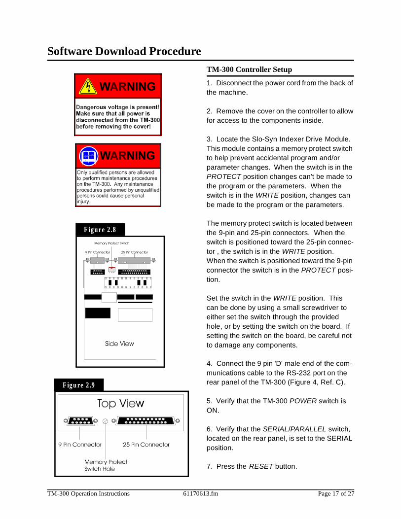
Software Download ProcedureTM-300 Controller Setup
1. Disconnect the power cord from the back of the machine.
2. Remove the cover on the controller to allow for access to the components inside.
3. Locate the Slo-Syn Indexer Drive Module. This module contains a memory protect switch to help prevent accidental program and/or parameter changes. When the switch is in the PROTECT position changes can’t be made to the program or the parameters. When the switch is in the WRITE position, changes can be made to the program or the parameters.
The memory protect switch is located between the 9-pin and 25-pin connectors. When the switch is positioned toward the 25-pin connec-tor , the switch is in the WRITE position. When the switch is positioned toward the 9-pin connector the switch is in the PROTECT posi-tion.
Set the switch in the WRITE position. This can be done by using a small screwdriver to either set the switch through the provided hole, or by setting the switch on the board. If setting the switch on the board, be careful not to damage any components.
4. Connect the 9 pin 'D' male end of the com-munications cable to the RS-232 port on the rear panel of the TM-300 (Figure 4, Ref. C).
5. Verify that the TM-300 POWER switch is ON.
6. Verify that the SERIAL/PARALLEL switch, located on the rear panel, is set to the SERIAL position.
7. Press the RESET button.
F ig u re 2 .8
F igu re 2 .9

TM-300 Operation Instructions 61170613.fm Page 18 of 27
PC Setup
1. Connect the 9-pin 'D' female end of the communications cable to the COM1 port on a PC (IBM compatible personal computer).
2. Insert TM-300 SOFTWARE disk into PC.
3. Change directory to the drive containing the DOWNLOAD disk.
Download Operation
1. Run the 'MS1.EXE' program on the TM-300 DOWNLOAD disk.
2. Select the 'UTILITY' pull down menu and choose the 'DISK TO INDEXER' option.
3. At the "Program Name" prompt window, type the <drive:> <filename.ext> of the pro-gram to be downloaded.(Example: 'A:TM300EXT.A01' )
4. At the "Indexer ID#" prompt window, verify ID# <1>. Press ENTER and the PC terminal will display the message ‘Transmitting File <filename.ext> to Indexer’. The downloading process takes approximately 20-30 seconds.
(Note: Do not press START or RESET while download transmission is in progress, or the download will be terminated and an error mes-sage will occur).
5. If the error message (‘Indexer 1 did not respond and is unable to accept program’) appears on the screen, ensure that the SET-UP conditions for both the TM-300 and PC are correct and retry the downloading operation.
Software Download Procedure (cont.)When Finished Downloading Program
1. Turn the main power OFF.
2. Once again, disconnect the power cord from the back of the machine.
3. Place the memory protect switch in the PROTECT position.
4. Remove the RS-232 Cable.
5. Replace the cover to the controller.
6. Set the SERIAL/PARALLEL switch to the PARALLEL position so that the machine will run.
7. Replace the power cord and turn the main power ON.
8. Press the RESET and START buttons on the controller to start the program.
Software Modification
The TM-300 Controller Software is factory set with specific default values. However, some applications may require special parameter settings.
The following two (stepper motor) parameters may be changed:�Ramping Profiles:
0- Trapezoidal1- "S"2- Hyperbolic
�Acceleration/Deceleration constant
Additional software modifications may be made for specific applications requiring fea-tures not available in the current software for the TM-300. Contact your V-TEK representa-tive for more detailed information on making software modifications.

TM-300 Operation Instructions 61170613.fm Page 19 of 27
Setup
Taping Assembly Setup
1. Mount Heat Sealer Assembly (Fig. 2.2, Ref. T)A sealer must be used which matches the width of the carrier tape being used. To remove an existing sealer, turn the sealer air pressure switch OFF, disconnect the sealer connector, and remove the two bolts which secure the sealer to the up-right plate. Care-fully lift the sealer away from the upright plate.
*CAUTION*-Sealers which have been in use will be hot. Serious burns can result if the heat shoes are touched.
When mounting a new sealer, first inspect the up-right plate where the sealer is mounted to make sure all of the O-rings are in place. There are (5) O-rings at the places shown which must be in place for the sealer to func-tion properly. Replace any missing or dam-aged O-rings. A small amount of glue can be used to secure the O-rings in their holes if they are replaced.
Carefully lower the new sealer into position. Do not hit the exposed corners of the loading track with the sealer or they may be damaged. Run the sealer connector and cord over the top of the up-right plate and plug the connec-tor into the receptacle on the back of the con-troller. Secure the sealer with its two mounting bolts.
There is a cover tape guide which accompa-nies every sealer (Fig. 2.2, Ref. S). When changing sealers, this guide must also be changed. To do so, remove the knurled, metal knob which secures it in place and slide the guide straight off. Once the new sealer is in place, mount the new cover tape guide, mak-ing sure its marked tape width matches that of the sealer.
F igu re 2 .10

TM-300 Operation Instructions 61170613.fm Page 20 of 27
2. Load the Cover TapeRemove the large black knob from the cover tape spindle (loosen the brass set screw if necessary). Remove the spring, washer, and front plastic cover from the spindle. Place a reel of cover tape (correct width to match the carrier tape) on the reel center, so the tape unwinds to the right from the bottom of the reel. Replace the plastic cover, washer, spring, and black knob. Tighten the knob until there is some tension on the cover tape as it unwinds, but make sure the tension is not excessive. Tighten the brass set screw on the black knob to secure it in place.
3. Load the Carrier TapeRemove the carrier tape clamp (Fig. 2.2, Ref. L) from the carrier tape spindle (Fig. 2.2, Ref. K) and mount the bulk carrier tape reel on the spindle (the sprocket holes on the carrier tape must be on the inside). Replace the clamp and position it so the reel is supported and spins freely on the spindle. Trim the end of the carrier tape so it is clean and straight.
The loading track (Fig. 2.2, Ref. P) is adjust-able for tape width. Set the track width to match the sealer mounted on the TM-300 by pulling out, or pushing in, evenly on both ends of the track. There are detents which will cause the track to lock in at each tape width.
Open the parts cover (Fig. 2.2, Ref. Q) by lift-ing on the black knob and remove carrier tape guide #2 (Fig.2. 2Ref. R) by unscrewing its black knob. Guide the carrier tape under car-rier tape guide #1 (Fig. 2.2, Ref. N) and into the loading track. The carrier tape should feed through the loading track easily. Lower the feed reel support arm if necessary to allow the tape to feed more easily into the loading track. Bring the end of the tape just up to cover tape guide #3 (Fig. 2.2, Ref. S).
Setup (cont.)
F igu re 2 .11

TM-300 Operation Instructions 61170613.fm Page 21 of 27
Setup (cont.)4. Load Tapes into SealerPull the cover tape down through the cover tape guides as shown. Pull about 12” of cover tape out and lay it over the carrier tape, with the free end pointing toward the sealer. The shiny side of the tape should be up. Allow about 2” of the free end of the cover tape to hang over the end of the carrier tape. Push the tapes under the cover tape guide and through the sealer by pushing on the carrier tape. Keep enough slack in the cover tape so it follows the carrier tape through the sealer.
Lift the idler wheel (Fig. 2.2, Ref. E) by push-ing down on the left side of the arm. Align the sprocket holes in the carrier tape over the pins on the drive sprocket (Fig. 2.2, Ref. F). Straighten the cover tape so it is aligned with the carrier tape and rewind any remaining slack back onto the cover tape reel. Position the cover tape so it is running in the groove in cover tape guide #3. Replace carrier tape guide #2 and screw it down. Close the parts cover.
5. Mount Take-up ReelMount an empty take-up reel on the take-up reel spindle (Fig. 2.2, Ref. H). The width of the reel must match the width of the carrier tape and the reel must be big enough around to accommodate the number of components in the taping job.
F igu re 2 .12
F igure 2 .13

TM-300 Operation Instructions 61170613.fm Page 22 of 27
All four factors may be varied on the TM-300 but only the dwell time, seal pressure, and temperature setting changes are usually required. The seal width is selected at the fac-tory and should only require changing under unusual circumstances. The settings in the chart are good general starting points to be used when first learning to use the TM-300. Experience will suggest variations from these settings that will provide the desired seal char-acteristics as determined by a peel force test.
Setup (cont.)
General Seal Setting Information
The cover tape peel force is determined by four things at the time the cover tape is sealed to the carrier tape.
These four factors are:1. The width of the sealing track on the heat seal shoe.2. The pressure applied to the seal area.3. The dwell time, or heating time that the heat shoe is pressing on the cover tape.4. The temperature of the seal assembly.
Approximate Starting Points for Seal Controls
CACACACARRRRRRRRIEIEIEIERRRR
TTTTAPAPAPAPEEEE TYTYTYTYPPPPEEEE
CCCCOVOVOVOVEEEERRRR
TTTTAPAPAPAPEEEE TYTYTYTYPPPPEEEE
TTTTEEEEMPMPMPMPEEEERRRRAAAATUTUTUTURERERERE
IIIIN CN CN CN CEEEELLLLSSSSIIIIUSUSUSUS
PPPPRRRRESSESSESSESSUUUURRRREEEE
ININININ PPPPSSSSIIII
DWDWDWDWEEEELLLLLLLL SETTINSETTINSETTINSETTINGGGG
SSSSEEEECCCCOOOONDNDNDNDSSSS3M TYPE 3000
CONDUCTIVE
CARRIER
3M TYPE 2673, 2675
CONDUCTIVE
COVER180° 40 0.40
3M TYPE 2701/2703
NON-CONDUCTIVE
CARRIER
3M TYPE 2653
NON-CONDUCTIVE
COVER140° 40 0.30
3M TYPE 2701/2703
NON-CONDUCTIVE
CARRIER
3M TYPE 2672
NON-CONDUCTIVE
COVER170° 40 0.40
3M TYPE 3000
CONDUCTIVE
CARRIER
3M TYPE 2672
NON-CONDUCTIVE
COVER185° 40 0.30
ADVANTEK
CONDUCTIVE
CARRIER
ADVANTEK
TYPE AA
COVER150° 40 0.40
ADVANTEK
NON-CONDUCTIVE
CARRIER
ADVANTEK
TYPE S
COVER170° 40 0.40
***Use this chart as a guide for setting the controls for the first time. These values may need to be altered due to variations in lot materials and customer requirements.***

TM-300 Operation Instructions 61170613.fm Page 23 of 27
Setup (cont.)Temperature Controls (cont.)
Increment Key (Ref. E)When pressed, increases the set temperature value. Successively increases the value when held down.
Decrement Jey (Ref. F)When pressed, decreases the set temperature value. Successively decreases the value when held down.
Return Key (Ref. G)Each time pressed, changes the readout on the main display as shown in Figure 2.15.
Present Data Indicator (Ref. H)“SP” lights while the set temperature is dis-played.
Setting the Temperature Controller1. Press the Return key until the “SP” inicator
lights.2. Adjust the value by pressing the ( )
or ( ) keys until the desired set temper-ature is displayed.
3. Press the Return key again to display the current temperature.
There is one temperature controller for the inside heat shoe and one for the outside heat shoe. Normally the two controllers should be set with the same values, but they can be set differently if the seal characteristics dictate that the one controller needs to be set higher than the other.
Error MessagesIf there is a fault (short or open) in the temper-ature sensor (thermocouple) of the sealer, the display will flash “ “ or “ “. This error message will also be displayed if there is no sealer connected to the TM-300.
F ig u re 2 .1 4
Current Temperatur e
Set Temperature
Alarm Value
F igu re 2 .15
OMRON E 5 C S
���
Ref. A Ref. B
Ref. C
Ref. D
Ref. E
Ref. F
Ref. G
Ref. H
Temperature Controls (Figure 2.14)
Led Deviation Indicator (Ref. A)The ( ) indicator lights when the current tem-perature is higher than the set temperature. The ( ) indicator lights when the current tem-perature is lower than the set temperature. The ( ) indicator lights up green when the current temperature is within the steady state range of the PID cycle.
Main Display (Ref. B)Sequentially displays the present temperature, set temperature, and an alarm value each time the RETURN key (Ref. G) is pressed.
Control Output Indicator (Ref. C)Lights while the control output is being pro-duced.
Alarm Indicator (Ref. D)If the present temperature exceeds or falls below the set temperature, by the alarm value, this indicator will light. This feature is not implemented on the TM-300 Controller.
TM-300 Operation Instructions 61170613.fm Page 24 of 27
Setup (cont.)
F igure 2 .16
F igure 2 .17
F igu re 2 .18
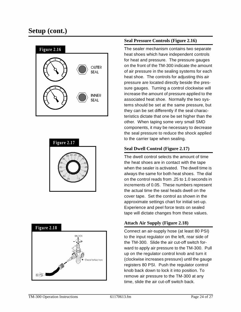
Seal Pressure Controls (Figure 2.16)
The sealer mechanism contains two separate heat shoes which have independent controls for heat and pressure. The pressure gauges on the front of the TM-300 indicate the amount of air pressure in the sealing systems for each heat shoe. The controls for adjusting this air pressure are located directly beside the pres-sure gauges. Turning a control clockwise will increase the amount of pressure applied to the associated heat shoe. Normally the two sys-tems should be set at the same pressure, but they can be set differently if the seal charac-teristics dictate that one be set higher than the other. When taping some very small SMD components, it may be necessary to decrease the seal pressure to reduce the shock applied to the carrier tape when sealing.
Seal Dwell Control (Figure 2.17)
The dwell control selects the amount of time the heat shoes are in contact with the tape when the sealer is activated. The dwell time is always the same for both heat shoes. The dial on the control reads from .25 to 1.0 seconds in increments of 0.05. These numbers represent the actual time the seal heads dwell on the cover tape. Set the control as shown in the approximate settings chart for initial set-up. Experience and peel force tests on sealed tape will dictate changes from these values.
Attach Air Supply (Figure 2.18)
Connect an air-supply hose (at least 80 PSI) to the input regulator on the left, rear side of the TM-300. Slide the air cut-off switch for-ward to apply air pressure to the TM-300. Pull up on the regulator control knob and turn it (clockwise increases pressure) until the gauge registers 80 PSI. Push the regulator control knob back down to lock it into position. To remove air pressure to the TM-300 at any time, slide the air cut-off switch back.

TM-300 Operation Instructions 61170613.fm Page 25 of 27
Operation
F igu re 2 .19
F igure 2 .20
Refer to Figures 2.19 and 2.20 for information on this page.
Initial Procedures
1. Set the Take-up Reel Adjust control to 0 (fully CCW).
2. Turn the TM-300 main power switch ON.3. Perform the Taping Assembly Setup pro-
cedures described in this manual.4. Set the Counter Module Preset and Pres-
cale values.5. Set the sealer controls at the appropriate
levels. Wait for the temperature controls to stabilize near their set temperature.
To move the cover tape in relation to the car-rier, loosen the knob on cover tape guide #3 and pull the guide slightly away from the adjustment dial so the dial will turn freely.
Turning the dial clockwise will move the cover tape closer to the sprocket holes on the inside edge of the carrier (ten divisions on the dial will move the tape .005 inches).
Turning the dial counter-clockwise will move the cover tape closer to the outside edge of the carrier (ten divisions on the dial will move the tape .005 inches).
Push the tape guide back against the dial after the adjustment has been made and tighten the knob. Run the tape out again until the cover tape stops shifting and check the align-ment. Repeat this procedure until the proper alignment has been achieved.
Peel ForceIn most taping applications a peel force test is needed to determine the seal characteristics. Take as many peel force tests as are needed, while adjusting the sealer controls, to obtain the desired seal.
TM-300 Operation Instructions 61170613.fm Page 26 of 27
Placing PartsStarting with the left-most pocket, place a part in each empty pocket for the full length of the loading track. Close the parts cover (Fig.2.2, Ref. Q) if desired. Press on the foot switch to advance the carrier tape through the taping assembly. Stop the tape advance prior to an empty pocket reaching carrier tape guide #2 and refill the carrier tape in the loading track. Repeat until the trailer has advanced to a posi-tion where the end of the sealed tape reaches the take-up reel and attach it to the inside hub of the reel. Adjust the take-up reel tension with just enough tension to wrap the tape on the take-up reel. DO NOT APPLY EXCESSIVE TENSION. Use only enough tension to wrap the tape. Adjust tension as needed as parts are added. Continue taping parts until the counter module reaches its Preset value and stops the tape advance.
To End Taping
PresetWhen the End Count value on the counter module is reached, the TM-300 will stop. The last part to pass under carrier tape guide #2 will be the last part counted. Any additional parts in the loading track must be removed.
ResetPress the RST button on the counter module to enable taping of the leader.
LeaderSeal the desired number of empty pockets. When the last sealed empty pocket has cleared the drive sprocket, cut the tape just to the left of the sprocket.
Operation (cont.)To Begin Taping
Leader/TrailerBefore beginning a production reel, you must decide how long the trailer and the leader need to be.
Trailer - The strip of empty pockets needed at the end of the reel.Leader - The strip of empty pockets needed at the beginning of the reel to feed into a pick and place machine.
The trailer of each reel is taped first. After the cover tape alignment and any peel force tests are completed, run out enough sealed empty pockets to make the trailer. After the trailer is taped, check the counter display to ensure it reads 0. If not, press the counter module RESET button.
Tape AlignmentTo ensure an accurate count, the first pocket in the loading track (left-most) must be a full pocket. That is, the left-most edge of the pocket must be aligned with the right edge of carrier tape guide #2 (Fig. 2.2, Ref. R). If a full pocket is not showing, lift the carrier tape free of the drive sprocket and move it back until a full pocket is showing, then engage the carrier tape on the drive sprocket at that point.
Counter EnableVerify that the COUNTER ENABLE SWITCH is UP and that the counter has been reset.

TM-300 Operation Instructions 61170613.fm Page 27 of 27
Maintenance
F igure 2 .21
Seal Assembly
DO NOT TOUCH THE HEAT SHOE ASSEM-BLY WHEN IT IS HOT! IT WILL STAY HOT ENOUGH TO BURN FINGERS SEVERAL MINUTES AFTER THE SEALER HAS BEEN TURNED OFF!
Heat SealerHeat sealer maintenance consists mainly of cleaning built-up residues from the heat shoes. These residues occur due to a mixture of dust, tape debris, and cover tape adhesive which accumulate during taping. Remove the two bottom screws holding the heat shield to the sealer. Be careful not to lose the O-rings which are under the head of these screws and between the heat shield and the anvil. Remove the two bolts which hold the anvil to the sealer assembly. Remove the anvil by sliding it to one side.
*CAUTION* - DO NOT USE ALCOHOL ON A HOT SEALER.
Clean the residues from the heat shoes by using a plastic or brass brush soaked in alco-hol. DO NOT USE A STEEL BRISTLED BRUSH. If there are some tough spots, such as melted plastic, which do not want to come clean, the sealer can be heated by plugging it into the taping machine, and then scraped with the handle of a wood brush or some other wooden implement.
AlignmentIf the seal becomes uneven, where one end of the heat shoe seems to be striking harder than the other, DO NOT DISASSEMBLE THE HEAT SHOE ASSEMBLY. To realign the heat shoes the sealer must be sent back to the factory.
O-RingsThere are five O-rings between the sealer assembly and the seal assembly up-right which provide a seal between the two for the air pres-sure that drives the sealer. When changing sealer assemblies, check that these O-rings are in place and not damaged. When replacing, place a small amount of adhesive, such as super glue, on the O-ring before inserting into the recess. Make sure that the airway is not blocked.
Tape Path
Loading TrackOccasionally, when the machine is stripped and cover tape guide #3 is removed, brush the dust and debris from the track with a small, stiff bris-tled paint brush.
Cover Tape Guide #3This may become coated with adhesive and dirt during taping. It is important to keep the tape groove clean for proper alignment of the cover tape. Clean the tape groove with alcohol and a cotton swab whenever it appears dirty.
Encoder WheelThe slotted wheel and adjacent sensors may become covered in dust and debris which may cause erroneous counting. Brush these off with a stiff bristled brush whenever they appear dirty.
Air Pressure RegulatorInspect the air regulator for moisture accumula-tion (see page 22). Check periodically depend-ing on air quality and press the petcock on the bottom of regulator to release the fluid if mois-ture is present.

TM-300 Index 61201910.FM Page 1 of 2
TM-300Index
Numbers 115vac (ac power input) 13Aadjustable loading track 9air pressure on/off switch 9air pressure regulator 27air regulator 13alarm indicator 23alignment 27approximate starting points
for seal controls 22assembling procedure 6, 7attach air supply 24attention 3Ccarrier tape quide #1 9carrier tape guide #2 9carrier tape type 22carrier tape quick lock 9caution 4changing the end count value
15control module 6control module base plate 6control output indicator 23controller operation 16controller setup 17count 12count enable switch 14count sensor 10counter 12counter controls 14counter enable 26counter module 14cover tape alignment 26cover tape guide #1 6, 9cover tape guide #2 9cover tape guide #3 10, 27cover tape reel spindle 9cover tape reel support 6cover tape type 22crushed hand
Ddangerous voltage 3, 4download operation 18drive motor 10drive sprocket 9dwell 12, 16dwell setting seconds 22Eencoder wheel 27ent (enter) 14error messages 23Ffeed reel support arm 6follower track support arm 6,
10fsw (footswitch) 13, 16fuse 13fwd button 11, 16Ggeneral seal setting informa-
tion 22Hheat sealer 27heat sealer assembly 10high temperature 3Ii/o (input/output) 13idler arm 10idler wheel 9increment/decrement key
(+/-) 14, 23initial procedures 25inner seal 12Jjog mode (tape adjust) 16jog/run switch 11Lleader 26led deviation indicator 23load tapes into the sealer 21load the carrier tape 20load the cover tape 20loading track 27
Mmain display 23maintenance 27marking definitions 3mechanical assembly 9, 10mount heat sealer assembly
19mount take-up reel 21Nnext digit 14Oopen book 3operation 25, 26operation instructions 5operating controls 11-13outer seal 12o-rings 19, 27Ppc setup 18parts cover 9peel force 26peripheral 13pitch 12, 16pitch setting guide 9placing parts 26power switch 11present data indicator 23preset 26pressure in psi 22pst (preset select) 14Rrst (reset) 13, 14, 26rev button 11, 16rs-232 connector 13run mode 16

TM-300 Index 61201910.FM Page 2 of 2
TM-300Index
Ssafety introduction 2safety instructions 1-4seal 12seal assembly 27seal assembly/motor upright
plate 10seal dwell control 24seal pressure adjust controls
9seal pressure controls 24seal pressure gauges 9sealer 13serial/parallel switch 13setting the counter 15setting the temperature con-
troller 23setup 19-24slo-syn indexer drive module
17software download procedure
17, 18software modification 18start button 12start-up procedure 16stop button 11, 16Ttake-up reel drive arm 6take-up reel drive motor 9take-up reel spindle 9tape alignment 26tape guide #3 9tape path 27tape speed 12, 16taping assembly setup 19temperature controls 12, 23temperature in celsius 22tension adjust (take-up
motor) 11to begin taping 26to end taping 26trailer 26

TM-300 Addendum 61170710.fm Page 1 of 1
This software modification allows additional tape PITCHes to be used (36, 40, 44, 48, 52 & 56mm).
To use this extended capability, the program, ‘TM300EXT.A01’, must be downloaded to the TM-300 controller. Follow the Software Download procedure on page 15 of the Operator’s Manual.
Page 13 of the TM-300 Operator’s Manual shows the index/seal capability of the current factory default program ‘TM300.A01’
The modified program, ‘TM300EXT.A01’, allows extended index/seal capability (shown below in boldface)Substitute this extended table below for the one located on page 13 of the Operator’s Manual.
Example sequence of events for PITCH=56.1. Tape sprocket advances 28mm.2. Seal is issued.3. Tape sprocket advances another 28mm.4. Add one count to the counter.5. Final Seal is issued.
AddendumTM-300 Extended Software Modification
PITCH INDEX (mm) COUNT
4 16 4
8 16 2
12 12 1
16 16 1
20 20 1
24 24 1
28 28 1
32 16 (x2) 1
PITCH INDEX (mm) COUNT
4 16 4
8 16 2
12 12 1
16 16 1
20 20 1
24 24 1
28 28 1
32 16 (x2) 1
36 18 (x2) 1
40 20 (x2) 1
44 22 (x2) 1
48 24 (x2) 1
52 26 (x2) 1
56 28 (x2) 1

751 Summit AvenueMankato, MN 56002
(507) 387-2039 FAX: (507) 387-2257
www.VTEKUSA.comE-Mail: [email protected]
