tm 5-2590-512-13&p operator, unit maintenance, and …tm 5-2590-512-13&p technical manual...
TRANSCRIPT

TM 5-2590-512-13&P
OPERATOR, UNIT MAINTENANCE,AND
DIRECT SUPPORT MAINTENANCEMANUAL
(INCLUDING REPAIR PARTS AND SPECIAL TOOLS LIST)
FOR
EARTH AUGER ASSEMBLY
MODEL 1650EH-MS
LOWE Manufacturing CompanyNSN 2590-01-384-6857
P/N 1650 EH-MSCONTRACT DAAE07-93-C-1034
CAGEC ONAG9
Approved for Public Release; Distribution is Unlimited
HEADQUARTERS, DEPARTMENT OF THE ARMY16 January 1995

WARNINGRead and understand this TM before operating orservicing the auger.
Read and understand starting, warm-up, and diggingprecautions in cold climates or under unusual climate orterrain conditions.
WARNINGHydraulic fluid under pressure can penetrate the skin ordamage eyes. Fluid leaks under pressure may not bevisible. Never use a bare hand to feel for leaks.
Hydraulic fluid, forced into the skin under pressure, mustbe removed by a doctor familiar with this injury andwithin a few hours.
Always wear safety goggles to protect eyes. Ensurehydraulic fluid power source is disconnected prior toservicing any component
DISPOSE OF HYDRAULIC FLUID PROPERLY.Contact your Environmental Coordinator for informationon proper use and disposal of fluid.
WARNINGDo not connect hydraulic quick disconnect fittings if SEEengine is running and operator is seated on SEE vehicle.
Hydraulic pressure remaining after SEE engine is offcould cause unexpected auger rotation resulting inserious injury or death.
Depressurize system by shutting off SEE engine andoperating all auger controls, several times, thru full rangeof motion, until no motion is felt from boom orstabilizers.
DISPOSE OF HYDRAULIC BRAKE FLUID PROPERLY.Contact your Environmental Coordinator for informationon the proper use and disposal of Brake Fluid.
WARNING/Prior to digging in developed areas, check with localutility authorities for locations of underground utilitylines
WARNING
Listen for unusual noises when digging. Stop andinvestigate source.
WARNING/Do not operate auger with loose, worn, damaged,missing, or unusable safety covers. Replace defectivesafety covers prior to operating auger.
WARNINGLocate safety labels and read them. Replace damagedlabels.
WARNINGEnsure all lynch, hitch pin clips, cotter pins, and otherretaining pins are in place and locked.
WARNINGAuger operator can not view auger hole site from his SEEseat position if hole being dug is in line with boom.Recommended position of boom Is 10 to 11 o'clock orfrom 1 to 2 o'clock position.
WARNINGDo not operate Earth Auger Assembly if hydraulic hosesare worn thru outer cover, kinked, or leaking fluid.
Tighten leaky fittings, or replace if defective. Alwayshand start threaded connectors prior to tightening withtools.
WARNINGOperate auger only when SEE vehicle is on fiat firmground. Do not operate auger when SEE vehicle is tipped(as on a hill side or sloping ground).
WARNINGDo not modify equipment because damage or injurycould occur.
WARNINGTo transport Auger Drive Unit fold boom to loweredposition, and tie Auger Drive Unit i rest position on SEEvehicle.
WARNINGDo not operate auger until all personnel are at least 10feet away from rotating auger and cutting head.
WARNINGDo not wear loose fitting clothing.
WARNINGDry cleaning solvent P-D-680 is toxic. Notify yourEnvironmental Coordinator before using. EnvironmentalCoordinator will refer to the Materiel Safety Data Sheets(MSDS) for instructions on proper use, cautions, storage,disposal, or less hazardous cleaning solvents.
Dry cleaning solvent P-D-680 is toxic and flammable.Wear protective gloves, face mask, and gloves, and useonly in a well ventilated area. Avoid contact with skin,eyes, and clothes. Don't breathe vapor. Do not use nearopen flame or excessive heat. The flashpoint for TYPE Idry cleaning solvent is 100°°F (38°°C), and for Type II it is140°°F (60°°C) if you become dizzy while using cleaningsolvent, get fresh air immediately and get medical aid. Ifcontact with eyes is made flush eyes with water and getimmediate medical attention.
WARNINGObserve lift limits of personnel when moving or installingAuger Drive Unit or Auger. Use a lifting device whenavailable.
TM 5-2590-512-13&P
Technical Manual HEADQUARTERSNo. 5-2590-512-13&P DEPARTMENT OF THE ARMY
Washington, DC, 16 January 1995
OPERATOR, UNIT MAINTENANCE,AND
DIRECT SUPPORT MAINTENANCE
MANUAL
(INCLUDING REPAIR PARTS AND SPECIAL TOOLS LIST)FOR
EARTH AUGER ASSEMBLYMODEL 1650 EH-MS
LOWE Manufacturing CompanyNSN 2950-01-384-6857
P/N 1650 EH-MS
Contract DAAE07-93-C-1034
CAGEC ONAG9
Current As OfDecember 12,1994
REPORTING OF ERRORS
You can help improve this manual. If you find any mistakes or if you know of a way toimprove the procedures, please let us know. Mail your letter, DA Form 2028Recommended Changes to Publications and Blank Forms, or DA Form 2028-2, locatedin the back of this manual, direct to: Commander, US Army Tank automotive andArmaments Command, ATTN: AMSTA-IM-MMAA, Warren, Ml 48397-5000. A replywill be furnished directly to you.
You may also send DA-Form 2028/2028-2 information to TACOM via E-mail or datafax. Our fax number is DSN 786-6323. Our E-mail address is: [email protected]
Approved for public release; distribution is unlimited
i
TM 5-2590-512-13&P
TABLE OF CONTENTS
CHAPTER 1. INTRODUCTION PageSection I. General Information................................................................................. 1-1Section II. Equipment Description............................................................................. 1-2Section III. Principles of Operation ............................................................................ 1-4
CHAPTER 2. OPERATING INSTRUCTIONSSection I. Description and Use of Operator's Controls.............................................. 2-1Section II. Operator Preventive Maintenance Checks and Services (PMCS) ............ 2-3Section III. Operation Under Usual Conditions........................................................... 2-12Section IV. Operation Under Unusual Conditions....................................................... 2-18
CHAPTER 3. OPERATOR MAINTENANCESection I. Operator Lubrication Instructions ............................................................. 3-1Section II. Operator Troubleshooting Procedures ..................................................... 3-1Section III. Preparation For Operation (Bucket or Earth Auger Use) .......................... 3-1Section IV. Operator Maintenance Procedures .......................................................... 3-2
CHAPTER 4. UNIT MAINTENANCESection I. Repair Parts and Special Tools (RPSTL) ................................................. 4-2Section II. Unit Preventive Maintenance Checks and Services (PMCS).................... 4-2Section III. Unit Troubleshooting Procedures............................................................. 4-4Section IV. Installation of Kit ...................................................................................... 4-6Section V. Unit Maintenance Procedures.................................................................. 4-17
CHAPTER 5. DIRECT SUPPORT MAINTENANCESection I. Repair Hydraulic Motor ............................................................................ 5-1
APPENDIX A Warranty A-1
APPENDIX B Maintenance Allocation Chart (MAC) B-1
APPENDIX C Components of End Item and Basic Issue Items C-1
APPENDIX D Additional Authorization List D-1
APPENDIX E Expendable and Durable Items List E-1
APPENDIX F Repair Parts and Special Tools List (RPSTL) F-1
APPENDIX G Torque Limits G-1
ALPHABETICAL INDEX
ii

TM 5-2590-512-13&P
CHAPTER 1INTRODUCTION
SECTION I GENERAL INFORMATIONPara Page Para Page1-1 Scope 1-1 1-4 Destruction of Army Materiel to1-2 Maintenance Forms, Records, Prevent Enemy Use 1-1
and Reports 1-1 1-5 Preparation for Storage or Shipment 1-21-3 Reporting Equipment Improvement
Recommendations (EIRs) 1-1
SECTION II EQUIPMENT DESCRIPTION AND DATA
1-6 Equipment Characteristics, Capabilities 1-9 Equipment Data 1-4and Features 1-2 1-10 Safety Cautions 1-4
1-7 Location of Major Components 1-21-8 Location of Safety Decals 1-3
SECTION III TECHNICAL PRINCIPLES OF OPERATION
1-11 Earth Auger Assembly 1-4
SECTION I. GENERAL INFORMATION
1-1. Scope.
a. Type of Manual. Operator, Unit, and Direct Support Maintenance Manual (Including Repair Parts and SpecialTools List).
b. Model Number and Equipment Name. LOWE Earth Auger Assembly, Model 1650EH-MS. Attaches to SEEVehicle (Small Emplacement Excavator).
c. Purpose of Equipment. Earth Auger Assembly is used for boring 12" holes in natural earth soil, to a depth ofapproximately 72 inches (6 feet). These holes are used for countermobility, survivability, and sustainmentengineering missions, such as emplacing pumps, slurry and cratering explosives, and setting utility posts andobstacles.
1-2. Maintenance Forms Records and Reports.
Department of the Army forms and procedures used for equipment maintenance will be those prescribed by DAPAM 738-750, The Army Maintenance Management Systems (TAMMS).
1-3. Reporting Equipment Improvement Recommendations (EIRs).
If your Earth Auger Assembly needs improvement, let us know. Send us an EIR. You, the user, are the only onewho can tell us what you don't like about your equipment. Let us know why you don't like the design orperformance, put it on an SF 368 (Product Quality Deficiency Report). Mail it to us at Commander, U.S. ArmyTank-automotive and Armaments Command, ATTN: AMSTA-GF, Warren, MI 483975000. We'll send you areply.
1-4. Destruction of Army Materiel to Prevent Enemy Use.
Refer to TM 750-244-6, Procedures for Destruction of Tank-Automotive Equipment to Prevent Enemy Use.
1-1
TM 5-2590-512-13&P
1-5. Preparation for Storage or Shipment.
Refer to Chapter 4, Section IV, for procedures for preparing Earth Auger Assembly for storage or shipment.
SECTION II. EQUIPMENT DESCRIPTION AND DATA.
1-6. Equipment Characteristics, Capabilities, and Features.
Description. Earth Auger Assembly is attached to and controlled from SEE vehicle. SEE hydraulic pump deliversfluid under pressure, thru hoses, to hydraulic motor in Auger Drive Unit. This provides rotational movement toAuger. Four adjacent teeth (two per side), (10), mounted on cutting head (11), dig hole, as SEE operator lowersboom/dipper and attached Auger into ground. Boom will not obstruct line of vision of Earth Auger Assemblyoperator if hole site is at either 10 to 11 o'clock or 1 to 2 o'clock position.
Characteristics. Earth Auger Assembly is designed to be attached to rear of Small Emplacement Excavator (SEE)and is operated and powered from it. Metric sizes are not used and no special tools are required.
Capabilities and Features. SEE vehicle rear bucket is removed and Auger Drive Unit is installed in its place. EarthAuger Assembly can dig 12" holes in natural earth soil, to depth of approximately 72" or 6 feet.
Short Distance Moving. Earth Auger Assembly may be left attached to SEE vehicle, but it must be tied down ormonitored to minimize swinging.
Long Distance Moving. There is no room or provision on SEE vehicle to secure Auger when moving it longdistances. Disconnect Auger from Auger Drive Unit and transport it in a companion vehicle.
1-7. Location and Description of Major Components.
a. Earth Auger Assembly has two major components-Auger Drive Unit (1) andAuger (2).
b. Auger Drive Unit (1) uses connecting link (3) to interface with SEE dipper.Inside of Auger Drive Unit (1) is hydraulic drive motor, drive chain,sprockets, bearings, and a solid hex shape output shaft. Two 138" hoses (4)are connected thru two quick disconnect fittings into top of Auger Drive Unit.
1. Auger Drive Unit connecting link (3) is a universal type drive couplingand provides constant multi-direction Auger movement during holedigging.
2. Auger shaft (5) is hollow and also hex shape. It slides over solid shaft(6) of Auger Drive Unit.
3. When Auger shaft (5) and Auger Drive Unit shaft (6) are nestled, pin(7) is inserted into aligned holes. Hitch Pin Clip (8) is inserted into pin(7) end hole, (with hitch pin clip loop facing up), to secure partstogether.
4. Front and rear metal covers (9) are safety covers. Greased rotatingparts are kept inside Auger Drive Unit (1) and dirt and contaminantskept out.
5. A spare chain master link is stored on flat washer welded to motorplate inside Auger Drive Unit (1).
c. Auger (2) is spiral shape. Four carbide tipped cutting teeth (10) are boltedto cutting head (11). Center point (12) guides Auger into center of selectedhole.
1-2
TM 5-2590-512-13&P
1-8. Location of Decals.
Safety Warning Decals are located as shown. Duplicate label is located on opposite side of component.
1-3

TM 5-2590-512-13&P
Reference. Always refer to applicable operator's TM for SEE vehicle when operating Earth Auger Assembly.
1-9. Equipment Data.
Operating Range - Hydraulic pressure of Earth Auger Assembly is 2,000 to 3,000 PSI (13,790 to 20,684 Kpa) with oilflow of 14 to 25 GPM (52.9 to 75 LPM (Liters Per Minute)).
Weight. - Earth Auger Assembly weighs 415 lbs. Auger Drive Unit weighs 225 lbs. and Auger weighs 190 lbs.Appropriate personnel or a lifting device is required to lift and move the Auger when it is removed or installed onAuger Drive Unit. Lifting limits of personal must not be exceeded.
1-10. Safety Cautions.
Read and understand SEE operator's manual, and Earth Auger Assembly operator instructions in Chapter 2 of thismanual, before operating or servicing.
Read and understand all safety precautions, instructions, Warnings, and Cautions prior to transporting, setting up,operating, storing or attaching to SEE vehicle. They guide you to avoid injury and machine damage.
Do not connect hydraulic hoses to Auger Drive Unit until it is mounted by connecting link to SEE vehicle.
Ensure hoses are securely mounted in place in their clamps prior to operating boom. Loose hoses are easily trappedand crushed by boom movement.
After digging hole, do not touch foot pedals when hoisting of Auger out of ground or boom will swing and bend Auger.
Wipe dirt off of quick disconnect fittings prior to connecting and use attached dust caps when disconnected.
Use care not to lose hitch pin clip when installing or removing Auger from Auger Drive Unit. Safety reasons do notallow a holding chain to be attached because of Auger rotation.
Observe lift limits of personnel in lifting or moving Earth Auger Unit or Auger. Use a lifting device when available.
Wear heavy gloves when moving or lifting Earth Auger Unit or Auger.
SECTION III. TECHNICAL PRINCIPLES OF OPERATION.1-11. Auger.
Auger Drive Unit and Auger are two components that make up the Earth Auger Assembly. Earth Auger Assembly isconnected to boom/dipper, thru a connecting link, at rear of SEE vehicle in place of bucket. An installation kit adaptsone bucket control lever so that moving it will it cause Auger to rotate clockwise or counterclockwise.
a. Auger Drive Unit.
Auger Drive Unit contains chain driven sprockets that rotate attached Auger at high torque output. Auger isdriven by an internal hydraulic motor using fluid under pressure delivered through hoses from attached SEEvehicle hydraulic pump. Quick disconnect fittings, on hydraulic hose ends, allow removing rotational source, forsafety reasons, when servicing.
b. Auger.
1. Auger is almost seven feet in length, spiral shaped, and can dig a 12 in. diameter hole into natural terrain.To dig, SEE operator, from seat at rear of SEE, moves control levers and foot pedals that move auger intoposition over hole site, lower boom, dipper and rotate Auger.
1-4

TM 5-2590-512-13&P
2. It is preferred that hole site be located to right or left of boom/dipper straight ahead position. Operator canswing boom over and view Auger as hole is being dug.
c. Stabilizers
Stabilizer arms, left and right, operated by control levers, extend from the SEE vehicle, to minimize SEE vehiclemovement and provide firm support during auger movement.
1-5
TM 5-2590-512-13&P
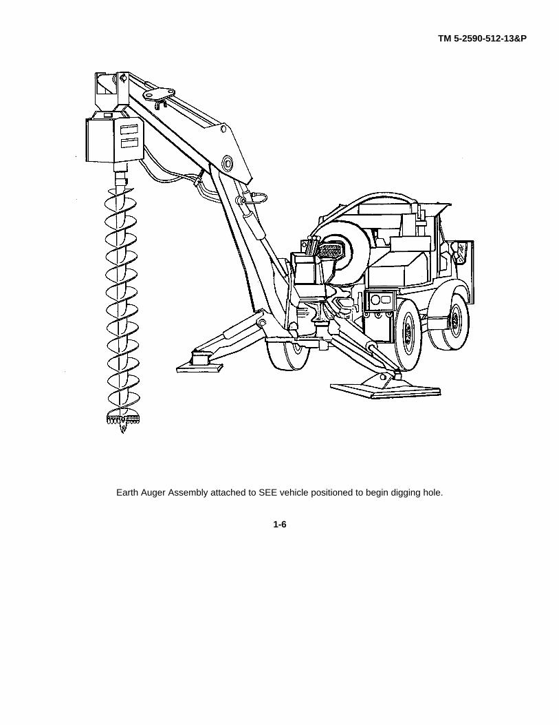
Earth Auger Assembly attached to SEE vehicle positioned to begin digging hole.
1-6
TM 5-2590-512-13&P
CHAPTER 2OPERATING INSTRUCTIONS
SECTION I DESCRIPTION AND USE OF OPERATOR'S CONTROLS.
Para Page Para Page2-1 General 2-1 2-2 Controls (Levers on SEE) 2-2
SECTION II OPERATOR PREVENTIVE MAINTENANCE CHECKS AND SERVICES (PMCS)
2-3 General PMCS Information 2-3 2-6 Leakage Definitions 2-32-4 PMCS Procedures 2-3 2-7 PMCS Tables 2-52-5 Explanation of Columns 2-3
SECTION III OPERATION UNDER USUAL CONDITIONS
2-8 Installation and Preparation for Use 2-12 2-11 Decals and Data Plates 2-172-9 Operating the Auger 2-14 2-12 Adjustments and Self Tests 2-172-10 Preparation for Movement 2-16 2-13 Emergency Stopping 2-17
SECTION IV OPERATION UNDER UNUSUAL CONDITIONS
2-14 Cold Weather Operation. 2-18
SECTION I. DESCRIPTION AND USE OF OPERATOR'S CONTROLS.
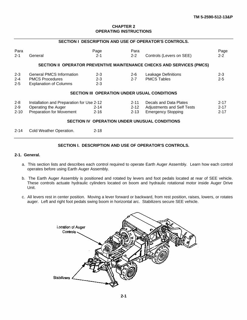
2-1. General.
a. This section lists and describes each control required to operate Earth Auger Assembly. Learn how each controloperates before using Earth Auger Assembly.
b. The Earth Auger Assembly is positioned and rotated by levers and foot pedals located at rear of SEE vehicle.These controls actuate hydraulic cylinders located on boom and hydraulic rotational motor inside Auger DriveUnit.
c. All levers rest in center position. Moving a lever forward or backward, from rest position, raises, lowers, or rotatesauger. Left and right foot pedals swing boom in horizontal arc. Stabilizers secure SEE vehicle.
2-1

TM 5-2590-512-13&P
2-2. Controls
1. Bucket Up-down Switch: Not Used In Auger Operation (Refers To SEE Front Bucket).
2. Engine RPM Control Switch: Increases Engine RPM (Torque) From 750 (Idle) To 2000 RPM.
3. Left Swing Control Foot Pedal: Swings Auger To Left.
4. Left Stabilizer Control Lever: Extends (Push Lever) Or Retracts (Pull Lever) Left Rear Stabilizer.
5. Bucket Control Lever: Rotates Auger Clockwise (Pull Lever Back) Or Counterclockwise (PushLever Forward).
6. Dipper Control Lever: Lowers Auger (Pull Lever Back) Or Raises Auger (Push Lever Forward).
7. Boom Control Lever: Raises Boom (Pull Lever Back) Or Lowers Boom (Push Lever Forward).
8. Right Stabilizer Control Lever: Extends (Push Lever) Or Retracts (Pull Lever) Right Rear Stabilizer.
9. Boom Lock Latch Lever: Locks Boom In Place For Travel.
10. Right Swing Control Foot Pedal: Swings Auger To Right.
2-2
TM 5-2590-512-13&P
SECTION II. OPERATOR PREVENTIVE MAINTENANCE CHECKS AND SERVICES (PMCS).
2-3. General PMCS Information.
Before you operate: Always keep in mind Warnings and Cautions. Read safety decals on Auger Drive Unit andboom. Perform your (B) Before PMCS prior to equipment leaving its containment area or performing its intendedmission.
While you Operate: Keep in mind Warnings and Cautions. Remember decal safety messages on Auger Drive Unitand boom (see para. 1 -8). Perform your (D) During PMCS when equipment is used for its intended mission.
After you Operate: Be sure to perform your (A) After PMCS when equipment has been taken out of mission mode orreturned to containment area.
If your equipment fails to operate: Note unusual operation. Report any deficiencies using proper forms. See DAPam 738-750.
2-4. PMCS Procedures.
Your PMCS table lists inspections and care required to keep your equipment in good operating condition.
If your equipment does not perform as required, refer to troubleshooting procedures in Chapter 3. Report anymalfunctions or failures on DA Form 2404 or refer to DA 738-750.
2-5. Explanation Of Columns.
Item Number. This column lists a logical order for performing PMCS. Use number in this column as '"TM Item No."on DA Form 2404, Equipment Inspection and Maintenance Worksheet, when recording results of PMCS.
Interval: This column tells you how often a certain check or service is to be done.
Item To Be inspected: This column lists portion of equipment to be inspected and specific item being inspected.
Procedures. This column tells you how to do required checks and services. Carefully follow these instructions. Ifyou do not have tools, or if procedure tells you to, have Unit maintenance do task.
NOTE
Both terms "ready/available" and "mission capable" mean that equipment is on hand and able toperform combat mission (See AR 700-138).
Equipment is Not Ready/Available if: This column tells you when and why your equipment cannot be used.
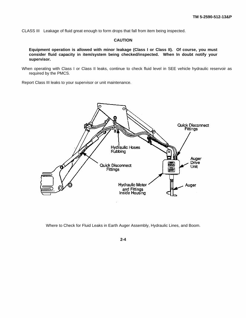
2-6. Leakage Definitions.
It is necessary for you to know how fluid leakage affects the status of your equipment. The following are definitionsof the types/classes of leakage you need to know to determine the status of your Earth Auger Assembly.
LEAKAGE DEFINITIONS FOR OPERATOR PMCS
CLASS I Seepage of fluid (as indicated by wetness or discoloration) not great enough to form drops.
CLASS II Leakage of fluid great enough to form drops but not great enough to cause drops to drip from theitem being inspected.
2-3
TM 5-2590-512-13&P
CLASS III Leakage of fluid great enough to form drops that fall from item being inspected.
CAUTION
Equipment operation is allowed with minor leakage (Class I or Class II). Of course, you mustconsider fluid capacity in item/system being checked/inspected. When In doubt notify yoursupervisor.
When operating with Class I or Class II leaks, continue to check fluid level in SEE vehicle hydraulic reservoir asrequired by the PMCS.
Report Class III leaks to your supervisor or unit maintenance.
Where to Check for Fluid Leaks in Earth Auger Assembly, Hydraulic Lines, and Boom.
2-4
TM 5-2590-512-13&P
2-7. TABLE OF OPERATOR PREVENTIVE MAINTENANCE CHECKS AND SERVICES (PMCS)
Item Item to be Procedure Not Fully MissionNo. Interval Checked or Capable If:
Service
1. Before Earth Auger Assembly Check that Auger Drive Unit thru Pins are bent orMounting at Connecting Connecting Link is mounted to SEE bind in place.Link. dipper and is secured in place by link
pin. Check that oblong head of linkpin is seated against pin stop.
Check that lynch pin is installed thru Either pin worn,end hole in link pin and is in locked elongated holes inposition. connecting link.
Check that cotter pin is installed thru Cotter pinend hole of unit clevis pin and is in missing, endlocked position. broken off, ends
not spread.
Check Connecting Link for bent Rust thru.parts, enlongated pin holes, rustdamage to pipe or defective welds.
2-5

TM 5-2590-512-13&P
2-7. TABLE OF OPERATOR PREVENTIVE MAINTENANCE CHECKS AND SERVICES (PMCS)
Item Item to be Procedure Not Fully MissionNo. Interval Checked or Capable If:
Serviced
2. Before Auger Drive Unit, hex Check that Auger end shaft (hollow) is If not nestled.After drive shaft, nestled over Auger Drive Unit shaft
Auger center shaft, (solid). (Both are hex shape).Hex pin, Hitch pin clip.
Check that hex pin is positioned thru If hex pin orboth shafts. Check that hitch pin clip locking hitch pin(retainer) is inserted thru hole in end of clip is missing.hex pin so that rounded section rests onhex pin side (not over hex pin end) andhitch pin loop is facing Auger Drive Unit.
Check for bent hex pin, bent or missing If any part ishitch pin clip. Bends or cracks in shaft of bent or dam-Auger Drive Unit or shaft of Auger that aged so as towould cause auger to wobble when rotat- cause bindinging. or unsafe opera-
tion.
2-6
TM 5-2590-512-13&P
2-7 TABLE OF OPERATOR PREVENTIVE MAINTENANCE CHECKS AND SERVICES (PMCS)
Item Item to be Procedure Not Fully MissionNo. Interval Checked or Capable If:
Service
3. Before Auger Check that Auger and Auger Drive Unit Hex pin bent orDuring are secured together in their shafts by missing,After hex pin. Check that rectangular shaped rectangle head
head of hex pin is installed thru side of not seated withinshaft having pin stop, and is seated within welded pin stop.pin stop.
Check that hex pin is locked by hitch pin Hitch pin clipclip installed in hole at end of hex pin. bent, loose, orCheck that hitch pin loop faces upward. missing.
Check Auger for cracks, breaks, visible Cracks are seen,wear, or if bent. auger severely
wobbles whenturning, missingor broken metalanywhere onauger.
Pin stop isbroken ormissing.
2-7
TM 5-2590-512-13&P
2-7. TABLE OF OPERATOR PREVENTIVE MAINTENANCE CHECKS AND SERVICES (PMCS)
Item Item to be Procedure Not Fully MissionNo. Interval Checked or Capable If:
Service
4. Before Auger Teeth Check for and tighten loose mounting Carriage bolt rest/During hardware. lock surfaceAfter rounded or nut
threads stripped.
Check for missing or broken Auger Any teeth areteeth. Check each of four cutting teeth broken, missing, orfor wear beyond 1/2 inch radius at worn more than 1/2corner as shown. inch radius.
Check if carbide insert is chipped ormissing.
Before Center Point Check center point for broken guide Center point orDuring points. Replace with BII spare if worn, hardware missing,After or defective. broken, or bent.
NOTE NOTEIn unusual operating Outside teeth will wearconditions check for out faster than inside Check for and tighten loose If hardware isteeth wear after teeth. Their useful life mounting hardware. missing, or bolt orevery hole, otherwise may be extended by rota- nut threadsafter every 10th hole tion of the inside teeth to stripped.
the outside.Check teeth wearevery third hole inhard soil.
2-8
TM 5-2590-512-13&P
2-7. TABLE OF OPERATOR PREVENTIVE MAINTENANCE CHECKS AND SERVICES (PMCS)
Item Item to be Procedure Not Fully MissionNo. Interval Checked or Capable If:
Serviced
5. Before Safety Covers Check that front and rear safety covers Front or rearDuring are in place and mounting bolts are tight. covers areAfter missing,
deformed.
Ensure flat washers and lockwashers are Hardware isnot broken and are in place. missing or
defective.
2-9
TM 5-2590-512-13&P
2-7. TABLE OF OPERATOR PREVENTIVE MAINTENANCE CHECKS AND SERVICES (PMCS)
Item Item to be Procedure Not Fully MissionNo. Interval Checked or Capable If:
Service
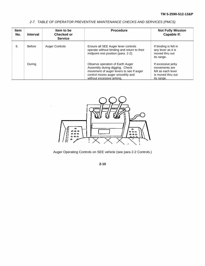
6. Before Auger Controls Ensure all SEE Auger lever controls If binding is felt inoperate without binding and return to their any lever as it ismidpoint rest position (para. 2-2). moved thru out
its range.
During Observe operation of Earth Auger If excessive jerkyAssembly during digging. Check movements aremovement of auger levers to see if auger felt as each levercontrol moves auger smoothly and is moved thru outwithout excessive jerking. its range.
Auger Operating Controls on SEE vehicle (see para 2-2 Controls.)
2-10

TM 5-2590-512-13&P
2-7. TABLE OF OPERATOR PREVENTIVE MAINTENANCE CHECKS AND SERVICES (PMCS).
Item Item to be Procedure Not Fully MissionNo. Interval Checked or Capable If:
Service
7. Before Hydraulic Hoses,During Fittings, and ClampsAfter WARNING
Hydraulic fluid under pressure can penetrate the skin or damageeyes. Fluid leaks under pressure may not be visible. Never use abare hand to feel for leaks.
Hydraulic fluid, injected into the skin under pressure, must beremoved by a doctor familiar with this injury and within a fewhours.
Always wear safety goggles to protect eyes. Ensure hydraulicfluid power source is disconnected prior toservicing any components.
Check for hydraulic leaks at fittings. If Class III Leak.Ensure hoses are secured in brackets andclamps. Check bracket and clamp hard-ware for defects. Ensure clamps are tight.
Check hoses, hose fittings, and couplings Wire meshfor wear due to rubbing. They are OK showing.unless wire mesh inside hose, (secondlayer), is showing.
8. After Auger Clean and remove excess debris beforeAuger Drive Unit storage.
Where hydraulic leaks and loose clamps are most likely to occur.
2-11
TM 5-2590-512-13&P
SECTION III. OPERATION UNDER USUAL CONDITIONS
2-8. Installation and Preparation for Use.
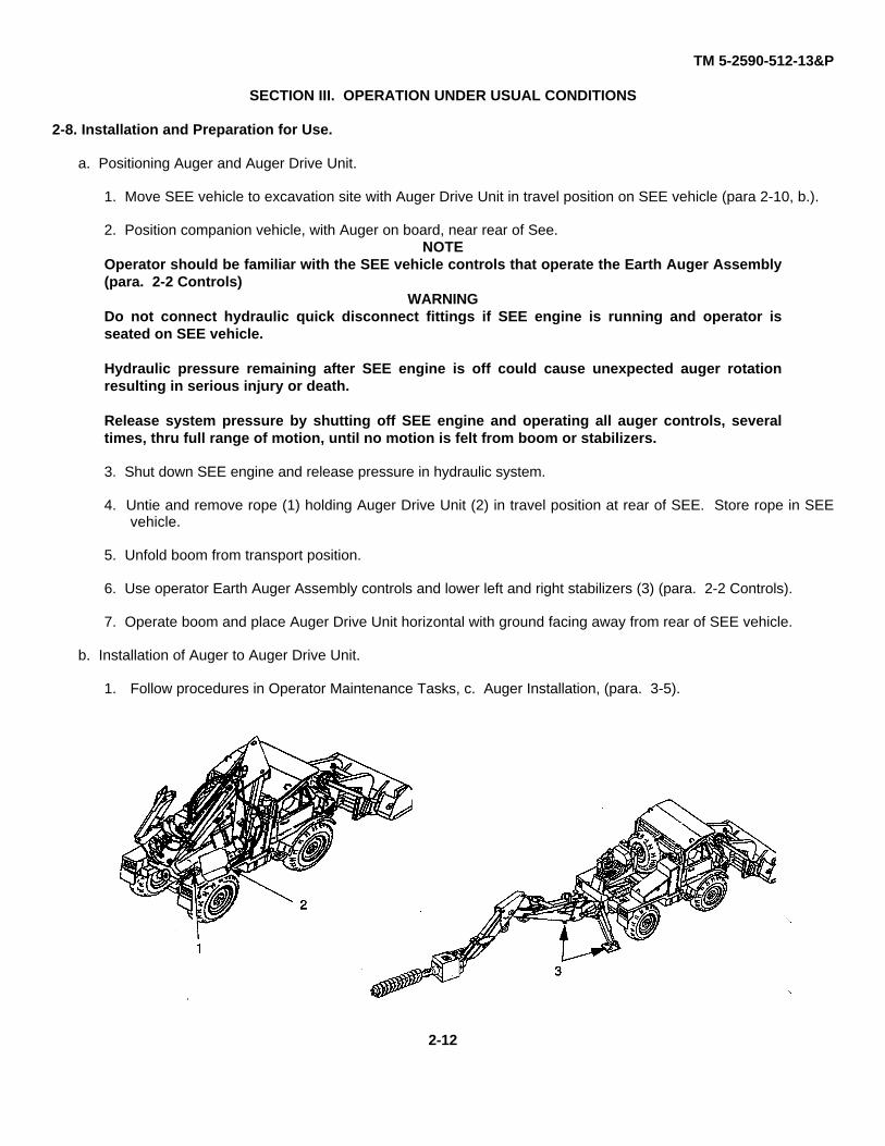
a. Positioning Auger and Auger Drive Unit.
1. Move SEE vehicle to excavation site with Auger Drive Unit in travel position on SEE vehicle (para 2-10, b.).
2. Position companion vehicle, with Auger on board, near rear of See.NOTE
Operator should be familiar with the SEE vehicle controls that operate the Earth Auger Assembly(para. 2-2 Controls)
WARNINGDo not connect hydraulic quick disconnect fittings if SEE engine is running and operator isseated on SEE vehicle.
Hydraulic pressure remaining after SEE engine is off could cause unexpected auger rotationresulting in serious injury or death.
Release system pressure by shutting off SEE engine and operating all auger controls, severaltimes, thru full range of motion, until no motion is felt from boom or stabilizers.
3. Shut down SEE engine and release pressure in hydraulic system.
4. Untie and remove rope (1) holding Auger Drive Unit (2) in travel position at rear of SEE. Store rope in SEEvehicle.
5. Unfold boom from transport position.
6. Use operator Earth Auger Assembly controls and lower left and right stabilizers (3) (para. 2-2 Controls).
7. Operate boom and place Auger Drive Unit horizontal with ground facing away from rear of SEE vehicle.
b. Installation of Auger to Auger Drive Unit.
1. Follow procedures in Operator Maintenance Tasks, c. Auger Installation, (para. 3-5).
2-12

TM 5-2590-512-13&P
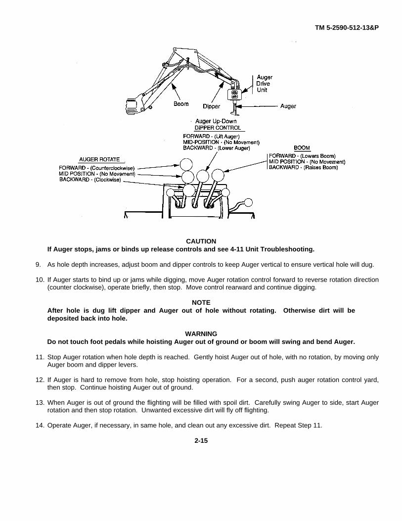
2-9. Operating The Auger.
1. Start SEE vehicle engine. Raise Earth Auger Assembly up into air until auger clears ground para 2-2 Controls).
2. Drive SEE vehicle (short distant only) to hole site. Operate SEE controls and position Auger over hole site.
WARNING
Advise all nearby personnel to move at least 10 feet away from Auger prior to digging.
Before digging, wait until Auger stops swinging and do not rotate Auger, until Auger center pointis touching ground at intended hole site.
Do not back up SEE with Auger attached.
3. Earth auger may be swinging when SEE vehicle is stopped at hole site area. Wait until swinging stops beforeproceding.
2-13

TM 5-2590-512-13&P
4. Position Earth Auger Assembly so that boom/dipper may be moved horizontally and stopped over intended holesite. To be able to see Auger, when digging, locate first hole site in either 10 to 11 or 1 to 2 o' clock position, asshown.
5. Move SEE engine RPM rocker type control switch (1) from "LO" position (Idle) to "HI" (2000 RPM) (para. 2-2Controls).
6. Do not begin hole digging if auger is swinging. Wait until it stops before preceding.
7. Move Auger controls and position Auger center point at center of intended hole. Slowly lower dipper and boomuntil the Auger center point touches ground.
8. Move boom, dipper, and auger rotational lever backward, as needed, to gently rotate and push Auger intoground. If Auger rotation binds or bogs down, ease up on controls and reverse direction (para. 2-2 Controls).
NOTEAuger rotational lever must cause Auger to rotate clockwise when lever is moved backward(towards operator). If rotational direction is reversed, check Auger kit installation for reversedhydraulic hose connections (para. 4-13 thru 4-15).
2-14
TM 5-2590-512-13&P
CAUTIONIf Auger stops, jams or binds up release controls and see 4-11 Unit Troubleshooting.
9. As hole depth increases, adjust boom and dipper controls to keep Auger vertical to ensure vertical hole will dug.
10. If Auger starts to bind up or jams while digging, move Auger rotation control forward to reverse rotation direction(counter clockwise), operate briefly, then stop. Move control rearward and continue digging.
NOTEAfter hole is dug lift dipper and Auger out of hole without rotating. Otherwise dirt will bedeposited back into hole.
WARNINGDo not touch foot pedals while hoisting Auger out of ground or boom will swing and bend Auger.
11. Stop Auger rotation when hole depth is reached. Gently hoist Auger out of hole, with no rotation, by moving onlyAuger boom and dipper levers.
12. If Auger is hard to remove from hole, stop hoisting operation. For a second, push auger rotation control yard,then stop. Continue hoisting Auger out of ground.
13. When Auger is out of ground the flighting will be filled with spoil dirt. Carefully swing Auger to side, start Augerrotation and then stop rotation. Unwanted excessive dirt will fly off flighting.
14. Operate Auger, if necessary, in same hole, and clean out any excessive dirt. Repeat Step 11.
2-15

TM 5-2590-512-13&P
CAUTIONIn normal soil use, operator must check condition of Auger, center point, and teeth every 10thhole. In hard soil and soft limestone, check condition after digging every third or fourth hole(see operator PMCS Table in para 2-7).
2-10. Preparation for Movement.
a. Short Distance Transport.
CAUTIONSEE driver cannot see Auger swing when driving to next nearby hole site. A swinging Augercould smash into rear of SEE and cause damage. Have ground guide advise SEE driver to stopor slow down when Auger begins to swing too much.
Operator must not back up SEE vehicle with Auger attached.
1. Keep Auger attached to Auger Drive Unit when moving short distances, as from hole site to hole site.
2. Raise left and right stabilizers and position Auger to clear ground by 1 or 2 inches.
3. Drive very slowly to next hole site to minimize Auger swinging.
b. Long Distance Transport.
1. Disconnect Auger from Auger Drive Unit when digging site is some distance away, (see OperatorMaintenance Task "Auger Replacement" (para 3-5)).
2. Lock boom using SEE control.
3. Raise both left and right stabilizers.
4. Fold SEE boom into transport position (1). (Refer to SEE vehicle Operator's TM 5-2420-224-10).
5. Using 9 ft. rope (2), tie Auger Drive Unit (3) securely in place to stabilizer and frame (4) to minimizemovement when transporting.
2-16

TM 5-2590-512-13&P
2-11. Decals, Instructions, and Data Plates.
Data plate with Earth Auger Assembly Serial Number is located on top of Auger Drive Unit under the connecting link.Safety Decal locations are shown in paragraph 1-8.
2-12. Adjustment And Self Tests.
There are no adjustments or self tests on Auger.
2-13. Emergency Stopping procedures.
Auger rotation is stopped by moving Auger lever (1) to mid position.
Allow spring loaded control lever (1) to return to rest position at midpoint of travel to stop Auger.
2-17
TM 5-2590-512-13&P
SECTION IV. OPERATION UNDER UNUSUAL CONDITIONS
2-14. Cold Weather Conditions.
a. Follow procedures in Section III, Operation Under Usual Conditions, and observe the following precautions.
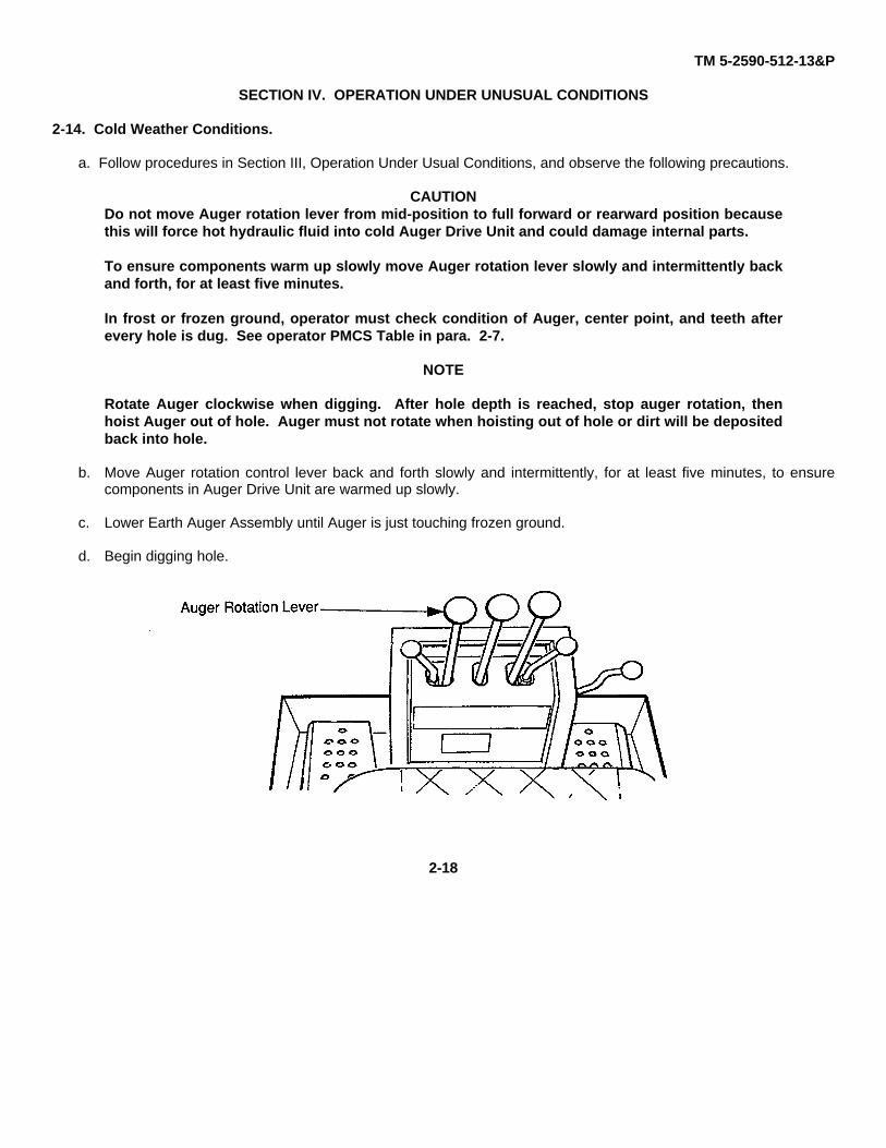
CAUTIONDo not move Auger rotation lever from mid-position to full forward or rearward position becausethis will force hot hydraulic fluid into cold Auger Drive Unit and could damage internal parts.
To ensure components warm up slowly move Auger rotation lever slowly and intermittently backand forth, for at least five minutes.
In frost or frozen ground, operator must check condition of Auger, center point, and teeth afterevery hole is dug. See operator PMCS Table in para. 2-7.
NOTE
Rotate Auger clockwise when digging. After hole depth is reached, stop auger rotation, thenhoist Auger out of hole. Auger must not rotate when hoisting out of hole or dirt will be depositedback into hole.
b. Move Auger rotation control lever back and forth slowly and intermittently, for at least five minutes, to ensurecomponents in Auger Drive Unit are warmed up slowly.
c. Lower Earth Auger Assembly until Auger is just touching frozen ground.
d. Begin digging hole.
2-18
TM 5-2590-512-13&P
CHAPTER 3
OPERATOR MAINTENANCE
SECTION I OPERATOR LUBRICATION INSTRUCTIONS
Para Page
3-1 General 3-1
SECTION II. OPERATOR TROUBLESHOOTING PROCEDURES
3-2 General 3-1
SECTION III PREPARATION FOR OPERATION
3-3 Preparation for Earth Auger Use 3-13-4 Preparation for Backhoe Bucket Use 3-1
SECTION IV OPERATOR'S MAINTENANCE PROCEDURES
3-5 Auger Removal and Installation 3-23-6 Auger Teeth Rotation or Replacement 3-63-7 Auger Center Point Replacement 3-7
SECTION I. LUBRICATION INSTRUCTIONS3-1. General.
There are no operator/crew lubrication requirements. Lubrication is task of Unit maintenance.
SECTION II. TROUBLESHOOTING PROCEDURES3-2. General.
There are no troubleshooting procedures at operator level. Operator will note and report any unusual operatingconditions during PMCS.
SECTION III. PREPARATION FOR OPERATION
3-3. Preparation for Earth Auger Use.
Follow procedures in Chapter 4, paragraph 4-14, for preparation for Earth Auger Assembly Use.
3-4. Preparation for Backhoe Bucket Use.
Follow procedures in Chapter 4, paragraph 4-15, for preparation for Backhoe Bucket Use.
3-1

TM 5-2590-512-13&P
SECTION IV. OPERATOR'S MAINTENANCE TASKS
3-5. Auger Removal and Installation.
This task covers: a. Removal (Flat ground) b. Removal (Rough ground) c. Installation
Initial SetupTools:
Equipment ConditionsSEE vehicle Bll Auger Drive Head attached to SEE vehicle.
Pliers, Item #13, 5120-01-243-5332 Three personnel required, (See Operator,Auger Operator, and Ground Guide).
Materials and Parts:Rags, 9 ft. Rope, Gloves,Silicone Lubricant Spray
a. Removal (Flat ground).
1. Set SEE front wheels straight forward and raise the Earth Auger Assembly until Auger center point is off theground.
2. Raise the SEE front loader and the SEE right and left stabilizers slightly off the ground.
3. Release the SEE vehicle parking brake.
4. Ground guide directs SEE Operator to drive SEE slowly forward as Auger Operator lowers boom/dipper so asto allow Earth Auger Assembly to fall into horizontal position on ground. Ground guide then directs SEEoperator to stop SEE and shut down engine.
3-2
TM 5-2590-512-13&P
WARNING
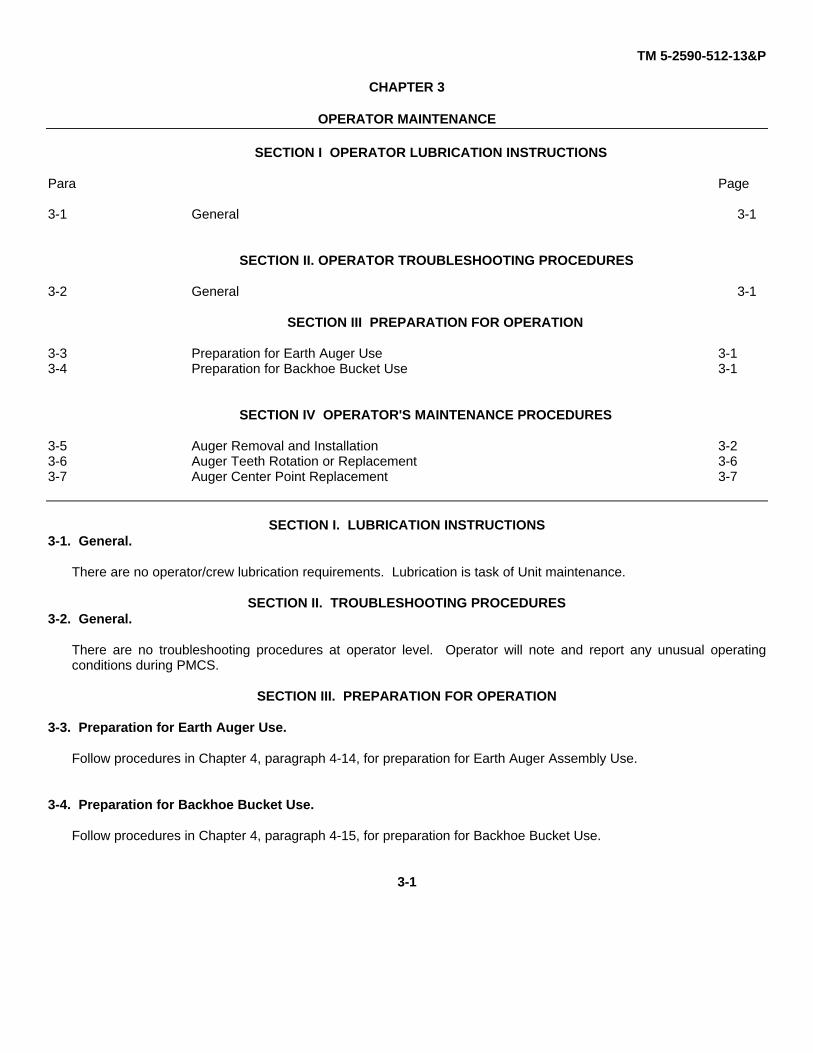
Hydraulic pressure remaining after SEE engine is off could cause unexpected auger rotationresulting in serious injury or death. Prior to separating quick disconnect fittings, release systempressure by operating all auger controls thru full range of motion (para 2.2).
Display auger by separating both quick-disconnect fittings on hydraulic hoseslocated on boom. Expect some fluid tofittings and use rags to control spilling.
5. Separate both quick-disconnect fittings onboth hydraulic hoses (1) located at AugerDrive Unit (2).
6. Remove any excess mud and dirt from thetop area the Auger (4).
7. Remove the Hitch Pin Clip (5) and slide outhex pin (6).
8. Lift and slide Auger (4) away from AugerDrive Unit (2).
9. Store Hex Pin (6) and Hitch Pin clip (5) on Auger (4) output shaft.
WARNING
If moving to next excavation site, lift and transport Auger, with a suitable liftingdevice, and set into bed of companion vehicle. Tie down to secure.
3-3
TM 5-2590-512-13&P
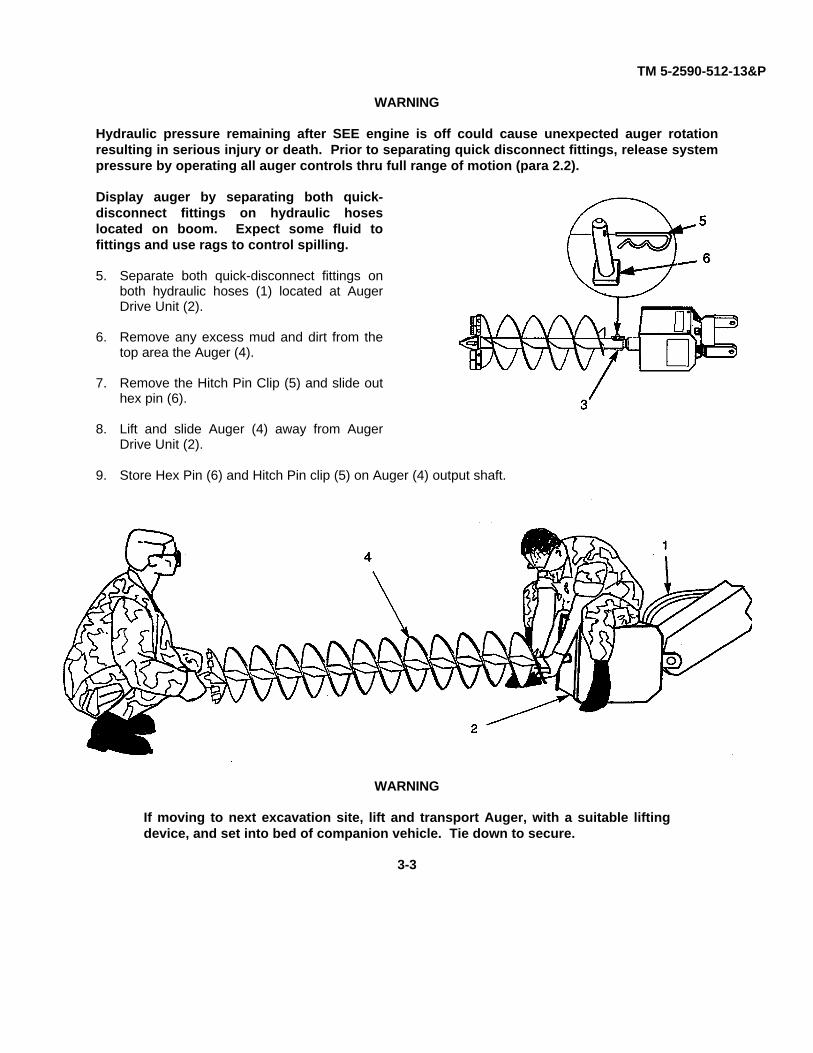
b. Removal (Rough ground).
1. Shut down SEE engineWARNING
Hydraulic pressure remains In system after SEE engine is off and could cause Auger to rotateresulting in serious injury or death. Prior to separating quick-disconnect fittings, depressurizesystem by operating all auger controls thru full range of motion.
2. Disconnect hoses at quick-disconnect fittings at Auger Drive Unit (1). Use rags to control spilling.
3. Attach 9 ft. rope (2), stored in SEE vehicle, to bottom of Auger (3). Stand back about 4 feet and pull on ropeas ground guide directs Auger Operator to start SEE engine and lower boom/dipper so as to allow EarthAuger Assembly (4) to fall into horizontal position on ground.
3-4
TM 5-2590-512-13&P
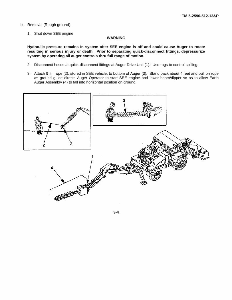
4. Ground guide then directs Auger operator tostop, and shut down engine.
5. Remove any excess mud and dirt from thetop area (1) of Auger (2).
6. Remove the hitch pin clip (3) and slide outhex pin (4) from Auger Drive Unit (5) shaft(6).
WARNING
Use a suitable lifting device orappropriate personnel to moveauger: Use gloves when handlingauger to prevent injury to hands.
7. Lift and slide Auger (2) away from AugerDrive Unit (5).
8. Store Hex Pin (4) and Hitch Pin clip (3) inthru hole on Auger (2) hex shape hollowoutput shaft at top area (1).
9. Move Auger to companion vehicle and secure for transporting.
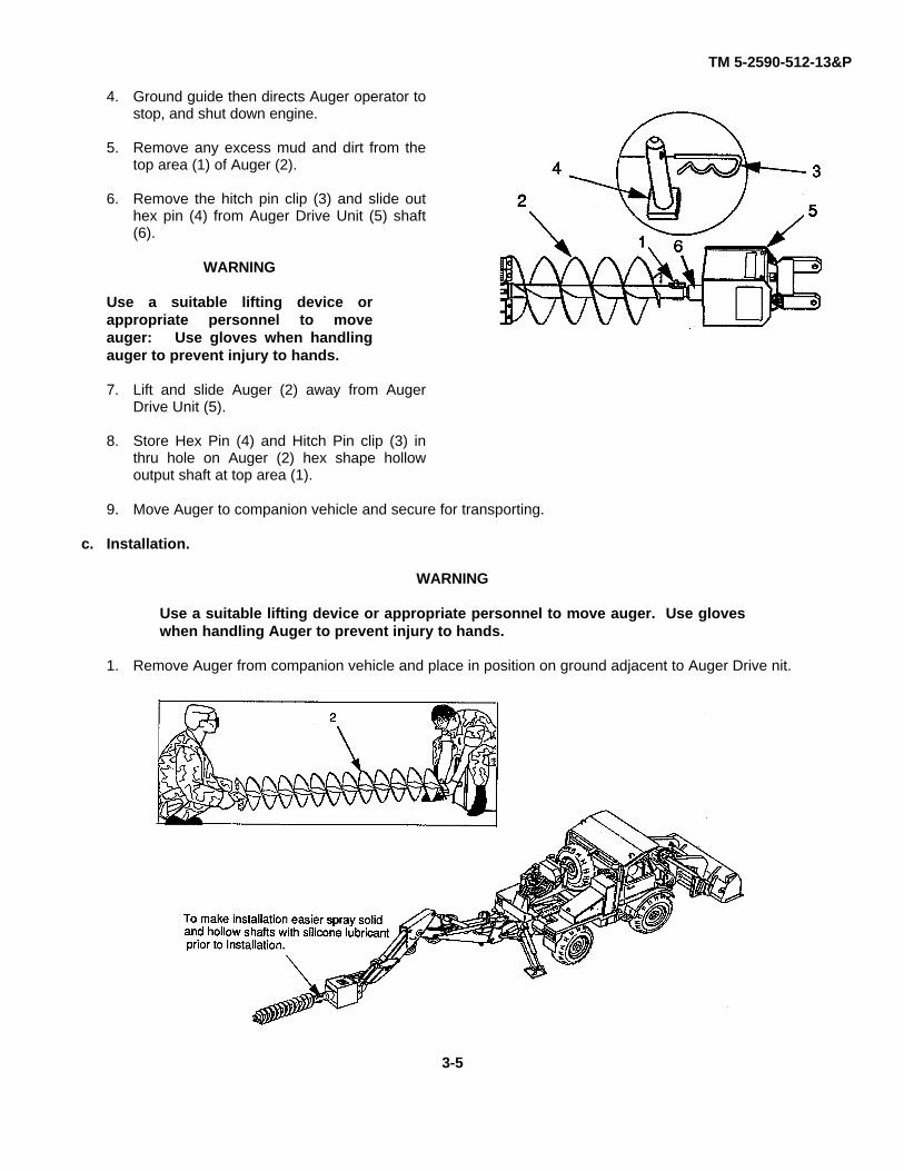
c. Installation.
WARNING
Use a suitable lifting device or appropriate personnel to move auger. Use gloveswhen handling Auger to prevent injury to hands.
1. Remove Auger from companion vehicle and place in position on ground adjacent to Auger Drive nit.
3-5

TM 5-2590-512-13&PNOTE
Install hex pin (4) thru side of augerhollow shaft (1) where raised anti-rotation pin stops are located.Ensure rectangle head of hex pin (4)rests inside of pin stop.
2. Use assistant and align both hex shafts sothat pin holes will be in line. Slide Augerhollow hex shaft (1) over solid hex AugerDrive Unit shaft (6) and stop when hex pinholes line up.
3. Insert rectangle head hex pin (4) throughaligned holes in Auger hex hollow shaft (1)and Auger Drive Unit hex shaft (6). Installhitch pin clip (3) with loop end pointingtoward Auger Drive Unit (5). For safetyreasons hitch pin clip is not tethered (toprevent dropping or loosing), so use carewhen removing or installing.
4. Wipe dirt from quick disconnects fittings andconnect hydraulic hoses.
5.
FOLLOW ON TASKCheck level of hydraulic fluid in SEE vehicle reservoir (TM Series 5-2420-224).
END OF TASK
3-6. Auger Teeth Rotation or Replacement.
This task covers: a. Removal b. InstallationInitial SetupTools: Equipment Conditions:SEE vehicle Bll SEE vehicle engine offAdjustable wrench Item #16. Hydraulic System Depressurized
5120-00-264-3796
Materials and Parts:Replacement Auger teeth in Bll., Rags
a. Removal. WARNINGPrior to opening any hydraulic lines or fittings shut down SEE engine and move all SEE vehiclehydraulic controls and pedals through their full range of motion to relieve system pressure.
To prevent serious injury or death from unexpected auger rotation, disconnect auger hydrauliclines at quick disconnect fittings at top of Auger Drive Unit.
3-6

1. Relieve system pressure by separating both quick disconnect fittings on both hydraulic hoses located onAuger Drive Unit. Use rags to collect drippings.
NOTEOutside teeth will wear out faster than inside teeth. The useful life of the teeth may be extendedby rotation of the outside teeth to the Inside.
2. Remove any excess mud and dirt from auger teeth and hardware areas.
3. Remove nut (1), carriage bolt (2) and tooth (3), from cutting head (4).
4. Repeat the process for any remaining worn teeth.
b. Rotation or Replacement
1. Exchange outside teeth with inside teeth or replace, if worn (see illustration above). Install carriage bolt (2),tooth (3), and nut (1), to cutting head (4). Tighten nut to 200-220 Ib. ft. (271-285 N.m).
2. Repeat process for any remaining teeth.
3. Connect auger hydraulic hoses at quick disconnect fittings. Clean fittings and catch drippings with rags
FOLLOW ON TASK
Check level of hydraulic fluid in SEE vehicle reservoir.
END OF TASK
3-7. Auger Center Point Replacement.
This task covers: a. Removal b. Installation.
Initial Setup
Tools: Equipment Conditions:SEE Vehicle BII SEE vehicle engine off.
13 MM wrench, Item #24, 5120-01-242-7225 Hydraulic System Depressurized.Adjustable wrench, Item #16, 5120-00-264-37
Materials and Parts:Center point in Bll. Rags.
a. Removal
3-7
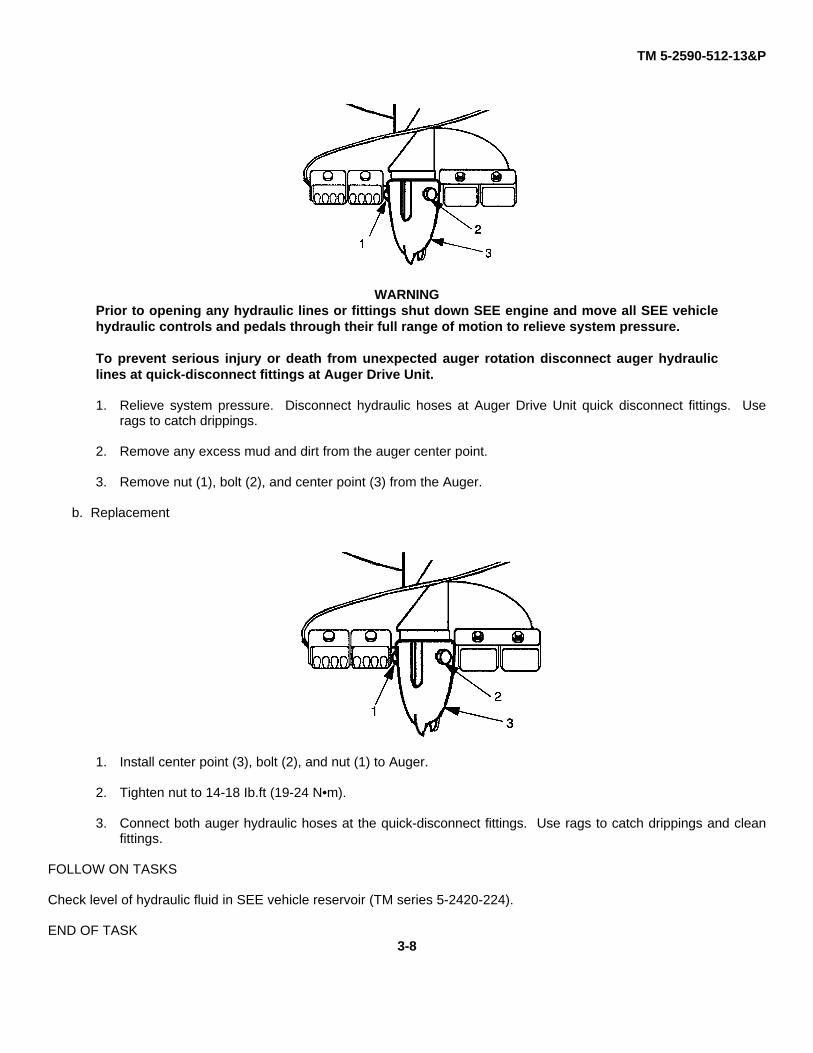
TM 5-2590-512-13&P
WARNINGPrior to opening any hydraulic lines or fittings shut down SEE engine and move all SEE vehiclehydraulic controls and pedals through their full range of motion to relieve system pressure.
To prevent serious injury or death from unexpected auger rotation disconnect auger hydrauliclines at quick-disconnect fittings at Auger Drive Unit.
1. Relieve system pressure. Disconnect hydraulic hoses at Auger Drive Unit quick disconnect fittings. Userags to catch drippings.
2. Remove any excess mud and dirt from the auger center point.
3. Remove nut (1), bolt (2), and center point (3) from the Auger.
b. Replacement
1. Install center point (3), bolt (2), and nut (1) to Auger.
2. Tighten nut to 14-18 Ib.ft (19-24 N•m).
3. Connect both auger hydraulic hoses at the quick-disconnect fittings. Use rags to catch drippings and cleanfittings.
FOLLOW ON TASKS
Check level of hydraulic fluid in SEE vehicle reservoir (TM series 5-2420-224).
END OF TASK3-8

TM 5-2590-512-13&P
CHAPTER 4UNIT MAINTENANCE
SECTION I REPAIR PARTS AND SPECIAL TOOLS (RPSTL)Para. Page
4-1 Spare Parts 4-24-2 Special Tools 4-24-3 Repair Parts 4-2
SECTION II UNIT PREVENTIVE MAINTENANCE CHECKS AND SERVICES (PMCS)
4-4 Unit PMCS Procedures 4-24-5 General 4-24-6 Explanation of Columns 4-24-7 Leakage Definitions 4-24-8 PMCS Table 4-3
SECTION III UNIT TROUBLESHOOTING PROCEDURES
4-9 General 4-44-10 Explanation Of Columns 4-44-11 Unit Troubleshooting 4-4
SECTION IV INSTALLATION OF KIT
4-12 Introduction 4-64-13 Unpacking Earth Auger Assembly Kit and Installation on SEE vehicle 4-64-14 Preparation for Operation of Earth Auger Assembly 4-134-15 Preparation for Operation of Backhoe Bucket 4-15
SECTION V UNIT MAINTENANCE PROCEDURES
4-16 Universal Connecting Link Replacement 4-174-17 Front Safety Cover Replacement 4-184-18 Rear Safety Cover Replacement 4-194-19 Chain Adjustment 4-204-20 Chain Replacement 4-214-21 Chain Repair 4-224-22 Motor Sprocket Replacement 4-234-23 Motor Plate Replacement 4-244-24 Hydraulic Motor Replacement 4-254-25 Driven Sprocket Replacement 4-264-26 Output Shaft Replacement 4-274-27 Shaft Bearing Adjustment 4-284-28 Shaft Bearing and Seal Replacement 4-294-29 Shaft Bearing and Seal Service 4-304-30 Elbow Replacement 4-314-31 Hose Replacement 4-324-32 Drive Chain Lubrication 4-334-33 Main Housing Replacement 4-34
4-1

TM 5-2590-512-13&P
SECTION I. REPAIR PARTS AND SPECIAL TOOLS (RPSTL)
4-1. Spare Parts.A spare master link (for use in the repair of a broken drive chain link) is located and secured to a washer weldedinside the Auger Drive Unit housing. Remove safety covers to gain access.
4-2. Special Tools.None required. All hardware is S.A.E. standard. Snap ring pliers are included in Kit.
4-3. Repair Parts.Repair parts are listed in Appendix F of this manual.
SECTION II. UNIT PREVENTIVE MAINTENANCE CHECKS AND SERVICES (PMCS).
4-4. PMCS Procedures.
Your PMCS table lists the inspections and care required to keep your equipment in good operating condition. Ifyour equipment does not perform as required, refer to the troubleshooting procedures in Section III of thischapter. Report any malfunctions or failures on DA Form 2404 or refer to DA Pam 738-750.
4-5. General.
a. All moving drive parts of the Earth Auger Assembly are contained in the Auger Drive Unit. To gain accessremove safety covers.
b. Inspect all parts for damage, broken or loose parts. Note condition of bearings, and inspect for cracks inhousing.
c. Check chain for looseness. Adjust to correct tension if loose (see para 4-19).
4-6. Explanation of Columns.
Item No. This column lists a logical order for performing PMCS. Use the number in this column as the 'TM ItemNo." on DA Form 2404, Equipment Inspection and Maintenance Work sheet, when recording theresults of PMCS.
Interval. This column tells you when to do a certain check or service.
Item to be inspected. This column lists the specific item being inspected.
Procedures. This column tells you how to do the required checks and services. Carefully follow theseinstructions.
4-7. Leakage Definitions.It is necessary for you to know how fluid leakage affects the status of your equipment. The following aredefinitions of the types/classes of leakage you need to know to be able to determine the status of your EarthAuger Assembly.
Leakage Definitions for Unit PMCS.CLASS I. Seepage of fluid (as indicated by wetness or discoloration) not great enough to form drops.
CLASS II. Leakage of fluid great enough to form drops but not great enough to cause drops to drip from theitem being inspected.
CLASS III. Leakage of fluid great enough to form drops that fall from the item/system being checked/inspected.
4-2

TM 5-2590-512-13&P
When in doubt, notify your supervisor.
Class III leaks must be corrected before releasing Earth Auger Assembly for operation.
4-8. SECTION II. TABLE OF UNIT PREVENTIVE MAINTENANCE CHECKS AND SERVICES (PMCS).
Item Item to be Procedure Not Fully MissionNo. Interval Checked or Capable If:
Service
NOTEPerform Operator PMCS prior to orin conjunction with Unit PMCS
1. Quarterly Drive Chain Adjust and lubricate chain (para 4-32)after every 50 hours of operation (seepara. 4-19 Chain adjustment).
2. Quarterly Hose Hanger Bracket Apply GAA Grease to Hose HangerBracket Pin
3. Quarterly Boom Arm Pivot Pin Apply GAA Grease to Boom Arm PivotPin end.
4. Annually Shaft Bearings Lubricate and adjust output shaftbearings inside shaft hub,(see para. 4-29 for bearing and sealservice).
4-3

TM 5-2590-512-13&PSECTION III. UNIT TROUBLESHOOTING.
4-9. GeneralParagraph 4-11 lists common malfunctions that you may find during the operation of the Earth Auger Assembly.You should perform the test/inspection and corrective actions in the order listed. This section cannot list all themalfunctions that may occur, nor all tests, inspections and corrective actions. If a malfunction is not listed, or isnot corrected by the listed corrective action, notify your supervisor.
4-10. Explanation of Columnsa. Malfunction. A visual or operational indication that something is wrong with the Earth Auger Assembly.b. Test or Inspection: A procedure to isolate the problem in a component or system.c. Corrective Action. A procedure to correct the problem.
4-11. Unit TroubleshootingWARNING
Prior to opening any hydraulic lines or fittings shut down SEE engine and move all SEE vehiclehydraulic controls and pedals several times through their full range of motion to relieve systempressure.
To prevent serious injury or death from unexpected auger rotation, disconnect Auger Drive Unithydraulic lines at quick disconnect fittings.
MalfunctionTest or Inspection
Corrective Action
AUGER BINDS, STOPS DIGGING, OR ROTATING WHEN CUTTING HOLE INTO EARTH.
Step 1. Stop auger, remove from hole being dug. Look into hole being dug for obstruction.
Remove obstruction or drill hole elsewhere.
Step 2. Stop rotation. Remove auger from hole, and inspect for worn, broken, or missing teeth ordefective center point.
Relieve system pressure. Replace broken, missing, or dull teeth and worn center point(para 3-4,3-5).
Step 3. Check hydraulic fluid level in SEE vehicle hydraulic reservoir. (See SEE TM Series 5-2420-224, Operators TM-1 0)
Add hydraulic fluid if level is tow. (See SEE Operators TM-10).
AUGER DOES NOT ROTATE WHEN CONTROL IS ACTIVATED.
Step 1. Ensure quick disconnects are properly connected.
Step 2. Check hydraulic fluid level in SEE vehicle hydraulic reservoir.
Add hydraulic fluid if level is low.
Step 3. Remove covers from Auger Drive Unit and look for broken chain or stripped sprockets.
Depressurize hydraulic system and replace defective chain or sprockets or otherdamage (para. 4-17 thru 4-29).
Step 4. Check auger operating levers on SEE vehicle.
If not operating properly see SEE TM manual Series 5-2420-224 for troubleshooting.
Step 5. Replace/repair Auger Drive Unit hydraulic motor (para. 4-24).
4-4

TM 5-2590-512-13&P
MalfunctionTest or Inspection
Corrective Action
AUGER ROTATES UNEVENLY OR ERRATICALLY.
Step 1. Inspect Auger for bent condition.
Depressurize hydraulic system and replace bent Auger if unable to dighole.
Step 2. Remove safety covers and check for cracked housing, loose motor, defective chain,sprockets, or bearings.
Depressurize hydraulic system and replace defective parts(para. 4-17 thru 4-29).
Step 3. Remove auger from hole and stop rotation. Check auger teeth and center point.
Depressurize hydraulic system and replace broken, missing, or dull teeth anddefective center point (para 3-6,3-7).
4-5

TM 5-2590-512-13&PSECTION IV. KIT INSTALLATION
4-12. Introduction.A portion of Earth Auger Assembly Kit must be installed on SEE vehicle before Earth Auger Assembly can beattached. The conversion kit can function with both backhoe bucket and Earth Auger Assembly. This conversionwill allow the SEE to change from backhoe bucket use to Earth Auger Assembly use and vice-versa.
4-13. Unpacking Earth Auger Assembly Kit And Installation On SEE Vehicle.
a. Unpacking.
NOTEKit Installation Is necessary one time for each SEE vehicle. After kit is installed, Bucket or AugerDrive Unit may be installed on SEE vehicle in shop or by operator at excavation site. If AugerDrive Unit or Auger is installed at excavation site, they are transported in a companion vehicle.
WARNINGAppropriate personnel and/or a suitable lifting device must be used.
1. Remove packing crate boards to gain access to kit parts. Remove nails or fasteners from boards.
2. Remove kit parts from packing crate. Check kit parts against packing slip for correct parts and quantities.Note and report any missing or damaged parts.
3. Earth Auger Assembly is shipped as a Kit. Part number is #1 650EH-MS, NSN 2590-01-384-6857. Parts areincluded to attach the Earth Auger Assembly to a SEE vehicle and also for backhoe bucket use. Kit contentsare listed in the following table and illustrated in this section.
NOTESome parts are preassembled by the manufacturer.
Item Part of ID# Number Amt. Description Notes
1. 1 Earth Auger Assembly, (Link, Auger Drive Unit, and Auger) CID A-A-52305
2. Bulk 2 Rope, Tie down, Black- (6 Ft. to tie down Bucket control Length 6 Ft. & 9 Ft.linkage to SEE when transporting). (9 ft. rope to pull Augerwhen removing from Auger Drive Unit, tie down to SEE).
3. MS35842-16 2 Clamp, Low Pressure, Type F. Holds #10 Clamp to dippercylinder.
4. MSHC-A 1 Bracket, Hanger, Hose (with Lynch Pin on wire rope). Holds auger hose assembly inplace on boom elbow.
5. 3451 1 Hose Assembly, Auger, Boom Mounted, 138 inch Two hoses w/clamp.
6. MSHC-B 1 Hose Assembly 30 inch Replaces rigid metal tubes.
7. MSHC-C 1 Adapter Assembly, Adapter Assembly consists of(Adapter with/Male Fitting and Adapter with/Female fitting). four fittings total.
8. DOM 1 DOM Spacer Assembly (With Bolt and Lock washer) Use in existing upper boom cyl.hose bracket.
9. SD1-MS 2 Label, Warning. (Hydraulic System Warnings). Mounts on Boom Cylinders.
10. HR2T-30 1 Clamp (Holds bucket hoses in place during Auger use). Mounts on Dipper Cylinder.
11 1234 1 Snap Ring Pliers
4-6

TM 5-2590-512-13&P
EARTH AUGER ASSEMBLY KIT - 1650EH-MS - NSN 2590-01-384-6857
4-7

TM 5-2590-512-13&P
WARNINGTo prevent personnel injury or equipment damage review all safety procedures in SEE TM(Series5-2420-224)before installing Earth Auger Assembly.
4. Lower stabilizers using Left (3) and Right (4) Stabilizer Control Levers.
5. Unlock boom by holding Boom Lock Lever (1) to right and moving Boom Control Lever (2) forward, thenrelease boom lock lever (1). Boom is now unlocked.
6. Move Boom Control Lever (2) and Dipper Control Lever (5) (see para. 2-2 Controls) and position bucket torest on shop floor to approximate position shown.
WARNING
Hydraulic pressure remains in system after SEE engine is off. This pressure could cause augerto move unexpectedly and could injure personnel. Depressurize hydraulic system by moving allsix SEE vehicle hydraulic controls and both pedals through their full range of motion severaltimes.
Ensure all personnel stand clear of bucket prior to depressurizing hydraulic system. Bucket willdrop when relieving hydraulic system pressure.
7. Stop SEE's engine and move all control levers through their full range of motion to relieve system pressure.
4-8

TM 5-2590-512-13&P
NOTEOriginal Setup - Hoses (2, 10) crosson top side of boon.Kit Install Setup - Hoses (9, 15) crossunder boom elbow.
b. Kit Installation.
NOTESEE vehicle has backhoe bucketattached during Conversion Kitinstallation.
CAUTIONStart all fittings and hose connectionsby hand to avoid stripping threads. Usedrip pans or shop rags to catch spilledhydraulic fluid.
1. Remove (crossed over) existing metal tube (2)under dipper cylinder (1)
2. Unscrew and disconnect fitting at each end ofmetal tube (2). Loosen hold-down bolts of twoexisting hose clamps (3) and (4). Remove anddiscard metal tube (2).
3. Assemble adapter (5) into male quickdisconnect fitting (6). Install adapter assembly(5 and 6), into driver side hose (7) coming fromrear of SEE.
4. Install 30 Inch hose (8) to Curb side bucketcylinder hose (9) where metal tube (2) wasremoved. (Thin 30" hose (8) has a femalequick disconnect fitting on one end).
5. Remove remaining metal tube (10).
6. Assemble fitting adapter (11) into female quickdisconnect fitting (12). Install fitting adapterassembly into curb side hose (13) coming fromrear of SEE.
7. Install 30 inch hose (14) into driver side bucketcylinder hose (15).
8. Fasten top half of tube clamp (3) closest to rearSEE vehicle by tightening bolt (17)
4-9

TM 5-2590-512-13&P
9. Seat hose (14) male quick disconnect fittinginto female quick disconnect fitting (12).
10. Seat hose female quick disconnect fitting(8) into male quick disconnect fitting (6).
11. Position upper end of hoses so that theycross beyond clamp (4) and under boomelbow (15).
12. Remove top half of tube clamp (4).
13. Position 30 inch hoses over open clamp (4).Install DOM spacer (16), top half of clamp(4), lock washer (17), bolt (18), and tighten.
c. Verify Hose Installation.
1. When hoses are installed correctly, 30 inchhose (8) (with female quick disconnect), willbe positioned along Driver Side of boom.
2. 30 inch hose(14) (with male quickdisconnect), will be positioned alongcurbside of boom.
3. Hoses will crossover after clamp (4) andunder boom elbow (15).
4. Hoses are positioned in clamps (3) and (4)so they do not stretch or bind when dipperor boom is moved throughout its range.
NOTE
If hoses are not crossed bucket andauger controls will operate reverse ofwhat is expected.
Layout of Metal Rigid Tubing Prior to Kit Installation.
Layout of Hoses and Connections after Kit Installation.
4-10

TM 5-2590-512-13&P
5. Install two spiral hose clamps (1), loosely on dippercylinder near top so that screw tighteners (2)are on bottom of dipper cylinder.
6. Place hose clamp (3) on top of dipper cylinder.Place center of clamp about 8 inches fromdipper cylinder upper end.
7. Slide spiral hose clamps (1) over base ends ofhose clamp (3) and tighten.
NOTE
When dipper cylinder is extended, 30inch hoses may need more slack, toavoid stretching. Adjust hoses asfollows: Loosen clamps (1) and moveclamp (3) lower or higher on dippercylinder until enough slack Is obtained.Move and tighten clamps (1).
NOTE
Use snap ring pliers supplied in kit toremove 2 Inch retaining ring (4).
8. Remove 2 inch retaining ring (4) and flatwasher (5) on driver's side boom arm pivot pin(6).
9. Discard flat washer (5).
10. Apply GAA grease to exposed end of boomarm pivot pin (6). Install hose hanger bracket(7) and existing 2 inch retaining ring (4) onboom arm pivot pin (6).
11. Insert lynch pin (8) downward through hole inlower pin (9) on hose hanger bracket (7) tostore. Pivot ring section of lynch pin (8) tolocking position.
4-11

TM 5-2590-512-13&P
12. Thoroughly clean driver's and curbsideboom cylinders (1,2), where safety Warninglabels are to be installed, to remove dirt, oil,and moisture. Ensure area is dry.
13. Install one label (3) to each boom cylinder(1,2).
14. Check and tighten all fittings (4), clamps (5),retainers (6) on boom and dipper installedfrom Kit.
15. Check hydraulic reservoir fluid level in SEEvehicle and replace any fluid lost duringinstallation. (Reference SEE TM Series 5-2420-224).
NOTEClean up fluid spills on fittings,hoses, and around area.
d. Conclusion.
1. Start SEE vehicle engine.
2. Visually examine kit installation parts forleaks from hoses at fittings. If there are anyleaks, shut down SEE engine and tightenfittings.
3. Pull bucket control lever towards you.Ensure bucket curls towards operator (seepara 2-2 Controls).
4. Move bucket control lever away from you.Ensure bucket uncurls away from operator.
NOTE
If controls work in reverse, hoseswere not crossed during installation.Check steps in Kit installationprocedures.
5. Operate bucket controls thru full range ofmotion and have assistant look for hosebinding or stretching. Adjust clamp ifnecessary (see NOTE on previous page).
NOTEThis completes one-time conversionkit installation. SEE may beswitched from Earth Auger Assemblyuse to Backhoe Bucket use, quickly,and easily.
4-12

TM 5-2590-512-13&P
4-14. Preparation for Earth Auger Assembly Use.
a. Removing Backhoe Bucket from SEE vehicle.
NOTEThe bucket is normally removed in theshop and the bucket stored there.However, the bucket may also beremoved in the field by the SEEoperator.
WARNINGHydraulic pressure remains in systemafter SEE engine is off. This pressurecauses boom to drift downward andcould injure personnel.
Depressurize hydraulic system bymoving all six SEE vehicle hydrauliccontrols and both pedals through theirfull range of motion several times.
Ensure all personnel stand clear ofbucket prior to depressurizing hydraulicsystem. Bucket will drop when relievinghydraulic system pressure.
1. Lower boom and dipper (1) to move bucket (2)to rest position on floor.
2. Remove two retaining rings (3), washers (4),and rod (5).
NOTEUse snap ring pliers supplied with kit toremove retaining rings (3) and (6).
3. Remove retaining ring (6), washers (7), taperedpin (8), and sleeve spacer (9).
4. Start SEE engine and raise dipper (1) awayfrom backhoe bucket (2). Store all retaininghardware in same holes on bucket.
5. Retract bucket control cylinder (10) and stopSEE engine.
End of Task
4-13

TM 5-2590-512-13&P
b. Attach Auger Drive Unit.
1. Position Auger Drive Unit (1) on groundnear dipper end (2) so that Auger hex shaftis away from SEE and hoses are on driver'sside. Move dipper (2) into place and installlink pin (3). Install link pin (3) into side oflink with pin stop and seat oblong headagainst pin stop. Install lynch pin (4).
2. Move lynch pin (4) into locked position.
3. Tie bucket control cylinder linkage (5) todipper arm bracket (6) with 6 ft. rope (7).
c. Removing And Storing Bucket Hoses.
1. Disconnect both 30 inch backhoe bucketcylinder hoses (8) and (9) at quickdisconnect fittings (10). Use rags to catchfluid and wipe fittings clean.
2. Loop hoses (8,9) and couple quickdisconnect fittings (11) together over thedipper cylinder (12).
3. Remove two nuts (14) at hose clamp (13)and remove top half of hose clamp (13).
4. Install coupled hose assembly (8,9) so thatfemale part of quick disconnect fitting (11)seats into lower half of hose clamp (13).
5. Install top half of hose clamp (13) and nuts(14). Tighten nuts to 3-5 lb. ft. (4-7 N•m).
NOTEInstallation of hoses into clamp iscorrect when hoses are secured andnot moveable.
4-14
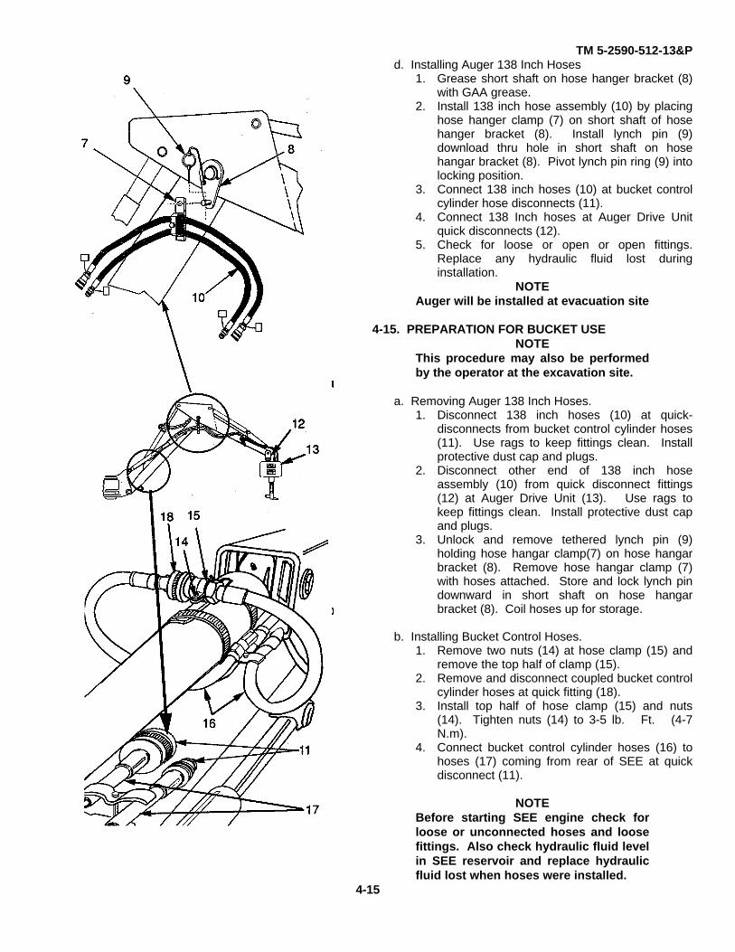
TM 5-2590-512-13&Pd. Installing Auger 138 Inch Hoses
1. Grease short shaft on hose hanger bracket (8)with GAA grease.
2. Install 138 inch hose assembly (10) by placinghose hanger clamp (7) on short shaft of hosehanger bracket (8). Install lynch pin (9)download thru hole in short shaft on hosehangar bracket (8). Pivot lynch pin ring (9) intolocking position.
3. Connect 138 inch hoses (10) at bucket controlcylinder hose disconnects (11).
4. Connect 138 Inch hoses at Auger Drive Unitquick disconnects (12).
5. Check for loose or open or open fittings.Replace any hydraulic fluid lost duringinstallation.
NOTEAuger will be installed at evacuation site
4-15. PREPARATION FOR BUCKET USENOTE
This procedure may also be performedby the operator at the excavation site.
a. Removing Auger 138 Inch Hoses.1. Disconnect 138 inch hoses (10) at quick-
disconnects from bucket control cylinder hoses(11). Use rags to keep fittings clean. Installprotective dust cap and plugs.
2. Disconnect other end of 138 inch hoseassembly (10) from quick disconnect fittings(12) at Auger Drive Unit (13). Use rags tokeep fittings clean. Install protective dust capand plugs.
3. Unlock and remove tethered lynch pin (9)holding hose hangar clamp(7) on hose hangarbracket (8). Remove hose hangar clamp (7)with hoses attached. Store and lock lynch pindownward in short shaft on hose hangarbracket (8). Coil hoses up for storage.
b. Installing Bucket Control Hoses.1. Remove two nuts (14) at hose clamp (15) and
remove the top half of clamp (15).2. Remove and disconnect coupled bucket control
cylinder hoses at quick fitting (18).3. Install top half of hose clamp (15) and nuts
(14). Tighten nuts (14) to 3-5 lb. Ft. (4-7N.m).
4. Connect bucket control cylinder hoses (16) tohoses (17) coming from rear of SEE at quickdisconnect (11).
NOTEBefore starting SEE engine check forloose or unconnected hoses and loosefittings. Also check hydraulic fluid levelin SEE reservoir and replace hydraulicfluid lost when hoses were installed.
4-15

TM 5-2590-512-13&P
c. Remove Auger Drive Unit.
WARNINGHydraulic Pressure remaining afterSEE engine is off could causeunexpected anger rotation resultingin serious injury or death.
Depressurize system by shutting off SEE engineand operating auger controls thru full range ofmotion.
1. If necessary, remove hoses at quickdisconnect fittings (1). Use rags to catchand clean fittings.
2. Place Auger Drive Unit (2) on floor.3. Remove lynch pin (3), and link pin (4). Pull
Auger Drive Unit (2) away from dipper armor start SEE engine and guide operator tomove dipper end (8) away from Auger DriveUnit (2).
4. Install link pin (4) and lynch pin (3) onconnecting link (5) for storage.
d. Install Bucket.
1. Untie rope (6) holding bucket control linkage(7) to the dipper (8). Store rope (6) in SEE'stool box.
2. Use a suitable lifting device, or move SEEboom and dipper, and position bucket (9) atrear of SEE vehicle dipper as shown.
3. Start SEE engine and guide operator toposition dipper end (8) into bucket mountingbracket (10).
4. Visually align dipper hole with bucketmounting bracket (10). Signal SEE operatorto stop dipper movement. Install rod (11)and washers (12).
NOTEUse snap ring pliers, supplied withkit, to install retainer rings (13) and(17).
5. Install two retaining rings (13) into slots atends of rod (11).
6. Position spacer (14) into place on bucketbracket and align holes through links andspacer (14).
7. Install washer (16) and retaining ring (17) onone end of pin (15). Insert pin (15) intoplace.
8. Add washers (16) to shim clearances untilretaining ring groove on end of pin (15) is atedge of last washer.
9. Install retaining ring (17) on end of pin (15).4-16

TM 5-2590-512-13&P
SECTION V. UNIT MAINTENANCE PROCEDURES
4-16. Connecting Link Replacement (Universal Drive Interface).
This task covers: a. Removal b. Installation
Initial Setup
Tools: Equipment Conditions:General Mechanic's Tool Kit Auger Drive Unit removed from
5180-00-177-7033 SEE and placed on ground (para. 4-15 c).
Materials and Parts:One cotter pin
a. Removal.
1. Remove cotter pin (1) from clevis pin (2).Discard cotter pin (1)
2. Remove clevis pin (2) from connecting link(3).
3. Remove connecting link (3) from drive unit(4).
b. Installation.
NOTE
Link (3) can be incorrectly installedinto Auger Drive Unit (4) bracket.Correct installation requires link pinstop (5), be located on hydraulichose side (6) of Auger Drive Unit(para 2-7).
1. Position connecting link (3) into place inAuger Drive Unit (4). Align holes inconnecting link (3) to holes in Auger DriveUnit (4). Install oblong head clevis pin (2)thru side of Auger Drive Unit (4) that hasmetal pin stop angle (7) welded in place.
2. Push clevis pin (2) through holes in bothbrackets and ensure oblong clevis pin headis seated flush with pin stop (7) on AugerDrive Unit (4).
3. Insert new cotter pin (1) thru end hole inclevis pin (2) and spread ends.
FOLLOW ON TASK.Install Auger Drive Unit on SEE vehicle (para 4-14).
END OF TASK
4-17
TM 5-2590-512-13&P
SECTION V. UNIT MAINTENANCE PROCEDURE
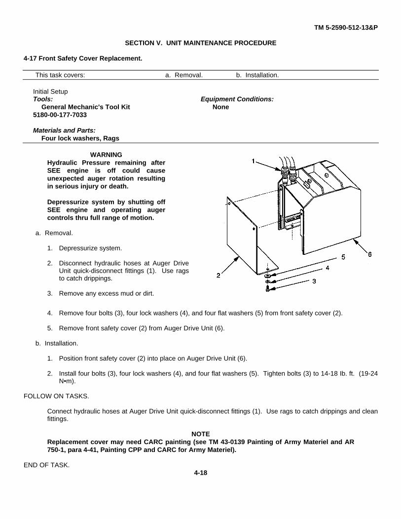
4-17 Front Safety Cover Replacement.
This task covers: a. Removal. b. Installation.
Initial SetupTools: Equipment Conditions:
General Mechanic's Tool Kit None5180-00-177-7033
Materials and Parts:Four lock washers, Rags
WARNINGHydraulic Pressure remaining afterSEE engine is off could causeunexpected auger rotation resultingin serious injury or death.
Depressurize system by shutting offSEE engine and operating augercontrols thru full range of motion.
a. Removal.
1. Depressurize system.
2. Disconnect hydraulic hoses at Auger DriveUnit quick-disconnect fittings (1). Use ragsto catch drippings.
3. Remove any excess mud or dirt.
4. Remove four bolts (3), four lock washers (4), and four flat washers (5) from front safety cover (2).
5. Remove front safety cover (2) from Auger Drive Unit (6).
b. Installation.
1. Position front safety cover (2) into place on Auger Drive Unit (6).
2. Install four bolts (3), four lock washers (4), and four flat washers (5). Tighten bolts (3) to 14-18 Ib. ft. (19-24N•m).
FOLLOW ON TASKS.
Connect hydraulic hoses at Auger Drive Unit quick-disconnect fittings (1). Use rags to catch drippings and cleanfittings.
NOTEReplacement cover may need CARC painting (see TM 43-0139 Painting of Army Materiel and AR750-1, para 4-41, Painting CPP and CARC for Army Materiel).
END OF TASK.4-18

TM 5-2590-512-13&P
SECTION V. UNIT MAINTENANCE PROCEDURE
4-18 Rear Safety Cover Replacement.
This task covers: a. Removal. b. Installation.
Initial Setup
Tools: Equipment Conditions:General Mechanic's Tool Kit None.
5180-00-177-7033.
Materials and Parts:Four lock washers.Rags.
WARNINGHydraulic pressure remaining afterSEE engine Is off could causeunexpected auger rotation anddeath.
Depressurize system by shutting offSEE engine and operating augercontrols thru full range of motion.
a. Removal
1. Depressurize system.
2. Disconnect hydraulic hoses at Auger DriveUnit quick disconnect fittings (1). Use ragsto catch drippings.
3. Remove any excess mud or dirt.
4. Remove four bolts (2), four lock washers(3), and four flat washers (4), from rearsafety cover (6).
5. Remove rear safety cover (6) from Auger Drive Unit (5).
b. Installation
1. Position rear safety cover (6) into place on Auger Drive Unit (5). Install four bolts (2), four lock washers (3),and four flat washers (4). Tighten bolts to 14-18 lb-ft. (19-24 N•m).
FOLLOW ON TASKS.
Connect the hydraulic hoses at Auger Drive Unit quick-disconnect fittings. Use rag to catch drippings and cleanconnections.
NOTEReplacement cover may need CARC painting (see TM 43-0139 Painting of Army Materiel and AR750-1, Para 4-41, Painting CPP and CARC for Army Materiel).
END OF TASK.4-19
TM 5-2590-512-13&PSECTION V. UNIT MAINTENANCE PROCEDURE
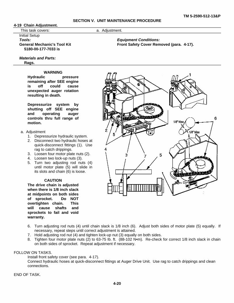
4-19 Chain Adjustment.This task covers: a. Adjustment.
Initial SetupTools: Equipment Conditions:General Mechanic's Tool Kit Front Safety Cover Removed (para. 4-17).
5180-00-177-7033 is
Materials and Parts:Rags.
WARNINGHydraulic pressureremaining after SEE engineis off could causeunexpected auger rotationresulting in death.
Depressurize system byshutting off SEE engineand operating augercontrols thru full range ofmotion.
a. Adjustment1. Depressurize hydraulic system.2. Disconnect two hydraulic hoses at
quick-disconnect fittings (1). Userag to catch drippings.
3. Loosen four motor plate nuts (2).4. Loosen two lock-up nuts (3).5. Turn two adjusting rod nuts (4)
until motor plate (5) will slide inits slots and chain (6) is loose.
CAUTIONThe drive chain is adjustedwhen there is 1/8 inch slackat midpoints on both sidesof sprocket. Do NOTovertighten chain. Thiswill cause shafts andsprockets to fail and voidwarranty.
6. Turn adjusting rod nuts (4) until chain slack is 1/8 inch (6). Adjust both sides of motor plate (5) equally. Ifnecessary, repeat steps until correct adjustment is attained.
7. Hold adjusting rod nut (4) and tighten lock-up nut (3) equally on both sides.8. Tighten four motor plate nuts (2) to 63-75 Ib. ft. (88-102 N•m). Re-check for correct 1/8 inch slack in chain
on both sides of sprocket. Repeat adjustment if necessary.
FOLLOW ON TASKS.Install front safety cover (see para. 4-17).Connect hydraulic hoses at quick-disconnect fittings at Auger Drive Unit. Use rag to catch drippings and cleanconnections.
END OF TASK.
4-20
TM 5-2590-512-13&P
SECTION V. UNIT MAINTENANCE PROCEDURE4-20 Chain Replacement.
This task covers: a. Removal. b. Installation.Initial Setup
Tools: Equipment Conditions:General Mechanic's Tool Kit Hydraulic System Depressurized
5180-00-177-7033. Front safety cover removed (para. 4-17).Rear safety cover removed (para. 4-18)
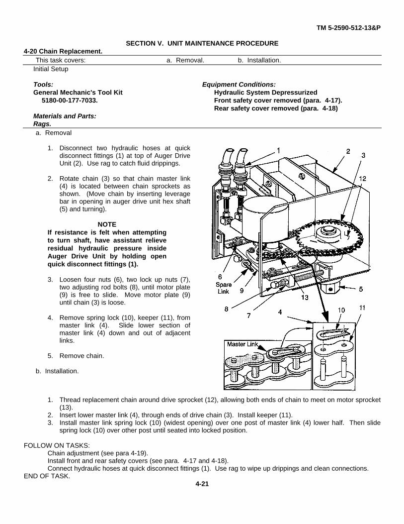
Materials and Parts:Rags.a. Removal
1. Disconnect two hydraulic hoses at quickdisconnect fittings (1) at top of Auger DriveUnit (2). Use rag to catch fluid drippings.
2. Rotate chain (3) so that chain master link(4) is located between chain sprockets asshown. (Move chain by inserting leveragebar in opening in auger drive unit hex shaft(5) and turning).
NOTEIf resistance is felt when attemptingto turn shaft, have assistant relieveresidual hydraulic pressure insideAuger Drive Unit by holding openquick disconnect fittings (1).
3. Loosen four nuts (6), two lock up nuts (7),two adjusting rod bolts (8), until motor plate(9) is free to slide. Move motor plate (9)until chain (3) is loose.
4. Remove spring lock (10), keeper (11), frommaster link (4). Slide lower section ofmaster link (4) down and out of adjacentlinks.
5. Remove chain.
b. Installation.
1. Thread replacement chain around drive sprocket (12), allowing both ends of chain to meet on motor sprocket(13).
2. Insert lower master link (4), through ends of drive chain (3). Install keeper (11).3. Install master link spring lock (10) (widest opening) over one post of master link (4) lower half. Then slide
spring lock (10) over other post until seated into locked position.
FOLLOW ON TASKS:Chain adjustment (see para 4-19).Install front and rear safety covers (see para. 4-17 and 4-18).Connect hydraulic hoses at quick disconnect fittings (1). Use rag to wipe up drippings and clean connections.
END OF TASK.4-21

TM 5-2590-512-13&P
SECTION V. UNIT MAINTENANCE PROCEDURE
4-21 Chain Repair.This task covers: a. Repair. b. Installation.
Initial Setup
Tools: Equipment Conditions:General Mechanic's Tool Kit Chain removed (see para. 4-20).
5180-00-177-7033
Materials and PartsRags, Tags.
a. Repair.1. Remove spare master link (1) stored in
washer welded inside Auger Drive Unit (2).
2. Place chain (3) in vice or other holdingdevice. Grind or file off link ends (4).Remove keeper (5), and defective link (6).Use center punch and tap out if necessary.
b. Installation.
1. Thread chain (3) around both sprockets,allowing both ends of chain to meet onmotor sprocket (7).
2. Insert lower part (8) of spare master link (1)through both ends of drive chain (3). Installkeeper (5).
3. Install master link spring lock (9) (widestopening) over one post of master link (8)lower half. Then slide spring lock.(9) overother post until seated into locked position.
NOTEAll chain repairs are a temporary fix.Always order new chain and sparelink and install as soon as possible.
Tag auger to Identify that new chainis on order.
FOLLOW ON TASKS:
Chain adjustment (see para. 4-19).Install front and rear safety covers (see para. 4-17 and 4-18).Connect hydraulic hoses at quick disconnect fittings. Use rag to catch drippings and clean fittings.
END OF TASK.
4-22

TM 5-2590-512-13&P
SECTION V. UNIT MAINTENANCE PROCEDURE4-22 Motor Sprocket Replacement.
This task covers: a. Removal. b. Installation.Initial Setup
Tools: Equipment Conditions:General Mechanic's Tool Kit Chain removed (see para. 4-20).5180-00-177-7033
Materials and Parts:Lock washer.Rags.GAA Grease.
a. Removal.
1. Remove bolt (1), lock washer (2), flatwashers (3), and spacer (4) from hydraulicmotor shaft (5).
2. Slide motor sprocket (6), and shaft key (7)off from shaft of hydraulic motor (5).
b. Installation.
1. Remove rust, dirt, etc. and lightly greaseshaft of hydraulic motor (5).
NOTEDisregard alien head set screw which may be in
some sprockets.
2. Slide motor sprocket (6) and shaft key (7)onto motor shaft (5). Do not force.
3. Install bolt (1), new lock washer (2), flatwasher (3) and spacer (4). Torque to 180 to250 Ib. ft.
FOLLOW ON TASKS:
Install chain (see para 4-20).
END OF TASK
4-23

TM 5-2590-512-13&PSECTION V. UNIT MAINTENANCE PROCEDURE
4-23 Motor Plate Replacement.This task covers: a. Removal b. Installation
Initial Setup
Tools: Equipment Conditions:General Mechanic's Tool Kit Chain removed (4-20).5180-00-177-7033
Materials and Parts:Lock washers
a. Removal1. Loosen lock-up nut (1) on each adjusting
rod (2),
2. Remove two adjusting rods (2) by turningwelded nut (3) on each adjusting rod end.
3. Remove four nuts (4), four lock washers (5),four flat washers (6) and four bolts (7), frommotor plate (8).
4. Slide motor plate (8), with hydraulic motor(9), (with short hoses) attached, out of mainhousing (10).
5. Remove four nuts (11), four lock washers(12), and four bolts (13), from motor plate(8). Remove motor (9) (with sprocket andhoses attached) from motor plate (8).
6. Remove and save spare master link (14).
b. Installation1. Install hydraulic motor (9) on motor plate
(8), with four bolts (13), four lock washers(12), and four nuts (11).Tighten four nuts(11) to 65-75 Ib. ft. (88-102 N•m)
2. Slide motor plate (8), and hydraulic motor(9) into the main housing (10). Ensuremaster link holder (14) is facing outward.
3. Install four bolts (7), four flat washers (6),four lock washers (5) and four nuts (4)fastening the motor plate to drive housing.Finger tighten four nuts (4).
4. Install the two adjusting rods (2). Do not tighten lock-up nuts (1).
5. Install spare master link (14) in welded washer on replacement motor plate (8).
FOLLOW ON TASKS:Install chain (para. 4-20)
END OF TASK
4-24
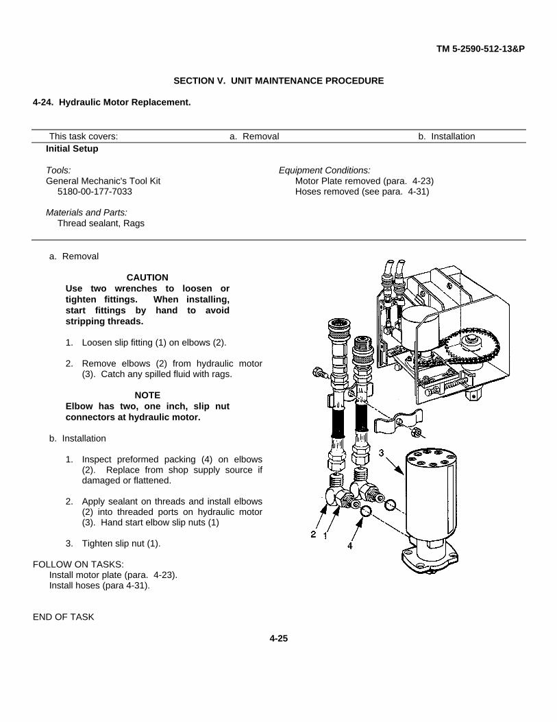
TM 5-2590-512-13&P
SECTION V. UNIT MAINTENANCE PROCEDURE
4-24. Hydraulic Motor Replacement.
This task covers: a. Removal b. InstallationInitial Setup
Tools: Equipment Conditions:General Mechanic's Tool Kit Motor Plate removed (para. 4-23)
5180-00-177-7033 Hoses removed (see para. 4-31)
Materials and Parts:Thread sealant, Rags
a. Removal
CAUTIONUse two wrenches to loosen ortighten fittings. When installing,start fittings by hand to avoidstripping threads.
1. Loosen slip fitting (1) on elbows (2).
2. Remove elbows (2) from hydraulic motor(3). Catch any spilled fluid with rags.
NOTEElbow has two, one inch, slip nutconnectors at hydraulic motor.
b. Installation
1. Inspect preformed packing (4) on elbows(2). Replace from shop supply source ifdamaged or flattened.
2. Apply sealant on threads and install elbows(2) into threaded ports on hydraulic motor(3). Hand start elbow slip nuts (1)
3. Tighten slip nut (1).
FOLLOW ON TASKS:Install motor plate (para. 4-23).Install hoses (para 4-31).
END OF TASK
4-25

TM 5-2590-512-13&P
SECTION V. UNIT MAINTENANCE PROCEDURE
4-25. Driven Sprocket Replacement.
This task covers: a. Removal b. InstallationInitial Setup
Tools: Equipment Conditions:General Mechanic's Tool Kit Chain Removed (para 4-20).
5180-00-177-7033Materials and Parts:
None.
a. Removal.
1. Straighten the tangs on lock washer (1).
2. Remove lock nut (2) and lock washer (1).
NOTEUse a spanner wrench to removelock nut (2)
3. Support output shaft (5) to preventmovement while carefully sliding off drivensprocket (3) and shaft key (4)
NOTE`Use care in removing driven sprocketto avoid damage to shaft threads.
b. Installation.
1. Install shaft key (4) in slot in output shaft (5)and slide replacement driven sprocket (3)(with hub side up) onto shaft (5). Use careto avoid damaging threads.
2. Install lock washer (1) and lock nut (2).Finger tighten lock nut (2). Do not bendtangs on lock washer (1) at this time.
FOLLOW ON TASKS:Shaft bearing adjustment (see para 4-27).Install chain (see para 4-20).
END OF TASK4-26

TM 5-2590-512-13&P
SECTION V. UNIT MAINTENANCE PROCEDURE4-26. Output Shaft Replacement.
This task covers: a. Removal b. InstallationInitial Setup
Tools: Equipment Conditions:General Mechanic's Tool Kit Chain Removed (para 4-20).5180-00-177-7033.
Materials and Parts:None.
a. Removal.1. Straighten tangs on lock washer (1).
2. Remove lock nut (2) and lock washer (1).Use spanner wrench.
3. Carefully slide off driven sprocket (3) alongwith shaft key (4) from output shaft (5).
NOTEUse care in removing sprocket toavoid damage to shaft threads.
4. Slide output shaft (5) out thru bottom ofAuger Drive Unit housing (7).
5. Remove spacer (6) positioned betweensprocket (3) and bearing (9) and nestledinside of shaft seal (8).
b. Installation.1. Carefully slide output shaft (5) into opening
in bottom of Auger Drive Unit housing (7).Check that it rotates, without binding, onhub bearings (9,10).
2. Place spacer (6) on output shaft (5) so it fitssnugly inside of upper shaft seal (8) and ontop race of bearing (9).
3. Install shaft key (4) in slot in output shaft (5)and slide driven sprocket (3) (with hub sideup) onto shaft (5). Use care to avoiddamaging shaft threads.
4. Install lock washer (1) and lock nut(2).Finger tighten lock nut (2). Do not bendtangs on lock washer (1) at this time.
FOLLOW ON TASKS:Shaft Bearing Adjustment (see para 4-27)Install Chain (see para. 4-20).
END OF TASK.
NOTEItems 8, 9, and 10 are in place inside hub.
4-27
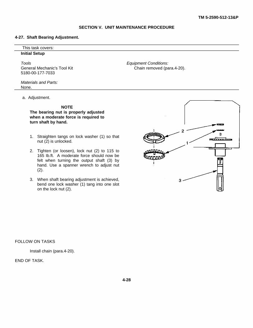
TM 5-2590-512-13&P
SECTION V. UNIT MAINTENANCE PROCEDURE
4-27. Shaft Bearing Adjustment.
This task covers:Initial Setup
Tools Equipment Conditions:General Mechanic's Tool Kit Chain removed (para.4-20).5180-00-177-7033
Materials and Parts:None.
a. Adjustment.
NOTEThe bearing nut is properly adjustedwhen a moderate force is required toturn shaft by hand.
1. Straighten tangs on lock washer (1) so thatnut (2) is unlocked.
2. Tighten (or loosen), lock nut (2) to 115 to165 Ib.ft. A moderate force should now befelt when turning the output shaft (3) byhand. Use a spanner wrench to adjust nut(2).
3. When shaft bearing adjustment is achieved,bend one lock washer (1) tang into one sloton the lock nut (2).
FOLLOW ON TASKS
Install chain (para.4-20).
END OF TASK.
4-28
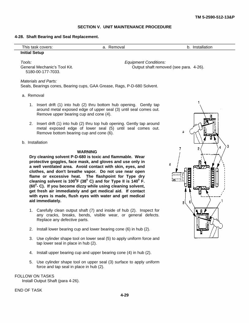
TM 5-2590-512-13&P
SECTION V. UNIT MAINTENANCE PROCEDURE
4-28. Shaft Bearing and Seal Replacement.
This task covers: a. Removal b. InstallationInitial Setup
Tools: Equipment Conditions:General Mechanic's Tool Kit. Output shaft removed (see para. 4-26).
5180-00-177-7033.
Materials and Parts:Seals, Bearings cones, Bearing cups, GAA Grease, Rags, P-D-680 Solvent.
a. Removal
1. Insert drift (1) into hub (2) thru bottom hub opening. Gently taparound metal exposed edge of upper seal (3) until seal comes out.Remove upper bearing cup and cone (4).
2. Insert drift (1) into hub (2) thru top hub opening. Gently tap aroundmetal exposed edge of lower seal (5) until seal comes out.Remove bottom bearing cup and cone (6).
b. Installation
WARNINGDry cleaning solvent P-D-680 is toxic and flammable. Wearprotective goggles, face mask, and gloves and use only ina well ventilated area. Avoid contact with skin, eyes, andclothes, and don't breathe vapor. Do not use near openflame or excessive heat. The flashpoint for Type drycleaning solvent is 1000F (380 C) and for Type II is 1400 F.(600- C). If you become dizzy while using cleaning solvent,get fresh air immediately and get medical aid. If contactwith eyes is made, flush eyes with water and get medicalaid immediately.
1. Carefully clean output shaft (7) and inside of hub (2). Inspect forany cracks, breaks, bends, visible wear, or general defects.Replace any defective parts.
2. Install lower bearing cup and lower bearing cone (6) in hub (2).
3. Use cylinder shape tool on lower seal (5) to apply uniform force andtap lower seal in place in hub (2).
4. Install upper bearing cup and upper bearing cone (4) in hub (2).
5. Use cylinder shape tool on upper seal (3) surface to apply uniformforce and tap seal in place in hub (2).
FOLLOW ON TASKSInstall Output Shaft (para 4-26).
END OF TASK4-29
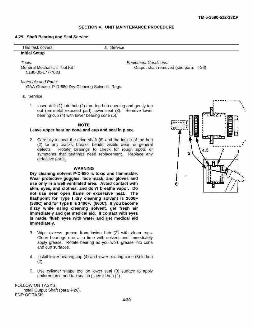
TM 5-2590-512-13&P
SECTION V. UNIT MAINTENANCE PROCEDURE
4-29. Shaft Bearing and Seal Service.
This task covers: a. ServiceInitial Setup
Tools: Equipment Conditions:General Mechanic's Tool Kit Output shaft removed (see para. 4-26)
5180-00-177-7033
Materials and Parts:GAA Grease, P-D-680 Dry Cleaning Solvent. Rags.
a. Service.
1. Insert drift (1) into hub (2) thru top hub opening and gently tapout (on metal exposed part) lower seal (3). Remove lowerbearing cup (4) with lower bearing cone (5).
NOTELeave upper bearing cone and cup and seal in place.
2. Carefully inspect the drive shaft (6) and the inside of the hub(2) for any cracks, breaks, bends, visible wear, or generaldefects. Rotate bearings to check for rough spots orsymptoms that bearings need replacement. Replace anydefective parts.
WARNINGDry cleaning solvent P-D-680 is toxic and flammable.Wear protective goggles, face mask, and gloves anduse only in a well ventilated area. Avoid contact withskin, eyes, and clothes, and don't breathe vapor. Donot use near open flame or excessive heat. Theflashpoint for Type I dry cleaning solvent is 1000F(380C) and for Type II is 1400F. (600C). If you becomedizzy while using cleaning solvent, get fresh airimmediately and get medical aid. If contact with eyesis made, flush eyes with water and get medical aidimmediately.
3. Wipe excess grease from inside hub (2) with clean rags.Clean bearings one at a time with solvent and immediatelyapply grease. Rotate bearing as you work grease into coneand cup surfaces.
4. Install lower bearing cup (4) and lower bearing cone (5) in hub(2).
5. Use cylinder shape tool on lower seal (3) surface to applyuniform force and tap seal in place in hub (2).
FOLLOW ON TASKSInstall Output Shaft (para 4-26).
END OF TASK4-30
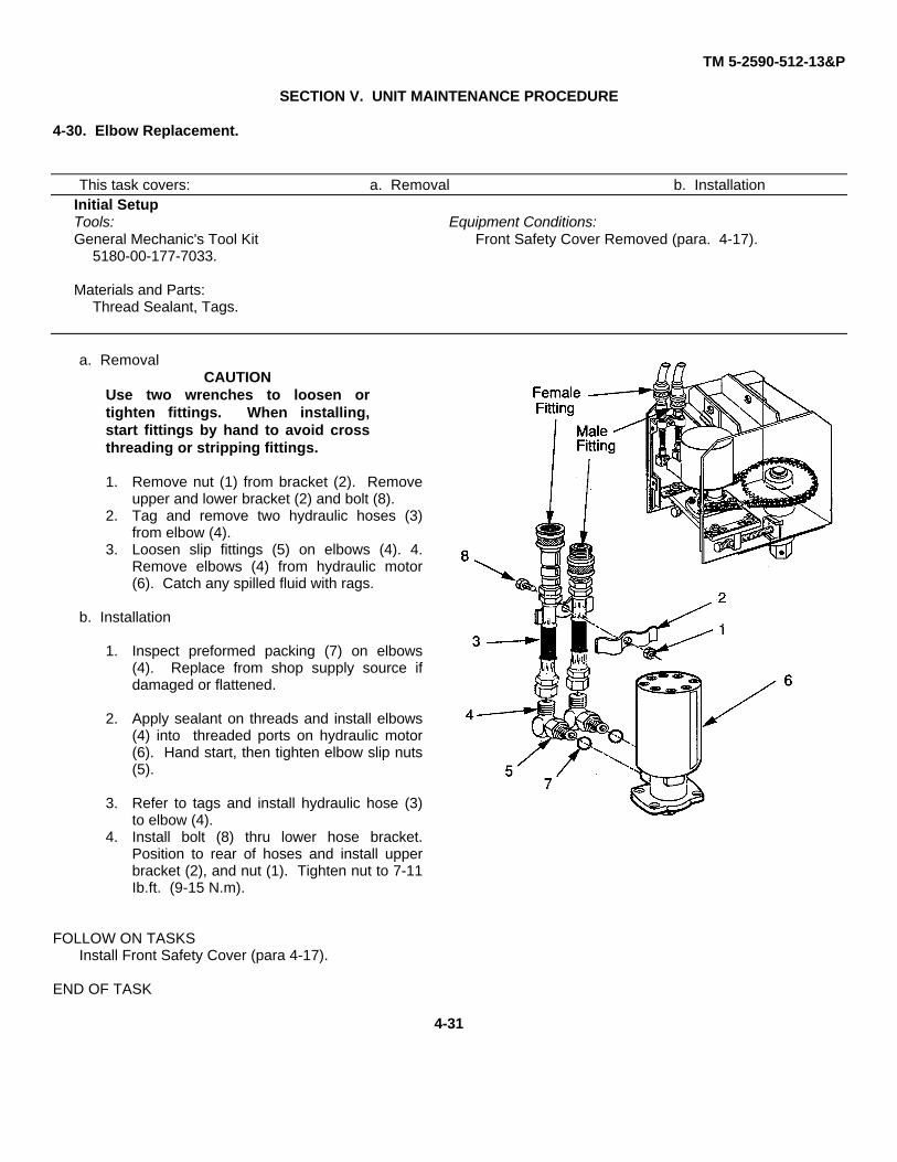
TM 5-2590-512-13&P
SECTION V. UNIT MAINTENANCE PROCEDURE
4-30. Elbow Replacement.
This task covers: a. Removal b. InstallationInitial SetupTools: Equipment Conditions:General Mechanic's Tool Kit Front Safety Cover Removed (para. 4-17).
5180-00-177-7033.
Materials and Parts:Thread Sealant, Tags.
a. RemovalCAUTION
Use two wrenches to loosen ortighten fittings. When installing,start fittings by hand to avoid crossthreading or stripping fittings.
1. Remove nut (1) from bracket (2). Removeupper and lower bracket (2) and bolt (8).
2. Tag and remove two hydraulic hoses (3)from elbow (4).
3. Loosen slip fittings (5) on elbows (4). 4.Remove elbows (4) from hydraulic motor(6). Catch any spilled fluid with rags.
b. Installation
1. Inspect preformed packing (7) on elbows(4). Replace from shop supply source ifdamaged or flattened.
2. Apply sealant on threads and install elbows(4) into threaded ports on hydraulic motor(6). Hand start, then tighten elbow slip nuts(5).
3. Refer to tags and install hydraulic hose (3)to elbow (4).
4. Install bolt (8) thru lower hose bracket.Position to rear of hoses and install upperbracket (2), and nut (1). Tighten nut to 7-11Ib.ft. (9-15 N.m).
FOLLOW ON TASKSInstall Front Safety Cover (para 4-17).
END OF TASK
4-31
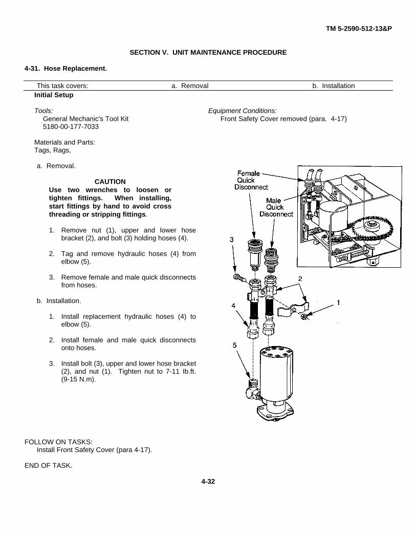
TM 5-2590-512-13&P
SECTION V. UNIT MAINTENANCE PROCEDURE
4-31. Hose Replacement.
This task covers: a. Removal b. InstallationInitial Setup
Tools: Equipment Conditions:General Mechanic's Tool Kit Front Safety Cover removed (para. 4-17)5180-00-177-7033
Materials and Parts:Tags, Rags,
a. Removal.
CAUTIONUse two wrenches to loosen ortighten fittings. When installing,start fittings by hand to avoid crossthreading or stripping fittings.
1. Remove nut (1), upper and lower hosebracket (2), and bolt (3) holding hoses (4).
2. Tag and remove hydraulic hoses (4) fromelbow (5).
3. Remove female and male quick disconnectsfrom hoses.
b. Installation.
1. Install replacement hydraulic hoses (4) toelbow (5).
2. Install female and male quick disconnectsonto hoses.
3. Install bolt (3), upper and lower hose bracket(2), and nut (1). Tighten nut to 7-11 Ib.ft.(9-15 N.m).
FOLLOW ON TASKS:Install Front Safety Cover (para 4-17).
END OF TASK.
4-32
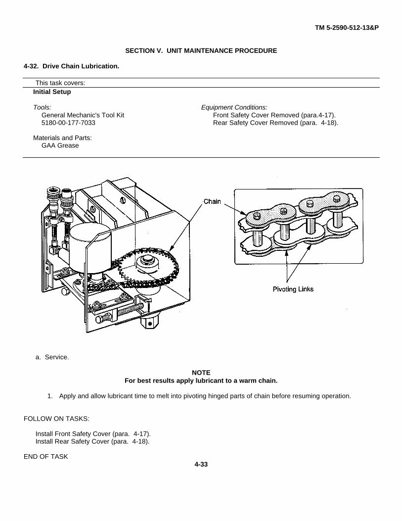
TM 5-2590-512-13&P
SECTION V. UNIT MAINTENANCE PROCEDURE
4-32. Drive Chain Lubrication.
This task covers:Initial Setup
Tools: Equipment Conditions:General Mechanic's Tool Kit Front Safety Cover Removed (para.4-17).5180-00-177-7033 Rear Safety Cover Removed (para. 4-18).
Materials and Parts:GAA Grease
a. Service.
NOTEFor best results apply lubricant to a warm chain.
1. Apply and allow lubricant time to melt into pivoting hinged parts of chain before resuming operation.
FOLLOW ON TASKS:
Install Front Safety Cover (para. 4-17).Install Rear Safety Cover (para. 4-18).
END OF TASK4-33
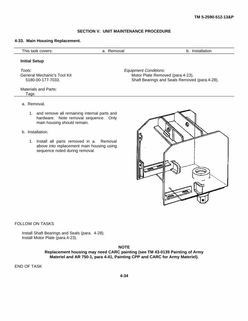
TM 5-2590-512-13&P
SECTION V. UNIT MAINTENANCE PROCEDURE
4-33. Main Housing Replacement.
This task covers: a. Removal b. Installation
Initial Setup
Tools: Equipment Conditions:General Mechanic's Tool Kit Motor Plate Removed (para.4-23).
5180-00-177-7033. Shaft Bearings and Seals Removed (para.4-28).
Materials and Parts:Tags
a. Removal.
1. and remove all remaining internal parts andhardware. Note removal sequence. Onlymain housing should remain.
b. Installation.
1. Install all parts removed in a. Removalabove into replacement main housing usingsequence noted during removal.
FOLLOW ON TASKS
Install Shaft Bearings and Seals (para. 4-28).Install Motor Plate (para.4-23).
NOTEReplacement housing may need CARC painting (see TM 43-0139 Painting of Army
Materiel and AR 750-1, para 4-41, Painting CPP and CARC for Army Materiel).
END OF TASK
4-34
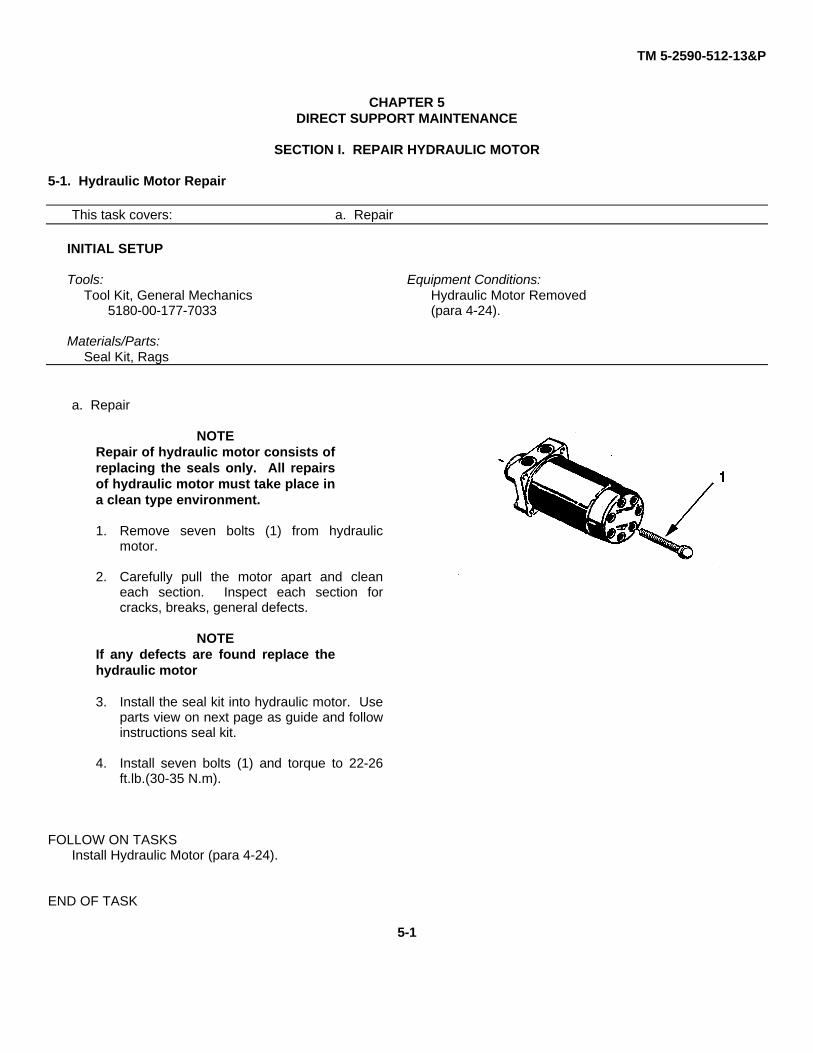
TM 5-2590-512-13&P
CHAPTER 5DIRECT SUPPORT MAINTENANCE
SECTION I. REPAIR HYDRAULIC MOTOR
5-1. Hydraulic Motor Repair
This task covers: a. Repair
INITIAL SETUP
Tools: Equipment Conditions:Tool Kit, General Mechanics Hydraulic Motor Removed
5180-00-177-7033 (para 4-24).
Materials/Parts:Seal Kit, Rags
a. Repair
NOTERepair of hydraulic motor consists ofreplacing the seals only. All repairsof hydraulic motor must take place ina clean type environment.
1. Remove seven bolts (1) from hydraulicmotor.
2. Carefully pull the motor apart and cleaneach section. Inspect each section forcracks, breaks, general defects.
NOTEIf any defects are found replace thehydraulic motor
3. Install the seal kit into hydraulic motor. Useparts view on next page as guide and followinstructions seal kit.
4. Install seven bolts (1) and torque to 22-26ft.lb.(30-35 N.m).
FOLLOW ON TASKSInstall Hydraulic Motor (para 4-24).
END OF TASK
5-1
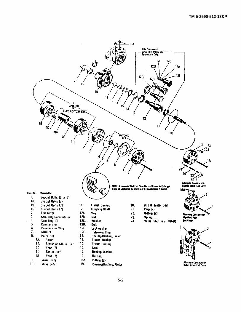
TM 5-2590-512-13&P
5-2
TM 5-2590-512-13&PAPPENDIX AWARRANTY
CONTENTS
PageWarranty Statement A-1LOWE Commercial Warranty A-2
The Earth Auger Assembly is not covered by the standard government warranty provisions associated with someTACOM managed Equipment.
However, the Lowe Manufacturing Company, Inc. (LOWE) will provide the using Army unit the standard warrantyavailable to their commercial customers.
It is highly recommended that prior to any work being initiated or repair parts requested, LOWE be notified of suchactions to ensure that no work and/or repairs are requested that are not covered under warranty.
Any cost associated with work and/or repairs accomplished by LOWE that is not covered under warranty, shall be thesole responsibility of the using Army unit.
This warranty is to be exercised exclusively between the using Army unit and LOWE.
Warranty registration of the ARMY equipment with LOWE is NOT required and it is NOT necessary to notify the TANK-automotive and Armaments Command (TACOM) regarding any warranty claim submission.
The local Warranty Control Office/Officer (WARCO) should pursue warranty coverage by administering the guidelinesprescribed within the LOWE Commercial Warranty.
For information regarding this warranty, please contact:
Lowe Manufacturing Company, Inc.P.O. Box 275Readstown, Wisconsin 54652
Toll Free 1-800-356-9180FAX 608-629-5666
A-1
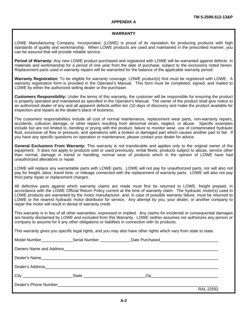
TM 5-2590-512-13&PAPPENDIX A
WARRANTY
LOWE Manufacturing Company, Incorporated, (LOWE) is proud of its reputation for producing products with highstandards of quality and workmanship. When LOWE products are used and maintained in the prescribed manner, youcan be assured that will provide reliable service.
Period of Warranty: Any new LOWE product purchased and registered with LOWE will be warranted against defects inmaterials and workmanship for a period of one year from the date of purchase, subject to the exclusions noted herein.Replacement parts used in warranty repairs will be warranted for the balance of the applicable warranty period.
Warranty Registration: To be eligible for warranty coverage, LOWE product(s) first must be registered with LOWE. Awarranty registration form is provided in the Operator's Manual. This form must be completed, signed, and mailed toLOWE by either the authorized selling dealer or the purchaser.
Customers Responsibility: Under the terms of this warranty, the customer will be responsible for ensuring the productis properly operated and maintained as specified in the Operator's Manual. The owner of the product shall give notice toan authorized dealer of any and all apparent defects within ten (10 days of discovery and make the product available forinspection and repairs at the dealer's place of business.
The customers responsibilities include all cost of normal maintenance, replacement wear parts, non-warranty repairs,accidents, collusion damage, or other repairs resulting from abnormal strain, neglect, or abuse. Specific examplesinclude but are not limited to, bending or prying with the product, failure to monitor wear, use of contaminated hydraulicfluid, excessive oil flow or pressure, and operations with a broken or damaged part which causes another part to fail. Ifyou have any specific questions on operation or maintenance, please contact your dealer for advice.
General Exclusions From Warranty: This warranty is not transferable and applies only to the original owner of theequipment. It does not apply to products sold or used previously, rental fleets, products subject to abuse, service otherthan normal, damage in transit or handling, normal wear of products which in the opinion of LOWE have hadunauthorized alterations or repair.
LOWE will replace any warrantable parts with LOWE parts. LOWE will not pay for unauthorized parts, nor will also notpay for freight, labor, travel time, or mileage connected with the replacement of warranty parts. LOWE will also not paythird party repair or replacement charges.
All defective parts against which warranty claims are made must first be returned to LOWE, freight prepaid, inaccordance with the LOWE Official Return Policy current at the time of warranty claim. The hydraulic motor(s) used inLOWE products are warranted by the motor manufacturer, and, in case of possible warranty failure, must be returned toLOWE or the nearest hydraulic motor distributor for service. Any attempt by you, your dealer, or another company torepair the motor will result in denial of warranty credit.
This warranty is in lieu of all other warranties, expressed or implied. Any claims for incidental or consequential damagesare hearby disclaimed by LOWE and excluded from this Warranty. LOWE neither assumes nor authorizes any person orcompany to assume for it any other obligations or liabilities in connection with its products.
This warranty gives you specific legal rights, and you may also have other rights which vary from state to state.
Model Number Serial Number Date Purchased
Owners Name and Address
Dealer's Name
Dealer's Address
City State Zip
Dealer's Phone Number RAL 22592
A-2

TM 5-2590-512-13&P
APPENDIX BMAINTENANCE ALLOCATION CHART (MAC)
Section I. INTRODUCTION
B-1. The Army Maintenance System MAC
a. This introduction (Section I) provides a generalexplanation of all maintenance and repair functionsauthorized at various maintenance levels under thestandard Army Maintenance System concept.
b. The Maintenance Allocation Chart (MAC) inSection II designates overall authority and responsibilityfor the performance of maintenance functions on theidentified end item or component. The application ofthe maintenance functions to the end item or componentwill be consistent with the capacities and capabilities ofthe designated maintenance levels. Which are shown onthe MAC in column (4) as:
Unit - includes two subcolumns, C(operator/crew) and O (unit) maintenance.
Direct Support - includes an F subcolumn.
General Support - includes an H subcolumn.
Depot - includes a D subcolumn.
c. Section III lists the tools and test equipment (both special tools and common tool sets) required foreach maintenance function as referenced from sectionII.
d. Section IV contains supplemental instructionsand explanatory notes for a particular maintenancefunction.
B-2. MAINTENANCE FUNCTIONS. Maintenancefunctions are limited to and defined as follows: (see3.2.5.2g for ammunition MAC exception).
a. Inspect. To determine the serviceability of anitem by comparing its physical, mechanical, and/orelectrical characteristics with established standardsthrough examination (e.g., by sight, sound, or feel).
b. Test. To verify serviceability by measuring themechanical, pneumatic, hydraulic, or electricalcharacteristics of an item and comparing thosecharacteristics with prescribed standards.
c. Service. Operations required periodically tokeep an item in proper operating condition, e.g., to clean(includes decontaminate, when required), to preserve, todrain, to paint, or to replenish fuel, lubricants, chemicalfluids, or gases.
d. Adjust. To maintain or regulate, withinprescribed limits, by bringing into proper or exactposition, or by setting the operating characteristics tospecified parameters.
e. Align. To adjust specified variable elements ofan item to bring about optimum and desiredperformance.
f. Calibrate. To determine and cause correctionto be made or to be adjusted on instruments or testmeasuring, and diagnostic equipment used in precisionmeasurement. Consists of comparisons of twoinstruments, one of which is a certified standard ofknown accuracy, to detect and adjust any discrepancy inthe accuracy of the instrument being compared.
g. Remove/Install. To remove and install thesame item when required to perform service or othermaintenance functions. Install may be the act ofemplacing, seating, or fixing into position a spare, repairpart, or module ( component or assembly) in a mannerto allow the proper functioning of an equipment orsystem.
h. Replace. To remove an unserviceable itemand install a serviceable counterpart in its place."Replace" is authorized by the MAC and the assignedmaintenance level is show as the 3rd position code ofthe SMR code.
B-1

TM 5-2590-512-13&P
i. Repair. The application of maintenanceservices, including fault location /troubleshooting2,removal / installation, and disassembly / assembly3procedures and maintenance actions4 to identifytroubles and restore serviceability to an item bycorrecting specific damage, fault, malfunction, or failurein a part, subassembly, module (component orassembly), end item, or system.
j. Overhaul. That maintenance effort(service/action) prescribed to restore an item tocompletely serviceable/ operational condition asrequired by maintenance standards in appropriatetechnical publications (i.e., DMWR). Overhaul isnormally the highest degree of maintenance performedby the Army.Overhaul does not normally return an item to like newcondition.
k. Rebuild. Consists of those services/actionsnecessary for the restoration of unserviceableequipment to a like new condition in accordance withoriginal manufacturing standards. Rebuild is the highestdegree of material maintenance applied to Armyequipment. The rebuild operation includes the act ofreturning to zero those age measurements (e.g.,hour/miles) considered in classifying Army equipment/components.
B-3. Explanation of Columns in the MAC, Section II.
a. Column 1, Group Number. Column 1 listsfunctional grouping codes, the purpose of which is toidentify maintenance significant components,assemblies, subassemblies, and modules with the nexthigher assembly.
b. Column 2, Component / Assembly. Column 2contains the item names of components, assemblies
subassemblies, and modules for which maintenance isauthorized.
c. Column 3, Maintenance Function. Column 3lists the functions to be performed on the item listed inColumn 2. (For detailed explanation of these functions,see Paragraph B-2.)
d. Column 4, Maintenance Level. Column 4specifies each level of maintenance authorized toperform each function listed in Column 3, by indicatingwork time required (expressed as manhours in wholehours or decimals) in the appropriate subcolumn. Thiswork-time figure represents the active time required toperform that maintenance function at the indicated levelof maintenance. If the number or complexity of thetasks within the listed maintenance function vary atdifferent maintenance levels, appropriate work-timefigures are shown for each level. The work-time figurerepresents the average time required to restore an item(assembly, subassembly, component, module, end item,or system) to a serviceable condition under typical fieldoperating conditions. This time includes preparationtime (including any necessary disassembly/assemblytime), troubleshooting/fault location time, and qualityassurance time in addition to the time required toperform the specific tasks identified for the maintenancefunctions authorized in the maintenance allocation chart.The symbol designations for the various maintenancelevels are as follows:
C - Operator or crew maintenanceO - Unit maintenanceF - Direct support maintenanceL - Specialized Repair Activity (SRA)sH - General support maintenanceD - Depot maintenance
1 Services - Inspect, test, service, adjust, align, calibrate, and/or replace.2 Fault location/troubleshooting - The process of investigating and detecting the cause of equipment malfunctioning; the
act of isolating a fault within a system or unit under test (UT).3 Disassembly/assembly - The step-by-step breakdown (taking apart) of a spare/functional group coded item to the level
of its least component, that is assigned an SMR code for the level of maintenance under consideration (i.e., identifiedas maintenance significant).
4 Actions - Welding, grinding, riveting, straightening, facing, machining, and/or resurfacing.5 This maintenance level is not included in Section II, column (4) of the Maintenance Allocation Chart. Functions to this
level of maintenance are identified by a work-time figure in the "H" column of Section II, column (4), and anassociated reference code is used in the Remarks column (6). This code is keyed to Section IV, Remarks, and theSRA complete repair application is explained there.
B-2
TM 5-2590-512-13&P
e. Column 5, Tools and Test Equipmentreference code. Column 5 specifies, by code, thosecommon tools sets (not individual tools), commonTMDE, and special support equipment required toperform the designated function. Codes are keyed totools and test equipment in section III.
f. column 6, Remarks. When applicable, thiscolumn contains a letter code, in alphabetical order,which is keyed to the remarks contained in Section IV.
B-4. Explanation of Columns in Tool and TestEquipment Requirements, Section III.
a. Column 1, Reference Code. The tool and testequipment reference code correlates with a code usedin the MAC, Section II, Column 5.
b. Column 2, Maintenance Level. The lowestlevel of maintenance authorized to use the tool or testequipment.
c. Column 3, Nomenclature. name oridentification the tool or test equipment.
d. Column 4, National Stock Number. TheNationalStock Number of the tool or test equipment.
e. Column 5, Tool Number. The manufacturer'snumber, model number, or type number.
B-5. Explanation of Columns In Remarks, SectionIV.
a. Column 1, Remarks Code. The code recordedin column 6, Section II.
b. Column 2, Remarks. This column listsinformation pertinent to the maintenance function beingperformed as indicated in the MAC, Section II.
B-3

TM 5-2590-512-13&P
SECTION II. MAINTENANCE ALLOCATION CHART FOR EARTH AUGER ASSEMBLY
(1) (2) (3) (4) (5) (6)Maintenance Level
DIRECT GEN.
Group Maintenance UNIT SUPPORTSUPPORT DEPOT Tools andNumber Component/Assembly Function C O F H D Equipment Remarks
EARTH AUGER ASS'Y
7400 Cranes, ShovelsAnd Earth MovingEquipment Components
7473 Lift and SwingMechanismsConnecting Link Inspect 0.1TBH Replace 0.1
7474 Drive Mechanism
HousingMain Housing Inspect 0.1
Replace 2.0Front Safety Cover Inspect 0.1
Replace 0.1Rear Safety Cover Inspect 0.1
Replace 0.1Chain Inspect 0.1
Service 0.2Adjust 0.4Replace 0.8Repair 0.9 A.
Output Shaft Inspect 0.1Replace 1.0
Shaft Bearings Inspect 0.1Service 1.3Adjust 0.8Replace 1.3
Driven Sprocket Inspect 0.1Replace 1.0
B-4
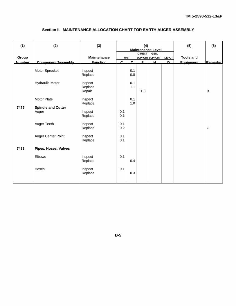
TM 5-2590-512-13&P
Section II. MAINTENANCE ALLOCATION CHART FOR EARTH AUGER ASSEMBLY
(1) (2) (3) (4) (5) (6)Maintenance Level
DIRECT GEN.
Group Maintenance UNIT SUPPORTSUPPORT DEPOT Tools andNumber Component/Assembly Function C O F H D Equipment Remarks
Motor Sprocket Inspect 0.1Replace 0.8
Hydraulic Motor Inspect 0.1Replace 1.1Repair 1.8 B.
Motor Plate Inspect 0.1Replace 1.0
7475 Spindle and CutterAuger Inspect 0.1
Replace 0.1
Auger Teeth Inspect 0.1Replace 0.2 C.
Auger Center Point Inspect 0.1Replace 0.1
7488 Pipes, Hoses, Valves
Elbows Inspect 0.1Replace 0.4
Hoses Inspect 0.1Replace 0.3
B-5
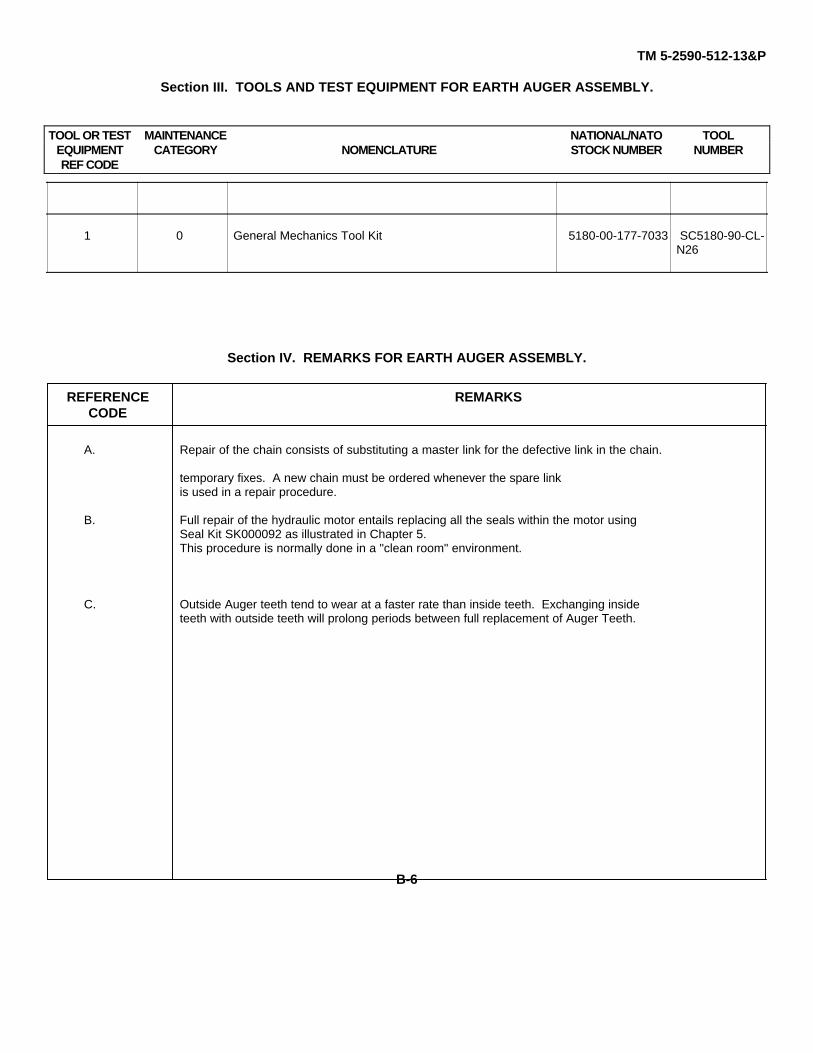
TM 5-2590-512-13&P
Section III. TOOLS AND TEST EQUIPMENT FOR EARTH AUGER ASSEMBLY.
TOOL OR TEST MAINTENANCE NATIONAL/NATO TOOLEQUIPMENT CATEGORY NOMENCLATURE STOCK NUMBER NUMBERREF CODE
1 0 General Mechanics Tool Kit 5180-00-177-7033 SC5180-90-CL-N26
Section IV. REMARKS FOR EARTH AUGER ASSEMBLY.
REFERENCE REMARKSCODE
A. Repair of the chain consists of substituting a master link for the defective link in the chain.
temporary fixes. A new chain must be ordered whenever the spare linkis used in a repair procedure.
B. Full repair of the hydraulic motor entails replacing all the seals within the motor usingSeal Kit SK000092 as illustrated in Chapter 5.This procedure is normally done in a "clean room" environment.
C. Outside Auger teeth tend to wear at a faster rate than inside teeth. Exchanging insideteeth with outside teeth will prolong periods between full replacement of Auger Teeth.
B-6

TM 5-2590-512-13&P
APPENDIX C
COMPONENTS OF END ITEM AND BASIS ISSUE ITEMS LIST
The Earth Auger Assembly does not have any Components of End Item
BASIC ISSUE ITEMS
(1) (2) (3) (4) (5)NATIONAL
ILLUS STOCK DESCRIPTION, Usable QTYNUMBER NUMBER CAGEC and Part Number On Code U/M Req’d
1 Hex Pin EA 1(0NAG9) L-50A
2 Hitch Pin Clip EA. 1(0CUJ4) HAIR-12
3 Carbide Tooth Assembly EA. 4(0NAG9) L13-G558
4 Center Point EA 1(ONAG9) Cap-55B
5 Rope 6 Ft. Length EA. 1(ONAG9) 560Rp
6 Rope 9 Ft. Length EA. 1(ONAG9) 590Rp
7 Snap Ring Pliers EA. 1(ONAG9) 1234
C-1

TM 5-2590-512-13&P
APPENDIX D
ADDITIONAL AUTHORIZATION LIST
The Earth Auger Assembly does not have any Additional Authorization Items for its support.
D-1

TM 5-2590-512-13&P
APPENDIX E
SECTION II. EXPENDABLE SUPPLIES AND MATERIALS LIST.
(1) (2) (3) (4) (5)
ITEM NATIONALNUMBER LEVEL STOCK DESCRIPTION U/M
NUMBER
1 O 8030-01-054-0740 Compound, Sealing, Pipe Thread CC
2 C Grease, Automotive and Artillery oz.(81349) MIL-G-10924
9150-00-065-0029 2-I/V4oz. Tube oz.9150-00-936-1017 14 oz. cartridge oz.9150-00-190-0904 1 lb. can lb.9150-00-190-0905 5 lb. can lb.9150-00-190-0907 35 lb. can lb.
3 C Lubricant, Silicone, Heavy Duty pg.Six - 9.75 oz. Spray Cans(5573) 21946
4 C Rag, Wiping: Cotton and cotton synthetic lb.(58536) A-A-531
4 C Solvent, Dry Cleaning, SD type II(58536) P-D-680
6850-00-110-4498 1 pint pt.6850-00-664-5685 1 quart qt.6850-00-274-5421 5 gallons gl.6850-00-285-8011 55 gallons gl.
5 C Tags, Identification (81349) MIL-T-1 2755
9905-00-537-8954 Red (Bundle of 50) ea.9905-00-537-8955 Yellow (Bundle of 50) ea.9905-00-537-8956 Green (Bundle of 50) ea.9905-00-537-8957 White (Bundle of 50) ea.
E-1

SECTION I APPENDIX F TM 5-2590-512-13&P
REPAIR PARTS AND SPECIAL TOOLS LISTSFOR
EARTH AUGER ASSEMBLY
SECTION I. INTRODUCTION
1. Scope.
This RPSTL lists and authorizes spares and repair parts;special tools; special test, measurement, and diagnosticequipment (TMDE); and other special supportequipment required for performance of Unit, DirectSupport and General Support Maintenance of the EarthAuger Assembly. It authorizes the requisitioning, issue,and disposition of spares, repair parts and special toolsas indicated by the source, maintenance andrecoverability (SMR) codes.
2. General.
In addition to Section I. Introduction, this Repair Partsand Special Tools List is divided into the followingsections:
a. Section II. Repair Parts List. A list of sparesand repair parts authorized by this RPSTL for use in theperformance of maintenance. The list also includesparts which must be removed for replacement of theauthorized parts. Parts lists are composed of functionalgroups in ascending alphanumeric sequence, with theparts in each group listed in ascending figure and itemnumber sequence. Bulk materials are listed in itemname sequence. Repair kits are listed separately intheir own functional group within Section II. Repair partsfor repairable special tools are also listed in the section.Items listed are shown on the associatedillustration(s)/figure(s).
b. Section III. Special Tools List. A list ofspecial tools, special TMDE, and other special supportequipment authorized by this RPSTL (as indicated byBasis of Issue (BOI) information in DESCRIPTION ANDUSABLE ON CODE column) for the performance ofmaintenance.
c. Section IV. National Stock Number and PartNumber Cross-reference Indexes. A list, in NationalItem Identification Number (NIIN) sequence, of allNational stock numbered items appearing in the listing,followed by a list in alphanumeric sequence of all partnumbers appearing; in the listings. National stocknumbers and part numbers are cross-referenced to eachillustration, figure and item number appearance
The figure and item number index lists figure and itemnumbers in alphanumeric sequence and cross-references NSN, CAGE and part numbers.
3. Explanation of Columns (Sections II and III).
a. ITEM NO. (Column (1)). Indicates the numberused to identify items called out in the illustration.
b. SMR CODE (Column (2)). The Source,Maintenance, and Recoverability (SMR) code is a 5-position code containing supply/requisitioninginformation, maintenance category authorization criteriaand disposition instructions, as shown in the followingbreakout:
*Complete Repair. Maintenance capacity, capability, and authority to perform all corrective maintenance tasks of the "Repair" function in a use/user
environment in order to restore serviceability to a faileditem.
F-1
TM 5-2590-512-13&PSECTION I APPENDIX F
(1) Source Code. The source code tells youhow to get an item needed for maintenance, repair oroverhaul of an end item/equipment. Explanations ofsource codes follows:
Code Application/Explanation
PA Stocked items; use the applicable NSN toPB request/requisition items with thesePC** source codes. They are authorized to thePD category indicated by the code entered inPE 3d position of the SMR code.PFPG **Items coded PC are subject to deteriora-
tion.KD Items with these codes are not to beKF requested/requisitioned individually. TheyKB are part of a kit which is authorized to the
maintenance category indicated in the 3d position of the SMR code. The complete kitmust be requisitioned and applied.
MO-(Made at UM Items with these codes are notAVUM Level) to be requested/ requisitionedMF-(Made at DS/ individually. They must be madeAVUM Level) from bulk material which is identiMH-(Made at GS fied by the part number in theLevel) DESCRIPTION AND USABLE
ON CODE (UOC) column andlisted in the Bulk Material group
ML-(Made at of the repair parts list in thisSpecialized Repair RPSTL. If the item is authorized
Act (SRA)) to you by the 3d position codeof the SMR code, but if the
MD-(Made at source code indicates it is madeDepot) at a higher level, order the item
from the higher level of maintenance.
AO-(Assembled by Items with these codes are notUM/A VUM Level) to be requested/requisitioned
individually The parts thatAF-(Assembled by make up the assembled itemDS/A VIM Level) must be requisitioned or fabricated
and assembled at the levelAH-(Assembled by of maintenance indicated byGS Category) the source code. If the 3d position
code of the SMR code byAL-(Assembled by authorizes you to replace the
SRA) item, but the source code indi-AD-(Assembled cates the item is assembled at aby Depot) bled at a higher level, order the
item from the higher level of maintenance.
XA- Do not requisition an "XA"-coded Item.Orderits next higher assembly. (Also, refer to the
NOTE below.)XB- If an "XB" item is not available from salvage
order it using the CAGE and part numbergiven
XC- Installation drawing, diagram, instructionsheet, field service drawing, that is
identified by the manufacturer's part number.XD- Item is not stocked. Order an "XD"-
coded item through normal supply channels using the CAGE and part number given, if no NSN is available.
NOTE: Cannibalization or controlled exchange,when authorized, may be used as source of supplyfor items with the above source codes, except forthose source coded "XA" or those aircraft supportitems restricted by requirements of AR 700-42.
(2) Maintenance Code. Maintenance codestell you the level(s) of maintenance authorized to USEand REPAIR support items. The maintenance codesare entered in the third and fourth positions of the SMRCode as follows:
(a) The maintenance code entered inthe third position tells you the lowest maintenance levelauthorized to remove, replace and use an item. Themaintenance code entered in the third position willindicate authorization to one of the following levels ofmaintenance:
Code Application/ExplanationC - Crew or operator maintenance done within unit
or aviation unit maintenance.
O - Unit maintenance or aviation unit category can remove, replace and use the item.
F - Direct support or aviation intermediate level canremove, replace and use the item.
H - General support level can remove, replace and use the item.
F-2

TM 5-2590-512-13&PSECTION I APPENDIX F
L - Specialized repair activity can remove, replace and use the item.
D - Depot level can remove, replace and usethe item.
(b) The maintenance code entered in the fourthposition tells whether or not the item is to be repairedand identifies the lowest maintenance level with thecapability to do complete repair (i.e., perform allauthorized repair functions.) (NOTE: Some limitedrepair may be done on the item at a lower level ofmaintenance, if authorized by the MaintenanceAllocation Chart (MAC) and SMR codes.) This positionwill contain one of the following maintenance codes:
Code Application/Explanation
O - Unit maintenance or Aviation unit is the low est level that can do complete repair of the item
F - Direct support or aviation intermediate is thelowest level that can do complete repair of the item.
H - General support is the lowest level that can do complete repair of the item.
L - Specialized repair activity is the lowest levelthat can do complete repair of the item.
D - Depot is the lowest level that can do complete repair of the item.
Z- Nonreparable. No repair is authorized.B - No repair is authorized. (No parts or special
tools are authorized for the maintenance ofa "B" coded item). However, the item may be
reconditioned by adjusting, lubrication, etc, at the user level.
(3) Recoverability Code. Recoverabilitycodes are assigned to items to indicate the dispositionaction on unserviceable items. The recoverability codeis entered in the fifth position of the SMR Code asfollows:
Code Application/Explanation
Z- Nonreparable item. When unserviceable, condemn and dispose of the item at the
level of maintenance shown in 3d position of the SMR code.
O - Reparable item. When uneconomical to repair, condemn and dispose of the item at unit maintenance or aviation unit level.
F- Reparable item. When uneconomically
reparable, condemn and dispose of the itemat the direct support or aviation intermediatelevel.
H - Reparable item. When uneconomically reparable, condemn and dispose of the itemat the general support level
D - Reparable item. When beyond lower level repair capability, return to depot. Condemnation and disposal of item not authorized below depot level.
L- Reparable item. Condemnation and disposal of item not authorized below specialized repair activity (SRA).
A - Item requires special handling or con- demnation procedures because of specific reasons (e.g., precious metal content, high dollar value, critical material, or hazardous material). Refer to appropriate manuals/directives for specific instructions.
c. CAGEC (Column (3)). The Commercial AndGovernment Entity (CAGE) Code (C) is a 5-digitalphanumeric code which is used to identify themanufacturer, distributor or Government agency, etc.,that supplies the item.
d. PART NUMBER (Column (4)). Indicates theprimary number used by the manufacturer (individual,company, firm, corporation or Government activity),which controls the design and characteristics of the itemby means of its engineering drawings, specificationsstandards and inspection requirements to identify anitem or range of items.
NOTE: When you use a NSN to requisition an item,the item you receive may have a different partnumber from the part ordered.
e. DESCRIPTION AND USABLE ON CODE(UOC)(Column (5)). This column includes the followinginformation:
(1) The Federal item name and, whenrequired, a minimum description to identify the item.
(2) The physical security classification isindicated by the parenthetical entry (insert applicablephysical security classification, e.g., Phy Sec Cl (C)-Confidential, Phy Sec Cl (S) - Secret, Phy Sec Cl (T)Top Secret).
(3) Items that are included in kits and sets arelisted below the name of the kit or set on Figure KIT.
(4) Spare/repair parts that make up andassembled item are listed immediately following theassembled item line entry.
F-3

TM 5-2590-512-13&PSECTION I APPENDIX F
(5) Part numbers for bulk materials arereferenced in this column in the line item entry for theitem to be manufactured/fabricated.
(6) When the item is not used with all serialnumbers of the same model, the effective serialnumbers are shown on the last line(s) of the description(before UOC) Not applicable.
(7) The usable on code, when applicable (seeparagraph 5, Special information)
(8) In the Special Tools List section, the basisof issue (BOI) appears as the last line(s) in the entry foreach special tool, special TMDE and other specialsupport equipment. When density of equipmentssupported exceeds density spread indicated in the basisof issue, the total authorization is increasedproportionately.
(9) The statement "END OF FIGURE"appears just below the last item description in Column 5for a given figure in both Section II and Section III.
f. QTY (Column (6)). The QTY (quantity perfigure column) indicates the quantity of the item usedin the breakout shown on the illustration figure, which isprepared for a functional group, subfunctional group or an assembly. A "V" appearing in this column in lieu of aquantity indicates that the quantity is variable and the quantity may vary from application to application.
4. Explanation of Columns (Section IV).
a. NATIONAL STOCK NUMBER (NSN) INDEX.(1) STOCK NUMBER column. This column
lists the NSN by National item identification number(NIIN) sequence. The NIIN consists of the last nine
NSN digits of the NSN (i.e., 5305-01-674-1467)
NIINWhen using this column to locate an item, ignore thefirst 4 digits of the NSN. However, the complete NSNshould be used when ordering items by stock number.
(2) FIG. column. This column lists thenumber of the Figure where the item isidentified/located. The figures are in numerical order inSection II and Section III.
(3) ITEM column. The item number identifiesthe item associated with the figure listed in the adjacentFIG. column. This item is also identified by the NSNlisted on the same line.
b. PART NUMBER INDEX. Part numbers in thisindex are listed by part number in ascendingalphanumeric sequence (i.e., vertical arrangement ofletter and number combination which places the firstletter or digit of each group in order A through Z,followed by the numbers 0 through 9 and each followingletter or digit in like order.)
(1) CAGEC column. The Commercial AndGovernment Entity (CAGE) Code (C) is a 5 digitalphanumeric code used to identify the manufacturer,distributor or Government agency, etc., that supplies theitem.
(2) PART NUMBER column. Indicates theprimary number used by the manufacturer (individual,firm, corporation or Government activity), which controlsthe design and characteristics of the item by means ofits engineering drawings, specifications standards, andinspection requirements to identify an item or range ofitems.
(3) STOCK NUMBER column. This columnlists the NSN for the associated part number andmanufacturer identified in the PART NUMBER andCAGEC columns to the left.
(4) FIG. column. This column lists thenumber of the figure where the item is identified/locatedin Section II and III.
(5) ITEM column. The item number is thatnumber assigned to the item as it appears in the figurereferenced in the adjacent figure number column.
c. FIGURE AND ITEM NUMBER INDEX.
(1) FIG. column. This column lists thenumber of the figure where the item is identified/locatedin Section II and III.
(2) ITEM column. The item number is thatnumber assigned to the item as it appears in the figurereferenced in the adjacent figure number column.
(3) STOCK NUMBER column. This columnlists the NSN for the item.
(4) CAGEC column. The Commercial AndGovernment Entity (CAGE) Code (C) is a 5 digitalphanumeric code used to identify the manufacturer,distributor or Government agency, etc., that supplies theitem.
F-4

TM 5-2590-512-13&PSECTION I APPENDIX F
(5) PART NUMBER column. Indicates theprimary number used by the manufacturer (individual,firm, corporation or Government activity), which controlsthe design and characteristics of the item by means ofits engineering drawings, specifications standards andinspection requirements to identify an item or range ofitems.
5. Special Information.
Use the following subparagraphs as applicable:
a. USABLE ON CODE. The usable on codeappears in the lower left corner of the DescriptionColumn heading. Usable on codes are shown as"UOC:..." in the Description Column (justified left) on thefirst line applicable item description/nomenclature.Uncoded items are applicable to all models.Identification of the usable on codes used in the RPSTLare:
Code Used On
GE1 Model SEE
b. FABRICATION INSTRUCTIONS. Bulkmaterials required to manufacture items are listed in theBulk Material Functional Group of this RPSTL. Partnumbers for bulk materials are also referenced in thedescription column of the line item entry for the item tobe manufactured/fabricated. Detailed fabricationinstructions for items source coded to be manufacturedor fabricated are found in the applicable maintenancelevel manual.
c. ASSEMBLY INSTRUCTION. Detailedassembly instructions for items source coded to beassembled from component spare/repair parts are foundin the applicable maintenance level manual. Items thatmake up the assembly are listed immediately followingthe assembly item entry or reference is made to anapplicable figure.
d. KITS. Line item entries for repair parts kitsappear in group 9401 in Section II.
e. ASSOCIATED PUBLICATIONS. Thepublications listed below pertain to the Tractor,
Wheeled, 4 x 4 DED, Small Emplacement Excavator(SEE).
TM5-2420-224-10 Operators ManualTM 5-2420-224-1 0-HR Hand ReceiptLO5-2420224-12 Lubrication OrderTM5-2420-224-24P RPSTLTM5-2420-224-20 Unit Maintenance Man.TM5-2420-224-34 Dir & Gen Sup Man.DMWR5-2420-224 Depot Main Work Req.
6. How to Locate Repair Parts.
a. When National Stock Number or Part Number isNot Known.
(1) First. Using the table of contents,determine the assembly group or subassembly group towhich the item belongs. This is necessary since figuresare prepared for assembly groups and subassemblygroups, and listings are divided into the some groups.
(2) Second. Find the figure covering theassembly group or subassembly group to which the itembelongs.
(3) Third. Identify the item on the figure anduse the Figure and Item Number Index to find the NSN.
b. When National Stock Number or Part Number isKnown.
(1) First. Using the National Stock Numberor the Part Number Index, find the pertinent NationalStock Number or Part Number. The NSN index is inNational Item Identification Number (NIIN) sequence(see 4.a(1)). The part numbers in the Part Numberindex are listed in ascending alphanumeric sequence(see 4.b). Both indexes cross-reference you to theillustration/figure and item number of the item you arelooking for.
(2) Second. Turn to the figure and itemnumber, verify that the item is the one you're lookingfor, then locate the item number in the repair parts listfor the figure.
7. Abbreviations.
For standard abbreviations see MIL-STD-1 2D, MilitaryStandard Abbreviations For Use On Drawings,Specifications, Standards And In Technical Documents.
F-5

TM 5-2590-512-13&P
FIGURE 1. CONNECTING LINK
SECTION II TM 5-2590-512-13&P(1) (2) (3) (4) (5) (6)
ITEM SMR PARTNO CODE CAGEC NUMBER DESCRIPTION AND USABLE ON CODES (UOC) QTY
GROUP 74 CRANES, SHOVELS AND EARTHMOVING EQUIPMENT COMPONENTS
GROUP 7473 LIFT AND SWING MECHANISMS
FIGURE 1 - CONNECTING LINK
1 PAOZZ ONAG9 10-012MS CONNECTING LINK, RIG ....................................................... 12 PFOZZ ONAG9 10-013MS PIN, STRAIGHT, HEADED...................................................... 13 PAOZZ OJKFO 826/00512A PIN, STRAIGHT, HEADED...................................................... 1
END OF FIGURE
1-1

TM 5-2590-512-13&P
FIGURE 2. DRIVE MECHANISM
SECTION II TM 5-2590-512-13&P(1) (2) (3) (4) (5) (6)
ITEM SMR PARTNO CODE CAGEC NUMBER DESCRIPTION AND USABLE ON CODES (UOC) QTY
GROUP 7474 DRIVE MECHANISM
FIGURE 2 - DRIVE MECHANISM
1 PFOFZ 0NAG9 1650HMS-012 DRIVE UNIT WITH CONNECTING LINK ............................... 12 PFOFZ 0NAG9 165OHMS DRIVE UNIT WITHOUT CONNECTING LINK........................ 13 PFOZZ 0NAG9 10-013 .PIN, STRAIGHT, HEADED..................................................... 14 PFOZZ 96906 MS24665-623 ..PIN, COTTER ....................................................................... 15 PFOZZ 0NAG9 CR-001 .HOUSING, MECHANICAL ..................................................... 16 PFOZZ 0NAG9 CR-002A .COVER, ACCESS.................................................................. 17 PFOZZ 0NAG9 CR-004A .COVER, ACCESS.................................................................. 18 PFOZZ 80204 818218H036C075D .SCREW, CAP, HEXAGON H ................................................ 89 PFOZZ 96906 MS35338-46 .WASHER, LOCK 3/8............................................................. 8
10 PFOZZ 96906 MS27183-14 .WASHER, FLAT..................................................................... 811 PAOZZ 0NAG9 46-60H .CHAIN.................................................................................... 112 PAOZZ 0NAG9 C-60H ..CHAIN, MASTER LINK ........................................................ 113 PAOZZ 0NAG9 40-60 .SPROCKET, WHEEL............................................................. 114 PFOZZ 0NAG9 HE255-13 .SHAFT, SHOULDERED......................................................... 115 XAOZZ 0NAG9 HE255-13A ..SHAFT, OUTPUT.................................................................. 116 PFOZZ 60038 TN-10 ..NUT, PLAIN, ROUND............................................................ 117 PFOZZ 60038 TW110 ..WASHER, KEY ..................................................................... 118 PFOZZ 0NAG9 10-15 ..SHAFT KEY ......................................................................... 119 PFOZZ 0NAG9 10-14 .SPACER, RING...................................................................... 120 PAOZZ 0NAG9 10-25028 .SEAL, PLAIN, ENCASED....................................................... 221 PAOZZ 60038 362A .CUP, TAPERED ROLLER..................................................... 222 PAOZZ 60038 368A .CONE AND ROLLERS, TA .................................................... 223 PAOFF 77640 ME180103AAAB .HYDRAULIC MOTOR ............................................................ 124 PFFZH 77640 SK000092 ..PARTS KIT, SEAL REPL ...................................................... 125 PFOZZ 52793 CW7435-57C ..WASHER, LOCK................................................................... 126 PFOZZ 96906 MS27183-21 ..WASHER, FLAT.................................................................... 127 PFOZZ 96906 MS90727-158 ..SCREW, CAP, HEXAGON H ............................................... 128 PFOZZ 80204 818218H050C200N .SCREW, CAP, HEXAGON H ................................................ 429 PFOZZ 0AHU0 09169665 .WASHER, LOCK.................................................................... 830 PFOZZ 96906 MS51967-14 .NUT, PLAIN, HEXAGON........................................................ 831 PFOZZ 0NAG9 CR-005 .MOTOR PLATE, HYDRAUL................................................... 132 PFOZZ 80204 81821BH050CI50N .SCREW, CAP, HEXAGON H ................................................ 433 PFOZZ 96906 MS27183-17 .WASHER, FLAT..................................................................... 434 PFOZZ 0NAG9 10-006 .ROD, CONTINUOUS THRE................................................... 235 PFOZZ 96906 MS51967-14 ..NUT, PLAIN, HEXAGON....................................................... 136 PAOZZ 0NAG9 11-60 .SPROCKET, WHEEL............................................................. 137 PFOZZ 0NAG9 10-007 .SPACER, SLEEVE................................................................. 1
END OF FIGURE
2-1
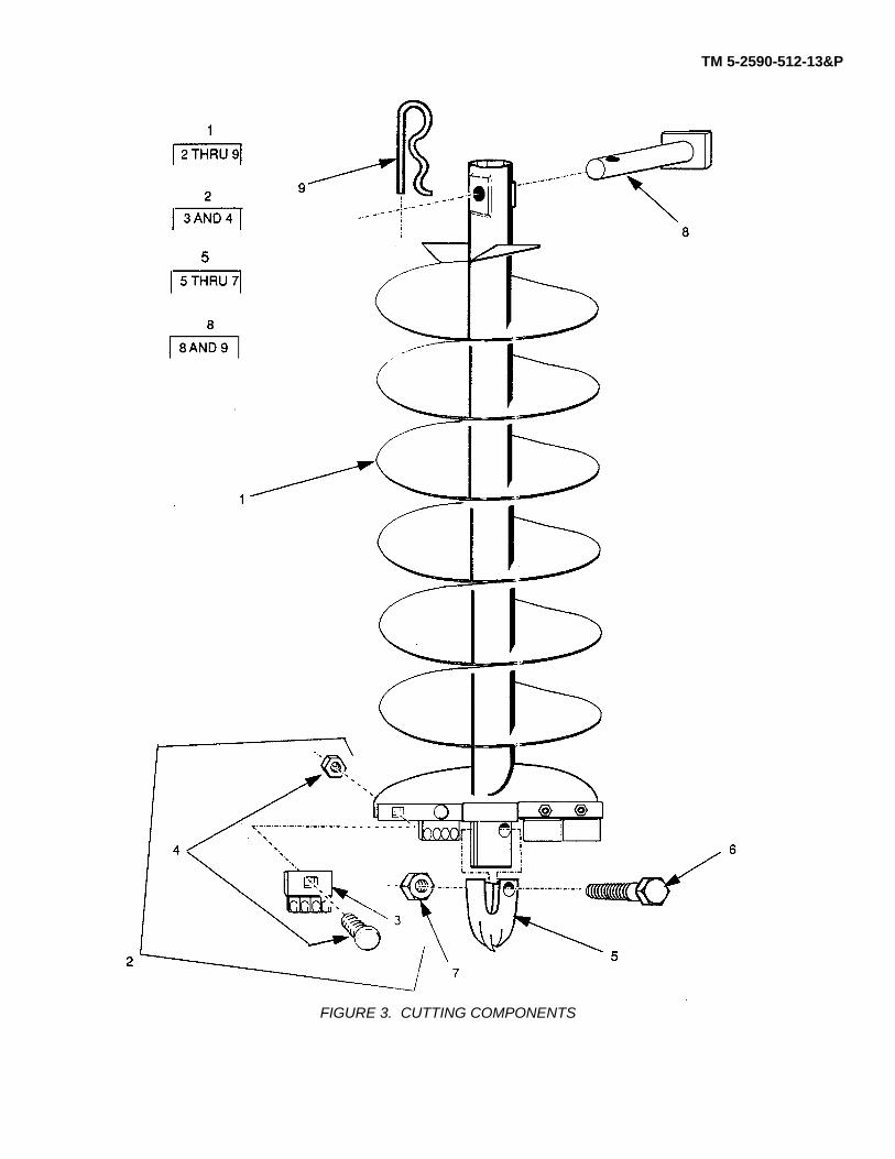
TM 5-2590-512-13&P
FIGURE 3. CUTTING COMPONENTS
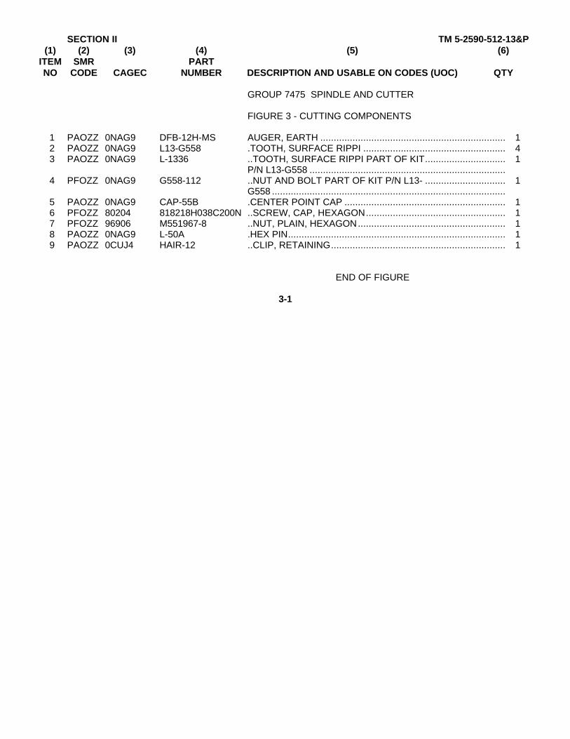
SECTION II TM 5-2590-512-13&P(1) (2) (3) (4) (5) (6)
ITEM SMR PARTNO CODE CAGEC NUMBER DESCRIPTION AND USABLE ON CODES (UOC) QTY
GROUP 7475 SPINDLE AND CUTTER
FIGURE 3 - CUTTING COMPONENTS
1 PAOZZ 0NAG9 DFB-12H-MS AUGER, EARTH ..................................................................... 12 PAOZZ 0NAG9 L13-G558 .TOOTH, SURFACE RIPPI ..................................................... 43 PAOZZ 0NAG9 L-1336 ..TOOTH, SURFACE RIPPI PART OF KIT.............................. 1
P/N L13-G558 .........................................................................4 PFOZZ 0NAG9 G558-112 ..NUT AND BOLT PART OF KIT P/N L13- .............................. 1
G558 .......................................................................................5 PAOZZ 0NAG9 CAP-55B .CENTER POINT CAP ............................................................ 16 PFOZZ 80204 818218H038C200N ..SCREW, CAP, HEXAGON.................................................... 17 PFOZZ 96906 M551967-8 ..NUT, PLAIN, HEXAGON....................................................... 18 PAOZZ 0NAG9 L-50A .HEX PIN................................................................................. 19 PAOZZ 0CUJ4 HAIR-12 ..CLIP, RETAINING................................................................. 1
END OF FIGURE
3-1

TM 5-2590-512-13&P
FIGURE 4. ELBOWS, HOSES, AND BRACKETS
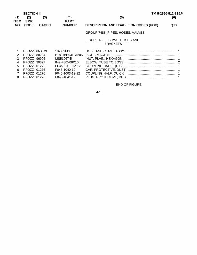
SECTION II TM 5-2590-512-13&P(1) (2) (3) (4) (5) (6)
ITEM SMR PARTNO CODE CAGEC NUMBER DESCRIPTION AND USABLE ON CODES (UOC) QTY
GROUP 7488 PIPES, HOSES, VALVES
FIGURE 4 - ELBOWS, HOSES ANDBRACKETS
1 PFOZZ 0NAG9 10-009MS HOSE AND CLAMP ASSY ...................................................... 12 PFOZZ 80204 B1821BH031C150N .BOLT, MACHINE ................................................................... 13 PFOZZ 96906 MS51967-5 .NUT, PLAIN, HEXAGON........................................................ 14 PFOZZ 30327 849-FSO-08X10 ELBOW, TUBE TO BOSS....................................................... 25 PFOZZ 01276 FD45-1002-12-12 COUPLING HALF, QUICK ...................................................... 16 PFOZZ 01276 F045-1040-12 CAP, PROTECTIVE, DUST..................................................... 17 PFOZZ 01276 F045-1003-12-12 COUPLING HALF, QUICK ...................................................... 18 PFOZZ 01276 F045-1041-12 PLUG, PROTECTIVE, DUS .................................................... 1
END OF FIGURE
4-1
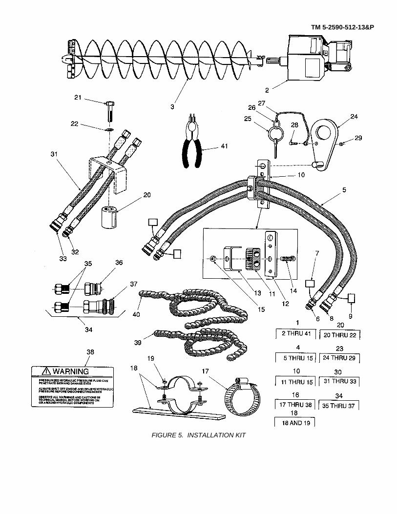
TM 5-2590-512-13&P
FIGURE 5. INSTALLATION KIT
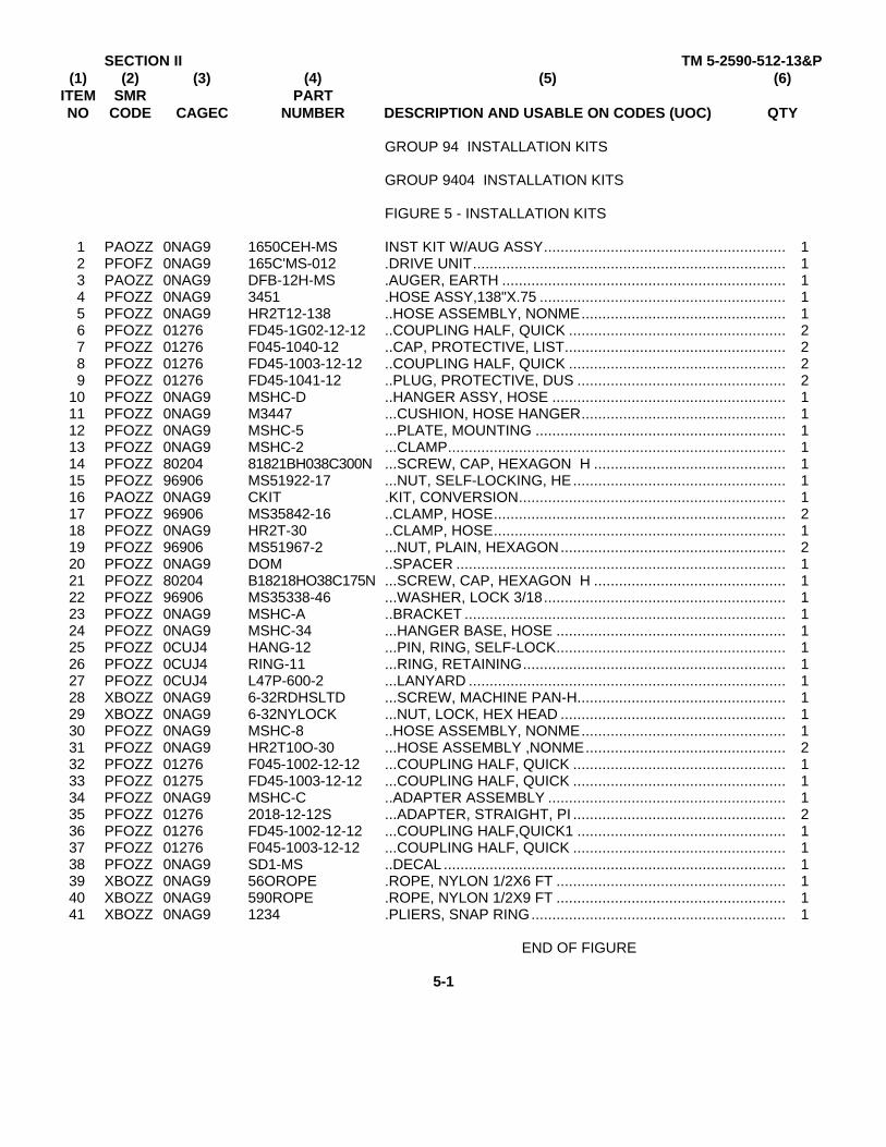
SECTION II TM 5-2590-512-13&P(1) (2) (3) (4) (5) (6)
ITEM SMR PARTNO CODE CAGEC NUMBER DESCRIPTION AND USABLE ON CODES (UOC) QTY
GROUP 94 INSTALLATION KITS
GROUP 9404 INSTALLATION KITS
FIGURE 5 - INSTALLATION KITS
1 PAOZZ 0NAG9 1650CEH-MS INST KIT W/AUG ASSY.......................................................... 12 PFOFZ 0NAG9 165C'MS-012 .DRIVE UNIT........................................................................... 13 PAOZZ 0NAG9 DFB-12H-MS .AUGER, EARTH .................................................................... 14 PFOZZ 0NAG9 3451 .HOSE ASSY,138"X.75 ........................................................... 15 PFOZZ 0NAG9 HR2T12-138 ..HOSE ASSEMBLY, NONME................................................. 16 PFOZZ 01276 FD45-1G02-12-12 ..COUPLING HALF, QUICK .................................................... 27 PFOZZ 01276 F045-1040-12 ..CAP, PROTECTIVE, LIST..................................................... 28 PFOZZ 01276 FD45-1003-12-12 ..COUPLING HALF, QUICK .................................................... 29 PFOZZ 01276 FD45-1041-12 ..PLUG, PROTECTIVE, DUS .................................................. 2
10 PFOZZ 0NAG9 MSHC-D ..HANGER ASSY, HOSE ........................................................ 111 PFOZZ 0NAG9 M3447 ...CUSHION, HOSE HANGER................................................. 112 PFOZZ 0NAG9 MSHC-5 ...PLATE, MOUNTING ............................................................ 113 PFOZZ 0NAG9 MSHC-2 ...CLAMP................................................................................. 114 PFOZZ 80204 81821BH038C300N ...SCREW, CAP, HEXAGON H .............................................. 115 PFOZZ 96906 MS51922-17 ...NUT, SELF-LOCKING, HE................................................... 116 PAOZZ 0NAG9 CKIT .KIT, CONVERSION................................................................ 117 PFOZZ 96906 MS35842-16 ..CLAMP, HOSE...................................................................... 218 PFOZZ 0NAG9 HR2T-30 ..CLAMP, HOSE...................................................................... 119 PFOZZ 96906 MS51967-2 ...NUT, PLAIN, HEXAGON...................................................... 220 PFOZZ 0NAG9 DOM ..SPACER ............................................................................... 121 PFOZZ 80204 B18218HO38C175N ...SCREW, CAP, HEXAGON H .............................................. 122 PFOZZ 96906 MS35338-46 ...WASHER, LOCK 3/18.......................................................... 123 PFOZZ 0NAG9 MSHC-A ..BRACKET ............................................................................. 124 PFOZZ 0NAG9 MSHC-34 ...HANGER BASE, HOSE ....................................................... 125 PFOZZ 0CUJ4 HANG-12 ...PIN, RING, SELF-LOCK....................................................... 126 PFOZZ 0CUJ4 RING-11 ...RING, RETAINING............................................................... 127 PFOZZ 0CUJ4 L47P-600-2 ...LANYARD ............................................................................ 128 XBOZZ 0NAG9 6-32RDHSLTD ...SCREW, MACHINE PAN-H.................................................. 129 XBOZZ 0NAG9 6-32NYLOCK ...NUT, LOCK, HEX HEAD ...................................................... 130 PFOZZ 0NAG9 MSHC-8 ..HOSE ASSEMBLY, NONME................................................. 131 PFOZZ 0NAG9 HR2T10O-30 ...HOSE ASSEMBLY ,NONME................................................ 232 PFOZZ 01276 F045-1002-12-12 ...COUPLING HALF, QUICK ................................................... 133 PFOZZ 01275 FD45-1003-12-12 ...COUPLING HALF, QUICK ................................................... 134 PFOZZ 0NAG9 MSHC-C ..ADAPTER ASSEMBLY ......................................................... 135 PFOZZ 01276 2018-12-12S ...ADAPTER, STRAIGHT, PI ................................................... 236 PFOZZ 01276 FD45-1002-12-12 ...COUPLING HALF,QUICK1 .................................................. 137 PFOZZ 01276 F045-1003-12-12 ...COUPLING HALF, QUICK ................................................... 138 PFOZZ 0NAG9 SD1-MS ..DECAL .................................................................................. 139 XBOZZ 0NAG9 56OROPE .ROPE, NYLON 1/2X6 FT ....................................................... 140 XBOZZ 0NAG9 590ROPE .ROPE, NYLON 1/2X9 FT ....................................................... 141 XBOZZ 0NAG9 1234 .PLIERS, SNAP RING............................................................. 1
END OF FIGURE
5-1

SECTION IV TM 5-2590-512-13&PCROSS- REFERENCE-INDEXES
NATIONAL STOCK NUMBER INDEXSTOCK NUMBER FIG. ITEM STOCK NUMBER FIG. ITEM
5310-00-003-4094 2 295310-00-003-9174 2 265305-00-071-2069 2 325305-00-071-2071 2 285310-00-080-6004 2 105310-00-087-4652 5 153110-00-100-0220 2 223110-00-100-0295 2 215305-00-115-9526 2 85310-00-185-6462 2 165310-00-186-0969 2 175306-00-226-4831 4 25315-00-297-2444 2 44730-00-608-1044 4 7
5 85 335 37
5305-00-726-2525 2 275310-00-732-0558 3 75310-00-761-6882 5 195310-00-768-0318 2 30
2 355305-00-782-9489 3 65310-00-809-5997 2 335310-00-820-6653 2 255305-00-821-3869 5 215305-00-846-5703 5 145310-00-880-7744 4 34730-00-908-6294 5 174730-01-192-4450 4 5
5 65 325 36
5340-01-230-1646 4 65 7
5340-01-236-2094 4 85 9
4730-01-310-4669 5 354730-01-311-4247 4 45330-01-343-8789 2 24
I-1
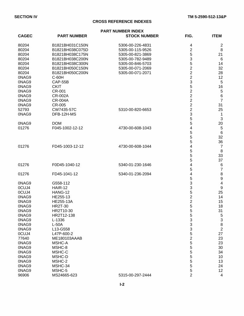
SECTION IV TM 5-2590-512-13&PCROSS REFERENCE INDEXES
PART NUMBER INDEXCAGEC PART NUMBER STOCK NUMBER FIG. ITEM
80204 B1821BH031C150N 5306-00-226-4831 4 280204 B1821BH038C075D 5305-00-115-9526 2 880204 B1821BH038C175N 5305-00-821-3869 5 2180204 B1821BH038C200N 5305-00-782-9489 3 680204 B1821BH038C300N 5305-00-846-5703 5 1480204 B1821BH050C150N 5305-00-071-2069 2 3280204 B1821BH050C200N 5305-00-071-2071 2 280NAG9 C-60H 2 120NAG9 CAP-55B 3 50NAG9 CKIT 5 160NAG9 CR-001 2 50NAG9 CR-002A 2 60NAG9 CR-004A 2 70NAG9 CR-005 2 3152793 CW7435-57C 5310-00-820-6653 2 250NAG9 DFB-12H-MS 3 1
5 30NAG9 DOM 5 2001276 F045-1002-12-12 4730-00-608-1043 4 5
5 65 325 36
01276 FD45-1003-12-12 4730-00-608-1044 4 75 85 335 37
01276 F0D45-1040-12 5340-01-230-1646 4 65 7
01276 FD45-1041-12 5340-01-236-2094 4 85 9
0NAG9 G558-112 3 40CUJ4 HAIR-12 3 90CUJ4 HANG-12 5 250NAG9 HE255-13 2 140NAG9 HE255-13A 2 150NAG9 HR2T-30 5 180NAG9 HR2T10-30 5 310NAG9 HR2T12-138 5 50NAG9 L-1336 3 30NAG9 L-50A 3 80NAG9 L13-G558 3 20CUJ4 L47P-600-2 5 2777640 ME180103AAAB 2 230NAG9 MSHC-A 5 230NAG9 MSHC-8 5 300NAG9 MSHC-C 5 340NAG9 MSHC-D 5 100NAG9 MSHC-2 5 130NAG9 MSHC-34 5 240NAG9 MSHC-5 5 1296906 MS24665-623 5315-00-297-2444 2 4
I-2
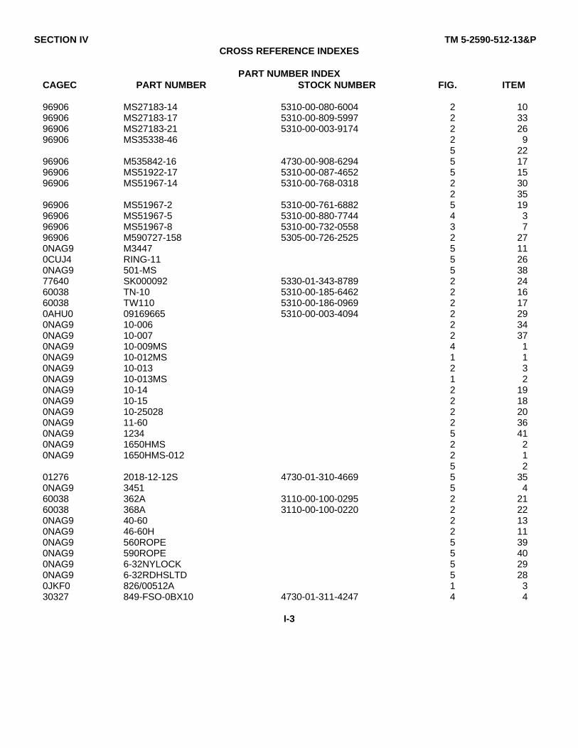
SECTION IV TM 5-2590-512-13&PCROSS REFERENCE INDEXES
PART NUMBER INDEXCAGEC PART NUMBER STOCK NUMBER FIG. ITEM
96906 MS27183-14 5310-00-080-6004 2 1096906 MS27183-17 5310-00-809-5997 2 3396906 MS27183-21 5310-00-003-9174 2 2696906 MS35338-46 2 9
5 2296906 M535842-16 4730-00-908-6294 5 1796906 MS51922-17 5310-00-087-4652 5 1596906 MS51967-14 5310-00-768-0318 2 30
2 3596906 MS51967-2 5310-00-761-6882 5 1996906 MS51967-5 5310-00-880-7744 4 396906 MS51967-8 5310-00-732-0558 3 796906 M590727-158 5305-00-726-2525 2 270NAG9 M3447 5 110CUJ4 RING-11 5 260NAG9 501-MS 5 3877640 SK000092 5330-01-343-8789 2 2460038 TN-10 5310-00-185-6462 2 1660038 TW110 5310-00-186-0969 2 170AHU0 09169665 5310-00-003-4094 2 290NAG9 10-006 2 340NAG9 10-007 2 370NAG9 10-009MS 4 10NAG9 10-012MS 1 10NAG9 10-013 2 30NAG9 10-013MS 1 20NAG9 10-14 2 190NAG9 10-15 2 180NAG9 10-25028 2 200NAG9 11-60 2 360NAG9 1234 5 410NAG9 1650HMS 2 20NAG9 1650HMS-012 2 1
5 201276 2018-12-12S 4730-01-310-4669 5 350NAG9 3451 5 460038 362A 3110-00-100-0295 2 2160038 368A 3110-00-100-0220 2 220NAG9 40-60 2 130NAG9 46-60H 2 110NAG9 560ROPE 5 390NAG9 590ROPE 5 400NAG9 6-32NYLOCK 5 290NAG9 6-32RDHSLTD 5 280JKF0 826/00512A 1 330327 849-FSO-0BX10 4730-01-311-4247 4 4
I-3
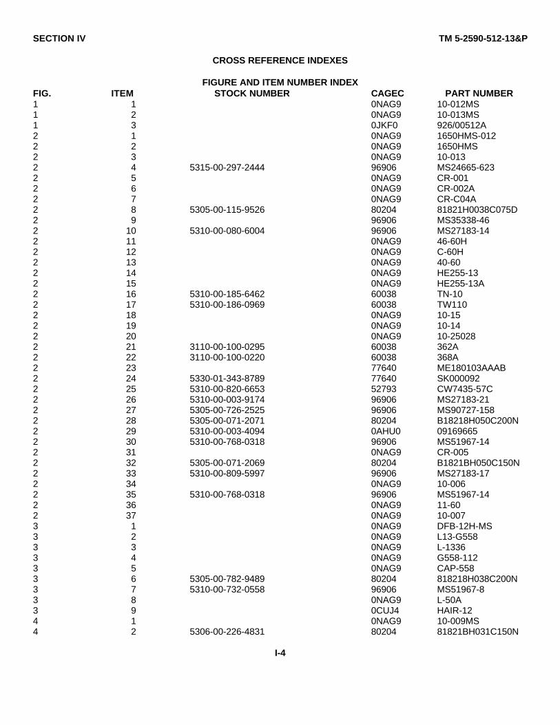
SECTION IV TM 5-2590-512-13&P
CROSS REFERENCE INDEXES
FIGURE AND ITEM NUMBER INDEXFIG. ITEM STOCK NUMBER CAGEC PART NUMBER1 1 0NAG9 10-012MS1 2 0NAG9 10-013MS1 3 0JKF0 926/00512A2 1 0NAG9 1650HMS-0122 2 0NAG9 1650HMS2 3 0NAG9 10-0132 4 5315-00-297-2444 96906 MS24665-6232 5 0NAG9 CR-0012 6 0NAG9 CR-002A2 7 0NAG9 CR-C04A2 8 5305-00-115-9526 80204 81821H0038C075D2 9 96906 MS35338-462 10 5310-00-080-6004 96906 MS27183-142 11 0NAG9 46-60H2 12 0NAG9 C-60H2 13 0NAG9 40-602 14 0NAG9 HE255-132 15 0NAG9 HE255-13A2 16 5310-00-185-6462 60038 TN-102 17 5310-00-186-0969 60038 TW1102 18 0NAG9 10-152 19 0NAG9 10-142 20 0NAG9 10-250282 21 3110-00-100-0295 60038 362A2 22 3110-00-100-0220 60038 368A2 23 77640 ME180103AAAB2 24 5330-01-343-8789 77640 SK0000922 25 5310-00-820-6653 52793 CW7435-57C2 26 5310-00-003-9174 96906 MS27183-212 27 5305-00-726-2525 96906 MS90727-1582 28 5305-00-071-2071 80204 B18218H050C200N2 29 5310-00-003-4094 0AHU0 091696652 30 5310-00-768-0318 96906 MS51967-142 31 0NAG9 CR-0052 32 5305-00-071-2069 80204 B1821BH050C150N2 33 5310-00-809-5997 96906 MS27183-172 34 0NAG9 10-0062 35 5310-00-768-0318 96906 MS51967-142 36 0NAG9 11-602 37 0NAG9 10-0073 1 0NAG9 DFB-12H-MS3 2 0NAG9 L13-G5583 3 0NAG9 L-13363 4 0NAG9 G558-1123 5 0NAG9 CAP-5583 6 5305-00-782-9489 80204 818218H038C200N3 7 5310-00-732-0558 96906 MS51967-83 8 0NAG9 L-50A3 9 0CUJ4 HAIR-124 1 0NAG9 10-009MS4 2 5306-00-226-4831 80204 81821BH031C150N
I-4
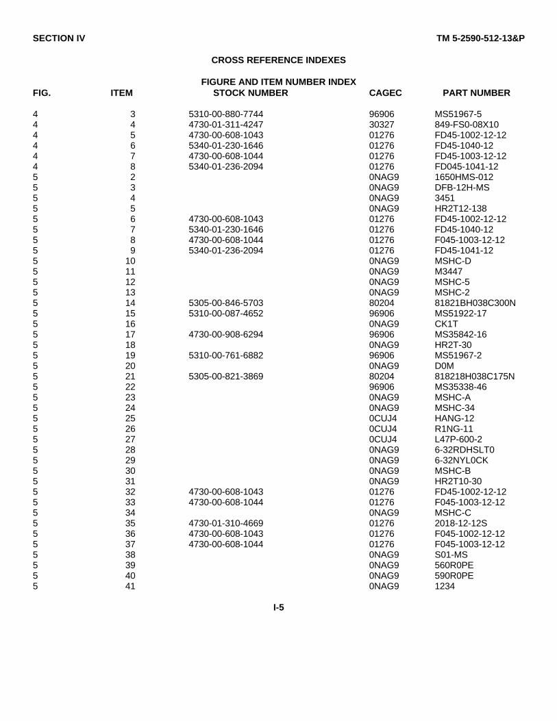
SECTION IV TM 5-2590-512-13&P
CROSS REFERENCE INDEXES
FIGURE AND ITEM NUMBER INDEXFIG. ITEM STOCK NUMBER CAGEC PART NUMBER
4 3 5310-00-880-7744 96906 MS51967-54 4 4730-01-311-4247 30327 849-FS0-08X104 5 4730-00-608-1043 01276 FD45-1002-12-124 6 5340-01-230-1646 01276 FD45-1040-124 7 4730-00-608-1044 01276 FD45-1003-12-124 8 5340-01-236-2094 01276 FD045-1041-125 2 0NAG9 1650HMS-0125 3 0NAG9 DFB-12H-MS5 4 0NAG9 34515 5 0NAG9 HR2T12-1385 6 4730-00-608-1043 01276 FD45-1002-12-125 7 5340-01-230-1646 01276 FD45-1040-125 8 4730-00-608-1044 01276 F045-1003-12-125 9 5340-01-236-2094 01276 FD45-1041-125 10 0NAG9 MSHC-D5 11 0NAG9 M34475 12 0NAG9 MSHC-55 13 0NAG9 MSHC-25 14 5305-00-846-5703 80204 81821BH038C300N5 15 5310-00-087-4652 96906 MS51922-175 16 0NAG9 CK1T5 17 4730-00-908-6294 96906 MS35842-165 18 0NAG9 HR2T-305 19 5310-00-761-6882 96906 MS51967-25 20 0NAG9 D0M5 21 5305-00-821-3869 80204 818218H038C175N5 22 96906 MS35338-465 23 0NAG9 MSHC-A5 24 0NAG9 MSHC-345 25 0CUJ4 HANG-125 26 0CUJ4 R1NG-115 27 0CUJ4 L47P-600-25 28 0NAG9 6-32RDHSLT05 29 0NAG9 6-32NYL0CK5 30 0NAG9 MSHC-B5 31 0NAG9 HR2T10-305 32 4730-00-608-1043 01276 FD45-1002-12-125 33 4730-00-608-1044 01276 F045-1003-12-125 34 0NAG9 MSHC-C5 35 4730-01-310-4669 01276 2018-12-12S5 36 4730-00-608-1043 01276 F045-1002-12-125 37 4730-00-608-1044 01276 F045-1003-12-125 38 0NAG9 S01-MS5 39 0NAG9 560R0PE5 40 0NAG9 590R0PE5 41 0NAG9 1234
I-5
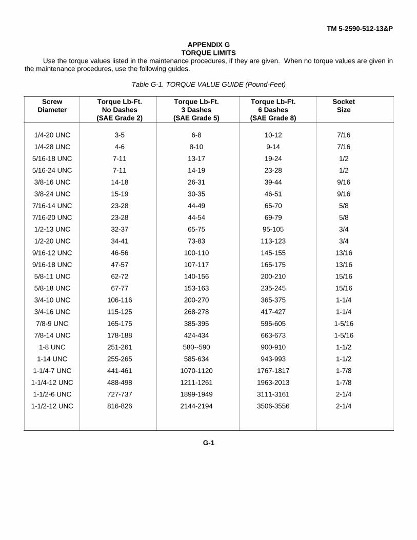
TM 5-2590-512-13&P
APPENDIX GTORQUE LIMITS
Use the torque values listed in the maintenance procedures, if they are given. When no torque values are given inthe maintenance procedures, use the following guides.
Table G-1. TORQUE VALUE GUIDE (Pound-Feet)
Screw Torque Lb-Ft. Torque Lb-Ft. Torque Lb-Ft. SocketDiameter No Dashes 3 Dashes 6 Dashes Size
(SAE Grade 2) (SAE Grade 5) (SAE Grade 8)
1/4-20 UNC 3-5 6-8 10-12 7/16
1/4-28 UNC 4-6 8-10 9-14 7/16
5/16-18 UNC 7-11 13-17 19-24 1/2
5/16-24 UNC 7-11 14-19 23-28 1/2
3/8-16 UNC 14-18 26-31 39-44 9/16
3/8-24 UNC 15-19 30-35 46-51 9/16
7/16-14 UNC 23-28 44-49 65-70 5/8
7/16-20 UNC 23-28 44-54 69-79 5/8
1/2-13 UNC 32-37 65-75 95-105 3/4
1/2-20 UNC 34-41 73-83 113-123 3/4
9/16-12 UNC 46-56 100-110 145-155 13/16
9/16-18 UNC 47-57 107-117 165-175 13/16
5/8-11 UNC 62-72 140-156 200-210 15/16
5/8-18 UNC 67-77 153-163 235-245 15/16
3/4-10 UNC 106-116 200-270 365-375 1-1/4
3/4-16 UNC 115-125 268-278 417-427 1-1/4
7/8-9 UNC 165-175 385-395 595-605 1-5/16
7/8-14 UNC 178-188 424-434 663-673 1-5/16
1-8 UNC 251-261 580--590 900-910 1-1/2
1-14 UNC 255-265 585-634 943-993 1-1/2
1-1/4-7 UNC 441-461 1070-1120 1767-1817 1-7/8
1-1/4-12 UNC 488-498 1211-1261 1963-2013 1-7/8
1-1/2-6 UNC 727-737 1899-1949 3111-3161 2-1/4
1-1/2-12 UNC 816-826 2144-2194 3506-3556 2-1/4
G-1
TM 5-2590-512-13&PINDEX
Subject Para Subject Para
A E
Additional Authorization List App D EquipmentAdjustments, Characteristics 1-6
Chain 4-21 Data 1-9Shaft Bearing 4-27 Description 1-7
Auger Assembly, Equip Description 1-7 ImprovementAuger Center Point Replacement 3-7 Recommendations (EIR), Reporting 1-3Auger Drive Unit Removal 4-15c Elbow Replacement 4-30Auger Drive Unit Installation 4-14bAuger Operating Controls 2-2 FAuger Replacement 3-5Auger Teeth Replacement 3-6Auger Use, Preparation For 4-14 Front Safety Cover Replacement 4-17
Forms, Maintenance Records andB Reports 1-2
Basic Issue Items (BII) App C HBearing, Shaft Adjustment 4-27Bearing, Shaft Replacement 4-28 Hose Replacement 4-31Bearing. Shaft Service 4-29 Housing, Main, Replacement 4-33Bucket Removal 4-14a Hydraulic MotorBucket Installation 4-15d Replacement 4-24Bucket Use. Preparation For 4-15 Repair 5-1
C K
Cautions, Safety 1-10 Kit Installation 4-13bCenter Point Replacement 3-7Chain L
Adjustment 4-19Repair 4-21 Link, Connecting. Replacement 4-16Replacement 4-20 Lubrication Instructions 4-8Service 4-32
Components of End Item App CConnecting Link Replacement 4-16 MControls, Operator 2-2Cover, Maintenance Allocation Chart (MAC) App B
Front Safety, Replacement 4-17 Major Components, Location andRear Safety, Replacement 4-18 Description of 1-7
Criteria. Replacement Teeth 2-7 Maintenance Forms, Records, andConversion Kit Installation 4-13b Reports 1-2
Main Housing Replacement 4-33D Motor, Hydraulic,
Replacement 4-24Repair 5-1
Data Plate Location 2-11 Motor Plate Replacement 4-23Decal Location 1-8 Motor Sprocket Replacement 4-22Description, Equipment 1-7 Movement Preparation forDestruction of Army Materiel to Long Distance 2-10b
Prevent Enemy Use 1-4 Short Distance 2-10aDriven Sprocket Replacement 4-25
INDEX-1
TM 5-2590-512-13&PINDEX
Subject Para Subject Para
O S
Operating Procedures 2-9 Safety Cautions 1-10Operation, Safety Cover Replacement
Cold Weather 2-14 Front 4-17Emergency Procedures 2-13 Rear 4-18Preparation for 4-12 Seal, ShaftTechnical Principles of 1-11 Replacement 4-28Under Unusual Conditions 2-14 Service 4-29Under Usual Conditions 2-8 Shaft Bearing.
Operator's Adjustment 4-27Controls 2-2 Replacement 4-28PMCS Table 2-7 Shaft Output Replacement 4-26Maintenance Tasks 3-5 Spare Parts 4-1Troubleshooting Procedures 3-1 Specifications. Torque, Chart App G
Output Shaft Replacement 4-26 SprocketDriven. Replacement 4-25
P Motor, Replacement 4-22Supplies, Expendable, and MaterialsList App E
Parts,Repair App FSpare 4-1 T
Plate, Motor. Replacement 4-23Preparation for Teeth, Criteria for Replacement 2-7
Bucket Use 4-15 Teeth. Auger, Replacement 3-6Earth Auger Use 4-14 Tools App BMovement Torque Specifications Chart App G
Long Distance 2-10b Transporting. AugerShort Distance 2-10a Long Distance 2-10b
Procedures, Operating 2-9 Short Distance 2-10aPMCS Table Troubleshooting. Unit 4-11
Operator 2-7Unit 4-8 U
R UnitPMCS 4-8
Rear Safety Cover Replacement 4-18 Troubleshooting 4-11Repair Parts and Special Tools List Unusual Conditions, Operation Under 2-14(RPSTL) App F Usual Conditions, Operation Under 2-8Replacement Teeth Criteria 2-7Reporting Equipment Improvement WRecommendations (EIR) 1-3
Warnings InsideCover
Warranty Information App A
INDEX-2

THE METRIC SYSTEM AND EQUIVALENTS

PIN: 074042-000

This fine document...
Was brought to you by me:
Liberated Manuals -- free army and government manuals
Why do I do it? I am tired of sleazy CD-ROM sellers, who take publicly available information, slap “watermarks” and other junk on it, and sell it. Those masters of search engine manipulation make sure that their sites that sell free information, come up first in search engines. They did not create it... They did not even scan it... Why should they get your money? Why are not letting you give those free manuals to your friends?
I am setting this document FREE. This document was made by the US Government and is NOT protected by Copyright. Feel free to share, republish, sell and so on.
I am not asking you for donations, fees or handouts. If you can, please provide a link to liberatedmanuals.com, so that free manuals come up first in search engines:
<A HREF=http://www.liberatedmanuals.com/>Free Military and Government Manuals</A>
– SincerelyIgor Chudovhttp://igor.chudov.com/
– Chicago Machinery Movers