tm 50 bd blast door single leaf
TRANSCRIPT

8/9/2019 TM 50 BD Blast Door Single Leaf
http://slidepdf.com/reader/full/tm-50-bd-blast-door-single-leaf 1/26
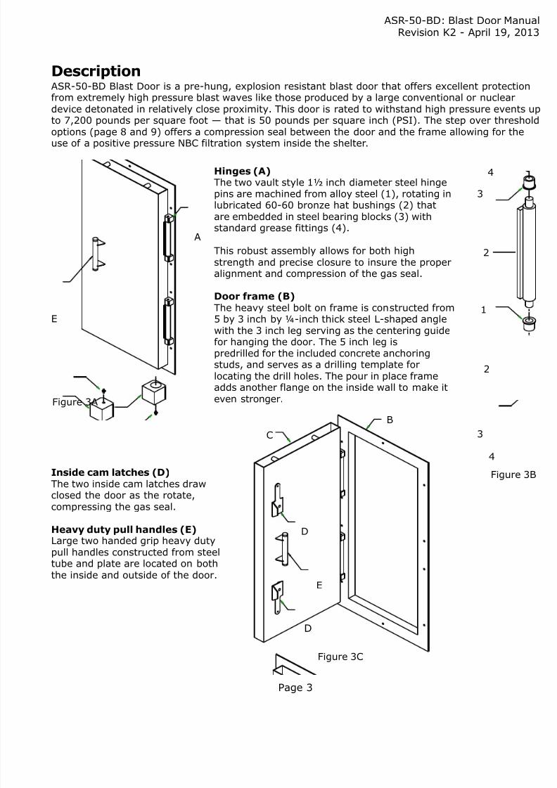
American Safe RoomExplosion Resistant
Pre-hung
Blast Door
Drawing number: ASR-50-Revision:
April 19, 20
8/9/2019 TM 50 BD Blast Door Single Leaf
http://slidepdf.com/reader/full/tm-50-bd-blast-door-single-leaf 2/26
Table of Contents
Description .............................................................................................................
Strength of the blast door ........................................................................................
Part number worksheet .............................................................................................
Option: opening direction ..........................................................................................Option: inward and outward swinging doors ................................................................Option: bolt on or pour in place frames .......................................................................Option: frame styles .................................................................................................Option: door size — step over threshold .....................................................................Option: door size — step over frame ..........................................................................Option: door size — flat threshold ..............................................................................Option: outside operators .........................................................................................Option: assault resistant security latches ....................................................................Option: outside deadbolt lock assembly.......................................................................Option: inset deadbolt lock assembly ..........................................................................Option: security viewer .............................................................................................Option: differential pressure gauge .............................................................................Option: additional fire rated door seal .........................................................................
Lock and latch operation ...........................................................................................
Bolt on frame installation: hanging the door ................................................................Bolt on frame installation: installing the anchors, grouting the door frame........................Bolt on frame installation: wall capture brackets ...........................................................Bolt on frame installation: sealing the inside door frame lip .............................................Bolt on frame installation: filling the door with concrete .................................................Bolt on frame installation: concrete wedge anchor — technical information .......................
Blast load certification: introduction ............................................................................Blast load certification: professional engineer stamped letter ..........................................Blast load certification: door leaf blast load rating .........................................................Blast load certification: rebound load cam latch load rating - 1 ........................................Blast load certification: rebound load cam latch load rating - 2 ........................................
COPYRIGHT ©2013 LEONARD M. HENRIKSON, ALL RIGHTS RESERVED
ASR-50-BD: Blast Door ManRevision K2 - April 19, 2
Contact information
American Safe Room868 Murdock DriveOakland, OR 97462
Telephone: 541-459-1806FAX: 503-212-6695
Websites: www.AmericanBombShelter.com www.AmericanSafeRoom.comwww.AmericanBlastDoor.com www.AmericanBlastValve.com
8/9/2019 TM 50 BD Blast Door Single Leaf
http://slidepdf.com/reader/full/tm-50-bd-blast-door-single-leaf 3/26
8/9/2019 TM 50 BD Blast Door Single Leaf
http://slidepdf.com/reader/full/tm-50-bd-blast-door-single-leaf 4/26

8/9/2019 TM 50 BD Blast Door Single Leaf
http://slidepdf.com/reader/full/tm-50-bd-blast-door-single-leaf 5/26
ASR-50-BD: Blast Door ManRevision K2 - April 19, 2
Page 5
Part numberThe first step to ordering a blast door is to determine which options are required and create a parnumber. Every option is explained in this manual on the page numbers references below.
The part number example shown below represents right hand outward swinging bolt-on door, withstep over frame threshold, a 36 inch wide by 80 inch high frame size, without outside operators, wassault resistant security latches, without outside deadbolt assembly, with the inset deadboltassembly, with a viewer, without a differential pressure gauge, and with an additional fire rated dooseal. You can fill out the part number block at the left to show the exact blast door you require.
Hand, frame, threshold and size1. Right or left hand opening, (R or L), see page 6
2. Outward or inward swinging (O or I), see page 6
3. Frame type, bolt-on or pour-in-place (B or P), see page 7 Note: Please include the dimension inside to inside of the frame flanges
with the part number. See page 7 for more information
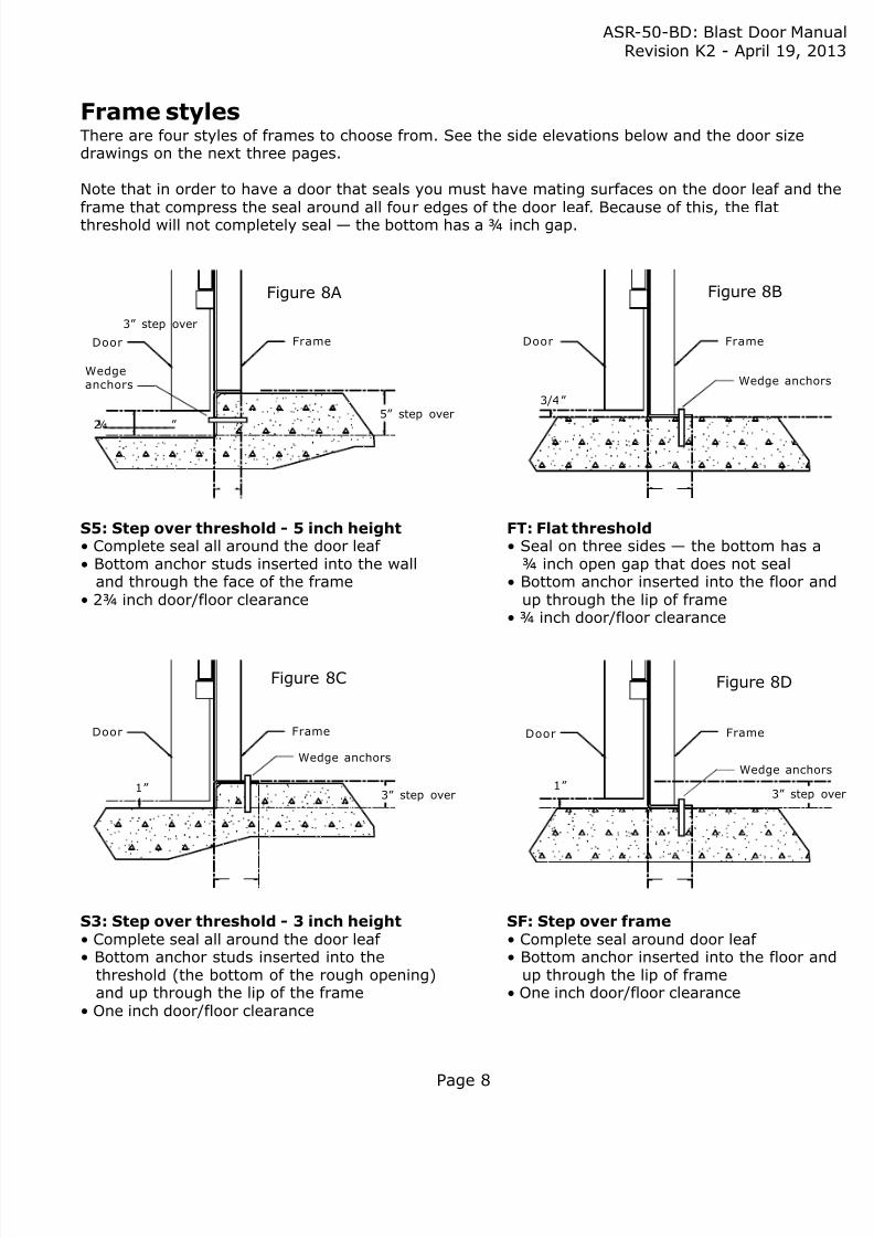
4. Threshold type: stepover 3” (S3), stepover 5” (S5), flat (FT),or stepover frame (SF), see page 8
5. Frame size in inches, width (##.##) x height (##.##), see page 9, 10, and 1132.00 x 72.00 inches and 36.00 x 80.00 inches are the standard door sizes
Note: nonstandard sized door sizes may cost extra We have built many custom doors and will build to fit your existing opening
Latches and locks6. Outside operators, (Y or N), see page 12
7. Assault resistant security latches andwall capture brackets, (Y or N), see page 13
8. Outside deadbolt lock assembly, (Y or N), see page 14
9. Inset deadbolt lock assembly (Y or N), see page 15
Note: Items (6 and 7) and (8 and 9) are not normally ordered together on the same door
Options10. Wide angle viewer, (Y or N), see page 16
11. Differential pressure gauge, (Y or N), see page 16
12. Additional fire rated door seal (Y or N), see page 16
R O B SF 36.0 80.0 N Y N Y Y Y Y
1 2 3 4 5 5 6 7 8 9 10 11 12Frame size
To quote price andavailability on a blasdoor, we need to knthis part number, tcomplete deliveryaddress, whether ita commercial orresidential address,
and if you can off-lit with forklift or nea drop gate truck tdeliver it on theground. You will neto have turn arounroom where the dowill be delivered.
Please e-mail this information to [email protected] or FAX it to 503-212-669
8/9/2019 TM 50 BD Blast Door Single Leaf
http://slidepdf.com/reader/full/tm-50-bd-blast-door-single-leaf 6/26
ASR-50-BD: Blast Door ManRevision K2 - April 19, 2
Page 6
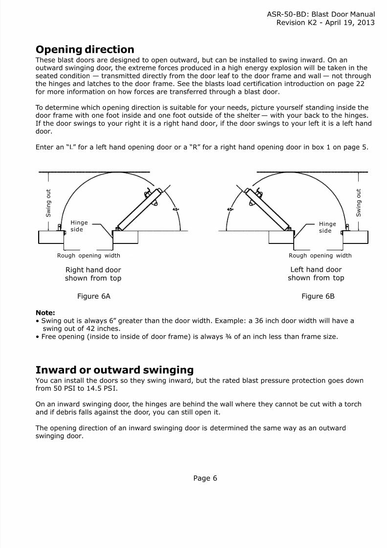
Note:• Swing out is always 6” greater than the door width. Example: a 36 inch door width will have a swing out of 42 inches.• Free opening (inside to inside of door frame) is always ¾ of an inch less than frame size.
Hinge
sideHingeside
S w i n g
o u t
S w i n g
o u t
Right hand doorshown from top
Left hand doorshown from top
Opening directionThese blast doors are designed to open outward, but can be installed to swing inward. On anoutward swinging door, the extreme forces produced in a high energy explosion will be taken in thseated condition — transmitted directly from the door leaf to the door frame and wall — not throuthe hinges and latches to the door frame. See the blasts load certification introduction on page 22for more information on how forces are transferred through a blast door.
To determine which opening direction is suitable for your needs, picture yourself standing inside thdoor frame with one foot inside and one foot outside of the shelter — with your back to the hingeIf the door swings to your right it is a right hand door, if the door swings to your left it is a left hadoor.
Enter an “L” for a left hand opening door or a “R” for a right hand opening door in box 1 on page
Figure 6A
Rough opening width
Inward or outward swinging
You can install the doors so they swing inward, but the rated blast pressure protection goes downfrom 50 PSI to 14.5 PSI.
On an inward swinging door, the hinges are behind the wall where they cannot be cut with a torchand if debris falls against the door, you can still open it.
The opening direction of an inward swinging door is determined the same way as an outwardswinging door.
Rough opening width
Figure 6B

8/9/2019 TM 50 BD Blast Door Single Leaf
http://slidepdf.com/reader/full/tm-50-bd-blast-door-single-leaf 7/26
ASR-50-BD: Blast Door ManRevision K2 - April 19, 2
Page 7
Bolt on or pour in place frame
Pour in place installationTo install a pour in place door, you need to connect theframe flanges to the wall forms. We don’ t provide specificinstallation instructions on how to do this, but here arethree installation methods that our customers have used:
Butt up the wall form boards to the frame flanges.
Overlap the wall form boards to the frame flanges.
Insert ICF blocks part way inside the frame flanges.
Whatever method you use, be sure that there is sufficient contactbetween the poured concrete and the frame: at least the bottomparts of both flanges and the web should be in contact with theconcrete. In other words, do not insert the form material (plywoodor ICF block) all the way to the web of the frame channel. This will
float the blast door on the form material instead of having a concreteto steel connection on the frame.
For pour in place doors, we need to know the inside to insideflange dimension you want. Please provide this with the part number. See figure 7B for this dimension.
If you are going to butt up the form boards to the frameflanges, the inside to inside dimension should be the exactthickness of the concrete wall.
If you are going to overlap the form boards to the frame
flanges, the inside to inside dimension should be the thicknessof the wall, minus ½ inch because the frame flanges are each¼ inch thick.
If you are going to insert ICF blocks part way into the frame,the inside to inside dimension should be the concretethickness of your wall plus double the ICF block thickness.
After the walls have cured, the door leaf needs to be filled withconcrete. See page 20 for instructions on filling it.
Bolt onThe bolt on doors feature an easy
installation and if you are on a tightschedule, it allows you to pour yourshelter walls first, then install thedoor after the wall cures. See page18 for this installation.
Pour in placeThe pour in place doors are the mo
secure installation. They feature achannel section frame that is the fofor the door opening. The wall pourconcrete flows into this channel, locking it in place.
Stiffenerbetween flang
Inner channelflange
Channel webbetween innerouter flanges
Figure 7APour in place frame detail
Outer channeflange
Door leaf
Figure 7B
Inside to inside of the frame flanges
8/9/2019 TM 50 BD Blast Door Single Leaf
http://slidepdf.com/reader/full/tm-50-bd-blast-door-single-leaf 8/26
8/9/2019 TM 50 BD Blast Door Single Leaf
http://slidepdf.com/reader/full/tm-50-bd-blast-door-single-leaf 9/26
8/9/2019 TM 50 BD Blast Door Single Leaf
http://slidepdf.com/reader/full/tm-50-bd-blast-door-single-leaf 10/26
ASR-50-BD: Blast Door ManRevision K2 - April 19, 2
Page 10
Width
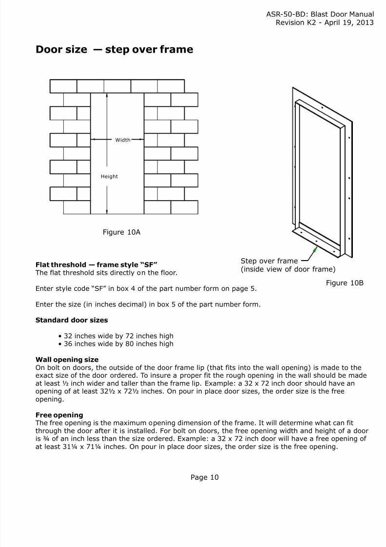
Door size — step over frame
Step over frame(inside view of door frame)
Figure 10A
Figure 10B
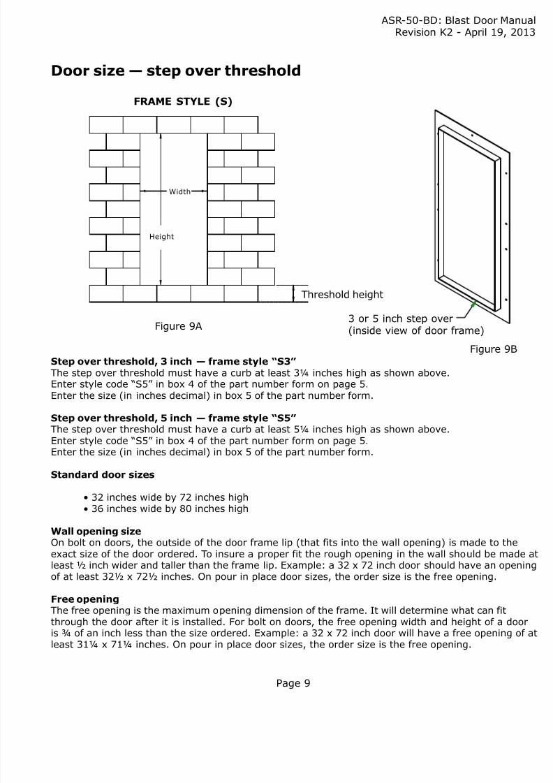
Flat threshold— frame style “SF”The flat threshold sits directly on the floor.
Enter style code “SF” in box 4 of the part number form on page 5.
Enter the size (in inches decimal) in box 5 of the part number form.
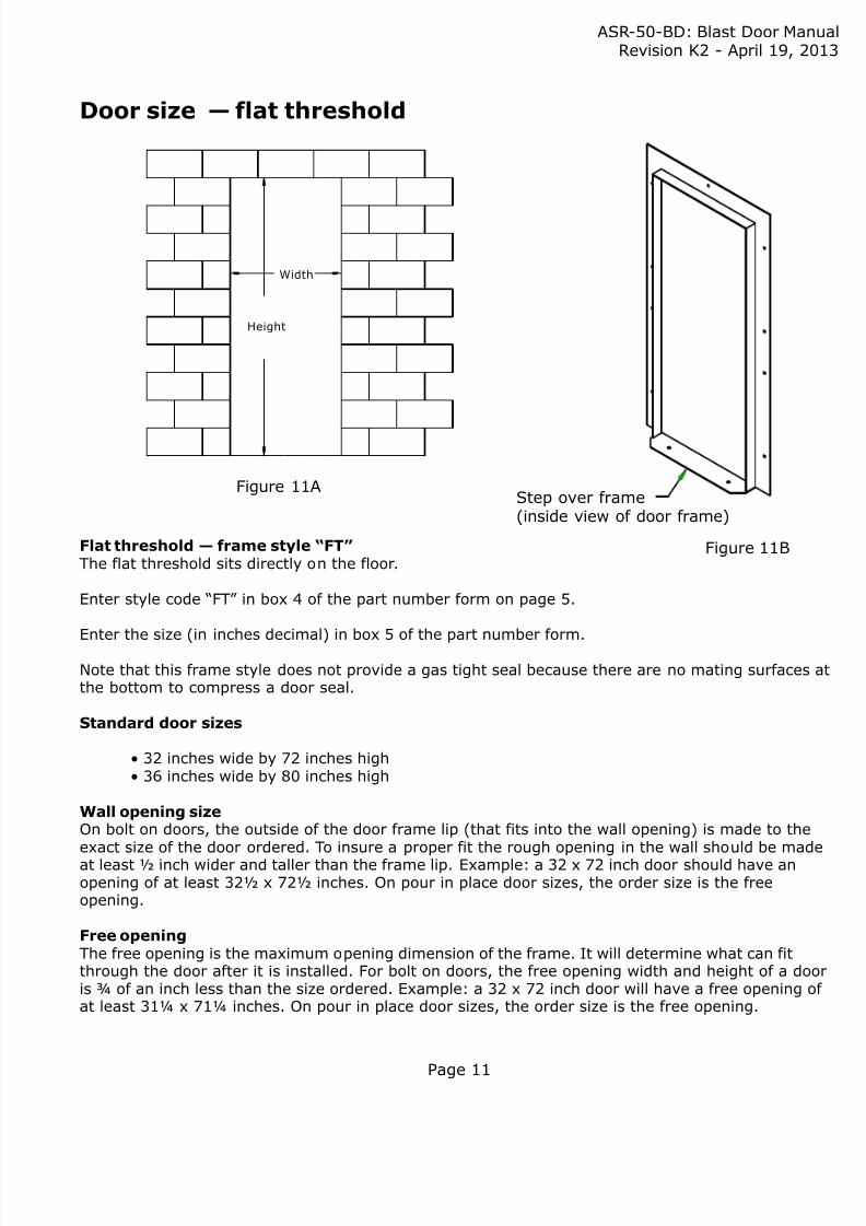
Standard door sizes
• 32 inches wide by 72 inches high• 36 inches wide by 80 inches high
Wall opening sizeOn bolt on doors, the outside of the door frame lip (that fits into the wall opening) is made to theexact size of the door ordered. To insure a proper fit the rough opening in the wall should be mad
at least ½ inch wider and taller than the frame lip. Example: a 32 x 72 inch door should have anopening of at least 32½ x 72½ inches. On pour in place door sizes, the order size is the freeopening.
Free openingThe free opening is the maximum opening dimension of the frame. It will determine what can fitthrough the door after it is installed. For bolt on doors, the free opening width and height of a doois ¾ of an inch less than the size ordered. Example: a 32 x 72 inch door will have a free opening oat least 31¼ x 71¼ inches. On pour in place door sizes, the order size is the free opening.
Height
8/9/2019 TM 50 BD Blast Door Single Leaf
http://slidepdf.com/reader/full/tm-50-bd-blast-door-single-leaf 11/26
8/9/2019 TM 50 BD Blast Door Single Leaf
http://slidepdf.com/reader/full/tm-50-bd-blast-door-single-leaf 12/26
ASR-50-BD: Blast Door ManRevision K2 - April 19, 2
Page 12
1
1
2
2
Figure 12A
Figure 12B
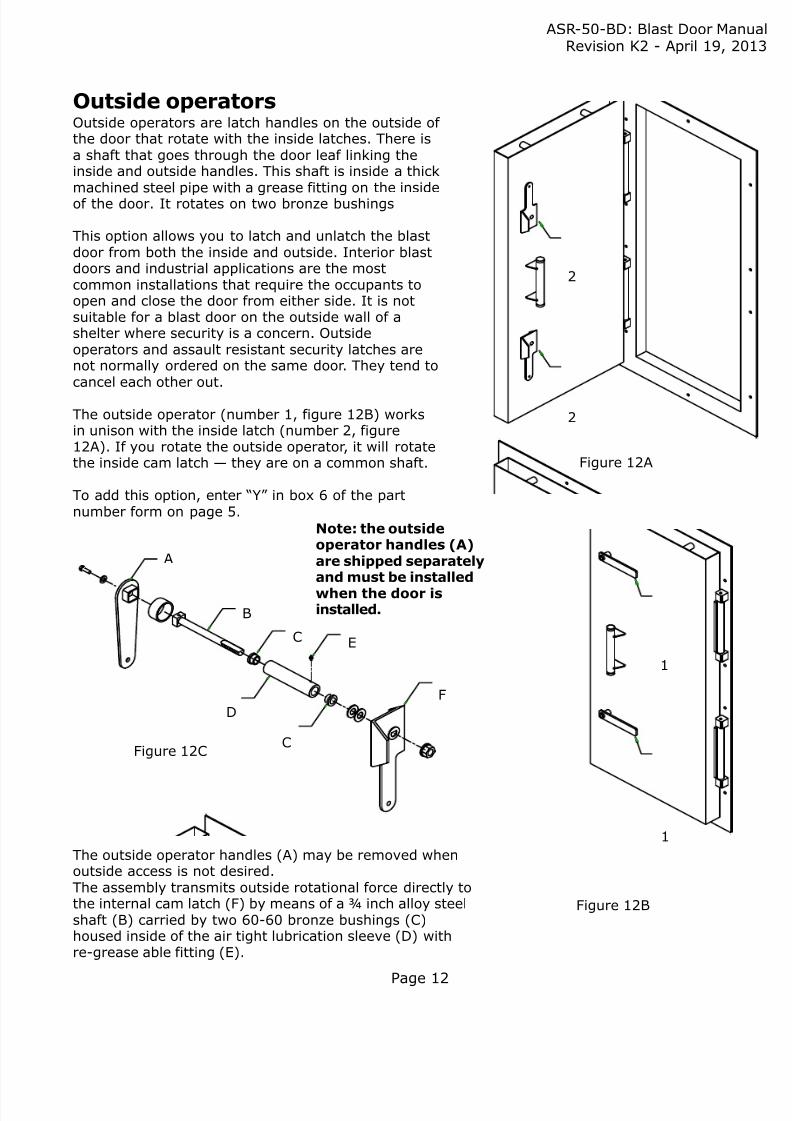
Outside operatorsOutside operators are latch handles on the outside of the door that rotate with the inside latches. There isa shaft that goes through the door leaf linking theinside and outside handles. This shaft is inside a thickmachined steel pipe with a grease fitting on the insideof the door. It rotates on two bronze bushings
This option allows you to latch and unlatch the blastdoor from both the inside and outside. Interior blastdoors and industrial applications are the mostcommon installations that require the occupants toopen and close the door from either side. It is notsuitable for a blast door on the outside wall of ashelter where security is a concern. Outsideoperators and assault resistant security latches arenot normally ordered on the same door. They tend tocancel each other out.
The outside operator (number 1, figure 12B) worksin unison with the inside latch (number 2, figure12A). If you rotate the outside operator, it will rotatethe inside cam latch — they are on a common shaft.
To add this option, enter “Y” in box 6 of the partnumber form on page 5.
The outside operator handles (A) may be removed whenoutside access is not desired.The assembly transmits outside rotational force directly tothe internal cam latch (F) by means of a ¾ inch alloy steelshaft (B) carried by two 60-60 bronze bushings (C)housed inside of the air tight lubrication sleeve (D) withre-grease able fitting (E).
A
B
C E
F
D
CFigure 12C
Note: the outsideoperator handles (A)are shipped separatelyand must be installed
when the door isinstalled.
8/9/2019 TM 50 BD Blast Door Single Leaf
http://slidepdf.com/reader/full/tm-50-bd-blast-door-single-leaf 13/26
ASR-50-BD: Blast Door ManRevision K2 - April 19, 2
Page 13
A
Banti-slipbracket
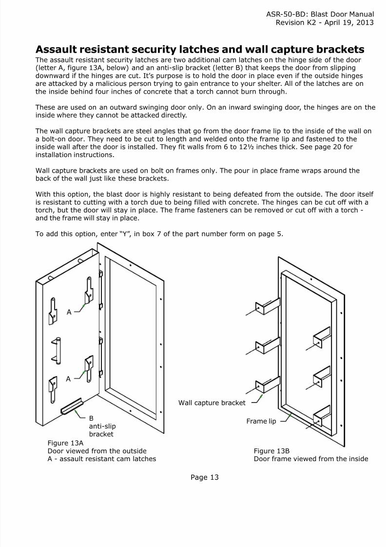
Figure 13ADoor viewed from the outsideA - assault resistant cam latches
Figure 13BDoor frame viewed from the insid
Assault resistant security latches and wall capture bracketsThe assault resistant security latches are two additional cam latches on the hinge side of the door(letter A, figure 13A, below) and an anti-slip bracket (letter B) that keeps the door from slippingdownward if the hinges are cut. It’ s purpose is to hold the door in place even if the outside hingesare attacked by a malicious person trying to gain entrance to your shelter. All of the latches are onthe inside behind four inches of concrete that a torch cannot burn through.
These are used on an outward swinging door only. On an inward swinging door, the hinges are on inside where they cannot be attacked directly.
The wall capture brackets are steel angles that go from the door frame lip to the inside of the wall a bolt-on door. They need to be cut to length and welded onto the frame lip and fastened to theinside wall after the door is installed. They fit walls from 6 to 12½ inches thick. See page 20 forinstallation instructions.
Wall capture brackets are used on bolt on frames only. The pour in place frame wraps around theback of the wall just like these brackets.
With this option, the blast door is highly resistant to being defeated from the outside. The door itis resistant to cutting with a torch due to being filled with concrete. The hinges can be cut off withtorch, but the door will stay in place. The frame fasteners can be removed or cut off with a torch -and the frame will stay in place.
To add this option, enter “Y” , in box 7 of the part number form on page 5.
Wall capture bracket
Frame lip
A
8/9/2019 TM 50 BD Blast Door Single Leaf
http://slidepdf.com/reader/full/tm-50-bd-blast-door-single-leaf 14/26
ASR-50-BD: Blast Door ManRevision K2 - April 19, 2
Page 14
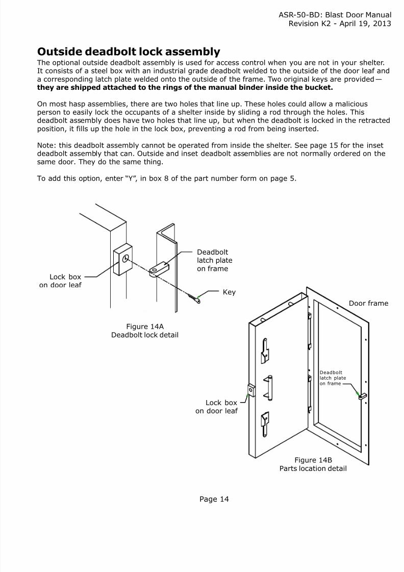
Lock boxon door leaf
Deadboltlatch plateon frame
Key
Figure 14ADeadbolt lock detail
Figure 14BParts location detail
Outside deadbolt lock assemblyThe optional outside deadbolt assembly is used for access control when you are not in your shelteIt consists of a steel box with an industrial grade deadbolt welded to the outside of the door leaf aa corresponding latch plate welded onto the outside of the frame. Two original keys are provided —
they are shipped attached to the rings of the manual binder inside the bucket.
On most hasp assemblies, there are two holes that line up. These holes could allow a maliciousperson to easily lock the occupants of a shelter inside by sliding a rod through the holes. Thisdeadbolt assembly does have two holes that line up, but when the deadbolt is locked in the retracposition, it fills up the hole in the lock box, preventing a rod from being inserted.
Note: this deadbolt assembly cannot be operated from inside the shelter. See page 15 for the insedeadbolt assembly that can. Outside and inset deadbolt assemblies are not normally ordered on thsame door. They do the same thing.
To add this option, enter “Y” , in box 8 of the part number form on page 5.
Door fra
Lock boxon door leaf
Deadboltlatch plateon frame
8/9/2019 TM 50 BD Blast Door Single Leaf
http://slidepdf.com/reader/full/tm-50-bd-blast-door-single-leaf 15/26
ASR-50-BD: Blast Door ManRevision K2 - April 19, 2
Page 15
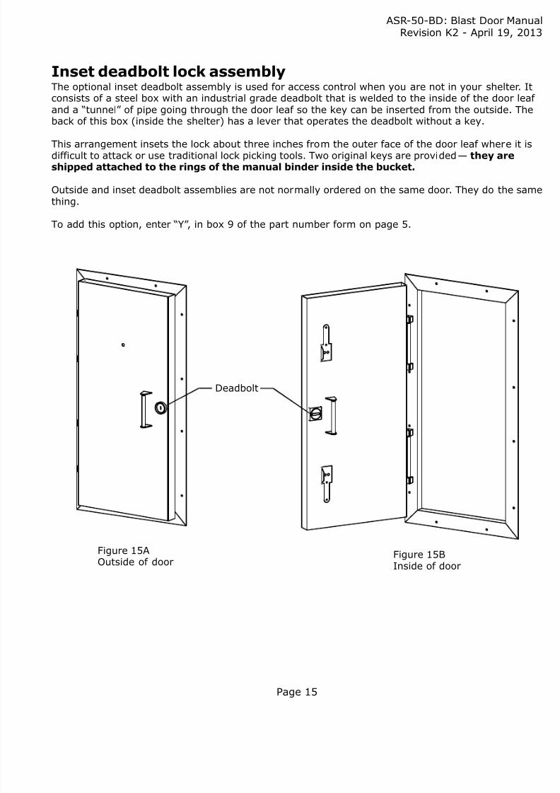
Inset deadbolt lock assemblyThe optional inset deadbolt assembly is used for access control when you are not in your shelter. Iconsists of a steel box with an industrial grade deadbolt that is welded to the inside of the door leand a “tunnel” of pipe going through the door leaf so the key can be inserted from the outside. Thback of this box (inside the shelter) has a lever that operates the deadbolt without a key.
This arrangement insets the lock about three inches from the outer face of the door leaf where it idifficult to attack or use traditional lock picking tools. Two original keys are provided — they areshipped attached to the rings of the manual binder inside the bucket.
Outside and inset deadbolt assemblies are not normally ordered on the same door. They do the sathing.
To add this option, enter “Y” , in box 9 of the part number form on page 5.
Figure 15AOutside of door Figure 15BInside of door
Deadbolt
8/9/2019 TM 50 BD Blast Door Single Leaf
http://slidepdf.com/reader/full/tm-50-bd-blast-door-single-leaf 16/26
ASR-50-BD: Blast Door ManRevision K2 - April 19, 2
Page 16
B
B
A
A
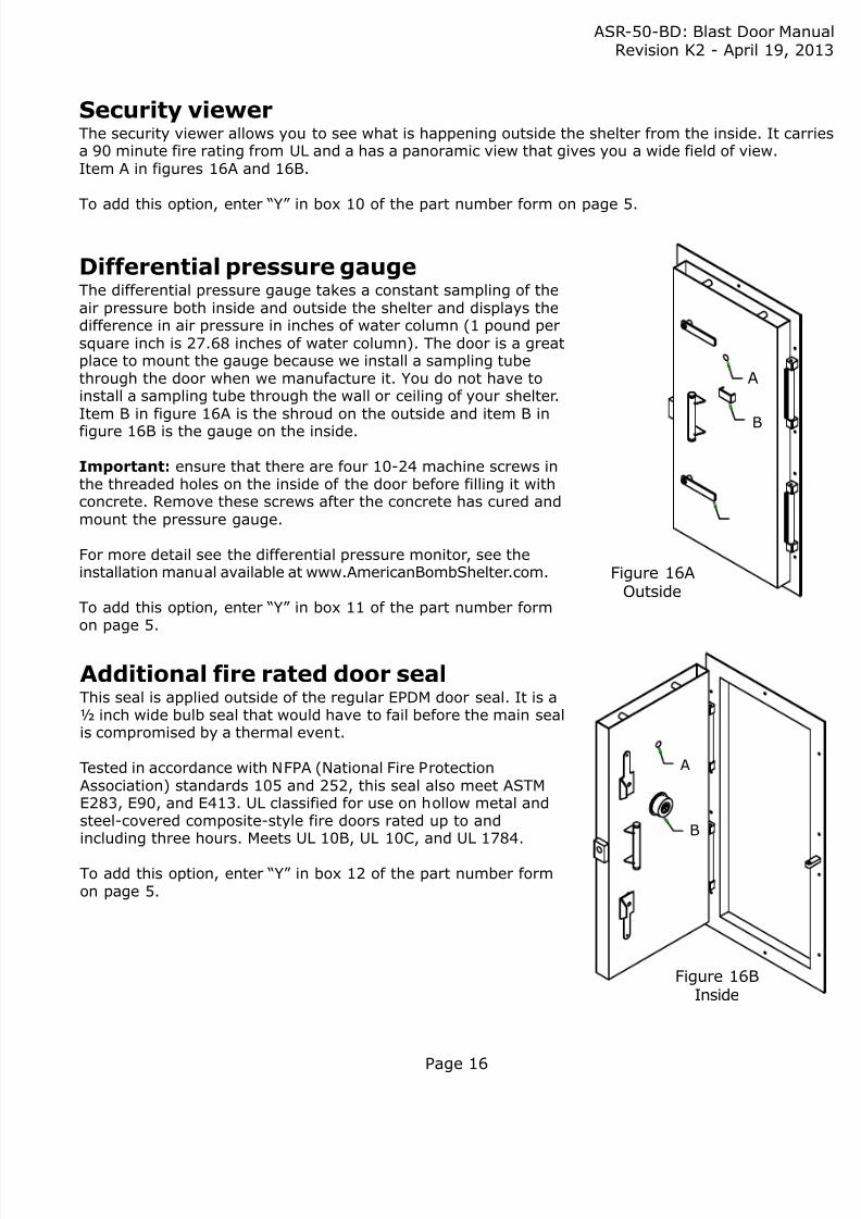
Figure 16AOutside
Figure 16BInside
Security viewerThe security viewer allows you to see what is happening outside the shelter from the inside. It cara 90 minute fire rating from UL and a has a panoramic view that gives you a wide field of view.Item A in figures 16A and 16B.
To add this option, enter “Y” in box 10 of the part number form on page 5.
Additional fire rated door sealThis seal is applied outside of the regular EPDM door seal. It is a½ inch wide bulb seal that would have to fail before the main sealis compromised by a thermal event.
Tested in accordance with NFPA (National Fire ProtectionAssociation) standards 105 and 252, this seal also meet ASTME283, E90, and E413. UL classified for use on hollow metal andsteel-covered composite-style fire doors rated up to andincluding three hours. Meets UL 10B, UL 10C, and UL 1784.
To add this option, enter “Y” in box 12 of the part number formon page 5.
Differential pressure gaugeThe differential pressure gauge takes a constant sampling of theair pressure both inside and outside the shelter and displays thedifference in air pressure in inches of water column (1 pound persquare inch is 27.68 inches of water column). The door is a greatplace to mount the gauge because we install a sampling tubethrough the door when we manufacture it. You do not have toinstall a sampling tube through the wall or ceiling of your shelter.Item B in figure 16A is the shroud on the outside and item B in
figure 16B is the gauge on the inside.
Important: ensure that there are four 10-24 machine screws inthe threaded holes on the inside of the door before filling it withconcrete. Remove these screws after the concrete has cured andmount the pressure gauge.
For more detail see the differential pressure monitor, see theinstallation manual available at www.AmericanBombShelter.com.
To add this option, enter “Y” in box 11 of the part number formon page 5.

8/9/2019 TM 50 BD Blast Door Single Leaf
http://slidepdf.com/reader/full/tm-50-bd-blast-door-single-leaf 17/26
ASR-50-BD: Blast Door ManRevision K2 - April 19, 2
Page 17
Outside view - outside deadboltThe outside deadbolt assembly is a steel box wa deadbolt lock welded to the door envelope (A
and latch plate welded to the frame (B). The bomay be locked in either the locked or opencondition from the outside, with a key. It cannobe operated from inside the shelter.
Outside view - inset deadboltThe inset deadbolt assembly is a steel pipe weldthrough the door leaf with a deadbolt lock weldto the inside end of it (C). The bolt inserts into hole in the frame when in the locked position. Tbolt may be locked in either the locked or opencondition from the outside with a key, or the inwithout a key — it has a rotating handle on theinside.
Note: if you have either of the deadbolt optionis critical that you not warp the frame whentightening the concrete wedge anchors. You caget the hole in the strike out of alignment with deadbolt.
Inside viewThe two cam lock levers (D) draw the door tigh
the gas seal by means of tightening against thecam plate (E). In the open position the lever enpoint up and down or away from each other. Inthe closed or locked position the lever ends areparallel pointing across the door to the hingedside. They rotate in opposite directions to latchcase the door is subject to extreme vibrations iblast — if one latch is loosened, the other willtighten.
Figure 17B shows the top lever in the open orunlatched position, and the bottom lever in the
closed or latched position.
Item F is the inside of the inset deadbolt assemIt has a handle the operates the bolt without thkey.
Figure 17A
A
B
D
E
D
Lock and latch operation
Figure 17B
C
F
Note: figures 17A and 17B show both theoutside deadbolt assembly and the insetdeadbolt assembly for illustration purposes.These two assemblies are not usually foundon the same door because they do thesame thing — give you access control whenyou are not in your shelter.
8/9/2019 TM 50 BD Blast Door Single Leaf
http://slidepdf.com/reader/full/tm-50-bd-blast-door-single-leaf 18/26
ASR-50-BD: Blast Door ManRevision K2 - April 19, 2
Page 18
Installation — bolt on frameHanging the doorThe pre-hung blast door is constructed with two lifting points inside the door envelope. Use onlylifting equipment and hardware approved for overhead lifting for this task.
Preparing the door for installationThe door leaf must be secured to the frame for installation. If the door has outside operators, secthe door shut with the cam latches. If it does not have outside operators, do one of the following:
1. If there is another ingress point in the shelter, like an escape hatch, secure the door shut wthe inside cam latches, then enter through the hatch to unlatch them after the door is instaand the concrete in the door leaf has cured.
2. If there is no other entrance, the deadbolt can be locked to hold the door leaf closed when door is bolted to the wall. The door should be braced closed for filling with concrete.
3. If there is no other entrance and no deadbolt, secure the door shut with a ratcheting tie dostrap while lifting the door into place, then remove the strap and hold the door shut whilemounting the door and brace it shut while the concrete that is poured into the door leaf cur
Caution:If the door is installed with the inside latches secured in an unoccupied shelter, the door and framemust be removed to gain access. This door is designed to deny entry to people outside the shelte
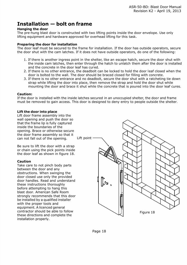
Figure 18
Lift point
Lift the door into placeLift door frame assembly into thewall opening and push the door sothat the frame lip is fully capturedinside the boundaries of theopening. Brace or otherwise securethe door frame assembly so that it
can not fall out of the opening.
Be sure to lift the door with a strapor chain using the pick points insidethe door leaf as shown in figure 18.
CautionTake care to not pinch body partsbetween the door and anyobstructions. When swinging thedoor closed use only the provideddoor handles. Read and understand
these instructions thoroughlybefore attempting to hang thisblast door. American Safe Roomstrongly recommends that this doorbe installed by a qualified installerwith the proper tools andequipment. A licenced generalcontractor should be able to followthese directions and complete theinstallation properly.
8/9/2019 TM 50 BD Blast Door Single Leaf
http://slidepdf.com/reader/full/tm-50-bd-blast-door-single-leaf 19/26
ASR-50-BD: Blast Door ManRevision K2 - April 19, 2
Page 19
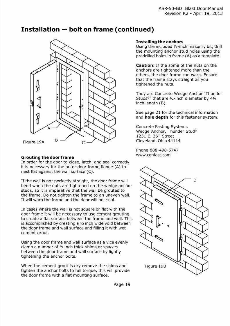
Installing the anchorsUsing the included ½-inch masonry bit, dthe mounting anchor stud holes using t
predrilled holes in frame (A) as a templat
Caution: If the some of the nuts on theanchors are tightened more than theothers, the door frame can warp. Ensurethat the frame stays straight as youtightened the nuts.
They are Concrete Wedge Anchor “ThunStuds©” that are ½-inch diameter by 4¼inch length (B).
See page 21 for the technical informatioand hole depth for this fastener system
Concrete Fasting SystemsWedge Anchor, Thunder Stud©
1231 E. 26th StreetCleveland, Ohio 44114
Phone 888-498-5747www.confast.com
Figure 19A
Figure 19B
A
BC
Grouting the door frameIn order for the door to close, latch, and seal correctlyit is necessary for the outer door frame flange (A) to
nest flat against the wall surface (C).
If the wall is not perfectly straight, the door frame willbend when the nuts are tightened on the wedge anchorstuds, so it is imperative that the wall be grouted tothe frame. Do not tighten the frame to an uneven wall.It will warp the frame and the door will not seal.
In cases where the wall is not square or flat with thedoor frame it will be necessary to use cement groutingto create a flat surface between the frame and well. Thisis accomplished by creating a ½ inch wide void between
the door frame and wall surface and filling it with wetcement grout.
Using the door frame and wall surface as a vice evenlyclamp a number of ½ inch thick shims or spacersbetween the door frame and wall surface by lightlytightening the anchor bolts.
When the cement grout is dry remove the shims andtighten the anchor bolts to full torque, this will providethe door frame with a flat mounting surface.
D
Installation— bolt on frame (continued)

8/9/2019 TM 50 BD Blast Door Single Leaf
http://slidepdf.com/reader/full/tm-50-bd-blast-door-single-leaf 20/26
ASR-50-BD: Blast Door ManRevision K2 - April 19, 2
Page 20
Wall capture bracketsThe wall capture brackets are designed to provide extra securityand strength to door loads in the unseating condition. They also
keep the door frame in place if a malicious person removes thenuts on the outside wedge anchors. Smaller doors will have fourbrackets, not six, as shown. Wall capture brackets are notnecessary on pour in place frames.
Position angle bracket as shown and cut off the long leg leaving a1/8 inch weld gap between the frame leg and the angle bracket.
Locate the angle brackets between the door frame anchor studsto avoid interferences of the anchors, and install the providedanchor studs as described on page 21.
Make a full length ¼ inch vertical fillet weld the across the 4 inchwide strap and the door frame.
Cut off excess
1 /4 inch fillet weld
Door frame
Wall capture bracket
Sealing the inside door frame lipAfter the cement grout is dry and the door frame anchor bolts have been tightened apply a liberalamount of silicon caulking between the inner door frame lip and the sill area.
Filling the door cavity with concreteThe door envelope (item D on Figure 19B on page 19) is ready for pouring the concrete.
If the latches cannot be used to hold the door closed (see Preparing the Door for Installation onpage 18), brace the door from the outside with boards so that it will not move until the concrete hcured. Fill the door with concrete.
The door must not be opened for at least 4 days while the concrete cures.
The amount of concrete required will depend on the door size ordered. The formula for calculating needed fill amount of concrete in cubic feet is the height of the door in inches times the width of thdoor in inches times the thickness of the door in inches divided by 1,728 (one cubic foot in inches)
Figure 20
Figure 20B
Figure 20C
Installation— bolt on frame (continued)
8/9/2019 TM 50 BD Blast Door Single Leaf
http://slidepdf.com/reader/full/tm-50-bd-blast-door-single-leaf 21/26
8/9/2019 TM 50 BD Blast Door Single Leaf
http://slidepdf.com/reader/full/tm-50-bd-blast-door-single-leaf 22/26
ASR-50-BD: Blast Door ManRevision K2 - April 19, 2
Page 22
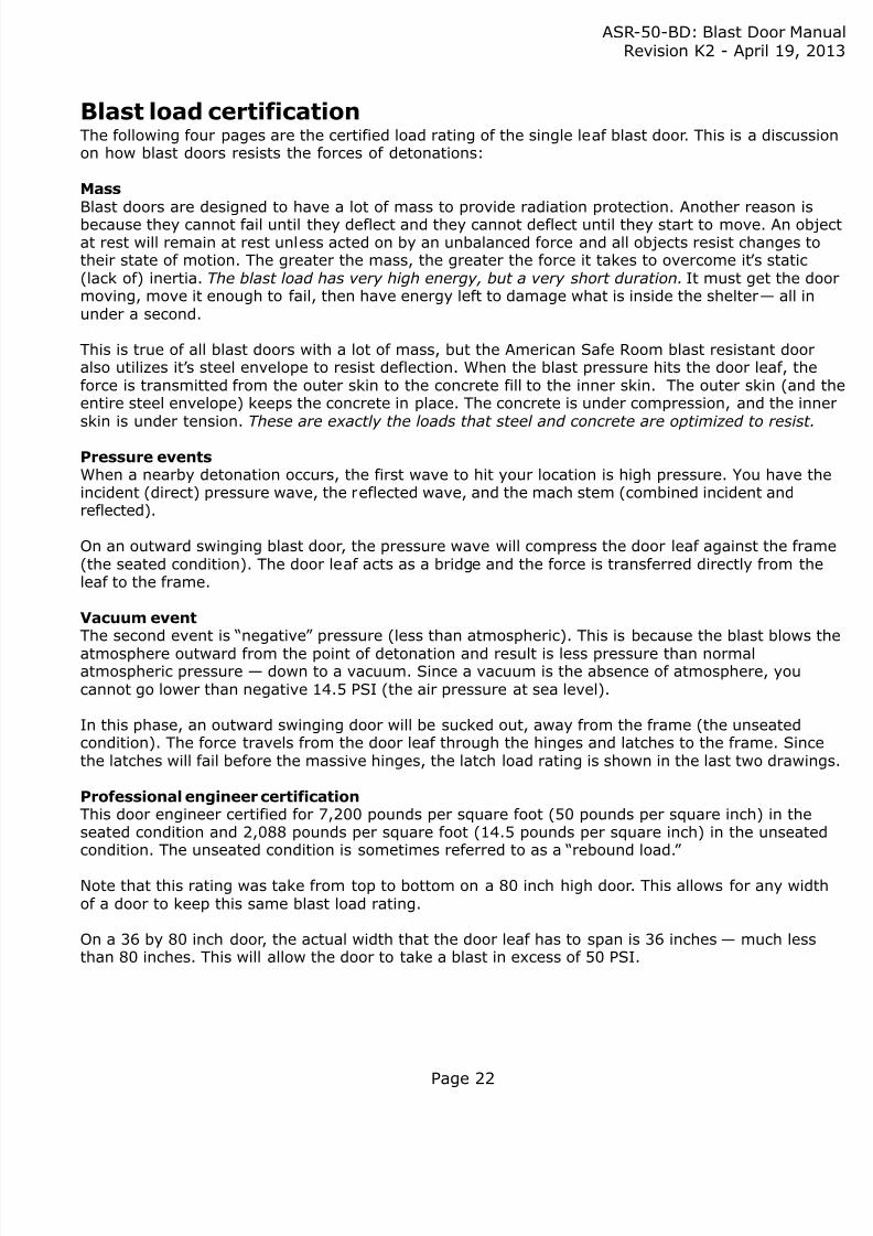
Blast load certificationThe following four pages are the certified load rating of the single leaf blast door. This is a discussion how blast doors resists the forces of detonations:
MassBlast doors are designed to have a lot of mass to provide radiation protection. Another reason isbecause they cannot fail until they deflect and they cannot deflect until they start to move. An objat rest will remain at rest unless acted on by an unbalanced force and all objects resist changes totheir state of motion. The greater the mass, the greater the force it takes to overcome it ’ s static(lack of) inertia. The blast load has very high energy, but a very short duration. It must get the domoving, move it enough to fail, then have energy left to damage what is inside the shelter — all inunder a second.
This is true of all blast doors with a lot of mass, but the American Safe Room blast resistant dooralso utilizes it’ s steel envelope to resist deflection. When the blast pressure hits the door leaf, theforce is transmitted from the outer skin to the concrete fill to the inner skin. The outer skin (and entire steel envelope) keeps the concrete in place. The concrete is under compression, and the innskin is under tension. These are exactly the loads that steel and concrete are optimized to resist.
Pressure eventsWhen a nearby detonation occurs, the first wave to hit your location is high pressure. You have thincident (direct) pressure wave, the reflected wave, and the mach stem (combined incident andreflected).
On an outward swinging blast door, the pressure wave will compress the door leaf against the fram(the seated condition). The door leaf acts as a bridge and the force is transferred directly from theleaf to the frame.
Vacuum eventThe second event is “negative” pressure (less than atmospheric). This is because the blast blows t
atmosphere outward from the point of detonation and result is less pressure than normalatmospheric pressure — down to a vacuum. Since a vacuum is the absence of atmosphere, youcannot go lower than negative 14.5 PSI (the air pressure at sea level).
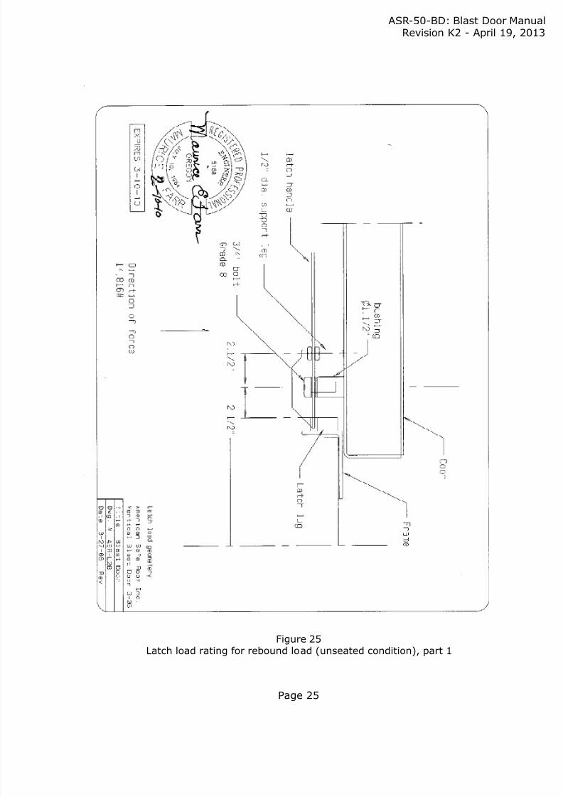
In this phase, an outward swinging door will be sucked out, away from the frame (the unseatedcondition). The force travels from the door leaf through the hinges and latches to the frame. Sincethe latches will fail before the massive hinges, the latch load rating is shown in the last two drawin
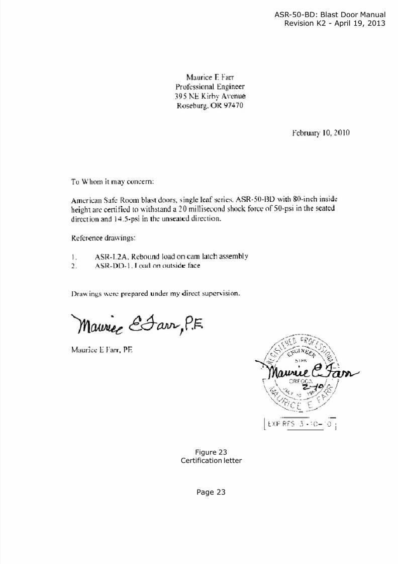
Professional engineer certificationThis door engineer certified for 7,200 pounds per square foot (50 pounds per square inch) in theseated condition and 2,088 pounds per square foot (14.5 pounds per square inch) in the unseatecondition. The unseated condition is sometimes referred to as a “rebound load.”
Note that this rating was take from top to bottom on a 80 inch high door. This allows for any widtof a door to keep this same blast load rating.
On a 36 by 80 inch door, the actual width that the door leaf has to span is 36 inches — much lessthan 80 inches. This will allow the door to take a blast in excess of 50 PSI.
8/9/2019 TM 50 BD Blast Door Single Leaf
http://slidepdf.com/reader/full/tm-50-bd-blast-door-single-leaf 23/26
ASR-50-BD: Blast Door ManRevision K2 - April 19, 2
Page 23
Figure 23Certification letter

8/9/2019 TM 50 BD Blast Door Single Leaf
http://slidepdf.com/reader/full/tm-50-bd-blast-door-single-leaf 24/26
ASR-50-BD: Blast Door ManRevision K2 - April 19, 2
Page 24
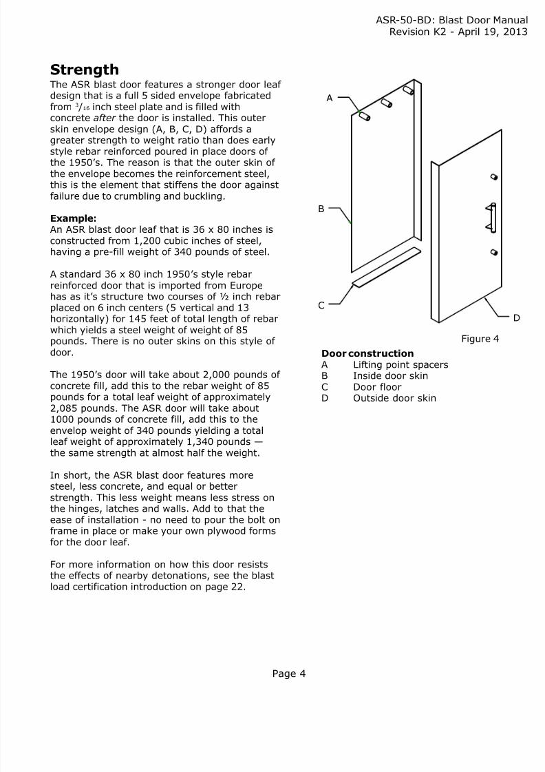
Figure 24Door leaf blast load rating
8/9/2019 TM 50 BD Blast Door Single Leaf
http://slidepdf.com/reader/full/tm-50-bd-blast-door-single-leaf 25/26
ASR-50-BD: Blast Door ManRevision K2 - April 19, 2
Page 25
Figure 25Latch load rating for rebound load (unseated condition), part 1

8/9/2019 TM 50 BD Blast Door Single Leaf
http://slidepdf.com/reader/full/tm-50-bd-blast-door-single-leaf 26/26
ASR-50-BD: Blast Door ManRevision K2 - April 19, 2
Figure 26Latch load rating for rebound load (unseated condition), part 2