tm 55-1425-289-14 technical manual ... - … following the dimension or other measurement. b. ......
TRANSCRIPT

TM 55-1425-289-14
TECHNICAL MANUAL
TRANSPORTABILITY GUIDANCE
ROLAND MISSILE SYSTEM
GUIDED MISSILE, INTERCEPT-AERIAL (LESS CARRIER),
ROLAND FIRE UNITS
(NSN 1425-01-146-9213 W/O NBC and
NSN 1425-01-144-9802
W/NBC, AN/GSG- 1 1(XO-1)(V)(2))
CARRIER, AIR DEFENSE (W/MODULE LOADER MECHANISM)
MISSILE SYSTEM
XM1058 TRUCK TRANSPORTER
(NSN 1450-01-134-9359, XM1058 (LIN C10788))
SHOP EQUIPMENT, GUIDED MISSILE SYSTEM
(NSN 4935-01-072-2890, GSM-272 (LIN S17188))
GUIDED MISSILE, AERIAL, XMIM-115
(NSN 1410-01-148-6372 through 1410-01-148-6378
and ROLF NSN 1410-01-148-6379
through 1410-01-148-6385 (LIN G95546))
SHELTER CARRIER, TRUCK, CARGO, 2-1/2-TON, M35A2, W/W
(NSN 2320-00-077-1617, X40146-12)
HEADQUARTERS, DEPARTMENT OF THE ARMY
16 SEPTEMBER 1985
TM 55-1425-289-14
TECHNICAL MANUAL
NO. 55-1425-289-14
HEADQUARTERSDEPARTMENT OF THE ARMY
WASHINGTON, DC, 16 September 1985
TRANSPORTABILITY GUIDANCEROLAND MISSILE SYSTEM
GUIDED MISSILE, INTERCEPT-AERIAL (LESS CARRIER), ROLAND FIRE UNITS(NSN 1425-01-146-9213 W/O NBC and NSN 1425-01-144-9802
W/NBC, AN/GSG-I 1(XO-1)(V)(2))CARRIER, AIR DEFENSE (W/MODULE LOADER MECHANISM) MISSILE SYSTEM
XM1058 TRUCK TRANSPORTER(NSN 1450-01-134-9359, XM1058 (LIN C10788))SHOP EQUIPMENT, GUIDED MISSILE SYSTEM(NSN 4935-01-072-2890, GSM-272 (LIN S17188))
GUIDED MISSILE, AERIAL, XMIM-115(NSN 1410-01-148-6372 through 1410-01-148-6378 and
ROLF NSN 1410-01-148-6379 through 1410-01-148-6385 (LIN G95546))SHELTER CARRIER, TRUCK, CARGO, 2-1/2-TON, M35A2, W/W
(NSN 2320-00-077-1617, X40146-12)
REPORTING ERRORS AND RECOMMENDING IMPROVEMENTSYou can help improve this manual. If you find any mistakes or if you know of a way toimprove the procedures, please let us know. Mail your letter or DA Form 2028(Recommended Changes to Publications and Blank Forms) directly to: Commander,Military Traffic Management Command-Trans. Eng. Agency, ATTN: MTT-TRC, P.O.Box 6276, Newport News, VA 23606-0276.
TABLE OF CONTENTSParagraph Page
Chapter 1 INTRODUCTIONPurpose and Scope ................................................................................ 1-1 1-1Safety...................................................................................................... 1-2 1-1Definitions of Warnings, Cautions, and Notes ......................................... 1-3 1-1Reporting of Recommendations and Comments ..................................... 1-4 1-1
Chapter 2. TRANSPORTABILITY DATASection I. GENERAL
Scope ..................................................................................................... 2-1 2-1Description ............................................................................................. 2-2 2-1Transportability Drawings ........................................................................ 2-3 2-1
II. CHARACTERISTICS AND RELATED DATAGeneral Transportability Characteristics ................................................. 2-4 2-1Unusual Characteristics .......................................................................... 2-5 2-15Hazardous and Dangerous Characteristics .............................................. 2-6 2-15Sensitivity................................................................................................ 2-7 2-15
Chapter 3. SAFETYGeneral ................................................................................................... 3-1 3-1Specific Safety Requirements ................................................................. 3-2 3-1
Chapter 4. AIR TRANSPORTABILITY GUIDANCEScope ..................................................................................................... 4-1 4-1Maximum Utilization of Aircraft ............................................................... 4-2 4-1Applicability ............................................................................................ 4-3 4-1Safety...................................................................................................... 4-4 4-6Preparation of Equipment ....................................................................... 4-5 4-6Transport of ROLAND Missile System by US Air Force Aircraft .............. 4-6 4-7Internal and External Transport by US Army Aircraft................................ 4-7 4-7
i
TM 55-1425-289-14
Paragraph PageChapter 5. HIGHWAY TRANSPORTABILITY GUIDANCESection I. GENERAL
Scope ..................................................................................................... 5-1 5-1Safety...................................................................................................... 5-2 5-1General .................................................................................................. 5-3 5-1
II. MOVEMENT ON SYSTEM CHASSISGeneral ................................................................................................... 5-4 5-1MTMC Assistance ................................................................................... 5-5 5-1
III. TRANSPORT BY SEMITRAILERTransport of ROLAND Missile System by Semitrailer .............................. 5-6 5-1Preparation for Transport ........................................................................ 5-7 5-1
Chapter 6. MARINE AND TERMINAL TRANSPORTABILITY GUIDANCESection I. GENERAL
Scope...................................................................................................... 6-1 6-1Safety ..................................................................................................... 6-2 6-1Water Shipment ..................................................................................... 6-3 6-1
II. LOADING AND SECURINGGeneral Rules for Stowing ...................................................................... 6-4 6-1Barges and Lighters ................................................................................ 6-5 6-4Landing Ships, Landing Craft, and Amphibious Vehicles ......................... 6-6 6-9Lighter Aboard Ship (LASH) .................................................................... 6-7 6-9
Chapter 7. RAIL TRANSPORTABILITY GUIDANCESection I. GENERAL
Scope ..................................................................................................... 7-1 7-1Maximum Utilization of Railcars ............................................................. 7-2 7-1
II. TRANSPORT ON CONUS RAILWAYSGeneral ................................................................................................... 7-3 7-1Preparation for Loading .......................................................................... 7-4 7-1Loading of ROLAND missile System on General Purpose Flatcar ........... 7-5 7-2Loading of ROLAND XM1058 Truck Transporter on General Purpose Flatcar .......... 7-6 7-6
III. TRANSPORT ON FOREIGN RAILWAYSGeneral ................................................................................................... 7-7 7-8Transport on Foreign Service Flatcars .................................................... 7-8 7-8
Appendix ................................................................................................................ A-1
ii

TM 55-1425-289-14
CHAPTER 1
INTRODUCTION
1-1. Purpose and Scopea. This manual provides transportability guidance for logistical handling and movement of the ROLAND all-weather
short-range air defense missile system. It contains information considered appropriate for safe transport of the system.Also included are significant technical and physical characteristics, as well as safety considerations, required forworldwide movement by various transportation modes. Where considered necessary, metric equivalents are given inparentheses following the dimension or other measurement.
b. This manual is intended for transportation officers and other personnel responsible for movement or for providingtransportation services.
1-2. SafetyAppropriate precautionary measures required during movement of the item are contained in chapter 3.
1-3. Definitions of Warnings, Cautions, and NotesThroughout this manual, warnings, cautions, and notes emphasize important or critical guidance. They are used for thefollowing conditions:
a. Warning. Instructions that, if not followed could result in injury to or death of personnel.b. Caution. Instructions that, if not strictly observed, could result in damage to or destruction of equipment.c. Note. A brief statement for use as necessary to emphasize a particular operating procedure or condition.
1-4. Reporting of Recommendations and CommentsIndividual users of this manual are encouraged to report errors and omissions and to make recommendations forimproving it. Reports should be prepared on DA Form 2028 (Recommended Changes to DA Publications and BlankForms) and forwarded to Commander, Military Traffic Management Command Transportation Engineering Agency,ATTN: MTT-TRC, PO Box 6276, Newport News, Virginia 23606-0276. Electrically transmitted messages should beaddressed to CDR MTMCTEA FT EUSTIS VA II/MTT-TRCII/. A reply will be furnished by this command.
1-1
TM 55-1425-289-14
CHAPTER 2
TRANSPORTABILITY DATA
SECTION I. GENERAL
2-1. ScopeThis chapter provides a general description and identification photographs of the ROLAND missile system components,as well as tabulated transportability characteristics, that are necessary in movement of the system.
2-2. Description
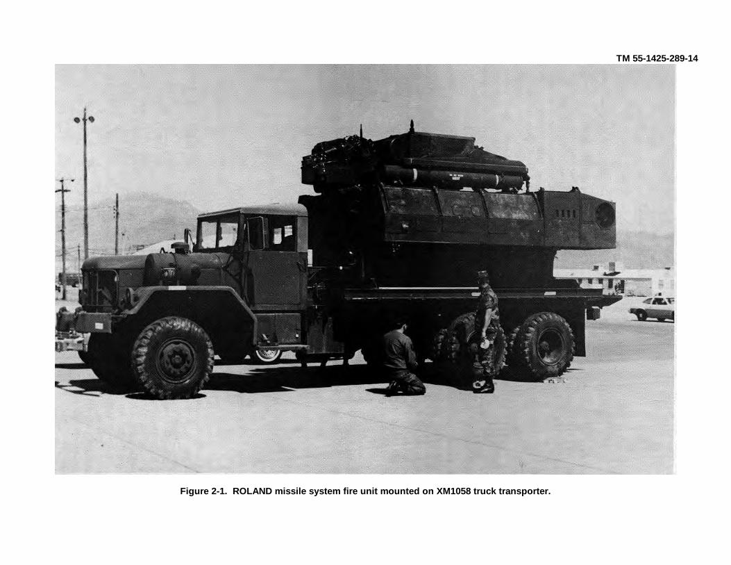
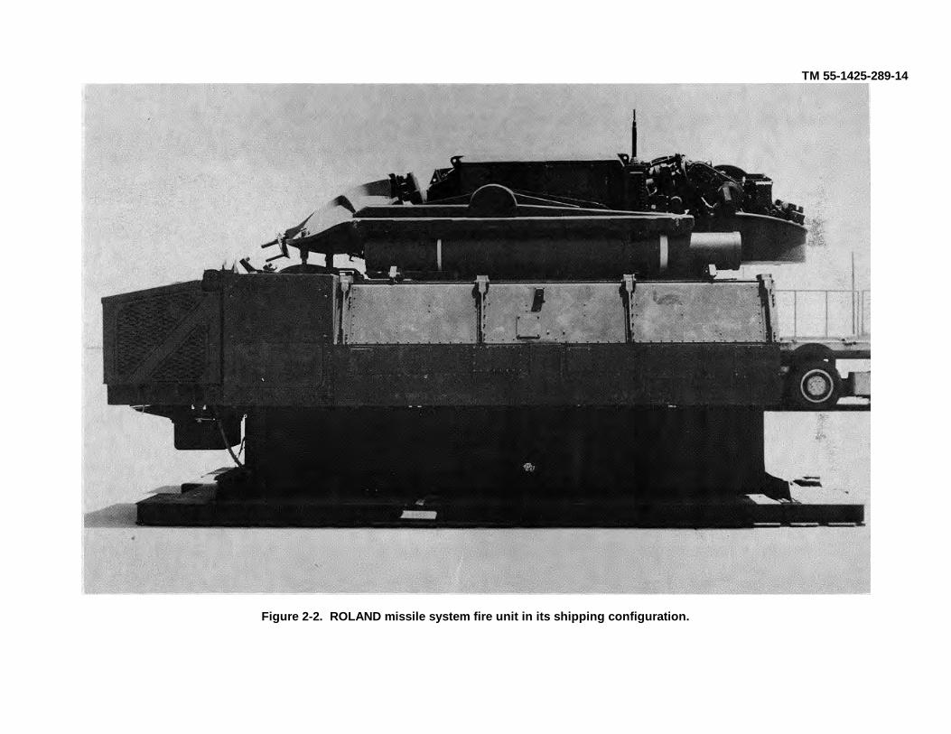
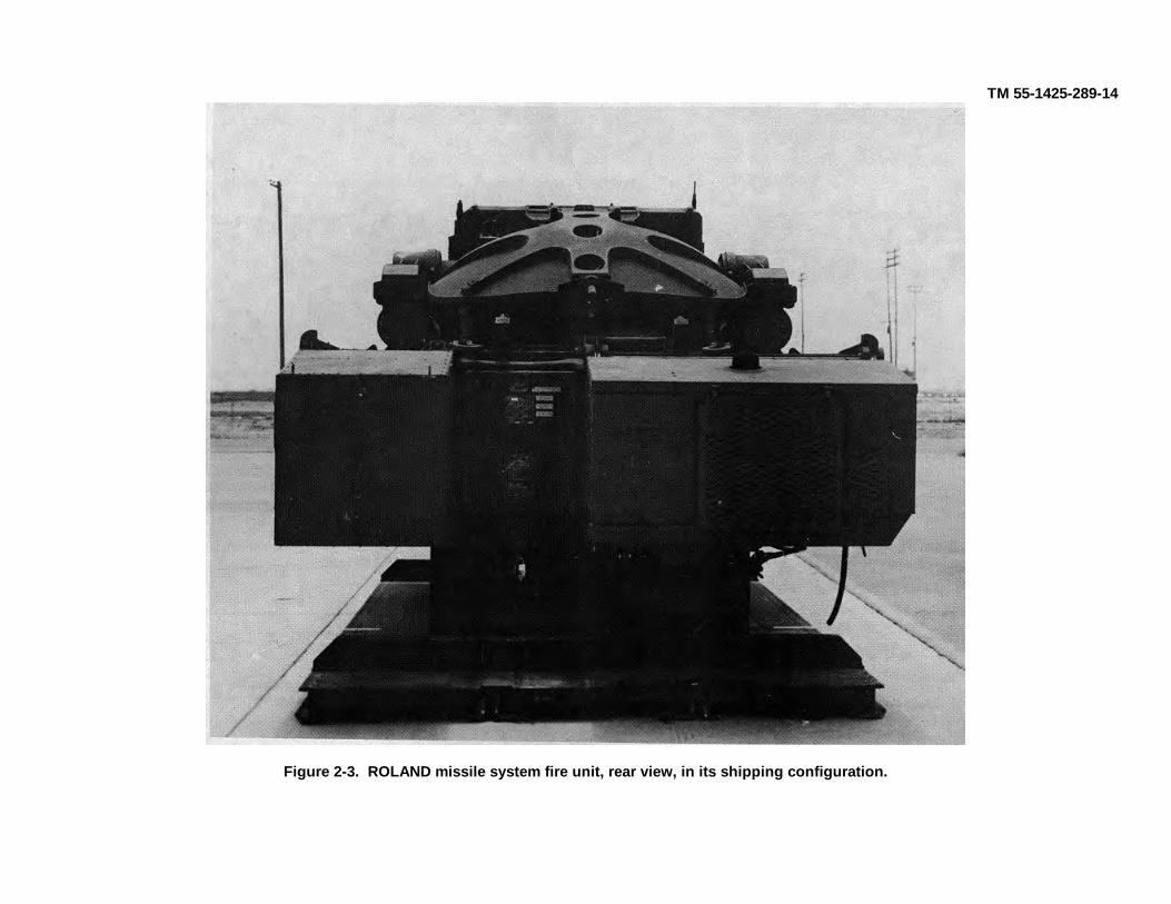
a. General. The ROLAND missile system has two major components: the XM1058 truck transporter (a modified 5-ton truck) and the guided-missile intercept aerial fire unit. The ROLAND missile system in its normal transportconfiguration is shown in figure 2-1. The fire unit has a fully traversable turret with missile launching tubes andacquisition antennae, as shown in figures 2-2 and 2-3. The complete fire unit is pallet mounted and can be removedfrom the XM1058 truck transporter to the ground surface or loaded onto the truck transporter from the ground, as shownin figure 2-4, without any crane or gantry.
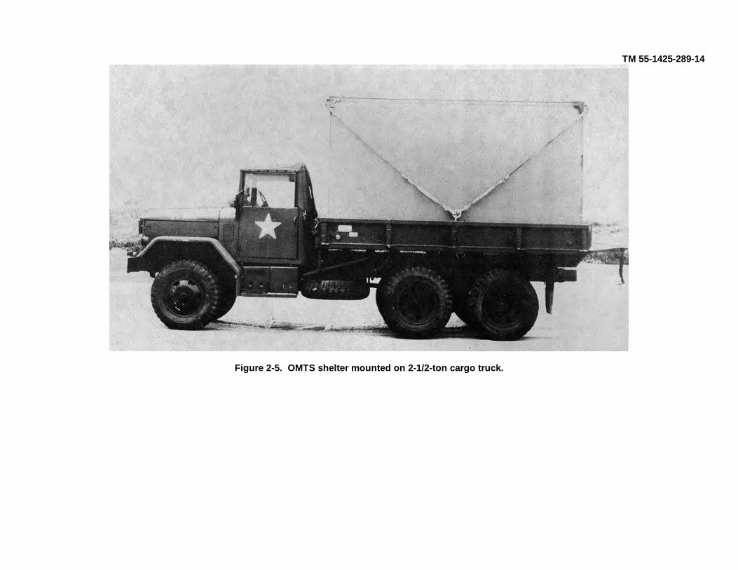
b. Support Equipment. Support equipment for the ROLAND missile system consists of an organizationalmaintenance test set (OMTS) stored and transported in two S280 shelters. Each shelter can be transported on a 2-1/2-ton cargo truck as shown in figure 2-5.
c. ROLAND Missile Rounds. The ROLAND missile rounds are contained in a launch tube and placed in a woodenoverpack primarily for air transportation, long-term storage, and logistical handling, as shown in figure 2-6.
2-3. Transportability Drawings
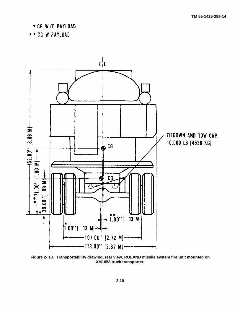
Detailed transportability drawings, side and end views, of the ROLAND missile system components and support shelters,with dimensions and load-rating capacities of the tiedown and lift provisions, are shown in figures 2-6 through 2-15.
Section II. CHARACTERISTIC AND RELATED DATA
2-4. General Transportability CharacteristicsData contained herein are applicable to model number or national stock number (NSN) shown. Changes in modelnumber of NSN may affect the load-ability of the item as related to the guidance shown in this manual.
a. ROLAND Missile System Fire Unit.Without NBCNational stock number 1425-01-146-9213Line item number G95795With NBCNational stock number 1425-01-144-9802Line item number Z32049Model number AN/GSG-11(X0-1X-2)Type classification LPDimensions and shipping data:Length, operational 208.0 in. (5.28 m)Width, operational 113 in. (2.87 m)Height, operational 155.4 in. (3.95 m)With antenna folded 102.0 in. (2.59 m)Area, operational 153.4 ft2 (14.25 m2)With antenna folded 153.4 ft2 (14.25 m2)Cube, operational 1986.5 ft3 (56.22 m3)With antenna folded 1219.5 ft3 (34.51 m3)Center of gravity:Above ground 53.3 in. (1.35 m)From forward edge of pallet 103.7 in. (2.63 in)
2-1
TM 55-1425-289-14
Figure 2-1. ROLAND missile system fire unit mounted on XM1058 truck transporter.
TM 55-1425-289-14
Figure 2-2. ROLAND missile system fire unit in its shipping configuration.
TM 55-1425-289-14
Figure 2-3. ROLAND missile system fire unit, rear view, in its shipping configuration.

TM 55-1425-289-14
Figure 2-4. ROLAND missile system fire unit in its operational configuration.
TM 55-1425-289-14
Figure 2-5. OMTS shelter mounted on 2-1/2-ton cargo truck.

TM 55-1425-289-14
Figure 2-6. ROLAND missile rounds in a launch tube inside a wooden shipping crate.
2-4. General Transportability Characteristics ContinuedFrom left side face rear end 56.9 in (1.45 m)Weights:
Fire unit 19,631 lb (8905 kg)Pallet 1,835 lb (832 kg)Empty 21,466 lb (9737 kg)With missile 24,313 lb (11 028 kg)Aircraft loading-basic 22,050 lb (10 001 kg)Aircraft loading-w/missile 24,068 lb (10 917 kg)Combat 24,781 lb (11 241 kg)b. ROLAND Missile System Fire Unit Mounted on XM1058 Truck Transporter.National stock number none assignedLine item number none assignedType classification none assigned
2-7

TM 55-1425-289-14
Figure 2-8. Transportability drawing, left-side view, XMI 058 truck transporter.

TM 55-1425-289-14
Figure 2-9. Transportability drawing, rear view, XM1058 truck transporter.
2-4. General Transportability Characteristics ContinuedPerformance:
Maximum speed 50 mph (80 km per hr)Maximum range 220 miles (352 km)Fuel type cetane, type IIFuel tank capacity 55 (usable) US gallons (208.2
liters)Turning radius L or R 47 ft 8 in. (1.21 m)Angle of approach 460Angle of departure 300Ground clearance:
Fuel tank 21.0 in. (0.53 m)Spring shackle 10.75 in. (0.27 m)
Tire size 11.00 x 20 G on 8.5-in. (0.22 m)wheels
Dimensions and shipping data:Length, operational 375.0 in. (9.53 m)Width, operational 107.0 in. (2.72 m)Height, operational 152.0 in. (3.86 m)With antenna folded 152.0 in. (3.86 m)
2-9
TM 55-1425-289-14
Figure 2- 10. Transportability drawing, rear view, ROLAND missile system fire unit mounted onXM1058 truck transporter,
2-10

TM 55-1425-289-14
Figure 2-11. Transportability drawing, left-side view, ROLAND system fire unit, pallet mounted.
2-4. General Transportability Characteristics Continued
Weights:Shipping (less crew, missiles, and fuel) 46,581 lb (21 129 kg)With combat load (missiles and fuel) 49,428 lb (22 420 kg)c. ROLAND Missile System XM1058 Truck Transporter.National stock number 1450-01-134-9359Line item number C10783*Dimensions and shipping data:Reduced for shipmentLength 375.0 in. (9.53 m)Width 107.0 in. (2.72 m)Height 104.0 in. (2.64 m)Weight 25,115 lb (11 392 kg)
*All other data is the same as paragraph 2-4b.d. ROLAND Missile System OMTS in Shelter Mounted on 2-1/2-Ton Truck.National stock numberLine item numberDimensions and shipping data:Reduced for shipmentLength 264.8 in. (6.73 m)Width 95.4 in. (2.43 m)
2-11

TM 55-1425-289-14
Figure 2-12. Transportability drawing, front view, ROLAND missile system fire unit, pallet mounted.
Figure 2-13. Transportability drawing, left-side view, unmounted OMTS shelter.
2-12

TM 55-1425-289-14
Figure 2-14. Transportability drawing, left-side view, OMTS shelter mounted on 2-1/2-ton cargo truck.
2-4. General Transportability Characteristics ContinuedHeight with OMTS shelter 135.9 in. (3.45 m)Reduced for shipment without 80.8 in. (2.05 m)shelterWeight with OMTS-Set #1 16,818 lb (7629 kg)-Set #2 17,318 lb (7855 kg)Without OMTS 13,180 lb (5978 kg)e. ROLAND Missile System OMTS Mounted in S-280 ShelterNational stock number 4935-01-072-2890Line item number S17188Dimensions and shipping data:Length 147,0 in, (3.73 m)Width 87.0 in. (2.21 m)Height 84.0 in. (2.13 m)Weight-Set #1 2,950 lb (1338 kg)-Set #2 3,450 lb (1565 kg)f. ROLAND Missile Round in a Launch Tube Inside Wooden Shipping Crate.
National stock number 1410-01-148-6372 through6378(ROLF 1410-01-148-6379through 6385)
Line item number Z32232Dimensions and shipping data:
Length 120 in. (3.05 m)Width 17.8 in. (0.45 m)Height 21.3 in. (0.54 m)Weight 337 lb (152.9 kg)
2-13

TM 55-1425-289-14
Figure 2-15. Transportability drawing, rear-end view, OMTS shelter mounted on 2-1/2-ton cargo truck.
2-14
TM 55-1425-289-14
2-5. Unusual Characteristics.
The ROLAND missile system components do not have any unusual characteristics requiring that special attention begiven to temperature, atmospheric pressure, or humidity variations during their exposure to normal transportationenvironments. The ROLAND missile system contains classified hardware. Instructions for declassification of the systemprior to shipment will be provided by the unit commander.
2-6. Hazardous and Dangerous CharacteristicsThe ROLAND missile system components will not present any special hazardous or dangerous characteristics duringtheir exposure to normal transportation environments.
NOTEThe ROLAND missile rounds are classified as rocket ammunition with explosive projectile, classA, explosives.
NOTEThose regulations and/or transportation procedures normally associated with vehiclescontaining diesel fuel will apply (appendix).
2-7. SensitivityThe ROLAND missile system is designed so that, when restrained according to guidance contained in this manual, it canwithstand the shock and vibration associated with current transportation methods.
2-15
TM 55-1425-289-14
CHAPTER 3
SAFETY
3-1. General
General safety considerations and precautions for handling and movement of the ROLAND missile system are asfollows:
a. The XM1058 truck transporter must not be left unattended while the engine is running.b. When the XM1058 truck transporter is being backed, not personnel or obstructions are allowed behind it.c. Extreme caution must be exercised when towing disabled XM1058 truck transporters.d. When the fire unit or XM1058 truck transporter is being lifted, for any purpose, no one is permitted to walk under
it.
WARNINGFire extinguishers must be readily available during all loading and unloading operations.
WARNINGProper ventilation must be provided during loading and unloading operations if the XM1058truck transporter engine is running. Prolonged exposure to carbon monoxide fumes may befatal.
3-2. Specific Safety Requirements
Pertinent safety requirements by individual modes can be found, where applicable, in the appropriate chapter.
3-1

TM 55-1425-289-14CHAPTER 4
AIR TRANSPORTABILITY GUIDANCE4-1. ScopeThis chapter provides air transportability guidance for the movement of the ROLAND missile system. It covers technical and physicalcharacteristics, as well as safety considerations, and prescribes the material required to prepare, load, and tie down systemequipment on, or offload from, US Air Force cargo aircraft.4-2. Maximum Utilization of AircraftThe loads described in this chapter are not maximum loads. General guidance on total cargo loads and operating ranges is providedin TM 38-2361AFP 71-8. Additional cargo and/or personnel, within allowable load limits and restrictions prescribed by pertinentsafety regulations, can be transported.4-3. Applicability
a. US Air Force Aircraft. The ROLAND missile system is transportable in US Air Force C-130, C-141B, and C-5A aircraft.Procedures in this manual and those prescribed by section VI, TO 1C-XX-9, are applicable.
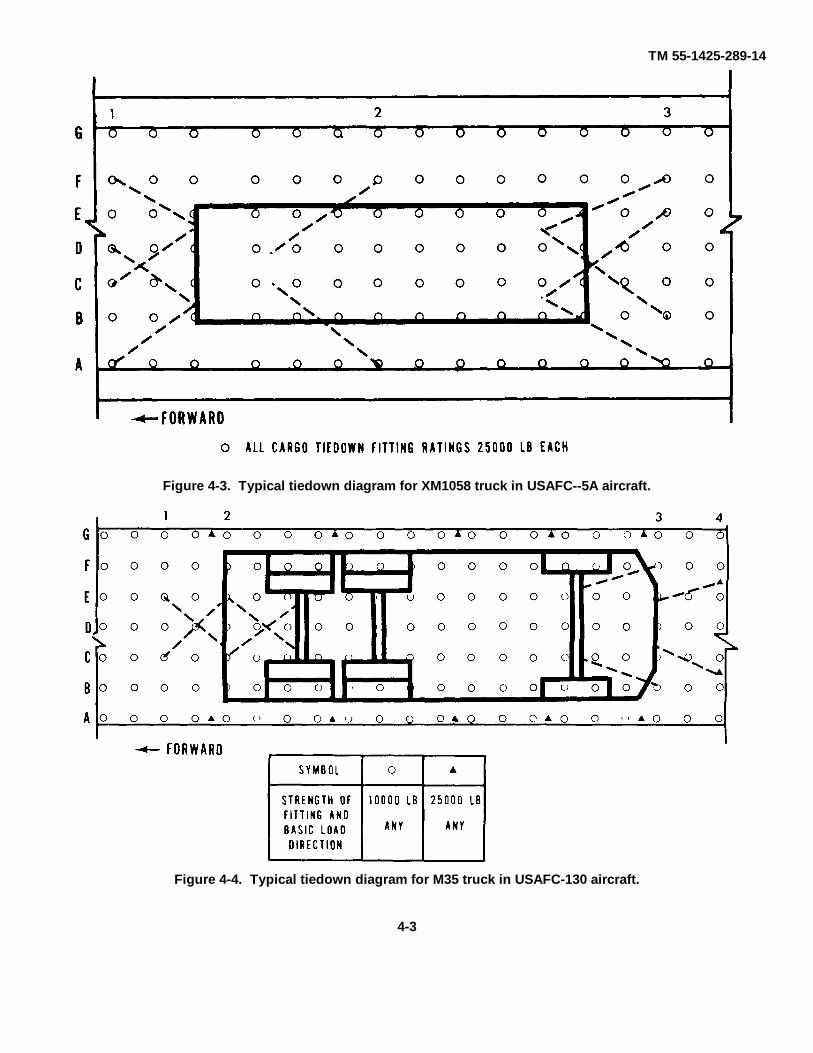
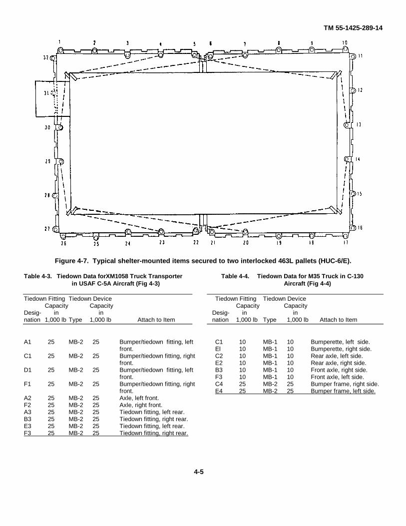
b. Tiedown Devices. The ROLAND missile system components are tied down in accordance with the minimum acceptablerestraint factors (g loads) identified in TO 1C-XX-9. The ROLAND XM1058 truck transporter and M35 truck will be tied down inaccordance with TO 1C-XX-9 and the figures and tables shown in this chapter. Suggested tiedown patterns for the XM1058 trucktransporter are shown in figures 4-1 through 4-3 for C-130, C-141B, and C-5A aircraft, respectively. Suggested tiedown patterns forthe M35 trucks are shown in figures 4-4 through 4-6. Tables 4-1 through 4-6 list the tiedown devices required, the location of tiedownpoints, the corresponding fittings to which the devices are secured, the number and capacity of devices, and the lumber shoringrequired for loading and securement. The OMTS shelters, when removed from their carrier vehicles because of C-130 and C-141Bheight restrictions, will be secured on coupled aircraft pallets. Figure 4-7 illustrates typical shelter-mounted items secured to coupledpallets, and table 4-7 lists tiedown data. The ROLAND missile system fire unit is mounted on a special pallet that is compatible withthe aircraft pallet system. For C-5 aircraft loading, the fire unit must be loaded on two HCU-6/E pallets, 2-1/2 inches off centertoward the inboard side. Therefore, the palletized fire unit and the OMTS shelters will be locked into appropriate pallet positions onC-130 and C-141 aircraft.
Table 4-1. Tiedown Data forXMI058 Truck Transporter in USAFC-130 Aircraft (Fig 4-1)
Tiedown Fitting Tiedown DeviceCapacity Capacity
Desig- in innation 1,000 lb Type 1,000 lb Attach to Item
Al 10 MB1 10 Tiedown fitting, right rear.C1 10 MB1 10 Tiedown fitting, left rear.El 10 MB1 10 Tiedown fitting, right rear.G1 10 MB1 10 Tiedown fitting, left rear.A2 10 MB1 10 Axle, right rear.G2 10 MB1 10 Axle, left rear.A3 25 MB2 25 Axle, right intermediate.G3 25 MB2 25 Axle, left intermediate.A4 25 MB2 25 Bumper/tiedown fitting, right
front.G4 25 MB2 25 Bumper tie down fitting, left
front.C5 10 MB1 10 Bumper/tiedown fitting, right
front.D5 10 MB1 10 Bumper/tiedown fitting, left front.
Table 4-2. Tiedown Data for XMI058 Truck Transporter in USAFC-141B Aircraft (Fig 4-2)
Tiedown Fitting Tiedown DeviceCapacity Capacity
Desig- in innation 1,000 lb Type 1,000 lb Attach to Item
Al 25 MB2 25 Tiedown fitting, right rear.C1 10 MB1 10 Tiedown fitting, left rear.El 10 MB1 10 Tiedown fitting, right rear.
G 1 25 MB2 25 Tiedown fitting, left rear.A2 25 MB2 25 Axle, right intermediate.G2 25 MB2 25 Axle, left intermediate.A3 25 MB2 25 Bumper/tiedown fitting, right
front.C3 10 MB1 10 Bumper/tiedown fitting, left
front.E3 10 MB1 10 Bumper/tiedown fitting, right
front.G3 25 MB2 25 Bumper/tiedown fitting, left front.
4-1

TM 55-1425-289-14
Figure 4-1. Typical tiedown diagram for XM1058 truck transporter in USAF C- 130 aircraft.
.Figure 4-2. Typical tiedown diagram for XMI 058 truck transporter in USAF C- 141 B aircraft.
4-2
TM 55-1425-289-14
Figure 4-3. Typical tiedown diagram for XM1058 truck in USAFC--5A aircraft.
Figure 4-4. Typical tiedown diagram for M35 truck in USAFC-130 aircraft.
4-3

TM 55-1425-289-14
Figure 4-5. Typical tiedown diagram for M35 truck in USAF C- 141B aircraft.
Figure 4-6. Typical tiedown diagram for M35 truck in USAF C-5A aircraft.
4-4
TM 55-1425-289-14
Figure 4-7. Typical shelter-mounted items secured to two interlocked 463L pallets (HUC-6/E).
Table 4-3. Tiedown Data forXM1058 Truck Transporter Table 4-4. Tiedown Data for M35 Truck in C-130in USAF C-5A Aircraft (Fig 4-3) Aircraft (Fig 4-4)
Tiedown Fitting Tiedown Device Tiedown Fitting Tiedown DeviceCapacity Capacity Capacity Capacity
Desig- in in Desig- in innation 1,000 lb Type 1,000 lb Attach to Item nation 1,000 lb Type 1,000 lb Attach to Item
A1 25 MB-2 25 Bumper/tiedown fitting, left C1 10 MB-1 10 Bumperette, left side.front. El 10 MB-1 10 Bumperette, right side.
C1 25 MB-2 25 Bumper/tiedown fitting, right C2 10 MB-1 10 Rear axle, left side.front. E2 10 MB-1 10 Rear axle, right side.
D1 25 MB-2 25 Bumper/tiedown fitting, left B3 10 MB-1 10 Front axle, right side.front. F3 10 MB-1 10 Front axle, left side.
F1 25 MB-2 25 Bumper/tiedown fitting, right C4 25 MB-2 25 Bumper frame, right side.front. E4 25 MB-2 25 Bumper frame, left side.
A2 25 MB-2 25 Axle, left front.F2 25 MB-2 25 Axle, right front.A3 25 MB-2 25 Tiedown fitting, left rear.B3 25 MB-2 25 Tiedown fitting, right rear.E3 25 MB-2 25 Tiedown fitting, left rear.F3 25 MB-2 25 Tiedown fitting, right rear.
4-5

TM 55-1425-289-14
Table 4-5. Tiedown Data forM35 Truck in C-141BAircraft (Fig 4-5)
Tiedown Fitting Tiedown DeviceCapacity Capacity
Desig- in innation 1,000 lb Type 1,000 lb Attach to ItemC1 10 MB-1 10 Bumperette, left side.El 10 MB-1 10 Bumperette, right side.C2 10 MB-1 10 Rear axle, left side.E2 10 MB-1 10 Rear axle, right side.B3 10 MB-1 10 Front axle, right side.F3 10 MB-1 10 Front axle, left side.A4 25 MB-2 25 Bumper frame, right side.G4 25 MB-2 25 Bumper frame, left side.
Table 4-6. Tiedown Data forM35 Truck in C-5AAircraft (Fig 4-6)
Tiedown Fitting Tiedown DeviceCapacity Capacity
Desig- in innation 1,000 lb Type 1,000 lb Attach to ItemE1l 25 MB-2 25 Bumper frame, right side.F1l 25 MB-2 25 Bumper frame, left side.E2 25 MB-2 25 Pintle.F2 25 MB-2 25 Pintle.E3 25 MB-2 25 Front axle, right side.F3 25 MB-2 25 Front axle, left side.E4 25 MB-2 25 Bumper frame, left side.F4 25 MB-2 25 Bumper frame, right side.
Table 4- 7. Tiedown Data for Typical Shelter-Mounted ItemsSecured to Two Interlocked 463L Pallets
(HUC-6/E) (Fig 4- 7)Tiedown Fitting Tiedown Device
Capacity CapacityDesig- in innation 1,000 lb Type 1,000 lb Attach to Item29 7.5 MB-1 10 Tiedown, left bottom.30 7.5 MB-1 10 Tiedown, right bottom.23 7.5 MB-1 10 Tiedown, left bottom.4 7.5 MB-1 10 Tiedown, right bottom.22 7.5 MB-1 10 Tiedown, aft left top.5 7.5 MB-1 10 Tiedown, aft right top.20* 7.5 MB-1 10 Tiedown, forward left top.7 ' 7.5 MB-1 10 Tiedown, forward right top.14 7.5 MB-1 10 Tiedown, aft left bottom.13 7.5 MB-1 10 Tiedown, aft right bottom.*Not required for C-5 aircraft.
c. Aircraft Commander Responsibilities. Theaircraft commander, or designated representative, willensure that the loaded equipment is secured inaccordance with restraint criteria outlined in TO 1C-XX-9.
4-4. SafetyIn addition to the safety precautions contained inchapter 3, the following procedures should be noted:
a. The activity offering the equipment for airtransport must notify the pilot in command or designatedrepresentative, when ammunition or explosives are tobe transported and ensure that all hazardous materials
have prepared for shipment in accordance with TM 38-250.
b. The vehicle fuel tanks must not be more thanthree-fourths full.
c. Vehicles must be tied down in accordance withprocedures prescribed by TO 1C-130-9, TO 1C-141B-9,or TO 1C-5A-9, as appropriate.
d. Each vehicle or component must be checkedcarefully to ensure that all loose items are properlysecured.
WARNINGFire extinguishers must be readilyavailable during all loading andunloading operations.
WARNINGProper ventilation must be providedduring loading and unloadingoperations if the XM1058 trucktransporter engine is running.Prolonged exposure to carbonmonoxide fumes may be fatal.
CAUTIONDo not allow the vehicle speed toexceed 3 miles per hour inside theaircraft or on the loading ramps.
4-5. Preparation of Equipment.a. Turret traverse and launch-elevating
mechanism must be in the travel position, locked, andwire-tied to prevent rotation.
b. Antennae must be tied down or removed;cupola must be placed in the closed position; and loosegear must be secured with nylon cord or a suitablesubstitute.
c. Mirrors from the XM1058 truck transporter mustbe removed and secured in the carrier.
d. The infra lens (IR) must be covered.e. The fire unit battery must be completely
protected and secured so that leakage of acid cannotoccur (TM 38-250/NAVSUP PUB505(REV)/MCOP4030.19D/DSAM4145.3, 22 March 1976).
f. TM 38-250 (AFR 71-4) must be consulted toensure compatibility of any additional cargo beingconsidered for loading with the ROLAND missilesystem.
g. All externally and internally stowed equipmentmust be secured.
h. The vehicle transmission must be placed inneutral, and the brakes must be set.
i. The vehicle fuel tanks must not be more thanthree-fourths full (TM 38-250 (AFR 71-4)).
j. Ten ROLAND missile rounds are permitted onboard the aircraft (certificate of equivalency (COE) AY-84-191).
4-6
TM 55-1425-289-14
k. When the XM1058 truck transporter, instead ofa TAC loader, is used to load the fire unit aboard the C-141B, ramp pedestal shoring (20 inches in length by 11inches in width by 28 inches in height, minimum) isrequired. This shoring must be placed under the aft endof the ramp to prevent the aircraft ramp fromdescending more than 51 inches from the ground.
l. When the shelters, with the OMTS, areremoved from their transport vehicles, the shelters mustbe palletized on coupled aircraft pallets. Transportvehicles will be reduced to the minimum shippingconfiguration.
4-6. Transport of ROLAND Missile System by US AirForce Aircraft
a. C130 Aircraft. ROLAND missile systemcomponents are air transportable in a configuration notto exceed 104 inches in height for the XM1058 trucktransporter or 102.4 inches in height for the fire unit. A25K or 40K TAC loader is required forloading/unloading. The C-130 is limited to one majorcomponent per aircraft since the axleload of theXM1058 truck transporter must be positioned in the highstrength area (center wing, fuselage stations 337 to 682)for flight. Because of height restrictions, the shelters,with the OMTS, must be removed from the transportingvehicles and secured on coupled aircraft pallets. TheOMTS carrier vehicles will be loaded in their reducedconfiguration.
b. C-141B Aircraft. The two ROLAND fire unitsand the XM1058 truck transporter are approved for C-141B airlift. However, the fire units must be removedfrom the carrier (XM1058 truck transporter) and loadedseparately because of height restrictions. Direct loadingof the fire units from the XM1058 truck transporter ontothe C-141B aircraft ramps, without the use of a TACloader, is an approved method of loading/unloading.The fire unit/pallet on the aircraft ramp or TAC loadermust be positioned within 4 feet of the end of the aircraftramp or TAC loader so that the pallet hook and theXM1058 truck transporter retrieving cable can beproperly mated. Both components (fire unit andXM1058 truck transporter) may be TM 55-1425-289-14
airlifted on the same C-141B aircraft because only theforward axle of the XM1058 is required in the centerwing section (fuselage stations 678 to 998) for flight.The XM1058 truck transporter, as a separate entity, canbe driven onto the aircraft when shipped with the fireunit. Because of height restrictions, the S-280 shelters,with the OMTS, must be removed from the transportingvehicles and secured on coupled aircraft pallets. Thecarrier vehicles (2-1/2-ton trucks) for the OMTS will beloaded in their reduced configuration.
c. C-5A Aircraft. ROLAND missile systemcomponents are transportable in C-5A aircraft. Becauseof weight and tiedown restrictions, the ROLAND fire unitand the XM1058 truck transporter must be transportedas separate units. The procedures prescribed in chapterIV, TO 1C-5A-9, are applicable for tiedown of thisequipment. The shelter, with the OMTS, may be loadedas a single unit when transported on a 2-1/2-ton truck.
(1) The loadmaster will coordinate with theROLAND missile system crew on leveling an alignmentof the XM1058 truck transporter duringloading/unloading, in accordance with the applicable TO1C-XX-9. The XM1058 truck transporter will bepositioned in accordance with the applicable TO 1C-XX-9. The ROLAND fire unit should always be locatedforward in the aircraft.
(2) Startup of the ROLAND fire unit and theair conditioning unit on board the aircraft is permissibleas noted in the appropriate TO 1C-XX-9.
4-7. Internal and External Transport by US ArmyAircraftThe ROLAND missile system fire unit is within theexternal lift capability of the CH-47D helicopter for short-range missions under ideal flight conditions. TheXM1058 truck transporter also is within the external liftcapability of the CH-47D helicopter. However, externalhelicopter lift operations for the XM1058 trucktransporter are impractical because the range of the CH-47D helicopter/,SM1058 truck transporter combination isextremely limited, even under ideal flight conditions.
4-7

TM 55-1425-289-14CHAPTER 5
HIGHWAY TRANSPORTABILITY GUIDANCE
Section I. GENERAL
5-1. ScopeThis chapter provides highway transportability guidancefor movement of the ROLAND missile system. It coverstechnical and physical characteristics, as well as safetyconsiderations, and prescribes the materials andguidance required to prepare, load, tie down, and unloadthe ROLAND fire unit and the XM1058 truck transporter.
5-2. SafetyIn addition to the safety precautions contained inchapter 3, movement is subject to all safety laws, rules,and regulations applicable to commercial carriers.Overseas, such movements are governed by theaterregulations.
CAUTIONDo not allow the XM1058 truck transporter toexceed 3 miles per hour during loading orunloading of semitrailers.
5-3. GeneralThe ROLAND missile system is a fully integrated firecontrol and missile launching system mounted on apallet for highway, rail, air, and marine transportability.The ROLAND fire unit is mounted on a modifiedXM1058 truck transporter for mobility. However, the fireunit can be easily dismounted from the wheeled carrierfor shipment by all modes. The supporting S280shelters with the OMTS, are transported on 21/2-tontrucks that do not exceed legal limitations.
Section II. MOVEMENT ON SYSTEM CHASSIS
5-4. GeneralIn CONUS, the XM1058 truck transporter/ROLAND fireunit combination exceeds the legal width in all states,the legal gross weight in 22 states, the legal tandemaxleload in 42 states, and the legal height in 1 state(West Virginia). Permits (AR 55-162) or a "certificationof essentially to national defense" (AR 55-80) arerequired in CONUS. Special routing and permits arealso required overseas. The XM1058 truck transporterwithout the fire unit exceeds legal width limitations inCONUS and, thus, permits are required for highwaymovement.
5-5. MTMC AssistanceAssistance in obtaining approvals for highwaymovement of the loaded transport system can beobtained from the Commander, Military TrafficManagement Command, ATTN: MT-SA, 5611Columbia Pike, Falls Church, Virginia 22041-5050,when highway movement can be certified as essentialfor national defense and no other transportation modecan be used.
Section III. TRANSPORT BY SEMITRAILER
5-6. Transport of ROLAND Missile System bySemitrailerWhen loaded on Semitrailers, the ROLAND missilesystem components can be transported over highways.Normally, highway movements are made with thesystem components loaded on military or commercialtrailers of adequate capacity and size. Both in CONUSand overseas, permits will be required because width ofthe transported items will exceed highway limitations. Inaddition, based on the tractor-trailer combination usedfor transport, other size and weight limitations may beexceeded.
5-7. Preparation for TransportPreparation of the ROLAND missile system for transportincludes the following procedures:
a. Turret traverse and launch-elevatingmechanism must be in the travel position, locked, andwire-tied to prevent rotation.
b. Antennae must be tied down or removed,cupola must be in closed position; and loose gear mustbe secured with nylon cord or suitable substitute.
5-8. Loading on Semitrailersa. XM1058 Truck Transporter. The truck
transporter can be loaded on a 25-ton, or larger,semitrailer. A tiedown diagram compatible withstandard loading practices that will offer adequaterestraint is provided
5-1
TM 55-1425-289-14
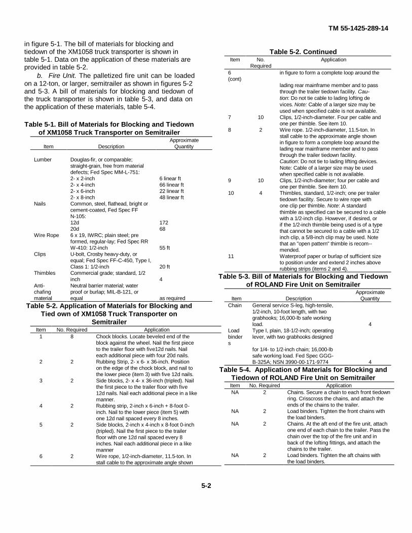
in figure 5-1. The bill of materials for blocking andtiedown of the XM1058 truck transporter is shown intable 5-1. Data on the application of these materials areprovided in table 5-2.
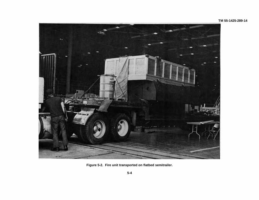
b. Fire Unit. The palletized fire unit can be loadedon a 12-ton, or larger, semitrailer as shown in figures 5-2and 5-3. A bill of materials for blocking and tiedown ofthe truck transporter is shown in table 5-3, and data onthe application of these materials, table 5-4.
Table 5-1. Bill of Materials for Blocking and Tiedownof XM1058 Truck Transporter on Semitrailer
ApproximateItem Description Quantity
Lumber Douglas-fir, or comparable;straight-grain, free from materialdefects; Fed Spec MM-L-751:2- x 2-inch 6 linear ft2- x 4-inch 66 linear ft2- x 6-inch 22 linear ft2- x 8-inch 48 linear ft
Nails Common, steel, flathead, bright orcement-coated, Fed Spec FFN-105:12d 17220d 68
Wire Rope 6 x 19, IWRC; plain steel; preformed, regular-lay; Fed Spec RRW-410: 1/2-inch 55 ft
Clips U-bolt, Crosby heavy-duty, orequal; Fed Spec FF-C-450, Type I,Class 1: 1/2-inch 20 ft
Thimbles Commercial grade; standard, 1/2inch 4
Anti- Neutral barrier material; waterchafing proof or burlap; MIL-B-121, ormaterial equal as required
Table 5-2. Application of Materials for Blocking andTied own of XM1058 Truck Transporter on
SemitrailerItem No. Required Application
1 8 Chock blocks. Locate beveled end of theblock against the wheel. Nail the first pieceto the trailer floor with five12d nails. Naileach additional piece with four 20d nails.
2 2 Rubbing Strip, 2- x 6- x 36-inch. Positionon the edge of the chock block, and nail tothe lower piece (item 3) with five 12d nails.
3 2 Side blocks, 2- x 4- x 36-inch (tripled). Nailthe first piece to the trailer floor with five12d nails. Nail each additional piece in a likemanner.
4 2 Rubbing strip, 2-inch x 6-inch + 8-foot 0-inch. Nail to the lower piece (item 5) withone 12d nail spaced every 8 inches.
5 2 Side blocks, 2-inch x 4-inch x 8-foot 0-inch(tripled). Nail the first piece to the trailerfloor with one 12d nail spaced every 8inches. Nail each additional piece in a likemanner
6 2 Wire rope, 1/2-inch-diameter, 11.5-ton. Install cable to the approximate angle shown
Table 5-2. ContinuedItem No.
RequiredApplication
6(cont)
in figure to form a complete loop around the
lading rear mainframe member and to passthrough the trailer tiedown facility. Cau-tion: Do not tie cable to lading lofting devices. Note: Cable of a larger size may beused when specified cable is not available.
7 10 Clips, 1/2-inch-diameter. Four per cable andone per thimble. See item 10.
8 2 Wire rope. 1/2-inch-diameter, 11.5-ton. Install cable to the approximate angle shownin figure to form a complete loop around thelading rear mainframe member and to passthrough the trailer tiedown facility.Caution: Do not tie to lading lifting devices.Note: Cable of a larger size may be usedwhen specified cable is not available.
9 10 Clips, 1/2-inch-diameter; four per cable andone per thimble. See item 10.
10 4 Thimbles, standard, 1/2-inch; one per trailertiedown facility. Secure to wire rope withone clip per thimble. Note: A standardthimble as specified can be secured to a cablewith a 1/2-inch clip. However, if desired, orif the 1/2-inch thimble being used is of a typethat cannot be secured to a cable with a 1/2inch clip, a 5/8-inch clip may be used. Notethat an "open pattern" thimble is recom--mended.
11 Waterproof paper or burlap of sufficient sizeto position under and extend 2 inches aboverubbing strips (items 2 and 4).
Table 5-3. Bill of Materials for Blocking and Tiedownof ROLAND Fire Unit on Semitrailer
ApproximateItem Description Quantity
Chain General service S-leg, high-tensile,1/2-inch, 10-foot length, with twograbhooks; 16,000-lb safe workingload. 4
Load Type I, plain, 18-1/2-inch; operatingbinders
lever, with two grabhooks designed
for 1/4- to 1/2-inch chain; 16,000-lbsafe working load. Fed Spec GGG-B-325A; NSN 3990-00-171-9774 4
Table 5-4. Application of Materials for Blocking andTiedown of ROLAND Fire Unit on SemitrailerItem No. Required ApplicationNA 2 Chains. Secure a chain to each front tiedown
ring. Crisscross the chains, and attach theends of the chains to the trailer.
NA 2 Load binders. Tighten the front chains withthe load binders.
NA 2 Chains. At the aft end of the fire unit, attachone end of each chain to the trailer. Pass thechain over the top of the fire unit and inback of the lofting fittings, and attach thechains to the trailer.
NA 2 Load binders. Tighten the aft chains withthe load binders.
5-2

TM 55-1425-289-14
Figure 5-1. Blocking and tiedown of XM1058 truck transporter on 25-ton, or larger, semitrailer.
5-3
TM 55-1425-289-14
Figure 5-2. Fire unit transported on flatbed semitrailer.
5-4

TM 55-1425-289-14
Figure 5-3. Fire unit tied down on flatbed semitrailer.
5-5

TM 55-1425-289-14
c. M35 Truck. When OMTS shelters cannot betransported over the highway on M35 trucks, because ofdistance involved or other considerations, shipment maybe made with either commercial or military flatbedtrailers or cargo trucks of adequate size and capacity.For unrestricted height clearance, the shelter is removedfrom the cargo truck and loaded separately. The cargotruck height must be reduced so that, when it iscombined with the semitrailer loading-surface height,the unrestricted height limit is not exceeded. Figures 5-4 through 5-6 provide blocking and tiedown details forthe ROLAND missile system components. Tables 5-5and 5-6 provide bills of materials, and tables 5-7 and 5-8, data on the application of these materials.
NOTEFigure 5-1 and tables 5-1 and 5-2were extracted from US ArmyMateriel Command drawings.
Table 5-5. Bill of Materials for Blocking andTiedown of M35 Truck on 12-Ton, or Larger,
Semitrailer (Figs 5-4 and 5-5)Approximate
Item Description QuantityLumber Douglas-fir, or comparable;
straight-grain, free from materialdefects; Fed Spec:MM-L-751H: 2- x 4-inch 24 linear ft
2- x 6-inch 12 linear ft6- x 8-inch 16 linear ft
Nails Common, steel; flathead; bright orcement-coated; table X1-b; FedSpec:FF-N-105a: 20d 48
30d 5240d 16
Cushion- Waterproof paper, burlap, or suit-ing able material as requiredmaterialChains Type 1, grade C, Class 2; welded-
steel, 1/4- to 1/2-inch width x 10-foot length; 6,000-lb safe workingload; welded-steel, high-test chain;Fed Spec RR-C-271; with twograbhooks equal to or better thanthe strength of the chain; grab-hooks are not required if wire ropeand clamps are used. 8
Load Double-hook, heavy-duty, eccentricbinders takeup, with chain grabhooks for
1/4- to 1/2-inch chain; 16,000-lbsafe working load; grabhooks arenot required if wire rope andclamps are used. 8
*Wire 6 x19, IWRC; improved plowrope steel, preformed, regular-lay; table
X, Fed Spec RR-W-410: 1/2-inch 64 ft
Table 5-5. ContinuedApproximate
Item Description Quantity*Clamps Wire rope, U-bolt clips, saddled,
single-grip, steel; Crosby heavy-duty, or equal; MIL-STD-16842:1/2-inch 32
*Wire rope and clamps may be substituted for chains andload binders.
Table 5-6. Bill of Materials for Blocking andTiedown of S-280 Shelter, With OMTS, on
Semitrailer(Fig 5-6)
ApproximateItem Description Quantity
Lumber Douglas-fir, or comparable;straight-grain, free from materialdefects; Fed Spec:MM-L-751H: 4- x 4-inch 22 linear ft
2- x 4-inch 44 linear ftNails Common, steel; flathead; bright or
cement-coated; Fed Spec FF-N-1058: 20d 4030d 4060d 44
Wire rope 6 x 19, IWRC; improved plowsteel, preformed, regular-lay; FedSpec RR-W-410C: 3/8-inch 122 ft
Clamps Wire rope, U-bolt clips, saddled,single-grip; steel; Crosby heavy-duty, or equal; Fed SpecFF-C-450D: 3/8-inch 32
Thimbles Standard, open-type: 3/8-inch 16Cushion- Waterproof paper, burlap, or othering suitable material as requiredmaterial
Table 5-7. Application of Materials for Blocking andTiedown of M35 Truck on 12-Ton, or Larger,
Semitrailer (Figs 5-4 and 5-5)Item No. Required Application
A 8 Chock blocks. Locate the 330 portionagainst the front of the front and inter-mediate wheels and against the rear of thefront and rear wheels. Toenail the heel of theblock (near the bottom edge) to the semi-trailer floor with one 20d nail. Also, drivetwo 40d nails into the heel of the block,perpendicular to the semitrailer floor. Toenaileach side of the block to the semitrailer floorwith two 30d nails on each side.
B as required Protective material, such as waterproofpaper or burlap, should be located under thebottom edge of the 2- x 4- x 36-inch pieceand between the tire and the 2- x 6- x 36-inch piece, to extend 2 inches above block-ing.
C 4 Side blocking. Each to consist of one piece of2- x 6- x 36-inch lumber and two pieces of2- x 4- x 36-inch lumber. Nail the 2- x 6- x36-inch piece to the edge of the lower 2- x 4-x 36-inch piece with five 20d nails. Placethe 2- x 6- x 36-inch piece against the tire,
5-6

TM 55-1425-289-14
Table 5-7. ContinuedItem No. Required Application
C(cont)
and nail to the semitrailer floor through the
2- x 4- x 36-inch piece with five 20d nails ina staggered pattern. Nail the other 2- x 4- x36-inch piece to the one below in a like man-ner with five 30d nails.
D 4 Chains, load-lashing. Attach to the front andrear tiedown provisions on the vehicles andsemitrailer as indicated. Substitute, if de-sired, 112- or 5/8-inch IWRC wire rope in acomplete loop, and secure with four cableclips spaced about 4 inches apart.
E 4 Load binders. Secure grabhooks to chains,and take up slack with eccentric takeup.Grabhooks are not required if wire rope andcable clips are used.
Table 5-8. Application of Materials for Blocking andTiedown of an S280 Shelter, with OMTS, on
Semitrailer (Fig 5-6)Item No. Required ApplicationA 2 End blocks. Each to consist of one piece of 4-
x 4- x 48-inch lumber. Center and placeeach piece against the end of the shelter, andnail to the floor with eight 60d nails. Nailthe lower 2- x 4- x 48-inch piece to the 4- x4- x 48-inch piece with eight 30d nails. Nailthe upper 2- x 4- x 48-inch piece to the low-er piece with eight 20d nails. If the trailer ortruck is equipped with a headboard, the for-ward end block should be placed prior toloading the shelter on the trailer or truck.
Table 5-8. ContinuedItem No. Required ApplicationB 4 Side blocks. Each to consist of one piece of 4-
x 4- x 36-inch lumber and two pieces of 2-x 4- x 36-inch lumber. Place the 4- x 4- x36-inch piece on the floor and against theshelter about 18 inches in from the end ofthe shelter. Nail to the floor with six 60dnails. Nail the lower 2- x 4- x 36-inch pieceto the 4- x 4- x 36-inch piece with six 30dnails. Nail the upper 2- x 4- x 36-inch pieceto the lower 2- x 4- x 36-inch piece with six30d nails.
C 8 Tiedowns. Each to consist of one piece ofwire rope, 3/8-inch, 6 x 19, IWRC, length asrequired. Form a complete loop between thetiedown provision and the appropriatetrailer stake pocket at a maximum angle of450. Wire-rope ends should overlap approx-imately 24 inches.
D 48 Clamps. Place four on each item E at theoverlapped area. Space clamps 3-1/2 inchesapart, with a minimum of 6 inches from theends of the wire rope. Place one clamp oneach thimble, item G, to secure the thimbleto the wire rope at the trailer stake pocketsand at the equipment tiedown provisions.
E 16 Thimbles. Locate one under the wire rope ateach place where the wire rope passesthrough the equipment tiedown provisionsand over the edge of the trailer stakepockets. Secure each thimble to the wirerope with one 3/8-inch clamp.
Figure 5-4. Blocking and tiedown of M35 truck on 12-ton, or larger, semitrailer.
5-7

TM 55-1425-289-14
Figure 5-5. Rear view of M35 truck tied down on 12. ton, or larger, semitrailer.
Figure 5-6. S-280 shelter, with OMTS, loaded on semitrailer.
5-8
TM 55-1425-289-14CHAPTER 6
MARINE AND TERMINAL TRANSPORTABILITY GUIDANCESection I. General
6-1. ScopeThis chapter provides marine and terminaltransportability guidance for movement of the ROLANDmissile system. It covers technical and physicalcharacteristics, as well as safety considerations, andprescribes the materials and guidance required toprepare, load, tie down, and unload the systemequipment.
6-2. SafetyIn addition to the safety precautions contained inchapter 3, the following areas should be noted asapplicable:
a. If ammunition or explosives are to betransported with the ROLAND missile system, theactivity offering the cargo for transport will notify thecarrier in compliance with paragraph 2-7, AR 55-228.
b. Ammunition, explosives, and vehicles will behandled and stowed in accordance with provisionscontained Water Carrier Tariff No. 31 and Title 46/Title49, Code of Federal Regulations.
c. Fire extinguishers must be available during allloading and unloading operations.
d. Vehicle fuel tanks must not be more than onefourth full.
6-3. Water ShipmentThe ROLAND missile system can be transported by agreat variety of inland-waterway cargo carriers andlighters and by all seagoing cargo vessels.
NOTEIn this chapter, the methodsdescribed for lifting and securingvehicles are recommendedprocedures. Other methods ofhandling and stowing may be usedprovided they will ensure safedelivery without damage.
Section II. LOADING AND SECURING
6-4. General Rules for Stowinga. General. Whenever possible, ROLAND missile
system components should receive the protection ofbelow-deck stowage. In general, good stowage ofvehicles means vehicles are placed fore and aft asclose together as practicable with minimum spacingbetween outer vehicles and the sweatboard. Breakableparts are protected, and spare parts are located within ornear the vehicles. Vehicles are stowed in neutral withbrakes set, battery terminals disconnected, and fueldrained, and secured with adequate blocking andlashing. Securing includes blocking of wheels on all foursides so that the vehicles cannot move in any direction;bracing of individual vehicle blocks to bulkheads,stanchions, and other vehicle blocks; and lashing ofvehicle with wire rope or chain.
NOTEDepartment of Transportationexemption (DOT-E-7280) authorizesDOD to ship vehicles with fuel tanksthree-quarters full when vehicles areloaded on vessels that areadequately ventilated by powerblowers, such as the roll-on/roll-offvessels.
b. Loading. Vehicles are always loaded ontovessels in their minimum configuration; that is, reducedheight, width, and length and with or without cargo. Thevehicles can be driven or lifted by crane of adequatecapacity onto landing craft, beach discharge and
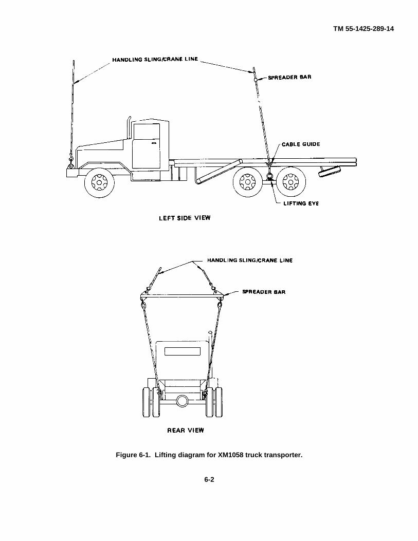
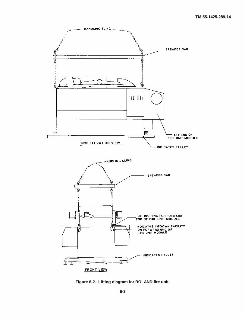
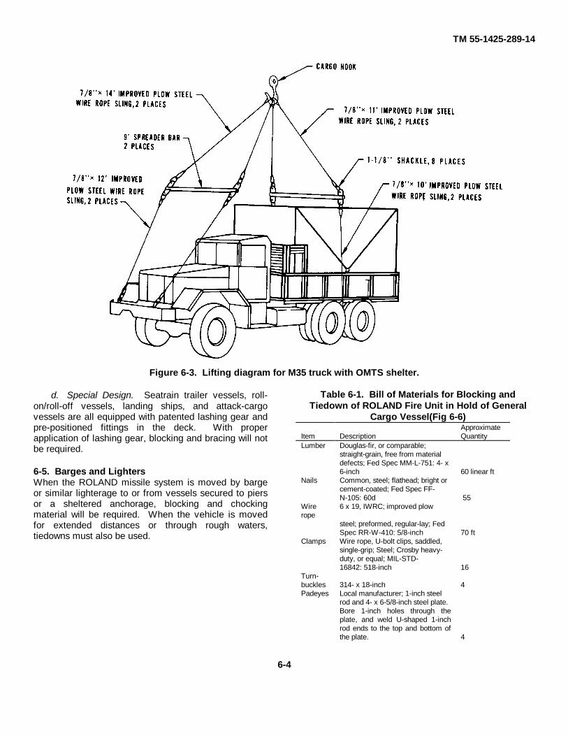
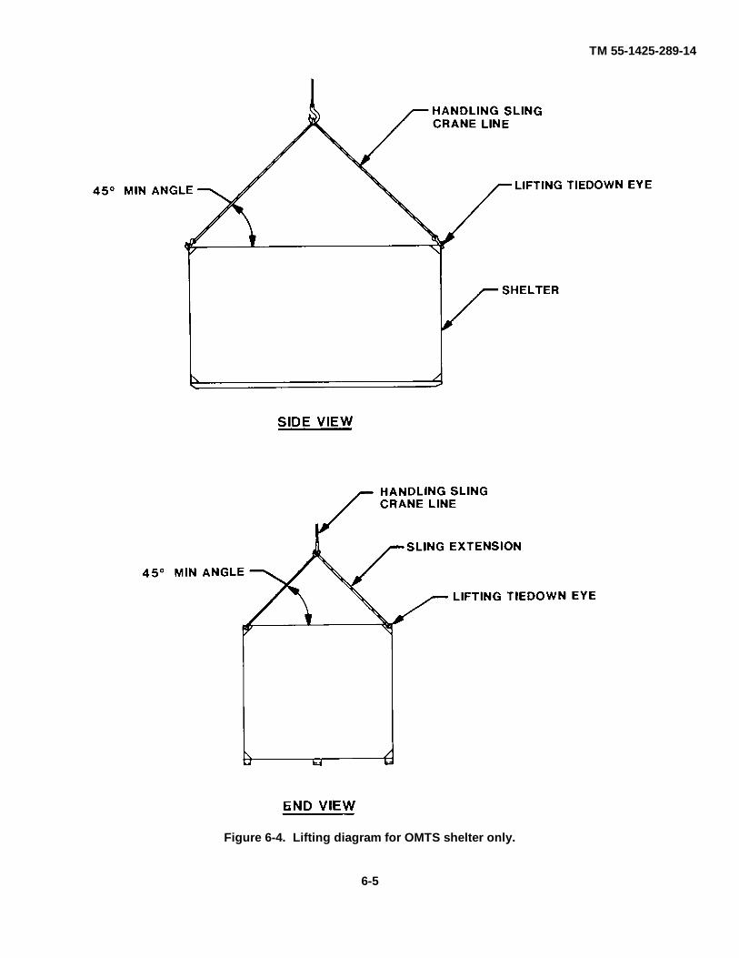
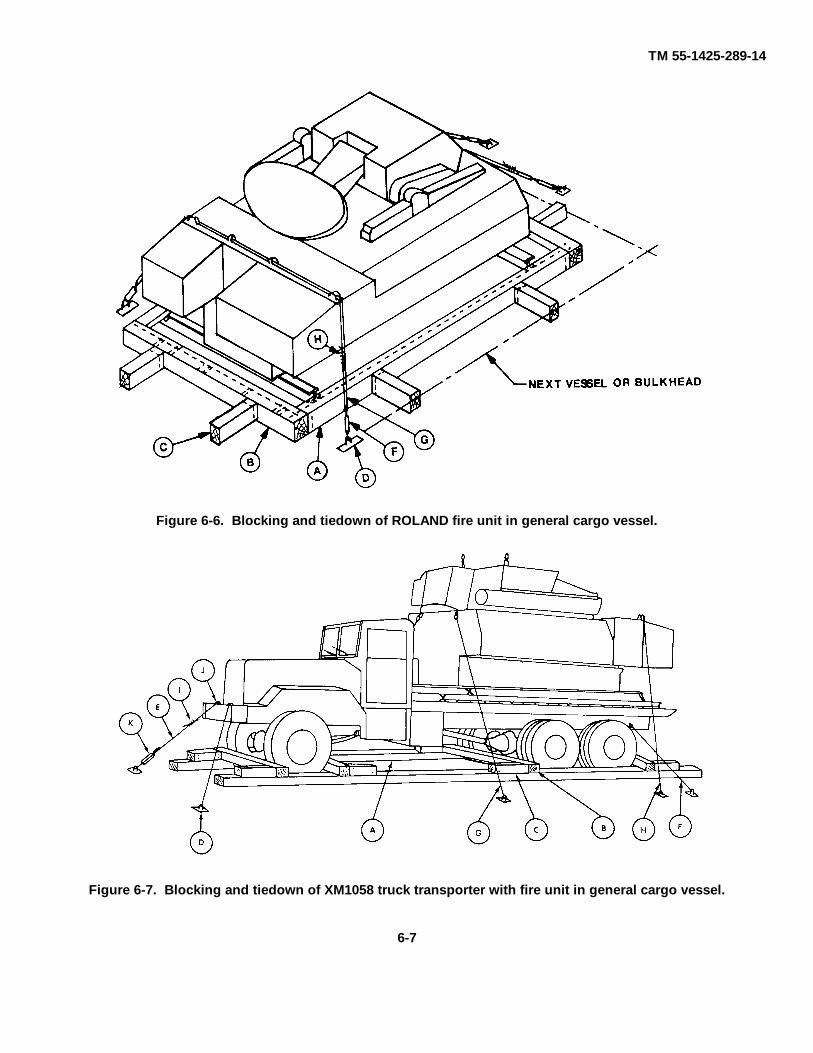
amphibious lighters, and landing ship tanks. They canalso be driven onto the decks or barges from a pierwhen tidal conditions are suitable and ramps areavailable. The vehicles and the fire unit can be lifted byshoreside or floating cranes of adequate capacity ontoseagoing vessels. Jumbo booms and heavy-lift ship'sgear may be used in loading vehicles and other cargoonto vessels. The vehicles can be driven or towed ontoroll-on/roll-off vessels. The ROLAND fire unit and theXM1058 truck transporter may be loaded as a single unitor as separate items, based on the type of vessel andthe stowage location available. The M35 trucktransporting an OMTS shelter may be loaded as a singleunit or as separate items. Typical lifting diagrams forROLAND missile system components are shown infigures 6-1 through 6-4.c. Tiedown. Typical blocking and tiedown details forROLAND missile system components are shown infigures 6-5 through 6-8. Materials and their applicationare listed in tables 6-1 through 6-6.
NOTEFigure 6-5 was extracted from USArmy Materiel Command drawings.Reference to page numbers in thenotes within this figure refer to thenumber listed in the lower left-handcorner of the figure.
6-1
TM 55-1425-289-14
Figure 6-1. Lifting diagram for XM1058 truck transporter.
6-2
TM 55-1425-289-14
Figure 6-2. Lifting diagram for ROLAND fire unit.
6-3
TM 55-1425-289-14
Figure 6-3. Lifting diagram for M35 truck with OMTS shelter.
d. Special Design. Seatrain trailer vessels, roll-on/roll-off vessels, landing ships, and attack-cargovessels are all equipped with patented lashing gear andpre-positioned fittings in the deck. With properapplication of lashing gear, blocking and bracing will notbe required.
6-5. Barges and LightersWhen the ROLAND missile system is moved by bargeor similar lighterage to or from vessels secured to piersor a sheltered anchorage, blocking and chockingmaterial will be required. When the vehicle is movedfor extended distances or through rough waters,tiedowns must also be used.
Table 6-1. Bill of Materials for Blocking andTiedown of ROLAND Fire Unit in Hold of General
Cargo Vessel(Fig 6-6)
Item DescriptionApproximateQuantity
Lumber Douglas-fir, or comparable;straight-grain, free from materialdefects; Fed Spec MM-L-751: 4- x6-inch 60 linear ft
Nails Common, steel; flathead; bright orcement-coated; Fed Spec FF-N-105: 60d 55
Wirerope
6 x 19, IWRC; improved plow
steel; preformed, regular-lay; FedSpec RR-W-410: 5/8-inch 70 ft
Clamps Wire rope, U-bolt clips, saddled,single-grip; Steel; Crosby heavy-duty, or equal; MIL-STD-16842: 518-inch 16
Turn-buckles 314- x 18-inch 4Padeyes Local manufacturer; 1-inch steel
rod and 4- x 6-5/8-inch steel plate.Bore 1-inch holes through theplate, and weld U-shaped 1-inchrod ends to the top and bottom ofthe plate. 4
6-4
TM 55-1425-289-14
Figure 6-4. Lifting diagram for OMTS shelter only.
6-5

TM 55-1425-289-14
Figure 6-5. Blocking and tiedown of XM1058 truck transporter in general cargo vessel.
6-6
TM 55-1425-289-14
Figure 6-6. Blocking and tiedown of ROLAND fire unit in general cargo vessel.
Figure 6-7. Blocking and tiedown of XM1058 truck transporter with fire unit in general cargo vessel.
6-7

TM 55-1425-289-14
Figure 6-8. Blocking and tiedown ofM35 truck, with OMTS shelter, in general cargo vessel.
Table 6-2. Bill of Materials for Blocking andTiedown of ROLAND Fire Unit in Hold of General
Cargo Vessel (Fig. 6-6)
Item No. Required ApplicationA 2 Side blocks, lumber, 4-inch x 6-inch x
length-to-suit. Locate against the fire unitpallet, one piece on each side of the fire unit.
B 2 End blocks. Each consists of one piece of 4-inch x 6-inch x length-to-suit lumber. Lo-cate on top of side blocking and pallet edge.Toenail to side blocking with four 60d nailsat each end.
C as required Bracing, lumber 4-inch x 6-inch x length-to-suit. Brace as required against fire unitblocking, on the side of the vessel or adja-cent to cargo blocking, to immobilize equip-ment. Toenail each end to adjacent bracingwith four 60d nails.
D 4 Padeyes. Required on the floor of the vesselif proper D-rings or deck tiedown fittingsare not available.
E 2 Wire rope, 5/8-inch, formed into a completeloop. Secure with clamps (item H below). At-tach to the front tiedown ring on each sideof the fire unit.
F 4 Turnbuckles, 3/4- x 18-inch. Apply betweenwire rope and padeyes. Tighten to even ten-sion between all turnbuckles.
G 2 Wire rope, 5/8-inch; form the first cable intoa complete loop between the rear right-handgold club clevis, routed through cable guidesat the top corner, and the left-hand padeye;form the second cable into a loop betweenthe left-hand golf club clevis, routed throughcable guides at the top corner, and the right-hand padeye. Secure each with four clamps(item H below).
H 16 Clamps, 5/8-inch. Secure to items E and Gabove.
Table 6-3. Bill of Materials for Blocking andTiedown of XM1 058 Truck Transporter with FireUnit in Hold of General Cargo Vessel (Fig 6- 7)
ApproximateItem Description QuantityLumber Douglas-fir, or comparable;
straight-grain, free from materialdefects; Fed Spec MM-L-751: 4- x6-inch 120 linear ft
Nails Common steel; flathead; bright orcement-coated; Fed SpecFF-N-105: 60d 110
Wire rope 6 x 19, IWRC; improved plowsteel; preformed, regular-lay; FedSpec RR-W-410: 5/8-inch 150 ft
Clamps Wire rope, U-bolt clips, saddled,single-grip; steel; Crosby heavy-duty, or equal; MIL-STD-16842:5/8-inch 32
Thimbles Standard, open-type: 5/8-inch 14Turn-buckles 3/4- x 18-inch 8Padeyes Local manufacturer; 1-inch steel
rod and 4- x 6- x 5/8-inch steelplate. Bore 1-inch holes through theplate, and weld U-shaped 1-inch rodends to the top and bottom of theplate. 8
Table 6-4. Application of Materials for Blocking andTiedown of XM1058 Truck with Fire Unit in Hold of
General Cargo Vessel (Fig 6-7).
Item No. Required Applicationas required Side blocks, lumber, 4- x 6-inch x length-to-
A suit. Locate against vehicle treads, one pieceon each side of vehicle.
6-8

TM 55-1425-289-14
Table 6-4. ContinuedItem No. Required Application
B 4 Blocks, lumber, 4- x 6- x 120-inch. Locateone in front of the front and intermediatewheels and in back of the front and rearwheels. Toenail each end to the side blockingwith two 60d nails.
C 8 Cleats, lumber, 4- x 6- x 18-inch. Locateagainst blocks as indicated in figure 6-7,and secure each cleat to side blocking withten 60d nails.
D 8 Padeyes. Required on the floor of the vesselif proper D-rings or deck tiedown fittingsare not available.
E 2 Wire rope, 5-8-inch, formed into a completeloop around the tiedown ring. Secure withclamps (item I below).
F 2 Wire rope, 518-inch, formed into a completeloop. Secure with clamps (item I below).
G 2 Wire rope, 518-inch, formed into a completeloop. Secure with clamps (items I below). At-tach to the front tiedown ring on the fireunit, on each side of the vehicle.
H 2 Wire rope, 5/8-inch; form the first cable intoa complete loop between the rear right-handgolf club clevis, routed through cable guidesat the top corner, and the left-hand padeye;form the second cable into a complete loopbetween the left-hand golf club clevis,routed through cable guides at the top cor-ner, and the right-hand padeye. Secure eachwith four clamps (item I below).
I 28 Clamps, 5/8-inch. Secure to items E throughH.
J 16 Place one thimble at each tiedown provisionand turnbuckle.
K 8 Turnbuckles, 3/4- x 18-inch. Apply turn-buckles between wire rope and padeyes.Tighten to even tension between all turn-buckles.
Table 6-5. Bill of Materials for Blocking andTiedown of M35 Truck, with OMTS Shelter, in
General Cargo Vessel (Fig 6-8)
ApproximateItem Description QuantityLumber Douglas-fir, or comparable:
Straight-grain, free from materialdefects; Fed Spec MM-L-751H:2- x 4-inch 8 linear ft2- x 12-inch 44 linear ft4- x 6-inch 62 linear ft
Nails Common steel; flathead; bright orcement-coated; Fed Spec FF-N-105B: 12d 32
30d as required60d 16
Wire rope 6 x 19, IWRC; improved plowsteel; preformed, regular-lay; FedSpec RR-W-410C: 5/8-inch 80 ft
Clamps Wire rope, U-bolt clips, saddled,single-grip; steel, Crosby heavy-duty, or equal; Fed Spec FF-C-450D: 5/8-inch 16
Table 6-6. Application of Materials for Blocking andTiedown of M35 Truck, with OMTS Shelter, in
General Cargo Vessel (Fig 6-8)
Item No. Required ApplicationA 4 Lumber, 2- x 12- x 96-inch. Pre-position on
vessel deck so that two pieces are under theleft rear wheels and two pieces are under theright rear wheels parallel to the long axis ofthe truck.
B 4 Lumber, 2- x 12- x 36-inch. Pre-position onvessel deck so that two pieces are under eachfront wheel parallel to the long axis of thetruck.
C 2 Side blocks. Each to consist of 4- x 6- x108-inch lumber. Center one piece againstthe outside of the left and right rear wheels.
D 2 Side blocks. Each to consist of 4- x 6- x 48-inch lumber. Center one piece against theoutside of each front wheel.
E 4 End blocks.inch lumber. Locate one piece forward of thefront and intermediate wheels and behindthe front and rear wheels. Toenail each endof the side block with two 60d nails.
F 8 Backup cleats. Each to consist of one pieceof 2- x 4- x 12-inch lumber. Locate one ontop of items C and D against the joint ofeach item E. Nail to items C and D with four12d nails per block.
G as required Bracing, lumber, 4-inch x 6-inch x randomlength, cut-to-fit. Place the ends against theside blocking and blocking of other cargo, orthe side of the ship or other ship's structure.Nail with 30d nails where appropriate.
H as required Blocks. 4-inch x 6-inch x random length,cut-to-fit. Place blocks around the truck andagainst other blocking, on the side of theship or other ship's structure as appropriate,to assist in holding the bracing in place.
J 4 Wire rope, approximately 20 feet each.Form a complete loop through the truck tie-down provision and appropriate deck padeyeor D-ring. Pull the wire rope taut and secureit with clamps (item K).
K 16 Clamps. Use four clamps to secure eachitem
J. Details for placement of clamps are pro-vided in figure 5-3 or 7-4.
Material for these items are not included in table 6-1.6-6. Landing Ships, Landing Craft, and AmphibiousVehicles When the ROLAND missile system is movedfor extended distances or through rough waters,blocking and tiedowns must be used. In most cases, thevessels are equipped with turnbuckles with a sheep'sfoot on one end that fits into a deck cloverleaf; wherenot provided, a suitable substitute may be used.
6-7. Lighter Aboard Ship (LASH)a. General. When transporting the ROLAND
missile system by LASH-type ships, securement withblocking and tiedowns is required. Barge stability is
6-9

TM 55-1425-289-14
noticeably affected by the placement of heavy-lift items;therefore, ROLAND missile system equipment shouldbe loaded in manner to counterbalance variations in thelocations of centers of gravity from true center.
b. Shoring. Shoring is not generally usedbeneath vehicles equipped with rubber tires. Frictionalforces between the tires and the deck are sufficient tomake it unnecessary. However, deck surfaces shouldbe dry and free of grease or debris.
6-10
TM 55-1425-289-14
CHAPTER 7
RAIL TRANSPORTABILITY GUIDANCE
Section I. GENERAL
7-1. ScopeThis chapter provides rail transportability guidance formovement of the ROLAND missile system. It coverstechnical and physical characteristics, as well as safetyconsiderations, and prescribes the materials andguidance required to prepare, load, tie down, and unloadthe vehicles.
7-2. Maximum Utilization of RailcarsAdditional cargo, as approved by the activity offering theitems for transport, may be transported with thevehicles.
Section II. TRANSPORT ON CONUS RAILWAYS
7-3. GeneralThe transportability guidance contained in this section isapplicable when the ROLAND missile system istransported on CONUS railways. The ROLAND fire unitand the XM1058 truck transporter must be transportedas separate components. The ROLAND missile systemdoes not exceed width limits for unrestricted movementin its reduced configuration.
7-4. Preparation for Loadinga. ROLAND Missile System. Preparation of theROLAND missile system will vary among loads to be
transported over various routes on different equipment,including rail equipment, and with different restraintprocedures as identified in paragraphs 7-5 through 7-8.b. Rail Shipment Only. Rear-door structural supportmust be installed prior to rail shipment. A diagram of arear entry door opening is shown in figure 7-1.c. Whip Antennae. The whip antennae must be foldedand secured to avoid damage. Procedures for foldingand securing the antennae are contained in TM 9-1425-625-10.
Figure 7-1. Diagram of rear entry door opening.
7-1

TM 55-1425-289-14
7-5. Loading of ROLAND Missile System on GeneralPurpose Flatcar
a. The ROLAND missile system may be placed inthe tiedown position on the flatcar by crane or it may bedriven onto the flatcar, provided a suitable ramp orbridge is available.
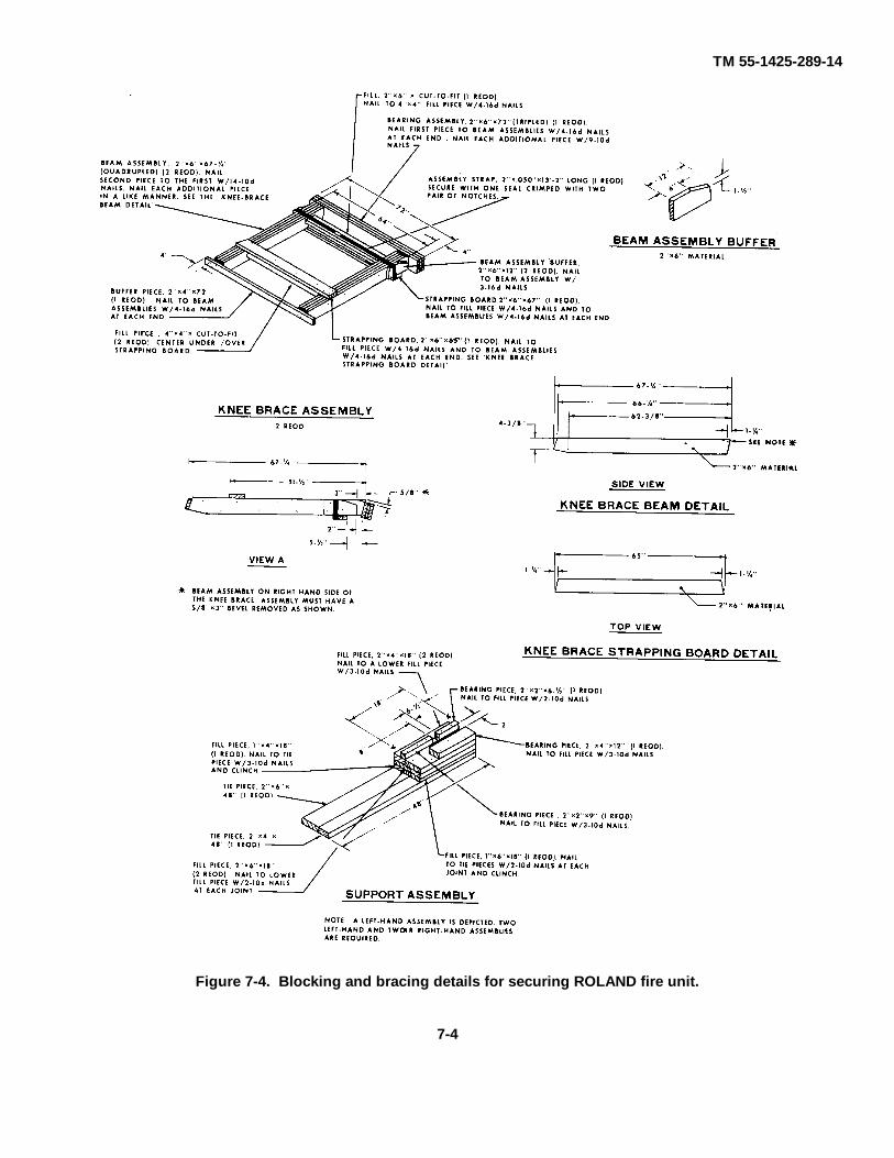
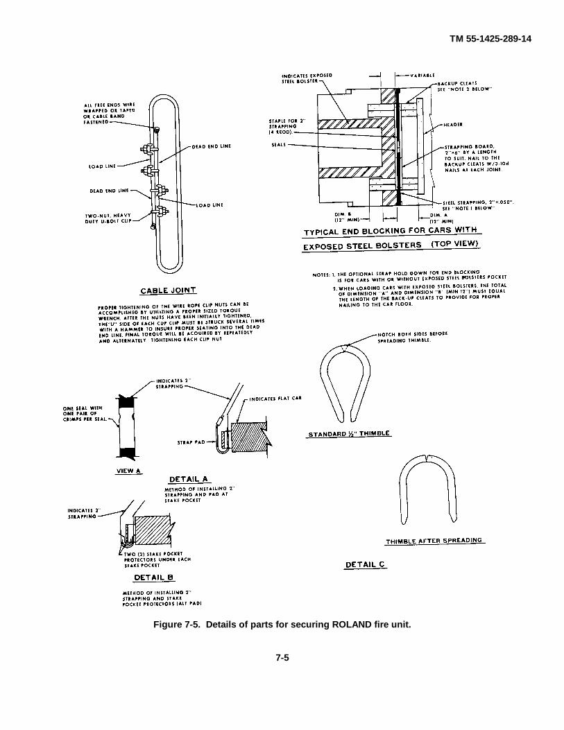
b General notes and material specifications arelisted in table 7-1. Also shown in this table is theapplication of materials for loading and securing theROLAND fire unit. Figures 7-2 (isometric view) and 7-3(front view) show blocking and tiedown for the ROLANDfire unit on a general purpose flatcar.
c. Figures 7-4 and 7-5 illustrate the details forsecuring the ROLAND fire unit.
Figure 7-2. Blocking and tiedown for ROLAND fire unit on general purpose flatcar (isometric view).
7-2

TM 55-1425-289-14
Figure 7-3. Blocking and tiedown for ROLAND fire unit on general purpose flatcar(front view).
7-3
TM 55-1425-289-14
Figure 7-4. Blocking and bracing details for securing ROLAND fire unit.
7-4
TM 55-1425-289-14
Figure 7-5. Details of parts for securing ROLAND fire unit.
7-5

TM 55-1425-289-14
Table 7-1. Application of Materials for Loading andSecuring ROLAND Fire Unit (Figs 7-2, 7-3, 7-4, and
7-5)Item No. Required Application
A 4 Support assembly. See the "support assem-bly detail in figure 7-4. Nail the assemblyto the car floor with four 16d nails.
B 4 Pallet beam stiffeners, 2- x 6- x 48-inch(doubled). Position so that it is approximate-ly 2 inches from contacting the lateralstiffener on the underside of the pallet. Nailthe first piece to the car floor with seven 20dnails. Nail the second piece to the first withseven 50d nails.
C 8 each Side blocks, 2- x 6- x 42-inch and 2- x 8- x42-inch. Position the first 2- x 6-inch piecenext to the pallet, and nail to the car floorwith eleven 20d nails. Position the second 2-x 6-inch piece on top of the first piece(against pallet beam web), and nail theeleven 20d nails. Nail the second 2- x 8-inchpiece to the first in a like manner.
D 2 Knee brace assembly. See the "knee brace as-sembly" detail in figure 7-4. Position asshown, on top of the pallet transverse beam,centered on the fire-unit module hull.
E 2 Headers, 2-inch x 6-inch x 7-ft 0-inch(doubled). Nail the first piece to the car floorwith sixteen 20d nails. Nail the second pieceto the first with sixteen 50d nails.
F 8 Backup cleats, 2- x 6- x 36-inch (doubled).Position two cleats side by side to align withpiece marked D, as shown in figure. Nail thefirst piece to the car floor with nine 20dnails. Nail the second piece to the first withnine 50d nails.
G 4 Dunnage holddown straps, 2-inch x .050-inch by length-to-suit. Install to form a com-plete loop over the knee brace assembly.Thread through the stake pocket from insideto outside on each side of the car and bringboth ends up above the knee brace assembly,where they can be tensioned and sealed withtwo seals. Secure to the knee brace assemblywith the two 20d nails driven partially intothe assembly and bent over the strap at eachend of the assembly.
H 8 Pads, steel, strapping, 2-inch x .050-inchlong. Position pad under stake pocket, andseal to holddown strap marked G (fig 7-5,detail A). For alternate stake pocket protec-tor (16 required), use two pads under eachstake pocket with a holddown strap (see fig7-5, detail A).
I 16 Seals, 2-inch strapping, four per strap.Double-crimp each seal except those used tosecure the pads marked H.
J 2 Wire rope, steel, 112-inch-diameter, 11.5-ton. Form a complete loop through a carstake pocket and around the tiedown facilityat the forward end of the lading.
K 1 Wire rope, steel, 112-inch dia, 11.5-ton.Form a complete loop through the car stakepockets and the aft end of the cable facilitiesas shown in figure 7-5.
Table 7-1. Continued
Item No. Required ApplicationL 6 Thimble, standard, 1/2-inch. Use one each
for the car stake pocket and the forward endtiedown facility. Secure to cables marked Jand K with one clip per thimble. Note: Astandard thimble as specified can be securedto a cable with a 11/2-inch clip. However, ifdesired, or if the 1/2-inch thimble being usedis of a type that cannot be secured to a cablewith a 112-inch clip, a 5/8-inch clip may beused. Alternate: No. 14 gauge wire may beused.
M 18 Clip, wire rope, 1/2-inch. Use four per cablejoint of pieces marked J and K and one perthimble.
N as required Waterproof paper or burlap. Position paperor burlap between cable and lading at pointsof contact. Tape or wire tie to prevent dis-placement.
7-6. Loading of XM1058 Truck transporter onGeneral Purpose Flatcar
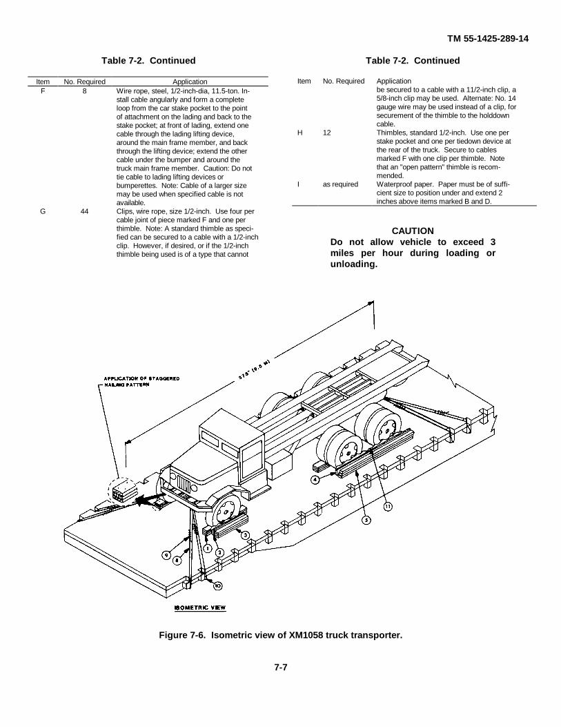
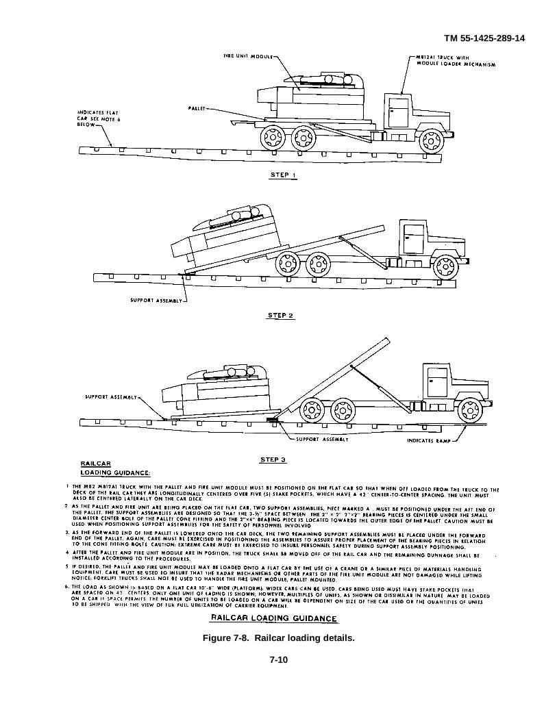
a. The vehicle may be placed in the tiedownposition on the flatcar by crane. It may be driven ortowed into position if a suitable ramp or bridge isavailable. The application of materials for loading andsecuring the XM1058 truck transporter is shown in table7-2. Figure 7-5 shows an isometric view of the trucktransporter, and figure 7-6 shows a rear view of the trucktransporter.
b. When the vehicle is loaded and tied down, thehandbrakes must be set. The transmission gearshiftmust be in neutral.
c. Fire Unit slinging and railcar loading details areshown in figures 6-2 and 7-8, respectively. Blockingdetails for lading are presented in figure 7-9.
Table 7-2. Application of Materials for Loading andSecuring XM1058 Truck Transporter (Figs 7-5
Through 7-6)Item No. Required Application
A 8 Wheel blocks. Place the 450 end of blockagainst a wheel. Nail through heel of blockwith three 40d and two 60d nails. Toenaileach side to car floor with two 40d nails.
B 2 Rubbing strips, 2-inch x 6-inch x 7-foot 6-inch. Position on edge of wheel block, andnail to lower piece marked C with one 12dnail every 8 inches.
C 2 Side blocks, 2-inch x 4-inch x 7-foot 6-inch(tripled). Nail the first piece to the car floorwith one 30d nail every 8 inches. Nail eachadditional piece in a like manner.
D 2 Rubbing strips, 2- x- x 36-inch. Position onedge of side block, and nail to lower piecemarked E with five 12d nails.
E 2 Side blocks, 2- x 6- x 36-inch (tripled). Nailthe first piece to the car floor with five 30dnails. Nail each additional piece in a likemanner.
7-6
TM 55-1425-289-14
Table 7-2. Continued
Item No. Required ApplicationF 8 Wire rope, steel, 1/2-inch-dia, 11.5-ton. In-
stall cable angularly and form a completeloop from the car stake pocket to the pointof attachment on the lading and back to thestake pocket; at front of lading, extend onecable through the lading lifting device,around the main frame member, and backthrough the lifting device; extend the othercable under the bumper and around thetruck main frame member. Caution: Do nottie cable to lading lifting devices orbumperettes. Note: Cable of a larger sizemay be used when specified cable is notavailable.
G 44 Clips, wire rope, size 1/2-inch. Use four percable joint of piece marked F and one perthimble. Note: A standard thimble as speci-fied can be secured to a cable with a 1/2-inchclip. However, if desired, or if the 1/2-inchthimble being used is of a type that cannot
Table 7-2. Continued
Item No. Required Applicationbe secured to a cable with a 11/2-inch clip, a5/8-inch clip may be used. Alternate: No. 14gauge wire may be used instead of a clip, forsecurement of the thimble to the holddowncable.
H 12 Thimbles, standard 1/2-inch. Use one perstake pocket and one per tiedown device atthe rear of the truck. Secure to cablesmarked F with one clip per thimble. Notethat an "open pattern" thimble is recom-mended.
I as required Waterproof paper. Paper must be of suffi-cient size to position under and extend 2inches above items marked B and D.
CAUTIONDo not allow vehicle to exceed 3miles per hour during loading orunloading.
Figure 7-6. Isometric view of XM1058 truck transporter.
7-7
TM 55-1425-289-14
Section III. TRANSPORT ON FOREIGN RAILWAYS
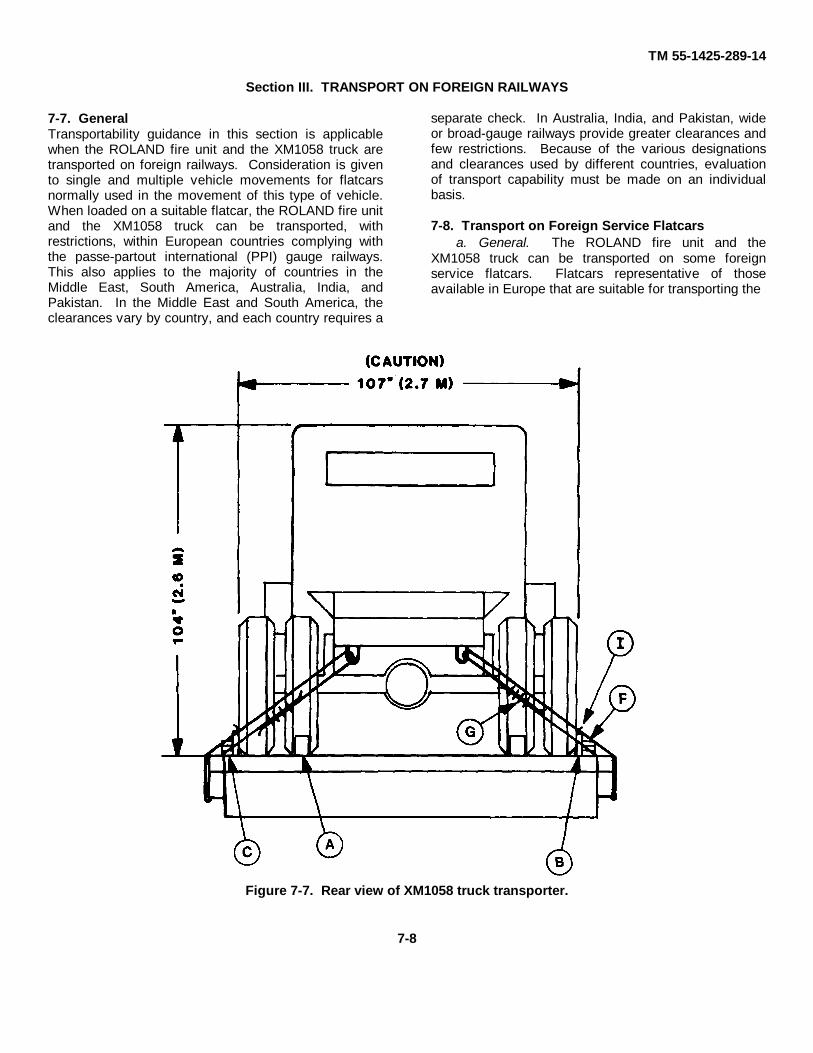
7-7. GeneralTransportability guidance in this section is applicablewhen the ROLAND fire unit and the XM1058 truck aretransported on foreign railways. Consideration is givento single and multiple vehicle movements for flatcarsnormally used in the movement of this type of vehicle.When loaded on a suitable flatcar, the ROLAND fire unitand the XM1058 truck can be transported, withrestrictions, within European countries complying withthe passe-partout international (PPI) gauge railways.This also applies to the majority of countries in theMiddle East, South America, Australia, India, andPakistan. In the Middle East and South America, theclearances vary by country, and each country requires a
separate check. In Australia, India, and Pakistan, wideor broad-gauge railways provide greater clearances andfew restrictions. Because of the various designationsand clearances used by different countries, evaluationof transport capability must be made on an individualbasis.
7-8. Transport on Foreign Service Flatcarsa. General. The ROLAND fire unit and the
XM1058 truck can be transported on some foreignservice flatcars. Flatcars representative of thoseavailable in Europe that are suitable for transporting the
Figure 7-7. Rear view of XM1058 truck transporter.
7-8
TM 55-1425-289-14
ROLAND fire unit and the XM1058 truck are describedbelow:
Flatcar PlatformDesignation Capacity Length Width HeightRLMMP 700 57.3-ton 31-ft 2-in. 10-ft 4-in. 4-ft 2-3/4-in.
(52.00 MT) (7.50 m) (3.15 m) (1.29 m)SAMMS 710 71.63-ton 49-ft 3-in. 10-ft 2-in. 4-ft 2-3/4-in.
(65.00 MT) (15.01 m) (3.10 m) (1.29 m)
b. Materials. The materials required for blockingand tiedown of the ROLAND fire unit and the XM1058truck on foreign service flatcars are essentially the sameas those used for transporting the ROLAND fire unit and
the XM1058 truck within CONUS. Detailed guidance iscontained in the 4th Transportation Command Pamphlet55-2, Tiedown Guide for Rail Movements.
7-9
TM 55-1425-289-14
Figure 7-8. Railcar loading details.
7-10
TM 55-1425-289-14
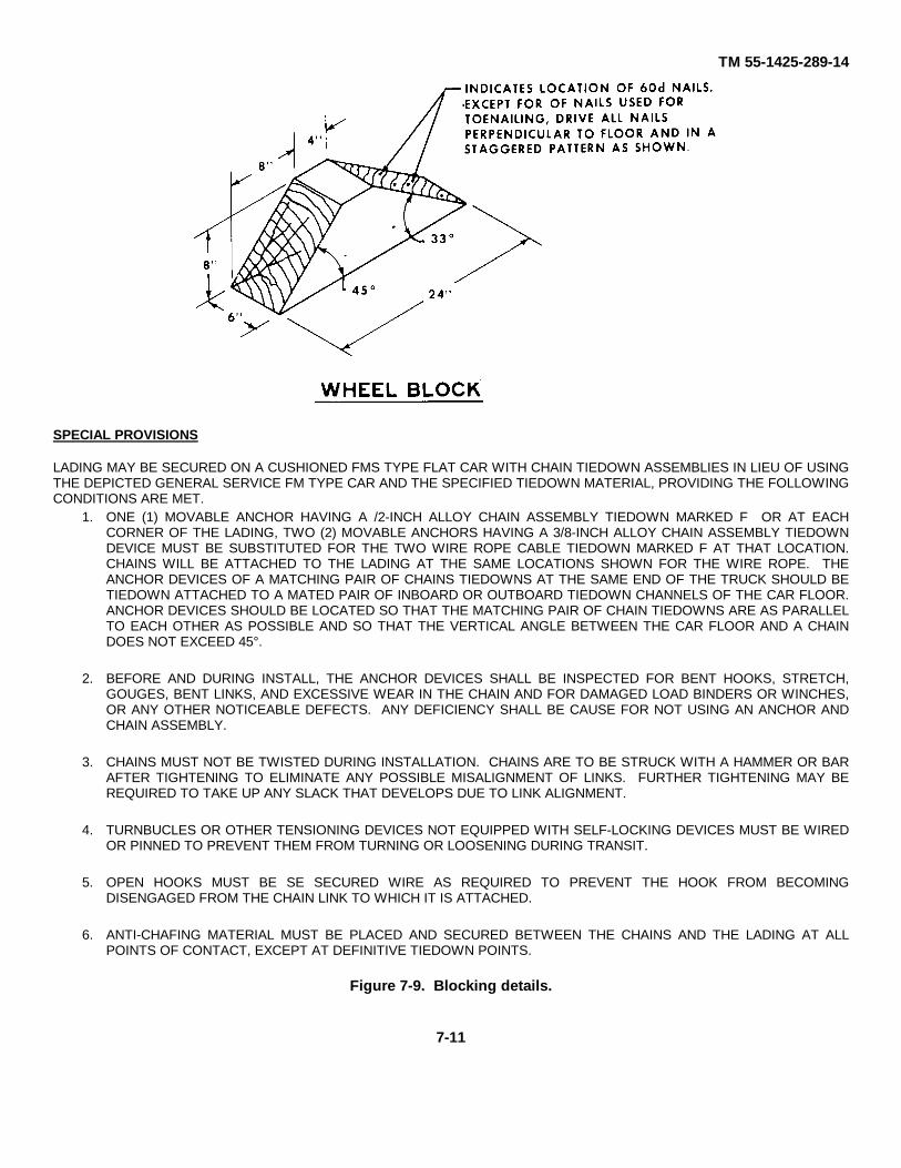
SPECIAL PROVISIONS
LADING MAY BE SECURED ON A CUSHIONED FMS TYPE FLAT CAR WITH CHAIN TIEDOWN ASSEMBLIES IN LIEU OF USINGTHE DEPICTED GENERAL SERVICE FM TYPE CAR AND THE SPECIFIED TIEDOWN MATERIAL, PROVIDING THE FOLLOWINGCONDITIONS ARE MET.
1. ONE (1) MOVABLE ANCHOR HAVING A /2-INCH ALLOY CHAIN ASSEMBLY TIEDOWN MARKED F OR AT EACHCORNER OF THE LADING, TWO (2) MOVABLE ANCHORS HAVING A 3/8-INCH ALLOY CHAIN ASSEMBLY TIEDOWNDEVICE MUST BE SUBSTITUTED FOR THE TWO WIRE ROPE CABLE TIEDOWN MARKED F AT THAT LOCATION.CHAINS WILL BE ATTACHED TO THE LADING AT THE SAME LOCATIONS SHOWN FOR THE WIRE ROPE. THEANCHOR DEVICES OF A MATCHING PAIR OF CHAINS TIEDOWNS AT THE SAME END OF THE TRUCK SHOULD BETIEDOWN ATTACHED TO A MATED PAIR OF INBOARD OR OUTBOARD TIEDOWN CHANNELS OF THE CAR FLOOR.ANCHOR DEVICES SHOULD BE LOCATED SO THAT THE MATCHING PAIR OF CHAIN TIEDOWNS ARE AS PARALLELTO EACH OTHER AS POSSIBLE AND SO THAT THE VERTICAL ANGLE BETWEEN THE CAR FLOOR AND A CHAINDOES NOT EXCEED 45°.
2. BEFORE AND DURING INSTALL, THE ANCHOR DEVICES SHALL BE INSPECTED FOR BENT HOOKS, STRETCH,GOUGES, BENT LINKS, AND EXCESSIVE WEAR IN THE CHAIN AND FOR DAMAGED LOAD BINDERS OR WINCHES,OR ANY OTHER NOTICEABLE DEFECTS. ANY DEFICIENCY SHALL BE CAUSE FOR NOT USING AN ANCHOR ANDCHAIN ASSEMBLY.
3. CHAINS MUST NOT BE TWISTED DURING INSTALLATION. CHAINS ARE TO BE STRUCK WITH A HAMMER OR BARAFTER TIGHTENING TO ELIMINATE ANY POSSIBLE MISALIGNMENT OF LINKS. FURTHER TIGHTENING MAY BEREQUIRED TO TAKE UP ANY SLACK THAT DEVELOPS DUE TO LINK ALIGNMENT.
4. TURNBUCLES OR OTHER TENSIONING DEVICES NOT EQUIPPED WITH SELF-LOCKING DEVICES MUST BE WIREDOR PINNED TO PREVENT THEM FROM TURNING OR LOOSENING DURING TRANSIT.
5. OPEN HOOKS MUST BE SE SECURED WIRE AS REQUIRED TO PREVENT THE HOOK FROM BECOMINGDISENGAGED FROM THE CHAIN LINK TO WHICH IT IS ATTACHED.
6. ANTI-CHAFING MATERIAL MUST BE PLACED AND SECURED BETWEEN THE CHAINS AND THE LADING AT ALLPOINTS OF CONTACT, EXCEPT AT DEFINITIVE TIEDOWN POINTS.
Figure 7-9. Blocking details.
7-11
TM 55-1425-289-14APPENDIX
REFERENCES
1. Army Regulations (AR)55-29 Military Convoy Operations in CONUS55-80 Highways for National Defense55-162 Permit for Oversize, Overweight, or Other Special Military
Movements on Public Highways in the Contiguous Statesand the District of Columbia of the United States
55-228 Transportation by Water of Explosives and Hazardous Car-go
55-355 Military Traffic Management Regulation70-44 DOD Engineering for Transportability70-47 Engineering for Transportability355-40 Accident Report and Records746-1 Color, Marking, and Preparation of Equipment for Ship-
ment2. Army Field Manuals (FM)
55-9 Unit Air Movement Planning55-15 Transportation Reference Data55-17 Terminal Operations Specialists Handbook
3. Army Supply Bulletins (SB)700-20 Army Adopted Items of Materiel
4. Army Technical Bulletins (TB)55-46-1 Standard Characteristics (Dimensions, Weight, and Cube)
for Transportability of Military Vehicles and Equipment5. Technical Manuals (TM)
9-1425-625-10 Operators Manual9-1425-625-20-1 Organizational Maintenance Manual: Fire Unit Trouble
Shooting9-1425-625-20-2 Organizational Maintenance Manual: Radar, IFF, E-O, C
and C Subsystems9-1425-625-20-3 Organizational Maintenance Manual: Electrical and Me-
chanical Subsystems9-1425-625-20-4 Fire Unit Hydraulic Subsystems9-1425-625-12-P Module Loader Mechanism38-250 (AFR 71-4) Packaging and Handling of Dangerous Materials for Trans-
portation by Military Aircraft55-405-9 Weight and Balance55-500 Marine Equipment Characteristics and Data55-2200-001-12 Transportability Guidance Application of Blocking, Brac-
ing, and Tiedown Materials for Rail Transportation6. Air Force Technical Orders
1-1B-40 Handbook of Weight and Balance Data1 C-5A-9 Loading Instructions, USAF Series C-5A Airplane
A-1

TM 55-1425-289-14
7. Other Publications and Source of Procurementa. Association of American Railroads, Rules Governing the Loading of Commodities on Open-Top Cars and
Trailers.Section No. 1-General RulesSection No. 6-Rules Governing the Loading of Department of Defense Materiel on Open-Top CarsAvailable from: R. C. Reber, Secretary
The Association of American Railroads1920 L Street, NWWashington, DC 20036
b. Rail Carriers Tariff No. 25 or reissues thereof-Hazardous Materials Regulations of the Department ofTransportation, Including Specifications for Shipping Containers.
Available from: R. M. Graziano, AgentAmerican Railroad Building1920 L Street, NWWashington, DC 20036
c. Water Carrier Tariff No. 24 or reissues thereof-Regulations Governing the Transportation or Storage ofExplosives or Other Dangerous Articles or Substances, and Combustible Liquids On Board Vessels.
Available from: R. M. Graziano, AgentAmerican Railroad Building1920 L Street, NWWashington, DC 20036
d. Water Shipment, Code of Federal Regulation, Title 46-Shipping, Part 146; Title 49-Carriage by Vessel, Part 176.Available from: Superintendent of Documents
US Government Printing OfficeWashington, DC 20402
e. Motor Carriers Explosives and Dangerous Articles Tariff No. 14 or reissues thereof-Department of TransportationHazardous Materials by Motor, Rail, and Water, Including Specifications for Shipping Containers.
Available from: Richard H. Hinchcliff, Issuing Officer1616 P Street, NWWashington, DC 20036
8. Department of TransportationSpecial Permit No. 3498USCG 108 Rules and Regulations for Military Explosives and Hazardous Munitions
By Order of the Secretary of the Army:
JOHN A. WICKHAM, JR.General, United States Army
Chief of StaffOfficial:
DONALD J. DELANDROBrigadier General, United States Army
The Adjutant General
Distribution: To be distributed in accordance with DA Form 12-32, Organizational Maintenance requirements for USRoland Missile System.
U. S. GOVERNMENT PRINTING OFFICE : 1992 0 - 311-831 (61025)
A-2

The Metric System and Equivalents
Linear Measure Liquid Measure
1 centiliter = 10 milliters = .34 fl. ounce1 centimeter = 10 millimeters = .39 inch 1 deciliter = 10 centiliters = 3.38 fl. ounces1 decimeter = 10 centimeters = 3.94 inches 1 liter = 10 deciliters = 33.81 fl. ounces1 meter = 10 decimeters = 39.37 inches 1 dekaliter = 10 liters = 2.64 gallons1 dekameter = 10 meters = 32.8 feet 1 hectoliter = 10 dekaliters = 26.42 gallons1 hectometer = 10 dekameters = 328.08 feet 1 kiloliter = 10 hectoliters = 264.18 gallons1 kilometer = 10 hectometers = 3,280.8 feet
Square MeasureWeights
1 sq. centimeter = 100 sq. millimeters = .155 sq. inch1 centigram = 10 milligrams = .15 grain 1 sq. decimeter = 100 sq. centimeters = 15.5 sq. inches1 decigram = 10 centigrams = 1.54 grains 1 sq. meter (centare) = 100 sq. decimeters = 10.76 sq. feet1 gram = 10 decigram = .035 ounce 1 sq. dekameter (are) = 100 sq. meters = 1,076.4 sq. feet1 decagram = 10 grams = .35 ounce 1 sq. hectometer (hectare) = 100 sq. dekameters = 2.47 acres1 hectogram = 10 decagrams = 3.52 ounces 1 sq. kilometer = 100 sq. hectometers = .386 sq. mile1 kilogram = 10 hectograms = 2.2 pounds1 quintal = 100 kilograms = 220.46 pounds Cubic Measure1 metric ton = 10 quintals = 1.1 short tons
1 cu. centimeter = 1000 cu. millimeters = .06 cu. inch1 cu. decimeter = 1000 cu. centimeters = 61.02 cu. inches1 cu. meter = 1000 cu. decimeters = 35.31 cu. feet
Approximate Conversion Factors
To change To Multiply by To change To Multiply by
inches centimeters 2.540 ounce-inches Newton-meters .007062feet meters .305 centimeters inches .394yards meters .914 meters feet 3.280miles kilometers 1.609 meters yards 1.094square inches square centimeters 6.451 kilometers miles .621square feet square meters .093 square centimeters square inches .155square yards square meters .836 square meters square feet 10.764square miles square kilometers 2.590 square meters square yards 1.196acres square hectometers .405 square kilometers square miles .386cubic feet cubic meters .028 square hectometers acres 2.471cubic yards cubic meters .765 cubic meters cubic feet 35.315fluid ounces milliliters 29,573 cubic meters cubic yards 1.308pints liters .473 milliliters fluid ounces .034quarts liters .946 liters pints 2.113gallons liters 3.785 liters quarts 1.057ounces grams 28.349 liters gallons .264pounds kilograms .454 grams ounces .035short tons metric tons .907 kilograms pounds 2.205pound-feet Newton-meters 1.356 metric tons short tons 1.102pound-inches Newton-meters .11296
Temperature (Exact)
°F Fahrenheit 5/9 (after Celsius °Ctemperature subtracting 32) temperature

PIN: 058502-000