tm 9-4940-568-10 frs
TRANSCRIPT

8/20/2019 TM 9-4940-568-10 FRS
http://slidepdf.com/reader/full/tm-9-4940-568-10-frs 1/403
DISTRIBUTION RESTRICTIONApproved for public release; distribution is unlimited.
TM 9-4940-568-10
OPERATOR’S MAINTENANCE MANUAL
FOR
FORWARD REPAIR SYSTEM (FRS)
MODEL M7
NSN 4940-01-463-7940
HEADQUARTERS, DEPARTMENT OF THE ARMYMARCH 2002

8/20/2019 TM 9-4940-568-10 FRS
http://slidepdf.com/reader/full/tm-9-4940-568-10-frs 2/403

8/20/2019 TM 9-4940-568-10 FRS
http://slidepdf.com/reader/full/tm-9-4940-568-10-frs 3/403
TM 9-4940-568-10
a
The FRS has been designed to operate safely and efficiently within the limits specified inthis TM. Operation beyond these limits is prohibited IAW AR 70-1 without written approval
from the Commander, U.S. Army Tank-Automotive and Armaments Command, Attn:AMSTA-LC-AH, Warren, MI 48397-5000. Failure to comply could result in injury or deathto personnel.
Personnel must not ride, rest, or sleep on or inside the FRS. Failure to comply may result ininjury or death to personnel.
Do not lower/open doors in winds that exceed 30 mph. Failure to comply may result ininjury or death to personnel.
Do not use shelter roof or doors (when open) for loading or storage. Failure to comply mayresult in injury or death to personnel.
Keep shelter roof and doors free of accumulated snow, ice, dirt and material buildup. Do notlower doors if buildup is in excess of 1/4 inch thick. Failure to comply may result in injury
or death to personnel.
Generator set engine must be shut off before performing PMCS walkaround. Severe injuryto personnel may result.
Drain air compressor reservoir before servicing the air lubricator. Failure to comply mayresult in injury to personnel.
The exhaust pipe and muffler can become very hot during operation. Do not touch these partswith bare hands, or allow body to come in contact with exhaust pipe or muffler. Exhaust systemparts can cause serious burns.

8/20/2019 TM 9-4940-568-10 FRS
http://slidepdf.com/reader/full/tm-9-4940-568-10-frs 4/403
TM 9-4940-568-10
b
Fuel is very flammable and can explode easily. To avoid serious injury or death, keep fuel awayfrom open fire and keep fire extinguisher within easy reach when working with fuel. Do not
work on fuel system when engine is hot. Fuel can be ignited by hot engine.
Hydraulic oil may be hot and cause serious burns.
Radiator coolant can be extremely hot and cause severe burns.
Use extreme caution when checking radiator hoses and clamps or injury to personnel mayresult.
Flatrack rollers must be supported while removing retaining pins or roller may drop causinginjury to personnel.
Remove all jewelry such as rings, ID tags, bracelets, etc. If jewelry or tools contact positiveelectrical circuits a direct short may result. Damage to equipment, injury or death topersonnel may occur.
Lead-acid battery gases can explode. Do not smoke, have open flames, or make sparksaround a battery, especially if caps are off. If a battery is gassing, it can explode and causeinjury to personnel.
Do not operate crane unless both outrigger jacks are properly set up. Shelter could turn overcausing serious injury or death.
8/20/2019 TM 9-4940-568-10 FRS
http://slidepdf.com/reader/full/tm-9-4940-568-10-frs 5/403
TM 9-4940-568-10
c
• Keep hands and feet away from outrigger jacks while operating lever to avoid injury.
• Outriggers should be deployed prior to crane operation to avoid injury.
Care must be taken when disconnecting HOIST load hook from hook block tiedown. Aswinging hook block can cause serious injury or death to personnel.
Keep boom clear of shelter, all electrical lines and other obstacles while operating crane.Failure to comply may result in injury or death to personnel.
Operator should be stationed to be able to see load at all times during crane operation. Boomand load moving out of control could cause serious injury or death.
Ensure that area is clear of personnel before moving SWING control lever. Boom should beswung slow enough so crane operator has complete control. If operator cannot see loadduring operation, operate crane from REMOTE CONTROL UNIT. Boom moving out of control could cause serious injury or death.
• Wire rope can become frayed or contain broken wires. Wear heavy leather-palmed work
gloves when handling wire rope. Frayed or broken wires can injure hands.
• Never let moving wire rope slide through hands, even when wearing gloves. A broken wire
could cut through glove and cut hand.
Ensure REMOTE CONTROL/EMERGENCY STOP/ON/OFF POWER switch is in OFFposition and switch guard is closed before connecting REMOTE CONTROL UNIT. Cranemoving out of control could cause serious injury or death.
Ensure that area is clear of personnel before moving SWING control lever. Boom should beswung slow enough so crane operator has complete control. Boom moving out of controlcould cause serious injury or death.
8/20/2019 TM 9-4940-568-10 FRS
http://slidepdf.com/reader/full/tm-9-4940-568-10-frs 6/403
TM 9-4940-568-10
d
If electrical power fails during crane operation, move switch on remote control unit toSHUTDOWN position. Serious injury could result from uncontrolled moving parts.
Electric power generating equipment must be grounded as a safety precaution. Strayelectrical current can injure or kill personnel and damage the equipment.
Do not attempt to open doors and access platforms while FRS is loaded on vehicle. Failure tocomply may result in injury or death to personnel.
Secure all equipment on FRS before unloading or loading from vehicle. Failure to comply mayresult in injury to personnel.
Opening shelter door is a two person operation. Ensure that upper door support arms lock overcenter. Failure to comply may result in injury to personnel.
Keep hands clear of pivot points on support arms during door operation. Failure to comply willresult in injury to personnel or damage to equipment.
PLS hook arm must be disconnected from FRS hook bar of the flatrack after FRS isunloaded.
FRS C-channels of the flatrack must NOT be in contact with the terrain or any object toprevent altering the critical reaction points of the FRS. Failure to comply could result inpersonnel injury or death.
Generator has an automatic start sequence which will make several attempts to start. Ensuremaster switch is in the off position before reaching anywhere inside the generatorenclosure/housing. Failure to comply could result in personnel injury or death.

8/20/2019 TM 9-4940-568-10 FRS
http://slidepdf.com/reader/full/tm-9-4940-568-10-frs 7/403
TM 9-4940-568-10
e
Exhaust emissions from the diesel generator can be hazardous to human health. PositionFRS so the generator is downwind of work area. If the prevailing wind puts the operatordownwind of the generator’s exhaust, a conscious effort must be made to limit inhalation of
exhaust fumes. Failure to comply may result in serious injury or death to personnel.
Personnel hearing can be PERMANENTLY DAMAGED if exposed to constant high noise levelsof 85 DBA or greater. Wear approved hearing protection devices when working in high noise levelareas. Personnel exposed to high noise levels shall participate in a hearing observation program inaccordance with TB MED 501. Hearing loss occurs gradually but becomes permanent over time.
Never run generator while FRS access platforms/doors are closed. Build-up of combustiblegases due to leaking hoses, fittings, etc., or if gas valves are not shut off, present a possibleexplosion if a short circuit should occur. Failure to comply may result in injury or death to
personnel and damage to equipment.
Failure to properly ground the FRS could result in serious injury or death to personnel.
When refueling, shut down generator. Ensure no open flame is near area. Never smoke. Never
add fuel with engine running. After fuel is added, securely close fuel tank cap; a loose cap cancause a fuel leak or be a fire hazard. Before starting generator, check that no fuel is spilled on oraround FRS. Failure to comply may cause serious injury or death. Never overfill the tank orspill fuel. If fuel is spilled, clean it up immediately.
Clothing fouled by Petroleum, Oil, or Lubricants (POL) must be changed at the earliestopportunity. Any POL contacting the skin should be washed off as soon as possible. Failure tocomply may result in serious injury or death to personnel.

8/20/2019 TM 9-4940-568-10 FRS
http://slidepdf.com/reader/full/tm-9-4940-568-10-frs 8/403
TM 9-4940-568-10
f
Fuel cap and fuel gage are enclosed in a confined space. Care must be used when refueling fueltank. Failure to comply may result in injury to personnel.
Double hearing protection is required. Open drain valve slowly. Noise level in excess of 120 DBA can occur. Failure to comply may cause injury to personnel.
Maximum allowable air pressure in air reservoir is 195 psi (1345 kPa). Failure to complymay result in injury or death to personnel.
Hearing and eye protection required when disconnecting the air supply hose or injury topersonnel may result.
Unsafe welding practices can cause serious injury from fire, explosions, or harmful agents.Allow only authorized personnel to weld or cut metals, and follow safety precautions inTC 9–237. Protective clothing and goggles must be worn; adequate protection used, asuitable fire extinguisher kept nearby, and requirements of TC 9–237 strictly followed.
Welding procedures must be performed beyond the enclosure of shelter, welding fumes canbe harmful to personnel. Failure to comply may result in serious injury or death topersonnel.
Ensure primary power switch located on back of ARC welder is in the OFF position. Failureto comply may result in serious injury or death to personnel.
If welding helmet has been stored for an extended period of time, place welding helmet indirect sun or fluorescent light for 1/2 hour prior to use or until low battery indicator is off.
8/20/2019 TM 9-4940-568-10 FRS
http://slidepdf.com/reader/full/tm-9-4940-568-10-frs 9/403
TM 9-4940-568-10
g
Welding helmet is only operational in temperatures above 25 degrees F. Welding personnelmust use different PPE when in temperatures below 25 degrees F.
Welding operation produces intense light and eye protection is required at all times. Failureto comply may result in serious injury to personnel.
Do not disassemble torch when tip is hot. Tip can be extremely hot and cause severe burns.
Do not disassemble ultrathermic cutting system while hot. Failure to comply could causesevere burns.
Ensure tank standard cap is installed on tank prior to removing or installing pressurizedtanks. Failure to comply may result in injury or death to personnel.
Ensure crane power ON/OFF switch is in the OFF position. Crane moving out of controlcould cause serious injury or death.
Ensure area is clear on both sides of crane before extending outrigger jacks. Failure tocomply may result in injury to personnel or damage to equipment.
Keep hands and feet clear outriggers during operation. Failure to comply may result ininjury to personnel.
Use caution when handling outrigger pads. Sharp edges can injure hands.

8/20/2019 TM 9-4940-568-10 FRS
http://slidepdf.com/reader/full/tm-9-4940-568-10-frs 10/403
TM 9-4940-568-10
h
Do not disconnect cable from stowage hook until boom is raised to a 45-degree angle. Hook assembly could fall. Failure to comply may result in injury to personnel.
If either right-to-left level bubble and/or front-to-back level bubble move out of green areaduring lifting or moving load, immediately lower load and adjust outriggers as necessary.
The crane must be operated with remote control if operator is not able to keep load in sight atall times during operation except in emergency and/or partial system failure. Failure tocomply may result in injury or death to personnel.
Ensure that area is clear of personnel before rotating boom. Boom must be rotated slowlyenough so operator has complete control of load. If operator cannot see load duringoperation, operate crane with remote control. Failure to comply may result in injury or deathto personnel.
Operator must keep control of load at all times. Attach guide lines to load as required.Failure to comply may result in injury or death to personnel.
Ensure that hook latch is closed and safety pin is installed before attempting to raise load. Ahook latch that is not closed and locked in position could allow load to become disengagedfrom hook, allowing load to fall. Injury or death could result.
Ensure there are at least two wraps of cable on hoist drum at all times. Failure to complymay result in injury or death to personnel.

8/20/2019 TM 9-4940-568-10 FRS
http://slidepdf.com/reader/full/tm-9-4940-568-10-frs 11/403
TM 9-4940-568-10
i
Keep all personnel clear of system when retracting O/R beams and jacks. The beams cancrush hands, and retracting the jacks drops the flatrack back on the ground which could
cause injury to personnel.
Ensure that no tools, parts, personnel or objects are on outriggers before retracting, toprevent personnel injury.
Prior to turning off MASTER DISCONNECT switch, allow shelter heater to perform cooldown cycle (approx. 3 minutes) until fan stops. Failure to comply may result in a firecausing injury or death to personnel.
Eye wash is to be refilled and testing by approved medical facility. Consult CHPPM (Centerfor Health Promotion and Preventive Medicine) for details.
Ensure MASTER DISCONNECT switch is in the OFF position. Failure to comply mayresult in serious injury or death to personnel.
Grounding rod must be driven in ground at least 8 feet. Failure to comply may result inserious injury or death to personnel.
Sharp corners on doors could be present, use caution during door operation. Failure tocomply may result in injury to personnel.
Opening/closing shelter door is a two-person operation. Failure to comply may result ininjury to personnel.

8/20/2019 TM 9-4940-568-10 FRS
http://slidepdf.com/reader/full/tm-9-4940-568-10-frs 12/403
TM 9-4940-568-10
j
Keep all personnel clear of FRS when operating outriggers. The beams can crush hands andretracting the jacks drops the flatrack back on the ground, which could cause injury to
personnel.
FRS cannot be placed on unstable uneven ground greater than 4 degrees. Failure to complymay result in injury or death to personnel and damage to equipment.
Do not touch extremely cold metal (below -26° F [–32 C]). Bare skin may freeze to coldmetal and cause injury to personnel.
Hydraulic fluid is under great pressure. Engines on both PLS truck and FRS must be shutoff while disconnecting hydraulic lines. Failure to do so could cause serious injury or deathto personnel.
Operator will have limited visibility of load when using the manual controls. Use a groundguide to relay signals to the operator. Boom and load moving out of control cause seriousinjury or death.
Never attempt crane operations or lifting with crane mast not fully erected. Operating thecrane with the crane mast not fully erected even slightly will disrupt the Overload ShutdownSystem. Failure to comply may result in injury to personnel and damage to equipment.
Pressure of the fuel in fuel lines is sufficient to penetrate the skin and cause injury topersonnel.

8/20/2019 TM 9-4940-568-10 FRS
http://slidepdf.com/reader/full/tm-9-4940-568-10-frs 13/403
TM 9-4940-568-10
k/(l blank)
Ensure fuel tank is full of fuel (Para 2-16).
Upon removal of all wires and cables, ensure no contact is made with battery terminals orother wires and cables. Strap wires and cables away from battery terminals and other wiresand cables as required to prevent damage to parts, personal injury, or death.
Battery acid (electrolyte) is extremely harmful. Always wear safety goggles and rubber gloves,and do not smoke when performing maintenance on batteries. Injury will result if acidcontacts skin or eyes. Wear rubber apron to prevent clothing being damaged.
Terminal on battery post (3) must be removed before terminals on posts 4, 9 and 10 aretouched or battery damage or personnel injury may occur.
Corrosion inhibitor contains alkali. Do not get in eyes; wear goggles/safety glasses when using.Avoid contact with skin. In case of contact, immediately wash area with soap and water. Ifeyes are contacted, flush eyes with large amounts of water for at least 15 minutes and getimmediate medical attention.
Terminal on battery post (3) must be installed after terminals on posts 4, 9 and 10 aretouched or battery damage or personnel injury may occur.

8/20/2019 TM 9-4940-568-10 FRS
http://slidepdf.com/reader/full/tm-9-4940-568-10-frs 14/403
8/20/2019 TM 9-4940-568-10 FRS
http://slidepdf.com/reader/full/tm-9-4940-568-10-frs 15/403
TM 9-4940-568-10
A/(B blank
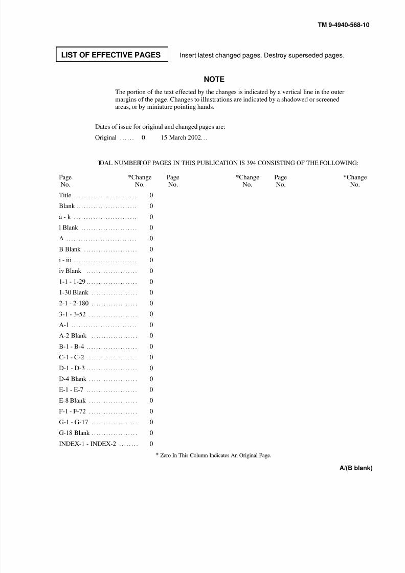
* Zero In This Column Indicates An Original Page.
LIST OF EFFECTIVE PAGES Insert latest changed pages. Destroy superseded pages.
NOTE
The portion of the text effected by the changes is indicated by a vertical line in the outermargins of the page. Changes to illustrations are indicated by a shadowed or screenedareas, or by miniature pointing hands.
Dates of issue for original and changed pages are:
Original . . . . . . 0 15 March 2002. . .
TOT AL NUMBER OF PAGES IN THIS PUBLICATION IS 394 CONSISTING OF THE FOLLOWING:
PageNo.
*ChangeNo.
PageNo.
*ChangeNo.
PageNo.
*ChangeNo.
Title . . . . . . . . . . . . . . . . . . . . . . . . . . 0
Blank . . . . . . . . . . . . . . . . . . . . . . . . . 0
a - k . . . . . . . . . . . . . . . . . . . . . . . . . . 0
l Blank . . . . . . . . . . . . . . . . . . . . . . . 0
A . . . . . . . . . . . . . . . . . . . . . . . . . . . . . 0
B Blank . . . . . . . . . . . . . . . . . . . . . . 0
i - iii . . . . . . . . . . . . . . . . . . . . . . . . . . 0
iv Blank . . . . . . . . . . . . . . . . . . . . . 0
1-1 - 1-29 . . . . . . . . . . . . . . . . . . . . . 0
1-30 Blank . . . . . . . . . . . . . . . . . . . 0
2-1 - 2-180 . . . . . . . . . . . . . . . . . . . 0
3-1 - 3-52 . . . . . . . . . . . . . . . . . . . . 0
A-1 . . . . . . . . . . . . . . . . . . . . . . . . . . . 0
A-2 Blank . . . . . . . . . . . . . . . . . . . 0
B-1 - B-4 . . . . . . . . . . . . . . . . . . . . . 0
C-1 - C-2 . . . . . . . . . . . . . . . . . . . . . 0
D-1 - D-3 . . . . . . . . . . . . . . . . . . . . . 0
D-4 Blank . . . . . . . . . . . . . . . . . . . . 0E-1 - E-7 . . . . . . . . . . . . . . . . . . . . . 0
E-8 Blank . . . . . . . . . . . . . . . . . . . . 0
F-1 - F-72 . . . . . . . . . . . . . . . . . . . . 0
G-1 - G-17 . . . . . . . . . . . . . . . . . . . 0
G-18 Blank . . . . . . . . . . . . . . . . . . . 0
INDEX-1 - INDEX-2 . . . . . . . . 0

8/20/2019 TM 9-4940-568-10 FRS
http://slidepdf.com/reader/full/tm-9-4940-568-10-frs 16/403
8/20/2019 TM 9-4940-568-10 FRS
http://slidepdf.com/reader/full/tm-9-4940-568-10-frs 17/403
TM 9-4940-568-10
i
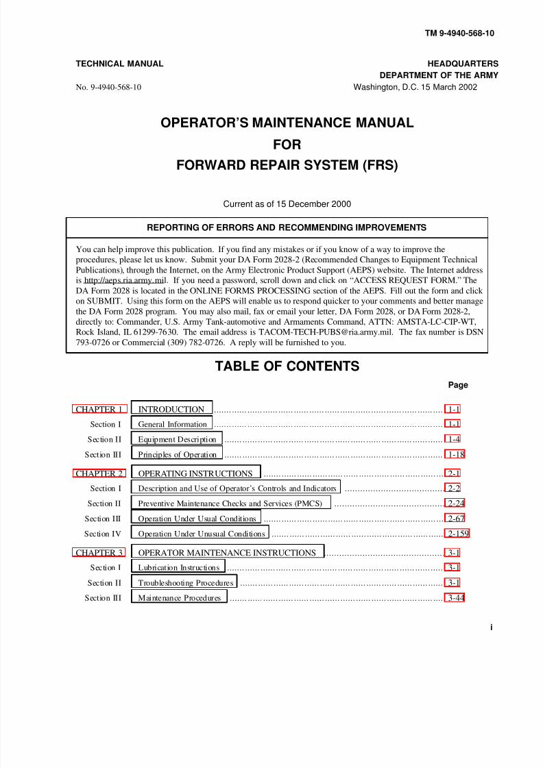
TECHNICAL MANUAL HEADQUARTERS
DEPARTMENT OF THE ARMY
No. 9-4940-568-10 Washington, D.C. 15 March 2002
OPERATOR’S MAINTENANCE MANUALFOR
FORWARD REPAIR SYSTEM (FRS)
Current as of 15 December 2000
REPORTING OF ERRORS AND RECOMMENDING IMPROVEMENTS
You can help improve this publication. If you find any mistakes or if you know of a way to improve the
procedures, please let us know. Submit your DA Form 2028-2 (Recommended Changes to Equipment Technical
Publications), through the Internet, on the Army Electronic Product Support (AEPS) website. The Internet address
is http://aeps.ria.army.mil. If you need a password, scroll down and click on “ACCESS REQUEST FORM.” The
DA Form 2028 is located in the ONLINE FORMS PROCESSING section of the AEPS. Fill out the form and click
on SUBMIT. Using this form on the AEPS will enable us to respond quicker to your comments and better manage
the DA Form 2028 program. You may also mail, fax or email your letter, DA Form 2028, or DA Form 2028-2,
directly to: Commander, U.S. Army Tank-automotive and Armaments Command, ATTN: AMSTA-LC-CIP-WT,
Rock Island, IL 61299-7630. The email address is [email protected]. The fax number is DSN
793-0726 or Commercial (309) 782-0726. A reply will be furnished to you.
TABLE OF CONTENTS
Page
CHAPTER 1 INTRODUCTION 1-1. . . . . . . . . . . . . . . . . . . . . . . . . . . . . . . . . . . . . . . . . . . . . . . . . . . . . . . . . . . . . . . . . . . . . . . . . . . . . . . . . . . . . . . . .
Section I General Information 1-1. . . . . . . . . . . . . . . . . . . . . . . . . . . . . . . . . . . . . . . . . . . . . . . . . . . . . . . . . . . . . . . . . . . . . . . . . . . . . . . . . . . . . . . . .
Section II Equipment Description 1-4. . . . . . . . . . . . . . . . . . . . . . . . . . . . . . . . . . . . . . . . . . . . . . . . . . . . . . . . . . . . . . . . . . . . . . . . . . . . . . . . . . . . .
Section III Principles of Operation 1-18. . . . . . . . . . . . . . . . . . . . . . . . . . . . . . . . . . . . . . . . . . . . . . . . . . . . . . . . . . . . . . . . . . . . . . . . . . . . . . . . . . . . .
CHAPTER 2 OPERATING INSTRUCTIONS 2-1. . . . . . . . . . . . . . . . . . . . . . . . . . . . . . . . . . . . . . . . . . . . . . . . . . . . . . . . . . . . . . . . . . . . . .
Section I Description and Use of Operator’s Controls and Indicators 2-2. . . . . . . . . . . . . . . . . . . . . . . . . . . . . . . . . . . . . . .
Section II Preventive Maintenance Checks and Services (PMCS) 2-24. . . . . . . . . . . . . . . . . . . . . . . . . . . . . . . . . . . . . . . . . . .
Section III Operation Under Usual Conditions 2-67. . . . . . . . . . . . . . . . . . . . . . . . . . . . . . . . . . . . . . . . . . . . . . . . . . . . . . . . . . . . . . . . . . . . . .
Section IV Operation Under Unusual Conditions 2-159. . . . . . . . . . . . . . . . . . . . . . . . . . . . . . . . . . . . . . . . . . . . . . . . . . . . . . . . . . . . . . . . . . .
CHAPTER 3 OPERATOR MAINTENANCE INSTRUCTIONS 3-1. . . . . . . . . . . . . . . . . . . . . . . . . . . . . . . . . . . . . . . . . . . . . . .
Section I Lubrication Instructions 3-1. . . . . . . . . . . . . . . . . . . . . . . . . . . . . . . . . . . . . . . . . . . . . . . . . . . . . . . . . . . . . . . . . . . . . . . . . . . . . . . . . . . .
Section II Troubleshooting Procedures 3-1. . . . . . . . . . . . . . . . . . . . . . . . . . . . . . . . . . . . . . . . . . . . . . . . . . . . . . . . . . . . . . . . . . . . . . . . . . . . . . .
Section III Maintenance Procedures 3-44. . . . . . . . . . . . . . . . . . . . . . . . . . . . . . . . . . . . . . . . . . . . . . . . . . . . . . . . . . . . . . . . . . . . . . . . . . . . . . . . . . .

8/20/2019 TM 9-4940-568-10 FRS
http://slidepdf.com/reader/full/tm-9-4940-568-10-frs 18/403
TM 9-4940-568-10
ii
TABLE OF CONTENTS
Page
APPENDIX A REFERENCES A-1. . . . . . . . . . . . . . . . . . . . . . . . . . . . . . . . . . . . . . . . . . . . . . . . . . . . . . . . . . . . . . . . . . . . . . . . . . . . . . . . . . . . . . . . . . . . .
APPENDIX B COMPONENTS OF END ITEM (COEI) AND BASIC ISSUE ITEMS (BII) B-1. . . . . . . . . . .
APPENDIX C ADDITIONAL AUTHORIZATION LIST (AAL) C-1. . . . . . . . . . . . . . . . . . . . . . . . . . . . . . . . . . . . . . . . . . . . . .
APPENDIX D EXPENDABLE AND DURABLE SUPPLIES AND MATERIALS LIST D-1. . . . . . . . . . . . . .
APPENDIX E STOWAGE AND SIGN GUIDE (for COEI, BII and AAL Items) E-1. . . . . . . . . . . . . . . . . . . . . . . . . . .
APPENDIX F FRS LOAD PLAN F-1. . . . . . . . . . . . . . . . . . . . . . . . . . . . . . . . . . . . . . . . . . . . . . . . . . . . . . . . . . . . . . . . . . . . . . . . . . . . . . . . . . . . . . . . . .
APPENDIX G LUBRICATION INFORMATION G-1. . . . . . . . . . . . . . . . . . . . . . . . . . . . . . . . . . . . . . . . . . . . . . . . . . . . . . . . . . . . . . . . . . . . .
Approved for public release; distribution is unlimited.

8/20/2019 TM 9-4940-568-10 FRS
http://slidepdf.com/reader/full/tm-9-4940-568-10-frs 19/403
TM 9-4940-568-10
iii/(iv blank)
HOW TO USE THIS MANUAL
This manual is designed to help operate and maintain the Forward Repair System (FRS), NSN 4940-01-463-7940, Par
Number RIA 149000. Listed below are some of the features included in this manual to help locate and use the needed
information:
• Warning, caution and note headings, subject headings and other essential information are printed in bold
type, making them easier to see.
• In addition to text, there are digital photos and some line art illustrations showing how to take a
component off and put it back on. Cleaning and inspection criteria are also included where
necessary.
• Chapter 1 of this manual describes the FRS and provides equipment description.
• Chapter 2 of this manual covers Operator’s Controls and Indicators, Operating Instructions,
Operator Preventive Maintenance Checks and Services (PMCS).
• Chapter 3 of this manual covers Lubrication Instructions, Troubleshooting, and Maintenance
Procedures.
• Appendix A of this manual lists the References.
• Appendix B of this manual covers COEI and the Basic Issue Items (BII) list.
• Appendix C of this manual covers AAL.
• Appendix D of this manual covers EDS/ML.
• Appendix E of this manual covers Stowage and Sign Guide (for COEI, BII and AAL Items).
• Appendix F of this manual covers FRS Load Plan.
• Appendix G of this manual covers Lubrication Information.
Follow these guidelines when using this manual:
• The operator must read through this manual and become familiar with the contents before
attempting to operate the FRS.
• Read all WARNINGS, CAUTIONS and NOTES prior to performing any procedure.
• The FRS is used with PLS M1074/M1075 or LHS HEMTT trucks. PLS M1075 truck shown.

8/20/2019 TM 9-4940-568-10 FRS
http://slidepdf.com/reader/full/tm-9-4940-568-10-frs 20/403

8/20/2019 TM 9-4940-568-10 FRS
http://slidepdf.com/reader/full/tm-9-4940-568-10-frs 21/403
TM 9-4940-568-10
1-1
CHAPTER 1
INTRODUCTION
Para Contents Page
1-1 Scope 1-1. . . . . . . . . . . . . . . . . . . . . . . . . . . . . . . . . . . . . . . . . . . . . . . . . . . . . . . . . . . . . . . . . . . . . . . . . . . . . . . . . . . . . . . . . . . . . . . . . . . . . . . . . . . . . . . . . . . . . .
1-2 Maintenance Forms and Records 1-3. . . . . . . . . . . . . . . . . . . . . . . . . . . . . . . . . . . . . . . . . . . . . . . . . . . . . . . . . . . . . . . . . . . . . . . . . . . . . . . . .
1-3 Corrosion Prevention and Control (CPC) 1-3. . . . . . . . . . . . . . . . . . . . . . . . . . . . . . . . . . . . . . . . . . . . . . . . . . . . . . . . . . . . . . . . . . . . . .
1-4 Destruction Of Army Material To Prevent Enemy Use 1-3. . . . . . . . . . . . . . . . . . . . . . . . . . . . . . . . . . . . . . . . . . . . . . . . . . . .
1-5 Reporting Equipment Improvement Recommendations (EIR) 1-3. . . . . . . . . . . . . . . . . . . . . . . . . . . . . . . . . . . . . . . . . . .
1-6 Warranty Information 1-3. . . . . . . . . . . . . . . . . . . . . . . . . . . . . . . . . . . . . . . . . . . . . . . . . . . . . . . . . . . . . . . . . . . . . . . . . . . . . . . . . . . . . . . . . . . . . . . .
1-7 List of Acronyms 1-3. . . . . . . . . . . . . . . . . . . . . . . . . . . . . . . . . . . . . . . . . . . . . . . . . . . . . . . . . . . . . . . . . . . . . . . . . . . . . . . . . . . . . . . . . . . . . . . . . . . . . .
1-8 Equipment Characteristics, Capabilities and Features 1-4. . . . . . . . . . . . . . . . . . . . . . . . . . . . . . . . . . . . . . . . . . . . . . . . . . . . . .
1-9 Equipment Data 1-5. . . . . . . . . . . . . . . . . . . . . . . . . . . . . . . . . . . . . . . . . . . . . . . . . . . . . . . . . . . . . . . . . . . . . . . . . . . . . . . . . . . . . . . . . . . . . . . . . . . . . . . .
1-10 Location And Description Of Major Components 1-10. . . . . . . . . . . . . . . . . . . . . . . . . . . . . . . . . . . . . . . . . . . . . . . . . . . . . . . . . . .
1-11 Systems Introduction 1-18. . . . . . . . . . . . . . . . . . . . . . . . . . . . . . . . . . . . . . . . . . . . . . . . . . . . . . . . . . . . . . . . . . . . . . . . . . . . . . . . . . . . . . . . . . . . . . . . .
1-12 Electrical System 1-18. . . . . . . . . . . . . . . . . . . . . . . . . . . . . . . . . . . . . . . . . . . . . . . . . . . . . . . . . . . . . . . . . . . . . . . . . . . . . . . . . . . . . . . . . . . . . . . . . . . . . .
1-13 Hydraulic System 1-19. . . . . . . . . . . . . . . . . . . . . . . . . . . . . . . . . . . . . . . . . . . . . . . . . . . . . . . . . . . . . . . . . . . . . . . . . . . . . . . . . . . . . . . . . . . . . . . . . . . . .
1-14 Generator Engine Set 1-20. . . . . . . . . . . . . . . . . . . . . . . . . . . . . . . . . . . . . . . . . . . . . . . . . . . . . . . . . . . . . . . . . . . . . . . . . . . . . . . . . . . . . . . . . . . . . . . . .
1-15 Generator Fuel System 1-21. . . . . . . . . . . . . . . . . . . . . . . . . . . . . . . . . . . . . . . . . . . . . . . . . . . . . . . . . . . . . . . . . . . . . . . . . . . . . . . . . . . . . . . . . . . . . . .
1-16 Cooling System 1-22. . . . . . . . . . . . . . . . . . . . . . . . . . . . . . . . . . . . . . . . . . . . . . . . . . . . . . . . . . . . . . . . . . . . . . . . . . . . . . . . . . . . . . . . . . . . . . . . . . . . . . . .
1-17 Air Compressor System 1-23. . . . . . . . . . . . . . . . . . . . . . . . . . . . . . . . . . . . . . . . . . . . . . . . . . . . . . . . . . . . . . . . . . . . . . . . . . . . . . . . . . . . . . . . . . . . .
1-18 Solar Air Vent 1-24. . . . . . . . . . . . . . . . . . . . . . . . . . . . . . . . . . . . . . . . . . . . . . . . . . . . . . . . . . . . . . . . . . . . . . . . . . . . . . . . . . . . . . . . . . . . . . . . . . . . . . . . . .
1-19 Shelter Heater 1-25. . . . . . . . . . . . . . . . . . . . . . . . . . . . . . . . . . . . . . . . . . . . . . . . . . . . . . . . . . . . . . . . . . . . . . . . . . . . . . . . . . . . . . . . . . . . . . . . . . . . . . . . . .
1-20 Crane System 1-26. . . . . . . . . . . . . . . . . . . . . . . . . . . . . . . . . . . . . . . . . . . . . . . . . . . . . . . . . . . . . . . . . . . . . . . . . . . . . . . . . . . . . . . . . . . . . . . . . . . . . . . . . . .
Section I. GENERAL INFORMATION
1-1. SCOPE.
This manual is provided to maximize use of the Forward Repair System (FRS) by presenting operation and operator
performed maintenance tasks. Read these instructions thoroughly before operating. This manual should be used in
conjunction with the standard PLS vehicle and LHS HEMTT manuals set to operate and maintain a PLS vehicle or
LHS HEMTT loaded with the FRS maintenance shop. PLS manualis referenced throughout this manual.
a. Type of Manual. Operation Instructions, TM 9-4940-568-10.
b. Equipment Name. Forward Repair System (FRS)
c. Purpose of Equipment. The purpose of FRS is to enable maintenance personnel to repair heavyequipment in the field or at a central location.

8/20/2019 TM 9-4940-568-10 FRS
http://slidepdf.com/reader/full/tm-9-4940-568-10-frs 22/403
TM 9-4940-568-10
1-2
Figure 1-1. Forward Repair System

8/20/2019 TM 9-4940-568-10 FRS
http://slidepdf.com/reader/full/tm-9-4940-568-10-frs 23/403
TM 9-4940-568-10
1-3
1-2. MAINTENANCE FORMS, RECORDS AND REPORTS.
Department of the Army forms and procedures used for equipment maintenance will be those prescribed by DA PAM
738-750, The Army Maintenance Management System (TAMMS) (Maintenance Management UPDATE).
1-3. CORROSION PREVENTION AND CONTROL (CPC).
The FRS has a total service life of ten years which allows for extended periods of operation in a corrosive
environment. A corrosive environment includes exposure to high humidity, salt spray, road-deicing chemicals, gravel,
and atmospheric contamination. No action beyond normal washing and repair of damaged areas is necessary to
control corrosion. To prevent moisture accumulation, drain holes are provided on structural and sheet metal areas
where necessary.
1-4. DESTRUCTION OF ARMY MATERIAL TO PREVENT ENEMY USE.
Refer to TM 750-244-6, Procedures for Destruction of Tank-Automotive Equipment to Prevent Enemy Use.
1-5. REPORTING EQUIPMENT IMPROVEMENT RECOMMENDATIONS (EIR).
If your FRS needs improvement, let us know. Send us an EIR. You, the user, are the only one who can tell us what
you don’t like about your equipment. Let us know why you don’t like the design. Put it on an SF368 (Quality
Deficiency Report). Mail it to us at: Commander, U.S. Army Tank-automotive and Armaments Command, ATTN:
AMSTA-TR-E-PQDR; Warren, Michigan 48397-5000. We’ll send you a reply.
1-6. WARRANTY INFORMATION.
There is no warranty, as such, for the FRS “box”. The government is procuring the hardware from itself (the prime
contractor is a government agency). By law, the government cannot make warranty type claims against itself;
however, Rock Island Arsenal (RIA) for the FRS guarantees that the deliverables are free from defects or systemic
defects in materiel and workmanship. In addition, there are “pass through” warranties on the major FRS components,i.e., the air compressor, generator, welding equipment, and crane. The FRS will conform to the design and
manufacturing requirements specifically delineated in the contract and all future modifications. The FRS will
conform to the essential performance requirements as defined in the system specification. If, during normal system
operations, a defect/failure of FRS “box” component occurs, the using unit or contact will submit, to RIA Major Item
and Product Assurance managers, an SF2407. RIA will replace the failed/damaged component. If a major componen
of the FRS (engine, air compressor, generator, welding equipment) fails during normal operations, upon notification of
such failure, RIA will exercise the “pass through” warranty with the appropriate component contractor. How to
process “pass through” warranty claims is currently being assessed. As stated above, the contractor will provide a
hand-off warranty during all fieldings. Under this warranty, the contractor will be liable for the supply of components
required to correct all failures from the time of system final acceptance up to and including hand-off to the user. The
contractor will supply all repair parts required during deprocessing within seventy-two (72) hours after notification.
The deprocessing team, not the contractor field technical representative, will perform all labor necessary to correct
hand-off deficiencies.
1-7. LIST OF ACRONYMS.
Forward Repair System FRS
Ground Fault Circuit Interrupt GFCI
Material Handling Crane MHC
Palletized Loading System PLS
Shielded Metal Arc Welding SMAW

8/20/2019 TM 9-4940-568-10 FRS
http://slidepdf.com/reader/full/tm-9-4940-568-10-frs 24/403
TM 9-4940-568-10
1-4
SECTION II. EQUIPMENT DESCRIPTION
1-8. EQUIPMENT CHARACTERISTICS, CAPABILITIES AND FEATURES.
a. Equipment Characteristics.
The FRS is a flatrack based repair system.
b. Capabilities.
The FRS is capable of supporting the repair of heavy tracked and wheel vehicles. The FRS is also capable of:
10K lift @ 14’ RAD
50 cfm @ 175 psi
230 amps @ 100 duty cable stick/MIG
c. Features.
The FRS is an autonomous system that can be delivered by a PLS vehicle to a central position or to a damaged vehicle
to make repairs. The FRS is downloaded and operated as a stand-alone unit.
The FRS is comprised of a 35KW diesel power generator, a fifteen horsepower air compressor, a Material Handling
Crane (MHC), and sufficient storage space for tools and equipment. The generator is the primary power source to run
the air compressor, the MHC, and supply power for lighting and tools. The air compressor provides air to run impact
wrenches, drills or fill tires. The MHC performs all heavy lifting functions including removal and replacement of a
vehicle powerpack. The storage space is enclosed for moisture control and security. It houses cabinets for the storageof tools, equipment, and spare parts.
8/20/2019 TM 9-4940-568-10 FRS
http://slidepdf.com/reader/full/tm-9-4940-568-10-frs 25/403
TM 9-4940-568-10
1-5
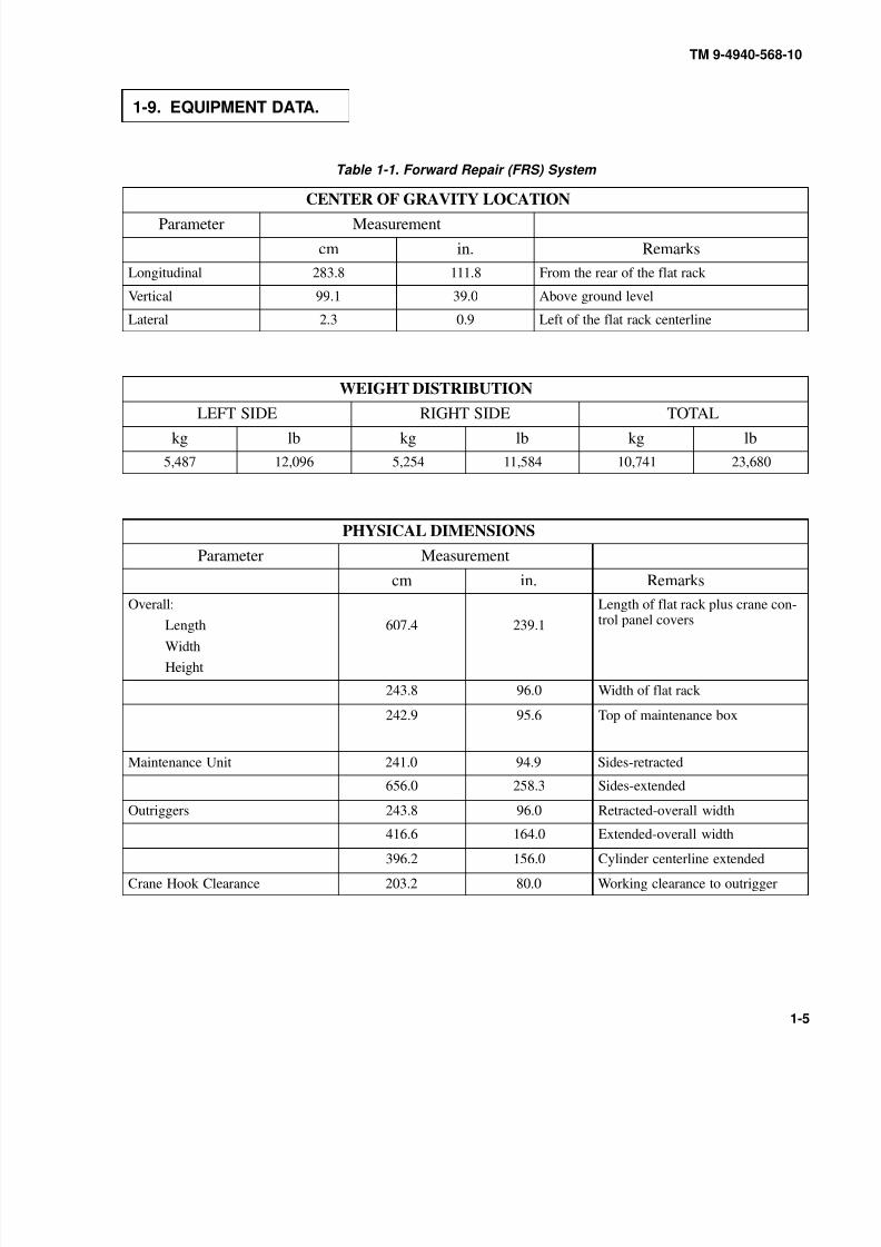
1-9. EQUIPMENT DATA.
Table 1-1. Forward Repair (FRS) System
CENTER OF GRAVITY LOCATION
Parameter Measurement
cm in. Remarks
Longitudinal 283.8 111.8 From the rear of the flat rack
Vertical 99.1 39.0 Above ground level
Lateral 2.3 0.9 Left of the flat rack centerline
WEIGHT DISTRIBUTION
LEFT SIDE RIGHT SIDE TOTALkg lb kg lb kg lb
5,487 12,096 5,254 11,584 10,741 23,680
PHYSICAL DIMENSIONS
Parameter Measurement
cm in. Remarks
Overall:
Length
Width
Height
607.4 239.1
Length of flat rack plus crane con-
trol panel covers
243.8 96.0 Width of flat rack
242.9 95.6 Top of maintenance box
Maintenance Unit 241.0 94.9 Sides-retracted
656.0 258.3 Sides-extended
Outriggers 243.8 96.0 Retracted-overall width
416.6 164.0 Extended-overall width
396.2 156.0 Cylinder centerline extended
Crane Hook Clearance 203.2 80.0 Working clearance to outrigger
8/20/2019 TM 9-4940-568-10 FRS
http://slidepdf.com/reader/full/tm-9-4940-568-10-frs 26/403
TM 9-4940-568-10
1-6
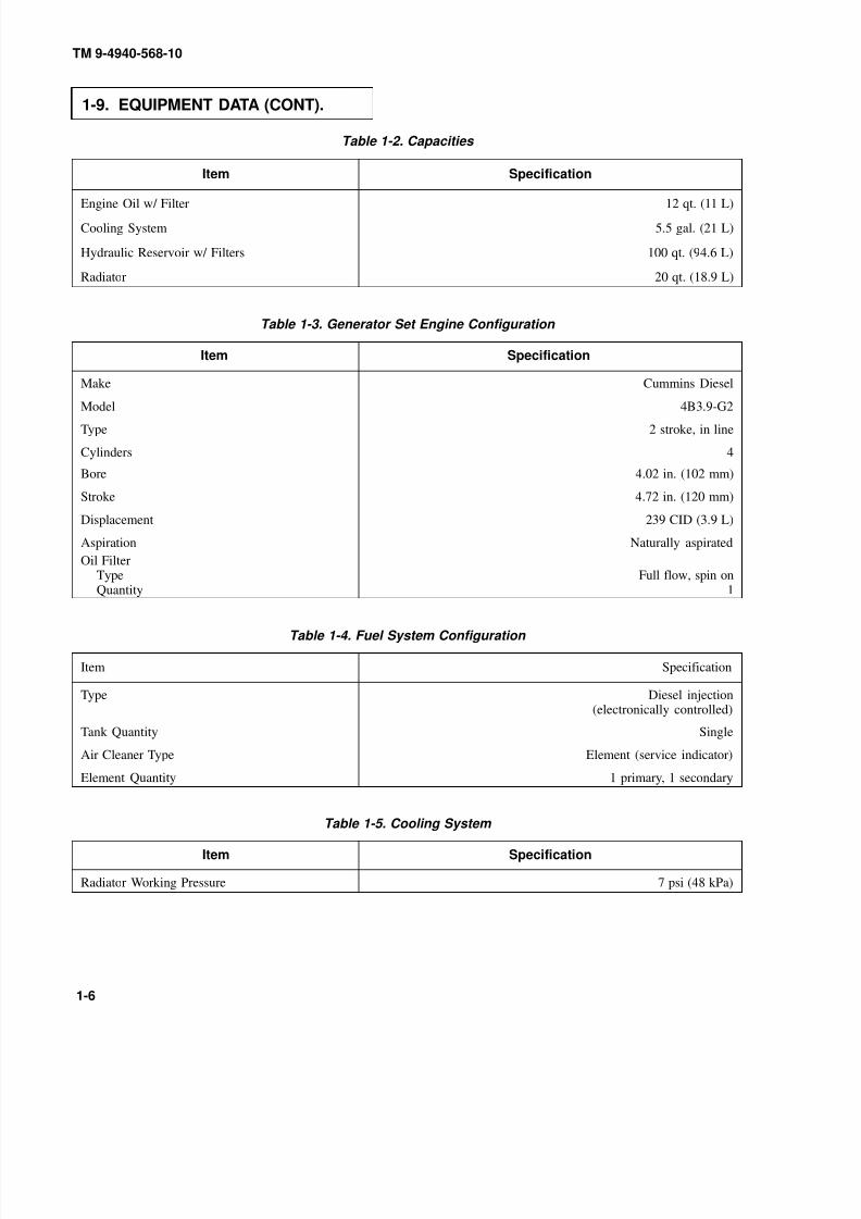
1-9. EQUIPMENT DATA (CONT).
Table 1-2. Capacities
Item Specification
Engine Oil w/ Filter 12 qt. (11 L)
Cooling System 5.5 gal. (21 L)
Hydraulic Reservoir w/ Filters 100 qt. (94.6 L)
Radiator 20 qt. (18.9 L)
Table 1-3. Generator Set Engine Configuration
Item Specification
Make Cummins Diesel
Model 4B3.9-G2
Type 2 stroke, in line
Cylinders 4
Bore 4.02 in. (102 mm)
Stroke 4.72 in. (120 mm)
Displacement 239 CID (3.9 L)
Aspiration Naturally aspirated
Oil FilterTypeQuantity
Full flow, spin on1
Table 1-4. Fuel System Configuration
Item Specification
Type Diesel injection(electronically controlled)
Tank Quantity Single
Air Cleaner Type Element (service indicator)
Element Quantity 1 primary, 1 secondary
Table 1-5. Cooling System
Item Specification
Radiator Working Pressure 7 psi (48 kPa)
8/20/2019 TM 9-4940-568-10 FRS
http://slidepdf.com/reader/full/tm-9-4940-568-10-frs 27/403
TM 9-4940-568-10
1-7
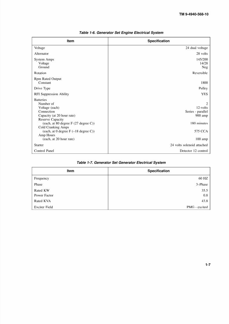
Table 1-6. Generator Set Engine Electrical System
Item Specification
Voltage 24 dual voltage
Alternator 28 volts
System AmpsVoltageGround
145/20014/28
Neg
Rotation Reversible
Rpm Rated OutputConstant 1800
Drive Type Pulley
RFI Suppression Ability YES
BatteriesNumber of
Voltage (each)ConnectionCapacity (at 20 hour rate)Reserve Capacity
(each, at 80 degree F (27 degree C))Cold Cranking Amps
(each, at 0 degree F (–18 degree C))Amp Hours
(each, at 20 hour rate)
2
12-voltsSeries - parallel
900 amp
180 minutes
575 CCA
100 amp
Starter 24 volts solenoid attached
Control Panel Detector 12 control
Table 1-7. Generator Set Generator Electrical System
Item Specification
Frequency 60 HZ
Phase 3–Phase
Rated KW 35.5
Power Factor 0.8
Rated KVA 43.8
Exciter Field PMG - excited
8/20/2019 TM 9-4940-568-10 FRS
http://slidepdf.com/reader/full/tm-9-4940-568-10-frs 28/403
TM 9-4940-568-10
1-8
1-9. EQUIPMENT DATA (CONT).
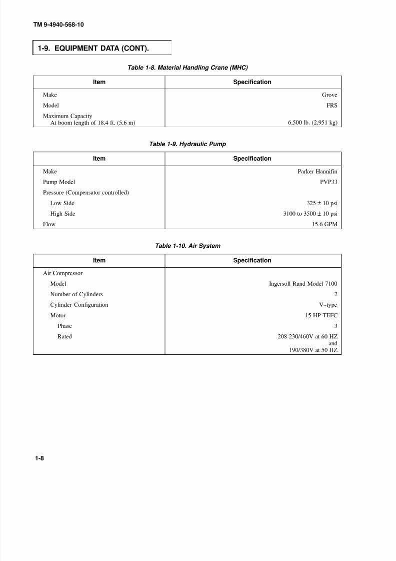
Table 1-8. Material Handling Crane (MHC)
Item Specification
Make Grove
Model FRS
Maximum CapacityAt boom length of 18.4 ft. (5.6 m) 6,500 lb. (2,951 kg)
Table 1-9. Hydraulic Pump
Item Specification
Make Parker Hannifin
Pump Model PVP33
Pressure (Compensator controlled)
Low Side 325 ± 10 psi
High Side 3100 to 3500 ± 10 psi
Flow 15.6 GPM
Table 1-10. Air System
Item Specification
Air Compressor
Model Ingersoll Rand Model 7100
Number of Cylinders 2
Cylinder Configuration V–type
Motor 15 HP TEFC
Phase 3
Rated 208-230/460V at 60 HZand
190/380V at 50 HZ

8/20/2019 TM 9-4940-568-10 FRS
http://slidepdf.com/reader/full/tm-9-4940-568-10-frs 29/403
TM 9-4940-568-10
1-9
Table 1-11. Heater
Item Specification
Heater Eberspacher
Model D8LC
Heating Medium Air
Fuel Diesel
Voltage 24V
Electrical Power Consumption
Start 335W ± 10%
Operation 115W ± 10%
Regulation of heat High/Low/Off
Heating Capacity
High 8000W ± 10%
Low 3500W ± 10%

8/20/2019 TM 9-4940-568-10 FRS
http://slidepdf.com/reader/full/tm-9-4940-568-10-frs 30/403
TM 9-4940-568-10
1-10
1-10. LOCATION AND DESCRIPTION OF MAJOR COMPONENTS.
Major components and accessories found on the FRS are illustrated and described below.
1. GENERATOR SET. Engine supplies power for the generator and the hydraulic pump. Generator sup-
plies power for lights and operation of tools, equipment and accessories.
2. HYDRAULIC TANK. Stores 25 gallons of oil for MHC crane.
3. GENERATOR SET ACCESS PANELS. Provides access to generator, engine, batteries and hydraulic
pump.
4. GENERATOR SET CONTROL ACCESS DOOR. Provides access to generator and engine controls,
master disconnect switch, fuel tank and grounding rod.
5. FUEL TANK. Stores 28 gallons of fuel used to operate engine and heater and allows 8.5 hours of running
time (without heater operation).
6. BUSTLE RACK.
Use to stow excess items.7. SHELTER ACCESS DOOR (RIGHT). Provides protection from weather and access to welding, air and
accessory tools.
8. FLATRACK ASSEMBLY. Is a flat cargo body used as a lifting point for securing the FRS during all
modes of transportation and during all specified load/unload operations.
8/20/2019 TM 9-4940-568-10 FRS
http://slidepdf.com/reader/full/tm-9-4940-568-10-frs 31/403
TM 9-4940-568-10
1-11
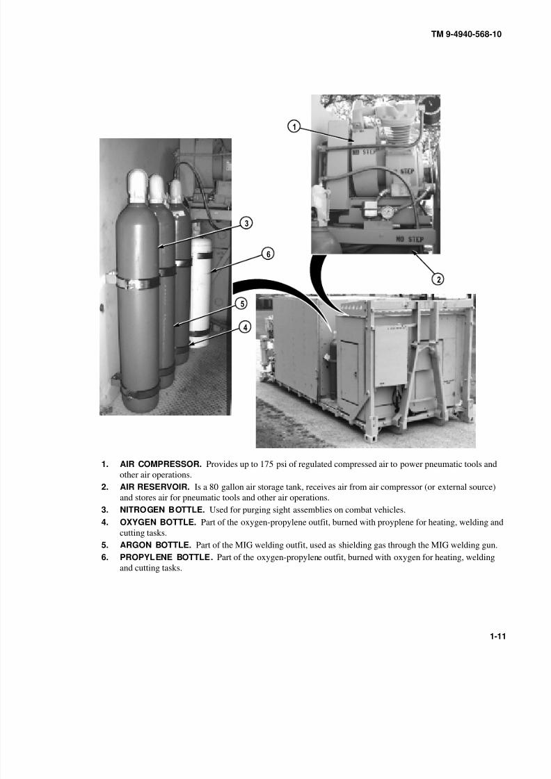
1. AIR COMPRESSOR. Provides up to 175 psi of regulated compressed air to power pneumatic tools and
other air operations.
2. AIR RESERVOIR. Is a 80 gallon air storage tank, receives air from air compressor (or external source)
and stores air for pneumatic tools and other air operations.
3. NITROGEN BOTTLE. Used for purging sight assemblies on combat vehicles.
4. OXYGEN BOTTLE.
Part of the oxygen-propylene outfit, burned with proyplene for heating, welding and
cutting tasks.
5. ARGON BOTTLE. Part of the MIG welding outfit, used as shielding gas through the MIG welding gun.
6. PROPYLENE BOTTLE. Part of the oxygen-propylene outfit, burned with oxygen for heating, welding
and cutting tasks.
8/20/2019 TM 9-4940-568-10 FRS
http://slidepdf.com/reader/full/tm-9-4940-568-10-frs 32/403
TM 9-4940-568-10
1-12
1-10. LOCATION AND DESCRIPTION OF MAJOR COMPONENTS (CONT).
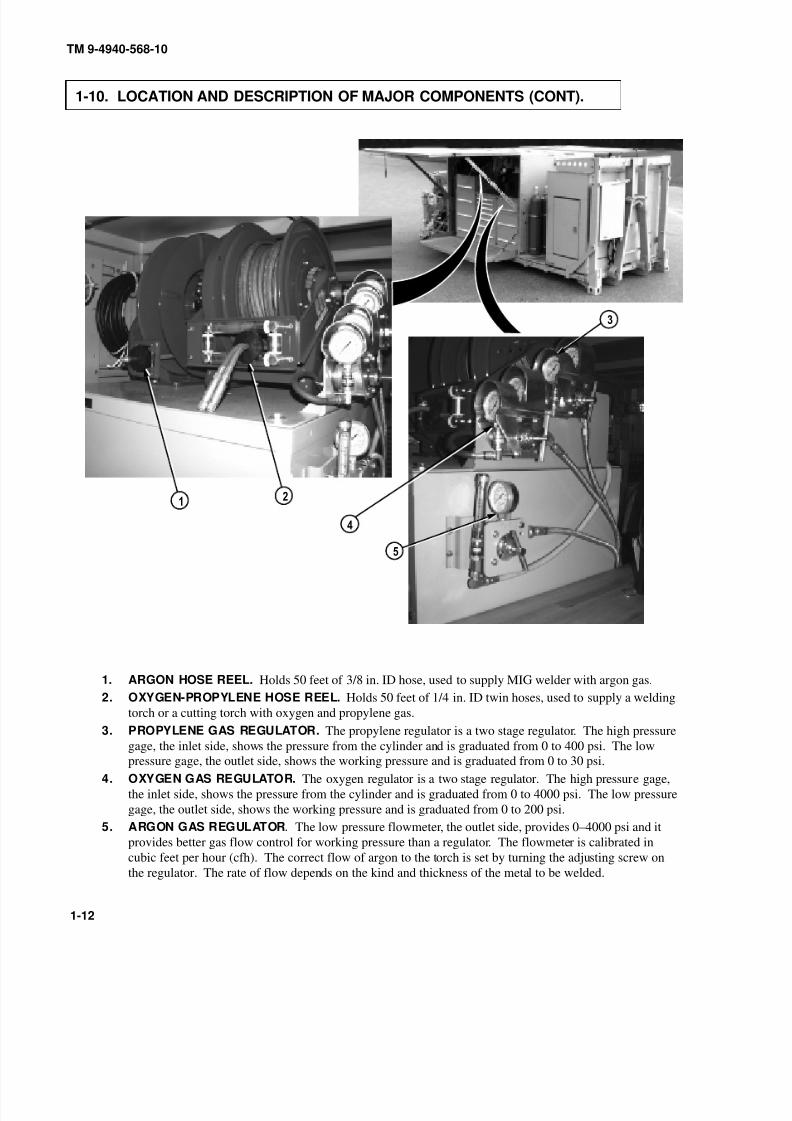
1. ARGON HOSE REEL. Holds 50 feet of 3/8 in. ID hose, used to supply MIG welder with argon gas.
2. OXYGEN-PROPYLENE HOSE REEL. Holds 50 feet of 1/4 in. ID twin hoses, used to supply a welding
torch or a cutting torch with oxygen and propylene gas.
3. PROPYLENE GAS REGULATOR. The propylene regulator is a two stage regulator. The high pressure
gage, the inlet side, shows the pressure from the cylinder and is graduated from 0 to 400 psi. The lowpressure gage, the outlet side, shows the working pressure and is graduated from 0 to 30 psi.
4. OXYGEN GAS REGULATOR. The oxygen regulator is a two stage regulator. The high pressure gage,
the inlet side, shows the pressure from the cylinder and is graduated from 0 to 4000 psi. The low pressure
gage, the outlet side, shows the working pressure and is graduated from 0 to 200 psi.
5. ARGON GAS REGULATOR. The low pressure flowmeter, the outlet side, provides 0–4000 psi and it
provides better gas flow control for working pressure than a regulator. The flowmeter is calibrated in
cubic feet per hour (cfh). The correct flow of argon to the torch is set by turning the adjusting screw on
the regulator. The rate of flow depends on the kind and thickness of the metal to be welded.

8/20/2019 TM 9-4940-568-10 FRS
http://slidepdf.com/reader/full/tm-9-4940-568-10-frs 33/403
TM 9-4940-568-10
1-13
1. MIG WELDER.
Gas metal-ARC (MIG) welder is designed for manual welding with small diameter wireelectrodes fed into a weld at a controled rate of speed.
2. STICK (SHIELDED METAL ARC WELDING [SMAW]) WELDER. Stick (SMAW) welder is a three-
phase DC arc welding power source with Constant Current (CC) output and Constant Voltage (CV) output
characteristics and a digital panel meter.
3. WELDERS STORAGE CABINET. Holds tools and material used to support welding operations by the
FRS.
4. BULK STORAGE CABINET. Holds bulk material used to support maintenance operations by the FRS.
5. TOOL STORAGE CABINET. Holds tools used to support maintenance operations by the FRS.

8/20/2019 TM 9-4940-568-10 FRS
http://slidepdf.com/reader/full/tm-9-4940-568-10-frs 34/403
TM 9-4940-568-10
1-14
1-10. LOCATION AND DESCRIPTION OF MAJOR COMPONENTS (CONT).
1. EYE WASH FOUNTAIN SPRAY HANDLE. Used as an emergency measure to flush contaminated area
with water.
2. EYE WASH FOUNTAIN PRESSURE GAGE. Valve is used to fill eye wash fountain tank with clean
compressed air to 95 P.S.I. (not to exceed 110 P.S.I.) as indicated on eye wash fountain pressure gage.3. REMOTE START SWITCH. Used by crew to start or stop generator set from the inside right front of
shelter.
4. AIR COMPRESSOR CONTROL BOX. Turns air compressor ON and OFF. Air compressor control
boxhas a built in overload reset button.
5. FIRE EXTINGUISHER. Used in an emergency to extinguish a fire and is located inside right and left rear
wall of shelter.
6. FIRE EXTINGUISHER. Used in an emergency to extinguish a fire and is located on the outside right rear
of shelter for easy access from outside of shelter.

8/20/2019 TM 9-4940-568-10 FRS
http://slidepdf.com/reader/full/tm-9-4940-568-10-frs 35/403
TM 9-4940-568-10
1-15
1. MATERIAL HANDLING CRANE (MHC). Used for lifting material during maintenance operations for the
FRS.
2. NATO TYPE 24 VDC (2 EACH) POWER RECEPTACLE. Provides capability to receive or transfer
power from an outside source.
3. JACKSTAND-TRESTLE STORAGE BOX. Used to stow three trestles (seven ton capacity), one trustle
storage box located on left and right side of crane.
4. REMOTE START SWITCH. Used by crew to start or stop generator set from outside left rear of shelter.
5. SHELTER ASSEMBLY. Provides storage and protection from weather for tools and equipment supplied
with the FRS.

8/20/2019 TM 9-4940-568-10 FRS
http://slidepdf.com/reader/full/tm-9-4940-568-10-frs 36/403
TM 9-4940-568-10
1-16
1-10. LOCATION AND DESCRIPTION OF MAJOR COMPONENTS (CONT).
1. 24 VOLT DC PANEL. Controls 24 VDC power for crane, dome lights, heater and portable flashlights.
2. 120/208 VOLT AC MAIN PANEL. Controls 120 VAC power for recepticles, reel lights and fixed lighting
system. Controls 208 VAC power for welder and air compressor.
3. PNEUMATIC AIR HOSE REEL. Holds 50 feet of 3/4 in. hose, used to supply air for general use.
4. PNEUMATIC AIR REGULATOR/WATER SEPARATOR AND LUBRICATOR. Filters air and controlsair pressure to pneumatic tools. The lubricator adds oil to the air supplied to pneumatic tools.
5. GENERAL AIR HOSE REEL. Holds 50 feet of 3/8 in. hose, used to supply air for general use.
6. GENERAL AIR REGULATOR/WATER SEPARATOR. Filters air and controls air pressure for general
use.
7. SHELTER HEATER. The shelter heater is a diesel-fueled air heater mounted on the inside front center
ceiling of shelter.
8. SHELTER HEATER CONTROL. Controls the operation of shelter heater, has on-off switch, temperature
control dial, red operating light and green diagnostic light.

8/20/2019 TM 9-4940-568-10 FRS
http://slidepdf.com/reader/full/tm-9-4940-568-10-frs 37/403
TM 9-4940-568-10
1-17
1. TOOL CABINETS. Holds tools used to support maintenance operations by the FRS.
2. TOOL BOX STORAGE RACK. Used to store general mechanics tool kits.
3. EYE WASH FOUNTAIN TANK.
Stores water that is pressurized to 95 psi, used for emergency measuresto flush the contaminated area.
4. SHELTER ACCESS DOOR (LEFT). Provides protection from weather and access to welding, air and
accessory tools.
8/20/2019 TM 9-4940-568-10 FRS
http://slidepdf.com/reader/full/tm-9-4940-568-10-frs 38/403
TM 9-4940-568-10
1-18
Section III. PRINCIPLES OF OPERATION
1-11. SYSTEMS INTRODUCTION.
This section provides a basic explanation of major systems on the FRS. Detailed operation information is provided in
Chapter 2.
1-12. ELECTRICAL SYSTEM.
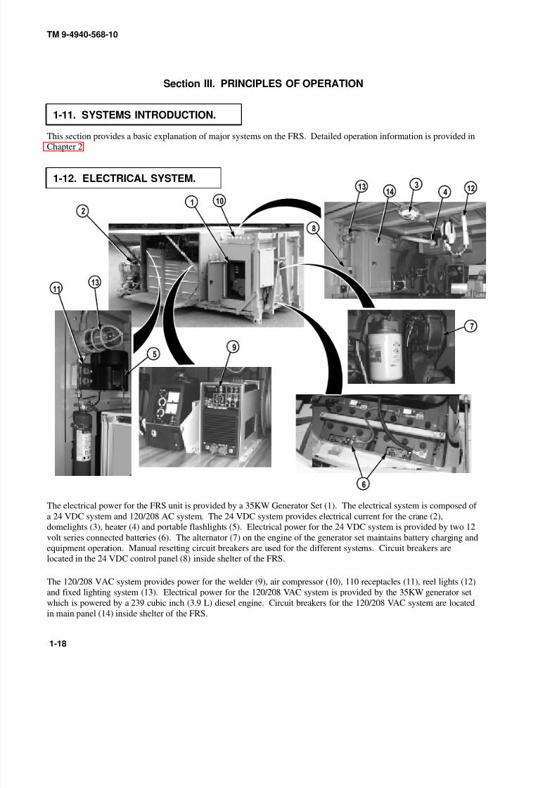
The electrical power for the FRS unit is provided by a 35KW Generator Set (1). The electrical system is composed of
a 24 VDC system and 120/208 AC system. The 24 VDC system provides electrical current for the crane (2),
domelights (3), heater (4) and portable flashlights (5). Electrical power for the 24 VDC system is provided by two 12volt series connected batteries (6). The alternator (7) on the engine of the generator set maintains battery charging and
equipment operation. Manual resetting circuit breakers are used for the different systems. Circuit breakers are
located in the 24 VDC control panel (8) inside shelter of the FRS.
The 120/208 VAC system provides power for the welder (9), air compressor (10), 110 receptacles (11), reel lights (12)
and fixed lighting system (13). Electrical power for the 120/208 VAC system is provided by the 35KW generator set
which is powered by a 239 cubic inch (3.9 L) diesel engine. Circuit breakers for the 120/208 VAC system are located
in main panel (14) inside shelter of the FRS.

8/20/2019 TM 9-4940-568-10 FRS
http://slidepdf.com/reader/full/tm-9-4940-568-10-frs 39/403
TM 9-4940-568-10
1-19
1-13. HYDRAULIC SYSTEM.
The hydraulic reservoir (1) holds 25 gallons of hydraulic fluid used during operation of the crane. Hydraulic fluid is
drawn from the hydraulic reservoir to the hydraulic pump (2) through the hydraulic filter (3). The hydraulic pump is
mounted on left front side of the engine. It provides hydraulic pressure for the crane hydraulic system.

8/20/2019 TM 9-4940-568-10 FRS
http://slidepdf.com/reader/full/tm-9-4940-568-10-frs 40/403
TM 9-4940-568-10
1-20
1-14. GENERATOR ENGINE SET.
The FRS is equipped with a 4 cylinder, in-line 239 cubic in. (3.9 L) diesel powered engine (1), standby generating
system, 35KW/44 KVA, continuous standby, 120/208 VAC, 0 three phase (broad range), 60Hz, 1800RPM. The
engine contoller (2) is unit mounted. The engine is mounted in the weather protective housing (3).

8/20/2019 TM 9-4940-568-10 FRS
http://slidepdf.com/reader/full/tm-9-4940-568-10-frs 41/403
TM 9-4940-568-10
1-21
1-15. GENERATOR FUEL SYSTEM.
Fuel is pumped from fuel tank (1), passes through a primary fuel filter (2) to a mechanical fuel pump (3). From the
fuel pump, fuel is pumped through the secondary fuel filter (4) to the engine. Excess fuel from the engine is returned
to the fuel tank through the return line (5). The primary fuel filter removes large solid particles from the fuel. The
smaller particles are removed by the secondary fuel filter before they can enter the engine fuel injectors.

8/20/2019 TM 9-4940-568-10 FRS
http://slidepdf.com/reader/full/tm-9-4940-568-10-frs 42/403
TM 9-4940-568-10
1-22
1-16. COOLING SYSTEM.
a. Cooling System.
The pressure-type cooling system protects the engine by removing the heat generated during combustion process.
Pressure within the cooling system is limited by a pressure release in the radiator filler cap (1). The hot coolant flows
from the engine to the radiator tank (2) and through the radiator core where a stream of air removes heat. This stream
of air is blown through the core by the fan. The water pump (3) draws coolant from the radiator and pushes it through
the engine, repeating the cooling process. Thermostat (4) mounted on the coolant outlet elbow, remains closed until
the coolant approaches 180° – 185°F (82°C – 85°C), when it opens. When coolant temperature drops below
thermostat rating, the thermostat closes.
b. Engine Block Heating System (Cold Operations Below 15 °F (–9 C)).
A coolant tank heater (5) is used to keep the engine coolant warm when the engine is shut down. It heats and
circulates the coolant within the engine. This reduces startup time and lessens engine wear caused by cold starts. It is
electrically operated and thermostatically controlled (ON at 70°F (21°C) and OFF at 100°F (38°C)). Heater operates
when connected to a 110 VAC.
8/20/2019 TM 9-4940-568-10 FRS
http://slidepdf.com/reader/full/tm-9-4940-568-10-frs 43/403
TM 9-4940-568-10
1-23
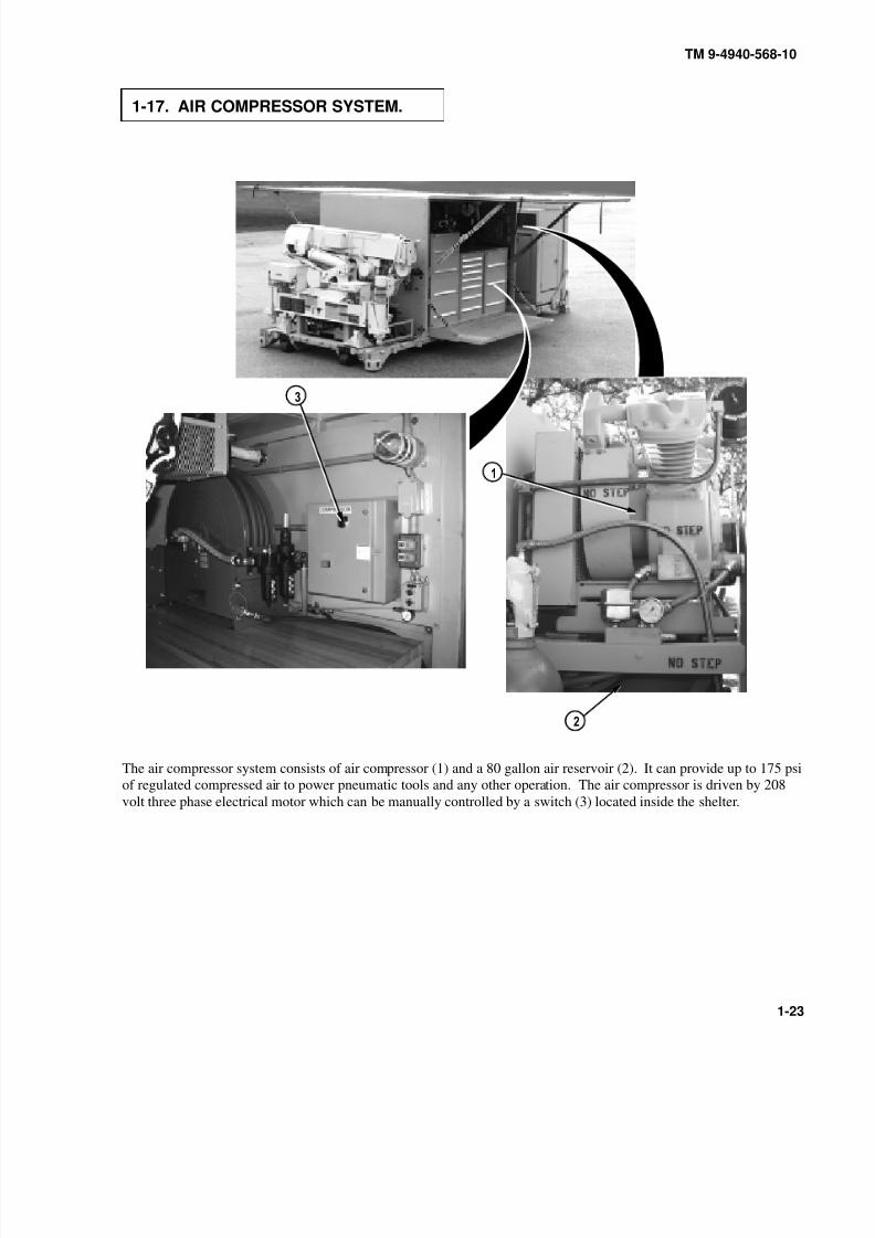
1-17. AIR COMPRESSOR SYSTEM.
The air compressor system consists of air compressor (1) and a 80 gallon air reservoir (2). It can provide up to 175 ps
of regulated compressed air to power pneumatic tools and any other operation. The air compressor is driven by 208
volt three phase electrical motor which can be manually controlled by a switch (3) located inside the shelter.
8/20/2019 TM 9-4940-568-10 FRS
http://slidepdf.com/reader/full/tm-9-4940-568-10-frs 44/403
TM 9-4940-568-10
1-24
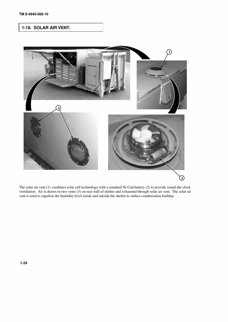
1-18. SOLAR AIR VENT.
The solar air vent (1) combines solar cell technology with a standard Ni-Cad battery (2) to provide round-the clock
ventilation. Air is drawn in two vents (3) on rear wall of shelter and exhausted through solar air vent. The solar air
vent is used to equalize the humidity level inside and outside the shelter to reduce condensation buildup.

8/20/2019 TM 9-4940-568-10 FRS
http://slidepdf.com/reader/full/tm-9-4940-568-10-frs 45/403
TM 9-4940-568-10
1-25
1-19. SHELTER HEATER.
The shelter heater (1) is a diesel-fueled air heater, 24 VDC system. Controlled by a thermostat with ON/OFF switch
(2), red operating light (3) and green diagnostic light (4). The thermostat control dial (5) has a variable setting of
approx. 50° F to approx. 85° F.

8/20/2019 TM 9-4940-568-10 FRS
http://slidepdf.com/reader/full/tm-9-4940-568-10-frs 46/403
TM 9-4940-568-10
1-26
1-20. CRANE.
a. Crane. The FRS crane (1) is fully hydraulic and is powered by the FRS hydraulic system. The boom can
rotate 300 degrees. The crane is capable of lifting up to 10,000 lbs. (4,534 kg) load at a 14 ft. (4.3 m) radius.The FRS stability and leveling is accomplished with the left and right side hydraulically operated outrigger jacks
(2). The outrigger pads (3) are attached to the outrigger jacks by means of retaining pins and are stowed on the
crane base. The pads swivel 360 degrees when installed on the jacks. The crane is energized by turning power
ON/OFF switch (4) to ON supplying electrical power to the hydraulic system solenoid (5) and the overload
shutdown system (6). The boom light (7) is powered directly from the FRS unit and works independently from
the crane power.

8/20/2019 TM 9-4940-568-10 FRS
http://slidepdf.com/reader/full/tm-9-4940-568-10-frs 47/403
TM 9-4940-568-10
1-27
b. Fixed Controls.
All crane controls and indicators are located to the rear of the crane. The crane controls (8)are to the left, the outrigger jack controls (9) are to the right and both are accessible to the operator while standing on
the ground. Control valves, both crane and outrigger jack, automatically return to the neutral position should operator
inadvertently or intentionally release control.
c. Remote Controls. The remote control (10) has multiple functions to match control levers on the crane
controls. It provides operator the ability to operate the crane remotely within 30 ft (9.2 m) of the crane base. Remote
control is also provided with an emergency shutdown capability designed so that when activated, all remote control
crane functions cease.

8/20/2019 TM 9-4940-568-10 FRS
http://slidepdf.com/reader/full/tm-9-4940-568-10-frs 48/403
TM 9-4940-568-10
1-28
1-20. CRANE (CONT).
d. Overload Shutdown. The crane is provided with an overload shutdown (1) which prevents structural
overloading. Two block and overload conditions are sensed through line-pull of the hoist. A preprogramed
microprocessor that is constantly comparing boom angle, boom length and hoist line pull, activates solenoid valves to
prevent telescope out, lift up, lift down and hoist up functions when unit is overloaded or two-blocked. During an
overload condition, the crane’s functions cease except for hoist down.

8/20/2019 TM 9-4940-568-10 FRS
http://slidepdf.com/reader/full/tm-9-4940-568-10-frs 49/403
TM 9-4940-568-10
1-29/(1-30 blank
e. Boom Light. The 24 VDC boom light (1) is powered directly from the FRS. As long as the FRS has power
directed to the crane the light can be utilized even when the crane is not energized. The boom light switch (2) is
located on the crane electrical box (3) and can be operated at three switchable intensities (DIM, MID & BRIGHT).

8/20/2019 TM 9-4940-568-10 FRS
http://slidepdf.com/reader/full/tm-9-4940-568-10-frs 50/403

8/20/2019 TM 9-4940-568-10 FRS
http://slidepdf.com/reader/full/tm-9-4940-568-10-frs 51/403
TM 9-4940-568-10
2-1
CHAPTER 2
OPERATING INSTRUCTIONSPara Contents Page
2-1 Preparation for Use 2-2. . . . . . . . . . . . . . . . . . . . . . . . . . . . . . . . . . . . . . . . . . . . . . . . . . . . . . . . . . . . . . . . . . . . . . . . . . . . . . . . . . . . . . . . . . . . . . . . . . .
2-2 Know Your Controls and Indicators 2-2. . . . . . . . . . . . . . . . . . . . . . . . . . . . . . . . . . . . . . . . . . . . . . . . . . . . . . . . . . . . . . . . . . . . . . . . . . . . .
2-3 Location and Use of Controls and Indicators 2-3. . . . . . . . . . . . . . . . . . . . . . . . . . . . . . . . . . . . . . . . . . . . . . . . . . . . . . . . . . . . . . . . .
2-4 Decals and Instruction Plates 2-18. . . . . . . . . . . . . . . . . . . . . . . . . . . . . . . . . . . . . . . . . . . . . . . . . . . . . . . . . . . . . . . . . . . . . . . . . . . . . . . . . . . . . .
2-5 General 2-24. . . . . . . . . . . . . . . . . . . . . . . . . . . . . . . . . . . . . . . . . . . . . . . . . . . . . . . . . . . . . . . . . . . . . . . . . . . . . . . . . . . . . . . . . . . . . . . . . . . . . . . . . . . . . . . . . . .
2-6 Warnings and Cautions 2-24. . . . . . . . . . . . . . . . . . . . . . . . . . . . . . . . . . . . . . . . . . . . . . . . . . . . . . . . . . . . . . . . . . . . . . . . . . . . . . . . . . . . . . . . . . . . . .
2-7 Explanation of Table Entries 2-25. . . . . . . . . . . . . . . . . . . . . . . . . . . . . . . . . . . . . . . . . . . . . . . . . . . . . . . . . . . . . . . . . . . . . . . . . . . . . . . . . . . . . . .
2-8 Shortened Maintenance Intervals 2-25. . . . . . . . . . . . . . . . . . . . . . . . . . . . . . . . . . . . . . . . . . . . . . . . . . . . . . . . . . . . . . . . . . . . . . . . . . . . . . . . . .
2-9 Lubrication Requirements 2-25. . . . . . . . . . . . . . . . . . . . . . . . . . . . . . . . . . . . . . . . . . . . . . . . . . . . . . . . . . . . . . . . . . . . . . . . . . . . . . . . . . . . . . . . . .
2-10 Leakage Classification and Definition 2-26. . . . . . . . . . . . . . . . . . . . . . . . . . . . . . . . . . . . . . . . . . . . . . . . . . . . . . . . . . . . . . . . . . . . . . . . . .
2-11 Operators Preventive Maintenance Checks and Services (PMCS) Tables 2-26. . . . . . . . . . . . . . . . . . . . . . . . . . . .
2-12 Preparing PLS Forward Repair System (FRS) for Operation 2-67. . . . . . . . . . . . . . . . . . . . . . . . . . . . . . . . . . . . . . . . . . . . .
2-13 Handling and Transportation Procedures 2-68. . . . . . . . . . . . . . . . . . . . . . . . . . . . . . . . . . . . . . . . . . . . . . . . . . . . . . . . . . . . . . . . . . . . . . .
2-14 Loading and Unloading Forward Repair System (FRS) 2-69. . . . . . . . . . . . . . . . . . . . . . . . . . . . . . . . . . . . . . . . . . . . . . . . . . .
2-15 Normal Generator Start/Shutdown Procedures 2-71. . . . . . . . . . . . . . . . . . . . . . . . . . . . . . . . . . . . . . . . . . . . . . . . . . . . . . . . . . . . . . .
2-16 Refueling Generator 2-73. . . . . . . . . . . . . . . . . . . . . . . . . . . . . . . . . . . . . . . . . . . . . . . . . . . . . . . . . . . . . . . . . . . . . . . . . . . . . . . . . . . . . . . . . . . . . . . . . .
2-17 Generator Engine Block Heater Operation 2-74. . . . . . . . . . . . . . . . . . . . . . . . . . . . . . . . . . . . . . . . . . . . . . . . . . . . . . . . . . . . . . . . . . . .
2-18 Air Compressor Operation 2-75. . . . . . . . . . . . . . . . . . . . . . . . . . . . . . . . . . . . . . . . . . . . . . . . . . . . . . . . . . . . . . . . . . . . . . . . . . . . . . . . . . . . . . . . . .
2-19 Air Reservoir Drain/Fill 2-76. . . . . . . . . . . . . . . . . . . . . . . . . . . . . . . . . . . . . . . . . . . . . . . . . . . . . . . . . . . . . . . . . . . . . . . . . . . . . . . . . . . . . . . . . . . . .
2-20 Welder Operation 2-78. . . . . . . . . . . . . . . . . . . . . . . . . . . . . . . . . . . . . . . . . . . . . . . . . . . . . . . . . . . . . . . . . . . . . . . . . . . . . . . . . . . . . . . . . . . . . . . . . . . . . .
2-21 Cutting Torch Operation 2-95. . . . . . . . . . . . . . . . . . . . . . . . . . . . . . . . . . . . . . . . . . . . . . . . . . . . . . . . . . . . . . . . . . . . . . . . . . . . . . . . . . . . . . . . . . . . .
2-22 Exothermic Cutting System Operation 2-101. . . . . . . . . . . . . . . . . . . . . . . . . . . . . . . . . . . . . . . . . . . . . . . . . . . . . . . . . . . . . . . . . . . . . . . . . .
2-23 Argon, Oxygen, or Propylene Tank Replacement 2-112. . . . . . . . . . . . . . . . . . . . . . . . . . . . . . . . . . . . . . . . . . . . . . . . . . . . . . . . . . .
2-24 Slave Starting Procedure 2-114. . . . . . . . . . . . . . . . . . . . . . . . . . . . . . . . . . . . . . . . . . . . . . . . . . . . . . . . . . . . . . . . . . . . . . . . . . . . . . . . . . . . . . . . . . . .
2-25 Filling Hydraulic Reservoir 2-116. . . . . . . . . . . . . . . . . . . . . . . . . . . . . . . . . . . . . . . . . . . . . . . . . . . . . . . . . . . . . . . . . . . . . . . . . . . . . . . . . . . . . . . .
2-26 Dome Light Operation 2-117. . . . . . . . . . . . . . . . . . . . . . . . . . . . . . . . . . . . . . . . . . . . . . . . . . . . . . . . . . . . . . . . . . . . . . . . . . . . . . . . . . . . . . . . . . . . . . .
2-27 Fixed Light Operation 2-118. . . . . . . . . . . . . . . . . . . . . . . . . . . . . . . . . . . . . . . . . . . . . . . . . . . . . . . . . . . . . . . . . . . . . . . . . . . . . . . . . . . . . . . . . . . . . . . .
2-28 Crane Boom Light Operation 2-119. . . . . . . . . . . . . . . . . . . . . . . . . . . . . . . . . . . . . . . . . . . . . . . . . . . . . . . . . . . . . . . . . . . . . . . . . . . . . . . . . . . . . .
2-29 Material Handling Crane (MHC) Operation 2-121. . . . . . . . . . . . . . . . . . . . . . . . . . . . . . . . . . . . . . . . . . . . . . . . . . . . . . . . . . . . . . . . . . .
2-30 Shelter Heater Operation 2-146. . . . . . . . . . . . . . . . . . . . . . . . . . . . . . . . . . . . . . . . . . . . . . . . . . . . . . . . . . . . . . . . . . . . . . . . . . . . . . . . . . . . . . . . . . . .
2-31 Eye Wash Operation 2-147. . . . . . . . . . . . . . . . . . . . . . . . . . . . . . . . . . . . . . . . . . . . . . . . . . . . . . . . . . . . . . . . . . . . . . . . . . . . . . . . . . . . . . . . . . . . . . . . . .
2-32 Grounding Procedure 2-149. . . . . . . . . . . . . . . . . . . . . . . . . . . . . . . . . . . . . . . . . . . . . . . . . . . . . . . . . . . . . . . . . . . . . . . . . . . . . . . . . . . . . . . . . . . . . . . .
2-33 Shelter Door and Platform Operation 2-151. . . . . . . . . . . . . . . . . . . . . . . . . . . . . . . . . . . . . . . . . . . . . . . . . . . . . . . . . . . . . . . . . . . . . . . . . . .
2-34 Canvas Enclosure Installation/Removal 2-154. . . . . . . . . . . . . . . . . . . . . . . . . . . . . . . . . . . . . . . . . . . . . . . . . . . . . . . . . . . . . . . . . . . . . . . .
2-35 Tool Drawer and Cabinet Operation 2-158. . . . . . . . . . . . . . . . . . . . . . . . . . . . . . . . . . . . . . . . . . . . . . . . . . . . . . . . . . . . . . . . . . . . . . . . . . . . .
2-36 Operating Forward Repair System (FRS) in Extreme Heat 2-159. . . . . . . . . . . . . . . . . . . . . . . . . . . . . . . . . . . . . . . . . . . . . . .
2-37 Operating Forward Repair System (FRS) in Mud, Sand, or Snow 2-161. . . . . . . . . . . . . . . . . . . . . . . . . . . . . . . . . . . . . .
2-38 Operating Forward Repair System (FRS) in Desert Environment 2-162. . . . . . . . . . . . . . . . . . . . . . . . . . . . . . . . . . . . . .
2-39 Operating Forward Repair System (FRS) on Unstable or Uneven Ground 2-163. . . . . . . . . . . . . . . . . . . . . . . . . . .
2-40 Operating Forward Repair System (FRS) in Cold Environment +45° Fto –25° F (+7° C to –32° C) 2-167. . . . . . . . . . . . . . . . . . . . . . . . . . . . . . . . . . . . . . . . . . . . . . . . . . . . . . . . . . . . . . . . . . . . . . . . . . . . . . . . . . . . . .
2-41 Operating Forward Repair System (FRS) in Extreme Cold Environment –26° F to–50° F (–32° C to –46° C) 2-169. . . . . . . . . . . . . . . . . . . . . . . . . . . . . . . . . . . . . . . . . . . . . . . . . . . . . . . . . . . . . . . . . . . . . . . . . . . . . . . . . . . . . . . . .
2-42 Forward Repair System (FRS) Emergency Procedures 2-171. . . . . . . . . . . . . . . . . . . . . . . . . . . . . . . . . . . . . . . . . . . . . . . . . . . .
2-43 Secure Forward Repair System (FRS) 2-180. . . . . . . . . . . . . . . . . . . . . . . . . . . . . . . . . . . . . . . . . . . . . . . . . . . . . . . . . . . . . . . . . . . . . . . . . .
8/20/2019 TM 9-4940-568-10 FRS
http://slidepdf.com/reader/full/tm-9-4940-568-10-frs 52/403
TM 9-4940-568-10
2-2
Section I. DESCRIPTION AND USE OF OPERATOR’S CONTROLSAND INDICATORS
2-1. PREPARATION FOR USE.
• The FRS has been designed to operate safely and efficiently within the limits specified in
this TM. Operation beyond these limits is prohibited IAW AR 70-1 without written
approval from the Commander, U.S. Army Tank-automotive and Armaments Command,
ATTN: AMSTA-LC-AH, Warren, MI 48397-5000. Failure to comply could result in
injury or death to personnel.
• Personnel must not ride, rest, or sleep on or inside the FRS. Failure to comply may result
in injury or death to personnel.
• Do not lower doors/roof in winds that exceed 30 mph. Failure to comply may result in
injury or death to personnel.
• Do not use shelter roof or doors (when open) for loading or storage. Failure to comply
may result in injury or death to personnel.
• Keep shelter roof and doors free of accumulated snow, ice, dirt and material buildup. Do
not lower doors if buildup is in excess of 1/4 inch thick. Failure to comply may result in
injury or death to personnel.
When a Forward Repair System (FRS) is first received by the using organization, it is the responsibility of the
officer-in-charge to determine whether it has been properly prepared for service by the supplier. It is also the
responsibility of the officer-in-charge to be sure the FRS is in condition to perform its functions. Unit Maintenance
will provide any additional service required to bring the FRS to operating standards. Before operating the FRS, the
operator must become familiar with the FRS controls and indicators as described in this chapter.
2-2. KNOW YOUR CONTROLS AND INDICATORS.
This section shows the location and describes the use of controls and indicators used to operate the FRS. Controls and
indicators described in this section are the same for all vehicles, except where otherwise indicated.
Know location and proper use of every control and indicator before operating the FRS. Use this section to learn about
each control and indicator to be used. Separate illustrations are provided for each group of controls and indicators.
8/20/2019 TM 9-4940-568-10 FRS
http://slidepdf.com/reader/full/tm-9-4940-568-10-frs 53/403
TM 9-4940-568-10
2-3
2-3. LOCATION AND USE OF CONTROLS AND INDICATORS.
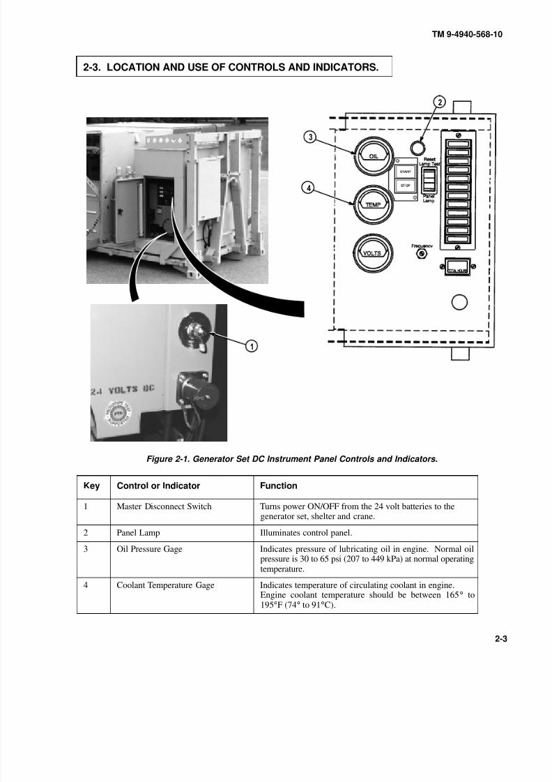
Figure 2-1. Generator Set DC Instrument Panel Controls and Indicators.
Key Control or Indicator Function
1 Master Disconnect Switch Turns power ON/OFF from the 24 volt batteries to thegenerator set, shelter and crane.
2 Panel Lamp Illuminates control panel.
3 Oil Pressure Gage Indicates pressure of lubricating oil in engine. Normal oilpressure is 30 to 65 psi (207 to 449 kPa) at normal operatingtemperature.
4 Coolant Temperature Gage Indicates temperature of circulating coolant in engine.Engine coolant temperature should be between 165° to195°F (74° to 91°C).

8/20/2019 TM 9-4940-568-10 FRS
http://slidepdf.com/reader/full/tm-9-4940-568-10-frs 54/403
TM 9-4940-568-10
2-4
2-3. LOCATION AND USE OF CONTROLS AND INDICATORS (CONT).
Figure 2-1. Generator Set DC Instrument Panel Controls and Indicators (Cont).
Key Control or Indicator Function
5 DC Voltmeter Indicates the battery charging system voltage. Normalcharging voltage is 22 to 28 volts.
6 START/STOP Switch Starts and stops the generator set locally.
7 Running Time Meter Registers the total number of hours the unit has run. Use itto keep a record of periodic servicing. Time is cumulative;
meter cannot be reset.
8 Reset/Lamp Test/Panel Lamp Switch Resets the fault circuit only when the Run/Stop/Remoteswitch is in the Stop (Reset) position. Tests fault lamps andturns on the control panel lamp.
8/20/2019 TM 9-4940-568-10 FRS
http://slidepdf.com/reader/full/tm-9-4940-568-10-frs 55/403
TM 9-4940-568-10
2-5
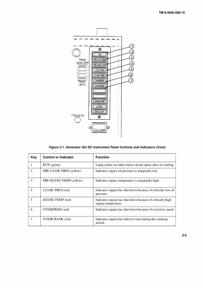
Figure 2-1. Generator Set DC Instrument Panel Controls and Indicators (Cont).
Key Control or Indicator Function
1 RUN (green) Lamp comes on when starter circuit opens after set starting.
2 PRE LO OIL PRES (yellow) Indicates engine oil pressure is marginally low.
3 PRE HI ENG TEMP (yellow) Indicates engine temperature is marginally high.
4 LO OIL PRES (red) Indicates engine has shut down because of critically low oilpressure.
5 HI ENG TEMP (red) Indicates engine has shut down because of critically highengine temperature.
6 OVERSPEED (red) Indicates engine has shut down because of excessive speed.
7 OVERCRANK (red) Indicates engine has failed to start during the crankingperiod.
8/20/2019 TM 9-4940-568-10 FRS
http://slidepdf.com/reader/full/tm-9-4940-568-10-frs 56/403
TM 9-4940-568-10
2-6
2-3. LOCATION AND USE OF CONTROLS AND INDICATORS (CONT).
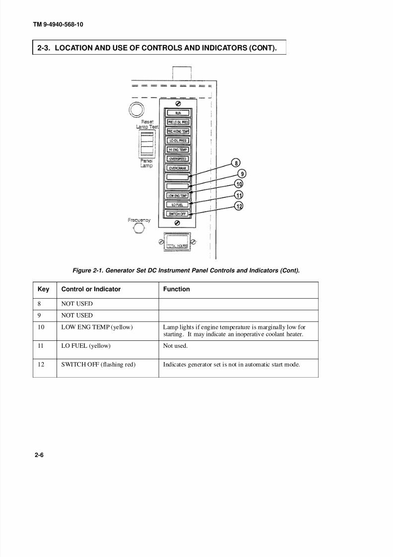
Figure 2-1. Generator Set DC Instrument Panel Controls and Indicators (Cont).
Key Control or Indicator Function
8 NOT USED
9 NOT USED
10 LOW ENG TEMP (yellow) Lamp lights if engine temperature is marginally low forstarting. It may indicate an inoperative coolant heater.
11 LO FUEL (yellow) Not used.
12 SWITCH OFF (flashing red) Indicates generator set is not in automatic start mode.
8/20/2019 TM 9-4940-568-10 FRS
http://slidepdf.com/reader/full/tm-9-4940-568-10-frs 57/403
RPM
HERTZ
A–C AMPERES
A–C VOLTS
Voltage
UPPER SCALE
L2–L3
L2
L1–L2
L1
Volts
Amps
L1–L2
L2
L3–L2
L3
L1–L0
None
Off
Off
L1–L2
L2
Three Phase
Single Phase
FieldBreaker
PUSH FORETHER INJECTION
LOWER SCALE
TM 9-4940-568-10
2-7
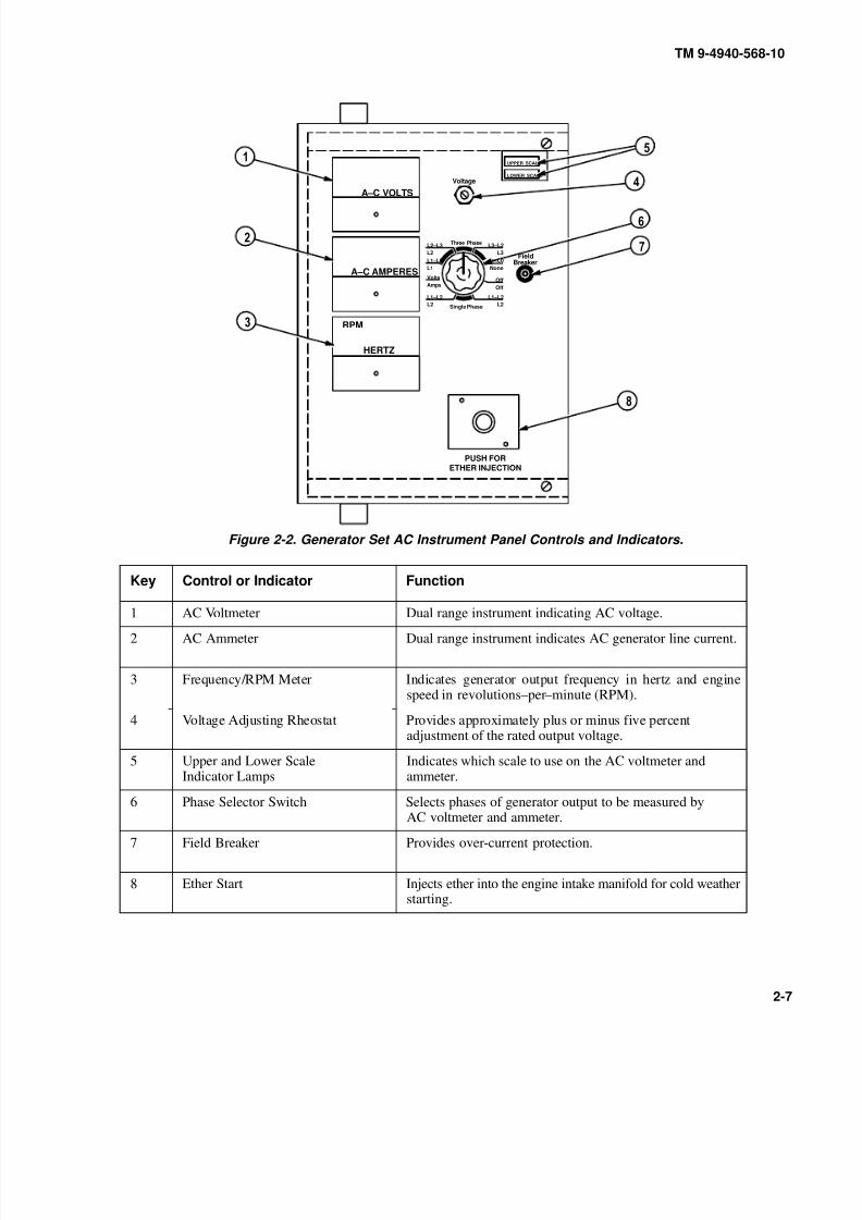
Figure 2-2. Generator Set AC Instrument Panel Controls and Indicators.
Key Control or Indicator Function
1 AC Voltmeter Dual range instrument indicating AC voltage.
2 AC Ammeter Dual range instrument indicates AC generator line current.
3 Frequency/RPM Meter Indicates generator output frequency in hertz and enginespeed in revolutions–per–minute (RPM).
4 Voltage Adjusting Rheostat Provides approximately plus or minus five percentadjustment of the rated output voltage.
5 Upper and Lower ScaleIndicator Lamps
Indicates which scale to use on the AC voltmeter andammeter.
6 Phase Selector Switch Selects phases of generator output to be measured by
AC voltmeter and ammeter.
7 Field Breaker Provides over-current protection.
8 Ether Start Injects ether into the engine intake manifold for cold weatherstarting.
8/20/2019 TM 9-4940-568-10 FRS
http://slidepdf.com/reader/full/tm-9-4940-568-10-frs 58/403
TM 9-4940-568-10
2-8
2-3. LOCATION AND USE OF CONTROLS AND INDICATORS (CONT).
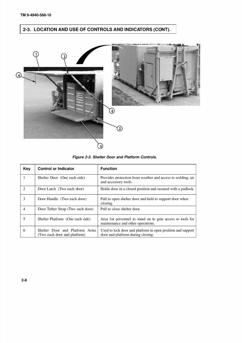
Figure 2-3. Shelter Door and Platform Controls.
Key Control or Indicator Function
1 Shelter Door (One each side) Provides protection from weather and access to welding, airand accessory tools.
2 Door Latch (Two each door) Holds door in a closed position and secured with a padlock.
3 Door Handle (Two each door) Pull to open shelter door and held to support door whenclosing.
4 Door Tether Strap (Two each door) Pull to close shelter door.
5 Shelter Platform (One each side) Area for personnel to stand on to gain access to tools formaintenance and other operations.
6 Shelter Door and Platform Arms(Two each door and platform)
Used to lock door and platform in open position and supportdoor and platform during closing.

8/20/2019 TM 9-4940-568-10 FRS
http://slidepdf.com/reader/full/tm-9-4940-568-10-frs 59/403
2A (DRAIN)
2B (DRAIN)
1A (DRAIN)
TM 9-4940-568-10
2-9
Figure 2-4. Air and Gas Regulators Controls and Indicators.
Key Control or Indicator Function
1 General Air Regulator/WaterSeparator
The general air regulator/water separator filters air, separateswater and controls air pressure to pneumatic tools.
2 Pneumatic Air Regulator/WaterSeparator and Lubricator
The pneumatic regulator/water separator filters air, separateswater and controls air pressure to pneumatic tools. The lubri-cator adds oil to the air supplied to pneumatic tools.
3 Propylene Regulator The propylene regulator is a two stage regulator. The high-pressure gage, the inlet side, shows the pressure from thecylinder and is graduated from 0 to 400 psi. The low pressuregage, the outlet side, shows the working pressure and isgraduated from 0 to 30 psi (3 – 5 psi is normal).
4 Oxygen Regulator The oxygen regulator is a two stage regulator. The high pres-
sure gage, the inlet side, shows the pressure from the cylinderand is from 0 to 4000 psi. The low pressure gage, the outletside, shows the working pressure and is graduated from 0 to200 psi (20 – 40 psi is normal).
5 Argon Regulator The argon regulator is designed with a low pressure flow me-ter. The high pressure gage, the inlet side, shows the pressurefrom the cylinder and is from 0-4000 psi. The low pressureflow meter, the outlet side, shows the working pressure andis graduated from 0 to 30 CFH (5 – 20 CFH is normal).
8/20/2019 TM 9-4940-568-10 FRS
http://slidepdf.com/reader/full/tm-9-4940-568-10-frs 60/403
TM 9-4940-568-10
2-10
2-3. LOCATION AND USE OF CONTROLS AND INDICATORS (CONT).
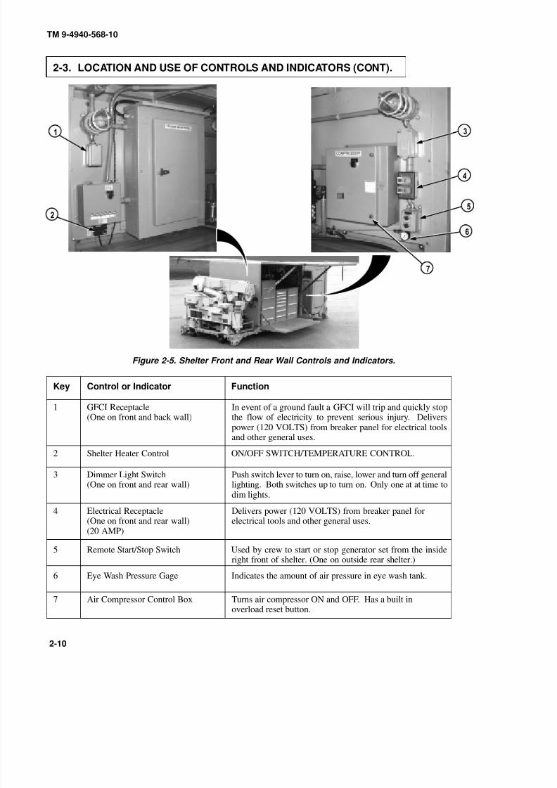
Figure 2-5. Shelter Front and Rear Wall Controls and Indicators.
Key Control or Indicator Function
1 GFCI Receptacle(One on front and back wall)
In event of a ground fault a GFCI will trip and quickly stopthe flow of electricity to prevent serious injury. Deliverspower (120 VOLTS) from breaker panel for electrical toolsand other general uses.
2 Shelter Heater Control ON/OFF SWITCH/TEMPERATURE CONTROL.
3 Dimmer Light Switch(One on front and rear wall)
Push switch lever to turn on, raise, lower and turn off generallighting. Both switches up to turn on. Only one at at time todim lights.
4 Electrical Receptacle
(One on front and rear wall)(20 AMP)
Delivers power (120 VOLTS) from breaker panel for
electrical tools and other general uses.
5 Remote Start/Stop Switch Used by crew to start or stop generator set from the insideright front of shelter. (One on outside rear shelter.)
6 Eye Wash Pressure Gage Indicates the amount of air pressure in eye wash tank.
7 Air Compressor Control Box Turns air compressor ON and OFF. Has a built inoverload reset button.
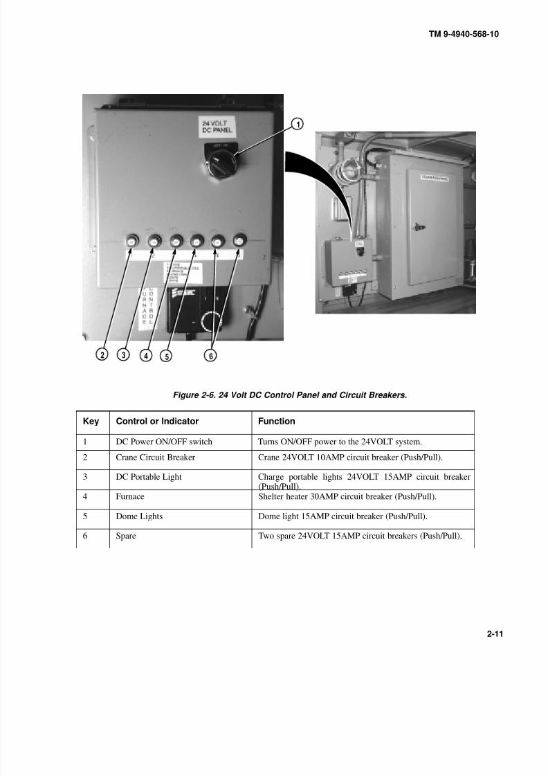
8/20/2019 TM 9-4940-568-10 FRS
http://slidepdf.com/reader/full/tm-9-4940-568-10-frs 61/403
TM 9-4940-568-10
2-11
Figure 2-6. 24 Volt DC Control Panel and Circuit Breakers.
Key Control or Indicator Function
1 DC Power ON/OFF switch Turns ON/OFF power to the 24VOLT system.
2 Crane Circuit Breaker Crane 24VOLT 10AMP circuit breaker (Push/Pull).
3 DC Portable Light Charge portable lights 24VOLT 15AMP circuit breaker(Push/Pull).
4 Furnace Shelter heater 30AMP circuit breaker (Push/Pull).
5 Dome Lights Dome light 15AMP circuit breaker (Push/Pull).
6 Spare Two spare 24VOLT 15AMP circuit breakers (Push/Pull).
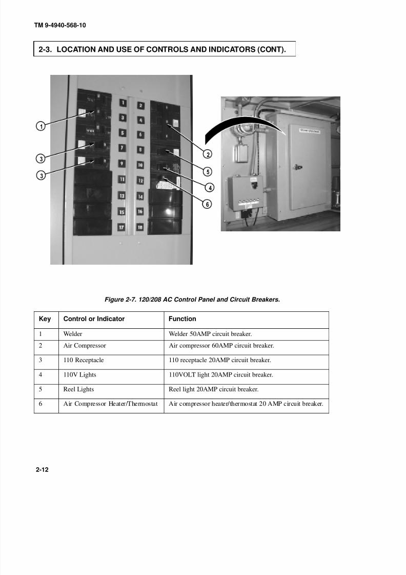
8/20/2019 TM 9-4940-568-10 FRS
http://slidepdf.com/reader/full/tm-9-4940-568-10-frs 62/403
TM 9-4940-568-10
2-12
2-3. LOCATION AND USE OF CONTROLS AND INDICATORS (CONT).
Figure 2-7. 120/208 AC Control Panel and Circuit Breakers.
Key Control or Indicator Function
1 Welder Welder 50AMP circuit breaker.
2 Air Compressor Air compressor 60AMP circuit breaker.
3 110 Receptacle 110 receptacle 20AMP circuit breaker.
4 110V Lights 110VOLT light 20AMP circuit breaker.
5 Reel Lights Reel light 20AMP circuit breaker.
6 Air Compressor Heater/Thermostat Air compressor heater/thermostat 20 AMP circuit breaker.

8/20/2019 TM 9-4940-568-10 FRS
http://slidepdf.com/reader/full/tm-9-4940-568-10-frs 63/403
TM 9-4940-568-10
2-13
Figure 2-8. Crane Main and Auxiliary Valve Controls.
Key Control or Indicator Function
1 Remote Control Hookup Connection for the remote control when used.
2 Crane Power Switch Provides electrical power to the crane and outrigger jacks.
3 BOOM Lift Control Lever Raises and lowers the boom.
TELESCOPE and HOIST control levers should beoperated at the same time or hook block will contactboom tip and cause damage.
4 TELESCOPE Control Lever Move TELESCOPE control lever to OUT or IN position toextend or retract the boom.
Boom must be above shelter for clearance. Hittingobstacles with boom may cause damage to boom or shelter.
5 SWING Control Lever Moves boom clockwise and counterclockwise.
6 MAST Control Lever Raises the mast to operating position and lowers the mast tostowage position.
7 HOIST Control Lever Reels in and pays out the cable.

8/20/2019 TM 9-4940-568-10 FRS
http://slidepdf.com/reader/full/tm-9-4940-568-10-frs 64/403
MANUAL OVERRIDE GUARD SHOWN
REMOVED FOR CLARITY
TM 9-4940-568-10
2-14
2-3. LOCATION AND USE OF CONTROLS AND INDICATORS (CONT).
Figure 2-8. Crane Main and Auxiliary Valve Controls (Cont).
Key Control or Indicator Function
8 LH O/R JACK Control Lowers and raises the left outrigger jack.
9 O/R EXT Control Lever Move O/R EXT control lever to OUT or IN position to extendor retract both outriggers.
10 RH O/R JACK Control Lever Lowers and raises the outrigger jack.
11 Front to Back Level Gage Used as an indicator for front to back leveling of FRS.
12 Left to Right Level Gage Used as an indicator for left to right leveling of FRS.
13 MHC Main Hydraulic PressureManual Override
Provides emergency hydraulic power when electrical powerfails that results in loss of outrigger jack and crane functions.

8/20/2019 TM 9-4940-568-10 FRS
http://slidepdf.com/reader/full/tm-9-4940-568-10-frs 65/403
TM 9-4940-568-10
2-15
Figure 2-9. Crane Remote Control Unit.
Key Control or Indicator Function
1 BOOM Control Lever Raises and lowers the boom.
TELESCOPE and HOIST control levers should be operatedat the same time or hook block will contact boom tip andcause damage.
2 TELESCOPE Control Lever Move TELESCOPE control lever to OUT or IN positionto extend or retract the boom.
3 REMOTE CONTROL UNITON/OFF EMERGENCY STOPSwitch
Supplies and shuts off electrical power to the crane andallows the operator to shut down the crane in an emergencysituation from the REMOTE CONTROL UNIT.
Boom must be above shelter for clearance. Hitting obstacleswith boom may cause damage to boom or shelter.
4 SWING Control Lever Moves the crane clockwise and counterclockwise.
5 HOIST Control Lever Reels in and pays out the cable.
6 REMOTE Hookup Wire Outlet Allows cable hookup between the crane and remote.

8/20/2019 TM 9-4940-568-10 FRS
http://slidepdf.com/reader/full/tm-9-4940-568-10-frs 66/403
TM 9-4940-568-10
2-16
2-3. LOCATION AND USE OF CONTROLS AND INDICATORS (CONT).
Figure 2-10. Exterior Mounted Controls and Indicators.
Key Control or Indicator Function
1 Hydraulic Tank Fill Sight Glass Indicates hydraulic oil level in hydraulic tank.
2 Air Reservoir Drain and Fill Valve Drains air pressure and water from air reservoir. Used tofill air reservoir with air from an external source.
3 Fuel Tank Gage Indicates the amount of fuel in fuel tank.
4 Air Compressor Dipstick Indicates air compressor oil level.
5 Air Compressor Pressure Gage Indicates the amount of air pressure in air reservoir.
6 Solar Air Vent The solar air vent is used to equalize the humidity level insideand outside the shelter to reduce condensation buildup.

8/20/2019 TM 9-4940-568-10 FRS
http://slidepdf.com/reader/full/tm-9-4940-568-10-frs 67/403
TM 9-4940-568-10
2-17
Figure 2-11. Exterior Mounted Controls and Indicators.
Key Control or Indicator Function
7 Air Filter Restriction Indicator Indicates when air filter needs servicing.
8 Governor Controller Controls engine speed under various loads for stableoperation.
9 Hydraulic Oil Filter Indicator Indicates when hydraulic oil filter needs servicing.
10 Engine Oil Dipstick Indicates the engine oil level.
11 Boom Angle Indicator Indicates the angle of the boom.

8/20/2019 TM 9-4940-568-10 FRS
http://slidepdf.com/reader/full/tm-9-4940-568-10-frs 68/403
TM 9-4940-568-10
2-18
2-4. DECALS AND INSTRUCTION PLATES.
Figure 2-12. Decals and Instruction Plates.

8/20/2019 TM 9-4940-568-10 FRS
http://slidepdf.com/reader/full/tm-9-4940-568-10-frs 69/403
TM 9-4940-568-10
2-19
Figure 2-12. Decals and Instruction Plates (Cont).

8/20/2019 TM 9-4940-568-10 FRS
http://slidepdf.com/reader/full/tm-9-4940-568-10-frs 70/403
120/208 MAIN PANEL
24V DC LIGHTS
TM 9-4940-568-10
2-20
2-4. DECALS AND INSTRUCTION PLATES (CONT).
Figure 2-12. Decals and Instruction Plates (Cont).

8/20/2019 TM 9-4940-568-10 FRS
http://slidepdf.com/reader/full/tm-9-4940-568-10-frs 71/403
TM 9-4940-568-10
2-21
Figure 2-12. Decals and Instruction Plates (Cont).
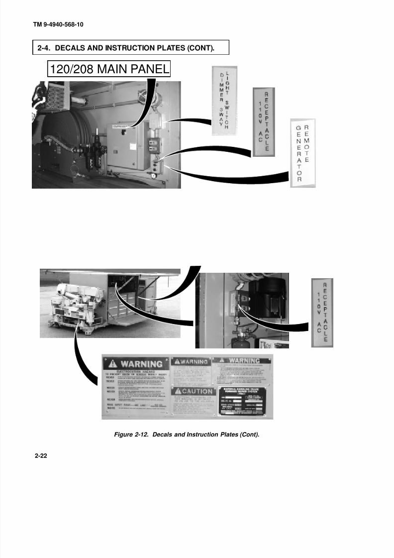
8/20/2019 TM 9-4940-568-10 FRS
http://slidepdf.com/reader/full/tm-9-4940-568-10-frs 72/403
120/208 MAIN PANEL
TM 9-4940-568-10
2-22
2-4. DECALS AND INSTRUCTION PLATES (CONT).
Figure 2-12. Decals and Instruction Plates (Cont).

8/20/2019 TM 9-4940-568-10 FRS
http://slidepdf.com/reader/full/tm-9-4940-568-10-frs 73/403
TM 9-4940-568-10
2-23
Figure 2-12. Decals and Instruction Plates (Cont).
8/20/2019 TM 9-4940-568-10 FRS
http://slidepdf.com/reader/full/tm-9-4940-568-10-frs 74/403
TM 9-4940-568-10
2-24
Section II. PREVENTIVE MAINTENANCE CHECKS AND SERVICES (PMCS)
2-5. GENERAL.
This section contains PMCS requirements for the FRS. The PMCS tables contain checks and services necessary to
ensure that the FRS is ready for operation. Using PMCS tables, perform maintenance at specified intervals.
a. Cleaning Instructions and Precautions. During PMCS keep the following general maintenance
procedures in mind:
(1) Cleanliness. Dirt, grease, oil and debris may cause or cover a serious problem. Clean all metal surfaces.
(2) Bolts, nuts and screws. Check bolts, nuts and screws for obvious looseness, missing, bent, or broken
condition. Look for chipped paint, bare metal, or rust around bolt heads. If any part seems loose, tighten
it, or have the part repaired or replaced.
(3) Welds. Look for loose or chipped paint, rust, or gaps on welds. If a bad weld is found, notify UnitMaintenance.
(4) Electrical wires and connectors. Look for cracked or broken insulation, bare wires and loose or broken
connectors. Tighten loose connectors and make sure wires are in good shape. If a wire or connector is
bad, notify Unit Maintenance.
(5) Fluid lines and fittings. Look for wear, damage and leaks, and make sure clamps and fittings are tight. If
a leak comes from a loose fitting or connector, tighten it. If something is broken or worn out and can not
be fixed with tools available, notify Unit Maintenance.
(6) Air system components. Look for worn, damaged or leaking components. Make sure clamps and fittings
are tight. If a leak comes from a loose fitting or connector, tighten it. If something is broken or worn out,
either repair or replace it, or notify Unit Maintenance.
2-6. WARNINGS AND CAUTIONS.
Always observe the warnings and cautions appearing in your PMCS table. Warnings and cautions appear before
applicable procedures. You must observe these warnings and cautions to prevent serious injury to yourself and others
or prevent equipment from being damaged.

8/20/2019 TM 9-4940-568-10 FRS
http://slidepdf.com/reader/full/tm-9-4940-568-10-frs 75/403
TM 9-4940-568-10
2-25
2-7. EXPLANATION OF TABLE ENTRIES.
a. Item Number Column. Items in this column are for reference. When completing DA Form 2404 or DA
Form 5988-E (Equipment Inspection and Maintenance Worksheet), include the item number for the
check/service indicating a fault. Item numbers also appear in the order that you must do the checks and servicesfor the intervals listed.
b. Interval Column. This column describes when, and how often, the check is to be made. Thus, if a given
check is performed before operation, the word Before is opposite the check in the Interval column.
(1) Perform the (Before) CHECKS before operating FRS.
(2) Perform the (During) CHECKS while operating FRS. During operation means to monitor the FRS and its
related components while being operated.
(3) Perform the (After) CHECKS right after operating the FRS.
(4) Perform the (Weekly) CHECKS once a week.
(5) Perform the (Monthly) CHECKS once a month.
c. Item To Be Inspected Column . The items listed in this column are divided into groups indicating the
portion of the equipment of which they are a part, i.e. front, left, engine. Under these groupings a few common
words are used to identify the specific item being checked.
d. Procedures Column. This column contains a brief description of the procedure by which the check is
performed.
e. Equipment Is Not Fully Mission Capable If: Column. This column contains the criteria that causes
the equipment to be classified as NOT READY/NOT AVAILABLE because of inability to perform its primary
mission. An entry in this column will:
(1) Identify conditions that will make the equipment not ready/available for readiness reporting purposes.
2-8. SHORTENED MAINTENANCE INTERVALS.
Extreme weather conditions, periods of high use, or combat conditions may dictate that PMCS is performed more
often than is required in the PMCS Tables.
2-9. LUBRICATION REQUIREMENTS.
For lubrication requirements and procedures, refer to Appendix G.
8/20/2019 TM 9-4940-568-10 FRS
http://slidepdf.com/reader/full/tm-9-4940-568-10-frs 76/403
TM 9-4940-568-10
2-26
2-10. LEAKAGE CLASSIFICATION AND DEFINITION.
Equipment operation is allowable with minor leak (Class I or II). Consideration mustbe given to the fluid capacity in the item/system being checked/inspected. When indoubt, notify the supervisor. When operating with Class I or II leaks, continue to check fluid levels as required in the PMCS. Class III leaks should be repaired using tools
available, if possible. If not, use “Not Fully Mission Capable” column criteria.
NOTE
If leakage is detected, further investigation is needed to determine the location andcause of the leak. If there is any doubt, contact your supervisor or Unit Maintenance.
a. Class I. Leakage of fluid as indicated by wetness or discoloration not great enough to form drops.
b. Class II. Leakage of fluid great enough to form drops but not enough to cause drops that fall from item
being checked/inspected.
c. Class III. Leakage of fluid great enough to form drops that fall from the item being checked/inspected.
Try to fix leak using tools available.
2-11. OPERATORS PREVENTIVE MAINTENANCE CHECKS AND SERVICES(PMCS) TABLES.
Generator set engine must be shut off before performing PMCS walkaround. Severeinjury to personnel may result.
Refer to Table 2-1 through 2-5 for Operator’s Preventive Maintenance Checks and Services (PMCS) for the FRS. The
routing diagram (Figure 2-13) will be of help to complete the PMCS. It shows the general path an operator will follow
to complete the PMCS.

8/20/2019 TM 9-4940-568-10 FRS
http://slidepdf.com/reader/full/tm-9-4940-568-10-frs 77/403
TM 9-4940-568-10
2-27
Figure 2 -13. PMCS Walkaround.
Table 2-1. Operator’s Level Preventive Maintenance Checks and Services (Before).
Item
No.
Interval Item to
Check/
Service
Procedure Not Fully Mission
Capable If:
NOTE
If leakage is detected, further investigation isneeded to determine the location and cause of the leak. If there is any doubt, contact yoursupervisor or Unit Maintenance.
1 Before Leaks Check underneath FRS for evidence of obviousfluid leakage.
Class III leak is evident.
2 Before Shelter Visually check outside of shelter for obviousdamage that would impair operation.
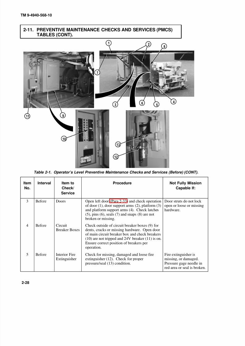
8/20/2019 TM 9-4940-568-10 FRS
http://slidepdf.com/reader/full/tm-9-4940-568-10-frs 78/403
TM 9-4940-568-10
2-28
2-11. PREVENTIVE MAINTENANCE CHECKS AND SERVICES (PMCS)TABLES (CONT).
Table 2-1. Operator’s Level Preventive Maintenance Checks and Services (Before) (CONT).
Item
No.
Interval Item to
Check/
Service
Procedure Not Fully Mission
Capable If:
3 Before Doors Open left door (Para 2-33) and check operationof door (1), door support arms (2), platform (3)and platform support arms (4). Check latches(5), pins (6), seals (7) and snaps (8) are notbroken or missing.
Door struts do not lock open or loose or missinghardware.
4 Before Circuit
Breaker Boxes
Check outside of circuit breaker boxes (9) for
dents, cracks or missing hardware. Open doorof main circuit breaker box and check breakers(10) are not tripped and 24V breaker (11) is on.Ensure correct position of breakers peroperation.
5 Before Interior FireExtinguisher
Check for missing, damaged and loose fireextinguisher (12). Check for properpressure/seal (13) condition.
Fire extinguisher ismissing, or damaged.Pressure gage needle inred area or seal is broken.
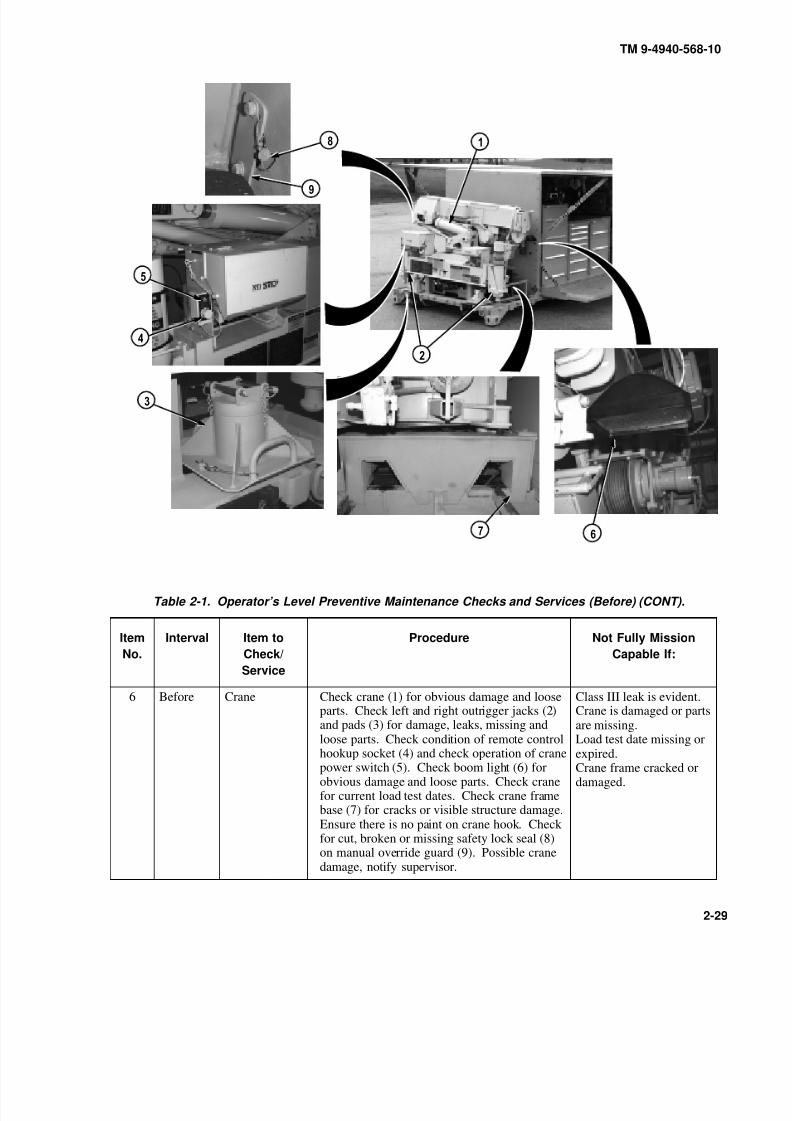
8/20/2019 TM 9-4940-568-10 FRS
http://slidepdf.com/reader/full/tm-9-4940-568-10-frs 79/403
TM 9-4940-568-10
2-29
Table 2-1. Operator’s Level Preventive Maintenance Checks and Services (Before) (CONT).
Item
No.
Interval Item to
Check/
Service
Procedure Not Fully Mission
Capable If:
6 Before Crane Check crane (1) for obvious damage and looseparts. Check left and right outrigger jacks (2)and pads (3) for damage, leaks, missing andloose parts. Check condition of remote controlhookup socket (4) and check operation of cranepower switch (5). Check boom light (6) forobvious damage and loose parts. Check cranefor current load test dates. Check crane framebase (7) for cracks or visible structure damage.Ensure there is no paint on crane hook. Check for cut, broken or missing safety lock seal (8)on manual override guard (9). Possible cranedamage, notify supervisor.
Class III leak is evident.Crane is damaged or partsare missing.Load test date missing orexpired.Crane frame cracked ordamaged.
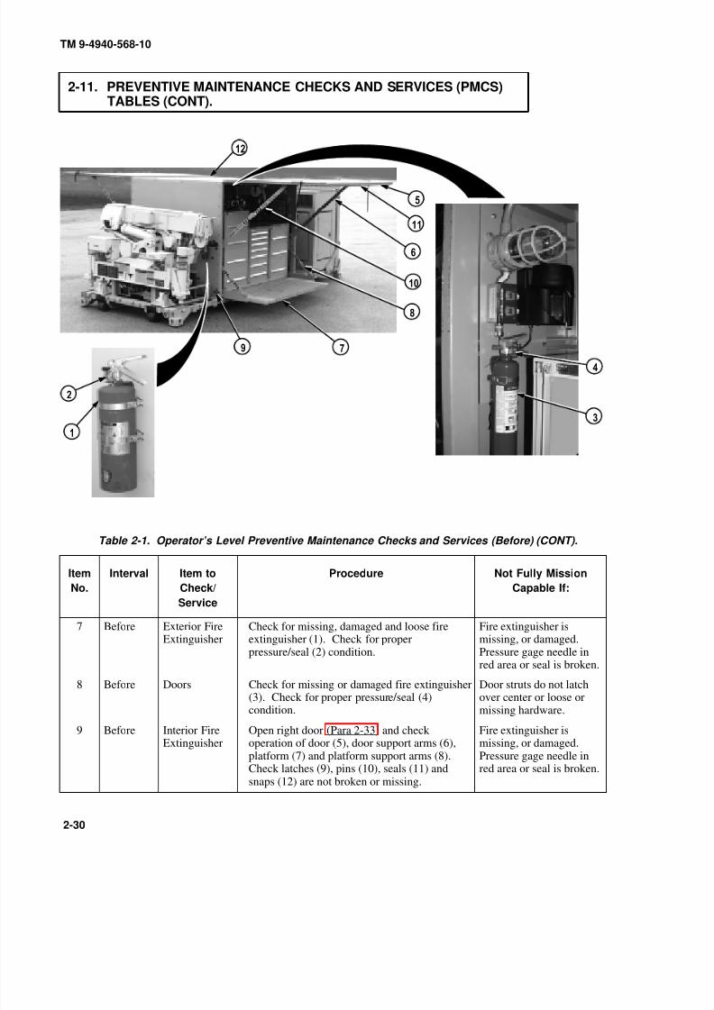
8/20/2019 TM 9-4940-568-10 FRS
http://slidepdf.com/reader/full/tm-9-4940-568-10-frs 80/403
TM 9-4940-568-10
2-30
2-11. PREVENTIVE MAINTENANCE CHECKS AND SERVICES (PMCS)TABLES (CONT).
Table 2-1. Operator’s Level Preventive Maintenance Checks and Services (Before) (CONT).
Item
No.
Interval Item to
Check/
Service
Procedure Not Fully Mission
Capable If:
7 Before Exterior FireExtinguisher
Check for missing, damaged and loose fireextinguisher (1). Check for properpressure/seal (2) condition.
Fire extinguisher ismissing, or damaged.Pressure gage needle inred area or seal is broken.
8 Before Doors Check for missing or damaged fire extinguisher(3). Check for proper pressure/seal (4)condition.
Door struts do not latchover center or loose ormissing hardware.
9 Before Interior FireExtinguisher
Open right door (Para 2-33) and check operation of door (5), door support arms (6),platform (7) and platform support arms (8).Check latches (9), pins (10), seals (11) andsnaps (12) are not broken or missing.
Fire extinguisher ismissing, or damaged.Pressure gage needle inred area or seal is broken.

8/20/2019 TM 9-4940-568-10 FRS
http://slidepdf.com/reader/full/tm-9-4940-568-10-frs 81/403
TM 9-4940-568-10
2-31
Table 2-1. Operator’s Level Preventive Maintenance Checks and Services (Before) (CONT).
Item
No.
Interval Item to
Check/
Service
Procedure Not Fully Mission
Capable If:
10 Before AirCompressorCircuit Box
Check outside of air compressor breaker box(1) for dents, cracks or missing hardware.Check that switch is in off position.
11 Before EyewashGage
Check eyewash gage (2) for proper reading of 95 to 110 psi.
Gage is inoperable orreads less than 95 psi orover 110 psi.

8/20/2019 TM 9-4940-568-10 FRS
http://slidepdf.com/reader/full/tm-9-4940-568-10-frs 82/403
SAFEOIL
LEVEL
TM 9-4940-568-10
2-32
2-11. PREVENTIVE MAINTENANCE CHECKS AND SERVICES (PMCS)TABLES (CONT).
Table 2-1. Operator’s Level Preventive Maintenance Checks and Services (Before) (CONT).
Item
No.
Interval Item to
Check/
Service
Procedure Not Fully Mission
Capable If:
Drain air compressor reservoir before servicing the air lubricator. Failure tocomply may result in injury to personnel.
12 Before General AirRegulator/ WaterSeparator,PnuematicAir Regulator/ WaterSeparator andAirLubricator
(a) Check overall condition of both airregulators/water separators (1) and (2) and airlubricator (3). Check for damaged or missingparts.
(b) Check both water separator site gages (4)for presence of water. Turn drain valve (5) anddrain water from both regulator bowls (6).Close drain valves.
(c) Check air lubricator (3) oil level. Oil levelshould be kept between hatchmarks on airlubricator site gage (7), as shown. To add oil,remove oil fill plug (8) and fill as required(refer to Appendix G). Install oil fill plug.
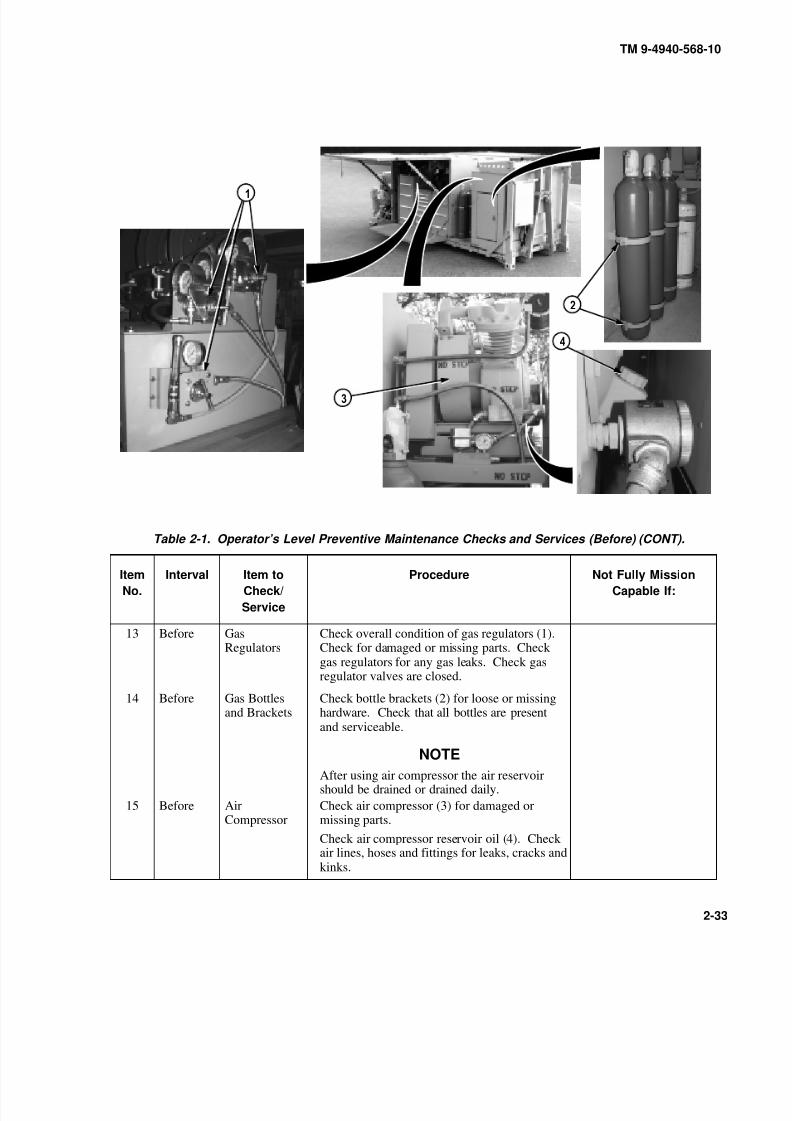
8/20/2019 TM 9-4940-568-10 FRS
http://slidepdf.com/reader/full/tm-9-4940-568-10-frs 83/403
TM 9-4940-568-10
2-33
Table 2-1. Operator’s Level Preventive Maintenance Checks and Services (Before) (CONT).
Item
No.
Interval Item to
Check/
Service
Procedure Not Fully Mission
Capable If:
13 Before GasRegulators
Check overall condition of gas regulators (1).Check for damaged or missing parts. Check gas regulators for any gas leaks. Check gasregulator valves are closed.
14 Before Gas Bottlesand Brackets
Check bottle brackets (2) for loose or missinghardware. Check that all bottles are presentand serviceable.
NOTE
After using air compressor the air reservoirshould be drained or drained daily.
15 Before AirCompressor
Check air compressor (3) for damaged ormissing parts.
Check air compressor reservoir oil (4). Check air lines, hoses and fittings for leaks, cracks andkinks.
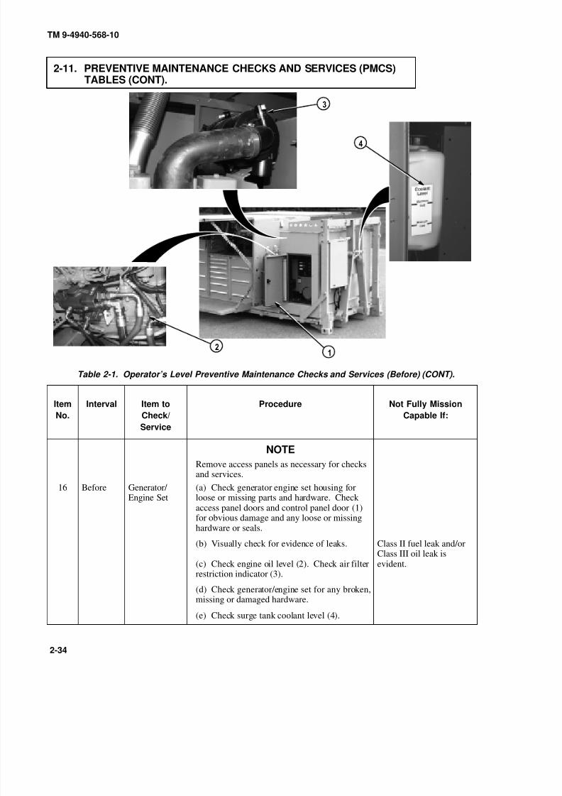
8/20/2019 TM 9-4940-568-10 FRS
http://slidepdf.com/reader/full/tm-9-4940-568-10-frs 84/403
TM 9-4940-568-10
2-34
2-11. PREVENTIVE MAINTENANCE CHECKS AND SERVICES (PMCS)TABLES (CONT).
Table 2-1. Operator’s Level Preventive Maintenance Checks and Services (Before) (CONT).
Item
No.
Interval Item to
Check/
Service
Procedure Not Fully Mission
Capable If:
NOTE
Remove access panels as necessary for checksand services.
16 Before Generator/ Engine Set
(a) Check generator engine set housing forloose or missing parts and hardware. Check access panel doors and control panel door (1)for obvious damage and any loose or missing
hardware or seals.(b) Visually check for evidence of leaks.
(c) Check engine oil level (2). Check air filterrestriction indicator (3).
Class II fuel leak and/orClass III oil leak isevident.
(d) Check generator/engine set for any broken,missing or damaged hardware.
(e) Check surge tank coolant level (4).

8/20/2019 TM 9-4940-568-10 FRS
http://slidepdf.com/reader/full/tm-9-4940-568-10-frs 85/403
TM 9-4940-568-10
2-35
Table 2-1. Operator’s Level Preventive Maintenance Checks and Services (Before) (CONT).
Item
No.
Interval Item to
Check/
Service
Procedure Not Fully Mission
Capable If:
16 Before Generator/
Engine Set
(f) Check for proper operation of fuel gage
(5). Check that fuel vent (6) is not clogged.
(g) Push lamp test switch (7) to check allindicator lights (8), are working on generator.
17 Before GroundingRod
Check grounding rod sections and brackets forany loose or missing parts and hardware.
Grounding rod sectionsare missing or damaged.
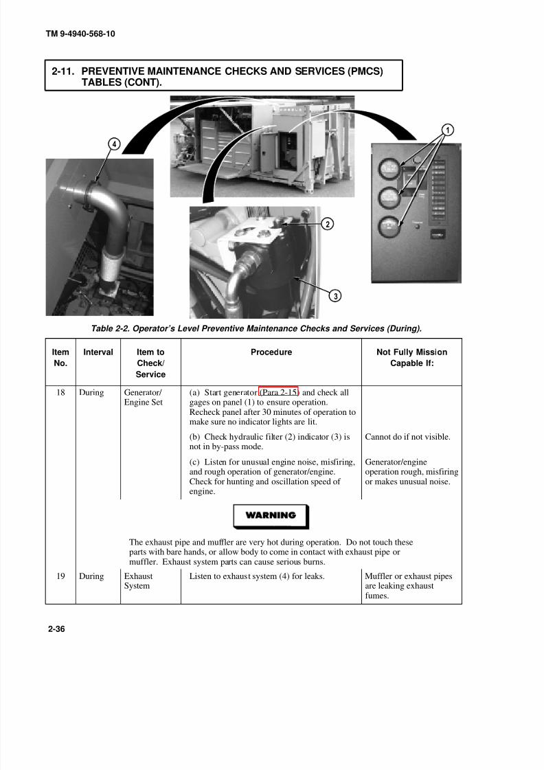
8/20/2019 TM 9-4940-568-10 FRS
http://slidepdf.com/reader/full/tm-9-4940-568-10-frs 86/403
TM 9-4940-568-10
2-36
2-11. PREVENTIVE MAINTENANCE CHECKS AND SERVICES (PMCS)TABLES (CONT).
Table 2-2. Operator’s Level Preventive Maintenance Checks and Services (During).
Item
No.
Interval Item to
Check/
Service
Procedure Not Fully Mission
Capable If:
18 During Generator/ Engine Set
(a) Start generator (Para 2-15) and check allgages on panel (1) to ensure operation.Recheck panel after 30 minutes of operation tomake sure no indicator lights are lit.
(b) Check hydraulic filter (2) indicator (3) isnot in by-pass mode.
Cannot do if not visible.
(c) Listen for unusual engine noise, misfiring,and rough operation of generator/engine.Check for hunting and oscillation speed of engine.
Generator/engineoperation rough, misfiringor makes unusual noise.
The exhaust pipe and muffler are very hot during operation. Do not touch theseparts with bare hands, or allow body to come in contact with exhaust pipe ormuffler. Exhaust system parts can cause serious burns.
19 During ExhaustSystem
Listen to exhaust system (4) for leaks. Muffler or exhaust pipesare leaking exhaustfumes.

8/20/2019 TM 9-4940-568-10 FRS
http://slidepdf.com/reader/full/tm-9-4940-568-10-frs 87/403
TM 9-4940-568-10
2-37
Table 2-2. Operator’s Level Preventive Maintenance Checks and Services (During) (CONT).
Item
No.
Interval Item to
Check/
Service
Procedure Not Fully Mission
Capable If:
20 During AirCompressor
Listen for any unusual noise and check forevidence of air leaks in air compressor (1).
Check air compressor gage (2) for properreading of 110 to 195 PSI.
Belt loose, unusual noise.
If reading is below 110PSI.
21 During ElectricalComponents
While generator is running, check all lights,handlamp (3), switches and crane boomlight (4).
22 During Shelter Doors Check shelter roof and doors for accumulatedsnow, ice, dirt and material buildup. Clearshelter roof and doors.

8/20/2019 TM 9-4940-568-10 FRS
http://slidepdf.com/reader/full/tm-9-4940-568-10-frs 88/403
TM 9-4940-568-10
2-38
2-11. PREVENTIVE MAINTENANCE CHECKS AND SERVICES (PMCS)TABLES (CONT).
Table 2-2. Operator’s Level Preventive Maintenance Checks and Services (During) (CONT).
Item
No.
Interval Item to
Check/
Service
Procedure Not Fully Mission
Capable If:
23 During MaterialHandlingCrane ManualOverride
Check manual overide valve is locked in closedposition.
(a) Position crane main power switch (1) in theOFF position.
(b) Move RH O/R JACK (2) or LH O/RJACK (3) to DOWN.
Outrigger jack lowers.
24 During MaterialHandlingCrane
Check for proper boom operation:
(a) Erect crane (Para 2-29). Move HOISTcontrol lever (4) to UP and slowly raise hook
block (5) to contact boom (6). Hold HOISTcontrol lever in UP position and move BOOMcontrol lever (7) to UP then DOWN.
Boom will raise and/orlower.
(b) Move HOIST control lever (4) to DOWNand slowly lower hook block one foot. MoveBOOM control lever (7) to UP then DOWN.
Boom will not raiseand/or lower.
(c) Stow crane (Para 2-29).
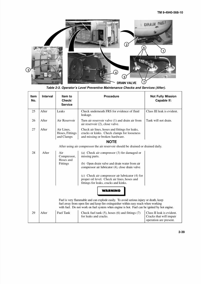
8/20/2019 TM 9-4940-568-10 FRS
http://slidepdf.com/reader/full/tm-9-4940-568-10-frs 89/403
TM 9-4940-568-10
2-39
Table 2-3. Operator’s Level Preventive Maintenance Checks and Services (After).
Item
No.
Interval Item to
Check/
Service
Procedure Not Fully Mission
Capable If:
25 After Leaks Check underneath FRS for evidence of fluidleakage.
Class III leak is evident.
26 After Air Reservoir Turn air reservoir valve (1) and drain air fromair reservoir (2), close valve.
Tank will not drain.
27 After Air Lines,Hoses, Fittingsand Clamps
Check air lines, hoses and fittings for leaks,cracks or kinks. Check clamps for loosenessand missing or broken hardware.
NOTEAfter using air compressor the air reservoir should be drained or drained daily.
28 After AirCompressor,Hoses andFittings
(a) Check air compressor (3) for damaged ormissing parts.
(b) Open drain valve and drain water from aircompressor air lubricator (4), close drain valve.
(c) Check air compressor air lubricator (4) forproper oil level. Check air lines, hoses andfittings for leaks, cracks and kinks.
Fuel is very flammable and can explode easily. To avoid serious injury or death, keepfuel away from open fire and keep fire extinguisher within easy reach when workingwith fuel. Do not work on fuel system when engine is hot. Fuel can be ignited by hot engine.
29 After Fuel Tank Check fuel tank (5), hoses (6) and fittings (7)for leaks and cracks.
Class II leak is evident.Cracks that will impairoperation are present.
DRAIN VALVE

8/20/2019 TM 9-4940-568-10 FRS
http://slidepdf.com/reader/full/tm-9-4940-568-10-frs 90/403
TM 9-4940-568-10
2-40
2-11. PREVENTIVE MAINTENANCE CHECKS AND SERVICES (PMCS)TABLES (CONT).
Table 2-3. Operator’s Level Preventive Maintenance Checks and Services (After) (CONT).
Item
No.
Interval Item to
Check/
Service
Procedure Not Fully Mission
Capable If:
Hydraulic oil may be hot and cause seriousburns.
30 After HydraulicReservoir
Check hydraulic reservoir fluid (1). If oil levelis within the marks on sight glass (2) thequantity of hydraulic oil is safe for operation.
Class III leak is evident.
31 After HydraulicPump, Hosesand Fittings
Check hydraulic pump (3), hoses and fittingsfor cracks or leaks.
Class III leak is evident.Cracked or brokenfittings or hoses arepresent.
32 After HydraulicLines andHoses
Check for leaking and damaged hydraulic linesand hoses.
Class III leak is evident.Cracks or kinks that willimpair operation arepresent.

8/20/2019 TM 9-4940-568-10 FRS
http://slidepdf.com/reader/full/tm-9-4940-568-10-frs 91/403
TM 9-4940-568-10
2-41
Table 2-3. Operator’s Level Preventive Maintenance Checks and Services (After) (CONT).
Item
No.
Interval Item to
Check/
Service
Procedure Not Fully Mission
Capable If:
• Never allow engine oil level to drop below the LOW (L) mark or above theHigh (H) mark. Damage to engine may result.
• Allow at least 5 minutes after shutdown before checking oil to allow time
for the oil to drain to the oil pan.33 After Generator/
Engine OilLevel
Check that oil level is between Low (L) andFull (F) on the dipstick (1). If below Low (L)fill as required.
Oil level is not betweenLow (L) and Full (F) ondipstick.
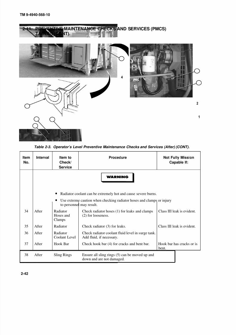
8/20/2019 TM 9-4940-568-10 FRS
http://slidepdf.com/reader/full/tm-9-4940-568-10-frs 92/403
TM 9-4940-568-10
2-42
2-11. PREVENTIVE MAINTENANCE CHECKS AND SERVICES (PMCS)TABLES (CONT).
Table 2-3. Operator’s Level Preventive Maintenance Checks and Services (After) (CONT).
Item
No.
Interval Item to
Check/
Service
Procedure Not Fully Mission
Capable If:
• Radiator coolant can be extremely hot and cause severe burns.
• Use extreme caution when checking radiator hoses and clamps or injuryto personnel may result.
34 After RadiatorHoses andClamps
Check radiator hoses (1) for leaks and clamps(2) for looseness.
Class III leak is evident.
35 After Radiator Check radiator (3) for leaks. Class III leak is evident.
36 After RadiatorCoolant Level
Check radiator coolant fluid level in surge tank.Add fluid, if necessary.
37 After Hook Bar Check hook bar (4) for cracks and bent bar. Hook bar has cracks or isbent.
38 After Sling Rings Ensure all sling rings (5) can be moved up anddown and are not damaged.
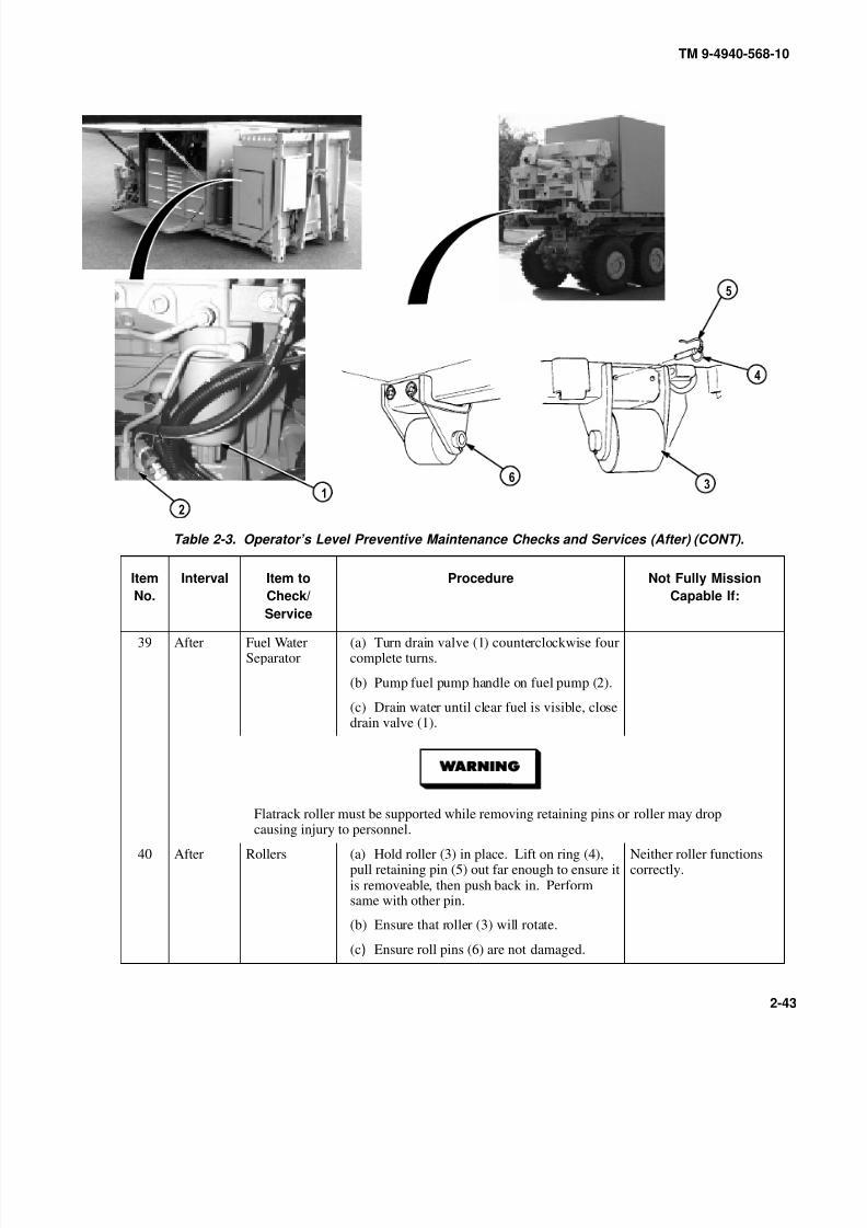
8/20/2019 TM 9-4940-568-10 FRS
http://slidepdf.com/reader/full/tm-9-4940-568-10-frs 93/403
TM 9-4940-568-10
2-43
Table 2-3. Operator’s Level Preventive Maintenance Checks and Services (After) (CONT).
Item
No.
Interval Item to
Check/
Service
Procedure Not Fully Mission
Capable If:
39 After Fuel WaterSeparator
(a) Turn drain valve (1) counterclockwise fourcomplete turns.
(b) Pump fuel pump handle on fuel pump (2).
(c) Drain water until clear fuel is visible, closedrain valve (1).
Flatrack roller must be supported while removing retaining pins or roller may dropcausing injury to personnel.
40 After Rollers (a) Hold roller (3) in place. Lift on ring (4),pull retaining pin (5) out far enough to ensure itis removeable, then push back in. Performsame with other pin.
Neither roller functionscorrectly.
(b) Ensure that roller (3) will rotate.
(c) Ensure roll pins (6) are not damaged.

8/20/2019 TM 9-4940-568-10 FRS
http://slidepdf.com/reader/full/tm-9-4940-568-10-frs 94/403
TM 9-4940-568-10
2-44
2-11. PREVENTIVE MAINTENANCE CHECKS AND SERVICES (PMCS)TABLES (CONT).
Table 2-4. Operator’s Level Preventive Maintenance Checks and Services (Weekly).
Item
No.
Interval Item to
Check/
Service
Procedure Not Fully Mission
Capable If:
NOTE
Perform the following check only as required during cold weather operation.
41 Weekly Ether StartingAid
Check hardware, mounts and canister of etherstarting aid (1), if present.
42 Weekly Engine AirFilter
Check engine air restriction indicator for dirtyair filter.
Engine air filter is dirty orunserviceable.
43 Weekly Engine
AccessoryDrive Belt
Check engine accessory drive belt (2) for
cracking, fraying, and breaks. Check fortightness.
Belt is broken or cracked
to the belt fiber, has morethan one crack (1/8 in.[3.2 mm] in depth or 50percent of belt thickness)or has frays more thantwo in. (51 mm) long.
44 Weekly EngineCooling Fan
Check cooling fan for cracks, loose or missinghardware, and bent or loose blades. Check thatfan is securely mounted.

8/20/2019 TM 9-4940-568-10 FRS
http://slidepdf.com/reader/full/tm-9-4940-568-10-frs 95/403
TM 9-4940-568-10
2-45
Table 2-4. Operator’s Level Preventive Maintenance Checks and Services (Weekly) (CONT).
Item
No.
Interval Item to
Check/
Service
Procedure Not Fully Mission
Capable If:
• Remove all jewelry such as rings, ID tags, bracelets, etc. If jewelry or
tools contact positive electrical circuits a direct short may result. Damageto equipment, injury or death to personnel may occur.
• Lead-acid battery gases can explode. Do not smoke, have open flames, ormake sparks around a battery, especially if caps are off. If a battery is gassing,it can explode and cause injury to personnel.
45 Weekly Batteries Visually check for missing battery caps (1).Check electrolyte level. Electrolyte should befilled to approximately 1/8 in. (3.2 mm) belowlevel/split ring in the battery filler opening(vent). Visually inspect batteries for crackedand leaking casing (2), broken, loose, burned,and corroded terminal posts (3), loose, or
missing hold down bar (4).
Battery is unserviceable,missing, leaking,terminals or cables areloose, corroded, burnt, orhold downs are notsecure.
NOTE
Perform the following check below 50° F(10° C) only.
46 Monthly Heater Check operation of heater control (5) byturning clockwise. Warm air flow should bepresent within five minutes. Check heater ventexhaust (6) for leaks or obstructions.
Heater exhaust is leaking.
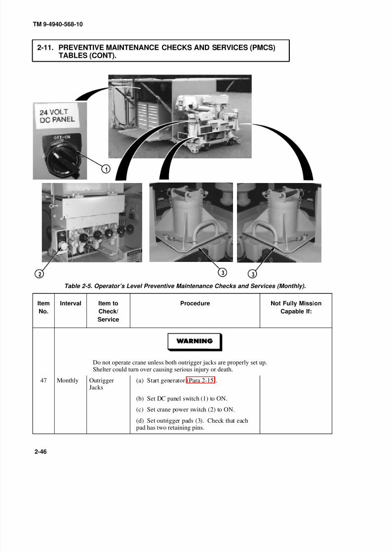
8/20/2019 TM 9-4940-568-10 FRS
http://slidepdf.com/reader/full/tm-9-4940-568-10-frs 96/403
TM 9-4940-568-10
2-46
2-11. PREVENTIVE MAINTENANCE CHECKS AND SERVICES (PMCS)TABLES (CONT).
Table 2-5. Operator’s Level Preventive Maintenance Checks and Services (Monthly).
Item
No.
Interval Item to
Check/
Service
Procedure Not Fully Mission
Capable If:
Do not operate crane unless both outrigger jacks are properly set up.
Shelter could turn over causing serious injury or death.
47 Monthly OutriggerJacks
(a) Start generator (Para 2-15).
(b) Set DC panel switch (1) to ON.
(c) Set crane power switch (2) to ON.
(d) Set outrigger pads (3). Check that eachpad has two retaining pins.
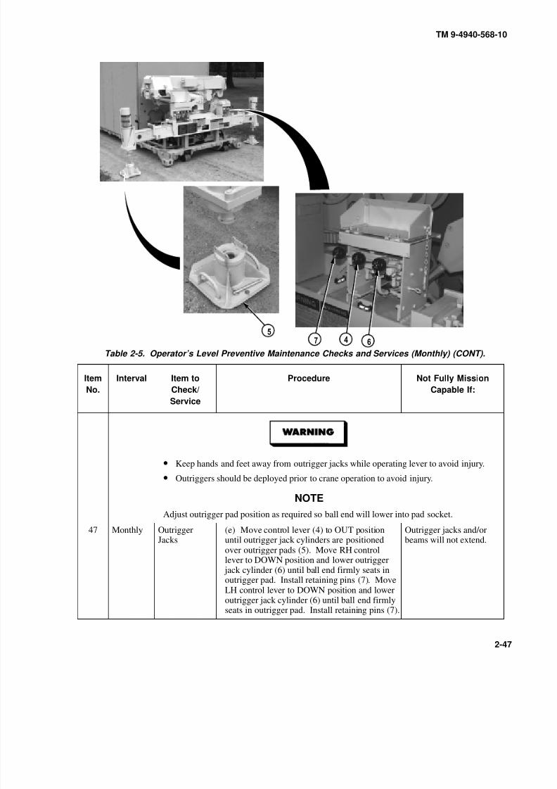
8/20/2019 TM 9-4940-568-10 FRS
http://slidepdf.com/reader/full/tm-9-4940-568-10-frs 97/403
TM 9-4940-568-10
2-47
Table 2-5. Operator’s Level Preventive Maintenance Checks and Services (Monthly) (CONT).
Item
No.
Interval Item to
Check/Service
Procedure Not Fully Mission
Capable If:
• Keep hands and feet away from outrigger jacks while operating lever to avoid injury.
• Outriggers should be deployed prior to crane operation to avoid injury.
NOTE
Adjust outrigger pad position as required so ball end will lower into pad socket.
47 Monthly OutriggerJacks
(e) Move control lever (4) to OUT positionuntil outrigger jack cylinders are positionedover outrigger pads (5). Move RH controllever to DOWN position and lower outrigger
jack cylinder (6) until ball end firmly seats inoutrigger pad. Install retaining pins (7). MoveLH control lever to DOWN position and loweroutrigger jack cylinder (6) until ball end firmlyseats in outrigger pad. Install retaining pins (7).
Outrigger jacks and/orbeams will not extend.

8/20/2019 TM 9-4940-568-10 FRS
http://slidepdf.com/reader/full/tm-9-4940-568-10-frs 98/403
TM 9-4940-568-10
2-48
2-11. PREVENTIVE MAINTENANCE CHECKS AND SERVICES (PMCS)TABLES (CONT).
Table 2-5. Operator’s Level Preventive Maintenance Checks and Services (Monthly) (CONT).
Item
No.
Interval Item to
Check/
Service
Procedure Not Fully Mission
Capable If:
Do not operate crane unless both outrigger jacks are properly set up. Sheltercould turn over causing serious injury or death.
48 Monthly Crane ControlLevers
(a) Move HOIST control lever (1) to DOWNposition and lower hoist cable about12 in. (305 mm).
Cable will not pay out.
Care must be taken when disconnecting HOIST load hook from hook blocktiedown. A swinging hook block can cause serious injury or death to personnel.
(b) Disconnect load hook (2) from hook block tie down.
(c) Check load hook for cracks. Hook willhave to be replaced if cracked.
Hook is cracked.

8/20/2019 TM 9-4940-568-10 FRS
http://slidepdf.com/reader/full/tm-9-4940-568-10-frs 99/403
TM 9-4940-568-10
2-49
Table 2-5. Operator’s Level Preventive Maintenance Checks and Services (Monthly) (CONT).
Item
No.
Interval Item to
Check/
Service
Procedure Not Fully Mission
Capable If:
• Keep boom clear of shelter, all electrical lines and other obstacles while operatingcrane. Failure to comply may result in injury or death to personnel.
• Do not operate crane unless both outrigger jacks are properly set up. Sheltercould turn over causing serious injury or death.
• Operator should be stationed to be able to see load at all times duringcrane operation. Boom and load moving out of control could causeserious injury or death.
• Do not hit outrigger jack with load hook or damage to equipment may occur.
• Do not swing crane until boom is at 0 degrees and mast is fully extended ordamage to equipment may occur.
48 Monthly Crane ControlLevers
(d) Move BOOM control lever (3) to UPposition until boom (4) is at 45 degree angle asshown on boom indicator.
Boom will not raise.

8/20/2019 TM 9-4940-568-10 FRS
http://slidepdf.com/reader/full/tm-9-4940-568-10-frs 100/403
TM 9-4940-568-10
2-50
2-11. PREVENTIVE MAINTENANCE CHECKS AND SERVICES (PMCS)TABLES (CONT).
Table 2-5. Operator’s Level Preventive Maintenance Checks and Services (Monthly) (CONT).
Item
No.
Interval Item to
Check/
Service
Procedure Not Fully Mission
Capable If:
Keep boom clear of shelter, all electrical lines and other obstacles while operating
crane. Failure to comply may result in serious injury or death to personnel.
48 Monthly Crane ControlLevers
(e) Move MAST control lever (5) to UPposition until mast cylinder is fully extended.
Mast will not raise.
(f) Move BOOM control lever (3) to raiseboom (4) until boom indicator reads 0 degrees.
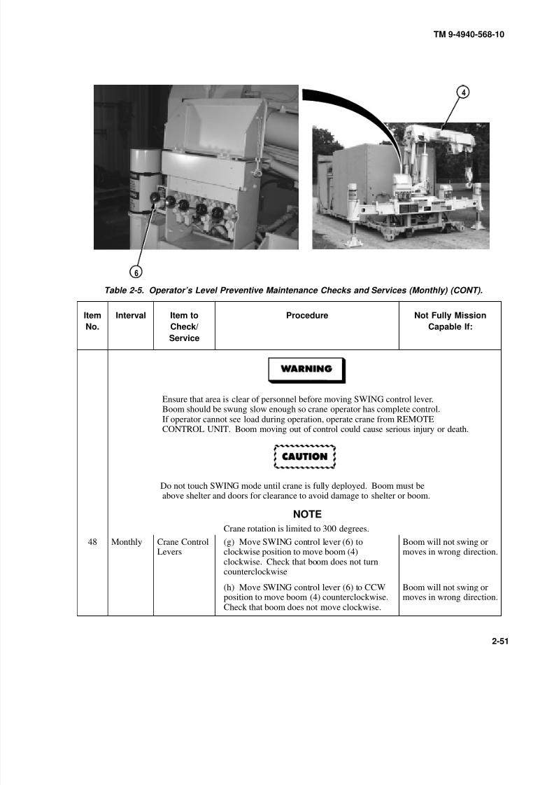
8/20/2019 TM 9-4940-568-10 FRS
http://slidepdf.com/reader/full/tm-9-4940-568-10-frs 101/403
TM 9-4940-568-10
2-51
Table 2-5. Operator’s Level Preventive Maintenance Checks and Services (Monthly) (CONT).
Item
No.
Interval Item to
Check/
Service
Procedure Not Fully Mission
Capable If:
Ensure that area is clear of personnel before moving SWING control lever.Boom should be swung slow enough so crane operator has complete control.If operator cannot see load during operation, operate crane from REMOTECONTROL UNIT. Boom moving out of control could cause serious injury or death.
Do not touch SWING mode until crane is fully deployed. Boom must beabove shelter and doors for clearance to avoid damage to shelter or boom.
NOTE
Crane rotation is limited to 300 degrees.
48 Monthly Crane ControlLevers
(g) Move SWING control lever (6) toclockwise position to move boom (4)clockwise. Check that boom does not turncounterclockwise
Boom will not swing ormoves in wrong direction.
(h) Move SWING control lever (6) to CCWposition to move boom (4) counterclockwise.Check that boom does not move clockwise.
Boom will not swing ormoves in wrong direction.
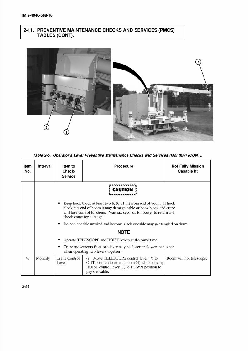
8/20/2019 TM 9-4940-568-10 FRS
http://slidepdf.com/reader/full/tm-9-4940-568-10-frs 102/403
TM 9-4940-568-10
2-52
2-11. PREVENTIVE MAINTENANCE CHECKS AND SERVICES (PMCS)TABLES (CONT).
Table 2-5. Operator’s Level Preventive Maintenance Checks and Services (Monthly) (CONT).
Item
No.
Interval Item to
Check/
Service
Procedure Not Fully Mission
Capable If:
• Keep hook block at least two ft. (0.61 m) from end of boom. If hookblock hits end of boom it may damage cable or hook block and cranewill lose control functions. Wait six seconds for power to return andcheck crane for damage.
• Do not let cable unwind and become slack or cable may get tangled on drum.
NOTE• Operate TELESCOPE and HOIST levers at the same time.
• Crane movements from one lever may be faster or slower than otherwhen operating two levers together.
48 Monthly Crane ControlLevers
(i) Move TELESCOPE control lever (7) toOUT position to extend boom (4) while movingHOIST control lever (1) to DOWN position topay out cable.
Boom will not telescope.

8/20/2019 TM 9-4940-568-10 FRS
http://slidepdf.com/reader/full/tm-9-4940-568-10-frs 103/403
TM 9-4940-568-10
2-53
Table 2-1. Operator’s Level Preventive Maintenance Checks and Services (Monthly) (CONT).
Item
No.
Interval Item to
Check/
Service
Procedure Not Fully Mission
Capable If:
48 Monthly Crane ControlLevers
(j) Move BOOM control lever (3) to upposition until boom (4) is at 45 degree angle.
Do not let cable unwind and become slack or cable may get tangled on drum.
(k) Move HOIST control lever (1) to downposition to pay out cable until hook (2) touchesground. Observe that the cable moves freely.
(l) Move BOOM control lever (3) to downposition and lower boom as far as possible.
(m) Turn crane POWER switch (8) to OFF.

8/20/2019 TM 9-4940-568-10 FRS
http://slidepdf.com/reader/full/tm-9-4940-568-10-frs 104/403
0
9
TM 9-4940-568-10
2-54
2-11. PREVENTIVE MAINTENANCE CHECKS AND SERVICES (PMCS)TABLES (CONT).
Table 2-5. Operator’s Level Preventive Maintenance Checks and Services (Monthly) (CONT).
Item
No.
Interval Item to
Check/
Service
Procedure Not Fully Mission
Capable If:
48 Monthly Crane ControlLevers
(n) Check first, second, and third extensions of boom (4) for broken welds and obviousdamage.
Operator should be stationed to be able to see load at all times during craneoperation. Boom and load moving out of control could cause serious injuryor death.
(o) Check all hoses (9), fittings (10), valves(11) and cylinders (12) for leaks.
Class III leak is evident.
(p) Check for cracked and broken welds.
(q) Check turntable bearing bolts (13) forobvious looseness.
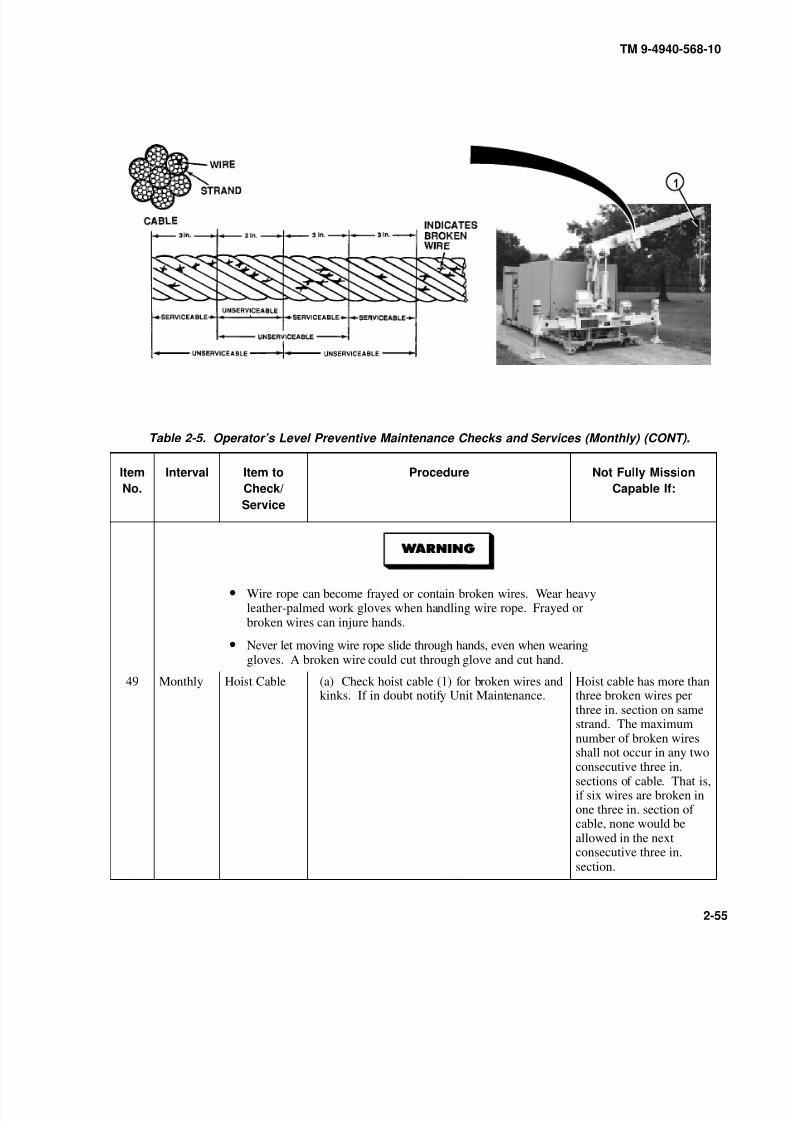
8/20/2019 TM 9-4940-568-10 FRS
http://slidepdf.com/reader/full/tm-9-4940-568-10-frs 105/403
TM 9-4940-568-10
2-55
Table 2-5. Operator’s Level Preventive Maintenance Checks and Services (Monthly) (CONT).
Item
No.
Interval Item to
Check/
Service
Procedure Not Fully Mission
Capable If:
• Wire rope can become frayed or contain broken wires. Wear heavyleather-palmed work gloves when handling wire rope. Frayed orbroken wires can injure hands.
• Never let moving wire rope slide through hands, even when wearinggloves. A broken wire could cut through glove and cut hand.
49 Monthly Hoist Cable (a) Check hoist cable (1) for broken wires andkinks. If in doubt notify Unit Maintenance.
Hoist cable has more thanthree broken wires perthree in. section on samestrand. The maximumnumber of broken wiresshall not occur in any twoconsecutive three in.sections of cable. That is,if six wires are broken inone three in. section of cable, none would beallowed in the nextconsecutive three in.section.
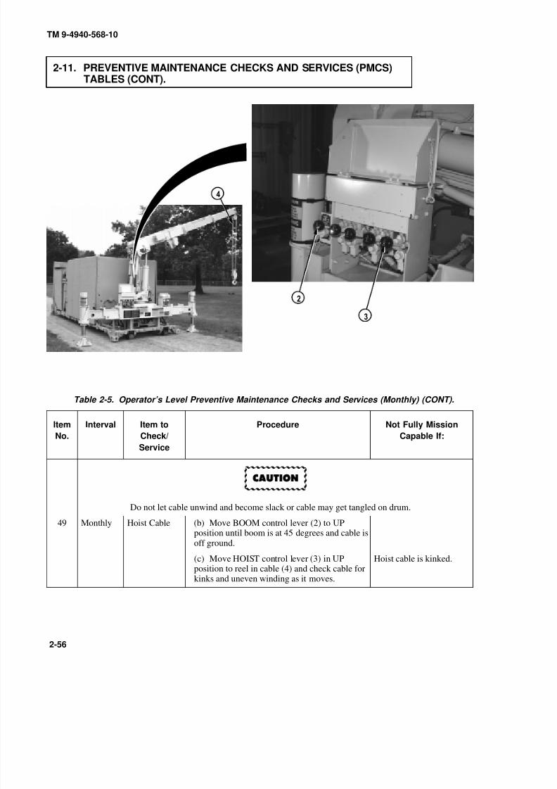
8/20/2019 TM 9-4940-568-10 FRS
http://slidepdf.com/reader/full/tm-9-4940-568-10-frs 106/403
TM 9-4940-568-10
2-56
2-11. PREVENTIVE MAINTENANCE CHECKS AND SERVICES (PMCS)TABLES (CONT).
Table 2-5. Operator’s Level Preventive Maintenance Checks and Services (Monthly) (CONT).
Item
No.
Interval Item to
Check/
Service
Procedure Not Fully Mission
Capable If:
Do not let cable unwind and become slack or cable may get tangled on drum.
49 Monthly Hoist Cable (b) Move BOOM control lever (2) to UPposition until boom is at 45 degrees and cable isoff ground.
(c) Move HOIST control lever (3) in UPposition to reel in cable (4) and check cable forkinks and uneven winding as it moves.
Hoist cable is kinked.
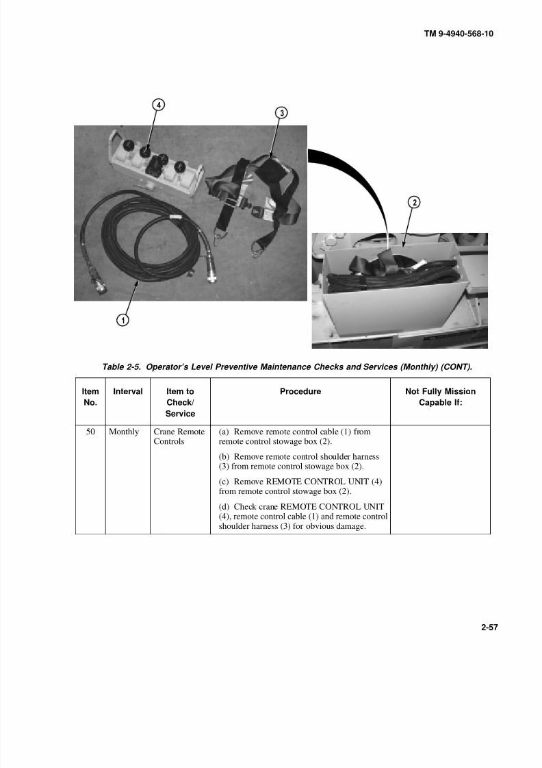
8/20/2019 TM 9-4940-568-10 FRS
http://slidepdf.com/reader/full/tm-9-4940-568-10-frs 107/403
TM 9-4940-568-10
2-57
Table 2-5. Operator’s Level Preventive Maintenance Checks and Services (Monthly) (CONT).
Item
No.
Interval Item to
Check/
Service
Procedure Not Fully Mission
Capable If:
50 Monthly Crane RemoteControls
(a) Remove remote control cable (1) fromremote control stowage box (2).
(b) Remove remote control shoulder harness(3) from remote control stowage box (2).
(c) Remove REMOTE CONTROL UNIT (4)from remote control stowage box (2).
(d) Check crane REMOTE CONTROL UNIT(4), remote control cable (1) and remote controlshoulder harness (3) for obvious damage.
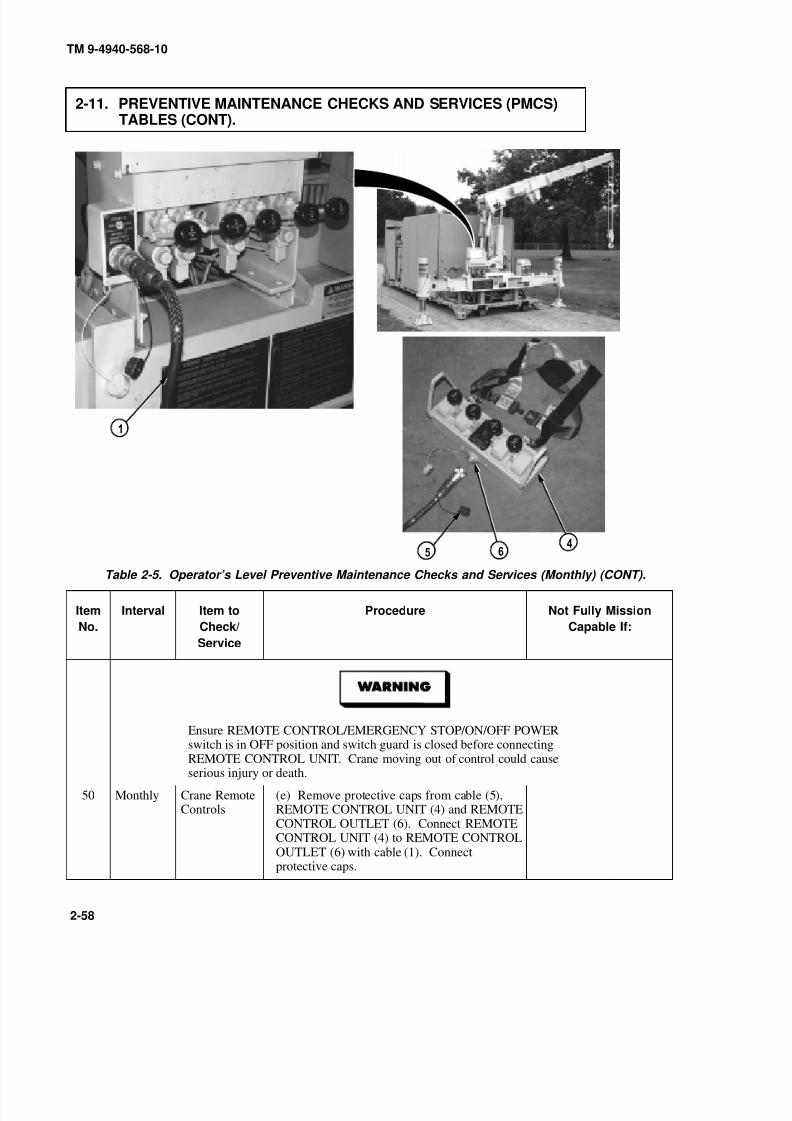
8/20/2019 TM 9-4940-568-10 FRS
http://slidepdf.com/reader/full/tm-9-4940-568-10-frs 108/403
TM 9-4940-568-10
2-58
2-11. PREVENTIVE MAINTENANCE CHECKS AND SERVICES (PMCS)TABLES (CONT).
Table 2-5. Operator’s Level Preventive Maintenance Checks and Services (Monthly) (CONT).
Item
No.
Interval Item to
Check/
Service
Procedure Not Fully Mission
Capable If:
Ensure REMOTE CONTROL/EMERGENCY STOP/ON/OFF POWER
switch is in OFF position and switch guard is closed before connectingREMOTE CONTROL UNIT. Crane moving out of control could causeserious injury or death.
50 Monthly Crane RemoteControls
(e) Remove protective caps from cable (5),REMOTE CONTROL UNIT (4) and REMOTECONTROL OUTLET (6). Connect REMOTECONTROL UNIT (4) to REMOTE CONTROLOUTLET (6) with cable (1). Connectprotective caps.

8/20/2019 TM 9-4940-568-10 FRS
http://slidepdf.com/reader/full/tm-9-4940-568-10-frs 109/403
TM 9-4940-568-10
2-59
Table 2-5. Operator’s Level Preventive Maintenance Checks and Services (Monthly) (CONT).
Item
No.
Interval Item to
Check/
Service
Procedure Not Fully Mission
Capable If:
Keep boom clear of shelter, all electrical lines and other obstacles while operatingcrane. Failure to comply may result in injury or death to personnel.
50 Monthly Crane Remote
Controls
(f) Check that remote control does not operate
when REMOTE CONTROL/EMERGENCYSTOP/ON/OFF POWER switch (7) is in OFFposition.
(g) Turn REMOTE CONTROL/ EMERGENCY STOP/ON/OFF POWERswitch (7) to ON position.

8/20/2019 TM 9-4940-568-10 FRS
http://slidepdf.com/reader/full/tm-9-4940-568-10-frs 110/403
9
TM 9-4940-568-10
2-60
2-11. PREVENTIVE MAINTENANCE CHECKS AND SERVICES (PMCS)TABLES (CONT).
Table 2-5. Operator’s Level Preventive Maintenance Checks and Services (Monthly) (CONT).
Item
No.
Interval Item to
Check/
Service
Procedure Not Fully Mission
Capable If:
• Ensure that area is clear of personnel before moving SWING control lever.Boom should be swung slow enough so crane operator has complete control.Boom moving out of control could cause serious injury or death.
• If electrical power fails during crane operation, move switch on remote controlunit to SHUTDOWN position. Serious injury could result from uncontrolledmoving parts.
Boom must be 15 degrees or above for clearance over shelter and doors to avoiddamage to truck boom, hook arm or hoist motor.
NOTE
Operate control levers with light even pressure. Moving lever slightly will causeslow movement of crane. Moving lever to full travel will cause faster movementof crane. Crane rotation is limited to 300 degrees.
50 Monthly Crane RemoteControls
(h) Move SWING control lever (8) to CWposition to turn boom (9) clockwise. Be sureboom turns in the clockwise direction.
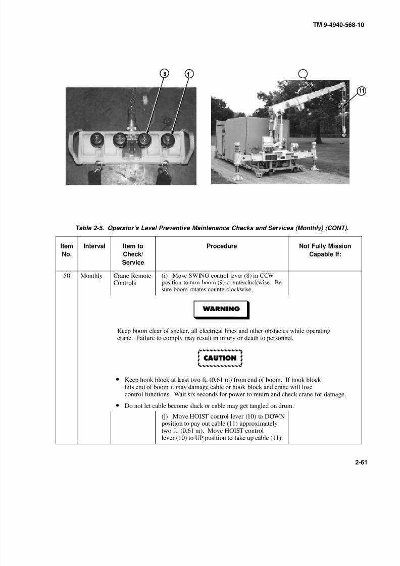
8/20/2019 TM 9-4940-568-10 FRS
http://slidepdf.com/reader/full/tm-9-4940-568-10-frs 111/403
0 9
TM 9-4940-568-10
2-61
Table 2-5. Operator’s Level Preventive Maintenance Checks and Services (Monthly) (CONT).
Item
No.
Interval Item to
Check/
Service
Procedure Not Fully Mission
Capable If:
50 Monthly Crane Remote
Controls
(i) Move SWING control lever (8) in CCW
position to turn boom (9) counterclockwise. Besure boom rotates counterclockwise.
Keep boom clear of shelter, all electrical lines and other obstacles while operatingcrane. Failure to comply may result in injury or death to personnel.
• Keep hook block at least two ft. (0.61 m) from end of boom. If hook blockhits end of boom it may damage cable or hook block and crane will losecontrol functions. Wait six seconds for power to return and check crane for damage.
• Do not let cable become slack or cable may get tangled on drum.
(j) Move HOIST control lever (10) to DOWNposition to pay out cable (11) approximatelytwo ft. (0.61 m). Move HOIST controllever (10) to UP position to take up cable (11).

8/20/2019 TM 9-4940-568-10 FRS
http://slidepdf.com/reader/full/tm-9-4940-568-10-frs 112/403
9
TM 9-4940-568-10
2-62
2-11. PREVENTIVE MAINTENANCE CHECKS AND SERVICES (PMCS)TABLES (CONT).
Table 2-5. Operator’s Level Preventive Maintenance Checks and Services (Monthly) (CONT).
Item
No.
Interval Item to
Check/
Service
Procedure Not Fully Mission
Capable If:
50 Monthly Crane RemoteControls
(k) Move BOOM control lever (12) to UPposition to raise boom (9). Move BOOMcontrol lever (12) to DOWN position to lowerboom (9) to 0 degrees on boom angle indicator.
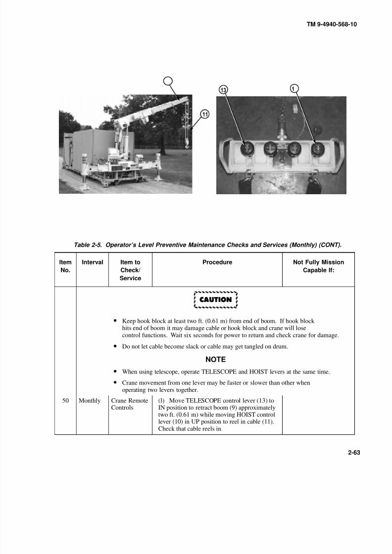
8/20/2019 TM 9-4940-568-10 FRS
http://slidepdf.com/reader/full/tm-9-4940-568-10-frs 113/403
TM 9-4940-568-10
2-63
Table 2-5. Operator’s Level Preventive Maintenance Checks and Services (Monthly) (CONT).
Item
No.
Interval Item to
Check/
Service
Procedure Not Fully Mission
Capable If:
• Keep hook block at least two ft. (0.61 m) from end of boom. If hook blockhits end of boom it may damage cable or hook block and crane will losecontrol functions. Wait six seconds for power to return and check crane for damage.
• Do not let cable become slack or cable may get tangled on drum.
NOTE
• When using telescope, operate TELESCOPE and HOIST levers at the same time.
• Crane movement from one lever may be faster or slower than other whenoperating two levers together.
50 Monthly Crane RemoteControls
(l) Move TELESCOPE control lever (13) toIN position to retract boom (9) approximatelytwo ft. (0.61 m) while moving HOIST controllever (10) in UP position to reel in cable (11).Check that cable reels in.
9
0

8/20/2019 TM 9-4940-568-10 FRS
http://slidepdf.com/reader/full/tm-9-4940-568-10-frs 114/403
0
TM 9-4940-568-10
2-64
2-11. PREVENTIVE MAINTENANCE CHECKS AND SERVICES (PMCS)TABLES (CONT).
Table 2-5. Operator’s Level Preventive Maintenance Checks and Services (Monthly) (CONT).
Item
No.
Interval Item to
Check/
Service
Procedure Not Fully Mission
Capable If:
50 Monthly Crane RemoteControls
(m) Move TELESCOPE control lever (13) toOUT position to extend boom while movingHOIST control lever (10) to DOWN position topay out cable.
(n) Shut off REMOTE CONTROL/ EMERGENCY STOP/ON/OFF POWERswitch (7).
(o) Disconnect cable (1) from REMOTECONTROL UNIT (4) and REMOTECONTROL OUTLET (6) and install protectivecap (5).
(p) Disconnect cable (1) from REMOTECONTROL HOOK-UP and install protectivecap.
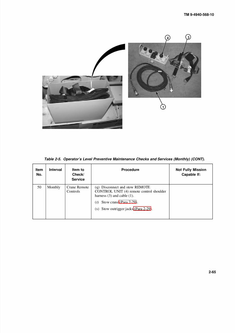
8/20/2019 TM 9-4940-568-10 FRS
http://slidepdf.com/reader/full/tm-9-4940-568-10-frs 115/403
TM 9-4940-568-10
2-65
Table 2-5. Operator’s Level Preventive Maintenance Checks and Services (Monthly) (CONT).
Item
No.
Interval Item to
Check/
Service
Procedure Not Fully Mission
Capable If:
50 Monthly Crane RemoteControls
(q) Disconnect and stow REMOTECONTROL UNIT (4) remote control shoulderharness (3) and cable (1).
(r) Stow crane (Para 2-29).
(s) Stow outrigger jacks (Para 2-29).
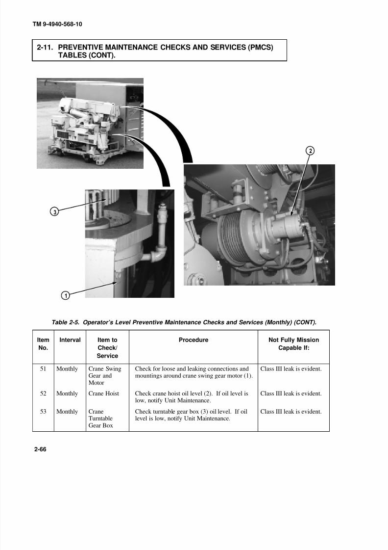
8/20/2019 TM 9-4940-568-10 FRS
http://slidepdf.com/reader/full/tm-9-4940-568-10-frs 116/403
TM 9-4940-568-10
2-66
2-11. PREVENTIVE MAINTENANCE CHECKS AND SERVICES (PMCS)TABLES (CONT).
Table 2-5. Operator’s Level Preventive Maintenance Checks and Services (Monthly) (CONT).
Item
No.
Interval Item to
Check/
Service
Procedure Not Fully Mission
Capable If:
51 Monthly Crane SwingGear andMotor
Check for loose and leaking connections andmountings around crane swing gear motor (1).
Class III leak is evident.
52 Monthly Crane Hoist Check crane hoist oil level (2). If oil level islow, notify Unit Maintenance.
Class III leak is evident.
53 Monthly CraneTurntableGear Box
Check turntable gear box (3) oil level. If oillevel is low, notify Unit Maintenance.
Class III leak is evident.
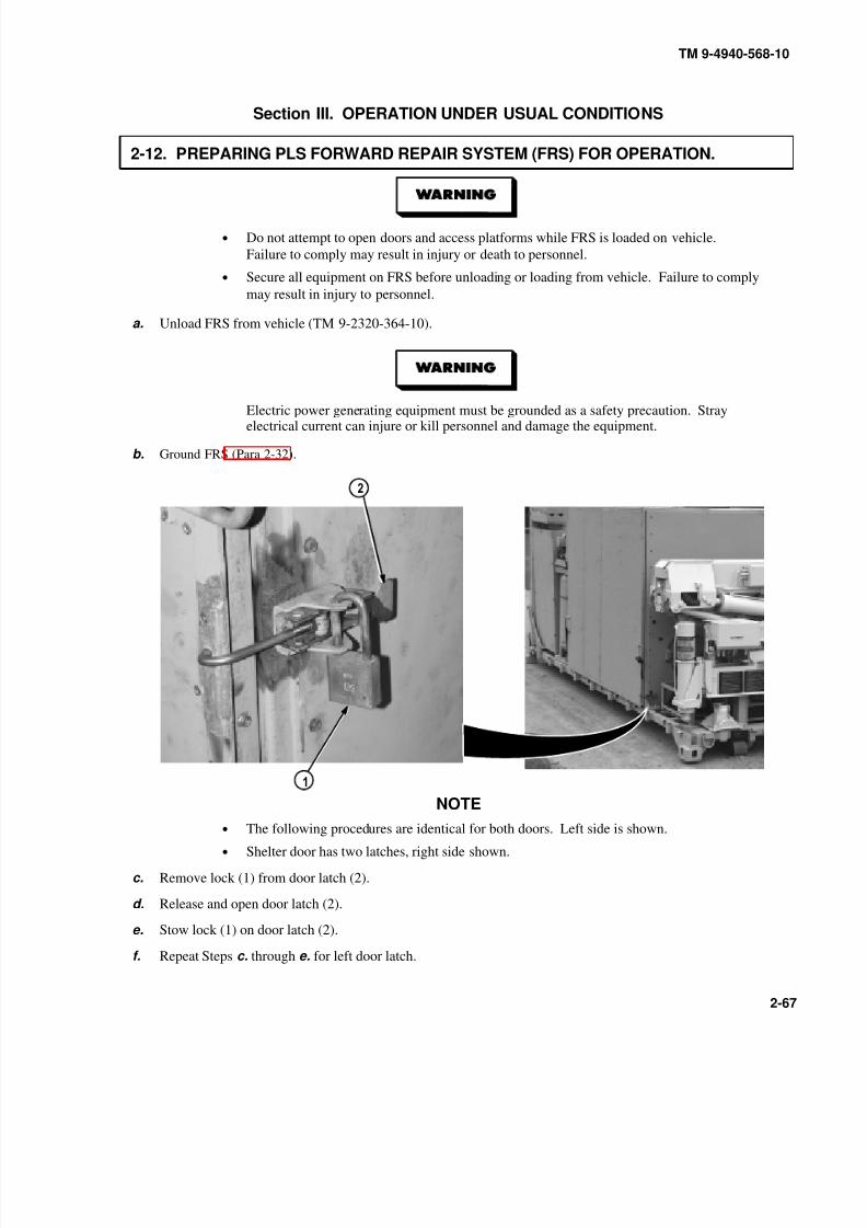
8/20/2019 TM 9-4940-568-10 FRS
http://slidepdf.com/reader/full/tm-9-4940-568-10-frs 117/403
TM 9-4940-568-10
2-67
Section III. OPERATION UNDER USUAL CONDITIONS
2-12. PREPARING PLS FORWARD REPAIR SYSTEM (FRS) FOR OPERATION.
• Do not attempt to open doors and access platforms while FRS is loaded on vehicle.
Failure to comply may result in injury or death to personnel.
• Secure all equipment on FRS before unloading or loading from vehicle. Failure to comply
may result in injury to personnel.
a. Unload FRS from vehicle (TM 9-2320-364-10).
Electric power generating equipment must be grounded as a safety precaution. Strayelectrical current can injure or kill personnel and damage the equipment.
b. Ground FRS (Para 2-32).
NOTE
• The following procedures are identical for both doors. Left side is shown.
• Shelter door has two latches, right side shown.
c. Remove lock (1) from door latch (2).
d. Release and open door latch (2).
e. Stow lock (1) on door latch (2).
f. Repeat Steps c. through e. for left door latch.
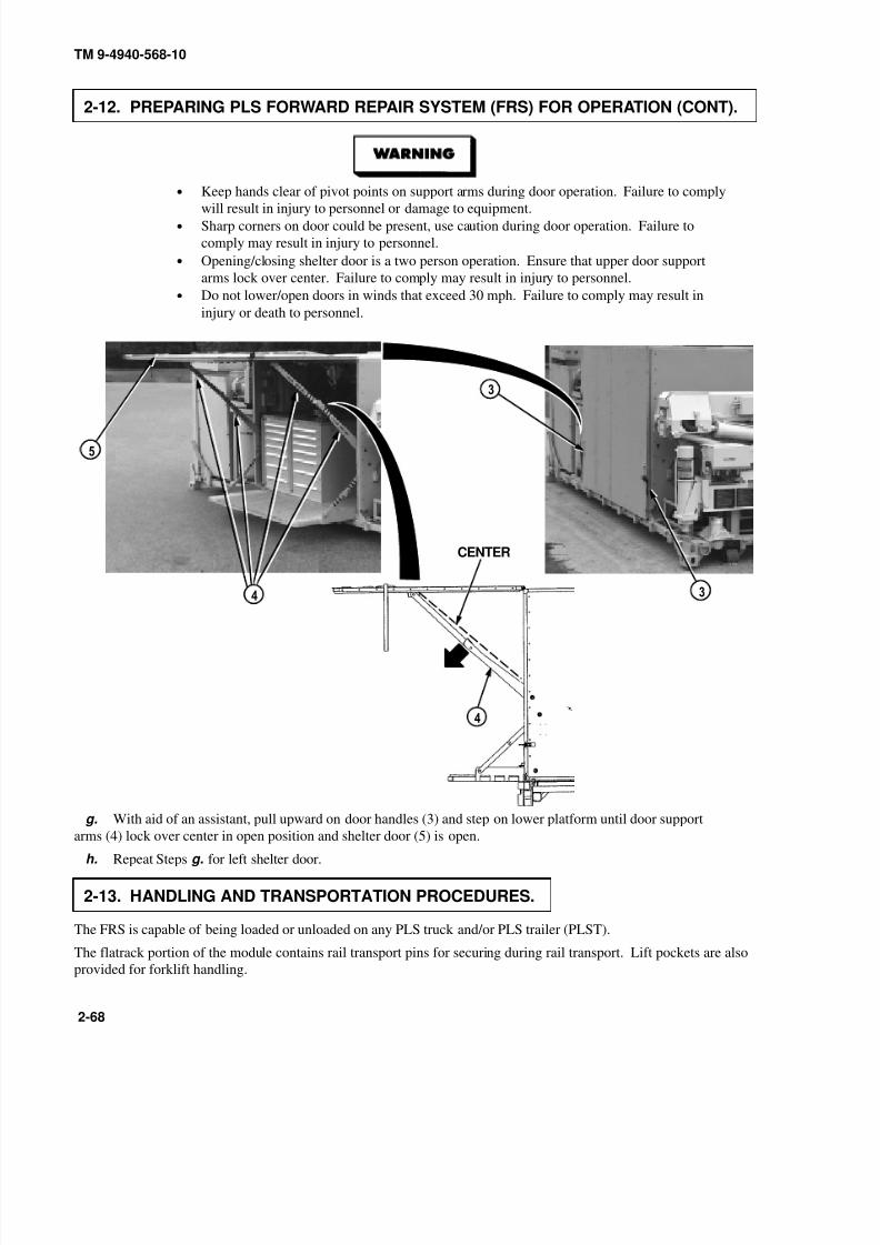
8/20/2019 TM 9-4940-568-10 FRS
http://slidepdf.com/reader/full/tm-9-4940-568-10-frs 118/403
TM 9-4940-568-10
2-68
2-12. PREPARING PLS FORWARD REPAIR SYSTEM (FRS) FOR OPERATION (CONT).
• Keep hands clear of pivot points on support arms during door operation. Failure to comply
will result in injury to personnel or damage to equipment.• Sharp corners on door could be present, use caution during door operation. Failure to
comply may result in injury to personnel.
• Opening/closing shelter door is a two person operation. Ensure that upper door support
arms lock over center. Failure to comply may result in injury to personnel.
• Do not lower/open doors in winds that exceed 30 mph. Failure to comply may result in
injury or death to personnel.
CENTER
g. With aid of an assistant, pull upward on door handles (3) and step on lower platform until door support
arms (4) lock over center in open position and shelter door (5) is open.
h. Repeat Steps g. for left shelter door.
2-13. HANDLING AND TRANSPORTATION PROCEDURES.
The FRS is capable of being loaded or unloaded on any PLS truck and/or PLS trailer (PLST).
The flatrack portion of the module contains rail transport pins for securing during rail transport. Lift pockets are also
provided for forklift handling.

8/20/2019 TM 9-4940-568-10 FRS
http://slidepdf.com/reader/full/tm-9-4940-568-10-frs 119/403
TM 9-4940-568-10
2-69
2-14. LOADING AND UNLOADING FORWARD REPAIR SYSTEM (FRS).
a. Loading.
Secure all equipment on FRS before unloading or loading from vehicle. Failure tocomply may result in injury to personnel.
(1) Ensure generator engine is “OFF” (Para 2-15).
(2) Ensure all shelter tools (1) and equipment are stowed and cabinets (2) are secure.
(3) Ensure shelter doors (3) are closed and secure (Para 2-33).
(4) Ensure generator door (4) is closed and panels secure.
(5) Ensure crane (5) and outriggers (6) are stowed and secure (Para 2-29).
(6) Ensure rear rollers (7) are installed.
(7) To load the FRS (8) on a PLS truck, refer to the PLS Operator’s Manual, TM 9-2320-364-10, “Picking
Up a Flatrack in Auto Mode.”

8/20/2019 TM 9-4940-568-10 FRS
http://slidepdf.com/reader/full/tm-9-4940-568-10-frs 120/403
TM 9-4940-568-10
2-70
2-14. LOADING AND UNLOADING FORWARD REPAIR SYSTEM (FRS) (CONT).
b. Unloading.
C - C H A N N E L S
• FRS C–channels of the flatrack must NOT be in contact with the terrain or any object to
prevent altering the critical reaction points of the FRS. Failure to comply could result in
personnel injury or death.
• Secure all equipment on FRS before unloading or loading from vehicle. Failure to comply
may result in injury to personnel.
• PLS hook arm must be disconnected from FRS hook bar of the flatrack after FRS is
unloaded.
NOTE
To determine unstable ground, observe a PLS tire track imprint left in the ground nearthe FRS. If the tire track imprint depth is greater than 1/8”, follow procedures in Para
2-39 “Operating FRS on Unstable or Uneven Ground”.
(1) Ensure generator door (4) is closed and panels secure.
(2) Ensure crane (5) and outriggers (6) are stowed and secure (Para 2-29).
(3) Ensure rear rollers (7) are installed.
(4) Ensure the FRS (8) is unloaded on semi-level hard surface when possible.
(5) To unload the FRS (8) from a PLS truck, refer to the PLS Operator’s Manual, TM 9-2320-364-10,
“Off-Loading a Flatrack in Auto Mode.”
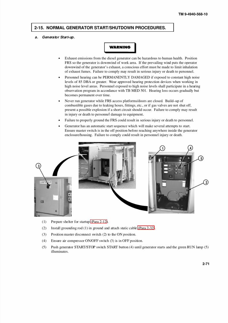
8/20/2019 TM 9-4940-568-10 FRS
http://slidepdf.com/reader/full/tm-9-4940-568-10-frs 121/403
TM 9-4940-568-10
2-71
2-15. NORMAL GENERATOR START/SHUTDOWN PROCEDURES.
a. Generator Start-up.
• Exhaust emissions from the diesel generator can be hazardous to human health. Position
FRS so the generator is downwind of work area. If the prevailing wind puts the operator
downwind of the generator’s exhaust, a conscious effort must be made to limit inhalation
of exhaust fumes. Failure to comply may result in serious injury or death to personnel.
• Personnel hearing can be PERMANENTLY DAMAGED if exposed to constant high noise
levels of 85 DBA or greater. Wear approved hearing protection devices when working in
high noise level areas. Personnel exposed to high noise levels shall participate in a hearing
observation program in accordance with TB MED 501. Hearing loss occurs gradually but
becomes permanent over time.
• Never run generator while FRS access platforms/doors are closed. Build–up of
combustible gases due to leaking hoses, fittings, etc., or if gas valves are not shut off,
present a possible explosion if a short circuit should occur. Failure to comply may result
in injury or death to personnel damage to equipment.
• Failure to properly ground the FRS could result in serious injury or death to personnel.
• Generator has an automatic start sequence which will make several attempts to start.
Ensure master switch is in the off position before reaching anywhere inside the generator
enclosure/housing. Failure to comply could result in personnel injury or death.
(1) Prepare shelter for startup (Para 2-12).
(2) Install grounding rod (1) in ground and attach static cable (Para 2-32).
(3) Position master disconnect switch (2) to the ON position.
(4) Ensure air compressor ON/OFF switch (3) is in OFF position.
(5) Push generator START/STOP switch START button (4) until generator starts and the green RUN lamp (5)
illuminates.
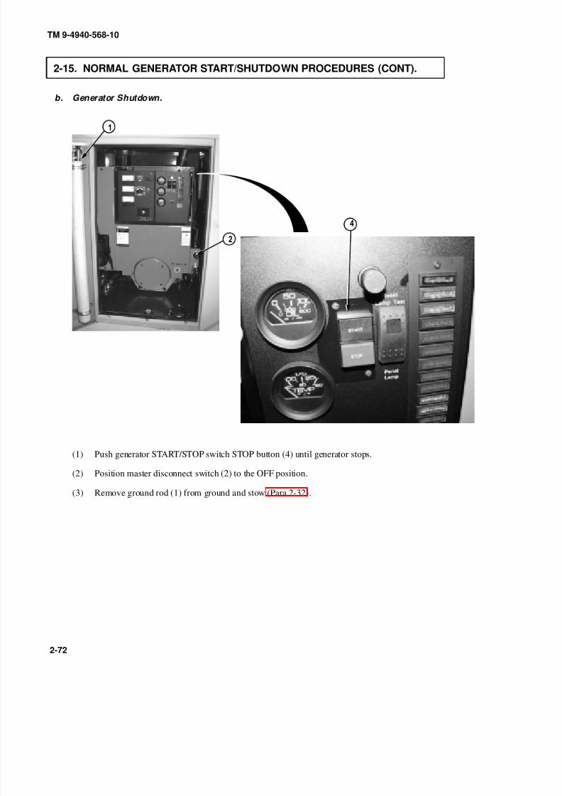
8/20/2019 TM 9-4940-568-10 FRS
http://slidepdf.com/reader/full/tm-9-4940-568-10-frs 122/403
TM 9-4940-568-10
2-72
2-15. NORMAL GENERATOR START/SHUTDOWN PROCEDURES (CONT).
b. Generator Shutdown.
(1) Push generator START/STOP switch STOP button (4) until generator stops.
(2) Position master disconnect switch (2) to the OFF position.
(3) Remove ground rod (1) from ground and stow (Para 2-32).

8/20/2019 TM 9-4940-568-10 FRS
http://slidepdf.com/reader/full/tm-9-4940-568-10-frs 123/403
TM 9-4940-568-10
2-73
2-16. REFUELING GENERATOR.
• When refueling, shut down generator. Ensure no open flame is near area. Never smoke. Never
add fuel with engine running. After fuel is added, securely close fuel tank cap; a loose cap can
cause a fuel leak or be a fire hazard. Before starting generator, check that no fuel is spilled on or
around FRS. Failure to comply may cause serious injury or death. Never overfill the tank or spill
fuel. If fuel is spilled, clean it up immediately.
• Clothing fouled by Petroleum, Oil, or Lubricants (POL) must be changed at the earliest opportunity.
Any POL contacting the skin should be washed off as soon as possible. Failure to comply may
result in serious injury or death to personnel.
• Fuel cap and fuel gage are enclosed in a confined space. Care must be used when refueling fuel
tank. Failure to comply may result in injury to personnel.
(1) Remove fuel cap (1) on fuel tank (2).
• Refuel generator with diesel fuel no. 2, JP-8, or DF-A only or damage to equipment may occur.
• Leave at least 1/2 inch air space between fuel level and top of filler neck.
(2) While observing fuel gage (3), fill fuel tank (2) until desired level is reached.
(3) Install fuel cap (1) on fuel tank (2).
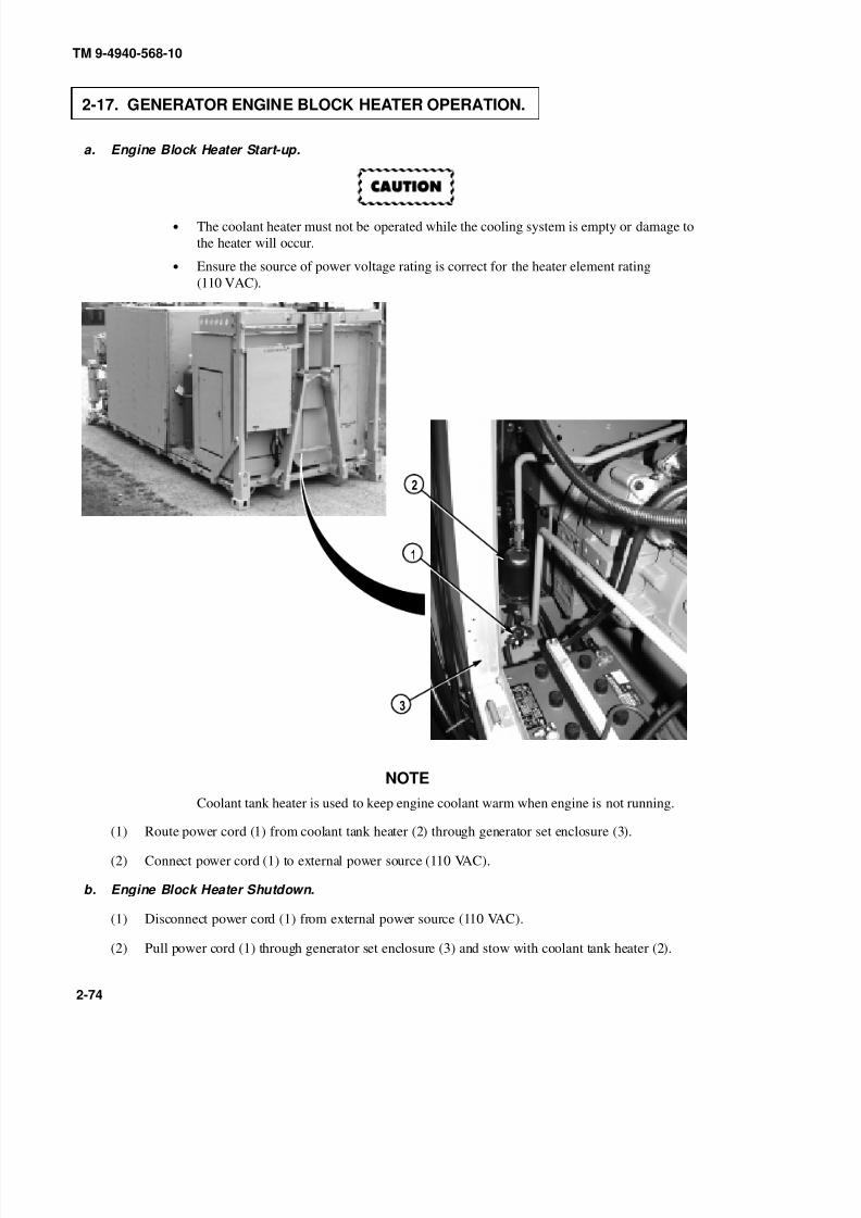
8/20/2019 TM 9-4940-568-10 FRS
http://slidepdf.com/reader/full/tm-9-4940-568-10-frs 124/403
TM 9-4940-568-10
2-74
2-17. GENERATOR ENGINE BLOCK HEATER OPERATION.
a. Engine Block Heater Start-up.
• The coolant heater must not be operated while the cooling system is empty or damage to
the heater will occur.
• Ensure the source of power voltage rating is correct for the heater element rating
(110 VAC).
NOTE
Coolant tank heater is used to keep engine coolant warm when engine is not running.
(1) Route power cord (1) from coolant tank heater (2) through generator set enclosure (3).
(2) Connect power cord (1) to external power source (110 VAC).
b. Engine Block Heater Shutdown.
(1) Disconnect power cord (1) from external power source (110 VAC).
(2) Pull power cord (1) through generator set enclosure (3) and stow with coolant tank heater (2).

8/20/2019 TM 9-4940-568-10 FRS
http://slidepdf.com/reader/full/tm-9-4940-568-10-frs 125/403
TM 9-4940-568-10
2-75
2-18. AIR COMPRESSOR OPERATION.
a. Air Compressor Start-up.
Personnel hearing can be PERMANENTLY DAMAGED if exposed to constant highnoise levels of 85 DBA or greater. Wear approved hearing protection devices whenworking in high noise level areas. Personnel exposed to high noise levels shallparticipate in a hearing observation program in accordance with TB MED 501. Hearingloss occurs gradually but becomes permanent over time.
(1) Start generator (1) (Para 2-15).
(2) Turn air compressor (2) ON/OFF switch (3) to ON.
b. Air Compressor Shutdown
(1) Turn air compressor (2) ON/OFF switch (3) to OFF.
(2) Shutdown generator (1) (Para 2-15).
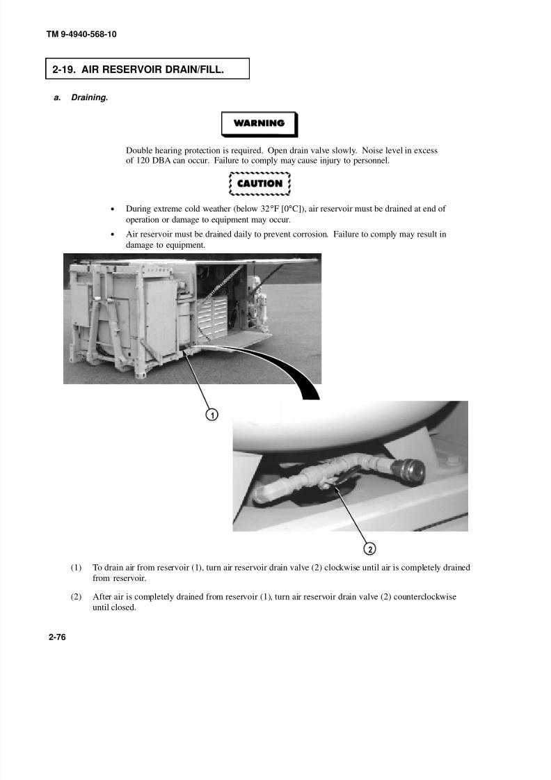
8/20/2019 TM 9-4940-568-10 FRS
http://slidepdf.com/reader/full/tm-9-4940-568-10-frs 126/403
TM 9-4940-568-10
2-76
2-19. AIR RESERVOIR DRAIN/FILL.
a. Draining.
Double hearing protection is required. Open drain valve slowly. Noise level in excessof 120 DBA can occur. Failure to comply may cause injury to personnel.
• During extreme cold weather (below 32°F [0°C]), air reservoir must be drained at end of
operation or damage to equipment may occur.
• Air reservoir must be drained daily to prevent corrosion. Failure to comply may result in
damage to equipment.
(1) To drain air from reservoir (1), turn air reservoir drain valve (2) clockwise until air is completely drained
from reservoir.
(2) After air is completely drained from reservoir (1), turn air reservoir drain valve (2) counterclockwise
until closed.

8/20/2019 TM 9-4940-568-10 FRS
http://slidepdf.com/reader/full/tm-9-4940-568-10-frs 127/403
TM 9-4940-568-10
2-77
b. Filling With External Source.
(1) Connect external air hose (3) to air reservoir (1) quick disconnect (4) using the adapter (5) provided with
FRS.
(2) Check air compressor gage (6) for proper pressure.
• Maximum allowable air pressure in air reservoir is 195 psi (1345 kPa). Failure to comply
may result in injury or death to personnel.
•
Hearing and eye protection required when disconnecting the air supply hose or injury topersonnel may result.
NOTE
• Valve does not control air supply.
• Constant resupply required for tools operation.
(3) When air reservoir (1) is filled to desired pressure, disconnect external air hose (3) from air reservoir (1)
and remove adapter (5).

8/20/2019 TM 9-4940-568-10 FRS
http://slidepdf.com/reader/full/tm-9-4940-568-10-frs 128/403
TM 9-4940-568-10
2-78
2-20. WELDER OPERATION.
a. STICK (Shielded Metal ARC Welding [SMAW]) Welder Start/Set-Up.
• Unsafe welding practices can cause serious injury from fire, explosions, or harmful agents. Allow
only authorized personnel to weld or cut metals, and follow safety precautions in TC 9–237.
Protective clothing and goggles must be worn; adequate protection used, a suitable fire extinguisher
kept nearby, and requirements of TC 9–237 strictly followed.
• Personnel hearing can be PERMANENTLY DAMAGED if exposed to constant high noise levels of
85 DBA or greater. Wear approved hearing protection devices when working in high noise level
areas. Personnel exposed to high noise levels shall participate in a hearing observation program in
accordance with TB MED 501. Hearing loss occurs gradually but becomes permanent over time.
• Remove all jewelry such as rings, ID tags, bracelets, etc. If jewelry or tools contact positive electrical
circuits a direct short may result. Damage to equipment, injury or death to personnel may occur.
• Welding procedures must be performed beyond the enclosure of shelter, welding fumes can be
harmful to personnel. Failure to comply may result in serious injury or death to personnel.
• Ensure primary power switch located on back of ARC welder is in the OFF position. Failure to
comply may result in serious injury or death to personnel.
• If welding helmet has been stored for an extended period of time, place welding helmet in direct
sun or fluorescent light for 1/2 hour prior to use or until low battery indicator is off.
• Welding helmet is only operational in temperatures above 25 degrees F. Welding personnel must
use different PPE when in temperatures below 25 degrees F.
• Welding operation produces intense light and eye protection is required at all times. Failure to
comply may result in serious injury to personnel.
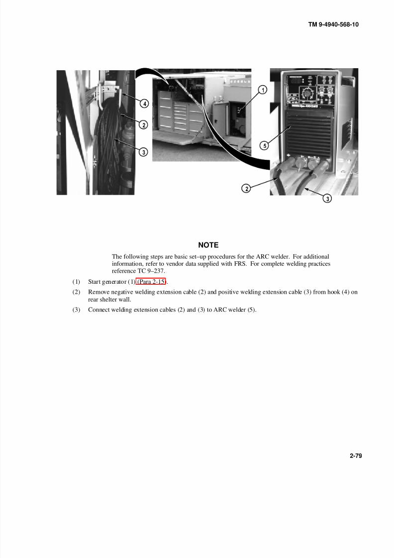
8/20/2019 TM 9-4940-568-10 FRS
http://slidepdf.com/reader/full/tm-9-4940-568-10-frs 129/403
TM 9-4940-568-10
2-79
NOTE
The following steps are basic set–up procedures for the ARC welder. For additionalinformation, refer to vendor data supplied with FRS. For complete welding practicesreference TC 9–237.
(1) Start generator (1) (Para 2-15).
(2) Remove negative welding extension cable (2) and positive welding extension cable (3) from hook (4) on
rear shelter wall.
(3) Connect welding extension cables (2) and (3) to ARC welder (5).

8/20/2019 TM 9-4940-568-10 FRS
http://slidepdf.com/reader/full/tm-9-4940-568-10-frs 130/403
TM 9-4940-568-10
2-80
2-20. WELDER OPERATION (CONT).
(4) Remove ARC welding lead (6) and grounding clamp cable (7) from welding cabinet (8).
• Do not attempt to weld on the vehicle without following the general welding maintenance
procedures or damage to the vehicles electical system may result.
• Disconnect batteries on item to be welded.
• Do not weld on or near electronic components or damage to the component may result.
• Do not connect welding cables to electronic components or damage to the component may
result.
• Place grounding clamp on or near part being welded or damage to other components may
result.
(5) Attach grounding clamp cable (7) to negative extension cable (2) and item to be welded.
(6) Connect ARC welding lead (6) to positive extension cable (3).

8/20/2019 TM 9-4940-568-10 FRS
http://slidepdf.com/reader/full/tm-9-4940-568-10-frs 131/403
9
0
TM 9-4940-568-10
2-81
Unsafe welding practices can cause serious injury from fire, explosions, or harmful agents.
Allow only authorized personnel to weld, and follow safety precautions in TC 9–237.Protective clothing and goggles must be worn; adequate protection used, a suitable fire
extinguisher kept nearby, and requirements of TC 9–237 strictly followed.(7) Turn amperage/voltage control (9) to proper position for desired application. Refer to TC 9–237.
(8) Position primary power switch (10), located on back of ARC welder (5), in the ON position.
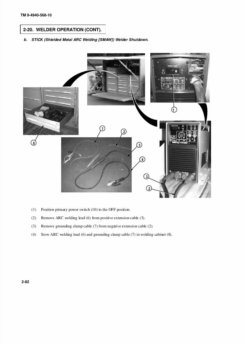
8/20/2019 TM 9-4940-568-10 FRS
http://slidepdf.com/reader/full/tm-9-4940-568-10-frs 132/403
0
TM 9-4940-568-10
2-82
2-20. WELDER OPERATION (CONT).
b. STICK (Shielded Metal ARC Welding [SMAW]) Welder Shutdown.
(1) Position primary power switch (10) to the OFF position.
(2) Remove ARC welding lead (6) from positive extension cable (3).
(3) Remove grounding clamp cable (7) from negative extension cable (2).
(4) Stow ARC welding lead (6) and grounding clamp cable (7) in welding cabinet (8).

8/20/2019 TM 9-4940-568-10 FRS
http://slidepdf.com/reader/full/tm-9-4940-568-10-frs 133/403
TM 9-4940-568-10
2-83
(5) Remove welding extension cables (2) and (3) from ARC welder (5).
(6) Stow welding extension cables (2) and (3) to hook (4) on rear shelter wall.
(7) Shutdown generator (1) (Para 2-15).

8/20/2019 TM 9-4940-568-10 FRS
http://slidepdf.com/reader/full/tm-9-4940-568-10-frs 134/403
TM 9-4940-568-10
2-84
2-20. WELDER OPERATION (CONT).
c. MIG Welder Start/Set-Up.
• Unsafe welding practices can cause serious injury from fire, explosions, or harmful agents. Allow
only authorized personnel to weld or cut metals, and follow safety precautions in TC 9–237.
Protective clothing and goggles must be worn; adequate protection used, a suitable fire extinguisher
kept nearby, and requirements of TC 9–237 strictly followed.
• Personnel hearing can be PERMANENTLY DAMAGED if exposed to constant high noise levels of
85 DBA or greater. Wear approved hearing protection devices when working in high noise level
areas. Personnel exposed to high noise levels shall participate in a hearing observation program in
accordance with TB MED 501. Hearing loss occurs gradually but becomes permanent over time.
•
Remove all jewelry such as rings, ID tags, bracelets, etc. If jewelry or tools contact positive electricalcircuits a direct short may result. Damage to equipment, injury or death to personnel may occur.
• Welding procedures must be performed beyond the enclosure of shelter, welding fumes can be
harmful to personnel. Failure to comply may result in serious injury or death to personnel.
• Ensure primary power switch located on back of ARC welder is in the OFF position. Failure to
comply may result in serious injury or death to personnel.
• Ensure argon gas regulator is OFF. Close argon tank valve and purge argon with the wire feeder
purge button. Failure to comply may result in serious injury or death to personnel.
• If welding helmet has been stored for an extended period of time, place welding helmet in direct
sun or fluorescent light for 1/2 hour prior to use or until low battery indicator is off.
•Welding helmet is only operational in temperatures above 25 degrees F. Welding personnel mustuse different PPE when in temperatures below 25 degrees F.
• Welding operation produces intense light and eye protection is required at all times. Failure to
comply may result in serious injury to personnel.
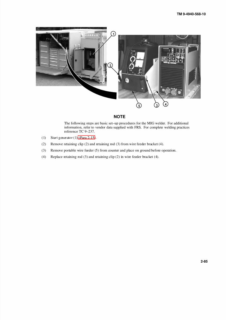
8/20/2019 TM 9-4940-568-10 FRS
http://slidepdf.com/reader/full/tm-9-4940-568-10-frs 135/403
TM 9-4940-568-10
2-85
NOTE
The following steps are basic set–up procedures for the MIG welder. For additionalinformation, refer to vendor data supplied with FRS. For complete welding practicesreference TC 9–237.
(1) Start generator (1) (Para 2-15).
(2) Remove retaining clip (2) and retaining rod (3) from wire feeder bracket (4).
(3) Remove portable wire feeder (5) from counter and place on ground before operation.
(4) Replace retaining rod (3) and retaining clip (2) in wire feeder bracket (4).

8/20/2019 TM 9-4940-568-10 FRS
http://slidepdf.com/reader/full/tm-9-4940-568-10-frs 136/403
9
TM 9-4940-568-10
2-86
2-20. WELDER OPERATION (CONT).
(5) Remove positive welding extension cable (6) and negative extension cable (7) from hook (8) on rear
shelter wall.
(6) Connect welding extension cables (6) and (7) to ARC welder (9).

8/20/2019 TM 9-4940-568-10 FRS
http://slidepdf.com/reader/full/tm-9-4940-568-10-frs 137/403
0
TM 9-4940-568-10
2-87
(7) Remove wire feeder gun (10) and grounding clamp cable (11) from welding cabinet (12).
• Do not attempt to weld on the vehicle without following the general welding maintenance
procedures or damage to the vehicles electical system may result.
• Disconnect batteries on item to be welded.
• Do not weld on or near electronic components or damage to the component may result.
• Do not connect welding cables to electronic components or damage to the component may
result.
• Place grounding clamp on or near part being welded or damage to other components may
result.
(8) Attach grounding clamp cable (11) to negative extension cable (6).

8/20/2019 TM 9-4940-568-10 FRS
http://slidepdf.com/reader/full/tm-9-4940-568-10-frs 138/403
0
TM 9-4940-568-10
2-88
2-20. WELDER OPERATION (CONT).
(9) Connect wire feeder gun (10) to wire feeder connector (13) and wire feeder gun wires (14) to gun switch
receptacle (15).
(10) Clamp wire feeder ground (16) to bare metal ground on item to be welded. Attach wire feeder ground
(16) in accordance with TC 9–237.

8/20/2019 TM 9-4940-568-10 FRS
http://slidepdf.com/reader/full/tm-9-4940-568-10-frs 139/403
9
TM 9-4940-568-10
2-89
(11) Connect positive welding extension cable (7) to wire feeder (17).
(12) Unwind argon hose (18) from argon hose reel (19).
(13) Attach argon hose (18) to back of wire feeder (5).

8/20/2019 TM 9-4940-568-10 FRS
http://slidepdf.com/reader/full/tm-9-4940-568-10-frs 140/403
9
0
TM 9-4940-568-10
2-90
2-20. WELDER OPERATION (CONT).
(14) Remove clip (20) and open tank safety cap (21) on argon tank (22).
(15) Turn handle (23) counterclockwise and open valve fully to engage upper seal.
(16) Close tank safety cap (21) and install clip (20).
(17) Turn process selector switch (24) on ARC welder (9) to MIG middle position.
(18) Position primary power switch (25), located on back of ARC welder (9) in the ON position.
(19) Adjust argon regulator (26) to desired level. Refer to TC 9–237.

8/20/2019 TM 9-4940-568-10 FRS
http://slidepdf.com/reader/full/tm-9-4940-568-10-frs 141/403
0
TM 9-4940-568-10
2-91
d. MIG Welder Shutdown.
(1) Position primary power switch (25) in the OFF position.
(2) Remove clip (20) and open tank safety cap (21) on argon tank (22).
(3) Turn handle (23) clockwise and close valve.
(4) Close tank safety cap (21) and install clip (20).
(5) Turn argon regulator valve (26) counterclockwise to bleed, and purge using the wire feeder purge button
(27).

8/20/2019 TM 9-4940-568-10 FRS
http://slidepdf.com/reader/full/tm-9-4940-568-10-frs 142/403
9
TM 9-4940-568-10
2-92
2-20. WELDER OPERATION (CONT).
(6) Remove argon hose (18) from wire feeder (5).
(7) Rewind argon hose (18) on argon hose reel (19).
(8) Remove positive welding extension cable (7) from wire feeder cable (17).

8/20/2019 TM 9-4940-568-10 FRS
http://slidepdf.com/reader/full/tm-9-4940-568-10-frs 143/403
0
9
TM 9-4940-568-10
2-93
(9) Unclamp wire feeder ground (16) from welded item.
(10) Remove wire feeder gun wires (14) from gun switch receptacle (15).
(11) Remove wire feeder gun (10) from wire feeder connector (13).
(12) Unclamp grounding clamp cable (11) from welded item.
(13) Remove grounding clamp cable (11) and negative extension cable (7) from welded item.
(14) Stow wire feeder gun (10) and grounding clamp cable (11) in welding cabinet (12).
(15) Remove welding extension cables (6) and (7) from ARC welder (9).

8/20/2019 TM 9-4940-568-10 FRS
http://slidepdf.com/reader/full/tm-9-4940-568-10-frs 144/403
TM 9-4940-568-10
2-94
2-20. WELDER OPERATION (CONT).
(16) Stow welding extension cables (6) and (7) to hook (8) on rear shelter wall.
(17) Remove retaining clip (2) and retaining rod (3) from wire feeder bracket (4).
(18) Install wire feeder (5) in wire feeder bracket (4).
(19) Install retaining rod (3) and retaining clip in wire feeder bracket (4).
(20) Shutdown generator (1) (Para 2-15).
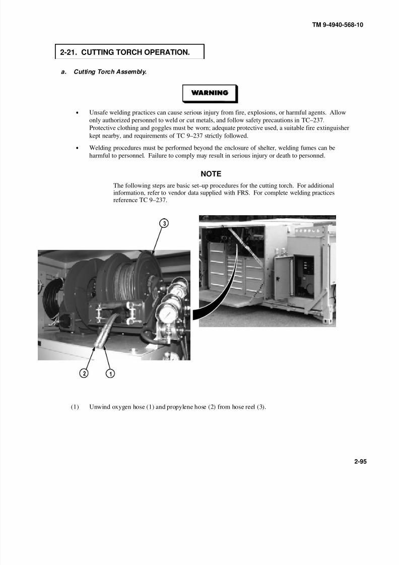
8/20/2019 TM 9-4940-568-10 FRS
http://slidepdf.com/reader/full/tm-9-4940-568-10-frs 145/403
TM 9-4940-568-10
2-95
2-21. CUTTING TORCH OPERATION.
a. Cutting Torch Assembly.
• Unsafe welding practices can cause serious injury from fire, explosions, or harmful agents. Allow
only authorized personnel to weld or cut metals, and follow safety precautions in TC–237.
Protective clothing and goggles must be worn; adequate protective used, a suitable fire extinguisher
kept nearby, and requirements of TC 9–237 strictly followed.
• Welding procedures must be performed beyond the enclosure of shelter, welding fumes can be
harmful to personnel. Failure to comply may result in serious injury or death to personnel.
NOTE
The following steps are basic set–up procedures for the cutting torch. For additionalinformation, refer to vendor data supplied with FRS. For complete welding practicesreference TC 9–237.
(1) Unwind oxygen hose (1) and propylene hose (2) from hose reel (3).

8/20/2019 TM 9-4940-568-10 FRS
http://slidepdf.com/reader/full/tm-9-4940-568-10-frs 146/403
TM 9-4940-568-10
2-96
2-21. CUTTING TORCH OPERATION (CONT).
NOTE
Choose the type of cutting tip needed for the procedure to be preformed. (Refer to TC 9–237.)
(2) Remove mixing chamber (4), torch head (5) and tip (6) from welding cabinet (7).
(3) Attach torch head (5) to mixing chamber (4).
(4) Remove retaining nut (8) form torch head (5) and install tip (6) and retaining nut to torch head.
NOTE
Insure oxygen hose and propylene hose are attached to the corresponding inlet port on
mixing chamber. Oxygen hose is green in color with right-hand threads. Propylenehose is red in color with left-hand threads and the attaching nut has a notch around theoutside.
(5) Attach oxygen hose (1) and propylene hose (2) to mixing chamber (4).
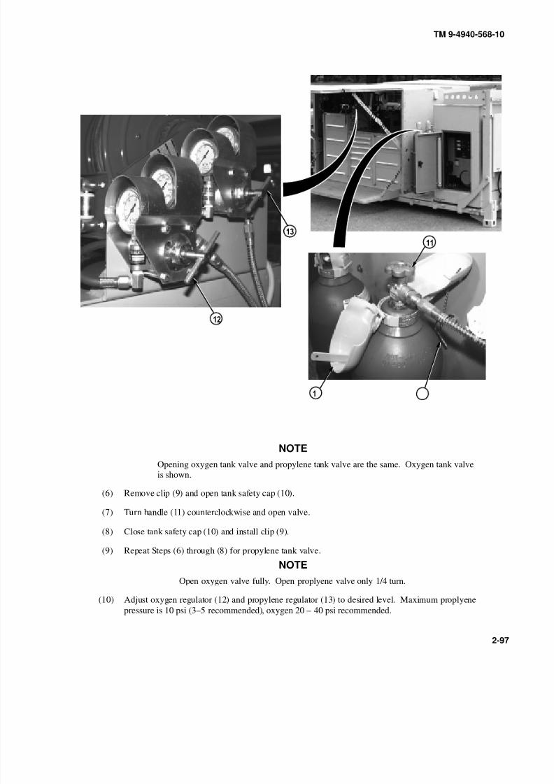
8/20/2019 TM 9-4940-568-10 FRS
http://slidepdf.com/reader/full/tm-9-4940-568-10-frs 147/403
0 9
TM 9-4940-568-10
2-97
NOTE
Opening oxygen tank valve and propylene tank valve are the same. Oxygen tank valve
is shown.
(6) Remove clip (9) and open tank safety cap (10).
(7) Turn handle (11) counterclockwise and open valve.
(8) Close tank safety cap (10) and install clip (9).
(9) Repeat Steps (6) through (8) for propylene tank valve.
NOTE
Open oxygen valve fully. Open proplyene valve only 1/4 turn.
(10) Adjust oxygen regulator (12) and propylene regulator (13) to desired level. Maximum proplyene
pressure is 10 psi (3–5 recommended), oxygen 20 – 40 psi recommended.
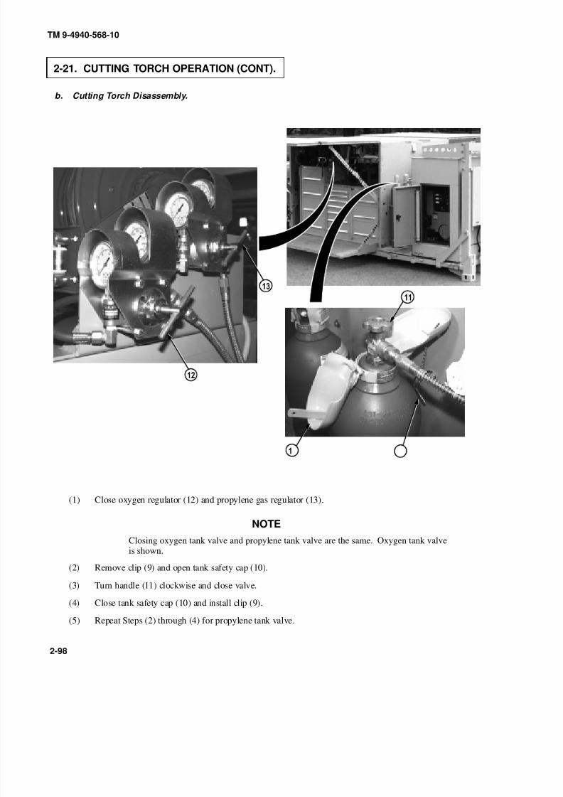
8/20/2019 TM 9-4940-568-10 FRS
http://slidepdf.com/reader/full/tm-9-4940-568-10-frs 148/403
0 9
TM 9-4940-568-10
2-98
2-21. CUTTING TORCH OPERATION (CONT).
b. Cutting Torch Disassembly.
(1) Close oxygen regulator (12) and propylene gas regulator (13).
NOTE
Closing oxygen tank valve and propylene tank valve are the same. Oxygen tank valveis shown.
(2) Remove clip (9) and open tank safety cap (10).
(3) Turn handle (11) clockwise and close valve.
(4) Close tank safety cap (10) and install clip (9).
(5) Repeat Steps (2) through (4) for propylene tank valve.
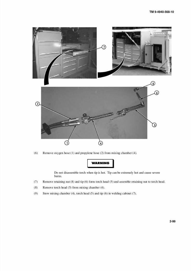
8/20/2019 TM 9-4940-568-10 FRS
http://slidepdf.com/reader/full/tm-9-4940-568-10-frs 149/403
TM 9-4940-568-10
2-99
(6) Remove oxygen hose (1) and propylene hose (2) from mixing chamber (4).
Do not disassemble torch when tip is hot. Tip can be extremely hot and cause severeburns.
(7) Remove retaining nut (8) and tip (6) form torch head (5) and assemble retaining nut to torch head.
(8) Remove torch head (5) from mixing chamber (4).
(9) Stow mixing chamber (4), torch head (5) and tip (6) in welding cabinet (7).

8/20/2019 TM 9-4940-568-10 FRS
http://slidepdf.com/reader/full/tm-9-4940-568-10-frs 150/403
TM 9-4940-568-10
2-100
2-21. CUTTING TORCH OPERATION (CONT).
(10) Rewind oxygen hose (1) and propylene hose (2) on hose reel (3).
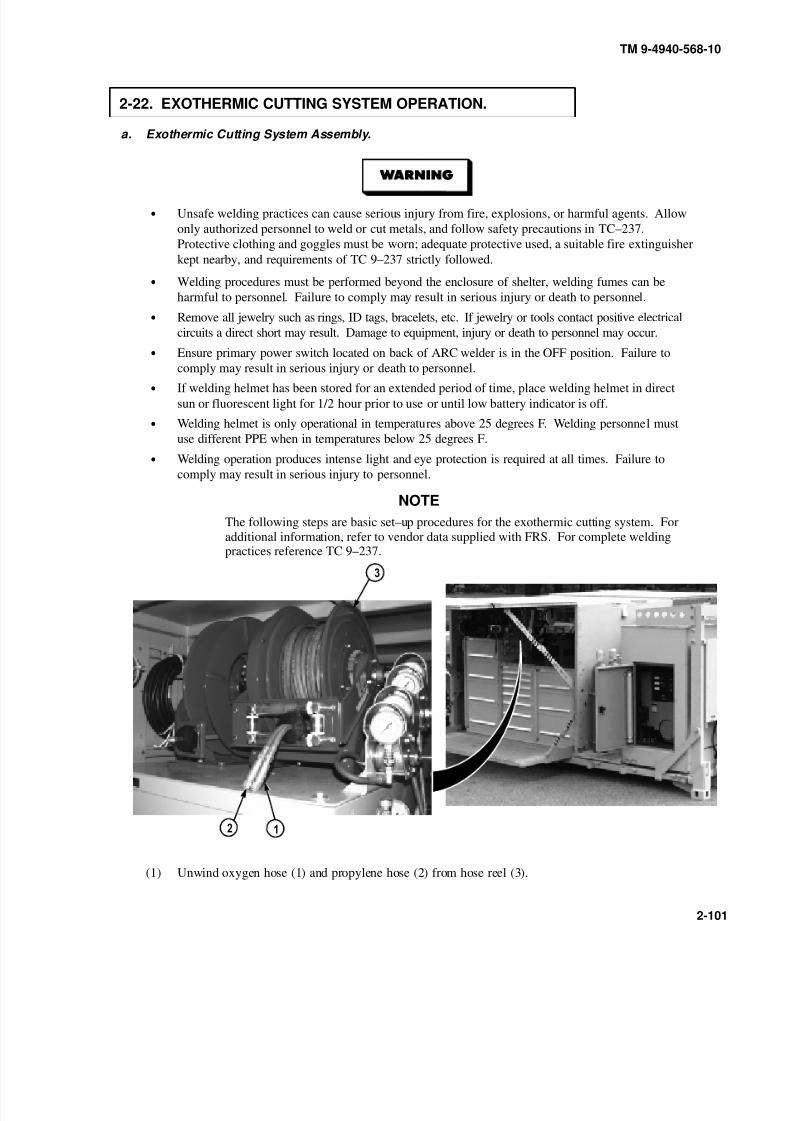
8/20/2019 TM 9-4940-568-10 FRS
http://slidepdf.com/reader/full/tm-9-4940-568-10-frs 151/403
TM 9-4940-568-10
2-101
2-22. EXOTHERMIC CUTTING SYSTEM OPERATION.
a. Exothermic Cutting System Assembly.
• Unsafe welding practices can cause serious injury from fire, explosions, or harmful agents. Allow
only authorized personnel to weld or cut metals, and follow safety precautions in TC–237.
Protective clothing and goggles must be worn; adequate protective used, a suitable fire extinguisher
kept nearby, and requirements of TC 9–237 strictly followed.
• Welding procedures must be performed beyond the enclosure of shelter, welding fumes can be
harmful to personnel. Failure to comply may result in serious injury or death to personnel.
• Remove all jewelry such as rings, ID tags, bracelets, etc. If jewelry or tools contact positive electrical
circuits a direct short may result. Damage to equipment, injury or death to personnel may occur.
• Ensure primary power switch located on back of ARC welder is in the OFF position. Failure to
comply may result in serious injury or death to personnel.• If welding helmet has been stored for an extended period of time, place welding helmet in direct
sun or fluorescent light for 1/2 hour prior to use or until low battery indicator is off.
• Welding helmet is only operational in temperatures above 25 degrees F. Welding personnel must
use different PPE when in temperatures below 25 degrees F.
• Welding operation produces intense light and eye protection is required at all times. Failure to
comply may result in serious injury to personnel.
NOTE
The following steps are basic set–up procedures for the exothermic cutting system. For
additional information, refer to vendor data supplied with FRS. For complete weldingpractices reference TC 9–237.
(1) Unwind oxygen hose (1) and propylene hose (2) from hose reel (3).

8/20/2019 TM 9-4940-568-10 FRS
http://slidepdf.com/reader/full/tm-9-4940-568-10-frs 152/403
TM 9-4940-568-10
2-102
2-22. EXOTHERMIC CUTTING SYSTEM OPERATION (CONT).
(2) Start generator (4) (Para 2-15).
(3) Remove negative welding extension cable (5) and positive welding extension cable (6) from hook (7) on
rear shelter wall.
(4) Connect welding extension cables (5) and (6) to ARC welder (8).
09
(5) Remove torch head (9), striker plate (10) and leather shield (11) from welding cabinet (12).

8/20/2019 TM 9-4940-568-10 FRS
http://slidepdf.com/reader/full/tm-9-4940-568-10-frs 153/403
TM 9-4940-568-10
2-103
9
(6) Remove collet nut (13) from torch head (9).
NOTE
Smooth side of leather shield should face away from the torch head.
(7) Install leather shield (11) onto torch head (9).
(8) Install collet nut (13) onto torch head (9).
(9) Position leather shield (11) so long end covers the oxygen control lever (14).
(10) Loosen collet nut (13) 1/2 turn.
(11) Insert recessed rod end (15) into the collet nut (13) until bottomed out on the collet washer and tighten
collet nut.

8/20/2019 TM 9-4940-568-10 FRS
http://slidepdf.com/reader/full/tm-9-4940-568-10-frs 154/403
TM 9-4940-568-10
2-104
2-22. EXOTHERMIC CUTTING SYSTEM OPERATION (CONT).
9
• Do not attempt to weld on the vehicle without following the general welding maintenance
procedures or damage to the vehicles electical system may result.
• Disconnect batteries on item to be welded.
• Do not weld on or near electronic components or damage to the component may result.
• Do not connect welding cables to electronic components or damage to the component may
result.
(12) Attach oxygen hose (1) to torch head (9).
(13) Attach torch head cable (16) to negative extension cable (5).
(14) Connect striker plate cable (17) to positive extension cable (6).

8/20/2019 TM 9-4940-568-10 FRS
http://slidepdf.com/reader/full/tm-9-4940-568-10-frs 155/403
9
0
TM 9-4940-568-10
2-105
(15) Remove clip (18) and open tank safety cap (19) on oxygen tank (20).
(16) Turn handle (21) counterclockwise and open valve.
(17) Close tank safety cap (19) and install clip (18).
NOTE
Open oxygen valve fully.
(18) Adjust oxygen regulator (22) between 10 and 80 psi, depending on the cutting material and type of work being performed. See vendor data for recommended settings.
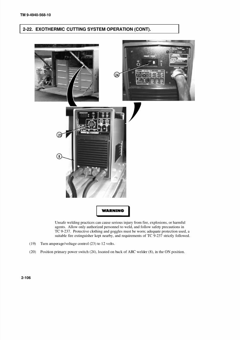
8/20/2019 TM 9-4940-568-10 FRS
http://slidepdf.com/reader/full/tm-9-4940-568-10-frs 156/403
TM 9-4940-568-10
2-106
2-22. EXOTHERMIC CUTTING SYSTEM OPERATION (CONT).
Unsafe welding practices can cause serious injury from fire, explosions, or harmful
agents. Allow only authorized personnel to weld, and follow safety precautions inTC 9-237. Protective clothing and goggles must be worn; adequate protection used, asuitable fire extinguisher kept nearby, and requirements of TC 9-237 strictly followed.
(19) Turn amperage/voltage control (23) to 12 volts.
(20) Position primary power switch (24), located on back of ARC welder (8), in the ON position.

8/20/2019 TM 9-4940-568-10 FRS
http://slidepdf.com/reader/full/tm-9-4940-568-10-frs 157/403
TM 9-4940-568-10
2-107
b. Exothermic Cutting System Disassembly.
(1) Position primary power switch (24) on back of ARC welder (8) to the OFF position.

8/20/2019 TM 9-4940-568-10 FRS
http://slidepdf.com/reader/full/tm-9-4940-568-10-frs 158/403
9
0
TM 9-4940-568-10
2-108
2-22. EXOTHERMIC CUTTING SYSTEM OPERATION (CONT).
(2) Close oxygen regulator (22).
(3) Remove clip (18) and open tank safety cap (19) on oxygen tank (20).
(4) Turn handle (21) clockwise and close valve.
(5) Close tank safety cap (19) and install clip (18).

8/20/2019 TM 9-4940-568-10 FRS
http://slidepdf.com/reader/full/tm-9-4940-568-10-frs 159/403
9
TM 9-4940-568-10
2-109
Do not disassemble exothermic cutting system while hot. Failure to comply could
cause severe burns.
(6) Remove oxygen hose (1) from torch head (9).
(7) Remove striker plate (17) cable from positive extension cable (6).
(8) Remove torch head (16) cable from negative extension cable (5).

8/20/2019 TM 9-4940-568-10 FRS
http://slidepdf.com/reader/full/tm-9-4940-568-10-frs 160/403
TM 9-4940-568-10
2-110
2-22. EXOTHERMIC CUTTING SYSTEM OPERATION (CONT).
9
(9) Loosen collet nut (13) 1/2 turn and remove recessed rod (15), if necessary.
(10) Remove collet nut (13) from torch head (9).
(11) Remove leather shield (11) from torch head (9).
(12) Install collet nut (13) onto torch head (9) and tighten collet nut.
09
(13) Stow striker plate (10), torch head (9), and leather shield (11) in welding cabinet (12).
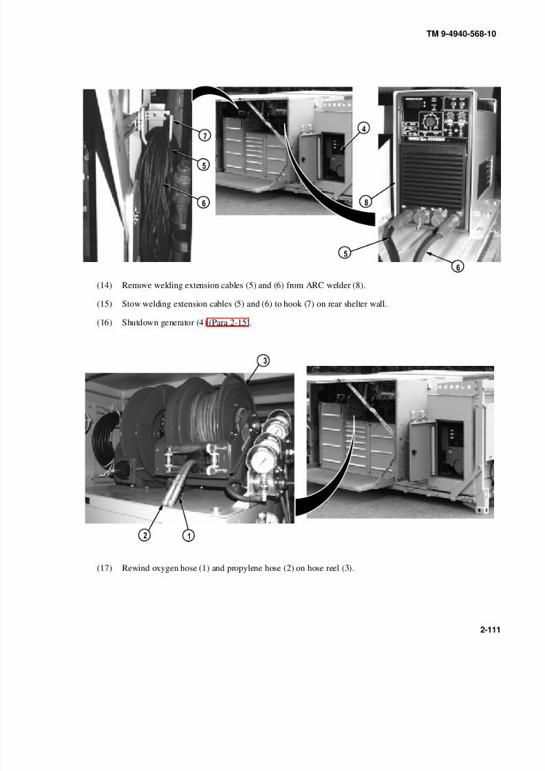
8/20/2019 TM 9-4940-568-10 FRS
http://slidepdf.com/reader/full/tm-9-4940-568-10-frs 161/403
TM 9-4940-568-10
2-111
(14) Remove welding extension cables (5) and (6) from ARC welder (8).
(15) Stow welding extension cables (5) and (6) to hook (7) on rear shelter wall.
(16) Shutdown generator (4) (Para 2-15).
(17) Rewind oxygen hose (1) and propylene hose (2) on hose reel (3).

8/20/2019 TM 9-4940-568-10 FRS
http://slidepdf.com/reader/full/tm-9-4940-568-10-frs 162/403
TM 9-4940-568-10
2-112
2-23. ARGON, OXYGEN, OR PROPYLENE TANK REPLACEMENT.
a. Tank Removal.
NOTE
Tank replacement procedures are identical for all four tanks.
(1) Remove pin (1) and open tank safety cap (2) on tank (3).
(2) Turn handle (4) clockwise and close valve (5) on tank (3).
NOTE
Note position of valve and tank safety cap prior to removal.
(3) Remove hose assembly (6) from tank (3).
Ensure tank standard cap is installed on tank prior to removing or installing pressurizedtanks. Failure to comply may result in injury or death to personnel.
NOTE
Standard cap should be stowed in bulk storage drawer.
(4) Remove tank safety cap (2) from tank (3) and install standard cap on tank.
(5) Loosen two nuts (7) and open tank brackets (8).
(6) With the aid of an assistant, remove tank (3) from tank brackets (8).

8/20/2019 TM 9-4940-568-10 FRS
http://slidepdf.com/reader/full/tm-9-4940-568-10-frs 163/403
TM 9-4940-568-10
2-113
b. Tank Installation.
Ensure tank standard cap is installed on tank prior to removing or installing pressurizedtanks. Failure to comply may result in injury or death to personnel.
(1) With the aid of an assistant, position tank (3) in tank brackets (8).
(2) Rotate tank brackets (8) closed and install nuts (7). Do not tighten nuts.
NOTEPosition tank safety cap and regulator valve as noted during removal.
(3) Remove standard cap from tank (3) and install tank safety cap (2) on tank.
(4) Install hose assembly (6) on tank (3).
(5) Position tank (3) and tighten nuts (7).
(6) Close tank safety cap (2) and install pin (1).

8/20/2019 TM 9-4940-568-10 FRS
http://slidepdf.com/reader/full/tm-9-4940-568-10-frs 164/403
TM 9-4940-568-10
2-114
2-24. SLAVE STARTING PROCEDURE.
Ensure CTIS ON/OFF switch is in the OFF position and the LHS selector switch is inthe OFF position on PLS truck while performing the slave starting procedure. Failureto comply may result in damage to equipment.
NOTE
Slave starting is a two person task.
(1) Start PLS truck (TM 9-2320-364-10).
(2) Position PLS truck next to the right side of FRS generator (1).
(3) Shut OFF PLS truck.
(4) Remove cover (2) from nato slave receptacle (3) on FRS and cover (4) from nato slave receptacle (5) on PLS
truck.
(5) Connect nato slave cable (6) to PLS truck.
(6) Connect other end of nato slave cable (6) on FRS nato slave receptacle (3).

8/20/2019 TM 9-4940-568-10 FRS
http://slidepdf.com/reader/full/tm-9-4940-568-10-frs 165/403
TM 9-4940-568-10
2-115
(7) Start engine of PLS truck (TM 9-2320-364-10).
NOTE
Charge period is five minutes.
(8) Start FRS generator engine (Para 2-15).
(9) After FRS generator engine starts and is running smoothly, disconnect slave cable (6) from nato slavereceptacles (3) and (5).
(10) Install covers (2) and (4) and stow nato slave cable (6).
(11) Move and park PLS truck.
(12) Shut OFF PLS truck.

8/20/2019 TM 9-4940-568-10 FRS
http://slidepdf.com/reader/full/tm-9-4940-568-10-frs 166/403
TM 9-4940-568-10
2-116
2-25. FILLING HYDRAULIC RESERVOIR.
Hydraulic oil may be hot and cause serious burns.
• Clean area before removing filler breather to keep foreign matter out of hydraulic
reservoir and to prevent damage.
• When installing breather cap, ensure that tether chain lowers into reservoir hole or damage
to breather cap gasket will result.NOTE
• Boom and outriggers must be in stowed position to attain proper hydraulic fluid level.
• At high temperature, oil level should be near minimum mark to allow for expansion.
(1) Remove breather cap (1) from hydraulic reservoir (2).
(2) Fill with oil (Appendix G) until oil level is between minimum and maximum levels as indicated in the sight
glass (3).
(3) Install breather cap (1) on hydraulic reservoir (2).

8/20/2019 TM 9-4940-568-10 FRS
http://slidepdf.com/reader/full/tm-9-4940-568-10-frs 167/403
TM 9-4940-568-10
2-117
2-26. DOME LIGHT OPERATION.
a. Black-Out Light Operation.
NOTE
• 24 VOLT DC PANEL power switch must be in the ON position.
• Two dome lights are located inside left and right ceiling of the shelter. Left side is shown.
(1) Turn MASTER DISCONNECT switch (1) to ON.
(2) Turn switch (2) counterclockwise to turn on black-out light (3).
(3) Turn switch (2) clockwise to the center position to turn off black-out light (3).
(4) Turn MASTER DISCONNECT switch (1) to OFF.
b. White Light Operation.
NOTE
•
24 VOLT DC PANEL power switch must be in the ON position.• Two dome lights are located inside left and right ceiling of the shelter. Left side is shown.
(1) Turn MASTER DISCONNECT switch (1) to ON.
(2) Push in lock button (4) and turn switch (2) clockwise to turn on white light (5).
(3) Push in lock button (4) and turn switch (2) counterclockwise to the center position to turn off white light
(5).
(4) Turn MASTER DISCONNECT switch (1) to OFF.
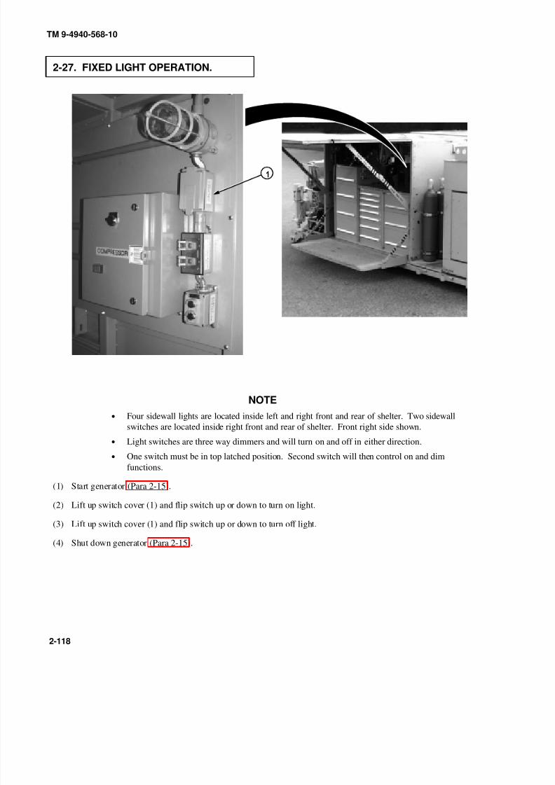
8/20/2019 TM 9-4940-568-10 FRS
http://slidepdf.com/reader/full/tm-9-4940-568-10-frs 168/403
TM 9-4940-568-10
2-118
2-27. FIXED LIGHT OPERATION.
NOTE
• Four sidewall lights are located inside left and right front and rear of shelter. Two sidewall
switches are located inside right front and rear of shelter. Front right side shown.
• Light switches are three way dimmers and will turn on and off in either direction.
• One switch must be in top latched position. Second switch will then control on and dim
functions.
(1) Start generator (Para 2-15).
(2) Lift up switch cover (1) and flip switch up or down to turn on light.
(3) Lift up switch cover (1) and flip switch up or down to turn off light.
(4) Shut down generator (Para 2-15).
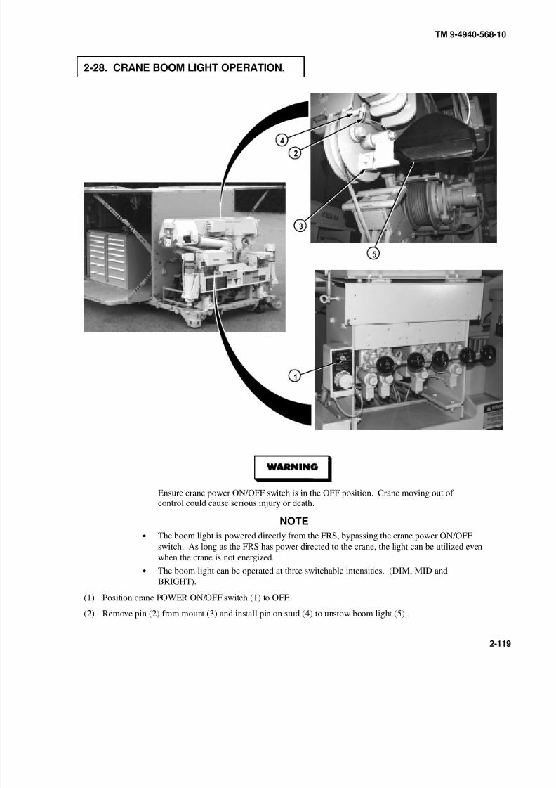
8/20/2019 TM 9-4940-568-10 FRS
http://slidepdf.com/reader/full/tm-9-4940-568-10-frs 169/403
TM 9-4940-568-10
2-119
2-28. CRANE BOOM LIGHT OPERATION.
Ensure crane power ON/OFF switch is in the OFF position. Crane moving out of control could cause serious injury or death.
NOTE• The boom light is powered directly from the FRS, bypassing the crane power ON/OFF
switch. As long as the FRS has power directed to the crane, the light can be utilized even
when the crane is not energized.
• The boom light can be operated at three switchable intensities. (DIM, MID and
BRIGHT).
(1) Position crane POWER ON/OFF switch (1) to OFF.
(2) Remove pin (2) from mount (3) and install pin on stud (4) to unstow boom light (5).

8/20/2019 TM 9-4940-568-10 FRS
http://slidepdf.com/reader/full/tm-9-4940-568-10-frs 170/403
TM 9-4940-568-10
2-120
2-28. CRANE BOOM LIGHT OPERATION (CONT).
NOTE
24 VOLT DC PANEL power switch must be in the ON position.
(3) Turn MASTER DISCONNECT switch (6) to ON.
(4) Turn BOOM LIGHT switch (7) to desired setting DIM/MID/BRT.
(5) Turn BOOM LIGHT switch (7) to OFF.
(6) Turn MASTER DISCONNECT switch (6) to OFF.
(7) Remove pin (2) from stud (4) and install pin on mount (3) to stow boom light (5).

8/20/2019 TM 9-4940-568-10 FRS
http://slidepdf.com/reader/full/tm-9-4940-568-10-frs 171/403
TM 9-4940-568-10
2-121
2-29. MATERIAL HANDLING CRANE (MHC) OPERATION.
a. General Description.
During operation, the material handling crane (MHC) has four basic functions: boom telescoping, boom elevation,
swing and hoist. The boom can rotate 300 degrees. The crane has a lifting capacity up to 10,000 lbs (4,536 kgs) at 14ft. (4.3 M) radius (see lifting capacity chart located at control panel for further information).
The crane is operated by hydraulics supplied by a hydraulic pump mounted on the diesel engine through the crane’s
main control panel. The main control panel provides the controls to operate all functions of the crane. The outrigger
control panel provides the controls to operate the outrigger functions.
Each control on the crane’s main control panel is proportional. The more travel of the control, the faster the selected
crane movement. The crane may also be operated by a remote control unit with the same operating functions, except
for outrigger controls and mast control, as the main control. Left and right retractable outrigger jack cylinders are
provided to stabilize, support, and level the system while the crane is operated. Built within the crane’s hydraulic
system are several safety features that protect the equipment and operating personnel. They are as follows:
• Hold valves will prevent a load from falling in the event of pressure loss because of hydraulic line
failure.
• A suspended load on the crane can be lowered if hydraulic pressure is lost at the hydraulic pump on
the diesel engine if external hydraulic lines from the PLS truck are attached to the quick disconnect
couplings at the back of the crane. Should hydraulic failure occur in the crane, the suspended load
can be lowered by using the emergency hand pump. This procedure should be done by Unit
Maintenance personnel.
• An overload protection system that prevents lifting greater loads, at a given distance, than the crane
can handle. All functions that decrease overload remain functional: hoist down, telescope in, and
swing left or right.

8/20/2019 TM 9-4940-568-10 FRS
http://slidepdf.com/reader/full/tm-9-4940-568-10-frs 172/403
TM 9-4940-568-10
2-122
2-29. MATERIAL HANDLING CRANE (MHC) OPERATION (CONT).
b. Determine Required Crane Settings from Range Diagram.
Area Definition Chart
(1) Use Area Definition Chart which is located above MHC main control panel and on remote control, to
determine position of crane.
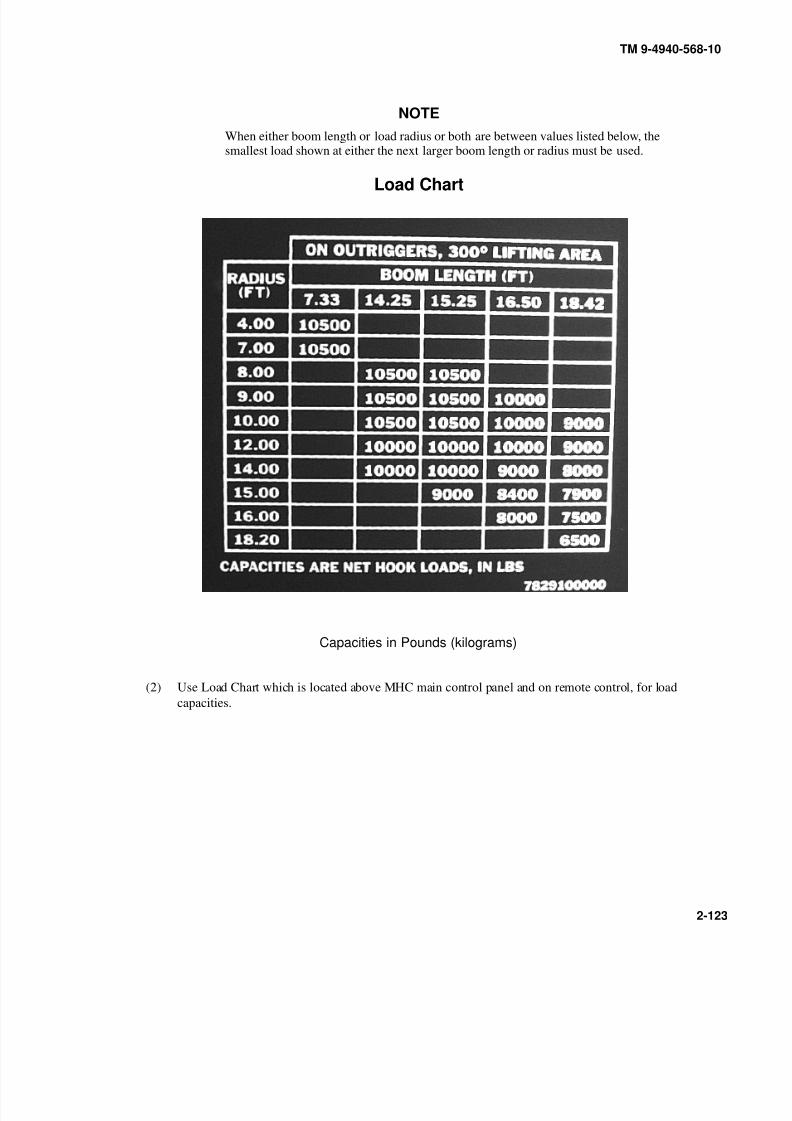
8/20/2019 TM 9-4940-568-10 FRS
http://slidepdf.com/reader/full/tm-9-4940-568-10-frs 173/403
TM 9-4940-568-10
2-123
NOTE
When either boom length or load radius or both are between values listed below, thesmallest load shown at either the next larger boom length or radius must be used.
Load Chart
Capacities in Pounds (kilograms)
(2) Use Load Chart which is located above MHC main control panel and on remote control, for load
capacities.

8/20/2019 TM 9-4940-568-10 FRS
http://slidepdf.com/reader/full/tm-9-4940-568-10-frs 174/403
TM 9-4940-568-10
2-124
2-29. MATERIAL HANDLING CRANE (MHC) OPERATION (CONT).
Range Diagram
(3) Determine what distance load is from crane and locate dimension along the bottom horizontal line (1).(Example: Load is 11 ft (3m) from crane.)
(4) Follow line vertically up graph until it intersects with boom length arc (2). Make intersection mark (3).
(5) Follow line along arc and make note of boom length (4). (Example: If load is 11 ft. (3m) from crane,
boom length is 14.25 ft (4m).)
(6) Return to intersection mark (3). Follow diagonal line (5) to determine boom angle setting (6). (Example:
Boom angle setting is 40-degrees from intersection mark.)
(7) Return to intersection mark (3). Follow horizontal line to determine boom height (7). (Example: Boom
height is 19 ft (5m) from intersection mark.)
(8) Locate distance the load is from crane in the Crane Range Diagram Summary.
(9) Follow across Crane Range Diagram Summary to verify height of boom and to determine maximum load.
(Example: Boom height is 19 ft (5m) and maximum crane load is 10,000 lbs (4,536 kgs).)

8/20/2019 TM 9-4940-568-10 FRS
http://slidepdf.com/reader/full/tm-9-4940-568-10-frs 175/403
TM 9-4940-568-10
2-125
c. Prepare Crane for Use.
X X
(1) Prepare FRS for operation (Para 2-12).
(2) Unstow crane boom light (Para 2-28).
NOTE
24 VOLT DC PANEL power switch must be in the ON position.
(3) Start FRS generator (Para 2-15).
(4) Position crane POWER switch (8) to ON.

8/20/2019 TM 9-4940-568-10 FRS
http://slidepdf.com/reader/full/tm-9-4940-568-10-frs 176/403
TM 9-4940-568-10
2-126
2-29. MATERIAL HANDLING CRANE (MHC) OPERATION (CONT).
d. Deploying Outrigger and Jack Cylinders.
9
0
0
• Ensure area is clear on both sides of crane before extending outrigger jacks. Failure to
comply may result in injury to personnel or damage to equipment.
• Keep hands and feet clear of outriggers during operation. Failure to comply may result in
injury to personnel.
(1) Open outrigger control cover (9).
NOTEEnsure chain of pin is looped over top of outrigger latch.
(2) Remove pin (10) and retaining pin (11) and place left outrigger latch (12) in open position. Install
retaining pin and pin.
(3) Repeat Step (2) for right outrigger latch.
(4) Move O/R EXT lever (13) to OUT position until outriggers (14) are fully extended.
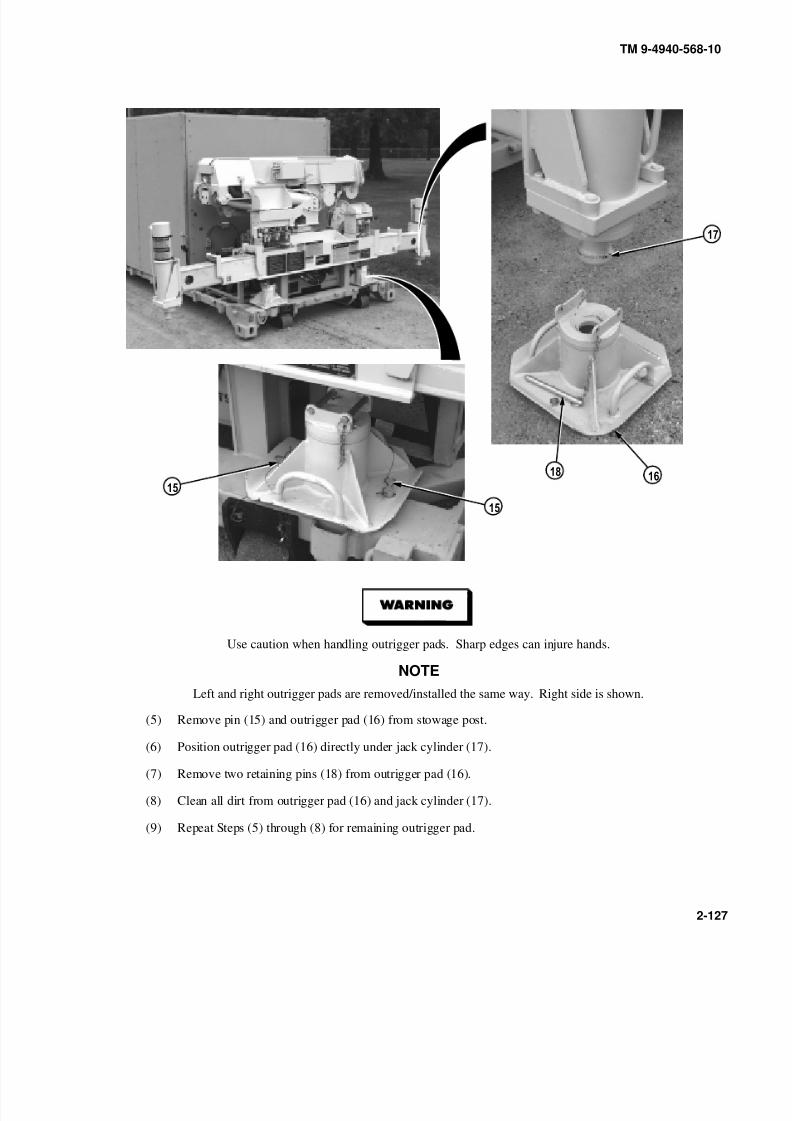
8/20/2019 TM 9-4940-568-10 FRS
http://slidepdf.com/reader/full/tm-9-4940-568-10-frs 177/403
TM 9-4940-568-10
2-127
Use caution when handling outrigger pads. Sharp edges can injure hands.
NOTE
Left and right outrigger pads are removed/installed the same way. Right side is shown.
(5) Remove pin (15) and outrigger pad (16) from stowage post.
(6) Position outrigger pad (16) directly under jack cylinder (17).
(7) Remove two retaining pins (18) from outrigger pad (16).
(8) Clean all dirt from outrigger pad (16) and jack cylinder (17).
(9) Repeat Steps (5) through (8) for remaining outrigger pad.
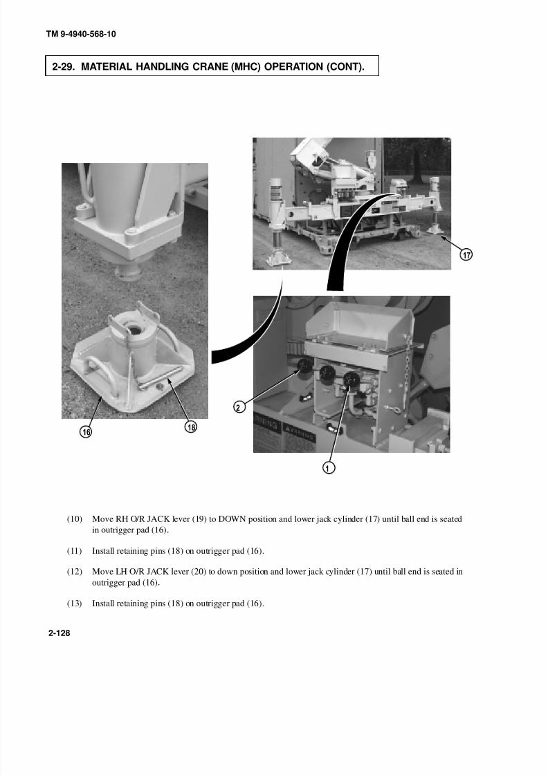
8/20/2019 TM 9-4940-568-10 FRS
http://slidepdf.com/reader/full/tm-9-4940-568-10-frs 178/403
TM 9-4940-568-10
2-128
2-29. MATERIAL HANDLING CRANE (MHC) OPERATION (CONT).
0
9
(10) Move RH O/R JACK lever (19) to DOWN position and lower jack cylinder (17) until ball end is seatedin outrigger pad (16).
(11) Install retaining pins (18) on outrigger pad (16).
(12) Move LH O/R JACK lever (20) to down position and lower jack cylinder (17) until ball end is seated in
outrigger pad (16).
(13) Install retaining pins (18) on outrigger pad (16).

8/20/2019 TM 9-4940-568-10 FRS
http://slidepdf.com/reader/full/tm-9-4940-568-10-frs 179/403
TM 9-4940-568-10
2-129
9
0
FRS C–channels of the flatrack must NOT be in contact with the terrain or any object to
prevent altering the critical reaction points of the FRS. Failure to comply could result inpersonnel injury or death.
NOTE• Lower outrigger jacks individually as necessary to level the FRS side-to-side and
front-to-back. The FRS is level when the black ball is under the “0” indicator (a portion of
the ball must be under the “0”) before the crane is loaded. Perform a final check of all
three level indicators before placing a load on the crane.
• Ensure that both outrigger jacks are taking load.
• If FRS is being leveled on unstable/uneven ground, refer to Operating FRS on Unstable or
Uneven Ground (Para 2-39).
(14) Using both RH O/R JACK and LH O/R JACK levers (19) and (20), lower jack cylinders (17) until rear of
flatrack (21) is clear of ground, and side-to-side level gage (22) shows FRS is level.
(15) Using both RH O/R JACK and LH O/R JACK levers (19) and (20), adjust jack cylinders until
front-to-back level gage (23) shows FRS (24) is level.
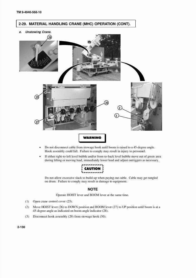
8/20/2019 TM 9-4940-568-10 FRS
http://slidepdf.com/reader/full/tm-9-4940-568-10-frs 180/403
9
0
TM 9-4940-568-10
2-130
2-29. MATERIAL HANDLING CRANE (MHC) OPERATION (CONT).
e. Unstowing Crane.
• Do not disconnect cable from stowage hook until boom is raised to a 45-degree angle.
Hook assembly could fall. Failure to comply may result in injury to personnel.
• If either right-to-left level bubble and/or front-to-back level bubble move out of green area
during lifting or moving load, immediately lower load and adjust outriggers as necessary.
Do not allow excessive slack to build-up when paying out cable. Cable may get tangledon drum. Failure to comply may result in damage to equipment.
NOTE
Operate HOIST lever and BOOM lever at the same time.
(1) Open crane control cover (25).
(2) Move HOIST lever (26) to DOWN position and BOOM lever (27) to UP position until boom is at a
45-degree angle as indicated on boom angle indicator (28).
(3) Disconnect hook assembly (29) from stowage hook (30).

8/20/2019 TM 9-4940-568-10 FRS
http://slidepdf.com/reader/full/tm-9-4940-568-10-frs 181/403
TM 9-4940-568-10
2-131
Keep boom clear of shelter, all electrical lines, and other obstacles while operating
crane. Failure to comply may result in injury or death to personnel.
Never telescope boom and lift load unless mast is fully raised. Failure to comply mayresult in damage to equipment.
NOTE
Operate BOOM lever and MAST lever at the same time to maintain boom atapproximately a 30-degree angle.
(4) Move BOOM lever (27) to UP position and MAST lever (31) to UP position until boom angle is
approximately 30-degrees.

8/20/2019 TM 9-4940-568-10 FRS
http://slidepdf.com/reader/full/tm-9-4940-568-10-frs 182/403
TM 9-4940-568-10
2-132
2-29. MATERIAL HANDLING CRANE (MHC) OPERATION (CONT).
(5) Move BOOM lever (27) to UP position and MAST lever (31) to UP position until mast (32) is fully
raised.
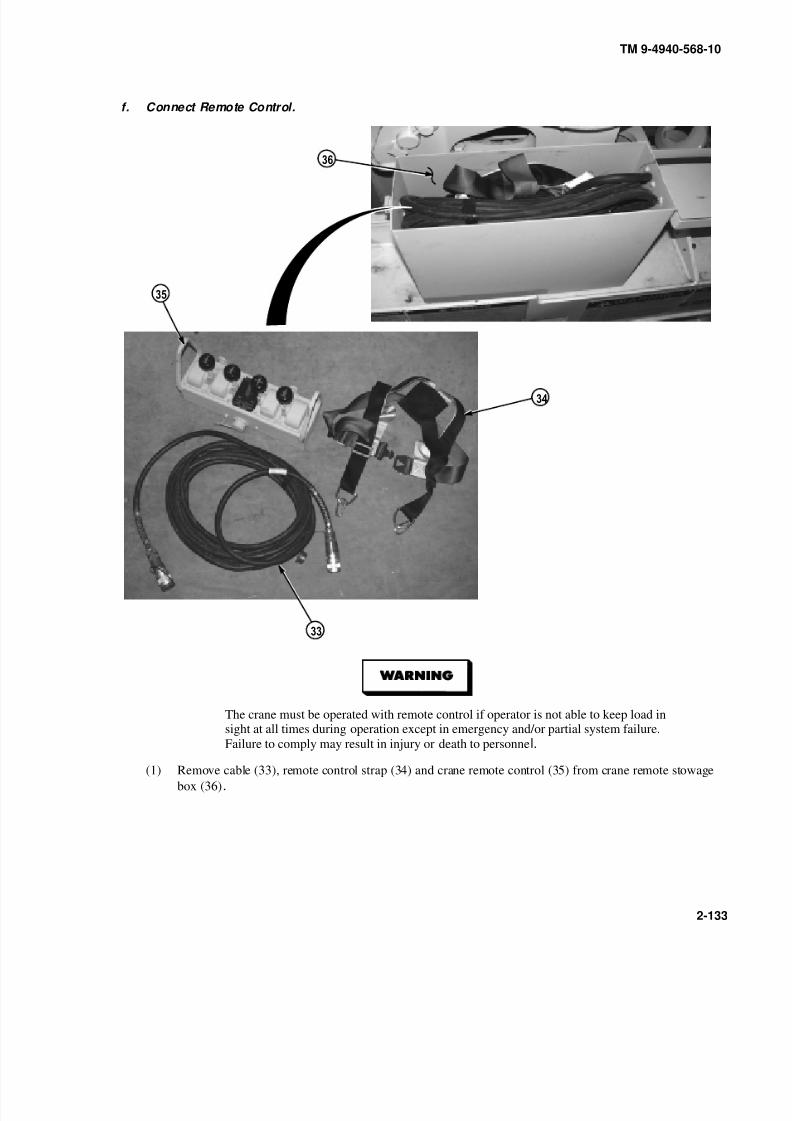
8/20/2019 TM 9-4940-568-10 FRS
http://slidepdf.com/reader/full/tm-9-4940-568-10-frs 183/403
TM 9-4940-568-10
2-133
f. Connect Remote Control.
The crane must be operated with remote control if operator is not able to keep load insight at all times during operation except in emergency and/or partial system failure.
Failure to comply may result in injury or death to personnel.
(1) Remove cable (33), remote control strap (34) and crane remote control (35) from crane remote stowage
box (36).
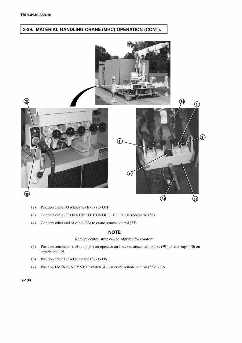
8/20/2019 TM 9-4940-568-10 FRS
http://slidepdf.com/reader/full/tm-9-4940-568-10-frs 184/403
TM 9-4940-568-10
2-134
2-29. MATERIAL HANDLING CRANE (MHC) OPERATION (CONT).
9
0
0
(2) Position crane POWER switch (37) to OFF.
(3) Connect cable (33) to REMOTE CONTROL HOOK UP receptacle (38).
(4) Connect other end of cable (33) to crane remote control (35).
NOTE
Remote control strap can be adjusted for comfort.
(5) Position remote control strap (34) on operator and buckle, attach two hooks (39) to two rings (40) on
remote control.
(6) Position crane POWER switch (37) to ON.
(7) Position EMERGENCY STOP switch (41) on crane remote control (35) to ON.

8/20/2019 TM 9-4940-568-10 FRS
http://slidepdf.com/reader/full/tm-9-4940-568-10-frs 185/403
TM 9-4940-568-10
2-135
g. Rotate and Telescope Boom.
• Keep boom clear of shelter, all electrical lines, and other obstacles while operating the
crane. Failure to comply may result in injury or death to personnel.
• Ensure that area is clear of personnel before rotating boom. Boom must be rotated slowly
enough so operator has complete control of load. If operator cannot see load during
operation, operate crane with remote control. Failure to comply may result in injury or
death to personnel.
• Keep hands and feet clear of outriggers during operation. Failure to comply may result in
injury to personnel.
NOTE
Operate crane control levers using even pressure. Moving lever slightly will cause slowmovement of crane. Moving lever to full travel will cause faster movement of thecrane.
(1) Move SWING lever (42) to CW position to move boom (43) to the right (when viewed from behind the
boom).
(2) Move SWING lever (42) to CCW position to move boom (43) to the left (when viewed from behind the
boom).

8/20/2019 TM 9-4940-568-10 FRS
http://slidepdf.com/reader/full/tm-9-4940-568-10-frs 186/403
TM 9-4940-568-10
2-136
2-29. MATERIAL HANDLING CRANE (MHC) OPERATION (CONT).
Operator must keep control of load at all times. Attach guide lines to load as required.Failure to comply may result in injury or death to personnel.
Keep hook assembly at least 2 ft (0.6m) from end of boom. If hook assembly hits endof boom, crane will lose power for several seconds and cable or hook assembly may be
damaged .
NOTE
Operate HOIST lever and TELESCOPE lever at the same time.
(3) Move HOIST lever (26) to DOWN position to pay out cable (44) and TELESCOPE lever (45) to OUT
position to extend boom (43).

8/20/2019 TM 9-4940-568-10 FRS
http://slidepdf.com/reader/full/tm-9-4940-568-10-frs 187/403
TM 9-4940-568-10
2-137
h. Raise and Lower Load.
NOTE
Range diagram boom angles are reference only. Each lift is to be planned in advance:
• Know the weight of the load.
• Know the distance of the load from the crane.
• Check on the load chart if the lift is achievable.
• Configure the crane appropriately (in terms of boom length) or relocate FRS or load
as necessary.
(1) Refer to range diagram and load chart on MHC main control panel or on remote control, (Para 2-29b) to
determine correct boom angle and boom length setting.
(2) Move BOOM lever (27) to UP position until boom angle indicator (28) shows correct boom angle as
determined in Step (1).

8/20/2019 TM 9-4940-568-10 FRS
http://slidepdf.com/reader/full/tm-9-4940-568-10-frs 188/403
9
TM 9-4940-568-10
2-138
2-29. MATERIAL HANDLING CRANE (MHC) OPERATION (CONT).
• Do not allow excessive slack to build-up when paying out cable. Failure to comply may
result in damage to equipment.
• Do not allow the weight of the hook to be removed from the cable. Failure to comply may
result in damage to equipment.
• Use only a straight pull when lifting load. The crane structures and associated hydraulicsystems are to be used only for vertical lifting of a load, any sustained loading which
results in the hoist cable deviating from the vertical in any direction (attempting to pull or
drag a load) is specifically prohibited. Failure to comply may result in damage to
equipment.
• Telescope boom within range determined in Step (1). Failure to comply may result in
damage to equipment.
(3) Operate SWING lever (46) and TELESCOPE lever (45) to center end of boom (43) directly over load.
(4) Remove safety pin (47) from hook assembly latch (48).
(5) Operate HOIST lever (26) to pay in or pay out cable (44) and connect hook assembly (29) to load.
Ensure that hook latch is closed and safety pin is installed before attempting to raiseload. A hook latch that is not closed and locked in position could allow load to becomedisengaged from hook, allowing load to fall. Injury or death could result.
(6) Install safety pin (47) in hook assembly latch (48).
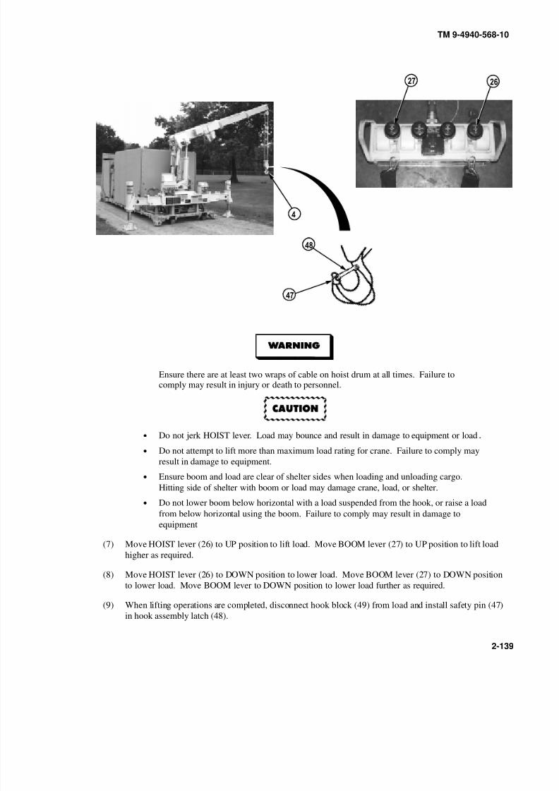
8/20/2019 TM 9-4940-568-10 FRS
http://slidepdf.com/reader/full/tm-9-4940-568-10-frs 189/403
9
TM 9-4940-568-10
2-139
Ensure there are at least two wraps of cable on hoist drum at all times. Failure tocomply may result in injury or death to personnel.
• Do not jerk HOIST lever. Load may bounce and result in damage to equipment or load.
• Do not attempt to lift more than maximum load rating for crane. Failure to comply may
result in damage to equipment.
• Ensure boom and load are clear of shelter sides when loading and unloading cargo.
Hitting side of shelter with boom or load may damage crane, load, or shelter.
• Do not lower boom below horizontal with a load suspended from the hook, or raise a load
from below horizontal using the boom. Failure to comply may result in damage to
equipment
(7) Move HOIST lever (26) to UP position to lift load. Move BOOM lever (27) to UP position to lift load
higher as required.
(8) Move HOIST lever (26) to DOWN position to lower load. Move BOOM lever (27) to DOWN position
to lower load. Move BOOM lever to DOWN position to lower load further as required.
(9) When lifting operations are completed, disconnect hook block (49) from load and install safety pin (47)
in hook assembly latch (48).

8/20/2019 TM 9-4940-568-10 FRS
http://slidepdf.com/reader/full/tm-9-4940-568-10-frs 190/403
TM 9-4940-568-10
2-140
2-29. MATERIAL HANDLING CRANE (MHC) OPERATION (CONT).
i. Stow Crane.
Boom must be positioned in line with outrigger beam and fully retracted beforelowering. Observe boom during lowering to ensure no contact is made with rear of shelter or crane outrigger jacks. Fai lure to comply may resul t in damage to
equipment.
NOTE
• Operate HOIST lever and TELESCOPE lever at the same time.
• Reel in cable until approximately 2 ft. (0.6m) of cable hangs from boom.
(1) Move HOIST lever (26) to UP position to reel in cable (44) and TELESCOPE lever (45) to IN position to
retract boom (43).
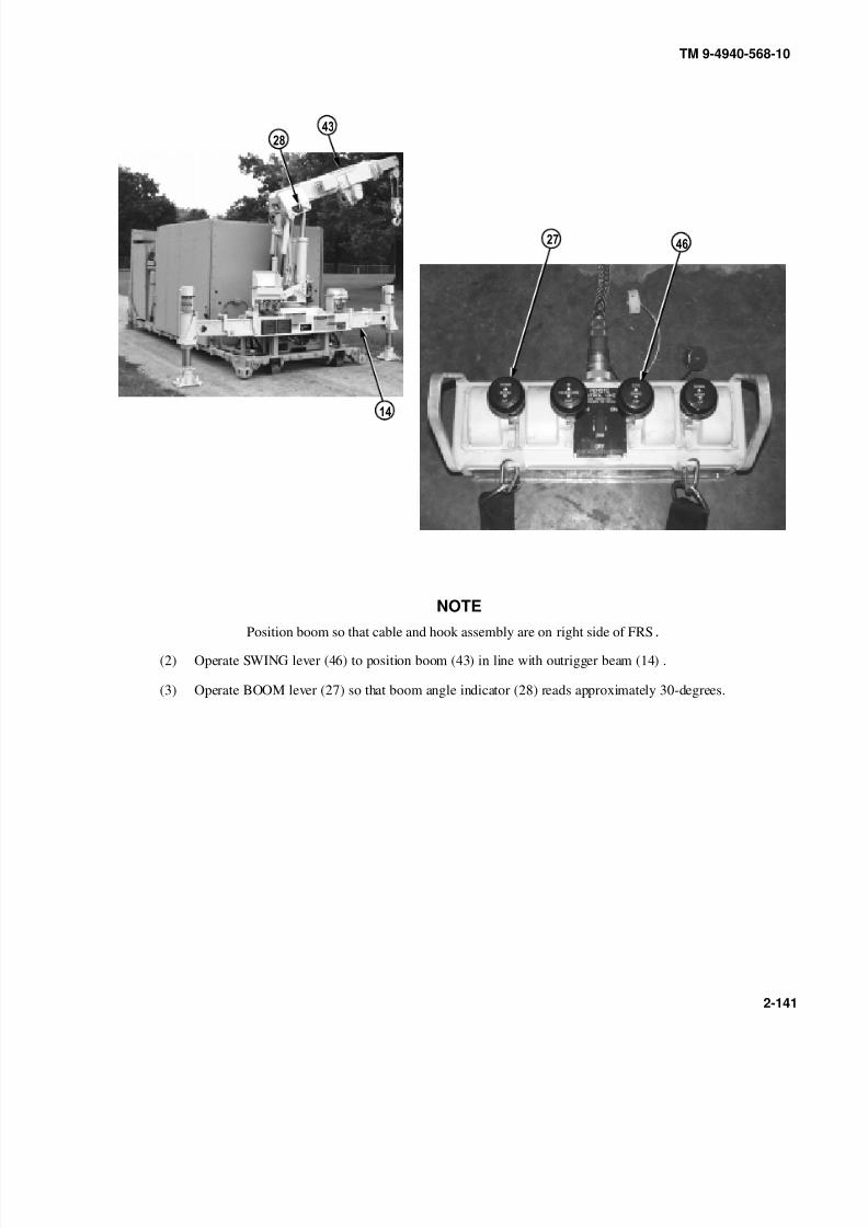
8/20/2019 TM 9-4940-568-10 FRS
http://slidepdf.com/reader/full/tm-9-4940-568-10-frs 191/403
TM 9-4940-568-10
2-141
NOTEPosition boom so that cable and hook assembly are on right side of FRS.
(2) Operate SWING lever (46) to position boom (43) in line with outrigger beam (14) .
(3) Operate BOOM lever (27) so that boom angle indicator (28) reads approximately 30-degrees.
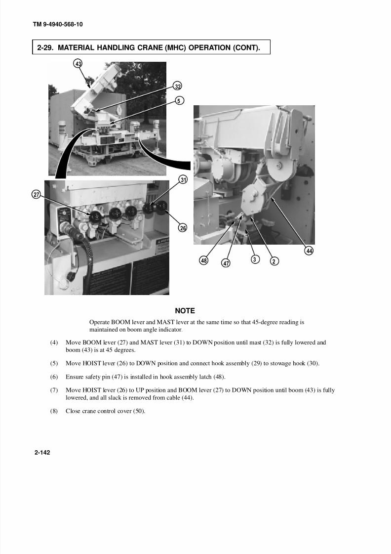
8/20/2019 TM 9-4940-568-10 FRS
http://slidepdf.com/reader/full/tm-9-4940-568-10-frs 192/403
0
90
TM 9-4940-568-10
2-142
2-29. MATERIAL HANDLING CRANE (MHC) OPERATION (CONT).
NOTE
Operate BOOM lever and MAST lever at the same time so that 45-degree reading is
maintained on boom angle indicator.
(4) Move BOOM lever (27) and MAST lever (31) to DOWN position until mast (32) is fully lowered and
boom (43) is at 45 degrees.
(5) Move HOIST lever (26) to DOWN position and connect hook assembly (29) to stowage hook (30).
(6) Ensure safety pin (47) is installed in hook assembly latch (48).
(7) Move HOIST lever (26) to UP position and BOOM lever (27) to DOWN position until boom (43) is fully
lowered, and all slack is removed from cable (44).
(8) Close crane control cover (50).
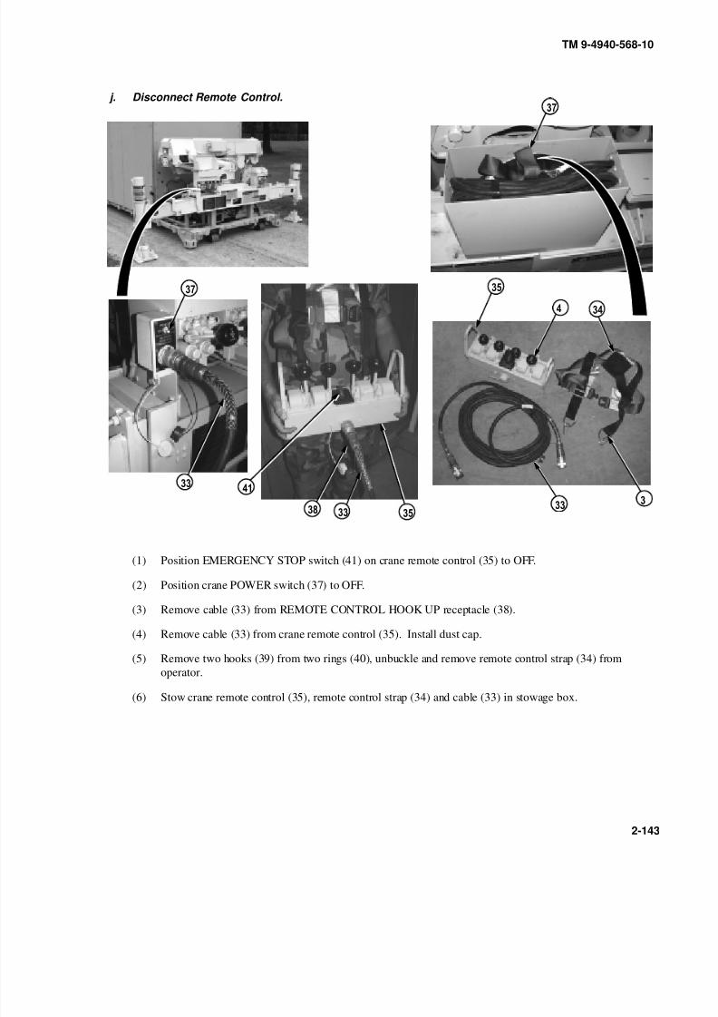
8/20/2019 TM 9-4940-568-10 FRS
http://slidepdf.com/reader/full/tm-9-4940-568-10-frs 193/403
0
9
TM 9-4940-568-10
2-143
j. Disconnect Remote Control.
(1) Position EMERGENCY STOP switch (41) on crane remote control (35) to OFF.
(2) Position crane POWER switch (37) to OFF.
(3) Remove cable (33) from REMOTE CONTROL HOOK UP receptacle (38).
(4) Remove cable (33) from crane remote control (35). Install dust cap.
(5) Remove two hooks (39) from two rings (40), unbuckle and remove remote control strap (34) from
operator.
(6) Stow crane remote control (35), remote control strap (34) and cable (33) in stowage box.
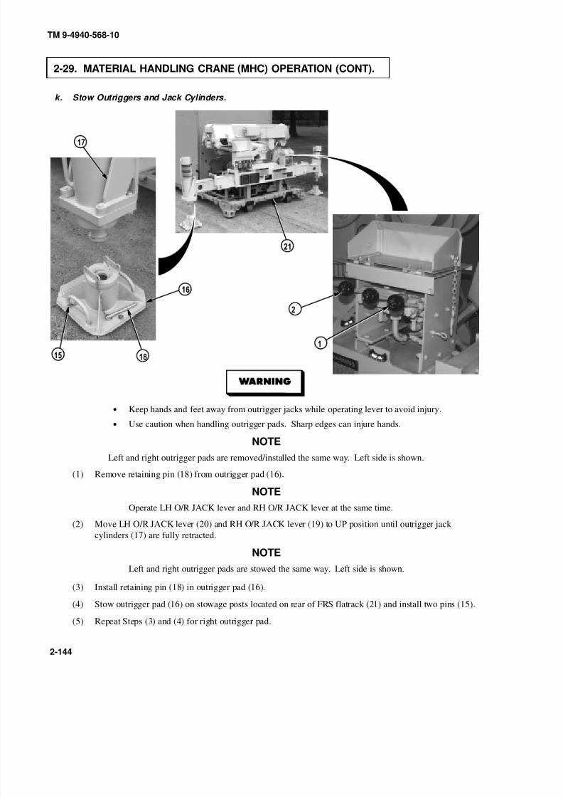
8/20/2019 TM 9-4940-568-10 FRS
http://slidepdf.com/reader/full/tm-9-4940-568-10-frs 194/403
0
9
TM 9-4940-568-10
2-144
2-29. MATERIAL HANDLING CRANE (MHC) OPERATION (CONT).
k. Stow Outriggers and Jack Cylinders.
• Keep hands and feet away from outrigger jacks while operating lever to avoid injury.
• Use caution when handling outrigger pads. Sharp edges can injure hands.
NOTE
Left and right outrigger pads are removed/installed the same way. Left side is shown.
(1) Remove retaining pin (18) from outrigger pad (16).
NOTE
Operate LH O/R JACK lever and RH O/R JACK lever at the same time.
(2) Move LH O/R JACK lever (20) and RH O/R JACK lever (19) to UP position until outrigger jack
cylinders (17) are fully retracted.
NOTE
Left and right outrigger pads are stowed the same way. Left side is shown.
(3) Install retaining pin (18) in outrigger pad (16).
(4) Stow outrigger pad (16) on stowage posts located on rear of FRS flatrack (21) and install two pins (15).
(5) Repeat Steps (3) and (4) for right outrigger pad.

8/20/2019 TM 9-4940-568-10 FRS
http://slidepdf.com/reader/full/tm-9-4940-568-10-frs 195/403
0
0
9
0
TM 9-4940-568-10
2-145
• Keep all personnel clear of system when retracting O/R beams and jacks. The beams can
crush hands, and retracting the jacks drops the flatrack back on the ground which could
cause injury to personnel.
• Ensure that no tools, parts, personnel or objects are on outriggers before retracting, to
prevent personnel injury.
(6) Move O/R EXT lever (13) to IN position until outrigger beams (14) are fully retracted.
NOTE
Ensure chain of pin is looped over top of outrigger latch.
(7) Remove pin (10) and retaining pin (11)and place left outrigger latch (12) in closed position. Install
retaining pin and pin.
(8) Repeat Step (7) for right outrigger latch.
(9) Position MAIN POWER switch (37) to OFF.
(10) Close outrigger control cover (50).
(11) Stow crane boom light (Para 2-28).
NOTE
Ensure dust cap is installed on remote control hookup.

8/20/2019 TM 9-4940-568-10 FRS
http://slidepdf.com/reader/full/tm-9-4940-568-10-frs 196/403
TM 9-4940-568-10
2-146
2-30. SHELTER HEATER OPERATION.
NOTE24 VOLT DC PANEL power switch must be in the ON position.
(1) Install shelter canvas (1) on shelter
(2) Start generator (Para 2-15).
(3) To start shelter heater (2), depress the switch (3) to the left () position and the red and green lights will
illuminate.
(4) Adjust temperature setting by adjusting the temperature control dial (4).
(5) To shutdown shelter heater (2), depress switch to the right () position and the red and green lights will go out.
Prior to turning off MASTER DISCONNECT switch, allow shelter heater to performcool down cycle (approx. 3 minutes) until fan stops. Failure to comply may result in afire causing injury or death to personnel.
(6) Allow the heater fan to stop before shutting down.
(7) Shutdown generator.
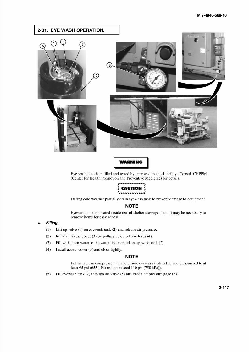
8/20/2019 TM 9-4940-568-10 FRS
http://slidepdf.com/reader/full/tm-9-4940-568-10-frs 197/403
TM 9-4940-568-10
2-147
2-31. EYE WASH OPERATION.
Eye wash is to be refilled and tested by approved medical facility. Consult CHPPM(Center for Health Promotion and Preventive Medicine) for details.
During cold weather partially drain eyewash tank to prevent damage to equipment.
NOTE
Eyewash tank is located inside rear of shelter stowage area. It may be necessary toremove items for easy access.
a. Filling.
(1) Lift up valve (1) on eyewash tank (2) and release air pressure.
(2) Remove access cover (3) by pulling up on release lever (4).
(3) Fill with clean water to the water line marked on eyewash tank (2).
(4) Install access cover (3) and close tightly.
NOTE
Fill with clean compressed air and ensure eyewash tank is full and pressurized to atleast 95 psi (655 kPa) (not to exceed 110 psi [758 kPa]).
(5) Fill eyewash tank (2) through air valve (5) and check air pressure gage (6).
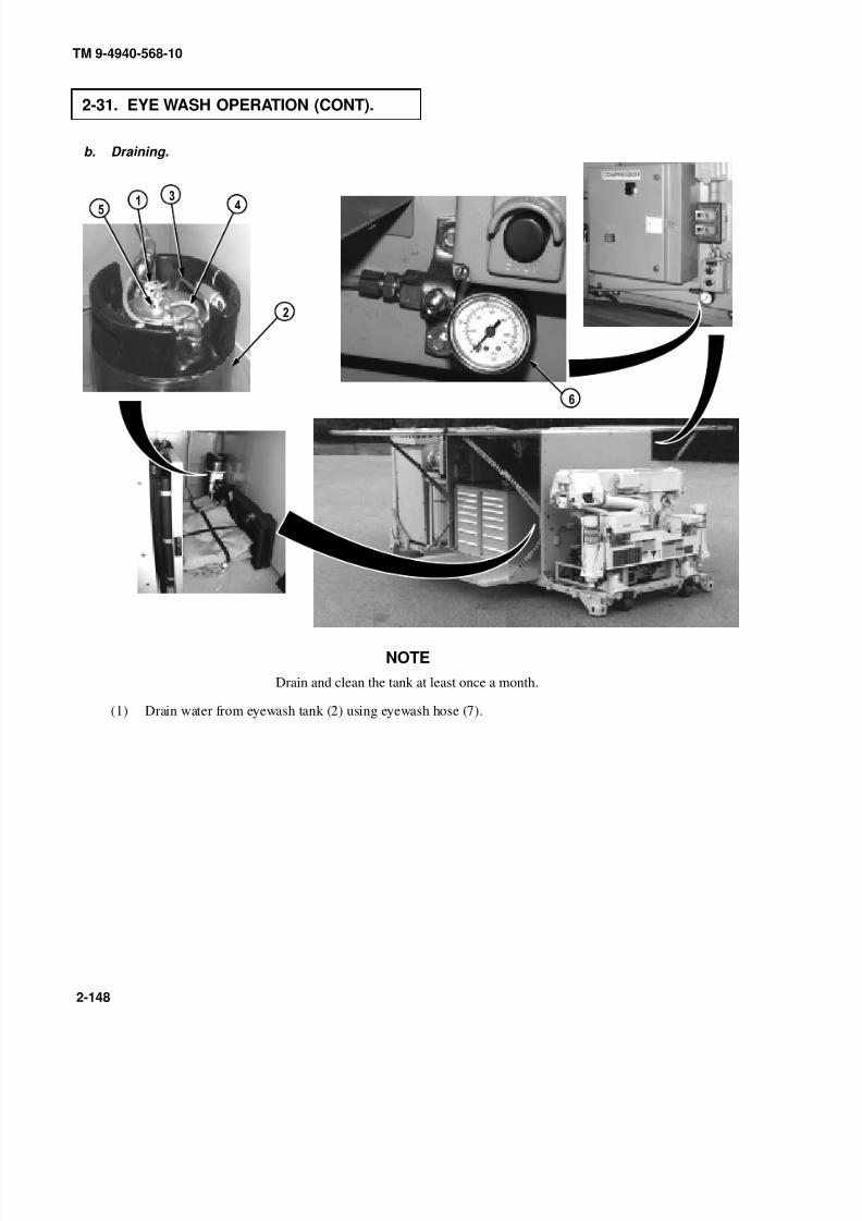
8/20/2019 TM 9-4940-568-10 FRS
http://slidepdf.com/reader/full/tm-9-4940-568-10-frs 198/403
TM 9-4940-568-10
2-148
2-31. EYE WASH OPERATION (CONT).
b. Draining.
NOTE
Drain and clean the tank at least once a month.
(1) Drain water from eyewash tank (2) using eyewash hose (7).
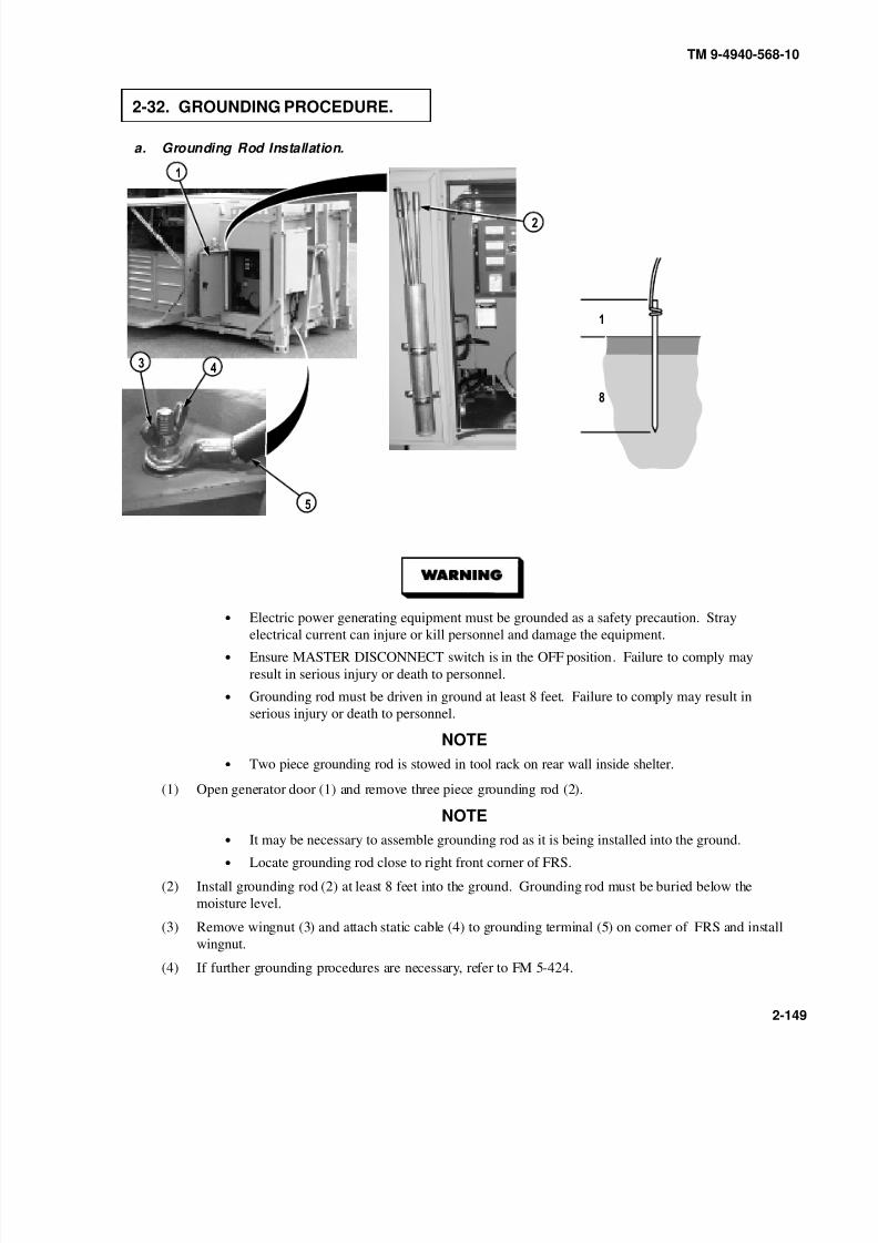
8/20/2019 TM 9-4940-568-10 FRS
http://slidepdf.com/reader/full/tm-9-4940-568-10-frs 199/403
TM 9-4940-568-10
2-149
2-32. GROUNDING PROCEDURE.
a. Grounding Rod Installation.
F T
M O I S T U R E L E V E L
F T
•Electric power generating equipment must be grounded as a safety precaution. Strayelectrical current can injure or kill personnel and damage the equipment.
• Ensure MASTER DISCONNECT switch is in the OFF position. Failure to comply may
result in serious injury or death to personnel.
• Grounding rod must be driven in ground at least 8 feet. Failure to comply may result in
serious injury or death to personnel.
NOTE
• Two piece grounding rod is stowed in tool rack on rear wall inside shelter.
(1) Open generator door (1) and remove three piece grounding rod (2).
NOTE
• It may be necessary to assemble grounding rod as it is being installed into the ground.
• Locate grounding rod close to right front corner of FRS.
(2) Install grounding rod (2) at least 8 feet into the ground. Grounding rod must be buried below the
moisture level.
(3) Remove wingnut (3) and attach static cable (4) to grounding terminal (5) on corner of FRS and install
wingnut.
(4) If further grounding procedures are necessary, refer to FM 5-424.

8/20/2019 TM 9-4940-568-10 FRS
http://slidepdf.com/reader/full/tm-9-4940-568-10-frs 200/403
TM 9-4940-568-10
2-150
2-32. GROUNDING PROCEDURE (CONT).
b. Grounding Rod Removal.
F T
M O I S T U R E L E V E L
F T
• Electric power generating equipment must be grounded as a safety precaution. Stray
electrical current can injure or kill personnel and damage the equipment.
• Ensure MASTER DISCONNECT switch is in the OFF position. Failure to comply may
result in serious injury or death to personnel.
(1) Remove wingnut (3) and static cable (4) from grounding terminal (5) on corner of FRS and install
wingnut.
(2) Remove grounding rod (2) from ground.
NOTETwo piece grounding rod is stowed in tool rack on rear wall inside shelter.
(3) Disassemble and stow grounding rod (2) on generator door (1) and close generator door.
(4) If further grounding procedures are necessary, refer to FM 5-424.
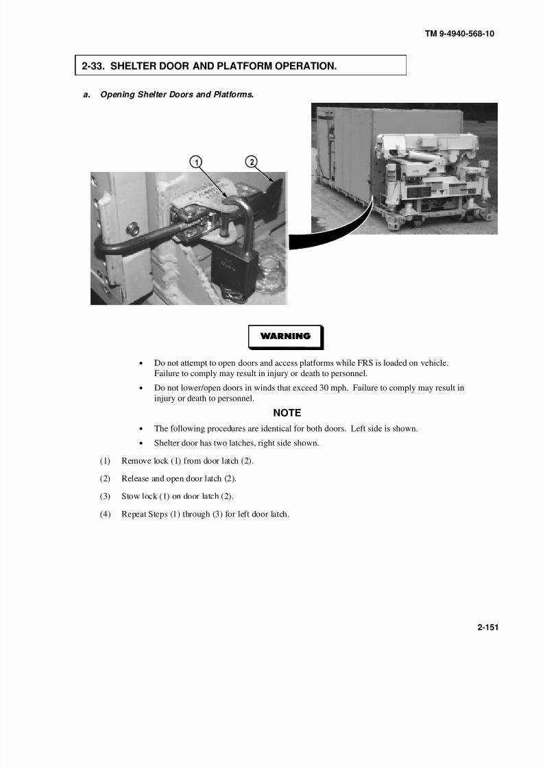
8/20/2019 TM 9-4940-568-10 FRS
http://slidepdf.com/reader/full/tm-9-4940-568-10-frs 201/403
TM 9-4940-568-10
2-151
2-33. SHELTER DOOR AND PLATFORM OPERATION.
a. Opening Shelter Doors and Platforms.
• Do not attempt to open doors and access platforms while FRS is loaded on vehicle.
Failure to comply may result in injury or death to personnel.
• Do not lower/open doors in winds that exceed 30 mph. Failure to comply may result in
injury or death to personnel.
NOTE
• The following procedures are identical for both doors. Left side is shown.
• Shelter door has two latches, right side shown.
(1) Remove lock (1) from door latch (2).
(2) Release and open door latch (2).
(3) Stow lock (1) on door latch (2).
(4) Repeat Steps (1) through (3) for left door latch.

8/20/2019 TM 9-4940-568-10 FRS
http://slidepdf.com/reader/full/tm-9-4940-568-10-frs 202/403
TM 9-4940-568-10
2-152
2-33. SHELTER DOOR AND PLATFORM OPERATION (CONT).
CENTER
• Keep hands clear of pivot points on support arms during door operation. Failure to comply
will result in injury to personnel or equipment.
• Sharp corners on door could be present, use caution during door operation. Failure to
comply may result in injury to personnel.
• Opening/closing shelter door is a two-person operation. Failure to comply may result in
injury to personnel.
• Do not lower/open doors in winds that exceed 30 mph. Failure to comply may result in
injury or death to personnel.
(5) With aid of an assistant, pull upward on door handles (3) and step on lower platform until door support
arms (4) lock over center in open position and shelter door (5) is open.
(6) Repeat Steps (1) through (5) for right door.

8/20/2019 TM 9-4940-568-10 FRS
http://slidepdf.com/reader/full/tm-9-4940-568-10-frs 203/403
TM 9-4940-568-10
2-153
b. Closing Shelter Doors and Platforms.
• Keep hands clear of pivot points on support arms during door operation. Failure to comply
will result in injury to personnel or equipment.• Sharp corners on door could be present, use caution during door operation. Failure to
comply may result in injury to personnel.
• Opening/closing shelter door is a two-person operation. Failure to comply may result in
injury to personnel.
• Do not lower/open doors in winds that exceed 30 mph. Failure to comply may result in
injury or death to personnel.
• Keep shelter roof and doors free of accumulated snow, ice, dirt and material buildup. Do
not lower doors if buildup is in excess of 1/4 inch thick. Failure to comply may result in
injury or death to personnel.
(1) With aid of an assistant, push in and release door support arms (4) and lower shelter door (5).
NOTE
Shelter door has two latches, right side shown.
(2) Remove lock (1) from door latch (2).
(3) Release and close door latch (2) to secure shelter door (5).
(4) Install lock (1) on door latch (2).
(5) Repeat Steps (1) through (4) for right door.

8/20/2019 TM 9-4940-568-10 FRS
http://slidepdf.com/reader/full/tm-9-4940-568-10-frs 204/403
TM 9-4940-568-10
2-154
2-34. CANVAS ENCLOSURE INSTALLATION/REMOVAL.
a. Canvas Enclosure Installation.
NOTE
The following procedures are identical for both sides of shelter. Left side is shown.
(1) Open storage compartment net (1).
(2) Remove canvas enclosure (2) sections from storage compartment.
(3) Unlatch straps (3) and layout canvas enclosure (2) sections to determine left and right side, two sections
for each side.

8/20/2019 TM 9-4940-568-10 FRS
http://slidepdf.com/reader/full/tm-9-4940-568-10-frs 205/403
TM 9-4940-568-10
2-155
• Opening/closing shelter door is a two person operation. Failure to comply may result in
injury to personnel.
• Sharp corners on doors could be present, use caution during door operation. Failure to
comply may result in injury to personnel.
• Do not lower doors/roof in winds that exceed 30 mph. Failure to comply may result in
injury to personnel.
(4) Lower shelter door (4) and attach right side of canvas (5) first.(5) Start at top right corner of shelter door (4) and mount right canvas (5) to shelter door.
(6) Start at top left corner of shelter door (4) and mount left canvas (6) to shelter door.
(7) Open shelter door (4) and mount right canvas (5) and left canvas (6) to shelter.
(8) Enclose left side canvas (6) over right side canvas (5).
(9) Install canvas ground anchors as necessary.
(10) Repeat Steps (4) through (9) for right side.
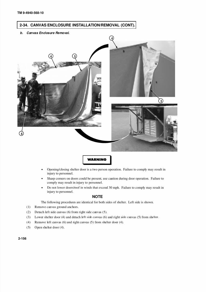
8/20/2019 TM 9-4940-568-10 FRS
http://slidepdf.com/reader/full/tm-9-4940-568-10-frs 206/403
TM 9-4940-568-10
2-156
2-34. CANVAS ENCLOSURE INSTALLATION/REMOVAL (CONT).
b. Canvas Enclosure Removal.
• Opening/closing shelter door is a two person operation. Failure to comply may result in
injury to personnel.
• Sharp corners on doors could be present, use caution during door operation. Failure to
comply may result in injury to personnel.
• Do not lower doors/roof in winds that exceed 30 mph. Failure to comply may result in
injury to personnel.
NOTE
The following procedures are identical for both sides of shelter. Left side is shown.
(1) Remove canvas ground anchors.
(2) Detach left side canvas (6) from right side canvas (5).
(3) Lower shelter door (4) and detach left side canvas (6) and right side canvas (5) from shelter.
(4) Remove left canvas (6) and right canvas (5) from shelter door (4).
(5) Open shelter door (4).
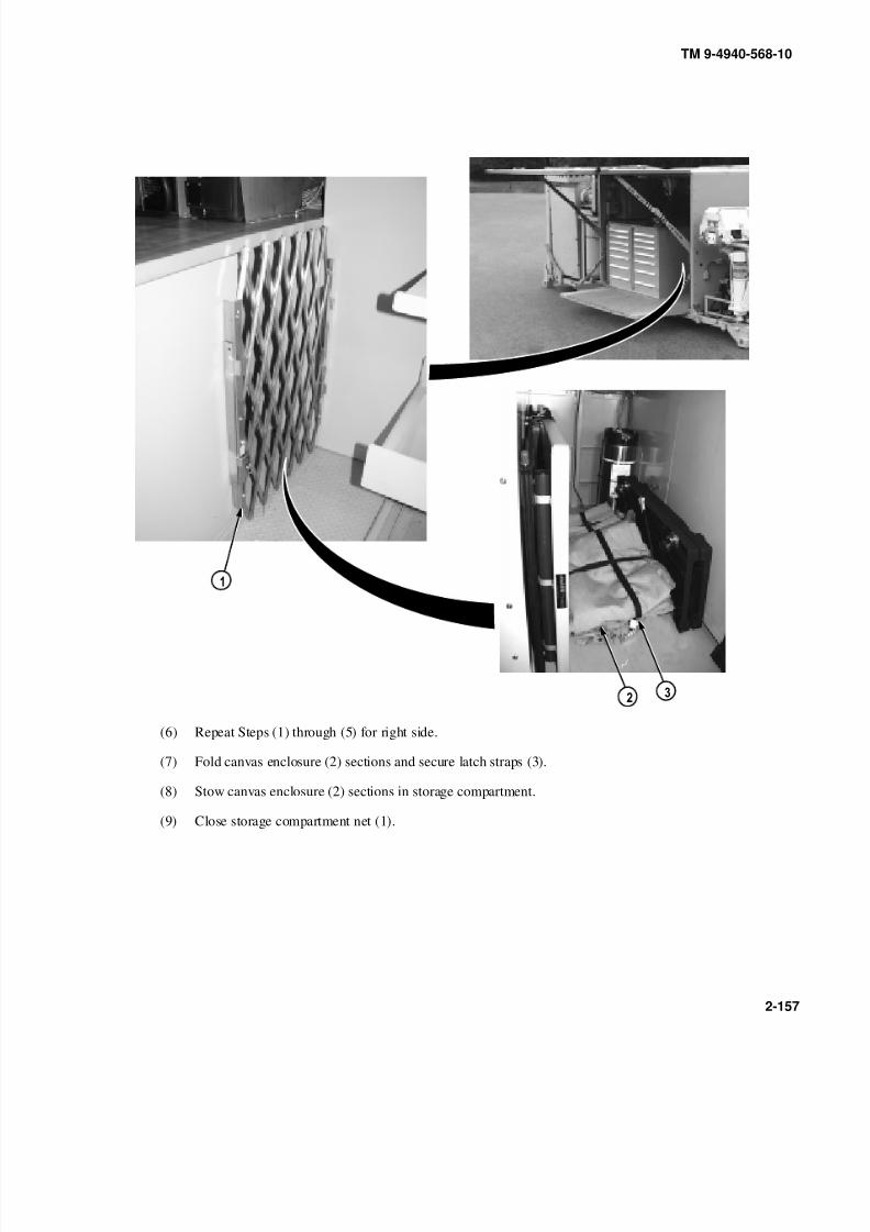
8/20/2019 TM 9-4940-568-10 FRS
http://slidepdf.com/reader/full/tm-9-4940-568-10-frs 207/403
TM 9-4940-568-10
2-157
(6) Repeat Steps (1) through (5) for right side.
(7) Fold canvas enclosure (2) sections and secure latch straps (3).
(8) Stow canvas enclosure (2) sections in storage compartment.
(9) Close storage compartment net (1).

8/20/2019 TM 9-4940-568-10 FRS
http://slidepdf.com/reader/full/tm-9-4940-568-10-frs 208/403
TM 9-4940-568-10
2-158
2-35. TOOL DRAWER AND CABINET OPERATION.
NOTE
All cabinets operate the same. Welding cabinet shown.
(1) Remove padlock (1) from cabinet (2).
(2) Lift and turn drawer locking bar (3) to the unlock position.
(3) To open drawer (4), push upward on drawer release latch (5) located, on right side of drawer.
(4) Using pulling motion, open drawer (4) to desired position.
(5) To close drawer (4), push upward on drawer release latch (5) located, on right side of drawer.
(6) Lift and turn drawer locking bar (3) to the lock position.
(7) Install padlock (1) on cabinet (2).
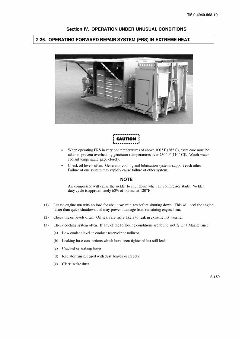
8/20/2019 TM 9-4940-568-10 FRS
http://slidepdf.com/reader/full/tm-9-4940-568-10-frs 209/403
TM 9-4940-568-10
2-159
Section IV. OPERATION UNDER UNUSUAL CONDITIONS
2-36. OPERATING FORWARD REPAIR SYSTEM (FRS) IN EXTREME HEAT.
• When operating FRS in very hot temperatures of above 100° F (38° C), extra care must be
taken to prevent overheating generator (temperatures over 230° F [110° C]). Watch water
coolant temperature gage closely.
• Check oil levels often. Generator cooling and lubrication systems support each other.
Failure of one system may rapidly cause failure of other system.
NOTE
Air compressor will cause the welder to shut down when air compressor starts. Welderduty cycle is approximately 60% of normal at 120°F.
(1) Let the engine run with no load for about two minutes before shutting down. This will cool the engine
faster than quick shutdown and may prevent damage from remaining engine heat.
(2) Check the oil levels often. Oil seals are more likely to leak in extreme hot weather.
(3) Check cooling system often. If any of the following conditions are found, notify Unit Maintenance:
(a) Low coolant level in coolant reservoir or radiator.
(b) Leaking hose connections which have been tightened but still leak.
(c) Cracked or leaking hoses.
(d) Radiator fins plugged with dust, leaves or insects.
(e) Clear intake duct.

8/20/2019 TM 9-4940-568-10 FRS
http://slidepdf.com/reader/full/tm-9-4940-568-10-frs 210/403
TM 9-4940-568-10
2-160
2-36. OPERATING FORWARD REPAIR SYSTEM (FRS) IN EXTREME HEAT (CONT).
NOTE
Batteries do not hold charge well in extreme heat. Battery will be tagged for use intropical conditions and will have a white circle printed on top. Battery specific gravitymust be changed to adjust for heat (TM 9-6140-200-14).
(4) Keep batteries (1) full, but do not overfill.
(5) In hot, damp climates check body and chassis often and notify Unit Maintenance if any of the following
are found:
(a) Signs of pitting or paint blistering on metal surfaces.
(b) Signs of mildew, mold or fungus on fabrics or rubber.
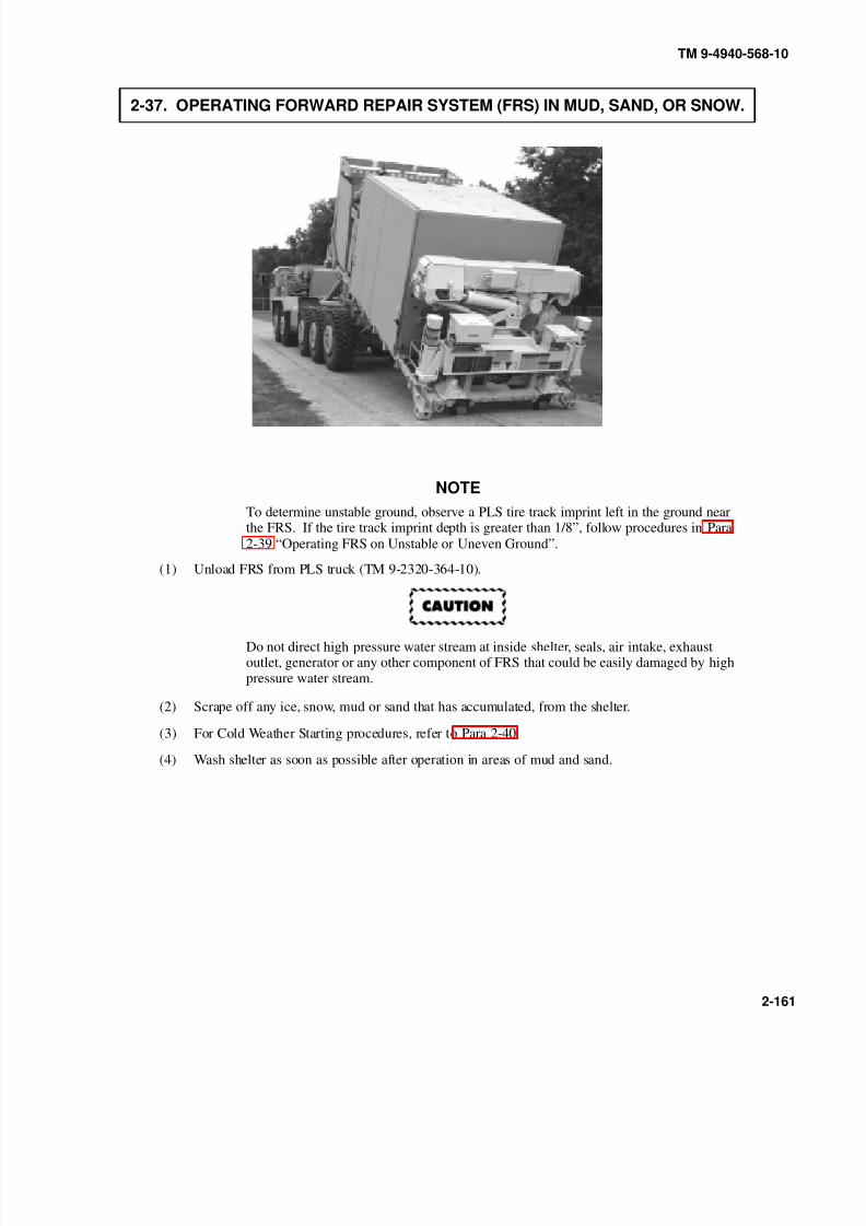
8/20/2019 TM 9-4940-568-10 FRS
http://slidepdf.com/reader/full/tm-9-4940-568-10-frs 211/403
TM 9-4940-568-10
2-161
2-37. OPERATING FORWARD REPAIR SYSTEM (FRS) IN MUD, SAND, OR SNOW.
NOTE
To determine unstable ground, observe a PLS tire track imprint left in the ground nearthe FRS. If the tire track imprint depth is greater than 1/8”, follow procedures in Para
2-39 “Operating FRS on Unstable or Uneven Ground”.
(1) Unload FRS from PLS truck (TM 9-2320-364-10).
Do not direct high pressure water stream at inside shelter, seals, air intake, exhaustoutlet, generator or any other component of FRS that could be easily damaged by highpressure water stream.
(2) Scrape off any ice, snow, mud or sand that has accumulated, from the shelter.
(3) For Cold Weather Starting procedures, refer to Para 2-40.
(4) Wash shelter as soon as possible after operation in areas of mud and sand.

8/20/2019 TM 9-4940-568-10 FRS
http://slidepdf.com/reader/full/tm-9-4940-568-10-frs 212/403
TM 9-4940-568-10
2-162
2-38. OPERATING FORWARD REPAIR SYSTEM (FRS) IN DESERT ENVIRONMENT.
NOTE
• FM 90-3 contains detailed instructions for living and working in the desert.
• To determine unstable ground, observe a PLS tire track imprint left in the ground near the
FRS. If the tire track imprint depth is greater than 1/8”, follow procedures in Para 2-39
“Operating FRS on Unstable or Uneven Ground”.
(1) Principles for operating in extreme heat and extreme dust, sand, or mud apply to desert environment
(Para 2-36 and 2-37).
(2) Temperatures may change as much as 70° F (21° C) between day and night. These changes may damage
equipment if FRS is not properly prepared. Due to expansion and contraction of all fluids and air, care
should be taken when filling fuel tank and fluid reservoirs to prevent overflow when temperatures
change.
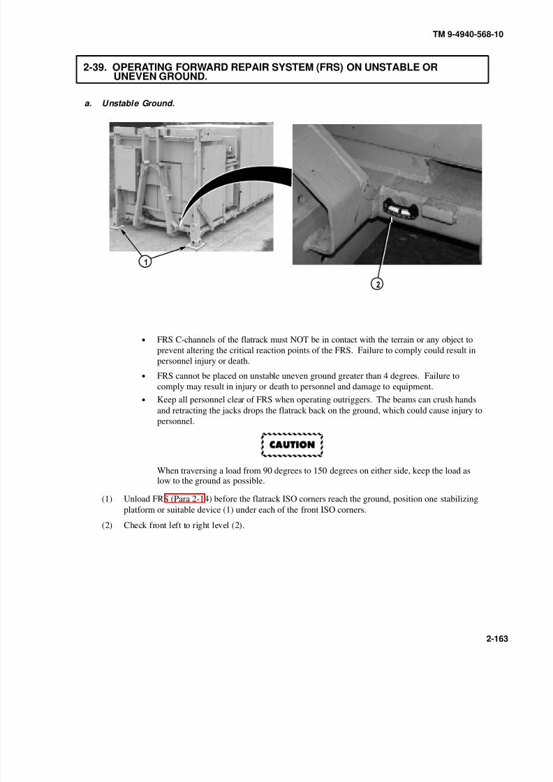
8/20/2019 TM 9-4940-568-10 FRS
http://slidepdf.com/reader/full/tm-9-4940-568-10-frs 213/403
TM 9-4940-568-10
2-163
2-39. OPERATING FORWARD REPAIR SYSTEM (FRS) ON UNSTABLE ORUNEVEN GROUND.
a. Unstable Ground.
• FRS C-channels of the flatrack must NOT be in contact with the terrain or any object to
prevent altering the critical reaction points of the FRS. Failure to comply could result in
personnel injury or death.
• FRS cannot be placed on unstable uneven ground greater than 4 degrees. Failure to
comply may result in injury or death to personnel and damage to equipment.• Keep all personnel clear of FRS when operating outriggers. The beams can crush hands
and retracting the jacks drops the flatrack back on the ground, which could cause injury to
personnel.
When traversing a load from 90 degrees to 150 degrees on either side, keep the load aslow to the ground as possible.
(1) Unload FRS (Para 2-14) before the flatrack ISO corners reach the ground, position one stabilizing
platform or suitable device (1) under each of the front ISO corners.
(2) Check front left to right level (2).
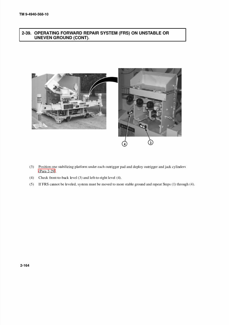
8/20/2019 TM 9-4940-568-10 FRS
http://slidepdf.com/reader/full/tm-9-4940-568-10-frs 214/403
TM 9-4940-568-10
2-164
2-39. OPERATING FORWARD REPAIR SYSTEM (FRS) ON UNSTABLE OR UNEVEN GROUND (CONT).
(3) Position one stabilizing platform under each outrigger pad and deploy outrigger and jack cylinders
(Para 2-29).
(4) Check front-to-back level (3) and left-to-right level (4).
(5) If FRS cannot be leveled, system must be moved to more stable ground and repeat Steps (1) through (4).
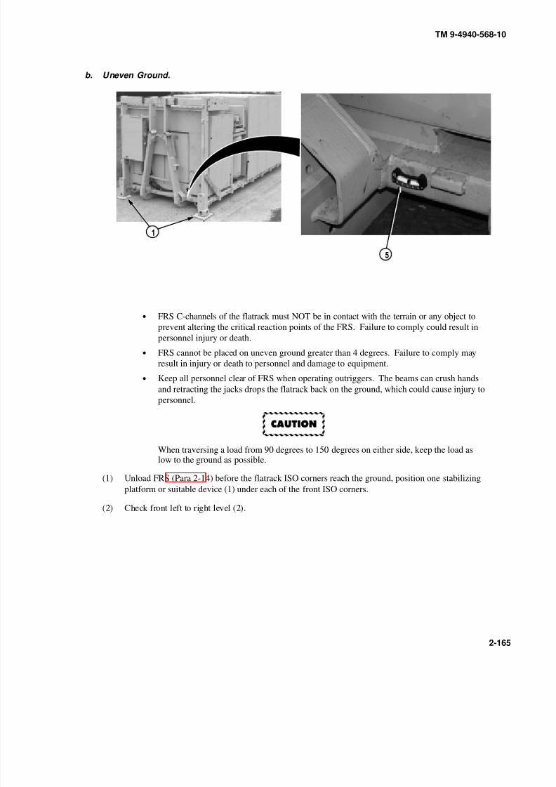
8/20/2019 TM 9-4940-568-10 FRS
http://slidepdf.com/reader/full/tm-9-4940-568-10-frs 215/403
TM 9-4940-568-10
2-165
b. Uneven Ground.
• FRS C-channels of the flatrack must NOT be in contact with the terrain or any object to
prevent altering the critical reaction points of the FRS. Failure to comply could result in
personnel injury or death.
• FRS cannot be placed on uneven ground greater than 4 degrees. Failure to comply may
result in injury or death to personnel and damage to equipment.
• Keep all personnel clear of FRS when operating outriggers. The beams can crush hands
and retracting the jacks drops the flatrack back on the ground, which could cause injury topersonnel.
When traversing a load from 90 degrees to 150 degrees on either side, keep the load aslow to the ground as possible.
(1) Unload FRS (Para 2-14) before the flatrack ISO corners reach the ground, position one stabilizing
platform or suitable device (1) under each of the front ISO corners.
(2) Check front left to right level (2).

8/20/2019 TM 9-4940-568-10 FRS
http://slidepdf.com/reader/full/tm-9-4940-568-10-frs 216/403
TM 9-4940-568-10
2-166
2-39. OPERATING FORWARD REPAIR SYSTEM (FRS) ON UNSTABLE OR UNEVEN GROUND (CONT).
(3) Position one stabilizing platform under each outrigger pad and deploy outrigger and jack cylinders
(Para 2-29).
(4) Check front-to-back level (3) and left-to-right level (4).
(5) If FRS cannot be leveled, system must be moved to level ground and repeat Steps (1) through (4).

8/20/2019 TM 9-4940-568-10 FRS
http://slidepdf.com/reader/full/tm-9-4940-568-10-frs 217/403
TM 9-4940-568-10
2-167
2-40. OPERATING FORWARD REPAIR SYSTEM (FRS) IN COLD ENVIRONMENT +45 F TO -25 F (+7 C TO –32 C).
• In severe cold, engine coolant can freeze, batteries can freeze and crack, oil and greasemay get thick and stiff, eyewash water may freeze, and rubber may crack or break easily.
• If engine fails to start after four tries, refer to troubleshooting.
• Inject starting fluid only while cranking engine and use only for starting.
NOTE
• Before operating FRS in severe cold environment, make sure it has been prepared as
described in FM 9-207. Refer to FM 31-70, FM 31-71 and FM 21-305 for additional
information on operation in cold environment.
(1) Press engine START/STOP switch START button (1) while pressing ether start switch (2)
for no more than 15 seconds. The start sequence is automated, only the ether button is held.(2) Release engine START/STOP switch START button (1). Oil pressure indicator (3) and oil pressure lamp
(4) may light briefly.
NOTE
If engine fails to start, wait 15 seconds before next start attempt to allow starter motorto cool.
(3) If engine fails to start, repeat Steps (1) and (2).

8/20/2019 TM 9-4940-568-10 FRS
http://slidepdf.com/reader/full/tm-9-4940-568-10-frs 218/403
TM 9-4940-568-10
2-168
2-40. OPERATING FORWARD REPAIR SYSTEM (FRS) IN COLD ENVIRONMENT +45 F TO -25 F (+7 C TO –32 C) (CONT).
(4) To keep moisture from building up inside air reservoir (5) and freezing, air should be drained from air
reservoir after each operation. Turn air reservoir valve (6) and drain air from air reservoir, close valve.
• Park in shelter when possible. Place planks or brush under FRS so it will not freeze in
place.
• Keep fuel tank as full as possible during cold operations. Water forms in empty fuel tank
as it cools. Water in fuel system could freeze and block fuel system.
(5) Place the FRS on high, dry ground if possible. If high, dry ground is not available, spread out planks or
brush to make raised and dry area so the FRS will not freeze in snow, water, ice, or mud.
(6) Place the FRS on level ground so body does not twist.
(7) Keep FRS free of snow and ice. Use broom or applicable material to remove snow and ice from shelter,as soon as possible.
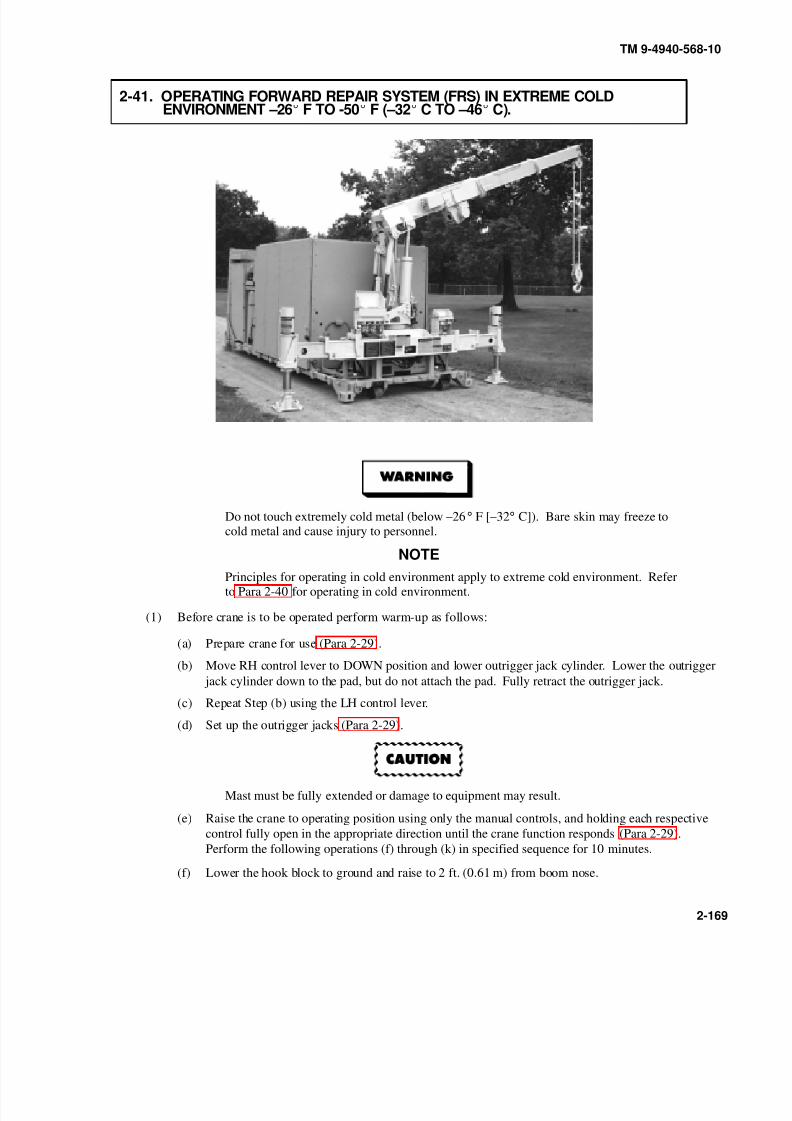
8/20/2019 TM 9-4940-568-10 FRS
http://slidepdf.com/reader/full/tm-9-4940-568-10-frs 219/403
TM 9-4940-568-10
2-169
2-41. OPERATING FORWARD REPAIR SYSTEM (FRS) IN EXTREME COLDENVIRONMENT –26 F TO -50 F (–32 C TO –46 C).
Do not touch extremely cold metal (below –26° F [–32° C]). Bare skin may freeze tocold metal and cause injury to personnel.
NOTEPrinciples for operating in cold environment apply to extreme cold environment. Referto Para 2-40 for operating in cold environment.
(1) Before crane is to be operated perform warm-up as follows:
(a) Prepare crane for use (Para 2-29).
(b) Move RH control lever to DOWN position and lower outrigger jack cylinder. Lower the outrigger
jack cylinder down to the pad, but do not attach the pad. Fully retract the outrigger jack.
(c) Repeat Step (b) using the LH control lever.
(d) Set up the outrigger jacks (Para 2-29).
Mast must be fully extended or damage to equipment may result.
(e) Raise the crane to operating position using only the manual controls, and holding each respective
control fully open in the appropriate direction until the crane function responds (Para 2-29).
Perform the following operations (f) through (k) in specified sequence for 10 minutes.
(f) Lower the hook block to ground and raise to 2 ft. (0.61 m) from boom nose.

8/20/2019 TM 9-4940-568-10 FRS
http://slidepdf.com/reader/full/tm-9-4940-568-10-frs 220/403
TM 9-4940-568-10
2-170
2-41. OPERATING FORWARD REPAIR SYSTEM (FRS) IN EXTREME COLD ENVIRONMENT –26 F TO -50 F (–32 C TO –46 C) (CONT).
(g) Raise the boom to maximum elevation (45 degrees).
(h) Telescope the boom out fully while operating hoist down to prevent hook block from contacting
boom nose.
(i) Fully retract the boom while operating hoist up to keep hook block approximately 2 ft. (0.61 m)from boom nose.
(j) Lower the boom to horizontal.
(k) Rotate the crane fully counterclockwise (180 degrees) and rotate back fully clockwise.
NOTE
Perform Steps (l) and (m) if using remote control.
(l) Connect the remote control (Para 2-29).
(m) Attempt to operate all crane functions by remote control (Para 2-29), without connecting to load. If
any crane function fails to respond, continue to exercise the specific function using the manualcontrol until it responds to the remote control.
(n) Continue with operation of crane (Para 2-29).
(o) When crane operation is completed, disconnect and stow remote control and cable (if used), and
shut down crane (Para 2-29).

8/20/2019 TM 9-4940-568-10 FRS
http://slidepdf.com/reader/full/tm-9-4940-568-10-frs 221/403
TM 9-4940-568-10
2-171
2-42. FORWARD REPAIR SYSTEM (FRS) EMERGENCY PROCEDURES.
a. Crane Emergency Procedures.
(1) Crane emergency operation with electrical failure:
Do not try to operate any electrical equipment on crane if electrical failure hasoccurred. Damage to equipment could result.
NOTE
• This procedure will provide emergency hydraulic power to lower crane and load when
electrical power has failed.
• Failure of hydraulic system will stop operation of any crane, winch or hydraulic motor.
All cranes and winches are equipped with automatic locking mechanisms to hold cranes
and winches in position they were in before hydraulics failed.
(a) Cut and remove safety lock seal (1).
(b) Remove two screws (2), lockwashers (3), washers (4) and manual override guard (5) from crane
(6).
(c) Press in, twist counterclockwise and pull out MHC MANUAL OVERRIDE valve (7).
(d) Stow crane (6) in accordance with crane stowage (Para 2-29), using manual controls only.
(e) Press in, twist clockwise and release MHC MANUAL OVERRIDE valve (7).
(f) Notify Unit Maintenance.
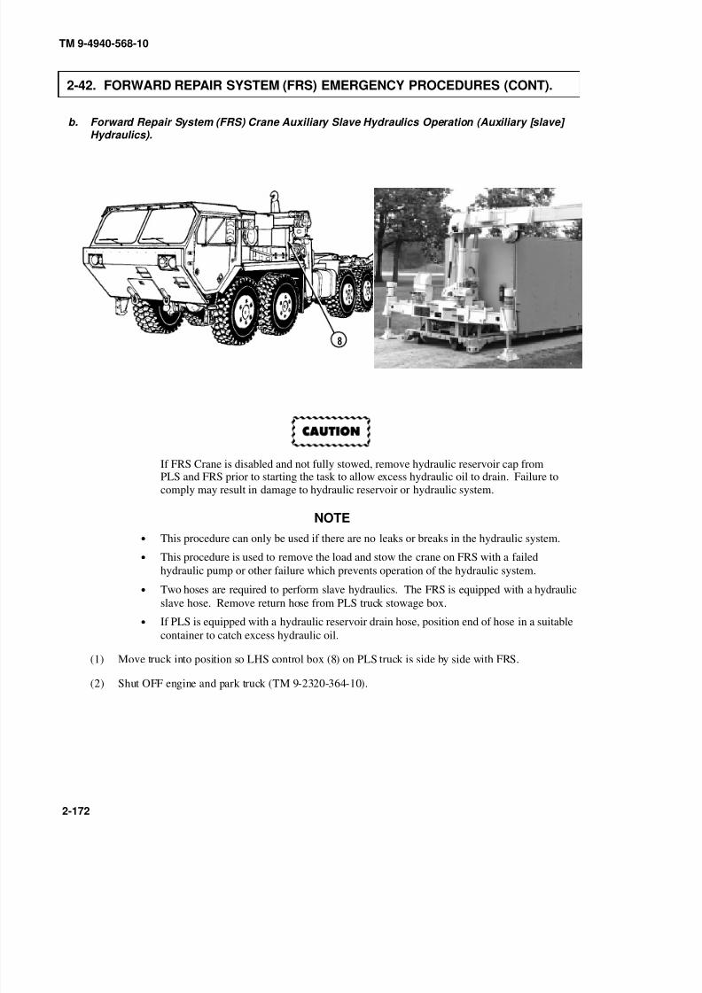
8/20/2019 TM 9-4940-568-10 FRS
http://slidepdf.com/reader/full/tm-9-4940-568-10-frs 222/403
TM 9-4940-568-10
2-172
2-42. FORWARD REPAIR SYSTEM (FRS) EMERGENCY PROCEDURES (CONT).
b. Forward Repair System (FRS) Crane Auxiliary Slave Hydraulics Operation (Auxiliary [slave] Hydraulics).
If FRS Crane is disabled and not fully stowed, remove hydraulic reservoir cap fromPLS and FRS prior to starting the task to allow excess hydraulic oil to drain. Failure to
comply may result in damage to hydraulic reservoir or hydraulic system.
NOTE
• This procedure can only be used if there are no leaks or breaks in the hydraulic system.
• This procedure is used to remove the load and stow the crane on FRS with a failed
hydraulic pump or other failure which prevents operation of the hydraulic system.
• Two hoses are required to perform slave hydraulics. The FRS is equipped with a hydraulic
slave hose. Remove return hose from PLS truck stowage box.
• If PLS is equipped with a hydraulic reservoir drain hose, position end of hose in a suitable
container to catch excess hydraulic oil.
(1) Move truck into position so LHS control box (8) on PLS truck is side by side with FRS.
(2) Shut OFF engine and park truck (TM 9-2320-364-10).

8/20/2019 TM 9-4940-568-10 FRS
http://slidepdf.com/reader/full/tm-9-4940-568-10-frs 223/403
9
0
TM 9-4940-568-10
2-173
Hydraulic fluid is under great pressure. Engines on both PLS truck and FRS must beshut off while disconnecting hydraulic lines, Steps (3) through (8). Failure to do socould cause serious injury or death to personnel.
To prevent hydraulic contamination, keep hydraulic quick disconnects clean or damageto hydraulic system may result.
NOTE
Quick disconnects are located on the back of the LHS control box and back of FRS.
(3) Disconnect hydraulic lines (9) quick disconnects (10) located on the back of the LHS control box (8).
(4) Disconnect hydraulic lines (11) quick disconnects (12) located on the back of the FRS.

8/20/2019 TM 9-4940-568-10 FRS
http://slidepdf.com/reader/full/tm-9-4940-568-10-frs 224/403
TM 9-4940-568-10
2-174
2-42. FORWARD REPAIR SYSTEM (FRS) EMERGENCY PROCEDURES (CONT).
NOTE
Supply slave hose is equipped with a flow control valve.
(5) Connect male end of supply slave hose (13) to female end of supply hose (14) on PLS truck.
(6) Connect female end of supply slave hose (13) to male end of supply hose quick disconnect (15) located
on FRS.
(7) Connect female end of return slave hose (16) to male end of return hose (17) on PLS truck.
(8) Connect male end of return slave hose (16) to female return hose quick disconnect (18) located on FRS.
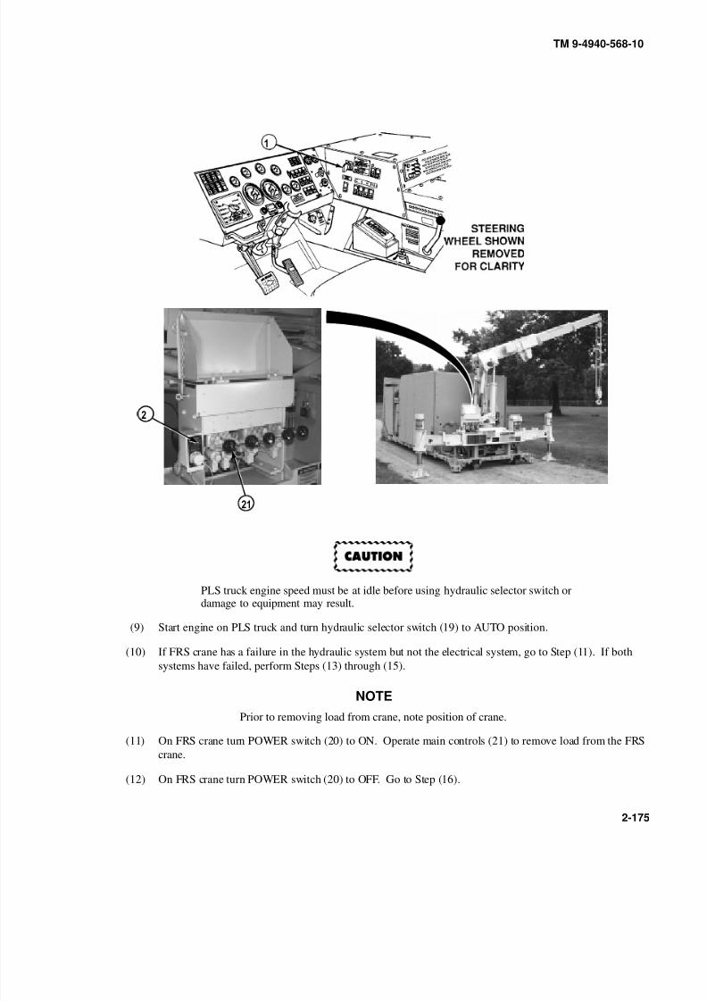
8/20/2019 TM 9-4940-568-10 FRS
http://slidepdf.com/reader/full/tm-9-4940-568-10-frs 225/403
TM 9-4940-568-10
2-175
PLS truck engine speed must be at idle before using hydraulic selector switch ordamage to equipment may result.
(9) Start engine on PLS truck and turn hydraulic selector switch (19) to AUTO position.
(10) If FRS crane has a failure in the hydraulic system but not the electrical system, go to Step (11). If both
systems have failed, perform Steps (13) through (15).
NOTE
Prior to removing load from crane, note position of crane.
(11) On FRS crane turn POWER switch (20) to ON. Operate main controls (21) to remove load from the FRS
crane.
(12) On FRS crane turn POWER switch (20) to OFF. Go to Step (16).
9
0

8/20/2019 TM 9-4940-568-10 FRS
http://slidepdf.com/reader/full/tm-9-4940-568-10-frs 226/403
TM 9-4940-568-10
2-176
2-42. FORWARD REPAIR SYSTEM (FRS) EMERGENCY PROCEDURES (CONT).
NOTE
Button may be stiff and hard to push in.
(13) Press in, twist counterclockwise and pull out MHC MANUAL OVERRIDE valve (7).
(14) Operate main controls (21) to remove load from the FRS crane.
(15) Press in, twist clockwise and release MHC MANUAL OVERRIDE valve (7).
PLS truck engine speed must be at idle before using hydraulic selector switch, ordamage to equipment may result.
(16) Turn hydraulic selector switch (19) to OFF position.
(17) Shut off engine on PLS truck.
9
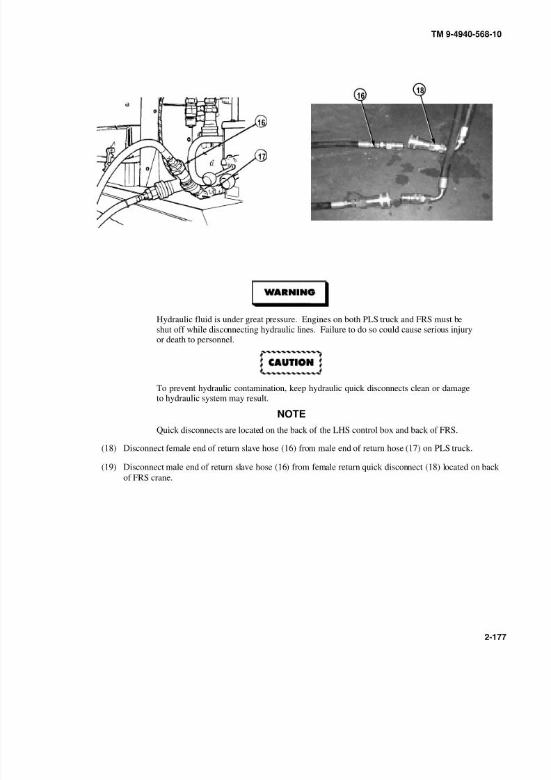
8/20/2019 TM 9-4940-568-10 FRS
http://slidepdf.com/reader/full/tm-9-4940-568-10-frs 227/403
TM 9-4940-568-10
2-177
Hydraulic fluid is under great pressure. Engines on both PLS truck and FRS must beshut off while disconnecting hydraulic lines. Failure to do so could cause serious injuryor death to personnel.
To prevent hydraulic contamination, keep hydraulic quick disconnects clean or damageto hydraulic system may result.
NOTE
Quick disconnects are located on the back of the LHS control box and back of FRS.
(18) Disconnect female end of return slave hose (16) from male end of return hose (17) on PLS truck.
(19) Disconnect male end of return slave hose (16) from female return quick disconnect (18) located on back
of FRS crane.

8/20/2019 TM 9-4940-568-10 FRS
http://slidepdf.com/reader/full/tm-9-4940-568-10-frs 228/403
TM 9-4940-568-10
2-178
2-42. FORWARD REPAIR SYSTEM (FRS) EMERGENCY PROCEDURES (CONT).
PLS truck engine speed must be at idle before using hydraulic selector switch ordamage to equipment may result.
(20) Start engine on PLS truck and turn hydraulic selector switch (19) to AUTO position.
(21) Turn FRS crane selector switch (20) to ON.
NOTE
• As you retract crane to stowed position, you must observe the FRS sight gage located on
hydraulic reservoir to prevent overfilling the reservoir.
• When the hydraulic reservoir has reached the required level, reconnect return lines and
continue to stow FRS crane.
(22) Return FRS crane to the stowed position (Para 2-29).
(23) Disconnect male end of supply slave hose (13) from female end of supply hose (14) on PLS truck.
(24) Disconnect female end of supply slave hose (13) from male end of supply quick disconnect (15) located
on back of FRS.
9
0

8/20/2019 TM 9-4940-568-10 FRS
http://slidepdf.com/reader/full/tm-9-4940-568-10-frs 229/403
TM 9-4940-568-10
2-179
(25) Connect hydraulic lines (9) quick disconnects (10) located on the back of the LHS control box (8).
(26) Connect supply hose quick disconnect (22) to female quick disconnect (23) located on back of the FRS.
(27) When operations are completed, check hydraulic fluid levels in both PLS truck (TM 9-2320-364-10) and
FRS (Para 2-11). Fill if necessary.
9
0

8/20/2019 TM 9-4940-568-10 FRS
http://slidepdf.com/reader/full/tm-9-4940-568-10-frs 230/403
TM 9-4940-568-10
2-180
2-43. SECURE FORWARD REPAIR SYSTEM (FRS).
(1) Lock crane remote stowage box (1).
(2) Lock FRS shelter doors (2). Refer to shelter door assembly and platform operation (Para 2-33).
8/20/2019 TM 9-4940-568-10 FRS
http://slidepdf.com/reader/full/tm-9-4940-568-10-frs 231/403
TM 9-4940-568-10
3-1
CHAPTER 3OPERATOR MAINTENANCE
Para Contents Page
3-1 Introduction 3-1. . . . . . . . . . . . . . . . . . . . . . . . . . . . . . . . . . . . . . . . . . . . . . . . . . . . . . . . . . . . . . . . . . . . . . . . . . . . . . . . . . . . . . . . . . . . . . . . . . . . . . . . . . . . .
3-2 Troubleshooting Introduction 3-1. . . . . . . . . . . . . . . . . . . . . . . . . . . . . . . . . . . . . . . . . . . . . . . . . . . . . . . . . . . . . . . . . . . . . . . . . . . . . . . . . . . . . .
3-3 Troubleshooting Symptoms 3-1. . . . . . . . . . . . . . . . . . . . . . . . . . . . . . . . . . . . . . . . . . . . . . . . . . . . . . . . . . . . . . . . . . . . . . . . . . . . . . . . . . . . . . . .
3-4 Fuel System Priming 3-44. . . . . . . . . . . . . . . . . . . . . . . . . . . . . . . . . . . . . . . . . . . . . . . . . . . . . . . . . . . . . . . . . . . . . . . . . . . . . . . . . . . . . . . . . . . . . . . . .
3-5 Air System Draining 3-46. . . . . . . . . . . . . . . . . . . . . . . . . . . . . . . . . . . . . . . . . . . . . . . . . . . . . . . . . . . . . . . . . . . . . . . . . . . . . . . . . . . . . . . . . . . . . . . . . .
3-6 Battery Disconnect/Connect 3-47. . . . . . . . . . . . . . . . . . . . . . . . . . . . . . . . . . . . . . . . . . . . . . . . . . . . . . . . . . . . . . . . . . . . . . . . . . . . . . . . . . . . . . . .
3-7 Governor Controller Gain Adjustment 3-49. . . . . . . . . . . . . . . . . . . . . . . . . . . . . . . . . . . . . . . . . . . . . . . . . . . . . . . . . . . . . . . . . . . . . . . . . . .
3-8 Generator Set Panel Removal/Stow 3-51. . . . . . . . . . . . . . . . . . . . . . . . . . . . . . . . . . . . . . . . . . . . . . . . . . . . . . . . . . . . . . . . . . . . . . . . . . . . . . .
Section I. LUBRICATION INSTRUCTIONS
3-1. INTRODUCTION.
Refer to Appendix G for lubrication procedures for the Forward Repair System (FRS).
Section II. TROUBLESHOOTING PROCEDURES
3-2. TROUBLESHOOTING INTRODUCTION.
Table 3-1 lists common malfunctions that you may find with your equipment. Perform the tests, inspections and
corrective actions in the order they appear in the table. This table cannot list all malfunctions that may occur, all tests
or inspections needed to find the fault or all corrective actions needed to correct the fault. If a malfunction is not listed
or actions listed do not correct the fault, notify your supervisor.
3-3. TROUBLESHOOTING SYMPTOMS.
To quickly find a troubleshooting procedure, use the Malfunction Index. Table 3-1 contains the operator
troubleshooting steps.

8/20/2019 TM 9-4940-568-10 FRS
http://slidepdf.com/reader/full/tm-9-4940-568-10-frs 232/403
TM 9-4940-568-10
3-2
MALFUNCTION INDEX
TROUBLESHOOTINGPROCEDURE PAGE
GENERATOR
1. Engine Will Not Crank or Cranks Slowly 3-3. . . . . . . . . . . . . . . . . . . . . . . . . . . . . . . . . . . . . . . . . . . . . . . . . . . . . . . . . . . . . . . . . . . .
2. Engine Cranks But Fails to Start 3-4. . . . . . . . . . . . . . . . . . . . . . . . . . . . . . . . . . . . . . . . . . . . . . . . . . . . . . . . . . . . . . . . . . . . . . . . . . . . . . . .
3. Engine Cranks But Fails to Start, No Smoke From Exhaust 3-6. . . . . . . . . . . . . . . . . . . . . . . . . . . . . . . . . . . . . . . . . . . .
4. Excessive Black Smoke From Exhaust 3-7. . . . . . . . . . . . . . . . . . . . . . . . . . . . . . . . . . . . . . . . . . . . . . . . . . . . . . . . . . . . . . . . . . . . . . . .
5. Coolant Temperature is Above Normal 3-8. . . . . . . . . . . . . . . . . . . . . . . . . . . . . . . . . . . . . . . . . . . . . . . . . . . . . . . . . . . . . . . . . . . . . . .
6. Engine Check Indicator Lamp or Lamps are On 3-9. . . . . . . . . . . . . . . . . . . . . . . . . . . . . . . . . . . . . . . . . . . . . . . . . . . . . . . . . . .
7. No AC Output Voltage or Voltage Not Within Specified Limits 110 - 120 3-10. . . . . . . . . . . . . . . . . . . . . . . . . . .
AIR COMPRESSOR
1. Fails To Start 3-12. . . . . . . . . . . . . . . . . . . . . . . . . . . . . . . . . . . . . . . . . . . . . . . . . . . . . . . . . . . . . . . . . . . . . . . . . . . . . . . . . . . . . . . . . . . . . . . . . . . . . . . . .
2. Starts but Fails to Stay Running or Shuts Down During Normal Operation 3-13. . . . . . . . . . . . . . . . . . . . . . . .
3. Fails to Build-up Air Pressure 3-14. . . . . . . . . . . . . . . . . . . . . . . . . . . . . . . . . . . . . . . . . . . . . . . . . . . . . . . . . . . . . . . . . . . . . . . . . . . . . . . . . . .
SHELTER INTERIOR LIGHTING
1. One or More Lighting Fixtures are Not Operating Properly 3-15. . . . . . . . . . . . . . . . . . . . . . . . . . . . . . . . . . . . . . . . . . . .
2. One or Both Worklight Fixtures are Not Operating Properly 3-16. . . . . . . . . . . . . . . . . . . . . . . . . . . . . . . . . . . . . . . . . . .
3. One or More Receptacles are Not Operating Properly 3-17. . . . . . . . . . . . . . . . . . . . . . . . . . . . . . . . . . . . . . . . . . . . . . . . . . . .
SHELTER HEATER
1. Heater Fails To Start or Does Not Stay Running 3-18. . . . . . . . . . . . . . . . . . . . . . . . . . . . . . . . . . . . . . . . . . . . . . . . . . . . . . . . . . .
MIG WELDER
1. Mig Welder Does Not Operate 3-21. . . . . . . . . . . . . . . . . . . . . . . . . . . . . . . . . . . . . . . . . . . . . . . . . . . . . . . . . . . . . . . . . . . . . . . . . . . . . . . . . . .
STICK (SHIELDED METAL ARC WELDER [SMAW]) WELDER
1. Stick (SMAW) Welder Does Not Operate 3-23. . . . . . . . . . . . . . . . . . . . . . . . . . . . . . . . . . . . . . . . . . . . . . . . . . . . . . . . . . . . . . . . . . . .
CRANE
1. Crane Does Not Operate 3-24. . . . . . . . . . . . . . . . . . . . . . . . . . . . . . . . . . . . . . . . . . . . . . . . . . . . . . . . . . . . . . . . . . . . . . . . . . . . . . . . . . . . . . . . . . .
2. Crane Does Not Operate With Remote Control Unit 3-28. . . . . . . . . . . . . . . . . . . . . . . . . . . . . . . . . . . . . . . . . . . . . . . . . . . . . .
3. Boom Operation Abnormal or Does Not Telescope In or Out 3-30. . . . . . . . . . . . . . . . . . . . . . . . . . . . . . . . . . . . . . . . . .
4. Boom Does Not Raise or Lower, or Raises and Lowers Slowly 3-32. . . . . . . . . . . . . . . . . . . . . . . . . . . . . . . . . . . . . . .
5. Hoist Operation Jerky, or Does Not Lift or Lower Load 3-33. . . . . . . . . . . . . . . . . . . . . . . . . . . . . . . . . . . . . . . . . . . . . . . . .
6. Hoist Does Not Spool Cable Properly 3-35. . . . . . . . . . . . . . . . . . . . . . . . . . . . . . . . . . . . . . . . . . . . . . . . . . . . . . . . . . . . . . . . . . . . . . . . .
7. Mast, Outriggers or Stabilizers Extend or Retract Slow or Abnormal 3-38. . . . . . . . . . . . . . . . . . . . . . . . . . . . . . . .
8. Swing Operation Slow or Jerky in One or Both Directions, or Does NotSwing in Either Direction 3-40. . . . . . . . . . . . . . . . . . . . . . . . . . . . . . . . . . . . . . . . . . . . . . . . . . . . . . . . . . . . . . . . . . . . . . . . . . . . . . . . . . . . . . . . .
9. Overload Shutdown System Does Not Operate Properly 3-41. . . . . . . . . . . . . . . . . . . . . . . . . . . . . . . . . . . . . . . . . . . . . . . .

8/20/2019 TM 9-4940-568-10 FRS
http://slidepdf.com/reader/full/tm-9-4940-568-10-frs 233/403
TM 9-4940-568-10
3-3
Table 3-1. Troubleshooting
MalfunctionTest or Inspection
Corrective Action
GENERATOR
1. ENGINE WILL NOT CRANK OR CRANKS SLOWLY.
Lead-acid battery gases can explode. Do not smoke, have open flames, or makesparks around a battery, expecially if caps are off. If a battery is gassing, it canexplode and cause injury to personnel.
Step 1. Check that Master Disconnect Switch (1) is in the ON position.
• Position Master Disconnect Switch (1) in ON position.
Step 2. Check for dirty battery cable connections (2) or loose or broken battery cables (3) or posts (4).
• If battery connections are dirty, or cable or posts are damaged, notify Unit Maintenance.

8/20/2019 TM 9-4940-568-10 FRS
http://slidepdf.com/reader/full/tm-9-4940-568-10-frs 234/403
TM 9-4940-568-10
3-4
Table 3-1. Troubleshooting - CONT.
MalfunctionTest or Inspection
Corrective Action
GENERATOR (CONT)
2. ENGINE CRANKS BUT FAILS TO START.
Lead-acid battery gases can explode. Do not smoke, have open flames, or makesparks around a battery, expecially if caps are off. If a battery is gassing, it canexplode and cause injury to personnel.
Step 1. Check for dirty battery cable connections (1) or loose or broken battery cables (2) or posts (3).
• If battery connections are dirty, or cable or posts are damaged, notify Unit Maintenance.
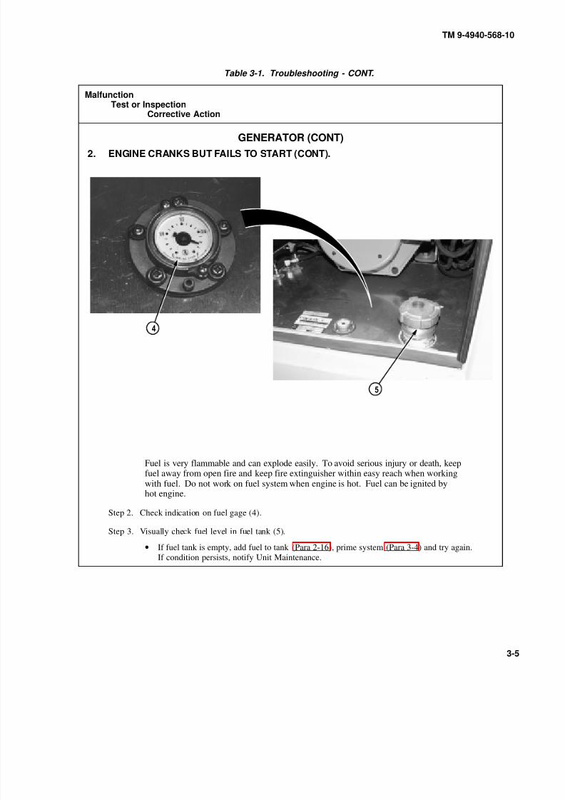
8/20/2019 TM 9-4940-568-10 FRS
http://slidepdf.com/reader/full/tm-9-4940-568-10-frs 235/403
TM 9-4940-568-10
3-5
Table 3-1. Troubleshooting - CONT.
MalfunctionTest or Inspection
Corrective Action
GENERATOR (CONT)
2. ENGINE CRANKS BUT FAILS TO START (CONT).
Fuel is very flammable and can explode easily. To avoid serious injury or death, keepfuel away from open fire and keep fire extinguisher within easy reach when workingwith fuel. Do not work on fuel system when engine is hot. Fuel can be ignited byhot engine.
Step 2. Check indication on fuel gage (4).
Step 3. Visually check fuel level in fuel tank (5).
• If fuel tank is empty, add fuel to tank (Para 2-16), prime system (Para 3-4) and try again.
If condition persists, notify Unit Maintenance.

8/20/2019 TM 9-4940-568-10 FRS
http://slidepdf.com/reader/full/tm-9-4940-568-10-frs 236/403
TM 9-4940-568-10
3-6
Table 3-1. Troubleshooting - CONT.
MalfunctionTest or Inspection
Corrective Action
GENERATOR (CONT)
3. ENGINE CRANKS BUT FAILS TO START, NO SMOKE FROM EXHAUST.
Fuel is very flammable and can explode easily. To avoid serious injury or death, keepfuel away from open fire and keep fire extinguisher within easy reach when workingwith fuel. Do not work on fuel system when engine is hot. Fuel can be ignited byhot engine.
Step 1. Check indication on fuel gage (1).
Step 2. Visually check fuel level in fuel tank (2).
• If fuel tank is empty, add fuel to tank (Para 2-16), prime system (Para 3-4) and try again.
If condition persists, notify Unit Maintenance.

8/20/2019 TM 9-4940-568-10 FRS
http://slidepdf.com/reader/full/tm-9-4940-568-10-frs 237/403
TM 9-4940-568-10
3-7
Table 3-1. Troubleshooting - CONT.
MalfunctionTest or Inspection
Corrective Action
GENERATOR (CONT)
4. EXCESSIVE BLACK SMOKE FROM EXHAUST.
Step 1. Check air filter restriction indicator (1) for condition of air cleaner element.
• If air filter restriction indicator indicates a dirty air cleaner element, notify Unit Maintenance.
• If air filter restriction indicator indicates air cleaner element is not dirty, notify Unit
Maintenance.
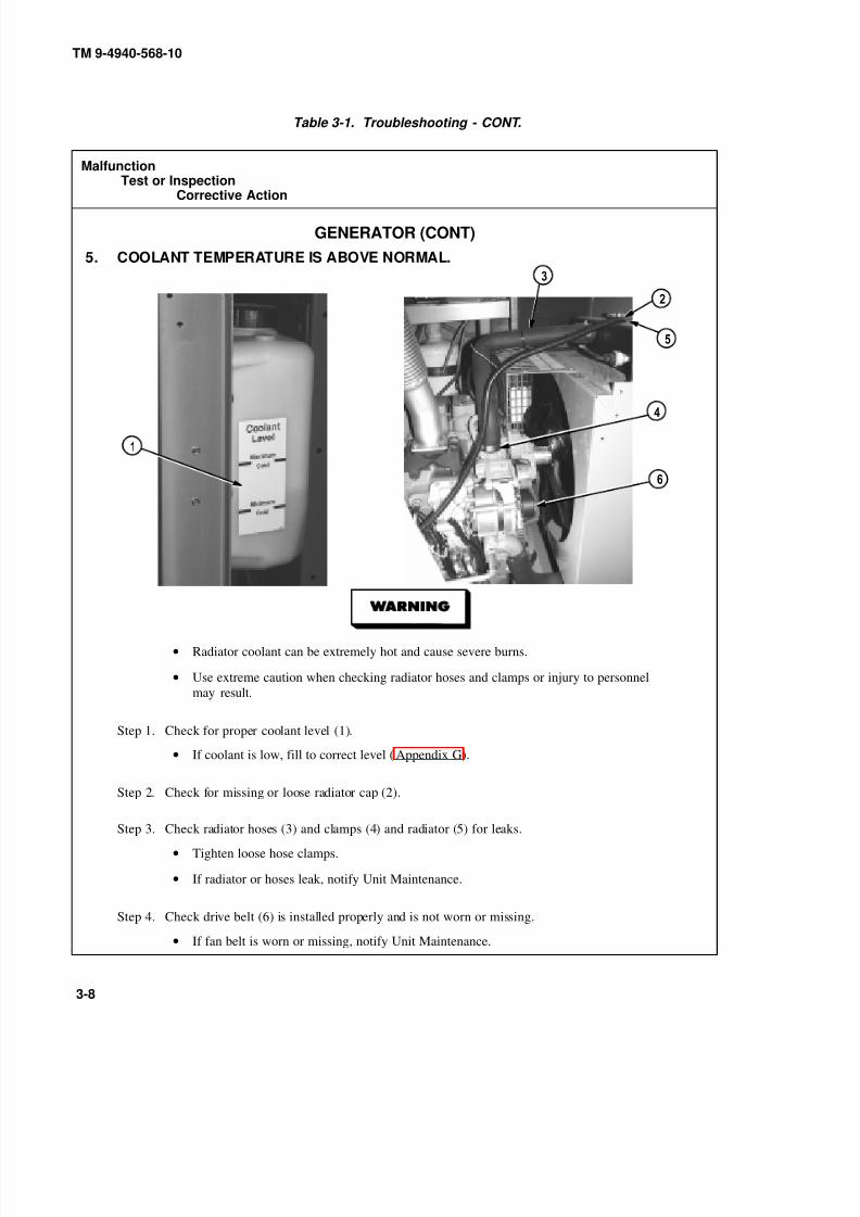
8/20/2019 TM 9-4940-568-10 FRS
http://slidepdf.com/reader/full/tm-9-4940-568-10-frs 238/403
TM 9-4940-568-10
3-8
Table 3-1. Troubleshooting - CONT.
MalfunctionTest or Inspection
Corrective Action
GENERATOR (CONT)
5. COOLANT TEMPERATURE IS ABOVE NORMAL.
• Radiator coolant can be extremely hot and cause severe burns.
• Use extreme caution when checking radiator hoses and clamps or injury to personnel
may result.
Step 1. Check for proper coolant level (1).
• If coolant is low, fill to correct level (Appendix G).
Step 2. Check for missing or loose radiator cap (2).
Step 3. Check radiator hoses (3) and clamps (4) and radiator (5) for leaks.
• Tighten loose hose clamps.
• If radiator or hoses leak, notify Unit Maintenance.
Step 4. Check drive belt (6) is installed properly and is not worn or missing.
• If fan belt is worn or missing, notify Unit Maintenance.

8/20/2019 TM 9-4940-568-10 FRS
http://slidepdf.com/reader/full/tm-9-4940-568-10-frs 239/403
TM 9-4940-568-10
3-9
Table 3-1. Troubleshooting - CONT.
MalfunctionTest or Inspection
Corrective Action
GENERATOR (CONT)
6. ENGINE CHECK INDICATOR LAMP OR LAMPS ARE ON.
Step 1. Check indicator lamps (1). Lamps indicate a potential engine failure (low oil pressure, low coolant,
coolant overheating) has occurred.
• Check gages and shut down engine. Gages should read as follows:
Oil pressure 10 psi (69 kPa) at idle; Water Temp gage below 203 degrees F (95 C).
• Check engine oil level (Para 2-11) if OIL PRESS gage indicates low reading add oil and
recheck gage. If condition still exists, notify Unit Maintenance.
•Check coolant level (Para 2-11) if Water Temp gage indicates high reading, addcoolant (Appendix G) and recheck gage. If condition still exists, notify Unit Maintenance.
Step 2. If LO OIL PRES lamp (2) is on, check engine oil pressure gage (3) and if HI ENG TEMP (4) is on
check water temperature gage (5). If both indicate normal, proceed with mission and then notify
Unit Maintenance. If either one does not indicate normal, stop engine immediately and notify
Unit Maintenance.
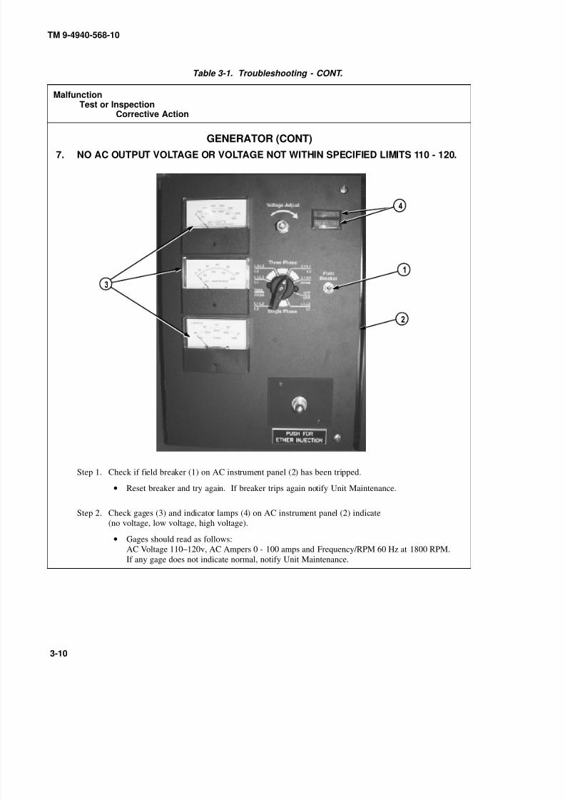
8/20/2019 TM 9-4940-568-10 FRS
http://slidepdf.com/reader/full/tm-9-4940-568-10-frs 240/403
TM 9-4940-568-10
3-10
Table 3-1. Troubleshooting - CONT.
MalfunctionTest or Inspection
Corrective Action
GENERATOR (CONT)
7. NO AC OUTPUT VOLTAGE OR VOLTAGE NOT WITHIN SPECIFIED LIMITS 110 - 120.
Step 1. Check if field breaker (1) on AC instrument panel (2) has been tripped.
• Reset breaker and try again. If breaker trips again notify Unit Maintenance.
Step 2. Check gages (3) and indicator lamps (4) on AC instrument panel (2) indicate
(no voltage, low voltage, high voltage).
• Gages should read as follows:
AC Voltage 110–120v, AC Ampers 0 - 100 amps and Frequency/RPM 60 Hz at 1800 RPM.
If any gage does not indicate normal, notify Unit Maintenance.

8/20/2019 TM 9-4940-568-10 FRS
http://slidepdf.com/reader/full/tm-9-4940-568-10-frs 241/403
TM 9-4940-568-10
3-11
Table 3-1. Troubleshooting - CONT.
MalfunctionTest or Inspection
Corrective Action
GENERATOR (CONT)
8. ENGINE HUNTS UPON START-UP.
Step 1. Check for type of fuel being used (Para 2-16).
• Minor adjustment to the governor controller (1) may be required depending upon type of fuel
used (Para 3-7a).
Step 2. Check for extreme change in ambient temperature.
• If operating at extreme temperature conditions adjust governor controller (1) (Para 3-7b).

8/20/2019 TM 9-4940-568-10 FRS
http://slidepdf.com/reader/full/tm-9-4940-568-10-frs 242/403
TM 9-4940-568-10
3-12
Table 3-1. Troubleshooting - CONT.
MalfunctionTest or Inspection
Corrective Action
AIR COMPRESSOR
1. FAILS TO START.
Step 1 Check oil compressor oil level.
Step 2. Press RESET button (1) on Air Compressor Control Box (2).
Step 3. Check if air compressor circuit breaker (3) on 120/208 MAIN PANEL (4) has been tripped.
• Reset breaker and try again. If breaker trips, notify Unit Maintenance.
Step 4. Check if MAIN circuit breaker (5) on 120/208 MAIN PANEL (4) is in ON position.
• Position circuit breaker in ON position.
• If problem still exists, notify Unit Maintenance.

8/20/2019 TM 9-4940-568-10 FRS
http://slidepdf.com/reader/full/tm-9-4940-568-10-frs 243/403
TM 9-4940-568-10
3-13
Table 3-1. Troubleshooting - CONT.
MalfunctionTest or Inspection
Corrective Action
AIR COMPRESSOR (CONT)
2. STARTS BUT FAILS TO STAY RUNNING OR SHUTS DOWN DURING NORMALOPERATION.
Step 1. Check crankcase oil level (1) on air conpressor (2).
• If oil level is low, add oil (Appendix G).
•If oil level is normal and problem still exists, notify Unit Maintenance.

8/20/2019 TM 9-4940-568-10 FRS
http://slidepdf.com/reader/full/tm-9-4940-568-10-frs 244/403
TM 9-4940-568-10
3-14
Table 3-1. Troubleshooting - CONT.
MalfunctionTest or Inspection
Corrective Action
AIR COMPRESSOR (CONT)
3. FAILS TO BUILD-UP AIR PRESSURE.
Step 1. Check air drain valve (1) is closed.
• Close air drain valve.
Step 2. Listen for leaks at hoses (2), fittings (3) and connectors (4).
• If leaks are found, tighten connectors and fittings.
• If problem still exists, notify Unit Maintenance.
Step 3. Check condition of drivebelt (5).
• If drivebelt is worn or damaged, notify Unit Maintenance.
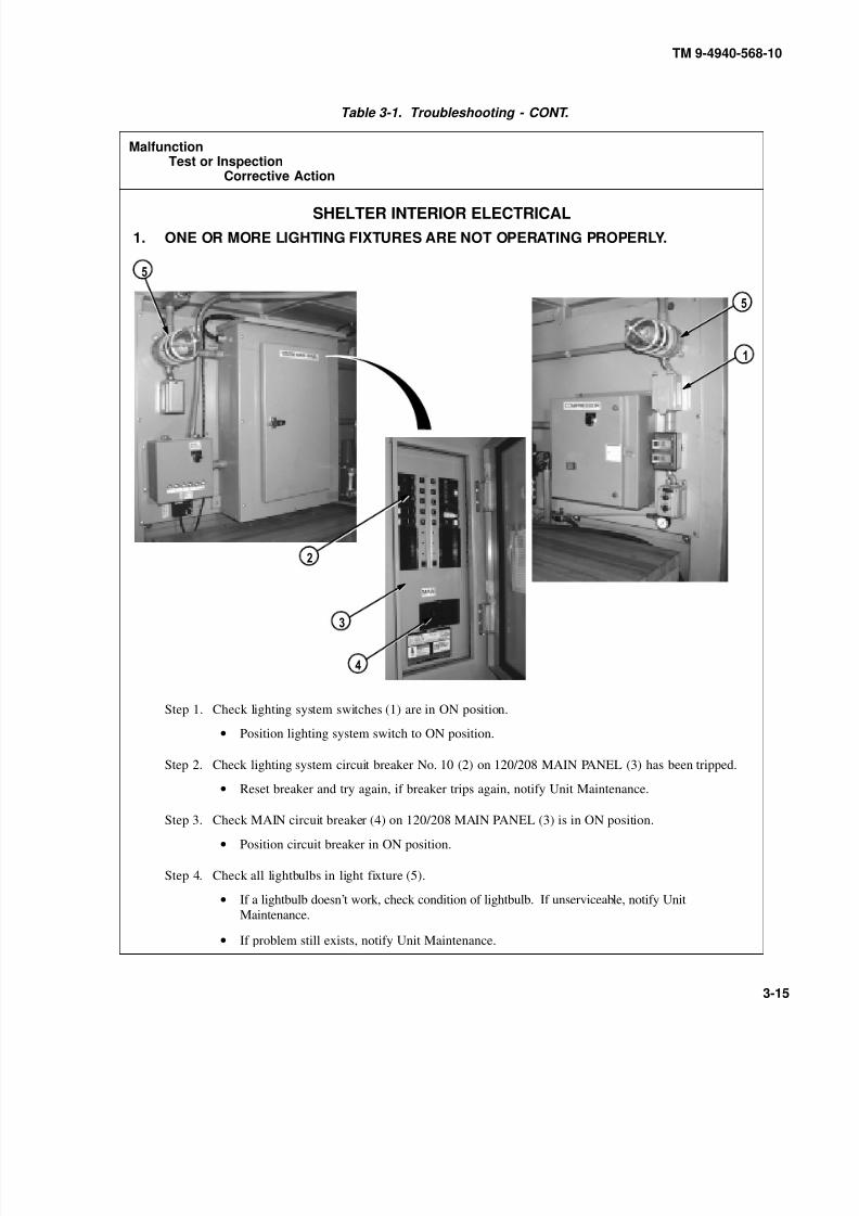
8/20/2019 TM 9-4940-568-10 FRS
http://slidepdf.com/reader/full/tm-9-4940-568-10-frs 245/403
TM 9-4940-568-10
3-15
Table 3-1. Troubleshooting - CONT.
MalfunctionTest or Inspection
Corrective Action
SHELTER INTERIOR ELECTRICAL
1. ONE OR MORE LIGHTING FIXTURES ARE NOT OPERATING PROPERLY.
Step 1. Check lighting system switches (1) are in ON position.
• Position lighting system switch to ON position.
Step 2. Check lighting system circuit breaker No. 10 (2) on 120/208 MAIN PANEL (3) has been tripped.
• Reset breaker and try again, if breaker trips again, notify Unit Maintenance.
Step 3. Check MAIN circuit breaker (4) on 120/208 MAIN PANEL (3) is in ON position.
• Position circuit breaker in ON position.
Step 4. Check all lightbulbs in light fixture (5).
• If a lightbulb doesn’t work, check condition of lightbulb. If unserviceable, notify Unit
Maintenance.
• If problem still exists, notify Unit Maintenance.
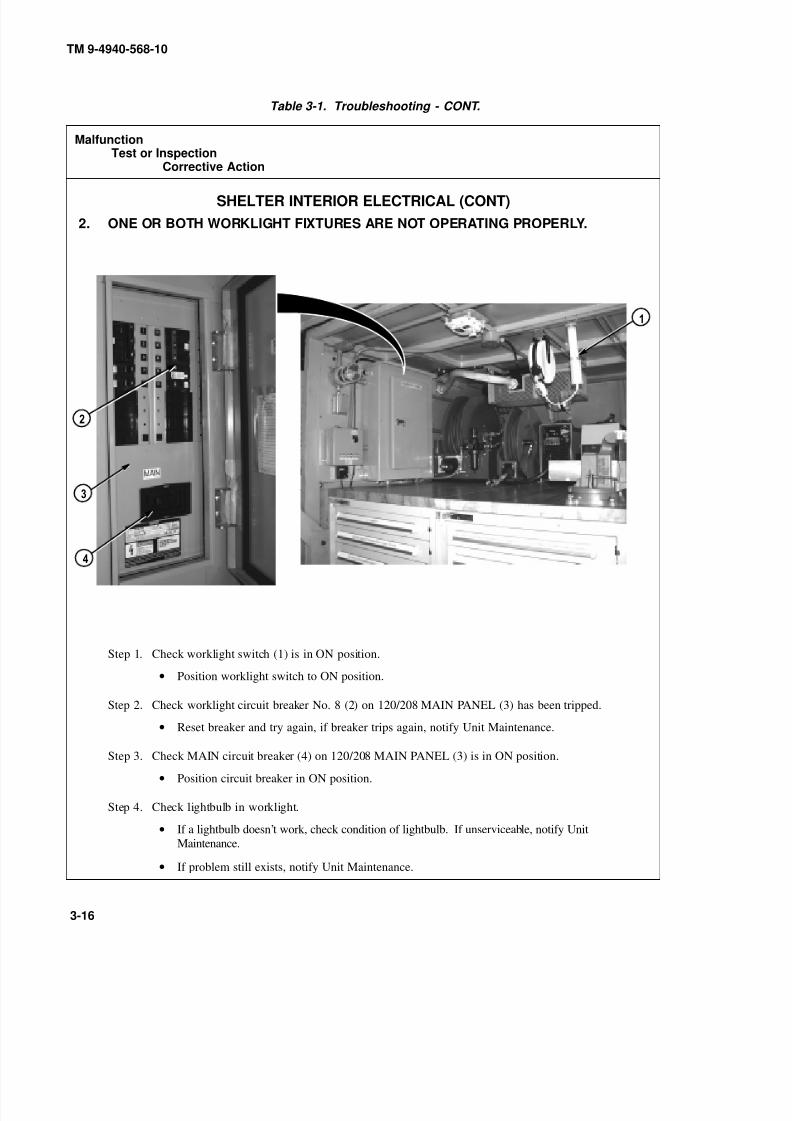
8/20/2019 TM 9-4940-568-10 FRS
http://slidepdf.com/reader/full/tm-9-4940-568-10-frs 246/403
TM 9-4940-568-10
3-16
Table 3-1. Troubleshooting - CONT.
MalfunctionTest or Inspection
Corrective Action
SHELTER INTERIOR ELECTRICAL (CONT)
2. ONE OR BOTH WORKLIGHT FIXTURES ARE NOT OPERATING PROPERLY.
Step 1. Check worklight switch (1) is in ON position.
• Position worklight switch to ON position.
Step 2. Check worklight circuit breaker No. 8 (2) on 120/208 MAIN PANEL (3) has been tripped.
• Reset breaker and try again, if breaker trips again, notify Unit Maintenance.
Step 3. Check MAIN circuit breaker (4) on 120/208 MAIN PANEL (3) is in ON position.
• Position circuit breaker in ON position.
Step 4. Check lightbulb in worklight.
• If a lightbulb doesn’t work, check condition of lightbulb. If unserviceable, notify Unit
Maintenance.
• If problem still exists, notify Unit Maintenance.

8/20/2019 TM 9-4940-568-10 FRS
http://slidepdf.com/reader/full/tm-9-4940-568-10-frs 247/403
TM 9-4940-568-10
3-17
Table 3-1. Troubleshooting - CONT.
MalfunctionTest or Inspection
Corrective Action
SHELTER INTERIOR ELECTRICAL (CONT)
3. ONE OR MORE RECEPTACLES ARE NOT OPERATING PROPERLY.
Step 1. Check Ground Fault Circuit Interupt (GFCI) circuit breaker on receptacle (1) and (2) have been
tripped.
• Reset GFCI breaker(s) and try again, if breaker(s) trips again, notify Unit Maintenance.
Step 2. Check receptical circuit breaker No. 7 (3) and No. 9 (4) on 120/208 MAIN PANEL (5) have
been tripped.
• Reset receptacle circuit breaker(s) and try again, if breaker(s) trips again, notify
Unit Maintenance.
Step 3. Check MAIN circuit breaker (6) on 120/208 MAIN PANEL (5) is in ON position.
• Position MAIN circuit breaker in ON position.

8/20/2019 TM 9-4940-568-10 FRS
http://slidepdf.com/reader/full/tm-9-4940-568-10-frs 248/403
TM 9-4940-568-10
3-18
Table 3-1. Troubleshooting - CONT.
MalfunctionTest or Inspection
Corrective Action
SHELTER HEATER
1. HEATER FAILS TO START OR DOES NOT STAY RUNNING.
Step 1. Check HEATER thermostat (1) power switch (2) is in ON position and green and red operating
light (3) is on.
• Position power switch to ON position.
Step 2. Check 24 VOLT DC PANEL (4) power switch (5) is in ON position.
• Position power switch to ON position.
Step 3. Visually check fuel level in fuel tank.
• If fuel tank is empty, add fuel to tank (Para 2-16).
Step 4. Check HEATER circuit breaker No. 3 (6) on 24 VOLT DC PANEL (4) has been tripped.
• Reset breaker and try again. If breaker trips, notify Unit Maintenance.

8/20/2019 TM 9-4940-568-10 FRS
http://slidepdf.com/reader/full/tm-9-4940-568-10-frs 249/403
TM 9-4940-568-10
3-19
Table 3-1. Troubleshooting - CONT.
MalfunctionTest or Inspection
Corrective Action
SHELTER HEATER (CONT)
1. HEATER FAILS TO START OR DOES NOT STAY RUNNING (CONT).
Step 5. Check heater thermostat (1) green light (7) for blinking fault code.
• If green light on thermostat is blinking, notify Unit Maintenance.
NOTE
The heater will automatically shutdown if overheating occurs. The thermostat green light willflash on and off to indicate an overheat situation.
Step 6. Check air intake screen and air outlet for obstruction.
• Clear any obstruction and restart heater.
• If condition persists, notify Unit Maintenance.

8/20/2019 TM 9-4940-568-10 FRS
http://slidepdf.com/reader/full/tm-9-4940-568-10-frs 250/403
TM 9-4940-568-10
3-20
Table 3-1. Troubleshooting - CONT.
MalfunctionTest or Inspection
Corrective Action
SHELTER HEATER (CONT)
1. HEATER FAILS TO START OR DOES NOT STAY RUNNING (CONT).
Fuel is very flammable and can explode easily. To avoid serious injury or death, keep fuelaway from open fire and keep fire extinguisher within easy reach when working with fuel.Do not work on fuel system when engine is hot. Fuel can be ignited by hot engine.
Step 7. Heater may need to be primed.
• Place drain pan under hose (1).
• Loosen clamp (2) and remove hose (1) from heater (3).
• Operate heater until entrapped air is bleed (Para 2-30).
• Install hose (1) on heater (3) and tighten clamp (2).
• Operate heater and check for leaks (Para 2-30).
• If condition persists, notify Unit Maintenance.
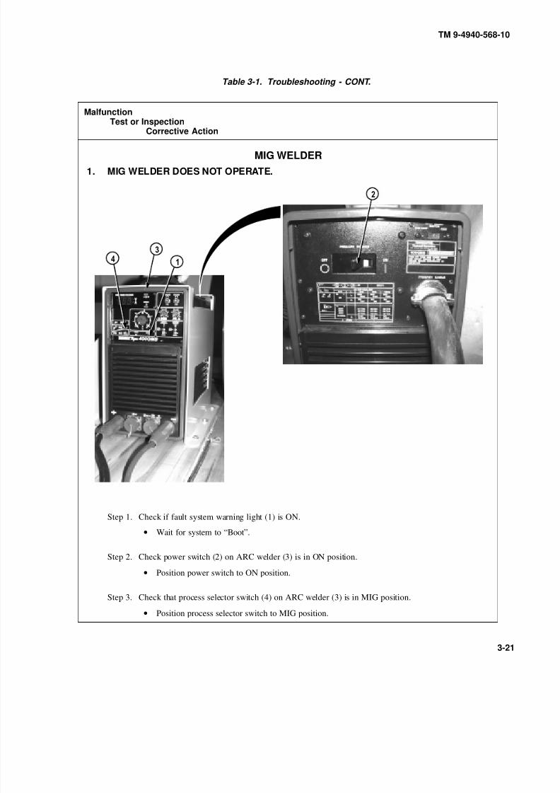
8/20/2019 TM 9-4940-568-10 FRS
http://slidepdf.com/reader/full/tm-9-4940-568-10-frs 251/403
TM 9-4940-568-10
3-21
Table 3-1. Troubleshooting - CONT.
MalfunctionTest or Inspection
Corrective Action
MIG WELDER
1. MIG WELDER DOES NOT OPERATE.
Step 1. Check if fault system warning light (1) is ON.
• Wait for system to “Boot”.
Step 2. Check power switch (2) on ARC welder (3) is in ON position.
• Position power switch to ON position.
Step 3. Check that process selector switch (4) on ARC welder (3) is in MIG position.
• Position process selector switch to MIG position.

8/20/2019 TM 9-4940-568-10 FRS
http://slidepdf.com/reader/full/tm-9-4940-568-10-frs 252/403
TM 9-4940-568-10
3-22
Table 3-1. Troubleshooting - CONT.
MalfunctionTest or Inspection
Corrective Action
MIG WELDER (CONT)
1. MIG WELDER DOES NOT OPERATE (CONT).
Step 4. Check WELDER circuit breaker No. 1, No. 3, No. 5 (5) on 120/208 MAIN PANEL (6) has
been tripped.
• Reset breaker and try again, if breaker trips again, notify Unit Maintenance.
Step 5. Check MAIN circuit breaker (7) on 120/208 MAIN PANEL (6) is in ON position.
• Position circuit breaker in ON position.
Step 6. Check all connections to MIG welder (8) from STICK (SMAW) welder (3).
• If connections are secure and MIG welder still does not operate, notify Unit Maintenance.
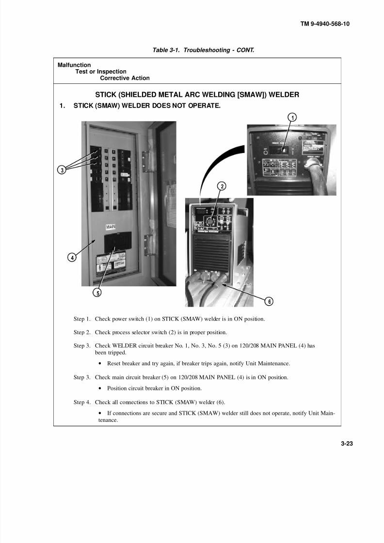
8/20/2019 TM 9-4940-568-10 FRS
http://slidepdf.com/reader/full/tm-9-4940-568-10-frs 253/403
TM 9-4940-568-10
3-23
Table 3-1. Troubleshooting - CONT.
MalfunctionTest or Inspection
Corrective Action
STICK (SHIELDED METAL ARC WELDING [SMAW]) WELDER
1. STICK (SMAW) WELDER DOES NOT OPERATE.
Step 1. Check power switch (1) on STICK (SMAW) welder is in ON position.
Step 2. Check process selector switch (2) is in proper position.
Step 3. Check WELDER circuit breaker No. 1, No. 3, No. 5 (3) on 120/208 MAIN PANEL (4) has
been tripped.
• Reset breaker and try again, if breaker trips again, notify Unit Maintenance.
Step 3. Check main circuit breaker (5) on 120/208 MAIN PANEL (4) is in ON position.
• Position circuit breaker in ON position.
Step 4. Check all connections to STICK (SMAW) welder (6).
• If connections are secure and STICK (SMAW) welder still does not operate, notify Unit Main-
tenance.
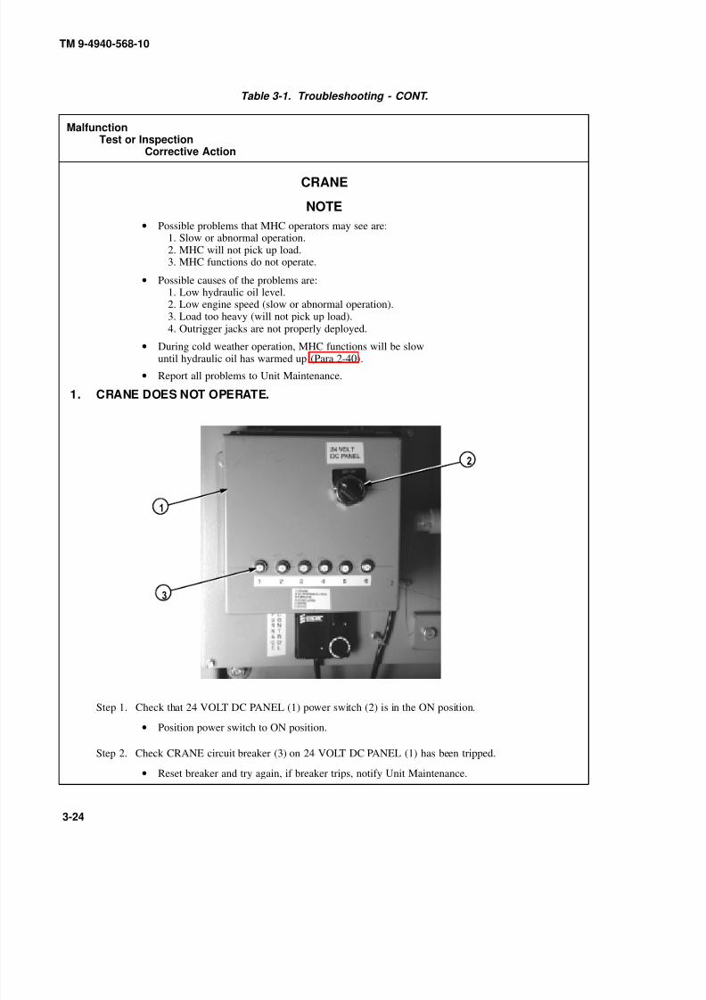
8/20/2019 TM 9-4940-568-10 FRS
http://slidepdf.com/reader/full/tm-9-4940-568-10-frs 254/403
TM 9-4940-568-10
3-24
Table 3-1. Troubleshooting - CONT.
MalfunctionTest or Inspection
Corrective Action
CRANE
NOTE
• Possible problems that MHC operators may see are:1. Slow or abnormal operation.2. MHC will not pick up load.3. MHC functions do not operate.
• Possible causes of the problems are:1. Low hydraulic oil level.2. Low engine speed (slow or abnormal operation).3. Load too heavy (will not pick up load).
4. Outrigger jacks are not properly deployed.• During cold weather operation, MHC functions will be slow
until hydraulic oil has warmed up (Para 2-40).
• Report all problems to Unit Maintenance.
1. CRANE DOES NOT OPERATE.
Step 1. Check that 24 VOLT DC PANEL (1) power switch (2) is in the ON position.
• Position power switch to ON position.
Step 2. Check CRANE circuit breaker (3) on 24 VOLT DC PANEL (1) has been tripped.
• Reset breaker and try again, if breaker trips, notify Unit Maintenance.

8/20/2019 TM 9-4940-568-10 FRS
http://slidepdf.com/reader/full/tm-9-4940-568-10-frs 255/403
TM 9-4940-568-10
3-25
Table 3-1. Troubleshooting - CONT.
MalfunctionTest or Inspection
Corrective Action
CRANE (CONT)
1. CRANE DOES NOT OPERATE (CONT).
NOTE
On the FRS, the crane must be in the stowed position when checking hydraulic oillevel. Hydraulic oil must be at operating temperature.
Step 3. Check the hydraulic oil level in sight glass (4) on hydraulic reservoir (5). Oil level shouldbe between add and full marks.
• If oil level is low, add oil (Appendix G).
• If oil level is OK, go to Step 4.
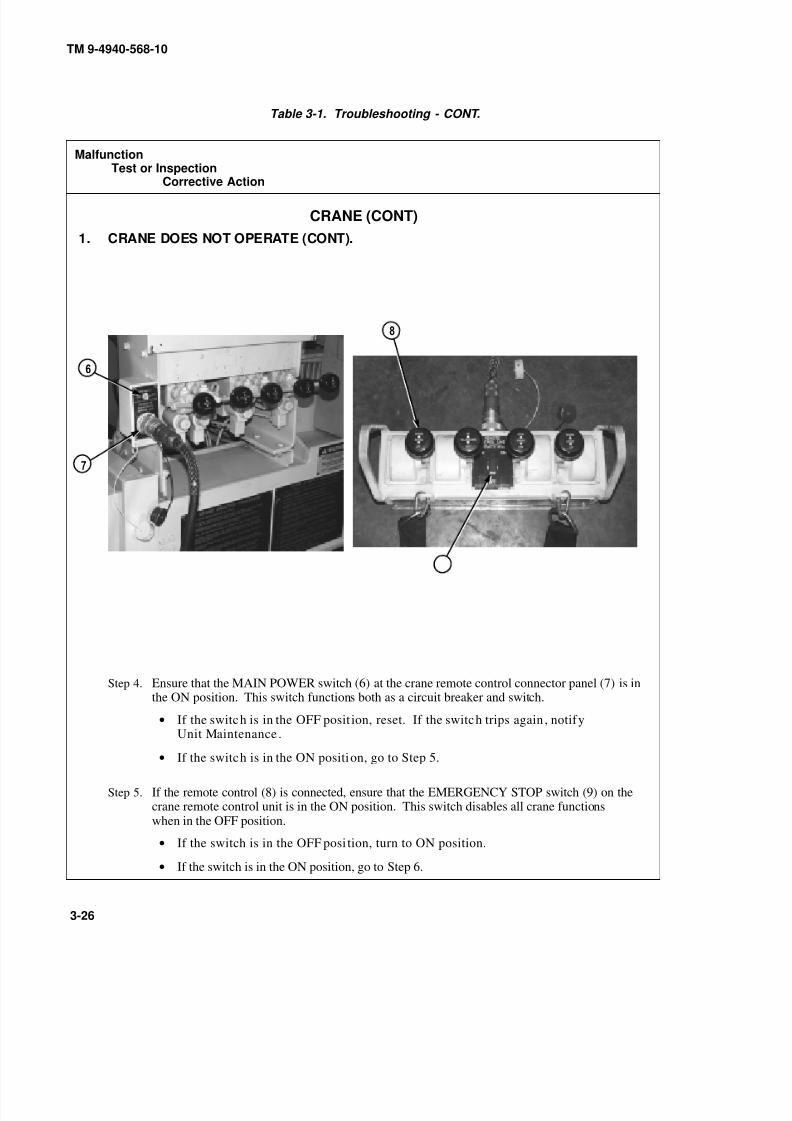
8/20/2019 TM 9-4940-568-10 FRS
http://slidepdf.com/reader/full/tm-9-4940-568-10-frs 256/403
9
TM 9-4940-568-10
3-26
Table 3-1. Troubleshooting - CONT.
MalfunctionTest or Inspection
Corrective Action
CRANE (CONT)
1. CRANE DOES NOT OPERATE (CONT).
Step 4. Ensure that the MAIN POWER switch (6) at the crane remote control connector panel (7) is inthe ON position. This switch functions both as a circuit breaker and switch.
• If the switch is in the OFF posit ion, reset. If the switch trips again , notifyUnit Maintenance .
• If the switch is in the ON position, go to Step 5.
Step 5. If the remote control (8) is connected, ensure that the EMERGENCY STOP switch (9) on thecrane remote control unit is in the ON position. This switch disables all crane functionswhen in the OFF position.
• If the switch is in the OFF posi tion, turn to ON position.
• If the switch is in the ON position, go to Step 6.

8/20/2019 TM 9-4940-568-10 FRS
http://slidepdf.com/reader/full/tm-9-4940-568-10-frs 257/403
0
TM 9-4940-568-10
3-27
Table 3-1. Troubleshooting - CONT.
MalfunctionTest or Inspection
Corrective Action
CRANE (CONT)
1. CRANE DOES NOT OPERATE (CONT).
NOTE
Button may be stiff and hard to push in.
Step 6. Press in, twist counterclockwise and pull out MHC MANUAL OVERRIDE valve (10)
(Para 2-42). Attempt to move outrigger beams/jack cylinders, using crane controls onoutrigger control valve bank (11).
• If outrigger beams/jack cylinders cannot be moved, notify Unit Maintenance.
• If outrigger beams/jack cylinders can be moved, go to Step 7.
Step 7. Check that all crane controls on outrigger valve bank (11) and main control valve bank (12)operate with MHC MANUAL OVERRIDE valve pulled out.
• If all crane controls operate, continue operations using manual controls only and notifyUnit Maintenance when mission is completed.

8/20/2019 TM 9-4940-568-10 FRS
http://slidepdf.com/reader/full/tm-9-4940-568-10-frs 258/403
TM 9-4940-568-10
3-28
Table 3-1. Troubleshooting - CONT.
MalfunctionTest or Inspection
Corrective Action
CRANE (CONT)
2. CRANE DOES NOT OPERATE WITH REMOTE CONTROL UNIT.
Step 1. Ensure that the EMERGENCY STOP switch (1) on the crane remote control unit (2) is in theON position. This switch disables all crane functions when in the OFF position.
• If the switch is in the OFF position, raise cover and move switch to ON position.
• If the switch is in the ON position, go to Step 2.
Step 2. Check electrical connections at the remote control unit (2) and at the crane (3). Inspectconnector (both the crane, remote control unit and harness side) for damage; bent,corroded, and unseated pins and sockets.
• If damaged connections were found, notify Unit Maintenance.
• If no damage is found, go to Step 3.

8/20/2019 TM 9-4940-568-10 FRS
http://slidepdf.com/reader/full/tm-9-4940-568-10-frs 259/403
TM 9-4940-568-10
3-29
Table 3-1. Troubleshooting - CONT.
MalfunctionTest or Inspection
Corrective Action
CRANE (CONT)
2. CRANE DOES NOT OPERATE WITH REMOTE CONTROL UNIT (CONT).
Operator will have limited visibility of load when using the manual controls. Use aground guide to relay signals to the operator. Boom and load moving out of controlcause serious injury or death.
Step 3. Operate the remote control unit (2) and check if the corresponding manual control levers (4)move when the remote control unit is actuated.
• If levers do not move, operate the crane using manual controls only and notifyUnit Maintenance when mission is completed.

8/20/2019 TM 9-4940-568-10 FRS
http://slidepdf.com/reader/full/tm-9-4940-568-10-frs 260/403
TM 9-4940-568-10
3-30
Table 3-1. Troubleshooting - CONT.
MalfunctionTest or Inspection
Corrective Action
CRANE (CONT)3. BOOM OPERATION ABNORMAL OR DOES NOT TELESCOPE IN OR OUT.
NOTE
On the FRS, the crane must be in the stowed position when checking hydraulicoil level. Hydraulic oil must be at operating temperature.
Step 1. Check the hydraulic oil level in sight glass (1) on hydraulic reservoir (2). Oil level shouldbe between add and full marks.
• If oil level is low, add oil (Appendix G).
• If oil level is OK, go to Step 2.
Step 2. Check that load is not over the load limit shown on the range diagram (Para 2-29). The craneoverload shutdown system prevents further lifting operations when the crane is overloaded.
• If load is over maximum weight, lower load and reduce load to correct weight.
• If load is OK, go to Step 3.

8/20/2019 TM 9-4940-568-10 FRS
http://slidepdf.com/reader/full/tm-9-4940-568-10-frs 261/403
TM 9-4940-568-10
3-31
Table 3-1. Troubleshooting - CONT.
MalfunctionTest or Inspection
Corrective Action
CRANE (CONT)
3. BOOM OPERATION ABNORMAL OR DOES NOT TELESCOPE IN OR OUT (CONT).
Step 3. Visually check boom sections (3) for proper lubrication, bends, or other damage.
• If boom sections require lubrication, lubricate in accordance with Appendix G. If damage is present, notify Unit Maintenance.
• If boom sections are OK, go to Step 4.
Step 4. Check for loose or leaking hydraulic connections and damaged hydraulic tubes or hoses.
• Tighten loose connections. If leak does not stop, notify Unit Maintenance.
• If tubes or hoses are damaged or other problems are evident, notify Unit Maintenance.
• If no visual leaks are evident, go to Step 5.
Step 5. Abnormal boom operation may be caused by air in hydraulic cylinders (4). To remove air,first remove load from crane (5). Then raise boom above horizontal and telescope out.Finally, lower boom below horizontal and telescope boom in to purge air from cylinder.
• If problem persists, notify Unit Maintenance.
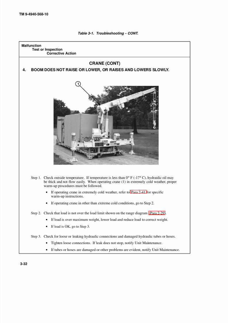
8/20/2019 TM 9-4940-568-10 FRS
http://slidepdf.com/reader/full/tm-9-4940-568-10-frs 262/403
TM 9-4940-568-10
3-32
Table 3-1. Troubleshooting - CONT.
MalfunctionTest or Inspection
Corrective Action
CRANE (CONT)
4. BOOM DOES NOT RAISE OR LOWER, OR RAISES AND LOWERS SLOWLY.
Step 1. Check outside temperature. If temperature is less than 0° F (-17° C), hydraulic oil maybe thick and not flow easily. When operating crane (1) in extremely cold weather, properwarm-up procedures must be followed.
• If operating crane in extremely cold weather, refer to Para 2-41 for specificwarm-up instructions.
• If operating crane in other than extreme cold conditions, go to Step 2.
Step 2. Check that load is not over the load limit shown on the range diagram (Para 2-29).
• If load is over maximum weight, lower load and reduce load to correct weight.
• If load is OK, go to Step 3.
Step 3. Check for loose or leaking hydraulic connections and damaged hydraulic tubes or hoses.
• Tighten loose connections. If leak does not stop, notify Unit Maintenance.
• If tubes or hoses are damaged or other problems are evident, notify Unit Maintenance.
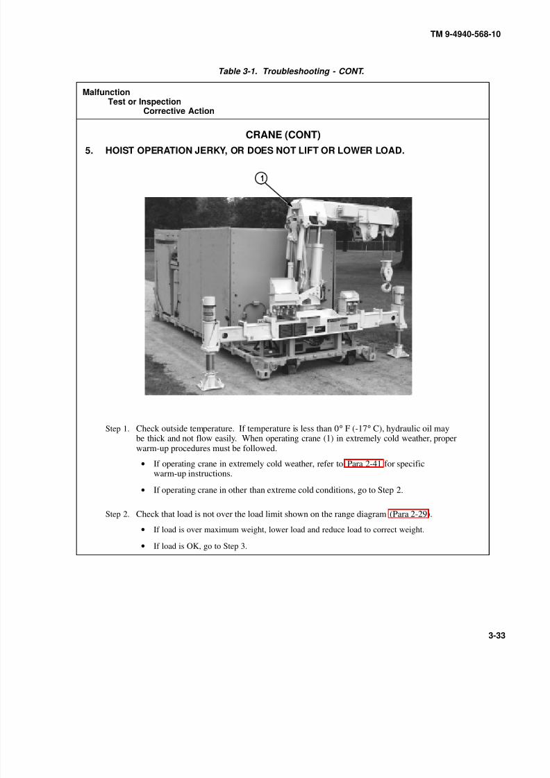
8/20/2019 TM 9-4940-568-10 FRS
http://slidepdf.com/reader/full/tm-9-4940-568-10-frs 263/403
TM 9-4940-568-10
3-33
Table 3-1. Troubleshooting - CONT.
MalfunctionTest or Inspection
Corrective Action
CRANE (CONT)
5. HOIST OPERATION JERKY, OR DOES NOT LIFT OR LOWER LOAD.
Step 1. Check outside temperature. If temperature is less than 0° F (-17° C), hydraulic oil maybe thick and not flow easily. When operating crane (1) in extremely cold weather, properwarm-up procedures must be followed.
• If operating crane in extremely cold weather, refer to Para 2-41 for specificwarm-up instructions.
• If operating crane in other than extreme cold conditions, go to Step 2.
Step 2. Check that load is not over the load limit shown on the range diagram (Para 2-29).• If load is over maximum weight, lower load and reduce load to correct weight.
• If load is OK, go to Step 3.
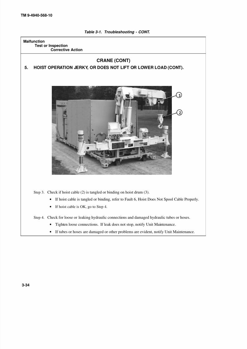
8/20/2019 TM 9-4940-568-10 FRS
http://slidepdf.com/reader/full/tm-9-4940-568-10-frs 264/403
TM 9-4940-568-10
3-34
Table 3-1. Troubleshooting - CONT.
MalfunctionTest or Inspection
Corrective Action
CRANE (CONT)
5. HOIST OPERATION JERKY, OR DOES NOT LIFT OR LOWER LOAD (CONT).
Step 3. Check if hoist cable (2) is tangled or binding on hoist drum (3).
• If hoist cable is tangled or binding, refer to Fault 6, Hoist Does Not Spool Cable Properly.
• If hoist cable is OK, go to Step 4.
Step 4. Check for loose or leaking hydraulic connections and damaged hydraulic tubes or hoses.
• Tighten loose connections. If leak does not stop, notify Unit Maintenance.
•If tubes or hoses are damaged or other problems are evident, notify Unit Maintenance.
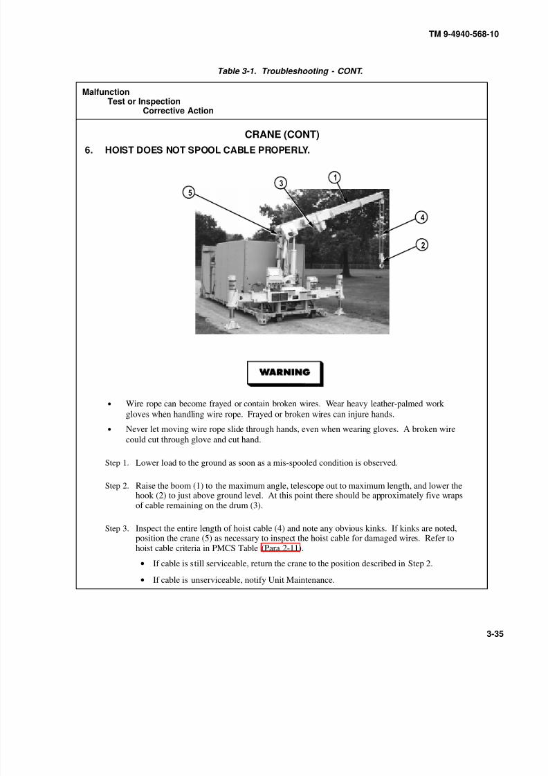
8/20/2019 TM 9-4940-568-10 FRS
http://slidepdf.com/reader/full/tm-9-4940-568-10-frs 265/403
TM 9-4940-568-10
3-35
Table 3-1. Troubleshooting - CONT.
MalfunctionTest or Inspection
Corrective Action
CRANE (CONT)
6. HOIST DOES NOT SPOOL CABLE PROPERLY.
• Wire rope can become frayed or contain broken wires. Wear heavy leather-palmed work
gloves when handling wire rope. Frayed or broken wires can injure hands.
• Never let moving wire rope slide through hands, even when wearing gloves. A broken wire
could cut through glove and cut hand.
Step 1. Lower load to the ground as soon as a mis-spooled condition is observed.
Step 2. Raise the boom (1) to the maximum angle, telescope out to maximum length, and lower thehook (2) to just above ground level. At this point there should be approximately five wrapsof cable remaining on the drum (3).
Step 3. Inspect the entire length of hoist cable (4) and note any obvious kinks. If kinks are noted,position the crane (5) as necessary to inspect the hoist cable for damaged wires. Refer tohoist cable criteria in PMCS Table (Para 2-11).
• If cable is still serviceable, return the crane to the position described in Step 2.
• If cable is unserviceable, notify Unit Maintenance.

8/20/2019 TM 9-4940-568-10 FRS
http://slidepdf.com/reader/full/tm-9-4940-568-10-frs 266/403
TM 9-4940-568-10
3-36
Table 3-1. Troubleshooting - CONT.
MalfunctionTest or Inspection
Corrective Action
CRANE (CONT)
6. HOIST DOES NOT SPOOL CABLE PROPERLY (CONT).
• Wire rope can become frayed or contain broken wires. Wear heavy leather-palmed work
gloves when handling wire rope. Frayed or broken wires can injure hands.
• Never let moving wire rope slide through hands, even when wearing gloves. A broken wire
could cut through glove and cut hand.
Step 4. Inspect the cable (4) remaining on the hoist drum (3) for any looseness or gaps between wraps.If gaps exist, lower crane boom (1) to gain access to hoist drum. Using a hammer, gently tapthe cable wraps back into close contact.
NOTE
If possible, perform Step 5 without changing the boom length or angle. If necessary,reconfigure the crane as little as possible to attach the load. The load is attached onlyfor the purpose of providing weight to straighten the cable while respooling.
Step 5. Attach a load (6), not exceeding 6500 lbs (2948.4 kg), to crane. Position the load where craneboom (1) can be extended to maximum length and raised to maximum angle. Extend the boomto maximum length and raise to maximum angle.

8/20/2019 TM 9-4940-568-10 FRS
http://slidepdf.com/reader/full/tm-9-4940-568-10-frs 267/403
TM 9-4940-568-10
3-37
Table 3-1. Troubleshooting - CONT.
MalfunctionTest or Inspection
Corrective Action
CRANE (CONT)
6. HOIST DOES NOT SPOOL CABLE PROPERLY (CONT).
• Wire rope can become frayed or contain broken wires. Wear heavy leather-palmed work
gloves when handling wire rope. Frayed or broken wires can injure hands.
• Never let moving wire rope slide through hands, even when wearing gloves. A broken wire
could cut through glove and cut hand.
Step 6. Lift the load (6) slowly to maximum height while observing the cable (4) spooling on
hoist drum (3).
• If mis-spooling occurs, immediately lower the load and repeat up to 12 times. If thecable continues to mis-spool badly, notify Unit Maintenance.
• If cable spools properly, lift the load and lower it 12 times. Then, repeat the processwith no load attached. If mis-spooling occurs without a load, notify Unit Maintenance.

8/20/2019 TM 9-4940-568-10 FRS
http://slidepdf.com/reader/full/tm-9-4940-568-10-frs 268/403
TM 9-4940-568-10
3-38
Table 3-1. Troubleshooting - CONT.
MalfunctionTest or Inspection
Corrective Action
CRANE (CONT)
7. MAST, OUTRIGGERS OR STABILIZERS EXTEND OR RETRACT SLOW ORABNORMAL.
Step 1. Check outside temperature. If temperature is less than 0° F (-17° C), hydraulic oil maybe thick and not flow easily. When operating crane (1) in extremely cold weather, properwarm-up procedures must be followed.
• If operating crane in extremely cold weather, refer to Para 2-41 for specificwarm-up instructions.
• If operating crane in other than extreme cold conditions, go to Step 2.
Step 2. Check for loose or leaking hydraulic connections and damaged hydraulic tubes or hoses.
• Tighten loose connections. If leak does not stop, notify Unit Maintenance.
• If tubes or hoses are damaged or other problems are evident, notify Unit Maintenance.

8/20/2019 TM 9-4940-568-10 FRS
http://slidepdf.com/reader/full/tm-9-4940-568-10-frs 269/403
TM 9-4940-568-10
3-39
Table 3-1. Troubleshooting - CONT.
MalfunctionTest or Inspection
Corrective Action
CRANE (CONT)
7. MAST, OUTRIGGERS OR STABILIZERS EXTEND OR RETRACT SLOW ORABNORMAL (CONT).
NOTE
On the FRS, the crane must be in the stowed position when checking hydraulic oil level.Hydraulic oil must be at operating temperature.
Step 3. Check the hydraulic oil level in sight glass (1) on hydraulic reservoir (2). Oil level shouldbe between add and full marks.
• If oil level is low, add oil (Appendix G).
• If oil level is OK, notify Unit Maintenance.

8/20/2019 TM 9-4940-568-10 FRS
http://slidepdf.com/reader/full/tm-9-4940-568-10-frs 270/403
TM 9-4940-568-10
3-40
Table 3-1. Troubleshooting - CONT.
MalfunctionTest or Inspection
Corrective Action
CRANE (CONT)
8. SWING OPERATION SLOW OR JERKY IN ONE OR BOTH DIRECTIONS, OR DOESNOT SWING IN EITHER DIRECTION.
Step 1. Check if FRS (1) is level (Refer to level gages (2) on crane (3), level bubble should bein green area on both gages.)
NOTE
On the FRS, the crane must be in the stowed position when checking hydraulic oil level.Hydraulic oil must be at operating temperature.
Step 2. Check the hydraulic oil level in sight glass (4) on hydraulic reservoir (5). Oil level shouldbe between add and full marks.
• If oil level is low, add oil (Appendix G).
• If oil level is OK, go to Step 3.
Step 3. Check for loose or leaking hydraulic connections and damaged hydraulic tubes or hoses.
• Tighten loose connections. If leak does not stop, notify Unit Maintenance.
• If tubes or hoses are damaged or other problems are evident, notify Unit Maintenance.

8/20/2019 TM 9-4940-568-10 FRS
http://slidepdf.com/reader/full/tm-9-4940-568-10-frs 271/403
TM 9-4940-568-10
3-41
Table 3-1. Troubleshooting - CONT.
MalfunctionTest or Inspection
Corrective Action
CRANE (CONT)
9. OVERLOAD SHUTDOWN SYSTEM DOES NOT OPERATE PROPERLY.
NOTE
The following tests and inspections should be performed in the event of any of thefollowing:
• Boom up and down, telescope out and hoist up functions are disabled.
• Intermittent cut-out of the above listed functions (with crane unloaded).
• Cut-out of the above listed functions too early or too late (with crane loaded).
Step 1. Ensure that the MAIN POWER switch (1) on the crane junction box (2) is in the ON position.
This switch functions both as a circuit breaker and switch.
• If the switch is in the OFF position, reset. If the switch trips again, notifyUnit Maintenance.
• If the switch is in the ON position, go to Step 2.
Step 2. If the remote control unit (3) is connected, ensure that the EMERGENCY STOP switch (4) onthe crane remote control unit is in the ON position. This switch disables all crane functionswhen in the OFF position.
• If the switch is in the OFF position, raise cover and move switch to ON position.
• If the switch is in the ON position, go to Step 3.
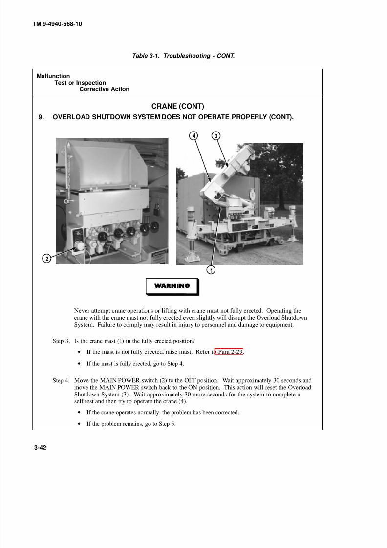
8/20/2019 TM 9-4940-568-10 FRS
http://slidepdf.com/reader/full/tm-9-4940-568-10-frs 272/403
TM 9-4940-568-10
3-42
Table 3-1. Troubleshooting - CONT.
MalfunctionTest or Inspection
Corrective Action
CRANE (CONT)
9. OVERLOAD SHUTDOWN SYSTEM DOES NOT OPERATE PROPERLY (CONT).
Never attempt crane operations or lifting with crane mast not fully erected. Operating thecrane with the crane mast not fully erected even slightly will disrupt the Overload ShutdownSystem. Failure to comply may result in injury to personnel and damage to equipment.
Step 3. Is the crane mast (1) in the fully erected position?
• If the mast is not fully erected, raise mast. Refer to Para 2-29.
•If the mast is fully erected, go to Step 4.
Step 4. Move the MAIN POWER switch (2) to the OFF position. Wait approximately 30 seconds andmove the MAIN POWER switch back to the ON position. This action will reset the OverloadShutdown System (3). Wait approximately 30 more seconds for the system to complete aself test and then try to operate the crane (4).
• If the crane operates normally, the problem has been corrected.
• If the problem remains, go to Step 5.

8/20/2019 TM 9-4940-568-10 FRS
http://slidepdf.com/reader/full/tm-9-4940-568-10-frs 273/403
TM 9-4940-568-10
3-43
Table 3-1. Troubleshooting - CONT.
MalfunctionTest or Inspection
Corrective Action
CRANE (CONT)
9. OVERLOAD SHUTDOWN SYSTEM DOES NOT OPERATE PROPERLY (CONT).
Step 5. Check for proper spooling on hoist drum (1) of the hoist cable (2). It is essential for the correctoperation of the Overload Shutdown System (3) to have the hoist cable spooled properly. TheOverload Shutdown System cannot accurately determine the amount of extended cable ifthe cable is not spooled evenly or “birdnested”.
• If the hoist cable is not spooled properly, refer to Fault 6, Hoist Does Not SpoolCable Properly.
• If the hoist cable is OK, notify Unit Maintenance.

8/20/2019 TM 9-4940-568-10 FRS
http://slidepdf.com/reader/full/tm-9-4940-568-10-frs 274/403
TM 9-4940-568-10
3-44
Section III. MAINTENANCE PROCEDURES
Materials/Parts
Gloves (Appendix C)
Rags, Wiping (Item 15, Appendix D)
This task covers:
a. Priming Low Pressure Fuel Lines and Fuel Filter b. Priming High Pressure Fuel Lines
INITIAL SETUP
Equipment Condition
Engine OFF, (Para 2-15)
Master Disconnect Switch OFF, (Para 2-15)
FRS Unloaded, (Para 2-14)
Tools and Special Tools
Wrench, Combination 1/2 in.(Item 5, Appendix B)
Pan, Drain (Appendix C)
3-4. FUEL SYSTEM PRIMING.
a. Priming Low Pressure Fuel Lines and Fuel Filter.
Fuel is very flammable and can explode easily. To avoid serious injury or death, keepfuel away from open fire and keep fire extinguisher within easy reach when workingwith fuel. Do not work on fuel system when engine is hot. Fuel can be ignited by hotengine.
(1) Place drain pan under secondary fuel filter (1).
(2) Open drain (2) on secondary fuel filter (1).
(3) Operate hand lever (3) on fuel transfer pump (4) until fuel flowing from the fitting (5) is free of air.
(4) Tighten drain (2) on secondary fuel filter (1).
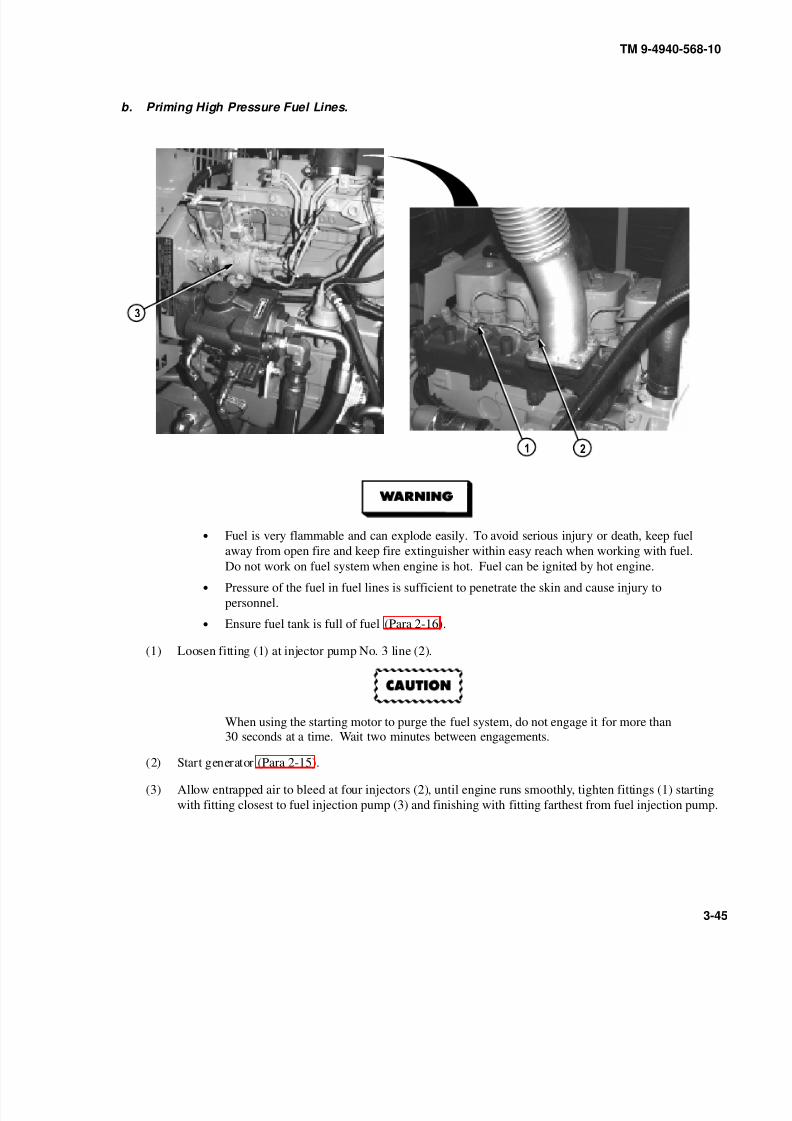
8/20/2019 TM 9-4940-568-10 FRS
http://slidepdf.com/reader/full/tm-9-4940-568-10-frs 275/403
TM 9-4940-568-10
3-45
b. Priming High Pressure Fuel Lines.
• Fuel is very flammable and can explode easily. To avoid serious injury or death, keep fuel
away from open fire and keep fire extinguisher within easy reach when working with fuel.
Do not work on fuel system when engine is hot. Fuel can be ignited by hot engine.
• Pressure of the fuel in fuel lines is sufficient to penetrate the skin and cause injury to
personnel.
• Ensure fuel tank is full of fuel (Para 2-16).
(1) Loosen fitting (1) at injector pump No. 3 line (2).
When using the starting motor to purge the fuel system, do not engage it for more than30 seconds at a time. Wait two minutes between engagements.
(2) Start generator (Para 2-15).
(3) Allow entrapped air to bleed at four injectors (2), until engine runs smoothly, tighten fittings (1) starting
with fitting closest to fuel injection pump (3) and finishing with fitting farthest from fuel injection pump.
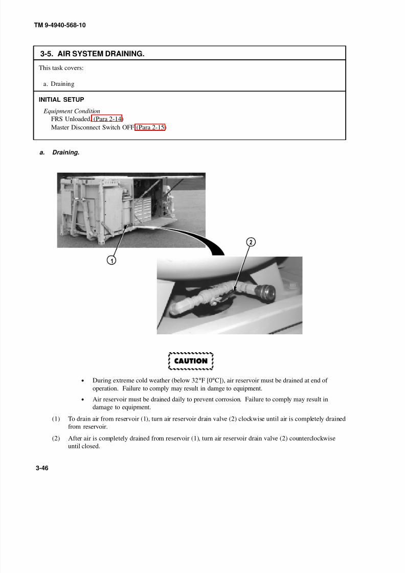
8/20/2019 TM 9-4940-568-10 FRS
http://slidepdf.com/reader/full/tm-9-4940-568-10-frs 276/403
TM 9-4940-568-10
3-46
This task covers:
a. Draining
INITIAL SETUP
Equipment Condition
FRS Unloaded, (Para 2-14)
Master Disconnect Switch OFF (Para 2-15)
3-5. AIR SYSTEM DRAINING.
a. Draining.
•During extreme cold weather (below 32
°F [0
°C]), air reservoir must be drained at end of
operation. Failure to comply may result in damge to equipment.
• Air reservoir must be drained daily to prevent corrosion. Failure to comply may result in
damage to equipment.
(1) To drain air from reservoir (1), turn air reservoir drain valve (2) clockwise until air is completely drained
from reservoir.
(2) After air is completely drained from reservoir (1), turn air reservoir drain valve (2) counterclockwise
until closed.

8/20/2019 TM 9-4940-568-10 FRS
http://slidepdf.com/reader/full/tm-9-4940-568-10-frs 277/403
TM 9-4940-568-10
3-47
This task covers:
a. Disconnect b. Connect c. Follow-On Maintenance
INITIAL SETUP
3-6. BATTERY DISCONNECT/CONNECT.
Equipment Condition
FRS Unloaded, (Para 2-14)
Master Disconnect Switch OFF (Para 2-15)
Remove panel (Para 3-8)
Tools and Special Tools
Wrench, Combination 1/2 in.
(Item 5, Appendix B)
a. Disconnect.
0
• Upon removal of all wires and cables, ensure no contact is made with battery terminals or
other wires and cables. Strap wires and cables away from battery terminals and other wires
and cables as required to prevent damage to parts, personal injury, or death.
• Battery acid (electrolyte) is extremely harmful. Always wear safety goggles and rubber
gloves, and do not smoke when performing maintenance on batteries. Injury will result if
acid contacts skin or eyes. Wear rubber apron to prevent clothing being damaged.
• Remove all jewelry such as rings, ID tags, bracelets, etc. If jewelry or tools contact
positive electrical circuits, a direct short may result. Damage to equipment, injury or deathto personnel may occur.
• Terminal on battery post (3) must be removed before terminals on posts 4, 9 and 10 are
touched or battery damage or personnel injury may occur.
(1) Loosen two nuts (1) and remove two terminals (2) from negative posts (3) and (4) on battery one (5) and
battery two (6).
(2) Loosen two nuts (7) and remove two terminals (8) from positive posts (9) and (10) on battery one (5) and
battery two (6).

8/20/2019 TM 9-4940-568-10 FRS
http://slidepdf.com/reader/full/tm-9-4940-568-10-frs 278/403
TM 9-4940-568-10
3-48
3-6. BATTERY DISCONNECT/CONNECT (CONT).
b. Connect.
0
NOTE
Install cable ties as required.
(1) Install two terminals (8) on positive posts (9) and (10) on battery one (5) and battery two (6) and tighten
two nuts (7).
Terminal on battery post (3) must be installed after terminals on posts 4, 9 and 10 aretouched or battery damage or personnel injury may occur.
(2) Install terminal (2) on negative post (4) on battery two (6) and tighten nut (1).
(3) Install terminal (2) on negative post (3) on battery one (5) and tighten nut (1).
Corrosion inhibitor contains alkali. Do not get in eyes; wear goggles/safety glasseswhen using. Avoid contact with skin. In case of contact, immediately wash area withsoap and water. If eyes are contacted, flush eyes with large amounts of water for atleast 15 minutes and get immediate medical attention.
(4) Apply anticorrosion compound to positive posts (9) and (10) and negative posts (3) and (4) and terminals
(8) and (2).
c. Follow-On Maintenance
• Install panel (Para 3-8).
END OF TASK

8/20/2019 TM 9-4940-568-10 FRS
http://slidepdf.com/reader/full/tm-9-4940-568-10-frs 279/403
TM 9-4940-568-10
3-49
This task covers:
a. Normal Ambient Condition b. Extreme Ambient Condition
INITIAL SETUP
3-7. GOVERNOR CONTROLLER GAIN ADJUSTMENT.
Equipment Condition
FRS Unloaded, (Para 2-14)
a. Normal Ambient Condition.
(1) Electronic Overspeed Module Adjustments: Adjust the governor controller as follows:
(a) The potentiometers (pots) on the controller are adjustable from zero to 100 percent and are marked
off in divisions of ten percent. The speed pot has a 20-turn adjustment range. Set the pots initially
as follows: GAIN (1) 30 %
INTEGRAL UPPER LIMIT (2) 0% (fully CCW)
DROOP 0% (3) (fully CCW)
(b) If a remote speed pot is used, set it at its midpoint.
(c) Start the set and adjust the RUN SPEED (4) pot to obtain the required output frequency: 60 Hertz
(1800 RPM) or 50 Hertz (1500 RPM). Warm up the set under load until it is up to normal operating
temperature.
(d) Disconnect the load and turn the GAIN (1) pot to 100 percent or until operation becomes unstable.
Then turn the pot counterclockwise until operation again becomes stable.
(e) Interrupt the governor by momentarily removing power from the governor. The engine should
recover in 3 to 5 diminishing speed oscillations.
(f) If engine continues to hunt, slightly reduce GAIN (1) setting (turn pot counterclockwise). Repeat
Step (e).
(g) After the RUN SPEED (4) and GAIN (1) are adjusted, apply 100% rated load to the generator.
(h) Readjust RUN SPEED (4) if necessary.

8/20/2019 TM 9-4940-568-10 FRS
http://slidepdf.com/reader/full/tm-9-4940-568-10-frs 280/403
TM 9-4940-568-10
3-50
3-7. GOVERNOR CONTROLLER GAIN ADJUSTMENT (CONT).
b. Extreme Ambient Condition.
NOTE
• The operating range of the governor controller is from –40°F to + 180° F.
• Adjustment to the GAIN potentiometer will be required when generator set is operated at
extreme temperatures.
• Minor adjustment may be required depending upon type of fuel used.
(1) Start engine (Para 2-15).
(2) With the engine at operational temperature, adjust the GAIN potentiometer (1) clockwise until the engine
begins to hunt.
(3) With the engine hunting, turn the GAIN potentiometer (1) couterclockwise until stable.
(4) Turn the GAIN potentiometer (1) an additional 5% (1/2 division) counterclockwise to help ensure a
stable engine when cold started, or when operated at lower ambients.
NOTEIf prolonged operation at extreme low ambient temperatures perform Step (5).
(5) Adjust GAIN potentiometer (1) counterclockwise as necessary to ensure stable operation.
c. Follow-On Maintenance:
• Start generator and check for proper operation, (Para 2-15).
END OF TASK

8/20/2019 TM 9-4940-568-10 FRS
http://slidepdf.com/reader/full/tm-9-4940-568-10-frs 281/403
TM 9-4940-568-10
3-51
This task covers:
a. Remove Panel b. Stow Panel
INITIAL SETUP
3-8. GENERATOR SET PANEL REMOVAL/STOW.
Equipment Condition
FRS Unloaded, (Para 2-14)
a. Remove Panel.
NOTE
• If removing front panel or right rear panel, perform Steps (1) and (2).
• If removing left rear panel, perform Steps (3) and (4).
• If removing front panel from behind hydraulic tank, it may be necessary to move hydraulic
tank for clearance. Notify Unit Maintenance.
• Two front panels and right rear panel are removed the same. Right rear panel shown.
(1) Pull out handle (1), lift and remove panel (2) from two lower panel brackets (3) and generator set housing
(4).
(2) Place panel (2) in a safe location.
(3) Pull out handle (5) and lift panel (6) from upper panel bracket (7) and generator set housing (4).
(4) Place panel (6) in a safe location.
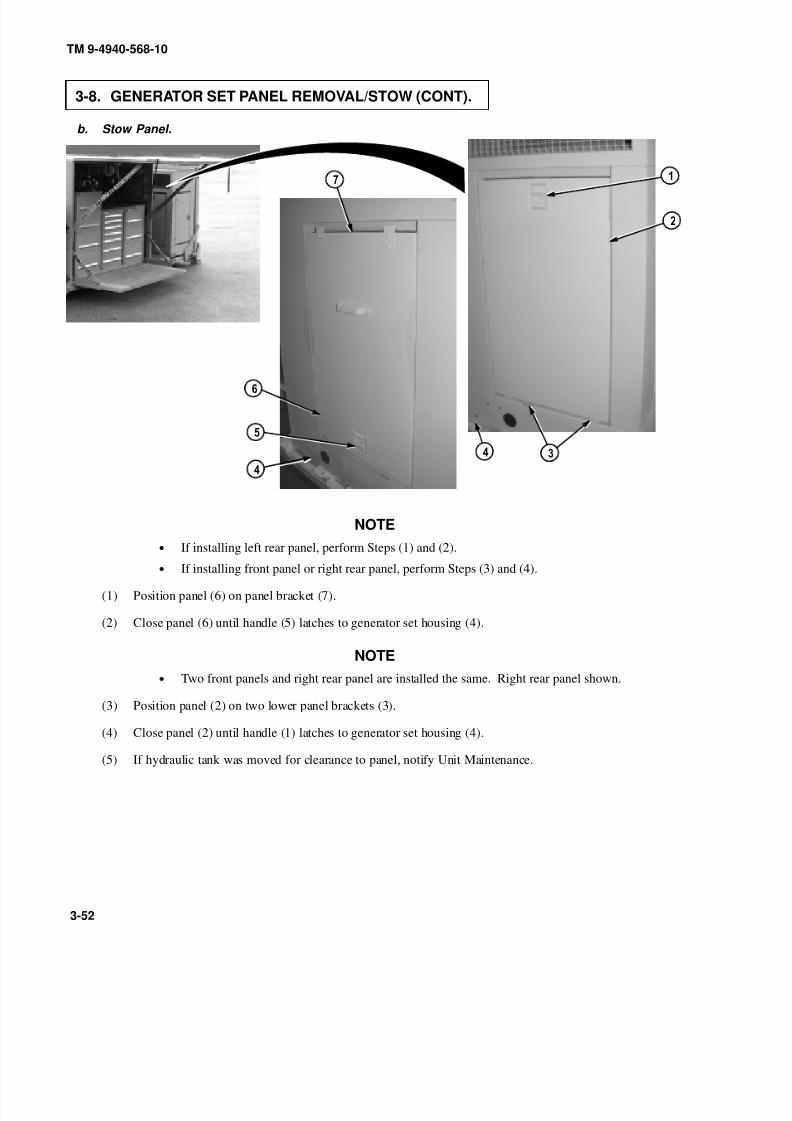
8/20/2019 TM 9-4940-568-10 FRS
http://slidepdf.com/reader/full/tm-9-4940-568-10-frs 282/403
TM 9-4940-568-10
3-52
3-8. GENERATOR SET PANEL REMOVAL/STOW (CONT).
b. Stow Panel.
NOTE
• If installing left rear panel, perform Steps (1) and (2).
• If installing front panel or right rear panel, perform Steps (3) and (4).
(1) Position panel (6) on panel bracket (7).
(2) Close panel (6) until handle (5) latches to generator set housing (4).
NOTE
• Two front panels and right rear panel are installed the same. Right rear panel shown.
(3) Position panel (2) on two lower panel brackets (3).
(4) Close panel (2) until handle (1) latches to generator set housing (4).
(5) If hydraulic tank was moved for clearance to panel, notify Unit Maintenance.
8/20/2019 TM 9-4940-568-10 FRS
http://slidepdf.com/reader/full/tm-9-4940-568-10-frs 283/403
TM 9-4940-568-10
A-1/(A-2 blank)
APPENDIX A
REFERENCES
A-1. FORMS.
The following forms pertain to this manual. See DA PAM 310-1 for index of blank forms. See DA PAM 738-750,
The Army Maintenance Management System (TAMMS), for instructions on the use of maintenance forms pertaining
to this manual.
The Army Maintenance Management System (TAMMS) DA PAM 738-750. . . . . . . . . . . . . . . . . . . . . . . . . . . . . . . . . . . . . . . . . . .
Equipment Inspection and Maintenance Worksheet DA Form 2404/5988E. . . . . . . . . . . . . . . . . . . . . . . . . . . . . . . . . . . . . . . . . . . . . .
Product Quality Deficiency Report SF 368. . . . . . . . . . . . . . . . . . . . . . . . . . . . . . . . . . . . . . . . . . . . . . . . . . . . . . . . . . . . . . . . . . . . . . . . . . . . . . . . . . . . . . . . .
Recommended Changes to DA Publications and Blank Form DA Form 2028. . . . . . . . . . . . . . . . . . . . . . . . . . . . . . . . . . . . . . . . . . .
Recommended Changes to Equipment and Technical Publications DA Form 2028-2. . . . . . . . . . . . . . . . . . . . . . . . . . . . . . . . .
TACOM Major End Item and Product Assurance Managers SF 2407. . . . . . . . . . . . . . . . . . . . . . . . . . . . . . . . . . . . . . . . . . . . . . . . . . . . .
A-2. TECHNICAL MANUALS.
Maintenance and Repair for Lead-Acid Storage Batteries TM 9-6140-200-14. . . . . . . . . . . . . . . . . . . . . . . . . . . . . . . . . . . . . . . . . .
Operator’s Manual for Truck, Tractor, M1074 and M1075 Palletized Load System (PLS)NSN 2320-01-304-2277 and NSN 2320-01-304-2278 TM 9-2320-364-10. . . . . . . . . . . . . . . . . . . . . . . . . . . . . . . . . . . . . . . . . . . . .
Procedures for Destruction of Tank-Automotive Equipment to Prevent Enemy Use TM 750-244-6. . . . . . . . . . . . .
A-3. FIELD MANUALS.
Basic Cold Weather Operation Manual FM 31-70. . . . . . . . . . . . . . . . . . . . . . . . . . . . . . . . . . . . . . . . . . . . . . . . . . . . . . . . . . . . . . . . . . . . . . . . . . . . . . . .
Desert Operations (FM 7-727) FM 90-3. . . . . . . . . . . . . . . . . . . . . . . . . . . . . . . . . . . . . . . . . . . . . . . . . . . . . . . . . . . . . . . . . . . . . . . . . . . . . . . . . . . . . . . . . . . .
Manual for Wheel Vehicle Driver FM 21-305. . . . . . . . . . . . . . . . . . . . . . . . . . . . . . . . . . . . . . . . . . . . . . . . . . . . . . . . . . . . . . . . . . . . . . . . . . . . . . . . . . . . . .
Northern Operations FM 31-71. . . . . . . . . . . . . . . . . . . . . . . . . . . . . . . . . . . . . . . . . . . . . . . . . . . . . . . . . . . . . . . . . . . . . . . . . . . . . . . . . . . . . . . . . . . . . . . . . . . . . . . .
Operation and Maintenance of Ordnance Material in ColdWeather (0 Degrees F to Minus 65 Degrees F) FM 9-207. . . . . . . . . . . . . . . . . . . . . . . . . . . . . . . . . . . . . . . . . . . . . . . . . . . . . . . . . . . . . . . . . . . . . .
A-4. MISCELLANEOUS PUBLICATIONS.
Army Acquistion Policy AR 70-1. . . . . . . . . . . . . . . . . . . . . . . . . . . . . . . . . . . . . . . . . . . . . . . . . . . . . . . . . . . . . . . . . . . . . . . . . . . . . . . . . . . . . . . . . . . . . . . . . .
Hearing Conservation Program TB MED 501. . . . . . . . . . . . . . . . . . . . . . . . . . . . . . . . . . . . . . . . . . . . . . . . . . . . . . . . . . . . . . . . . . . . . . . . . . . . . . . . . . . . .
Operator’s Circular for Welding Theory and Application TC 9-237. . . . . . . . . . . . . . . . . . . . . . . . . . . . . . . . . . . . . . . . . . . . . . . . . . . . . . .
Theatre of Operations Electrical Systems FM 5-424. . . . . . . . . . . . . . . . . . . . . . . . . . . . . . . . . . . . . . . . . . . . . . . . . . . . . . . . . . . . . . . . . . . . . . . . . . . . .

8/20/2019 TM 9-4940-568-10 FRS
http://slidepdf.com/reader/full/tm-9-4940-568-10-frs 284/403

8/20/2019 TM 9-4940-568-10 FRS
http://slidepdf.com/reader/full/tm-9-4940-568-10-frs 285/403
TM 9-4940-568-10
B-1
APPENDIX B
COMPONENTS OF END ITEM (COEI) ANDBASIC ISSUE ITEMS (BII) LISTS
Section I. INTRODUCTION
B-1. SCOPE.
This appendix lists COEI and BII for the Forward Repair System (FRS) to help you inventory the items for safe and
efficient operation of the equipment.
B-2. GENERAL.
The COEI and BII lists are divided into the following sections:
a. Section II - Components of End Item (COEI). This listing is for information purposes only, and is not
authority to requisition replacements. These items are part of the FRS, but they are to be removed and separately
packaged for transportation or shipment. As part of the end item, these items must be with the end item whenever it is
issued or transferred between property accounts. Illustrations are furnished to help you find and identify the items.
b. Section III - Basic Issue Items (BII). Section III contains the BII List. These essential items are required to
place the FRS in operation. Although shipped separately packaged, BII must be with the FRS during operation and
when it is transferred between property accounts. Listing these items is your authority to request/requisition them for
replacement based on authorization of the end item by the TOE/MTOE. Illustrations are furnished to help you find
and identify the items.
B-3. EXPLANATION OF COLUMNS.
The following provides an explanation of columns found in the tabular listings:
a. Column (1) - Illustration Number (Illus Number). This column indicates the number of the item called out
in the illustration.
b. Column (2) - National Stock Number (NSN). Indicates the National Stock Number (NSN) assigned to the
item and will be used for requisitioning purposes.

8/20/2019 TM 9-4940-568-10 FRS
http://slidepdf.com/reader/full/tm-9-4940-568-10-frs 286/403
TM 9-4940-568-10
B-2
c. Column (3) - Description. Indicates the Federal item name, and, if required, a minimum description to
identify and locate the item. The last line for each item indicates the Commercial and Government Entity (CAGE)
Code in parentheses followed by the part number.
d. Column (4) - Unit of Issue (U/I). Indicates the measure used in performing the actualoperational/maintenance function. This measure is expressed by a two-character alphabetical abbreviation (ea., in.,
pr.).
e. Column (5) - Quantity Required (Qty Rqr). Indicates the quantity of the item authorized to be used with/on
the equipment.
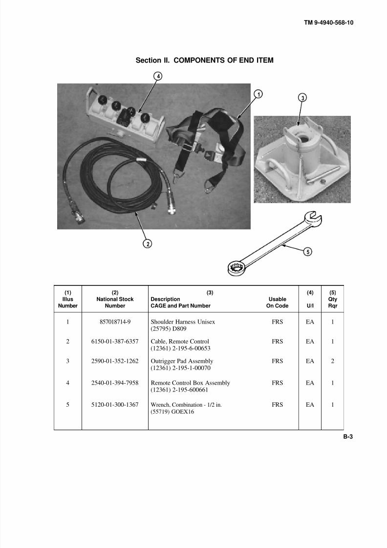
8/20/2019 TM 9-4940-568-10 FRS
http://slidepdf.com/reader/full/tm-9-4940-568-10-frs 287/403
TM 9-4940-568-10
B-3
Section II. COMPONENTS OF END ITEM
(1)
Illus
Number
(2)
National Stock
Number
(3)
Description
CAGE and Part Number
Usable
On Code
(4)
U/I
(5)
Qty
Rqr
1 857018714-9 Shoulder Harness Unisex(25795) D809
FRS EA 1
2 6150-01-387-6357 Cable, Remote Control(12361) 2-195-6-00653
FRS EA 1
3 2590-01-352-1262 Outrigger Pad Assembly(12361) 2-195-1-00070
FRS EA 2
4 2540-01-394-7958 Remote Control Box Assembly(12361) 2-195-600661
FRS EA 1
5 5120-01-300-1367 Wrench, Combination - 1/2 in.
(55719) GOEX16
FRS EA 1

8/20/2019 TM 9-4940-568-10 FRS
http://slidepdf.com/reader/full/tm-9-4940-568-10-frs 288/403
TM 9-4940-568-10
B-4
Section III. BASIC ISSUE ITEMS
(1)
IllusNumber
(2)
National StockNumber
(3)
DescriptionCAGE and Part Number
UsableOn Code
(4)
U/I
(5)
QtyRqr
1 Hose Supply Line, Slave
RIA 149182-1
FRS EA 1
2 Hose Return Line, Slave
RIA 149182-2
FRS EA 1
3 4210-00-165-4703 Extinguisher, Fire (5 lb)(DLA)
FRS EA 1
4 4210-00-965-1105 Extinguisher, Fire (2.5 lb)(RIA)
FRS EA 2
5 6545-00-922-1200 Kit, First Aid(DLA)
FRS EA 1
6 5340-00-158-3805 Padlock W/Short Shaft(96906) MS35647-10
FRS EA 16

8/20/2019 TM 9-4940-568-10 FRS
http://slidepdf.com/reader/full/tm-9-4940-568-10-frs 289/403
TM 9-4940-568-10
C-1
APPENDIX C
ADDITIONAL AUTHORIZATION LIST (AAL)
Section I. INTRODUCTION
C-1. SCOPE.
This appendix lists additional items you are authorized for the support of the Forward Repair System (FRS).
C-2. GENERAL.
This list identifies items that do not have to accompany the FRS and that do not have to be turned in with it. These
items are all authorized to you by Common Tables of Allowance (CTA), Modification Table of Organization and
Equipment (MTOE), Tables of Distribution and Allowances (TDA), or Joint Table of Allowance (JTA).
C-3. EXPLANATION OF LISTING.
National Stock Number (NSN), descriptions and quantities are provided to help you identify and request the additiona
items you require to support this equipment. The items are listed in alphabetical sequence by item name. If the item
you require differs between serial numbers of the same model, effective serial numbers are shown in the last line of
the description.

8/20/2019 TM 9-4940-568-10 FRS
http://slidepdf.com/reader/full/tm-9-4940-568-10-frs 290/403
TM 9-4940-568-10
C-2
Section II. ADDITIONAL AUTHORIZATION ITEMS LIST
(1) (2) (3) (4)
National Stock Description Qty
Number CAGE & Part Number Usable On Code U/M Auth
8415-00-634-4658 Gloves, Leather(90142), 37G2940
FRSPR 2
4910-00-287-2944 Pan, Drain(81349), MIL-P-45819
FRSEA 1
8/20/2019 TM 9-4940-568-10 FRS
http://slidepdf.com/reader/full/tm-9-4940-568-10-frs 291/403
TM 9-4940-568-10
D-1
APPENDIX D
EXPENDABLE AND DURABLE SUPPLIES AND MATERIALS LIST
Section I. INTRODUCTION
D-1. SCOPE.
This appendix lists all expendable and durable items that you will need to operate and maintain the Forward Repair
System (FRS). This listing is for information only and is not authority to requisition the listed items. These items are
authorized to you by CTA 50-790 Expendable/Durable Items (except Medical, Class V, Repair Parts and Heraldic
Items) or CTA 8-100, Army Medical Department Expendable/Durable
Section II. EXPENDABLE AND DURABLE ITEMS LIST
D-2. EXPLANATION OF COLUMNS.
a. Column (1) - Item Number. This number is assigned to the entry in the listing and is referenced in the
narrative instructions to identify the item; Dry Cleaning Solvent, (Item 16, Appendix D).
b. Column (2) - Level. This column identifies the lowest level of maintenance that requires the item.
C - Operator/Crew
c. Column (3) - National Stock Number. This is the National Stock Number assigned to the item which you
can use to requisition it.
d. Column (4) - Item Name, Description, Commercial and Government Entity Code (CAGEC) and Part
Number. This provides the other information you need to identify the item.
e. Column (5) - Unit of Measure. This code shows the physical measurement of an item, such as gallon, dozen,
gross, etc.

8/20/2019 TM 9-4940-568-10 FRS
http://slidepdf.com/reader/full/tm-9-4940-568-10-frs 292/403
TM 9-4940-568-10
D-2
(1)Item
Number
(2)
Level
(3)National Stock
Number
(4)
Description
(5)
U/M
1 C 6850-00-243-19926850-00-174-1806
Antifreeze, Arctic Type (MIL-A-11755) 1 gal. can 55 gal. drum
gal.gal.
2 C 6850-00-181-7940 Antifreeze, Permanent, Glycol, Inhibited(MIL-A-46153)
gal.
3 C 7939-00-634-3935 Chips, Soap, (P-S-579)
4 C 8030-00-903-0931 Corrosion Preventive Compound1 pt. can
pt.
5 C
9150-01-197-77899150-01-197-76939150-01-197-76909150-01-197-76929150-01-197-7691
Grease, Automotive and Artillery (GAA)
(MIL-G-10924) 2.5 oz. tube 14 oz. cartridge 1.75 lb. can 35 lb. can 120 lb. drum
oz.oz.lb.lb.lb.
6 C9150-01-025-8649
Oil, Air Compressor Lubricant 1 qt. can qt.
7 C
9140-00-286-5286
9140-00-286-52879140-00-286-52889140-00-286-5289
Oil, Fuel, Diesel, DF-1, Winter(VV-F-800) Bulk
5 gal. drum 55 gal. drum, 16 gage 55 gal. drum, 18 gage
gal.
gal.gal.gal.
8 C
9140-00-286-52949140-00-286-52959140-00-286-5296
Oil, Fuel, Diesel, DF-2, Regular(VV-F-800) Bulk 5 gal. drum 55 gal. drum, 16 gage
gal.gal.gal.
9 C Oil, Lubricating, Gear, GO 85/140(MIL-PRF-2105) 5 gal. drum gal.
10 C
9150-00-402-44789150-00-402-2372
9150-00-402-7197
Oil, Lubricating, OEA, ICE, Subzero(MIL-L-46167) 1 qt. can 5 gal. drum
55 gal. drum, 16 gage
qt.gal.
gal.

8/20/2019 TM 9-4940-568-10 FRS
http://slidepdf.com/reader/full/tm-9-4940-568-10-frs 293/403
TM 9-4940-568-10
D-3/(D-4 blank)
(1)Item
Number
(2)
Level
(3)National Stock
Number
(4)
Description
(5)
U/M
11 C
9150-00-189-67279150-00-186-6668
9150-00-191-2772
Oil, Lubricating, OE/HDO 10
(MIL-L-2104) 1 qt. can 5 gal. drum 55 gal. drum, 16 gage 55 gal. drum, 18 gage
qt.gal.gal.gal.
12 C
9150-01-178-47259150-01-152-4118
9150-01-152-4119
Oil, Lubricating, OE/HDO 15/40(SAE 15W-40) (MIL-L-2104) 1 qt. can 5 gal. drum
55 gal. drum
qt.gal.
gal.
13 C
9150-00-186-66819150-00-188-98589150-00-265-94369150-00-189-6729
Oil, Lubricating, OE/HDO 30
(SAE 30) (MIL-L-2140) 1 qt. can 5 gal. drum 55 gal. drum, 16 gage 55 gal. drum, 18 gage
qt.gal.gal.gal.
14 C
9150-00-188-67309150-00-188-98659150-00-188-98629150-00-405-2987
Oil, Lubricating, OE/HDO 40(MIL-L-2104) 1 qt. can 5 gal. drum 55 gal. drum, 16 gage bulk
qt.gal.gal.gal.
15 C7920-00-205-1711
Rags, Wiping (A-A-531) 50 lb. bale
16 C6850-00-664-56856850-00-281-1985
6850-01-378-0679
Solvent, Dry Cleaning, SD (P-D-680) 1 qt. can 1 gal. can(Environmentally Compliant Solvent)(0K209) Breakthrough5 gallon can
qt.gal.
gal.
17 C6850-01-181-02736850-01-184-74536850-01-184-3182
Solvent, Biodegradable (MIL-C-87936) 1 qt. can 5 gal. drum 55 gal. drum
qt.gal.gal.

8/20/2019 TM 9-4940-568-10 FRS
http://slidepdf.com/reader/full/tm-9-4940-568-10-frs 294/403

8/20/2019 TM 9-4940-568-10 FRS
http://slidepdf.com/reader/full/tm-9-4940-568-10-frs 295/403
TM 9-4940-568-10
E-1
APPENDIX E
STOWAGE AND SIGN GUIDE(FOR COEI, BII, AND APPLICABLE AAL ITEMS)
Section I. INTRODUCTION
E-1. SCOPE.
This appendix shows locations for data plates, decals and stencils that are required to be in place on the Forward
Repair System (FRS).
E-2. GENERAL.
The figures on the next pages show the location of metal signs, decals and stencils used on the FRS. Most of these
signs and stencils contain cautions or information needed to operate the FRS safely.
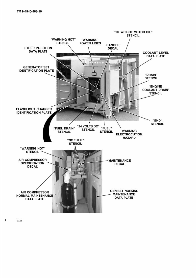
8/20/2019 TM 9-4940-568-10 FRS
http://slidepdf.com/reader/full/tm-9-4940-568-10-frs 296/403
COOLANT LEVELDATA PLATE
ETHER INJECTIONDATA PLATE
WARNINGELECTROCUTION
HAZARD
GENERATOR SETIDENTIFICATION PLATE
FLASHLIGHT CHARGERIDENTIFICATION PLATE
“10 WEIGHT MOTOR OIL”STENCIL
“ENGINECOOLANT DRAIN”
STENCIL
“DRAIN”STENCIL
“GND”STENCIL
“24 VOLTS DC”STENCIL“FUEL DRAIN”
STENCIL
“WARNING HOT”STENCIL
AIR COMPRESSORNORMAL MAINTENANCE
DATA PLATE
GEN/SET NORMALMAINTENANCE
DATA PLATE
MAINTENANCEDECAL
“NO STEP”STENCIL
AIR COMPRESSORSPECIFICATION
DECAL
“FUEL”STENCIL
“WARNING HOT”STENCIL
WARNINGPOWER LINES
DANGERDECAL
TM 9-4940-568-10
E-2

8/20/2019 TM 9-4940-568-10 FRS
http://slidepdf.com/reader/full/tm-9-4940-568-10-frs 297/403
WARNINGAIR COMPRESSOR
GENERAL
WARNINGAIR COMPRESSOR
HOT SURFACE
WARNINGSUPPORT JACK
LIGHT SWITCHDECAL
RECEPTACLEDECAL
“DRAIN”STENCIL
“208V 3 PHASE”STENCIL
CAUTION
PINCH AREA(BOTH DOORS)
WARNINGAIR COMPRESSOR MOTORWARNING
AIR COMPRESSOR
WARNINGPOWER LINES
SHIPPING PLATEDATA PLATE
HEARING
PROTECTIONREQUIRED
WARNINGPOWERLINES
TM 9-4940-568-10
E-3

8/20/2019 TM 9-4940-568-10 FRS
http://slidepdf.com/reader/full/tm-9-4940-568-10-frs 298/403
CAUTIONMANUAL CRANE OVERRIDE
CAUTIONOUTRIGGER BEAMS
WARNING
OUTRIGGER PADS
24V DC LIGHTSDECAL
120/208 MAIN PANELDECAL
24 VOLT DC PANELDECAL
CAUTIONCABINET
24 VOLT DCCIRCUIT BREAKERDECAL
FURNACE CONTROL DECAL
HYDRAULIC OIL SAMPLINGVALVE
“JACK STANDDATED” STENCIL
TM 9-4940-568-10
E-4

8/20/2019 TM 9-4940-568-10 FRS
http://slidepdf.com/reader/full/tm-9-4940-568-10-frs 299/403
BOOM ANGLEDATA PLATE RANGE DIAGRAM
DATA PLATE“NO STEP”
STENCILPOWER SWITCH
REMOTE HOOK–UPDATA PLATE
WARNINGBOOM OPERATION
“24 VOLTS DC”STENCIL
CAUTIONCRANE OPERATION
WARNINGCRANE OPERATION
CRANE STOWAGEDATA PLATE
CRANE OPERATION
DATA PLATE
BOOM LIGHTDATA PLATE
GENERATORREMOTEDECAL
DATA PLATEMODEL NO.
NSNREGISTRATION NUMBER
CONTRACT NO.MANUFACTURER
SERIAL NO.MANUFACTURE DATE
“NO STEP”STENCIL
CRANE MAINTENANCE
DATA PLATE
N/1 XX, XXSTENCIL
N/1 XX, XXSTENCIL
WARNING OUTRIGGRETAINING LATCHE
WARNING KEEP CLEOF OUTRIGGERS
TM 9-4940-568-10
E-5
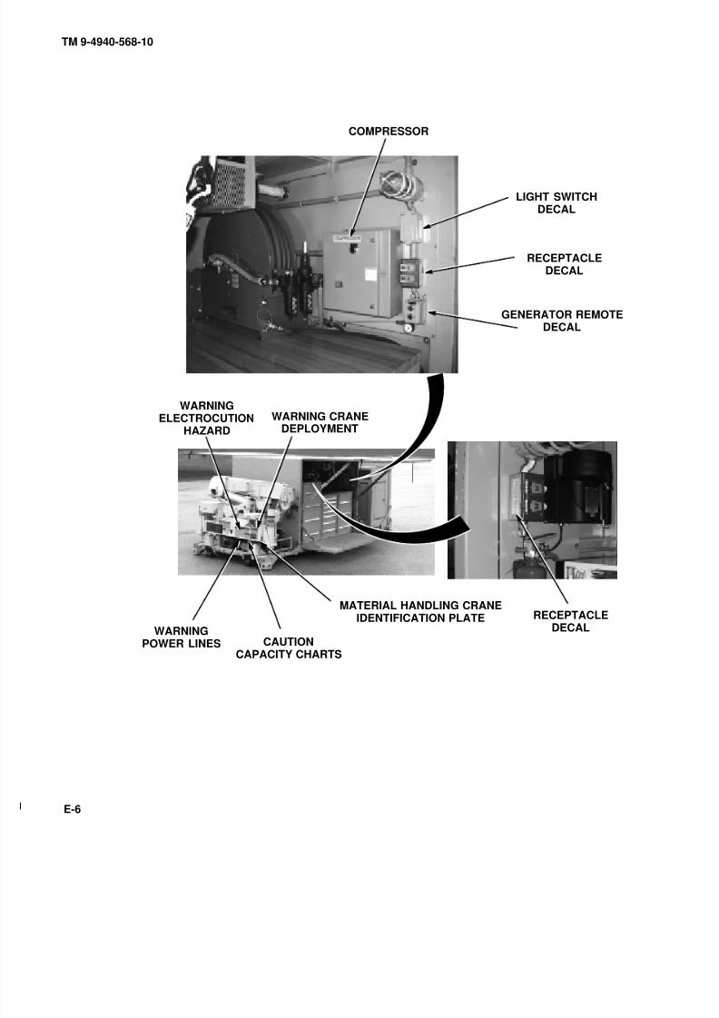
8/20/2019 TM 9-4940-568-10 FRS
http://slidepdf.com/reader/full/tm-9-4940-568-10-frs 300/403
COMPRESSOR
LIGHT SWITCHDECAL
RECEPTACLEDECAL
GENERATOR REMOTEDECAL
RECEPTACLEDECAL
WARNINGELECTROCUTION
HAZARD
WARNINGPOWER LINES
MATERIAL HANDLING CRANEIDENTIFICATION PLATE
CAUTIONCAPACITY CHARTS
WARNING CRANEDEPLOYMENT
TM 9-4940-568-10
E-6
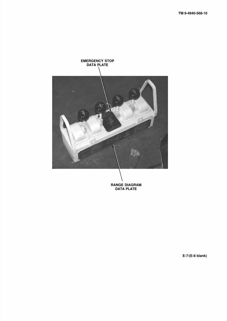
8/20/2019 TM 9-4940-568-10 FRS
http://slidepdf.com/reader/full/tm-9-4940-568-10-frs 301/403
TM 9-4940-568-10
E-7/(E-8 blank)
EMERGENCY STOPDATA PLATE
RANGE DIAGRAMDATA PLATE

8/20/2019 TM 9-4940-568-10 FRS
http://slidepdf.com/reader/full/tm-9-4940-568-10-frs 302/403
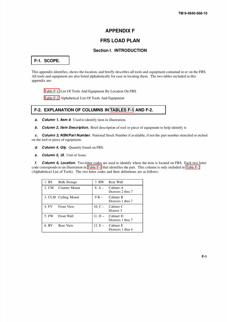
8/20/2019 TM 9-4940-568-10 FRS
http://slidepdf.com/reader/full/tm-9-4940-568-10-frs 303/403
TM 9-4940-568-10
F-1
APPENDIX F
FRS LOAD PLAN
Section I. INTRODUCTION
F-1. SCOPE.
This appendix identifies, shows the location, and briefly describes all tools and equipment contained in or on the FRS.
All tools and equipment are also listed alphabetically for ease in locating them. The two tables included in this
appendix are:
Table F-1. List Of Tools And Equipment By Location On FRS
Table F-2. Alphabetical List Of Tools And Equipment
F-2. EXPLANATION OF COLUMNS IN TABLES F-1 AND F-2.
a. Column 1, Item #. Used to identify item in illustration.
b. Column 2, Item Description. Brief description of tool or piece of equipment to help identify it.
c. Column 3, NSN/Part Number. National Stock Number if available, if not the part number stenciled or etched
on the tool or piece of equipment.
d. Column 4, Qty. Quantity found on FRS.
e. Column 5, UI. Unit of Issue.
f. Column 6, Location. Two letter codes are used to identify where the item is located on FRS. Each two letter
code corresponds to an illustration in Table F-1 that identifies the part. This column is only included in Table F-2
(Alphabetical List of Tools). The two letter codes and their definitions are as follows:
1. BS Bulk Storage 7. RW Rear Wall
2. CM Counter Mount 8. A – Cabinet ADrawers 2 thru 7
3. CLM Ceiling Mount 9 B – Cabinet BDrawers 1 thru 7
4. FV Front View 10. C – Cabinet CDrawer 3
5. FW Front Wall 11. D – Cabinet DDrawers 1 thru 7
6. RV Rear View 12. E – Cabinet EDrawers 1 thru 4
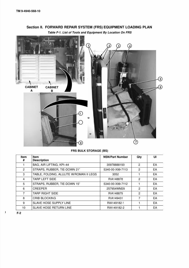
8/20/2019 TM 9-4940-568-10 FRS
http://slidepdf.com/reader/full/tm-9-4940-568-10-frs 304/403
TM 9-4940-568-10
F-2
Section II. FORWARD REPAIR SYSTEM (FRS) EQUIPMENT LOADING PLAN
Table F-1. List of Tools and Equipment By Location On FRS
CABINET
ACABINET
B
0
9
FRS BULK STORAGE (BS)
Item#
ItemDescription
NSN/Part Number Qty UI
1 BAG, AIR LIFTING, KPI–44 30978888190 2 EA
2 STRAPS, RUBBER, TIE-DOWN 21” 5340-00-X99-7113 2 EA
3 TABLE, FOLDING, ALULITE W/ROMAN II LEGS 3052 1 EA
4 TARP LEFT SIDE RIA148878 2 EA
5 STRAPS, RUBBER, TIE-DOWN 15” 5340-00-X99-7112 1 EA
6 CREEPER 257954WM29 2 EA
7 TARP RIGHT SIDE RIA148879 2 EA
8 CRIB BLOCKING RIA149431 7 EA
9 SLAVE HOSE SUPPLY LINE RIA149182-1 1 EA
10 SLAVE HOSE RETURN LINE RIA149182-2 1 EA

8/20/2019 TM 9-4940-568-10 FRS
http://slidepdf.com/reader/full/tm-9-4940-568-10-frs 305/403
TM 9-4940-568-10
F-3
Table F-1. List Of Tools And Equipment By Location On FRS – Continued
CABINET
E
CABINET
D
CABINET
C
FRS COUNTER MOUNT (CM)
Item#
ItemDescription
NSN/Part Number Qty UI
1 ARGON HOSE REEL 4930-01-311-2882 1 EA
2 HOSE REEL, DUAL OXY/ACTYL W/O HOSE 52173S36106LT 1 EA
3 VISE, MACHINIST’S SWVL BASE, 4” JAW 5120-00-293-1439 1 EA
4 CAPS, VISE JAW 5120-00-221-1506 1 PG
5 HOSE REEL, AIR LINE, SPR. RET., 3/8” 521737670 OLP 1 EA
6 HOSE REEL, AIR LINE, SPR. RET., 3/4” 52173D9375 OLP 1 EA
7 WELDER, 400GMS 3431-00-X99-8023 1 EA
8 WELDER, WIRE FEED 3431-00-X99-8025 1 EA
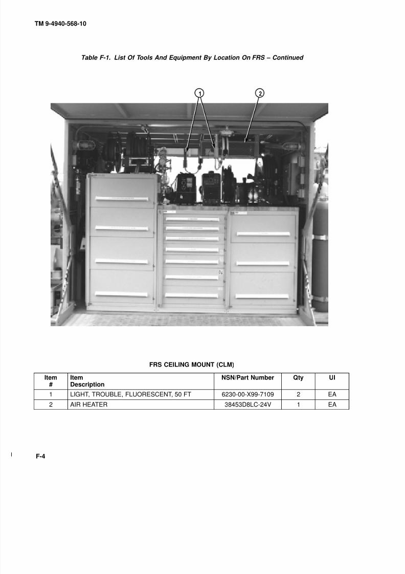
8/20/2019 TM 9-4940-568-10 FRS
http://slidepdf.com/reader/full/tm-9-4940-568-10-frs 306/403
TM 9-4940-568-10
F-4
Table F-1. List Of Tools And Equipment By Location On FRS – Continued
FRS CEILING MOUNT (CLM)
Item#
ItemDescription
NSN/Part Number Qty UI
1 LIGHT, TROUBLE, FLUORESCENT, 50 FT 6230-00-X99-7109 2 EA
2 AIR HEATER 38453D8LC-24V 1 EA

8/20/2019 TM 9-4940-568-10 FRS
http://slidepdf.com/reader/full/tm-9-4940-568-10-frs 307/403
TM 9-4940-568-10
F-5
Table F-1. List Of Tools And Equipment By Location On FRS – Continued
9
FRS FRONT VIEW (FV)
Item#
ItemDescription
NSN/Part Number Qty UI
1 SAFETY CAPS 5340-01-396-3951 4 EA
2 AIR COMPRESSOR AND RECEIVER 3W2937100X15 1 EA
3 ROD ASSEMBLY, GROUND INSIDE GEN SET 5975-00-897-3791 1 EA
4 GENERATOR SET 6115-00-X99-5156 1 EA
5 LIGHT, WOLF 6230-00-X99-5117 1 EA
6 TANK, PROPYLENE 6830-00-X99-7120 1 EA
7 TANK, OXYGEN 6830-00-X99-7119 1 EA
8 TANK, ARGON 6830-00-X99-7118 1 EA
9 TANK, NITROGEN 6830-00-X99-7121 1 EA

8/20/2019 TM 9-4940-568-10 FRS
http://slidepdf.com/reader/full/tm-9-4940-568-10-frs 308/403
TM 9-4940-568-10
F-6
Table F-1. List Of Tools And Equipment By Location On FRS – Continued
FRS FRONT WALL (FW)
Item#
ItemDescription
NSN/Part Number Qty UI
1 FOUNTAIN, EYE AND FACE WASH 4240-00-551-3134 1 EA

8/20/2019 TM 9-4940-568-10 FRS
http://slidepdf.com/reader/full/tm-9-4940-568-10-frs 309/403
TM 9-4940-568-10
F-7
Table F-1. List Of Tools And Equipment By Location On FRS – Continued
REMOTE STOWAGE BOX
FRS REAR VIEW (RV)
Item#
ItemDescription
NSN/Part Number Qty UI
1 CRANE, LVS MK17A1 3950-00-X99-8101 1 EA
2 FIRE EXTINGUISHER 5 LB. 4210-00-165-4703 1 EA3 REMOTE CONTROL ASSEMBLY 2-195-6-10000 1 EA
4 STRAP, REMOTE CONTROL D809 1 EA
5 CABLE 2-195-6-00653 1 EA
6 TRESTLE, 7 TON 3950-00-251-8013 6 EA

8/20/2019 TM 9-4940-568-10 FRS
http://slidepdf.com/reader/full/tm-9-4940-568-10-frs 310/403
TM 9-4940-568-10
F-8
Table F-1. List Of Tools And Equipment By Location On FRS – Continued
9
9
0
0
OPTIONALGROUND RODSTORAGE
FRS REAR WALL (RW)
Item#
ItemDescription
NSN/Part Number Qty UI
1 FIRE EXTINGUISHERS W/ BRACKET, 2.5 LB 4210-00-965-1105 2 EA
2 LIGHT, WOLF 6230-00-X99-5117 2 EA
3 CABLE, WELDING ASSY, W/2 FTGS, 45 FT REDLDP-70
6150-00-X99-7105 1 EA
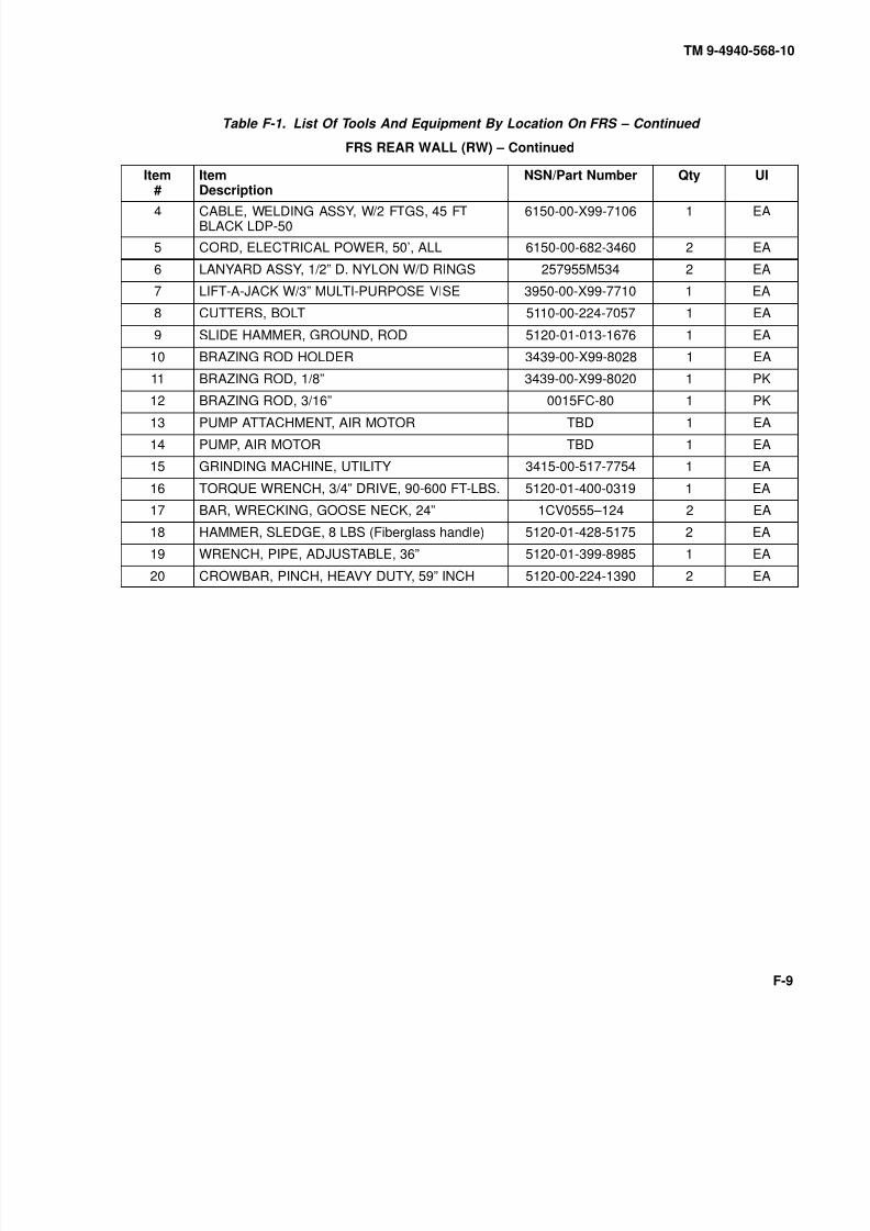
8/20/2019 TM 9-4940-568-10 FRS
http://slidepdf.com/reader/full/tm-9-4940-568-10-frs 311/403
TM 9-4940-568-10
F-9
Table F-1. List Of Tools And Equipment By Location On FRS – Continued
FRS REAR WALL (RW) – Continued
Item#
ItemDescription
NSN/Part Number Qty UI
4 CABLE, WELDING ASSY, W/2 FTGS, 45 FTBLACK LDP-50
6150-00-X99-7106 1 EA
5 CORD, ELECTRICAL POWER, 50’, ALL 6150-00-682-3460 2 EA
6 LANYARD ASSY, 1/2” D. NYLON W/D RINGS 257955M534 2 EA
7 LIFT-A-JACK W/3” MULTI-PURPOSE VISE 3950-00-X99-7710 1 EA
8 CUTTERS, BOLT 5110-00-224-7057 1 EA
9 SLIDE HAMMER, GROUND, ROD 5120-01-013-1676 1 EA
10 BRAZING ROD HOLDER 3439-00-X99-8028 1 EA
11 BRAZING ROD, 1/8” 3439-00-X99-8020 1 PK
12 BRAZING ROD, 3/16” 0015FC-80 1 PK
13 PUMP ATTACHMENT, AIR MOTOR TBD 1 EA
14 PUMP, AIR MOTOR TBD 1 EA
15 GRINDING MACHINE, UTILITY 3415-00-517-7754 1 EA
16 TORQUE WRENCH, 3/4” DRIVE, 90-600 FT-LBS. 5120-01-400-0319 1 EA
17 BAR, WRECKING, GOOSE NECK, 24” 1CV0555–124 2 EA
18 HAMMER, SLEDGE, 8 LBS (Fiberglass handle) 5120-01-428-5175 2 EA
19 WRENCH, PIPE, ADJUSTABLE, 36” 5120-01-399-8985 1 EA
20 CROWBAR, PINCH, HEAVY DUTY, 59” INCH 5120-00-224-1390 2 EA

8/20/2019 TM 9-4940-568-10 FRS
http://slidepdf.com/reader/full/tm-9-4940-568-10-frs 312/403
TM 9-4940-568-10
F-10
Table F-1. List Of Tools And Equipment By Location On FRS – Continued
CABINET A
DRAWER A1(Hardware)
DRAWER A2(3/8 Dr. Socket Set,
Pneumatic Ratchet,
Torque Wrenches)DRAWER A3
(Snap Set, Spanner Wrench,
Feeler Gage Set and
Battery Terminal Cleaner) DRAWER A4(1/2 Dr. Socket Set)
DRAWER A5(Impact Socket Set, 1/2 Dr.
Pneumatic Impact Wrench)
DRAWER A6(3/4 Dr. Socket Set,
Torque Wrench,
Tape Measure)
DRAWER A7(Electric Drills, Drill
Bit Sets)
DRAWER A1
Item#
ItemDescription
NSN/Part Number Qty UI
Drawer will be used for storage of fasteners.
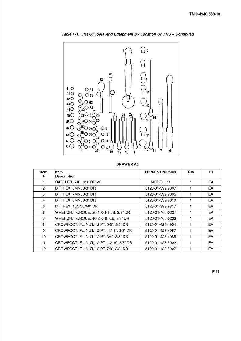
8/20/2019 TM 9-4940-568-10 FRS
http://slidepdf.com/reader/full/tm-9-4940-568-10-frs 313/403
TM 9-4940-568-10
F-11
Table F-1. List Of Tools And Equipment By Location On FRS – Continued
9
0
9
0
9
0
9
0
9
0
9
0
DRAWER A2
Item#
ItemDescription
NSN/Part Number Qty UI
1 RATCHET, AIR, 3/8” DRIVE MODEL 111 1 EA
2 BIT, HEX, 6MM, 3/8” DR 5120-01-399-9807 1 EA
3 BIT, HEX, 7MM, 3/8” DR 5120-01-399-9805 1 EA
4 BIT, HEX, 8MM, 3/8” DR 5120-01-399-9819 1 EA
5 BIT, HEX, 10MM, 3/8” DR 5120-01-399-9817 1 EA
6 WRENCH, TORQUE, 20-100 FT-LB, 3/8” DR 5120-01-400-0237 1 EA
7 WRENCH, TORQUE, 40-200 IN-LB, 3/8” DR 5120-01-400-0233 1 EA
8 CROWFOOT, FL. NUT, 12 PT, 5/8”, 3/8” DR 5120-01-428-4954 1 EA
9 CROWFOOT, FL. NUT, 12 PT, 11/16”, 3/8” DR 5120-01-428-4957 1 EA
10 CROWFOOT, FL. NUT, 12 PT, 3/4”, 3/8” DR 5120-01-428-4986 1 EA
11 CROWFOOT, FL. NUT, 12 PT, 13/16”, 3/8” DR 5120-01-428-5002 1 EA
12 CROWFOOT, FL. NUT, 12 PT, 7/8”, 3/8” DR 5120-01-428-5007 1 EA

8/20/2019 TM 9-4940-568-10 FRS
http://slidepdf.com/reader/full/tm-9-4940-568-10-frs 314/403
TM 9-4940-568-10
F-12
Table F-1. List Of Tools And Equipment By Location On FRS – Continued
DRAWER A2 – Continued
Item#
ItemDescription
NSN/Part Number Qty UI
13 CROWFOOT, FL. NUT, 12 PT, 15/16”, 3/8” DR 5120-01-428-4966 1 EA
14 CROWFOOT, FL. NUT, 12 PT, 1”, 3/8” DR 5120-01-428-4993 1 EA
15 CROWFOOT, FL. NUT, 12 PT, 1 1/16”, 3/8” DR 5120-01-428-4997 1 EA
16 BIT, HEX, EXTRA LONG, 1/8”, 3/8” DR 5120-01-399-9787 1 EA
17 BIT, HEX, EXTRA LONG, 5/32”, 3/8” DR 5120-01-399-9799 1 EA
18 BIT, HEX, EXTRA LONG, 3/16”, 3/8” DR 5120-01-399-9796 1 EA
19 BIT, HEX, EXTRA LONG, 7/32”, 3/8” DR 5120-01-399-9806 1 EA
20 BIT, HEX, EXTRA LONG, 1/4”, 3/8” DR 1CV0549901/4XL 1 EA
21 BIT, HEX, EXTRA LONG, 5/16”, 3/8” DR 5120-01-399-9809 1 EA
22 BIT, HEX, EXTRA LONG, 3/8”, 3/8” DR 5120-01-399-9812 1 EA23 BIT, HEX, 1/8”, 3/8” DR 5120-01-399-9977 1 EA
24 BIT, HEX, 5/32”, 3/8” DR 5120-01-399-9979 1 EA
25 BIT, HEX, 3/16”, 3/8” DR 5120-01-399-9978 1 EA
26 BIT, HEX, 7/32”, 3/8” DR 5120-01-399-9981 1 EA
27 BIT, HEX, 1/4”, 3/8” DR 5120-01-399-9980 1 EA
28 BIT, HEX, 5/16”, 3/8” DR 5120-01-399-9982 1 EA
29 BIT, HEX, 3/8”, 3/8” DR 5120-01-399-9784 1 EA
30 BIT, TORX, T10, 3/8” DRIVE 5120-01-399-9779 1 EA
31 BIT, TORX, T15, 3/8” DRIVE 5120-01-399-9776 1 EA
32 BIT, TORX, T20, 3/8” DRIVE 5120-01-399-9778 1 EA
33 BIT, TORX, T25, 3/8” DRIVE 5120-01-399-9781 1 EA
34 BIT, TORX, T27, 3/8” DRIVE 5120-01-399-9789 1 EA
35 BIT, TORX, T30, 3/8” DRIVE 5120-01-399-9786 1 EA
36 BIT, TORX, T40, 3/8” DRIVE 5120-01-399-9795 1 EA
37 BIT, TORX, T45, 3/8” DRIVE 5120-01-399-9791 1 EA
38 BIT, TORX, T50, 3/8” DRIVE 5120-01-399-9793 1 EA
39 BIT, TORX, T55, 3/8” DRIVE 5120-01-399-9800 1 EA
40 SOCKET, DEEP, 9 MM, 12 PT, 3/8 DRIVE 5120-01-399-9886 1 EA
41 SOCKET, DEEP, 10 MM, 12 PT, 3/8 DRIVE 5120-01-399-9598 1 EA
42 SOCKET, DEEP, 11 MM, 12 PT, 3/8 DRIVE 5120-01-399-9599 1 EA
43 SOCKET, DEEP, 12 MM, 12 PT, 3/8 DRIVE 5120-01-399-9603 1 EA
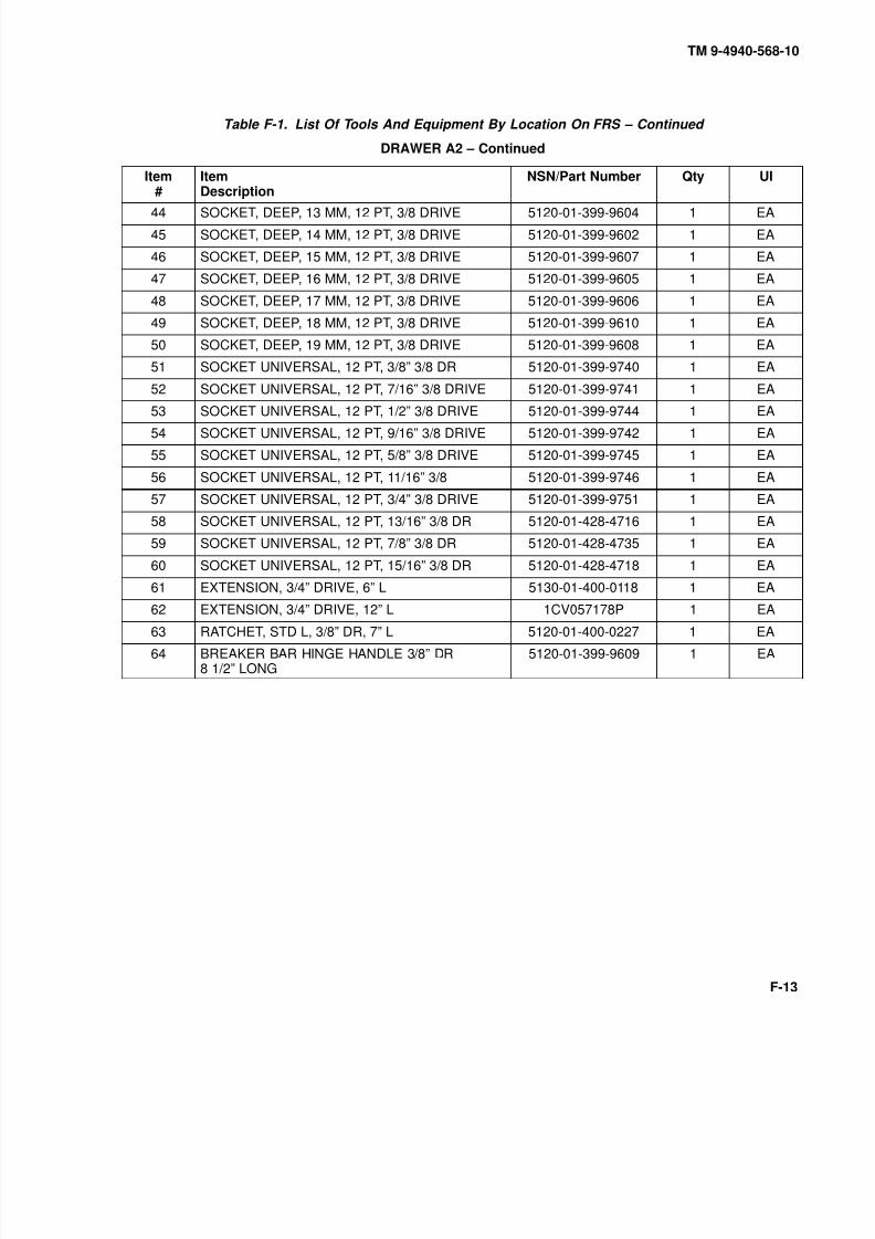
8/20/2019 TM 9-4940-568-10 FRS
http://slidepdf.com/reader/full/tm-9-4940-568-10-frs 315/403
TM 9-4940-568-10
F-13
Table F-1. List Of Tools And Equipment By Location On FRS – Continued
DRAWER A2 – Continued
Item#
ItemDescription
NSN/Part Number Qty UI
44 SOCKET, DEEP, 13 MM, 12 PT, 3/8 DRIVE 5120-01-399-9604 1 EA
45 SOCKET, DEEP, 14 MM, 12 PT, 3/8 DRIVE 5120-01-399-9602 1 EA
46 SOCKET, DEEP, 15 MM, 12 PT, 3/8 DRIVE 5120-01-399-9607 1 EA
47 SOCKET, DEEP, 16 MM, 12 PT, 3/8 DRIVE 5120-01-399-9605 1 EA
48 SOCKET, DEEP, 17 MM, 12 PT, 3/8 DRIVE 5120-01-399-9606 1 EA
49 SOCKET, DEEP, 18 MM, 12 PT, 3/8 DRIVE 5120-01-399-9610 1 EA
50 SOCKET, DEEP, 19 MM, 12 PT, 3/8 DRIVE 5120-01-399-9608 1 EA
51 SOCKET UNIVERSAL, 12 PT, 3/8” 3/8 DR 5120-01-399-9740 1 EA
52 SOCKET UNIVERSAL, 12 PT, 7/16” 3/8 DRIVE 5120-01-399-9741 1 EA
53 SOCKET UNIVERSAL, 12 PT, 1/2” 3/8 DRIVE 5120-01-399-9744 1 EA54 SOCKET UNIVERSAL, 12 PT, 9/16” 3/8 DRIVE 5120-01-399-9742 1 EA
55 SOCKET UNIVERSAL, 12 PT, 5/8” 3/8 DRIVE 5120-01-399-9745 1 EA
56 SOCKET UNIVERSAL, 12 PT, 11/16” 3/8 5120-01-399-9746 1 EA
57 SOCKET UNIVERSAL, 12 PT, 3/4” 3/8 DRIVE 5120-01-399-9751 1 EA
58 SOCKET UNIVERSAL, 12 PT, 13/16” 3/8 DR 5120-01-428-4716 1 EA
59 SOCKET UNIVERSAL, 12 PT, 7/8” 3/8 DR 5120-01-428-4735 1 EA
60 SOCKET UNIVERSAL, 12 PT, 15/16” 3/8 DR 5120-01-428-4718 1 EA
61 EXTENSION, 3/4” DRIVE, 6” L 5130-01-400-0118 1 EA
62 EXTENSION, 3/4” DRIVE, 12” L 1CV057178P 1 EA
63 RATCHET, STD L, 3/8” DR, 7” L 5120-01-400-0227 1 EA
64 BREAKER BAR HINGE HANDLE 3/8” DR8 1/2” LONG
5120-01-399-9609 1 EA
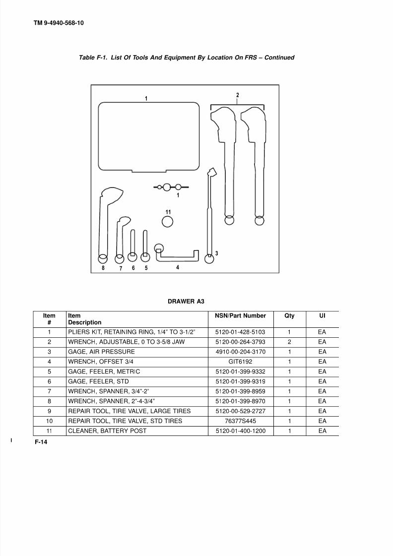
8/20/2019 TM 9-4940-568-10 FRS
http://slidepdf.com/reader/full/tm-9-4940-568-10-frs 316/403
TM 9-4940-568-10
F-14
Table F-1. List Of Tools And Equipment By Location On FRS – Continued
9 0
DRAWER A3
Item#
ItemDescription
NSN/Part Number Qty UI
1 PLIERS KIT, RETAINING RING, 1/4” TO 3-1/2” 5120-01-428-5103 1 EA
2 WRENCH, ADJUSTABLE, 0 TO 3-5/8 JAW 5120-00-264-3793 2 EA
3 GAGE, AIR PRESSURE 4910-00-204-3170 1 EA
4 WRENCH, OFFSET 3/4 GIT6192 1 EA
5 GAGE, FEELER, METRIC 5120-01-399-9332 1 EA
6 GAGE, FEELER, STD 5120-01-399-9319 1 EA
7 WRENCH, SPANNER, 3/4”-2” 5120-01-399-8959 1 EA
8 WRENCH, SPANNER, 2”-4-3/4” 5120-01-399-8970 1 EA
9 REPAIR TOOL, TIRE VALVE, LARGE TIRES 5120-00-529-2727 1 EA
10 REPAIR TOOL, TIRE VALVE, STD TIRES 76377S445 1 EA
11 CLEANER, BATTERY POST 5120-01-400-1200 1 EA

8/20/2019 TM 9-4940-568-10 FRS
http://slidepdf.com/reader/full/tm-9-4940-568-10-frs 317/403
TM 9-4940-568-10
F-15
Table F-1. List Of Tools And Equipment By Location On FRS – Continued
0
9
0
9 0
9
DRAWER A4
Item#
ItemDescription
NSN/Part Number Qty UI
1 BIT, HEX, 1/2”, 1/2” DR 5120-01-399-9830 1 EA
2 BIT, HEX, 9/16”, 1/2” DR 5120-01-399-9829 1 EA
3 BIT, HEX, 5/8”, 1/2” DR 5120-01-399-9831 1 EA
4 UNIVERSAL JOINT, 1/2” DR 5120-01-399-9658 1 EA
5 EXTENSION, 1/2” DR, 2 1/2” LONG 5120-01-399-9663 1 EA
6 ADAPTER, 1/2” F X 3/8”M 5120-01-399-9665 1 EA
7 BIT, HEX, 7/16”, 1/2” DR 5120-01-399-9828 1 EA
8 BIT, HEX, 3/8”, 1/2” DR 5120-01-399-9827 1 EA
9 BIT, HEX, 1/4”, 1/2” DR 5120-01-399-9824 1 EA
10 BIT, HEX, 5/16”, 1/2” DR 5120-01-399-9825 1 EA
11 BIT, HEX, EXTRA LONG, 1/4”, 1/2” DR 5120-01-399-9832 1 EA
12 BIT, HEX, EXTRA LONG, 5/16”, 1/2” DR 5120-01-399-9833 1 EA
13 BIT, HEX, EXTRA LONG, 3/8”, 1/2” DR 5120-01-399-9835 1 EA
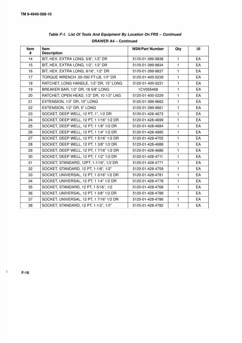
8/20/2019 TM 9-4940-568-10 FRS
http://slidepdf.com/reader/full/tm-9-4940-568-10-frs 318/403
TM 9-4940-568-10
F-16
Table F-1. List Of Tools And Equipment By Location On FRS – Continued
DRAWER A4 – Continued
Item#
ItemDescription
NSN/Part Number Qty UI
14 BIT, HEX, EXTRA LONG, 5/8”, 1/2” DR 5120-01-399-9838 1 EA
15 BIT, HEX, EXTRA LONG, 1/2”, 1/2” DR 5120-01-399-9834 1 EA
16 BIT, HEX, EXTRA LONG, 9/16”, 1/2” DR 5120-01-399-9837 1 EA
17 TORQUE WRENCH .50-250 FT-LB, 1/2” DR 5120-01-400-0239 1 EA
18 RATCHET, LONG HANDLE, 1/2” DR, 15” LONG 5120-01-400-0231 1 EA
19 BREAKER BAR, 1/2” DR, 18 5/8” LONG 1CV055468 1 EA
20 RATCHET, OPEN HEAD, 1/2” DR, 10 1/2” LNG 5120-01-400-0229 1 EA
21 EXTENSION, 1/2” DR, 10” LONG 5120-01-399-9662 1 EA
22 EXTENSION, 1/2” DR, 5” LONG 5120-01-399-9661 1 EA
23 SOCKET, DEEP WELL, 12 PT, 1”, 1/2 DR 5120-01-428-4673 1 EA24 SOCKET, DEEP WELL, 12 PT, 1 1/16” 1/2 DR 5120-01-428-4699 1 EA
25 SOCKET, DEEP WELL, 12 PT, 1 1/8” 1/2 DR 5120-01-428-4684 1 EA
26 SOCKET, DEEP WELL, 12 PT, 1 1/4” 1/2 DR 5120-01-428-4680 1 EA
27 SOCKET, DEEP WELL, 12 PT, 1 5/16” 1/2 DR 5120-01-428-4705 1 EA
28 SOCKET, DEEP WELL, 12 PT, 1 3/8” 1/2 DR 5120-01-428-4688 1 EA
29 SOCKET, DEEP WELL, 12 PT, 1 7/16” 1/2 DR 5120-01-428-4686 1 EA
30 SOCKET, DEEP WELL, 12 PT, 1 1/2” 1/2 DR 5120-01-428-4711 1 EA
31 SOCKET, STANDARD, 12PT, 1-1/16”, 1/2 DR 5120-01-428-4771 1 EA
32 SOCKET, STANDARD, 12 PT, 1-1/8”, 1/2” 5120-01-428-4759 1 EA
33 SOCKET, UNIVERSAL, 12 PT, 1 3/16” 1/2 DR 5120-01-428-4781 1 EA
34 SOCKET, UNIVERSAL, 12 PT, 1 1/4” 1/2 DR 5120-01-428-4778 1 EA
35 SOCKET, STANDARD, 12 PT, 1 5/16”, 1/2 5120-01-428-4768 1 EA
36 SOCKET, UNIVERSAL, 12 PT, 1 3/8” 1/2 DR 5120-01-428-4788 1 EA
37 SOCKET, UNIVERSAL, 12 PT, 1 7/16” 1/2 DR 5120-01-428-4786 1 EA
38 SOCKET, STANDARD, 12 PT, 1-1/2”, 1/2” 5120-01-428-4782 1 EA

8/20/2019 TM 9-4940-568-10 FRS
http://slidepdf.com/reader/full/tm-9-4940-568-10-frs 319/403
TM 9-4940-568-10
F-17
Table F-1. List Of Tools And Equipment By Location On FRS – Continued
0
9
9
9
0
0
9
0
9
0
9
0
DRAWER A5
Item#
ItemDescription
NSN/Part Number Qty UI
1 SOCKET, IMPACT, STD, 6 PT, 1-1/4”, 1/2” DR 5130-01-400-0067 1 EA
2 SOCKET, IMPACT, STD, 6 PT, 1 3/16”, 1/2” DR 5130-01-400-0065 1 EA
3 SOCKET, IMPACT, STD, 6 PT, 1-1/8”, 1/2” DR 5130-01-400-0061 1 EA
4 SOCKET, IMPACT, STD, 6 PT, 1 1/16”, 1/2” DR 1CV057434H 1 EA
5 SOCKET, IMPACT, STD, 6 PT, 1”, 1/2” DR 1CV057432H 1 EA
6 SOCKET, IMPACT, STD, 6 PT, 15/16”, 1/2” DR 5120-00-912-5444 1 EA
7 SOCKET, IMPACT, STD, 6 PT, 7/8”, 1/2” DR 1CV057428H 1 EA
8 SOCKET, IMPACT, STD, 6 PT, 13/16”, 1/2” DR 5120-00-912-5451 1 EA
9 SOCKET, IMPACT, STD, 6 PT, 3/4”, 1/2” DR 1CV057424H 1 EA
10 SOCKET, IMPACT, STD, 6 PT, 11/16”, 1/2” DR 1CV057422H 1 EA
11 SOCKET, IMPACT, STD, 6 PT, 5/8”, 1/2” DR 1CV057420H 1 EA
12 SOCKET, IMPACT, STD, 6 PT, 9/16”, 1/2” DR 7418H 1 EA
13 SOCKET, IMPACT, STD, 6 PT, 1/2”, 1/2” DR 1CV057416H 1 EA
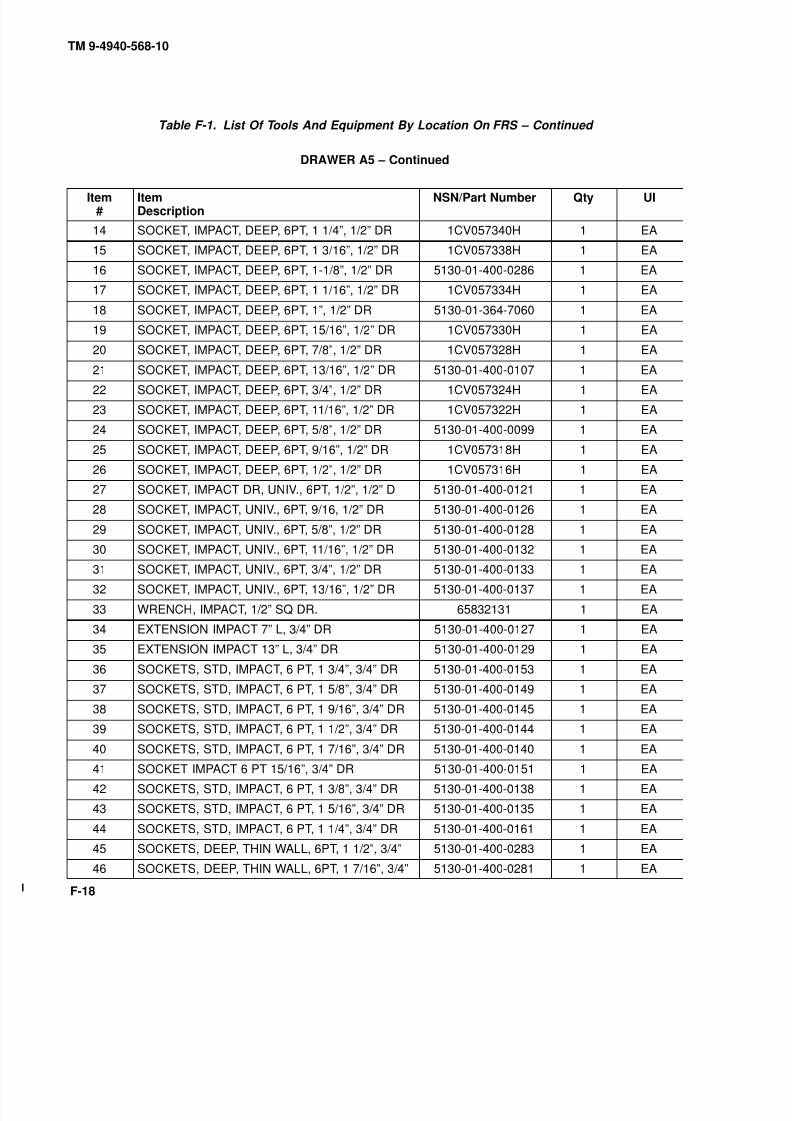
8/20/2019 TM 9-4940-568-10 FRS
http://slidepdf.com/reader/full/tm-9-4940-568-10-frs 320/403
TM 9-4940-568-10
F-18
Table F-1. List Of Tools And Equipment By Location On FRS – Continued
DRAWER A5 – Continued
Item#
ItemDescription
NSN/Part Number Qty UI
14 SOCKET, IMPACT, DEEP, 6PT, 1 1/4”, 1/2” DR 1CV057340H 1 EA
15 SOCKET, IMPACT, DEEP, 6PT, 1 3/16”, 1/2” DR 1CV057338H 1 EA
16 SOCKET, IMPACT, DEEP, 6PT, 1-1/8”, 1/2” DR 5130-01-400-0286 1 EA
17 SOCKET, IMPACT, DEEP, 6PT, 1 1/16”, 1/2” DR 1CV057334H 1 EA
18 SOCKET, IMPACT, DEEP, 6PT, 1”, 1/2” DR 5130-01-364-7060 1 EA
19 SOCKET, IMPACT, DEEP, 6PT, 15/16”, 1/2” DR 1CV057330H 1 EA
20 SOCKET, IMPACT, DEEP, 6PT, 7/8”, 1/2” DR 1CV057328H 1 EA
21 SOCKET, IMPACT, DEEP, 6PT, 13/16”, 1/2” DR 5130-01-400-0107 1 EA22 SOCKET, IMPACT, DEEP, 6PT, 3/4”, 1/2” DR 1CV057324H 1 EA
23 SOCKET, IMPACT, DEEP, 6PT, 11/16”, 1/2” DR 1CV057322H 1 EA
24 SOCKET, IMPACT, DEEP, 6PT, 5/8”, 1/2” DR 5130-01-400-0099 1 EA
25 SOCKET, IMPACT, DEEP, 6PT, 9/16”, 1/2” DR 1CV057318H 1 EA
26 SOCKET, IMPACT, DEEP, 6PT, 1/2”, 1/2” DR 1CV057316H 1 EA
27 SOCKET, IMPACT DR, UNIV., 6PT, 1/2”, 1/2” D 5130-01-400-0121 1 EA
28 SOCKET, IMPACT, UNIV., 6PT, 9/16, 1/2” DR 5130-01-400-0126 1 EA
29 SOCKET, IMPACT, UNIV., 6PT, 5/8”, 1/2” DR 5130-01-400-0128 1 EA
30 SOCKET, IMPACT, UNIV., 6PT, 11/16”, 1/2” DR 5130-01-400-0132 1 EA
31 SOCKET, IMPACT, UNIV., 6PT, 3/4”, 1/2” DR 5130-01-400-0133 1 EA
32 SOCKET, IMPACT, UNIV., 6PT, 13/16”, 1/2” DR 5130-01-400-0137 1 EA
33 WRENCH, IMPACT, 1/2” SQ DR. 65832131 1 EA
34 EXTENSION IMPACT 7” L, 3/4” DR 5130-01-400-0127 1 EA
35 EXTENSION IMPACT 13” L, 3/4” DR 5130-01-400-0129 1 EA
36 SOCKETS, STD, IMPACT, 6 PT, 1 3/4”, 3/4” DR 5130-01-400-0153 1 EA
37 SOCKETS, STD, IMPACT, 6 PT, 1 5/8”, 3/4” DR 5130-01-400-0149 1 EA
38 SOCKETS, STD, IMPACT, 6 PT, 1 9/16”, 3/4” DR 5130-01-400-0145 1 EA
39 SOCKETS, STD, IMPACT, 6 PT, 1 1/2”, 3/4” DR 5130-01-400-0144 1 EA
40 SOCKETS, STD, IMPACT, 6 PT, 1 7/16”, 3/4” DR 5130-01-400-0140 1 EA
41 SOCKET IMPACT 6 PT 15/16”, 3/4” DR 5130-01-400-0151 1 EA
42 SOCKETS, STD, IMPACT, 6 PT, 1 3/8”, 3/4” DR 5130-01-400-0138 1 EA
43 SOCKETS, STD, IMPACT, 6 PT, 1 5/16”, 3/4” DR 5130-01-400-0135 1 EA
44 SOCKETS, STD, IMPACT, 6 PT, 1 1/4”, 3/4” DR 5130-01-400-0161 1 EA
45 SOCKETS, DEEP, THIN WALL, 6PT, 1 1/2”, 3/4” 5130-01-400-0283 1 EA
46 SOCKETS, DEEP, THIN WALL, 6PT, 1 7/16”, 3/4” 5130-01-400-0281 1 EA
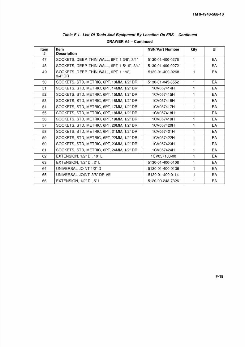
8/20/2019 TM 9-4940-568-10 FRS
http://slidepdf.com/reader/full/tm-9-4940-568-10-frs 321/403
TM 9-4940-568-10
F-19
Table F-1. List Of Tools And Equipment By Location On FRS – Continued
DRAWER A5 – Continued
Item#
ItemDescription
NSN/Part Number Qty UI
47 SOCKETS, DEEP, THIN WALL, 6PT, 1 3/8”, 3/4” 5130-01-400-0276 1 EA
48 SOCKETS, DEEP, THIN WALL, 6PT, 1 5/16”, 3/4” 5130-01-400-0272 1 EA
49 SOCKETS, DEEP, THIN WALL, 6PT, 1 1/4”,3/4” DR
5130-01-400-0268 1 EA
50 SOCKETS, STD, METRIC, 6PT, 13MM, 1/2” DR 5130-01-045-8552 1 EA
51 SOCKETS, STD, METRIC, 6PT, 14MM, 1/2” DR 1CV057414H 1 EA
52 SOCKETS, STD, METRIC, 6PT, 15MM, 1/2” DR 1CV057415H 1 EA
53 SOCKETS, STD, METRIC, 6PT, 16MM, 1/2” DR 1CV057416H 1 EA
54 SOCKETS, STD, METRIC, 6PT, 17MM, 1/2” DR 1CV057417H 1 EA
55 SOCKETS, STD, METRIC, 6PT, 18MM, 1/2” DR 1CV057418H 1 EA
56 SOCKETS, STD, METRIC, 6PT, 19MM, 1/2” DR 1CV057419H 1 EA
57 SOCKETS, STD, METRIC, 6PT, 20MM, 1/2” DR 1CV057420H 1 EA
58 SOCKETS, STD, METRIC, 6PT, 21MM, 1/2” DR 1CV057421H 1 EA
59 SOCKETS, STD, METRIC, 6PT, 22MM, 1/2” DR 1CV057422H 1 EA
60 SOCKETS, STD, METRIC, 6PT, 23MM, 1/2” DR 1CV057423H 1 EA
61 SOCKETS, STD, METRIC, 6PT, 24MM, 1/2” DR 1CV057424H 1 EA
62 EXTENSION, 1/2” D., 10” L 1CV057183-00 1 EA
63 EXTENSION, 1/2” D., 2” L 5130-01-400-0108 1 EA
64 UNIVERSAL JOINT 1/2” D 5130-01-400-0136 1 EA
65 UNIVERSAL JOINT, 3/8” DRIVE 5130-01-400-0114 1 EA
66 EXTENSION, 1/2” D., 5” L 5120-00-243-7326 1 EA
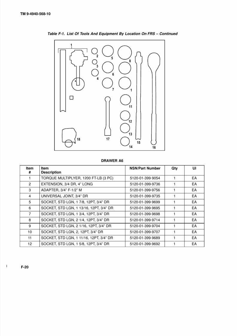
8/20/2019 TM 9-4940-568-10 FRS
http://slidepdf.com/reader/full/tm-9-4940-568-10-frs 322/403
TM 9-4940-568-10
F-20
Table F-1. List Of Tools And Equipment By Location On FRS – Continued
0
9
DRAWER A6
Item#
ItemDescription
NSN/Part Number Qty UI
1 TORQUE MULTIPLYER, 1200 FT-LB (3 PC) 5120-01-399-9054 1 EA
2 EXTENSION, 3/4 DR, 4” LONG 5120-01-399-9736 1 EA
3 ADAPTER, 3/4” F-1/2” M 5120-01-399-9756 1 EA
4 UNIVERSAL JOINT, 3/4” DR 5120-01-399-9735 1 EA
5 SOCKET, STD LGN, 1 7/8, 12PT, 3/4” DR 5120-01-399-9699 1 EA
6 SOCKET, STD LGN, 1 13/16, 12PT, 3/4” DR 5120-01-399-9695 1 EA
7 SOCKET, STD LGN, 1 3/4, 12PT, 3/4” DR 5120-01-399-9698 1 EA
8 SOCKET, STD LGN, 2 1/4, 12PT, 3/4” DR 5120-01-399-9714 1 EA
9 SOCKET, STD LGN, 2 1/16, 12PT, 3/4” DR 5120-01-399-9704 1 EA
10 SOCKET, STD LGN, 2, 12PT, 3/4” DR 5120-01-399-9707 1 EA
11 SOCKET, STD LGN, 1 11/16, 12PT, 3/4” DR 5120-01-399-9689 1 EA
12 SOCKET, STD LGN, 1 5/8, 12PT, 3/4” DR 5120-01-399-9692 1 EA

8/20/2019 TM 9-4940-568-10 FRS
http://slidepdf.com/reader/full/tm-9-4940-568-10-frs 323/403
TM 9-4940-568-10
F-21
Table F-1. List Of Tools And Equipment By Location On FRS – Continued
DRAWER A6 – Continued
Item#
ItemDescription
NSN/Part Number Qty UI
13 SOCKET, STD LGN, 1 9/16, 12PT, 3/4” DR 5120-01-399-9684 1 EA
14 SOCKET, STD LGN, 1 1/2, 12PT, 3/4” DR 5120-01-399-9686 1 EA
15 BREAKER BAR, 3/4” DR, 20” LONG 5120-01-358-3171 1 EA
16 RATCHET, 3/4” DR, 20” LONG 5120-01-400-0266 1 EA
17 EXTENSION, 3/4” DR, 8” LONG 5120-01-399-9747 1 EA
18 TAPE MEASURE, 25 FT 5120-01-428-5470 1 EA

8/20/2019 TM 9-4940-568-10 FRS
http://slidepdf.com/reader/full/tm-9-4940-568-10-frs 324/403
TM 9-4940-568-10
F-22
Table F-1. List Of Tools And Equipment By Location On FRS – Continued
WRENCH DRILL
HANDLE
9
BAR
DRAWER A7
Item#
ItemDescription
NSN/Part Number Qty UI
1 DRILL, HAND, VSR, ELEC, 1/2” 609337554 1 EA
2 DRILL, RIGHT ANGLE, ELEC, 1/2” 5130-01-180-7933 1 EA
3 DRILL BIT SET, METRIC 1MM-13MM X 0.55MM(25 PIECES)
5133-01-052-3580 1 SE
4 DRILL BIT SET, ALPHA A-Z 257951V710 1 SE
5 DRILL SET STANDARD 1/16” 1/2” 257951U200 1 SE
6 BRUSH, WIRE, ROTARY, SOLID 5130-00-263-0235 1 EA
7 BRUSH, WIRE, ROTARY, FLARE 5130-00-293-2409 1 EA
8 DRILL, HAND, VSR, ELECT, 3/8” 5130-01-396-6314 1 EA
9 WHEEL, ABRASIVE, W/CUTTERS 5130-00-223-9952 1 EA

8/20/2019 TM 9-4940-568-10 FRS
http://slidepdf.com/reader/full/tm-9-4940-568-10-frs 325/403
TM 9-4940-568-10
F-23
Table F-1. List Of Tools And Equipment By Location On FRS – Continued
CABINET B
DRAWER B1(Hand Tools, Screwdrivers,
Brake Tool, Chain Wrench,
Soft Faced Hammers,
Pipe Wrench, Mech. Fingers)
DRAWER B2(Hand Tools, Files,
Chisels, Punches,
Utility Knife)DRAWER B3
(Hand Tools, Adj. Wrench,Prybars, Pliers)
DRAWER B4(Hand Tools, Combination
Wrenches)
DRAWER B5(Hand Tools, Large
Combination Wrenches)
DRAWER B6(Tap and Die Sets)
DRAWER B7(Pneumatic Power Tools)

8/20/2019 TM 9-4940-568-10 FRS
http://slidepdf.com/reader/full/tm-9-4940-568-10-frs 326/403
TM 9-4940-568-10
F-24
Table F-1. List Of Tools And Equipment By Location On FRS – Continued
9
0
DRAWER B1
Item#
ItemDescription
NSN/Part Number Qty UI
1 SCREWDRIVER, OFFSET, PHIL. TIP, 3 & 4 5120-01-399-9188 1 EA
2 SCREWDRIVER, OFFSET, STANDARD TIP 5120-01-399-9181 1 EA
3 SCREWDRIVER, OFFSET, PHIL. TIP, 1 & 2 5120-01-399-9182 1 EA
4 SCREWDRIVER, OFFSET, STANDARD TIP 5120-01-399-9183 1 EA
5 SCREWDRIVER BIT SET, MAGNETIC, 28 PC 1CV0561929 1 EA
6 PLIERS, BRAKE REPAIR, 12-7/8 LNG 5120-01-400-1201 1 EA
7 WRENCH, UNIVERSAL CHAIN 1CV05801 1 EA
8 HAMMER, BALL PEEN, 32 OZ, 14 LNG 76377CBH32-O 1 EA
9 HAMMER, DEAD BLOW, 42 OZ, 14” LNG 5120-01-399-5746 1 EA
10 TOOL, PICK UP, CLAW-TYPE, FLEXIBLE23 1/2” LONG
5120-01-399-9296 1 EA
11 WRENCH, PIPE, ADJUSTABLE, 12” 5120-01-399-8981 1 EA
12 100 PLUS SQ SHNK STD SCREWDRIVER 66-170 1 EA

8/20/2019 TM 9-4940-568-10 FRS
http://slidepdf.com/reader/full/tm-9-4940-568-10-frs 327/403
TM 9-4940-568-10
F-25
Table F-1. List Of Tools And Equipment By Location On FRS – Continued
DRAWER B1 – Continued
Item#
ItemDescription
NSN/Part Number Qty UI
13 100 PLUS 3 POINT PHILLIPS SCREWDRIVER 66-178 1 EA
14 100 PLUS 4 POINT PHILLIPS SCREWDRIVER 66-176 1 EA
15 SCREWDRIVER, STANDARD, 1/4” 66-090 1 EA
16 100 PLUS SQ SHNK STD SCREWDRIVER 8 64-103 1 EA
17 100 PLUS SQ SHNK STD SCREWDRIVER 10 64-104 1 EA

8/20/2019 TM 9-4940-568-10 FRS
http://slidepdf.com/reader/full/tm-9-4940-568-10-frs 328/403
TM 9-4940-568-10
F-26
Table F-1. List Of Tools And Equipment By Location On FRS – Continued
0
0
9
9
0
DRAWER B2
Item#
ItemDescription
NSN/Part Number Qty UI
1 KNIFE, UTILITY 5110-01-428-5547 1 EA
2 PUNCH, DRIVE PIN, BRASS, 3/8” DIA PT 1CV05BD8 1 EA
3 PUNCH, DRIVE PIN, BRASS, 1/4” DIA PT 1CV05BD6 1 EA
4 PUNCH, DRIFT PIN, BRASS, 1/2” DIA PT 1CV0549920 1 EA
5 CHISEL, COLD, 7/8” CUT 5110-01-406-7201 1 EA
6 CHISEL, COLD, 1” CUT 1CV0586A718X8 1 EA
7 CHISEL, COLD, 1 3/16” CUT 1CV0586A1X8 1 EA
8 PUNCH, STARTING, 1/4” DIA PT 5110-01-399-9940 1 EA
9 PUNCH, STARTING, 7/32” DIA PT 5110-01-399-9402 1 EA
10 PUNCH, STARTING, 3/16” DIA PT 5110-01-399-9400 1 EA
11 PUNCH, STARTING, 1/8” DIA PT 5110-01-399-9399 1 EA
12 PUNCH, STARTING, 3/32” DIA PT 5110-01-399-9397 1 EA

8/20/2019 TM 9-4940-568-10 FRS
http://slidepdf.com/reader/full/tm-9-4940-568-10-frs 329/403
TM 9-4940-568-10
F-27
Table F-1. List Of Tools And Equipment By Location On FRS – Continued
DRAWER B2 – Continued
Item#
ItemDescription
NSN/Part Number Qty UI
13 PUNCH, DRIVE PIN, 3/32” DIA PT 5110-01-399-9937 1 EA
14 PUNCH, DRIVE PIN, 5/32” DIA PT 5110-01-399-9947 1 EA
15 PUNCH, DRIVE PIN, 1/8” DIA PT 5110-01-399-9945 1 EA
16 PUNCH, DRIVE PIN, 3/16” DIA PT 5110-01-399-9942 1 EA
17 PUNCH, DRIVE PIN, 7/32” DIA PT 5110-01-399-9948 1 EA
18 PUNCH, DRIVE PIN, 1/4” DIA PT 5110-01-399-9949 1 EA
19 FILE, HAND, ROUND, 1/2” DIA, 12” L 5110-00-234-6557 1 EA
20 FILE, HAND, HALF ROUND, 10” L 5110-00-249-2858 1 EA
21 FILE, HAND, FLAT, 10” L 5110-00-234-6537 1 EA
22 FILE, HAND, PILLAR TYPE, 10” L 5110-00-239-6889 1 EA23 FILE, HAND, TRI SQUARE, 6” L 5110-00-241-9160 1 EA
24 THREAD RESTORER, METRIC THREADS 5110-01-431-0299 1 EA
25 THREAD RESTORER, STANDARD THREADS 5110-01-431-0309 1 EA
26 THREAD RESTORER, STANDARD THREADS 5110-01-431-0286 1 EA
27 BRUSH, FILE CLEANER 7920-00-224-7987 1 EA
28 PUNCH, CENTER 1/4” 5110-01-399-9953 1 EA
29 PUNCH, CENTER 3/8” 5110-01-399-9951 1 EA
30 PUNCH, CENTER 1/2” 5110-01-399-9955 1 EA
31 PUNCH, DRIFT, 1/4” DIA PT 5110-01-399-9395 1 EA
32 PUNCH, DRIFT, 3/16” DIA PT 5110-01-399-9392 1 EA
33 PUNCH, DRIFT, 1/8” DIA PT 5110-01-399-9391 1 EA

8/20/2019 TM 9-4940-568-10 FRS
http://slidepdf.com/reader/full/tm-9-4940-568-10-frs 330/403
TM 9-4940-568-10
F-28
Table F-1. List Of Tools And Equipment By Location On FRS – Continued
0
DRAWER B3
Item# ItemDescription NSN/Part Number Qty UI
1 PLIERS, 4-1/16”, SLIP JOINT 5120-01-399-9259 1 EA
2 WRENCH, ADJUSTABLE, AUTO LOCKING 18” 5120-01-399-9869 1 EA
3 BATTERY TERMINAL SPREADER & REAMER 5120-01-399-9240 1 EA
4 PLIERS, 78 DEG, BENT NOSE 5120-01-399-9227 1 EA
5 PLIERS, 6 5/8” HEAVY DUTY LONG NOSE 5120-01-399-9167 1 EA
6 PLIERS, BATTERY TERMINAL 5120-01-431-0225 1 EA
7 VISE GRIP, LONG NOSE, 9” 5120-01-399-9233 1 EA
8 VISE GRIP, 10”, STRAIGHT JAW 5120-01-400-0314 1 EA
9 VISE GRIP, 10” CURVED W/CUTTER 5120-01-399-9226 1 EA
10 WIRE TWISTER, AUTO RETURN 5120-01-431-1957 1 EA
BAR SET, PRY 4 PC (Includes the following:) 1CV052100 1 EA
11 BAR, PRY 2126 1 EA
12 BAR, PRY 2130 1 EA
13 BAR, PRY 2120 1 EA
14 BAR, PRY 2124 1 EA

8/20/2019 TM 9-4940-568-10 FRS
http://slidepdf.com/reader/full/tm-9-4940-568-10-frs 331/403
TM 9-4940-568-10
F-29
Table F-1. List Of Tools And Equipment By Location On FRS – Continued
0 9
9
0
9
0
DRAWER B4
Item#
ItemDescription
NSN/Part Number Qty UI
1 WRENCH, FL NUT, DBL END, 12 PT, 19 X 21 MM 1CV053719MT 1 EA
2 WRENCH, FL NUT, DBL END, 12 PT, 16 X 18 MM 1CV053716MT 1 EA
3 WRENCH, FL NUT, DBL END, 12 PT, 15 X 17 MM 1CV053715MT 1 EA
4 WRENCH, FL NUT, DBL END, 12 PT, 13 X 14 MM 1CV053713MT 1 EA
5 WRENCH, FL NUT, DBL END, 12 PT, 10 X 12 MM 1CV053710MT 1 EA
6 WRENCH, FL NUT, DBL END, 12 PT, 9 X 11 MM 1CV053709MT 1 EA
7 WRENCH, FL NUT, DBL END, 12 PT, 7 X 8 MM 1CV053707MT 1 EA
8 WRENCH, DEEP OFFSET BOX, 12 P, 3/4”-7/8” 5120-01-399-8913 1 EA
9 WRENCH, DEEP OFFSET BOX, 12 P, 15/16”-1” 5120-01-399-8914 1 EA
10 WRENCH, DEEP OFFSET BOX, 12 P,11/16”-13/16”
5120-01-399-8916 1 EA
11 WRENCH, DEEP OFFSET BOX, 12 P, 5/8”-11/16” 5120-01-399-8915 1 EA
12 WRENCH, DEEP OFFSET BOX, 12 P, 1/2”-9/16” 5120-01-399-8910 1 EA
13 WRENCH, DEEP OFFSET BOX, 12 P, 3/8”-7/16” 5120-01-399-8909 1 EA

8/20/2019 TM 9-4940-568-10 FRS
http://slidepdf.com/reader/full/tm-9-4940-568-10-frs 332/403
TM 9-4940-568-10
F-30
Table F-1. List Of Tools And Equipment By Location On FRS – Continued
DRAWER B4 – Continued
Item#
ItemDescription
NSN/Part Number Qty UI
14 WRENCH, C-BOX, OPEN END, 12 P, 1/4” 5120-00-288-9997 1 EA
15 WRENCH, C-BOX, OPEN END, 12 P, 5/16” 1CV051210 1 EA
16 WRENCH, C-BOX, OPEN END, 12 PT, 11/32” 1CV051211 1 EA
17 WRENCH, C-BOX, OPEN END, 12 PT, 3/8” 5120-00-228-9504 1 EA
18 WRENCH, C-BOX, OPEN END, 12 P, 7/16” 5120-00-228-9505 1 EA
19 WRENCH, C-BOX, OPEN END, 12 P, 1/2” 5120-00-228-9506 1 EA
20 WRENCH, C-BOX, OPEN END, 12 P, 9/16” 5120-00-228-9507 1 EA
21 WRENCH, C-BOX, OPEN END, 12 P, 5/8” 5120-00-228-9508 1 EA
22 WRENCH, C-BOX, OPEN END, 12 P, 11/16” 5120-00-228-9509 1 EA
23 WRENCH, C-BOX, OPEN END, 12 P, 3/4” 5120-00-228-9510 1 EA24 WRENCH, C-BOX, OPEN END, 12 P, 13/16” 5120-00-228-9511 1 EA
25 WRENCH, C-BOX, OPEN END, 12 P, 7/8” 1CV051228 1 EA
26 WRENCH, C-BOX, OPEN END, 12 P, 15/16” 1CV051230 1 EA
27 WRENCH, COMB FL NUT, OPN END, 12 PT, 3/4” 1CV053757T 1 EA
28 WRENCH, COMB FL NUT, OPN END, 12PT,11/16”
1CV053756T 1 EA
29 WRENCH, COMB FL NUT, OPN END, 12PT, 5/8” 1CV053755T 1 EA
30 WRENCH, COMB FL NUT, OPN END, 12PT,9/16”
1CV053754T 1 EA
31 WRENCH, COMB FL NUT, OPN END, 12PT, 1/2” 1CV053753T 1 EA32 WRENCH, COMB FL NUT, OPN END, 12PT,
7/16”1CV053752T 1 EA
33 WRENCH, COMB FL NUT, OPN END, 12PT, 3/8” 1CV053751T 1 EA
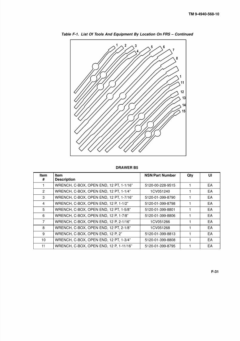
8/20/2019 TM 9-4940-568-10 FRS
http://slidepdf.com/reader/full/tm-9-4940-568-10-frs 333/403
TM 9-4940-568-10
F-31
Table F-1. List Of Tools And Equipment By Location On FRS – Continued
0
9
DRAWER B5
Item#
ItemDescription
NSN/Part Number Qty UI
1 WRENCH, C-BOX, OPEN END, 12 PT, 1-1/16” 5120-00-228-9515 1 EA
2 WRENCH, C-BOX, OPEN END, 12 PT, 1-1/4” 1CV051240 1 EA
3 WRENCH, C-BOX, OPEN END, 12 PT, 1-7/16” 5120-01-399-8790 1 EA
4 WRENCH, C-BOX, OPEN END, 12 P, 1-1/2” 5120-01-399-8798 1 EA
5 WRENCH, C-BOX, OPEN END, 12 PT, 1-5/8” 5120-01-399-8801 1 EA
6 WRENCH, C-BOX, OPEN END, 12 P, 1-7/8” 5120-01-399-8806 1 EA
7 WRENCH, C-BOX, OPEN END, 12 P, 2-1/16” 1CV051266 1 EA
8 WRENCH, C-BOX, OPEN END, 12 PT, 2-1/8” 1CV051268 1 EA
9 WRENCH, C-BOX, OPEN END, 12 P, 2” 5120-01-399-8813 1 EA
10 WRENCH, C-BOX, OPEN END, 12 PT, 1-3/4” 5120-01-399-8808 1 EA
11 WRENCH, C-BOX, OPEN END, 12 P, 1-11/16” 5120-01-399-8795 1 EA

8/20/2019 TM 9-4940-568-10 FRS
http://slidepdf.com/reader/full/tm-9-4940-568-10-frs 334/403
TM 9-4940-568-10
F-32
Table F-1. List Of Tools And Equipment By Location On FRS – Continued
DRAWER B5 – Continued
Item#
ItemDescription
NSN/Part Number Qty UI
12 WRENCH, C-BOX, OPEN END, 12 PT, 1-3/8” 5120-01-399-8793 1 EA
13 WRENCH, C-BOX, OPEN END, 12 P, 1-5/16” 5120-01-399-8786 1 EA
14 WRENCH, C-BOX, OPEN END, 12 P, 1-1/8” 5120-00-228-9516 1 EA
15 WRENCH, C-BOX, OPEN END, 12 PT, 1” 1CV051232 1 EA
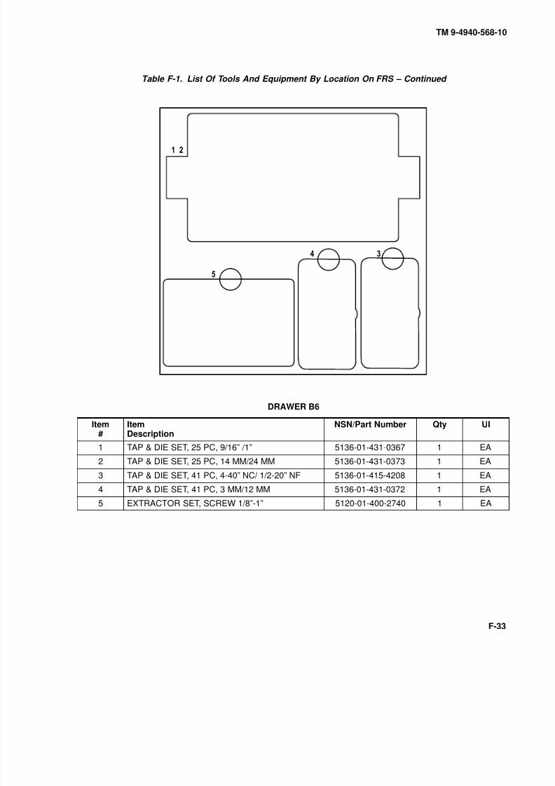
8/20/2019 TM 9-4940-568-10 FRS
http://slidepdf.com/reader/full/tm-9-4940-568-10-frs 335/403
TM 9-4940-568-10
F-33
Table F-1. List Of Tools And Equipment By Location On FRS – Continued
,
DRAWER B6
Item#
ItemDescription
NSN/Part Number Qty UI
1 TAP & DIE SET, 25 PC, 9/16” /1” 5136-01-431-0367 1 EA
2 TAP & DIE SET, 25 PC, 14 MM/24 MM 5136-01-431-0373 1 EA
3 TAP & DIE SET, 41 PC, 4-40” NC/ 1/2-20” NF 5136-01-415-4208 1 EA
4 TAP & DIE SET, 41 PC, 3 MM/12 MM 5136-01-431-0372 1 EA
5 EXTRACTOR SET, SCREW 1/8”-1” 5120-01-400-2740 1 EA
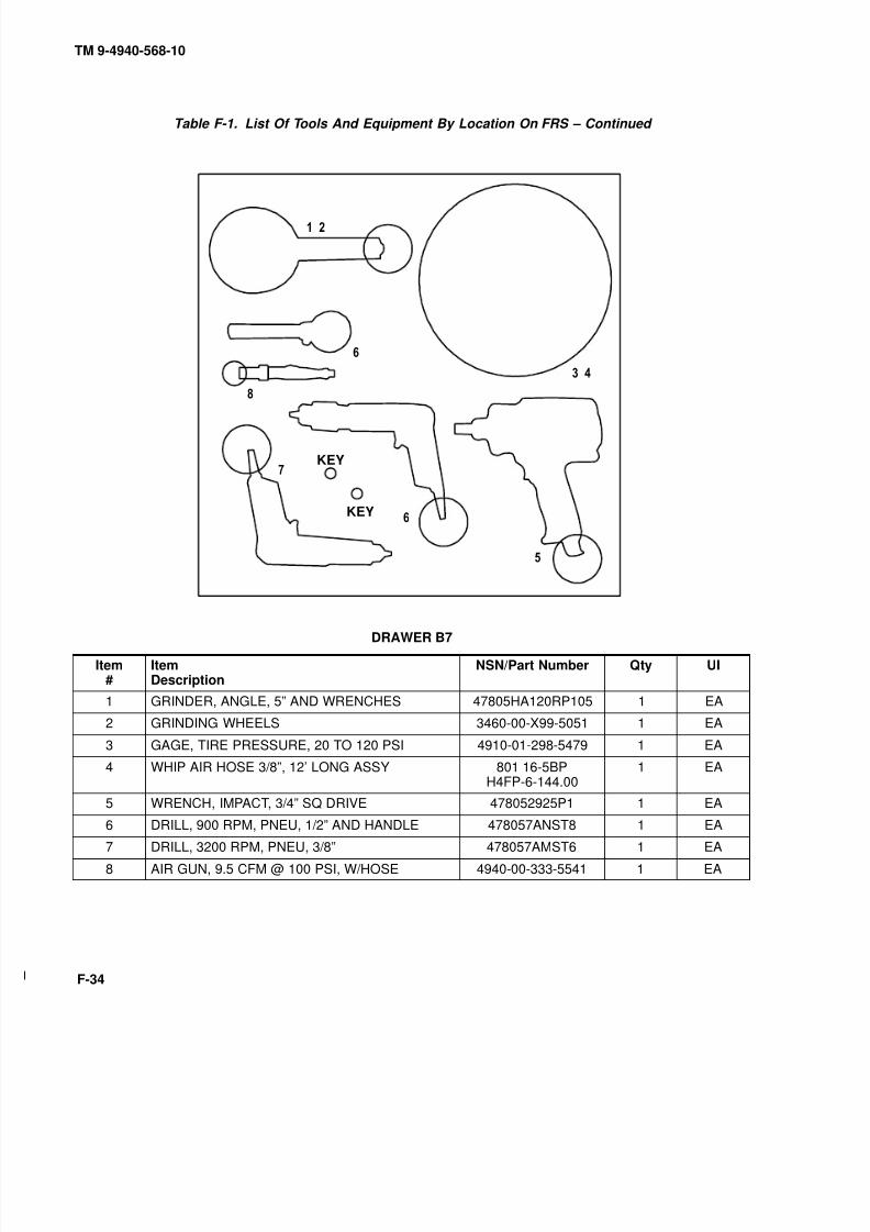
8/20/2019 TM 9-4940-568-10 FRS
http://slidepdf.com/reader/full/tm-9-4940-568-10-frs 336/403
TM 9-4940-568-10
F-34
Table F-1. List Of Tools And Equipment By Location On FRS – Continued
,
,
KEY
KEY
DRAWER B7
Item#
ItemDescription
NSN/Part Number Qty UI
1 GRINDER, ANGLE, 5” AND WRENCHES 47805HA120RP105 1 EA
2 GRINDING WHEELS 3460-00-X99-5051 1 EA
3 GAGE, TIRE PRESSURE, 20 TO 120 PSI 4910-01-298-5479 1 EA
4 WHIP AIR HOSE 3/8”, 12’ LONG ASSY 801 16-5BPH4FP-6-144.00
1 EA
5 WRENCH, IMPACT, 3/4” SQ DRIVE 478052925P1 1 EA
6 DRILL, 900 RPM, PNEU, 1/2” AND HANDLE 478057ANST8 1 EA
7 DRILL, 3200 RPM, PNEU, 3/8” 478057AMST6 1 EA
8 AIR GUN, 9.5 CFM @ 100 PSI, W/HOSE 4940-00-333-5541 1 EA
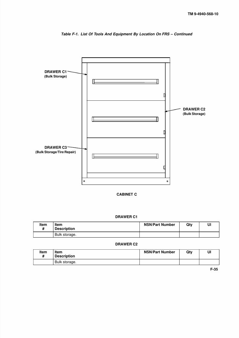
8/20/2019 TM 9-4940-568-10 FRS
http://slidepdf.com/reader/full/tm-9-4940-568-10-frs 337/403
TM 9-4940-568-10
F-35
Table F-1. List Of Tools And Equipment By Location On FRS – Continued
CABINET C
DRAWER C1(Bulk Storage)
DRAWER C2
(Bulk Storage)
DRAWER C3(Bulk Storage/Tire Repair)
DRAWER C1
Item#
ItemDescription
NSN/Part Number Qty UI
Bulk storage.
DRAWER C2
Item#
ItemDescription
NSN/Part Number Qty UI
Bulk storage.

8/20/2019 TM 9-4940-568-10 FRS
http://slidepdf.com/reader/full/tm-9-4940-568-10-frs 338/403
TM 9-4940-568-10
F-36
Table F-1. List Of Tools And Equipment By Location On FRS – Continued
JACK
HANDLES
DRAWER C3
Item#
ItemDescription
NSN/Part Number Qty UI
1 SOCKET SET, WHEEL, BEARING KIT 5120-00-169-4586 1 SE
2 JACK KIT, HYD HAND, 20 TON CAP 5120-00-188-1788 2 EA
3 WRENCH, WHEEL, STUD NUT GEARED, SOC, 5120-00-378-4411 1 EA

8/20/2019 TM 9-4940-568-10 FRS
http://slidepdf.com/reader/full/tm-9-4940-568-10-frs 339/403
TM 9-4940-568-10
F-37
Table F-1. List Of Tools And Equipment By Location On FRS – Continued
CABINET D
DRAWER D1(Miscellaneous)
DRAWER D4(Puller Set)
DRAWER D3
(Welding Supplies,
Clamps, Hacksaw,
Welding Rod)
DRAWER D2(Welding Supplies, Torch
Accessories)
DRAWER D6(Welding Supplies,
Mig Accessories)
DRAWER D5(Puller Set)
DRAWER D7(Welding Supplies,
Welding Rod, Face
Shields)
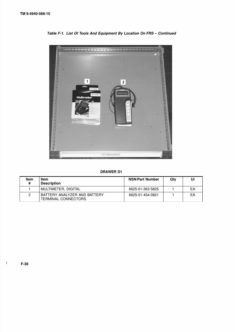
8/20/2019 TM 9-4940-568-10 FRS
http://slidepdf.com/reader/full/tm-9-4940-568-10-frs 340/403
TM 9-4940-568-10
F-38
Table F-1. List Of Tools And Equipment By Location On FRS – Continued
DRAWER D1
Item#
ItemDescription
NSN/Part Number Qty UI
1 MULTIMETER, DIGITAL 6625-01-363-5825 1 EA
2 BATTERY ANALYZER AND BATTERYTERMINAL CONNECTORS
6625-01-454-0821 1 EA
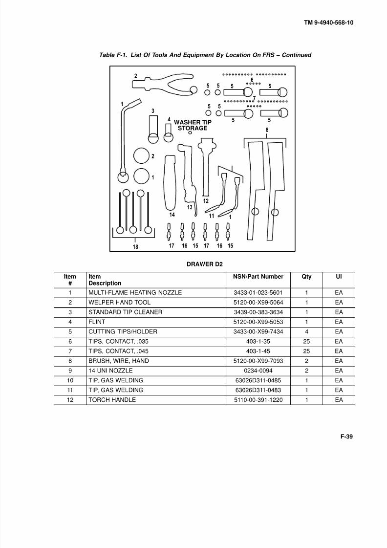
8/20/2019 TM 9-4940-568-10 FRS
http://slidepdf.com/reader/full/tm-9-4940-568-10-frs 341/403
TM 9-4940-568-10
F-39
Table F-1. List Of Tools And Equipment By Location On FRS – Continued
9
0
0
9
WASHER TIPSTORAGE
DRAWER D2
Item#
ItemDescription
NSN/Part Number Qty UI
1 MULTI-FLAME HEATING NOZZLE 3433-01-023-5601 1 EA
2 WELPER HAND TOOL 5120-00-X99-5064 1 EA
3 STANDARD TIP CLEANER 3439-00-383-3634 1 EA
4 FLINT 5120-00-X99-5053 1 EA
5 CUTTING TIPS/HOLDER 3433-00-X99-7434 4 EA
6 TIPS, CONTACT, .035 403-1-35 25 EA
7 TIPS, CONTACT, .045 403-1-45 25 EA
8 BRUSH, WIRE, HAND 5120-00-X99-7093 2 EA
9 14 UNI NOZZLE 0234-0094 2 EA
10 TIP, GAS WELDING 63026D311-0485 1 EA
11 TIP, GAS WELDING 63026D311-0483 1 EA
12 TORCH HANDLE 5110-00-391-1220 1 EA
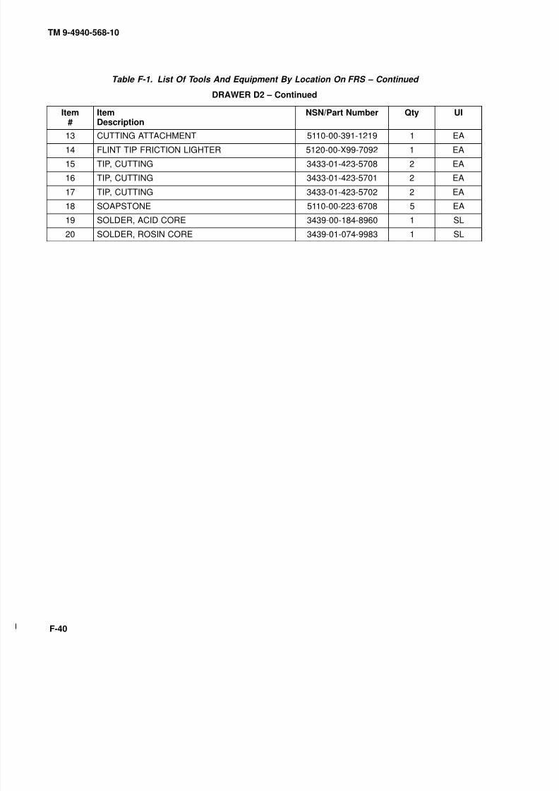
8/20/2019 TM 9-4940-568-10 FRS
http://slidepdf.com/reader/full/tm-9-4940-568-10-frs 342/403
TM 9-4940-568-10
F-40
Table F-1. List Of Tools And Equipment By Location On FRS – Continued
DRAWER D2 – Continued
Item#
ItemDescription
NSN/Part Number Qty UI
13 CUTTING ATTACHMENT 5110-00-391-1219 1 EA
14 FLINT TIP FRICTION LIGHTER 5120-00-X99-7092 1 EA
15 TIP, CUTTING 3433-01-423-5708 2 EA
16 TIP, CUTTING 3433-01-423-5701 2 EA
17 TIP, CUTTING 3433-01-423-5702 2 EA
18 SOAPSTONE 5110-00-223-6708 5 EA
19 SOLDER, ACID CORE 3439-00-184-8960 1 SL
20 SOLDER, ROSIN CORE 3439-01-074-9983 1 SL
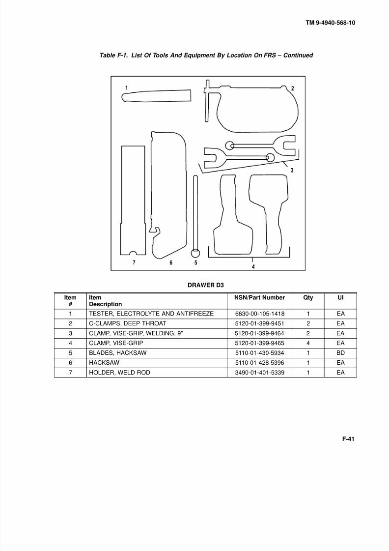
8/20/2019 TM 9-4940-568-10 FRS
http://slidepdf.com/reader/full/tm-9-4940-568-10-frs 343/403
TM 9-4940-568-10
F-41
Table F-1. List Of Tools And Equipment By Location On FRS – Continued
DRAWER D3
Item#
ItemDescription
NSN/Part Number Qty UI
1 TESTER, ELECTROLYTE AND ANTIFREEZE 6630-00-105-1418 1 EA
2 C-CLAMPS, DEEP THROAT 5120-01-399-9451 2 EA
3 CLAMP, VISE-GRIP, WELDING, 9” 5120-01-399-9464 2 EA
4 CLAMP, VISE-GRIP 5120-01-399-9465 4 EA
5 BLADES, HACKSAW 5110-01-430-5934 1 BD
6 HACKSAW 5110-01-428-5396 1 EA
7 HOLDER, WELD ROD 3490-01-401-5339 1 EA
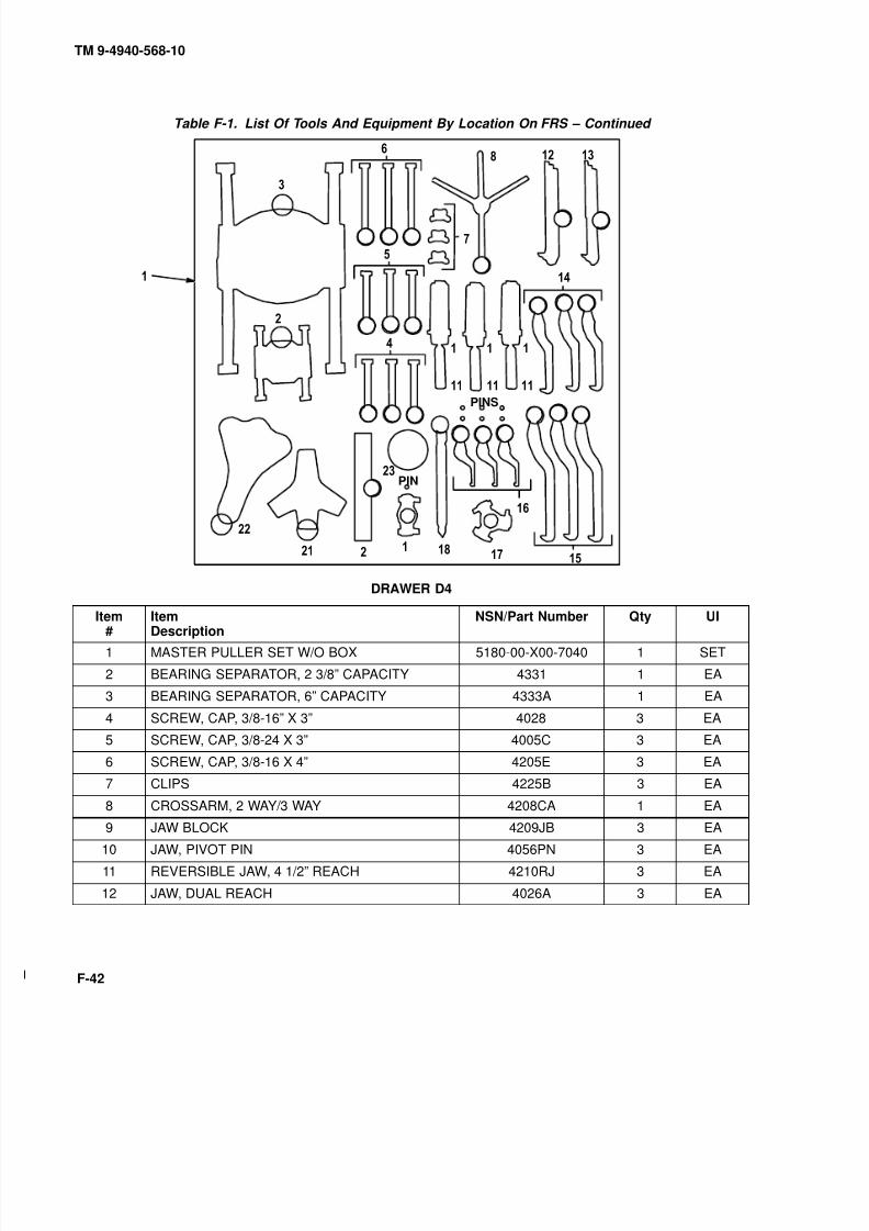
8/20/2019 TM 9-4940-568-10 FRS
http://slidepdf.com/reader/full/tm-9-4940-568-10-frs 344/403
TM 9-4940-568-10
F-42
Table F-1. List Of Tools And Equipment By Location On FRS – Continued
09
9
PIN
PINS
0
9 9
00
DRAWER D4
Item#
ItemDescription
NSN/Part Number Qty UI
1 MASTER PULLER SET W/O BOX 5180-00-X00-7040 1 SET
2 BEARING SEPARATOR, 2 3/8” CAPACITY 4331 1 EA
3 BEARING SEPARATOR, 6” CAPACITY 4333A 1 EA
4 SCREW, CAP, 3/8-16” X 3” 4028 3 EA
5 SCREW, CAP, 3/8-24 X 3” 4005C 3 EA
6 SCREW, CAP, 3/8-16 X 4” 4205E 3 EA
7 CLIPS 4225B 3 EA
8 CROSSARM, 2 WAY/3 WAY 4208CA 1 EA
9 JAW BLOCK 4209JB 3 EA
10 JAW, PIVOT PIN 4056PN 3 EA
11 REVERSIBLE JAW, 4 1/2” REACH 4210RJ 3 EA
12 JAW, DUAL REACH 4026A 3 EA
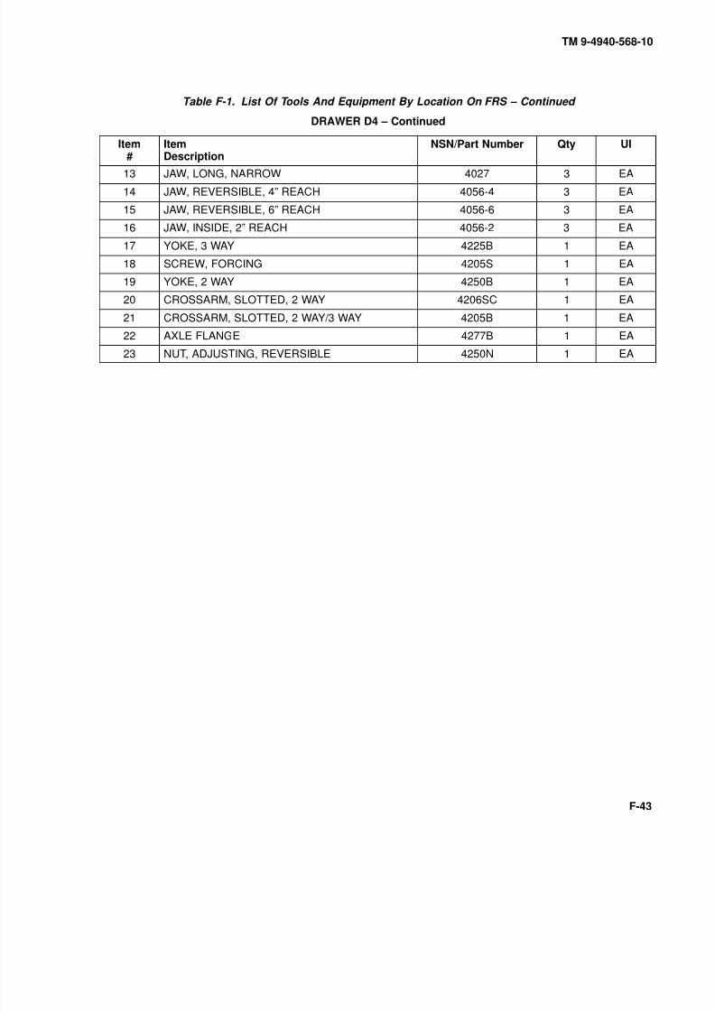
8/20/2019 TM 9-4940-568-10 FRS
http://slidepdf.com/reader/full/tm-9-4940-568-10-frs 345/403
TM 9-4940-568-10
F-43
Table F-1. List Of Tools And Equipment By Location On FRS – Continued
DRAWER D4 – Continued
Item#
ItemDescription
NSN/Part Number Qty UI
13 JAW, LONG, NARROW 4027 3 EA
14 JAW, REVERSIBLE, 4” REACH 4056-4 3 EA
15 JAW, REVERSIBLE, 6” REACH 4056-6 3 EA
16 JAW, INSIDE, 2” REACH 4056-2 3 EA
17 YOKE, 3 WAY 4225B 1 EA
18 SCREW, FORCING 4205S 1 EA
19 YOKE, 2 WAY 4250B 1 EA
20 CROSSARM, SLOTTED, 2 WAY 4206SC 1 EA
21 CROSSARM, SLOTTED, 2 WAY/3 WAY 4205B 1 EA
22 AXLE FLANGE 4277B 1 EA23 NUT, ADJUSTING, REVERSIBLE 4250N 1 EA

8/20/2019 TM 9-4940-568-10 FRS
http://slidepdf.com/reader/full/tm-9-4940-568-10-frs 346/403
TM 9-4940-568-10
F-44
Table F-1. List Of Tools And Equipment By Location On FRS – Continued
9
0
0
0 0
9 9
DRAWER D5
Item#
ItemDescription
NSN/Part Number Qty UI
1 ROD, SHORT, SLIDE 4275R 1 EA
2 ROD, T-HANDLE SLIDE 4260R 1 EA
3 SCREW, FORCING 4225S 1 EA
4 CROSSARM, 2 WAY 4226CA 1 EA
5 CROSSARM, 3 WAY 4227CA 1 EA
6 JAW, CAP SCREW 4018 3 EA
7 JAW, LONG, NARROW 4017 3 EA
8 JAW, DUAL-REACH 4016 3 EA
JAW SPRING, 10 TON (Includes the following:) 4011S 3 EA
9 JAW BLOCK 4229JB 3 EA
10 JAW, PIVOT PIN 4056PN 3 EA
11 REVERSIBLE JAW 4230RJ 3 EA
12 BLIND BEARING PULLER 4280-S-1 1 EA

8/20/2019 TM 9-4940-568-10 FRS
http://slidepdf.com/reader/full/tm-9-4940-568-10-frs 347/403
TM 9-4940-568-10
F-45
Table F-1. List Of Tools And Equipment By Location On FRS – Continued
DRAWER D5 – Continued
Item#
ItemDescription
NSN/Part Number Qty UI
13 PIN 4280-S-2 1 EA
14 JAW, INSIDE HOOK 4256S 1 EA
15 HAMMER, 5 LB. SLIDE 4055H 1 EA
16 HAMMER, 2 1/2 LB. SLIDE 4260H 1 EA
STEP PLATE ADAPTER SET(Includes the following:)
4040 1 EA
17 STEP PLATE, 2 3/8 BORE 4040-14 1 EA
18 STEP PLATE, 2 1/4 BORE 4040-13 1 EA
19 STEP PLATE, 2 1/8 BORE 4040-12 1 EA
20 STEP PLATE, BORE 4040-11 1 EA
21 STEP PLATE, BORE 4040-10 1 EA
22 STEP PLATE, BORE 4040-9 1 EA
23 STEP PLATE, BORE 4040-8 1 EA
24 STEP PLATE, BORE 4040-7 1 EA
25 STEP PLATE, BORE 4040-6 1 EA
26 STEP PLATE, BORE 4040-5 1 EA
27 STEP PLATE, BORE 4040-4 1 EA
28 STEP PLATE, BORE 4040-3 1 EA
29 STEP PLATE, BORE 4040-2 1 EA
30 STEP PLATE, BORE 4040-1 1 EA
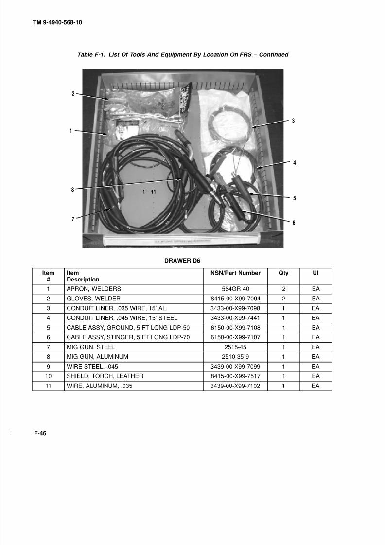
8/20/2019 TM 9-4940-568-10 FRS
http://slidepdf.com/reader/full/tm-9-4940-568-10-frs 348/403
TM 9-4940-568-10
F-46
Table F-1. List Of Tools And Equipment By Location On FRS – Continued
9 , 0 ,
DRAWER D6
Item#
ItemDescription
NSN/Part Number Qty UI
1 APRON, WELDERS 564GR-40 2 EA
2 GLOVES, WELDER 8415-00-X99-7094 2 EA
3 CONDUIT LINER, .035 WIRE, 15’ AL. 3433-00-X99-7098 1 EA
4 CONDUIT LINER, .045 WIRE, 15’ STEEL 3433-00-X99-7441 1 EA
5 CABLE ASSY, GROUND, 5 FT LONG LDP-50 6150-00-X99-7108 1 EA
6 CABLE ASSY, STINGER, 5 FT LONG LDP-70 6150-00-X99-7107 1 EA
7 MIG GUN, STEEL 2515-45 1 EA
8 MIG GUN, ALUMINUM 2510-35-9 1 EA
9 WIRE STEEL, .045 3439-00-X99-7099 1 EA
10 SHIELD, TORCH, LEATHER 8415-00-X99-7517 1 EA
11 WIRE, ALUMINUM, .035 3439-00-X99-7102 1 EA

8/20/2019 TM 9-4940-568-10 FRS
http://slidepdf.com/reader/full/tm-9-4940-568-10-frs 349/403
TM 9-4940-568-10
F-47
Table F-1. List Of Tools And Equipment By Location On FRS – Continued
,
DRAWER D7
Item#
ItemDescription
NSN/Part Number Qty UI
1 HOLDER, WELD ROD 3490-01-401-5339 2 EA
2 CUTTING RODS, EXOTHERMIC TORCH, 3/8 X 3421-00-X99-7124 1 EA
3 CUTTING RODS, EXOTHERMIC TORCH, 1/4 X 3421-00-X99-7125 1 EA
4 GOGGLES, INDUSTRIAL 749360746-0515 2 EA
5 HEADGEAR 170S 0742-0020 2 EA
6 CLEAR VISOR 915-60 0754-0215 2 EA
7 CABLE ASSY, EXOTHERMIC, 5 FT LONG 6150-00-X99-7117 1 EA
8 CABLE ASSY, EXOTHERMIC, 5 FT LONG 6150-00-X99-7116 1 EA
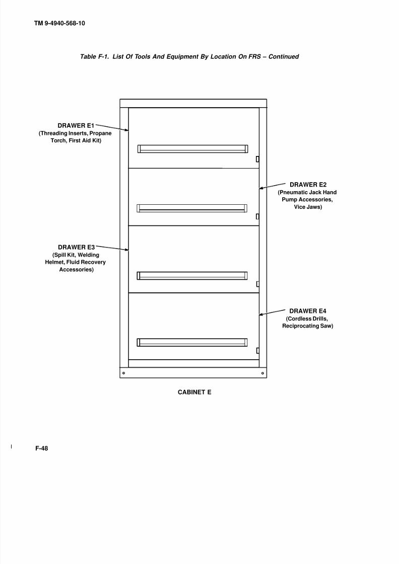
8/20/2019 TM 9-4940-568-10 FRS
http://slidepdf.com/reader/full/tm-9-4940-568-10-frs 350/403
TM 9-4940-568-10
F-48
Table F-1. List Of Tools And Equipment By Location On FRS – Continued
CABINET E
DRAWER E1(Threading Inserts, Propane
Torch, First Aid Kit)
DRAWER E2(Pneumatic Jack Hand
Pump Accessories,
Vice Jaws)
DRAWER E4(Cordless Drills,
Reciprocating Saw)
DRAWER E3(Spill Kit, Welding
Helmet, Fluid Recovery
Accessories)
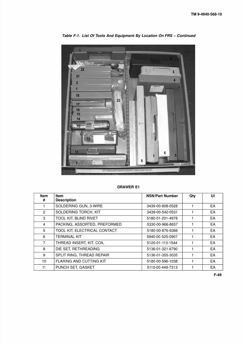
8/20/2019 TM 9-4940-568-10 FRS
http://slidepdf.com/reader/full/tm-9-4940-568-10-frs 351/403
TM 9-4940-568-10
F-49
Table F-1. List Of Tools And Equipment By Location On FRS – Continued
0
9
0
9
DRAWER E1
Item#
ItemDescription
NSN/Part Number Qty UI
1 SOLDERING GUN, 3-WIRE 3439-00-808-0528 1 EA
2 SOLDERING TORCH, KIT 3439-00-542-0531 1 EA
3 TOOL KIT, BLIND RIVET 5180-01-201-4978 1 EA
4 PACKING, ASSORTED, PREFORMED 5330-00-966-8657 1 EA
5 TOOL KIT, ELECTRICAL CONTACT 5180-00-876-9366 1 EA
6 TERMINAL KIT 5940-00-525-0907 1 EA
7 THREAD INSERT, KIT, COIL 5120-01-113-1544 1 EA
8 DIE SET, RETHREADING 5136-01-321-6790 1 EA
9 SPLIT RING, THREAD REPAIR 5136-01-355-3035 1 EA
10 FLARING AND CUTTING KIT 5180-00-596-1038 1 EA
11 PUNCH SET, GASKET 5110-00-449-7313 1 EA

8/20/2019 TM 9-4940-568-10 FRS
http://slidepdf.com/reader/full/tm-9-4940-568-10-frs 352/403
TM 9-4940-568-10
F-50
Table F-1. List Of Tools And Equipment By Location On FRS – Continued
DRAWER E1 – Continued
Item#
ItemDescription
NSN/Part Number Qty UI
12 FIRST AID KIT, GENERAL PURPOSE 6545-00-922-1200 1 EA
13 THREAD INSERT, SCREW, 1/2-13 UNC 5180-00-051-5024 1 EA
14 REFACING TOOL, TUBE FITTING 5110-00-595-9279 1 EA
15 THREAD INSERT, SCREW, 1/4-28 UNC 5180-00-935-0736 1 EA
16 THREAD INSERT, SCREW, 1/4-20 UNC 5180-00-935-0732 1 EA
17 TUBE FLARING, METRIC 5120-01-335-1606 1 EA
18 THREAD INSERT, SCREW, 3/8-16 UNC 5180-00-935-0734 1 EA
19 THREAD INSERT, SCREW, 5/16-18 UNC 5180-00-935-0733 1 EA
20 THREAD INSERT, SCREW, 5/16-24 UNC 5180-00-935-0737 1 EA
21 THREAD INSERT, SCREW, 1/2-20 UNC 5180-00-054-7505 1 EA22 THREAD INSERT, SCREW, 3/8-24 UNC 5180-00-935-0738 1 EA
23 SCALE, DIAL, INDICATING 6670-00-254-4634 1 EA
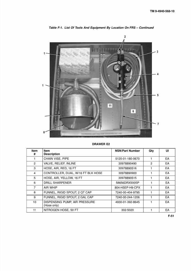
8/20/2019 TM 9-4940-568-10 FRS
http://slidepdf.com/reader/full/tm-9-4940-568-10-frs 353/403
TM 9-4940-568-10
F-51
Table F-1. List Of Tools And Equipment By Location On FRS – Continued
0
9
DRAWER E2
Item#
ItemDescription
NSN/Part Number Qty UI
1 CHAIN VISE, PIPE 5120-01-180-0670 1 EA
2 VALVE, RELIEF, INLINE 30978890490 2 EA
3 HOSE, AIR, RED, 16 FT 30978890516 1 EA
4 CONTROLLER, DUAL, W/16 FT BLK HOSE 30978890900 1 EA
5 HOSE, AIR, YELLOW, 16 FT 30978890515 1 EA
6 DRILL SHARPENER 58656DRX500SP 1 EA
7 AIR WHIP 804-H5EP-H9-CPX 1 EA
8 FUNNEL, RIGID SPOUT, 2 QT CAP 7240-00-404-9795 1 EA
9 FUNNEL, RIGID SPOUT, 2 GAL CAP 7240-00-244-1206 1 EA
10 DISPENSING PUMP, AIR PRESSURE(Hose only)
4930-01-392-8645 1 EA
11 NITROGEN HOSE, 50 FT 302-5020 1 EA

8/20/2019 TM 9-4940-568-10 FRS
http://slidepdf.com/reader/full/tm-9-4940-568-10-frs 354/403
TM 9-4940-568-10
F-52
Table F-1. List Of Tools And Equipment By Location On FRS – Continued
DRAWER E3
Item#
ItemDescription
NSN/Part Number Qty UI
1 ENVIRONMENTAL SUPPORT 4235-01-399-2495 1 EA
2 FUNNEL, FLEXIBLE SPOUT, 1 QT CAP 7240-00-559-7364 1 EA
3 HELMET, QEC MASTER WELDING 749360744-0753 1 EA
4 ADAPTER KIT, GREASE GUN 4930-01-178-8848 1 EA
5 GLOVES, RUBBER: MEN 8415-00-266-8675 1 EA
6 BOX TOTE, PLASTIC, 20.5L X 12.6W X 8H 3990-01-056-2990 1 EA
7 APRON, RUBBER COATED, BLACK 8415-00-082-6108 1 EA
8 GUN, GREASE YA732 1 EA

8/20/2019 TM 9-4940-568-10 FRS
http://slidepdf.com/reader/full/tm-9-4940-568-10-frs 355/403
TM 9-4940-568-10
F-53
Table F-1. List Of Tools And Equipment By Location On FRS – Continued
, , , , 9
,
ALTERNATE2 GAL FUNNELLOCATION
DRAWER E4
Item#
ItemDescription
NSN/Part Number Qty UI
1 SAW ALL, VARIABLE SPEED 5120-01-139-9674 1 EA
2 ALL PURPOSE BLADES 6093312421-5 1 EA
3 DRILL CORDLESS, 12 V, 1/2” 609339862 1 EA
4 PAN, DRAIN, 5 GAL CAP 257956Y810 1 EA
5 STRAPS, RUBBER, TIE-DOWN 9” 5340-00-X99-7111 4 EA
6 STRAPS, RUBBER, TIE-DOWN 15” 5340-00-X99-7112 5 EA
7 STRAPS, RUBBER, TIE-DOWN 21” 5340-00-X99-7113 6 EA
8 STRAPS, RUBBER, TIE-DOWN 31” 5340-00-X99-7114 4 EA
9 STRAPS, RUBBER, TIE-DOWN 41” 5340-00-X99-7115 4 EA
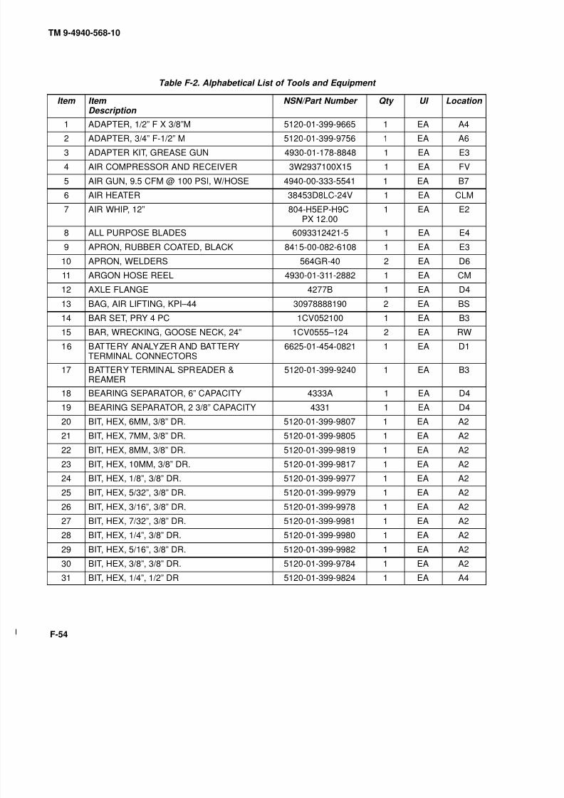
8/20/2019 TM 9-4940-568-10 FRS
http://slidepdf.com/reader/full/tm-9-4940-568-10-frs 356/403
TM 9-4940-568-10
F-54
Table F-2. Alphabetical List of Tools and Equipment
Item Item Description
NSN/Part Number Qty UI Location
1 ADAPTER, 1/2” F X 3/8”M 5120-01-399-9665 1 EA A4
2 ADAPTER, 3/4” F-1/2” M 5120-01-399-9756 1 EA A6
3 ADAPTER KIT, GREASE GUN 4930-01-178-8848 1 EA E3
4 AIR COMPRESSOR AND RECEIVER 3W2937100X15 1 EA FV
5 AIR GUN, 9.5 CFM @ 100 PSI, W/HOSE 4940-00-333-5541 1 EA B7
6 AIR HEATER 38453D8LC-24V 1 EA CLM
7 AIR WHIP, 12” 804-H5EP-H9CPX 12.00
1 EA E2
8 ALL PURPOSE BLADES 6093312421-5 1 EA E4
9 APRON, RUBBER COATED, BLACK 8415-00-082-6108 1 EA E3
10 APRON, WELDERS 564GR-40 2 EA D611 ARGON HOSE REEL 4930-01-311-2882 1 EA CM
12 AXLE FLANGE 4277B 1 EA D4
13 BAG, AIR LIFTING, KPI–44 30978888190 2 EA BS
14 BAR SET, PRY 4 PC 1CV052100 1 EA B3
15 BAR, WRECKING, GOOSE NECK, 24” 1CV0555–124 2 EA RW
16 BATTERY ANALYZER AND BATTERYTERMINAL CONNECTORS
6625-01-454-0821 1 EA D1
17 BATTERY TERMINAL SPREADER &REAMER
5120-01-399-9240 1 EA B3
18 BEARING SEPARATOR, 6” CAPACITY 4333A 1 EA D4
19 BEARING SEPARATOR, 2 3/8” CAPACITY 4331 1 EA D4
20 BIT, HEX, 6MM, 3/8” DR. 5120-01-399-9807 1 EA A2
21 BIT, HEX, 7MM, 3/8” DR. 5120-01-399-9805 1 EA A2
22 BIT, HEX, 8MM, 3/8” DR. 5120-01-399-9819 1 EA A2
23 BIT, HEX, 10MM, 3/8” DR. 5120-01-399-9817 1 EA A2
24 BIT, HEX, 1/8”, 3/8” DR. 5120-01-399-9977 1 EA A2
25 BIT, HEX, 5/32”, 3/8” DR. 5120-01-399-9979 1 EA A2
26 BIT, HEX, 3/16”, 3/8” DR. 5120-01-399-9978 1 EA A2
27 BIT, HEX, 7/32”, 3/8” DR. 5120-01-399-9981 1 EA A2
28 BIT, HEX, 1/4”, 3/8” DR. 5120-01-399-9980 1 EA A2
29 BIT, HEX, 5/16”, 3/8” DR. 5120-01-399-9982 1 EA A2
30 BIT, HEX, 3/8”, 3/8” DR. 5120-01-399-9784 1 EA A2
31 BIT, HEX, 1/4”, 1/2” DR 5120-01-399-9824 1 EA A4

8/20/2019 TM 9-4940-568-10 FRS
http://slidepdf.com/reader/full/tm-9-4940-568-10-frs 357/403
TM 9-4940-568-10
F-55
Table F-2. Alphabetical List of Tools and Equipment – Continued
Item Item Description
NSN/Part Number Qty UI Location
32 BIT, HEX, 5/16”, 1/2” DR 5120-01-399-9825 1 EA A4
33 BIT, HEX, 3/8”, 1/2” DR 5120-01-399-9827 1 EA A4
34 BIT, HEX, 7/16”, 1/2” DR 5120-01-399-9828 1 EA A4
35 BIT, HEX, 1/2”, 1/2” DR 5120-01-399-9830 1 EA A4
36 BIT, HEX, 9/16”, 1/2” DR 5120-01-399-9829 1 EA A4
37 BIT, HEX, 5/8”, 1/2” DR 5120-01-399-9831 1 EA A4
38 BIT, HEX, EXTRA LONG, 1/8”, 3/8” DR. 5120-01-399-9787 1 EA A2
39 BIT, HEX, EXTRA LONG, 5/32”, 3/8” DR. 5120-01-399-9799 1 EA A2
40 BIT, HEX, EXTRA LONG, 3/16”, 3/8” DR. 5120-01-399-9796 1 EA A2
41 BIT, HEX, EXTRA LONG, 7/32”, 3/8” DR. 5120-01-399-9806 1 EA A2
42 BIT, HEX, EXTRA LONG, 1/4”, 3/8” DR. 1CV0549901/4XL 1 EA A243 BIT, HEX, EXTRA LONG, 5/16”, 3/8” DR. 5120-01-399-9809 1 EA A2
44 BIT, HEX, EXTRA LONG, 3/8”, 3/8” DR. 5120-01-399-9812 1 EA A2
45 BIT, HEX, EXTRA LONG, 1/4”, 1/2” DR 5120-01-399-9832 1 EA A4
46 BIT, HEX, EXTRA LONG, 5/16”, 1/2” DR 5120-01-399-9833 1 EA A4
47 BIT, HEX, EXTRA LONG, 3/8”, 1/2” DR 5120-01-399-9835 1 EA A4
48 BIT, HEX, EXTRA LONG, 1/2”, 1/2” DR 5120-01-399-9834 1 EA A4
49 BIT, HEX, EXTRA LONG, 9/16”, 1/2” DR 5120-01-399-9837 1 EA A4
50 BIT, HEX, EXTRA LONG, 5/8”, 1/2” DR 5120-01-399-9838 1 EA A4
51 BIT, TORX, T10, 3/8” DRIVE 5120-01-399-9779 1 EA A2
52 BIT, TORX, T15, 3/8” DRIVE 5120-01-399-9776 1 EA A2
53 BIT, TORX, T20, 3/8” DRIVE 5120-01-399-9778 1 EA A2
54 BIT, TORX, T25, 3/8” DRIVE 5120-01-399-9781 1 EA A2
55 BIT, TORX, T27, 3/8” DRIVE 5120-01-399-9789 1 EA A2
56 BIT, TORX, T30, 3/8” DRIVE 5120-01-399-9786 1 EA A2
57 BIT, TORX, T40, 3/8” DRIVE 5120-01-399-9795 1 EA A2
58 BIT, TORX, T45, 3/8” DRIVE 5120-01-399-9791 1 EA A2
59 BIT, TORX, T50, 3/8” DRIVE 5120-01-399-9793 1 EA A2
60 BIT, TORX, T55, 3/8” DRIVE 5120-01-399-9800 1 EA A2
61 BLADES, HACKSAW 5110-01-430-5934 1 BD D3
62 BLIND BEARING PULLER 4280-S-1 1 EA D5
63 BOX TOTE, PLASTIC, 20.5L X 12.6W X 8H 3990-01-056-2990 1 EA E3

8/20/2019 TM 9-4940-568-10 FRS
http://slidepdf.com/reader/full/tm-9-4940-568-10-frs 358/403
TM 9-4940-568-10
F-56
Table F-2. Alphabetical List of Tools and Equipment – Continued
Item Item Description
NSN/Part Number Qty UI Location
64 BRAZING ROD HOLDER 3439-00-X99-8028 1 EA RW
65 BRAZING ROD, 1/8” 3439-00-X99-8020 1 PK RW
66 BRAZING ROD, 3/16” 0015FC-80 1 PK RW
67 BREAKER BAR HINGE HANDLE 3/8” DR8 1/2” LONG
5120-01-399-9609 1 EA A2
68 BREAKER BAR, 1/2” DR, 18 5/8” LONG 1CV055468 1 EA A4
69 BREAKER BAR, 3/4” DR, 20” LONG 5120-01-358-3171 1 EA A6
70 BRUSH, FILE CLEANER 7920-00-224-7987 1 EA B2
71 BRUSH, WIRE, HAND 5120-00-X99-7093 2 EA D2
72 BRUSH, WIRE, ROTARY, FLARE 5130-00-293-2409 1 EA A7
73 BRUSH, WIRE, ROTARY, SOLID 5130-00-263-0235 1 EA A7
74 CABLE 2-195-6-00653 1 EA RV
75 CABLE ASSY, EXOTHERMIC, 5 FT LONGLDP-50 END
6150-00-X99-7117 1 EA D7
76 CABLE ASSY, EXOTHERMIC, 5 FT LONGLDP-70 END
6150-00-X99-7116 1 EA D7
77 CABLE ASSY, GROUND, 5 FT LONG LDP-50 6150-00-X99-7108 1 EA D6
78 CABLE ASSY, STINGER, 5 FT LONG LDP-70 6150-00-X99-7107 1 EA D6
79 CABLE, WELDING ASSY, W/2 FTGS, 45 FTBLACK LDP-50
6150-00-X99-7106 1 EA RW
80 CABLE, WELDING ASSY, W/2 FTGS, 45 FT
RED LDP-70
6150-00-X99-7105 1 EA RW
81 CAPS, VISE JAW 5120-00-221-1506 1 PG CM
82 C-CLAMPS, DEEP THROAT 5120-01-399-9451 2 EA D3
83 CHAIN VISE, PIPE 5120-01-180-0670 1 EA E2
84 CHISEL, COLD, 7/8” CUT 5110-01-406-7201 1 EA B2
85 CHISEL, COLD, 1” CUT 1CV0586A718X8 1 EA B2
86 CHISEL, COLD, 1 3/16” CUT 1CV0586A1X8 1 EA B2
87 CLAMP, VISE-GRIP 5120-01-399-9465 4 EA D3
88 CLAMP, VISE-GRIP, WELDING, 9” 5120-01-399-9464 2 EA D3
89 CLEANER, BATTERY POST 5120-01-400-1200 1 EA A3
90 CLEAR VISOR 915-60 0754-0215 2 EA D7
91 CLIPS 4225B 3 EA D4
92 CONDUIT LINER, .035 WIRE, 15’ AL. 3433-00-X99-7098 1 EA D6
93 CONDUIT LINER, .045 WIRE, 15’ STEEL 3433-00-X97-7441 1 EA D6
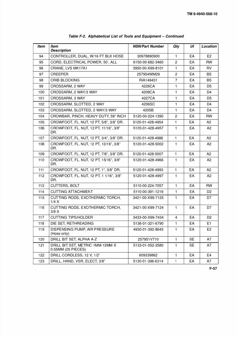
8/20/2019 TM 9-4940-568-10 FRS
http://slidepdf.com/reader/full/tm-9-4940-568-10-frs 359/403
TM 9-4940-568-10
F-57
Table F-2. Alphabetical List of Tools and Equipment – Continued
Item Item Description
NSN/Part Number Qty UI Location
94 CONTROLLER, DUAL, W/16 FT BLK HOSE 30978890900 1 EA E2
95 CORD, ELECTRICAL POWER, 50’, ALL 6150-00-682-3460 2 EA RW
96 CRANE, LVS MK17A1 3950-00-X99-8101 1 EA RV
97 CREEPER 257954WM29 2 EA BS
98 CRIB BLOCKING RIA149431 7 EA BS
99 CROSSARM, 2 WAY 4226CA 1 EA D5
100 CROSSARM, 2 WAY/3 WAY 4208CA 1 EA D4
101 CROSSARM, 3 WAY 4227CA 1 EA D5
102 CROSSARM, SLOTTED, 2 WAY 4206SC 1 EA D4
103 CROSSARM, SLOTTED, 2 WAY/3 WAY 4205B 1 EA D4
104 CROWBAR, PINCH, HEAVY DUTY, 59” INCH 5120-00-224-1390 2 EA RW
105 CROWFOOT, FL. NUT, 12 PT, 5/8”, 3/8” DR. 5120-01-428-4954 1 EA A2
106 CROWFOOT, FL. NUT, 12 PT, 11/16”, 3/8”DR.
5120-01-428-4957 1 EA A2
107 CROWFOOT, FL. NUT, 12 PT, 3/4”, 3/8” DR. 5120-01-428-4986 1 EA A2
108 CROWFOOT, FL. NUT, 12 PT, 13/16”, 3/8”DR.
5120-01-428-5002 1 EA A2
109 CROWFOOT, FL. NUT, 12 PT, 7/8”, 3/8” DR. 5120-01-428-5007 1 EA A2
110 CROWFOOT, FL. NUT, 12 PT, 15/16”, 3/8”DR.
5120-01-428-4966 1 EA A2
111 CROWFOOT, FL. NUT, 12 PT, 1”, 3/8” DR. 5120-01-428-4993 1 EA A2
112 CROWFOOT, FL. NUT, 12 PT, 1 1/16”, 3/8”DR.
5120-01-428-4997 1 EA A2
113 CUTTERS, BOLT 5110-00-224-7057 1 EA RW
114 CUTTING ATTACHMENT 5110-00-391-1219 1 EA D2
115 CUTTING RODS, EXOTHERMIC TORCH,1/4 X
3421-00-X99-7125 1 EA D7
116 CUTTING RODS, EXOTHERMIC TORCH,3/8 X
3421-00-X99-7124 1 EA D7
117 CUTTING TIPS/HOLDER 3433-00-X99-7434 4 EA D2
118 DIE SET, RETHREADING 5136-01-321-6790 1 EA E1119 DISPENSING PUMP, AIR PRESSURE
(Hose only)4930-01-392-8645 1 EA E2
120 DRILL BIT SET, ALPHA A-Z 257951V710 1 SE A7
121 DRILL BIT SET, METRIC 1MM-13MM X0.55MM (25 PIECES)
5133-01-052-3580 1 SE A7
122 DRILL CORDLESS, 12 V, 1/2” 609339862 1 EA E4
123 DRILL, HAND, VSR, ELECT, 3/8” 5130-01-396-6314 1 EA A7

8/20/2019 TM 9-4940-568-10 FRS
http://slidepdf.com/reader/full/tm-9-4940-568-10-frs 360/403
TM 9-4940-568-10
F-58
Table F-2. Alphabetical List of Tools and Equipment – Continued
Item Item Description
NSN/Part Number Qty UI Location
124 DRILL, HAND, VSR, ELEC, 1/2” 609337554 1 EA A7
125 DRILL, RIGHT ANGLE, ELEC, 1/2” 5130-01-180-7933 1 EA A7
126 DRILL, 900 RPM, PNEU, 1/2” AND HANDLE 478057ANST8 1 EA B7
127 DRILL, 3200 RPM, PNEU, 3/8” 478057AMST6 1 EA B7
128 DRILL SET STANDARD 1/16” 1/2” 257951U200 1 SE A7
129 DRILL SHARPENER 58656DRX500SP 1 EA E2
130 ENVIRONMENTAL SUPPORT 4235-01-399-2495 1 EA E3
131 EXTENSION, 1/2” D., 2” L 5130-01-400-0108 1 EA A5
132 EXTENSION, 1/2” D., 5” L 5120-00-243-7326 1 EA A5
133 EXTENSION, 1/2” D., 10” L 1CV057183-00 1 EA A5
134 EXTENSION, 1/2” DR, 2 1/2” LONG 5120-01-399-9663 1 EA A4135 EXTENSION, 1/2” DR, 5” LONG 5120-01-399-9661 1 EA A4
136 EXTENSION, 1/2” DR, 10” LONG 5120-01-399-9662 1 EA A4
137 EXTENSION, 3/4 DR, 4” LONG 5120-01-399-9736 1 EA A6
138 EXTENSION, 3/4” DRIVE, 6” L 5130-01-400-0118 1 EA A2
139 EXTENSION, 3/4” DR, 8” LONG 5120-01-399-9747 1 EA A6
140 EXTENSION, 3/4” DRIVE, 12” L 1CV057178P 1 EA A2
141 EXTENSION IMPACT 7” L, 3/4” DR 5130-01-400-0127 1 EA A5
142 EXTENSION, IMPACT, 7” L, 3/4” DRIVE 07567 1 EA A2
143 EXTENSION IMPACT 13” L, 3/4” DR 5130-01-400-0129 1 EA A5
144 EXTENSION, IMPACT, 13” L, 3/4” DRIVE, 07569 1 EA A2
145 EXTRACTOR SET, SCREW 1/8”-1” 5120-01-400-2740 1 EA B6
146 FILE, HAND, FLAT, 10” L 5110-00-234-6537 1 EA B2
147 FILE, HAND, HALF ROUND, 10” L 5110-00-249-2858 1 EA B2
148 FILE, HAND, PILLAR TYPE, 10” L 5110-00-239-6889 1 EA B2
149 FILE, HAND, ROUND, 1/2” DIA, 12” L 5110-00-234-6557 1 EA B2
150 FILE, HAND, TRI SQUARE, 6” L 5110-00-241-9160 1 EA B2
151 FIRE EXTINGUISHER 5 LB. 4210-00-165-4703 1 EA RV
152 FIRE EXTINGUISHERS W/ BRACKET, 2.5 LB 4210-00-965-1105 2 EA RW
153 FIRST AID KIT, GENERAL PURPOSE 6545-00-922-1200 1 EA E1
154 FLARING AND CUTTING KIT 5180-00-596-1038 1 EA E1

8/20/2019 TM 9-4940-568-10 FRS
http://slidepdf.com/reader/full/tm-9-4940-568-10-frs 361/403
TM 9-4940-568-10
F-59
Table F-2. Alphabetical List of Tools and Equipment – Continued
Item Item Description
NSN/Part Number Qty UI Location
155 FLINT 5120-00-X99-5053 1 EA D2
156 FLINT TIP FRICTION LIGHTER 5120-00-X99-7092 1 EA D2
157 FOUNTAIN, EYE AND FACE WASH 4240-00-551-3134 1 EA FW
158 FUNNEL, FLEXIBLE SPOUT, 1 QT CAP 7240-00-559-7364 1 EA E3
159 FUNNEL, RIGID SPOUT, 2 QT CAP 7240-00-404-9795 1 EA E2
160 FUNNEL, RIGID SPOUT, 2 GAL CAP 7240-00-244-1206 1 EA E2
161 GAGE, AIR PRESSURE 4910-00-204-3170 1 EA A3
162 GAGE, FEELER, METRIC 5120-01-399-9332 1 EA A3
163 GAGE, FEELER, STD 5120-01-399-9319 1 EA A3
164 GAGE, TIRE PRESSURE, 20 TO 120 PSI 4910-01-298-5479 1 EA B7
165 GENERATOR SET 6115-00-X99-5156 1 EA FV166 GLOVES, RUBBER: MEN 8415-00-266-8675 1 EA E3
167 GLOVES, WELDER 8415-00-X99-7094 2 EA D6
168 GOGGLES, INDUSTRIAL 749360746-0515 2 EA D7
169 GRINDER, ANGLE, 5” AND WRENCHES 47805HA120RP105 1 EA B7
170 GRINDING MACHINE, UTILITY 3415-00-517-7754 1 EA RW
171 GRINDING WHEELS 3460-00-X99-5051 1 EA B7
172 GUN, GREASE YA732 1 EA E3
173 HACKSAW 5110-01-428-5396 1 EA D3
174 HAMMER, BALL PEEN, 32 OZ, 14 LNG 76377CBH32-O 1 EA B1
175 HAMMER, SLEDGE, 8 LBS (Fiberglasshandle)
5120-01-428-5175 2 EA RW
176 HAMMER, 2 1/2 LB. SLIDE 4260H 1 EA D5
177 HAMMER, 5 LB. SLIDE 4055H 1 EA D5
178 HAMMER, DEAD BLOW, 42 OZ, 14” LNG 5120-01-399-5746 1 EA B1
179 HEADGEAR 170S 0742-0020 2 EA D7
180 HELMET, QEC MASTER WELDING 749360744-0753 1 EA E3
181 HOLDER, WELD ROD 3490-01-401-5339 1 EA D3
182 HOLDER, WELD ROD 3490-01-401-5339 2 EA D7
183 HOSE, AIR, RED, 16 FT 30978890516 1 EA E2184 HOSE, AIR, YELLOW, 16 FT 30978890515 1 EA E2

8/20/2019 TM 9-4940-568-10 FRS
http://slidepdf.com/reader/full/tm-9-4940-568-10-frs 362/403
TM 9-4940-568-10
F-60
Table F-2. Alphabetical List of Tools and Equipment – Continued
Item Item Description
NSN/Part Number Qty UI Location
185 HOSE REEL, AIR LINE, SPR. RET., 3/8” 521737670 OLP 1 EA CM
186 HOSE REEL, AIR LINE, SPR. RET., 3/4” 52173D9375 OLP 1 EA CM
187 HOSE REEL, DUAL OXY/ACTYL W/O HOSE 52173S36106LT 1 EA CM
188 HOSE SUPPLY LINE, SLAVE RIA149182-1 1 EA BS
189 HOSE SUPPLY LINE, SLAVE RIA149182-2 1 EA BS
190 JACK KIT, HYD HAND, 20 TON CAP 5120-00-188-1788 2 EA C3
191 JAW BLOCK 4209JB 3 EA D4
192 JAW BLOCK 4229JB 3 EA D5
193 JAW, CAP SCREW 4018 3 EA D5
194 JAW, DUAL-REACH 4016 3 EA D5
195 JAW, DUAL REACH 4026A 3 EA D4196 JAW, INSIDE HOOK 4256S 1 EA D5
197 JAW, INSIDE, 2” REACH 4056-2 3 EA D4
198 JAW, LONG, NARROW 4017 3 EA D5
199 JAW, LONG, NARROW 4027 3 EA D4
200 JAW, PIVOT PIN 4056PN 3 EA D4
201 JAW, PIVOT PIN 4056PN 3 EA D5
202 JAW, REVERSIBLE, 4” REACH 4056-4 3 EA D4
203 JAW, REVERSIBLE, 6” REACH 4056-6 3 EA D4
204 KNIFE, UTILITY 5110-01-428-5547 1 EA B2
205 LANYARD ASSY, 1/2” D. NYLON W/D RINGS 257955M534 2 EA RW
206 LIFT-A-JACK W/3” MULTI-PURPOSE VISE 3950-00-X99-7710 1 EA RW
207 LIGHT, TROUBLE, FLUORESCENT, 50 FT 6230-00-X99-7109 2 EA CLM
208 LIGHT, WOLF 6230-00-X99-5117 1 EA FV
209 LIGHT, WOLF 6230-00-X99-5117 2 EA RW
210 MASTER PULLER SET W/O BOX 5180-00-X00-7040 1 SET D4
211 MIG GUN, ALUMINUM 2510-35-9 1 EA D6
212 MIG GUN, STEEL 2515-45 1 EA D6
213 MULTI-FLAME HEATING NOZZLE 3433-01-023-5601 1 EA D2
214 MULTIMETER, DIGITAL 6625-01-363-5825 1 EA D1
215 NITROGEN HOSE, 50 FT 302-5020 1 EA E2
216 NUT, ADJUSTING, REVERSIBLE 4250N 1 EA D4
217 PACKING, ASSORTED, PREFORMED 5330-00-966-8657 1 EA E1
218 PAN, DRAIN, 5 GAL CAP 257956Y810 1 EA E4
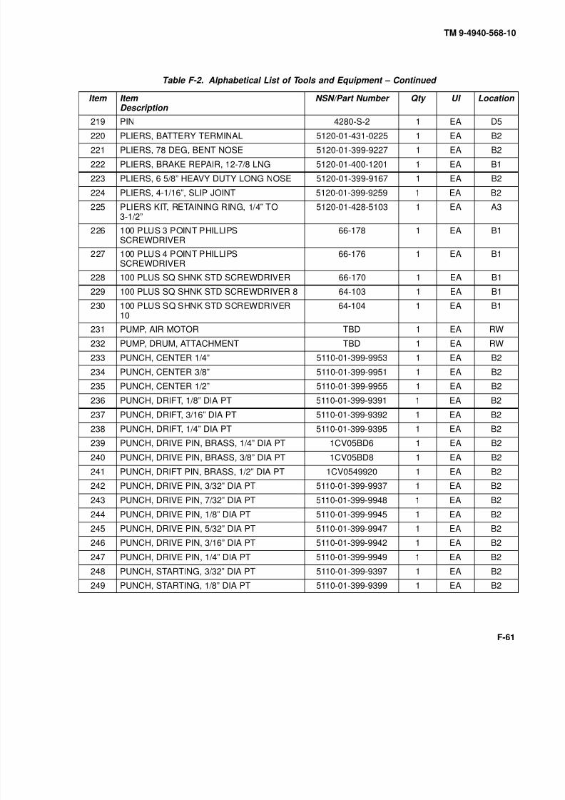
8/20/2019 TM 9-4940-568-10 FRS
http://slidepdf.com/reader/full/tm-9-4940-568-10-frs 363/403
TM 9-4940-568-10
F-61
Table F-2. Alphabetical List of Tools and Equipment – Continued
Item Item Description
NSN/Part Number Qty UI Location
219 PIN 4280-S-2 1 EA D5
220 PLIERS, BATTERY TERMINAL 5120-01-431-0225 1 EA B2
221 PLIERS, 78 DEG, BENT NOSE 5120-01-399-9227 1 EA B2
222 PLIERS, BRAKE REPAIR, 12-7/8 LNG 5120-01-400-1201 1 EA B1
223 PLIERS, 6 5/8” HEAVY DUTY LONG NOSE 5120-01-399-9167 1 EA B2
224 PLIERS, 4-1/16”, SLIP JOINT 5120-01-399-9259 1 EA B2
225 PLIERS KIT, RETAINING RING, 1/4” TO3-1/2”
5120-01-428-5103 1 EA A3
226 100 PLUS 3 POINT PHILLIPSSCREWDRIVER
66-178 1 EA B1
227 100 PLUS 4 POINT PHILLIPS
SCREWDRIVER
66-176 1 EA B1
228 100 PLUS SQ SHNK STD SCREWDRIVER 66-170 1 EA B1
229 100 PLUS SQ SHNK STD SCREWDRIVER 8 64-103 1 EA B1
230 100 PLUS SQ SHNK STD SCREWDRIVER10
64-104 1 EA B1
231 PUMP, AIR MOTOR TBD 1 EA RW
232 PUMP, DRUM, ATTACHMENT TBD 1 EA RW
233 PUNCH, CENTER 1/4” 5110-01-399-9953 1 EA B2
234 PUNCH, CENTER 3/8” 5110-01-399-9951 1 EA B2
235 PUNCH, CENTER 1/2” 5110-01-399-9955 1 EA B2
236 PUNCH, DRIFT, 1/8” DIA PT 5110-01-399-9391 1 EA B2
237 PUNCH, DRIFT, 3/16” DIA PT 5110-01-399-9392 1 EA B2
238 PUNCH, DRIFT, 1/4” DIA PT 5110-01-399-9395 1 EA B2
239 PUNCH, DRIVE PIN, BRASS, 1/4” DIA PT 1CV05BD6 1 EA B2
240 PUNCH, DRIVE PIN, BRASS, 3/8” DIA PT 1CV05BD8 1 EA B2
241 PUNCH, DRIFT PIN, BRASS, 1/2” DIA PT 1CV0549920 1 EA B2
242 PUNCH, DRIVE PIN, 3/32” DIA PT 5110-01-399-9937 1 EA B2
243 PUNCH, DRIVE PIN, 7/32” DIA PT 5110-01-399-9948 1 EA B2
244 PUNCH, DRIVE PIN, 1/8” DIA PT 5110-01-399-9945 1 EA B2
245 PUNCH, DRIVE PIN, 5/32” DIA PT 5110-01-399-9947 1 EA B2246 PUNCH, DRIVE PIN, 3/16” DIA PT 5110-01-399-9942 1 EA B2
247 PUNCH, DRIVE PIN, 1/4” DIA PT 5110-01-399-9949 1 EA B2
248 PUNCH, STARTING, 3/32” DIA PT 5110-01-399-9397 1 EA B2
249 PUNCH, STARTING, 1/8” DIA PT 5110-01-399-9399 1 EA B2

8/20/2019 TM 9-4940-568-10 FRS
http://slidepdf.com/reader/full/tm-9-4940-568-10-frs 364/403
TM 9-4940-568-10
F-62
Table F-2. Alphabetical List of Tools and Equipment – Continued
Item Item Description
NSN/Part Number Qty UI Location
250 PUNCH, STARTING, 3/16” DIA PT 5110-01-399-9400 1 EA B2
251 PUNCH, STARTING, 7/32” DIA PT 5110-01-399-9402 1 EA B2
252 PUNCH, STARTING, 1/4” DIA PT 5110-01-399-9940 1 EA B2
253 PUNCH SET, GASKET 5110-00-449-7313 1 EA E1
254 RATCHET, AIR, 3/8” DRIVE MODEL 111 1 EA A2
255 RATCHET, 3/4” DR, 20” LONG 5120-01-400-0266 1 EA A6
256 RATCHET, LONG HANDLE, 1/2” DR, 15”LONG
5120-01-400-0231 1 EA A4
257 RATCHET, OPEN HEAD, 1/2” DR, 10 1/2”LNG
5120-01-400-0229 1 EA A4
258 RATCHET, STD L, 3/8” DR, 7” L 5120-01-400-0227 1 EA A2
259 REFACING TOOL, TUBE FITTING 5110-00-595-9279 1 EA E1
260 REMOTE CONTROL ASSEMBLY 2-195-6-10000 1 EA RV
261 REPAIR TOOL, TIRE VALVE, LARGE TIRES 5120-00-529-2727 1 EA A3
262 REPAIR TOOL, TIRE VALVE, STD TIRES 76377S445 1 EA A3
263 REVERSIBLE JAW, 4 1/2” REACH 4210RJ 3 EA D4
264 REVERSIBLE JAW 4230RJ 3 EA D5
265 ROD ASSEMBLY, GROUND INSIDE GENSET
5975-00-897-3791 1 EA FV
266 ROD, SHORT, SLIDE 4275R 1 EA D5
267 ROD, T-HANDLE SLIDE 4260R 1 EA D5
268 SAFETY CAPS 5340-01-396-3951 4 EA FV
269 SAW ALL, VARIABLE SPEED 5120-01-139-9674 1 EA E4
270 SCALE, DIAL, INDICATING 6670-00-254-4634 1 EA E1
271 SCREW, CAP, 3/8-16” X 3” 4028 3 EA D4
272 SCREW, CAP, 3/8-16 X 4” 4205E 3 EA D4
273 SCREW, CAP, 3/8-24 X 3” 4005C 3 EA D4
274 SCREW, FORCING 4205S 1 EA D4
275 SCREW, FORCING 4225S 1 EA D5
276 SCREWDRIVER BIT SET, MAGNETIC, 28 PC 1CV0561929 1 EA B1
277 SCREWDRIVER, OFFSET, PHIL. TIP, 1 & 2 5120-01-399-9182 1 EA B1
278 SCREWDRIVER, OFFSET, PHIL. TIP, 3 & 4 5120-01-399-9188 1 EA B1

8/20/2019 TM 9-4940-568-10 FRS
http://slidepdf.com/reader/full/tm-9-4940-568-10-frs 365/403
TM 9-4940-568-10
F-63
Table F-2. Alphabetical List of Tools and Equipment – Continued
Item Item Description
NSN/Part Number Qty UI Location
279 SCREWDRIVER, OFFSET, STANDARD TIP 5120-01-399-9181 1 EA B1
280 SCREWDRIVER, OFFSET, STANDARD TIP 5120-01-399-9183 1 EA B1
281 SCREWDRIVER, STANDARD, 1/4” 66-090 1 EA B1
282 SHIELD, TORCH, LEATHER 8415-00-X99-7517 1 EA D6
283 SLIDE HAMMER, GROUND, ROD 5120-01-013-1676 1 EA RW
284 SOAPSTONE 5110-00-223-6708 5 EA D2
285 SOCKET, DEEP, 9 MM, 12 PT, 3/8 DRIVE 5120-01-399-9886 1 EA A2
286 SOCKET, DEEP, 10 MM, 12 PT, 3/8 DRIVE 5120-01-399-9598 1 EA A2
287 SOCKET, DEEP, 11 MM, 12 PT, 3/8 DRIVE 5120-01-399-9599 1 EA A2
288 SOCKET, DEEP, 12 MM, 12 PT, 3/8 DRIVE 5120-01-399-9603 1 EA A2
289 SOCKET, DEEP, 13 MM, 12 PT, 3/8 DRIVE 5120-01-399-9604 1 EA A2290 SOCKET, DEEP, 14 MM, 12 PT, 3/8 DRIVE 5120-01-399-9602 1 EA A2
291 SOCKET, DEEP, 15 MM, 12 PT, 3/8 DRIVE 5120-01-399-9607 1 EA A2
292 SOCKET, DEEP, 16 MM, 12 PT, 3/8 DRIVE 5120-01-399-9605 1 EA A2
293 SOCKET, DEEP, 17 MM, 12 PT, 3/8 DRIVE 5120-01-399-9606 1 EA A2
294 SOCKET, DEEP, 18 MM, 12 PT, 3/8 DRIVE 5120-01-399-9610 1 EA A2
295 SOCKET, DEEP, 19 MM, 12 PT, 3/8 DRIVE 5120-01-399-9608 1 EA A2
296 SOCKET, DEEP WELL, 12 PT, 1”, 1/2 DR 5120-01-428-4673 1 EA A4
297 SOCKET, DEEP WELL, 12 PT, 1 1/16” 1/2 DR 5120-01-428-4699 1 EA A4
298 SOCKET, DEEP WELL, 12 PT, 1 1/8” 1/2 DR 5120-01-428-4684 1 EA A4
299 SOCKET, DEEP WELL, 12 PT, 1 1/4” 1/2 DR 5120-01-428-4680 1 EA A4
300 SOCKET, DEEP WELL, 12 PT, 1 5/16” 1/2 DR 5120-01-428-4705 1 EA A4
301 SOCKET, DEEP WELL, 12 PT, 1 3/8” 1/2 DR 5120-01-428-4688 1 EA A4
302 SOCKET, DEEP WELL, 12 PT, 1 7/16” 1/2 DR 5120-01-428-4686 1 EA A4
303 SOCKET, DEEP WELL, 12 PT, 1 1/2” 1/2 DR 5120-01-428-4711 1 EA A4
304 SOCKET IMPACT 6 PT 15/16”, 3/4” DR 5130-01-400-0151 1 EA A5
305 SOCKET, IMPACT, DEEP, 6PT, 1/2”, 1/2” DR 1CV057316H 1 EA A5
306 SOCKET, IMPACT, DEEP, 6PT, 9/16”, 1/2” DR 1CV057318H 1 EA A5
307 SOCKET, IMPACT, DEEP, 6PT, 5/8”, 1/2” DR 5130-01-400-0099 1 EA A5
308 SOCKET, IMPACT, DEEP, 6PT, 11/16”, 1/2”DR
1CV057322H 1 EA A5
309 SOCKET, IMPACT, DEEP, 6PT, 3/4”, 1/2” DR 1CV057324H 1 EA A5
310 SOCKET, IMPACT, DEEP, 6PT, 13/16”, 1/2”DR
5130-01-400-0107 1 EA A5

8/20/2019 TM 9-4940-568-10 FRS
http://slidepdf.com/reader/full/tm-9-4940-568-10-frs 366/403
TM 9-4940-568-10
F-64
Table F-2. Alphabetical List of Tools and Equipment – Continued
Item Item Description
NSN/Part Number Qty UI Location
311 SOCKET, IMPACT, DEEP, 6PT, 7/8”, 1/2” DR 1CV057328H 1 EA A5
312 SOCKET, IMPACT, DEEP, 6PT, 15/16”, 1/2”DR
1CV057330H 1 EA A5
313 SOCKET, IMPACT, DEEP, 6PT, 1-1/8”, 1/2”DR
5130-01-400-0286 1 EA A5
314 SOCKET, IMPACT, DEEP, 6PT, 1”, 1/2” DR 5130-01-364-7060 1 EA A5
315 SOCKET, IMPACT, DEEP, 6PT, 1 1/16”, 1/2”DR
1CV057334H 1 EA A5
316 SOCKET, IMPACT, DEEP, 6PT, 1 3/16”, 1/2”DR
1CV057338H 1 EA A5
317 SOCKET, IMPACT, DEEP, 6PT, 1 1/4”, 1/2”DR
1CV057340H 1 EA A5
318 SOCKET, IMPACT DR, UNIV., 6PT, 1/2”, 1/2”D
5130-01-400-0121 1 EA A5
319 SOCKET, IMPACT, STD, 6 PT, 1/2”, 1/2” DR 1CV057416H 1 EA A5
320 SOCKET, IMPACT, STD, 6 PT, 9/16”, 1/2” DR 7418H 1 EA A5
321 SOCKET, IMPACT, STD, 6 PT, 5/8”, 1/2” DR 1CV057420H 1 EA A5
322 SOCKET, IMPACT, STD, 6 PT, 11/16”, 1/2” DR 1CV057422H 1 EA A5
323 SOCKET, IMPACT, STD, 6 PT, 3/4”, 1/2” DR 1CV057424H 1 EA A5
324 SOCKET, IMPACT, STD, 6 PT, 13/16”, 1/2”DR
5120-00-912-5451 1 EA A5
325 SOCKET, IMPACT, STD, 6 PT, 7/8”, 1/2” DR 1CV057428H 1 EA A5
326 SOCKET, IMPACT, STD, 6 PT, 15/16”, 1/2”DR
5120-00-912-5444 1 EA A5
327 SOCKET, IMPACT, STD, 6 PT, 1”, 1/2” DR 1CV057432H 1 EA A5
328 SOCKET, IMPACT, STD, 6 PT, 1 1/16”, 1/2”DR
1CV057434H 1 EA A5
329 SOCKET, IMPACT, STD, 6 PT, 1-1/8”, 1/2” DR 5130-01-400-0061 1 EA A5
330 SOCKET, IMPACT, STD, 6 PT, 1 3/16”, 1/2”DR
5130-01-400-0065 1 EA A5
331 SOCKET, IMPACT, STD, 6 PT, 1-1/4”, 1/2” DR 5130-01-400-0067 1 EA A5
332 SOCKET, IMPACT, UNIV., 6PT, 9/16, 1/2” DR 5130-01-400-0126 1 EA A5333 SOCKET, IMPACT, UNIV., 6PT, 5/8”, 1/2” DR 5130-01-400-0128 1 EA A5
334 SOCKET, IMPACT, UNIV., 6PT, 11/16”, 1/2”DR
5130-01-400-0132 1 EA A5
335 SOCKET, IMPACT, UNIV., 6PT, 3/4”, 1/2” DR 5130-01-400-0133 1 EA A5
336 SOCKET, IMPACT, UNIV., 6PT, 13/16”, 1/2”DR
5130-01-400-0137 1 EA A5
337 SOCKET SET, WHEEL, BEARING KIT 5120-00-169-4586 1 SE C3

8/20/2019 TM 9-4940-568-10 FRS
http://slidepdf.com/reader/full/tm-9-4940-568-10-frs 367/403
TM 9-4940-568-10
F-65
Table F-2. Alphabetical List of Tools and Equipment – Continued
Item Item Description
NSN/Part Number Qty UI Location
338 SOCKET, STANDARD, 12 PT, 1-1/16”, 1/2 DR 5120-01-428-4771 1 EA A4
339 SOCKET, STANDARD, 12 PT, 1-1/8”, 1/2” 5120-01-428-4759 1 EA A4
340 SOCKET, STANDARD, 12 PT, 1 5/16”, 1/2 5120-01-428-4768 1 EA A4
341 SOCKET, STANDARD, 12 PT, 1-1/2”, 1/2” 5120-01-428-4782 1 EA A4
342 SOCKET, STD LGN, 1 1/2, 12PT, 3/4” DR 5120-01-399-9686 1 EA A6
343 SOCKET, STD LGN, 1 9/16, 12PT, 3/4” DR 5120-01-399-9684 1 EA A6
344 SOCKET, STD LGN, 1 5/8, 12PT, 3/4” DR 5120-01-399-9692 1 EA A6
345 SOCKET, STD LGN, 1 11/16, 12PT, 3/4” DR 5120-01-399-9689 1 EA A6
346 SOCKET, STD LGN, 1 3/4, 12PT, 3/4” DR 5120-01-399-9698 1 EA A6
347 SOCKET, STD LGN, 1 13/16, 12PT, 3/4” DR 5120-01-399-9695 1 EA A6
348 SOCKET, STD LGN, 1 7/8, 12PT, 3/4” DR 5120-01-399-9699 1 EA A6349 SOCKET, STD LGN, 2, 12PT, 3/4” DR 5120-01-399-9707 1 EA A6
350 SOCKET, STD LGN, 2 1/16, 12PT, 3/4” DR 5120-01-399-9704 1 EA A6
351 SOCKET, STD LGN, 2 1/4, 12PT, 3/4” DR 5120-01-399-9714 1 EA A6
352 SOCKET UNIVERSAL, 12 PT, 13/16” 3/8 DR 5120-01-428-4716 1 EA A2
353 SOCKET UNIVERSAL, 12 PT, 15/16” 3/8 DR 5120-01-428-4718 1 EA A2
354 SOCKET UNIVERSAL, 12 PT, 3/8” 3/8 DR 5120-01-399-9740 1 EA A2
355 SOCKET UNIVERSAL, 12 PT, 7/16” 3/8DRIVE
5120-01-399-9741 1 EA A2
356 SOCKET UNIVERSAL, 12 PT, 1/2” 3/8 DRIVE 5120-01-399-9744 1 EA A2
357 SOCKET UNIVERSAL, 12 PT, 9/16” 3/8DRIVE
5120-01-399-9742 1 EA A2
358 SOCKET UNIVERSAL, 12 PT, 5/8” 3/8 DRIVE 5120-01-399-9745 1 EA A2
359 SOCKET UNIVERSAL, 12 PT, 11/16” 3/8 5120-01-399-9746 1 EA A2
360 SOCKET UNIVERSAL, 12 PT, 3/4” 3/8 DRIVE 5120-01-399-9751 1 EA A2
361 SOCKET UNIVERSAL, 12 PT, 7/8” 3/8 DR 5120-01-428-4735 1 EA A2
362 SOCKET, UNIVERSAL, 12 PT, 1 3/16” 1/2 DR 5120-01-428-4781 1 EA A4
363 SOCKET, UNIVERSAL, 12 PT, 1 1/4” 1/2 DR 5120-01-428-4778 1 EA A4
364 SOCKET, UNIVERSAL, 12 PT, 1 3/8” 1/2 DR 5120-01-428-4788 1 EA A4
365 SOCKET, UNIVERSAL, 12 PT, 1 7/16” 1/2 DR 5120-01-428-4786 1 EA A4
366 SOCKETS, DEEP, THIN WALL, 6PT, 1 1/4”,3/4” DR
5130-01-400-0268 1 EA A5
367 SOCKETS, DEEP, THIN WALL, 6PT, 1 5/16”,3/4”
5130-01-400-0272 1 EA A5
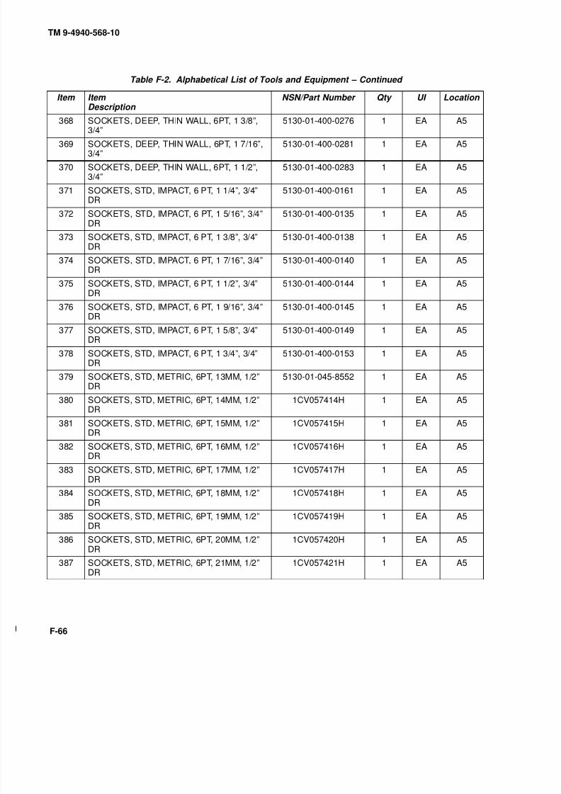
8/20/2019 TM 9-4940-568-10 FRS
http://slidepdf.com/reader/full/tm-9-4940-568-10-frs 368/403
TM 9-4940-568-10
F-66
Table F-2. Alphabetical List of Tools and Equipment – Continued
Item Item Description
NSN/Part Number Qty UI Location
368 SOCKETS, DEEP, THIN WALL, 6PT, 1 3/8”,
3/4”
5130-01-400-0276 1 EA A5
369 SOCKETS, DEEP, THIN WALL, 6PT, 1 7/16”,3/4”
5130-01-400-0281 1 EA A5
370 SOCKETS, DEEP, THIN WALL, 6PT, 1 1/2”,3/4”
5130-01-400-0283 1 EA A5
371 SOCKETS, STD, IMPACT, 6 PT, 1 1/4”, 3/4”DR
5130-01-400-0161 1 EA A5
372 SOCKETS, STD, IMPACT, 6 PT, 1 5/16”, 3/4”DR
5130-01-400-0135 1 EA A5
373 SOCKETS, STD, IMPACT, 6 PT, 1 3/8”, 3/4”DR
5130-01-400-0138 1 EA A5
374 SOCKETS, STD, IMPACT, 6 PT, 1 7/16”, 3/4”DR 5130-01-400-0140 1 EA A5
375 SOCKETS, STD, IMPACT, 6 PT, 1 1/2”, 3/4”DR
5130-01-400-0144 1 EA A5
376 SOCKETS, STD, IMPACT, 6 PT, 1 9/16”, 3/4”DR
5130-01-400-0145 1 EA A5
377 SOCKETS, STD, IMPACT, 6 PT, 1 5/8”, 3/4”DR
5130-01-400-0149 1 EA A5
378 SOCKETS, STD, IMPACT, 6 PT, 1 3/4”, 3/4”DR
5130-01-400-0153 1 EA A5
379 SOCKETS, STD, METRIC, 6PT, 13MM, 1/2”DR
5130-01-045-8552 1 EA A5
380 SOCKETS, STD, METRIC, 6PT, 14MM, 1/2”DR
1CV057414H 1 EA A5
381 SOCKETS, STD, METRIC, 6PT, 15MM, 1/2”DR
1CV057415H 1 EA A5
382 SOCKETS, STD, METRIC, 6PT, 16MM, 1/2”DR
1CV057416H 1 EA A5
383 SOCKETS, STD, METRIC, 6PT, 17MM, 1/2”DR
1CV057417H 1 EA A5
384 SOCKETS, STD, METRIC, 6PT, 18MM, 1/2”DR
1CV057418H 1 EA A5
385 SOCKETS, STD, METRIC, 6PT, 19MM, 1/2”
DR
1CV057419H 1 EA A5
386 SOCKETS, STD, METRIC, 6PT, 20MM, 1/2”DR
1CV057420H 1 EA A5
387 SOCKETS, STD, METRIC, 6PT, 21MM, 1/2”DR
1CV057421H 1 EA A5
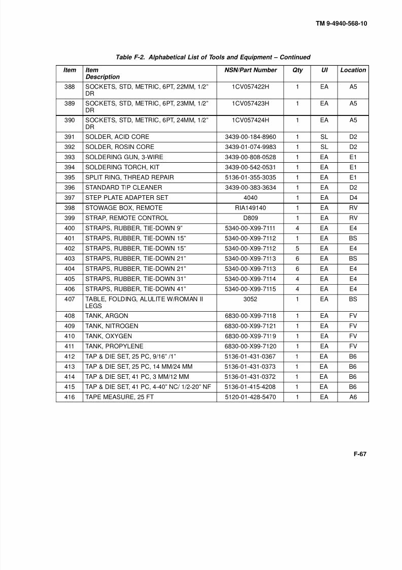
8/20/2019 TM 9-4940-568-10 FRS
http://slidepdf.com/reader/full/tm-9-4940-568-10-frs 369/403
TM 9-4940-568-10
F-67
Table F-2. Alphabetical List of Tools and Equipment – Continued
Item Item Description
NSN/Part Number Qty UI Location
388 SOCKETS, STD, METRIC, 6PT, 22MM, 1/2”
DR
1CV057422H 1 EA A5
389 SOCKETS, STD, METRIC, 6PT, 23MM, 1/2”DR
1CV057423H 1 EA A5
390 SOCKETS, STD, METRIC, 6PT, 24MM, 1/2”DR
1CV057424H 1 EA A5
391 SOLDER, ACID CORE 3439-00-184-8960 1 SL D2
392 SOLDER, ROSIN CORE 3439-01-074-9983 1 SL D2
393 SOLDERING GUN, 3-WIRE 3439-00-808-0528 1 EA E1
394 SOLDERING TORCH, KIT 3439-00-542-0531 1 EA E1
395 SPLIT RING, THREAD REPAIR 5136-01-355-3035 1 EA E1
396 STANDARD TIP CLEANER 3439-00-383-3634 1 EA D2397 STEP PLATE ADAPTER SET 4040 1 EA D4
398 STOWAGE BOX, REMOTE RIA149140 1 EA RV
399 STRAP, REMOTE CONTROL D809 1 EA RV
400 STRAPS, RUBBER, TIE-DOWN 9” 5340-00-X99-7111 4 EA E4
401 STRAPS, RUBBER, TIE-DOWN 15” 5340-00-X99-7112 1 EA BS
402 STRAPS, RUBBER, TIE-DOWN 15” 5340-00-X99-7112 5 EA E4
403 STRAPS, RUBBER, TIE-DOWN 21” 5340-00-X99-7113 6 EA BS
404 STRAPS, RUBBER, TIE-DOWN 21” 5340-00-X99-7113 6 EA E4
405 STRAPS, RUBBER, TIE-DOWN 31” 5340-00-X99-7114 4 EA E4
406 STRAPS, RUBBER, TIE-DOWN 41” 5340-00-X99-7115 4 EA E4
407 TABLE, FOLDING, ALULITE W/ROMAN IILEGS
3052 1 EA BS
408 TANK, ARGON 6830-00-X99-7118 1 EA FV
409 TANK, NITROGEN 6830-00-X99-7121 1 EA FV
410 TANK, OXYGEN 6830-00-X99-7119 1 EA FV
411 TANK, PROPYLENE 6830-00-X99-7120 1 EA FV
412 TAP & DIE SET, 25 PC, 9/16” /1” 5136-01-431-0367 1 EA B6
413 TAP & DIE SET, 25 PC, 14 MM/24 MM 5136-01-431-0373 1 EA B6
414 TAP & DIE SET, 41 PC, 3 MM/12 MM 5136-01-431-0372 1 EA B6415 TAP & DIE SET, 41 PC, 4-40” NC/ 1/2-20” NF 5136-01-415-4208 1 EA B6
416 TAPE MEASURE, 25 FT 5120-01-428-5470 1 EA A6

8/20/2019 TM 9-4940-568-10 FRS
http://slidepdf.com/reader/full/tm-9-4940-568-10-frs 370/403
TM 9-4940-568-10
F-68
Table F-2. Alphabetical List of Tools and Equipment – Continued
Item Item Description
NSN/Part Number Qty UI Location
417 TARP LEFT SIDE RIA148878 2 EA BS
418 TARP RIGHT SIDE RIA148879 2 EA BS
419 TERMINAL KIT 5940-00-525-0907 1 EA E1
420 TESTER, ELECTROLYTE AND ANTIFREEZE 6630-00-105-1418 1 EA D3
421 THREAD INSERT, KIT, COIL 5120-01-113-1544 1 EA E1
422 THREAD INSERT, SCREW, 1/4-20 UNC 5180-00-935-0732 1 EA E1
423 THREAD INSERT, SCREW, 1/4-28 UNC 5180-00-935-0736 1 EA E1
424 THREAD INSERT, SCREW, 5/16-18 UNC 5180-00-935-0733 1 EA E1
425 THREAD INSERT, SCREW, 5/16-24 UNC 5180-00-935-0737 1 EA E1
426 THREAD INSERT, SCREW, 3/8-16 UNC 5180-00-935-0734 1 EA E1
427 THREAD INSERT, SCREW, 3/8-24 UNC 5180-00-935-0738 1 EA E1428 THREAD INSERT, SCREW, 1/2-13 UNC 5180-00-051-5024 1 EA E1
429 THREAD INSERT, SCREW, 1/2-20 UNC 5180-00-054-7505 1 EA E1
430 THREAD RESTORER, METRIC THREADS 5110-01-431-0299 1 EA B2
431 THREAD RESTORER, STANDARDTHREADS
5110-01-431-0286 1 EA B2
432 THREAD RESTORER, STANDARDTHREADS
5110-01-431-0309 1 EA B2
433 TIP, CUTTING 3433-01-423-5701 2 EA D2
434 TIP, CUTTING 3433-01-423-5702 2 EA D2
435 TIP, CUTTING 3433-01-423-5708 2 EA D2436 TIP, GAS WELDING 63026D311-0483 1 EA D2
437 TIP, GAS WELDING 63026D311-0485 1 EA D2
438 TIPS, CONTACT, .035 403-1-35 25 EA D2
439 TIPS, CONTACT, .045 403-1-45 25 EA D2
440 TOOL KIT, BLIND RIVET 5180-01-201-4978 1 EA E1
441 TOOL KIT, ELECTRICAL CONTACT 5180-00-876-9366 1 EA E1
442 TOOL, PICK UP, CLAW-TYPE, FLEXIBLE 231/2” LONG
5120-01-399-9296 1 EA B1
443 TORCH HANDLE 5110-00-391-1220 1 EA D2
444 TORQUE MULTIPLYER, 1200 FT-LB (3 PC) 5120-01-399-9054 1 EA A6
445 TORQUE WRENCH, 3/4” DRIVE, 90-600 FT-LBS.
5120-01-400-0319 1 EA RW

8/20/2019 TM 9-4940-568-10 FRS
http://slidepdf.com/reader/full/tm-9-4940-568-10-frs 371/403
TM 9-4940-568-10
F-69
Table F-2. Alphabetical List of Tools and Equipment – Continued
Item Item Description
NSN/Part Number Qty UI Location
446 TORQUE WRENCH .50-250 FT-LB, 1/2” DR 5120-01-400-0239 1 EA A4
447 TRESTLE, 7 TON 3950-00-251-8013 6 EA RV
448 TUBE FLARING, METRIC 5120-01-335-1606 1 EA E1
449 14 UNI NOZZLE 0234-0094 2 EA D2
450 UNIVERSAL JOINT, 1/2” DR 5120-01-399-9658 1 EA A4
451 UNIVERSAL JOINT 1/2” D. 5130-01-400-0136 1 EA A5
452 UNIVERSAL JOINT, 3/8” DRIVE 5130-01-400-0114 1 EA A5
453 UNIVERSAL JOINT, 3/4” DR 5120-01-399-9735 1 EA A6
454 VALVE, RELIEF, INLINE 30978890490 2 EA E2
455 VISE GRIP, LONG NOSE, 9” 5120-01-399-9233 1 EA B3
456 VISE GRIP, 10” CURVED W/CUTTER 5120-01-399-9226 1 EA B3457 VISE GRIP, 10”, STRAIGHT JAW 5120-01-400-0314 1 EA B3
458 VISE, MACHINIST’S SWVL BASE, 4” JAW 5120-00-293-1439 1 EA CM
459 WELPER HAND TOOL 5120-00-X99-5064 1 EA D2
460 WELDER, 400GMS 3431-00-X99-8023 1 EA CM
461 WELDER, WIRE FEED 3431-00-X99-8025 1 EA CM
462 WHEEL, ABRASIVE, W/CUTTERS 5130-00-223-9952 1 EA A7
463 WHIP AIR HOSE 3/8”, 12’ LONG ASSY 801 16-5BPH4FP-6-144.00
1 EA B7
464 WIRE, ALUMINUM, .035 3439-00-X99-7102 1 EA D6
465 WIRE STEEL, .045 3439-00-X99-7099 1 EA D6
466 WIRE TWISTER, AUTO RETURN 5120-01-431-1957 1 EA B3
467 WRENCH, ADJUSTABLE, AUTO LOCKING18”
5120-01-399-9869 1 EA B3
468 WRENCH, ADJUSTABLE, 0 TO 3-5/8 JAW 5120-00-264-3793 2 EA A3
469 WRENCH, C-BOX, OPEN END, 12 P, 1/4” 5120-00-288-9997 1 EA B4
470 WRENCH, C-BOX, OPEN END, 12 P, 5/16” 1CV051210 1 EA B4
471 WRENCH, C-BOX, OPEN END, 12 PT, 11/32” 1CV051211 1 EA B4
472 WRENCH, C-BOX, OPEN END, 12 PT, 3/8” 5120-00-228-9504 1 EA B4
473 WRENCH, C-BOX, OPEN END, 12 P, 7/16” 5120-00-228-9505 1 EA B4
474 WRENCH, C-BOX, OPEN END, 12 P, 1/2” 5120-00-228-9506 1 EA B4
475 WRENCH, C-BOX, OPEN END, 12 P, 9/16” 5120-00-228-9507 1 EA B4
476 WRENCH, C-BOX, OPEN END, 12 P, 5/8” 5120-00-228-9508 1 EA B4

8/20/2019 TM 9-4940-568-10 FRS
http://slidepdf.com/reader/full/tm-9-4940-568-10-frs 372/403
TM 9-4940-568-10
F-70
Table F-2. Alphabetical List of Tools and Equipment – Continued
Item Item Description
NSN/Part Number Qty UI Location
477 WRENCH, C-BOX, OPEN END, 12 P, 11/16” 5120-00-228-9509 1 EA B4
478 WRENCH, C-BOX, OPEN END, 12 P, 3/4” 5120-00-228-9510 1 EA B4
479 WRENCH, C-BOX, OPEN END, 12 P, 13/16” 5120-00-228-9511 1 EA B4
480 WRENCH, C-BOX, OPEN END, 12 P, 7/8” 1CV051228 1 EA B4
481 WRENCH, C-BOX, OPEN END, 12 P, 15/16” 1CV051230 1 EA B4
482 WRENCH, C-BOX, OPEN END, 12 PT, 1” 1CV051232 1 EA B5
483 WRENCH, C-BOX, OPEN END, 12 PT,1-1/16”
5120-00-228-9515 1 EA B5
484 WRENCH, C-BOX, OPEN END, 12 P, 1-1/8” 5120-00-228-9516 1 EA B5
485 WRENCH, C-BOX, OPEN END, 12 PT, 1-1/4” 1CV051240 1 EA B5
486 WRENCH, C-BOX, OPEN END, 12 P, 1-5/16” 5120-01-399-8786 1 EA B5
487 WRENCH, C-BOX, OPEN END, 12 PT, 1-3/8” 5120-01-399-8793 1 EA B5
488 WRENCH, C-BOX, OPEN END, 12 PT,1-7/16”
5120-01-399-8790 1 EA B5
489 WRENCH, C-BOX, OPEN END, 12 P, 1-1/2” 5120-01-399-8798 1 EA B5
490 WRENCH, C-BOX, OPEN END, 12 PT, 1-5/8” 5120-01-399-8801 1 EA B5
491 WRENCH, C-BOX, OPEN END, 12 P,1-11/16”
5120-01-399-8795 1 EA B5
492 WRENCH, C-BOX, OPEN END, 12 PT, 1-3/4” 5120-01-399-8808 1 EA B5
493 WRENCH, C-BOX, OPEN END, 12 P, 1-7/8” 5120-01-399-8806 1 EA B5
494 WRENCH, C-BOX, OPEN END, 12 P, 2” 5120-01-399-8813 1 EA B5
495 WRENCH, C-BOX, OPEN END, 12 P, 2-1/16” 1CV051266 1 EA B5
496 WRENCH, C-BOX, OPEN END, 12 PT, 2-1/8” 1CV051268 1 EA B5
497 WRENCH, COMB FL NUT, OPN END, 12PT,3/8”
1CV053751T 1 EA B4
498 WRENCH, COMB FL NUT, OPN END, 12PT,7/16”
1CV053752T 1 EA B4
499 WRENCH, COMB FL NUT, OPN END, 12PT,1/2”
1CV053753T 1 EA B4
500 WRENCH, COMB FL NUT, OPN END, 12PT,9/16”
1CV053754T 1 EA B4
501 WRENCH, COMB FL NUT, OPN END, 12PT,5/8”
1CV053755T 1 EA B4
502 WRENCH, COMB FL NUT, OPN END, 12PT,11/16”
1CV053756T 1 EA B4
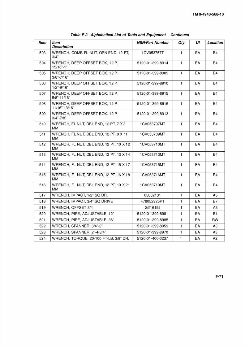
8/20/2019 TM 9-4940-568-10 FRS
http://slidepdf.com/reader/full/tm-9-4940-568-10-frs 373/403
TM 9-4940-568-10
F-71
Table F-2. Alphabetical List of Tools and Equipment – Continued
Item Item Description
NSN/Part Number Qty UI Location
503 WRENCH, COMB FL NUT, OPN END, 12 PT,
3/4”
1CV053757T 1 EA B4
504 WRENCH, DEEP OFFSET BOX, 12 P,15/16”-1”
5120-01-399-8914 1 EA B4
505 WRENCH, DEEP OFFSET BOX, 12 P,3/8”-7/16”
5120-01-399-8909 1 EA B4
506 WRENCH, DEEP OFFSET BOX, 12 P,1/2”-9/16”
5120-01-399-8910 1 EA B4
507 WRENCH, DEEP OFFSET BOX, 12 P,5/8”-11/16”
5120-01-399-8915 1 EA B4
508 WRENCH, DEEP OFFSET BOX, 12 P,11/16”-13/16”
5120-01-399-8916 1 EA B4
509 WRENCH, DEEP OFFSET BOX, 12 P,3/4”-7/8” 5120-01-399-8913 1 EA B4
510 WRENCH, FL NUT, DBL END, 12 PT, 7 X 8MM
1CV053707MT 1 EA B4
511 WRENCH, FL NUT, DBL END, 12 PT, 9 X 11MM
1CV053709MT 1 EA B4
512 WRENCH, FL NUT, DBL END, 12 PT, 10 X 12MM
1CV053710MT 1 EA B4
513 WRENCH, FL NUT, DBL END, 12 PT, 13 X 14MM
1CV053713MT 1 EA B4
514 WRENCH, FL NUT, DBL END, 12 PT, 15 X 17MM
1CV053715MT 1 EA B4
515 WRENCH, FL NUT, DBL END, 12 PT, 16 X 18MM
1CV053716MT 1 EA B4
516 WRENCH, FL NUT, DBL END, 12 PT, 19 X 21MM
1CV053719MT 1 EA B4
517 WRENCH, IMPACT, 1/2” SQ DR. 65832131 1 EA A5
518 WRENCH, IMPACT, 3/4” SQ DRIVE 478052925P1 1 EA B7
519 WRENCH, OFFSET 3/4 GIT 6192 1 EA A3
520 WRENCH, PIPE, ADJUSTABLE, 12” 5120-01-399-8981 1 EA B1
521 WRENCH, PIPE, ADJUSTABLE, 36” 5120-01-399-8985 1 EA RW
522 WRENCH, SPANNER, 3/4”-2” 5120-01-399-8959 1 EA A3
523 WRENCH, SPANNER, 2”-4-3/4” 5120-01-399-8970 1 EA A3
524 WRENCH, TORQUE, 20-100 FT-LB, 3/8” DR. 5120-01-400-0237 1 EA A2

8/20/2019 TM 9-4940-568-10 FRS
http://slidepdf.com/reader/full/tm-9-4940-568-10-frs 374/403
TM 9-4940-568-10
F-72
Table F-2. Alphabetical List of Tools and Equipment – Continued
Item Item Description
NSN/Part Number Qty UI Location
525 WRENCH, TORQUE, 40-200 IN-LB, 3/8” DR. 5120-01-400-0233 1 EA A2
526 WRENCH, UNIVERSAL CHAIN 1CV05801 1 EA B1
527 WRENCH, WHEEL, STUD NUT GEARED,SOC,
5120-00-378-4411 1 EA C3
528 YOKE, 2 WAY 4250B 1 EA D4
529 YOKE, 3 WAY 4225B 1 EA D4
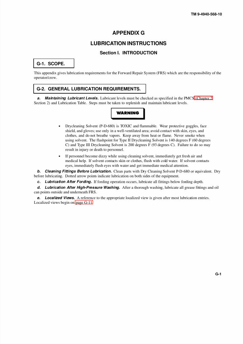
8/20/2019 TM 9-4940-568-10 FRS
http://slidepdf.com/reader/full/tm-9-4940-568-10-frs 375/403
TM 9-4940-568-10
G-1
APPENDIX G
LUBRICATION INSTRUCTIONS
Section I. INTRODUCTION
G-1. SCOPE.
This appendix gives lubrication requirements for the Forward Repair System (FRS) which are the responsibility of the
operator/crew.
G-2. GENERAL LUBRICATION REQUIREMENTS.
a. Maintaining Lubricant Levels. Lubricant levels must be checked as specified in the PMCS (Chapter 2,
Section 2) and Lubrication Table. Steps must be taken to replenish and maintain lubricant levels.
• Drycleaning Solvent (P-D-680) is TOXIC and flammable. Wear protective goggles, face
shield, and gloves; use only in a well-ventilated area; avoid contact with skin, eyes, and
clothes, and do not breathe vapors. Keep away from heat or flame. Never smoke when
using solvent. The flashpoint for Type II Drycleaning Solvent is 140 degrees F (60 degrees
C) and Type III Drycleaning Solvent is 200 degrees F (93 degrees C). Failure to do so may
result in injury or death to personnel.
• If personnel become dizzy while using cleaning solvent, immediately get fresh air and
medical help. If solvent contacts skin or clothes, flush with cold water. If solvent contacts
eyes, immediately flush eyes with water and get immediate medical attention.
b. Cleaning Fittings Before Lubrication. Clean parts with Dry Cleaning Solvent P-D-680 or equivalent. Drybefore lubricating. Dotted arrow points indicate lubrication on both sides of the equipment.
c. Lubrication After Fording. If fording operation occurs, lubricate all fittings below fording depth.
d. Lubrication After High-Pressure Washing. After a thorough washing, lubricate all grease fittings and oil
can points outside and underneath FRS.
e. Localized Views. A reference to the appropriate localized view is given after most lubrication entries.
Localized views begin on page G-11.

8/20/2019 TM 9-4940-568-10 FRS
http://slidepdf.com/reader/full/tm-9-4940-568-10-frs 376/403
TM 9-4940-568-10
G-2
G-3. LUBRICATION INTERVALS.
a. Service Interval Under Normal Conditions. Service intervals listed are for normal operation in moderate
temperatures, humidity, and atmospheric conditions. Hard time intervals may be shortened if your lubricants arecontaminated or if you are operating the equipment under adverse conditions, including longer-than-usual operating
hours. Hard time intervals may be extended during periods of low activity, though adequate preservation precautions
must be taken. Perform semi-annual service intervals every six months.
b. Service Interval Under Unusual Conditions. Increase frequency of lubricating service when operating
under abnormal conditions such as high or low temperatures. Such operation can diminsh lubricant’s protective
qualities. More frequent lubricating service intervals are necessary to maintain FRS readiness when operating under
abnormal conditions.
c. Hard Time Intervals. Intervals shown in this appendix are based on hours and calendar times. An example of
hours and calendar intervals is 3/S, in which 3 HRS stands for three hours, and S stands for semiannually (every six
months). The lubrication for the FRS is to be performed at whichever interval occurs first. For equipment under
manufacturer’s warranty, hard time oil service intervals shall be followed.
G-4. LUBRICATION FOR OPERATION UNDER EXTREMETEMPERATURES.
a. Changes in Lubricant Grades. Lubricant grades change with weather conditions. Refer to Lubrication
Table for lubricant grade changes.
b. Arctic Conditions. Refer to FM 9-207, Operation and Maintenance of Ordinance Material in cold weather (0
degrees F to –65 degrees F) (–18 degrees C to –54 degrees C), or the Lubrication Table.
G-5. CORROSION CONTROL.
Refer to Para 1-3 for appropriate corrosion control procedures.

8/20/2019 TM 9-4940-568-10 FRS
http://slidepdf.com/reader/full/tm-9-4940-568-10-frs 377/403
TM 9-4940-568-10
G-3
Section II. LUBRICATION TABLE KEY
Table G-1. Lubricants
ComponentApproximate
CapacityExpected
TemperaturesIntervals
Engine
AirCompressor
Hydraulic
Reservoir
Oil Can Points
12 qt (11 l)
4 qt(3.8 l)
See Chart A.
See Chart B.
100 qt
(95 l)
See Chart C.
See Chart D.As required
D – DAILY
M – MONTHLY
AR – AS REQUIRED
HRS – HOURS
S – SEMIANNUALLY(6 MONTHS)
BI – BIANNUALLY(2 YEARS)
See Chart E.Air Lubricant As required

8/20/2019 TM 9-4940-568-10 FRS
http://slidepdf.com/reader/full/tm-9-4940-568-10-frs 378/403
TM 9-4940-568-10
G-4
Section II. LUBRICATION TABLE KEY (CONT).
Table G-2. Other Fluids
22 qt (21 l)*
22 qt (21 l)*
Table G-3. Grease; Automotive and Artillery (GAA) (MIL-L-10924)
Table G-4. Antiseize Compound (MIL-A-907)
The following components are lubricatedwith GAA as required at all temperatures.
The following components are lubricatedwith antiseize compound as required atall temperatures.
Crane (Fittings) (Wear Pads)
(Plates)
Shelter Doors (Gears)
Crane Tension Link
Shelter Doors (Support Arms)

8/20/2019 TM 9-4940-568-10 FRS
http://slidepdf.com/reader/full/tm-9-4940-568-10-frs 379/403
TM 9-4940-568-10
G-5
Section II. LUBRICATION TABLE KEY (CONT).
EXPECTED TEMPERATURE –50 –46
–40 –40
–30 –34
–20 –29
–10 –23
0 –18
10 –12
20 –7
30 –1
40 4
5010
6016
7021
8027
9032
100 38
110 44
120 49
FC
OE/HDO LUBRICATING OIL, ICE, TACTICAL (MIL–L–2104)
OEA LUBRICATING OIL, ICE, ARTIC (MIL–L–46167)
LUBRICANTS:
*See Notes 1a and 1b
CHART A. ENGINE
OE/HDO–40*
OE/HDO –15W–40
OEA
EXPECTED TEMPERATURE
–50
–46
–40
–40
–30
–34
–20
–29
–10
–23
0
–18
10
–12
20
–7
30
–1
40
4
50
10
60
16
70
21
80
27
90
32
100
38
110
44
120
49
F
C
OE/HDO LUBRICATING OIL, ICE, TACTICAL (MIL–L–2104)
OEA LUBRICATING OIL, ICE, ARTIC (MIL–L–46167)
LUBRICANTS:
CHART B. AIR COMPRESSOR
AIR COMPRESSOR LUBRICATING OIL (T30)
EXPECTED TEMPERATURE
–50 –46
–40 –40
–30 –34
–20 –29
–10 –23
0 –18
10 –12
20 –7
30 –1
40 4
5010
6016
7021
8027
9032
100 38
110 44
120 49
FC
OE/HDO LUBRICATING OIL, ICE, TACTICAL (MIL–L–2104)
OEA LUBRICATING OIL, ICE, ARTIC (MIL–L–46167)
LUBRICANTS:
CHART C. HYDRAULIC RESERVOIR
OE/HDO–30*
OE/HDO –10
OEA
OEA
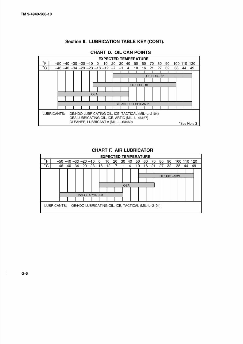
8/20/2019 TM 9-4940-568-10 FRS
http://slidepdf.com/reader/full/tm-9-4940-568-10-frs 380/403
TM 9-4940-568-10
G-6
Section II. LUBRICATION TABLE KEY (CONT).
EXPECTED TEMPERATURE
–50 –46
–40 –40
–30 –34
–20 –29
–10 –23
0 –18
10 –12
20 –7
30 –1
40 4
5010
6016
7021
8027
9032
100 38
110 44
120 49
FC
OE/HDO LUBRICATING OIL, ICE, TACTICAL (MIL–L–2104)OEA LUBRICATING OIL, ICE, ARTIC (MIL–L–46167)
CLEANER, LUBRICANT A (MIL–L–63460)
LUBRICANTS:
*See Note 3
CHART D. OIL CAN POINTS
OE/HDO–30*
OE/HDO –10
OEA
CLEANER, LUBRICANT*
EXPECTED TEMPERATURE
–50 –46
–40 –40
–30 –34
–20 –29
–10 –23
0 –18
10 –12
20 –7
30 –1
40 4
5010
6016
7021
8027
9032
100 38
110 44
120 49
FC
OE/HDO LUBRICATING OIL, ICE, TACTICAL (MIL–L–2104)LUBRICANTS:
CHART F. AIR LUBRICATOR
OE/HDO –10W
OEA
25% OEA/75% JP8

8/20/2019 TM 9-4940-568-10 FRS
http://slidepdf.com/reader/full/tm-9-4940-568-10-frs 381/403
TM 9-4940-568-10
G-7
Section III. LUBRICATION POINTS
Engine Oil Level
Check oil at dipstick.
(See Note 1a and View 1.)
Fill at filler cap.
See View 1.) OE/HDO D/10HRS
Hydraulic Oil Level
Check fluid level at sight gage
and fill. (See View 2.) OE/HDO D/10HRS
Engine Coolant Level
Check level and fill.
(See View 3.) T30 D/10HRS
Compressor Oil Level
Check level and fill.
(See View 4.) D/10 HRS
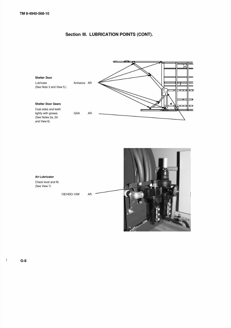
8/20/2019 TM 9-4940-568-10 FRS
http://slidepdf.com/reader/full/tm-9-4940-568-10-frs 382/403
TM 9-4940-568-10
G-8
Section III. LUBRICATION POINTS (CONT).
Shelter Door
Lubricate Antiseize AR
(See Note 3 and View 5.)
Shelter Door Gears
Coat sides and teethlightly with grease. GAA AR
(See Notes 2a, 2d
and View 6)
Air Lubricator
Check level and fill.
(See View 7)
OE/HDO-10W AR

8/20/2019 TM 9-4940-568-10 FRS
http://slidepdf.com/reader/full/tm-9-4940-568-10-frs 383/403
6 0 ‘
5 0 ‘
40‘30‘
20‘10‘0‘
55010 10
6 0 ‘ 5 0 ‘ 40‘
30‘20‘
10‘ 0‘
TM 9-4940-568-10
G-9
Section III. LUBRICATION POINTS (CONT).
LUBRICANT INTERVAL
Boom Nose Sheave
Lubricate. (1 fitting) GAA M/50HRS
(See Note 2a and View 15.)
Hoist Cable Clevis
Lubricate with oil can.
(See Note 2a and View 15.) OE/HDO AR
Hoist Cable
Clean and lubricate. OE/HDO AR
(See View 8.) (Crane extended)
(Requires assistant)
Lift Cylinder
Lubricate. (8 fittings)
(See Note 2a and View 9.) Antiseize M/50HRS
Tension Link
Lubricate. (8 fittings) GAA M/50HRS
(See Note 2a and View 10.)
Lubricate link. Antiseize M/50HRS
(See Note 2a and View 10.)
Rotation Gear and Pinion Teeth
Coat teeth of rotation gear GAA M/50HRS
lightly with grease. (See Notes 2a,
2c and View 8.)
Turntable Bearing
Lubricate. (4 Swing Bearing) GAA M/50HRS
(See Note 2a and View 11.)
Jack Cylinder Barrels
Lubricate. (See Note 2a) Antiseize M/50HRS
and View 12.)
Hook Block Sheave
Lubricate. (1 fitting) GAA M/50HRS
(See Note 2a and View 8.)Hook Assembly Bearing
Lubricate with oil can. OE/HDO AR
(See Note 2a and View 8.)

8/20/2019 TM 9-4940-568-10 FRS
http://slidepdf.com/reader/full/tm-9-4940-568-10-frs 384/403
3020‘10‘0‘
TM 9-4940-568-10
G-10
Section III. LUBRICATION POINTS (CONT).
LUBRICANT INTERVAL
Boom Wear Pads
Clean top and bottom sliding
surfaces of boom wear pads GAA M/50HRS
and lubricate by coating with
grease. (Crane extended)
Mast
Lubricate. (4 fittings) GAA M/50HRS
(See Note 2a and View 13.)
Mast Cylinder
Lubricate. (6 fittings) GAA M/50HRS
(Crane extended.)
(See Note 2a and View 14.)
Hoist Gear Box
Check and fill. GO BI/250HRS
(See Note 2e and View 8.)
Hoist Cable Guide Rollers
Lubricate with oil can. OE/HDO M/50HRS
(See Note 2a and View 15.)
Crane Control Valve Levers
Lubricate with oil can. OE/HDO M/50HRS(See Note 2a and View 10.)
Top, Bottom and Side Outrigger Plate
Clean and Lubricate. GAA M/50HRS
(See Note 2a and View 16.)
Boom Light
Lubricate with oil can. OE/HDO M/50HRS
(See Note 2a and View 17.)
Turntable Gearbox
Check plug and fill. GO BI/250HRS
(See Note 2f and View 18.)

8/20/2019 TM 9-4940-568-10 FRS
http://slidepdf.com/reader/full/tm-9-4940-568-10-frs 385/403
TM 9-4940-568-10
G-11
LOCALIZED LUBRICATION VIEW POINTS.
1
ENGINE CRANKCASE ENGINE CRANKCASE
2
HYDRAULIC RESERVOIR HYDRAULIC RESERVOIR
ENGINE DIPSTICK ENGINE FILL CAP
CHECK
SIGHT
GLASS
FILL
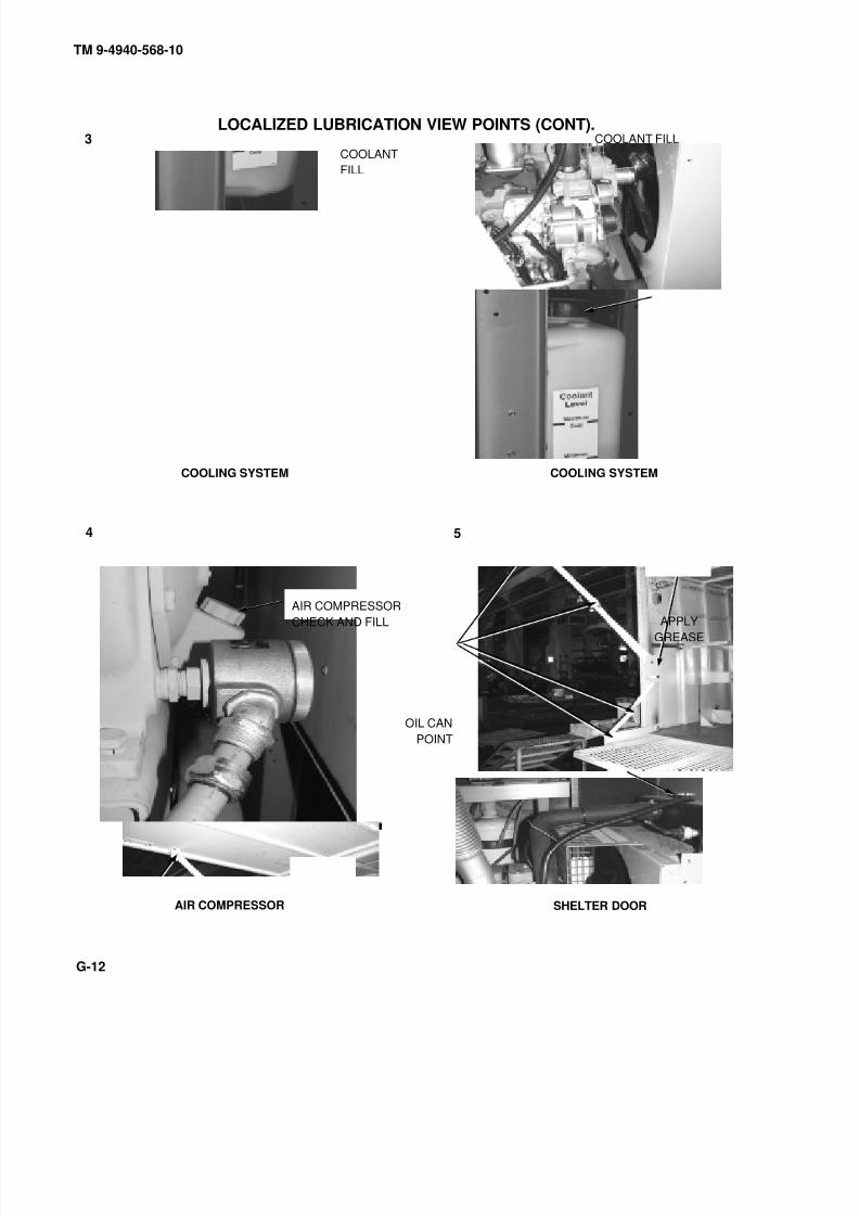
8/20/2019 TM 9-4940-568-10 FRS
http://slidepdf.com/reader/full/tm-9-4940-568-10-frs 386/403
TM 9-4940-568-10
G-12
LOCALIZED LUBRICATION VIEW POINTS (CONT).3
4 5
COOLING SYSTEM COOLING SYSTEM
SHELTER DOORAIR COMPRESSOR
COOLANT
FILL
COOLANT FILL
AIR COMPRESSORCHECK AND FILL APPLY
GREASE
OIL CAN
POINT
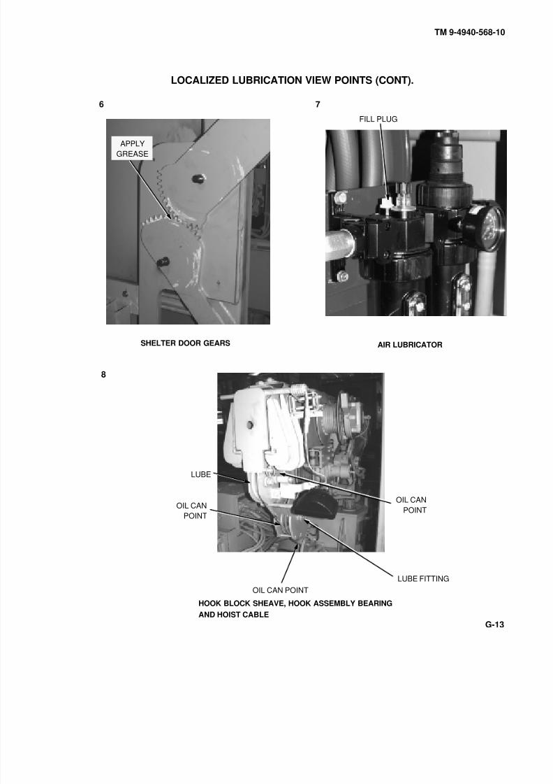
8/20/2019 TM 9-4940-568-10 FRS
http://slidepdf.com/reader/full/tm-9-4940-568-10-frs 387/403
TM 9-4940-568-10
G-13
LOCALIZED LUBRICATION VIEW POINTS (CONT).
6 7
SHELTER DOOR GEARS AIR LUBRICATOR
8
HOOK BLOCK SHEAVE, HOOK ASSEMBLY BEARING
AND HOIST CABLE
APPLY
GREASE
FILL PLUG
OIL CAN
POINTOIL CAN
POINT
LUBE
LUBE FITTING
OIL CAN POINT
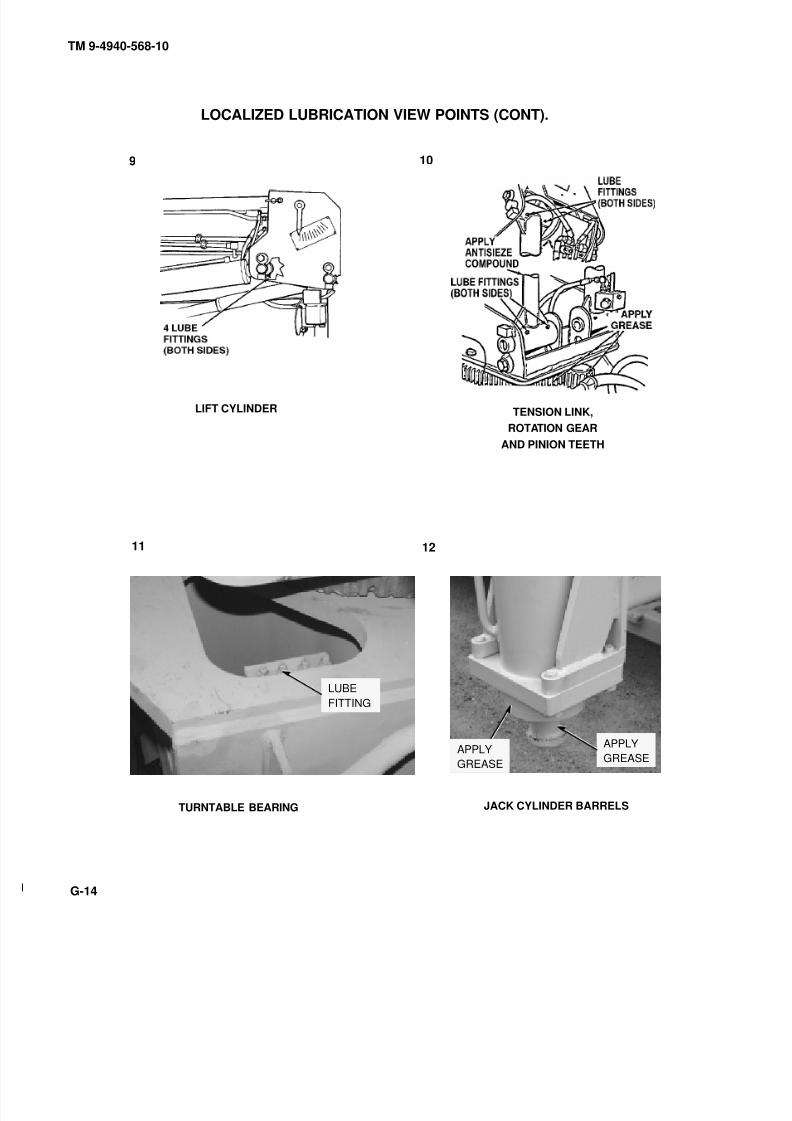
8/20/2019 TM 9-4940-568-10 FRS
http://slidepdf.com/reader/full/tm-9-4940-568-10-frs 388/403
TM 9-4940-568-10
G-14
LOCALIZED LUBRICATION VIEW POINTS (CONT).
9
LIFT CYLINDER
10
TENSION LINK,
ROTATION GEAR
AND PINION TEETH
11
TURNTABLE BEARING
12
JACK CYLINDER BARRELS
APPLYGREASE
LUBE
FITTING
APPLYGREASE
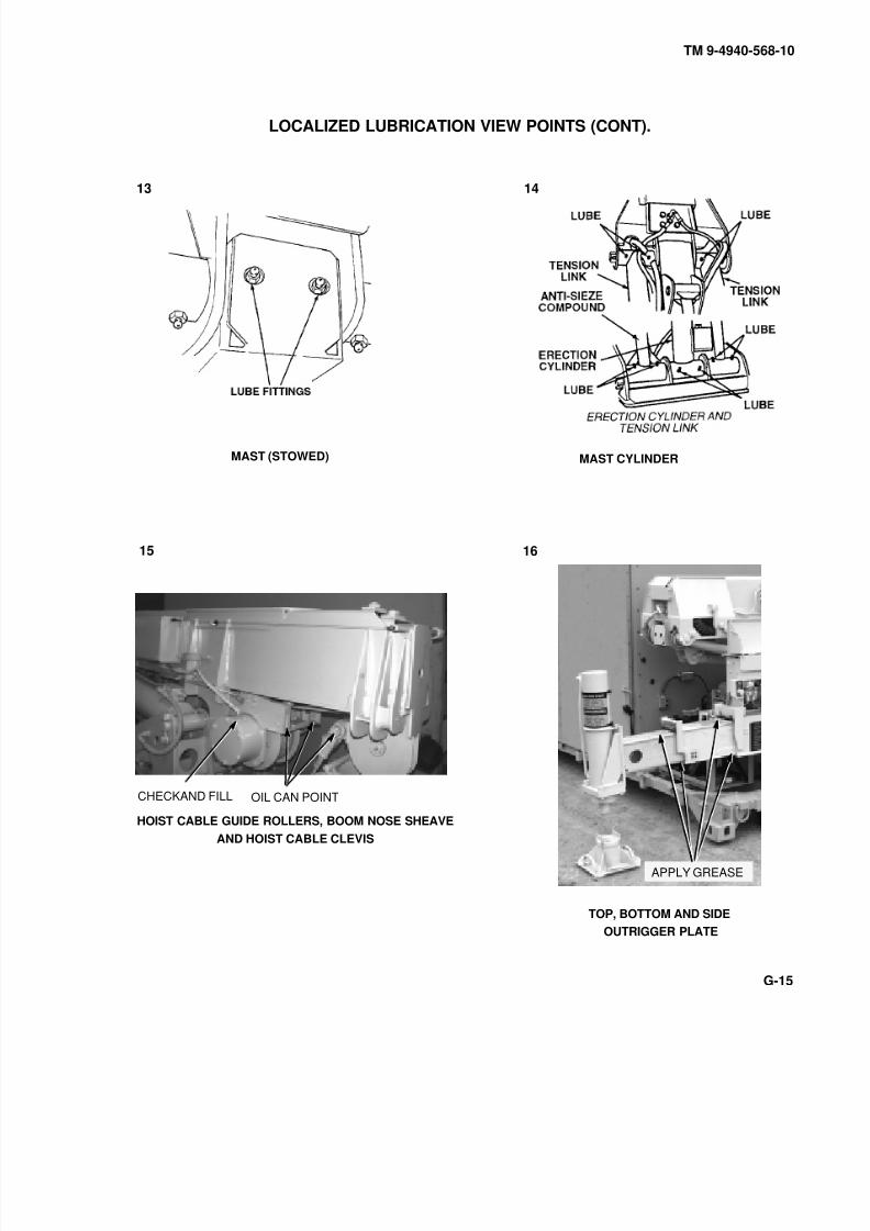
8/20/2019 TM 9-4940-568-10 FRS
http://slidepdf.com/reader/full/tm-9-4940-568-10-frs 389/403
TM 9-4940-568-10
G-15
LOCALIZED LUBRICATION VIEW POINTS (CONT).
13 14
15
MAST (STOWED) MAST CYLINDER
HOIST CABLE GUIDE ROLLERS, BOOM NOSE SHEAVEAND HOIST CABLE CLEVIS
16
TOP, BOTTOM AND SIDE
OUTRIGGER PLATE
OIL CAN POINT
APPLY GREASE
CHECKAND FILL

8/20/2019 TM 9-4940-568-10 FRS
http://slidepdf.com/reader/full/tm-9-4940-568-10-frs 390/403
TM 9-4940-568-10
G-16
LOCALIZED LUBRICATION VIEW POINTS (CONT).
TURNTABLE GEARBOX
17 18
BOOM LIGHT
APPLY GREASE
OIL POINT
CHECK PLUG
AND FILL
8/20/2019 TM 9-4940-568-10 FRS
http://slidepdf.com/reader/full/tm-9-4940-568-10-frs 391/403
TM 9-4940-568-10
G-17/(G-18 blank)
NOTES
1. ENGINE.
a. Cold Oil Check. Keep engine oil level as close as possible to the dipstick high mark without overfilling.
b. Crankcase. Check oil level with FRS on level ground and the engine off and cool. Do not overfill
crankcase.
2. MATERIAL HANDLING CRANE (MHC).
a. The 50 hour interval is based on actual MHC operating hours. The hours can be tracked by the operator and
recorded in the logbook. The MHC should be lubricated on a monthly or 50 actual operating hour interval,
whichever comes first. Crane must be fully unstowed to properly lubricate.
b. Use oil can sparingly. A single oil can application at each oil can point is required.
c. Lubricate boom wear pads and exposed rotation gears more often when cranes are operated in sandy ordusty conditions.
d. Remove safety pin from hook. Lubricate safety pin and reinstall in hook.
e. The 250 hour interval is based on actual crane operating hours. The hours can be tracked by the operator
and recorded in the logbook or the hour-meter on the crane. The crane should be lubricated on a semiannual or
250 actual operating hour interval, whichever comes first.
f. The 150 hour interval is based on annual or 150 actual operating. Fill with oil until oil level reaches bottom
of check plug hole.
3. OIL CAN POINTS.Lubricate doors, side panels, locks and pivot points every 250 hrs or Semiannually. Lubricate more often if usage is
high.

8/20/2019 TM 9-4940-568-10 FRS
http://slidepdf.com/reader/full/tm-9-4940-568-10-frs 392/403

8/20/2019 TM 9-4940-568-10 FRS
http://slidepdf.com/reader/full/tm-9-4940-568-10-frs 393/403
TM 9-4940-568-10
INDEX-1
INDEXSubject, Para
A
Air Compressor Operation, 2-18Air Compressor System, 1-17
Air Reservoir Drain/Fill, 2-19
Air System Draining, 3-5
Argon, Oxygen, or Propylene Tank Replacement, 2-23
B
Battery Disconnect/Connect, 3-6
C
Canvas Enclosure Installation/Removal, 2-34
Cooling System, 1-16Corrosion Prevention and Control (CPC), 1-3
Crane Boom Light Operation, 2-28
Crane, 1-20
Cutting Torch Operation, 2-21
D
Decals and Instruction Plates, 2-4
Destruction Of Army Material To Prevent Enemy Use,
1-4
Dome Light Operation, 2-26
EElectrical System, 1-12
Equipment Characteristics, Capabilities and Features,
1-8
Equipment Data, 1-9
Explanation of Table Entries, 2-7
Eye Wash Operation, 2-31
F
Filling Hydraulic Reservoir, 2-25
Fixed Light Operation, 2-27
Forward Repair System (FRS) Emergency
Procedures, 2-42
Fuel System Priming , 3-4
G
General, 2-5
Generator Controller Gain Adjustment, 3-7
Subject, Para
G (Cont)
Generator Engine Block Heater Operation, 2-17Generator Engine Set, 1-14
Generator Fuel System, 1-15
Generator Set Panel Removal/Stow, 3-8
Grounding Procedure, 2-32
H
Handling and Transportation Procedures, 2-13
Hydraulic System, 1-13
I
Introduction, 3-1
K
Know Your Controls and Indicators, 2-2
L
Leakage Classification and Definition, 2-10
List of Acronyms, 1-7
Loading and Unloading Forward Repair System (FRS),
2-14
Location and Description of Major Components, 1-10
Location and Use of Controls and Indicators, 2-3Lubrication Requirements, 2-9
M
Maintenance Forms, Records, and Reports, 1-2
Material Handling Crane (MHC) Operation, 2-29
N
Normal Generator Start/Shutdown Procedures, 2-15
O
Operating Forward Repair System (FRS) in ColdEnvironment +45° F to –25° F (+ 7° to-32° C), 2-40
Operating Forward Repair System (FRS) in Desert
Environment, 2-38
Operating Forward Repair System (FRS) in Extreme
Cold –26° F to –50° F (–32° C to –46° C), 2-41
Operating Forward Repair System (FRS) in Extreme
Heat, 2-36

8/20/2019 TM 9-4940-568-10 FRS
http://slidepdf.com/reader/full/tm-9-4940-568-10-frs 394/403
TM 9-4940-568-10
INDEX-2
Subject, Para
O (Cont)
Operating Forward Repair System (FRS) in Mud, Sand,
or Snow, 2-37
Operating Forward Repair System (FRS) on Unstable orUneven Ground, 2-39
Operators Preventive Maintenance Checks and Services
(PMCS) Tables, 2-11
P
Preparation for Use, 2-1
Preparing PLS Forward Repair System (FRS) for
Operation, 2-12
R
Refueling Generator, 2-16Reporting Equipment Improvement Recommendations
(EIR), 1-5
S
Scope, 1-1
Secure Forward Repair System (FRS), 2-43
Shelter Door and Platform Operation, 2-33
Shelter Heater, 1-19
Subject, Para
S (Cont)
Shelter Heater Operation, 2-30
Shortened Maintenance Intervals, 2-8
Sidewall Light Operation, 2-27Slave Starting Procedure, 2-24
Solar Air Vent, 1-18
Systems Introduction, 1-11
T
Tool Drawer and Cabinet Operation, 2-35
Troubleshooting Introduction, 3-2
Troubleshooting Symptoms, 3-3
U
Ultrathermic Cutting System Operation, 2-22
W
Warnings and Cautions, 2-6
Warranty Information, 1-6
Welder Operation, 2-20

8/20/2019 TM 9-4940-568-10 FRS
http://slidepdf.com/reader/full/tm-9-4940-568-10-frs 395/403
0030710
DISTRIBUTION: To be distributed in accordance with the initial distribution number (IDN) 256647, requirements for TM 9-4940-568-10.
By Order of the Secretary of the Army:
ERIC K. SHINSEKIGeneral, United States Army
Chief of Staff Official:
JOEL B. HUDSON Administrative Assistant to the
Secretary of the Army

8/20/2019 TM 9-4940-568-10 FRS
http://slidepdf.com/reader/full/tm-9-4940-568-10-frs 396/403
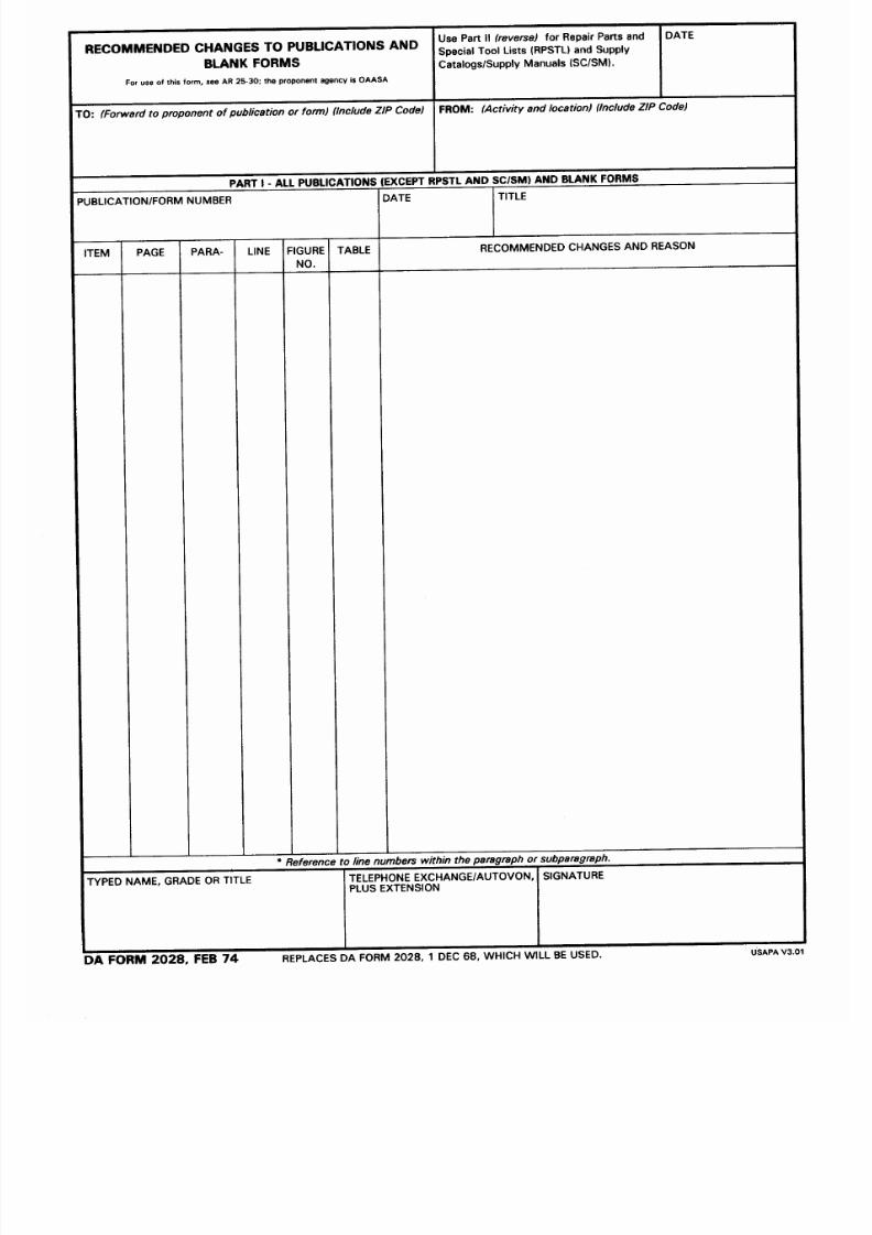
8/20/2019 TM 9-4940-568-10 FRS
http://slidepdf.com/reader/full/tm-9-4940-568-10-frs 397/403

8/20/2019 TM 9-4940-568-10 FRS
http://slidepdf.com/reader/full/tm-9-4940-568-10-frs 398/403

8/20/2019 TM 9-4940-568-10 FRS
http://slidepdf.com/reader/full/tm-9-4940-568-10-frs 399/403

8/20/2019 TM 9-4940-568-10 FRS
http://slidepdf.com/reader/full/tm-9-4940-568-10-frs 400/403

8/20/2019 TM 9-4940-568-10 FRS
http://slidepdf.com/reader/full/tm-9-4940-568-10-frs 401/403

8/20/2019 TM 9-4940-568-10 FRS
http://slidepdf.com/reader/full/tm-9-4940-568-10-frs 402/403
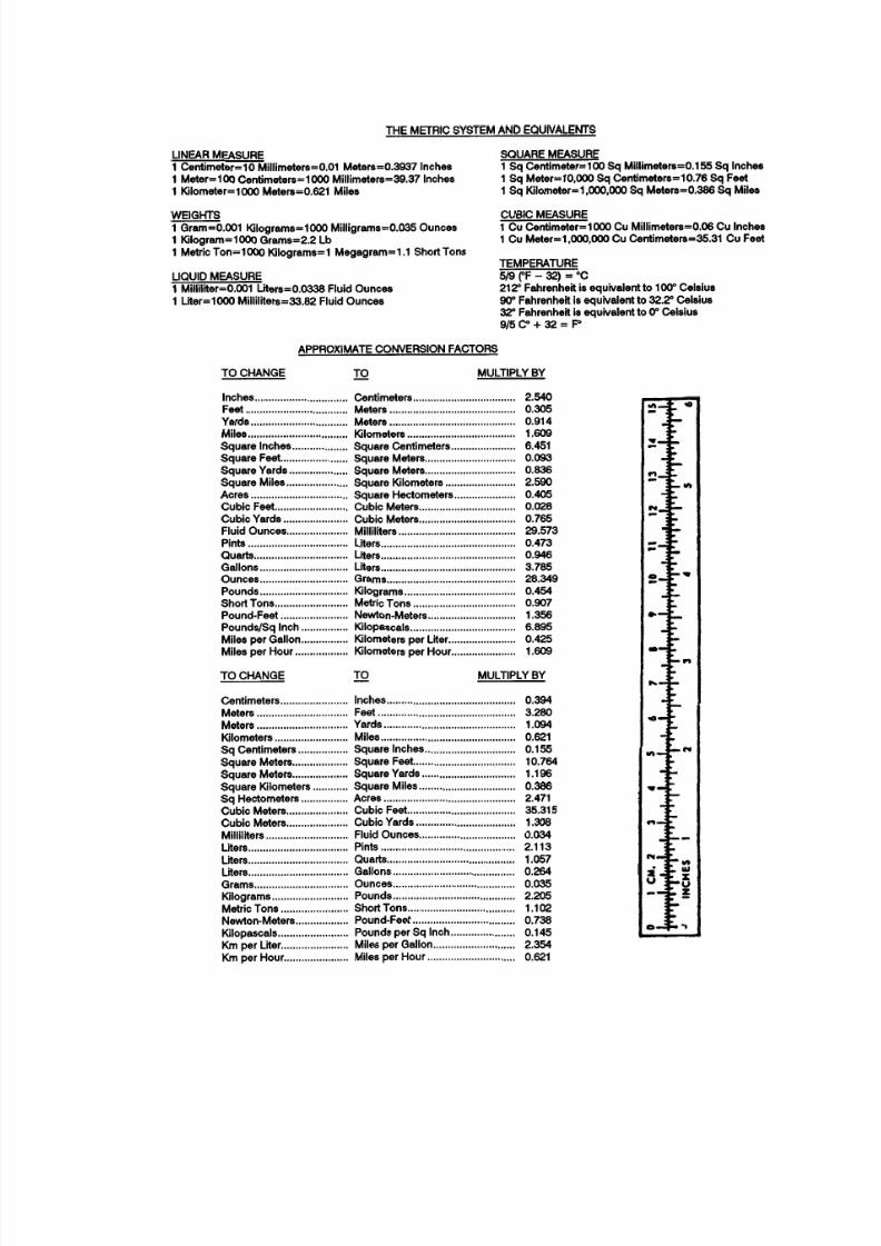
8/20/2019 TM 9-4940-568-10 FRS
http://slidepdf.com/reader/full/tm-9-4940-568-10-frs 403/403