tm512 installation r5 - arris i
TRANSCRIPT
Touchstone®TM508/TM512 Installation GuideRelease 5 Standard 1.2March 2007
About this documentThis guide describes the installation and testing procedures for the Touchstone Multi-Line Telephony Modem models (TM508 and TM512).
1 Planning the InstallationUse this chapter to plan the Telephony Modem installation.
2 Installing the Telephony ModemUse this chapter to install the Telephony Modem.
3 Troubleshooting InformationThis chapter describes troubleshooting features.
2006-2007 ARRISAll rights reserved
All information contained in this document is subject to change without notice. ARRIS reserves the right to make changes to equipment design or program components, as progress in engineering, manufacturing methods, or other circumstances may warrant.
ARRIS, ARRIS Interactive, and Touchstone are trademarks of ARRIS Group. All other trademarks are the property of their respective holders.
Release 5.0 Standard 1.2March 2007

ii
Touchstone Telephony Release 5 Standard 1.2 Mar 2007

iii
Publication historyMarch 2007
Release 5 Standard 1.2 version of this document.
February 2007Release 5 Standard 1.1 version of this document.
April 2006Release 5 Standard 1.0 version of this document.
TM508/TM512 Installation Guide Release 5 Standard 1.2 Mar 2007

iv
Touchstone Telephony Release 5 Standard 1.2 Mar 2007
v
ContentsAbout this Document vii
Safety Requirements viiRadio Frequency Emissions and Immunity viiiProduct Safety ix
CE Compliance ix
Planning the Installation 1Environmental Requirements 1Site Location 1Power Requirements 2
AC Powering 2DC Powering 2
Telephony Requirements 4Network Requirements 4Telephony Modem Accessories 5
Punch-Block Kit 5Battery Backup Power Supply 6
Installing the Telephony Modem 7Cable and Connector Pinouts 8
Telephone Connector Pinouts 8Telemetry Block Pinouts 8
Procedure: Inspecting and Unpacking the Telephony Modem 10Action 10
Procedure: Rack-Mounting the Chassis 12Action 12
Procedure: Wall-Mounting the Chassis 13Using the Mounting Holes 14Using the Rack-Mounting Brackets 14
Procedure: Installing the Punch-Block Kit 15Mounting the Punch-Down Block 16Connecting Subscriber Wiring 17
Procedure: Connecting Cables 18Action 19
Procedure: Installing the Battery Backup Power Supply 21Mounting the Power Supply 22
TM508/TM512 Installation Guide Release 5 Standard 1.2 Mar 2007
vi
Connecting the Cables 23
Troubleshooting Information 27Troubleshooting Interfaces 27
Front Panel LEDs 27Telemetry Block 29Serial Port 29
Touchstone Telephony Release 5 Standard 1.2 Mar 2007
About this DocumentThis guide describes the installation and testing procedures for the Touchstone Multi-Line Telephony Modem models:
• TM508A: North American DOCSIS, 100-240V AC/48V DC Power; 8 telephony lines
• TM512A: North American DOCSIS, 100-240V AC/48V DC Power; 12 telephony lines
Safety RequirementsARRIS Telephony Modems comply with the applicable requirements for performance, construction, labeling, and information when used as outlined below:
CAUTIONRisk of damageMake sure that the existing wires providing telephone service are phys-ically disconnected from the incumbent service provider’s network interface device. This is a physical break in the connection, not just a discontinuation of service. Failure to do so will result in damage to the Telephony Modem.
Connect only DC or AC power, not both, to the TM512. Connecting both supplies may cause a reset upon loss of AC power.
Do not locate the equipment within 6 feet (1.9m) of a flame or ignition source (e.g. heat registers, space heaters, fireplaces, etc.), to avoid dam-age or injury from battery explosion.
Do not use product near water (i.e. wet basement, bathtub, sink or near a swimming pool, etc.), to avoid risk of electrocution.
Avoid using and/or connecting the equipment during an electrical storm, to avoid risk of electrocution.
TM508/TM512 Installation Guide Release 5 Standard 1.2 Mar 2007
viii
Do not locate the equipment within 6 feet (1.9 m) of a flame or ignition source (i.e. heat registers, space heaters, fireplaces, etc.).
Use only the power cord included with the equipment.
Equipment should be installed near the power outlet and should be eas-ily accessible.
The shield of the coaxial cable must be connected to earth (grounded) at the entrance to the building in accordance with applicable national electrical installation codes. In the U.S., this is required by NFPA 70 (National Electrical Code) Article 820. In the European Union and cerain other countries, CATV installation equipotential bonding requirements are specified in IEC 60728-11, Cable networks for televi-sion signals, sound signals and interactive services, Part 11: Safety. This equipment is intended to be installed in accordance with the requirements of IEC 60728-11 for safe operation.
If the equipment is to be installed in an area serviced by an IT power line network, as is found in many areas of Norway, special attention should be given that the installation is in accordance with IEC 60728-11, in particular Annex B and Figure B.4.
In areas of high surge events or poor grounding situations and areas prone to lightning strikes, additional surge protection may be required (i.e. PF11VNT3 from American Power Conversion) on the AC, RF, Ethernet and Phone lines.
When the Telephony Modem is connected to a local computer through an Ethernet cable, the computer must be properly grounded to the building/residence AC ground network. All plug in cards within the computer must be properly installed and grounded to the computer frame per the manufacturer’s specifications.
Radio Frequency Emissions and Immunity
FCC Declaration of ConformityThis equipment has been tested and found to comply with the limits for a Class B digital device, pursuant to part 15 of the FCC Rules. These limits are designed to provide reasonable protection against harmful interference in a residential installation. Operation is subject to the fol-lowing two conditions: (1) this device may not cause harmful interfer-ence, and (2) this device may accept any interference that may cause undesired operations.
This equipment generates, uses and can radiate radio frequency energy and, if not installed and used in accordance with the instructions, may cause harmful interference to radio communications. However, there is no guarantee that interference will not occur in a particular installation. If this equipment does cause harmful interference to radio or television
Touchstone Telephony Release 5 Standard 1.2 Mar 2007
ix
reception, which can be determined by turning the equipment off and on, the user is encouraged to try to correct the interference by one or more of the following measures:
Reorient or relocate the receiving antenna.
• Increase the separation between the equipment and the receiver.
• Connect the equipment into an outlet on a circuit different from that to which the receiver is connected.
• Consult the dealer or an experienced radio/TV technician for help.
The FCC advises that any unauthorized changes or modifications may void the user’s authority to operate this equipment. For more informa-tion on FCC conformity, please contact: ARRIS International, Inc., 3871 Lakefield Drive, Suite 300, Suwanee, GA 30024.
This product was FCC certified under test conditions that included the use of the supplied cables between system components. To ensure com-pliance with FCC regulation, the user must use these cables and install them properly.
Product Safety UL listed per UL60950-1.
CE ComplianceThis product complies with the provisions of the Electromagnetic Compatibility (EMC) Directive (89/336/EEC), the Amending Directive (92/31/EEC), the Low Voltage Directive (73/23/EEC), and the CE Marking Directive (93/68/EEC). As such, this product bears the CE marking in accordance with the above applicable Directive(s).
A copy of the Declaration of Conformity may be obtained by contact-ing: ARRIS International, Inc., 3871 Lakefield Drive, Suite 300, Suwanee, GA 30024.
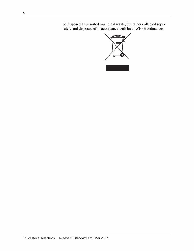
As indicated by the symbol below, disposal of this product is governed by Directive 2002/96/EC of the European Parliament and of the Coun-cil on waste electrical and electronic equipment (WEEE). WEEE could potentially prove harmful to the environment; as such, upon disposal of the Telephony Modem the Directive requires that this product must not
TM508/TM512 Installation Guide Release 5 Standard 1.2 Mar 2007
x
be disposed as unsorted municipal waste, but rather collected sepa-rately and disposed of in accordance with local WEEE ordinances.
Touchstone Telephony Release 5 Standard 1.2 Mar 2007
1 1 Planning theInstallation
Use this chapter to plan the Telephony Modem installation.
Environmental RequirementsInstallation of the equipment in a rack should not restrict airflow. In particular, provide adequate side clearance.
Mount the Telephony Modem properly to prevent uneven mechanical loading on the chassis. Improper mounting can cause premature failure and potentially hazardous conditions.
When installed in a closed or multi-unit rack assembly, the operating temperature inside the rack environment may be higher than ambient temperature. Install the Telephony Modem in an environment where the ambient temperatures remains below 50° Celsius.
Site LocationNote: Install the Telephony Modem in a restricted access location.
The Telephony Modem is designed to be installed in a wiring closet rack. The wiring closet must provide access to power, telephony, and network facilities as described in this chapter.
The Telephony Modem can be wall-mounted using the rack-mounting brackets (recommended) or the cutouts on the bottom of the Telephony Modem. ARRIS recommends wall-mounting to a plywood surface.
TM508/TM512 Installation Guide Release 5 Standard 1.2 Mar 2007
2
Power RequirementsThe Telephony Modem can use either 120V AC power or 48V DC power. Maximum power consumption is 60 watts.
CAUTIONRisk of equipment damageConnect only DC or AC power, not both, to the TM512. Connecting both supplies may cause a reset upon loss of AC power.
Each type of power supply has a separate power connector mounted on the rear panel of the Telephony Modem. The power connectors are typ-ically plugged into the AC power or DC power distribution unit of the rack or cabinet using the power cords supplied with the Telephony Modem.
Note:Make sure that the power circuits have sufficient capacity to power the Telephony Modem before connecting power.
AC Powering The Telephony Modem requires up to 85 VA, 47 to 63 Hz AC power. The socket-outlet must be properly earthed.
DC Powering For DC powering, ARRIS recommends the use of a Local Battery Backup Supply, part number 718115K. The DC input voltage range is 40 V DC to 60 V DC; the nominal voltage is 48 V DC. The DC power supply requires up to 60 watts of DC power from a SELV rated source.
If you intend to power the Telephony Modem from a common 48V DC supply, contact ARRIS for recommendations. The following table shows the DC power connections.
Signal To AWG Color
DC RTN - 16 Black
48V Feed 1 + 16 Red
Touchstone Telephony Release 5 Standard 1.2 Mar 2007
3
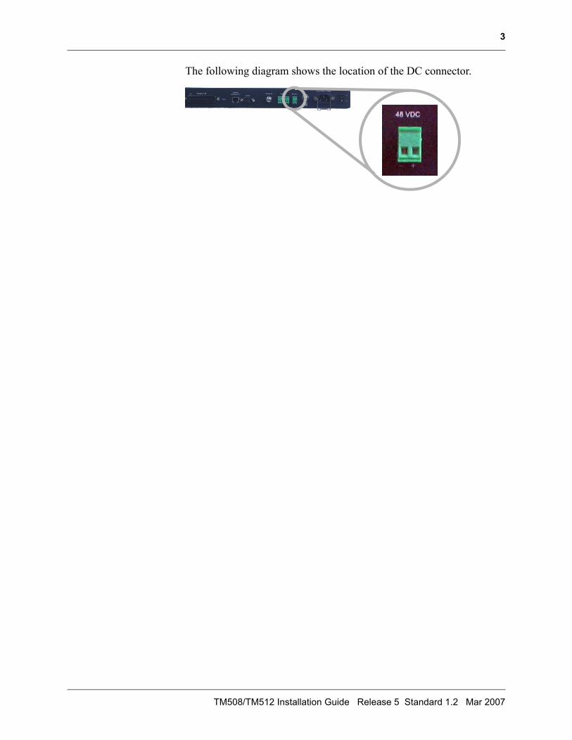
The following diagram shows the location of the DC connector.
TM508/TM512 Installation Guide Release 5 Standard 1.2 Mar 2007
4
Telephony RequirementsEach telephone line supports copper wire loop lengths of up to 128¾, equivalent to 1500 feet of 26 AWG (American Wire Gauge) copper wire loop. The loop length includes the cable between the Telephony Modem and punch-down block, subscriber premises wiring, and exten-sion cables used with subscriber CPE.
The Telephony Modem uses a cable with RJ-21X connectors to the punch-down block.
Network RequirementsIf the Telephony Modem is to provide data service for subscribers, a 100BaseT Ethernet connection (usually a hub or switch) must be avail-able.
Note:When most or all lines are off-hook, data services may be impacted due to lack of bandwidth.
For best results, the RF connection should use RJ-6 coaxial cable, cut to the minimum practical length to minimize losses. The HFC network must be DOCSIS 2.0 compatible.
Touchstone Telephony Release 5 Standard 1.2 Mar 2007
5
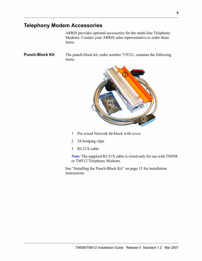
Telephony Modem AccessoriesARRIS provides optional accessories for the multi-line Telephony Modems. Contact your ARRIS sales representative to order these items.
Punch-Block Kit The punch-block kit, order number 719321, contains the following items.
1 Pre-wired Network 66-block with cover
2 24 bridging clips
3 RJ-21X cable
Note: The supplied RJ-21X cable is wired only for use with TM508 or TM512 Telephony Modems.
See “Installing the Punch-Block Kit” on page 15 for installation instructions.
1
2
3
TM508/TM512 Installation Guide Release 5 Standard 1.2 Mar 2007
6
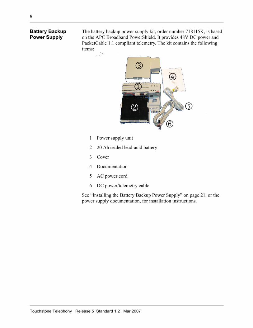
Battery Backup Power Supply
The battery backup power supply kit, order number 718115K, is based on the APC Broadband PowerShield. It provides 48V DC power and PacketCable 1.1 compliant telemetry. The kit contains the following items:
1 Power supply unit
2 20 Ah sealed lead-acid battery
3 Cover
4 Documentation
5 AC power cord
6 DC power/telemetry cable
See “Installing the Battery Backup Power Supply” on page 21, or the power supply documentation, for installation instructions.
1
2
34
5
6
Touchstone Telephony Release 5 Standard 1.2 Mar 2007

2 2 Installing theTelephony Modem
Use this chapter to install the Telephony Modem.
TM508/TM512 Installation Guide Release 5 Standard 1.2 Mar 2007
8
Cable and Connector Pinouts
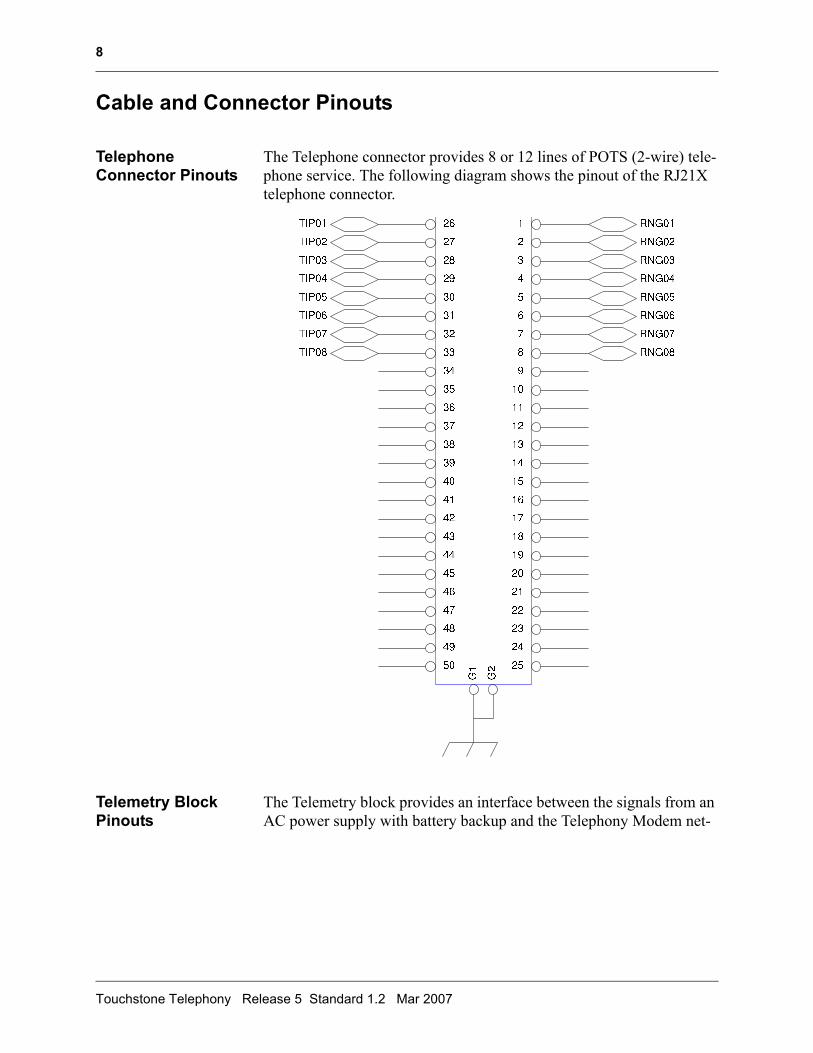
Telephone Connector Pinouts
The Telephone connector provides 8 or 12 lines of POTS (2-wire) tele-phone service. The following diagram shows the pinout of the RJ21X telephone connector.
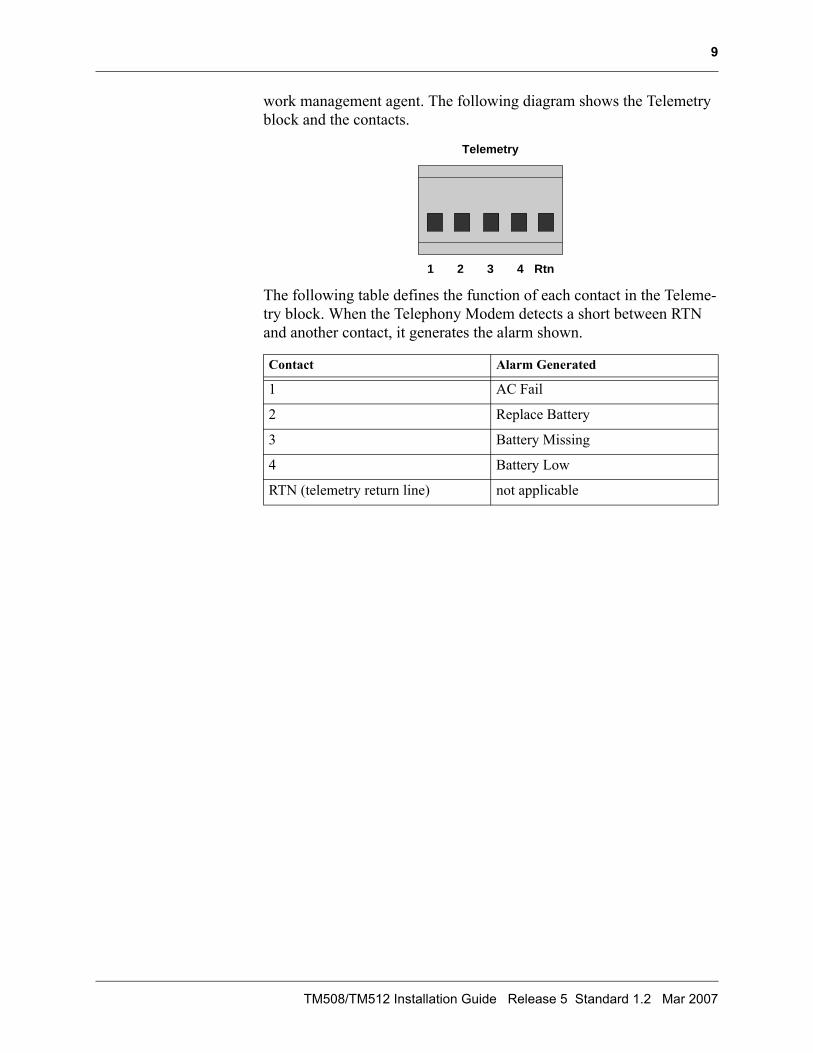
Telemetry Block Pinouts
The Telemetry block provides an interface between the signals from an AC power supply with battery backup and the Telephony Modem net-
Touchstone Telephony Release 5 Standard 1.2 Mar 2007
9
work management agent. The following diagram shows the Telemetry block and the contacts.
The following table defines the function of each contact in the Teleme-try block. When the Telephony Modem detects a short between RTN and another contact, it generates the alarm shown.
Contact Alarm Generated
1 AC Fail
2 Replace Battery
3 Battery Missing
4 Battery Low
RTN (telemetry return line) not applicable
1 2 3 4 Rtn
Telemetry
TM508/TM512 Installation Guide Release 5 Standard 1.2 Mar 2007
10
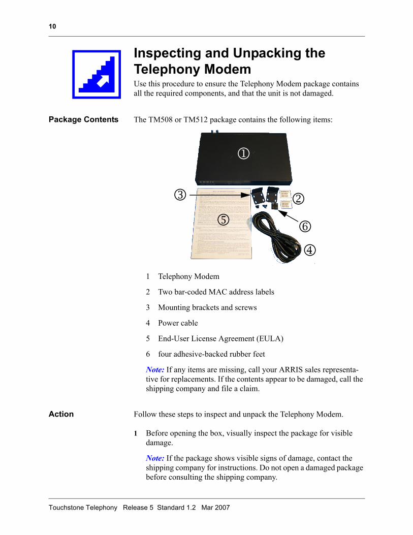
Inspecting and Unpacking the Telephony ModemUse this procedure to ensure the Telephony Modem package contains all the required components, and that the unit is not damaged.
Package Contents The TM508 or TM512 package contains the following items:
1 Telephony Modem
2 Two bar-coded MAC address labels
3 Mounting brackets and screws
4 Power cable
5 End-User License Agreement (EULA)
6 four adhesive-backed rubber feet
Note: If any items are missing, call your ARRIS sales representa-tive for replacements. If the contents appear to be damaged, call the shipping company and file a claim.
Action Follow these steps to inspect and unpack the Telephony Modem.
1 Before opening the box, visually inspect the package for visible damage.
Note: If the package shows visible signs of damage, contact the shipping company for instructions. Do not open a damaged package before consulting the shipping company.
1
23
4
5 6
Touchstone Telephony Release 5 Standard 1.2 Mar 2007
11
2 If the package is undamaged, open the box at the top.
3 Lift the Telephony Modem bag out of the package.
4 If all the items are present and undamaged, affix the MAC address stickers where they can be seen after installation.
TM508/TM512 Installation Guide Release 5 Standard 1.2 Mar 2007
12
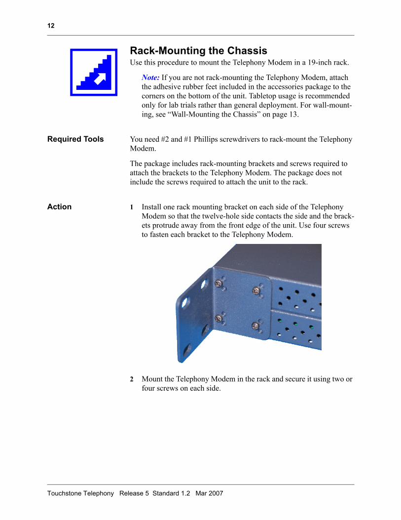
Rack-Mounting the ChassisUse this procedure to mount the Telephony Modem in a 19-inch rack.
Note: If you are not rack-mounting the Telephony Modem, attach the adhesive rubber feet included in the accessories package to the corners on the bottom of the unit. Tabletop usage is recommended only for lab trials rather than general deployment. For wall-mount-ing, see “Wall-Mounting the Chassis” on page 13.
Required Tools You need #2 and #1 Phillips screwdrivers to rack-mount the Telephony Modem.
The package includes rack-mounting brackets and screws required to attach the brackets to the Telephony Modem. The package does not include the screws required to attach the unit to the rack.
Action 1 Install one rack mounting bracket on each side of the Telephony Modem so that the twelve-hole side contacts the side and the brack-ets protrude away from the front edge of the unit. Use four screws to fasten each bracket to the Telephony Modem.
2 Mount the Telephony Modem in the rack and secure it using two or four screws on each side.
Touchstone Telephony Release 5 Standard 1.2 Mar 2007
13
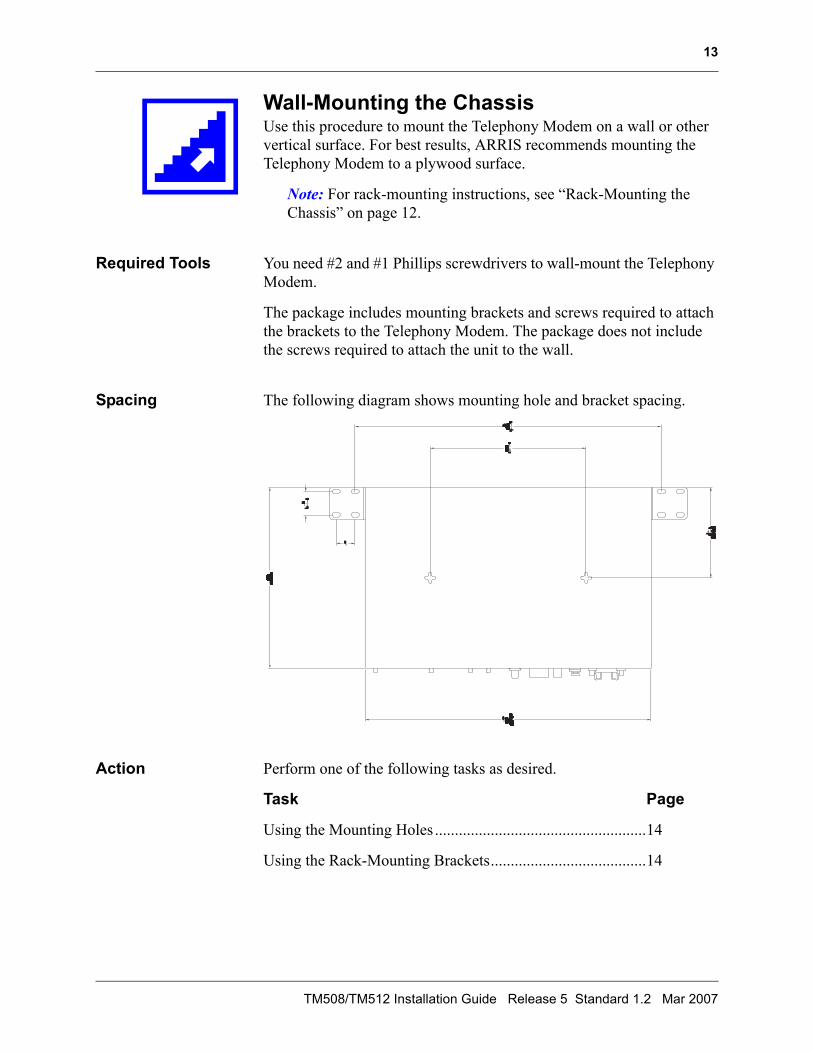
Wall-Mounting the ChassisUse this procedure to mount the Telephony Modem on a wall or other vertical surface. For best results, ARRIS recommends mounting the Telephony Modem to a plywood surface.
Note: For rack-mounting instructions, see “Rack-Mounting the Chassis” on page 12.
Required Tools You need #2 and #1 Phillips screwdrivers to wall-mount the Telephony Modem.
The package includes mounting brackets and screws required to attach the brackets to the Telephony Modem. The package does not include the screws required to attach the unit to the wall.
Spacing The following diagram shows mounting hole and bracket spacing.
Action Perform one of the following tasks as desired.
Task Page
Using the Mounting Holes .....................................................14
Using the Rack-Mounting Brackets.......................................14
TM508/TM512 Installation Guide Release 5 Standard 1.2 Mar 2007
14
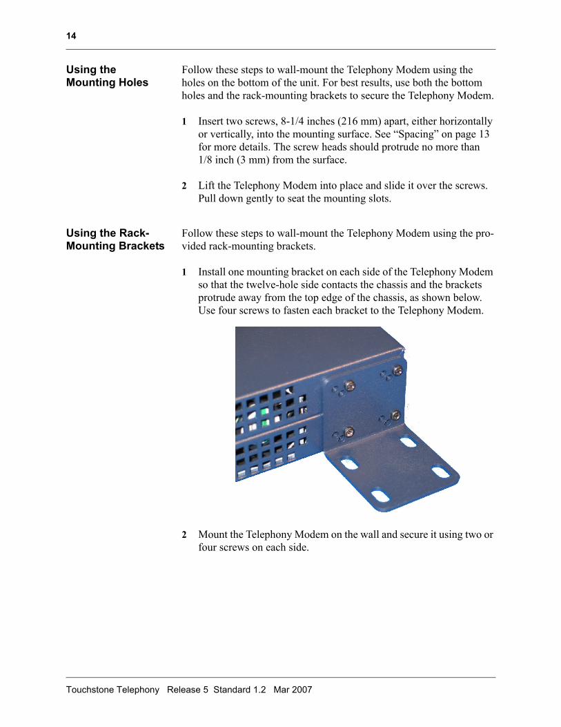
Using the Mounting Holes
Follow these steps to wall-mount the Telephony Modem using the holes on the bottom of the unit. For best results, use both the bottom holes and the rack-mounting brackets to secure the Telephony Modem.
1 Insert two screws, 8-1/4 inches (216 mm) apart, either horizontally or vertically, into the mounting surface. See “Spacing” on page 13 for more details. The screw heads should protrude no more than 1/8 inch (3 mm) from the surface.
2 Lift the Telephony Modem into place and slide it over the screws. Pull down gently to seat the mounting slots.
Using the Rack-Mounting Brackets
Follow these steps to wall-mount the Telephony Modem using the pro-vided rack-mounting brackets.
1 Install one mounting bracket on each side of the Telephony Modem so that the twelve-hole side contacts the chassis and the brackets protrude away from the top edge of the chassis, as shown below. Use four screws to fasten each bracket to the Telephony Modem.
2 Mount the Telephony Modem on the wall and secure it using two or four screws on each side.
Touchstone Telephony Release 5 Standard 1.2 Mar 2007
15
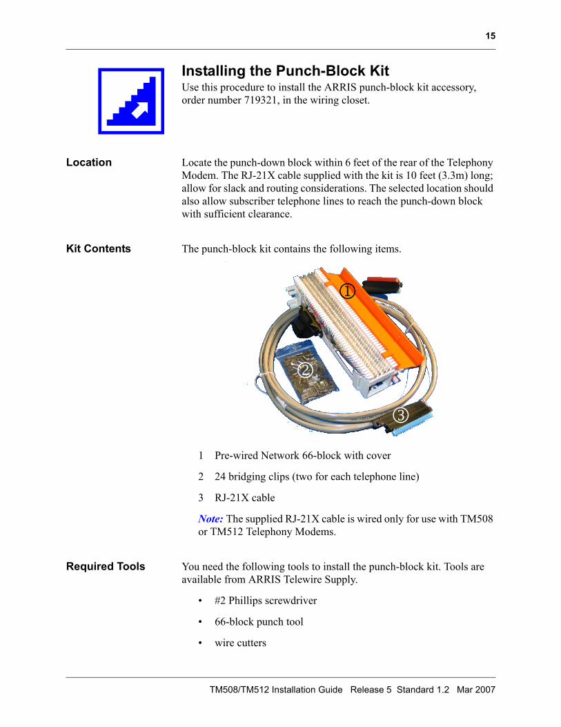
Installing the Punch-Block KitUse this procedure to install the ARRIS punch-block kit accessory, order number 719321, in the wiring closet.
Location Locate the punch-down block within 6 feet of the rear of the Telephony Modem. The RJ-21X cable supplied with the kit is 10 feet (3.3m) long; allow for slack and routing considerations. The selected location should also allow subscriber telephone lines to reach the punch-down block with sufficient clearance.
Kit Contents The punch-block kit contains the following items.
1 Pre-wired Network 66-block with cover
2 24 bridging clips (two for each telephone line)
3 RJ-21X cable
Note: The supplied RJ-21X cable is wired only for use with TM508 or TM512 Telephony Modems.
Required Tools You need the following tools to install the punch-block kit. Tools are available from ARRIS Telewire Supply.
• #2 Phillips screwdriver
• 66-block punch tool
• wire cutters
1
2
3
TM508/TM512 Installation Guide Release 5 Standard 1.2 Mar 2007
16
Additional Items The following additional items are required, but not supplied, depend-ing on the mounting surface.
• To mount the punch-down block on drywall, you need two dry-wall anchors.
• To mount the punch-down block on plywood, you need two 1-inch #6 wood screws.
Action Perform the following tasks in the order shown.
Task Page
Mounting the Punch-Down Block .........................................16
Connecting Subscriber Wiring...............................................17
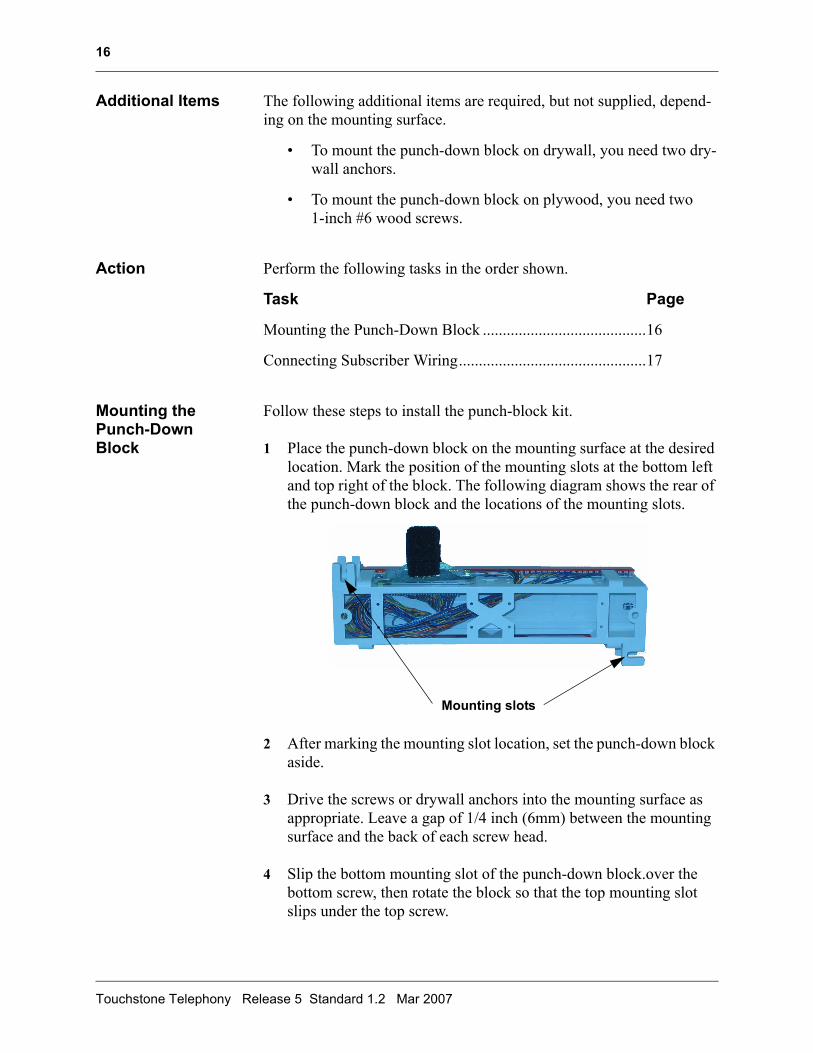
Mounting the Punch-Down Block
Follow these steps to install the punch-block kit.
1 Place the punch-down block on the mounting surface at the desired location. Mark the position of the mounting slots at the bottom left and top right of the block. The following diagram shows the rear of the punch-down block and the locations of the mounting slots.
2 After marking the mounting slot location, set the punch-down block aside.
3 Drive the screws or drywall anchors into the mounting surface as appropriate. Leave a gap of 1/4 inch (6mm) between the mounting surface and the back of each screw head.
4 Slip the bottom mounting slot of the punch-down block.over the bottom screw, then rotate the block so that the top mounting slot slips under the top screw.
Mounting slots
Touchstone Telephony Release 5 Standard 1.2 Mar 2007
17
5 Tighten the screws to firmly hold the punch-down block against the mounting surface.
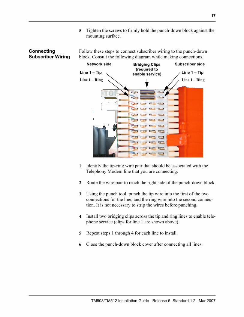
Connecting Subscriber Wiring
Follow these steps to connect subscriber wiring to the punch-down block. Consult the following diagram while making connections.
1 Identify the tip-ring wire pair that should be associated with the Telephony Modem line that you are connecting.
2 Route the wire pair to reach the right side of the punch-down block.
3 Using the punch tool, punch the tip wire into the first of the two connections for the line, and the ring wire into the second connec-tion. It is not necessary to strip the wires before punching.
4 Install two bridging clips across the tip and ring lines to enable tele-phone service (clips for line 1 are shown above).
5 Repeat steps 1 through 4 for each line to install.
6 Close the punch-down block cover after connecting all lines.
Bridging Clips (required to
enable service)
Network side Subscriber side
Line 1 – Tip
Line 1 – Ring
Line 1 – Tip
Line 1 – Ring
TM508/TM512 Installation Guide Release 5 Standard 1.2 Mar 2007
18
Connecting CablesUse this procedure to connect the Telephony Modem to power and net-works.
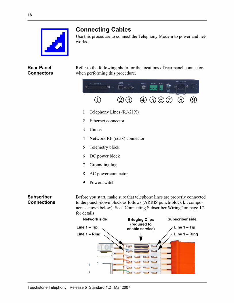
Rear Panel Connectors
Refer to the following photo for the locations of rear panel connectors when performing this procedure.
1 Telephony Lines (RJ-21X)
2 Ethernet connector
3 Unused
4 Network RF (coax) connector
5 Telemetry block
6 DC power block
7 Grounding lug
8 AC power connector
9 Power switch
Subscriber Connections
Before you start, make sure that telephone lines are properly connected to the punch-down block as follows (ARRIS punch-block kit compo-nents shown below). See “Connecting Subscriber Wiring” on page 17 for details.
1 23 4567 8 9
Bridging Clips (required to
enable service)
Network side Subscriber side
Line 1 – Tip
Line 1 – Ring
Line 1 – Tip
Line 1 – Ring
Touchstone Telephony Release 5 Standard 1.2 Mar 2007
19
If the Telephony Modem is intended to provide data services, Ethernet lines from subscriber units must be run to a switch or hub in the wiring closet. The switch or hub must have at least one free connection for the Telephony Modem.
Grounding Requirements
When using AC power, a grounded 3-prong AC outlet provides safety ground. When using a SELV DC power supply, such as the Local Bat-tery Backup Supply (part number 718115K), safety ground is not required.
The grounding lug on the Telephony Modem provides chassis ground, and can be used if desired. Use #12 AWG wire to connect the ground-ing lug to the AC building ground.
The coax ground should be tied to AC building ground per NFPA 70 (National Electrical Code) Article 820 requirements.
Tools You need a small flat-blade screwdriver to secure serial, telemetry, and DC power cables.
You need a #1 Phillips screwdriver to secure the ground wire to the grounding lug.
A torque-limiting wrench can be used to secure RF cables.
Action Follow these steps to connect cables to the Telephony Modem.
1 (optional) Attach a ground wire between the Telephony Modem ground lug and a proper earth ground. For best results, minimize sharp bends or kinks between the Telephony Modem and the ground.
2 Connect the RF cable to the Network RF connector, and tighten to a torque pressure of 17 to 23 Kg-cm (15 to 20 in-lb.).
Note: If a torque-limiting wrench is not available, tighten the con-nector by hand, then tighten a further 1/8 to 1/4 turn with a wrench.
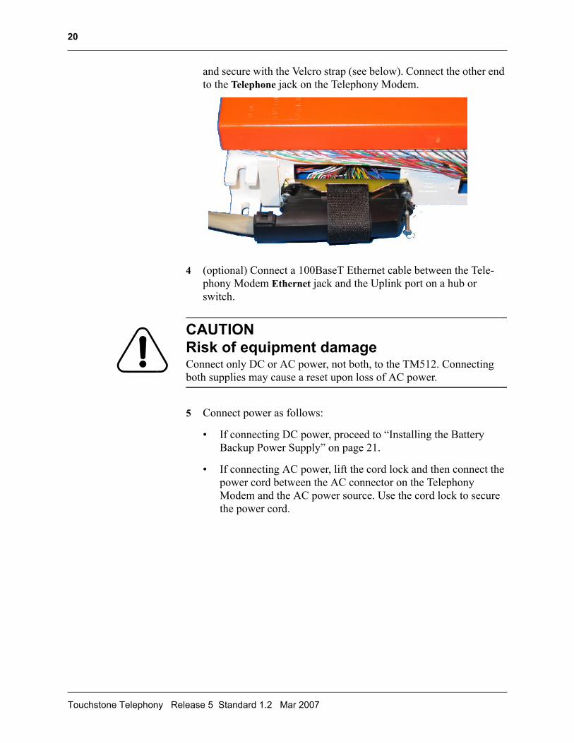
3 Insert one end of the telephony cable through the Velcro® strap on the punch-down block connector, plug the cable into the connector,
TM508/TM512 Installation Guide Release 5 Standard 1.2 Mar 2007
20
and secure with the Velcro strap (see below). Connect the other end to the Telephone jack on the Telephony Modem.
4 (optional) Connect a 100BaseT Ethernet cable between the Tele-phony Modem Ethernet jack and the Uplink port on a hub or switch.
CAUTIONRisk of equipment damageConnect only DC or AC power, not both, to the TM512. Connecting both supplies may cause a reset upon loss of AC power.
5 Connect power as follows:
• If connecting DC power, proceed to “Installing the Battery Backup Power Supply” on page 21.
• If connecting AC power, lift the cord lock and then connect the power cord between the AC connector on the Telephony Modem and the AC power source. Use the cord lock to secure the power cord.
Touchstone Telephony Release 5 Standard 1.2 Mar 2007
21
Installing the Battery Backup Power SupplyUse this procedure to mount and connect the battery backup power sup-ply kit, part number 718115K, to the Telephony Modem.
Note: Before installing the power supply, charge the battery as instructed by the documentation accompanying the power supply kit.
Location Locate the power supply within 4 feet of the rear of the Telephony Modem. The power cable supplied with the kit is 6 feet (1.8 m) long; allow for slack and routing considerations.
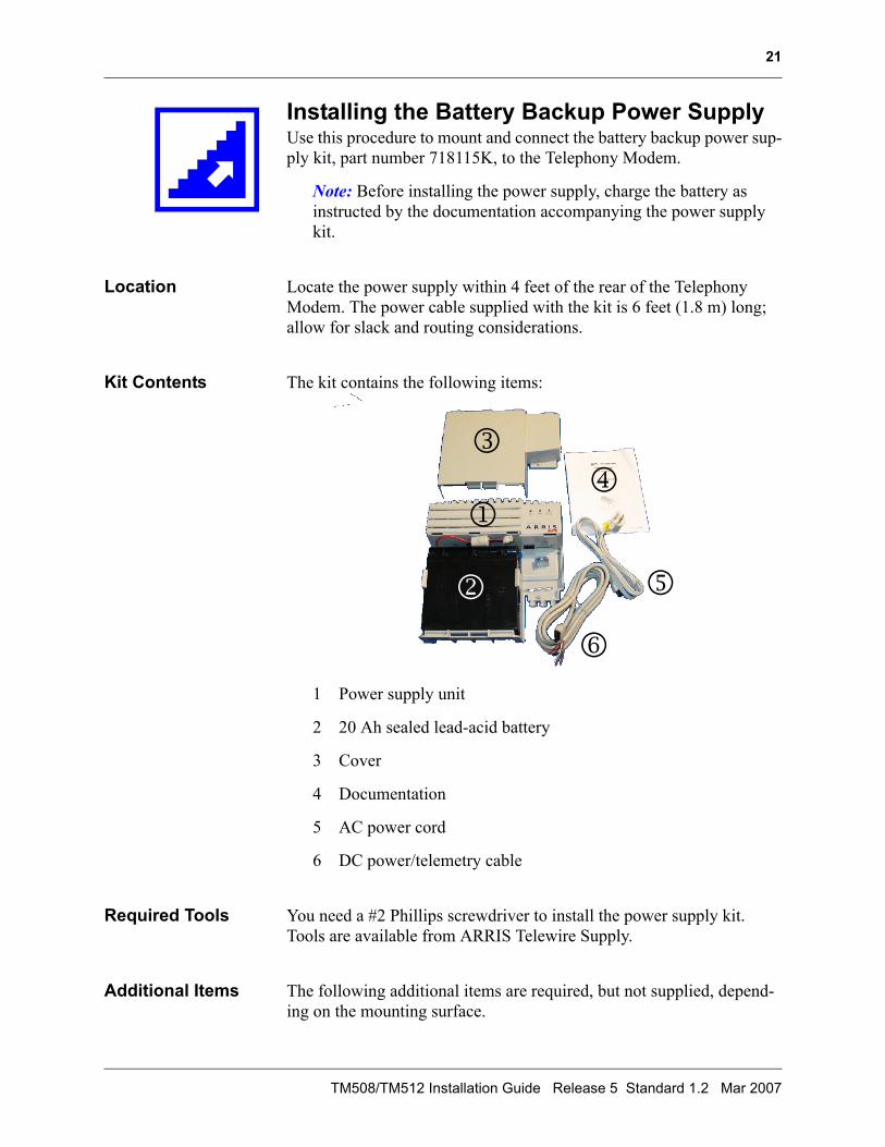
Kit Contents The kit contains the following items:
1 Power supply unit
2 20 Ah sealed lead-acid battery
3 Cover
4 Documentation
5 AC power cord
6 DC power/telemetry cable
Required Tools You need a #2 Phillips screwdriver to install the power supply kit. Tools are available from ARRIS Telewire Supply.
Additional Items The following additional items are required, but not supplied, depend-ing on the mounting surface.
1
2
34
5
6
TM508/TM512 Installation Guide Release 5 Standard 1.2 Mar 2007
22
• To mount the power supply on drywall, you need two drywall anchors.
• To mount the power supply on plywood, you need two 1-inch #6 wood screws.
CAUTIONRisk of equipment damageConnect only DC or AC power, not both, to the TM512. Connecting both supplies may cause a reset upon loss of AC power.
Action Perform the following tasks in the order shown.
Task Page
Mounting the Power Supply ..................................................22
Connecting the Cables ...........................................................23
Mounting the Power Supply
Follow these steps to mount the power supply.
1 Remove the battery from the power supply and set the battery aside.
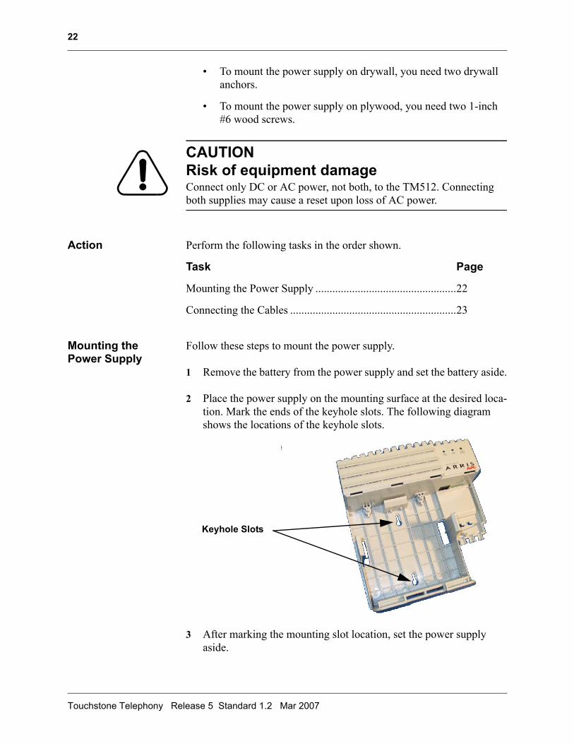
2 Place the power supply on the mounting surface at the desired loca-tion. Mark the ends of the keyhole slots. The following diagram shows the locations of the keyhole slots.
3 After marking the mounting slot location, set the power supply aside.
Keyhole Slots
Touchstone Telephony Release 5 Standard 1.2 Mar 2007
23
4 Drive the screws or drywall anchors into the mounting surface as appropriate. Leave a gap of 1/8 inch (3mm) between the mounting surface and the back of each screw head.
5 Slip the large ends of the power supply keyhole slots.over the screws, then pull down on the power supply until the screw shafts contact the small end of the keyhole slots.
6 Tighten the screws to firmly hold the power supply against the mounting surface.
Connecting the Cables
Follow these steps to connect power and battery cables to the power supply.
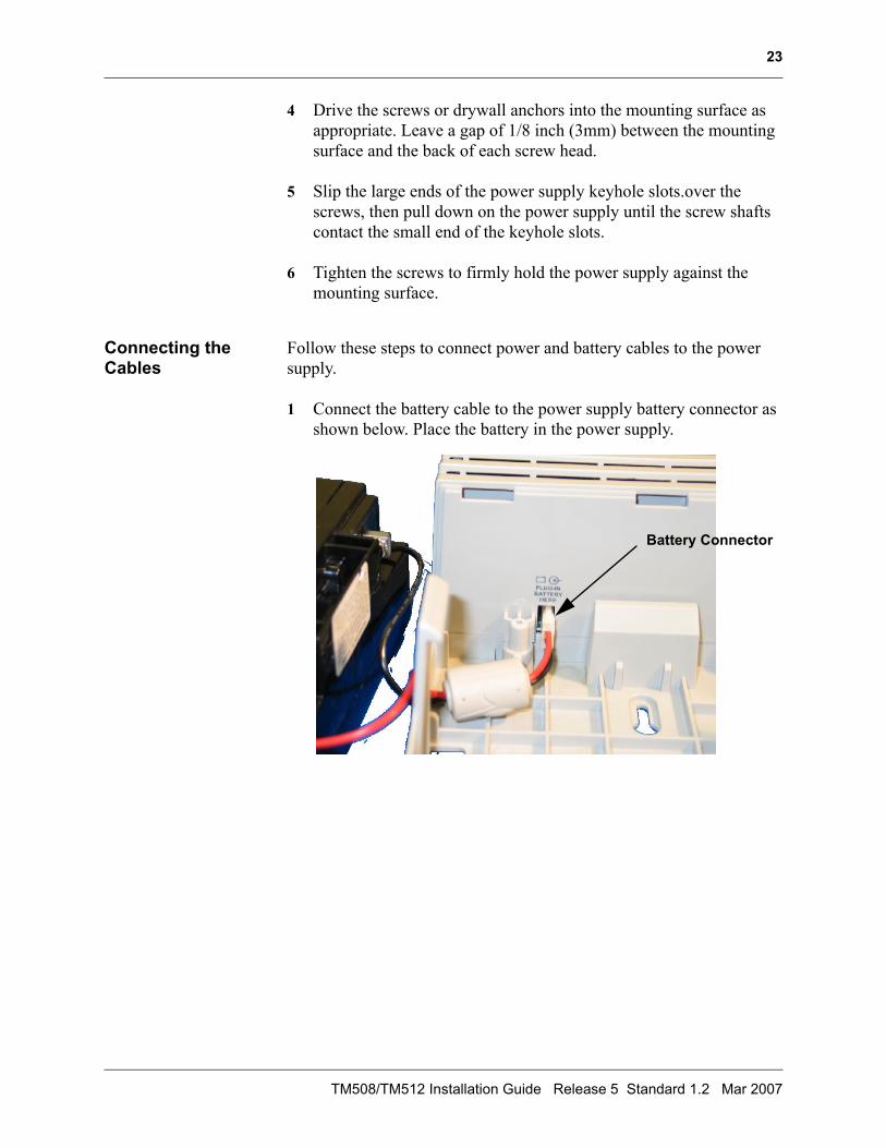
1 Connect the battery cable to the power supply battery connector as shown below. Place the battery in the power supply.
Battery Connector
TM508/TM512 Installation Guide Release 5 Standard 1.2 Mar 2007
24
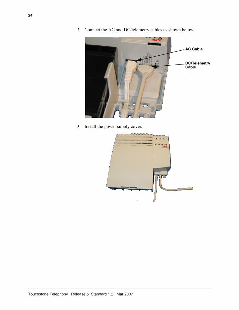
2 Connect the AC and DC/telemetry cables as shown below.
3 Install the power supply cover.
AC Cable
DC/TelemetryCable
Touchstone Telephony Release 5 Standard 1.2 Mar 2007
25
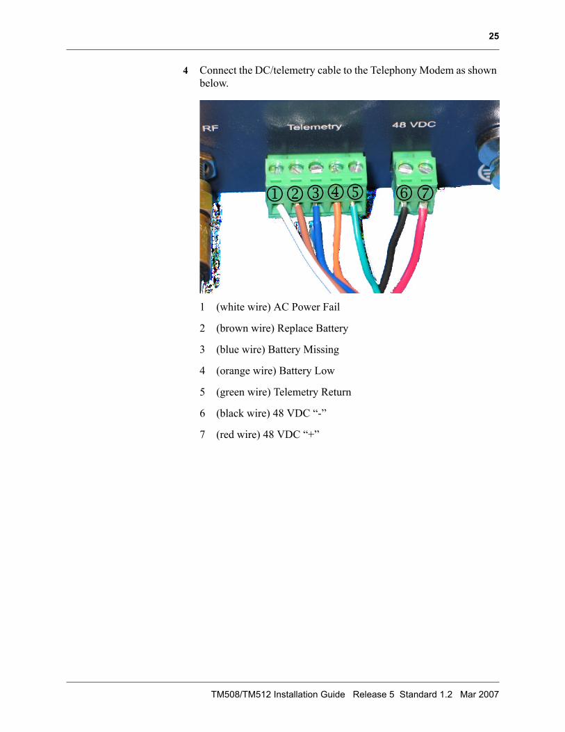
4 Connect the DC/telemetry cable to the Telephony Modem as shown below.
1 (white wire) AC Power Fail
2 (brown wire) Replace Battery
3 (blue wire) Battery Missing
4 (orange wire) Battery Low
5 (green wire) Telemetry Return
6 (black wire) 48 VDC “-”
7 (red wire) 48 VDC “+”
12345 67
TM508/TM512 Installation Guide Release 5 Standard 1.2 Mar 2007

26
Touchstone Telephony Release 5 Standard 1.2 Mar 2007
3 3 TroubleshootingInformation
This chapter describes troubleshooting features.
Troubleshooting InterfacesThe Telephony Modem provides two troubleshooting interfaces: the front panel LEDs and the telemetry block.
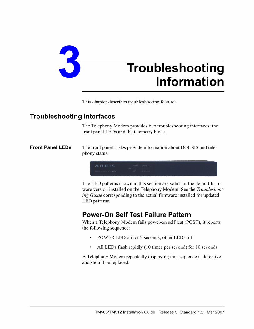
Front Panel LEDs The front panel LEDs provide information about DOCSIS and tele-phony status.
The LED patterns shown in this section are valid for the default firm-ware version installed on the Telephony Modem. See the Troubleshoot-ing Guide corresponding to the actual firmware installed for updated LED patterns.
Power-On Self Test Failure PatternWhen a Telephony Modem fails power-on self test (POST), it repeats the following sequence:
• POWER LED on for 2 seconds; other LEDs off
• All LEDs flash rapidly (10 times per second) for 10 seconds
A Telephony Modem repeatedly displaying this sequence is defective and should be replaced.
TM508/TM512 Installation Guide Release 5 Standard 1.2 Mar 2007
28
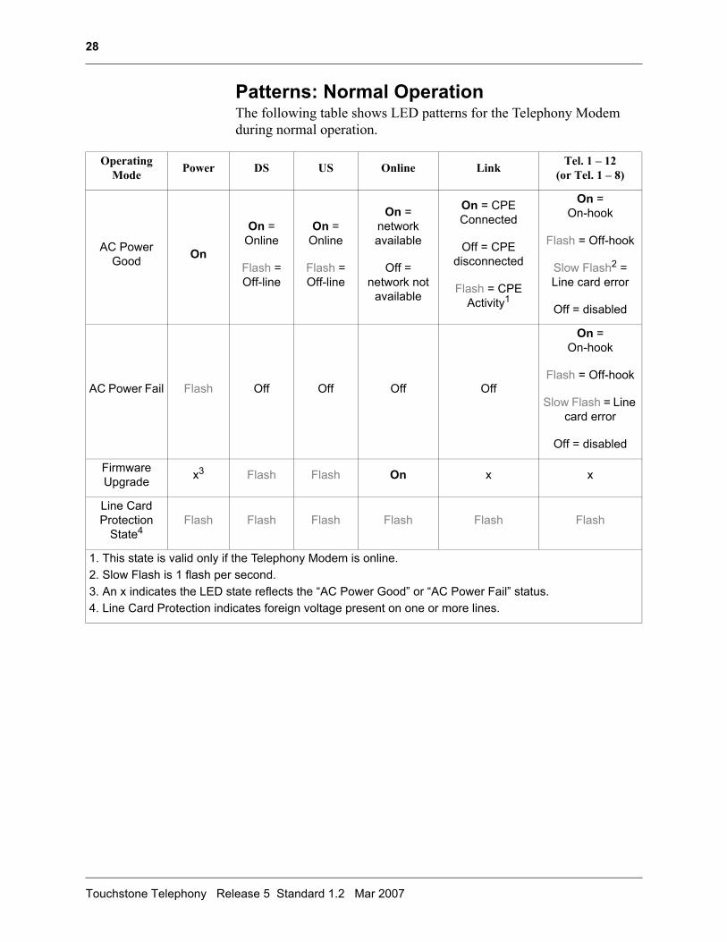
Patterns: Normal OperationThe following table shows LED patterns for the Telephony Modem during normal operation.
Operating Mode Power DS US Online Link Tel. 1 – 12
(or Tel. 1 – 8)
AC Power Good On
On = Online
Flash = Off-line
On = Online
Flash = Off-line
On =network available
Off =network not
available
On = CPE Connected
Off = CPE disconnected
Flash = CPE Activity1
On = On-hook
Flash = Off-hook
Slow Flash2 = Line card error
Off = disabled
AC Power Fail Flash Off Off Off Off
On = On-hook
Flash = Off-hook
Slow Flash = Line card error
Off = disabled
Firmware Upgrade x3 Flash Flash On x x
Line Card Protection
State4Flash Flash Flash Flash Flash Flash
1. This state is valid only if the Telephony Modem is online.2. Slow Flash is 1 flash per second.3. An x indicates the LED state reflects the “AC Power Good” or “AC Power Fail” status.4. Line Card Protection indicates foreign voltage present on one or more lines.
Touchstone Telephony Release 5 Standard 1.2 Mar 2007
29
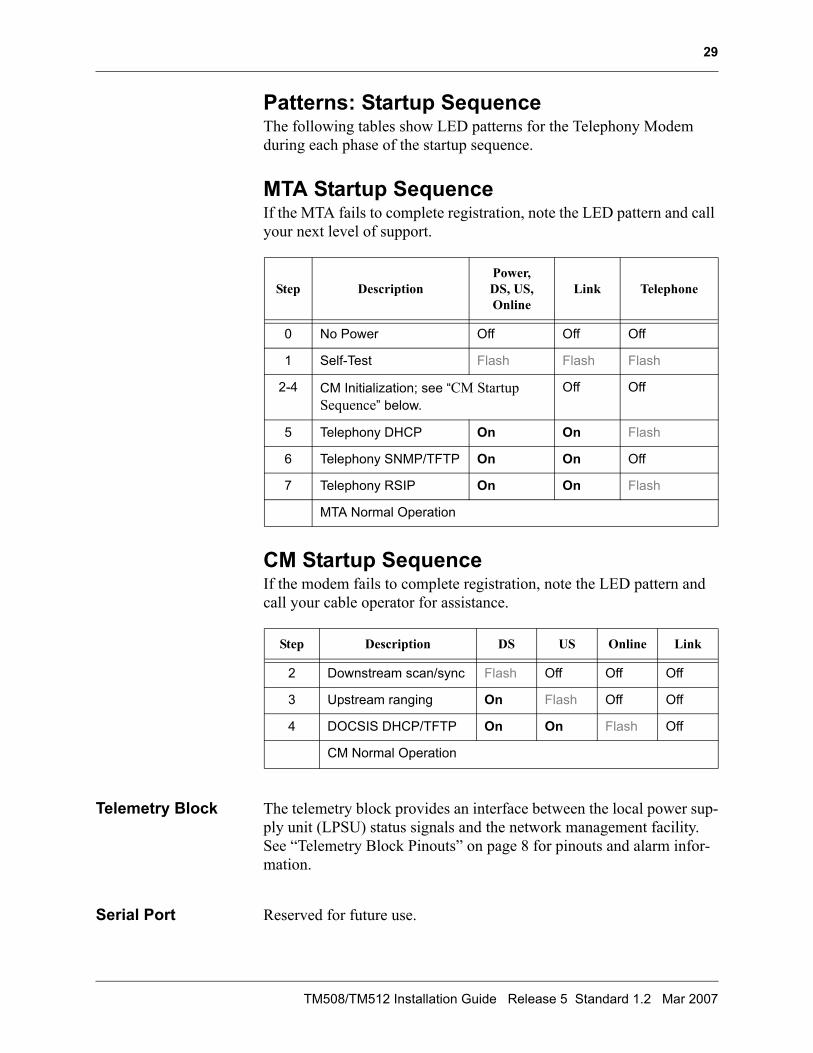
Patterns: Startup SequenceThe following tables show LED patterns for the Telephony Modem during each phase of the startup sequence.
MTA Startup SequenceIf the MTA fails to complete registration, note the LED pattern and call your next level of support.
CM Startup SequenceIf the modem fails to complete registration, note the LED pattern and call your cable operator for assistance.
Telemetry Block The telemetry block provides an interface between the local power sup-ply unit (LPSU) status signals and the network management facility. See “Telemetry Block Pinouts” on page 8 for pinouts and alarm infor-mation.
Serial Port Reserved for future use.
Step DescriptionPower, DS, US, Online
Link Telephone
0 No Power Off Off Off
1 Self-Test Flash Flash Flash
2-4 CM Initialization; see “CM Startup Sequence” below.
Off Off
5 Telephony DHCP On On Flash
6 Telephony SNMP/TFTP On On Off
7 Telephony RSIP On On Flash
MTA Normal Operation
Step Description DS US Online Link
2 Downstream scan/sync Flash Off Off Off
3 Upstream ranging On Flash Off Off
4 DOCSIS DHCP/TFTP On On Flash Off
CM Normal Operation
TM508/TM512 Installation Guide Release 5 Standard 1.2 Mar 2007

30
Touchstone Telephony Release 5 Standard 1.2 Mar 2007


Touchstone® TM508/TM512Telephony Modem Installation Guide
2006-2007 ARRISAll rights reserved
All information contained in this document is subject to change without notice. ARRIS reserves the right to make changes to equipment design or program components, as progress in engineering, manufacturing methods, or other circumstances may warrant.
ARRIS, ARRIS Interactive, and Touchstone Telephony are trademarks of ARRIS Group. All other trademarks and registered trademarks are the property of their respective holders.
Release 5 Standard 1.2March 2007