tmd 0001 - cad and drafting manual - electrical …...engineering manual design electrical operating...
TRANSCRIPT

Engineering Manual Design Electrical Operating Diagrams
Engi
neer
ing
Man
ual TMD 0001
CAD AND DRAFTING MANUAL – ELECTRICAL OPERATING DIAGRAMS – SECTION 5
Version 2.2
Issued September 2010
Reconfirmed 23 July 2019
Owner: Applications Manager – RailCAD
Approved by:
Brent Mallam Authorised by:
Mike Hogan General Manager Professional Services
Applications Manager RailCAD
Disclaimer This document was prepared for use on the RailCorp Network only. RailCorp makes no warranties, express or implied, that compliance with the contents of this document shall be sufficient to ensure safe systems or work or operation. It is the document user’s sole responsibility to ensure that the copy of the document it is viewing is the current version of the document as in use by RailCorp. RailCorp accepts no liability whatsoever in relation to the use of this document by any party, and RailCorp excludes any liability which arises in any manner by the use of this document. Copyright The information in this document is protected by Copyright and no part of this document may be reproduced, altered, stored or transmitted by any person without the prior consent of RailCorp.
UNCONTROLLED WHEN PRINTED Page 1 of 35
RailCorp Engineering Manual — Design — Electrical Operating Diagrams CAD and Drafting Manual – Electrical Operating Diagrams – Section 5 TMD 0001
© RailCorp Page 2 of 35 Issued September 2010 UNCONTROLLED WHEN PRINTED Version 2.2
Document control
Version Date Summary of change 1.0 August 2008 First draft 2.0 April 2009 Re-formatted to new template 2.1 August 2009 Additions after stakeholder review 2.2 September 2010 Application of TMA 400 format
RailCorp Engineering Manual — Design — Electrical Operating Diagrams CAD and Drafting Manual – Electrical Operating Diagrams – Section 5 TMD 0001
© RailCorp Page 3 of 35 Issued September 2010 UNCONTROLLED WHEN PRINTED Version 2.2
Contents
5 Electrical Operating Diagram Standards..............................................................................5 5.1 Introduction ................................................................................................................5
5.1.1 Glossary of Terms and Acronyms..............................................................5 5.2 General ......................................................................................................................5
5.2.1 Diagrams and Design Files and Seed Files ...............................................5 5.2.2 Design Files................................................................................................6
5.2.2.1 Design Model ..............................................................................6 5.2.2.2 Sheet Model................................................................................6
5.2.3 Stripped Down Design Files (diagrams minus border, title etc.).............................................................................................................6
5.2.4 Levels and Symbology ...............................................................................6 5.2.4.1 Level Structure............................................................................7 5.2.4.2 Colour........................................................................................10 5.2.4.3 Weight .......................................................................................11 5.2.4.4 Line Styles ................................................................................11
5.2.5 Text Styles................................................................................................12 5.3 1500 Volt Sectioning Diagrams ...............................................................................12
5.3.1 Linework ...................................................................................................13 5.3.2 Colour.......................................................................................................14 5.3.3 Text...........................................................................................................15 5.3.4 Cells..........................................................................................................16
5.3.4.1 Symbols placed as Cells...........................................................16 5.3.4.2 Summary of the most commonly used Cells ............................17
5.3.5 Placement Guidelines ..............................................................................17 5.3.6 MultiLines .................................................................................................19
5.3.6.1 MultiLine Bubbles:.....................................................................19 5.3.6.2 MultiLine Tracks And Feeders: .................................................19
5.3.7 Sample 1500 Volt Sectioning Diagram ....................................................20 5.3.7.1 Detail from part of the above sample:.......................................20
5.4 AC & DC Substation Diagrams................................................................................21 5.4.1 Linework ...................................................................................................22 5.4.2 Colour.......................................................................................................22 5.4.3 Text...........................................................................................................22 5.4.4 Cells..........................................................................................................24
5.4.4.1 General information on OD_HVlib.cel.......................................24 5.4.5 Placement Guidelines ..............................................................................24
5.4.5.1 AC and DC Diagrams in General..............................................24 5.4.5.2 AC Diagrams............................................................................25 5.4.5.3 DC Diagrams ............................................................................25
5.4.6 Sample AC Substation Diagram ..............................................................26 5.4.7 Sample DC Substation Diagram ..............................................................26
5.5 System and Reticulation Diagrams .........................................................................27 5.5.1 System Diagrams – 11kV and 33kV ......................................................27 5.5.2 Linework used in System Diagrams.........................................................27

RailCorp Engineering Manual — Design — Electrical Operating Diagrams CAD and Drafting Manual – Electrical Operating Diagrams – Section 5 TMD 0001
© RailCorp Page 4 of 35 Issued September 2010 UNCONTROLLED WHEN PRINTED Version 2.2
5.5.3 Colour.......................................................................................................28 5.5.4 Text used in System Diagrams ................................................................28 5.5.5 Placement Guidelines for System Diagrams............................................29
5.5.5.1 Substations Drawn In Abbreviated Form..................................30 5.5.6 Sample System Diagram .........................................................................31
5.5.6.1 Detail from part of the above sample:.......................................31 5.5.7 Reticulation Diagrams ..............................................................................31 5.5.8 Sample Reticulation Diagram...................................................................32
5.5.8.1 Detail from part of the above sample:.......................................33 5.6 Reference Sheets ....................................................................................................33
5.6.1 Key Maps for System Diagrams...............................................................33 5.7 Hybrid Files..............................................................................................................34 5.8 Reference Files........................................................................................................34 5.9 File Naming Conventions.........................................................................................34 5.10 In-force Diagram Conventions.................................................................................34
5.10.1 Proposed Diagram Conventions ..............................................................35

RailCorp Engineering Manual — Design — Electrical Operating Diagrams CAD and Drafting Manual – Electrical Operating Diagrams – Section 5 TMD 0001
© RailCorp Page 5 of 35 Issued September 2010 UNCONTROLLED WHEN PRINTED Version 2.2
5 Electrical Operating Diagram Standards
5.1 Introduction Geospatial Product Delivery (GPD) (incorporating the former Electrical Operating Diagrams group) is a team within Geospatial Services Unit (GSU). The members of this team who use CAD are the Elec_Srv CAD group.
The GPD team (Elec_Srv) produces three basic types of diagrams using CAD:
a) Coloured 1500 Volt Sectioning Diagrams
b) Black and White (B&W) AC & DC Substation Operating Diagrams
c) Black and White System and Reticulation Diagrams
There are also a few key maps and symbol sheets, some black and white and some coloured.
The abovementioned types can each be further subdivided into two categories: “Proposed” and “In Force”.
5.1.1 Glossary of Terms and Acronyms B&W Black and White, i.e. monochrome
pu Positional Unit, i.e. a Unit Of Resolution in a CAD design file
Hybrid A diagram composed of both raster and vector graphics.
CAD Computer Aided Design.
MicroStation Proprietary CAD software provided by Bentley.
Symbology A combination of Colour, Weight and Style.
For other MicroStation CAD specific technical terms (e.g. ED field (Enter Data Field), model, level, cell, element etc.) refer to the MicroStation documentation.
For electrical technical terms and abbreviations used in diagrams refer to Electrical Operating Diagram Sheets S1, S2, S3 and S4.
5.2 General
5.2.1 Diagrams and Design Files and Seed Files Electrical Operating Diagrams are all A3 size. Each diagram is fully contained in one CAD design file, and each design file contains only one diagram. Working units are: mm / 1000 um / 1 pu.
Seed files are available for each type of diagram, with the models set up, references called up and scaled, and the border cell already placed as specified below. See the following sections to determine which seed file to use.
RailCorp Engineering Manual — Design — Electrical Operating Diagrams CAD and Drafting Manual – Electrical Operating Diagrams – Section 5 TMD 0001
© RailCorp Page 6 of 35 Issued September 2010 UNCONTROLLED WHEN PRINTED Version 2.2
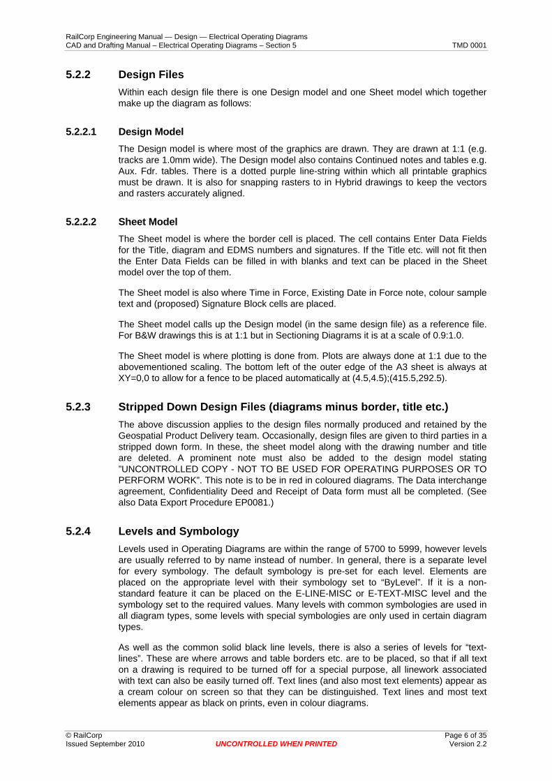
5.2.2 Design Files Within each design file there is one Design model and one Sheet model which together make up the diagram as follows:
5.2.2.1 Design Model The Design model is where most of the graphics are drawn. They are drawn at 1:1 (e.g. tracks are 1.0mm wide). The Design model also contains Continued notes and tables e.g. Aux. Fdr. tables. There is a dotted purple line-string within which all printable graphics must be drawn. It is also for snapping rasters to in Hybrid drawings to keep the vectors and rasters accurately aligned.
5.2.2.2 Sheet Model The Sheet model is where the border cell is placed. The cell contains Enter Data Fields for the Title, diagram and EDMS numbers and signatures. If the Title etc. will not fit then the Enter Data Fields can be filled in with blanks and text can be placed in the Sheet model over the top of them.
The Sheet model is also where Time in Force, Existing Date in Force note, colour sample text and (proposed) Signature Block cells are placed.
The Sheet model calls up the Design model (in the same design file) as a reference file. For B&W drawings this is at 1:1 but in Sectioning Diagrams it is at a scale of 0.9:1.0.
The Sheet model is where plotting is done from. Plots are always done at 1:1 due to the abovementioned scaling. The bottom left of the outer edge of the A3 sheet is always at XY=0,0 to allow for a fence to be placed automatically at (4.5,4.5);(415.5,292.5).
5.2.3 Stripped Down Design Files (diagrams minus border, title etc.) The above discussion applies to the design files normally produced and retained by the Geospatial Product Delivery team. Occasionally, design files are given to third parties in a stripped down form. In these, the sheet model along with the drawing number and title are deleted. A prominent note must also be added to the design model stating ”UNCONTROLLED COPY - NOT TO BE USED FOR OPERATING PURPOSES OR TO PERFORM WORK”. This note is to be in red in coloured diagrams. The Data interchange agreement, Confidentiality Deed and Receipt of Data form must all be completed. (See also Data Export Procedure EP0081.)
5.2.4 Levels and Symbology Levels used in Operating Diagrams are within the range of 5700 to 5999, however levels are usually referred to by name instead of number. In general, there is a separate level for every symbology. The default symbology is pre-set for each level. Elements are placed on the appropriate level with their symbology set to “ByLevel”. If it is a non-standard feature it can be placed on the E-LINE-MISC or E-TEXT-MISC level and the symbology set to the required values. Many levels with common symbologies are used in all diagram types, some levels with special symbologies are only used in certain diagram types.
As well as the common solid black line levels, there is also a series of levels for “text-lines”. These are where arrows and table borders etc. are to be placed, so that if all text on a drawing is required to be turned off for a special purpose, all linework associated with text can also be easily turned off. Text lines (and also most text elements) appear as a cream colour on screen so that they can be distinguished. Text lines and most text elements appear as black on prints, even in colour diagrams.
RailCorp Engineering Manual — Design — Electrical Operating Diagrams CAD and Drafting Manual – Electrical Operating Diagrams – Section 5 TMD 0001
© RailCorp Page 7 of 35 Issued September 2010 UNCONTROLLED WHEN PRINTED Version 2.2
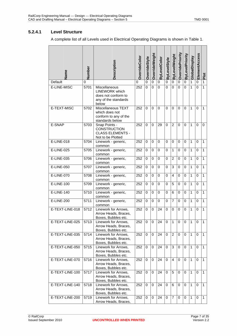
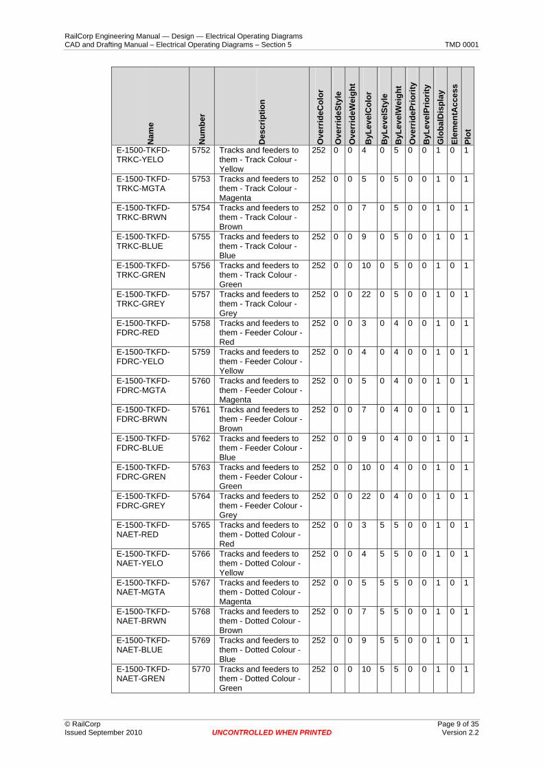
5.2.4.1 Level Structure A complete list of all Levels used in Electrical Operating Diagrams is shown in Table 1.
Nam
e
Num
ber
Des
crip
tion
Ove
rrid
eCol
or
Ove
rrid
eSty
le
Ove
rrid
eWei
ght
ByL
evel
Col
or
ByL
evel
Styl
e B
yLev
elW
eigh
t O
verr
ideP
riorit
y B
yLev
elPr
iorit
y G
loba
lDis
play
El
emen
tAcc
ess
Plot
Default 0 0 0 0 0 0 0 0 0 1 0 1 E-LINE-MISC 5701 Miscellaneous
LINEWORK which does not conform to any of the standards below
252 0 0 0 0 0 0 0 1 0 1
E-TEXT-MISC 5702 Miscellaneous TEXT which does not conform to any of the standards below
252 0 0 0 0 0 0 0 1 0 1
E-SNAP 5703 Snap Points - CONSTRUCTION CLASS ELEMENTS - Not to be Plotted
252 0 0 29 0 2 0 0 1 0 0
E-LINE-018 5704 Linework - generic, common
252 0 0 0 0 0 0 0 1 0 1
E-LINE-025 5705 Linework - generic, common
252 0 0 0 0 1 0 0 1 0 1
E-LINE-035 5706 Linework - generic, common
252 0 0 0 0 2 0 0 1 0 1
E-LINE-050 5707 Linework - generic, common
252 0 0 0 0 3 0 0 1 0 1
E-LINE-070 5708 Linework - generic, common
252 0 0 0 0 4 0 0 1 0 1
E-LINE-100 5709 Linework - generic, common
252 0 0 0 0 5 0 0 1 0 1
E-LINE-140 5710 Linework - generic, common
252 0 0 0 0 6 0 0 1 0 1
E-LINE-200 5711 Linework - generic, common
252 0 0 0 0 7 0 0 1 0 1
E-TEXT-LINE-018 5712 Linework for Arrows, Arrow Heads, Braces, Boxes, Bubbles etc.
252 0 0 24 0 0 0 0 1 0 1
E-TEXT-LINE-025 5713 Linework for Arrows, Arrow Heads, Braces, Boxes, Bubbles etc.
252 0 0 24 0 1 0 0 1 0 1
E-TEXT-LINE-035 5714 Linework for Arrows, Arrow Heads, Braces, Boxes, Bubbles etc.
252 0 0 24 0 2 0 0 1 0 1
E-TEXT-LINE-050 5715 Linework for Arrows, Arrow Heads, Braces, Boxes, Bubbles etc.
252 0 0 24 0 3 0 0 1 0 1
E-TEXT-LINE-070 5716 Linework for Arrows, Arrow Heads, Braces, Boxes, Bubbles etc.
252 0 0 24 0 4 0 0 1 0 1
E-TEXT-LINE-100 5717 Linework for Arrows, Arrow Heads, Braces, Boxes, Bubbles etc.
252 0 0 24 0 5 0 0 1 0 1
E-TEXT-LINE-140 5718 Linework for Arrows, Arrow Heads, Braces, Boxes, Bubbles etc.
252 0 0 24 0 6 0 0 1 0 1
E-TEXT-LINE-200 5719 Linework for Arrows, Arrow Heads, Braces,
252 0 0 24 0 7 0 0 1 0 1

RailCorp Engineering Manual — Design — Electrical Operating Diagrams CAD and Drafting Manual – Electrical Operating Diagrams – Section 5 TMD 0001
© RailCorp Page 8 of 35 Issued September 2010 UNCONTROLLED WHEN PRINTED Version 2.2
Nam
e
Num
ber
Des
crip
tion
Ove
rrid
eCol
or
Ove
rrid
eSty
le
Ove
rrid
eWei
ght
ByL
evel
Col
or
ByL
evel
Styl
e B
yLev
elW
eigh
t O
verr
ideP
riorit
y B
yLev
elPr
iorit
y G
loba
lDis
play
El
emen
tAcc
ess
Plot
Boxes, Bubbles etc. E-TEXT-018 5720 Common Text Level
Stroke Weight 0.18 252 0 0 24 0 0 0 0 1 0 1
E-TEXT-025 5721 Common Text Level Stroke Weight 0.25
252 0 0 24 0 1 0 0 1 0 1
E-TEXT-035 5722 Common Text Level Stroke Weight 0.35
252 0 0 24 0 2 0 0 1 0 1
E-TEXT-050 5723 Common Text Level Stroke Weight 0.50
252 0 0 24 0 3 0 0 1 0 1
E-TEXT-070 5724 Common Text Level Stroke Weight 0.70
252 0 0 24 0 4 0 0 1 0 1
E-TEXT-100 5725 Common Text Level Stroke Weight 1.00
252 0 0 24 0 5 0 0 1 0 1
E-TEXT-140 5726 Common Text Level Stroke Weight 1.40
252 0 0 24 0 6 0 0 1 0 1
E-TEXT-200 5727 Common Text Level Stroke Weight 2.00
252 0 0 24 0 7 0 0 1 0 1
E-HILI-BLUE 5728 Highlight Colour - Pale Blue
252 0 0 15 0 0 0 0 1 0 1
E-HILI-GREN 5729 Highlight Colour - Pale Green
252 0 0 16 0 0 0 0 1 0 1
E-HILI-RED 5730 Highlight Colour - Pale Red
252 0 0 17 0 0 0 0 1 0 1
E-HILI-BYEL 5731 Highlight Colour - Bright Yellow
252 0 0 18 0 0 0 0 1 0 1
E-HILI-MGTA 5732 Highlight Colour - Pale Magenta
252 0 0 19 0 0 0 0 1 0 1
E-HILI-ORNG 5733 Highlight Colour - Pale Orange
252 0 0 14 1 1 0 0 1 0 1
E-HILI-PYEL 5734 Highlight Colour - Pale Yellow
252 0 0 12 1 1 0 0 1 0 1
E-CROS-WATR 5735 Railway Crossings - dotted lines in river (white)
252 0 0 0 1 0 0 0 1 0 1
E-CROS-LEVX 5736 Level Crossings - dashed lines
252 0 0 0 5 0 0 0 1 0 1
E-LINE-DIVD 5737 Dividing line between halves of drawing
252 0 0 0 1 0 0 0 1 0 1
E-LINE-CLOD 5738 Clouds (in BLACK & WHITE proposed drawings)
252 0 0 8 1 0 0 0 1 0 1
E-LINE-COLR-CLOD
5739 Clouds (in COLOUR proposed drawings)
252 0 0 8 0 2 0 0 1 0 1
E-TEXT-COLR-RICL
5740 R.I.C. Logo Orange 252 0 0 21 0 0 0 0 1 0 1
E-TEXT-COLR-GREN
5741 Plot Identification (P.I.D.) etc.
252 0 0 2 0 1 0 0 1 0 1
E-TEXT-COLR-RED
5742 Red text for issue and D.I.F.
252 0 0 3 0 2 0 0 1 0 1
E-TEXT-COLR-BLUE
5743 Web Address in border files etc.
252 0 0 9 0 0 0 0 1 0 1
E-1500-TKFD-EDGE-GREY
5750 Outlines of Features primarily shown on other diagrams.
252 0 0 8 0 0 0 0 1 0 1
E-1500-TKFD-TRKC-RED
5751 Tracks and feeders to them - Track Colour - Red
252 0 0 3 0 5 0 0 1 0 1
RailCorp Engineering Manual — Design — Electrical Operating Diagrams CAD and Drafting Manual – Electrical Operating Diagrams – Section 5 TMD 0001
© RailCorp Page 9 of 35 Issued September 2010 UNCONTROLLED WHEN PRINTED Version 2.2
Nam
e
Num
ber
Des
crip
tion
Ove
rrid
eCol
or
Ove
rrid
eSty
le
Ove
rrid
eWei
ght
ByL
evel
Col
or
ByL
evel
Styl
e B
yLev
elW
eigh
t O
verr
ideP
riorit
y B
yLev
elPr
iorit
y G
loba
lDis
play
El
emen
tAcc
ess
Plot
E-1500-TKFD-TRKC-YELO
5752 Tracks and feeders to them - Track Colour - Yellow
252 0 0 4 0 5 0 0 1 0 1
E-1500-TKFD-TRKC-MGTA
5753 Tracks and feeders to them - Track Colour - Magenta
252 0 0 5 0 5 0 0 1 0 1
E-1500-TKFD-TRKC-BRWN
5754 Tracks and feeders to them - Track Colour - Brown
252 0 0 7 0 5 0 0 1 0 1
E-1500-TKFD-TRKC-BLUE
5755 Tracks and feeders to them - Track Colour - Blue
252 0 0 9 0 5 0 0 1 0 1
E-1500-TKFD-TRKC-GREN
5756 Tracks and feeders to them - Track Colour - Green
252 0 0 10 0 5 0 0 1 0 1
E-1500-TKFD-TRKC-GREY
5757 Tracks and feeders to them - Track Colour - Grey
252 0 0 22 0 5 0 0 1 0 1
E-1500-TKFD-FDRC-RED
5758 Tracks and feeders to them - Feeder Colour - Red
252 0 0 3 0 4 0 0 1 0 1
E-1500-TKFD-FDRC-YELO
5759 Tracks and feeders to them - Feeder Colour - Yellow
252 0 0 4 0 4 0 0 1 0 1
E-1500-TKFD-FDRC-MGTA
5760 Tracks and feeders to them - Feeder Colour - Magenta
252 0 0 5 0 4 0 0 1 0 1
E-1500-TKFD-FDRC-BRWN
5761 Tracks and feeders to them - Feeder Colour - Brown
252 0 0 7 0 4 0 0 1 0 1
E-1500-TKFD-FDRC-BLUE
5762 Tracks and feeders to them - Feeder Colour - Blue
252 0 0 9 0 4 0 0 1 0 1
E-1500-TKFD-FDRC-GREN
5763 Tracks and feeders to them - Feeder Colour - Green
252 0 0 10 0 4 0 0 1 0 1
E-1500-TKFD-FDRC-GREY
5764 Tracks and feeders to them - Feeder Colour - Grey
252 0 0 22 0 4 0 0 1 0 1
E-1500-TKFD-NAET-RED
5765 Tracks and feeders to them - Dotted Colour - Red
252 0 0 3 5 5 0 0 1 0 1
E-1500-TKFD-NAET-YELO
5766 Tracks and feeders to them - Dotted Colour - Yellow
252 0 0 4 5 5 0 0 1 0 1
E-1500-TKFD-NAET-MGTA
5767 Tracks and feeders to them - Dotted Colour - Magenta
252 0 0 5 5 5 0 0 1 0 1
E-1500-TKFD-NAET-BRWN
5768 Tracks and feeders to them - Dotted Colour - Brown
252 0 0 7 5 5 0 0 1 0 1
E-1500-TKFD-NAET-BLUE
5769 Tracks and feeders to them - Dotted Colour - Blue
252 0 0 9 5 5 0 0 1 0 1
E-1500-TKFD-NAET-GREN
5770 Tracks and feeders to them - Dotted Colour - Green
252 0 0 10 5 5 0 0 1 0 1

RailCorp Engineering Manual — Design — Electrical Operating Diagrams CAD and Drafting Manual – Electrical Operating Diagrams – Section 5 TMD 0001
© RailCorp Page 10 of 35 Issued September 2010 UNCONTROLLED WHEN PRINTED Version 2.2
Nam
e
Num
ber
Des
crip
tion
Ove
rrid
eCol
or
Ove
rrid
eSty
le
Ove
rrid
eWei
ght
ByL
evel
Col
or
ByL
evel
Styl
e B
yLev
elW
eigh
t O
verr
ideP
riorit
y B
yLev
elPr
iorit
y G
loba
lDis
play
El
emen
tAcc
ess
Plot
E-1500-TKFD-NAET-GREY
5771 Tracks and feeders to them - Dotted Colour - Grey
252 0 0 22 5 5 0 0 1 0 1
E-1500-BDRY-BDRY
5772 District boundaries - actual boundary line
252 0 0 0 6 0 0 0 1 0 1
E-SUBS-LINE-GANG
5800 Dashed line switch gang
252 0 0 0 5 0 0 0 1 0 1
E-SUBS-LINE-BDRY
5801 Substation Boundary 252 0 0 0 7 1 0 0 1 0 1
E-SUBS-COND-MEDI-YELO
5802 Conductors in S.S. 252 0 0 4 0 2 0 0 1 0 1
E-SUBS-COND-LARG-YELO
5803 Conductors in S.S. 252 0 0 4 0 3 0 0 1 0 1
E-SUBS-COND-LARG-BLUE
5804 Conductors in S.S. 252 0 0 9 0 3 0 0 1 0 1
E-SUBS-COND-HUGE-BLUE
5805 Conductors in S.S. 252 0 0 9 0 4 0 0 1 0 1
E-SYRT-FEED-AERL
5850 Aerial Feeders 252 0 0 9 0 3 0 0 1 0 1
E-SYRT-FEED-CABL
5851 Cable Feeders 252 0 0 3 0 3 0 0 1 0 1
E-SYRT-FEED-POLE
5852 Pole 252 0 0 9 0 0 0 0 1 0 1
E-SYRT-FEED-UGCS
5853 Underground cable symbol
252 0 0 3 0 0 0 0 1 0 1
E-SYRT-FEED-TPEG
5854 Pegline cable troughing peg
252 0 0 3 0 1 0 0 1 0 1
E-SYRT-SUBS-LINE-BILD
5855 S.S. Building Box 252 0 0 26 0 1 0 0 1 0 1
E-SYRT-SUBS-LINE-PADM
5856 S.S. Padmount Box 252 0 0 26 5 0 0 0 1 0 1
E-SYRT-SUBS-LINE-BAKP
5857 Backup arrow line (and was for P.S.I.)
252 0 0 2 0 0 0 0 1 0 1
E-SYRT-SUBS-LINE-GANG
5858 Dashed line switch gang
252 0 0 0 5 0 0 0 1 0 1
E-SYRT-TRAK-LINE
5859 Track ""centreline"" (may also be used for sleepers)
252 0 0 8 0 0 0 0 1 0 1
E-SYRT-TRAK-SLEP
5860 Track ""sleepers"" (when separate from centreline)
252 0 0 8 0 0 0 0 1 0 1
E-SYRT-TRAK-PLAT
5861 Track - station platform 252 0 0 8 0 0 0 0 1 0 1
E-SYRT-CROS-RIVR-BANK
5862 Crossings - River, Creek - Bank (BLUE)
252 0 0 1 0 0 0 0 1 0 1
E-SYRT-CROS-RIVR-WATR
5863 Crossings - River, Creek - Water (BLUE)
252 0 0 1 5 0 0 0 1 0 1
Table 1 - Levels
5.2.4.2 Colour Colours used in Electrical Operating Diagrams are shown in Table 2.

RailCorp Engineering Manual — Design — Electrical Operating Diagrams CAD and Drafting Manual – Electrical Operating Diagrams – Section 5 TMD 0001
© RailCorp Page 11 of 35 Issued September 2010 UNCONTROLLED WHEN PRINTED Version 2.2
Colour On Screen
Colour Number
Colour on Colour Plot
Colour on B&W Plot
White 0 Black (Linework) Black
Red 3 Red Black
Yellow 4 Yellow Black
Magenta 5 Magenta Black
Brown 7 Brown Black
Mid Grey 8 Mid Grey Black
Blue 9 Blue Black
Green 10 Green Black
Pale Yellow 12 Pale Yellow Highlight Black
Pale Orange 14 Pale Orange Highlight Black
Cream 24 Black (Text & Arrows) Black
Purple 29 (Not Plotted - points) (Not Plotted - points)
Dark Grey 250 or 251 Pale Grey Pale Grey
Mid Grey 252 Mid Grey Mid Grey
Pale Grey 253 Dark Grey Dark Grey
Table 2 – Colours
5.2.4.3 Weight Weight in design file vs. Line thickness on Plot are as follows in Table 3.
Weight Line thickness
WT=0 0.18mm
WT=1 0.25mm
WT=2 0.35mm
WT=3 0.50mm
WT=4 0.70mm
WT=5 1.00mm
WT=6 1.40mm
WT=7 2.00mm
Table 3 – Weights and line thickness
5.2.4.4 Line Styles Line styles were originally unspecified and depended on the default styles of the plotting system used at the time. The "dotted" colour (used for tracks which are wired but not available for electric traction) is actually line style five (LC=5) i.e. "short dash". Since

RailCorp Engineering Manual — Design — Electrical Operating Diagrams CAD and Drafting Manual – Electrical Operating Diagrams – Section 5 TMD 0001
© RailCorp Page 12 of 35 Issued September 2010 UNCONTROLLED WHEN PRINTED Version 2.2
styles are not scaled with line thickness, and the lines are 0.9mm wide on the plot, the coloured lines appear dotted. Similarly, the dot sizes are not scaled down for thin lines - style one ("dotted") appears dotted on screen but as short dashes on plots. For Coloured (1500 Volt Sectioning) Diagrams only, many diagrams have been drawn and issued using these styles, so any future plotting methods should emulate them. The following table lists line styles vs. stroke/gap lengths as produced by the legacy plotting methods.
LC= Stroke, Gap, Stroke, Gap, … (mm)
0 Continuous
1 0.76,0.76
2 1.52,1.52
3 3.05,1.52
4 3.05,1.52,0.76,1.52
5 1.14,1.14
6 3.05,1.52,0.76,1.52,0.76,1.52
7 3.05,1.14,1.52,1.14
Table 4 - Line styles used in Coloured (1500 Volt Sectioning Diagrams) only
For B&W Substation and System & Reticulation diagrams, the dot sizes are scaled down for thin "dotted" lines, so that they appear dotted on plots as well as on screen.
5.2.5 Text Styles Text is placed using Text Styles. Text Styles are defined for all sizes commonly used of each of the fonts used in Operating Diagrams. All of these text styles have centre-centre justification. (There is not a separate text style for every possible combination of font, size and justification.) When placing a text element, the appropriate justification must be set. E.g. if text is placed at the right hand end of a leader line, left-centre justification must be set.
Table 5 lists the fonts required on plots vs. font numbers in the design file (and text style design library) used to achieve them:
Font on Plot Font name or number in design file
Plain single stroke font 135
Bold infilled 11
Narrow infilled 75 (or “Swiss Condensed”)
Regular infilled “Arial”
Signatures (optional) 71 or 107 (optional)
Table 5 - Fonts
5.3 1500 Volt Sectioning Diagrams Sectioning diagrams show how the Overhead Wiring Traction System is fed and sectionalised. They are drawn and plotted in colour.
RailCorp Engineering Manual — Design — Electrical Operating Diagrams CAD and Drafting Manual – Electrical Operating Diagrams – Section 5 TMD 0001
© RailCorp Page 13 of 35 Issued September 2010 UNCONTROLLED WHEN PRINTED Version 2.2
For 1500 Volt Sectioning Diagrams only, the Sheet model references the Design model at a scale of 0.9 times. The dimensions specified in this manual are the dimensions used in each respective design file model. (On paper plots, the Design model features will measure as 0.9 times the specified values.)
When creating a new drawing, use the seed file “OD_SEseed.dgn” for In-Force or “OD_SEseedP.dgn” for Proposed diagrams. The sheet model of these contains the appropriate drawing sheet border cell, and references the design model at 1.0:0.9.
The cell library " OD_1500V.cel" is used, the cells are placed in the design file at 1:1
5.3.1 Linework Note: The following discussion assumes that the Colour, Weight and Style of lines are all set to “ByLevel” where only a Level Name is given.
Electrified tracks are drawn as two parallel lines 1.0 mm apart on the “E-LINE-018” level with the space between these lines infilled with colour. This is achieved by placing a thick coloured line on the appropriate level and then placing two E-LINE-018 lines parallel to this, 0.5mm away, one each side. (For an alternative method see the section below on Multilines.)
Unelectrified tracks are similar except the colour is replaced with patterns of small black dots ( :·:·: ) using the cell “Unwired”.
The tracks normally run from left to right across the page (from Sydney to Country). Crossovers and branch lines are drawn at multiples of 30° to this (i.e. 30°, 60°, 90°, 120° etc.).
The distance between the main line track centres is 7mm (i.e. 6mm between closest edges). Siding track centres are 6mm and tracks in congested yards can be at 4 or 5mm centres.
Buffer stops are a 1.5mm long E-LINE-025 (or alternatively E-LINE-018) line, perpendicular to and at the end of the track (extending 0.25mm past each side of the track).
Feeders from substations, sectioning huts and switches are drawn by placing a coloured line on the appropriate level and then placing two E-LINE-018 lines parallel to this, 0.3mm away, with one each side. (Feeder colour lines are similar to the electrified track ones but are thinner.) Where coming from S.S.s and S.H.s they are spaced the same as the breakers, in other places they are to have a minimum spacing of 3mm centres. They are normally drawn over the top of tracks (i.e. the tracks are broken) unless they are in an under track crossing (in which case the feeders are broken).
Auxiliary feeders are drawn as a single black E-LINE-050 line, parallel to the track, and broken at crossovers and O.H.W. connections. The centreline of the feeder is 0.8mm out from the edge of the track (i.e. 1.3mm from track centreline).
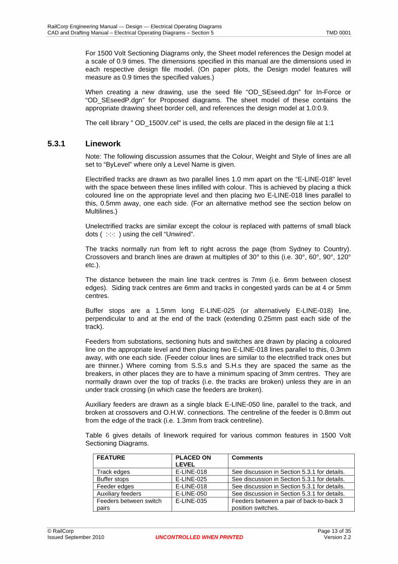
Table 6 gives details of linework required for various common features in 1500 Volt Sectioning Diagrams.
FEATURE PLACED ON LEVEL
Comments
Track edges E-LINE-018 See discussion in Section 5.3.1 for details. Buffer stops E-LINE-025 See discussion in Section 5.3.1 for details. Feeder edges E-LINE-018 See discussion in Section 5.3.1 for details. Auxiliary feeders E-LINE-050 See discussion in Section 5.3.1 for details. Feeders between switch pairs
E-LINE-035 Feeders between a pair of back-to-back 3 position switches.

RailCorp Engineering Manual — Design — Electrical Operating Diagrams CAD and Drafting Manual – Electrical Operating Diagrams – Section 5 TMD 0001
© RailCorp Page 14 of 35 Issued September 2010 UNCONTROLLED WHEN PRINTED Version 2.2
FEATURE PLACED ON LEVEL
Comments
Place either a line or line-string as appropriate.
Circuit Breaker connections
E-LINE-025 Within substations, connections between links and breakers, and breakers and busbars, are placed as a single line.
Rail connections E-LINE-025 Connections from rail symbols to switches or tracks are placed as a single line.
Leader lines E-LINE-018 Within substations, leader lines from busbars to section labels – where the section label is on the E-LINE-018 level.
Leader lines E-TEXT-LINE-018 Within substations, leader lines from busbars to section labels – where the section label is on the E-TEXT-LINE-018 level.
Overline bridges E-LINE-018 Drawn as two parallel lines spaced 2.0mm apart.
Footbridges E-LINE-018 Drawn as two parallel lines spaced 1.5mm apart.
Level crossings E-CROS-LEVX Drawn as two parallel lines spaced 2.0mm apart, (note that lines on the E-CROS-LEVX level are dashed).
Pedestrian level crossings E-CROS-LEVX Drawn as two parallel lines spaced 1.5mm apart, (note that lines on the E-CROS-LEVX level are dashed).
Creeks and tunnels E-LINE-018 & E-CROS-LEVX
Made up of solid and dashed lines. (Tracks are not broken for bridges, level crossings, creeks or tunnels.)
Leaders and arrows E-TEXT-LINE-018 General purpose leaders from text to arrow heads. (Arrow heads are the cell ARROW0 – 1.8mm long and 0.9mm wide).
Continued arrows E-TEXT-LINE-025 Exception: arrows for “Continued on Diag. …” note. Used with a 2mm by 1mm head (the ARROW1 cell).
Brackets E-TEXT-LINE-018 Brackets at breaks in tracks at the ends of drawing sections.
Separation line E-LINE-050 Separation line between the top and bottom half of the drawing.
Table 6 - Details of linework used in 1500 volt Sectioning Diagrams
5.3.2 Colour All linework and text is to be black unless otherwise stated. Colour is used for wiring as follows:
Tracks infilled with continuous colour: indicates available for electric traction OR may be made available by operation of sectioning switches.
Tracks infilled with dotted colour: indicates wiring erected but not available for electric traction. (Airgaps and crossovers or parts thereof connected to tracks with dotted colour are to be shown with dotted colour. Feeder colours are not shown dotted even when connected to tracks with dotted colour.)
A 1.0mm wide dotted colour line (without any black lines): indicates wiring erected but not above a track.
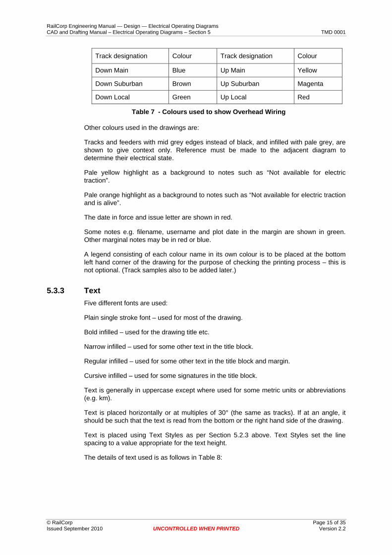
The colours used for wiring are in general as follows in Table 7:
RailCorp Engineering Manual — Design — Electrical Operating Diagrams CAD and Drafting Manual – Electrical Operating Diagrams – Section 5 TMD 0001
© RailCorp Page 15 of 35 Issued September 2010 UNCONTROLLED WHEN PRINTED Version 2.2
Track designation Colour Track designation Colour
Down Main Blue Up Main Yellow
Down Suburban Brown Up Suburban Magenta
Down Local Green Up Local Red
Table 7 - Colours used to show Overhead Wiring
Other colours used in the drawings are:
Tracks and feeders with mid grey edges instead of black, and infilled with pale grey, are shown to give context only. Reference must be made to the adjacent diagram to determine their electrical state.
Pale yellow highlight as a background to notes such as “Not available for electric traction”.
Pale orange highlight as a background to notes such as “Not available for electric traction and is alive”.
The date in force and issue letter are shown in red.
Some notes e.g. filename, username and plot date in the margin are shown in green. Other marginal notes may be in red or blue.
A legend consisting of each colour name in its own colour is to be placed at the bottom left hand corner of the drawing for the purpose of checking the printing process – this is not optional. (Track samples also to be added later.)
5.3.3 Text Five different fonts are used:
Plain single stroke font – used for most of the drawing.
Bold infilled – used for the drawing title etc.
Narrow infilled – used for some other text in the title block.
Regular infilled – used for some other text in the title block and margin.
Cursive infilled – used for some signatures in the title block.
Text is generally in uppercase except where used for some metric units or abbreviations (e.g. km).
Text is placed horizontally or at multiples of 30° (the same as tracks). If at an angle, it should be such that the text is read from the bottom or the right hand side of the drawing.
Text is placed using Text Styles as per Section 5.2.3 above. Text Styles set the line spacing to a value appropriate for the text height.
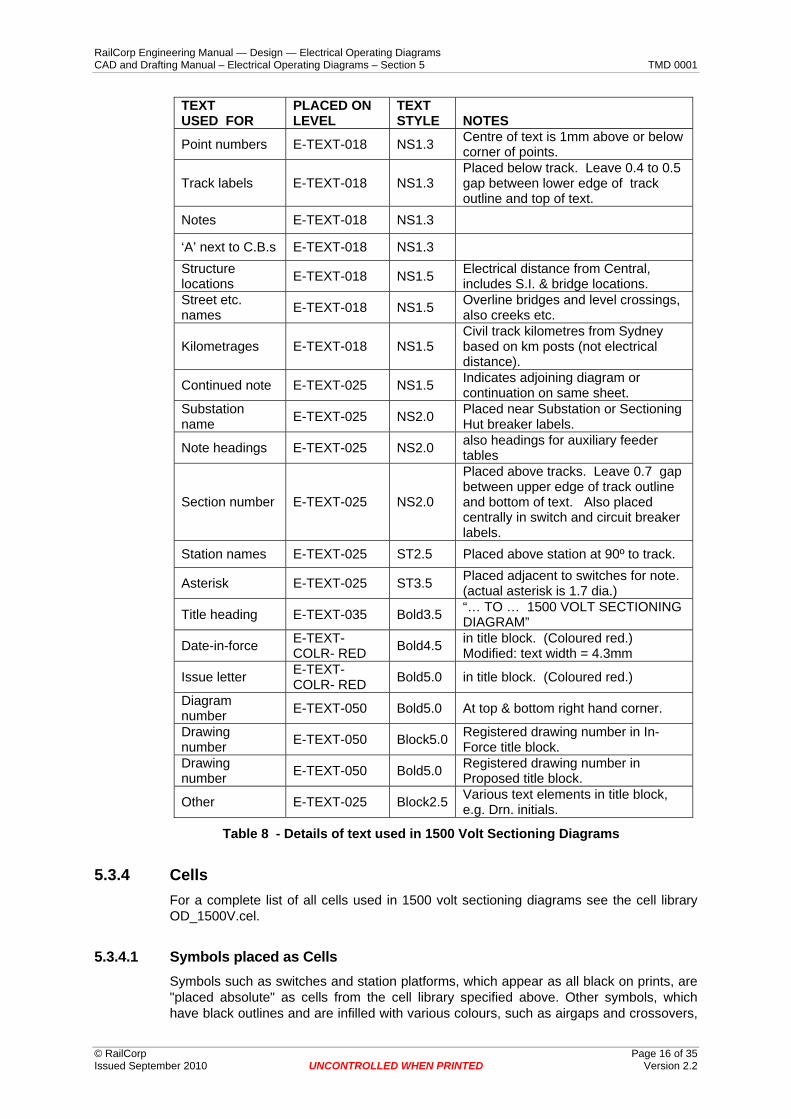
The details of text used is as follows in Table 8:
RailCorp Engineering Manual — Design — Electrical Operating Diagrams CAD and Drafting Manual – Electrical Operating Diagrams – Section 5 TMD 0001
© RailCorp Page 16 of 35 Issued September 2010 UNCONTROLLED WHEN PRINTED Version 2.2
TEXT USED FOR
PLACED ON LEVEL
TEXT STYLE
NOTES
Point numbers E-TEXT-018 NS1.3 Centre of text is 1mm above or below corner of points.
Track labels E-TEXT-018 NS1.3 Placed below track. Leave 0.4 to 0.5 gap between lower edge of track outline and top of text.
Notes E-TEXT-018 NS1.3
‘A’ next to C.B.s E-TEXT-018 NS1.3 Structure locations E-TEXT-018 NS1.5 Electrical distance from Central,
includes S.I. & bridge locations. Street etc. names E-TEXT-018 NS1.5 Overline bridges and level crossings,
also creeks etc.
Kilometrages E-TEXT-018 NS1.5 Civil track kilometres from Sydney based on km posts (not electrical distance).
Continued note E-TEXT-025 NS1.5 Indicates adjoining diagram or continuation on same sheet.
Substation name E-TEXT-025 NS2.0 Placed near Substation or Sectioning
Hut breaker labels.
Note headings E-TEXT-025 NS2.0 also headings for auxiliary feeder tables
Section number E-TEXT-025 NS2.0
Placed above tracks. Leave 0.7 gap between upper edge of track outline and bottom of text. Also placed centrally in switch and circuit breaker labels.
Station names E-TEXT-025 ST2.5 Placed above station at 90º to track.
Asterisk E-TEXT-025 ST3.5 Placed adjacent to switches for note. (actual asterisk is 1.7 dia.)
Title heading E-TEXT-035 Bold3.5 “… TO … 1500 VOLT SECTIONING DIAGRAM”
Date-in-force E-TEXT-COLR- RED Bold4.5 in title block. (Coloured red.)
Modified: text width = 4.3mm
Issue letter E-TEXT-COLR- RED Bold5.0 in title block. (Coloured red.)
Diagram number E-TEXT-050 Bold5.0 At top & bottom right hand corner.
Drawing number E-TEXT-050 Block5.0 Registered drawing number in In-
Force title block. Drawing number E-TEXT-050 Bold5.0 Registered drawing number in
Proposed title block.
Other E-TEXT-025 Block2.5 Various text elements in title block, e.g. Drn. initials.
Table 8 - Details of text used in 1500 Volt Sectioning Diagrams
5.3.4 Cells For a complete list of all cells used in 1500 volt sectioning diagrams see the cell library OD_1500V.cel.
5.3.4.1 Symbols placed as Cells Symbols such as switches and station platforms, which appear as all black on prints, are "placed absolute" as cells from the cell library specified above. Other symbols, which have black outlines and are infilled with various colours, such as airgaps and crossovers,

RailCorp Engineering Manual — Design — Electrical Operating Diagrams CAD and Drafting Manual – Electrical Operating Diagrams – Section 5 TMD 0001
© RailCorp Page 17 of 35 Issued September 2010 UNCONTROLLED WHEN PRINTED Version 2.2
are placed as two separate cells. The outlines are "placed absolute" as above, but the coloured components are stored in the cell library as separate cells and "placed relative" on the appropriate level.
Cells should not be dropped except in exceptional circumstances, such as where one half of an overlap is required to be a different colour to the other half. In this case drop only the coloured cell, and move each element of the dropped cell to the appropriate level, leaving the symbology set to “ByLevel”.
Multiline crossover and airgap cells are also available as an alternative to the above. Place them “Relative” on an appropriate "E-1500-TKFD-TRKC-...." level (they are drawn on the Default level in the cell library). The MultiLine Style will override the outline colour and weight.
Most cells have snap points which are Primary class elements on the E-SNAP level, not Construction class.
The exception is for coloured cells, which are to be placed relative: in these the snap points are Construction class elements on the same level as the linework (otherwise the linework will end up on some random level, if any).
(The cell "BDOT" is a special case, it is placed either ”Absolute” as a black busbar dot or “Relative” as a coloured track-feeder join dot. The E-SNAP level can't be used so the snap asterisk and circle are on the same level.)
5.3.4.2 Summary of the most commonly used Cells Station platforms: solid black rectangle 8.0mm by 1.8mm.
O.H.W. structures: 0.7mm by 0.7mm solid black square.
Wood poles beside track: solid black circle diameter 0.8mm.
Poles in line of feeder: hollow black E-LINE-018 circle, 1.0mm diameter.
Rail connection: a cross-section of a rail about 2mm to 2.5mm high (solid black infilled).
Hut: a 3.0mm by 2.0mm rectangle with diagonal lines from opposite corners, on the E-LINE-018 level (symbology all ByLevel).
SIJ: Jumper over (jumpered) S.I.s. Contains an E-LINE-025 line string.
5.3.5 Placement Guidelines Drawing Breaks between diagrams, and between top and bottom halves of diagrams, are to be at an area containing minimal information.
Substations and Sectioning Huts are to be generally drawn complete on one diagram if possible and on the correct side of the track. Alternatively they can be drawn on the other side and a hut symbol drawn in the correct location.Substations may be drawn over two diagrams, for example Erskineville.
Feeders are to be labelled to indicate if cable, twin cable, three cables or aerial feeder. Only one cable is to be drawn.
If all feeders from one S.S. are twin cable then a note should be placed beside the S.S. indicating this, and no arrows should be drawn to the cables.
Cable / aerial symbols are to be used only where both exist on the one feeder or on cables which run for a long distance.

RailCorp Engineering Manual — Design — Electrical Operating Diagrams CAD and Drafting Manual – Electrical Operating Diagrams – Section 5 TMD 0001
© RailCorp Page 18 of 35 Issued September 2010 UNCONTROLLED WHEN PRINTED Version 2.2
If an aerial feeder route is over a long distance, poles should be shown indicating track crossings etc.
Auxiliary Feeder details are to be given in table form, as well as a line being drawn beside the track.
Section Insulators should be labelled to indicate their approximate location and should be at a different location to a structure unless directly under the structure. Switches across a section insulator should be labelled with a structure location number (as well as the switch label) but the structure is not required to be drawn.
Sectioning Switches should, where possible, be drawn on the correct side of the track with the jaw and hinge positions as they are in the field. Where more than one switch is shown they should be separated by 10mm to allow for the switch label and structure location text.
Not Available Where a section of track is not available for electric traction, as well as the colour being shown dotted, the cell “NAFET” shall be placed near the section of track with an arrow pointing to the track. For long sections of track this shall be done at both ends and several places in the middle. (This cell is to be placed “Absolute".)
Structure Locations indicate the Sydney end of air gaps, overlap spans etc. (The overlap span is where the two contact wires go into / out of running.) Where a structure carries feeder cables this structure shall be prefixed with the words “FEEDERS ON”, e.g. “FEEDERS ON SW 10+082”.
Overline Bridges are to be labelled to indicate the Sydney end attachment to the bridge as an Electrical location number, Or if not attached, an estimated Civil track kilometrage of the Sydney face of the bridge should be given.
Underline Bridges are not to be shown unless spanning significant features, such as rivers.
Labelling of bridges, structures, section insulator location numbers etc. should generally be placed below tracks. Station names and kilometrages should generally be placed above the tracks.
Station Kilometrages are Civil track kilometrages, NOT electrical location number distance. (Names and kilometrages are placed at right angles to the track.) Kilometrages are placed below (i.e. to the right of) station names except where it may be confused with a footbridge on the Country (right hand) side of the station, in which case it is placed above it (to the left).
Tracks & Points are labelled in accordance with drivers diagrams provided by Signals Design, point numbers are generally required on points off main lines only.
O.H.W. Terminations should be shown to indicate end of electrified track in sidings etc.
Date and Time In Force is when stated in Advice or if existing shall be date advice written (unless this is prior to the current D.I.F.). If existing, the “EXIDIF” cell shall be placed in the Sheet model above the date in force. If a time in force is stated in the Advice the “TIF” cell shall be placed in the Sheet model above the date in force and filled in with the time in force, otherwise the “TIF” cell shall NOT be placed.
Continued Note for a branch line should give the line name e.g.
CARLINGFORD LINE
CONTINUED ON

RailCorp Engineering Manual — Design — Electrical Operating Diagrams CAD and Drafting Manual – Electrical Operating Diagrams – Section 5 TMD 0001
© RailCorp Page 19 of 35 Issued September 2010 UNCONTROLLED WHEN PRINTED Version 2.2
DIAG. 20
5.3.6 MultiLines MultiLines are available for placing some types of elements where the features of MultiLines offer an advantage in drawing efficiency.
5.3.6.1 MultiLine Bubbles: The flat-sided ovals (or “bubbles”) around section numbers were traditionally placed as cells of various fixed widths. MultiLines are an alternative method for placing these bubbles, and are easily adjusted to the correct length using the “Extend Line” tool. Three sizes are defined, one for the section numbers above switches and another two for placing in notes. When placing bubbles, first select the required size from the menu and snap the first end to the centre of the text element. Then set the MultiLine angle to zero (or the text’s angle) and draw the to the right-hand end of the text. Finally select the “Extend Line” tool and extend the left-hand end of the MultiLine to the left-hand end of the text. If the text is later edited, the previously placed MultiLine’s length can be easily adjusted using the “Extend Line” tool. (Note that the purple centreline of MultiLine bubbles only appears on screen and will not print.)
5.3.6.2 MultiLine Tracks And Feeders: As well as the standard method of placing tracks and feeders described in Section 5.3.1 above, MultiLines are provided as an alternative method. Advantages are that tracks and feeders can be drawn quickly and easily, in particular crossings can be rendered using the “Construct Closed Cross Joint” MultiLine Joint Tool. Disadvantages are that if the multi-lines are joined then stretched or modified, the joins are not moved along the elements correctly, (using the current version uStn).
MultiLine tracks and feeders are to be placed on a level appropriate for the colour and feature required, with all symbology set to ByLevel. The MultiLine Style will override the outline colour and weight and leave the infill lines the correct colour. If the colour only of a previously placed Multi-line track is to be changed, only the level needs to be changed. However if the status is to be changed to or from “not available for electric traction” then the level and MultiLine style should both be changed.
Note: the reason that the MultiLine tracks and feeders are filled with several thin lines instead of actual “fill” is that fill is not cut by the MultiLine Joint Tool. Fill not being cut would result in the wrong fill colour showing through in 50% of cases. The several thin lines are all cut automatically. If one thick colour line was used the corners would protrude in angle crossings – this does not occur with thin lines. However for dotted colour only, a single thick line is used because the dots of separate thin lines would be skewed in track bends, and instances of protrusion are less frequent.
MultiLine crossover and airgap cells are also available in the cell library as an alternative to the standard two-cell representation described in Section 5.3.4 above. The black edges and colour infill are contained in the one cell, place them “Relative” on an appropriate "E-1500-TKFD-TRKC-...." level (they are drawn on the Default level in the cell library).
RailCorp Engineering Manual — Design — Electrical Operating Diagrams CAD and Drafting Manual – Electrical Operating Diagrams – Section 5 TMD 0001
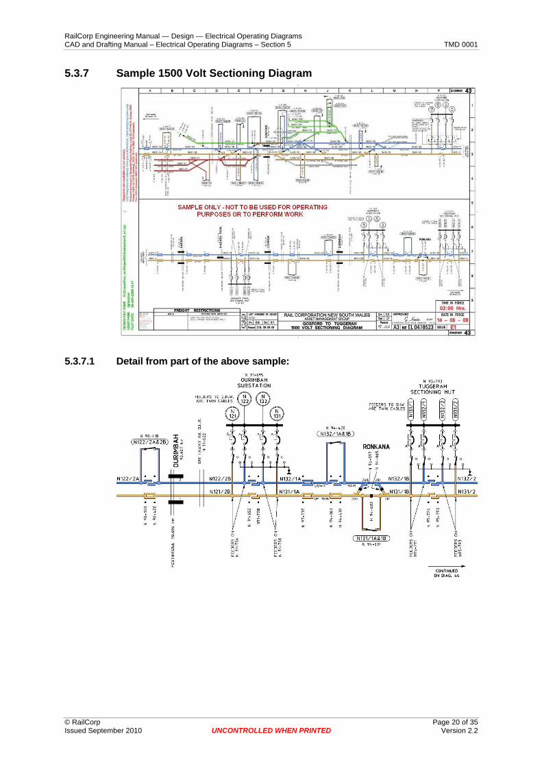
5.3.7 Sample 1500 Volt Sectioning Diagram
5.3.7.1 Detail from part of the above sample:
© RailCorp Page 20 of 35 Issued September 2010 UNCONTROLLED WHEN PRINTED Version 2.2

RailCorp Engineering Manual — Design — Electrical Operating Diagrams CAD and Drafting Manual – Electrical Operating Diagrams – Section 5 TMD 0001
5.3.7.1.1 Dimensions of common features used in 1500 volt sectioning diagrams:
5.4 AC & DC Substation Diagrams AC & DC Substation Diagrams are Black and White internal schematic diagrams of each of the substations. For each traction substation there is a separate diagram for the A.C. part and the D.C. part. In the case of large substations, such as Strathfield or Prince Alfred, the A.C. or D.C. part may be further split into two separate diagrams.
Substation Diagrams are drawn and plotted at 1:1. When creating a new drawing, use the seed file “OD_HVseed.dgn” for In-Force or “OD_HVseedP.dgn” for Proposed diagrams. The sheet model for these contains the appropriate drawing sheet border cell and calls up the design model at 1:1.
© RailCorp Page 21 of 35 Issued September 2010 UNCONTROLLED WHEN PRINTED Version 2.2

RailCorp Engineering Manual — Design — Electrical Operating Diagrams CAD and Drafting Manual – Electrical Operating Diagrams – Section 5 TMD 0001
© RailCorp Page 22 of 35 Issued September 2010 UNCONTROLLED WHEN PRINTED Version 2.2
The cell library "OD_HVlib.cel" is used, the cells are placed in the design file at 1:1. Most cell origins (where appropriate) have been placed at the centre of the cells and a snap point is provided at the origin.
5.4.1 Linework Note: The following discussion assumes that the Colour, Weight and Style of lines are all set to “ByLevel” where only a Level Name is given. Table 9 gives details of linework required for various common features in AC & DC Substation Diagrams.
FEATURE PLACED ON LEVEL Comments Main Conductors E-SUBS-COND-LARG-BLUE Lines representing feeders
and main power carrying conductors
Other Conductors E-SUBS-COND-MEDI-YELO Lines representing conductors going to auxiliary transformers, CTs or VTs, surge diverters or earth or rail connecting switches
Mechanical Interlocking E-SUBS-LINE-GANG Dashed lines representing mechanical interlocking between switches
Boundaries E-SUBS-LINE-BDRY Lines representing substation boundaries
Arrows and Table Borders etc.
E-TEXT-LINE-… Lines associated with text, such as arrows and table borders etc., are to be placed on an appropriate E-TEXT-LINE-… level
Other Solid Lines E-LINE-… Any other types of solid lines are to be placed on an appropriate E-LINE-… level (where ”…“ represents the line thickness)
Miscellaneous Lines E-LINE-MISC Any other non-standard lines are required they can be placed on the E-LINE-MISC level with their symbologies set to the required value instead of ByLevel
Table 9 - Details of Linework used in AC & DC Substation Diagrams
5.4.2 Colour When plotting Substation Diagrams a pen table is used which causes all elements to plot as black regardless of what colour they appear on screen. Elements are drawn with various colours on screen so that different features are easily distinguished while drawing. Exceptions are the shades of grey with colour numbers from 250 to 253, see Table 2 in Section 5.2.2.2 for further information.
5.4.3 Text Note: The following discussion assumes that the Colour, Weight and Style of text elements are all set to “ByLevel” where only a Level Name is given.
Text elements are to be placed on an appropriate E-TEXT-… level. Lines associated with text, such as arrows and table borders etc., are to be placed on an appropriate E-TEXT-LINE-… level.

RailCorp Engineering Manual — Design — Electrical Operating Diagrams CAD and Drafting Manual – Electrical Operating Diagrams – Section 5 TMD 0001
© RailCorp Page 23 of 35 Issued September 2010 UNCONTROLLED WHEN PRINTED Version 2.2
Text is generally in uppercase except where used for some metric units or abbreviations (e.g. mH, kVA). It is to be placed either horizontally or vertically such that the text is read from the bottom or the right hand side of the drawing.
Text is placed using Text Styles as per Section 5.2.3 above. Text Styles set the line spacing to a value appropriate for the text height.
The details of text used is as follows in Table 10. See also Section 5.2.1 regarding which model to place the various types of text in.
TEXT USED FOR
PLACED ON LEVEL
TEXT STYLE
NOTES
Control symbols E-TEXT-018 NS1.8 Right-centre justified (or centre-centre for horizontal switches)
Protection symbols E-TEXT-018 NS1.8 Left-centre justified (or centre-centre for horizontal switches)
Ratings E-TEXT-018 NS2.0 Ratings of transformers etc.
Feeder numbers E-TEXT-035 Arial3.5 Alternatively Block3.5 may be used
Feeder names E-TEXT-025 NS2.0
Busbar labels E-TEXT-035 Block3.5
Rectifier rating E-TEXT-025 Block3.0 Alternatively Block2.5 may be used
Notes E-TEXT-025 Arial2.5 Address and Phone Numbers etc.
Headings E-TEXT-025 Block2.5 Optional – for notes
Notes E-TEXT-025 NS2.0 Miscellaneous notes
Notes E-TEXT-025 NS1.8 Miscellaneous notes
Asterisk E-TEXT-035 (none) Font 1 or Font 0 , text size = 3.5mm
Diagram number E-TEXT-140 Block14.0 Right-top justified. DL=-5,-4 from corner. Normally only part of the border cell as an E.D. field.
Drawing Title E-TEXT-035 Bold3.5 Only use if E.D. fields in border cell will not accommodate title
Drawing number E-TEXT-050 Block5.0 Normally only part of the border cell as an E.D. field
Issue letter E-TEXT-COLR-RED Bold5.0 Normally part of border cell as an
E.D. field, but see note below.
Date in force E-TEXT-COLR-RED Bold4.0 Normally only part of the border cell
as E.D. fields
Time in force E-TEXT-COLR-RED Bold4.0 Normally only part of the “TIF_HV”
cell as E.D. fields Approved Signature E-TEXT-035 (none) 4.5mm Font 71 (Normally part of
border cell as an E.D. field)
Approved sig. Date E-TEXT-035 (none) 3.0mm Font 71 (Normally part of border cell as an E.D. field)
Approved sig. Title E-TEXT-025 NS1.8 Normally only part of the border cell as an E.D. field. (Centre-bottom justified, place 0.85mm above line.)
Advice number E-TEXT-025 NS2.0 Advice numbers where there are insufficient E.D. fields
Table 10 - Details of text used in AC & DC Substation Diagrams
NOTE: For example in issues after Z1, the issue letter needs to be made TW=4.5 (with TH=5.0) and the subscript number placed as another separate text element of TH=3.0 &

RailCorp Engineering Manual — Design — Electrical Operating Diagrams CAD and Drafting Manual – Electrical Operating Diagrams – Section 5 TMD 0001
© RailCorp Page 24 of 35 Issued September 2010 UNCONTROLLED WHEN PRINTED Version 2.2
TW=2.75 approximately. The Enter Data Field is to be filled in with a blank and the two new separate text elements are to be placed in the Sheet model over the top of it.
5.4.4 Cells A common cell library OD_HVlib.cel is used for all B&W diagrams. For a complete list of all cells used in B&W diagrams, including AC & DC Substation Diagrams, see the cell library OD_HVlib.cel.
5.4.4.1 General information on OD_HVlib.cel The following discussion applies to the OD_HVlib.cel library in general and will also be referred to in other sections about other types of B&W diagram:
• All cells used in B&W diagrams are to be placed Absolute.
• The cells are normally placed in the design file at 1:1.
• Cells should not be dropped except in exceptional circumstances.
• Most cell origins (where appropriate) have been placed at the centre of the cell and a snap point (being a Primary class element on the E-SNAP level) is provided at the origin in many cells.
• In some cells (e.g. filled squares representing closed CBs), a pair of diagonal lines are shown as well as fill, so that they will not appear to be open if the display of fill is turned off.
There are various sized Dot cells for general use in all types of diagrams. Each sized dot is available using three different representations which all have advantages and disadvantages. The ones named without the “b” or “p” suffixes, e.g. “Dot1.5”, should generally be used for the following reasons:
• You almost always want to snap to the centre of a dot but you have an 80% chance of getting the edge of a snappable circle.
• For the abovementioned reason the normal "Dot" cells are made up of non-snappable filled circles and are also provided with a unique snap point.
• Snappable font zero asterisks are used for the snap point because they are easier to snap to than Point elements.
The other two alternate representations of Dots are as follows:
• Dot cells with snappable Point elements. These are not recommended because they are hard to snap to. They are named with “p” suffixes.
• Dot cells with snappable Arial Black 'O's which show up better than font zero asterisks and are easy to snap to. However, these are only useful while Arial Black font is available and are therefore not recommended – these are named with “b” suffixes.
5.4.5 Placement Guidelines
5.4.5.1 AC and DC Diagrams in General To maintain consistency with GIS diagrams, and to enable a smooth transition, please refer also to the document "EOD Placement Guidelines" (EP0344) further to the guidelines below.
a) Switches to open in a clockwise / up / right direction.

RailCorp Engineering Manual — Design — Electrical Operating Diagrams CAD and Drafting Manual – Electrical Operating Diagrams – Section 5 TMD 0001
© RailCorp Page 25 of 35 Issued September 2010 UNCONTROLLED WHEN PRINTED Version 2.2
b) Order of circuit breakers to be as viewed when standing in front of them at the substation.
c) Diagram to include all equipment located within the substation boundary.
d) Spare cubicles to be shown only if connection to busbar.
e) Twin cables to be drawn as 2 parallel lines 2mm apart.
f) Rectifier rating to be in MW.
g) Protection and control symbols are shown on symbols sheet.
5.4.5.2 AC Diagrams a) Control symbols shown on left hand side.
b) Protection symbols shown on right hand side.
c) Supervisory control symbol to be shown adjacent to the rectifier OCB not the rectifier.
d) Earthing and vector diagram of transformers to be shown.
e) Addresses, where possible, are to reference street numbers such as ‘opposite’ or ‘adjacent’ to a house number. A street name is always required.
f) All protection (that trips a rectifier) is to be shown adjacent to the rectifier ACCB.
g) All protection which causes lockout of rectifier to be bracketed and shown ‘L/O’.
5.4.5.3 DC Diagrams a) Control symbols S and V to be drawn on the right side.
b) DCCB’s to show bus and/or feeder supply and auto reclose on bus or feeder side.
c) Supervisory control symbol to be shown adjacent to rectifier symbol.
d) Resonant shunt to be labelled as harmonic filter and frequencies to be shown.
e) Order of circuits off the control negative bus need not be in correct order.
f) Emergency / backup DCCB’s normally shown in open position. [ NOTE there are exceptions ]
g) Where the normal and emergency breakers are shown closed a ‘V’ should be shown adjacent both breakers.
h) Rectifier DCCB normal trip current direction is in the reverse direction. If forward direction indicate with an arrow.
i) Rectifier mH to be shown.

RailCorp Engineering Manual — Design — Electrical Operating Diagrams CAD and Drafting Manual – Electrical Operating Diagrams – Section 5 TMD 0001
5.4.6 Sample AC Substation Diagram
5.4.7 Sample DC Substation Diagram
© RailCorp Page 26 of 35 Issued September 2010 UNCONTROLLED WHEN PRINTED Version 2.2

RailCorp Engineering Manual — Design — Electrical Operating Diagrams CAD and Drafting Manual – Electrical Operating Diagrams – Section 5 TMD 0001
© RailCorp Page 27 of 35 Issued September 2010 UNCONTROLLED WHEN PRINTED Version 2.2
5.5 System and Reticulation Diagrams
5.5.1 System Diagrams – 11kV and 33kV System Diagrams are Black and White diagrams which show in detail the equipment fed off transmission lines between substations. Most are 11kV but there are some 33kV drawn to these same standards.
System Diagrams are drawn and plotted at 1:1. When creating a new drawing, use the seed file “OD_HVseed.dgn” for In-Force or “OD_HVseedP.dgn” for Proposed diagrams. The sheet model for these contains the appropriate drawing sheet border cell and calls up the design model at 1:1.
The cell library "OD_HVlib.cel" is used, the cells are placed in the design file at 1:1. Most cell origins (where appropriate) have been placed at the centre of the cells and a snap point is provided at the origin. See Section 5.4.5.1 for a complete list of cells in OD_HVlib.cel.
5.5.2 Linework used in System Diagrams Note: The following discussion assumes that the Colour, Weight and Style of lines are all set to “ByLevel” where only a Level Name is given.
The following table gives details required for various common features:
FEATURE PLACED ON LEVEL Comments
Feeders – generic E-LINE-050 Inside S.S. boxes
Aerial Feeders E-SYRT-FEED-AERL Outside of S.S. boxes
Pole E-SYRT-FEED-POLE Normally only part of cell Lead from Feeder to S.D. E-LINE-035 Also feeders to earth etc. in
S.S. Ellipse - common pole line E-LINE-018 ≈2.5mm by ≈7.5mm
Cable Feeders E-SYRT-FEED-CABL Outside of S.S. boxes Underground cable symbol E-SYRT-FEED-UGCS Normally only part of cell
Pegline cable trough peg E-SYRT-FEED-TPEG Normally only part of cell
S.S. Building Box E-SYRT-SUBS-LINE-BILD Normally only part of cell
Padmount Box E-SYRT-SUBS-LINE-PADM Drawn as rectangle, size as required
Backup arrow line E-SYRT-SUBS-LINE-BAKP (was also for P.S.I.) Low Voltage connections E-LINE-025
Dashed line switch gang E-SYRT-SUBS-LINE-GANG
Track "centreline" * E-SYRT-TRAK-LINE * may also be used for sleepers
Track "sleepers" E-SYRT-TRAK-SLEP If separate from track, at 1.5mm spacing
Track - station platform E-SYRT-TRAK-PLAT Normally only part of cell
Overline Bridge E-LINE-018

RailCorp Engineering Manual — Design — Electrical Operating Diagrams CAD and Drafting Manual – Electrical Operating Diagrams – Section 5 TMD 0001
© RailCorp Page 28 of 35 Issued September 2010 UNCONTROLLED WHEN PRINTED Version 2.2
FEATURE PLACED ON LEVEL Comments
River or creek bank E-SYRT-CROS-RIVR-BANK
River or creek water E-SYRT-CROS-RIVR-WATR
Continuation brace E-TEXT-LINE-018
Table 11 - Details of Linework used in System Diagrams
Lines associated with text, such as arrows and table borders etc., are to be placed on an appropriate E-TEXT-LINE-… level. Any other types of solid lines not listed in the table above are to be placed on an appropriate E-LINE-… level. If any other non-standard lines are required they can be placed on the E-LINE-MISC level with their symbologies set to the required value instead of ByLevel.
5.5.3 Colour When plotting System and Reticulation Diagrams, a pen table is used which causes all elements to plot as black regardless of what colour they appear on screen. Elements are drawn with various colours on screen so that different features are easily distinguished while drawing. Exceptions are the shades of grey with colour numbers from 250 to 253, see Table 2 in Section 5.2.2.2 for further information.
5.5.4 Text used in System Diagrams Note: The following discussion assumes that the Colour, Weight and Style of text elements are all set to “ByLevel” where only a Level Name is given.
Text elements are to be placed on an appropriate E-TEXT-… level. Lines associated with text, such as arrows and table borders etc., are to be placed on an appropriate E-TEXT-LINE-… level.
Text is generally in uppercase except where used for some metric units or abbreviations (e.g. mH, kVA). It is to be placed either horizontally or vertically such that the text is read from the bottom or the right hand side of the drawing.
Text is placed using Text Styles as per Section 5.2.3 above. Text Styles set the line spacing to a value appropriate for the text height.
The details of text used is as follows in Table 10. See also Section 5.2.1 regarding which model to place the various types of text in.
TEXT USED FOR
PLACED ON LEVEL
TEXT STYLE
NOTES
Feeder number text E-TEXT-018 (none)
2.0mm Font 103 centre-bottom justified and placed 0.85mm above line. (Alternatively use Block2.0 style)
Substation name text E-TEXT-018 Block1.8 Centre-centre justified.
Substation Diag. No. text E-TEXT-018 Block4.0 Normally part of “SUBSTN” cell as
an E.D. field.
L.V. supply name text E-TEXT-025 NS1.8 Justify as appropriate.
Pole number text E-TEXT-025 NS1.8 Centre-centre justified.
Substation kilometrage E-TEXT-025 NS1.8 Centre-centre justified.

RailCorp Engineering Manual — Design — Electrical Operating Diagrams CAD and Drafting Manual – Electrical Operating Diagrams – Section 5 TMD 0001
© RailCorp Page 29 of 35 Issued September 2010 UNCONTROLLED WHEN PRINTED Version 2.2
TEXT USED FOR
PLACED ON LEVEL
TEXT STYLE
NOTES
Transformer rating text E-TEXT-018 NS1.5 Left-centre justified
Protection symbol text E-TEXT-018 NS1.5 Left-centre justified
C.B. control symbol text E-TEXT-018 NS1.5 Right-centre justified
Rly. station name text E-TEXT-025 NS1.8 Centre-centre justified.
Rly. station kilometrage E-TEXT-018 NS1.5 Centre-centre justified.
Street names E-TEXT-018 NS1.5 Left-centre justified
Continued note text E-TEXT-025 NS1.8 Justify as appropriate.
Note text - small E-TEXT-018 NS1.5 May be left-centre justified if required
Note text - medium E-TEXT-025 NS1.8 May be left-centre justified if required
Note text - large E-TEXT-025 Block2.5 May be left-centre justified if required
Diagram number text E-TEXT-140 Block14.0 Normally part of border cell as an E.D. field. (Right-top justified. DL=-5,-4 from corner.)
Drawing Title text E-TEXT-035 Bold3.5
Normally part of border cell as an E.D. field. If title won’t fit then adjust text width if required and place 0.25mm above centre to compensate for font and border lines.
Drawing number text E-TEXT-050 Block5.0 Normally part of border cell as an E.D. field. (1.15mm above line, centre-bottom justified.
Issue letter text E-TEXT-COLR-RED Bold5.0
See note below the Substation text table in Section 4.4.3 (Table 8). Normally part of border cell as an E.D. field.
Date In Force text E-TEXT-COLR-RED Bold4.0
Five text elements at 5mm centres. Normally only part of the border cell as E.D. fields.
Time in force E-TEXT-COLR-RED Bold4.0 Normally only part of the “TIF_HV”
cell as E.D. fields
Approved Signature E-TEXT-035 (none) 4.5mm Font 71 (Normally part of border cell as an E.D. field)
Approved sig. Date E-TEXT-035 (none) 3.0mm Font 71 (Normally part of border cell as an E.D. field)
Approved sig. Title E-TEXT-025 NS1.8
Normally only part of the border cell as an E.D. field. (Centre-bottom justified, place 0.85mm above line.)
Advice Number for this amendment E-TEXT-025 NS2.0
Advice numbers where there are insufficient E.D. fields Left-centre justified, place DL=2,3 from corner
Table 12 - Details of text used in System Diagrams
5.5.5 Placement Guidelines for System Diagrams The flow of diagrams should be left to right, top to bottom. Sydney is normally on the left.
Only feeders of one voltage should be included on one diagram, but where other transmission lines not shown on the diagram occupy the same pole line a note should be added stating this.

RailCorp Engineering Manual — Design — Electrical Operating Diagrams CAD and Drafting Manual – Electrical Operating Diagrams – Section 5 TMD 0001
© RailCorp Page 30 of 35 Issued September 2010 UNCONTROLLED WHEN PRINTED Version 2.2
Feeders are drawn straight with the track bent around to show whether the feeder is on the Up or Down side of the track.
It is not necessary to show overline bridges in future, however they may remain on existing drawings where they cross aerial transmission lines.
Pole numbers are to be shown at each substation and each track crossing.
Low voltage equipment is not to be shown, but a simplified sketch should be drawn to show what is being fed. NOTE: Where a backfeed is possible via the low voltage, some detail should be provided and a note added.
Power supply indicators are to be listed in tabular form.
System substations (or those in brick buildings) are to be indicated by surrounding the equipment with a drop box / shadow block.
Pad mounted substations are to be indicated by surrounding the equipment with a dashed box.
Pole mounted substations are not to be surrounded by a box.
5.5.5.1 Substations Drawn In Abbreviated Form Substations which have more than one bus section, or which take up too much space on a system diagram, should be drawn as a separate AC substation diagram. Substations which have been drawn in the AC diagram series should be drawn in abbreviated form on the system diagrams using the “SUBSTN” cell as follows:
Circuit breakers are to be shown only for feeders and bus sections. They are to be shown as a 2mm square; empty for open, infilled for closed, using the cells “SysCBopen” and “SysCBclosed”.
Control symbols are to be shown to the left of feeder circuit breakers.
Protection symbols are to be shown to the right of feeder circuit breakers.
Transformers which supply the 11kV bus from a higher voltage are to be shown above the bus as small transformers symbols without any C.B.s or ratings.
Any other feeds off the 11kV bus, including feeders which are continued on other diagrams, are to be shown as un-labelled stubs below the bus.
All connections to the bus are to be shown in order (as in AC diagrams).
Feeders may have to be drawn crossing each other as they enter a substation to meet this requirement.
Bus section numbers may be shown as #1 , #2 etc.
Inside the box around the S.S., the diagram number for the S.S. is to be shown in the upper right hand corner and the S.S. name is to be shown to the left of the diagram number. The phone numbers of the substation are to be shown below the S.S. name.

RailCorp Engineering Manual — Design — Electrical Operating Diagrams CAD and Drafting Manual – Electrical Operating Diagrams – Section 5 TMD 0001
5.5.6 Sample System Diagram
5.5.6.1 Detail from part of the above sample:
5.5.7 Reticulation Diagrams Reticulation Diagrams are similar to System Diagrams and are drawn to the same standards but with the following differences:
Reticulation Diagrams are geographical rather than electrical schematics. North is at the top of the page instead of Sydney being at the left.
© RailCorp Page 31 of 35 Issued September 2010 UNCONTROLLED WHEN PRINTED Version 2.2

RailCorp Engineering Manual — Design — Electrical Operating Diagrams CAD and Drafting Manual – Electrical Operating Diagrams – Section 5 TMD 0001
Reticulation Diagrams cover a larger area and do not show all minor S.S.’s.
Tracks are shown as a plain thin line without “sleepers”.
Feeders bend around tracks rather than tracks bending around feeders.
Text is generally smaller in Reticulation Diagrams and is not necessarily placed exactly horizontally or vertically (although it is to be placed such that it is read from the bottom or the right hand side of the drawing). Names of electrical substations are shown in all uppercase however names of railway stations are shown in title case (i.e. mixed upper and lower case).
5.5.8 Sample Reticulation Diagram
© RailCorp Page 32 of 35 Issued September 2010 UNCONTROLLED WHEN PRINTED Version 2.2

RailCorp Engineering Manual — Design — Electrical Operating Diagrams CAD and Drafting Manual – Electrical Operating Diagrams – Section 5 TMD 0001
5.5.8.1 Detail from part of the above sample:
5.6 Reference Sheets There are a number of drawings (which are referred to as sheets as opposed to diagrams) such as indexes, key maps and legends which have unique features and are drawn to ad-hoc standards. Whenever modifying a Reference Sheet, use the standards that the rest of that drawing are already drawn to, or standards compatible with the three main drawing types described above.
5.6.1 Key Maps for System Diagrams Key Maps for System Diagrams are one type of Reference Sheet which will be mentioned here because there are several of them and they are amended more frequently. They also use special MultiLines and pale coloured highlighting.
The MultiLines are used to highlight sections of feeder and are of MultiLine Style Highlight-300-500. They are placed on any one of four special levels. They take on the pale ByLevel colour assigned to that level as their fill colour. The four levels used are E-HILI-BLUE, E-HILI-GREN, E-HILI-RED, and E-HILI-BYEL.
The only other unique features used in Key Maps for System Diagrams are the highlighting blocks placed as a background to the diagram reference numbers. These are normal rectangles placed using the “Place Block” command, with their fill type set to opaque and their fill colour set to ByLevel. They are placed on the same levels as the MultiLines mentioned above.
When plotting Key Maps for System Diagrams, a pen table is used which sets the Priority of the pale highlighting levels to a lower value than the linework and text. This ensures that the highlighting appears as a background to the other elements instead of obscuring them, regardless of how they appear on screen.
© RailCorp Page 33 of 35 Issued September 2010 UNCONTROLLED WHEN PRINTED Version 2.2

RailCorp Engineering Manual — Design — Electrical Operating Diagrams CAD and Drafting Manual – Electrical Operating Diagrams – Section 5 TMD 0001
© RailCorp Page 34 of 35 Issued September 2010 UNCONTROLLED WHEN PRINTED Version 2.2
5.7 Hybrid Files These are produced when a manual drawing is initially converted to CAD. In subsequent issues of the CAD diagram, raster graphics are progressively erased and CAD vector elements are drawn in their place.
The manual drawings are scanned at a resolution which will result in a 600 dots per inch A3 drawing when reduced. (For example, imperial D sheets are scanned at 508 dpi.) The raster border is discarded and the resultant image is cropped so that it is either 9448×6685 or 9456×6690 pixels. This image is then saved in a high compression monochrome format. The file name must be in accordance with the design file naming conventions specified in Section 5.9 below, including the issue letter (or letter and number), except that the extension “.dgn” is replaced with the extension appropriate to the raster file type.
In CAD, the raster file is then attached to the design file using File → Raster Manager then File → Attach… and data points are given by snapping to the bottom left and top right of the dotted purple rectangle. This rectangle (which is part of the seed file) is designed to keep the raster aligned accurately with the vector elements which will be drawn in the design file. The rectangle is the same aspect ratio as the raster reference file specified above and coincides with the margin of the drawing sheet. The “tail” at the bottom left of the rectangle extends to the origin (0,0) which coincides with the bottom left of the A3 drawing sheet. The border cell in the Sheet model replaces the scanned raster border. Signatures scanned as part of the raster file may need to be moved (within the raster file) if the layout of the title block is different. Alternatively, if legible, they may be typed into the border cell enter data fields as in normal full vector files. The sample Reticulation Diagram 103 in Section 5.5.8 above is also an example of a hybrid diagram.
It is important to keep a raster file with every Hybrid CAD design file when archiving. When starting an amended issue, the issue letters in both copied files must be incremented so that they match for every issue of the diagram. The filename of the referenced file in Raster Manager must also be incremented.
5.8 Reference Files Reference files (other than rasters) are not used as any part of the content of Electrical Operating Diagrams, including the drawing sheet borders. See Section 5.2.1 regarding the use of cells as borders.
Other design files may be attached temporarily as reference files for the purpose of copying content out of them but must be either detached or have their display turned off when the copying operation is complete.
5.9 File Naming Conventions The following design file naming conventions are used within RailCorp and it is recommended that external contractors also adopt the same conventions when transferring files to RailCorp.
Note that if a file is NOT an official controlled document, either in-force or proposed, then it must NOT be named using the conventions shown below.
5.10 In-force Diagram Conventions File names of In-force diagrams have the following format:
A two letter prefix, a two to four character diagram number, an underbar, the issue letter or letter and number, ".dgn".

RailCorp Engineering Manual — Design — Electrical Operating Diagrams CAD and Drafting Manual – Electrical Operating Diagrams – Section 5 TMD 0001
© RailCorp Page 35 of 35 Issued September 2010 UNCONTROLLED WHEN PRINTED Version 2.2
Prefixes are as follows:
se 1500 volt sectioning diagrams
ac AC substation diagrams
dc DC substation diagrams
sy System diagrams
rt Reticulation diagrams
ct Contingencies diagrams
The diagram number in file names is padded with a single leading zero for diagrams 1 to 9 only. Single letter sheet names are padded with a leading underbar. Two and three digit diagram numbers are not padded with zeroes. The 'A' suffix in DC substation diagram numbers is omitted, the prefix "dc" is used to indicate that they are DC and not AC. For low voltage AC diagrams the suffix 'B' or 'C' is retained however.
Examples:
The second issue of sectioning diagram 3 would be se03_b.dgn
The 230th issue of DC SS diagram 175A would be dc175_z9.dgn
Note that issues I , O and Q are not used. For example the next issue after H is J, and the next issue after P9 is R9.
5.10.1 Proposed Diagram Conventions File names of Proposed diagrams have the following format:
The two letter prefix "EL", a seven digit EDMS number padded with leading zeroes, an underbar, the issue letter or letter and number, ".dgn".
For example the sixteenth issue of the Proposed E.C.R.L. 1500 Volt Sectioning Diagram was named “EL0189486_S.dgn”.
Note that blank spaces are not used anywhere in any diagram file names.