tms340 interface user's guide' - texas instruments preface read this first how to use this...
TRANSCRIPT

Interface
User’s Guide
Computer Video ProductsSeptember 1990

SPVU015CSeptember 1990
Printed on Recycled Paper
InterfaceUser’s Guide

Copyright 1991, Texas Instruments Incorporated
IMPORTANT NOTICE
Texas Instruments (TI) reserves the right to make changes to or to discontinue any semiconduc-tor product or service identified in this publication without notice. TI advises its customers to ob-tain the latest version of the relevant information to verify, before placing orders, that the informa-tion being relied upon is current.
TI warrants performance of its semiconductor products to current specifications in accordancewith TI’s standard warranty. Testing and other quality control techniques are utilized to the extentTI deems necessary to support this warranty. Unless mandated by government requirements,specific testing of all parameters of each device is not necessarily performed.
TI assumes no liability for TI applications assistance, customer product design, software per-formance, or infringement of patents or services described herein. Nor does TI warrant or repre-sent that license, either express or implied, is granted under any patent right, copyright, maskwork right, or other intellectual property right of TI covering or relating to any combination, ma-chine, or process in which such semiconductor products or services might be or are used.
Texas Instruments products are not intended for use in life-support appliances, devices, or sys-tems. Use of a TI product in such applications without the written consent of the appropriate TIofficer is prohibited.

iii
Preface
Read This First
How to Use This Manual
This document contains the following chapters:
Chapter 1 IntroductionIntroduces the TIGA Interface, its features and architecture.
Chapter 2 Getting StartedContains instructions to install TIGA on a PC and to run a demonstration pro-gram.
Chapter 3 Application InterfaceDescribes the application interface and lists all TIGA functions by functionalgroup.
Chapter 4 Core FunctionsDescribes the core functions alphabetically, showing the syntax and argu-ments of each function, a detailed description, and programming examples orreferences to related functions.
Chapter 5 Extended Graphics Library FunctionsDescribes the extended functions contained in the TIGA graphics library,showing the syntax and arguments of each function, a detailed description,and programming examples or references to related functions.
Chapter 6 Graphics Library ConventionsDescribes the assumptions made and conventions adopted regarding coordi-nate systems, mapping of pixels to coordinates, operations on pixels, clipping,and the geometric figures and rendering styles supported by TIGA.
Chapter 7 Bit-Mapped TextDescribes the text capabilities of TIGA, the types of fonts supported, and theinternal structure of the database for each font; gives an alphabetical listing ofthe available fonts with illustrations.
Chapter 8 ExtensibilityDescribes how to extend TIGA by adding your own functions; also describesthe command processing entry points of the communication driver.

How to Use This Manual/Related Documentation
iv Read This First
Appendix A Data StructuresDescribes the data structures used in TIGA.
Appendix B TIGA Reserved SymbolsDescribes the function names reserved for internal use of TIGA.
Appendix C Debugger Support for TIGADescribes TIGA debugger support functions.
Appendix D Error Messages / Error CodesContains a list of error codes and messages returned by TIGA.
Appendix E GlossaryContains the definitions of TIGA-specific and TIGA-related terms and acro-nyms.
Related Documentation
The following documents are available from Texas Instruments:
TMS34010 User’s Guide (literature number SPVU001).
Describes the internal architecture, hardware interfaces, programmableregisters, and instruction set of the TMS34010 32-bit graphics processorchip.
TMS34020 User’s Guide (literature number SPVU019).
Describes the internal architecture, hardware interfaces, programmableregisters, and instruction set of the TMS34020 32-bit graphics processorchip.
TMS340 Family Code Generation Tools User’s Guide (literature numberSPVU020).
Describes the C compiler, assembler, linker, and archiver for theTMS340x0 graphics system processors.
To obtain any of TI’s product literature listed above, please contact the TexasInstruments Customer Response Center at toll-free telephone number(800) 336-5236, or at (214) 995-6611 if you are calling from outside the USand Canada.

Related Documentation/Style and Symbol Conventions
v
You may also find the following documentation useful:
Kernighan, Brian, and Dennis Ritchie. The C Programming Language.Second Edition. Englewood Cliffs, New Jersey: Prentice-Hall, 1988.
Kochan, Stephen G. Programming in C. Hasbrouck Heights, New Jersey:Hayden Book Company, 1983.
Sobelman, Gerald E., and David E. Krekelberg. Advanced C: Techniquesand Applications. Indianapolis, Indiana: Que Corporation, 1985.
Style and Symbol Conventions
This document uses the following conventions:
TIGA functions and their parameters are shown in italic face in regulartext. For example, the TIGA function draw_line has parameters x1, y1, x2,y2. Filenames (example: tigalnk.exe) are also shown in italic face..Program examples and interactive display examples are shown in mono-spaced program font. Here is an example program:
#include <tiga.h>
main(){
short module;
/*–––––––––––––––––––––––––––––––––––––––––––––––––––––––– *//* Initialize TIGA *//*–––––––––––––––––––––––––––––––––––––––––––––––––––––––– */if (tiga_set(CD_OPEN) < 0){
printf(”CD initialization error\n”);exit(0);
}
if(!set_videomode(TIGA,INIT)){
printf(”TIGA GM initialization error\n”);tiga_set(CD_CLOSE);exit(0);
}/*–––––––––––––––––––––––––––––––––––––––––––––––––––––––– *//* Attempt to install module *//*–––––––––––––––––––––––––––––––––––––––––––––––––––––––– */if ((module=install_rlm(”EXAMPLE”)) < 0){
printf(”Error %d installing EXAMPLE rlm\n”, module);exit_tiga();
}/*–––––––––––––––––––––––––––––––––––––––––––––––––––––––– *//* Main body of application appears here *//*–––––––––––––––––––––––––––––––––––––––––––––––––––––––– */
::

Style and Symbol Conventions
vi Read This First
/*–––––––––––––––––––––––––––––––––––––––––––––––––––––––– *//* Terminate TIGA *//*–––––––––––––––––––––––––––––––––––––––––––––––––––––––– */exit_tiga();
}
exit_tiga(){
set_videomode(PREVIOUS, INIT);tiga_set(CD_CLOSE);exit(0);
}
In syntax descriptions, the instruction, command, or directive is in a boldface font with parameters in italic face. Portions of a syntax in bold face(including quote marks) should be entered as shown. Portions of a syntaxin italic face describe the type of information that you provide. Squarebrackets identify optional information:
mg2tiga MG font TIGA font [ ” facename” ]
Italic face is also used to emphasize a word or phrase that may be impor-tant or that is being defined or used for the first time in a chapter.

Trademarks
vii
Trademarks
DGIS is a trademark of Graphic Software Systems, Inc.
GEM is a trademark of Digital Research, Inc.
GSS*CGI is a trademark of Graphic Software Systems, Inc.
High C and Metaware are trademarks of MetaWare Incorporated.
MS-Windows, PM, MS-DOS, and CodeView are trademarks of Microsoft Corp.
NDP C-386 and MicroWay are trademarks of Microway, Inc.
Phar Lap, 386|DOS-Extender, and 386|VMM are trademarks of Phar Lap Software, Inc.
PC-DOS and PGA are trademarks of IBM Corp.
TIGA is a trademark of Texas Instruments Incorporated.

viii Read This First

ix
Contents
1 Introduction 1-1. . . . . . . . . . . . . . . . . . . . . . . . . . . . . . . . . . . . . . . . . . . . . . . . . . . . . . . . . . . . . . . . . . . . . 1.1 Features 1-2. . . . . . . . . . . . . . . . . . . . . . . . . . . . . . . . . . . . . . . . . . . . . . . . . . . . . . . . . . . . . . . . . . 1.2 Architecture 1-3. . . . . . . . . . . . . . . . . . . . . . . . . . . . . . . . . . . . . . . . . . . . . . . . . . . . . . . . . . . . . . . . 1.3 Extensibility 1-5. . . . . . . . . . . . . . . . . . . . . . . . . . . . . . . . . . . . . . . . . . . . . . . . . . . . . . . . . . . . . . . .
2 Getting Started 2-1. . . . . . . . . . . . . . . . . . . . . . . . . . . . . . . . . . . . . . . . . . . . . . . . . . . . . . . . . . . . . . . . . . 2.1 TMS340 Development Products 2-2. . . . . . . . . . . . . . . . . . . . . . . . . . . . . . . . . . . . . . . . . . . . . . 2.2 System Requirements 2-3. . . . . . . . . . . . . . . . . . . . . . . . . . . . . . . . . . . . . . . . . . . . . . . . . . . . . . .
2.2.1 TIGA Driver Development Package (TIGA-DDP) and TIGA SoftwareDevelopment Package (TIGA-SDP) 2-3. . . . . . . . . . . . . . . . . . . . . . . . . . . . . . . . . . . .
2.2.2 TIGA Software Porting Package (TIGA-SPP) 2-3. . . . . . . . . . . . . . . . . . . . . . . . . . . . 2.3 Installing TIGA on Your System 2-4. . . . . . . . . . . . . . . . . . . . . . . . . . . . . . . . . . . . . . . . . . . . . . .
2.3.1 TIGA Driver Development Package (TIGA-DDP) Subdirectories 2-5. . . . . . . . . . . 2.3.2 TIGA Software Development Package (TIGA-SDP) Subdirectories 2-5. . . . . . . . . 2.3.3 TIGA Software Porting Package (TIGA-SPP) Subdirectories 2-5. . . . . . . . . . . . . .
2.4 Modifying Autoexec and the Environment 2-7. . . . . . . . . . . . . . . . . . . . . . . . . . . . . . . . . . . . . . 2.5 The TIGA Environment Variable 2-8. . . . . . . . . . . . . . . . . . . . . . . . . . . . . . . . . . . . . . . . . . . . . . 2.6 Running the TIGA Driver 2-9. . . . . . . . . . . . . . . . . . . . . . . . . . . . . . . . . . . . . . . . . . . . . . . . . . . . 2.7 TIGA Utility Programs 2-10. . . . . . . . . . . . . . . . . . . . . . . . . . . . . . . . . . . . . . . . . . . . . . . . . . . . . .
2.7.1 cltiga Batch File 2-10. . . . . . . . . . . . . . . . . . . . . . . . . . . . . . . . . . . . . . . . . . . . . . . . . . . . 2.7.2 mg2tiga Utility 2-11. . . . . . . . . . . . . . . . . . . . . . . . . . . . . . . . . . . . . . . . . . . . . . . . . . . . . .
2.8 Rebuilding Existing TIGA Applications for TIGA 2.0 2-13. . . . . . . . . . . . . . . . . . . . . . . . . . . . 2.8.1 TIGA 2.0 Initialization / Termination 2-13. . . . . . . . . . . . . . . . . . . . . . . . . . . . . . . . . . . 2.8.2 CURSOR Structure Change 2-13. . . . . . . . . . . . . . . . . . . . . . . . . . . . . . . . . . . . . . . . . 2.8.3 Return Value of set_config 2-14. . . . . . . . . . . . . . . . . . . . . . . . . . . . . . . . . . . . . . . . . . . 2.8.4 Elimination of Offscreen Workspace 2-15. . . . . . . . . . . . . . . . . . . . . . . . . . . . . . . . . . 2.8.5 TIGA 1.1 Functions No Longer Supported 2-15. . . . . . . . . . . . . . . . . . . . . . . . . . . . . 2.8.6 New Functions Available in TIGA 2.0 2-15. . . . . . . . . . . . . . . . . . . . . . . . . . . . . . . . . . 2.8.7 Functional Differences in TIGA 2.0 2-15. . . . . . . . . . . . . . . . . . . . . . . . . . . . . . . . . . . .
3 Application Interface 3-1. . . . . . . . . . . . . . . . . . . . . . . . . . . . . . . . . . . . . . . . . . . . . . . . . . . . . . . . . . . . . 3.1 Supported Development Tools 3-2. . . . . . . . . . . . . . . . . . . . . . . . . . . . . . . . . . . . . . . . . . . . . . . .
3.1.1 Host-PC Development Tools 3-2. . . . . . . . . . . . . . . . . . . . . . . . . . . . . . . . . . . . . . . . . . 3.1.2 TMS340 Development Tools 3-2. . . . . . . . . . . . . . . . . . . . . . . . . . . . . . . . . . . . . . . . . .
3.2 Host-PC Include Files and Libraries 3-3. . . . . . . . . . . . . . . . . . . . . . . . . . . . . . . . . . . . . . . . . . . 3.3 TMS340 Include Files and Libraries 3-5. . . . . . . . . . . . . . . . . . . . . . . . . . . . . . . . . . . . . . . . . . .

Contents
x Table of Contents
3.4 Sample TIGA Application 3-6. . . . . . . . . . . . . . . . . . . . . . . . . . . . . . . . . . . . . . . . . . . . . . . . . . . . 3.5 TIGA Functions 3-9. . . . . . . . . . . . . . . . . . . . . . . . . . . . . . . . . . . . . . . . . . . . . . . . . . . . . . . . . . . .
3.5.1 Core Functions 3-9. . . . . . . . . . . . . . . . . . . . . . . . . . . . . . . . . . . . . . . . . . . . . . . . . . . . . . 3.5.2 Extended Functions 3-9. . . . . . . . . . . . . . . . . . . . . . . . . . . . . . . . . . . . . . . . . . . . . . . . . .
3.6 Summary of Functions by Functional Group 3-10. . . . . . . . . . . . . . . . . . . . . . . . . . . . . . . . . . . 3.6.1 Graphics System Initialization Functions 3-10. . . . . . . . . . . . . . . . . . . . . . . . . . . . . . . 3.6.2 Clear Functions 3-10. . . . . . . . . . . . . . . . . . . . . . . . . . . . . . . . . . . . . . . . . . . . . . . . . . . . 3.6.3 Graphics Attribute Control Functions 3-11. . . . . . . . . . . . . . . . . . . . . . . . . . . . . . . . . . 3.6.4 Palette Functions 3-12. . . . . . . . . . . . . . . . . . . . . . . . . . . . . . . . . . . . . . . . . . . . . . . . . . . 3.6.5 Graphics Drawing Functions 3-12. . . . . . . . . . . . . . . . . . . . . . . . . . . . . . . . . . . . . . . . . 3.6.6 Poly Drawing Functions 3-13. . . . . . . . . . . . . . . . . . . . . . . . . . . . . . . . . . . . . . . . . . . . . 3.6.7 Pixel Array Functions 3-14. . . . . . . . . . . . . . . . . . . . . . . . . . . . . . . . . . . . . . . . . . . . . . . 3.6.8 Text Functions 3-15. . . . . . . . . . . . . . . . . . . . . . . . . . . . . . . . . . . . . . . . . . . . . . . . . . . . . 3.6.9 Graphics Cursor Functions 3-15. . . . . . . . . . . . . . . . . . . . . . . . . . . . . . . . . . . . . . . . . . 3.6.10 Graphics Utility Functions 3-16. . . . . . . . . . . . . . . . . . . . . . . . . . . . . . . . . . . . . . . . . . . . 3.6.11 Handle-Based Memory Management Functions 3-16. . . . . . . . . . . . . . . . . . . . . . . . 3.6.12 Pointer-Based Memory Management Functions 3-17. . . . . . . . . . . . . . . . . . . . . . . . 3.6.13 Data Input/Output Functions 3-18. . . . . . . . . . . . . . . . . . . . . . . . . . . . . . . . . . . . . . . . . 3.6.14 Extensibility Functions 3-18. . . . . . . . . . . . . . . . . . . . . . . . . . . . . . . . . . . . . . . . . . . . . . 3.6.15 Interrupt Handler Functions 3-19. . . . . . . . . . . . . . . . . . . . . . . . . . . . . . . . . . . . . . . . . .
4 Core Functions 4-1. . . . . . . . . . . . . . . . . . . . . . . . . . . . . . . . . . . . . . . . . . . . . . . . . . . . . . . . . . . . . . . . . . 4.1 Core Functions Reference 4-2. . . . . . . . . . . . . . . . . . . . . . . . . . . . . . . . . . . . . . . . . . . . . . . . . . .
5 Extended Graphics Library Functions 5-1. . . . . . . . . . . . . . . . . . . . . . . . . . . . . . . . . . . . . . . . . . . . . 5.1 Extended Graphics Library Functions 5-2. . . . . . . . . . . . . . . . . . . . . . . . . . . . . . . . . . . . . . . . .
6 Graphics Library Conventions 6-1. . . . . . . . . . . . . . . . . . . . . . . . . . . . . . . . . . . . . . . . . . . . . . . . . . . . 6.1 Graphics Library Function Naming Conventions 6-2. . . . . . . . . . . . . . . . . . . . . . . . . . . . . . . . 6.2 Coordinate Systems 6-4. . . . . . . . . . . . . . . . . . . . . . . . . . . . . . . . . . . . . . . . . . . . . . . . . . . . . . . . 6.3 Area-Filling Conventions 6-6. . . . . . . . . . . . . . . . . . . . . . . . . . . . . . . . . . . . . . . . . . . . . . . . . . . . . 6.4 Vector-Drawing Conventions 6-8. . . . . . . . . . . . . . . . . . . . . . . . . . . . . . . . . . . . . . . . . . . . . . . . . 6.5 Rectangular Drawing Pen 6-10. . . . . . . . . . . . . . . . . . . . . . . . . . . . . . . . . . . . . . . . . . . . . . . . . . . 6.6 Area-Fill Patterns 6-12. . . . . . . . . . . . . . . . . . . . . . . . . . . . . . . . . . . . . . . . . . . . . . . . . . . . . . . . . . 6.7 Line-Style Patterns 6-13. . . . . . . . . . . . . . . . . . . . . . . . . . . . . . . . . . . . . . . . . . . . . . . . . . . . . . . . 6.8 Operations on Pixels 6-15. . . . . . . . . . . . . . . . . . . . . . . . . . . . . . . . . . . . . . . . . . . . . . . . . . . . . . .
6.8.1 Transparency 6-15. . . . . . . . . . . . . . . . . . . . . . . . . . . . . . . . . . . . . . . . . . . . . . . . . . . . . . 6.8.2 Plane Mask 6-16. . . . . . . . . . . . . . . . . . . . . . . . . . . . . . . . . . . . . . . . . . . . . . . . . . . . . . . . 6.8.3 Pixel-Processing Operations 6-16. . . . . . . . . . . . . . . . . . . . . . . . . . . . . . . . . . . . . . . . .
6.9 Clipping Window 6-18. . . . . . . . . . . . . . . . . . . . . . . . . . . . . . . . . . . . . . . . . . . . . . . . . . . . . . . . . . . 6.10 Pixel-Size Independence 6-19. . . . . . . . . . . . . . . . . . . . . . . . . . . . . . . . . . . . . . . . . . . . . . . . . . .
7 Bit-Mapped Text 7-1. . . . . . . . . . . . . . . . . . . . . . . . . . . . . . . . . . . . . . . . . . . . . . . . . . . . . . . . . . . . . . . . . 7.1 Bit-Mapped Font Parameters 7-2. . . . . . . . . . . . . . . . . . . . . . . . . . . . . . . . . . . . . . . . . . . . . . . . . 7.2 Font Data Structure 7-5. . . . . . . . . . . . . . . . . . . . . . . . . . . . . . . . . . . . . . . . . . . . . . . . . . . . . . . . .

Contents
xi
7.2.1 Font Header Information 7-5. . . . . . . . . . . . . . . . . . . . . . . . . . . . . . . . . . . . . . . . . . . . . 7.2.2 Font Pattern Table 7-8. . . . . . . . . . . . . . . . . . . . . . . . . . . . . . . . . . . . . . . . . . . . . . . . . . . 7.2.3 Location Table 7-10. . . . . . . . . . . . . . . . . . . . . . . . . . . . . . . . . . . . . . . . . . . . . . . . . . . . . 7.2.4 Offset/Width Table 7-10. . . . . . . . . . . . . . . . . . . . . . . . . . . . . . . . . . . . . . . . . . . . . . . . . .
7.3 Proportionally Spaced Versus Block Fonts 7-11. . . . . . . . . . . . . . . . . . . . . . . . . . . . . . . . . . . . 7.4 Font Table 7-12. . . . . . . . . . . . . . . . . . . . . . . . . . . . . . . . . . . . . . . . . . . . . . . . . . . . . . . . . . . . . . . . 7.5 Text Attributes 7-13. . . . . . . . . . . . . . . . . . . . . . . . . . . . . . . . . . . . . . . . . . . . . . . . . . . . . . . . . . . . . 7.6 Available Fonts 7-14. . . . . . . . . . . . . . . . . . . . . . . . . . . . . . . . . . . . . . . . . . . . . . . . . . . . . . . . . . . .
7.6.1 Installing Fonts 7-15. . . . . . . . . . . . . . . . . . . . . . . . . . . . . . . . . . . . . . . . . . . . . . . . . . . . . 7.6.2 Alphabetical Listing of Fonts 7-16. . . . . . . . . . . . . . . . . . . . . . . . . . . . . . . . . . . . . . . . .
8 Extensibility 8-1. . . . . . . . . . . . . . . . . . . . . . . . . . . . . . . . . . . . . . . . . . . . . . . . . . . . . . . . . . . . . . . . . . . . . 8.1 Dynamic Load Module 8-2. . . . . . . . . . . . . . . . . . . . . . . . . . . . . . . . . . . . . . . . . . . . . . . . . . . . . .
8.1.1 Relocatable Load Modules 8-2. . . . . . . . . . . . . . . . . . . . . . . . . . . . . . . . . . . . . . . . . . . . 8.1.2 Absolute Load Modules 8-2. . . . . . . . . . . . . . . . . . . . . . . . . . . . . . . . . . . . . . . . . . . . . .
8.2 Generating a Dynamic Load Module 8-4. . . . . . . . . . . . . . . . . . . . . . . . . . . . . . . . . . . . . . . . . . 8.2.1 TIGAEXT Section 8-4. . . . . . . . . . . . . . . . . . . . . . . . . . . . . . . . . . . . . . . . . . . . . . . . . . . 8.2.2 The TIGAISR Section 8-4. . . . . . . . . . . . . . . . . . . . . . . . . . . . . . . . . . . . . . . . . . . . . . . . 8.2.3 Linking the Code and Special Sections Into an RLM 8-5. . . . . . . . . . . . . . . . . . . . .
8.3 Installing a Dynamic Load Module 8-6. . . . . . . . . . . . . . . . . . . . . . . . . . . . . . . . . . . . . . . . . . . . 8.3.1 Installing a Relocatable Load Module 8-6. . . . . . . . . . . . . . . . . . . . . . . . . . . . . . . . . . 8.3.2 Installing an Absolute Load Module 8-7. . . . . . . . . . . . . . . . . . . . . . . . . . . . . . . . . . . .
8.4 Invoking Functions in a Dynamic Load Module 8-9. . . . . . . . . . . . . . . . . . . . . . . . . . . . . . . . . 8.4.1 Command Number Format 8-9. . . . . . . . . . . . . . . . . . . . . . . . . . . . . . . . . . . . . . . . . . . 8.4.2 Using Macros in Command Number Definitions 8-10. . . . . . . . . . . . . . . . . . . . . . . . 8.4.3 Passing Parameters to the TIGA Function 8-10. . . . . . . . . . . . . . . . . . . . . . . . . . . . .
8.5 C-Packet Mode 8-12. . . . . . . . . . . . . . . . . . . . . . . . . . . . . . . . . . . . . . . . . . . . . . . . . . . . . . . . . . . . 8.5.1 The Type of Call 8-12. . . . . . . . . . . . . . . . . . . . . . . . . . . . . . . . . . . . . . . . . . . . . . . . . . . . 8.5.2 The Command Number 8-12. . . . . . . . . . . . . . . . . . . . . . . . . . . . . . . . . . . . . . . . . . . . . 8.5.3 Description of Function Arguments 8-13. . . . . . . . . . . . . . . . . . . . . . . . . . . . . . . . . . . 8.5.4 C-Packet Examples 8-14. . . . . . . . . . . . . . . . . . . . . . . . . . . . . . . . . . . . . . . . . . . . . . . . . 8.5.5 Overflow of the Command Buffer 8-15. . . . . . . . . . . . . . . . . . . . . . . . . . . . . . . . . . . . .
8.6 Direct Mode 8-16. . . . . . . . . . . . . . . . . . . . . . . . . . . . . . . . . . . . . . . . . . . . . . . . . . . . . . . . . . . . . . . 8.6.1 Differences Between Microsoft C and High C/NDP Compilers 8-16. . . . . . . . . . . . 8.6.2 Standard Command Entry Point 8-17. . . . . . . . . . . . . . . . . . . . . . . . . . . . . . . . . . . . . . 8.6.3 Standard Command Entry Point With Return 8-18. . . . . . . . . . . . . . . . . . . . . . . . . . . 8.6.4 Standard Memory Send Command Entry Point 8-19. . . . . . . . . . . . . . . . . . . . . . . . . 8.6.5 Standard Memory Return Command Entry Point 8-20. . . . . . . . . . . . . . . . . . . . . . . . 8.6.6 Standard String Entry Point 8-21. . . . . . . . . . . . . . . . . . . . . . . . . . . . . . . . . . . . . . . . . . 8.6.7 Altered Memory Return Command Entry Point 8-21. . . . . . . . . . . . . . . . . . . . . . . . . 8.6.8 Send/Return Memory Command Entry Point 8-21. . . . . . . . . . . . . . . . . . . . . . . . . . . 8.6.9 Mixed Immediate and Pointer Command Entry Point 8-22. . . . . . . . . . . . . . . . . . . . 8.6.10 Mixed Immediate and Pointer Command Entry Point With Return 8-22. . . . . . . . . 8.6.11 Poly Function Command 8-22. . . . . . . . . . . . . . . . . . . . . . . . . . . . . . . . . . . . . . . . . . . .

Contents
xii Table of Contents
8.6.12 Immediate and Poly Data Entry Point 8-25. . . . . . . . . . . . . . . . . . . . . . . . . . . . . . . . . 8.7 Downloaded Function Restrictions 8-28. . . . . . . . . . . . . . . . . . . . . . . . . . . . . . . . . . . . . . . . . . .
8.7.1 Register Usage Conventions 8-29. . . . . . . . . . . . . . . . . . . . . . . . . . . . . . . . . . . . . . . . . 8.7.2 TIGA Graphics Manager System Parameters 8-30. . . . . . . . . . . . . . . . . . . . . . . . . .
8.8 Using the TMS340-to-Host Callback Functions 8-31. . . . . . . . . . . . . . . . . . . . . . . . . . . . . . . . 8.8.1 The Command Number 8-31. . . . . . . . . . . . . . . . . . . . . . . . . . . . . . . . . . . . . . . . . . . . . 8.8.2 Description of the Function Arguments 8-31. . . . . . . . . . . . . . . . . . . . . . . . . . . . . . . . 8.8.3 Call-Back Examples 8-32. . . . . . . . . . . . . . . . . . . . . . . . . . . . . . . . . . . . . . . . . . . . . . . . 8.8.4 Initializing the Callback Environment 8-33. . . . . . . . . . . . . . . . . . . . . . . . . . . . . . . . . . 8.8.5 Sizing the Callback Buffer and Handling Overflow 8-34. . . . . . . . . . . . . . . . . . . . . . .
8.9 Installing Interrupts 8-36. . . . . . . . . . . . . . . . . . . . . . . . . . . . . . . . . . . . . . . . . . . . . . . . . . . . . . . . 8.10 Object Code Compatibility 8-39. . . . . . . . . . . . . . . . . . . . . . . . . . . . . . . . . . . . . . . . . . . . . . . . . .
8.10.1 Determining the Processor 8-39. . . . . . . . . . . . . . . . . . . . . . . . . . . . . . . . . . . . . . . . . . . 8.10.2 Pattern B-File Register 8-40. . . . . . . . . . . . . . . . . . . . . . . . . . . . . . . . . . . . . . . . . . . . . . 8.10.3 Pitch Registers 8-40. . . . . . . . . . . . . . . . . . . . . . . . . . . . . . . . . . . . . . . . . . . . . . . . . . . . . 8.10.4 Video Timing Registers 8-41. . . . . . . . . . . . . . . . . . . . . . . . . . . . . . . . . . . . . . . . . . . . . . 8.10.5 TM34020-Specific Instructions 8-43. . . . . . . . . . . . . . . . . . . . . . . . . . . . . . . . . . . . . . . 8.10.6 VRAM Block Mode 8-43. . . . . . . . . . . . . . . . . . . . . . . . . . . . . . . . . . . . . . . . . . . . . . . . .
8.11 The TIGA Linking Loader 8-45. . . . . . . . . . . . . . . . . . . . . . . . . . . . . . . . . . . . . . . . . . . . . . . . . . . 8.11.1 /ca – Create Absolute Load Module 8-45. . . . . . . . . . . . . . . . . . . . . . . . . . . . . . . . . . . 8.11.2 /cs – Create External Symbol Table 8-46. . . . . . . . . . . . . . . . . . . . . . . . . . . . . . . . . . . 8.11.3 /ec – Error Check 8-46. . . . . . . . . . . . . . . . . . . . . . . . . . . . . . . . . . . . . . . . . . . . . . . . . . . 8.11.4 /fs – Flush External Symbol Table 8-47. . . . . . . . . . . . . . . . . . . . . . . . . . . . . . . . . . . . . 8.11.5 /la – Load and Install an Absolute Load Module 8-47. . . . . . . . . . . . . . . . . . . . . . . . 8.11.6 /lr – Load and Install a Relocatable Load Module 8-47. . . . . . . . . . . . . . . . . . . . . . . 8.11.7 /lx – Load and Execute a COFF File / Execute TIGA GM 8-47. . . . . . . . . . . . . . . .
A Data Structures A-1. . . . . . . . . . . . . . . . . . . . . . . . . . . . . . . . . . . . . . . . . . . . . . . . . . . . . . . . . . . . . . . . . A.1 Integral Data Types A-2. . . . . . . . . . . . . . . . . . . . . . . . . . . . . . . . . . . . . . . . . . . . . . . . . . . . . . . . . A.2 CONFIG Structure A-3. . . . . . . . . . . . . . . . . . . . . . . . . . . . . . . . . . . . . . . . . . . . . . . . . . . . . . . . . . A.3 CURSOR Structure A-5. . . . . . . . . . . . . . . . . . . . . . . . . . . . . . . . . . . . . . . . . . . . . . . . . . . . . . . . . A.4 ENVIRONMENT Structure A-7. . . . . . . . . . . . . . . . . . . . . . . . . . . . . . . . . . . . . . . . . . . . . . . . . . . A.5 FONTINFO Structure A-8. . . . . . . . . . . . . . . . . . . . . . . . . . . . . . . . . . . . . . . . . . . . . . . . . . . . . . . A.6 MODEINFO Structure A-9. . . . . . . . . . . . . . . . . . . . . . . . . . . . . . . . . . . . . . . . . . . . . . . . . . . . . . . A.7 OFFSCREEN Structure A-13. . . . . . . . . . . . . . . . . . . . . . . . . . . . . . . . . . . . . . . . . . . . . . . . . . . . A.8 PALET Structure A-14. . . . . . . . . . . . . . . . . . . . . . . . . . . . . . . . . . . . . . . . . . . . . . . . . . . . . . . . . . . A.9 PATTERN Structure A-15. . . . . . . . . . . . . . . . . . . . . . . . . . . . . . . . . . . . . . . . . . . . . . . . . . . . . . . .
B TIGA Reserved Symbols B-1. . . . . . . . . . . . . . . . . . . . . . . . . . . . . . . . . . . . . . . . . . . . . . . . . . . . . . . . . B.1 Reserved Functions B-2. . . . . . . . . . . . . . . . . . . . . . . . . . . . . . . . . . . . . . . . . . . . . . . . . . . . . . . . . B.2 TIGA Core Functions Symbols B-3. . . . . . . . . . . . . . . . . . . . . . . . . . . . . . . . . . . . . . . . . . . . . . . B.3 TIGA Extended Graphics Library Symbols B-6. . . . . . . . . . . . . . . . . . . . . . . . . . . . . . . . . . . . .
C Debugger Support for TIGA C-1. . . . . . . . . . . . . . . . . . . . . . . . . . . . . . . . . . . . . . . . . . . . . . . . . . . . . . C.1 Debugger Functions C-2. . . . . . . . . . . . . . . . . . . . . . . . . . . . . . . . . . . . . . . . . . . . . . . . . . . . . . . .

Contents
xiii
C.2 TIGA / Debugger Interface C-12. . . . . . . . . . . . . . . . . . . . . . . . . . . . . . . . . . . . . . . . . . . . . . . . . . C.3 Compatibility Functions C-14. . . . . . . . . . . . . . . . . . . . . . . . . . . . . . . . . . . . . . . . . . . . . . . . . . . . .
D Error Messages / Error Codes D-1. . . . . . . . . . . . . . . . . . . . . . . . . . . . . . . . . . . . . . . . . . . . . . . . . . . . D.1 Error Messages D-2. . . . . . . . . . . . . . . . . . . . . . . . . . . . . . . . . . . . . . . . . . . . . . . . . . . . . . . . . . . . D.2 Error Codes D-3. . . . . . . . . . . . . . . . . . . . . . . . . . . . . . . . . . . . . . . . . . . . . . . . . . . . . . . . . . . . . . . . D.3 Communication Driver (CD) Errors D-7. . . . . . . . . . . . . . . . . . . . . . . . . . . . . . . . . . . . . . . . . . . .
E Glossary E-1. . . . . . . . . . . . . . . . . . . . . . . . . . . . . . . . . . . . . . . . . . . . . . . . . . . . . . . . . . . . . . . . . . . . . . . .

xiv Table of Contents
Figures
1–1. Block Diagram 1-3. . . . . . . . . . . . . . . . . . . . . . . . . . . . . . . . . . . . . . . . . . . . . . . . . . . . . . . . . . . . . . . .
1–2. Function Configuration Options 1-5. . . . . . . . . . . . . . . . . . . . . . . . . . . . . . . . . . . . . . . . . . . . . . . . .
4–1. Outcodes for Lines Endpoints 4-12. . . . . . . . . . . . . . . . . . . . . . . . . . . . . . . . . . . . . . . . . . . . . . . . . .
6–1. Screen Coordinates and Drawing Coordinates 6-4. . . . . . . . . . . . . . . . . . . . . . . . . . . . . . . . . . . .
6–2. Mapping of Pixels to Coordinate Grid 6-5. . . . . . . . . . . . . . . . . . . . . . . . . . . . . . . . . . . . . . . . . . . .
6–3. A Filled Rectangle 6-6. . . . . . . . . . . . . . . . . . . . . . . . . . . . . . . . . . . . . . . . . . . . . . . . . . . . . . . . . . . . .
6–4. A Filled Polygon 6-7. . . . . . . . . . . . . . . . . . . . . . . . . . . . . . . . . . . . . . . . . . . . . . . . . . . . . . . . . . . . . .
6–5. An Outlined Polygon 6-9. . . . . . . . . . . . . . . . . . . . . . . . . . . . . . . . . . . . . . . . . . . . . . . . . . . . . . . . . . .
6–6. A Line Drawn by a Pen 6-10. . . . . . . . . . . . . . . . . . . . . . . . . . . . . . . . . . . . . . . . . . . . . . . . . . . . . . .
6–7. A 16-by-16 Area-Fill Pattern 6-12. . . . . . . . . . . . . . . . . . . . . . . . . . . . . . . . . . . . . . . . . . . . . . . . . . .
6–8. Three Connected Styled Lines 6-14. . . . . . . . . . . . . . . . . . . . . . . . . . . . . . . . . . . . . . . . . . . . . . . . .
7–1. Bit-Mapped Font Parameters 7-4. . . . . . . . . . . . . . . . . . . . . . . . . . . . . . . . . . . . . . . . . . . . . . . . . . .
7–2. Data Structure for Bit-Mapped Fonts 7-5. . . . . . . . . . . . . . . . . . . . . . . . . . . . . . . . . . . . . . . . . . . . .
7–3. Bit-Mapped Font Representation 7-9. . . . . . . . . . . . . . . . . . . . . . . . . . . . . . . . . . . . . . . . . . . . . . . .
8–1. Command Number Format 8-9. . . . . . . . . . . . . . . . . . . . . . . . . . . . . . . . . . . . . . . . . . . . . . . . . . . . .
8–2. Data Structure of dm_cmd 8-18. . . . . . . . . . . . . . . . . . . . . . . . . . . . . . . . . . . . . . . . . . . . . . . . . . . .
8–3. Data Structure of dm_psnd 8-20. . . . . . . . . . . . . . . . . . . . . . . . . . . . . . . . . . . . . . . . . . . . . . . . . . . .
8–4. Data Structure of dm_poly 8-23. . . . . . . . . . . . . . . . . . . . . . . . . . . . . . . . . . . . . . . . . . . . . . . . . . . . .

xv
Tables
3–1. Include Files for PC Development 3-3. . . . . . . . . . . . . . . . . . . . . . . . . . . . . . . . . . . . . . . . . . . . . . .
3–2. AI Libraries Development Tools 3-4. . . . . . . . . . . . . . . . . . . . . . . . . . . . . . . . . . . . . . . . . . . . . . . . .
3–3. Include Files for TIGA Extended Function Development 3-5. . . . . . . . . . . . . . . . . . . . . . . . . . . .
3–4. Graphics System Initialization Functions 3-10. . . . . . . . . . . . . . . . . . . . . . . . . . . . . . . . . . . . . . . .
3–5. Clear Functions 3-11. . . . . . . . . . . . . . . . . . . . . . . . . . . . . . . . . . . . . . . . . . . . . . . . . . . . . . . . . . . . . .
3–6. Graphics Attribute Control Functions 3-11. . . . . . . . . . . . . . . . . . . . . . . . . . . . . . . . . . . . . . . . . . . .
3–7. Palette Functions 3-12. . . . . . . . . . . . . . . . . . . . . . . . . . . . . . . . . . . . . . . . . . . . . . . . . . . . . . . . . . . .
3–8. Graphics Drawing Functions 3-12. . . . . . . . . . . . . . . . . . . . . . . . . . . . . . . . . . . . . . . . . . . . . . . . . . .
3–9. Poly Drawing Functions 3-14. . . . . . . . . . . . . . . . . . . . . . . . . . . . . . . . . . . . . . . . . . . . . . . . . . . . . . .
3–10. Pixel Array Functions 3-14. . . . . . . . . . . . . . . . . . . . . . . . . . . . . . . . . . . . . . . . . . . . . . . . . . . . . . . . .
3–11. Text Functions 3-15. . . . . . . . . . . . . . . . . . . . . . . . . . . . . . . . . . . . . . . . . . . . . . . . . . . . . . . . . . . . . . .
3–12. Graphics Cursor Functions 3-15. . . . . . . . . . . . . . . . . . . . . . . . . . . . . . . . . . . . . . . . . . . . . . . . . . . .
3–13. Graphics Utility Functions 3-16. . . . . . . . . . . . . . . . . . . . . . . . . . . . . . . . . . . . . . . . . . . . . . . . . . . . .
3–14. Handle-Based Memory Management Functions 3-17. . . . . . . . . . . . . . . . . . . . . . . . . . . . . . . . . .
3–15. Pointer-Based Memory Management Functions 3-17. . . . . . . . . . . . . . . . . . . . . . . . . . . . . . . . . .
3–16. Data Input /Output Functions 3-18. . . . . . . . . . . . . . . . . . . . . . . . . . . . . . . . . . . . . . . . . . . . . . . . . .
3–17. Extensibility Functions 3-18. . . . . . . . . . . . . . . . . . . . . . . . . . . . . . . . . . . . . . . . . . . . . . . . . . . . . . . .
3–18. Interrupt Handler Functions 3-19. . . . . . . . . . . . . . . . . . . . . . . . . . . . . . . . . . . . . . . . . . . . . . . . . . . .
4–1. Pixel-Processing Operations 4-43. . . . . . . . . . . . . . . . . . . . . . . . . . . . . . . . . . . . . . . . . . . . . . . . . . .
4–2. Pixel-Processing Operations 4-120. . . . . . . . . . . . . . . . . . . . . . . . . . . . . . . . . . . . . . . . . . . . . . . . . .
6–1. Geometric Types 6-2. . . . . . . . . . . . . . . . . . . . . . . . . . . . . . . . . . . . . . . . . . . . . . . . . . . . . . . . . . . . . .
6–2. Rendering Styles 6-3. . . . . . . . . . . . . . . . . . . . . . . . . . . . . . . . . . . . . . . . . . . . . . . . . . . . . . . . . . . . . .
6–3. Checklist of Available Geometric Types and Rendering Styles 6-3. . . . . . . . . . . . . . . . . . . . . .
6–4. Boolean Pixel-Processing Operation Codes 6-17. . . . . . . . . . . . . . . . . . . . . . . . . . . . . . . . . . . . .
6–5. Arithmetic Pixel-Processing Operation Codes 6-17. . . . . . . . . . . . . . . . . . . . . . . . . . . . . . . . . . . .
7–1. Text-Related Functions 7-2. . . . . . . . . . . . . . . . . . . . . . . . . . . . . . . . . . . . . . . . . . . . . . . . . . . . . . . .
7–2. Font Database Summary 7-14. . . . . . . . . . . . . . . . . . . . . . . . . . . . . . . . . . . . . . . . . . . . . . . . . . . . . .
7–3. Installable Font Names 7-15. . . . . . . . . . . . . . . . . . . . . . . . . . . . . . . . . . . . . . . . . . . . . . . . . . . . . . .
8–1. Keyword Equivalent Types 8-13. . . . . . . . . . . . . . . . . . . . . . . . . . . . . . . . . . . . . . . . . . . . . . . . . . . .
8–2. Trap Vectors 8-36. . . . . . . . . . . . . . . . . . . . . . . . . . . . . . . . . . . . . . . . . . . . . . . . . . . . . . . . . . . . . . . . .
8–3. Interrupt Service Routines 8-37. . . . . . . . . . . . . . . . . . . . . . . . . . . . . . . . . . . . . . . . . . . . . . . . . . . . .
8–4. Linking Loader Options 8-45. . . . . . . . . . . . . . . . . . . . . . . . . . . . . . . . . . . . . . . . . . . . . . . . . . . . . . .

xvi Table of Contents
Examples
8–1. Installation of the RLM example.rlm 8-6. . . . . . . . . . . . . . . . . . . . . . . . . . . . . . . . . . . . . . . . . . . . .
8–2. Creation of an ALM From EXAMPLE.RLM 8-7. . . . . . . . . . . . . . . . . . . . . . . . . . . . . . . . . . . . . . . .
8–3. TMS340 Shell Routine With dm_poly 8-24. . . . . . . . . . . . . . . . . . . . . . . . . . . . . . . . . . . . . . . . . . .
8–4. C Code to Determine the TMS340 Processor Type 8-39. . . . . . . . . . . . . . . . . . . . . . . . . . . . . . .
8–5. Assembly Code to Determine the TMS340 Processor Type 8-40. . . . . . . . . . . . . . . . . . . . . . . .
8–6. Initialization of the CONVSP Register 8-41. . . . . . . . . . . . . . . . . . . . . . . . . . . . . . . . . . . . . . . . . . .
8–7. Initialization of the Video Timing I/O Register Pointers 8-42. . . . . . . . . . . . . . . . . . . . . . . . . . . . .
8–8. Use of TMS34020-Specific Instructions 8-43. . . . . . . . . . . . . . . . . . . . . . . . . . . . . . . . . . . . . . . . .
8–9. Use of the VFILL Instruction 8-44. . . . . . . . . . . . . . . . . . . . . . . . . . . . . . . . . . . . . . . . . . . . . . . . . . .

1-1
Chapter 1
Introduction
This user’s guide describes TIGA (Texas Instruments Graphics Architecture),a software interface that standardizes communication between applicationsoftware and all TMS340 family-based hardware for IBM-compatible personalcomputers. TIGA divides tasks between the TMS340 processor and the 80x86host to improve application performance.
The TIGA interface standard simplifies the development of portable applica-tions and application drivers for the diverse range of TMS340-based systems.TIGA’s function set can be easily extended and customized by software devel-opers for an application’s specific needs. In addition, hardware developers cancustomize TIGA to take advantage of any value-added features available onthe target TMS340-based board.
TIGA contains a low-level communication interface designed so that otherstandards such as MS-Windows, Presentation Manager (PM), DGIS, GEM,CGI, and PGA can run through the interface with no performance penalty. Es-sentially, TIGA replaces custom communication routines in other software in-terfaces with a single standard set of host-to-TMS340 communication rou-tines.
Topics in this chapter include
Section Page1.1 Features 1-2. . . . . . . . . . . . . . . . . . . . . . . . . . . . . . . . . . . . . . . . . . . . . . . . . . 1.2 Architecture 1-3. . . . . . . . . . . . . . . . . . . . . . . . . . . . . . . . . . . . . . . . . . . . . . . 1.3 Extensibility 1-5. . . . . . . . . . . . . . . . . . . . . . . . . . . . . . . . . . . . . . . . . . . . . . .

Features
1-2 Introduction
1.1 Features
These are the key application-related features of the TIGA interface standard:
Applications run faster TIGA provides the application developer with adual-processor environment. This environmentpartitions the tasks in the application to run inparallel between the host and the TMS340processors. The TIGA interface is optimized toprovide high-speed communications betweenthe host and the TMS340 family processorsand to minimize the overhead in the processingof TIGA commands.
TMS340 family support TIGA supports the complete line of TMS340x0graphics system processors from Texas Instru-ments. TIGA’s functions take advantage of anyavailable enhanced TMS340 processor in-structions.
Dual-mode support TIGA supports both real- and protected-modeDOS applications.
Easy to use TIGA provides applications with a base set ofgraphics functions and with all the supportrequired for the graphics subsystem. TIGA iscompatible with a variety of popular DOS andextended DOS development tools.
Extensible When an application requires graphicsfunctions that are not available in the TIGAbase set of functions, you can develop user-extended functions by using TMS340 C,assembly language, or a mixture of the two.These extended graphics library functions canbe downloaded at runtime during theapplication initialization.
Hardware independent Inquiry functions enable the application todetermine the resolution, pixel size, etc., of thegraphics subsystem and to adapt itself to theTMS340-based board on which it runs.

Architecture
1-3
1.2 Architecture
Figure 1–1 shows a block diagram of the TIGA interface, illustrating the com-munication between the host routines and the TMS340 family processor rou-tines.
As Figure 1–1 shows, the TIGA standard consists of four components:
1) Application Interface (AI)
a) Communication Driver (CD)
b) Graphics Manager (GM)
c) TIGA Extensions
Figure 1–1. Block Diagram
Application
APPLICATION INTERFACE
COMMUNICATIONDRIVER (TSR)
TIGA Interface
CommandExecutive
TIGA FunctionsUser-Extended
Functions
GRAPHICS MANAGER
Host PC TMS340 Board
The application interface (AI) provides the communication path between aTIGA application and the TIGA communication driver. The AI consists of head-er files that reference TIGA function and type definitions, which may be usedin the application, and of a library that the application links to when it is created.The AI does not actually contain the routines that interface to the TMS340 pro-cessor; these routines are contained in the communication driver.
The communication driver (CD) is a terminate-and-stay-resident (TSR) pro-gram that runs on a host PC. The CD is specific to the TMS340 board and isported to it by a board manufacturer. A manufacturer ships the CD with theboard; the CD is in a file called tigacd.exe. This file can be invoked directly fromthe command line or placed in the autoexec.bat file to be executed at startup.The CD contains the functions used to communicate between the host and theTMS340 board. The application invokes these functions via calls in the AI.These communication functions control the host side hardware-dependent

Architecture
1-4 Introduction
portion of TIGA, including whether the TMS340 board is memory-mapped orI/O-mapped.
The graphics manager (GM) is the portion of TIGA that runs on the TMS340board and is specific to the board that it resides on. It consists of a commandexecutive that controls the TMS340 side of the communications with the host,and of a set of core functions that provide memory management, palette sup-port, and low-level graphics support. The GM typically resides in RAM on theTMS340 board (although this is not a requirement) and therefore must beloaded onto the board after power-up. The task of loading the GM is handledautomatically by TIGA.
In addition to its core functions,TIGA also provides a set of functions to performa wide range of graphics drawing operations. TIGA’s functions can be ex-tended by downloading additional, user-developed functions onto theTMS340 system. These downloaded functions may be written with either theTMS340 C or assembly language. Downloading functions can decrease theamount of processing required by the host and thus improve the performanceof the application.
The host application invokes most of the TIGA functions on the TMS340 pro-cessor by downloading the parameters of the function, along with a commandnumber, into one of several communication buffers. The command number isan identifier for the function to be executed. The command executive, whichforms part of the GM, determines which function is to be invoked and calls itwith the parameters that have been passed to it. Because there are severalbuffers, the host downloads data into one buffer while the TMS340 is executingdata from another. This parallelism produces significant speed improvementover the host performing the graphics manipulation directly.

Extensibility
1-5
1.3 Extensibility
Graphics standards that existed prior to TIGA limited software developmentby providing a fixed set of graphics drawing functions. In the rapidly changinggraphics market, a fixed set of functions is unacceptable.
TIGA’s functions can be extended by adding or manipulating its user librarycollection of C-callable routines. Figure 1–2 shows the configuration optionsfor TIGA functions.
Figure 1–2. Function Configuration Options
ÉÉÉÉÉÉÉÉÉÉÉÉÉÉÉÉÉÉÉÉÉÉÉÉÉÉÉÉÉÉÉÉÉÉÉÉÉÉÉÉÉÉÉÉÉÉÉÉÉÉÉÉÉÉÉÉ
ÉÉÉÉÉÉÉÉÉÉÉÉÉÉÉÉÉÉÉÉÉÉÉÉÉÉÉÉÉÉÉÉÉÉÉÉÉÉÉÉÉÉÉÉÉÉÉÉÉÉÉÉÉÉÉÉ
Base Set of TIGAFunctions
Hardware and Software Developer Options
User-ExtendedFunctions
User-ExtendedFunctions
or
TIGA Graphics Library(example: patnfill_oval)
TIGA ExtendedFunctions
Core Functions (example:gsp_malloc) Core Functions Core Functions
TIGA-compatible applications can be developed by using the base set of func-tions provided by TIGA (as shown in the left-hand side of Figure 1–2). TheseTIGA functions include the core functions, which are always available to theapplication, and the TIGA graphics library functions, which can be loaded if theapplication requires them.This set of graphics functions and the TMS340 pro-cessor give many applications an acceptable level of graphics performance.However, downloading user-extended functions can improve this perform-ance still further. The user-extended functions can be downloaded to be usedin addition to or instead of the TIGA graphics library (as shown on the right-hand side of Figure 1–2).
The same concept of adding functions can be implemented in hardware. Forexample, if you develop a TMS340-based graphics system and incorporatehardware in addition to the TMS340 processor, you can provide access to this

Extensibility
1-6 Introduction
hardware through the TIGA interface by developing a set of user-extendedfunctions that use the additional hardware functionality. Thus, the TIGA inter-face becomes a standard programming platform for the software written withthese user-extended functions.

2-1
Chapter 2
Getting Started
This chapter contains instructions for installing TIGA on your system. Topicsin this chapter include
Section Page2.1 TIGA Development Products 2-2. . . . . . . . . . . . . . . . . . . . . . . . . . . . . . . . 2.2 System Requirements 2-3. . . . . . . . . . . . . . . . . . . . . . . . . . . . . . . . . . . . . . 2.3 Installing TIGA on Your System 2-4. . . . . . . . . . . . . . . . . . . . . . . . . . . . . . 2.4 Modifying Autoexec and the Environment 2-7. . . . . . . . . . . . . . . . . . . . . 2.5 The TIGA Environment Variable 2-8. . . . . . . . . . . . . . . . . . . . . . . . . . . . . 2.6 Running the TIGA Driver 2-9. . . . . . . . . . . . . . . . . . . . . . . . . . . . . . . . . . . . 2.7 TIGA Utility Programs 2-10. . . . . . . . . . . . . . . . . . . . . . . . . . . . . . . . . . . . . 2.8 Rebuilding Existing TIGA Applications for TIGA 2.0 2-13. . . . . . . . . . . .

TMS340 Development Products
2-2 Getting Started
2.1 TMS340 Development Products
Three TMS340 software development products are available from Texas In-struments:
DDK: TMS340 Driver Developer’s Kit (TI part number TMS340DDK-PC)
The DDK is intended for software developers writing TIGA-compatibleapplications and drivers, for which no TIGA extension development is re-quired. The TIGA Driver Development Package (TIGA-DDP), a subas-sembly of the DDK, contains the TIGA-related files and information.
SDK: TMS340 Software Developer’s Kit (TI part number TMS340SDK-PC)
The SDK is intended for software developers writing TIGA-compatibleapplications and drivers, for which TIGA extension development is re-quired. The TIGA Software Development Package (TIGA-SDP), a subas-sembly of the SDK, contains the TIGA-related files and information. Othersubassemblies included with the SDK are the TMS340 Code GenerationTools and the TMS340 Graphics Library.
SPK: TMS340 Software Porting Kit (TI part number TMS340SPK-PC)
The SPK is intended for OEMs porting TIGA to their TMS340-based videohardware. The TIGA Software Porting Package (TIGA-SPP), a subas-sembly of the SPK, contains the TIGA-related files and information. Othersubassemblies included with the SPK are the TMS340 Code GenerationTools and the TMS340 Graphics Library.

System Requirements
2-3
2.2 System Requirements
To ensure proper installation and operation of TIGA, your system must meetcertain software and hardware minimum requirements. Consult the followingsections for a list of these requirements, depending on the TIGA package youare installing.
2.2.1 TIGA Driver Development Package (TIGA-DDP) and TIGA SoftwareDevelopment Package (TIGA-SDP)
IBM PC, XT, AT, or 100% compatible (hard disk required)640K RAMTMS340-based TIGA 2.0-compliant video board with TIGA 2.0 driverMS-DOS or PC-DOS, version 2.13 or higherMicrosoft Macro Assembler, version 5.0 or higher (if developing assemb-ler-based applications/drivers)Microsoft C Compiler, version 5.0 or higher (if developing DOS real-modeC applications)MetaWare High C compiler, version 1.5 or 1.7, or Microway NDP C compil-er, version 2.0 or higher, and Phar Lap 386 development tools, version 2.2(if developing DOS protected-mode applications/drivers).TMS340 Family Code Generation Tools, version 4.0 or higher (if writinguser-extended functions)
2.2.2 TIGA Software Porting Package (TIGA-SPP)
IBM PC, XT, AT, or 100% compatible (hard disk required)640K RAMTMS340-based video board (TIGA 2.0 target platform)MS-DOS or PC-DOS, version 2.13 or higherMicrosoft Macro Assembler, version 5.0 or higherMicrosoft C Compiler, version 5.0 or higherTMS340 Family Code Generation Tools, version 4.0 or higher
Note:
The TIGA-SPP provides complete porting sources to build and run TIGA 2.0on a Texas Instruments TMS34010 or TMS34020 software developmentboard, or on the TMS34010-based TIGA Development Board (TDB). In addi-tion, all software necessary to port TIGA to a different TMS340 board is in-cluded in the TIGA-SPP; consult the Porting Guide in the file\tiga\docs\portguid.doc for information.

Installing TIGA on Your System
2-4 Getting Started
2.3 Installing TIGA on Your System
Note:
If you have an earlier version of TIGA on your system, be aware that the TIGAinstallation procedure overwrites same-named files in the tiga directory. Forthis reason, you should back up files of previous versions of TIGA, if needed,before proceeding with the new TIGA installation.
All TIGA development packages have an automated installation program withidentical procedures to aid in installing TIGA on your system.
Follow these instructions to install your TIGA kit:
Step 1: Make backup copies of the product diskettes.
Step 2: Place diskette #1 (DDP #1, SDP #1, or SPP #1) of your TIGA kit intodrive A.
Step 3: If A is not your current drive, at the MS-DOS prompt enter
A:
Step 4: Make sure you are at the root directory of A. If you are not sure, enterthis at the MS-DOS prompt:
cd\
Step 5: Enter
setup
Step 6: Follow the instructions displayed on the screen to complete installa-tion.
Note:
After installing TIGA, consult the \tiga\docs\readme.1st file for the latest in-formation not included in this user’s guide.
The installation of your TIGA development package creates a number of sub-directories on your destination drive. Consult one of the following three sec-tions (depending on the TIGA development package you installed) for informa-tion describing these subdirectories and the files contained within them.

Installing TIGA on Your System
2-5
2.3.1 TIGA Driver Development Package (TIGA-DDP) Subdirectories
Installing the TIGA-DDP on your system creates the following subdirectories:Subdirectory Description\tiga TIGA root directory, TIGA drivers, system files, and utility
programs\tiga\demos TIGA-compatible example programs\tiga\docs Additional TIGA-related documentation\tiga\fonts TIGA-compatible fonts\tiga\include Include files\tiga\libs Application interface libraries
2.3.2 TIGA Software Development Package (TIGA-SDP) Subdirectories
Installing the TIGA-SDP on your system creates the following subdirectories:Subdirectory Description\tiga TIGA root directory, TIGA drivers, system files, and util-
ity programs\tiga\demos TIGA-compatible example programs\tiga\docs Additional TIGA-related documentation\tiga\fonts TIGA-compatible font files\tiga\gm\extprims TIGA-extended graphics library files\tiga\include Include files\tiga\libs Application interface libraries
The \tiga\gm\extprims directory contains the self-extracting archive fileextprims.exe. This archive contains source for every extended graphics libraryfunction available within TIGA. It enables you to choose the extended func-tions you need, link them with your specific user extensions, and create a cus-tom TIGA dynamic load module with the TMS340 functions that your applica-tion or driver requires. To extract the source files contained in this archive, en-ter extprims from within this directory.
2.3.3 TIGA Software Porting Package (TIGA-SPP) Subdirectories
Installing the TIGA-SPP on your system creates the following subdirectories:Subdirectory Description\tiga TIGA root directory, TIGA drivers, system files, and util-
ity programs\tiga\cd Common TIGA communication driver (CD) files\tiga\cd\cd34010 TMS34010 common CD files\tiga\cd\cd34020 TMS34020 common CD files\tiga\cd\tdb10 TIGA Development Board-specific CD files\tiga\cd\sdb10 TMS34010 SDB-specific CD files

Installing TIGA on Your System
2-6 Getting Started
Subdirectory Description\tiga\cd\sdb20 TMS34020 SDB-specific CD files\tiga\demos TIGA-compatible example programs/drivers\tiga\docs Additional TIGA-related documentation\tiga\fonts TIGA-compatible font files\tiga\gm TIGA Graphics Manager (GM) files\tiga\gm\corprims TIGA core function files\tiga\gm\extprims TIGA-extended graphics library files\tiga\gm\tdb10 TIGA Development Board-specific GM files\tiga\gm\sdb10 TMS34010 SDB-specific GM files\tiga\gm\sdb20 TMS34020 SDB-specific GM files\tiga\include Include files\tiga\libs Application interface (AI) libraries
Refer to the file portguid.doc in the \tiga\docs directory for detailed instructionson how to port TIGA to your TMS340-based video board.

Modifying Autoexec and the Environment
2-7
2.4 Modifying Autoexec and the Environment
After installing your TIGA package, you will need to make a few modificationsand/or additions to your autoexec.bat or comparable batch file. Note that theseinstructions use C: to identify the hard disk drive. Replace C: with the designa-tor for the drive where you installed your particular TIGA package:
1) Append C:\tiga to the MS-DOS path:
PATH=existing PATH ; C:\tiga
2) If you plan to develop TIGA-compatible applications using the MicrosoftC Compiler, append C:\tiga\include to the Microsoft C compiler environ-ment variable INCLUDE:
set INCLUDE= existing INCLUDE ;C:\tiga\include
If you do not currently have an INCLUDE environment variable in yourautoexec.bat file, this command adds it.
3) If you have the TMS340 Family Code Generation Tools installed on yoursystem, then append C:\tiga\include to the existing A_DIR and C_DIR en-vironment variables:
set A_DIR= existing A_DIR ;C:\tiga\include
set C_DIR= existing C_DIR ;C:\tiga\include
Again, if these environment variables currently do not exist, these com-mands add them.
4) Add the following TIGA environment variable:
set TIGA= –mC:\tiga –lC:\tiga –i0x60
See Section 2.5 for a complete description of the TIGA environment vari-able.
5) After modifying your autoexec.bat file, run it or reboot your PC.

The TIGA Environment Variable
2-8 Getting Started
2.5 The TIGA Environment Variable
TIGA uses the environment variable TIGA to get information about the locationof TIGA system files, dynamic load modules, and the desired interrupt level.Set the TIGA environment variable by using the following syntax:
set TIGA = [options] [string] [options] [string]
set TIGA is the command that sets the environmentoptions valid options include
–m specifies the path for TIGA system files
–l specifies the path for TIGA dynamic load user modules
–i specifies the host interrupt level used by the TIGA commu-nication driver
The option string cannot contain the character ’–’. In addition, there should beno spaces between the option and the option string. For example:set TIGA=–mc:\tiga is correctset TIGA=–m c:\tiga is incorrect
Also, a space is required between options. For example:set TIGA=–mc:\tiga –lc:\tiga is correctset TIGA=–mc:\tiga–lc:\tiga is incorrect
When TIGA is initially installed, all TIGA system files are placed in the TIGAdirectory of the destination drive. Specify this path with the –m option of theTIGA environment variable.
Any dynamic load modules loaded from a TIGA application must be locatedin either
the current directory from which the TIGA application is called, orthe path specified by the –l option in the TIGA environment variable.
By default, TIGA’s communication driver uses interrupt level 0x7F to communi-cate with an application. Use the –i option followed by the interrupt level (in hexformat) in the TIGA environment variable to specify an alternate interrupt level.
Note:
The TIGA interrupt level must be set below 0x70 for the TIGA CD to operateproperly with the Phar Lap utilities (that is, applications linked with the Meta-Ware High C or NDP C compilers). TI recommends using 0x60.
For example, assume that all TIGA system files are located in C:\tiga, that userdynamic load modules are in D:\dlm, and that the desired interrupt level to useis 0x60. Set the corresponding TIGA environment variable:
set TIGA =–mc:\tiga –ld:\dlm –i0x60

Running the TIGA Driver
2-9
2.6 Running the TIGA Driver
This section provides general instructions on how to load the TIGA communi-cation driver. Consult the TIGA software installation instructions that accom-pany your TIGA video board for specific loading information.
To load TIGA, enter this at the MS-DOS prompt:
tigacd [options]
tigacd is the command that invokes the TIGA communication driver (CD).
options valid options include
–i Reinstalls the TSR. This option forces a new copy of theTIGA communication driver to be loaded in memory, there-by superseding any previously installed CD. Note that rein-stalling the TSR with the –i option forces reloading of theTIGA graphics manager.
–u Uninstalls the TSR. This option causes the previously in-stalled TIGA CD to be released from memory, disablingTIGA. To re-enable TIGA, enter tigacd once again.
The following options control TIGA’s debugger facilities. For detailed informa-tion on how to debug a TIGA application, refer to the TMS340 Family C SourceDebugger user’s guide.
–d0 Disables the TIGA debug facility.
–d1 Enables the emulator mode of TIGA’s debug facility. Thisoption, used in conjunction with the emulator version of theTMS340 C source debugger and the XDS500 emulator,provides C source level debug capability for TIGA applica-tions.
–d2 Enables the development board mode of the TIGA debugfacility. This option, used in conjunction with the serial linkconfiguration of the TMS340 C source debugger, providesC-source-level debug capability for TIGA applications.
After the TIGA CD is loaded, TIGA is ready to use; however, the TMS340 sideof TIGA has not yet been initialized. This is accomplished by an applicationcalling set_videomode(TIGA,INIT) to check whether the TIGA graphics man-ager (GM) is loaded and running on the TMS340 side. If so, both the host andTMS340 sides of TIGA are ready. If not, the GM is loaded, executed, and initial-ized before returning from the set_videomode function.
After you load the host and TMS340 sides of TIGA, your application is free tocall TIGA’s core functions.

TIGA Utility Programs
2-10 Getting Started
2.7 TIGA Utility Programs
The following TIGA utility programs are in TIGA’s root directory \tiga to simplifyporting and/or applications development:
TIGA Utility Descriptioncltiga.bat Batch file that uses Microsoft C tools to compile and link a
TIGA application.hcc.bat Batch file that invokes the MetaWare High C Compiler,
compiling the specified source file.hcl.bat Batch file that invokes the Phar Lap linker, linking the object
code and optional user library with the MetaWare High Cversion of the TIGA AI library (hcai.lib).
make.exe Texas Instruments program maintenance utility. It is fullycompatible with the Microsoft make.exe utility and has ad-ditional features. Consult the file \tiga\docs\make.doc fordetailed usage information.
oldap.exe This utility restores the TIGA environment back to a known,stable state. There is always the potential of a TIGA 1.1application prematurely aborting and not properly restor-ing the TIGA environment. Run oldap.exe anytime you en-counter timeout errors while running TIGA applications un-der TIGA 2.0.
mg2tiga.exe Utility to convert TMS340 math/graphics fonts to TIGA-compatible fonts.
tigamode.exe Utility to query available modes and select default mode.
2.7.1 cltiga Batch File
The cltiga.bat batch file easily compiles and links a TIGA-compatible applica-tion (contained in a single C source file) to the TIGA application interface libraryai.lib, using the Microsoft C compiler. It also supports symbolic debuggingthrough Microsoft’s CodeView debugger. The syntax for cltiga is
cltiga [–d] filename
where:cltiga is a batch file to compile and link a TIGA application,–d is an option that specifies symbolic debug processing, and filename is the name of the C file to be processed. No extension should be
specified on the filename.
Note:
The TIGA application interface library ai.lib is independent of the MicrosoftC model. However, the cltiga batch file uses the large model by default. Youcan override the default by modifying the cltiga.bat file(consult the MicrosoftC reference manual for details).

TIGA Utility Programs
2-11
2.7.2 mg2tiga Utility
The mg2tiga utility converts fonts compatible with the TMS340 Graphics Li-brary to a format compatible with the TIGA text functions. To invoke themg2tiga utility, enter
mg2tiga MG font TIGA font [ ” facename” ]
mg2tiga is the command to invoke the mg2tiga.exe utility.MG font is a binary or COFF object image of a math/graphics compatible
font.TIGA font is the filename under which the converted font is saved.facename is an optional name of the font (up to 29 characters long) enclosed
within double quotes. If this parameter is not specified on the com-mand line, mg2tiga prompts you for it.
Here is an example of converting the TI Roman 18-point font from the math/graphics font library to TIGA format.
1) Locate the library that contains TI Roman fonts. As supplied, this libraryis called ti_roman.lib and contains 12 fonts. To display a table of contentsof this library, enter
gspar –t ti_roman
GSP Archiver Version 4.00(c) Copyright 1985, 1990, Texas Instruments Incorporated
FILE NAME SIZE DATE --------- ----- ----- ti_rom11.obj 2358 Thu Jun 12 12:00:32 1986 ti_rom14.obj 2744 Thu Jun 12 12:02:20 1986 ti_rom16.obj 3130 Thu Jun 12 12:04:12 1986 ti_rom18.obj 3258 Thu Jun 12 12:06:06 1986 ti_rom20.obj 3898 Thu Jun 12 12:08:06 1986 ti_rom22.obj 4538 Thu Jun 12 12:10:16 1986 ti_rom26.obj 5432 Thu Jun 12 12:12:34 1986 ti_rom30.obj 6330 Thu Jun 12 12:15:00 1986 ti_rom33.obj 7098 Thu Jun 12 12:17:36 1986 ti_rom38.obj 9658 Thu Jun 12 12:20:42 1986 ti_rom52.obj 16698 Thu Jun 12 12:25:00 1986 ti_rom78.obj 34878 Wed Jun 18 02:45:56 1986
2) Extract the desired font — in this case, ti_rom18.obj.
Example: gspar x ti_roman ti_rom18.obj
3) Now use mg2tiga to convert it to TIGA format.
Example: mg2tiga ti_rom18.obj roman18.fnt
At this point, mg2tiga prompts you to enter a facename for the font. Thisfacename can be up to 29 characters long and should be the name of thefont.

TIGA Utility Programs
2-12 Getting Started
Example:MGFL to TIGA font converter
Enter facename (29 chars max): TI ROMAN
After you have entered the facename, mg2tiga displays the MG font headerand then the new TIGA font header. A prompt to press follows each ofthese displays. After you enter this information, the conversion is complete.
[ -------- Old Font Header -------- ]fonttype: 9000firstchar: 0000lastchar: 00ffwidemax: 0010kernmax: 0000ndescent: fffdcharhigh: 0011owtloc: 046aascent: 000edescent: 0003leading: 0002rowwords: 0033[ Press return ]->
[ -------- New Font Header -------- ]magic: 8040length: 00000b18facename: TI ROMANfirst: 0000last: 00ffdeflt: 0000maxwide: 0010maxkern: 0000charwide: 0000avgwide: 0008charhigh: 0011ascent: 000edescent: 0003leading: 0002rowpitch: 00000330oPatnTbl: 00000250oLocTbl: 00003880oOwTbl: 000048a0[ Press return ]->

Rebuilding Existing TIGA Applications for TIGA 2.0
2-13
2.8 Rebuilding Existing TIGA Applications for TIGA 2.0
Any TIGA application or driver linked with the TIGA 1.1 Application Interface(AI) library will run unchanged under TIGA 2.0. However, if you relink your ex-isting TIGA 1.1 compatible application or driver with one of the TIGA 2.0 AI li-braries, several modifications to your source code will be required. This sec-tion outlines the modifications required to upgrade existing TIGA 1.1 applica-tions to link with TIGA 2.0 libraries.
2.8.1 TIGA 2.0 Initialization / Termination
A new method of initializing and terminating a TIGA application has been add-ed to TIGA 2.0. This was required to support TIGA’s ability to run both real- andprotected-mode DOS applications.
TIGA 1.1 initialization was accomplished by calling one of the following twofunctions:
cd_is_alive()
set_videomode(TIGA, style)
Both establish communications with the TIGA communication driver. In addi-tion, the set_videomode function loads the TIGA graphics manager if specifiedto do so by the style argument.
A new function, tiga_set, has been added to TIGA 2.0 for properly initializingand terminating the TIGA environment from an application. This function re-places the cd_is_alive function formerly used in TIGA 1.1. In addition, the TIGA2.0 version of the set_videomode function only switches video modes anddoes not initialize communications.
TIGA 2.0 applications must call tiga_set(CD_OPEN) before calling any otherTIGA function and must call tiga_set(CD_CLOSE) before returning to DOS.This will insure that the TIGA environment is properly maintained. Refer to thesample TIGA 2.0 application listing in Section 3.4, page 3-6, and to the tiga_setfunction description in Chapter 4, page 4-136, for more information.
2.8.2 CURSOR Structure Change
TIGA’s CURSOR structure has been modified to support two-color cursors.TIGA 1.1 allowed only the cursor shape color to be modified. TIGA 2.0 nowallows both the cursor mask and shape colors to be specified. Any existingsource code using the TIGA CURSOR structure must be modified to conformto the TIGA 2.0 CURSOR structure definition.

Rebuilding Existing TIGA Applications for TIGA 2.0
2-14 Getting Started
The TIGA 1.1 CURSOR structure was defined as
typedef struct
{
short hot_x; /* hotspot offset from top */
short hot_y; /* left–hand corner */
unsigned short width; /* cursor width (in bits) */
unsigned short height; /* cursor height (lines) */
unsigned short pitch; /* pitch of cursor data */
unsigned long color; /* cursor shape color */
unsigned short mask_rop; /* cursor mask rop */
unsigned short shape_rop; /* cursor shape rop */
PTR data; /* pointer to cursor data in TMS340 memory */
}CURSOR;
The TIGA 2.0 CURSOR structure has an additional field, mask_color, alongwith transparency support added to the rop fields:
typedef struct
{
short hot_x; /* hotspot offset from top */
short hot_y; /* left–hand corner */
unsigned short width; /* cursor width (in bits) */
unsigned short height; /* cursor height (lines) */
unsigned short pitch; /* pitch of cursor data */
unsigned long color; /* cursor shape color */
unsigned short mask_rop; /* cursor mask rop */
unsigned short shape_rop; /* cursor shape rop */
unsigned long mask_color; /* cursor mask color */
PTR data; /* pointer to cursor data in TMS340 memory */
}CURSOR;
Consult the set_curs_shape and set_cursattr function descriptions in Chapter4 for additional information.
2.8.3 Return Value of set_config
The TIGA 2.0 Graphics Manager (GM) is relocatable to support varyingmemory maps. Specifying a particular graphics mode with the set_config func-tion may cause the TMS340 memory map to change, which in turn could forcethe GM to be reloaded. This may have undesirable results, since reloading theGM causes all downloaded extensions to be flushed and all allocated memoryto be freed.
The return value of the TIGA 2.0 set_config function can be used by an applica-tion to query whether the GM was reloaded. If so, the application can take theappropriate steps necessary to return the TMS340 environment back to aknown state. However, it is recommended that any application that callsset_config does so before downloading any TIGA extensions or allocating anymemory. See the set_config function description, page 4-100, for more infor-mation.

Rebuilding Existing TIGA Applications for TIGA 2.0
2-15
2.8.4 Elimination of Offscreen Workspace
The TIGA 1.1 fill_polygon and patnfill_polygon functions both required the useof a one-bit-per-pixel offscreen workspace to operate properly. In TIGA 2.0,these functions have been modified to remove this restriction. You may wishto remove existing code used to initialize the offscreen workspace area; it isno longer required by any function in TIGA 2.0.
2.8.5 TIGA 1.1 Functions No Longer Supported
Only one function previously available in TIGA 1.1 is no longer supported inTIGA 2.0. It is the cd_is_alive function. Consult subsection 2.8.1 for additionalinformation.
2.8.6 New Functions Available in TIGA 2.0
TIGA 2.0 provides a variety of new functions, which are listed in this section.Also, many existing TIGA 1.1 functions have been modified to provide addi-tional functionality. For further information, consult the appropriate function’sdescription in Chapter 4, for core functions, and in Chapter 5, for extendedgraphics library functions.
New TIGA 2.0 core functions:aux_commandcvxylflush_moduleget_text_xygm_idlefunctiongsph_allocgsph_callocgsph_compactgsph_derefgsph_fallocgsph_fcallocgsph_findhandlegsph_findmemgsph_free
gsph_initgsph_maxheapgsph_memtypegsph_reallocgsph_totalfreesetup_hostcmdset_cursattrset_module_stateset_text_xysym_flushtext_outptiga_busytiga_set
New TIGA 2.0 extended graphics library functions:decode_rectencode_rectget_pixelin_fontmove_pixel
put_pixelstyled_ovalstyled_ovalarcstyled_piearc
2.8.7 Functional Differences in TIGA 2.0get_pmask The TIGA 2.0 implementation returns the value of the
plane mask register right-justified (and zero-extended) in

Rebuilding Existing TIGA Applications for TIGA 2.0
2-16 Getting Started
the N LSBs of the return value, where N is the current pixelsize. The TIGA 1.1 implementation of get_pmask simplyreturned the current 32-bit value in the plane mask register.
gsp_minit The stack size argument supplied to the gsp_minit functionis ignored in TIGA 2.0 because of limitations imposed bythe new TIGA 2.0 memory manager. Note however, that anargument must still be specified for the function.
page_flip The TIGA 1.1 implementation of page_flip returned zero ifan invalid drawing or display page argument was speci-fied, and nonzero if the specified arguments were valid.The TIGA 2.0 implementation of page_flip does not returna value and treats invalid display and/or drawing page ar-guments as if the function were called as page_flip(0,0).
set_pmask The TIGA 2.0 implementation of set_pmask automaticallyreplicates the right-justified N LSBs (where N is the currentpixel size) of the mask argument, throughout the 32-bitplane mask register. The TIGA 1.1 implementation ex-pected the mask argument to be already replicated.
graphics cursors The TIGA 2.0 cursor generator automatically saves and re-stores the current PMASK register, then clears it to zero(enables all bit planes) before saving the cursor back-ground, drawing the cursor, and restoring the originalbackground. Earlier versions of the cursor generator sim-ply used whatever value was currently set in PMASK.

3-1
Chapter 3
Application Interface
TIGA consists of a set of functions that a host-PC application can invoke to per-form a variety of graphics-related tasks (a host-PC application is defined asthat portion of the application that is running on the host-PC processor). Thesefunctions may run entirely on the host-PC or the TMS340 board, or they mayexecute in parallel on both processors.
TIGA also gives the application developer the capability to create functionsthat are downloaded to the TMS340-based target board by the host-PC appli-cation. Because these functions are not part of the standard TIGA core func-tions, and because they reside and run on a TMS340-based board, they arecommonly referred to as extended functions. Once these extended functionsare loaded, the host-PC application may call them at any time. In addition, anextended function may call a core function, a previously loaded extended func-tion, or even a function residing on the host-PC side of the application. Detailedinformation on how to create, load, and call TMS340 extended functions ispresented in Chapter 8.
This chapter discusses basic information required to develop a TIGA-compat-ible application. It also lists the TIGA functions in their functional groups.
Topics in this chapter include
Section Page3.1 Supported Development Tools 3-2. . . . . . . . . . . . . . . . . . . . . . . . . . . . . . . . . . . 3.2 Host-PC Include Files and Libraries 3-3. . . . . . . . . . . . . . . . . . . . . . . . . . . . . 3.3 TMS340 Include Files and Libraries 3-5. . . . . . . . . . . . . . . . . . . . . . . . . . 3.4 Sample TIGA Application 3-6. . . . . . . . . . . . . . . . . . . . . . . . . . . . . . . . . . . 3.5 TIGA Functions 3-11. . . . . . . . . . . . . . . . . . . . . . . . . . . . . . . . . . . . . . . . . . . 3.6 Summary of Functions by Functional Group 3-12. . . . . . . . . . . . . . . . . .

Supported Development Tools
3-2 Application Interface
3.1 Supported Development Tools
The following development tools are currently supported by TIGA 2.0.
Note:
Consult the \tiga\docs\readme.1st file for information describing any addi-tional development tools supported by TIGA 2.0.
3.1.1 Host-PC Development Tools
Compiler/Assembler Version Operating System
Microsoft C Compiler 5.0 or higher DOS (real mode)
Microsoft Macro Assembler 5.0 or higher DOS (real mode)
MetaWare High-C Compiler 1.5 or 1.7 Phar Lap DOS Extender v 2.2
Microway NDP C-386 Compiler 2.0 or higher Phar Lap DOS Extender v 2.2
Note:
The examples in this user’s guide are intended to be built with the MicrosoftC Compiler. Minor modifications may be required to build the examples withany of the other supported development tools listed above.
3.1.2 TMS340 Development Tools
The TMS340 Family Code Generation Tools, version 3.0 or higher, are usedto build TMS340 extended functions. You will need these tools only if you areplanning on writing your own extended functions.

Host PC Include Files and Libraries
3-3
3.2 host-PC Include Files and Libraries
Three types of TIGA includes files are used for developing host-PC TIGA-com-patible applications:
tiga.* Contains TIGA constants commonly required by a TIGA applica-tion and core function references. Every TIGA host-PC applica-tion must include and specify this file before any other TIGA in-clude file.
extend.* Contains references used for the TIGA 2-D Graphics Library.Any application calling a function from this TMS340 extended li-brary must include this file.
typedefs.* Contains references for TIGA structures. Any application usinga TIGA structure type must include this file.
These include files are located in the \tiga\include directory. Different versionsof each include file type are provided for each set of supported developmenttools. Table 3–1 summarizes the include files provided in TIGA 2.0 for host-PCcode development:
Table 3–1.Include Files for PC Development
MicrowayNDP C-386
MetaWareHigh C 386
Microsoft C(all models)
MicrosoftAssembler
tiga.* tiga.ndp tiga.hch tiga.h tiga.inc,tiga_sm.inc
extend.* extend.pl extend.pl extend.h extend.inc
typedefs.* typedefs.pl typedefs.pl typedefs.h typedefs.inc
After you compile and/or assemble the host-PC source program, you must linkthe derivative object file(s) with the appropriate TIGA Application Interface (AI)library. The functions within this library provide the communications interfacebetween the application and the TIGA Communication Driver (CD).
All TIGA AI libraries are located in the \tiga\libs directory. Different versions ofthe AI library are provided for each set of supported development tools.Table 3–2 summarizes the AI libraries provided in TIGA 2.0 for linking host-PCdeveloped code. In addition,Table 3–2 lists the code/data referencing type,memory models, and compatible development tools for each TIGA AI library.

Host PC Include Files and Libraries
3-4 Application Interface
Table 3–2.AI Libraries Development Tools
TIGA AILibrary
Description Development Tools Memory Models
ai.lib Far code references,Far data references
Microsoft C 5.0 or higher,Microsoft Macro Assembler
small, medium, compact,large, huge
ai_com.lib Near code references,Near data references
Microsoft C 5.0 or higher,Microsoft Macro Assembler
.com
hcai.lib Near code references,Near data references
MetaWare High C not applicable
ndpai.lib Near code references,Near data references
Microway NDP C not applicable

TMS340 Include Files and Libraries
3-5
3.3 TMS340 Include Files and Libraries
A standard set of include files supports development of extended functions forTIGA. TIGA extensions may be developed in C or TMS340 assembly code.See Chapter 8 for more information on how to develop TMS340 extensions toTIGA.
The TIGA TMS340 include files and libraries are identified by the leading char-acters gsp (Graphics System Processor). In addition to the three types of in-clude files described in Section 3.2, three other include file types are providedfor developing TIGA extended functions:
gspglobs.* Contains references to TIGA global variables, arrays, and struc-tures. Include this file if your TMS340 extended functions refer-ence any TIGA variable, array, or structure.
gspreg.* Contains equated constants for all TMS34010 and TMS34020processor registers.
gspmac.lib Contains macros useful for developing TMS340 assembly code.Consult the \tiga\docs\gspmac.doc file for a description of themacros in this library.
Table 3–3 summarizes the include files and libraries provided in TIGA 2.0 forTMS340 extended function development:
Table 3–3.Include Files for TIGA Extended Function Development
TMS340 C TMS340 Assembler
gsptiga.* gsptiga.h gsptiga.inc
gspextnd.* gspextnd.h gspextnd.inc
gsptypes.* gsptypes.h gsptypes.inc
gspglobs.* gspglobs.h gspglobs.inc
gspreg.* gspreg.h gspreg.inc
gspmac.lib – gspmac.lib

Sample TIGA Application
3-6 Application Interface
3.4 Sample TIGA Application
This section describes the basic components of a TIGA application. In general,all TIGA applications contain the following:
InitializationLoad TIGA extended functions (optional)Main bodyTermination
The initialization establishes the communications link between the applicationand the TIGA communication driver. Also, correct operation of the TIGA graph-ics manager is verified. Initialization is extremely important to ensure a stableTIGA environment for your application.
After initialization is complete, the application may call any of TIGA’s core func-tions. However, this set of functions may be insufficient for your application.Additional required functions are normally loaded into TIGA following initializa-tion. These extended functions may include TIGA’s graphics library and/or anyother required extended function library.
Once all functions are loaded into TIGA, the application can call them at anytime throughout the main body of the application.
Finally, the TIGA environment must be properly terminated. This step restoresthe video environment to the state it was in before you executed the TIGAapplication.
The following example TIGA application illustrates how to set up the TIGA en-vironment, load extended functions, and then terminate the TIGA environ-ment.
/********************************************************************************//* Sample TIGA 2.0 application *//* *//* This example illustrates the basic components of a TIGA app: *//* *//* – Initialization *//* – Loading extended functions *//* – Main body *//* – Termination *//* *//* This example is intended to be built with the Microsoft ’C’ *//* compiler. *//********************************************************************************/#include <tiga.h> /* All apps MUST include this file */#include <extend.h> /* We are going to call an ext func */#include <typedefs.h> /* We may want to ref a TIGA struct */
short oldmode; /* Storage for old videomode */

Sample TIGA Application
3-7
/*––––––––––––––––––––––––––––––––––––––––––––––––––––––––––––––––––––––––––––––*//* term_tiga *//* *//* syntax void term_tiga(void) *//* *//* This function properly terminates a TIGA application by *//* restoring the previous video mode and closing the TIGA CD. *//* It must be called prior to returning to DOS. *//*––––––––––––––––––––––––––––––––––––––––––––––––––––––––––––––––––––––––––––––*/void term_tiga(){
printf(”Press any key to return to DOS...”);getch();set_videomode(oldmode,INIT); /* Return mode to prev state */tiga_set(CD_CLOSE); /* Close the TIGA CD */exit(0); /* Exit back to DOS */
}
/*––––––––––––––––––––––––––––––––––––––––––––––––––––––––––––––––––––––––––––––*//* init_tiga *//* *//* syntax void init_tiga(load_graphics_lib) *//* short load_graphics_lib; *//* *//* This function properly initializes the TIGA environment *//* and loads the graphics library functions if argument *//* load_graphics_lib is non–zero. This function should be *//* called prior to calling any other TIGA function. *//*––––––––––––––––––––––––––––––––––––––––––––––––––––––––––––––––––––––––––––––*/void init_tiga(load_graphics_lib)short load_graphics_lib;{
short v;long lv;/*––––––––––––––––––––––––––––––––––––––––––––––––––––––––––––––––––––––––––– *
//* Open TIGA Communications Driver *//*––––––––––––––––––––––––––––––––––––––––––––––––––––––––––––––––––––––––––– *
/if((lv = tiga_set(CD_OPEN)) < 0L){
printf(”TIGA CD error: %ld\n”, lv);exit(0); /* Exit back to DOS */
}

Sample TIGA Application
3-8 Application Interface
/*––––––––––––––––––––––––––––––––––––––––––––––––––––––––––––––––––––––––––– */
/* Go into TIGA mode *//*––––––––––––––––––––––––––––––––––––––––––––––––––––––––––––––––––––––––––– *
/oldmode = get_videomode(); /* Save current videomode for later */if(!(v = set_videomode(TIGA,INIT | CLR_SCREEN))){
printf(”TIGA GM error: %d\n”, v);tiga_set(CD_CLOSE); /* Be sure to close the open TIGA CD */exit(0); /* before exiting to DOS */
}/*––––––––––––––––––––––––––––––––––––––––––––––––––––––––––––––––––––––––––– *
//* Load graphics library functions if specified to do so *//*––––––––––––––––––––––––––––––––––––––––––––––––––––––––––––––––––––––––––– *
/if(load_graphics_lib && (v=install_primitives()) < 0){
printf( ”Graphics Library load error: %d\n”, v );term_tiga();
}}

Sample TIGA Application
3-9
/*––––––––––––––––––––––––––––––––––––––––––––––––––––––––––––––––––––––––––––––*//* Main program. *//*––––––––––––––––––––––––––––––––––––––––––––––––––––––––––––––––––––––––––––––*/main(){
CONFIG config; /* Storage for TIGA config struct */short width,height,xleft,ytop; /* fill_rect() arguments
*/
/*––––––––––––––––––––––––––––––––––––––––––––––––––––––––––––––––––––––––––– */
/* Call init_tiga() to initialize the TIGA environment. Also, *//* load the Graphics Library functions. *//*––––––––––––––––––––––––––––––––––––––––––––––––––––––––––––––––––––––––––– *
/init_tiga(1);
/*––––––––––––––––––––––––––––––––––––––––––––––––––––––––––––––––––––––––––– */
/* Load extended functions section (OPTIONAL) *//* *//* At this point, the TIGA environment has been properly *//* initialized. This is a good time to load any other extended *//* functions required by the application. *//*––––––––––––––––––––––––––––––––––––––––––––––––––––––––––––––––––––––––––– *
/::
/*––––––––––––––––––––––––––––––––––––––––––––––––––––––––––––––––––––––––––– */
/* Main body *//* *//* All functions are now loaded. We can now safely call any of *//* these functions. *//* *//* As an example, let’s draw a blue, solid filled rectangle, *//* half the size of the screen, centered in the screen. *//*––––––––––––––––––––––––––––––––––––––––––––––––––––––––––––––––––––––––––– *
/
get_config(&config); /* Get info on current mode */width = config.mode.disp_hres >> 1; /* Width 1/2 screen width */height = config.mode.disp_vres >> 1; /* Height 1/2 screen height */xleft = width >> 1; /* Center rect in middle */ytop = height >> 1; /* of screen */set_fcolor(BLUE); /* Set foreground color */fill_rect(width,height,xleft,ytop); /* Fill the rectangle */
:::
term_tiga(); /* Properly terminate TIGA */}
All example programs provided with the function descriptions in this user’sguide use similar methods to properly initialize and terminate the TIGA envi-ronment. You will notice that, to simplify the source code listings, each exam-ple makes calls to the functions init_tiga and term_tiga.
The above source code listings of init_tiga and term_tiga are an example ofhow to properly initialize and terminate the TIGA environment from a TIGA

Sample TIGA Application
3-10 Application Interface
application. Your initialization and termination code may differ slightly from theone presented here but should provide similar functionality.

TIGA Functions
3-11
3.5 TIGA Functions
A TIGA function falls into one of two classes:
Core functions
Extended functions
3.5.1 Core Functions
TIGA’s core functions are always available to an application following properinitialization of the TIGA environment as shown in the example in Section 3.4.The majority of core functions can be called by host-PC applications and anyextended function. There are, however, a few core functions that can be calledonly by a host-PC application and may not be called by an extended function.These functions are referred to as host-only core functions and are identifiedas such in Chapter 4.
3.5.2 Extended Functions
Extended functions are not a part of TIGA’s core function set and must be ex-plicitly loaded by an application before the application can call them.
TIGA includes an extended graphics library that contains a comprehensive setof 2-D drawing functions. The functions in this library are examples of ex-tended functions because they must be loaded into TIGA via theinstall_primitives() function before being available to the application.

Summary of Functions by Functional Group
3-12 Application Interface
3.6 Summary of Functions by Functional Group
3.6.1 Graphics System Initialization Functions
The graphics system initialization functions perform the initializing, terminat-ing, and inquiring of the TIGA environment. Before a TIGA function is called,the TIGA environment must be properly initialized. Similarly, once the TIGAapplication has completed, the graphics environment, which existed prior torunning the TIGA application, must be properly restored. These initializationand termination tasks are handled by the functions shown in Table 3–4.
Table 3–4.Graphics System Initialization Functions
Function Description Type
aux_command Execute auxiliary command Host
function_implemented Return if function is implemented Host
get_config Return hardware configuration information Core
get_modeinfo Return graphics mode information Host
get_videomode Return current video mode Host
gm_idlefunction Enable/disable GM idle function Core
gsp_execute Execute a COFF program Host
install_primitives Install extended graphics library functions Host
install_usererror Install user error handler Host
loadcoff Load COFF file Host
set_config Set hardware configuration Host
set_timeout Set timeout delay value Host
set_videomode Set video mode Host
setup_hostcmd Initialize callback environment Host
synchronize Synchronize host and TMS340 communications Host
tiga_busy Determine if TIGA is busy Host
tiga_set Open/close/query communication driver Host
3.6.2 Clear Functions
The clear functions, shown in Table 3–5, provide different ways to clear thescreen. They all attempt to use any special memory functions (such asshift-register transfers), that the board or the memory chips themselves mayhave, to perform as quickly as possible.

Summary of Functions by Functional Group
3-13
Table 3–5.Clear Functions
Function Description Type
clear_frame_buffer Clear frame buffer Core
clear_page Clear current drawing page Core
clear_screen Clear screen Core
3.6.3 Graphics Attribute Control Functions
The graphics attribute control functions, shown in Table 3–6, are used tomodify and query graphics attributes used by the TIGA drawing functionswhen drawing to the screen. See Chapter 6, Graphics Library Conventions,for additional information concerning graphics attributes.
Table 3–6.Graphics Attribute Control Functions
Function Description Type
cpw Compare point to clipping window Core
get_colors Return foreground and background colors Core
get_env Return graphics environment information Ext
get_pmask Return plane mask Core
get_ppop Return pixel-processing operation code Core
get_transp Return transparency flag Core
get_windowing Return window-clipping mode Core
set_bcolor Set background color Core
set_clip_rect Set clipping rectangle Core
set_colors Set foreground and background colors Core
set_draw_origin Set drawing origin Ext
set_fcolor Set foreground color Core
set_patn Set current pattern address Ext
set_pensize Set pen size Ext
set_pmask Set plane mask Core
set_ppop Set pixel-processing operation code Core
set_transp Set transparency mode Core
set_windowing Set window-clipping mode Core
transp_off Turn transparency off Core
transp_on Turn transparency on Core

Summary of Functions by Functional Group
3-14 Application Interface
3.6.4 Palette Functions
The palette functions, shown in Table 3–7, provide a board-independent wayto modify and query palette values on the target TMS340-based board. Seethe example TIGA program in the directory \tiga\demos\msc\tigademo formore information on color and palette management with TIGA.
Table 3–7.Palette Functions
Function Description Type
get_nearest_color Return nearest color in palette Core
get_palet Read entire palette Core
get_palet_entry Return single palette entry Core
init_palet Initialize palette Core
set_palet Set multiple palette entries Core
set_palet_entry Set single palette entry Core
3.6.5 Graphics Drawing Functions
The graphics drawing functions, shown in Table 3–8, are self-explanatory. Forfurther details concerning the drawing functions, see Chapter 6.
Table 3–8.Graphics Drawing Functions
Function Description Type
draw_line Draw straight line Ext
draw_oval Draw ellipse outline Ext
draw_ovalarc Draw ellipse arc Ext
draw_piearc Draw ellipse pie arc Ext
draw_point Draw single pixel Ext
draw_polyline Draw list of lines Ext
draw_rect Draw rectangle outline Ext
fill_convex Draw solid convex polygon Ext
fill_oval Draw solid ellipse Ext
fill_piearc Draw solid ellipse pie slice Ext
fill_polygon Draw solid polygon Ext
fill_rect Draw solid rectangle Ext

Summary of Functions by Functional Group
3-15
Table 3–8. Graphics Drawing Functions (Continued)
Function Description Type
frame_oval Draw oval border Ext
frame_rect Draw rectangular border Ext
patnfill_convex Fill convex polygon with pattern Ext
patnfill_oval Fill oval with pattern Ext
patnfill_piearc Fill pie slice with pattern Ext
patnfill_polygon Fill polygon with pattern Ext
patnfill_rect Fill rectangle with pattern Ext
patnframe_oval Fill oval frame with pattern Ext
patnframe_rect Fill rectangular frame with pattern Ext
patnpen_line Draw line with pen and pattern Ext
patnpen_ovalarc Draw oval arc with pen and pattern Ext
patnpen_piearc Draw pie arc with pen and pattern Ext
patnpen_point Draw point with pen and pattern Ext
patnpen_polyline Draw polyline with pen and pattern Ext
pen_line Draw line with pen Ext
pen_ovalarc Draw oval arc with pen Ext
pen_piearc Draw pie arc with pen Ext
pen_point Draw point with pen Ext
pen_polyline Draw polyline with pen Ext
put_pixel Assign value to pixel Ext
seed_fill Fill region with color Ext
seed_patnfill Fill region with pattern Ext
styled_line Draw styled line Ext
styled_oval Draw styled oval Ext
styled_ovalarc Draw styled oval arc Ext
styled_piearc Draw styled pie arc Ext
3.6.6 Poly Drawing Functions
The TIGA communication driver functions pass the arguments of all the TIGAfunctions into a communication buffer for the TIGA graphics manager to use.Nearly all TIGA functions have fixed-size arguments that fit easily into the com-munication buffer. This is not the case with the poly drawing functions, shownin Table 3–9, which have a point list parameter that can be of any length. It is

Summary of Functions by Functional Group
3-16 Application Interface
easy for the function to overflow the buffer, destroying the TIGA environment.The application can either check the size of the data that it is sending, againstthe communication buffer size in the CONFIG structure, or it can use alternateentry points (with an _a appended to the function name), which use a bufferallocated from the dynamic heap pool, to store the data. However, these alter-nate entry points are slower.
Table 3–9.Poly Drawing Functions
Function Description Type
draw_polyline Draw polyline Ext
fill_convex Draw solid convex polygon Ext
fill_polygon Fill polygon Ext
patnfill_convex Pattern fill convex polygon Ext
patnfill_polygon Pattern fill polygon Ext
patnpen_polyline Pattern pen polyline Ext
pen_polyline Pen polyline Ext
3.6.7 Pixel Array Functions
The pixel array functions, shown in Table 3–10, operate on rectangular pixelarrays. TIGA contains two bitmaps —the source and destination bitmaps—used as implied operands for most of these functions.
The source bitmap is ignored by all functions except bitblt, swap_bm, andzoom_rect. The destination bitmap is used as an implied operand for all draw-ing functions. If it is set to anything other than the screen, all drawing functions(other than bitblt) abort. In the future, linear drawing capability may be addedto each drawing function to enable drawing into a linear bitmap.
Table 3–10.Pixel Array Functions
Function Description Type
bitblt Transfer bit-aligned block Ext
decode_rect Decode rectangular image Ext
encode_rect Encode rectangular image Ext
set_dstbm Set destination bitmap Ext
set_srcbm Set source bitmap Ext
swap_bm Swap source and destination bitmaps Ext
zoom_rect Zoom source rectangle Ext

Summary of Functions by Functional Group
3-17
3.6.8 Text Functions
The text functions, shown in Table 3–11, provide the bitmap text-handling ca-pabilities available in TIGA. Additional information concerning these capabili-ties can be found in Chapter 7, Bit-Mapped Text.
Table 3–11. Text Functions
Function Description Type
delete_font Remove a font from font table Ext
get_fontinfo Return installed font information Core
get_textattr Return text-rendering attributes Ext
get_text_xy Return text x-y function Core
in_font Verify characters in font Ext
init_text Initialize text-drawing environment Core
install_font Install font into font table Ext
select_font Select an installed font Ext
set_textattr Set text-rendering attributes Ext
set_text_xy Set text x-y position Core
text_out Render ASCII string Core
text_outp Render ASCII string at current x-y position Core
text_width Return width of ASCII string Ext
3.6.9 Graphics Cursor Functions
The graphics cursor functions, shown in Table 3–12, provide graphics cursorsupport. Consult the example program in the set_curs_shape function de-scription in Chapter 4, page 4-103, for additional information.
Table 3–12.Graphics Cursor Functions
Function Description Type
get_curs_state Return current cursor state Core
get_curs_xy Return current cursor position Core
set_curs_shape Set current cursor shape Core
set_curs_state Make cursor visible/invisible Core
set_curs_xy Set current cursor position Core
set_cursattr Set current cursor attributes Core

Summary of Functions by Functional Group
3-18 Application Interface
3.6.10 Graphics Utility Functions
The graphics utility functions, shown in Table 3–13, are a group of miscella-neous graphics functions, most of which require no explanation other thanwhat is given with the individual functions.
Table 3–13.Graphics Utility Functions
Function Description Type
cvxyl Convert x-y address to linear address Core
get_pixel Return pixel value Ext
get_wksp Return workspace information Core
lmo Return leftmost one bit number Core
peek_breg Read from B-file register Core
poke_breg Write to B-file register Core
rmo Return rightmost one bit number Core
set_wksp Set workspace information Core
3.6.11 Handle-Based Memory Management Functions
The handle-based memory management functions, shown in Table 3–14, pro-vide TIGA with a handle-based memory management system. Handle-basedmemory management is preferred over pointer-based memory managementbecause of its ability to reduce the amount of memory fragmentation. Memoryfragmentation occurs when numerous allocations and deletions are made dur-ing an application. The fragmentation results in a reduction in the number oflarge, free memory blocks available to the application.

Summary of Functions by Functional Group
3-19
Table 3–14.Handle-Based Memory Management Functions
Function Description Type
gsph_alloc Allocate memory block Core
gsph_calloc Allocate and clear memory Core
gsph_compact Invoke memory compaction routine Core
gsph_deref Return pointer to memory block referenced by handle Core
gsph_falloc Allocate memory block with associated function Core
gsph_fcalloc Allocate and clear memory with associated function Core
gsph_findhandle Return handle to specified memory address Core
gsph_findmem Return type of memory Core
gsph_free Free block of memory Core
gsph_init Initialize all user memory and compact all segments Core
gsph_maxheap Return size of largest alloc without compaction Core
gsph_memtype Set characteristics of memory block Core
gsph_realloc Reallocate block of memory Core
gsph_totalfree Return size of largest block with compaction Core
3.6.12 Pointer-Based Memory Management Functions
The pointer-based memory management functions, shown in Table 3–15, pro-vide TIGA with a pointer-based memory management system. The functionsgsp_malloc, gsp_free, gsp_calloc, and gsp_realloc should be familiar to mostC programmers. They operate in a manner similar to that of the memory man-agement functions provided in the Microsoft C runtime library.
Table 3–15.Pointer-Based Memory Management Functions
Function Description Type
get_offscreen_memory Return offscreen memory blocks Core
gsp_calloc Clear and allocate TMS340 memory Core
gsp_free Free TMS340 memory from allocation Core
gsp_malloc Allocate TMS340 memory Core
gsp_maxheap Return largest free block Core
gsp_minit Reinitialize dynamic memory pool Core
gsp_realloc Reallocate TMS340 memory Core

Summary of Functions by Functional Group
3-20 Application Interface
3.6.13 Data Input/Output Functions
The data input/output functions, shown in Table 3–16, transfer data betweenhost and TMS340 memory spaces, on between the TMS340 and its coproces-sor.
Table 3–16.Data Input/Output Functions
Function Description Type
cop2gsp Copy from coprocessor memory to TMS340 memory Core
field_extract Extract field from TMS340 memory Core
field_insert Insert field into TMS340 memory Core
gsp2cop Copy from TMS340 memory to coprocessor memory Core
gsp2gsp Transfer data within TMS340 memory Core
gsp2host Move data from TMS340 memory to host memory Host
gsp2hostxy Copy rectangular memory area from TMS340 to host Host
host2gsp Move data from host memory to TMS340 memory Host
host2gspxy Copy rectangular memory area from host to TMS340 Host
3.6.14 Extensibility Functions
The extensibility functions, shown in Table 3–17, are described in detail inChapter 8.
Table 3–17.Extensibility Functions
Function Description Type
create_alm Create absolute load module Host
create_esym Create external symbol table file Host
flush_esym Flush external symbol table file Host
flush_extended Flush all user extensions Host
flush_module Remove module from TMS340 memory Core
get_isr_priorities Return interrupt service routine priorities Core
install_alm Install absolute load module Host
install_primitives Install extended drawing functions Host
install_rlm Install relocatable load module Host
set_module_state Set state of loaded module Core
sym_flush Flush relocatable load module symbols Core

Summary of Functions by Functional Group
3-21
3.6.15 Interrupt Handler Functions
The interrupt handler functions, shown in Table 3–18, provide interrupt han-dler support. For more information of interrupt handling in TIGA, refer to Sec-tion 8.9, Installing Interrupts, page 8-36.
Table 3–18.Interrupt Handler Functions
Function Description Type
get_vector Return address at TMS340 trap vector Core
page_busy Return status of page flipping Core
page_flip Flip display and drawing pages Core
set_interrupt Set interrupt handler Core
set_vector Set contents of TMS340 trap vector Core
wait_scan Wait for scan line Core

3-22 Application Interface

4-1
Chapter 4
Core Functions
This chapter discusses the core functions alphabetically. Each discussion
Shows the syntax of the function declaration and the arguments that thefunction uses.
Contains a description of the function operation, which explains input ar-guments and return values.
Provides an example of the use of some functions.
The examples in this chapter use the functions init_tiga and term_tiga to initial-ize and terminate the TIGA environment. Although the init_tiga and term_tigafunctions are not actually TIGA functions, they do make calls to various TIGAfunctions. The init_tiga function initializes the TIGA environment and is calledbefore any other TIGA function. The term_tiga function terminates a TIGAapplication by restoring the previous video mode and closing the TIGA com-munication driver. Refer to Section 3.4, page 3-6, for a sample TIGA applica-tion that illustrates the init_tiga and term_tiga functions.

Core Functions
4-2 Core Functions
4.1 Core Functions Reference
The following is an alphabetical table of contents for functions reference.
Function Page. . . . . . . . . . . . . . . . . . . . . . . . . . . . . . . . . . . . . . . . . . . . . . . . . . . . . . . . . . . aux_command 4-4. . . . . . . . . . . . . . . . . . . . . . . . . . . . . . . . . . . . . . . . . . . . . . . . . . . . . . . . clear_frame_buffer 4-7. . . . . . . . . . . . . . . . . . . . . . . . . . . . . . . . . . . . . . . . . . . . . . . . . . . . . clear_page 4-8. . . . . . . . . . . . . . . . . . . . . . . . . . . . . . . . . . . . . . . . . . . . . . . . . . . . . . . . . . . clear_screen 4-10. . . . . . . . . . . . . . . . . . . . . . . . . . . . . . . . . . . . . . . . . . . . . . . . . . . . . . . . . cop2gsp 4-11. . . . . . . . . . . . . . . . . . . . . . . . . . . . . . . . . . . . . . . . . . . . . . . . . . . . . . . . . . . . . cpw 4-12. . . . . . . . . . . . . . . . . . . . . . . . . . . . . . . . . . . . . . . . . . . . . . . . . . . . . . . . . . . . . . . . . create_alm 4-14. . . . . . . . . . . . . . . . . . . . . . . . . . . . . . . . . . . . . . . . . . . . . . . . . . . . . . . . . . create_esym 4-15. . . . . . . . . . . . . . . . . . . . . . . . . . . . . . . . . . . . . . . . . . . . . . . . . . . . . . . . . cvxyl 4-16. . . . . . . . . . . . . . . . . . . . . . . . . . . . . . . . . . . . . . . . . . . . . . . . . . . . . . . . . . . . . . . . field_extract 4-17. . . . . . . . . . . . . . . . . . . . . . . . . . . . . . . . . . . . . . . . . . . . . . . . . . . . . . . . . . field_insert 4-18. . . . . . . . . . . . . . . . . . . . . . . . . . . . . . . . . . . . . . . . . . . . . . . . . . . . . . . . . . . flush_esym 4-19. . . . . . . . . . . . . . . . . . . . . . . . . . . . . . . . . . . . . . . . . . . . . . . . . . . . . . . . . . flush_extended 4-20. . . . . . . . . . . . . . . . . . . . . . . . . . . . . . . . . . . . . . . . . . . . . . . . . . . . . . . flush_module 4-21. . . . . . . . . . . . . . . . . . . . . . . . . . . . . . . . . . . . . . . . . . . . . . . . . . . . . . . . function_implemented 4-22. . . . . . . . . . . . . . . . . . . . . . . . . . . . . . . . . . . . . . . . . . . . . . . . . get_colors 4-23. . . . . . . . . . . . . . . . . . . . . . . . . . . . . . . . . . . . . . . . . . . . . . . . . . . . . . . . . . . get_config 4-24. . . . . . . . . . . . . . . . . . . . . . . . . . . . . . . . . . . . . . . . . . . . . . . . . . . . . . . . . . . get_curs_state 4-26. . . . . . . . . . . . . . . . . . . . . . . . . . . . . . . . . . . . . . . . . . . . . . . . . . . . . . . get_curs_xy 4-27. . . . . . . . . . . . . . . . . . . . . . . . . . . . . . . . . . . . . . . . . . . . . . . . . . . . . . . . . . get_fontinfo 4-28. . . . . . . . . . . . . . . . . . . . . . . . . . . . . . . . . . . . . . . . . . . . . . . . . . . . . . . . . . get_isr_priorities 4-30. . . . . . . . . . . . . . . . . . . . . . . . . . . . . . . . . . . . . . . . . . . . . . . . . . . . . . get_modeinfo 4-31. . . . . . . . . . . . . . . . . . . . . . . . . . . . . . . . . . . . . . . . . . . . . . . . . . . . . . . . get_nearest_color 4-34. . . . . . . . . . . . . . . . . . . . . . . . . . . . . . . . . . . . . . . . . . . . . . . . . . . . get_offscreen_memory 4-36. . . . . . . . . . . . . . . . . . . . . . . . . . . . . . . . . . . . . . . . . . . . . . . . get_palet 4-38. . . . . . . . . . . . . . . . . . . . . . . . . . . . . . . . . . . . . . . . . . . . . . . . . . . . . . . . . . . . get_palet_entry 4-40. . . . . . . . . . . . . . . . . . . . . . . . . . . . . . . . . . . . . . . . . . . . . . . . . . . . . . . get_pmask 4-42. . . . . . . . . . . . . . . . . . . . . . . . . . . . . . . . . . . . . . . . . . . . . . . . . . . . . . . . . . . get_ppop 4-43. . . . . . . . . . . . . . . . . . . . . . . . . . . . . . . . . . . . . . . . . . . . . . . . . . . . . . . . . . . . get_text_xy 4-45. . . . . . . . . . . . . . . . . . . . . . . . . . . . . . . . . . . . . . . . . . . . . . . . . . . . . . . . . . get_transp 4-46. . . . . . . . . . . . . . . . . . . . . . . . . . . . . . . . . . . . . . . . . . . . . . . . . . . . . . . . . . . get_vector 4-47. . . . . . . . . . . . . . . . . . . . . . . . . . . . . . . . . . . . . . . . . . . . . . . . . . . . . . . . . . . get_videomode 4-48. . . . . . . . . . . . . . . . . . . . . . . . . . . . . . . . . . . . . . . . . . . . . . . . . . . . . . . get_windowing 4-49. . . . . . . . . . . . . . . . . . . . . . . . . . . . . . . . . . . . . . . . . . . . . . . . . . . . . . . get_wksp 4-50. . . . . . . . . . . . . . . . . . . . . . . . . . . . . . . . . . . . . . . . . . . . . . . . . . . . . . . . . . . . gm_idlefunction 4-51. . . . . . . . . . . . . . . . . . . . . . . . . . . . . . . . . . . . . . . . . . . . . . . . . . . . . . gsp2cop 4-52. . . . . . . . . . . . . . . . . . . . . . . . . . . . . . . . . . . . . . . . . . . . . . . . . . . . . . . . . . . . . gsp2gsp 4-53. . . . . . . . . . . . . . . . . . . . . . . . . . . . . . . . . . . . . . . . . . . . . . . . . . . . . . . . . . . . . gsp2host 4-54. . . . . . . . . . . . . . . . . . . . . . . . . . . . . . . . . . . . . . . . . . . . . . . . . . . . . . . . . . . . gsp2hostxy 4-55. . . . . . . . . . . . . . . . . . . . . . . . . . . . . . . . . . . . . . . . . . . . . . . . . . . . . . . . . . gsp_calloc 4-56. . . . . . . . . . . . . . . . . . . . . . . . . . . . . . . . . . . . . . . . . . . . . . . . . . . . . . . . . . . gsp_execute 4-57. . . . . . . . . . . . . . . . . . . . . . . . . . . . . . . . . . . . . . . . . . . . . . . . . . . . . . . . . gsp_free 4-58. . . . . . . . . . . . . . . . . . . . . . . . . . . . . . . . . . . . . . . . . . . . . . . . . . . . . . . . . . . . . gsp_malloc 4-59. . . . . . . . . . . . . . . . . . . . . . . . . . . . . . . . . . . . . . . . . . . . . . . . . . . . . . . . . . gsp_maxheap 4-60. . . . . . . . . . . . . . . . . . . . . . . . . . . . . . . . . . . . . . . . . . . . . . . . . . . . . . . . gsp_minit 4-61. . . . . . . . . . . . . . . . . . . . . . . . . . . . . . . . . . . . . . . . . . . . . . . . . . . . . . . . . . . . gsp_realloc 4-62. . . . . . . . . . . . . . . . . . . . . . . . . . . . . . . . . . . . . . . . . . . . . . . . . . . . . . . . . . gsph_alloc 4-63. . . . . . . . . . . . . . . . . . . . . . . . . . . . . . . . . . . . . . . . . . . . . . . . . . . . . . . . . . . gsph_calloc 4-64. . . . . . . . . . . . . . . . . . . . . . . . . . . . . . . . . . . . . . . . . . . . . . . . . . . . . . . . . . gsph_compact 4-65. . . . . . . . . . . . . . . . . . . . . . . . . . . . . . . . . . . . . . . . . . . . . . . . . . . . . . . gsph_deref 4-66. . . . . . . . . . . . . . . . . . . . . . . . . . . . . . . . . . . . . . . . . . . . . . . . . . . . . . . . . . gsph_falloc 4-67. . . . . . . . . . . . . . . . . . . . . . . . . . . . . . . . . . . . . . . . . . . . . . . . . . . . . . . . . . gsph_fcalloc 4-68. . . . . . . . . . . . . . . . . . . . . . . . . . . . . . . . . . . . . . . . . . . . . . . . . . . . . . . . . gsph_findhandle 4-69. . . . . . . . . . . . . . . . . . . . . . . . . . . . . . . . . . . . . . . . . . . . . . . . . . . . . . gsph_findmem 4-70. . . . . . . . . . . . . . . . . . . . . . . . . . . . . . . . . . . . . . . . . . . . . . . . . . . . . . . gsph_free 4-71. . . . . . . . . . . . . . . . . . . . . . . . . . . . . . . . . . . . . . . . . . . . . . . . . . . . . . . . . . . gsph_init 4-72. . . . . . . . . . . . . . . . . . . . . . . . . . . . . . . . . . . . . . . . . . . . . . . . . . . . . . . . . . . . gsph_maxheap 4-73. . . . . . . . . . . . . . . . . . . . . . . . . . . . . . . . . . . . . . . . . . . . . . . . . . . . . . .

Core Functions
4-3
gsph_memtype 4-74. . . . . . . . . . . . . . . . . . . . . . . . . . . . . . . . . . . . . . . . . . . . . . . . . . . . . . . gsph_realloc 4-75. . . . . . . . . . . . . . . . . . . . . . . . . . . . . . . . . . . . . . . . . . . . . . . . . . . . . . . . . gsph_totalfree 4-76. . . . . . . . . . . . . . . . . . . . . . . . . . . . . . . . . . . . . . . . . . . . . . . . . . . . . . . . host2gsp 4-77. . . . . . . . . . . . . . . . . . . . . . . . . . . . . . . . . . . . . . . . . . . . . . . . . . . . . . . . . . . . host2gspxy 4-78. . . . . . . . . . . . . . . . . . . . . . . . . . . . . . . . . . . . . . . . . . . . . . . . . . . . . . . . . . init_palet 4-79. . . . . . . . . . . . . . . . . . . . . . . . . . . . . . . . . . . . . . . . . . . . . . . . . . . . . . . . . . . . init_text 4-80. . . . . . . . . . . . . . . . . . . . . . . . . . . . . . . . . . . . . . . . . . . . . . . . . . . . . . . . . . . . . install_alm 4-81. . . . . . . . . . . . . . . . . . . . . . . . . . . . . . . . . . . . . . . . . . . . . . . . . . . . . . . . . . . install_primitives 4-82. . . . . . . . . . . . . . . . . . . . . . . . . . . . . . . . . . . . . . . . . . . . . . . . . . . . . . install_rlm 4-83. . . . . . . . . . . . . . . . . . . . . . . . . . . . . . . . . . . . . . . . . . . . . . . . . . . . . . . . . . . install_usererror 4-85. . . . . . . . . . . . . . . . . . . . . . . . . . . . . . . . . . . . . . . . . . . . . . . . . . . . . . lmo 4-87. . . . . . . . . . . . . . . . . . . . . . . . . . . . . . . . . . . . . . . . . . . . . . . . . . . . . . . . . . . . . . . . . loadcoff 4-88. . . . . . . . . . . . . . . . . . . . . . . . . . . . . . . . . . . . . . . . . . . . . . . . . . . . . . . . . . . . . page_busy 4-89. . . . . . . . . . . . . . . . . . . . . . . . . . . . . . . . . . . . . . . . . . . . . . . . . . . . . . . . . . . page_flip 4-91. . . . . . . . . . . . . . . . . . . . . . . . . . . . . . . . . . . . . . . . . . . . . . . . . . . . . . . . . . . . peek_breg 4-93. . . . . . . . . . . . . . . . . . . . . . . . . . . . . . . . . . . . . . . . . . . . . . . . . . . . . . . . . . . poke_breg 4-94. . . . . . . . . . . . . . . . . . . . . . . . . . . . . . . . . . . . . . . . . . . . . . . . . . . . . . . . . . . rmo 4-95. . . . . . . . . . . . . . . . . . . . . . . . . . . . . . . . . . . . . . . . . . . . . . . . . . . . . . . . . . . . . . . . . set_bcolor 4-96. . . . . . . . . . . . . . . . . . . . . . . . . . . . . . . . . . . . . . . . . . . . . . . . . . . . . . . . . . . set_clip_rect 4-97. . . . . . . . . . . . . . . . . . . . . . . . . . . . . . . . . . . . . . . . . . . . . . . . . . . . . . . . . set_colors 4-99. . . . . . . . . . . . . . . . . . . . . . . . . . . . . . . . . . . . . . . . . . . . . . . . . . . . . . . . . . . set_config 4-100. . . . . . . . . . . . . . . . . . . . . . . . . . . . . . . . . . . . . . . . . . . . . . . . . . . . . . . . . . set_curs_shape 4-103. . . . . . . . . . . . . . . . . . . . . . . . . . . . . . . . . . . . . . . . . . . . . . . . . . . . . set_curs_state 4-108. . . . . . . . . . . . . . . . . . . . . . . . . . . . . . . . . . . . . . . . . . . . . . . . . . . . . . set_curs_xy 4-109. . . . . . . . . . . . . . . . . . . . . . . . . . . . . . . . . . . . . . . . . . . . . . . . . . . . . . . . . set_cursattr 4-110. . . . . . . . . . . . . . . . . . . . . . . . . . . . . . . . . . . . . . . . . . . . . . . . . . . . . . . . . set_fcolor 4-111. . . . . . . . . . . . . . . . . . . . . . . . . . . . . . . . . . . . . . . . . . . . . . . . . . . . . . . . . . . set_interrupt 4-112. . . . . . . . . . . . . . . . . . . . . . . . . . . . . . . . . . . . . . . . . . . . . . . . . . . . . . . . set_module_state 4-113. . . . . . . . . . . . . . . . . . . . . . . . . . . . . . . . . . . . . . . . . . . . . . . . . . . . set_palet 4-115. . . . . . . . . . . . . . . . . . . . . . . . . . . . . . . . . . . . . . . . . . . . . . . . . . . . . . . . . . . set_palet_entry 4-117. . . . . . . . . . . . . . . . . . . . . . . . . . . . . . . . . . . . . . . . . . . . . . . . . . . . . . set_pmask 4-118. . . . . . . . . . . . . . . . . . . . . . . . . . . . . . . . . . . . . . . . . . . . . . . . . . . . . . . . . . set_ppop 4-120. . . . . . . . . . . . . . . . . . . . . . . . . . . . . . . . . . . . . . . . . . . . . . . . . . . . . . . . . . . set_text_xy 4-122. . . . . . . . . . . . . . . . . . . . . . . . . . . . . . . . . . . . . . . . . . . . . . . . . . . . . . . . . set_timeout 4-123. . . . . . . . . . . . . . . . . . . . . . . . . . . . . . . . . . . . . . . . . . . . . . . . . . . . . . . . . set_transp 4-124. . . . . . . . . . . . . . . . . . . . . . . . . . . . . . . . . . . . . . . . . . . . . . . . . . . . . . . . . . set_vector 4-125. . . . . . . . . . . . . . . . . . . . . . . . . . . . . . . . . . . . . . . . . . . . . . . . . . . . . . . . . . set_videomode 4-126. . . . . . . . . . . . . . . . . . . . . . . . . . . . . . . . . . . . . . . . . . . . . . . . . . . . . . set_windowing 4-128. . . . . . . . . . . . . . . . . . . . . . . . . . . . . . . . . . . . . . . . . . . . . . . . . . . . . . set_wksp 4-129. . . . . . . . . . . . . . . . . . . . . . . . . . . . . . . . . . . . . . . . . . . . . . . . . . . . . . . . . . . setup_hostcmd 4-130. . . . . . . . . . . . . . . . . . . . . . . . . . . . . . . . . . . . . . . . . . . . . . . . . . . . . . sym_flush 4-131. . . . . . . . . . . . . . . . . . . . . . . . . . . . . . . . . . . . . . . . . . . . . . . . . . . . . . . . . . synchronize 4-132. . . . . . . . . . . . . . . . . . . . . . . . . . . . . . . . . . . . . . . . . . . . . . . . . . . . . . . . . text_out 4-133. . . . . . . . . . . . . . . . . . . . . . . . . . . . . . . . . . . . . . . . . . . . . . . . . . . . . . . . . . . . text_outp 4-134. . . . . . . . . . . . . . . . . . . . . . . . . . . . . . . . . . . . . . . . . . . . . . . . . . . . . . . . . . . tiga_busy 4-135. . . . . . . . . . . . . . . . . . . . . . . . . . . . . . . . . . . . . . . . . . . . . . . . . . . . . . . . . . . tiga_set 4-136. . . . . . . . . . . . . . . . . . . . . . . . . . . . . . . . . . . . . . . . . . . . . . . . . . . . . . . . . . . . transp_off 4-138. . . . . . . . . . . . . . . . . . . . . . . . . . . . . . . . . . . . . . . . . . . . . . . . . . . . . . . . . . transp_on 4-139. . . . . . . . . . . . . . . . . . . . . . . . . . . . . . . . . . . . . . . . . . . . . . . . . . . . . . . . . . wait_scan 4-140. . . . . . . . . . . . . . . . . . . . . . . . . . . . . . . . . . . . . . . . . . . . . . . . . . . . . . . . . .

aux_command Execute Auxiliary Command
4-4 Core Functions
#include <tiga.h>#include <typedefs.h>
void far *aux_command(command_index, command_buffer)unsigned short command_index;void far *command_buffer;
Host-only
The aux_command function invokes hardware-specific extended functionsprovided by the board OEM. Currently, two auxiliary commands are definedand callable on every TIGA-compliant board. Information pertaining to any ad-ditional auxiliary commands is supplied by the respective TIGA board man-ufacturer.
The argument command_index specifies the auxiliary command to be ex-ecuted. The argument command_buffer is a far pointer to arguments that maybe required by the specified command. If no arguments are required,command_buffer is NULL. The format of the far pointer is dependent on thecompiler being used, as follows:
Compiler Pointer FormatMicrosoft DX = Segment, AX = OffsetMetaWare DX = Selector, EAX = OffsetMicroway EAX = Selector :: 16 bit Offset
For additional examples of correct far pointer handling, refer to the TEST_AUXexample program for the various compilers in the \tiga\demos directory.
Note:
When the host PC is in protected mode, this command may pass back a datareadable code selector as the 16 MSBs of the pointer. Any attempt to writeto this segment results in a memory protection fault.
Command indices 0 – 99 are reserved for the exclusive use of Texas Instru-ments. Command indices 100 – 65535 are available for OEM use.
The following command indices have been defined and are supported on allTIGA compliant boards:
command_index = 0, command_buffer = NULL
Auxiliary command 0 with a NULL command_buffer pointer returns a farpointer to a null terminated string identifying the TMS340-based board onwhich the TIGA driver is operating. A null pointer may be returned by thiscommand.
Syntax
Type
Description

Execute Auxiliary Command aux_command
4-5
command_index = 1, command_buffer = NULL
Auxiliary command 1 with a NULL command_buffer pointer returns a far point-er to the following AUX_CONFIG structure:
typedef struct{
unsigned long base;unsigned long range;
}MEM_MAP;
typedef struct{
unsigned short base;unsigned short range;
}IO_MAP;
typedef struct{
unsigned short alt_video;unsigned short emulation;short mem_mapped;MEM_MAP memmap[8];short io_mapped;IO_MAP iomap[8];
}AUX_CONFIG;
The fields of the MEM_MAP structure are defined as follows:
base A 32-bit field that specifies the paragraph address corre-sponding to the start of the memory-mapped host area. Forexample, an origin value of D700 specifies the actual addressof D700:0 or D7000.
range A 32-bit field that specifies the size in bytes, of the memory-mapped area, beginning at the paragraph address specifiedby the origin.
The fields of the IO_MAP structure are defined as follows:
base A 16-bit field that specifies the starting I/O address of a rangeI/O address.
range A 16-bit field that specifies the range, in bytes, of the I/O-mapped area beginning at the I/O address specified by base.For example, a base address of 0x280 with range of 0x10specifies the I/O address of 0x280 to 0x290.
The fields of the AUX_CONFIG structure are defined as follows:
alt_video Alternate video capabilities. This 16-bit field describes the al-ternate non-TMS340 video capabilities of the TMS340-basedboard.
Bits 0 MDA capability (0=no / 1=yes)Bits 1 CGA capability (0=no / 1=yes)

aux_command Execute Auxiliary Command
4-6 Core Functions
Bits 2 HERC capability (0=no / 1=yes)Bits 3 EGA capability (0=no / 1=yes)Bits 4 VGA capability (0=no / 1=yes)Bits 5 8514/A capability (0=no / 1=yes)Bits 6–12 ReservedBit 13 Shared VRAM buffer (0=no / 1=yes)Bits 14–15 Monitor config (00=Single / 01=Dual)
Capability is defined as the ability of the TMS340-based board to display out-put in the indicated format, either through onboard chip support, pass-through,or TMS340 software emulation.
emulation Alternate video emulation flags. This 16-bit field tells whetherthe capabilities described in the alt_video field are emulatedin software by the TMS340 processor.
Bits 0 MDA emulated (0=no / 1=yes)Bits 1 CGA emulated (0=no / 1=yes)Bits 2 HERC emulated (0=no / 1=yes)Bits 3 EGA emulated (0=no / 1=yes)Bits 4 VGA emulated (0=no / 1=yes)Bits 5 8514/A emulated (0=no / 1=yes)Bits 6–15 Reserved
Emulation is defined as the entire or partial support that the TMS340 providesthrough software emulation, processor of the indicated video format. Emula-tion also indicates that the alternate video mode and TIGA modes share thesame video buffer and/or program RAM area.
mem_mapped A16-bit field that specifies the number of memory-mappedhost address areas used by the board.
memmap An array structure of type MEM_MAP, containing the base ad-dress and range of each memory-mapped area. The numberof areas is specified by the mem_mapped field.
io_mapped A 16-bit field that specifies the number of I/O-mapped hostaddress areas used by the board.
iomap An array of structure of type IO_MAP, containing the base ad-dress and range of each I/O-mapped area. The number ofareas is specified by the io_mapped field.

Clear Frame Buffer clear_frame_buffer
4-7
#include <tiga.h>
void clear_frame_buffer(color)unsigned long color; /* pixel value */
Core
The clear_frame_buffer function rapidly clears the entire display memory bysetting it to the specified color. If the display memory contains multiple displaypages (for example, for double-buffered animation), all pages are cleared.
Argument color is a pixel value. Given a screen pixel depth of N bits, the pixelvalue contained in the N LSBs of the argument is replicated throughout the dis-play memory. In other words, the pixel value is replicated 32/N times withineach 32-bit longword in the display memory. Pixel size N is restricted to thevalues 1, 2, 4, 8, 16, and 32 bits.
If the value of argument color is specified as –1, the function clears the displaymemory to the current background color. (To clear the frame buffer to all 1swhen the pixel size is 32 bits, set the background color to 0xFFFFFFFF andcall the clear_frame_buffer function with an argument of –1.)
This function can rapidly clear the screen in hardware configurations that sup-port bulk initialization of the display memory. Bulk initialization is supported byvideo RAMs that can perform serial-register-to-memory cycles. The serial reg-ister in each video RAM is loaded with initialization data and copied internallyto a series of rows in the memory array. Whether the function utilizes bulk ini-tialization or some other functionally equivalent method of clearing the screenvaries from one implementation to the next.
Offscreen areas of the display memory may also be affected by this function;data stored in such areas may be lost as a result. The clear_screen functionis similar in operation but does not affect data contained in offscreen areas.
If the graphics display system reserves an area of the display memory to storepalette information (as is the case in configurations that use the TMS34070color palette chip), this area is left intact by the function.
Use the clear_frame_buffer function to clear the display memory to the defaultbackground color. Use the text_out function to print a couple of words to thescreen.
#include <tiga.h>
main(){
init_tiga(0);clear_frame_buffer (–1);text_out(10, 10, ”Hello world.”);term_tiga();
}
Syntax
Type
Description
Example

clear_page Clear Current Drawing Page
4-8 Core Functions
#include <tiga.h>
void clear_page(color)unsigned long color; /* pixel value */
Core
The clear_page function rapidly clears the entire drawing page by setting it tothe specified pixel value. If the display memory contains multiple display pages(for example, for double-buffered animation), only the current drawing pageis cleared.
Given a screen pixel depth of N bits, the pixel value contained in the N LSBsof argument color is replicated throughout the drawing page memory. In otherwords, the pixel value is replicated 32/N times within each 32-bit long word inthe area of display memory corresponding to the page. Pixel size N is re-stricted to the values 1, 2, 4, 8, 16, and 32 bits.
If the value of argument color is specified as –1, the function clears the pageto the current background color. (In order to clear the drawing page to all 1swhen the pixel size is 32 bits, set the background color to 0xFFFFFFFF andcall the clear_page function with an argument of –1.)
The clear_page function can rapidly clear the screen in hardware configura-tions that support bulk initialization of the display memory. Bulk initialization issupported by video RAMs that can perform serial-register-to-memory cycles.The serial register in each video RAM is loaded with initialization data and co-pied internally to a series of rows in the memory array. Whether the functionutilizes bulk initialization or some other functionally equivalent method of clear-ing the screen varies from one implementation to the next.
The clear_page function can affect offscreen as well as onscreen areas of thedisplay memory. Data stored in offscreen areas may be lost as a result. Theclear_screen function is similar in operation but does not affect data containedin offscreen areas. The clear_page function may clear the screen more rapidlythan the clear_screen function, depending on the implementation.
If the graphics display system reserves an area of the display memory to storepalette information (as is the case in configurations that use the TMS34070color palette chip), this area is left intact by the function.
Use the clear_page function to clear alternating drawing pages in an applica-tion requiring double-buffered animation. The current graphics mode is as-sumed to support more than one video page. The text_out function is used tomake the letters abc rotate in a clockwise direction around the digits 123.
Syntax
Type
Description
Example

Clear Current Drawing Page clear_page
4-9
#include <tiga.h>
#define RADIUS 64 /* radius of rotating text */
main(){
long x, y;short disppage, drawpage;
init_tiga(0);drawpage = 0;disppage = 1;x = (long)RADIUS << 16;y = 0;do{
page_flip(disppage ^= 1, drawpage^= 1);x – = y >> 5;y += x >> 5;while(page_busy());clear_page (–1);text_out(RADIUS,RADIUS,”123”);text_out(RADIUS+(x>>16), RADIUS+(y>>16), ”abc”);
}while(!kbhit());getch();term_tiga();
}

clear_screen Clear Screen
4-10 Core Functions
#include <tiga.h>
void clear_screen(color)unsigned long color; /* pixel value */
Core
The clear_screen function clears the entire current drawing page by setting itto the specified pixel value. If the display memory contains multiple displaypages (for example, for double-buffered animation), only the current drawingpage is cleared.
Given a screen pixel depth of N bits, the pixel value contained in the N LSBsof argument color is replicated throughout the visible screen memory. In otherwords, the pixel value is replicated 32/N times within each 32-bit long word inthe area of display memory corresponding to the visible screen. Pixel size Nis restricted to the values 1, 2, 4, 8, 16, and 32 bits.
If the value of argument color is specified as –1, the function clears the screento the current background color. (To clear the screen to all 1s when the pixelsize is 32 bits, set the background color to 0xFFFFFFFF and call theclear_screen function with an argument of –1.)
The clear_screen function does not affect data contained in offscreen areasof the display memory. The clear_page function is similar in operation but mayaffect data contained in offscreen areas; data stored in such areas may be lostas a result. The clear_page function may clear the screen more rapidly thanthe clear_screen function, depending on the implementation.
Use the clear_screen function to clear the screen to the default backgroundcolor before printing the text “Hello world” on the screen.
#include <tiga.h>
main(){
init_tiga(0);clear_screen (–1);text_out(10, 10, ”Hello world.”);term_tiga();
}
Syntax
Type
Description
Example

Copy From Coprocessor Memory to TMS340 Memory cop2gsp
4-11
#include <tiga.h>#include <typedefs.h>
void cop2gsp(copid, copaddr, gspaddr, length)short copid;PTR copaddr;PTR gspaddr;long length;
Core
The cop2gsp function copies data from the address space of the TMS34082coprocessor with id copid (a number from 0 to 7, with 4 being broadcast, asdefined in the TMS34020 specification) into TMS340 memory. The data to betransferred is in 32-bit long words.
Syntax
Type
Description

cpw Compare Point to Clipping Window
4-12 Core Functions
#include <tiga.h>
short cpw(x, y)short x, y; /* pixel coordinates */
Core
The cpw function returns a 4-bit outcode indicating the specified pixel’s posi-tion relative to the current clipping window. The outcode indicates whether thepixel is located above or below, to the left or right of, or inside the clipping win-dow.
Arguments x and y are the coordinates of the pixel, specified relative to the cur-rent drawing origin.
The clipping window is rectangular. As shown in Figure 4–1, the area sur-rounding the clipping window is partitioned into 8 regions.
Figure 4–1. Outcodes for Lines Endpoints
0000
Window
X=X Max.X=X Min.
Y=Y Max.
Y=Y Min.
101010001001
00100001
01100101 0100
+y
+x
Each of the 8 regions is identified by a unique 4-bit outcode. The outcode val-ues for the 8 regions and for the window itself are encoded as follows:
01XX2 if the point lies above the window10XX2 if the point lies below the windowXX012 if the point lies left of the windowXX102 if the point lies right of the window00002 if the point lies within the window
The outcode is right-justified in the 4 LSBs of the return value and zero-ex-tended.
Syntax
Type
Description

Compare Point to Clipping Window cpw
4-13
Refer to the user’s guide for the TMS34010 or TMS34020 for a detailed de-scription of the outcodes.
Use the cpw function to animate a moving object that bounces off the sides ofthe clipping window. When a check of the object’s x-y coordinates indicatesthat it has strayed outside the window, the sign of the object’s x or y componentof velocity, as appropriate, is reversed. The moving object is an asterisk ren-dered in the system font. The asterisk is erased by overwriting it with a blank.Note that the system font is a block font; overwriting an asterisk with a blankfrom a proportionally spaced font might not have the same effect.
#include <tiga.h>#define WCLIP 130 /* width of clipping window */#define HCLIP 100 /* height of clipping window */
main(){
short x, y, vx, vy;
init_tiga(0);clear_screen(–1);set_clip_rect(WCLIP, HCLIP, 0, 0);vx = 2;vy = 1;x = y = 0;do{
text_out(x, y, ”*”);if ( cpw(x, 0))
vx=–vx;if ( cpw(0, y))
vy=–vy;wait_scan(HCLIP);text_out(x, y,” ”);
}while(!kbhit());getch();term_tiga();
}
Example

create_alm Create Absolute Load Module
4-14 Core Functions
#include <tiga.h>
short create_alm(rlm_name, alm_name)char *rlm_name;char *alm_name;
Host-only
The create_alm function creates an Absolute Load Module (ALM). ALMs wererequired before version 2.0 of TIGA because the downloading of a user exten-sion to TIGA was done by calling the linking loader. This is not the case in ver-sions 2.0 onward, so ALMs are now redundant. This function is included purelyto maintain compatibility with TIGA drivers written before version 2.0 of TIGA.
The create_alm function converts the relocatable load module (specified byrlm_name) into an absolute load module and saves it under the filename spe-cified by alm_name. If no file extension is supplied for the RLM, then an exten-sion of .RLM is used. If no extension is supplied for the ALM, then an exten-sion of .ALM is used. If no path information is specified, this function looks firstin the current directory and then in the directory specified by the –l option ofthe TIGA environment variable.
If the ALM file already exists, the procedure does nothing. This saves time bycreating the ALM file only once. If a new ALM file is desired, the old one mustbe deleted explicitly. For more details on extensibility and an example of theuse of this function, refer to subsection 8.3.2.
If the function terminates correctly, zero is returned; if an error occurs, a nega-tive error code is returned. The function returns these error codes:
Error DescriptionCode
–3 Out of Memory — Not enough TMS340 memory to load the ALM.
–6 Error Accessing RLM — Unable to open RLM for reading. Eitherthe spelling of the RLM filename does not match the RLM filenamein the current directory, or the –l option of the TIGA environmentvariable is not set up correctly.
–8 Error Accessing ALM — Unable to open ALM for writing; checkthe specified file name.
–10 Symbol Reference — An unresolved symbol was refernced by theRLM. Determine the name of the symbol, either by producing a linkmap for the RLM or by invoking TIGALNK from the command linevia the –ec option.
–14 Error Loading COFF File — An error was obtained in the loadingof the COFF file. Recreate the RLM and try again.
–15 Out of Symbol Memory — Not enough TMS340 memory to storethe symbols of the RLM.
Syntax
Type
Description

Create External Symbol Table create_esym
4-15
short create_esym()
Host-only
The create_esym function does not need to be called. It is provided for down-ward compatibility with prior versions of TIGA, which provided stored symboltable information in a host file.
This function creates a new symbol table in TMS340 memory. After creation,the table contains only the global (or external) symbols that were contained inthe TIGA graphics manager file. During subsequent installations of relocatableload modules, this table is used to resolve external references. Also, any exter-nal symbols contained in the RLM are added to table during the installationprocess so that those symbols can be referenced by other RLMs.
The symbol table is flushed automatically at the start of each application or youcan do it explicitly by calling the flush_esym or the flush_extended functions.For more details on extensibility, refer to Chapter 8.
If an error occurs, a negative error code is returned. If the function terminatesnormally, zero is returned.
This function can return the following error codes:
Error DescriptionCode
–3 Out of Memory — Not enough TMS340 memory to create the sym-bol table.
–9 Error Accessing TIGAGM.OUT — Could not access the graphicsmanager COFF file to read in the symbols. The file is either missing,or the –m option of the TIGA environment variable is not set up cor-rectly.
–14 Error Loading COFF File — An error was obtained in the load ofthe tigagm.out COFF file. Recopy this file from the installation disk.
–15 Out of Symbol Memory — Not enough TMS340 memory to storethe symbol table.
Syntax
Type
Description

cvxyl Convert x-y Position to Linear Address
4-16 Core Functions
#include <tiga.h>#include <typedefs.h>
PTR cvxyl(x,y)short x,y; /* x-y coordinates */
Core
The cvxyl function returns the 32-bit linear address of a pixel in the TMS340graphics processor’s memory, given the x and y coordinates of the pixel on thescreen.
Arguments x and y are the coordinates of the specified pixel, defined relativeto the current drawing origin. If the coordinates correspond to an offscreen lo-cation, the calling program is responsible for ensuring that the coordinates cor-respond to a valid pixel location.
Use the cvxyl function to determine the base addresses of the all the videopages available in the current graphics mode. The page_flip function is usedrepeatedly to flip to a new page before the cvxyl function is called. The text_outfunction is used to print out the 32-bit memory address of each page.
#include <tiga.h>#include <typedefs.h>
main(){
short x, y, n;char s[16];CONFIG cfg;FONTINFO fntinf;
init_tiga(0);clear_screen(–1);get_config(&cfg);get_fontinfo(–1, &fntinf);x = y = 10;text_out(x,y,”video page addresses:”);for (n=0; n < cfg.mode.num_pages; n++){
page_flip(0,n);sprintf(s, ”0x%lx”, cvxyl (0,0));y+=fntinf.charhigh;page_flip(0, 0);text_out(x, y, s);
}term_tiga();
}
Syntax
Type
Description
Example

Extract Field From TMS340 Memory field_extract
4-17
#include <tiga.h>#include <typedefs.h>
unsigned long field_extract(gptr,fs)PTR gptr; /* TMS340 memory pointer */unsigned short fs; /* field size */
Core
The field_extract function returns the contents of a field located in TMS340memory.
Argument gptr is a pointer containing the 32-bit address of a field in theTMS340 graphics processor’s memory. Argument fs specifies the length of thefield and is restricted to values in the range of 1 to 32 bits.
The function definition places no restrictions on the alignment of the address;the field is permitted to begin at any bit address. Given an fs value of N anda gptr value of A, the specified field consists of contiguous bits A throughA+N–1 in memory.
The contents of the field are placed in the N LSBs of the return value and zero-extended.
Use the field_extract function to examine a field from an I/O register locatedin the TMS340 graphics processor’s memory. Retrieve the contents of thePPOP field, a 5-bit field that begins in bit 10 of the CONTROL register.
#include <tiga.h>#define CONTROL 0xC00000B0 /*TMS340 CONTROL reg. address */#define XOR 10 /*PPOP = XOR */
main(){
unsigned short ppop;char s[16];
init_tiga(0);clear_screen(–1);set_ppop(XOR); /* load PPOP field */synchronize(); /* wait for set_ppop to complete */ppop= field_extract (CONTROL+10, 5); /* read it back */sprintf(s, ”PPOP = %d”, ppop);text_out(10, 10, s);term_tiga();
}
Syntax
Type
Description
Example

field_insert Insert Field Into TMS340Memory
4-18 Core Functions
#include <tiga.h>#include <typedefs.h>
void field_insert(gptr, fs, val)PTR gptr; /* TMS340 memory pointer */short fs; /* field size */unsigned long val; /* data to be inserted */
Core
The field_insert function writes a specified value to a field located in theTMS340 graphics processor’s memory.
Argument gptr is a pointer containing the 32-bit address of a field in theTMS340 graphics processor’s memory. Argument fs specifies the length of thefield and is restricted to values in the range of 1 to 32 bits. Argument val speci-fies the value to be written.
The function definition places no restrictions on the alignment of the address;the field is permitted to begin at any bit address. Given an fs value of N anda gptr value of A, the specified field consists of contiguous bits A throughA+N–1 in memory. The N LSBs of argument val are copied into the specifiedfield in memory; the remaining bits of the argument are ignored by the function.
Use the field_insert function to load a value into a field in an I/O register locatedin the TMS340 graphics processor’s memory. The PPOP field is a 5-bit fieldthat begins in bit 10 of the CONTROL register. Use the get_ppop function toread back the PPOP field, and use the text_out function to print its value.
#include <tiga.h>#define CONTROL 0xC00000B0 /* I/O register address */#define NOT_OR 13 /* NOT src OR dst ––> dst */
main(){
char s[16];
init_tiga(0);clear_screen(–1);synchronize(); /* wait for clear_screen to complete */field_insert (CONTROL+10, 5, NOT_OR); /* load PPOP field */sprintf(s, ”PPOP = %d”, get_ppop());text_out(10, 10, s);term_tiga();
}
Syntax
Type
Description
Example

Flush External Symbol Table File flush_esym
4-19
#include <tiga.h>
short flush_esym()
Host-only
The flush_esym function does not need to be called by the user. It is providedfor backwards compatibility with older versions of TIGA, which provided storedsymbol table information in a host file.
This function deletes all unsecured installed modules and flushes the modulesymbols from the symbol table, except for those in the TIGA graphics manag-er.
Currently, there are no error codes returned by this function.
For more details on extensibility, refer to Chapter 8.
Syntax
Type
Description

flush_extended Flush All User Extensions
4-20 Core Functions
#include <tiga.h>
void flush_extended()
Host-only
The flush_extended function deletes all unsecured installed modules andflushes the module symbols from the symbol table, except for those in theTIGA graphics manager.
Note that if TIGA is initialized with a call to set_videomode with an INIT styleparameter, this function is executed automatically because all unsecuredheap is initialized.
For more details on extensibility and the use of this function, see Chapter 8.
Syntax
Type
Description

Remove Module From TMS340 Memory flush_module
4-21
#include <tiga.h>
short flush_module(module_id)short module_id; /* module identifier */
Host-only
The flush_module function flushes the code and symbols of the module speci-fied by the argument module_id, which is returned by the install_rlm andinstall_alm functions. Use the constant GRAPHICS_LIB_ID defined in thetiga.h file to specify the module corresponding to the extended graphics librarymodule.
The function returns the following values:
1 = Module flushed succesfully0 = Error, caused by one of the following:
Invalid module idSpecified module is not loadedSpecified module is locked
Syntax
Type
Description

function_implemented Return if Function Is Implemented
4-22 Core Functions
#include <tiga.h>
short function_implemented(function_code)short function_code;
Host-only
The function_implemented function queries whether a function is implem-ented or not. Functions in TIGA have an associated function_code; somefunctions may not be implemented on every board.
The following functions are not likely to be implemented on all boards andshould be queried with function_implemented before being invoked:
cop2gspset_paletget_paletset_palet_entry
get_palet_entryset_transpgsp2copinit_palet
The function codes themselves are contained in the tiga.h, tiga.hch, andtiga.ndp include files, which contain the type and function declarations. Thefunction codes are #defined to be the same as the function name, but in uppercase. Thus, the syntax to inquire if set_palet is implemented is
if(function_implemented(SET_PALET)){ .....}
#include <tiga.h>#include <typedefs.h>
CONFIG config;
main(){
unsigned long green_index;
init_tiga(0);/* if it is possible to set the palet entry value, *//* set it to bright green */if ( function_implemented (SET_PALET_ENTRY)){
green_index = 1;set_palet_entry(green_index, 0, 0xFF, 0, 0);
}else{
/* if it is not possible to set the palet entry, *//* (as in the case of a ROM–based palette) *//* then get the index of the brightest green */green_index = get_nearest_color(0, 0xFF, 0, 0);
}/* use index to clear the screen to */clear_screen(green_index);term_tiga();
}
Syntax
Type
Description
Example

Return Foreground and Background Colors get_colors
4-23
#include <tiga.h>
void get_colors(fcolor, bcolor)unsigned long *fcolor; /* pointer to foreground color */unsinged long *bcolor; /* pointer to background color */
Core
The get_colors function retrieves the pixel values corresponding to the currentforeground and background colors.
Arguments fcolor and bcolor are pointers to long integers into which the func-tion loads the foreground and background colors, respectively. Each pixel val-ue is right-justified within its destination longword and is zero-extended.
Use the get_colors function to retrieve the default foreground and backgroundpixel values. Use the text_out function to print the values on the screen.
#include <tiga.h>#include <typedefs.h> /* defines FONTINFO structure */
main(){
FONTINFO fontinfo;unsigned long fcolor, bcolor;short x, y;char s[20];
init_tiga(0);clear_screen(–1);get_fontinfo(0, &fontinfo);get_colors (&fcolor, &bcolor); /* retrieve colors */x = y = 10;sprintf(s, ”white = %ld”, fcolor);text_out(x, y, s);y += fontinfo.charhigh;sprintf(s, ”black = %ld”, bcolor);text_out(x, y, s);term_tiga();
}
Syntax
Type
Description
Example

get_config Return Hardware Configuration Information
4-24 Core Functions
#include <tiga.h>#include <typedefs.h>
void get_config(config)CONFIG *config; /* hardware configuration info */
Core
The get_config function retrieves a list of parameters that describe the charac-teristics of both the hardware configuration and the current graphics mode.
Argument config is a pointer to a structure of type CONFIG, into which the func-tion copies parameter values describing the configuration of the display hard-ware. The last field in the CONFIG structure is a structure of type MODEINFOthat contains parameters describing the currently selected graphics mode.
The CONFIG structure contains the following fields:
typedef struct{
unsigned short version_number;unsigned long comm_buff_size;unsigned long sys_flags;unsigned long device_rev;unsigned short num_modes;unsigned short current_mode;unsigned long program_mem_start;unsigned long program_mem_end;unsigned long display_mem_start;unsigned long display_mem_end;unsigned long stack_size;unsigned long shared_mem_size;HPTR shared_host_addr;PTR shared_gsp_addr;MODEINFO mode;
}CONFIG;
Syntax
Type
Description

Return Hardware Configuration Information get_config
4-25
The MODEINFO structure contains the following fields:
typedef struct{
unsigned long disp_pitch;unsigned short disp_vres;unsigned short disp_hres;short screen_wide;short screen_high;unsigned short disp_psize;unsigned long pixel_mask; unsigned short palet_gun_depth;unsigned long palet_size; short palet_inset;unsigned short num_pages;short num_offscrn_areas;unsigned long wksp_addr;unsigned long wksp_pitch;unsigned short silicon_capability;unsigned short color_class;unsigned long red_mask;unsigned long blue_mask;unsigned long green_mask;unsigned short x_aspect;unsigned short y_aspect;unsigned short diagonal_aspect;
}MODEINFO;
Refer to the CONFIG and MODEINFO structure descriptions in Appendix A fordetailed descriptions of each field.
Note that the CONFIG and MODEINFO structures may change in subsequentrevisions. To minimize the impact of such changes, write your application pro-grams to refer to the elements of the structure symbolically by their fieldnames, rather than as offsets from the start of the structure. The include filesprovided with the library will be updated in future revisions to track any suchchanges in data structure definitions.
Use the get_config function to retrieve the pixel size for the current graphicsmode. Use the text_out function to print the pixel size on the screen.
#include <tiga.h>#include <typedefs.h> /* defines CONFIG structure */
main(){
CONFIG cfg;char s[20];
init_tiga(0);clear_screen(–1);get_config (&cfg);sprintf(s,”Pixel size = %d”, cfg.mode.disp_psize);text_out(10, 10, s);term_tiga();
}
Example

get_curs_state Return Current Cursor State
4-26 Core Functions
#include <tiga.h>
short get_curs_state()
Core
The get_curs_state function returns true (nonzero) if the graphics cursor is en-abled, false (zero) otherwise.
See cursor manipulation in set_curs_shape.
Syntax
Type
Description
Example

Return Current Cursor Position get_curs_xy
4-27
#include <tiga.h>
void get_curs_xy(px, py)short *px;short *py;
Core
The get_curs_xy returns the pixel coordinates of the graphics cursor hotspot.Note that the coordinates are relative to the upper left corner of the screen, notto the drawing origin.
Note:
Because the cursor is moved by an interrupt service routine driven by the dis-play interrupt of the TMS340 processor, it is possible to set a new positionand then execute a get_curs_xy to return this new position before the inter-rupt service routine has actually moved the cursor. Thus, the function returnsthe new position either where the cursor is, if the display interrupt has beeninvoked, or where it will be, once the display interrupt has been invoked forthe current frame.
See cursor manipulation in set_curs_shape.
Syntax
Type
Description
Example

get_fontinfo Return Installed Font Information
4-28 Core Functions
#include <tiga.h>#include <typedefs.h>
short get_fontinfo(id, pfontinfo)short id; /* font identifier */FONTINFO *pfontinfo; /* font information */
Core
The get_fontinfo function copies a structure whose elements describe thecharacteristics of the designated font. The font must have been previously in-stalled in the font table.
Argument id is an index that identifies the font. The system font is always des-ignated as font 0; that is, it is identified by an id value of 0. The system font isinstalled in the font table during initialization of the drawing environment byTIGA. Additional fonts may be installed in the font table by means of calls tothe install_font function. The install_font function returns an identifier valuethat is subsequently used to refer to the font. The currently selected font is des-ignated by an id value of –1.
Argument pfontinfo is a pointer to a structure of type FONTINFO, into whichthe function copies parameter values that characterize the font designated byargument id.
The function returns a nonzero value if the structure is successfully copied;otherwise, it rerutns 0.
The FONTINFO structure contains the following fields:
typedef struct{
char facename[30];short deflt;short first;short last;short maxwide;short avgwide;short maxkern;short charwide;short charhigh;short ascent;short descent;short leading;PTR fontptr;short id;
}FONTINFO;
Refer to the FONTINFO structure description in appendix A for detailed de-scriptions of each field.
Syntax
Type
Description

Return Installed Font Information get_fontinfo
4-29
Note that the FONTINFO structure may change in subsequent revisions. Tominimize the impact of such changes, write your application programs to referto the elements of the structure symbolically by their field names, rather thanas offsets from the start of the structure. The include files provided with the li-brary will be updated in future revisions to track any such changes in datastructure definitions.
Use the get_fontinfo function to retrieve the face name, character width, andcharacter height of the system font. Use the text_out function to display thethree font parameters on the screen.
#include <tiga.h>#include <typedefs.h> /* defines FONTINFO structure */
main(){
FONTINFO fntinf;short x, y;char s[80];
init_tiga(0);clear_screen(–1);get_fontinfo (0, &fntinf);x=y=10;text_out(x, y, fntinf.facename);y += fntinf.charhigh;sprintf(s, ”character width = %d”, fntinf.charwide);text_out(x, y, s);y+=fntinf.charhigh;sprintf(s, ”character height = %d”, fntinf.charhigh);text_out(x, y, s);term_tiga();
}
Example

get_isr_priorities Return Interrupt Service Routine Priorities
4-30 Core Functions
#include <tiga.h>
void get_isr_priorities(numisrs, ptr)short numisrs; /* number of isrs */short *ptr; /* pointer to array of shorts */
Core
The get_isr_priorities function returns the priorities assigned when installinginterrupt service routines (ISRs) using the install_rlm or install_alm functions.The calling function must ensure that enough space is allocated to hold all re-turned priority information.
There is a one-to-one correspondence between an ISR and its associatedpriority. The first priority returned corresponds to the first ISR installed, and soon.
After this function is called, all priority data is flushed internally within TIGA,thereby enabling new priority data to be collected the next time install_alm orinstall_rlm is called to install an ISR.
For more details on extensibility and the use of this function, see Chapter 8.
Syntax
Type
Description

Return Graphics Mode Information get_modeinfo
4-31
#include <tiga.h>#include <typedefs.h>
short get_modeinfo(index, modeinfo)short index; /* graphics mode index */MODEINFO *modeinfo; /* graphics mode information */
Host-only
The get_modeinfo function copies a structure whose elements describe thecharacteristics of the designated graphics mode.
Argument index is a number that identifies one of the graphics modes sup-ported by the display hardware configuration. The index values are assignedto the available graphics modes by the display hardware vendor. Each config-uration supports one or more graphics modes, which are numbered in ascend-ing order beginning with 0. Argument modeinfo is a pointer to a structure oftype MODEINFO, into which the function copies parameter values that char-acterize the graphics mode designated by argument index.
The function returns a nonzero value if the mode information is successfullyretrieved. If an invalid index is specified, the function returns 0.
The number of graphics modes supported by a particular display configurationis specified in the num_modes field of the CONFIG structure returned by theget_config function. Given that the number of supported modes is some num-ber N, the modes are assigned indices from 0 to N–1.
The get_modeinfo function has no effect on the current graphics mode setting.The display is configured in a particular graphics mode by means of a call tothe set_config function.
Syntax
Type
Description

get_modeinfo Return Graphics Mode Information
4-32 Core Functions
The MODEINFO structure contains the following fields:
typedef struct{
unsigned long disp_pitch;unsigned short disp_vres;unsigned short disp_hres; short screen_wide;short screen_high;unsigned short disp_psize;unsigned long pixel_mask;unsigned short palet_gun_depth;unsigned long palet_size;short palet_inset;unsigned short num_pages;short num_offscrn_areas;unsigned long wksp_addr;unsigned long wksp_pitch;unsigned short silicon_capability;unsigned short color_class;unsigned long red_mask;unsigned long blue_mask;unsigned long green_mask;unsigned short x_aspect;unsigned short y_aspect;unsigned short diagonal_aspect;
}MODEINFO;
Refer to the MODEINFO structure description in Appendix A for detailed de-scriptions of each field.
Note that the MODEINFO structure may change in subsequent revisions. Tominimize the impact of such changes, write your application programs to referto the elements of the structure symbolically by their field names, rather thanas offsets from the start of the structure. The include files provided with the li-brary will be updated in future revisions to track any such changes in datastructure definitions.
Use the get_modeinfo function to retrieve a list of the screen resolutions corre-sponding to the graphics modes supported by the display hardware configura-tion. Use the text_out function to print the list on the screen.
Example

Return Graphics Mode Information get_modeinfo
4-33
#include <tiga.h>#include <typedefs.h> /* MODEINFO, CONFIG & FONTINFO */
main(){
MODEINFO modinf;FONTINFO fntinf;char s[80];short x, y, mode;
init_tiga(0);clear_screen(–1);get_fontinfo(0, &fntinf);x = y = 10;for (mode = 0; get_modeinfo (mode, &modinf); mode++){
sprinf(s, ”mode = %d: %d–by–%d”, mode,modinf.disp_hres, modinf.disp_vres);
text_out(x, y, s);y += fntinf.charhigh;
}term_tiga();
}

get_nearest_color Return Nearest Color in Palette
4-34 Core Functions
#include <tiga.h>
unsigned long get_nearest_color(r, g, b, i)unsigned char r, g, b; /* red, green & blue components */unsigned char i; /* gray–scale intensity */
Core
The get_nearest_color function returns the pixel value whose color is closestto that specified by the input arguments.
If the current graphics mode supports a color display, arguments r, g, and brepresent the 8-bit red, green, and blue components of the target color. Eachcomponent value corresponds to an intensity value in the range 0 to 255,where 255 is the brightest intensity and 0 is the darkest.
In the case of a gray-scale display, argument i represents a gray-scale intensi-ty in the range of 0 to 255.
The pixel value returned by the function is right-justified and zero-extended.
In the case of a gray-scale palette, the return value is the pixel whose intensityis closest to that specified in argument i.
In the case of a color palette, the function performs a more complex calcula-tion. The function calculates the magnitude of the differences between the r,g, and b argument values and the red, green, and blue components, respec-tively, of each individual color available in the palette. Each of the three differ-ences (red, green, and blue) is multiplied by an individual weighting factor, andthe sum of the weighted differences is treated as the effective distance of thecolor palette entry from the color specified by arguments r, g, and b. The pal-ette entry corresponding to the smallest weighted sum is selected as beingnearest to the specified color. The function returns the palette index value cor-responding to the selected color.
Use the get_nearest_color function to determine the pixel values around theperimeter of a color wheel. Use the fill_piearc function from the extended func-tions library to render the wheel. The wheel is partitioned into the following sixregions of color transition:
red to yellowyellow to greengreen to cyancyan to blueblue to magentamagenta to red
Each region spans a 60-degree arc of the wheel.
Syntax
Type
Description
Example

Return Nearest Color in Palette get_nearest_color
4-35
#include <tiga.h>#include <extend.h>
color_wheel(t, r, g, b, i)short t;unsigned char r, g, b, i;{
long val;
val = get_nearest_color (r, g, b, i);set_fcolor(val);fill_piearc(140, 110, 10, 10, t, 1);
}
main(){
short t;unsigned char r, g, b;
init_tiga(1);clear_screen(–1);for (t = 0, r = 255, g = b = 15; t < 60; t++, g += 4)
color_wheel(t, r, g, b, g); /* red to yellow */for ( ; t < 120; t++, r – = 4)
color_wheel(t, r, g, b, r); /* yellow to green */for ( ; t < 180; t++, b + = 4)
color_wheel(t, r, g, b, b); /* green to cyan */for ( ; t < 240; t++, g – = 4)
color_wheel(t, r, g, b, g); /* cyan to blue */for ( ; t < 300; t++, r + = 4)
color_wheel(t, r, g, b, r); /* blue to magenta */for ( ; t < 360; t++, b – = 4)
color_wheel(t, r, g, b, b); /* magenta to red */term_tiga();
}

get_offscreen_memory Return Offscreen Memory Blocks
4-36 Core Functions
#include <tiga.h>#include <typedefs.h>
void get_offscreen_memory(num_blocks, offscreen)short num_blocks; /* number of offscreen buffers */OFFSCREEN_AREA *offscreen; /* list of offscreen buffers*/
Core
The get_offscreen_memory function returns a list of offscreen buffers locatedin the TMS340 graphics processor’s display memory.
Argument num_blocks specifies the number of offscreen buffer areas to belisted. Argument offscreen is an array to contain the list of offscreen buffers.Each element of the offscreen array is a structure of typeOFFSCREEN_AREA.
The OFFSCREEN_AREA structure contains the following fields:
typedef struct{
PTR addr;unsigned short xext;unsigned short yext;
}OFFSCREEN_AREA;
Refer to the OFFSCREEN_AREA structure description in Appendix A for de-tailed descriptions of each field.
An offscreen buffer is a two-dimensional array of pixels, the rows of which maynot be contiguous in memory. The pixel size is the same as that of the screen,and each offscreen buffer has the same pitch as the screen. The pitch is thedifference in memory addresses between two vertically adjacent pixels in thebuffer.
If an offscreen buffer is used as the offscreen workspace (see the descriptionof the set_wksp and get_wksp functions), this buffer is always the first bufferlisted in the offscreen array.
Let N represent the number of offscreen buffers available in a particular graph-ics mode. If argument num_blocks is greater than N, only the first N elementsof the offscreen array will be loaded with valid data. If argument num_blocksis less than N, only the first num_blocks elements of the offscreen array willbe loaded with valid data. The number of offscreen areas available in the cur-rent mode is specified in the num_offscrn_areas field of the CONFIG structurereturned by the get_config function.
After the display memory (usually video RAM) has been partitioned into oneor more video pages (or frame buffers), some number of rectangular, noncon-tiguous blocks of display memory are typically left over. These blocks may notbe suitable for general use (for example, for storing a program) but may be ofuse to some applications as temporary storage for graphical information suchas the areas behind pull-down menus on the screen.
Syntax
Type
Description

Return Offscreen Memory Blocks get_offscreen_memory
4-37
Use the get_offscreen_memory function to list the first (up to) 5 offscreen buff-ers available in the current graphics mode. Use the text_out function to printon the screen the x and y extent of each buffer .
#include <tiga.h>#include <typedefs.h> /* OFFSCREEN_AREA, CONFIG, FONTINFO */#define MAXBUFS 5 /* max. number of buffers needed */
main(){
OFFSCREEN_AREA offscrn[MAXBUFS];CONFIG cfg;FONTINFO fntinf;short x, y, i, nbufs;char s[80];
init_tiga(0);clear_screen(–1);get_config(&cfg);get_fontinfo(–1, &fntinf);if ((nbufs = cfg.mode.num_offscrn_areas) > MAXBUFS)
nbufs = MAXBUFS;get_offscreen_memory (nbufs, offscrn);if (!nbufs)
text_out(10, 10, ”No off–screen buffers available.”);else
for (i = 0, x = y = 10; i < nbufs; i++){
sprintf(s, ”Buffer %d: xext = %d, yext = %d”, i,offscrn[i].xext, offscrn[i].yext);
text_out(x, y, c);y += fntinf.charhigh;
}term_tiga();
}
Example

get_palet Read Entire Palette
4-38 Core Functions
#include <tiga.h>#include <typedefs.h>
void get_palet(palet_size, palet)short palet_size; /* number of palette entries */PALET *palet; /* list of palette entries */
Core
The get_palet function copies multiple palette entries into an array.
Argument palet_size is the number of palette entries to load into the targetarray.
Argument palet is an array of type PALET. The PALET structure contains thefollowing fields:
typedef struct{
unsigned char r;unsigned char g;unsigned char b;unsigned char i;
}PALET;
Refer to the PALET structure description in Appendix A for detailed descrip-tions of each field.
Each array element is a structure containing r, g, b, and i fields. Each fieldspecifies an 8-bit red, green, blue, or gray-scale intensity value in the rangeof 0 to 255, where 255 is the brightest intensity and 0 is the darkest. In the caseof a graphics mode for a color display, the red, green, and blue component in-tensities are loaded into the r, g, and b fields, respectively, while the i field isset to 0. In the case of a gray-scale mode, the intensities are loaded into thei fields, and the r, g, and b fields are set to 0.
If argument palet_size specifies some number N that is less than the numberof entries in the palette, only the first N palette entries are loaded into the array.If the number N of palette entries is less than the number specified inpalet_size, only the first N elements of the array are modified. The number ofpalette entries in the current graphics mode is specified in the palet_size fieldof the CONFIG structure returned by the get_config function.
The 8-bit r, g, b, and i values retrieved for each palette entry represent the col-or components or gray-scale intensity actually output by the physical displaydevice. For example, assume that the r, g, b, and i values of a particular paletteentry are set by the set_palet or set_palet_entry functions to the following val-ues: r = 0xFF, g = 0xFF, b = 0xFF, and i = 0. If the display hardware supportsonly 4 bits of red, green, and blue intensity per gun, the values read by a callto get_palet or get_palet_entry are r = 0xF0, g = 0xF0, b = 0xF0, and i = 0.
Use the get_palet function to get the r, g, b, and i components of the first 8 col-ors in the default palette. Use the text_out function to print the values on thescreen.
Syntax
Type
Description
Example

Read Entire Palette get_palet
4-39
#include <tiga.h>#include <typedefs.h> /* PALET, CONFIG and FONTINFO */#define MAXSIZE 8 /* max. LUT entries to print */
main(){
PALET lut[16];CONFIG cfg;FONTINFO fntinf;short k, size, x, y;char s[80];
init_tiga(0);clear_screen(–1);get_config(&cfg);if ((size = cfg.mode.palet_size) > MAXSIZE)
size = MAXSIZE;get_palet (size, lut); /* get up to 8 palette entries */get_fontinfo(–1, &fntinf);x = y = 10;for (k = 0; k < size; k++, y += fntinf.charhigh){
sprintf(s, ”Color %d: r = %d, g = %d, b = %d, i = %d”,k, lut[k].r, lut[k].g, lut[k].b, lut[k].i);
text_out(x, y, s);}term_tiga();
}

get_palet_entry Return Single Palette Entry
4-40 Core Functions
#include <tiga.h>
short get_palet_entry(index, r, g, b, i)long index; /* index to palette entry */unsigned char *r, *g, *b; /* red, green & blue components */unsigned char *i; /* gray–scale intensity */
Core
The get_palet_entry function returns the red, green, blue, and gray-scale in-tensity components of a specified entry in the palette.
The palette entry is specified by argument index, which is an index into the col-or lookup table, or palette. If the palette contains N entries, valid indices arein the range 0 to N–1. The number of palette entries in the current graphicsmode is specified in the palet_size field of the CONFIG structure returned bythe get_config function.
Arguments r, g, b, and i are pointers to the red, green, blue, and gray-scale in-tensity values, respectively, that are retrieved by the function. Each intensityis represented as an 8-bit value in the range of 0 to 255, where 255 is the bright-est intensity and 0 is the darkest. In the case of a graphics mode for a colordisplay, the red, green, and blue component intensities are loaded into the r,g, and b fields, respectively, while the i field is set to 0. In the case of agray-scale mode, the intensity is loaded into the i field, and the r, g, and bfields are set to 0.
If argument index is in the valid range, the function returns a nonzero value,indicating that the components of the palette entry have been successfully re-trieved. If argument index is invalid, the return value is 0, indicating that no pal-ette entry corresponds to the specified index.
Use the get_palet_entry function to get the r, g, b, and i components of the first8 colors in the default palette. Use the text_out function to print the values onthe screen.
Syntax
Type
Description
Example

Return Single Palette Entry get_palet_entry
4-41
#include <tiga.h>#include <typedefs.h> /* CONFIG and FONTINFO struct’s */#define MAXSIZE 8 /* max. LUT entries to print */
main(){
CONFIG cfg;FONTINFO fntinf;unsigned char r, g, b, i;short k, size, x, y;char s[80];
init_tiga(0);clear_screen(–1);get_config(&cfg);if ((size = cfg.mode.palet_size) > MAXSIZE)
size = MAXSIZE;get_fontinfo(–1, &fntinf);x = y = 10;for (k = 0; k < size; k++, y += fntinf.charhigh){
get_palet_entry (k, &r, &g, &b, &i);sprintf(s, ”Color %d: r = %d, g = %d, b = %d”,
i = %d”, k, r, g, b, i);text_out(x, y, s);
}term_tiga();
}

get_pmask Return Plane Mask
4-42 Core Functions
#include <tiga.h>
unsigned long get_pmask()
Core
The get_pmask function returns the value of the plane mask. The size of theplane mask in bits is the same as the pixel size.
Given a pixel size of N bits, the plane mask is right-justified in the N LSBs ofthe return value and is zero-extended. The screen pixel size in the currentgraphics mode is specified in the disp_psize field of the CONFIG structure re-turned by the get_config function.
The plane mask designates which bits within a pixel are protected againstwrites and affects all operations on pixels. During writes, the 1s in the planemask designate bits in the destination pixel that are protected against modifi-cation, while the 0s in the plane mask designate bits that can be altered. Duringreads, the 1s in the plane mask designate bits in the source pixel that are readas 0s, while the 0s in the plane mask designate bits that can be read from thesource pixel as is.
The plane mask is set to its default value of 0 during initialization of the drawingenvironment. The plane mask can be altered with a call to the set_pmask func-tion.
The plane mask corresponds to the contents of the TMS340 graphics proces-sor’s PMASK register. The effect of the plane mask in conjunction with the pix-el-processing operation and the transparency mode is described in the user’sguides for the TMS34010 and TMS34020.
Use the get_pmask function to verify that the plane mask is initialized to 0. Usethe text_out function to print the default plane mask value to the screen.
#include <tiga.h>
main(){
unsigned long pmask;char s[16];
init_tiga(0);clear_screen(–1);sprintf(s, ”Plane mask = 0x%lx, get_pmask ());text_out(10, 10, s);term_tiga();
}
Syntax
Type
Description
Example

Return Pixel-Processing Operation Code get_ppop
4-43
#include <tiga.h>
unsigned short get_ppop()
Core
The get_ppop function returns the pixel-processing operation code. The 5-bitPPOP code determines the manner in which pixels are combined (Boolean orarithmetic operation) during drawing operations.
The PPOP code is right-justified in the 5 LSBs of the return value and is zero-extended.
Legal PPOP codes are in the range of 0 to 21. The source and destination pixelvalues are combined according to the selected Boolean or arithmetic opera-tion, and the result is written back to the destination pixel. As shown inTable 4–1, Boolean operations are in the range of 0 to 15, and arithmetic oper-ations are in the range of 16 to 21.
Table 4–1.Pixel-Processing Operations
PPOP Code Description
0123456789101112131415161718192021
replace destination with sourcesource AND destinationsource AND NOT destinationset destination to all 0ssource OR NOT destinationsource EQU destinationNOT destinationsource NOR destinationsource OR destinationdestination (no change)source XOR destinationNOT source AND destinationset destination to all 1sNOT source or destinationsource NAND destinationNOT sourcesource plus destination (with overflow)source plus destination (with saturation)destination minus source (with overflow)destination minus source (with saturation)MAX(source, destination)MIN(source, destination)
The PPOP code is set to its default value of 0 (replace operation) during initial-ization of the drawing environment. The PPOP code can be altered with a callto the set_ppop function.
The pixel-processing operation code corresponds to the 5-bit PPOP field in theTMS340 graphics processor’s CONTROL register. The effects of the 22 differ-ent codes are described in more detail in the user’s guides for the TMS34010and TMS34020.
Use the get_ppop function to verify that the pixel-processing operation codeis initialized to 0 (replace destination with source). Use the text_out functionto print the default PPOP code to the screen.
Syntax
Type
Description
Example

4-44 Core Functions
#include <tiga.h>
main(){
char s[16];
init_tiga(0);clear_screen(–1);sprintf(s, ”PPOP code = %d”, get_ppop ());text_out(10, 10, s);term_tiga();
}

Return Text x-y Position get_text_xy
4-45
#include <tiga.h>
void get_text_xy(x, y)short *x, *y; /* text x-y coordinates */
Core
The get_text_xy function retrieves the x-y coordinates of the current text draw-ing position. This is the position at which the next character (or string of charac-ters) will be drawn if a subsequent call is made to the text_outp function. Boththe text_outp and text_out functions automatically update the text position tobe the right edge of the last string output to the screen.
Arguments x and y are pointers to variables of type short. The x and y coordi-nate values copied by the function into these variables correspond to the cur-rent text position on the screen, specified relative to the current drawing origin.The x coordinate corresponds to the left edge of the next string output by thetext_outp function. The y coordinate corresponds either to the top of the stringor to the base line, depending on the state of the text alignment attribute (seethe description of the set_textattr function).
Use the get_text_xy function to print four short lines of text in a stairstep patternon the screen. Each time the text_outp function outputs the string step to thescreen, the get_text_xy function is called next to obtain the current text posi-tion. The y coordinate of this position is incremented by a call to the set_text_xyfunction, and the next call to the text_outp function prints the string at the newposition.
#include <tiga.h>#include <typedefs.h>
main(){
short x, y, i;FONTINFO fntinf;
init_tiga(0);clear_screen(–1);get_fontinfo(–1, &fntinf);x = y = 0;for (i = 4; i; i––){
set_text_xy(x, y);text_outp(”step”);get_text_xy (&x, &y);y += fntinf.charhigh;
}term_tiga();
}
Syntax
Type
Description
Example

get_transp Return Transparency Flag
4-46 Core Functions
#include <tiga.h>
short get_transp()
Core
The get_transp function returns a value indicating whether transparency is en-abled. A nonzero value is returned if transparency is enabled; 0 is returned iftransparency is disabled.
Transparency is an attribute that affects drawing operations. If transparencyis enabled and the result of a pixel-processing operation is 0, the destinationpixel is not altered. If transparency is disabled, the destination pixel is replacedby the result of the pixel-processing operation on the TMS34010, and is modi-fied according to the transparency mode selected on the TMS34020. To avoidmodifying destination pixels in the rectangular region surrounding each char-acter shape, transparency can be enabled before the text_out or text_outpfunction is called.
The transparency attribute value returned by the function corresponds to theT bit in the TMS340 graphics processor’s CONTROL register. The effect oftransparency in conjunction with the pixel-processing operation and the planemask is described in the user’s guides for the TMS34010 and TMS34020.
Use the get_transp function to verify that transparency is disabled by default.Use the text_out function to print the value returned by the get_transp functionto the screen.
#include <tiga.h>
main(){
char s[20];
init_tiga(0);sprintf(s, ”Transparency = %s”, get_transp () ? ”ON” :
”OFF”);clear_screen(–1);text_out(10, 10, s);term_tiga();
}
Syntax
Type
Description
Example

Return Address at TMS340 Trap Vector get_vector
4-47
#include <tiga.h>#include <typedefs.h>
PTR get_vector(trapnum)short trapnum; /* trap number */
Core
The get_vector function returns one of the TMS340 graphics processor’s trapvectors. This function provides a portable means of obtaining the entry pointto a trap service routine, regardless of whether the actual trap vector is locatedin RAM or ROM.
Argument trapnum specifies a trap number in the range from –32768 to 32767for a TMS34020, and from 0 to 31 for a TMS34010.
The value returned by the function is the 32-bit address contained in the desig-nated trap vector.
Use the get_vector function to retrieve whatever address happens to be in trapvector 0. Use the text_out function to print the value returned by the get_vectorfunction to the screen as an 8-digit hexadecimal number.
#include <tiga.h>
main(){
char s[32];
init_tiga(0);clear_screen(–1);sprintf(s, ”trap 0 vector = 0x%8lx”, get_vector (0));text_out(10, 10, s);term_tiga();
}
Syntax
Type
Description
Example

get_videomode Return Current Video Mode
4-48 Core Functions
#include <tiga.h>
short get_videomode();
Host-only
The get_videomode function returns the current video mode. Possible videomodes are discussed in the set_videomode function.
This function is normally used to obtain the video mode before entering TIGAmode. Once the TIGA application has completed, the previous video modecan be easily restored.
Syntax
Type
Description

Return Window-Clipping Mode get_windowing
4-49
#include <tiga.h>
short get_windowing()
Core
The get_windowing function returns a 2-bit code designating the current win-dow-checking mode.
There are four windowing modes:
1) 002 Window clipping disabled
2) 012 Interrupt request on write to pixel inside window
3) 102 Interrupt request on write to pixel outside window
4) 112 Clip to window
TIGA’s graphics library drawing functions assume that the TMS340 graphicsprocessor is configured in windowing mode 3. Changing the windowing modefrom this default may result in undefined behavior if calls are made to the ex-tended graphics library functions.
The 2-bit code for the window-clipping mode corresponds to the W field in theTMS340 graphics processor’s control register. The effects of the W field onwindow-clipping operations are described in the user’s guides for theTMS34010 and TMS34020.
Immediately following initialization of the drawing environment, the system isconfigured in windowing mode 3, which is the default.
Syntax
Type
Description

get_wksp Return Workspace Information
4-50 Core Functions
#include <tiga.h>#include <typedefs.h>
short get_wksp(addr, pitch)PTR *addr; /* pointer to workspace address */unsigned long *pitch; /* pointer to workspace pitch */
Core
The get_wksp function retrieves the parameters that define the current off-screen workspace. None of the current TIGA core or extended functions usethis workspace; it is provided to support future graphics extensions that requirestorage for edge flags or region-of-interest masks. Not all display configura-tions may have sufficient memory to support an offscreen workspace.
Argument addr is the base address of the offscreen workspace. Argumentpitch is the difference in memory addresses of two adjacent rows in the off-screen workspace.
A nonzero value is returned by the function if a valid offscreen workspace iscurrently allocated. A value of 0 is returned if no offscreen workspace is allo-cated; in this case, the workspace address and pitch are not retrieved by thefunction.
The offscreen workspace is a 1-bit-per-pixel bitmap of the same width andheight as the screen. If the display hardware provides sufficient offscreenmemory, the workspace can be allocated statically. By convention, the work-space pitch retrieved by the get_wksp function is nonzero when a workspaceis allocated; the pitch can be checked following initialization to determinewhether a workspace is statically allocated. The workspace can be allocateddynamically by calling the set_wksp function with the address of a valid work-space in memory and a nonzero pitch; it can be deallocated by callingset_wksp with a pitch of 0.
Syntax
Type
Description

Enable/Disable GM Idle Function Execution gm_idlefunction
4-51
#include <tiga.h>
short gm_idlefunction(mn,fn)short mn; /* Module number of desired idle function */short fn; /* function number of desired idle function */
Core
The gm_idlefunction function enables the function specified by the modulenumber argument mn and by the function number argument fn to be calledwhenever the TIGA graphics manager (GM) is idle, that is, is not servicing aTIGA function call.
The argument mn corresponds to the module identifier returned by theinstall_rlm function. The argument fn corresponds to the index of the desiredfunction within the specified module.
To ensure correct operation, the function specified to gm_idlefunction mustconform to the following requirements to ensure correct operation:
Be currently loaded into TMS340 memory (by calling the install_rlm func-tion).
The idle function, when called by the TIGA GM, is passed one 32-bit argu-ment on the program stack (STK). This argument informs the idle functionwhether or not a TIGA function is next to be executed. Valid argumentsare:
0 = No TIGA command is pending.
1 = A TIGA command is pending (this is the last time the idle function iscalled before servicing the TIGA function).
The idle function must conform to the standard TMS340 C-calling conven-tions.
Save and restore all registers that it uses (except for A8).
Not modify the sign or sign extent of field 1.
To disable the GM idle function calling feature, specify a module number of –1.
If no function corresponding to the specified module and function numbers iscurrently loaded in TMS340 memory, 0 is returned. Otherwise, 1 is returned.
Syntax
Type
Description

gsp2cop Copy From TMS340 Memory to Coprocessor Memory
4-52 Core Functions
#include <tiga.h>#include <typedefs.h>
void gsp2cop(copid,gspaddr,copaddr,length)short copid;PTR gspaddr;PTR copaddr;long length;
Core
The gsp2cop function copies data from TMS340 space into the TMS34082 co-processor space with ID copid (a number from 0 to 7, with 4 being broadcast,as defined in the TMS34020 User’s Guide). The size of the data to be trans-ferred is in 32-bit long words.
Syntax
Type
Description

Transfer Data Within TMS340 Memory gsp2gsp
4-53
#include <tiga.h>#include <typedefs.h>
void gsp2gsp(src, dst, length)PTR src, dst; /* source and destination arrays */unsigned long length; /* number of bytes to copy */
Core
The gsp2gsp function copies the specified number of bytes from one regionof the TMS340 graphics processor’s memory to another.
Argument src is a pointer to the source array, and argument dst is a pointer tothe destination array. Argument length is the number of contiguous 8-bit bytesto be transferred from the source to the destination.
If the source and destination arrays overlap, the function adjusts the order inwhich the bytes are transferred so that no source byte is overwritten before ithas been copied to the destination.
Unlike the standard character string function strncpy, the gsp2gsp functiondoes not restrict the alignment of the source and destination addresses toeven-byte boundaries in memory. Arguments src and dst may point to any bitboundaries in memory.
Syntax
Type
Description

gsp2host Move Data From TMS340 Memory to Host Memory
4-54 Core Functions
#include <tiga.h>#include <typedefs.h>
void gsp2host(gptr, hptr, length, swizzle)PTR gptr; /* TMS340 memory pointer */char far *hptr; /* host memory pointer */unsigned short length; /* length in bytes */short swizzle; /* data SWIZZLE flag */
Host-only
The gsp2host function copies length number of bytes from TMS340 memorypointed to by gptr to host memory at hptr. If swizzle is nonzero, the data isswizzled before it is written to the host (that is, the order of the bits in each byteis reversed). gptr is a pointer to TMS340 memory. It must be byte-aligned (thatis, 3 LSBs must be 0). hptr is a pointer to host memory. It must be declared asa long pointer (for example, segment:offset format).
All data being passed to the host must fit in the segment specified by hptr. Nosegment boundary checking is performed by this function.
Syntax
Type
Description

Copy Rectangular Memory Area From TMS340 to Host gsp2hostxy
4-55
#include <tiga.h>#include <typedefs.h>
void gsp2hostxy(saddr, sptch, daddr, dptch, sx, sy, dx, dy,xext, yext, psize, swizzle)
PTR saddr;long sptch;char far *daddr;long dptch;short sx;short sy;short dx;short dy;short xext;short yext;short psize;short swizzle;
Host-only
The gsp2hostxy function transfers a rectangular area from TMS340 to hostmemory. The area is extracted from the source bitmap, starting at addresssaddr in TMS340 memory and is xext by yext pixels, with the pixel size beingpsize. The area starts at coordinates (sx, sy) in the source bitmap and is trans-ferred to coordinates (dx, dy) of the destination bitmap. Because the hostmemory address is restricted to be byte-address aligned, the rectangular areasent is always padded on every side (if necessary) to ensure that the data sentis aligned to the nearest byte boundary. The source pitch, sptch, is the differ-ence in the linear addresses between two pixels in the same column and adja-cent rows of the bitmap in TMS340 memory. dptch is the same for hostmemory.
If swizzle is nonzero, the data is swizzled before it is written to the host (thatis, the order of the bits in each byte is reversed).
This function has three restrictions placed upon it:
The source pitch ( on the TMS340 side), sptch, though a long variable,must be a multiple of 16 and less than 16 bits long. The source address,saddr, must also be a multiple of 16.
All data in the host array must be accessible from the segment addressof daddr; that is, none of the data being transferred must have a host ad-dress that crosses segment boundaries.
If data is being swizzled, it is transferred from TMS340 to host and thentransferred back again. The integrity of the data is preserved only if it istransferred back to the same address it came from. Otherwise, the datamay be garbled.
Syntax
Type
Description

gsp_calloc Clear and Allocate TMS340 Memory
4-56 Core Functions
#include <tiga.h>#include <typedefs.h>
PTR gsp_calloc(nmemb, size)long nmemb; /* number of items to allocate */long size; /* size (in bytes) of each item */
Core
The gsp_calloc function allocates a packet of TMS340 memory large enoughto contain nmemb objects of the specified size and returns a pointer. If it cannotallocate the packet (that is, if it runs out of memory), it returns a null pointer (0).This function also initiates the allocated memory to all zeros. This function isused in conjunction with gsp_free, gsp_malloc, gsp_minit, and gsp_realloc.
Syntax
Type
Description

Execute a COFF Program gsp_execute
4-57
#include <tiga.h>
void gsp_execute(entry_point)unsigned long entry_point;
Host-only
The gsp_execute function is not of general use to a TIGA application but isincluded here because the capability to load the graphics manager is anintegral part of TIGA. As a side effect of this, TIGA provides a portable COFFloader across all TMS340 boards. This function executes a program that hasbeen loaded by the loadcoff function. The parameter entry_point specifies thestarting TMS340 address of the program. On most TMS340 boards, thisaddress loads into the NMI vector, and an NMI is performed.
#include <tiga.h>
main(argc, argv)int argc;char *argv[];{
unsigned long entry;
if (argc == 2){
if (tiga_set(CD_OPEN) >= 0){
if (entry = loadcoff(argv[1]))gsp_execute (entry);
elseprintf(”Error in load\n”);
tiga_set(CD_CLOSE);}else printf(”TIGACD not running\n”);
}else printf(”Usage: %s <coff filename>\n”, argv[0]);
}
Syntax
Type
Description
Example

gsp_free Free TMS340 Memory From Allocation
4-58 Core Functions
#include <tiga.h>#include <typedefs.h>
short gsp_free(ptr)PTR ptr;
Core
The gsp_free function deallocates a packet of TMS340 memory (pointed to byptr) previously allocated by gsp_malloc, gsp_calloc, or gsp_realloc. The func-tion takes no action and returns false (zero) when an attempt is made to freea packet not previously allocated. This function returns true (nonzero) if thefunction sucessfully frees a valid TMS340 pointer.
Syntax
Type
Description

Allocate TMS340 Memory gsp_malloc
4-59
#include <tiga.h>#include <typedefs.h>
PTR gsp_malloc(size)long size; /* size (in bytes) of block */
Core
The gsp_malloc function allocates a packet of TMS340 memory of a specifiedsize and returns a pointer. If gsp_malloc is unable to allocate the packet (thatis, if it runs out of memory), it returns a null pointer (0). This function does notmodify the memory it allocates. This function is used in conjunction withgsp_free, gsp_minit, and gsp_realloc.
Syntax
Type
Description

gsp_maxheap Return Largest Free Block
4-60 Core Functions
#include <tiga.h>
unsigned long gsp_maxheap()
Core
The gsp_maxheap function returns the size of the largest contiguous block ofprogram memory for heap allocation. It can be used at the start of an applica-tion to determine the total size of the available memory for heap allocation. Ifcalled during an application, it informs the application of the largest availableblock to an object; for example, a bitmap can be downloaded.
Syntax
Type
Description

Reinitialize Dynamic Memory Pool gsp_minit
4-61
#include <tiga.h>
void gsp_minit(stack_size)long stack_size;
Core
The gsp_minit function reinitializes and frees all unsecured memory blocks inthe TMS340 dynamic memory heap pool. Any previously allocated blocks areno longer allocated, and all pointers to such blocks become invalid after thisprocedure is called.
In previous versions of TIGA, this function could modify the size of the systemstack by using argument stack_size. TIGA 2.0 no longer supports this feature;however, to maintain downward compatibility, you should still specify an argu-ment of type long for this function.
Be careful when you use this function: all unsecured allocated blocks ofmemory are freed, including the background save area for the cursor (if storedin heap). Disable the cursor before calling this function and install a new cursorvia a call to set_curs_shape afterward. If the workspace set by the set_wkspfunction was previously allocated in heap, it will have to be reset before usingit. The gsp_minit function also frees data associated with downloadedextensions and interrupt service routines. Therefore, any required extensionsor interrupt handlers must be reloaded after calling gsp_minit. This function isused in conjunction with gsp_free, gsp_malloc, and gsp_realloc.
Syntax
Type
Description

gsp_realloc Reallocate TMS340 Memory
4-62 Core Functions
#include <tiga.h>#include <typedefs.h>
PTR gsp_realloc(ptr, size)PTR ptr; /* pointer to object to change */unsigned long size; /* new size (in bytes) of packet */
Core
The gsp_realloc function changes the size of the allocated data area pointedto by the first argument, ptr, to the size specified by the second argument. Itreturns a pointer to the space allocated because the packet and its contentsmay have to be moved to expand. Any memory freed by this operation is deal-located. If an error occurs, the function returns a zero. This function is used inconjunction with gsp_calloc, gsp_free, gsp_malloc, and gsp_minit.
Syntax
Type
Description

Allocate Memory Block gsph_alloc
4-63
#include <tiga.h>
unsigned short gsph_alloc(size)unsigned long size;
Core
The gsph_alloc function allocates a memory block of the size (in bytes) speci-fied by the argument size and returns a handle identifying this memory block.The handle is used in subsequent handle-based memory functions to specifythe memory block. The memory block’s type defaults to moveable and unde-letable. The function gsp_memtype may be used to modify the memory block’scharacteristics. If insufficient memory is available, NULL (0) is returned.
See also gsph_memtype.
Syntax
Type
Description

gsph_calloc Allocate and Clear Memory
4-64 Core Functions
#include <tiga.h>
unsigned short gsph_calloc(ecount, esize)unsigned long ecount;unsigned long esize;
Core
The gsph_calloc function allocates an area of memory whose size is specifiedby the arguments ecount and esize. Argument ecount specifies the numberof blocks to be allocated, and argument esize specifies the size, in bytes, ofeach block. The allocated memory is then cleared (set to zero).
A handle to the allocated memory area is returned. If an error occurs, NULL(0) is returned.
Syntax
Type
Description

Invoke Memory Compaction Routine gsph_compact
4-65
#include <tiga.h>
void gsph_compact(purge) short purge;
Core
The gsph_compact function invokes TIGA’s memory manager compactionroutine. This routine attempts to reorganize allocated memory blocks to createlarger, contiguous memory areas for further allocation. The argument purgespecifies if memory blocks marked as deletable are to be purged during com-paction. If purge is set to true (1), then deletable blocks are purged.
See also gsph_memtype.
Syntax
Type
Description

gsph_deref Return Pointer to Memory Block Referenced by Handle
4-66 Core Functions
#include <tiga.h>#include <typedefs.h>
PTR gsph_deref(handle)unsigned short handle;
Core
The gsph_deref function returns a void pointer to the memory block (inTMS340 processor memory) referenced by the argument handle. This is use-ful if an application requires direct access to the memory block address. Theargument handle must be a valid handle returned by either the gsph_alloc orgsph_falloc functions. If the handle passed is invalid, NULL (0) is returned bythis function.
See also gsph_alloc and gsph_falloc.
Syntax
Type
Description

Allocate Memory Block With Associated Function gsph_falloc
4-67
#include <tiga.h>#include <typedefs.h>
unsigned short gsph_falloc(size, func, flags)unsigned long size;PTR func;unsigned char flags;
Core
The gsph_falloc function allocates a memory block of the size (in bytes) speci-fied by argument size and returns a handle identifying this memory block. Thehandle is used in subsequent handle-based memory functions to specify thememory block.
The argument func is a pointer to a TMS340-resident function of type void,which is called if this memory block is ever moved or deleted by TIGA’smemory manager. Note that the memory block’s flags must be set accordinglyto enable this function to be called.
The argument flags defines the memory block’s initial characteristics. flags iscomposed of the following manifest constants:
BLK_FUNCDELETE Call specified function when block is deleted
BLK_FUNCMOVE Call specified function when block is moved
The memory block’s type defaults to moveable and undeletable. However, ifthe BLK_FUNCDELETE flag is specified, then the block is marked as delet-able. The function gsph_memtype may also be used to modify the memoryblock’s characteristics. If insufficient memory is available, NULL is returned.
See also gsph_memtype.
Syntax
Type
Description

gsph_fcalloc Allocate and Clear Memory With Associated Function
4-68 Core Functions
#include <tiga.h>#include <typedefs.h>
unsigned short gsph_fcalloc(ecount, esize, func, flags)unsigned long ecount;unsigned long esize;PTR func;unsigned char flags;
Core
The gsph_fcalloc function allocates an area of memory whose size is specifiedby arguments ecount and esize. Argument ecount specifies the number ofblocks to be allocated, and argument esize specifies the size, in bytes, of eachblock. The allocated memory is then cleared (set to zero).
A handle to the allocated memory area is returned. If an error occurs, NULL(0) is returned.
The argument func is a pointer to a TMS340-resident function of type void,which is called if this memory block is ever moved or deleted by TIGA’smemory manager. Note that the memory block’s flags must be set accordinglyto allow this function to be called.
The argument flags defines the memory block’s initial characteristics. It is com-posed of the following manifest constants:
BLK_FUNCDELETE Call specified function when block is deleted
BLK_FUNCMOVE Call specified function when block is moved
The memory block’s type defaults to moveable and undeletable. However, ifthe BLK_FUNCDELETE flag is specified, then the block is marked as delet-able. The function gsph_memtype may also be used to modify the memoryblock’s characteristics.
Syntax
Type
Description

Return Handle to Specified Memory Address gsph_findhandle
4-69
#include <tiga.h>#include <typedefs.h>
unsigned short gsph_findhandle(memptr)PTR memptr;
Core
The gsph_findhandle function returns the handle of the memory block speci-fied by the TMS340 memory address in argument memptr. If the argumentdoes not point to a valid memory block, the function returns NULL (0).Thisfunction performs the inverse of the gsph_deref function.
See also gsph_deref.
Syntax
Type
Description

gsph_findmem Return Information About Specified Memory Address
4-70 Core Functions
#include <tiga.h>#include <typedefs.h>
short gsph_findmem(memptr, handle, flags)PTR memptr;unsigned short *handle;unsigned char *flags;
Core
The gsph_findmem function returns information about the memory block con-taining the TMS340 address specified by the argument memptr.
This function returns, in argument handle, the handle of the memory blockspecified by the memory address in argument memptr; whereas thegsph_deref function returns a pointer to the memory block pointed to by thehandle. The value of handle is NULL (0) if the memory address is not part ofan allocated block.
Argument flags contains information about the memory block’s status. Validflags include:
BLK_INUSE This memory block is currently in use.
BLK_DELETABLE This memory block may be deletable.
BLK_LOCKED This memory block must remain at its current address.It may not be moved during compaction by TIGA’smemory manager.
BLK_SECURED Secured system memory block (will not be purged by agsp_minit() or gsph_init() function call).
BLK_FUNCMOVE When the block is moved by TIGA’s memory manager,a call is made to the previously installed memory func-tion.
BLK_FUNCDELETE When the block is purged by TIGA’s memory manager,a call is made to the previously installed memory func-tion.
The function returns
0 if the memory address supplied marks the start of a memory blockmanaged by the memory manager.
1 if the memory address is contained in a memory block managed bythe memory manager.
–1 if the memory lies outside that managed by the memory manager.
See also gsph_deref and gsph_memtype.
Syntax
Type
Description

Free Block of Memory gsph_free
4-71
#include <tiga.h>
void gsph_free(handle)unsigned short handle;
Core
The gsph_free function frees the memory associated with the memory blockspecified by the argument handle. This memory block is returned to thememory pool and is then available for further allocation. The argument handlemust be a valid handle returned by either the gsph_alloc or gsph_falloc func-tions. No value is returned by this function.
See also gsph_alloc and gsph_falloc.
Syntax
Type
Description

gsph_init Initialize All User Memory and Compact All Segments
4-72 Core Functions
#include <tiga.h>
void gsph_init(void)
Core
The gsph_init function frees all allocated nonsecured memory blocks and per-forms a compaction on this freed memory.
Syntax
Type
Description

Return Size of Largest Block Without Compaction gsph_maxheap
4-73
#include <tiga.h>
unsigned long gsph_maxheap()
Core
The gsph_maxheap function returns the size, in bytes, of the largest memoryblock that can be allocated with the gsph_alloc or gsph_falloc functions. Notethat the size returned by this function assumes that the memory block will beallocated from the current memory state. In other words, it is functionally equiv-alent to the gsp_maxheap function. This function is similar to thegsph_totalfree function, with the exception of the memory state assumption.
See also gsph_alloc, gsph_falloc, and gsph_totalfree.
Syntax
Type
Description

gsph_memtype Set Characteristics of Memory Block
4-74 Core Functions
#include <tiga.h>
void gsph_memtype(handle,flags)unsigned short handle;unsigned char flags;
Core
The gsph_memtype function allows the characteristics of the memory blockidentified by the argument handle to be modified. The argument handle mustbe a valid handle returned by either the gsph_alloc or gsph_falloc functions.The argument flags specifies the new characteristics of the specified memoryblock and is composed of the following manifest constants, which are definedin tiga.h:
BLK_DELETABLE This memory block may be deleted.
BLK_LOCKED This memory block must remain at its current address.It may not be moved during compaction by TIGA’smemory manager.
BLK_SECURED Secured system memory block (will never be moved orpurged by compaction or by a call to gsph_init orgsp_minit).
BLK_FUNCMOVE When the block is moved by TIGA’s memory manager,a call will be made to the previously installed memoryfunction.
BLK_FUNCDELETE When the block is purged by TIGA’s memory manager,a call will be made to the previously installed memoryfunction.
See also gsph_alloc, gsph_falloc, and gsph_maxheap.
Syntax
Type
Description

Reallocate Block of Memory gsph_realloc
4-75
#include <tiga.h>
unsigned long gsph_realloc(handle, size)unsigned short handle;unsigned long size;
Core
The gsph_realloc function allows the size of a previously allocated memoryblock to be modified. The argument handle specifies the memory block whosesize is to be adjusted. The argument handle must be a valid handle returnedby either the gsph_alloc or gsph_falloc functions. The argument size specifiesthe new size of the memory block in bytes. The new size of the memory block(in bytes) is returned. If the requested size could not be allocated, then theamount that was actually allocated is returned.
See also gsph_alloc and gsph_falloc.
Syntax
Type
Description

gsph_totalfree Return Size of Largest Block Without Compaction
4-76 Core Functions
#include <tiga.h>
unsigned long gsph_totalfree()
Core
The gsph_totalfree function returns the size, in bytes, of the largest contiguousmemory block potentially available after compaction. Note that you will haveto call the function gsph_compact before allocating a memory block of the sizereturned by the gsph_totalfree function.
Syntax
Type
Description

Move Data From Host Memory to TMS340 Memory host2gsp
4-77
#include <tiga.h>#include <typedefs.h>
void host2gsp (hptr, gptr, length, swizzle)char far *hptr; /* host memory pointer */PTR gptr; /* TMS340 memory pointer */unsigned short length; /* length in bytes */short swizzle; /* data SWIZZLE flag */
Host-only
The host2gsp function copies length number of bytes from the host memorypointed to by hptr, to TMS340 memory at gptr. If swizzle is nonzero, the datais swizzled before it is written to the TMS340 (that is, the order of the bits ineach byte is reversed). Argument hptr is a pointer to host memory and mustbe declared as a long pointer (that is, segment:offset format). Argument gptris a pointer to TMS340 memory. It must be byte-aligned (that is, 3 LSBs mustbe 0).
All data being passed from the host must fit in the segment specified by hptr.No segment-boundary checking is performed by this function.
See get_offscreen_memory.
Syntax
Type
Description
Example

host2gspxy Copy Rectangular Memory Area From Host to TMS340
4-78 Core Functions
#include <tiga.h>#include <typedefs.h>
void host2gspxy(saddr, sptch, daddr, dptch, sx, sy, dx, dy, xext, yext, psize, swizzle)
char far *saddr;long sptch;PTR daddr;long dptch;short sx;short sy;short dx;short dy;short xext;short yext;short psize;short swizzle;
Host-only
The host2gspxy function transfers a rectangular area from host to TMS340memory. The area is extracted from the source bitmap, starting at addresssaddr in host memory, and is xext by yext pixels, with the pixel size being psize.The area starts at coordinates (sx, sy) in the source bitmap and is transferredto coordinates (dx, dy) of the destination bitmap. Because the host memoryaddress is restricted to be byte-address aligned, the rectangular area sent isalways padded on every side (if necessary) to ensure that the data sent isaligned to the nearest byte boundary.The source pitch, sptch, is the differencein the linear addresses between two pixels in the same column and adjacentrows of the bitmap in host memory. The destination pitch dptch is the same forTMS340 memory. Note that dptch and daddr must be multiples of 16.
If swizzle is nonzero, the data is swizzled before it is written to the TMS340(that is, the order of the bits in each byte is reversed).
Syntax
Type
Description

Initialize Palette init_palet
4-79
#include <tiga.h>
void init_palet()
Core
The init_palet function initializes the first 16 entries of the palette to the EGAdefault colors:
Index Color
0123456789101112131415
blackbluegreencyanredmagentabrownlight graydark graylight bluelight greenlight cyanlight redlight magentayellowwhite
If the palette contains more than 16 entries, the function replicates the 16 col-ors through the remainder of the palette. At 2 bits per pixel, palette indices 0–3are assigned the default colors black, green, red, and white. At 1 bit per pixel,palette indices 0 and 1 are assigned the default colors black and white. If thepalette is nonprogrammable, the function has no effect.
The palette is also initialized to the default colors any time the drawing environ-ment is initialized. Initialization occurs when the set_videomode function iscalled with the style argument specified as INIT or INIT_GLOBALS, or whenset_config is called with the init_draw argument set to true.
Use the init_palet function to restore the default colors.
#include <tiga.h>
main(){
short i;
init_tiga(0);clear_screen(–1);for (i = 0; i < 16; i++) /* overwrite default colors */
set_palet_entry(i, i, i, i, i);init_palet (); /* restore default colors */term_tiga();
}
Syntax
Type
Description
Example

init_text Initialize Text-Drawing Environment
4-80 Core Functions
#include <tiga.h>
void init_text()
Core
The init_text function removes all installed fonts from the font table and selectsthe system font (font 0) for use in subsequent text operations. It also resets alltext drawing attributes to their default states.
The set_videomode and set_config functions also initialize the font table andtext attributes as part of their initialization of the drawing environment.
Use the init_text function to discard all installed fonts from the font table andselect the default font. The install_font and select_font functions from the TIGAgraphics library are used to install and select a proportionally spaced font.
Note that the function loadinst_font is called to load and install a TIGA font froma font file. The loadinst_font is not a TIGA function but does make calls to vari-ous TIGA functions to load a font. Refer to the install_font function descriptionin Chapter 5 for a complete source listing of the loadinst_font function.
#include <tiga.h>#include <typedefs.h> /* defines FONT & FONTINFO struct. */#include <extend.h>
main(){
FONTINFO fontinfo;short x, y, index;
init_tiga(1);clear_screen(–1);x = y = 10;index = loadinst_font(”ti_rom16.fnt”);select_font(index);get_fontinfo(–1, &fontinfo);text_out(x, y, ”Hello world.”); /* print in TI Roman 16 */y += fontinfo.charhigh;init_text ();text_out(x, y, ”Hello world.”); /* print in system font */term_tiga();
}
Syntax
Type
Description
Example

Install Absolute Load Module install_alm
4-81
#include <tiga.h>
short install_alm(alm_name)char far *alm_name; /* load module filename */
Host-only
The install_alm function installs an absolute load module (ALM). ALMs wererequired before version 2.0 of TIGA because the downloading of a user exten-sion to TIGA was done by calling the linking loader. This is not the case in ver-sions 2.0 and higher; so ALMs are now redundant. This function is includedpurely to maintain compatibility with TIGA drivers written before version 2.0 ofTIGA.The install_alm function installs the absolute load module (specified byargument alm_name) into theTIGA graphics manager and returns a moduleidentifier that is used to invoke the extensions specified in the TIGAEXT sec-tion.
If the module contains interrupt service routines, they are installed into TIGA,and the priority information associated with each can be retrieved, once instal-lation is complete, with a call to get_isr_priorities, which returns a priority listfor last block of ISRs installed. For more details on extensibility and the useof this function, refer to Chapter 8.
If an error occurs, a negative error code number is returned. Otherwise, a mod-ule identifier is returned. This module identifier should be used whenever aroutine contained within this module is specified, by joining the identifier withthe function number and command type using the bitwise-OR operator ( | ).The function returns these error codes:
Error DescriptionCode
–3 Memory Error – Either there is not enough TMS340 memory toload the ALM, or the address at which the ALM was linked to whenit was created does not match the address at install time. Check thisby trying to install the ALM by invoking TIGALNK from the com-mand line with the la option.
–8 Error Accessing ALM – Unable to open ALM for reading, or thecontents of the file were in unexpected format. The spelling of theALM filename does not match the ALM filename in the current di-rectory, or the –l option of the TIGA environment variable is not setup correctly, or alternatively, the file has been corrupted, in whichcase it will need to be recreated.
See subsection 8.3.2 on page 8-7.
Syntax
Type
Description
Example

install_primitives Install Graphics Library Functions
4-82 Core Functions
#include <tiga.h>
short install_primitives()
Host-only
The install_primitives function is similar to a call to install_rlm and is used todownload the TIGA extended graphics library functions such as draw_line etc.These functions must be loaded before an application can call them.
If the extended graphics library functions are currently installed wheninstall_primitives is called, no action is performed.
The function returns the module id of the installed graphics library functionsif successful. If an error occurred, a negative error code is returned as follows:
Error DescriptionCode
–3 Out of Memory — Not enough TMS340 memory to load the ex-tended graphics library functions.
–6 Error Accessing RLM — Unable to open extended functions(primitives) RLM for reading. Either the file extprims.rlm is missingfrom the main TIGA directory, or the –m option of the TIGA environ-ment variable is not set up correctly.
–10 Symbol Reference — An unresolved symbol was referenced bythe extended graphics library. To determine the name of the sym-bol, invoke TIGALNK from the command line by using the –ec op-tion.
–14 Error Loading COFF File — An error was obtained in the loadingof the extprims.rlm COFF file. Recopy the extprims.rlm file from theinstallation disk.
–15 Out of Symbol Memory — Not enough TMS340 memory to storethe symbols of the extended graphics library.
#include <tiga.h>#include <typedefs.h>#include <extend.h>
main(){
CONFIG cfg;
init_tiga(1); /* Init TIGA and load graphics lib. */get_config(&cfg);draw_line(0, 0, cfg.mode.disp_hres, cfg.mode.disp_vres);term_tiga();
}
Syntax
Type
Description
Example

Install Relocatable Load Module install_rlm
4-83
#include <tiga.h>
short install_rlm(rlm_name)char *rlm_name; /* load module filename */
Host-only
The install_rlm function installs the relocatable load module (specified by theargument rlm_name) into TIGA and returns a module identifier that is used toinvoke the extensions specified in the TIGAEXT section.
If the module contains interrupt service routines, they are installed into theTIGA graphics manager. The priority information associated with each can beretrieved, once installation is complete, with a call to the functionget_isr_priorities, which returns a priority list for the last block of ISRs installed.
If an error occurs, a negative value is returned. Otherwise, a module identifieris returned. Whenever a routine contained within this module is specified, jointhe module identifier with the routine number and command type by using thebitwise-OR operator ( | ).
The rlm_name argument can contain the special flag %f appended to the endof the name (for example, install_rlm(”myrlm %f”)). This flag flushes the sym-bols so that they are not loaded into TMS340 memory. If this flag is absent, theglobal symbols in the RLM are stored in TMS340 memory so that subsequentlyinstalled RLMs can reference these symbols. If this is not required — that is,if there are no RLMs to be installed that reference symbols in this RLM,— thenusing the %f flag enables the TMS340 memory to be used by the application’sheap pool.
For more details on extensibility and the use of this function, see Chapter 8.
The function returns these error codes:
Error DescriptionCode
–3 Out of Memory — Not enough TMS340 memory to load the RLM.
–6 Error Accessing RLM — Unable to open RLM for reading. Eitherthe spelling of the RLM filename does not match the RLM filenamein the current directory, or the –l option of the TIGA environmentvariable is not set up correctly.
–10 Symbol Reference — An unresolved symbol was referenced bythe RLM. Determine the name of the symbol, either by producinga link map for the RLM or by invoking TIGALNK from the commandline using the –ec flag.
Error Description (continued)Code
–14 Error Loading RLM COFF File — An error was obtained in theload of the RLM COFF file. Recreate the RLM and try again.
Syntax
Type
Description

install_rlm Install Relocatable Load Module
4-84 Core Functions
–15 Out of Symbol Memory — Not enough TMS340 memory to storethe symbols of the RLM.
See subsection 8.3.1 on page 8-6.Example

Install User Error Handler install_usererror
4-85
#include <tiga.h>
void install_usererror(function_name)void (*function_name)();
Host-only
The install_usererror function installs a host-resident user error function thatis called when an error is encountered in the host communications. The defaultuser error function simply prints a message to the screen when an error oc-curs. You can install another function to trap these errors and handle them ac-cordingly. The user error function expects the following parameters:
usererror(command_number, error_code)
unsigned short command_number;
short error_code;
These error codes are passed to the error function:
1 Timeout with TMS340 communication on trying to load new function;that is, a previous function has not completed.
2 Timeout on waiting for TMS340 function to complete; that is, the func-tion just invoked has not completed.
3 Parameter allocation failure; not enough memory to allocate a bufferto download data from the current function.
The return value from the installed handler tells TIGA whether to keep tryingto determine if the TMS340 processor has completed (if nonzero) or to abort(if zero).
#include <tiga.h>#include <typedefs.h>#include <extend.h>
#define nofpts 4000short lotofpts[nofpts*2];
short far usererror(command_number, error_code)unsigned short command_number;short error_code;{
printf(”TIGA error code of %d in command number %4x\n”,error_code, command_number);
return(1);}
Syntax
Type
Description
Example

install_usererror Install User Error Handler
4-86 Core Functions
main(){
short i, x, y;CONFIG config;
init_tiga(1);get_config(&config);install_usererror (usererror);/* initialize nofpts points to some value */x = y = 0;for (i = 0; i < nofpts*2; ){
lotofpts[i++] = x;lotofpts[i++] = y;if (i % 4){
if (x++ > config.mode.disp_hres)x = 0;
}else{
if (y++ > config.mode.disp_vres)y = 0;
}}/* set timeout value to 1 second */set_timeout(1000);set_pensize(64,64);/* tie up the TMS340 to get timeout since many points *//* are being downloaded, use parameter alloc entry *//* points to allocate a temporary command buffer *//* for the data transfer from host to TMS340 */pen_polyline_a(nofpts, lotofpts);/* wait for TMS340 side to finish (to produce timeouts) */synchronize();term_tiga();
}

Return Leftmost One Bit Number lmo
4-87
#include <tiga.h>
short lmo(n)unsigned long n; /* 32-bit integer */
Core
The lmo function calculates the bit number of the leftmost 1 in argument n. Theargument is treated as a 32-bit number whose bits are numbered from 0 to 31,where bit 0 is the LSB (the rightmost bit position) and bit 31 is the MSB (theleftmost bit position).
For nonzero arguments, the return value is in the range of 0 to 31. If the argu-ment is 0, a value of –1 is returned.
Use the lmo function to return the bit number of the leftmost 1 in the integervalue 1234.
#include <tiga.h>
main(){
long x;char s[80];
init_tiga(0);clear_screen(–1);x = 1234;sprintf(s, ”The leftmost 1 in %ld is bit number %d”,
x, lmo (x));text_out(10, 10, s);term_tiga();
}
Syntax
Type
Description
Example

loadcoff Load COFF FIle
4-88 Core Functions
#include <tiga.h>
unsigned long loadcoff(filename)char *filename;
Host-only
The loadcoff function is not of general use to a TIGA application but is includedhere because the capability to load the graphics manager is an integral partof TIGA. With this function, TIGA provides a portable COFF loader across allTMS340 boards. This function loads the COFF file specified by argumentfilename. It returns false (0) if an error occurs during the load; otherwise, itreturns the entry point address of the program. The entry point can be passedto the gsp_execute function to execute the COFF file.
See gsp_execute.
Syntax
Type
Description
Example

Return Status of Page Flipping page_busy
4-89
#include <tiga.h>
short page_busy()
Core
The page_busy function returns a nonzero value as long as a previously re-quested video page flip has not yet occurred. This function is used in conjunc-tion with the page_flip function to achieve flickerless, double-buffered anima-tion.
Before the page_busy function is called, the page_flip function is called to re-quest the page flip, which is scheduled to occur when the bottom line of thescreen has been scanned on the monitor. The page_flip function returns im-mediately without waiting for the requested page flip to be completed, and thepage_busy function is used thereafter to monitor the status of the request. Be-tween the call to the page_flip function and the time the page flip actually oc-curs, the page_busy function returns a nonzero value. After the page flip hasoccurred, the page_busy returns a value of 0 (until the next time page_flip iscalled).
Double buffering is a technique used to achieve flickerless animation in graph-ics modes supporting more than one video page. The TMS340 graphics pro-cessor alternately draws to one page (or frame buffer) while the other page isdisplayed on the monitor. When the processor has finished drawing, the newpage is ready to be displayed on the screen in place of the old page. The actualflipping (or switching) of display pages is delayed until the vertical blanking in-terval, however, to avoid causing the image on the screen to flicker.
The rationale for providing separate page_flip and page_busy functions is tomake the time between a page flip request and the actual completion of thepage flip available to the application program for performing background cal-culations. For example, the main loop of a 3-D animation program can bestructured as follows:
for (disp = 1, draw = 0; ; disp ^= 1, draw ^= 1){
page_flip(disp, draw);< Perform 3D background calculations . >while (page_busy())
;< Draw updated 3D scene . >
}
If the page_flip function is used alone without the page_busy function, you riskdrawing to a page that is still being displayed on the screen.
Use the page_busy function to smoothly animate an object rotating in a circle.The best effect is achieved in a graphics mode that provides double buffering(more than one video page). If the mode supports only a single page, the pro-gram will still run correctly, but the display may flicker.
Syntax
Type
Description
Example

page_busy Return Status of Page Flipping
4-90 Core Functions
#include <tiga.h>#define RADIUS 60 /* radius of circle of rotation */#define N 4 /* angular increment = 1>>N radians */
main(){
short disp = 0, draw = 1;long x, y;
init_tiga(0);x = (long)RADIUS << 16;y = 0;do{
page_flip(disp, draw);x –= y >> N;y += x >> N;while ( page_busy ())
;clear_page(–1);text_out((x>>16)+RADIUS, (y>>16)+RADIUS, ”*”);disp ^= 1;draw ^= 1;
}while(!kbhit());getch();term_tiga();
}

Flip Display and Drawing Pages page_flip
4-91
#include <tiga.h>
void page_flip(disp, draw)short disp, draw; /* display and drawing pages */
Core
The page_flip function is used to switch between alternate video pages. Thisfunction is used in conjunction with the page_busy function to achieve flicker-less, double-buffered animation.
Argument disp is a nonnegative value indicating the number of the video pageto be displayed—that is, output to the monitor screen. Argument draw is a non-negative value indicating the number of the video page to be drawn to; thispage is the target of all graphics output directed to the screen. All graphicsmodes support at least one video page, page number 0. In graphics modessupporting more than one page, the pages are numbered 0, 1, and so on.
Valid values for arguments disp and draw are restricted to video page numberssupported by the current graphics mode. If either argument is invalid, the func-tion behaves as if both arguments are 0; that is, page 0 is selected as both thedisplay page and the drawing page. This behavior permits programs writtenfor double-buffered modes to be run in single-buffered modes. Although thesingle-buffered display may flicker, the program will execute at nearly thesame frame rate as in the double-buffered mode.
The number of pages in a particular graphics mode is specified in thenum_pages field of the CONFIG structure returned by the get_config function.If the num_pages field contains some value N, the N pages are numbered 0through N–1.
The page_flip function requests that a page flip be performed but returns im-mediately without waiting for the requested page flip to be completed. Uponreturn from the function, all subsequent screen drawing operations are di-rected toward the page specified by argument draw. The monitor display, how-ever, is not updated to the page specified by argument disp until the start ofthe next vertical blanking interval (which occurs when the monitor finishesscanning the last line on the screen). Between the call to the page_flip functionand the time the page flip actually occurs, the page_busy function returns anonzero value. This is true, regardless of whether the disp and draw argu-ments are the same or whether the new display page is the same as the olddisplay page. After the page flip has occurred, the page_busy returns a valueof 0 (until the next time page_flip is called).
Syntax
Type
Description

page_flip Flip Display and Drawing Pages
4-92 Core Functions
Double buffering is a technique used to achieve flickerless animation in graph-ics modes supporting more than one video page. The TMS340 graphics pro-cessor alternately draws to one page (or frame buffer) while the other page isdisplayed on the monitor. When the processor has finished drawing, the newpage is ready to be displayed on the screen in place of the old page. The actualflipping (or switching) of display pages is delayed until the vertical blanking in-terval, however, to avoid causing the image on the screen to flicker.
Use the page_flip function to smoothly animate two moving rectangles. Usethe fill_rect function from the extended functions library to draw the rectangles.The selected graphics mode is assumed to be double-buffered—that is, tosupport more than one video page. If the mode supports only a single page,the program will still run correctly, but the display may flicker.
#include <tiga.h>#include <extend.h>#define RADIUS 60 /* radius of circle of rotation */#define XOR 10 /* pixel processing operation code */#define N 5 /* angular increment = 1>>N radians */
main(){
short disp = 0, draw = 1;long x, y;
init_tiga(1);set_ppop(XOR);x = (long)RADIUS << 16;y = 0;do{
page_flip (disp, draw);x – = y >> N;y += x >> N;while (page_busy())
;clear_screen(–1);fill_rect(2*RADIUS, RADIUS/4, 10, RADIUS+(y>>16));fill_rect(RADIUS/4, 2*RADIUS, RADIUS+(x>>16), 10);disp ^= 1;draw ^= 1;
}while(!kbhit());getch();term_tiga();
}
Example

Read From B-File Register peek_breg
4-93
#include <tiga.h>
unsigned long peek_breg(breg)short breg; /* B-file register number */
Core
The peek_breg function returns the contents of a TMS340 B-file register. Argu-ment breg is a number in the range of 0 to 15 that designates a register in theTMS340 graphics processor’s B file. Argument values 0 through 14 corre-spond to registers B0 through B14. An argument value of 15 designates theSP (system stack pointer). The function ignores all but the 4 LSBs of argumentbreg. The return value is 32 bits.
Use the peek_breg function to read the contents of register B9, also referredto as the COLOR1 register. Register B9 contains the foreground color in pix-el-replicated form. For example, at 4 bits per pixel, a foreground pixel value of7 is replicated 8 times to form the 32-bit value 0x77777777.
#include <tiga.h>
main(){
char s[32];
init_tiga(0);clear_screen(–1);sprintf(s, ”COLOR1 = 0x%lx”, peek_breg (9));text_out(10, 10, s);term_tiga();
}
Syntax
Type
Description
Example

poke_breg Write to B-File Register
4-94 Core Functions
#include <tiga.h>
void poke_breg(breg, val)short breg; /* B-file register number */unsigned long val; /* 32-bit register contents */
Core
The poke_breg function loads a 32-bit value into a B-file register. Argumentbreg is a number in the range of 0 to 15 that designates a register in theTMS340 graphics processor’s B file. Argument values 0 through 14 corre-spond to registers B0 through B14. An argument value of 15 designates theSP (system stack pointer). The function ignores all but the 4 LSBs of argumentbreg. Argument val is a 32-bit value that is loaded into the designated register.
Use the poke_breg function to load the value 0 into the TMS340 graphics pro-cessor’s register B6, also referred to as the WEND register. Use the fill_rectfunction from the TIGA graphics library to draw a filled rectangle that is speci-fied to be larger than the clipping window. Register B6 contains the upper x andy limits for the clipping window. Following the poke_breg call, the clipping win-dow contains only the single pixel at (0, 0). Obviously, the set_clip_rect func-tion provides a safer and more portable means to adjust the clipping windowthan the one used in this example.
#include <tiga.h>#include <extend.h>
main(){
init_tiga(1);clear_screen(–1);poke_breg (6, 0);fill_rect(100, 100, 0, 0);term_tiga();
}
Syntax
Type
Description
Example

Return Rightmost One Bit Number rmo
4-95
#include <tiga.h>
short rmo(n)unsigned long n; /* 32-bit integer */
Core
The rmo function calculates the bit number of the rightmost 1 in argument n.The argument is treated as a 32-bit number whose bits are numbered from 0to 31, where bit 0 is the LSB (the rightmost bit position) and bit 31 is the MSB(the leftmost bit position).
For nonzero arguments, the return value is in the range 0 to 31. If the argumentis 0, a value of –1 is returned.
Use the rmo function to calculate the bit number of the rightmost 1 for eachinteger in the range 1 to 127. Represent the result graphically as a series of127 adjacent vertical lines. Use the fill_rect function from the TIGA graphicslibrary to draw the vertical lines.
#include <tiga.h>#include <extend.h>
main(){
unsigned long i;short n;
init_tiga(1);clear_screen(–1);for (i = 1; i < 128; i++){
n = rmo(i);fill_rect(1, 8*n, 10+i, 10);
}term_tiga();
}
Syntax
Type
Description
Example

set_bcolor Set Background Color
4-96 Core Functions
#include <tiga.h>
void set_bcolor(color)unsigned long color; /* background pixel value */
Core
The set_bcolor function sets the background color for subsequent drawing op-erations.
Argument color specifies the pixel value to be used to draw background pixels.Given a pixel size of N bits, the pixel value is contained in the N LSBs of theargument; the higher order bits are ignored.
The function creates a 32-bit replicated pixel value and loads the result into theTMS340 graphics processor’s register B8, also referred to as the COLOR0register. For example, given a pixel size of 4 bits and a pixel value of 6, the repli-cated pixel value is 0x66666666.
Use the set_bcolor function to swap the foreground and background colors.
#include <tiga.h>
main(){
unsigned long fcolor, bcolor;
init_tiga(0);clear_screen(–1);get_colors(&fcolor, &bcolor);set_fcolor(bcolor);set_bcolor (fcolor);text_out(10, 10, ”Swap COLOR0 and COLOR1.”);term_tiga();
}
Syntax
Type
Description
Example

Set Clipping Rectangle set_clip_rect
4-97
#include <tiga.h>
void set_clip_rect(w, h, xleft, ytop)unsigned short w, h; /* width, height of clip window */short xleft, ytop; /* coordinates at top left corner */
Core
The set_clip_rect function specifies the position and size of the rectangularclipping window for subsequent drawing operations.
Arguments w and h specify the width and height of the clipping window in pix-els. Arguments xleft and ytop specify the x and y coordinates at the top-left cor-ner of the window, relative to the drawing origin in effect at the timeset_clip_rect is called.
If the specified clipping window extends beyond the screen boundaries, theeffective window is limited by the function to that portion of the specified win-dow that actually lies on the screen.
A call to the set_draw_origin function (in the TIGA graphics library) has no ef-fect on the position of the clipping window until the set_clip_rect function iscalled. During initialization of the drawing environment, the clipping window isset to its default limits, which is the entire screen.
The function updates the contents of the TMS340 graphics processor’s regis-ters B5 and B6, which are also referred to as the WSTART (window start) andWEND (window end) registers. These registers are described in the user’sguides for the TMS34010 and TMS34020.
Use the set_clip_rect function to specify a clipping window of width 192 pixelsand height 128 pixels. Use the draw_line function to draw a series of concentricrays that emanate from a point within the window, but that extend beyond thewindow. The rays are automatically clipped to the limits of the window. Notethat the call to set_clip_rect follows the call to the set_draw_origin function,and that the x-y coordinates (–80, –80) passed as arguments to set_clip_rectare specified relative to the drawing origin at (88, 88).
Syntax
Type
Description
Example

set_clip_rect Set Clipping Rectangle
4-98 Core Functions
#include <tiga.h>#include <extend.h>
main(){
short i;long x, y;
init_tiga(1);clear_screen(–1);set_draw_origin(88, 88);set_clip_rect (192, 128, –80, –80);x = (long)160 << 16;y = 0;for (i = 0; i <= 100; i + +){
draw_line(0, 0, x>>16, y>>16);x –= y >> 4;y += x >> 4;
}term_tiga();
}

Set Foreground and Background Colors set_colors
4-99
#include <tiga.h>
void set_colors(fcolor, bcolor)unsigned long fcolor; /* foreground pixel value */unsigned long bcolor; /* background pixel value */
Core
The set_colors function specifies the foreground and background colors to beused in subsequent drawing operations.
Arguments fcolor and bcolor contain the pixel values used to draw the fore-ground and background colors, respectively. Given a pixel size of N bits, thepixel value is contained in the N LSBs of each argument; the higher order bitsare ignored.
The function creates 32-bit replicated pixel values and loads the results intothe TMS340 graphics processor’s registers B8 and B9, also referred to as theCOLOR0 and COLOR1 registers. For example, given a pixel size of 4 bits anda pixel value of 3, the replicated pixel value is 0x33333333.
Use the set_colors function to swap the default foreground and backgroundcolors. Use the text_out function to print a string of text with the colorsswapped.
#include <tiga.h>
main(){
long white, black;
init_tiga(0);clear_screen(–1);get_colors(&white, &black);set_colors (black, white);text_out(8, 8, ”Black text on white background.”);term_tiga();
}
Syntax
Type
Description
Example

set_config Set Hardware Configuration
4-100 Core Functions
#include <tiga.h>
short set_config(graphics_mode, init_draw)short graphics_mode; /* graphics mode */short init_draw; /* initialize drawing environment */
Host-only
The set_config function configures the display system in the specified graph-ics mode. Both the display hardware and graphics software environment areinitialized. Note that calling the set_videomode function, with the mode argu-ment set to TIGA and the style argument set to INIT or INIT_GLOBALS, per-forms identical initialization for the default graphics mode as described here.
Argument graphics_mode specifies the graphics mode. All display systemsprovide at least one graphics mode, mode 0. In display systems supportingmultiple modes, the modes are numbered 0, 1, and so on.
Argument init_draw specifies whether the function initializes the drawing envi-ronment to its default state. If init_draw is nonzero, the environment is initial-ized; otherwise, the drawing environment remains unaltered.
The set_config function returns a 16-bit value, encoded as follows:
Bit 0: Status (0=Error, 1=OK)Bit 1: GM reloaded (0=No, 1=Yes)Bits 2–15: 0
If an invalid graphics_mode argument is specified, zero is returned. Other-wise, bit 0 is set to 1.
Changing the graphics mode may change the memory map of the TMS340side of TIGA. If this memory map change results in the alteration of the graph-ics manager (GM) load address, then set_config automatically reloads the GMand sets bit 1 of the return value to 1. If no reload is necessary, bit 1 is set to0. Note that if the GM is reloaded, all downloaded extensions are flushed andallocated memory is freed. Therefore, it is recommended that an applicationuse the set_config function before loading any TIGA extensions or allocatingany TMS340 memory.
The number of modes available for a particular hardware configuration is spe-cified in the num_modes field of the CONFIG structure returned by theget_config function. The modes are numbered 0 through num_modes – 1.
Following a call to set_config, the display system remains in the specifiedgraphics mode until a subsequent call to set_config is made. Associated witheach mode is a particular display resolution, pixel size, and so on.
Syntax
Type
Description

Set Hardware Configuration set_config
4-101
The set_config function configures the following system parameters:
horizontal and vertical video timingvideo-RAM screen-refresh cyclesscreen pixel size in bitsscreen dimensions (width and height in pixels)location in memory of one or more video pages (or frame buffers)default clipping window (entire screen)default color palette (See description of init_palet function.)default display and drawing pages (page 0 for both)default offscreen workspace (which may be null)
If a nonzero value is specified for argument init_draw, the parameters of thedrawing environment are initialized as follows:
Pixel transparency is disabled.The pixel-processing operation code is set to its default value of 0 (thecode for the replace operation).The plane mask is set to its default value of 0, which enables all bit planes.The foreground color is set to light gray and the background color to black.The screen is designated as both the source bit map and destination bitmap.The drawing origin is set to screen coordinates (0, 0), which correspondto the pixel at the top left corner of the screen.The pen width and height are both set to 1.The current area-fill pattern is set to its default state, which is to fill with sol-id foreground color.The current line-style pattern is set to its default value, which is all 1s.All installed fonts are removed, and font 0, the permanently installed sys-tem font, is selected.The text x-y position coordinates are set to (0, 0).The text attributes are set to their initial states:
alignment = 0 (top left)additional intercharacter spacing = 0intercharacter gaps = 0 (leave gaps)
The default graphics cursor, an arrow, is installed and selected.
Use the set_config function to sequence the display through all availablegraphics modes. Use the draw_rect function to draw a box around the visiblescreen area, and use the text_out function to print the mode number andscreen width and height to the screen. Use the wait_scan function to insert adelay of 120 frames between mode switches.
Example

set_config Set Hardware Configuration
4-102 Core Functions
#include <tiga.h>#include <typedefs.h>#include <extend.>#define NFRAMES 120 /*delay in frames between modes */
main(){
CONFIG cfg;char s[80];short mode, i, w, h;
init_tiga(1);for (mode = 0; set_config (mode, !0); mode++){
clear_screen(–1);get_config(&cfg);w = cfg.mode.disp_hres;h = cfg.mode.disp_vres;draw_rect(w–1, h–1, 0, 0);sprintf(s, ”Graphics mode %d: %d–by–%d”, mode, w, h);text_out(10, 10, s);for (i = NFRAMES; i; i – –) /* delay loop */
wait_scan(h);}term_tiga();
}

Set Current Cursor Shape set_curs_shape
4-103
#include <tiga.h>#include <typedefs.h>
void set_curs_shape(shape);PTR shape;
Core
The set_curs_shape function selects a new cursor shape. Argument shape isa pointer to the CURSOR structure in TMS340 memory of the desired cursor.Before this function is called, both the cursor shape and mask data, and thecursor structure must be loaded into TMS340 memory using the gsp_mallocand host2gsp functions. The TMS340 memory address of the cursor shapedata must be assigned to the data element of the cursor structure before thestructure is loaded. The TMS340 memory address of the cursor structure canthen be passed to this routine to select the cursor. A default cursor shape (anarrow) is installed with the graphics manager and is available until this routineis called to download a user cursor. The default cursor shape can be restoredby invoking set_curs_shape with a shape argument of 0.
If the cursor is disabled when a call to set_curs_shape is made, the new cursorshape is not loaded immediately. Instead, the new cursor shape is loaded onthe next call to set_curs_state(1). For this reason, it is extremely important thatthe cursor shape and structure data resident in TMS340 memory not be freedor moved while the new cursor is being used.
On the other hand, if the cursor is enabled when set_curs_shape is called, thecursor shape is loaded immediately, and the new cursor shape and structuredata may be removed safely from TMS340 memory (assuming this cursorshape will never need to be selected again by the application).
In the set_curs_xy function, (x, y) is the position of the top-left pixel of the cur-sor if hot_x and hot_y are zero. These values are subtracted from the currentcursor position to give the top-left hand corner of the cursor’s starting drawingpoint. For example, in a simple crosshairs cursor of width16 pixels and height12 pixels, the hot_x is set to width/2, that is, 8; and similarly, hot_y is set to 6.If the current cursor position is (320, 240), the rectangle defining the cursor isdrawn with its top left hand corner at 320 – hot_x and 240 – hot_y, that is (312,236). This puts the center of the crosshair cursor at position (320, 240), thedesired cursor position.
The data that defines the cursor consists of (1) cursor mask data, and (2) cur-sor shape data. This data defining the cursor shape must be contiguous; thatis, the cursor shape data must immediately follow the cursor mask data. Thepitch of this cursor data is indicated by the pitch element in the CURSOR struc-ture.
Syntax
Type
Description

set_curs_shape Set Current Cursor Shape
4-104 Core Functions
Two raster operators, mask_rop and shape_rop, determine how the cursormask data and cursor shape data, respectively, are expanded onto the screen.For the mask and shape data, the background color is always 0. The fore-ground color of the shape and mask are specified by the color and mask_colorfields, respectively, of the CURSOR structure.
An example of cursor data follows. The mask data consists of an array widthby height with 0s where the cursor is located and 1s elsewhere. The raster opfor this data is AND(1), no transparency. The shape data is an array width byheight with 1s where the cursor is located and 0s elsewhere. The raster op forthe shape data is OR(8), no transparency. Typically, the shape of the cursorin the mask data is one pixel wider than that of the shape data. This enablesthe cursor outline to be seen when placed over a background of the same coloras the cursor shape.
Example masks for a simple crosshair cursor:
MASKDATA SHAPEDATA
11111111111 00000000000
11110001111 00000000000
11110001111 00000100000
11110001111 00000100000
10000000001 00000100000
10000100001 00111011100
10000000001 00000100000
11110001111 00000100000
11110001111 00000100000
11110001111 00000000000
11111111111 00000000000
#include <tiga.h>#include <typedefs.h>#include <extend.h>
#include <dos.h>#include <conio.h>
#define ESC 0x1b
CONFIG config;
/* Shape data for pencil cursor */char far PencilData[] ={0xFF,0x87,0x03,0x00,0xFF,0x03,0x03,0x00,0xFF,0x03,0x02,0x00,0xFF,0x01,0x02,0x00,
0xFF,0x01,0x03,0x00,0xFF,0x00,0x03,0x00,0xFF,0x80,0x03,0x00,0x7F,0x80,0x03,0x00,
0x7F,0xC0,0x03,0x00,0x3F,0xC0,0x03,0x00,0x3F,0xE0,0x03,0x00,0x1F,0xE0,0x03,0x00,
0x1F,0xF0,0x03,0x00,0x0F,0xF0,0x03,0x00,0x0F,0xF8,0x03,0x00,0x07,0xF8,0x03,0x00,
Example

Set Current Cursor Shape set_curs_shape
4-105
0x07,0xFC,0x03,0x00,0x03,0xFC,0x03,0x00,0x03,0xFE,0x03,0x00,0x01,0xFE,0x03,0x00,
0x01,0xFF,0x03,0x00,0x00,0xFF,0x03,0x00,0x80,0xFF,0x03,0x00,0xC0,0xFF,0x03,0x00,
0xE0,0xFF,0x03,0x00,0xF0,0xFF,0x03,0x00,0xF8,0xFF,0x03,0x00,0xFD,0xFF,0x03,0x00,
0x00,0x00,0x00,0x00,0x00,0x78,0x00,0x00,0x00,0xF8,0x00,0x00,0x00,0xFC,0x00,0x00,
0x00,0x7C,0x00,0x00,0x00,0x72,0x00,0x00,0x00,0x26,0x00,0x00,0x00,0x39,0x00,0x00,
0x00,0x11,0x00,0x00,0x80,0x10,0x00,0x00,0x80,0x08,0x00,0x00,0x40,0x08,0x00,0x00,
0x40,0x04,0x00,0x00,0x20,0x04,0x00,0x00,0x20,0x02,0x00,0x00,0x10,0x02,0x00,0x00,
0x10,0x01,0x00,0x00,0x08,0x01,0x00,0x00,0x88,0x00,0x00,0x00,0x84,0x00,0x00,0x00,
0x44,0x00,0x00,0x00,0x4E,0x00,0x00,0x00,0x3E,0x00,0x00,0x00,0x1E,0x00,0x00,0x00,
0x0E,0x00,0x00,0x00,0x06,0x00,0x00,0x00,0x02,0x00,0x00,0x00,0x00,0x00,0x00,0x00
};
/* Pencil cursor structure */CURSOR far pencil = {0x0000, 0x001B, 0x0011, 0x001C, 0x0020, 0x0FL, 1, 8, 0x0FFFFFFFFL, 0x0L
};
/* Shape for Arrow2 cursor */unsigned short far Arrow2Data[] ={0x0010, 0x0018, 0x001C, 0xFFFE, 0xFFFF, 0xFFFE, 0x001C, 0x0018, 0x0010,
0x0000, 0x0000, 0x0008, 0x000C, 0x7FFE, 0x000C, 0x0008, 0x0000, 0x0000
};
/* Arrow2 cursor structure */CURSOR far Arrow2 ={00x0000, 0x0004, 0x0010, 0x0009, 0x0010, 0x0FL, 0x0020, 0x0020, 0x0FFFFFFFFL, 0x0L
};
struct{
short x,y; /* coordinates */short left, right; /* buttons */short x1,y1, x2,y2; /* boundary */
}mouse;
union REGS regs;
/* this function checks if a mouse driver is installed */check_mouse(){
regs.x.ax = 0;int86(0x33,®s,®s);return(regs.x.ax);
}
mouse_driver(){
/* get mouse coordinates */regs.x.ax = 11;int86(0x33,®s,®s);mouse.x += regs.x.cx;mouse.y += regs.x.dx;
/* ensure the mouse stays within the screen boundary */if (mouse.x < mouse.x1)
mouse.x = mouse.x1;if (mouse.x > mouse.x2)
mouse.x = mouse.x2;if (mouse.y < mouse.y1)
mouse.y = mouse.y1;

set_curs_shape Set Current Cursor Shape
4-106 Core Functions
if (mouse.y > mouse.y2)mouse.y = mouse.y2;
/* Tell the TMS340 cursor */set_curs_xy(mouse.x, mouse.y);
/* get the mouse buttons */regs.x.ax = 3;int86(0x33,®s,®s);mouse.left = regs.h.bl & 1;mouse.right = (regs.h.bl & 2) >> 1;
}
void install_cursor(type)short type; /* 0=default(arrow), 1=user(pencil),
2=Arrow2 */{
static PTR gpUserCurs1 = 0L; /* Address of user cursor1in TMS340 mem */
static PTR gpUserCurs2 = 0L; /* Address of user cursor2in TMS340 mem */
CURSOR *hpCursStruct;void *hpCursData;PTR *gpCursStruct;
switch(type){
case 1: /* Pencil cursor */hpCursStruct = &pencil;hpCursData = (void *)PencilData;gpCursStruct = (PTR *)&gpUserCurs1;break;
case 2: /* Arrow2 cursor */hpCursStruct = &Arrow2;hpCursData = (void *)Arrow2Data;gpCursStruct = (PTR *)&gpUserCurs2;break;
default:set_curs_shape ((PTR)0);/* Default cursor */return;
}
if(*gpCursStruct == 0L){
unsigned short num_bytes;
/* download cursor shape data to TMS340 */num_bytes = ((hpCursStruct–>height *
hpCursStruct–>pitch) << 1) >> 3;hpCursStruct–>data = (PTR)gsp_malloc(num_bytes);host2gsp(hpCursData, hpCursStruct–>data, num_bytes, 0);
/* download cursor structure to TMS340 */num_bytes = sizeof(CURSOR);*gpCursStruct = (PTR)gsp_malloc(num_bytes);host2gsp(hpCursStruct, *gpCursStruct, num_bytes, 0);
}set_curs_shape ( *gpCursStruct );
}
main(){
char key;

Set Current Cursor Shape set_curs_shape
4-107
short CursorType = 1, fgc = 0;
if(!check_mouse()){
printf(”Mouse driver needs to be installed to run thisexample\n”);
exit(0);}init_tiga(1);printf(”Press...\n”);printf(” ESC to quit\n”);printf(” SPACE to toggle cursor shapes\n”);printf(” LEFT mouse button to draw points\n”);printf(” C to change cursor color\n”);
/* assign a new cursor shape */install_cursor(CursorType);
/* initialize mouse to the center of the screen */get_config(&config);mouse.x = config.mode.disp_hres>>1;mouse.y = config.mode.disp_vres>>1;set_curs_xy(mouse.x, mouse.y);
/* intialize mouse boundary */mouse.x1 = mouse.y1 = 0;mouse.x2 = config.mode.disp_hres – 1;mouse.y2 = config.mode.disp_vres – 1;
/* Turn on cursor */set_curs_state(1);
for(;;){
/* move the cursor with the mouse */mouse_driver();/* if left button pressed draw a point */if (mouse.left)
draw_point(mouse.x, mouse.y);if(kbhit())
switch(getch()){
case ’ ’ :if(++CursorType > 2)
CursorType = 0;install_cursor(CursorType);break;
case ’c’ :case ’C’ :
if(++fgc == config.mode.palet_size)fgc = 1;
if(CursorType==2)set_cursattr(fgc,0x0FFFFFFFFL,0x0020,0x0020);
elseset_cursattr(fgc,0x0FFFFFFFFL,8,1);
break;case ESC :
set_curs_state(0);/* Turn cursor off */term_tiga();
}}
}

set_curs_state Set Current Cursor State
4-108 Core Functions
#include <tiga.h>
void set_curs_state(enable)short enable;
Core
The set_curs_state function enables (displays) the cursor (if enable is non-zero) or disables it (if enable is zero).
See set_curs_shape.
Syntax
Type
Description
Example

Set Current Cursor Position set_curs_xy
4-109
#include <tiga.h>
void set_curs_xy(x, y)short x;short y;
Core
The set_curs_xy function modifies the pixel coordinates of the cursor’s hot-spot.The cursor coordinates (arguments x and y) are not relative to the draw-ing origin; they are always relative to the top left-hand corner of the screen.
See set_curs_shape.
Syntax
Type
Description
Example

set_cursattr Set Current Cursor Attributes
4-110 Core Functions
#include <tiga.h>
void set_cursattr(shape_c, mask_c, shape_a, mask_a)unsigned long shape_c; /* shape (foregnd.) curs. color */unsigned long mask_c; /* mask (backgnd.) cursor color */unsigned short shape_a; /* cursor shape attributes */unsigned short mask_a; /* cursor mask attributes */
Core
The set_cursattr function changes the display attributes of the current activecursor. Only the attributes for the cursor currently selected are modified.
The shape_c and mask_c arguments specify the shape (foreground) andmask (background) colors, respectively. The values specified by these argu-ments are replicated by the current pixel size before use by the cursor routines.The mask_a and shape_a arguments define the raster op and transparencymodes used when drawing the cursor on the screen. Each is a 16-bit value withbit fields defined as follows:
Reserved ppopte
15 14 13 12 11 10 9 8 7 6 5 4 3 2 1 0
bits 0–4 ppop (see TMS34010 User’s Guide, p. 6–13)bit 5 transparency enable (0=disable,1=enable)bits 6–15 reserved for future use
See set_curs_shape.
Syntax
Type
Description
Example

Set Foreground Color set_fcolor
4-111
#include <tiga.h>
void set_fcolor(color)unsigned long color; /* foreground pixel value */
Core
The set_fcolor function sets the foreground color for subsequent drawing op-erations.
Argument color specifies the pixel value to be used to draw foreground pixels.Given a pixel size of N bits, the pixel value is contained in the N LSBs of theargument; the higher order bits are ignored.
The function creates a 32-bit replicated pixel value and loads the result into theTMS340 graphics processor’s register B9, also referred to as the COLOR1register. For example, given a pixel size of 8 bits and a pixel value of 5, the repli-cated pixel value is 0x05050505.
Use the set_fcolor function to swap the foreground and background colors.
#include <tiga.h>
main(){
unsigned long fcolor, bcolor;
init_tiga(0);clear_screen(–1);get_colors(&fcolor, &bcolor);set_fcolor (bcolor);set_bcolor(fcolor);text_out(10, 10, ”Swap COLOR0 and COLOR1.”);term_tiga();
}
Syntax
Type
Description
Example

set_interrupt Set Interrupt Handler
4-112 Core Functions
#include <tiga.h>
short set_interrupt(level, priority, enable, scan_line)short level;short priority;short enable;short scan_line;
Core
The set_interrupt function enables/disables a previously installed interruptservice routine. The routine must have been installed via the install_rlm func-tion or the combination of create_alm and install_alm.
Argument level indicates the interrupt level where the interrupt routine was in-stalled. When the interrupt is installed, the priority is returned by theget_isr_priorities function to distinguish between different interrupt serviceroutines on the same interrupt level. If enable is true (nonzero), the interruptis enabled; otherwise, it is disabled.
Argument scan_line is valid only for display interrupts (interrupt level 10). It isused to set the line at which the interrupt occurs. Argument scan_line is speci-fied in the range of 0 to VTOTAL–1, where VTOTAL is the total number of linesin the frame. Note that a scan_line value of 0 does not necessarily correspondto the top line of the visible screen. For further information, consult the videotiming chapter in the TMS34010 or TMS34020 user’s guide. If the scan_lineargument is –1, then the value for the scan_line is taken to be that passed inthe previous invocation of set_interrupt. This allows the interrupt to be en-abled/disabled without respecifying the scan_line parameter.
The set_interrupt function returns true (nonzero) if the interrupt is set correctly;it returns false (zero) otherwise.
For more details on extensibility and the use of this function, see Chapter 8.
See Section 8.9.
Syntax
Type
Description
Example

Set State of Loaded Module set_module_state
4-113
#include <tiga.h>
short set_module_state(module_id, flags)short module_id; /* Module identifier */short flags; /* State flags */
Core
The set_module_state function is used to set the state of the module specifiedby the argument module_id.
The module identifier returned from the install_rlm and install_alm functionsis used as the module_id argument for this function. If you wish to modify thestate of the TIGA graphics library module after loading it via theinstall_primitives function (which does not return a module identifier), use theconstant GRAPHICS_LIB_ID provided in the tiga.h, tiga.hch, and tiga.ndp in-clude files as the module_id argument.
If an invalid module identifier is passed, or if the module corresponding to thespecified module_id is currently not loaded, then the set_module_state func-tion returns FALSE (0). Otherwise, it returns TRUE, indicating no errors.
The argument flags contains state information to be assigned to the specifiedmodule. These flags are currently supported:
Bit 0 0=unlock module / 1=lock module
Locking a downloaded module protects it from being flushed whenever theTIGA memory management system is initialized. This initialization occurswhen
The set_videomode() function is called with either the INIT orINIT_GLOBALS style argument specified, orThe gsp_minit() function is called.
Conversely, to enable flushing of a previously locked module, the modulemust first be unlocked by clearing bit 0 of the flags argument and calling theset_module_state function.
Bits 1–15 Reserved for future use
Syntax
Type
Description

set_module_state Set State of Loaded Module
4-114 Core Functions
#include <tiga.h>#include <extend.h>
main(){
/*–––––––––––––––––––––––––––––––––––––––––––––––––––––––––––––––––––––––––––– */
/* Initialize TIGA environment and load extended graphics library *//*–––––––––––––––––––––––––––––––––––––––––––––––––––––––––––––––––––––––––––– *
/init_tiga(1);/*–––––––––––––––––––––––––––––––––––––––––––––––––––––––––––––––––––––––––––– *
//* Lock the graphics lib module. Module should be present *//*–––––––––––––––––––––––––––––––––––––––––––––––––––––––––––––––––––––––––––– *
/set_module_state (GRAPHICS_LIB_ID, 1);printf(”After lock: RLM %spresent\n”,
function_implemented(DRAW_LINE) ? ” ” : ”not ”);/*–––––––––––––––––––––––––––––––––––––––––––––––––––––––––––––––––––––––––––– *
//* Free memory. Module should still be present because it *//* is currently locked *//*–––––––––––––––––––––––––––––––––––––––––––––––––––––––––––––––––––––––––––– *
/gsp_minit(–1);printf(”After gsp_minit(–1): RLM %spresent\n”,
function_implemented(DRAW_LINE) ? ” ” : ”not ”);/*–––––––––––––––––––––––––––––––––––––––––––––––––––––––––––––––––––––––––––– *
//* Unlock module. Module is still present but can now be *//* flushed *//*–––––––––––––––––––––––––––––––––––––––––––––––––––––––––––––––––––––––––––– *
/set_module_state (GRAPHICS_LIB_ID, 0);printf(”After unlock: RLM %spresent\n”,
function_implemented(DRAW_LINE) ? ” ” : ”not ”);/*––––––––––––––––––––––––––––––––––––––––––––––––––––––––––––––––––––––––––– –*
//* Free memory. Module should not be present now *//*–––––––––––––––––––––––––––––––––––––––––––––––––––––––––––––––––––––––––––– *
/gsp_minit(–1);printf(”After gsp_minit(–1): RLM %spresent\n”,
function_implemented(DRAW_LINE) ? ” ” : ”not ”);
term_tiga(); /* Terminate the TIGA environment */}
Example

Set Multiple Palette Entries set_palet
4-115
#include <tiga.h>#include <typedefs.h>
void set_palet(count, index, palet)long count; /* number of palette entries */long index; /* index to starting entry */PALET *palet; /* list of palette data */
Core
The set_palet function loads multiple palette entries from a specified list of col-ors.
Argument count specifies the number of contiguous palette entries to beloaded. Argument index designates the palette entry at which loading is to be-gin. Argument palet is an array containing the colors to be loaded into the pal-ette. The palet array must contain at least count elements. The palette entryidentified by index is loaded from palet[0], and so on.
Argument palet is an array of type PALET. The PALET structure contains thefollowing fields:
typedef struct{
unsigned char r;unsigned char g;unsigned char b;unsigned char i;
}PALET;
Refer to the PALET structure description in Appendix A for detailed descrip-tions of each field.
Each array element is a structure containing r, g, b, and i fields. Each field spec-ifies an 8-bit red, green, blue, or gray-scale intensity value in the range 0 to255, where 255 is the brightest intensity and 0 is the darkest. In the case of agraphics mode for a color display, the r, g, and b fields from each array elementare loaded into the red, green, and blue component intensities for the corre-sponding palette entry; the i field from the element is ignored, and thegray-scale intensity component for the palette entry is set to 0. In the case ofa gray-scale mode, the i field from each array element is loaded into thegray-scale intensity value for the corresponding palette entry; the r, g, and bfields from the element are ignored, and the red, green, and blue intensitiesfor the palette entry are set to 0.
The range of palette entries to be loaded is checked by the function to ensurethat it does not overflow the palette. If the starting index plus the number of en-tries (count) is greater than the palette size, the function decreases the countvalue by the appropriate amount.
Syntax
Type
Description

set_palet Set Multiple Palette Entries
4-116 Core Functions
The entire palette may be loaded at once by specifying a count equal to thenumber of palette entries, and an index of 0. The number of palette entries inthe current graphics mode is specified in the palet_size field of the CONFIGstructure returned by the get_config function.
The 8-bit r, g, b, and i values contained in the palet array are modified by thefunction to represent the color components or gray-scale intensity actually out-put by the physical display device. For example, assume that the r, g, b, andi values of a particular array element are specified as follows: r = 0xFF, g =0xFF, b = 0xFF, and i = 0. If the display hardware supports only 4 bits of red,green, and blue intensity per gun, the values actually loaded into the paletteby the set_palet function are r = 0xF0, g = 0xF0, b = 0xF0, and i = 0.
In systems that store the palette data in display memory (such as those usingthe TMS34070 color palette), this function updates the palette area in theframe buffer. If the system contains multiple display pages, the function up-dates the palette area for every page.
Use the set_palet function to load a gray-scale palette into the first 16 colorpalette entries. Use the fill_rect function from the TIGA graphics library to filla series of rectangles in intensities increasing from left to right. Note that thisexample requires a color palette with a capacity of at least 16 entries.
#include <tiga.h>#include <typedefs.h> /* defines PALET struct */#include <extend.h>
main(){
short n;PALET p[16];
init_tiga(1);clear_screen(–1);for (n = 0; n < 16; n ++)
p[n].r = p[n].g = p[n].b = p[n].i = 16*n;set_palet (16, 0, p);
for (n = 0; n < 16; n ++){
set_fcolor(n);fill_rect(12, 80, 8+12*n, 8);
}term_tiga();
}
Example

Set Single Palette Entry set_palet_entry
4-117
#include <tiga.h>
short set_palet_entry(index, r, g, b, i)long index; /* index to palette entry */unsigned char r, g, b; /* red, green & blue components */unsigned char i; /* gray–scale intensity */
Core
The set_palet_entry function updates a single entry in the color palette.
Argument index identifies the palette entry to be updated. Arguments r, g, b,and i specify 8-bit red, green, blue, and gray-scale intensity values in the range0 to 255, where 255 is the brightest intensity and 0 is the darkest. If the currentgraphics mode supports a color display, arguments r, g, and b are the red,green, and blue component intensities. In the case of a gray-scale display, ar-gument i is the gray-scale intensity.
If the palette contains N entries, the valid range of argument index is 0 throughN–1. The number of palette entries in the current graphics mode is specifiedin the palet_size field of the CONFIG structure returned by the get_config func-tion.
If argument index specifies an invalid value, the function aborts (returns imme-diately) and returns a value of 0; otherwise, it returns a nonzero value.
In systems that store the palette data in display memory (such as those usingthe TMS34070 color palette), this function updates the palette area in theframe buffer. If the system contains multiple display pages, the function up-dates the palette area for every page.
Use the set_palet_entry function to load a gray-scale palette into the first 16color palette entries. Use the fill_rect function from the extended functions li-brary to fill a series of rectangles in intensities increasing from left to right. Notethat this example requires a color palette with a capacity of at least 16 entries.
#include <tiga.h>#include <extend.h>
main(){
short n;
init_tiga(1);clear_screen(–1);for (n = 0; n < 16; n ++)
set_palet_entry (n, 16*n, 16*n, 16*n, 16*n);for (n = 0; n < 16; n ++){
set_fcolor(n);fill_rect(12, 80, 8+12*n, 8);
}term_tiga();
}
Syntax
Type
Description
Example

set_pmask Set Plane Mask
4-118 Core Functions
#include <tiga.h>
void set_pmask(pmask)unsigned long pmask; /* plane mask */
Core
The set_pmask function sets the plane mask to the specified value. The sizeof the plane mask in bits is the same as the pixel size.
Argument pmask contains the plane mask. Given a pixel size of N bits, theplane mask is right-justified in the N LSBs of the argument; the higher orderbits are ignored by the function.
The plane mask designates which bits within a pixel are protected againstwrites and affects all operations on pixels. During writes, the 1s in the planemask designate bits in the destination pixel that are protected against modifi-cation, while the 0s in the plane mask designate bits that can be altered. Duringreads, the 1s in the plane mask designate bits in the source pixel that are readas 0s, while the 0s in the plane mask designate bits that can be read, as is, fromthe source pixel.
The plane mask is set to its default value of 0 during initialization of the drawingenvironment. The plane mask can be altered with a call to the set_pmask func-tion.
The plane mask corresponds to the contents of the TMS340 graphics proces-sor’s PMASK register. The effect of the plane mask in conjunction with the pix-el-processing operation and the transparency mode is described in the user’sguides for the TMS34010 and TMS34020.
Use the set_pmask function to demonstrate the effects of enabling and disab-ling particular bit planes. For each bit plane, print a line of text with all but theone plane enabled; print another line of text with only the one plane enabled.This example assumes that the display has at least 4 bit planes —that is, a pix-el size of at least 4 bits.
Syntax
Type
Description
Example

Set Plane Mask set_pmask
4-119
#include <tiga.h>#include <typedefs.h> /* defines CONFIG and FONTINFO */#define MINPSIZE 4 /* minimum pixel size */
main(){
CONFIG cfg;FONTINFO fntinf;unsigned long pmask;short x, y;char s[80];
init_tiga(0);clear_screen(–1);get_config(&cfg);get_fontinfo(–1, &fntinf);x = y = 10;for (pmask = 1; pmask != 1<<MINPSIZE; pmask <<= 1){
/* Enable all planes except one */set_pmask (pmask);sprintf(s, ”All planes enabled except %d”, lmo(pmask));text_out(x, y, s);y += fntinf.charhigh;
/* Disable all planes except one */set_pmask (~pmask);sprintf(s, ”All planes enabled except %d”, lmo(pmask));text_out(x, y, s);y += fntinf.charhigh;
}term_tiga();
}

set_ppop Set Pixel-Processing Operation Code
4-120 Core Functions
#include <tiga.h>
void set_ppop(ppop)short ppop; /* pixel processing operation code */
Core
The set_ppop function specifies the pixel-processing operation to be used forsubsequent drawing operations. The specified Boolean or arithmetic opera-tion determines the manner in which source and destination pixel values arecombined during drawing operations.
Argument ppop is a pixel-processing operation code in the range of 0 to 21.The PPOP code is right-justified in the 5 LSBs of the argument; the higher or-der bits are ignored by the function.
Legal PPOP codes are in the range of 0 to 21. The source and destination pixelvalues are combined according to the selected Boolean or arithmetic opera-tion, and the result is written back to the destination pixel. As shown inTable 4–2, Boolean operations are in the range of 0 to 15, and arithmetic oper-ations are in the range of 16 to 21.
Table 4–2.Pixel-Processing Operations
PPOP Code Description
0123456789101112131415161718192021
replace destination with sourcesource AND destinationsource AND NOT destinationset destination to all 0ssource OR NOT destinationsource EQU destinationNOT destinationsource NOR destinationsource OR destinationdestination (no change)source XOR destinationNOT source AND destinationset destination to all 1sNOT source OR destinationsource NAND destinationNOT sourcesource plus destination (with overflow)source plus destination (with saturation)destination minus source (with overflow)destination minus source (with saturation)MAX(source, destination)MIN(source, destination)
When the drawing environment is initialized, the PPOP code is set to its defaultvalue of 0 (replace operation). The PPOP code can be read with a call to theget_ppop function.
Syntax
Type
Description

Set Pixel-Processing Operation Code set_ppop
4-121
The pixel-processing operation code corresponds to the 5-bit PPOP field in theTMS340 graphics processor’s CONTROL register. The effects of the 22 differ-ent codes are described in more detail in the user’s guides for the TMS34010and TMS34020.
Use the set_ppop function to set the current pixel-processing operation codeto 10 (exclusive-OR ). Use the fill_rect function from the TIGA graphics libraryto fill two rectangles that partially overlap. The overlapping region shows theeffect of exclusive-ORing identical source and destination pixel values.
#include <tiga.h>#include <extend.h>#define XOR 10 /* pixel processing operation code */
main(){
init_tiga(1);clear_screen(–1);
set_ppop (XOR);fill_rect(100, 20, 10, 50);fill_rect(20, 100, 50, 10);term_tiga();
}
Example

set_text_xy Set Text x-y Position
4-122 Core Functions
#include <tiga.h>
void set_text_xy(x, y)short x, y; /* text x-y coordinates */
Core
The set_text_xy function sets the text-drawing position to the specified x-ycoordinates. This is the position at which the next character (or string of char-acters) will be drawn if a subsequent call is made to the text_outp function.Both the text_outp and text_out functions automatically update the text posi-tion to be the right edge of the last string output to the screen.
Arguments x and y are the coordinates of the new text position on the screen,specified relative to the current drawing origin. Argument x is the x coordinateat the left edge of the next string output by the text_outp function. Argumenty is the y coordinate at either the top of the string or the base line, dependingon the state of the text alignment attribute (see the description of theset_textattr function).
Use the set_text_xy function to set the text-drawing position to x-y coordinates(10, 20). Use the text_outp function to print a text string to the screen startingat these coordinates.
#include <tiga.h>
main(){
init_tiga(0);clear_screen(–1);set_text_xy (10, 20);text_outp(”hello, world”);term_tiga();
}
Syntax
Type
Description
Example

Set Timeout Delay Value set_timeout
4-123
#include <tiga.h>
void set_timeout(value)short value; /* value in milliseconds */
Host-only
The set_timeout function sets the timeout value (in milliseconds) that deter-mines how long the host waits for a TMS340 function to complete before call-ing the error function with a timeout error. The user can ignore timeouts alto-gether by installing a user error handler function that is called when the timeoutoccurs. This function can be made to ignore such timeouts.
See install_usererror.
Syntax
Type
Description
Example

set_transp Set Transparency Mode
4-124 Core Functions
#include <tiga.h>
void set_transp(mode)short mode; /* transparency mode */
Core
The set_transp function, if implemented, changes the transparency mode.When transparency is enabled, this mode determines how a pixel is definedas transparent. During a graphics output operation, a nontransparent pixel re-places the original destination pixel, but a transparent pixel does not.
The set_transp function is implemented only on TMS34020 systems. Current-ly, the modes supported on TMS34020 systems are
mode = 0 Transparent if result equal to zeromode = 1 Transparent if source equal to COLOR0mode = 5 Transparent if destination equal to COLOR0
Argument mode must be set to one of these values. Specifying an invalid modenumber may result in undefined behavior.
On TMS34010 systems, the set_transp function is not implemented, and onlytransparency mode 0 is supported.
The enabling and disabling of transparency, regardless of the mode selected,is performed by two other functions, transp_on and transp_off. Refer to the de-scriptions of these functions for more information.
Immediately after initialization of the drawing environment, the system is confi-gured in transparency mode 0, which is the default.
Syntax
Type
Description

Set Contents of TMS340 Trap Vector set_vector
4-125
#include <tiga.h>#include <typedefs.h>
PTR set_vector(trapnum, gptr)short trapnum; /* trap number */PTR gptr; /* pointer to TMS340 memory */
Core
The set_vector function loads one of the TMS340 graphics processor’s trapvectors with a pointer to a location in the processor’s memory. This functionprovides a portable means of loading the entry point to a trap service routine,regardless of whether the actual trap vector is located in RAM or ROM.
Argument trapnum specifies a trap number in the range of –32768 to 32767for a TMS34020, and in the range of 0 to 31 for a TMS34010. Argument gptris a pointer containing the 32-bit memory address to be loaded into the trapvector.
The value returned by the function is the original 32-bit TMS340 graphics pro-cessor address contained in the designated trap vector at the time of the call.
Syntax
Type
Description

set_videomode Set Video Mode
4-126 Core Functions
#include <tiga.h>
short set_videomode(mode, style)unsigned short mode;unsigned short style;
Host-only
The set_videomode function sets up the video mode to be used. Every TIGAapplication should call this function (after calling tiga_set to initialize the TIGAenvironment), with a mode of TIGA, before invoking any other TIGA function.
The following values, provided in tiga.h, are valid mode arguments:
TIGA CGAOFF_MODE VGAPREVIOUS AI_8514MDA EGAHERCULES
TIGA is a high-resolution mode supported by the board. OFF_MODE is usedon systems that provide no videomode for the DOS screen (such as EGA);when not running TIGA, such boards are in the OFF_MODE. PREVIOUS isthe mode that the board was in before the current mode. All the other modes(MDA, HERCULES, CGA, etc.) provide the graphics modes for DOS. They areeither provided by separate hardware or are emulated by the TMS340 proces-sor.
All TIGA applications should call set_videomode with TIGA mode upon start-ing. They should then call set_videomode again at the end of their program torestore the video mode (since in many cases the board on which TIGA is beingrun is not the primary video board). The mode selected could be PREVIOUS,which restores the mode set in the last call to set_videomode. However, if aparticular application wants to switch back and forth between several modes,it is recommended that a call be made to get_videomode and that the modebe saved by the application.The saved mode can be used to terminate theTIGA application and to restore the board to the initial state.
If a call is made to set_videomode specifying a video mode not supported bythe board, the function returns false (0). Otherwise, it returns true (1), indicat-ing successful completion.
The style argument is used to determine the manner in which the mode is setup on entry. These are the valid styles:
NO_INIT Used during an application to switch between TIGA andother modes. It enters TIGA, leaving all global variables in-tact.
INIT_GLOBALS Initializes the global variables only, by calling set_configwith the init_draw flag true and by restoring the timeout val-
Syntax
Type
Description

Set Video Mode set_videomode
4-127
ue and the user error handler. The heap pool is retained,which keeps any downloaded extensions installed.
INIT Initializes global variables and dynamic memory (heappool).This frees all allocated pointers and thus deletes allunsecured downloaded extensions.
INIT_GM Forces the TIGA Graphics Manager to be reloaded, initial-izes GM global variables, and frees all allocated pointersand downloaded TIGA extensions.
The state of the graphics manager is checked by the set_videomode functionwith a mode of TIGA. If the graphics manager is not loaded or is corrupted andthe specified style argument is INIT or INIT_GLOBALS, set_videomode loadsand executes it.
The style argument contains two additional options, which can be selected byORing with the above style parameter:
CLR_SCREEN Clears the screen with zeros when specified. It should bespecified at initialization when you are using theINIT_GLOBALS or INIT styles. The screen is blankedwhile the video registers are initialized. Note that all dis-play memory is cleared to 0 (including any offscreen areas)when specifying CLR_SCREEN. In other words, specify-ing CLR_SCREEN is functionally equivalent to calling theclear_frame_buffer() function.
NO_ENABLE This parameter inhibits switching the video output from thecurrent mode to TIGA. It is valid only when TIGA is speci-fied as the mode argument. For example, assuming asingle monitor configuration and a current video mode ofVGA, calling set_videomode(TIGA, INIT | NO_ENABLE)would enable you to call any TIGA core function but wouldnot switch the video output from the VGA board to the TIGAboard.
See the init_tiga and term_tiga function listings in Section 3.4, page 3-6.Example

set_windowing Set Window-Clipping Mode
4-128 Core Functions
#include <tiga.h>
void set_windowing(mode)short mode;
Core
The set_windowing function loads the specified value into the 2-bit windowingfield contained in the CONTROL I/O register.
The four windowing modes are
1) 002 No windowing.
2) 012 Interrupt request on write in window.
3) 102 Interrupt request on write outside window.
4) 112 Clip to window.
Take care in using this function. TIGA’s drawing functions assume that theTMS340 graphics processor is configured in windowing mode 3. Changing thewindowing mode from this default may result in undefined behavior of the ex-tended graphics library functions. The code specified for the window-clippingmode corresponds to the 2-bit W field in the TMS340 graphics processor’sCONTROL register. The effects of the W field on window-clipping operationsare described in the user’s guides for the TMS34010 and TMS34020.
Immediately following initialization of the drawing environment, the system isconfigured in windowing mode 3, which is the default.
Syntax
Type
Description

Set Workspace Information set_wksp
4-129
#include <tiga.h>#include <typedefs.h>
void set_wksp(addr, pitch)PTR addr; /* starting address */PTR pitch; /* workspace pitch */
Core
The set_wksp function specifies an offscreen workspace. None of the currentTIGA core or extended functions makes use of this workspace; it is providedto support future graphics extensions that require storage for edge flags or re-gion-of-interest masks.
Argument addr is the base address of the offscreen workspace. Argumentpitch is the difference in memory addresses of two adjacent rows in the off-screen workspace. The pitch is required to be a power of two and a multipleof 16. The exception to this requirement is that the pitch argument is specifiedas 0 in the event that no workspace is allocated (in which case, the value ofthe addr argument is a don’t care.)
The offscreen workspace is a 1-bit-per-pixel bit map of the same width andheight as the screen. If the display hardware provides sufficient offscreenmemory, the workspace can be allocated statically. By convention, the work-space pitch retrieved by the get_wksp function is nonzero when a workspaceis allocated; following initialization the pitch can be checked to determinewhether a workspace is statically allocated. The workspace can be allocateddynamically by calling the set_wksp function with the address of a valid work-space in memory and a nonzero pitch; it can be deallocated by callingset_wksp with a pitch of 0.
Not all TMS340 graphics processor-based display configurations may containsufficient memory to allocate (statically or dynamically) an offscreen work-space. For this reason, proprietary extensions to the core functions library thatrequire use of the workspace may be unable to execute on some systems.
Syntax
Type
Description

setup_hostcmd Initialize Call-Back Environment
4-130 Core Functions
#include <tiga.h>#include <typedefs.h>
void setup_hostcmd( hinit )HOST_INIT *hinit; /* Far ptr. to HOST_INIT struc. */
Host-only
The setup_hostcmd function initializes the TIGA call-back environment, enab-ling host-resident functions to be called from the TMS340 processor.
The argument hinit is a far pointer to a structure of type HOST_INIT. The ele-ments of this structure are defined in the typedefs.h include file. No value isreturned by this function.
See Section 8.8, page 8-31, for detailed information on how to use this andother functions related to the TIGA call-back feature.
Syntax
Type
Description

Flush Relocatable Load Module Symbols sym_flush
4-131
#include <tiga.h>
short sym_flush(module_id);short module_id;
Core
The sym_flush function flushes the symbols associated with the module speci-fied by the argument module_id. Argument module_id is returned by theinstall_rlm or install_alm function when the module is loaded. Use themodule_id GRAPHICS_LIB_ID provided in the tiga.h, tiga.hch, and tiga.ndpinclude files to specifiy the TIGA extended graphics library module.
If module_id is –1, then the symbols associated with all unsecured installedmodules are flushed. The TIGA graphics manager and core function symbolsare retained.
The function returns true (1) if the symbols were flushed successfully. A returnvalue of false (0) indicates an error, caused by either of these conditions: amodule_id is invalid, or the module specified by module_id is not loaded or issecured.
Flushing symbols frees TMS340 memory, increasing the memory available forallocation by the TIGA application. However, installing at a later time any user-extended module that references previously flushed symbols results in a sym-bol-referencing load error.
Syntax
Type
Description

synchronize Synchronize Host and TMS340 Communications
4-132 Core Functions
#include <tiga.h>
void synchronize()
Host-only
The synchronize function ensures that the TMS340 completes all pending op-erations before it returns. TIGA supports two-processor execution, and someconditions require the two processors to be synchronized. For instance, if thehost downloads data that is being manipulated by the TMS340, it is essentialthat the TMS340 finishes with it before the host overwrites the data.
See install_usererror.
Syntax
Type
Description
Example

Render ASCII String text_out
4-133
#include <tiga.h>
short text_out(x, y, s)short x, y; /* starting coordinates */char *s; /* character string */
Core
The text_out function draws a character string to the screen in the currentlyselected font.
Arguments x and y are the starting coordinates of the string, relative to the cur-rent drawing origin. Argument s is a string of 8-bit ASCII characters terminatedby a null (0) character.
The string is rendered in the currently selected font using the currenttext-drawing attributes.
Argument x is the x coordinate at the left edge of the string. Argument y is they coordinate at either the top of the string or the base line, depending on thestate of the text alignment attribute. During initialization of the drawing environ-ment, the alignment is set to its default position at the top left corner. The attrib-ute can be modified by means of a call to the set_textattr function.
The return value is the x coordinate of the next character position to the rightof the string. If the string lies entirely above or below the clipping rectangle, theunmodified starting x coordinate is returned.
Use the text_out function to write a single line of text to the screen in the systemfont.
#include <tiga.h>
main(){
init_tiga(0);clear_screen(–1);text_out (10, 10, ”Hello world.”);term_tiga();
}
Syntax
Type
Description
Example

text_outp Render ASCII String at Current x-y Position
4-134 Core Functions
#include <tiga.h>
void text_outp(s)char *s;
Core
The text_outp function outputs text to the screen, starting at the current textdrawing position. The specified string of characters is rendered in the currentlyselected font and with the current text-drawing attributes. The text positionmust have been specified by a previous call to the set_text_xy, text_out, ortext_outp function.
Argument s is a string of 8-bit ASCII character codes terminated by a null (0)character.
After printing the text on the screen, the function automatically updates the textposition to be the position of the next character to the right of the string justprinted. A subsequent call to the text_outp function will result in the next stringbeing printed, beginning at this position.
Unlike the text_out function, the text_outp function does not return a value.
Use the text_outp function to mix two fonts —TI Roman size 20 and TI Helveti-ca size 22 —in the same line of text. Use the set_textattr function to align thetext to the base line.
Note that the function loadinst_font is called to load and install a TIGA font froma font file. The loadinst_font is not a TIGA function but does make calls to vari-ous TIGA functions to load a font. Refer to the install_font function descriptionin Chapter 5 for a complete source listing of the loadinst_font function.
#include <tiga.h>#include <typedefs.h>#include <extend.h>
static FONTINFO fontinfo;
main(){
short i, j;
init_tiga(1);clear_screen(–1);i = loadinst_font(”ti_rom20.fnt”);j = loadinst_font(”ti_hel22.fnt”);set_textattr(”%1a”, 0, 0);select_font(i);get_fontinfo(0, &fontinfo);set_text_xy(0, fontinfo.charhigh);text_outp (” Concatenate”);select_font(j);text_outp (” one font”);select_font(i);text_outp (” with another.”);term_tiga();
}
Syntax
Type
Description
Example

Determine if TIGA Is Busy tiga_busy
4-135
#include <tiga.h>
short tiga_busy(void )
Host-only
The tiga_busy function returns a status code indicating whether TIGA is imme-diately ready to process a host-initiated TIGA command. If so, 0 is returned.However, if TIGA is busy,1 is returned.
When a host application calls a TIGA core or extended function, the functionrequest is queued up in the communication buffer queue. This queue is serv-iced by the TIGA graphics manager (GM), which pulls the function request in-formation out of the buffer and executes the specified command. There maybe instances when the GM cannot service the functions as fast as the host isrequesting them. In this case, the TIGA communication driver (CD, on the hostside of TIGA) waits until a free communications buffer is available, before writ-ing the requested function information and returning control to the application.You may find this dead time useful for performing other tasks while the GM isprocessing queued commands.
Note that host-only TIGA functions are always executed immediately by theCD. Thus, the return value of tiga_busy is valid only for core or extended func-tions.
Syntax
Type
Description

tiga_set Open/Close/Query Communication Driver
4-136 Core Functions
#include <tiga.h>
long tiga_set(mode)short mode; /* Mode or command */
Host-only
The tiga_set function initializes communications with the TIGA communica-tions driver and sets up the TIGA device to a known state. It should be the firstfunction called in a TIGA application.
The mode argument specifies the state of the TIGA communication driver orrequests that information relating to the current TIGA environment be re-turned.
These are valid values for the mode argument:
mode = CD_OPEN (1)
Initialize the TIGA communication driver. If a protected mode TIGA envi-ronment is required (that is, the TIGA application is running in protectedmode), this is also initialized. Valid return values are
0 Initialization OK–4 TIGA CD is not installed
–25 TIGA board communications init failure
mode = CD_CLOSE (0)
Restore the PC environment to that before tiga_set(CD_OPEN) wascalled. Valid return values are
0 Success–26 TIGA CD was not open
mode = CD_STATUS (2)
Return information about the current TIGA CD environment in the 32-bitreturn value as follows:
Bit 0 CD State: 0=closed / 1=openBit 1 CD operating mode: 0=Real / 1=Protected modeBit 2 CD communications: 0=Polled / 1=HW interruptBits 3–15 ReservedBits 16–23 TIGA CD Minor revision levelBits 24–31 TIGA CD Major revision level
Syntax
Type
Description

Open/Close/Query Communication Driver tiga_set
4-137
The tiga_set function is new to TIGA 2.0. In previous versions of TIGA, theTIGA environment became active when a call to cd_is_alive was executed,and it remained active until the application terminated. Most applications acti-vated the TIGA environment through calls to set_videomode, which indirectlyexecuted the function cd_is_alive.
Calling any other TIGA function before calling tiga_set(CD_OPEN) results inan error return. In addition, the cd_is_alive function is no longer available tothe application developer, because its functionality is a subset of the tiga_setfunction.
Note that applications linked with the TIGA 1.1 AI library are not affected bythe addition of the tiga_set function.
See the init_tiga and term_tiga function listings in Section 3.4, page 3-6.Example

transp_off Turn Transparency Off
4-138 Core Functions
#include <tiga.h>
void transp_off()Core
The transp_off function disables transparency for subsequent drawing opera-tions.
Transparency is an attribute that affects drawing operations. Several transpar-ency modes are supported. During initialization of the drawing environment,transparency is disabled, and the transparency mode is set to the default,mode 0. The TMS34010 supports only transparency mode 0, but theTMS34020 supports additional modes. Refer to the description of theset_transp function for details.
In transparency mode 0, if transparency is enabled and the result of a pixel-processing operation is 0, the destination pixel is not altered. If transparencyis disabled, the destination pixel is replaced by the result of the pixel-process-ing operation, regardless of the value of that result. For instance, to avoid mo-difying destination pixels in the rectangular region surrounding each charactershape, you can enable transparency before you call the text_out or text_outpfunction.
The effect of transparency in conjunction with the pixel-processing operationand the plane mask is described in the user’s guides for the TMS34010 andTMS34020.
Use the transp_off function to demonstrate the effect of disabling transparen-cy. Use the draw_rect function from the TIGA graphics library to construct abackground pattern. To show that the background pattern is preserved in therectangle surrounding each character, use the text_out function to draw a lineof text to the screen with transparency enabled. Also, draw a line of text to thescreen with transparency disabled to show that the background pattern isoverwritten.
#include <tiga.h>#include <typedefs.h> /* defines FONTINFO structure */#include <extend.h>
main(){
short x, y;FONTINFO fntinf;
init_tiga(1);clear_screen(–1);get_fontinfo(–1, &fntinf);for (x = y = 0; x < 200; x += 15)
draw_rect(8, 80, x, y);x = y = 10;transp_on();text_out(x, y, ”Transparency enabled.”);transp_off ();text_out(x, y+fntinf.charhigh, ”Transparency disabled.”);term_tiga();
}
Syntax
Type
Description
Example

Turn Transparency On transp_on
4-139
#include <tiga.h>
void transp_on()
Core
The transp_on function enables transparency for subsequent drawing opera-tions.
Transparency is an attribute that affects drawing operations. Several transpar-ency modes are supported. During initialization of the drawing environment,transparency is disabled, and the transparency mode is set to the default,mode 0. The TMS34010 supports only transparency mode 0, but theTMS34020 supports additional modes. Refer to the description of theset_transp function for details.
In transparency mode 0, if transparency is enabled and the result of a pixel-processing operation is 0, the destination pixel is not altered. If transparencyis disabled, the destination pixel is replaced by the result of the pixel-process-ing operation, regardless of the value of that result. For instance, to avoid mo-difying destination pixels in the rectangular region surrounding each charactershape, you can enable transparency before you call the text_out or text_outpfunction.
The effect of transparency in conjunction with the pixel-processing operationand the plane mask is described in the user’s guides for the TMS34010 andTMS34020.
Use the transp_on function to demonstrate the effect of enabling transparency.Use the draw_rect function from the TIGA graphics library to construct a back-ground pattern. To show that the background pattern is overwritten in the rect-angle surrounding each character, use the text_out function to draw a line oftext to the screen with transparency disabled. Also, draw a line of text to thescreen with transparency enabled to show that the background pattern is pre-served.
#include <tiga.h>#include <typedefs.h> /* defines FONTINFO structure */#include <extend.h>
main(){
short x, y;FONTINFO fntinf;
init_tiga(1);clear_screen(–1);get_fontinfo(–1, &fntinf);for (x = y = 0; y < 80; y += 13)
draw_rect(180, 7, x, y);x = y = 10;text_out(x, y, ”Transparency is off.”);transp_on ();text_out(x, y+fntinf.charhigh, ”Transparency is on.”);term_tiga();
}
Syntax
Type
Description
Example

wait_scan Wait for Scan Line
4-140 Core Functions
#include <tiga.h>
void wait_scan(line)short line; /* scan line number */
Core
The wait_scan function waits for the monitor to scan a designated line on thescreen.
Argument line is the scan line number. Scan lines are numbered in ascendingorder, starting with line 0 at the top of the screen. Given a display of N lines,valid arguments are in the range of 0 to N–1. If argument line is less than 0,the function uses the value 0 in place of the argument value. If argument lineis greater than the bottom scan line, the function uses the number of the bottomscan line in place of the argument value.
The number of scan lines on the screen in the current graphics mode is speci-fied in the disp_vres field of the CONFIG structure returned by the get_configfunction.
Once the function is called, it does not return control to the calling routine untilthe designated line is scanned by the monitor’s electron beam. Control is re-turned at the start of the horizontal blanking interval that follows the scan line.
This function is used to synchronize drawing operations with the position of theelectron beam on the monitor screen. For example, when an animated se-quence of frames is being drawn, transitions from one frame to the next appearsmoother if an area of the screen is not being drawn at the same time it is beingscanned on the monitor.
The wait_scan function is typically used to achieve a limited degree of smoothanimation in graphics modes that provide only a single video page (or framebuffer). The page_flip and page_busy functions support double buffering inmodes that provide more than one page. Double buffering, when available, isusually preferred for animation applications.
Use the wait_scan function to smoothly animate a rotating asterisk. The posi-tion of the asterisk is updated once per frame. Before drawing the asterisk inits updated position, the wait_scan function is utilized to delay erasing the as-terisk until the area just beneath it is being scanned. The asterisk is erased byoverwriting it with a space character. This technique works well with the systemfont, which is a block font, but might produce unexpected results if used witha proportionally spaced font.
Syntax
Type
Description
Example

Wait for Scan Line wait_scan
4-141
#include <tiga.h>#include <typedefs.h> /* defines FONTINFO structure */#define RADIUS 60 /* radius of revolution */
main(){
long x, y;short i, j;FONTINFO fntinf;
init_tiga(0);clear_screen(–1);get_fontinfo(–1, &fntinf);x = (long)RADIUS << 16;y = 0;i = j = 0;do{
wait_scan (j+fntinf.charhigh);text_out(i, j, ” ”);i = RADIUS + (x >> 16);j = RADIUS + (y >> 16);text_out(i, j, ”*”);x –= y >> 4;y += x >> 4;
}while(!kbhit());getch();term_tiga();
}

4-142 Core Functions

5-1
Chapter 5
Extended Graphics Library Functions
This chapter discusses the extended functions alphabetically. Each discus-sion
Shows the syntax of the function declaration and the arguments that thefunction uses.
Contains a description of the function operation, which explains input ar-guments and return values.
Provides an example of the use of some functions.
Before you use the functions described in this chapter, you must first installthem by calling the install_primitives function, described on page 4-82.
The examples in this chapter use the functions init_tiga and term_tiga to initial-ize and terminate the TIGA environment. Although the init_tiga and term_tigafunctions are not actually TIGA functions, they do make calls to various TIGAfunctions.The init_tiga function initializes the TIGA environment and is calledbefore any other TIGA function. The term_tiga function terminates a TIGAapplication by restoring the previous video mode and closing the TIGA com-munication driver. Refer to Section 3.4, page 3-6, for a sample TIGA applica-tion that illustrates the init_tiga and term_tiga functions.

Extended Graphics Library Functions
5-2 Extended Graphics Library Functions
5.1 Extended Graphics Library Functions
The following is an alphabetical table of contents for functions reference.
Function Page. . . . . . . . . . . . . . . . . . . . . . . . . . . . . . . . . . . . . . . . . . . . . . . . . . . . . . . . . . . bitblt 5-4. . . . . . . . . . . . . . . . . . . . . . . . . . . . . . . . . . . . . . . . . . . . . . . . . . . . . . . . . . . . . . . . . decode_rect 5-7. . . . . . . . . . . . . . . . . . . . . . . . . . . . . . . . . . . . . . . . . . . . . . . . . . . . . . . . . . delete_font 5-9. . . . . . . . . . . . . . . . . . . . . . . . . . . . . . . . . . . . . . . . . . . . . . . . . . . . . . . . . . . draw_line 5-11. . . . . . . . . . . . . . . . . . . . . . . . . . . . . . . . . . . . . . . . . . . . . . . . . . . . . . . . . . . . draw_oval 5-12. . . . . . . . . . . . . . . . . . . . . . . . . . . . . . . . . . . . . . . . . . . . . . . . . . . . . . . . . . . draw_ovalarc 5-13. . . . . . . . . . . . . . . . . . . . . . . . . . . . . . . . . . . . . . . . . . . . . . . . . . . . . . . . draw_piearc 5-15. . . . . . . . . . . . . . . . . . . . . . . . . . . . . . . . . . . . . . . . . . . . . . . . . . . . . . . . . draw_point 5-17. . . . . . . . . . . . . . . . . . . . . . . . . . . . . . . . . . . . . . . . . . . . . . . . . . . . . . . . . . . draw_polyline 5-18. . . . . . . . . . . . . . . . . . . . . . . . . . . . . . . . . . . . . . . . . . . . . . . . . . . . . . . . draw_rect 5-20. . . . . . . . . . . . . . . . . . . . . . . . . . . . . . . . . . . . . . . . . . . . . . . . . . . . . . . . . . . . encode_rect 5-21. . . . . . . . . . . . . . . . . . . . . . . . . . . . . . . . . . . . . . . . . . . . . . . . . . . . . . . . . fill_convex 5-25. . . . . . . . . . . . . . . . . . . . . . . . . . . . . . . . . . . . . . . . . . . . . . . . . . . . . . . . . . . fill_oval 5-27. . . . . . . . . . . . . . . . . . . . . . . . . . . . . . . . . . . . . . . . . . . . . . . . . . . . . . . . . . . . . . fill_piearc 5-28. . . . . . . . . . . . . . . . . . . . . . . . . . . . . . . . . . . . . . . . . . . . . . . . . . . . . . . . . . . . fill_polygon 5-30. . . . . . . . . . . . . . . . . . . . . . . . . . . . . . . . . . . . . . . . . . . . . . . . . . . . . . . . . . fill_rect 5-32. . . . . . . . . . . . . . . . . . . . . . . . . . . . . . . . . . . . . . . . . . . . . . . . . . . . . . . . . . . . . . frame_oval 5-33. . . . . . . . . . . . . . . . . . . . . . . . . . . . . . . . . . . . . . . . . . . . . . . . . . . . . . . . . . frame_rect 5-34. . . . . . . . . . . . . . . . . . . . . . . . . . . . . . . . . . . . . . . . . . . . . . . . . . . . . . . . . . . get_env 5-35. . . . . . . . . . . . . . . . . . . . . . . . . . . . . . . . . . . . . . . . . . . . . . . . . . . . . . . . . . . . . get_pixel 5-37. . . . . . . . . . . . . . . . . . . . . . . . . . . . . . . . . . . . . . . . . . . . . . . . . . . . . . . . . . . . get_textattr 5-38. . . . . . . . . . . . . . . . . . . . . . . . . . . . . . . . . . . . . . . . . . . . . . . . . . . . . . . . . . in_font 5-40. . . . . . . . . . . . . . . . . . . . . . . . . . . . . . . . . . . . . . . . . . . . . . . . . . . . . . . . . . . . . . install_font 5-41. . . . . . . . . . . . . . . . . . . . . . . . . . . . . . . . . . . . . . . . . . . . . . . . . . . . . . . . . . . move_pixel 5-43. . . . . . . . . . . . . . . . . . . . . . . . . . . . . . . . . . . . . . . . . . . . . . . . . . . . . . . . . . patnfill_convex 5-44. . . . . . . . . . . . . . . . . . . . . . . . . . . . . . . . . . . . . . . . . . . . . . . . . . . . . . . patnfill_oval 5-46. . . . . . . . . . . . . . . . . . . . . . . . . . . . . . . . . . . . . . . . . . . . . . . . . . . . . . . . . . patnfill_piearc 5-47. . . . . . . . . . . . . . . . . . . . . . . . . . . . . . . . . . . . . . . . . . . . . . . . . . . . . . . . patnfill_polygon 5-49. . . . . . . . . . . . . . . . . . . . . . . . . . . . . . . . . . . . . . . . . . . . . . . . . . . . . . . patnfill_rect 5-51. . . . . . . . . . . . . . . . . . . . . . . . . . . . . . . . . . . . . . . . . . . . . . . . . . . . . . . . . . patnframe_oval 5-52. . . . . . . . . . . . . . . . . . . . . . . . . . . . . . . . . . . . . . . . . . . . . . . . . . . . . . . patnframe_rect 5-54. . . . . . . . . . . . . . . . . . . . . . . . . . . . . . . . . . . . . . . . . . . . . . . . . . . . . . . patnpen_line 5-56. . . . . . . . . . . . . . . . . . . . . . . . . . . . . . . . . . . . . . . . . . . . . . . . . . . . . . . . . patnpen_ovalarc 5-57. . . . . . . . . . . . . . . . . . . . . . . . . . . . . . . . . . . . . . . . . . . . . . . . . . . . . . patnpen_piearc 5-59. . . . . . . . . . . . . . . . . . . . . . . . . . . . . . . . . . . . . . . . . . . . . . . . . . . . . . . patnpen_point 5-61. . . . . . . . . . . . . . . . . . . . . . . . . . . . . . . . . . . . . . . . . . . . . . . . . . . . . . . . patnpen_polyline 5-62. . . . . . . . . . . . . . . . . . . . . . . . . . . . . . . . . . . . . . . . . . . . . . . . . . . . . pen_line 5-64. . . . . . . . . . . . . . . . . . . . . . . . . . . . . . . . . . . . . . . . . . . . . . . . . . . . . . . . . . . . . pen_ovalarc 5-65. . . . . . . . . . . . . . . . . . . . . . . . . . . . . . . . . . . . . . . . . . . . . . . . . . . . . . . . . pen_piearc 5-67. . . . . . . . . . . . . . . . . . . . . . . . . . . . . . . . . . . . . . . . . . . . . . . . . . . . . . . . . . pen_point 5-69. . . . . . . . . . . . . . . . . . . . . . . . . . . . . . . . . . . . . . . . . . . . . . . . . . . . . . . . . . . . pen_polyline 5-70. . . . . . . . . . . . . . . . . . . . . . . . . . . . . . . . . . . . . . . . . . . . . . . . . . . . . . . . . put_pixel 5-72. . . . . . . . . . . . . . . . . . . . . . . . . . . . . . . . . . . . . . . . . . . . . . . . . . . . . . . . . . . . seed_fill 5-73. . . . . . . . . . . . . . . . . . . . . . . . . . . . . . . . . . . . . . . . . . . . . . . . . . . . . . . . . . . . . seed_patnfill 5-75. . . . . . . . . . . . . . . . . . . . . . . . . . . . . . . . . . . . . . . . . . . . . . . . . . . . . . . . . select_font 5-77. . . . . . . . . . . . . . . . . . . . . . . . . . . . . . . . . . . . . . . . . . . . . . . . . . . . . . . . . . . set_draw_origin 5-78. . . . . . . . . . . . . . . . . . . . . . . . . . . . . . . . . . . . . . . . . . . . . . . . . . . . . . set_dstbm 5-79. . . . . . . . . . . . . . . . . . . . . . . . . . . . . . . . . . . . . . . . . . . . . . . . . . . . . . . . . . . set_patn 5-81. . . . . . . . . . . . . . . . . . . . . . . . . . . . . . . . . . . . . . . . . . . . . . . . . . . . . . . . . . . . .

Extended Graphics Library Functions
5-3
set_pensize 5-83. . . . . . . . . . . . . . . . . . . . . . . . . . . . . . . . . . . . . . . . . . . . . . . . . . . . . . . . . . set_srcbm 5-84. . . . . . . . . . . . . . . . . . . . . . . . . . . . . . . . . . . . . . . . . . . . . . . . . . . . . . . . . . . set_textattr 5-86. . . . . . . . . . . . . . . . . . . . . . . . . . . . . . . . . . . . . . . . . . . . . . . . . . . . . . . . . . styled_line 5-88. . . . . . . . . . . . . . . . . . . . . . . . . . . . . . . . . . . . . . . . . . . . . . . . . . . . . . . . . . . styled_oval 5-90. . . . . . . . . . . . . . . . . . . . . . . . . . . . . . . . . . . . . . . . . . . . . . . . . . . . . . . . . . styled_ovalarc 5-92. . . . . . . . . . . . . . . . . . . . . . . . . . . . . . . . . . . . . . . . . . . . . . . . . . . . . . . . styled_piearc 5-94. . . . . . . . . . . . . . . . . . . . . . . . . . . . . . . . . . . . . . . . . . . . . . . . . . . . . . . . . swap_bm 5-96. . . . . . . . . . . . . . . . . . . . . . . . . . . . . . . . . . . . . . . . . . . . . . . . . . . . . . . . . . . . text_width 5-97. . . . . . . . . . . . . . . . . . . . . . . . . . . . . . . . . . . . . . . . . . . . . . . . . . . . . . . . . . . zoom_rect 5-98. . . . . . . . . . . . . . . . . . . . . . . . . . . . . . . . . . . . . . . . . . . . . . . . . . . . . . . . . . .

bitblt Transfer Bit-Aligned Block
5-4 Extended Graphics Library Functions
#include <tiga.h>#include <extend.h>
void bitblt(w, h, xs, ys, xd, yd)short w, h; /* width and height of both bit maps */short xs, ys; /* source array coordinates */short xd, yd; /* destination array coordinates */
The bitblt function copies a two-dimensional array of pixels from the currentsource bitmap to the current destination bit map. The source and destinationbitmaps are specified by calling the set_srcbm and set_dstbm functions beforecalling the bitblt function. Calling the set_videomode function with the style ar-gument set to INIT or INIT_GLOBALS causes both the source and destinationbitmaps to be set to the default bitmap, which is the screen.
The source and destination arrays are assumed to be rectangular, two-dimen-sional arrays of pixels. The two arrays are assumed to be identical in width andheight. The bitblt function accepts source and destination arrays that have thesame pixel size. If the pixel sizes are not equal, the pixel size for either thesource or the destination must be 1. Other combinations of source and desti-nation pixel sizes are not accepted by the function.
Arguments w and h specify the width and height common to the source anddestination arrays. Arguments xs and ys specify the x-y coordinates of the topleft corner (lowest memory address) of the source array as a displacementfrom the origin (base address) of the source bitmap. Arguments xd and ydspecify the x-y coordinates of the top left corner of the destination array as adisplacement from the origin of the destination bitmap.
If the source and destination pixel sizes are equal, then pixels in the sourcearray are copied to the destination. During the copying process, the pixels maybe modified, depending on the current pixel-processing operation, transparen-cy mode, and plane mask.
If the source bitmap’s pixel size is 1 and the destination pixel size is greaterthan 1, source pixels are expanded to color in the destination array. During theexpansion process, pixels corresponding to 1s in the source bitmap are ex-panded to the current foreground color before being drawn to the destination;0s are expanded to the current background color.
If the destination bitmap’s pixel size is 1 and the source pixel size is greaterthan 1, bitblt performs a contract function on the source before writing to thedestination. During the contraction process, destination pixels are set to 0 ifthey correspond to source pixels that are equal to the background color; all oth-er destination pixels are set to 1.
Syntax
Description

Transfer Bit-Aligned Block bitblt
5-5
When the source or destination bitmap is the screen, the specified source ordestination coordinates are defined relative to the current drawing origin. In thecase of a linear bitmap contained in an off-screen buffer, the bitblt function cal-culates the memory address of a pixel from the specified x and y coordinatesas follows:
address = baseaddr + y*(pitch) + x*(psize)
where baseaddr, pitch, and psize are the argument values passed to theset_dstbm or set_srcbm function.
When the destination bitmap is set to the screen, the function clips the destina-tion bitmap to the current rectangular clipping window. When the source bit-map is set to the screen and any portion of the source array lies in negativescreen coordinate space, the source rectangle is clipped to positive x-y coordi-nate space; in most systems this means that the source is clipped to the topand left edges of the screen. The resulting clipped source rectangle is copiedto the destination rectangle and justified to the lower right corner of the speci-fied destination rectangle. Portions of the destination array corresponding toclipped portions of the source are not modified.
The clipping window for a linear bitmap encloses the pixels in the x-y coordi-nate range (0,0) to (xext, yext), where xext and yext are arguments passed toset_dstbm or set_srcbm. The bitblt function itself performs no clipping in thecase of a linear bitmap; responsibility for clipping is left to the calling routine.
If both source and destination bitmaps are set to the screen, then the functioncorrectly handles the case in which the rectangular areas containing thesource and destination bitmaps overlap. In other words, the order in which thepixels of the source are copied to the destination is automatically adjusted toprevent any portion of the source from being overwritten before it has been co-pied to the destination.
Use the bitblt function to color-expand an image contained in a 1-bit-per-pixelbitmap to the screen. The original image is 16 pixels wide and 40 pixels high;it has a pitch of 16. Use the zoom_rect function to zoom the screen image bya factor of 5.#include <tiga.h>#include <extend.h>#include <typedefs.h>
#define PITCH 16#define W 16#define H 40#define IMAGEDEPTH 1#define ZOOM 5
static unsigned short image[] ={
0x00F00, 0x01F80, 0x07FC0, 0x031F0, 0x010C0, 0x01080, 0x00880, 0x00700,
0x01FC0, 0x07FE0, 0x0FFF0, 0x0FFF8, 0x0FFF8, 0x0FFFC, 0x0FFFC, 0x0FFFC,
0x0FFFC, 0x0FFFC, 0x0FFFC, 0x0FFFC, 0x0FFF8, 0x0FFF8, 0x0FFB8, 0x0FFD0,
0x0FFE0, 0x0BFE0, 0x0BDE0, 0x07DE0, 0x03DE0, 0x03DE0, 0x03DE0, 0x03DE0,
0x03DE0, 0x03DE0, 0x03DE0, 0x03DE0, 0x03DE0, 0x03DE0, 0x07DF0, 0x0F8F8
};
Example

bitblt Transfer Bit-Aligned Block
5-6 Extended Graphics Library Functions
main(){
PTR image_ptr, rowbuf;CONFIG c;
init_tiga(1);clear_screen(0);/* Allocate memory for image */image_ptr = gsp_malloc(sizeof(image));/* Copy image to TMS340 memory */host2gsp(image, image_ptr, sizeof(image), 0);/* Set source bitmap to image */set_srcbm(image_ptr, PITCH, W, H, IMAGEDEPTH);/* Blit image to screen */bitblt (W, H, 0, 0, 10, 10);/* Set source bitmap to screen */set_srcbm(0, 0, 0, 0, 0);get_config(&c);rowbuf = gsp_malloc((c.mode.disp_hres *
c.mode.disp_psize) / 8);zoom_rect(W, H, 10, 10, ZOOM*W, ZOOM*H, 20+W,
10, rowbuf);term_tiga();
}

Decode Rectangular Image decode_rect
5-7
#include <tiga.h>#include <extend.h>#include <typedefs.h>
short decode_rect(xleft, ytop, buf)short xleft, ytop; /* top left corner */PTR buf; /* image buffer */
The decode_rect function restores a previously compressed image to thescreen. The image was previously encoded by the encode_rect function. Theimage is rectangular and is restored at the same width, height, and pixel sizeas the image originally encoded by the encode_rect function.
The first two arguments, xleft and ytop, specify the x and y coordinates at thetop left corner of the destination rectangle and are defined relative to the draw-ing origin.
The final argument, buf, is a pointer to a buffer in the TMS340 graphics proces-sor’s memory in which the compressed image is stored.
The function returns a nonzero value if it has successfully decoded the image;otherwise, the return value is 0.
Refer to the description of the encode_rect function for a discussion of the for-mat in which the compressed image is saved.
Use the decode_rect function to decompress multiple copies of a rectangularimage that was previously captured from the screen by the encode_rect func-tion.
#include <tiga.h>#include <extend.h>#include <typedefs.h>
#define MAXSIZE 4096 /* max picture size in bytes */
main(){
short w, h, x, y, n;char *s;PTR image;
init_tiga(1);clear_screen(–1);
Syntax
Description
Example

decode_rect Decode Rectangular Image
5-8 Extended Graphics Library Functions
/* Create an image on the screen */w = 100;h = 80;x = 10;y = 10;frame_rect(w, h, x, y, 4, 3);frame_oval(w–8, h–6, x+4, y+3, 4, 3);s = ”IMAGE”;n = text_width(s);text_out(x+(w–n)/2, y+h/2, s);
image = gsp_malloc(MAXSIZE);/* Compress image */encode_rect(w, h, x, y, image, MAXSIZE, 0);
/* Now decompress the image several times */for (n = x ; n <= x + w; n += 16)
decode_rect (n, n, image);term_tiga();
}

Remove a Font From Font Table delete_font
5-9
#include <tiga.h>#include <extend.h>
short delete_font(id)short id; /* font identifier */
The delete_font function removes from the font table the installed font desig-nated by an identifier. The font is identified by argument id, which contains thevalue returned from the install_font function at the time the font was installed.
A nonzero value is returned if the font was successfully removed. A value of0 is returned if argument id is invalid; that is, if id does not correspond to aninstalled font.
If the font removed was also the one selected for current text drawing opera-tions, the system font is automatically selected by the function. A request todelete the system font (id = 0) will be ignored by the function, and a value of0 will be returned.
Use the delete_font function to delete a font that was previously installed. First,install and select three fonts. The first and third fonts installed by the exampleprogram are proportionally spaced fonts. The second font is a block font. Thethree fonts are used to write three lines of text to the screen. At this point, theblock font is deleted with the delete_font function, and another proportionallyspaced font is installed in its place. An additional three lines of text are writtento the screen via the three installed fonts.
Note that the function loadinst_font is called to load and install a TIGA font froma font file. The loadinst_font is not itself a TIGA function but does make callsto various TIGA functions to load a font. Refer to the install_font function de-scription on page 5-41 for a complete source listing of the loadinst_font func-tion.
#include <tiga.h>#include <extend.h>#include <typedefs.h> /* defines FONTINFO structures */
#define NFONTS 3 /* number of fonts installed */#define NLINES 2 /* number of lines of text per font */
main(){
FONTINFO fontinfo;short index[NFONTS];short i, j, x, y;
Syntax
Description
Example

delete_font Remove a Font From Font Table
5-10 Extended Graphics Library Functions
init_tiga(1);clear_screen(0);index[0] = loadinst_font(”ti_rom11.fnt”);/* install block font */index[1] = loadinst_font(”sys16.fnt”);index[2] = loadinst_font(”ti_rom16.fnt”);x = y = 10;for (i = 0; i < 2; i++){
for (j = 0; j < NFONTS; j++){
select_font(index[j]);get_fontinfo(index[j], &fontinfo);text_out(x, y, ”Output text in new font.”);y += fontinfo.charhigh;
}y += fontinfo.charhigh;delete_font (index[1]); /* delete block font */index[1] = loadinst_font(”ti_rom14.fnt”);
}term_tiga();
}

Draw Straight Line draw_line
5-11
#include <tiga.h>#include <extend.h>
void draw_line(x1, y1, x2, y2)short x1, y1; /* start coordinates */short x2, y2; /* end coordinates */
The draw_line function uses Bresenham’s algorithm to draw a straight linefrom the starting point to the ending point. The line is one pixel thick and isdrawn in the current foreground color.
Arguments x1 and y1 specify the starting x and y coordinates of the line, andarguments x2 and y2 specify the ending coordinates.
In the case of a line that is more horizontal than vertical, the number of pixelsused to render the line is 1 + |x2 – x1|. The number of pixels for a line that ismore vertical than horizontal is 1 + |y2 –y1|.
Use the draw_line function to draw a line from (10, 20) to (120, 80).
#include <tiga.h>#include <extend.h>
main(){
short x1, y1, x2, y2;
init_tiga(1);clear_screen(0);x1 = 10;y1 = 20;x2 = 120;y2 = 80;draw_line (x1, y1, x2, y2);term_tiga();
}
Syntax
Description
Example

draw_oval Draw Ellipse Outline
5-12 Extended Graphics Library Functions
#include <tiga.h>#include <extend.h>
void draw_oval(w, h, xleft, ytop)short w, h; /* ellipse width and height */short xleft, ytop; /* top left corner */
The draw_oval function draws the outline of an ellipse, given the enclosingrectangle in which the ellipse is inscribed. The ellipse is in standard position,with its major and minor axes parallel to the coordinate axes. The outline of theellipse is one pixel thick and is drawn in the current foreground color.
The four arguments specify the rectangle enclosing the ellipse:
Arguments w and h specify the width and height of the rectangle.
Arguments xleft and ytop specify the coordinates at the top left corner ofthe rectangle and are defined relative to the drawing origin.
Use the draw_oval function to draw an ellipse. The ellipse is 130 pixels wideand 90 pixels high. Also, draw a rectangle that circumscribes the ellipse.
#include <tiga.h>#include <extend.h>
main(){
short w, h, x, y;
init_tiga(1);clear_screen(0);w = 130;h = 90;x = 10;y = 10;draw_oval (w, h, x, y);draw_rect(w, h, x, y);term_tiga();
}
Syntax
Description
Example

Draw Ellipse Arc draw_ovalarc
5-13
#include <tiga.h>#include <extend.h>
void draw_ovalarc(w, h, xleft, ytop, theta, arc)short w, h; /* ellipse width and height */short xleft, ytop; /* top left corner */short theta; /* starting angle (degrees) */short arc; /* angle extent (degrees) */
The draw_ovalarc function draws an arc taken from an ellipse. The ellipse isin standard position, with the major and minor axes parallel to the coordinateaxes. The ellipse from which the arc is taken is specified in terms of the enclos-ing rectangle in which it is inscribed. The arc is one pixel thick and is drawn inthe current foreground color.
The first four arguments specify the rectangle enclosing the ellipse from whichthe arc is taken:
Arguments w and h specify the width and height of the rectangle.
Arguments xleft and ytop specify the coordinates at the top left corner ofthe rectangle and are defined relative to the drawing origin.
The last two arguments define the limits of the arc and are specified in integerdegrees:
Argument theta specifies the starting angle and is measured from the cen-ter of the right side of the enclosing rectangle.
Argument arc specifies the arc’s extent — that is, the number of degrees(positive or negative) spanned by the angle.
Both arguments are expressed in degrees of elliptical arc, with 360 degreesrepresenting one full rotation around the ellipse. For both arguments, positiveangles are in the clockwise direction, and negative angles are counterclock-wise. Argument theta is treated as modulus 360. If the value of argument arcis outside the range of [–359, +359], the entire ellipse is drawn.
Use the draw_ovalarc function to draw an arc that extends from 21 degreesto 300 degrees. The ellipse from which the arc is taken is 130 pixels wide and90 pixels high. Also, draw a rectangle enclosing the arc and draw two rays fromthe center of the ellipse through the start and end points of the arc.
#include <tiga.h>#include <extend.h>
#define PI 3.141592654#define K (PI/180.0) /* convert degrees to radians */
main(){
extern double cos(), sin();double a, b;short w, h, x, y;
Syntax
Description
Example

draw_ovalarc Draw Ellipse Arc
5-14 Extended Graphics Library Functions
init_tiga(1);clear_screen(0);w = 130;h = 90;x = 40;y = 50;draw_rect(w, h, x, y);draw_ovalarc (w, h, x, y, 21, 300–21);
/* Now draw the two rays */set_draw_origin(x+w/2, y+h/2);a = w;b = h;x = a*cos(21.0*K) + 0.5;y = b*sin(21.0*K) + 0.5;draw_line(0, 0, x, y);text_out(x, y, ” 21”); /* label ray at 21 degrees */x = a*cos(300.0*K) + 0.5;y = b*sin(300.0*K) + 0.5;draw_line(0, 0, x, y);text_out(x, y, ” 300”); /* label ray at 300 degrees */term_tiga();
}

Draw Ellipse Pie Arc draw_piearc
5-15
#include <tiga.h>#include <extend.h>
void draw_piearc(w, h, xleft, ytop, theta, arc)short w, h; /* ellipse width and height */short xleft, ytop; /* top left corner */short theta; /* starting angle (degrees) */short arc; /* angle extent (degrees) */
The draw_piearc function draws an arc taken from an ellipse. Two straightlines connect the two end points of the arc with the center of the ellipse. Theellipse is in the standard position, with the major and minor axes parallel to thecoordinate axes. The ellipse from which the arc is taken is specified in termsof the enclosing rectangle in which it is inscribed. The arc and the two lines areall one pixel thick and are drawn in the current foreground color.
The first four arguments specify the rectangle enclosing the ellipse from whichthe arc is taken:
Arguments w and h specify the width and height of the rectangle.
Arguments xleft and ytop specify the coordinates at the top left corner ofthe rectangle and are defined relative to the drawing origin.
The last two arguments define the limits of the arc and are specified in integerdegrees:
Argument theta specifies the starting angle and is measured from the cen-ter of the right side of the enclosing rectangle.
Argument arc specifies the arc’s extent — that is, the number of degrees(positive or negative) spanned by the angle.
Both arguments are expressed in degrees of elliptical arc, with 360 degreesrepresenting one full rotation around the ellipse. For both arguments, positiveangles are in the clockwise direction, and negative angles are counterclock-wise. Argument theta is treated as modulus 360. If the value of argument arcis outside the range of [–359, +359], the entire ellipse is drawn.
Syntax
Description

draw_piearc Draw Ellipse Pie Arc
5-16 Extended Graphics Library Functions
Use the draw_piearc function to draw a pie chart corresponding to a slice ofan ellipse from 21 degrees to 300 degrees. The ellipse is 130 pixels wide and90 pixels high. Draw an enclosing rectangle of the same dimensions.
#include <tiga.h>#include <extend.h>
main(){
short w, h, x, y;
init_tiga(1);clear_screen(0);w = 130;h = 90;x = 10;y = 10;draw_piearc (w, h, x, y, 21, 300–21);draw_rect(w, h, x, y);term_tiga();
}
Example

Draw Single Pixel draw_point
5-17
#include <tiga.h>#include <extend.h>
void draw_point(x, y)short x, y; /* pixel coordinates */
The draw_point function draws a point represented as a single pixel. Argu-ments x and y specify the x-y coordinates of the designated pixel and are de-fined relative to the drawing origin. The pixel is drawn in the current foregroundcolor.
Use the draw_point function to draw a circle of radius 60 in the top left cornerof screen. Each point on the circle is separated from its two neighbors by angu-lar increments of approximately 1/8 radian.
#include <tiga.h>#include <extend.h>
#define TWOPI 411775L /* fixed–point 2*PI */#define HALF 32768L /* fixed–point 1/2 */#define RADIUS 60L /* radius of circle */#define N 3 /* angular increm. = 1/2**N radians */
main(){
short x, y;long i;long u, v, xc, yc;
init_tiga(1);clear_screen(0);u = 0;v = RADIUS << 16; /* convert to fixed–pt */xc = yc = v + HALF; /* fixed–pt center coord’s */for (i = (TWOPI << N) >> 16; i >= 0; i––){
x = (u + xc) >> 16;y = (v + yc) >> 16;draw_point (x, y);u – = v >> N;v + = u >> N;
}term_tiga();
}
Syntax
Description
Example

draw_polyline Draw List of Lines
5-18 Extended Graphics Library Functions
#include <tiga.h>#include <extend.h>typedef struct { short x, y; } POINT;
void draw_polyline(n, vert)short n; /* vertex count */POINT *vert; /* vertex coordinates */
The draw_polyline function draws multiple, connected lines. An array of inte-ger x-y coordinates representing the polyline vertices is specified as one of thearguments. A straight line is drawn between each pair of adjacent vertices inthe array. Each line is constructed with Bresenham’s algorithm, is one pixelthick, and is drawn in the current foreground color.
Argument n specifies the number of vertices in the polyline; the number of linesdrawn is n–1.
Argument vert is an array of x-y coordinates representing the polyline verticesin the order in which they are to be traversed. The x-y coordinate pairs, 0through n–1, of the vert array contain the coordinates for the n vertices. Thefunction draws a line between each adjacent pair of vertices in the array. Eachvertex is represented by a 16-bit x-coordinate value followed by a 16-bit y-coordinate value. Coordinates are specified relative to the drawing origin.
For the polyline to form a closed polygon, the calling program must ensure thatthe first and last vertices in the vert array are the same.
Note that large amounts of data passed to this function may overflow the TIGAcommand buffer. The size of the command buffer is contained in thecomm_buff_size field of the CONFIG structure returned by the get_configfunction. The application must ensure that data passed to this function will notoverflow the command buffer.
The number of vertices that may be sent without overflowing the commandbuffer is calculated as:
comm_buff_size(bytes) – 10max_verts = ––––––––––––––––––––––––––
4
An alternate entry point, draw_polyline_a, is provided to automatically checkthe size of the data being passed. The arguments for this function are identicalto those described above. If the command buffer is too small to contain thefunction’s data, this entry point will attempt to allocate a temporary buffer inTMS340 memory. If there is not enough memory available for this buffer, thestandard TIGA error function is invoked (which can be trapped by using theinstall_usererror function). Although draw_polyline_a frees the applicationfrom having to check the data size, it takes longer to execute than its non-checking counterpart draw_polyline.
Syntax
Description

Draw List of Lines draw_polyline
5-19
Use the draw_polyline function to draw a three-segment polyline. The four ver-tices are located at coordinates (0, 0), (60, 70), (120, 10), and (120, 80).
#include <tiga.h>#include <extend.h>
#define NVERTS 4 /* numbers of vertices */
typedef struct { short x, y; } POINT;
static POINT xy[NVERTS] ={
{ 0, 0 }, { 60, 70 }, { 120, 10 }, { 120, 80 }};
main(){
init_tiga(1);clear_screen(0);draw_polyline (NVERTS, xy);term_tiga();
}
Example

draw_rect Draw Rectangle Outline
5-20 Extended Graphics Library Functions
#include <tiga.h>#include <extend.h>
void draw_rect(w, h, xleft, ytop)short w, h; /* rectangle width and height */short xleft, ytop; /* top left corner */
The draw_rect function draws the outline of a rectangle. The rectangle con-sists of two horizontal and two vertical lines. Each line is one pixel thick andis drawn in the current foreground color.
The four arguments specify the rectangle:
Arguments w and h specify the width and height of the rectangle.
Arguments xleft and ytop specify the coordinates at the top left corner ofthe rectangle and are defined relative to the drawing origin.
The draw_rect function is equivalent to the following four calls to the draw_linefunction:
draw_line(xleft, ytop, xleft+w, ytop);
draw_line(xleft, ytop+h, xleft+w, ytop+h);
draw_line(xleft, ytop+1, xleft, ytop+h–2);
draw_line(xleft+w, ytop+1, xleft+w, ytop+h–2);
Use draw_rect function to draw a rectangle that is 130 pixels wide and 90 pix-els high.
#include <tiga.h>#include <extend.h>
main(){
init_tiga(1);clear_screen(0);draw_rect (130, 90, 10, 10);term_tiga();
}
Syntax
Description
Example

Encode Rectangular Image encode_rect
5-21
#include <tiga.h>#include <extend.h>#include <typedefs.h>
unsigned long encode_rect(w, h, xleft, ytop, buf, bufsize, scheme)short w, h; /* rectangle width and height */short xleft, ytop; /* top left corner */PTR buf; /* image buffer */unsigned long bufsize; /* buffer capacity in bytes */unsigned short scheme; /* encoding scheme */
The encode_rect function uses the specified encoding scheme to save animage in compressed form. The image to be saved is contained in a specifiedrectangular portion of the screen. The function compresses the image andsaves it in a specified destination buffer.
Once an image has been encoded by the encode_rect function, it can be de-compressed and restored to a designated area of the screen by thedecode_rect function. The image is restored at the same width, height, andpixel size as the original image saved by the encode_rect function.
The first four arguments specify the rectangular region of the screen contain-ing the original image:
Arguments w and h specify the width and height (in pixels) of the rectanglecontaining the image.
Arguments xleft and ytop specify the x and y coordinates at the top left cor-ner of the rectangle and are defined relative to the drawing origin.
The next two arguments specify the destination array for the compressedimage:
Argument buf is a pointer to a buffer in TMS340 memory in which to savethe compressed image.
Argument bufsize is the storage capacity of the buf array in bytes.
The final argument, scheme, specifies the encoding scheme to be used. Cur-rently, only run-length encoding is supported, for which the value of schememust be specified as 0.
The value returned by the function is the number of 8-bit bytes required to en-code the image, including the header. If the return value is nonzero and posi-tive, but less than or equal to the size of the output buffer (as specified by thebufsize argument), then the encoding is complete. If the value returned by thefunction is greater than bufsize, the specified buffer was not large enough tocontain the encoded data. In this case, the encode_rect function should becalled again with a larger buffer. A value of 0 is returned if the function is unableto perform any encoding. This can happen if argument bufsize is specified as0 or if the intersection of the rectangle to be encoded and the clipping rectangleis empty.
Syntax
Description

encode_rect Encode Rectangular Image
5-22 Extended Graphics Library Functions
If the original image lies only partially within the current clipping window, onlythe portion of the image lying within the window is encoded. When the encodedimage is later restored by the decode_rect function, only the encoded portionof the image is restored. Relative to the enclosing rectangle, this portion of therestored image occupies the same position as in the original image. If the origi-nal image lies entirely outside the clipping window, the encoded image isempty.
Currently, the only encoding scheme supported by the function is run-lengthencoding. This is a simple but effective image-compression technique thatstores each horizontal line of the image as a series of color transitions. Thecolor for each transition is paired with the number of times the color is repeated(the length of the run) before the next color transition. To illustrate, a run of 7yellow pixels followed by a run of 5 red pixels could be stored as [ 7 ] [ yellow][ 5 ] [ red ]. As expected, the greatest amount of compression is achieved inthe case of images that contain large regions of uniform color.
The compressed image format consists of a 20-byte header followed by thedata representing the image in compressed form. The header structure is in-variant across all encoding schemes and is defined as follows:
typedef struct {unsigned short magic; /* magic number */unsigned long length; /* length of data in bytes */unsigned short scheme; /* encoding scheme */short width, height; /* dimensions of image rect. */short psize; /* pixel size of image */short flags; /* usage varies with scheme */unsigned long clipadj; /* x–y clipping adjustments */
}ENCODED_RECT;
The fields of the ENCODED_RECT data structure above are used as follows:magic A TIGA data structure identifier. The value for this data structure is
0x8101.length The length of the entire compressed image in bytes, including the
header. This value is useful for allocating memory for a data struc-ture and for reading it from a disk.
scheme The type of encoding scheme that was used to encode the rectan-gle. Only one scheme is currently supported: scheme = 0 — run-length encoding.
width The width of the rectangle containing the original image.height The height of the rectangle containing the original image.psize The original pixel size of the encoded image. This value is 1, 2, 4,
8, 16, or 32.flags Reserved for future enhancements. Bits in this field are currently
set to 0.

Encode Rectangular Image encode_rect
5-23
clipadj Set to 0 except in the case in which the top left corner of the origi-nal image rectangle is located above or to the left of the clippingwindow. In this case, the clipadj field contains the concatenated xand y displacements of the top left corner of the clipping windowfrom the top left corner of the image. (The x displacement is in the16 LSBs, and the y displacement in the 16 MSBs.) If the left edgeof the window is to the right of the left edge of the image, the x dis-placement is set to the positive distance between these twoedges; otherwise, it is 0. If the top edge of the window is below thetop edge of the image, the y displacement is set to the positive dis-tance between these two edges; otherwise, it is 0.
The encoded image immediately follows the clipadj field. This data is of vari-able length, and its format depends on the encoding scheme used to com-press the image.
The run-length encoded image consists of a number of run-length encodedhorizontal scan lines; the number of lines is given by the height entry in the EN-CODED_RECT structure. Each line is encoded according to the following for-mat:
[REPSIZ] [OPSIZ] [OPCODE] [DATA] [OPCODE] [DATA]...
The REPSIZ and OPSIZ fields, which appear at the start of each line, are de-fined as follows:
REPSIZ Bits 0–2 specify the size of the repeating data. Repeating data canbe 1, 2, 4, 8, 16, or 32 bits in length. REPSIZ is the log to the base 2of the data size (that is, 1 shifted left by the value of REPSIZ willgive the size of the repeating data).
OPSIZ Bits 3–7 specify the length in bits of the OPCODE entry. This canbe a value between 1 and 32 indicating the signed integer size ofOPCODE. For example, if the value of OPSIZ is 8, then OP-CODES are 8-bit signed integers. If OPSIZ is 3, then OPCODESare 3-bit signed integers. Beginning with bit 8, the remainder ofthe line consists of a variable number of [OPCODE] [DATA] se-quences. If the opcode value is positive, it indicates a repeatingsequence and will be followed by 1, 2, 4, 8, 16, or 32 bits worth ofrepeating data, as indicated by REPSIZ. If the opcode is negative,then it is followed by n pixels of absolute (unencoded) data, wheren is the absolute value of the OPCODE, and the pixel size is speci-fied in the PSIZE field of the ENCODED_RECT structure.
Within each line of the image, the absolute value of all the opcodes that areread equals the width of the encoded rectangle. This fact is utilized by the de-code_rect function during decompression of the image.
Use the encode_rect function to capture a rectangular image from the screen.Verify that the image buffer used by the encode_rect function is large enough
Example

encode_rect Encode Rectangular Image
5-24 Extended Graphics Library Functions
to contain the entire compressed image. Use the decode_rect function to de-compress the image to a different region of the screen to verify that the imagewas captured correctly by the encode_rect function.
#include <tiga.h>#include <extend.h>#include <typedefs.h>
#define MAXSIZE 4096 /* max picture size in bytes */
main(){
short w, h, x, y, n;char *s;PTR picture;
init_tiga(1);clear_screen(0);
/* Create an image on the screen */w = 100;h = 80;x = 10;y = 10;frame_rect(w, h, x, y, 1, 1);frame_oval(w, h, x, y, 4, 3);draw_line(x+w/2, y, x, y+h–1);draw_line(x+w/2, y, x+w–1, y+h–1);s = ”IMAGE”;n = text_width(s);text_out(x+(w–n)/2, y+h/2, s);
/* Compress image, and verify buffer doesn’t overflow */picture = gsp_malloc(MAXSIZE);n = encode_rect (w, h, x, y, picture, MAXSIZE, 0);if (n > MAXSIZE){
text_out(x, y+h+20, ”Image buffer too small!”);term_tiga();
}
/* Now decompress the image */decode_rect(x+w, y+h, picture);term_tiga();
}

Draw Solid Convex Polygon fill_convex
5-25
#include <tiga.h>#include <extend.h>typedef struct { short x, y; } POINT;
void fill_convex(n, vert)short n; /* vertex count */POINT *vert; /* vertex coordinates */
The fill_convex function fills a convex polygon with a solid color. The polygonis specified by a list of points representing the polygon vertices in the order inwhich they are traversed in tracing the boundary of the polygon. The polygonis filled with the current foreground color.
Argument n specifies the number of vertices in the polygon, which is the sameas the number of sides.
Argument vert is an array of integer x-y coordinates representing the polygonvertices in the order in which they are to be traversed. The x-y coordinate pairs,0 through n–1, of the vert array contain the coordinates for the n vertices. Thefunction assumes that an edge connects each adjacent pair of vertices in thearray and also assumes that vertex n–1 is connected to vertex 0 by an edge.Each vertex is represented by a 16-bit x-coordinate value followed by a 16-bity-coordinate value. Coordinates are specified relative to the drawing origin.
The fill_convex function is similar to the fill_polygon function but is specializedfor rapid drawing of convex polygons. It also executes more rapidly and sup-ports realtime applications such as animation. The function assumes that thepolygon contains no concavities; if this requirement is violated, the polygonmay be drawn incorrectly.
To support 3-D applications, the fill_convex function automatically culls backfaces. A polygon is drawn only if its front side is visible—that is, if it is facingtoward the viewer. The direction in which the polygon is facing is determinedby the order in which the vertices are listed in the vert array. If the vertices arespecified in clockwise order, the polygon is assumed to be facing forward. Ifthe vertices are specified in counterclockwise order, the polygon is assumedto face away from the viewer and is therefore not drawn.
The back-face test is done by first comparing vertices n–2, n–1, and 0 to deter-mine whether the polygon vertices are specified in clockwise (front facing) orcounterclockwise (back facing) order. This test assumes the polygon containsno concavities. If the three vertices are colinear, the back-face test is per-formed again using the next three vertices, n–1, 0, and 1. The test repeats untilthree vertices are found that are not colinear. If all the vertices are colinear, thepolygon is invisible.
Note that large amounts of data passed to this function may overflow the TIGAcommand buffer. The size of the command buffer is contained in thecomm_buff_size field of the CONFIG structure returned by the get_config
Syntax
Description

fill_convex Draw Solid Convex Polygon
5-26 Extended Graphics Library Functions
function. The application must ensure that data passed to this function will notoverflow the command buffer.
The number of vertices that may be sent without overflowing the commandbuffer is calculated as
comm_buff_size(bytes) – 10max_verts = ––––––––––––––––––––––––––
4
An alternate entry point, fill_convex_a, is provided to automatically check thesize of the data being passed. The arguments for this function are identical tothose described above. If the command buffer is too small to contain the func-tion’s data, this entry point will attempt to allocate a temporary buffer inTMS340 memory. If there is not enough memory available for this buffer, thestandard TIGA error function is invoked (which can be trapped by using theinstall_usererror function). Although this alternate entry point frees the appli-cation from having to check the data size, it takes longer to execute than itsnonchecking counterpart.
Use the fill_convex function to fill a triangle. The three vertices are at coordi-nates (10, 10), (130, 10), and (70, 90).
#include <tiga.h>#include <extend.h>
#define NVERTS 3 /* number of vertices */
typedef struct {short x, y;} POINT;
static POINT xy[NVERTS] ={
{10, 10}, {130, 10}, {70, 90}};
main(){
init_tiga(1);clear_screen(0);fill_convex (NVERTS, xy);term_tiga();
}
Example

Draw Solid Ellipse fill_oval
5-27
#include <tiga.h>#include <extend.h>
void fill_oval(w, h, xleft, ytop)short w, h; /* ellipse width and height */short xleft, ytop; /* top left corner */
The fill_oval function fills an ellipse with a solid color. The ellipse is in standardposition, with its major and minor axes parallel to the coordinate axes. The el-lipse is specified in terms of the enclosing rectangle in which the ellipse is in-scribed. The ellipse is filled with the current foreground color.
The four arguments specify the rectangle enclosing the ellipse:
Arguments w and h specify the width and height of the rectangle.
Arguments xleft and ytop specify the coordinates at the top left corner ofthe rectangle and are defined relative to the drawing origin.
If the specified width or height is 0, nothing is drawn.
Use the fill_oval function to draw an ellipse that is 130 pixels wide and 90 pixelshigh. Also, draw the outline of a rectangle that encloses the ellipse withouttouching it.
#include <tiga.h>#include <extend.h>
main(){
init_tiga(1);clear_screen(0);fill_oval (130, 90, 10, 10);draw_rect(130+3, 90+3, 10–2, 10–2);term_tiga();
}
Syntax
Description
Example

fill_piearc Draw Solid Ellipse Pie Slice
5-28 Extended Graphics Library Functions
#include <tiga.h>#include <extend.h>
void fill_piearc(w, h, xleft, ytop, theta, arc)short w, h; /* ellipse width and height */short xleft, ytop; /* top left corner */short theta; /* starting angle (degrees) */short arc; /* extent of angle (degrees) */
The fill_piearc function fills a pie-slice-shaped wedge with a solid color. Thewedge is bounded by an arc and two straight edges. The two straight edgesconnect the end points of the arc with the center of the ellipse. The arc is takenfrom an ellipse in standard position, with its major and minor axes parallel tothe coordinate axes. The ellipse is specified by the enclosing rectangle inwhich it is inscribed. The wedge is filled with the current foreground color.
The first four arguments specify the rectangle enclosing the ellipse from whichthe arc is taken:
Arguments w and h specify the width and height of the rectangle.
Arguments xleft and ytop specify the coordinates at the top left corner ofthe rectangle and are defined relative to the drawing origin.
If the specified width or height is 0, nothing is drawn.
The last two arguments define the limits of the arc and are specified in integerdegrees:
Argument theta specifies the starting angle and is measured from the cen-ter of the right side of the enclosing rectangle.
Argument arc specifies the arc’s extent — that is, the number of degrees(positive or negative) spanned by the angle.
Both arguments are expressed in degrees of elliptical arc, with 360 degreesrepresenting one full rotation around the ellipse. For both arguments, positiveangles are in the clockwise direction, and negative angles are counterclock-wise. Argument theta is treated as modulus 360. If the value of argument arcis outside the range of [–359, +359], the entire ellipse is filled.
Use the fill_piearc function to draw a pie chart corresponding to a slice of anellipse from 21 degrees to 300 degrees. The ellipse is 130 pixels wide and 90pixels high. Also, draw a rectangle that encloses the ellipse without touchingit.
#include <tiga.h>#include <extend.h>
Syntax
Description
Example

Draw Solid Ellipse Pie Slice fill_piearc
5-29
main(){
short w, h, x, y;
init_tiga(1);clear_screen(0);w = 130;h = 90;x = 10;y = 10;fill_piearc (w, h, x, y, 21, 300–21);draw_rect(w+3, h+3, x–2, y–2);term_tiga();
}

fill_polygon Draw Solid Polygon
5-30 Extended Graphics Library Functions
#include <tiga.h>#include <extend.h>typedef struct { short x, y; } POINT;
void fill_polygon(n, vert)short n; /* vertex count */POINT *vert; /* vertex coordinates */
The fill_polygon function fills an arbitrarily shaped polygon with a solid color.The polygon is specified by a list of points representing the polygon verticesin the order in which they are traversed in tracing the boundary of the polygon.The interior of the polygon is determined according to the parity (or odd- even)rule. A pixel is considered to be part of the filled region representing the poly-gon if an infinite, arbitrarily oriented ray emanating from the center of the pixelcrosses the boundary of the polygon an odd number of times. The polygon isfilled with the current foreground color.
Argument n specifies the number of vertices in the polygon, which is the sameas the number of sides.
Argument vert is an array of integer x-y coordinates representing the polygonvertices in the order in which they are to be traversed. The x-y coordinate pairs,0 through n–1, of the vert array contain the coordinates for the n vertices. Thefunction assumes that an edge connects each adjacent pair of vertices in thearray and also assumes that vertex n–1 is connected to vertex 0 by an edge.Each vertex is represented by a 16-bit x-coordinate value followed by a 16-bity-coordinate value. Coordinates are specified relative to the drawing origin.
No restrictions are placed on the shape of the polygons filled by this function.Edges may cross each other. Filled areas can contain holes (this is accom-plished by connecting a hole to the outside edge of the polygon by an infinitelythin region of the polygon). Two or more filled regions can be disconnectedfrom each other (or more precisely, be connected by infinitely thin regions ofthe polygon).
Note that large amounts of data passed to this function may overflow the TIGAcommand buffer. The size of the command buffer is contained in thecomm_buff_size field of the CONFIG structure returned by the get_configfunction. The application must ensure that data passed to this function will notoverflow the command buffer.
Syntax
Description

Draw Solid Polygon fill_polygon
5-31
The number of vertices that may be sent without overflowing the commandbuffer is calculated as
comm_buff_size(bytes) – 10max_verts = ––––––––––––––––––––––––––
4
An alternate entry point, fill_polygon_a, is provided to automatically check thesize of the data being passed. The arguments for this function are identical tothose described above. If the command buffer is too small to contain the func-tion’s data, this entry point will attempt to allocate a temporary buffer inTMS340 memory. If there is not enough memory available for this buffer, thestandard TIGA error function is invoked (which can be trapped by using theinstall_usererror function). Although fill_polygon_a frees the application fromhaving to check the data size, it takes longer to execute than its noncheckingcounterpart fill_polygon.
Use the fill_polygon function to fill a polygon that has a hole, two disconnectedregions, and two edges that cross each other.
#include <tiga.h>#include <extend.h>
#define NVERTS 14 /* number of vertices */
typedef struct {short x, y;} POINT;
static POINT xy[NVERTS] ={
{150,170}, { 30,150}, {150, 30}, { 30, 50},{150,170}, {140, 70}, {260, 70}, {200,160},{140, 70}, {200, 80}, {220,120}, {180,120},{200, 80}, {140, 70}
};
main(){
init_tiga(1);clear_screen(0);fill_polygon (NVERTS, xy);term_tiga();
}
Example

fill_rect Draw Solid Rectangle
5-32 Extended Graphics Library Functions
#include <tiga.h>#include <extend.h>
void fill_rect(w, h, xleft, ytop)short w, h; /* rectangle width and height */short xleft, ytop /* top left corner */
The fill_rect function fills a rectangle with a solid color. The rectangle is filledwith the current foreground color.
The four arguments specify the rectangle:
Arguments w and h specify the width and height of the rectangle.
Arguments xleft and ytop specify the coordinates at the top left corner ofthe rectangle and are defined relative to the drawing origin.
If the specified width or height is 0, nothing is drawn.
Use the fill_rect function to fill a rectangle that is 130 pixels wide and 90 pixelshigh.
#include <tiga.h>#include <extend.h>
main(){
init_tiga(1);clear_screen(0);fill_rect (130, 90, 10, 10);term_tiga();
}
Syntax
Description
Example

Draw Oval Border frame_oval
5-33
#include <tiga.h>#include <extend.h>
void frame_oval(w, h, xleft, ytop, dx, dy)short w, h; /* ellipse width and height */short xleft, ytop; /* top left corner */short dx, dy; /* frame thickness in x, y */
The frame_oval function fills an ellipse-shaped frame with a solid color. Theframe consists of a filled region between two concentric ellipses. The outer el-lipse is specified in terms of the enclosing rectangle in which it is inscribed. Theframe thickness is specified separately for the x and y dimensions. The portionof the screen enclosed by the frame is not altered. The frame is filled with thecurrent foreground color.
The first four arguments define the rectangle enclosing the outer edge of theelliptical frame:
Arguments w and h specify the width and height of the rectangle.
Arguments xleft and ytop specify the coordinates at the top left corner ofthe rectangle and are defined relative to the drawing origin.
If the specified width or height is 0, nothing is drawn.
The last two arguments control the thickness of the frame:
Arguments dx and dy specify the horizontal and vertical separation be-tween the outer and inner ellipses, respectively.
Use the frame_oval function to draw an elliptical frame. The outer border of theframe is an ellipse that is 130 pixels wide and 90 pixels high. The thickness ofthe frame in the x and y dimensions is 16 and 12, respectively. Also, outlinethe outer border of the frame with the draw_rect function.
#include <tiga.h>#include <extend.h>
main(){
short w, h, x, y, dx, dy;
init_tiga(1);clear_screen(0);w = 130;h = 90;x = 10;y = 10;dx = 16;dy = 12;frame_oval (w, h, x, y, dx, dy);draw_rect(w+1, h+1, x–1, y–1);term_tiga();
}
Syntax
Description
Example

frame_rect Draw Rectangular Border
5-34 Extended Graphics Library Functions
#include <tiga.h>#include <extend.h>
void frame_rect(w, h, xleft, ytop, dx, dy)short w, h; /* rectangle width and height */short xleft, ytop; /* top left corner */short dx, dy /* frame thickness in x, y */
The frame_rect function fills a rectangular-shaped frame with a solid color. Theframe consists of a filled region between two concentric rectangles. The outeredge of the frame is a rectangle specified in terms of its width, height, and posi-tion. The frame thickness is specified separately for the x and y dimensions.The portion of the screen enclosed by the frame is not altered. The frame isfilled with the current foreground color.
The first four arguments define the rectangle enclosing the outer edge of theelliptical frame:
Arguments w and h specify the width and height of the rectangle.
Arguments xleft and ytop specify the coordinates at the top left corner ofthe rectangle and are defined relative to the drawing origin.
If the specified width or height is 0, nothing is drawn.
The last two arguments control the thickness of the frame:
Arguments dx and dy specify the horizontal and vertical separation be-tween the outer and inner rectangles, respectively.
Use the frame_rect function to draw a rectangular frame. The outer border ofthe frame is a rectangle that is 127 pixels wide and 89 pixels high. The thick-ness of the frame in the x and y dimensions is 15 and 10, respectively. Alsodraw a diamond shape inside the frame with four calls to the draw_line func-tion. The vertices of the diamond touch the center of each of the four inneredges of the frame.#include <tiga.h>#include <extend.h>
main(){
short w, h, x, y, dx, dy;
init_tiga(1);clear_screen(0);w = 127;h = 89;x = 10;y = 10;dx = 15;dy = 10;frame_rect (w, h, x, y, dx, dy);draw_line(x+w/2, y+dy, x+w–dx–1, y+h/2);draw_line(x+w–dx–1, y+h/2, x+w/2, y+h–dy–1);draw_line(x+w/2, y+h–dy–1, x+dx, y+h/2);draw_line(x+dx, y+h/2, x+w/2, y+dy);term_tiga();
}
Syntax
Description
Example

Return Graphics Environment Information get_env
5-35
#include <tiga.h>#include <extend.h>#include <typedefs.h>
void get_env(env)ENVIRONMENT *env; /* graphics environment pointer */
The get_env function retrieves the current graphics environment information.Although the library contains other functions that manipulate individual envi-ronment parameters, this function retrieves the entire graphics environmentas a single structure.
Argument env is a pointer to a structure of type ENVIRONMENT. The functioncopies the graphics environment information into the structure pointed to bythis argument.
The ENVIRONMENT structure contains the following fields:
typedef struct{
unsigned long xyorigin;unsigned long pensize; PTR srcbm;PTR dstbm;unsigned long stylemask;
}ENVIRONMENT;
Refer to the ENVIRONMENT structure description in Appendix A for detaileddescriptions of each field.
Note that the structure described above may change in subsequent revisions.To minimize the impact of such changes, write application programs to referto the elements of the structure symbolically by their field names, rather thanas offsets from the start of the structure. The include files provided with TIGAwill be updated in future revisions to track any such changes in data structuredefinitions.
Use the get_env function to verify the initial state of the graphics environmentparameters. Use the text_out function to print the parameter values on thescreen.
#include <tiga.h>#include <extend.h>#include <typedefs.h> /* define ENVIRONMENT and FONTINFO */
main(){
ENVIRONMENT env;FONTINFO fontinfo;char s[80];short h, x, y;
init_tiga(1);clear_screen(0);get_fontinfo(0, &fontinfo);h = fontinfo.charhigh;x = y = 10;get_env (&env); /* get graphics environment */
Syntax
Description
Example

get_env Return Graphics Environment Information
5-36 Extended Graphics Library Functions
text_out(x, y, ”INITIAL GRAPHICS ENVIRONMENT:”);
sprintf(s, ”x origin = %d”, (short) env.xyorigin);text_out(x, y += h, s);
sprintf(s, ”y origin = %d”, env.xyorigin >> 16);text_out(x, y += h, s);
sprintf (s, ”pen width = %d”, (short)env.pensize);text_out(x, y += h, s);
sprintf(s, ”pen height = %d”, env.pensize >> 16);text_out(x, y += h, s);
sprntf(s, ”source bitmap = %lx”, env.srcbm);text_out(x, y += h, s);
sprintf(s, ”destination bitmap = %lx”, env.dstbm);text_out(x, y += h, s);
sprintf(s, ”line-style pattern = %lx”, env.stylemask);text_out(x, y += h, s);term_tiga();
}

Return Pixel Value get_pixel
5-37
#include <tiga.h>#include <extend.h>
unsigned long get_pixel(x, y)short x, y; /* pixel coordinates */
The get_pixel function returns the value of the pixel at x-y coordinates (x,y) on the screen. The coordinates are defined relative to the drawing origin.Given a pixel size of n bits, the pixel is contained in the n LSBs of the returnvalue; the 32–n MSBs are set to 0.
Use the get_pixel function to rotate a text image on the screen by 180 degrees.
#include <tiga.h>#include <extend.h>#include <typedefs.h> /* defines FONTINFO structure */
main(){
FONTINFO fontinfo;short xs, ys, xd, yd, w, h;long val;char *s;
init_tiga(1);clear_screen(0);s = ”Rotate text by 180 degrees.”;get_fontinfo(0, &fontinfo);w = text_width(s);h = fontinfo.charhigh;xs = ys = 0;text_out(xs, ys, s);for (yd = 2*h+1; ys <= h; ys++, yd––)
for (xs = 0, xd = w–1; xs <= w; xs++, xd––){
val = get_pixel (xs, ys);put_pixel(val, xd, yd);
}term_tiga();
}
Syntax
Description
Example

get_textattr Return Text-Rendering Attributes
5-38 Extended Graphics Library Functions
#include <tiga.h>#include <extend.h>
short get_textattr(pcontrol, count, val)char *pcontrol; /* control string */short count; /* val array length */short *val; /* array of attribute values */
The get_textattr function retrieves the text-rendering attributes. The three textattributes currently supported are text alignment, additional intercharacterspacing, and intercharacter gaps.
Argument pcontrol is a control string specifying the attributes (one or more) tobe retrieved. Argument count is the number of attributes designated in thepcontrol string and is also the number of attributes stored in the val array. Argu-ment val is the array into which the designated attributes are stored. The attrib-ute values are stored into the consecutive elements of the val array, beginningwith val [0], in the order in which they appear in the pcontrol string.
The function returns a value indicating the number of attributes actually loadedinto the val array.
The following attributes are currently supported:
Symbol Attribute Description Option Value%a alignment 0 = top left, 1 = base line%e additional intercharacter spacing 16-bit signed integer%f intercharacter gaps 0 = leave gaps, 1 = fill gaps
Use the get_textattr function to verify the initial state of the text attributes. Usethe text_out function to print the attribute values on the screen.
#include <tiga.h>#include <extend.h>#include <typedefs.h> /* define FONTINFO structure */
Syntax
Description
Example

Return Text-Rendering Attributes get_textattr
5-39
main(){
ENVIRONMENT env;FONTINFO fontinfo;char s[80];short val[3];short h, x, y;
init_tiga(1);clear_screen(–1);get_fontinfo(0, &fontinfo);h = fontinfo.charhigh;x = y = 10;get_textattr (”%a%e%f”, 3, val); /* get text attributes */
text_out(x, y, ”DEFAULT TEXT ATTRIBUTES:”);
sprintf(s, ”text alignment = %d”, val[0]);text_out(x, y += h, s);
sprintf(s, ”extra inter char spacing = %d”, val[1]);text_out(x, y += h, s);
sprintf(s, ”inter char gaps = %d”, val[2]);text_out(x, y += h, s);term_tiga();
}

in_font Verify Characters in Font
5-40 Extended Graphics Library Functions
#include <tiga.h>#include <extend.h>
short in_font(start_code, end_code)short start_code; /* starting character code */short end_code; /* ending character code */
The in_font function returns a value indicating whether the current font definesall the characters within a specified range of ASCII codes.
The two arguments specify the range of characters:
Argument start_code specifies the ASCII code at the start of the range.(This is the first character included in the range.)
Argument end_code specifies the ASCII code at the end of the range.(This is the last character included in the range.)
The value of start_code should be less than or equal to the value of end_code.Valid arguments are restricted to the range 1 to 255.
The value returned by the function is 0 if the current font defines all charactersin the range specified by the arguments. Otherwise, the return value is theASCII code of the first character (lowest ASCII code) in the specified range thatis undefined in the current font.
Use the in_font function to determine whether the system font defines all char-acters from ASCII code 32 to ASCII code 126. Use the text_out function toprint the result of the test on the screen.
#include <tiga.h>#include <extend.h>
main(){
short n;unsigned char v, s[80];
init_tiga(1);clear_screen(–1);if (v = in_font (’ ’, ’~’)){
sprintf(s, ”ASCII character code %d is undefined.”, v);text_out(10, 10, s);
}else
text_out(10, 10, ”Characters ’ ’ to ’~’ are defined.”);term_tiga();
}
Syntax
Description
Example

Install Font Into Font Table install_font
5-41
#include <tiga.h>#include <extend.h>#include <typedefs.h>
short install_font(pfont)PTR pfont; /* font structure pointer in TMS340 mem. */
The install_font function installs a font in the font table and returns an identifier(ID) of type short. The ID can be used to refer to the font in subsequent textoperations.
Argument pfont is a pointer to a structure of type FONT in TMS340 memory.(The FONT structure is described in Chapter 7.) The install_font functionmerely adds the address of the font to the font table. It does not select the font.
The ID returned is nonzero if the installation was successful. If unsuccessful,0 is returned.
The maximum number of fonts that can be installed is limited only by theamount of available RAM on the TMS340 board.
The following example illustrates a function to load and install a TIGA font froma TIGA font file. The function, loadinst_font, reads the font information from thefont file, downloads it into TMS340 memory, and then installs the font and re-turns the font identifier. This function is extremely useful as a general TIGA fontloader for any TIGA application.
#include <tiga.h>#include <extend.h>#include <typedefs.h>#include <stdio.h>#include <malloc.h>
#define FONT_MAGIC 0x8040typedef struct{
ushort magic;long size;
} FILEHDR;
/*LOADINST_FONT() Load, install font and return ref. ID */short loadinst_font(name)char *name;{
FILE *fp;FILEHDR fh;FONT *hpTmp;short id = 0;PTR gpTmp = 0L;
Syntax
Description
Example

install_font Install Font Into Font Table
5-42 Extended Graphics Library Functions
/* Examine font hdr. magic num. If incorrect return 0. */if (!(fp = fopen( name, ”rb”)))
return (0);fread( &fh, sizeof(FILEHDR), 1, fp);if (fh.magic != FONT_MAGIC){
fclose(fp);return (0);
}/* Malloc font in host and target. Read font into host, *//* then move to target and free host memory. */if (hpTmp = (FONT*)malloc((ushort)fh.size))
if (gpTmp = (PTR)gsp_malloc( fh.size)){
rewind(fp);fread( hpTmp, fh.size, 1, fp);host2gsp (hpTmp, gpTmp, fh.size, 0);free( hpTmp);
}/* If all is OK, then install the font. */if (gpTmp)
id = install_font (gpTmp);fclose(fp);return (id);
}

Copy Pixel to Value move_pixel
5-43
#include <tiga.h>#include <extend.h>
void move_pixel(xs, ys, xd, yd)short xs, ys; /* source pixel coordinates */short xd, yd; /* destination pixel coordinates */
The move_pixel function copies a pixel from one screen location to another.Arguments xs and ys are the x and y coordinates of the source pixel. Argu-ments xd and yd are the x and y coordinates of the destination pixel. Coordi-nates are defined relative to the drawing origin.
Use the move_pixel function to rotate text image on screen by 90 degrees.
#include <tiga.h>#include <extend.h>#include <typedefs.h> /* define FONTINFO structure */
main(){
FONTINFO fontinfo;short xs, ys, xd, yd, w, h;char *s;
init_tiga(1);clear_screen(0);s = ”Rotate 90 degrees.”;get_fontinfo(0, &fontinfo);w = text_width(s);h = fontinfo.charhigh;xs = h;ys = 0;text_out(xs, ys, s);for (xd = yd = h; ys < h; ys++, xd = h–ys, yd = h)
for (xs = h; xs < w+h; xs++, yd++)move_pixel (xs, ys, xd, yd);
term_tiga();}
Syntax
Description
Example

patnfill_convex Fill Convex Polygon With Pattern
5-44 Extended Graphics Library Functions
#include <tiga.h>#include <extend.h>typedef struct { short x, y; } POINT;
void patnfill_convex(n, vert)short n; /* vertex count */POINT *vert; /* vertex coordinates */
The patnfill_convex function fills a convex polygon with the current area-fillpattern. The polygon is specified by a list of points representing the polygonvertices in the order in which they are traversed in tracing the boundary of thepolygon.
Argument n specifies the number of vertices in the polygon, which is the sameas the number of sides.
Argument vert is an array of integer x-y coordinates representing the polygonvertices in the order in which they are to be traversed. The x-y coordinate pairs,0 through n–1, of the vert array contain the coordinates for the n vertices. Thefunction assumes that an edge connects each adjacent pair of vertices in thearray and that an edge connects vertex n–1 to vertex 0. Each vertex is repre-sented by a 16-bit x-coordinate value followed by a 16-bit y-coordinate value.Coordinates are specified relative to the drawing origin.
The patnfill_convex function is similar to the patnfill_polygon function but isspecialized for rapid drawing of convex polygons. It also executes more rapidlyand supports realtime applications, such as animation. The function assumesthat the polygon contains no concavities; if this requirement is violated, thepolygon may be drawn incorrectly.
To support 3-D applications, the patnfill_convex function automatically cullsback faces. A polygon is drawn only if its front side is visible—that is, if it is fac-ing toward the viewer. The direction in which the polygon is facing is deter-mined by the order in which the vertices are listed in the vert array. If the ver-tices are specified in clockwise order, the polygon is assumed to be facing for-ward. If the vertices are specified in counterclockwise order, the polygon is as-sumed to face away from the viewer and is therefore not drawn.
The back-face test is done by first comparing vertices n–2, n–1, and 0 to deter-mine whether the polygon vertices are specified in clockwise (front facing) orcounterclockwise (back-facing) order. This test assumes the polygon containsno concavities. If the three vertices are colinear, the back-face test is madeagain using the next three vertices, n–1, 0, and 1. The test repeats until threevertices are found that are not colinear. If all the vertices are colinear, the poly-gon is invisible.
Note that large amounts of data passed to this function may overflow the TIGAcommand buffer. The size of the command buffer is contained in thecomm_buff_size field of the CONFIG structure returned by the get_config
Syntax
Description

Fill Convex Polygon With Pattern patnfill_convex
5-45
function. The application must ensure that data passed to this function will notoverflow the command buffer.
The number of vertices that may be sent without overflowing the commandbuffer is calculated as
comm_buff_size(bytes) – 10max_verts = ––––––––––––––––––––––––––
4
An alternate entry point, patnfill_convex_a, is provided to automatically checkthe size of the data being passed. The arguments for this function are identicalto those described above. If the command buffer is too small to contain thefunction’s data, this entry point will attempt to allocate a temporary buffer inTMS340 memory. If there is not enough memory available for this buffer, thestandard TIGA error function is invoked (which can be trapped by using theinstall_usererror function). Although patnfill_convex_a frees the applicationfrom having to check the data size, it takes longer to execute than its non-checking counterpart patnfill_convex.
Use the patnfill_convex function to fill a quadrilateral with a pattern. The fourvertices are located at (96, 16), (176, 72), (96, 128), and (16, 72).
#include <tiga.h>#include <extend.h>#include <typedefs.h>
typedef struct {short x, y;} POINT;
#define NVERTS 4 /* num. of vertices in quadrilateral */
static short snowflake[16] ={
0x0000, 0x01C0, 0x19CC, 0x188C, 0x0490, 0x02A0, 0x31C6, 0x3FFE,0x31C6, 0x02A0, 0x0490, 0x188C, 0x19CC, 0x01C0, 0x0000, 0x0000
};
static PATTERN fillpatn = {16, 16, 1, (PTR)0};static POINT xy[NVERTS] ={
{96, 16}, {176, 72}, {96, 128}, {16, 72}};
main(){
init_tiga(1);clear_screen(0);fillpatn.data = gsp_malloc(sizeof(snowflake));host2gsp(snowflake, fillpatn.data, sizeof(snowflake), 0);set_patn(&fillpatn);patnfill_convex (NVERTS, xy);term_tiga();
}
Example

patnfill_oval Fill Oval With Pattern
5-46 Extended Graphics Library Functions
#include <tiga.h>#include <extend.h>
void patnfill_oval(w, h, xleft, ytop)short w, h; /* ellipse width and height */short xleft, ytop; /* top left corner */
The patnfill_oval function fills an ellipse with the current area-fill pattern. Theellipse is in standard position, with its major and minor axes parallel to the coor-dinate axes. The ellipse is specified in terms of the enclosing rectangle inwhich the ellipse is inscribed.
The four arguments specify the rectangle enclosing the ellipse:
Arguments w and h specify the width and height of the rectangle.
Arguments xleft and ytop specify the coordinates at the top left corner ofthe rectangle and are defined relative to the drawing origin.
Use the patnfill_oval function to fill an ellipse that is 144 pixels wide by 96 pixelshigh with a 16-by-16 area-fill pattern.
#include <tiga.h>#include <extend.h>#include <typedefs.h>
/* brick pattern */static short patnbits[] ={
0xFFFF, 0xD555, 0x8000, 0xC001, 0x8000, 0xC001, 0x8000, 0xD555,0xFFFF, 0x55D5, 0x0080, 0x01C0, 0x0080, 0x01C0, 0x0080, 0x55D5
};
static PATTERN current_patn = {16, 16, 1, (PTR)0};
main(){
init_tiga(1);clear_screen(0);current_patn.data = gsp_malloc(sizeof(patnbits));host2gsp(patnbits, current_patn.data, sizeof(patnbits), 0);set_patn(¤t_patn);patnfill_oval (144, 96, 16, 16);term_tiga();
}
Syntax
Description
Example

Fill Pie Slice With Pattern patnfill_piearc
5-47
#include <tiga.h>#include <extend.h>
void patnfill_piearc(w, h, xleft, ytop, theta, arc)short w, h; /* ellipse width and height */short xleft, ytop ; /* top left corner */short theta; /* starting angle (degrees) */short arc; /* extent of angle (degrees) */
The patnfill_piearc function fills a pie-slice-shaped wedge with an area-fill pat-tern. The wedge is bounded by an arc and two straight edges. The two straightedges connect the end points of the arc with the center of the ellipse. The arcis taken from an ellipse in standard position, with its major and minor axes par-allel to the coordinate axes. The ellipse is specified by the enclosing rectanglein which it is inscribed. The wedge is filled with the current area-fill pattern.
The first four arguments specify the rectangle enclosing the ellipse from whichthe arc is taken:
Arguments w and h specify the width and height of the rectangle.
Arguments xleft and ytop specify the coordinates at the top left corner ofthe rectangle and are defined relative to the drawing origin.
The last two arguments define the limits of the arc and are specified in integerdegrees:
Argument theta specifies the starting angle and is measured from the cen-ter of the right side of the enclosing rectangle.
Argument arc specifies the arc’s extent — that is, the number of degrees(positive or negative) spanned by the angle.
Both arguments are expressed in degrees of elliptical arc, with 360 degreesrepresenting one full rotation around the ellipse. For both arguments, positiveangles are in the clockwise direction, and negative angles are counterclock-wise. Argument theta is treated as modulus 360. If the value of argument arcis outside the range of [–359, +359], the entire ellipse is filled.
Use the patnfill_piearc function to draw a pie chart 144 pixels wide by 96 pixelshigh with a 16-by-16 area-fill pattern. The pie chart contains four pie slices.
#include <tiga.h>#include <extend.h>#include <typedefs.h>
#define W 30 /* width of pie chart */#define H 90 /* height of pie chart */#define X 10 /* left edge of pie chart */#define Y 10 /* top edge of pie chart */
Syntax
Description
Example

patnfill_piearc Fill Pie Slice With Pattern
5-48 Extended Graphics Library Functions
/* Two contrasting area–fill patterns */static short patnbits[] ={
0x8888, 0x4444, 0x2222, 0x1111, 0x8888, 0x4444, 0x2222, 0x1111,0x8888, 0x4444, 0x2222, 0x1111, 0x8888, 0x4444, 0x2222, 0x1111,0xFFFF, 0x1111, 0x1111, 0x1111, 0xFFFF, 0x1111, 0x1111, 0x1111,0xFFFF, 0x1111, 0x1111, 0x1111, 0xFFFF, 0x1111, 0x1111, 0x1111
};
main(){
static PATTERN piepatn = { 16, 16, 1, (PTR)0 };
init_tiga(1);clear_screen(0);piepatn.data = gsp_malloc(sizeof(patnbits));host2gsp(patnbits, piepatn.data, sizeof(patnbits), 0);set_patn(&piepatn);patnfill_piearc (W, H, X, Y, 30, 160–30); /* slice #1 */piepatn.data += (16 * 16);set_patn(&piepatn);patnfill_piearc (W, H, X, Y, 160, 230–160); /* slice #2 */piepatn.data –= (16 * 16);set_patn((PTR)&piepatn);patnfill_piearc (W, H, X, Y, 230, 320–230); /* slice #3 */piepatn.data += (16 * 16);set_patn(&piepatn);patnfill_piearc (W, H, X+20, Y, 320, 390–320);/* slice #4 */term_tiga();
}

Fill Polygon With Pattern patnfill_polygon
5-49
#include <tiga.h>#include <extend.h>typedef struct { short x, y; } POINT;
void patnfill_polygon(n, vert)short n; /* vertex count */POINT *vert; /* vertex coordinates */
The patnfill_polygon function fills an arbitrarily shaped polygon with the currentarea-fill pattern. The polygon is specified by a list of points representing thepolygon vertices in the order in which they are traversed in tracing the bound-ary of the polygon. The interior of the polygon is determined according to theparity (or odd-even) rule. A pixel is considered to be part of the filled region rep-resenting the polygon if an infinite, arbitrarily oriented ray emanating from thecenter of the pixel crosses the boundary of the polygon an odd number oftimes.
Argument n specifies the number of vertices in the polygon, which is the sameas the number of sides.
Argument vert is an array of integer x-y coordinates representing the polygonvertices in the order in which they are to be traversed. The x-y coordinate pairs,0 through n–1 of the vert array contain the coordinates for the n vertices. Thefunction assumes that an edge connects each adjacent pair of vertices in thearray and also assumes that an edge connects vertex n–1 to vertex 0. Eachvertex is represented by a 16-bit x-coordinate value followed by a 16-bit y-coordinate value. Coordinates are specified relative to the drawing origin.
No restrictions are placed on the shape of the polygons filled by this function.Edges may cross each other. Filled areas can contain holes (this is accom-plished by connecting a hole to the outside edge of the polygon by an infinitelythin region of the polygon). Two or more filled regions can be disconnectedfrom each other (or more precisely, be connected by infinitely thin regions ofthe polygon).
Note that large amounts of data passed to this function may overflow the TIGAcommand buffer. The size of the command buffer is contained in thecomm_buff_size field of the CONFIG structure returned by the get_configfunction. The application must ensure that data passed to this function will notoverflow the command buffer.
The number of vertices that may be sent without overflowing the commandbuffer is calculated as:
comm_buff_size(bytes) – 10max_verts = ––––––––––––––––––––––––––
4
An alternate entry point, patnfill_polygon_a, is provided to automatically checkthe size of the data being passed. The arguments for this function are identical
Syntax
Description

patnfill_polygon Fill Polygon With Pattern
5-50 Extended Graphics Library Functions
to those described above. If the command buffer is too small to contain thefunction’s data, this entry point will attempt to allocate a temporary buffer inTMS340 memory. If there is not enough memory available for this buffer, thestandard TIGA error function is invoked (which can be trapped by using theinstall_usererror function). Although patnfill_polygon_a frees the applicationfrom having to check the data size, it takes longer to execute than its non-checking counterpart patnfill_polygon.
Use the patnfill_polygon function to fill a polygon that has a hole, two discon-nected regions, and two edges that cross each other.
#include <tiga.h>#include <extend.h>#include <typedefs.h>
typedef struct { short x, y; } POINT;
#define NVERTS 14 /* 14 vertices in polygon */
/* squares pattern */static short patnbits[16] ={
0x00FF, 0x0081, 0x1881, 0x3C81, 0x3C81, 0x1881, 0x0081, 0x00FF,0xFF00, 0x8100, 0x8118, 0x813C, 0x813C, 0x8118, 0x8100, 0xFF0 0
};
static PATTERN current_patn = {16, 16, 1, (PTR)0};
static POINT xy[NVERTS] ={
{150,170}, { 30,150}, {150, 30}, { 30, 50},{150,170}, {140, 70}, {260, 70}, {200,160},{140, 70}, {200, 80}, {220,120}, {180,120},{200, 80}, {140, 70}
};
main(){
init_tiga(1);clear_screen(0);current_patn.data = gsp_malloc(sizeof(patnbits));host2gsp(patnbits, current_patn.data, sizeof(patnbits), 0);set_patn(¤t_patn);patnfill_polygon (NVERTS, xy);term_tiga();
}
Example

Fill Rectangle With Pattern patnfill_rect
5-51
#include <tiga.h>#include <extend.h>
void patnfill_rect(w, h, xleft, ytop)short w, h; /* rectangle width and height */short xleft, ytop /* top left corner */
The patnfill_rect function fills a rectangle with the current area-fill pattern.
The four arguments specify the rectangle:
Arguments w and h specify the width and height of the rectangle.
Arguments xleft and ytop specify the coordinates at the top left corner ofthe rectangle and are defined relative to the drawing origin.
If the specified width or height is 0, nothing is drawn.
Use the patnfill_rect function to fill a rectangle that is 144 pixels wide by 96 pix-els high with a 16-by-16 area-fill pattern.
#include <tiga.h>#include <extend.h>#include <typedefs.h>
static short patnbits[] ={
0x0000, 0x01C0, 0x19CC, 0x188C, 0x0490, 0x02A0, 0x31C6, 0x3FFE,0x31C6, 0x02A0, 0x0490, 0x188C, 0x19CC, 0x01C0, 0x0000, 0x0000
};
static PATTERN current_patn = { 16, 16, 1, (PTR)0 };
main(){
init_tiga(1);clear_screen(0);current_patn.data = gsp_malloc(sizeof(patnbits));host2gsp(patnbits, current_patn.data, sizeof(patnbits), 0);set_patn(¤t_patn);patnfill_rect (144, 96, 16, 16);term_tiga();
}
Syntax
Description
Example

patnframe_oval Fill Oval Frame With Pattern
5-52 Extended Graphics Library Functions
#include <tiga.h>#include <extend.h>
void patnframe_oval(w, h, xleft, ytop, dx, dy)short w, h; /* ellipse width and height */short xleft, ytop; /* top left corner */short dx, dy; /* frame thickness in x, y */
The patnframe_oval function fills an ellipse-shaped frame with the currentarea-fill pattern. The frame consists of a filled region between two concentricellipses. The outer ellipse is specified in terms of the enclosing rectangle inwhich it is inscribed. The frame thickness is specified separately for the x andy dimensions. The portion of the screen enclosed by the frame is not altered.
The first four arguments define the rectangle enclosing the outer edge of theelliptical frame:
Arguments w and h specify the width and height of the rectangle.
Arguments xleft and ytop specify the coordinates at the top left corner ofthe rectangle and are defined relative to the drawing origin.
The last two arguments control the thickness of the frame:
Arguments dx and dy specify the horizontal and vertical separation, re-spectively, between the outer and inner ellipses.
Use the patnframe_oval function to draw an elliptical frame rendered with anarea-fill pattern. The elliptical frame is superimposed upon a filled rectangle.Both the rectangle and the outer boundary of the elliptical frame are 130 inwidth and 90 in height.
#include <tiga.h>#include <extend.h>#include <typedefs.h>
static short fillpatn[] = {
0x8888, 0x4444, 0x2222, 0x1111, 0x8888, 0x4444, 0x2222, 0x1111,0x8888, 0x4444, 0x2222, 0x1111, 0x8888, 0x4444, 0x2222, 0x1111
};
static PATTERN framepatn = {16, 16, 1, (PTR)0};
main(){
short w, h, x, y, dx, dy;
Syntax
Description
Example

Fill Oval Frame With Pattern patnframe_oval
5-53
init_tiga(1);clear_screen(0);w = 130;h = 90;x = 10;y = 10;dx = w/4;dy = h/4;framepatn.data = gsp_malloc(sizeof(fillpatn));host2gsp(fillpatn, framepatn.data, sizeof(fillpatn), 0)set_patn(&framepatn);fill_rect(w, h, x, y);patnframe_oval (w, h, x, y, dx, dy);term_tiga();
}

patnframe_rect Fill Rectangular Frame With Pattern
5-54 Extended Graphics Library Functions
#include <tiga.h>#include <extend.h>
void patnframe_rect(w, h, xleft, ytop, dx, dy)short w, h; /* rectangle width and height */short xleft, ytop; /* top left corner */short dx, dy /* frame thickness in x, y */
The patnframe_rect function fills a rectangle-shaped frame with the currentarea-fill pattern. The frame consists of a filled region between two concentricrectangles. The outer edge of the frame is a rectangle specified in terms of itswidth, height, and position. The frame thickness is specified separately for thex and y dimensions. The portion of the screen enclosed by the frame is not al-tered.
The first four arguments define the rectangle enclosing the outer edge of theelliptical frame:
Arguments w and h specify the width and height of the rectangle.
Arguments xleft and ytop specify the coordinates at the top left corner ofthe rectangle and are defined relative to the drawing origin.
The last two arguments control the thickness of the frame:
Arguments dx and dy specify the horizontal and vertical separation, re-spectively, between the outer and inner rectangles.
Use the patnframe_rect function to draw a rectangular frame rendered with a16-by-16 area-fill pattern. Also, outline the outer and inner borders of the framewith the draw_rect function.
#include <tiga.h>#include <extend.h>#include <typedefs.h>
static short fillpatn[] ={
0x0000, 0x0000, 0x7C7C, 0x4444, 0x4444, 0x4444, 0x7FFC, 0x0440,0x0440, 0x0440, 0x7FFC, 0x4444, 0x4444, 0x4444, 0x7C7C, 0x0000
};
static PATTERN framepatn = {16, 16, 1, (PTR)0};main(){
short w, h, x, y, dx, dy;
Syntax
Description
Example

Fill Rectangular Frame With Pattern patnframe_rect
5-55
init_tiga(1);clear_screen(0);w = 144;h = 96;x = 16;y = 16;dx = 32;dy = 16;framepatn.data = gsp_malloc(sizeof(fillpatn));host2gsp (fillptn, framepatn.data, sizeof(fillpatn), 0);set_patn(&framepatn);patnframe_rect (w, h, x, y, dx, dy);draw_rect(w+2, h+2, x–1, y–1);draw_rect(w–2*dx–2, h–2*dy–2, x+dx+1, y+dy+1);term_tiga();
}

patnpen_line Draw Line With Pen and Pattern
5-56 Extended Graphics Library Functions
#include <tiga.h>#include <extend.h>
void patnpen_line(x1, y1, x2, y2)short x1, y1; /* start coordinates */short x2, y2; /* end coordinates */
The patnpen_line function draws a line with a pen and an area-fill pattern. Thethickness of the line is determined by the width and height of the rectangulardrawing pen. The area covered by the pen to represent the line is filled withthe current area-fill pattern.
Arguments x1 and y1 specify the starting x and y coordinates of the line. Argu-ments x2 and y2 specify the ending x and y coordinates of the line.
The pen is a rectangle whose width and height can be modified by means ofthe set_pensize function. At each point on the line drawn by the patnpen_linefunction, the pen is located with its top left corner touching the line. The areacovered by the pen as it traverses the line from start to end is filled with a pat-tern.
Use the patnpen_line function to draw two lines. The first line goes from (16,16) to (144, 112), and the second line goes from (144, 112) to (144, 16). Usethe set_pensize function to set the pen dimensions to 24 by 16.
#include <tiga.h>#include <extend.h>#include <typedefs.h> /* define PATTERN structure */
static short spiral[] ={
0x0000, 0x3FFC, 0x7FFE, 0x0006, 0x0006, 0x1FC6, 0x3FE6, 0x3066,0x3066, 0x33E6, 0x31C6, 0x3006, 0x3006, 0x3FFE, 0x1FFC, 0x0000
};
static PATTERN fillpatn = {16, 16, 1, (PTR)0};
main(){
init_tiga(1);clear_screen(0);set_pensize(24, 16);fillpatn.data = gsp_malloc(sizeof(spiral));host2gsp(spiral, fillpatn.data, sizeof(spiral), 0);set_patn(&fillpatn);patnpen_line (16, 16, 144, 112);patnpen_line (144, 112, 144, 16);term_tiga();
}
Syntax
Description
Example

Draw Oval Arc With Pen and Pattern patnpen_ovalarc
5-57
#include <tiga.h>#include <extend.h>
void patnpen_ovalarc(w, h, xleft, ytop, theta, arc)short w, h; /* ellipse width and height */short xleft, ytop; /* top left corner */short theta; /* starting angle (degrees) */short arc; /* angle extent (degrees) */
The patnpen_ovalarc function draws an arc of an ellipse with a pen and anarea-fill pattern. The ellipse from which the arc is taken is in standard position,with the major and minor axes parallel to the coordinate axes. The ellipse isspecified in terms of the enclosing rectangle in which it is inscribed. The areaswept out by the pen as it traverses the arc is filled with the current area-fill pat-tern. The thickness of the arc is determined by the width and height of the rect-angular drawing pen.
The pen is a rectangle whose width and height can be modified by means ofthe set_pensize function. At each point on the arc drawn by thepatnpen_ovalarc function, the pen is located with its top left corner touchingthe arc. The area covered by the pen as it traverses the arc from start to endis filled with a pattern.
The first four arguments specify the rectangle enclosing the ellipse from whichthe arc is taken:
Arguments w and h specify the width and height of the rectangle.
Arguments xleft and ytop specify the coordinates at the top left corner ofthe rectangle and are defined relative to the drawing origin.
The last two arguments define the limits of the arc and are specified in integerdegrees:
Argument theta specifies the starting angle and is measured from the cen-ter of the right side of the enclosing rectangle.
Argument arc specifies the arc’s extent — that is, the number of degrees(positive or negative) spanned by the angle.
Both arguments are expressed in degrees of elliptical arc, with 360 degreesrepresenting one full rotation around the ellipse. For both arguments, positiveangles are in the clockwise direction, and negative angles are counterclock-wise. Argument theta is treated as modulus 360. If the value of argument arcis outside the range of [–359, +359], the entire ellipse is drawn.
Syntax
Description

patnpen_ovalarc Draw Oval Arc With Pen and Pattern
5-58 Extended Graphics Library Functions
Use the patnpen_ovalarc function to draw an arc taken from an ellipse. Set thepen dimensions to 24 by 16, and set the width and height of the ellipse to 144and 112, respectively. Use the draw_oval function to superimpose a thin el-lipse having the same width and height on the path taken by the pen in tracingthe arc.
#include <tiga.h>#include <extend.h>#include <typedefs.h>
static short stripes[16] ={
0x8888, 0x4444, 0x2222, 0x1111, 0x8888, 0x4444, 0x2222, 0x1111,0x8888, 0x4444, 0x2222, 0x1111, 0x8888, 0x4444, 0x2222, 0x1111
};
static PATTERN fillpatn = { 16, 16, 1, (PTR)0 };
main(){
short w, h, x, y;
init_tiga(1);clear_screen(0);set_pensize(24, 16);fillpatn.data = gsp_malloc(sizeof(stripes));host2gsp(stripes, fillpatn.data, sizeof(stripes), 0);set_patn(&fillpatn);w = 144;h = 112;x = 16;y = 16;patnpen_ovalarc (w, h, x, y, 35, 255–45);draw_oval(w, h, x, y);term_tiga();
}
Example

Draw Pie Arc With Pen and Pattern patnpen_piearc
5-59
#include <tiga.h>#include <extend.h>
void patnpen_piearc(w, h, xleft, ytop, theta, arc)short w, h; /* ellipse width and height */short xleft, ytop; /* top left corner */short theta; /* starting angle (degrees) */short arc; /* angle extent (degrees) */
The patnpen_piearc function draws a pie-slice-shaped wedge from an ellipsewith a pen and an area-fill pattern. The wedge is formed by an arc of the ellipseand by two straight lines that connect the two end points of the arc with the cen-ter of the ellipse. The ellipse from which the arc is taken is in standard position,with the major and minor axes parallel to the coordinate axes. The ellipse isspecified in terms of the enclosing rectangle in which it is inscribed. The areaswept out by the pen as it traverses the perimeter of the wedge is filled withthe current area-fill pattern. The thickness of the arc and of two lines drawn torepresent the wedge is determined by the width and height of the rectangulardrawing pen.
The pen is a rectangle whose width and height can be modified by means ofthe set_pensize function. As the pen traverses the arc from start to end, thepen is located with its top left corner touching the arc. The two lines connectingthe arc’s start and end points with the center of the ellipse are drawn in similarfashion, with the top left corner of the pen touching each line as it traverses theline from start to end.
The first four arguments specify the rectangle enclosing the ellipse from whichthe arc is taken:
Arguments w and h specify the width and height of the rectangle.
Arguments xleft and ytop specify the coordinates at the top left corner ofthe rectangle and are defined relative to the drawing origin.
The last two arguments define the limits of the arc and are specified in integerdegrees:
Argument theta specifies the starting angle and is measured from the cen-ter of the right side of the enclosing rectangle.
Argument arc specifies the arc’s extent — that is, the number of degrees(positive or negative) spanned by the angle.
Both arguments are expressed in degrees of elliptical arc, with 360 degreesrepresenting one full rotation around the ellipse. For both arguments, positiveangles are in the clockwise direction, and negative angles are counterclock-wise. Argument theta is treated as modulus 360. If the value of argument arcis outside the range of [–359, +359], the entire ellipse is drawn.
Syntax
Description

patnpen_piearc Draw Pie Arc With Pen and Pattern
5-60 Extended Graphics Library Functions
Use the patnpen_piearc function to draw an arc taken from an ellipse. Set thepen dimensions to 16 by 16. Use the pen_piearc function to superimpose a thinpie slice on the path taken by the pen in tracing the fat pie slice. Both the fatand thin slices are taken from the same ellipse, which has width 144 and height112. The arc extends from 33 degrees to 295 degrees.
#include <tiga.h>#include <extend.h>#include <typedefs.h>
static short stripes[] ={
0x8888, 0x4444, 0x2222, 0x1111, 0x8888, 0x4444, 0x2222, 0x1111,0x8888, 0x4444, 0x2222, 0x1111, 0x8888, 0x4444, 0x2222, 0x1111
};
static PATTERN fillpatn = { 16, 16, 1, (PTR)0 };
main(){
short w, h, x, y;
init_tiga(1);clear_screen(0);fillpatn.data = gsp_malloc(sizeof(stripes));host2gsp(stripes, fillpatn.data, sizeof(stripes), 0);set_patn(&fillpatn);w = 144;h = 112;x = 16;y = 16;set_pensize(16, 16);patnpen_piearc (w, h, x, y, 33, 295–33);set_pensize(1, 1);pen_piearc(w, h, x, y, 33, 295–33);term_tiga();
}
Example

Draw Point With Pen and Pattern patnpen_point
5-61
#include <tiga.h>#include <extend.h>
void patnpen_point(x, y)short x, y; /* pen coordinates */
The patnpen_point function draws a point with a pen and an area-fill pattern.Arguments x and y specify where the top left corner of the rectangular drawingpen is positioned relative to the drawing origin. The resulting figure is a rectan-gle the width and height of the pen and filled with the current area-fill pattern.
Use the patnpen_point function to draw a sine wave of amplitude 60. Eachpoint on the wave is separated from the next by an angular increment of ap-proximately 1/16 of a radian.
#include <tiga.h>#include <extend.h>#include <typedefs.h>
#define FOURPI 823550L /* fixed–point 4*PI */#define HALF 32768L /* fixed–point 1/2 */#define AMPL 60L /* sine wave amplitude */#define N 4 /* increment = 1/2**N radians */
static short stripes[] ={
0x8888, 0x4444, 0x2222, 0x1111, 0x8888, 0x4444, 0x2222, 0x1111,0x8888, 0x4444, 0x2222, 0x1111, 0x8888, 0x4444, 0x2222, 0x1111
};
static PATTERN fillpatn = { 16, 16, 1, (PTR)0 };
main(){
long i;short x, y;long u, v;
init_tiga(1);clear_screen(0);fillpatn.data = gsp_malloc(sizeof(stripes));host2gsp(stripes, fillpatn.data, sizeof(stripes), 0);set_patn(&fillpatn);set_pensize(1, 32);set_draw_origin(10, 10+AMPL);u = AMPL << 16; /* convert to fixed–pt */v = 0;for (i = (FOURPI << N) >> 16, x = 0 ; i >= 0; i––, x++){
y = (v + HALF) >> 16;patnpen_point (x, y); /* draw next point */u += v >> N;v –= u >> N;
}term_tiga();
}
Syntax
Description
Example

patnpen_polyline Draw Polyline With Pen and Pattern
5-62 Extended Graphics Library Functions
#include <tiga.h>#include <extend.h>typedef struct { short x, y; } POINT;
void patnpen_polyline(n, vert)short n; /* vertex count */POINT *vert; /* vertex coordinates */
The patnpen_polyline function draws multiple, connected lines with a pen andan area-fill pattern. The thickness of the lines is determined by the width andheight of the rectangular drawing pen. An array of integer x-y coordinates rep-resenting the polyline vertices is specified as one of the arguments. A line isdrawn between each pair of adjacent vertices in the array. The area coveredby the rectangular drawing pen as it traverses each line is drawn in the currentarea-fill pattern.
Argument n specifies the number of vertices in the polyline; the number of linesdrawn is n–1.
Argument vert is an array of x-y coordinates representing the polyline verticesin the order in which they are to be traversed. The x-y coordinate pairs, 0through n–1 of the vert array contain the coordinates for the n vertices. Thefunction draws a line between each adjacent pair of vertices in the array. Eachvertex is represented by a 16-bit x-coordinate value followed by a 16-bit y-coordinate value. Coordinates are specified relative to the drawing origin.
For the polyline to form a closed polygon, the calling program must ensure thatthe first and last vertices in the vert array are the same.
Note that large amounts of data passed to this function may overflow the TIGAcommand buffer. The size of the command buffer is contained in thecomm_buff_size field of the CONFIG structure returned by the get_configfunction. The application must ensure that data passed to this function will notoverflow the command buffer.
The number of vertices that may be sent without overflowing the commandbuffer is calculated as
comm_buff_size(bytes) – 10max_verts = ––––––––––––––––––––––––––
4
Syntax
Description

Draw Polyline With Pen and Pattern patnpen_polyline
5-63
An alternate entry point, patnpen_polyline_a, is provided to automaticallycheck the size of the data being passed. The arguments for this function areidentical to those described above. If the command buffer is too small to con-tain the function’s data, this entry point will attempt to allocate a temporary buff-er in TMS340 memory. If there is not enough memory available for this buffer,the standard TIGA error function is invoked (which can be trapped by using theinstall_usererror function). Although this alternate entry point frees the appli-cation from having to check the data size, it takes longer to execute than itsnonchecking counterpart.
Use the patnpen_polyline function to draw a polyline with four vertices. Alsouse the pen_polyline function to superimpose a thin line on the fat line to markthe position of the pen relative to the specified polyline. The vertex coordinatesgiven to both polyline functions are (16, 16), (64, 128), (128, 48), and (160, 48).
#include <tiga.h>#include <extend.h>#include <typedefs.h>
typedef struct {short x, y;} POINT;
#define NVERTS 4 /* number of vertices in polyline */
static short amoeba[16] ={
0x1008, 0x0C30, 0x03C0, 0x8001, 0x4002, 0x4002, 0x2004, 0x2004,0x2004, 0x2004, 0x4002, 0x4002, 0x8001, 0x03C0, 0x0C30, 0x1008
};
static PATTERN fillpatn = {16, 16, 1, (PTR)0};
static POINT xy[NVERTS] ={
{16, 16}, {64, 128}, {128, 48}, {160, 48}};
main(){
init_tiga(1);clear_screen(0);fillpatn.data = gsp_malloc(sizeof(amoeba));host2gsp(amoeba, fillpatn.data, sizeof(amoeba), 0);set_patn(&fillpatn);set_pensize(24, 32);patnpen_polyline (NVERTS, xy); /* fat polyline */set_pensize(2, 2);pen_polyline(NVERTS, xy); /* thin polyline */term_tiga();
}
Example

pen_line Draw Line With Pen
5-64 Extended Graphics Library Functions
#include <tiga.h>#include <extend.h>
void pen_line(x1, y1, x2, y2)short x1, y1; /* start coordinates */short x2, y2; /* end coordinates */
The pen_line function draws a line with a pen and a solid color. The thicknessof the line is determined by the width and height of the rectangular drawingpen. The area covered by the pen to represent the line is filled with the currentforeground color.
Arguments x1 and y1 specify the starting x and y coordinates of the line. Argu-ments x2 and y2 specify the ending x and y coordinates of the line. All coordi-nates are specified relative to the drawing origin.
The pen is a rectangle whose width and height can be modified by means ofthe set_pensize function. At each point on the line drawn by the pen_line func-tion, the pen is located with its top left corner touching the line. The area cov-ered by the pen as it traverses the line from start to end is filled with a solidcolor.
Use the pen_line function to draw a thick line from (16, 16) to (128, 80) witha 5-by-3 pen. Use the draw_oval function to draw a small circle around the startpoint of the line.
#include <tiga.h>#include <extend.h>
main(){
short x1, y1, x2, y2, r;
init_tiga(1);clear_screen(0);set_pensize(5, 3);x1 = 16;y1 = 16;x2 = 128;y2 = 80;pen_line (x1, y1, x2, y2);r = 7;draw_oval(2*r, 2*r, x1–r, y1–r);term_tiga();
}
Syntax
Description
Example

Draw Oval Arc With Pen pen_ovalarc
5-65
#include <tiga.h>#include <extend.h>
void pen_ovalarc(w, h, xleft, ytop, theta, arc)short w, h; /* ellipse width and height */short xleft, ytop; /* top left corner */short theta; /* starting angle (degrees) */short arc; /* angle extent (degrees) */
The pen_ovalarc function draws an arc of an ellipse with a pen and a solid col-or. The ellipse from which the arc is taken is in standard position, with the majorand minor axes parallel to the coordinate axes. The ellipse is specified in termsof the enclosing rectangle in which it is inscribed. The area swept out by thepen as it traverses the arc is filled with the current foreground color. The thick-ness of the arc is determined by the width and height of the rectangular draw-ing pen.
The pen is a rectangle whose width and height can be modified by means ofthe set_pensize function. At each point on the arc drawn by the pen_ovalarcfunction, the pen is located with its top left corner touching the arc. The areacovered by the pen as it traverses the arc from start to end is filled with a solidcolor.
The first four arguments specify the rectangle enclosing the ellipse from whichthe arc is taken:
Arguments w and h specify the width and height of the rectangle.
Arguments xleft and ytop specify the coordinates at the top left corner ofthe rectangle and are defined relative to the drawing origin.
The last two arguments define the limits of the arc and are specified in integerdegrees:
Argument theta specifies the starting angle and is measured from the cen-ter of the right side of the enclosing rectangle.
Argument arc specifies the arc’s extent—that is, the number of degrees(positive or negative) spanned by the angle.
Both arguments are expressed in degrees of elliptical arc, with 360 degreesrepresenting one full rotation around the ellipse. For both arguments, positiveangles are in the clockwise direction, and negative angles are counterclock-wise. Argument theta is treated as modulus 360. If the value of argument arcis outside the range from [–359, +359], the entire ellipse is drawn.
Syntax
Description

pen_ovalarc Draw Oval Arc With Pen
5-66 Extended Graphics Library Functions
Use the pen_ovalarc function to draw two thick arcs taken from an ellipse ofwidth 132 and height 94. Also, draw the ellipse with the draw_oval function.
#include <tiga.h>#include <extend.h>
main(){
short w, h, x, y;
init_tiga(1);clear_screen(0);w = 132;h = 94;x = 10;y = 10;draw_oval(w, h, x, y);set_pensize(9, 9);pen_ovalarc (w, h, x, y, 0, 90);set_pensize(6, 6);pen_ovalarc (w, h, x, y, 135, 210–135);term_tiga();
}
Example

Draw Pie Arc With Pen pen_piearc
5-67
#include <tiga.h>#include <extend.h>
void pen_piearc(w, h, xleft, ytop, theta, arc)short w, h; /* ellipse width and height */short xleft, ytop; /* top left corner */short theta; /* starting angle (degrees) */short arc; /* angle extent (degrees) */
The pen_piearc function draws a pie-slice-shaped wedge from an ellipse witha pen and a solid color. The wedge is formed by an arc of the ellipse and bytwo straight lines that connect the two end points of the arc with the center ofthe ellipse. The ellipse from which the arc is taken is in standard position, withthe major and minor axes parallel to the coordinate axes. The ellipse is speci-fied in terms of the enclosing rectangle in which it is inscribed. The area sweptout by the pen as it traverses the perimeter of the wedge is filled with the cur-rent foreground color. The thickness of the arc and two lines drawn to repre-sent the wedge is determined by the width and height of the rectangular draw-ing pen.
The pen is a rectangle whose width and height can be modified by means ofthe set_pensize function. As the pen traverses the arc from start to end, thepen is located with its top left corner touching the arc. The two lines connectingthe arc’s start and end points with the center of the ellipse are drawn in similarfashion, with the top left corner of the pen touching each line as it traverses theline from start to end.
The first four arguments specify the rectangle enclosing the ellipse from whichthe arc is taken:
Arguments w and h specify the width and height of the rectangle.
Arguments xleft and ytop specify the coordinates at the top left corner ofthe rectangle and are defined relative to the drawing origin.
The last two arguments define the limits of the arc and are specified in integerdegrees:
Argument theta specifies the starting angle and is measured from the cen-ter of the right side of the enclosing rectangle.
Argument arc specifies the arc’s extent—that is, the number of degrees(positive or negative) spanned by the angle.
Both arguments are expressed in degrees of elliptical arc, with 360 degreesrepresenting one full rotation around the ellipse. For both arguments, positiveangles are in the clockwise direction, and negative angles are counterclock-wise. Argument theta is treated as modulus 360. If the value of argument arcis outside the range of [–359, +359], the entire ellipse is drawn.
Syntax
Description

pen_piearc Draw Pie Arc With Pen
5-68 Extended Graphics Library Functions
Use the pen_piearc function to draw two pie slices taken from an ellipse ofwidth 132 and height 94. Also, draw the ellipse with the draw_oval function.
#include <tiga.h>#include <extend.h>
main(){
short w, h, x, y;
init_tiga(1);clear_screen(0);w = 132;h = 94;x = 10;y = 10;draw_oval(w, h, x, y);set_pensize(7, 6);pen_piearc (w, h, x, y, 0, 90);set_pensize(4, 3);pen_piearc (w, h, x, y, 155, 250–155);term_tiga();
}
Example

Draw Point With Pen pen_point
5-69
#include <tiga.h>#include <extend.h>
void pen_point(x, y)short x, y; /* pen coordinates */
The pen_point function draws a point with a pen and a solid color. Argumentsx and y specify where the top left corner of the rectangular drawing pen is posi-tioned relative to the drawing origin. The resulting figure is a rectangle thewidth and height of the pen and filled with the current foreground color.
Use the pen_point function to draw a series of rectangular pens of increasingsize.
#include <tiga.h>#include <extend.h>
main(){
short w, h, x, y;
init_tiga(1);clear_screen(0);x = y = 10;w = h = 1;for ( ; x < 140; w += 3, h += 2, x += 2*w, y += h){
set_pensize(w, h);pen_point (x, y);
}term_tiga();
}
Syntax
Description
Example

pen_polyline Draw Polyline With Pen
5-70 Extended Graphics Library Functions
#include <tiga.h>#include <extend.h>typedef struct { short x, y; } POINT;
void pen_polyline(n, vert)short n; /* vertex count */POINT *vert; /* vertex coordinates */
The pen_polyline function draws multiple, connected lines with a pen and asolid color. The thickness of the lines is determined by the width and height ofthe rectangular drawing pen. An array of x-y coordinates representing thepolyline vertices is specified as one of the arguments. A line is drawn betweeneach pair of adjacent vertices in the array. The area covered by the rectangulardrawing pen as it traverses each line is drawn in the current foreground color.
Argument n specifies the number of vertices in the polyline; the number of linesdrawn is n–1.
Argument vert is an array of integer x-y coordinates representing the polylinevertices in the order in which they are to be traversed. The x-y coordinate pairs,0 through n–1 of the vert array contain the coordinates for the n vertices. Thefunction draws a line between each adjacent pair of vertices in the array. Eachvertex is represented by a 16-bit x-coordinate value followed by a 16-bit y-coordinate value. Coordinates are specified relative to the drawing origin.
For the polyline to form a closed polygon, the calling program must ensure thatthe first and last vertices in the vert array are the same.
Note that large amounts of data passed to this function may overflow the TIGAcommand buffer. The size of the command buffer is contained in thecomm_buff_size field of the CONFIG structure returned by the get_configfunction. The application must ensure that data passed to this function will notoverflow the command buffer.
The number of vertices that may be sent without overflowing the commandbuffer is calculated as:
comm_buff_size(bytes) – 10max_verts = ––––––––––––––––––––––––––
4
Syntax
Description

Draw Polyline With Pen pen_polyline
5-71
An alternate entry point, pen_polyline_a, is provided to automatically checkthe size of the data being passed. The arguments for this function are identicalto those described above. If the command buffer is too small to contain thefunction’s data, this entry point will attempt to allocate a temporary buffer inTMS340 memory. If there is not enough memory available for this buffer, thestandard TIGA error function is invoked (which can be trapped by using theinstall_usererror function). Although pen_polyline_a frees the application fromhaving to check the data size, it takes longer to execute than its noncheckingcounterpart pen_polyline.
Use the pen_polyline function to draw a fat polyline. The polyline vertices areat coordinates (10, 10), (64, 96), (100, 48), and (140, 48).
#include <tiga.h>#include <extend.h>
typedef struct {short x, y;} POINT;
#define NVERTS 4 /* number of vertices in polyline */
static POINT xy[NVERTS] ={
{10, 10}, {64, 96}, {100, 48}, {140, 48}};
main(){
init_tiga(1);clear_screen(0);set_pensize(5, 4);pen_polyline (NVERTS, xy);term_tiga();
}
Example

put_pixel Put Pixel
5-72 Extended Graphics Library Functions
#include <tiga.h>#include <extend.h>
void put_pixel(val, x, y)unsigned long val; /* pixel value */short x, y; /* pixel coordinates */
The put_pixel function sets a pixel on the screen to a specified value. Argu-ment val is the value written to the pixel. Arguments x and y are the coordinatesof the pixel, defined relative to the drawing origin. If the screen pixel size is nbits, the pixel value is contained in the n LSBs of argument val; the higher orderbits of val are ignored.
Use the put_pixel function to rotate a text image on the screen by 45 degrees.
#include <tiga.h>#include <extend.h>#include <typedefs.h> /* define FONTINFO structure */
main(){
FONTINFO fontinfo;short xs, ys, xd, yd, w, h;unsigned long val;char *s;
init_tiga(1);clear_screen(0);s = ”45–degree slant”;get_fontinfo(0, &fontinfo);w = text_width(s);h = fontinfo.charhigh;xs = ys = 0;text_out(xs, ys, s);for (xd = h, yd = h; ys < h; ys++, xd = h–ys, yd = ys+h)
for (xs = 0; xs < w; xs++, xd++, yd++){
val = get_pixel(xs, ys);put_pixel (val, xd, yd);
}term_tiga();
}
Syntax
Description
Example

Seed Fill seed_fill
5-73
#include <tiga.h>#include <extend.h>#include <typedefs.h>
void seed_fill(x, y, buf, maxbytes)short x, y; /* seed pixel coordinates */PTR buf; /* temporary buffer */short maxbytes; /* buffer capacity in bytes */
The seed_fill function fills a connected region of pixels on the screen with asolid color, starting at a specified seed pixel. All pixels that are part of the con-nected region that includes the seed pixel are filled with the current foregroundcolor.
The seed color is the original color of the specified seed pixel. All pixels in theconnected region match the seed color before being filled with the foregroundcolor.
The connected region filled by the function always includes the seed pixel. Tobe considered part of the connected region, a pixel must both match the seedcolor and be horizontally or vertically adjacent to another pixel that is part ofthe connected region. (Having a diagonally adjacent neighbor that is part ofthe region is not sufficient.)
Arguments x and y specify the coordinates of the seed pixel, defined relativeto the current drawing origin.
The last two arguments specify the temporary buffer used as a working stor-age during the seed fill. Argument buf is an array in TMS340 memory largeenough to contain the temporary data that the function uses. Argument max-bytes is the number of 8-bit bytes available in the buf array. Working storagerequirements can be expected to increase with the complexity of the con-nected region being filled.
The seed_fill function aborts (returns immediately) if any of these conditionsis detected:
The seed pixel matches the current foreground color.
The seed pixel lies outside the current clipping window.
The storage buffer space specified by argument maxbytes is insufficientto continue.
Syntax
Description

seed_fill Seed Fill
5-74 Extended Graphics Library Functions
In the last case, the function may have filled some portion of the connectedregion before aborting.
Use the seed_fill function to fill a connected region of pixels on the screen. Usethe draw_rect function to draw a maze, the interior of which is filled by theseed_fill function.
#include <tiga.h>#include <extend.h>#include <typedefs.h>
#define MAXBYTES 2048
main(){
PTR buf; /* seed-fill temp. buffer */
init_tiga(1);clear_screen(0);
/* Construct a maze consisting of 6 rectangles */draw_rect(120, 80, 10, 10);draw_rect(10, 30, 35, 5);draw_rect(55, 10, 5, 40);draw_rect(10, 55, 65, 5);draw_rect(85, 10, 5, 65);draw_rect(10, 80, 95, 5);
/* Now seed fill the interior of the maze */buf = gsp_malloc(MAXBYTES);seed_fill (20, 20, buf, MAXBYTES);term_tiga();
}
Example

Seed Fill With Pattern seed_patnfill
5-75
#include <tiga.h>#include <extend.h>#include <typedefs.h>
void seed_patnfill(x, y, buf, maxbytes)short x, y; /* seed pixel coordinates */PTR buf; /* temporary buffer */short maxbytes; /* buffer capacity in bytes */
The seed_patnfill function fills a connected region of pixels with a pattern, start-ing at a specified seed pixel. All pixels that are part of the connected region thatincludes the seed pixel are filled with the current area-fill pattern.
The seed color is the original color of the specified seed pixel. All pixels in theconnected region match the seed color before being filled with the pattern.
The connected region filled by the function always includes the seed pixel. Tobe considered part of the connected region, a pixel must both match the seedcolor and be horizontally or vertically adjacent to another pixel that is part ofthe connected region. (Having a diagonally adjacent neighbor that is part ofthe region is not sufficient.)
Arguments x and y specify the coordinates of the seed pixel, defined relativeto the current drawing origin.
The last two arguments specify a buffer used as a working storage during theseed fill. Argument buf is an array in TMS340 memory large enough to containthe temporary data that the function uses. Argument maxbytes is the numberof 8-bit bytes available in the buf array. Working storage requirements can beexpected to increase with the complexity of the connected region being filled.
The seed_patnfill function aborts (returns immediately) if any of these condi-tions are detected:
The seed pixel matches either the current foreground color or the back-ground color. (The area-fill pattern is rendered in these two colors.)
The seed pixel lies outside the current clipping window.
The storage buffer space specified by maxbytes is insufficient to continue.
In the last case, the function may have filled some portion of the connectedregion prior to aborting.
Syntax
Description

seed_patnfill Seed Fill With Pattern
5-76 Extended Graphics Library Functions
Use the seed_patnfill function to fill a connected region of pixels on the screenwith a pattern. Use the draw_rect function to draw a maze, the interior of whichis filled by the seed_patnfill function. Note that the two colors in the area-fill pat-tern, white and blue, differ from the original color of the connected region,black. If either color in the pattern matches the seed pixel color, theseed_patnfill function will return immediately without drawing anything.
#include <tiga.h>#include <extend.h>#include <typedefs.h>
#define MAXBYTES 2048 /* size of temp buffer in bytes */
static short snowflake[] ={
0x0000, 0x01C0, 0x19CC, 0x188C, 0x0490, 0x02A0, 0x31C6, 0x3FFE,0x31C6, 0x02A0, 0x0490, 0x188C, 0x19CC, 0x01C0, 0x0000, 0x0000
};
static PATTERN fillpatn = {16, 16, 1, (PTR)0};
main(){
short w, h, x, y, n;PTR buf;
init_tiga(1);clear_screen(0);fillpatn.data = gsp_malloc(sizeof(snowflake));host2gsp(snowflake, fillpatn.data, sizeof(snowflake), 0);set_patn(&fillpatn);
/* Construct a maze consisting of 6 rectangles */draw_rect(120, 80, 10, 10);draw_rect (10, 30, 35, 5);draw_rect (55, 10, 5, 40);draw_rect (10, 55, 65, 5);draw_rect (85, 10, 5, 65);draw_rect (10, 80, 95, 5);
/* Fill the interior of the maze with a pattern */set_bcolor(BLUE);buf = gsp_malloc(MAXBYTES);seed_patnfill (20, 20, buf, MAXBYTES);term_tiga();
}
Example

Select Font select_font
5-77
#include <tiga.h>#include <extend.h>
short select_font(id)short id; /* font identifier */
The select_font function selects one of the installed fonts for use by the textfunctions. The input argument, id, is valid only if it identifies a font currently in-stalled in the font table. Argument id must either be a valid identifier value re-turned by a previous call to the install_font function, or be 0, indicating selec-tion of the system font.
A value of 0 is returned if the argument id is not valid; in this case, the functionreturns without attempting to select a new font. A nonzero value is returned ifthe selection is successful.
See the delete_font function description example on page 5-9.
Syntax
Description
Example

set_draw_origin Set Drawing Origin
5-78 Extended Graphics Library Functions
#include <tiga.h>#include <extend.h>
void set_draw_origin(x, y)short x, y; /* new drawing origin */
The set_draw_origin function sets the position of the drawing origin for all sub-sequent drawing operations to the screen. The coordinates specified for alldrawing functions are defined relative to the drawing origin. The x and y axesfor drawing operations pass through the drawing origin, with x increasing to theright, and y increasing in the downward direction.
Arguments x and y are the horizontal and vertical coordinates of the new draw-ing origin relative to the screen origin at the top left corner of the screen.
Use the set_draw_origin function to move the drawing origin to various loca-tions on the screen. In each case, verify that subsequent text and graphics out-put are positioned relative to the current origin.
#include <tiga.h>#include <extend.h>
main(){
short x, y, w;char *s;
init_tiga(1);clear_screen(0);s = ”abc”;w = text_width(s);
for (y = 10; y < 100; y += 50)for (x = 10; x < 100; x += 65){
set_draw_origin (x, y);draw_line(0, 0, 60–1, 45–1);draw_line(0, 45–1, 60–1, 0);text_out(30–w/2, 10, ”abc”);frame_rect(60, 45, 0, 0, 1, 1);frame_oval(60, 45, 0, 0, 3, 3);
}term_tiga();
}
Syntax
Description
Example

Set Destination Bitmap set_dstbm
5-79
#include <tiga.h>#include <extend.h>#include <typedefs.h>
void set_dstbm(baseaddr, pitch, xext, yext, psize)PTR baseaddr; /* bitmap base address */short pitch; /* bitmap pitch */short xext, yext; /* x and y extents */short psize; /* pixel size */
The set_dstbm function sets the destination bitmap for subsequent drawingfunctions. Currently, only the bitblt function can write to a bitmap other than thescreen. All other drawing functions abort (return without drawing anything) ifthe destination bitmap is set to a bitmap other than the screen.
Argument baseaddr is a pointer to the destination bitmap. Invoking the func-tion with a baseaddr value of 0 sets the destination bitmap to the screen andcauses the last four arguments to the function to be ignored. A nonzero base-addr is interpreted as a pointer to a linear bitmap; in other words, the destina-tion bitmap is contained in an offscreen buffer. The specified bitmap should be-gin on an even pixel boundary in memory. For instance, when the pixel sizeis 32 bits, the 5 LSBs of the bitmap’s base address should be 0s.
Argument pitch is the difference in bit addresses from the start of one row ofthe bitmap to the next. The bitblt function requires that the destination pitch bespecified as a positive, nonzero multiple of the destination bitmap’s pixel size.The bitblt function executes faster if the pitch is further restricted to be a multi-ple of 16.
Arguments xext and yext define the upper limits of the effective clipping win-dow for a linear destination bitmap. The pixel having the lowest memory ad-dress in the window is the pixel at (0, 0), whose address is baseaddr. The pixelhaving the highest memory address in the window is the pixel at (xext, yext),whose address is calculated as
address = baseaddr + yext*(pitch) + xext*(psize)
In the case of a linear bitmap, responsibility for clipping is left to the calling pro-gram.
Syntax
Description

set_dstbm Set Destination Bitmap
5-80 Extended Graphics Library Functions
Use the set_dstbm function to designate an offscreen buffer as the destinationbitmap. Contract an image from the screen to 1 bit per pixel and store the con-tracted image in the offscreen buffer. Next, expand the image from 1 bit perpixel to the screen pixel size and copy to another area of the screen below theoriginal image. This example includes the C header file typedefs.h, which de-fines the FONT and FONTINFO structures.
#include <tiga.h>#include <extend.h>#include <typedefs.h> /* define FONTINFO */
#define MAXBYTES 4096 /* size of image buffer (bytes) */
static FONTINFO fontinfo;
main(){
short w, h, x, y, pitch;char *s;PTR image;
init_tiga(1);clear_screen(0);
/* Print one line of text to screen */x = y = 10;s = ”Capture this text image.”;text_out(x, y, s);w = text_width(s);get_fontinfo(0, &fontinfo);h = fontinfo.charhigh;
/* Make sure buffer is big enough to contain image */pitch = ((w + 15)/16)*16;if (pitch*h/8 > MAXBYTES){
text_out(x, y+h, ”Image too big!”);term_tiga();
}
/* Capture text image from screen */image = gsp_malloc(MAXBYTES);set_dstbm (image, pitch, w, h, 1); /* offscreen bitmap */bitblt(w, h, x, y, 0, 0); /* contract */
/* Now copy text image to another area of screen */swap_bm();bitblt(w, h, 0, 0, x, y+h); /* expand */term_tiga();
}
Example

Set Fill Pattern set_patn
5-81
#include <tiga.h>#include <extend.h>#include <typedefs.h>
void set_patn(ppatn)PATTERN *ppatn;
The set_patn function sets the fill pattern for subsequent drawing operations.This pattern is used for drawing functions such as patnfill_rect and patn-fill_oval that fill regions with patterns. All pattern-filling functions are easilyidentified by their function names, which include the four-letter descriptor patn.
Argument ppatn is a pointer in host memory to a PATTERN structure.
The PATTERN structure contains the following fields:
typedef struct{
unsigned short width;unsigned short height;unsigned short depth; PTR data;
}PATTERN;
Fields width and height specify the dimensions of the pattern.
Field depth specifies the pixel size of the pattern.
Field data is a pointer to a bitmap in TMS340 memory containing the actualpattern.
Refer to the PATTERN structure description in Appendix A for detailed descrip-tions of each field.
Only two-color 16-by-16 patterns are currently supported by the pattern-filldrawing functions. This means that the fields width, height, and depth of thePATTERN structure pointed to by argument ppatn must be specified as 16, 16,and 1, respectively. The data field is assumed to be a pointer to a 16-by-16,1-bit-per-pixel bitmap. A bit value of 1 in the pattern bitmap specifies that theforeground color be used to draw the corresponding pixel; a bit value of 0 spec-ifies the background color. The first pattern bit controls the pixel in the top leftcorner of the pattern; the last pattern bit controls the pixel in the bottom rightcorner.
The tiling of patterns to the screen is currently fixed relative to the top left cornerof the screen. In other words, changing the drawing origin causes no shift inthe mapping of the pattern to the screen, although the boundaries of the geo-metric primitives themselves (rectangles, ovals, and so on) are positioned rel-ative to the drawing origin. The pixel at screen coordinates (x, y) is controlledby the bit at coordinates (x mod 16, y mod 16) in the pattern bitmap.
The entire PATTERN structure is saved by the set_patn function, and the origi-nal structure pointed to by argument ppatn need not be preserved following
Syntax
Description

set_patn Set Fill Pattern
5-82 Extended Graphics Library Functions
the call to the function. However, the actual bitmap containing the pattern isnot saved by the function; this bitmap must be preserved by the calling pro-gram as long as the pattern remains in use.
During initialization of the drawing environment, the area-fill pattern is set toits default state, which is to fill with solid foreground color.
Use set_patn function to change the area-fill pattern. With each change in thepattern, call the patnfill_rect function to tile the screen with alternating heartand star patterns.
#include <tiga.h>#include <extend.h>#include <typedefs.h> /* define PATTERN structure */
static PATTERN fillpatn = {16, 16, 1, (PTR)0};
static short patnbits[] =/* Heart pattern */{0x0000, 0x0000, 0x0E38, 0x1F7C, 0x3FFE, 0x3FFE, 0x3FFE, 0x3FFE,0x1FFC, 0x0FF8, 0x07F0, 0x03E0, 0x01C0, 0x0080, 0x0000, 0x0000,
/* Star pattern */0xFFFF, 0xFF7F, 0xFF7F, 0xFF7F, 0xFE3F, 0xFE3F, 0x8000, 0xE003,0xF007, 0xFC1F, 0xFC1F, 0xF80F, 0xF9CF, 0xF3E7, 0xF7F7, 0xFFF F};
main(){
short x, y, index;PTR patn_base_addr;
init_tiga(1);clear_screen(0);index = 0;patn_base_addr = gsp_malloc(sizeof(patnbits));host2gsp(patnbits, patn_base_addr, sizeof(patnbits), 0);for (x = 16; x < 160; x += 32)
for (y = 16; y < 96; y += 32){
fillpatn.data = patn_base_addr + (16 * 16 * (index ^=1));
set_patn (&fillpatn);patnfill_rect(32, 32, x, y);
}term_tiga();
}
Example

Set Pen Size set_pensize
5-83
#include <tiga.h>#include <extend.h>
void set_pensize(w, h)short w, h; /* pen width and height */
The set_pensize function sets the dimensions of the pen for subsequent draw-ing operations. The pen is a rectangular shape that is used by drawing func-tions such as pen_line and pen_ovalarc to sweep out wide lines and arcs. Allfunctions that utilize the pen are easily identified by their function names, whichinclude the three-letter descriptor pen.
Arguments w and h specify the width and height of the pen. The width andheight are specified in terms of pixels.
A mathematically ideal line is infinitely thin. Conceptually, a function such aspen_line renders a wide line by positioning the top left corner of the pen to coin-cide with the ideal line as the pen is moved from one end of the line to the other.The area swept out by the pen is filled with either a solid color (for instance,pen_line) or a pattern (for instance, patnpen_line). Arcs are rendered in similarfashion.
Use set_pensize function to change dimensions of rectangular drawing pen.Draw a point and a line to show the effect of the change in pen size.
#include <tiga.h>#include <extend.h>
main(){
init_tiga(1);clear_screen(0);
/* Draw point and line with default pen */pen_point(10, 10);pen_line(20, 10, 100, 30);
/* Set pen dimensions to 8x6 */set_pensize (8, 6);
/* Draw new point and line */pen_point(10, 30);pen_line(30, 30, 110, 50);term_tiga();
}
Syntax
Description
Example

set_srcbm Set Source Bitmap
5-84 Extended Graphics Library Functions
#include <tiga.h>#include <extend.h>#include <typedefs.h>
void set_srcbm(baseaddr, pitch, xext, yext, psize)PTR baseaddr; /* bitmap base address */short pitch; /* bitmap pitch */short xext, yext; /* x and y extents */short psize; /* pixel size */
The set_srcbm function sets the source bitmap in TMS340 memory for subse-quent drawing functions. Currently, only the bitblt and zoom_rect functions canaccess a source bitmap other than the screen.
Argument baseaddr is a pointer to the source bitmap in TMS340 memory. In-voking the function with a baseaddr value of 0 designates the screen as thesource bitmap. In this case, the last four arguments are ignored by the function.A nonzero baseaddr is interpreted as a pointer to a linear bitmap; that is, thesource bitmap is contained in an offscreen buffer. The specified bitmap shouldbegin on an even pixel boundary in memory. For instance, when the pixel sizeis 32 bits, the 5 LSBs of the bitmap’s base address should all be 0s.
Argument pitch is the difference in bit addresses from the start of one row ofthe bitmap to the next. The bitblt function requires that the source pitch be spe-cified as a positive, nonzero multiple of the source bitmap’s pixel size. Thebitblt function executes faster if the pitch is further restricted to be a multipleof 16. The zoom_rect function requires that the source pitch be specified asa positive, nonzero multiple of 16. In the case of a 32-bit source pixel size,zoom_rect requires a multiple-of-32 pitch.
Arguments xext and yext define the upper limits of the effective clipping win-dow for the linear bitmap. The pixel having the lowest memory address in thewindow is the pixel at (0,0), whose address is baseaddr. The pixel having thehighest memory address in the window is the pixel at (xext,yext), whose ad-dress is calculated as
address = baseaddr + yext*(pitch) + xext*(psize)
In the case of a linear bitmap, responsibility for clipping is left to the applicationprogram.
Syntax
Description

Set Source Bitmap set_srcbm
5-85
Use the set_srcbm function to designate an offscreen buffer as the source bit-map. Expand the image from 1 bit per pixel to the screen pixel size and copythe image to the screen.
#include <tiga.h>#include <extend.h>#include <typedefs.h>
#define W 23 /* width of image in pixels */#define H 9 /* height of image in pixels */#define PITCH 32 /* pitch of image in bits */
static short image[] ={
0xFFFF, 0x007F, 0x0001, 0x0040, 0x45D5, 0x005C,0x4455, 0x0054, 0x44DD, 0x0054, 0x4455, 0x0054,0xDDD5, 0x005D, 0x0001, 0x0040, 0xFFFF, 0x007F
};
main(){
PTR buf, bmaddr;short x, y;CONFIG c;
init_tiga(1);clear_screen(0);
/* Expand image to screen */x = y = 10;bmaddr = gsp_malloc(sizeof(image));host2gsp(image, bmaddr, sizeof(image), 0);set_srcbm (bmaddr, PITCH, W, H, 1); /* offscreen bitmap */bitblt(W, H, 0, 0, x, y);
/* Blow the image up so it’s big enough to see */set_srcbm (0, 0, 0, 0, 0); /* screen */get_config(&c);buf = gsp_malloc((c.mode.disp_psize * W)/8);zoom_rect(W, H, x, y, 3*W, 3*H, x, y+2*H, buf);term_tiga();
}
Example

set_textattr Set Text Attributes
5-86 Extended Graphics Library Functions
#include <tiga.h>#include <extend.h>
short set_textattr(pcontrol, count, val)char *pcontrol; /* control string */short count; /* val array length */short *val; /* array of attribute values */
The set_textattr function sets text-rendering attributes. The function providescontrol over text attributes such as alignment, additional intercharacter spac-ing, and intercharacter gaps. The attributes specified by the function remainin effect during subsequent calls to the install_font, select_font, anddelete_font functions.
Argument pcontrol is a control string specifying the attributes (one or more) tobe updated. Argument count is the number of elements in the val array and isalso the number of asterisks in the control string. Argument val is the array con-taining the attribute values designated by asterisks in the control string. Theattribute values are contained in the consecutive elements of the val array, be-ginning with val [0], in the order in which they appear in the pcontrol string.
The following attributes are currently supported:
Symbol Attribute Description Option Value%a alignment 0 = top left, 1 = base line%e additional intercharacter spacing 16-bit signed integer%f fill gaps 0 = leave gaps, 1 = fill gaps%r reset all options ignored
Values associated with attributes can be specified either as immediate valuesin the control string or as values in the val array. When an attribute value ispassed as a string literal, it should be placed between the percent (%) charac-ter and the attribute symbol. When an attribute value is passed as a val arrayelement, an asterisk (*) is placed between the percent character and the attrib-ute symbol. Upon encountering the asterisk, the function will retrieve the valuefrom the val array and increment its internal pointer to the next val array ele-ment.
The value returned by the function is the number of attributes successfully set.
Only the text attributes of proportionally spaced fonts can be modified by thisfunction; the attributes of block fonts are fixed. Block fonts are characterizedby uniform horizontal spacing between adjacent characters. Block fonts arealways aligned to the top left corner of the character cell; that is, the positionof a string of block text is always specified in terms of the x-y coordinates atthe top left corner of the first character in the string. The intercharacter gapsbetween block-font characters are always filled with the background color.
The system font, font 0, is always a block font. Fonts installed by calls to theinstall_font function (identified by font indices 1, 2, and so on) may be selectedto be either block fonts or proportionally spaced fonts.
Syntax
Description

Set Text Attributes set_textattr
5-87
In the case of a proportionally spaced font, text alignment in the y dimensioncan be set either to the top of the character or to the base line of the character.Text alignment in the x dimension is fixed at the left edge of the character. Im-mediately following initialization of the drawing environment by the set_configfunction, the alignment is to the top left corner of the character, which is thedefault.
The additional intercharacter spacing attribute specifies how many extra pix-els of space are to be added (or subtracted in the case of a negative value) tothe default horizontal separation between adjacent characters, as specified inthe FONT data structure. Immediately following initialization of the drawing en-vironment, the additional intercharacter spacing is 0, which is the default.
The intercharacter gaps attribute controls whether or not the gaps betweenhorizontally adjacent characters are automatically filled with the backgroundcolor. When this attribute is enabled, one line of proportionally spaced text maybe cleanly written directly on top of another without first erasing the text under-neath. Immediately following initialization of the drawing environment, the fill-ing of intercharacter gaps is disabled, which is the default.
Set the text alignment to the character base line position. This can be accom-plished by assigning the value 1 to attribute symbol %a by means of the literalmethod:set_textattr (”%1a”, 0, 0);
Note that in the example above the third argument is ignored by the function.
The same effect can be achieved by passing the attribute value in the val array.An asterisk is placed between the “%” and the “a” in the control string, and val[0] contains the attribute value, 1:
short val[1];val[0] = 1;set_textattr (”%*a”, 1, val);
The following example shows two attributes set by a single call to set_textattr.It sets the text alignment mode to base line position by using a literal value em-bedded in the control string, and sets the additional intercharacter spacing to–21 by passing the value through the val array:
short val[1];val[0] = –21;set_textattr (”%0a%*e”, 1, val);
The same effect can be achieved by passing both values through the val array:
short val[2];val[0] = 0;val[1] = –21;set_textattr (”%*a%*e”, 2, val);
Finally, the following function call resets all text attributes to their default val-ues:set_textattr (” %0r”,0,0);
Example

styled_line Draw Styled Line
5-88 Extended Graphics Library Functions
#include <tiga.h>#include <extend.h>
void styled_line(x1, y1, x2, y2, style, mode)short x1, y1; /* start coordinates */short x2, y2; /* end coordinates */long style; /* 32-bit line style pattern */short mode /* 1 of 4 drawing modes */
The styled_line function uses Bresenham’s algorithm to draw a styled line fromthe specified start point to the specified end point. The line is a single pixel thickand is drawn in the specified line-style pattern.
Arguments x1 and y1 specify the starting coordinates of the line. Argumentsx2 and y2 specify the ending coordinates. Coordinates are specified relativeto the drawing origin. The last two arguments, style and mode, specify the linestyle and drawing mode.
Argument style is a long integer containing a 32-bit repeating line-style pattern.Pattern bits are consumed in the order 0,1,...,31, where 0 is the rightmost bit(the LSB). The pattern is repeated modulo 32 as the line is drawn. A bit valueof 1 in the pattern specifies that the foreground color is used to draw the corre-sponding pixel. A bit value of 0 in the pattern means that the correspondingpixel is either drawn in the background color (drawing modes 1 and 3) or notdrawn (modes 0 and 2).
The function supports four drawing modes:
mode 0 – Does not draw background pixels (leaves gaps); loads newline-style pattern from style argument.
mode 1 – Draws background pixels and loads new line-style pattern fromstyle argument.
mode 2 – Does not draw background pixels (leaves gaps); reuses oldline-style pattern (ignores style argument).
mode 3 – Draws background pixels and reuses old line-style pattern (ig-nores style argument).
Drawing modes 2 and 3 support line-style pattern reuse in instances in whichthe pattern must be continuous across two or more connecting lines. Duringthe course of drawing a line of length n (in pixels), the original line-style patternis rotated left (n–1) modulo 32 bits. The rotated pattern is always saved by thefunction before returning. The saved pattern is ready to be used as the patternfor a new line that continues from the end of the line just drawn.
During initialization of the drawing environment, the line-style pattern is set toits default value, which is all 1s.
The current line-style pattern can be obtained by calling the get_env function.See the get_env function description for more information.
Syntax
Description

Draw Styled Line styled_line
5-89
Use the styled_line function to draw four connected lines. The line-style pat-tern is continuous from one line segment to the next.
#include <tiga.h>#include <extend.h>
#define DOTDASH 0x18FF18FF /* dot–dash line-style pattern */#define NEW 0 /* mode = load new line style */#define OLD 2 /* mode = re–use old line style */
main(){
init_tiga(1);clear_screen(0);styled_line ( 10, 10, 140, 10, DOTDASH, NEW);styled_line (140, 10, 140, 60, 0, OLD);styled_line (140, 60, 95, 60, 0, OLD);styled_line ( 95, 60, 55, 100, 0, OLD);term_tiga();
}
Example

styled_oval Draw Styled Oval
5-90 Extended Graphics Library Functions
#include <tiga.h>#include <extend.h>
void styled_oval(w, h, xleft, ytop, style, mode)short w, h; /* ellipse width and height */short xleft, ytop; /* top left corner */long style; /* 32-bit line-style pattern */short mode; /* selects 1 of 4 drawing modes */
The styled_oval function draws the styled outline of an ellipse, given the en-closing rectangle in which the ellipse is inscribed. The outline of the ellipse isonly one pixel in thickness and is drawn using a 32-bit line-style pattern. Theellipse is in standard position, with its major and minor axes parallel to the coor-dinate axes.
The first four arguments specify the rectangle enclosing the ellipse:
Arguments w and h specify the width and height of the rectangle.
Arguments xleft and ytop specify the coordinates at the top left corner ofthe rectangle and are defined relative to the drawing origin.
If either the width or height is 0, the oval is not drawn.
The line-style pattern is specified in argument style, a long integer containinga 32-bit repeating line-style pattern. Pattern bits are consumed in the order0,1,...,31, where bit 0 is the LSB. The pattern is repeated modulo 32, as theellipse is drawn. A bit value of 1 in the pattern specifies that the foreground col-or is used to draw the corresponding pixel. A bit value of 0 means that the cor-responding pixel is either drawn in the background color (modes 1 and 3) ornot drawn (modes 0 and 2). The ellipse is drawn in the clockwise direction onthe screen, beginning at the rightmost point of the ellipse if w < h, or at the bot-tom of the ellipse if w ≥ h.
The function supports four drawing modes:
mode 0 – Does not draw background pixels (leaves gaps); loads newline-style pattern from style argument.
mode 1 – Draws background pixels and loads new line-style pattern fromstyle argument.
mode 2 – Does not draw background pixels (leaves gaps); reuses oldline-style pattern (ignores style argument).
mode 3 – Draws background pixels and reuses old line-style pattern (ig-nores style argument).
Drawing modes 2 and 3 support line-style pattern reuse in instances in whichthe pattern must be continuous across two or more connecting lines. Duringthe course of drawing a line of length n (in pixels), the original line-style patternis rotated left (n–1) modulo 32 bits. The rotated pattern is always saved by thefunction before returning. The saved pattern is ready to be used as the patternfor a new line that continues from the end of the line just drawn.
Syntax
Description

Draw Styled Oval styled_oval
5-91
During initialization of the drawing environment, the line-style pattern is set toits default value, which is all 1s.
The current line-style pattern can be obtained by calling the get_env function.See the get_env function description for more information.
Use the styled_oval function to render the outline of an ellipse with a 32-bit re-peating line-style pattern.
#include <tiga.h>#include <extend.h>
#define DOTDASH 0x18FF18FF /* dot-dash line-style pattern */
main(){
init_tiga(1);clear_screen(0);styled_oval (130, 90, 10, 10, DOTDASH, 0);term_tiga();
}
Example

styled_ovalarc Draw Styled Oval Arc
5-92 Extended Graphics Library Functions
#include <tiga.h>#include <extend.h>
void styled_ovalarc(w, h, xleft, ytop, theta, arc, style, mode)short w, h; /* width and height */short xleft, ytop; /* top left corner */short theta; /* starting angle (degrees) */short arc; /* angle extent (degrees) */long style; /* 32-bit line-style pattern */short mode; /* selects 1 of 4 drawing modes */
The styled_ovalarc function draws a styled arc taken from an ellipse. The el-lipse is in standard position, with the major and minor axes parallel to the x andy axes. The arc is drawn one pixel in thickness using the specified repeatingline-style pattern. The ellipse from which the arc is taken is specified in termsof the enclosing rectangle in which it is inscribed.
The first four arguments specify the rectangle enclosing the ellipse from whichthe arc is taken:
Arguments w and h specify the width and height of the rectangle.
Arguments xleft and ytop specify the coordinates at the top left corner ofthe rectangle and are defined relative to the drawing origin. If either thewidth or height is 0, the arc is not drawn.
The next two arguments define the limits of the arc and are specified in integerdegrees:
Argument theta specifies the starting angle and is measured from the cen-ter of the right side of the enclosing rectangle.
Argument arc specifies the arc’s extent — that is, the number of degrees(positive or negative) spanned by the angle.
Both arguments are expressed in degrees of elliptical arc, with 360 degreesrepresenting one full rotation around the ellipse. For both arguments, positiveangles are in the clockwise direction, and negative angles are counterclock-wise. Argument theta is treated as modulus 360. If the value of argument arcis outside the range of [–359, +359], the entire ellipse is drawn.
Argument style is a long integer containing a 32-bit repeating line-style pattern.Pattern bits are consumed in the order 0,1,...,31, where 0 is the rightmost bit(the LSB). The pattern is repeated modulo 32 as the line is drawn. A bit valueof 1 in the pattern specifies that the foreground color is used to draw the corre-sponding pixel. A bit value of 0 in the pattern means that the correspondingpixel is either drawn in the background color (drawing modes 1 and 3) or notdrawn (modes 0 and 2).
Syntax
Description

Draw Styled Oval Arc styled_ovalarc
5-93
The function supports four drawing modes:
mode 0 – Does not draw background pixels (leaves gaps); loads newline-style pattern from style argument.
mode 1 – Draws background pixels and loads new line-style pattern fromstyle argument.
mode 2 – Does not draw background pixels (leaves gaps); reuses oldline-style pattern (ignores style argument).
mode 3 – Draws background pixels and reuses old line-style pattern (ig-nores style argument).
Drawing modes 2 and 3 support line-style pattern reuse in instances in whichthe pattern must be continuous across two or more connecting lines. Duringthe course of drawing a line of length n (in pixels), the original line-style patternis rotated left (n–1) modulo 32 bits. The rotated pattern is always saved by thefunction before returning. The saved pattern is ready to be used as the patternfor a new line that continues from the end of the line just drawn.
During initialization of the drawing environment, the line-style pattern is set toits default value, which is all 1s.
The current line-style pattern can be obtained by calling the get_env function.See the get_env function description for more information.
Use the styled_ovalarc function to draw two arcs that are rendered with a dot-dot-dash line-style pattern. Use the styled_line function to draw a line connect-ing the two arcs. The line-style pattern is continuous at the joints between thearcs and the line.
#include <tiga.h>#include <extend.h>
#define DOTDOTDASH 0x3F333F33 /* ..–..– line-style pattern */#define NEW 0 /* mode = load new line style */#define OLD 2 /* mode = re-use old line style */
main(){
init_tiga(1);clear_screen(0);styled_ovalarc (70, 70, 10, 65, 180, 90, DOTDOTDASH, NEW);styled_line(45, 65, 85, 65, –1, OLD);styled_ovalarc (110, 110, 30, –45, 90, –90, –1, OLD);term_tiga();
}
Example

styled_piearc Draw Styled Pie Arc
5-94 Extended Graphics Library Functions
#include <tiga.h>#include <extend.h>
void styled_piearc(w, h, xleft, ytop, theta, arc, style, mode)short w, h; /* width and height */short xleft, ytop ; /* top left corner */short theta; /* starting angle (degrees) */short arc; /* angle extent (degrees) */long style; /* 32-bit line-style pattern */short mode; /* selects 1 of 4 drawing modes */
The styled_piearc function draws a styled arc taken from an ellipse. Twostraight, styled lines connect the two end points of the arc with the center ofthe ellipse. The ellipse is in standard position, with the major and minor axesparallel to the x and y axes. The arc and the two lines from the center are drawnone pixel in thickness using the specified repeating line-style pattern. The el-lipse from which the arc is taken is specified in terms of the enclosing rectanglein which it is inscribed.
The first four arguments specify the rectangle enclosing the ellipse from whichthe arc is taken:
Arguments w and h specify the width and height of the rectangle.Arguments xleft and ytop specify the coordinates at the top left corner ofthe rectangle and are defined relative to the drawing origin. If either the width or height is 0, the arc is not drawn.
The next two arguments define the limits of the arc and are specified in integerdegrees:
Argument theta specifies the starting angle and is measured from the cen-ter of the right side of the enclosing rectangle.Argument arc specifies the arc’s extent — that is, the number of degrees(positive or negative) spanned by the angle.
Both arguments are expressed in degrees of elliptical arc, with 360 degreesrepresenting one full rotation around the ellipse. For both arguments, positiveangles are in the clockwise direction, and negative angles are counterclock-wise. Argument theta is treated as modulus 360. If the value of argument arcis outside the range of [–359, +359], the entire ellipse is drawn.
Argument style is a long integer containing a 32-bit repeating line-style pattern.Pattern bits are consumed in the order 0,1,...,31, where 0 is the rightmost bit(the LSB). The pattern is repeated modulo 32 as the line is drawn. A bit valueof 1 in the pattern specifies that the foreground color is used to draw the corre-sponding pixel. A bit value of 0 in the pattern means that the correspondingpixel is either drawn in background color (drawing modes 1 and 3) or not drawn(modes 0 and 2).
Syntax
Description

Draw Styled Pie Arc styled_piearc
5-95
The function supports four drawing modes:
mode 0 – Does not draw background pixels (leaves gaps); loads newline-style pattern from style argument.
mode 1 – Draws background pixels and loads new line-style pattern fromstyle argument.
mode 2 – Does not draw background pixels (leaves gaps); reuses oldline-style pattern (ignores style argument).
mode 3 – Draws background pixels and reuses old line-style pattern (ig-nores style argument).
Drawing modes 2 and 3 support line-style pattern reuse in instances in whichthe pattern must be continuous across two or more connecting lines. Duringthe course of drawing a line of length n (in pixels), the original line-style patternis rotated left (n–1) modulo 32 bits. The rotated pattern is always saved by thefunction before returning. The saved pattern is ready to be used as the patternfor a new line that continues from the end of the line just drawn.
During initialization of the drawing environment, the line-style pattern is set toits default value, which is all 1s.
The current line-style pattern can be obtained by calling the get_env function.See the get_env function description for more information.
Use the styled_piearc function to draw a pie slice taken from an ellipse of width130 and height 90. The slice traverses a 237-degree arc of the ellipse extend-ing from –33 degrees to –270 degrees, drawn in the counterclockwise direc-tion around the perimeter of the ellipse.
#include tiga.h#include <extend.h>
#define DOTDOTDASH 0x3F333F33 /* line-style pattern */
main(){
init_tiga(1);clear_screen(0);styled_piearc (130, 90, 10, 10, –33, –270+33,
DOTDOTDASH, 0);term_tiga();
}
Example

swap_bm Swap Source and Destination Bitmaps
5-96 Extended Graphics Library Functions
#include <tiga.h>#include <extend.h>
void swap_bm()
The swap_bm function swaps the source and destination bitmaps. To movepixels back and forth between two bitmaps, this function is more convenientthan calling both the set_srcbm and set_dstbm functions.
Use the swap_bm function to swap the source and destination bitmaps. Initial-ly, the destination bitmap is designated as an offscreen buffer, and the sourcebitmap is the screen. A line of text is rendered on the screen, and its image iscontracted from the screen pixel depth to one bit per pixel and stored in theoffscreen buffer by a call to the bitblt function. Following a call to swap_bm, thedestination bitmap is the screen, and the source bitmap is the offscreen buffer.The captured image is copied to the screen three times by three calls to thebitblt function.
#include <tiga.h>#include <extend.h>#include <typedefs.h> /* define FONT and FONTINFO */#define MAXBYTES 2048 /* size of image buffer in bytes */
static FONTINFO fontinfo;
main(){
short w, h, x, y, pitch;char *s;PTR image;
init_tiga(1);clear_screen(0);/* Print one line of text to screen */x = y = 10;s = ”TEXT IMAGE”;text_out(x, y, s);w = text_width(s);get_fontinfo(0, &fontinfo);h = fontinfo.charhigh;/* Make sure buffer is big enough to contain image */pitch = ((w + 15)/16)*16;if (pitch*h/8 > MAXBYTES){
text_out(x, y+h, ”Image won’t fit!”);term_tiga();
}/* Capture text image from screen */image = gsp_malloc(MAXBYTES);set_dstbm(image, pitch, w, h, 1); /* offscreen bitmap */bitblt(w, h, x, y, 0, 0); /* contract *//* Now copy text image to 3 other areas of screen */swap_bm();bitblt(w, h, 0, 0, x, y+h); /* expand copy #1 */bitblt(w, h, 0, 0, x, y+2*h); /* expand copy #2 */bitblt(w, h, 0, 0, x, y+3*h); /* expand copy #3 */term_tiga();
}
Syntax
Description
Example

Get Width of Text String text_width
5-97
#include <tiga.h>#include <extend.h>
short text_width(s)char *s; /* character string */
The text_width returns the width of the string in pixels, as if it were renderedusing the current selected font and the current set of text-drawing attributes.Argument s is a string of 8-bit ASCII character codes terminated by a null (0)character code.
Use the text_width function to enclose a line of text in a rectangular frame.
#include <tiga.h>#include <extend.h>#include <typedefs.h> /* define FONTINFO structure */
#define DX 5 /* frame thickness in x dimension */#define DY 4 /* frame thickness in y dimension */
main(){
FONTINFO fontinfo;short w, h, x, y;char *s;
init_tiga(1);clear_screen(0);s = ”Enclose this text.”;get_fontinfo(0, &fontinfo);w = text_width (s);h = fontinfo.charhigh;x = y = 10;text_out(x+2*DX, y+2*DY, s);frame_rect(w+4*DX, h+4*DY, x, y, DX, DY);term_tiga();
}
Syntax
Description
Example

zoom_rect Zoom Rectangle
5-98 Extended Graphics Library Functions
#include <tiga.h>#include <extend.h>#include <typedefs.h>
void zoom_rect(ws, hs, xs, ys, wd, hd, xd, yd, rowbuf)short ws, hs; /* source width and height */short xs, ys; /* source top left corner */short wd, hd /* destination width and height */short xd, yd; /* destination top left corner */PTR rowbuf; /* temporary row buffer */
The zoom_rect function expands or shrinks a two-dimensional source arrayof pixels to fit the dimensions of a rectangular destination array on the screen.The source array may be either a rectangular area of the screen or a pixel arraycontained in an offscreen buffer. The width and height of the source array arespecified independently from (and, in general, differ from) those of the destina-tion array. Horizontal zooming is accomplished by replicating or collapsing (bydeleting, for instance) columns of pixels from the source array to fit the widthof the destination array. Vertical zooming is accomplished by replicating or col-lapsing rows of pixels from the source array to fit the height of the destinationarray. This type of function is sometimes referred to as a stretch blit.
The source and destination arrays are contained within the currently selectedsource and destination bitmaps; these bitmaps are selected by calling theset_srcbm and set_dstbm functions before calling zoom_rect. Calling theset_config function with the init_draw argument set to a nonzero value causesboth the source and destination bitmaps to be set to the default bitmap, whichis the screen. The zoom_rect function requires that the pixel sizes for thesource and destination bitmaps be the same. The destination bitmap must bethe screen.
The first four arguments define the source array:
Arguments ws and hs specify the width and height of the source array.
Arguments xs and ys specify the x and y displacements of the top left cor-ner of the source array from the origin. If the source bitmap is the screen,the current drawing origin is used. If the source bitmap is an offscreen buff-er, the origin lies at the bitmap’s base address, as specified to theset_srcbm function.
The next four arguments define the destination array on the screen:
Arguments wd and hd specify the width and height of the destination array.
Arguments xd and yd specify the x and y coordinates at the top left cornerof the source array, defined relative to the drawing origin.
Syntax
Description

Zoom Rectangle zoom_rect
5-99
The final argument, rowbuf, is a pointer to a buffer in TMS340 memory, whichis large enough to contain one complete row of either the destination array orthe source array, whichever has the greater width. (A buffer the width of thescreen will always be sufficient.) The required storage capacity in 8-bit bytesis calculated by multiplying the array width by the pixel size and dividing theresult by 8.
Each of the following conditions is treated as an error that causes thezoom_rect function to abort (return immediately) without drawing anything:
The destination is not the screen.
The source and destination pixel sizes are not the same.
The widths and heights specified for the source and destination arrays arenot all nonnegative. No value is returned by the function in any event.
Only the portion of the destination rectangle lying within the current clippingwindow is modified by this function. The source rectangle, however, is per-mitted to lie partially or entirely outside the clipping window, in which case, thepixels lying within the source rectangle are zoomed to the destination, regard-less of whether they are inside or outside the window. You are responsible forconstraining the size and position of the source rectangle to ensure that it en-closes valid pixel values.
The only exception to this behavior occurs when the left or top edge of thesource rectangle lies in negative screen coordinate space, in which case thefunction automatically clips the source rectangle to positive x-y coordinatespace; in most systems, this means that the source is clipped to the top andleft edges of the screen. The resulting clipped source rectangle is zoomed tothe destination rectangle and justified to the lower right corner of the specifieddestination rectangle. Portions of the destination rectangle corresponding toclipped portions of the source are not modified.
If the desired effect is to zoom a 1-bit-per-pixel bitmap to the screen and thescreen pixel size is greater than 1, the zoom operation must be done in twostages. First, the bitblt function is called to expand the original bitmap to a colorpixel array contained in an offscreen buffer. Second, the zoom_rect functionis called to zoom the expanded pixel array from the offscreen buffer to thescreen.

zoom_rect Zoom Rectangle
5-100 Extended Graphics Library Functions
Shrinking in the horizontal direction causes some number of horizontally adja-cent source pixels to be collapsed to a single destination pixel. Similarly,shrinking in the vertical direction causes some number of vertically adjacentrows of source pixels to be collapsed to a single row in the destination array.When several source pixels are collapsed to a single destination pixel, they arecombined with each other and with the destination background pixel accordingto the selected pixel-processing operation code. For example, the replace op-eration simply selects a single source pixel to represent all the source pixelsin the region being collapsed. A better result can often be obtained by usinga Boolean-OR operation (at 1 bit per pixel) or a max operation (at multiple bitsper pixel).
The function internally disables transparency during the zoom operation butrestores the original transparency state before returning.
The zoom_rect function may yield unexpected results for the following pixel-processing operation codes:
PPOP Code Operation7 ~src AND ~dst11 ~src AND dst13 ~src OR dst14 ~src OR ~dst15 ~src
When used in conjunction with the zoom_rect function, selecting these opera-tions causes the source array to be 1s complemented not once, as might beexpected, but twice.
The buffer specified by the rowbuf argument is not used if all three of the follow-ing conditions are satisfied:
1) The pixel-processing operation code is 0 (replace).
2) The destination width and height are both greater than or equal to thesource width and height.
3) The top of the destination rectangle does not lie above the top of thescreen (in negative-y screen space).

Zoom Rectangle zoom_rect
5-101
Use the zoom_rect function to blow up an area-fill pattern for closer inspection.The image is zoomed by a factor of 3.
#include <tiga.h>#include <extend.h>#include <typedefs.h>
#define W 48 /* width of source rectangle */#define H 32 /* height of source rectangle */#define X 12 /* source rectangle left edge */#define Y 12 /* top edge of source rectangle */#define Z 3 /* zoom factor */
static short tinyblobs[16] ={
0x1008, 0x0C30, 0x03C0, 0x8001, 0x4002, 0x4002, 0x2004, 0x2004,0x2004, 0x2004, 0x4002, 0x4002, 0x8001, 0x03C0, 0x0C30, 0x1008
};
static PATTERN fillpatn = {16, 16, 1, (PTR)0};
main(){
CONFIG c;PTR buf;
init_tiga(1);clear_screen(0);fillpatn.data = gsp_malloc(sizeof(tinyblobs));host2gsp(tinyblobs, fillpatn.data, sizeof(tinyblobs), 0);set_patn(&fillpatn);patnfill_rect(W, H, X, Y);frame_rect(W, H, X, Y, 1, 1);get_config(&c);buf = gsp_malloc((c.mode.disp_psize * W)/8);zoom_rect (W, H, X, Y, Z*W, Z*H, X+W+10, Y, buf);term_tiga();
}
Example

5-102 Extended Graphics Library Functions

6-1
Chapter 6
Graphics Library Conventions
The TIGA Extended Graphics Library supports the drawing of a variety of two-dimensional geometric objects such as points, lines, polygons, ellipses, arcs,pie-slice wedges and polygons.
The graphics library follows a set of strict conventions to make the behaviorof the drawing functions (library functions that produce graphics output) pre-dictable in all cases. These conventions cover the following:
The naming of the functionsThe mapping of x-y coordinates onto the screen (a display surface ad-dressed as a two-dimensional array of pixels)Defining the paths followed by vector functions such as lines and arcsDefining the pixels covered by area-fill functions such as polygons and el-lipses
The graphics library supports a variety of methods for combining source anddestination pixel values during drawing operations. Pixels are combined ac-cording to how you configure the library’s plane mask, transparency attribute,and pixel-processing operation code.
All graphics output is automatically clipped either to the screen or to a rectan-gular clipping window located within the screen limits.
This chapter discusses the following topics:
Section Page6.1 Graphics Library Function Naming Conventions 6-2. . . . . . . . . . . . . . . . 6.2 Coordinate Systems 6-4. . . . . . . . . . . . . . . . . . . . . . . . . . . . . . . . . . . . . . . . 6.3 Area-Filling Conventions 6-6. . . . . . . . . . . . . . . . . . . . . . . . . . . . . . . . . . . . 6.4 Vector Drawing Conventions 6-8. . . . . . . . . . . . . . . . . . . . . . . . . . . . . . . . 6.5 Rectangular Drawing Pen 6-10. . . . . . . . . . . . . . . . . . . . . . . . . . . . . . . . . . 6.6 Area-Fill Patterns 6-12. . . . . . . . . . . . . . . . . . . . . . . . . . . . . . . . . . . . . . . . . 6.7 Line-Style Patterns 6-13. . . . . . . . . . . . . . . . . . . . . . . . . . . . . . . . . . . . . . . . 6.8 Operations on Pixels 6-15. . . . . . . . . . . . . . . . . . . . . . . . . . . . . . . . . . . . . . 6.9 Clipping Window 6-18. . . . . . . . . . . . . . . . . . . . . . . . . . . . . . . . . . . . . . . . . . 6.10 Pixel-Size Independence 6-19. . . . . . . . . . . . . . . . . . . . . . . . . . . . . . . . . . .

Graphics Library Function Naming Conventions
6-2 Graphics Library Conventions
6.1 Graphics Library Function Naming Conventions
A set of conventions has been adopted for naming extended graphics libraryfunctions that draw geometric objects such as lines and ellipses. Each objectcan be rendered in a variety of styles, and the rendering style also is reflectedin the function name. The name assigned to the function is a concatenationof a modifier (such as rect for rectangle) denoting a geometric type and anoth-er modifier (such as fill) designating a rendering style. For example, the fill_rectfunction fills a rectangle with a solid color.
Table 6–1 is a list of the geometric types supported by the library. The left col-umn specifies the function-name modifier corresponding to each type.
Table 6–1.Geometric Types
FunctionName
Geometric Type
line A straight line
oval An ellipse in standard position (major and minor axes aligned with the x-ycoordinate axes)
ovalarc An arc from an ellipse in standard position
point A single point
polygon A filled region bounded by a series of connected straight edges
polyline A series of connected straight lines
piearc A pie-slice-shaped wedge bounded by an arc (from an ellipse in standard po-sition) and two straight edges (connecting the ends of the arc to the centerof the ellipse)
rect A rectangle with vertical and horizontal sides
seed A pixel of a particular color designating a connected region of pixels of thesame color
Table 6–2 is a list of the graphics rendering styles supported by the library. Theleft column specifies the function-name modifier corresponding to each style.

Graphics Library Function Naming Conventions
6-3
Table 6–2.Rendering Styles
Function Name Rendering Style
draw Draws a pixel-thick line, arc, or outline with the current foreground color.
styled Similar to draw except that the line, arc, or outline is drawn using a repeat-ing 32-bit line-style pattern that is rendered in the current foreground andbackground colors. Alternately, background pixels in the pattern areskipped.
pen Traces a line or curve with a rectangular drawing pen and fills the areaswept out by the pen with the current background color.
patnpen Similar to pen except that the area swept out by the pen is filled with a16-by-16 area-fill pattern in the current foreground and background colors.
fill Fills the interior of an object with the current foreground color.
patnfill Similar to fill except that the object is filled with a 16-by-16 area-fill patternin the current foreground and background colors.
frame Fills a frame with the current foreground color. The area enclosed by theframe is not modified.
patnframe Similar to frame except that the frame is filled with a 16-by-16 area-fill pat-tern in the current foreground and background colors.
Not all combinations of geometric type and rendering style are available in thelibrary. Table 6–3 is a checklist indicating which combinations are supported.
Table 6–3.Checklist of Available Geometric Types and Rendering Styles
Rendering Style
Geometric Type draw styled pen patnpen fill patnfill frame patnframe
line √ √ √ √
oval √ √ √ √ √ √
ovalarc √ √ √ √
piearc √ √ √ √ √ √
point √ √ √
polygon √ √
polyline √ √ √
rect √ √ √ √ √
seed √ √

Coordinate Systems
6-4 Graphics Library Conventions
6.2 Coordinate Systems
Figure 6–1 shows the conventions used by TIGA to map x-y coordinates ontothe screen.
Figure 6–1. Screen Coordinates and Drawing Coordinates
Edge of screen
Screen origin
y
x
y’
x’
Drawing origin
The screen coordinate system maps the pixels on the display surface to x andy coordinates. By convention, the screen origin is located in the top left cornerof the screen. The x axis is horizontal, and x increases from left to right. They axis is vertical, and y increases from top to bottom.
A drawing coordinate system is also defined. All drawing operations (bothgraphics and text output) take place relative to the drawing origin. Unlike thescreen origin, which remains fixed, the drawing origin can be moved relativeto the screen. The directions of the x and y axes match those of the screencoordinate system.
The drawing origin is aligned with the screen origin immediately after initializa-tion of the graphics environment by the set_config function. The drawing originmay be displaced in x and y from the screen origin by means of a call to theset_draw_origin function. All subsequent drawing operations are specified rel-ative to the new drawing origin. While Figure 6–1 shows the drawing origin ly-ing within the boundaries of the screen, the origin may also be moved to a posi-tion above, below, or to the side of the screen. Only objects that are drawn onthe screen and within the clipping window (to be described) are visible.

Coordinate Systems
6-5
Figure 6–2 is a close-up of several pixels in the vicinity of the drawing originthat illustrates the relationship of the pixels on the screen to the coordinate gridlines. Each vertical or horizontal grid line corresponds to an integer x or y coor-dinate value. Centered within each square of the grid is a pixel, drawn as acircle.
The draw and styled functions within the library (refer to Table 6–2) identify apixel by the integer x-y coordinates at the top left corner of its grid square. Forinstance, the pixel designated by the function call
draw_point(2, 1);
is, in fact, centered at (2.5, 1.5) and is darkened in Figure 6–2.
Figure 6–2. Mapping of Pixels to Coordinate GridDrawing origin
4
3
2
1
Y
X543210
TIGA’s extended graphics library represents x-y coordinates as16-bit signedintegers. Valid coordinate values are limited to the range of –16384 to +16383.Restricting the values to this range provides one guard bit to protect againstoverflow during 16-bit arithmetic operations.

Area-Filling Conventions
6-6 Graphics Library Conventions
6.3 Area-Filling Conventions
Geometric objects can be rendered in a variety of styles. Filled functions suchas polygons and ellipses can be filled with either a solid color or a two-dimen-sional area-fill pattern.
The fill, frame, and pen functions within the library designate a pixel as beingpart of a filled region if the center of the pixel falls within the boundary of thatregion.
Figure 6–3 shows an example of a filled region — a rectangle of width 5 andheight 3. The top left corner of the rectangle is located at coordinates (4, 2).The function call to fill this particular rectangle is
fill_rect(5, 3, 4, 2);
The pixels selected to fill the rectangle are indicated in the figure.
Figure 6–3. A Filled Rectangle
94
5
2
0
Y
X
w=5
h=3
Drawing origin
As a second example, a filled polygon is shown in Figure 6–4. The five straightedges of the polygon separate the interior of the polygon, which is filled, fromthe exterior. (This figure was drawn using the fill_polygon function.)

Area-Filling Conventions
6-7
Figure 6–4. A Filled Polygon
9
5
2
0
Y
X8753
Drawing origin
By convention, a pixel is considered to be part of the interior if its center fallswithin the boundary of the polygon. If the center falls precisely on a boundary,the pixel is inside if and only if the polygon interior is immediately to its right(x-increasing direction). Pixels with centers along a horizontal edge are a spe-cial case and are inside if and only if the polygon interior is immediately below(y-increasing direction).
The names of graphics functions that follow the area-filling conventions de-scribed in this section include the modifiers fill, pen, or frame.

Vector-Drawing Conventions
6-8 Graphics Library Conventions
6.4 Vector-Drawing Conventions
Mathematically ideal points, lines, and arcs are defined to be infinitely thin. Be-cause these figures contain no area, they would be invisible if drawn using theconventions described in Section 6.3 for filled areas. A different set of conven-tions must be used to make points, lines and arcs visible. These are referredto as vector-drawing conventions to distinguish them from the area-filling con-ventions discussed previously. Vector-drawing conventions apply to all libraryfunctions whose names include the modifiers draw or styled.
Vector functions that produce pixel-thick lines and arcs can be drawn either ina single color or with a one-dimensional line-style pattern. A rectangular draw-ing pen (or brush) is available for producing thicker lines and arcs; the areaswept out under the pen is filled with either a solid color or an area-fill pattern.
The vector-drawing conventions associate the point specified by the integercoordinate pair (x, y) with the pixel that lies just to the lower right of this point;that is, the pixel whose center lies at coordinates (x+1/2, y+1/2). For example,the function call
draw_point(2, 1);
draws the pixel centered at (2.5, 1.5), as shown in Figure 6–2.
As a second example, the polygon from Figure 6–4 is shown again inFigure 6–5, but this time it is outlined rather than filled. (This figure was drawnusing the draw_polyline function.) The integer coordinate points selected torepresent the edges of the polygon are indicated as small black dots. The pixelto the lower right of each point is turned on to represent the edge of the poly-gon.

Vector-Drawing Conventions
6-9
Figure 6–5. An Outlined Polygon
9
5
2
0
Y
X8753
Drawing origin
A line or arc drawn using the vector drawing conventions consists of a thin, butconnected set of pixels selected to follow the ideal line or arc as closely as pos-sible. Each pixel is horizontally, vertically, or diagonally adjacent to its neighboron either side, with no holes or gaps in between. The resulting line or arc is onlya single pixel in thickness.

Rectangular Drawing Pen
6-10 Graphics Library Conventions
6.5 Rectangular Drawing Pen
The graphics functions that follow the vector-drawing conventions in Section6.4 can draw only lines and arcs that are a single pixel in thickness. To drawlines and arcs of arbitrary thickness, a logical pen (or brush) is defined. TIGAfunctions that use the pen include the modifier pen as part of their names.
The drawing pen is rectangular, and its position is defined by the integer coor-dinates at its top left corner. When a pen of integer width w and height h drawsa point at (x, y), the rectangle’s top left corner lies at (x, y), and its bottom rightcorner lies at (x+w, y+h). The rectangular area covered by the pen is filled ei-ther with a solid color or with an area-fill pattern, depending on the functioncalled.
Figure 6–6 shows a line from (1, 4) to (7, 1) drawn by a pen of width 1 andheight 2. The pen is initially positioned at the bottom left of the figure, with itstop left corner at (1, 4). As the pen moves along the line, the pen is always lo-cated with its top left corner touching the ideal line. The area swept out by thepen as it traverses the line from start to end is filled according to the area-fillingconventions described in Section 6.3. The pixels interior to the line are indi-cated in the figure.
Figure 6–6. A Line Drawn by a Pen
positionfinalPen’s
positionPen’s initial
Ideal line
1
4
1
0
Y
X7
Drawing origin

Rectangular Drawing Pen
6-11
When the pen’s width and height are both 1, a line or arc drawn by the pen issimilar in appearance to one drawn using the vector-drawing conventions dis-cussed in Section 6.4. The pen, however, conforms to the area-filling conven-tions, and a pen function can track the perimeter of a filled figure more faithfullythan the corresponding vector-drawing function.
For instance, consider an ellipse defined by width w, height h, and top-left-cor-ner coordinates (x, y). The ellipse is filled by the function call
fill_oval(w, h, x, y);
If the filled ellipse is outlined with the same arguments by calling draw_oval,which is a vector-drawing function, the outline may not conform to the edge ofthe filled area, and gaps may appear between the filled area and the outline.Calling the pen_oval function with the same arguments, however, draws anoutline that follows the edge of the filled area precisely, remaining flush to theellipse at all points along the perimeter.

Area-Fill Patterns
6-12 Graphics Library Conventions
6.6 Area-Fill Patterns
Graphics functions that include the modifier patn as part of their names fill geo-metric figures with a two-dimensional pattern rather than a solid color. Current-ly, the only area-fill patterns supported are two-color patterns that are 16 pixelswide by 16 pixels high.
The tiling of patterns to the screen is currently fixed relative to the top left cornerof the screen. In other words, changing the drawing origin causes no shift inthe mapping of the pattern to the screen, although the geometric objects filledwith the pattern are themselves positioned relative to the drawing origin. Thescreen-relative x and y coordinate values at the top left corner of each instanceof the pattern are multiples of 16.
Before an area of the screen is filled with a pattern, the pattern must be in-stalled by calling the set_patn function. The pattern is specified as a 16-by-16bit map, as shown in Figure 6–7, and is stored in memory as an array of 256contiguous bits. The bits within a pattern bit map are listed in left-to-right orderwithin a row, and the rows are listed in top-to-bottom order. For instance, thetop row in the figure contains bits 0 (left) to 15 (right); bit 255 is located in thebottom right corner. The shaded squares in Figure 6–7 correspond to1s in thesource bit map, and white squares correspond to 0s. When a pattern is drawnto the screen, screen pixels corresponding to 1s in the bit map are replacedby the foreground color, and those corresponding to 0s by the background col-or.
Figure 6–7. A 16-by-16 Area-Fill Pattern

Line-Style Patterns
6-13
6.7 Line-Style Patterns
Graphics functions that include the modifier styled as part of their names drawlines and arcs using a line-style pattern. A line-style pattern is a 1-dimensionalpattern of two colors. The pattern controls the color of each successive pixeloutput to the screen as a line or arc is drawn.
The line-style pattern is specified as a 32-bit mask containing a repeating pat-tern of 1s and 0s. The pattern bits are used in the order 0,1,...,31, where 0 isthe LSB. If the line is more than 32 pixels long, the pattern is repeated modulo32 as the line is drawn. A bit value of 1 in the pattern mask means that the corre-sponding pixel is drawn in the foreground color, while a 0 means that the pixelis drawn in the background color. As an option, background pixels can beskipped over rather than drawn.
When a line-style pattern function such as styled_line is called, either a newpattern mask is specified, or an old one is reused. The latter option supportsthe drawing of continuous patterns across a series of connecting lines. Aftera styled_line has been used to draw a line n pixels in length, the original patternhas been rotated left (n–1) modulo 32 bits. The rotated pattern is always savedby the function before returning. The saved pattern is ready to be used as thepattern for a second line that continues from the end point of the first line. Thelast pixel plotted in the first line is identical to the first pixel in the second line.
For example, three connected styled lines are shown in Figure 6–8. Darkenedpixels correspond to 1s in the line-style mask, and white pixels correspond to0s. The lines in the Figure 6–8 are drawn by the following three function calls:
styled_line( 2, 1, 7, 1, 1, 0xF3F3F3F3);styled_line( 7, 1, 10, 4, 3, 0);styled_line(10, 4, 10, 8, 3, 0);
The first call loads the line-style mask 0xF3F3F3F3 and draws a line from (2, 1)to (7, 1). The last two calls reuse the mask loaded by the first call and draw linesfrom (7, 1) to (10, 4) to (10, 8).

Line-Style Patterns
6-14 Graphics Library Conventions
Figure 6–8. Three Connected Styled Lines
8
4
1
102
9
0
Y
X7
Drawing origin

Operations on Pixels
6-15
6.8 Operations on Pixels
Drawing (or graphics output) operations consist of replacing one or more pix-els on the screen with new pixel values. By default, a specified source pixelsimply replaces a designated destination pixel. The graphics library, however,provides several optional methods for processing the source and destinationpixel values to determine the final pixel value written to the screen.
Transparency is a pixel attribute that, when enabled, permits objects writ-ten onto the screen to have transparent regions through which the originalbackground pixels are preserved.
The plane mask specifies which bits within pixels can be modified duringpixel operations.
Boolean and arithmetic pixel-processing operations specify how sourceand destination pixel values are combined.
These three methods for processing pixels can be used independently or inconjunction with each other. Transparency, plane masking, and pixel process-ing are orthogonal in the sense that they can be used in any combination, andeach is controlled independently of the other two. These attributes affect alldrawing operations, including those that involve text, geometric objects, andpixel arrays.
Immediately following initialization of the drawing environment by the set_con-fig function, the following defaults are in effect:
Transparency is disabled (all pixels are opaque).
The plane mask is 0 (all bits within pixels can be modified).
The pixel-processing operation is replaced (the source pixel value simplyreplaces the destination pixel).
Transparency, plane masking, and pixel processing are described individuallybelow. Refer to the TMS34010 User’s Guide and to the TMS34020 User’sGuide for additional information.
6.8.1 Transparency
Pixel transparency is useful in applications involving text, area-fill patterns,and pixel arrays in which only the shapes, and not the extraneous pixels sur-rounding them, are to be drawn to the screen. When a rectangular pixel arraycontaining a shape is written to the screen, the pixel transparency attribute canbe enabled to avoid modifying destination pixels in the rectangular region sur-rounding the shape. In effect, the source pixels surrounding the shape aretreated as though they are transparent rather than opaque.
The library’s default transparency mode is enabled and disabled by calls to thetransp_on and transp_off functions. In TMS34020-based systems, additional

Operations on Pixels
6-16 Graphics Library Conventions
transparency modes may be selected by means of the set_transp function.Only the default mode is available in TMS34010-based systems. Refer to theTMS34020 User’s Guide for information on the additional modes.
When transparency is enabled in the default mode, a pixel that has a value of0 is considered to be transparent, and it will not overwrite a destination pixel.The check for a 0-valued pixel is applied not to the source pixel value, but tothe pixel value resulting from pixel processing and plane masking. In the caseof pixel-processing operations such as AND, MIN, and replace, a source pixelvalue of 0 ensures that the result of the operation is a transparent pixel, regard-less of the destination pixel value.
6.8.2 Plane Mask
The plane mask specifies which bits within a pixel are protected from modifica-tion, and it affects all operations on pixels. The plane mask has the same num-ber of bits as a pixel in the display memory. A value of 1 in a particular planemask bit means that the corresponding bit in a pixel is protected from modifica-tion. Pixel bits corresponding to 0s in the plane mask can be modified.
The plane mask allows the bits within the pixels on the screen to be manipu-lated as bit planes (or color planes) that can be modified independently of otherplanes. A useful way to think of planes is as laminations or layers parallel tothe display surface. The number of planes is the same as the number of bitsin a pixel.
For example, at 4 bits per pixel, three contiguous planes can be dedicated to8-color graphics, while the fourth is used to overlay text in a single color. Theplane mask permits the text layer to be manipulated independently of thegraphics layers, and vice versa.
During a write to a pixel in memory, the 1s in the plane mask designate whichbits in the pixel are write-protected; only pixel bits corresponding to 0s in theplane mask are modified. During a pixel read, 1s designate which bits withina pixel are always read as 0, regardless of their values in memory; only pixelbits corresponding to 0s in the plane mask are read as they appear in memory.
The plane mask can be modified by means of a call to the library’s set_pmaskfunction.
6.8.3 Pixel-Processing Operations
During drawing operations, source and destination pixels are combined ac-cording to a specified Boolean or arithmetic operation and written back to thedestination pixel. The library supports 16 Boolean pixel-processing operations(or raster ops) and 6 arithmetic operations. The Booleans are performed in bit-wise fashion on operand pixels, while the arithmetic operations treat pixels asunsigned integers.

Operations on Pixels
6-17
A 5-bit PPOP code specifies one of the 22 pixel-processing operations, asshown in Table 6–4 and Table 6–5. Legal PPOP codes are in the range 0 to21. As shown in the two tables, codes for Boolean operations are in the range0 to 15, and codes for arithmetic operations are in the range 16 to 21.
Table 6–4.Boolean Pixel-Processing Operation Codes
PPOP Code Description
0 replace destination with source
1 source AND destination
2 source AND NOT destination
3 set destination to all 0s
4 source OR NOT destination
5 source EQU destination
6 NOT destination
7 source NOR destination
8 source OR destination
9 destination (no change)
10 source XOR destination
11 NOT source AND destination
12 set destination to all 1s
13 NOT source or destination
14 source NAND destination
15 NOT source
Table 6–5.Arithmetic Pixel-Processing Operation Codes
PPOP Code Description
16 source plus destination (with overflow)
17 source plus destination (with saturation)
18 destination minus source (with overflow)
19 destination minus source (with saturation)
20 MAX(source, destination)
21 MIN(source, destination)
The result of an arithmetic pixel-processing operation is undefined at screenpixel sizes of 1 and 2 bits on the TMS34010 and at a pixel size of 1 bit on theTMS34020.
The PPOP code can be altered with a call to the set_ppop function.

Clipping Window
6-18 Graphics Library Conventions
6.9 Clipping Window
The graphics output produced by the TIGA drawing functions is always con-fined to the interior of a rectangular clipping window that occupies all or a por-tion of the screen. All TIGA drawing functions automatically inhibit attemptedwrites to pixels outside this window.
The width, height, and position of the clipping window can be modified by a callto the set_clip_rect function. The function call
set_clip_rect(w, h, x, y);
defines the window to be a rectangle of width w and height h whose top leftcorner lies at coordinates (x, y). The x-y coordinates are specified relative tothe drawing origin in effect at the time the function is called. The four sides ofthe clipping window are parallel to the x and y axes. If a clipping rectangle isspecified that lies partially outside the screen boundaries, the set_clip_rectfunction automatically trims the window to the limits of the screen.
The default clipping window covers the entire screen. This default is in effectimmediately following initialization of the drawing environment by theset_config function.

Pixel-Size Independence
6-19
6.10 Pixel-Size Independence
The TMS34010 can support pixel sizes of 1, 2, 4, 8, and 16 bits, and theTMS34020 can support pixel sizes of 1, 2, 4, 8, 16, and 32 bits. Any particularTMS340-based display hardware system, however, may support only a sub-set of the pixel sizes that the TMS340 processor itself can handle. Possiblehardware limitations include the amount of video RAM in the system and thepixel sizes supported by the color palette device.
With the exception of the handful of system-dependent functions, the graphicslibrary functions are written to be independent of the pixel size. The libraryachieves pixel-size independence by taking advantage of special graphicshardware internal to the TMS34010 and TMS34020 chips. Changing the pixelsize in software is not much more difficult than loading the TMS340 proces-sor’s PSIZE (pixel size) register with a new value.
Application programs based on the graphics library are potentially able to ex-ecute on display systems that support a variety of pixel sizes. Ideally, an appli-cation program should be flexible enough to take advantage of the large num-ber of colors available in systems with large pixel sizes, yet also run satisfacto-rily in systems that are limited to small pixel sizes. In practice, this ideal maybe difficult to achieve.
For instance, an application written to run on a 1-bit-per-pixel display shouldbe able to run with little modification at 2, 4, 8, 16, or 32 bits per pixel. This isaccomplished, however, by restricting the application’s choice of colors toblack and white, regardless of the number of colors supported by the displayhardware.
At the other end of the spectrum, consider an application that is written to con-trol a true color display with 8 bits of red, green, and blue intensity per pixel.The application writer may be able to stretch the program to reasonably ac-commodate pixel sizes of 16 or even 8 bits per pixel, although at some lossin image quality. This can be done by using certain well-known half-toning orordered-dithering algorithms to simulate a larger palette of colors. The applica-tion may be unable to run satisfactorily on a 1-bit-per-pixel display.
To summarize, the graphics library’s high degree of pixel-size independencerepresents a powerful and useful feature. This does not automatically guaran-tee that all applications that call the library will not themselves contain inherentcolor dependencies.

6-20 Graphics Library Conventions

7-1
Chapter 7
Bit-Mapped Text
The TIGA Interface supports the display of text in a variety of styles and fonts.At the low end, block fonts emulate the cell-mapped text produced by a charac-ter-ROM display. For desktop publishing applications, proportionally spacedWYSIWYG (what you see is what you get) text allows you to preview a pageon the screen as it will appear when typeset.
Topics in this chapter include
Section Page7.1 Bit-Mapped Font Parameters 7-2. . . . . . . . . . . . . . . . . . . . . . . . . . . . . . . . . . . . 7.2 Font Data Structure 7-5. . . . . . . . . . . . . . . . . . . . . . . . . . . . . . . . . . . . . . . . 7.3 Proportionally Spaced Versus Block Fonts 7-11. . . . . . . . . . . . . . . . . . . 7.4 Font Table 7-12. . . . . . . . . . . . . . . . . . . . . . . . . . . . . . . . . . . . . . . . . . . . . . . 7.5 Text Attributes 7-13. . . . . . . . . . . . . . . . . . . . . . . . . . . . . . . . . . . . . . . . . . . . 7.6 Available Fonts 7-14. . . . . . . . . . . . . . . . . . . . . . . . . . . . . . . . . . . . . . . . . . .

Bit-Mapped Font Parameters
7-2 Bit-Mapped Text
7.1 Bit-Mapped Font Parameters
Table 7–1 lists the text-related functions available in both the core and ex-tended graphics libraries. Refer to the individual descriptions of these func-tions in Chapters 4 and 5 for details.
Table 7–1.Text-Related Functions
Function Description Type
delete_fontget_fontinfoget_textattrget_text_xyin_fontinit_textinstall_fontselect_fontset_textattrset_text_xytext_outtext_outptext_width
Remove a font from font tableReturn installed font informationReturn text-rendering attributesReturn text x-y positionVerify characters in fontInitialize text-drawing environmentInstall font into font tableSelect an installed fontSet text rendering attributesSet text x-y positionRender ASCII stringRender ASCII stirng at current x-y positionReturn width of an ASCII string
ExtCoreExtCoreExtCoreExtExtExtCoreCoreCoreExt
A font is a complete assortment of characters of a particular size and style (ortypeface). TIGA currently supports fonts represented in bit-mapped form, al-though other representations (stroke and outline font formats, for example)may be supported in the future.
A bit-mapped representation of a font encodes the shape of each characterin a bit map—a two-dimensional array of bits representing a rectangularimage. The 1s in the bit map represent the body of the character, while the 0srepresent the background. The character shape is drawn to the screen by ex-panding each bit to the pixel depth of the screen: 1s are expanded to the cur-rent foreground color, and 0s to the background color.
Figure 7–1 illustrates the parameters that characterize a bit-mapped charac-ter shape. These parameters are defined as follows:
Base Line The base line is an invisible reference line correspond-ing to the bottom of the characters, not including thedescenders.
Ascent The ascent is measured as the number of vertical pixelsfrom the base line to the top of the highest character (ormore precisely, the top of the font rectangle, defined be-low). For example, in Figure 7–1, the ascent is 16 pixels.
Descent The descent is measured as the number of vertical pix-els from the base line to the bottom of the lowest des-cender. For example, in Figure 7–1, the descent is sixpixels.

Bit-Mapped Font Parameters
7-3
Leading The leading is the number of vertical pixels between thedescent line of one row of characters and the ascent lineof the row just beneath it. For example, in Figure 7–1,the leading is five pixels. The term leading derives fromthe time that typesetters used strips of lead to separaterows of characters in their printing presses.
Character Origin The character origin is the point in the character whosecoordinates designate the position of the characterwhen it is drawn on the screen. The position of the originrelative to the body of the character depends on thestate of the text alignment attribute. In the default state,the origin lies at the top left corner of the character. Alter-nately, as shown in Figure 7–1, the origin can be locatedat the intersection of the base line with the left edge ofthe character, excluding any portion of the characterwhich kerns to the left of the origin (as in the case of thedescender of the character “j” in the figure). The base-line origin is useful when multiple fonts are mixed in asingle row of text, in which case, the base lines for allcharacters should coincide.
Character Height The character height is the sum of the ascent, the de-scent, and the leading. For example, in Figure 7–1, thecharacter height is 16+6+5=27 pixels. Character heightis constant for all characters within a particular font butcan vary between fonts.
Character Width The character width is the distance from the characterorigin of the current character to the origin of the nextcharacter to its right. This width typically spans both thecharacter image and the space separating the charac-ter image from the next character. The character widthcan vary from one character to the next within a font. Forexample, in Figure 7–1, the widths of the characters “A”and “j” are 18 and 6, respectively.
Character Rectangle The character rectangle is a rectangle enclosing thecharacter image. This image corresponds to the portionof the font data structure containing the bitmap for thecharacter shape. The sides of the rectangle are definedby the image width and the character height, as definedbelow. For example, in Figure 7–1, the character rect-angle for the letter “A” is 16 pixels wide by 27 pixels high.
Font Height The font height is the sum of the ascent and descent pa-rameters for the font.

Bit-Mapped Font Parameters
7-4 Bit-Mapped Text
Character Offset The character offset is the horizontal displacement fromthe character origin to the left edge of character image. Ifthe offset is negative, the character image extends tothe left of the character origin. For example, inFigure 7–1, the descender of the lower-case “j” has anoffset of –2. In the case of an especially narrow charac-ter, such as a lower-case “i” or “l”, a positive offset maybe required to position the left edge of the characterimage to the right of the origin.
Image Width The image width is the width of the bit map within thefont data structure that contains the shape of the char-acter. This width may not include the blank space sepa-rating the character from the character to its left or rightwhen it is displayed. In general, the image width variesfrom character to character within a font. For example,in Figure 7–1, the image widths of the characters “A”and “j” are 16 and 5, respectively.
Figure 7–1. Bit-Mapped Font Parameters
CharacterHeight
Width“j” Image“A” Image Width
5
6
16
“A” Character OriginDescent
“j” Character Origin
Ascent
Width“j” Character“A” Character Width
Offset
Next Character Origin
BaseLine
Leading

Font Data Structure
7-5
7.2 Font Data Structure
The data structure for TIGA bit-mapped fonts is shown in Figure 7–2. Theheader portion is fixed in size and specifies font parameters such as ascent,descent, and so on. The other three parts—the pattern, location, and offset/width tables—vary in size from one font to the next. The pattern table is a bitmap containing the shapes of the characters in the font. Each entry in the loca-tion table is an offset indicating where in the bit map the shape of a particularcharacter is located. The offset/width table gives the character width, as de-fined above, for each character and also the character offset from the originto the left edge of the character image. In general, the larger a particular fontappears on the screen, the larger the data structure must be to represent it.
Figure 7–2. Data Structure for Bit-Mapped Fonts
Header
Pattern Table
Location Table
Offset/width Table
7.2.1 Font Header Information
The header information is organized according to the FONT structure definedin the following C typedef declaration:
typedef struct{
unsigned short magic; /* bit–mapped font code 0x8040 */long length; /* length of font data in bytes */char facename[30]; /* ASCII string name of font */short default; /* default for missing character */short first; /* first ASCII code in font */short last; /* last ASCII code in font */short maxwide; /* maximum character width */short maxkern; /* maximum kerning amount */short charwide; /* block font character width */short avgwide; /* average character width */short charhigh; /* character height */short ascent; /* ascent of highest character */short descent; /* longest descender */short leading; /* separation between text rows */long rowpitch; /* bit pitch of pattern table */long oPatnTbl; /* offset to pattern table */long oLocTbl; /* offset to location table */long oOwTbl; /* offset to offset/width table */
}FONT;
The fields of the FONT struct (font structure header) are defined as follows:
1) magic
This field contains the value 0x8040, a code that designates the FONTstructure for bit-mapped fonts above. If alternate data structures for strokeor outline fonts are supported in the future, these will be distinguished byalternate magic codes.

Font Data Structure
7-6 Bit-Mapped Text
2) length
The length of the entire font specified in 8-bit bytes. The length includesthe entire data structure from the start of the magic field to the end of theoffset/width table. The length parameter provides a convenient means forprograms to determine how much memory to allocate for a font withouthaving to analyze the internal details of the font data structure.
3) facename
A 30-character string consisting of a font name of up to 29 characters, anda terminating null character. Some examples: TI Roman, TI Helvetica.
4) default
The ASCII code of the default character to be used in place of a charactermissing from the font. When a missing character is encountered in anASCII string, the default character is printed in its place. The default char-acter must be implemented in the font. Typical choices for a default char-acter include a space (ASCII code 32), period (46), and question mark(63). A value of 0 for the default field is a special case indicating that noth-ing is to be printed in place of the missing character; it is simply ignored.
A missing character is any character that is not implemented in the font. Bydefinition, all characters with ASCII codes in the ranges [1...first–1] and[last+1...255] are missing. (Note that ASCII code 0, or null, is reserved foruse as a string terminator.) If a particular character in the range [first...last]is missing from the font, the offset/width table entry for the character is –1.
5) first
The ASCII code of the first character implemented in the font. For exam-ple, ASCII character codes 0 through 31 may represent control functionsthat are nonprinting. If the first implemented character in a font is a space,with an ASCII code of 32, then the first field is set to 32.
6) last
ASCII code of last character implemented in font.
7) maxwide
The maximum character width. This is the width of the widest character inthe font.
8) maxkern
The maximum amount by which any character in the font kerns, expresseda positive horizontal distance measured in pixels. The descender of acharacter such as a lower-case j may extend or kern beneath the charac-ter to its left. The amount of kerning is measured as the offset from thecharacter origin to the left edge of the character image. For example, if themaximum amount any character in the font kerns to the left of the origin is3, the maxkern value is specified as +3.

Font Data Structure
7-7
9) charwide
The fixed character width in the case of a block font. For a proportionallyspaced font, this field is set to 0, in which case, the width for each individualcharacter appears as an entry in the offset/width table.
10) avgwide
Average width of all characters implemented in the font. This value is thesum of all the character widths divided by the number of characters in thefont. This parameter is useful for selecting a best-fit font at a particular tar-get display resolution.
11) charhigh
The font height. This is the sum of the ascent and descent fields and is aconstant across all characters within a particular font.
12) ascent
The distance in pixels from the base line to top of the highest character,specified as a positive number.
13) descent
The distance in pixels from base line to bottom of lowest descender, speci-fied as a positive number.
14) leading
The vertical spacing in pixels from bottom of one line of text to top of nextline of text, specified as a positive number.
15) rowpitch
The pitch per row of the pattern table. This is the difference in bit addressesfrom the start of one row in the pattern table bit map to the start of the nextrow. The TMS340 graphics processor’s addresses point to bit boundariesin memory, and each row must start on an even 16-bit word boundary;hence, the rowpitch value is always a multiple of 16.
16) oPatnTbl
The pattern table offset. This is the difference in bit addresses from thestart of the FONT structure (magic field) to the start of the pattern table.This field is expressed as a positive value that is an even multiple of 16 (theword size).

Font Data Structure
7-8 Bit-Mapped Text
17) oLocTbl
The location table offset. This is the difference in bit addresses from thestart of the FONT structure (magic field) to the start of the location table.This field is expressed as a positive value that is an even multiple of 16 (theword size).
18) oOwTbl
The offset/width table offset. This is the difference in bit addresses fromthe start of the FONT structure (magic field) to the start of the offset/widthtable. This field is expressed as a positive value that is an even multiple of16 (the word size).
7.2.2 Font Pattern Table
The font pattern table is a two-dimensional bit map organized as shown inFigure 7–3. The table contains the character images for all characters implem-ented in the font, concatenated in order from left to right. The width of the table(number of bits per row) is the sum of the individual character widths and mustbe less than or equal to the pitch specified in the rowpitch field of the FONTstructure. The number of rows is equal to the value contained in the charhighfield. The total number of bits in the bit map is obtained by multiplying rowpitchby charhigh. The base address of the table is the address of the bit located inthe top left corner of the bit map. The top row of the bit map contains the toprow of each character shape, stored in left-to-right order; the second row fromthe top contains the second row of each character shape, and so on.

Font Data Structure
7-9
Figure 7–3. Bit-Mapped Font Representation
Row Pitch
CharactersNot Shown
Character Height

Font Data Structure
7-10 Bit-Mapped Text
7.2.3 Location Table
The location table specifies the locations of the images for the individual char-acters in the pattern table. Each location table entry is 16 bits. One entry is pro-vided for each character code in the range [first...last]. The table contains oneadditional entry, and the total number of entries is (last – first + 2).
The table entry for each character is the bit displacement from the base ad-dress of the pattern table (top left corner of the bit map in Figure 7–3) to thetop left corner of the corresponding character image. The image width for aparticular image is just the difference between the location table entries for thatcharacter and for the character that immediately follows it. The location tablecontains entries for all character codes from first to last, and an additional entrythat is used to calculate the image width of the last character. The final locationtable entry is the offset of the first bit past the right edge of the top row inFigure 7–3.
If a particular ASCII character n in the range [first...last] is missing from the font,the image width is 0. In other words, location table entries n–first and n–first+1contain the same offset value.
7.2.4 Offset/Width Table
The offset/width table contains the character offset and character width for allcharacters in the range [first...last] that are implemented in the font. (Refer tothe definitions of the terms character offset and character width earlier in thissection.) Each offset/width table entry is 16 bits. One entry is provided for eachcharacter code in the range [first...last]. The table also contains one final entrythat is always set to –1, and the total number of entries is (last – first + 2).
The table entry for each character implemented in the font is an 8-bit characteroffset concatenated with an 8-bit character width. The offset is in the 8 MSBsof the word, and the width is in the 8 LSBs. If a particular ASCII character inthe range [first...last] is missing from the font, the corresponding 16-bit entryis set to –1.

Proportionally Spaced Versus Block Fonts
7-11
7.3 Proportionally Spaced Versus Block Fonts
Two varieties of TIGA fonts are distinguished by the value of the charwide fieldin the FONT structure. A proportionally spaced font is identified by a charwidevalue of 0, while a nonzero charwide value identifies a block font. The systemfont, which is permanently installed in the font table as font number 0, is alwaysa block font. The installable fonts may be either proportionally spaced or blockfonts.
In the case of a proportionally spaced font, the character width is permitted tovary from one character to the next. The character image may cover only a por-tion of the character width. In other words, the character image does not nec-essarily overwrite the spaces separating successive characters in a string dis-played on the screen. To replace an old line of text on the screen with a newline, the old line typically must be erased completely. If this is not done, portionsof the old characters may be visible between the new characters. Also, thespace (ASCII code 32) character causes the character pointer to move to theright on the screen but may not cause any pixels to actually be modified. Usingspace characters from a proportionally spaced font to erase a line of text isgenerally an ineffective technique.
In the case of a block font, on the other hand, the character width is uniformacross all characters implemented in the font. The character image completelyspans the character width, even in the case of a space character. Writing astring of characters, which may include spaces, to the screen completely over-writes an old line of characters lying beneath it.
This discussion assumes that the pixel-processing replace operation is in ef-fect, and that transparency is disabled. Different effects can be achieved byaltering pixel processing and transparency, as described in the user’s guidesfor the TMS34010 and TMS34020. The replace operation with transparencyenabled may be particularly useful in applications requiring proportionallyspaced text.

Font Table
7-12 Bit-Mapped Text
7.4 Font Table
The system font, permanently installed in TIGA’s font table as font number 0,is always a block font. Additional fonts can be installed in the table and can beany combination of proportionally spaced and block fonts. The installable fontsare assigned table indices 1, 2, and so on by TIGA as they are installed, andthe fonts are thereafter identified by these indices during text operations.
The maximum number of fonts that may be installed is limited only by theamount of memory available on the TMS340-based board.

Text Attributes
7-13
7.5 Text Attributes
The graphics library provides application programs with direct control overthree text attributes:
1) Text Alignment
Specifies whether the character origin (see previous definition) for eachcharacter is located at the base line or at the top edge of the character. Thedefault is the top edge.
2) Additional Intercharacter Spacing
Specifies an amount by which the default character width (see definition)defined within the font data structure is increased. The default is 0.
3) Intercharacter Gaps
Specifies if the gaps between horizontally adjacent characters are auto-matically filled with the background color. When this attribute is enabled,one line of proportionally-spaced text may be cleanly written directly on topof another without first erasing the text underneath. When the attribute isdisabled, only the rectangular area immediately surrounding each charac-ter image (see definition of image width) is filled with the background color.
By default, the filling of intercharacter gaps is disabled.
Only proportionally spaced fonts are affected by the state of these attributes.In the case of a block font, the text alignment is always to the top left cornerof each character, the intercharacter spacing is fixed at the charwide value de-fined in the font structure, and intercharacter gaps are always filled.

Available Fonts
7-14 Bit-Mapped Text
7.6 Available Fonts
The TIGA Interface includes a bit-mapped font database consisting of 19 type-faces available in a variety of sizes. The size of a font is specified in terms ofits character height in pixels. The available fonts are summarized in Table 7–2.All TIGA-compatible fonts have a filename extension of .fnt and are located inthe \tiga\fonts directory.
Several of the fonts in Table 7–2 are labeled as monospaced (type M in therightmost column) rather than proportionally spaced. A monospaced font hasuniform character width across the font. The monospaced fonts in Table 7–2use the same font data structure as the proportionally spaced fonts. In particu-lar, the charwide field is 0, and the structure includes an offset/width table.
Table 7–2.Font Database Summary
Font Name Font Size in Pixels Type†
Arrows 25 31 M
Austin 11 15 20 25 38 50 P
Corpus Christi 15 16 26 29 49 M
Devonshire 23 28 41 P
Fargo 22 26 38 P
Galveston 12 15 21 22 28 42 P
Houston 14 17 20 26 38 50 P
Luckenbach 07 P
Math 16 19 24 32 44 64 P
San Antonio 22 28 40 P
System 16 24 B
Tampa 18 22 30 42 P
TI Art Nouveau 22 28 41 54 82 P
TI Bauhaus 11 14 17 19 22 24 28 43 56 P
TI Cloister 27 40 P
TI Dom Casual 23 25 30 42 46 P
TI Helvetica 11 15 18 20 22 24 28 32 36 42 54 82 P
TI Park Avenue 15 18 21 23 25 28 43 54 P
TI Roman 11 14 16 18 20 22 26 30 33 38 52 78 P
TI Typewriter Elite 11 14 16 18 20 22 26 38 M
Point. size equivalentat 640 × 480 pixels
05 09 10 12 14 16 18 20 24 28 32 36 40 48 72
† P = Proportional spacing M = Mono spacing B = Block font

Available Fonts
7-15
7.6.1 Installing Fonts
The application program must load the font(s) used by the application. Eachfont is referred to by a filename that uniquely identifies it. Specify this filenamewhen you load the desired font. The filenames of the available fonts are pres-ented in Table 7–3.
Table 7–3.Installable Font Names
Font Name Font Filename (all have . fnt extension)
Arrows font sizes 25 and 31: arrows25, arrows31
Austin font sizes 11 through 50: austin11, austin15, austin20, austin25, austin38, austin50
Corpus Christi font sizes 15 through 49: corpus15, corpus16, corpus26, corpus29, corpus49
Devonshire font sizes 23 through 41: devons23, devons28, devons41
Fargo font sizes 22 through 38: fargo22, fargo26, fargo38
Galveston font sizes 12 through 42: galves12, galves15, galves21, galves22, galves28, galves42
Houston font sizes 14 through 50: houstn14, houstn17, houstn20, houstn26, houstn38, houstn50
Luckenbach font size 7: lucken07
Math font sizes 16 through 64: math16, math19, math24, math32, math44, math64
San Antonio font sizes 22 through 40: sanant22, sanant28, sanant40
System font sizes 16 and 24 sys16, sys24
Tampa font sizes 18 through 42: tampa18, tampa22, tampa30, tampa42
TI Art Nouveau font sizes 22 through 82: ti_art22, ti_art28, ti_art41, ti_art54, ti_art82
TI Bauhaus font sizes 11 through 56: ti_bau11, ti_bau14, ti_bau17, ti_bau19, ti_bau22, ti_bau24,ti_bau28, ti_bau43, ti_bau56
TI Cloister font sizes 27 and 40: ti_clo27, ti_clo40
TI Dom Casual font sizes 23 through 46: ti_dom23, ti_dom25, ti_dom30, ti_dom42, ti_dom46
TI Helvetica font sizes 11 through 82: ti_hel11, ti_hel15, ti_hel18, ti_hel20, ti_hel22, ti_hel24, ti_hel28,ti_hel32, ti_hel36, ti_hel42, ti_hel54, ti_hel82
TI Park Avenue font sizes 15 through 54: ti_prk15, ti_prk18, ti_prk21, ti_prk23, ti_prk25, ti_prk28, ti_prk43,ti_prk54
TI Roman font sizes 11 through 78: ti_rom11, ti_rom14, ti_rom16, ti_rom18, ti_rom20, ti_rom22,ti_rom26, ti_rom30, ti_rom33, ti_rom38, ti_rom52, ti_rom78
TI Typewriter Elite font sizes 11 through 38: ti_typ11, ti_typ14, ti_typ16, ti_typ18, ti_typ20, ti_typ22, ti_typ26,ti_typ38

Available Fonts
7-16 Bit-Mapped Text
The System font sizes 16 and 24 appearing in the bottom entry of Table 7–2are the only two block fonts. One of these is typically designated as the systemfont (the permanently installed font number 0) in a particular graphics mode.These fonts can also be installed in the font table in the same manner as theother fonts in Table 7–2.
See the install_font function description in Chapter 5 for an example of howto load a TIGA font.
7.6.2 Alphabetical Listing of Fonts
Each of the fonts included with the library is described briefly in the remainderof this section. Each typeface is presented separately, along with the list ofavailable font sizes, spacing, and recommendations regarding the use of theface. Illustrations of each font are also presented at approximately true scaleto indicate the relative dimensions of the various font sizes available for eachtypeface. The actual physical size of a font will vary, depending on the dimen-sions of the display device.

Arrows Fonts arrows
7-17
MonospaceOriginal character set, no typesetter’s equivalentGraphic accents, arrows, and symbols suitable for use in memos, transparen-cies, posters, flyers, and newsletters.25 and 31 pixels
SpacingDerivationDescription
Sizes
Example

austin Austin Fonts
7-18 Bit-Mapped Text
ProportionalOriginal typeface, no typesetter’s equivalentAn upright, bold-weight, sans-serif typeface. Suited to many purposes. Small-er sizes serve well for general usage as body text or headings, while largersizes are ideal for headlines and titles.11, 15, 20, 25, 38, and 50 pixels
SpacingDerivationDescription
Sizes
Example

Austin Fonts austin
7-19

corpus Corpus Christi Fonts
7-20 Bit-Mapped Text
MonospaceOriginal character set, no typesetter’s equivalentDesigned as a terminal display font. The 16-pixel size renders a standard80-column display at 640 × 480 resolution. The 29-pixel renders a 40-columndisplay at the same resolution. Light- to bold-weight, depending on size.15, 16, 26, 29, 49 pixels
SpacingDerivationDescription
Sizes
Example

Corpus Christi Fonts corpus
7-21

devons Devonshire Fonts
7-22 Bit-Mapped Text
ProportionalOriginal character set, no typesetter’s equivalentA light-weight, stylized serif typeface. Elongated ascenders and descendersdistinguish this font. Suitable for invitations, newsletters, flyers, or anything re-quiring a formal appearance.23, 28, and 41 pixels
SpacingDerivationDescription
Sizes
Example

Devonshire Fonts devons
7-23

fargo Fargo Fonts
7-24 Bit-Mapped Text
ProportionalOriginal character set, no typesetter’s equivalentAn upright, medium-weight serif face. Small sizes suited for diagrams and la-bels. Larger sizes are well suited to headlines and posters.22, 26, and 38 pixels
SpacingDerivationDescription
Sizes
Example

Fargo Fonts fargo
7-25

galves Galveston Fonts
7-26 Bit-Mapped Text
ProportionalOriginal character set, no typesetter’s equivalentAn upright, bold-weight serif face. Suited to many purposes. Smaller sizesserve well for general usage as body text or headings, while larger sizes areideal for headlines and titles.12, 15, 21, 22, 28, and 42 pixels
SpacingDerivationDescription
Sizes
Example

Galveston Fonts galves
7-27

houstn Houston Fonts
7-28 Bit-Mapped Text
ProportionalOriginal character set, no typesetter’s equivalentAn upright, light-to-medium-weight serif typeface. Suited to many purposes.Smaller sizes serve well for general usage as body text or headings while larg-er sizes are ideal for headlines and titles.14, 17, 20, 26, 38, and 50 pixels
SpacingDerivationDescription
Sizes
Example

Houston Fonts houstn
7-29

lucken Luckenbach Fonts
7-30 Bit-Mapped Text
ProportionalOrigin character set, no typesetter’s equivalentDesigned as the smallest legible font at 640 × 480 resolution. Useful for dia-grams or any other task requiring very small text.7 pixels
SpacingDerivationDescription
Sizes
Example

Math Fonts math
7-31
ProportionalOriginal character set, no typesetter’s equivalentMath and Greek symbols, including subscripts and superscripts. Light to me-diumweight, depending on size.16, 19, 24, 32, 44, and 64 pixels
SpacingDerivationDescription
Sizes
Example

math Math Fonts
7-32 Bit-Mapped Text

San Antonio Fonts sanant
7-33
ProportionalOriginal character set, no typesetter’s equivalentA serif typeface with hollow (commonly called in-line) uprights. Distinctive andsemiformal in appearance, ideal for memos, newsletters, flyers, and headings.22, 28, and 40 pixels
SpacingDerivationDescription
Sizes
Example

sanant San Antonio Fonts
7-34 Bit-Mapped Text

System Fonts sys
7-35
Monospaced (block font)Original character set, no typesetter’s equivalentDesigned to emulate character-ROM fonts displayed by text terminals. Thesmaller size is suitable for low-to-medium-resolution displays. The larger sizeis suitable for high-resolution displays of 1024-by-768 and above. The charac-ters defined within this font are compatible with the IBM EGA/VGA extendedcharacter set.16 and 24 pixels
SpacingDerivationDescription
Sizes
Example

tampa Tampa Fonts
7-36 Bit-Mapped Text
ProportionalOriginal character set, no typesetter’s equivalentA bold-to-medium-weight serif typeface. Small sizes suited for diagrams andlabels. Larger sizes are well suited to headlines and posters.18, 22, 30, and 42 pixels
SpacingDerivationDescription
Sizes
Example

Tampa Fonts tampa
7-37

ti_art TI Art Nouveau Fonts
7-38 Bit-Mapped Text
ProportionalArt NouveauA bold-weight, stylized serif typeface. Very ornate; perfect for flyers, posters,and newsletters.22, 28, 41, 54, and 82 pixels
SpacingDerivationDescription
Sizes
Example

TI Art Nouveau Fonts ti_art
7-39

ti_bau TI Bauhaus Fonts
7-40 Bit-Mapped Text
ProportionalBauhaus MediumA medium-weight sans-serif typeface. General-purpose font suited to all uses.Commonly seen on business cards, letterheads, magazines, and other publi-cations.11, 14, 17, 19, 22, 24, 28, 43, 56 pixels
SpacingDerivationDescription
Sizes
Example

TI Bauhaus Fonts ti_bau
7-41

ti_bau TI Bauhaus Fonts
7-42 Bit-Mapped Text

TI Cloister Fonts ti_clo
7-43
ProportionalCloister BlackA highly stylized, bold-weight Olde English typeface. Best suited for invita-tions, posters, and flyers. Very decorative.27 and 40 pixels
SpacingDerivationDescription
Sizes

ti_dom TI Dom Casual Fonts
7-44 Bit-Mapped Text
ProportionalDom CasualA bold-weight semi cursive typeface. Distinctive and informal. Ideal for news-letters, posters, and flyers.23, 25, 30, 42, and 46 pixels
\
SpacingDerivationDescription
Sizes

TI Dom Casual Fonts ti_dom
7-45

ti_hel TI Helvetica Fonts
7-46 Bit-Mapped Text
ProportionalHelveticaA light-weight sans-serif typeface. Patterned after one of the most widely usedtypefaces in the United States. Appropriate for use in all business-relatedapplications, particularly correspondence and newsletters.11, 15, 18, 20, 22, 24, 28, 32, 36, 42, 54, and 82 pixels
SpacingDerivationDescription
Sizes
Example

TI Helvetica Fonts ti_hel
7-47

ti_hel TI Helvetica Fonts
7-48 Bit-Mapped Text

TI Park Avenue Fonts ti_prk
7-49
ProportionalPark Avenue/Zapf ChanceryA medium-weight, ornate cursive typeface. Suited to many purposes. Com-monly seen on wedding invitations but appropriate wherever a formal font isdesired.15, 18, 21, 23, 25, 28, 43, and 54 pixels
SpacingDerivationDescription
Sizes
Example

ti_prk TI Park Avenue Fonts
7-50 Bit-Mapped Text

TI Park Avenue Fonts ti_prk
7-51

ti_rom TI Roman Fonts
7-52 Bit-Mapped Text
ProportionalTimes-RomanA light-to-medium-weight serif typeface. Patterned after the most widely usedtypeface in the United States and most English-speaking countries. Appropri-ate for use in all business-related applications, particularly correspondenceand newsletters.11, 14, 16, 18, 20, 22, 26, 30, 33, 38, 52, and 78 pixels
SpacingDerivationDescription
Sizes
Example
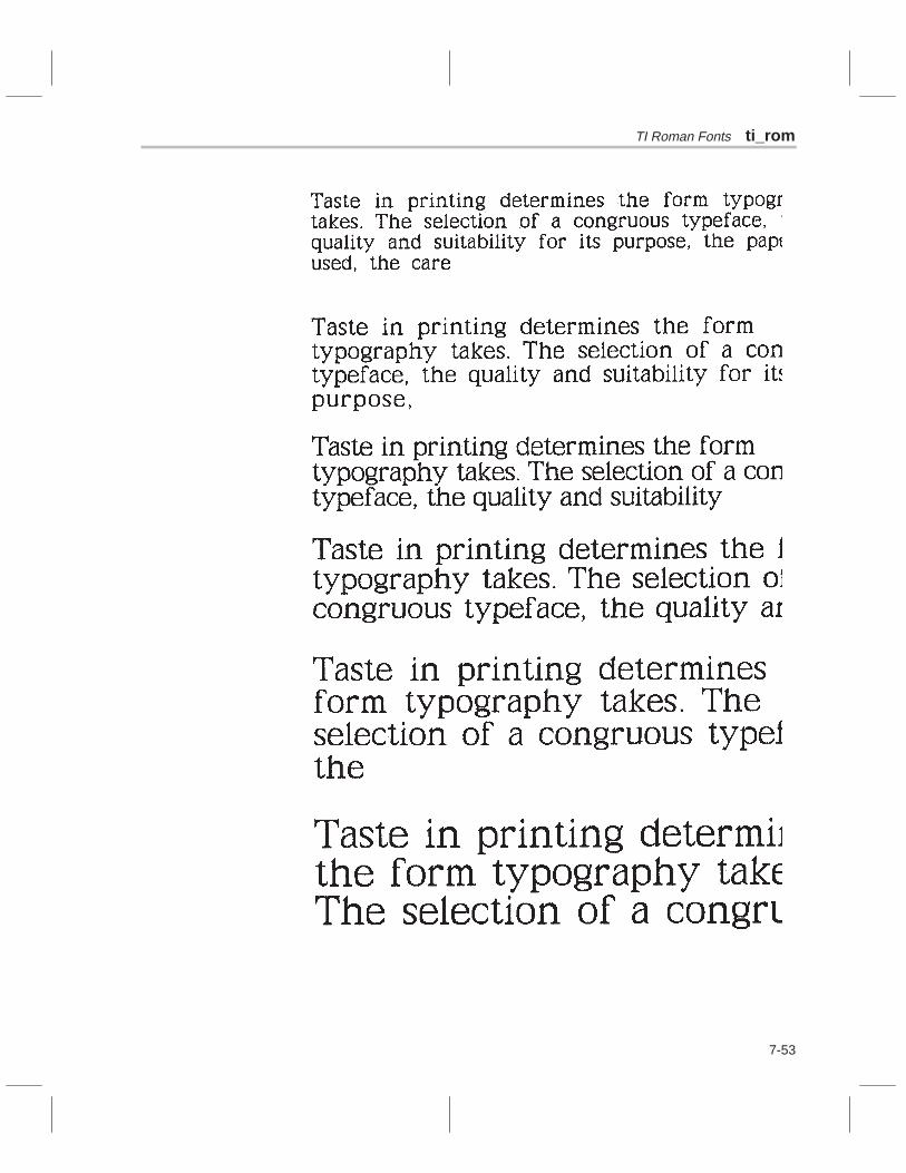
TI Roman Fonts ti_rom
7-53

ti_rom TI Roman Fonts
7-54 Bit-Mapped Text

TI Roman Fonts ti_rom
7-55

ti_typ TI Typewriter Elite Fonts
7-56 Bit-Mapped Text
MonospaceTypewriter EliteA light-weight serif typeface. Small sizes suited to correspondence and news-letters. Larger sizes perfect for labels and headlines.11, 14, 16, 18, 20, 22, 26, and 38 pixels
SpacingDerivationDescription
Sizes
Example

TI Typewriter Elite Fonts ti_typ
7-57

7-58 Bit-Mapped Text

8-1
Chapter 8
Extensibility
Prior to TIGA, the software developer was limited by fixed sets of graphicsdrawing functions. In the rapidly changing graphics market, a fixed set of draw-ing functions is unacceptable.
The extensibility designed into the TIGA interface was a major goal. As a re-sult, TIGA provides functions that enable an application or driver to install cus-tom graphics functions.
Topics in this chapter include
Section Page8.1 Dynamic Load Module 8-2. . . . . . . . . . . . . . . . . . . . . . . . . . . . . . . . . . . . . . 8.2 Generating a Dynamic Load Module 8-4. . . . . . . . . . . . . . . . . . . . . . . . . . 8.3 Installing a Dynamic Load Module 8-6. . . . . . . . . . . . . . . . . . . . . . . . . . . . 8.4 Invoking Functions in a Dynamic Load Module 8-9. . . . . . . . . . . . . . . . . 8.5 C-Packet Mode 8-12. . . . . . . . . . . . . . . . . . . . . . . . . . . . . . . . . . . . . . . . . . . 8.6 Direct Mode 8-16. . . . . . . . . . . . . . . . . . . . . . . . . . . . . . . . . . . . . . . . . . . . . . 8.7 Downloaded Function Restrictions 8-28. . . . . . . . . . . . . . . . . . . . . . . . . . 8.8 Using the TMS340-to-Host Callback Functions 8-31. . . . . . . . . . . . . . . 8.9 Installing Interrupts 8-36. . . . . . . . . . . . . . . . . . . . . . . . . . . . . . . . . . . . . . . . 8.10 Object Code Compatibility 8-39. . . . . . . . . . . . . . . . . . . . . . . . . . . . . . . . . . 8.11 TIGA Linking Loader 8-45. . . . . . . . . . . . . . . . . . . . . . . . . . . . . . . . . . . . . .

Dynamic Load Module
8-2 Extensibility
8.1 Dynamic Load Module
The key to TIGA’s extensibility is the dynamic load module (DLM). This moduleis a collection of C or assembly functions written by the application or devicedriver programmer and linked together to form the module. The DLM is down-loaded at runtime into TMS340 memory and integrated with the TIGA graphicsmanager. Once downloaded, each function contained within the module canbe called with the same conventions as the TIGA core or extended graphicslibrary functions.
TIGA currently supports two types of dynamic load modules:
Relocatable load module (RLM), and
Absolute load module (ALM).
A dynamic load module comprises functions that can be either standardC-type functions callable either from the host processor or from the TMS340,or interrupt service routines called on reception of an interrupt via the TIGAstandard interrupt handler.
8.1.1 Relocatable Load Modules
Relocatable load modules (RLMs) are produced directly with the TMS340compiler and assembly tools and are in common object file format, or COFF.A description of this file format is given in the TMS340 Family Code GenerationTools User’s Guide. These modules contain the necessary relocation entriesso that they can be loaded anywhere in TMS340 memory. They may also con-tain unresolved references to TIGA core or graphics library functions, whichare resolved when the modules are loaded. Furthermore, the modules containall the necessary symbol information, stored after loading, so that subsequentRLMs that are loaded may reference the functions in another RLM. You caninstall an RLM by invoking the install_rlm function.
RLMs are the preferred format for creating a dynamic load module. They offerthe greatest flexibility because the module can be relocated anywhere inTMS340 memory space, and the module’s symbols can be accessed by sub-sequently loaded modules.
8.1.2 Absolute Load Modules
Absolute load modules (ALMs) were required in pre-2.0 versions of TIGA be-cause the downloading of a user extension to TIGA was done by invoking thelinking loader. This is not the case in versions 2.0 and onward, and ALMs arenow redundant. ALMs are supported in TIGA purely to maintain downwardcompatibility with TIGA drivers written for versions of TIGA prior to 2.0.

Dynamic Load Module
8-3
You create ALMs from relocatable load modules by calling the create_almfunction, which uses the TIGA heap management routines to allocate a spacein TMS340 memory where the ALM will be loaded. The function create_almthen links and relocates the module to the area starting address in heap. Thus,the ALM can be loaded only into this one area in memory. The heap area forthe module is then freed by the create_alm function. It is therefore imperativethat the state of the heap in TMS340 memory is the same when the ALM iscreated as when it is installed. Normally, you can achieve this by always initial-izing heap before calling create_alm and then reinitializing heap when themodule is installed. You can perform heap initialization by callingset_videomode with an INIT style.
When an ALM is loaded, heap is allocated to store the module. The start ad-dress is compared to the one returned when the module was created. If theyare the same, the ALM is loaded into TIGA; if not, the load is aborted. Thereis a further restriction: since the symbol information is no longer available with-in the file (as it is with RLMs), modules loaded subsequently cannot referencefunctions in an ALM.
With TIGA 2.0, the functionality of the relocating loader in TIGALNK has beenincorporated into the TIGA communication driver, thus eliminating the need toinvoke TIGALNK when loading RLMs. Therefore, RLMs can now be loadedby any TIGA application, even if no free host memory is available.

Generating a Dynamic Load Module
8-4 Extensibility
8.2 Generating a Dynamic Load Module
A TIGA dynamic load module consists of the following three parts:
A collection of C and/or assembly functions, some (or all) of which are tobecome TIGA extensions or interrupt service routines.
A TIGAEXT section declaration. Required only if TIGA extensions are be-ing declared.
A TIGAISR section declaration. Required only if TIGA interrupt serviceroutines are being declared.
This document does not describe the mechanics of generating the TMS340source and object code of a user function. This is discussed fully in theTMS340 Family Code Generation Tools User’s Guide. If the user library is tocontain functions written with TMS340 assembly code, then certain guidelinesmust to be met to ensure that the C environment is maintained by the assemblylanguage function. For a description of how to interface assembly languageroutines with the C environment, see Chapter 5, Runtime Environment in theTMS340 Family Code Generation Tools User’s Guide.
Depending on whether or not a DLM contains extensions or interrupt servicesroutines, one or two specially named COFF sections must be created andlinked with the module. If the module contains extensions, then a section calledTIGAEXT must be created. If the module contains interrupt service routines,then a section called TIGAISR must be created. The format of these sectionsis described below.
8.2.1 TIGAEXT Section
The TIGAEXT section must contain one and only one address reference foreach extension contained within the module (that is callable from the host). Forexample, if the module contains two functions called my_func1 andmy_func2, the section declaration would look like this:
;–––––––––––––––––––––––––––––––––––––––––––––––––––––––––––––––– ;;TIGAEXT – This COFF section contains references for all ;;extensions contained in the module it is linked with. ;;–––––––––––––––––––––––––––––––––––––––––––––––––––––––––––––––– ;;External References
.globl _my_func1, _my_func2;Start section declaration
.sect ”.TIGAEXT”
.long _my_func1 ;command number 0 within module
.long _my_func2 ;command number 1 within module
.text ;end section
8.2.2 The TIGAISR Section
The TIGAISR section contains two entries for every interrupt service routinecontained within the module. These entries specify an address reference tothe ISR and the interrupt number of the ISR.

Generating a Dynamic Load Module
8-5
For example, if two ISRs called my_int1 and my_int10 were contained withinthe module, then the section declaration would look like this:;–––––––––––––––––––––––––––––––––––––––––––––––––––––––––––––––– ;;TIGAISR – This COFF section contains information for all ;;of the ISRs contained in the module it is linked with. ;;–––––––––––––––––––––––––––––––––––––––––––––––––––––––––––––––– ;;External References
.globl _my_int1, _my_int10;Start section declaration
.sect ”.TIGAISR”
.long _my_int1
.word 1 ;interrupt number 1;
.long _my_int10
.word 10 ;interrupt number 10;
.text ;end section
Note:
The TIGAEXT and TIGAISR sections must contain the exact number of dec-larations for the external functions to be installed. This is because the lengthof these sections is used to determine the number of declarations.
8.2.3 Linking the Code and Special Sections Into an RLM
Once the user functions have been written, they are compiled and/or as-sembled, producing a series of COFF object files (.obj). These files should bepartially linked together with the object files generated by assembling theTIGAEXT and/or TIGAISR sections. Below is an example where two functionsand two interrupt service routines are created and linked into a RLM.
The source files contain the following:
myfuncs.c Functions my_func1 and my_func2tigaext.asm References for the above (as in the example)myints.asm Two interrupt routines, my_int1, and my_int10tigaisr.asm References and trap numbers for the above ISRs
1) Assemble and/or compile all of the source files:
gspcl myfuncs.c tigaext.asm myints.asm tigaisr.asm
This produces four object files:
myfuncs.obj myints.objtigaext.obj tigaisr.obj
2) Partially link all the object modules together to form the RLM:
gsplnk –o EXAMPLE.RLM –r –cr myfuncs.obj tigaext.objmyints.obj tigaisr.obj
The result of the linking is a relocatable load module entitled example.rlm.
Note:
In some versions of the linker, the warning –Unresolved Reference to”_c_int00” is displayed. It can be ignored.

Installing a Dynamic Load Module
8-6 Extensibility
8.3 Installing a Dynamic Load Module
To invoke the commands in a dynamic load module, you must first install themodule into the TIGA graphics manager. The module file is in the form of a filein a directory of the host PC. If this directory is not the current working directory,the TIGA environment variable must first be set up to point to this directory. Usethe –l option of the TIGA environment variable to find the DLM. The actual in-stallation procedure differs from RLM to ALM.
8.3.1 Installing a Relocatable Load Module
A relocatable load module is installed by the install_rlm function. Below is anexample program written in Microsoft C, which demonstrates how to install theRLM example.rlm, described in subsection 8.2.3.
Example 8–1. Installation of the RLM example.rlm
#include <tiga.h>
main(){
short module;/*–––––––––––––––––––––––––––––––––––––––––––––––––––––––––– *//* Initialize the TIGA environment *//*–––––––––––––––––––––––––––––––––––––––––––––––––––––––––––– */init_tiga(0);/*–––––––––––––––––––––––––––––––––––––––––––––––––––––––––––– *//* Attempt to load example.rlm *//*–––––––––––––––––––––––––––––––––––––––––––––––––––––––––––– */if((module = install_rlm(”example”)) < 0){
printf( ”Fatal Error – Could not install example.rlm\n” );printf( ”Error code: %d\n”, module );term_tiga();
}/*–––––––––––––––––––––––––––––––––––––––––––––––––––––––––– *//* RLM loaded. We can now call any TIGA Core or RLM function *//*–––––––––––––––––––––––––––––––––––––––––––––––––––––––––– */
::
/*–––––––––––––––––––––––––––––––––––––––––––––––––––––––––– *//* Terminate TIGA *//*–––––––––––––––––––––––––––––––––––––––––––––––––––––––––– */term_tiga(); /* Terminate TIGA */
}
Note:
Refer to Section 3.4 for listings of the init_tiga and term_tiga functions usedin this example.

Installing a Dynamic Load Module
8-7
The install_rlm function is invoked with the filename of the RLM file. If the RLMfile is in the same directory as the calling application or is in the directory speci-fied by the –l TIGA environment variable, only the filename of the RLM mustbe specified. Otherwise, the complete path must be specified. A default exten-sion of .rlm is assumed unless one is given. The install_rlm function returnseither the module ID for the RLM, which is used when invoking the functions,or an error code if some error occurred. Error codes are negative values; mod-ule identifiers are always positive (including zero).
8.3.2 Installing an Absolute Load Module
An absolute load module must first be created from a relocatable load module.Example 8–2 is a program written in Microsoft C that demonstrates how tocreate an ALM from the example.rlm described in subsection 8.3.1.
Example 8–2. Creation of an ALM From EXAMPLE.RLM
#include <tiga.h>
main(){
register short return_code;
/*––––––––––––––––––––––––––––––––––––––––––––––––––––– *//* Initialize the TIGA environment *//*––––––––––––––––––––––––––––––––––––––––––––––––––––– */init_tiga(0);/*––––––––––––––––––––––––––––––––––––––––––––––––––––– *//* Attempt to create the ALM module *//*––––––––––––––––––––––––––––––––––––––––––––––––––––– */return_code = create_alm(”example”, ”example”);if(return_code < 0){
printf(”Fatal Error – Could not create example.alm\n”);printf(”Error code: %d\n”, return_code);term_tiga();
}/*––––––––––––––––––––––––––––––––––––––––––––––––––––– *//* Further initialization code would go here... *//*––––––––––––––––––––––––––––––––––––––––––––––––––––– */
::
/*––––––––––––––––––––––––––––––––––––––––––––––––––––– *//* Terminate TIGA *//*––––––––––––––––––––––––––––––––––––––––––––––––––––– */term_tiga();
}
init_driver(){
register short return_code;
/*––––––––––––––––––––––––––––––––––––––––––––––––––––– *//* Initialize the TIGA environment *//*––––––––––––––––––––––––––––––––––––––––––––––––––––– */init_tiga(0);

Installing a Dynamic Load Module
8-8 Extensibility
/*––––––––––––––––––––––––––––––––––––––––––––––––––––– *//* Attempt to load example.alm *//*––––––––––––––––––––––––––––––––––––––––––––––––––––– */if((return_code = install_alm(”example”)) < 0){
printf(”Fatal Error –Could not install example.alm\n”);printf(”Error code: %d\n”, return_code);term_tiga();
}/*––––––––––––––––––––––––––––––––––––––––––––––––––––– *//* ALM loaded. We can now call any Core or ALM function *//*––––––––––––––––––––––––––––––––––––––––––––––––––––– */
::
/*––––––––––––––––––––––––––––––––––––––––––––––––––––– *//* Terminate TIGA *//*––––––––––––––––––––––––––––––––––––––––––––––––––––– */term_tiga(); /* Terminate TIGA */
}
Note:
Refer to Section 3.4 for listings of the init_tiga and term_tiga functions usedin this example.
The example assumes that at the time the program is run initially, the functioncreate_alm can be invoked by create_alm to produce the ALM file. The invoca-tion produces an example.alm file in the same directory as example.rlm. De-fault extensions of .rlm and .alm are assumed unless overridden by the filenames supplied. The function create_alm produces an ALM file only if it doesnot already exist. This generally restrains the program from unnecessarily rec-reating the ALM every time the program is run. If the application requires a newALM, it must first delete the old one explicitly.
The example also assumes that the part of the program that uses the user ex-tensions in the ALM is executed after the init_driver function is invoked. Thisscenario is typical with application drivers. The main program actually doesvery little more than initialization and calling the DOS TSR exit function. Later,the application calls an init_driver type function to get the driver ready for sub-sequent application calls. At this time, the TIGA environment is reinitialized,and the ALM is installed. The install_alm function loads the code from the hostPC file into TMS340 memory.

Invoking Functions in a Dynamic Load Module
8-9
8.4 Invoking Functions in a Dynamic Load Module
The process of invoking a function in a DLM is done in two parts:
Selection of the function, (described in this section).
Actual invocation of the function and passing of its parameters from thehost to the TMS34 (described in subsequent sections).
8.4.1 Command Number Format
User extensions that are installed in a DLM are identified by a unique com-mand number. This command number consists of a 16-bit word divided intothe following fields, as Figure 8–1 shows:
Figure 8–1. Command Number Format
1) The function type (bits 14–15) :
00 = direct mode01 = C-packet10 = reserved for future use11 = reserved for future use
2) The module number (between 0 and 31) (bits 9–13) :
31 = TIGA core functions30 = TIGA graphics library functions installed via the install_primitives function0 thru 29 for user modules in the order of installation
3) The function number within the module (bits 0–8).
The function type field currently selects between the C-packet mode and di-rect-mode functions. These two modes determine the manner in which the pa-rameters of the function are passed between the host and the TMS340. Thetwo modes are described in subsequent sections.
The module number is a unique identifier for each module. TIGA supports upto 32 DLMs, numbered from 0 to 31. The TIGA core functions are always in-stalled at initialization time as module number 31. Likewise, the DLM that con-tains the TIGA graphics library functions is always assigned module number30 by the install_primitives function. The remaining 30 module slots, num-bered 0–29, are assigned to user DLMs as they are installed. The first userDLM installed is assigned the number 0, the second DLM the number 1, andso on.

Invoking Functions in a Dynamic Load Module
8-10 Extensibility
The function number specifies one of the 512 possible functions that can becontained within a module. Function numbers are defined by the order in whichthey are declared in the TIGAEXT section within a module. For example, asdescribed in subsection 8.2.1 my_func1 would be designated function num-ber 0, and my_func2 would be designated function number 1.
8.4.2 Using Macros in Command Number Definitions
The format of the command number may be subject to change in future ver-sions of TIGA. To minimize the potential changes to an application, macros areprovided in the tiga.* include files so that a command number of a function canbe specified without referencing the individual bits in the command number.The macros are
CORE_CP(function_number)CORE_DM(function_number)EXT_CP(function_number) EXT_DM(function_number) USER_CP(module | function_number)USER_DM(module | function_number)
The macros CORE_CP and CORE_DM select C-packet or direct-mode func-tions with a module number of 31 (for the TIGA core functions). Similarly,EXT_CP and EXT_DM select C-packet or direct-mode functions with a mod-ule number of 30 (for the TIGA graphics library functions). USER_CP andUSER_DM designate user extensions. They take a single argument, whichis the module number returned by the install_rlm or install_alm function ORedwith the function number of the function from its position in the TIGAEXT sec-tion. The module number should be passed as it is supplied from the installprocedure.
These macros should always be used when specifying command numbers.If they are not, and if an application hard-codes the bits in a command number,there is a risk of incompatibility with future versions of TIGA.
8.4.3 Passing Parameters to the TIGA Function
A TIGA function can be invoked in two ways, depending on the type of functioncall that is made: C-packet or direct mode.
C-packet functions are the easiest of the two to write and have a more flexibleparameter format. C-packet functions receive their parameters on the stack;this makes it very easy for you to develop a function that becomes a user ex-tension, by first writing it and debugging it on the host side. The function canthen be extracted from the host code and recompiled with the TMS340 C com-piler. Any parameters it received on the host side will be passed from the hostto the TMS340 via a TIGA communication driver routine and then pushed ontothe TMS340 C stack so that the function behaves just as if it were invoked lo-cally to the host. To do this, however, extra data that describes the type andsize of each parameter must be sent along to the TMS340.

Invoking Functions in a Dynamic Load Module
8-11
The extra overhead of sending this data, plus the time taken to format the pa-rameters and push them onto the stack, can be eliminated by using directmode. This sends raw data into the communication buffer used for host-to-TMS340 communication. The user extension function receives on the stacka single parameter that is a pointer to the communication buffer where the datais stored. The function itself must pick up the data from this buffer in the ex-pected format.
Most applications are developed by using C-packet initially. Those functionsthat are more time critical can be modified to use direct mode. Source codechanges to an extension to change it from C-packet to direct mode are not thatsignificant. Sections 8.5 and 8.6 give a complete description of C-packet anddirect modes, respectively.

C-Packet Mode
8-12 Extensibility
8.5 C-Packet Mode
To invoke a user extension using C-packet mode, you must supply threepieces of information:
The type of call the function uses
The function’s command number
A description of the function arguments
8.5.1 The Type of Call
The current C-packet system supports three basic types of function calls:
cp_cmd This entry point is for functions that do not require any form ofreturn data.
cp_ret This entry point is for functions that require only a single stan-dard C-type return value.
cp_alt This entry point is for those functions that pass pointers to datathat is modified indirectly by the function called.
draw_a_line(x1, y1, x2, y2) uses cp_cmdpoly_line(10, &point_list) uses cp_cmdi = read_point(x, y) uses cp_retcopy_mem(&src, &dst, len) uses cp_alt
An additional set of entry points is used when the argument list is potentiallytoo large for the size of the communication buffer used to transfer parametersbetween the host and the TMS340. These entry points, cp_cmd_a, cp_ret_a,and cp_alt_a, have the same functionality as those described above but canalso allocate additional space for passing larger amounts of data as parame-ters to a TIGA extended function, at a cost of speed performance. Avoid theseentry points when you know that the argument length of the function in ques-tion will not exceed the maximum size dictated by the communication buffer’sdata size (comm_buff_size is a field of the CONFIG structure returned byget_config).
8.5.2 The Command Number
Subsection 8.4.1 describes in detail the command number format. The com-mand number should always be specified in the form:
USER_CP (module | function_number)
for user C-packet extensions, where module is the module ID of the DLM re-turned at install time and function_number is the position of the function in theTIGAEXT section.

C-Packet Mode
8-13
8.5.3 Description of Function Arguments
To call the desired function, each of that function’s arguments must be under-stood by the graphics manager so that data can be passed to the DLM functionin the expected form. Each individual argument is called a packet and has itsown separate header. Entering the packet headers is made easier when addi-tional defines in the tiga.* include files are used to represent the different datatypes.
The packet header uses a keyword to describe the value being passed.Table 8–1 describes the Microsoft C equivalent types for each keyword:
Table 8–1.Keyword Equivalent Types
Keyword Microsoft C Equivalent Type
BYTE 8-bit unsigned char
WORD 16-bit unsigned short
DWORD 32-bit signed long
SWORD 16-bit signed short
DOUBLE 64-bit double floating-point
These packet headers are currently supported by TIGA:
_WORD(a) Immediate WORD argument a_SWORD(a) Immediate signed WORD argument a_DWORD(a) Immediate double WORD argument a_DOUBLE(a) Immediate double floating-point argument a_BYTE_PTR(b,a) BYTE array pointer a with b elements_WORD_PTR(b,a) WORD array pointer a with b elements_DWORD_PTR(b,a) DWORD array pointer a with b elements_DOUBLE_PTR(b,a) DOUBLE array pointer a with b elements_STRING(a ) Null-terminated string pointer a_ALTBYTE_PTR(b,a) Function-altered BYTE array pointer_ALTWORD_PTR(b,a) Function-altered WORD array pointer_ALTDWORD_PTR(b,a) Function-altered DWORD array pointer_ALTDOUBLE_PTR(b,a) Function-altered DOUBLE array pointer
Because the immediate arguments passed in Microsoft C are always pro-moted to short type, there is no BYTE identifier. If immediate char values arepassed, either the_WORD or _SWORD identifier should be used. Also, sinceimmediate short types are the only data types that must be promoted (to 32bits) by the graphics manager, they are the only data size to have a signedidentifier. All other arguments’ sign extension requirements should be handledby the called routines.

C-Packet Mode
8-14 Extensibility
8.5.4 C-Packet Examples
The exact argument list of the C-packet entry points is as follows:
entry_point_name(cmd_number, num_packets, packet1, ..,packetn)
where:
cmd_number is the command numbernum_packets is the number of C type packetspacket1...packetn is the packet data (see below)
The following are some examples of user extensions. These examples are notsupplied TI-extended functions.
Example function:
init_grafix()
The function requires no return data. (Use cp_cmd)The function’s command number was stored in CMD_ID.
The function has no arguments.
Resulting include file entry:
#define init_grafix() cp_cmd(USER_CP(CMD_ID), 0)
Example function:
fill_rect(w, h, x, y)
The function requires no return data. (Use cp_cmd.)The function’s command number was stored in CMD_ID.
The function has 4 arguments, all WORDS.
Resulting include file entry:
#define fill_rect(w,h,x,y) \cp_cmd(USER_CP(CMD_ID),4,_WORD(w),_WORD(h),_WORD(x),_WORD(y
))
Example function:
poly_line(n, &linelist )
The function requires no return data (Use cp_cmd.)The function’s command number was stored in CMD_ID.
The function has 2 arguments, WORDn, and WORD_PTR, line_list.
Resulting include file entry:
#define poly_line(n,ptr) \cp_cmd(USER_CP(CMD_ID),2,_WORD(n),_WORD_PTR(2*n,ptr))

C-Packet Mode
8-15
Example function:
init_matrix(&matrix)
The called function initializes the array pointed to indirectly by &matrix .(Use cp_alt)The function’s command number was stored in CMD_ID.
The function has one argument, which points to a 4 × 4 element-function-altered array of longs.
Resulting include file entry:
#define init_matrix(ptr) \cp_alt(USER_CP(CMD_ID),1,_ALTDWORD_PTR(16,ptr))
8.5.5 Overflow of the Command Buffer
When a command of any kind (TIGA or user function) is invoked by an applica-tion, the communication driver functions transfer its parameters from hostmemory into a temporary buffer in the TMS340 memory (called a commandbuffer). If one of the parameters of the function is a pointer, then the pointeritself is not copied over; only the data that is being pointed to is copied. If thepointer is an array, as in the polyline function, then it can be of arbitrary length.Thus, it is simple for the application to overflow this fixed length buffer by, forexample, asking TIGA to draw a million-element polyline. The application mustknow the size of data that it is attempting to transfer into the TMS340 processormemory and must check that it will fit in the command buffer. For this reason,the command buffer size is included as an element in the configuration struc-ture returned by get_config. Note that if a C-packet entry point is being used,allowances must be made for the packet type and size words, which also usespace in the command buffer.
Memory space management is required for all direct-mode and three regularC-packet entry points. However, the application can use the _a C-packet entrypoints (for example, cp_cmd_a) that check the size of the parameters, anddownload them in the normal way if they fit. If they do not fit, the entry pointsattempt to allocate a temporary buffer from the TMS340 heap pool to store theparameters. If the allocation is not successful, the error function is invoked.The checking of the parameter size requires two passes through the argu-ments. This technique incurs some speed overhead; however, a rapidreal-time function does not commonly use arrays too large to fit in the com-mand buffer.
Another technique provided in TIGA for the management of large amounts ofdata that may overflow the command buffer is the direct-mode entry pointsdm_poly and dm_ipoly. These entry points turn the buffer into a circular queueso that any size of data can download into the buffer. This technique requiresthe writing of a custom TMS340 processor command that manages the dataand the handshaking employed.

Direct Mode
8-16 Extensibility
8.6 Direct Mode
The principal difference between C-packet and direct modes is that in directmode, when the downloaded function is invoked on the TMS340 side, the ar-guments are not on the stack as in C-packet mode. The downloaded functionis invoked with a single argument, which is a pointer to a data area where thehost downloaded the parameters. The function itself must fetch the passed ar-guments from this data area into the local variables.This process makes thewriting of functions slightly more complicated, but this is offset by the increasein performance. These functions are intended to improve the process of invok-ing TIGA extensions from the TMS340; they are not intended to be called fromother downloaded functions from the TMS340 side (although they could be).Functions that need to be called from both the host and TMS340 (by anotherdownloaded function) are best written in C-packet or should have an alternateC-callable entry point.
Note that for the fastest possible transfer of data, the direct-mode entry pointsdo not check the size of the data being transferred. The application must en-sure that the data being transferred does not overflow the command buffer.
A further difference between C-packet and direct mode is that in C-packetmode the arguments passed to a function could be of any combination of im-mediate data and pointers in any particular order. This is not the case with di-rect mode. No packet information is sent with the data to specify whether it isimmediate or not and what its size is. The direct-mode entry point itself deter-mines what format the parameters can be specified in, and, in turn, how theseparameters are received in the TMS340 communication buffer. The followingsections provide a list of the direct-mode entry points and the parameterizationof their arguments.
8.6.1 Differences Between Microsoft C and High C/NDP Compilers
The MetaWare High C and Microway NDP compilers promote all argumenttypes to 32-bit long words when passing arguments between functions,whereas the Microsoft C compiler promotes chars and shorts to 16-bit words.This fundamental difference affects how arguments are passed via the direct-mode entry points.
Those direct-mode entry points affected by the difference in immediate argu-ment promotion described above have two calling definitions: one for use withthe Microsoft C compiler and the other for use with the High C/NDP compiler.The High C/NDP definition has an additional argument, flags, which identifiesthe actual significant words for each immediate value argument. For example,the dm_cmd entry point definition for the High C/NDP compilers is
void dm_cmd(cmd_number, length, flags, arg1, ... , argn);short cmd_number;short length;unsigned long flags;short (or long) arg1...argn;

Direct Mode
8-17
Here, length contains the number of significant words in the argument list. Ashort and a char both have one significant word, whereas a long has two signif-icant words. Although the arguments are defined as shorts, longs are passedin many TIGA functions (including our own) as a single argument, and the 2is added to the length instead of 1.
The flags argument is a simple identifier for the first 32 arguments passed tothe entry point. Bit 0 of flags corresponds to arg1, and so on. The bit shouldbe set to 1 if its corresponding argument is a long, and set to 0 if the argumentis a short or a char. These identifiers enable the High C/NDP AI libraries to con-vert the call into the standard Microsoft C format, 16-bit segmented call, beforecalling the appropriate TIGA CD function.
Another difference between the Microsoft and the High C/NDP AI libraries isthe way data pointers are handled. Refer to Section 3.2, page 3-3, for a de-scription of how data pointers are interpreted in each AI library. The interpreta-tion affects pointer types passed as arguments to direct-mode entry points.For example, the definition for the dm_psnd entry point depends on which AIlibrary is being linked to as follows:
ai.lib , ai_com.lib : (far data references):
void dm_psnd(cmd_number, length, ptr)short cmd_number;short length;void far *ptr;
hcai.lib , ndpai.lib (near data references):
void dm_psnd(cmd_number, length, ptr)short cmd_number;short length;void *ptr;
Note that the only difference is the type of argument pointer. For far data refer-ences, it is a far pointer. For near data references, it is a near pointer. It is impor-tant to keep this in mind because the direct-mode entry point descriptions inthe following sections do not differentiate near and far pointers.
8.6.2 Standard Command Entry Point
Compiler: Microsoft C, AI libraries: ai.lib, ai_com.lib
void dm_cmd(cmd_number, length, arg1, ... , argn);short cmd_number;short length;short arg1...argn;
Compiler: High C / NDP, AI libraries: hcai.lib / ndpai.lib
void dm_cmd(cmd_number, length, flags, arg1, ... , argn);short cmd_number;short length;unsigned long flags;short (or long) arg1...argn;

Direct Mode
8-18 Extensibility
This command is the most commonly used for direct-mode commands in theTIGA system. The length specified is the number of 16-bit words that are sent;thus, to send a long, length should increase by 2.
The TIGA core function poke_breg uses this entry point. It sends a 16-bit regis-ter number and a 32-bit value to be loaded into the register. Note that the lengthis three because three16-bit words are pushed onto the stack (2 of them beingthe MSW and LSW of value ).
Compiler: Microsoft C, AI libraries: ai.lib, ai_com.lib
#define poke_breg(regno,value) \dm_cmd(POKE_BREG,3,(short)(regno),(long)(value))
Compiler: High C / NDP, AI libraries: hcai.lib / ndpai.lib
#define poke_breg(regno,value) \dm_cmd(POKE_BREG,3,2,(short)(regno),(long)(value))
Note the additional flags argument value of 2. This specifies
Flag Bit Significant Words in Argument
bit 0 = 0: Argument 0 (regno) has 1 significant word
bit 1 = 1: Argument 1 (value) has 2 significant words
Figure 8–2 shows how the data in the communication buffer looks.
Figure 8–2. Data Structure of dm_cmd
The poke_breg function has one parameter on the stack, which is data_ptr.The function contains the following TMS340 assembly code to extract the datafrom the communication buffer:
_dm_poke_breg:move A0,*–SP,1 ; save A0
; (Field Size 1 is 32–bits by default)move *–A14,A8,1 ; get data_ptrsetf 16,1,0 ; set Field Size 0 to 16–bitsmove *A8+,A0,0 ; get regno into A0move *A8,A8,1 ; get value into A8
8.6.3 Standard Command Entry Point With Return
Compiler: Microsoft C, AI libraries: ai.lib, ai_com.lib

Direct Mode
8-19
long dm_ret(cmd_number, length, arg1, ... , argn);short cmd_number;short length;short (or long) arg1...argn;
Compiler: High C / NDP, AI libraries: hcai.lib / ndpai.lib
long dm_ret(cmd_number, length, flags, arg1, ...,argn);
short cmd_number;short length;unsigned long flags;short (or long) arg1...argn;
This command is similar to dm_cmd described in subsection 8.6.2. The differ-ence is that after calling the TMS340 function, the host waits for the commandto finish and then fetches and returns the standard C return value as a long,but is of the same type as that returned by the called routine (signed or un-signed, etc.). The value is returned in the DX:AX registers. As with dm_cmd,dm_ret specifies length in 16-bit words.
The TIGA core function cvxyl uses the dm_ret entry point. It passes two 16-bitarguments, x and y, returning a 32-bit long value.
Compiler: Microsoft C, AI libraries: ai.lib, ai_com.lib
#define cvxyl(x,y) \dm_ret(CVXYL,2,(short)(x),(short)(y))
Compiler: High C / NDP, AI libraries: hcai.lib / ndpai.lib
#define cvxyl(x,y) \dm_ret(CVXYL,2,0,(short)(x),(short)(y))
Note the additional flags argument value of 0. This specifies that each argu-ment x and y has only one significant word (flag bits are 0 for each).
8.6.4 Standard Memory Send Command Entry Point
void dm_psnd(cmd_number, length, ptr)short cmd_number;short length;void *ptr; /* void far *ptr for ai, ai_com libs */
This command calls functions that require information in the form of an arrayor structure. Note that in this case the length specified is in bytes, not 16-bitwords as in the previous two entry points. The ptr argument is a pointer intohost memory. The contents of this pointer are downloaded into the communi-cation buffer.
The TIGA extended function draw_polyline uses this entry point. Notice thatthe numpts is multiplied by 4 because every point consists of two coordinates(x and y), each of which is 2 bytes long.

Direct Mode
8-20 Extensibility
Compiler: Microsoft C, AI libraries: ai.lib, ai_com.lib
#define draw_polyline(numpts,pts) \dm_psnd(DRAW_POLYLINE, (short)(4*(numpts)), (short far
*)(pts))
Compiler: High C / NDP, AI libraries: hcai.lib / ndpai.lib
#define draw_polyline(numpts,pts) \dm_psnd(DRAW_POLYLINE, (short)(4*(numpts)), (short
*)(pts))
Figure 8–3 shows how the data in the communication buffer looks.
Figure 8–3. Data Structure of dm_psnd
16-Bit Words
numpts × 4data_ptr
pts[)],x x Coordinate of First Point
y Coordinate of First Point
x Coordinate of Second Point
y Coordinate of Second Point
pts[)],y
pts[1),x
pts[1),y
Because the entry point always sends the byte count into the first word of thecommunication buffer, the TMS340 function itself must scale it to a point-countby dividing the value by 4. The function contains the following TMS340 assem-bly code to extract the data from the communication buffer:
_dm_draw_polyline: : :
move *–A14,A11,1 ;get data_ptrsetf 16,1,0 ;set field Size 0 to 16 bitsmove *A11+,A10,0 ;1st word is number of bytes
;the post–increment of A11 means that;it is now a pointer to pts[0]
srl 2,A10 ;convert to numpts
8.6.5 Standard Memory Return Command Entry Point
long dm_pget(cmd_number, length, ptr)short cmd_number;short length;void *ptr; /* void far *ptr for ai, ai_com libs */

Direct Mode
8-21
The dm_pget command calls functions that return information in the form ofan array or structure. The length (in bytes) is sent as the first element in thecommand buffer. The function writes the return data into the communicationbuffer at the word following the length. The dm_pget entry point then copiesthe data from the communication buffer to the host address specified by theargument ptr.
8.6.6 Standard String Entry Point
void dm_pstr(cmd_number, ptr)short cmd_number;void *ptr; /* void far *ptr for ai, ai_com libs */
The dm_pstr entry point is similar to dm_psnd, but instead of sending a pointerwith a known length, it sends a null-terminated string. In this case, the commu-nication buffer has no length entry as the first word. Successive bytes of thebuffer contain the characters in ptr with a null (zero) terminator.
8.6.7 Altered Memory Return Command Entry Point
unsigned long dm_palt(cmd_number, length, ptr)short cmd_number;short length;void *ptr; /* void far *ptr for ai, ai_com libs */
The long_palt entry point sends and returns information in the form of an arrayor structure. This entry point combines the functionality of the dm_psnd anddm_pget entry points to send the contents of a pointer (of length bytes), whichis then modified by the TMS340 function. When the command completes ex-ecution, the data is returned back into the host memory pointed to by ptr.
8.6.8 Send/Return Memory Command Entry Point
unsigned long dm_ptrx(cmd_number, send_length, send_ptr,return_length, return_ptr)
short cmd_number;short send_length;void *send_ptr; /* void far *send_ptr for ai, ai_com libs */short return_length;void *return_ptr; /* void far *return_ptr for ai, ai_com libs */
The dm_ptrx entry point is used to send information in an array or structure andreturn information to a different array or structure. It is similar to dm_palt in sub-section 8.6.7 except that data is returned to a different area of host memory.The parameters send_length and return_length are in bytes.

Direct Mode
8-22 Extensibility
8.6.9 Mixed Immediate and Pointer Command Entry Point
void dm_pcmd(cmd_number, num_words, word1, word2,...,num_ptrs, cnt1, ptr1, cnt2, ptr2, ...)
short cmd_number; /* command_number */short num_words; /* number of words to send */short word1; /* immediate data */short word2;
:short num_ptrs; /* number of pointers to send */short cnt1; /* number of bytes in pointer 1 */void *ptr1; /* void far *ptr1 for ai, ai_com libs */short cnt2;void *ptr2; /* void far *ptr2 for ai, ai_com libs */
The dm_pcmd entry point combines immediate and pointer data. The first pa-rameter after the command number is the number of words (num_words) tosend in the same manner as dm_cmd. Following that are the words them-selves on the stack. After the immediate data is a count of the number of point-ers to send (num_ptrs). Each pointer is preceded by a count of the number ofbytes contained in the array or structure that the pointer is pointing to.
Note that the arguments word1, word2, ..., must be words (that is, not morethan 16-bits of significant data).
8.6.10 Mixed Immediate and Pointer Command Entry Point With Return
unsigned long dm_pret(cmd_number, num_words, word1, word,..,num_ptrs, cnt1, ptrl, cnt2, ptr2, ..)
short cmd_numbers; /* command_number */short num_words; /* number of words to send */short word1; /* immediate data */short word2;
:short num_ptrs; /* number of pointers to send */short cnt1; /* number of bytes in pointer 1 */void *ptr1; /* void far *ptr1 for ai, ai_com libs */short cnt2;void *ptr2; /* void far *ptr2 for ai, ai_com libs */
The dm_pret command is similar to dm_pcmd except that it returns a standardC value in the DX:AX registers.
Note that the arguments word1, word2, ..., must be words (that is, not morethan 16-bits of significant data).
8.6.11 Poly Function Command
void dm_poly(cmd_number, packet_number, packet_size, packet_ptr)short cmd_number;short packet_number;short packet_size;void *packet_ptr; /* void far *packet_ptr for ai, ai_com libs */

Direct Mode
8-23
The dm_poly entry point is different from every other C-packet and di-rect-mode entry point in that it does not simply transfer data from host toTMS340 memory and invoke a command. This command supports paralleloperations on large amounts of data; that is, some of the data being sent canbe processed while the rest is being sent down.
The command buffer used by the communication driver to download the pa-rameters is turned into a circular queue of packets. Figure 8–4 shows what thecommand buffer contains.
Figure 8–4. Data Structure of dm_poly16-Bit Words
Total Number of Packets
Number of Packets in a Burst
Packets Sent
Packets Used
Start of Packet 1
data_ptr
The dm_poly entry point sends a burst of packets down from the host to theTMS340. It updates the packets-sent count and monitors the packets-usedcount to ensure that there is enough room to download more packets. The userfunction must be specially written to comprehend this handshaking schemeand be responsible for the update of the packets-used entry.

Direct Mode
8-24 Extensibility
Example 8–3. TMS340 Shell Routine With dm_poly
;–––––––––––––––––––––––––––––––––––––––––––––––––––––––––––––––– ;; TIGA – Graphics Manager function ;;–––––––––––––––––––––––––––––––––––––––––––––––––––––––––––––––– ;; Usage: Example TMS340 shell routine with dm_poly entry point ;;––––––––––––––––––––––––––––––––––––––––––––––––––––––––––––––––; Include TMS340 register definitions .copy gspreg.inc; Include macros .mlib gspmac.lib; Declare globals .globl _example_dmpoly; External References; Arguments Received from HostaTOTAL .set 0 ;total number of packets aPAGE .set 10h ;packets per pageaSENT .set 20h ;packets sentaUSED .set 30h ;packets usedaDATA .set 40h ;data starts here; Register usageRarg .set A0 ;pointer to argumentsRccurrent .set A1 ;count (current)Rctotal .set A2 ;count (total packets)Rctemp .set A3 ;count (temp)Rcpage .set A4 ;count (total per page)Rdata .set A5 ;pointer to dataBURST_SIZE .set 16_example_dmpoly: mmtm SP,A0,A1,A2,A3,A4,A5,A6,A7,A9 Popc Rarg ;get pointer to args move *Rarg(aTOTAL),Rctotal,0 ;get total packets move *Rarg(aPAGE),Rcpage,0 ;get packets per page clr Rccurrent ;clear current countpage_loop: move Rarg,Rdata addi aDATA,Rdata Push Rcpageburst_loop: movk BURST_SIZE,Rctemp ;Rctemp is number pkts sub Rctemp,Rctotal jrge full_burst add Rctotal,Rctemp clr Rctotalfull_burst: add Rctemp,Rccurrent ;current count up to datecheck_loop: move *Rarg(aSENT),A8,0 ;Get count ready sub Rccurrent,A8 ;Sub off desired count jrlt check_loop ;If not ready, then wait
packet_loop:;––––––––––––––––––––––––––––––––––––––––––––––––––––––––––––––– ;; Grab some data and do something with it ;;––––––––––––––––––––––––––––––––––––––––––––––––––––––––––––––– ; move *Rdata+,A6,1 move *Rdata+,A7,1 move *Rdata+,A9,0;––––––––––––––––––––––––––––––––––––––––––––––––––––––––––––––– ; dsjs Rctemp,packet_loop move Rccurrent,*Rarg(aUSED),0 move Rctotal,Rctotal jrz exit subk BURST_SIZE,Rcpage jrgt burst_loop Pop Rcpage jruc page_loopexit: Pop Rcpage mmfm SP,A0,A1,A2,A3,A4,A5,A6,A7,A9 rets 2

Direct Mode
8-25
8.6.12 Immediate and Poly Data Entry Point
void dm_ipoly(cmd_number, nShorts, sData,..., ItemSz, nItems, pData)unsigned short cmd_number; /* command number */unsigned short nShorts; /* # of immediate short words to send */unsigned short sData; /* First short word of data to send */
:unsigned short ItemSz; /* Size of items that follow (bytes) */unsigned short nItems; /* # of items that follow */void *pData; /* void far *pData for ai, ai_com libs */
This entry point is similar to dm_poly; it is used for operations that require alarge amount of data items to be transferred. The TMS340 has the ability tooperate on one or more data items at a time; some of the data can be pro-cessed by the TMS340 while more is being sent down.
A user function located on the TMS340, which expects data sent by this entrypoint, must be coded by using a specific set of rules. When the TMS340 func-tion is called, it receives a data pointer in TMS340 memory. The data at thataddress consists of the immediate data values. The poly data, which is sentin bursts by the host, requires special processing and communication protocolto be received. To isolate this processing from the user function, a service rou-tine is provided called srv_ipoly. This service routine should be called, once theuser function is ready to process the poly data. The parameters for this functionare as follows:
srv_ipoly(pItemSrv, pDataBuf)void (*pItemSrv)(); /* Ptr to item handler */char *pDataBuf; /* Address after last immed. word */
The pDataBuf argument is the address immediately following the last immedi-ate word received by the user function.
The pItemSrv is the address of a function that can, in turn, be called by srv_ipo-ly to handle 1 or more Items. This function will be called repetitively by srv_ipolyuntil all the items have been received by the host and serviced. This functionwill be called with the following arguments:
(*pItemSrv)( nItems, pItems);unsigned short nItems; /* Number of items this time */char *pItems; /* Pointer to data */
The nItems argument is the number of items requiring service. The pItems ar-gument is the address of a data buffer containing nItems worth of data.
The following is an example of how this entry point can be used. For this exam-ple, a polypixel command is implemented. The function has two immediate ar-guments: the foregound color of the pixel, and the raster op to be used to drawthe pixels. The remaining poly data is an array of points where pixels are to bedrawn.

Direct Mode
8-26 Extensibility
The host program to call the entry point would look like this:
dm_ipoly(CMD, 2, color, rop, 4, nPoints, pData)
where:
CMD is the command number of the polypixel function.
2 specifies that two immediate arguments follow: color and rop.
color is the first immediate argument.
rop is the second immediate value.
4 specifies the item size as four bytes. Each item is a point, which inthis case is two words. The first specifies the X coordinate, the sec-ond specifies the Y.
nPoints specifies the number.
pData is the pointer in host memory where the point resides.
The downloaded TMS340 user function called polypixel looks like this:
;–––––––––––––––––––––––––––––––––––––––––––––––––––––––––––––; TIGA – POLYPIXEL – Example User function ;–––––––––––––––––––––––––––––––––––––––––––––––––––––––––––; Example of a downloaded TMS340 function that uses the; dm_ipoly host entry point. ;–––––––––––––––––––––––––––––––––––––––––––––––––––––––––––; Include TMS340 register definitions .copy gspreg.inc; Include macros .mlib gspmac.lib; Declare globals .globl _PolyPixel; External References .globl _srv_ipoly; Polypixel argument definitionaCOLOR .set 0haROP .set 10haDATA .set 20h ; address passed to srv_ipoly

Direct Mode
8-27
_PolyPixel:mmtm SP,A0,A1,A2setf 16,0,0move @CONTROL,A2,0 ;save CONTROL registerPopc A0 ;get pointer to datamove *A0(aCOLOR),A1,0 ;get colormove A1,COLOR1 ;set gsp foreground colormove *A0(aROP),A1,0 ;get raster opsetf 5,0,0move A1,@CONTROL+10,0 ;use it to set gsp pp opsetf 16,0,0
; Ready for poly data, push the address following the; immediate data and the address of the service routine
Push STKmove A0,A8addi aDATA,A8Pushc A8 ;push data addressmovi drawpixels,A8Pushc A8 ;push item service routinecalla _srv_ipoly
; All done, cleanup and exitmove A2,@CONTROL,0 ;restore CONTROL registermmfm SP,A0,A1,A2rets 2
;–––––––––––––––––––––––––––––––––––––––––––––––––––––––––––;; Item service routine: drawpixels;; This function is called repetitively by the srv_ipoly; function until all the items sent by the host have been; received and serviced. This function is called with two; stack parameters: the 1st parameter is the number of; items requiring service, and the 2nd argument is the; address of the data items in TMS340 memory.;;–––––––––––––––––––––––––––––––––––––––––––––––––––––––––––drawpixels:
mmtm SP,B10,B11,B12,B13 ;save registersmove STK,B13move *–B13,B10,1 ;pop number of itemsmove *–B13,B11,1 ;pop ptr to item datamove B13,STK
drawloop:addk 1,COLOR1move *B11+,B12,1 ;get Y:X pixel coordspixt COLOR1,*B12.XY ;draw a pixeldsjs B10,drawloop ;loop until items exhaustedmmfm SP,B10,B11,B12,B13 ;restore registersrets 2

Downloaded Function Restrictions
8-28 Extensibility
8.7 Downloaded Function Restrictions
User extended functions and interrupt service routines contained in a dynamicload module have the ability to access functions or globals that were previouslyinstalled into TIGA. This includes the core functions and the TIGA graphics li-brary functions (provided that they have been installed by the application).Note that certain functions are host-only functions and cannot be invoked bya dynamically loaded routine. These functions are identified by the host-onlytype field in Chapter 4, Core Functions.
The downloaded function, whether written in TMS340-C or assembly lan-guage, can take advantage of all the facilities of the graphics manager. Specifi-cally, it can
1) Invoke nearly all the TIGA core functions as if they were written on the hostside. Thus, it can invoke the function set_palet with the parameters usedin Microsoft C. Not all the functions can be invoked from the TMS340 side,because some require access to host side data structures, such as thoseconcerned with the linking loader. Two include files (gsptiga.h andgspextnd.h) containing the graphics manager core functions and graphicslibrary functions are supplied for this purpose. This capability has the ad-vantage that an application can be written and debugged on the host sideby using Microsoft debug tools, and then individual functions can be down-loaded onto the TMS340 side with no changes.
2) Access global variables of the graphics manager, such as those specifyingdisplay coordinates, directly without invoking functions to do it. An includefile (gspglobs.h) containing the graphics manager global variables issupplied for this purpose. The file shown in the following example lists theglobal variables that the downloaded extension is free to access in the cur-rent version of TIGA.

Downloaded Function Restrictions
8-29
extern long bottom_of_stack; /* Declared in link file */extern CONFIG config; /* Current configuration */extern PALET DEFAULT_PALET[16]; /* Default palette */extern CURSOR DefaultCursor; /* Default cursor struct */extern long end_of_dram; /* Declared in link file */extern ENVIRONMENT env; /* Environment variables */extern ENVTEXT envtext; /* Text environment */extern ENVCURS envcurs; /* Cursor environment */extern MODEINFO *modeinfo; /* Operating mode info */extern MODULE Module[32]; /* Function module descr. */extern unsigned char *monitorinfo; /* Monitor timing info */extern OFFSCREEN_AREA *offscreen; /* Pointer to current data */extern unsigned char *page; /* Pointer to current data */extern PALET palet[]; /* Current palette in use */extern PATTERN pattern; /* Current pattern information */extern unsigned char *setup; /* Current setup pointer */extern unsigned short sin_tbl[]; /* Sine lookup table */extern long stack_size; /* Declared in link file */extern long start_of_dram /* Declared in link file */extern FONT *sysfont; /* Pointer to system font */extern FONT sys16, sys24; /* System font choices */extern long *sys_memory; /* Pointer to heap packets */extern long sys_size; /* Size of heap */extern unsigned short *pHCOUNT, *pHEBLNK, *pHESYNC, *pHSBLNK, *pHTOTAL;extern unsigned short *pVCOUNT, *pVEBLNK, *pVESYNC, *pVSBLNK, *pVTOTAL;
When these variables refer to a specific type of declaration, such as PALET,
the include file gsptypes.h should also be included to define this type of decla-ration.
8.7.1 Register Usage Conventions
Assembly language functions used in conjunction with the TIGA functionsshould follow certain guidelines for register use. The following registers mustbe restored to their original states (the state before the function was called) be-fore control is returned to the calling routine:
Status register fields FE1 and FS1. Fields FE0 and FS0 need not be re-stored.
All A-file registers except A8.
In general, all B-file registers. However, certain B-file registers such asCOLOR0 and COLOR1 may be altered by attribute control functions thatupdate parameters .
In general, I/O registers CONTROL, DPYCTL, CONVDP, and INTENB.However, some I/O register bits may be altered by attribute control func-tions that update parameters such as the plane mask, pixel-processingoperation, or transparency flag. These register bits typically are notchanged by graphics output functions.

Downloaded Function Restrictions
8-30 Extensibility
Upon entry to a downloaded extension, certain registers are in a known stateand contain well-defined parameters. These assumptions cannot be made ofinterrupt service routines, because they can interrupt a function that may beusing one of these registers for a different purpose. Extensions, however, canassume that the following registers are in these states:
Status register:
FE1 = 0FS1 = 32FE0 and FS0 are undefined
A-File Registers: STK-A14 points to the C-parameter stack.
B-file registers:DPTCH Screen pitch (difference in starting memory addresses of
any two successive scan lines in display memory).OFFSET Memory address of pixel at top left of screen.WSTART Top left corner of current window.WEND Bottom right corner of current window.COLOR0 Source background color.COLOR1 Source foreground color.
I/O registers:CONTROL Contains current pixel-processing operation code and
transparency control bit. These are set by the applicationprogram and may vary from one call to the next. In contrast,in the window mode, PBH and PBV bits are set to specificvalues. The window mode is set to enable clipping withoutinterrupts (W = 3). The PBH and PBV bits are both zero.
CONVDP Is set up for the screen pitch.PMASK Contains the current plane mask.
8.7.2 TIGA Graphics Manager System Parameters
The TIGA graphics manager assumes that certain system parameters are un-der its control. Dynamic load modules should not alter the following registerbits:
The master interrupt enable bit (IE) in the status register.The cache disable bit (CD) in the CONTROL register.The DRAM refresh control bits (RR and RM) in the CONTROL register ofthe TMS34010.The four host interface registers (HSTADRL, HSTADRH, HSTDATA, andHSTCTL) of the TMS34010.The DRAM refresh control bits and RCA bus configuration mode in theCONFIG register of the TMS34020.

Using the TMS340-to-Host Callback Functions
8-31
8.8 Using the TMS340-to-Host Callback Functions
The mechanics used in implementing a TMS340 function that calls back to the80x86 host are based on the same C-Packet scheme as the standard C-Pack-et host-to-TMS340 call. One simplifying difference, however, is that the call-back version of the packet handler contains only a single entry point. This entrypoint handles all types of callback functions. Thus, to create a callback invoca-tion line, only two pieces of information are required:
The function’s command number
The description of the function arguments.
8.8.1 The Command Number
Since callback functions are always application defined, there is no complexmechanism for calculating callback function numbers. The function number isdetermined solely by the position of the function pointer in the function pointerarray passed at callback initialization. (See subsection 8.8.4).
8.8.2 Description of the Function Arguments
To call the desired function, each of that function’s arguments must be under-stood by the graphics manager so that data can be passed to the host routinein the expected form. As with the standard TMS340 call, C-Packets are usedto describe the arguments. The following packet types are defined in gsptiga.hfor host calls:
__WORD(a) Immediate word, argument a__DWORD(a) Immediate double word, argument a__BYTE_PTR(b,a) Byte array pointer a with b elements__WORD_PTR(b,a) Word array pointer a with b elements__DWORD_PTR(b,a) Double-word array pointer a with b elements__STRING(a) Null-terminated string pointer a__ALTBYTE_PTR(b,a) Function-altered byte array pointer__ALTWORD_PTR(b,a) Function-altered word array pointer__ALTDWORD_PTR(b,a) Function-altered double-word array pointer__INBYTE_PTR(b,a) Function-initialized byte array pointer__INWORD_PTR(b,a) Function-initialized word array pointer__INDWORD_PTR(b,a) Function-initialized double-word array pointer
These packets conform closely to those defined for the standard TMS340 call.The added IN-type packets are used for functions that initialize arrays and arenot concerned with the initial values in the array. Note that each packet typeused in TMS340-to-host calls has two leading underscores, whereas host-to-TMS340 packet types have one.

Using the TMS340-to-Host Callback Functions
8-32 Extensibility
8.8.3 Callback Examples
The exact argument list of the callback entry point is as follows:
host_command(cmd_number, num_packets, packet1, ... ,packetn)
where:
cmd_number is the command numbernum_packets is the number of C type packetspacket1...packetn is the packet data
Below are some examples of user extensions. The example functions usedare the standard file access functions as supplied with Microsoft C 5.1.
Example Function:
FILE *fopen(path, type)char *path; ;Path name of filechar *type; ;Type of access permitted
Assume that the function number is stored in CMD_ID.
The function has two arguments, both null-terminated strings.
Resulting include file entry:
#define fopen(a,b)\host_command(CMD_ID, 2, __STRING(a), __STRING(b))
Note:
This function returns a 32-bit pointer in FAR model; thus, it can be treated asa DWORD on the TMS340.
Example Function:
short fread(buffer, size, count, stream)void *buffer; Storage location for datashort size; Item size in bytesshort count; Max number of items to readFILE *stream Pointer to FILE structure
Assume that the function number is stored in CMD_ID.
The function has four arguments. The first is a function-initialized pointer(size * count elements), the second two are immediate words, and the lastis a FAR pointer, which is treated as a DWORD.
Resulting include file entry:
#define fread(a,b,c,d)\host_command(CMD_ID, 4,__INBYTE_PTR(b*c,a), __WORD(b), __WORD(c), __DWORD(d))

Using the TMS340-to-Host Callback Functions
8-33
Example Function:
short fwrite(buffer, size, count, stream)void *buffer; Storage location for datashort size; Item size in bytesshort count; Max number of items to readFILE *stream Pointer to FILE structure
Assume that the function number is stored in CMD_ID.
The function has four arguments. The first is a nonaltered array pointer(size * count elements), the second two are immediate words, and the lastis a FAR pointer, which is treated as a DWORD.
Resulting include file entry:
#define fwrite(a,b,c,d)\host_command(CMD_ID, 4, __BYTE_PTR(b*c,a), __WORD(b),
__WORD(c), __DWORD(d))
Note:
This function returns a 32-bit pointer in FAR model; thus, it can be treated asa DWORD on the TMS340.
Example Function:
FILE *fclose(stream) FILE *stream; Pointer to FILE structure
Assume that the function number is stored in CMD_ID.
The function has a single arguments: a FAR pointer, which is treated asa DWORD.
Resulting include file entry:
#define fclose(a) host_command(CMD_ID, 1, __DWORD(a))
8.8.4 Initializing the Callback Environment
Because callback is purely an application option in TIGA 2.0, there are no as-signed communications buffers to handle it. To initialize the callback environ-ment, the TIGA application must
Allocate equal-sized host memory and TMS340 memory command buff-ers
Define the host function array
Initialize the HOST_INIT structure and execute the TIGA core functionsetup_hostcmd()

Using the TMS340-to-Host Callback Functions
8-34 Extensibility
For example, consider the file I/O functions discussed in the previous section.The following is a host code excerpt, which performs the callback initializationfor these functions.
#include <tiga.h>#include <typedefs.h>#include <stdio.h> /* Microsoft C include file */
HOST_INIT far hinit;
void (*hcmds[4])() = {fopen,fread,fwrite,fclose};short handle;unsigned long gptr;char *hptr;
init_callback(){
/* Allocate TMS340 Side Buffer */if(!(handle = gsph_alloc(BUFFER_SIZE)))
memory_error();gptr = gsph_deref(handle);
/* Allocate Host Side Buffer */if(!(hptr = (char*) malloc(BUFFER_SIZE)))
memory_error();
/* Initialize HOST_INIT structure */hinit.host_buffer = hptr;hinit.TMS340_buffer = gptr;hinit.buffer_size = BUFFER_SIZE;hinit.host_commands = &hcmds[0];hinit.command_count = 4;
/* Initialize Callback*/setup_hostcmd(&hinit);
}
For a more complete example, refer to the CBFILE example in the \tiga\demosdirectory.
8.8.5 Sizing the Callback Buffer and Handling Overflow
Since the callback buffer is application-allocated, it is assumed that the sizeallocated is large enough to handle the application’s requirements. In the eventthat the packet data overflows the allocated buffer size, the command abortson the TMS340 side without calling the host.

Using the TMS340-to-Host Callback Functions
8-35
To help calculate whether a command will fit into the command buffer allo-cated, use the following packet sizes as a guide:
__WORD(a) 8 bytes__DWORD(a) 8 bytes__BYTE_PTR(b,a) (8 + b) bytes__WORD_PTR(b,a) (8 + 2 * b) bytes__DWORD_PTR(b,a) (8 + 4 * b) bytes__STRING(a) (8 + sizeof(a) + 1) bytes__ALTBYTE_PTR(b,a) (8 + b) bytes__ALTWORD_PTR(b,a) (1 + 2 * b) bytes__ALTDWORD_PTR(b,a) (8 + 4 * b) bytes__INBYTE_PTR(b,a) (10 + b) bytes__INWORD_PTR(b,a) (10 + 2 * b) bytes__INDWORD_PTR(b,a) (10 + 4 * b) bytes
Because most functions have few arguments, you can calculate the staticpacket size, and array sizes could be limited accordingly.

Installing Interrupts
8-36 Extensibility
8.9 Installing Interrupts
TIGA 2.0 has a built-in interrupt handler to ease the use of interrupt serviceroutines (ISR) within TIGA. TIGA’s ISR handler supports traps 0–31 and pro-vides special support for the trap vectors shown in Table 8–2.
Table 8–2.Trap Vectors
Trap Description Mnemonic
1 External interrupt 1 X1
2 External interrupt 2 X2
9 Host interrupt HI
10 Display interrupt DI
11 Window violation interrupt WV
30 Illegal opcode interrupt ILLOP
The TIGA ISR handler properly manages the INTENB and INTPEND registersfor the traps listed in Table 8–2.
TIGA’s ISR handler provides support for chaining multiple ISRs on a single in-terrupt level. Up to eight ISRs can be installed for the display interrupt (trap 10),while a virtually unlimited number (limited only by processing time and avail-able memory) of ISRs can be installed on the other supported traps.
The interrupt service routines are installed into the general interrupt handlerduring the installation of a dynamic load module.The routines that are to be-come interrupt service routines must be written, compiled, and assembled. Aspecially named TIGAISR section must then be declared, identifying the nameof each interrupt service routine and the level where it should be installed. Theformat of this section is explained in subsection 8.2.2 on page 8-4. During thedownload process, the information within this special section is used to chaininterrupts into the TIGA interrupt handler, where each interrupt is assigned apriority level.
ISRs are uniquely identified by the trap number that they service and theirpriority of execution when the trap is called. ISRs are serviced in priority order,with a priority of 0 being serviced first, then priority 1, and so on. The priorityof an ISR is assigned when the ISR is loaded into the TIGA graphics managerusing the install_rlm or install_alm functions. The function get_isr_prioritiescan be called to obtain the priorities assigned to ISRs after loading. Additionalinformation about the get_isr_priorities function can be found on page 4-30.
When the TIGA graphics manager is initially loaded, or wheneverset_videomode(TIGA,INIT) is called, TIGA’s interrupt handler is initialized.The ISRs shown in Table 8–3 are installed automatically during this initializa-tion.

Installing Interrupts
8-37
Table 8–3.Interrupt Service Routines
Trap # Priority Trap Function ISR Function
10 0 Display interrupt Cursor handling
10 1 Display interrupt Page flip servicing
10 2 Display interrupt Wait scan servicing
30 0 Illegal opcode trap Emulation of REV instruction
The set_interrupt function must be called to enable or disable a particular inter-rupt service routine. The interrupt level and the associated priority must bespecified as arguments to this function. The TIGA core functionsset_curs_state, page_flip, and wait_scan automatically enable and disablethe interrupt service routines for the cursor, page flip, and waitscan interrupts,respectively.
Interrupt service routines installed into the TIGA interrupt handler must followa strict set of conventions and can make certain assumptions concerning thestate of the TMS340 device:
An ISR is called by the TIGA interrupt handler with no arguments.
The ISR must terminate with a RETS 0 instruction. The TIGA interrupthandler performs the required RETI after processing all ISRs.
The TIGA interrupt handler sets up a temporary C program stack (registerA14) to enable ISRs to make calls to C functions.
When the ISR is called, fields 0 and 1 are initialized as
Field 0: FS0: 16 FE0: 0Field 1: FS1: 32 FE1: 0
The ISR does not need to restore fields 0 and 1 before exiting. The TIGAinterrupt handler resets them upon return from the ISR.
All A- and B-files registers that are modified by the ISR, with the exceptionof A8, must be restored before exiting.
The ISR must not re-enable interrupts via the eint instruction.
Installing Interrupts
8-38 Extensibility
Note that it is possible for a downloaded extension to be executed from thehost and, in turn, set the traps to its own service routine to avoid the overheadof the global interrupt handler in certain time-critical functions. However, caremust be taken, especially in the display interrupt used by TIGA functions suchas the cursor functions. If equivalent support is not given to these functions,as provided by the global interrupt handler, certain TIGA functions may not ex-ecute correctly.
Certain TMS340 boards provide external connection to the LINT1 and LINT2TMS340 processor pins. In such cases, interrupt service routines can be writ-ten for them by using the techniques outlined here. However, these techniquesare clearly not portable across all TMS340 processor boards.
For an example of how to create, load, and use an interrupt service routine withTIGA, refer to the files in the \tiga\demos\isr directory.

Object Code Compatibility
8-39
8.10 Object Code Compatibility
Because TIGA 2.0 encompasses both the TMS34010 and TMS34020 proces-sors, you must keep in mind the differences between the two processors whenyou write extensions to TIGA. The two processors are 100% object code com-patible, and all code written for the TMS34010 runs on the TMS34020. Howev-er, additional functionality has been added to the TMS34020; for this reason,take care in executing the code on that processor. A full list of compatibilityguidelines are given in Appendix C of the TMS34010 User’s Guide and inChapter 1 of the TMS34020 User’s Guide. Those guidelines provide a thor-ough list of restrictions to follow to maintain software compatibility. The follow-ing subsections are not exhaustive but provide a more detailed approach onhow to deal with the differences between the two processors.
8.10.1 Determining the Processor
Because the processor checks in this section invariably involve a two-waybranch where different actions must be performed for each of the two proces-sors (’34010 and ’34020), you must be able to distinguish them. The de-vice_rev field of the CONFIG structure is provided for this purpose. The codeto perform the processor check in C and in assembly language is as follows:
Example 8–4. C Code to Determine the TMS340 Processor Type
#include <gsptypes.h>#include <gspglobs.h>#include <gspreg.h>
{:
if(config.device_rev & (1 << REV_34010)){
/* TMS34010-specific code */:
}if (config.device_rev & (1 << REV_34020)){
/* TMS34020-specific code */:
}:
}

Object Code Compatibility
8-40 Extensibility
Example 8–5. Assembly Code to Determine the TMS340 Processor Type
include gsptypes.incinclude gspglobs.incinclude gspreg.inc
:move @_config+CONFIG_DEVICE_REV,A8,1btst REV_34010,A8jrz not_34010
is_34010:: ;TMS34010-specific code
not_34010:btst REV_34020,A8jrz not_34020
is_34020::
;TMS34020-specific codenot_34020:
:
8.10.2 Pattern B-File Register
A simple modification must be made to the TMS34020’s LINE instruction be-cause the B13 register is used to define a 32-bit pattern with which the line isdrawn. On the TMS34010, this register was not used, and, although theTMS34010’s user guide states that this register should be set to all 1s to guar-antee the drawing of a solid line, this was generally not done. If the routine isto draw a solid line, then the code should be like this:
movi –1,B13 ;set PATTERN register to all 1smove B11,B11 ;does line point up or down?jrlt downline 0 ;draw Bresenham linejruc exit
down:line 1 ;draw Bresenham line
exit:
Note that although this is required only for the TMS34020, it does not causea problem for the TMS34010, so, in this case, there is no need to provide abranch around the initialization of B13 for the TMS34010.
8.10.3 Pitch Registers
Another potential problem is with the SPTCH/DPTCH B-file registers and theCONVSP/CONVDP I/O registers. On the TMS34010, the CONVSP andCONVDP I/O registers contain the value of the leftmost one of the SPTCH andDPTCH registers, respectively, and these are used in the conversion of an XYaddress to a linear address in certain graphics instructions (such as PIXBLTXY,XY). Some of these graphics instructions, however, do not actually use thevalues in the SPTCH and DPTCH registers; these become, in some sense,spare registers and can be used as temporary variables. The TMS34020 be-

Object Code Compatibility
8-41
haves in the same way, except that the TMS34020 eliminated one of the re-strictions on the TMS34010: that the pitch for XY conversion must be a powerof 2. If an arbitrary pitch is to be used, CONVSP and CONVDP no longer con-tain the leftmost one of the SPTCH and DPTCH registers. In these cases, theI/O registers are not used, and SPTCH and DPTCH must contain the pitch.Thus, these registers are no longer spare. This means that you must be carefulin using TMS34010 code written for power-of-two displays on TMS34020boards with nonpower-of-2 displays. In this case, the SPTCH/CONVSP andDPTCH/CONVDP instruction pairs should contain corresponding values, asthe TMS34010 User’s Guide indicates (although this is sometimes ignored).
The initialization of CONVSP and CONVDP in the TMS34010 is different fromthat in the TMS34020. Although it is unlikely that you will need to initialize theCONVDP register, it is quite likely that you will need to initialize the CONVSPregister. The initialization must be done as follows:
Example 8–6. Initialization of the CONVSP Register
include gsptypes.incinclude gspglobs.incinclude gspreg.inc
_set_spitch:; Assume A0 contains the desired pitch
move A0,SPTCH ; Initialize the SPTCH registermove @_config+CONFIG_DEVICE_REV, A8, 1btst REV_34010,A8jrz not_34010
is_34010: ; TMS34010 code (SPTCH must be a power of 2)lmo A0,A0setf 16,0,0move A0,@CONVSP, 0 ; Put lmo (SPTCH) into CONVSP
not_34010:btst REV_34020,A8jrz not_34020
is_34020: setcsp
not_34020:
8.10.4 Video Timing Registers
Most applications do not need to access the video timing I/O registers, be-cause they are set up by TIGA at initialization time and thereafter are neveraccessed directly. The video timing I/O registers are useful for functions thatneed to synchronize themselves to the display (such as cursor handling, pageflipping etc.). These functions are provided by the TIGA graphics manager di-rectly. TIGA also provides mechanisms to allow an application to install an in-terrupt

Object Code Compatibility
8-42 Extensibility
service routine that is invoked whenever a particular line of the frame bufferis being displayed. Despite these provisions, there may be a reason to syn-chronize an application directly into the display hardware and therefore to in-terrogate the state of the video I/O registers.
Due to enhancements made to the video controller on the TMS34020, it wasnecessary to modify the addresses where the video I/O registers reside. TIGAprovides global pointers that allow an application to access these registers.The global pointers are automatically initialized to either the TMS34010 or theTMS34020 processor I/O addresses, depending on which processor is in-stalled on the board. The application should use these pointers rather than ac-cess the I/O addresses directly. The pointers and the TIGA function that initial-izes them are shown in the following example:
Example 8–7. Initialization of the Video Timing I/O Register Pointers
unsigned short *pHCOUNT, *pHEBLNK, *pHESYNC, *pHSBLNK, *pHTOTAL;unsigned short *pVCOUNT, *pVEBLNK, *pVESYNC, *pVSBLNK, *pVTOTAL; #include <gsptypes.h>#include <gspglobs.h>#include <gspreg.h>
init_ioreg_ptrs(){ if(config.device_rev & (1 << REV_34010)) { pHCOUNT = (unsigned short *)HCOUNT10; pHEBLNK = (unsigned short *)HEBLNK10; pHESYNC = (unsigned short *)HESYNC10; pHSBLNK = (unsigned short *)HSBLNK10; pHTOTAL = (unsigned short *)HTOTAL10; pVCOUNT = (unsigned short *)VCOUNT10; pVEBLNK = (unsigned short *)VEBLNK10; pVESYNC = (unsigned short *)VESYNC10; pVSBLNK = (unsigned short *)VSBLNK10; pVTOTAL = (unsigned short *)VTOTAL10; } if(config.device_rev & (1 << REV_34020)) { pHCOUNT = (unsigned short *)HCOUNT20; pHEBLNK = (unsigned short *)HEBLNK20; pHESYNC = (unsigned short *)HESYNC20; pHSBLNK = (unsigned short *)HSBLNK20; pHTOTAL = (unsigned short *)HTOTAL20; pVCOUNT = (unsigned short *)VCOUNT20; pVEBLNK = (unsigned short *)VEBLNK20; pVESYNC = (unsigned short *)VESYNC20; pVSBLNK = (unsigned short *)VSBLNK20; pVTOTAL = (unsigned short *)VTOTAL20; }}

Object Code Compatibility
8-43
8.10.5 TM34020-Specific Instructions
Although all TMS34010 instructions run on the TMS34020, the TMS34020contains new instructions that are not available on the TMS34010. In manycases, these instructions provide considerably increased performance overthe TMS34010-only instructions, so it is in the application programmer’s inter-est to detect the TMS34020 and use its instructions whenever possible. Thefollowing code uses the TMS34020’s fast line instruction FLINE, which is 1cycle per pixel faster than the regular LINE instruction:
Example 8–8. Use of TMS34020-Specific Instructions
include gsptypes.incinclude gspglobs.incinclude gspreg.inc
btst REV_34020,A8jrz not_34020
is_34020: ;TMS34020–specific codecvdxyl B2 ;convert to linear addressmove B11,B11 ;does line point up or down?jrlt fdownfline 0 ;draw Bresenham linejruc exit
fdown:fline 1 ;draw Bresenham linejruc exit
not_34020: ;TMS34010–compatible codemove B11,B11 ;does line point up or down?jrlt downline 0 ;draw Bresenham linejruc exit
down:line 1 ;draw Bresenham line
exit:
8.10.6 VRAM Block Mode
The TMS34020 supports two instructions (VFILL and VBLT) that use the spe-cial VRAM block mode. Certain restrictions limit the use of these instructions.These instructions can be used only if
1) The particular VRAMs used on the board support block mode (theTMS44C251s do support it)
2) DPTCH is an integral multiple of 080h
3) PSIZE is 4, 8, 16, or 32

Object Code Compatibility
8-44 Extensibility
4) Pixel processing is set to replace
5) Transparency is disabled
To assist the checking of these restrictions, TIGA has a silicon_capability fieldin its MODEINFO structure (a substructure of the CONFIG structure), whichis a combination of the first three restrictions. If Bit 0 of this field is a 1, then theVRAMs do support block write, and DPTCH and PSIZE of the current modedo allow correct operation of the block write feature. If bit 0 of this field is a 0,then block write support is not available.
Note that this field may change from mode to mode because a board may sup-port different pixel sizes. If block write is supported in an 8-bit-per-pixel mode,it will not be supported in a 1-bit-per-pixel mode. Also note that restrictions 4and 5 must be checked by an application before the VFILL or VBLT instructioncan be executed, but this can be done by a simple check of the CONTROL reg-ister. An example of a piece of code showing the use of the VFILL instructionis given below.
Example 8–9. Use of the VFILL Instruction
include gsptypes.incinclude gspglobs.incinclude gspreg.inc
btst REV_34020,A8 ;Suppose B–file is set up for a FILL XYjrne no_vfill
is_34020: ;34020–specific codesetf 1,0,0move@(_config+CONFIG_SILICON_CAPABILITY), A8, 0jrz no_vfill ;Check the VRAM_BLOCK_WRITE flag setsetf 10,0,0move @CONTROL+5,A8,0andi 3E1h,A8 ;T and PPOP must be zero for VFILLjrnz no_vfillclipjrz exitcvdxyl B2 ;convert to linear dest addressvlcol ;load VRAM color latchesvfill L ;perform linear filljruc exit
no_vfill:fill XY ;fill the rectangle
exit:

The TIGA Linking Loader
8-45
8.11 The TIGA Linking Loader
The TIGA linking loader, TIGALNK, was the mechanism by which extensibilitywas made possible in TIGA versions prior to TIGA 2.0. The functions per-formed by TIGALNK are now included in the TIGA communication driver, soTIGALNK is useful only for debugging the installation of relocatable load mod-ules, because it provides useful error messages. Furthermore, theerror_check option, described in subsection 8.11.3, cannot be performed byan equivalent procedure in the CD. It can be performed only through TI-GALNK.
TIGALNK is a full TMS340 linker that provides object code relocation any-where in TMS340 memory. It is fully portable, using the TIGA communicationdriver to interface to any TMS340 board that has TIGA ported to it. TIGALNKhas extensibility control built into it, so that it can read the TIGAEXT andTIGAISR sections and inform the graphics manager of the user extensionsthat are to be installed.
TIGALNK’s options can be performed via equivalent functions in TIGA’s com-munication driver. A list of the linking loader options with their proceduralequivalents is given in Table 8–4.
Table 8–4.Linking Loader Options
Option Files Description Equivalent Function
–ca RLMNAME,ALMNAME
Link, then create an ALM create_alm
–cs COFFNAME Create external symbol table create_esym
–ec RLMNAME Check the RLM for errors None
–fs SYMNAME Flush external symbol table flush_esym
–la ALMNAME Load ALM into GM install_alm
–lr RLMNAME Link, then load into GM install_rlm
–lx COFFNAME Load and execute COFF file load_coff / gsp_execute
The rest of this section contains a detailed description of the TIGALNK options.These options can be placed anywhere on the command line; they do not haveto be placed before filename arguments.
In addition to the flags are a –q (quiet) option and a –v (verbose) option. If nooptions are specified, then the linker assumes normal command line opera-tion, and all working messages and error messages are displayed normally.Selecting quiet mode operation suppresses all textual messages, and only er-ror codes are returned upon termination. In verbose mode operation, the linkerprovides messages during every internal operation.

The TIGA Linking Loader
8-46 Extensibility
8.11.1 /ca — Create Absolute Load Module
This option creates an absolute load module (.alm) from the specified relocat-able load module (.rlm). If the name of the output ALM file is not specified onthe command line, then the base name of the RLM file is used, but with a forcedfile extension of .alm. Also, if no path information is supplied for the output file,then it is placed in the path specified by the –l option of the TIGA environmentvariable.
8.11.2 /cs — Create External Symbol Table
This option reads the symbolic information from the TIGA’s graphics manager,tigagm.out and builds a new symbol table from it.
8.11.3 /ec — Error Check
This command line option can be used to check the integrity of an RLM beforeinstalling it.
Once executed, the /ec option scans the specified RLM and prints out the num-ber of extensions or interrupt service routines contained within the module. Ifnone are present — that is, if no .TIGAEXT or .TIGAISR section is present—then a warning message is displayed. The amount of heap required to load themodule is then displayed, and the largest available block of TMS340 heap isalso displayed.
If the module contains any unresolved references that would not be resolvedat loadtime, these are printed out. This allows you to resolve symbol refer-ences before actually attempting to download and install the file.
Note:
Only symbols contained in the TIGA external symbol table are used to re-solve symbol references. As supplied, or after creation by the /lx or /cs op-tion, this file contains only the symbols for tigagm.out, the TIGA core func-tions. If the module being checked contains references to other modules,such as the TIGA extended functions, then these must be loaded before per-forming the check.
Example:
TIGALNK /LX – load and execute TIGAGM.OUTTIGALNK /LR extprims – load TIGA extended functions
(EXTPRIMS.RLM)TIGALNK /EC user – check integrity of user.rlm

The TIGA Linking Loader
8-47
8.11.4 /fs — Flush External Symbol Table
This option flushes all symbols from the external symbol table, except thosein the TIGA graphics manager, tigagm.out. As the symbols for each installedmodule are deleted, a call to the TIGA graphics manager is made to delete themodule from TMS340 memory.
8.11.5 /la — Load and Install an Absolute Load Module
This option loads and installs an ALM into the active TIGA graphics managerrunning on the target; this makes it possible for functions contained in the mod-ule to be invoked from the host.
Note:
ALMs contain no symbolic information, so modules loaded after an ALM can-not make references to symbols contained within an ALM.
8.11.6 /lr — Load and Install a Relocatable Load Module
This option loads and installs an RLM into the TIGA graphics manager so thatfunctions contained in the module can be invoked from the host.
Symbols contained in the module are added to the external symbol table sothat they can be referenced by modules loaded afterwards.
8.11.7 /lx — Load and Execute a COFF File / Execute TIGA GM
This option has the ability to perform two distinct functions, depending onwhether or not a COFF file is specified as a command line argument. If a COFFfile name is provided on the command line, then it is loaded and executedmuch like the stand-alone COFF loader provided with the TI software develop-ment board.
If a COFF file name is not provided, then it is assumed that the TIGA graphicsmanager is to be loaded and executed. In this case, two additional functionsare performed after tigagm.out is loaded and executed. The TIGA externalsymbol table is created, and the symbols contained in tigagm.out are writtento it. Once these two functions are complete, a call to the TIGA communicationdriver function handshake is performed to initialize communications betweenthe host and the TMS340.

8-48 Extensibility

A-1
Appendix A
Data Structures
This appendix contains the data structure definitions required by TIGA appli-cations. They are defined in the include files typedefs.h and typedefs.pl.
Section PageA.1 Integral Data Types A-2. . . . . . . . . . . . . . . . . . . . . . . . . . . . . . . . . . . . . . . . A.2 CONFIG Structure A-3. . . . . . . . . . . . . . . . . . . . . . . . . . . . . . . . . . . . . . . . . A.3 CURSOR Structure A-5. . . . . . . . . . . . . . . . . . . . . . . . . . . . . . . . . . . . . . . . A.4 ENVIRONMENT Structure A-7. . . . . . . . . . . . . . . . . . . . . . . . . . . . . . . . . . A.5 FONTINFO Structure A-8. . . . . . . . . . . . . . . . . . . . . . . . . . . . . . . . . . . . . . . A.6 MODEINFO Structure A-9. . . . . . . . . . . . . . . . . . . . . . . . . . . . . . . . . . . . . . A.7 OFFSCREEN Structure A-13. . . . . . . . . . . . . . . . . . . . . . . . . . . . . . . . . . . . A.8 PALET Structure A-14. . . . . . . . . . . . . . . . . . . . . . . . . . . . . . . . . . . . . . . . . . A.9 PATTERN Structure A-15. . . . . . . . . . . . . . . . . . . . . . . . . . . . . . . . . . . . . . .
The structure definitions supplied refer to the C syntax. In the assembly lan-guage equivalent file, typedefs.inc, the structure name precedes every fieldname. Thus, the hot_x field in the cursor structure becomes cursor_hot_x.This is because in the macro assembler, all fields must be unique. Note thatthis also applies to the TMS340-side equivalent file gsptypes.inc. All type defi-nitions in this file are in upper case. The two TMS340-side type definition files,gsptypes.h and gsptypes.inc, contain additional type definitions internal toTIGA and are not generally of use to the applications programmer.

Integral Data Types
A-2 Data Structures
A.1 Integral Data Types
The TIGA data structures use the following type definitions throughout:
typedef unsigned char uchar;typedef unsigned short ushort;typedef unsigned long ulong;typedef unsigned long PTR;typedef uchar far *HPTR;

CONFIG Structure
A-3
A.2 CONFIG Structure
The CONFIG structure contains the TMS340 board and display mode configu-ration information. Part of this structure is the MODEINFO structure definedin Section A.6, which describes the display mode configuration. If alternateconfigurations are available, they can be set with set_config.
typedef struct{
ushort version_number;ulong comm_buff_size;ulong sys_flags;ulong device_rev;ushort num_modes;ushort current_mode;ulong program_mem_start;ulong program_mem_end;ulong display_mem_start;ulong display_mem_end;ulong stack_size;ulong shared_mem_size;HPTR shared_host_addr;PTR shared_gsp_addr;MODEINFO mode;
}CONFIG;
The CONFIG structure consists of the following fields:
version_number TIGA Graphics Manager revision number, assigned byTexas Instruments. The major revision number appearsin the 8 MSBs, the minor revision number in the 8 LSBs.For example, the TIGA 2.0 Graphics Manager versionnumber assigned to the version_number field is0x0200.
comm_buff_size Size, in bytes, of each communication buffer. This fieldcan be used by an application to determine if the databeing sent to a TIGA function has the potential of over-flowing the communications buffer. If so, an alternateentry point can be called.
sys_flags This 32-bit field describes the silicon devices residenton the target TMS340-based board as follows:Bit 0 TMS34082 #0 is present (0=no,1=yes)Bit 1 TMS34082 #1 is present (0=no,1=yes)Bit 2 TMS34082 #2 is present (0=no,1=yes) Bit 3 TMS34082 #3 is present (0=no,1=yes) Bit 4 Reserved (broadcast ID)Bits 5–6 Reserved for future devicesBit 7 User-defined coprocessor is presentBits 8–31 Reserved for future use by TI

CONFIG Structure
A-4 Data Structures
device_rev This 32-bit field describes the revision of the TMS340processor on the target board as follows:Bits 0–2 Silicon revision numberBit 3 ’34010 present (0=’34020,1=’34010)Bit 4 ’34020 present (0=’34010,1=’34020)Bits 5–15 Reserved for future generation partsBits 16–31 Reserved for use by TI
num_modes Total number of display modes available. The modenumber argument specified to the set_config functionmust be in the range from 0 to num_modes–1.
current_mode Mode number corresponding to the current displaymode. This value will be in the range from 0 tonum_modes–1.
program_mem_start Starting linear address of the largest block of TMS340program memory.
program_mem_end Ending linear address of the largest block of TMS340program memory.
display_mem_start Starting linear address of TMS340 display memory.
display_mem_end Ending linear address of TMS340 display memory.
stack_size Size (in bits) of the TIGA graphics manager systemstack.
shared_mem_size Size (in bytes) of shared memory area that is availablefor use by a TIGA application. This field is 0 for TMS340boards that do not support shared memory.
shared_host_addr If shared_mem_size is nonzero, then this field containsthe starting host address of the shared memory area. Ifshared_mem_size is zero, then this field is undefined.
shared_gsp_addr If shared_mem_size is nonzero, then this field containsthe starting TMS340 address of the shared memoryarea. If shared_mem_size is zero, then this field is un-defined.
mode This structure contains information pertaining to the cur-rent display mode. See the MODEINFO structure defini-tion in Section A.6 for detailed information.

CURSOR Structure
A-5
A.3 CURSOR Structure
This structure defines the cursor shape parameter for the set_curs_shapefunction.
typedef struct{
short hot_x;short hot_y;ushort width;ushort height;ushort pitch;ulong color;ushort mask_rop;ushort shape_rop;ulong mask_color;PTR data;
}CURSOR;
This structure consists of the following fields:
hot_x This value is added to the x coordinate of the top-left corner ofthe cursor shape array to position the cursor hotspot at the pixelspecified by the set_curs_xy function.
hot_y This value is added to the y coordinate of the top-left corner ofthe cursor shape array to position the cursor hotspot at the pixelspecified by the set_curs_xy function.
width Width (x-dimension) of the cursor shape in pixels.
height Height (y-dimension) of the cursor shape in pixels.
pitch Linear bit difference in the addresses of successive rows of thecursor data.
color Cursor shape foreground color. This value is automatically rep-licated by the pixel size before use.
mask_rop This field specifies the pixel-processing and transparency op-erations used to draw the cursor mask data to the screen asfollows:Bits 0–4 Pixel processing operating codeBit 5 Transparency enable (0=disable,1=enable)Bits 6–15 Reserved for future use
Consult the set_ppop function description on page 4-120 forfurther information on valid pixel processing operating codes.Also, note that the transparency mode is always set to 0 (trans-parency on result equal 0) for theTMS34020 device by the cur-sor drawing functions.
shape_rop This field specifies the pixel-processing and transparency op-erations used to draw the cursor shape data to the screen. Thefield bit definitions are the same as those described in themask_rop field above.

CURSOR Structure
A-6 Data Structures
mask_color Cursor mask foreground color. This value is automatically rep-licated by the pixel size before use.
data Pointer to TMS340 memory containing two contiguous arrays.The dimensions of these arrays are specified by the width andheight CURSOR structure fields. The bit pitch of the arrays isspecified by the pitch CURSOR structure field. The first arraycontains the cursor mask data. The second array contains thecursor shape information.

ENVIRONMENT Structure
A-7
A.4 ENVIRONMENT Structure
The ENVIRONMENT structure contains the TIGA graphics library environ-ment global variables.
typedef struct{
ulong xyorigin;ulong pensize;PTR srcbm;PTR dstbm;ulong stylemask;
}ENVIRONMENT;
The ENVIRONMENT structure consists of the following fields:
xyorigin Current drawing origin in y::x format. The x drawing origin is con-tained in the 16 LSBs, and the y drawing origin is contained in the16 MSBs. The drawing origin is modified by using theset_draw_origin graphics library function.
pensize Current size of drawing pen in y::x format. The x dimension of thedrawing pen is contained in the 16 LSBs, the y dimension in the16 MSBs. The pen size is modified by using the set_pensizegraphics library function.
srcbm The address in TMS340 memory of the source bitmap structure.The elements of this structure are modified by using theset_srcbm graphics library function.
dstbm The address in TMS340 memory of the destination bitmap struc-ture. The elements of this structure are modified by using theset_dstbm graphics library function.
stylemask Contains the current line style mask used in the styled_line,styled_oval, styled_ovalarc, and styled_piearc graphics libraryfunctions.

FONTINFO Structure
A-8 Data Structures
A.5 FONTINFO Structure
The FONTINFO structure contains parameters describing the font currently inuse in TIGA. These parameters can be obtained by an application through thecore function get_fontinfo.
typedef struct{
char facename[30];short deflt; /* ASCII code of default character */short first; /* ASCII code of first character */short last; /* ASCII code of last character */short maxwide; /* maximum character width */short avgwide; /* Average width of characters */short maxkern; /* Max character kerning amount */short charwide;/* Width of characters (0=proportional) */short charhigh;/* character height */short ascent; /* ascent (how far above base line) */short descent; /* descent (how far below base line) */short leading; /* leading (row bottom to next row top) */PTR fontptr; /* address of font in TMS340 memory */short id; /* id of font (set at install time) */
}FONTINFO;
The majority of the fields within the FONTINFO structure are identical to thosedefined in the FONT structure. An application uses the FONT structure to ob-tain font information from a font file, while it uses the FONTINFO structure toobtain font information about a loaded font. Consult Chapter 7, Bit-MappedText, for a complete description of TIGA fonts. Section 7.1, Bit-Mapped FontParameters on page 7-2describes some of the parameters in the FONTINFOstructure. Subsection 7.2.1, page 7-5, describes the fields of the FONT struc-ture.
The following FONTINFO structure fields are not described in Section 7.1:
fontptr The address, in TMS340 memory, where the font shape data islocated.
id The font identifier, returned by the function install_font, which isused in subsequent text functions to identify the desired font.

MODEINFO Structure
A-9
A.6 MODEINFO Structure
This structure contains configuration information for the current display mode.It is part of the configuration structure returned by get_config (which returnsonly the MODEINFO for the current display mode). The get_modeinfo functioncan be used to query the configuration information for any display mode sup-ported by the TMS340 board.
typedef struct{
ulong disp_pitch;ushort disp_vres;ushort disp_hres;short screen_wide;short screen_highushort disp_psize;ulong pixel_mask; ushort palet_gun_depthulong palet_size;short palet_inset;ushort num_pages;short num_offscrn_areas;ulong wksp_addr;ulong wksp_pitch;ushort silicon_capability;unsigned short color_class;unsigned long red_mask;unsigned long blue_mask;unsigned long green_mask;unsigned short x_aspect;unsigned short y_aspect;unsigned short diagonal_aspect;
}MODEINFO;
The MODEINFO structure consists of the following fields:
disp_pitch Linear difference (in bits) in the starting memory ad-dresses of adjacent rows of the display memory.
disp_vres Vertical resolution, in scan lines, of the visible portionof the screen.
disp_hres Horizontal resolution, in pixels, of the visible portion ofthe screen.
screen_wide Physical width, in millimeters, of the monitor attachedto the TMS340-based board.
screen_high Physical height, in millimeters, of the monitor attachedto the TMS340-based board.
disp_psize Pixel size, in bits. Valid pixel sizes are 1, 2, 4, 8, and 16.In addition, boards based on the TMS34020 may alsosupport a 32-bit pixel size.
pixel_mask Bits within a pixel with valid data.The pixel_mask fieldnormally contains the value (2^disp_psize)–1, indicatingthat every bit of the pixel is pertinent. However, onsome boards, the frame buffer may be arranged by 8

MODEINFO Structure
A-10 Data Structures
bits (disp_psize = 8), but with only 6 bits actually im-plemented. In this case, pixel_mask would contain thevalue 0x3F.
palet_gun_depth Number of bits of resolution in the digital-to-analogconverter (DAC) in the display hardware. For a mono-chrome display, this value is one. For color displays,this value is the maximum of the number of red, blue,or green bits that are used to drive the RGB gun.
palet_size Number of valid color values for this display mode. Fora monochrome system, this value is two. For a singlecolor index system, this value is the number of valid in-dices. For systems with individual red, green, and blueindices, this value is the maximum valid index for thered, blue or green index.
palet_inset Linear offset, from the beginning of the scan line to thefirst valid pixel data, for display boards using theTMS34070 color palette, which stores the palette datain the frame buffer. For most systems, this field is 0.
num_pages Number of display pages available. Some boards maysupport display modes with multiple pages. Multiplepages are extremely useful in animation applications.The core function, page_flip, can be used to flip rapidlybetween display pages.
num_offscrn_areas Number of offscreen memory blocks available in thisdisplay mode. If nonzero, then information describingthese offscreen areas can be obtained by calling thecore function get_offscreen_memory.
wksp_addr Starting linear address, in TMS340 memory, of a one-bit-per-pixel workspace, with the same dimensions asthe visible screen. This field is valid only if argumentwksp_pitch is nonzero. This workspace is not requiredfor any of TIGA’s drawing functions.
wksp_pitch Pitch, in bits, of the workspace area. If wksp_pitch=0,then no workspace area is currently allocated.
silicon_capability Silicon features available in the current display mode.This 16-bit field contains the following bit definitions:Bit 0 VRAM block write support (0=no,
1=yes)Bits 1–15 Reserved for future use

MODEINFO Structure
A-11
color_class This 16-bit field describes the color capabilities of thecurrent display mode. Valid color classes are:
Color Color Palette Color Type Pixel Value
Class Description R/W Fixed Color Gray Index RGB
0 Gray scale √ √ √
1 Static gray √ √ √
2 Pseudo color √ √ √
3 Static color √ √ √
4 Direct color √ √ √
5 True color √ √ √
Color capabilities are dependent on three physical attributes of theTMS340-based display board:
1) Palette type; either programmble (R/W) or nonprogrammable (fixed or nopalette at all).
2) Color type; either color or gray scale.
3) Pixel-value usage; the pixel value is either a single index for RG&B or iscomposed of separate RGB values, which index into different RGB color-map entries.
Note that a monochrome mode is simply a gray-scale or static-gray class witha two-element colormap.
red_mask, green_mask, blue_maskThese 32-bit fields are used for the direct color andtrue color classes where there is a separate colormapfor each primary color. Each mask defines within a pix-el value those bits that index into the appropriate red,green, or blue colormap. Each mask is composed ofone contiguous set of bits, with no bits in common withthe other masks. These fields are zero for colorclasses 0–3.
x_aspect, y_aspect, diagonal_aspectThese fields specify the relative width, height, and di-agonal dimensions of a screen pixel and corresponddirectly to the screen’s aspect ratio. The x_aspect andy_aspect values are calculated so that the following istrue:
(x_aspect * disp_hres) / screen_wide = (y_aspect * disp_vres) / screen_high
For example, a monitor screen with physical dimensions of 280 × 203 millime-ters and a display mode of 1024 pixels × 768 lines (horizonal, vertical, respec-tively) would result in x, y, and diagonal aspects of 1, 0.97, and 1.39, respec-

MODEINFO Structure
A-12 Data Structures
tively. This corresponds to an aspect ratio of 100 horizontal pixels to every 97vertical pixels. For screens whose pixels do not have integral diagonal lengths,the field values should be multiplied by a constant factor to derive integral re-sults. Therefore, the correct values for x, y, and diagonal aspects in our pre-vious example would be 100, 97, and 139, respectively. For numerical stability,these field values should be kept under 1000.

OFFSCREEN Structure
A-13
A.7 OFFSCREEN Structure
This structure defines the offscreen areas returned by theget_offscreen_memory function.
typedef struct{
PTR addr;ushort xext;ushort yext;
}OFFSCREEN_AREA;
The OFFSCREEN structure consists of the following fields:
addr Address in TMS340 memory of the offscreen area.
xext x extension (width) of the offscreen area in pixels.
yext y extension (height) of the offscreen area in scan lines.

PALET Structure
A-14 Data Structures
A.8 PALET Structure
This structure contains the red, green, blue, and intensity components for apalette entry.
typedef struct {
uchar r;uchar g;uchar b;uchar i;
}PALET;
This structure consists of the following fields of the palette entry:
r Value of the red color component
g Value of the green color component
b Value of the blue color component
i Value of the intensity

PATTERN Structure
A-15
A.9 PATTERN Structure
The PATTERN structure defines the pattern shape information passed to theset_patn function.
typedef structure{
ushort width;ushort height;ushort depth;PTR data;
}PATTERN;
This structure consists of the following fields:
width Width of the pattern in bits. Currently, only 16-bit wide patternsare supported.
height Height of pattern in bits. Currently, only 16-bit high patterns aresupported.
depth Depth (bits/pixel) of pattern. Currently, only monochrome (1 bit-per-pixel) patterns are supported.
data Pointer to pattern data in TMS340 memory.

A-16 Data Structures

B-1
Appendix B
TIGA Reserved Symbols
This appendix lists the TIGA and TMS340 reserved symbols in the followingsections:
Section PageB.1 Reserved Functions B-2. . . . . . . . . . . . . . . . . . . . . . . . . . . . . . . . . . . . . . . . . . . . B.2 TIGA Core Functions Symbols B-3. . . . . . . . . . . . . . . . . . . . . . . . . . . . . . . B.3 TIGA Extended Graphics Library Symbols B-6. . . . . . . . . . . . . . . . . . . .

Reserved Functions
B-2 TIGA Reserved Symbols
B.1 Reserved Functions
TIGA currently reserves the following functions for internal use. Do not choosefunction names that conflict with these. Avoid calling functions from an applica-tion program, because future versions of TIGA may not contain these func-tions.
add_interruptadd_moduledel_all_modulesdel_interruptdel_moduleget_memsegget_moduleget_msgget_stateget_xstategm_is_alivehandshakeinit_cursorinit_interruptsinit_video_regsmakename
oem_initread_hstaddrread_hstadrhread_hstadrlread_hstctlread_hstdatarstr_commstatesave_commstateset_memsegset_msgset_xstatewrite_hstaddrwrite_hstadrhwrite_hstadrlwrite_hstctlwrite_hstdata

TIGA Core Functions Symbols
B-3
B.2 TIGA Core Functions Symbols
TIGA currently uses the following symbols in its core functions and in theTMS340 C environment. To guarantee successful operation, do not use down-loadable extensions whose names conflict with any of these symbols.
Downloadable extensions used with the graphics library functions should havenames that do not conflict with those in Section B.3.
IsrCStkIsrEntryTableIsrSrv_CoreFunc_CursorISR_DEFAULT_PALET_DefaultCursor_DiTable_IsrEnabled_ModIntIoRegs_Module_NextDiEntry_OutTTY_PageFlipISR_TrapVector_WaitScanISR_abort_add_interrupt_add_module_ai_rev_atexit_c_int00_cb_buffer_cb_size_check_dpyint_clear_frame_buffer_clear_page_clear_screen_comm_info_config_cpacket_cpw_csa_curs_offset
_cvxyl_default_setup_del_all_modules_del_interrupt_del_module_delay_dm_clear_frame_buffer_dm_clear_page_dm_clear_screen_dm_cpw_dm_cvxyl_dm_get_nearest_color_dm_gsp2gsp_dm_init_palet_dm_lmo_dm_peek_breg_dm_poke_breg_dm_rmo_dm_set_ai_rev_dm_set_bcolor_dm_set_cbbuf_dm_set_clip_rect_dm_set_colors_dm_set_curs_shape_dm_set_curs_state_dm_set_cursattr_dm_set_fcolor_dm_set_palet_entry_dm_set_pmask_dm_set_ppop_dm_set_text_xy_dm_set_windowing_dm_set_wksp_dm_text_outp

TIGA Core Functions Symbols
B-4 TIGA Reserved Symbols
_envtext_envcurs_env_esym_exit_field_insert_field_extract_flush_extended_flush_module_function_implemented_get_colors_get_config_get_curs_state_get_curs_xy_get_fontinfo_get_isr_priorities_get_module_get_nearest_color_get_offscreen_memory_get_palet_entry_get_palet_get_pmask_get_ppop_get_state_get_text_xy_get_transp_get_vector_get_windowing_get_wksp_getrev_gm_idlefunction_gsp2gsp_gsp_calloc_gsp_free_gsp_handle_gsp_malloc_gsp_maxheap_gsp_minit_gsp_realloc_gsph_alloc_gsph_compact_gsph_deref_gsph_falloc_gsph_findhandle
_gsph_findmem_gsph_free_gsph_init_gsph_maxheap_gsph_memtype_gsph_realloc_gsph_sinit_gsph_totalfree_handleBlock_handleAlloc_handle_handleGrow_hblock_handle_high_water_mark_highlevel_minit_host_command_idlefunc_ptr_illop_init_cursor_init_interrupts_init_ioreg_ptrs_init_palet_init_text_init_trap_vectors_init_video_regs_lastMP_lastSeg_linmem_lmem_lmo_lowlevel_minit_main_makekey_memcpy_memmove_modeinfo_monitorinfo_movmem_mpFree_null_patn_line_numMP_numSegs_numstr

TIGA Core Functions Symbols
B-5
_oemdata_oemmsg_offscreen_pHCOUNT_pHEBLNK_pHESYNC_pHSBLNK_pHTOTAL_pVCOUNT_pVEBLNK_pVESYNC_pVSBLNK_pVTOTAL_page_busy_page_page_flip_palet_palloc_pattern_peek_breg_poke_breg_printf_release_buffer_rmo_set_bcolor_set_clip_rect_set_colors_set_config_set_curs_shape_set_curs_state_set_cursattr_set_dpitch_set_fcolor_set_interrupt_set_module_state
_set_palet_set_palet_entry_set_pmask_set_ppop_set_text_xy_set_vector_set_windowing_set_wksp_setup_srv_ipoly_stack_size_strcmp_strcpy_strlen_sym_chk_sym_close_sym_flush_sym_getstate_sym_get_sym_init_sym_open_sym_put_sys16_sys_memory_sysfont_text_out_text_outp_tmphandles_transp_off_transp_on_video_enable_wait_scancp_calldm_call

TIGA Extended Graphics Library Symbols
B-6 TIGA Reserved Symbols
B.3 TIGA Extended Graphics Library Symbols
TIGA uses the following symbols in its extended graphics library functions. Toguarantee successful operation, downloadable extensions with graphics li-brary functions should not use names that conflict with any of these symbols.
_arc_draw_arc_fill_arc_pen_arc_quadrant_arc_quad_arc_slice_bitblt_decode_rect_delete_font_dm_bitblt_dm_draw_line_dm_draw_oval_dm_draw_ovalarc_dm_draw_piearc_dm_draw_point_dm_draw_polyline_dm_draw_rect_dm_fill_convex_dm_fill_oval_dm_fill_piearc_dm_fill_polygon_dm_fill_rect_dm_frame_oval_dm_frame_rect_dm_get_pixel_dm_move_pixel_dm_patnfill_convex_dm_patnfill_oval_dm_patnfill_piearc_dm_patnfill_polygon_dm_patnfill_rect_dm_patnframe_oval_dm_patnframe_rect_dm_patnpen_line_dm_patnpen_ovalarc_dm_patnpen_piearc_dm_patnpen_point_dm_patnpen_polyline_dm_pen_line
_dm_pen_ovalarc_dm_pen_piearc_dm_pen_point_dm_pen_polyline_dm_put_pixel_dm_seed_fill_dm_seed_patnfill_dm_set_draw_origin_dm_set_patn_dm_set_pensize_dm_styled_ovalarc_dm_styled_oval_dm_zoom_rect_draw_eliparc_draw_line_draw_oval_draw_ovalarc_draw_piearc_draw_point_draw_polyline_draw_rect_encode_rect_fill_convex_fill_eliparc_fill_oval_fill_piearc_fill_polygon_fill_rect_frame_oval_frame_rect_get_env_get_pixel_get_textattr_in_font_install_font_move_pixel_onarc_patn_line
_patnfill_convex_patnfill_oval_patnfill_piearc_patnfill_polygon_patnfill_rect_patnframe_oval_patnframe_rect_patnpen_line_patnpen_ovalarc_patnpen_piearc_patnpen_point_patnpen_polyline_pen_eliparc_pen_line_pen_ovalarc_pen_piearc_pen_point_pen_polyline_put_pixel_seed_fill_seed_patnfill_select_font_set_draw_origin_set_dstbm_set_patn_set_pensize_set_srcbm_set_textattr_sin_tbl_styled_line_styled_oval_styled_ovalarc_styled_piearc_swap_bm_text_width_trig_values_zoom_rect

C-1
Appendix C
Debugger Support for TIGA
TIGA is the definitive interface standard for applications software written to runon the TMS340 architecture. However, it gives no guidelines to debuggerdevelopers with special hardware accessing requirements.
A set of routines has been included in TIGA to meet the often unique needsof debugger developers. This appendix contains those routines.
Section PageC.1 Debugger Routines C-2. . . . . . . . . . . . . . . . . . . . . . . . . . . . . . . . . . . . . . . . . . . . C.2 TIGA / Debugger Interface C-12. . . . . . . . . . . . . . . . . . . . . . . . . . . . . . . . . C.3 Compatibility Functions C-14. . . . . . . . . . . . . . . . . . . . . . . . . . . . . . . . . . . .

Debugger Functions
C-2 Debugger
C.1 Debugger Functions
A separate document describing the use of the debugger functions will bepublished in the future. Development of debugger functions will be based onuser feedback received and on the following criteria:
Portability to any TIGA environment, which potentially includes allTMS34010- and TMS34020-based PC graphics displays.
Transparency to share the TMS34010’s host interface registers with anapplication that is being debugged and that uses the host interface forcommunication between host and TMS340-resident software.
Ability to support the symbolic debugging of RLMs (Relocatable LoadModules).
The following is a list of the routines in TIGA that provide debugger support:
get_vector Return contents of TMS340 trap vector
set_vector Set contents of TMS340 trap vector
get_xstate Return TMS340 execution state
set_xstate Set TMS340 execution state
get_memseg Return high/low bounds of TMS340 memory segment
set_memseg Set high/low bounds of TMS340 memory segment
get_msg Receive a message from the TMS340
set_msg Send a message to the TMS340
save_commstate Save communication state
rstr_commstate Restore communication state
oem_init Initialize board-specific data
Note:
The get_vector and set_vector functions are described in Chapter 4 becausetheir usefulness is not restricted to debuggers.

Return High/Low Bounds of TMS340 Memory Segment get_memseg
C-3
void get_memseg(addrlo, addrhi);unsigned long *addrlo, *addrhi;
Host-only
The get_memseg function is not for general use. It is intended for debuggersand other such tools that have special hardware accessing requirements. Thisfunction returns the low and high bit addresses of a usable block of TMS340memory. Note that if the TIGA graphics manager is active (determined by a callto gm_is_alive), then this block of memory has been appropriated by the TIGAmemory manager and should not be used. Instead, a call to TIGA shouldallocate usable memory. The two arguments, addrlo and addrhi, are pointersto unsigned longs where the TMS340 addresses are to be placed.
Syntax
Type
Description

get_msg Return a Message From the TMS340
C-4 Debugger Support for TIGA
unsigned short get_msg();
Host-only
The get_msg function is not for general use. It is intended for debuggers andother such tools that have special hardware accessing requirements.Thisfunction receives a 3-bit message from the TMS340. The message is locatedin bits 0–2 of the returned value. The fourth bit, bit 3, is an interrupt bit andindicates that an interrupt was requested by the host.
Syntax
Type
Description

Return TMS340 Execution State get_xstate
C-5
unsigned short get_xstate();
Host-only
The get_xstate function is not for general use. It is intended for debuggers andother such tools that have special hardware accessing requirements. Thisfunction returns the current TMS340 execution state. The returned 16 bits aredescribed below:
Bit 0 1 if TMS340 is halted, 0 if not
Bit 1 1 if NMI set, 0 if not
Bit 2 1 if NMIMODE set, 0 if not
Bit 3 1 if cache flushed, 0 if not
Bit 4 1 if cache disabled, 0 if not
Bit 5 1 if host interrupt (the INTIN bit of the host control register) is set, 0 ifit is cleared.
Bits 6–15 Reserved for future use
#include <tiga.h>main(){
if (tiga_set(CD_OPEN) >= 0){
if (get_xstate() & 1)printf(”TMS340 is halted\n”);
elseprintf(”TMS340 is running\n”);
tiga_set(CD_CLOSE);}
}
Syntax
Type
Description
Example

oem_init Initialize Board-Specific Data
C-6 Debugger Support for TIGA
unsigned long oem_init(gm_size)unsigned long gm_size;
Host-only
The oem_init function halts the TMS340 and performs any board-specificinitialization required before loading a COFF file. It also performs TMS340heap memory initialization using the size of the TIGA graphics manager (GM)in its calculations. This size, in bytes, is specified by the argument gm_size.
The oem_init function returns a TMS340 address corresponding to the startof the TIGA GM. This address is not the execution entry point of the TIGA GM,but rather the relocation address of the TIGA GM COFF file.
Syntax
Type
Description

Restore Communication State rstr_commstate
C-7
unsigned short rstr_commstate();
Host-only
The rstr_commstate function is not for general use. It is intended fordebuggers and other such tools that have special hardware accessingrequirements. This function restores the state of TMS340 communications tothe state it was in after a previous call to save_commstate.The function returnszero if it is unable to save the state, nonzero if it is successful.
Syntax
Type
Description

save_commstate Save Communication State
C-8 Debugger Support for TIGA
unsigned short save_commstate();
Host-only
The save_commstate function is not for general use. It is intended fordebuggers and other such tools that have special hardware accessingrequirements. This function saves the state of TMS340 communications. Thefunction returns zero if it is unable to save the state, nonzero if it is successful.
Syntax
Type
Description

Set High/Low Bounds of TMS340 Memory Segment set_memseg
C-9
void set_memseg(addrlo, addhi);unsigned long addrlo, addrhi;
Host-only
The set_memseg function is not for general use. It is intended for debuggersand other such tools that have special hardware accessing requirements. Thisfunction sets the low and high bit addresses of a usable block of TMS340memory. It should be called to reflect the new memory size after some of thememory returned by get_memseg is used.
Syntax
Type
Description

set_msg Set a Message From the TMS340
C-10 Debugger Support for TIGA
void set_msg( msg );unsigned short msg;
Host-only
The set_msg function is not for general use. It is intended for debuggers andother such tools that have special hardware accessing requirements. Thisfunction sends a 3-bit message to the TMS340. The message is located in bits0–2 of argument msg. The fourth bit, bit 3, is an interrupt bit and requests a hostinterrupt into the TMS340.
Syntax
Type
Description

Set TMS340 Execution State set_xstate
C-11
void set_xstate(options);unsigned short options;
Host-only
The set_xstate function is not for general use. It is intended for debuggers andother such tools that have special hardware accessing requirements. Thisfunction sets the current TMS340 execution state. The returned 16 bits aredescribed below:
Bit 0 1 to halt the TMS340, 0 to let it run
Bit 1 1 to invoke an NMI, 0 to clear NMI
Bit 2 1 to set NMIMODE, 0 to clear NMIMODE
Bit 3 1 to flush cache, 0 to stop cache flush
Bit 4 1 to disable cache, 0 to enable cache
Bit 5 1 to set the host interrupt (the INTIN bit of the host control register);0 does nothing because the bit can be cleared only by the TMS340.
Bits 6–15 Reserved for future use; must be set to 0s
#include <tiga.h>
main(){
if (tiga_set(CD_OPEN) >=0){
set_xstate(1); /* halt the TMS340 */set_xstate(0); /* run the TMS340 */tiga_set(CD_CLOSE);
}}
Syntax
Type
Description
Example

TIGA /Debugger Interface
C-12 Debugger Support for TIGA
C.2 TIGA / Debugger Interface
TIGA 2.2 provides the capability for symbolic debugging of relocatable loadmodules (RLMs) by providing RLM relocation and filename information to aTMS340-resident debugger monitor via the TRAP 29 software interface. Thiscapability is enabled by specifying the –d2 option when loading the TIGAcommunication driver (tigacd.exe).
For a debugger to take advantage of this capability, it must provide and installan interrupt service routine (ISR) into the trap 29 vector. The following threeservices must be provided by the debugger ISR to fully support TIGA’s debugcapability:
1) Load symbols into the debugger that correspond to an RLM or the TIGAgraphics manager.
2) Flush symbols that correspond to a previously loaded RLM.
3) Flush all symbols that correspond to all previously loaded RLMs.
Whenever an application loads or flushes an RLM, TIGA first services therequest and then passes the request onto the debugger ISR, via a trap 29software interrupt, for processing. When control is passed to the debugger’sISR, the stack is set up as follows:
old PC (msw)old PC (lsw)ST (msw)ST (lsw)SP memory addresses
Information regarding the request is stored relative to the old PC on the stack.Once the ISR has fetched the value of the old PC (for example, in Addr), therequest information can then be read relative to Addr as follows:
1) Module Load (ML) request
Addr: RETS instruction (0x0960)Addr+0x10: Magic number (0x0468)Addr+0x20 Request type (0x4D4C, ASCII for ML)Addr+0x30: Module IDAddr+0x40: Number of sections (starts with section 0)Addr+0x50: LSW of section 0 relocationAddr+0x60: MSW of section 0 relocation
: :Addr+0x50+(n–1)*0x20: LSW of section n–1 relocationAddr+0x50+(n–1)*0x20: MSW of section n–1 relocationAddr+0x50+n*0x20: Filename[0]Addr+0x58+n*0x20: Filename[1]
: :

TIGA /Debugger Interface
C-13
Note:
Filename is a null-terminated, fully qualified (drive and directory included)string.
2) Module Flush (MF) request
Addr: RETS instruction (0x0960)Addr+0x10: Magic number (0x0468)Addr+0x20: Request type (0x4D46, ASCII for MF)Addr+0x30: Module ID
3) Flush all Modules (MA) request
Addr: RETS instruction (0x0960)Addr+0x10: Magic number (0x0468)Addr+0x20: Request type (0x4D41, ASCII for MA)
After servicing the request, the debugger ISR should call the RETI instructionto properly terminate the interrupt.

Compatibility Functions
C-14 Debugger Support for TIGA
C.3 Compatibility Functions
It is recommended that you do not use the compatibility functions. Theiroperations functions can be performed by the entry points in the previoussection and by the communication functions described in Chapter 4. Thesefunctions talk directly to TMS34010 hardware, which is not present on theTMS34020. Their functionality can be emulated only on the TMS34020.However, since the TMS34010 has been available for some years now, manyutilities have been written that interface to the TMS34010 hardware directly.If these utilities are to be ported to TIGA with the understanding that they maynot run correctly on the TMS34020 or other future products, then thesefunctions may provide a quick method of porting.
read_hstaddr Read the TMS34010 host address register
read_hstadrh Read the TMS34010 host address high register
read_hstadrl Read the TMS34010 host address low register
read_hstctl Read the TMS34010 host control register
read_hstdata Read the TMS34010 host data register
write_hstaddr Write to the TMS34010 host address register
write_hstadrh Write to the TMS34010 host address high register
write_hstadrl Write to the TMS34010 host address low register
write_hstctl Write to the TMS34010 host control register
write_hstdata Write to the TMS34010 host data register

Read the TMS34010 Host Address Register read_hstaddr
C-15
unsigned long read_hstaddr();
Host-only
The read_hstaddr function returns the contents of the host address register ofthe TMS34010.
Syntax
Type
Description

read_hstadrh Read the TMS34010 Host Address High Register
C-16 Debugger Support for TIGA
unsigned short read_hstadrh();
Host-only
The read_hstadrh function returns the contents of the host address highregister of the TMS34010.
Syntax
Type
Description

Read the TMS34010 Host Address Low Register read_hstadrl
C-17
unsigned short read_hstadrl();
Host-only
The read_hstadrl function returns the contents of the host address low registerof the TMS34010.
Syntax
Type
Description

read_hstctl Read the TMS34010 Host Control Register
C-18 Debugger Support for TIGA
unsigned short read_hstctl();
Host-only
The read_hstctl function returns the contents of the host control register of theTMS34010.
Syntax
Type
Description

Read the TMS34010 Host Data Register read_hstdata
C-19
unsigned short read_hstdata();
Host-only
The read_hstdata function returns the contents of the host data register of theTMS34010.
Syntax
Type
Description

write_hstaddr Write to the TMS34010 Host Address Register
C-20 Debugger Support for TIGA
void write_hstaddr(value) unsigned long value;
Host-only
The write_hstaddr function writes the supplied 32-bit value into the hostaddress register of the TMS34010.
Syntax
Type
Description

Write to the TMS34010 Host Address High Register write_hstadrh
C-21
void write_hstadrh(value) unsigned short value;
Host-only
The write_hstadrh function writes the supplied 16-bit value into the hostaddress high register of the TMS34010.
Syntax
Type
Description

write_hstadrl Write to the TMS34010 Host Address Low Register
C-22 Debugger Support for TIGA
void write_hstadrl(value)unsigned short value;
Host-only
The write_hstadrl function writes the supplied 16-bit value into the hostaddress low register of the TMS34010.
Syntax
Type
Description

Write to the TMS34010 Host Control Register write_hstctl
C-23
void write_hstctl(value)unsigned short value;
Host-only
The write_hstctl function writes the supplied 16-bit value into the host controlregister of the TMS34010. Note that for TIGA to function properly, the valuesof the INCR, INCW, and LBL bits in host control must be set in a particularmanner. If these bits are modified, they must be restored before invokinganother TIGA function, or else the TIGA environment may be corrupted.
Syntax
Type
Description

write_hstdata Write to the TMS34010 Host Data Register
C-24 Debugger Support for TIGA
void write_hstdata(value)unsigned short value;
Host-only
The write_hstdata function writes the supplied 16-bit value into the host dataregister of the TMS34010.
Syntax
Type
Description

D-1
Appendix D
Error Messages / Error Codes
Error messages are returned by the standard TIGA error handler if problemsare encountered while a TIGA driver or application is running. The problemsassociated with these errors are likely caused by the application or by the driv-er itself.
Error codes are returned when problems occur during loading of the TIGACommunication Driver (CD), the TIGA Graphics Manager (GM), or TIGA ex-tensions contained in ALM or RLM files. These problems may be caused bythe TIGA application or by the driver but are more apt to be the result of improp-er installation of TIGA or the TMS340 board. The following TIGA functions andutility programs, which provide the CD, GM, RLM and ALM load support inTIGA, are the most likely to generate these error codes:
tigalnk.exe TIGA linking loader utilitycreate_alm() Create alm filecreate_esym() Create external symbol fileflush_esym() Flush external symbols from symbol fileinstall_alm() Load TIGA extensions from ALM fileinstall_primitives() Load TIGA graphics library functionsinstall_rlm() Load TIGA extensions from RLM filesym_flush() Flush relocatable load module symbols
Each description of error message / error code contains the following informa-tion:
The status code returned to signify that an error has occurred
The status message returned to signify that an error has occurred
The general type of error that has occurred
A list of possible causes that prompted the error
Possible solutions to fix the cause of the error
This appendix contains a list of error messages and error codes returned byTIGA, in the following sections:
Section PageD.1 Error Messages D-2. . . . . . . . . . . . . . . . . . . . . . . . . . . . . . . . . . . . . . . . . . . . . . . D.2 Error Codes D-3. . . . . . . . . . . . . . . . . . . . . . . . . . . . . . . . . . . . . . . . . . . . . . . D.3 Communication Driver (CD) Errors D-7. . . . . . . . . . . . . . . . . . . . . . . . . . .
Error Code
Error Msg.
Error Type
Cause(s)
Fix(es)

Error Messages
D-2 Error Messages / Error Codes
D.1 Error Messages
Timeout waiting for a free command buffer
TIGA extended function error
TIGA graphics manager has been corrupted. A called TIGA extended functiondid not execute to completion
Check TIGA function source for problems. Also, check host entry point invoca-tion to ensure that arguments are being passed correctly
Timeout waiting for current TIGA command
TIGA extended function error
TIGA graphics manager has been corrupted. A called TIGA extended functiondid not execute to completion
Check TIGA function source for problems. Also, check host entry point invoca-tion to ensure that arguments are being passed correctly
Not enough memory to store parameters
TIGA function calling error
An alternate (_a) entry point was called, but not enough TMS340 memory wasavailable to allocate temporary command buffer
Reduce the amount of data being sent to the function
Error Msg.
Error Type
Cause(s)
Fix(es)
Error Msg.
Error Type
Cause(s)
Fix(es)
Error Msg.
Error Type
Cause(s)
Fix(es)

Error Codes
D-3
D.2 Error Codes
–1
TIGA system error (TIGA 1.1 and lower only)
The file tigalnk.exe could not be found
1) Ensure that the –m option of the TIGA environment variable is set to yourmain TIGA directory
2) If so, verify that the file tigalnk.exe is contained in the directory specified bythe –m option
–2
TIGA communication driver (CD) error
Invalid command line arguments specified for tigacd.exe
Ensure that the command line arguments are specified when runningtigacd.exe are valid. Check Section 2.6 for valid options
–3
TIGA memory error
1) Not enough host memory to invoke TIGALNK (TIGA versions 1.1 and loweronly) or
2) Not enough TMS340 memory available to load specified module
1) Free memory on host by eliminating unused TSR’s2) Ensure that your TMS340 board has enough memory to run the application.
If not, add additional memory to TMS340 board, if possible
–4
TIGA communication driver (CD) error
TIGA communication driver (tigacd.exe) not running
Run tigacd.exe to install the TIGA communications driver before running aTIGA application or driver
–5
TIGA graphics manager (GM) error
1)TIGA graphics manager (tigagm.out) load error or2) TMS340 board failure
1) Ensure that the file tigagm.out exists in the directory specified by the –m op-tion of the TIGA environment variable
2) Run the manufacturer’s supplied diagnostics to ensure your TMS340 boardis operating properly
Error Code
Error Type
Cause(s)
Fix(es)
Error Code
Error Type
Cause(s)
Fix(es)
Error Code
Error Type
Cause(s)
Fix(es)
Error Code
Error Type
Cause(s)
Fix(es)
Error Code
Error Type
Cause(s)
Fix(es)

Error Codes
D-4 Error Messages / Error Codes
–6
RLM load error
1) RLM does not exist in the directory specified in the application or2) RLM does not exist in the directory specified by the –l option of the TIGA
environment variable
1, 2) Ensure that the RLM file exists in either the directory specified by theapplication or in the directory specified by the –l option of the TIGA environ-ment variable
3) Obtain a new copy of the RLM file
–7
Symbol file error (TIGA versions 1.1 and lower only)
1) TIGA could not find the file tiga340.sym2) The tiga340.sym file is corrupt
1) Ensure that the –m option of the TIGA environment variable is set to yourmain TIGA directory. Also, make sure that the file tiga340.sym exists in thisdirectory
2) Run tigalnk /ca to create a new tiga340.sym file
–8
ALM load error
1) ALM does not exist in directory specified in the application2) ALM does not exist in directory specified by the –l option of the TIGA envi-
ronment variable3) ALM file is corrupt
1, 2) Ensure that the ALM file exists in either the directory specified by theapplication or in the directory specified by the –l option of the TIGA environ-ment variable
3) Obtain a new copy of the ALM file
–9
COFF (.out) file load error
TIGA could not locate specified COFF .out file
Ensure that the specified COFF.out file exists in the directory expected by theapplication
Error Code
Error Type
Cause(s)
Fix(es)
Error Code
Error Type
Cause(s)
Fix(es)
Error Code
Error Type
Cause(s)
Fix(es)
Error Code
Error Type
Cause(s)
Fix(es)

Error Codes
D-5
–10
Symbol reference error
An unresolved symbol was encountered when the specified RLM or ALM filewas loading
1) Run tigalnk /lx to reinitialize external symbol table2) Run tigalnk /ec filename to determine undefined symbols
–11
Symbol file creation error (TIGA versions1.1 and lower only)
The COFF file specified in tigalnk /cs filename is not linked at an absolute ad-dress
Relink the specified COFF file without the –ar or –r linker option
–12
Symbol file error
The modules installed in the symbol table do not match those the TIGA graph-ics manager has installed
Run tigalnk –fs to flush the symbols. Then, rerun your TIGA application
–13
Handshake error
1) TIGA graphics manager (tigagm.out) load error2) Wrong tigagm.out being used3) TMS340 board failure
1, 2) Ensure that the correct file tigagm.out exists in the directory specified bythe –m option of the TIGA environment variable
3) Run the manufacturer’s supplied diagnostics to make sure your TMS340board is operating properly.
–14
COFF load error (TIGA versions 2.0 and higher only)
An error was encountered while attempting to load a COFF file
Recreate the COFF file and try again
Error Code
Error Type
Cause(s)
Fix(es)
Error Code
Error Type
Cause(s)
Fix(es)
Error Code
Error Type
Cause(s)
Fix(es)
Error Code
Error Type
Cause(s)
Fix(es)
Error Code
Error Type
Cause(s)
Fix(es)

Error Codes
D-6 Error Messages / Error Codes
–15
Symbol table error (TIGA versions 2.0 and higher only)
Not enough TMS340 memory available to store the symbols associated withan RLM
1) Use the %f option of the install_rlm function to disable loading of symbols2) Reduce the number and name length of symbols in RLM3) Add more memory to the TMS340 board, if possible
–25
TMS340 board error (TIGA versions 2.0 and higher only)
Communications error with target TMS340 board
1) Ensure that you installed the TMS340 board properly2) Run the manufacturer’s supplied diagnostics to ensure your TMS340 board
is operating properly
–26
TIGA communication driver error (TIGA versions 2.0 and higher only)
The TIGA communications driver was already closed when the TIGA functiontiga_set(CD_CLOSE) was issued
No fix required
Error Code
Error Type
Cause(s)
Fix(es)
Error Code
Error Type
Cause(s)
Fix(es)
Error Code
Error Type
Cause(s)
Fix(es)

Communication Driver (CD) Errors
D-7
D.3 Communication Driver (CD) Errors
TIGA Driver already installed in interrupt level 0x ??
An attempt was made to load the TIGA CD at the current TIGA interrupt levelwhen it is already installed.
Do not reload the TIGA CD once it is installed. The TIGA CD remains memoryresident until:
1) The PC is rebooted or powered off, or
2) The TIGA CD is uninstalled (using the command tigacd –u from the DOScommand line.
NonTIGA Driver installed in interrupt level 0x ??
An attempt was made to load the TIGA CD at an interrupt level currently in useby another driver.
Load the TIGA CD at a different interrupt level. To change the TIGA interruptlevel, modify the –i option of the TIGA environment variable. See Section 2.5.
Abort (No response from display board)
Initialization of the TIGA display board failed. Possible causes are:
1) The TIGA display board is not installed or is defective.
2) The TIGA display board is not is not set up properly.
3) The wrong TIGA CD is being used.
4) The wrong TIGA configuration file (tiga.cfg) is being used.
To fix the causes lilsted above:
1) Ensure that the TIGA display board is installed properly in your PC.
Is the board connector fully seated into the adapter slot?Is the board installed in the correct slot? A board with a 16-bit connec-tor should be installed in a 16-bit slot.Are all socketed components fully seated into their sockets?Run any diagnostics provided with the display board to determine ifthe board is damaged.
2) Rerun the TIGA board setup program that came with the board (ifsupplied). Ensure that all I/O addresses and memory addresses requiredduring setup correspond to the actual configuration of your diplay board.You may want to try various combinations of options presented during set-up to see if any of them work with your display board.
3) Ensure that the TIGA CD you are using is intended for your display board.If in doubt, refer to your board’s software installation manual.
Error Msg.
Cause(s)
Fix(es)
Error Msg.
Cause(s)
Fix(es)
Error Msg.
Cause(s)
Fix(es)

Communication Driver (CD) Errors
D-8 Error Messages / Error Codes
Ensure that the file tiga.cfg in use is intended for your display board. If indoubt, refer to your board’s software installation manual.
TIGA driver is not installed!
An attempt was made to unload the TIGA CD from memory (using the com-mand tigacd –u from the DOS command line), but it failed because no interruptvector is present at the current TIGA interrupt level.
1) Do not attempt to unload the TIGA CD when it is not installed.2) Do not modify the TIGA interrupt level (by changing the –i option of the TIGA
environment variable) after loading the TIGA CD.
Attempt to unload TIGA driver failed!
An attempt was made to unload the TIGA CD from memory (using the com-mand tigacd –u from the DOS command line), but it failed because the inter-rupt vector present at the current TIGA interrupt level does not belong to TIGA.
1) Do not modify the TIGA interrupt level (by changing the –i option of the TIGAenvironment variable) after loading the TIGA CD.
2) Ensure that no other driver is using the same interrupt level as TIGA.
Required file TIGA.CFG not found
The file tiga.cfg could not be found in the directory specified by the –m optionof the TIGA environment variable.
1) Ensure that the –m option of the TIGA environment is set to the main TIGAdirectory. See Section 2.5 for more information.2) Ensure that the file tiga.cfg exists in the directory specified by the –m option
of the TIGA envronment variable3) Ensure that the hidden or read-only file attributes are not set for tiga.cfg.4) Ensure that the file tiga.cfg is not damaged. If in doubt, refer to your board’s
software installation manual.
Error Msg.
Cause(s)
Fix(es)
Error Msg.
Cause(s)
Fix(es)
Error Msg.
Cause(s)
Fix(es)

E-1
Appendix E
Glossary
AA_DIR: An MS-DOS environment variable; identifies the directories
searched when you specify include and macro files for the TMS340 fami-ly assembler.
AI: Application interface. A part of TIGA consisting of a linkable applicationlibrary and include files that reference TIGA type and function definitions.The AI provides the interface between an application and the TIGA com-munication driver (CD).
ALM: Absolute load module. An extension to the TIGA standard in the formof TMS340 object code. It is linked to an absolute memory location andstored in a memory image format. An application can load the ALM to in-voke custom TMS340 functions.
Bbitblt: Bit-aligned block transfer. Transfer of a rectangular array of pixel in-
formation from one location in a bitmap to another with the potential ofapplying 1 of 16 logical operators during the transfer.
bitmap: 1. The digital representation of an image in which bits are mappedto pixels. 2. A block of memory used to hold raster images in a device-specific format.
CCD: Communication driver. This is a terminate-and-stay-resident program
that runs on the PC. It is specific to a particular board and is supplied bythe board manufacturer with the board.The CD contains functions thatare invoked by an application’s calls to the AI to communicate via the PCbus to the target TMS340 board.
C_DIR: An MS-DOS environment variable; it identifies the directoriessearched when you specify include files for the TMS340 C compiler andobject directories for the TMS340 linker.

Glossary
E-2 Glossary
COFF: Common object file format. An implementation of the object file for-mat of the same name developed by AT&T. The TMS340 family compiler,assembler, and linker use and produce COFF files.
command buffer: An area of TMS340 memory used by the TIGA interfacebuffer data passed by the application and read by the TMS340 proces-sor.
command number: An identifier of a function to be invoked by an applica-tion when the function resides on the TMS340 board. The commandnumber consists of three parts: 1) The function type, which specifies theformat in which the parameters are referenced by the TMS340. 2) Themodule number, which acts as an identifier to the group of functions. Ev-ery DLM receives a module number when it is installed . 3) The functionnumber, which specifies the specific function within the DLM that is to beinvoked.
communication buffer: See command buffer.
configuration: The hardware setting of the TMS340 board, comprising dis-play resolution, pixel size, palette size, availability of shared memory, etc.
coprocessor: Microdevice that offloads numeric operations from the mainprocessor to speed up overall operation. The TMS34082 is a coproces-sor to the TMS34020. The two devices are tightly coupled together. Thecoprocessor adds to the register and instruction capability of theTMS34020, resulting in improved handling of floating-point arithmetic. Inthis manual, the TMS340 processors are occasionally defined as copro-cessors to the 80x86 PC processor. This is to emphasize that theTMS340 is a programmable processor and can offload much of the bur-den of the graphics processing and bitmap manipulation from the hostPC.
core functions: A group of TIGA functions that can always be invoked byan application after TIGA has been installed, as opposed to the extendedfunctions that need to be loaded explicitly by an application.
C-packet mode: A method of passing parameters in TIGA from the host toa function on the TMS340 board. It enables the parameters pushed ontothe host stack to appear on the TMS340 program stack, as if the functionhad been invoked locally to the TMS340.
cursor: In TIGA, an icon on the screen. The cursor is generally under mousecontrol and is used as a pointing device in a graphics application.

Glossary
E-3
DDDK: Driver developer’s kit. A product provided by Texas Instruments to al-
low software developers to write application drivers that interface to theTIGA-340 standard.
direct mode: A TIGA mode that is the fastest mechanism to transfer param-eters from the host to a function on the TMS340 board. The parameterdata is passed in raw form to a TIGA communication buffer, and theTMS340 function receives a pointer to the data.
DLM: Dynamic load module. The DLM is a key part of TIGA’s extensibility.The module consists of a collection of custom C or assembly routinesthat are not otherwise part of TIGA; thus, they are an extension of TIGA’sfunctionality. The DLM is loaded by an application so that the customTMS340 functions can be invoked by the application. There are twotypes of modules: relocatable load modules (RLMs) and absolute loadmodules (ALMs).
Eenvironment or drawing environment: A group of attributes consisting of
drawing origin, pen size, fill pattern, source and destination bitmaps, andline style.
environment variable: An MS-DOS variable that can have a string as-signed by an end-user with the MS-DOS SET command. This string canbe interrogated by a program running under MS-DOS.
extended functions: A portion of the TIGA interface functions that can beinvoked only by a TIGA application after they have been explicitly in-stalled.They consist mostly of drawing functions.
extensibility: A key feature of TIGA that consists of an expandable functionset. An application programmer can write custom TMS340 functions,which can be installed at runtime and invoked from the host applicationin the same manner as the standard TIGA functions.
Ffont: A set of characters in predefined format that contain alignment infor-
mation, allowing the text routines to produce a visually correct represen-tation of a given character string.
frame buffer: A portion of memory used to buffer rasterized data to be out-put to a CRT display monitor. The contents of the frame buffer are oftenreferred to as the bitmap of the display and contain the logical pixels cor-responding to the points on the monitor screen.

Glossary
E-4 Glossary
GGM: Graphics manager. A TMS340 object file specific to a particular board,
supplied with the board by the manufacturer. It contains a command ex-ecutive to process commands sent from the application, and a set offunctions. Some of these are integral TIGA functions, and some may beuser extensions.
GSP: Graphics system processor. A TMS340 family-based system with theprocessing power and control capabilities necessary to manage high-performance bitmapped graphics.
Hheap: An area of memory that a program can allocate dynamically.
IISR: Interrupt service routine. A routine to service an interrupt on the
TMS340 processor. The most common interrupt is that produced by thedisplay interrupt, but other interrupts are available from the host proces-sor and from two external interrupt pins for window violation. ISRs canbe downloaded by an application as part of a DLM .
ISV: Independent software vendor. A company that produces software prod-ucts. In this guide, ISV refers to a company that writes a software productto interface directly with TIGA. ISVs include Microsoft, Autodesk, etc.
Llinking loader: A program called TIGALNK that runs under MS-DOS and is
an integral part of TIGA. It loads and links a dynamic load module withuser extensions to TIGA into the TIGA Graphics Manager on theTMS340.
Mmemory management: Also referred to as dynamic memory allocation. It
consists of a group of functions that are used for heap management.
mode: A particular configuration of a board. An individual board may haveseveral modes, for example: 1024 pixels × 768 lines at 8 bits per pixel,or 640 pixels × 480 lines at 4 bits per pixel.
MS-DOS : Microsoft disk operating system. A PC-based operating system.Because MS-DOS and PC-DOS are essentially the same operating sys-tem, this manual uses the term MS-DOS to refer to both systems.

Glossary
E-5
NNMI: Nonmaskable Interrupt.The NMI cannot be disabled; it is usually gen-
erated by a host processor.
OOEM: Original equipment manufacturer. A hardware manufacturing compa-
ny. In this user’s guide, it refers to companies that manufacture PCgraphics add-in boards with a TMS340 processor on them.
offscreen memory: The part of the frame buffer not being output to a dis-play. A frame buffer, although typically one contiguous area of linearmemory, can be viewed as a rectangular area with a specific pitch. Eachrow of the rectangular area corresponds to a row of pixels on the screen.If the length is less than the frame buffer pitch, or if there are more linesin the frame buffer than are displayed on the screen, there will be an areaof the frame buffer not used for display. This area is named offscreenmemory. Offscreen memory does not include the program memory usedto store code and data.
origin: The zero intersection of X and Y axes from which all points are calcu-lated.
Ppage: Some TMS340 boards may have enough memory in their frame buff-
er to hold two complete copies of the bitmap output to the screen. Thistechnique, sometimes called double buffering, allows one area of thescreen to be displayed (the display page) while another is being updated(the drawing page). When the drawing is completed, the drawing and dis-play pages are interchanged (page flipping). The flip is synchronized tothe vertical blank time to ensure a flicker-free display. This technique isuseful for producing animation sequences.
palette: A digital-lookup table used in a computer graphics display for trans-lating data from the bitmap into the pixel values shown on the display.
pattern or fill pattern: A design that some TIGA graphics output functionsuse to fill an area with a pattern rather than a solid color. The pattern isspecified as a 1-bit-per-pixel map. When the pattern is drawn, 0s in thebitmap are drawn in the current background color, and 1s are drawn inthe current foreground color.
pen or drawing pen: A software drafting tool that some TIGA graphics func-tions use to draw a pixel outline on the screen. The application can selectthe width and the height of the pen. The area covered by the pen can besolid or pattern-filled.

Glossary
E-6 Glossary
pixel processing: A logical or arithmetic combination of two pixel values(source and destination).
PixBlt: Pixelblock transfer. Operations on arrays of pixels in which each pix-el is represented by one or more bits. PixBlt operations are a supersetof bitblt operations and include not only commonly used logical opera-tions, but also integer arithmetic and other multibit operations.
plane: (Also bit plane or color plane). A bitmap layer in a display device withmultiple bits per pixel. If the pixel size is n bits and the bits in each pixelare numbered 0 to n–1, plane 0 is made up of bits 0 from all the pixels,and plane n–1 is made up of bits numbered n–1 from all the pixels. A lay-ered graphics display allows planes or groups of planes to be manipu-lated independently of the other planes.
Rraster-op: Raster operation. See pixel processing.
RLM: Relocatable load module. An extension to the TIGA standard in theform of TMS340 object code. The RLM file is in COFF file format. It isloaded by an application so that the application can invoke customTMS340 functions.
SSDB: Software development board. A PC-compatible board manufactured
by Texas Instruments. Two SDBs are produced by Texas Instruments:a TMS34010-based board and a TMS34020-based board.
SDK: Software developer’s kit. A Texas Instruments product that allows soft-ware developers to write TMS340 code. The SDK may be used to devel-op a TIGA extension, but it is equally applicable for programmers whowish to develop stand-alone TMS340 applications.
shift-register transfer: A transfer between RAM storage and the internalshift register in a video RAM.
SPK: Software porting kit. A Texas Instruments product that allows man-ufacturers of TMS340-based boards to port TIGA to their board. It con-tains all TIGA software source code.

Glossary
E-7
swizzle: The reversal of every bit in a byte. This is required to convert frombig-endian processors (where the smallest numbered bit in a word ismost significant) to little-endian processors (where the smallest num-bered bit in a word is least significant).
symbol table: A file containing the symbol names of all the variables andfunctions on the TMS340 side of TIGA. The symbol table is used by thelinking loader when it is downloading an RLM to resolve references tothose symbols. This enables the functions in the RLM to call TIGA func-tions that are resident on the TMS340 board.
T
TDB: TIGA development board. A TMS34010-based graphics board avail-able from Texas Instruments.
TIGA: Texas Instruments Graphics Architecture. A software interface stan-dard that allows a host processor to communicate with the TMS340graphics processors that are typically resident on an add-in board. Thecurrent implementation of TIGA is for the PC market and interfaces the80x86 processor running under MS-DOS with the TMS340.
TIGACD: The filename of the executable program containing the communi-cation driver that you run to install TIGA on your system.
TIGALNK: See linking loader.
time-out: The time allowed for a command to complete. An application in-vokes a TIGA TMS340 function by placing a command number and ap-propriate parameters in one of several command buffers. After loadingseveral commands, the command buffers may be full; the host must waituntil the TMS340 finishes the current command and frees up a buffer.Also, if the function invoked needs to return data back to the application,the application must wait until the TMS340 completes the command. Ifthe application waits longer than a specified time, a time-out warningmessage is displayed.
TMS340: A family of graphics system processors and peripherals manufac-tured by Texas Instruments.
TMS34010: First-generation graphics processor manufactured by Texas In-struments.
TMS34020: Second-generation graphics processor manufactured by TexasInstruments.
TMS34070: First-generation color palette manufactured by Texas Instru-ments.

Glossary
E-8 Glossary
TMS34082: Floating-point unit manufactured by Texas Instruments; copro-cessor to the TMS34020.
transparency: The attribute of effective invisibility in a pixel. When a trans-parent pixel is written to the screen, it does not alter that portion of thescreen it is written to. For example, in a pixel array containing the patternfor the letter A, all pixels surrounding the A pattern could be given a spe-cial value indicating that they are transparent. When the array is writtento the screen, the A pattern, but not the pixels in the rectangle containingit, would be invisible.
trap vector: A specific 32-bit address in TMS340 memory that contains theaddress of an interrupt service routine.
TSR: Terminate and stay resident. A type of program that runs under MS-DOS. When it terminates, this type of program leaves a portion of itselfin memory.
Wwindow: A specified rectangular area of virtual space on the display.
workspace: An area of memory that is equal in size to a 1-bit-per-pixel re-presentation of the current display resolution. Polygon fill functions usethe workspace as a temporary drawing area before drawing on thescreen. The workspace can reside either in offscreen memory or in heap.

Index-1
Index
Aabsolute load module, ALM, 4-14, 4-81, 8-3, 8-7,
8-45, 8-47installation, 8-7
addr, A-13AI libraries, development tools, 3-4application interface, AI, 1-3, 2-5, 2-10application program, 4-29, 4-32, 4-89, 5-84area-fill, pattern, 4-101, 5-56, 5-57, 5-59, 5-61, 5-62,
5-75, 5-76, 5-82, 5-101, 6-12ascent, 7-2attributes, 8-29autoexec modification, 2-7aux_command, 3-10
Bb, A-14back-face test, 5-25background color, 8-29base line, 7-2bitblt, 3-14block font, 4-140, 5-86Bresenham’s algorithm, 5-11
CC-packet, 8-9, 8-10, 8-12, 8-16callback functions, 8-31cd_is_alive, 2-15, 4-57cd_is_alive replacement, 2-13changes in TIGA 2.0, 2-13character height, 7-3character offset, 7-4
character origin, 7-3character rectangle, 7-3character width, 7-3clear functions, 3-10clear_frame_buffer, 3-11clear_page, 3-11clear_screen, 3-11clipping, 5-73, 5-75, 5-79, 5-84, 5-99
window, 6-18cltiga batch file, 2-10COFF loader, 4-57color, A-5comm_buff_size, A-3command buffer, 1-4, 3-13, 8-10, 8-12, 8-15, 8-16command number, 1-4, 4-85, 8-4, 8-9, 8-10, 8-12communication driver, CD, 1-3, 2-8, 2-9, 3-13, 8-10,
8-12, 8-15, 8-45communication functions, 1-3, 3-18compatibility functions, C-14CONFIG structure, 3-10, 3-13, 3-16, 4-61, 8-12,
8-15, A-3coordinate
pixel, 4-12, 4-16screen, 4-101x-y, 4-12, 4-45, 4-97, 4-122, 4-133
cop2gsp, 3-18, 4-11coprocessor, 3-18, 4-11, 4-52core functions, reserved symbols, B-3cp_alt, 8-12, 8-14cp_cmd, 8-12, 8-14cp_ret, 8-12cpw, 3-11create_alm, 3-18, 4-14, 4-112, 8-2, 8-3, 8-7, 8-8,
8-45create_esym, 3-18, 8-45current_mode, A-4

Index
Index-2
cursor, 4-26, 4-27, 4-61, 4-103, 4-108, 4-109, 8-36,A-5
CURSOR structure, A-5CURSOR structure change, 2-13CURSOR structure, version 1.1, 2-14CURSOR structure, version 2.0, 2-14cvxyl, 3-16
Ddata, A-6, A-15debugger functions, C-2decode_rect, 3-14delete_font, 3-15depth, A-15descent, 7-2destination bit map, 5-4development tools, 3-2device_rev, A-4direct mode, 8-9, 8-10, 8-16, 8-28disp_hres, A-9disp_pitch, A-9disp_psize, A-9disp_vres, A-9display_mem_end, A-4display_mem_start, A-4dm_cmd, 8-17dm_ipoly, 8-15, 8-25dm_palt, 8-21dm_pcmd, 8-22dm_pget, 8-20dm_poly, 8-15, 8-22dm_pret, 8-22dm_psnd, 8-19dm_pstr, 8-21dm_ptrx, 8-21dm_ret, 8-18documentation files, 2-5double buffering, 4-92downward compatibility, 2-13draw_line, 3-12, 6-3, 6-8draw_oval, 3-12, 6-3, 6-8draw_ovalarc, 3-12, 6-3, 6-8draw_piearc, 3-12, 6-3, 6-8
draw_point, 3-12, 6-3draw_polyline, 3-12, 3-14, 6-3, 6-8draw_rect, 3-12, 6-3, 6-8drawing origin, 4-27, 4-109, A-7driver developer’s kit, DDK, 2-2driver development package, DDP
subdirectories, 2-5system requirements, 2-3
dstbm, A-7dynamic load module, DLM, 8-2, 8-9
Eelliptical arc, 5-13encode_rect, 3-14ENVIRONMENT structure, 3-11, A-7environment variable, 2-7, 2-8, 4-14, 8-6, 8-45
–i option, 2-8–l option, 2-8–m option, 2-8
extended function development, 3-5extended functions, reserved symbols, B-6extensibility, 1-2, 1-3, 1-5, 4-14, 4-20, 4-30, 4-61,
4-81, 4-83, 4-112, 8-1extensibility functions, 3-18
Ffield_extract, 3-18field_insert, 3-18fill_convex, 3-12, 3-14, 6-3fill_oval, 3-12, 6-3fill_piearc, 3-12, 6-3fill_polygon, 3-12, 3-14, 6-3fill_rect, 3-12, 6-3flush_esym, 3-18flush_extended, 3-18, 4-20flush_module, 3-18font, 2-11
alphabetical listing, 7-16available, 7-14bit-mapped parameters, 7-2block, 7-11data structure, 7-5database summary, 7-14header information, 7-5height, 7-3

Index
Index-3
installing, 7-15location table, 7-10names, 7-15offset/width, 7-10pattern table, 7-8proportionally spaced, 4-13, 7-11size, 4-80table, 5-9, 5-41, 5-77, 7-12TIGA-compatible, 2-5
font structureascent, 7-7avgwide, 7-7charhigh, 7-7charwide, 7-7default, 7-6descent, 7-7facename, 7-6first, 7-6last, 7-6leading, 7-7length, 7-6magic, 7-5maxkern, 7-6maxwide, 7-6oLocTbl, 7-8oOwTbl, 7-8oPatnTbl, 7-7rowpitch, 7-7
FONTINFO structure, A-8fontptr, A-8foreground color, 8-29frame thickness, 5-34frame_oval, 3-13, 6-3frame_rect, 3-13, 6-3function argument, 8-13function_implemented, 3-10, 4-11, 4-22
Gg, A-14get_colors, 3-11get_config, 3-10, 4-61, 8-12, 8-15get_curs_state, 3-15, 4-26get_curs_xy, 3-15, 4-27get_env, 3-11get_fontinfo, 3-15get_isr_priorities, 3-18, 4-30, 4-81, 4-83, 4-112get_memseg, C-3
get_modeinfo, 3-10get_msg, C-4get_nearest_color, 3-12get_offscreen_memory, 3-17, A-13get_palet, 3-12get_palet_entry, 3-12get_pixel, 3-16get_pmask, 3-11get_ppop, 3-11get_text_xy, 3-15get_textattr, 3-15get_transp, 3-11get_vector, 3-19get_videomode, 3-10, 4-48, 4-126get_windowing, 3-11get_wksp, 3-16get_xstate, C-5gm_idlefunc, 3-10graphics attributes control functions, 3-11graphics cursor functions, 3-15graphics drawing functions, 3-12graphics library, 2-11graphics library functions, 4-82, 8-10graphics manager, GM, 1-4, 2-9, 3-13, 4-57, 4-81,
4-83, 8-13, 8-28, 8-30, 8-47graphics utility functions, 3-16gsp_calloc, 3-17, 4-56gsp_execute, 3-10, 4-57, 4-88gsp_free, 3-17, 4-58gsp_malloc, 3-17, 4-59gsp_maxheap, 3-17, 4-60gsp_minit, 3-17, 4-61gsp_realloc, 3-17, 4-62gsp2cop, 3-18, 4-22, 4-52gsp2gsp, 3-18gsp2host, 3-18, 4-54gsp2hostxy, 3-18, 4-55gsph_alloc, 3-17gsph_calloc, 3-17gsph_compact, 3-17gsph_deref, 3-17gsph_falloc, 3-17gsph_fcalloc, 3-17gsph_findhandle, 3-17gsph_findmtype, 3-17

Index
Index-4
gsph_free, 3-17
gsph_init, 3-17
gsph_maxheap, 3-17
gsph_memtype, 3-17
gsph_realloc, 3-17
gsph_totalfree, 3-17
Hhandle-based functions, 3-16
header, 5-80, 5-101
height, A-5, A-15
host-PC development tools, 3-2
host-PC include files, 3-3
host-PC libraries, 3-3
host2gsp, 3-18
host2gspxy, 3-18, 4-78
hot_x, A-5
hot_y, A-5
Ii, A-14
I/O functions, 3-18
id, A-8
image width, 7-4
in_font, 3-15
include files, 2-5, 2-7, 3-3, 3-5, 8-10, 8-13, 8-28, A-1
include files for PC development, 3-3
INIT_GM, 4-127
init_palet, 3-12, 4-22
init_text, 3-15
initialization, 2-9, 3-6, 4-61, 8-47
initialization functions, 3-10
initialization/termination, 2-13
install_alm, 3-18, 4-30, 4-81, 4-112, 8-8, 8-10, 8-45
install_font, 3-15
install_primitives, 3-10, 3-18, 4-82, 8-9
install_rlm, 3-18, 4-30, 4-83, 4-112, 8-7, 8-10, 8-45
install_usererror, 3-10, 4-85, 4-123, 4-127
installation, 2-4, 8-6, 8-36
integral data types, A-2
intercharacter spacing, 5-38, 5-86, 5-87
interrupt, 2-8, 3-18, 4-30, 4-81, 4-83, 4-112, 8-2, 8-4,8-28, 8-30
interrupt handler functions, 3-19
Lleading, 7-3leftmost one, 4-87
libraries, 3-5line-style, pattern, 4-101, 5-88, 5-89, 5-90, 5-92,
5-93, 5-94, 5-95, 6-13linking loader, 8-45
options, 8-45
lmo, 3-16loadcoff, 3-10, 4-57, 4-88
Mmagic, 5-22mask_color, A-6
mask_rop, A-5math/graphics, 2-10memory management, 8-3, A-3
handle-based functions, 3-16pointer-based functions, 3-17
mg2tiga utility, 2-11mode, A-4
mode arguments, 4-126AI_8514, 4-126CGA, 4-126EGA, 4-126HERCULES, 4-126MDA, 4-126OFF_MODE, 4-126PREVIOUS, 4-126tiga, 4-126VGA, 4-126
MODEINFO structure, A-9
Nnew functions, 2-15NO_ENABLE, 4-127
num_modes, A-4num_offscrn_areas, A-10num_pages, A-10

Index
Index-5
Ooem_init, C-6OFFSCREEN structure, A-13offscreen workspace, 2-15operations on pixels, 6-15origin
character, 5-87drawing, 4-12, 4-16, 4-45, 4-97, 4-101, 4-122,
4-133, 5-57, 5-59, 5-62, 5-65, 5-67, 5-70,5-72, 5-73, 5-75, 5-78, 5-81, 5-88, 5-90, 5-92,5-94, 5-98
outcode, 4-12
Ppacket header, 8-13page flip, 4-89page_busy, 3-19page_flip, 3-19PALET structure, A-14palet_gun_depth, A-9, A-10palet_inset, A-10palet_size, A-10palette, 4-7, 4-8, 4-34, 4-38, 4-40, 4-79, 4-101,
4-115, 4-116, 4-117, A-14palette functions, 3-12patn, 6-12patnfill_convex, 3-13, 3-14, 6-2, 6-6patnfill_oval, 3-13, 6-2, 6-6patnfill_piearc, 3-13, 6-2, 6-6patnfill_polygon, 3-13, 3-14, 6-2, 6-6patnfill_rect, 3-13, 6-2patnframe_oval, 3-13, 6-3patnframe_rect, 3-13, 6-3patnpen_line, 3-13, 6-2patnpen_ovalarc, 3-13, 6-3patnpen_piearc, 3-13, 6-3patnpen_point, 6-2patnpen_polyline, 3-13, 3-14, 6-2pattern, 3-11, 3-13, 5-81, 5-83, 6-3, A-15
area-fill, 4-101, 5-56, 5-57, 5-59, 5-61, 5-62,5-75, 5-76, 5-82, 5-101
line-style, 4-101, 5-88, 5-89, 5-90, 5-92, 5-93,5-94, 5-95
PATTERN structure, A-15peek_breg, 3-16pen, 3-13, 4-101, 5-57, 5-59, 5-61, 5-62, 5-64, 5-65,
5-67, 5-69, 5-70, 5-83, 6-2, 6-10, A-7pen_line, 3-13, 6-2pen_ovalarc, 3-13, 6-2pen_piearc, 3-13, 6-2pen_point, 3-13, 6-2pen_polyline, 3-13, 3-14, 6-2pie chart, 5-28pitch, 5-79, 5-80, 5-84, 5-85, A-5pixel array function, 3-14pixel processing, 4-103pixel_mask, A-9pixel-processing operation, 4-101, 4-138, 4-139,
5-4, 5-100, 6-16pixel-size independence, 6-19plane mask, 4-42, 4-46, 4-101, 4-118, 4-138, 4-139,
5-4, 6-16pointer-based functions, 3-17poke_breg, 3-16poly drawing functions, 3-13, 6-3, 8-15program_mem_end, A-4program_mem_start, A-4proportionally spaced, 4-80, 5-86, 5-87proprietary extension, 4-129put_pixel, 3-13
Rr, A-14read_hstaddr, C-15read_hstadrh, C-16read_hstadrl, C-17read_hstctl, C-18read_hstdata, C-19rectangular drawing pen, 6-10register usage, 8-29relocatable load module, RLM, 4-14, 4-83, 8-2, 8-5,
8-46, 8-47installation, 8-6
rightmost one, 4-95rmo, 3-16rstr_commstate, C-7run-length encoding, 5-21

Index
Index-6
Ssample TIGA application, 3-6save_commstate, C-8screen_high, A-9seed fill, 5-73seed_fill, 3-13seed_patnfill, 3-13select_font, 3-15set_bcolor, 3-11set_clip_rect, 3-11set_colors, 3-11set_config, 2-14, 3-10, A-3
return value, 2-14set_curs_shape, 3-15, 4-61, 4-103, A-5set_curs_state, 3-15, 4-108set_curs_xy, 3-15, 4-103, 4-109set_cursattr, 3-15set_draw_origin, 3-11, A-7set_dstbm, 3-14, A-7set_fcolor, 3-11set_interrupt, 3-19, 4-112, 8-37set_memseg, C-9set_module_state, 3-18set_msg, C-10set_palet, 3-12, 4-22set_palet_entry, 3-12, 4-22set_patn, 3-11, 6-12, A-15set_pensize, 3-11set_pmask, 3-11set_ppop, 3-11set_srcbm, 3-14, A-7set_text_xy, 3-15set_textattr, 3-15set_timeout, 3-10, 4-123set_transp, 3-11, 4-22set_vector, 3-19set_videomode, 2-9, 3-10, 4-48, 4-126set_videomode replacement, 2-13set_windowing, 3-11set_wksp, 3-16, 4-61set_xstate, C-11setup_hostcmd, 3-10shape_rop, A-5
share_gsp_addr, A-4share_host_addr, A-4share_mem_size, A-4silicon_capability, A-10software developer’s kit, SDK, 2-2software development package, SDP, subdirecto-
ries, 2-5software porting kit, SPK, 2-2software porting package, SPP
subdirectories, 2-5system requirements, 2-3
source bit map, 5-4srcbm, A-7stack_size, 4-61, A-4style argument
CLR_SCREEN, 4-127INIT, 4-127INIT_GLOBALS, 4-126NO_INIT, 4-126
styled_line, 3-13styled_oval, 3-13styled_ovalarc, 3-13styled_piearc, 3-13stylemask, A-7supported development tools, 3-2swap_bm, 3-14sym_flush, 3-18symbol table, 3-18, 8-46, 8-47synchronize, 3-10, 4-132sys_flags, 4-11, 4-52, A-3system requirements, 2-3
Ttermination, 3-6text
alignment, 5-38, 5-87functions, 2-11, 3-15
text attributesalignment, 7-13intercharacter gaps, 7-13intercharacter spacing, 7-13
text_out, 3-15text_outp, 3-15text_width, 3-15text-related functions, 7-2TIGA, 5-22

Index
Index-7
TIGA 1.1, 2-13tiga_busy, 3-10tiga_set, 3-10tigacd, 2-9TIGAEXT section, 4-81, 4-83, 8-4, 8-5, 8-10, 8-12,
8-45TIGAISR section, 8-4, 8-36, 8-45TIGALNK, 8-45
options, 8-45TMS340 development products, 2-2TMS340 development tools, 3-2TMS340 function library, 2-11TMS340 include files and libraries, 3-5TMS34082 coprocessor, 4-52transp_off, 3-11transp_on, 3-11transparency, 4-22, 4-42, 4-46, 4-101, 4-118, 4-124,
4-138, 4-139, 5-4, 5-100, 6-15, 8-29trap vector, 4-47, 8-36
Uunsupported functions, 2-15utilities, 2-5, 2-10, 3-16
Vversion_number, A-3
Wwait_scan, 3-19width, A-5, A-15windowing modes, 4-49
default, 4-49wksp_addr, A-10wksp_pitch, A-10write_hstaddr, C-20write_hstadrh, C-21write_hstadrl, C-22write_hstctl, C-23write_hstdata, C-24
Xx-y coordinates, 4-13xext, A-13xyorigin, A-7
Yyext, A-13
Zzoom, 5-98zoom_rect, 3-14

Index
Index-8