tmu950
TRANSCRIPT

Return to main menu
TM-U950/U950PTechnical Manual
Using this online technical guide
The words on the left side of this screen are bookmarks for all the topics in this guide.
Use the scroll bar next to the bookmarks to find any topic you want. Click a bookmark to instantly jump to its topic. (If you wish, you can increase the size of the bookmark area by dragging the dividing bar to the right.)
Use the scroll bar on the right side of this screen to move through the text.
Use the zoom tools to magnify or reduce the page display.
Click the Find button if you want to search for a particular term. (However, using the bookmarks is usually quicker.)
Complete online documentation for Acrobat Reader is located in the Help directory for Acrobat Reader.
CONFIDENTIAL

Technical manualTM-U950/TM-U950P
English4005789
Copied Date 199 , ,
Copied by

EPSONSEIKO EPSON CORPORATION Printed in Japan E96010130-0000SE
CONFIDENTIAL

Confidential
CONFIDENTIALITY AGREEMENT
BY USING THIS DOCUMENT, YOU AGREE TO ABIDE BY THE TERMS OF THIS AGREEMENT. PLEASE RETURN THIS DOCUMENT IMMEDIATELY IF YOU DO NOT AGREE TO THESE TERMS.
1. This document contains confidential, proprietary information of Seiko Epson Corporation or its affiliates. You must keep such information confidential. If the user is a business entity or organization, you must limit disclosure to those of your employees, agents and contractors who have a need to know and who are also bound by obligations of confidentiality.
2. On the earlier of (a) termination of your relationship with Seiko Epson, or (b) Seiko Epson’s request, you must stop using the confidential information. You must then return or destroy the information, as directed by Seiko Epson.
3. If a court, arbitrator, government agency or the like orders you to disclose any confidential information, you must immediately notify Seiko Epson. You agree to give Seiko Epson reasonable cooperation and assistance in resisting disclosure.
4. You may use confidential information only for the purpose of operating or servicing the products to which the document relates, unless you obtain the prior written consent of Seiko Epson for some other use.
5. Seiko Epson warrants that it has the right to disclose the confidential information. SEIKO EPSON MAKES NO OTHER WARRANTIES CONCERNING THE CONFIDENTIAL INFORMATION OR ANY OTHER INFORMATION IN THE DOCUMENT, INCLUDING (WITHOUT LIMITATION) ANY WARRANTY OF TITLE OR NON-INFRINGEMENT. Seiko Epson has no liability for loss or damage arising from or relating to your use of or reliance on the information on the document.
6. You may not reproduce, store or transmit the confidential information in any form or by any means (electronic, mechanical, photocopying, recording, or otherwise) without the prior written permission of Seiko Epson.
7. Your obligations under this Agreement are in addition to any other legal obligations. Seiko Epson does not waive any right under this Agreement by failing to exercise it. The laws of Japan apply to this Agreement.

Rev. A i
TM-U950/TM-U950P Technical Manual
FCC CLASS A
FCC Compliance Statement
For American Users
This equipment has been tested and found to comply with the limits for a Class A digital device, pursuant to Part 15 of the FCC Rules. These limits are designed to provide reasonable protection against harmful interference when the equipment is operated in a commercial environment.
This equipment generates, uses, and can radiate radio frequency energy and, if not installed and used in accordance with the instruction manual, may cause harmful interference to radio communications. Operation of this equipment in a residential area is likely to cause harmful interference, in which case the user will be required to correct the interference at his own expense.
WARNING
The connection of a non-shielded printer interface cable to this printer will invalidate the FCC Verification of this device and may cause interference levels which exceed the limits established by the FCC for this equipment.
You are cautioned that changes or modifications not expressly approved by the party responsible for compliance could void your authority to operate the equipment.
FOR CANADIAN USERS
This digital apparatus does not exceed the Class A limits for radio noise emissions from digital apparatus as set out in the radio interference regulations of the Canadian Department of Communications.
Le présent appareil numérique n’émet pas de bruits radioélectriques dépassant les limites applicables aux appareils numériques de Class A prescrites dans le règlement sur le brouillage radioélectrique édicté par le Ministère des Communications du Canada.
GEREÄUSCHPEGEL
Gemäß der Dritten Verordrung zum Gerätesicherheitsgecsetz (Maschinenlärminformations- Verordnung-3. GSGV) ist der arbeitsplatzbezogene Geräusch-Emissionswert kleiner als 70 dB(A) (basierend auf ISO 7779).
CONFIDENTIAL
ii Rev. A
Introduction
The TM-U950 printer is an ESC/POS® compatible high-performance point of sale (POS) printer which can handle receipt, journal, and slip paper. There are two models: the TM-U950 and the TM-U950P. The TM-U950P has a parallel interface. Differences between the two models are noted throughout this manual.
The main features of the TM-U950 and TM-U950P printers are the following:
Usable with a wide range of slip paper types.
Non-protruding interface connectors integrated in the body of the printer.
Bidirectional logic seek for high throughput.
Paper feed pitch of 1/144 inch.
Integrated printer buffer with 32 byte or 2 KB capacity.
Slip paper eject sensor.
ASB (Automatic Status Back) function to send the printer status automatically.
EPSON intelligent module connection (Not available on the TM-U950P).
EPSON customer display series connection (Not available on the TM-U950P).
Optional Magnetic Ink Character Recognition (MICR) reader that enables the printer to perform consecutive reading and processing of MICR characters and printing endorsements (not available for the TM-U950P).
CONFIDENTIAL

Rev. A iii
TM-U950/TM-U950P Technical Manual
About This Manual
Chapter 1 provides general specifications and hardware configuration information.
Chapter 2 provides general operating principles and printer mechanism configuration information.
Chapter 3 provides handling and maintenance information.
Chapter 4 provides troubleshooting information.
Chapter 5 provides printer disassembly, assembly, and adjustment instructions.
Chapter 6 (Appendix) provides circuit board and exploded diagrams.
Notes and Cautions
Note:Notes have important information and useful tips on the operation of your printer.
CAUTION:Cautions must be observed to avoid damage to your equipment.
CONFIDENTIAL

iv Rev. A
Revision Sheet
Revision Page Altered Item and Contents
Rev. A
CONFIDENTIAL

Rev. A v
TM-U950/TM-U950P Technical Manual
Contents
Chapter 1 Features and General Specifications
Features ...................................................................................................................................................................................... 1-1General Specifications .............................................................................................................................................................. 1-3
Printing Specifications ...................................................................................................................................................... 1-3Character Specifications .................................................................................................................................................. 1-4Paper Specifications ......................................................................................................................................................... 1-5Paper Roll Feed Mechanism ............................................................................................................................................ 1-9Journal Paper Take-up Mechanism ................................................................................................................................ 1-9Auto-cutter ........................................................................................................................................................................ 1-9Electrical Specifications .................................................................................................................................................... 1-9Stamp .................................................................................................................................................................................. 1-10Ink Ribbon ......................................................................................................................................................................... 1-10Dimensions, Weight, Finish ............................................................................................................................................ 1-11Environmental Specifications ......................................................................................................................................... 1-11Reliability ........................................................................................................................................................................... 1-12
Hardware Configuration ......................................................................................................................................................... 1-13Main Unit Configuration ................................................................................................................................................. 1-13Main Unit Specifications .................................................................................................................................................. 1-14Connectors ......................................................................................................................................................................... 1-17Interface .............................................................................................................................................................................. 1-19Switches and Buttons ....................................................................................................................................................... 1-27
Functions .................................................................................................................................................................................... 1-31Error Processing ................................................................................................................................................................ 1-31Self-test ............................................................................................................................................................................... 1-32Hexadecimal Dumping .................................................................................................................................................... 1-32Printing Operation ............................................................................................................................................................ 1-33
Options ....................................................................................................................................................................................... 1-34AC Adapter (PS-150) ........................................................................................................................................................ 1-34Journal Lock ...................................................................................................................................................................... 1-34
Chapter 2 Mechanism Configuration and Operating Principles
Printer Mechanism Components ............................................................................................................................................ 2-1Printer Mechanism Operating Principles .............................................................................................................................. 2-2
Printing Assembly ............................................................................................................................................................. 2-2Sensor Assemblies ............................................................................................................................................................. 2-4Paper Feed Assembly ....................................................................................................................................................... 2-9Slip Paper Assembly ........................................................................................................................................................ 2-12MICR Reader Assembly (for printers with a MICR reader) (not available for the TM-U950P) ........................... 2-16Ribbon Feed Assembly .................................................................................................................................................... 2-18Stamp Assembly (for printers with a stamp assembly) .............................................................................................. 2-19Auto-cutter Assembly ...................................................................................................................................................... 2-20Paper Roll Take-up Assembly ........................................................................................................................................ 2-23
Electrical Circuitry Operating Principles .............................................................................................................................. 2-25Hardware Configuration ................................................................................................................................................. 2-25Main Board Operating Principle .................................................................................................................................... 2-30MICR Board Operating Principle (on printers with a MICR reader) (not available for the TM-U950P) ............ 2-49
CONFIDENTIAL
vi Rev. A
Chapter 3 Handling and Maintenance
Handling .....................................................................................................................................................................................3-1Handling Precautions .......................................................................................................................................................3-1Loading the Paper Rolls ...................................................................................................................................................3-2Removing the Paper Rolls ................................................................................................................................................3-4Inserting Slip Paper and Printing on Slip Paper ...........................................................................................................3-5Printing on Personal Checks (only on printers with a MICR reader) (not available for the TM-U950P) ............3-6Installing and Removing the Ribbon Cassette ..............................................................................................................3-8Inserting the Stamp Set .....................................................................................................................................................3-9Mounting the Power Switch Cover ................................................................................................................................3-10Journal Lock Key Handling .............................................................................................................................................3-10Removing the Jammed Paper ..........................................................................................................................................3-10
Maintenance ...............................................................................................................................................................................3-13Periodic Checks .................................................................................................................................................................3-13Cleaning ..............................................................................................................................................................................3-13Lubrication .........................................................................................................................................................................3-14Tool List ..............................................................................................................................................................................3-17Measuring Equipment List ..............................................................................................................................................3-18Lubricant List .....................................................................................................................................................................3-18
Chapter 4 Troubleshooting
Troubleshooting ........................................................................................................................................................................4-1Self-test ................................................................................................................................................................................4-1Troubleshooting Flowchart ..............................................................................................................................................4-4Troubleshooting Tables ....................................................................................................................................................4-12
Major Part Replacements .........................................................................................................................................................4-23Fuse replacement ...............................................................................................................................................................4-23Print Head Unit Replacement .........................................................................................................................................4-23Cutter Blade Replacement ................................................................................................................................................4-23
Error Types And Countermeasures ........................................................................................................................................4-24
Chapter 5 Disassembly, Assembly, and Adjustment
Small Part Specifications ..........................................................................................................................................................5-1Actual Size E-type Retaining Rings ................................................................................................................................5-1
Disassembly ...............................................................................................................................................................................5-2Replacing the Print Head Unit ........................................................................................................................................5-3Replacing the Cutter Blade ..............................................................................................................................................5-5
Printer Mechanism Unit Assembly .........................................................................................................................................5-6Sub-assembly A: Detector-Paper Assembly...................................................................................................................5-7Sub-assembly B: Paper Guide-Upper Unit Assembly .................................................................................................5-8Sub-assembly C: Paper Guide-Lower Unit Assembly..................................................................................................5-10Sub-assembly D: Cutter Motor Mount Plate Assembly ...............................................................................................5-12Sub-assembly E: Roller-Paper Hold Assembly..............................................................................................................5-12Sub-assembly F: Cutter Frame Assembly.......................................................................................................................5-13Sub-assembly G: Detector-Slip Ejection Assembly .......................................................................................................5-13Sub-assembly H: Auto-cutter Unit Assembly ...............................................................................................................5-14Sub-assembly I: Pulley Base-Carriage Transmission Assembly .................................................................................5-17Sub-assembly J: Carriage-Head Assembly ....................................................................................................................5-17Sub-assembly K: Assembling the MICR Head Holder Assembly (for printers with a MICR reader) .................5-18Sub-assembly L-(1): Frame-Carriage Unit Assembly (for printers without a MICR reader) .................................5-22Sub-assembly L-(2): Frame Carriage Unit Assembly (for printers with a MICR reader) ........................................5-27Sub-assembly M: Frame-Inner Assembly.......................................................................................................................5-35Sub-assembly N: Detector-Slip Insertion Assembly .....................................................................................................5-36Sub-assembly O: Solenoid J/S Changeover Assembly.................................................................................................5-36Sub-assembly P: Paper Guide-Slip-Lower Assembly ...................................................................................................5-37
CONFIDENTIAL
Rev. A vii
TM-U950/TM-U950P Technical Manual
Sub-assembly Q: Frame-Paper Take-up Assembly ...................................................................................................... 5-38Sub-assembly R: Assembling the motor-paper guide-J assembly (for printers with a MICR reader).................. 5-39Main Assembly (Part 1) ................................................................................................................................................... 5-40Adjustments ...................................................................................................................................................................... 5-53Main Assembly (Part 2) ................................................................................................................................................... 5-59
Whole Unit Assembly .............................................................................................................................................................. 5-65Sub-assembly A: N.E. Detector-J Assembly and N.E. Detector-R Assembly ........................................................... 5-65Sub-assembly B: Holder-Switch Circuit Board Assembly .......................................................................................... 5-67Sub-assembly C: Journal Lock and Cover-Paper Take-up Assembly (Option) ...................................................... 5-68Sub-assembly D: Cover Paper Take-up ......................................................................................................................... 5-69
Main Assembly ......................................................................................................................................................................... 5-70Main Assembly 1: Main Circuit Board, P-ROM, and Plate-Main Mounting ........................................................... 5-70Main Assembly 2: FFC, Power Cable, and Plate-Circuit Board Attachment ........................................................... 5-71Main Assembly 3: Printer Mechanism Assembly Attachment on Plate-Main ........................................................ 5-72Main Assembly 4: N.E. Detector-R and -J Assemblies Attachment .......................................................................... 5-73Main Assembly 5: Printer Mechanism Assembly Attachment on Case-Lower Assembly .................................... 5-75Main Assembly 6: Case-Upper Assembly Mounting .................................................................................................. 5-76Main Assembly 7: Cover-Face and Cover-Main Assembly Attachment .................................................................. 5-77Main Assembly 8: Cover-ROM Attachment ................................................................................................................. 5-78
Adjustments .............................................................................................................................................................................. 5-79Adjustment G: Adjusting the Paper Roll Near-end Detector Location .................................................................... 5-79Adjustment H: Detector-Slip Insertion Assembly Threshold Value Adjustment.................................................... 5-81Adjustment I: MICR mechanism check.......................................................................................................................... 5-83
Chapter 6 Appendix
Electrical Circuit Drawings ...................................................................................................................................................... 6-1Circuit 1.............................................................................................................................................................................. 6-2Circuit 2.............................................................................................................................................................................. 6-3Circuit 3.............................................................................................................................................................................. 6-4Circuit 4.............................................................................................................................................................................. 6-5Circuit 5.............................................................................................................................................................................. 6-6Circuit 6.............................................................................................................................................................................. 6-7Circuit 7.............................................................................................................................................................................. 6-7Circuit 8.............................................................................................................................................................................. 6-8Main Unit Circuit Drawing for TM-U950..................................................................................................................... 6-9Main Unit Circuit Drawing for TM-U950P .................................................................................................................. 6-10MICR Board (for printers with a MICR reader) (Not available for the TM-U950P) .............................................. 6-11Parallel Interface Circuit Board Diagram ..................................................................................................................... 6-12Main Circuit Board Parts Layout for TM-U950 ........................................................................................................... 6-13Main Circuit Board Parts Layout for TM-U950P......................................................................................................... 6-14Parallel Interace Circuit Board Parts Layout................................................................................................................ 6-15Overall Exploded Diagrams ........................................................................................................................................... 6-16Lubrication Points Diagram for Printers Without a MICR Reader (1/3) ................................................................ 6-26Lubrication Points Diagram for Printers Without a MICR Reader (2/3) ................................................................ 6-27Lubrication Points Diagram for Printers Without a MICR Reader (3/3) ................................................................ 6-28Lubrication Points Diagram for Printers With a MICR Reader (1/4) ...................................................................... 6-29Lubrication Points Diagram for Printers With a MICR Reader (2/4) ...................................................................... 6-30Lubrication Points Diagram for Printers With a MICR Reader (3/4) ...................................................................... 6-31Lubrication Points Diagram for Printers With a MICR Reader (4/4) ...................................................................... 6-32
CONFIDENTIAL

Rev. A Features and General Specifications 1-1
TM-U950/U950P Technical Manual
Chapter 1Features and General Specifications
Features
The TM-U950 printer is an ESC/POS™ compatible high-performance point of sale (POS) printer which can handle receipt, journal, and slip paper. There are two models: the TM-U950 and the TM-U950P. The TM-U950P has a parallel interface. Differences between the two models are noted throughout this manual.
The main features of the TM-U950 and TM-U950P printers are the following:
Usable with a wide range of slip paper types.
Non-protruding interface connectors integrated in the body of the printer.
Bidirectional logic seek for high throughput.
Paper feed pitch of 1/144 inch.
Integrated printer buffer with 32 byte or 2 KB capacity.
Slip paper eject sensor.
ASB (Automatic Status Back) function to send the printer status automatically.
EPSON intelligent module connection (Not available on the TM-U950P).
EPSON customer display series connection (Not available on the TM-U950P).
Optional Magnetic Ink Character Recognition (MICR) reader that enables the printer to perform consecutive reading and processing of MICR characters and printing endorsements (not available for the TM-U950P).
CONFIDENTIAL

1-2 Features and General Specifications Rev. A
Figure 1-1. TM-U950 Appearance
CONFIDENTIAL
Rev. A Features and General Specifications 1-3
TM-U950/U950P Technical Manual
General Specifications
Printing Specifications
Operation principle
Serial impact dot-matrix printer
Print head wire layout
Serial 9-pin
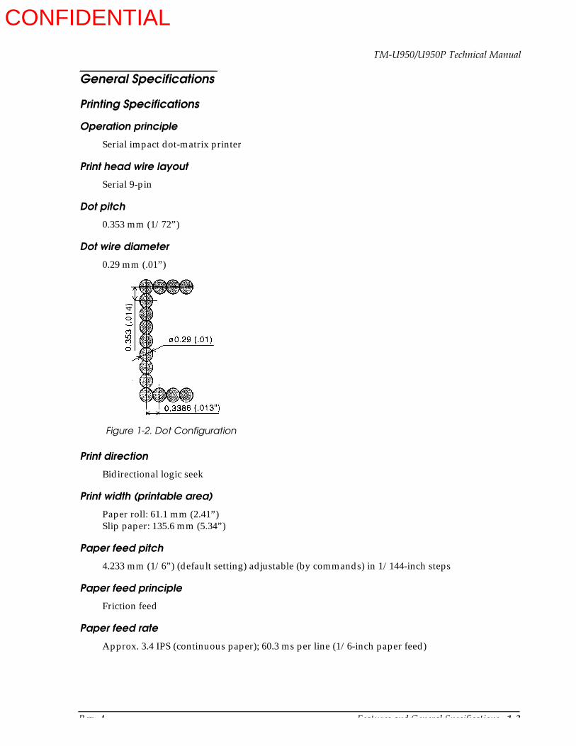
Dot pitch
0.353 mm (1/72”)
Dot wire diameter
0.29 mm (.01”)
Print direction
Bidirectional logic seek
Print width (printable area)
Paper roll: 61.1 mm (2.41”)Slip paper: 135.6 mm (5.34”)
Paper feed pitch
4.233 mm (1/6”) (default setting) adjustable (by commands) in 1/144-inch steps
Paper feed principle
Friction feed
Paper feed rate
Approx. 3.4 IPS (continuous paper); 60.3 ms per line (1/6-inch paper feed)
Figure 1-2. Dot Configuration
CONFIDENTIAL

1-4 Features and General Specifications Rev. A
Printing format
See CPI in Table 1-2.
Character spacing
See Table 1-2.
Total dot count
70 mm paper roll (2.76”): 180 dots (360 positions) per lineSlip paper: 400 dots (800 positions) per line
Printing speed
See Table 1-2.
As shown in the table below, the TM-U950 has three printing modes, which differ in printing speed and head power time (impact).
Character Specifications
Character set
Alphanumeric: 95International: 32Extended graphics: 128 x 8 pages
Character matrix
(Alphanumeric, international, extended graphics)7 x 9 (spacing: 2 half-dots)0 x 9 (spacing: 3 half-dots)
Larger spacing can be set by using ESC SP.
Table 1-1. Printing Operation Mode
Operation mode Printing speed Head power time (impact)
Standard High Standard
Copy Low Copy
Low-speed Low Standard
Table 1-2. CPI, CPS, CPL, Character Size
CG Mode (Horizontal dots x vertical dots)
Character Spacing (half dots)
Characters Per Inch (CPI)
Characters Per Second (CPS) (Carriage moving speed)
Characters Per Line (CPL) Character Size Width x Height
High speed Low speed Paper roll Slip paper
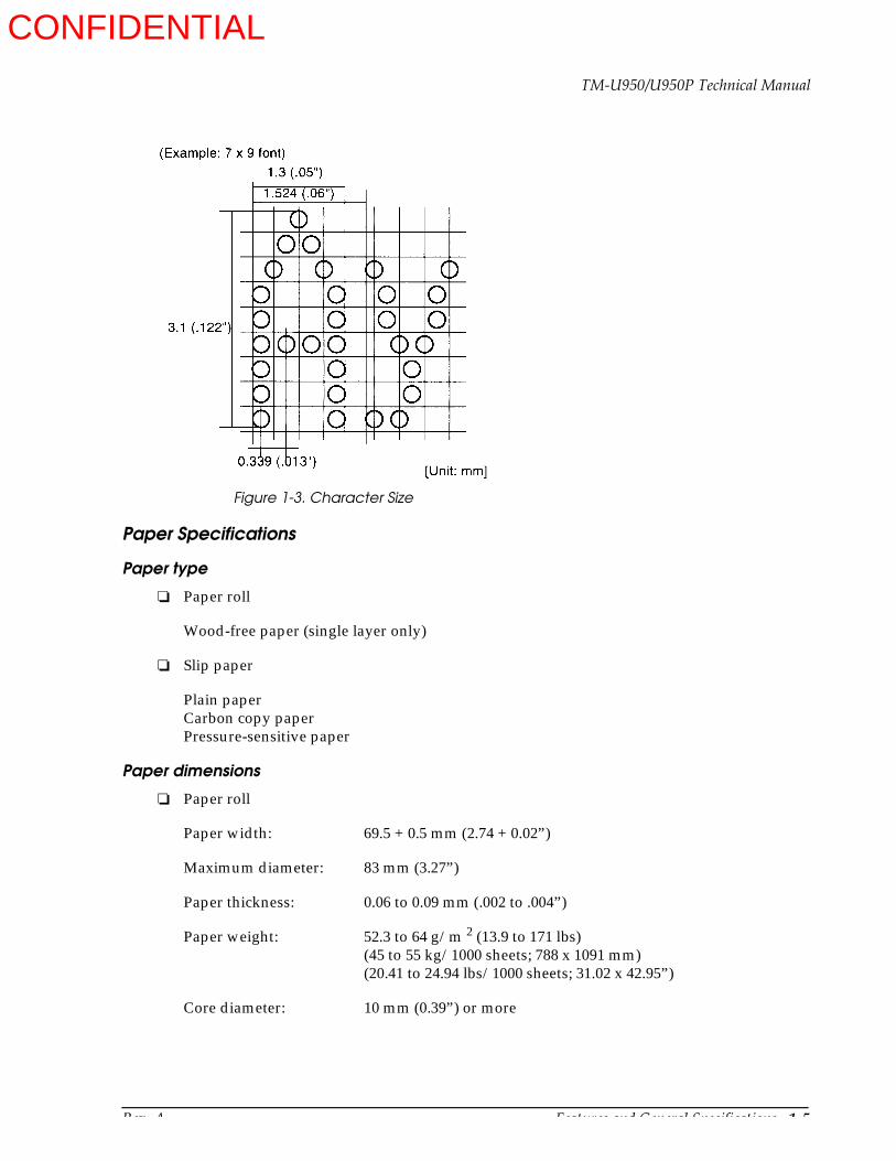
9 x 9 3 dots 12.5 233 200 30 661.6 mm x 3.1 mm (0.6” x .12”)
7 x 9 2 dots 16.7 311 267 40 881.3 mm x 3.1 mm (0.5” x .12”)
CONFIDENTIAL
Rev. A Features and General Specifications 1-5
TM-U950/U950P Technical Manual
Paper Specifications
Paper type
Paper roll
Wood-free paper (single layer only)
Slip paper
Plain paperCarbon copy paperPressure-sensitive paper
Paper dimensions
Paper roll
Paper width: 69.5 + 0.5 mm (2.74 + 0.02”)
Maximum diameter: 83 mm (3.27”)
Paper thickness: 0.06 to 0.09 mm (.002 to .004”)
Paper weight: 52.3 to 64 g/m 2 (13.9 to 171 lbs)(45 to 55 kg/1000 sheets; 788 x 1091 mm)(20.41 to 24.94 lbs/1000 sheets; 31.02 x 42.95”)
Core diameter: 10 mm (0.39”) or more
Figure 1-3. Character Size
CONFIDENTIAL
1-6 Features and General Specifications Rev. A
Slip paper
Dimensions: 70 x 70 to 210 x 297 mm (W x H)(2.76 x 2.76 to 8.27 x 11.69”)
Thickness: 0.09 to 0.36 mm (.004 to .014”)
Temperature and copying capability
As copying capability is influenced by the ambient temperature, printing must be performed under the conditions described in Table 1-3.
Paper thickness and copying capability
Plain paper (single sheet): 0.09 to 0.2 mm(.0035 to .0079”)
Carbon copy paper (original + 4 copies)
Backing paper 0.06 to 0.15 mm (.002 to .006”)
Copy paper and original paper 0.04 to 0.07 mm (.0016 to .003”)
Carbon paper Approx. 0.035 mm (.001”)
Total thickness 0.30 mm (.012”) or less (1 to 1 + 3)0.36 mm (.014”) or less (1 + 4)
Pressure-sensitive paper (original + 4 copies)
Backing paper 0.06 to 0.15 mm (.002 to .006”)
Copy paper and original paper 0.06 to 0.075 mm (.002 to .003”)
Total thickness 0.24 mm (.009”) or less (1 to 1 + 3)0.30 mm (.012”) or less (1 + 4)
Note:When using multi-ply paper that consists of an original and three copies, be sure to print with a 9 x 9 font. If a 7 x 9 font is used, some characters on some of the copies may not be readable.
Check paper (only when the printer is used with the MICR reader)
Paper type: Normal paper
Total thickness: 0.09 to 0.2 mm (.0035 to .0079”)
Table 1-3. Relationship Between Ambient Temperature and Number of Copies
Number of Copies Ambient Temperature
Original + 4 copies approx. 20° to 40°C (68° to 104°F)
Original + 1 to 3 copies 5° to 40°C (41° to 104°F)
CONFIDENTIAL
Rev. A Features and General Specifications 1-7
TM-U950/U950P Technical Manual
Size: 68 to 102 mm x 152 to 210 mm(2.68 to 4.02” x 2.98 to 8.27”)
Weight: 70 to 90 kg paper
Notes on setting the print operation mode
The GS E command sets print mode (printing speed and print head energizing time).
When the power is turned on, normal mode is selected as the default. The printer automatically switches from normal mode to copy mode when slip is selected by ESC c 0.
Notes on slip paper
The slip paper must be flat, without curls or wrinkles, especially at the top edges. Otherwise, the paper may rub against the ribbon and become dirty.
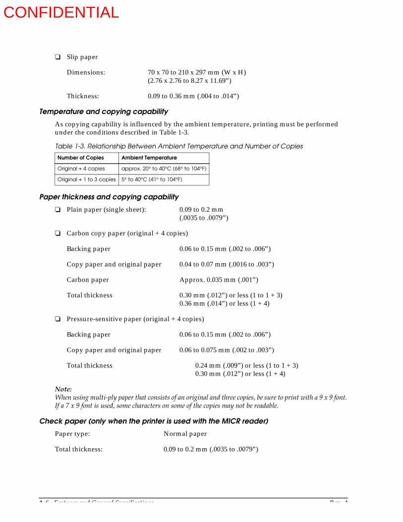
There must be no glue on the bottom edge of slip paper. It is desirable for the glue to be on the top edge. Choose slip paper carefully when the glue is on the right or left edge, since paper feeding and insertion are affected by gluing conditions (e.g., glue quality, method, and length) and glue location (see Figure 1-4). Be especially careful when slip paper is wide and has the glue on the right or left edge, since meandering may occur.
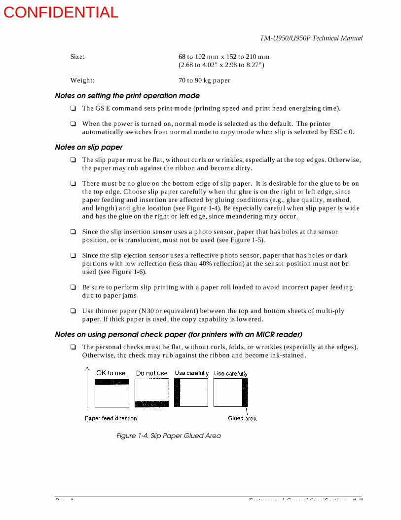
Since the slip insertion sensor uses a photo sensor, paper that has holes at the sensor position, or is translucent, must not be used (see Figure 1-5).
Since the slip ejection sensor uses a reflective photo sensor, paper that has holes or dark portions with low reflection (less than 40% reflection) at the sensor position must not be used (see Figure 1-6).
Be sure to perform slip printing with a paper roll loaded to avoid incorrect paper feeding due to paper jams.
Use thinner paper (N30 or equivalent) between the top and bottom sheets of multi-ply paper. If thick paper is used, the copy capability is lowered.
Notes on using personal check paper (for printers with an MICR reader)
The personal checks must be flat, without curls, folds, or wrinkles (especially at the edges). Otherwise, the check may rub against the ribbon and become ink-stained.
Figure 1-4. Slip Paper Glued Area
CONFIDENTIAL
1-8 Features and General Specifications Rev. A
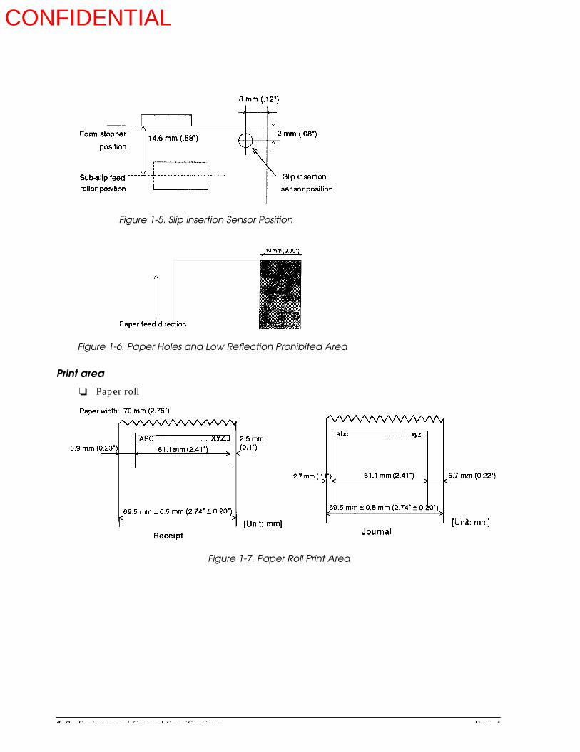
Print area
Paper roll
Figure 1-5. Slip Insertion Sensor Position
Figure 1-6. Paper Holes and Low Reflection Prohibited Area
Figure 1-7. Paper Roll Print Area
CONFIDENTIAL
Rev. A Features and General Specifications 1-9
TM-U950/U950P Technical Manual
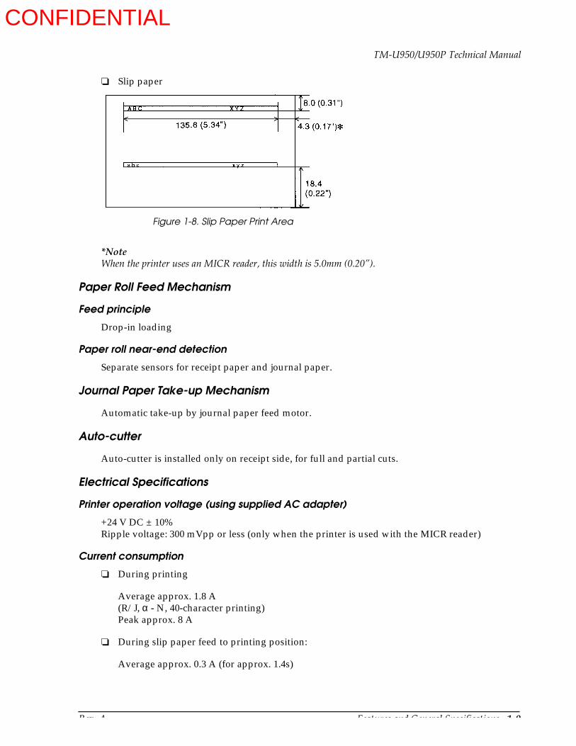
Slip paper
*NoteWhen the printer uses an MICR reader, this width is 5.0mm (0.20”).
Paper Roll Feed Mechanism
Feed principle
Drop-in loading
Paper roll near-end detection
Separate sensors for receipt paper and journal paper.
Journal Paper Take-up Mechanism
Automatic take-up by journal paper feed motor.
Auto-cutter
Auto-cutter is installed only on receipt side, for full and partial cuts.
Electrical Specifications
Printer operation voltage (using supplied AC adapter)
+24 V DC ± 10%Ripple voltage: 300 mVpp or less (only when the printer is used with the MICR reader)
Current consumption
During printing
Average approx. 1.8 A(R/J, α - N, 40-character printing)Peak approx. 8 A
During slip paper feed to printing position:
Average approx. 0.3 A (for approx. 1.4s)
Figure 1-8. Slip Paper Print Area
CONFIDENTIAL
1-10 Features and General Specifications Rev. A
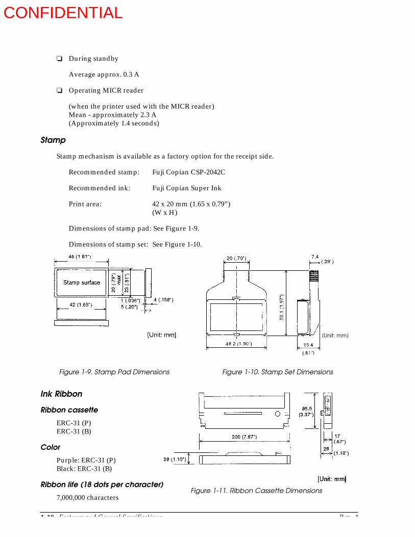
Figure 1-11. Ribbon Cassette Dimensions
During standby
Average approx. 0.3 A
Operating MICR reader
(when the printer used with the MICR reader)Mean - approximately 2.3 A(Approximately 1.4 seconds)
Stamp
Stamp mechanism is available as a factory option for the receipt side.
Recommended stamp: Fuji Copian CSP-2042C
Recommended ink: Fuji Copian Super Ink
Print area: 42 x 20 mm (1.65 x 0.79”)(W x H)
Dimensions of stamp pad: See Figure 1-9.
Dimensions of stamp set: See Figure 1-10.
Ink Ribbon
Ribbon cassette
ERC-31 (P)ERC-31 (B)
Color
Purple: ERC-31 (P)Black: ERC-31 (B)
Ribbon life (18 dots per character)
7,000,000 characters
Figure 1-9. Stamp Pad Dimensions Figure 1-10. Stamp Set Dimensions
[Unit: mm]
CONFIDENTIAL
Rev. A Features and General Specifications 1-11
TM-U950/U950P Technical Manual
Dimensions, Weight, Finish
Dimensions
251 x 298 x 194.5 mm (9.88 x 11.73 x 7.66”) (W x D x H)
Weight
Approx. 5.6 kg (12.3 lbs)
Color
EPSON Standard Gray
Environmental Specifications
Temperature
Operation: 5° to 40°C (41° to 104°F)
Storage: -10° to +50°C (14° to 122°F) (except ribbon)
Humidity
Operation: 30 to 80% (non-condensing; limit above 30°C: 30°C, 80%)
Storage: 30 to 90% (non-condensing; except ribbon)
Vibration resistance (in standard EPSON packing)
Frequency: 5 to 55 Hz
Acceleration: 2 G
Sweep: 5 minutes (one way)
Time: 1 h
Directions: X, Y, Z
No visible external or internal problems or operation failure after the above vibration test.
Shock resistance (in standard EPSON packing)
With packing
Drop height: 50 cm (19.69”)Angle: 1 angle, 3 surfaces, 6 sides
No visible external or internal problems or operation failure after the above drop test.
Without packing
Drop height: 5 cm (1.97”)Angle: 4 sides, one-point support
No damage when dropped while printer is off.
CONFIDENTIAL

1-12 Features and General Specifications Rev. A
Noise
63 dB (operating, measured in ANSI bystander position; printing on receipt and journal paper roll)
Reliability
Mechanics
MCBF 5,000,000 lines (auto-cutter and stamp once every 15 lines)
Life expectancy 7,500,000 lines (The printer’s life is considered over when the printer cannot function due to worn-out main parts such as motor, solenoids, frames, and shafts.)
Life expectancy of print head 150,000,000 characters (average 2 dot/wire/1 character)
MICR reader mechanism (only when the printer is used with the MICR reader):
MCBF: 160,000 passes
Life: 240,000 passes
1 pass: reading characters to printing endorsements on a U.S. personal check (152 mm (5.98”) long)
The MICR reader is defined to have reached the end of its life when it cannot function properly because of wearing out of the main parts (magnetic head, head holding roller, etc).
Certifications
Japan: EMI: VCCI Class 1
North America: EMI: FCC Class 1
Safety standards: UL1950-2TH-D3 C-UL
Europe: CE marking (printer with MICR reader under application)EN55022EN50082-1EN45501 (except when connected to IM)
Safety standard: TÜV
CONFIDENTIAL

Rev. A Features and General Specifications 1-13
TM-U950/U950P Technical Manual
Hardware Configuration
Main Unit Configuration
Printer mechanism
Electrical circuit and unit on cases
Figure 1-12. TM-U950 Printer Mechanism Main Unit Configuration
Figure 1-13. TM-U950 Electrical Circuit and Unit on Cases Main Unit Configuration
CONFIDENTIAL

1-14 Features and General Specifications Rev. A
Main Unit Specifications
Paper feed motors
Receipt and journal paper feeding is performed by dedicated feed motors. Slip paper feeding is performed by using the journal paper feed motor and a journal/slip switching solenoid.
Motor type
4-phase, 48-pole PM type stepping motor
Drive voltage
24 V DC + 10% (including voltage drop caused by drive transistor)
Winding resistance
Journal paper feed motor 35 Ω ± 7% at 25°C (77°F), per phaseReceipt paper feed motor: 42 Ω ± 7% at 25°C (77°F), per phase
Current consumption (per motor)
Journal paper feed motor
Peak current: 1.94A in worst case
Average current: 615 mA at rated speed; 25°C (77°F), 24 V DC, 500 pps930 mA max. in worst case
Hold current 92.5+42.5 mA per phase at normal hold, 25°C (77°F)
Receipt paper feed motor
Peak current: 1.5 A in worst case
Average current: 510 mA at rated speed; 25°C (77°F), 24 V DC, 500 pps770 mA max. in worst case
Hold current: Approx. 130 ± 50 mA per phase at normal hold, 25°C (77°F)
Drive frequency
500 pps (minimum pulse interval 2.00 ms)
Drive principle
Constant voltage drive, 2-2 phase induction
Carriage motor
Motor type
4-phase, 48-pole PM type stepping motor
CONFIDENTIAL
Rev. A Features and General Specifications 1-15
TM-U950/U950P Technical Manual
Drive voltage
24 V DC ± 10% (including voltage drop caused by drive transistor)
Winding resistance
9 Ω ± 7% at 25°C (77°F), per phase
Current consumption (per motor)
Peak current: 1.5 A in worst caseAverage current: 550 mA at rated speedHold current: 150 mA± 8% per phase
Drive frequency
Standard mode: 1400 pps (pulse interval 714 µs)Copy mode: 1200 pps (pulse interval 834 µs)
Drive principle
Constant-current chopper drive, 2-2 phase induction
Carriage feed pitch
0.3386 mm (1/75”) per pulse
Print head unit (print solenoids)
Number of solenoids: 9
Drive voltage: 24 V DC ± 10% (including voltage drop caused by drive transistor)
DC resistance: 6.65 Ω ± 4% at 25°C (77°F)
Near-end sensors (journal, receipt)
A sensor is provided for the receipt and journal paper roll respectively. The sensors check the diameter of each roll and activate the near-end alarm when the diameter falls below a user-determined value.
Sensor type: MicroswitchVoltage: 5 V DC ± 5%Output level: Low when near-end is detected
Paper roll sensors (journal, receipt) (*)
A sensor is provided in the paper path (receipt and journal side, respectively) of the printer mechanism. These sensors check for the presence of paper, and accordingly control loading of the paper roll.
Sensor type: MicroswitchSwitch rating: 10 to 100 mA, 5 V DC (resistive load)Contact condition: On when paper is present
(*) If the paper roll sensor detects the “no paper” condition while the cover is open, semi-automatic loading can be performed by inserting the paper roll into the paper path.
CONFIDENTIAL
1-16 Features and General Specifications Rev. A
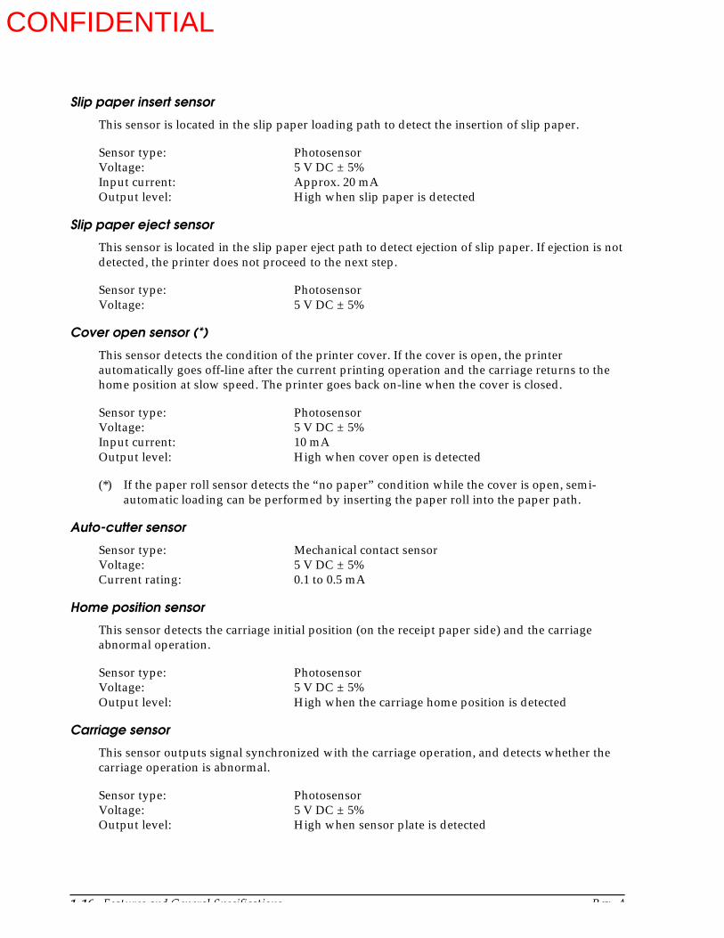
Slip paper insert sensor
This sensor is located in the slip paper loading path to detect the insertion of slip paper.
Sensor type: PhotosensorVoltage: 5 V DC ± 5%Input current: Approx. 20 mAOutput level: High when slip paper is detected
Slip paper eject sensor
This sensor is located in the slip paper eject path to detect ejection of slip paper. If ejection is not detected, the printer does not proceed to the next step.
Sensor type: PhotosensorVoltage: 5 V DC ± 5%
Cover open sensor (*)
This sensor detects the condition of the printer cover. If the cover is open, the printer automatically goes off-line after the current printing operation and the carriage returns to the home position at slow speed. The printer goes back on-line when the cover is closed.
Sensor type: PhotosensorVoltage: 5 V DC ± 5%Input current: 10 mAOutput level: High when cover open is detected
(*) If the paper roll sensor detects the “no paper” condition while the cover is open, semi-automatic loading can be performed by inserting the paper roll into the paper path.
Auto-cutter sensor
Sensor type: Mechanical contact sensorVoltage: 5 V DC ± 5%Current rating: 0.1 to 0.5 mA
Home position sensor
This sensor detects the carriage initial position (on the receipt paper side) and the carriage abnormal operation.
Sensor type: PhotosensorVoltage: 5 V DC ± 5%Output level: High when the carriage home position is detected
Carriage sensor
This sensor outputs signal synchronized with the carriage operation, and detects whether the carriage operation is abnormal.
Sensor type: PhotosensorVoltage: 5 V DC ± 5%Output level: High when sensor plate is detected
CONFIDENTIAL

Rev. A Features and General Specifications 1-17
TM-U950/U950P Technical Manual
MICR Reader (when the printer is used with the MICR reader)(Not available for the TM-U950P)
Available fonts: E-13B, CMC7Recognition rating: 98% or more (at 25°C)
Recognition rating is defined as follows:
Check paper used for test is EPSON standard check paper. Checks must be flat, without curls, folds, or wrinkles.
Connectors
All connectors are located on the rear panel of the printer. (Refer to Figure 1-1.)
Connector panels
Interface
See the Interface section in this chapter.
Power supply connector
This connector is for the AC adapter.
Connector type: TCS7960-53-2010 (Hoshiden) or equivalent
Note:Be sure to ground the printer via the frame ground terminal on the metal strip on the rear panel.
Table 1-4. Power Supply Pin Assignment
Pin number Function
1 24 VDC
2 Signal ground
3 NC
Shell Frame ground
Recognition rating (%) =
Total number of checks - (number of sheets misread
Total number of checks× 100
and those not identified)
1
14 25
13
1 61
2
3
1 8
Customer display (DM-D) connector
Interface connector
Drawer kick- out connector
Power connector
Figure 1-14. Rear Panel ConnectorsTM-U950PTM-U950
Interface connector Drawer kickout Power connectorconnector
CONFIDENTIAL

1-18 Features and General Specifications Rev. A
Drawer kick-out connector (modular connector)
Pulse specified by ESC p command is output to this connector. The host can confirm the status of the input signal by using the DLE EOT, ESC u, GR r, or GS a (ASB) commands.
Connector type:
Printer side 52065-6615 (Molex) or equivalentUser side 6-position 6-contact (RJ12 telephone jack)
(*1) Drawer kick-out drive signal
The signal specified by the ESC p command is output from pins 2 and 5 of the connector.
Output voltage: Approx. 24 VOutput current: 1 A max.
Output waveform: The waveform of the signal at pins 2 and 5 is shown in Figure 1-15. (The ON time n1 and OFF time n2 are determined by the ESC p command.)
(*2) Drawer open/close signal
The host computer can check the drawer open/close status with the DLE EOT, ESC u, GR r, or GS a (ASB) commands.
Input signal level (connector pin 3)
Low = 0 to 0.8 VHigh = 2 to 5 V
Table 1-5. Drawer Kick-out Connector Pin Assignment
Pin number Signal name I/O
1 Frame ground —
2 Drawer kick-out drive signal 1 (*1) O
3 Drawer open/close signal (*2) I
4 + 24 V —
5 Drawer kick-out drive signal 2 (*1) O
6 Signal ground —
n1 x 10ms n2 x 10ms
Figure 1-15. Drawer Kick-out Drive Signal Timing
CONFIDENTIAL
Rev. A Features and General Specifications 1-19
TM-U950/U950P Technical Manual
Notes
Use a shielded cable for the drawer connection.
It is not possible to drive two drawers at the same time.
Use a solenoid rated for at least 24 Ω as the drawer kick-out solenoid. Otherwise, excessive current may damage the solenoid.
The drawer must be powered from the printer (connector pin 4).
Do not drive the drawer continuously.
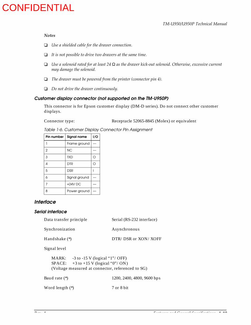
Customer display connector (not supported on the TM-U950P)
This connector is for Epson customer display (DM-D series). Do not connect other customer displays.
Connector type: Receptacle 52065-8845 (Molex) or equivalent
Interface
Serial interface
Data transfer principle Serial (RS-232 interface)
Synchronization Asynchronous
Handshake (*) DTR/DSR or XON/XOFF
Signal level
MARK: -3 to -15 V (logical “1”/OFF)SPACE: +3 to +15 V (logical “0”/ON)(Voltage measured at connector, referenced to SG)
Baud rate (*) 1200, 2400, 4800, 9600 bps
Word length (*) 7 or 8 bit
Table 1-6. Customer Display Connector Pin Assignment
Pin number Signal name I/O
1 Frame ground —
2 NC —
3 TXD O
4 DTR O
5 DSR I
6 Signal ground —
7 +24V DC —
8 Power ground —
CONFIDENTIAL
1-20 Features and General Specifications Rev. A
Parity (*) None, even, odd
Number of stop bits 1 or more
Connector type D-SUB 25 female or equivalent
(*)Can be set with DIP switches on the bottom of the unit (See Tables 1-9 and 1-10.)
On-line/off-line switching
This printer has no on-line/off-line switch. It automatically goes off-line in the following cases:
During self-test.
When the cover is open.
When the paper feed button (receipt or journal/slip) is used to advance the paper.
When printing has stopped due to no paper (“no paper” condition selected with ESC c 4).
During the interval between power-on (including reset using the interface) and the end of the initialization sequence, until data can be received.
When an error has occurred
During the macro execution switch waiting status.
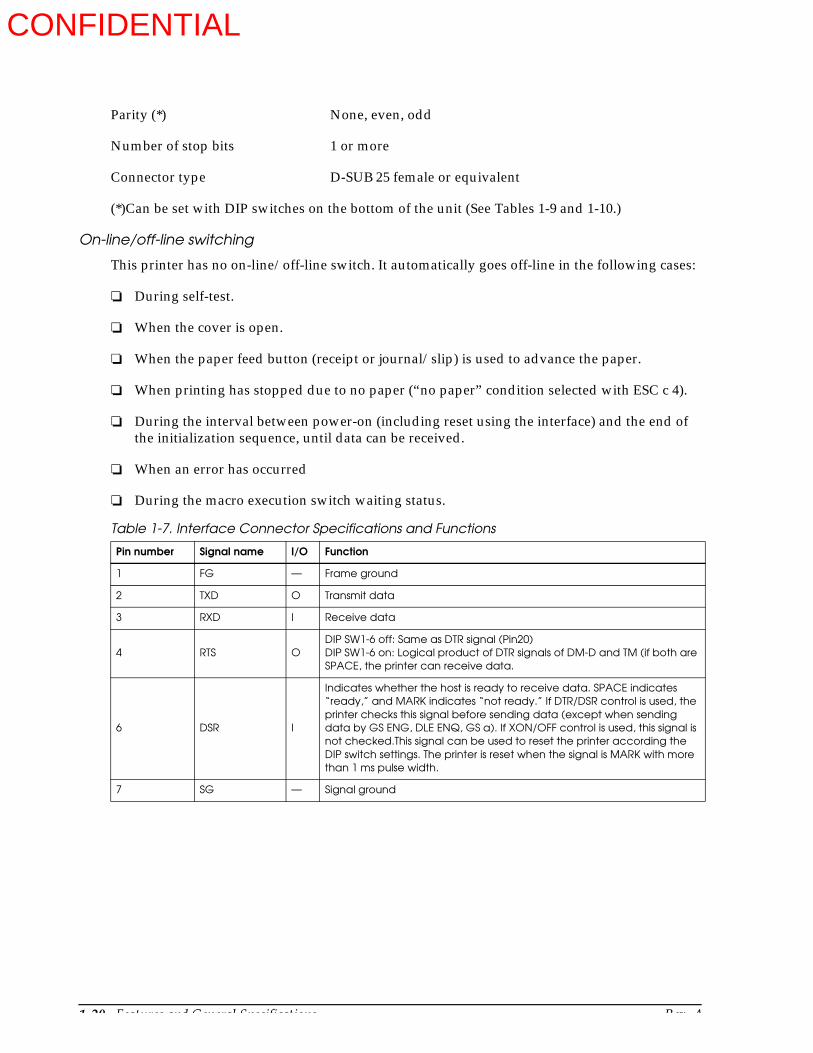
Table 1-7. Interface Connector Specifications and Functions
Pin number Signal name I/O Function
1 FG — Frame ground
2 TXD O Transmit data
3 RXD I Receive data
4 RTS ODIP SW1-6 off: Same as DTR signal (Pin20)DIP SW1-6 on: Logical product of DTR signals of DM-D and TM (if both are SPACE, the printer can receive data.
6 DSR I
Indicates whether the host is ready to receive data. SPACE indicates “ready,” and MARK indicates “not ready.” If DTR/DSR control is used, the printer checks this signal before sending data (except when sending data by GS ENG, DLE ENQ, GS a). If XON/OFF control is used, this signal is not checked.This signal can be used to reset the printer according the DIP switch settings. The printer is reset when the signal is MARK with more than 1 ms pulse width.
7 SG — Signal ground
CONFIDENTIAL
Rev. A Features and General Specifications 1-21
TM-U950/U950P Technical Manual
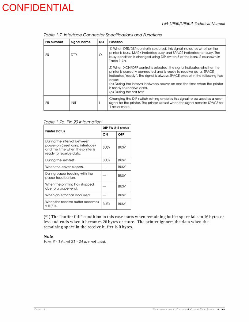
Table 1-7a. Pin 20 Information
(*1) The “buffer full” condition in this case starts when remaining buffer space falls to 16 bytes or less and ends when it becomes 26 bytes or more. The printer ignores the data when the remaining space in the receive buffer is 0 bytes.
NotePins 8 - 19 and 21 - 24 are not used.
20 DTR O
1) When DTR/DSR control is selected, this signal indicates whether the printer is busy. MARK indicates busy and SPACE indicates not busy. The busy condition is changed using DIP switch 5 of the bank 2 as shown in Table 1-7a.
2) When XON/OFF control is selected, the signal indicates whether the printer is correctly connected and is ready to receive data. SPACE indicates “ready”. The signal is always SPACE except in the following two cases:(o) During the interval between power-on and the time when the printer is ready to receive data.(o) During the self-test.
25 INIT IChanging the DIP switch setting enables this signal to be used as a reset signal for the printer. The printer is reset when the signal remains SPACE for 1 ms or more.
Printer statusDIP SW 2-5 status
ON OFF
During the interval between power-on (reset using interface) and the time when the printer is ready to receive data.
BUSY BUSY
During the self-test BUSY BUSY
When the cover is open. — BUSY
During paper feeding with the paper feed button.
— BUSY
When the printing has stopped due to a paper-end.
— BUSY
When an error has occurred. — BUSY
When the receive buffer becomes full (*1).
BUSY BUSY
Table 1-7. Interface Connector Specifications and Functions
Pin number Signal name I/O Function
CONFIDENTIAL

1-22 Features and General Specifications Rev. A
XON/XOFF control
When XON/XOFF control is selected, the XON and XOFF output timing is as described below. (XON code: 11H; XOFF code: 13H) Transmit timing differs depending on the DIP switch 5 of the bank 2.
(*1) XON is not transmitted when the receive buffer is full.(*2) XOFF is not transmitted when the receive buffer is full.
Notes on setting DIP switch 2-5 on
The printer stops printing mechanism operation but does not go off-line when an error has occurred, printing stops due to a paper-end, or paper is fed using the paper feed button.
When setting DIP SW 2-5 on to enable handshaking with the host computer, be sure to check the printer status by the GS a command and automatic status transmission function. In this setting, the default values of n for GS a is 2, and the printer automatically transmits the changes in on-line/off-line.
When using DLE EOT, DLE ENQ, and GS ENQ, be sure that the receive buffer does not become full.
a) When using a host that cannot transmit data when the printer is busy:
If an error has occurred, DLE EOT, DLE ENQ, and GS ENQ cannot be used when the printer is busy due to receive buffer-full.
b) When using a host that can transmit data when the printer is busy:
When the receive buffer becomes full while transmitting data, DLE EOT, DLE ENQ, or GS ENQ using between the bit image data is processed as bit image data. The data transmitted when the receive buffer is full may be lost.
Table 1.8. XON/XOFF Transmit Timing
Printer statusDIP SW 2-5 status
ON OFF
XON transmission
When the printer goes on-line after the power-on or reset with interface.
Transmit Transmit
When the receive buffer is released from the buffer full state. Transmit Transmit
When the printer changes to on-line. (*1) — Transmit
When the printer recovers from an error by the DLE ENQ 1 or DLE ENQ 2.
— Transmit
XOFF transmissionWhen receive buffer becomes full. Transmit Transmit
When the printer changes to off-line. (*2) — Transmit
CONFIDENTIAL
Rev. A Features and General Specifications 1-23
TM-U950/U950P Technical Manual
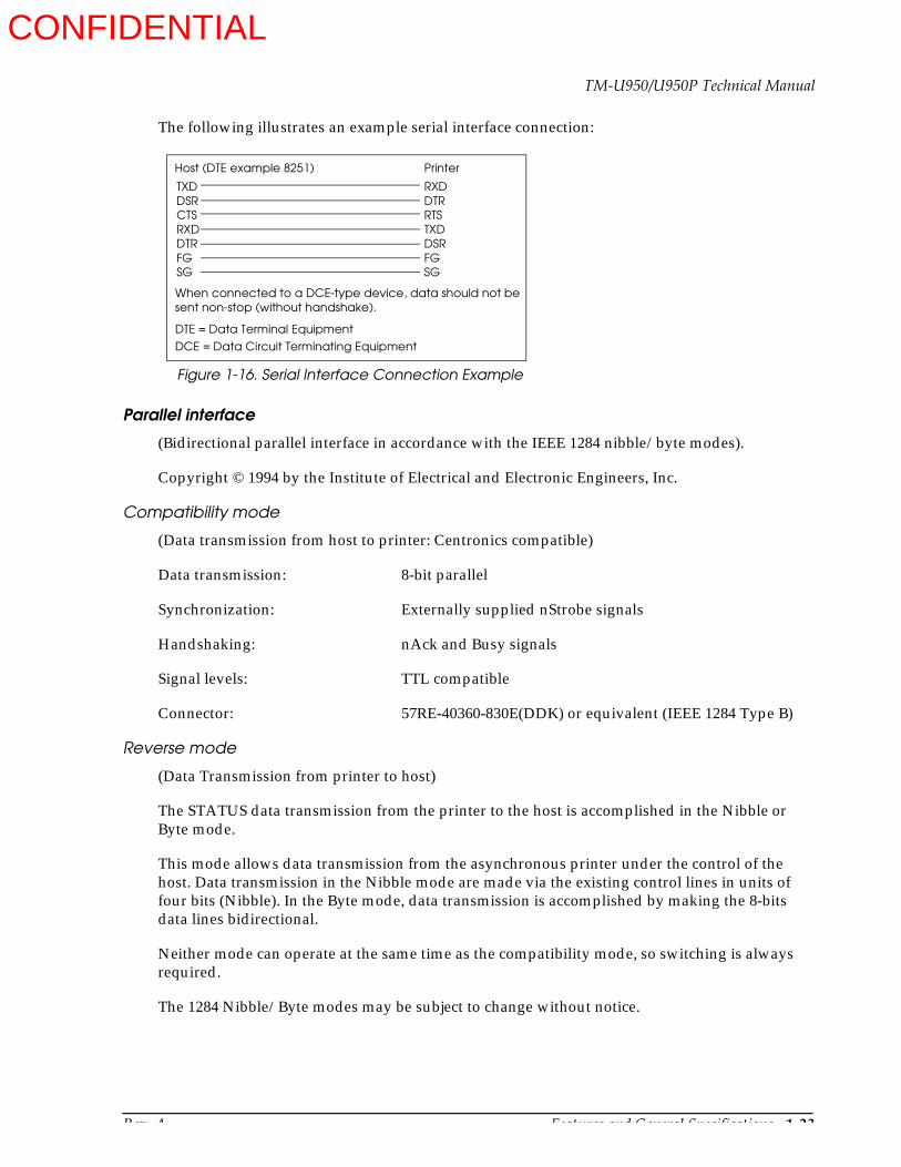
The following illustrates an example serial interface connection:
Parallel interface
(Bidirectional parallel interface in accordance with the IEEE 1284 nibble/byte modes).
Copyright © 1994 by the Institute of Electrical and Electronic Engineers, Inc.
Compatibility mode
(Data transmission from host to printer: Centronics compatible)
Data transmission: 8-bit parallel
Synchronization: Externally supplied nStrobe signals
Handshaking: nAck and Busy signals
Signal levels: TTL compatible
Connector: 57RE-40360-830E(DDK) or equivalent (IEEE 1284 Type B)
Reverse mode
(Data Transmission from printer to host)
The STATUS data transmission from the printer to the host is accomplished in the Nibble or Byte mode.
This mode allows data transmission from the asynchronous printer under the control of the host. Data transmission in the Nibble mode are made via the existing control lines in units of four bits (Nibble). In the Byte mode, data transmission is accomplished by making the 8-bits data lines bidirectional.
Neither mode can operate at the same time as the compatibility mode, so switching is always required.
The 1284 Nibble/Byte modes may be subject to change without notice.
Figure 1-16. Serial Interface Connection Example
Host (DTE example 8251)
TXDDSRCTSRXDDTRFGSG
RXDDTRRTSTXDDSRFGSG
Printer
When connected to a DCE-type device, data should not besent non-stop (without handshake).
DTE = Data Terminal Equipment
DCE = Data Circuit Terminating Equipment
CONFIDENTIAL
1-24 Features and General Specifications Rev. A
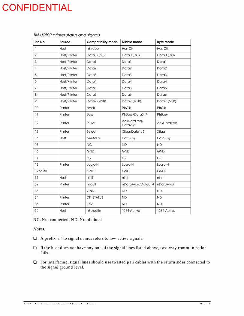
NC: Not connected, ND: Not defined
Notes:
A prefix "n" to signal names refers to low active signals.
If the host does not have any one of the signal lines listed above, two-way communication fails.
For interfacing, signal lines should use twisted pair cables with the return sides connected to the signal ground level.
TM-U950P printer status and signals
Pin No. Source Compatibility mode Nibble mode Byte mode
1 Host nStrobe HostClk HostClk
2 Host/Printer Data0 (LSB) Data0 (LSB) Data0 (LSB)
3 Host/Printer Data1 Data1 Data1
4 Host/Printer Data2 Data2 Data2
5 Host/Printer Data3 Data3 Data3
6 Host/Printer Data4 Data4 Data4
7 Host/Printer Data5 Data5 Data5
8 Host/Printer Data6 Data6 Data6
9 Host/Printer Data7 (MSB) Data7 (MSB) Data7 (MSB)
10 Printer nAck PtrClk PtrClk
11 Printer Busy PtrBusy/Data3, 7 PtrBusy
12 Printer PErrorAckDataReq/Data2, 6
AckDataReq
13 Printer Select Xflag/Data1, 5 Xflag
14 Host nAutoFd HostBusy HostBusy
15 NC ND ND
16 GND GND GND
17 FG FG FG
18 Printer Logic-H Logic-H Logic-H
19 to 30 GND GND GND
31 Host nInit nInit nInit
32 Printer nFault nDataAvail/Data0, 4 nDataAvail
33 GND ND ND
34 Printer DK_STATUS ND ND
35 Printer +5V ND ND
36 Host nSelectIn 1284-Active 1284-Active
CONFIDENTIAL
Rev. A Features and General Specifications 1-25
TM-U950/U950P Technical Manual
Interfacing conditions should be all based on the TTL level. In addition, both the rise time and fall time of each signal must be 0.5 µs or less.
Data transmission should not ignore the signal nAck or Busy. An attempt to transmit data with either signal, nAck or Busy, ignored can cause lost data. (Data transmission to the printer should be made after verifying the nAck signal or while the Busy signal is low.)
Interface cables should be as short as possible.
Precautions on receiving status from the printer
The printer status transmission is available by using the both-way communication facility in the Nibble/Byte mode in accordance with the IEEE 1284 mode.
The following precautions must be taken for receiving the status from the printer.
The allowable capacity of the printer’s internal buffer is 100 bytes. Status signals exceeding this capacity will be discarded. To prevent possible loss of status data, the host should always be ready for data reception (reverse mode).
When ASB is used, the host should be in the wait state for data reception (reverse idle mode). When this state is not available, the host should enter the reverse mode to always monitor the presence of data.
When ASB is used, preference should be given to the ASB status for transmission over the other status signals. Any accumulated ASB status signals left for transmission from the last to the newest ASB status transmission should be transmitted together at one time as one ASB status showing the change has been made, followed by the latest ASB status.
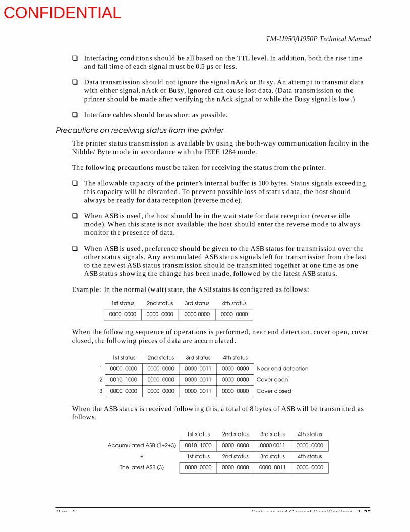
Example: In the normal (wait) state, the ASB status is configured as follows:
When the following sequence of operations is performed, near end detection, cover open, cover closed, the following pieces of data are accumulated.
When the ASB status is received following this, a total of 8 bytes of ASB will be transmitted as follows.
1st status 2nd status 3rd status 4th status
0000 0000 0000 0000 0000 0000 0000 0000
1st status 2nd status 3rd status 4th status
1 0000 0000 0000 0000 0000 0011 0000 0000 Near end detection
2 0010 1000 0000 0000 0000 0011 0000 0000 Cover open
3 0000 0000 0000 0000 0000 0011 0000 0000 Cover closed
1st status 2nd status 3rd status 4th status
Accumulated ASB (1+2+3) 0010 1000 0000 0000 0000 0011 0000 0000
+ 1st status 2nd status 3rd status 4th status
The latest ASB (3) 0000 0000 0000 0000 0000 0011 0000 0000
CONFIDENTIAL
1-26 Features and General Specifications Rev. A
Switching between on-line and off-line
The TM-U950P printer does not have an on-line/off-line button. The printer goes off-line in the following conditions:
Between the time when the power is turned on (including reset using the interface) and when the printer is ready to receive data.
During the self-test.
When the cover is open.
During paper feeding using the paper feed button.
When the printer stops printing due to a paper-end (when the paper-end sensor detects a paper end or when the paper near-end sensor is enabled by ESC c 4 and detects a paper-end).
During the macro execution standby state. (The macro is executed by pressing the paper feed button.)
When an error has occurred.
Notes on setting DIP switch 2-5 to ON
The printer mechanism stops but does not become busy when an error has occurred, the cover is open, printing stops due to a paper end, or paper is fed using the PAPER FEED button.
When setting DIP switch 2-5 to ON to enable handshaking with the printer, be sure to check the printer status using the GS a command and the ASB function. In this setting, the default value of n for GS a is 2. The printer automatically transmits the printer status, depending on on-line/off-line changes.
When using DLE EOT, DLE ENQ and GS ENQ, be sure that the receive buffer does not become full.
When using a host that cannot transmit data when the printer is busy and if an error occurs, DLE EOT, DLE ENQ and GS ENQ cannot be used when the printer is busy due to a receive buffer-full state.
When using a host that can transmit data when the printer is busy and the receive buffer becomes full while transmitting bit-image data, a DLE EOT, DLE ENQ or GS ENQ used while sending bit-image data is processed as bit-image data, not as acommand. Secondly, any data transmitted when the receive buffer is full may be lost. Thirdly, data sent during data entry or data sent when the printer is busy may be lost regardless of the DIP switch setting.
Example: Check the printer status using ESC v or ESC u after transmitting each line of data and use the 2K byte receive buffer. Transmit one line of data so that the receive buffer does not become full.
CONFIDENTIAL
Rev. A Features and General Specifications 1-27
TM-U950/U950P Technical Manual
Switches and Buttons
The power switch is located on the front side of the printer, at the lower left. The operation panel buttons are located on the right top side of the printer. Two banks of DIP switches are located on the bottom of the printer. (See Figure 1-1.)
Power switch
Turns the printer on or off.
Power switch cover guards the power switch from incorrect operation.
For using the cover see Mounting the Power Switch Cover in Chapter 3.
Operation panel buttons
The ESC c 5 command determines whether or not the operation panel buttons are active.
RECEIPT FEED button
Type: Non-locking push button
Function: If this button is pushed once and released, the printer feeds receipt paper for one line based on the line spacing set by ESC 2 and ESC 3. If this button is held down, the printer feed paper continuously.
The paper is fed after the carriage is moved to the center of the receipt paper roll.
JOURNAL/SLIP FEED button
Type: Non-locking push button
Function: If this button is pushed once and released, the printer feeds journal paper for one line based on the line spacing set by ESC 2 and ESC 3. If this button is held down, the printer feeds paper continuously.
When this button is pushed in slip mode (slip LED lights or blinks), the printer feeds slip paper.
In 2-sheet mode, the paper is fed after the carriage is moved to the center of the journal paper roll.
In slip mode, the paper is fed after the carriage is moved to the right edge of the slip paper.
Notes
When the printer cover is open, these buttons are active regardless of the ESC c 5 setting.
Be careful not to catch your finger in the printer when you push these buttons with the printer cover open.
CONFIDENTIAL
1-28 Features and General Specifications Rev. A
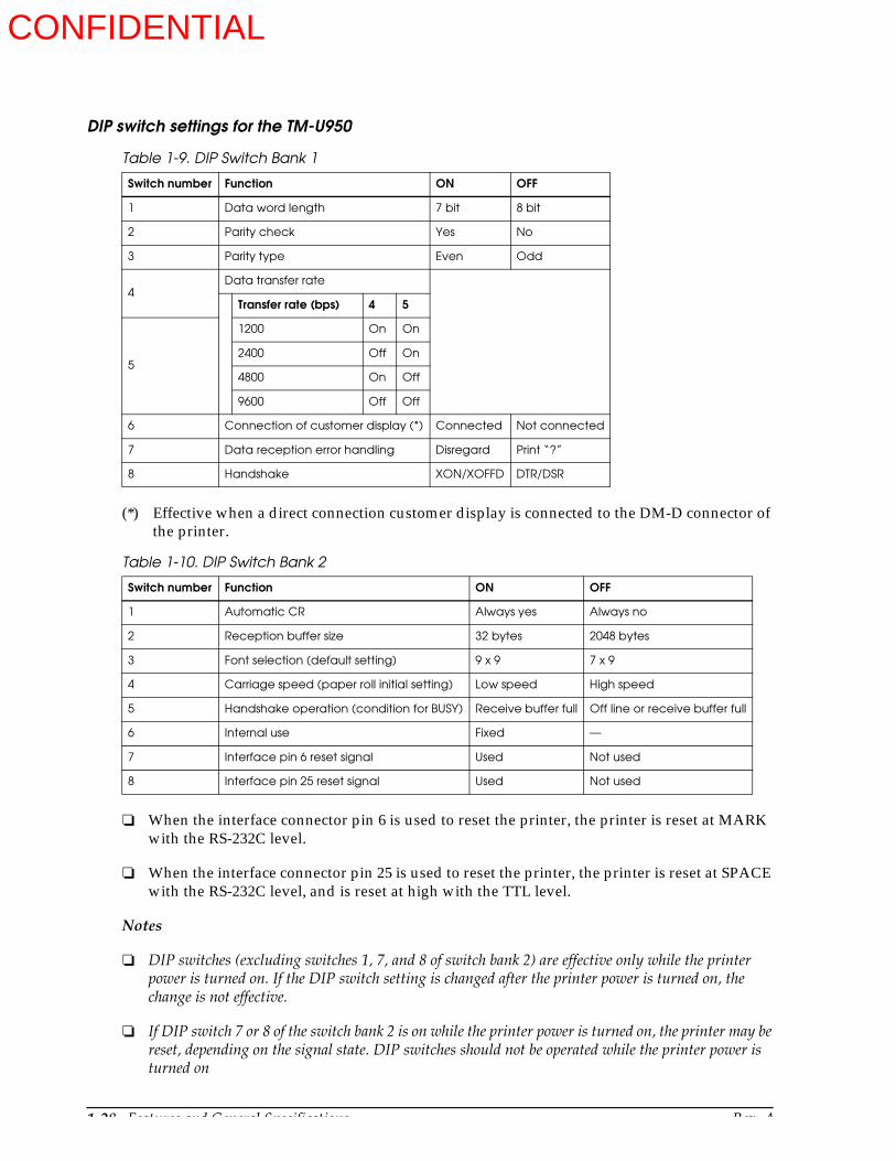
DIP switch settings for the TM-U950
(*) Effective when a direct connection customer display is connected to the DM-D connector of the printer.
When the interface connector pin 6 is used to reset the printer, the printer is reset at MARK with the RS-232C level.
When the interface connector pin 25 is used to reset the printer, the printer is reset at SPACE with the RS-232C level, and is reset at high with the TTL level.
Notes
DIP switches (excluding switches 1, 7, and 8 of switch bank 2) are effective only while the printer power is turned on. If the DIP switch setting is changed after the printer power is turned on, the change is not effective.
If DIP switch 7 or 8 of the switch bank 2 is on while the printer power is turned on, the printer may be reset, depending on the signal state. DIP switches should not be operated while the printer power is turned on
Table 1-9. DIP Switch Bank 1
Switch number Function ON OFF
1 Data word length 7 bit 8 bit
2 Parity check Yes No
3 Parity type Even Odd
4Data transfer rate
Transfer rate (bps) 4 5
5
1200 On On
2400 Off On
4800 On Off
9600 Off Off
6 Connection of customer display (*) Connected Not connected
7 Data reception error handling Disregard Print “?”
8 Handshake XON/XOFFD DTR/DSR
Table 1-10. DIP Switch Bank 2
Switch number Function ON OFF
1 Automatic CR Always yes Always no
2 Reception buffer size 32 bytes 2048 bytes
3 Font selection (default setting) 9 x 9 7 x 9
4 Carriage speed (paper roll initial setting) Low speed High speed
5 Handshake operation (condition for BUSY) Receive buffer full Off line or receive buffer full
6 Internal use Fixed —
7 Interface pin 6 reset signal Used Not used
8 Interface pin 25 reset signal Used Not used
CONFIDENTIAL
Rev. A Features and General Specifications 1-29
TM-U950/U950P Technical Manual
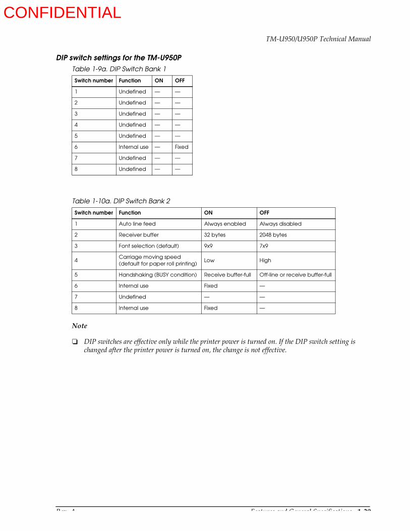
DIP switch settings for the TM-U950P
Note
DIP switches are effective only while the printer power is turned on. If the DIP switch setting is changed after the printer power is turned on, the change is not effective.
Table 1-9a. DIP Switch Bank 1
Switch number Function ON OFF
1 Undefined — —
2 Undefined — —
3 Undefined — —
4 Undefined — —
5 Undefined — —
6 Internal use — Fixed
7 Undefined — —
8 Undefined — —
Table 1-10a. DIP Switch Bank 2
Switch number Function ON OFF
1 Auto line feed Always enabled Always disabled
2 Receiver buffer 32 bytes 2048 bytes
3 Font selection (default) 9x9 7x9
4Carriage moving speed(default for paper roll printing)
Low High
5 Handshaking (BUSY condition) Receive buffer-full Off-line or receive buffer-full
6 Internal use Fixed —
7 Undefined — —
8 Internal use Fixed —
CONFIDENTIAL

1-30 Features and General Specifications Rev. A
Indicators
The indicators are located on the operation panel. (See Figure 1-1.)
POWER LED (green)
On: Stable power (+5 V) is supplied.
Off: Stable power (+5 V) is not supplied.
ERROR LED (red)
On: Printer is off-line (except when paper is being advanced with the FEED buttons and during self test printing).
Off: Normal operation
Flashing: An error has occurred. (See Error Types and Countermeasures on page 4-23).
RECEIPT OUT LED (red)
On: Near-end condition or paper end is detected for paper roll at receipt side.
Off: Paper roll at receipt side is sufficient.
Flashing: Stand by for test printing
JOURNAL OUT LED (red)
On: Near-end condition or paper end is detected for paper roll at journal side.
Off: Paper roll at journal side is sufficient.
Flashing: Stand by for test printing
SLIP LED (green)
On: Slip paper mode
Off: Two-sheet (paper roll) mode
CONFIDENTIAL

Rev. A Features and General Specifications 1-31
TM-U950/U950P Technical Manual
Blinking: Stand by for slip paper insertion
Functions
Error Processing
Error detection
When the printer detects an error, it carries out the following operation sequence:
All running operations are stopped.
The printer goes off-line
The ERROR LED flashes. (See Error Types and Countermeasures on page 4-23.)
Error recovery
The commands DLE ENQ 1 and DLE ENQ 2 are used to recover from a recoverable error (*1).
Notes
If slip paper is selected and DLE ENQ 1 is used to recover from a recoverable error, the printer ejects the remaining slip paper and repeats the loading process.
When recovering from a slip paper eject error, the printer ejects the paper but does not repeat loading.
When the printer recovers from an error using DLE ENQ 2 while slip paper is selected, the printer first ejects the slip, then goes to 2-sheet mode.
When an unrecoverable error (*2) has occurred, turn off the printer as soon as possible.
(*1) Errors (6) to (10) in Table 4-5 in Chapter 4 are the recoverable errors.
(*2) Errors (1) to (5) in Table 4-5 in Chapter 4 are the unrecoverable errors.
Blinking pattern
Blinking: Stand by for slip paper removalBlinking pattern
Blinking: Personal check waiting state (when the printer isused with the MICR reader)
CONFIDENTIAL

1-32 Features and General Specifications Rev. A
Data receive error
When an error is detected in data received by the printer (parity, framing, or overrun error), the data is either ignored or replaced to “?”, depending on the DIP switch setting.
Self-test
The self-test checks the following items:
Control circuit operation
Printer mechanism operation
Print quality
Control ROM version (on status printout)
DIP switch settings (on status printout)
MICR reader circuit function check (for printers with an MICR reader)
For details about the self-test, please see Self-test in Chapter 4.
Hexadecimal Dumping
Hexadecimal dumping function
This function prints the data transmitted from the host computer in hexadecimal numbers and in its corresponding characters.
Starting hexadecimal dumping
Open the cover and turn the power on while pressing the RECEIPT FEED button, then close the cover. The printer first prints “Hexadecimal Dump” on the paper roll and prints the received print data in hexadecimal numbers and in its corresponding characters.
Notes
If no characters correspond to the data received, the printer prints “.”.
During hexadecimal dumping, any commands other than DLE EOT, DLE ENQ, and GS ENQ do not function.
Ending hexadecimal dumping
Hexadecimal dumping ends by turning the power off or resetting the printer after printing has finished.
CONFIDENTIAL

Rev. A Features and General Specifications 1-33
TM-U950/U950P Technical Manual
Printing example.
Printing Operation
Sensors and printing operation
The ESC c 4 command can be used to select whether the printer should stop or continue printing when the “no paper” condition is detected. The following sensors are involved:
Two-sheet mode: Journal near-end sensorReceipt near-end sensorJournal paper sensor (*1)Receipt paper sensor (*1)
Slip paper mode: Slip paper insert sensor
(*1) The journal and receipt paper roll sensors are used for auto-loading and cannot be used for paper-end detection. Printing may not be stopped even if the sensors are selected by ESC c 4. Therefore, use the near-end sensors to detect the paper roll end.
When “stop printing” is selected
Two-sheet mode
When the “no paper” condition is detected, the printer automatically goes off-line. To resume printing, close the cover after inserting a new paper roll.
Slip paper mode
When the “no paper” condition is detected, the printer continues to print on the printable area, ejects the paper, and waits for the paper to be removed. The printer then stands by for paper insertion.
Buffer full printing
After the maximum number of characters per line has been received and processed, the line is printed and the paper is advanced automatically when additional data is received.
Hexadecimal Dump
1B 21 00 1B 26 02 40 40 : .!.&.@@
1B 25 01 1B 63 34 00 1B : .%..C4..
41 42 43 44 45 46 47 48 : ABCDEFGH
CONFIDENTIAL
1-34 Features and General Specifications Rev. A
Options
AC Adapter (PS-150)
Specifications
Input specifications
Rated input voltage: 90 to 110 V AC(specified at time of purchase): 108 to 132 V AC
198 to 264 V AC
Frequency: 48 to 62 Hz
Rated input current: 1.0 A (100 V type)1.0 A (120 V type)0.5 A (230 V type)
Power switch: None
Power LED: None
Output specifications
Output voltage: 24 V DC + 7%
Rated output current: 1.9 A North American model2.0 A Japanese and European model
(If the adapter is not connected to a DC load of 2.0 A or less during power-on, the voltage will not build up sufficiently for operation.)
Rated output power: Approx. 48 W
Output peak current: 6 A (within 10 ms)
Compliance to safety regulations
UL/CSA/TÜV
Dimensions and weight
Dimensions: 86 x 166 x 44 mm (3.39 x 6.54 x 1.73”) (W x D x H) without protruding parts
Weight: 700 g (1.54 lbs) excluding AC adapter
Journal Lock
Journal lock mechanism is a factory option. It protects journal paper roll from being taken away. For handling, see Journal lock key handling in Chapter 3.
CONFIDENTIAL
Rev. A Mechanism Configuration and Operating Principles 2-1
TM-U950/U950P Technical Manual
Chapter 2Mechanism Configuration and Operating Principles
Printer Mechanism Components
The TM-U950 impact dot matrix printer consists of the following eight components:
Printing assembly
Sensor assembly
Paper feed assembly
Slip paper assembly
Ribbon feed assembly
Stamp assembly (for printers with a stamp assembly)
Auto-cutter assembly
Paper roll-take-up assembly
These components are described in detail in the following sections.
CONFIDENTIAL

2-2 Mechanism Configuration and Operating Principles Rev. A
Printer Mechanism Operating Principles
Printing Assembly
The printing assembly consists of the print head unit with nine vertical wires, and the parts shown in Figure 2-1.
Print head unit movement
When the carriage motor is driven, the gear wheel turns in the direction indicated by the arrow , and the carriage feed pulley and carriage drive belt transmit the driving force so that the
head carriage fastened to the carriage drive belt moves in the direction of the arrow . When the carriage motor turns in the direction indicated by the arrow , the head carriage moves in the direction of the arrow .
Figure 2-1. Printing Asssembly
Figure 2-2. Print Head Unit Movement
CONFIDENTIAL
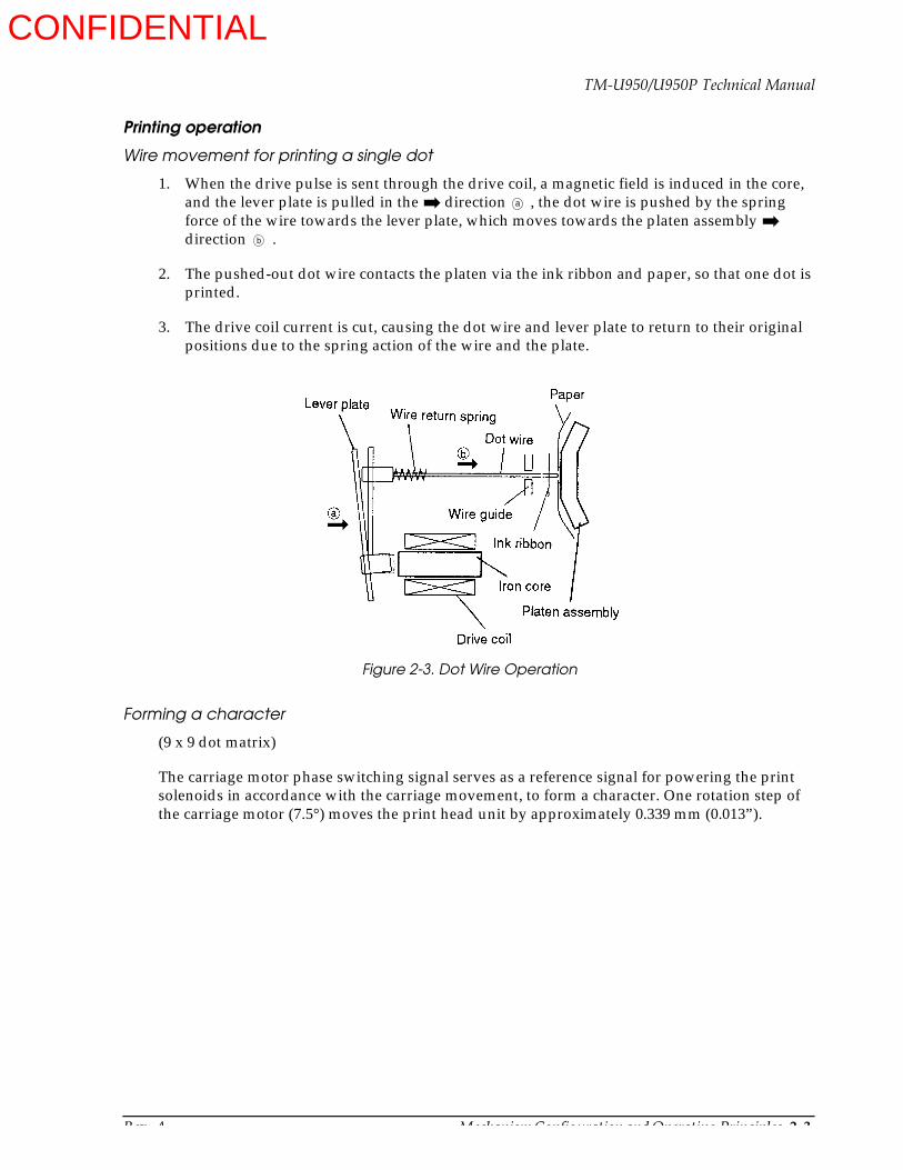
Rev. A Mechanism Configuration and Operating Principles 2-3
TM-U950/U950P Technical Manual
Printing operation
Wire movement for printing a single dot
1. When the drive pulse is sent through the drive coil, a magnetic field is induced in the core, and the lever plate is pulled in the direction , the dot wire is pushed by the spring force of the wire towards the lever plate, which moves towards the platen assembly direction .
2. The pushed-out dot wire contacts the platen via the ink ribbon and paper, so that one dot is printed.
3. The drive coil current is cut, causing the dot wire and lever plate to return to their original positions due to the spring action of the wire and the plate.
Forming a character
(9 x 9 dot matrix)
The carriage motor phase switching signal serves as a reference signal for powering the print solenoids in accordance with the carriage movement, to form a character. One rotation step of the carriage motor (7.5°) moves the print head unit by approximately 0.339 mm (0.013”).
a
b
Figure 2-3. Dot Wire Operation
CONFIDENTIAL
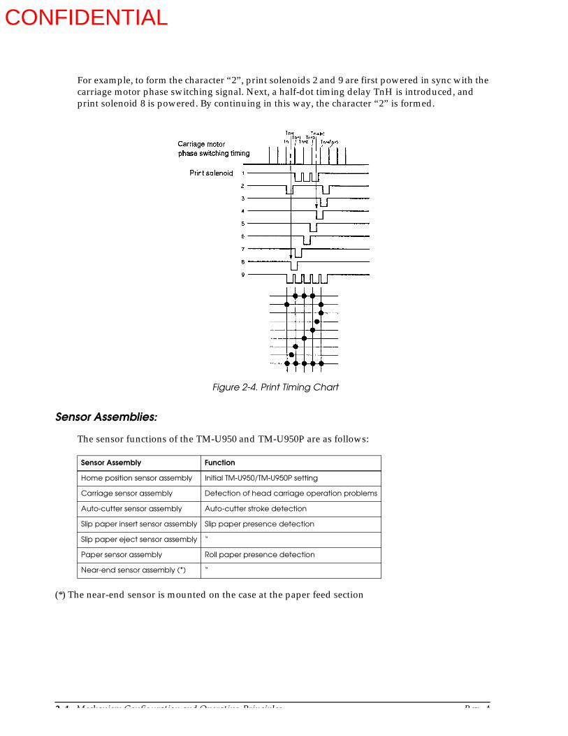
2-4 Mechanism Configuration and Operating Principles Rev. A
For example, to form the character “2”, print solenoids 2 and 9 are first powered in sync with the carriage motor phase switching signal. Next, a half-dot timing delay TnH is introduced, and print solenoid 8 is powered. By continuing in this way, the character “2” is formed.
Sensor Assemblies:
The sensor functions of the TM-U950 and TM-U950P are as follows:
(*) The near-end sensor is mounted on the case at the paper feed section
Sensor Assembly Function
Home position sensor assembly Initial TM-U950/TM-U950P setting
Carriage sensor assembly Detection of head carriage operation problems
Auto-cutter sensor assembly Auto-cutter stroke detection
Slip paper insert sensor assembly Slip paper presence detection
Slip paper eject sensor assembly “
Paper sensor assembly Roll paper presence detection
Near-end sensor assembly (*) “
Figure 2-4. Print Timing Chart
CONFIDENTIAL
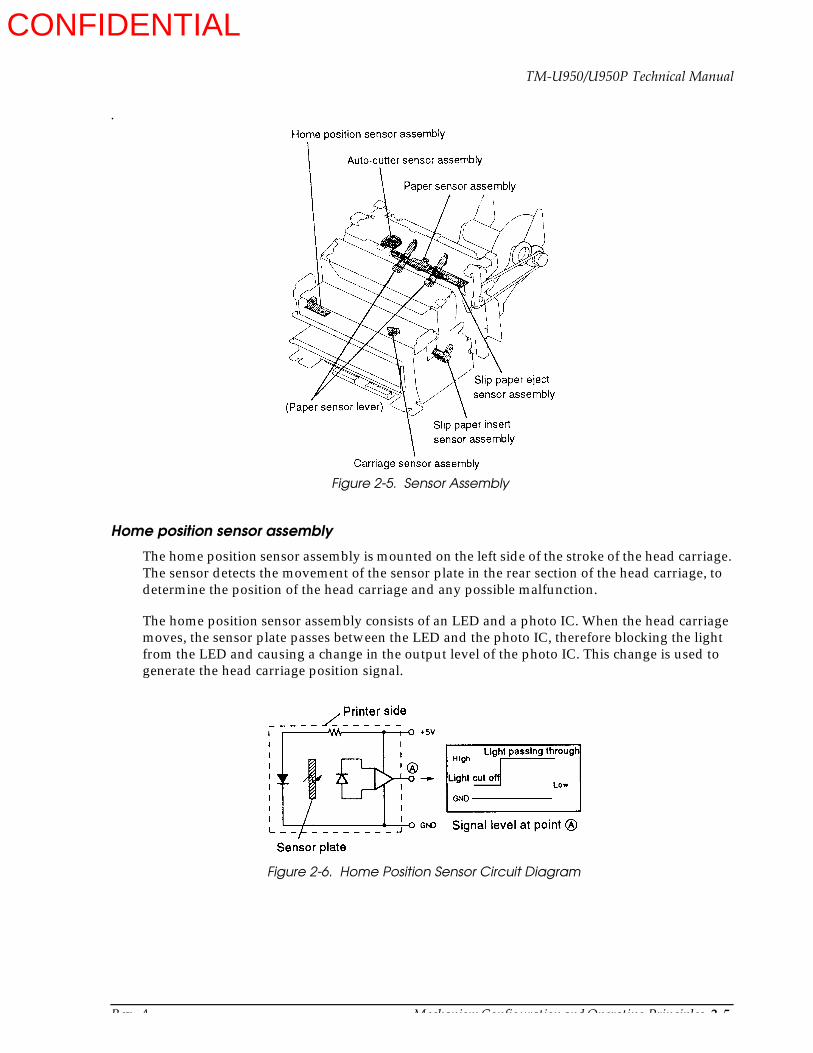
Rev. A Mechanism Configuration and Operating Principles 2-5
TM-U950/U950P Technical Manual
.
Home position sensor assembly
The home position sensor assembly is mounted on the left side of the stroke of the head carriage. The sensor detects the movement of the sensor plate in the rear section of the head carriage, to determine the position of the head carriage and any possible malfunction.
The home position sensor assembly consists of an LED and a photo IC. When the head carriage moves, the sensor plate passes between the LED and the photo IC, therefore blocking the light from the LED and causing a change in the output level of the photo IC. This change is used to generate the head carriage position signal.
Figure 2-5. Sensor Assembly
Figure 2-6. Home Position Sensor Circuit Diagram
CONFIDENTIAL
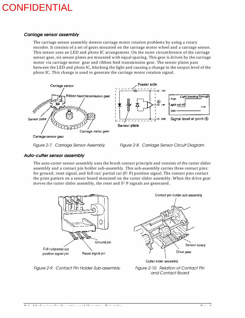
2-6 Mechanism Configuration and Operating Principles Rev. A
Carriage sensor assembly
The carriage sensor assembly detects carriage motor rotation problems by using a rotary encoder. It consists of a set of gears mounted on the carriage motor wheel and a carriage sensor. This sensor uses an LED and photo IC arrangement. On the outer circumference of the carriage sensor gear, six sensor plates are mounted with equal spacing. This gear is driven by the carriage motor via carriage motor gear and ribbon feed transmission gear. The sensor plates pass between the LED and photo IC, blocking the light and causing a change in the output level of the photo IC. This change is used to generate the carriage motor rotation signal.
Auto-cutter sensor assembly
The auto-cutter sensor assembly uses the brush contact principle and consists of the cutter slider assembly and a contact pin holder sub-assembly. This sub-assembly carries three contact pins: for ground, reset signal, and full cut/partial cut (F/P) position signal. The contact pins contact the print pattern on a sensor board mounted on the cutter slider assembly. When the drive gear moves the cutter slider assembly, the reset and F/P signals are generated.
Figure 2-8. Carriage Sensor Circuit DiagramFigure 2-7. Carriage Sensor Assembly
Figure 2-9. Contact Pin Holder Sub-assembly Figure 2-10. Relation of Contact Pinand Contact Board
CONFIDENTIAL

Rev. A Mechanism Configuration and Operating Principles 2-7
TM-U950/U950P Technical Manual
Slip paper insert sensor assembly
The slip paper insert sensor assembly detects the tip of the paper when slip paper is being inserted and detects the end of the paper during printing. It is mounted immediately to the right of the paper set position.
The sensor sub-assembly uses an LED and photo transistor arrangement. When slip paper is inserted, it blocks the light from the LED and causes a change in the output level of the photo transistor. This change is used to generate the slip paper presence signal.
Slip paper eject sensor assembly
The slip paper eject assembly is mounted on the right side of the slip paper eject slot. It detects whether or not the paper has been properly ejected after printing.
The sensor sub-assembly uses an LED and photo transistor arrangement to detect light reflected by the paper. Since the photo transistor is also subject to external light, the light of the LED is modulated by turning it on and off with a 2-kHz pulse. The output of the photo transistor is then extracted via a 2-kHz filter to inhibit the influence of external light.
Paper roll sensor assembly
The paper roll sensor assembly consists of the paper roll sensor, and paper sensor lever. The assembly detects the presence of the paper roll.
Figure 2-11. Slip Paper and Slip Paper Insert Sensor Sub-assembly
Figure 2-12. Slip Paper InsertSensor Circuit Diagram
Figure 2-13. Slip Paper Eject Sensor Circuit Diagram
CONFIDENTIAL

2-8 Mechanism Configuration and Operating Principles Rev. A
The paper sensor lever can rotate freely above the upper paper guide and is in constant contact with the paper roll, due to the internal spring pressure of the microswitch and its own weight. Therefore, when paper is present in the paper path, the paper sensor lever contacts the paper at an angle, as shown by the solid line in Figure 2-14, and the microswitch is on. When there is no paper, the lever moves in the direction and the microswitch is off, so that the detection signal is generated.
Near-end sensor assembly
The near-end sensor assembly consists of the near-end sensor lever, and a microswitch. This assembly is mounted on the right and left sides of the lower case paper feed section and detects the remaining amount of paper on the paper roll.
The tip of the near-end sensor lever is pressed against the side of the paper roll by the internal spring pressure of the microswitch. Therefore, when the paper roll is full, the lever contacts the paper at an angle, as shown by the solid line in Figure 2-15, and the microswitch is on. When the diameter of the paper roll falls below a user-determined value, the lever moves in the direction and drops into the paper roll core opening, so that the microswitch is off and the detection signal is generated.
Figure 2-14. Paper Roll Sensor Assembly
Figure 2-15. Near End Sensor
CONFIDENTIAL
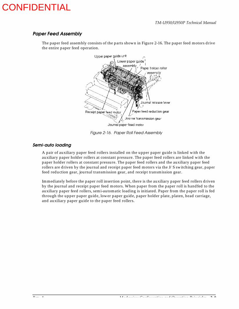
Rev. A Mechanism Configuration and Operating Principles 2-9
TM-U950/U950P Technical Manual
Paper Feed Assembly
The paper feed assembly consists of the parts shown in Figure 2-16. The paper feed motors drive the entire paper feed operation.
Semi-auto loading
A pair of auxiliary paper feed rollers installed on the upper paper guide is linked with the auxiliary paper holder rollers at constant pressure. The paper feed rollers are linked with the paper holder rollers at constant pressure. The paper feed rollers and the auxiliary paper feed rollers are driven by the journal and receipt paper feed motors via the J/S switching gear, paper feed reduction gear, journal transmission gear, and receipt transmission gear.
Immediately before the paper roll insertion point, there is the auxiliary paper feed rollers driven by the journal and receipt paper feed motors. When paper from the paper roll is handfed to the auxiliary paper feed rollers, semi-automatic loading is initiated. Paper from the paper roll is fed through the upper paper guide, lower paper guide, paper holder plate, platen, head carriage, and auxiliary paper guide to the paper feed rollers.
Figure 2-16. Paper Roll Feed Assembly
CONFIDENTIAL

2-10 Mechanism Configuration and Operating Principles Rev. A
Immediately before the journal and receipt paper feed motors are driven, the carriage motor is activated and positions the carriage in the center of the paper width. After passing the paper feed rollers, the paper lifts the pawl of the auxiliary paper guide and thereby closes the guide. Therefore the paper from the paper roll cannot be advanced to the paper feed rollers merely by manual operation.
Paper feed operation
The paper feed roller at the upper paper guide is linked with the paper holder roller at constant pressure, and paper on the paper roll is fed in from the paper feed roller. The paper feed roller shaft in the paper feed roller assembly is equipped with a gear that is driven by the journal paper feed motor via the J/S switching gear, paper feed reduction gear, paper feed transmission gear, and journal transmission gear.
By driving the journal paper feed motor as described above, the journal-side paper feed roller turns and advances the paper by a predetermined amount. For receipt side, the paper feed gear is driven by the receipt paper feed motor via the paper feed reduction gear, paper feed transmission gear, and receipt transmission gear. By the operation above, the receipt-side paper feed roller turns and advances the paper by a predetermined amount.
Figure 2-17. Paper Roll Insertion
CONFIDENTIAL

Rev. A Mechanism Configuration and Operating Principles 2-11
TM-U950/U950P Technical Manual
The auxiliary paper feed roller is set to a slightly smaller value than the paper advance amount. The difference becomes the slip in the friction clutch between the auxiliary paper feed roller and the transmission gear.
Paper release operation
Paper release is perform by separate release levers on the journal and release sides. The release levers are in constant contact with the paper holder roller shaft. When the levers are moved in the direction shown in Figure 2-19, the paper holder roller moves, the link with the paper feed roller is released, and the paper can be removed.
As indicated by the solid line in Figure 2-19, the release lever is linked to the paper holder roller shaft at both sides, in order not to disturb the paper feed roller and paper holder roller. When section (A) of the release lever is pushed in the direction, the lever rotates in the direction, pivoting around section (B). The paper holder roller shaft and release lever therefore are
Figure 2-18. Paper Feed Operation (Journal Side)
CONFIDENTIAL
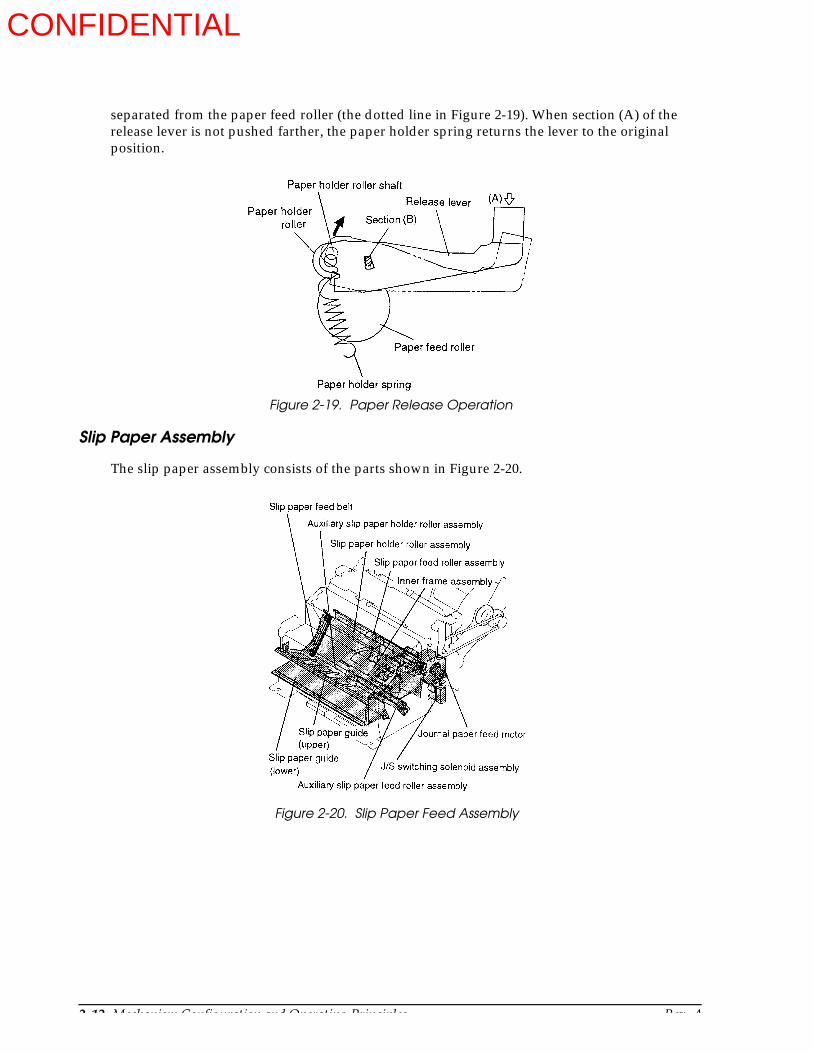
2-12 Mechanism Configuration and Operating Principles Rev. A
separated from the paper feed roller (the dotted line in Figure 2-19). When section (A) of the release lever is not pushed farther, the paper holder spring returns the lever to the original position.
Slip Paper Assembly
The slip paper assembly consists of the parts shown in Figure 2-20.
Figure 2-19. Paper Release Operation
Figure 2-20. Slip Paper Feed Assembly
CONFIDENTIAL

Rev. A Mechanism Configuration and Operating Principles 2-13
TM-U950/U950P Technical Manual
Slip paper positioning operation
A form stopper placed at a right angle in the slip paper path blocks the path due to the action of the form stopper spring (Figure 2-21).
When the slip paper is inserted along the slip paper guide (lower) in the direction, the paper can enter as far as the stopper (Figure 2-21).
Next, the J/S switching solenoid is powered while rotating the journal paper feed motor several steps in the forward and backward directions. The J/S change lever now causes the J/S switching gear, which has been positioned to feed the journal paper up to this point, to move to a position to feed the slip paper. The auxiliary slip paper feed solenoid is then powered, causing the auxiliary slip paper feed shaft lever linked to the ferrite core to move in the direction. The roller of the auxiliary slip paper feed roller is pushed up against the auxiliary slip paper holder roller. The auxiliary slip paper feed shaft lever moves the form stopper in the
direction, thus opening the slip paper path and completing the preparations for slip paper feeding (Figure 2-21).
The journal paper feed motor now rotates a certain number of steps (depending on the slip paper format) in the direction, causing the J/S switching gear, paper feed reduction gear, slip paper holder roller, slip paper feed belt, auxiliary slip paper holder roller, and auxiliary slip paper feed roller to move in turn and thus bring the slip paper into the printing position (Figure 2-23).
Immediately before the operating sequence described above, the head carriage is moved to the right most position. When positioning is completed, the auxiliary slip paper feed solenoid is turned off, and the J/S switching solenoid is set to hold (during slip paper printing and paper feeding).
a
b
Figure 2-21. Slip Paper Positioning (1)
CONFIDENTIAL
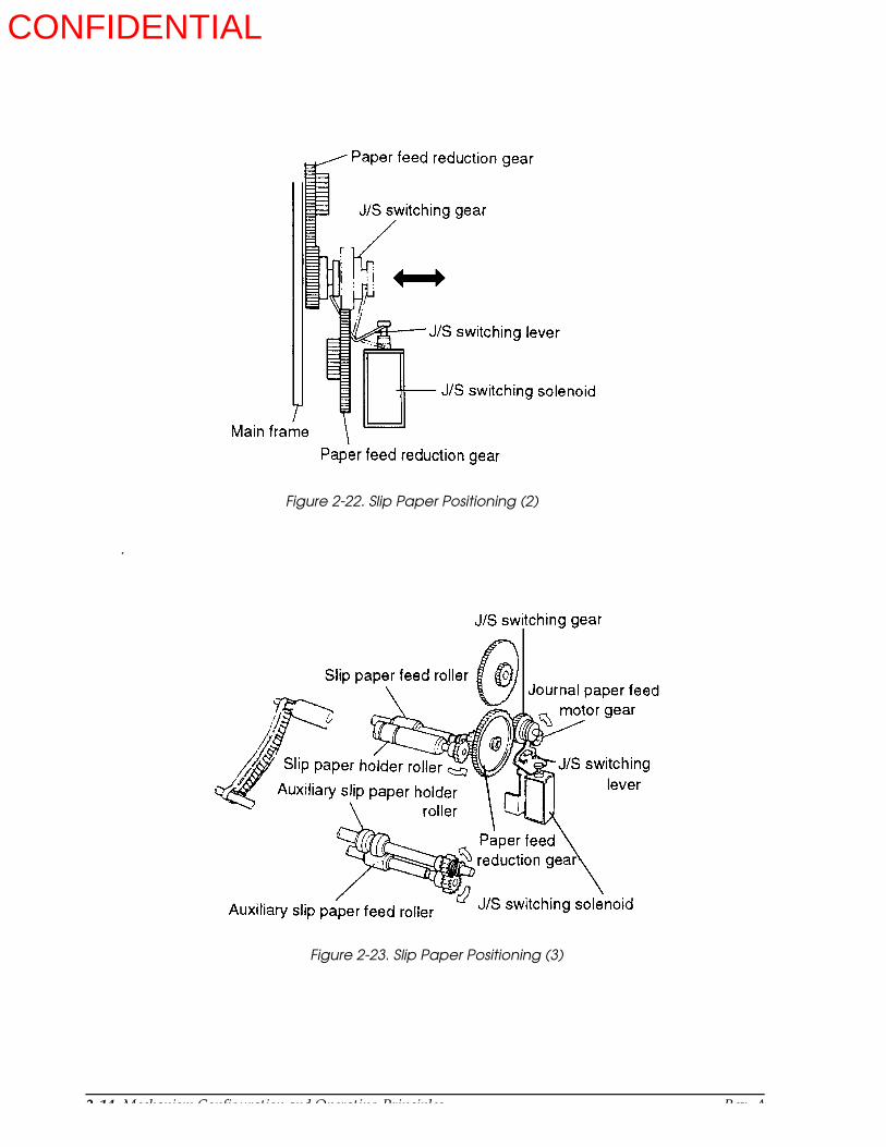
2-14 Mechanism Configuration and Operating Principles Rev. A
.
Figure 2-22. Slip Paper Positioning (2)
Figure 2-23. Slip Paper Positioning (3)
CONFIDENTIAL
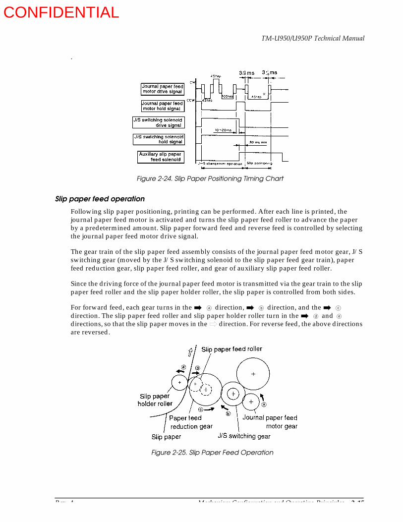
Rev. A Mechanism Configuration and Operating Principles 2-15
TM-U950/U950P Technical Manual
.
Slip paper feed operation
Following slip paper positioning, printing can be performed. After each line is printed, the journal paper feed motor is activated and turns the slip paper feed roller to advance the paper by a predetermined amount. Slip paper forward feed and reverse feed is controlled by selecting the journal paper feed motor drive signal.
The gear train of the slip paper feed assembly consists of the journal paper feed motor gear, J/S switching gear (moved by the J/S switching solenoid to the slip paper feed gear train), paper feed reduction gear, slip paper feed roller, and gear of auxiliary slip paper feed roller.
Since the driving force of the journal paper feed motor is transmitted via the gear train to the slip paper feed roller and the slip paper holder roller, the slip paper is controlled from both sides.
For forward feed, each gear turns in the direction, direction, and the direction. The slip paper feed roller and slip paper holder roller turn in the and directions, so that the slip paper moves in the direction. For reverse feed, the above directions are reversed.
Figure 2-24. Slip Paper Positioning Timing Chart
a b c
d e
Figure 2-25. Slip Paper Feed Operation
CONFIDENTIAL

2-16 Mechanism Configuration and Operating Principles Rev. A
MICR Reader Assembly (for printers with a MICR reader) (not available for the TM-U950P)
The main components of this assembly include those shown in the slip assembly section of this chapter, namely the MICR head assembly, carriage motor assembly, head carriage assembly, frame carriage assembly, MICR head holder change lever, MICR head holder frame, MICR head holder lever, MICR head holder roller, MICR transmission pulley, and MICR transmission belt. This assembly is installed at the factory, as an option, in the paper path of the slip assembly shown later in this chapter.
MICR reading and reverse-side printing operations
Check paper is inserted in the same way as slip paper, with the check paper following along below the right end of the slip paper guide and being inserted from the direction. After reaching the form stopper, the check paper is positioned for printing (see Figure 2-26).
At this point, the slip entrance detector detects the presence of the check paper. Next, the top of the check paper is positioned by the slip assembly, as described in the Slip Paper Assembly section of this chapter, so that the check paper is ready for feeding (see Figure 2-26).
Next, the journal motor rotates in the same way as with slip feeding, at the MICR reading speed, and begins to carry the leading edge of the check paper the specified number of steps from the form stopper to the MICR head assembly.
At this point, the head carriage assembly is moved by the carriage motor assembly the specified number of steps, then waits (see Figure 2-27).
In response to this movement of the head carriage assembly, the MICR head holder change lever moves in the direction, and the MICR head holder roller is pressed against the MICR head assembly, in the direction, so that the check paper is caught between the roller and the assembly.
Because the MICR head holder roller comes between the MICR transmission belt and the MICR transmission pulley and is normally synchronized to the rotation of the slip holder roller assembly, the movement of the head carriage assembly causes the shifted MICR head holder roller, with the check paper caught in it, to transport the check paper from the point where it is pressed against the MICR head assembly at the MICR reading speed to be read by the MICR.
Next, the check paper moves to a position conforming to the reverse-side printing format, and the check paper is confirmed to be effective.
At this point, if the MICR characters could not be discerned easily, the reading operation is repeated. (If problems occur with the second reading, or if the MICR character waveform cannot by detected, the check paper is ejected without being printed.)
When the check paper has been confirmed to be effective, printing is carried out on the reverse side by the head carriage assembly, in the specified format, and the paper is ejected, thus concluding the printing operation.
a
a
CONFIDENTIAL

Rev. A Mechanism Configuration and Operating Principles 2-17
TM-U950/U950P Technical Manual
The gear operation of this assembly, which carries out MICR reading of the check paper, backfeeding, and reverse-side printing, is the same as that of the slip feeding assembly. The only element which differs from the slip feeding assembly is the speed.
Figure 2-26. Check Paper Positioning (1)
Figure 2-27. Inserting the Check Paper
CONFIDENTIAL
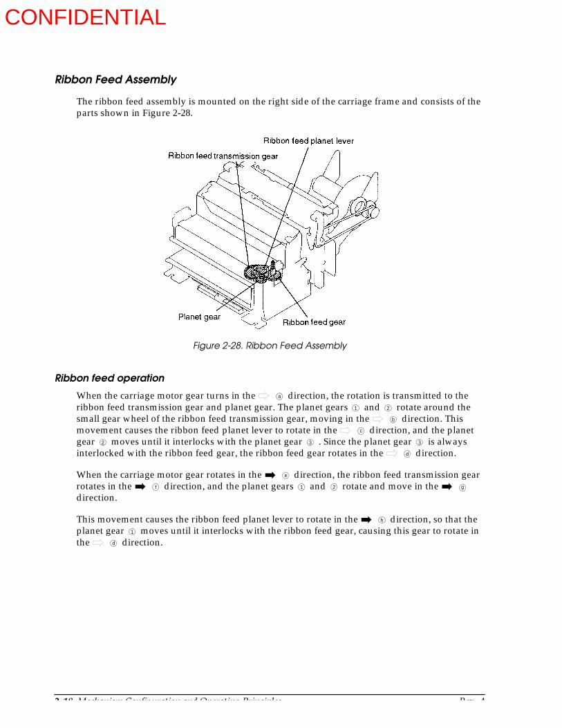
2-18 Mechanism Configuration and Operating Principles Rev. A
Ribbon Feed Assembly
The ribbon feed assembly is mounted on the right side of the carriage frame and consists of the parts shown in Figure 2-28.
Ribbon feed operation
When the carriage motor gear turns in the direction, the rotation is transmitted to the ribbon feed transmission gear and planet gear. The planet gears and rotate around the small gear wheel of the ribbon feed transmission gear, moving in the direction. This movement causes the ribbon feed planet lever to rotate in the direction, and the planet gear moves until it interlocks with the planet gear . Since the planet gear is always interlocked with the ribbon feed gear, the ribbon feed gear rotates in the direction.
When the carriage motor gear rotates in the direction, the ribbon feed transmission gear rotates in the direction, and the planet gears and rotate and move in the direction.
This movement causes the ribbon feed planet lever to rotate in the direction, so that the planet gear moves until it interlocks with the ribbon feed gear, causing this gear to rotate in the direction.
Figure 2-28. Ribbon Feed Assembly
a
1 2
b
c
2 3 3
d
e
f 1 2 g
h
1
d
CONFIDENTIAL

Rev. A Mechanism Configuration and Operating Principles 2-19
TM-U950/U950P Technical Manual
Therefore, the ribbon feed gear always turns in the direction, regardless of the rotation direction of the carriage motor. The ribbon feed gear is interlocked with the ribbon feed roller and ribbon feed holder roller inside the ribbon cassette, thus feeding the ribbon.
Stamp Assembly (for printers with a stamp assembly)
The optional stamp assembly consists of the parts shown in Figure 2-30. The assembly is installed below the paper inlet on the receipt side.
h
Figure 2-29. Ribbon Feed Operation
Figure 2-30. Stamp Assembly
CONFIDENTIAL

2-20 Mechanism Configuration and Operating Principles Rev. A
Stamp operation
When the stamp solenoid is powered, the ferrite core moves in the direction. Since the ferrite core serves as the pivot for the stamp drive lever, the lever rotates in the direction, causing the linked stamp lever to move in the direction. Therefore, the stamp assembly attached to the lever also moves in the direction and is pushed up against the upper paper guide, thus stamping the paper. When the stamp solenoid goes off, the force of the stamp drive lever spring returns the stamp to its original position.
Auto-cutter Assembly
The auto-cutter assembly consists of the transmission mechanism, sensor, and cutter. For easy maintenance and paper removal, this assembly can be completely opened. For the sensor, see auto-cutter sensor assembly on page 2-6.
Figure 2-31. Stamp Operation
Figure 2-32. Auto-cutter Assembly
CONFIDENTIAL

Rev. A Mechanism Configuration and Operating Principles 2-21
TM-U950/U950P Technical Manual
Transmission mechanism
The transmission mechanism consists of the cutter motor gear fastened on the cutter motor shaft, two reduction gears A, the reduction gear B, two drive gears on the drive gear shaft, and the cutter slider assembly. The cutter motor rotation is reduced and transmitted to the drive shaft via the reduction gears A and B. The gears on the drive shaft then translate the rotary motion into a sliding motion for operation of the cutter slider.
Cutter mechanism
The cutter mechanism consists of the cutter blade frame, cutter blade, and cutter blade cover. The mechanism performs either a full or a partial cut, depending on the F/P position signal supplied by the sensor assembly.
Figure 2-33. Auto-cutter Transmission Mechanism
Figure 2-34. Auto-cutter Mechanism
CONFIDENTIAL
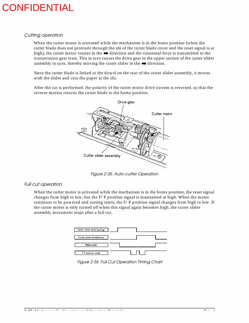
2-22 Mechanism Configuration and Operating Principles Rev. A
Cutting operation
When the cutter motor is activated while the mechanism is in the home position (when the cutter blade does not protrude through the slit of the cutter blade cover and the reset signal is at high), the cutter motor rotates in the direction and the rotational force is transmitted to the transmission gear train. This in turn causes the drive gear in the upper section of the cutter slider assembly to turn, thereby moving the cutter slider in the direction.
Since the cutter blade is linked to the dowel on the rear of the cutter slider assembly, it moves with the slider and cuts the paper at the slit.
After the cut is performed, the polarity of the cutter motor drive current is reversed, so that the reverse motion returns the cutter blade to the home position.
Full cut operation
When the cutter motor is activated while the mechanism is in the home position, the reset signal changes from high to low, but the F/P position signal is maintained at high. When the motor continues to be powered and cutting starts, the F/P position signal changes from high to low. If the cutter motor is only turned off when this signal again becomes high, the cutter slider assembly movement stops after a full cut.
Figure 2-35. Auto-cutter Operation
Figure 2-36. Full Cut Operation Timing Chart
CONFIDENTIAL
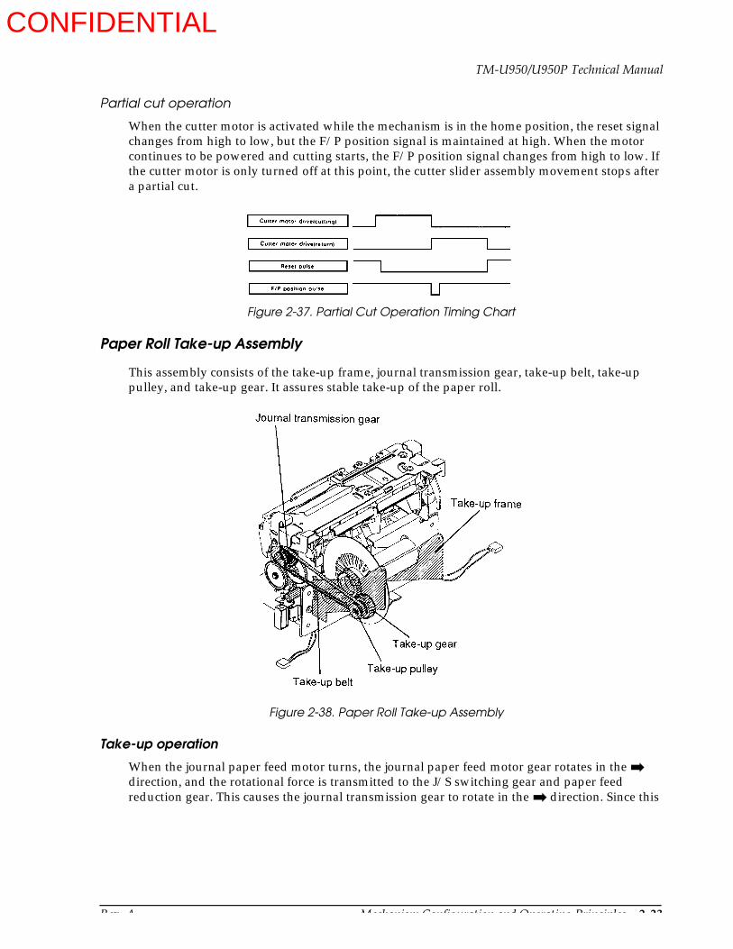
Rev. A Mechanism Configuration and Operating Principles 2-23
TM-U950/U950P Technical Manual
Partial cut operation
When the cutter motor is activated while the mechanism is in the home position, the reset signal changes from high to low, but the F/P position signal is maintained at high. When the motor continues to be powered and cutting starts, the F/P position signal changes from high to low. If the cutter motor is only turned off at this point, the cutter slider assembly movement stops after a partial cut.
Paper Roll Take-up Assembly
This assembly consists of the take-up frame, journal transmission gear, take-up belt, take-up pulley, and take-up gear. It assures stable take-up of the paper roll.
Take-up operation
When the journal paper feed motor turns, the journal paper feed motor gear rotates in the direction, and the rotational force is transmitted to the J/S switching gear and paper feed reduction gear. This causes the journal transmission gear to rotate in the direction. Since this
Figure 2-37. Partial Cut Operation Timing Chart
Figure 2-38. Paper Roll Take-up Assembly
CONFIDENTIAL

2-24 Mechanism Configuration and Operating Principles Rev. A
gear is linked to the take-up belt, the take-up pulley turns in the direction. The take-up clutch spring mounted between the take-up pulley and take-up gear transmits the force to the take-up gear and thus to the take-up shaft, which turns to take up the paper.
Figure 2-39. Take-up Operation
CONFIDENTIAL
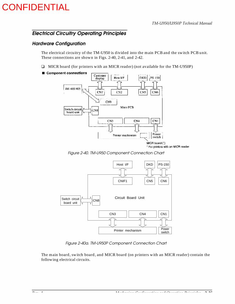
Rev. A Mechanism Configuration and Operating Principles 2-25
TM-U950/U950P Technical Manual
Electrical Circuitry Operating Principles
Hardware Configuration
The electrical circuitry of the TM-U950 is divided into the main PCB and the switch PCB unit. These connections are shown in Figs. 2-40, 2-41, and 2-42.
MICR board (for printers with an MICR reader) (not available for the TM-U950P)
The main board, switch board, and MICR board (on printers with an MICR reader) contain the following electrical circuits.
Figure 2-40. TM-U950 Component Connection Chart
Figure 2-40a. TM-U950P Component Connection Chart
CN3 CN4 CN1
Host I/F DKD PS-150
CNIF1 CN5 CN6
Printer mechanism Power switch
CN8Switch circuit board unit
Circuit Board Unit
CONFIDENTIAL
2-26 Mechanism Configuration and Operating Principles Rev. A
Switch PCB unit
FEED buttons
LEDs (power, paper status, and error)
Cover open sensor
Main PCB
Power supply circuit
Reset circuit
CPU
Memory (ROM: 512 KB, RAM: 64 KB, EEPROM)
Gate array
Operation panel control circuit
Host interface circuit
Drawer kick-out circuit
Print head drive circuit
Solenoid drive circuits
Paper feed motor drive circuit
Auto-cutter control
Carriage motor drive circuit
Actuator irregular operation protection circuit
Mechanism sensor circuits
IM-403/405 connection circuit (not supported by the TM-U950P)
MICR board (on printers with an MICR reader) (not available on the TM-U950P)
Power supply section (eliminates power supply noise)
Input section (protects against excessive voltage)
Amplifier section
Signal limiting section
Signal switching section
Self-bias current supplier
CONFIDENTIAL

Rev. A Mechanism Configuration and Operating Principles 2-27
TM-U950/U950P Technical Manual
Figure 2-41. Block Diagram of TM-U950 Main Board
Figure 2-41a. Block Diagram of TM-U950P Main Board
Circuit Board Unit
Connected to host interface
Connected to drawer
Connected to PS-150
CNIF1
CN5
CN6
CN8
CN4
CN3
R
J
Host interface
circuit (parallel)
Drawer kick-out driving circuit
Power circuit
Address bus
Data busOperation panel and cover sensor circuit
Various sensor circuit
Various solenoid driving circuit
Paper feed motors (R,J) driving circuit
Auto cutter driving and
sensor circuit
Carriage motor circuit
Print head driving circuit
Irregular operation
protection circuit
Power switch
+5V
+24V
CN1
EEPROM
RAM
ROM
CPU
Gate Array
DIP switches
Reset circuit
Switc
h P
CB
uni
tPr
inte
r m
echa
nism
ass
embl
y
Main Circuit Board Assembly
CONFIDENTIAL
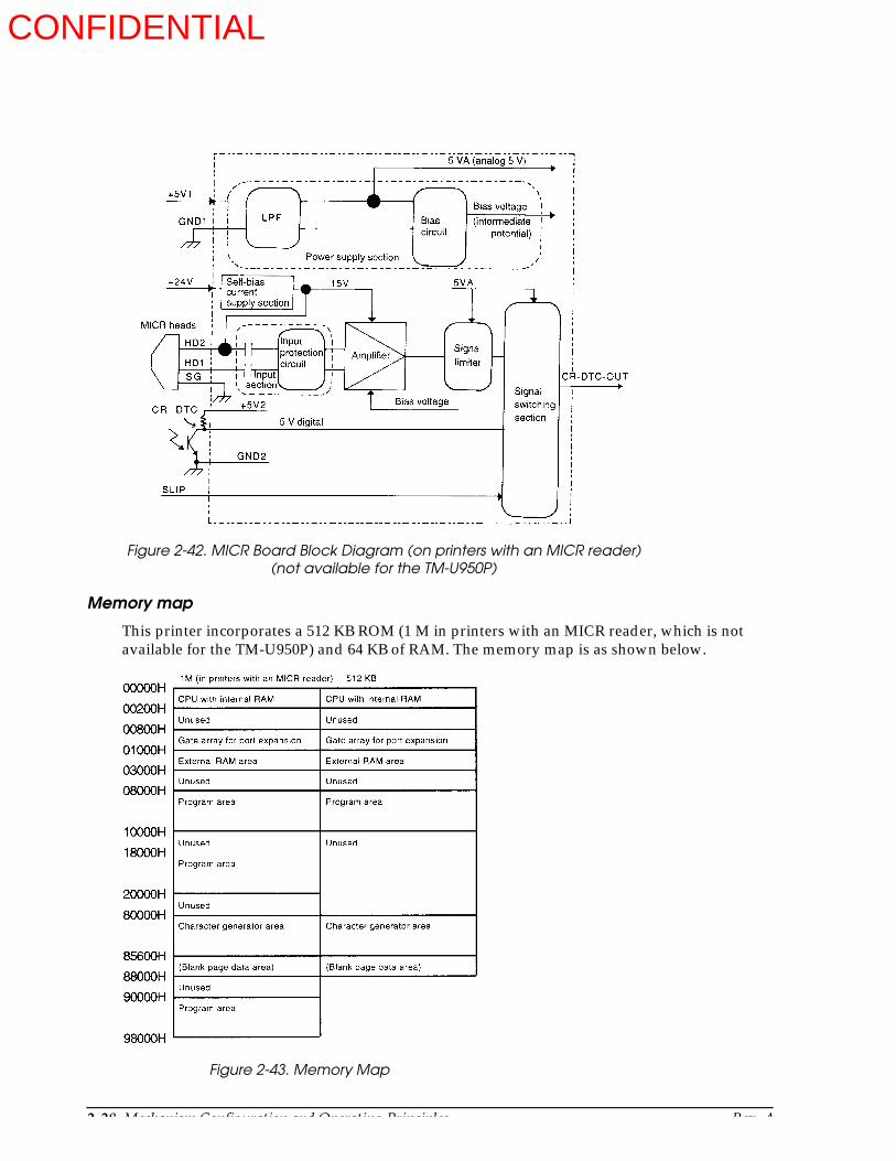
2-28 Mechanism Configuration and Operating Principles Rev. A
Memory map
This printer incorporates a 512 KB ROM (1 M in printers with an MICR reader, which is not available for the TM-U950P) and 64 KB of RAM. The memory map is as shown below.
Figure 2-42. MICR Board Block Diagram (on printers with an MICR reader)(not available for the TM-U950P)
Figure 2-43. Memory Map
CONFIDENTIAL

Rev. A Mechanism Configuration and Operating Principles 2-29
TM-U950/U950P Technical Manual
Reset circuit for the TM-U950
The reset IC (M51953BFP) monitors the +5 V voltage. When the voltage becomes more than 4.5 V, the IC releases the reset condition for the CPU and other circuits, thus enabling normal printer operation. When a reset signal from the host is sent from the host interface (DSR, #25) more than 1 ms, the output of the reset IC becomes low and the CPU and other circuits are reset.
Reset circuit for the TM-U950P
The reset IC (M51953BFP) monitors the +5 V voltage. When the voltage becomes more than 4.5 V, the IC releases the reset condition for the CPU and other circuits, thus enabling normal printer operation. When the interface reset signal (nInit, #31) is added to the reset circuit more than 50 µs when the host interface is in forward direction transmission (I/F signal 1284 ACT, #36 is low), the reset IC becomes low and the CPU and other circuits are reset.
Figure 2-44. Reset Circuit for the TM-U950
Figure 2-44a. Reset Circuit for the TM-U950P
Q10
8
7
1
2
DSW2 DM1
3
Q4
RESCTL
SG
R14
R11
+C17
_C19
R12
IN OUT
5
7
C GND4
6R13
C35
RESET OUT
+5V
+5V
nInit
1284ACT
CN1
CONFIDENTIAL
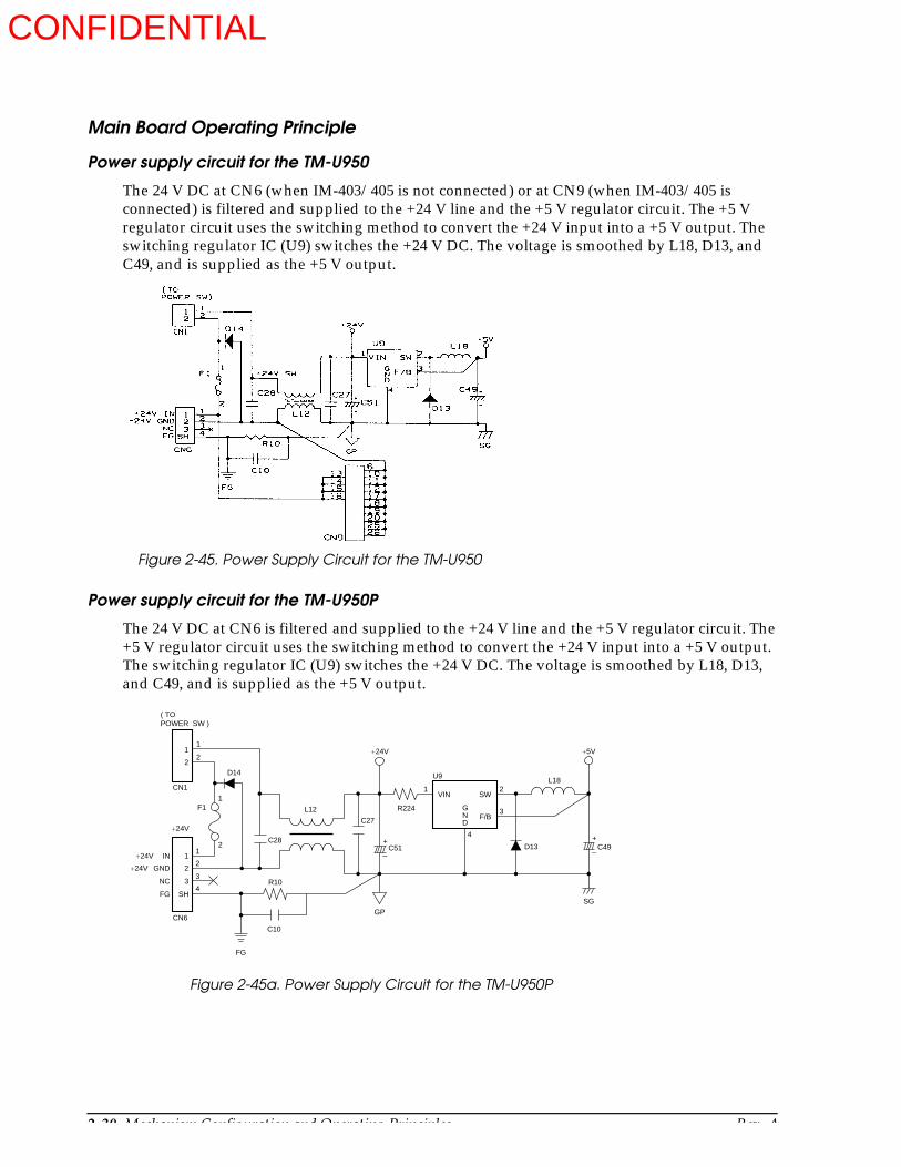
2-30 Mechanism Configuration and Operating Principles Rev. A
Main Board Operating Principle
Power supply circuit for the TM-U950
The 24 V DC at CN6 (when IM-403/405 is not connected) or at CN9 (when IM-403/405 is connected) is filtered and supplied to the +24 V line and the +5 V regulator circuit. The +5 V regulator circuit uses the switching method to convert the +24 V input into a +5 V output. The switching regulator IC (U9) switches the +24 V DC. The voltage is smoothed by L18, D13, and C49, and is supplied as the +5 V output.
Power supply circuit for the TM-U950P
The 24 V DC at CN6 is filtered and supplied to the +24 V line and the +5 V regulator circuit. The +5 V regulator circuit uses the switching method to convert the +24 V input into a +5 V output. The switching regulator IC (U9) switches the +24 V DC. The voltage is smoothed by L18, D13, and C49, and is supplied as the +5 V output.
Figure 2-45. Power Supply Circuit for the TM-U950
FG
1
22
1
CN1
C27
+C51
_
+C49_
CN6
U9L18
D13C28
D14
F1
R10
C10
1
2
3
4
1
2
3
SH
L12
1 2
3
4
R224
+5V
SG
+24V
GP
FG
1
2
( TO POWER SW )
IN
GND
NC
+24V
+24V
+24V
G N D
VIN SW
F/B
Figure 2-45a. Power Supply Circuit for the TM-U950P
CONFIDENTIAL
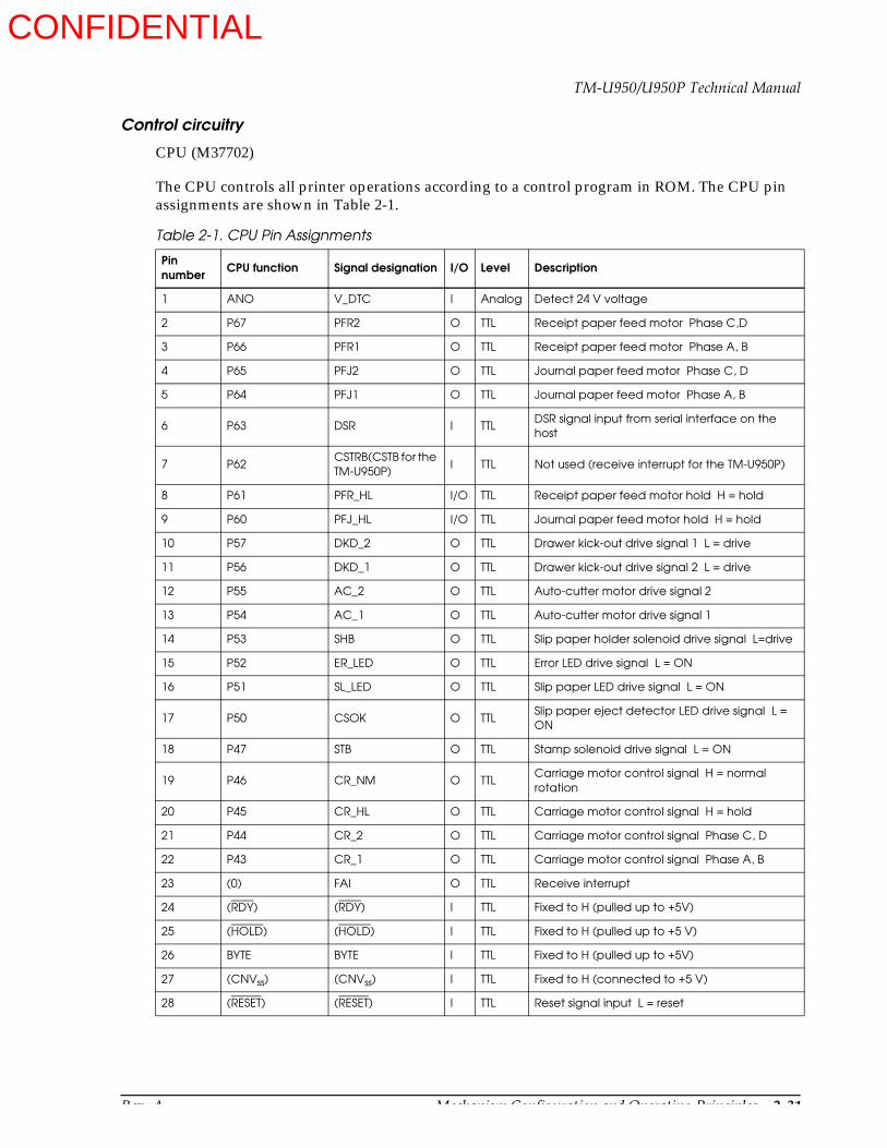
Rev. A Mechanism Configuration and Operating Principles 2-31
TM-U950/U950P Technical Manual
Control circuitry
CPU (M37702)
The CPU controls all printer operations according to a control program in ROM. The CPU pin assignments are shown in Table 2-1.
Table 2-1. CPU Pin Assignments
Pin number CPU function Signal designation I/O Level Description
1 ANO V_DTC I Analog Detect 24 V voltage
2 P67 PFR2 O TTL Receipt paper feed motor Phase C,D
3 P66 PFR1 O TTL Receipt paper feed motor Phase A, B
4 P65 PFJ2 O TTL Journal paper feed motor Phase C, D
5 P64 PFJ1 O TTL Journal paper feed motor Phase A, B
6 P63 DSR I TTLDSR signal input from serial interface on the host
7 P62CSTRB(CSTB for the TM-U950P)
I TTL Not used (receive interrupt for the TM-U950P)
8 P61 PFR_HL I/O TTL Receipt paper feed motor hold H = hold
9 P60 PFJ_HL I/O TTL Journal paper feed motor hold H = hold
10 P57 DKD_2 O TTL Drawer kick-out drive signal 1 L = drive
11 P56 DKD_1 O TTL Drawer kick-out drive signal 2 L = drive
12 P55 AC_2 O TTL Auto-cutter motor drive signal 2
13 P54 AC_1 O TTL Auto-cutter motor drive signal 1
14 P53 SHB O TTL Slip paper holder solenoid drive signal L=drive
15 P52 ER_LED O TTL Error LED drive signal L = ON
16 P51 SL_LED O TTL Slip paper LED drive signal L = ON
17 P50 CSOK O TTLSlip paper eject detector LED drive signal L = ON
18 P47 STB O TTL Stamp solenoid drive signal L = ON
19 P46 CR_NM O TTLCarriage motor control signal H = normal rotation
20 P45 CR_HL O TTL Carriage motor control signal H = hold
21 P44 CR_2 O TTL Carriage motor control signal Phase C, D
22 P43 CR_1 O TTL Carriage motor control signal Phase A, B
23 (0) FAI O TTL Receive interrupt
24 (RDY) (RDY) I TTL Fixed to H (pulled up to +5V)
25 (HOLD) (HOLD) I TTL Fixed to H (pulled up to +5 V)
26 BYTE BYTE I TTL Fixed to H (pulled up to +5V)
27 (CNVss) (CNVss) I TTL Fixed to H (connected to +5 V)
28 (RESET) (RESET) I TTL Reset signal input L = reset
CONFIDENTIAL

2-32 Mechanism Configuration and Operating Principles Rev. A
29 xin (xin) I TTL Clock input
30 XOUT (XOUT) O TTL Clock input
31 (E) (E) O TTL Enable signal L = Data read/write)
32 (Vss) (Vss) - GND Power supply
33 HLDA HLDA O TTL Unused (open)
34 ALE ALE O TTL Address latch enable signal H = address latch
35 BHE BHE O TTL Unused (open)
36 (R/W) (R/W) O TTL Read/write signal H = read, L = write
37 A23/D7A23 O TTL Address signal Bit 23
D7 I/O TTL Data signal Bit 7
38 A22/D6A22 O TTL Address signal Bit 22
D6 I/O TTL Data signal Bit 6
39 A21/D5A21 O TTL Address signal Bit 21
D5 I/O TTL Data signal Bit 5
40 A20/D4A20 O TTL Address signal Bit 20
D4 I/O TTL Data signal Bit 4
41 A19/D3A19 O TTL Address signal Bit 20
D4 I/O TTL Data signal Bit 3
42 A18/D2A18 O TTL Address signal Bit 18
D2 I/O TTL Data signal Bit 2
43 A17/D1A17 O TTL Address signal Bit 17
D1 I/O TTL Data signal Bit 1
44 A16/D0A16 O TTL Address signal Bit 16
D0 I/O TTL Data signal Bit 0
45 A15 A15 O TTL Address signal Bit 15
46 A14 A14 O TTL Address signal Bit 14
47 A13 A13 O TTL Address signal Bit 13
48 A12 A12 O TTL Address signal Bit 12
49 A11 A11 O TTL Address signal Bit 11
50 A10 A10 O TTL Address signal Bit 10
51 A9 A9 O TTL Address signal Bit 9
52 A8 A8 O TTL Address signal Bit 8
53 A7 A7 O TTL Address signal Bit 7
54 A6 A6 O TTL Address signal Bit 6
55 A5 A5 O TTL Address signal Bit 5
Table 2-1. CPU Pin Assignments (continued)
Pin number CPU function Signal designation I/O Level Description
CONFIDENTIAL

Rev. A Mechanism Configuration and Operating Principles 2-33
TM-U950/U950P Technical Manual
ROM (512 KB, [1 M in printers with an MICR reader])
The ROM contains the printer control program and the character generator. The control program governs the basic printer functions. The CPU operates entirely under the control of this program.
RAM (64 KB)
The RAM is used for the following:
As input buffer for data received via the connector interface.
56 A4 A4 O TTL Address signal Bit 4
57 A3 A3 O TTL Address signal Bit 3
58 A2 A2 O TTL Address signal Bit 2
59 A1 A1 O TTL Address signal Bit 1
60 A0 A0 O TTL Address signal Bit 0
61 P87 TXD O TTL TXD signal output for the interface circuit board
62 P86 RXD I TTLRXD signal input from the interface circuit board
63 P85 DTR O TTL DTR signal output for the interface circuit board
64 P84 CTS1 O TTL Unused (pulled down to (Vss))
65 P83 IMSD I TTLSD signal output for the IM-403/405 serial interface (not used on the TM-U950P)
66 P82 IMSD I TTLRD signal input from the IM-403/405 serial interface (not used on the TM-U950P)
67 P81 IMDTR_TM O TTLDTR signal output for the IM-403/405 serial interface (not used on the TM-U950P)
68 P80 CTSO O TTL Unused (pulled down to (Vss))
69 (Vcc) - - +5V Power supply
70 (AVcc) - - +5V Analog power supply
71 (Vref) - - +5V Analog reference voltage
72 (AVss) - - GND Analog power supply
73 (Vss) - - GND Power supply
74 P77 CACT I TTL Auto-cutter full/partial signal
75 P76 CACR I TTL Auto-cutter reset signal
76 P75 CCRP I TTL Carriage detachment sensor signal
77 P74 CHP I TTL Home position sensor signal
78 AN3 CSOE I Analog Slip paper eject sensor signal
79 AN2 CSLPIN I Analog Slip paper insert sensor signal
80 AN1 CHDTH I Analog Print head temperature sensor signal
Table 2-1. CPU Pin Assignments (continued)
Pin number CPU function Signal designation I/O Level Description
CONFIDENTIAL

2-34 Mechanism Configuration and Operating Principles Rev. A
As print buffer for pattern data to be sent to the print head
As storage area for CPU processing functions (flags, pointers, etc.)
EEPROM
The EEPROM stores the slip paper insert sensor level. Data exchange with the CPU is performed via a serial link.
Gate array
The gate array is a five I/O port type with an eight-bit (see Table 2-2). It serves two purposes. It can be used by the CPU for I/O port expansion, as specified in the memory map (port expansion function). When the ALE signal goes high, the gate array also latches to the multiplexed address/data signal output by the CPU and extracts the address signal (address latch function).
Table 2-2. Gate Array Pin Assignments
Pin number Gate array function Signal designation` I/O Level Description
1 (RSET) (RSET) I TTL Reset signal input L = reset
2 PA 0 HEAD 8 O TTL Print head 8 L = ON
3 PA 1 HEAD 7 O TTL Print head 7 L = ON
4 PA 2 HEAD 6 O TTL Print head 6 L = ON
5 PC 6 JN_LED O TTL Print head 5 L = ON
6 PA 3 HEAD 5 O TTL Print head 4 L = ON
7 PA 4 HEAD 4 O TTL Print head 3 L = ON
8 PA 5 HEAD 3 O TTL Print head 2 L = ON
9 PA 6 HEAD 2 O TTL Print head 1 L = ON
10 PA 7 HEAD 1 O TTL Print head 0 L = ON
11 GND - - GND Power supply
12 PB 0 SW1I I TTL DIP switch bank 1 serial input
13 PB 1 SW2I I TTL DIP switch bank 1 serial input
14 PB 2 SWCK I TTL DIP switch settings read clock
15 PB 3 SWSL I TTL DIP switch bank select
16 PB 4 SCB O TTL S/J switching solenoid drive signal L = drive
17 PB 5 S/J HL O TTL S/J switching solenoid hold signal L = hold
18 PB 6 HD_COM O TTL Print head common L = ON
19 PB 7 HEAD 9 O TTL Print head L = ON
20 PC 0 E2DI I TTL Data input from EEROM
21 PC 1 E2DO O TTL Data output from EEROM
22 PC 2 E2CK O TTL EEROM select output
23 PC 3 E2CE O TTL EEROM select output
24 PC 4 IMDSR I TTLDSR signal input from the IM-403/405 serial interface (unused on the TM-U950P)
CONFIDENTIAL

Rev. A Mechanism Configuration and Operating Principles 2-35
TM-U950/U950P Technical Manual
25 PC 5 POW_TRG O TTL Power control trigger signal
26 PD 0 IF_DET I TTLUnused (connected to GND) on TM-U950 I/F circuit board identify signal on TM-U950P
27 PD 1 CLK_REQ I TTLUnused (connected to GND) on TM-U950 synchronization clock request signal for TM-U950P
28 GND - - GND Power supply
29 GND - - GND Power supply
30 VDD - - +5V Power supply
31 PD 2 SRTS 0 TTLUnused (connected to GND) on TM-U950, software RTS output on TM-U950P
32 PD 3 N. C I TTL Unused (connected to GND)
33 PD 4 N. C I TTL Unused (connected to GND)
34 PD 5 N. C I TTL Unused (connected to GND)
35 PD 6 N. C I TTL Unused (connected to GND)
36 PD 7 N. C I TTL Unused (connected to GND)
37 PD 0 CJNE I TTL Journal near-end signal
38 PE 1 CRNE I TTL Receipt near-end signal
39 PE 2 CJPE I TTL Journal paper-end signal
40 PE 3 CRPE I TTL Receipt paper-end signal
41 PE 4 PFR_SW I TTL Receipt FEED switch L = ON
42 PE 5 PFJ_SW I TTL Journal FEED switch L = ON
43 PE 6 COVER I TTL Cover open detection
44 PE 7 DK_S I TTL Drawer status signal
45 PC 7 PC_LED O TTL Receipt LED L = ON
46 (STRB) CLK I TTL Unused (connected to GND) on TM-U950 synchronization clock interrupt for the TM-U950P
47 BUSY RTS O TTLUnused (open) for TM-U950. RTS output for the I/F circuit board for the TM-U950P
48 (CSTRB) CSTB O TTLUnused on TM-U950, receive interrupt on TM-U950P
49 (CRDY) SRTS I TTLUnused (connected to GND) for the TM-U950, software RTS input for TM-U950P
50 GND _ _ GND Power supply
51 CRIN CRIN I TTL Unused (connected to GND)
52 (CROUT) (CROUT) O TTL Unused (open)
53 AB 0 A 0 I TTL Address signal Bit 0
54 AB 1 A 1 I TTL Address signal Bit 1
Table 2-2. Gate Array Pin Assignments (continued)
Pin number Gate array function Signal designation` I/O Level Description
CONFIDENTIAL

2-36 Mechanism Configuration and Operating Principles Rev. A
Operation panel and cover open sensor circuits
There are five LEDs on the operation panel (POWER, ERROR, RECEIPT OUT, JOURNAL OUT, and SLIP) and two buttons (RECEIPT FEED, and JOURNAL/SLIP FEED). The cover open sensor uses a photosensor.
These parts are mounted directly on the switch PCB unit, which is linked to the main PCB assembly via connectors (CN8).
55 AB 2 A 2 I TTL Address signal Bit 2
56 AB 3 A 3 I TTL Address signal Bit 3
57 AB 4 A 4 I TTL Address signal Bit 4
58 (R/W) (R/W) I TTL Read/write signal
59 (CS) (CS) I TTL Chip select signal L = select
60 (E) (E) I TTL Enable signal
61 ASTB ASTB I TTL Address latch enable signal
62 ALB 0 A 16 O TTL Address signal Bit 16
63 ABL 1 A 17 O TTL Address signal Bit 17
64 ABL 2 A 18 O TTL Address signal Bit 18
65 ABL 3 A 19 O TTL Address signal Bit 19
66 ABL 4 N. C O TTL Unused (open)
67 ABL 5 N. C O TTL Unused (open)
68 ABL 6 N. C O TTL Unused (open)
69 ABL 7 N. C O TTL Unused (open)
70 GND — — GND Power supply
71 GND — — GND Power supply
72 (Vss) — — +5V Power supply
73 DB 0 D 0 I/O TTL Data signal Bit 0
74 DB 1 D 1 I/O TTL Data signal Bit 1
75 DB 2 D 2 I/O TTL Data signal Bit 2
76 DB 3 D 3 I/O TTL Data signal Bit 3
77 DB 4 D 4 I/O TTL Data signal Bit 4
78 DB 5 D 5 I/O TTL Data signal Bit 5
79 DB 6 D 6 I/O TTL Data signal Bit 6
80 DB 7 D 7 I/O TTL Data signal Bit 7
Table 2-2. Gate Array Pin Assignments (continued)
Pin number Gate array function Signal designation` I/O Level Description
CONFIDENTIAL

Rev. A Mechanism Configuration and Operating Principles 2-37
TM-U950/U950P Technical Manual
LED drive as well as switch and photosensor status detection is performed by the CPU. For signal I/O, the CPU ports and the expansion ports on the gate array are used.
DIP switch circuit
Parallel-to-serial conversion of the settings of DIP switch banks 1 and 2 is performed by the conversion IC (U10, U17), and the result is input to the gate array port (PB0, PB1). DIP switch selection is made by the SWSL signal (PB3). The SWCL signal (PB2) is used as a clock signal and the switch settings are read one bit at a time.
Figure 2-46. Operation Panel and Cover Open Sensor Circuits
Figure 2-47. DIP Switch Circuit for the TM-U950
CONFIDENTIAL
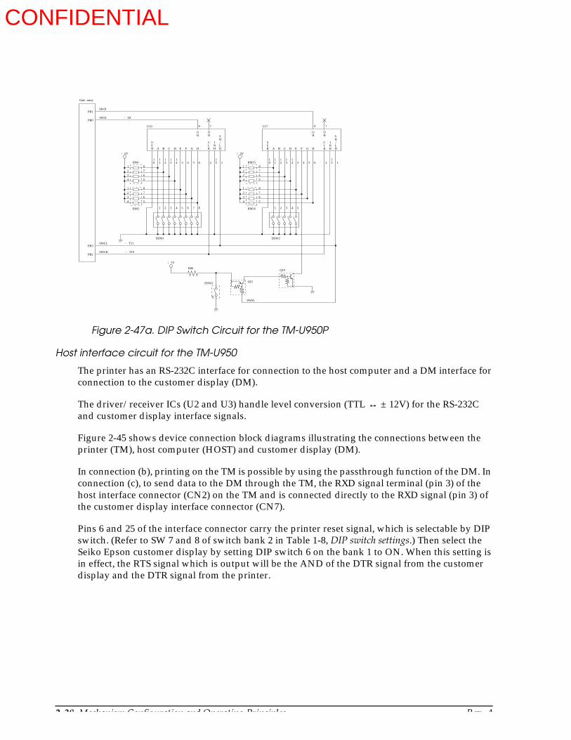
2-38 Mechanism Configuration and Operating Principles Rev. A
Host interface circuit for the TM-U950
The printer has an RS-232C interface for connection to the host computer and a DM interface for connection to the customer display (DM).
The driver/receiver ICs (U2 and U3) handle level conversion (TTL ↔ ± 12V) for the RS-232C and customer display interface signals.
Figure 2-45 shows device connection block diagrams illustrating the connections between the printer (TM), host computer (HOST) and customer display (DM).
In connection (b), printing on the TM is possible by using the passthrough function of the DM. In connection (c), to send data to the DM through the TM, the RXD signal terminal (pin 3) of the host interface connector (CN2) on the TM and is connected directly to the RXD signal (pin 3) of the customer display interface connector (CN7).
Pins 6 and 25 of the interface connector carry the printer reset signal, which is selectable by DIP switch. (Refer to SW 7 and 8 of switch bank 2 in Table 1-8, DIP switch settings.) Then select the Seiko Epson customer display by setting DIP switch 6 on the bank 1 to ON. When this setting is in effect, the RTS signal which is output will be the AND of the DTR signal from the customer display and the DTR signal from the printer.
Figure 2-47a. DIP Switch Circuit for the TM-U950P
1
2
3
4
1
2
3
4
7654321 8
5
4
3
1 4
1 3
1 2
1 1
1 0
6
8
7
6
5
8
7
6
5
G
F
E
D
C
B
A
S E R
H
I N H
C L K
S H / L D
O H
O H
5V
1
2
3
4
1
2
3
4
54321
5
4
3
1 4
1 3
1 2
1 1
1 0
6
8
7
6
5
8
7
6
5
G
F
E
D
C
B
A
S E R
H
I N H
C L K
S H / L D
\ O H
O H
\
RM1
RM2
1 5
2
1
U10 U17
1 5
2
1
9
9
7
7
RM15
RM16
DSW1 DSW2
5V
5V
R80
Q21
Q19
SWSL
DSW2
6
SWCK ⁄ T19
SWCL ⁄ T21
SW1I ⁄ T8
SW2I
PB2
PB3
PB0
PB1
Gate array
CONFIDENTIAL

Rev. A Mechanism Configuration and Operating Principles 2-39
TM-U950/U950P Technical Manual
When neither the customer display nor the printer DTR signal is SPACE, the RTS signal is not SPACE either. When DIP switch 6 of the bank 1 is OFF, the same signal as the printer’s DTR signal is output to the RTS signal.
Figure 2-48. Host Interface Circuit and Customer Display Interface Circuit
CONFIDENTIAL

2-40 Mechanism Configuration and Operating Principles Rev. A
Host interface circuit for the TM-U950P
TM-U950P printer has an IEEE 1284 interface for connection to the host computer. Control CPU (I/F circuit board U2) controls the transmission between the host computer, and the CPU converts the received data to the serial data, and then the CPU sends the data to the main circuit board. TTL IC (I/F circuit board U1, U9, U10) drives or receives the interface signal. Transmission between host has other mode, IEEE 1284 Nibble/Byte mode which is the reverse directional transmission.
Drawer kick-out circuit
The DKD_1 and DKD_2 signals from the CPU set the drawer kick-out driver transistors Q7 and Q8 to on; they in turn output the drawer open signal. The drawer status signal DK_S is input to the gate array, allowing the host to check the status via the interface.
The +24 V drawer power supply is controlled by the three-pin regulator (U1) which cuts off the supply in case of excessive current.
Figure 2-49. Device Connection Block Diagram
CONFIDENTIAL

Rev. A Mechanism Configuration and Operating Principles 2-41
TM-U950/U950P Technical Manual
The drawer drive signal is also supplied to the IM-403/405 through CN9 for the TM-U950 only.
Print head drive circuit
The print head has nine pins that are driven by dedicated solenoids. Ports PA0 - PA7 and PB7 of the gate array carry the solenoid signals (HEAD1 - 9). PB7 carries the common signal for the solenoids (HD_COM). The HEAD1 - 9 signals activate the sync transistors (QM3 - QM5). The HD_COM signal activates the source transistors (Q24, Q33, and Q34) to power the solenoids. When the source transistors go off, the energy stored by the solenoids is dissipated via the flywheel diodes (D39, D40, D44, D45, D46, and D47). When the sync transistors go off, the solenoid current is cut.
Figure 2-50. Drawer Kick-out Circuit for the TM-U950
Figure 2-50a. Drawer Kick-out Circuit for the TM-U950P
1 FG2 DKD1
3 DK S
4 DK P5 DKD2
6 SG
12
3
45
6
CN5
R23C9
R22
R9 R8
5V
24V
FGDKD1
DKD STAT
DKD POWDKD2
SG
U1
1 2
3
I O
G
D6
D4
D5
DKD1
DKD2
@ F @ G
D K P
Q8
Q2
Q7Q15
5V
UNTRG-HIZ
DKD 2
SG
DKD 1
DK S
11
10
44
9
7
5
3
8
6
4
2
1 0
1
QM1 G-PS24
CPU
PS6
PS7
PE7
Gate array
CONFIDENTIAL
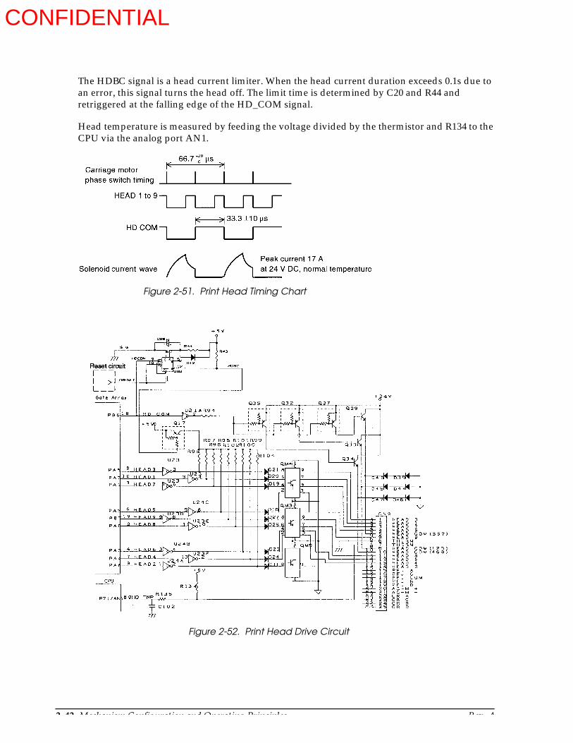
2-42 Mechanism Configuration and Operating Principles Rev. A
The HDBC signal is a head current limiter. When the head current duration exceeds 0.1s due to an error, this signal turns the head off. The limit time is determined by C20 and R44 and retriggered at the falling edge of the HD_COM signal.
Head temperature is measured by feeding the voltage divided by the thermistor and R134 to the CPU via the analog port AN1.
Figure 2-51. Print Head Timing Chart
Figure 2-52. Print Head Drive Circuit
CONFIDENTIAL

Rev. A Mechanism Configuration and Operating Principles 2-43
TM-U950/U950P Technical Manual
S/J switching solenoid drive circuit
The solenoid hold and off status is controlled by the SCB and S/J_HL signals.
Auxiliary slip paper feed solenoid/stamp solenoid drive circuit
These solenoids are driven by transistors QM5 according the STB and SHB signals from the CPU.
S/J_DR S/J_HL Operation
L L Drive
L H Hold
H H Off
Figure 2-53. S/J Switching Solenoid Drive Circuit
Figure 2-54. Auxillary Slip Paper Feed Solenoid/Stamp Solenoid Drive Circuit
CONFIDENTIAL
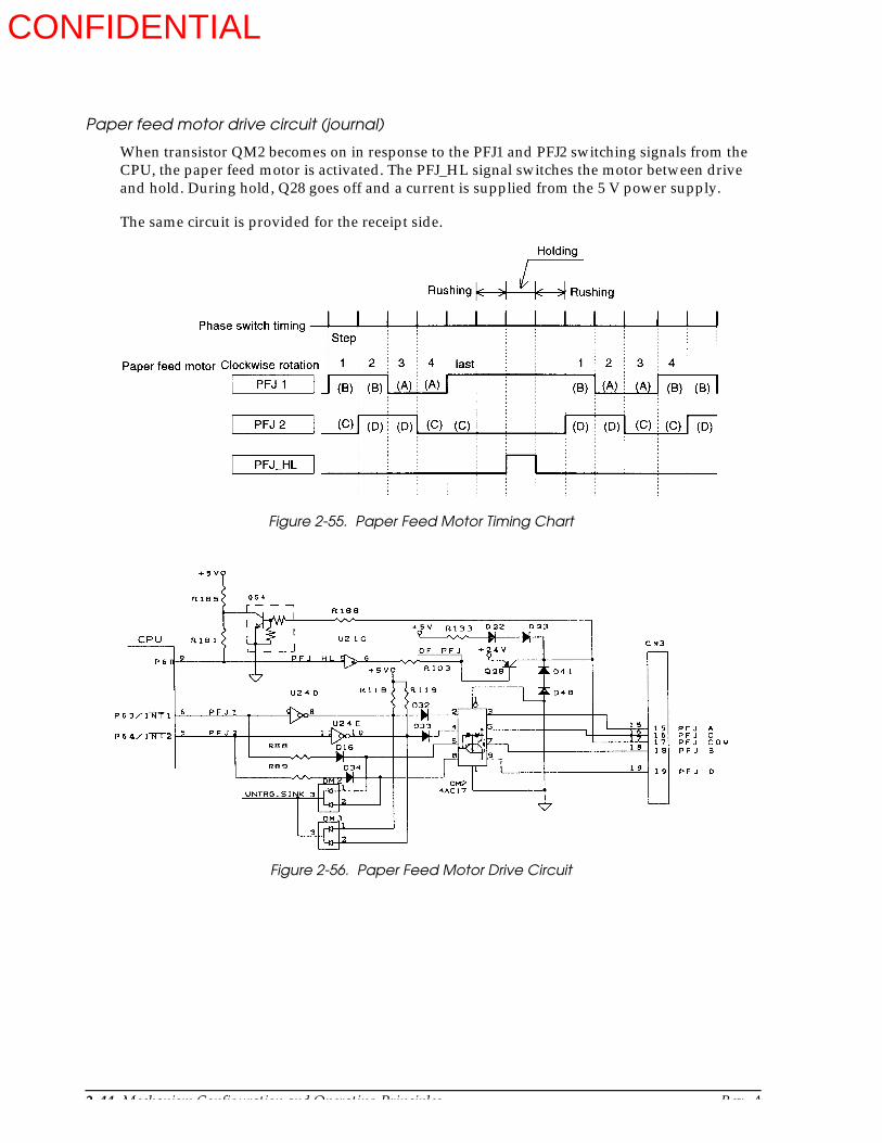
2-44 Mechanism Configuration and Operating Principles Rev. A
Paper feed motor drive circuit (journal)
When transistor QM2 becomes on in response to the PFJ1 and PFJ2 switching signals from the CPU, the paper feed motor is activated. The PFJ_HL signal switches the motor between drive and hold. During hold, Q28 goes off and a current is supplied from the 5 V power supply.
The same circuit is provided for the receipt side.
Figure 2-55. Paper Feed Motor Timing Chart
Figure 2-56. Paper Feed Motor Drive Circuit
CONFIDENTIAL

Rev. A Mechanism Configuration and Operating Principles 2-45
TM-U950/U950P Technical Manual
Auto-cutter drive circuit
The auto-cutter drive circuit uses the dedicated DC motor drive IC TA8428K. The CPU issues the AC_1 and AC_2 signals to control off, normal, reverse, and braking operations of the auto-cutter motor.
Carriage motor drive circuit
The carriage motor is driven by a dedicated constant-current IC. The CPU issues the mutual switching signals CR_1 and CR_2 and the constant-current switching signals CR_HL and CR_NM. In response to these signals, the IC controls the carriage motor via the OUTA, OUTA, OUTB, and OUTB terminals.
AC_1 AC_2 Operation
L L Off
H L Normal
L H Reverse
H H Brake
CR_HL CR_NM Operation
0 0 Speed up / slow down
0 1 Normal rotation
1 0 Hold
Figure 2-57. Auto-cutter Drive Circuit
CONFIDENTIAL

2-46 Mechanism Configuration and Operating Principles Rev. A
Figure 2-58. Carriage Motor Timing Chart
Figure 2-59. Carriage Motor Drive Circuit
CONFIDENTIAL
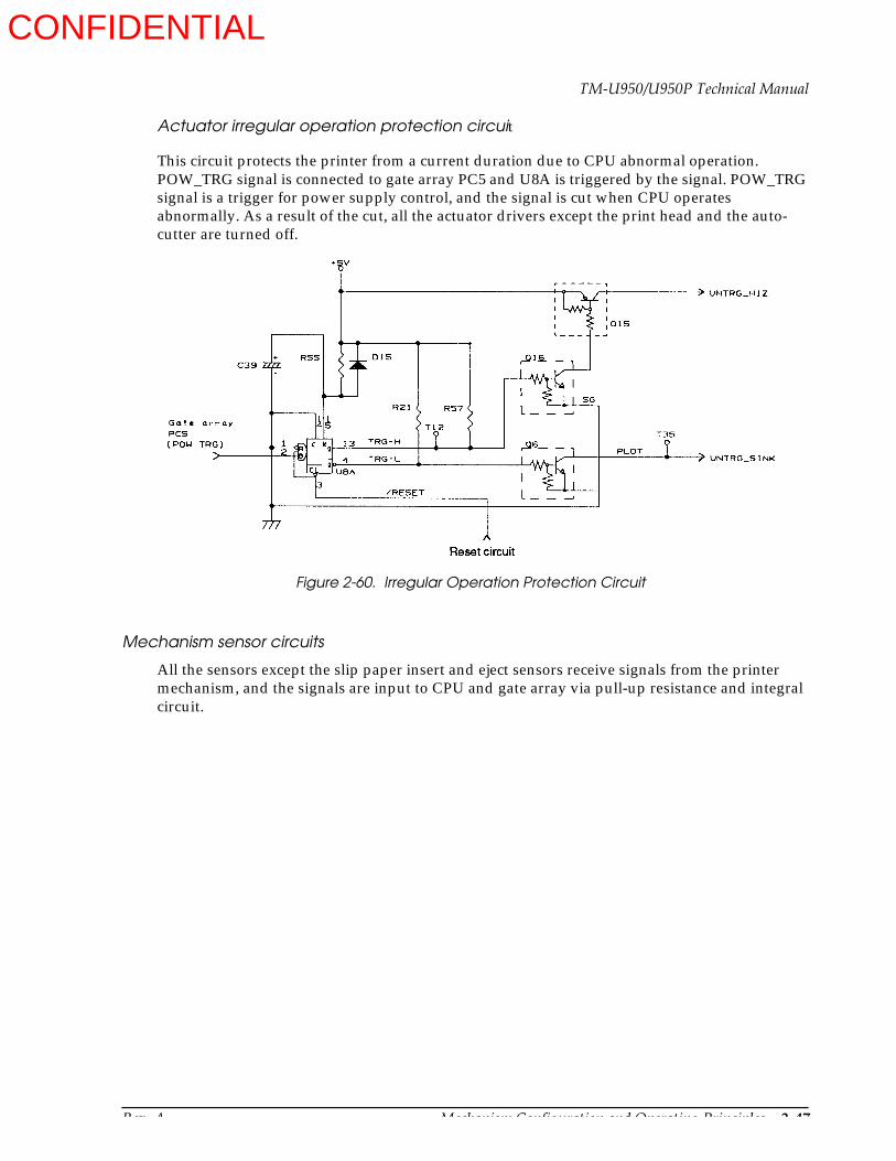
Rev. A Mechanism Configuration and Operating Principles 2-47
TM-U950/U950P Technical Manual
Actuator irregular operation protection circuit
This circuit protects the printer from a current duration due to CPU abnormal operation. POW_TRG signal is connected to gate array PC5 and U8A is triggered by the signal. POW_TRG signal is a trigger for power supply control, and the signal is cut when CPU operates abnormally. As a result of the cut, all the actuator drivers except the print head and the auto-cutter are turned off.
Mechanism sensor circuits
All the sensors except the slip paper insert and eject sensors receive signals from the printer mechanism, and the signals are input to CPU and gate array via pull-up resistance and integral circuit.
Figure 2-60. Irregular Operation Protection Circuit
CONFIDENTIAL
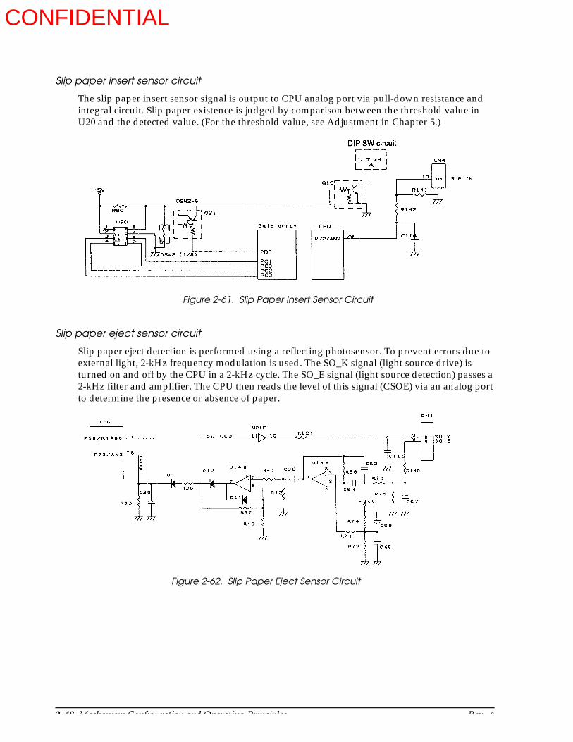
2-48 Mechanism Configuration and Operating Principles Rev. A
Slip paper insert sensor circuit
The slip paper insert sensor signal is output to CPU analog port via pull-down resistance and integral circuit. Slip paper existence is judged by comparison between the threshold value in U20 and the detected value. (For the threshold value, see Adjustment in Chapter 5.)
Slip paper eject sensor circuit
Slip paper eject detection is performed using a reflecting photosensor. To prevent errors due to external light, 2-kHz frequency modulation is used. The SO_K signal (light source drive) is turned on and off by the CPU in a 2-kHz cycle. The SO_E signal (light source detection) passes a 2-kHz filter and amplifier. The CPU then reads the level of this signal (CSOE) via an analog port to determine the presence or absence of paper.
Figure 2-61. Slip Paper Insert Sensor Circuit
Figure 2-62. Slip Paper Eject Sensor Circuit
CONFIDENTIAL

Rev. A Mechanism Configuration and Operating Principles 2-49
TM-U950/U950P Technical Manual
MICR Board Operating Principle (on printers with an MICR reader) (not available for the TM-U950P)
Operating principle of the MICR reader
“MICR” stands for “Magnetic Ink Character Recognition”. Magnetic ink is different from ink normally used for printing in that it contains magnetic particles such as iron filings which magnetize the ink.
When a magnetic field is applied from a certain direction to the magnetic ink characters printed on check paper, the characters are magnetized, as shown in the diagram below. (The term “magnetic ink” is used in this manual, but in actuality, the characters are read by sending current to a magnetic reading head and forming a magnet.)
Characters magnetized in this way are read by the magnetic reading head, and character recognition is carried out.
Figure 2-63. Magnetization of the Magnetic Ink Characters.
Figure 2-64. Operation of the Magnetic Reading Head
CONFIDENTIAL
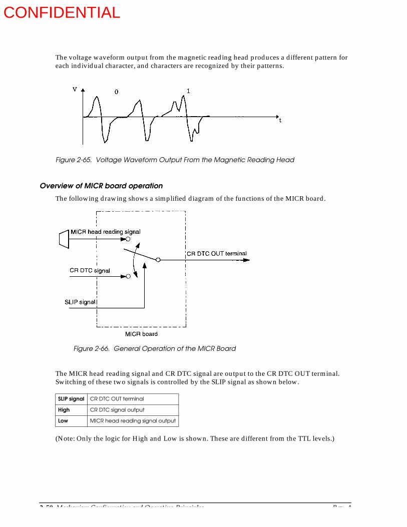
2-50 Mechanism Configuration and Operating Principles Rev. A
The voltage waveform output from the magnetic reading head produces a different pattern for each individual character, and characters are recognized by their patterns.
Overview of MICR board operation
The following drawing shows a simplified diagram of the functions of the MICR board.
The MICR head reading signal and CR DTC signal are output to the CR DTC OUT terminal. Switching of these two signals is controlled by the SLIP signal as shown below.
(Note: Only the logic for High and Low is shown. These are different from the TTL levels.)
SLIP signal CR DTC OUT terminal
High CR DTC signal output
Low MICR head reading signal output
Figure 2-65. Voltage Waveform Output From the Magnetic Reading Head
Figure 2-66. General Operation of the MICR Board
CONFIDENTIAL

Rev. A Handling and Maintenance 3-1
TM-U950/U950P Technical Manual
Chapter 3Handling and Maintenance
Handling
Handling Precautions
Transport Precautions
When transporting the printer, insert the protective material in the slip paper path and pack the printer in a specially provided package so that the printer does not come into contact with other products. Also, be careful not to drop it or apply any kind of external stress.
Storage Precautions
Avoid storing the printer in an area that is dusty, humid, or subject to excessively low temperatures. Also avoid areas which are exposed to direct sunlight for long periods of time.
For long-term storage, put the printer in a polyethylene bag with anti-rust paper (VCI paper), and keep it in a dry place.
Use Precautions
Always install a ribbon cassette and load paper before printing. If paper runs out, be sure to load new paper before resuming printing.
If printing is executed when there is no paper or no ribbon cassette in the printer, the print quality may deteriorate (the printing color may become uneven or some dots may not be printed) because of damage to the surface of the platen, printing wires, or ribbon.
Do not touch the print head unit after printing. It becomes very hot during printing.
There is a set screw for the frame ground (FG.) Use it for grounding the printer.
Be careful when wiring and connecting the interface, power, and drawer kick-out cables to avoid subjecting the connectors to excessive pressure.
Figure 3-1. Inserting the Protective Material
Protective Material
CONFIDENTIAL
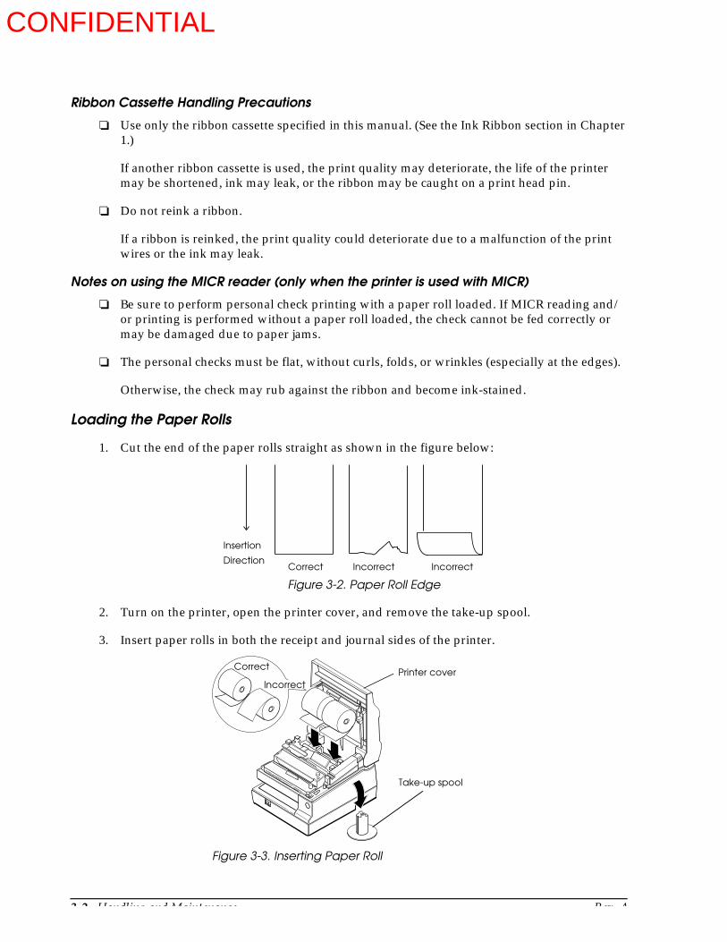
3-2 Handling and Maintenance Rev. A
Ribbon Cassette Handling Precautions
Use only the ribbon cassette specified in this manual. (See the Ink Ribbon section in Chapter 1.)
If another ribbon cassette is used, the print quality may deteriorate, the life of the printer may be shortened, ink may leak, or the ribbon may be caught on a print head pin.
Do not reink a ribbon.
If a ribbon is reinked, the print quality could deteriorate due to a malfunction of the print wires or the ink may leak.
Notes on using the MICR reader (only when the printer is used with MICR)
Be sure to perform personal check printing with a paper roll loaded. If MICR reading and/or printing is performed without a paper roll loaded, the check cannot be fed correctly or may be damaged due to paper jams.
The personal checks must be flat, without curls, folds, or wrinkles (especially at the edges).
Otherwise, the check may rub against the ribbon and become ink-stained.
Loading the Paper Rolls
1. Cut the end of the paper rolls straight as shown in the figure below:
2. Turn on the printer, open the printer cover, and remove the take-up spool.
3. Insert paper rolls in both the receipt and journal sides of the printer.
Figure 3-2. Paper Roll Edge
Insertion
DirectionCorrect Incorrect Incorrect
Figure 3-3. Inserting Paper Roll
Take-up spool
CorrectPrinter cover
Incorrect
CONFIDENTIAL

Rev. A Handling and Maintenance 3-3
TM-U950/U950P Technical Manual
4. Insert the tip of the paper from each roll into the corresponding paper inlet. The paper will automatically be detected and fed into the printer.
5. Tear off the receipt paper on the paper cutter. If the paper was not fed far enough, press the RECEIPT FEED button to feed additional paper.
6. Press the JOURNAL/SLIP FEED button to feed an additional 30 cm (a foot) or so of journal paper.
7. Insert the tip of the journal paper into the groove on the take-up spool and rotate the spool two or three times to secure the paper.
Figure 3-4. Inserting Paper into the Paper Inlet
Figure 3-5.Inserting the Paper into the Spool
Take-up spool
Groove
CONFIDENTIAL
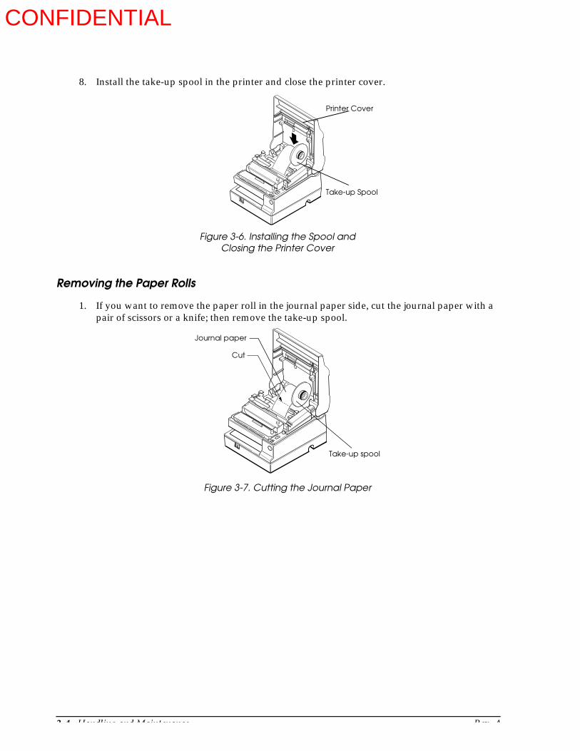
3-4 Handling and Maintenance Rev. A
8. Install the take-up spool in the printer and close the printer cover.
Removing the Paper Rolls
1. If you want to remove the paper roll in the journal paper side, cut the journal paper with a pair of scissors or a knife; then remove the take-up spool.
Figure 3-6. Installing the Spool and
Printer Cover
Take-up Spool
Closing the Printer Cover
Figure 3-7. Cutting the Journal Paper
Journal paper
Take-up spool
Cut
CONFIDENTIAL

Rev. A Handling and Maintenance 3-5
TM-U950/U950P Technical Manual
2. Hold down the paper release lever (marked PRESS) and pull out the paper roll in the direction of the arrow. As there is a paper release lever on both the receipt and journal sides of the printer, you can remove either (or both) of the paper rolls in this way.
Inserting Slip Paper and Printing on Slip Paper
Inserting Slip Paper
Note:Be sure to install the paper rolls in the printer, even if you plan to print only on slip papers. This will prevent paper jams. You can also prevent paper jams by using only flat paper, without wrinkles, creases, or folds.
1. Send ESC c 04 command from the computer, so that the printer enters slip paper mode. When the printer enters slip paper mode, the SLIP indicator flashes.
Figure 3-8. Removing the Paper Rolls
Release Lever
Release Lever
CONFIDENTIAL
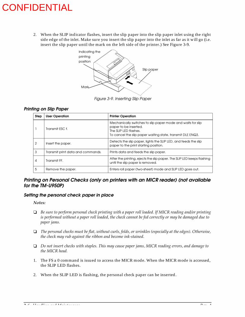
3-6 Handling and Maintenance Rev. A
2. When the SLIP indicator flashes, insert the slip paper into the slip paper inlet using the right side edge of the inlet. Make sure you insert the slip paper into the inlet as far as it will go (i.e. insert the slip paper until the mark on the left side of the printer.) See Figure 3-9.
Printing on Personal Checks (only on printers with an MICR reader) (not available for the TM-U950P)
Setting the personal check paper in place
Notes:
Be sure to perform personal check printing with a paper roll loaded. If MICR reading and/or printing is performed without a paper roll loaded, the check cannot be fed correctly or may be damaged due to paper jams.
The personal checks must be flat, without curls, folds, or wrinkles (especially at the edges). Otherwise, the check may rub against the ribbon and become ink-stained.
Do not insert checks with staples. This may cause paper jams, MICR reading errors, and damage to the MICR head.
1. The FS a 0 command is issued to access the MICR mode. When the MICR mode is accessed, the SLIP LED flashes.
2. When the SLIP LED is flashing, the personal check paper can be inserted.
Printing on Slip PaperStep User Operation Printer Operation
1 Transmit ESC f.
Mechanically switches to slip paper mode and waits for slip paper to be inserted. The SLIP LED flashes.To cancel the slip paper waiting state, transmit DLE ENQ3.
2 Insert the paper.Detects the slip paper, lights the SLIP LED, and feeds the slip paper to the print starting position.
3 Transmit print data and commands. Prints data and feeds the slip paper.
4 Transmit FF.After the printing, ejects the slip paper. The SLIP LED keeps flashing until the slip paper is removed.
5 Remove the paper. Enters roll paper (two-sheet) mode and SLIP LED goes out.
Figure 3-9. Inserting Slip Paper
Indicating the
printing
position
Mark
Slip paper
CONFIDENTIAL
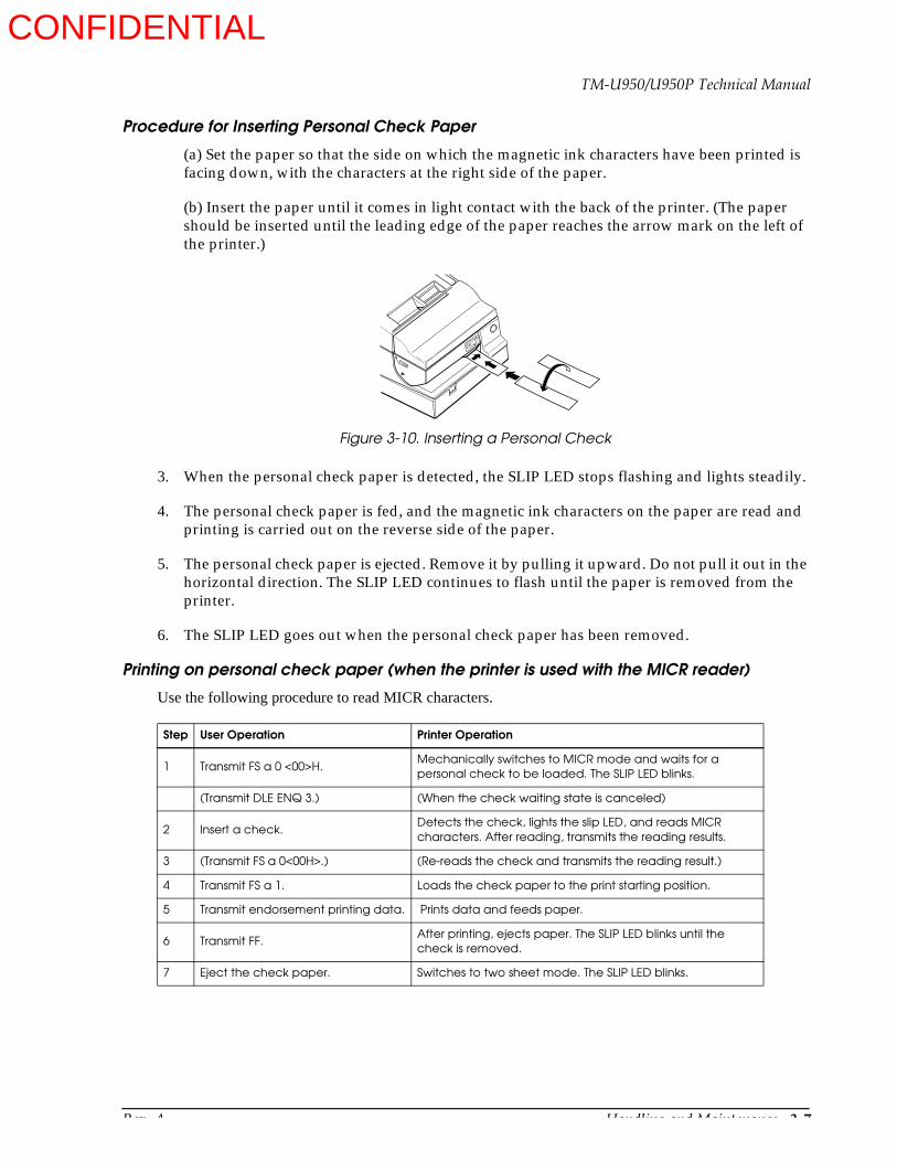
Rev. A Handling and Maintenance 3-7
TM-U950/U950P Technical Manual
Procedure for Inserting Personal Check Paper
(a) Set the paper so that the side on which the magnetic ink characters have been printed is facing down, with the characters at the right side of the paper.
(b) Insert the paper until it comes in light contact with the back of the printer. (The paper should be inserted until the leading edge of the paper reaches the arrow mark on the left of the printer.)
3. When the personal check paper is detected, the SLIP LED stops flashing and lights steadily.
4. The personal check paper is fed, and the magnetic ink characters on the paper are read and printing is carried out on the reverse side of the paper.
5. The personal check paper is ejected. Remove it by pulling it upward. Do not pull it out in the horizontal direction. The SLIP LED continues to flash until the paper is removed from the printer.
6. The SLIP LED goes out when the personal check paper has been removed.
Printing on personal check paper (when the printer is used with the MICR reader)
Use the following procedure to read MICR characters.
Step User Operation Printer Operation
1 Transmit FS a 0 <00>H.Mechanically switches to MICR mode and waits for a personal check to be loaded. The SLIP LED blinks.
(Transmit DLE ENQ 3.) (When the check waiting state is canceled)
2 Insert a check.Detects the check, lights the slip LED, and reads MICR characters. After reading, transmits the reading results.
3 (Transmit FS a 0<00H>.) (Re-reads the check and transmits the reading result.)
4 Transmit FS a 1. Loads the check paper to the print starting position.
5 Transmit endorsement printing data. Prints data and feeds paper.
6 Transmit FF.After printing, ejects paper. The SLIP LED blinks until the check is removed.
7 Eject the check paper. Switches to two sheet mode. The SLIP LED blinks.
Figure 3-10. Inserting a Personal Check
CONFIDENTIAL

3-8 Handling and Maintenance Rev. A
Notes:
Personal check is ejected in the forward direction only.
The paper roll must be loaded onto both the receipt and journal sides correctly before selecting MICR function by transmitting FS a 0. Otherwise, check paper is not fed properly.
The check waiting state is canceled using DLE ENQ 3.
After the personal check is ejected, the SLIP LED indicator lights and the printer does not proceed to the next operation until the check is removed.
The check waiting time and the interval from when a check is inserted to when the operation starts can be set using ESC f.
To check the MICR function status exactly, DLE EOT BS 1 should be used.
Installing and Removing the Ribbon Cassette
Installing the Ribbon Cassette
1. Open the printer cover.
2. Turn the ribbon cassette’s knob in the direction of the arrow, to take up any slack in the ribbon.
3. Insert the ribbon cassette in the printer and rotate the cassette’s knob five or six more times. This is necessary to place the ribbon in the correct position.
Notes:
Make sure that the ribbon is installed in front of the print head without wrinkles or creases. If it is hard to see, open the print head cover.
Never turn the ribbon cassette’s feed knob in the opposite direction of the arrow marked on the cassette.
Figure 3-11. Installing the Ribbon Cassette
Knob
CONFIDENTIAL

Rev. A Handling and Maintenance 3-9
TM-U950/U950P Technical Manual
Removing the Ribbon Cassette
To remove the ribbon cassette, grasp the ribbon cassette’s tab and pull it out of the printer.
Inserting the Stamp Set
If your printer has the stamping feature, follow the steps below to install the stamp set in the printer.
1. Open the printer cover.
2. Insert the stamp set into the printer as shown in the figure below. Then close the printer cover.
Note:To remove the stamp set, pull it out of the printer in the opposite direction of the arrow in the figure above.
Figure 3-12. Removing the Ribbon Cassette
Figure 3-13. Installing the Stamp Set
Printer cover
Stamp set
CONFIDENTIAL

3-10 Handling and Maintenance Rev. A
Mounting the Power Switch Cover
To guard the power switch from incorrect operation, attach the power switch cover on the printer power switch as shown in Figure 3-14.
Journal Lock Key Handling
The journal lock is located inside the printer cover as shown in Figure 3-15. The lock is closed when the key is turned to the right. The lock is open when the key is turned to the left.
Note:Make sure that you remove the key from the lock before you close the printer cover, otherwise the printer cover may be damaged.
Removing the Jammed Paper
To clear a paper jam inside the printer, follow the steps below:
1. Turn the printer off and open the printer cover.
2. If the paper is jammed in the journal paper side, cut the journal paper with a pair of scissors or a knife referring to Figure 3-7; then remove the take-up spool.
Figure 3-14. Installing the Power Switch Cover
Figure 3-15. Using the Journal Lock Key
Journal lock key
CONFIDENTIAL

Rev. A Handling and Maintenance 3-11
TM-U950/U950P Technical Manual
3. Cut the paper on the lines shown in the figure below, using a pair of scissors or a knife; then remove the paper roll. (See Figure 3-16.)
4. If the paper is caught in the cutter blade inside the auto-cutter, open the cutter blade by rotating the gear in the direction shown in the figure below.
Figure 3-16. Cutting the Paper
Figure 3-17. Opening the Cutter Blade
Gear
Paper roll
CONFIDENTIAL

3-12 Handling and Maintenance Rev. A
5. Move the OPEN ↔ LOCK lever on each side of the printer in the direction in the figure below; then the cutter unit opens automatically.
6. Pull the paper out gently. If the paper tears, make sure you remove any remaining pieces.
7. Close the cutter unit and lock it by moving both OPEN ↔ LOCK levers in the direction marked with LOCK.
If you encounter difficulty in clearing a paper jam, remove the print head cover by loosening the screw on the right side of the cover, as shown in the figure below.
Be careful not to touch the print head unit, as it can be very hot after printing continuously for a long time.
Figure 3-18. Opening the Cutter Unit
OPEN
LOCK
Figure 3-19. Removing the Print Head Cover
head
cover
CONFIDENTIAL
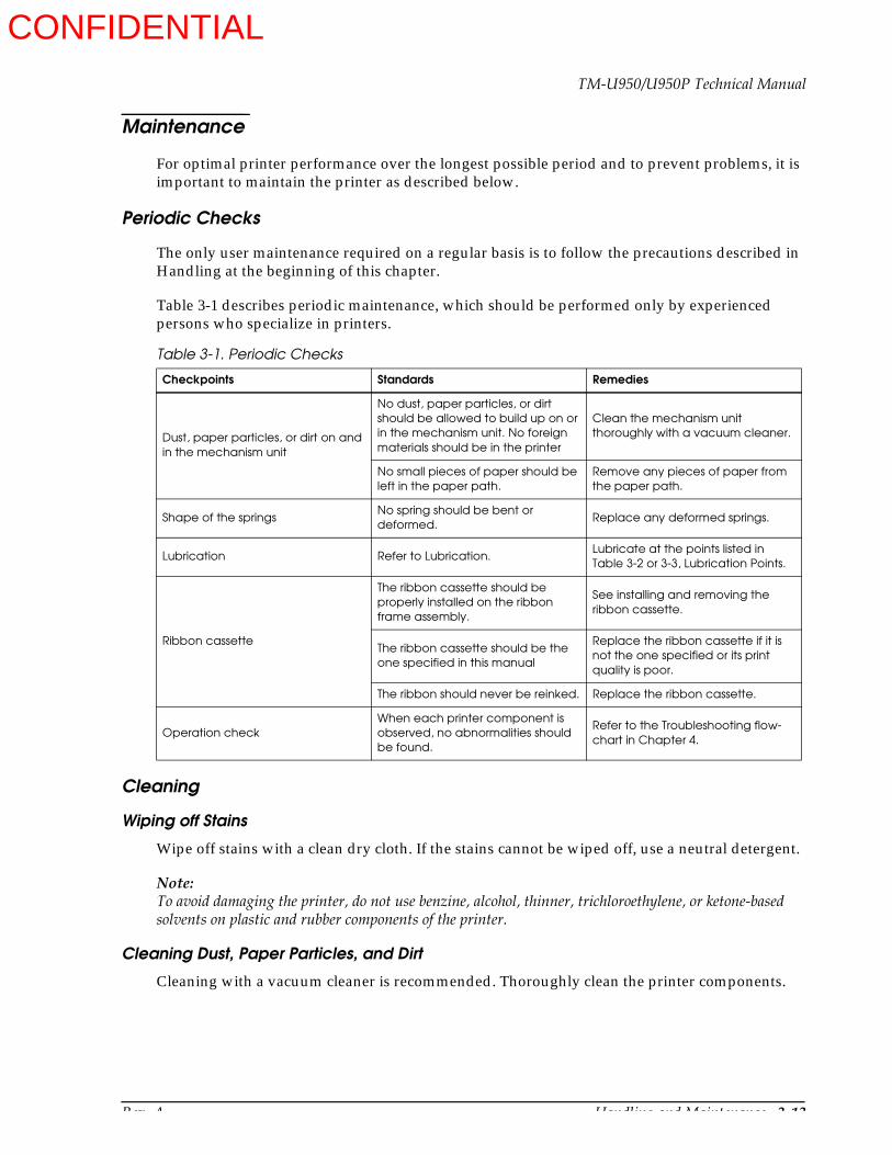
Rev. A Handling and Maintenance 3-13
TM-U950/U950P Technical Manual
Maintenance
For optimal printer performance over the longest possible period and to prevent problems, it is important to maintain the printer as described below.
Periodic Checks
The only user maintenance required on a regular basis is to follow the precautions described in Handling at the beginning of this chapter.
Table 3-1 describes periodic maintenance, which should be performed only by experienced persons who specialize in printers.
Cleaning
Wiping off Stains
Wipe off stains with a clean dry cloth. If the stains cannot be wiped off, use a neutral detergent.
Note:To avoid damaging the printer, do not use benzine, alcohol, thinner, trichloroethylene, or ketone-based solvents on plastic and rubber components of the printer.
Cleaning Dust, Paper Particles, and Dirt
Cleaning with a vacuum cleaner is recommended. Thoroughly clean the printer components.
Table 3-1. Periodic Checks
Checkpoints Standards Remedies
Dust, paper particles, or dirt on and in the mechanism unit
No dust, paper particles, or dirt should be allowed to build up on or in the mechanism unit. No foreign materials should be in the printer
Clean the mechanism unit thoroughly with a vacuum cleaner.
No small pieces of paper should be left in the paper path.
Remove any pieces of paper from the paper path.
Shape of the springsNo spring should be bent or deformed.
Replace any deformed springs.
Lubrication Refer to Lubrication.Lubricate at the points listed in Table 3-2 or 3-3, Lubrication Points.
Ribbon cassette
The ribbon cassette should be properly installed on the ribbon frame assembly.
See installing and removing the ribbon cassette.
The ribbon cassette should be the one specified in this manual
Replace the ribbon cassette if it is not the one specified or its print quality is poor.
The ribbon should never be reinked. Replace the ribbon cassette.
Operation checkWhen each printer component is observed, no abnormalities should be found.
Refer to the Troubleshooting flow-chart in Chapter 4.
CONFIDENTIAL

3-14 Handling and Maintenance Rev. A
Note:After cleaning is completed, verify that each lubrication point is adequately lubricated. If not, lubricate with the specified lubricant.
Cleaning the MICR Mechanism (when the printer is used with MICR reader)
Foreign matter on the MICR mechanism can cause MICR reading errors. To clean the MICR mechanism, execute the cleaning command (FS c). Then insert cleaning paper in the same way you insert check paper to clean the MICR head, roller, and paper path.
Cleaning period: Once per month or every 6000 passes
Example cleaning sheet: KIP Products PRESAT brand check reader cleaning card or equivalent
Lubrication
To maintain optimal printer performance over the longest possible period, apply the specified lubricant to the lubrication points according to the lubrication schedule below.
Lubrication Standards
When lubricating parts during assembly and disassembly of the printer, clean the parts before lubricating them.
If lubricant is wiped off during cleaning, or disassembly or parts replacement is performed, be sure to lubricate the appropriate points, even if it is not yet time for the periodic lubrication.
Lubricants
The performance and life of the printer is greatly affected by the lubricant applied. Therefore, pay careful attention to lubricant specifications, especially to the low temperature characteristics.
The lubricants for the printer are chosen based on technical information analysis and tests on various lubricants by EPSON. EPSON supplies EPSON specified lubricants in 40 cc (gr) plastic containers (the minimum supply unit).
Two lubricants, G-15, G-19, G-20, G-36 andO-2, may be applied to the printer.
Lubrication Points
See the General Lubrication Points Diagrams in the Appendix (Chapter 6). The numbers in the left column of Table 3-2 correspond to the numbers in the figures in Chapter 6.
CONFIDENTIAL

Rev. A Handling and Maintenance 3-15
TM-U950/U950P Technical Manual
Lubrication schedule: When the printer is overhauled or after every 5 million print lines.
Table 3-2. Lubrication Points for Printer Mechanism Unit (for printers without an MICR reader)
No. Lubrication Point (See lubrication point diagrams at end of Chapter 6 (Appendix) Type
1 Roller-sub paper feed assembly mounting U-cut notches (four) of paper guide-upper G-36
2 Roller mounting portions of sub paper hold roller G-36
3 Shaft of paper guide-lower G-15
4 Lever-stamp sliding portions (three) of paper guide-lower G-36
5 Lever-stamp drive hooding portion of lever-stamp G-15
6 Iron core notch G-15
7 Shaft of cutter motor mount plate sub assembly G-36
8 Bigger wheel of deceleration gear A G-36
9 Two holes of each paper hold roller G-36
10 Two shafts of cutter frame sub assembly G-36
11 Center wheel of cutter drive shaft sub assembly G-36
12 Both wheel of deceleration gear B G-36
13 Bigger wheel of deceleration gear A G-36
14 Cutter slider contact portion of frame-cutter blade receiving assembly G-36
15 Circuit pattern on cutter slider assembly G-20
16 Shaft of pulley base-carriage transmission assembly G-36
17 Oil ring O-2
18 Two shafts of frame-carriage assembly G-15
19 Carriage catching surface (above) of frame-carriage assembly (five) G-19
20 Carriage catching whole surface (below) of frame-carriage assembly G-19
21 Five shafts of frame-carriage assembly G-36
22 Wheel of carriage feed pulley G-36
23 Ribbon feed transmission gear G-36
24 Gear-ribbon feed G-36
25 Two shafts of roller-slip paper hold assembly G-15
26 Four dowels of frame-inner G-15
27 Lever-sub slip paper feed shaft contact portion with roller-sub slip paper feed G-15
28 Iron core notch G-15
29 Contact portion of form stopper and lever-sub slip paper feed shaft G-15
30 Contact portion of J/S changeover solenoid mount plate and J/S changeover solenoid G-15
31 Shaft of frame-paper take-up sub assembly G-36
32 Two U-cut notches of frame-paper take-up sub assembly G-36
33 Paper take-up gear contact portion with Paper take-up spring G-36
34 External surface of paper take-up spring G-36
CONFIDENTIAL

3-16 Handling and Maintenance Rev. A
35 Six shafts of frame-main assembly G-36
36 Roller-sub slip paper feed assembly mounting two U-cut notches of frame-main assembly G-15
37 Gear of roller-slip paper feed assembly G-36
38 Paper feed deceleration gear G-36
39 Receipt transmission gear G-36
40 Notch of J/S changeover gear G-36
41 Paper feed deceleration gear G-36
42 Bigger wheel gear of gear-journal transmission G-36
Table 3-3. Lubrication Points for Printer Mechanism Unit (for printers with an MICR reader)
No. Lubrication Point (See lubrication point diagrams at end of Chapter 6 (Appendix) Type
1 Roller-sub paper feed assembly mounting U-cut notches (four) of paper guide-upper G-36
2 Roller mounting portions of sub paper hold roller G-36
3 Shaft of paper guide-lower G-15
4 Lever-stamp sliding portions (three) of paper guide-lower G-36
5 Lever-stamp drive hooking portion of lever-stamp G-15
6 Iron core notch G-15
7 Shaft of cutter motor mount plate sub assembly G-36
8 Bigger wheel of deceleration gear A G-36
9 Two holes of each paper hold roller G-36
10 Two shafts of cutter frame sub assembly G-36
11 Center wheel of cutter drive shaft sub assembly G-36
12 Both wheel of deceleration gear B G-36
13 Bigger wheel of deceleration gear A G-36
14 Cutter slider contact portion of frame-cutter blade receiving assembly G-36
15 Circuit pattern on cutter slider assembly G-20
16 Shaft of pulley base-carriage transmission assembly G-36
17 Oil ring O-2
18 Two shafts of frame-carriage assembly G-15
19 Carriage catching surface (above) of frame-carriage assembly (five) G-19
20 Carriage catching whole surface (below) of frame-carriage assembly G-19
21 Five shafts of frame-carriage assembly G-36
22 Wheel of carriage feed pulley G-36
23 Ribbon feed transmission gear G-36
24 Gear-ribbon feed G-36
25 Five points on lever-MICR head holder change G-15
Table 3-2. Lubrication Points for Printer Mechanism Unit (for printers without an MICR reader)
No. Lubrication Point (See lubrication point diagrams at end of Chapter 6 (Appendix) Type
CONFIDENTIAL

Rev. A Handling and Maintenance 3-17
TM-U950/U950P Technical Manual
Tool List
26 Four dowels of frame-inner G-15
27 Lever-sub slip paper feed shaft contact portion with roller-sub slip paper feed G-15
28 Iron core notch G-15
29 Contact portion of form stopper and lever-sub slip paper feed shaft G-15
30 Contact portion of J/S changeover solenoid mount plate and J/S changeover solenoid G-15
31 Shaft of frame-paper take-up sub assembly G-36
32 Two U-cut notches of frame-paper take-up sub assembly G-36
33 Paper take-up gear contact portion with Paper take-up spring G-36
34 External surface of paper take-up spring G-36
35 Six shafts of frame-main assembly G-36
36 Roller-sub slip paper feed assembly mounting two U-cut notches of frame-main assembly G-15
37 Gear of roller-slip paper feed assembly G-36
38 Paper feed deceleration gear G-36
39 Receipt transmission gear G-36
40 Notch of J/S changeover gear G-36
41 Paper feed deceleration gear G-36
42 Bigger wheel gear of gear-journal transmission G-36
43 Two axles of roller-MICR head holder G-36
44 Notch in sleeve of roller-MICR head holder G-36
Table 3-4. Tools Required for Servicing the Printer (all are commercially available)
Tool Name
Brush #1
Brush #2
Cleaning brush
Phillips screwdriver no. 1
Phillips screwdriver no. 2
Flatblade screwdriver
Hexagon screwdriver 5 mm (0.2”)
Tweezers
Round-nose pliers
Clearance gauges, 0.5 mm (0.02”)
ET holders (#1.5, #2.3, and #3)
Table 3-3. Lubrication Points for Printer Mechanism Unit (for printers with an MICR reader)
No. Lubrication Point (See lubrication point diagrams at end of Chapter 6 (Appendix) Type
CONFIDENTIAL
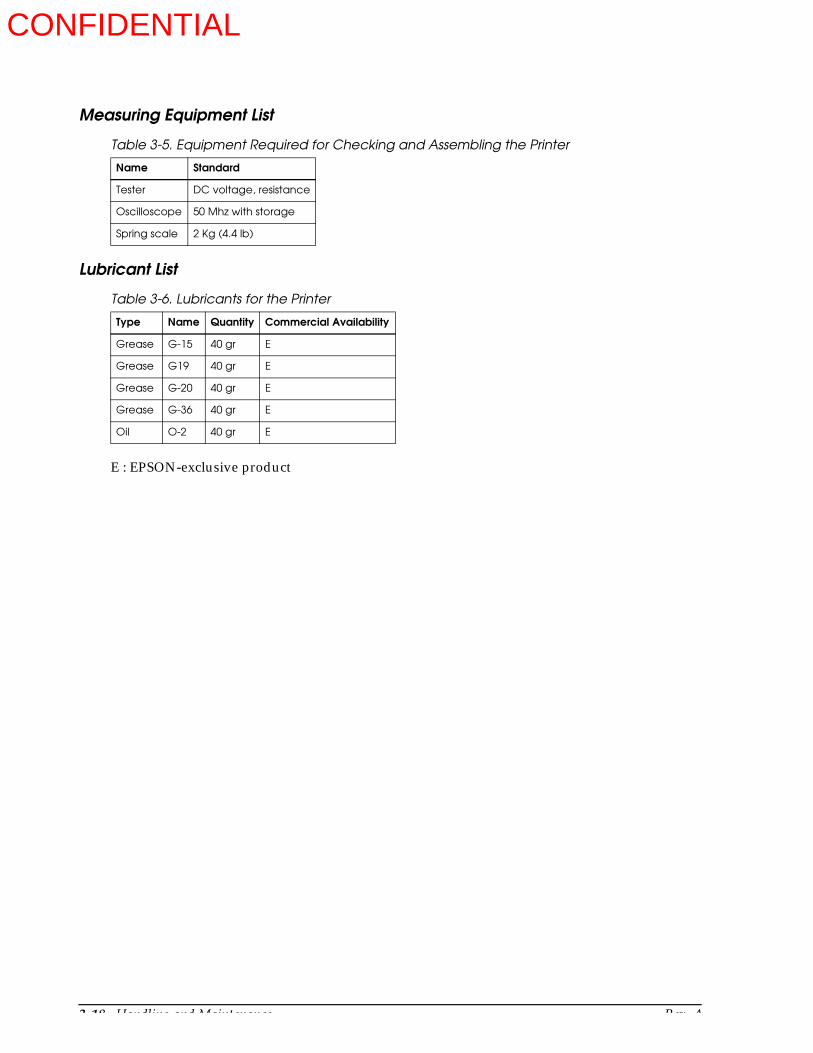
3-18 Handling and Maintenance Rev. A
Measuring Equipment List
Lubricant List
E : EPSON-exclusive product
Table 3-5. Equipment Required for Checking and Assembling the Printer
Name Standard
Tester DC voltage, resistance
Oscilloscope 50 Mhz with storage
Spring scale 2 Kg (4.4 lb)
Table 3-6. Lubricants for the Printer
Type Name Quantity Commercial Availability
Grease G-15 40 gr E
Grease G19 40 gr E
Grease G-20 40 gr E
Grease G-36 40 gr E
Oil O-2 40 gr E
CONFIDENTIAL
Rev. A Troubleshooting 4-1
TM-U950/U950P Technical Manual
Chapter 4Troubleshooting
Troubleshooting
Use the following to troubleshoot and repair the printer:
Self-test
Use the self-test to check the operation of the control circuitry and the printer mechanism.
Troubleshooting flowchart
When the source of the problem is not clear, use the flowchart to find and replace a defective component.
Troubleshooting tables
Follow the steps outlined in these tables to repair a defect whose symptoms are known.
Self-test
The self test can be performed for paper rolls or for slip paper. Make sure the printer is turned off before starting the self-test with either paper type.
Initiating the self-test
Paper roll self-test
1. Insert paper rolls in both receipt and journal sides of the printer, and close the printer cover.
2. Turn on the printer while keeping the RECEIPT FEED button depressed. The self-test starts and status information is printed on the receipt paper roll.
Slip paper self test
1. Insert paper rolls in both receipt and journal sides of the printer, and close the printer cover.
Note:When printing on slip paper, paper rolls should also be inserted in both sides of the printer. This prevents paper jams.
2. Turn on the printer while keeping the JOURNAL/SLIP FEED button depressed. The SLIP LED flashes.
3. Feed a sheet of slip paper into the printer. The self-test starts, loading the paper automatically and then printing status information.
Self-test standby
Paper roll self test
1. When the status information printing is complete, the following is printed:
CONFIDENTIAL

4-2 Troubleshooting Rev. A
“Self-test printing. Please press RECEIPT FEED button.”
The RECEIPT OUT and JOURNAL OUT LEDs flash alternately to indicate the standby condition.
2. Press the RECEIPT FEED button to continue self-test.
Slip paper self test
When the status information printing is complete, the slip paper is ejected, and the printer waits for insertion of the next sheet (SLIP LED flashes). To continue the self-test, continue to feed slip paper into the printer.
CONFIDENTIAL
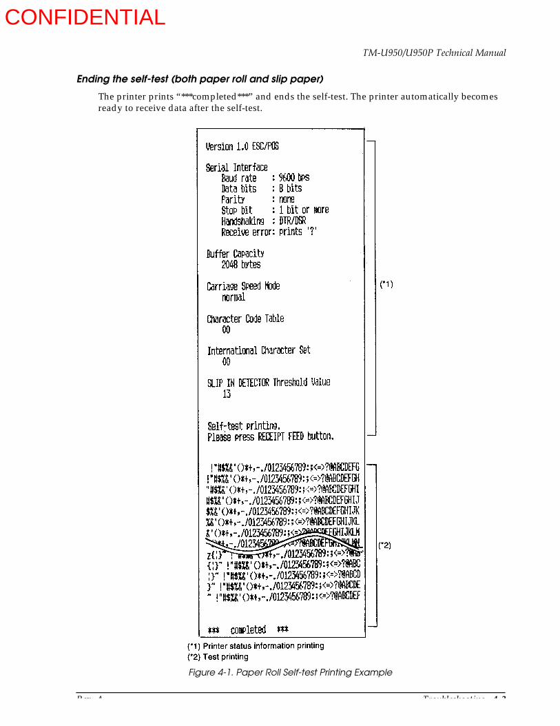
Rev. A Troubleshooting 4-3
TM-U950/U950P Technical Manual
Ending the self-test (both paper roll and slip paper)
The printer prints “***completed***” and ends the self-test. The printer automatically becomes ready to receive data after the self-test.
Figure 4-1. Paper Roll Self-test Printing Example
CONFIDENTIAL

4-4 Troubleshooting Rev. A
Troubleshooting Flowchart
If the source of a problem is not clear, use the flowchart below to find and replace a defective component. Normally servicing should be performed by component replacement. Repairs of the PCBs and other components should be performed only by technicians.
CONFIDENTIAL
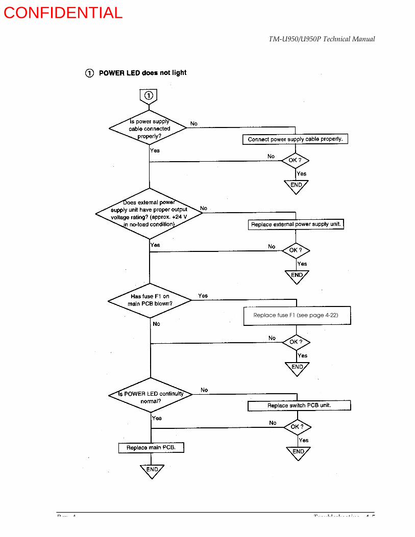
Rev. A Troubleshooting 4-5
TM-U950/U950P Technical Manual
Replace fuse F1 (see page 4-22)
CONFIDENTIAL

4-6 Troubleshooting Rev. A
CONFIDENTIAL
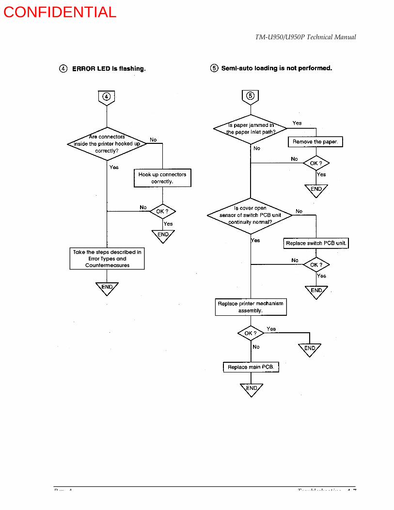
Rev. A Troubleshooting 4-7
TM-U950/U950P Technical Manual
Take the steps described inError Types and
Countermeasures
CONFIDENTIAL
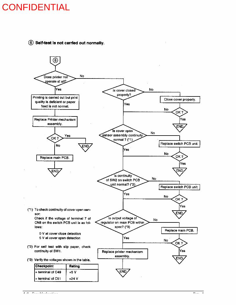
4-8 Troubleshooting Rev. A
CONFIDENTIAL

Rev. A Troubleshooting 4-9
TM-U950/U950P Technical Manual
Data from host is not printed normally for the TM-U950
CONFIDENTIAL

4-10 Troubleshooting Rev. A
Is interfacecircuit board
connected to the maincircuit board
firmly?
7
Replace with a proper cable.
Replace the cable.
Connect the board firmly
Replace the I/F circuit board
OK?
OK?
OK?
Does
Is interface
End
End
End
No
No
No
No
No
No
Yes
Yes
Yes
Yes
Yes
Data from host is not printed normally for the TM-U950P
Yes
cable matchspecification?
interface
cable broken?
OK?
End
Replace the printer mechanism assembly
OK?
EndNo
Check the host
➆
No
CONFIDENTIAL

Rev. A Troubleshooting 4-11
TM-U950/U950P Technical Manual
End
End
CONFIDENTIAL

4-12 Troubleshooting Rev. A
Troubleshooting Tables
If a problem that can be verified by visual examination has occurred, use the tables below to determine the cause and perform repairs.
There are three tables, divided by symptom category:
Table 4-1 Initialization ProblemsTable 4-2 Printing Quality ProblemsTable 4-3 Printer Mechanism Problems
The tables contain the following columns:
Problem
This is the symptom that can be verified.
Probable Cause
This is a listing of one or several possible causes that should be examined.
Level
Level A
The problem can be corrected by persons who are familiar with the printer and have general knowledge, but special technical skills are not required.
Level B
The problem requires thorough knowledge and familiarity with the printer that should be checked.
Checkpoint
These are one or more areas in the printer that should be checked.
Action
These are the steps to correct the problem. If the problem persists after taking these steps, check the other possible causes listed
CONFIDENTIAL
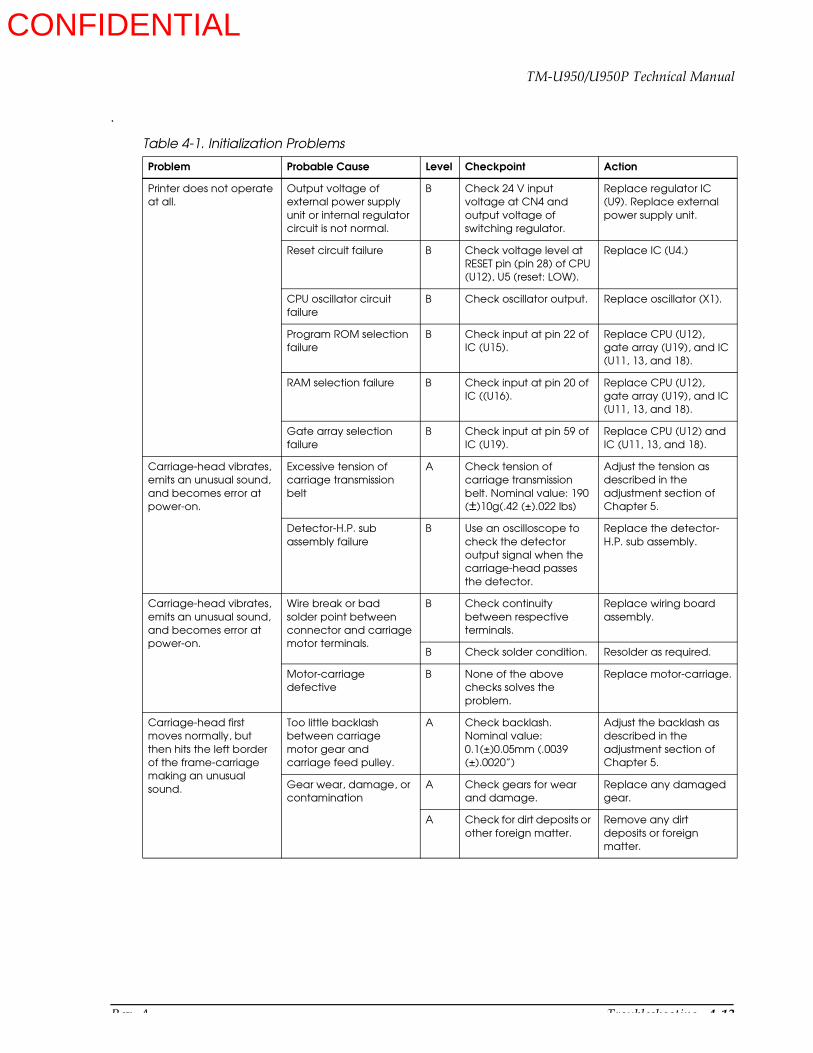
Rev. A Troubleshooting 4-13
TM-U950/U950P Technical Manual
.
Table 4-1. Initialization Problems
Problem Probable Cause Level Checkpoint Action
Printer does not operate at all.
Output voltage of external power supply unit or internal regulator circuit is not normal.
B Check 24 V input voltage at CN4 and output voltage of switching regulator.
Replace regulator IC (U9). Replace external power supply unit.
Reset circuit failure B Check voltage level at RESET pin (pin 28) of CPU (U12), U5 (reset: LOW).
Replace IC (U4.)
CPU oscillator circuit failure
B Check oscillator output. Replace oscillator (X1).
Program ROM selection failure
B Check input at pin 22 of IC (U15).
Replace CPU (U12), gate array (U19), and IC (U11, 13, and 18).
RAM selection failure B Check input at pin 20 of IC ((U16).
Replace CPU (U12), gate array (U19), and IC (U11, 13, and 18).
Gate array selection failure
B Check input at pin 59 of IC (U19).
Replace CPU (U12) and IC (U11, 13, and 18).
Carriage-head vibrates, emits an unusual sound, and becomes error at power-on.
Excessive tension of carriage transmission belt
A Check tension of carriage transmission belt. Nominal value: 190 (±)10g(.42 (±).022 lbs)
Adjust the tension as described in the adjustment section of Chapter 5.
Detector-H.P. sub assembly failure
B Use an oscilloscope to check the detector output signal when the carriage-head passes the detector.
Replace the detector-H.P. sub assembly.
Carriage-head vibrates, emits an unusual sound, and becomes error at power-on.
Wire break or bad solder point between connector and carriage motor terminals.
B Check continuity between respective terminals.
Replace wiring board assembly.
B Check solder condition. Resolder as required.
Motor-carriage defective
B None of the above checks solves the problem.
Replace motor-carriage.
Carriage-head first moves normally, but then hits the left border of the frame-carriage making an unusual sound.
Too little backlash between carriage motor gear and carriage feed pulley.
A Check backlash. Nominal value: 0.1(±)0.05mm (.0039 (±).0020”)
Adjust the backlash as described in the adjustment section of Chapter 5.
Gear wear, damage, or contamination
A Check gears for wear and damage.
Replace any damaged gear.
A Check for dirt deposits or other foreign matter.
Remove any dirt deposits or foreign matter.
CONFIDENTIAL

4-14 Troubleshooting Rev. A
Motor-carriage does not operate at all when power is turned on and becomes error.
Carriage motor drive signal failure
B Check motor drive signal at connector with an oscilloscope.
Repair motor drive signal generator circuit.
Wire break or bad solder point between connector and carriage motor terminals.
B Check continuity between respective terminals.
Replace wiring board assembly.
B Check solder condition. Resolder as required.
Motor carriage defective
B Above three checks have been passed.
Replace motor-carriage.
Detector-carriage sub assembly failure
B Move the carriage-head and check the detection signal by using an oscilloscope.
Replace detector-carriage subassembly.
Table 4-2. Printing Quality Problems
Problem Probable Cause Level Checkpoint Action
All dots do not print, or print is very faint.
FPC is disconnected. A Check FPC connector. Insert FPC again.
Wire break or bad solder point in common wire inside print head.
A Check common wire for continuity.
Replace print head unit.
Wire break or bad solder somewhere on the line between print head unit and connector.
B Check common wire for continuity.
Resolder parts or replace wire break parts.
Platen gap is not adjusted correctly.
A Check platen gap. Nominal value: 0.50(±)0.05 mm (.020(±).0020”)
Adjust the gap as described in the adjustment section in Chapter 5.
Input pulse irregularity B Check dot wire input pulse with an oscilloscope.
Repair input pulse control circuit or input pulse drive circuit.
A certain dot does not print.
FPC wire break B Check FPC for continuity.
Replace print head unit.
Wire break between soldered point of flat cable on wiring board and connector terminals.
B Check wire between terminals for continuity.
Replace wiring board assembly.
Print head coil wire break
B Check coil resistance with a multimeter.
Replace print head unit.
Bad solder point between connector and head coil.
B Check wire between terminals for continuity.
Resolder.
Print head wire break B Check for dot wire break.
Replace print head unit.
Table 4-1. Initialization Problems (continued)
Problem Probable Cause Level Checkpoint Action
CONFIDENTIAL

Rev. A Troubleshooting 4-15
TM-U950/U950P Technical Manual
Dots are dropped irregularly.
Print head FPC break B Check FPC for continuity.
Replace print head unit.
Print head operation failure
B Check wire tip for paper or ink deposits.
Clean wire tip.
Print head wear B Above two checks have been passed.
Replace print head unit.
Character width changes irregularly.
Carriage transmission belt tension is too low.
A Check carriage transmission belt tension. Nominal value: 190 ± 10 g (.42 ± .022 lbs)
Adjust the tension as described in the adjustment section in Chapter 5.
Gears, carriage feed pulley, or carriage transmission belt wear or damage
B Check parts for wear or damage.
Replace parts as necessary.
Print head wear B Above two checks have been passed.
Replace print head unit.
Table 4-3. Printer Mechanism Problems
Problem Probable Level Checkpoint Action
Paper roll does not advance, and printing is all on the same line.
Paper roll supplying problem
A Check whether paper roll corresponds to specifications.
Use paper roll that corresponds to specifications.
A Check paper roll path for obstacles.
Remove any obstacles and repair paper roll path as required.
Roller-paper feed wear B Check surface of roller-paper feed for wear and damage.
Replace roller-paper feed assembly.
Gear wheel wear B Check gear wheels for wear and damage.
Replace gear wheels as required.
Paper hold roller wear B Check surface and core of paper hold roller for wear.
Replace paper hold roller.
J and R paper feed motors drive signal failure
B Check motor drive signal at connector with an oscilloscope.
Repair motor drive signal generator circuit.
Wire break or bad solder point in wiring between connector and motor-paper feed-J and -R
B Check connection for continuity.
Replace wiring board assembly.
B Check solder condition. Resolder as required.
Paper roll does not advance, and printing is all on the same line
Motor-paper feed-J and -R failure
B Above eight checks have been passed.
Replace motor-paper feed -J and -R.
Table 4-2. Printing Quality Problems (continued)
Problem Probable Cause Level Checkpoint Action
CONFIDENTIAL
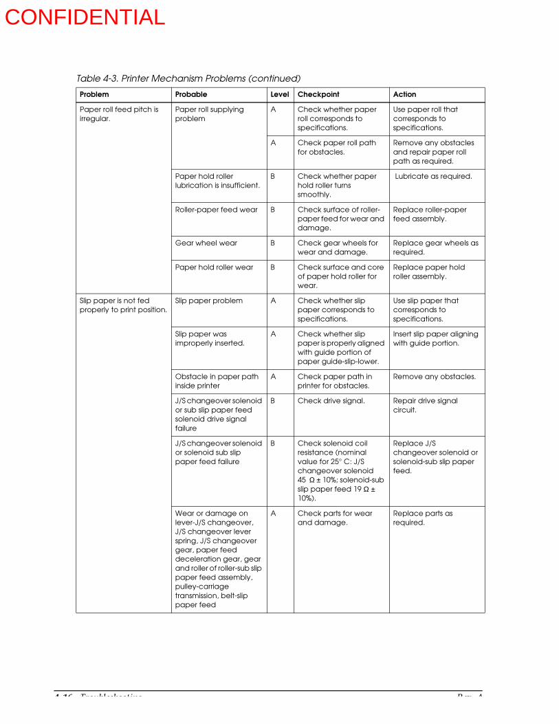
4-16 Troubleshooting Rev. A
Paper roll feed pitch is irregular.
Paper roll supplying problem
A Check whether paper roll corresponds to specifications.
Use paper roll that corresponds to specifications.
A Check paper roll path for obstacles.
Remove any obstacles and repair paper roll path as required.
Paper hold roller lubrication is insufficient.
B Check whether paper hold roller turns smoothly.
Lubricate as required.
Roller-paper feed wear B Check surface of roller-paper feed for wear and damage.
Replace roller-paper feed assembly.
Gear wheel wear B Check gear wheels for wear and damage.
Replace gear wheels as required.
Paper hold roller wear B Check surface and core of paper hold roller for wear.
Replace paper hold roller assembly.
Slip paper is not fed properly to print position.
Slip paper problem A Check whether slip paper corresponds to specifications.
Use slip paper that corresponds to specifications.
Slip paper was improperly inserted.
A Check whether slip paper is properly aligned with guide portion of paper guide-slip-lower.
Insert slip paper aligning with guide portion.
Obstacle in paper path inside printer
A Check paper path in printer for obstacles.
Remove any obstacles.
J/S changeover solenoid or sub slip paper feed solenoid drive signal failure
B Check drive signal. Repair drive signal circuit.
J/S changeover solenoid or solenoid sub slip paper feed failure
B Check solenoid coil resistance (nominal value for 25° C: J/S changeover solenoid 45 Ω ± 10%; solenoid-sub slip paper feed 19 Ω ± 10%).
Replace J/S changeover solenoid or solenoid-sub slip paper feed.
Wear or damage on lever-J/S changeover, J/S changeover lever spring, J/S changeover gear, paper feed deceleration gear, gear and roller of roller-sub slip paper feed assembly, pulley-carriage transmission, belt-slip paper feed
A Check parts for wear and damage.
Replace parts as required.
Table 4-3. Printer Mechanism Problems (continued)
Problem Probable Level Checkpoint Action
CONFIDENTIAL
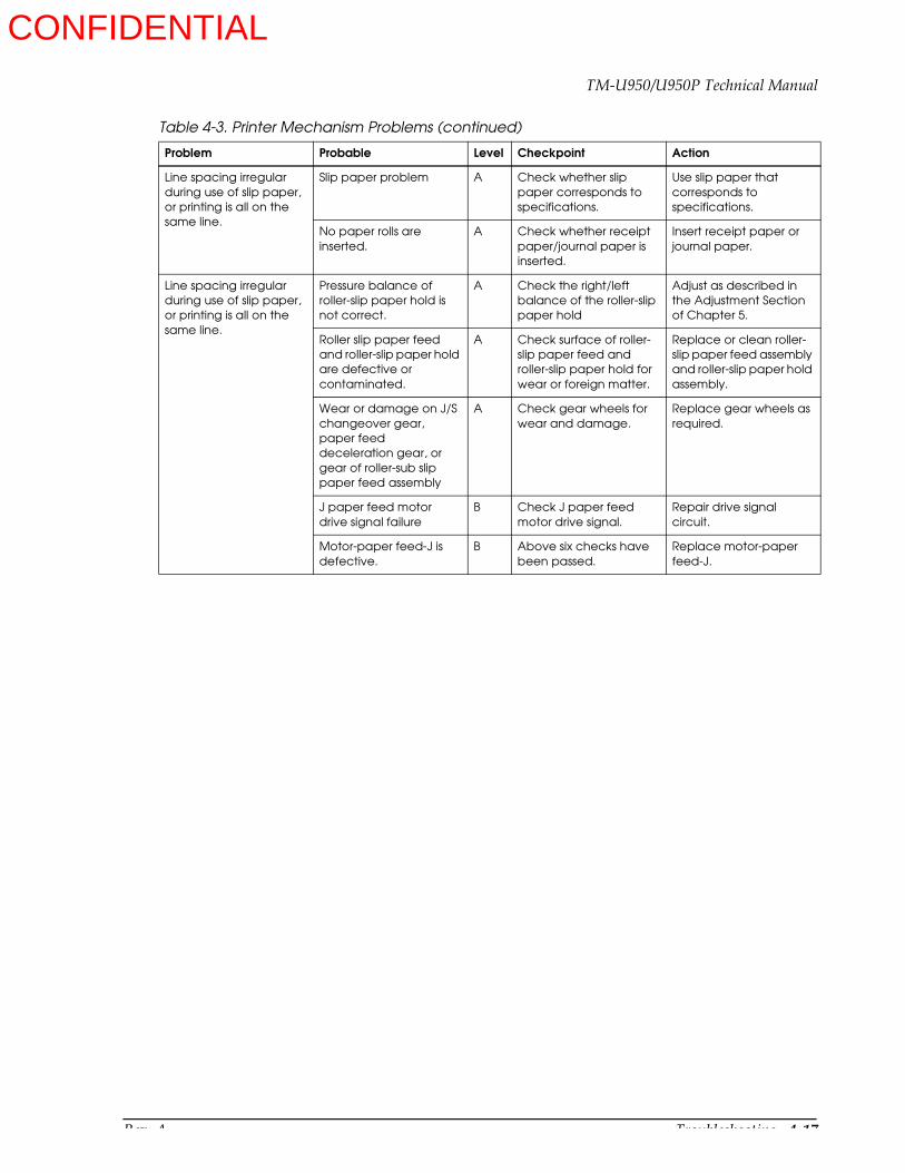
Rev. A Troubleshooting 4-17
TM-U950/U950P Technical Manual
Line spacing irregular during use of slip paper, or printing is all on the same line.
Slip paper problem A Check whether slip paper corresponds to specifications.
Use slip paper that corresponds to specifications.
No paper rolls are inserted.
A Check whether receipt paper/journal paper is inserted.
Insert receipt paper or journal paper.
Line spacing irregular during use of slip paper, or printing is all on the same line.
Pressure balance of roller-slip paper hold is not correct.
A Check the right/left balance of the roller-slip paper hold
Adjust as described in the Adjustment Section of Chapter 5.
Roller slip paper feed and roller-slip paper hold are defective or contaminated.
A Check surface of roller-slip paper feed and roller-slip paper hold for wear or foreign matter.
Replace or clean roller-slip paper feed assembly and roller-slip paper hold assembly.
Wear or damage on J/S changeover gear, paper feed deceleration gear, or gear of roller-sub slip paper feed assembly
A Check gear wheels for wear and damage.
Replace gear wheels as required.
J paper feed motor drive signal failure
B Check J paper feed motor drive signal.
Repair drive signal circuit.
Motor-paper feed-J is defective.
B Above six checks have been passed.
Replace motor-paper feed-J.
Table 4-3. Printer Mechanism Problems (continued)
Problem Probable Level Checkpoint Action
CONFIDENTIAL

4-18 Troubleshooting Rev. A
Semi-auto loading is not carried out.
Paper guide-assist operation problem
B Check paper guide-assist for paper deposits or other contamination. Check deformation of auxiliary paper guide spring.
Remove any paper deposits or other contamination. Replace auxiliary paper guide spring.
Paper roll is not inserted properly.
A Check paper roll alignment and paper edge shape.
Insert paper roll properly (see Chapter 3).
Paper roll supplying problem
A Check whether paper roll corresponds to specifications.
Use paper roll that corresponds to specifications.
A Check paper roll path for obstacles.
Remove any obstacles and repair paper roll path as required.
Roller-sub paper feed wear or damage
B Check surface of roller-sub paper feed for wear and damage.
Replace roller-sub paper feed assembly.
Paper sub hold roller wear or damage
B Check surface and core of sub paper hold roller for wear and damage.
Replace sub paper hold roller.
Insufficient lubrication of friction lever in roller-sub paper feed assembly
B Check lubrication condition and wear.
Lubricate as required or replace roller-sub paper feed assembly.
Gear wheel wear or damage
B Check gear wheels for wear and damage.
Replace gear wheels as required.
J/R paper feed motor drive signal failure
B Check motor drive signal at connector with an oscilloscope.
Repair motor drive signal generator circuit.
Wire break or bad solder point in wiring between connector and motor-paper feed-J and -R
B Check connection for continuity.
Replace wiring board assembly.
B Check solder condition. Resolder as required.
Motor-paper feed-J and -R failure
B Above eleven checks have been passed.
Replace motor-paper feed -J and -R.
Table 4-3. Printer Mechanism Problems (continued)
Problem Probable Level Checkpoint Action
CONFIDENTIAL
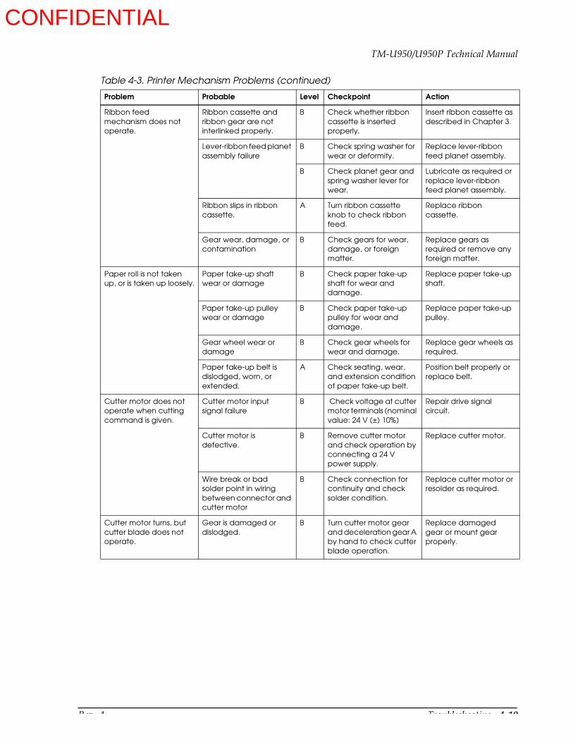
Rev. A Troubleshooting 4-19
TM-U950/U950P Technical Manual
Ribbon feed mechanism does not operate.
Ribbon cassette and ribbon gear are not interlinked properly.
B Check whether ribbon cassette is inserted properly.
Insert ribbon cassette as described in Chapter 3.
Lever-ribbon feed planet assembly failure
B Check spring washer for wear or deformity.
Replace lever-ribbon feed planet assembly.
B Check planet gear and spring washer lever for wear.
Lubricate as required or replace lever-ribbon feed planet assembly.
Ribbon slips in ribbon cassette.
A Turn ribbon cassette knob to check ribbon feed.
Replace ribbon cassette.
Gear wear, damage, or contamination
B Check gears for wear, damage, or foreign matter.
Replace gears as required or remove any foreign matter.
Paper roll is not taken up, or is taken up loosely.
Paper take-up shaft wear or damage
B Check paper take-up shaft for wear and damage.
Replace paper take-up shaft.
Paper take-up pulley wear or damage
B Check paper take-up pulley for wear and damage.
Replace paper take-up pulley.
Gear wheel wear or damage
B Check gear wheels for wear and damage.
Replace gear wheels as required.
Paper take-up belt is dislodged, worn, or extended.
A Check seating, wear, and extension condition of paper take-up belt.
Position belt properly or replace belt.
Cutter motor does not operate when cutting command is given.
Cutter motor input signal failure
B Check voltage at cutter motor terminals (nominal value: 24 V (±) 10%)
Repair drive signal circuit.
Cutter motor is defective.
B Remove cutter motor and check operation by connecting a 24 V power supply.
Replace cutter motor.
Wire break or bad solder point in wiring between connector and cutter motor
B Check connection for continuity and check solder condition.
Replace cutter motor or resolder as required.
Cutter motor turns, but cutter blade does not operate.
Gear is damaged or dislodged.
B Turn cutter motor gear and deceleration gear A by hand to check cutter blade operation.
Replace damaged gear or mount gear properly.
Table 4-3. Printer Mechanism Problems (continued)
Problem Probable Level Checkpoint Action
CONFIDENTIAL

4-20 Troubleshooting Rev. A
Cutter blade operates but full cut is not performed or becomes error.
Output signal failure B Check output signals at contact pin holder sub assembly with an oscilloscope (blue: F/P position pulse; red: reset pulse; black: common).
Replace contact pin holder sub assembly and cutter slider assembly if irregular chattering (more than 2 ms pulse width) is generated. Remove any contamination on cutter slider assembly.
Paper dust or other contamination has accumulated on cutter blade.
B Check for paper dust or other contamination
Remove cover-cutter blade receiving assembly and remove paper dust or other contamination.
Cutter blade operates but full cut is not performed or becomes error.
Gear wheel wear or damage
B Check gear wheels for wear and damage.
Replace gear wheels as required.
Paper roll supplying problem
A Check whether paper roll corresponds to specifications.
Use paper roll that corresponds to specifications.
A Check paper feed path. Repair paper feed mechanism as required.
Slip paper is positioned correctly, but printer does not detect it.
Detector-slip paper insertion sub assembly failure
B Insert paper and check detector output signal with an oscilloscope.
Replace detector-slip paper insertion sub assembly.
Slip paper problem A Check whether slip paper corresponds to specifications.
Use slip paper that corresponds to specifications.
EEPROM (U20) failure B Check EEPROM (U20) output signal.
Replace EEPROM (U20).
Slip paper eject waiting status is not released when slip paper is removed.
Detector-slip paper ejection sub assembly failure
B Check detection signal by using an oscilloscope when slip paper is removed.
Replace detector-slip paper ejection sub assembly.
Slip paper eject detection circuit failure
B Check pin 70 of CPU (U12) with an oscilloscope.
Replace detector-slip paper ejection assembly.
Paper roll near-end detection does not work properly.
Microswitch failure A Check continuity between microswitch terminals and check on/off operation.
Replace microswitch.
Slip paper is not released.
Internal diameter of paper roll core is too small.
A Check internal diameter of paper roll core. Nominal value: 10 mm (.39”) or more
Use paper roll that corresponds to specifications.
Table 4-3. Printer Mechanism Problems (continued)
Problem Probable Level Checkpoint Action
CONFIDENTIAL
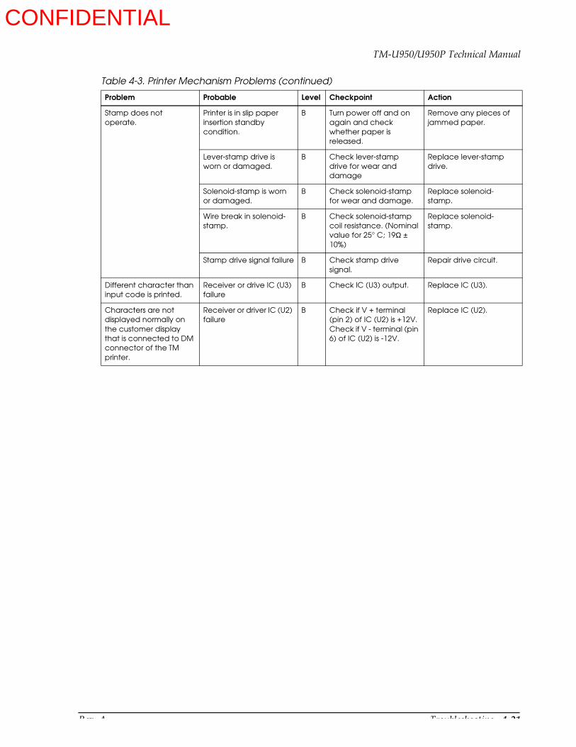
Rev. A Troubleshooting 4-21
TM-U950/U950P Technical Manual
Stamp does not operate.
Printer is in slip paper insertion standby condition.
B Turn power off and on again and check whether paper is released.
Remove any pieces of jammed paper.
Lever-stamp drive is worn or damaged.
B Check lever-stamp drive for wear and damage
Replace lever-stamp drive.
Solenoid-stamp is worn or damaged.
B Check solenoid-stamp for wear and damage.
Replace solenoid-stamp.
Wire break in solenoid-stamp.
B Check solenoid-stamp coil resistance. (Nominal value for 25° C; 19Ω ± 10%)
Replace solenoid-stamp.
Stamp drive signal failure B Check stamp drive signal.
Repair drive circuit.
Different character than input code is printed.
Receiver or drive IC (U3) failure
B Check IC (U3) output. Replace IC (U3).
Characters are not displayed normally on the customer display that is connected to DM connector of the TM printer.
Receiver or driver IC (U2) failure
B Check if V + terminal (pin 2) of IC (U2) is +12V. Check if V - terminal (pin 6) of IC (U2) is -12V.
Replace IC (U2).
Table 4-3. Printer Mechanism Problems (continued)
Problem Probable Level Checkpoint Action
CONFIDENTIAL

4-22 Troubleshooting Rev. A
Table 4-4. MICR Malfunction
Problem Probable Level Checkpoint Action
None of the magnetic printing can be read. (The paper is processed as an error)
Carriage head malfunction
B Check to see if the carriage head stops at the right end when the check paper is read.
Refer to related items under the previous section on carriage head malfunction.
MICR component malfunction
B Insert check paper, move the carriage head to the right end, and see if the printer enters paper holding mode (the check paper is hard to pull out of the printer).
Replace the MICR mechanism part.
Defective rotation of check paper holder roller
B Check to see if the transfer belt on the check paper holder roller is cut someplace, and if the roller turns smoothly.
Replace the transfer belt on the check sheet holder roller.Replace the check sheet holder roller.
Defective MICR head and MICR circuit board
B See if the MICR head is damaged. Also, check circuits and lead wires for disconnected wires, and see if a sinewave is produced in the circuit output.
Replace the MICR head unit (including the circuits).
Magnetic printing is misread. (The paper is processed normally.)
Dirty carriage head A Clean the carriage head, using cleaning paper.
Clean the MICR head.
Deformation of check paper, or magnetic ink characters do not conform to standard
A Check to see if the check paper is mis-shapen, or if there is any bleeding, protrusion, or missing lines in the magnetic ink characters on the check paper.
Replace the check paper.
Carriage head malfunction
B Check to see if the carriage head stops at the right end when the check paper is read.
Refer to related items under the previous section on carriage head malfunction.
MICR component malfunction
B Insert check paper, move the carriage head to the right end, and see if the printer enters paper holding mode (the check paper is hard to pull out of the printer).
Replace the MICR mechanism part.
Defective rotation of check paper holder roller
B Check to see if the transfer belt on the check paper holder roller is cut someplace, and if the roller turns smoothly.
Replace the transfer belt on the check sheet holder roller. Replace the check sheet holder roller.
Defective MICR hear and MICR circuit board
B See if the MICR head is damaged. Also, check circuits and lead wires for disconnected wires, and see if a sinewave is produced in the circuit output.
Replace the MICR head unit (including the circuits).
CONFIDENTIAL
Rev. A Troubleshooting 4-23
TM-U950/U950P Technical Manual
Major Part Replacements
Fuse replacement
Follow the steps below to replace a blown fuse:
1. Turn the printer off.
2. Disconnect the external power supply unit.
3. Perform Main Assembly 6 and 7 in Chapter 5 in reverse.
4. Replace the blown fuse (125 V, 3.15 AT).
5. Perform steps (1) through (3) in reverse.
If the printer still does not operate properly, or if the fuse blows again, use the flowchart in Chapter 4 to check for other problems.
Print Head Unit Replacement
Follow the steps below to replace the print head unit:
1. Turn the printer off.
2. Disconnect the external power supply unit.
3. Disassemble the printer following the procedure described in Replacing the Print Head Unit in Chapter 5.
4. Replace the print head unit.
5. Perform gap adjustment referring to page 5-58.
6. Perform steps (1) through (3) in reverse.
Cutter Blade Replacement
Follow the steps below to replace the cutter blade:
1. Turn the printer off.
2. Disconnect the external power supply unit.
3. Disassemble the printer following the procedure described in Replacing the Cutter Blade in Chapter 5.
4. Replace the cutter blade. (Make sure the cutter blade is only one leaf.)
5. Perform steps (1) through (3) in reverse.
CONFIDENTIAL
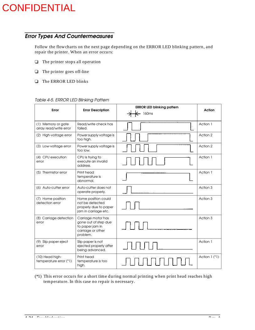
4-24 Troubleshooting Rev. A
Error Types And Countermeasures
Follow the flowcharts on the next page depending on the ERROR LED blinking pattern, and repair the printer. When an error occurs:
The printer stops all operation
The printer goes off-line
The ERROR LED blinks
(*1) This error occurs for a short time during normal printing when print head reaches high temperature. In this case no repair is necessary.
Table 4-5. ERROR LED Blinking Pattern
Error Error DescriptionERROR LED blinking pattern
Action
(1) Memory or gate array read/write error
Read/write check has failed.
Action 1
(2) High-voltage error Power supply voltage is too high.
Action 2
(3) Low-voltage error Power supply voltage is too low.
Action 2
(4) CPU execution error
CPU is trying to execute an invalid address.
Action 1
(5) Thermistor error Print head temperature is abnormal.
Action 1
(6) Auto-cutter error Auto-cutter does not operate properly.
Action 3
(7) Home position detection error
Home position could not be detected properly due to paper jam in carriage etc.
Action 3
(8) Carriage detection error
Carriage motor has gone out of step due to paper jam in carriage or other problem.
Action 3
(9) Slip paper eject error
Slip paper is not ejected properly after being advanced.
Action 1
(10) Head high-temperature error (*1)
Print head temperature is too high.
Action 1 (*1)
160ms
CONFIDENTIAL
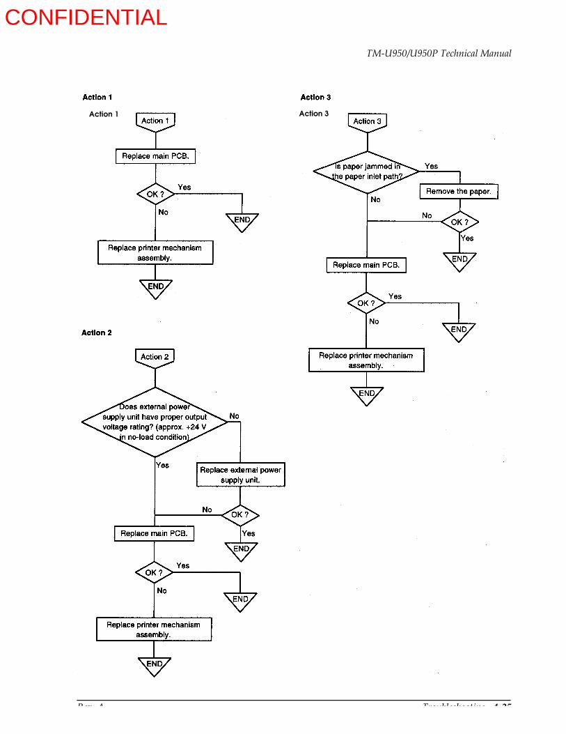
Rev. A Troubleshooting 4-25
TM-U950/U950P Technical Manual
Action 1 Action 3
CONFIDENTIAL
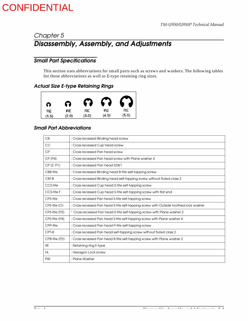
Rev. A Disassembly, Assembly, and Adjustments 5-1
TM-U950/U950P Technical Manual
Chapter 5Disassembly, Assembly, and Adjustments
Small Part Specifications
This section uses abbreviations for small parts such as screws and washers. The following tables list these abbreviations as well as E-type retaining ring sizes.
Actual Size E-type Retaining Rings
Small Part Abbreviations
CB : Cross-recessed Binding head screw
CC : Cross-recessed Cup head screw
CP : Cross-recessed Pan head screw
CP (P4) : Cross-recessed Pan head screw with Plane washer 4
CP (S. P1) : Cross-recessed Pan head S2W1
CBB-tite : Cross-recessed Binding head B-tite self-tapping screw
CBT-B : Cross-recessed Binding head self-tapping screw without fluted class 2
CCS-tite : Cross-recessed Cup head S-tite self-tapping screw
CCS-tite F : Cross-recessed Cup head S-tite self-tapping screw with flat end
CPS-tite : Cross-recessed Pan head S-tite self-tapping screw
CPS-tite (O) : Cross-recessed Pan head S-tite self-tapping screw with Outside toothed lock washer
CPS-tite (P2) “ Cross-recessed Pan head S-tite self-tapping screw with Plane washer 2
CPS-tite (P4) : Cross-recessed Pan head S-tite self-tapping screw with Plane washer 4
CPP-tite : Cross-recessed Pan head P-tite self-tapping screw
CPT-B : Cross-recessed Pan head self-tapping screw without fluted class 2
CPB-tite (P2) : Cross-recessed Pan head B-tite self-tapping screw with Plane washer 2
RE : Retaining ring E-type
HL : Hexagon Lock screw
PW : Plane Washer
CONFIDENTIAL
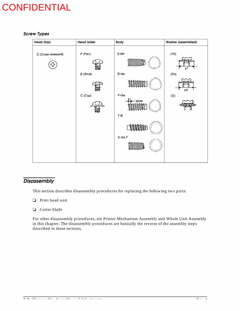
5-2 Disassembly, Assembly, and Adjustments Rev. A
Screw Types
Disassembly
This section describes disassembly procedures for replacing the following two parts:
Print head unit
Cutter blade
For other disassembly procedures, see Printer Mechanism Assembly and Whole Unit Assembly in this chapter. The disassembly procedures are basically the reverse of the assembly steps described in these sections.
Head (top) Head (side) Body Washer (assembled)
CONFIDENTIAL
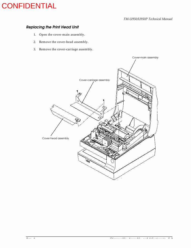
Rev. A Disassembly, Assembly, and Adjustments 5-3
TM-U950/U950P Technical Manual
Replacing the Print Head Unit
1. Open the cover-main assembly.
2. Remove the cover-head assembly.
3. Remove the cover-carriage assembly.
Cover-main assembly
Cover-head assembly
Cover-carriage assembly
CONFIDENTIAL
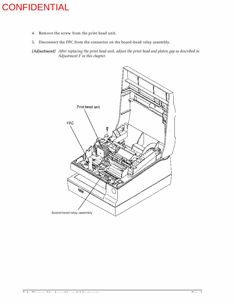
5-4 Disassembly, Assembly, and Adjustments Rev. A
4. Remove the screw from the print head unit.
5. Disconnect the FPC from the connector on the board-head relay assembly.
[Adjustment] After replacing the print head unit, adjust the print head and platen gap as described in Adjustment F in this chapter.
Board-head relay assembly
CONFIDENTIAL

Rev. A Disassembly, Assembly, and Adjustments 5-5
TM-U950/U950P Technical Manual
Replacing the Cutter Blade
1. Open the cover-main assembly.
2. Remove the screws from the cover-cutter blade receiving assembly and replace the cover.
[Adjustment] Make sure to perform the cutter blade play after the replacement. See Adjustment A in this chapter.
Art To Come
Cover-cutter blade receiving assembly
Cover-main assembly
CONFIDENTIAL

5-6 Disassembly, Assembly, and Adjustments Rev. A
Printer Mechanism Unit Assembly
The assembly process is divided into sub-assembly and main assembly.
Perform the sub-assembly first to construct each unit from the parts. Then proceed to the main assembly.
When assembling the printer, check each part and its attachment position by referring to the exploded diagrams in Chapter 6.
An asterisk after a step number (such as 2.*) indicates that lubrication must be performed. Lubricants should be applied when assembling the parts, since it is difficult to do so afterwards. Perform lubrication by referring to the lubrication section at the end of Chapter 6.
For adjustments, follow the descriptions in the Adjustments sections in this chapter. Whenever disassembly is performed even for just one part, check whether adjustment is necessary before assembly.
All illustrations show the printer with a MICR reader installed, unless marked “Without MICR reader.”
CONFIDENTIAL
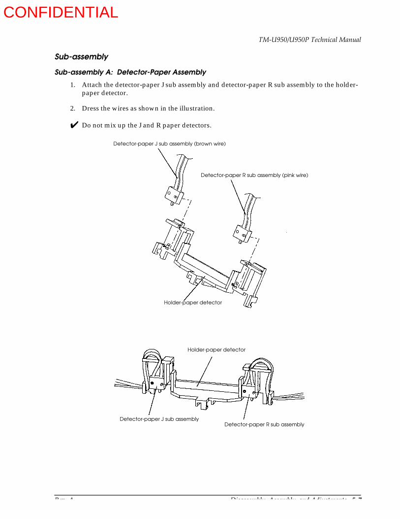
Rev. A Disassembly, Assembly, and Adjustments 5-7
TM-U950/U950P Technical Manual
Sub-assembly
Sub-assembly A: Detector-Paper Assembly
1. Attach the detector-paper J sub assembly and detector-paper R sub assembly to the holder-paper detector.
2. Dress the wires as shown in the illustration.
Do not mix up the J and R paper detectors.
Detector-paper J sub assembly (brown wire)
Detector-paper R sub assembly (pink wire)
Holder-paper detector
Detector-paper J sub assemblyDetector-paper R sub assembly
Holder-paper detector
CONFIDENTIAL

5-8 Disassembly, Assembly, and Adjustments Rev. A
Sub-assembly B: Paper Guide-Upper Unit Assembly
1.* Attach both paper sensor levels to the paper guide-upper.
2. Fit hook of the detector-paper assembly into hole and move it in the direction to lock.
3. Dress the wires of the paper sensors as shown in the illustration.
a b
Detector paper assembly
CONFIDENTIAL
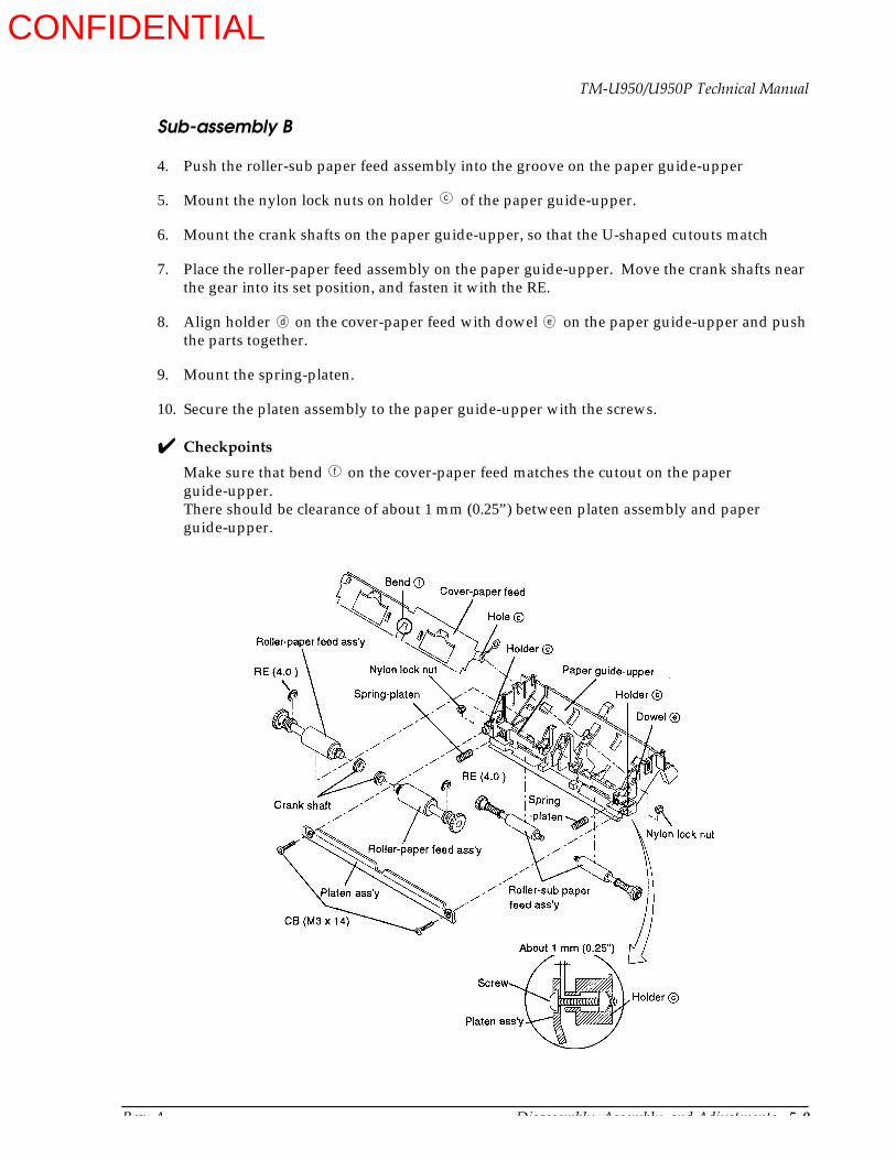
Rev. A Disassembly, Assembly, and Adjustments 5-9
TM-U950/U950P Technical Manual
Sub-assembly B
4. Push the roller-sub paper feed assembly into the groove on the paper guide-upper
5. Mount the nylon lock nuts on holder of the paper guide-upper.
6. Mount the crank shafts on the paper guide-upper, so that the U-shaped cutouts match
7. Place the roller-paper feed assembly on the paper guide-upper. Move the crank shafts near the gear into its set position, and fasten it with the RE.
8. Align holder on the cover-paper feed with dowel on the paper guide-upper and push the parts together.
9. Mount the spring-platen.
10. Secure the platen assembly to the paper guide-upper with the screws.
Checkpoints
Make sure that bend on the cover-paper feed matches the cutout on the paper guide-upper.There should be clearance of about 1 mm (0.25”) between platen assembly and paper guide-upper.
c
d e
f
CONFIDENTIAL
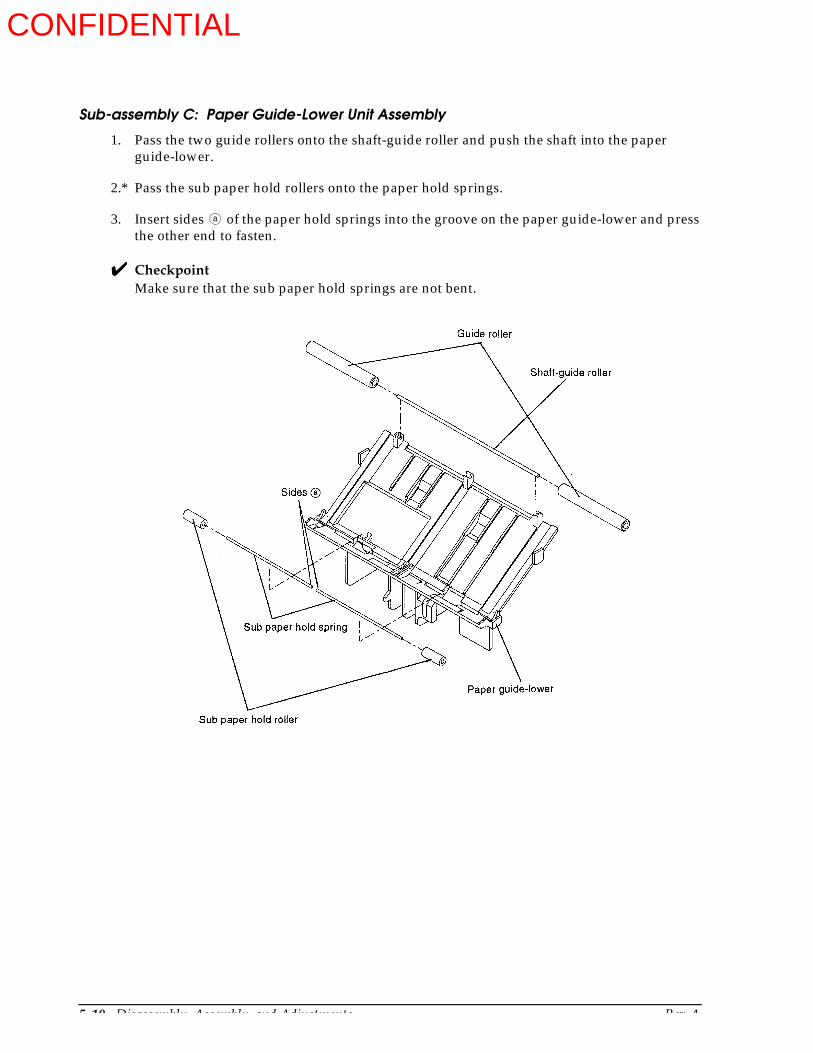
5-10 Disassembly, Assembly, and Adjustments Rev. A
Sub-assembly C: Paper Guide-Lower Unit Assembly
1. Pass the two guide rollers onto the shaft-guide roller and push the shaft into the paper guide-lower.
2.* Pass the sub paper hold rollers onto the paper hold springs.
3. Insert sides of the paper hold springs into the groove on the paper guide-lower and press the other end to fasten.
CheckpointMake sure that the sub paper hold springs are not bent.
a
CONFIDENTIAL
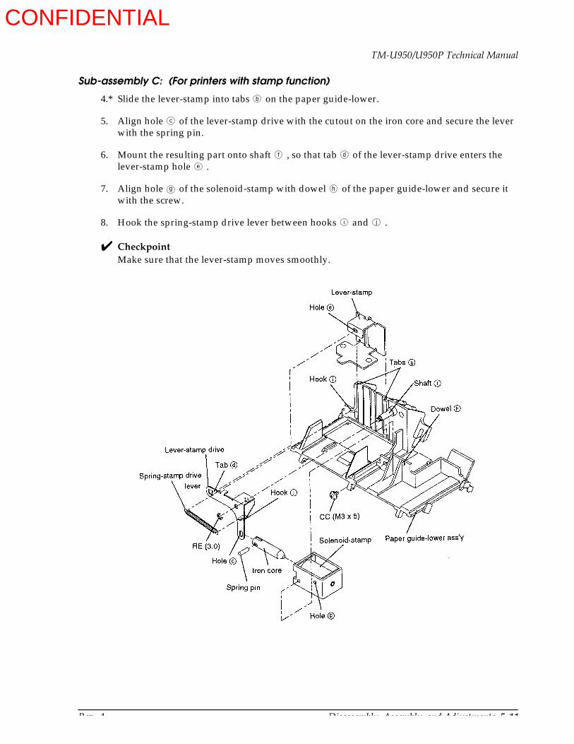
Rev. A Disassembly, Assembly, and Adjustments 5-11
TM-U950/U950P Technical Manual
Sub-assembly C: (For printers with stamp function)
4.* Slide the lever-stamp into tabs on the paper guide-lower.
5. Align hole of the lever-stamp drive with the cutout on the iron core and secure the lever with the spring pin.
6. Mount the resulting part onto shaft , so that tab of the lever-stamp drive enters the lever-stamp hole .
7. Align hole of the solenoid-stamp with dowel of the paper guide-lower and secure it with the screw.
8. Hook the spring-stamp drive lever between hooks and .
CheckpointMake sure that the lever-stamp moves smoothly.
b
c
f d
e
g h
i j
Paper guide-lower assembly
CONFIDENTIAL

5-12 Disassembly, Assembly, and Adjustments Rev. A
Sub-assembly D: Cutter Motor Mount Plate Assembly
1. Mount the cutter motor gear onto the cutter motor.
2.* Hold the motor with the label facing up and insert it into the cutter motor mount place sub-assembly. Turn it in the direction and secure it with the screws.
3.* Mount the deceleration gear A and fasten it with the RE.
Sub-assembly E: Roller-Paper Hold Assembly
1. Mount the paper hold rollers onto the paper guide-assist.
2.* Pass the shaft-paper hold roller through the guides-paper assist and the paper hold rollers.
3. Clip the C rings onto the grooves on the shaft-paper hold roller.
Cutter motor mount plate sub-assembly
CONFIDENTIAL
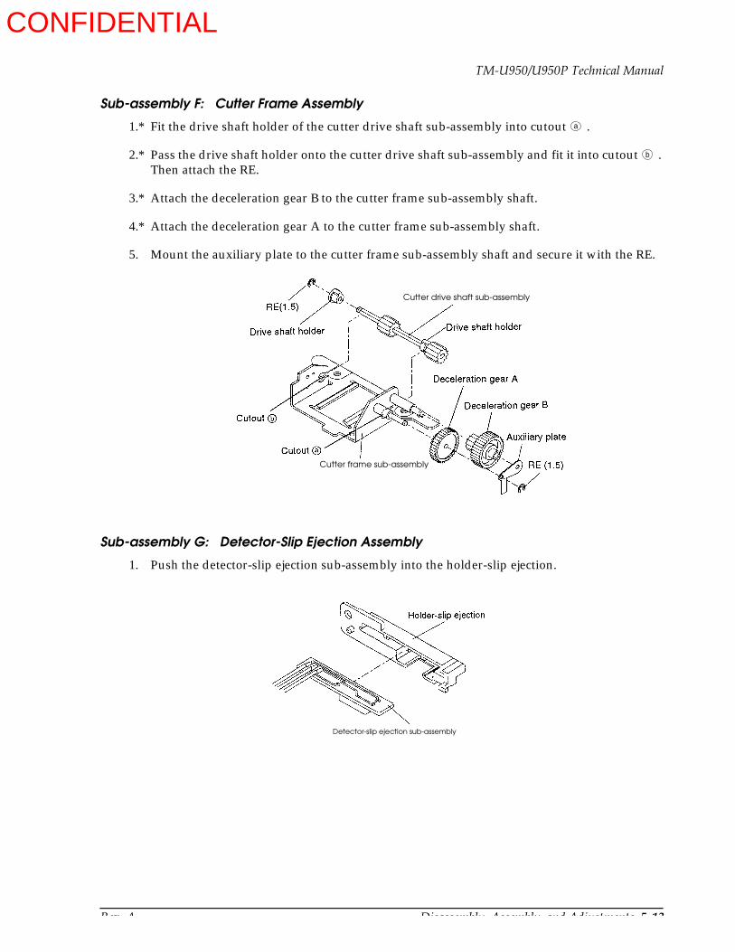
Rev. A Disassembly, Assembly, and Adjustments 5-13
TM-U950/U950P Technical Manual
Sub-assembly F: Cutter Frame Assembly
1.* Fit the drive shaft holder of the cutter drive shaft sub-assembly into cutout .
2.* Pass the drive shaft holder onto the cutter drive shaft sub-assembly and fit it into cutout . Then attach the RE.
3.* Attach the deceleration gear B to the cutter frame sub-assembly shaft.
4.* Attach the deceleration gear A to the cutter frame sub-assembly shaft.
5. Mount the auxiliary plate to the cutter frame sub-assembly shaft and secure it with the RE.
Sub-assembly G: Detector-Slip Ejection Assembly
1. Push the detector-slip ejection sub-assembly into the holder-slip ejection.
a
b
Cutter drive shaft sub-assembly
Cutter frame sub-assembly
Detector-slip ejection sub-assembly
CONFIDENTIAL

5-14 Disassembly, Assembly, and Adjustments Rev. A
Sub-assembly H: Auto-cutter Unit Assembly
1.* Place the cutter slider assembly on the frame-cutter blade receiving assembly.
2.* Fasten the contact pin holder sub-assembly to the cutter frame assembly with the screw.
3. Align the dowel with the dowel hole and fasten the cutter motor mount plate assembly to the frame-cutter blade receiving assembly with the screws.
4. Align the dowel with the dowel hole and fasten the cutter frame assembly to the frame-cutter blade receiving assembly with the screws.
5. Align hole with tab and attach the lever-release R.
6. Attach the lever-release J in the same way.
7. Engage the paper hold springs in hooks and .
a b
c d
Contact pin holder sub-assembly
Cutter frame assembly
Cutter slider assembly
CONFIDENTIAL

Rev. A Disassembly, Assembly, and Adjustments 5-15
TM-U950/U950P Technical Manual
Sub-assembly H
8. Pass the roller-paper hold assembly shaft then shaft through holes and fasten the RE.
9. Attach the auxiliary paper guide springs.
10. Make sure that there is only one leaf of the cutter blade, and align the rectangular cutout on the cutter blade with the protruding section on the cutter slide assembly.
11. Fasten the cover-cutter blade receiving assembly to the frame-cutter blade receiving assembly with the screws.
12. Pass the leaf springs onto the shaft, mount cutter unit lock levers R and J, and fasten them with REs.
13. Align hole with tab on the detector-slip ejection assembly and tighten the screws.
CheckpointMake sure that the roller-paper hold assembly and the leaf springs are mounted in the correct orientation.
e f
g h
Cover-cutter blade receiving assembly
Roller-paper hold assembly
Frame-cutter blade receiving assembly
Detector-slipejection assembly
CONFIDENTIAL
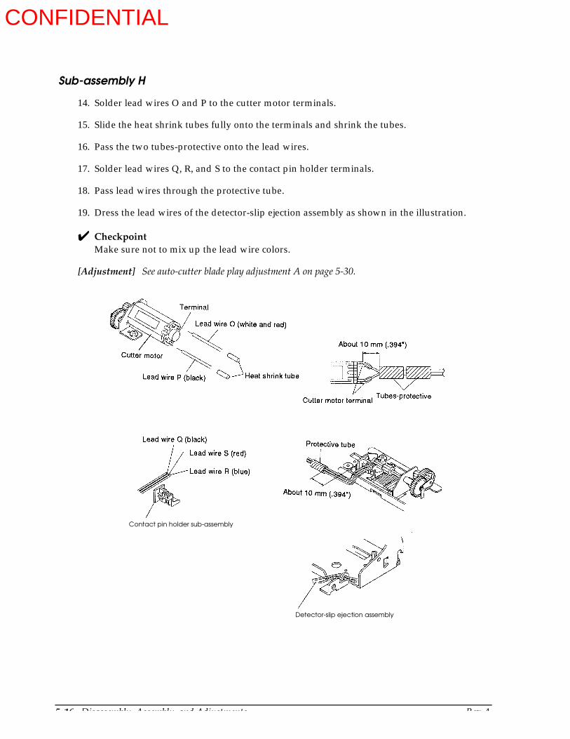
5-16 Disassembly, Assembly, and Adjustments Rev. A
Sub-assembly H
14. Solder lead wires O and P to the cutter motor terminals.
15. Slide the heat shrink tubes fully onto the terminals and shrink the tubes.
16. Pass the two tubes-protective onto the lead wires.
17. Solder lead wires Q, R, and S to the contact pin holder terminals.
18. Pass lead wires through the protective tube.
19. Dress the lead wires of the detector-slip ejection assembly as shown in the illustration.
CheckpointMake sure not to mix up the lead wire colors.
[Adjustment] See auto-cutter blade play adjustment A on page 5-30.
Detector-slip ejection assembly
Contact pin holder sub-assembly
CONFIDENTIAL
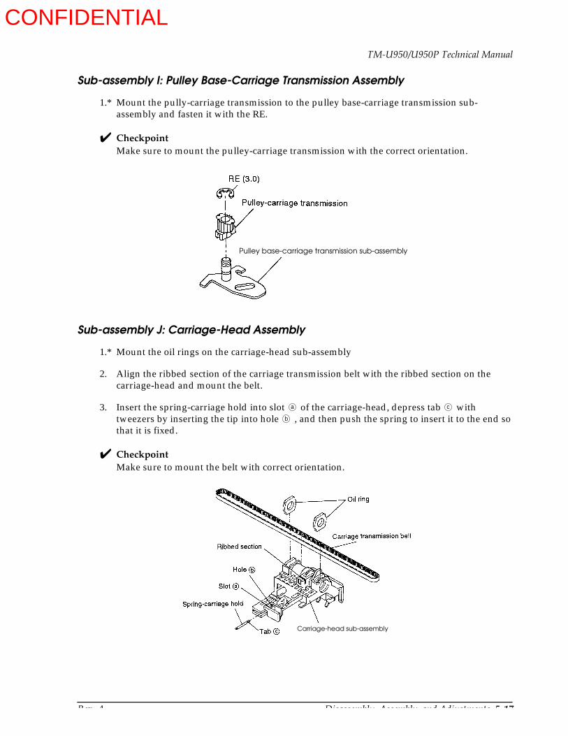
Rev. A Disassembly, Assembly, and Adjustments 5-17
TM-U950/U950P Technical Manual
Sub-assembly I: Pulley Base-Carriage Transmission Assembly
1.* Mount the pully-carriage transmission to the pulley base-carriage transmission sub-assembly and fasten it with the RE.
CheckpointMake sure to mount the pulley-carriage transmission with the correct orientation.
Sub-assembly J: Carriage-Head Assembly
1.* Mount the oil rings on the carriage-head sub-assembly
2. Align the ribbed section of the carriage transmission belt with the ribbed section on the carriage-head and mount the belt.
3. Insert the spring-carriage hold into slot of the carriage-head, depress tab with tweezers by inserting the tip into hole , and then push the spring to insert it to the end so that it is fixed.
CheckpointMake sure to mount the belt with correct orientation.
Pulley base-carriage transmission sub-assembly
a c
b
Carriage-head sub-assembly
CONFIDENTIAL
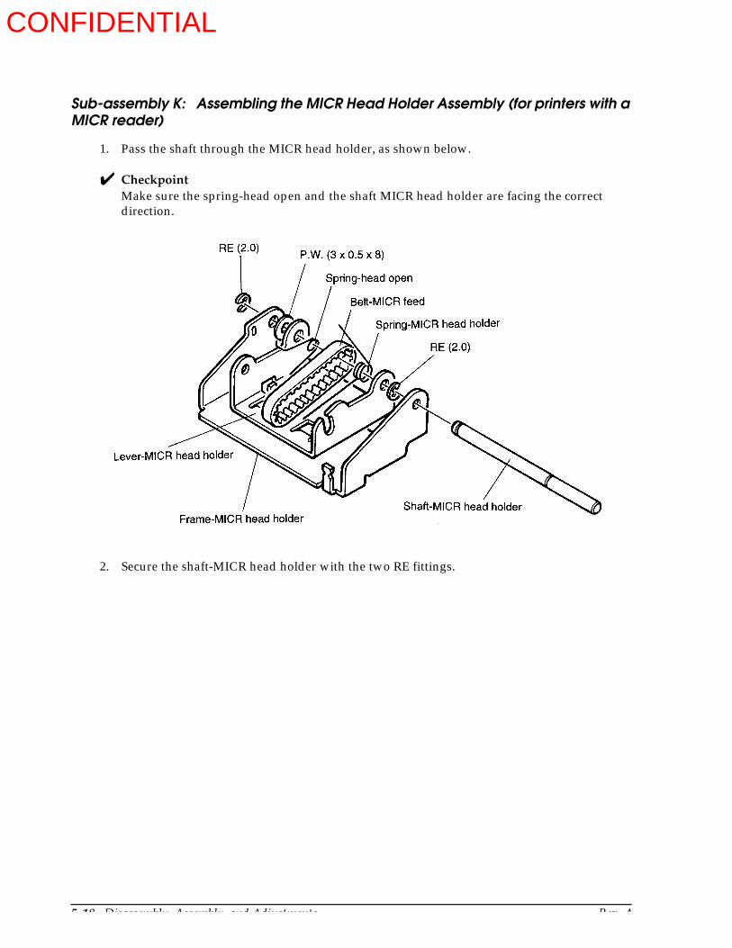
5-18 Disassembly, Assembly, and Adjustments Rev. A
Sub-assembly K: Assembling the MICR Head Holder Assembly (for printers with a MICR reader)
1. Pass the shaft through the MICR head holder, as shown below.
CheckpointMake sure the spring-head open and the shaft MICR head holder are facing the correct direction.
2. Secure the shaft-MICR head holder with the two RE fittings.
CONFIDENTIAL

Rev. A Disassembly, Assembly, and Adjustments 5-19
TM-U950/U950P Technical Manual
Sub-assembly K
3. Fit the two springs into the three locations shown below.
4. Pass the belt-MICR feed through the roller - MICR head holder.
CheckpointSee the illustration below when lubricating the roller-MICR head holder. Be sure that the correct grease is used.
CONFIDENTIAL
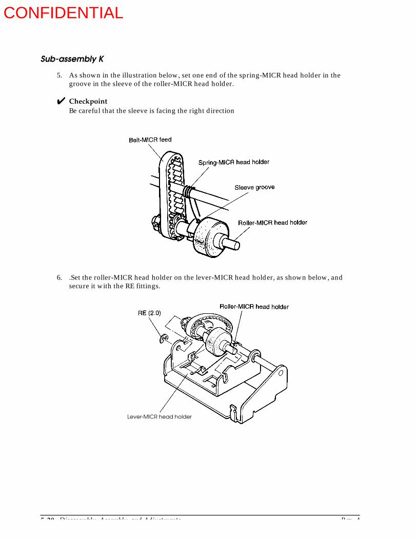
5-20 Disassembly, Assembly, and Adjustments Rev. A
Sub-assembly K
5. As shown in the illustration below, set one end of the spring-MICR head holder in the groove in the sleeve of the roller-MICR head holder.
CheckpointBe careful that the sleeve is facing the right direction
6. .Set the roller-MICR head holder on the lever-MICR head holder, as shown below, and secure it with the RE fittings.
Lever-MICR head holder
CONFIDENTIAL

Rev. A Disassembly, Assembly, and Adjustments 5-21
TM-U950/U950P Technical Manual
Sub-assembly K
7. Fit the paper dust cover onto the shaft-MICR head holder.
CheckpointFit the paper dust cover between the P.W. and the frame - MICR head holder, as shown below.
CONFIDENTIAL

5-22 Disassembly, Assembly, and Adjustments Rev. A
Sub-assembly L-(1): Frame-Carriage Unit Assembly (for printers without a MICR reader)
1.* Attach the motor-carriage to the frame-carriage assembly with the screws.
2. Slide the board-head relay assembly into position along guides and , and fasten it with the screw.
3.* Mount the gears in the order to in the illustration, and fasten them with the REs.
4. Attach the lever-ribbon feed planet assembly so that the section encloses shaft .
[Adjustment] Backlash adjustment of carriage feed pulley and carriage motor (see Adjustment B on page 5-54).
a b
Frame-carriage assembly
Board-head relay assembly
1 6
c d
Frame-carriage assembly
Lever-ribbon feed planet assembly
CONFIDENTIAL
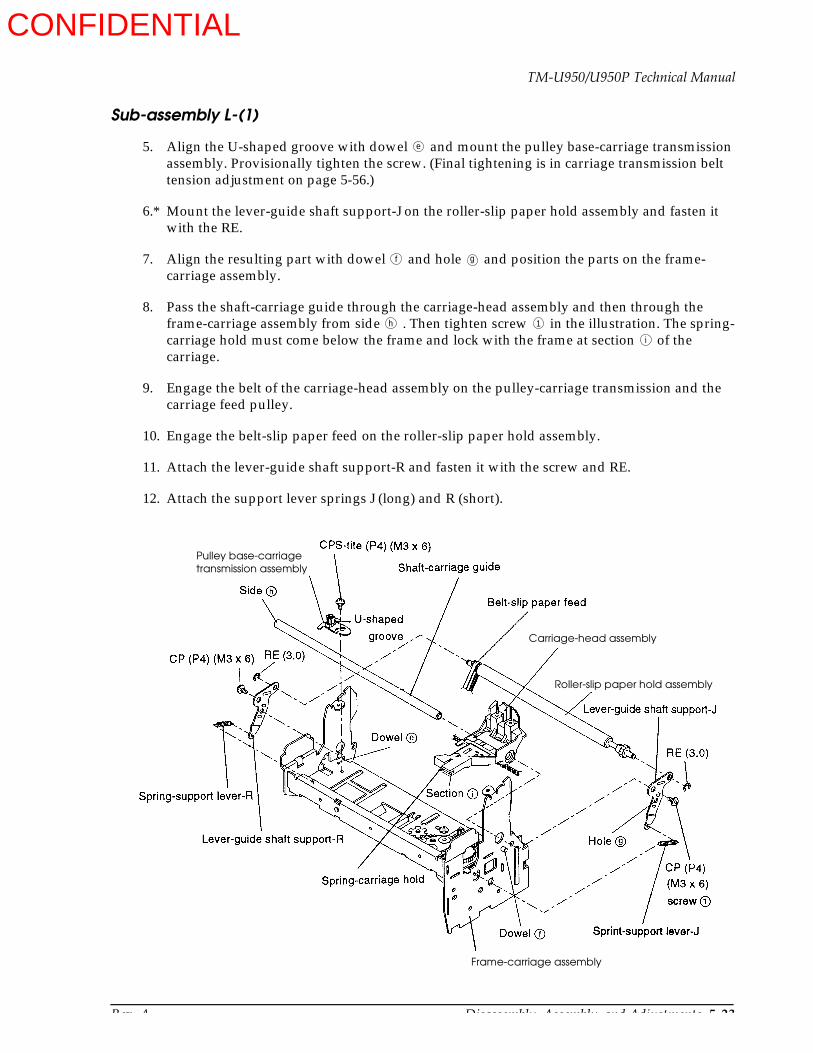
Rev. A Disassembly, Assembly, and Adjustments 5-23
TM-U950/U950P Technical Manual
Sub-assembly L-(1)
5. Align the U-shaped groove with dowel and mount the pulley base-carriage transmission assembly. Provisionally tighten the screw. (Final tightening is in carriage transmission belt tension adjustment on page 5-56.)
6.* Mount the lever-guide shaft support-J on the roller-slip paper hold assembly and fasten it with the RE.
7. Align the resulting part with dowel and hole and position the parts on the frame-carriage assembly.
8. Pass the shaft-carriage guide through the carriage-head assembly and then through the frame-carriage assembly from side . Then tighten screw in the illustration. The spring-carriage hold must come below the frame and lock with the frame at section of the carriage.
9. Engage the belt of the carriage-head assembly on the pulley-carriage transmission and the carriage feed pulley.
10. Engage the belt-slip paper feed on the roller-slip paper hold assembly.
11. Attach the lever-guide shaft support-R and fasten it with the screw and RE.
12. Attach the support lever springs J (long) and R (short).
e
f g
h 1
i
Frame-carriage assembly
Roller-slip paper hold assembly
Carriage-head assembly
Pulley base-carriage transmission assembly
CONFIDENTIAL

5-24 Disassembly, Assembly, and Adjustments Rev. A
Sub-assembly L-(1)
13. Engage the belt-slip paper feed on the pulley-carriage transmission. Mount the print shaft holders and roller-sub slip paper hold assembly, and fasten with the RE.
14. Pass the wires through the frame-carriage assembly, attach the detector-H.P. sub-assembly to the frame, and tighten the screw.
Roller-sub slip paper hold assembly
Detector-H.P. sub-assembly
Frame-carriage assembly
CONFIDENTIAL
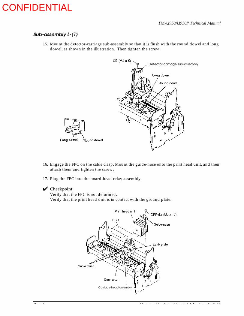
Rev. A Disassembly, Assembly, and Adjustments 5-25
TM-U950/U950P Technical Manual
Sub-assembly L-(1)
15. Mount the detector-carriage sub-assembly so that it is flush with the round dowel and long dowel, as shown in the illustration. Then tighten the screw.
16. Engage the FPC on the cable clasp. Mount the guide-nose onto the print head unit, and then attach them and tighten the screw.
17. Plug the FPC into the board-head relay assembly.
CheckpointVerify that the FPC is not deformed.Verify that the print head unit is in contact with the ground plate.
Detector-carriage sub-assembly
Carriage-head assembly
CONFIDENTIAL
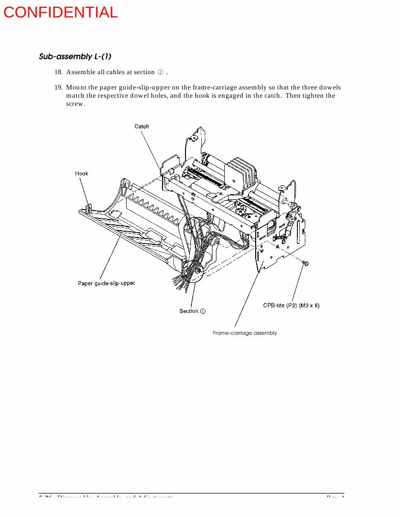
5-26 Disassembly, Assembly, and Adjustments Rev. A
Sub-assembly L-(1)
18. Assemble all cables at section .
19. Mount the paper guide-slip-upper on the frame-carriage assembly so that the three dowels match the respective dowel holes, and the hook is engaged in the catch. Then tighten the screw.
j
Frame-carriage assembly
CONFIDENTIAL
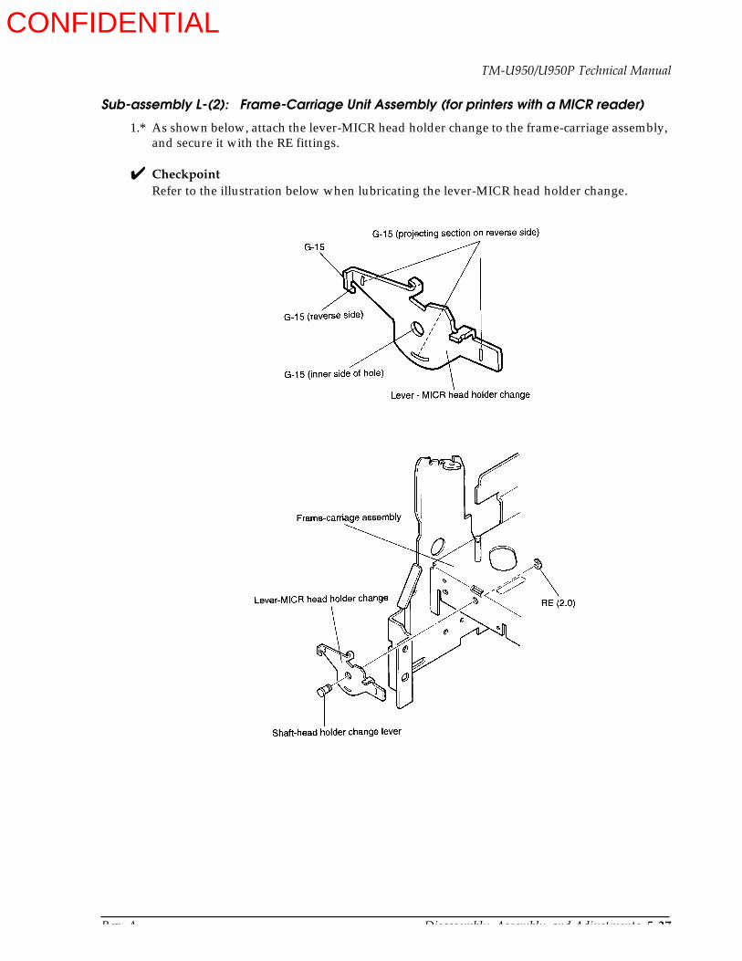
Rev. A Disassembly, Assembly, and Adjustments 5-27
TM-U950/U950P Technical Manual
Sub-assembly L-(2): Frame-Carriage Unit Assembly (for printers with a MICR reader)
1.* As shown below, attach the lever-MICR head holder change to the frame-carriage assembly, and secure it with the RE fittings.
CheckpointRefer to the illustration below when lubricating the lever-MICR head holder change.
CONFIDENTIAL
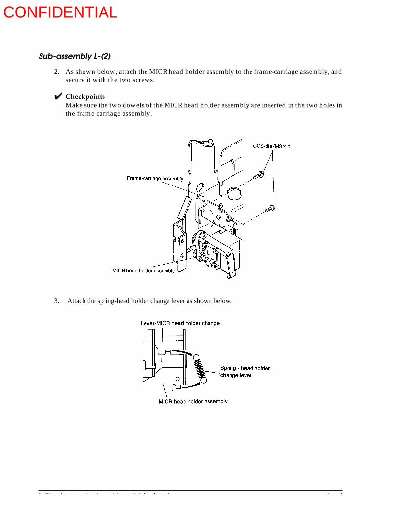
5-28 Disassembly, Assembly, and Adjustments Rev. A
Sub-assembly L-(2)
2. As shown below, attach the MICR head holder assembly to the frame-carriage assembly, and secure it with the two screws.
CheckpointsMake sure the two dowels of the MICR head holder assembly are inserted in the two holes in the frame carriage assembly.
3. Attach the spring-head holder change lever as shown below.
CONFIDENTIAL
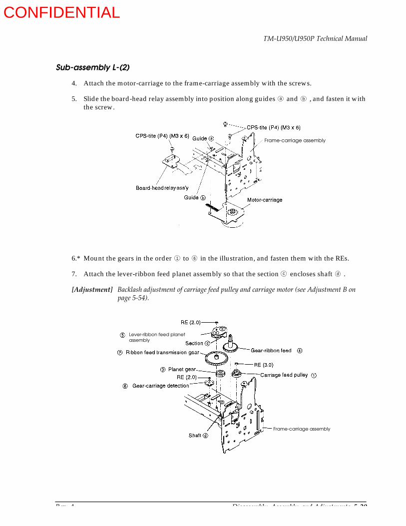
Rev. A Disassembly, Assembly, and Adjustments 5-29
TM-U950/U950P Technical Manual
Sub-assembly L-(2)
4. Attach the motor-carriage to the frame-carriage assembly with the screws.
5. Slide the board-head relay assembly into position along guides and , and fasten it with the screw.
6.* Mount the gears in the order to in the illustration, and fasten them with the REs.
7. Attach the lever-ribbon feed planet assembly so that the section encloses shaft .
[Adjustment] Backlash adjustment of carriage feed pulley and carriage motor (see Adjustment B on page 5-54).
a b
Frame-carriage assembly
1 6
c d
Frame-carriage assembly
Lever-ribbon feed planet assembly
CONFIDENTIAL
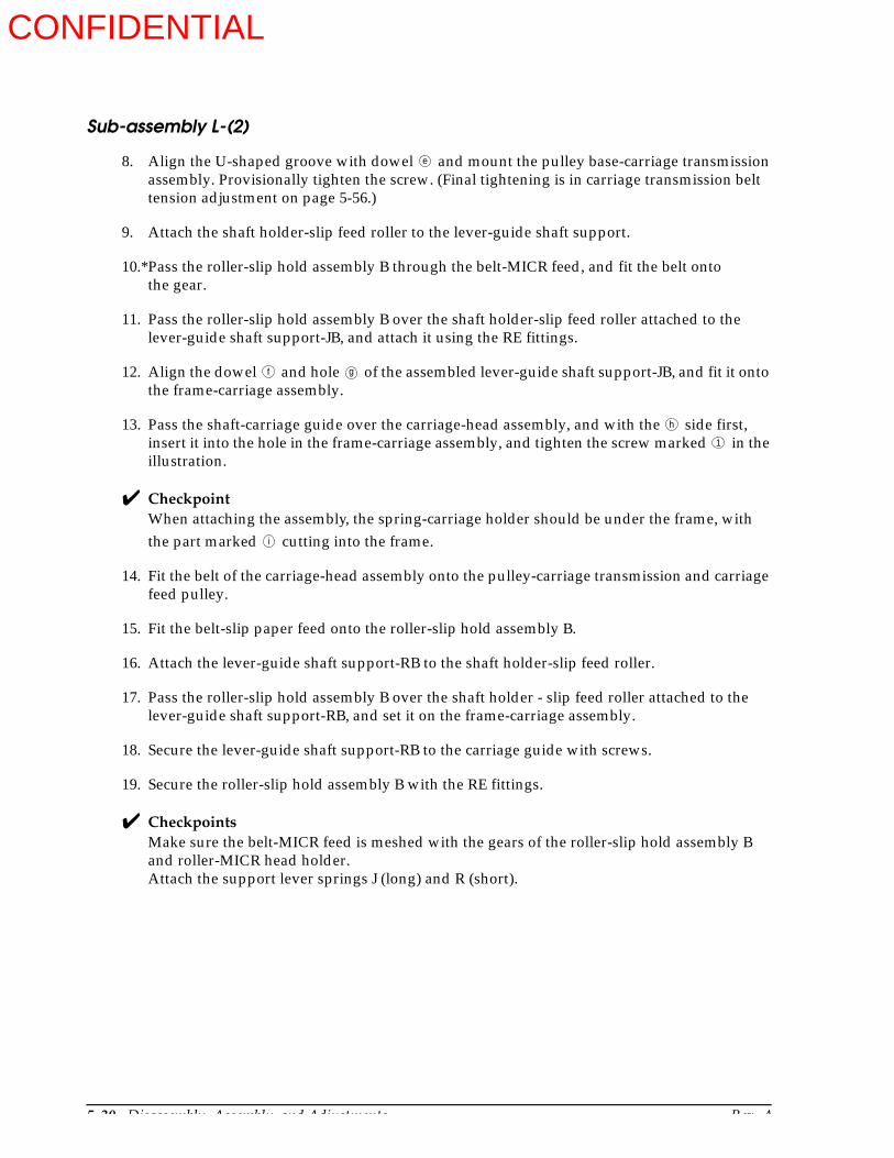
5-30 Disassembly, Assembly, and Adjustments Rev. A
Sub-assembly L-(2)
8. Align the U-shaped groove with dowel and mount the pulley base-carriage transmission assembly. Provisionally tighten the screw. (Final tightening is in carriage transmission belt tension adjustment on page 5-56.)
9. Attach the shaft holder-slip feed roller to the lever-guide shaft support.
10.*Pass the roller-slip hold assembly B through the belt-MICR feed, and fit the belt onto the gear.
11. Pass the roller-slip hold assembly B over the shaft holder-slip feed roller attached to the lever-guide shaft support-JB, and attach it using the RE fittings.
12. Align the dowel and hole of the assembled lever-guide shaft support-JB, and fit it onto the frame-carriage assembly.
13. Pass the shaft-carriage guide over the carriage-head assembly, and with the side first, insert it into the hole in the frame-carriage assembly, and tighten the screw marked in the illustration.
CheckpointWhen attaching the assembly, the spring-carriage holder should be under the frame, with the part marked cutting into the frame.
14. Fit the belt of the carriage-head assembly onto the pulley-carriage transmission and carriage feed pulley.
15. Fit the belt-slip paper feed onto the roller-slip hold assembly B.
16. Attach the lever-guide shaft support-RB to the shaft holder-slip feed roller.
17. Pass the roller-slip hold assembly B over the shaft holder - slip feed roller attached to the lever-guide shaft support-RB, and set it on the frame-carriage assembly.
18. Secure the lever-guide shaft support-RB to the carriage guide with screws.
19. Secure the roller-slip hold assembly B with the RE fittings.
CheckpointsMake sure the belt-MICR feed is meshed with the gears of the roller-slip hold assembly B and roller-MICR head holder.Attach the support lever springs J (long) and R (short).
e
f g
h
1
i
CONFIDENTIAL
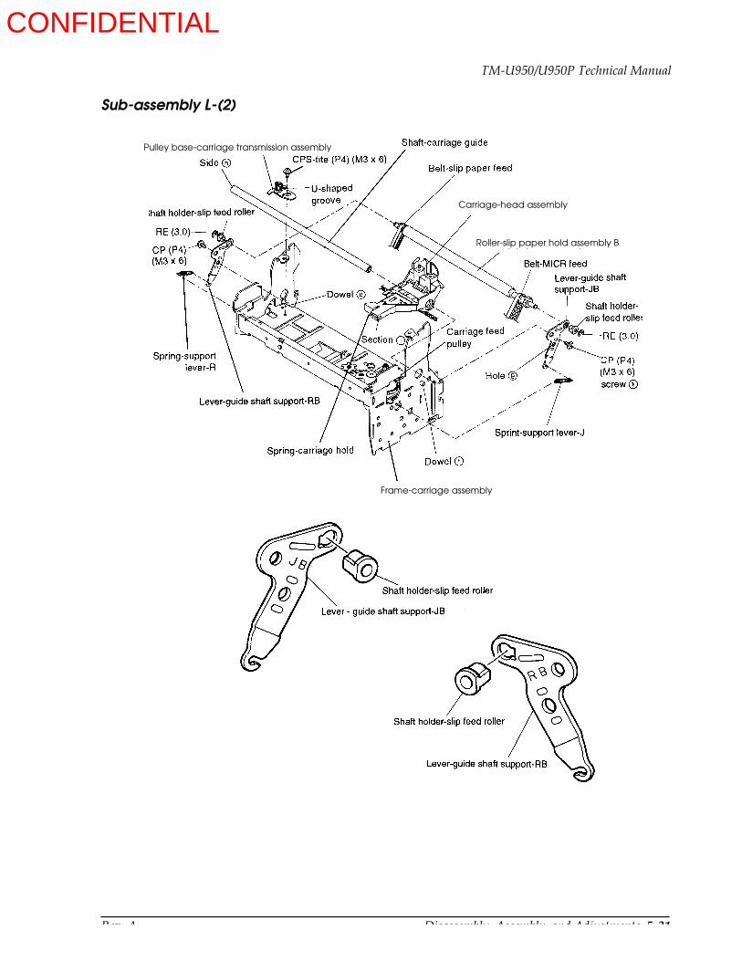
Rev. A Disassembly, Assembly, and Adjustments 5-31
TM-U950/U950P Technical Manual
Sub-assembly L-(2)
Frame-carriage assembly
Carriage-head assembly
Roller-slip paper hold assembly B
Pulley base-carriage transmission assembly
CONFIDENTIAL

5-32 Disassembly, Assembly, and Adjustments Rev. A
Sub-assembly L-(2)
20. Attach the tension-pulley to the lever-slip tension and fix it with the RE.
21. Attach the lever to the frame-carriage assembly and secure it with the screw.
22. Attach the pulley-slip tension to the frame-carriage assembly and secure it with the RE.
CONFIDENTIAL

Rev. A Disassembly, Assembly, and Adjustments 5-33
TM-U950/U950P Technical Manual
Sub-assembly L-(2)
23. Engage the belt-slip paper feed on the pulley-carriage transmission. Mount the print shaft holders and roller-sub slip paper hold assembly, and fasten with the RE.
24. Pass the wires through the frame-carriage assembly, attach the detector-H.P. sub-assembly to the frame, and tighten the screw.
25. Mount the detector-carriage sub assembly so that it is flush with the round dowel and long dowel, as shown in the illustration. Then tighten the screw.
Belt-slip paper feed
Print shaft holder
Pulley-carriage transmission
Roller-sub slip paper hold assembly
Print shaft holder
Detector-H.P sub-assembly
Frame-carriage assembly
Detector-carriage sub-assembly
CONFIDENTIAL
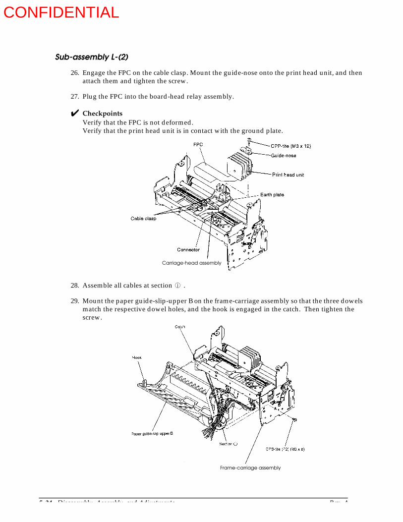
5-34 Disassembly, Assembly, and Adjustments Rev. A
Sub-assembly L-(2)
26. Engage the FPC on the cable clasp. Mount the guide-nose onto the print head unit, and then attach them and tighten the screw.
27. Plug the FPC into the board-head relay assembly.
CheckpointsVerify that the FPC is not deformed.Verify that the print head unit is in contact with the ground plate.
28. Assemble all cables at section .
29. Mount the paper guide-slip-upper B on the frame-carriage assembly so that the three dowels match the respective dowel holes, and the hook is engaged in the catch. Then tighten the screw.
Carriage-head assembly
j
Frame-carriage assembly
CONFIDENTIAL
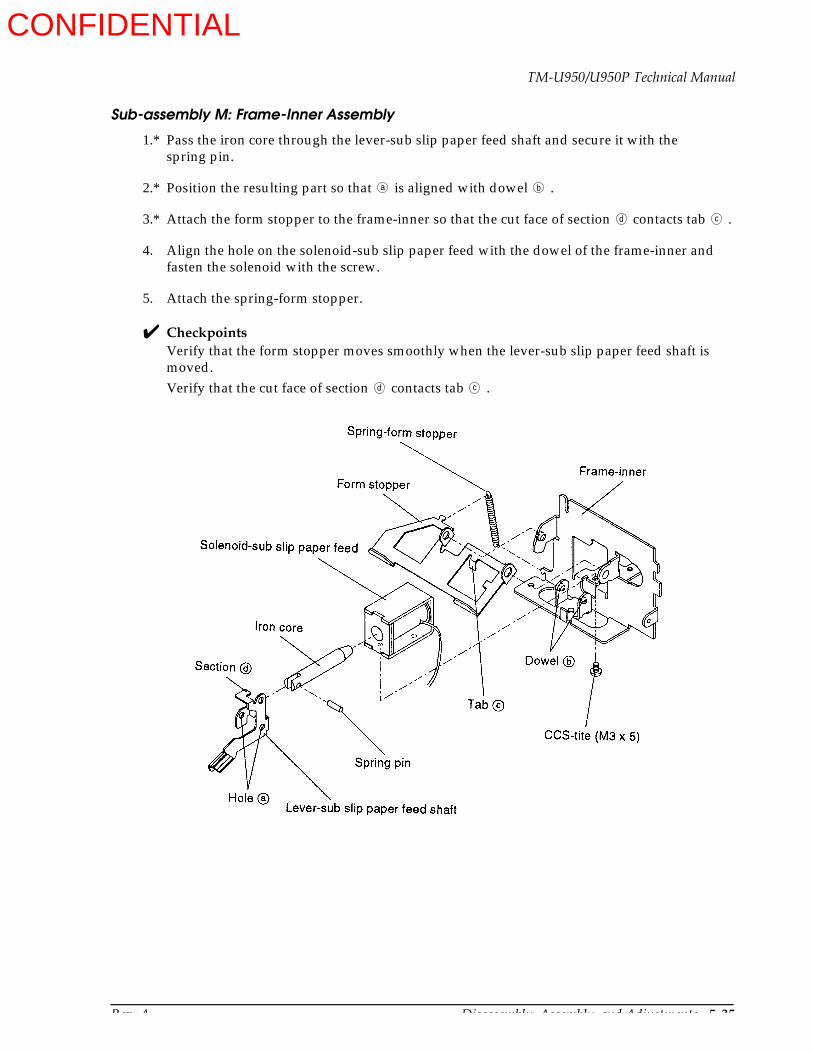
Rev. A Disassembly, Assembly, and Adjustments 5-35
TM-U950/U950P Technical Manual
Sub-assembly M: Frame-Inner Assembly
1.* Pass the iron core through the lever-sub slip paper feed shaft and secure it with the spring pin.
2.* Position the resulting part so that is aligned with dowel .
3.* Attach the form stopper to the frame-inner so that the cut face of section contacts tab .
4. Align the hole on the solenoid-sub slip paper feed with the dowel of the frame-inner and fasten the solenoid with the screw.
5. Attach the spring-form stopper.
CheckpointsVerify that the form stopper moves smoothly when the lever-sub slip paper feed shaft is moved.Verify that the cut face of section contacts tab .
a b
d c
d c
CONFIDENTIAL

5-36 Disassembly, Assembly, and Adjustments Rev. A
Sub-assembly N: Detector-Slip Insertion Assembly
1. Push the detector-slip insertion sub assembly into the holder-slip insertion detector.
Sub-assembly O: Solenoid J/S Changeover Assembly
1.* Attach the J/S changeover solenoid to the J/S changeover solenoid mount plate and tighten the screw.
2. Align the U-shaped groove of the lever-J/S changeover with the groove on the side of the J/S changeover solenoid and attach the lever by joining sections and .
3. Engage the J/S changeover lever spring.
Detector-slip insertion sub-assembly
a b
CONFIDENTIAL
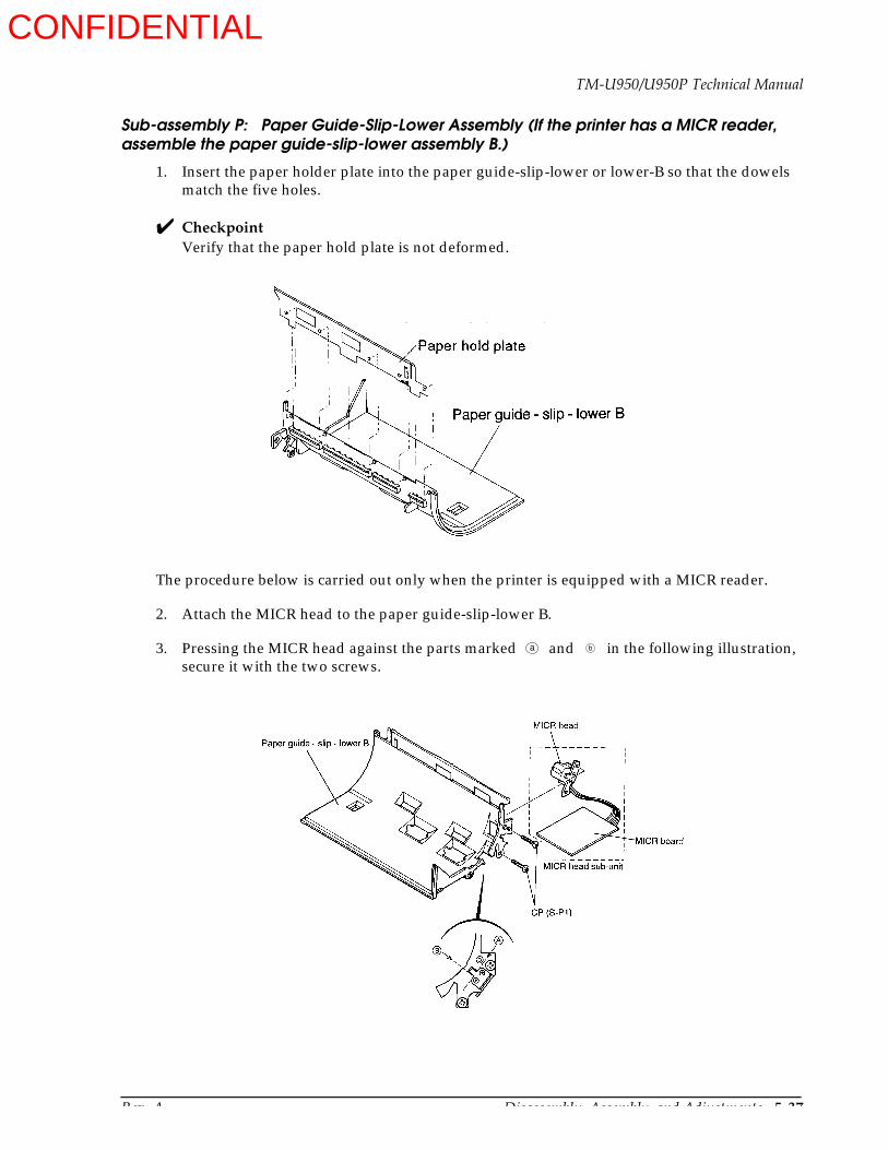
Rev. A Disassembly, Assembly, and Adjustments 5-37
TM-U950/U950P Technical Manual
Sub-assembly P: Paper Guide-Slip-Lower Assembly (If the printer has a MICR reader, assemble the paper guide-slip-lower assembly B.)
1. Insert the paper holder plate into the paper guide-slip-lower or lower-B so that the dowels match the five holes.
CheckpointVerify that the paper hold plate is not deformed.
The procedure below is carried out only when the printer is equipped with a MICR reader.
2. Attach the MICR head to the paper guide-slip-lower B.
3. Pressing the MICR head against the parts marked and in the following illustration, secure it with the two screws.
a b
CONFIDENTIAL
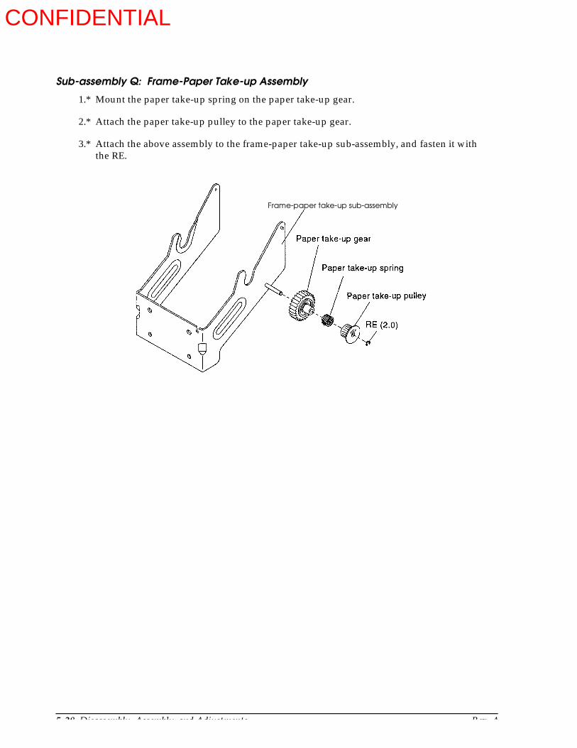
5-38 Disassembly, Assembly, and Adjustments Rev. A
Sub-assembly Q: Frame-Paper Take-up Assembly
1.* Mount the paper take-up spring on the paper take-up gear.
2.* Attach the paper take-up pulley to the paper take-up gear.
3.* Attach the above assembly to the frame-paper take-up sub-assembly, and fasten it with the RE.
Frame-paper take-up sub-assembly
CONFIDENTIAL
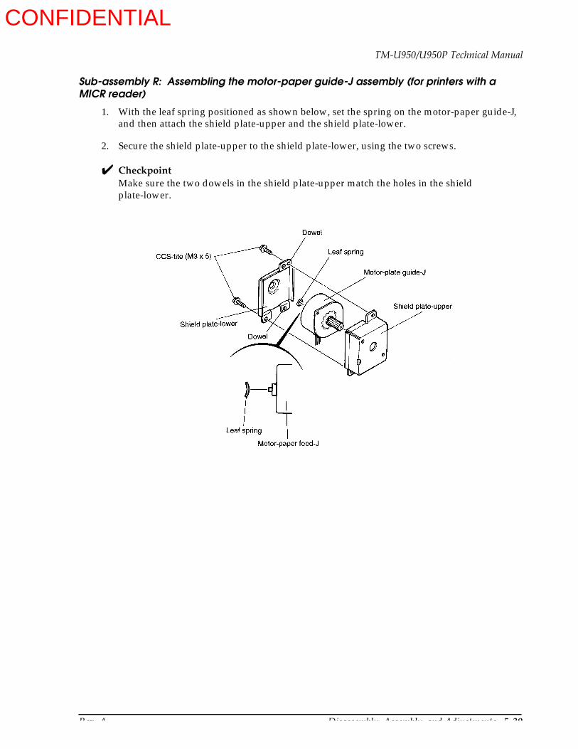
Rev. A Disassembly, Assembly, and Adjustments 5-39
TM-U950/U950P Technical Manual
Sub-assembly R: Assembling the motor-paper guide-J assembly (for printers with a MICR reader)
1. With the leaf spring positioned as shown below, set the spring on the motor-paper guide-J, and then attach the shield plate-upper and the shield plate-lower.
2. Secure the shield plate-upper to the shield plate-lower, using the two screws.
CheckpointMake sure the two dowels in the shield plate-upper match the holes in the shield plate-lower.
CONFIDENTIAL

5-40 Disassembly, Assembly, and Adjustments Rev. A
Main Assembly (Part 1)
Main Assembly 1-1: Frame-Main Unit Assembly
1.* Mount the screw in hole .
2. Attach the frame-inner assembly and secure it with the screw.
3. Mount the motor-paper feed-J (larger motor) and motor-paper feed-R and secure them with the screws.
4.* Insert the print shaft holder (shaft holder-slip feed roller for printers with a MICR reader) in groove , mount the roller-slip paper feed assembly on the holder, and fasten it with the RE.
5. Mount the detector-slip paper insertion assembly and fasten it with the screw.
CheckpointsMake sure not to mix up the paper feed motors.Make sure that section on the frame-inner is properly seated. (For the details see the Checkpoint on page 5-35.)
a
b
c
Detector-slip paper insertion assembly
Roller-slip paper feed assembly
Frame-main assembly
Frame-inner assembly
(shaft holder-slip feed roller)
CONFIDENTIAL

Rev. A Disassembly, Assembly, and Adjustments 5-41
TM-U950/U950P Technical Manual
Main Assembly 1-1-(2): Frame-Main Unit Assembly (for printers with a MICR reader)
1.* Mount the screw in hole .
2. Attach the frame-inner assembly and secure it with the screw.
3. Attach the motor-paper feed-J assembly (the larger assembly) and R assembly (the smaller assembly), and secure them with the screws.
4.* Fit the shaft holder-slip feed roller into the groove , attach the roller-slip paper feed assembly, and secure it with the RE fittings.
5. Mount the detector-slip paper insertion assembly and fasten it with the screw.
CheckpointsBe careful that the motor-paper feed-J and R assemblies are attached correctly.Make sure that section on the frame-inner is properly seated. (For details see the Checkpoint on page 5-35.)
a
b
c
Detector-slip paper insertion assembly
Roller-slip paper feed assembly B
Frame-main assembly
Motor-paper feed-J assembly
Frame-inner assembly
CONFIDENTIAL
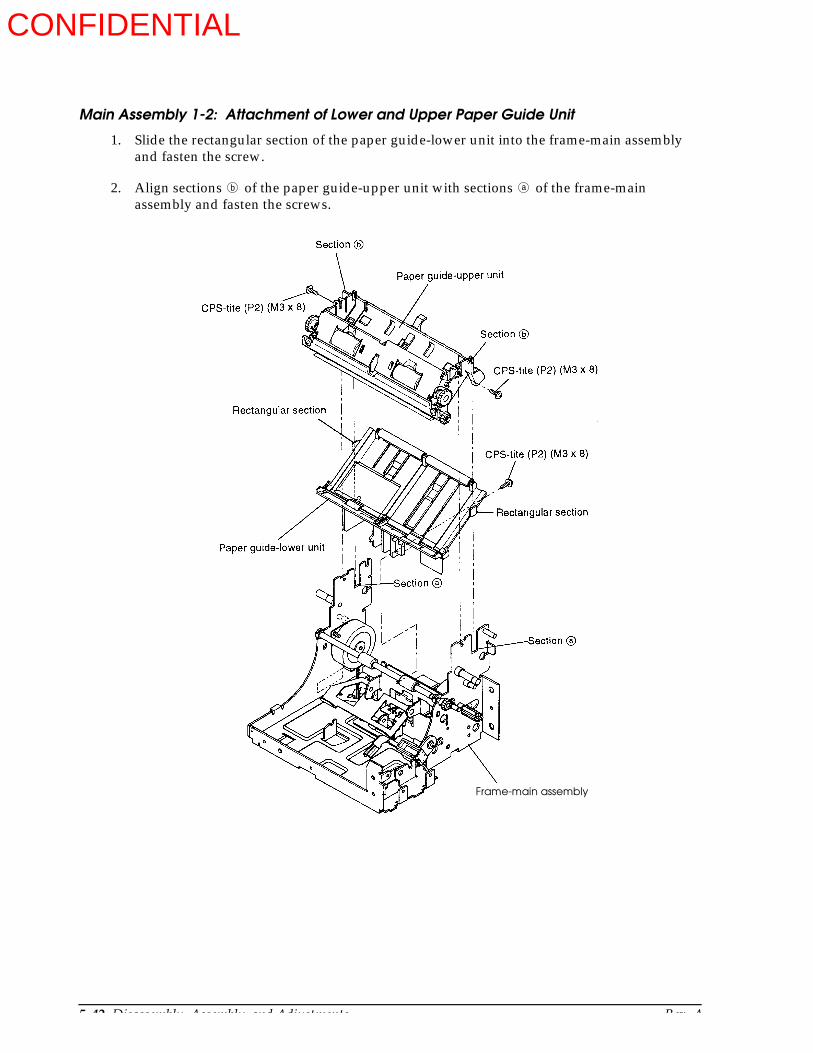
5-42 Disassembly, Assembly, and Adjustments Rev. A
Main Assembly 1-2: Attachment of Lower and Upper Paper Guide Unit
1. Slide the rectangular section of the paper guide-lower unit into the frame-main assembly and fasten the screw.
2. Align sections of the paper guide-upper unit with sections of the frame-main assembly and fasten the screws.
b a
Frame-main assembly
CONFIDENTIAL

Rev. A Disassembly, Assembly, and Adjustments 5-43
TM-U950/U950P Technical Manual
Main Assembly 1-3: Attachment of Paper Guide-Slip-Lower and Roller-Sub Slip Paper Feed Assembly
1. Mount the roller-sub slip paper feed assembly in the U-shaped grooves of the frame-main assembly.
2. Align the dowel and dowel hole of the paper guide-slip-lower assembly and engage hook of the frame-main in cutout of the paper guide. Then slide the paper guide into place and fasten it with the screw.
3. If the printer has a MICR reader, the cable for the MICR board will be coming out of the section marked .
a b
c
Paper guide-slip-lower assembly
Roller-sub slip paper feed assembly
CONFIDENTIAL

5-44 Disassembly, Assembly, and Adjustments Rev. A
Main Assembly 1-4: Attachment of Solenoid-J/S Changeover and Various Gears
1.* Mount the paper feed deceleration gear and then the receipt transmission gear on the frame-main assembly and fasten with the RE.
2.* Align the tip of the lever-J/S changeover with the groove on the J/S changeover gear. Align the hole on the lever with the dowel on the frame-main assembly and secure the solenoid-J/S changeover assembly with the screw.
3.* Mount the paper feed deceleration gear and then the gear-journal transmission on the frame-main assembly, and fasten with the RE.
Frame-main assembly
Solenoid-J/S changeover assembly
CONFIDENTIAL

Rev. A Disassembly, Assembly, and Adjustments 5-45
TM-U950/U950P Technical Manual
Main Assembly 1-5: Attachment of Auto-cutter Unit
1. Place the spring-cutter unit shaft-R onto the shaft of the auto-cutter unit with the short end first.
2. Place the spring-cutter unit shaft-J in the same way.
3. Thread the wiring from the contact pin holder sub-assembly through cutout to the outside.
4. Thread the wiring from the detector-slip ejection assembly through clasp .
5. Thread the cutter motor wiring through cutout and then along groove . The two protective tubes should not protrude from cutout .
6. Mount the auto-cutter unit on the frame-main sassembly and engage the cutter unit shaft springs J and R. Secure it with the RE.
CheckpointMake sure that the spring-cutter unit shaft-J is not caught in the detector-slip ejection assembly wiring.
a
b
c d
c
Connect pin holder sub-assembly wiring
Detector-slip ejection assembly wiring
Frame-main assembly
CONFIDENTIAL

5-46 Disassembly, Assembly, and Adjustments Rev. A
Main Assembly 1-6: Wiring, and Frame-Rear and Connector Assembly-N.E. Detector Mounting
1. Dress the wires as shown in the illustration.
2. Attach the frame-rear to the frame-main assembly and secure it with the screw.
3. Pass the connector assembly-N.E. detector-J through hole and then hole .
4. Pass the connector assembly-N.E. detector-R through hole and then hole .
CheckpointMake sure not to mix up the J and R connector cables.
a b
c d
Connector assembly-N.E. detector-J(orange cable)
Connector assembly-N.E. detector-R(purple cable)
CONFIDENTIAL

Rev. A Disassembly, Assembly, and Adjustments 5-47
TM-U950/U950P Technical Manual
Main Assembly 1-7: Attachment of Frame-Carriage Unit
1. Pass the lead wires through hole .
2. Mount the frame-carriage unit on the frame-main assembly and tighten the screws provisionally. (Final tightening is done in Adjustment C on the next page.)
a
Frame-main assembly
CONFIDENTIAL
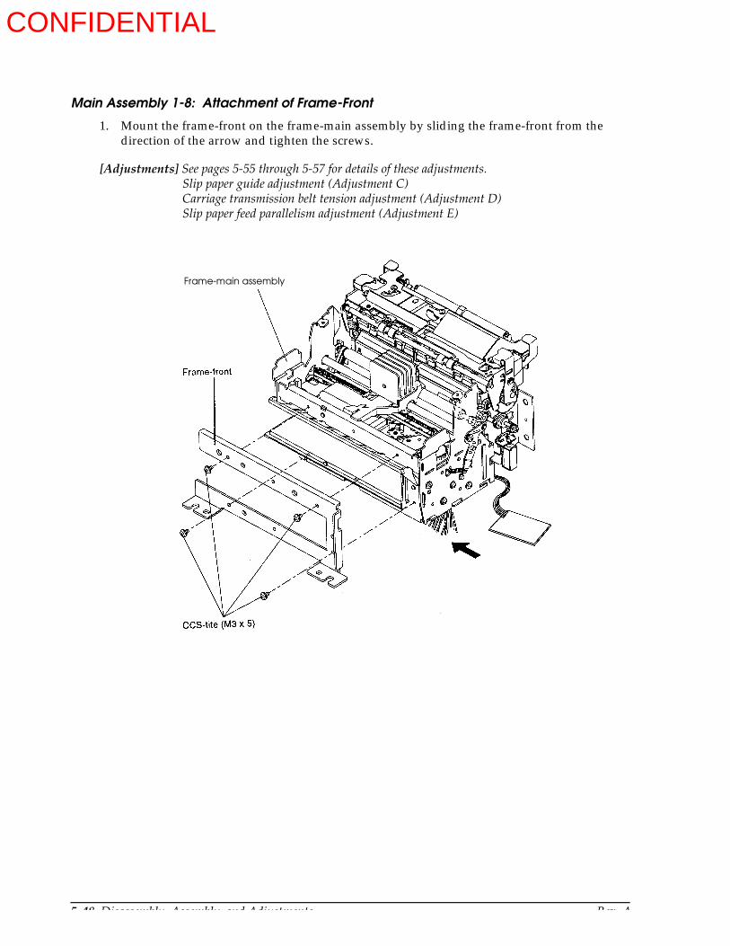
5-48 Disassembly, Assembly, and Adjustments Rev. A
Main Assembly 1-8: Attachment of Frame-Front
1. Mount the frame-front on the frame-main assembly by sliding the frame-front from the direction of the arrow and tighten the screws.
[Adjustments] See pages 5-55 through 5-57 for details of these adjustments.Slip paper guide adjustment (Adjustment C)Carriage transmission belt tension adjustment (Adjustment D)Slip paper feed parallelism adjustment (Adjustment E)
Frame-main assembly
CONFIDENTIAL

Rev. A Disassembly, Assembly, and Adjustments 5-49
TM-U950/U950P Technical Manual
Main Assembly 1-9: Attachment of Frame-Paper Take-up Assembly
1. Mount the frame-paper take-up assembly on the frame-rear by fully aligning the frame to side J and tighten the screws.
Frame-paper take-up assembly
CONFIDENTIAL

5-50 Disassembly, Assembly, and Adjustments Rev. A
Main Assembly 1-10: Attachment of Paper Take-up Belt and Paper Feed Deceleration Gear
1. Release the cutter unit lock levers of the auto-cutter unit and lift the unit in thedirection.
2. Mount the paper feed deceleration gear and fasten it with the RE.
3. Engage the paper take-up belt on the gear-journal transmission and the paper take-up pulley.
CheckpointPrint head and platen gap adjustment. (See Adjustment F on page 5-58.)
CONFIDENTIAL
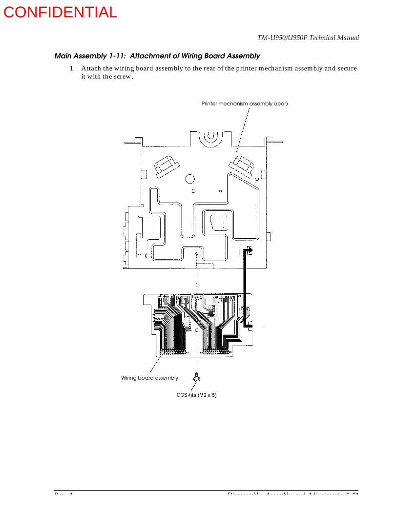
Rev. A Disassembly, Assembly, and Adjustments 5-51
TM-U950/U950P Technical Manual
Main Assembly 1-11: Attachment of Wiring Board Assembly
1. Attach the wiring board assembly to the rear of the printer mechanism assembly and secure it with the screw.
Printer mechanism assembly (rear)
Wiring board assembly
CONFIDENTIAL
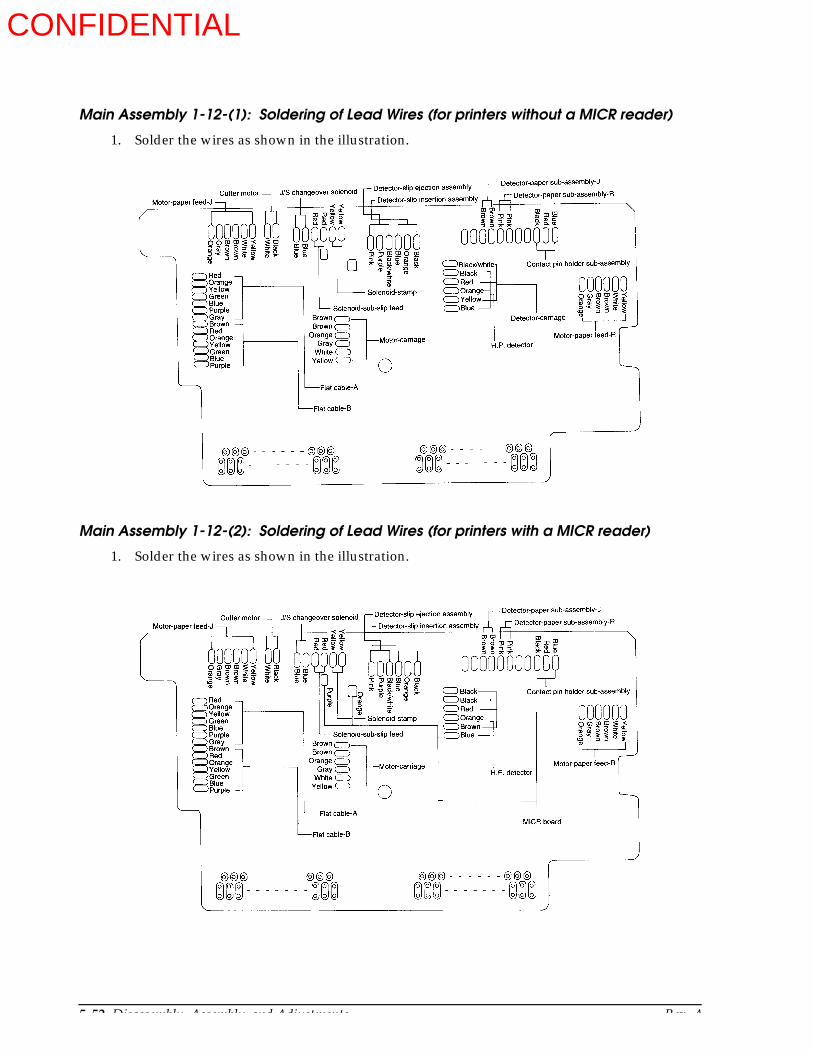
5-52 Disassembly, Assembly, and Adjustments Rev. A
Main Assembly 1-12-(1): Soldering of Lead Wires (for printers without a MICR reader)
1. Solder the wires as shown in the illustration.
Main Assembly 1-12-(2): Soldering of Lead Wires (for printers with a MICR reader)
1. Solder the wires as shown in the illustration.
CONFIDENTIAL
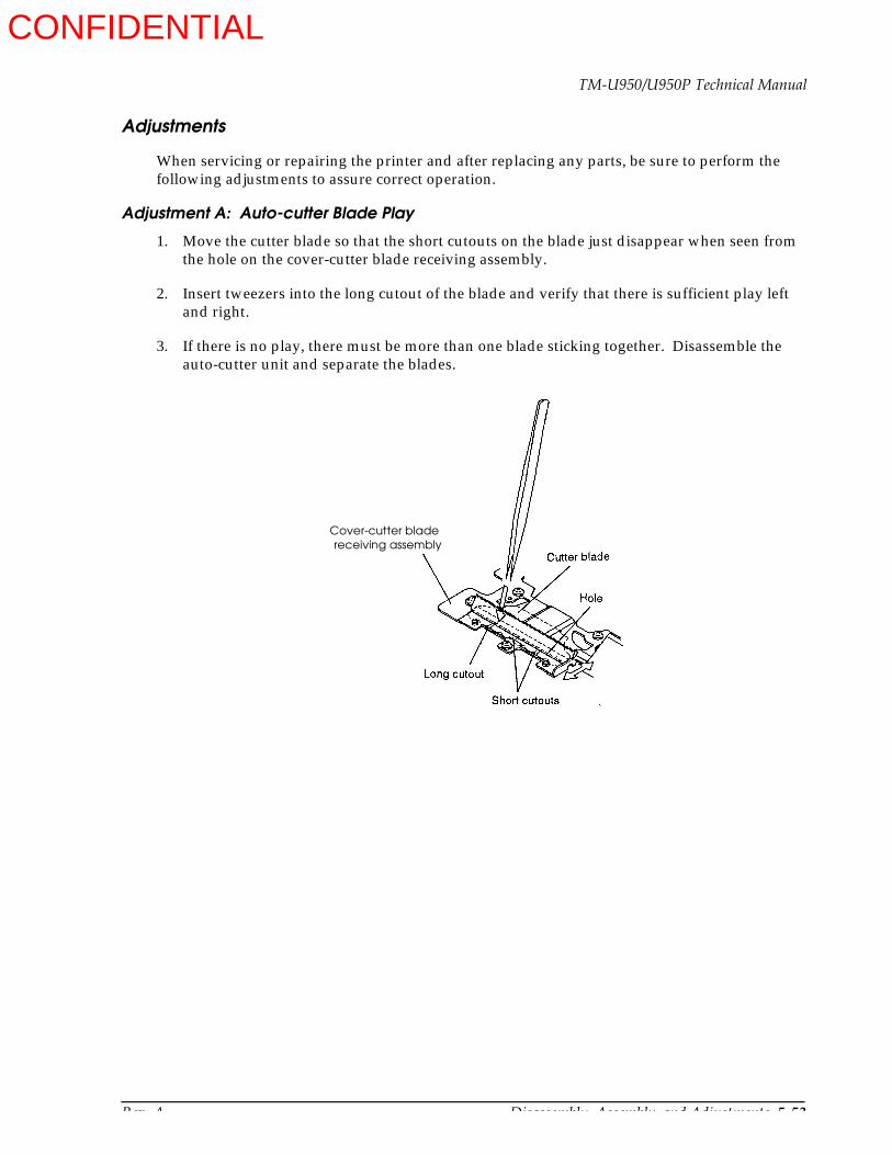
Rev. A Disassembly, Assembly, and Adjustments 5-53
TM-U950/U950P Technical Manual
Adjustments
When servicing or repairing the printer and after replacing any parts, be sure to perform the following adjustments to assure correct operation.
Adjustment A: Auto-cutter Blade Play
1. Move the cutter blade so that the short cutouts on the blade just disappear when seen from the hole on the cover-cutter blade receiving assembly.
2. Insert tweezers into the long cutout of the blade and verify that there is sufficient play left and right.
3. If there is no play, there must be more than one blade sticking together. Disassemble the auto-cutter unit and separate the blades.
Cover-cutter bladereceiving assembly
CONFIDENTIAL
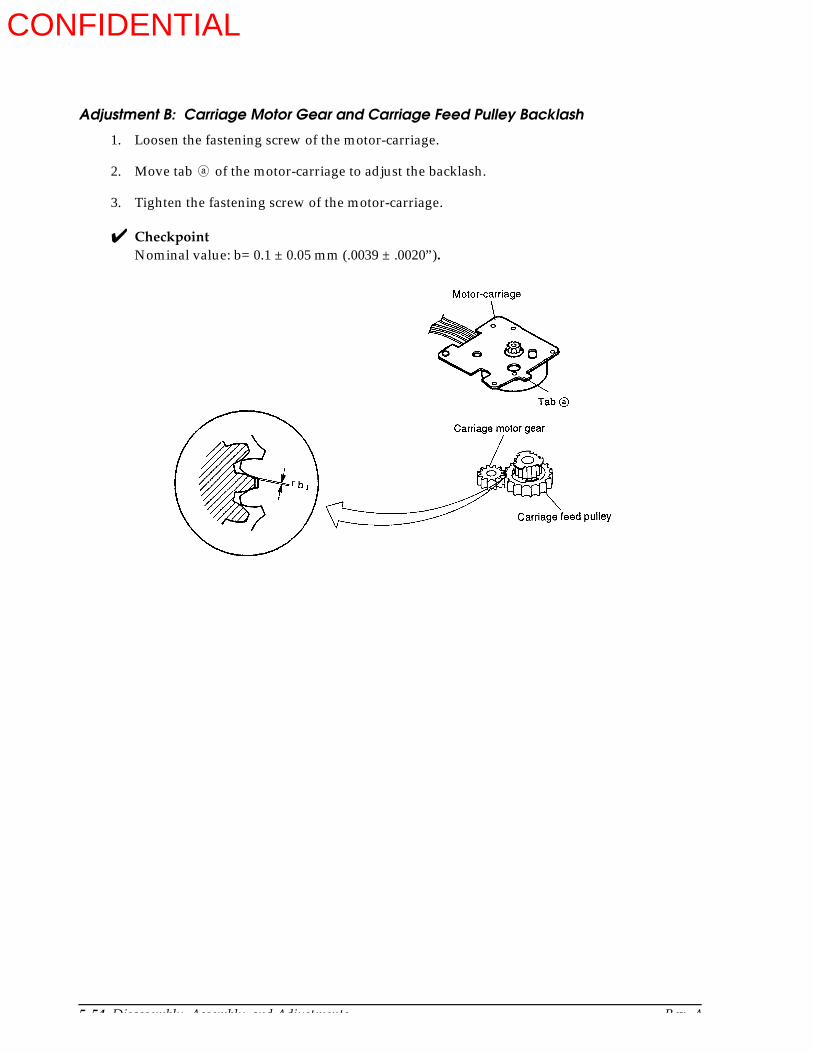
5-54 Disassembly, Assembly, and Adjustments Rev. A
Adjustment B: Carriage Motor Gear and Carriage Feed Pulley Backlash
1. Loosen the fastening screw of the motor-carriage.
2. Move tab of the motor-carriage to adjust the backlash.
3. Tighten the fastening screw of the motor-carriage.
CheckpointNominal value: b= 0.1 ± 0.05 mm (.0039 ± .0020”).
a
CONFIDENTIAL

Rev. A Disassembly, Assembly, and Adjustments 5-55
TM-U950/U950P Technical Manual
Adjustment C: Slip Paper Guide
1. Insert the slip paper path spacer between the upper and lower slip paper guides.
2. Push the frame-front in the direction and tighten the screws firmly.
3. Remove the spacer.
CheckpointNominal value: a= 2 mm
CONFIDENTIAL
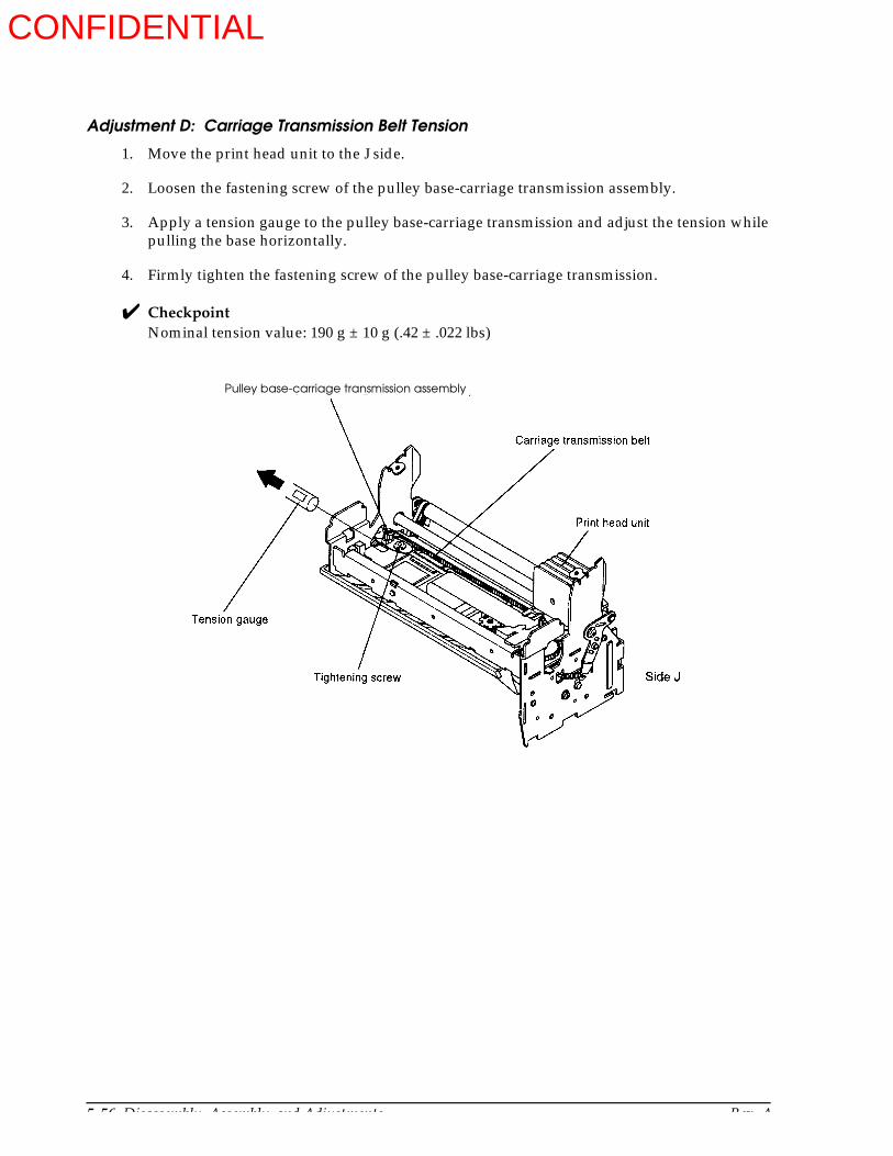
5-56 Disassembly, Assembly, and Adjustments Rev. A
Adjustment D: Carriage Transmission Belt Tension
1. Move the print head unit to the J side.
2. Loosen the fastening screw of the pulley base-carriage transmission assembly.
3. Apply a tension gauge to the pulley base-carriage transmission and adjust the tension while pulling the base horizontally.
4. Firmly tighten the fastening screw of the pulley base-carriage transmission.
CheckpointNominal tension value: 190 g ± 10 g (.42 ± .022 lbs)
Pulley base-carriage transmission assembly
CONFIDENTIAL

Rev. A Disassembly, Assembly, and Adjustments 5-57
TM-U950/U950P Technical Manual
Adjustment E: Slip Paper Feed Parallelism
1. Insert a piece of roll paper (45 to 55 Kg) 99 to 121 lbs) between the left and right slip paper feed rollers and slip paper hold rollers.
2. Pull out one of the piece of paper and check whether the paper feed amount is identical for each side.
3. If the paper feed amount differs between sides, readjust the carriage guide shaft fastening screw.
CONFIDENTIAL

5-58 Disassembly, Assembly, and Adjustments Rev. A
Adjustment F: Print Head Unit and Platen Gap
1. Move the print head unit to the two adjustment points (see the illustration below) and perform step 2 for each point.
2. Insert a clearance gauge between the print head unit and the platen, and adjust the gap to get the nominal value by turning the platen assembly fastening screw.
Note:Align the print head nose with the paper hold roller.
CheckpointNominal value: a= 0.5 ± 0.05 mm (.020 ± .0020”)
CONFIDENTIAL

Rev. A Disassembly, Assembly, and Adjustments 5-59
TM-U950/U950P Technical Manual
Main Assembly (Part 2)
Main Assembly 2-1: Attaching lever stop plates-J and -R and adjusting their positions (for printers with a MICR reader)
Always adjust the following items before carrying out the assembly: (See pages 5-53 - 58.)
Check the auto cutter blade for looseness. Adjustment A.
Adjust the backlash between the carriage motor gear and the carriage feed slip. Adjustment B.
Adjust the slip paper guide. Adjustment C.
Adjust the tension of the carriage transmission belt. Adjustment D.
Adjust the parallelism of the slip paper feed. Adjustment E.
Adjust the gap between the print head unit and the platen assembly. Adjustment F.
1. As shown in the illustration below, attach the lever stop plates-J and -R, securing each temporarily with one screw.
CONFIDENTIAL
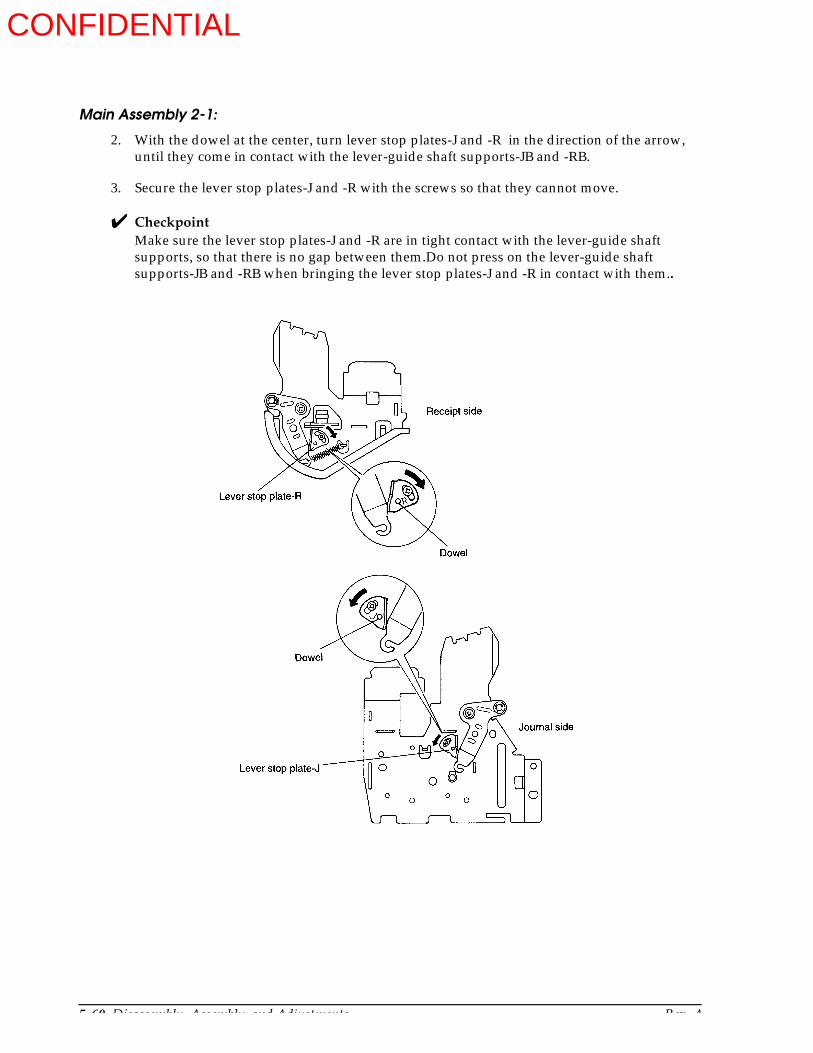
5-60 Disassembly, Assembly, and Adjustments Rev. A
Main Assembly 2-1:
2. With the dowel at the center, turn lever stop plates-J and -R in the direction of the arrow, until they come in contact with the lever-guide shaft supports-JB and -RB.
3. Secure the lever stop plates-J and -R with the screws so that they cannot move.
CheckpointMake sure the lever stop plates-J and -R are in tight contact with the lever-guide shaft supports, so that there is no gap between them.Do not press on the lever-guide shaft supports-JB and -RB when bringing the lever stop plates-J and -R in contact with them..
CONFIDENTIAL
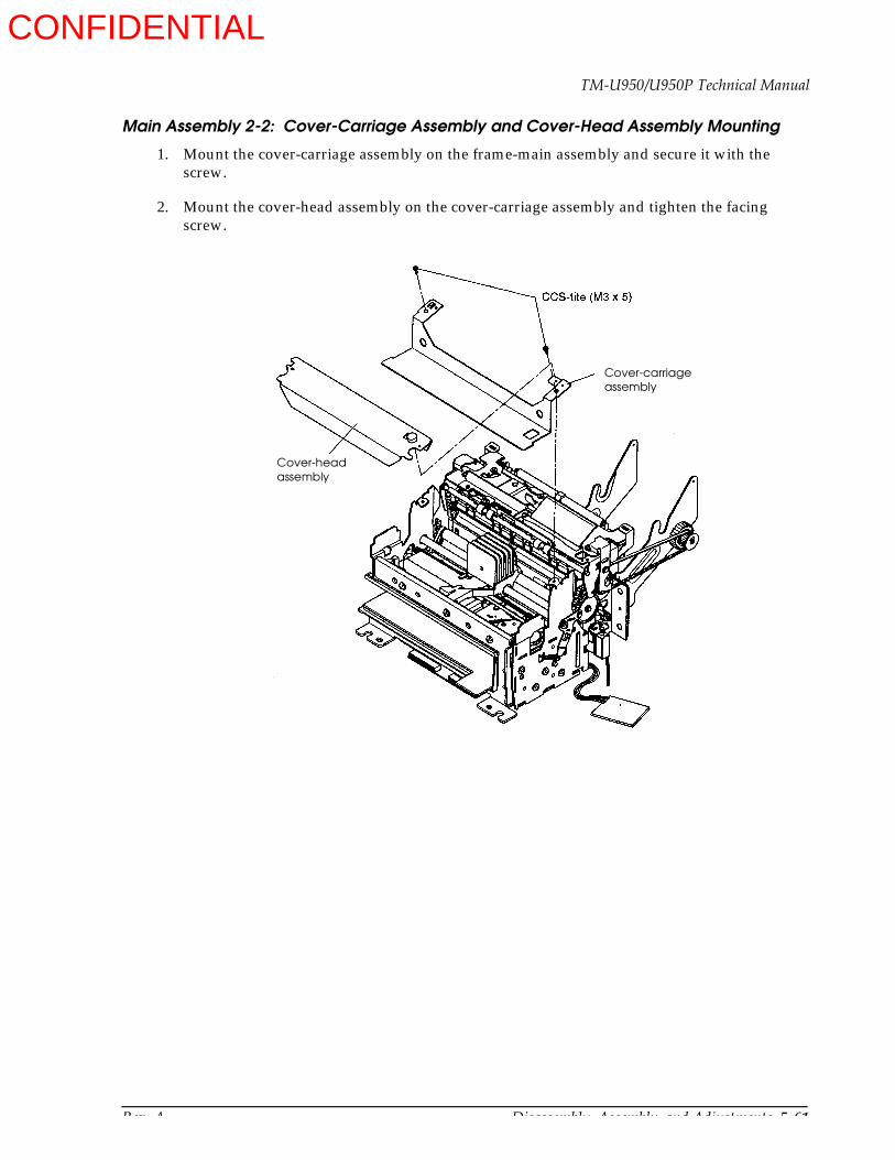
Rev. A Disassembly, Assembly, and Adjustments 5-61
TM-U950/U950P Technical Manual
Main Assembly 2-2: Cover-Carriage Assembly and Cover-Head Assembly Mounting
1. Mount the cover-carriage assembly on the frame-main assembly and secure it with the screw.
2. Mount the cover-head assembly on the cover-carriage assembly and tighten the facing screw.
Cover-carriageassembly
Cover-head assembly
CONFIDENTIAL
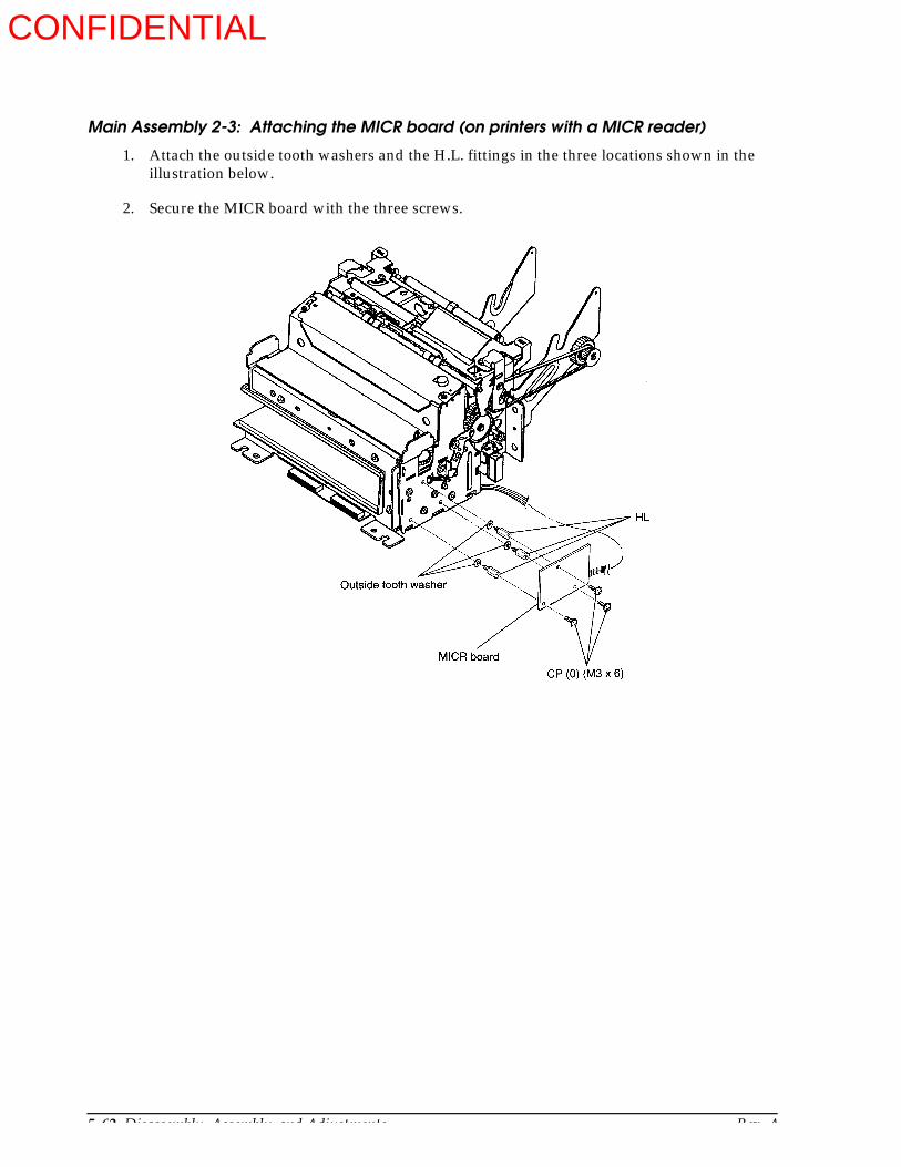
5-62 Disassembly, Assembly, and Adjustments Rev. A
Main Assembly 2-3: Attaching the MICR board (on printers with a MICR reader)
1. Attach the outside tooth washers and the H.L. fittings in the three locations shown in the illustration below.
2. Secure the MICR board with the three screws.
CONFIDENTIAL
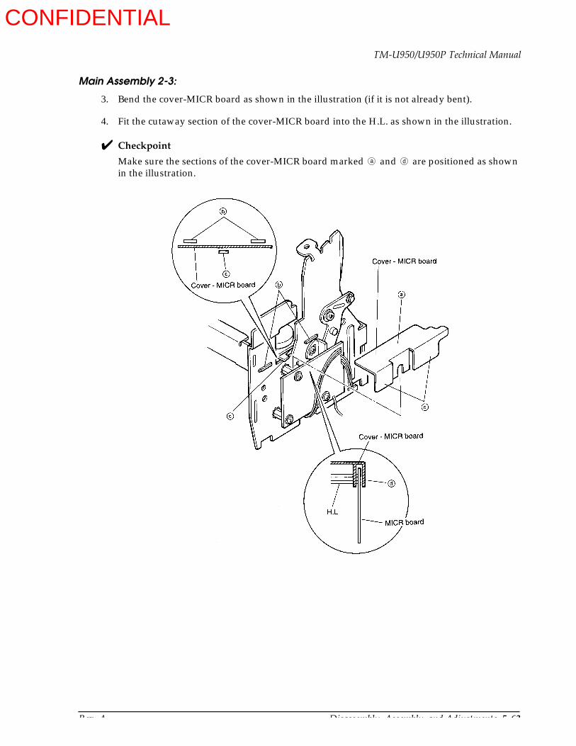
Rev. A Disassembly, Assembly, and Adjustments 5-63
TM-U950/U950P Technical Manual
Main Assembly 2-3:
3. Bend the cover-MICR board as shown in the illustration (if it is not already bent).
4. Fit the cutaway section of the cover-MICR board into the H.L. as shown in the illustration.
Checkpoint
Make sure the sections of the cover-MICR board marked and are positioned as shown in the illustration.
a d
CONFIDENTIAL
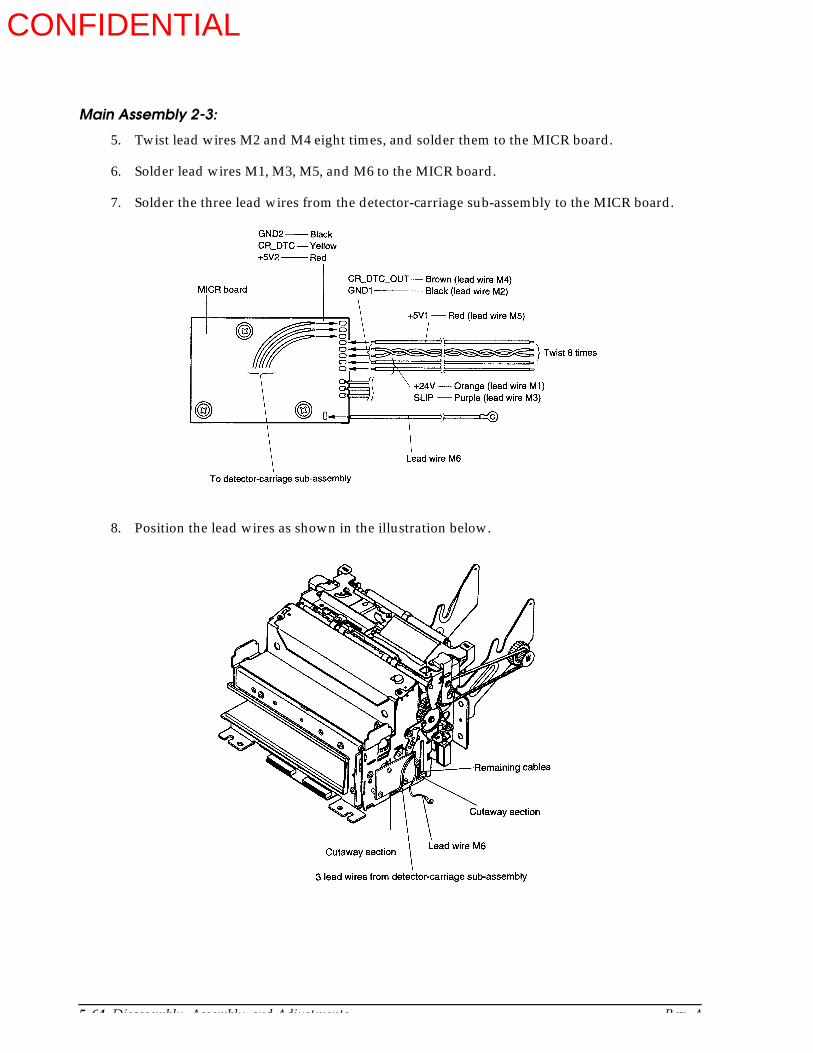
5-64 Disassembly, Assembly, and Adjustments Rev. A
Main Assembly 2-3:
5. Twist lead wires M2 and M4 eight times, and solder them to the MICR board.
6. Solder lead wires M1, M3, M5, and M6 to the MICR board.
7. Solder the three lead wires from the detector-carriage sub-assembly to the MICR board.
8. Position the lead wires as shown in the illustration below.
CONFIDENTIAL

Rev. A Disassembly, Assembly, and Adjustments 5-65
TM-U950/U950P Technical Manual
Whole Unit Assembly
The assembly process is divided into sub-assembly and main assembly.
Perform the sub-assembly first to construct each unit from the parts. Then proceed to the main assembly.
When assembling the printer, check each part and its attachment position by referring to the exploded diagrams in Chapter 6.
For adjustments, follow the descriptions at the end of this chapter. Whenever disassembly is performed even for just one part, check whether adjustment is necessary before assembly.
Sub-assembly
Sub-assembly A: N.E. Detector-J Assembly and N.E. Detector-R Assembly
1. Place protrusions of the lever-N.E. detector onto sections of the holder-N.E. detector.
2. Align the U-shaped grooves with dowels by turning the lever-N.E. detector in the direction of the arrow with protusions as the center.
b a
c
a
CONFIDENTIAL
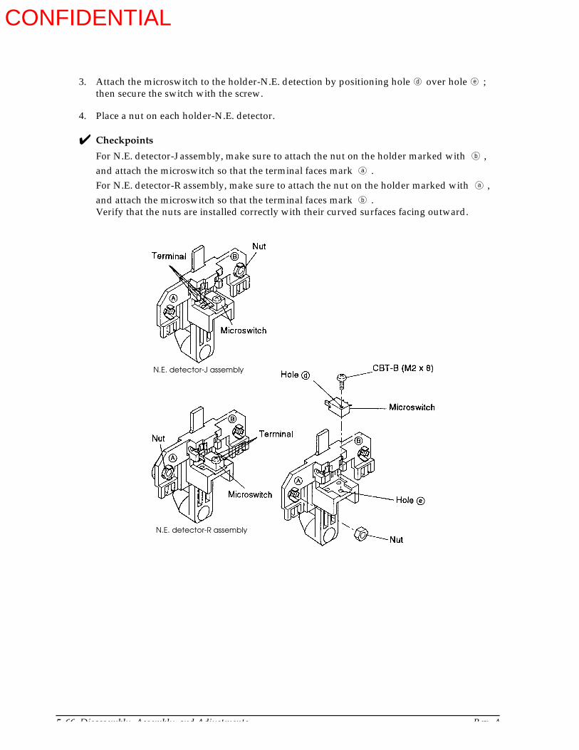
5-66 Disassembly, Assembly, and Adjustments Rev. A
3. Attach the microswitch to the holder-N.E. detection by positioning hole over hole ; then secure the switch with the screw.
4. Place a nut on each holder-N.E. detector.
Checkpoints
For N.E. detector-J assembly, make sure to attach the nut on the holder marked with , and attach the microswitch so that the terminal faces mark .For N.E. detector-R assembly, make sure to attach the nut on the holder marked with , and attach the microswitch so that the terminal faces mark .Verify that the nuts are installed correctly with their curved surfaces facing outward.
d e
b
a
a
b
N.E. detector-J assembly
N.E. detector-R assembly
CONFIDENTIAL
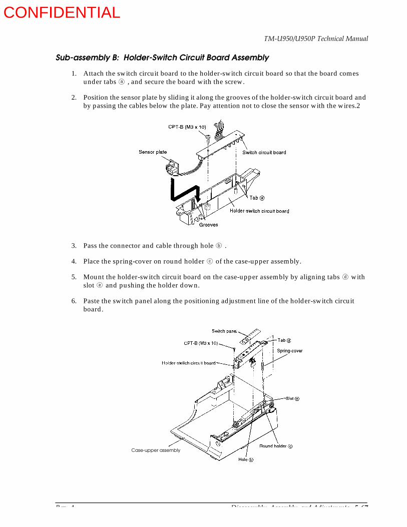
Rev. A Disassembly, Assembly, and Adjustments 5-67
TM-U950/U950P Technical Manual
Sub-assembly B: Holder-Switch Circuit Board Assembly
1. Attach the switch circuit board to the holder-switch circuit board so that the board comes under tabs , and secure the board with the screw.
2. Position the sensor plate by sliding it along the grooves of the holder-switch circuit board and by passing the cables below the plate. Pay attention not to close the sensor with the wires.2
3. Pass the connector and cable through hole .
4. Place the spring-cover on round holder of the case-upper assembly.
5. Mount the holder-switch circuit board on the case-upper assembly by aligning tabs with slot and pushing the holder down.
6. Paste the switch panel along the positioning adjustment line of the holder-switch circuit board.
a
b
c
d
e
Case-upper assembly
CONFIDENTIAL
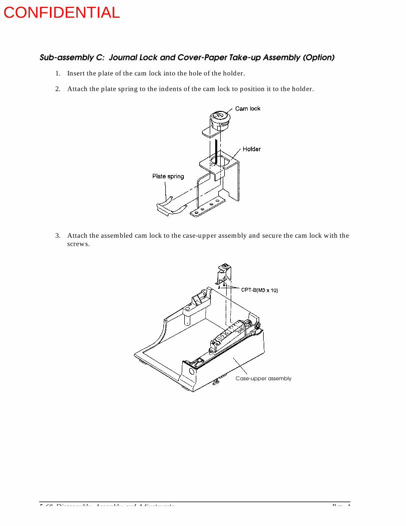
5-68 Disassembly, Assembly, and Adjustments Rev. A
Sub-assembly C: Journal Lock and Cover-Paper Take-up Assembly (Option)
1. Insert the plate of the cam lock into the hole of the holder.
2. Attach the plate spring to the indents of the cam lock to position it to the holder.
3. Attach the assembled cam lock to the case-upper assembly and secure the cam lock with the screws.
Case-upper assembly
CONFIDENTIAL

Rev. A Disassembly, Assembly, and Adjustments 5-69
TM-U950/U950P Technical Manual
Sub-assembly D: Cover Paper Take-up
1. Attach the cover-paper take-up to the frame-paper take-up assembly on the printer mechanism assembly.
Frame-paper take-up assembly
Printer mechanism assembly
CONFIDENTIAL
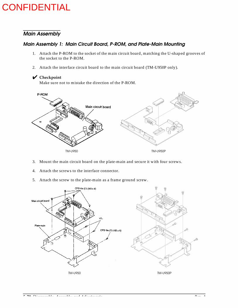
5-70 Disassembly, Assembly, and Adjustments Rev. A
Main Assembly
Main Assembly 1: Main Circuit Board, P-ROM, and Plate-Main Mounting
1. Attach the P-ROM to the socket of the main circuit board, matching the U-shaped grooves of the socket to the P-ROM.
2. Attach the interface circuit board to the main circuit board (TM-U950P only).
CheckpointMake sure not to mistake the direction of the P-ROM.
3. Mount the main circuit board on the plate-main and secure it with four screws.
4. Attach the screws to the interface connector.
5. Attach the screw to the plate-main as a frame ground screw.
TM-U950 TM-U950P
TM-U950 TM-U950P
CONFIDENTIAL
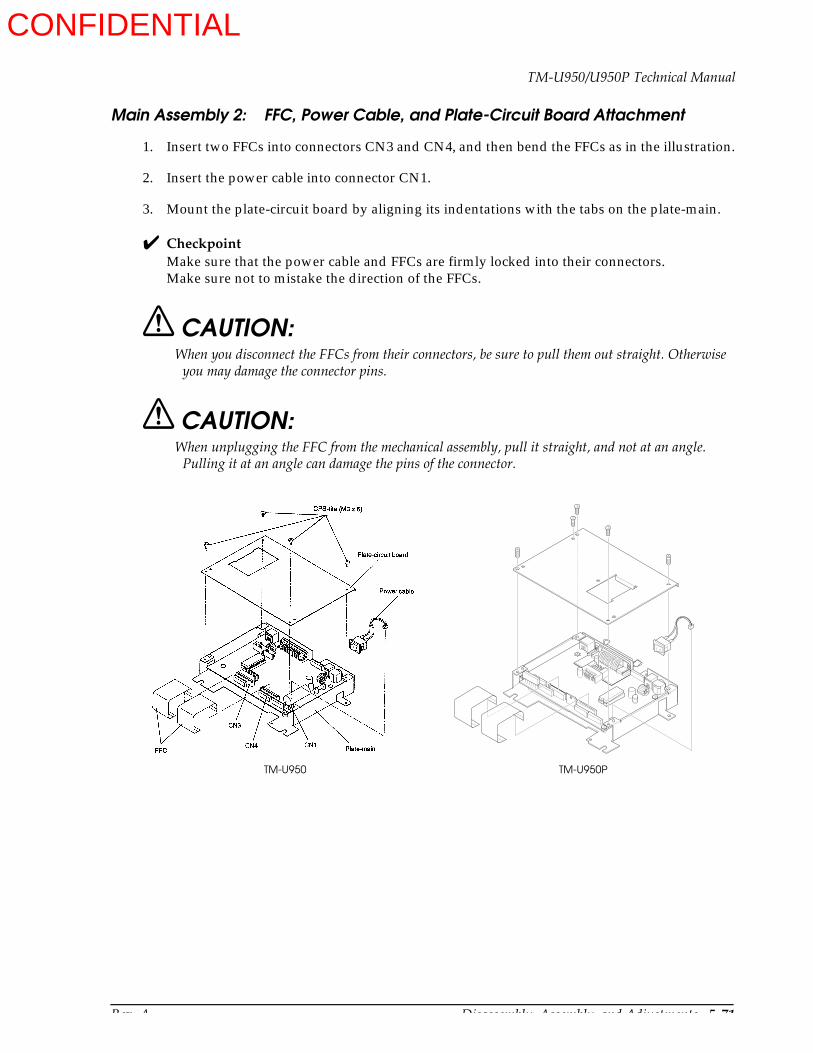
Rev. A Disassembly, Assembly, and Adjustments 5-71
TM-U950/U950P Technical Manual
Main Assembly 2: FFC, Power Cable, and Plate-Circuit Board Attachment
1. Insert two FFCs into connectors CN3 and CN4, and then bend the FFCs as in the illustration.
2. Insert the power cable into connector CN1.
3. Mount the plate-circuit board by aligning its indentations with the tabs on the plate-main.
CheckpointMake sure that the power cable and FFCs are firmly locked into their connectors.Make sure not to mistake the direction of the FFCs.
CAUTION:When you disconnect the FFCs from their connectors, be sure to pull them out straight. Otherwise
you may damage the connector pins.
CAUTION:When unplugging the FFC from the mechanical assembly, pull it straight, and not at an angle.
Pulling it at an angle can damage the pins of the connector.
TM-U950 TM-U950P
CONFIDENTIAL
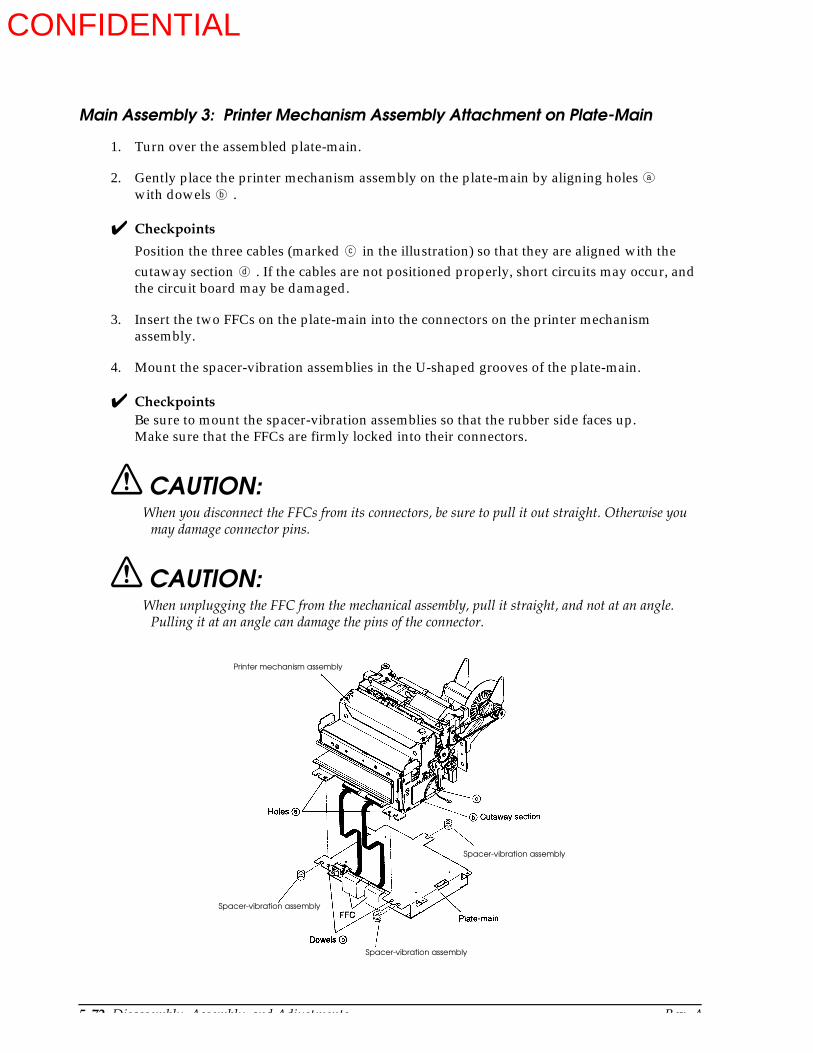
5-72 Disassembly, Assembly, and Adjustments Rev. A
Main Assembly 3: Printer Mechanism Assembly Attachment on Plate-Main
1. Turn over the assembled plate-main.
2. Gently place the printer mechanism assembly on the plate-main by aligning holeswith dowels .
Checkpoints
Position the three cables (marked in the illustration) so that they are aligned with the cutaway section . If the cables are not positioned properly, short circuits may occur, and the circuit board may be damaged.
3. Insert the two FFCs on the plate-main into the connectors on the printer mechanism assembly.
4. Mount the spacer-vibration assemblies in the U-shaped grooves of the plate-main.
CheckpointsBe sure to mount the spacer-vibration assemblies so that the rubber side faces up.Make sure that the FFCs are firmly locked into their connectors.
CAUTION:When you disconnect the FFCs from its connectors, be sure to pull it out straight. Otherwise you
may damage connector pins.
CAUTION:When unplugging the FFC from the mechanical assembly, pull it straight, and not at an angle.
Pulling it at an angle can damage the pins of the connector.
a
b
c
d
Printer mechanism assembly
Spacer-vibration assembly
Spacer-vibration assembly
Spacer-vibration assembly
CONFIDENTIAL
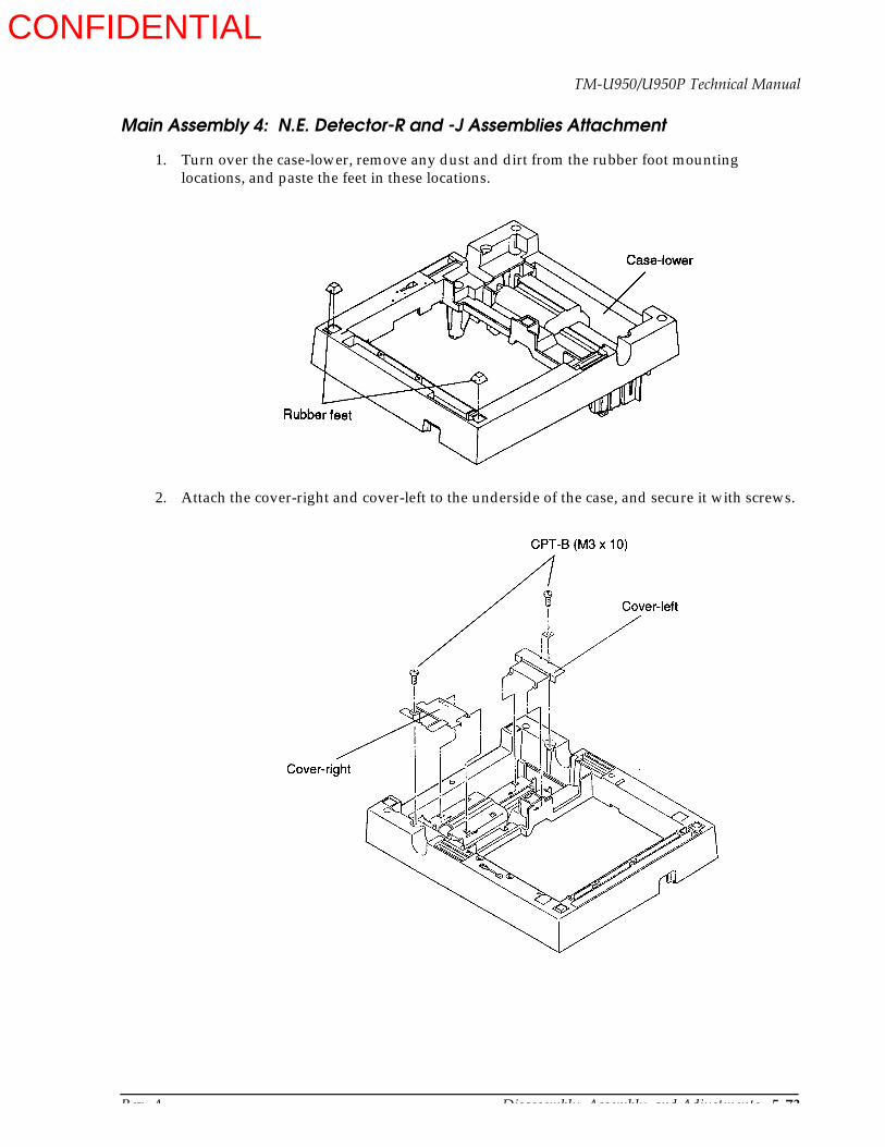
Rev. A Disassembly, Assembly, and Adjustments 5-73
TM-U950/U950P Technical Manual
Main Assembly 4: N.E. Detector-R and -J Assemblies Attachment
1. Turn over the case-lower, remove any dust and dirt from the rubber foot mounting locations, and paste the feet in these locations.
2. Attach the cover-right and cover-left to the underside of the case, and secure it with screws.
CONFIDENTIAL

5-74 Disassembly, Assembly, and Adjustments Rev. A
3. Attach the roll paper rollers to the case-lower.
4. Attach the spacers-N.E. detector to the detector adjustment screws.
5. Attach the N.E. detector-R assembly and -J assembly to the case-lower by sliding section ; then secure them with the assembled detector adjustment screws.
[Adjustment] Adjust the N.E. detectors. Refer to Adjustment G at the end of this chapter.
a
N.E. detector-R assembly
N.E. detector-J assembly
CONFIDENTIAL
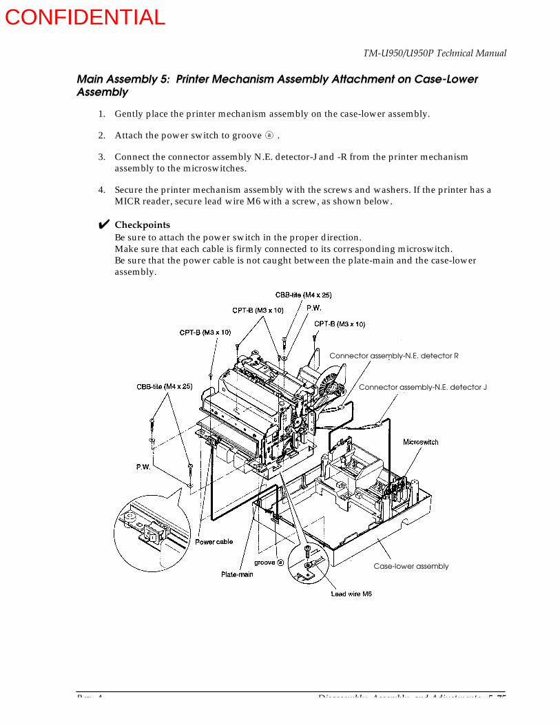
Rev. A Disassembly, Assembly, and Adjustments 5-75
TM-U950/U950P Technical Manual
Main Assembly 5: Printer Mechanism Assembly Attachment on Case-Lower Assembly
1. Gently place the printer mechanism assembly on the case-lower assembly.
2. Attach the power switch to groove .
3. Connect the connector assembly N.E. detector-J and -R from the printer mechanism assembly to the microswitches.
4. Secure the printer mechanism assembly with the screws and washers. If the printer has a MICR reader, secure lead wire M6 with a screw, as shown below.
CheckpointsBe sure to attach the power switch in the proper direction.Make sure that each cable is firmly connected to its corresponding microswitch.Be sure that the power cable is not caught between the plate-main and the case-lower assembly.
a
Case-lower assembly
Connector assembly-N.E. detector R
Connector assembly-N.E. detector J
CONFIDENTIAL

5-76 Disassembly, Assembly, and Adjustments Rev. A
Main Assembly 6: Case-Upper Assembly Mounting
1. Connect the cable from the switch circuit board to the CN8 on the main circuit board unit.
2. Mount the case-upper assembly on the case-lower assembly by hooking the three tabs on the case-upper assembly to the three hooks on the case-lower; then secure the case-upper with two screws.
Case-upper assembly
Case-lower assembly
CONFIDENTIAL
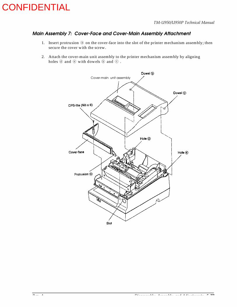
Rev. A Disassembly, Assembly, and Adjustments 5-77
TM-U950/U950P Technical Manual
Main Assembly 7: Cover-Face and Cover-Main Assembly Attachment
1. Insert protrusion on the cover-face into the slot of the printer mechanism assembly; then secure the cover with the screw.
2. Attach the cover-main unit assembly to the printer mechanism assembly by aligning holes and with dowels and .
a
d e b c
Cover-main unit assembly
CONFIDENTIAL
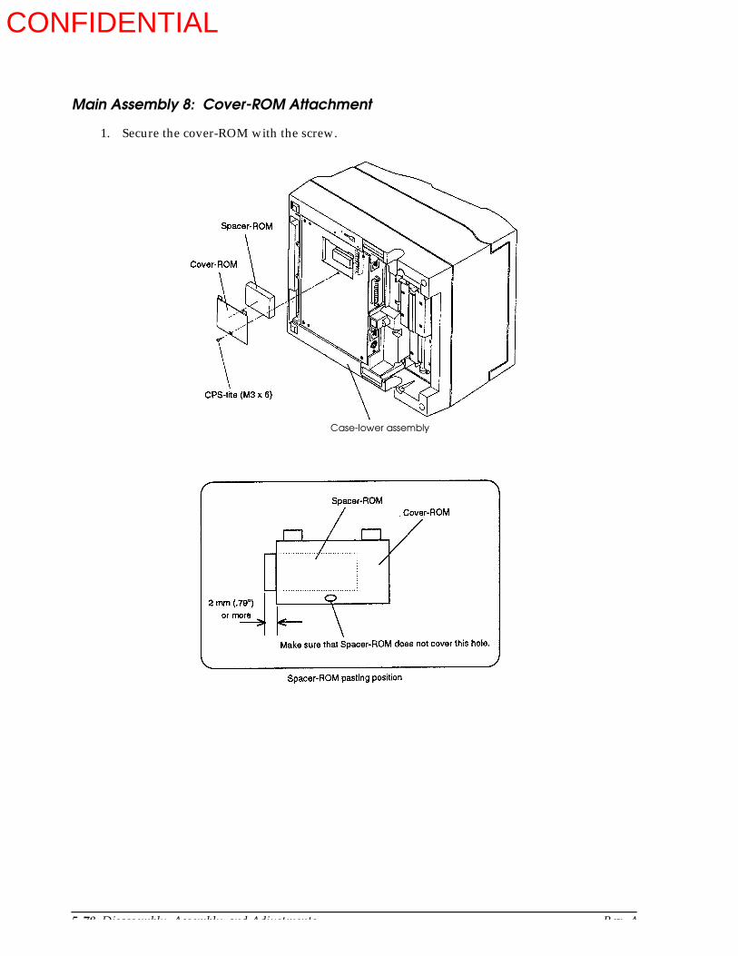
5-78 Disassembly, Assembly, and Adjustments Rev. A
Main Assembly 8: Cover-ROM Attachment
1. Secure the cover-ROM with the screw.
Case-lower assembly
CONFIDENTIAL
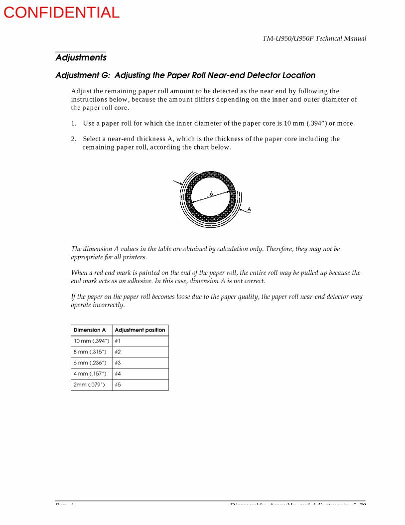
Rev. A Disassembly, Assembly, and Adjustments 5-79
TM-U950/U950P Technical Manual
Adjustments
Adjustment G: Adjusting the Paper Roll Near-end Detector Location
Adjust the remaining paper roll amount to be detected as the near end by following the instructions below, because the amount differs depending on the inner and outer diameter of the paper roll core.
1. Use a paper roll for which the inner diameter of the paper core is 10 mm (.394”) or more.
2. Select a near-end thickness A, which is the thickness of the paper core including the remaining paper roll, according the chart below.
The dimension A values in the table are obtained by calculation only. Therefore, they may not be appropriate for all printers.
When a red end mark is painted on the end of the paper roll, the entire roll may be pulled up because the end mark acts as an adhesive. In this case, dimension A is not correct.
If the paper on the paper roll becomes loose due to the paper quality, the paper roll near-end detector may operate incorrectly.
Dimension A Adjustment position
10 mm (,394”) #1
8 mm (.315”) #2
6 mm (.236”) #3
4 mm (.157”) #4
2mm (.079”) #5
CONFIDENTIAL
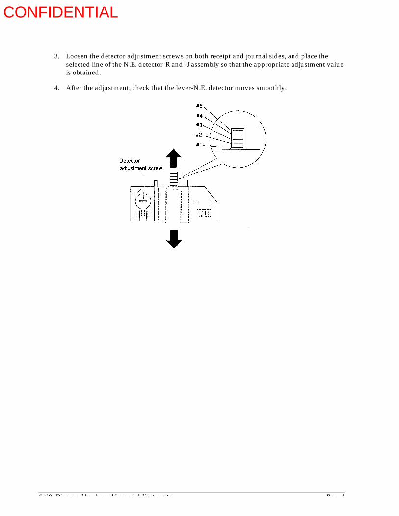
5-80 Disassembly, Assembly, and Adjustments Rev. A
3. Loosen the detector adjustment screws on both receipt and journal sides, and place the selected line of the N.E. detector-R and -J assembly so that the appropriate adjustment value is obtained.
4. After the adjustment, check that the lever-N.E. detector moves smoothly.
CONFIDENTIAL

Rev. A Disassembly, Assembly, and Adjustments 5-81
TM-U950/U950P Technical Manual
Adjustment H: Detector-Slip Insertion Assembly Threshold Value Adjustment
After replacing detector-slip insertion assembly, main circuit board, or printer mechanism assembly, be sure to perform the following adjustment to assure correct operation of the printer.
Step Printer Operation User Operation
1 Preparing to enter special setting mode Set DIP switch 6 of switch bank 2 to off.
2 Enter special setting modePrints the following message when user operation 1 to 4 is finished.
Execute the following steps 1 to 4.1 Open the cover-main assembly. Turn on the
printer while pressing both the RECEIPT FEED and JOURNAL/SLIP FEED buttons.
2 Release RECEIPT FEED button then JOURNAL/SLIP FEED button.
3 Press RECEIPT FEED button or JOURNAL/SLIP FEED button more than six times.
4 Close the cover-main assembly.
3 EEPROM read/write testPrints the following message after the test depending on the result.When no error was found:
This is an unrecoverable error. Reset the printer and confirm that the initialization is executed correctly.Replace the main circuit board if this error message is still printed after executing the adjustment two times.
4 EEPROM threshold value checkChecks the threshold value in EEPROM, and prints the following message.
(**shows threshold value in hexadecimal.)
5 Detection value measurement without slip paperMeasures the slip paper insert detection value without slip paper. The result is printed as follows:
6 Detection value measurement with slip paperMeasures the slip paper insert detection value with slip paper, and prints the following message.
When message (4) is printed, insert the slip paper in the slip paper insert detection position, and press either panel operation button.
*****Special Setting Mode*****This mode is used for
changing internal setting mode.Turn off the power, if not necessary.
(1) EEPROM Read/Write Test is completed.
When error was found:
(1) EEPROM Read/Write ERROR!!EEPROM process STOP.
(2) SLIP IN DETECTOR THRESHOLD VALUEin the EEPROM : [ ** ]
(** shows threshold value in hexadecimal )
(3) A/D-converted valuePaper OUT : [ ** ]
(** shows detection value in hexadecimal.)
(4) Please SET paperon SLIP IN detector position.
If ready, Press panel switch.
(** shows detection value in hexadecimal.)
Prints the detection value of the measurementas follows:
(5) A/D-converted valuePaper IN : [ ** ]
CONFIDENTIAL
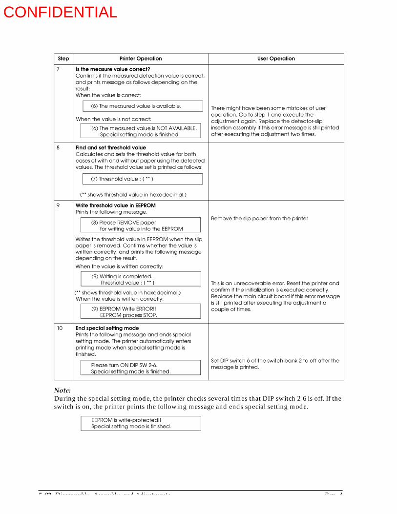
5-82 Disassembly, Assembly, and Adjustments Rev. A
Note:During the special setting mode, the printer checks several times that DIP switch 2-6 is off. If the switch is on, the printer prints the following message and ends special setting mode.
7 Is the measure value correct?Confirms if the measured detection value is correct, and prints message as follows depending on the result:When the value is correct:
There might have been some mistakes of user operation. Go to step 1 and execute the adjustment again. Replace the detector-slip insertion assembly if this error message is still printed after executing the adjustment two times.
8 Find and set threshold valueCalculates and sets the threshold value for both cases of with and without paper using the detected values. The threshold value set is printed as follows:
9 Write threshold value in EEPROMPrints the following message.
Remove the slip paper from the printer
This is an unrecoverable error. Reset the printer and confirm if the initialization is executed correctly.Replace the main circuit board if this error message is still printed after executing the adjustment a couple of times.
10 End special setting modePrints the following message and ends special setting mode. The printer automatically enters printing mode when special setting mode is finished.
Set DIP switch 6 of the switch bank 2 to off after the message is printed.
Step Printer Operation User Operation
(6) The measured value is available.
When the value is not correct:
(6) The measured value is NOT AVAILABLE.Special setting mode is finished.
(7) Threshold value : [ ** ]
(** shows threshold value in hexadecimal.)
(8) Please REMOVE paperfor writing value into the EEPROM
Writes the threshold value in EEPROM when the slippaper is removed. Confirms whether the value iswritten correctly, and prints the following messagedepending on the result.
When the value is written correctly:
(9) Writing is completed.Threshold value : [ ** ]
When the value is written correctly:(** shows threshold value in hexadecimal.)
(9) EEPROM Write ERROR!!EEPROM process STOP.
Please turn ON DIP SW 2-6.Special setting mode is finished.
EEPROM is write-protected!!Special setting mode is finished.
CONFIDENTIAL
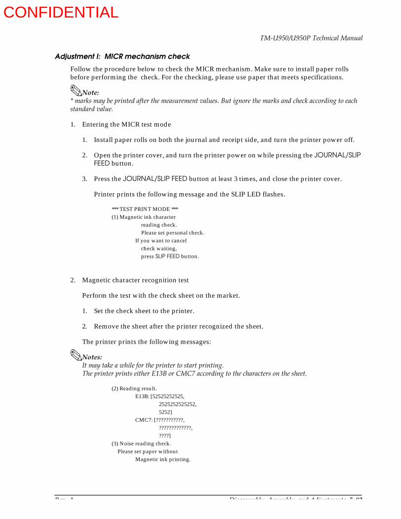
Rev. A Disassembly, Assembly, and Adjustments 5-83
TM-U950/U950P Technical Manual
Adjustment I: MICR mechanism check
Follow the procedure below to check the MICR mechanism. Make sure to install paper rolls before performing the check. For the checking, please use paper that meets specifications.
Note: * marks may be printed after the measurement values. But ignore the marks and check according to each standard value.
1. Entering the MICR test mode
1. Install paper rolls on both the journal and receipt side, and turn the printer power off.
2. Open the printer cover, and turn the printer power on while pressing the JOURNAL/SLIP FEED button.
3. Press the JOURNAL/SLIP FEED button at least 3 times, and close the printer cover.
Printer prints the following message and the SLIP LED flashes.
*** TEST PRINT MODE ***(1) Magnetic ink character
reading check.Please set personal check.
If you want to cancelcheck waiting,press SLIP FEED button.
2. Magnetic character recognition test
Perform the test with the check sheet on the market.
1. Set the check sheet to the printer.
2. Remove the sheet after the printer recognized the sheet.
The printer prints the following messages:
Notes: It may take a while for the printer to start printing.The printer prints either E13B or CMC7 according to the characters on the sheet.
(2) Reading result.E13B: [52525252525,
2525252525252,5252]
CMC7: [???????????,?????????????,????]
(3) Noise reading check.Please set paper without
Magnetic ink printing.
CONFIDENTIAL
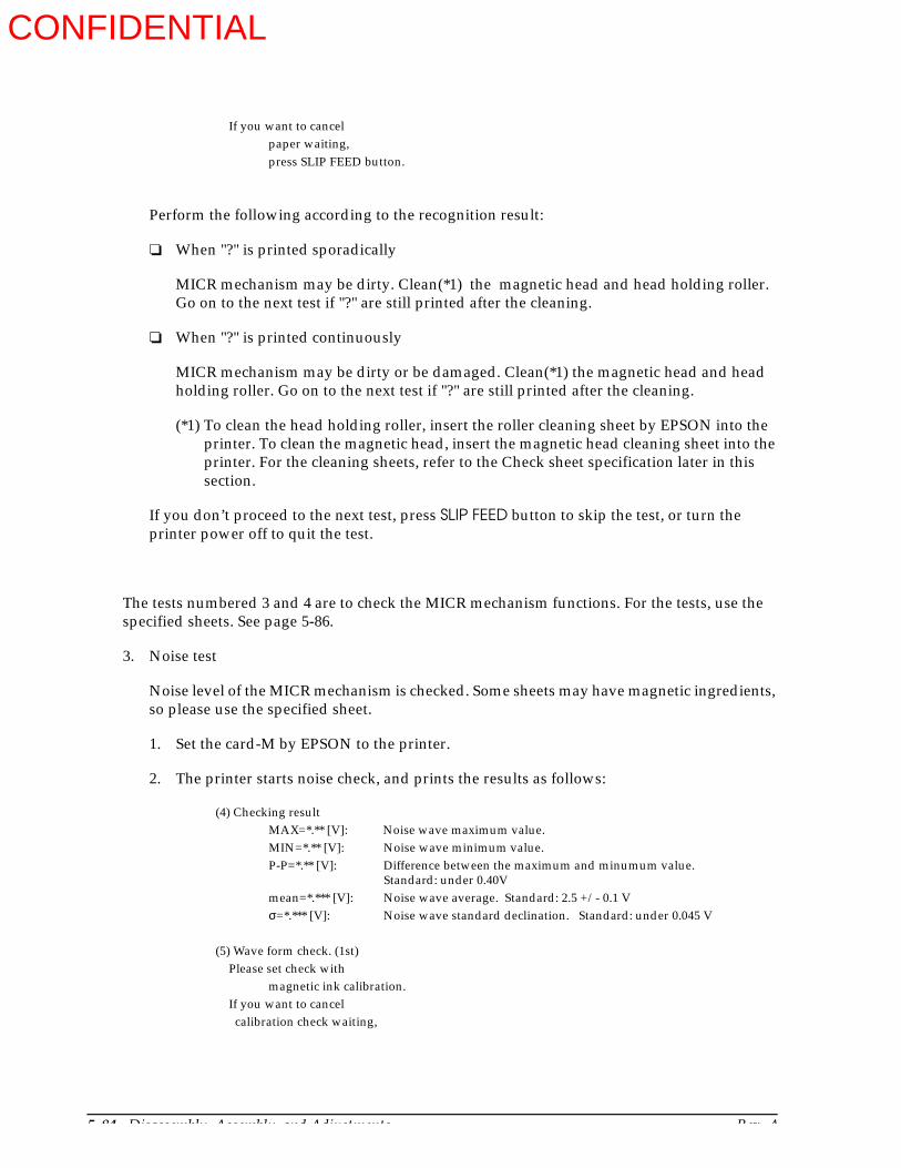
5-84 Disassembly, Assembly, and Adjustments Rev. A
If you want to cancelpaper waiting,press SLIP FEED button.
Perform the following according to the recognition result:
When "?" is printed sporadically
MICR mechanism may be dirty. Clean(*1) the magnetic head and head holding roller. Go on to the next test if "?" are still printed after the cleaning.
When "?" is printed continuously
MICR mechanism may be dirty or be damaged. Clean(*1) the magnetic head and head holding roller. Go on to the next test if "?" are still printed after the cleaning.
(*1) To clean the head holding roller, insert the roller cleaning sheet by EPSON into the printer. To clean the magnetic head, insert the magnetic head cleaning sheet into the printer. For the cleaning sheets, refer to the Check sheet specification later in this section.
If you don’t proceed to the next test, press SLIP FEED button to skip the test, or turn the printer power off to quit the test.
The tests numbered 3 and 4 are to check the MICR mechanism functions. For the tests, use the specified sheets. See page 5-86.
3. Noise test
Noise level of the MICR mechanism is checked. Some sheets may have magnetic ingredients, so please use the specified sheet.
1. Set the card-M by EPSON to the printer.
2. The printer starts noise check, and prints the results as follows:
(4) Checking resultMAX=*.** [V]: Noise wave maximum value.MIN=*.** [V]: Noise wave minimum value.P-P=*.** [V]: Difference between the maximum and minumum value.
Standard: under 0.40Vmean=*.*** [V]: Noise wave average. Standard: 2.5 +/- 0.1 V σ=*.*** [V]: Noise wave standard declination. Standard: under 0.045 V
(5) Wave form check. (1st)Please set check with
magnetic ink calibration.If you want to cancel calibration check waiting,
CONFIDENTIAL
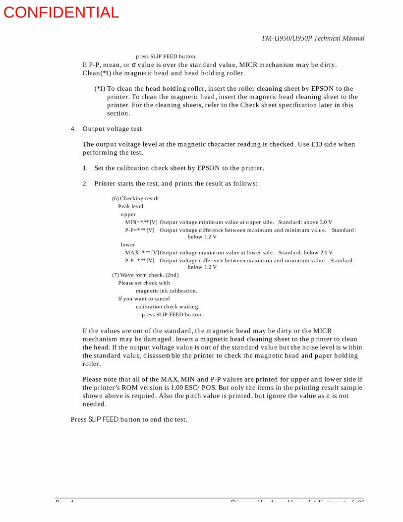
Rev. A Disassembly, Assembly, and Adjustments 5-85
TM-U950/U950P Technical Manual
press SLIP FEED button.
If P-P, mean, or σ value is over the standard value, MICR mechanism may be dirty. Clean(*1) the magnetic head and head holding roller.
(*1) To clean the head holding roller, insert the roller cleaning sheet by EPSON to the printer. To clean the magnetic head, insert the magnetic head cleaning sheet to the printer. For the cleaning sheets, refer to the Check sheet specification later in this section.
4. Output voltage test
The output voltage level at the magnetic character reading is checked. Use E13 side when performing the test.
1. Set the calibration check sheet by EPSON to the printer.
2. Printer starts the test, and prints the result as follows:
(6) Checking resultPeak level upper MIN=*.** [V] Output voltage minimum value at upper side. Standard: above 3.0 V P-P=*.** [V] Output voltage difference between maximum and minimum value. Standard:
below 1.2 V lower MAX=*.** [V]Output voltage maximum value at lower side. Standard: below 2.0 V P-P=*.** [V] Output voltage difference between maximum and minimum value. Standard:
below 1.2 V(7) Wave form check. (2nd)
Please set check withmagnetic ink calibration.
If you want to cancelcalibration check waiting,
press SLIP FEED button.
If the values are out of the standard, the magnetic head may be dirty or the MICR mechanism may be damaged. Insert a magnetic head cleaning sheet to the printer to clean the head. If the output voltage value is out of the standard value but the noise level is within the standard value, disassemble the printer to check the magnetic head and paper holding roller.
Please note that all of the MAX, MIN and P-P values are printed for upper and lower side if the printer’s ROM version is 1.00 ESC/POS. But only the items in the printing result sample shown above is requied. Also the pitch value is printed, but ignore the value as it is not needed.
Press SLIP FEED button to end the test.
CONFIDENTIAL
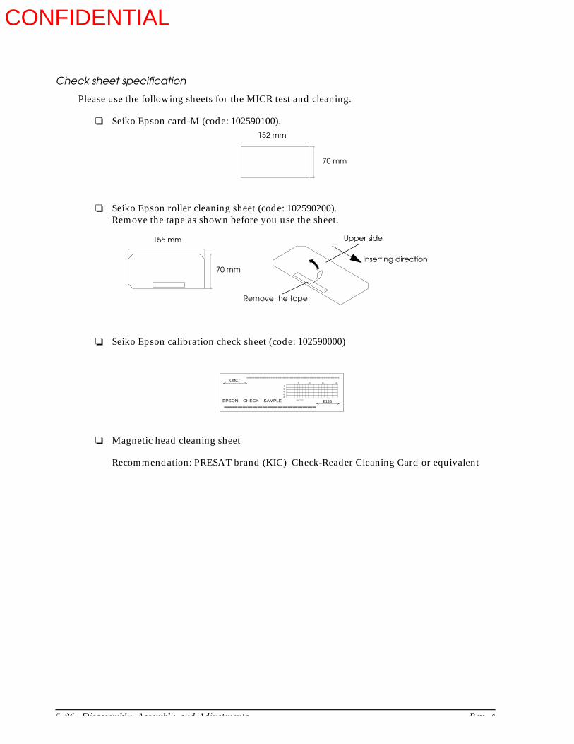
5-86 Disassembly, Assembly, and Adjustments Rev. A
Check sheet specification
Please use the following sheets for the MICR test and cleaning.
Seiko Epson card-M (code: 102590100).
Seiko Epson roller cleaning sheet (code: 102590200).Remove the tape as shown before you use the sheet.
Seiko Epson calibration check sheet (code: 102590000)
Magnetic head cleaning sheet
Recommendation: PRESAT brand (KIC) Check-Reader Cleaning Card or equivalent
152 mm
70 mm
155 mm
70 mm
Remove the tape
Upper side
Inserting direction
20406080
5 10 15 200
CMC7
E13BEPSON CHECK SAMPLE gpæ‘FbN
CONFIDENTIAL

Rev. A Appendix 6-1
TM-U950/U950P Technical Manual
Chapter 6Appendix
Electrical Circuit Drawings
Main board
Main circuit board contains circuit 1 to circuit 8 and main circuit which are shown in the following pages.
Figure 6-1 indicates the main circuit board block diagram.
Circuit 1 to circuit 8 are included in the main circuit.
Figure 6-1. Main Circuit Block Diagram
CONFIDENTIAL
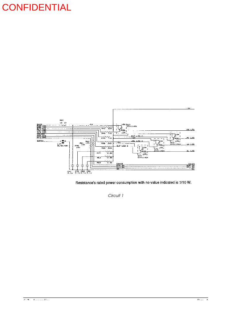
6-2 Appendix Rev. A
Circuit 1
CONFIDENTIAL

Rev. A Appendix 6-3
TM-U950/U950P Technical Manual
Circuit 2
CONFIDENTIAL

6-4 Appendix Rev. A
Circuit 3
CONFIDENTIAL
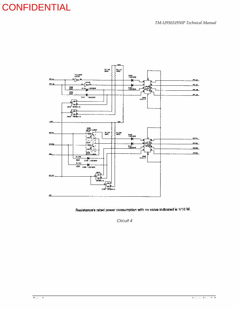
Rev. A Appendix 6-5
TM-U950/U950P Technical Manual
Circuit 4
CONFIDENTIAL

6-6 Appendix Rev. A
Circuit 4
Circuit 5
CONFIDENTIAL
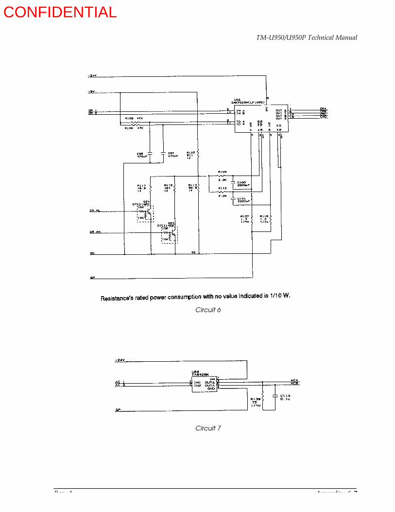
Rev. A Appendix 6-7
TM-U950/U950P Technical Manual
Circuit 6
Circuit 7
CONFIDENTIAL
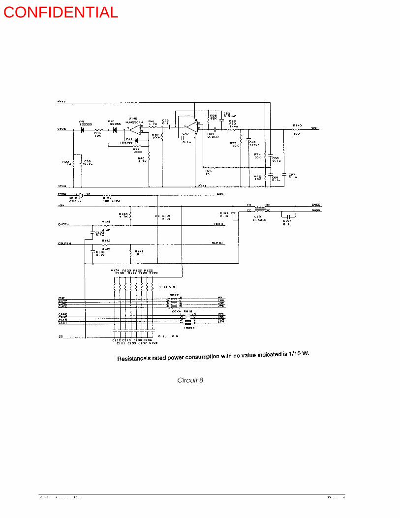
6-8 Appendix Rev. A
Circuit 8
CONFIDENTIAL

Main Unit Circuit Drawing for TM-U950
Appendix 6-9
TM-U950/U950P Technical Manual
CO
NF
IDE
NT
IAL
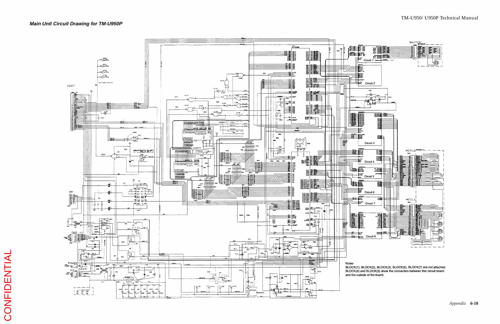
TM-U950/U950P Technical ManualMain Unit Circuit Drawing for TM-U950P
Appendix 6-10
CO
NF
IDE
NT
IAL
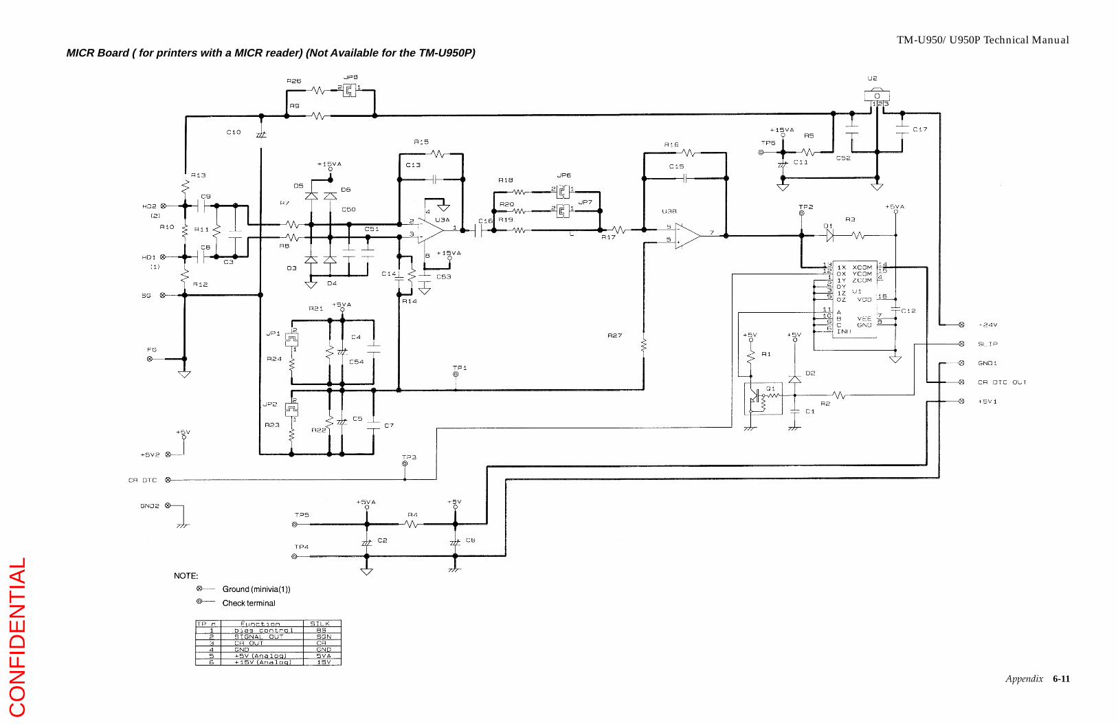
MICR Board ( for printers with a MICR reader) (Not Available for the TM-U950P)TM-U950/U950P Technical Manual
Appendix 6-11
CO
NF
IDE
NT
IAL
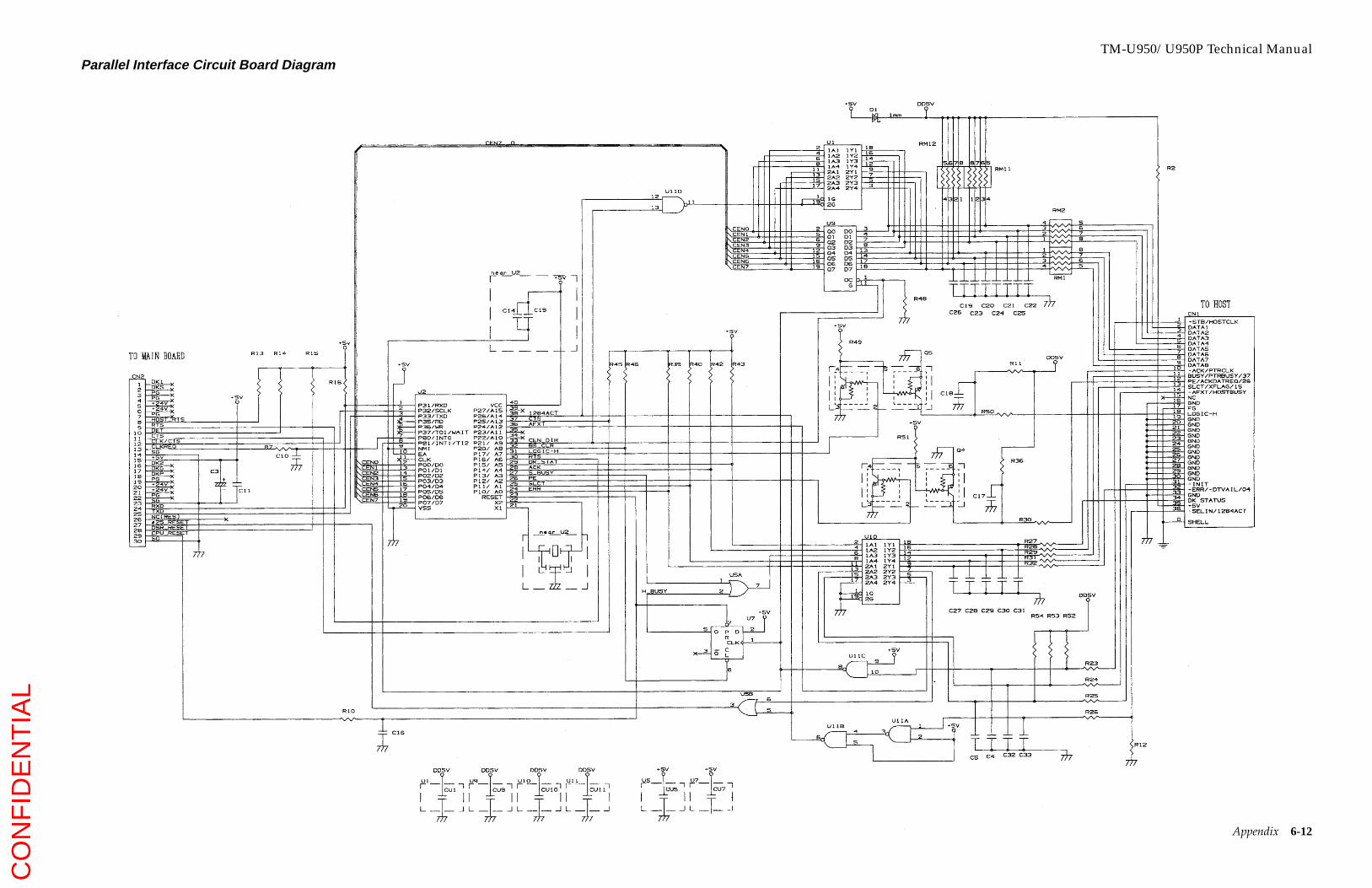
TM-U950/U950P Technical ManualParallel Interface Circuit Board Diagram
Appendix 6-12
CO
NF
IDE
NT
IAL
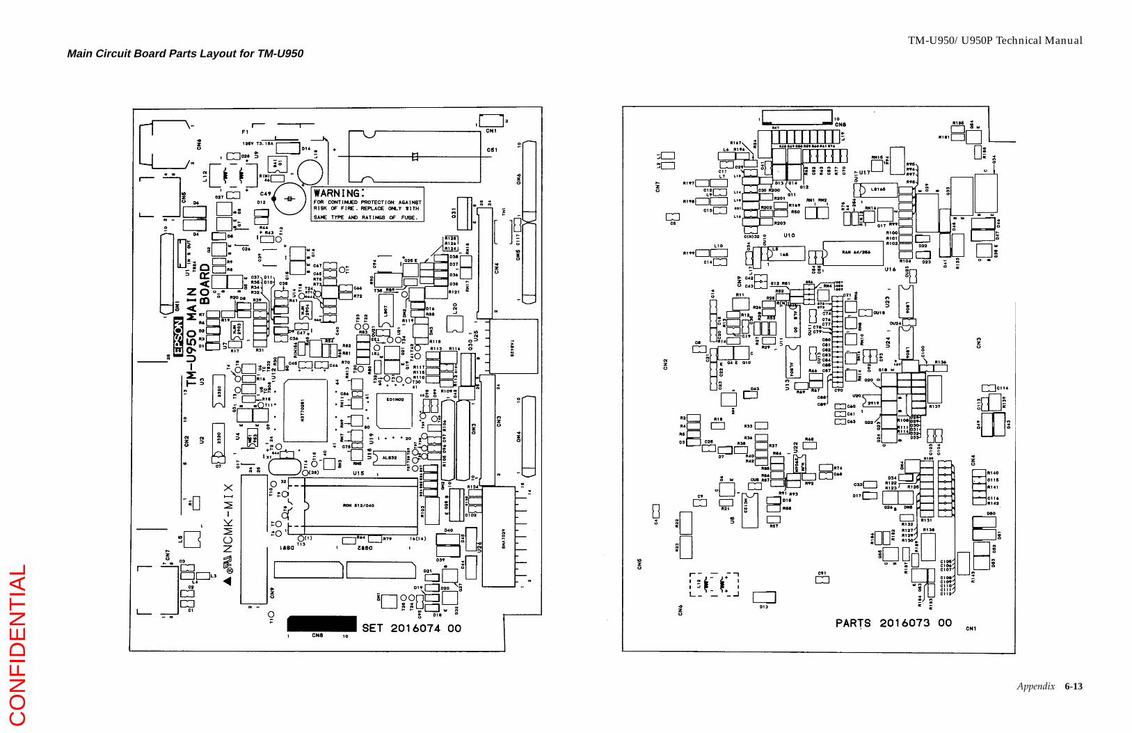
Main Circuit Board Parts Layout for TM-U950TM-U950/U950P Technical Manual
Appendix 6-13
CO
NF
IDE
NT
IAL

TM-U950/U950P Technical ManualMain Circuit Board Parts Layout for TM-U950P
Appendix 6-14
CO
NF
IDE
NT
IAL
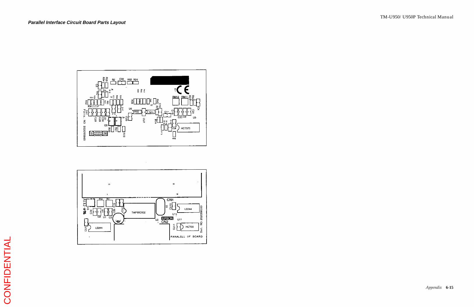
TM-U950/U950P Technical ManualParallel Interface Circuit Board Parts Layout
Appendix 6-15
CO
NF
IDE
NT
IAL
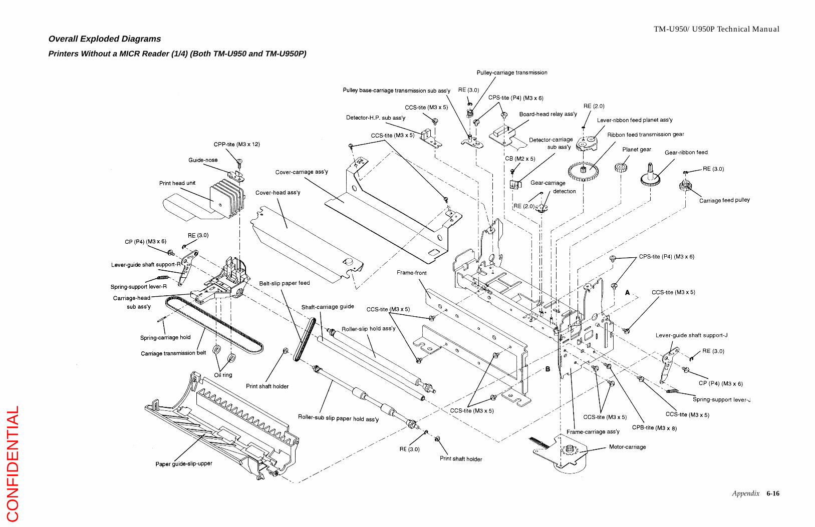
TM-U950/U950P Technical ManualOverall Exploded Diagrams
Printers Without a MICR Reader (1/4) (Both TM-U950 and TM-U950P)
Appendix 6-16
CO
NF
IDE
NT
IAL

TM-U950/U950P Technical ManualPrinters Without a MICR Reader (2/4)
Appendix 6-17
CO
NF
IDE
NT
IAL

TM-U950/U950P Technical ManualPrinters Without a MICR Reader (3/4)
Appendix 6-18
CO
NF
IDE
NT
IAL
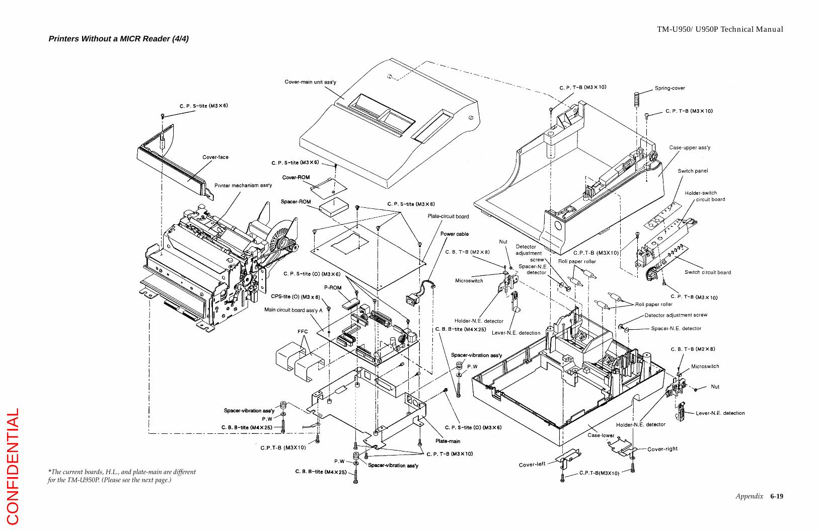
TM-U950/U950P Technical ManualPrinters Without a MICR Reader (4/4)
Appendix 6-19
*The current boards, H.L., and plate-main are differentfor the TM-U950P. (Please see the next page.)
CO
NF
IDE
NT
IAL

TM-U950/U950P Technical ManualPrinters Without a MICR Reader (4/4): TM-U950P Only
Appendix 6-20
Interface circuit board
P-ROM
Main circuit board
CPS-tite (M3 x 6)
Plate-main
Note: These parts are different for the TM-U950P.All other parts are the same as the TM-U950.
CO
NF
IDE
NT
IAL

TM-U950/U950P Technical ManualPrinters With a MICR Reader (1/5)
Appendix 6-21
CO
NF
IDE
NT
IAL
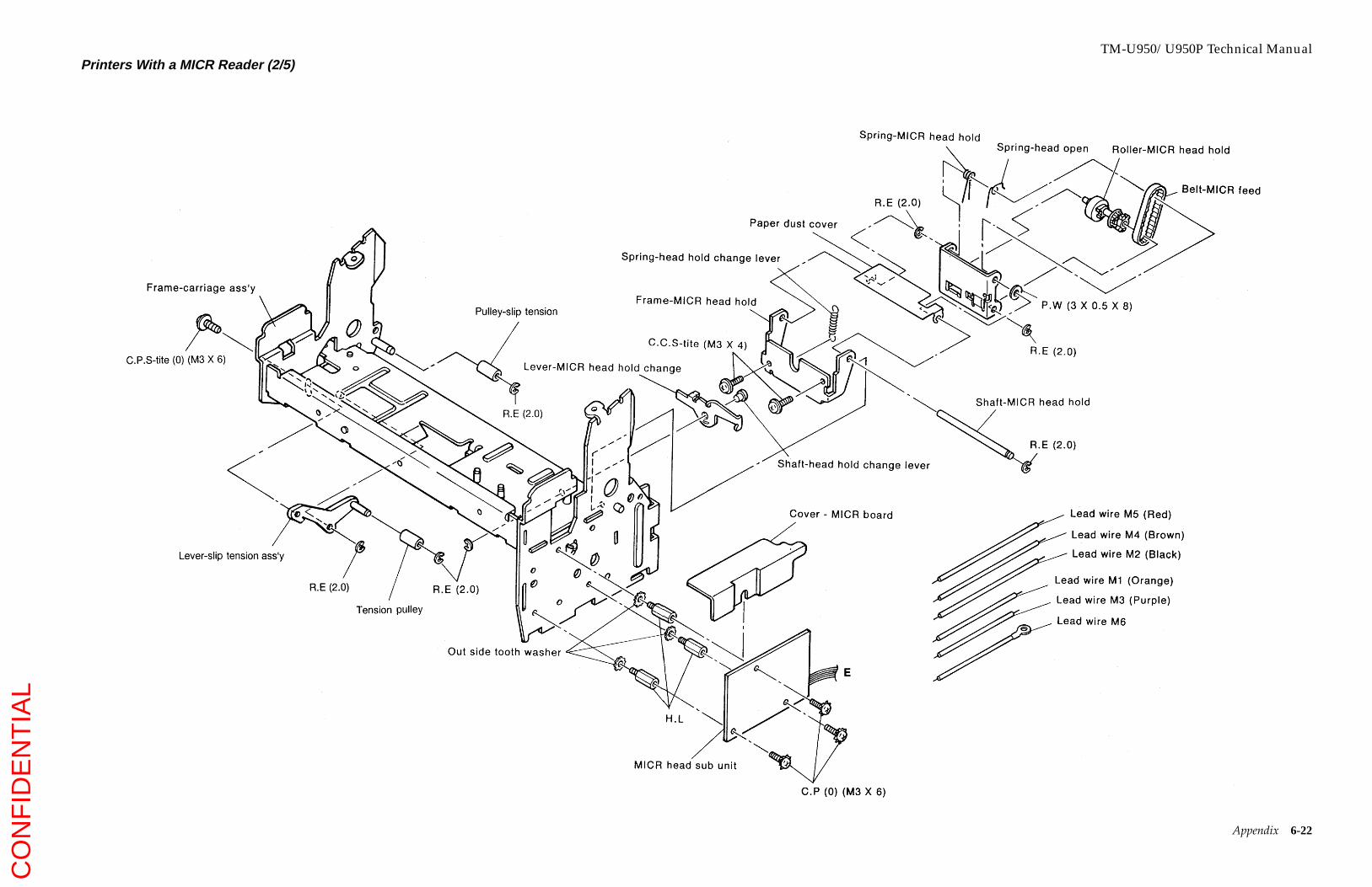
TM-U950/U950P Technical ManualPrinters With a MICR Reader (2/5)
Appendix 6-22
CO
NF
IDE
NT
IAL

TM-U950/U950P Technical ManualPrinters With a MICR Reader (3/5)
Appendix 6-23
CO
NF
IDE
NT
IAL
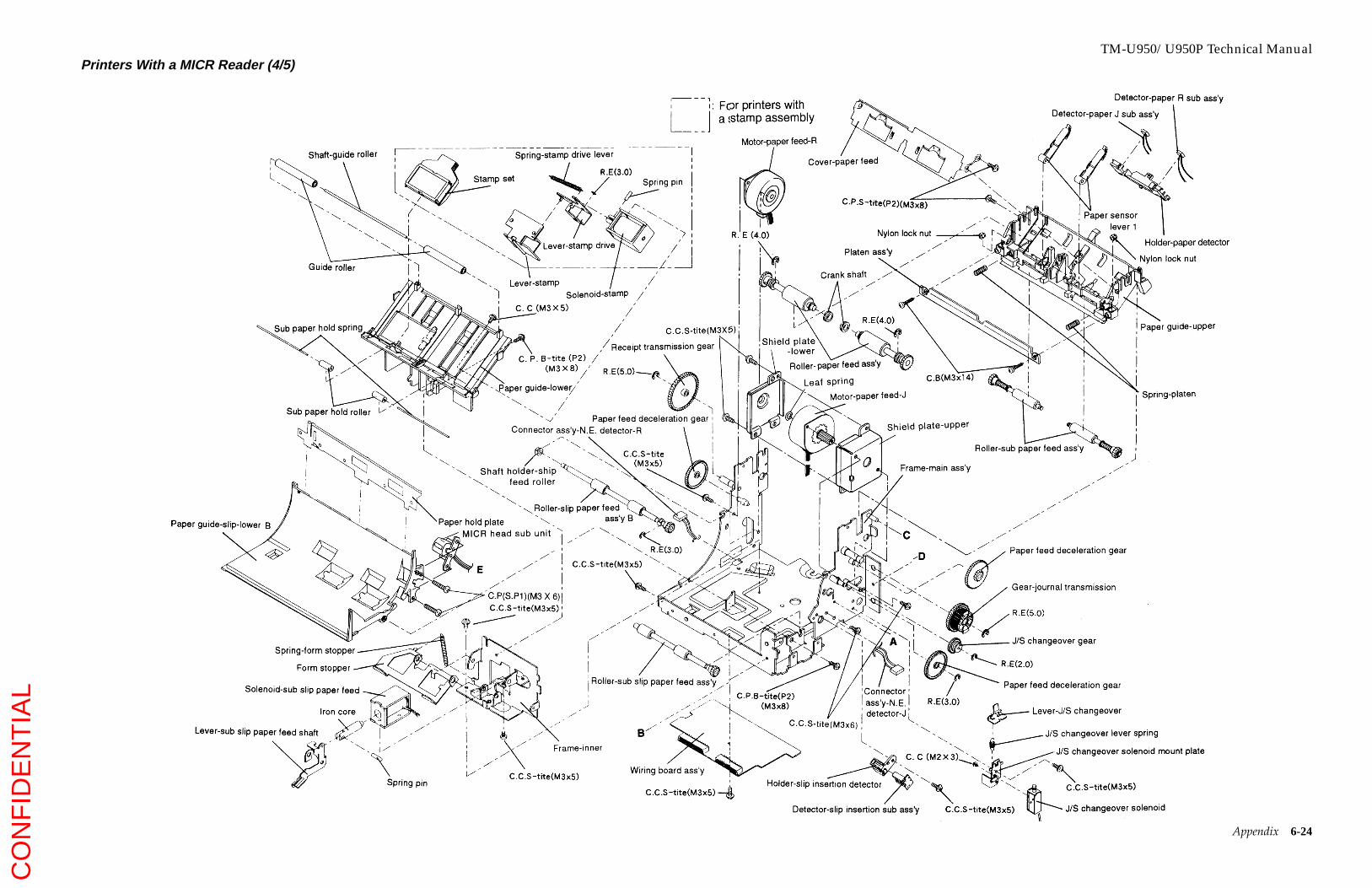
TM-U950/U950P Technical ManualPrinters With a MICR Reader (4/5)
Appendix 6-24
CO
NF
IDE
NT
IAL

TM-U950/U950P Technical ManualPrinters With a MICR Reader (5/5)
Appendix 6-25
CO
NF
IDE
NT
IAL

TM-U950/U950P Technical ManualLubrication Points Diagram for Printers Without a MICR Reader (1/3)
Appendix 6-26
CO
NF
IDE
NT
IAL

TM-U950/U950P Technical ManualLubrication Points Diagram for Printers Without a MICR Reader (2/3)
Appendix 6-27
CO
NF
IDE
NT
IAL
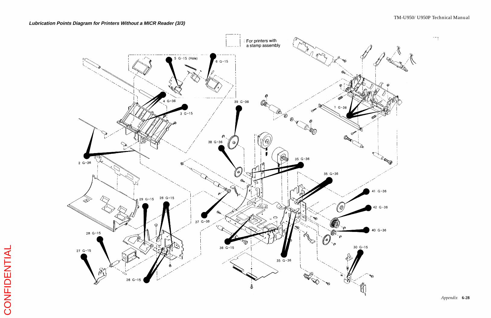
TM-U950/U950P Technical ManualLubrication Points Diagram for Printers Without a MICR Reader (3/3)
Appendix 6-28
CO
NF
IDE
NT
IAL

TM-U950/U950P Technical ManualLubrication Points Diagram for Printers With a MICR Reader (1/4)
Appendix 6-29
CO
NF
IDE
NT
IAL
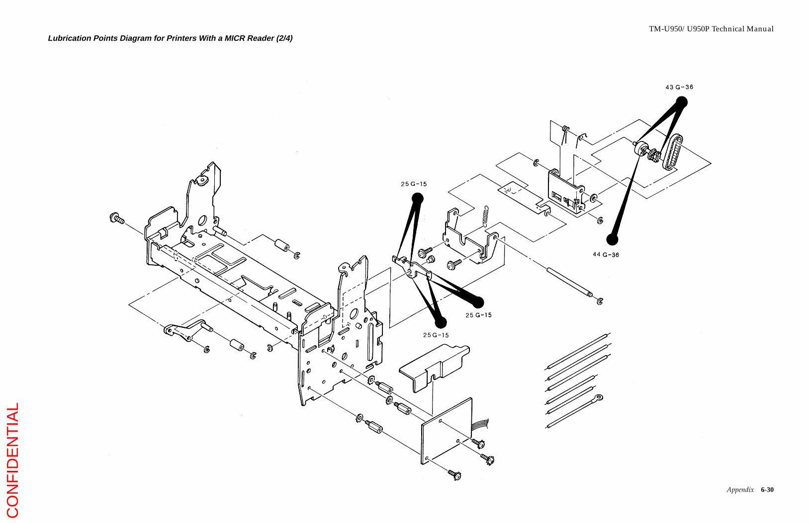
TM-U950/U950P Technical ManualLubrication Points Diagram for Printers With a MICR Reader (2/4)
Appendix 6-30
CO
NF
IDE
NT
IAL
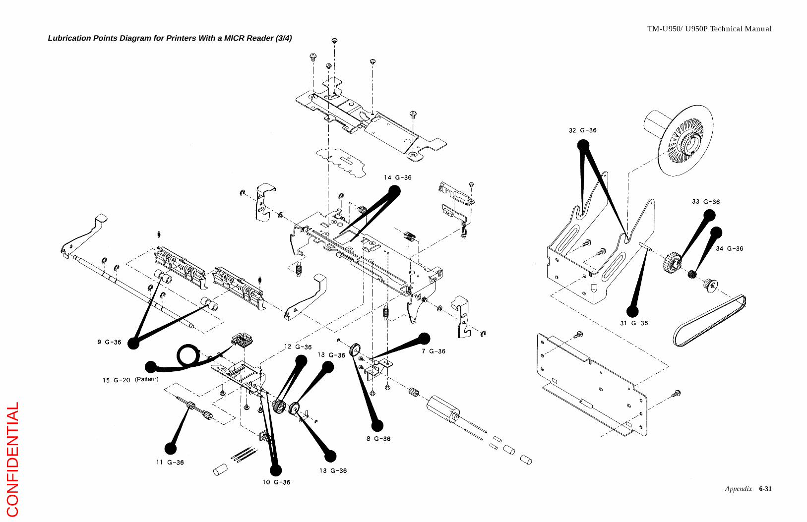
TM-U950/U950P Technical ManualLubrication Points Diagram for Printers With a MICR Reader (3/4)
Appendix 6-31
CO
NF
IDE
NT
IAL

TM-U950/U950P Technical ManualLubrication Points Diagram for Printers With a MICR Reader (4/4)
Appendix 6-32
CO
NF
IDE
NT
IAL