tn5250 terminal reference guide - southern graphics & … · editing ascii files ... figure 2-1...
TRANSCRIPT
TN5250 Terminal Reference Guide
An EMS Technologies Company
Copyright © February 2003 by LXE Inc. All Rights Reserved TN5250A136RFGD E-SW-TN5250RG-H
Notices LXE’s TN5250 is terminal emulation software developed by LXE. The software is installed in computer equipment. Any reference, whether direct or implied, to any LXE RF equipment requires the reader to refer to the specific RF equipment’s User Manuals for cautions, warnings and federal notices (e.g. FCC, EMC, UL, CE, etc.). Copyright Notice:
This manual is copyrighted. All rights are reserved. This document may not, in whole or in part, be copied, photocopied, reproduced, translated or reduced to any electronic medium or machine-readable form without prior consent, in writing, from LXE Inc.
Copyright © February, 2003 by LXE Inc. An EMS Technologies Company. 125 Technology Parkway, Norcross, GA 30092 U.S.A. (770) 447-4224
Trademarks:
LXE® is a registered trademark of LXE Inc.
All other brand or product names are trademarks or registered trademarks of their respective companies or organizations. When this manual is in PDF format: "Acrobat ® Reader Copyright © 1987-2001 Adobe Systems Incorporated. All rights reserved. Adobe, the Adobe logo, Acrobat, and the Acrobat logo are trademarks of Adobe Systems Incorporated." applies.
Notice:
LXE Inc. reserves the right to make improvements or changes in the software products described in this manual at any time without notice. While reasonable efforts have been made in the preparation of this document to assure its accuracy, LXE assumes no liability resulting from any errors or omissions in this document, or from the use of the information contained herein. Further, LXE Incorporated, reserves the right to revise this publication and to make changes to it from time to time without any obligation to notify any person or organization of such revision or changes.
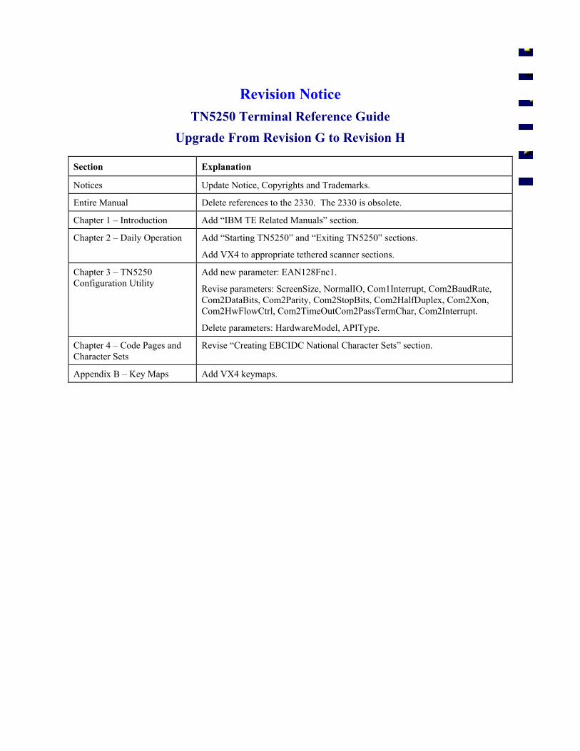
Revision Notice TN5250 Terminal Reference Guide
Upgrade From Revision G to Revision H
Section Explanation
Notices Update Notice, Copyrights and Trademarks.
Entire Manual Delete references to the 2330. The 2330 is obsolete.
Chapter 1 – Introduction Add “IBM TE Related Manuals” section.
Chapter 2 – Daily Operation Add “Starting TN5250” and “Exiting TN5250” sections.
Add VX4 to appropriate tethered scanner sections.
Chapter 3 – TN5250 Configuration Utility
Add new parameter: EAN128Fnc1.
Revise parameters: ScreenSize, NormalIO, Com1Interrupt, Com2BaudRate, Com2DataBits, Com2Parity, Com2StopBits, Com2HalfDuplex, Com2Xon, Com2HwFlowCtrl, Com2TimeOutCom2PassTermChar, Com2Interrupt.
Delete parameters: HardwareModel, APIType.
Chapter 4 – Code Pages and Character Sets
Revise “Creating EBCIDC National Character Sets” section.
Appendix B – Key Maps Add VX4 keymaps.

An EMS Technologies Company
E-SW-TN5250RG-H TN5250 Terminal Reference Guide
Table of Contents
CHAPTER 1 INTRODUCTION 1-1
How To Use This Guide......................................................................................... 1-1 Document Conventions ........................................................................................................ 1-2 Getting Help.......................................................................................................................... 1-2 IBM TE Related Manuals..................................................................................................... 1-3
The TN5250 Terminal Emulator ............................................................................ 1-4 Entering Messages ................................................................................................................ 1-4 Remote Setup From Host...................................................................................................... 1-5 Window Manager ................................................................................................................. 1-5
CHAPTER 2 DAILY OPERATION 2-1
Introduction ............................................................................................................ 2-1
Starting TN5250...................................................................................................... 2-1 Single TE .............................................................................................................................. 2-1 The TE Selection Menu........................................................................................................ 2-2
Exiting TN5250 ....................................................................................................... 2-3
Hosts....................................................................................................................... 2-4 Connect with the Host .......................................................................................................... 2-4 Autologin .............................................................................................................................. 2-4 Unsuccessful Host Connection ............................................................................................. 2-4
Keys and Key Sequences...................................................................................... 2-5 Keyboard Lock ..................................................................................................................... 2-5 DOS Computer Special Keys ............................................................................................... 2-6 Legacy Key Incompatibility ................................................................................................. 2-6 TN5250 TE and the 2325 ..................................................................................................... 2-7 TN5250 Keyed Function Descriptions ................................................................................. 2-8 LXE DOS Autotransmit Function ...................................................................................... 2-14 Function Keys..................................................................................................................... 2-18
Data Entry ............................................................................................................. 2-19 Entering Messages .............................................................................................................. 2-19 Scan and Increment............................................................................................................. 2-21 Interpreting the Status Line ................................................................................................ 2-23 5250 Host Communication Errors ...................................................................................... 2-24
Window Manager ................................................................................................. 2-27 The Virtual Screen and the Computer Display................................................................... 2-28
ii Table of Contents
TN5250 Terminal Reference Guide E-SW-TN5250RG-H
Window Movement Types ................................................................................................. 2-30 Lock Window Mode ........................................................................................................... 2-35 Cursor Tracking Mode........................................................................................................ 2-38 Status Line .......................................................................................................................... 2-40 Message Line ...................................................................................................................... 2-41
CHAPTER 3 TN5250 CONFIGURATION UTILITY 3-1
Introduction ............................................................................................................ 3-1
Password Access Levels ...................................................................................... 3-1
Changed Radio Parameters .................................................................................. 3-2
Configuration File Structure ................................................................................. 3-2
Directory Structure ................................................................................................ 3-2 \IBM24 - TN5250 TE Files .................................................................................................. 3-2
The TN5250 Configuration Utility ......................................................................... 3-3 Pre-Configured Passwords.................................................................................................... 3-3 Menu Components................................................................................................................ 3-4 Using the Configuration Program......................................................................................... 3-6 Main Menu Display .............................................................................................................. 3-7 Screen Displays .................................................................................................................... 3-9 System Menu Options......................................................................................................... 3-10 Emulation Menu Option ..................................................................................................... 3-14 Protocol Menu Option ........................................................................................................ 3-27 Radio Menu Option – 6400 and 6500 Systems .................................................................. 3-41 Platform Menu .................................................................................................................... 3-42 Exit With Save Option........................................................................................................ 3-60 Exit Without Save Option................................................................................................... 3-60
CHAPTER 4 CODE PAGES AND CHARACTER SETS 4-1
Introduction ............................................................................................................ 4-1
Displayable Characters ......................................................................................... 4-2 Default Code Page ................................................................................................................ 4-2 LXE Character Set................................................................................................................ 4-3 Default TE EBCDIC Character Set ...................................................................................... 4-4 Creating EBCDIC National Character Sets.......................................................................... 4-5 Example: UK EBCDIC Character Set .................................................................................. 4-6
Keyboard Mapping................................................................................................. 4-8 Special Keys ......................................................................................................................... 4-8 Alphanumeric Keys .............................................................................................................. 4-8 Modifying the Keyboard Map .............................................................................................. 4-9
Messages.............................................................................................................. 4-10
Table of Contents iii
E-SW-TN5250RG-H TN5250 Terminal Reference Guide
Default Messages................................................................................................................ 4-10 Editing The Message.Txt File ............................................................................................ 4-10
Editing ASCII Files ............................................................................................... 4-12 Editing Files at the Computer ............................................................................................. 4-12 Edit then Transfer Files Using a PC Card .......................................................................... 4-13 Transfer Files Using DOS REMDISK/REMSERV ........................................................... 4-15
CHAPTER 5 5250 PROGRAMMER’S REFERENCE 5-1
Introduction ............................................................................................................ 5-1 Primary Audience ................................................................................................................. 5-1 Examples............................................................................................................................... 5-1 About RF Performance ......................................................................................................... 5-2 Data Stream .......................................................................................................................... 5-3
Match and Local Field Compare Commands....................................................... 5-4 Command Letters.................................................................................................................. 5-4 Match Field Edit ................................................................................................................... 5-6 Local Field Compare ............................................................................................................ 5-8 Scan and Increment Match Field ........................................................................................ 5-10 Input Device ID .................................................................................................................. 5-13
Terminal Setup Commands................................................................................. 5-17 Screen Design for Terminal Setup Commands .................................................................. 5-17 Command String................................................................................................................. 5-18 Left Justify Mode: p2.......................................................................................................... 5-21 Clear Mode: p3 ................................................................................................................... 5-22 Truncate Mode: p4.............................................................................................................. 5-23 Advance Mode: p5.............................................................................................................. 5-24 Auto Transmit After Data Stream Print: p6........................................................................ 5-25 Printer Carriage Return per Line: p7 .................................................................................. 5-26 Printer Line Feed per Line: p8............................................................................................ 5-27 Status Line Display Mode: p9 ............................................................................................ 5-28 Input Device ID: p10 .......................................................................................................... 5-29 Swap TAB/Field Exit: p11 ................................................................................................. 5-30 Advance: p12 ...................................................................................................................... 5-31 Command String for Wildcard Match Characters .............................................................. 5-32 Window Setup .................................................................................................................... 5-34 Beep Pattern Command ...................................................................................................... 5-44 Printing a Field ................................................................................................................... 5-47
USA/Canada EBCDIC Code Page 00037 ............................................................. A-1
LXE Character Set................................................................................................. A-2
Decimal - Hexadecimal Equivalents .................................................................... A-3
DOS U.S. PC Standard Character Set ................................................................. A-5
iv Table of Contents
TN5250 Terminal Reference Guide E-SW-TN5250RG-H
APPENDIX B KEY MAPS B-1
The MX1 Keypad ................................................................................................... B-1 Alpha-Numeric Keypad (60 Key) ........................................................................................B-1 Numeric-Alpha Keypad (41 Key) ........................................................................................B-3
The MX2 Keypad ................................................................................................... B-5 38-key Keypad (Also 2325 Keypad) ....................................................................................B-5 48-key Keypad......................................................................................................................B-7
The MX3 Keypad ................................................................................................... B-9
The VX1, VX2 and VX4 Keyboards..................................................................... B-11
The 1380 Keyboard ............................................................................................. B-13
INDEX
Illustrations
Figure 2-1 TN5250 TE Function Key Editor................................................................................................. 2-18 Figure 2-2 Half Screen (HSC) Vehicle Mount Virtual Screen Display versus Computer Display Window. 2-28 Figure 2-3 Handheld (HHC) Virtual Screen Display versus Computer Display Window ............................ 2-29 Figure 2-4 Full Window Movement of a HHC Display ................................................................................ 2-30 Figure 2-5 Quadrant Movement of a HHC Display....................................................................................... 2-31 Figure 2-6 Full and Quadrant Vertical Movement of a HSC Display ........................................................... 2-32 Figure 2-7 HHC Horizontal Display Wrapping............................................................................................. 2-34 Figure 2-8 HHC Vertical Display Wrapping ................................................................................................. 2-34 Figure 2-9 Valid Window Positions - 12 and 25 Row x 80 Column ............................................................. 2-35 Figure 2-10 HHC Valid Window Positions - 10 Row x 20 Column ............................................................. 2-36 Figure 2-11 HHC Valid Window Positions - 20 Row x 20 Column ............................................................. 2-36 Figure 2-12 HHC Virtual Display With Arbitrary Labels ............................................................................. 2-38 Figure 2-13 Cursor Tracking Display Examples ........................................................................................... 2-39 Figure 3-1 Configuration Utility - Menu Components .................................................................................... 3-4 Figure 3-2 Configuration Utility Main Menu .................................................................................................. 3-7 Figure 3-3 Main Menu on a Full Screen VMC with 2.4GHz Radio................................................................ 3-9 Figure 3-4 Main Menu on a Half Screen VMC with 2.4GHz Radio ............................................................... 3-9 Figure 3-5 Main Menu on a Handheld computer with 2.4GHz Radio............................................................. 3-9 Figure 4-1 Code Page 00437 ........................................................................................................................... 4-2 Figure 4-2 LXE Character Set - Abbreviated .................................................................................................. 4-3 Figure 4-3 USA/Canada IBM EBCDIC........................................................................................................... 4-4 Figure 4-4 U.K. IBM EBCDIC........................................................................................................................ 4-6 Figure 5-1 IBM 5250 Data Stream with RF Header and Trailer ..................................................................... 5-3 Figure 5-2 Match Field Example ..................................................................................................................... 5-6 Figure 5-3 Match Field Containing Wildcard and Exact Match Characters.................................................... 5-7 Figure 5-4 Local Compare Field Example....................................................................................................... 5-9 Figure 5-5 Local Field Compare and Scan and Increment Example ............................................................... 5-9 Figure 5-6 Predecessor, Match, Match Count and Count Specifier Fields .................................................... 5-10 Figure 5-7 Input ID Feature with Normal Input Field ................................................................................... 5-14
Table of Contents v
E-SW-TN5250RG-H TN5250 Terminal Reference Guide
Figure 5-8 Contents of Fields after Keyboard Entry...................................................................................... 5-14 Figure 5-9 Protected Fields............................................................................................................................ 5-15 Figure 5-10 Input ID used with Scan and Increment Match Fields ............................................................... 5-15 Figure 5-11 Window Manager Setup Command ........................................................................................... 5-18 Figure 5-12 Example of Left Justify Off ....................................................................................................... 5-21 Figure 5-13 Example of Left Justify On ........................................................................................................ 5-21 Figure 5-14 Virtual Screen and Display Window Relationship..................................................................... 5-34 Figure 5-15 Valid Window Positions - 12 and 25 Row x 80 Column ........................................................... 5-40 Figure 5-16 Valid Window Positions - 10 Row x 20 Column....................................................................... 5-40 Figure 5-17 Valid Window Positions - 20 Row x 20 Column....................................................................... 5-40 Figure 5-18 Beep Pattern Command String ................................................................................................... 5-44 Figure 5-19 Beep Pattern Template ............................................................................................................... 5-45 Figure 5-20 Beep Pattern Example ................................................................................................................ 5-45 Figure 5-21 Print Command Example ........................................................................................................... 5-47
vi Table of Contents
TN5250 Terminal Reference Guide E-SW-TN5250RG-H
An EMS Technologies Company
E-SW-TN5250RG-H TN5250 Terminal Reference Guide
Table of Contents
CHAPTER 1 INTRODUCTION 1-1
How To Use This Guide......................................................................................... 1-1 Document Conventions ........................................................................................................ 1-2 Getting Help.......................................................................................................................... 1-2 IBM TE Related Manuals..................................................................................................... 1-3
The TN5250 Terminal Emulator ............................................................................ 1-4 Entering Messages ................................................................................................................ 1-4
Keyboard Data Entry.......................................................................................................... 1-4 Barcode Data Entry ............................................................................................................ 1-4 RS-232 Data Entry ............................................................................................................. 1-4
Remote Setup From Host...................................................................................................... 1-5 Window Manager ................................................................................................................. 1-5
1-ii Table of Contents
TN5250 Terminal Reference Guide E-SW-TN5250RG-H
An EMS Technologies Company
E-SW-TN5250RG-H TN5250 Terminal Reference Guide
Chapter 1 Introduction
How To Use This Guide
This guide provides detailed information on the features and functionality of LXE's TN5250 Terminal Emulation (TE) software as it relate to LXE’s 2.4GHz DOS mobile computers. Use this Terminal Emulation (TE) reference guide as you would any other source book: reading portions to learn about the system, and then referring to it when you need more information about a particular subject. This guide takes you through all aspects of the TN5250 TE and the host/client interaction of DOS mobile computers.
Note: Use this guide in conjunction with the manuals delivered with your LXE DOS computers and Access Points.
This chapter briefly describes the LXE TN5250 TE and LXE DOS mobile computers, the reference guide structure, and how to contact LXE. The remainder of the guide describes the TN5250 TE and it’s function in greater detail.
Chapter 2 “Daily Operation” contains information relating to the hardware and software setup of the DOS computers. It lists and explains computer keypress functions.
Chapter 3 “TN5250 Configuration Utility” contains information and instructions relating to the configuration utility resident in each computer. Configuration program instructions are included in this chapter.
Chapter 4 “Code Pages and Character Sets” describes the EBCDIC code pages and the LXE character set resident in each computer. Instructions are included for editing and copying ASCII files from PC to PC Card to mobile computer.
Chapter 5 “5250 Programmer’s Reference” contains relevant information for the 5250 programmer when programming the host application to communicate with LXE devices.
Appendix A "EBCDIC Code Pages" contains graphics of the Code Page and LXE Character Set.
Appendix B "Key Maps" contains keyboard specific mapping for LXE DOS equipment when it is running the TN5250 terminal emulation program.
1-2 How To Use This Guide
TN5250 Terminal Reference Guide E-SW-TN5250RG-H
Document Conventions This Reference Guide uses the following document conventions:
Convention Meaning
ALL CAPS All caps are used to represent disk directories, file names, and application names.
“Quotes” Indicates the title of a chapter or a section, subject, topic, element or point within a chapter (for example, “Documentation Conventions”).
[BRACKETS] Indicates a key on the mobile computer's keyboard (for example, [CTRL]).
Note: Keyword that indicates immediately relevant information.
Caution:
! Keyword that indicates a cautionary warning to follow.
Attention: Keyword that indicates vital or pivotal information to follow.
Getting Help All LXE manuals are now available on one CD and they can also be viewed/downloaded from the LXE website. Contact your LXE representative to obtain the LXE Manuals CD (Product No. 9000A426LXEMANUALS).
You can also get help from LXE by calling the telephone numbers listed on the LXE Manuals CD, in the file titled "Contacting LXE". This information is also available on the LXE website www.lxe.com.
How To Use This Guide 1-3
E-SW-TN5250RG-H TN5250 Terminal Reference Guide
IBM TE Related Manuals The following lists the manuals that are available on the LXE Documentation CD-ROM (9000A426LXEMANAUALS). These manuals provide references that may be required when using the IBM TN5250 TE with LXE certified DOS computers.
These manuals provide setup, operating instructions, software / accessory installation instructions:
• 1380 Reference Guide • 1390 Reference Guide • 2325 Reference Guide • MX1 Reference Guide • MX2 Reference Guide • MX3 Reference Guide • VX1 Reference Guide • VX2 Reference Guide • VX4D Reference Guide • 6224 Session Manager Reference Guide • DOS Autoconfigurator Instructions
The following manuals describe how to use SNMP to configure, monitor and update LXE computers with 2.4GHz radios:
• Client Configuration Manager Reference Guide • SNMP Agent Reference Guide
1-4 The TN5250 Terminal Emulator
TN5250 Terminal Reference Guide E-SW-TN5250RG-H
The TN5250 Terminal Emulator
The TN5250 TE product is LXE’s MS-DOS based TELNET 5250 Terminal Emulator (TE) and allows the user to enter standard data into the IBM system.
Entering Messages
For complete information and operating procedures for entering messages, please refer to Chapter 2 “Daily Operation” section titled “Entering Messages” in this guide.
The LXE DOS computer accepts data entry from the keyboard, barcode scanner and the auxiliary (RS-232) input port.
Keyboard Data Entry Once the TN5250 TE is started, data can be entered with the computer keyboard. Keyboard data can be entered into a data field and transmitted to the host. You might respond to a prompt sent by the host application with a keyboard entry, such as a menu listing choices for your next action.
Barcode Data Entry Most LXE DOS computers support an accessory barcode reading device for reading preprinted labels. Keyboard data entries can be mixed with barcode data entries. Any scanner that decodes the barcode internally and outputs an RS-232 data stream may be used. The serial port parameters may need to be changed (using the TN5250 configuration utility) to match the parameters of the scanner. Refer to the computers hardware manual for more information on which COM ports are available for use with a scanner.
RS-232 Data Entry The LXE DOS computer accepts input from an RS-232 device connected to the RS-232 port of the computer. The computer processes data from the RS-232 port the same way it processes keyed data. The data is entered at the cursor position, and the data is subject to all of the barcode/RS-232 input menu parameters, such as truncate.
The TN5250 Terminal Emulator 1-5
E-SW-TN5250RG-H TN5250 Terminal Reference Guide
Remote Setup From Host The TN5250 TE can take advantage of LXE’s Remote Setup feature. Host application programmers can specify computer software operating parameters in the host-to-terminal data stream. Remote setup applies to:
• wild card local edit characters.
• window manager parameters.
• beep pattern.
• field exit/TAB key swap.
Window Manager The TN5250 TE takes advantage of the LXE’s Window Manager feature.
For complete information when using the Window Manager feature, please refer to Chapter 2 “Daily Operation” section titled “Window Manager” in this guide.
Note: This feature is only applicable to LXE computers that do not have a full screen display.

1-6 The TN5250 Terminal Emulator
TN5250 Terminal Reference Guide E-SW-TN5250RG-H
An EMS Technologies Company
E-SW-TN5250RG-H TN5250 Terminal Reference Guide
Table of Contents
CHAPTER 2 DAILY OPERATION 2-1
Introduction ............................................................................................................ 2-1
Starting TN5250...................................................................................................... 2-1 Single TE .............................................................................................................................. 2-1 The TE Selection Menu........................................................................................................ 2-2
Multiple TEs....................................................................................................................... 2-2 Modifying the TE Selection Menu..................................................................................... 2-2
Exiting TN5250 ....................................................................................................... 2-3
Hosts....................................................................................................................... 2-4 Connect with the Host .......................................................................................................... 2-4 Autologin .............................................................................................................................. 2-4 Unsuccessful Host Connection ............................................................................................. 2-4
Keys and Key Sequences...................................................................................... 2-5 Keyboard Lock ..................................................................................................................... 2-5 DOS Computer Special Keys ............................................................................................... 2-6 Legacy Key Incompatibility ................................................................................................. 2-6 TN5250 TE and the 2325 ..................................................................................................... 2-7 TN5250 Keyed Function Descriptions ................................................................................. 2-8
ATTN ................................................................................................................................. 2-8 Backtab............................................................................................................................... 2-8 Cancel................................................................................................................................. 2-8 Char Backspace .................................................................................................................. 2-8 Clear ................................................................................................................................... 2-8 Cursor Block/Underline ..................................................................................................... 2-8 Delete ................................................................................................................................. 2-8 DUP.................................................................................................................................... 2-8 ENTERCADV.................................................................................................................... 2-9 Erase Input.......................................................................................................................... 2-9 Error Reset or Reset ........................................................................................................... 2-9 Exit Program ...................................................................................................................... 2-9 F1 - F10 .............................................................................................................................. 2-9 Fastback.............................................................................................................................. 2-9 Fastfwd ............................................................................................................................... 2-9 Field Exit .......................................................................................................................... 2-10 Field Minus ...................................................................................................................... 2-10 Field Plus.......................................................................................................................... 2-10 Function Key Editor ......................................................................................................... 2-10
2-ii Table of Contents
TN5250 Terminal Reference Guide E-SW-TN5250RG-H
Help .................................................................................................................................. 2-10 HEX Input ........................................................................................................................ 2-10 Homekey .......................................................................................................................... 2-10 Inquiry or INQ.................................................................................................................. 2-10 Insert................................................................................................................................. 2-10 Log File Toggle................................................................................................................ 2-10 New Line Key .................................................................................................................. 2-11 NEXT or TAB or Field Advance ..................................................................................... 2-11 Print (5250 host)............................................................................................................... 2-11 Printer On/Off .................................................................................................................. 2-11 Roll Down ........................................................................................................................ 2-11 Roll Up ............................................................................................................................. 2-12 Status Line Toggle ........................................................................................................... 2-12 SW Rev............................................................................................................................. 2-12 System Request ................................................................................................................ 2-12 Test Request ..................................................................................................................... 2-12 Window Down ................................................................................................................. 2-12 Window Home ................................................................................................................. 2-12 Window Left..................................................................................................................... 2-13 Window Right .................................................................................................................. 2-13 Window Up ...................................................................................................................... 2-13
LXE DOS Autotransmit Function ...................................................................................... 2-14 Introduction ...................................................................................................................... 2-14 LXE MX1 with SE1223 Integrated Scanners .................................................................. 2-15
Enable the DOS Autotransmit Function .....................................................................................2-15 Disable the DOS Autotransmit Function ....................................................................................2-15
LXE 1380 / 1390 and VX1 / VX2 / VX4 with LS3203 or LS3603 Tethered Scanners .. 2-16 Enable the DOS Autotransmit Function .....................................................................................2-16 Disable the DOS Autotransmit Function ....................................................................................2-16
LXE 1380 / 1390 and VX1 / VX2 / VX4 with PSC 53XX Tethered Scanner................. 2-17 Enable the DOS Autotransmit Function .....................................................................................2-17 Disable the DOS Autotransmit Function ....................................................................................2-17
Function Keys..................................................................................................................... 2-18 Function Key Editing ....................................................................................................... 2-18
Data Entry ............................................................................................................. 2-19 Entering Messages .............................................................................................................. 2-19
Keyboard Data Entry........................................................................................................ 2-19 Barcode Data Entry .......................................................................................................... 2-20 RS-232 Data Entry ........................................................................................................... 2-20
Scan and Increment............................................................................................................. 2-21 Operation.......................................................................................................................... 2-22 Autotransmit..................................................................................................................... 2-22 Exceptions ........................................................................................................................ 2-22
Interpreting the Status Line ................................................................................................ 2-23 Operating Modes .............................................................................................................. 2-23 Status Line Indicators....................................................................................................... 2-23
Table of Contents 2-iii
E-SW-TN5250RG-H TN5250 Terminal Reference Guide
5250 Host Communication Errors ...................................................................................... 2-24 Error Codes ...................................................................................................................... 2-24
Window Manager ................................................................................................. 2-27 The Virtual Screen and the Computer Display................................................................... 2-28 Window Movement Types ................................................................................................. 2-30
Full Window Movement .................................................................................................. 2-30 Quadrant Movement......................................................................................................... 2-31 Window Movement Keys................................................................................................. 2-33 Cursor Position................................................................................................................. 2-33 Display Wrapping ............................................................................................................ 2-34
Lock Window Mode ........................................................................................................... 2-35 Valid Window Positions................................................................................................... 2-35
The Full and Half Screens Computers ........................................................................................2-35 The Handheld Computer Screens ...............................................................................................2-36
Window Movement in Lock Window Mode ................................................................... 2-37 Cursor Tracking Mode........................................................................................................ 2-38
Window Moving Methods ............................................................................................... 2-38 Display Example .............................................................................................................. 2-38 Basic Moves ..................................................................................................................... 2-39 Quadrant Choice............................................................................................................... 2-39
Status Line .......................................................................................................................... 2-40 Status Line Modes............................................................................................................ 2-40 Display Appearance ......................................................................................................... 2-40 Operation.......................................................................................................................... 2-40 Status Line and Message Line.......................................................................................... 2-40
Message Line ...................................................................................................................... 2-41 Physical Display............................................................................................................... 2-41 Reviewing the Message Line ........................................................................................... 2-41 Message Line Doesn't Follow the Window...................................................................... 2-41
2-iv Table of Contents
TN5250 Terminal Reference Guide E-SW-TN5250RG-H
Illustrations
Figure 2-1 TN5250 TE Function Key Editor................................................................................................. 2-18 Figure 2-2 Half Screen (HSC) Vehicle Mount Virtual Screen Display versus Computer Display Window. 2-28 Figure 2-3 Handheld (HHC) Virtual Screen Display versus Computer Display Window ............................ 2-29 Figure 2-4 Full Window Movement of a HHC Display ................................................................................ 2-30 Figure 2-5 Quadrant Movement of a HHC Display....................................................................................... 2-31 Figure 2-6 Full and Quadrant Vertical Movement of a HSC Display ........................................................... 2-32 Figure 2-7 HHC Horizontal Display Wrapping............................................................................................. 2-34 Figure 2-8 HHC Vertical Display Wrapping ................................................................................................. 2-34 Figure 2-9 Valid Window Positions - 12 and 25 Row x 80 Column ............................................................. 2-35 Figure 2-10 HHC Valid Window Positions - 10 Row x 20 Column ............................................................. 2-36 Figure 2-11 HHC Valid Window Positions - 20 Row x 20 Column ............................................................. 2-36 Figure 2-12 HHC Virtual Display With Arbitrary Labels ............................................................................. 2-38 Figure 2-13 Cursor Tracking Display Examples ........................................................................................... 2-39
E-SW-TN5250RG-H TN5250 Terminal Reference Guide
Chapter 2 Daily Operation
Introduction
This chapter describes those features of the TN5250 DOS computers that are used on a daily basis.
Starting TN5250
TN5250 is configured to start as follows:
• TN5250 is started automatically after the device boots if it is the only TE loaded on the computer.
• If multiple Terminal Emulators (TE’s) are installed, the TE Selection Menu is displayed after boot. To launch TN5250, select the appropriate choice from the menu.
TN5250 is started manually by returning to the TE Selection Menu with the following command: c:\teselect
• TN5250 is started automatically if it is the only TE installed.
• The TE Selection Menu is displayed if multiple TE’s are installed. Select the appropriate choice from the TE Selection Menu.
Single TE Power on the DOS computer and the TN5250 welcome screen is automatically displayed. When the TE is closed with an Alt-X keypress, the screen is cleared and the system returns to the DOS prompt.
2-2 Starting TN5250
TN5250 Terminal Reference Guide E-SW-TN5250RG-H
The TE Selection Menu
Multiple TEs In the event there is more than one Terminal Emulator (TE) installed in the computer, the user is presented with the TE Selection Menu listing the available terminal emulators that can be accessed using the computer.
For example, a user could see: [5] Launch 5250 [A] Launch ANSIPLUS [E] Exit to DOS
Please select option: [5, A, E]?
Upon selecting one of the terminal emulator options, the desired TE is launched. When the user selects E, the screen is cleared and the DOS prompt is displayed. When the TE is closed with an Alt-X keypress, the screen is cleared and the menu is presented again.
Note: The system administrator may change almost every facet of the menu display, including suppressing the “Exit to DOS” option, by modifying the variables found at the top of TESELECT.BAT. Details on modifying the TESELECT.BAT file are included in the “DOS Autoconfigurator Instructions”, included on the LXE Manuals CD.
Modifying the TE Selection Menu
Please refer to the “DOS Autoconfigurator Instructions”, included on the LXE Manuals CD for complete details on modifying the TE Selection Menu.
Exiting TN5250 2-3
E-SW-TN5250RG-H TN5250 Terminal Reference Guide
Exiting TN5250
The behavior of the LXE computer when exiting TN5250 can be customized by suppressing the “exit to DOS” option in the TE Selection Menu. For more information on suppressing the prompt, please refer to the “DOS Autoconfigurator Instructions”, included on the LXE Manuals CD.
If TE Selection Menu “Exit to DOS” Option is not Suppressed:
Single TE: <Alt-X> from the TE takes the system to a DOS prompt.
Dual TE: <Alt-X> from the TE takes the system to the TE Selection Menu with the “Exit to DOS” option.
If TE Selection Menu “Exit to DOS” Option is Suppressed:
Single TE: <Alt-X> from the TE takes the system to a DOS prompt.
Dual TE: <Alt-X> from the TE takes the system to the TE Selection Menu without the “Exit to DOS” option.
2-4 Hosts
TN5250 Terminal Reference Guide E-SW-TN5250RG-H
Hosts
Connect with the Host For DOS computers with a single TE loaded, the computers are automatically connected to the host after the bootup process.
Autologin The Autologin feature enables computers to automatically log on to a TELNET host computer upon initial communication.
Autologin relieves the user from repeating the same logon information every time the computer is powered up or rebooted.
The Autologin script file contains the host prompts and user replies needed for logging in. The autologin script is created in each computer using the Configuration Utility.
If the autologin sequence is unsuccessful, you can log on with one of the following methods:
Log on manually from the computer.
- or -
Power down until the problem is corrected. Then, power on again.
Refer to Chapter 3 “TN5250 Configuration Utility” for details on configuring the Autologin feature.
Unsuccessful Host Connection If the computer cannot connect with the host (or the address is invalid), error messages are displayed and computer control returns to the computer.
Note: There may be a short pause while attempting to contact the host.
When the computer is unable to connect to the host, an error message is displayed on the screen explaining the inability to connect.
For Example: Unsuccessful Host Connection No Host found Please Power Down
Refer to the FTP manual for an explanation of error messages.
Keys and Key Sequences 2-5
E-SW-TN5250RG-H TN5250 Terminal Reference Guide
Keys and Key Sequences
This section describes the LXE RF DOS computer keys and key sequences in the IBM TN5250 terminal emulation.
Most key sequences require two keystrokes. To use an LXE key sequence, you must:
• press either the [2nd], [ALT], [SHIFT], or [CTRL] key
• and press the associated key
Note: Depending on which computer you are using you may need to press and release the [2nd], [ALT], [SHIFT], or [CTRL] key before pressing the associated key.
Keyboard Lock Reset key sequence for DOS computers: [CTRL] [R]
Under certain conditions, attempted input from the keyboard locks the keyboard from further input. Since the DOS computer does not differentiate among input from the keyboard, input from the scanner, and input from the RS-232 port; any condition that locks one locks the others.
Press [CTRL] [R] to restore the computer to normal operation.
2-6 Keys and Key Sequences
TN5250 Terminal Reference Guide E-SW-TN5250RG-H
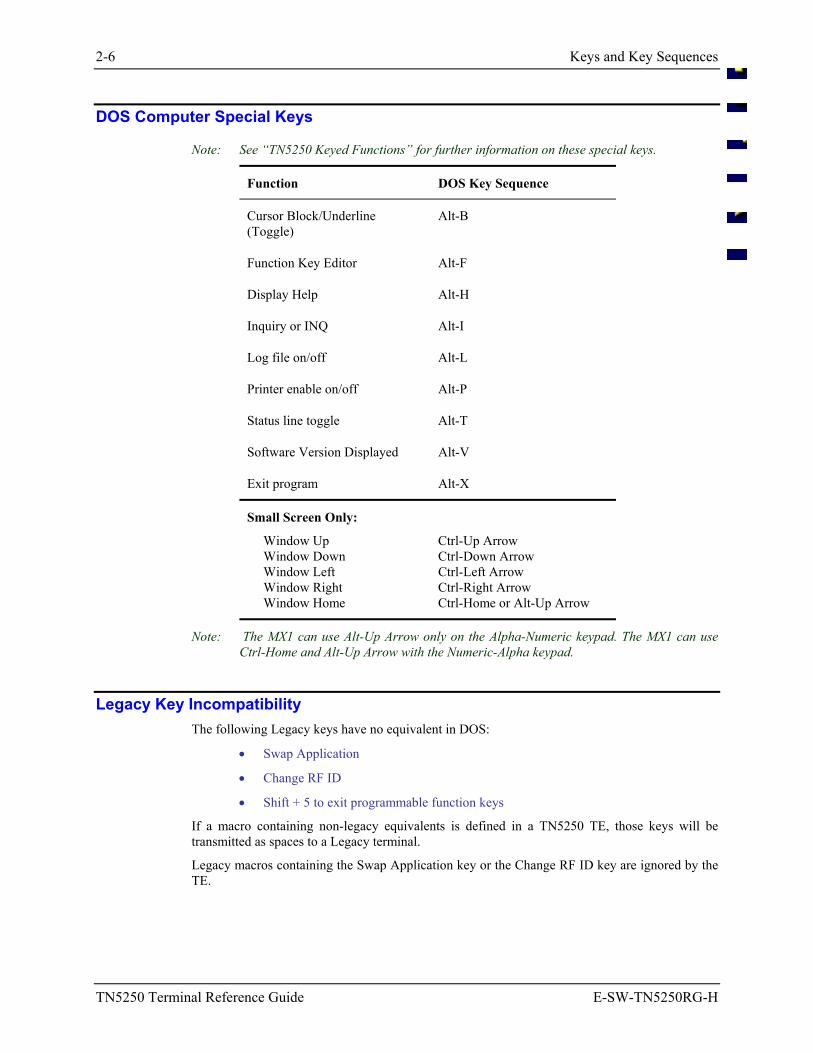
DOS Computer Special Keys
Note: See “TN5250 Keyed Functions” for further information on these special keys.
Function DOS Key Sequence
Cursor Block/Underline (Toggle)
Alt-B
Function Key Editor Alt-F
Display Help Alt-H
Inquiry or INQ Alt-I
Log file on/off Alt-L
Printer enable on/off Alt-P
Status line toggle Alt-T
Software Version Displayed Alt-V
Exit program Alt-X
Small Screen Only:
Window Up Ctrl-Up Arrow Window Down Ctrl-Down Arrow Window Left Ctrl-Left Arrow Window Right Ctrl-Right Arrow Window Home Ctrl-Home or Alt-Up Arrow
Note: The MX1 can use Alt-Up Arrow only on the Alpha-Numeric keypad. The MX1 can use Ctrl-Home and Alt-Up Arrow with the Numeric-Alpha keypad.
Legacy Key Incompatibility The following Legacy keys have no equivalent in DOS:
• Swap Application
• Change RF ID
• Shift + 5 to exit programmable function keys
If a macro containing non-legacy equivalents is defined in a TN5250 TE, those keys will be transmitted as spaces to a Legacy terminal.
Legacy macros containing the Swap Application key or the Change RF ID key are ignored by the TE.
Keys and Key Sequences 2-7
E-SW-TN5250RG-H TN5250 Terminal Reference Guide
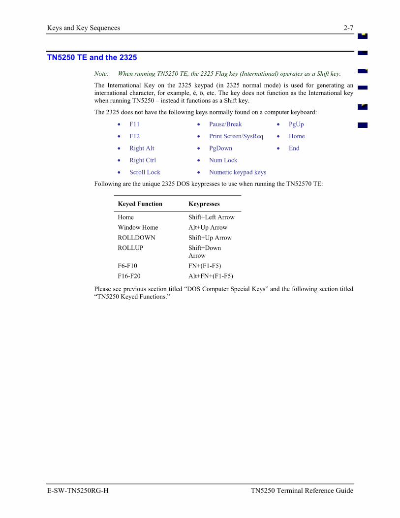
TN5250 TE and the 2325
Note: When running TN5250 TE, the 2325 Flag key (International) operates as a Shift key.
The International Key on the 2325 keypad (in 2325 normal mode) is used for generating an international character, for example, é, ö, etc. The key does not function as the International key when running TN5250 – instead it functions as a Shift key.
The 2325 does not have the following keys normally found on a computer keyboard:
• F11
• F12
• Right Alt
• Right Ctrl
• Scroll Lock
• Pause/Break
• Print Screen/SysReq
• PgDown
• Num Lock
• Numeric keypad keys
• PgUp
• Home
• End
Following are the unique 2325 DOS keypresses to use when running the TN52570 TE:
Keyed Function Keypresses
Home Shift+Left Arrow Window Home Alt+Up Arrow ROLLDOWN Shift+Up Arrow ROLLUP Shift+Down
Arrow F6-F10 FN+(F1-F5) F16-F20 Alt+FN+(F1-F5)
Please see previous section titled “DOS Computer Special Keys” and the following section titled “TN5250 Keyed Functions.”
2-8 Keys and Key Sequences
TN5250 Terminal Reference Guide E-SW-TN5250RG-H
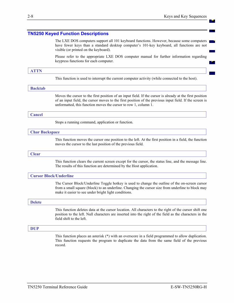
TN5250 Keyed Function Descriptions The LXE DOS computers support all 101 keyboard functions. However, because some computers have fewer keys than a standard desktop computer’s 101-key keyboard, all functions are not visible (or printed on the keyboard).
Please refer to the appropriate LXE DOS computer manual for further information regarding keypress functions for each computer.
ATTN
This function is used to interrupt the current computer activity (while connected to the host).
Backtab
Moves the cursor to the first position of an input field. If the cursor is already at the first position of an input field, the cursor moves to the first position of the previous input field. If the screen is unformatted, this function moves the cursor to row 1, column 1.
Cancel
Stops a running command, application or function.
Char Backspace
This function moves the cursor one position to the left. At the first position in a field, the function moves the cursor to the last position of the previous field.
Clear
This function clears the current screen except for the cursor, the status line, and the message line. The results of this function are determined by the Host application.
Cursor Block/Underline
The Cursor Block/Underline Toggle hotkey is used to change the outline of the on-screen cursor from a small square (block) to an underline. Changing the cursor size from underline to block may make it easier to see under bright light conditions.
Delete
This function deletes data at the cursor location. All characters to the right of the cursor shift one position to the left. Null characters are inserted into the right of the field as the characters in the field shift to the left.
DUP
This function places an asterisk (*) with an overscore in a field programmed to allow duplication. This function requests the program to duplicate the data from the same field of the previous record.
Keys and Key Sequences 2-9
E-SW-TN5250RG-H TN5250 Terminal Reference Guide
ENTERCADV
The [Enter] keypress function is determined by the cursor’s location and the application’s function.
When in an input field, pressing Enter moves the cursor from the current position to the next input field. If there are no more input fields on the screen, control is returned to the application.
When the cursor is on a menu item and the [Enter] key is pressed, either the menu option function is activated or, if the menu option has a submenu of further options, the submenu is displayed.
Erase Input
This function in normal communication mode erases the contents of all input fields in the screen and moves the cursor to the beginning of the first input field.
This key sequence under program control erases all characters of the current input field and moves the cursor to row 1, column 1.
Error Reset or Reset
Performs one of the following functions:
• causes the computer to exit insert mode. • ends the System Request functions. • clears all messages on the message line. • clears all four-digit error codes from the upper left corner of the display. • unlocks the keyboard, and removes the II symbol from the status line. • aborts the printing process.
Exit Program
Using the Exit Program hotkey causes the computer to close the current TN5250 application and return control to the DOS prompt.
F1 - F10
The Function [F1 - F24] keys communicate with the application program. Each function key sends a particular signal to the application program. Access the function keys by pressing the following key sequences:
F1 - F10 [F1 - F10]
F11 - F20 [ALT] [F1 - F10]
F21 - F24 [SHIFT] [F1 - F4]
Fastback
The Fastback function moves the cursor backward two spaces.
Fastfwd
The Fastfwd function moves the cursor forward two spaces.
2-10 Keys and Key Sequences
TN5250 Terminal Reference Guide E-SW-TN5250RG-H
Field Exit
Causes the cursor to exit an input field, and null characters (displayed as blank) are inserted from the current cursor location to the end of the field. If the field is an Auto Enter field the auto transmit function is activated.
Field Minus
May be used in signed numeric and numeric-only fields. Use of this function causes the cursor to advance to the next field and a minus sign is inserted in the last position of a signed numeric-only field. If that field is an Auto Enter field the auto transmit function is activated.
Field Plus
(Same as Field Exit) Causes the cursor to exit an input field, and null characters (displayed as blank) are inserted from the current cursor location to the end of the field. If the field is an Auto Enter field the auto transmit function is activated.
Function Key Editor
Using the Function Key Editor hotkey causes the computer to begin running the Function Key Editor in the foreground while the current application remains in the background.
See the section titled “Function Keys” for editing instruction.
Help
This function displays a TE help file that shows each key function and the key strokes required.
HEX Input
Use this function to enter the hexadecimal value of the next key you press.
Homekey
Causes the cursor to move to the first input position.
Inquiry or INQ
This function checks the communication on the RF channel.
Insert
This function inserts a character into an existing input field without overwriting the data.
When a character is inserted at the cursor position, characters to the right of the cursor are shifted one character position to the right. Press the [Enter] key to cancel the Insert mode.
Log File Toggle
When logging is enabled, the application writes all pertinent data to the log text file. The log file may be disabled until there is a need to troubleshoot the computer or the system.
The log file can be viewed using a DOS text editor.
Keys and Key Sequences 2-11
E-SW-TN5250RG-H TN5250 Terminal Reference Guide
New Line Key
This function moves the cursor to the first input position in the next line.
If there are no input positions, the cursor moves to row 1, column 1 of the screen. If the screen is unformatted, the cursor moves to the first character position of the next line.
NEXT or TAB or Field Advance
The [NEXT] or [TAB] key moves the cursor from the current position to the next input field.
If the screen is unformatted, pressing this key moves the cursor to row 1, column 1.
Print (5250 host)
This function informs the host system that the operator wants to print the contents of the present display.
Printer On/Off
Use the Printer On/Off hotkey to turn the printer on before sending data through the RS-232 port. Use the hotkey again to turn the printer off.
When [ALT] [P] is pressed, a prompt is displayed on the screen. The prompt’s contents are directly related to the current printer status and are automatically removed after print status is confirmed.
For example:
When printing is active at the time of the keypress, “Disable Printing?” is displayed. Press “Y”, the message is replaced with “Printing Disabled” and the print function is disabled. Press “N” and the message is replaced with “Printing Enabled” and the print function remains active.
When printing is not active at the time of the keypress, “Enable Printing?” is displayed. Press “Y”, the message is replaced with “Printing Enabled” and the print function is active. Press “N” and the message is replaced with “Printing Disabled” and the print function remains disabled.
Roll Down
The Roll Down key sequence sends a request to the host computer to roll the information on the display.
Roll Down issues AID code X 'F4'.
The following conditions cause errors using a roll key sequence:
• after the Sys Req key • after the Cmd key • when the display station is in Insert mode.
2-12 Keys and Key Sequences
TN5250 Terminal Reference Guide E-SW-TN5250RG-H
Roll Up
The Roll Up key sequence sends a request to the host computer to roll the information on the display.
Roll Up issues an Attention Identifier (AID) code X 'F5'.
The following conditions cause errors using a roll key sequence:
• after the Sys Req key • after the Cmd key • when the display station is in Insert mode.
Status Line Toggle
The function temporarily displays the status line on the screen.
SW Rev
Using the SW Revision hotkey causes the computer to display the current TN5250 version information on the screen and the computer’s IP address. Press any key to remove the information from the screen and continue.
System Request
This function performs the following functions on most IBM host systems:
• informs the host system that the computer is ready to choose a new activity. • chooses and starts an alternate activity.
When the computer is connected to an application program, this key sequence performs the following additional functions:
• erases the screen. • moves the cursor to the message line and fills the message line with column
separators. You may now type a message in the message line.
To cancel this function, press the [RESET] key sequence and then Enter.
Test Request
Sends a test request message to the host. The host responds with a test screen. Most of the test functions do not relate to the LXE computer.
Window Down
The window moves down, but the cursor does not move. When an 8-line display windows moves vertically in full window movement, the display moves 8 lines at a time. The display does not overlap any of the area it previously occupied. When the 8-line display window moves vertically in quadrant movement, the display window moves 4 lines at a time. The display overlaps half of the area it previously occupied.
Window Home
This function causes the cursor to move to the first input position of the first input field. If the screen is unformatted, this function moves the cursor to row 1, column 1 of the screen.
Keys and Key Sequences 2-13
E-SW-TN5250RG-H TN5250 Terminal Reference Guide
Window Left
The window moves left, but the cursor does not move. When the display window moves horizontally in full window movement, the display window moves 20 columns if it is a 20-column display, or 40 columns if it is a 40 column display. When a 20 column display window moves horizontally in quadrant movement, the display window moves 10 columns. A 40 column display moves 20 columns.
Window Right
The window moves right, but the cursor does not move. When the display window moves horizontally in full window movement, the display window moves 20 columns if it is a 20-column display, or 40 columns if it is a 40 column display. When a 20 column display window moves horizontally in quadrant movement, the display window moves 10 columns. A 40 column display moves 20 columns.
Window Up
The window moves up, but the cursor does not move. When an 8-line display windows moves vertically in full window movement, the display moves 8 lines at a time. The display does not overlap any of the area it previously occupied. When the 8-line display window moves vertically in quadrant movement, the display window moves 4 lines at a time. The display overlaps half of the area it previously occupied.
2-14 Keys and Key Sequences
TN5250 Terminal Reference Guide E-SW-TN5250RG-H
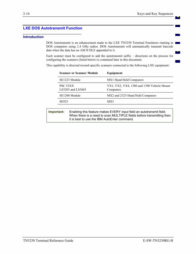
LXE DOS Autotransmit Function
Introduction DOS Autotransmit is an enhancement made to the LXE TN5250 Terminal Emulators running in DOS computers using 2.4 GHz radios. DOS Autotransmit will automatically transmit barcode data when the data has an ASCII DLE appended to it.
Each scanner must be configured to add the autotransmit suffix – directions on the process for configuring the scanners (listed below) is contained later in this document.
This capability is directed toward specific scanners connected to the following LXE equipment:
Scanner or Scanner Module Equipment
SE1223 Module MX1 Hand Held Computers
PSC 53XX LS3203 and LS3603
VX1, VX2, VX4, 1380 and 1390 Vehicle Mount Computers
SE1200 Module MX2 and 2325 Hand Held Computers
SE923 MX3
Important: Enabling this feature makes EVERY input field an autotransmit field. When there is a need to scan MULTIPLE fields before transmitting then it is best to use the IBM AutoEnter command.
Keys and Key Sequences 2-15
E-SW-TN5250RG-H TN5250 Terminal Reference Guide
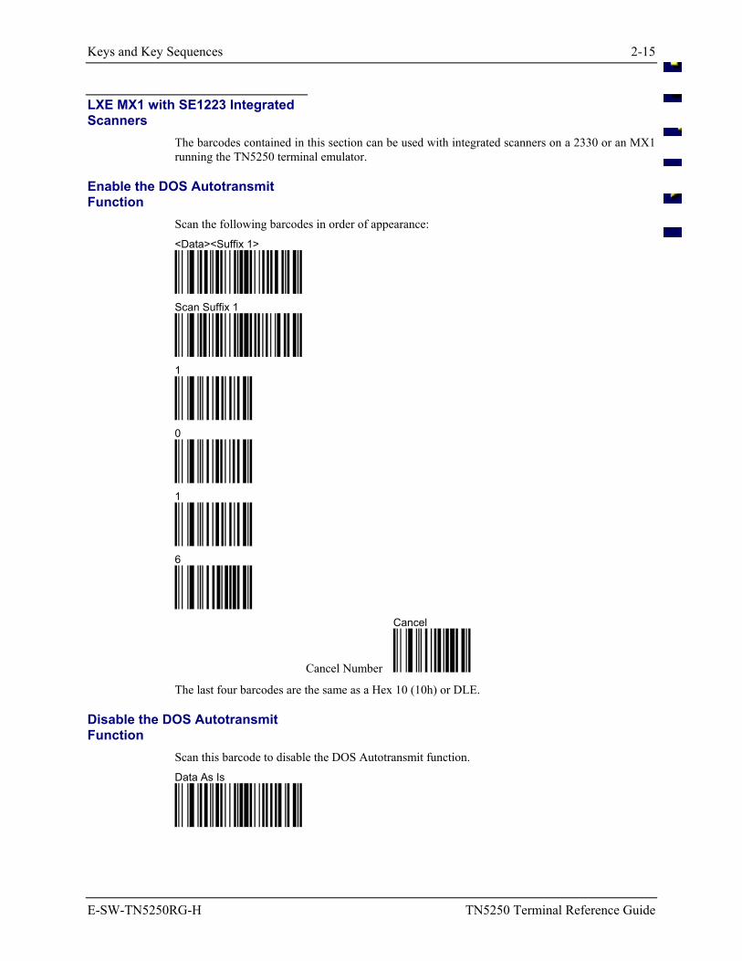
LXE MX1 with SE1223 Integrated Scanners
The barcodes contained in this section can be used with integrated scanners on a 2330 or an MX1 running the TN5250 terminal emulator.
Enable the DOS Autotransmit Function
Scan the following barcodes in order of appearance: <Data><Suffix 1>
Scan Suffix 1
1
0
1
6
Cancel Number
Cancel
The last four barcodes are the same as a Hex 10 (10h) or DLE.
Disable the DOS Autotransmit Function
Scan this barcode to disable the DOS Autotransmit function. Data As Is
2-16 Keys and Key Sequences
TN5250 Terminal Reference Guide E-SW-TN5250RG-H
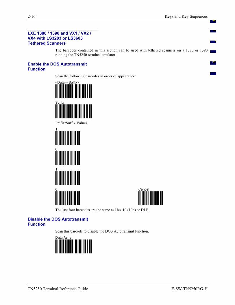
LXE 1380 / 1390 and VX1 / VX2 / VX4 with LS3203 or LS3603 Tethered Scanners
The barcodes contained in this section can be used with tethered scanners on a 1380 or 1390 running the TN5250 terminal emulator.
Enable the DOS Autotransmit Function
Scan the following barcodes in order of appearance: <Data><Suffix>
Suffix
Prefix/Suffix Values 1
0
1
6
Cancel
The last four barcodes are the same as Hex 10 (10h) or DLE.
Disable the DOS Autotransmit Function
Scan this barcode to disable the DOS Autotransmit function. Data As Is
Keys and Key Sequences 2-17
E-SW-TN5250RG-H TN5250 Terminal Reference Guide
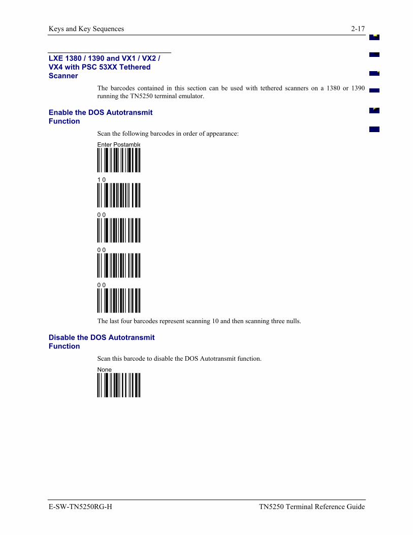
LXE 1380 / 1390 and VX1 / VX2 / VX4 with PSC 53XX Tethered Scanner
The barcodes contained in this section can be used with tethered scanners on a 1380 or 1390 running the TN5250 terminal emulator.
Enable the DOS Autotransmit Function
Scan the following barcodes in order of appearance: Enter Postamble
1 0
0 0
0 0
0 0
The last four barcodes represent scanning 10 and then scanning three nulls.
Disable the DOS Autotransmit Function
Scan this barcode to disable the DOS Autotransmit function. None
2-18 Keys and Key Sequences
TN5250 Terminal Reference Guide E-SW-TN5250RG-H
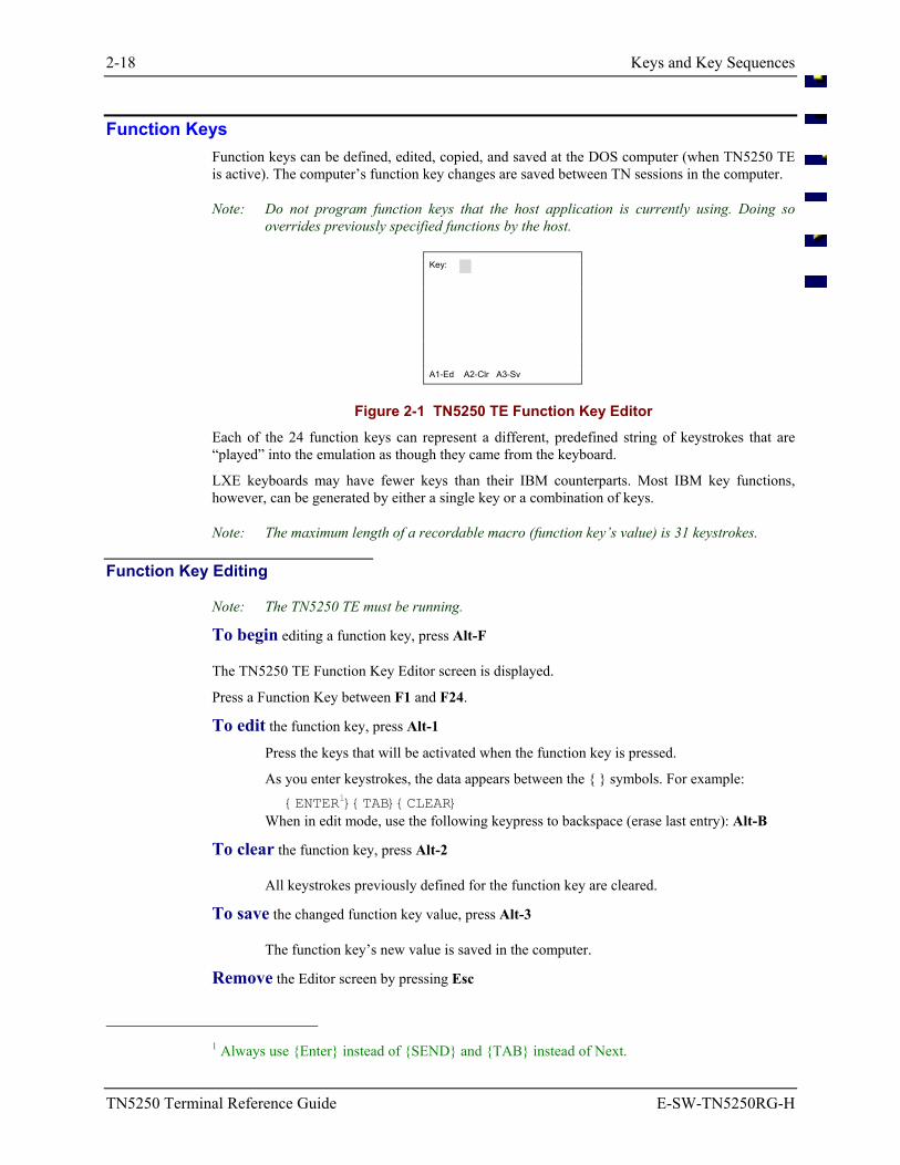
Function Keys Function keys can be defined, edited, copied, and saved at the DOS computer (when TN5250 TE is active). The computer’s function key changes are saved between TN sessions in the computer.
Note: Do not program function keys that the host application is currently using. Doing so overrides previously specified functions by the host.
Key:
A1-Ed A2-Clr A3-Sv
Figure 2-1 TN5250 TE Function Key Editor Each of the 24 function keys can represent a different, predefined string of keystrokes that are “played” into the emulation as though they came from the keyboard.
LXE keyboards may have fewer keys than their IBM counterparts. Most IBM key functions, however, can be generated by either a single key or a combination of keys.
Note: The maximum length of a recordable macro (function key’s value) is 31 keystrokes.
Function Key Editing
Note: The TN5250 TE must be running.
To begin editing a function key, press Alt-F
The TN5250 TE Function Key Editor screen is displayed.
Press a Function Key between F1 and F24.
To edit the function key, press Alt-1
Press the keys that will be activated when the function key is pressed.
As you enter keystrokes, the data appears between the symbols. For example: ENTER1TABCLEAR
When in edit mode, use the following keypress to backspace (erase last entry): Alt-B
To clear the function key, press Alt-2
All keystrokes previously defined for the function key are cleared.
To save the changed function key value, press Alt-3
The function key’s new value is saved in the computer.
Remove the Editor screen by pressing Esc
1 Always use Enter instead of SEND and TAB instead of Next.
Data Entry 2-19
E-SW-TN5250RG-H TN5250 Terminal Reference Guide
Data Entry
The Data Entry section provides basic information to help you communicate with the host computer.
Entering Messages The LXE computer accepts data entry from the keyboard, barcode scanner, and the auxiliary (RS-232) input port.
Keyboard Data Entry Once the computer establishes communication with the host, you can enter data with the computer keyboard. The application program sends messages to the computer that prompt you to make your next keyboard entry. For example, the application may prompt you to press an [F1] through [F24] key. You cannot enter data when the keyboard is locked.
When the keyboard is locked, an II (Input Inhibited) is displayed in the status line.
Pressing a function key transmits a signal to the host. The host responds as specified by the application program.
Note: Do not program function keys that the host application is currently using. Doing so overrides previously specified functions by the host.
Refer to “Keys and Key Sequences” in this chapter for the function key sequences used by your computer.
2-20 Data Entry
TN5250 Terminal Reference Guide E-SW-TN5250RG-H
Barcode Data Entry The computers support an accessory barcode reading device for reading barcode labels. Generally, handheld computer users prefer the Long Range or Standard Range barcode scanner endcap. You can intermix keyboard data entries with barcode data entries.
The standard barcode is Code 39 (C39). All legal Code 39 characters are accepted. The standard computer software supports the following barcode formats:
• Code 39 (C39)
• Code 128 (A, B, C)
• UPC-A
• UPC-E
• Codabar (CDB)
• Code 11 (C11)
• MSI Plessey
• Discrete 2 of 5 (C25)
• Interleaved 2 of 5 (I25)
• EAN-8
• EAN-13
• EAN-128
• Code 93
RS-232 Data Entry The computer accepts input from an RS-232 device connected to the RS-232 port. The computer processes data from the RS-232 port the same way it processes barcode data. The data is entered at the cursor position, and the data is subject to all of the barcode/RS-232 input menu parameters, such as truncate. You must activate the RS-232 input device before you can send data to or receive data from the RS-232 port.
Data Entry 2-21
E-SW-TN5250RG-H TN5250 Terminal Reference Guide
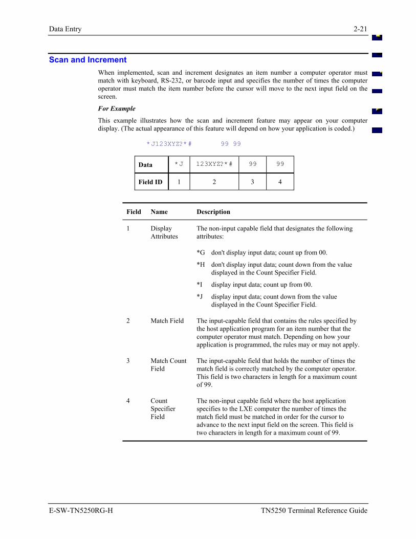
Scan and Increment When implemented, scan and increment designates an item number a computer operator must match with keyboard, RS-232, or barcode input and specifies the number of times the computer operator must match the item number before the cursor will move to the next input field on the screen.
For Example
This example illustrates how the scan and increment feature may appear on your computer display. (The actual appearance of this feature will depend on how your application is coded.)
*J123XYZ?*# 99 99
Data *J 123XYZ?*# 99 99
Field ID 1 2 3 4
Field Name Description
1 Display Attributes
The non-input capable field that designates the following attributes:
*G don't display input data; count up from 00.
*H don't display input data; count down from the value displayed in the Count Specifier Field.
*I display input data; count up from 00.
*J display input data; count down from the value displayed in the Count Specifier Field.
2 Match Field The input-capable field that contains the rules specified by the host application program for an item number that the computer operator must match. Depending on how your application is programmed, the rules may or may not apply.
3 Match Count Field
The input-capable field that holds the number of times the match field is correctly matched by the computer operator. This field is two characters in length for a maximum count of 99.
4 Count Specifier Field
The non-input capable field where the host application specifies to the LXE computer the number of times the match field must be matched in order for the cursor to advance to the next input field on the screen. This field is two characters in length for a maximum count of 99.
2-22 Data Entry
TN5250 Terminal Reference Guide E-SW-TN5250RG-H
Operation When you or the application program place the cursor at the beginning of the match field and you successfully match the data contained in it with barcode, keyboard or RS-232 device input, the match count field value changes by one (counting up or down, depending on how it is programmed). The cursor returns to the beginning of the match field while the match count value counts up to or down from the value in the count specifier field.
If a mismatch occurs during input to the match field, an error message appears and further input is inhibited. Pressing the [RESET] key clears this condition. The cursor remains on the position where the mismatch occurred.
You can then enter the remainder of the match field with the keyboard or move the cursor to the beginning of the match field and enter the data again. The match count field does not change through any of this -- a match count occurs only when every position in the match field has been matched. The test for all positions matched occurs when the last position of the match field is filled and matched.
When the match field has been matched for the number of times indicated in the count specifier field, the cursor advances to the next input field following the count specifier field.
Autotransmit When a scan and increment match field is defined with the autotransmit attribute, autotransmit occurs when the match count satisfies the value in the count specifier field.
Autotransmit will also occur when you press the Field Exit key after matching the field at least once. Depending on where the cursor is when you press Field Exit, the rest of the field will be filled with null characters.
Exceptions If you cannot match the number of items indicated in the count specifier field and must move on to the next item, move the cursor to the next item input field with arrow, TAB, or Field Exit keys. You can return to the skipped match field later to resume the scan and increment process without losing count or matched characters.
In the event you need to complete a count with the keyboard (the scanner cannot read the barcode, for example), you can enter the item number in the match field, TAB to the match count field, and enter the total.
Refer to “Local Edit Commands” in Chapter 5 “5250 Programmer’s Reference” for details about programming this feature.
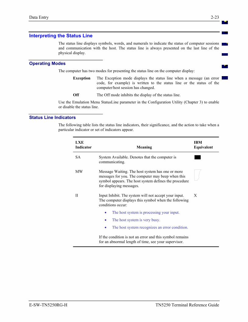
Data Entry 2-23
E-SW-TN5250RG-H TN5250 Terminal Reference Guide
Interpreting the Status Line The status line displays symbols, words, and numerals to indicate the status of computer sessions and communication with the host. The status line is always presented on the last line of the physical display.
Operating Modes The computer has two modes for presenting the status line on the computer display:
Exception The Exception mode displays the status line when a message (an error code, for example) is written to the status line or the status of the computer/host session has changed.
Off The Off mode inhibits the display of the status line.
Use the Emulation Menu StatusLine parameter in the Configuration Utility (Chapter 3) to enable or disable the status line.
Status Line Indicators The following table lists the status line indicators, their significance, and the action to take when a particular indicator or set of indicators appear.
LXE Indicator
Meaning
IBM Equivalent
SA System Available. Denotes that the computer is communicating.
MW Message Waiting. The host system has one or more messages for you. The computer may beep when this symbol appears. The host system defines the procedure for displaying messages.
II Input Inhibit. The system will not accept your input. The computer displays this symbol when the following conditions occur:
• The host system is processing your input.
• The host system is very busy.
• The host system recognizes an error condition.
X
If the condition is not an error and this symbol remains for an abnormal length of time, see your supervisor.
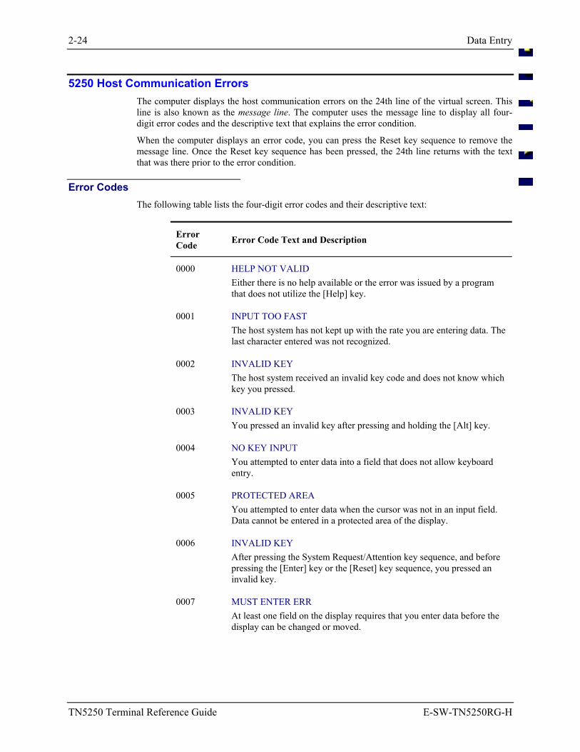
2-24 Data Entry
TN5250 Terminal Reference Guide E-SW-TN5250RG-H
5250 Host Communication Errors The computer displays the host communication errors on the 24th line of the virtual screen. This line is also known as the message line. The computer uses the message line to display all four-digit error codes and the descriptive text that explains the error condition.
When the computer displays an error code, you can press the Reset key sequence to remove the message line. Once the Reset key sequence has been pressed, the 24th line returns with the text that was there prior to the error condition.
Error Codes The following table lists the four-digit error codes and their descriptive text:
Error Code Error Code Text and Description
0000 HELP NOT VALID Either there is no help available or the error was issued by a program that does not utilize the [Help] key.
0001 INPUT TOO FAST The host system has not kept up with the rate you are entering data. The last character entered was not recognized.
0002 INVALID KEY The host system received an invalid key code and does not know which key you pressed.
0003 INVALID KEY You pressed an invalid key after pressing and holding the [Alt] key.
0004 NO KEY INPUT You attempted to enter data into a field that does not allow keyboard entry.
0005 PROTECTED AREA You attempted to enter data when the cursor was not in an input field. Data cannot be entered in a protected area of the display.
0006 INVALID KEY After pressing the System Request/Attention key sequence, and before pressing the [Enter] key or the [Reset] key sequence, you pressed an invalid key.
0007 MUST ENTER ERR At least one field on the display requires that you enter data before the display can be changed or moved.
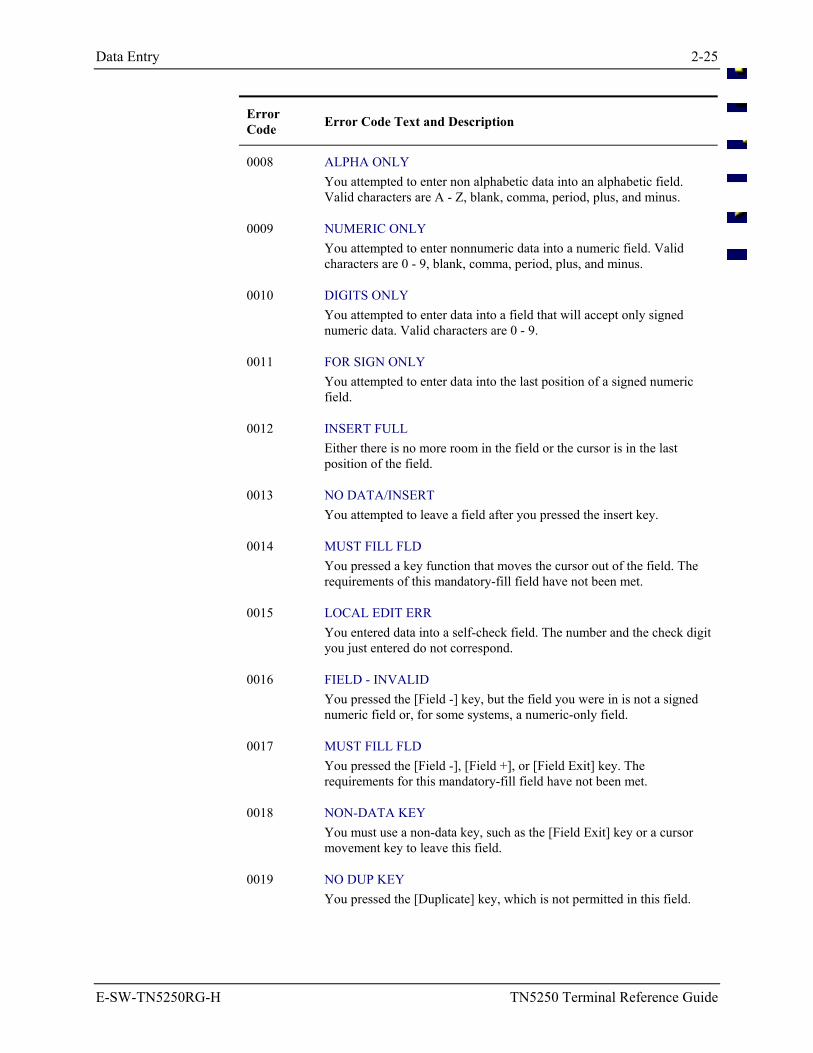
Data Entry 2-25
E-SW-TN5250RG-H TN5250 Terminal Reference Guide
Error Code Error Code Text and Description
0008 ALPHA ONLY You attempted to enter non alphabetic data into an alphabetic field. Valid characters are A - Z, blank, comma, period, plus, and minus.
0009 NUMERIC ONLY You attempted to enter nonnumeric data into a numeric field. Valid characters are 0 - 9, blank, comma, period, plus, and minus.
0010 DIGITS ONLY You attempted to enter data into a field that will accept only signed numeric data. Valid characters are 0 - 9.
0011 FOR SIGN ONLY You attempted to enter data into the last position of a signed numeric field.
0012 INSERT FULL Either there is no more room in the field or the cursor is in the last position of the field.
0013 NO DATA/INSERT You attempted to leave a field after you pressed the insert key.
0014 MUST FILL FLD You pressed a key function that moves the cursor out of the field. The requirements of this mandatory-fill field have not been met.
0015 LOCAL EDIT ERR You entered data into a self-check field. The number and the check digit you just entered do not correspond.
0016 FIELD - INVALID You pressed the [Field -] key, but the field you were in is not a signed numeric field or, for some systems, a numeric-only field.
0017 MUST FILL FLD You pressed the [Field -], [Field +], or [Field Exit] key. The requirements for this mandatory-fill field have not been met.
0018 NON-DATA KEY You must use a non-data key, such as the [Field Exit] key or a cursor movement key to leave this field.
0019 NO DUP KEY You pressed the [Duplicate] key, which is not permitted in this field.
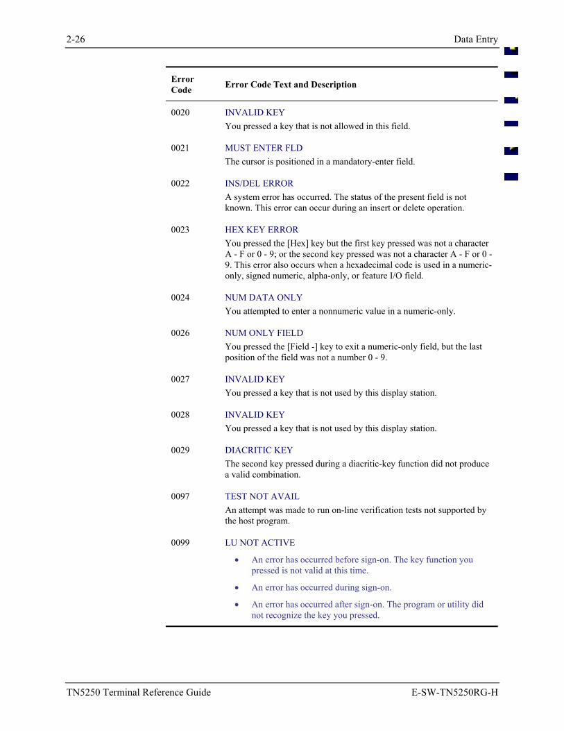
2-26 Data Entry
TN5250 Terminal Reference Guide E-SW-TN5250RG-H
Error Code Error Code Text and Description
0020 INVALID KEY You pressed a key that is not allowed in this field.
0021 MUST ENTER FLD The cursor is positioned in a mandatory-enter field.
0022 INS/DEL ERROR A system error has occurred. The status of the present field is not known. This error can occur during an insert or delete operation.
0023 HEX KEY ERROR You pressed the [Hex] key but the first key pressed was not a character A - F or 0 - 9; or the second key pressed was not a character A - F or 0 - 9. This error also occurs when a hexadecimal code is used in a numeric-only, signed numeric, alpha-only, or feature I/O field.
0024 NUM DATA ONLY You attempted to enter a nonnumeric value in a numeric-only.
0026 NUM ONLY FIELD You pressed the [Field -] key to exit a numeric-only field, but the last position of the field was not a number 0 - 9.
0027 INVALID KEY You pressed a key that is not used by this display station.
0028 INVALID KEY You pressed a key that is not used by this display station.
0029 DIACRITIC KEY The second key pressed during a diacritic-key function did not produce a valid combination.
0097 TEST NOT AVAIL An attempt was made to run on-line verification tests not supported by the host program.
0099 LU NOT ACTIVE
• An error has occurred before sign-on. The key function you pressed is not valid at this time.
• An error has occurred during sign-on.
• An error has occurred after sign-on. The program or utility did not recognize the key you pressed.
Window Manager 2-27
E-SW-TN5250RG-H TN5250 Terminal Reference Guide
Window Manager
LXE's window manager is a software program that controls the virtual screen display of screen data on the LXE computer display window. Window manager display choices are specified from the host computer.
Window manager provides two display modes for displaying the information from the virtual screen at the computer: cursor tracking mode and lock window mode.
The display window is the screen on the computer that allows portions of the virtual screen to be seen.
The virtual screen is the full 25 line x 80 column screen generated by the host computer. An example of a virtual screen is the screen you view when you use a personal computer in DOS mode.
Lock window mode locks the display window in a permanent window position relative to the virtual screen.
Cursor tracking mode allows the display window to follow the movement of the cursor. You move the display window around the virtual screen by moving the cursor.
Note: This section does not apply to the full screen computers.
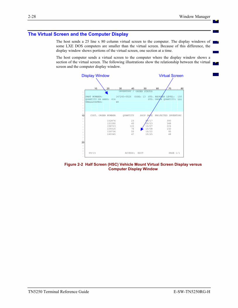
2-28 Window Manager
TN5250 Terminal Reference Guide E-SW-TN5250RG-H
The Virtual Screen and the Computer Display The host sends a 25 line x 80 column virtual screen to the computer. The display windows of some LXE DOS computers are smaller than the virtual screen. Because of this difference, the display window shows portions of the virtual screen, one section at a time.
The host computer sends a virtual screen to the computer where the display window shows a section of the virtual screen. The following illustrations show the relationship between the virtual screen and the computer display window.
Display Window Virtual Screen
. . . . . . . .10 . . . . . . . .20 . . . . . . . .30 . . . . . . . .40 . . . . . . . .50 . . . . . . . .60 . . . . . . . .70 . . . . . . . .80. INVENTORY / ORDER STATUS . . PART NUMBER: 147265-0026 CODE: 13 STD. REORDER LEVEL: 150 . QUANTITY ON HAND: 416 STD. ORDER QUANTITY: 500 . UNALLOCATED: 48 . . . .
10 CUST. ORDER NUMBER QUANTITY SHIP DATE PROJECTED INVENTORY . . 152876 23 09/17 393 . 153390 45 09/23 348 . 158723 122 10/07 226 . 159316 76 10/08 150 . 159736 55 10/22 95 . 160345 47 10/25 48 . .
20 . . . . 09/15 ACCESS: EDIT PAGE 1/1 .
Figure 2-2 Half Screen (HSC) Vehicle Mount Virtual Screen Display versus Computer Display Window
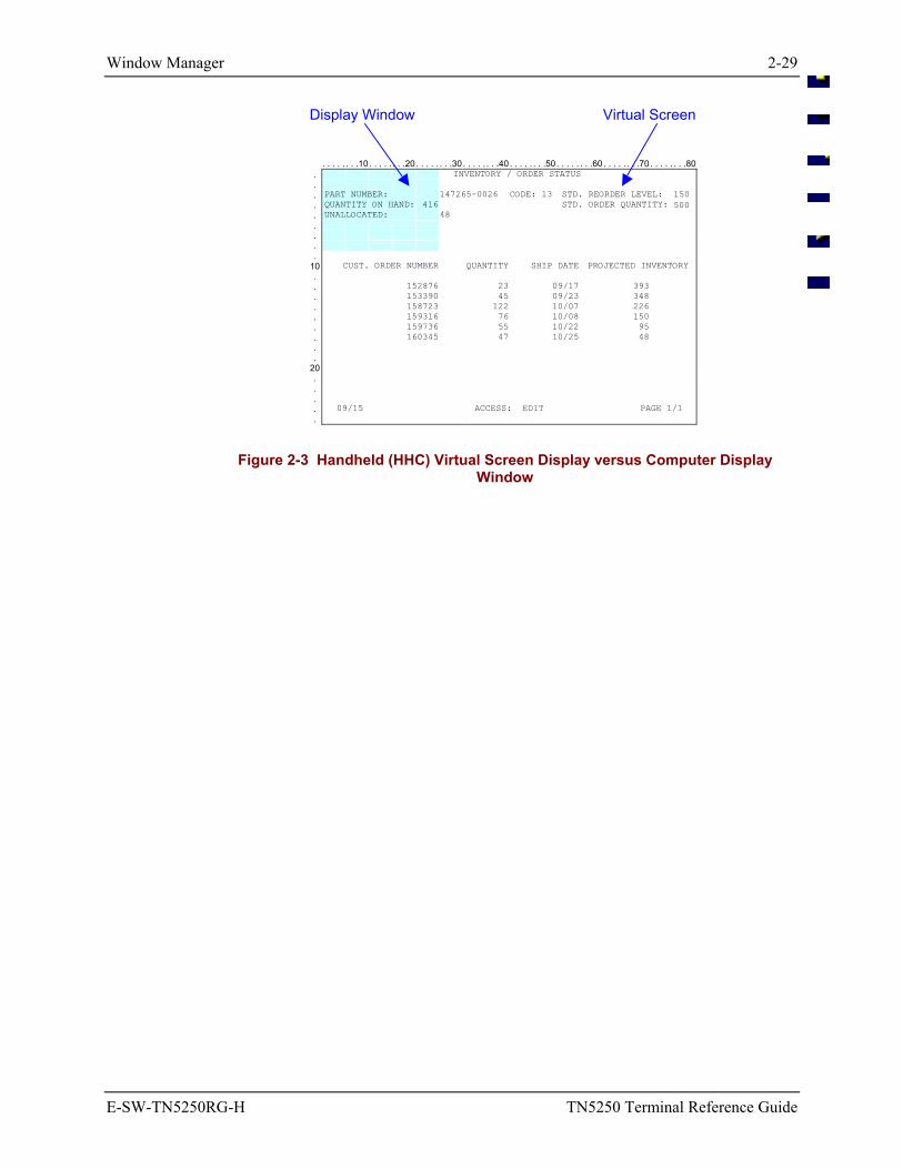
Window Manager 2-29
E-SW-TN5250RG-H TN5250 Terminal Reference Guide
Display Window Virtual Screen
. . . . . . . .10 . . . . . . . .20 . . . . . . . .30 . . . . . . . .40 . . . . . . . .50 . . . . . . . .60 . . . . . . . .70 . . . . . . . .80. INVENTORY / ORDER STATUS . . PART NUMBER: 147265-0026 CODE: 13 STD. REORDER LEVEL: 150 . QUANTITY ON HAND: 416 STD. ORDER QUANTITY: 500 . UNALLOCATED: 48 . . . .
10 CUST. ORDER NUMBER QUANTITY SHIP DATE PROJECTED INVENTORY . . 152876 23 09/17 393 . 153390 45 09/23 348 . 158723 122 10/07 226 . 159316 76 10/08 150 . 159736 55 10/22 95 . 160345 47 10/25 48 . .
20 . . . . 09/15 ACCESS: EDIT PAGE 1/1 .
Figure 2-3 Handheld (HHC) Virtual Screen Display versus Computer Display Window
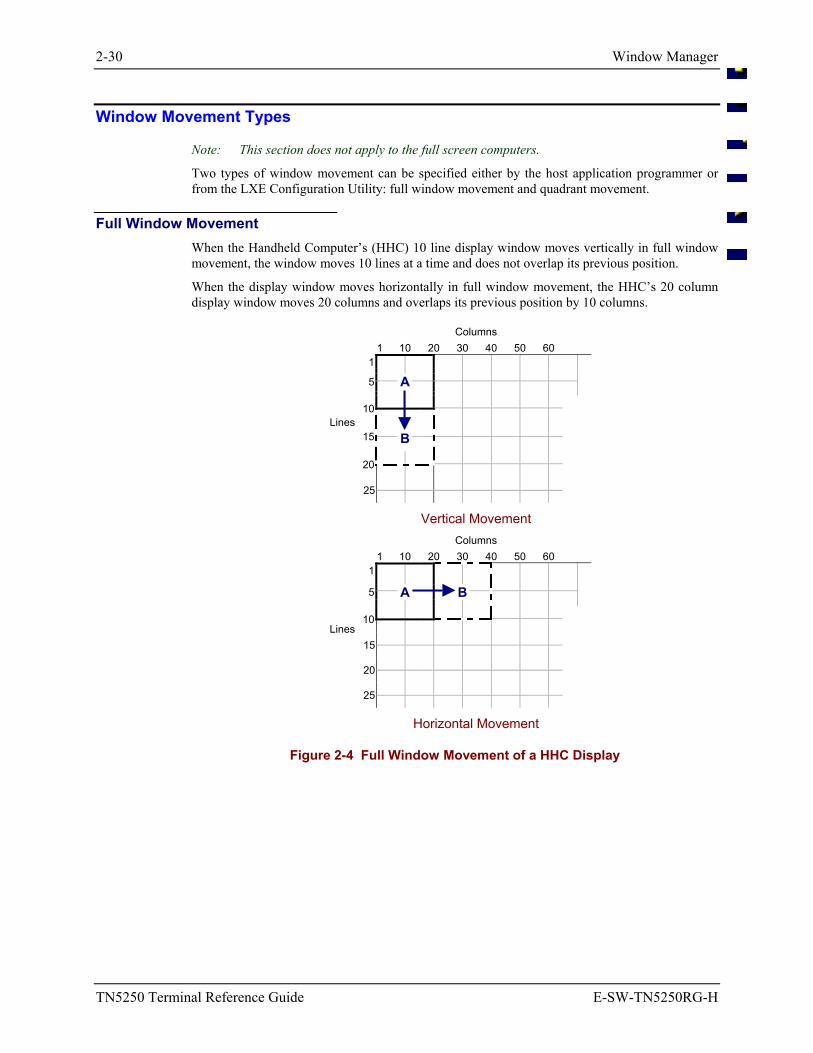
2-30 Window Manager
TN5250 Terminal Reference Guide E-SW-TN5250RG-H
Window Movement Types
Note: This section does not apply to the full screen computers.
Two types of window movement can be specified either by the host application programmer or from the LXE Configuration Utility: full window movement and quadrant movement.
Full Window Movement When the Handheld Computer’s (HHC) 10 line display window moves vertically in full window movement, the window moves 10 lines at a time and does not overlap its previous position.
When the display window moves horizontally in full window movement, the HHC’s 20 column display window moves 20 columns and overlaps its previous position by 10 columns.
Columns 1 10 20 30 40 50 60
1
A 5
10
B 15
20
Lines
25
Vertical Movement
Columns 1 10 20 30 40 50 60
1 A B 5
10 15 20
Lines
25
Horizontal Movement
Figure 2-4 Full Window Movement of a HHC Display
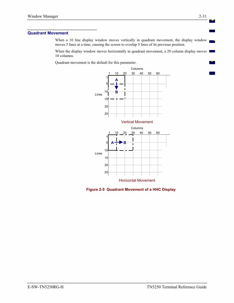
Window Manager 2-31
E-SW-TN5250RG-H TN5250 Terminal Reference Guide
Quadrant Movement When a 10 line display window moves vertically in quadrant movement, the display window moves 5 lines at a time, causing the screen to overlap 5 lines of its previous position.
When the display window moves horizontally in quadrant movement, a 20 column display moves 10 columns.
Quadrant movement is the default for this parameter. Columns
1 10 20 30 40 50 60 1 A
5
B 10
15 20
Lines
25
Vertical Movement
Columns 1 10 20 30 40 50 60
1
A B 5
10 15 20
Lines
25
Horizontal Movement
Figure 2-5 Quadrant Movement of a HHC Display
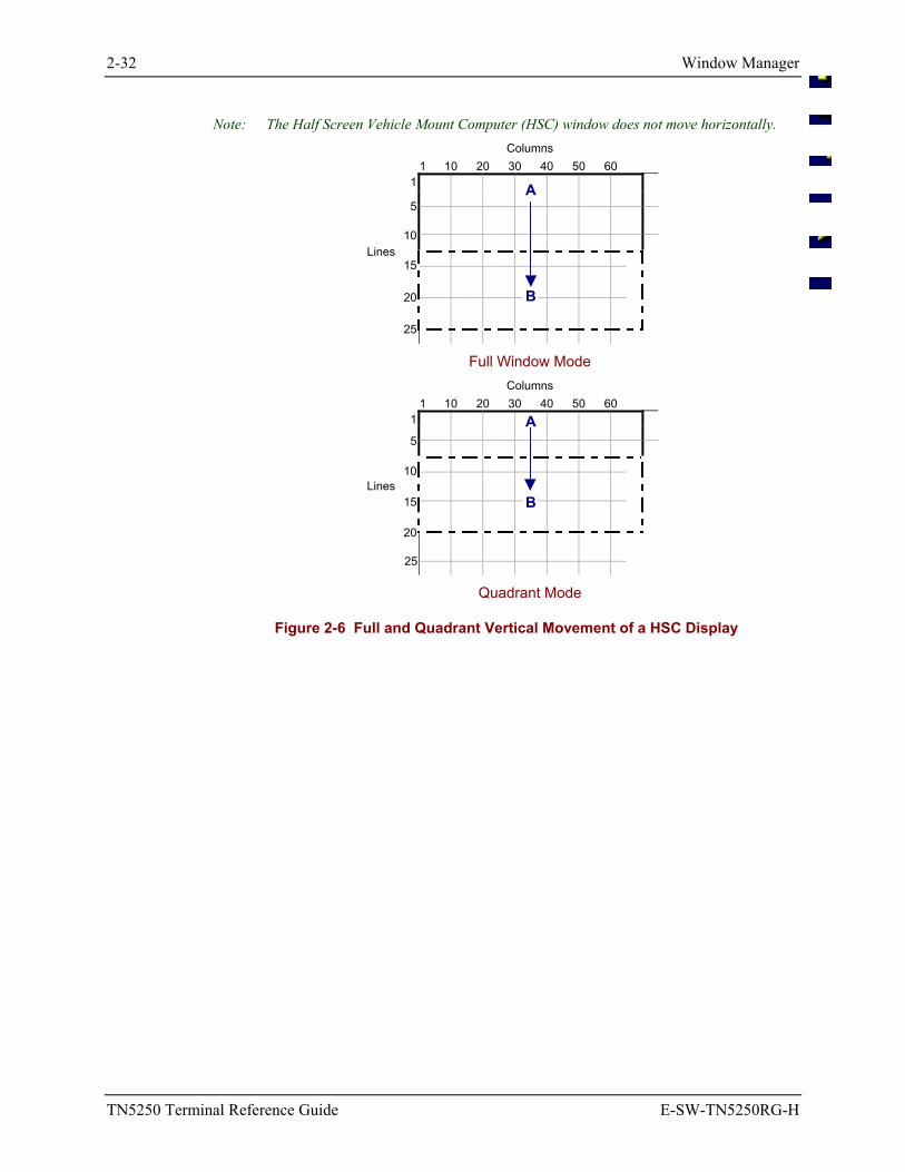
2-32 Window Manager
TN5250 Terminal Reference Guide E-SW-TN5250RG-H
Note: The Half Screen Vehicle Mount Computer (HSC) window does not move horizontally. Columns
1 10 20 30 40 50 60 1
A 5 10 15
B 20
Lines
25
Full Window Mode
Columns 1 10 20 30 40 50 60
1
A
5 10
B 15
20
Lines
25
Quadrant Mode
Figure 2-6 Full and Quadrant Vertical Movement of a HSC Display
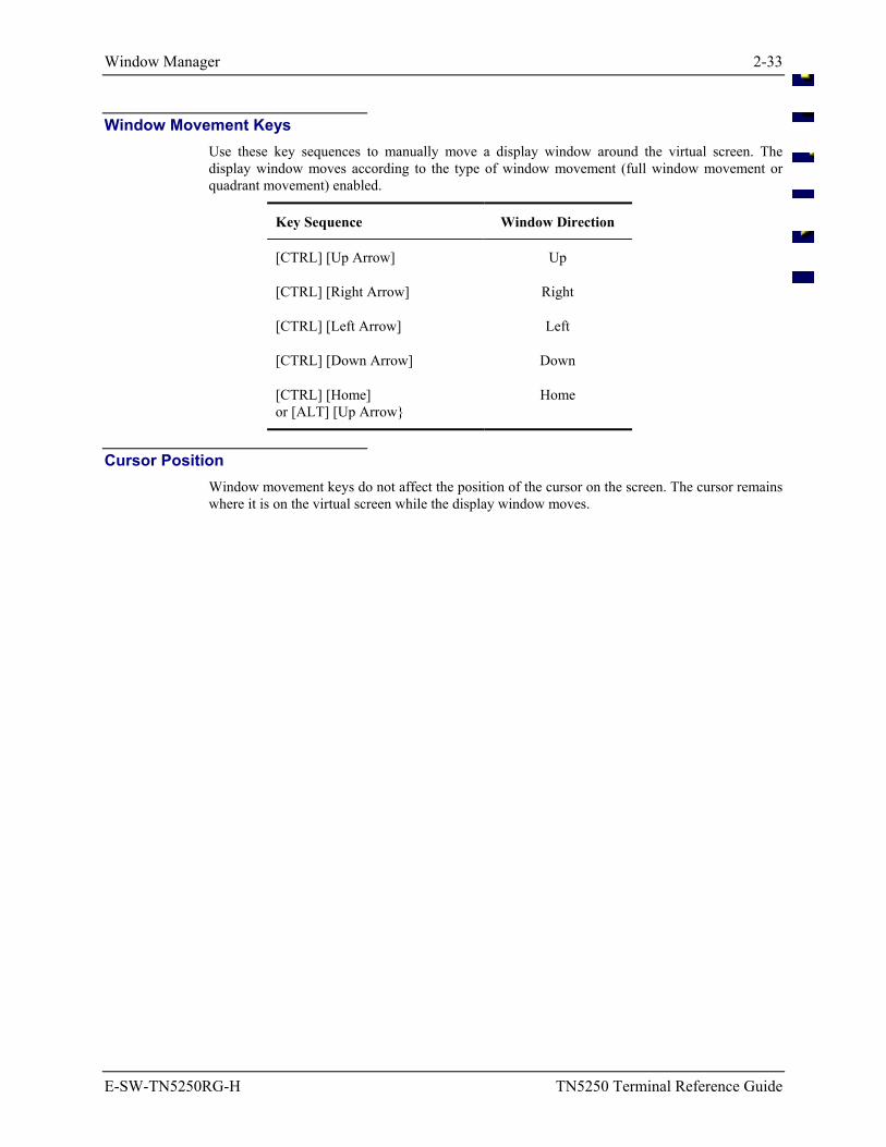
Window Manager 2-33
E-SW-TN5250RG-H TN5250 Terminal Reference Guide
Window Movement Keys Use these key sequences to manually move a display window around the virtual screen. The display window moves according to the type of window movement (full window movement or quadrant movement) enabled.
Key Sequence Window Direction
[CTRL] [Up Arrow] Up
[CTRL] [Right Arrow] Right
[CTRL] [Left Arrow] Left
[CTRL] [Down Arrow] Down
[CTRL] [Home] or [ALT] [Up Arrow
Home
Cursor Position Window movement keys do not affect the position of the cursor on the screen. The cursor remains where it is on the virtual screen while the display window moves.
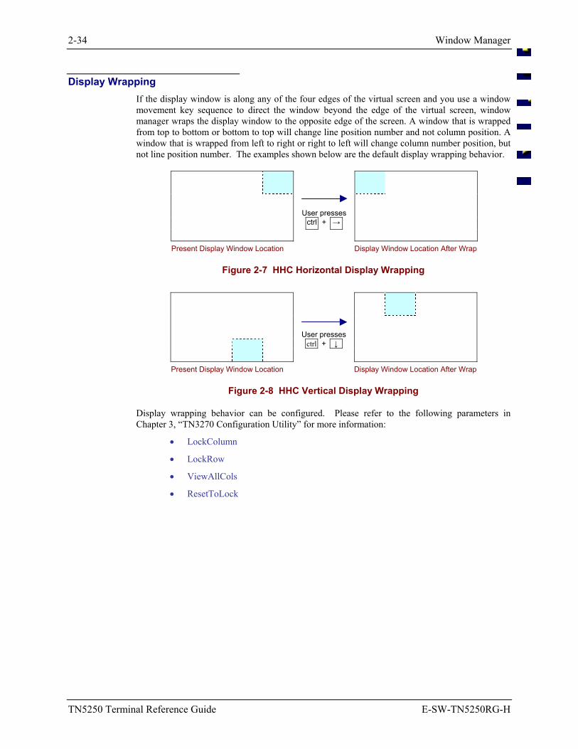
2-34 Window Manager
TN5250 Terminal Reference Guide E-SW-TN5250RG-H
Display Wrapping If the display window is along any of the four edges of the virtual screen and you use a window movement key sequence to direct the window beyond the edge of the virtual screen, window manager wraps the display window to the opposite edge of the screen. A window that is wrapped from top to bottom or bottom to top will change line position number and not column position. A window that is wrapped from left to right or right to left will change column number position, but not line position number. The examples shown below are the default display wrapping behavior.
User presses
ctrl + →
Present Display Window Location Display Window Location After Wrap
Figure 2-7 HHC Horizontal Display Wrapping
User presses
ctrl + ↓
Present Display Window Location Display Window Location After Wrap
Figure 2-8 HHC Vertical Display Wrapping
Display wrapping behavior can be configured. Please refer to the following parameters in Chapter 3, “TN3270 Configuration Utility” for more information:
• LockColumn
• LockRow
• ViewAllCols
• ResetToLock
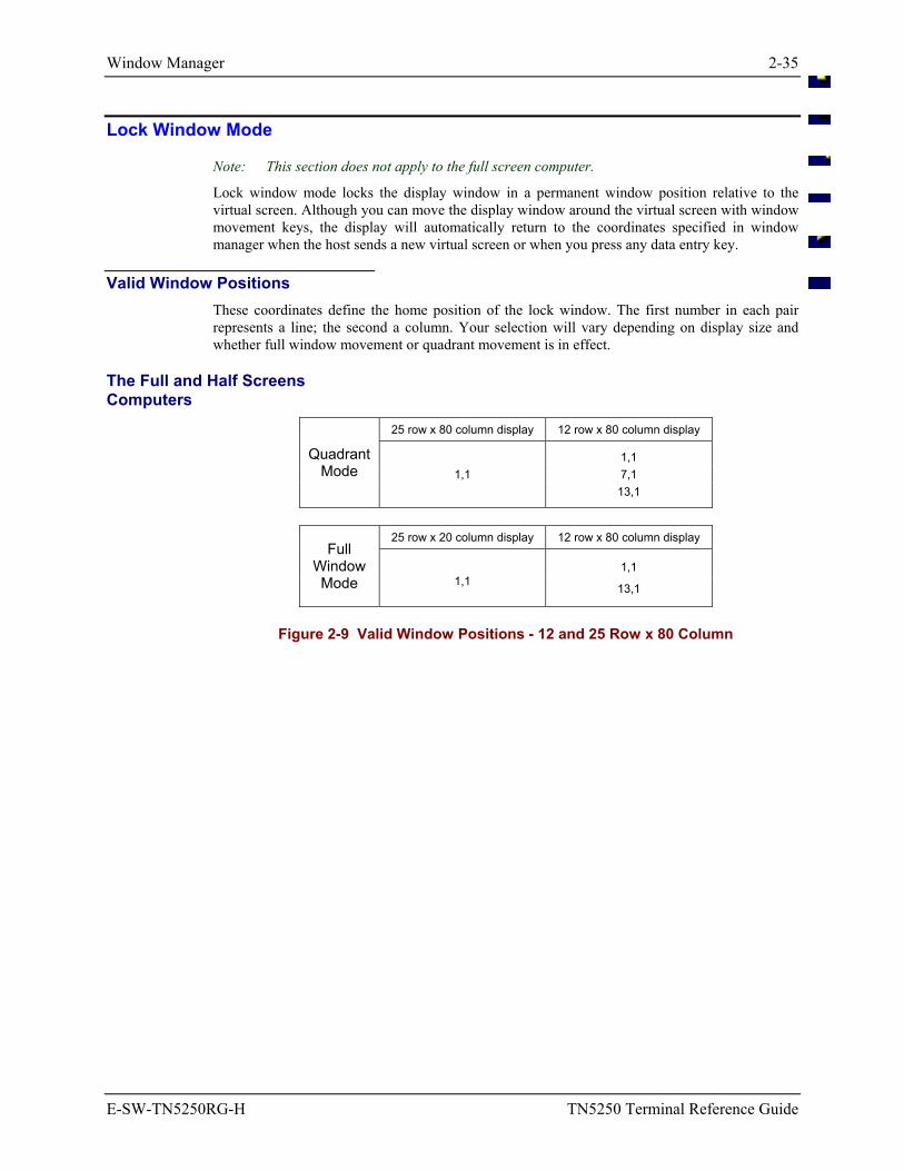
Window Manager 2-35
E-SW-TN5250RG-H TN5250 Terminal Reference Guide
Lock Window Mode
Note: This section does not apply to the full screen computer.
Lock window mode locks the display window in a permanent window position relative to the virtual screen. Although you can move the display window around the virtual screen with window movement keys, the display will automatically return to the coordinates specified in window manager when the host sends a new virtual screen or when you press any data entry key.
Valid Window Positions These coordinates define the home position of the lock window. The first number in each pair represents a line; the second a column. Your selection will vary depending on display size and whether full window movement or quadrant movement is in effect.
The Full and Half Screens Computers
25 row x 80 column display 12 row x 80 column display
1,1 1,1 7,1
Quadrant Mode
13,1
25 row x 20 column display 12 row x 80 column display
1,1 Full
Window Mode 1,1 13,1
Figure 2-9 Valid Window Positions - 12 and 25 Row x 80 Column
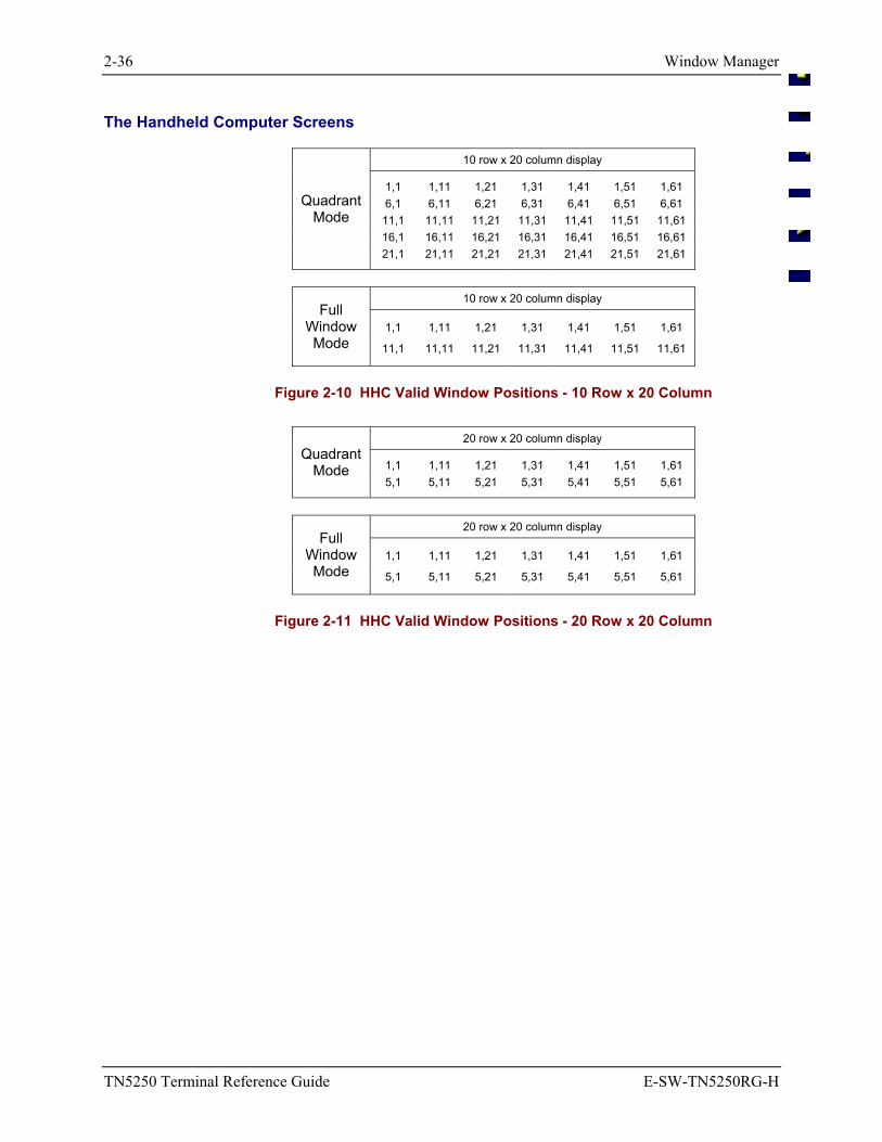
2-36 Window Manager
TN5250 Terminal Reference Guide E-SW-TN5250RG-H
The Handheld Computer Screens
10 row x 20 column display
1,1 1,11 1,21 1,31 1,41 1,51 1,61 6,1 6,11 6,21 6,31 6,41 6,51 6,61
11,1 11,11 11,21 11,31 11,41 11,51 11,61 16,1 16,11 16,21 16,31 16,41 16,51 16,61
Quadrant Mode
21,1 21,11 21,21 21,31 21,41 21,51 21,61
10 row x 20 column display
1,1 1,11 1,21 1,31 1,41 1,51 1,61 Full
Window Mode 11,1 11,11 11,21 11,31 11,41 11,51 11,61
Figure 2-10 HHC Valid Window Positions - 10 Row x 20 Column
20 row x 20 column display
1,1 1,11 1,21 1,31 1,41 1,51 1,61 Quadrant
Mode 5,1 5,11 5,21 5,31 5,41 5,51 5,61
20 row x 20 column display
1,1 1,11 1,21 1,31 1,41 1,51 1,61 Full
Window Mode 5,1 5,11 5,21 5,31 5,41 5,51 5,61
Figure 2-11 HHC Valid Window Positions - 20 Row x 20 Column
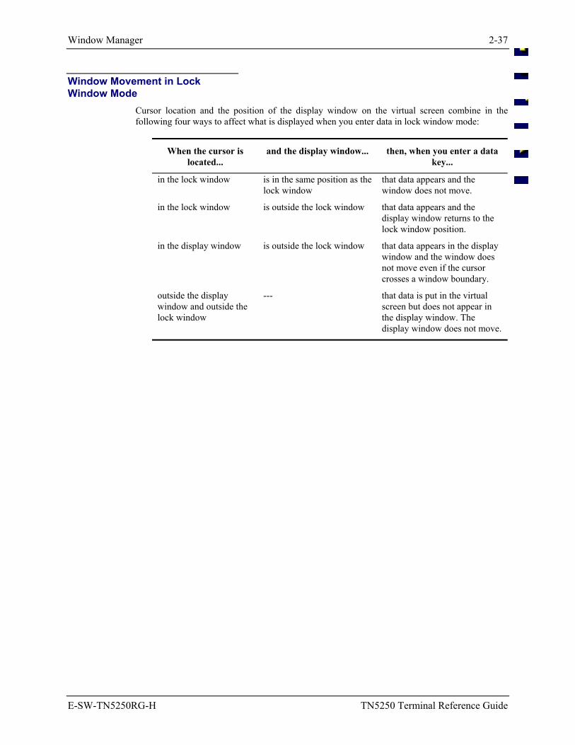
Window Manager 2-37
E-SW-TN5250RG-H TN5250 Terminal Reference Guide
Window Movement in Lock Window Mode
Cursor location and the position of the display window on the virtual screen combine in the following four ways to affect what is displayed when you enter data in lock window mode:
When the cursor is located...
and the display window... then, when you enter a data key...
in the lock window is in the same position as the lock window
that data appears and the window does not move.
in the lock window is outside the lock window that data appears and the display window returns to the lock window position.
in the display window is outside the lock window that data appears in the display window and the window does not move even if the cursor crosses a window boundary.
outside the display window and outside the lock window
--- that data is put in the virtual screen but does not appear in the display window. The display window does not move.
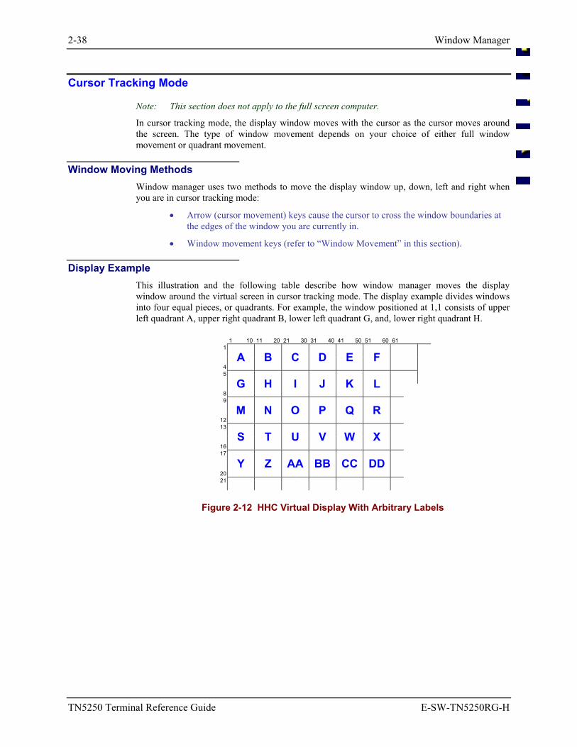
2-38 Window Manager
TN5250 Terminal Reference Guide E-SW-TN5250RG-H
Cursor Tracking Mode
Note: This section does not apply to the full screen computer.
In cursor tracking mode, the display window moves with the cursor as the cursor moves around the screen. The type of window movement depends on your choice of either full window movement or quadrant movement.
Window Moving Methods Window manager uses two methods to move the display window up, down, left and right when you are in cursor tracking mode:
• Arrow (cursor movement) keys cause the cursor to cross the window boundaries at the edges of the window you are currently in.
• Window movement keys (refer to “Window Movement” in this section).
Display Example This illustration and the following table describe how window manager moves the display window around the virtual screen in cursor tracking mode. The display example divides windows into four equal pieces, or quadrants. For example, the window positioned at 1,1 consists of upper left quadrant A, upper right quadrant B, lower left quadrant G, and, lower right quadrant H.
1 10 11 20 21 30 31 40 41 50 51 60 61 1
4
A B C D E F 5
8
G H I J K L 9
12
M N O P Q R 13
16
S T U V W X 17
20 Y Z AA BB CC DD
21
Figure 2-12 HHC Virtual Display With Arbitrary Labels
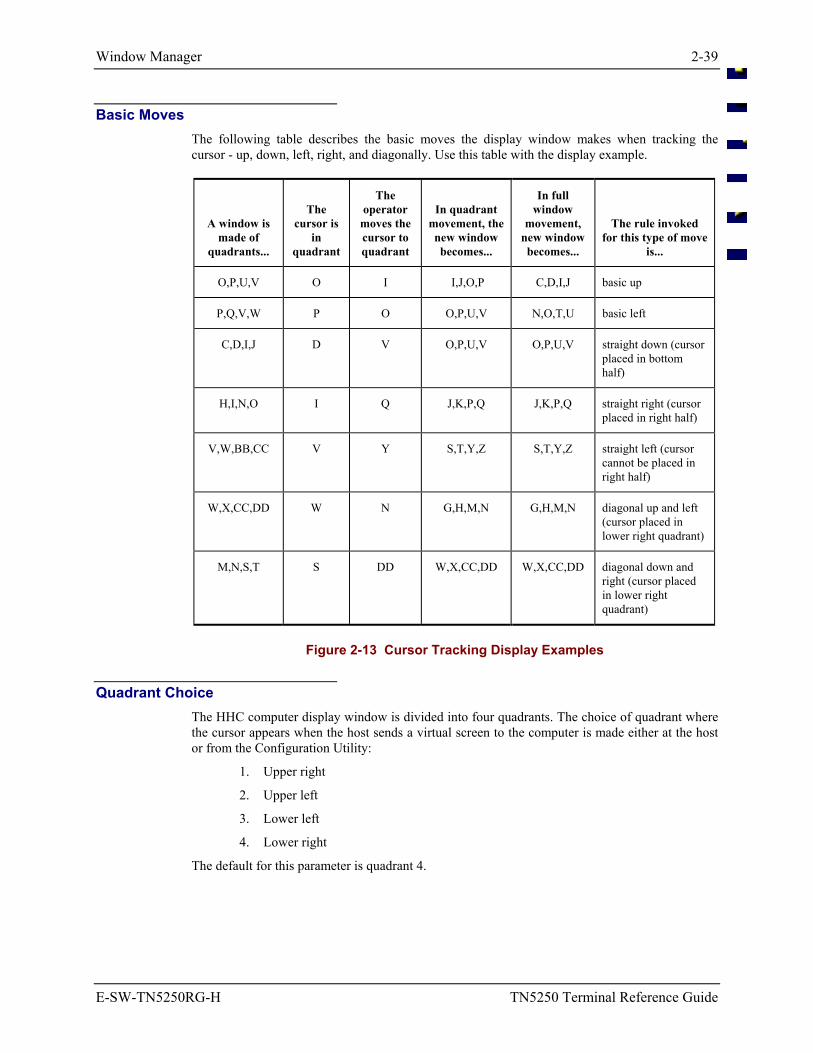
Window Manager 2-39
E-SW-TN5250RG-H TN5250 Terminal Reference Guide
Basic Moves The following table describes the basic moves the display window makes when tracking the cursor - up, down, left, right, and diagonally. Use this table with the display example.
A window is made of
quadrants...
The
cursor is in
quadrant
The operator
moves the cursor to quadrant
In quadrant
movement, the new window becomes...
In full window
movement, new window becomes...
The rule invoked for this type of move
is...
O,P,U,V O I I,J,O,P C,D,I,J basic up
P,Q,V,W P O O,P,U,V N,O,T,U basic left
C,D,I,J D V O,P,U,V O,P,U,V straight down (cursor placed in bottom half)
H,I,N,O I Q J,K,P,Q J,K,P,Q straight right (cursor placed in right half)
V,W,BB,CC V Y S,T,Y,Z S,T,Y,Z straight left (cursor cannot be placed in right half)
W,X,CC,DD W N G,H,M,N G,H,M,N diagonal up and left (cursor placed in lower right quadrant)
M,N,S,T S DD W,X,CC,DD W,X,CC,DD diagonal down and right (cursor placed in lower right quadrant)
Figure 2-13 Cursor Tracking Display Examples
Quadrant Choice The HHC computer display window is divided into four quadrants. The choice of quadrant where the cursor appears when the host sends a virtual screen to the computer is made either at the host or from the Configuration Utility:
1. Upper right
2. Upper left
3. Lower left
4. Lower right
The default for this parameter is quadrant 4.
2-40 Window Manager
TN5250 Terminal Reference Guide E-SW-TN5250RG-H
Status Line The status line appears on line 25 on the virtual screen, occupies up to 80 character positions, and displays messages that indicate an exception condition. Status line messages and the conditions they represent in the TN5250 terminal emulation are described in the previous section titled “Data Entry”.
Status Line Modes There are two modes for displaying the status line:
Always off The status line never appears.
Exception only The status line appears when the computer emulation determines an exception condition exists.
Display Appearance When enabled and displayed, the entire status line appears in the computer window. An 80 character status line appears in an interleaved format. A 20 character status line occupies a single line at the bottom of the window.
Operation When the status line parameter is enabled and an exception condition occurs, the status line appears at the bottom of the display window.
The status line overwrites the last line (or lines) of the display window, including the cursor (if it is on the bottom of the display). If you then enter valid data, the status line disappears and the previous virtual screen reappears, along with the new data that you enter.
The status line remains in the display window when you move the display.
The appearance or disappearance of the status line never causes the display window to move.
Status Line and Message Line If both the message line and the status line are displayed and any operator input causes one of them to be removed, the computer removes them both.
Window Manager 2-41
E-SW-TN5250RG-H TN5250 Terminal Reference Guide
Message Line The TN5250 terminal emulation supports an 80 character message line that the host can address. This 80 character message line
• exists in one of the available 24 lines of the virtual screen (usually line 24).
• appears in the current computer display window when received.
• displays all 80 characters in the window at one time.
Physical Display If necessary, the message line is displayed in an interleaved format. Trailing blanks at the end of the message are suppressed to save a line in the window.
When the message line appears, it overwrites as many of the bottom lines of the computer display as necessary. The message line does not overwrite the status line -- they are displayed together. If the computer displays both the message line and the status line and your input causes one of them to be removed, the computer removes them both.
Display of the message line does not change the location of the display window on the virtual screen.
If the message line overwrites the cursor and you enter data, the computer removes the message line and displays your data at the cursor.
Reviewing the Message Line Any keystroke will cause the message line to disappear from the window. The message remains in the virtual screen on the line where the host originally put it. You can review the message by moving the window to that line in the virtual screen and moving the window left and right.
Message Line Doesn't Follow the Window
If you move the window using window movement keys or cursor tracking while the message line is displayed in the window, the message line will not follow the display window.

2-42 Window Manager
TN5250 Terminal Reference Guide E-SW-TN5250RG-H
An EMS Technologies Company
E-SW-TN5250RG-H TN5250 Terminal Reference Guide
Table of Contents
CHAPTER 3 TN5250 CONFIGURATION UTILITY 3-1
Introduction ............................................................................................................ 3-1
Password Access Levels ...................................................................................... 3-1
Changed Radio Parameters .................................................................................. 3-2
Configuration File Structure ................................................................................. 3-2
Directory Structure ................................................................................................ 3-2 \IBM24 - TN5250 TE Files .................................................................................................. 3-2
The TN5250 Configuration Utility ......................................................................... 3-3 Pre-Configured Passwords.................................................................................................... 3-3 Menu Components................................................................................................................ 3-4 Using the Configuration Program......................................................................................... 3-6 Main Menu Display .............................................................................................................. 3-7 Screen Displays .................................................................................................................... 3-9 System Menu Options......................................................................................................... 3-10
Passwords ......................................................................................................................... 3-10 Default Passwords.......................................................................................................................3-11
OperatorPasswd – Level 1 Password .......................................................................... 3-11 SupvPasswd – Level 2 Password ................................................................................ 3-12 LxeEngPasswd – Level 3 Password ............................................................................ 3-12
Reset Defaults .................................................................................................................. 3-13 Resetting Parameters Changes Files ...........................................................................................3-13
Emulation Menu Option ..................................................................................................... 3-14 LockWindow – Lock Window Mode............................................................................... 3-14 LockRow – Lock Row ..................................................................................................... 3-14 LockCol – Lock Column.................................................................................................. 3-15 FullWinIncs – Full Window Mode .................................................................................. 3-15 HostQuad – Host Quadrant .............................................................................................. 3-16 StatusLine – Status Line Mode ........................................................................................ 3-16 AlphaOnly – Alpha Only Wildcard ................................................................................. 3-17 DigitsOnly – Digits Only Wildcard ................................................................................. 3-17 NumericOnly – Numeric Only Wildcard ......................................................................... 3-18 AlphaNumericOnly – Alphanumeric Only Wildcard ...................................................... 3-18 MatchAll – Match All Wildcard ...................................................................................... 3-19 LeftJustify – Left Justify Mode........................................................................................ 3-19 ClearData – Clear Data Mode .......................................................................................... 3-20 TruncateData – Truncate Data Mode ............................................................................... 3-20 AutoAdvance – Automatic Advance Mode ..................................................................... 3-20
3-ii Table of Contents
TN5250 Terminal Reference Guide E-SW-TN5250RG-H
AutoEnter – Automatic Enter........................................................................................... 3-21 BCPreStrip – Barcode Head Character Strip ................................................................... 3-21 BCPostStrip – Barcode Tail Character Strip.................................................................... 3-22 CRPerLine – Carriage Return per Line............................................................................ 3-22 LFPerLine – Line Feed per Line ...................................................................................... 3-23 Input ID – Input Identifier Mode...................................................................................... 3-23 SwapTab – Swap Tab and Field Exit ............................................................................... 3-24 SwapAdvance – Swap Advance and Field Exit ............................................................... 3-24 DeviceName – Telnet Server Request ............................................................................. 3-25 LxeEscape – Extra Features ............................................................................................. 3-25 ViewAllCols – View All Columns................................................................................... 3-26 ResetToLock – Reset Screen To Locked Position ........................................................... 3-26
Protocol Menu Option ........................................................................................................ 3-27 Hosts Parameters .............................................................................................................. 3-28
Host1 – First Host Name................................................................................................ 3-29 Host1RLS – First Host Connect Retries ........................................................................ 3-29 Host2 – Second Host Name ........................................................................................... 3-30 Host2RLS – Second Host Connect Retries.................................................................... 3-30 Host3 – Third Host Name.............................................................................................. 3-30 Host3RLS – Third Host Connect Retries ...................................................................... 3-30 Host4 – Fourth Host Name ............................................................................................ 3-30 Host4RLS – Fourth Host Connect Retries..................................................................... 3-30 Host5 – Fifth Host Name ............................................................................................... 3-31 Host5RLS – Fifth Host Connect Retries........................................................................ 3-31 Host6 – Sixth Host Name .............................................................................................. 3-31 Host6RLS – Sixth Host Connect Retries ....................................................................... 3-31 HostDataTimeout – Host Wait Interval ......................................................................... 3-32
Auto Login Parameters..................................................................................................... 3-33 Auto Login and the MX2............................................................................................................3-33 AutoLoginOn – Computer Automatic Login................................................................. 3-34 Prompt1 – First Host String ........................................................................................... 3-34 Reply1 – First Response Sent to Host ........................................................................... 3-35 Prompt2 – Second Host String....................................................................................... 3-35 Reply2 – Second Response Sent to Host ....................................................................... 3-35 Prompt3 – Third Host String ......................................................................................... 3-35 Reply3 – Third Response Sent to Host .......................................................................... 3-35 Prompt4 – Fourth Host String........................................................................................ 3-36 Reply4 – Fourth Response Sent to Host ........................................................................ 3-36 Prompt5 – Fifth Host String........................................................................................... 3-36 Reply5 – Fifth Response Sent to Host ........................................................................... 3-36 Prompt6 – Sixth Host String.......................................................................................... 3-36 Reply6 – Sixth Response Sent to Host .......................................................................... 3-36 ALITimeout – Login Interval Timeout.......................................................................... 3-37
Interface Parameters ......................................................................................................... 3-38 DNS Parameters ............................................................................................................... 3-38 General Parameters .......................................................................................................... 3-38
Table of Contents 3-iii
E-SW-TN5250RG-H TN5250 Terminal Reference Guide
Kernel Parameters ............................................................................................................ 3-38 Logging Parameters.......................................................................................................... 3-39
EvtMask – Event Logging Mask ................................................................................... 3-39 TNLogging – TELNET Logging ................................................................................... 3-39 TNLogFS – TELNET Log File Size.............................................................................. 3-40
Radio Menu Option – 6400 and 6500 Systems .................................................................. 3-41 Driver Settings.................................................................................................................. 3-41 Packet Driver.................................................................................................................... 3-41
Platform Menu .................................................................................................................... 3-42 CursorType – Cursor Type............................................................................................... 3-42 BeeperVolume – Beeper Volume..................................................................................... 3-43 Printing – Print to COM port............................................................................................ 3-43 Com1BaudRate – COM1 Baud Rate................................................................................ 3-44 Com1DataBits – COM1 Data Bits ................................................................................... 3-44 Com1Parity – COM1 Parity ............................................................................................. 3-45 Com1StopBits – COM1 Stop Bits ................................................................................... 3-45 Com1HalfDuplex – COM1 Half Duplex ......................................................................... 3-46 Com1Xon – COM1 Software Flow Control .................................................................... 3-46 Com1HwFlowCtrl – COM1 Hardware Flow Control...................................................... 3-47 Com1TimeOut – COM1 Time Out .................................................................................. 3-47 Com1PassTermChar – COM1 Pass Termination Character ............................................ 3-48 Com1Interrupt – COM1 Interrupt .................................................................................... 3-48 Com2BaudRate – COM2 Baud Rate................................................................................ 3-49 Com2DataBits – COM2 Data Bits ................................................................................... 3-49 Com2Parity – COM2 Parity ............................................................................................. 3-50 Com2StopBits – COM2 Stop Bits ................................................................................... 3-50 Com2HalfDuplex – COM2 Half Duplex ......................................................................... 3-51 Com2Xon – COM2 Software Flow Control .................................................................... 3-51 Com2HwFlowCtrl – COM2 Hardware Flow Control...................................................... 3-52 Com2TimeOut – COM2 Time Out .................................................................................. 3-52 Com2PassTermChar – COM2 Pass Termination Character ............................................ 3-53 Com2Interrupt – COM2 Interrupt .................................................................................... 3-53 InitialScrlDly – Initial Scroll Delay ................................................................................. 3-54 RepeatScrlDly – Repeat Scroll Delay .............................................................................. 3-54 HardwareModel – Hardware Model ................................................................................ 3-54 ScreenSize – FontSize Selections .................................................................................... 3-55 APIType – API Type........................................................................................................ 3-56 DockedBehavior – Docked I/O Configuration................................................................. 3-56 NormalIO – Undocked I/O Configuration ....................................................................... 3-58 EAN128Fnc1 – Decode F1 As Space .............................................................................. 3-59
Exit With Save Option........................................................................................................ 3-60 Exit Without Save Option................................................................................................... 3-60
3-iv Table of Contents
TN5250 Terminal Reference Guide E-SW-TN5250RG-H
Illustrations
Figure 3-1 Configuration Utility - Menu Components .................................................................................... 3-4 Figure 3-2 Configuration Utility Main Menu .................................................................................................. 3-7 Figure 3-3 Main Menu on a Full Screen VMC with 2.4GHz Radio................................................................ 3-9 Figure 3-4 Main Menu on a Half Screen VMC with 2.4GHz Radio ............................................................... 3-9 Figure 3-5 Main Menu on a Handheld computer with 2.4GHz Radio............................................................. 3-9
E-SW-TN5250RG-H TN5250 Terminal Reference Guide
Chapter 3 TN5250 Configuration Utility
Introduction
The TN5250 configuration program provides the ability to modify the terminal emulation (TE) setup parameters and hardware parameters. The configuration program is a DOS program. The configuration utility allows the modification of the following parameters:
• Terminal emulation parameters.
• Radio configuration parameters.
• Hardware configuration parameters.
• TN host interaction parameters.
Configuration menu options displayed on the computer screens, and in this chapter, are unique to the
• computer being configured,
• the access level of the current user,
• and computer screen display size.
The illustrations contained in this section represent the menu options for each menu and submenu as shown on a screen that has 20 or more columns. Menus displayed on the handheld computers will display all parameters relative to the TN5250 TE setup, although an extra keypress may be needed to move from parameter to parameter.
Password Access Levels
There are three (3) access levels associated with the configuration utility. The access levels are:
• Operator (Access Level 1)
• System Administrator (Access Level 2)
• LXE Technical staff (Access Level 3)
Access to the configuration utility is gained by entering the appropriate password at the Enter Password text box. The password determines the access level of the user. Passwords are masked upon entry. When a password is entered on a vehicle mounted computer, each character is displayed as an “*” on the computer display. When a password is entered on a handheld computer, no characters are displayed.
Passwords are modified by selecting the System option from the main menu. The Password menu option is then chosen:
Only passwords for the current access level (or any lower access levels) can be modified. For example, the System Administrator may change his/her password and that of the Operator, but the Operator can only change his/her password.
See the “Pre-Configured Passwords” section for password entry instruction. See the “Passwords” option in the System menu for password edit instruction.
3-2 \IBM24 - TN5250 TE Files
TN5250 Terminal Reference Guide E-SW-TN5250RG-H
Changed Radio Parameters
When parameters in a TN5250 TE computer are changed or reset to default values, the LXE.INI file is changed.
Configuration files are updated upon exiting the Configuration utility.
The DOS computer must be rebooted before the radio parameter changes will take effect.
Configuration File Structure
Please refer to the equipment Reference Guide for information on the AUTOEXEC.BAT and CONFIG.SYS files. Files installed in each TN5250 TE computer are specific to the computer
Directory Structure
The directory structure of a computer intended for TN5250 TE operation is, essentially, the same for each system. In addition to the standard operating files the DOS computer will contain an IBM24 directory where the TN5250 specific files reside.
\IBM24 - TN5250 TE Files
Filename Function
CONFIG.EXE TN5250 TE Configuration utility program.
CONFIG.INF TN5250 TE Configuration utility file.
DOS5250.EXE TN5250 TE interface program.
FIBM*.FNT LXE screen font file.
HELP5250.TXT Text used for TN5250 TE application’s help screens.
LANG2.TXT Text used for CONFIG.EXE screen displays.
LANGUAGE.TXT Text used for CONFIG.EXE screen displays.
LXE.INI Stores configuration parameters set using CONFIG.EXE.
MESSAGE.TXT Text used for TN5250 TE application’s error messages.
REV.BAT Displays software revision level.
Pre-Configured Passwords 3-3
E-SW-TN5250RG-H TN5250 Terminal Reference Guide
The TN5250 Configuration Utility
The TN5250 TE Configuration utility is accessed at the DOS prompt.
From the DOS prompt:
Type CD\IBM24, at the DOS prompt.
Press [Enter].
Type CONFIG at the prompt.
Press [Enter].
The LXE Configuration Utility welcome screen is displayed while the configuration utility loads. It is removed and the Enter Password text is displayed:
Enter Password Password [ ]
The cursor is located at the beginning of the password field.
Pre-Configured Passwords The TN5250 TE is shipped with passwords pre-configured. The pre-configured passwords are:
• Operator Access (Level 1) = Tab 1 2
• System Administrator Access (Level 2) = Tab 3 4 5
Refer to the “Passwords” section of this chapter for more information on changing the passwords.
If an incorrect password is entered, the Configuration Utility closes and control returns to the DOS prompt or the TE. If the correct password is entered, the Configuration Utility Main Menu appears.
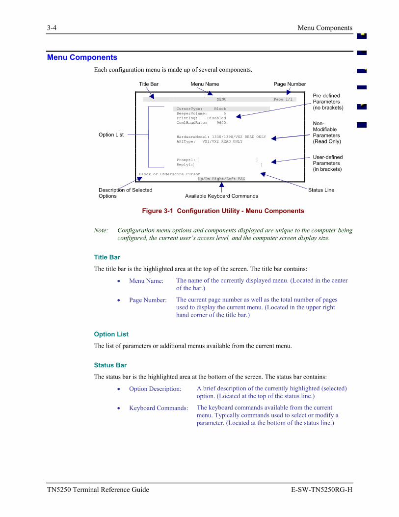
3-4 Menu Components
TN5250 Terminal Reference Guide E-SW-TN5250RG-H
Menu Components Each configuration menu is made up of several components.
Title Bar Menu Name Page Number MENU Page 1/1 CursorType: Block BeeperVolume: 5
Pre-defined Parameters (no brackets)
Printing: Disabled Com1BaudRate: 9600
Option List HardwareModel: 1330/1390/VX2 READ ONLY APIType: VX1/VX2 READ ONLY
Non-Modifiable Parameters (Read Only)
Prompt1: [ ] Reply1:[ ]
User-defined Parameters (in brackets)
Block or Underscore Cursor Up/Dn Right/Left ESC Description of Selected Options Available Keyboard Commands
Status Line
Figure 3-1 Configuration Utility - Menu Components
Note: Configuration menu options and components displayed are unique to the computer being configured, the current user’s access level, and the computer screen display size.
Title Bar The title bar is the highlighted area at the top of the screen. The title bar contains:
• Menu Name: The name of the currently displayed menu. (Located in the center of the bar.)
• Page Number: The current page number as well as the total number of pages used to display the current menu. (Located in the upper right hand corner of the title bar.)
Option List The list of parameters or additional menus available from the current menu.
Status Bar The status bar is the highlighted area at the bottom of the screen. The status bar contains:
• Option Description: A brief description of the currently highlighted (selected) option. (Located at the top of the status line.)
• Keyboard Commands: The keyboard commands available from the current menu. Typically commands used to select or modify a parameter. (Located at the bottom of the status line.)
Menu Components 3-5
E-SW-TN5250RG-H TN5250 Terminal Reference Guide
Modifiable Parameters There are two types of modifiable parameters within the configuration utility:
• Pre-defined
• User Defined
Pre-Defined Parameters Pre-defined parameters are parameters with a specific set of pre-defined options. These parameters may only be set to one of the pre-defined options.
User Defined Parameters User defined parameters are parameter strings that have no pre-defined options. The user defined parameter strings are denoted with [brackets]. The space within the brackets indicates the maximum characters allowed:
[ ] Short parameter field
[ ] Longer parameter field
These parameters require the user to type in a parameter definition when modifying them. Some parameters have a default setting. This default can be recalled by using the Reset to Defaults option from the main menu.
Note: When using the Reset to Defaults option all parameters available for that user level are reset to their factory default setting, with the exception of the passwords.
Non-Modifiable Parameters The non-modifiable parameters are those which cannot be modified by Operators or System Administrators. These parameters are not displayed for Operators and are marked as Read Only for Administrators.
3-6 Using the Configuration Program
TN5250 Terminal Reference Guide E-SW-TN5250RG-H
Using the Configuration Program The set of keyboard commands used to select menu items and parameters, as well as modify parameter values are as follows:
Action Keystrokes
Exit a menu [Esc]
Acknowledge message or prompt
[Esc] or [Enter]
Select menu option (Menu or Parameter)
Up, Down, Left or Right Arrow
Display menu [Enter]
Modify parameter [Space] or Left Arrow or Right Arrow or type in the value
Next/Previous page selection
Up or Down Arrow
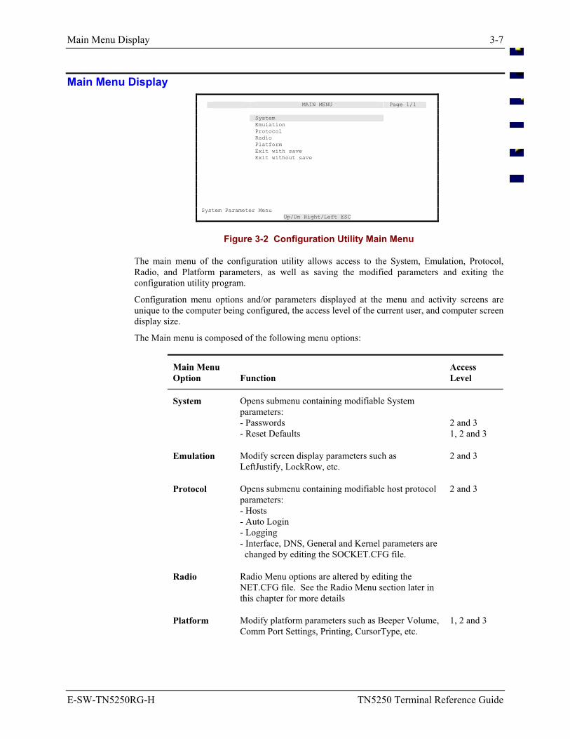
Main Menu Display 3-7
E-SW-TN5250RG-H TN5250 Terminal Reference Guide
Main Menu Display MAIN MENU Page 1/1 System Emulation Protocol Radio Platform Exit with save Exit without save System Parameter Menu Up/Dn Right/Left ESC
Figure 3-2 Configuration Utility Main Menu
The main menu of the configuration utility allows access to the System, Emulation, Protocol, Radio, and Platform parameters, as well as saving the modified parameters and exiting the configuration utility program.
Configuration menu options and/or parameters displayed at the menu and activity screens are unique to the computer being configured, the access level of the current user, and computer screen display size.
The Main menu is composed of the following menu options:
Main Menu Option
Function
Access Level
System Opens submenu containing modifiable System parameters: - Passwords - Reset Defaults
2 and 3 1, 2 and 3
Emulation Modify screen display parameters such as LeftJustify, LockRow, etc.
2 and 3
Protocol Opens submenu containing modifiable host protocol parameters: - Hosts - Auto Login - Logging - Interface, DNS, General and Kernel parameters are changed by editing the SOCKET.CFG file.
2 and 3
Radio Radio Menu options are altered by editing the NET.CFG file. See the Radio Menu section later in this chapter for more details
Platform Modify platform parameters such as Beeper Volume, Comm Port Settings, Printing, CursorType, etc.
1, 2 and 3
3-8 Main Menu Display
TN5250 Terminal Reference Guide E-SW-TN5250RG-H
Main Menu Option
Function
Access Level
Exit with Save
Saves current settings and exits the configuration program.
1, 2 and 3
Exit Without Save
Exits the configuration program without saving the changed parameter settings.
1, 2 and 3
Note: When parameters are changed, the DOS computer must be rebooted before the parameter changes will take effect.
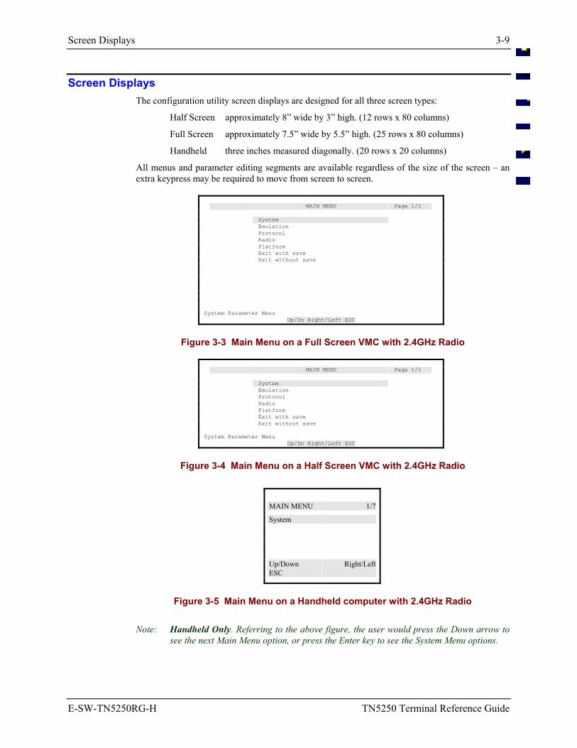
Screen Displays 3-9
E-SW-TN5250RG-H TN5250 Terminal Reference Guide
Screen Displays The configuration utility screen displays are designed for all three screen types:
Half Screen approximately 8” wide by 3” high. (12 rows x 80 columns)
Full Screen approximately 7.5” wide by 5.5” high. (25 rows x 80 columns)
Handheld three inches measured diagonally. (20 rows x 20 columns)
All menus and parameter editing segments are available regardless of the size of the screen – an extra keypress may be required to move from screen to screen.
MAIN MENU Page 1/1 System Emulation Protocol Radio Platform Exit with save Exit without save System Parameter Menu Up/Dn Right/Left ESC
Figure 3-3 Main Menu on a Full Screen VMC with 2.4GHz Radio
MAIN MENU Page 1/1 System Emulation Protocol Radio Platform Exit with save Exit without save System Parameter Menu Up/Dn Right/Left ESC
Figure 3-4 Main Menu on a Half Screen VMC with 2.4GHz Radio
MAIN MENU 1/7
System Up/Down Right/LeftESC
Figure 3-5 Main Menu on a Handheld computer with 2.4GHz Radio
Note: Handheld Only. Referring to the above figure, the user would press the Down arrow to see the next Main Menu option, or press the Enter key to see the System Menu options.
3-10 System Menu Options
TN5250 Terminal Reference Guide E-SW-TN5250RG-H
System Menu Options Upon choosing System at the Main Menu, the next screen displayed is the System submenu:
To return to the Main Menu press the [Esc] key.
Submenu Parameters
Passwords OperatorPasswd SupvPasswd LxeEngPasswd
Reset Defaults Yes No
Passwords Selecting Passwords at the System menu displays the Passwords activity screen. Press [Esc] to return to the System menu.
Note: Passwords are NOT affected by the Reset Defaults function.
System Menu Options 3-11
E-SW-TN5250RG-H TN5250 Terminal Reference Guide
Default Passwords Passwords entered by users are validated against user-defined entries found in the configuration file (LXE.INI). If the configuration file (LXE.INI) does not exist, the configuration utility will use the internally generated password.
The default password is generated daily, and therefore does not remain the same. To obtain the generated password, contact LXE customer support.
OperatorPasswd – Level 1 Password
Function The OperatorPasswd parameter specifies the password that must be typed by Level 1 users before they may have access to the Configuration Utility.
Note: When the OperatorPasswd value is changed, write it down and keep in a safe place.
Options
Valid options: user defined (3 character alphanumeric string)
Default setting: Tab 1 2 (pre-configured by LXE)
Change the password by typing the new password. Press [Esc] to return to the System Menu. When exiting the utility, select the Exit with Save option.
A user with an access level of 1 (operator) has access to the following menu options:
• System - Passwords - User can edit the Operator password.
• System - Reset Defaults - User can reset the system to the default values.
• Platform - User can edit the Beeper Volume parameter value.
Access Level Parameter can be modified by a user with an access level of 1, 2 or 3.
3-12 System Menu Options
TN5250 Terminal Reference Guide E-SW-TN5250RG-H
SupvPasswd – Level 2 Password
Function The SupvPasswd parameter specifies the password that must be typed by Level 2 users before they may have access to the Configuration Utility. This level allows modification of all parameters.
Note: When the SupvPasswd value is changed, write it down and keep in a safe place.
Options
Valid options: user defined (4 character alphanumeric string)
Default setting: Tab 3 4 5 (pre-configured by LXE)
Change the password by typing the new password. Press [Esc] to return to the System Menu. When exiting the utility, select the Exit with Save option.
Access Level Parameter can only be modified by a user with an access level of 2 or 3.
LxeEngPasswd – Level 3 Password
Function The LxeEngPasswd parameter specifies the password that must be typed by Level 3 users before they may have access to the Configuration Utility. This level allows modification of all parameters (except read-only parameters).
Note: When the LxeEngPasswd value is changed, write it down and keep in a safe place.
Options
Valid options: user defined (5 character alphanumeric string)
Default setting: Tab 6 7 8 9 (pre-configured by LXE)
Change the password by typing the new password. Press [Esc] to return to the System Menu. When exiting the utility, select the Exit with Save option.
Access Level Parameter can be modified by a user with an access level of 3.
System Menu Options 3-13
E-SW-TN5250RG-H TN5250 Terminal Reference Guide
Reset Defaults Note: Passwords are NOT affected by the Reset Defaults function.
The Reset Defaults option from the System menu allows the restoration of factory defaults. This feature only allows the restoration of defaults for the parameters currently accessible to the user.
In other words, only the parameters available to the current user’s access level will be restored. For example, a user with Operator access will reset the Beeper Loudness parameter only.
To return to the System Menu press the [Esc] key.
Reset Press the [Y] key and then the [Enter] key to reset the default values. System values are returned to their default values and configuration files are changed. See the sub-section titled “Reset Parameters” in this Section.
- or -
Ignore Press the [N] key and then the [Enter] key to ignore the Reset command and remove the Reset text box from the screen display. System values are not changed.
- or -
Ignore At the [N] prompt, press the [Enter] key to remove the Reset box from the screen display. System values are not changed.
Resetting Parameters Changes Files
When parameters in a TN5250 TE computer are changed or reset to default values, the LXE.INI, PROTOCOL.INI, PCTCP.INI, the radio driver and the FTP stack files are changed.
Note: The computer must be rebooted before the parameter changes will take effect.
Configuration files are updated upon exiting the Configuration utility.
3-14 Emulation Menu Option
TN5250 Terminal Reference Guide E-SW-TN5250RG-H
Emulation Menu Option The Emulation menu contains parameters pertaining to the terminal emulation. Emulation parameters are displayed on multiple screens.
To access the second screen of terminal emulation parameters, press the [Page Down] key.
To return to the first screen, press the [Page Up] key. A detailed description of each terminal emulation parameter follows.
To return to the Main Menu, press [Esc].
Access Levels Refer to the “Passwords” section of this chapter for more information on access levels.
LockWindow – Lock Window Mode
Function The LockWindow parameter determines whether the display window is locked in a permanent window position or if it follows the cursor in the virtual window.
Options
Valid options: Does not track (locked in permanent position) Track cursor
Default setting: Track cursor
Change the parameter by pressing the left or right arrow keys until the desired value is displayed. Press [Esc] to return to the Main Menu. When exiting the utility, select the Exit with Save option.
Access Level Parameter may only be modified by a user with an access level of 2 or 3.
LockRow – Lock Row
Function The LockRow parameter specifies the row coordinate of the upper left-hand corner (Home) position of the physical display window.
Options
Valid options: 1 - 15
Default setting: 1
Change the parameter by typing one of the numbers shown above for the type of computer you are configuring. Press [Esc] to return to the Main Menu. When exiting the utility, select the Exit with Save option.
Access Level Parameter may only be modified by a user with an access level of 2 or 3.
Emulation Menu Option 3-15
E-SW-TN5250RG-H TN5250 Terminal Reference Guide
LockCol – Lock Column
Function The LockCol parameter specifies the column coordinate of the upper left-hand corner (Home) position of the physical display window.
Options
Valid options: 1 - 61
Default setting: 1
Change the parameter by typing one of the numbers shown above. Press [Esc] to return to the Main Menu. When exiting the utility, select the Exit with Save option.
Access Level Parameter may only be modified by a user with an access level of 2 or 3.
FullWinIncs – Full Window Mode
Function The FullWinIncs parameter determines whether the computer display moves in half or full window increments.
Options
Valid options: Half, Full
Default setting: Half
Change the parameter by pressing the left or right arrow keys until the desired setting is displayed. Press [Esc] to return to the Main Menu. When exiting the utility, select the Exit with Save option.
Access Level Parameter may only be modified by a user with an access level of 2 or 3.
3-16 Emulation Menu Option
TN5250 Terminal Reference Guide E-SW-TN5250RG-H
HostQuad – Host Quadrant
Function The HostQuad parameter determines which quadrant the cursor appears in when the host sends a virtual screen to the computer.
Options
Valid options: 1 Upper right 2 Upper left 3 Lower left 4 Lower right
Default setting: 4
Change the parameter by pressing the left or right arrow keys until the desired setting is displayed or by typing one of the numbers shown above. Press [Esc] to return to the Main Menu. When exiting the utility, select the Exit with Save option.
Access Level Parameter may only be modified by a user with an access level of 2 or 3.
StatusLine – Status Line Mode
Function The StatusLine parameter specifies whether the status line will be displayed (usually on line 25) or not. The status line on a full screen computer is always displayed. The status line on a half screen and handheld computer is displayed only when there is an exception to normal operation.
Options
Valid options: Enabled, Disabled
Default setting: Enabled
Change the parameter by pressing the left or right arrow keys until the desired setting is displayed. Press [Esc] to return to the Main Menu. When exiting the utility, select the Exit with Save option.
Access Level Parameter may only be modified by a user with an access level of 2 or 3.
Emulation Menu Option 3-17
E-SW-TN5250RG-H TN5250 Terminal Reference Guide
AlphaOnly – Alpha Only Wildcard
Function The AlphaOnly parameter specifies the wildcard character that represents an alphabetic character. The characters represented by this wildcard are: A - Z, a - z, comma (,), period (.), dash (-) and space ( ).
Options Enter the decimal equivalent of the ASCII character desired.
Valid options: 32 - 126 (Decimal)
Default setting: 63 (? in ASCII)
Note: See Chapter 4 “Code Pages and Character Sets” section titled “DOS US PC Standard Character Set” for Decimal to ASCII equivalents.
Change the parameter by pressing the left or right arrow keys until the desired setting is displayed or by typing the decimal value. Press [Esc] to return to the Main Menu. When exiting the utility, select the Exit with Save option.
Access Level Parameter may only be modified by a user with an access level of 2 or 3.
DigitsOnly – Digits Only Wildcard
Function The DigitsOnly parameter specifies the wildcard character that represents a digit. The characters represented by this wildcard are: 0 - 9.
Options Enter the decimal equivalent of the ASCII character desired.
Valid options: 32 - 126 (Decimal)
Default setting: 36 ($ in ASCII)
Note: See Chapter 4 “Code Pages and Character Sets” section titled “DOS US PC Standard Character Set” for Decimal to ASCII equivalents.
Change the parameter by pressing the left or right arrow keys until the desired setting is displayed or by typing the decimal value. Press [Esc] to return to the Main Menu. When exiting the utility, select the Exit with Save option.
Access Level Parameter may only be modified by a user with an access level of 2 or 3.
3-18 Emulation Menu Option
TN5250 Terminal Reference Guide E-SW-TN5250RG-H
NumericOnly – Numeric Only Wildcard
Function The NumericOnly parameter specifies the wildcard character that represents a numeric character. The characters represented by this wildcard are: 0 - 9, plus (+), comma (,), period (.), dash (-) and space ( ).
Options Enter the decimal equivalent of the ASCII character desired.
Valid options: 32 - 126 (Decimal)
Default setting: 35 (# in ASCII)
Note: See Chapter 4 “Code Pages and Character Sets” section titled “DOS US PC Standard Character Set” for Decimal to ASCII equivalents.
Change the parameter by pressing the left or right arrow keys until the desired setting is displayed or by typing the decimal value. Press [Esc] to return to the Main Menu. When exiting the utility, select the Exit with Save option.
Access Level Parameter may only be modified by a user with an access level of 2 or 3.
AlphaNumericOnly – Alphanumeric Only Wildcard
Function The AlphaNumericOnly parameter specifies the wildcard character that represents an alphanumeric character. The characters represented by this wildcard are: A - Z, a - z, 0 - 9, plus (+), comma (,), period (.), dash (-) and space ( ).
Options Enter the decimal equivalent of the ASCII character desired.
Valid options: 32 - 126 (Decimal)
Default setting: 43 (+ in ASCII)
Note: See Chapter 4 “Code Pages and Character Sets” section titled “DOS US PC Standard Character Set” for Decimal to ASCII equivalents.
Change the parameter by pressing the left or right arrow keys until the desired setting is displayed or by typing the decimal value. Press [Esc] to return to the Main Menu. When exiting the utility, select the Exit with Save option.
Access Level Parameter may only be modified by a user with an access level of 2 or 3.
Emulation Menu Option 3-19
E-SW-TN5250RG-H TN5250 Terminal Reference Guide
MatchAll – Match All Wildcard
Function The MatchAll parameter specifies the wildcard character that represents any non-control character (all characters included). The characters represented by this wildcard are: any GL or GR character.
Options Enter the decimal equivalent of the ASCII character desired.
Valid options: 32 - 126 (Decimal)
Default setting: 42 (* in ASCII)
Note: See Chapter 4 “Code Pages and Character Sets” section titled “DOS US PC Standard Character Set” for Decimal to ASCII equivalents.
Change the parameter by pressing the left or right arrow keys until the desired setting is displayed or by typing the decimal value. Press [Esc] to return to the Main Menu. When exiting the utility, select the Exit with Save option.
Access Level Parameter may only be modified by a user with an access level of 2 or 3.
LeftJustify – Left Justify Mode
Function The LeftJustify parameter determines where the cursor appears in a field from one barcode entry to the next.
Options When enabled, the cursor in a field justifies to the left each time a new barcode entry occurs. When disabled, the barcode entry appears at the end of the previous entry in that field.
Valid options: Yes, No
Default setting: Yes
Change the parameter by pressing the left or right arrow keys until the desired setting is displayed. Press [Esc] to return to the Main Menu. When exiting the utility, select the Exit with Save option.
Access Level Parameter may only be modified by a user with an access level of 2 or 3.
3-20 Emulation Menu Option
TN5250 Terminal Reference Guide E-SW-TN5250RG-H
ClearData – Clear Data Mode
Function The ClearData parameter determines if a field is automatically cleared when the next barcode entry occurs or if the data in the field is overwritten by the new entry.
Options
Valid options: Clear, Overwrite
Default setting: Clear
Access Level Parameter may only be modified by a user with an access level of 2 or 3.
TruncateData – Truncate Data Mode
Function The TruncateData parameter determines whether the character position of a barcode entry that exceeds the field length are simply dropped off or if the leftover characters are entered in the next available field.
Options
Valid options: Don’t Truncate, Truncate
Default setting: Truncate
Change the parameter by pressing the left or right arrow keys until the desired setting is displayed. Press [Esc] to return to the Main Menu. When exiting the utility, select the Exit with Save option.
Access Level Parameter may only be modified by a user with an access level of 2 or 3.
AutoAdvance – Automatic Advance Mode
Function The AutoAdvance parameter determines whether the cursor advances to the next field at the end of a barcode entry. If the cursor does not advance to the next field, the next barcode entry is entered at the end of the previous barcode entry.
Options
Valid options: Yes, No
Default setting: Yes
Change the parameter by pressing the left or right arrow keys until the desired setting is displayed. Press [Esc] to return to the Main Menu. When exiting the utility, select the Exit with Save option.
Access Level Parameter may only be modified by a user with an access level of 2 or 3.
Emulation Menu Option 3-21
E-SW-TN5250RG-H TN5250 Terminal Reference Guide
AutoEnter – Automatic Enter
Function The AutoEnter parameter determines whether there is an automatic [Enter] function after a datastream print.
Options
Valid options: Disabled, Enabled
Default setting: Enabled
Change the parameter by pressing the left or right arrow keys until the desired setting is displayed. Press [Esc] to return to the Main Menu. When exiting the utility, select the Exit with Save option.
Access Level Parameter may only be modified by a user with an access level of 2 or 3.
BCPreStrip – Barcode Head Character Strip
Function The BCPreStrip parameter determines the number of characters to strip from the head of a barcode.
Options
Valid options: 0 (disabled) 1 - 20
Default setting: 0
Change the parameter by pressing the left or right arrow keys until the desired setting is displayed. Press [Esc] to return to the Main Menu. When exiting the utility, select the Exit with Save option.
Access Level Parameter may only be modified by a user with an access level of 2 or 3.
Related Parameters BCPostStrip
3-22 Emulation Menu Option
TN5250 Terminal Reference Guide E-SW-TN5250RG-H
BCPostStrip – Barcode Tail Character Strip
Function The BCPostStrip parameter determines the number of characters to strip from the tail of a barcode.
Options
Valid options: 0 (disabled) 1 - 20
Default setting: 0
Change the parameter by pressing the left or right arrow keys until the desired setting is displayed. Press [Esc] to return to the Main Menu. When exiting the utility, select the Exit with Save option.
Access Level Parameter may only be modified by a user with an access level of 2 or 3.
Related Parameters BCPreStrip
CRPerLine – Carriage Return per Line
Function The CRPerLine parameter determines whether a single carriage return (CR) is transmitted in screen paint.
Options
Valid options: Enabled, Disabled
Default setting: Disabled
Change the parameter by pressing the left or right arrow keys until the desired setting is displayed. Press [Esc] to return to the Main Menu. When exiting the utility, select the Exit with Save option.
Access Level Parameter may only be modified by a user with an access level of 2 or 3.
Emulation Menu Option 3-23
E-SW-TN5250RG-H TN5250 Terminal Reference Guide
LFPerLine – Line Feed per Line
Function The LFPerLine parameter determines whether a single line feed (LF) is transmitted in screen paint.
Options
Valid options: Enabled, Disabled
Default setting: Disabled
Change the parameter by pressing the left or right arrow keys until the desired setting is displayed. Press [Esc] to return to the Main Menu. When exiting the utility, select the Exit with Save option.
Access Level Parameter may only be modified by a user with an access level of 2 or 3.
Input ID – Input Identifier Mode
Note: Input ID function is not supported in DOS computers.
Function The InputID parameter determines whether the type of data (barcode port, keyboard) is identified to the host.
Options
Valid options: Enabled, Disabled
Default setting: Disabled
Change the parameter by pressing the left or right arrow keys until the desired setting is displayed. Press [Esc] to return to the Main Menu. When exiting the utility, select the Exit with Save option.
Access Level Parameter may only be modified by a user with an access level of 2 or 3.
3-24 Emulation Menu Option
TN5250 Terminal Reference Guide E-SW-TN5250RG-H
SwapTab – Swap Tab and Field Exit
Function The SwapTab parameter determines whether the Tab key function and Field Exit functions are switched.
Options
Valid options: Enabled, Disabled
Default setting: Disabled
Change the parameter by pressing the left or right arrow keys until the desired setting is displayed. Press [Esc] to return to the Main Menu. When exiting the utility, select the Exit with Save option.
Access Level Parameter may only be modified by a user with an access level of 2 or 3.
SwapAdvance – Swap Advance and Field Exit
Function The SwapAdvance parameter determines whether the Barcode Advance and Field Exit functions are switched.
Options
Valid options: Enabled, Disabled
Default setting: Disabled
Change the parameter by pressing the left or right arrow keys until the desired setting is displayed. Press [Esc] to return to the Main Menu. When exiting the utility, select the Exit with Save option.
Access Level Parameter may only be modified by a user with an access level of 2 or 3.
Emulation Menu Option 3-25
E-SW-TN5250RG-H TN5250 Terminal Reference Guide
DeviceName – Telnet Server Request
Function The DeviceName parameter allows the Telnet client to request a specific session using a "device name". If the requested device is already in use by another client a message is displayed ("Device Name in Use") and the Telnet session is not granted. The Server creates the session if the device name is available.
Note: When using this feature, you must be careful to terminate the session with the [ALT]+[X] exit key sequence. If the application is not terminated with the exit key sequence, the session remains active and the message "Device Name in Use" is displayed when the computer is turned on again.
An empty string in DeviceName disables this feature.
Options
Valid options: up to 10 alphanumeric characters
Default setting: [empty string]
Access Level Parameter may only be modified by a user with an access level of 2 or 3.
LxeEscape – Extra Features
Function The LxeEscape parameter determines which ASCII character the computer will use for the LXE Extra Feature command.
The LXE “Extra Features” such as *B for the Beep command and *L for Local Edit all use the * character to let the TE know that the following letter may be an LXE Extra Feature command. These commands are described in Chapter 5 “5250 Programmer’s Reference.” The user may select one of the following EBCDIC Hexadecimal codes to replace the default asterisk.
Options
Valid options: ASCII Character EBCDIC Hex Code * 5c ¢ 4a ~ a1 ` 79 @ 7c \ e0
Default setting: 5c
Change the parameter by pressing the left or right arrow keys until the desired setting is displayed or by typing in one of the hex codes from the list shown above. Press [Esc] to return to the Main Menu. When exiting the utility, select the Exit with Save option.
Access Level Parameter may only be modified by a user with an access level of 2 or 3.
3-26 Emulation Menu Option
TN5250 Terminal Reference Guide E-SW-TN5250RG-H
ViewAllCols – View All Columns
Function The ViewAllCols parameter determines whether the user can view all columns and rows. If Hide Columns is selected, all columns to the left of the LockCol and all rows above the LockRow are not displayed. Data in the rows or columns that are not displayed cannot be used. Vertical display panning stops at the LockRow at the top of the screen and row 25 at the bottom. Likewise, horizontal display panning stops at the LockCol value at the left of the screen and column 80 at the right.
Options
Valid options: View All Columns, Hide Columns
Default setting: View All Columns
Change the parameter by pressing the left or right arrow keys until the desired setting is displayed. Press [Esc] to return to the Main Menu. When exiting the utility, select the Exit with Save option.
Access Level Parameter may only be modified by a user with an access level of 2 or 3.
Related Parameters LockCol, LockRow
ResetToLock – Reset Screen To Locked Position
Function The ResetToLock parameter determines how a new screen will be displayed. When Don’t Reset on Enter is selected, a new screen is displayed in the position it was last left in. When Reset on Enter is selected. a new screen is displayed at the LockRow and LockCol position.
Options
Valid options: Don’t Reset on Enter, Reset on Enter
Default setting: Don’t Reset on Enter
Change the parameter by pressing the left or right arrow keys until the desired setting is displayed. Press [Esc] to return to the Main Menu. When exiting the utility, select the Exit with Save option.
Access Level Parameter may only be modified by a user with an access level of 2 or 3.
Related Parameters LockCol, LockRow
Protocol Menu Option 3-27
E-SW-TN5250RG-H TN5250 Terminal Reference Guide
Protocol Menu Option Upon choosing Protocol at the Main Menu, the next screen displayed is the Protocol submenu:
To return to the Main Menu press the [Esc key. A detailed description of Protocol parameters follows.
Menu Option Parameters
Hosts Host1 Host1RLS ...through... Host6 Host6RLS HostDataTimeout
Auto Login AutoLoginOn Prompt1 Reply1 Prompt2 Reply2 ...through... Prompt6 Reply6 ALITimeout
Interface
DNS
General
Kernel
The Interface, DNS, General, Kernel parameters are changed by editing the SOCKET.CFG file. When any of these options are selected, the following message is displayed: Manually edit SOCKET.cfg in the pctcp directory
Logging
EvtMask TNLogging TNLogFS
3-28 Protocol Menu Option
TN5250 Terminal Reference Guide E-SW-TN5250RG-H
Hosts Parameters The Hosts parameters enable computers to specify a list of up to six host computers. The list is provided for alternate host connection in case the first or current host fails or is unavailable. There is no provision for hot swapping between hosts. The number of host retries (when the host is not immediately available) is also set on this screen.
The Hosts screen contains parameters pertaining to computer login.
Press the <Esc> key to return to the Protocol Menu.
Note: There are six (6) parameters available for host name (Host1 through Host6) and six (6) parameters available for retrying lost sessions (Host1RLS through Host6RLS). The only difference in the parameter names is the number of the host. The functions of each are the same.
The TE (Terminal Emulation) will try and connect to the first defined host in the list. If that host fails, the TE will attempt the next specified host in the list. Once all hosts in the list plus one more attempt at the first defined host are tried and no successful connection is made, the TE will issue the message “No Hosts found Please Power Down”. Once there is a connection with a host (TCP/IP-Telnet level), the TE will wait up to ‘HostDataTimeout’ seconds for host data before trying the next host. If the connection process starts over, the logic of “Try All Hosts” starting with the next defined host begins. If there is still no connection, “Try the first host” is tried one last time before issuing the power down message.
Once there is an established session, meaning PLU data has been received from the host, there is a RLS (Retry Lost Session) parameter per host to guide reconnect logic. If RLS is set to yes and PLU data has been received from the host and a disconnect occurs, the current host will be retried again before trying the next host.
Each time there is a host connection (TCP/IP-Telnet level) success, the autologin timers and sequences are reinitialized.
Protocol Menu Option 3-29
E-SW-TN5250RG-H TN5250 Terminal Reference Guide
Host1 – First Host Name
Function The host string containing the domain name or IP address of an IBM host with a TN server. This is the first host to contact when login is attempted. The number of retry attempts to Host1 is contained in the Host1RLS parameter. Permission to retry a lost session with Host1 is contained in the Host1RLS parameter.
Host2 stores the host name of the “second” host in the system. Host3 stores the host name of the “third” host in the system. Host4 stores the host name of the “fourth” host in the system. Host5 stores the host name of the “fifth” host in the system. Host6 stores the host name of the “sixth” host in the system.
Options
Valid options: [user defined]
Default setting: Blank
Change the parameter by typing the name for the host. Press [Esc] to return to the Protocol menu. When exiting the utility, select the Exit with Save option.
Access Level Parameter may only be modified by a user with an access level of 2 or 3.
Host1RLS – First Host Connect Retries
Function The Host1RLS parameter is used to allow retries with Host1 after a lost session, if PLU data had been previously received from this host, before attempting connection with Host2.
Host2RLS stores the retry permission of the “second” host in the system. Host3RLS stores the retry permission of the “third” host in the system. Host4RLS stores the retry permission of the “fourth” host in the system. Host5RLS stores the retry permission of the “fifth” host in the system. Host6RLS stores the retry permission of the “sixth” host in the system.
Options
Valid options: Yes, No
Default setting: Yes
Change the parameter by pressing the left or right arrow keys until the desired setting is displayed. Press [Esc] to return to the Protocol menu. When exiting the utility, select the Exit with Save option.
Access Level Parameter may only be modified by a user with an access level of 2 or 3.
3-30 Protocol Menu Option
TN5250 Terminal Reference Guide E-SW-TN5250RG-H
Host2 – Second Host Name
The host string containing the domain name or IP address of an IBM host with a TN server. This is the second host to contact when login is attempted. The number of retry attempts to Host2 is contained in the Host2RLS parameter. Permission to retry a lost session with Host2 is contained in the Host2RLS parameter.
Note: See the previous parameter description of Host1 for equivalent Host2 valid values, defaults and other information.
Host2RLS – Second Host Connect Retries
The Host2RLS parameter is used to allow retries with Host2 after a lost session, if PLU data had been previously received from this host, before attempting connection with Host3.
Note: See the previous parameter description of Host1RLS for equivalent Host2RLS valid values, defaults and other information.
Host3 – Third Host Name
The host string containing the domain name or IP address of an IBM host with a TN server. This is the third host to contact when login is attempted. The number of retry attempts to Host3 is contained in the Host3RLS parameter. Permission to retry a lost session with Host3 is contained in the Host3RLS parameter.
Note: See the previous parameter description of Host1 for equivalent Host3 valid values, defaults and other information.
Host3RLS – Third Host Connect Retries
The Host3RLS parameter is used to allow retries with Host3 after a lost session, if PLU data had been previously received from this host, before attempting connection with Host4.
Note: See the previous parameter description of Host1RLS for equivalent Host3RLS valid values, defaults and other information.
Host4 – Fourth Host Name
The host string containing the domain name or IP address of an IBM host with a TN server. This is the fourth host to contact when login is attempted. The number of retry attempts to Host4 is contained in the Host4RLS parameter. Permission to retry a lost session with Host4 is contained in the Host4RLS parameter.
Note: See the previous parameter description of Host1 for equivalent Host4 valid values, defaults and other information.
Host4RLS – Fourth Host Connect Retries
The Host4RLS parameter is used to allow retries with Host4 after a lost session, if PLU data had been previously received from this host, before attempting connection with Host5.
Note: See the previous parameter description of Host1RLS for equivalent Host4RLS valid values, defaults and other information.

Protocol Menu Option 3-31
E-SW-TN5250RG-H TN5250 Terminal Reference Guide
Host5 – Fifth Host Name
The host string containing the domain name or IP address of an IBM host with a TN server. This is the fifth host to contact when login is attempted. The number of retry attempts to Host5 is contained in the Host5RLS parameter. Permission to retry a lost session with Host5 is contained in the Host5RLS parameter.
Note: See the previous parameter description of Host1 for equivalent Host5 valid values, defaults and other information.
Host5RLS – Fifth Host Connect Retries
The Host5RLS parameter is used to allow retries with Host5 after a lost session, if PLU data had been previously received from this host, before attempting connection with Host6.
Note: See the previous parameter description of Host1RLS for equivalent Host5RLS valid values, defaults and other information.
Host6 – Sixth Host Name
The host string containing the domain name or IP address of an IBM host with a TN server. This is the sixth host to contact when login is attempted. The number of retry attempts to Host6 is contained in the Host6RLS parameter. Permission to retry a lost session with Host6 is contained in the Host6RLS parameter.
Note: See the previous parameter description of Host1 for equivalent Host6 valid values, defaults and other information.
Host6RLS – Sixth Host Connect Retries
The Host6RLS parameter is used to allow retries with Host6 after a lost session, if PLU data had been previously received from this host.
Note: See the previous parameter description of Host1RLS for equivalent Host6RLS valid values, defaults and other information.
3-32 Protocol Menu Option
TN5250 Terminal Reference Guide E-SW-TN5250RG-H
HostDataTimeout – Host Wait Interval
Function The parameter containing the number of seconds the TE will wait after a TCP/IP connection before trying the next host if no data is received from the host. When the host wait interval has expired and the connection is not made, the next host – with YES in the HostnRLS parameter – will be tried.
The HostDataTimeout timer starts when a message similar to “Connecting to” disappears from the screen. The timer starts counting down until the host responds with data. When data is received from the host, the time delay function is closed and the login process continues. If data is not received from the host before the time delay function concludes, the next host will be tried and the HostDataTimeout process begins again.
Setting this parameter to 0 inhibits the host data timeout function. LXE does not recommend setting this parameter to 0.
Options
Valid options: 0 (disabled) 1 - 240
Default setting: 20
Change the parameter by pressing the left or right arrow keys until the desired setting is displayed or by typing the number of the desired setting. Press [Esc] to return to the Protocol Menu. When exiting the utility, select the Exit with Save option.
Access Level Parameter may only be modified by a user with an access level of 2 or 3.
Protocol Menu Option 3-33
E-SW-TN5250RG-H TN5250 Terminal Reference Guide
Auto Login Parameters The Auto Login feature parameters allows the TELNET client used by the computer to use the autologin parameters and function as an automatic login for the user.
Note: The default value for AutoLoginOn is “Disabled”.
Auto Login is designed for NVT(ASCII) mode and IBM data stream mode. The prompts and replies do not need to differentiate what type of mode to be in. The client mode will determine the prompt to match (in ASCII or EBCDIC) on the screen received from the host or server.
The prompt only needs to match any word or phrase on the receiving message for the reply to be sent as keyboard input. In the Reply fields, to identify any function or AID key for IBM data stream, the name of the key must be in curly brackets , i.e. enter, DEL, SysReq, fl, f12, etc. for that key's value to be sent in the message. By specifying Enter in the Replyl field and Promptl matches, the text in the Replyl field before Enter will be sent to the host with the Enter key pressed.
With NVT data stream, the only function key supported is Enter. Control keys with characters A to Z are identified as ^A, ^B, ^C, ...^Z.
The Auto Login screen contains parameters pertaining to computer login.
Press the <Esc> key to return to the Protocol Menu.
Note: There are six (6) parameters available for prompts (Prompt1 through Prompt6) and six (6) parameters available for reply (Reply1 through Reply6). The only difference in the parameter names is the number at the end of the parameter. The functions of each are the same.
After Login and Password have been completed, you can use the rest of the prompt/reply sequences to, for example, issue commands, load files, or start a program running, once the user has been auto connected to the host.
Note: Be aware the host may send multiple screens that appear to the user as only one screen. Choose a prompt content as close to the reply input field as possible to eliminate the possibility the prompt is a part of one screen and the reply is a part of another screen.
Auto Login and the MX2 The MX2 keypad does not have ““ or “” keys. To define an Auto Login setup, it is necessary transfer the LXE.INI file to a PC, edit the file on the PC, and then transfer the LXE.INI file back to the MX2.
Lines longer than 25 characters may not display correctly in the configuration file. Even though the line does not display, it functions correctly. To view the entire LXE.INI file, use the NED.EXE text editor.
3-34 Protocol Menu Option
TN5250 Terminal Reference Guide E-SW-TN5250RG-H
AutoLoginOn – Computer Automatic Login
Function Turn autologin function on (Enabled). When this parameter is set to enabled, the TELNET client used by the computer will use the autologin parameters and attempt to autologin at computer powerup.
When it is disabled, the computer will stop at the signon screen and the user must supply the response to the Login: and Password: prompts to get logged in.
Open stack only.
Options
Valid options: Disabled, Enabled
Default setting: Disabled
Change the parameter by pressing the left or right arrow keys until the desired setting is displayed. Press [Esc] to return to the Protocol Menu. When exiting the utility, select the Exit with Save option.
Access Level Parameter may only be modified by a user with an access level of 2 or 3.
Prompt1 – First Host String
Function The host string that the computer's auto login must see in order to send Reply1 back to the host. Normally this is the “User:” prompt.
Prompt2 stores the text of the second string in the auto login process. Normally this is the Password: prompt.
Prompt3 stores the text of the third string in the auto login process. Prompt4 stores the text of the fourth string in the auto login process. Prompt5 stores the text of the fifth string in the auto login process. Prompt6 stores the text of the sixth string in the auto login process.
Options
Valid options: [user defined] all characters except quotation marks ( “ ) and the left square bracket ( [ )
Default setting: Blank
Change the parameter by typing the text displayed to the user. Press [Esc] to return to the Protocol Menu. When exiting the utility, select the Exit with Save option.
Access Level Parameter may only be modified by a user with an access level of 2 or 3.
Protocol Menu Option 3-35
E-SW-TN5250RG-H TN5250 Terminal Reference Guide
Reply1 – First Response Sent to Host
Function The string that the computer's autologin mechanism sends to the host after Prompt1 has been received. Normally this is the user name that is being logged in.
Reply2 stores the text of the second string sent to the host. Normally this is the user’s password. Reply3 stores the text of the third string sent to the host. Reply4 stores the text of the fourth string sent to the host. Reply5 stores the text of the fifth string sent to the host. Reply6 stores the text of the sixth string sent to the host.
Options
Valid options: [user defined] all characters except quotation marks ( “ ) and the left square bracket ( [ )
Default setting: Blank
Change the parameter by typing the text of the reply to the host. Press [Esc] to return to the Protocol Menu. When exiting the utility, select the Exit with Save option.
Access Level Parameter may only be modified by a user with an access level of 2 or 3.
Prompt2 – Second Host String
The host string that the computer's auto login must see in order to send Reply2 back to the host.
Note: See the previous parameter description of Prompt1 for equivalent Prompt2 valid values, defaults and other information.
Reply2 – Second Response Sent to Host
The string that the computer's autologin mechanism sends to the host after Prompt2 has been received.
Note: See the previous parameter description of Reply1 for equivalent Reply2 valid values, defaults and other information.
Prompt3 – Third Host String
The host string that the computer's auto login must see in order to send Reply3 back to the host.
Note: See the previous parameter description of Prompt1 for equivalent Prompt3 valid values, defaults and other information.
Reply3 – Third Response Sent to Host
The string that the computer's autologin mechanism sends to the host after Prompt3 has been received.
Note: See the previous parameter description of Reply1 for equivalent Reply3 valid values, defaults and other information.
3-36 Protocol Menu Option
TN5250 Terminal Reference Guide E-SW-TN5250RG-H
Prompt4 – Fourth Host String
The host string that the computer's auto login must see in order to send Reply4 back to the host.
Note: See the previous parameter description of Prompt1 for equivalent Prompt4 valid values, defaults and other information.
Reply4 – Fourth Response Sent to Host
The string that the computer's autologin mechanism sends to the host after Prompt4 has been received.
Note: See the previous parameter description of Reply1 for equivalent Reply4 valid values, defaults and other information.
Prompt5 – Fifth Host String
The host string that the computer's auto login must see in order to send Reply5 back to the host.
Note: See the previous parameter description of Prompt1 for equivalent Prompt5 valid values, defaults and other information.
Reply5 – Fifth Response Sent to Host
The string that the computer's autologin mechanism sends to the host after Prompt5 has been received.
Note: See the previous parameter description of Reply1 for equivalent Reply5 valid values, defaults and other information.
Prompt6 – Sixth Host String
The host string that the computer's auto login must see in order to send Reply6 back to the host.
Note: See the previous parameter description of Prompt1 for equivalent Prompt6 valid values, defaults and other information.
Reply6 – Sixth Response Sent to Host
The string that the computer's autologin mechanism sends to the host after Prompt6 has been received.
Note: See the previous parameter description of Reply1 for equivalent Reply6 valid values, defaults and other information.
Protocol Menu Option 3-37
E-SW-TN5250RG-H TN5250 Terminal Reference Guide
ALITimeout – Login Interval Timeout
Function The parameter containing the number of seconds to wait between sending Promptn and Replyn and the next Promptn.
Options
Valid options: 1 - 120 sec
Default setting: 10
Change the parameter by pressing the left or right arrow keys until the desired setting is displayed or by typing the number of the desired setting. Press [Esc] to return to the Protocol Menu. When exiting the utility, select the Exit with Save option.
Access Level Parameter may only be modified by a user with an access level of 2 or 3.
3-38 Protocol Menu Option
TN5250 Terminal Reference Guide E-SW-TN5250RG-H
Interface Parameters
The Interface parameters are changed by editing the SOCKET.CFG file. When the Interface option is selected, the user is instructed to manually edit the parameters in the SOCKET.CFG file:
Manually edit SOCKET.CFG in the pctcp dir
For information on editing the SOCKET.CFG file, please refer to the reference guide for the appropriate LXE computer.
DNS Parameters
The DNS parameters are changed by editing the SOCKET.CFG file. When the DNS option is selected, the user is instructed to manually edit the parameters in the SOCKET.CFG file:
Manually edit SOCKET.CFG in the pctcp dir
For information on editing the SOCKET.CFG file, please refer to the reference guide for the appropriate LXE computer.
General Parameters
The General parameters are changed by editing the SOCKET.CFG file. When the General option is selected, the user is instructed to manually edit the parameters in the SOCKET.CFG file:
Manually edit SOCKET.CFG in the pctcp dir
For information on editing the SOCKET.CFG file, please refer to the reference guide for the appropriate LXE computer.
Kernel Parameters
The Kernel parameters are changed by editing the SOCKET.CFG file. When the Kernel option is selected, the user is instructed to manually edit the parameters in the SOCKET.CFG file:
Manually edit SOCKET.CFG in the pctcp dir
For information on editing the SOCKET.CFG file, please refer to the reference guide for the appropriate LXE computer.
Protocol Menu Option 3-39
E-SW-TN5250RG-H TN5250 Terminal Reference Guide
Logging Parameters The Logging screen contains parameters pertaining to TN events and logs.
Press the <Esc> key to return to the Protocol Menu.
EvtMask – Event Logging Mask
Function The EvtMask parameter is Off when the parameter value is 0. A value of 1F indicates all options are On.
Options
Valid options: [user defined]
Default setting: 0
Change the parameter by pressing the left or right arrow keys until the desired setting is displayed or by typing in a hexadecimal code between 0 and 1f. Press [Esc] to return to the Protocol Menu. When exiting the utility, select the Exit with Save option.
Access Level Parameter may only be modified by a user with an access level of 2 or 3.
TNLogging – TELNET Logging
Function The TNLogging function can be turned on and off using this parameter.
Options
Valid options: On, Off
Default setting: Off
Change the parameter by pressing the left or right arrow keys until the desired setting is displayed. Press [Esc] to return to the Protocol Menu. When exiting the utility, select the Exit with Save option.
Access Level Parameter may only be modified by a user with an access level of 2 or 3.
3-40 Protocol Menu Option
TN5250 Terminal Reference Guide E-SW-TN5250RG-H
TNLogFS – TELNET Log File Size
Function Use the TNLogFS parameter to set the size of the TN logging file. Setting the value to 1 will inhibit TN logging.
Options
Valid options: 1 - 62
Default setting: 20
Change the parameter by pressing the left or right arrow keys until the desired setting is displayed or by typing the number of the setting. Press [Esc] to return to the Protocol Menu. When exiting the utility, select the Exit with Save option.
Access Level Parameter may only be modified by a user with an access level of 2 or 3.
Radio Menu Option – 6400 and 6500 Systems 3-41
E-SW-TN5250RG-H TN5250 Terminal Reference Guide
Radio Menu Option – 6400 and 6500 Systems The Radio menu contains parameters pertaining to the Radio Frequency Network. Upon choosing Radio at the Main Menu, the next screen displayed is the Radio submenu.
To return to the Main Menu press the <Esc> key. A detailed description of 2.4GHz Radio parameters follows.
Driver Settings
The Driver Settings parameters are changed by editing the NET.CFG file. When the Driver Settings option is selected, the user is instructed to manually edit the parameters in the NET.CFG file:
Manually edit NET.CFG in the pctcp dir
For information on editing the NET.CFG file, please refer to the reference guide for the appropriate LXE computer.
Packet Driver
The Packet Driver parameters are changed by editing the NET.CFG file. When the Packet Driver option is selected, the user is instructed to manually edit the parameters in the NET.CFG file:
Manually edit NET.CFG in the pctcp dir
For information on editing the NET.CFG file, please refer to the reference guide for the appropriate LXE computer.
3-42 Platform Menu
TN5250 Terminal Reference Guide E-SW-TN5250RG-H
Platform Menu Upon choosing Platform at the Main Menu, the next screen displayed is the first in a series of screens.
To return to the Main Menu press the [Esc] key. To view the next Platform screen, press the PageDown key:
A detailed description of Platform parameters follows.
Note: Configuration menu options and components displayed are unique to the computer being configured, the current user’s access level, and the computer screen display size.
Parameter Access Levels Refer to the “System Passwords” section of this chapter for more information on access levels.
CursorType – Cursor Type
Function The CursorType parameter determines whether the cursor will be displayed as a block or an underscore character.
Options
Valid options: Block, Underscore
Default setting: Block
Change the parameter by pressing the left or right arrow keys until the desired setting is displayed. Press [Esc] to return to the Platform Menu. When exiting the utility, select the Exit with Save option.
Access Level Parameter may only be modified by a user with an access level of 2 or 3.
Platform Menu 3-43
E-SW-TN5250RG-H TN5250 Terminal Reference Guide
BeeperVolume – Beeper Volume
Function The BeeperVolume parameter specifies the default beeper volume for the computer. This parameter allows you to increase or decrease the beeper volume. Each computer may react differently to the beeper settings; some setting may appear to give the same audible tone. The volume ranges from inaudible (lower numbers) to loud (higher numbers).
Note: The MX1 must have an endcap installed. The beeper is located in the MX1 endcap.
Options
Valid options: 0 (Beeper off) 1 - 9
Default setting: 6 (2325/MX2) 9 (MX3) 5 (all other platforms)
Access Level Parameter may only be modified by users with access levels of 1, 2 or 3.
Printing – Print to COM port
Function The Printing parameter allows you to print using the COM port. The LXE Escape *P causes the TE to print to the RS232 port.
Note: See Platform Menu option IRDAPort. 2330 only.
Options
Valid options: Enabled, Disabled
Default setting: Disabled
Change the parameter by pressing the left or right arrow keys until the desired setting is displayed. Press [Esc] to return to the Platform Menu. When exiting the utility, select the Exit with Save option.
Access Level Parameter may only be modified by users with access levels of 2 or 3.
3-44 Platform Menu
TN5250 Terminal Reference Guide E-SW-TN5250RG-H
Com1BaudRate – COM1 Baud Rate
Function The Com1BaudRate parameter specifies the baud rate setting for communication port number 1 (COM1).
Options
Valid options: 600, 1200, 2400, 4800, 9600, 19200, 38400 bps
Default setting: 9600
Change the parameter by pressing the left or right arrow keys until the desired setting is displayed. Press [Esc] to return to the Platform Menu. When exiting the utility, select the Exit with Save option.
Access Level Parameter may only be modified by a user with an access level of 2 or 3.
Com1DataBits – COM1 Data Bits
Function The Com1DataBits parameter specifies the data bits setting for communications port number 1 (COM1).
Options
Valid options: Eight, Seven
Default setting: Eight
Change the parameter by pressing the left or right arrow keys until the desired setting is displayed. Press [Esc] to return to the Platform Menu. When exiting the utility, select the Exit with Save option.
Access Level Parameter may only be modified by a user with an access level of 2 or 3.
Platform Menu 3-45
E-SW-TN5250RG-H TN5250 Terminal Reference Guide
Com1Parity – COM1 Parity
Function The Com1Parity parameter specifies the parity setting for communications port number 1 (COM1).
Options
Valid options: Even, Odd, None
Default setting: None
Change the parameter by pressing the left or right arrow keys until the desired setting is displayed. Press [Esc] to return to the Platform Menu. When exiting the utility, select the Exit with Save option.
Access Level Parameter may only be modified by a user with an access level of 2 or 3.
Com1StopBits – COM1 Stop Bits
Function The Com1StopBits parameter specifies the stop bits setting for communications port number 1 (COM1).
Options
Valid options: 1, 2
Default setting: 1
Change the parameter by pressing the left or right arrow keys until the desired setting is displayed. Press [Esc] to return to the Platform Menu. When exiting the utility, select the Exit with Save option.
Access Level Parameter may only be modified by a user with an access level of 2 or 3.
3-46 Platform Menu
TN5250 Terminal Reference Guide E-SW-TN5250RG-H
Com1HalfDuplex – COM1 Half Duplex
Function The Com1HalfDuplex parameter determines whether or not characters received on communications port number 1 (COM1) are echoed back to COM1. When Echo is selected, the characters received on COM1 are echoed back out to COM1. When No Echo is selected, the characters are not echoed.
Options
Valid options: Echo, No Echo
Default setting: No Echo
Change the parameter by pressing the left or right arrow keys until the desired setting is displayed. Press [Esc] to return to the Platform Menu. When exiting the utility, select the Exit with Save option.
Access Level Parameter may only be modified by a user with an access level of 2 or 3.
Com1Xon – COM1 Software Flow Control
Function The Com1Xon parameter enables or disables the use of software flow control (XON/XOFF) for communications port number 1 (COM1).
Options
Valid options: Disable, Enable
Default setting: Disable
Change the parameter by pressing the left or right arrow keys until the desired setting is displayed. Press [Esc] to return to the Platform Menu. When exiting the utility, select the Exit with Save option.
Access Level Parameter may only be modified by a user with an access level of 2 or 3.
Platform Menu 3-47
E-SW-TN5250RG-H TN5250 Terminal Reference Guide
Com1HwFlowCtrl – COM1 Hardware Flow Control
Function The Com1HwFlowCtrl parameter specifies the Platform flow control setting for communications port number 1 (COM1).
Options
Valid options: Off, RTS/CTS, DTR/CTS
Default setting: Off
Change the parameter by pressing the left or right arrow keys until the desired setting is displayed. Press [Esc] to return to the Platform Menu. When exiting the utility, select the Exit with Save option.
Access Level Parameter may only be modified by a user with an access level of 2 or 3.
Com1TimeOut – COM1 Time Out
Function The Com1TimeOut parameter enables or disables the time out feature for communications port number 1 (COM1). When enabled (On), a gap of more than 50ms between characters received on COM1 terminates the message. When disabled (Off), the message is not terminated by a time gap between characters.
Options
Valid options: Off, On
Default setting: Off
Change the parameter by pressing the left or right arrow keys until the desired setting is displayed. Press [Esc] to return to the Platform Menu. When exiting the utility, select the Exit with Save option.
Access Level Parameter may only be modified by a user with an access level of 2 or 3.
3-48 Platform Menu
TN5250 Terminal Reference Guide E-SW-TN5250RG-H
Com1PassTermChar – COM1 Pass Termination Character
Function The Com1PassTermChar parameter determines whether or not communications port number 1 (COM1) will propagate (transmit to host) the termination character. Propagation characters are: 00, 0A, 0D.
Options
Valid options: Don't Propagate, Propagate
Default setting: Propagate
Change the parameter by pressing the left or right arrow keys until the desired setting is displayed. Press [Esc] to return to the Platform Menu. When exiting the utility, select the Exit with Save option.
Access Level Parameter may only be modified by a user with an access level of 2 or 3.
Com1Interrupt – COM1 Interrupt
Function The Com1Interrupt parameter determines if power is interrupted to Com1 when the keyboard is locked. If Com1Interrupt is On, power to the scanner (Com1) is turned off when the keyboard is locked. This parameter is not valid for 2325/MX2.
Options
Valid options: Off, On
Default setting: Off
Change the parameter by pressing the left or right arrow keys until the desired setting is displayed. Press [Esc] to return to the Platform Menu. When exiting the utility, select the Exit with Save option.
Access Level Parameter may only be modified by a user with an access level of 2 or 3.
Platform Menu 3-49
E-SW-TN5250RG-H TN5250 Terminal Reference Guide
Com2BaudRate – COM2 Baud Rate
Function The Com2BaudRate parameter specifies the baud rate setting for communication port number 2 (COM2). This parameter is not valid for 2325/MX2.
Options
Valid options: 600, 1200, 2400, 4800, 9600, 19200, 38400 bps
Default setting: 9600
Change the parameter by pressing the left or right arrow keys until the desired setting is displayed. Press [Esc] to return to the Platform Menu. When exiting the utility, select the Exit with Save option.
Access Level Parameter may only be modified by a user with an access level of 2 or 3.
Com2DataBits – COM2 Data Bits
Function The Com2DataBits parameter specifies the data bits setting for communications port number 2 (COM2). This parameter is not valid for 2325/MX2.
Options
Valid options: Eight, Seven
Default setting: Eight
Change the parameter by pressing the left or right arrow keys until the desired setting is displayed. Press [Esc] to return to the Platform Menu. When exiting the utility, select the Exit with Save option.
Access Level Parameter may only be modified by a user with an access level of 2 or 3.
3-50 Platform Menu
TN5250 Terminal Reference Guide E-SW-TN5250RG-H
Com2Parity – COM2 Parity
Function The Com2Parity parameter specifies the parity setting for communications port number 2 (COM2). This parameter is not valid for 2325/MX2.
Options
Valid options: Even, Odd, None
Default setting: None
Change the parameter by pressing the left or right arrow keys until the desired setting is displayed. Press [Esc] to return to the Platform Menu. When exiting the utility, select the Exit with Save option.
Access Level Parameter may only be modified by a user with an access level of 2 or 3.
Com2StopBits – COM2 Stop Bits
Function The Com2StopBits parameter specifies the stop bits setting for communications port number 2 (COM2). This parameter is not valid for 2325/MX2.
Options
Valid options: 1, 2
Default setting: 1
Change the parameter by pressing the left or right arrow keys until the desired setting is displayed. Press [Esc] to return to the Platform Menu. When exiting the utility, select the Exit with Save option.
Access Level Parameter may only be modified by a user with an access level of 2 or 3.
Platform Menu 3-51
E-SW-TN5250RG-H TN5250 Terminal Reference Guide
Com2HalfDuplex – COM2 Half Duplex
Function The Com2HalfDuplex parameter determines whether or not characters received on communications port number 2 (COM2) are echoed back to COM2. When Echo is selected, the characters received on COM2 are echoed back out to COM2. When No Echo is selected, the characters are not echoed. This parameter is not valid for 2325/MX2.
Options
Valid options: Echo, No Echo
Default setting: No Echo
Change the parameter by pressing the left or right arrow keys until the desired setting is displayed. Press [Esc] to return to the Platform Menu. When exiting the utility, select the Exit with Save option.
Access Level Parameter may only be modified by a user with an access level of 2 or 3.
Com2Xon – COM2 Software Flow Control
Function The Com2Xon parameter enables or disables the use of software flow control (XON/XOFF) for communications port number 2 (COM2). This parameter is not valid for 2325/MX2.
Options
Valid options: Disable, Enable
Default setting: Disable
Change the parameter by pressing the left or right arrow keys until the desired setting is displayed. Press [Esc] to return to the Platform Menu. When exiting the utility, select the Exit with Save option.
Access Level Parameter may only be modified by a user with an access level of 2 or 3.
3-52 Platform Menu
TN5250 Terminal Reference Guide E-SW-TN5250RG-H
Com2HwFlowCtrl – COM2 Hardware Flow Control
Function The Com2HwFlowCtrl parameter specifies the hardware flow control setting for communications port number 2 (COM2). This parameter is not valid for 2325/MX2.
Options
Valid options: Off, RTS/CTS, DTR/CTS
Default setting: Off
Change the parameter by pressing the left or right arrow keys until the desired setting is displayed. Press [Esc] to return to the Platform Menu. When exiting the utility, select the Exit with Save option.
Access Level Parameter may only be modified by a user with an access level of 2 or 3.
Com2TimeOut – COM2 Time Out
Function The Com2TimeOut parameter enables or disables the time out feature for communications port number 2 (COM2). When enabled (On), a gap of more than 50ms between characters received on COM2 terminates the message. When disabled (Off), the message is not terminated by a time gap between characters. This parameter is not valid for 2325/MX2.
Options
Valid options: Off, On
Default setting: Off
Change the parameter by pressing the left or right arrow keys until the desired setting is displayed. Press [Esc] to return to the Platform Menu. When exiting the utility, select the Exit with Save option.
Access Level Parameter may only be modified by a user with an access level of 2 or 3.
Platform Menu 3-53
E-SW-TN5250RG-H TN5250 Terminal Reference Guide
Com2PassTermChar – COM2 Pass Termination Character
Function The Com2PassTermChar parameter determines whether or not communications port number 2 (COM2) will propagate (transmit to host) the termination character. Propagation characters are: 00, 0A, 0D. This parameter is not valid for 2325/MX2.
Options
Valid options: Don't Propagate, Propagate
Default setting: Propagate
Change the parameter by pressing the left or right arrow keys until the desired setting is displayed. Press [Esc] to return to the Platform Menu. When exiting the utility, select the Exit with Save option.
Access Level Parameter may only be modified by a user with an access level of 2 or 3.
Com2Interrupt – COM2 Interrupt
Function The Com2Interrupt parameter determines if power is interrupted to COM2 when the keyboard is locked. If Com2Interrupt is On, power to the scanner (COM2) is turned off when the keyboard is locked. This parameter is not valid for 2325/MX2.
Options
Valid options: Off, On
Default setting: Off
Change the parameter by pressing the left or right arrow keys until the desired setting is displayed. Press [Esc] to return to the Platform Menu. When exiting the utility, select the Exit with Save option.
Access Level Parameter may only be modified by a user with an access level of 2 or 3.
3-54 Platform Menu
TN5250 Terminal Reference Guide E-SW-TN5250RG-H
InitialScrlDly – Initial Scroll Delay
Function The InitialScrlDly parameter determines how long (in milliseconds) a key must be held down (depressed) before it repeats.
Options
Valid options: 250, 500, 750, 1000 msec
Default setting: 500
Change the parameter by pressing the left or right arrow keys until the desired setting is displayed. Press [Esc] to return to the Platform Menu. When exiting the utility, select the Exit with Save option.
Access Level Parameter may only be modified by a user with an access level of 2 or 3.
RepeatScrlDly – Repeat Scroll Delay
Function The RepeatScrlDly parameter specifies the speed (in cps - characters per second) at which the key is repeated or the cursor moves across the display.
Options
Valid options: 2, 8, 16, 24, 30 cps
Default setting: 16
Change the parameter by pressing the left or right arrow keys until the desired setting is displayed. Press [Esc] to return to the Platform Menu. When exiting the utility, select the Exit with Save option.
Access Level Parameter may only be modified by a user with an access level of 2 or 3.
HardwareModel – Hardware Model
Function The HardwareModel parameter specifies which computer is configured.
Options
Valid options: MX1, MX3, 1330/1390/VX2, 1320/1380/VX1, 2325/MX2
Default setting: Set by LXE Engineering (Read Only)
Access level This is a read only parameter that may be viewed but not modified.
Platform Menu 3-55
E-SW-TN5250RG-H TN5250 Terminal Reference Guide
ScreenSize – FontSize Selections
Function This option allows the user to configure the display fonts on DOS computers running the terminal emulation program. These settings are in effect only when the TE program is running. They do not supercede the font settings at the DOS prompt or on a batch unit.
Options
2330 / MX1
Valid options: 10 rows x 20 cols 16 rows x 20 cols 16 rows x 24 cols 20 rows x 20 cols
Default setting: 20 rows x 20 cols
2325 / MX2
Valid options: 9 rows x 20 cols 16 rows x 20 cols
Default setting: 9 rows x 20 cols
MX3
Valid options: 8 rows x 40 cols 16 rows x 40 cols 12 rows x 80 cols 16 rows x 80 cols 25 rows x 80 cols
Default setting: 16 rows x 80 cols
1380 / VX1
Valid options: 8 rows x 40 cols 16 rows x 40 cols 12 rows x 80 cols 16 rows x 80 cols 25 rows x 80 cols
Default setting: 12 rows x 80 cols
1390 / VX2 / VX4
Valid options: 16 rows x 40 cols 25 rows x 40 cols 25 rows x 80 cols
Default setting: 25 rows x 80 cols
Access Level This is a level 2 read only parameter that may be viewed but not modified by a user with an access level of 2.
3-56 Platform Menu
TN5250 Terminal Reference Guide E-SW-TN5250RG-H
APIType – API Type
Function The APIType parameter specifies the API (Application Program Interface) type.
Options
Valid options: MX3, 1330/1320, MX1, 1380/1390, VX1/VX2, MX2/2325
Default setting: Set by LXE Engineering (Read Only)
Access Level This is a read only parameter that may be viewed but not modified.
DockedBehavior – Docked I/O Configuration
Function The DockedBehavior parameter specifies which comm port to use as local input (for a bar code scanner) and which one to use as local output (for a printer). This parameter only affects operation of the MX1 and MX3 when they are docked. This parameter is valid for MX1 and MX3 only.
The MX1 supports endcaps with an integrated scanner, an RS-232 port or both. A selection of a DockedBehavior configuration that is not fully supported by the endcap will result in partial functionality. The TE will not attempt to correct the selection.
The MX3 COM2 port supports both an IR port and an RS-232 port. The power is applied to the port configured as input until the terminal receives a print command. At that time, the power is switched to the port configured as output. When the print command is completed, power is returned to the input port. This configuration option allows dual scanning through a cradle.
Options
MX1
Valid options: Not supported1 COM1 RS-232 Not supported COM1 Scanner Not supported COM2 IR Not supported RS-IN/OUT:IR:IN COM1 RS-232 Input/Output COM1 Scanner N/A COM2 IR Input IS-IN:IR-IN/OUT COM1 RS-232 N/A COM1 Scanner Input COM2 IR Input/Output RS-IN:IR-IN/OUT COM1 RS-232 Input COM1 Scanner N/A COM2 IR Input/Output IS&RS-IN:RS-OUT COM1 RS-232 Output COM1 Scanner Input COM2 IR Input
Default setting: Not supported
1 Defaults to undocked configuration. See Normal IO.
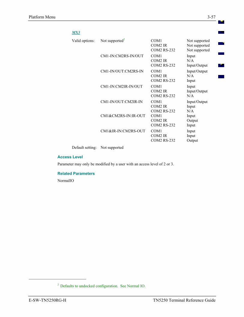
Platform Menu 3-57
E-SW-TN5250RG-H TN5250 Terminal Reference Guide
MX3
Valid options: Not supported2 COM1 Not supported COM2 IR Not supported COM2 RS-232 Not supported CM1-IN:CM2RS-IN/OUT COM1 Input COM2 IR N/A COM2 RS-232 Input/Output CM1-IN/OUT:CM2RS-IN COM1 Input/Output COM2 IR N/A COM2 RS-232 Input CM1-IN:CM2IR-IN/OUT COM1 Input COM2 IR Input/Output COM2 RS-232 N/A CM1-IN/OUT:CM2IR-IN COM1 Input/Output COM2 IR Input COM2 RS-232 N/A CM1&CM2RS-IN:IR-OUT COM1 Input COM2 IR Output COM2 RS-232 Input CM1&IR-IN:CM2RS-OUT COM1 Input COM2 IR Input COM2 RS-232 Output
Default setting: Not supported
Access Level Parameter may only be modified by a user with an access level of 2 or 3.
Related Parameters NormalIO
2 Defaults to undocked configuration. See Normal IO.
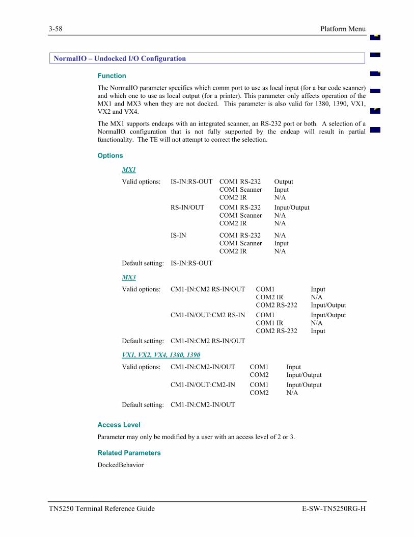
3-58 Platform Menu
TN5250 Terminal Reference Guide E-SW-TN5250RG-H
NormalIO – Undocked I/O Configuration
Function The NormalIO parameter specifies which comm port to use as local input (for a bar code scanner) and which one to use as local output (for a printer). This parameter only affects operation of the MX1 and MX3 when they are not docked. This parameter is also valid for 1380, 1390, VX1, VX2 and VX4.
The MX1 supports endcaps with an integrated scanner, an RS-232 port or both. A selection of a NormalIO configuration that is not fully supported by the endcap will result in partial functionality. The TE will not attempt to correct the selection.
Options
MX1
Valid options: IS-IN:RS-OUT COM1 RS-232 Output COM1 Scanner Input COM2 IR N/A RS-IN/OUT COM1 RS-232 Input/Output COM1 Scanner N/A COM2 IR N/A
IS-IN COM1 RS-232 N/A COM1 Scanner Input COM2 IR N/A
Default setting: IS-IN:RS-OUT
MX3
Valid options: CM1-IN:CM2 RS-IN/OUT COM1 Input COM2 IR N/A COM2 RS-232 Input/Output CM1-IN/OUT:CM2 RS-IN COM1 Input/Output COM1 IR N/A COM2 RS-232 Input Default setting: CM1-IN:CM2 RS-IN/OUT
VX1, VX2, VX4, 1380, 1390
Valid options: CM1-IN:CM2-IN/OUT COM1 Input COM2 Input/Output CM1-IN/OUT:CM2-IN COM1 Input/Output COM2 N/A
Default setting: CM1-IN:CM2-IN/OUT
Access Level Parameter may only be modified by a user with an access level of 2 or 3.
Related Parameters DockedBehavior
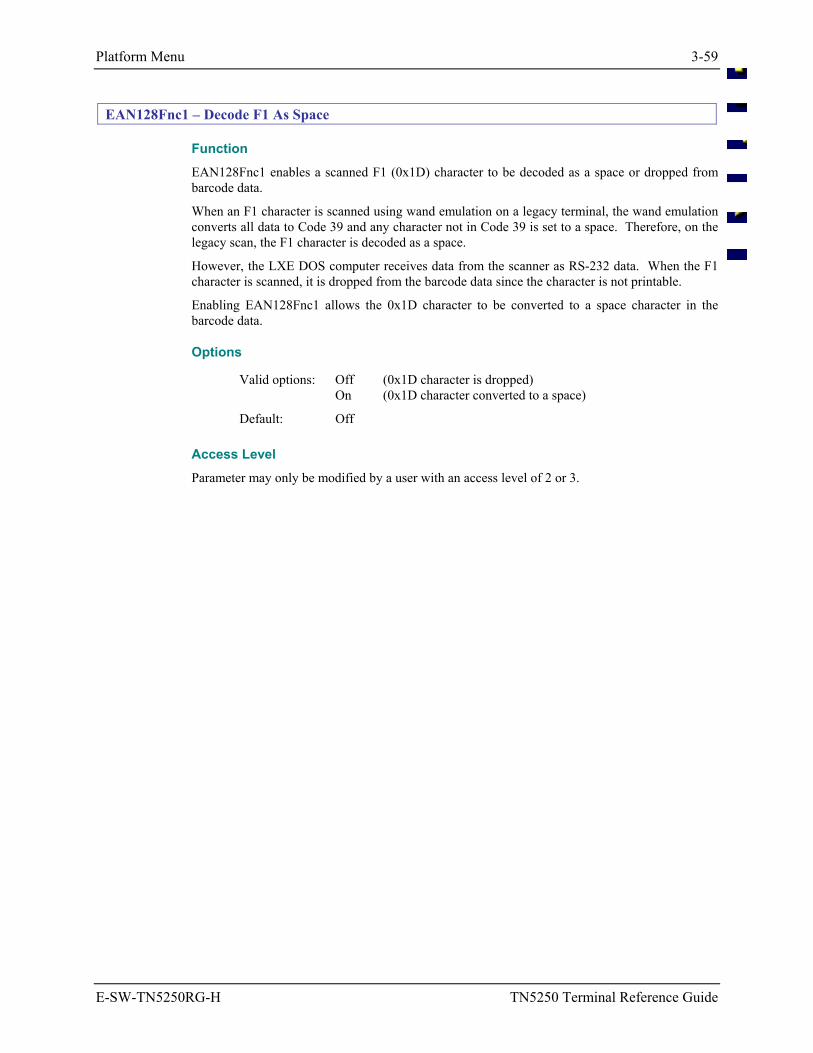
Platform Menu 3-59
E-SW-TN5250RG-H TN5250 Terminal Reference Guide
EAN128Fnc1 – Decode F1 As Space
Function EAN128Fnc1 enables a scanned F1 (0x1D) character to be decoded as a space or dropped from barcode data.
When an F1 character is scanned using wand emulation on a legacy terminal, the wand emulation converts all data to Code 39 and any character not in Code 39 is set to a space. Therefore, on the legacy scan, the F1 character is decoded as a space.
However, the LXE DOS computer receives data from the scanner as RS-232 data. When the F1 character is scanned, it is dropped from the barcode data since the character is not printable.
Enabling EAN128Fnc1 allows the 0x1D character to be converted to a space character in the barcode data.
Options
Valid options: Off (0x1D character is dropped) On (0x1D character converted to a space)
Default: Off
Access Level Parameter may only be modified by a user with an access level of 2 or 3.
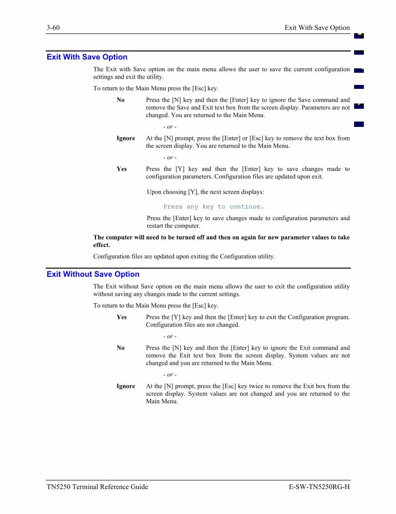
3-60 Exit With Save Option
TN5250 Terminal Reference Guide E-SW-TN5250RG-H
Exit With Save Option The Exit with Save option on the main menu allows the user to save the current configuration settings and exit the utility.
To return to the Main Menu press the [Esc] key.
No Press the [N] key and then the [Enter] key to ignore the Save command and remove the Save and Exit text box from the screen display. Parameters are not changed. You are returned to the Main Menu.
- or -
Ignore At the [N] prompt, press the [Enter] or [Esc] key to remove the text box from the screen display. You are returned to the Main Menu.
- or -
Yes Press the [Y] key and then the [Enter] key to save changes made to configuration parameters. Configuration files are updated upon exit.
Upon choosing [Y], the next screen displays:
Press any key to continue.
Press the [Enter] key to save changes made to configuration parameters and restart the computer.
The computer will need to be turned off and then on again for new parameter values to take effect.
Configuration files are updated upon exiting the Configuration utility.
Exit Without Save Option The Exit without Save option on the main menu allows the user to exit the configuration utility without saving any changes made to the current settings.
To return to the Main Menu press the [Esc] key.
Yes Press the [Y] key and then the [Enter] key to exit the Configuration program. Configuration files are not changed.
- or -
No Press the [N] key and then the [Enter] key to ignore the Exit command and remove the Exit text box from the screen display. System values are not changed and you are returned to the Main Menu.
- or -
Ignore At the [N] prompt, press the [Esc] key twice to remove the Exit box from the screen display. System values are not changed and you are returned to the Main Menu.
E-SW-TN5250RG-H TN5250 Terminal Reference Guide
Table of Contents
CHAPTER 4 CODE PAGES AND CHARACTER SETS 4-1
Introduction ............................................................................................................ 4-1
Displayable Characters ......................................................................................... 4-2 Default Code Page ................................................................................................................ 4-2 LXE Character Set................................................................................................................ 4-3 Default TE EBCDIC Character Set ...................................................................................... 4-4 Creating EBCDIC National Character Sets.......................................................................... 4-5 Example: UK EBCDIC Character Set .................................................................................. 4-6
Sample EBCDIC.TXT File ................................................................................................ 4-7 Keyboard Mapping................................................................................................. 4-8
Special Keys ......................................................................................................................... 4-8 Alphanumeric Keys .............................................................................................................. 4-8 Modifying the Keyboard Map .............................................................................................. 4-9
Sample Keys.Txt File ......................................................................................................... 4-9 Messages.............................................................................................................. 4-10
Default Messages................................................................................................................ 4-10 Editing The Message.Txt File ............................................................................................ 4-10
Sample Message.Txt File ................................................................................................. 4-11 Editing ASCII Files ............................................................................................... 4-12
Editing Files at the Computer ............................................................................................. 4-12 Edit then Transfer Files Using a PC Card .......................................................................... 4-13 Transfer Files Using DOS REMDISK/REMSERV ........................................................... 4-15
Illustrations
Figure 4-1 Code Page 00437 ........................................................................................................................... 4-2 Figure 4-2 LXE Character Set - Abbreviated .................................................................................................. 4-3 Figure 4-3 USA/Canada IBM EBCDIC........................................................................................................... 4-4 Figure 4-4 U.K. IBM EBCDIC........................................................................................................................ 4-6
4-ii Table of Contents
TN5250 Terminal Reference Guide E-SW-TN5250RG-H
An EMS Technologies Company
E-SW-TN5250RG-H TN5250 Terminal Reference Guide
Chapter 4 Code Pages and Character Sets
Introduction
On a standard PC running DOS, a program can access 256 characters from the “Active Code Page” in VGA Text Mode. This character set consists of a table of 256 characters, numbered 0 to 255. A DOS program can display any character by selecting a number between 0 and 255.
The LXE computers use a standard VGA chipset which produces the same results as on a standard PC.
What is actually displayed on the screen is dependant on which Code Page table is loaded and active. The VGA standard can accommodate 2 loaded Code Pages, with only one active at any given time.
A Code Page table is an ordered collection of up to 256 “display fonts”, with each font representing the actual pixels drawn on the display. Hundreds of Code Pages and “Font Files” exist, enabling the display of virtually any character in any language. The TN5250 TE uses two – USA/Canada Code Page 00037 and the LXE Character Set.
Appendix A contains a graphic representation of the USA/Canada IBM EBCDIC code page, the LXE Character Set, Decimal/Hexadecimal counterparts, and the decimal equivalents of Code Page 00437 (USA).
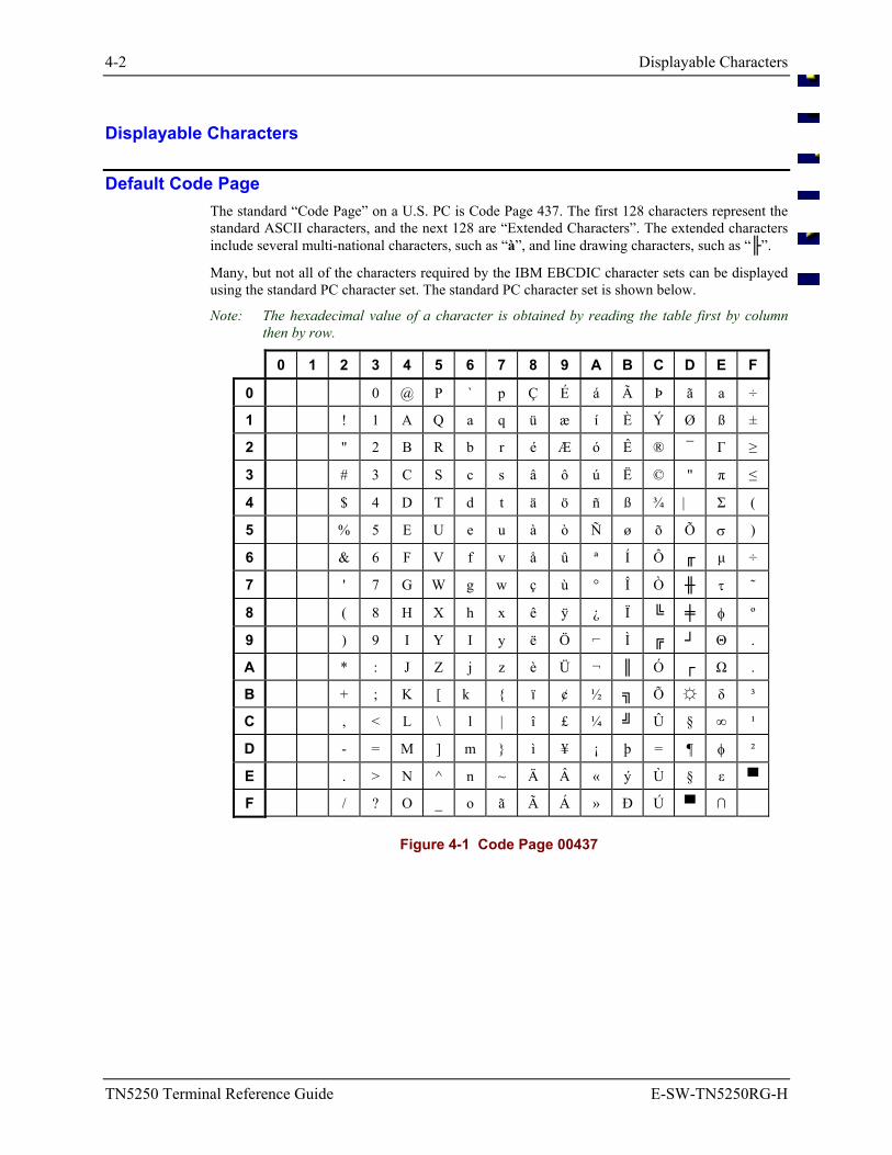
4-2 Displayable Characters
TN5250 Terminal Reference Guide E-SW-TN5250RG-H
Displayable Characters
Default Code Page The standard “Code Page” on a U.S. PC is Code Page 437. The first 128 characters represent the standard ASCII characters, and the next 128 are “Extended Characters”. The extended characters include several multi-national characters, such as “à”, and line drawing characters, such as “”.
Many, but not all of the characters required by the IBM EBCDIC character sets can be displayed using the standard PC character set. The standard PC character set is shown below.
Note: The hexadecimal value of a character is obtained by reading the table first by column then by row.
0 1 2 3 4 5 6 7 8 9 A B C D E F
0 0 @ P ` p Ç É á Ã Þ ã a ÷
1 ! 1 A Q a q ü æ í È Ý Ø ß ±
2 " 2 B R b r é Æ ó Ê ® ¯ Γ ≥
3 # 3 C S c s â ô ú Ë © " π ≤
4 $ 4 D T d t ä ö ñ ß ¾ | Σ (
5 % 5 E U e u à ò Ñ ø õ Õ σ )
6 & 6 F V f v å û ª Í Ô µ ÷
7 ' 7 G W g w ç ù ° Î Ò τ ˜
8 ( 8 H X h x ê ÿ ¿ Ï φ º
9 ) 9 I Y I y ë Ö Ì Θ .
A * : J Z j z è Ü ¬ Ó Ω .
B + ; K [ k ï ¢ ½ Õ δ ³
C , < L \ l | î £ ¼ Û § ∞ ¹
D - = M ] m ì ¥ ¡ þ = ¶ φ ²
E . > N ^ n ~ Ä Â « ý Ù § ε
F / ? O _ o ã Ã Á » Ð Ú ∩
Figure 4-1 Code Page 00437
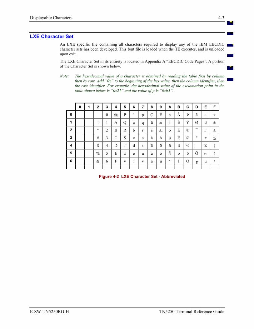
Displayable Characters 4-3
E-SW-TN5250RG-H TN5250 Terminal Reference Guide
LXE Character Set An LXE specific file containing all characters required to display any of the IBM EBCDIC character sets has been developed. This font file is loaded when the TE executes, and is unloaded upon exit.
The LXE Character Set in its entirety is located in Appendix A “EBCDIC Code Pages”. A portion of the Character Set is shown below.
Note: The hexadecimal value of a character is obtained by reading the table first by column then by row. Add “0x” to the beginning of the hex value, then the column identifier, then the row identifier. For example, the hexadecimal value of the exclamation point in the table shown below is “0x21” and the value of µ is “0xb5”.
0 1 2 3 4 5 6 7 8 9 A B C D E F
0 0 @ P ` p Ç É á Ã Þ ã a ÷
1 ! 1 A Q a q ü æ í È Ý Ø ß ±
2 " 2 B R b r é Æ ó Ê ® ¯ Γ ≥
3 # 3 C S c s â ô ú Ë © " π ≤
4 $ 4 D T d t ä ö ñ ß ¾ | Σ (
5 % 5 E U e u à ò Ñ ø õ Õ σ )
6 & 6 F V f v å û ª Í Ô µ ÷
Figure 4-2 LXE Character Set - Abbreviated
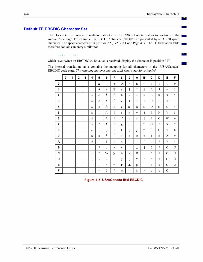
4-4 Displayable Characters
TN5250 Terminal Reference Guide E-SW-TN5250RG-H
Default TE EBCDIC Character Set The TEs contain an internal translation table to map EBCDIC character values to positions in the Active Code Page. For example, the EBCDIC character “0x40” is represented by an ASCII space character. The space character is in position 32 (0x20) in Code Page 437. The TE translation table therefore contains an entry similar to:
0x40 → 32
which says “when an EBCDIC 0x40 value is received, display the character in position 32”.
The internal translation table contains the mapping for all characters in the “USA/Canada” EBCDIC code page. The mapping assumes that the LXE Character Set is loaded.
0 1 2 3 4 5 6 7 8 9 A B C D E F
0 & - ø Ø ° µ ^ \ 0
1 é / É a j ˜ £ A J ÷ 1
2 â ê Â Ê b k s ¥ B K S 2
3 ä ë Ä Ë c l t • C L T 3
4 à è À È d m u © D M U 4
5 á í Á Í e n v § E N V 5
6 ã î Ã Î f o w ¶ F O W 6
7 å ï Å Ï g p x ¼ G P X 7
8 ç ì Ç Ì h q y ½ H Q Y 8
9 ñ ß Ñ ` i r z ¾ I R Z 9
A ¢ ! | : « ª ¡ [ - ¹ ² ³
B . $ , # » º ¿ ] ô û Ô Û
C ‹ * % @ ð æ Ð ¯ ö ü Ö Ü
D ( ) – ' ý ¸ Ý ¨ ò ù Ò Ù
E + ; > = Þ Æ þ ' ó ú Ó Ú
F | ¬ ? " ± ¤ ® × õ ÿ Õ
Figure 4-3 USA/Canada IBM EBCDIC
Displayable Characters 4-5
E-SW-TN5250RG-H TN5250 Terminal Reference Guide
Creating EBCDIC National Character Sets The method for creating EBCDIC character sets for countries other than the U.S. is described below, and is followed by an example.
Upon loading, the TE first loads the LXE Character Set, then searches for a file called “EBCDIC.TXT”. If this file is not found, the TE uses its internal translation table (default U.S. EBCDIC). If this file is found, the TE modifies its internal translation table based on the information contained in the file. Each line in this text file contains two entries separated by a space:
EBCDIC character LXE Character Set Position
For example: 0x40 32
- or - 0x40 0x20
Where the <white space> represents any number of spaces and/or tabs, and is used for clarity. The first entry is the EBCDIC character position in hexadecimal in the default EBCDIC character table, and the second entry is the hexadecimal or decimal position in the LXE Character Set table.
The EBCDIC.TXT file is a standard DOS text file, and may be created and edited using the DOS edit utility.
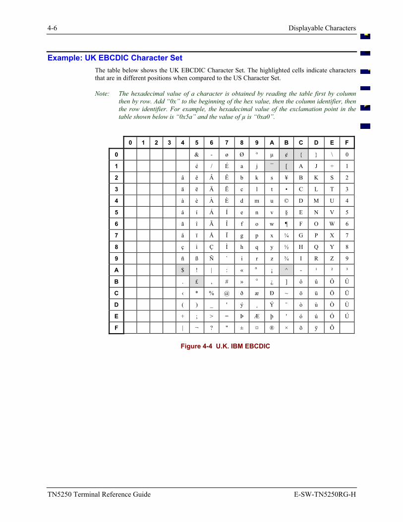
4-6 Displayable Characters
TN5250 Terminal Reference Guide E-SW-TN5250RG-H
Example: UK EBCDIC Character Set The table below shows the UK EBCDIC Character Set. The highlighted cells indicate characters that are in different positions when compared to the US Character Set.
Note: The hexadecimal value of a character is obtained by reading the table first by column then by row. Add “0x” to the beginning of the hex value, then the column identifier, then the row identifier. For example, the hexadecimal value of the exclamation point in the table shown below is “0x5a” and the value of µ is “0xa0”.
0 1 2 3 4 5 6 7 8 9 A B C D E F
0 & - ø Ø ° µ ¢ \ 0
1 é / É a j ¯ [ A J ÷ 1
2 â ê Â Ê b k s ¥ B K S 2
3 ä ë Ä Ë c l t • C L T 3
4 à è À È d m u © D M U 4
5 á í Á Í e n v § E N V 5
6 ã î Ã Î f o w ¶ F O W 6
7 å ï Å Ï g p x ¼ G P X 7
8 ç ì Ç Ì h q y ½ H Q Y 8
9 ñ ß Ñ ` i r z ¾ I R Z 9
A $ ! | : « ª ¡ ^ - ¹ ² ³
B . £ , # » º ¿ ] ô û Ô Û
C ‹ * % @ ð æ Ð ~ ö ü Ö Ü
D ( ) _ ' ý ¸ Ý ¨ ò ù Ò Ù
E + ; > = Þ Æ þ ' ó ú Ó Ú
F | ¬ ? " ± ¤ ® × õ ÿ Õ
Figure 4-4 U.K. IBM EBCDIC
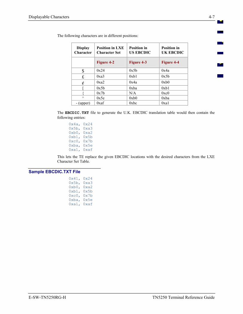
Displayable Characters 4-7
E-SW-TN5250RG-H TN5250 Terminal Reference Guide
The following characters are in different positions:
Display Character
Position in LXECharacter Set
Position in US EBCDIC
Position in UK EBCDIC
Figure 4-2 Figure 4-3 Figure 4-4
$ 0x24 0x5b 0x4a
£ 0xa3 0xb1 0x5b
¢ 0xa2 0x4a 0xb0 [ 0x5b 0xba 0xb1 0x7b N/A 0xc0 ^ 0x5e 0xb0 0xba
- (upper) 0xaf 0xbc 0xa1
The EBCDIC.TXT file to generate the U.K. EBCDIC translation table would then contain the following entries:
0x4a, 0x24 0x5b, 0xa3 0xb0, 0xa2 0xb1, 0x5b 0xc0, 0x7b 0xba, 0x5e 0xa1, 0xaf
This lets the TE replace the given EBCDIC locations with the desired characters from the LXE Character Set Table.
Sample EBCDIC.TXT File 0x41, 0x24 0x5b, 0xa3 0xb0, 0xa2 0xb1, 0x5b 0xc0, 0x7b 0xba, 0x5e 0xa1, 0xaf
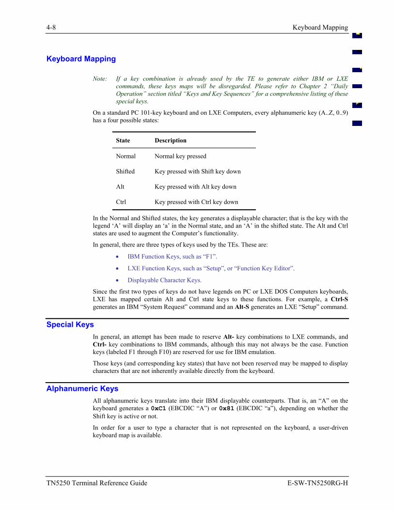
4-8 Keyboard Mapping
TN5250 Terminal Reference Guide E-SW-TN5250RG-H
Keyboard Mapping
Note: If a key combination is already used by the TE to generate either IBM or LXE commands, these keys maps will be disregarded. Please refer to Chapter 2 “Daily Operation” section titled “Keys and Key Sequences” for a comprehensive listing of these special keys.
On a standard PC 101-key keyboard and on LXE Computers, every alphanumeric key (A..Z, 0..9) has a four possible states:
State Description
Normal Normal key pressed
Shifted Key pressed with Shift key down
Alt Key pressed with Alt key down
Ctrl Key pressed with Ctrl key down
In the Normal and Shifted states, the key generates a displayable character; that is the key with the legend ‘A’ will display an ‘a’ in the Normal state, and an ‘A’ in the shifted state. The Alt and Ctrl states are used to augment the Computer’s functionality.
In general, there are three types of keys used by the TEs. These are:
• IBM Function Keys, such as “F1”.
• LXE Function Keys, such as “Setup”, or “Function Key Editor”.
• Displayable Character Keys.
Since the first two types of keys do not have legends on PC or LXE DOS Computers keyboards, LXE has mapped certain Alt and Ctrl state keys to these functions. For example, a Ctrl-S generates an IBM “System Request” command and an Alt-S generates an LXE “Setup” command.
Special Keys In general, an attempt has been made to reserve Alt- key combinations to LXE commands, and Ctrl- key combinations to IBM commands, although this may not always be the case. Function keys (labeled F1 through F10) are reserved for use for IBM emulation.
Those keys (and corresponding key states) that have not been reserved may be mapped to display characters that are not inherently available directly from the keyboard.
Alphanumeric Keys All alphanumeric keys translate into their IBM displayable counterparts. That is, an “A” on the keyboard generates a 0xC1 (EBCDIC “A”) or 0x81 (EBCDIC “a”), depending on whether the Shift key is active or not.
In order for a user to type a character that is not represented on the keyboard, a user-driven keyboard map is available.
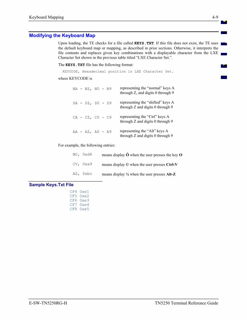
Keyboard Mapping 4-9
E-SW-TN5250RG-H TN5250 Terminal Reference Guide
Modifying the Keyboard Map Upon loading, the TE checks for a file called KEYS.TXT. If this file does not exist, the TE uses the default keyboard map or mapping, as described in prior sections. Otherwise, it interprets the file contents and replaces given key combinations with a displayable character from the LXE Character Set shown in the previous table titled “LXE Character Set.”.
The KEYS.TXT file has the following format: KEYCODE, Hexadecimal position in LXE Character Set.
where KEYCODE is
NA - NZ, N0 - N9 representing the “normal” keys A through Z, and digits 0 through 9
SA - SZ, S0 - S9 representing the “shifted” keys A through Z and digits 0 through 9
CA - CZ, C0 - C9 representing the “Ctrl” keys A through Z and digits 0 through 9
AA - AZ, A0 - A9 representing the “Alt” keys A through Z and digits 0 through 9
For example, the following entries:
NO, 0xd6 means display Ö when the user presses the key O
CV, 0xa9 means display © when the user presses Ctrl-V
AZ, 0xbc means display ¼ when the user presses Alt-Z
Sample Keys.Txt File CF4 0xe1 CF5 0xe2 CF6 0xe3 CF7 0xe4 CF8 0xe5
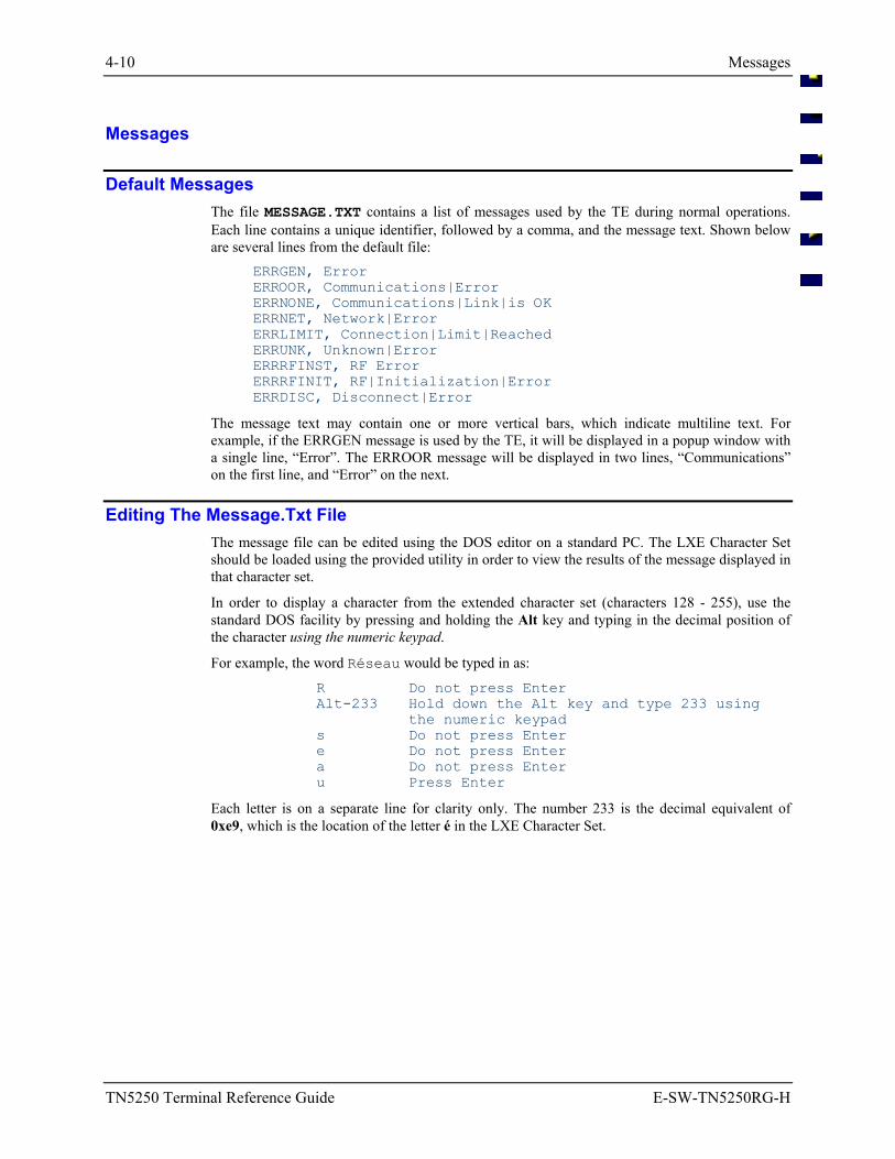
4-10 Messages
TN5250 Terminal Reference Guide E-SW-TN5250RG-H
Messages
Default Messages The file MESSAGE.TXT contains a list of messages used by the TE during normal operations. Each line contains a unique identifier, followed by a comma, and the message text. Shown below are several lines from the default file:
ERRGEN, Error ERROOR, Communications|Error ERRNONE, Communications|Link|is OK ERRNET, Network|Error ERRLIMIT, Connection|Limit|Reached ERRUNK, Unknown|Error ERRRFINST, RF Error ERRRFINIT, RF|Initialization|Error ERRDISC, Disconnect|Error
The message text may contain one or more vertical bars, which indicate multiline text. For example, if the ERRGEN message is used by the TE, it will be displayed in a popup window with a single line, “Error”. The ERROOR message will be displayed in two lines, “Communications” on the first line, and “Error” on the next.
Editing The Message.Txt File The message file can be edited using the DOS editor on a standard PC. The LXE Character Set should be loaded using the provided utility in order to view the results of the message displayed in that character set.
In order to display a character from the extended character set (characters 128 - 255), use the standard DOS facility by pressing and holding the Alt key and typing in the decimal position of the character using the numeric keypad.
For example, the word Réseau would be typed in as:
R Do not press Enter Alt-233 Hold down the Alt key and type 233 using
the numeric keypad s Do not press Enter e Do not press Enter a Do not press Enter u Press Enter
Each letter is on a separate line for clarity only. The number 233 is the decimal equivalent of 0xe9, which is the location of the letter é in the LXE Character Set.
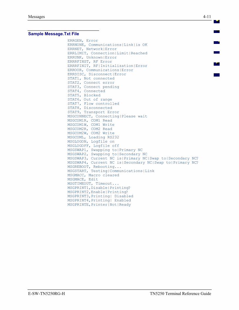
Messages 4-11
E-SW-TN5250RG-H TN5250 Terminal Reference Guide
Sample Message.Txt File ERRGEN, Error ERRNONE, Communications|Link|is OK ERRNET, Network|Error ERRLIMIT, Connection|Limit|Reached ERRUNK, Unknown|Error ERRRFINST, RF Error ERRRFINIT, RF|Initialization|Error ERROOR, Communications|Error ERRDISC, Disconnect|Error STAT1, Not connected STAT2, Connect error STAT3, Connect pending STAT4, Connected STAT5, Blocked STAT6, Out of range STAT7, Flow controlled STAT8, Disconnected STAT9, Transport Error MSGCONNECT, Connecting|Please wait MSGCOM1R, COM1 Read MSGCOM1W, COM1 Write MSGCOM2R, COM2 Read MSGCOM2W, COM2 Write MSGCOML, Loading RS232 MSGLOGON, Logfile on MSGLOGOFF, Logfile off MSGSWAP1, Swapping to|Primary NC MSGSWAP2, Swapping to|Secondary NC MSGSWAP3, Current NC is|Primary NC|Swap to|Secondary NC? MSGSWAP4, Current NC is|Secondary NC|Swap to|Primary NC? MSGREBOOT, Rebooting... MSGSTART, Testing|Communications|Link MSGMACC, Macro cleared MSGMACE, Edit MSGTIMEOUT, Timeout... MSGPRINT1,Disable|Printing? MSGPRINT2,Enable|Printing? MSGPRINT3,Printing| Disabled MSGPRINT4,Printing| Enabled MSGPRINTE,Printer|Not|Ready
4-12 Editing ASCII Files
TN5250 Terminal Reference Guide E-SW-TN5250RG-H
Editing ASCII Files
There are several ways to edit “text” files that are contained in the directories. The files could be:
• edited while resident in the computer.
• edited on an IBM compatible PC/Laptop (with a PCMCIA card drive) and transferred to the computer using a PCMCIA card.
• edited on an IBM compatible PC/Laptop and transferred to the computer using a file transfer utility (REMDISK / REMSERV).
The following processes use the KEYS.TXT file.
Editing Files at the Computer
Refer to the DOS User’s Manuals delivered with your DOS computer for complete instructions when using DOS commands and utilities.
1. Power on the computer. Exit from any running programs. The DOS prompt should appear on the screen.
C:>
Note: Enter the appropriate DOS commands to locate the filename of the ASCII editor you want to use. The ROM-DOS NED file (NED.EXE and NED.CFG) are usually in the DOS directory.
2. Enter the appropriate commands to locate the file you want to edit.
For example, at the DOS prompt, type: CD\IBM Press Enter
Result: This will change the pointer to the IBM directory.
Then type the following at the DOS prompt to make sure the file you want to edit is in the IBM directory:
C:\IBM > DIR KEYS.TXT Press Enter
If the file exists in the IBM subdirectory, the KEYS.TXT file information will be displayed. If not, the computer will display File Not Found.
Type the following at the DOS prompt: COPY KEYS.TXT KEYS.OLD
This will create a backup of the KEYS.TXT file.
3. After a copy of the original KEYS file has been made, type the following at the DOS prompt:
NED KEYS.TXT
This will allow you to edit the KEYS.TXT file.
Note: If NED.EXE is not installed or you prefer not to use it, you may use any text editor to edit the KEYS.TXT file.
4. Save the changes to your KEYS.TXT file and exit the text editor.
5. Restart the computer by pressing Ctrl+Alt+Del.
Editing ASCII Files 4-13
E-SW-TN5250RG-H TN5250 Terminal Reference Guide
Edit then Transfer Files Using a PC Card PCMCIA cards are used in computers and computerized equipment and are commonly called PC Cards. PC Cards can be used to store Flash Memory, SRAM Memory, function as Network/LAN drivers, FAX/Modem drivers, be used as ATA disks, hard disks, SCSI disk drives, and other I/O functions. After files have been transferred to the PC card, the card is inserted in the computer or equipment and the files on the card are accessed in the same manner as any file on the computer system.
Requirements:
• Diskette(s) containing files to be transferred to the computer.
• One (1) SRAM card (PC card).
Note: If the PC Card is unformatted, format the card using the DOS FORMAT command before copying files to the card. Refer to the DOS manual for more information on the FORMAT command.
An IBM compatible PC/Laptop with:
• DOS version 3 or later.
• one floppy drive (minimum).
• one (1) PCMCIA Type II slot (minimum).
• PCMCIA Card management software (i.e. Phoenix Card Management).
1. Insert the Diskette (containing files to be edited and/or transferred) into the floppy disk drive of the PC/Laptop. (Typically this is drive A:)
2. Insert the SRAM card into the PCMCIA slot of the PC/Laptop. (Typically this is drive D:)
3. At the DOS prompt, type the following... A:
Where A: is the drive containing the diskette.
4. Press Enter
5. Locate the file(s) to be edited or copied to the computer. (Use the DOS DIR and CD commands to locate files.)
Refer to the MS-DOS manual for more information on the DIR and CD commands.
6. Type the following at the DOS prompt: COPY KEYS.TXT KEYS.OLD
This will create a backup of the KEYS.TXT file.
7. After a copy of the original KEYS file has been made, type the following at the DOS prompt:
EDIT KEYS.TXT
This will allow you to edit the KEYS.TXT file.
Note: If EDIT is not installed or you prefer not to use it, you may use any text editor, such as NED.EXE to edit the KEYS.TXT file.
4-14 Editing ASCII Files
TN5250 Terminal Reference Guide E-SW-TN5250RG-H
8. Save the changes to your KEYS.TXT file and exit the text editor.
9. Once the file(s) have been edited on the SRAM card, remove the SRAM card from the PC/Laptop.
10. Following the instructions in the specific computer’s Reference Guide insert the SRAM card into the appropriate slot in the computer.
11. Copy the edited file to the appropriate drive and subdirectory in the computer. In the case of the 2330, copy the edited file to the Internal Flash Array, referred to as Drive C.
Editing ASCII Files 4-15
E-SW-TN5250RG-H TN5250 Terminal Reference Guide
Transfer Files Using DOS REMDISK/REMSERV Requirements:
• An IBM compatible PC/Laptop with:
DOS version 3 or later
one serial port (minimum)
one floppy drive (minimum).
• An LXE computer with a serial port.
• One 3-wire null modem serial cable for a serial connection.
Refer to the DOS Computer’s Reference Guide for more details on using REMDISK and REMSERV. The parameters for each utility are detailed in the Reference Guides.
Note: Edit the file on the PC/Laptop before transferring it to the computer with REMDISK/REMSERV.
1. Using the null modem cable, connect the PC/Laptop to the LXE computer’s serial port.
2. On the PC/Laptop, make sure the REMDISK.EXE is running with the same baud rate and packet/nonpacket-style transmission that REMSERV.EXE is using on the LXE DOS computer.
3. The LXE computer’s drive specified in the REMSERV command becomes the next assigned drive letter for the PC/Laptop. For example, if D: was the last drive assigned on the PC/Laptop, the REMDISK creates drive E.
4. Insert the Diskette (containing files to be transferred) into the floppy disk drive of the PC/Laptop. (Typically this is drive A:).
5. At the DOS prompt on the PC/Laptop, type... A:
where A: is the drive containing the diskette.
3. Press Enter.
4. Locate the file(s) to be copied to the computer. (Use the DOS DIR and CD commands to locate files.)
Note: Refer to the DOS manual for more information on the DIR and CD commands.
5. Copy the specified files from the diskette to the computer. (Use the DOS COPY or XCOPY commands to copy the specified files from the SRAM card.)
Note: Refer to the MS-DOS manual for more information on the COPY and XCOPY commands. COPY A:\KEYS.TXT E:\KEYS.TXT
This command copies a single file (KEYS.TXT) from the diskette to the LXE computer (where A: is the floppy drive containing the diskette and E: is the LXE computer’s hard drive).
4-16 Editing ASCII Files
TN5250 Terminal Reference Guide E-SW-TN5250RG-H
An EMS Technologies Company
E-SW-TN5250RG-H TN5250 Terminal Reference Guide
Table of Contents
CHAPTER 5 5250 PROGRAMMER’S REFERENCE 5-1
Introduction ............................................................................................................ 5-1 Primary Audience ................................................................................................................. 5-1 Examples............................................................................................................................... 5-1 About RF Performance ......................................................................................................... 5-2
Screen Design..................................................................................................................... 5-2 Collisions............................................................................................................................ 5-2 Auto Transmit .................................................................................................................... 5-2
Data Stream .......................................................................................................................... 5-3 RF Header .......................................................................................................................... 5-3 RF Trailer ........................................................................................................................... 5-3
Match and Local Field Compare Commands....................................................... 5-4 Command Letters.................................................................................................................. 5-4 Match Field Edit ................................................................................................................... 5-6
Constructing Predecessor Fields ........................................................................................ 5-6 Constructing Match Fields ................................................................................................. 5-6 Data Fails Match Test ........................................................................................................ 5-7 Default Wildcard Match Characters................................................................................... 5-7
Local Field Compare ............................................................................................................ 5-8 Data Fails Compare Test .................................................................................................... 5-8 Using Local Compare Field ............................................................................................... 5-8 Example.............................................................................................................................. 5-9
Scan and Increment Match Field ........................................................................................ 5-10 Description ....................................................................................................................... 5-10 Predecessor Field.............................................................................................................. 5-10 Match Count Field............................................................................................................ 5-11 Advancing the Cursor....................................................................................................... 5-11 Cursor Placement ............................................................................................................. 5-11 Count Specifier Field ....................................................................................................... 5-11 Auto Transmit .................................................................................................................. 5-11 Advance Mode ................................................................................................................. 5-11 Incorrect Data Entry ......................................................................................................... 5-12
Input Device ID .................................................................................................................. 5-13 Description ....................................................................................................................... 5-13 Input ID Field ................................................................................................................... 5-13 Terminal Operation .......................................................................................................... 5-14 Examples .......................................................................................................................... 5-14 Input Identification Types ................................................................................................ 5-16
Terminal Setup Commands................................................................................. 5-17
5-ii Table of Contents
TN5250 Terminal Reference Guide E-SW-TN5250RG-H
Screen Design for Terminal Setup Commands .................................................................. 5-17 Command String................................................................................................................. 5-18
Semicolon......................................................................................................................... 5-18 String Elements ................................................................................................................ 5-19
Left Justify Mode: p2.......................................................................................................... 5-21 Clear Mode: p3 ................................................................................................................... 5-22 Truncate Mode: p4.............................................................................................................. 5-23 Advance Mode: p5.............................................................................................................. 5-24 Auto Transmit After Data Stream Print: p6........................................................................ 5-25 Printer Carriage Return per Line: p7 .................................................................................. 5-26 Printer Line Feed per Line: p8............................................................................................ 5-27 Status Line Display Mode: p9 ............................................................................................ 5-28 Input Device ID: p10 .......................................................................................................... 5-29 Swap TAB/Field Exit: p11 ................................................................................................. 5-30 Advance: p12 ...................................................................................................................... 5-31 Command String for Wildcard Match Characters .............................................................. 5-32 Window Setup .................................................................................................................... 5-34
Message Line.................................................................................................................... 5-35 Command String for Window Setup ................................................................................ 5-35 String Elements ................................................................................................................ 5-36 Display Modes: p2 ........................................................................................................... 5-38 Valid Window Positions: p3 and p4................................................................................. 5-39
The Vehicle Mounted Computer Screens ...................................................................................5-40 Handheld Computer Screens.......................................................................................................5-40
Window Movement: p5.................................................................................................... 5-41 Quadrant for Cursor: p6 ................................................................................................... 5-42 Status Line........................................................................................................................ 5-42
Behavior......................................................................................................................................5-42 Removing the Status Line...........................................................................................................5-42 Modes of Operation ....................................................................................................................5-42
Message Line.................................................................................................................... 5-43 Display Window .........................................................................................................................5-43 Overwriting the Display..............................................................................................................5-43 Removing the Message Line.......................................................................................................5-43 Window Movement Keys ...........................................................................................................5-43
Beep Pattern Command ...................................................................................................... 5-44 Rules................................................................................................................................. 5-44 Command String............................................................................................................... 5-45 Elements ........................................................................................................................... 5-45 Determine the Beep Pattern Number ............................................................................... 5-45
Printing a Field ................................................................................................................... 5-47 Rules................................................................................................................................. 5-47 Auto Transmit .................................................................................................................. 5-48 CR/LF............................................................................................................................... 5-48

Table of Contents 5-iii
E-SW-TN5250RG-H TN5250 Terminal Reference Guide
Illustrations
Figure 5-1 IBM 5250 Data Stream with RF Header and Trailer ..................................................................... 5-3 Figure 5-2 Match Field Example ..................................................................................................................... 5-6 Figure 5-3 Match Field Containing Wildcard and Exact Match Characters.................................................... 5-7 Figure 5-4 Local Compare Field Example....................................................................................................... 5-9 Figure 5-5 Local Field Compare and Scan and Increment Example ............................................................... 5-9 Figure 5-6 Predecessor, Match, Match Count and Count Specifier Fields .................................................... 5-10 Figure 5-7 Input ID Feature with Normal Input Field ................................................................................... 5-14 Figure 5-8 Contents of Fields after Keyboard Entry...................................................................................... 5-14 Figure 5-9 Protected Fields............................................................................................................................ 5-15 Figure 5-10 Input ID used with Scan and Increment Match Fields ............................................................... 5-15 Figure 5-11 Window Manager Setup Command ........................................................................................... 5-18 Figure 5-12 Example of Left Justify Off ....................................................................................................... 5-21 Figure 5-13 Example of Left Justify On ........................................................................................................ 5-21 Figure 5-14 Virtual Screen and Display Window Relationship..................................................................... 5-34 Figure 5-15 Valid Window Positions - 12 and 25 Row x 80 Column ........................................................... 5-40 Figure 5-16 Valid Window Positions - 10 Row x 20 Column....................................................................... 5-40 Figure 5-17 Valid Window Positions - 20 Row x 20 Column....................................................................... 5-40 Figure 5-18 Beep Pattern Command String ................................................................................................... 5-44 Figure 5-19 Beep Pattern Template ............................................................................................................... 5-45 Figure 5-20 Beep Pattern Example ................................................................................................................ 5-45 Figure 5-21 Print Command Example ........................................................................................................... 5-47

5-iv Table of Contents
TN5250 Terminal Reference Guide E-SW-TN5250RG-H
An EMS Technologies Company
E-SW-TN5250RG-H TN5250 Terminal Reference Guide
Chapter 5 5250 Programmer’s Reference
Introduction
The 5250 Programmer's Reference provides information to help you program the host application to communicate with LXE devices.
This chapter is intended to be used in conjunction with “IBM 5250 Information Display System Functions Reference Manual,” SA21-9247-6.
The 5250 Programmer's Reference includes explanations of the extra LXE features such as local field match edit, beep patterns, terminal setup, and window manager.
Primary Audience The primary audience for this chapter is the application programmer who is experienced with IBM 5250 programming standards and responsible for writing applications that communicate with LXE devices in a 5250 environment.
Examples The examples provided are for illustration purposes and should only be used as guidelines. Do not use these examples for your operation because every operation is different. Additionally, the examples in this guide are only fragments of code and are not intended for implementation.
5-2 Introduction
TN5250 Terminal Reference Guide E-SW-TN5250RG-H
About RF Performance There are several factors that can adversely affect performance in an RF environment. You can optimize RF performance by avoiding these factors or minimizing their occurrence.
Screen Design The screen design directly affects RF performance. Here are some rules you need to follow for creating and sending screens:
• Do not transmit a large number of space characters and null characters on the screen.
• Do not clutter the screens with unnecessary information.
• Perform a partial screen update (Write command) whenever possible because it takes less time than updating the entire screen (Erase/Write command).
Collisions In an RF environment, terminals compete to communicate with the Access Point. If the access point is busy, the terminal must wait and transmit its message again.
A collision occurs when two or more transmissions occur at the same time. The access point receiving the messages from the terminals either accepts the message with the stronger signal or the access point dumps both messages. The terminals must retransmit the messages that are dumped or not received.
Auto Transmit To utilize this feature, the host programmer must use the IBM 5250 CHECK keyword with the ER (End of Record Code). Refer to the IBM 5250 Programmer documentation.
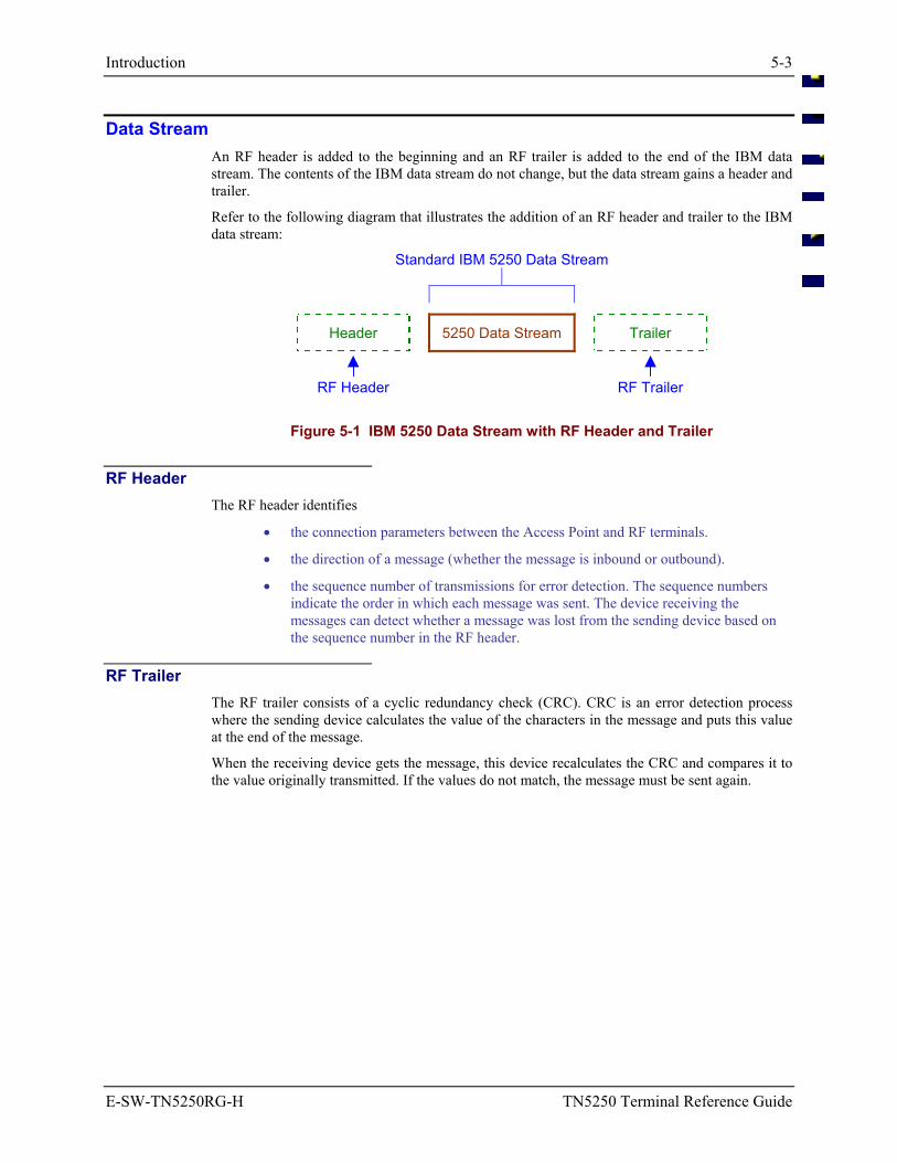
Introduction 5-3
E-SW-TN5250RG-H TN5250 Terminal Reference Guide
Data Stream An RF header is added to the beginning and an RF trailer is added to the end of the IBM data stream. The contents of the IBM data stream do not change, but the data stream gains a header and trailer.
Refer to the following diagram that illustrates the addition of an RF header and trailer to the IBM data stream:
Standard IBM 5250 Data Stream
Header 5250 Data Stream Trailer
RF Header RF Trailer
Figure 5-1 IBM 5250 Data Stream with RF Header and Trailer
RF Header The RF header identifies
• the connection parameters between the Access Point and RF terminals.
• the direction of a message (whether the message is inbound or outbound).
• the sequence number of transmissions for error detection. The sequence numbers indicate the order in which each message was sent. The device receiving the messages can detect whether a message was lost from the sending device based on the sequence number in the RF header.
RF Trailer The RF trailer consists of a cyclic redundancy check (CRC). CRC is an error detection process where the sending device calculates the value of the characters in the message and puts this value at the end of the message.
When the receiving device gets the message, this device recalculates the CRC and compares it to the value originally transmitted. If the values do not match, the message must be sent again.
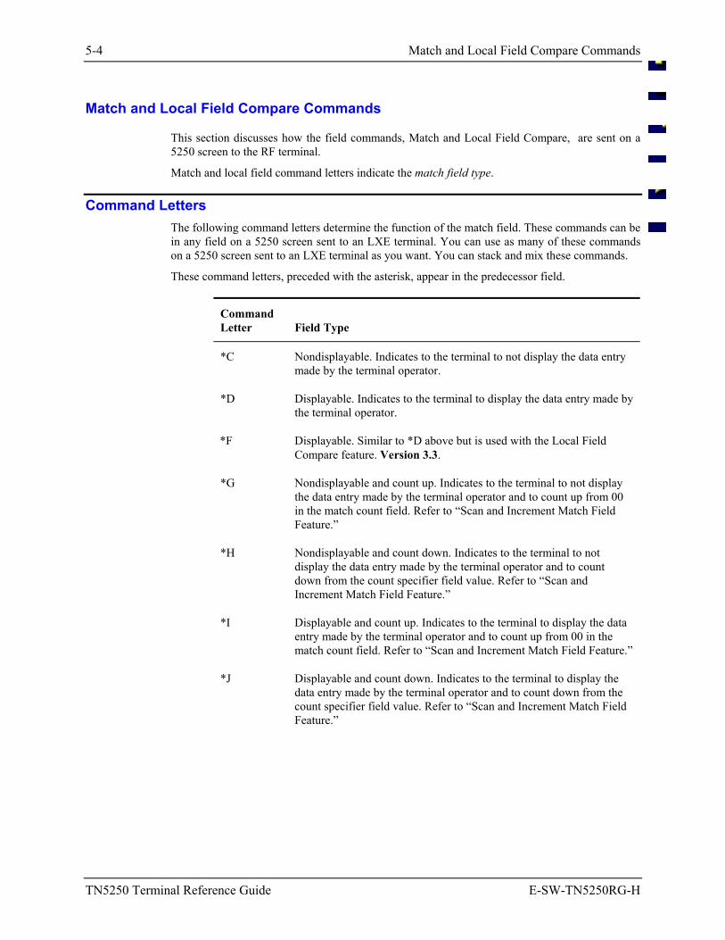
5-4 Match and Local Field Compare Commands
TN5250 Terminal Reference Guide E-SW-TN5250RG-H
Match and Local Field Compare Commands
This section discusses how the field commands, Match and Local Field Compare, are sent on a 5250 screen to the RF terminal.
Match and local field command letters indicate the match field type.
Command Letters The following command letters determine the function of the match field. These commands can be in any field on a 5250 screen sent to an LXE terminal. You can use as many of these commands on a 5250 screen sent to an LXE terminal as you want. You can stack and mix these commands.
These command letters, preceded with the asterisk, appear in the predecessor field.
Command Letter
Field Type
*C Nondisplayable. Indicates to the terminal to not display the data entry made by the terminal operator.
*D Displayable. Indicates to the terminal to display the data entry made by the terminal operator.
*F Displayable. Similar to *D above but is used with the Local Field Compare feature. Version 3.3.
*G Nondisplayable and count up. Indicates to the terminal to not display the data entry made by the terminal operator and to count up from 00 in the match count field. Refer to “Scan and Increment Match Field Feature.”
*H Nondisplayable and count down. Indicates to the terminal to not display the data entry made by the terminal operator and to count down from the count specifier field value. Refer to “Scan and Increment Match Field Feature.”
*I Displayable and count up. Indicates to the terminal to display the data entry made by the terminal operator and to count up from 00 in the match count field. Refer to “Scan and Increment Match Field Feature.”
*J Displayable and count down. Indicates to the terminal to display the data entry made by the terminal operator and to count down from the count specifier field value. Refer to “Scan and Increment Match Field Feature.”
Match and Local Field Compare Commands 5-5
E-SW-TN5250RG-H TN5250 Terminal Reference Guide
Command Letter
Field Type
*K Input Device ID. Identifies and returns to the host:
• the type of input device used by an operator to enter information
• the barcode symbology whenever barcode input occurs
Refer to “Input Device ID Feature.”
*M Displayable and count up. Similar to *I above but is used with the Local Field Compare feature. Version 3.3.
*N Displayable and count down. Similar to * J above but is used with the Local Field Compare feature. Version 3.3.
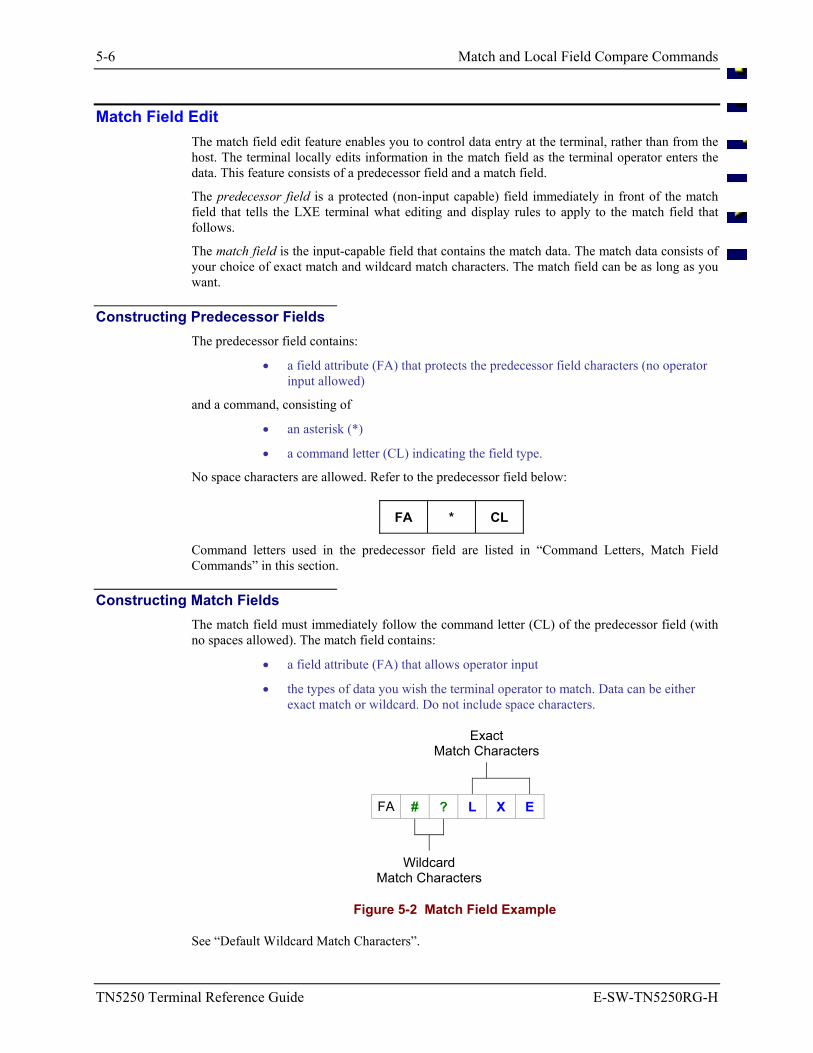
5-6 Match and Local Field Compare Commands
TN5250 Terminal Reference Guide E-SW-TN5250RG-H
Match Field Edit The match field edit feature enables you to control data entry at the terminal, rather than from the host. The terminal locally edits information in the match field as the terminal operator enters the data. This feature consists of a predecessor field and a match field.
The predecessor field is a protected (non-input capable) field immediately in front of the match field that tells the LXE terminal what editing and display rules to apply to the match field that follows.
The match field is the input-capable field that contains the match data. The match data consists of your choice of exact match and wildcard match characters. The match field can be as long as you want.
Constructing Predecessor Fields The predecessor field contains:
• a field attribute (FA) that protects the predecessor field characters (no operator input allowed)
and a command, consisting of
• an asterisk (*)
• a command letter (CL) indicating the field type.
No space characters are allowed. Refer to the predecessor field below:
FA * CL
Command letters used in the predecessor field are listed in “Command Letters, Match Field Commands” in this section.
Constructing Match Fields The match field must immediately follow the command letter (CL) of the predecessor field (with no spaces allowed). The match field contains:
• a field attribute (FA) that allows operator input
• the types of data you wish the terminal operator to match. Data can be either exact match or wildcard. Do not include space characters.
Exact Match Characters
FA # ? L X E
Wildcard Match Characters
Figure 5-2 Match Field Example
See “Default Wildcard Match Characters”.
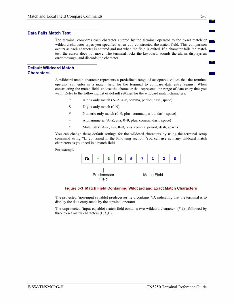
Match and Local Field Compare Commands 5-7
E-SW-TN5250RG-H TN5250 Terminal Reference Guide
Data Fails Match Test The terminal compares each character entered by the terminal operator to the exact match or wildcard character types you specified when you constructed the match field. This comparison occurs as each character is entered and not when the field is exited. If a character fails the match test, the cursor does not move. The terminal locks the keyboard, sounds the alarm, displays an error message, and discards the character.
Default Wildcard Match Characters
A wildcard match character represents a predefined range of acceptable values that the terminal operator can enter in a match field for the terminal to compare data entry against. When constructing the match field, choose the character that represents the range of data entry that you want. Refer to the following list of default settings for the wildcard match characters:
? Alpha only match (A–Z, a–z, comma, period, dash, space)
$ Digits only match (0–9)
# Numeric only match (0–9, plus, comma, period, dash, space)
+ Alphanumeric (A–Z, a–z, 0–9, plus, comma, dash, space)
* Match all ( (A–Z, a–z, 0–9, plus, comma, period, dash, space)
You can change these default settings for the wildcard characters by using the terminal setup command string *L, contained in the following section. You can use as many wildcard match characters as you need in a match field.
For example:
FA * D FA # ? L X E
Predecessor Field
Match Field
Figure 5-3 Match Field Containing Wildcard and Exact Match Characters
The protected (non-input capable) predecessor field contains *D, indicating that the terminal is to display the data entry made by the terminal operator.
The unprotected (input capable) match field contains two wildcard characters (#,?), followed by three exact match characters (L,X,E).
5-8 Match and Local Field Compare Commands
TN5250 Terminal Reference Guide E-SW-TN5250RG-H
Local Field Compare The Local Field Compare feature works in conjunction with the Scan and Increment feature or as a stand-alone feature. A single screen has the capability of having multiple local compare fields (or Local Field Compares, LFC’s). This feature enables you to check for errors when the user presses the [Enter] key, or an autosend is activated. Version 3.3 feature.
Data Fails Compare Test The terminal compares the characters entered by the terminal operator to the exact match or wildcard character types you specified when you constructed the compare field. This comparison occurs when the terminal operator presses the [Enter] key, or if an autosend is activated.
If an error is found, a local error message appears on the terminal display (0030 LOC CMPARE ERR), and the cursor is placed on the first local compare field that is in error. The user should next press the [RESET] key sequence to remove the error message. The terminal ignores any keypresses that are not an attempt to correct the current error. Entering a new value, pressing [F9] or the [Enter] key are acceptable actions during an error condition.
Pressing the [F9] key sets the current field in override mode and allows the input field to contain a value that is less than or equal to the compare field value, and still not cause an error.
Upon pressing the [F9] key or entering a new value into the field, the terminal will either autosend, if the input field is designated as such, or the cursor will advance to the next input field.
Using Local Compare Field It is recommended that the input field for *F be declared as an I (Input only) field and the input fields for *M and *N (including the Local Field Edit input field) be declared as B (Both) fields. Input fields should not be protected and, at least for *M and *N, the Local Field Compare input field should have an attribute of MDT (Modified Data Tag).
In the case of B (both) fields, the last entry may be propagated into the field when a new screen arrives from the Host. To avoid this, the application program should reinitialize these fields for each new screen. To work properly, the Local Compare Field input fields for *M and *N should be initialized with 00 (0 = zero = F0 hex) and the count value initialized also.
To bypass the compare check for fields that are blank, *F input fields can be initialized with nulls (00 hex). This can be done by defining the *F input fields as I (input only) and avoiding initializing these fields. Autosend (check<er>) may be declared for any input field.
Each format string should not exceed 80 characters, to keep each unique Local Compare Field on one display line of the terminal. (It is possible to have more than one Local Compare Field on a line, but there should not be one Local Compare Field wrapping across two lines).
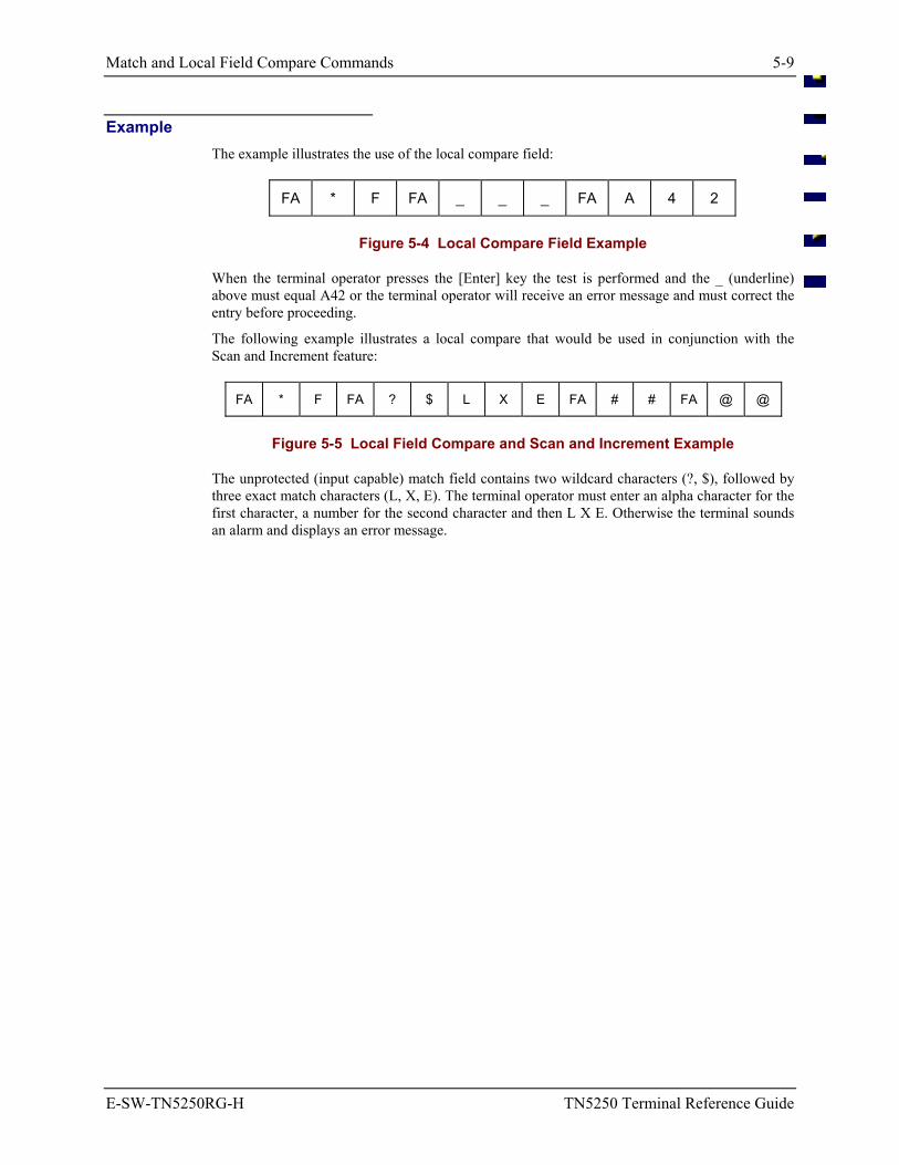
Match and Local Field Compare Commands 5-9
E-SW-TN5250RG-H TN5250 Terminal Reference Guide
Example The example illustrates the use of the local compare field:
FA * F FA _ _ _ FA A 4 2
Figure 5-4 Local Compare Field Example
When the terminal operator presses the [Enter] key the test is performed and the _ (underline) above must equal A42 or the terminal operator will receive an error message and must correct the entry before proceeding.
The following example illustrates a local compare that would be used in conjunction with the Scan and Increment feature:
FA * F FA ? $ L X E FA # # FA @ @
Figure 5-5 Local Field Compare and Scan and Increment Example
The unprotected (input capable) match field contains two wildcard characters (?, $), followed by three exact match characters (L, X, E). The terminal operator must enter an alpha character for the first character, a number for the second character and then L X E. Otherwise the terminal sounds an alarm and displays an error message.
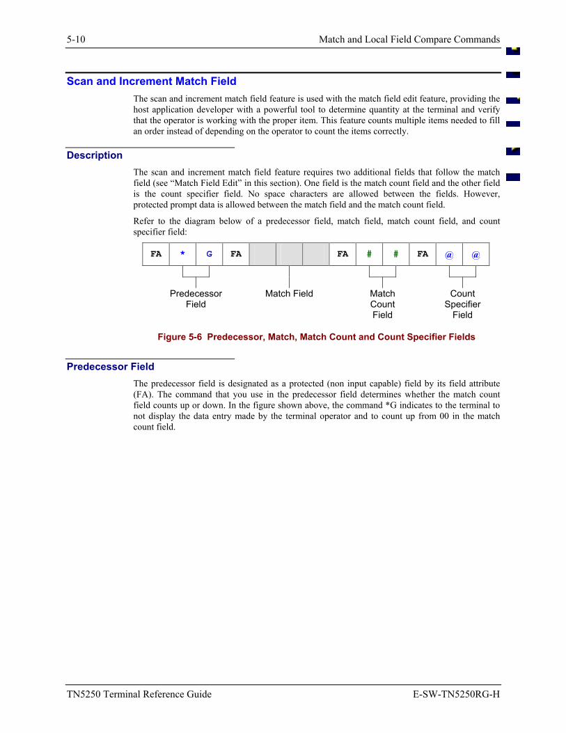
5-10 Match and Local Field Compare Commands
TN5250 Terminal Reference Guide E-SW-TN5250RG-H
Scan and Increment Match Field The scan and increment match field feature is used with the match field edit feature, providing the host application developer with a powerful tool to determine quantity at the terminal and verify that the operator is working with the proper item. This feature counts multiple items needed to fill an order instead of depending on the operator to count the items correctly.
Description The scan and increment match field feature requires two additional fields that follow the match field (see “Match Field Edit” in this section). One field is the match count field and the other field is the count specifier field. No space characters are allowed between the fields. However, protected prompt data is allowed between the match field and the match count field.
Refer to the diagram below of a predecessor field, match field, match count field, and count specifier field:
FA * G FA FA # # FA @ @
Predecessor
Field Match Field Match
Count Field
Count Specifier
Field
Figure 5-6 Predecessor, Match, Match Count and Count Specifier Fields
Predecessor Field The predecessor field is designated as a protected (non input capable) field by its field attribute (FA). The command that you use in the predecessor field determines whether the match count field counts up or down. In the figure shown above, the command *G indicates to the terminal to not display the data entry made by the terminal operator and to count up from 00 in the match count field.
Match and Local Field Compare Commands 5-11
E-SW-TN5250RG-H TN5250 Terminal Reference Guide
Match Count Field The match count field (unprotected-input capable) indicates the number of times the correct barcode is scanned in the match field. The match count field value increases or decreases by one each time a correct entry occurs in the match field. The match count field contains a number from 00 to 99. This field must be two characters long. No space characters are allowed.
Advancing the Cursor The match count field directly affects the match field and the advancement of the cursor. When the match count field value equals the count specifier field value, the cursor advances to the next unprotected field.
Note: The terminal operator can press the [Arrow] keys, [Tab] keys, or [Field Exit] keys to advance the cursor to the next unprotected field. However, if the terminal operator returns to the match field, the terminal continues with the scan and increment feature. No loss of character matches or counts occurs.
Cursor Placement The scan and increment feature does not place the cursor in the match count field. Only the terminal operator can place the cursor in the match count field. Once in this field, the terminal operator can enter any character. However, the operator should not enter the match count field unless overriding the match count field is necessary.
Count Specifier Field The count specifier field indicates the number of times that you want the terminal operator to make a correct entry in the match field before the cursor advances to the next field. This field must be protected and must be two characters long with a number between 01 and 99. If the host application puts a number in the count specifier field that is not in the range of 01 -- 99, the terminal emulation will place a 01 in the field.
The field attribute (FA) for the count specifier field determines if the count specifier field is displayable or non-displayable. If the content of the count specifier field is displayable, the terminal operator will see what the host application put in the field, but the terminal will see 01.
Auto Transmit When auto transmit is enabled in the terminal setup, auto transmit only occurs when the match count field value equals the count specifier field value.
Exception: However, if the terminal operator scans the correct barcode at least once and then presses the [Field Exit] key, auto transmit occurs. Depending on the position of the cursor, the remainder of the field will be filled with nulls.
Advance Mode Advance mode (parameter p5 of the command string for terminal setup) discussed later in this chapter does not work inside a scan and increment field feature until the match count field equals the count specifier field.
5-12 Match and Local Field Compare Commands
TN5250 Terminal Reference Guide E-SW-TN5250RG-H
Incorrect Data Entry If an error occurs while the terminal operator scans barcodes, an error message appears, the keyboard locks, and the terminal operator must press the [Reset] key sequence to continue. The match count field does not change. The terminal operator must use the keypad to finish the entry or place the cursor at the beginning of the match field and try again.
See Also
Refer to Match Field Edit, Match Count Field, Match Field Commands, and Count Specifier field in this section for more information.
Match and Local Field Compare Commands 5-13
E-SW-TN5250RG-H TN5250 Terminal Reference Guide
Input Device ID This feature is not currently supported in the DOS TE’s. The input device ID feature provides the host application developer with the ability to determine what input device and what barcode symbology the LXE terminal operator used to enter data in any field on the screen. When the 5250 host application is programmed to request this data from the terminal, and when the input device ID feature is enabled at the terminal, the LXE terminal sends this information to the 5250 host emulation. This feature can be used with the match field edit and scan and increment features, in addition to normal operator input.
This feature is useful to monitor the use of automatic input devices to enforce the practice of not using the keyboard as an input device.
Description There are two major components to this feature:
• The input ID field identifies the field that follows as an operator input field.
• The operator input field is the area on the screen where information is returned to the host application.
Input ID Field The input ID field:
• must be preceded by a field attribute (FA) that designates the input ID field as unprotected (operator input capable).
• is designated with an * (asterisk) as the first character and a K as the second character.
• can have any display attribute including non-display.
• does not have to be on the same line as the operator input field, but it must be the first input field to precede it.
• cannot have any input fields defined on the screen map between it and its associated operator input field.
• must have the Modified Data Tag (MDT) set by the host application so it will return to the host when [SEND] is pressed.
• behaves exactly the same as any protected field on the LXE terminal screen.
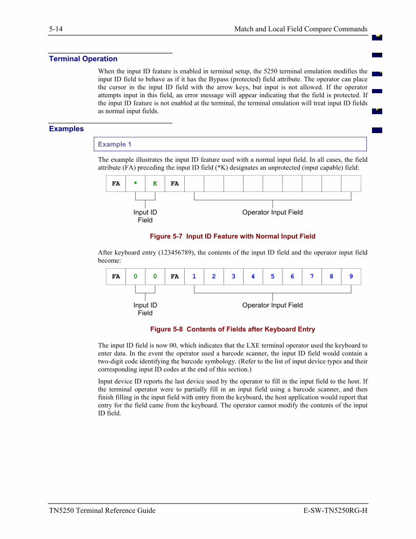
5-14 Match and Local Field Compare Commands
TN5250 Terminal Reference Guide E-SW-TN5250RG-H
Terminal Operation When the input ID feature is enabled in terminal setup, the 5250 terminal emulation modifies the input ID field to behave as if it has the Bypass (protected) field attribute. The operator can place the cursor in the input ID field with the arrow keys, but input is not allowed. If the operator attempts input in this field, an error message will appear indicating that the field is protected. If the input ID feature is not enabled at the terminal, the terminal emulation will treat input ID fields as normal input fields.
Examples
Example 1
The example illustrates the input ID feature used with a normal input field. In all cases, the field attribute (FA) preceding the input ID field (*K) designates an unprotected (input capable) field:
FA * K FA
Input ID
Field Operator Input Field
Figure 5-7 Input ID Feature with Normal Input Field
After keyboard entry (123456789), the contents of the input ID field and the operator input field become:
FA 0 0 FA 1 2 3 4 5 6 7 8 9
Input ID
Field Operator Input Field
Figure 5-8 Contents of Fields after Keyboard Entry
The input ID field is now 00, which indicates that the LXE terminal operator used the keyboard to enter data. In the event the operator used a barcode scanner, the input ID field would contain a two-digit code identifying the barcode symbology. (Refer to the list of input device types and their corresponding input ID codes at the end of this section.)
Input device ID reports the last device used by the operator to fill in the input field to the host. If the terminal operator were to partially fill in an input field using a barcode scanner, and then finish filling in the input field with entry from the keyboard, the host application would report that entry for the field came from the keyboard. The operator cannot modify the contents of the input ID field.
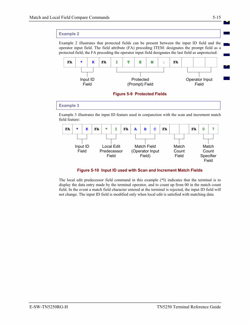
Match and Local Field Compare Commands 5-15
E-SW-TN5250RG-H TN5250 Terminal Reference Guide
Example 2
Example 2 illustrates that protected fields can be present between the input ID field and the operator input field. The field attribute (FA) preceding ITEM: designates the prompt field as a protected field; the FA preceding the operator input field designates the last field as unprotected:
FA * K FA I T E M : FA
Input ID
Field Protected
(Prompt) Field Operator Input
Field
Figure 5-9 Protected Fields
Example 3
Example 3 illustrates the input ID feature used in conjunction with the scan and increment match field feature:
FA * K FA * I FA A B C FA FA 0 7
Input ID Field
Local Edit Predecessor
Field
Match Field (Operator Input
Field)
Match Count Field
Match Count
Specifier Field
Figure 5-10 Input ID used with Scan and Increment Match Fields
The local edit predecessor field command in this example (*I) indicates that the terminal is to display the data entry made by the terminal operator, and to count up from 00 in the match count field. In the event a match field character entered at the terminal is rejected, the input ID field will not change. The input ID field is modified only when local edit is satisfied with matching data.
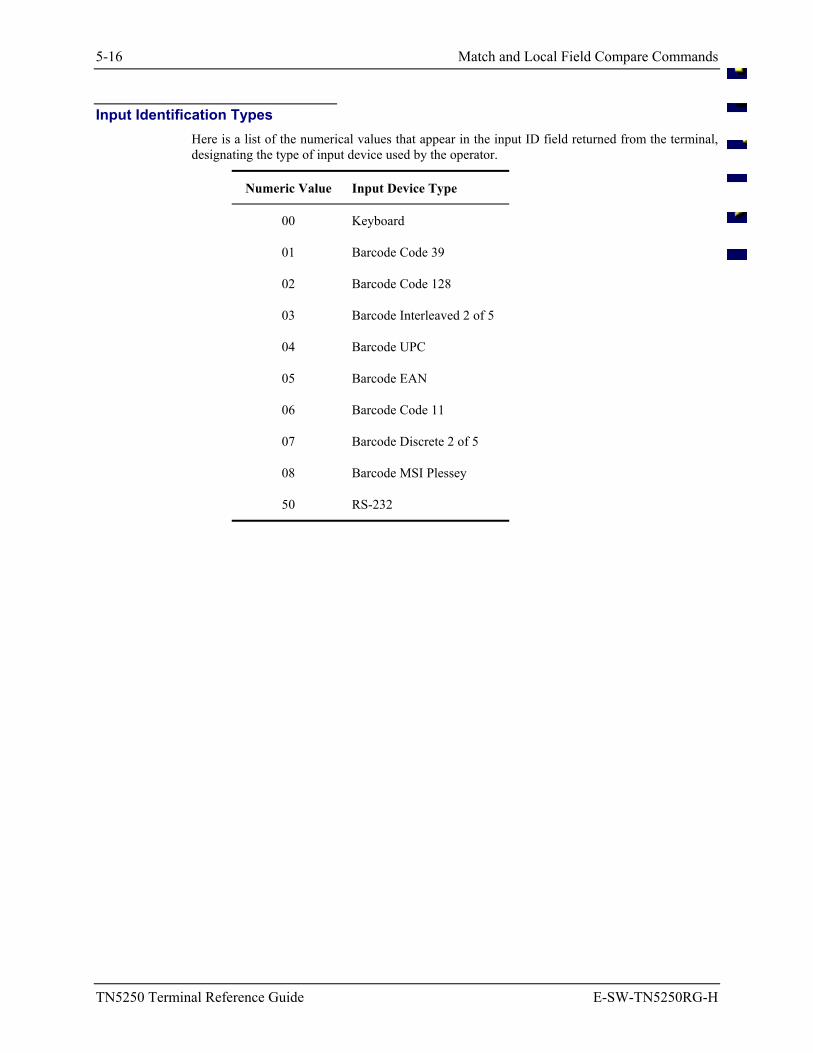
5-16 Match and Local Field Compare Commands
TN5250 Terminal Reference Guide E-SW-TN5250RG-H
Input Identification Types Here is a list of the numerical values that appear in the input ID field returned from the terminal, designating the type of input device used by the operator.
Numeric Value Input Device Type
00 Keyboard
01 Barcode Code 39
02 Barcode Code 128
03 Barcode Interleaved 2 of 5
04 Barcode UPC
05 Barcode EAN
06 Barcode Code 11
07 Barcode Discrete 2 of 5
08 Barcode MSI Plessey
50 RS-232
Terminal Setup Commands 5-17
E-SW-TN5250RG-H TN5250 Terminal Reference Guide
Terminal Setup Commands
There are two ways to configure the 5250 terminal:
• Configuration utility in the terminal.
• Host remote configuration with command strings.
This section describes how to configure the terminal from the host application using command strings.
Refer to Chapter 3 “TN5250 Configuration Utility” to configure the terminal with the configuration parameters.
Screen Design for Terminal Setup Commands All terminal setup commands must be in the first field of the 5250 screen. You must precede each command with a field attribute (FA). This field attribute can be protected (input prohibited) or unprotected (input capable). Do not include space characters.
Terminal setup commands include:
*B Beep Pattern
*E Terminal Emulation Setup
*L Local Edit Match Field Setup
*P Data Stream Print
*W Window Manager Setup
You can use only one of these commands with each screen. You cannot stack these commands.
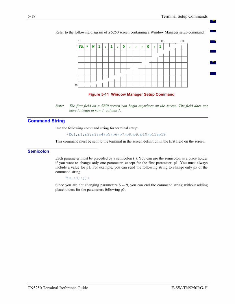
5-18 Terminal Setup Commands
TN5250 Terminal Reference Guide E-SW-TN5250RG-H
Refer to the following diagram of a 5250 screen containing a Window Manager setup command:
1 15 . . . 80
1 FA * W 1 ; 1 ; 0 ; ; ; 0 ; 1
.
.
. 25
Figure 5-11 Window Manager Setup Command
Note: The first field on a 5250 screen can begin anywhere on the screen. The field does not have to begin at row 1, column 1.
Command String Use the following command string for terminal setup:
*Ec1;p1;p2;p3;p4;p5;p6;p7;p8;p9;p10;p11;p12
This command must be sent to the terminal in the screen definition in the first field on the screen.
Semicolon Each parameter must be preceded by a semicolon (;). You can use the semicolon as a place holder if you want to change only one parameter, except for the first parameter, p1. You must always include a value for p1. For example, you can send the following string to change only p5 of the command string:
*E1;0;;;;1
Since you are not changing parameters 6 -- 9, you can end the command string without adding placeholders for the parameters following p5.
Terminal Setup Commands 5-19
E-SW-TN5250RG-H TN5250 Terminal Reference Guide
String Elements The following table describes the different elements of the command string for the terminal emulation setup:
Element Description
*E Indicates that this command string is a terminal emulation setup command.
c1 A compatibility byte that ensures the terminal emulation understands the command string sent to it. The c1 is a revision level character for compatibility purposes, which increments when a change in the string content would make newer RF terminals incompatible with older host applications. Examples in this book display c1. Your rev level may be higher.
; A required delimiter that must precede all parameter entries.
p1 Save to disk (save the command string to EEPROM).
0 Use the command string in the terminal but do not save. The configuration is used only as long as the terminal is powered on.
1 Use the command string in the terminal and save. The configuration is saved even after the terminal is powered off.
p2 Bar Code/RS-232 Input Left Justify Mode
0 Left Justify Mode Off
1 Left Justify Mode On
See “Left Justify Mode: p2” in this section.
p3 Bar Code/RS-232 Input Clear Mode
0 Clear Off
1 Clear On
See “Clear Mode: p3” in this section.
p4 Bar Code/RS-232 Input Truncate Mode
0 Truncate OFF
1 Truncate ON
See “Truncate Mode: p4” in this section.
p5 Bar Code/RS-232 Input Advance Mode
0 Advance OFF
1 Advance ON
See “Advance Mode: p5” in this section.
5-20 Terminal Setup Commands
TN5250 Terminal Reference Guide E-SW-TN5250RG-H
Element Description
p6 Auto transmit after a data stream print
0 Do not auto transmit after a data stream print.
1 Auto transmit after a data stream print.
See “Auto Transmit: p6” in this section.
p7 Printer Carriage Return per Line
0 No carriage return per line on a screen print
1 Carriage return per line on a screen print
See “Printer Carriage Return per Line: p7” in this section.
p8 Printer Line Feed per Line
0 No line feed per line on a screen print
1 Line feed per line on a screen print
See “Printer Line Feed per Line: p8” in this section.
p9 Status Line Display Mode
0 Status line always off
1 Status line only on when there is an exception
See “Status Line Display Mode: p9” in this section.
p10 Input Device ID Feature Not supported in DOS TE.
0 Input Device ID is disabled
1 Input Device ID is enabled.
See “Input Device ID Feature: p10” in this section.
p11 Swap TAB/Field Exit
0 Do not swap the TAB and Field Exit functions (default).
1 Swap the TAB and Field Exit functions.
See “Swap TAB/Field Exit: p11” in this section.
p12 Advance
0 Use the TAB for advancing (default).
1 Use the Field Exit function when advancing.
See “Advance: p12” in this section.
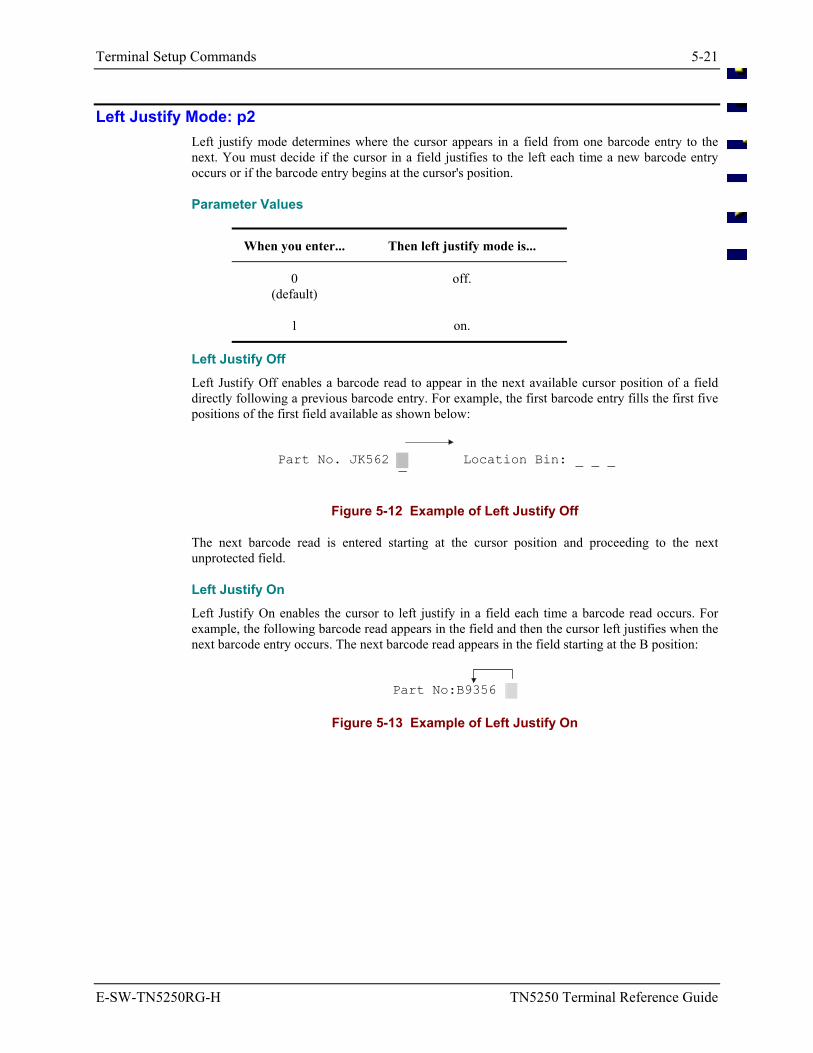
Terminal Setup Commands 5-21
E-SW-TN5250RG-H TN5250 Terminal Reference Guide
Left Justify Mode: p2 Left justify mode determines where the cursor appears in a field from one barcode entry to the next. You must decide if the cursor in a field justifies to the left each time a new barcode entry occurs or if the barcode entry begins at the cursor's position.
Parameter Values
When you enter... Then left justify mode is...
0 (default)
off.
1 on.
Left Justify Off Left Justify Off enables a barcode read to appear in the next available cursor position of a field directly following a previous barcode entry. For example, the first barcode entry fills the first five positions of the first field available as shown below:
Part No. JK562 Location Bin: _ _ _ ¯
Figure 5-12 Example of Left Justify Off
The next barcode read is entered starting at the cursor position and proceeding to the next unprotected field.
Left Justify On Left Justify On enables the cursor to left justify in a field each time a barcode read occurs. For example, the following barcode read appears in the field and then the cursor left justifies when the next barcode entry occurs. The next barcode read appears in the field starting at the B position:
Part No:B9356
Figure 5-13 Example of Left Justify On
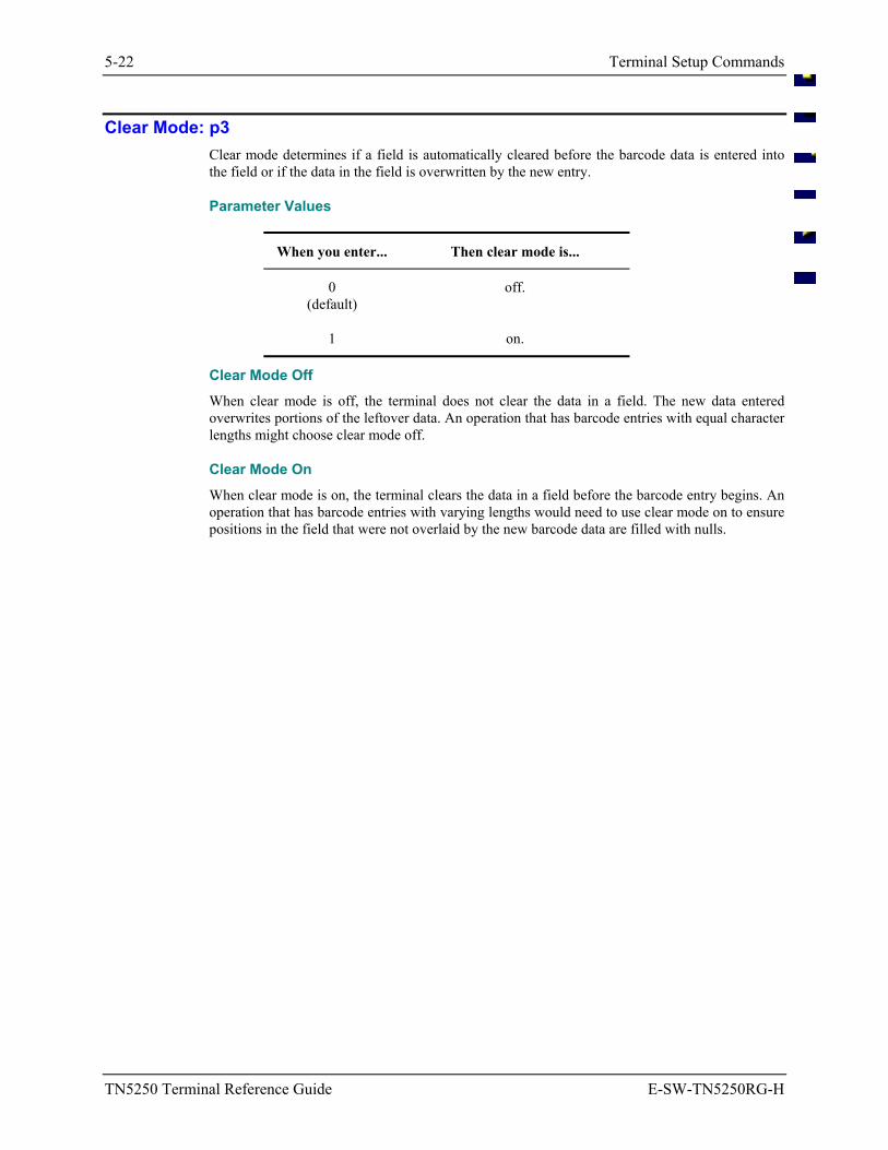
5-22 Terminal Setup Commands
TN5250 Terminal Reference Guide E-SW-TN5250RG-H
Clear Mode: p3 Clear mode determines if a field is automatically cleared before the barcode data is entered into the field or if the data in the field is overwritten by the new entry.
Parameter Values
When you enter... Then clear mode is...
0 (default)
off.
1 on.
Clear Mode Off When clear mode is off, the terminal does not clear the data in a field. The new data entered overwrites portions of the leftover data. An operation that has barcode entries with equal character lengths might choose clear mode off.
Clear Mode On When clear mode is on, the terminal clears the data in a field before the barcode entry begins. An operation that has barcode entries with varying lengths would need to use clear mode on to ensure positions in the field that were not overlaid by the new barcode data are filled with nulls.
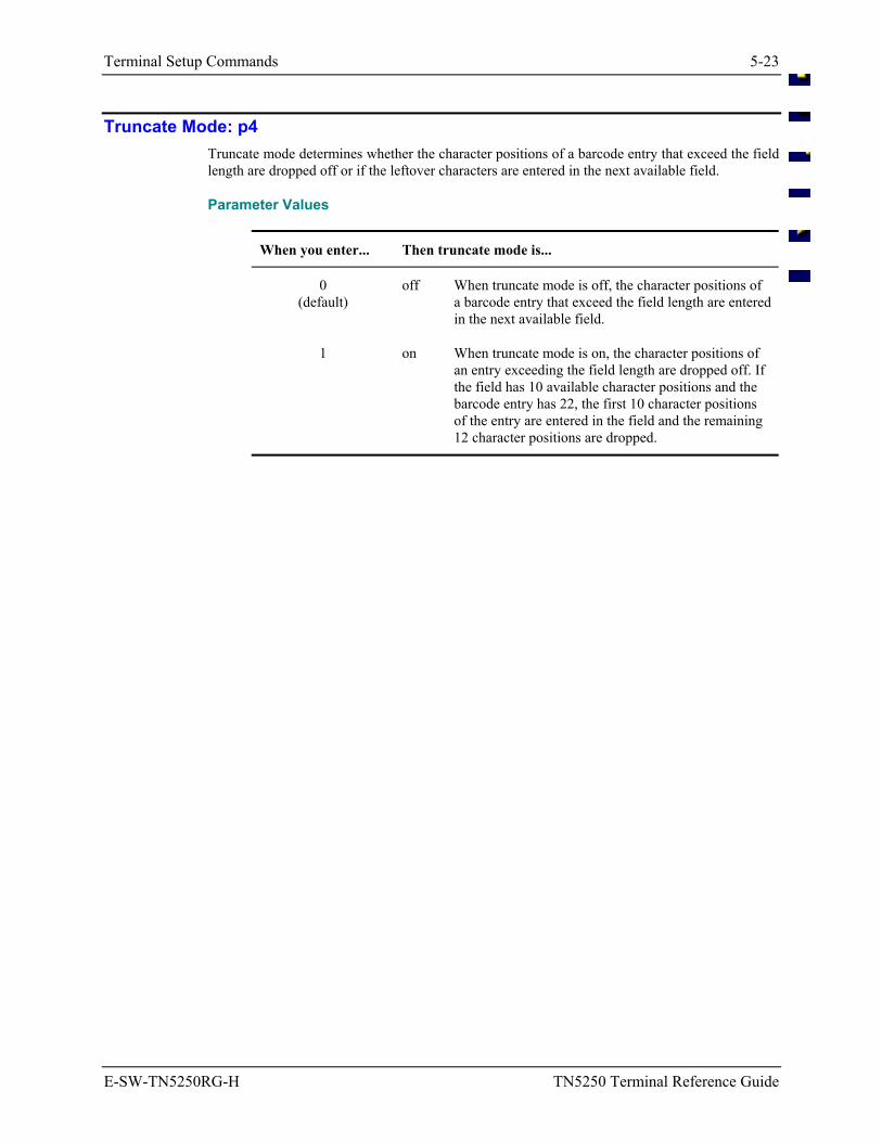
Terminal Setup Commands 5-23
E-SW-TN5250RG-H TN5250 Terminal Reference Guide
Truncate Mode: p4 Truncate mode determines whether the character positions of a barcode entry that exceed the field length are dropped off or if the leftover characters are entered in the next available field.
Parameter Values
When you enter... Then truncate mode is...
0 (default)
off When truncate mode is off, the character positions of a barcode entry that exceed the field length are entered in the next available field.
1 on When truncate mode is on, the character positions of an entry exceeding the field length are dropped off. If the field has 10 available character positions and the barcode entry has 22, the first 10 character positions of the entry are entered in the field and the remaining 12 character positions are dropped.
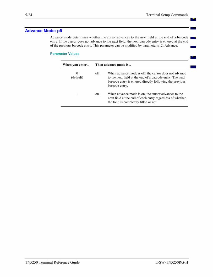
5-24 Terminal Setup Commands
TN5250 Terminal Reference Guide E-SW-TN5250RG-H
Advance Mode: p5 Advance mode determines whether the cursor advances to the next field at the end of a barcode entry. If the cursor does not advance to the next field, the next barcode entry is entered at the end of the previous barcode entry. This parameter can be modified by parameter p12: Advance.
Parameter Values
When you enter... Then advance mode is...
0 (default)
off When advance mode is off, the cursor does not advance to the next field at the end of a barcode entry. The next barcode entry is entered directly following the previous barcode entry.
1 on When advance mode is on, the cursor advances to the next field at the end of each entry regardless of whether the field is completely filled or not.
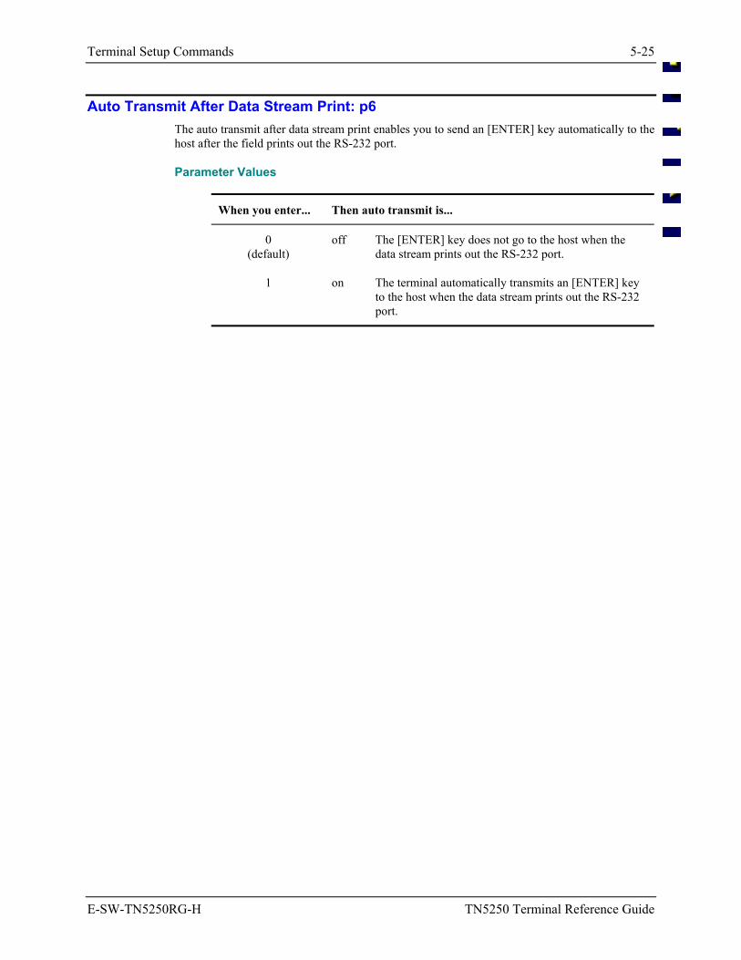
Terminal Setup Commands 5-25
E-SW-TN5250RG-H TN5250 Terminal Reference Guide
Auto Transmit After Data Stream Print: p6 The auto transmit after data stream print enables you to send an [ENTER] key automatically to the host after the field prints out the RS-232 port.
Parameter Values
When you enter... Then auto transmit is...
0 (default)
off The [ENTER] key does not go to the host when the data stream prints out the RS-232 port.
1 on The terminal automatically transmits an [ENTER] key to the host when the data stream prints out the RS-232 port.
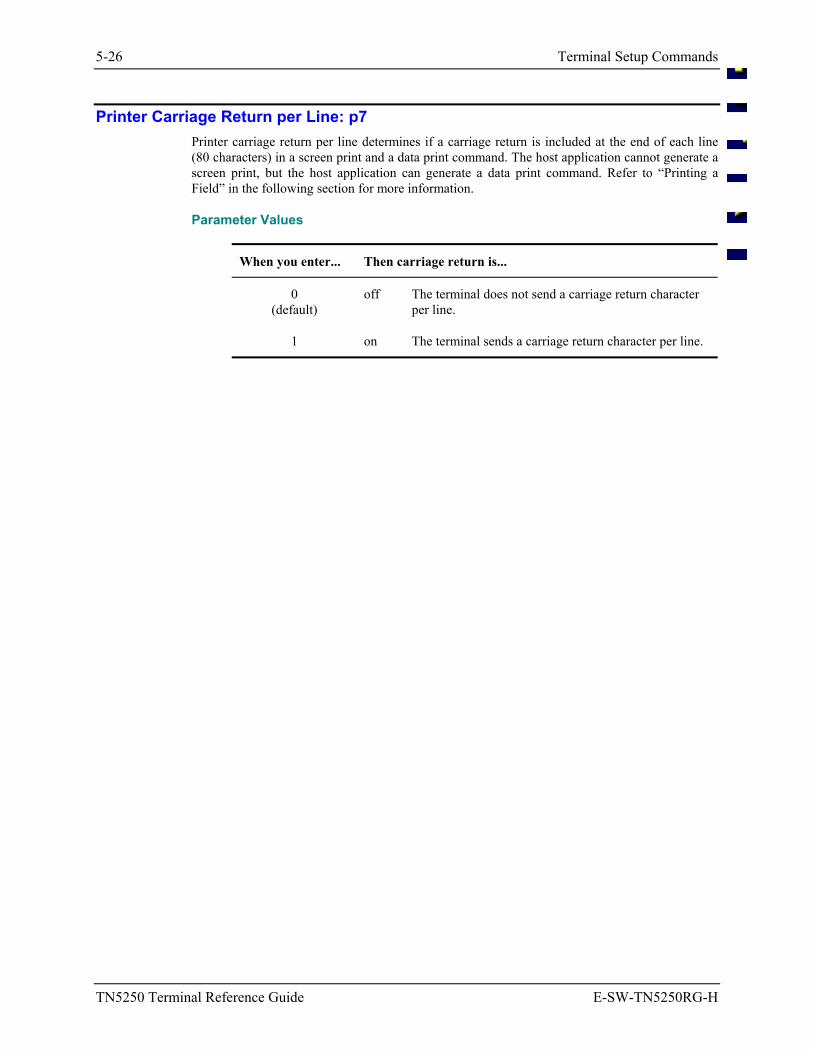
5-26 Terminal Setup Commands
TN5250 Terminal Reference Guide E-SW-TN5250RG-H
Printer Carriage Return per Line: p7 Printer carriage return per line determines if a carriage return is included at the end of each line (80 characters) in a screen print and a data print command. The host application cannot generate a screen print, but the host application can generate a data print command. Refer to “Printing a Field” in the following section for more information.
Parameter Values
When you enter... Then carriage return is...
0 (default)
off The terminal does not send a carriage return character per line.
1 on The terminal sends a carriage return character per line.
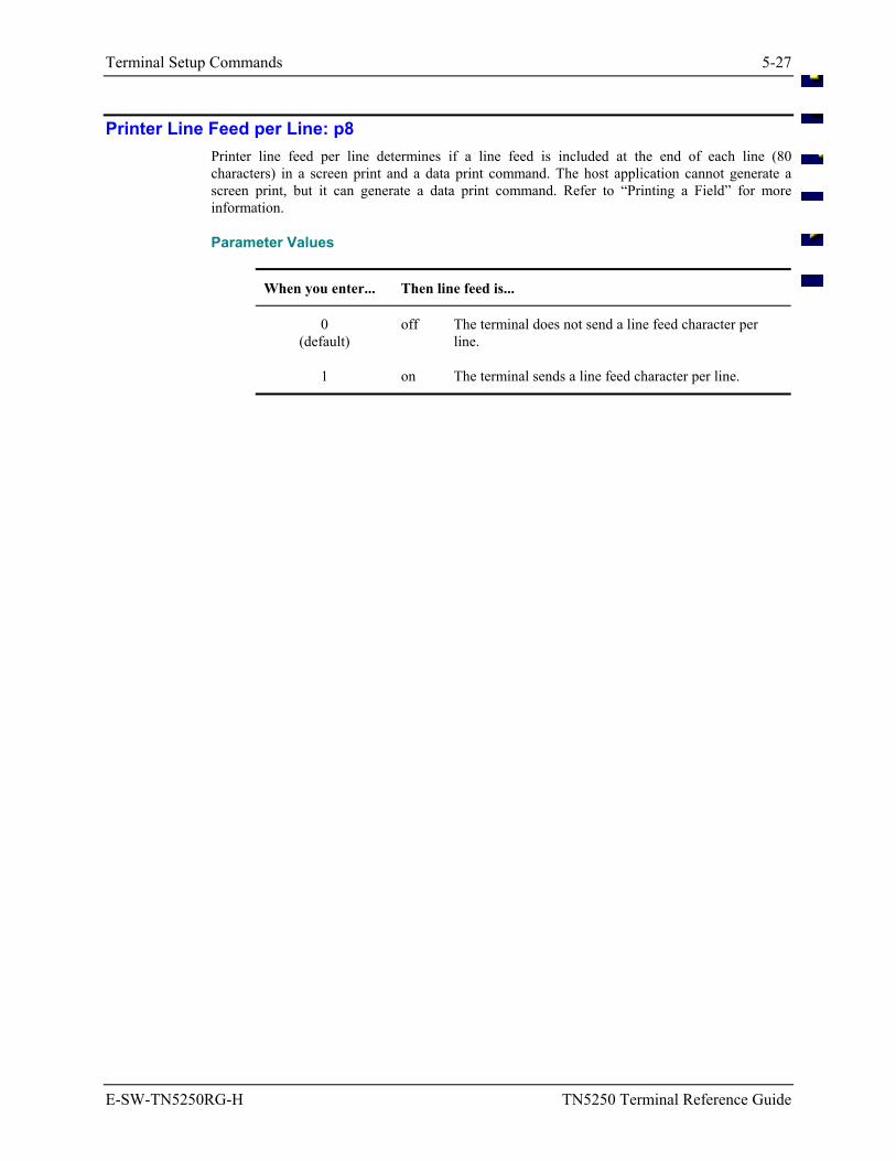
Terminal Setup Commands 5-27
E-SW-TN5250RG-H TN5250 Terminal Reference Guide
Printer Line Feed per Line: p8 Printer line feed per line determines if a line feed is included at the end of each line (80 characters) in a screen print and a data print command. The host application cannot generate a screen print, but it can generate a data print command. Refer to “Printing a Field” for more information.
Parameter Values
When you enter... Then line feed is...
0 (default)
off The terminal does not send a line feed character per line.
1 on The terminal sends a line feed character per line.
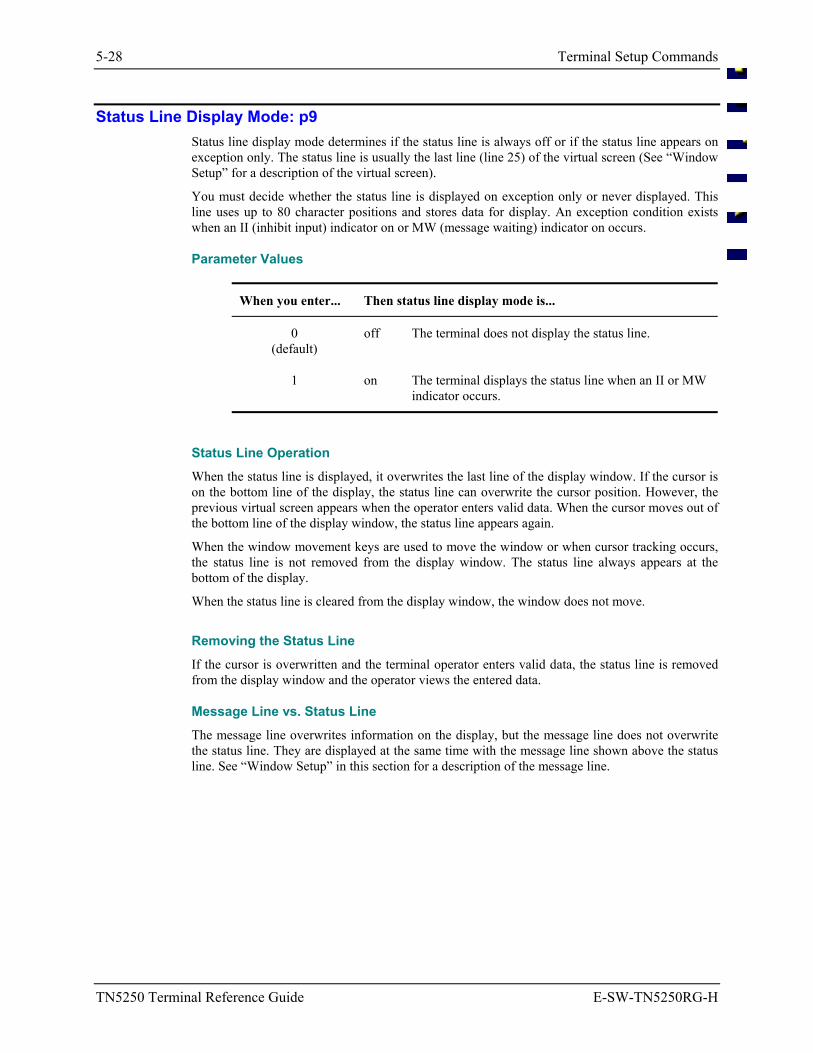
5-28 Terminal Setup Commands
TN5250 Terminal Reference Guide E-SW-TN5250RG-H
Status Line Display Mode: p9 Status line display mode determines if the status line is always off or if the status line appears on exception only. The status line is usually the last line (line 25) of the virtual screen (See “Window Setup” for a description of the virtual screen).
You must decide whether the status line is displayed on exception only or never displayed. This line uses up to 80 character positions and stores data for display. An exception condition exists when an II (inhibit input) indicator on or MW (message waiting) indicator on occurs.
Parameter Values
When you enter... Then status line display mode is...
0 (default)
off The terminal does not display the status line.
1 on The terminal displays the status line when an II or MW indicator occurs.
Status Line Operation When the status line is displayed, it overwrites the last line of the display window. If the cursor is on the bottom line of the display, the status line can overwrite the cursor position. However, the previous virtual screen appears when the operator enters valid data. When the cursor moves out of the bottom line of the display window, the status line appears again.
When the window movement keys are used to move the window or when cursor tracking occurs, the status line is not removed from the display window. The status line always appears at the bottom of the display.
When the status line is cleared from the display window, the window does not move.
Removing the Status Line If the cursor is overwritten and the terminal operator enters valid data, the status line is removed from the display window and the operator views the entered data.
Message Line vs. Status Line The message line overwrites information on the display, but the message line does not overwrite the status line. They are displayed at the same time with the message line shown above the status line. See “Window Setup” in this section for a description of the message line.
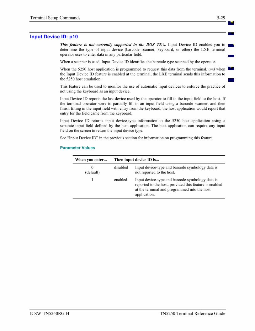
Terminal Setup Commands 5-29
E-SW-TN5250RG-H TN5250 Terminal Reference Guide
Input Device ID: p10 This feature is not currently supported in the DOS TE’s. Input Device ID enables you to determine the type of input device (barcode scanner, keyboard, or other) the LXE terminal operator uses to enter data in any particular field.
When a scanner is used, Input Device ID identifies the barcode type scanned by the operator.
When the 5250 host application is programmed to request this data from the terminal, and when the Input Device ID feature is enabled at the terminal, the LXE terminal sends this information to the 5250 host emulation.
This feature can be used to monitor the use of automatic input devices to enforce the practice of not using the keyboard as an input device.
Input Device ID reports the last device used by the operator to fill in the input field to the host. If the terminal operator were to partially fill in an input field using a barcode scanner, and then finish filling in the input field with entry from the keyboard, the host application would report that entry for the field came from the keyboard.
Input Device ID returns input device-type information to the 5250 host application using a separate input field defined by the host application. The host application can require any input field on the screen to return the input device type.
See “Input Device ID” in the previous section for information on programming this feature.
Parameter Values
When you enter... Then input device ID is...
0 (default)
disabled Input device-type and barcode symbology data is not reported to the host.
1 enabled Input device-type and barcode symbology data is reported to the host, provided this feature is enabled at the terminal and programmed into the host application.
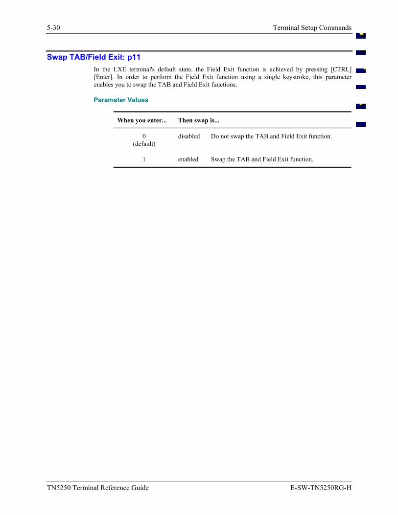
5-30 Terminal Setup Commands
TN5250 Terminal Reference Guide E-SW-TN5250RG-H
Swap TAB/Field Exit: p11 In the LXE terminal's default state, the Field Exit function is achieved by pressing [CTRL] [Enter]. In order to perform the Field Exit function using a single keystroke, this parameter enables you to swap the TAB and Field Exit functions.
Parameter Values
When you enter... Then swap is...
0 (default)
disabled Do not swap the TAB and Field Exit function.
1 enabled Swap the TAB and Field Exit function.
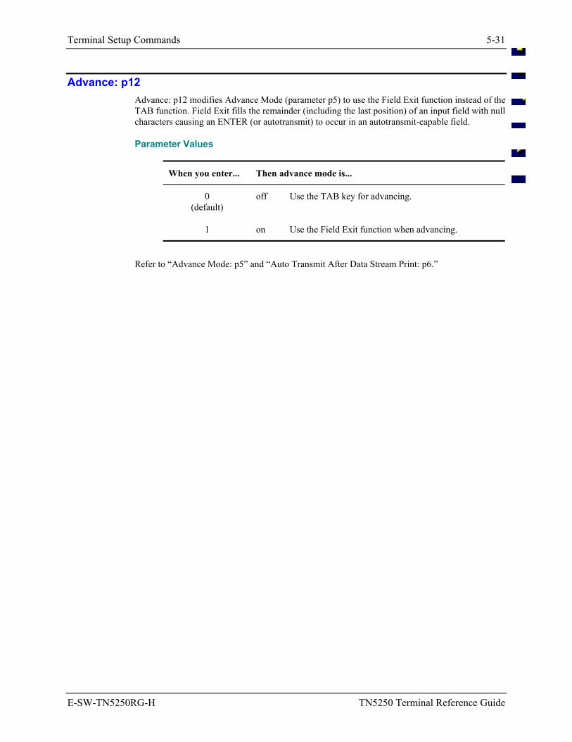
Terminal Setup Commands 5-31
E-SW-TN5250RG-H TN5250 Terminal Reference Guide
Advance: p12 Advance: p12 modifies Advance Mode (parameter p5) to use the Field Exit function instead of the TAB function. Field Exit fills the remainder (including the last position) of an input field with null characters causing an ENTER (or autotransmit) to occur in an autotransmit-capable field.
Parameter Values
When you enter... Then advance mode is...
0 (default)
off Use the TAB key for advancing.
1 on Use the Field Exit function when advancing.
Refer to “Advance Mode: p5” and “Auto Transmit After Data Stream Print: p6.”
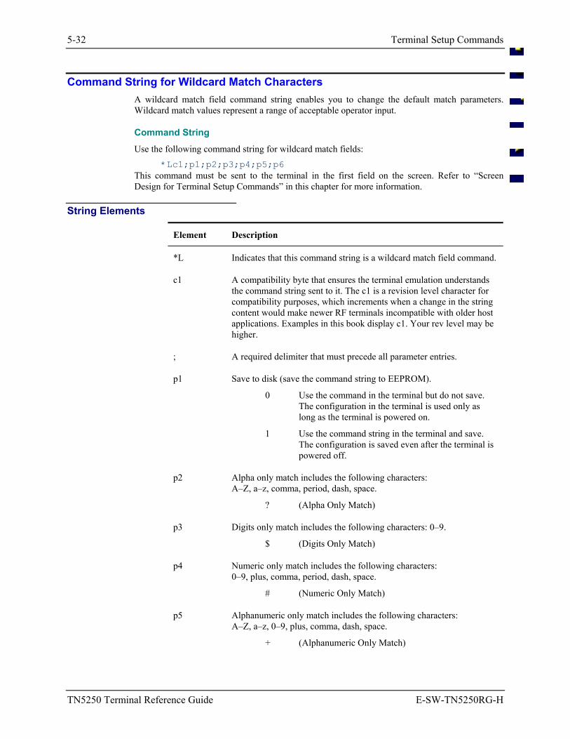
5-32 Terminal Setup Commands
TN5250 Terminal Reference Guide E-SW-TN5250RG-H
Command String for Wildcard Match Characters A wildcard match field command string enables you to change the default match parameters. Wildcard match values represent a range of acceptable operator input.
Command String Use the following command string for wildcard match fields:
*Lc1;p1;p2;p3;p4;p5;p6 This command must be sent to the terminal in the first field on the screen. Refer to “Screen Design for Terminal Setup Commands” in this chapter for more information.
String Elements
Element Description
*L Indicates that this command string is a wildcard match field command.
c1 A compatibility byte that ensures the terminal emulation understands the command string sent to it. The c1 is a revision level character for compatibility purposes, which increments when a change in the string content would make newer RF terminals incompatible with older host applications. Examples in this book display c1. Your rev level may be higher.
; A required delimiter that must precede all parameter entries.
p1 Save to disk (save the command string to EEPROM).
0 Use the command in the terminal but do not save. The configuration in the terminal is used only as long as the terminal is powered on.
1 Use the command string in the terminal and save. The configuration is saved even after the terminal is powered off.
p2 Alpha only match includes the following characters: A–Z, a–z, comma, period, dash, space.
? (Alpha Only Match)
p3 Digits only match includes the following characters: 0–9.
$ (Digits Only Match)
p4 Numeric only match includes the following characters: 0–9, plus, comma, period, dash, space.
# (Numeric Only Match)
p5 Alphanumeric only match includes the following characters: A–Z, a–z, 0–9, plus, comma, dash, space.
+ (Alphanumeric Only Match)
Terminal Setup Commands 5-33
E-SW-TN5250RG-H TN5250 Terminal Reference Guide
Element Description
p6 Match all includes the following characters: A–Z, a–z, 0–9, plus, comma, period, dash, space.
* (Match All)
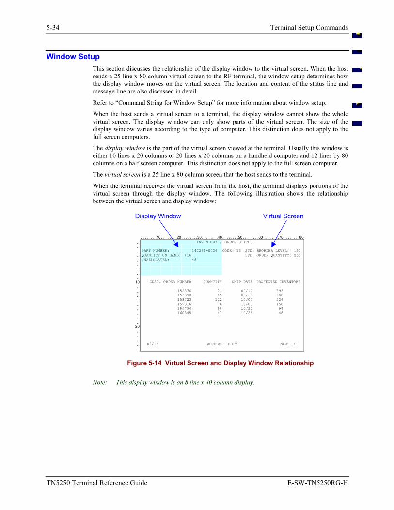
5-34 Terminal Setup Commands
TN5250 Terminal Reference Guide E-SW-TN5250RG-H
Window Setup This section discusses the relationship of the display window to the virtual screen. When the host sends a 25 line x 80 column virtual screen to the RF terminal, the window setup determines how the display window moves on the virtual screen. The location and content of the status line and message line are also discussed in detail.
Refer to “Command String for Window Setup” for more information about window setup.
When the host sends a virtual screen to a terminal, the display window cannot show the whole virtual screen. The display window can only show parts of the virtual screen. The size of the display window varies according to the type of computer. This distinction does not apply to the full screen computers.
The display window is the part of the virtual screen viewed at the terminal. Usually this window is either 10 lines x 20 columns or 20 lines x 20 columns on a handheld computer and 12 lines by 80 columns on a half screen computer. This distinction does not apply to the full screen computer.
The virtual screen is a 25 line x 80 column screen that the host sends to the terminal.
When the terminal receives the virtual screen from the host, the terminal displays portions of the virtual screen through the display window. The following illustration shows the relationship between the virtual screen and display window:
Display Window Virtual Screen
. . . . . . . .10 . . . . . . . .20 . . . . . . . .30 . . . . . . . .40 . . . . . . . .50 . . . . . . . .60 . . . . . . . .70 . . . . . . . .80. INVENTORY / ORDER STATUS . . PART NUMBER: 147265-0026 CODE: 13 STD. REORDER LEVEL: 150 . QUANTITY ON HAND: 416 STD. ORDER QUANTITY: 500 . UNALLOCATED: 48 . . . .
10 CUST. ORDER NUMBER QUANTITY SHIP DATE PROJECTED INVENTORY . . 152876 23 09/17 393 . 153390 45 09/23 348 . 158723 122 10/07 226 . 159316 76 10/08 150 . 159736 55 10/22 95 . 160345 47 10/25 48 . .
20 . . . . 09/15 ACCESS: EDIT PAGE 1/1 .
Figure 5-14 Virtual Screen and Display Window Relationship
Note: This display window is an 8 line x 40 column display.
Terminal Setup Commands 5-35
E-SW-TN5250RG-H TN5250 Terminal Reference Guide
Message Line The message line is used for error messages from the host. The LXE 5250 emulation supports a message line that the host can address. The message line is displayed before the status line in the current display window on the terminal and is shown in its full 80-character length on the display window.
• The host specifies a line as the message line and the message line appears in the display window above the status line.
• LXE window manager software enables the terminal emulation to identify when the message line is active and which line of the virtual screen contains the 80 characters of data.
• The message line overwrites information on the display, but the message line does not overwrite the status line. They are displayed at the same time with the message line shown above the status line.
• If the cursor is overwritten and the terminal operator enters valid data, the message line is removed from the display window and the operator views the entered data.
• If the operator moves the window with the window movement keys, the message line does not follow the display window.
Command String for Window Setup
Window setup determines how the display window shows portions of the virtual screen. You can set the parameters for window setup by using the correct command string.
Use the following command string for window setup: *Wc1;p1;p2;p3;p4;p5;p6
This command must be sent to the terminal in the screen definition in the first field on the screen. Whenever the terminal receives this command it will perform an auto transmit.
Refer to “Screen Design for Terminal Setup Commands” in this section for more information.
5-36 Terminal Setup Commands
TN5250 Terminal Reference Guide E-SW-TN5250RG-H
String Elements The following table describes the different elements of the command string for window setup:
Element Description
*W Indicates that this command string is a window setup command string.
c1 A compatibility byte that ensures the host emulation understands the command string sent to it. The c1 is a revision level character for compatibility purposes, which increments when a change in the string content would make newer RF terminals incompatible with older host applications.
; A required delimiter that must precede all parameter entries.
p1 Save to Disk (save the command string to EEPROM)
0 Use command string in the terminal but do not save. The configuration in the terminal is used only as long as the terminal is powered on.
1 Use the command string in the terminal and save. The configuration is saved even after the terminal is powered off.
p2 Lock Window Mode.
0 Lock window mode off. (Cursor Tracking Mode)
1 Lock window mode on.
“Display Modes: p2” in this section discusses lock window mode and cursor tracking mode in more detail.
p3 Lock Window Line Number. This two-digit number between 01 and 24 identifies the line of the top left corner position of the display window.
“Valid Window Positions: p3 and p4” in this section lists the valid window positions.
p4 Lock Window Column Number. This two-digit number between 01 and 80 identifies the column of the top left corner position of the display window.
“Valid Window Positions: p3 and p4” in this section lists the valid window positions.
p5 Window Movement Mode.
0 Move by Quadrant
1 Move by Full Window
“Window Movement: p5” in this section describes Quadrant and full window movement.
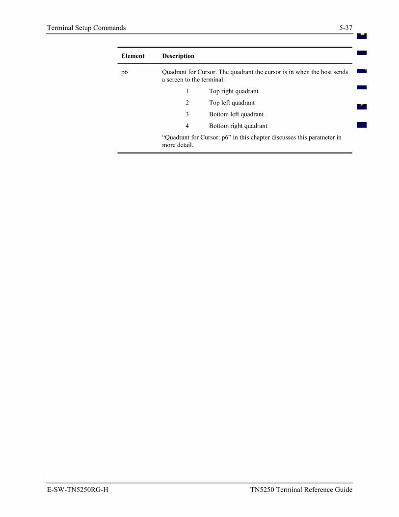
Terminal Setup Commands 5-37
E-SW-TN5250RG-H TN5250 Terminal Reference Guide
Element Description
p6 Quadrant for Cursor. The quadrant the cursor is in when the host sends a screen to the terminal.
1 Top right quadrant
2 Top left quadrant
3 Bottom left quadrant
4 Bottom right quadrant
“Quadrant for Cursor: p6” in this chapter discusses this parameter in more detail.
5-38 Terminal Setup Commands
TN5250 Terminal Reference Guide E-SW-TN5250RG-H
Display Modes: p2 Parameter p2 of the window setup command string enables you to choose the display mode. The window setup supports two types of display modes for displaying the information from the virtual screen at the terminal: cursor tracking mode and lock window mode.
Cursor tracking mode is a display mode that enables the window to follow the movement of the cursor.
Lock window mode is a display mode that enables the programmer to lock the display window in a permanent window position.
Parameter Values
When you enter... Then display modes are...
0 off.
1 on.
Lock Window Mode Off When lock window mode is off, window manager automatically defaults to cursor tracking mode.
Lock Window Mode On When lock window mode is on, the programmer must specify valid line and column positions in p3 and p4 of the command string. The line and column positions specify the location of the top left corner of the locked window.
Note: The terminal does not reposition the display window if the operator moves the cursor outside the display window.
See Also Refer to “Valid Window Positions: p3 and p4” in this section for more information on valid line positions and valid column positions.
Terminal Setup Commands 5-39
E-SW-TN5250RG-H TN5250 Terminal Reference Guide
Valid Window Positions: p3 and p4
When the terminal operates in lock window mode (p2 set to 1), you must specify valid line and column positions in p3 and p4 of the command string.
Parameter p3 sets the line position for the upper left corner of the display window, and p4 sets the column position of the upper left corner of the display window.
Note: When p2 is set to 0 (lock window mode off), the display window defaults to cursor tracking mode, which does not use predefined window positions. Parameters p3 and p4 are ignored.
Computer Physical Window Size
Half Screen Window Size: approximately 8” wide by 3” high.
Full Screen Window Size: approximately 7.5” wide by 5.5” high.
Handheld Window Size: three inches measured diagonally.
For available rows/columns, please refer to the ScreenSize parameter in Chapter 3, “TN3270 Configuration Utility”.
Refer to the following rules on valid window positions:
• When lock mode is on, the programmer must specify the display window's line/column positions in p3 and p4.
• The line and column positions must be among the valid numbers listed in the charts that follow that represent the location of the top left corner of the display window.
These coordinates define the home position of the lock window. The first number in each pair represents a line; the second a column. Your selection will vary depending on display size and whether full window movement or quadrant movement is in effect.
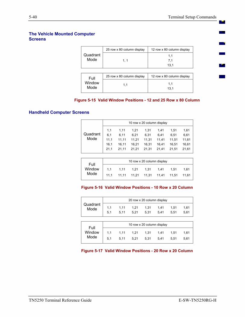
5-40 Terminal Setup Commands
TN5250 Terminal Reference Guide E-SW-TN5250RG-H
The Vehicle Mounted Computer Screens
25 row x 80 column display 12 row x 80 column display
1,1 1, 1 7,1
Quadrant Mode
13,1
25 row x 80 column display 12 row x 80 column display
1,1 Full
Window Mode
1,1 13,1
Figure 5-15 Valid Window Positions - 12 and 25 Row x 80 Column
Handheld Computer Screens
10 row x 20 column display
1,1 1,11 1,21 1,31 1,41 1,51 1,61 6,1 6,11 6,21 6,31 6,41 6,51 6,61
11,1 11,11 11,21 11,31 11,41 11,51 11,61 16,1 16,11 16,21 16,31 16,41 16,51 16,61
Quadrant Mode
21,1 21,11 21,21 21,31 21,41 21,51 21,61
10 row x 20 column display
1,1 1,11 1,21 1,31 1,41 1,51 1,61 Full
Window Mode 11,1 11,11 11,21 11,31 11,41 11,51 11,61
Figure 5-16 Valid Window Positions - 10 Row x 20 Column
20 row x 20 column display
1,1 1,11 1,21 1,31 1,41 1,51 1,61 Quadrant
Mode 5,1 5,11 5,21 5,31 5,41 5,51 5,61
10 row x 20 column display
1,1 1,11 1,21 1,31 1,41 1,51 1,61 Full
Window Mode 5,1 5,11 5,21 5,31 5,41 5,51 5,61
Figure 5-17 Valid Window Positions - 20 Row x 20 Column
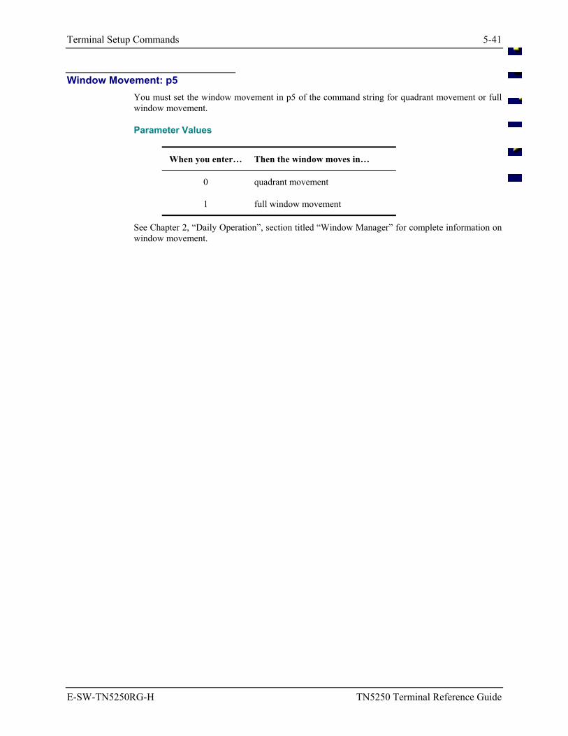
Terminal Setup Commands 5-41
E-SW-TN5250RG-H TN5250 Terminal Reference Guide
Window Movement: p5 You must set the window movement in p5 of the command string for quadrant movement or full window movement.
Parameter Values
When you enter… Then the window moves in…
0 quadrant movement
1 full window movement
See Chapter 2, “Daily Operation”, section titled “Window Manager” for complete information on window movement.
5-42 Terminal Setup Commands
TN5250 Terminal Reference Guide E-SW-TN5250RG-H
Quadrant for Cursor: p6 The display window is divided into four quadrants that identify sections of the virtual screen. The programmer must choose which quadrant the cursor appears in when the host sends a virtual screen to the terminal:
1. Upper right 2. Upper left 3. Lower left 4. Lower right
Parameter p6 enables you to determine where the cursor appears when the host sends a screen down to the terminal. The cursor appears in the specified quadrant entered in p6 once the terminal receives the screen. The default for this parameter is quadrant 4.
Status Line The status line is usually the last line on the virtual screen. You must decide whether the status line is displayed on exception only or never displayed. This line uses up to 80 character positions and stores data for display.
The status line is located on line 25 of the virtual screen.
Behavior When the status line is displayed, it overwrites the last line of the display window. If the cursor is on the bottom line of the display, the status line can overwrite the cursor position. However, the previous virtual screen appears when the operator enters valid data. When the cursor moves out of the bottom line of the display window, the status line appears again.
When the window movement keys are used to move the window or when cursor tracking occurs, the status line is not removed from the display window. The status line always appears at the bottom of the display.
Removing the Status Line If the cursor is overwritten and the terminal operator enters valid data, the status line is removed from the display window and the operator views the entered data.
Modes of Operation Window manager supports the following modes of operation for the status line:
• Always off in which case the status line never appears.
• Display on command by operator action at the keyboard.
• Display on exception only, which occurs when either an X (keyboard lock) or a T (time) error message occurs.
Terminal Setup Commands 5-43
E-SW-TN5250RG-H TN5250 Terminal Reference Guide
Message Line The LXE TN5250 emulation supports a message line that the host can address. The message line is displayed before the status line in the current display window on the terminal and is shown in its full 80-character length on the display window.
The host specifies a line as the message line and the message line appears in the display window above the status line. The message line is used for error messages from the host.
Display Window Window manager enables the terminal emulation to identify when the message line is active and which line of the virtual screen contains the 80 characters of data.
Overwriting the Display The message line overwrites information on the display, but the message line does not overwrite the status line. They are displayed at the same time with the message line shown above the status line.
Removing the Message Line If the cursor is overwritten and the terminal operator enters valid data, the message line is removed from the display window and the operator views the entered data.
Window Movement Keys If the operator moves the window with the window movement keys, the message line does not follow the display window.
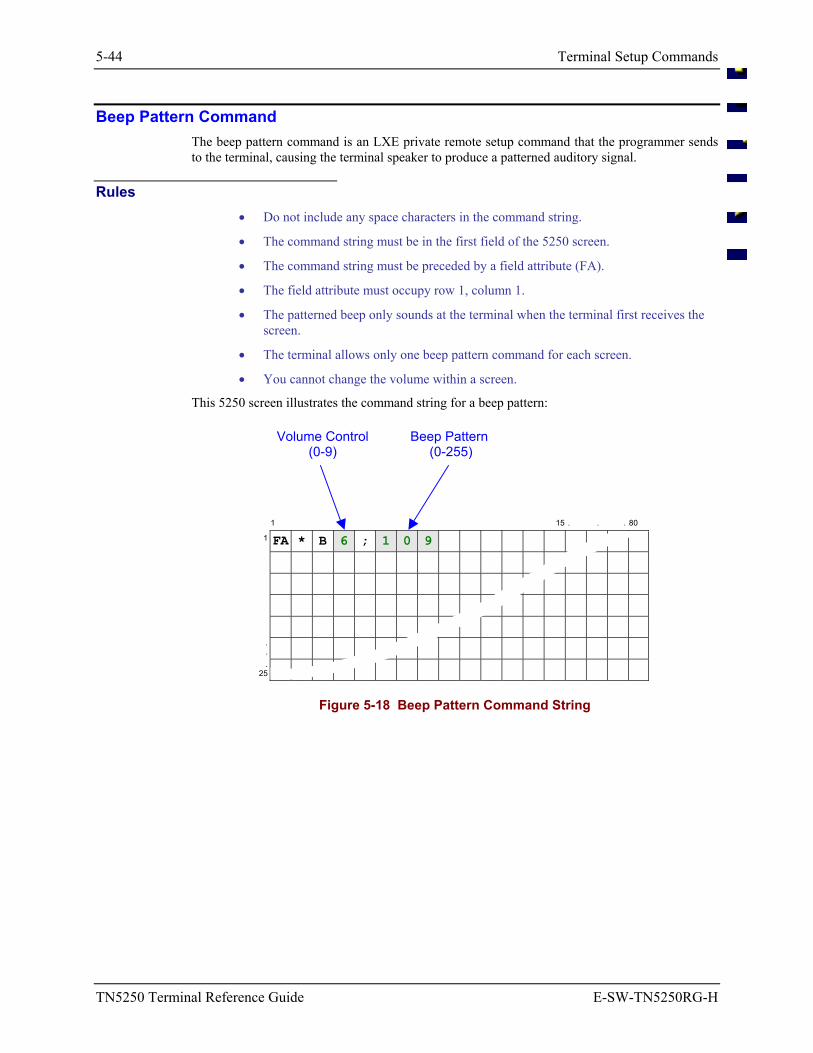
5-44 Terminal Setup Commands
TN5250 Terminal Reference Guide E-SW-TN5250RG-H
Beep Pattern Command The beep pattern command is an LXE private remote setup command that the programmer sends to the terminal, causing the terminal speaker to produce a patterned auditory signal.
Rules • Do not include any space characters in the command string.
• The command string must be in the first field of the 5250 screen.
• The command string must be preceded by a field attribute (FA).
• The field attribute must occupy row 1, column 1.
• The patterned beep only sounds at the terminal when the terminal first receives the screen.
• The terminal allows only one beep pattern command for each screen.
• You cannot change the volume within a screen.
This 5250 screen illustrates the command string for a beep pattern:
Volume Control (0-9)
Beep Pattern (0-255)
1 15 . . . 80
1 FA * B 6 ; 1 0 9
.
.
. 25
Figure 5-18 Beep Pattern Command String
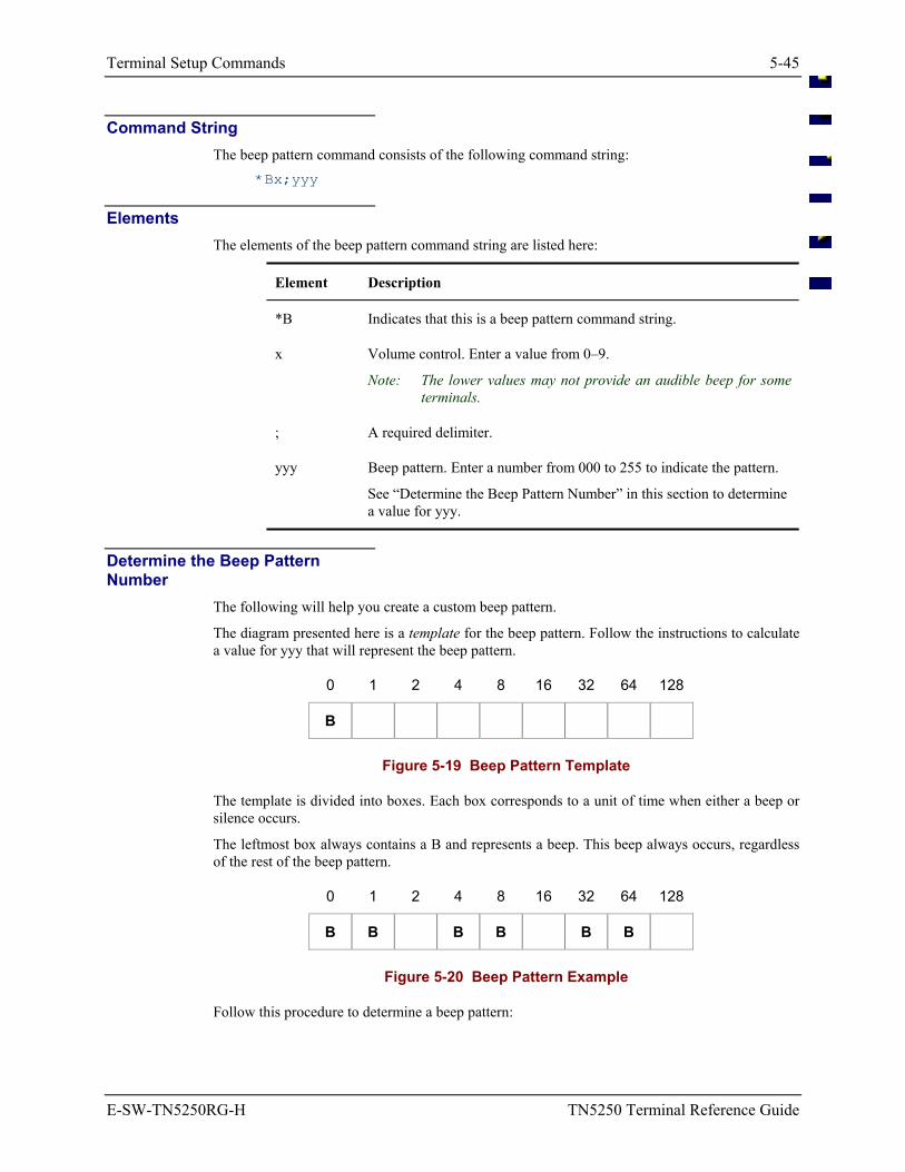
Terminal Setup Commands 5-45
E-SW-TN5250RG-H TN5250 Terminal Reference Guide
Command String The beep pattern command consists of the following command string:
*Bx;yyy
Elements The elements of the beep pattern command string are listed here:
Element Description
*B Indicates that this is a beep pattern command string.
x Volume control. Enter a value from 0–9.
Note: The lower values may not provide an audible beep for some terminals.
; A required delimiter.
yyy Beep pattern. Enter a number from 000 to 255 to indicate the pattern.
See “Determine the Beep Pattern Number” in this section to determine a value for yyy.
Determine the Beep Pattern Number
The following will help you create a custom beep pattern.
The diagram presented here is a template for the beep pattern. Follow the instructions to calculate a value for yyy that will represent the beep pattern.
0 1 2 4 8 16 32 64 128
B
Figure 5-19 Beep Pattern Template
The template is divided into boxes. Each box corresponds to a unit of time when either a beep or silence occurs.
The leftmost box always contains a B and represents a beep. This beep always occurs, regardless of the rest of the beep pattern.
0 1 2 4 8 16 32 64 128
B B B B B B
Figure 5-20 Beep Pattern Example
Follow this procedure to determine a beep pattern:

5-46 Terminal Setup Commands
TN5250 Terminal Reference Guide E-SW-TN5250RG-H
1. Starting from the left, put a B in the first box and in each box of the template where you want a beep to occur. Leave the boxes blank where you want a pause to occur.
2. Add the numbers listed above each box that has a B in it.
Note: The total is the number you use in the command string for yyy.
Or, using the Beep Pattern Example, add 0 + 1 + 4 + 8 + 32 + 64 = 109
3. Enter the total from Step 2 in the yyy position of the command string *Bx;yyy.
Using the example, the yyy total is 109.
Result:
If you execute this command string:
*B5;109
you will hear the terminal emit three short beeps at medium volume.
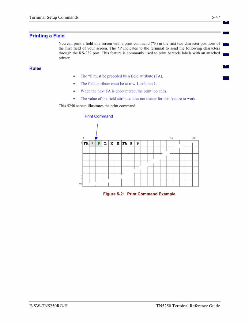
Terminal Setup Commands 5-47
E-SW-TN5250RG-H TN5250 Terminal Reference Guide
Printing a Field You can print a field in a screen with a print command (*P) in the first two character positions of the first field of your screen. The *P indicates to the terminal to send the following characters through the RS-232 port. This feature is commonly used to print barcode labels with an attached printer.
Rules • The *P must be preceded by a field attribute (FA).
• The field attribute must be at row 1, column 1.
• When the next FA is encountered, the print job ends.
• The value of the field attribute does not matter for this feature to work.
This 5250 screen illustrates the print command:
Print Command
1 15 . . . 80
1 FA * P L X E FA 9 9
.
.
. 25
Figure 5-21 Print Command Example
5-48 Terminal Setup Commands
TN5250 Terminal Reference Guide E-SW-TN5250RG-H
Auto Transmit When auto transmit is enabled the terminal automatically transmits a [SEND] when a print job ends. This notifies the host application that the print is complete and the host application can send another screen.
To enable auto transmit from the host refer to “Auto Transmit after Datastream Print: p6” in this guide.
To enable auto transmit from the terminal refer to the Configuration Utility.
CR/LF Some printers require a carriage return and/or a line feed at the end of each line.
To configure the terminal to append a CR/LF with a host command string, refer to “Printer Carriage Return per Line: p7”, and “Printer Line Feed per Line: p8” in this guide.
To directly configure the terminal to append a CR/LF see Configuration Utility.
E-SW-TN5250RG-H TN5250 Terminal Reference Guide
Table of Contents
APPENDIX A EBCDIC CODE PAGES A-1
USA/Canada EBCDIC Code Page 00037 ............................................................. A-1
LXE Character Set................................................................................................. A-2
Decimal - Hexadecimal Equivalents .................................................................... A-3
DOS U.S. PC Standard Character Set ................................................................. A-5
A-ii Table of Contents
TN5250 Terminal Reference Guide E-SW-TN5250RG-H
An EMS Technologies Company
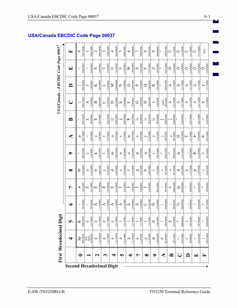
USA/Canada EBCDIC Code Page 00037 A-1
E-SW-TN5250RG-H TN5250 Terminal Reference Guide
USA/Canada EBCDIC Code Page 00037
F 0 N
D10
0000
1 N
D01
0000
2 N
D02
0000
3 N
D03
0000
4 N
D04
0000
5 N
D05
0000
6 N
D06
0000
7 N
D07
0000
8 N
D08
0000
9 N
D09
0000
3
ND
0310
00
Û
LU16
0000
Ü
LU18
0000
Ù
LU14
0000
Ú
LU12
0000
(EO
)
E \
SM07
0000
÷ SA
0600
00
S LS
0200
00
T LT
0200
00
U
LU02
0000
V
LV02
0000
W
LW02
0000
X
LX02
0000
Y
LY02
0000
Z LZ
0200
00
2
ND
2100
00
Ô
LO16
0000
Ö
LO18
0000
Ò
LO14
0000
Ó
LO12
0000
Õ
LO20
0000
D
SM
1400
00
J LJ
0200
00
K
LK02
0000
L LL
0200
00
M
LM02
0000
N
LN02
0000
O
LO02
0000
P LP
0200
00
Q
LQ02
0000
R
LR02
0000
1
ND
0110
00
û LU
1500
00
ü LU
1700
00
ù LU
1300
00
ú LU
1100
00
ÿ LY
1700
00
C
SM
1100
00
A
LA02
0000
B
LB02
0000
C
LC02
0000
D
LD02
0000
E LE
0200
00
F LF
0200
00
G
LG02
0000
H
LH02
0000
I LI
0200
00
__
(SH
Y)
SP32
0000
ô LO
1500
00
ö LO
1700
00
ò LO
1300
00
ó LO
1100
00
õ LO
1900
00
B
^ SD
1500
00
£ SC
0200
00
¥ SC
0500
00
· SD
6300
00
©
SM52
0000
§ SM
2400
00
¶ SM
2500
00
¼
NF0
4000
0
½
NF0
1000
0
¾
NF0
5000
0
[ SM
0600
00
] SM
0800
00
¯ SM
1500
00
˙˙
SD17
0000
΄ SD
1100
00
× SA
0700
00
A
µ SM
1700
00
~ A
D19
0000
s LS
0100
00
t LT
0100
00
u LU
0100
00
v LV
0100
00
w
LW01
0000
x LX
0100
00
y LY
0100
00
z LZ
0100
00
¡ SP
0300
00
¿ SP
1600
00
Ð
LD62
0000
Ý
LY12
0000
Þ LT
6400
00
®
SM53
0000
USA
/Can
ada
– EB
CDIC
Cod
e Pa
ge 0
0037
7
9 ° SM
1900
00
j LJ
0100
00
k LK
0100
00
l LL
0100
00
m
LM01
0000
n LN
0100
00
o LO
0100
00
p LP
0100
00
q LQ
0100
00
r LR
0100
00
a
SM21
0000
o
SM20
0000
æ
LA51
0000
, SD
4100
00
Æ
LA52
0000
¤ SC
0100
00
8 Ø
LO62
0000
a LA
0100
00
b LB
0100
00
c LC
0100
00
d LD
0100
00
e LE
0100
00
f LF
0100
00
g LG
0100
00
h LH
0100
00
i LI
0100
00
« SP
1700
00
» SP
1800
00
ð LD
6300
00
ý LY
1100
00
þ LT
6300
00
± SA
0200
00
7 ø L0
6100
00
É LE
1200
00
Ê LE
1600
00
Ë LE
1800
00
È LE
1400
00
Í LI
1200
00
Î LI
1600
00
Ï LI
1800
00
Ì LI
1400
00
` SD
1300
00
: SP
1300
00
# SM
0100
00
@
SM05
0000
' SP
0500
00
= SA
0400
00
" SP
0400
00
6 - SP
1000
00
/ SP
1200
00
Â
LA16
0000
Ä
LA18
0000
À
LA14
0000
Á
LA12
0000
Ã
LA20
0000
Å
LA28
0000
Ç
LC42
0000
Ñ
LN20
0000
¦ SM
6500
00
, SP
0800
00
%
SM02
0000
_ SP
0900
00
> SA
0500
00
? SP
1500
00
5 &
SM03
0000
é LE
1100
00
ê LE
1500
00
ë LE
1700
00
è LE
1300
00
í LI
1100
00
î LI
1500
00
ï LI
1700
00
ì LI
1300
00
ß LS
6100
00
! SP
0200
00
$ SC
0300
00
* SM
0400
00
) SP
0700
00
; SP
1400
00
¬ SM
6600
00
4 Sp
SP01
0000
R
eq
Spa
ce
SP30
0000
â LA
1500
00
ä LA
1700
00
à LA
1300
00
á LA
1100
00
ã LA
1900
00
å LA
2700
00
ç LC
4100
00
ñ LN
1900
00
¢ SC
0400
00
. SP
1100
00
< SA
0300
00
( SP
0600
00
+ SA
0100
00
| SM
1300
00
Firs
t H
exad
ecim
al D
igit
0 1 2 3 4 5 6 7 8 9 A
B
C
D
E F
Second Hexadecimal Digit
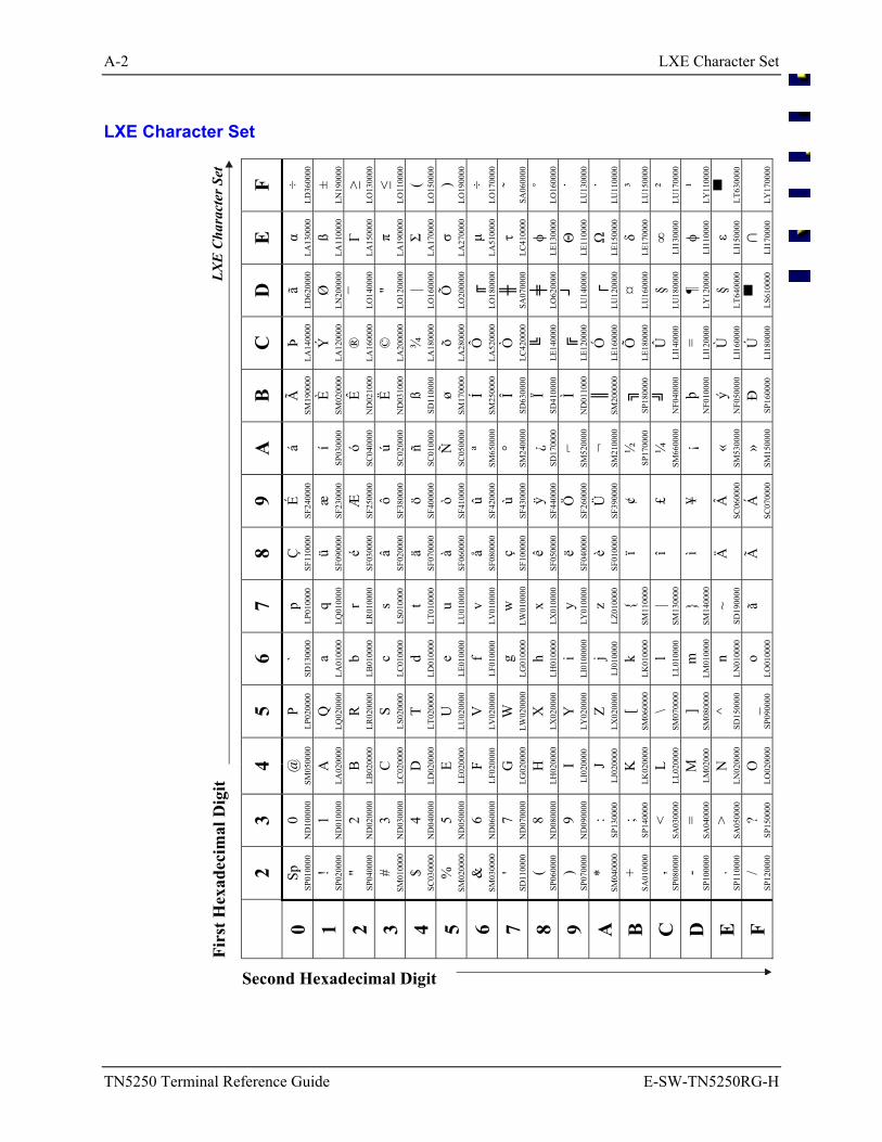
A-2 LXE Character Set
TN5250 Terminal Reference Guide E-SW-TN5250RG-H
LXE Character Set
F ÷ LD
3600
00
± LN
1900
00
≥ LO
1300
00
≤ LO
1100
00
( LO
1500
00
) LO
1900
00
÷ LO
1700
00
˜ SA
0600
00
˚ LO
1600
00
˙ LU
1300
00
˙ LU
1100
00
³ LU
1500
00
² LU
1700
00
¹ LY
1100
00
LT63
0000
LY
1700
00
E
α LA
1300
00
ß LA
1100
00
Γ LA
1500
00
π LA
1900
00
Σ LA
1700
00
σ LA
2700
00
µ LA
5100
00
τ LC
4100
00
φ LE
1300
00
Θ
LE11
0000
Ω
LE15
0000
δ LE
1700
00
∞
LI13
0000
φ LI
1100
00
ε LI
1500
00
∩
LI17
0000
D
ã LD
6200
00
Ø
LN20
0000
¯ LO
1400
00
" LO
1200
00
| LO
1600
00
Õ
LO20
0000
LO18
0000
SA07
0000
LO62
0000
LU14
0000
LU12
0000
¤ LU
1600
00
§ LU
1800
00
¶ LY
1200
00
§ LT
6400
00
LS61
0000
C
Þ LA
1400
00
Ý
LA12
0000
®
LA16
0000
©
LA20
0000
¾
LA18
0000
õ LA
2800
00
Ô
LA52
0000
Ò
LC42
0000
LE14
0000
LE12
0000
Ó
LE16
0000
Õ
LE18
0000
Û
LI14
0000
= LI
1200
00
Ù
LI16
0000
Ú
LI18
0000
B
Ã
SM19
0000
È SM
0200
00
Ê N
D02
1000
Ë N
D03
1000
ß SD
1100
00
ø SM
1700
00
Í SM
2500
00
Î SD
6300
00
Ï SD
4100
00
Ì N
D01
1000
SM20
0000
SP18
0000
NF0
4000
0
þ N
F010
000
ý N
F050
000
Đ
SP16
0000
A
á í SP
0300
00
ó SC
0400
00
ú SC
0200
00
ñ SC
0100
00
Ñ
SC05
0000
ª SM
6500
00
° SM
2400
00
¿ SD
1700
00
SM
5200
00
¬
SM21
0000
½
SP17
0000
¼
SM66
0000
¡ « SM
5300
00
» SM
1500
00
9 É SF
2400
00
æ
SF23
0000
Æ
SF25
0000
ô SF
3800
00
ö SF
4000
00
ò SF
4100
00
û SF
4200
00
ù SF
4300
00
ÿ SF
4400
00
Ö
SF26
0000
Ü
SF39
0000
¢ £ ¥ Â
SC06
0000
Á
SC07
0000
8 Ç
SF11
0000
ü SF
0900
00
é SF
0300
00
â SF
0200
00
ä SF
0700
00
à SF
0600
00
å SF
0800
00
ç SF
1000
00
ê SF
0500
00
ë SF
0400
00
è SF
0100
00
ï î ì Ä Ã
7 p LP
0100
00
q LQ
0100
00
r LR
0100
00
s LS
0100
00
t LT
0100
00
u LU
0100
00
v LV
0100
00
w
LW01
0000
x LX
0100
00
y LY
0100
00
z LZ
0100
00
SM
1100
00
| SM
1300
00
SM
1400
00
~ SD
1900
00
ã
6 ` SD
1300
00
a LA
0100
00
b LB
0100
00
c LC
0100
00
d LD
0100
00
e LE
0100
00
f LF
0100
00
g LG
0100
00
h LH
0100
00
i LI
0100
000
j LJ
0100
00
k LK
0100
00
l LL
0100
00
m
LM01
0000
n LN
0100
00
o LO
0100
00
5 P LP
0200
00
Q
LQ02
0000
R
LR02
0000
S LS
0200
00
T LT
0200
00
U
LU02
0000
V
LV02
0000
W
LW02
0000
X
LX02
0000
Y
LY02
0000
Z LX
0200
00
[ SM
0600
00
\ SM
0700
00
] SM
0800
00
^ SD
1500
00
_ SP
0900
00
LXE
Char
acte
r Set
4 @
SM05
0000
A
LA02
0000
B
LB02
0000
C
LC02
0000
D
LD02
0000
E LE
0200
00
F LF
0200
00
G
LG02
0000
H
LH02
0000
I LI
0200
00
J LJ
0200
00
K
LK02
0000
L LL
0200
00
M
LM02
000
N
LN02
0000
O
LO02
0000
3 0 N
D10
0000
1 N
D01
0000
2 N
D02
0000
3 N
D03
0000
4 N
D04
0000
5 N
D05
0000
6 N
D06
0000
7 N
D07
0000
8 N
D08
0000
9 N
D09
0000
: SP
1300
00
; SP
1400
00
< SA
0300
00
= SA
0400
00
> SA
0500
00
? SP
1500
00
2 Sp
SP01
0000
! SP
0200
00
" SP
0400
00
# SM
0100
00
$ SC
0300
00
%
SM02
0000
&
SM03
0000
' SD
1100
00
( SP
0600
00
) SP
0700
00
* SM
0400
00
+ SA
0100
00
, SP
0800
00
- SP
1000
00
. SP
1100
00
/ SP
1200
00
Firs
t Hex
adec
imal
Dig
it
0 1 2 3 4 5 6 7 8 9 A
B
C
D
E F
Second Hexadecimal Digit
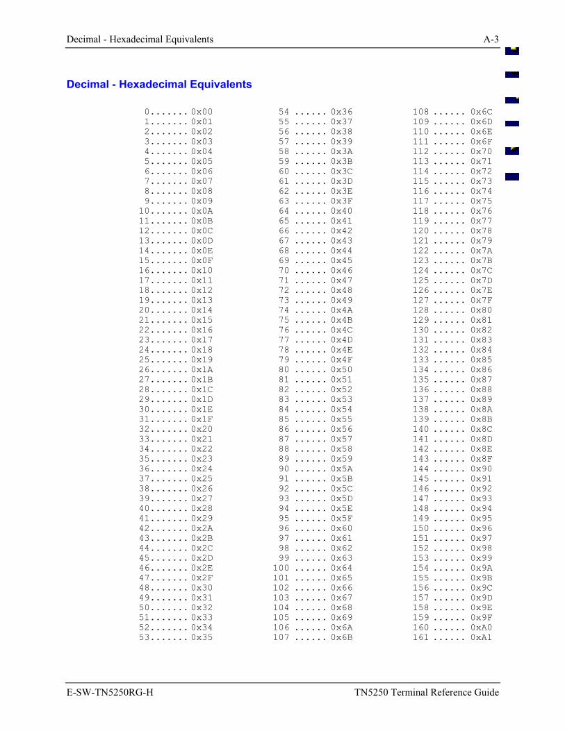
Decimal - Hexadecimal Equivalents A-3
E-SW-TN5250RG-H TN5250 Terminal Reference Guide
Decimal - Hexadecimal Equivalents
0....... 0x00 1....... 0x01 2....... 0x02 3....... 0x03 4....... 0x04 5....... 0x05 6....... 0x06 7....... 0x07 8....... 0x08 9....... 0x09 10....... 0x0A 11....... 0x0B 12....... 0x0C 13....... 0x0D 14....... 0x0E 15....... 0x0F 16....... 0x10 17....... 0x11 18....... 0x12 19....... 0x13 20....... 0x14 21....... 0x15 22....... 0x16 23....... 0x17 24....... 0x18 25....... 0x19 26....... 0x1A 27....... 0x1B 28....... 0x1C 29....... 0x1D 30....... 0x1E 31....... 0x1F 32....... 0x20 33....... 0x21 34....... 0x22 35....... 0x23 36....... 0x24 37....... 0x25 38....... 0x26 39....... 0x27 40....... 0x28 41....... 0x29 42....... 0x2A 43....... 0x2B 44....... 0x2C 45....... 0x2D 46....... 0x2E 47....... 0x2F 48....... 0x30 49....... 0x31 50....... 0x32 51....... 0x33 52....... 0x34 53....... 0x35
54 ...... 0x36 55 ...... 0x37 56 ...... 0x38 57 ...... 0x39 58 ...... 0x3A 59 ...... 0x3B 60 ...... 0x3C 61 ...... 0x3D 62 ...... 0x3E 63 ...... 0x3F 64 ...... 0x40 65 ...... 0x41 66 ...... 0x42 67 ...... 0x43 68 ...... 0x44 69 ...... 0x45 70 ...... 0x46 71 ...... 0x47 72 ...... 0x48 73 ...... 0x49 74 ...... 0x4A 75 ...... 0x4B 76 ...... 0x4C 77 ...... 0x4D 78 ...... 0x4E 79 ...... 0x4F 80 ...... 0x50 81 ...... 0x51 82 ...... 0x52 83 ...... 0x53 84 ...... 0x54 85 ...... 0x55 86 ...... 0x56 87 ...... 0x57 88 ...... 0x58 89 ...... 0x59 90 ...... 0x5A 91 ...... 0x5B 92 ...... 0x5C 93 ...... 0x5D 94 ...... 0x5E 95 ...... 0x5F 96 ...... 0x60 97 ...... 0x61 98 ...... 0x62 99 ...... 0x63100 ...... 0x64101 ...... 0x65102 ...... 0x66103 ...... 0x67104 ...... 0x68105 ...... 0x69106 ...... 0x6A107 ...... 0x6B
108 ...... 0x6C109 ...... 0x6D110 ...... 0x6E111 ...... 0x6F112 ...... 0x70113 ...... 0x71114 ...... 0x72115 ...... 0x73116 ...... 0x74117 ...... 0x75118 ...... 0x76119 ...... 0x77120 ...... 0x78121 ...... 0x79122 ...... 0x7A123 ...... 0x7B124 ...... 0x7C125 ...... 0x7D126 ...... 0x7E127 ...... 0x7F128 ...... 0x80129 ...... 0x81130 ...... 0x82131 ...... 0x83132 ...... 0x84133 ...... 0x85134 ...... 0x86135 ...... 0x87136 ...... 0x88137 ...... 0x89138 ...... 0x8A139 ...... 0x8B140 ...... 0x8C141 ...... 0x8D142 ...... 0x8E143 ...... 0x8F144 ...... 0x90145 ...... 0x91146 ...... 0x92147 ...... 0x93148 ...... 0x94149 ...... 0x95150 ...... 0x96151 ...... 0x97152 ...... 0x98153 ...... 0x99154 ...... 0x9A155 ...... 0x9B156 ...... 0x9C157 ...... 0x9D158 ...... 0x9E159 ...... 0x9F160 ...... 0xA0161 ...... 0xA1
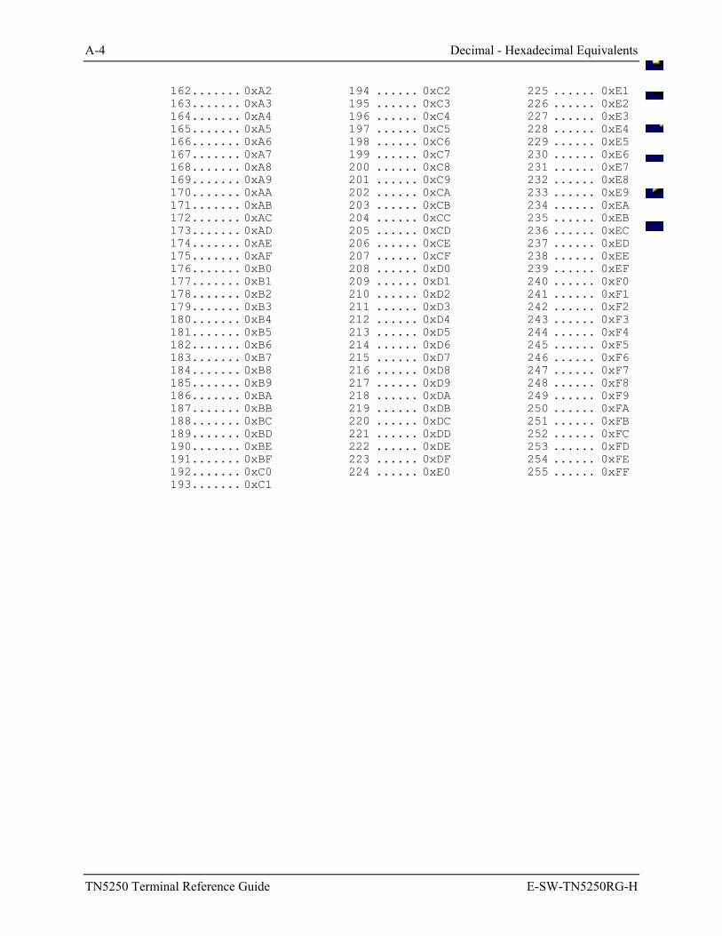
A-4 Decimal - Hexadecimal Equivalents
TN5250 Terminal Reference Guide E-SW-TN5250RG-H
162....... 0xA2 163....... 0xA3 164....... 0xA4 165....... 0xA5 166....... 0xA6 167....... 0xA7 168....... 0xA8 169....... 0xA9 170....... 0xAA 171....... 0xAB 172....... 0xAC 173....... 0xAD 174....... 0xAE 175....... 0xAF 176....... 0xB0 177....... 0xB1 178....... 0xB2 179....... 0xB3 180....... 0xB4 181....... 0xB5 182....... 0xB6 183....... 0xB7 184....... 0xB8 185....... 0xB9 186....... 0xBA 187....... 0xBB 188....... 0xBC 189....... 0xBD 190....... 0xBE 191....... 0xBF 192....... 0xC0 193....... 0xC1
194 ...... 0xC2195 ...... 0xC3196 ...... 0xC4197 ...... 0xC5198 ...... 0xC6199 ...... 0xC7200 ...... 0xC8201 ...... 0xC9202 ...... 0xCA203 ...... 0xCB204 ...... 0xCC205 ...... 0xCD206 ...... 0xCE207 ...... 0xCF208 ...... 0xD0209 ...... 0xD1210 ...... 0xD2211 ...... 0xD3212 ...... 0xD4213 ...... 0xD5214 ...... 0xD6215 ...... 0xD7216 ...... 0xD8217 ...... 0xD9218 ...... 0xDA219 ...... 0xDB220 ...... 0xDC221 ...... 0xDD222 ...... 0xDE223 ...... 0xDF224 ...... 0xE0
225 ...... 0xE1226 ...... 0xE2227 ...... 0xE3228 ...... 0xE4229 ...... 0xE5230 ...... 0xE6231 ...... 0xE7232 ...... 0xE8233 ...... 0xE9234 ...... 0xEA235 ...... 0xEB236 ...... 0xEC237 ...... 0xED238 ...... 0xEE239 ...... 0xEF240 ...... 0xF0241 ...... 0xF1242 ...... 0xF2243 ...... 0xF3244 ...... 0xF4245 ...... 0xF5246 ...... 0xF6247 ...... 0xF7248 ...... 0xF8249 ...... 0xF9250 ...... 0xFA251 ...... 0xFB252 ...... 0xFC253 ...... 0xFD254 ...... 0xFE255 ...... 0xFF
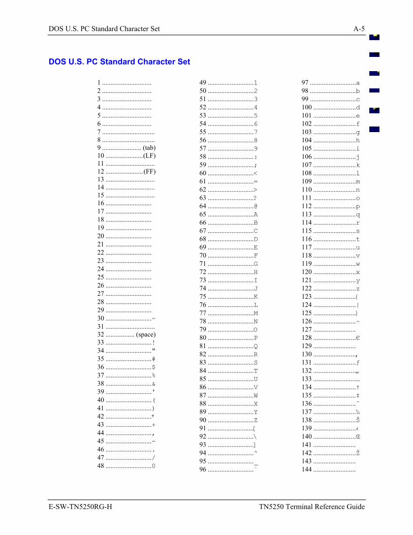
DOS U.S. PC Standard Character Set A-5
E-SW-TN5250RG-H TN5250 Terminal Reference Guide
DOS U.S. PC Standard Character Set
1 ............................. 2 ............................. 3 ............................. 4 ............................. 5 ............................. 6 ............................. 7 ............................... 8 ............................... 9 ....................... (tab) 10 ......................(LF) 11 ............................. 12 ......................(FF) 13 ............................. 14 ............................. 15 ............................. 16 ........................... 17 ........................... 18 ........................... 19 ........................... 20 ........................... 21 ........................... 22 ........................... 23 ........................... 24 ........................... 25 ........................... 26 ........................... 27 ........................... 28 ........................... 29 ........................... 30 ...........................- 31 ............................. 32 ................. (space) 33 ...........................! 34 ..........................." 35 ...........................# 36 ...........................$ 37 ...........................% 38 ...........................& 39 ...........................' 40 ...........................( 41 ...........................) 42 ...........................* 43 ...........................+ 44 ..........................., 45 ...........................- 46 ............................ 47 .........................../ 48 ...........................0
49 ...........................150 ...........................251 ...........................352 ...........................453 ...........................554 ...........................655 ...........................756 ...........................857 ...........................958 ...........................:59 ...........................;60 ...........................<61 ...........................=62 ...........................>63 ...........................?64 ...........................@65 ...........................A66 ...........................B67 ...........................C68 ...........................D69 ...........................E70 ...........................F71 ...........................G72 ...........................H73 ...........................I74 ...........................J75 ...........................K76 ...........................L77 ...........................M78 ...........................N79 ...........................O80 ...........................P81 ...........................Q82 ...........................R83 ...........................S84 ...........................T85 ...........................U86 ...........................V87 ...........................W88 ...........................X89 ...........................Y90 ...........................Z91 ...........................[92 ...........................\93 ...........................]94 ...........................^95 ..........................._96 ...........................`
97 ...........................a98 ...........................b99 ...........................c100 .........................d101 .........................e102 .........................f103 .........................g104 .........................h105 .........................i106 .........................j107 .........................k108 .........................l109 .........................m110 .........................n111 .........................o112 .........................p113 .........................q114 .........................r115 .........................s116 .........................t117 .........................u118 .........................v119 .........................w120 .........................x121 .........................y122 .........................z123 .........................124 .........................|125 .........................126 .........................~127 .........................128 .........................€129 .........................130 .........................‚131 .........................ƒ132 .........................„133 .........................…134 .........................†135 .........................‡136 .........................ˆ137 .........................‰138 .........................Š139 .........................‹140 .........................Œ141 .........................142 .........................Ž143 .........................144 .........................
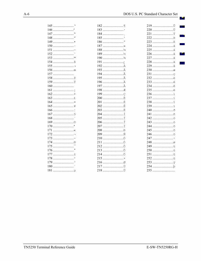
A-6 DOS U.S. PC Standard Character Set
TN5250 Terminal Reference Guide E-SW-TN5250RG-H
145 .........................‘ 146 .........................’ 147 .........................“ 148 .........................” 149 .........................• 150 .........................– 151 .........................— 152 .........................˜ 153 .........................™ 154 .........................š 155 .........................› 156 .........................œ 157 ......................... 158 .........................ž 159 .........................Ÿ 160 ......................... 161 .........................¡ 162 .........................¢ 163 .........................£ 164 .........................¤ 165 .........................¥ 166 .........................¦ 167 .........................§ 168 .........................¨ 169 .........................© 170 .........................ª 171 .........................« 172 .........................¬ 173 .........................- 174 .........................® 175 .........................¯ 176 .........................° 177 .........................± 178 .........................² 179 .........................³ 180 .........................´ 181 .........................µ
182 .........................¶183 .........................·184 .........................¸185 .........................¹186 .........................º187 .........................»188 .........................¼189 .........................½190 .........................¾191 .........................¿192 .........................À193 .........................Á194 .........................Â195 .........................Ã196 .........................Ä197 .........................Å198 .........................Æ199 .........................Ç200 .........................È201 .........................É202 .........................Ê203 .........................Ë204 .........................Ì205 .........................Í206 .........................Î207 .........................Ï208 .........................Ð209 .........................Ñ210 .........................Ò211 .........................Ó212 .........................Ô213 .........................Õ214 .........................Ö215 .........................×216 .........................Ø217 .........................Ù218 .........................Ú
219 .........................Û220 .........................Ü221 .........................Ý222 .........................Þ223 .........................ß224 .........................à225 .........................á226 .........................â227 .........................ã228 .........................ä229 .........................å230 .........................æ231 .........................ç232 .........................è233 .........................é234 .........................ê235 .........................ë236 .........................ì237 .........................í238 .........................î239 .........................ï240 .........................ð241 .........................ñ242 .........................ò243 .........................ó244 .........................ô245 .........................õ246 .........................ö247 .........................÷248 .........................ø249 .........................ù250 .........................ú251 .........................û252 .........................ü253 .........................ý254 .........................þ255 ...........................
E-SW-TN5250RG-H TN5250 Terminal Reference Guide
Table of Contents
APPENDIX B KEY MAPS B-1
The MX1 Keypad ................................................................................................... B-1 Alpha-Numeric Keypad (60 Key) ........................................................................................B-1 Numeric-Alpha Keypad (41 Key) ........................................................................................B-3
The MX2 Keypad ................................................................................................... B-5 38-key Keypad (Also 2325 Keypad) ....................................................................................B-5 48-key Keypad......................................................................................................................B-7
The MX3 Keypad ................................................................................................... B-9
The VX1, VX2 and VX4 Keyboards..................................................................... B-11
The 1380 Keyboard ............................................................................................. B-13
B-ii Table of Contents
TN5250 Terminal Reference Guide E-SW-TN5250RG-H
An EMS Technologies Company
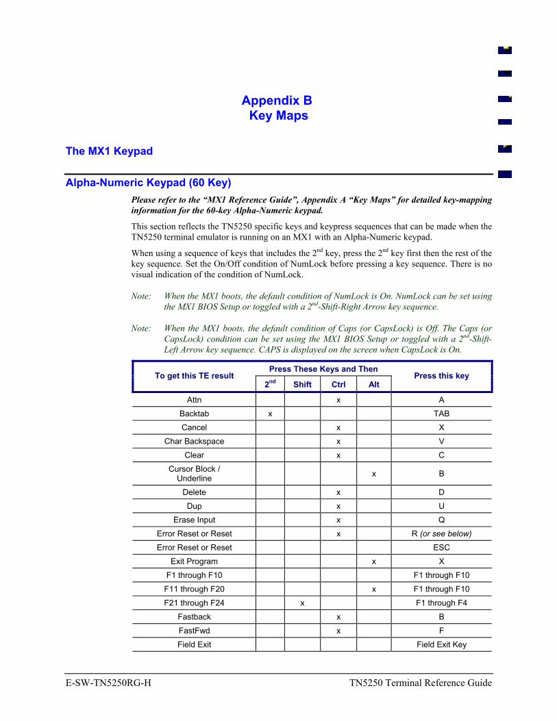
E-SW-TN5250RG-H TN5250 Terminal Reference Guide
Appendix B Key Maps
The MX1 Keypad
Alpha-Numeric Keypad (60 Key) Please refer to the “MX1 Reference Guide”, Appendix A “Key Maps” for detailed key-mapping information for the 60-key Alpha-Numeric keypad.
This section reflects the TN5250 specific keys and keypress sequences that can be made when the TN5250 terminal emulator is running on an MX1 with an Alpha-Numeric keypad.
When using a sequence of keys that includes the 2nd key, press the 2nd key first then the rest of the key sequence. Set the On/Off condition of NumLock before pressing a key sequence. There is no visual indication of the condition of NumLock.
Note: When the MX1 boots, the default condition of NumLock is On. NumLock can be set using the MX1 BIOS Setup or toggled with a 2nd-Shift-Right Arrow key sequence.
Note: When the MX1 boots, the default condition of Caps (or CapsLock) is Off. The Caps (or CapsLock) condition can be set using the MX1 BIOS Setup or toggled with a 2nd-Shift-Left Arrow key sequence. CAPS is displayed on the screen when CapsLock is On.
Press These Keys and Then To get this TE result
2nd Shift Ctrl Alt Press this key
Attn x A Backtab x TAB Cancel x X
Char Backspace x V Clear x C
Cursor Block / Underline x B
Delete x D Dup x U
Erase Input x Q Error Reset or Reset x R (or see below) Error Reset or Reset ESC
Exit Program x X F1 through F10 F1 through F10
F11 through F20 x F1 through F10 F21 through F24 x F1 through F4
Fastback x B FastFwd x F Field Exit Field Exit Key
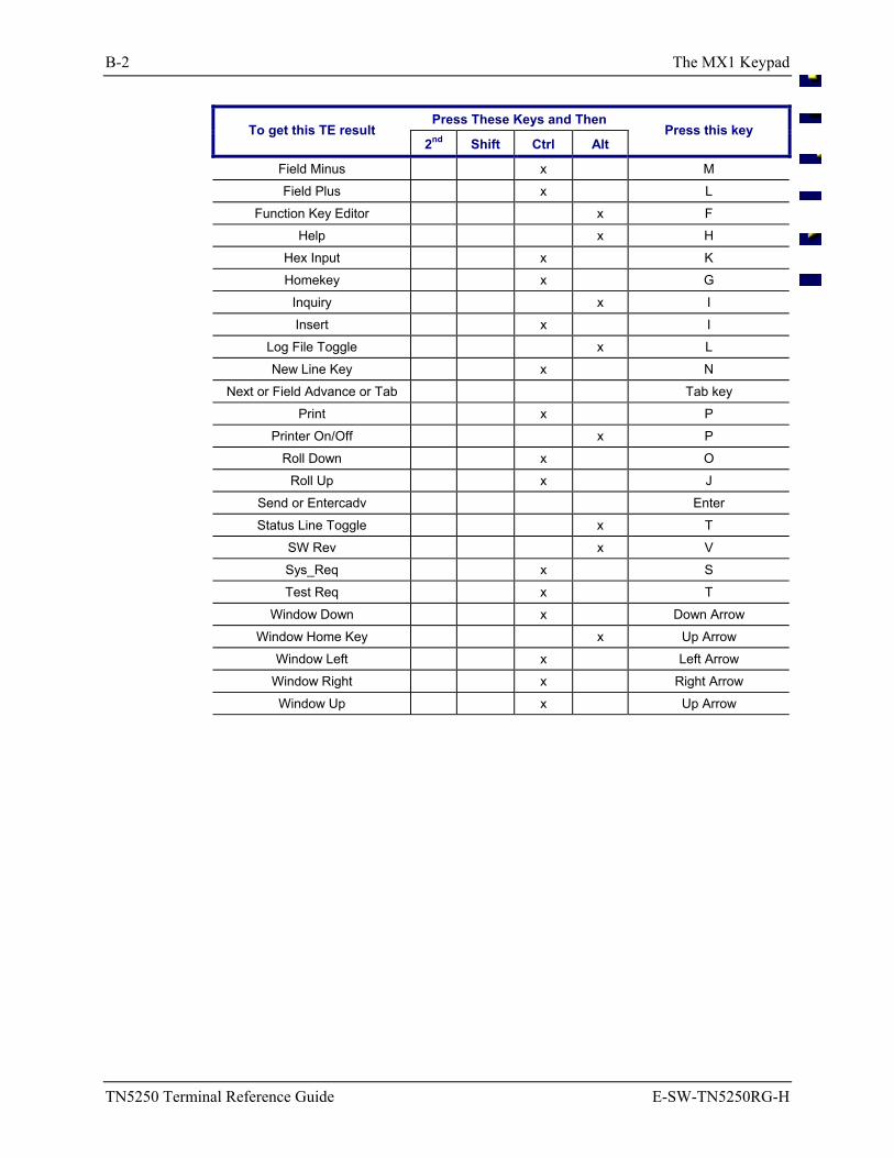
B-2 The MX1 Keypad
TN5250 Terminal Reference Guide E-SW-TN5250RG-H
Press These Keys and Then To get this TE result
2nd Shift Ctrl Alt Press this key
Field Minus x M Field Plus x L
Function Key Editor x F Help x H
Hex Input x K Homekey x G
Inquiry x I Insert x I
Log File Toggle x L New Line Key x N
Next or Field Advance or Tab Tab key Print x P
Printer On/Off x P Roll Down x O
Roll Up x J Send or Entercadv Enter Status Line Toggle x T
SW Rev x V Sys_Req x S Test Req x T
Window Down x Down Arrow Window Home Key x Up Arrow
Window Left x Left Arrow Window Right x Right Arrow Window Up x Up Arrow
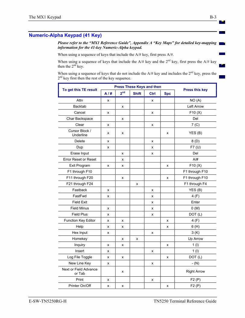
The MX1 Keypad B-3
E-SW-TN5250RG-H TN5250 Terminal Reference Guide
Numeric-Alpha Keypad (41 Key) Please refer to the “MX1 Reference Guide”, Appendix A “Key Maps” for detailed key-mapping information for the 41-key Numeric-Alpha keypad.
When using a sequence of keys that include the A/# key, first press A/#.
When using a sequence of keys that include the A/# key and the 2nd key, first press the A/# key then the 2nd key.
When using a sequence of keys that do not include the A/# key and includes the 2nd key, press the 2nd key first then the rest of the key sequence.
Press These Keys and then To get this TE result
A / # 2nd Shift Ctrl Spc Press this key
Attn x x NO (A) Backtab x Left Arrow Cancel x x F10 (X)
Char Backspace x Del Clear x x 7 (C)
Cursor Block / Underline x x x YES (B)
Delete x x 8 (D) Dup x x F7 (U)
Erase Input x x Del Error Reset or Reset x A/#
Exit Program x x x F10 (X) F1 through F10 F1 through F10
F11 through F20 x x F1 through F10 F21 through F24 x F1 through F4
Fastback x x YES (B) FastFwd x x 4 (F) Field Exit x Enter
Field Minus x x 0 (M) Field Plus x x DOT (L)
Function Key Editor x x x 4 (F) Help x x x 6 (H)
Hex Input x x 3 (K) Homekey x x Up Arrow
Inquiry x x x 1 (I) Insert x x 1 (I)
Log File Toggle x x x DOT (L) New Line Key x x - (N)
Next or Field Advance or Tab x Right Arrow
Print x x F2 (P) Printer On/Off x x x F2 (P)
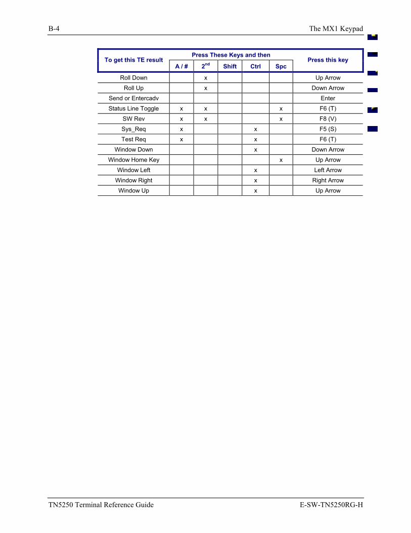
B-4 The MX1 Keypad
TN5250 Terminal Reference Guide E-SW-TN5250RG-H
Press These Keys and then To get this TE result
A / # 2nd Shift Ctrl Spc Press this key
Roll Down x Up Arrow Roll Up x Down Arrow
Send or Entercadv Enter Status Line Toggle x x x F6 (T)
SW Rev x x x F8 (V) Sys_Req x x F5 (S) Test Req x x F6 (T)
Window Down x Down Arrow Window Home Key x Up Arrow
Window Left x Left Arrow Window Right x Right Arrow Window Up x Up Arrow
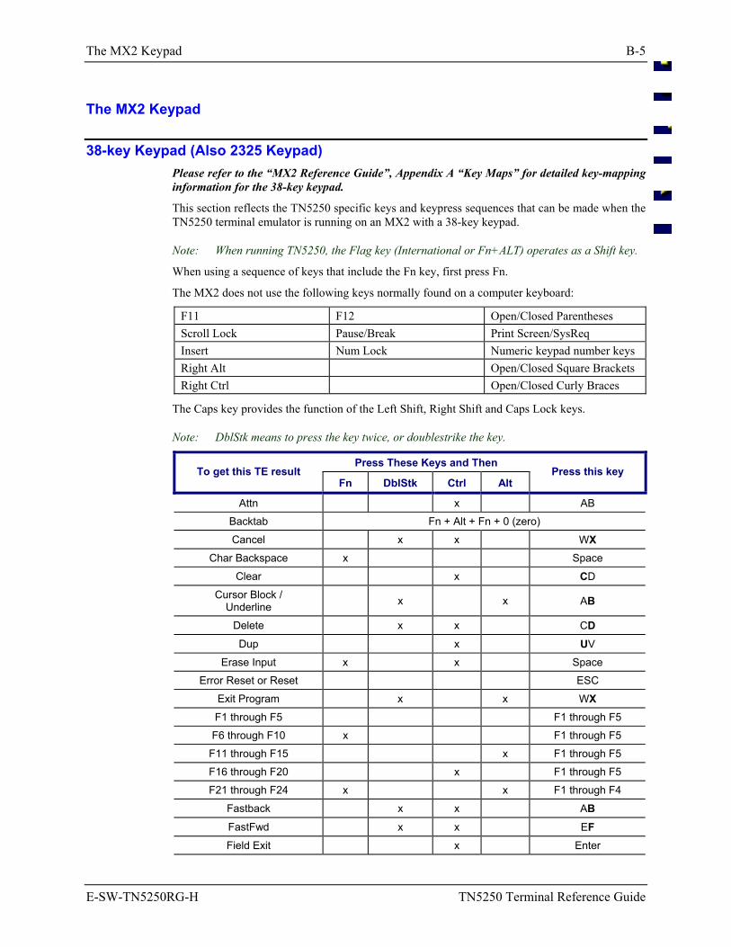
The MX2 Keypad B-5
E-SW-TN5250RG-H TN5250 Terminal Reference Guide
The MX2 Keypad
38-key Keypad (Also 2325 Keypad) Please refer to the “MX2 Reference Guide”, Appendix A “Key Maps” for detailed key-mapping information for the 38-key keypad.
This section reflects the TN5250 specific keys and keypress sequences that can be made when the TN5250 terminal emulator is running on an MX2 with a 38-key keypad.
Note: When running TN5250, the Flag key (International or Fn+ALT) operates as a Shift key.
When using a sequence of keys that include the Fn key, first press Fn.
The MX2 does not use the following keys normally found on a computer keyboard:
F11 F12 Open/Closed Parentheses Scroll Lock Pause/Break Print Screen/SysReq Insert Num Lock Numeric keypad number keys Right Alt Open/Closed Square Brackets Right Ctrl Open/Closed Curly Braces
The Caps key provides the function of the Left Shift, Right Shift and Caps Lock keys.
Note: DblStk means to press the key twice, or doublestrike the key.
Press These Keys and Then To get this TE result
Fn DblStk Ctrl Alt Press this key
Attn x AB Backtab Fn + Alt + Fn + 0 (zero) Cancel x x WX
Char Backspace x Space Clear x CD
Cursor Block / Underline x x AB
Delete x x CD
Dup x UV Erase Input x x Space
Error Reset or Reset ESC Exit Program x x WX F1 through F5 F1 through F5 F6 through F10 x F1 through F5
F11 through F15 x F1 through F5 F16 through F20 x F1 through F5 F21 through F24 x x F1 through F4
Fastback x x AB
FastFwd x x EF Field Exit x Enter
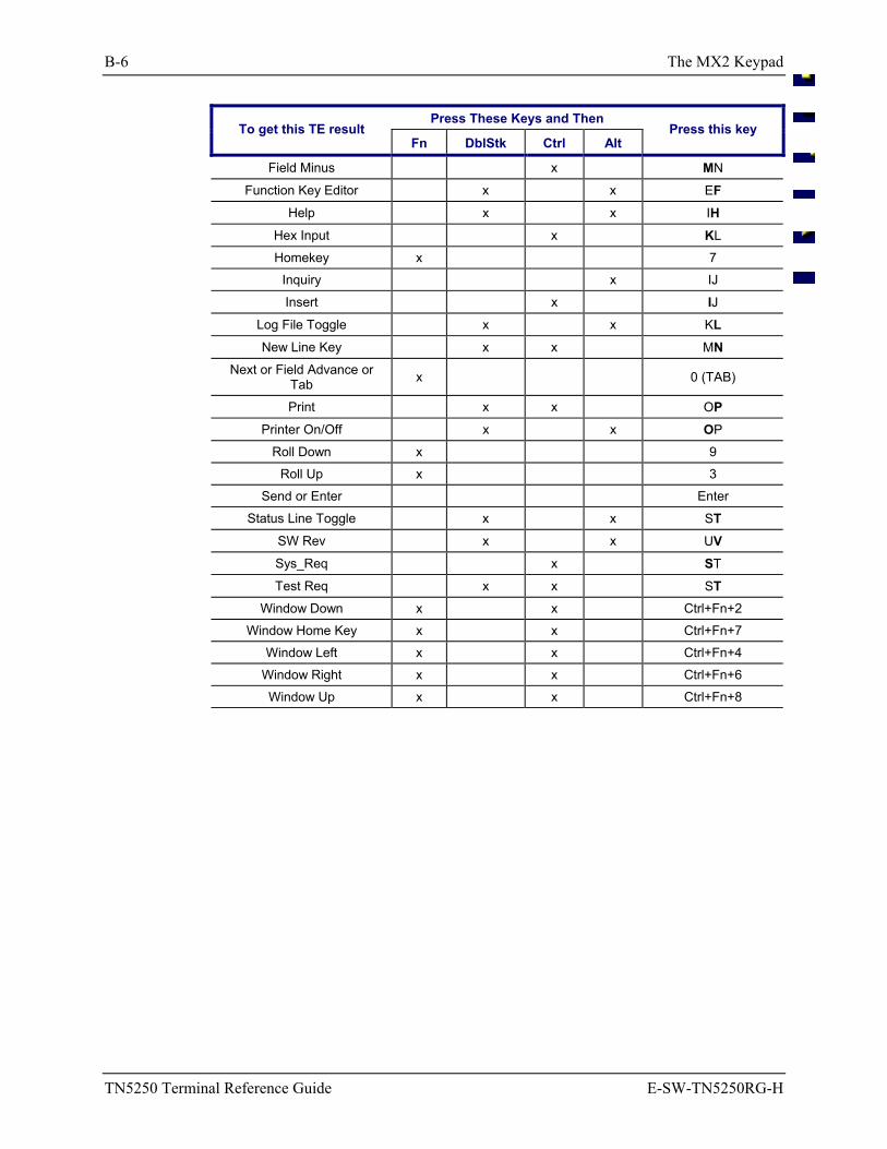
B-6 The MX2 Keypad
TN5250 Terminal Reference Guide E-SW-TN5250RG-H
Press These Keys and Then To get this TE result
Fn DblStk Ctrl Alt Press this key
Field Minus x MN
Function Key Editor x x EF
Help x x IH
Hex Input x KL Homekey x 7
Inquiry x IJ
Insert x IJ
Log File Toggle x x KL
New Line Key x x MN Next or Field Advance or
Tab x 0 (TAB)
Print x x OP
Printer On/Off x x OP Roll Down x 9
Roll Up x 3 Send or Enter Enter
Status Line Toggle x x ST
SW Rev x x UV
Sys_Req x ST
Test Req x x ST Window Down x x Ctrl+Fn+2
Window Home Key x x Ctrl+Fn+7 Window Left x x Ctrl+Fn+4
Window Right x x Ctrl+Fn+6 Window Up x x Ctrl+Fn+8
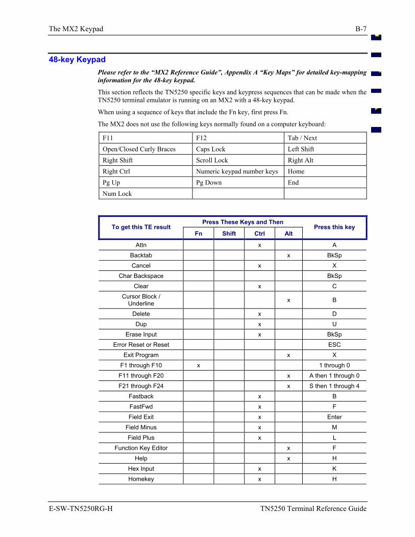
The MX2 Keypad B-7
E-SW-TN5250RG-H TN5250 Terminal Reference Guide
48-key Keypad Please refer to the “MX2 Reference Guide”, Appendix A “Key Maps” for detailed key-mapping information for the 48-key keypad.
This section reflects the TN5250 specific keys and keypress sequences that can be made when the TN5250 terminal emulator is running on an MX2 with a 48-key keypad.
When using a sequence of keys that include the Fn key, first press Fn.
The MX2 does not use the following keys normally found on a computer keyboard:
F11 F12 Tab / Next
Open/Closed Curly Braces Caps Lock Left Shift
Right Shift Scroll Lock Right Alt
Right Ctrl Numeric keypad number keys Home
Pg Up Pg Down End
Num Lock
Press These Keys and Then To get this TE result
Fn Shift Ctrl Alt Press this key
Attn x A Backtab x BkSp Cancel x X
Char Backspace BkSp Clear x C
Cursor Block / Underline x B
Delete x D Dup x U
Erase Input x BkSp Error Reset or Reset ESC
Exit Program x X F1 through F10 x 1 through 0
F11 through F20 x A then 1 through 0 F21 through F24 x S then 1 through 4
Fastback x B FastFwd x F Field Exit x Enter
Field Minus x M Field Plus x L
Function Key Editor x F Help x H
Hex Input x K Homekey x H
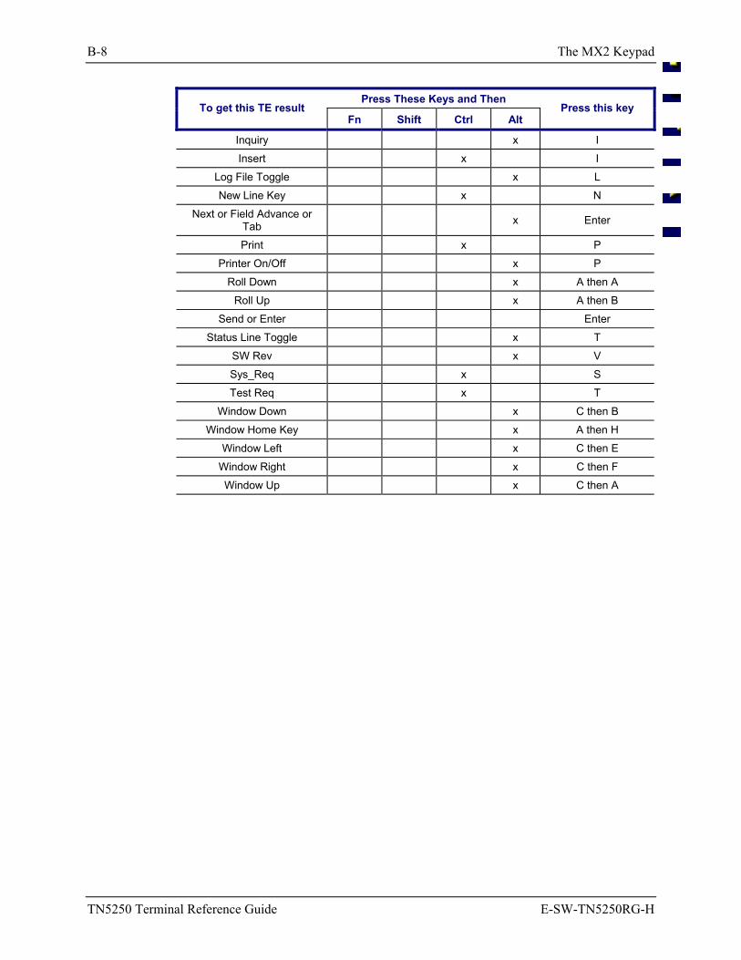
B-8 The MX2 Keypad
TN5250 Terminal Reference Guide E-SW-TN5250RG-H
Press These Keys and Then To get this TE result
Fn Shift Ctrl Alt Press this key
Inquiry x I Insert x I
Log File Toggle x L New Line Key x N
Next or Field Advance or Tab x Enter
Print x P Printer On/Off x P
Roll Down x A then A Roll Up x A then B
Send or Enter Enter Status Line Toggle x T
SW Rev x V Sys_Req x S Test Req x T
Window Down x C then B Window Home Key x A then H
Window Left x C then E Window Right x C then F Window Up x C then A
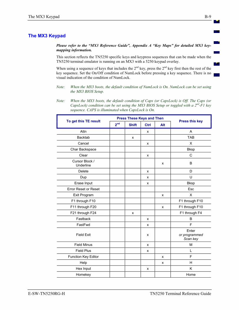
The MX3 Keypad B-9
E-SW-TN5250RG-H TN5250 Terminal Reference Guide
The MX3 Keypad
Please refer to the “MX3 Reference Guide”, Appendix A “Key Maps” for detailed MX3 key-mapping information.
This section reflects the TN5250 specific keys and keypress sequences that can be made when the TN5250 terminal emulator is running on an MX3 with a 5250 keypad overlay.
When using a sequence of keys that includes the 2nd key, press the 2nd key first then the rest of the key sequence. Set the On/Off condition of NumLock before pressing a key sequence. There is no visual indication of the condition of NumLock.
Note: When the MX3 boots, the default condition of NumLock is On. NumLock can be set using the MX3 BIOS Setup.
Note: When the MX3 boots, the default condition of Caps (or CapsLock) is Off. The Caps (or CapsLock) condition can be set using the MX3 BIOS Setup or toggled with a 2nd-F1 key sequence. CAPS is illuminated when CapsLock is On.
Press These Keys and Then To get this TE result
2nd Shift Ctrl Alt Press this key
Attn x A Backtab x TAB Cancel x X
Char Backspace Bksp Clear x C
Cursor Block / Underline x B
Delete x D Dup x U
Erase Input x Bksp Error Reset or Reset Esc
Exit Program x X F1 through F10 F1 through F10
F11 through F20 x F1 through F10 F21 through F24 x F1 through F4
Fastback x B FastFwd x F
Field Exit x Enter
or programmed Scan key
Field Minus x M Field Plus x L
Function Key Editor x F Help x H
Hex Input x K Homekey Home
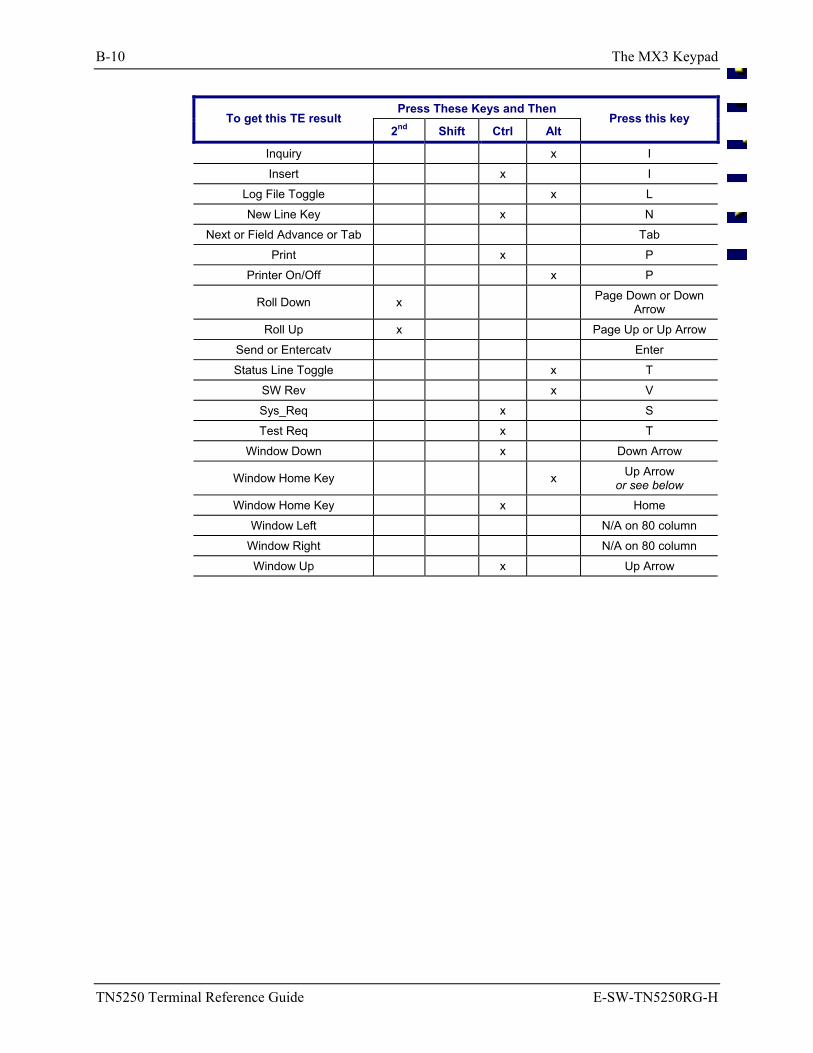
B-10 The MX3 Keypad
TN5250 Terminal Reference Guide E-SW-TN5250RG-H
Press These Keys and Then To get this TE result
2nd Shift Ctrl Alt Press this key
Inquiry x I Insert x I
Log File Toggle x L New Line Key x N
Next or Field Advance or Tab Tab Print x P
Printer On/Off x P
Roll Down x Page Down or Down Arrow
Roll Up x Page Up or Up Arrow Send or Entercatv Enter Status Line Toggle x T
SW Rev x V Sys_Req x S Test Req x T
Window Down x Down Arrow
Window Home Key x Up Arrow or see below
Window Home Key x Home Window Left N/A on 80 column
Window Right N/A on 80 column Window Up x Up Arrow
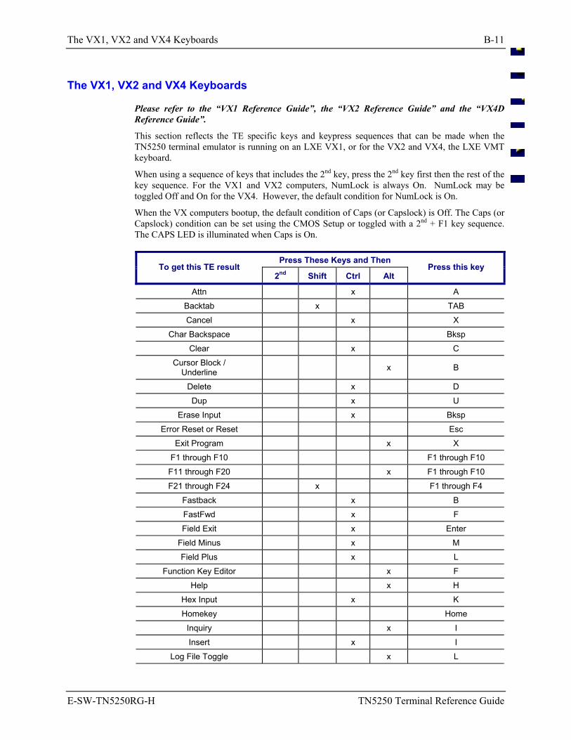
The VX1, VX2 and VX4 Keyboards B-11
E-SW-TN5250RG-H TN5250 Terminal Reference Guide
The VX1, VX2 and VX4 Keyboards
Please refer to the “VX1 Reference Guide”, the “VX2 Reference Guide” and the “VX4D Reference Guide”.
This section reflects the TE specific keys and keypress sequences that can be made when the TN5250 terminal emulator is running on an LXE VX1, or for the VX2 and VX4, the LXE VMT keyboard.
When using a sequence of keys that includes the 2nd key, press the 2nd key first then the rest of the key sequence. For the VX1 and VX2 computers, NumLock is always On. NumLock may be toggled Off and On for the VX4. However, the default condition for NumLock is On.
When the VX computers bootup, the default condition of Caps (or Capslock) is Off. The Caps (or Capslock) condition can be set using the CMOS Setup or toggled with a 2nd + F1 key sequence. The CAPS LED is illuminated when Caps is On.
Press These Keys and Then To get this TE result
2nd Shift Ctrl Alt Press this key
Attn x A Backtab x TAB Cancel x X
Char Backspace Bksp Clear x C
Cursor Block / Underline x B
Delete x D Dup x U
Erase Input x Bksp Error Reset or Reset Esc
Exit Program x X F1 through F10 F1 through F10
F11 through F20 x F1 through F10 F21 through F24 x F1 through F4
Fastback x B FastFwd x F Field Exit x Enter
Field Minus x M Field Plus x L
Function Key Editor x F Help x H
Hex Input x K Homekey Home
Inquiry x I Insert x I
Log File Toggle x L
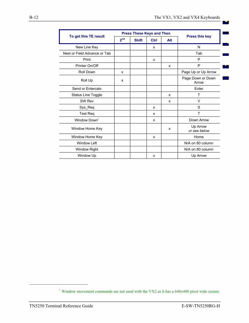
B-12 The VX1, VX2 and VX4 Keyboards
TN5250 Terminal Reference Guide E-SW-TN5250RG-H
Press These Keys and Then To get this TE result
2nd Shift Ctrl Alt Press this key
New Line Key x N Next or Field Advance or Tab Tab
Print x P Printer On/Off x P
Roll Down x Page Up or Up Arrow
Roll Up x Page Down or Down Arrow
Send or Entercatv Enter Status Line Toggle x T
SW Rev x V Sys_Req x S Test Req x T
Window Down1 x Down Arrow
Window Home Key x Up Arrow or see below
Window Home Key x Home Window Left N/A on 80 column
Window Right N/A on 80 column Window Up x Up Arrow
1 Window movement commands are not used with the VX2 as it has a 640x480 pixel wide screen.
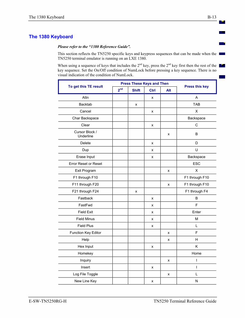
The 1380 Keyboard B-13
E-SW-TN5250RG-H TN5250 Terminal Reference Guide
The 1380 Keyboard
Please refer to the “1380 Reference Guide”.
This section reflects the TN5250 specific keys and keypress sequences that can be made when the TN5250 terminal emulator is running on an LXE 1380.
When using a sequence of keys that includes the 2nd key, press the 2nd key first then the rest of the key sequence. Set the On/Off condition of NumLock before pressing a key sequence. There is no visual indication of the condition of NumLock.
Press These Keys and Then To get this TE result
2nd Shift Ctrl Alt Press this key
Attn x A
Backtab x TAB
Cancel x X
Char Backspace Backspace
Clear x C
Cursor Block / Underline x B
Delete x D
Dup x U
Erase Input x Backspace
Error Reset or Reset ESC
Exit Program x X
F1 through F10 F1 through F10
F11 through F20 x F1 through F10
F21 through F24 x F1 through F4
Fastback x B
FastFwd x F
Field Exit x Enter
Field Minus x M
Field Plus x L
Function Key Editor x F
Help x H
Hex Input x K
Homekey Home
Inquiry x I
Insert x I
Log File Toggle x L
New Line Key x N
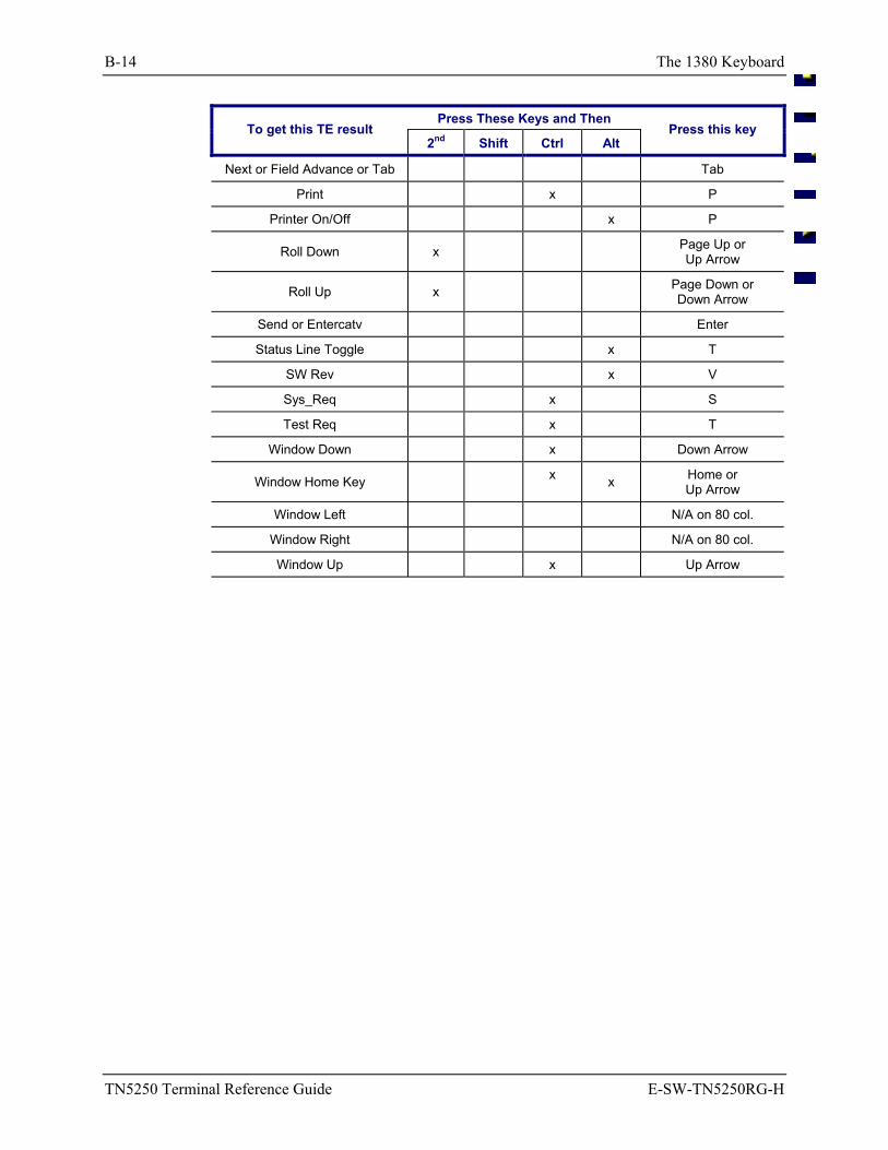
B-14 The 1380 Keyboard
TN5250 Terminal Reference Guide E-SW-TN5250RG-H
Press These Keys and Then To get this TE result
2nd Shift Ctrl Alt Press this key
Next or Field Advance or Tab Tab
Print x P
Printer On/Off x P
Roll Down x Page Up or Up Arrow
Roll Up x Page Down or Down Arrow
Send or Entercatv Enter
Status Line Toggle x T
SW Rev x V
Sys_Req x S
Test Req x T
Window Down x Down Arrow
Window Home Key x x Home or
Up Arrow
Window Left N/A on 80 col.
Window Right N/A on 80 col.
Window Up x Up Arrow
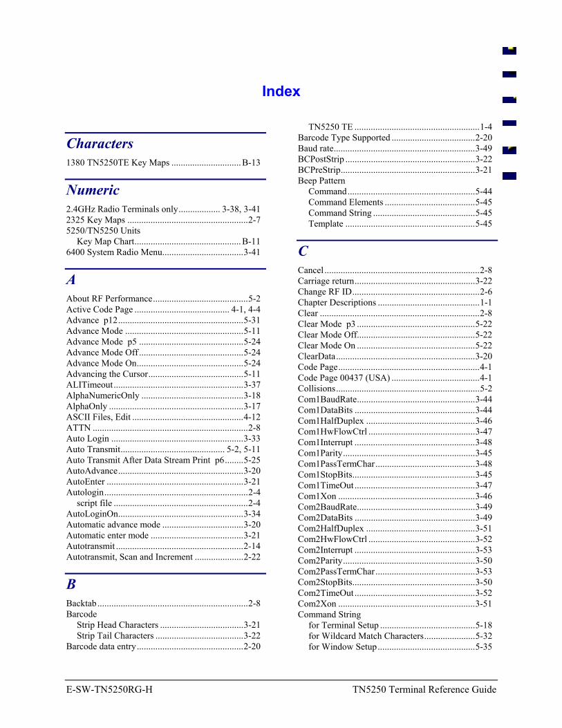
E-SW-TN5250RG-H TN5250 Terminal Reference Guide
Index
Characters 1380 TN5250TE Key Maps .............................. B-13
Numeric 2.4GHz Radio Terminals only.................. 3-38, 3-41 2325 Key Maps ....................................................2-7 5250/TN5250 Units
Key Map Chart.............................................. B-11 6400 System Radio Menu...................................3-41
A About RF Performance.........................................5-2 Active Code Page ......................................... 4-1, 4-4 Advance p12......................................................5-31 Advance Mode ...................................................5-11 Advance Mode p5 .............................................5-24 Advance Mode Off .............................................5-24 Advance Mode On..............................................5-24 Advancing the Cursor.........................................5-11 ALITimeout........................................................3-37 AlphaNumericOnly ............................................3-18 AlphaOnly ..........................................................3-17 ASCII Files, Edit ................................................4-12 ATTN ...................................................................2-8 Auto Login .........................................................3-33 Auto Transmit............................................. 5-2, 5-11 Auto Transmit After Data Stream Print p6........5-25 AutoAdvance......................................................3-20 AutoEnter ...........................................................3-21 Autologin..............................................................2-4
script file ..........................................................2-4 AutoLoginOn......................................................3-34 Automatic advance mode ...................................3-20 Automatic enter mode ........................................3-21 Autotransmit .......................................................2-14 Autotransmit, Scan and Increment .....................2-22
B Backtab.................................................................2-8 Barcode
Strip Head Characters ....................................3-21 Strip Tail Characters ......................................3-22
Barcode data entry..............................................2-20
TN5250 TE ......................................................1-4 Barcode Type Supported ....................................2-20 Baud rate.............................................................3-49 BCPostStrip ........................................................3-22 BCPreStrip..........................................................3-21 Beep Pattern
Command.......................................................5-44 Command Elements .......................................5-45 Command String ............................................5-45 Template ........................................................5-45
C Cancel ...................................................................2-8 Carriage return....................................................3-22 Change RF ID.......................................................2-6 Chapter Descriptions ............................................1-1 Clear .....................................................................2-8 Clear Mode p3 ...................................................5-22 Clear Mode Off...................................................5-22 Clear Mode On ...................................................5-22 ClearData............................................................3-20 Code Page.............................................................4-1 Code Page 00437 (USA) ......................................4-1 Collisions..............................................................5-2 Com1BaudRate...................................................3-44 Com1DataBits ....................................................3-44 Com1HalfDuplex ...............................................3-46 Com1HwFlowCtrl ..............................................3-47 Com1Interrupt ....................................................3-48 Com1Parity.........................................................3-45 Com1PassTermChar...........................................3-48 Com1StopBits.....................................................3-45 Com1TimeOut ....................................................3-47 Com1Xon ...........................................................3-46 Com2BaudRate...................................................3-49 Com2DataBits ....................................................3-49 Com2HalfDuplex ...............................................3-51 Com2HwFlowCtrl ..............................................3-52 Com2Interrupt ....................................................3-53 Com2Parity.........................................................3-50 Com2PassTermChar...........................................3-53 Com2StopBits.....................................................3-50 Com2TimeOut ....................................................3-52 Com2Xon ...........................................................3-51 Command String
for Terminal Setup .........................................5-18 for Wildcard Match Characters......................5-32 for Window Setup..........................................5-35
2 D - E Index
TN5250 Terminal Reference Guide E-SW-TN5250RG-H
Command String ......................................5-35 String Elements ........................................5-36
Computer Display Window, Quadrants..........................2-39 Function Keys ..................................................2-9
CONFIG.EXE ......................................................3-2 CONFIG.INF........................................................3-2 Configuration Program
Modifiable Parameters .....................................3-5 Non-Modifiable Parameters.............................3-5 Pre-Defined Parameters ...................................3-5 User Defined Parameters .................................3-5
Configuration Utility ............................................3-1 6400 System Radio Menu..............................3-41 Emulation Menu.............................................3-14 Exit With Save Option ...................................3-60 Exit Without Save ..........................................3-60 Keypresses .......................................................3-6 Main Menu.......................................................3-7 Main Menu Options .........................................3-7 Menu Components ...........................................3-4 Passwords.........................................................3-3 Platform Menu ...............................................3-42 Pre-configured passwords................................3-3 Protocol Menu................................................3-27 System Menu .................................................3-10
Configuration Utility Access ................................3-3 Configuring the TN5250 Terminal.....................5-17 Connecting to the Host, Failure............................2-4 Constructing Match Fields....................................5-6 Constructing Predecessor Fields...........................5-6 Count Specifier Field................................ 2-21, 5-11
Field Attribute................................................5-11 CRPerLine ..........................................................3-22 Cursor Block/Underline........................................2-8 Cursor Block/Underline Toggle ...........................2-8 Cursor Placement................................................5-11 Cursor position ...................................................3-19
Window Movement .......................................2-33 Cursor Tracking Display Examples....................2-39 Cursor Tracking Mode .................... 2-27, 2-38, 5-38 CursorType.........................................................3-42
D Daily Operation ....................................................2-1 Data bit setting....................................................3-49 Data Entry...........................................................2-19
Barcode ..........................................................2-20 Keyboard........................................................2-19 Keyboard Lock ..............................................2-19 Lock Window Mode ......................................2-37 RS-232 ...........................................................2-20
Data Fails Match Test...........................................5-7 Data Stream, IBM Host Programming .................5-3
Default Code Page ........................................................4-2 Passwords.......................................................3-11 Values ............................................................3-13 Wildcard Match Characters .............................5-7
Delete....................................................................2-8 DeviceName .......................................................3-25 DigitsOnly ..........................................................3-17 Directory structure, TN5250 TE computer...........3-2 Display................................................................5-34
Attributes .......................................................2-21 Modes p2.......................................................5-38 Window..........................................................2-27
and Virtual Screen....................................5-34 Display Version ..................................................2-12 Docked I/O Configuration..................................3-56 DockedBehavior .................................................3-56 Document Conventions ........................................1-2 DOS Autotransmit ..............................................2-14 DOS5250.EXE .....................................................3-2 DUP......................................................................2-8
E EAN128Fnc1......................................................3-59 EBCDIC ...............................................................4-1 EBCDIC.TXT.......................................................4-5 Echo.......................................................... 3-46, 3-51 Edit ASCII Files .................................................4-12 Emulation Menu .................................................3-14
AlphaNumericOnly........................................3-18 AlphaOnly......................................................3-17 AutoAdvance .................................................3-20 AutoEnter.......................................................3-21 BCPostStrip ...................................................3-22 BCPreStrip .....................................................3-21 ClearData .......................................................3-20 CRPerLine .....................................................3-22 DeviceName...................................................3-25 DigitsOnly......................................................3-17 FullWinIncs ...................................................3-15 HostQuad .......................................................3-16 InputID...........................................................3-23 LeftJustify ......................................................3-19 LFPerLine ......................................................3-23 LockCol .........................................................3-15 LockRow........................................................3-14 LockWindow .................................................3-14 LxeEscape......................................................3-25 MatchAll ........................................................3-19 NumericOnly..................................................3-18 ResetToLock..................................................3-26 StatusLine ......................................................3-16 SwapAdvance ................................................3-24 SwapTab ........................................................3-24
Index F - H 3
E-SW-TN5250RG-H TN5250 Terminal Reference Guide
TruncateData..................................................3-20 Enter Function ......................................................2-9 ENTERCADV......................................................2-9 Entering Messages, TN5250 TE...........................1-4 ER (End of Record Code).....................................5-2 Erase Input............................................................2-9 ERRGEN ............................................................4-10 ERROOR............................................................4-10 Error Codes.........................................................2-24
ALPHA ONLY ..............................................2-25 DIACRITIC KEY ..........................................2-26 DIGITS ONLY ..............................................2-25 FIELD - INVALID ........................................2-25 FOR SIGN ONLY .........................................2-25 HELP NOT VALID.......................................2-24 HEX KEY ERROR........................................2-26 INPUT TOO FAST........................................2-24 INS/DEL ERROR..........................................2-26 INSERT FULL ..............................................2-25 INVALID KEY 0002.....................................2-24 INVALID KEY 0003.....................................2-24 INVALID KEY 0006.....................................2-24 INVALID KEY 0020.....................................2-26 INVALID KEY 0027.....................................2-26 INVALID KEY 0028.....................................2-26 LOCAL EDIT ERR .......................................2-25 LU NOT ACTIVE .........................................2-26 MUST ENTER ERR......................................2-24 MUST ENTER FLD......................................2-26 MUST FILL FLD 0014 .................................2-25 MUST FILL FLD 0017 .................................2-25 NO DATA/INSERT.......................................2-25 NO DUP KEY ...............................................2-25 NO KEY INPUT............................................2-24 NON-DATA KEY .........................................2-25 NUM DATA ONLY......................................2-26 NUM ONLY FIELD......................................2-26 NUMERIC ONLY.........................................2-25 PROTECTED AREA.....................................2-24 TEST NOT AVAIL .......................................2-26
error messages ......................................................2-4 Error Reset or Reset..............................................2-9 EvtMask..............................................................3-39 Examples, IBM Host Programming .....................5-1 Exception Mode, Status Line..............................2-23 Exit
Program............................................................2-9 Function Keys ............................................2-9
With Save Option...........................................3-60 Without Save Option .....................................3-60
Exit TE .................................................................2-3 Extended Characters .............................................4-2
F F1 - F10 ................................................................2-9 Factory Defaults .................................................3-13 Fastback................................................................2-9 Fastback Function.................................................2-9 Fastfwd .................................................................2-9 Features, TN5250 TE ...........................................1-4 Field Advance.....................................................2-11 field attribute (FA)..............................................5-11 Field Exit ............................................................2-10 Field Exit key .....................................................2-22 Field Minus.........................................................2-10 Field Plus ............................................................2-10 File Transfer .......................................................4-13
INTERLNK/INTERSVR...............................4-15 Flag key is Shift Key, 2325 ..................................2-7 Font File ...............................................................4-3 FullWinIncs ........................................................3-15 Function Key
editing, TN5250 TE .......................................2-18 Editor .............................................................2-10
Function Keys.......................................................2-9 TN5250 TE ....................................................2-18
H Hardware flow control........................................3-52 Hardware type
Configuration Utility......................................3-54 HardwareModel..................................................3-54 Help ....................................................................2-10 HELP5250.TXT ...................................................3-2 HEX Input ..........................................................2-10 Homekey.............................................................2-10 Host Communication Errors ...............................2-24 Host Connection Logic.......................................3-28 Host Connection, Failed .......................................2-4 Host quadrant .....................................................3-16 Host string
Fifth................................................................3-36 First ................................................................3-34 Fourth.............................................................3-36 Second............................................................3-35 Sixth ...............................................................3-36 Third...............................................................3-35
Host1 ..................................................................3-29 Host1RLS ...........................................................3-29 Host2 ..................................................................3-30 Host2RLS ...........................................................3-30 Host3 ..................................................................3-30 Host3RLS ...........................................................3-30 Host4 ..................................................................3-30 Host4RLS ...........................................................3-30
4 I - L Index
TN5250 Terminal Reference Guide E-SW-TN5250RG-H
Host5 ..................................................................3-31 Host5RLS ...........................................................3-31 Host6 ..................................................................3-31 Host6RLS ...........................................................3-31 HostDataTimeout ...............................................3-32 HostQuad............................................................3-16 Hosts...................................................................3-28 Hot Keys...............................................................2-6 How To
Access Configuration Utility ...........................3-3 Create a Beep Pattern Number.......................5-45 Edit ASCII Files.............................................4-12 Edit Files at the Terminal...............................4-12 Edit MESSAGE.TXT File .............................4-10 Edit then Transfer Files with PC Card ...........4-13 Ignore changes and exit configuration utility 3-60 Save changes and exit configuration utility ...3-60 Set auto login parameters...............................3-33 Set autologin timer .........................................3-37 Set Emulation parameters ..............................3-14 Set Host parameters .......................................3-28 set local comm port .............................. 3-56, 3-58 Set logging parameters...................................3-39 Set network protocol parameters....................3-27 Set Radio parameters .....................................3-41 Use INTERLNK and INTERSVR .................4-15
I IBM 5250 CHECK...............................................5-2 IBM EBCDIC.......................................................4-2 IBM Host Programming .......................................5-1 IBM TN5250 Terminal Emulation
Keys and Key Sequences .................................2-5 Incompatible Keys, Legacy ..................................2-6 Incorrect Data Entry ...........................................5-12 Indicator
Error ...............................................................2-24 Inhibit Input ......................................... 2-19, 5-28 Keyboard Lock ..............................................2-19 Status Line .....................................................2-23
Initial scroll key delay ........................................3-54 InitialScrlDly ......................................................3-54 Input Device ID ..................................................5-13
Description.....................................................5-13 Input Device ID p10 ..........................................5-29 Input ID Feature
Examples........................................................5-14 Input ID Field .....................................................5-13
Terminal Operation........................................5-14 Input Identification Types ..................................5-16 InputID ...............................................................3-23 Inquiry or INQ....................................................2-10 Insert ...................................................................2-10 INTERLNK.EXE ...............................................4-15
International Key on the 2325 ..............................2-7 International Support ............................................4-1 Interrupt
Com1..............................................................3-48 Com2..............................................................3-53
INTERSVR.EXE................................................4-15 IRDAPort............................................................3-56
K Key
Mapping ...........................................................4-8 Maps................................................................ B-1 repeat scroll delay ..........................................3-54
Key Map Chart 5250/TN5250 Unit ........................................ B-11
Keyboard data entry
TN5250 TE ................................................1-4 Data Entry ......................................................2-19 Functions..........................................................2-5 Lock .................................................................2-5
Indicator ...................................................2-19 Map, Modify ....................................................4-9
Keyed Functions...................................................2-8 KEYS.TXT...........................................................4-9
L LANG2.TXT ........................................................3-2 LANGUAGE.TXT ...............................................3-2 Left Justify Mode p2 .........................................5-21 Left Justify Off ...................................................5-21 Left Justify On....................................................5-21 LeftJustify...........................................................3-19 Legacy Function Not Supported........ 2-6, 5-13, 5-29 Legacy Keys .........................................................2-6 LFPerLine...........................................................3-23 Line feed.............................................................3-23 Local Field Compare ............................................5-8 Lock display window .........................................3-14 Lock Window.....................................................2-35 Lock Window Mode........................ 2-27, 3-14, 5-38 Lock Window Mode Off ....................................5-38 Lock Window Mode On.....................................5-38 LockCol ..............................................................3-15 Locked Keyboard .................................................2-5 LockRow ............................................................3-14 LockWindow......................................................3-14 Log File Toggle ..................................................2-10 Logging Parameters............................................3-39 LXE Character Set................................ 4-1, 4-3, A-2 LXE.INI............................................. 3-2, 3-11, 3-13 LxeEngPasswd ...................................................3-12
Index M - P 5
E-SW-TN5250RG-H TN5250 Terminal Reference Guide
LxeEscape ..........................................................3-25
M Main Menu Display..............................................3-7 Manuals ................................................................1-3 Mapping................................................................4-4 Maps, Keys, 2325 .................................................2-7 Match count
mismatch ........................................................2-22 successful .......................................................2-22
Match Count Field.................................... 2-21, 5-11 Match Field................................................. 2-21, 5-6
and Autotransmit............................................2-22 Commands .......................................................5-4 Edit...................................................................5-6 Exceptions......................................................2-22
Match Fields Commands Command Letters.............................................5-4
MatchAll.............................................................3-19 MDT (Modified Data Tag) ...................................5-8 Menu Components................................................3-4
Option List .......................................................3-4 Status Bar .........................................................3-4 Title Bar ...........................................................3-4
Message Line..........................2-24, 2-41, 5-35, 5-43 and Status Line...............................................2-40 Clear...............................................................2-41 Display Window ............................................5-43 Format ............................................................2-41 Location .........................................................5-43 Overwriting the Display.................................5-43 Review ...........................................................2-41 Window Movement Keys ..............................5-43
Message Line vs. Status Line .............................5-28 MESSAGE.TXT......................................... 3-2, 4-10 Messages, Status Line ........................................2-23 Mismatch, clearing with RESET ........................2-22 Mode, Status Line...............................................2-40 modifiable parameters ..........................................3-5 Modify TN5250 TE Parameters ...........................3-1 MX1 TN5250TE Key Maps................................ B-1 MX2 TN5250TE Key Maps........................ B-5, B-7 MX3 TN5250TE Key Maps................................ B-9
N New Line Key.....................................................2-11 NEXT or TAB ....................................................2-11 non-modifiable parameters ...................................3-5 NormalIO............................................................3-58 NumericOnly ......................................................3-18
O Off Mode, Status Line ........................................2-23 OperatorPasswd..................................................3-11 option list ..............................................................3-4 Overwrite............................................................3-20
P Parameter Access Levels ......................................3-1 Parity setting.......................................................3-50 Pass termination character ..................................3-48 Password
Default ...........................................................3-11 Level 3, Default .............................................3-11 Operator ...........................................................3-3 Parameters......................................................3-10 System Administrator ......................................3-3
Passwords .............................................................3-1 Platform Menu....................................................3-42
Com1BaudRate ..............................................3-44 Com1DataRate ...............................................3-44 Com1HalfDuplex...........................................3-46 Com1HwFlowCtrl..........................................3-47 Com1Interrupt...................................... 3-48, 3-53 Com1Parity ....................................................3-45 Com1PassTermChar ......................................3-48 Com1StopBits ................................................3-45 Com1TimeOut ...............................................3-47 Com1Xon.......................................................3-46 Com2BaudRate ..............................................3-49 Com2DataBits................................................3-49 Com2HalfDuplex...........................................3-51 Com2HwFlowCtrl..........................................3-52 Com2Parity ....................................................3-50 Com2PassTermChar ......................................3-53 Com2StopBits ................................................3-50 Com2TimeOut ...............................................3-52 Com2Xon.......................................................3-51 CursorType ....................................................3-42 EAN128Fnc1 .................................................3-59 HardwareModel .............................................3-54 InitialScrlDly..................................................3-54 IRDAPort .......................................................3-56 Printing...........................................................3-43 RepeatScrlDly ................................................3-54
Pre-Configured Passwords ...................................3-3 Predecessor Field........................................ 5-6, 5-10 Primary Audience
IBM Host Programming...................................5-1 Print (5250 host) .................................................2-11 Printer Carriage Return per Line p7 ..................5-26 Printer Line Feed per Line p8............................5-27 Printer On/Off Function .....................................2-11
6 Q - S Index
TN5250 Terminal Reference Guide E-SW-TN5250RG-H
Printing ...............................................................3-43 Printing a Field ...................................................5-47
Auto Transmit ................................................5-48 CR/LF ............................................................5-48
Prompt1 ..............................................................3-34 Prompt2 ..............................................................3-35 Prompt3 ..............................................................3-35 Prompt4 ..............................................................3-36 Prompt5 ..............................................................3-36 Prompt6 ..............................................................3-36 Protocol Menu ....................................................3-27
ALITimeout ...................................................3-37 Auto Login.....................................................3-33 AutoLoginOn .................................................3-34 EvtMask .........................................................3-39 Host1..............................................................3-29 Host1RLS.......................................................3-29 Host2..............................................................3-30 Host2RLS.......................................................3-30 Host3..............................................................3-30 Host3RLS.......................................................3-30 Host4..............................................................3-30 Host4RLS.......................................................3-30 Host5..............................................................3-31 Host5RLS.......................................................3-31 Host6..............................................................3-31 Host6RLS.......................................................3-31 HostDataTimeout ...........................................3-32 Hosts ..............................................................3-28 Logging Parameters .......................................3-39 Prompt1..........................................................3-34 Prompt2..........................................................3-35 Prompt3..........................................................3-35 Prompt4..........................................................3-36 Prompt5..........................................................3-36 Prompt6..........................................................3-36 Reply1............................................................3-35 Reply2............................................................3-35 Reply3............................................................3-35 Reply4............................................................3-36 Reply5............................................................3-36 Reply6............................................................3-36 TNLogFS .......................................................3-40 TNLogging.....................................................3-39
Q Quadrant for Cursor p6......................................5-42 Quadrants, Computer Display Window..............2-39
R read only parameter ........................... 3-5, 3-54, 3-56 Recordable Macro, Maximum Length................2-18
Remote setup from host, TN5250 TE...................1-5 Removing the Message Line ..............................5-43 Removing the Status Line......................... 5-28, 5-42 RepeatScrlDly.....................................................3-54 Reply1 ................................................................3-35 Reply2 ................................................................3-35 Reply3 ................................................................3-35 Reply4 ................................................................3-36 Reply5 ................................................................3-36 Reply6 ................................................................3-36 Reset
Defaults ..........................................................3-13 Key Sequence ..................................................2-5 Parameters.............................................. 3-2, 3-13
ResetToLock.......................................................3-26 Restore Default Values.......................................3-13 RF Header.............................................................5-3 RF Performance
Collisions .........................................................5-2 Screen Design ..................................................5-2
RF Trailer .............................................................5-3 Roll Down ..........................................................2-11 Roll Up ...............................................................2-12 RS-232
Data Entry ......................................................2-20 TN5250 TE ................................................1-4
Rules Beep Pattern Command .................................5-44 Command String for Terminal Setup.............5-18 Printing a Field...............................................5-47 Valid Window
Positions p3 and p4 .................................5-39
S Scan and Increment ............................................2-21
Example .........................................................2-21 Exceptions......................................................2-22 Match Field ....................................................5-10
Description ...............................................5-10 Screen Design for Terminal Setup
Commands .....................................................5-17 Screen Displays and screen types.........................3-9 Screen Wrap .......................................................2-34 script file...............................................................2-4 SHIFT Key on the 2325 .......................................2-7 Software flow control ............................... 3-46, 3-51 Special Keys ................................................. 2-6, 4-8 Starting TE
Dual TE............................................................2-2 Manually ..........................................................2-1 Single TE .........................................................2-1
status bar...............................................................3-4 Status Line ....................................... 2-23, 2-40, 5-42
and Message Line ..........................................2-40
Index T - W 7
E-SW-TN5250RG-H TN5250 Terminal Reference Guide
Description.....................................................5-42 Display Mode p9...........................................5-28 Location ............................................... 2-40, 5-42 Messages ........................................................2-23 Mode
Always Off ...............................................2-40 Exception Only.........................................2-40
Modes of Operation .......................................5-42 Off and Exception Modes ..............................2-23 Operation .......................................................5-28 Toggle ............................................................2-12
StatusLine ...........................................................3-16 Stop bit setting....................................................3-50 String Elements ..................................................5-19 SupvPasswd........................................................3-12 SW Rev...............................................................2-12 Swap Application .................................................2-6 Swap TAB/Field Exit p11 .................................5-30 SwapAdvance.....................................................3-24 SwapTab.............................................................3-24 System Menu ......................................................3-10
LxeEngPasswd...............................................3-12 Operating Mode Parameters
DockedBehavior.......................................3-56 NormalIO .................................................3-58
OperatorPasswd .............................................3-11 Passwords.......................................................3-10 Reset Defaults ................................................3-13 SupvPasswd ...................................................3-12
System Request ..................................................2-12
T TE Selection Menu ...............................................2-2
Multiple TEs ....................................................2-2 TELNET, Autologin.............................................2-4 Terminal Emulation Setup
String Elements..............................................5-19 Terminal Setup Commands ................................5-17
Screen Design ................................................5-17 Termination character.........................................3-53 Test Request .......................................................2-12 Timeout feature ..................................................3-52 title bar..................................................................3-4 TN log file size ...................................................3-40 TN5250
Function Keys ..................................................2-9 Message Line .................................................2-41 TE.....................................................................1-4
TNLogFS............................................................3-40 TNLogging .........................................................3-39 Toggle Status Line..............................................2-12 Transfer Files......................................................4-15 Truncate Mode
Off..................................................................5-23 On ..................................................................5-23
Truncate Mode p4..............................................5-23 TruncateData ......................................................3-20
U U.S. ASCII Character Set .................................A-5 UK EBCDIC Character Set ..................................4-6 Undocked I/O Configuration..............................3-58 Unsuccessful Host Connection.............................2-4 USA/Canada Code Page 00037............................4-1 Using the Configuration Program.........................3-6 Using the Match Field, Commands ......................5-4 Using the Terminal Setup Commands................5-17
V Valid Window ....................................................2-35
Positions............................................... 2-35, 5-40 Valid Window Positions p3 and p4 ...................5-39 ViewAllCols .......................................................3-26 Virtual Screen........................................... 2-27, 2-28
W Wildcard Match
Characters Command.....................................5-32 Wildcards......................................... 3-17, 3-18, 3-19 Window
Down..............................................................2-12 Home..............................................................2-12 home column..................................................3-15 home row .......................................................3-14 increments ......................................................3-15 Left.................................................................2-13 Right...............................................................2-13 Up ..................................................................2-13
Window Manager Software Program ..........................................2-27 TN5250 TE ......................................................1-5
Window Mode Cursor Tracking .............................................2-38 Lock ...............................................................2-35
Window Movement Cursor Position ..............................................2-33 Full .................................................................2-30 Keys ...............................................................2-33 Methods .........................................................2-38 Quadrant.........................................................2-31 Types..............................................................2-30
Window Movement p5 ......................................5-41 Wrapping, Window Movement ..........................2-34
8 W - W Index
TN5250 Terminal Reference Guide E-SW-TN5250RG-H
An EMS Technologies Company