tn70 gps receiver installation manual - trig avionics gps receiver installation manual 12 august...
TRANSCRIPT
TN70 GPS/SBAS WAAS Class Beta-1 Receiver
Installation Manual
01385-00-AA
12 August 2014
Trig Avionics Limited Heriot Watt Research Park Riccarton, Currie EH14 4AP Scotland, UK Copyright Trig Avionics Limited, 2014

This page intentionally left blank

TN70 GPS Receiver Installation Manual 12 August 2014 01385-00 Issue AA
______________________
CONTENTS
1. PREFACE ....................................................................................................................................... 3
1.1 PURPOSE.................................................................................................................................... 3
1.2 SCOPE........................................................................................................................................ 3
1.3 CHANGES FROM PREVIOUS ISSUE .............................................................................................. 3
1.4 DOCUMENTS CROSS REFERENCED............................................................................................. 3
1.5 TERMS AND DEFINITIONS .......................................................................................................... 3
2. HARDWARE MOD LEVEL HISTORY ..................................................................................... 5
3. INTRODUCTION .......................................................................................................................... 6
3.1 EQUIPMENT DESCRIPTION ......................................................................................................... 6
3.2 TECHNICAL SPECIFICATION ....................................................................................................... 7
3.3 CERTIFICATION.......................................................................................................................... 8
4. REGULATORY COMPLIANCE AND LIMITATIONS........................................................... 9
4.1 OPERATIONAL CAPABILITY ....................................................................................................... 9
4.2 BARO ALTITUDE AIDING ........................................................................................................... 9
4.3 LIMITATIONS ............................................................................................................................. 9
4.4 ANTENNAS ................................................................................................................................ 9
4.5 DESIGN ASSURANCE LEVEL ...................................................................................................... 9
4.6 ENVIRONMENTAL QUALIFICATION .......................................................................................... 10
4.7 SCHEDULED AND UNSCHEDULED MAINTENANCE.................................................................... 10
5. INSTALLATION OVERVIEW.................................................................................................. 11
5.1 INTRODUCTION........................................................................................................................ 11
5.2 ANTENNA SPECIFICATION........................................................................................................ 11
5.2.1 Antenna Power ............................................................................................................... 11
5.2.2 Recommended Cable ...................................................................................................... 11
5.3 COMPATIBILITY WITH SATCOM ENVIRONMENT .................................................................... 11
6. INSTALLATION PROCEDURE ............................................................................................... 12
6.1 UNIT MOUNTING ..................................................................................................................... 12
6.2 CABLING AND WIRING CONSIDERATIONS................................................................................ 12
6.3 AIR CIRCULATION AND COOLING ............................................................................................ 12
6.4 MATERIALS SUPPLIED ............................................................................................................. 12
6.5 MATERIALS REQUIRED (NOT SUPPLIED): ................................................................................ 12
6.6 GPS/SBAS ANTENNA LOCATION............................................................................................ 12
6.7 GPS/SBAS ANTENNA AND CABLE INSTALLATION.................................................................. 13
6.8 SYSTEM INTERCONNECTIONS .................................................................................................. 13
6.8.1 Main Connector.............................................................................................................. 14
Trig Avionics Limited i
TN70 GPS Receiver Installation Manual 12 August 2014 01385-00 Issue AA
______________________
ii Trig Avionics Limited
6.9 ELECTRICAL LOAD ASSESSMENT............................................................................................. 14
6.10 AIRCRAFT WIRING .................................................................................................................. 14
6.10.1 Port 1 and Port 2 (RS-232 TX/RX I/O)........................................................................... 14
6.10.2 PPS Y&Z......................................................................................................................... 15
6.10.3 Unit Power wiring .......................................................................................................... 15
6.11 WIRING DIAGRAM................................................................................................................... 15
6.12 SERIAL DATA COMMUNICATION ............................................................................................. 16
6.13 SOFTWARE INSTALLATION ...................................................................................................... 16
6.14 OPERATING INSTRUCTIONS...................................................................................................... 16
6.15 VHF COM INTERFERENCE TESTING......................................................................................... 16
6.16 PHYSICAL CHARACTERISTICS.................................................................................................. 17
APPENDIX A - ENVIRONMENTAL QUALIFICATION FORM................................................. 18
APPENDIX B - GUIDANCE FOR INTERFACING WITH ADSB SYSTEMS ............................ 20

TN70 GPS Receiver Installation Manual 12 August 2014 01385-00 Issue AA
______________________
1. Preface
1.1 Purpose
This document describes the system descriptions, and technical specification, as well as the installation, electrical and physical characteristics, limitations, environmental qualification, periodic maintenance procedures and corrective maintenance procedures for the TN70 GPS SBAS Receiver for Class Beta 1 Applications.
1.2 Scope
This document applies to the Trig TN70 GPS Receiver.
The Trig TN70 is an Accord Technologies, NexNav mini 21000 GPS receiver. No regulatory or certification specifications have been changed. Whenever this document refers to the TN70 is should be understood that it is actually a NexNav mini 21000 (Part number 21000) GPS Receiver.
1.3 Changes from Previous Issue
None, this is the first issue.
1.4 Documents Cross Referenced
RTCA/DO-229D RTCA Document - Minimum Operational Performance Standards for Global Positioning System/Wide Area Augmentation System Airborne Equipment
FAA/TSO-C145c Technical Standard Order for Airborne Navigation Sensors Using the Global Positioning System (GPS) Augmented by the Wide Area Augmentation System (WAAS) GPS Augmented by Wide Area Augmented System
AC 20-138C Airworthiness Approval of Global Navigation Satellite System (GNSS) Equipment
AC 43.13-1B Acceptable Methods, Techniques, and Practices - Aircraft Inspection and Repair
AC 43.13-2A
Acceptable Methods, Techniques, and Practices - Aircraft Alterations
RTCA/DO-160F RTCA Document – Environmental Conditions and test Procedures for Airborne Equipment
RTCA/DO-301 RTCA Document – Minimum Operational Performance Standards for Global Navigation Satellite System (GNSS) Airborne Active Antenna Equipment for the L1 Frequency Band
FAA/TSO-C190 Technical Standard Order for Active Airborne Global Navigation Satellite System (GNSS) Antenna
FAA/TSO-C144a
Technical Standard Order for Passive Airborne Global Navigation Satellite Systems (GNSS) Antenna
AC 20-165A Airworthiness Approval of Automatic Dependent Surveillance-Broadcast (ADS-B) Out systems
1.5 Terms and Definitions
DAL Design Assurance Level
EGNOS European Geo Stationary Navigation Overlay Service
FAA Federal Aviation Administration
Trig Avionics Limited 3

TN70 GPS Receiver Installation Manual 12 August 2014 01385-00 Issue AA
______________________
FD/FDE Fault Detection and Exclusion
GAGAN GPS Aided Geo Augmented Navigation
GNSS Global Navigation Satellite Systems
GNSSU Global Navigation Satellite Sensor Unit
GPS Global Positioning System
GPSB Global Positioning System Satellite Based Augmentation System
LNAV Lateral Navigation
MSAS Multi-functional Satellite Augmentation System
NMEA National Marine Electronic Association
PVT Position, Velocity and Time
RAIM Receiver Autonomous Integrity Monitoring
PRAIM Predictive Receiver Autonomous Integrity Monitoring
RF Radio Frequency
SATCOM Satellite Communication
SBAS Satellite Based Augmentation System
TSO Technical Standard Order
VHF Very High Frequency
WAAS Wide Area Augmentation System
Page 4 Trig Avionics Limited

TN70 GPS Receiver Installation Manual 12 August 2014 01385-00 Issue AA
______________________
2. Hardware MOD Level History
The following table identifies hardware modification (MOD) levels for the TN70 product.
The MOD levels are listed with the associated service bulletin number, service bulletin date and purpose of the modification.
MOD Number SERVICE BULLETIN NUMBER
SERVICE BULLETIN DATE
PURPOSE OF THE MODIFICATION
1 AT-SB-21000-07122013
12-July-2013 Incorporation of GPS CCA PN 12000/12001 with MCX-type RF connector and mating cable assembly in the build for GPS-SBAS Sensor PN 21000/21001.
Trig Avionics Limited 5

TN70 GPS Receiver Installation Manual 12 August 2014 01385-00 Issue AA
______________________
3. Introduction
3.1 Equipment Description
The TN70 GPS SBAS Class Beta-1 Receiver is a satellite receiver that utilises signals coming from Global Positioning System (GPS) satellite constellation and satellite-based augmentation systems (SBAS) such as the USA Wide Area Augmentation System (WAAS), European EGNOS, Indian GAGAN and the Japanese MSAS. The TN70 is limited to only using SBAS systems that are compatible with WAAS.
The primary function of the TN70 Receiver is to compute the Position, Velocity and Precise Time (PVT). It also computes the integrity of the PVT from the SBAS signal, when available. The TN70 detects and excludes failed satellites (FD/FDE) using Receiver Autonomous Integrity Monitoring (RAIM) algorithm, whenever there are an adequate number of tracked satellites.
The sensor unit communicates with other avionics through a serial communication link.
Figure 1: TN70 Interface Diagram
TN7
Antenna /
Port 1 (RS-232) T nsmit ra
Port 1 (RS-232) Receive
Port 2 (RS-232) Transmit
NMEA
DC Power Input Time Mark 1PPS (RS-422)
Power Ground
Page 6 Trig Avionics Limited

TN70 GPS Receiver Installation Manual 12 August 2014 01385-00 Issue AA
______________________
3.2 Technical Specification
The following table describes the technical specification of TN70 Unit
Table 1: Technical Specification
Characteristics Parameter Specification
RTCA DO-229D
DO-254, Level C
DO-178B, Level C
DO-160F
Conformity
FAA TSO-C145c Class Beta - 1
General Type 1575.42 MHz L1, C/A code receiver with SBAS capability
Number of Channels 12 GPS and 3 SBAS/WAAS parallel channels
Position Update Interval
5 Hz (0.2 seconds)
Tracking -145 dBm Sensitivity
Reacquisition 6 seconds typical at –130 dBm GPS
9 seconds typical at –130 dBm SBAS
RMS Horizontal with WAAS
5 metres, RMS Position Accuracy
RMS Vertical with WAAS
7 metres, RMS
1 PPS Pulse per seconds 30 ns, RMS
Altitude Maximum 18287 metres
Speed, acceleration and jerk
Per DO-229D requirements for oceanic, en-route, terminal, LNAV, and non precision approach modes of operation
Velocity Maximum 513 m/s
Dynamics
Accuracy 0.1 m/s RMS
Cold start 90 seconds at –130 dBm (typical) TTFF (Time To First Fix)
Warm Start 66 seconds at –130 dBm (typical)
RAIM SBAS integrity incorporated
FD/FDE FD/FDE incorporated
Alert Navigation alert as per DO-229D
Integrity Monitoring
BIT Comprehensive power on and online self tests
Hardware Per RTCA DO-254, Level C Design Assurance
Software Per RTCA DO-178B, Level C
Serial Port
P/N 21000
Port1: RS-232, 19.2 kbps (NexNav Legacy Protocol)
Port2: RS-232, 57.6 kbps (NMEA Protocol)
Communication
Time Mark RS-422 One PPS
Trig Avionics Limited 7

TN70 GPS Receiver Installation Manual 12 August 2014 01385-00 Issue AA
______________________
Characteristics Parameter Specification
Software Protocol NexNav Legacy Binary Protocol and NMEA Protocol
SATCOM Compatibility
Compatible on aircraft equipped with SATCOM, when installed with TSO-C144( ) or TSO-C190( ) approved antenna.
Environmental Characteristics
DO-160F As per environmental qualification form in Appendix A.
Power Supply 14 VDC to 28 VDC (nominal)
9-32 VDC (operational)
Antenna Power Supply 5 VDC, 100 mA max
Electrical Characteristics
Power 3 W (typical)
Dimension 4.13”W x 6.50”D x 1.60”H
Weight Less than 1.5 lbs
Antenna Connector TNC RF connector, Female
Physical Characteristics
I/O Connector 25 pin D, receptacle
3.3 Certification
The TN70 Receiver conforms to TSO-C145c Class Beta 1 without any deviations. It also meets RTCA/DO-160F environmental specifications and has been developed in accordance with RTCA/DO-178B level C and RTCA/DO-254 level C design assurance level.
Table 2: Deviations
Deviations
TSO-C145c
DO-229D
No deviations from TSO-C145c
No deviations from RTCA/DO-229D
Page 8 Trig Avionics Limited
TN70 GPS Receiver Installation Manual 12 August 2014 01385-00 Issue AA
______________________
4. Regulatory Compliance and Limitations
4.1 Operational Capability
The equipment is FAA TSO-C145c Class Beta 1 Approved. It can be operated in Oceanic, En-route, Terminal, LNAV airspace, and Beta 1 applications.
4.2 Baro Altitude Aiding
TN70 is capable of accepting altimeter data corrected for the local barometric pressure setting. However, the receiver does not depend upon the baro altimeter aiding to satisfy the FD/FDE integrity requirements of DO-229D.
4.3 Limitations
The conditions and tests required for TSO approval of this article are minimum performance standards. Those installing this article, on or in a specific type or class of aircraft, must determine that the aircraft installation conditions are within the TSO standards. TSO articles must have separate approval for installation in an aircraft. The article may be installed only according to AC 20-138C applicable airworthiness requirements.
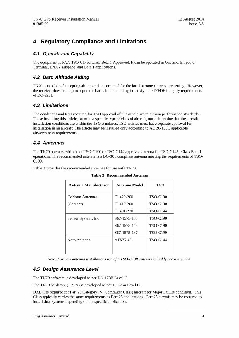
4.4 Antennas
The TN70 operates with either TSO-C190 or TSO-C144 approved antenna for TSO-C145c Class Beta 1 operations. The recommended antenna is a DO-301 compliant antenna meeting the requirements of TSO-C190.
Table 3 provides the recommended antennas for use with TN70.
Table 3: Recommended Antenna
Antenna Manufacturer Antenna Model TSO
Cobham Antennas
(Comant)
CI 429-200
CI 419-200
CI 401-220
TSO-C190
TSO-C190
TSO-C144
Sensor Systems Inc S67-1575-135
S67-1575-145
S67-1575-137
TSO-C190
TSO-C190
TSO-C190
Aero Antenna AT575-43 TSO-C144
Note: For new antenna installations use of a TSO-C190 antenna is highly recommended
4.5 Design Assurance Level
The TN70 software is developed as per DO-178B Level C.
The TN70 hardware (FPGA) is developed as per DO-254 Level C.
DAL C is required for Part 23 Category IV (Commuter Class) aircraft for Major Failure condition. This Class typically carries the same requirements as Part 25 applications. Part 25 aircraft may be required to install dual systems depending on the specific application.
Trig Avionics Limited 9

TN70 GPS Receiver Installation Manual 12 August 2014 01385-00 Issue AA
______________________
DO-229D specifies DAL C for Class Beta-1 receivers.
4.6 Environmental Qualification
The TN70 receiver is tested for environmental conditions specified in relevant sections of DO-160F. The Environmental Qualification Form is included in Appendix A of this document.
4.7 Scheduled and Unscheduled Maintenance
There is no requirement for periodic service, inspection or preventive maintenance for continued airworthiness of the TN70.
Page 10 Trig Avionics Limited

TN70 GPS Receiver Installation Manual 12 August 2014 01385-00 Issue AA
______________________
5. Installation Overview
5.1 Introduction
Careful planning and consideration of suggestions in this section are required to achieve the desired performance and reliability from the TN70 Receiver.
The installation instructions meet the guidance provided in AC 20-138C “Airworthiness Approval of Global Navigation Satellite System (GNSS) Equipment”.
5.2 Antenna Specification
The antenna performance is critical to operation of GPS/SBAS receiver. The recommended antenna is a DO-301 compliant antenna meeting the requirements of TSO-C190. For installations where the aircraft has an existing antenna complying with DO-228 (TSO-C144a), the TN70 may be installed utilising this antenna, as per DO-229D Note 1, Section 2.1.1.10.
The performance of the TN70 is affected by the gain, noise figure, impedance, and frequency selectivity characteristics of the antenna. TN70 should be used only with the recommended antenna and cable. Use of other antennas or cables may not meet all the performance characteristics specified in DO-229D.
5.2.1 Antenna Power
The TN70 receiver utilises an active antenna which means the antenna includes a low noise amplifier. The power for the low noise amplifier is provided from the GPS receiver via the antenna coax cable.
5.2.2 Recommended Cable
RG 400 or RG142 is recommended. A maximum length of 50 ft is recommended. The cable including connectors, loss should not exceed 10dB
5.3 Compatibility with SATCOM Environment
The performance of the TN70 is unaffected when operating in a SATCOM environment. The performance of the TN70 Receiver is specification compliant for SATCOM compatibility per DO-229D.
Trig Avionics Limited 11
TN70 GPS Receiver Installation Manual 12 August 2014 01385-00 Issue AA
______________________
6. Installation Procedure
6.1 Unit Mounting
The TN70 unit is designed to mount in any convenient location in the aircraft. Consideration should be given to the length of the antenna coax cable when selecting a location.
Attach the TN70 Receiver firmly to the airframe. The chassis of the unit must be properly grounded to the aircraft.
6.2 Cabling and Wiring Considerations
The equipment wiring should be performed in accordance with AC 43.13-1B Chapter 11. Ensure that the cable is not routed close to high-energy sources. Use of 22 AWG wire is recommended for all connections other than coax.
6.3 Air Circulation and Cooling
The TN70 unit does not require external cooling. However, as with all electronic equipment, lower operating temperatures extend equipment life.
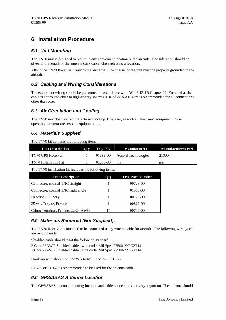
6.4 Materials Supplied
The TN70 kit contains the following items:
Unit Description Qty Trig P/N Manufacturer Manufacturers P/N
TN70 GPS Receiver 1 01386-00 Accord Technologies 21000
TN70 Installation Kit 1 01380-00 n/a n/a
The TN70 installation kit includes the following items:
Unit Description Qty Trig Part Number
Connector, coaxial TNC straight 1 00723-00
Connector, coaxial TNC right angle 1 01383-00
Headshell, 25 way 1 00726-00
25 way D-type, Female 1 00866-00
Crimp Terminal, Female, 22-24 AWG 14 00730-00
6.5 Materials Required (Not Supplied):
The TN70 Receiver is intended to be connected using wire suitable for aircraft. The following wire types are recommended.
Shielded cable should meet the following standard:
2 Core 22AWG Shielded cable , wire code: Mil Spec 27500-22TG2T14 3 Core 22AWG Shielded cable , wire code: Mil Spec 27500-22TG3T14 Hook-up wire should be 22AWG to Mil Spec 22759/16-22 RG400 or RG142 is recommended to be used for the antenna cable
6.6 GPS/SBAS Antenna Location
The GPS/SBAS antenna mounting location and cable connections are very important. The antenna should
Page 12 Trig Avionics Limited
TN70 GPS Receiver Installation Manual 12 August 2014 01385-00 Issue AA
______________________
not be mounted close to VHF COM transmitter antennas, and other antennas emitting high power. Special care should be taken to ensure that the GPS antenna is not mounted in close proximity to antennas that may emit harmonic interference at the L1 frequency of 1575.42 MHz. Refer to AC 20-138C “Airworthiness Approval of Global Navigation Satellite System (GNSS) Equipment” for additional information and guidelines. For best performance, select a location with an unobstructed view of the sky above the aircraft when in level flight.
For installations on rotorcraft, ensure that the rotor blades do not interfere with the GPS/SBAS received signal. This problem has been experienced in some rotorcraft and varies with rotation rate.
6.7 GPS/SBAS Antenna and Cable Installation
Antennas with TSO-C190 are highly recommended for the installations. Table 3 provides the recommended antennas for use with the TN70.
Once the antenna mounting position has been prepared, route the coaxial cable from the antenna to the TN70 Receiver. Proper selection of coaxial cable and assembly of connectors are critical to GPS signal performance. The recommended cable is RG 400 or RG142. Connector losses should be considered when computing the cable loss. Total cable loss including connectors, should be less than 10dB.
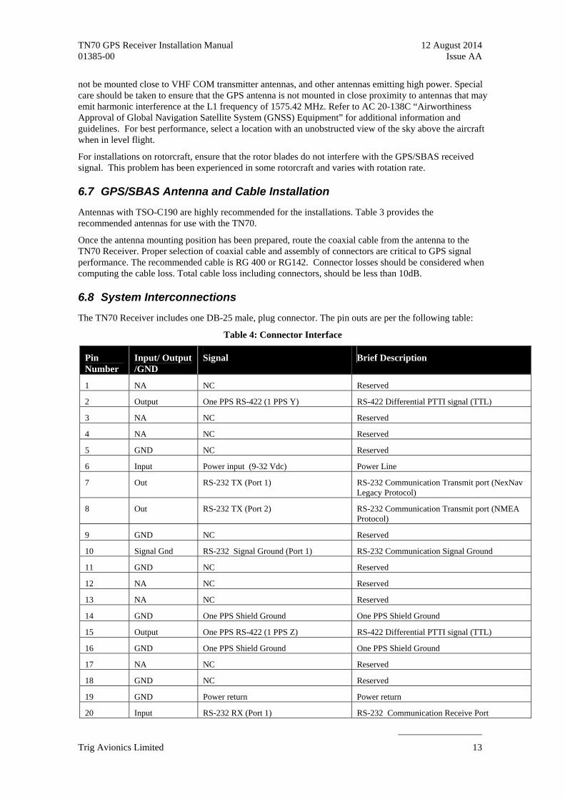
6.8 System Interconnections
The TN70 Receiver includes one DB-25 male, plug connector. The pin outs are per the following table:
Table 4: Connector Interface
Pin Number
Input/ Output /GND
Signal Brief Description
1 NA NC Reserved
2 Output One PPS RS-422 (1 PPS Y) RS-422 Differential PTTI signal (TTL)
3 NA NC Reserved
4 NA NC Reserved
5 GND NC Reserved
6 Input Power input (9-32 Vdc) Power Line
7 Out RS-232 TX (Port 1) RS-232 Communication Transmit port (NexNav Legacy Protocol)
8 Out RS-232 TX (Port 2) RS-232 Communication Transmit port (NMEA Protocol)
9 GND NC Reserved
10 Signal Gnd RS-232 Signal Ground (Port 1) RS-232 Communication Signal Ground
11 GND NC Reserved
12 NA NC Reserved
13 NA NC Reserved
14 GND One PPS Shield Ground One PPS Shield Ground
15 Output One PPS RS-422 (1 PPS Z) RS-422 Differential PTTI signal (TTL)
16 GND One PPS Shield Ground One PPS Shield Ground
17 NA NC Reserved
18 GND NC Reserved
19 GND Power return Power return
20 Input RS-232 RX (Port 1) RS-232 Communication Receive Port
Trig Avionics Limited 13

TN70 GPS Receiver Installation Manual 12 August 2014 01385-00 Issue AA
______________________
21 Input RS-232 RX (Port 2) RS-232 Communication Receive Port
22 GND NC Reserved
23 Signal Gnd RS-232 Signal Ground (Port 2) RS-232 Communication Ground
24 NA NC Reserved
25 GND NC Reserved
6.8.1 Main Connector
(View looking at unit)
6.9 Electrical Load Assessment
The GNSS equipment should be installed after completing an electrical load analysis in accordance with AC 43.13-1B, Chapter 11 on the aircraft. The electrical load requirements of the GPS SBAS equipment are provided in Table 5.
The receiver operates from 9-32 Vdc with full performance.
An electrical load analysis should be completed on each aircraft prior to installation. Use below table for computation.
Table 5: Electric Load Analysis
Input Voltage 14 VDC 28 VDC
Typical 0.20 A 0.1 A Current Consumption
Maximum 0.30A 0.15 A
Typical 2.8 W 2.8 W Power
Maximum 4.0W 4.0W
6.10 Aircraft Wiring
6.10.1 Port 1 and Port 2 (RS-232 TX/RX I/O)
Use 3 conductor shielded 22 gauge wiring. The Signal Ground should be an independent conductor. Do not use the shield for the Signal Ground. Terminate the shield at both ends with a short 22 gauge wire not more than 3 inches in length. All shields may be connected to this short wire. The shield wire should be
Page 14 Trig Avionics Limited

TN70 GPS Receiver Installation Manual 12 August 2014 01385-00 Issue AA
______________________
terminated on the connector shell or an external connection on the LRU. Do not terminate to a connector contact as this will cause the shield to be terminated inside the enclosure.
6.10.2 PPS Y&Z
Use 2 conductor shielded 22 gauge wiring. Terminate both shields to a single wire and then to Pins 14 & 16 respectively per the drawing.
6.10.3 Unit Power wiring
Use 22 gauge 2-conductor shielded wiring for providing power to the unit. Use one conductor for Power Input and one conductor for Power Return. The shield should be terminated outside the enclosure.
6.11 Wiring Diagram
Figure 2: Wiring Diagram
Trig Avionics Limited 15

TN70 GPS Receiver Installation Manual 12 August 2014 01385-00 Issue AA
______________________
6.12 Serial Data Communication
The TN70 Receiver interfaces with other avionics by transmitting messages through RS-232 protocol. There are two RS-232 ports available. Port 1 utilises the NexNav Legacy protocol and can be used to provide GPS data to a Trig transponder as part of an ADS-B solution. Port 2 is always NMEA protocol.
The table below characterises the two RS-232 ports.
Table 6: RS-232 Ports
Protocol NexNav Legacy
P/N 21000
(Port 1)
NMEA
(Port 2)
RS-232 Transmit PIN-7 PIN-8
RS-232 Receive PIN-20 Pin 21
RS-232 Signal Ground PIN-10 PIN-23
Baud Rate 19200 bps 57600 bps
All protocols transmit navigation messages intended for air-bone navigation and surveillance. The NexNav Legacy protocol has the capability to receive messages from other avionics.
6.13 Software Installation
The TN70 Receiver is preloaded with the approved software build. No additional software is required for operation.
6.14 Operating Instructions
Upon power up after the installation, the TN70 Receiver computes aircraft Position, Velocity, and Precise Time (PVT) within the specified time when the antenna is exposed to the open sky. The receiver transmits the PVT and integrity information through the serial communication link to the connected avionics system.
6.15 VHF Com Interference Testing
Susceptibility to harmonics of VHF COM transceivers shall be evaluated. If problems arise, then more isolation or greater distance may be required between the GPS and COM antennas to reduce or eliminate the harmonic interference.
Confirm compatibility by tuning the VHF Com transceivers to the following frequencies and then check for flags or alerts for the avionics that are connected to the NexNav GPS, when transmitting or receiving. VHF Com Freq 121.150 MHz 121.175 MHz 121.200 MHz 131.200 MHz 131.250 MHz 131.300 MHz
Page 16 Trig Avionics Limited
TN70 GPS Receiver Installation Manual 12 August 2014 01385-00 Issue AA
______________________
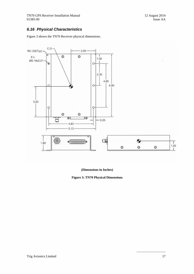
6.16 Physical Characteristics
Figure 3 shows the TN70 Receiver physical dimensions.
(Dimensions in Inches)
Figure 3: TN70 Physical Dimensions
Trig Avionics Limited 17

TN70 GPS Receiver Installation Manual 12 August 2014 01385-00 Issue AA
______________________
Appendix A - Environmental Qualification Form
Nomenclature NexNav mini 21000 : NexNav GPS-SBAS Receiver
Part Number 21000
TSO Number TSO-C145c
Manufacturer Accord Technology LLC
Address 347 N. Edgewood Lane, Suite 180, Eagle, ID 83616
Standard document DO-160F
Date Tested Oct 2009
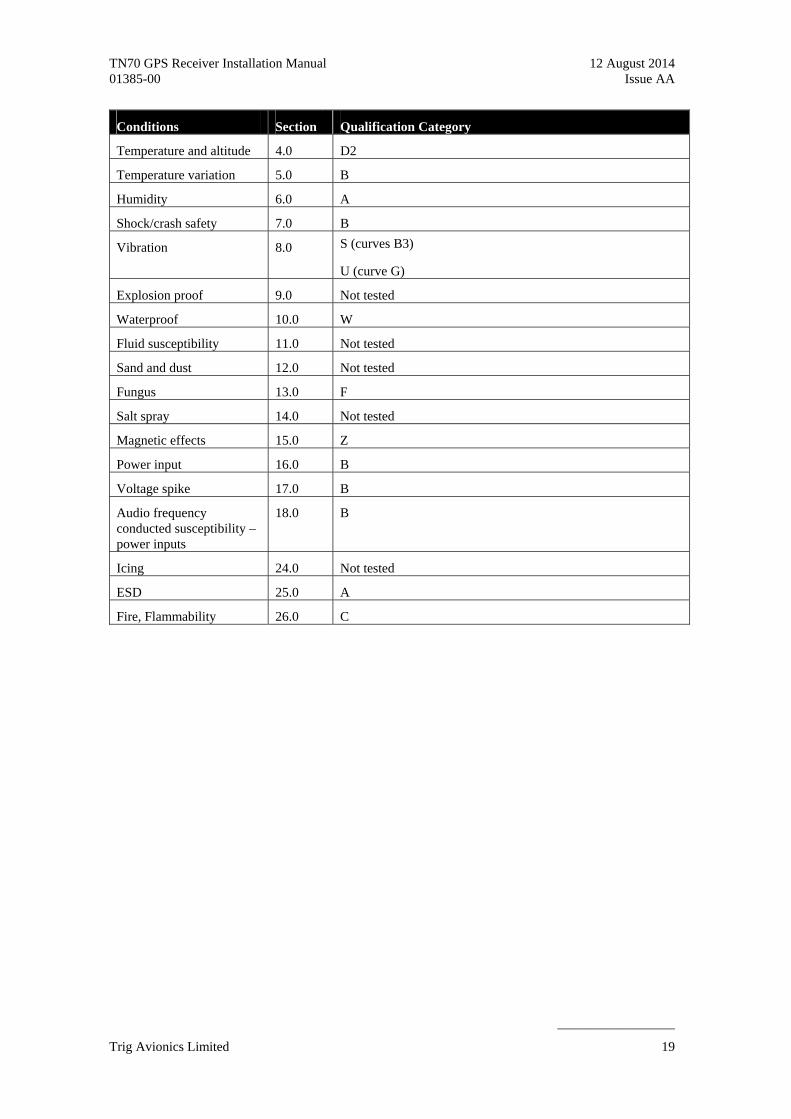
Conditions Section Qualification Category
Temperature and altitude 4.0 D2
Temperature variation 5.0 B
Humidity 6.0 A
Shock/crash safety 7.0 B
Vibration 8.0 S (curves B3)
U (curve G)
Explosion proof 9.0 Not tested
Waterproof 10.0 W
Fluid susceptibility 11.0 Not tested
Sand and dust 12.0 Not tested
Fungus 13.0 F
Salt spray 14.0 Not tested
Magnetic effects 15.0 Z
Power input 16.0 B
Voltage spike 17.0 B
Audio frequency conducted susceptibility – power inputs
18.0 B
Induced signal susceptibility
19.0 AC
Radio frequency susceptibility
20.0 W
Emission of radio frequency energy
21.0 M
Lightning induced susceptibility
22.0 J33 A3 A2
Lightning direct effects 23.0 Not tested
Page 18 Trig Avionics Limited
TN70 GPS Receiver Installation Manual 12 August 2014 01385-00 Issue AA
______________________
Conditions Section Qualification Category
Temperature and altitude 4.0 D2
Temperature variation 5.0 B
Humidity 6.0 A
Shock/crash safety 7.0 B
Vibration 8.0 S (curves B3)
U (curve G)
Explosion proof 9.0 Not tested
Waterproof 10.0 W
Fluid susceptibility 11.0 Not tested
Sand and dust 12.0 Not tested
Fungus 13.0 F
Salt spray 14.0 Not tested
Magnetic effects 15.0 Z
Power input 16.0 B
Voltage spike 17.0 B
Audio frequency conducted susceptibility – power inputs
18.0 B
Icing 24.0 Not tested
ESD 25.0 A
Fire, Flammability 26.0 C
Trig Avionics Limited 19
TN70 GPS Receiver Installation Manual 12 August 2014 01385-00 Issue AA
______________________
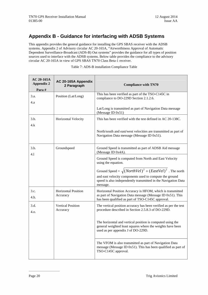
Appendix B - Guidance for interfacing with ADSB Systems
This appendix provides the general guidance for installing the GPS SBAS receiver with the ADSB systems. Appendix 2 of Advisory circular AC 20-165A, “Airworthiness Approval of Automatic Dependent Surveillance-Broadcast (ADS-B) Out systems” provides the guidance for all types of position sources used to interface with the ADSB systems. Below table provides the compliance to the advisory circular AC 20-165A in view of GPS SBAS TN70 Class Beta-1 receiver.
Table 7: ADS-B installation Compliance Table
AC 20-165A Appendix 2
Para #
AC 20-165A Appendix 2 Paragraph Compliance with TN70
3.a.
4.a
Position (Lat/Long) This has been verified as part of the TSO-C145C in compliance to DO-229D Section 2.1.2.6.
Lat/Long is transmitted as part of Navigation Data message (Message ID 0x51)
3.b.
4.k
Horizontal Velocity This has been verified with the test defined in AC 20-138C.
North/south and east/west velocities are transmitted as part of Navigation Data message (Message ID 0x51).
Ground Speed is transmitted as part of ADSB Aid message (Message ID 0x4A).
3.b.
4.l
Groundspeed
Ground Speed is computed from North and East Velocity using the equation.
Ground Speed = 22 )()( EastVelNorthVel . The north
and east velocity components used to compute the ground speed is also independently transmitted in the Navigation Data message.
3.c.
4.h.
Horizontal Position Accuracy
Horizontal Position Accuracy is HFOM, which is transmitted as part of Navigation Data message (Message ID 0x51). This has been qualified as part of TSO-C145C approval.
The vertical position accuracy has been verified as per the test procedure described in Section 2.5.8.3 of DO-229D.
The horizontal and vertical position is computed using the general weighted least squares where the weights have been used as per appendix J of DO-229D.
3.d.
4.o.
Vertical Position Accuracy
The VFOM is also transmitted as part of Navigation Data message (Message ID 0x51). This has been qualified as part of TSO-C145C approval.
Page 20 Trig Avionics Limited
TN70 GPS Receiver Installation Manual 12 August 2014 01385-00 Issue AA
______________________
AC 20-165A AC 20-165A Appendix
Appendix 2 Compliance with TN70 2 Paragraph Para #
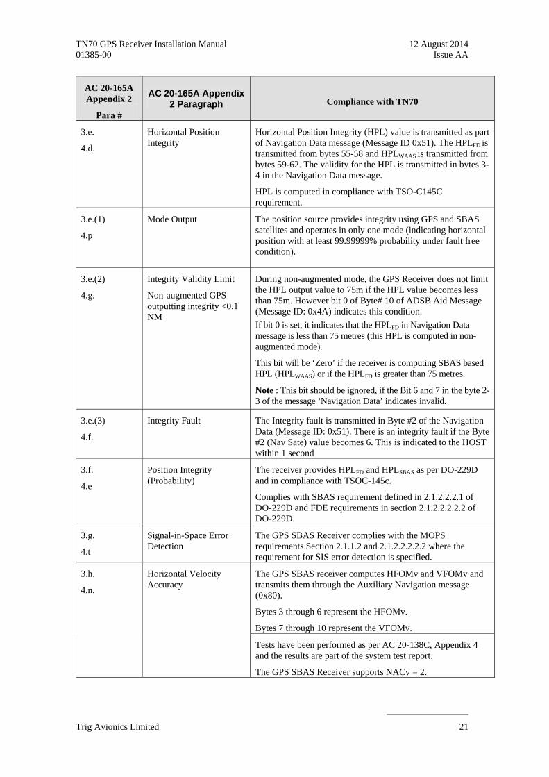
3.e.
4.d.
Horizontal Position Integrity
Horizontal Position Integrity (HPL) value is transmitted as part of Navigation Data message (Message ID 0x51). The HPLFD is transmitted from bytes 55-58 and HPLWAAS is transmitted from bytes 59-62. The validity for the HPL is transmitted in bytes 3-4 in the Navigation Data message.
HPL is computed in compliance with TSO-C145C requirement.
3.e.(1)
4.p
Mode Output The position source provides integrity using GPS and SBAS satellites and operates in only one mode (indicating horizontal position with at least 99.99999% probability under fault free condition).
3.e.(2)
4.g.
Integrity Validity Limit
Non-augmented GPS outputting integrity <0.1 NM
During non-augmented mode, the GPS Receiver does not limit the HPL output value to 75m if the HPL value becomes less than 75m. However bit 0 of Byte# 10 of ADSB Aid Message (Message ID: 0x4A) indicates this condition.
If bit 0 is set, it indicates that the HPLFD in Navigation Data message is less than 75 metres (this HPL is computed in non-augmented mode).
This bit will be ‘Zero’ if the receiver is computing SBAS based HPL (HPLWAAS) or if the HPLFD is greater than 75 metres.
Note : This bit should be ignored, if the Bit 6 and 7 in the byte 2-3 of the message ‘Navigation Data’ indicates invalid.
3.e.(3)
4.f.
Integrity Fault The Integrity fault is transmitted in Byte #2 of the Navigation Data (Message ID: 0x51). There is an integrity fault if the Byte #2 (Nav Sate) value becomes 6. This is indicated to the HOST within 1 second
3.f.
4.e
Position Integrity (Probability)
The receiver provides HPLFD and HPLSBAS as per DO-229D and in compliance with TSOC-145c.
Complies with SBAS requirement defined in 2.1.2.2.2.1 of DO-229D and FDE requirements in section 2.1.2.2.2.2.2 of DO-229D.
3.g.
4.t
Signal-in-Space Error Detection
The GPS SBAS Receiver complies with the MOPS requirements Section 2.1.1.2 and 2.1.2.2.2.2.2 where the requirement for SIS error detection is specified.
The GPS SBAS receiver computes HFOMv and VFOMv and transmits them through the Auxiliary Navigation message (0x80).
Bytes 3 through 6 represent the HFOMv.
Bytes 7 through 10 represent the VFOMv.
3.h.
4.n.
Horizontal Velocity Accuracy
Tests have been performed as per AC 20-138C, Appendix 4 and the results are part of the system test report.
The GPS SBAS Receiver supports NACv = 2.
Trig Avionics Limited 21

TN70 GPS Receiver Installation Manual 12 August 2014 01385-00 Issue AA
______________________
AC 20-165A AC 20-165A Appendix
Appendix 2 Compliance with TN70 2 Paragraph Para #
3.i. Design Assurance Supports Major failure effect. Software is compliant with DO-178B level C and complex hardware is compliant with DO-254 level C.
3.j.
4.i.
Geometric Altitude (Height Above Ellipsoid)
The GPS Receiver computes the Geometric Altitude (Height Above the Ellipsoid) and transmits it through the Navigation Data Label (Message ID 0x51).
The vertical position accuracy has been verified as per the test procedure described in Section 2.5.8.3 of DO-229D.
The horizontal and vertical position is computed using the general weighted least squares where the weights have been used as per appendix J of DO-229D.
Geometric Altitude is transmitted in Byte # 25-32 as part of Navigation Data message (Message ID 0x51).
3.k.
4.j
Update Rate Position update rate is 5Hz
3.l.
4.b
Position Source Latency Position Source latches measurements and computes the position at UTC second boundary and at 5Hz interval.
The uncompensated latency i.e the time interval between time of measurement and time to transmit position, velocity and FOM information is less than 150 msec from the measurement time and well within the 200 msec requirement specified in the AC 20-165A.
3.m.
4.m.
Time of Applicability For each position, the GPS SBAS receiver outputs velocity, horizontal accuracy metric (HFOM) and horizontal integrity metric (HPL) in the Navigation Data message (Message ID: 0x51). The horizontal velocity metric (Velocity HFOM) is transmitted in Auxiliary Navigation Message (Message ID: 0x80).
The HPL and HFOM computation is performed at 5Hz rate and is within the integrity, time-to-alert requirement of DO-229D.
3.n.
4.s.
Time Mark The UTC time mark is transmitted as differential signals on pins 2 and 15 of the 25 PIN connector (DB-25 male connector).
Refer to Figure 4 for the relationship between Time Mark and the applicability of Position data.
3.o.
4.c
Availability As per Table 14 of AC 20-165A the estimated GNSS availability of GPS/SBAS with TSOC-145 is greater than or equal to 99.9%.
4.q. Approach Mode Integrity NA, the integrity output need not be scaled, since the GPS SBAS receiver does not support LNAV/VNAV or LP/LPV mode of operation.
Page 22 Trig Avionics Limited
TN70 GPS Receiver Installation Manual 12 August 2014 01385-00 Issue AA
______________________
AC 20-165A AC 20-165A Appendix
Appendix 2 Compliance with TN70 2 Paragraph Para #
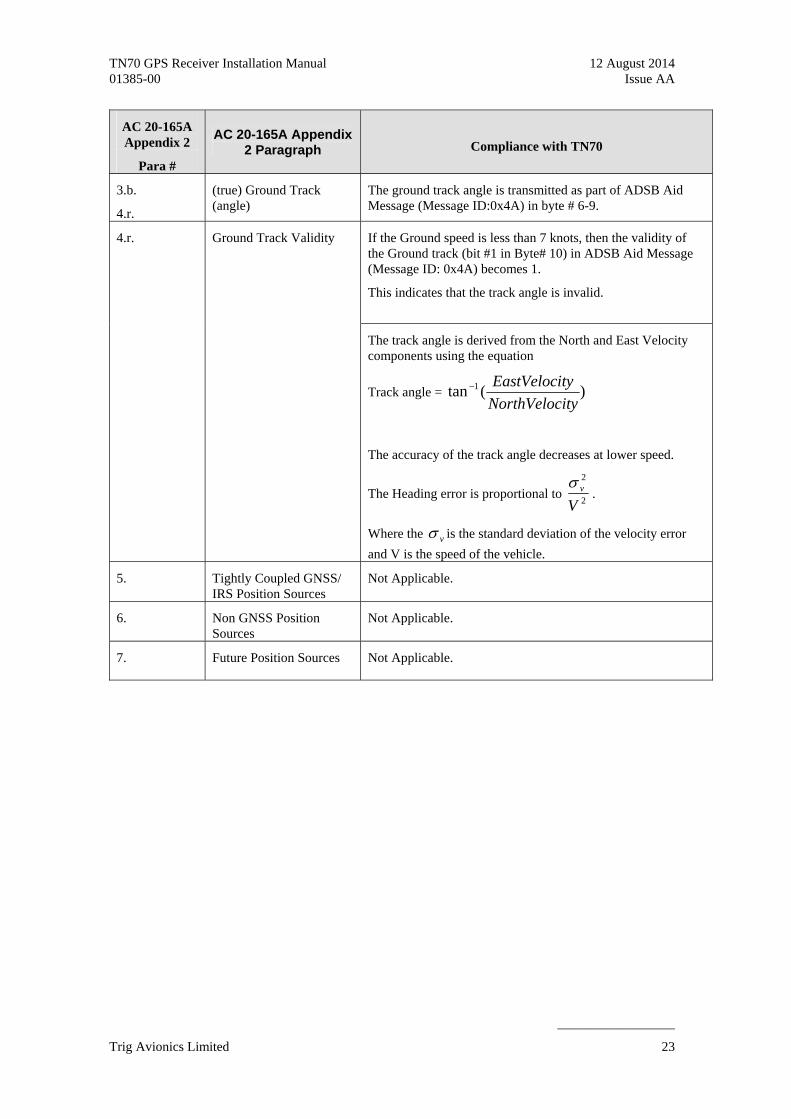
3.b.
4.r.
(true) Ground Track (angle)
The ground track angle is transmitted as part of ADSB Aid Message (Message ID:0x4A) in byte # 6-9.
If the Ground speed is less than 7 knots, then the validity of the Ground track (bit #1 in Byte# 10) in ADSB Aid Message (Message ID: 0x4A) becomes 1.
This indicates that the track angle is invalid.
4.r. Ground Track Validity
The track angle is derived from the North and East Velocity components using the equation
Track angle = )(tan 1
ityNorthVeloc
tyEastVeloci
The accuracy of the track angle decreases at lower speed.
The Heading error is proportional to 2
2
Vv
.
Where the v is the standard deviation of the velocity error
and V is the speed of the vehicle.
5. Tightly Coupled GNSS/ IRS Position Sources
Not Applicable.
6. Non GNSS Position Sources
Not Applicable.
7. Future Position Sources Not Applicable.
Trig Avionics Limited 23

TN70 GPS Receiver Installation Manual 12 August 2014 01385-00 Issue AA
______________________
Page 24 Trig Avionics Limited
Time of Applicability for TN70 M
easu
rem
ent
Lat
ch
Nav
igat
ion
Com
pu
tati
on a
nd
Oth
er F
un
ctio
ns
0ms 70ms
Nav
igat
ion
Dat
a M
essa
ge
Au
xili
ary
Nav
igat
ion
Mes
sage
Sen
sor
Sta
tus
Mes
sage
PR
AIM
Res
po
nse
Mes
sag
e
Ver
sion
Res
pon
se M
essa
ge
AD
SB
Aid
Mes
sag
e
Time for Data Transfer
Mea
sure
men
t L
atch
Nav
igat
ion
Com
pu
tati
on a
nd
Oth
er F
un
ctio
ns
200ms 300ms
Time (in msec)Time mark synchronizedto UTC Epoch
103ms
173ms
Figure 4 : Time of Applicability for TN70