tnc 320 - heidenhaincontent.heidenhain.de/.../tnc320/.../679_220-20.pdfheidenhain tnc 320 5 software...
TRANSCRIPT
User’s ManualCycle Programming
TNC 320
NC Software340 551-04340 554-04
English (en)9/2009

HEIDENHAIN TNC 320 3
Ab
ou
t th
is M
an
ua
lAbout this Manual
The symbols used in this manual are described below.
Do you desire any changes, or have you found
any errors?
We are continuously striving to improve documentation for you. Please help us by sending your requests to the following e-mail address: [email protected].
This symbol indicates that important notes about the function described must be adhered to.
This symbol indicates that there is one or more of the following risks when using the described function:
Danger to workpieceDanger to fixturesDanger to toolDanger to machineDanger to operator
This symbol indicates that the described function must be adapted by the machine tool builder. The function described may therefore vary depending on the machine.
This symbol indicates that you can find detailed information about a function in another manual.
4
TN
C M
od
el,
So
ftw
are
an
d F
ea
ture
s TNC Model, Software and Features
This manual describes functions and features provided by TNCs as of the following NC software numbers.
The machine tool builder adapts the usable features of the TNC to his machine by setting machine parameters. Some of the functions described in this manual may therefore not be among the features provided by the TNC on your machine tool.
TNC functions that may not be available on your machine include:
Tool measurement with the TT
Please contact your machine tool builder to become familiar with the features of your machine.
Many machine manufacturers, as well as HEIDENHAIN, offer programming courses for the TNCs. We recommend these courses as an effective way of improving your programming skill and sharing information and ideas with other TNC users.
TNC model NC software number
TNC 320 340 551-04
TNC 320 Programming Station 340 554-04
User's Manual:
All TNC functions that have no connection with cycles are described in the User's Manual of the TNC 320. Please contact HEIDENHAIN if you require a copy of this User’s Manual.
ID of Conversational Programming User's Manual: 679 222-xx.
ID of User’s Manual for ISO programming: 679 226-xx.
HEIDENHAIN TNC 320 5
TN
C M
od
el,
So
ftw
are
an
d F
ea
ture
sSoftware options
The TNC 320 features various software options that can be enabled by your machine tool builder. Each option is to be enabled separately and contains the following respective functions:
Hardware options
Additional axis for 4 axes and open-loop spindle
Additional axis for 5 axes and open-loop spindle
Software option 1 (option number #08)
Cylinder surface interpolation (Cycles 27, 28 and 29)
Feed rate in mm/min for rotary axes: M116
Tilting the machining plane (plane functions, Cycle 19 and 3D-ROT soft key in the Manual Operation mode)
Circle in 3 axes with tilted working plane
6
TN
C M
od
el,
So
ftw
are
an
d F
ea
ture
s Feature content level (upgrade functions)
Along with software options, significant further improvements of the TNC software are managed via the Feature Content Level (FCL) upgrade functions. Functions subject to the FCL are not available simply by updating the software on your TNC.
Upgrade functions are identified in the manual with FCL n, where n indicates the sequential number of the feature content level.
You can purchase a code number in order to permanently enable the FCL functions. For more information, contact your machine tool builder or HEIDENHAIN.
Intended place of operation
The TNC complies with the limits for a Class A device in accordance with the specifications in EN 55022, and is intended for use primarily in industrially-zoned areas.
Legal information
This product uses open source software. Further information is available on the control under
U Programming and Editing operating modeU MOD functionU LICENSE INFO soft key
All upgrade functions are available to you without surcharge when you receive a new machine.
HEIDENHAIN TNC 320 7
Ne
w F
un
cti
on
s o
f S
oft
wa
re 3
40
55
x-0
4New Functions of Software 340 55x-04
The PATTERN DEF function for defining patterns was introduced (see “Pattern Definition PATTERN DEF” on page 44)The SEL PATTERN function makes it possible to select point tables (see “Selecting a point table in the program” on page 54)With the CYCL CALL PAT function, cycles can now be run in connection with point tables (see “Calling a cycle in connection with point tables” on page 55)The DECLARE CONTOUR function can now also define the depth of the contour (see “Entering a simple contour formula” on page 223)New machining cycle for single-fluted deep-hole drilling (see “SINGLE-FLUTED DEEP-HOLE DRILLING (Cycle 241, DIN/ISO: G241)” on page 84)The new fixed cycles 251 to 257 were introduced for milling pockets, studs and slots (see “Overview” on page 126)Touch Probe Cycle 412: Additional parameter Q365 "type of traverse" (see “DATUM FROM INSIDE OF CIRCLE (Cycle 412, DIN/ISO: G412)” on page 328)Touch Probe Cycle 413: Additional parameter Q365 "type of traverse" (see “DATUM FROM OUTSIDE OF CIRCLE (Cycle 413, DIN/ISO: G413)” on page 332)Touch Probe Cycle 416: Additional parameter Q320 (setup clearance, (see “DATUM CIRCLE CENTER (Cycle 416, DIN/ISO: G416)” on page 345))Touch Probe Cycle 421: Additional parameter Q365 "type of traverse" (see “MEASURE HOLE (Cycle 421, DIN/ISO: G421)” on page 376)Touch Probe Cycle 422: Additional parameter Q365 "type of traverse" (see “MEAS. CIRCLE OUTSIDE (Cycle 422, DIN/ISO: G422)” on page 380)Touch Probe Cycle 425 (MEASURE SLOT) was expanded by parameters Q301 (Move to clearance height) and Q320 (setup clearance) ((see “MEASURE INSIDE WIDTH (Cycle 425, DIN/ISO: G425)” on page 392))In the machine operating modes Program Run, Full Sequence and Program Run, Single Block, datum tables can now also be selected (STATUS M)The definition of feed rates in fixed cycles can now also include FU and FZ values
8
Ne
w F
un
cti
on
s o
f S
oft
wa
re 3
40
55
x-0
4 The PLANE function for flexible definition of a tilted working place was introduced (see User’s Manual for Conversational Programming)The context-sensitive help system TNCguide was introduced (see User’s Manual for Conversational Programming)The FUNCTION PARAX function for defining the behavior of the parallel axes U, V and W was introduced (see User’s Manual for Conversational Programming)The conversational languages Slovak, Norwegian, Latvian, Korean, Turkish and Romanian were introduced (see User’s Manual for Conversational Programming)Individual characters can now be deleted by using the backspace key (see User’s Manual for Conversational Programming)
HEIDENHAIN TNC 320 9
Ch
an
ge
d F
un
cti
on
s o
f S
oft
wa
re 3
40
55
x-0
4Changed Functions of Software 340 55x-04
In Cycle 22 you can now define a tool name also for the coarse roughing tool (see “ROUGH-OUT (Cycle 22, DIN/ISO: G122)” on page 180).With Cycle 25 Contour Train, closed contours can now also be programmedThe pocket-, stud- and slot-milling cycles 210 to 214 were removed from the standard soft-key row (CYCL DEF > POCKETS/STUDS/SLOTS). For reasons of compatibility, the cycles will still be available, and can be selected via the GOTO keyThe additional status display has been revised. The following improvements were made (see User’s Manual for Conversational Programming)
A new overview page with the most important status displays was introducedThe tolerance values set in Cycle 32 are displayed
Tool changes are now also possible during mid-program startupLanguage-dependent tables can now be output with FN16 F-PrintThe soft-key structure of the SPEC FCT function was changed and adapted to the iTNC 530

10
Ch
an
ge
d F
un
cti
on
s o
f S
oft
wa
re 3
40
55
x-0
4
HEIDENHAIN TNC 320 11
Contents Fundamentals / Overviews 1Using Fixed Cycles 2Fixed Cycles: Drilling 3Fixed Cycles: Tapping / Thread Milling 4Fixed Cycles: Pocket Milling / Stud Milling / Slot Milling 5Fixed Cycles: Pattern Definitions 6Fixed Cycles: Contour Pocket 7Fixed Cycles: Cylindrical Surface 8Fixed Cycles: Contour Pocket with Contour Formula 9Fixed Cycles: Multipass Milling 10Cycles: Coordinate Transformations 11Cycles: Special Functions 12Using Touch Probe Cycles 13Touch Probe Cycles: Automatic Measurement of Workpiece Misalignment 14Touch Probe Cycles: Automatic Datum Setting 15Touch Probe Cycles: Automatic Workpiece Inspection 16Touch Probe Cycles: Special Functions 17Touch Probe Cycles: Automatic Tool Measurement 18

HEIDENHAIN TNC 320 13
1.1 Introduction ..... 361.2 Available Cycle Groups ..... 37
Overview of fixed cycles ..... 37Overview of touch probe cycles ..... 38
1 Fundamentals / Overviews ..... 35
14
2.1 Working with Fixed Cycles ..... 40Machine-specific cycles ..... 40Defining a cycle using soft keys ..... 41Defining a cycle using the GOTO function ..... 41Calling cycles ..... 42
2.2 Pattern Definition PATTERN DEF ..... 44Application ..... 44Entering PATTERN DEF definitions ..... 45Using PATTERN DEF ..... 45Defining individual machining positions ..... 46Defining a single row ..... 47Defining a single pattern ..... 48Defining individual frames ..... 49Defining a full circle ..... 50Defining a circular arc ..... 51
2.3 Point Tables ..... 52Application ..... 52Creating a point table ..... 52Hiding single points from the machining process ..... 53Selecting a point table in the program ..... 54Calling a cycle in connection with point tables ..... 55
2 Using Fixed Cycles ..... 39
HEIDENHAIN TNC 320 15
3.1 Fundamentals ..... 58Overview ..... 58
3.2 CENTERING (Cycle 240, DIN/ISO: G240) ..... 59Cycle run ..... 59Please note while programming: ..... 59Cycle parameters ..... 60
3.3 DRILLING (Cycle 200) ..... 61Cycle run ..... 61Please note while programming: ..... 61Cycle parameters ..... 62
3.4 REAMING (Cycle 201, DIN/ISO: G201) ..... 63Cycle run ..... 63Please note while programming: ..... 63Cycle parameters ..... 64
3.5 BORING (Cycle 202, DIN/ISO: G202) ..... 65Cycle run ..... 65Please note while programming: ..... 66Cycle parameters ..... 67
3.6 UNIVERSAL DRILLING (Cycle 203, DIN/ISO: G203) ..... 69Cycle run ..... 69Please note while programming: ..... 70Cycle parameters ..... 71
3.7 BACK BORING (Cycle 204, DIN/ISO: G204) ..... 73Cycle run ..... 73Please note while programming: ..... 74Cycle parameters ..... 75
3.8 UNIVERSAL PECKING (Cycle 205, DIN/ISO: G205) ..... 77Cycle run ..... 77Please note while programming: ..... 78Cycle parameters ..... 79
3.9 BORE MILLING (Cycle 208, DIN/ISO: G208) ..... 81Cycle run ..... 81Please note while programming: ..... 82Cycle parameters ..... 83
3.10 SINGLE-FLUTED DEEP-HOLE DRILLING (Cycle 241, DIN/ISO: G241) ..... 84Cycle run ..... 84Please note while programming: ..... 84Cycle parameters ..... 85
3.11 Programming Examples ..... 87
3 Fixed Cycles: Drilling ..... 57
16
4.1 Fundamentals ..... 92Overview ..... 92
4.2 TAPPING NEW with a Floating Tap Holder (Cycle 206, DIN/ISO: G206) ..... 93Cycle run ..... 93Please note while programming: ..... 93Cycle parameters ..... 94
4.3 RIGID TAPPING without a Floating Tap Holder NEW (Cycle 207, DIN/ISO: G207) ..... 95Cycle run ..... 95Please note while programming: ..... 96Cycle parameters ..... 97
4.4 TAPPING WITH CHIP BREAKING (Cycle 209, DIN/ISO: G209) ..... 98Cycle run ..... 98Please note while programming: ..... 99Cycle parameters ..... 100
4.5 Fundamentals of Thread Milling ..... 101Prerequisites ..... 101
4.6 THREAD MILLING (Cycle 262, DIN/ISO: G262) ..... 103Cycle run ..... 103Please note while programming: ..... 104Cycle parameters ..... 105
4.7 THREAD MILLING/COUNTERSINKING (Cycle 263, DIN/ISO: G263) ..... 106Cycle run ..... 106Please note while programming: ..... 107Cycle parameters ..... 108
4.8 THREAD DRILLING/MILLING (Cycle 264, DIN/ISO: G264) ..... 110Cycle run ..... 110Please note while programming: ..... 111Cycle parameters ..... 112
4.9 HELICAL THREAD DRILLING/MILLING (Cycle 265, DIN/ISO: G265) ..... 114Cycle run ..... 114Please note while programming: ..... 115Cycle parameters ..... 116
4.10 OUTSIDE THREAD MILLING (Cycle 267, DIN/ISO: G267) ..... 118Cycle run ..... 118Please note while programming: ..... 119Cycle parameters ..... 120
4.11 Programming Examples ..... 122
4 Fixed Cycles: Tapping / Thread Milling ..... 91
HEIDENHAIN TNC 320 17
5.1 Fundamentals ..... 126Overview ..... 126
5.2 RECTANGULAR POCKET (Cycle 251, DIN/ISO: G251) ..... 127Cycle run ..... 127Please note while programming: ..... 128Cycle parameters ..... 129
5.3 CIRCULAR POCKET (Cycle 252, DIN/ISO: G252) ..... 132Cycle run ..... 132Please note while programming: ..... 133Cycle parameters ..... 134
5.4 SLOT MILLING (Cycle 253, DIN/ISO: G253) ..... 136Cycle run ..... 136Please note while programming: ..... 137Cycle parameters ..... 138
5.5 CIRCULAR SLOT (Cycle 254, DIN/ISO: G254) ..... 141Cycle run ..... 141Please note while programming: ..... 142Cycle parameters ..... 143
5.6 RECTANGULAR STUD (Cycle 256, DIN/ISO: G256) ..... 146Cycle run ..... 146Please note while programming: ..... 147Cycle parameters ..... 148
5.7 CIRCULAR STUD (Cycle 257, DIN/ISO: G257) ..... 150Cycle run ..... 150Please note while programming: ..... 151Cycle parameters ..... 152
5.8 Programming Examples ..... 154
5 Fixed Cycles: Pocket Milling / Stud Milling / Slot Milling ..... 125
18
6.1 Fundamentals ..... 158Overview ..... 158
6.2 CIRCULAR PATTERN (Cycle 220, DIN/ISO: G220) ..... 159Cycle run ..... 159Please note while programming: ..... 159Cycle parameters ..... 160
6.3 LINEAR PATTERN (Cycle 221, DIN/ISO: G221) ..... 162Cycle run ..... 162Please note while programming: ..... 162Cycle parameters ..... 163
6.4 Programming Examples ..... 164
6 Fixed Cycles: Pattern Definitions ..... 157
HEIDENHAIN TNC 320 19
7.1 SL Cycles ..... 168Fundamentals ..... 168Overview ..... 170
7.2 CONTOUR GEOMETRY (Cycle 14, DIN/ISO: G37) ..... 171Please note while programming: ..... 171Cycle parameters ..... 171
7.3 Overlapping Contours ..... 172Fundamentals ..... 172Subprograms: overlapping pockets ..... 173Area of inclusion ..... 174Area of exclusion ..... 175Area of intersection ..... 175
7.4 CONTOUR DATA (Cycle 20, DIN/ISO: G120) ..... 176Please note while programming: ..... 176Cycle parameters ..... 177
7.5 PILOT DRILLING (Cycle 21, DIN/ISO: G121) ..... 178Cycle run ..... 178Please note while programming: ..... 178Cycle parameters ..... 179
7.6 ROUGH-OUT (Cycle 22, DIN/ISO: G122) ..... 180Cycle run ..... 180Please note while programming: ..... 181Cycle parameters ..... 182
7.7 FLOOR FINISHING (Cycle 23, DIN/ISO: G123) ..... 183Cycle run ..... 183Please note while programming: ..... 183Cycle parameters ..... 183
7.8 SIDE FINISHING (Cycle 24, DIN/ISO: G124) ..... 184Cycle run ..... 184Please note while programming: ..... 184Cycle parameters ..... 185
7.9 CONTOUR TRAIN (Cycle 25, DIN/ISO: G125) ..... 186Cycle run ..... 186Please note while programming: ..... 186Cycle parameters ..... 187
7.10 Programming Examples ..... 188
7 Fixed Cycles: Contour Pocket ..... 167
20
8.1 Fundamentals ..... 196Overview of cylindrical surface cycles ..... 196
8.2 CYLINDER SURFACE (Cycle 27, DIN/ISO: G127, Software Option) ..... 197Execution of cycle ..... 197Please note while programming: ..... 198Cycle parameters ..... 199
8.3 CYLINDER SURFACE Slot Milling (Cycle 28, DIN/ISO: G128, Software-Option 1) ..... 200Cycle run ..... 200Please note while programming: ..... 201Cycle parameters ..... 202
8.4 CYLINDER SURFACE Ridge Milling (Cycle 29, DIN/ISO: G129, Software-Option 1) ..... 203Cycle run ..... 203Please note while programming: ..... 204Cycle parameters ..... 205
8.5 Programming Examples ..... 206
8 Fixed Cycles: Cylindrical Surface ..... 195
HEIDENHAIN TNC 320 21
9.1 SL Cycles with Complex Contour Formula ..... 212Fundamentals ..... 212Selecting a program with contour definitions ..... 214Defining contour descriptions ..... 214Entering a complex contour formula ..... 215Overlapping contours ..... 216Contour machining with SL Cycles ..... 218
9.2 SL Cycles with Simple Contour Formula ..... 222Fundamentals ..... 222Entering a simple contour formula ..... 223Contour machining with SL Cycles ..... 223
9 Fixed Cycles: Contour Pocket with Contour Formula ..... 211
22
10.1 Fundamentals ..... 226Overview ..... 226
10.2 MULTIPASS MILLING (Cycle 230, DIN/ISO: G230) ..... 227Cycle run ..... 227Please note while programming: ..... 227Cycle parameters ..... 228
10.3 RULED SURFACE (Cycle 231, DIN/ISO: G231) ..... 229Cycle run ..... 229Please note while programming: ..... 230Cycle parameters ..... 231
10.4 FACE MILLING (Cycle 232, DIN/ISO: G232) ..... 233Cycle run ..... 233Please note while programming: ..... 235Cycle parameters ..... 235
10.5 Programming Examples ..... 238
10 Fixed Cycles: Multipass Milling ..... 225
HEIDENHAIN TNC 320 23
11.1 Fundamentals ..... 242Overview ..... 242Effect of coordinate transformations ..... 242
11.2 DATUM SHIFT (Cycle 7, DIN/ISO: G54) ..... 243Effect ..... 243Cycle parameters ..... 243
11.3 DATUM Shift with Datum Tables (Cycle 7, DIN/ISO: G53) ..... 244Effect ..... 244Please note while programming: ..... 245Cycle parameters ..... 246Selecting a datum table in the part program ..... 246Editing the datum table in the Programming and Editing mode of operation ..... 247Configuring the datum table ..... 248To leave a datum table ..... 248Status displays ..... 248
11.4 DATUM SETTING (Cycle 247, DIN/ISO: G247) ..... 249Effect ..... 249Please note before programming: ..... 249Cycle parameters ..... 249Status displays ..... 249
11.5 MIRROR IMAGE (Cycle 8, DIN/ISO: G28) ..... 250Effect ..... 250Please note while programming: ..... 250Cycle parameters ..... 251
11.6 ROTATION (Cycle 10, DIN/ISO: G73) ..... 252Effect ..... 252Please note while programming: ..... 252Cycle parameters ..... 253
11.7 SCALING (Cycle 11, DIN/ISO: G72) ..... 254Effect ..... 254Cycle parameters ..... 255
11.8 AXIS-SPECIFIC SCALING (Cycle 26) ..... 256Effect ..... 256Please note while programming: ..... 256Cycle parameters ..... 257
11 Cycles: Coordinate Transformations ..... 241
24
11.9 WORKING PLANE (Cycle 19, DIN/ISO: G80, Software Option 1) ..... 258Effect ..... 258Please note while programming: ..... 259Cycle parameters ..... 259Reset ..... 259Position the axis of rotation ..... 260Position display in the tilted system ..... 262Workspace monitoring ..... 262Positioning in a tilted coordinate system ..... 262Combining coordinate transformation cycles ..... 263Procedure for working with Cycle 19 WORKING PLANE ..... 264
11.10 Programming Examples ..... 265
HEIDENHAIN TNC 320 25
12.1 Fundamentals ..... 268Overview ..... 268
12.2 DWELL TIME (Cycle 9, DIN/ISO: G04) ..... 269Function ..... 269Cycle parameters ..... 269
12.3 PROGRAM CALL (Cycle 12, DIN/ISO: G39) ..... 270Cycle function ..... 270Please note while programming: ..... 270Cycle parameters ..... 271
12.4 ORIENTED SPINDLE STOP (Cycle 13, DIN/ISO: G36) ..... 272Cycle function ..... 272Please note while programming: ..... 272Cycle parameters ..... 272
12.5 TOLERANCE (Cycle 32, DIN/ISO: G62) ..... 273Cycle function ..... 273Influences of the geometry definition in the CAM system ..... 274Please note while programming: ..... 275Cycle parameters ..... 276
12 Cycles: Special Functions ..... 267
26
13.1 General Information about Touch Probe Cycles ..... 278Method of function ..... 278Consider a basic rotation in the Manual Operation mode ..... 278Cycles in the Manual and El. Handwheel Modes ..... 278Touch probe cycles for automatic operation ..... 279
13.2 Before You Start Working with Touch Probe Cycles ..... 281Maximum traverse to touch point: DIST in touch probe table ..... 281Setup clearance to touch point: SET_UP in touch probe table ..... 281Orient the infrared touch probe to the programmed probe direction: TRACK in touch probe table ..... 281Touch trigger probe, probing feed rate: F in touch probe table ..... 282Touch trigger probe, rapid traverse for positioning: FMAX ..... 282Touch trigger probe, rapid traverse for positioning: F_PREPOS in touch probe table ..... 282Multiple measurements ..... 282Confidence range for multiple measurement ..... 282Executing touch probe cycles ..... 283
13.3 Touch Probe Table ..... 284General information ..... 284Editing touch probe tables ..... 284Touch probe data ..... 285
13 Using Touch Probe Cycles ..... 277
HEIDENHAIN TNC 320 27
14.1 Fundamentals ..... 288Overview ..... 288Characteristics common to all touch probe cycles for measuring workpiece misalignment ..... 289
14.2 BASIC ROTATION (Cycle 400, DIN/ISO: G400) ..... 290Cycle run ..... 290Please note while programming: ..... 290Cycle parameters ..... 291
14.3 BASIC ROTATION from Two Holes (Cycle 401, DIN/ISO: G401) ..... 293Cycle run ..... 293Please note while programming: ..... 293Cycle parameters ..... 294
14.4 BASIC ROTATION over Two Studs (Cycle 402, DIN/ISO: G402) ..... 296Cycle run ..... 296Please note while programming: ..... 296Cycle parameters ..... 297
14.5 BASIC ROTATION compensation via rotary axis (Cycle 403, DIN/ISO: G403) ..... 299Cycle run ..... 299Please note while programming: ..... 299Cycle parameters ..... 300
14.6 SET BASIC ROTATION (Cycle 404, DIN/ISO: G404) ..... 302Cycle run ..... 302Cycle parameters ..... 302
14.7 Compensating Workpiece Misalignment by Rotating the C Axis (Cycle 405, DIN/ISO: G405) ..... 303Cycle run ..... 303Please note while programming: ..... 304Cycle parameters ..... 305
14 Touch Probe Cycles: Automatic Measurement of Workpiece Misalignment ..... 287
28
15.1 Fundamentals ..... 310Overview ..... 310Characteristics common to all touch probe cycles for datum setting ..... 311
15.2 SLOT CENTER REF PT (Cycle 408, DIN/ISO: G408) ..... 313Cycle run ..... 313Please note while programming: ..... 314Cycle parameters ..... 314
15.3 DATUM RIDGE CENTER (Cycle 409, DIN/ISO: G409) ..... 317Cycle run ..... 317Please note while programming: ..... 317Cycle parameters ..... 318
15.4 DATUM FROM INSIDE OF RECTANGLE (Cycle 410, DIN/ISO: G410) ..... 320Cycle run ..... 320Please note while programming: ..... 321Cycle parameters ..... 321
15.5 DATUM FROM OUTSIDE OF RECTANGLE (Cycle 411, DIN/ISO: G411) ..... 324Cycle run ..... 324Please note while programming: ..... 325Cycle parameters ..... 325
15.6 DATUM FROM INSIDE OF CIRCLE (Cycle 412, DIN/ISO: G412) ..... 328Cycle run ..... 328Please note while programming: ..... 329Cycle parameters ..... 329
15.7 DATUM FROM OUTSIDE OF CIRCLE (Cycle 413, DIN/ISO: G413) ..... 332Cycle run ..... 332Please note while programming: ..... 333Cycle parameters ..... 333
15.8 DATUM FROM OUTSIDE OF CORNER (Cycle 414, DIN/ISO: G414) ..... 336Cycle run ..... 336Please note while programming: ..... 337Cycle parameters ..... 338
15.9 DATUM FROM INSIDE OF CORNER (Cycle 415, DIN/ISO: G415) ..... 341Cycle run ..... 341Please note while programming: ..... 342Cycle parameters ..... 342
15 Touch Probe Cycles: Automatic Datum Setting ..... 309
HEIDENHAIN TNC 320 29
15.10 DATUM CIRCLE CENTER (Cycle 416, DIN/ISO: G416) ..... 345Cycle run ..... 345Please note while programming: ..... 346Cycle parameters ..... 346
15.11 DATUM IN TOUCH PROBE AXIS (Cycle 417, DIN/ISO: G417) ..... 349Cycle run ..... 349Please note while programming: ..... 349Cycle parameters ..... 350
15.12 DATUM AT CENTER OF 4 HOLES (Cycle 418, DIN/ISO: G418) ..... 351Cycle run ..... 351Please note while programming: ..... 352Cycle parameters ..... 352
15.13 DATUM IN ONE AXIS (Cycle 419, DIN/ISO: G419) ..... 355Cycle run ..... 355Please note while programming: ..... 355Cycle parameters ..... 356
30
16.1 Fundamentals ..... 364Overview ..... 364Recording the results of measurement ..... 365Measurement results in Q parameters ..... 367Classification of results ..... 367Tolerance monitoring ..... 368Tool monitoring ..... 368Reference system for measurement results ..... 369
16.2 REF. PLANE (Cycle 0, DIN/ISO: G55) ..... 370Cycle run ..... 370Please note while programming: ..... 370Cycle parameters ..... 370
16.3 POLAR REFERENCE PLANE (Cycle 1) ..... 371Cycle run ..... 371Please note while programming: ..... 371Cycle parameters ..... 372
16.4 MEASURE ANGLE (Cycle 420, DIN/ISO: G420) ..... 373Cycle run ..... 373Please note while programming: ..... 373Cycle parameters ..... 374
16.5 MEASURE HOLE (Cycle 421, DIN/ISO: G421) ..... 376Cycle run ..... 376Please note while programming: ..... 376Cycle parameters ..... 377
16.6 MEAS. CIRCLE OUTSIDE (Cycle 422, DIN/ISO: G422) ..... 380Cycle run ..... 380Please note while programming: ..... 380Cycle parameters ..... 381
16.7 MEAS. RECTAN. INSIDE (Cycle 423, DIN/ISO: G423) ..... 384Cycle run ..... 384Please note while programming: ..... 385Cycle parameters ..... 385
16.8 MEAS. RECTAN. OUTSIDE (Cycle 424, ISO: G424) ..... 388Cycle run ..... 388Please note while programming: ..... 389Cycle parameters ..... 389
16.9 MEASURE INSIDE WIDTH (Cycle 425, DIN/ISO: G425) ..... 392Cycle run ..... 392Please note while programming: ..... 392Cycle parameters ..... 393
16 Touch Probe Cycles: Automatic Workpiece Inspection ..... 363
HEIDENHAIN TNC 320 31
16.10 MEASURE RIDGE WIDTH (Cycle 426, ISO: G426) ..... 395Cycle run ..... 395Please note while programming: ..... 395Cycle parameters ..... 396
16.11 MEASURE COORDINATE (Cycle 427, DIN/ISO: G427) ..... 398Cycle run ..... 398Please note while programming: ..... 398Cycle parameters ..... 399
16.12 MEAS. BOLT HOLE CIRC. (Cycle 430, DIN/ISO: G430) ..... 401Cycle run ..... 401Please note while programming: ..... 401Cycle parameters ..... 402
16.13 MEASURE PLANE (Cycle 431, DIN/ISO: G431) ..... 405Cycle run ..... 405Please note while programming: ..... 406Cycle parameters ..... 406
16.14 Programming Examples ..... 408
32
17.1 Fundamentals ..... 414Overview ..... 414
17.2 MEASURING (Cycle 3) ..... 415Cycle run ..... 415Please note while programming: ..... 415Cycle parameters ..... 416
17 Touch Probe Cycles: Special Functions ..... 413
HEIDENHAIN TNC 320 33
18.1 Fundamentals ..... 418Overview ..... 418Differences between Cycles 31 to 33 and Cycles 481 to 483 ..... 419Setting the machine parameters ..... 420Entries in the tool table TOOL.T ..... 421
18.2 Calibrating the TT (Cycle 30 or 480, DIN/ISO: G480) ..... 423Cycle run ..... 423Please note while programming: ..... 423Cycle parameters ..... 423
18.3 Measuring the Tool Length (Cycle 31 or 481, DIN/ISO: G481) ..... 424Cycle run ..... 424Please note while programming: ..... 425Cycle parameters ..... 425
18.4 Measuring the Tool Radius (Cycle 32 or 482, ISO: G482) ..... 426Cycle run ..... 426Please note while programming: ..... 426Cycle parameters ..... 427
18.5 Measuring Tool Length and Radius (Cycle 33 or 483, ISO: G483) ..... 428Cycle run ..... 428Please note while programming: ..... 428Cycle parameters ..... 429
18 Touch Probe Cycles: Automatic Tool Measurement ..... 417

Fundamentals /
Overviews
36 Fundamentals / Overviews
1.1
In
tro
du
cti
on 1.1 Introduction
Frequently recurring machining cycles that comprise several working steps are stored in the TNC memory as standard cycles. Coordinate transformations and several special functions are also available as cycles.
Most cycles use Q parameters as transfer parameters. Parameters with specific functions that are required in several cycles always have the same number: For example, Q200 is always assigned the setup clearance, Q202 the plunging depth, etc.
Danger of collision!
Cycles sometimes execute extensive operations. For safety reasons, you should run a graphical program test before machining.
If you use indirect parameter assignments in cycles with numbers greater than 200 (e.g. Q210 = Q1), any change in the assigned parameter (e.g. Q1) will have no effect after the cycle definition. Define the cycle parameter (e.g. Q210) directly in such cases.
If you define a feed-rate parameter for fixed cycles greater than 200, then instead of entering a numerical value you can use soft keys to assign the feed rate defined in the TOOL CALL block (FAUTO soft key). You can also use the feed-rate alternatives FMAX (rapid traverse), FZ (feed per tooth) and FU (feed per rev), depending on the respective cycle and the function of the feed-rate parameter.
Note that, after a cycle definition, a change of the FAUTO feed rate has no effect, because internally the TNC assigns the feed rate from the TOOL CALL block when processing the cycle definition.
If you want to delete a block that is part of a cycle, the TNC asks you whether you want to delete the whole cycle.
HEIDENHAIN TNC 320 37
1.2
Ava
ila
ble
Cycle
Gro
up
s1.2 Available Cycle Groups
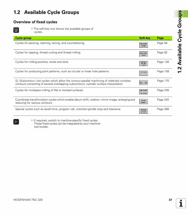
Overview of fixed cycles
U The soft-key row shows the available groups of cycles.
U If required, switch to machine-specific fixed cycles. These fixed cycles can be integrated by your machine tool builder.
Cycle group Soft key Page
Cycles for pecking, reaming, boring, and counterboring Page 58
Cycles for tapping, thread cutting and thread milling Page 92
Cycles for milling pockets, studs and slots Page 126
Cycles for producing point patterns, such as circular or linear hole patterns Page 158
SL (Subcontour List) cycles which allow the contour-parallel machining of relatively complex contours consisting of several overlapping subcontours, cylinder surface interpolation
Page 170
Cycles for multipass milling of flat or twisted surfaces Page 226
Coordinate transformation cycles which enable datum shift, rotation, mirror image, enlarging and reducing for various contours
Page 242
Special cycles such as dwell time, program call, oriented spindle stop and tolerance Page 268
38 Fundamentals / Overviews
1.2
Ava
ila
ble
Cycle
Gro
up
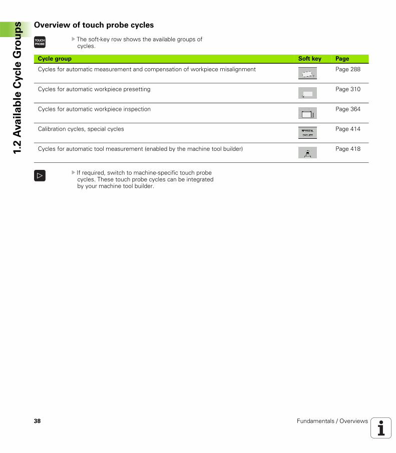
s Overview of touch probe cycles
U The soft-key row shows the available groups of cycles.
U If required, switch to machine-specific touch probe cycles. These touch probe cycles can be integrated by your machine tool builder.
Cycle group Soft key Page
Cycles for automatic measurement and compensation of workpiece misalignment Page 288
Cycles for automatic workpiece presetting Page 310
Cycles for automatic workpiece inspection Page 364
Calibration cycles, special cycles Page 414
Cycles for automatic tool measurement (enabled by the machine tool builder) Page 418
Using Fixed Cycles
40 Using Fixed Cycles
2.1
Wo
rkin
g w
ith
Fix
ed
Cycle
s 2.1 Working with Fixed Cycles
Machine-specific cycles
In addition to the HEIDENHAIN cycles, many machine tool builders offer their own cycles in the TNC. These cycles are available in a separate cycle-number range:
Cycles 300 to 399Machine-specific cycles that are to be defined through the CYCLE DEF keyCycles 500 to 599Machine-specific touch probe cycles that are to be defined through the TOUCH PROBE key
Sometimes, machine-specific cycles also use transfer parameters, which HEIDENHAIN already used in the standard cycles. The TNC executes DEF-active cycles as soon as they are defined (see also ”Calling cycles” on page 42). It executes CALL-active cycles only after they have been called (see also ”Calling cycles” on page 42). When DEF-active cycles and CALL-active cycles are used simultaneously, it is important to prevent overwriting of transfer parameters already in use. Use the following procedure:
U As a rule, always program DEF-active cycles before CALL-active cycles.
U If you do want to program a DEF-active cycle between the definition and call of a CALL-active cycle, do it only if there is no common use of specific transfer parameters.
Refer to your machine manual for a description of the specific function.
HEIDENHAIN TNC 320 41
2.1
Wo
rkin
g w
ith
Fix
ed
Cycle
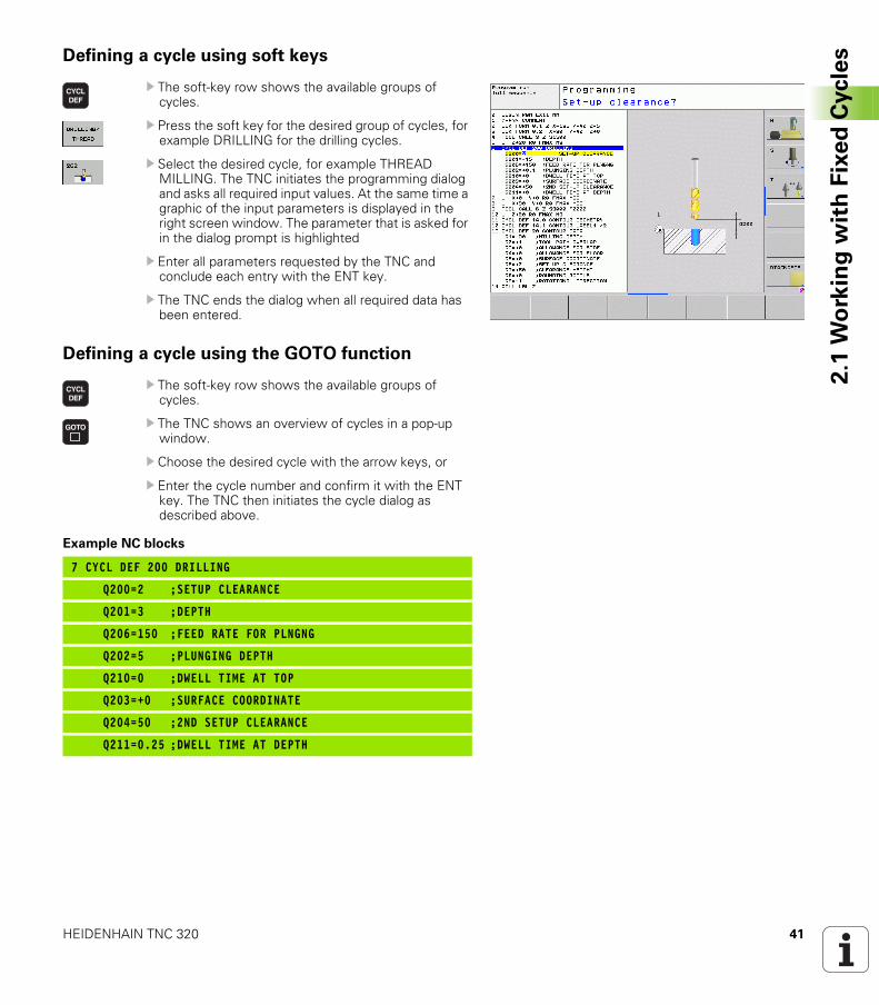
sDefining a cycle using soft keys
U The soft-key row shows the available groups of cycles.
U Press the soft key for the desired group of cycles, for example DRILLING for the drilling cycles.
U Select the desired cycle, for example THREAD MILLING. The TNC initiates the programming dialog and asks all required input values. At the same time a graphic of the input parameters is displayed in the right screen window. The parameter that is asked for in the dialog prompt is highlighted
U Enter all parameters requested by the TNC and conclude each entry with the ENT key.
U The TNC ends the dialog when all required data has been entered.
Defining a cycle using the GOTO function
U The soft-key row shows the available groups of cycles.
U The TNC shows an overview of cycles in a pop-up window.
U Choose the desired cycle with the arrow keys, or
U Enter the cycle number and confirm it with the ENT key. The TNC then initiates the cycle dialog as described above.
Example NC blocks
7 CYCL DEF 200 DRILLING
Q200=2 ;SETUP CLEARANCE
Q201=3 ;DEPTH
Q206=150 ;FEED RATE FOR PLNGNG
Q202=5 ;PLUNGING DEPTH
Q210=0 ;DWELL TIME AT TOP
Q203=+0 ;SURFACE COORDINATE
Q204=50 ;2ND SETUP CLEARANCE
Q211=0.25 ;DWELL TIME AT DEPTH
42 Using Fixed Cycles
2.1
Wo
rkin
g w
ith
Fix
ed
Cycle
s Calling cycles
The following cycles become effective automatically as soon as they are defined in the part program. These cycles cannot and must not be called:
Cycle 220 for point patterns on circles and Cycle 221 for point patterns on linesSL Cycle 14 CONTOUR GEOMETRYSL Cycle 20 CONTOUR DATACycle 32 TOLERANCECoordinate transformation cyclesCycle 9 DWELL TIMEAll touch probe cycles
You can call all other cycles with the functions described as follows.
Prerequisites
The following data must always be programmed before a cycle call:
BLK FORM for graphic display (needed only for test graphics)Tool callDirection of spindle rotation (M functions M3/M4)Cycle definition (CYCL DEF)
For some cycles, additional prerequisites must be observed. They are detailed in the descriptions for each cycle.
HEIDENHAIN TNC 320 43
2.1
Wo
rkin
g w
ith
Fix
ed
Cycle
sCalling a cycle with CYCL CALL
The CYCL CALL function calls the most recently defined fixed cycle once. The starting point of the cycle is the position that was programmed last before the CYCL CALL block.
U To program the cycle call, press the CYCL CALL key.
U Press the CYCL CALL M soft key to enter a cycle call.
U If necessary, enter the miscellaneous function M (for example M3 to switch the spindle on), or end the dialog by pressing the END key.
Calling a cycle with CYCL CALL PAT
The CYCL CALL PAT function calls the most recently defined fixed cycle at all positions that you defined in a PATTERN DEF pattern definition (see “Pattern Definition PATTERN DEF” on page 44) or in a point table (see “Point Tables” on page 52).
Calling a cycle with M99/89
The M99 function, which is active only in the block in which it is programmed, calls the last defined fixed cycle once. You can program M99 at the end of a positioning block. The TNC moves to this position and then calls the last defined fixed cycle.
If the TNC is to execute the cycle automatically after every positioning block, program the cycle call with M89.
To cancel the effect of M89, program:
M99 in the positioning block in which you move to the last starting point, orDefine with CYCL DEF a new fixed cycle
44 Using Fixed Cycles
2.2
Pa
tte
rn D
efi
nit
ion
PA
TT
ER
N D
EF 2.2 Pattern Definition PATTERN DEF
Application
You use the PATTERN DEF function to easily define regular machining patterns, which you can call with the CYCL CALL PAT function. As with the cycle definitions, support graphics that illustrate the respective input parameter are also available for pattern definitions.
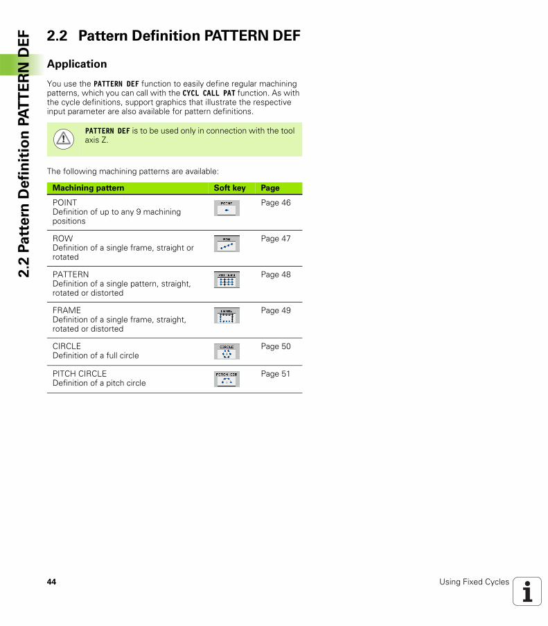
The following machining patterns are available:
PATTERN DEF is to be used only in connection with the tool axis Z.
Machining pattern Soft key Page
POINTDefinition of up to any 9 machining positions
Page 46
ROWDefinition of a single frame, straight or rotated
Page 47
PATTERNDefinition of a single pattern, straight, rotated or distorted
Page 48
FRAMEDefinition of a single frame, straight, rotated or distorted
Page 49
CIRCLEDefinition of a full circle
Page 50
PITCH CIRCLEDefinition of a pitch circle
Page 51
HEIDENHAIN TNC 320 45
2.2
Pa
tte
rn D
efi
nit
ion
PA
TT
ER
N D
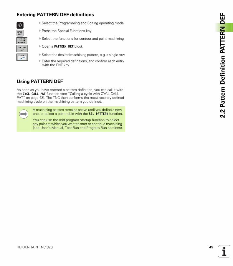
EFEntering PATTERN DEF definitions
U Select the Programming and Editing operating mode
U Press the Special Functions key
U Select the functions for contour and point machining
U Open a PATTERN DEF block
U Select the desired machining pattern, e.g. a single row
U Enter the required definitions, and confirm each entry with the ENT key
Using PATTERN DEF
As soon as you have entered a pattern definition, you can call it with the CYCL CALL PAT function (see “Calling a cycle with CYCL CALL PAT” on page 43). The TNC then performs the most recently defined machining cycle on the machining pattern you defined.
A machining pattern remains active until you define a new one, or select a point table with the SEL PATTERN function.
You can use the mid-program startup function to select any point at which you want to start or continue machining (see User's Manual, Test Run and Program Run sections).
46 Using Fixed Cycles
2.2
Pa
tte
rn D
efi
nit
ion
PA
TT
ER
N D
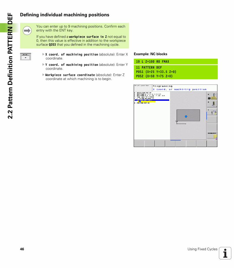
EF Defining individual machining positions
U X coord. of machining position (absolute): Enter X coordinate.
U Y coord. of machining position (absolute): Enter Y coordinate.
U Workpiece surface coordinate (absolute): Enter Z coordinate at which machining is to begin.
You can enter up to 9 machining positions. Confirm each entry with the ENT key.
If you have defined a workpiece surface in Z not equal to 0, then this value is effective in addition to the workpiece surface Q203 that you defined in the machining cycle.
Example: NC blocks
10 L Z+100 R0 FMAX
11 PATTERN DEFPOS1 (X+25 Y+33.5 Z+0)POS2 (X+50 Y+75 Z+0)
HEIDENHAIN TNC 320 47
2.2
Pa
tte
rn D
efi
nit
ion
PA
TT
ER
N D
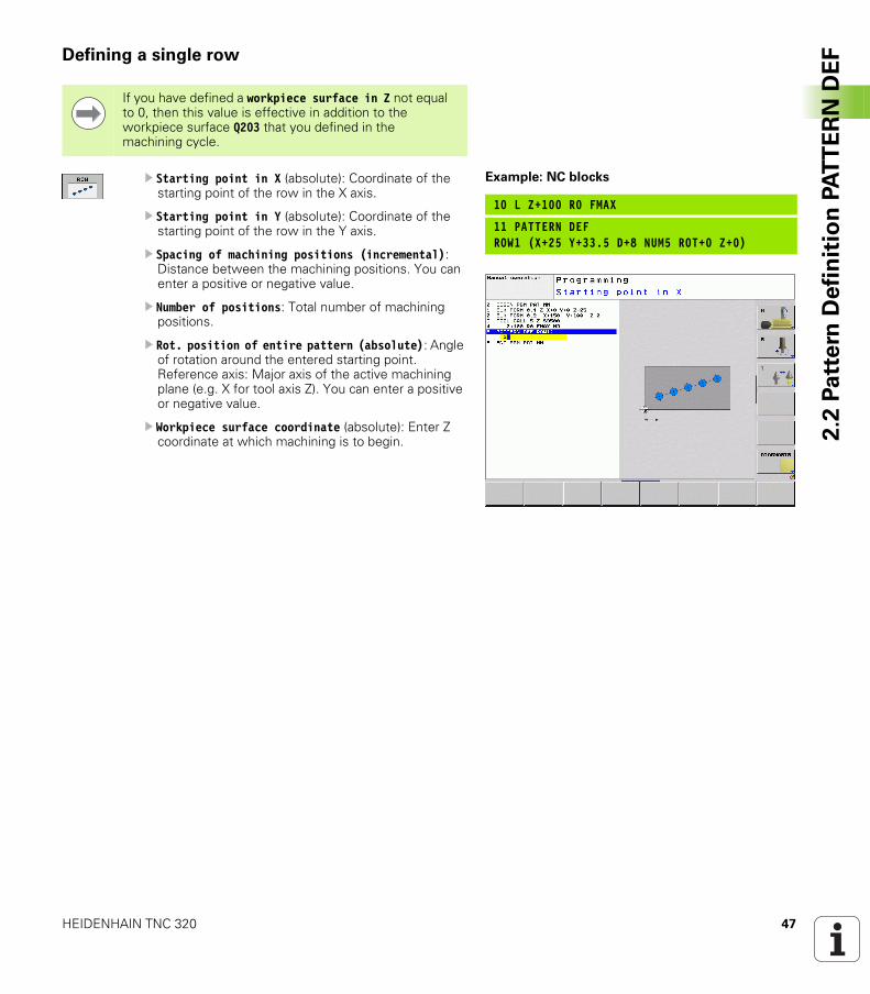
EFDefining a single row
U Starting point in X (absolute): Coordinate of the starting point of the row in the X axis.
U Starting point in Y (absolute): Coordinate of the starting point of the row in the Y axis.
U Spacing of machining positions (incremental): Distance between the machining positions. You can enter a positive or negative value.
U Number of positions: Total number of machining positions.
U Rot. position of entire pattern (absolute): Angle of rotation around the entered starting point. Reference axis: Major axis of the active machining plane (e.g. X for tool axis Z). You can enter a positive or negative value.
U Workpiece surface coordinate (absolute): Enter Z coordinate at which machining is to begin.
If you have defined a workpiece surface in Z not equal to 0, then this value is effective in addition to the workpiece surface Q203 that you defined in the machining cycle.
Example: NC blocks
10 L Z+100 R0 FMAX
11 PATTERN DEFROW1 (X+25 Y+33.5 D+8 NUM5 ROT+0 Z+0)
48 Using Fixed Cycles
2.2
Pa
tte
rn D
efi
nit
ion
PA
TT
ER
N D
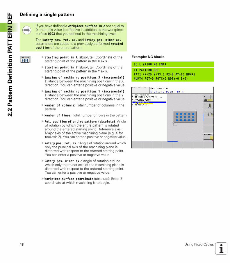
EF Defining a single pattern
U Starting point in X (absolute): Coordinate of the starting point of the pattern in the X axis.
U Starting point in Y (absolute): Coordinate of the starting point of the pattern in the Y axis.
U Spacing of machining positions X (incremental): Distance between the machining positions in the X direction. You can enter a positive or negative value.
U Spacing of machining positions Y (incremental): Distance between the machining positions in the Y direction. You can enter a positive or negative value.
U Number of columns: Total number of columns in the pattern
U Number of lines: Total number of rows in the pattern
U Rot. position of entire pattern (absolute): Angle of rotation by which the entire pattern is rotated around the entered starting point. Reference axis: Major axis of the active machining plane (e.g. X for tool axis Z). You can enter a positive or negative value.
U Rotary pos. ref. ax.: Angle of rotation around which only the principal axis of the machining plane is distorted with respect to the entered starting point. You can enter a positive or negative value.
U Rotary pos. minor ax.: Angle of rotation around which only the minor axis of the machining plane is distorted with respect to the entered starting point. You can enter a positive or negative value.
U Workpiece surface coordinate (absolute): Enter Z coordinate at which machining is to begin.
If you have defined a workpiece surface in Z not equal to 0, then this value is effective in addition to the workpiece surface Q203 that you defined in the machining cycle.
The Rotary pos. ref. ax. and Rotary pos. minor ax. parameters are added to a previously performed rotated position of the entire pattern.
Example: NC blocks
10 L Z+100 R0 FMAX
11 PATTERN DEFPAT1 (X+25 Y+33.5 DX+8 DY+10 NUMX5NUMY4 ROT+0 ROTX+0 ROTY+0 Z+0)
HEIDENHAIN TNC 320 49
2.2
Pa
tte
rn D
efi
nit
ion
PA
TT
ER
N D
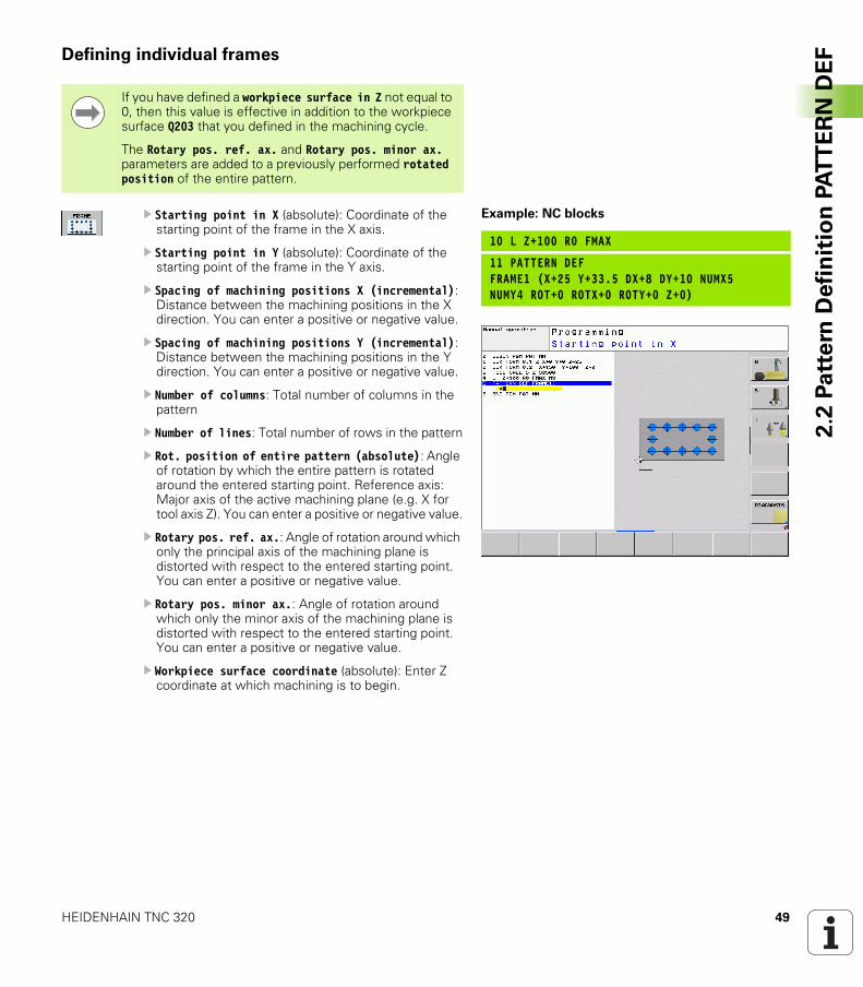
EFDefining individual frames
U Starting point in X (absolute): Coordinate of the starting point of the frame in the X axis.
U Starting point in Y (absolute): Coordinate of the starting point of the frame in the Y axis.
U Spacing of machining positions X (incremental): Distance between the machining positions in the X direction. You can enter a positive or negative value.
U Spacing of machining positions Y (incremental): Distance between the machining positions in the Y direction. You can enter a positive or negative value.
U Number of columns: Total number of columns in the pattern
U Number of lines: Total number of rows in the pattern
U Rot. position of entire pattern (absolute): Angle of rotation by which the entire pattern is rotated around the entered starting point. Reference axis: Major axis of the active machining plane (e.g. X for tool axis Z). You can enter a positive or negative value.
U Rotary pos. ref. ax.: Angle of rotation around which only the principal axis of the machining plane is distorted with respect to the entered starting point. You can enter a positive or negative value.
U Rotary pos. minor ax.: Angle of rotation around which only the minor axis of the machining plane is distorted with respect to the entered starting point. You can enter a positive or negative value.
U Workpiece surface coordinate (absolute): Enter Z coordinate at which machining is to begin.
If you have defined a workpiece surface in Z not equal to 0, then this value is effective in addition to the workpiece surface Q203 that you defined in the machining cycle.
The Rotary pos. ref. ax. and Rotary pos. minor ax. parameters are added to a previously performed rotated position of the entire pattern.
Example: NC blocks
10 L Z+100 R0 FMAX
11 PATTERN DEFFRAME1 (X+25 Y+33.5 DX+8 DY+10 NUMX5NUMY4 ROT+0 ROTX+0 ROTY+0 Z+0)
50 Using Fixed Cycles
2.2
Pa
tte
rn D
efi
nit
ion
PA
TT
ER
N D
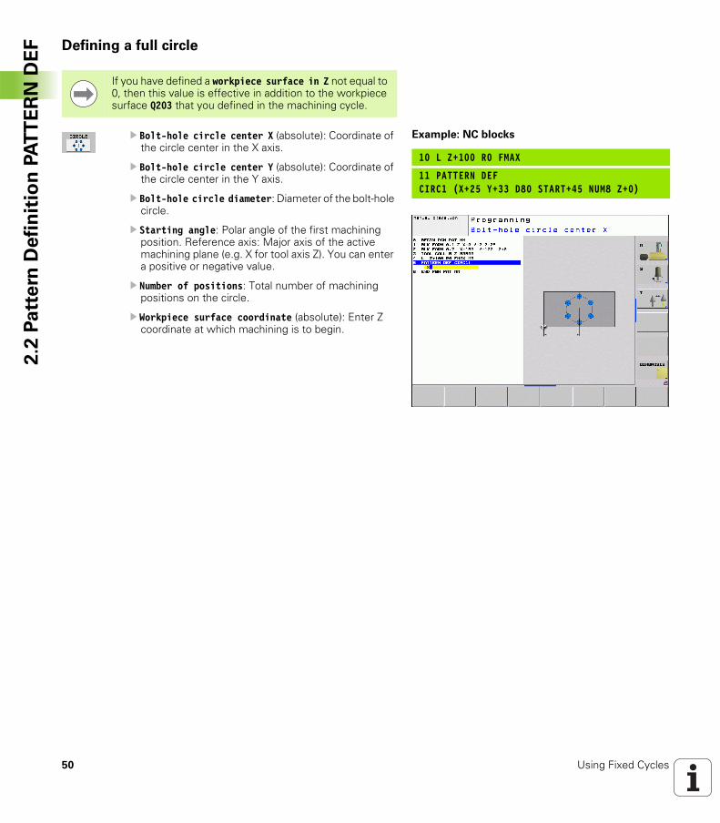
EF Defining a full circle
U Bolt-hole circle center X (absolute): Coordinate of the circle center in the X axis.
U Bolt-hole circle center Y (absolute): Coordinate of the circle center in the Y axis.
U Bolt-hole circle diameter: Diameter of the bolt-hole circle.
U Starting angle: Polar angle of the first machining position. Reference axis: Major axis of the active machining plane (e.g. X for tool axis Z). You can enter a positive or negative value.
U Number of positions: Total number of machining positions on the circle.
U Workpiece surface coordinate (absolute): Enter Z coordinate at which machining is to begin.
If you have defined a workpiece surface in Z not equal to 0, then this value is effective in addition to the workpiece surface Q203 that you defined in the machining cycle.
Example: NC blocks
10 L Z+100 R0 FMAX
11 PATTERN DEFCIRC1 (X+25 Y+33 D80 START+45 NUM8 Z+0)
HEIDENHAIN TNC 320 51
2.2
Pa
tte
rn D
efi
nit
ion
PA
TT
ER
N D
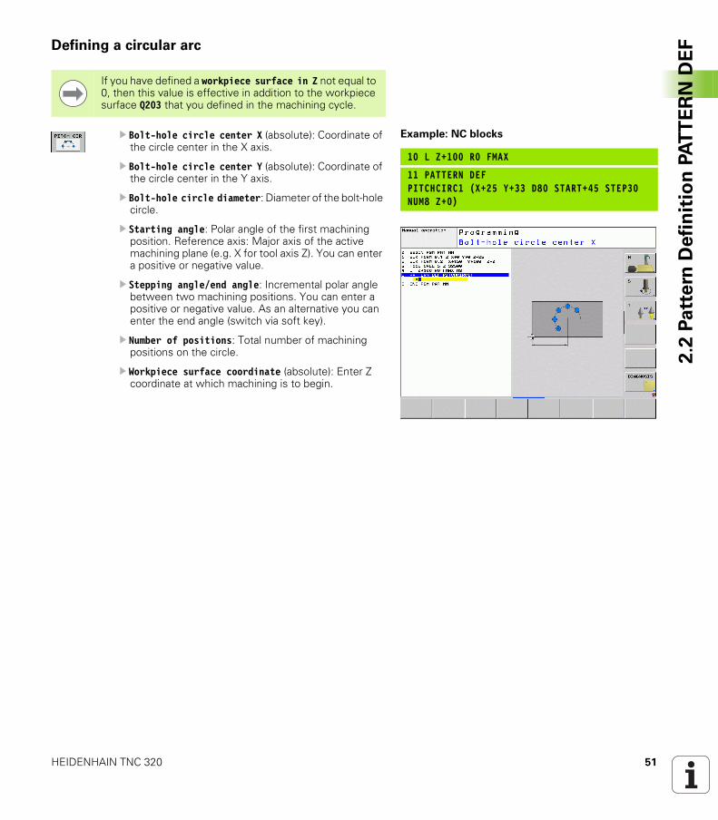
EFDefining a circular arc
U Bolt-hole circle center X (absolute): Coordinate of the circle center in the X axis.
U Bolt-hole circle center Y (absolute): Coordinate of the circle center in the Y axis.
U Bolt-hole circle diameter: Diameter of the bolt-hole circle.
U Starting angle: Polar angle of the first machining position. Reference axis: Major axis of the active machining plane (e.g. X for tool axis Z). You can enter a positive or negative value.
U Stepping angle/end angle: Incremental polar angle between two machining positions. You can enter a positive or negative value. As an alternative you can enter the end angle (switch via soft key).
U Number of positions: Total number of machining positions on the circle.
U Workpiece surface coordinate (absolute): Enter Z coordinate at which machining is to begin.
If you have defined a workpiece surface in Z not equal to 0, then this value is effective in addition to the workpiece surface Q203 that you defined in the machining cycle.
Example: NC blocks
10 L Z+100 R0 FMAX
11 PATTERN DEFPITCHCIRC1 (X+25 Y+33 D80 START+45 STEP30NUM8 Z+0)
52 Using Fixed Cycles
2.3
Po
int
Ta
ble
s 2.3 Point Tables
Application
You should create a point table whenever you want to run a cycle, or several cycles in sequence, on an irregular point pattern.
If you are using drilling cycles, the coordinates of the working plane in the point table represent the hole centers. If you are using milling cycles, the coordinates of the working plane in the point table represent the starting-point coordinates of the respective cycle (e.g. center-point coordinates of a circular pocket). Coordinates in the spindle axis correspond to the coordinate of the workpiece surface.
Creating a point table
Select the Programming and Editing mode of operation.
Press the PGM MGT key to call the file manager
Enter the name and file type of the point table and confirm your entry with the ENT key.
To select the unit of measure, press the MM or INCH soft key. The TNC changes to the program blocks window and displays an empty point table.
With the soft key INSERT LINE, insert new lines and enter the coordinates of the desired machining position.
Repeat the process until all desired coordinates have been entered.
FILE NAME?
The name of the point table must begin with a letter.
With the soft keys X OFF/ON, Y OFF/ON, Z OFF/ON (second soft-key row), you can specify which coordinates you want to enter in the point table.
HEIDENHAIN TNC 320 53
2.3
Po
int
Ta
ble
sHiding single points from the machining process
In the FADE column of the point table you can specify if the defined point is to be hidden during the machining process.
In the table, select the point to be hidden.
Select the FADE column.
Activate hiding, or
Deactivate hiding.
54 Using Fixed Cycles
2.3
Po
int
Ta
ble
s Selecting a point table in the program
In the Programming and Editing mode of operation, select the program for which you want to activate the point table:
Press the PGM CALL key to call the function for selecting the point table.
Press the POINT TABLE soft key.
Enter the name of the point table and confirm your entry with the END key. If the point table is not stored in the same directory as the NC program, you must enter the complete path.
Example NC block
7 SEL PATTERN “TNC:\DIRKT5\NUST35.PNT”
HEIDENHAIN TNC 320 55
2.3
Po
int
Ta
ble
sCalling a cycle in connection with point tables
If you want the TNC to call the last defined fixed cycle at the points defined in a point table, then program the cycle call with CYCLE CALL PAT:
U To program the cycle call, press the CYCL CALL key.
U Press the CYCL CALL PAT soft key to call a point table.
U Enter the feed rate at which the TNC is to move from point to point (if you make no entry the TNC will move at the last programmed feed rate; FMAX not valid).
U If required, enter a miscellaneous function M, then confirm with the END key.
The TNC retracts the tool to the safety clearance between the starting points. Depending on which is greater, the TNC uses either the spindle axis coordinate from the cycle call or the value from cycle parameter Q204 as the safety clearance.
If you want to move at reduced feed rate when pre-positioning in the spindle axis, use the miscellaneous function M103.
Effect of the point tables with SL cycles and Cycle 12
The TNC interprets the points as an additional datum shift.
Effect of the point tables with Cycles 200 to 208 and 262 to 267
The TNC interprets the points of the working plane as coordinates of the hole centers. If you want to use the coordinate defined in the point table for the spindle axis as the starting point coordinate, you must define the workpiece surface coordinate (Q203) as 0.
Effect of the point tables with Cycles 210 to 215
The TNC interprets the points as an additional datum shift. If you want to use the points defined in the point table as starting-point coordinates, you must define the starting points and the workpiece surface coordinate (Q203) in the respective milling cycle as 0.
Effect of the point tables with Cycles 251 to 254
The TNC interprets the points of the working plane as coordinates of the cycle starting point. If you want to use the coordinate defined in the point table for the spindle axis as the starting point coordinate, you must define the workpiece surface coordinate (Q203) as 0.
With CYCL CALL PAT the TNC runs the point table that you last defined (even if you defined the point table in a program that was nested with CALL PGM).

56 Using Fixed Cycles
2.3
Po
int
Ta
ble
s
Fixed Cycles: Drilling
58 Fixed Cycles: Drilling
3.1
Fu
nd
am
en
tals 3.1 Fundamentals
Overview
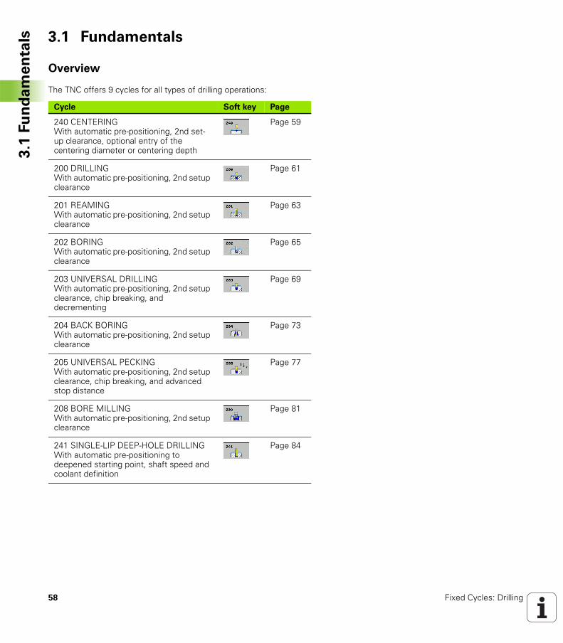
The TNC offers 9 cycles for all types of drilling operations:
Cycle Soft key Page
240 CENTERINGWith automatic pre-positioning, 2nd set-up clearance, optional entry of the centering diameter or centering depth
Page 59
200 DRILLINGWith automatic pre-positioning, 2nd setup clearance
Page 61
201 REAMINGWith automatic pre-positioning, 2nd setup clearance
Page 63
202 BORINGWith automatic pre-positioning, 2nd setup clearance
Page 65
203 UNIVERSAL DRILLINGWith automatic pre-positioning, 2nd setup clearance, chip breaking, and decrementing
Page 69
204 BACK BORINGWith automatic pre-positioning, 2nd setup clearance
Page 73
205 UNIVERSAL PECKINGWith automatic pre-positioning, 2nd setup clearance, chip breaking, and advanced stop distance
Page 77
208 BORE MILLINGWith automatic pre-positioning, 2nd setup clearance
Page 81
241 SINGLE-LIP DEEP-HOLE DRILLINGWith automatic pre-positioning to deepened starting point, shaft speed and coolant definition
Page 84
HEIDENHAIN TNC 320 59
3.2
CE
NT
ER
ING
(C
ycle
24
0,
DIN
/IS
O:
G2
40
)3.2 CENTERING (Cycle 240, DIN/ISO: G240)
Cycle run
1 The TNC positions the tool in the spindle axis at rapid traverse FMAX to the setup clearance above the workpiece surface.
2 The tool is centered at the programmed feed rate F to the entered centering diameter or centering depth.
3 If defined, the tool remains at the centering depth.4 Finally, the tool moves to setup clearance or—if programmed—to
the 2nd setup clearance at rapid traverse FMAX.
Please note while programming:
Program a positioning block for the starting point (hole center) in the working plane with radius compensation R0.
The algebraic sign for the cycle parameter Q344 (diameter) or Q201 (depth) determines the working direction. If you program the diameter or depth = 0, the cycle will not be executed.
Danger of collision!
Use the machine parameter displayDepthErr to define whether, if a positive depth is entered, the TNC should output an error message (on) or not (off).
Keep in mind that the TNC reverses the calculation for pre-positioning when a positive diameter or depth is entered. This means that the tool moves at rapid traverse in the tool axis to setup clearance below the workpiece surface!
60 Fixed Cycles: Drilling
3.2
CE
NT
ER
ING
(C
ycle
24
0,
DIN
/IS
O:
G2
40
) Cycle parameters
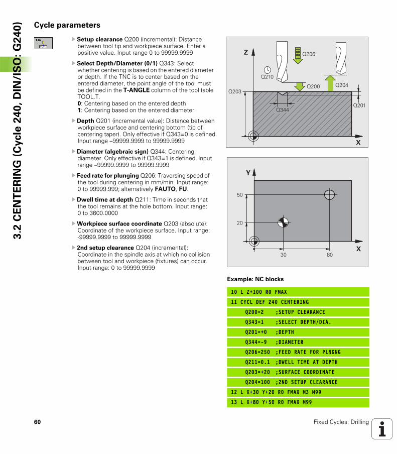
U Setup clearance Q200 (incremental): Distance between tool tip and workpiece surface. Enter a positive value. Input range 0 to 99999.9999
U Select Depth/Diameter (0/1) Q343: Select whether centering is based on the entered diameter or depth. If the TNC is to center based on the entered diameter, the point angle of the tool must be defined in the T-ANGLE column of the tool table TOOL.T.0: Centering based on the entered depth1: Centering based on the entered diameter
U Depth Q201 (incremental value): Distance between workpiece surface and centering bottom (tip of centering taper). Only effective if Q343=0 is defined. Input range –99999.9999 to 99999.9999
U Diameter (algebraic sign) Q344: Centering diameter. Only effective if Q343=1 is defined. Input range –99999.9999 to 99999.9999
U Feed rate for plunging Q206: Traversing speed of the tool during centering in mm/min. Input range: 0 to 99999.999; alternatively FAUTO, FU.
U Dwell time at depth Q211: Time in seconds that the tool remains at the hole bottom. Input range: 0 to 3600.0000
UWorkpiece surface coordinate Q203 (absolute): Coordinate of the workpiece surface. Input range: -99999.9999 to 99999.9999
U 2nd setup clearance Q204 (incremental): Coordinate in the spindle axis at which no collision between tool and workpiece (fixtures) can occur. Input range: 0 to 99999.9999
Example: NC blocks
10 L Z+100 R0 FMAX
11 CYCL DEF 240 CENTERING
Q200=2 ;SETUP CLEARANCE
Q343=1 ;SELECT DEPTH/DIA.
Q201=+0 ;DEPTH
Q344=-9 ;DIAMETER
Q206=250 ;FEED RATE FOR PLNGNG
Q211=0.1 ;DWELL TIME AT DEPTH
Q203=+20 ;SURFACE COORDINATE
Q204=100 ;2ND SETUP CLEARANCE
12 L X+30 Y+20 R0 FMAX M3 M99
13 L X+80 Y+50 R0 FMAX M99
�
�
����
����
����
����
��������
����
���
�
��
�
�
HEIDENHAIN TNC 320 61
3.3
DR
ILL
ING
(C
ycle
20
0)3.3 DRILLING (Cycle 200)
Cycle run
1 The TNC positions the tool in the spindle axis at rapid traverse FMAX to the setup clearance above the workpiece surface.
2 The tool drills to the first plunging depth at the programmed feed rate F.
3 The TNC returns the tool at FMAX to the setup clearance, dwells there (if a dwell time was entered), and then moves at FMAX to the setup clearance above the first plunging depth.
4 The tool then advances with another infeed at the programmed feed rate F.
5 The TNC repeats this process (2 to 4) until the programmed depth is reached.
6 The tool is retracted from the hole bottom to the setup clearance or—if programmed—to the 2nd setup clearance at FMAX.
Please note while programming:
Program a positioning block for the starting point (hole center) in the working plane with radius compensation R0.
The algebraic sign for the cycle parameter DEPTH determines the working direction. If you program DEPTH = 0, the cycle will not be executed.
Danger of collision!
Use the machine parameter displayDepthErr to define whether, if a positive depth is entered, the TNC should output an error message (on) or not (off).
Keep in mind that the TNC reverses the calculation for pre-positioning when a positive depth is entered. This means that the tool moves at rapid traverse in the tool axis to setup clearance below the workpiece surface!
62 Fixed Cycles: Drilling
3.3
DR
ILL
ING
(C
ycle
20
0) Cycle parameters
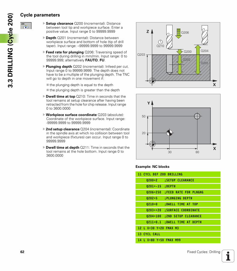
U Setup clearance Q200 (incremental): Distance between tool tip and workpiece surface. Enter a positive value. Input range 0 to 99999.9999
U Depth Q201 (incremental): Distance between workpiece surface and bottom of hole (tip of drill taper). Input range: –99999.9999 to 99999.9999
U Feed rate for plunging Q206: Traversing speed of the tool during drilling in mm/min. Input range: 0 to 99999.999; alternatively FAUTO, FU.
U Plunging depth Q202 (incremental): Infeed per cut. Input range 0 to 99999.9999. The depth does not have to be a multiple of the plunging depth. The TNC will go to depth in one movement if:
the plunging depth is equal to the depththe plunging depth is greater than the depth
U Dwell time at top Q210: Time in seconds that the tool remains at setup clearance after having been retracted from the hole for chip release. Input range 0 to 3600.0000
UWorkpiece surface coordinate Q203 (absolute): Coordinate of the workpiece surface. Input range: -99999.9999 to 99999.9999
U 2nd setup clearance Q204 (incremental): Coordinate in the spindle axis at which no collision between tool and workpiece (fixtures) can occur. Input range 0 to 99999.9999
U Dwell time at depth Q211: Time in seconds that the tool remains at the hole bottom. Input range 0 to 3600.0000
Example: NC blocks
11 CYCL DEF 200 DRILLING
Q200=2 ;SETUP CLEARANCE
Q201=-15 ;DEPTH
Q206=250 ;FEED RATE FOR PLNGNG
Q202=5 ;PLUNGING DEPTH
Q210=0 ;DWELL TIME AT TOP
Q203=+20 ;SURFACE COORDINATE
Q204=100 ;2ND SETUP CLEARANCE
Q211=0.1 ;DWELL TIME AT DEPTH
12 L X+30 Y+20 FMAX M3
13 CYCL CALL
14 L X+80 Y+50 FMAX M99
�
�
����
����
����
����
����
��������
���
�
��
�
�
HEIDENHAIN TNC 320 63
3.4
RE
AM
ING
(C
ycle
201
, D
IN/I
SO
: G
201
)3.4 REAMING (Cycle 201, DIN/ISO: G201)
Cycle run
1 The TNC positions the tool in the spindle axis to the entered setup clearance above the workpiece surface at rapid traverse FMAX.
2 The tool reams to the entered depth at the programmed feed rate F.
3 If programmed, the tool remains at the hole bottom for the entered dwell time.
4 The tool then retracts to the setup clearance at the feed rate F, and from there—if programmed—to the 2nd setup clearance at FMAX.
Please note while programming:
Program a positioning block for the starting point (hole center) in the working plane with radius compensation R0.
The algebraic sign for the cycle parameter DEPTH determines the working direction. If you program DEPTH = 0, the cycle will not be executed.
Danger of collision!
Use the machine parameter displayDepthErr to define whether, if a positive depth is entered, the TNC should output an error message (on) or not (off).
Keep in mind that the TNC reverses the calculation for pre-positioning when a positive depth is entered. This means that the tool moves at rapid traverse in the tool axis to setup clearance below the workpiece surface!
64 Fixed Cycles: Drilling
3.4
RE
AM
ING
(C
ycle
201
, D
IN/I
SO
: G
201
) Cycle parameters
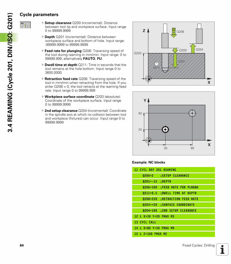
U Setup clearance Q200 (incremental): Distance between tool tip and workpiece surface. Input range 0 to 99999.9999
U Depth Q201 (incremental): Distance between workpiece surface and bottom of hole. Input range: -99999.9999 to 99999.9999
U Feed rate for plunging Q206: Traversing speed of the tool during reaming in mm/min. Input range: 0 to 99999.999; alternatively FAUTO, FU.
U Dwell time at depth Q211: Time in seconds that the tool remains at the hole bottom. Input range 0 to 3600.0000
U Retraction feed rate Q208: Traversing speed of the tool in mm/min when retracting from the hole. If you enter Q208 = 0, the tool retracts at the reaming feed rate. Input range 0 to 99999.999
UWorkpiece surface coordinate Q203 (absolute): Coordinate of the workpiece surface. Input range 0 to 99999.9999
U 2nd setup clearance Q204 (incremental): Coordinate in the spindle axis at which no collision between tool and workpiece (fixtures) can occur. Input range 0 to 99999.9999
Example: NC blocks
11 CYCL DEF 201 REAMING
Q200=2 ;SETUP CLEARANCE
Q201=-15 ;DEPTH
Q206=100 ;FEED RATE FOR PLNGNG
Q211=0.5 ;DWELL TIME AT DEPTH
Q208=250 ;RETRACTION FEED RATE
Q203=+20 ;SURFACE COORDINATE
Q204=100 ;2ND SETUP CLEARANCE
12 L X+30 Y+20 FMAX M3
13 CYCL CALL
14 L X+80 Y+50 FMAX M9
15 L Z+100 FMAX M2
�
�
����
����
����
����
��������
���
�
��
�
�
HEIDENHAIN TNC 320 65
3.5
BO
RIN
G (
Cycle
20
2,
DIN
/IS
O:
G2
02
)3.5 BORING (Cycle 202, DIN/ISO: G202)
Cycle run
1 The TNC positions the tool in the spindle axis at rapid traverse FMAX to the setup clearance above the workpiece surface.
2 The tool drills to the programmed depth at the feed rate for plunging.
3 If programmed, the tool remains at the hole bottom for the entered dwell time with active spindle rotation for cutting free.
4 The TNC then orients the spindle to the position that is defined in parameter Q336.
5 If retraction is selected, the tool retracts in the programmed direction by 0.2 mm (fixed value).
6 The TNC moves the tool at the retraction feed rate to the setup clearance and then, if entered, to the 2nd setup clearance at FMAX. If Q214=0, the tool point remains on the wall of the hole.
66 Fixed Cycles: Drilling
3.5
BO
RIN
G (
Cycle
20
2,
DIN
/IS
O:
G2
02
) Please note while programming:
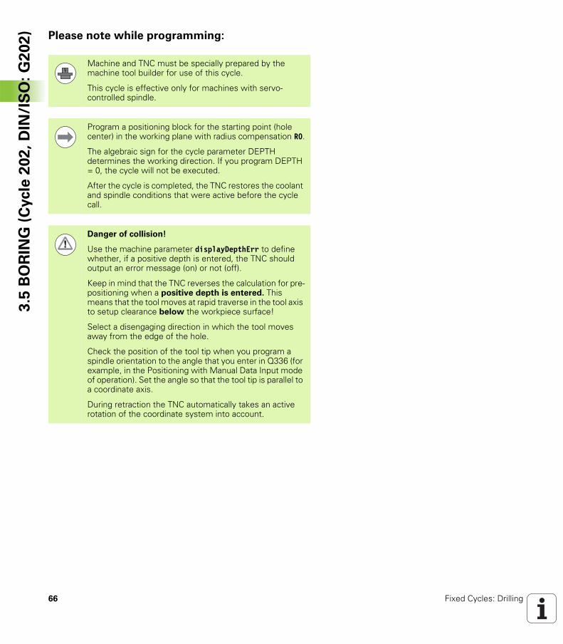
Machine and TNC must be specially prepared by the machine tool builder for use of this cycle.
This cycle is effective only for machines with servo-controlled spindle.
Program a positioning block for the starting point (hole center) in the working plane with radius compensation R0.
The algebraic sign for the cycle parameter DEPTH determines the working direction. If you program DEPTH = 0, the cycle will not be executed.
After the cycle is completed, the TNC restores the coolant and spindle conditions that were active before the cycle call.
Danger of collision!
Use the machine parameter displayDepthErr to define whether, if a positive depth is entered, the TNC should output an error message (on) or not (off).
Keep in mind that the TNC reverses the calculation for pre-positioning when a positive depth is entered. This means that the tool moves at rapid traverse in the tool axis to setup clearance below the workpiece surface!
Select a disengaging direction in which the tool moves away from the edge of the hole.
Check the position of the tool tip when you program a spindle orientation to the angle that you enter in Q336 (for example, in the Positioning with Manual Data Input mode of operation). Set the angle so that the tool tip is parallel to a coordinate axis.
During retraction the TNC automatically takes an active rotation of the coordinate system into account.
HEIDENHAIN TNC 320 67
3.5
BO
RIN
G (
Cycle
20
2,
DIN
/IS
O:
G2
02
)Cycle parameters
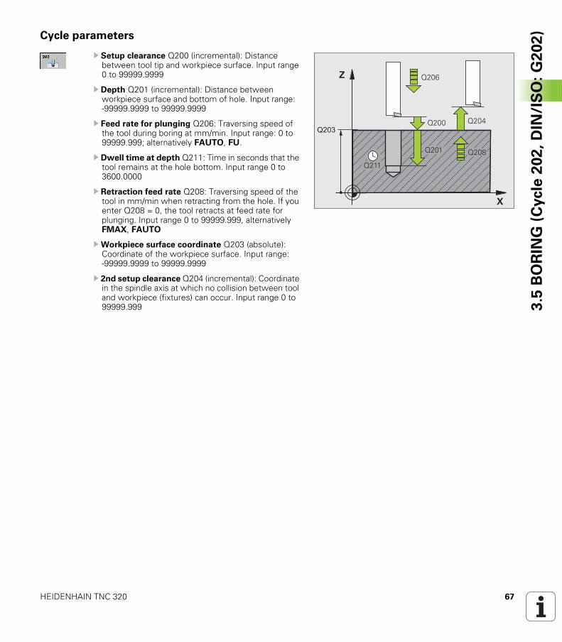
U Setup clearance Q200 (incremental): Distance between tool tip and workpiece surface. Input range 0 to 99999.9999
U Depth Q201 (incremental): Distance between workpiece surface and bottom of hole. Input range: -99999.9999 to 99999.9999
U Feed rate for plunging Q206: Traversing speed of the tool during boring at mm/min. Input range: 0 to 99999.999; alternatively FAUTO, FU.
U Dwell time at depth Q211: Time in seconds that the tool remains at the hole bottom. Input range 0 to 3600.0000
U Retraction feed rate Q208: Traversing speed of the tool in mm/min when retracting from the hole. If you enter Q208 = 0, the tool retracts at feed rate for plunging. Input range 0 to 99999.999, alternatively FMAX, FAUTO
UWorkpiece surface coordinate Q203 (absolute): Coordinate of the workpiece surface. Input range: -99999.9999 to 99999.9999
U 2nd setup clearance Q204 (incremental): Coordinate in the spindle axis at which no collision between tool and workpiece (fixtures) can occur. Input range 0 to 99999.999
�
�
����
����
����
����
��������
���
68 Fixed Cycles: Drilling
3.5
BO
RIN
G (
Cycle
20
2,
DIN
/IS
O:
G2
02
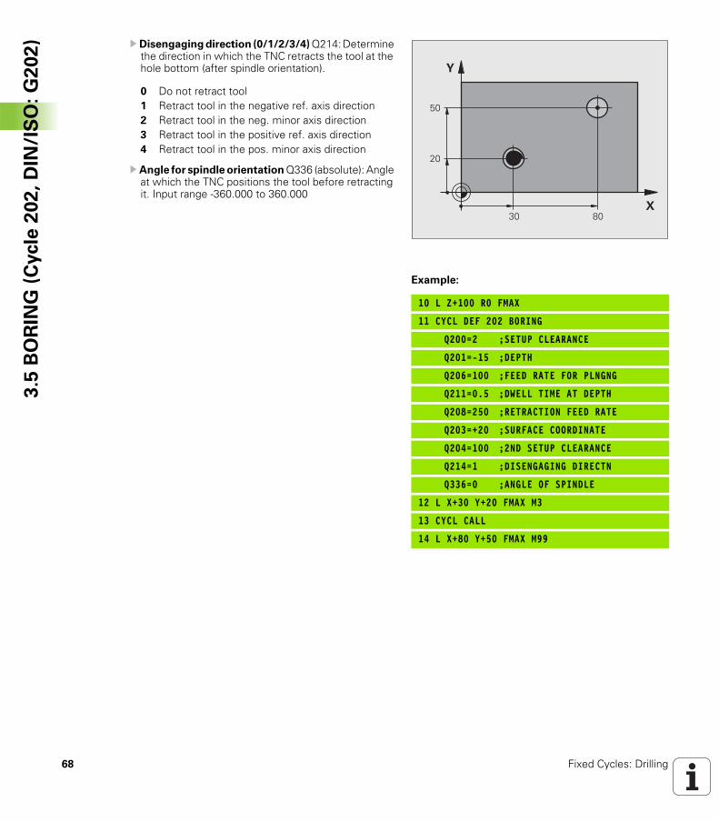
) U Disengaging direction (0/1/2/3/4) Q214: Determine the direction in which the TNC retracts the tool at the hole bottom (after spindle orientation).
U Angle for spindle orientation Q336 (absolute): Angle at which the TNC positions the tool before retracting it. Input range -360.000 to 360.000
Example:
10 L Z+100 R0 FMAX
11 CYCL DEF 202 BORING
Q200=2 ;SETUP CLEARANCE
Q201=-15 ;DEPTH
Q206=100 ;FEED RATE FOR PLNGNG
Q211=0.5 ;DWELL TIME AT DEPTH
Q208=250 ;RETRACTION FEED RATE
Q203=+20 ;SURFACE COORDINATE
Q204=100 ;2ND SETUP CLEARANCE
Q214=1 ;DISENGAGING DIRECTN
Q336=0 ;ANGLE OF SPINDLE
12 L X+30 Y+20 FMAX M3
13 CYCL CALL
14 L X+80 Y+50 FMAX M99
���
�
��
�
�
0 Do not retract tool1 Retract tool in the negative ref. axis direction2 Retract tool in the neg. minor axis direction3 Retract tool in the positive ref. axis direction4 Retract tool in the pos. minor axis direction
HEIDENHAIN TNC 320 69
3.6
UN
IVE
RS
AL
DR
ILL
ING
(C
ycle
20
3,
DIN
/IS
O:
G2
03
)3.6 UNIVERSAL DRILLING (Cycle 203, DIN/ISO: G203)
Cycle run
1 The TNC positions the tool in the spindle axis to the entered setup clearance above the workpiece surface at rapid traverse FMAX.
2 The tool drills to the first plunging depth at the programmed feed rate F.
3 If you have programmed chip breaking, the tool then retracts by the entered retraction value. If you are working without chip breaking, the tool retracts at the retraction feed rate to the setup clearance, remains there—if programmed—for the entered dwell time, and advances again at FMAX to the setup clearance above the first PLUNGING DEPTH.
4 The tool then advances with another infeed at the programmed feed rate. If programmed, the plunging depth is decreased after each infeed by the decrement.
5 The TNC repeats this process (2 to 4) until the programmed total hole depth is reached.
6 The tool remains at the hole bottom—if programmed—for the entered dwell time to cut free, and then retracts to the setup clearance at the retraction feed rate. If programmed, the tool moves to the 2nd setup clearance at FMAX.
70 Fixed Cycles: Drilling
3.6
UN
IVE
RS
AL
DR
ILL
ING
(C
ycle
20
3,
DIN
/IS
O:
G2
03
) Please note while programming:
Program a positioning block for the starting point (hole center) in the working plane with radius compensation R0.
The algebraic sign for the cycle parameter DEPTH determines the working direction. If you program DEPTH = 0, the cycle will not be executed.
Danger of collision!
Use the machine parameter displayDepthErr to define whether, if a positive depth is entered, the TNC should output an error message (on) or not (off).
Keep in mind that the TNC reverses the calculation for pre-positioning when a positive depth is entered. This means that the tool moves at rapid traverse in the tool axis to setup clearance below the workpiece surface!
HEIDENHAIN TNC 320 71
3.6
UN
IVE
RS
AL
DR
ILL
ING
(C
ycle
20
3,
DIN
/IS
O:
G2
03
)Cycle parameters
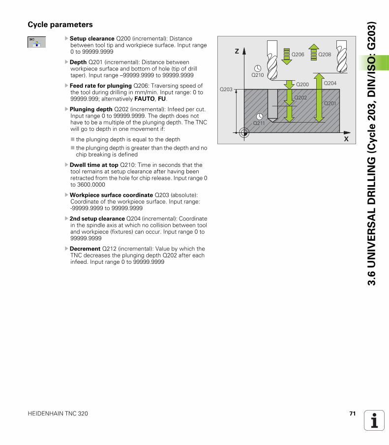
U Setup clearance Q200 (incremental): Distance between tool tip and workpiece surface. Input range 0 to 99999.9999
U Depth Q201 (incremental): Distance between workpiece surface and bottom of hole (tip of drill taper). Input range –99999.9999 to 99999.9999
U Feed rate for plunging Q206: Traversing speed of the tool during drilling in mm/min. Input range: 0 to 99999.999; alternatively FAUTO, FU.
U Plunging depth Q202 (incremental): Infeed per cut. Input range 0 to 99999.9999. The depth does not have to be a multiple of the plunging depth. The TNC will go to depth in one movement if:
the plunging depth is equal to the depththe plunging depth is greater than the depth and no chip breaking is defined
U Dwell time at top Q210: Time in seconds that the tool remains at setup clearance after having been retracted from the hole for chip release. Input range 0 to 3600.0000
UWorkpiece surface coordinate Q203 (absolute): Coordinate of the workpiece surface. Input range: -99999.9999 to 99999.9999
U 2nd setup clearance Q204 (incremental): Coordinate in the spindle axis at which no collision between tool and workpiece (fixtures) can occur. Input range 0 to 99999.9999
U Decrement Q212 (incremental): Value by which the TNC decreases the plunging depth Q202 after each infeed. Input range 0 to 99999.9999
�
�
����
����
����
����
����
��������
����
���
72 Fixed Cycles: Drilling
3.6
UN
IVE
RS
AL
DR
ILL
ING
(C
ycle
20
3,
DIN
/IS
O:
G2
03
) U No. of breaks before retracting Q213: Number of chip breaks after which the TNC is to withdraw the tool from the hole for chip release. For chip breaking, the TNC retracts the tool each time by the value in Q256. Input range 0 to 99999
UMinimum plunging depth Q205 (incremental): If you have entered a decrement, the TNC limits the plunging depth to the value entered with Q205. Input range 0 to 99999.9999
U Dwell time at depth Q211: Time in seconds that the tool remains at the hole bottom. Input range 0 to 3600.0000
U Retraction feed rate Q208: Traversing speed of the tool in mm/min when retracting from the hole. If you enter Q208 = 0, the TNC retracts the tool at the feed rate in Q206. Input range 0 to 99999.999, alternatively FMAX, FAUTO
U Retraction rate for chip breaking Q256 (incremental): Value by which the TNC retracts the tool during chip breaking. Input range 0.1000 to 99999.9999
Example: NC blocks
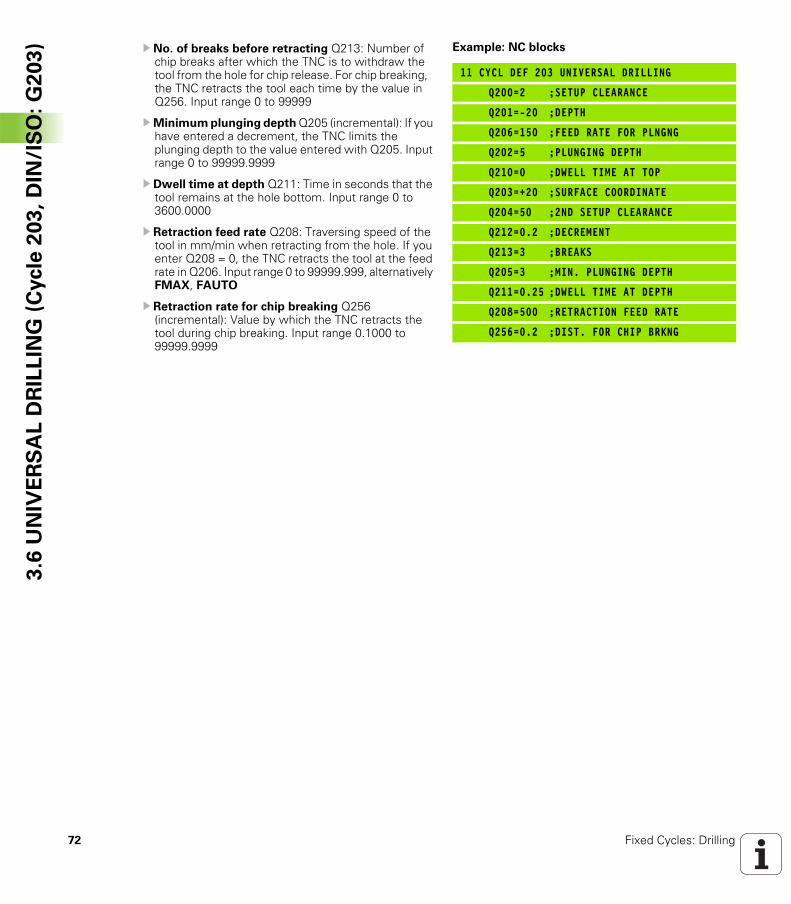
11 CYCL DEF 203 UNIVERSAL DRILLING
Q200=2 ;SETUP CLEARANCE
Q201=-20 ;DEPTH
Q206=150 ;FEED RATE FOR PLNGNG
Q202=5 ;PLUNGING DEPTH
Q210=0 ;DWELL TIME AT TOP
Q203=+20 ;SURFACE COORDINATE
Q204=50 ;2ND SETUP CLEARANCE
Q212=0.2 ;DECREMENT
Q213=3 ;BREAKS
Q205=3 ;MIN. PLUNGING DEPTH
Q211=0.25 ;DWELL TIME AT DEPTH
Q208=500 ;RETRACTION FEED RATE
Q256=0.2 ;DIST. FOR CHIP BRKNG
HEIDENHAIN TNC 320 73
3.7
BA
CK
BO
RIN
G (
Cycle
20
4,
DIN
/IS
O:
G2
04
)3.7 BACK BORING (Cycle 204, DIN/ISO: G204)
Cycle run
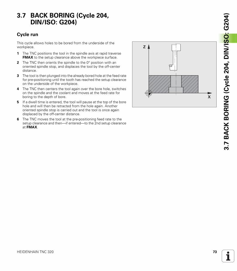
This cycle allows holes to be bored from the underside of the workpiece.
1 The TNC positions the tool in the spindle axis at rapid traverse FMAX to the setup clearance above the workpiece surface.
2 The TNC then orients the spindle to the 0° position with an oriented spindle stop, and displaces the tool by the off-center distance.
3 The tool is then plunged into the already bored hole at the feed rate for pre-positioning until the tooth has reached the setup clearance on the underside of the workpiece.
4 The TNC then centers the tool again over the bore hole, switches on the spindle and the coolant and moves at the feed rate for boring to the depth of bore.
5 If a dwell time is entered, the tool will pause at the top of the bore hole and will then be retracted from the hole again. Another oriented spindle stop is carried out and the tool is once again displaced by the off-center distance.
6 The TNC moves the tool at the pre-positioning feed rate to the setup clearance and then—if entered—to the 2nd setup clearance at FMAX.
�
�
74 Fixed Cycles: Drilling
3.7
BA
CK
BO
RIN
G (
Cycle
20
4,
DIN
/IS
O:
G2
04
) Please note while programming:
Machine and TNC must be specially prepared by the machine tool builder for use of this cycle.
This cycle is effective only for machines with servo-controlled spindle.
Special boring bars for upward cutting are required for this cycle.
Program a positioning block for the starting point (hole center) in the working plane with radius compensation R0.
The algebraic sign for the cycle parameter depth determines the working direction. Note: A positive sign bores in the direction of the positive spindle axis.
The entered tool length is the total length to the underside of the boring bar and not just to the tooth.
When calculating the starting point for boring, the TNC considers the tooth length of the boring bar and the thickness of the material.
Danger of collision!
Check the position of the tool tip when you program a spindle orientation to the angle that you enter in Q336 (for example, in the Positioning with Manual Data Input mode of operation). Set the angle so that the tool tip is parallel to a coordinate axis. Select a disengaging direction in which the tool moves away from the edge of the hole.
HEIDENHAIN TNC 320 75
3.7
BA
CK
BO
RIN
G (
Cycle
20
4,
DIN
/IS
O:
G2
04
)Cycle parameters
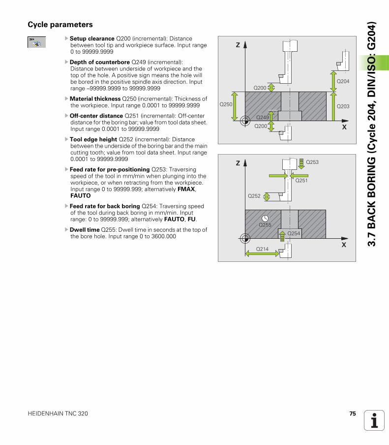
U Setup clearance Q200 (incremental): Distance between tool tip and workpiece surface. Input range 0 to 99999.9999
U Depth of counterbore Q249 (incremental): Distance between underside of workpiece and the top of the hole. A positive sign means the hole will be bored in the positive spindle axis direction. Input range –99999.9999 to 99999.9999
UMaterial thickness Q250 (incremental): Thickness of the workpiece. Input range 0.0001 to 99999.9999
U Off-center distance Q251 (incremental): Off-center distance for the boring bar; value from tool data sheet. Input range 0.0001 to 99999.9999
U Tool edge height Q252 (incremental): Distance between the underside of the boring bar and the main cutting tooth; value from tool data sheet. Input range 0.0001 to 99999.9999
U Feed rate for pre-positioning Q253: Traversing speed of the tool in mm/min when plunging into the workpiece, or when retracting from the workpiece. Input range 0 to 99999.999; alternatively FMAX, FAUTO
U Feed rate for back boring Q254: Traversing speed of the tool during back boring in mm/min. Input range: 0 to 99999.999; alternatively FAUTO, FU.
U Dwell time Q255: Dwell time in seconds at the top of the bore hole. Input range 0 to 3600.000
�
�
��� ����
����
����
����
����
�
�
��
���
����
���
���
���
76 Fixed Cycles: Drilling
3.7
BA
CK
BO
RIN
G (
Cycle
20
4,
DIN
/IS
O:
G2
04
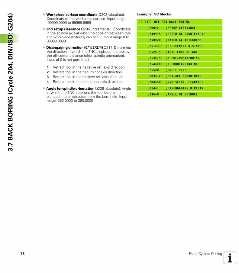
) UWorkpiece surface coordinate Q203 (absolute): Coordinate of the workpiece surface. Input range: -99999.9999 to 99999.9999
U 2nd setup clearance Q204 (incremental): Coordinate in the spindle axis at which no collision between tool and workpiece (fixtures) can occur. Input range 0 to 99999.9999
U Disengaging direction (0/1/2/3/4) Q214: Determine the direction in which the TNC displaces the tool by the off-center distance (after spindle orientation). Input of 0 is not permitted.
U Angle for spindle orientation Q336 (absolute): Angle at which the TNC positions the tool before it is plunged into or retracted from the bore hole. Input range -360.0000 to 360.0000
Example: NC blocks
11 CYCL DEF 204 BACK BORING
Q200=2 ;SETUP CLEARANCE
Q249=+5 ;DEPTH OF COUNTERBORE
Q250=20 ;MATERIAL THICKNESS
Q251=3.5 ;OFF-CENTER DISTANCE
Q252=15 ;TOOL EDGE HEIGHT
Q253=750 ;F PRE-POSITIONING
Q254=200 ;F COUNTERSINKING
Q255=0 ;DWELL TIME
Q203=+20 ;SURFACE COORDINATE
Q204=50 ;2ND SETUP CLEARANCE
Q214=1 ;DISENGAGING DIRECTN
Q336=0 ;ANGLE OF SPINDLE
1 Retract tool in the negative ref. axis direction2 Retract tool in the neg. minor axis direction3 Retract tool in the positive ref. axis direction4 Retract tool in the pos. minor axis direction
HEIDENHAIN TNC 320 77
3.8
UN
IVE
RS
AL
PE
CK
ING
(C
ycle
20
5,
DIN
/IS
O:
G2
05
)3.8 UNIVERSAL PECKING (Cycle 205, DIN/ISO: G205)
Cycle run
1 The TNC positions the tool in the spindle axis to the entered setup clearance above the workpiece surface at rapid traverse FMAX.
2 If you enter a deepened starting point, the TNC moves at the defined positioning feed rate to the setup clearance above the deepened starting point.
3 The tool drills to the first plunging depth at the programmed feed rate F.
4 If you have programmed chip breaking, the tool then retracts by the entered retraction value. If you are working without chip breaking, the tool is moved at rapid traverse to the setup clearance, and then at FMAX to the entered starting position above the first plunging depth.
5 The tool then advances with another infeed at the programmed feed rate. If programmed, the plunging depth is decreased after each infeed by the decrement.
6 The TNC repeats this process (2 to 4) until the programmed total hole depth is reached.
7 The tool remains at the hole bottom—if programmed—for the entered dwell time to cut free, and then retracts to the setup clearance at the retraction feed rate. If programmed, the tool moves to the 2nd setup clearance at FMAX.
78 Fixed Cycles: Drilling
3.8
UN
IVE
RS
AL
PE
CK
ING
(C
ycle
20
5,
DIN
/IS
O:
G2
05
) Please note while programming:
Program a positioning block for the starting point (hole center) in the working plane with radius compensation R0.
The algebraic sign for the cycle parameter DEPTH determines the working direction. If you program DEPTH = 0, the cycle will not be executed.
If you enter advance stop distances Q258 not equal to Q259, the TNC will change the advance stop distances between the first and last plunging depths at the same rate.
If you use Q379 to enter a deepened starting point, the TNC merely changes the starting point of the infeed movement. Retraction movements are not changed by the TNC, therefore they are calculated with respect to the coordinate of the workpiece surface.
Danger of collision!
Use the machine parameter displayDepthErr to define whether, if a positive depth is entered, the TNC should output an error message (on) or not (off).
Keep in mind that the TNC reverses the calculation for pre-positioning when a positive depth is entered. This means that the tool moves at rapid traverse in the tool axis to setup clearance below the workpiece surface!
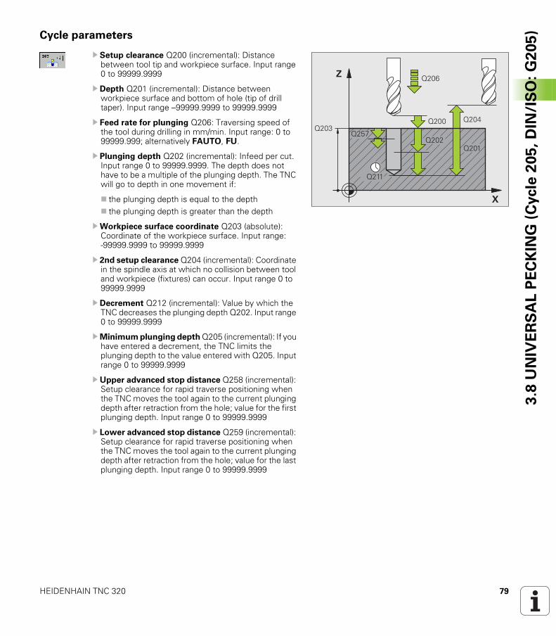
HEIDENHAIN TNC 320 79
3.8
UN
IVE
RS
AL
PE
CK
ING
(C
ycle
20
5,
DIN
/IS
O:
G2
05
)Cycle parameters
U Setup clearance Q200 (incremental): Distance between tool tip and workpiece surface. Input range 0 to 99999.9999
U Depth Q201 (incremental): Distance between workpiece surface and bottom of hole (tip of drill taper). Input range –99999.9999 to 99999.9999
U Feed rate for plunging Q206: Traversing speed of the tool during drilling in mm/min. Input range: 0 to 99999.999; alternatively FAUTO, FU.
U Plunging depth Q202 (incremental): Infeed per cut. Input range 0 to 99999.9999. The depth does not have to be a multiple of the plunging depth. The TNC will go to depth in one movement if:
the plunging depth is equal to the depththe plunging depth is greater than the depth
UWorkpiece surface coordinate Q203 (absolute): Coordinate of the workpiece surface. Input range: -99999.9999 to 99999.9999
U 2nd setup clearance Q204 (incremental): Coordinate in the spindle axis at which no collision between tool and workpiece (fixtures) can occur. Input range 0 to 99999.9999
U Decrement Q212 (incremental): Value by which the TNC decreases the plunging depth Q202. Input range 0 to 99999.9999
UMinimum plunging depth Q205 (incremental): If you have entered a decrement, the TNC limits the plunging depth to the value entered with Q205. Input range 0 to 99999.9999
U Upper advanced stop distance Q258 (incremental): Setup clearance for rapid traverse positioning when the TNC moves the tool again to the current plunging depth after retraction from the hole; value for the first plunging depth. Input range 0 to 99999.9999
U Lower advanced stop distance Q259 (incremental): Setup clearance for rapid traverse positioning when the TNC moves the tool again to the current plunging depth after retraction from the hole; value for the last plunging depth. Input range 0 to 99999.9999
�
�
����
����
����
����
��������
����
���
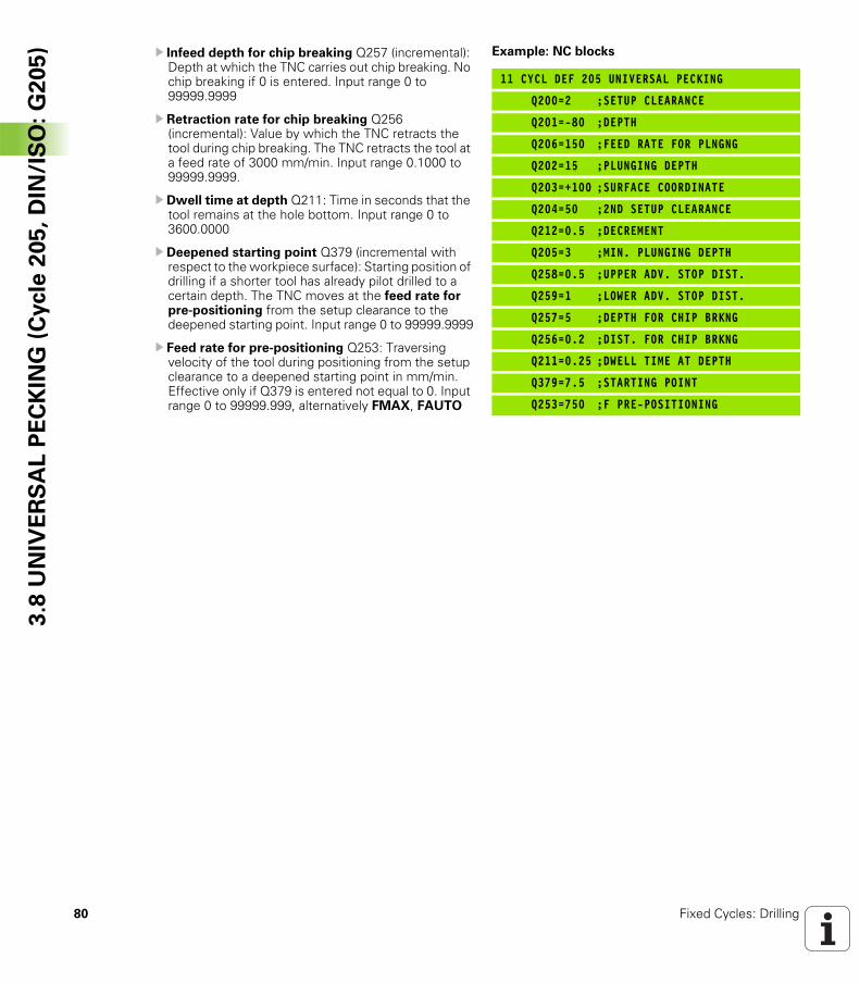
80 Fixed Cycles: Drilling
3.8
UN
IVE
RS
AL
PE
CK
ING
(C
ycle
20
5,
DIN
/IS
O:
G2
05
) U Infeed depth for chip breaking Q257 (incremental): Depth at which the TNC carries out chip breaking. No chip breaking if 0 is entered. Input range 0 to 99999.9999
U Retraction rate for chip breaking Q256 (incremental): Value by which the TNC retracts the tool during chip breaking. The TNC retracts the tool at a feed rate of 3000 mm/min. Input range 0.1000 to 99999.9999.
U Dwell time at depth Q211: Time in seconds that the tool remains at the hole bottom. Input range 0 to 3600.0000
U Deepened starting point Q379 (incremental with respect to the workpiece surface): Starting position of drilling if a shorter tool has already pilot drilled to a certain depth. The TNC moves at the feed rate for pre-positioning from the setup clearance to the deepened starting point. Input range 0 to 99999.9999
U Feed rate for pre-positioning Q253: Traversing velocity of the tool during positioning from the setup clearance to a deepened starting point in mm/min. Effective only if Q379 is entered not equal to 0. Input range 0 to 99999.999, alternatively FMAX, FAUTO
Example: NC blocks
11 CYCL DEF 205 UNIVERSAL PECKING
Q200=2 ;SETUP CLEARANCE
Q201=-80 ;DEPTH
Q206=150 ;FEED RATE FOR PLNGNG
Q202=15 ;PLUNGING DEPTH
Q203=+100 ;SURFACE COORDINATE
Q204=50 ;2ND SETUP CLEARANCE
Q212=0.5 ;DECREMENT
Q205=3 ;MIN. PLUNGING DEPTH
Q258=0.5 ;UPPER ADV. STOP DIST.
Q259=1 ;LOWER ADV. STOP DIST.
Q257=5 ;DEPTH FOR CHIP BRKNG
Q256=0.2 ;DIST. FOR CHIP BRKNG
Q211=0.25 ;DWELL TIME AT DEPTH
Q379=7.5 ;STARTING POINT
Q253=750 ;F PRE-POSITIONING
HEIDENHAIN TNC 320 81
3.9
BO
RE
MIL
LIN
G (
Cycle
20
8,
DIN
/IS
O:
G2
08
)3.9 BORE MILLING (Cycle 208, DIN/ISO: G208)
Cycle run
1 The TNC positions the tool in the spindle axis at rapid traverse FMAX to the programmed setup clearance above the workpiece surface and then moves the tool to the bore hole circumference on a rounded arc (if enough space is available).
2 The tool mills in a helix from the current position to the first plunging depth at the programmed feed rate F.
3 When the drilling depth is reached, the TNC once again traverses a full circle to remove the material remaining after the initial plunge.
4 The TNC then positions the tool at the center of the hole again.5 Finally the TNC returns to the setup clearance at FMAX. If
programmed, the tool moves to the 2nd setup clearance at FMAX.
82 Fixed Cycles: Drilling
3.9
BO
RE
MIL
LIN
G (
Cycle
20
8,
DIN
/IS
O:
G2
08
) Please note while programming:
Program a positioning block for the starting point (hole center) in the working plane with radius compensation R0.
The algebraic sign for the cycle parameter DEPTH determines the working direction. If you program DEPTH = 0, the cycle will not be executed.
If you have entered the bore hole diameter to be the same as the tool diameter, the TNC will bore directly to the entered depth without any helical interpolation.
An active mirror function does not influence the type of milling defined in the cycle.
Note that if the infeed distance is too large, the tool or the workpiece may be damaged.
To prevent the infeeds from being too large, enter the maximum plunge angle of the tool in the ANGLE column of the tool table. The TNC then automatically calculates the max. infeed permitted and changes your entered value accordingly.
Danger of collision!
Use the machine parameter displayDepthErr to define whether, if a positive depth is entered, the TNC should output an error message (on) or not (off).
Keep in mind that the TNC reverses the calculation for pre-positioning when a positive depth is entered. This means that the tool moves at rapid traverse in the tool axis to setup clearance below the workpiece surface!
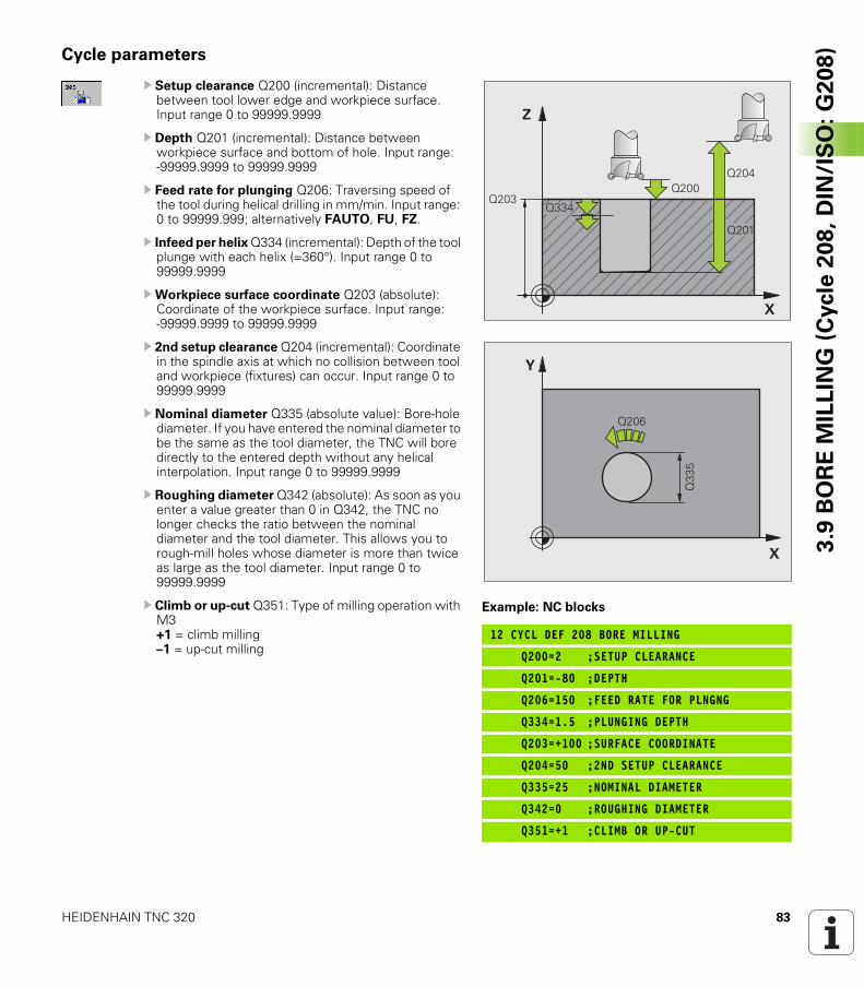
HEIDENHAIN TNC 320 83
3.9
BO
RE
MIL
LIN
G (
Cycle
20
8,
DIN
/IS
O:
G2
08
)Cycle parameters
U Setup clearance Q200 (incremental): Distance between tool lower edge and workpiece surface. Input range 0 to 99999.9999
U Depth Q201 (incremental): Distance between workpiece surface and bottom of hole. Input range: -99999.9999 to 99999.9999
U Feed rate for plunging Q206: Traversing speed of the tool during helical drilling in mm/min. Input range: 0 to 99999.999; alternatively FAUTO, FU, FZ.
U Infeed per helix Q334 (incremental): Depth of the tool plunge with each helix (=360°). Input range 0 to 99999.9999
UWorkpiece surface coordinate Q203 (absolute): Coordinate of the workpiece surface. Input range: -99999.9999 to 99999.9999
U 2nd setup clearance Q204 (incremental): Coordinate in the spindle axis at which no collision between tool and workpiece (fixtures) can occur. Input range 0 to 99999.9999
U Nominal diameter Q335 (absolute value): Bore-hole diameter. If you have entered the nominal diameter to be the same as the tool diameter, the TNC will bore directly to the entered depth without any helical interpolation. Input range 0 to 99999.9999
U Roughing diameter Q342 (absolute): As soon as you enter a value greater than 0 in Q342, the TNC no longer checks the ratio between the nominal diameter and the tool diameter. This allows you to rough-mill holes whose diameter is more than twice as large as the tool diameter. Input range 0 to 99999.9999
U Climb or up-cut Q351: Type of milling operation with M3+1 = climb milling–1 = up-cut milling
Example: NC blocks
12 CYCL DEF 208 BORE MILLING
Q200=2 ;SETUP CLEARANCE
Q201=-80 ;DEPTH
Q206=150 ;FEED RATE FOR PLNGNG
Q334=1.5 ;PLUNGING DEPTH
Q203=+100 ;SURFACE COORDINATE
Q204=50 ;2ND SETUP CLEARANCE
Q335=25 ;NOMINAL DIAMETER
Q342=0 ;ROUGHING DIAMETER
Q351=+1 ;CLIMB OR UP-CUT
�
�
����
����
����
����
����
�
�
����
���
84 Fixed Cycles: Drilling
3.1
0 S
ING
LE
-FL
UT
ED
DE
EP
-HO
LE
DR
ILL
ING
(C
ycle
24
1,
DIN
/IS
O:
G2
41
) 3.10 SINGLE-FLUTED DEEP-HOLE DRILLING (Cycle 241, DIN/ISO: G241)
Cycle run
1 The TNC positions the tool in the spindle axis to the entered setup clearance above the workpiece surface at rapid traverse FMAX.
2 Then the TNC moves the tool at the defined positioning feed rate to the setup clearance above the deepened starting point and switches on the drilling speed (M3) and the coolant. The TNC executes the approach motion at the direction of rotation defined in the cycle, with clockwise, counterclockwise or stationary spindle.
3 The tool drills to the entered drilling depth at the programmed feed rate F.
4 If programmed, the tool remains at the hole bottom for chip breaking. Then the TNC switches off the coolant and resets the drilling speed to the value defined for retraction.
5 After the dwell time at the hole bottom, the tool is retracted to the setup clearance at the retraction feed rate. If programmed, the tool moves to the 2nd setup clearance at FMAX.
Please note while programming:
Program a positioning block for the starting point (hole center) in the working plane with radius compensation R0.
The algebraic sign for the cycle parameter DEPTH determines the working direction. If you program DEPTH = 0, the cycle will not be executed.
Danger of collision!
Use the machine parameter displayDepthErr to define whether, if a positive depth is entered, the TNC should output an error message (on) or not (off).
Keep in mind that the TNC reverses the calculation for pre-positioning when a positive depth is entered. This means that the tool moves at rapid traverse in the tool axis to setup clearance below the workpiece surface!
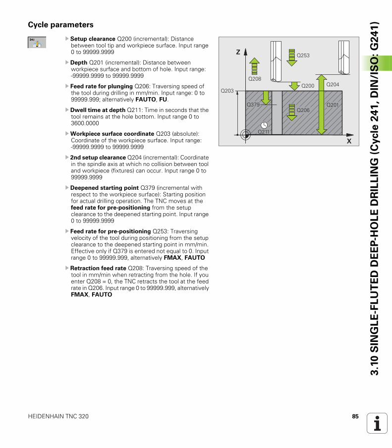
HEIDENHAIN TNC 320 85
3.1
0 S
ING
LE
-FL
UT
ED
DE
EP
-HO
LE
DR
ILL
ING
(C
ycle
24
1,
DIN
/IS
O:
G2
41
)Cycle parameters
U Setup clearance Q200 (incremental): Distance between tool tip and workpiece surface. Input range 0 to 99999.9999
U Depth Q201 (incremental): Distance between workpiece surface and bottom of hole. Input range: -99999.9999 to 99999.9999
U Feed rate for plunging Q206: Traversing speed of the tool during drilling in mm/min. Input range: 0 to 99999.999; alternatively FAUTO, FU.
U Dwell time at depth Q211: Time in seconds that the tool remains at the hole bottom. Input range 0 to 3600.0000
UWorkpiece surface coordinate Q203 (absolute): Coordinate of the workpiece surface. Input range: -99999.9999 to 99999.9999
U 2nd setup clearance Q204 (incremental): Coordinate in the spindle axis at which no collision between tool and workpiece (fixtures) can occur. Input range 0 to 99999.9999
U Deepened starting point Q379 (incremental with respect to the workpiece surface): Starting position for actual drilling operation. The TNC moves at the feed rate for pre-positioning from the setup clearance to the deepened starting point. Input range 0 to 99999.9999
U Feed rate for pre-positioning Q253: Traversing velocity of the tool during positioning from the setup clearance to the deepened starting point in mm/min. Effective only if Q379 is entered not equal to 0. Input range 0 to 99999.999, alternatively FMAX, FAUTO
U Retraction feed rate Q208: Traversing speed of the tool in mm/min when retracting from the hole. If you enter Q208 = 0, the TNC retracts the tool at the feed rate in Q206. Input range 0 to 99999.999, alternatively FMAX, FAUTO
�
�
����
����
���
��������
����
���
��������
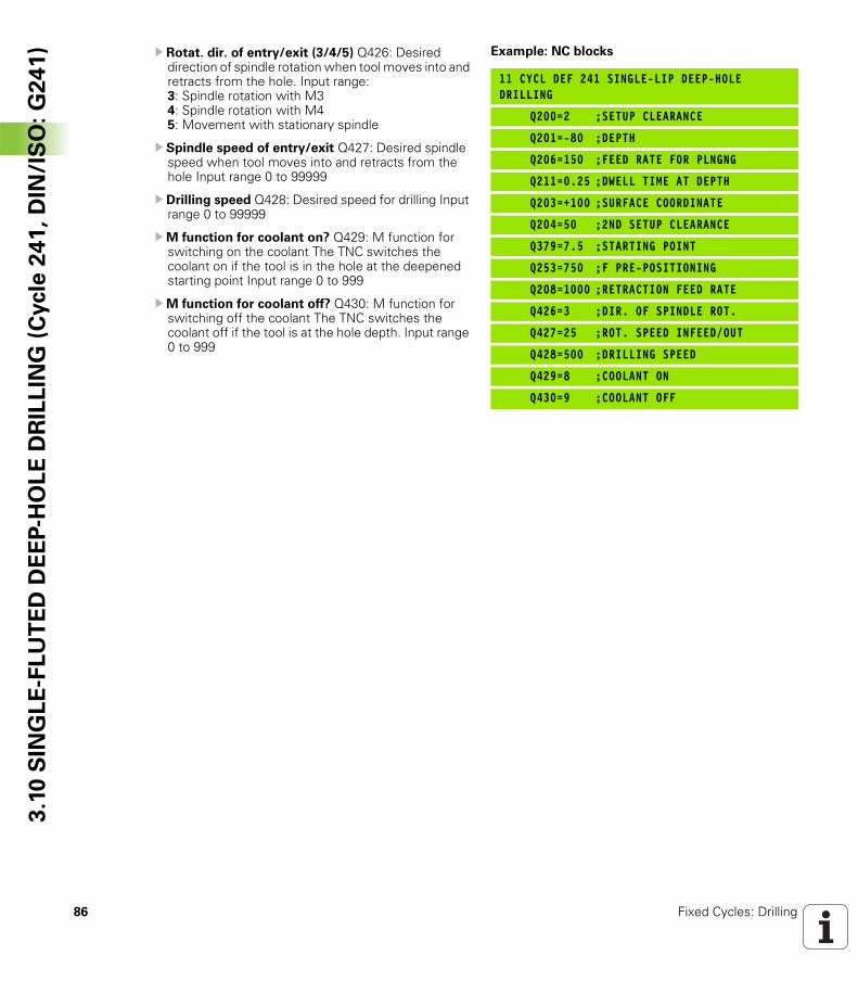
86 Fixed Cycles: Drilling
3.1
0 S
ING
LE
-FL
UT
ED
DE
EP
-HO
LE
DR
ILL
ING
(C
ycle
24
1,
DIN
/IS
O:
G2
41
) U Rotat. dir. of entry/exit (3/4/5) Q426: Desired direction of spindle rotation when tool moves into and retracts from the hole. Input range:3: Spindle rotation with M34: Spindle rotation with M45: Movement with stationary spindle
U Spindle speed of entry/exit Q427: Desired spindle speed when tool moves into and retracts from the hole Input range 0 to 99999
U Drilling speed Q428: Desired speed for drilling Input range 0 to 99999
UM function for coolant on? Q429: M function for switching on the coolant The TNC switches the coolant on if the tool is in the hole at the deepened starting point Input range 0 to 999
UM function for coolant off? Q430: M function for switching off the coolant The TNC switches the coolant off if the tool is at the hole depth. Input range 0 to 999
Example: NC blocks
11 CYCL DEF 241 SINGLE-LIP DEEP-HOLE DRILLING
Q200=2 ;SETUP CLEARANCE
Q201=-80 ;DEPTH
Q206=150 ;FEED RATE FOR PLNGNG
Q211=0.25 ;DWELL TIME AT DEPTH
Q203=+100 ;SURFACE COORDINATE
Q204=50 ;2ND SETUP CLEARANCE
Q379=7.5 ;STARTING POINT
Q253=750 ;F PRE-POSITIONING
Q208=1000 ;RETRACTION FEED RATE
Q426=3 ;DIR. OF SPINDLE ROT.
Q427=25 ;ROT. SPEED INFEED/OUT
Q428=500 ;DRILLING SPEED
Q429=8 ;COOLANT ON
Q430=9 ;COOLANT OFF
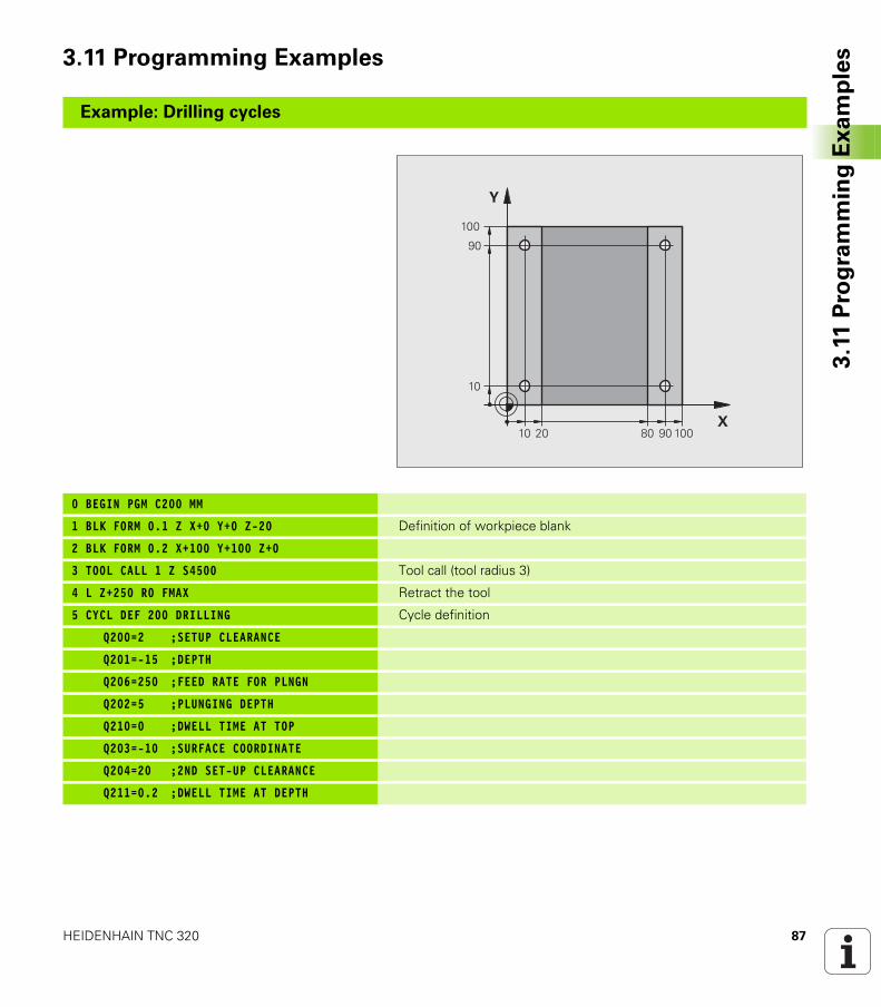
HEIDENHAIN TNC 320 87
3.1
1 P
rog
ram
min
g E
xa
mp
les3.11 Programming Examples
Example: Drilling cycles
0 BEGIN PGM C200 MM
1 BLK FORM 0.1 Z X+0 Y+0 Z-20 Definition of workpiece blank
2 BLK FORM 0.2 X+100 Y+100 Z+0
3 TOOL CALL 1 Z S4500 Tool call (tool radius 3)
4 L Z+250 R0 FMAX Retract the tool
5 CYCL DEF 200 DRILLING Cycle definition
Q200=2 ;SETUP CLEARANCE
Q201=-15 ;DEPTH
Q206=250 ;FEED RATE FOR PLNGN
Q202=5 ;PLUNGING DEPTH
Q210=0 ;DWELL TIME AT TOP
Q203=-10 ;SURFACE COORDINATE
Q204=20 ;2ND SET-UP CLEARANCE
Q211=0.2 ;DWELL TIME AT DEPTH
�
�
��
��
���
���
��
��
���
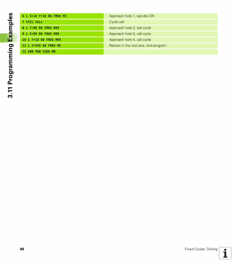
88 Fixed Cycles: Drilling
3.1
1 P
rog
ram
min
g E
xa
mp
les 6 L X+10 Y+10 R0 FMAX M3 Approach hole 1, spindle ON
7 CYCL CALL Cycle call
8 L Y+90 R0 FMAX M99 Approach hole 2, call cycle
9 L X+90 R0 FMAX M99 Approach hole 3, call cycle
10 L Y+10 R0 FMAX M99 Approach hole 4, call cycle
11 L Z+250 R0 FMAX M2 Retract in the tool axis, end program
12 END PGM C200 MM
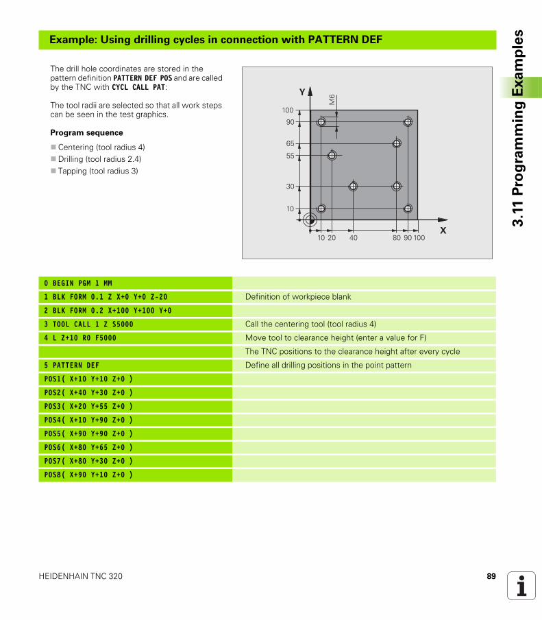
HEIDENHAIN TNC 320 89
3.1
1 P
rog
ram
min
g E
xa
mp
les
Example: Using drilling cycles in connection with PATTERN DEF
The drill hole coordinates are stored in the pattern definition PATTERN DEF POS and are called by the TNC with CYCL CALL PAT:
The tool radii are selected so that all work steps can be seen in the test graphics.
Program sequence
Centering (tool radius 4)Drilling (tool radius 2.4)Tapping (tool radius 3)
0 BEGIN PGM 1 MM
1 BLK FORM 0.1 Z X+0 Y+0 Z-20 Definition of workpiece blank
2 BLK FORM 0.2 X+100 Y+100 Y+0
3 TOOL CALL 1 Z S5000 Call the centering tool (tool radius 4)
4 L Z+10 R0 F5000 Move tool to clearance height (enter a value for F)
The TNC positions to the clearance height after every cycle
5 PATTERN DEF Define all drilling positions in the point pattern
POS1( X+10 Y+10 Z+0 )
POS2( X+40 Y+30 Z+0 )
POS3( X+20 Y+55 Z+0 )
POS4( X+10 Y+90 Z+0 )
POS5( X+90 Y+90 Z+0 )
POS6( X+80 Y+65 Z+0 )
POS7( X+80 Y+30 Z+0 )
POS8( X+90 Y+10 Z+0 )
�
�
��
��
���
���
��
��
���
��
��
�
�
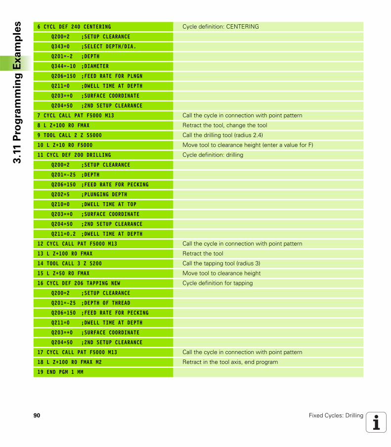
90 Fixed Cycles: Drilling
3.1
1 P
rog
ram
min
g E
xa
mp
les 6 CYCL DEF 240 CENTERING Cycle definition: CENTERING
Q200=2 ;SETUP CLEARANCE
Q343=0 ;SELECT DEPTH/DIA.
Q201=-2 ;DEPTH
Q344=-10 ;DIAMETER
Q206=150 ;FEED RATE FOR PLNGN
Q211=0 ;DWELL TIME AT DEPTH
Q203=+0 ;SURFACE COORDINATE
Q204=50 ;2ND SETUP CLEARANCE
7 CYCL CALL PAT F5000 M13 Call the cycle in connection with point pattern
8 L Z+100 R0 FMAX Retract the tool, change the tool
9 TOOL CALL 2 Z S5000 Call the drilling tool (radius 2.4)
10 L Z+10 R0 F5000 Move tool to clearance height (enter a value for F)
11 CYCL DEF 200 DRILLING Cycle definition: drilling
Q200=2 ;SETUP CLEARANCE
Q201=-25 ;DEPTH
Q206=150 ;FEED RATE FOR PECKING
Q202=5 ;PLUNGING DEPTH
Q210=0 ;DWELL TIME AT TOP
Q203=+0 ;SURFACE COORDINATE
Q204=50 ;2ND SETUP CLEARANCE
Q211=0.2 ;DWELL TIME AT DEPTH
12 CYCL CALL PAT F5000 M13 Call the cycle in connection with point pattern
13 L Z+100 R0 FMAX Retract the tool
14 TOOL CALL 3 Z S200 Call the tapping tool (radius 3)
15 L Z+50 R0 FMAX Move tool to clearance height
16 CYCL DEF 206 TAPPING NEW Cycle definition for tapping
Q200=2 ;SETUP CLEARANCE
Q201=-25 ;DEPTH OF THREAD
Q206=150 ;FEED RATE FOR PECKING
Q211=0 ;DWELL TIME AT DEPTH
Q203=+0 ;SURFACE COORDINATE
Q204=50 ;2ND SETUP CLEARANCE
17 CYCL CALL PAT F5000 M13 Call the cycle in connection with point pattern
18 L Z+100 R0 FMAX M2 Retract in the tool axis, end program
19 END PGM 1 MM
Fixed Cycles: Tapping /
Thread Milling
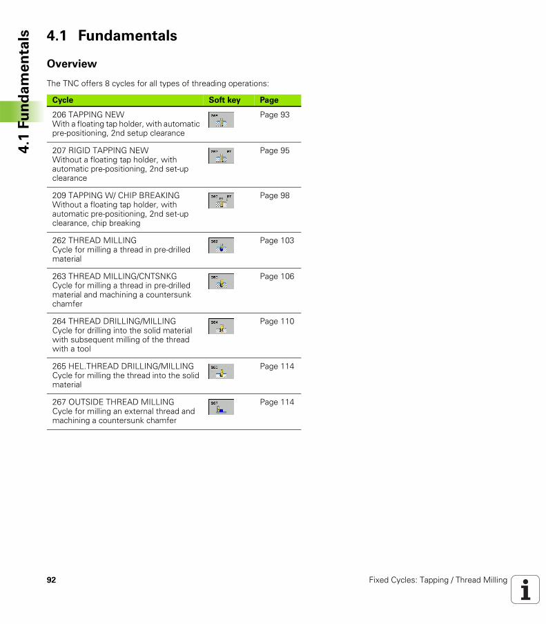
92 Fixed Cycles: Tapping / Thread Milling
4.1
Fu
nd
am
en
tals 4.1 Fundamentals
Overview
The TNC offers 8 cycles for all types of threading operations:
Cycle Soft key Page
206 TAPPING NEWWith a floating tap holder, with automatic pre-positioning, 2nd setup clearance
Page 93
207 RIGID TAPPING NEWWithout a floating tap holder, with automatic pre-positioning, 2nd set-up clearance
Page 95
209 TAPPING W/ CHIP BREAKINGWithout a floating tap holder, with automatic pre-positioning, 2nd set-up clearance, chip breaking
Page 98
262 THREAD MILLINGCycle for milling a thread in pre-drilled material
Page 103
263 THREAD MILLING/CNTSNKGCycle for milling a thread in pre-drilled material and machining a countersunk chamfer
Page 106
264 THREAD DRILLING/MILLINGCycle for drilling into the solid material with subsequent milling of the thread with a tool
Page 110
265 HEL.THREAD DRILLING/MILLINGCycle for milling the thread into the solid material
Page 114
267 OUTSIDE THREAD MILLINGCycle for milling an external thread and machining a countersunk chamfer
Page 114
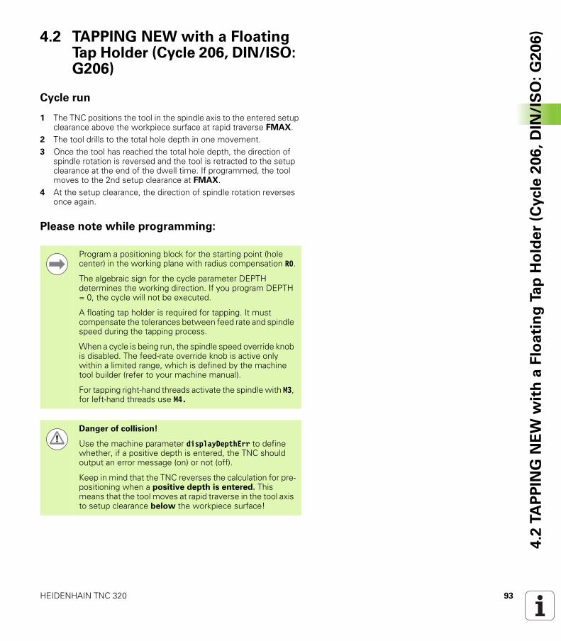
HEIDENHAIN TNC 320 93
4.2
TA
PP
ING
NE
W w
ith
a F
loa
tin
g T
ap
Ho
lde
r (C
ycle
20
6,
DIN
/IS
O:
G2
06
)4.2 TAPPING NEW with a Floating Tap Holder (Cycle 206, DIN/ISO: G206)
Cycle run
1 The TNC positions the tool in the spindle axis to the entered setup clearance above the workpiece surface at rapid traverse FMAX.
2 The tool drills to the total hole depth in one movement.3 Once the tool has reached the total hole depth, the direction of
spindle rotation is reversed and the tool is retracted to the setup clearance at the end of the dwell time. If programmed, the tool moves to the 2nd setup clearance at FMAX.
4 At the setup clearance, the direction of spindle rotation reverses once again.
Please note while programming:
Program a positioning block for the starting point (hole center) in the working plane with radius compensation R0.
The algebraic sign for the cycle parameter DEPTH determines the working direction. If you program DEPTH = 0, the cycle will not be executed.
A floating tap holder is required for tapping. It must compensate the tolerances between feed rate and spindle speed during the tapping process.
When a cycle is being run, the spindle speed override knob is disabled. The feed-rate override knob is active only within a limited range, which is defined by the machine tool builder (refer to your machine manual).
For tapping right-hand threads activate the spindle with M3, for left-hand threads use M4.
Danger of collision!
Use the machine parameter displayDepthErr to define whether, if a positive depth is entered, the TNC should output an error message (on) or not (off).
Keep in mind that the TNC reverses the calculation for pre-positioning when a positive depth is entered. This means that the tool moves at rapid traverse in the tool axis to setup clearance below the workpiece surface!
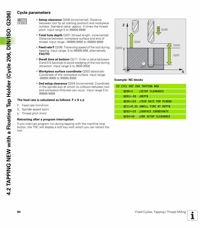
94 Fixed Cycles: Tapping / Thread Milling
4.2
TA
PP
ING
NE
W w
ith
a F
loa
tin
g T
ap
Ho
lde
r (C
ycle
20
6,
DIN
/IS
O:
G2
06
) Cycle parameters
U Setup clearance Q200 (incremental): Distance between tool tip (at starting position) and workpiece surface. Standard value: approx. 4 times the thread pitch. Input range 0 to 99999.9999
U Total hole depth Q201 (thread length, incremental): Distance between workpiece surface and end of thread. Input range –99999.9999 to 99999.9999
U Feed rate F Q206: Traversing speed of the tool during tapping. Input range: 0 to 99999.999, alternatively FAUTO
U Dwell time at bottom Q211: Enter a value between 0 and 0.5 seconds to avoid wedging of the tool during retraction. Input range 0 to 3600.0000
UWorkpiece surface coordinate Q203 (absolute): Coordinate of the workpiece surface. Input range: -99999.9999 to 99999.9999
U 2nd setup clearance Q204 (incremental): Coordinate in the spindle axis at which no collision between tool and workpiece (fixtures) can occur. Input range 0 to 99999.9999
The feed rate is calculated as follows: F = S x p
Retracting after a program interruption
If you interrupt program run during tapping with the machine stop button, the TNC will display a soft key with which you can retract the tool.
Example: NC blocks
25 CYCL DEF 206 TAPPING NEW
Q200=2 ;SETUP CLEARANCE
Q201=-20 ;DEPTH
Q206=150 ;FEED RATE FOR PLNGNG
Q211=0.25 ;DWELL TIME AT DEPTH
Q203=+25 ;SURFACE COORDINATE
Q204=50 ;2ND SETUP CLEARANCE
�
�
��������
����
����
����
����
F: Feed rate (mm/min)S: Spindle speed (rpm)p: Thread pitch (mm)
HEIDENHAIN TNC 320 95
4.3
RIG
ID T
AP
PIN
G w
ith
ou
t a
Flo
ati
ng
Ta
p H
old
er
NE
W (
Cycle
20
7,D
IN/I
SO
:G
20
7)4.3 RIGID TAPPING without a
Floating Tap Holder NEW (Cycle 207, DIN/ISO: G207)
Cycle run
The TNC cuts the thread without a floating tap holder in one or more passes.
1 The TNC positions the tool in the spindle axis to the entered setup clearance above the workpiece surface at rapid traverse FMAX.
2 The tool drills to the total hole depth in one movement.3 Once the tool has reached the total hole depth, the direction of
spindle rotation is reversed and the tool is retracted to the setup clearance at the end of the dwell time. If programmed, the tool moves to the 2nd setup clearance at FMAX.
4 The TNC stops the spindle turning at setup clearance.
96 Fixed Cycles: Tapping / Thread Milling
4.3
RIG
ID T
AP
PIN
G w
ith
ou
t a
Flo
ati
ng
Ta
p H
old
er
NE
W (
Cycle
20
7,D
IN/I
SO
:G
20
7) Please note while programming:
Machine and TNC must be specially prepared by the machine tool builder for use of this cycle.
This cycle is effective only for machines with servo-controlled spindle.
Program a positioning block for the starting point (hole center) in the working plane with radius compensation R0.
The algebraic sign for the total hole depth parameter determines the working direction.
The TNC calculates the feed rate from the spindle speed. If the feed-rate override is used during tapping, the TNC automatically adjusts the feed rate.
The feed-rate override knob is disabled.
At the end of the cycle the spindle comes to a stop. Before the next operation, restart the spindle with M3 (or M4).
Danger of collision!
Use the machine parameter displayDepthErr to define whether, if a positive depth is entered, the TNC should output an error message (on) or not (off).
Keep in mind that the TNC reverses the calculation for pre-positioning when a positive depth is entered. This means that the tool moves at rapid traverse in the tool axis to setup clearance below the workpiece surface!
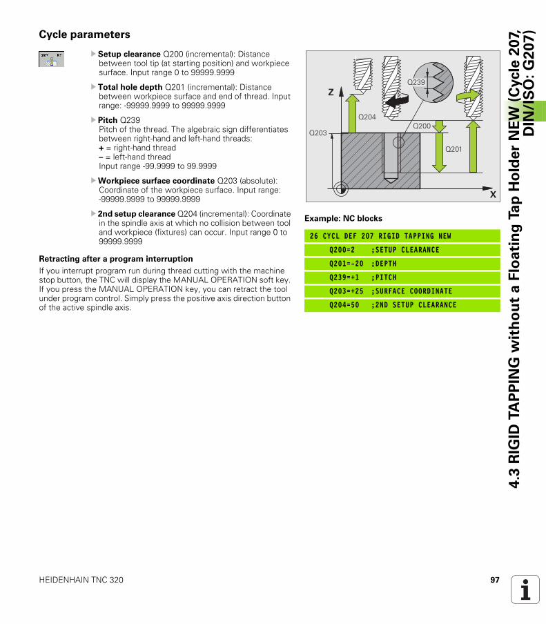
HEIDENHAIN TNC 320 97
4.3
RIG
ID T
AP
PIN
G w
ith
ou
t a
Flo
ati
ng
Ta
p H
old
er
NE
W (
Cycle
20
7,D
IN/I
SO
:G
20
7)Cycle parameters
U Setup clearance Q200 (incremental): Distance between tool tip (at starting position) and workpiece surface. Input range 0 to 99999.9999
U Total hole depth Q201 (incremental): Distance between workpiece surface and end of thread. Input range: -99999.9999 to 99999.9999
U Pitch Q239Pitch of the thread. The algebraic sign differentiates between right-hand and left-hand threads:+ = right-hand thread– = left-hand thread Input range -99.9999 to 99.9999
UWorkpiece surface coordinate Q203 (absolute): Coordinate of the workpiece surface. Input range: -99999.9999 to 99999.9999
U 2nd setup clearance Q204 (incremental): Coordinate in the spindle axis at which no collision between tool and workpiece (fixtures) can occur. Input range 0 to 99999.9999
Retracting after a program interruption
If you interrupt program run during thread cutting with the machine stop button, the TNC will display the MANUAL OPERATION soft key. If you press the MANUAL OPERATION key, you can retract the tool under program control. Simply press the positive axis direction button of the active spindle axis.
Example: NC blocks
26 CYCL DEF 207 RIGID TAPPING NEW
Q200=2 ;SETUP CLEARANCE
Q201=-20 ;DEPTH
Q239=+1 ;PITCH
Q203=+25 ;SURFACE COORDINATE
Q204=50 ;2ND SETUP CLEARANCE
�
�
����
��������
����
����
98 Fixed Cycles: Tapping / Thread Milling
4.4
TA
PP
ING
WIT
H C
HIP
BR
EA
KIN
G (
Cycle
20
9,
DIN
/IS
O:
G2
09
) 4.4 TAPPING WITH CHIP BREAKING (Cycle 209, DIN/ISO: G209)
Cycle run
The TNC machines the thread in several passes until it reaches the programmed depth. You can define in a parameter whether the tool is to be retracted completely from the hole for chip breaking.
1 The TNC positions the tool in the tool axis at rapid traverse FMAX to the programmed setup clearance above the workpiece surface. There it carries out an oriented spindle stop.
2 The tool moves to the programmed infeed depth, reverses the direction of spindle rotation and retracts by a specific distance or completely for chip breaking, depending on the definition. If you have defined a factor for increasing the spindle speed, the TNC retracts from the hole at the corresponding speed
3 It then reverses the direction of spindle rotation again and advances to the next infeed depth.
4 The TNC repeats this process (2 to 3) until the programmed thread depth is reached.
5 The tool is then retracted to the setup clearance. If programmed, the tool moves to the 2nd setup clearance at FMAX.
6 The TNC stops the spindle turning at setup clearance.
HEIDENHAIN TNC 320 99
4.4
TA
PP
ING
WIT
H C
HIP
BR
EA
KIN
G (
Cycle
20
9,
DIN
/IS
O:
G2
09
)Please note while programming:
Machine and TNC must be specially prepared by the machine tool builder for use of this cycle.
This cycle is effective only for machines with servo-controlled spindle.
Program a positioning block for the starting point (hole center) in the working plane with radius compensation R0.
The algebraic sign for the parameter thread depth determines the working direction.
The TNC calculates the feed rate from the spindle speed. If the feed-rate override is used during tapping, the TNC automatically adjusts the feed rate.
The feed-rate override knob is disabled.
If you defined an rpm factor for fast retraction in cycle parameter Q403, the TNC limits the speed to the maximum speed of the active gear range.
At the end of the cycle the spindle comes to a stop. Before the next operation, restart the spindle with M3 (or M4).
Danger of collision!
Use the machine parameter displayDepthErr to define whether, if a positive depth is entered, the TNC should output an error message (on) or not (off).
Keep in mind that the TNC reverses the calculation for pre-positioning when a positive depth is entered. This means that the tool moves at rapid traverse in the tool axis to setup clearance below the workpiece surface!
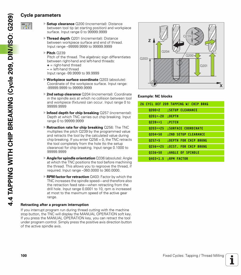
100 Fixed Cycles: Tapping / Thread Milling
4.4
TA
PP
ING
WIT
H C
HIP
BR
EA
KIN
G (
Cycle
20
9,
DIN
/IS
O:
G2
09
) Cycle parameters
U Setup clearance Q200 (incremental): Distance between tool tip (at starting position) and workpiece surface. Input range 0 to 99999.9999
U Thread depth Q201 (incremental): Distance between workpiece surface and end of thread. Input range –99999.9999 to 99999.9999
U Pitch Q239Pitch of the thread. The algebraic sign differentiates between right-hand and left-hand threads:+ = right-hand thread– = left-hand threadInput range -99.9999 to 99.9999
UWorkpiece surface coordinate Q203 (absolute): Coordinate of the workpiece surface. Input range: -99999.9999 to 99999.9999
U 2nd setup clearance Q204 (incremental): Coordinate in the spindle axis at which no collision between tool and workpiece (fixtures) can occur. Input range 0 to 99999.9999
U Infeed depth for chip breaking Q257 (incremental): Depth at which TNC carries out chip breaking. Input range 0 to 99999.9999
U Retraction rate for chip breaking Q256: The TNC multiplies the pitch Q239 by the programmed value and retracts the tool by the calculated value during chip breaking. If you enter Q256 = 0, the TNC retracts the tool completely from the hole (to the setup clearance) for chip breaking. Input range 0.1000 to 99999.9999
U Angle for spindle orientation Q336 (absolute): Angle at which the TNC positions the tool before machining the thread. This allows you to regroove the thread, if required. Input range –360.0000 to 360.0000.
U RPM factor for retraction Q403: Factor by which the TNC increases the spindle speed—and therefore also the retraction feed rate—when retracting from the drill hole. Input range 0.0001 to 10, rpm is increased at most to the maximum speed of the active gear range.
Retracting after a program interruption
If you interrupt program run during thread cutting with the machine stop button, the TNC will display the MANUAL OPERATION soft key. If you press the MANUAL OPERATION key, you can retract the tool under program control. Simply press the positive axis direction button of the active spindle axis.
Example: NC blocks
26 CYCL DEF 209 TAPPING W/ CHIP BRKG
Q200=2 ;SETUP CLEARANCE
Q201=-20 ;DEPTH
Q239=+1 ;PITCH
Q203=+25 ;SURFACE COORDINATE
Q204=50 ;2ND SETUP CLEARANCE
Q257=5 ;DEPTH FOR CHIP BRKNG
Q256=+25 ;DIST. FOR CHIP BRKNG
Q336=50 ;ANGLE OF SPINDLE
Q403=1.5 ;RPM FACTOR
�
�
����
��������
����
����
HEIDENHAIN TNC 320 101
4.5
Fu
nd
am
en
tals
of
Th
rea
d M
illi
ng4.5 Fundamentals of Thread Milling
Prerequisites
Your machine tool should feature internal spindle cooling (cooling lubricant at least 30 bars, compressed air supply at least 6 bars).Thread milling usually leads to distortions of the thread profile. To correct this effect, you need tool-specific compensation values which are given in the tool catalog or are available from the tool manufacturer. You program the compensation with the delta value for the tool radius DR in the TOOL CALL.The Cycles 262, 263, 264 and 267 can only be used with rightward rotating tools. For Cycle 265 you can use rightward and leftward rotating tools.The working direction is determined by the following input parameters: Algebraic sign Q239 (+ = right-hand thread / – = left-hand thread) and milling method Q351 (+1 = climb / –1 = up-cut). The table below illustrates the interrelation between the individual input parameters for rightward rotating tools.
Internal thread Pitch Climb/Up-cut Work direction
Right-handed + +1(RL) Z+
Left-handed – –1(RR) Z+
Right-handed + –1(RR) Z–
Left-handed – +1(RL) Z–
External thread Pitch Climb/Up-cut Work direction
Right-handed + +1(RL) Z–
Left-handed – –1(RR) Z–
Right-handed + –1(RR) Z+
Left-handed – +1(RL) Z+
The TNC references the programmed feed rate during thread milling to the tool cutting edge. Since the TNC, however, always displays the feed rate relative to the path of the tool tip, the displayed value does not match the programmed value.
The machining direction of the thread changes if you execute a thread milling cycle in connection with Cycle 8 MIRRORING in only one axis.
102 Fixed Cycles: Tapping / Thread Milling
4.5
Fu
nd
am
en
tals
of
Th
rea
d M
illi
ng Danger of collision!
Always program the same algebraic sign for the infeeds: Cycles comprise several sequences of operation that are independent of each other. The order of precedence according to which the work direction is determined is described with the individual cycles. For example, if you only want to repeat the countersinking process of a cycle, enter 0 for the thread depth. The work direction will then be determined from the countersinking depth.
Procedure in case of a tool break
If a tool break occurs during thread cutting, stop the program run, change to the Positioning with MDI operating mode and move the tool in a linear path to the hole center. You can then retract the tool in the infeed axis and replace it.
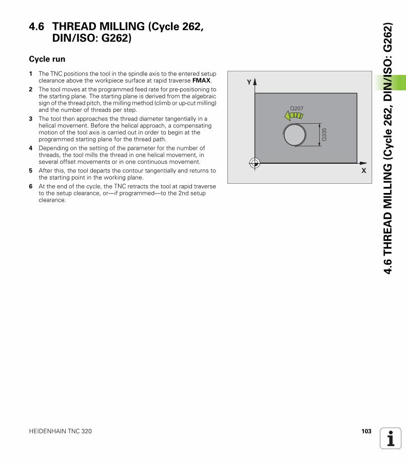
HEIDENHAIN TNC 320 103
4.6
TH
RE
AD
MIL
LIN
G (
Cycle
26
2,
DIN
/IS
O:
G2
62
)4.6 THREAD MILLING (Cycle 262, DIN/ISO: G262)
Cycle run
1 The TNC positions the tool in the spindle axis to the entered setup clearance above the workpiece surface at rapid traverse FMAX.
2 The tool moves at the programmed feed rate for pre-positioning to the starting plane. The starting plane is derived from the algebraic sign of the thread pitch, the milling method (climb or up-cut milling) and the number of threads per step.
3 The tool then approaches the thread diameter tangentially in a helical movement. Before the helical approach, a compensating motion of the tool axis is carried out in order to begin at the programmed starting plane for the thread path.
4 Depending on the setting of the parameter for the number of threads, the tool mills the thread in one helical movement, in several offset movements or in one continuous movement.
5 After this, the tool departs the contour tangentially and returns to the starting point in the working plane.
6 At the end of the cycle, the TNC retracts the tool at rapid traverse to the setup clearance, or—if programmed—to the 2nd setup clearance.
�
�
����
���
104 Fixed Cycles: Tapping / Thread Milling
4.6
TH
RE
AD
MIL
LIN
G (
Cycle
26
2,
DIN
/IS
O:
G2
62
) Please note while programming:
Program a positioning block for the starting point (hole center) in the working plane with radius compensation R0.
The algebraic sign for the cycle parameter thread depth determines the working direction. If you program the thread DEPTH = 0, the cycle will not be executed.
The nominal thread diameter is approached in a semi-circle from the center. A pre-positioning movement to the side is carried out if the pitch of the tool diameter is four times smaller than the nominal thread diameter.
Note that the TNC makes a compensation movement in the tool axis before the approach movement. The length of the compensation movement is at most half of the thread pitch. Ensure sufficient space in the hole!
If you change the thread depth, the TNC automatically changes the starting point for the helical movement.
Danger of collision!
Use the machine parameter displayDepthErr to define whether, if a positive depth is entered, the TNC should output an error message (on) or not (off).
Keep in mind that the TNC reverses the calculation for pre-positioning when a positive depth is entered. This means that the tool moves at rapid traverse in the tool axis to setup clearance below the workpiece surface!
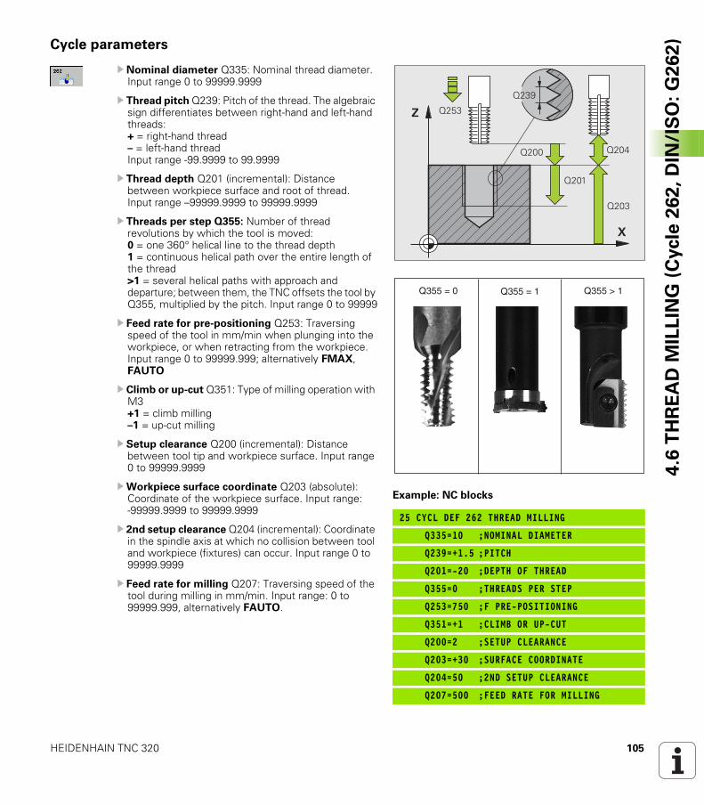
HEIDENHAIN TNC 320 105
4.6
TH
RE
AD
MIL
LIN
G (
Cycle
26
2,
DIN
/IS
O:
G2
62
)Cycle parameters
U Nominal diameter Q335: Nominal thread diameter. Input range 0 to 99999.9999
U Thread pitch Q239: Pitch of the thread. The algebraic sign differentiates between right-hand and left-hand threads:+ = right-hand thread– = left-hand threadInput range -99.9999 to 99.9999
U Thread depth Q201 (incremental): Distance between workpiece surface and root of thread. Input range –99999.9999 to 99999.9999
U Threads per step Q355: Number of thread revolutions by which the tool is moved: 0 = one 360° helical line to the thread depth 1 = continuous helical path over the entire length of the thread >1 = several helical paths with approach and departure; between them, the TNC offsets the tool by Q355, multiplied by the pitch. Input range 0 to 99999
U Feed rate for pre-positioning Q253: Traversing speed of the tool in mm/min when plunging into the workpiece, or when retracting from the workpiece. Input range 0 to 99999.999; alternatively FMAX, FAUTO
U Climb or up-cut Q351: Type of milling operation with M3+1 = climb milling–1 = up-cut milling
U Setup clearance Q200 (incremental): Distance between tool tip and workpiece surface. Input range 0 to 99999.9999
UWorkpiece surface coordinate Q203 (absolute): Coordinate of the workpiece surface. Input range: -99999.9999 to 99999.9999
U 2nd setup clearance Q204 (incremental): Coordinate in the spindle axis at which no collision between tool and workpiece (fixtures) can occur. Input range 0 to 99999.9999
U Feed rate for milling Q207: Traversing speed of the tool during milling in mm/min. Input range: 0 to 99999.999, alternatively FAUTO.
Example: NC blocks
25 CYCL DEF 262 THREAD MILLING
Q335=10 ;NOMINAL DIAMETER
Q239=+1.5 ;PITCH
Q201=-20 ;DEPTH OF THREAD
Q355=0 ;THREADS PER STEP
Q253=750 ;F PRE-POSITIONING
Q351=+1 ;CLIMB OR UP-CUT
Q200=2 ;SETUP CLEARANCE
Q203=+30 ;SURFACE COORDINATE
Q204=50 ;2ND SETUP CLEARANCE
Q207=500 ;FEED RATE FOR MILLING
�
�
����
���
����
����
��������
�������� ����������������
106 Fixed Cycles: Tapping / Thread Milling
4.7
TH
RE
AD
MIL
LIN
G/C
OU
NT
ER
SIN
KIN
G (
Cycle
26
3,
DIN
/IS
O:
G2
63
) 4.7 THREAD MILLING/COUNTERSINKING (Cycle 263, DIN/ISO: G263)
Cycle run
1 The TNC positions the tool in the spindle axis to the entered setup clearance above the workpiece surface at rapid traverse FMAX.
Countersinking
2 The tool moves at the feed rate for pre-positioning to the countersinking depth minus the setup clearance, and then at the feed rate for countersinking to the countersinking depth.
3 If a safety clearance to the side has been entered, the TNC immediately positions the tool at the feed rate for pre-positioning to the countersinking depth.
4 Then, depending on the available space, the TNC makes a tangential approach to the core diameter, either tangentially from the center or with a pre-positioning move to the side, and follows a circular path.
Countersinking at front
5 The tool moves at the feed rate for pre-positioning to the countersinking depth at front.
6 The TNC positions the tool without compensation from the center on a semicircle to the offset at front, and then follows a circular path at the feed rate for countersinking.
7 The tool then moves in a semicircle to the hole center.
Thread milling
8 The TNC moves the tool at the programmed feed rate for pre-positioning to the starting plane for the thread. The starting plane is determined from the thread pitch and the type of milling (climb or up-cut).
9 Then the tool moves tangentially on a helical path to the thread diameter and mills the thread with a 360° helical motion.
10 After this, the tool departs the contour tangentially and returns to the starting point in the working plane.
11 At the end of the cycle, the TNC retracts the tool at rapid traverse to setup clearance, or—if programmed—to the 2nd setup clearance.
HEIDENHAIN TNC 320 107
4.7
TH
RE
AD
MIL
LIN
G/C
OU
NT
ER
SIN
KIN
G (
Cycle
26
3,
DIN
/IS
O:
G2
63
)Please note while programming:
Before programming, note the following:
Program a positioning block for the starting point (hole center) in the working plane with radius compensation R0.
The algebraic sign of the cycle parameters depth of thread, countersinking depth or sinking depth at front determines the working direction. The working direction is defined in the following sequence:1st: Depth of thread2nd: Countersinking depth3rd: Depth at front
If you program a depth parameter to be 0, the TNC does not execute that step.
If you want to countersink with the front of the tool, define the countersinking depth as 0.
Program the thread depth as a value smaller than the countersinking depth by at least one-third the thread pitch.
Danger of collision!
Use the machine parameter displayDepthErr to define whether, if a positive depth is entered, the TNC should output an error message (on) or not (off).
Keep in mind that the TNC reverses the calculation for pre-positioning when a positive depth is entered. This means that the tool moves at rapid traverse in the tool axis to setup clearance below the workpiece surface!
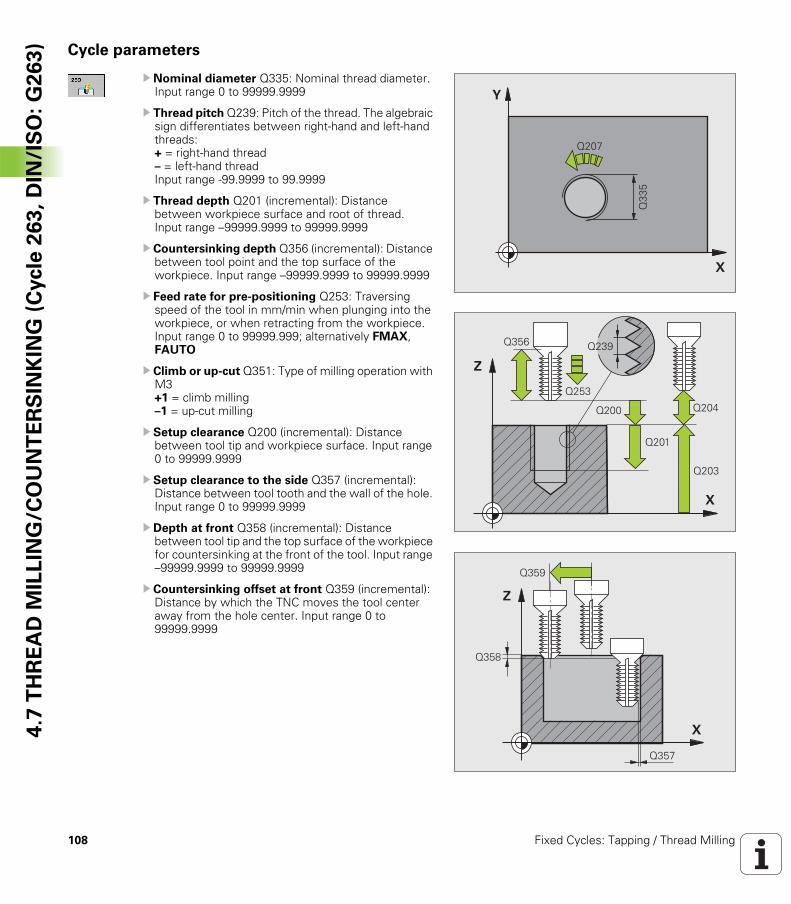
108 Fixed Cycles: Tapping / Thread Milling
4.7
TH
RE
AD
MIL
LIN
G/C
OU
NT
ER
SIN
KIN
G (
Cycle
26
3,
DIN
/IS
O:
G2
63
) Cycle parameters
U Nominal diameter Q335: Nominal thread diameter. Input range 0 to 99999.9999
U Thread pitch Q239: Pitch of the thread. The algebraic sign differentiates between right-hand and left-hand threads:+ = right-hand thread– = left-hand threadInput range -99.9999 to 99.9999
U Thread depth Q201 (incremental): Distance between workpiece surface and root of thread. Input range –99999.9999 to 99999.9999
U Countersinking depth Q356 (incremental): Distance between tool point and the top surface of the workpiece. Input range –99999.9999 to 99999.9999
U Feed rate for pre-positioning Q253: Traversing speed of the tool in mm/min when plunging into the workpiece, or when retracting from the workpiece. Input range 0 to 99999.999; alternatively FMAX, FAUTO
U Climb or up-cut Q351: Type of milling operation with M3+1 = climb milling–1 = up-cut milling
U Setup clearance Q200 (incremental): Distance between tool tip and workpiece surface. Input range 0 to 99999.9999
U Setup clearance to the side Q357 (incremental): Distance between tool tooth and the wall of the hole. Input range 0 to 99999.9999
U Depth at front Q358 (incremental): Distance between tool tip and the top surface of the workpiece for countersinking at the front of the tool. Input range –99999.9999 to 99999.9999
U Countersinking offset at front Q359 (incremental): Distance by which the TNC moves the tool center away from the hole center. Input range 0 to 99999.9999
�
�
����
���
�
�
����
����
����
��������
���
���
�
�
���
���
��
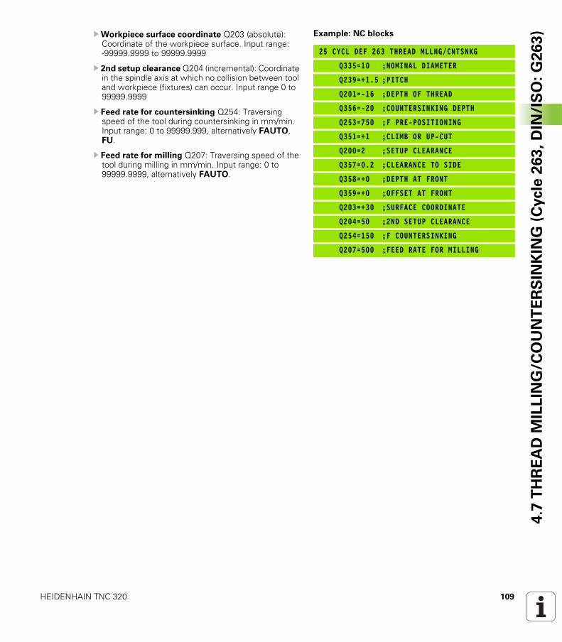
HEIDENHAIN TNC 320 109
4.7
TH
RE
AD
MIL
LIN
G/C
OU
NT
ER
SIN
KIN
G (
Cycle
26
3,
DIN
/IS
O:
G2
63
)UWorkpiece surface coordinate Q203 (absolute): Coordinate of the workpiece surface. Input range: -99999.9999 to 99999.9999
U 2nd setup clearance Q204 (incremental): Coordinate in the spindle axis at which no collision between tool and workpiece (fixtures) can occur. Input range 0 to 99999.9999
U Feed rate for countersinking Q254: Traversing speed of the tool during countersinking in mm/min. Input range: 0 to 99999.999, alternatively FAUTO, FU.
U Feed rate for milling Q207: Traversing speed of the tool during milling in mm/min. Input range: 0 to 99999.9999, alternatively FAUTO.
Example: NC blocks
25 CYCL DEF 263 THREAD MLLNG/CNTSNKG
Q335=10 ;NOMINAL DIAMETER
Q239=+1.5 ;PITCH
Q201=-16 ;DEPTH OF THREAD
Q356=-20 ;COUNTERSINKING DEPTH
Q253=750 ;F PRE-POSITIONING
Q351=+1 ;CLIMB OR UP-CUT
Q200=2 ;SETUP CLEARANCE
Q357=0.2 ;CLEARANCE TO SIDE
Q358=+0 ;DEPTH AT FRONT
Q359=+0 ;OFFSET AT FRONT
Q203=+30 ;SURFACE COORDINATE
Q204=50 ;2ND SETUP CLEARANCE
Q254=150 ;F COUNTERSINKING
Q207=500 ;FEED RATE FOR MILLING

110 Fixed Cycles: Tapping / Thread Milling
4.8
TH
RE
AD
DR
ILL
ING
/MIL
LIN
G (
Cycle
26
4,
DIN
/IS
O:
G2
64
) 4.8 THREAD DRILLING/MILLING (Cycle 264, DIN/ISO: G264)
Cycle run
1 The TNC positions the tool in the spindle axis to the entered setup clearance above the workpiece surface at rapid traverse FMAX.
Drilling
2 The tool drills to the first plunging depth at the programmed feed rate for plunging.
3 If you have programmed chip breaking, the tool then retracts by the entered retraction value. If you are working without chip breaking, the tool is moved at rapid traverse to the setup clearance, and then at FMAX to the entered starting position above the first plunging depth.
4 The tool then advances with another infeed at the programmed feed rate.
5 The TNC repeats this process (2 to 4) until the programmed total hole depth is reached.
Countersinking at front
6 The tool moves at the feed rate for pre-positioning to the countersinking depth at front.
7 The TNC positions the tool without compensation from the center on a semicircle to the offset at front, and then follows a circular path at the feed rate for countersinking.
8 The tool then moves in a semicircle to the hole center.
Thread milling
9 The TNC moves the tool at the programmed feed rate for pre-positioning to the starting plane for the thread. The starting plane is determined from the thread pitch and the type of milling (climb or up-cut).
10 Then the tool moves tangentially on a helical path to the thread diameter and mills the thread with a 360° helical motion.
11 After this, the tool departs the contour tangentially and returns to the starting point in the working plane.
12 At the end of the cycle, the TNC retracts the tool at rapid traverse to setup clearance, or—if programmed—to the 2nd setup clearance.
HEIDENHAIN TNC 320 111
4.8
TH
RE
AD
DR
ILL
ING
/MIL
LIN
G (
Cycle
26
4,
DIN
/IS
O:
G2
64
)Please note while programming:
Program a positioning block for the starting point (hole center) in the working plane with radius compensation R0.
The algebraic sign of the cycle parameters depth of thread, countersinking depth or sinking depth at front determines the working direction. The working direction is defined in the following sequence:1st: Depth of thread2nd: Total hole depth3rd: Depth at front
If you program a depth parameter to be 0, the TNC does not execute that step.
Program the thread depth as a value smaller than the total hole depth by at least one-third the thread pitch.
Danger of collision!
Use the machine parameter displayDepthErr to define whether, if a positive depth is entered, the TNC should output an error message (on) or not (off).
Keep in mind that the TNC reverses the calculation for pre-positioning when a positive depth is entered. This means that the tool moves at rapid traverse in the tool axis to setup clearance below the workpiece surface!
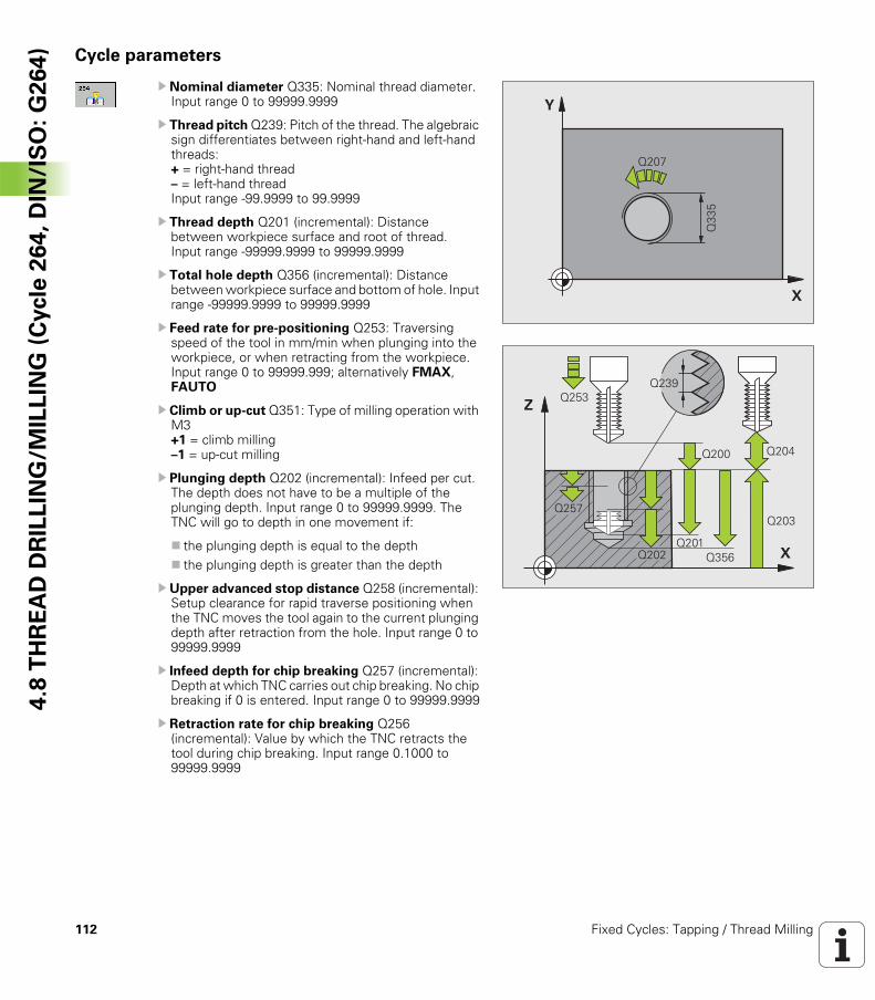
112 Fixed Cycles: Tapping / Thread Milling
4.8
TH
RE
AD
DR
ILL
ING
/MIL
LIN
G (
Cycle
26
4,
DIN
/IS
O:
G2
64
) Cycle parameters
U Nominal diameter Q335: Nominal thread diameter. Input range 0 to 99999.9999
U Thread pitch Q239: Pitch of the thread. The algebraic sign differentiates between right-hand and left-hand threads:+ = right-hand thread– = left-hand threadInput range -99.9999 to 99.9999
U Thread depth Q201 (incremental): Distance between workpiece surface and root of thread. Input range -99999.9999 to 99999.9999
U Total hole depth Q356 (incremental): Distance between workpiece surface and bottom of hole. Input range -99999.9999 to 99999.9999
U Feed rate for pre-positioning Q253: Traversing speed of the tool in mm/min when plunging into the workpiece, or when retracting from the workpiece. Input range 0 to 99999.999; alternatively FMAX, FAUTO
U Climb or up-cut Q351: Type of milling operation with M3+1 = climb milling–1 = up-cut milling
U Plunging depth Q202 (incremental): Infeed per cut. The depth does not have to be a multiple of the plunging depth. Input range 0 to 99999.9999. The TNC will go to depth in one movement if:
the plunging depth is equal to the depththe plunging depth is greater than the depth
U Upper advanced stop distance Q258 (incremental): Setup clearance for rapid traverse positioning when the TNC moves the tool again to the current plunging depth after retraction from the hole. Input range 0 to 99999.9999
U Infeed depth for chip breaking Q257 (incremental): Depth at which TNC carries out chip breaking. No chip breaking if 0 is entered. Input range 0 to 99999.9999
U Retraction rate for chip breaking Q256 (incremental): Value by which the TNC retracts the tool during chip breaking. Input range 0.1000 to 99999.9999
�
�
����
���
�
�
����
����
����
��������
���
����
���
���
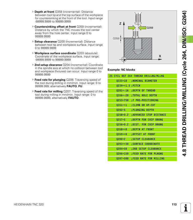
HEIDENHAIN TNC 320 113
4.8
TH
RE
AD
DR
ILL
ING
/MIL
LIN
G (
Cycle
26
4,
DIN
/IS
O:
G2
64
)U Depth at front Q358 (incremental): Distance between tool tip and the top surface of the workpiece for countersinking at the front of the tool. Input range -99999.9999 to 99999.9999
U Countersinking offset at front Q359 (incremental): Distance by which the TNC moves the tool center away from the hole center. Input range 0 to 99999.9999
U Setup clearance Q200 (incremental): Distance between tool tip and workpiece surface. Input range 0 to 99999.9999
UWorkpiece surface coordinate Q203 (absolute): Coordinate of the workpiece surface. Input range: -99999.9999 to 99999.9999
U 2nd setup clearance Q204 (incremental): Coordinate in the spindle axis at which no collision between tool and workpiece (fixtures) can occur. Input range 0 to 99999.9999
U Feed rate for plunging Q206: Traversing speed of the tool during drilling in mm/min. Input range: 0 to 99999.999; alternatively FAUTO, FU.
U Feed rate for milling Q207: Traversing speed of the tool during milling in mm/min. Input range: 0 to 99999.9999, alternatively FAUTO.
Example: NC blocks
25 CYCL DEF 264 THREAD DRILLNG/MLLNG
Q335=10 ;NOMINAL DIAMETER
Q239=+1.5 ;PITCH
Q201=-16 ;DEPTH OF THREAD
Q356=-20 ;TOTAL HOLE DEPTH
Q253=750 ;F PRE-POSITIONING
Q351=+1 ;CLIMB OR UP-CUT
Q202=5 ;PLUNGING DEPTH
Q258=0.2 ;ADVANCED STOP DISTANCE
Q257=5 ;DEPTH FOR CHIP BRKNG
Q256=0.2 ;DIST. FOR CHIP BRKNG
Q358=+0 ;DEPTH AT FRONT
Q359=+0 ;OFFSET AT FRONT
Q200=2 ;SETUP CLEARANCE
Q203=+30 ;SURFACE COORDINATE
Q204=50 ;2ND SETUP CLEARANCE
Q206=150 ;FEED RATE FOR PLNGNG
Q207=500 ;FEED RATE FOR MILLING
�
��������
��
114 Fixed Cycles: Tapping / Thread Milling
4.9
HE
LIC
AL
TH
RE
AD
DR
ILL
ING
/MIL
LIN
G (
Cycle
26
5,
DIN
/IS
O:
G2
65
) 4.9 HELICAL THREAD DRILLING/MILLING (Cycle 265, DIN/ISO: G265)
Cycle run
1 The TNC positions the tool in the spindle axis to the entered setup clearance above the workpiece surface at rapid traverse FMAX.
Countersinking at front
2 If countersinking is before thread milling, the tool moves at the feed rate for countersinking to the sinking depth at front. If countersinking occurs after thread milling, the TNC moves the tool to the countersinking depth at the feed rate for pre-positioning.
3 The TNC positions the tool without compensation from the center on a semicircle to the offset at front, and then follows a circular path at the feed rate for countersinking.
4 The tool then moves in a semicircle to the hole center.
Thread milling
5 The tool moves at the programmed feed rate for pre-positioning to the starting plane for the thread.
6 The tool then approaches the thread diameter tangentially in a helical movement.
7 The tool moves on a continuous helical downward path until it reaches the thread depth.
8 After this, the tool departs the contour tangentially and returns to the starting point in the working plane.
9 At the end of the cycle, the TNC retracts the tool at rapid traverse to setup clearance, or—if programmed—to the 2nd setup clearance.
HEIDENHAIN TNC 320 115
4.9
HE
LIC
AL
TH
RE
AD
DR
ILL
ING
/MIL
LIN
G (
Cycle
26
5,
DIN
/IS
O:
G2
65
)Please note while programming:
Program a positioning block for the starting point (hole center) in the working plane with radius compensation R0.
The algebraic sign of the cycle parameters depth of thread or sinking depth at front determines the working direction. The working direction is defined in the following sequence:1st: Depth of thread2nd: Depth at front
If you program a depth parameter to be 0, the TNC does not execute that step.
If you change the thread depth, the TNC automatically changes the starting point for the helical movement.
The type of milling (up-cut/climb) is determined by the thread (right-hand/left-hand) and the direction of tool rotation, since it is only possible to work in the direction of the tool.
Danger of collision!
Use the machine parameter displayDepthErr to define whether, if a positive depth is entered, the TNC should output an error message (on) or not (off).
Keep in mind that the TNC reverses the calculation for pre-positioning when a positive depth is entered. This means that the tool moves at rapid traverse in the tool axis to setup clearance below the workpiece surface!
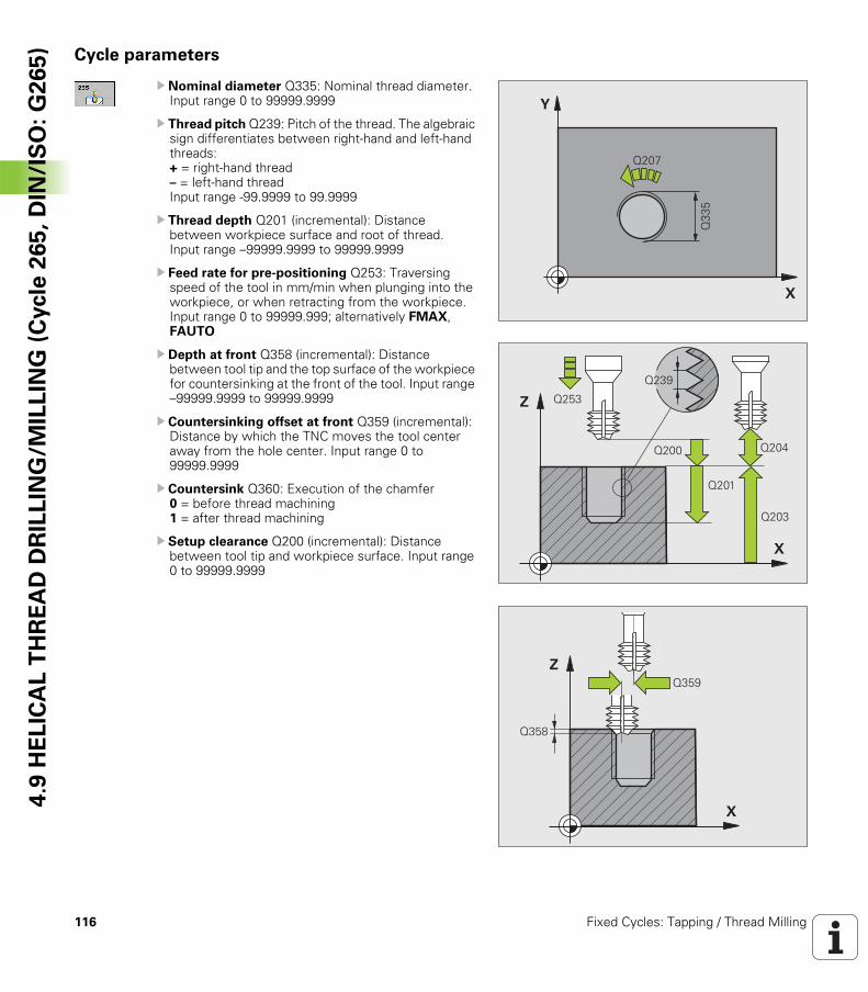
116 Fixed Cycles: Tapping / Thread Milling
4.9
HE
LIC
AL
TH
RE
AD
DR
ILL
ING
/MIL
LIN
G (
Cycle
26
5,
DIN
/IS
O:
G2
65
) Cycle parameters
U Nominal diameter Q335: Nominal thread diameter. Input range 0 to 99999.9999
U Thread pitch Q239: Pitch of the thread. The algebraic sign differentiates between right-hand and left-hand threads:+ = right-hand thread– = left-hand threadInput range -99.9999 to 99.9999
U Thread depth Q201 (incremental): Distance between workpiece surface and root of thread. Input range –99999.9999 to 99999.9999
U Feed rate for pre-positioning Q253: Traversing speed of the tool in mm/min when plunging into the workpiece, or when retracting from the workpiece. Input range 0 to 99999.999; alternatively FMAX, FAUTO
U Depth at front Q358 (incremental): Distance between tool tip and the top surface of the workpiece for countersinking at the front of the tool. Input range –99999.9999 to 99999.9999
U Countersinking offset at front Q359 (incremental): Distance by which the TNC moves the tool center away from the hole center. Input range 0 to 99999.9999
U Countersink Q360: Execution of the chamfer0 = before thread machining1 = after thread machining
U Setup clearance Q200 (incremental): Distance between tool tip and workpiece surface. Input range 0 to 99999.9999
�
�
����
���
�
�
����
���
����
����
��������
�
����
��
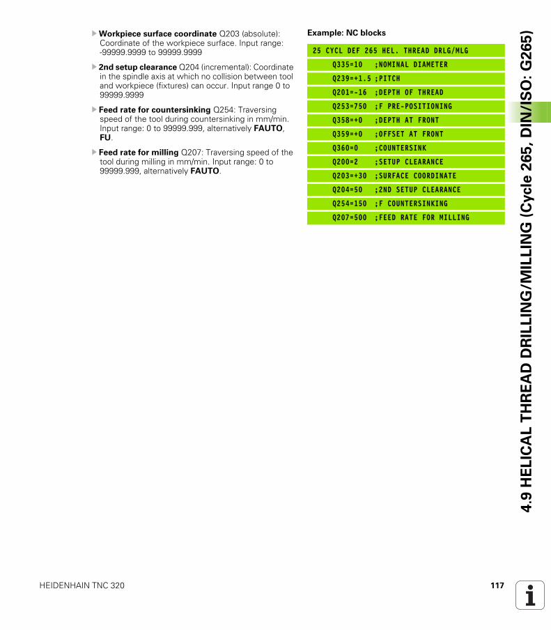
HEIDENHAIN TNC 320 117
4.9
HE
LIC
AL
TH
RE
AD
DR
ILL
ING
/MIL
LIN
G (
Cycle
26
5,
DIN
/IS
O:
G2
65
)UWorkpiece surface coordinate Q203 (absolute): Coordinate of the workpiece surface. Input range: -99999.9999 to 99999.9999
U 2nd setup clearance Q204 (incremental): Coordinate in the spindle axis at which no collision between tool and workpiece (fixtures) can occur. Input range 0 to 99999.9999
U Feed rate for countersinking Q254: Traversing speed of the tool during countersinking in mm/min. Input range: 0 to 99999.999, alternatively FAUTO, FU.
U Feed rate for milling Q207: Traversing speed of the tool during milling in mm/min. Input range: 0 to 99999.999, alternatively FAUTO.
Example: NC blocks
25 CYCL DEF 265 HEL. THREAD DRLG/MLG
Q335=10 ;NOMINAL DIAMETER
Q239=+1.5 ;PITCH
Q201=-16 ;DEPTH OF THREAD
Q253=750 ;F PRE-POSITIONING
Q358=+0 ;DEPTH AT FRONT
Q359=+0 ;OFFSET AT FRONT
Q360=0 ;COUNTERSINK
Q200=2 ;SETUP CLEARANCE
Q203=+30 ;SURFACE COORDINATE
Q204=50 ;2ND SETUP CLEARANCE
Q254=150 ;F COUNTERSINKING
Q207=500 ;FEED RATE FOR MILLING
118 Fixed Cycles: Tapping / Thread Milling
4.1
0 O
UT
SID
E T
HR
EA
D M
ILL
ING
(C
ycle
26
7, D
IN/I
SO
: G
26
7) 4.10 OUTSIDE THREAD MILLING
(Cycle 267, DIN/ISO: G267)
Cycle run
1 The TNC positions the tool in the spindle axis to the entered setup clearance above the workpiece surface at rapid traverse FMAX.
Countersinking at front
2 The TNC moves in the reference axis of the working plane from the center of the stud to the starting point for countersinking at front. The position of the starting point is determined by the thread radius, tool radius and pitch.
3 The tool moves at the feed rate for pre-positioning to the countersinking depth at front.
4 The TNC positions the tool without compensation from the center on a semicircle to the offset at front, and then follows a circular path at the feed rate for countersinking.
5 The tool then moves on a semicircle to the starting point.
Thread milling
6 The TNC positions the tool to the starting point if there has been no previous countersinking at front. Starting point for thread milling = starting point for countersinking at front.
7 The tool moves at the programmed feed rate for pre-positioning to the starting plane. The starting plane is derived from the algebraic sign of the thread pitch, the milling method (climb or up-cut milling) and the number of threads per step.
8 The tool then approaches the thread diameter tangentially in a helical movement.
9 Depending on the setting of the parameter for the number of threads, the tool mills the thread in one helical movement, in several offset movements or in one continuous movement.
10 After this, the tool departs the contour tangentially and returns to the starting point in the working plane.
11 At the end of the cycle, the TNC retracts the tool at rapid traverse to the setup clearance, or—if programmed—to the 2nd setup clearance.
HEIDENHAIN TNC 320 119
4.1
0 O
UT
SID
E T
HR
EA
D M
ILL
ING
(C
ycle
26
7, D
IN/I
SO
: G
26
7)Please note while programming:
Program a positioning block for the starting point (stud center) in the working plane with radius compensation R0.
The offset required before countersinking at the front should be determined ahead of time. You must enter the value from the center of the stud to the center of the tool (uncorrected value).
The algebraic sign of the cycle parameters depth of thread or sinking depth at front determines the working direction. The working direction is defined in the following sequence:1st: Depth of thread2nd: Depth at front
If you program a depth parameter to be 0, the TNC does not execute that step.
The algebraic sign for the cycle parameter thread depth determines the working direction.
Danger of collision!
Use the machine parameter displayDepthErr to define whether, if a positive depth is entered, the TNC should output an error message (on) or not (off).
Keep in mind that the TNC reverses the calculation for pre-positioning when a positive depth is entered. This means that the tool moves at rapid traverse in the tool axis to setup clearance below the workpiece surface!
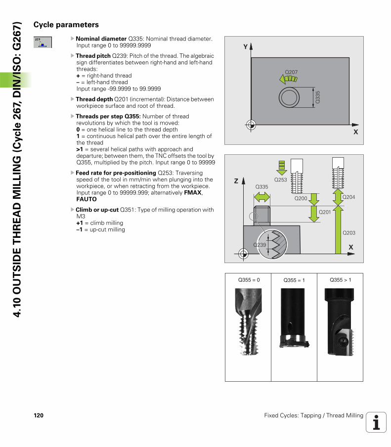
120 Fixed Cycles: Tapping / Thread Milling
4.1
0 O
UT
SID
E T
HR
EA
D M
ILL
ING
(C
ycle
26
7, D
IN/I
SO
: G
26
7) Cycle parameters
U Nominal diameter Q335: Nominal thread diameter. Input range 0 to 99999.9999
U Thread pitch Q239: Pitch of the thread. The algebraic sign differentiates between right-hand and left-hand threads:+ = right-hand thread– = left-hand threadInput range -99.9999 to 99.9999
U Thread depth Q201 (incremental): Distance between workpiece surface and root of thread.
U Threads per step Q355: Number of thread revolutions by which the tool is moved:0 = one helical line to the thread depth 1 = continuous helical path over the entire length of the thread >1 = several helical paths with approach and departure; between them, the TNC offsets the tool by Q355, multiplied by the pitch. Input range 0 to 99999
U Feed rate for pre-positioning Q253: Traversing speed of the tool in mm/min when plunging into the workpiece, or when retracting from the workpiece. Input range 0 to 99999.999; alternatively FMAX, FAUTO
U Climb or up-cut Q351: Type of milling operation with M3+1 = climb milling–1 = up-cut milling
�
�
����
���
�
�
����
���
����
��������
����
���
�������� ����������������
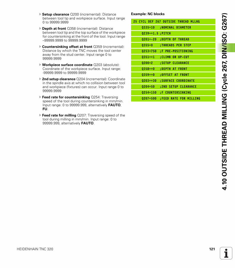
HEIDENHAIN TNC 320 121
4.1
0 O
UT
SID
E T
HR
EA
D M
ILL
ING
(C
ycle
26
7, D
IN/I
SO
: G
26
7)U Setup clearance Q200 (incremental): Distance
between tool tip and workpiece surface. Input range 0 to 99999.9999
U Depth at front Q358 (incremental): Distance between tool tip and the top surface of the workpiece for countersinking at the front of the tool. Input range –99999.9999 to 99999.9999
U Countersinking offset at front Q359 (incremental): Distance by which the TNC moves the tool center away from the stud center. Input range 0 to 99999.9999
UWorkpiece surface coordinate Q203 (absolute): Coordinate of the workpiece surface. Input range: -99999.9999 to 99999.9999
U 2nd setup clearance Q204 (incremental): Coordinate in the spindle axis at which no collision between tool and workpiece (fixtures) can occur. Input range 0 to 99999.9999
U Feed rate for countersinking Q254: Traversing speed of the tool during countersinking in mm/min. Input range: 0 to 99999.999, alternatively FAUTO, FU.
U Feed rate for milling Q207: Traversing speed of the tool during milling in mm/min. Input range: 0 to 99999.999, alternatively FAUTO.
Example: NC blocks
25 CYCL DEF 267 OUTSIDE THREAD MLLNG
Q335=10 ;NOMINAL DIAMETER
Q239=+1.5 ;PITCH
Q201=-20 ;DEPTH OF THREAD
Q355=0 ;THREADS PER STEP
Q253=750 ;F PRE-POSITIONING
Q351=+1 ;CLIMB OR UP-CUT
Q200=2 ;SETUP CLEARANCE
Q358=+0 ;DEPTH AT FRONT
Q359=+0 ;OFFSET AT FRONT
Q203=+30 ;SURFACE COORDINATE
Q204=50 ;2ND SETUP CLEARANCE
Q254=150 ;F COUNTERSINKING
Q207=500 ;FEED RATE FOR MILLING
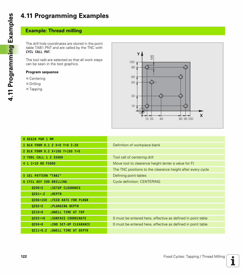
122 Fixed Cycles: Tapping / Thread Milling
4.1
1 P
rog
ram
min
g E
xa
mp
les 4.11 Programming Examples
Example: Thread milling
The drill hole coordinates are stored in the point table TAB1.PNT and are called by the TNC with CYCL CALL PAT.
The tool radii are selected so that all work steps can be seen in the test graphics.
Program sequence
CenteringDrillingTapping
0 BEGIN PGM 1 MM
1 BLK FORM 0.1 Z X+0 Y+0 Z-20 Definition of workpiece blank
2 BLK FORM 0.2 X+100 Y+100 Y+0
3 TOOL CALL 1 Z S5000 Tool call of centering drill
4 L Z+10 R0 F5000 Move tool to clearance height (enter a value for F)
The TNC positions to the clearance height after every cycle
5 SEL PATTERN “TAB1” Defining point tables
6 CYCL DEF 200 DRILLING Cycle definition: CENTERING
Q200=2 ;SETUP CLEARANCE
Q201=-2 ;DEPTH
Q206=150 ;FEED RATE FOR PLNGN
Q202=2 ;PLUNGING DEPTH
Q210=0 ;DWELL TIME AT TOP
Q203=+0 ;SURFACE COORDINATE 0 must be entered here, effective as defined in point table
Q204=0 ;2ND SET-UP CLEARANCE 0 must be entered here, effective as defined in point table
Q211=0.2 ;DWELL TIME AT DEPTH
�
�
��
��
���
���
��
��
���
��
��
�
�
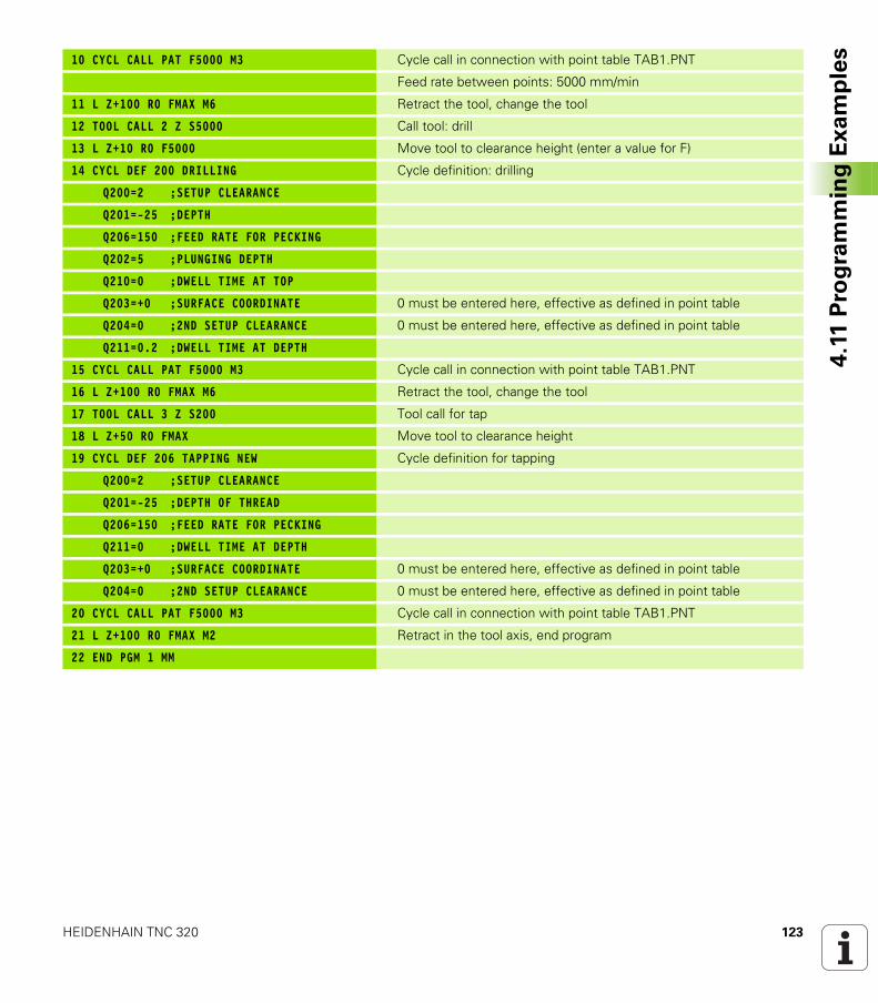
HEIDENHAIN TNC 320 123
4.1
1 P
rog
ram
min
g E
xa
mp
les10 CYCL CALL PAT F5000 M3 Cycle call in connection with point table TAB1.PNT
Feed rate between points: 5000 mm/min
11 L Z+100 R0 FMAX M6 Retract the tool, change the tool
12 TOOL CALL 2 Z S5000 Call tool: drill
13 L Z+10 R0 F5000 Move tool to clearance height (enter a value for F)
14 CYCL DEF 200 DRILLING Cycle definition: drilling
Q200=2 ;SETUP CLEARANCE
Q201=-25 ;DEPTH
Q206=150 ;FEED RATE FOR PECKING
Q202=5 ;PLUNGING DEPTH
Q210=0 ;DWELL TIME AT TOP
Q203=+0 ;SURFACE COORDINATE 0 must be entered here, effective as defined in point table
Q204=0 ;2ND SETUP CLEARANCE 0 must be entered here, effective as defined in point table
Q211=0.2 ;DWELL TIME AT DEPTH
15 CYCL CALL PAT F5000 M3 Cycle call in connection with point table TAB1.PNT
16 L Z+100 R0 FMAX M6 Retract the tool, change the tool
17 TOOL CALL 3 Z S200 Tool call for tap
18 L Z+50 R0 FMAX Move tool to clearance height
19 CYCL DEF 206 TAPPING NEW Cycle definition for tapping
Q200=2 ;SETUP CLEARANCE
Q201=-25 ;DEPTH OF THREAD
Q206=150 ;FEED RATE FOR PECKING
Q211=0 ;DWELL TIME AT DEPTH
Q203=+0 ;SURFACE COORDINATE 0 must be entered here, effective as defined in point table
Q204=0 ;2ND SETUP CLEARANCE 0 must be entered here, effective as defined in point table
20 CYCL CALL PAT F5000 M3 Cycle call in connection with point table TAB1.PNT
21 L Z+100 R0 FMAX M2 Retract in the tool axis, end program
22 END PGM 1 MM
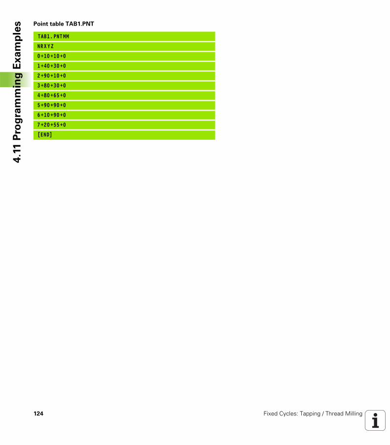
124 Fixed Cycles: Tapping / Thread Milling
4.1
1 P
rog
ram
min
g E
xa
mp
les Point table TAB1.PNT
TAB1. PNT MM
NRX YZ
0+10 +10+0
1+40 +30+0
2+90 +10+0
3+80 +30+0
4+80 +65+0
5+90 +90+0
6+10 +90+0
7+20 +55+0
[END]
Fixed Cycles: Pocket
Milling / Stud Milling /
Slot Milling
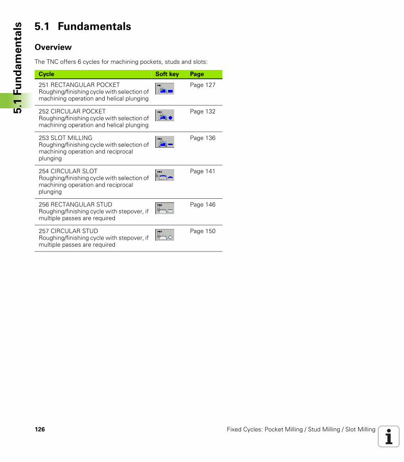
126 Fixed Cycles: Pocket Milling / Stud Milling / Slot Milling
5.1
Fu
nd
am
en
tals 5.1 Fundamentals
Overview
The TNC offers 6 cycles for machining pockets, studs and slots:
Cycle Soft key Page
251 RECTANGULAR POCKETRoughing/finishing cycle with selection of machining operation and helical plunging
Page 127
252 CIRCULAR POCKETRoughing/finishing cycle with selection of machining operation and helical plunging
Page 132
253 SLOT MILLINGRoughing/finishing cycle with selection of machining operation and reciprocal plunging
Page 136
254 CIRCULAR SLOTRoughing/finishing cycle with selection of machining operation and reciprocal plunging
Page 141
256 RECTANGULAR STUDRoughing/finishing cycle with stepover, if multiple passes are required
Page 146
257 CIRCULAR STUDRoughing/finishing cycle with stepover, if multiple passes are required
Page 150
HEIDENHAIN TNC 320 127
5.2
RE
CTA
NG
UL
AR
PO
CK
ET
(C
ycle
25
1,
DIN
/IS
O:
G2
51
)5.2 RECTANGULAR POCKET (Cycle 251, DIN/ISO: G251)
Cycle run
Use Cycle 251 RECTANGULAR POCKET to completely machine rectangular pockets. Depending on the cycle parameters, the following machining alternatives are available:
Complete machining: Roughing, floor finishing, side finishingOnly roughingOnly floor finishing and side finishingOnly floor finishingOnly side finishing
Roughing
1 The tool plunges into the workpiece at the pocket center and advances to the first plunging depth. Specify the plunging strategy with Parameter Q366.
2 The TNC roughs out the pocket from the inside out, taking the overlap factor (Parameter Q370) and the finishing allowances (parameters Q368 and Q369) into account.
3 At the end of the roughing operation, the TNC moves the tool tangentially away from the pocket wall, then moves by the setup clearance above the current pecking depth and returns from there at rapid traverse to the pocket center.
4 This process is repeated until the programmed pocket depth is reached.
Finishing
5 Inasmuch as finishing allowances are defined, the TNC then finishes the pocket walls, in multiple infeeds if so specified. The pocket wall is approached tangentially.
6 Then the TNC finishes the floor of the pocket from the inside out. The pocket floor is approached tangentially.
128 Fixed Cycles: Pocket Milling / Stud Milling / Slot Milling
5.2
RE
CTA
NG
UL
AR
PO
CK
ET
(C
ycle
25
1,
DIN
/IS
O:
G2
51
) Please note while programming:
With an inactive tool table you must always plunge vertically (Q366=0) because you cannot define a plunging angle.
Pre-position the tool in the machining plane to the starting position with radius compensation R0. Note Parameter Q367 (pocket position).
The TNC automatically pre-positions the tool in the tool axis. Note Parameter Q204 (2nd setup clearance).
The algebraic sign for the cycle parameter DEPTH determines the working direction. If you program DEPTH = 0, the cycle will not be executed.
At the end of the cycle, the TNC returns the tool to the starting position.
At the end of a roughing operation, the TNC positions the tool back to the pocket center at rapid traverse. The tool is above the current pecking depth by the setup clearance. Enter the setup clearance so that the tool cannot jam because of chips.
Danger of collision!
Use the machine parameter displayDepthErr to define whether, if a positive depth is entered, the TNC should output an error message (on) or not (off).
Keep in mind that the TNC reverses the calculation for pre-positioning when a positive depth is entered. This means that the tool moves at rapid traverse in the tool axis to setup clearance below the workpiece surface!
If you call the cycle with machining operation 2 (only finishing), then the TNC positions the tool in the center of the pocket at rapid traverse to the first plunging depth.
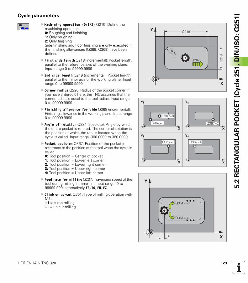
HEIDENHAIN TNC 320 129
5.2
RE
CTA
NG
UL
AR
PO
CK
ET
(C
ycle
25
1,
DIN
/IS
O:
G2
51
)Cycle parameters
U Machining operation (0/1/2) Q215: Define the machining operation:0: Roughing and finishing1: Only roughing2: Only finishingSide finishing and floor finishing are only executed if the finishing allowances (Q368, Q369) have been defined.
U First side length Q218 (incremental): Pocket length, parallel to the reference axis of the working plane. Input range 0 to 99999.9999
U 2nd side length Q219 (incremental): Pocket length, parallel to the minor axis of the working plane. Input range 0 to 99999.9999
U Corner radius Q220: Radius of the pocket corner. If you have entered 0 here, the TNC assumes that the corner radius is equal to the tool radius. Input range 0 to 99999.9999
U Finishing allowance for side Q368 (incremental): Finishing allowance in the working plane. Input range 0 to 99999.9999
U Angle of rotation Q224 (absolute): Angle by which the entire pocket is rotated. The center of rotation is the position at which the tool is located when the cycle is called. Input range -360.0000 to 360.0000
U Pocket position Q367: Position of the pocket in reference to the position of the tool when the cycle is called:0: Tool position = Center of pocket1: Tool position = Lower left corner2: Tool position = Lower right corner3: Tool position = Upper right corner4: Tool position = Upper left corner
U Feed rate for milling Q207: Traversing speed of the tool during milling in mm/min. Input range: 0 to 99999.999; alternatively FAUTO, FU, FZ
U Climb or up-cut Q351: Type of milling operation with M3:+1 = climb milling–1 = up-cut milling
�
�
����
���
����
����
�
�
�
�
�
�
�
�
������
������ ������
������ ������
�
�
�
�������
�������
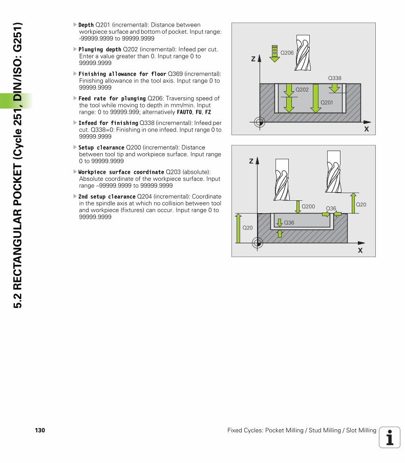
130 Fixed Cycles: Pocket Milling / Stud Milling / Slot Milling
5.2
RE
CTA
NG
UL
AR
PO
CK
ET
(C
ycle
25
1,
DIN
/IS
O:
G2
51
) U Depth Q201 (incremental): Distance between workpiece surface and bottom of pocket. Input range: -99999.9999 to 99999.9999
U Plunging depth Q202 (incremental): Infeed per cut. Enter a value greater than 0. Input range 0 to 99999.9999
U Finishing allowance for floor Q369 (incremental): Finishing allowance in the tool axis. Input range 0 to 99999.9999
U Feed rate for plunging Q206: Traversing speed of the tool while moving to depth in mm/min. Input range: 0 to 99999.999; alternatively FAUTO, FU, FZ
U Infeed for finishing Q338 (incremental): Infeed per cut. Q338=0: Finishing in one infeed. Input range 0 to 99999.9999
U Setup clearance Q200 (incremental): Distance between tool tip and workpiece surface. Input range 0 to 99999.9999
U Workpiece surface coordinate Q203 (absolute): Absolute coordinate of the workpiece surface. Input range –99999.9999 to 99999.9999
U 2nd setup clearance Q204 (incremental): Coordinate in the spindle axis at which no collision between tool and workpiece (fixtures) can occur. Input range 0 to 99999.9999
�
�
����
����
����
���
�
�
���� ���
������
���
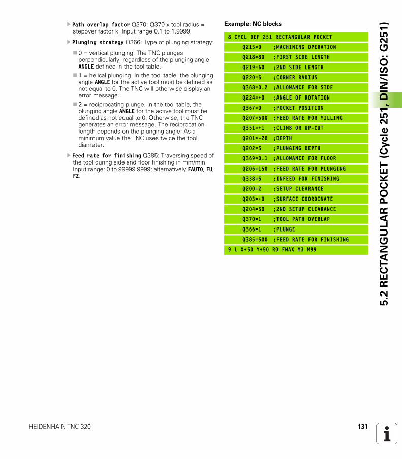
HEIDENHAIN TNC 320 131
5.2
RE
CTA
NG
UL
AR
PO
CK
ET
(C
ycle
25
1,
DIN
/IS
O:
G2
51
)U Path overlap factor Q370: Q370 x tool radius = stepover factor k. Input range 0.1 to 1.9999.
U Plunging strategy Q366: Type of plunging strategy:
0 = vertical plunging. The TNC plunges perpendicularly, regardless of the plunging angle ANGLE defined in the tool table.1 = helical plunging. In the tool table, the plunging angle ANGLE for the active tool must be defined as not equal to 0. The TNC will otherwise display an error message.2 = reciprocating plunge. In the tool table, the plunging angle ANGLE for the active tool must be defined as not equal to 0. Otherwise, the TNC generates an error message. The reciprocation length depends on the plunging angle. As a minimum value the TNC uses twice the tool diameter.
U Feed rate for finishing Q385: Traversing speed of the tool during side and floor finishing in mm/min. Input range: 0 to 99999.9999; alternatively FAUTO, FU, FZ.
Example: NC blocks
8 CYCL DEF 251 RECTANGULAR POCKET
Q215=0 ;MACHINING OPERATION
Q218=80 ;FIRST SIDE LENGTH
Q219=60 ;2ND SIDE LENGTH
Q220=5 ;CORNER RADIUS
Q368=0.2 ;ALLOWANCE FOR SIDE
Q224=+0 ;ANGLE OF ROTATION
Q367=0 ;POCKET POSITION
Q207=500 ;FEED RATE FOR MILLING
Q351=+1 ;CLIMB OR UP-CUT
Q201=-20 ;DEPTH
Q202=5 ;PLUNGING DEPTH
Q369=0.1 ;ALLOWANCE FOR FLOOR
Q206=150 ;FEED RATE FOR PLUNGING
Q338=5 ;INFEED FOR FINISHING
Q200=2 ;SETUP CLEARANCE
Q203=+0 ;SURFACE COORDINATE
Q204=50 ;2ND SETUP CLEARANCE
Q370=1 ;TOOL PATH OVERLAP
Q366=1 ;PLUNGE
Q385=500 ;FEED RATE FOR FINISHING
9 L X+50 Y+50 R0 FMAX M3 M99
132 Fixed Cycles: Pocket Milling / Stud Milling / Slot Milling
5.3
CIR
CU
LA
R P
OC
KE
T (
Cycle
25
2,
DIN
/IS
O:
G2
52
) 5.3 CIRCULAR POCKET (Cycle 252, DIN/ISO: G252)
Cycle run
Use Cycle 252 CIRCULAR POCKET to completely machine circular pockets. Depending on the cycle parameters, the following machining alternatives are available:
Complete machining: Roughing, floor finishing, side finishingOnly roughingOnly floor finishing and side finishingOnly floor finishingOnly side finishing
Roughing
1 The tool plunges into the workpiece at the pocket center and advances to the first plunging depth. Specify the plunging strategy with Parameter Q366.
2 The TNC roughs out the pocket from the inside out, taking the overlap factor (Parameter Q370) and the finishing allowances (parameters Q368 and Q369) into account.
3 At the end of the roughing operation, the TNC moves the tool tangentially away from the pocket wall, then moves by the setup clearance above the current pecking depth and returns from there at rapid traverse to the pocket center.
4 This process is repeated until the programmed pocket depth is reached.
Finishing
5 Inasmuch as finishing allowances are defined, the TNC then finishes the pocket walls, in multiple infeeds if so specified. The pocket wall is approached tangentially.
6 Then the TNC finishes the floor of the pocket from the inside out. The pocket floor is approached tangentially.
HEIDENHAIN TNC 320 133
5.3
CIR
CU
LA
R P
OC
KE
T (
Cycle
25
2,
DIN
/IS
O:
G2
52
)Please note while programming:
With an inactive tool table you must always plunge vertically (Q366=0) because you cannot define a plunging angle.
Pre-position the tool in the machining plane to the starting position (circle center) with radius compensation R0.
The TNC automatically pre-positions the tool in the tool axis. Note Parameter Q204 (2nd setup clearance).
The algebraic sign for the cycle parameter DEPTH determines the working direction. If you program DEPTH = 0, the cycle will not be executed.
At the end of the cycle, the TNC returns the tool to the starting position.
At the end of a roughing operation, the TNC positions the tool back to the pocket center at rapid traverse. The tool is above the current pecking depth by the setup clearance. Enter the setup clearance so that the tool cannot jam because of chips.
Danger of collision!
Use the machine parameter displayDepthErr to define whether, if a positive depth is entered, the TNC should output an error message (on) or not (off).
Keep in mind that the TNC reverses the calculation for pre-positioning when a positive depth is entered. This means that the tool moves at rapid traverse in the tool axis to setup clearance below the workpiece surface!
If you call the cycle with machining operation 2 (only finishing), then the TNC positions the tool in the center of the pocket at rapid traverse to the first plunging depth.
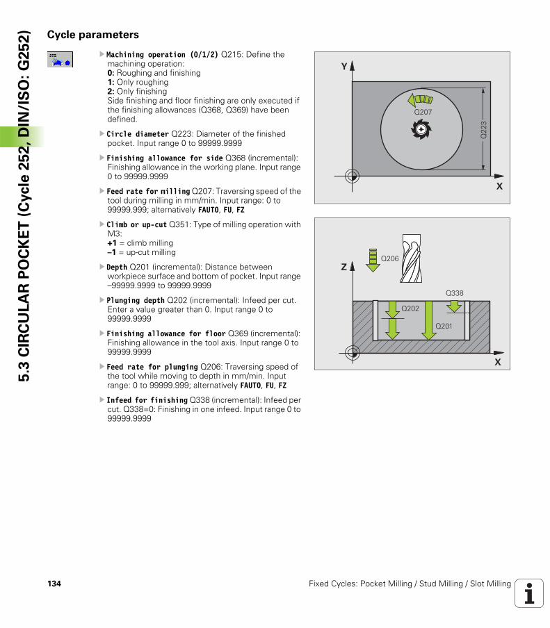
134 Fixed Cycles: Pocket Milling / Stud Milling / Slot Milling
5.3
CIR
CU
LA
R P
OC
KE
T (
Cycle
25
2,
DIN
/IS
O:
G2
52
) Cycle parameters
U Machining operation (0/1/2) Q215: Define the machining operation:0: Roughing and finishing1: Only roughing2: Only finishingSide finishing and floor finishing are only executed if the finishing allowances (Q368, Q369) have been defined.
U Circle diameter Q223: Diameter of the finished pocket. Input range 0 to 99999.9999
U Finishing allowance for side Q368 (incremental): Finishing allowance in the working plane. Input range 0 to 99999.9999
U Feed rate for milling Q207: Traversing speed of the tool during milling in mm/min. Input range: 0 to 99999.999; alternatively FAUTO, FU, FZ
U Climb or up-cut Q351: Type of milling operation with M3:+1 = climb milling–1 = up-cut milling
U Depth Q201 (incremental): Distance between workpiece surface and bottom of pocket. Input range –99999.9999 to 99999.9999
U Plunging depth Q202 (incremental): Infeed per cut. Enter a value greater than 0. Input range 0 to 99999.9999
U Finishing allowance for floor Q369 (incremental): Finishing allowance in the tool axis. Input range 0 to 99999.9999
U Feed rate for plunging Q206: Traversing speed of the tool while moving to depth in mm/min. Input range: 0 to 99999.999; alternatively FAUTO, FU, FZ
U Infeed for finishing Q338 (incremental): Infeed per cut. Q338=0: Finishing in one infeed. Input range 0 to 99999.9999
�
�
����
����
�
�
����
����
����
���
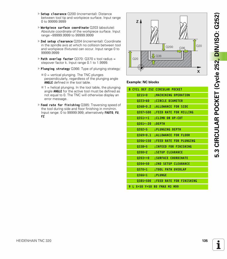
HEIDENHAIN TNC 320 135
5.3
CIR
CU
LA
R P
OC
KE
T (
Cycle
25
2,
DIN
/IS
O:
G2
52
)U Setup clearance Q200 (incremental): Distance between tool tip and workpiece surface. Input range 0 to 99999.9999
U Workpiece surface coordinate Q203 (absolute): Absolute coordinate of the workpiece surface. Input range –99999.9999 to 99999.9999
U 2nd setup clearance Q204 (incremental): Coordinate in the spindle axis at which no collision between tool and workpiece (fixtures) can occur. Input range 0 to 99999.9999
U Path overlap factor Q370: Q370 x tool radius = stepover factor k. Input range 0.1 to 1.9999.
U Plunging strategy Q366: Type of plunging strategy:
0 = vertical plunging. The TNC plunges perpendicularly, regardless of the plunging angle ANGLE defined in the tool table.1 = helical plunging. In the tool table, the plunging angle ANGLE for the active tool must be defined as not equal to 0. The TNC will otherwise display an error message.
U Feed rate for finishing Q385: Traversing speed of the tool during side and floor finishing in mm/min. Input range: 0 to 99999.999; alternatively FAUTO, FU, FZ
Example: NC blocks
8 CYCL DEF 252 CIRCULAR POCKET
Q215=0 ;MACHINING OPERATION
Q223=60 ;CIRCLE DIAMETER
Q368=0.2 ;ALLOWANCE FOR SIDE
Q207=500 ;FEED RATE FOR MILLING
Q351=+1 ;CLIMB OR UP-CUT
Q201=-20 ;DEPTH
Q202=5 ;PLUNGING DEPTH
Q369=0.1 ;ALLOWANCE FOR FLOOR
Q206=150 ;FEED RATE FOR PLUNGING
Q338=5 ;INFEED FOR FINISHING
Q200=2 ;SETUP CLEARANCE
Q203=+0 ;SURFACE COORDINATE
Q204=50 ;2ND SETUP CLEARANCE
Q370=1 ;TOOL PATH OVERLAP
Q366=1 ;PLUNGE
Q385=500 ;FEED RATE FOR FINISHING
9 L X+50 Y+50 R0 FMAX M3 M99
�
�
���� ���
������
���
136 Fixed Cycles: Pocket Milling / Stud Milling / Slot Milling
5.4
SLO
T M
ILL
ING
(C
ycle
25
3,
DIN
/IS
O:
G2
53
) 5.4 SLOT MILLING (Cycle 253, DIN/ISO: G253)
Cycle run
Use Cycle 253 to completely machine a slot. Depending on the cycle parameters, the following machining alternatives are available:
Complete machining: Roughing, floor finishing, side finishingOnly roughingOnly floor finishing and side finishingOnly floor finishingOnly side finishing
Roughing
1 Starting from the left slot arc center, the tool moves in a reciprocating motion at the plunging angle defined in the tool table to the first infeed depth. Specify the plunging strategy with Parameter Q366.
2 The TNC roughs out the slot from the inside out, taking the finishing allowances (parameters Q368 and Q369) into account.
3 This process is repeated until the slot depth is reached.
Finishing
4 Inasmuch as finishing allowances are defined, the TNC then finishes the slot walls, in multiple infeeds if so specified. The slot side is approached tangentially in the right slot arc.
5 Then the TNC finishes the floor of the slot from the inside out. The slot floor is approached tangentially.
HEIDENHAIN TNC 320 137
5.4
SLO
T M
ILL
ING
(C
ycle
25
3,
DIN
/IS
O:
G2
53
)Please note while programming:
With an inactive tool table you must always plunge vertically (Q366=0) because you cannot define a plunging angle.
Pre-position the tool in the machining plane to the starting position with radius compensation R0. Note Parameter Q367 (slot position).
The TNC automatically pre-positions the tool in the tool axis. Note Parameter Q204 (2nd setup clearance).
At the end of the cycle the TNC returns the tool to the starting point (slot center) in the working plane. Exception: if you define a slot position not equal to 0, then the TNC only positions the tool in the tool axis to the 2nd setup clearance. In these cases, always program absolute traverse movements after the cycle call.
The algebraic sign for the cycle parameter DEPTH determines the working direction. If you program DEPTH = 0, the cycle will not be executed.
If the slot width is greater than twice the tool diameter, the TNC roughs the slot correspondingly from inside out. You can therefore mill any slots with small tools, too.
Danger of collision!
Use the machine parameter displayDepthErr to define whether, if a positive depth is entered, the TNC should output an error message (on) or not (off).
Keep in mind that the TNC reverses the calculation for pre-positioning when a positive depth is entered. This means that the tool moves at rapid traverse in the tool axis to setup clearance below the workpiece surface!
If you call the cycle with machining operation 2 (only finishing), then the TNC positions the tool to the first plunging depth at rapid traverse!

138 Fixed Cycles: Pocket Milling / Stud Milling / Slot Milling
5.4
SLO
T M
ILL
ING
(C
ycle
25
3,
DIN
/IS
O:
G2
53
) Cycle parameters
UMachining operation (0/1/2) Q215: Define the machining operation:0: Roughing and finishing1: Only roughing2: Only finishingSide finishing and floor finishing are only executed if the finishing allowances (Q368, Q369) have been defined.
U Slot length Q218 (value parallel to the reference axis of the working plane): Enter the length of the slot. Input range 0 to 99999.9999
U Slot width Q219 (value parallel to the secondary axis of the working plane): Enter the slot width. If you enter a slot width that equals the tool diameter, the TNC will carry out the roughing process only (slot milling). Maximum slot width for roughing: Twice the tool diameter. Input range 0 to 99999.9999
U Finishing allowance for side Q368 (incremental): Finishing allowance in the working plane.
U Angle of rotation Q374 (absolute): Angle by which the entire slot is rotated. The center of rotation is the position at which the tool is located when the cycle is called. Input range –360.000 to 360.000
U Slot position (0/1/2/3/4) Q367: Position of the slot in reference to the position of the tool when the cycle is called:0: Tool position = Center of slot1: Tool position = Left end of slot2: Tool position = Center of left slot circle3: Tool position = Center of right slot circle4: Tool position = Right end of slot
U Feed rate for milling Q207: Traversing speed of the tool during milling in mm/min. Input range: 0 to 99999.999; alternatively FAUTO, FU, FZ
U Climb or up-cut Q351: Type of milling operation with M3:+1 = climb milling–1 = up-cut milling
�
�
����
���
����
�
�
�
�
�
�
�
�
����
������ ������
���� ������
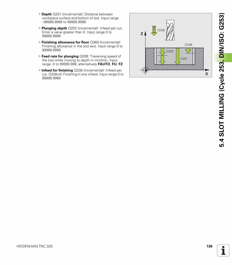
HEIDENHAIN TNC 320 139
5.4
SLO
T M
ILL
ING
(C
ycle
25
3,
DIN
/IS
O:
G2
53
)U Depth Q201 (incremental): Distance between workpiece surface and bottom of slot. Input range –99999.9999 to 99999.9999
U Plunging depth Q202 (incremental): Infeed per cut. Enter a value greater than 0. Input range 0 to 99999.9999
U Finishing allowance for floor Q369 (incremental): Finishing allowance in the tool axis. Input range 0 to 99999.9999
U Feed rate for plunging Q206: Traversing speed of the tool while moving to depth in mm/min. Input range: 0 to 99999.999; alternatively FAUTO, FU, FZ
U Infeed for finishing Q338 (incremental): Infeed per cut. Q338=0: Finishing in one infeed. Input range 0 to 99999.9999
�
�
����
����
����
���
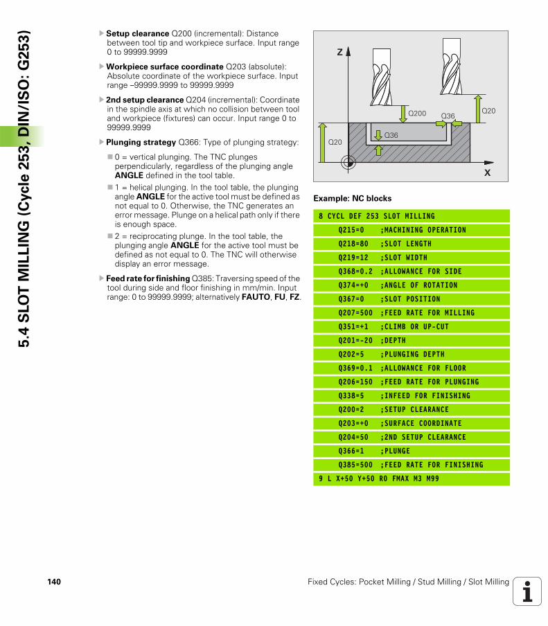
140 Fixed Cycles: Pocket Milling / Stud Milling / Slot Milling
5.4
SLO
T M
ILL
ING
(C
ycle
25
3,
DIN
/IS
O:
G2
53
) U Setup clearance Q200 (incremental): Distance between tool tip and workpiece surface. Input range 0 to 99999.9999
UWorkpiece surface coordinate Q203 (absolute): Absolute coordinate of the workpiece surface. Input range –99999.9999 to 99999.9999
U 2nd setup clearance Q204 (incremental): Coordinate in the spindle axis at which no collision between tool and workpiece (fixtures) can occur. Input range 0 to 99999.9999
U Plunging strategy Q366: Type of plunging strategy:
0 = vertical plunging. The TNC plunges perpendicularly, regardless of the plunging angle ANGLE defined in the tool table.1 = helical plunging. In the tool table, the plunging angle ANGLE for the active tool must be defined as not equal to 0. Otherwise, the TNC generates an error message. Plunge on a helical path only if there is enough space.2 = reciprocating plunge. In the tool table, the plunging angle ANGLE for the active tool must be defined as not equal to 0. The TNC will otherwise display an error message.
U Feed rate for finishing Q385: Traversing speed of the tool during side and floor finishing in mm/min. Input range: 0 to 99999.9999; alternatively FAUTO, FU, FZ.
Example: NC blocks
8 CYCL DEF 253 SLOT MILLING
Q215=0 ;MACHINING OPERATION
Q218=80 ;SLOT LENGTH
Q219=12 ;SLOT WIDTH
Q368=0.2 ;ALLOWANCE FOR SIDE
Q374=+0 ;ANGLE OF ROTATION
Q367=0 ;SLOT POSITION
Q207=500 ;FEED RATE FOR MILLING
Q351=+1 ;CLIMB OR UP-CUT
Q201=-20 ;DEPTH
Q202=5 ;PLUNGING DEPTH
Q369=0.1 ;ALLOWANCE FOR FLOOR
Q206=150 ;FEED RATE FOR PLUNGING
Q338=5 ;INFEED FOR FINISHING
Q200=2 ;SETUP CLEARANCE
Q203=+0 ;SURFACE COORDINATE
Q204=50 ;2ND SETUP CLEARANCE
Q366=1 ;PLUNGE
Q385=500 ;FEED RATE FOR FINISHING
9 L X+50 Y+50 R0 FMAX M3 M99
�
�
���� ���
������
���
HEIDENHAIN TNC 320 141
5.5
CIR
CU
LA
R S
LO
T (
Cycle
25
4,
DIN
/IS
O:
G2
54
)5.5 CIRCULAR SLOT (Cycle 254, DIN/ISO: G254)
Cycle run
Use Cycle 254 to completely machine a circular slot. Depending on the cycle parameters, the following machining alternatives are available:
Complete machining: Roughing, floor finishing, side finishingOnly roughingOnly floor finishing and side finishingOnly floor finishingOnly side finishing
Roughing
1 The tool moves in a reciprocating motion in the slot center at the plunging angle defined in the tool table to the first infeed depth. Specify the plunging strategy with Parameter Q366.
2 The TNC roughs out the slot from the inside out, taking the finishing allowances (parameters Q368 and Q369) into account.
3 This process is repeated until the slot depth is reached.
Finishing
4 Inasmuch as finishing allowances are defined, the TNC then finishes the slot walls, in multiple infeeds if so specified. The slot side is approached tangentially.
5 Then the TNC finishes the floor of the slot from the inside out. The slot floor is approached tangentially.
142 Fixed Cycles: Pocket Milling / Stud Milling / Slot Milling
5.5
CIR
CU
LA
R S
LO
T (
Cycle
25
4,
DIN
/IS
O:
G2
54
) Please note while programming:
With an inactive tool table you must always plunge vertically (Q366=0) because you cannot define a plunging angle.
Pre-position the tool in the machining plane with radius compensation R0. Define Parameter Q367 (Reference for slot position) appropriately.
The TNC automatically pre-positions the tool in the tool axis. Note Parameter Q204 (2nd setup clearance).
At the end of the cycle the TNC returns the tool to the starting point (center of the circular arc) in the working plane. Exception: if you define a slot position not equal to 0, then the TNC only positions the tool in the tool axis to the 2nd setup clearance. In these cases, always program absolute traverse movements after the cycle call.
The algebraic sign for the cycle parameter DEPTH determines the working direction. If you program DEPTH = 0, the cycle will not be executed.
If the slot width is greater than twice the tool diameter, the TNC roughs the slot correspondingly from inside out. You can therefore mill any slots with small tools, too.
The slot position 0 is not allowed if you use Cycle 254 Circular Slot in combination with Cycle 221.
Danger of collision!
Use the machine parameter displayDepthErr to define whether, if a positive depth is entered, the TNC should output an error message (on) or not (off).
Keep in mind that the TNC reverses the calculation for pre-positioning when a positive depth is entered. This means that the tool moves at rapid traverse in the tool axis to setup clearance below the workpiece surface!
If you call the cycle with machining operation 2 (only finishing), then the TNC positions the tool to the first plunging depth at rapid traverse!
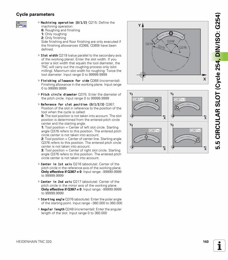
HEIDENHAIN TNC 320 143
5.5
CIR
CU
LA
R S
LO
T (
Cycle
25
4,
DIN
/IS
O:
G2
54
)Cycle parameters
U Machining operation (0/1/2) Q215: Define the machining operation:0: Roughing and finishing1: Only roughing2: Only finishingSide finishing and floor finishing are only executed if the finishing allowances (Q368, Q369) have been defined.
U Slot width Q219 (value parallel to the secondary axis of the working plane): Enter the slot width. If you enter a slot width that equals the tool diameter, the TNC will carry out the roughing process only (slot milling). Maximum slot width for roughing: Twice the tool diameter. Input range 0 to 99999.9999
U Finishing allowance for side Q368 (incremental): Finishing allowance in the working plane. Input range 0 to 99999.9999
U Pitch circle diameter Q375: Enter the diameter of the pitch circle. Input range 0 to 99999.9999
U Reference for slot position (0/1/2/3) Q367: Position of the slot in reference to the position of the tool when the cycle is called:0: The tool position is not taken into account. The slot position is determined from the entered pitch circle center and the starting angle.1: Tool position = Center of left slot circle. Starting angle Q376 refers to this position. The entered pitch circle center is not taken into account.2: Tool position = Center of center line. Starting angle Q376 refers to this position. The entered pitch circle center is not taken into account. 3: Tool position = Center of right slot circle. Starting angle Q376 refers to this position. The entered pitch circle center is not taken into account.
U Center in 1st axis Q216 (absolute): Center of the pitch circle in the reference axis of the working plane. Only effective if Q367 = 0. Input range: -99999.9999 to 99999.9999
U Center in 2nd axis Q217 (absolute): Center of the pitch circle in the minor axis of the working plane. Only effective if Q367 = 0. Input range: -99999.9999 to 99999.9999
U Starting angle Q376 (absolute): Enter the polar angle of the starting point. Input range –360.000 to 360.000
U Angular length Q248 (incremental): Enter the angular length of the slot. Input range 0 to 360.000
�
�
���
��������
���
�
�
�
�
�
�
�
�
������ ������
������ ������
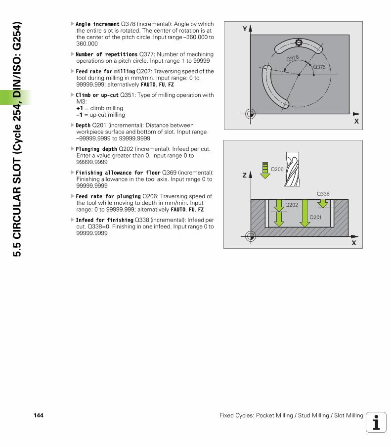
144 Fixed Cycles: Pocket Milling / Stud Milling / Slot Milling
5.5
CIR
CU
LA
R S
LO
T (
Cycle
25
4,
DIN
/IS
O:
G2
54
) U Angle increment Q378 (incremental): Angle by which the entire slot is rotated. The center of rotation is at the center of the pitch circle. Input range –360.000 to 360.000
U Number of repetitions Q377: Number of machining operations on a pitch circle. Input range 1 to 99999
U Feed rate for milling Q207: Traversing speed of the tool during milling in mm/min. Input range: 0 to 99999.999; alternatively FAUTO, FU, FZ
U Climb or up-cut Q351: Type of milling operation with M3:+1 = climb milling–1 = up-cut milling
U Depth Q201 (incremental): Distance between workpiece surface and bottom of slot. Input range –99999.9999 to 99999.9999
U Plunging depth Q202 (incremental): Infeed per cut. Enter a value greater than 0. Input range 0 to 99999.9999
U Finishing allowance for floor Q369 (incremental): Finishing allowance in the tool axis. Input range 0 to 99999.9999
U Feed rate for plunging Q206: Traversing speed of the tool while moving to depth in mm/min. Input range: 0 to 99999.999; alternatively FAUTO, FU, FZ
U Infeed for finishing Q338 (incremental): Infeed per cut. Q338=0: Finishing in one infeed. Input range 0 to 99999.9999
�
�
�������
�
�
����
����
����
���
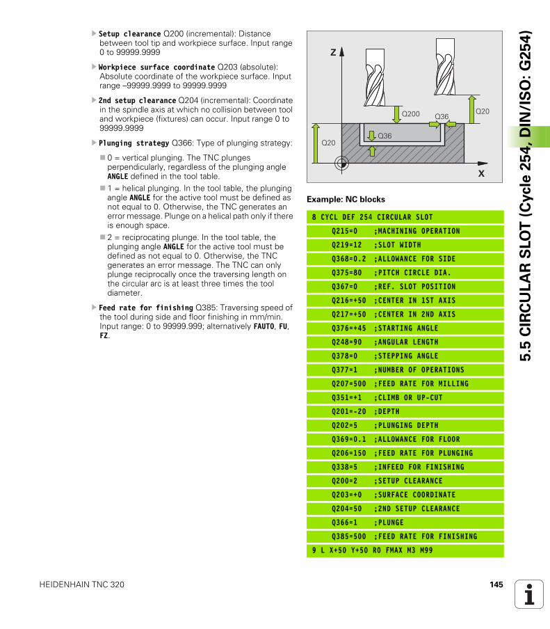
HEIDENHAIN TNC 320 145
5.5
CIR
CU
LA
R S
LO
T (
Cycle
25
4,
DIN
/IS
O:
G2
54
)U Setup clearance Q200 (incremental): Distance between tool tip and workpiece surface. Input range 0 to 99999.9999
U Workpiece surface coordinate Q203 (absolute): Absolute coordinate of the workpiece surface. Input range –99999.9999 to 99999.9999
U 2nd setup clearance Q204 (incremental): Coordinate in the spindle axis at which no collision between tool and workpiece (fixtures) can occur. Input range 0 to 99999.9999
U Plunging strategy Q366: Type of plunging strategy:
0 = vertical plunging. The TNC plunges perpendicularly, regardless of the plunging angle ANGLE defined in the tool table.1 = helical plunging. In the tool table, the plunging angle ANGLE for the active tool must be defined as not equal to 0. Otherwise, the TNC generates an error message. Plunge on a helical path only if there is enough space.2 = reciprocating plunge. In the tool table, the plunging angle ANGLE for the active tool must be defined as not equal to 0. Otherwise, the TNC generates an error message. The TNC can only plunge reciprocally once the traversing length on the circular arc is at least three times the tool diameter.
U Feed rate for finishing Q385: Traversing speed of the tool during side and floor finishing in mm/min. Input range: 0 to 99999.999; alternatively FAUTO, FU, FZ.
Example: NC blocks
8 CYCL DEF 254 CIRCULAR SLOT
Q215=0 ;MACHINING OPERATION
Q219=12 ;SLOT WIDTH
Q368=0.2 ;ALLOWANCE FOR SIDE
Q375=80 ;PITCH CIRCLE DIA.
Q367=0 ;REF. SLOT POSITION
Q216=+50 ;CENTER IN 1ST AXIS
Q217=+50 ;CENTER IN 2ND AXIS
Q376=+45 ;STARTING ANGLE
Q248=90 ;ANGULAR LENGTH
Q378=0 ;STEPPING ANGLE
Q377=1 ;NUMBER OF OPERATIONS
Q207=500 ;FEED RATE FOR MILLING
Q351=+1 ;CLIMB OR UP-CUT
Q201=-20 ;DEPTH
Q202=5 ;PLUNGING DEPTH
Q369=0.1 ;ALLOWANCE FOR FLOOR
Q206=150 ;FEED RATE FOR PLUNGING
Q338=5 ;INFEED FOR FINISHING
Q200=2 ;SETUP CLEARANCE
Q203=+0 ;SURFACE COORDINATE
Q204=50 ;2ND SETUP CLEARANCE
Q366=1 ;PLUNGE
Q385=500 ;FEED RATE FOR FINISHING
9 L X+50 Y+50 R0 FMAX M3 M99
�
�
���� ���
������
���
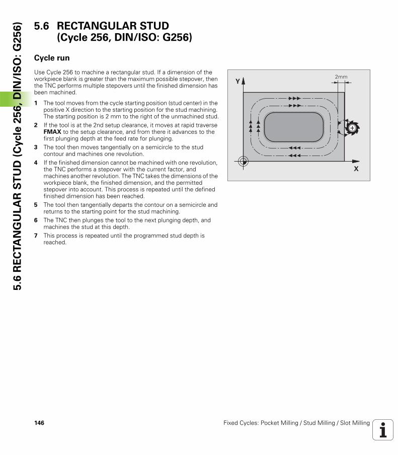
146 Fixed Cycles: Pocket Milling / Stud Milling / Slot Milling
5.6
RE
CTA
NG
UL
AR
ST
UD
(C
ycle
25
6,
DIN
/IS
O:
G2
56
) 5.6 RECTANGULAR STUD (Cycle 256, DIN/ISO: G256)
Cycle run
Use Cycle 256 to machine a rectangular stud. If a dimension of the workpiece blank is greater than the maximum possible stepover, then the TNC performs multiple stepovers until the finished dimension has been machined.
1 The tool moves from the cycle starting position (stud center) in the positive X direction to the starting position for the stud machining. The starting position is 2 mm to the right of the unmachined stud.
2 If the tool is at the 2nd setup clearance, it moves at rapid traverse FMAX to the setup clearance, and from there it advances to the first plunging depth at the feed rate for plunging.
3 The tool then moves tangentially on a semicircle to the stud contour and machines one revolution.
4 If the finished dimension cannot be machined with one revolution, the TNC performs a stepover with the current factor, and machines another revolution. The TNC takes the dimensions of the workpiece blank, the finished dimension, and the permitted stepover into account. This process is repeated until the defined finished dimension has been reached.
5 The tool then tangentially departs the contour on a semicircle and returns to the starting point for the stud machining.
6 The TNC then plunges the tool to the next plunging depth, and machines the stud at this depth.
7 This process is repeated until the programmed stud depth is reached.
�
����
HEIDENHAIN TNC 320 147
5.6
RE
CTA
NG
UL
AR
ST
UD
(C
ycle
25
6,
DIN
/IS
O:
G2
56
)Please note while programming:
Pre-position the tool in the machining plane to the starting position with radius compensation R0. Note Parameter Q367 (stud position).
The TNC automatically pre-positions the tool in the tool axis. Note Parameter Q204 (2nd setup clearance).
The algebraic sign for the cycle parameter DEPTH determines the working direction. If you program DEPTH = 0, the cycle will not be executed.
At the end, the TNC positions the tool back to the setup clearance, or to the 2nd setup clearance if one was programmed.
Danger of collision!
Use the machine parameter displayDepthErr to define whether, if a positive depth is entered, the TNC should output an error message (on) or not (off).
Keep in mind that the TNC reverses the calculation for pre-positioning when a positive depth is entered. This means that the tool moves at rapid traverse in the tool axis to setup clearance below the workpiece surface!
Leave enough room next to the stud for the approach motion. Minimum: tool diameter + 2 mm
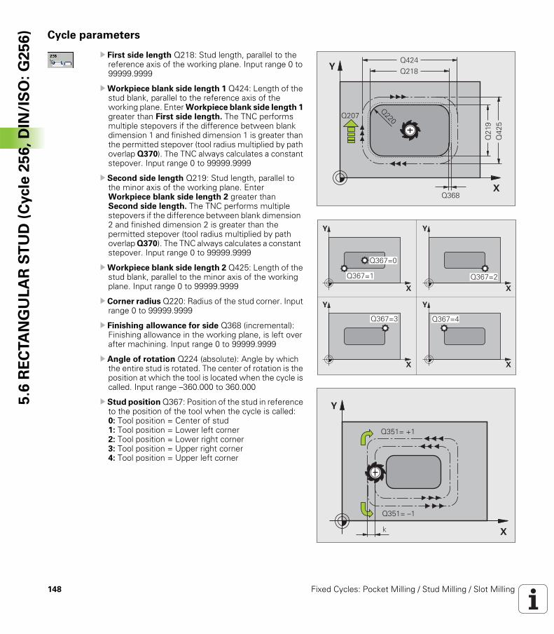
148 Fixed Cycles: Pocket Milling / Stud Milling / Slot Milling
5.6
RE
CTA
NG
UL
AR
ST
UD
(C
ycle
25
6,
DIN
/IS
O:
G2
56
) Cycle parameters
U First side length Q218: Stud length, parallel to the reference axis of the working plane. Input range 0 to 99999.9999
UWorkpiece blank side length 1 Q424: Length of the stud blank, parallel to the reference axis of the working plane. Enter Workpiece blank side length 1 greater than First side length. The TNC performs multiple stepovers if the difference between blank dimension 1 and finished dimension 1 is greater than the permitted stepover (tool radius multiplied by path overlap Q370). The TNC always calculates a constant stepover. Input range 0 to 99999.9999
U Second side length Q219: Stud length, parallel to the minor axis of the working plane. Enter Workpiece blank side length 2 greater than Second side length. The TNC performs multiple stepovers if the difference between blank dimension 2 and finished dimension 2 is greater than the permitted stepover (tool radius multiplied by path overlap Q370). The TNC always calculates a constant stepover. Input range 0 to 99999.9999
UWorkpiece blank side length 2 Q425: Length of the stud blank, parallel to the minor axis of the working plane. Input range 0 to 99999.9999
U Corner radius Q220: Radius of the stud corner. Input range 0 to 99999.9999
U Finishing allowance for side Q368 (incremental): Finishing allowance in the working plane, is left over after machining. Input range 0 to 99999.9999
U Angle of rotation Q224 (absolute): Angle by which the entire stud is rotated. The center of rotation is the position at which the tool is located when the cycle is called. Input range –360.000 to 360.000
U Stud position Q367: Position of the stud in reference to the position of the tool when the cycle is called:0: Tool position = Center of stud1: Tool position = Lower left corner2: Tool position = Lower right corner3: Tool position = Upper right corner4: Tool position = Upper left corner
�
�
����
���
���
��������
����
���
�
�
�
�
�
�
�
�
������
������ ������
������ ������
�
�
�
�������
�������
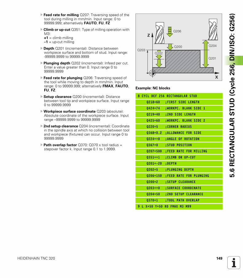
HEIDENHAIN TNC 320 149
5.6
RE
CTA
NG
UL
AR
ST
UD
(C
ycle
25
6,
DIN
/IS
O:
G2
56
)U Feed rate for milling Q207: Traversing speed of the tool during milling in mm/min. Input range: 0 to 99999.999; alternatively FAUTO, FU, FZ
U Climb or up-cut Q351: Type of milling operation with M3:+1 = climb milling–1 = up-cut milling
U Depth Q201 (incremental): Distance between workpiece surface and bottom of stud. Input range: -99999.9999 to 99999.9999
U Plunging depth Q202 (incremental): Infeed per cut. Enter a value greater than 0. Input range 0 to 99999.9999
U Feed rate for plunging Q206: Traversing speed of the tool while moving to depth in mm/min. Input range: 0 to 99999.999; alternatively FMAX, FAUTO, FU, FZ.
U Setup clearance Q200 (incremental): Distance between tool tip and workpiece surface. Input range 0 to 99999.9999
UWorkpiece surface coordinate Q203 (absolute): Absolute coordinate of the workpiece surface. Input range –99999.9999 to 99999.9999
U 2nd setup clearance Q204 (incremental): Coordinate in the spindle axis at which no collision between tool and workpiece (fixtures) can occur. Input range 0 to 99999.9999
U Path overlap factor Q370: Q370 x tool radius = stepover factor k. Input range 0.1 to 1.9999.
Example: NC blocks
8 CYCL DEF 256 RECTANGULAR STUD
Q218=60 ;FIRST SIDE LENGTH
Q424=74 ;WORKPC. BLANK SIDE 1
Q219=40 ;2ND SIDE LENGTH
Q425=60 ;WORKPC. BLANK SIDE 2
Q220=5 ;CORNER RADIUS
Q368=0.2 ;ALLOWANCE FOR SIDE
Q224=+0 ;ANGLE OF ROTATION
Q367=0 ;STUD POSITION
Q207=500 ;FEED RATE FOR MILLING
Q351=+1 ;CLIMB OR UP-CUT
Q201=-20 ;DEPTH
Q202=5 ;PLUNGING DEPTH
Q206=150 ;FEED RATE FOR PLUNGING
Q200=2 ;SETUP CLEARANCE
Q203=+0 ;SURFACE COORDINATE
Q204=50 ;2ND SETUP CLEARANCE
Q370=1 ;TOOL PATH OVERLAP
9 L X+50 Y+50 R0 FMAX M3 M99
�
�
����
����
����
��������
����
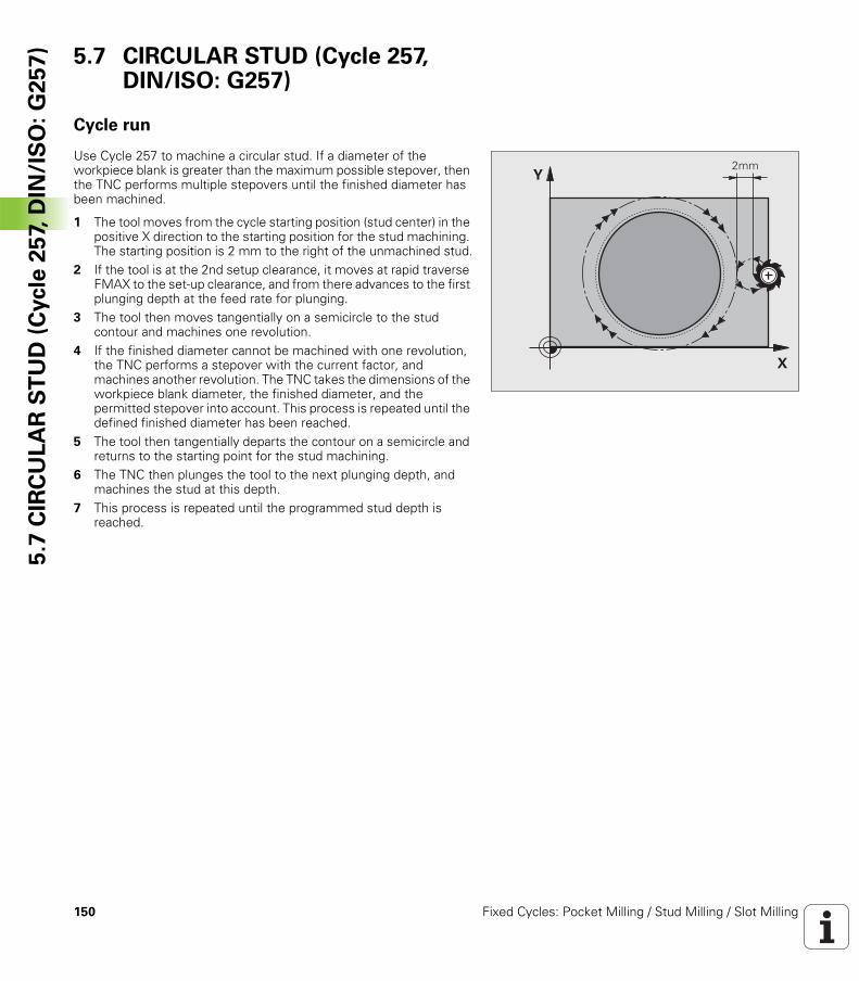
150 Fixed Cycles: Pocket Milling / Stud Milling / Slot Milling
5.7
CIR
CU
LA
R S
TU
D (
Cycle
25
7, D
IN/I
SO
: G
25
7) 5.7 CIRCULAR STUD (Cycle 257,
DIN/ISO: G257)
Cycle run
Use Cycle 257 to machine a circular stud. If a diameter of the workpiece blank is greater than the maximum possible stepover, then the TNC performs multiple stepovers until the finished diameter has been machined.
1 The tool moves from the cycle starting position (stud center) in the positive X direction to the starting position for the stud machining. The starting position is 2 mm to the right of the unmachined stud.
2 If the tool is at the 2nd setup clearance, it moves at rapid traverse FMAX to the set-up clearance, and from there advances to the first plunging depth at the feed rate for plunging.
3 The tool then moves tangentially on a semicircle to the stud contour and machines one revolution.
4 If the finished diameter cannot be machined with one revolution, the TNC performs a stepover with the current factor, and machines another revolution. The TNC takes the dimensions of the workpiece blank diameter, the finished diameter, and the permitted stepover into account. This process is repeated until the defined finished diameter has been reached.
5 The tool then tangentially departs the contour on a semicircle and returns to the starting point for the stud machining.
6 The TNC then plunges the tool to the next plunging depth, and machines the stud at this depth.
7 This process is repeated until the programmed stud depth is reached.
�
����
HEIDENHAIN TNC 320 151
5.7
CIR
CU
LA
R S
TU
D (
Cycle
25
7, D
IN/I
SO
: G
25
7)Please note while programming:
Pre-position the tool in the machining plane to the starting position (stud center) with radius compensation R0.
The TNC automatically pre-positions the tool in the tool axis. Note Parameter Q204 (2nd setup clearance).
The algebraic sign for the cycle parameter DEPTH determines the working direction. If you program DEPTH = 0, the cycle will not be executed.
At the end of the cycle, the TNC returns the tool to the starting position.
At the end, the TNC positions the tool back to the setup clearance, or to the 2nd setup clearance if one was programmed.
Danger of collision!
Use the machine parameter displayDepthErr to define whether, if a positive depth is entered, the TNC should output an error message (on) or not (off).
Keep in mind that the TNC reverses the calculation for pre-positioning when a positive depth is entered. This means that the tool moves at rapid traverse in the tool axis to setup clearance below the workpiece surface!
Leave enough room next to the stud for the approach motion. Minimum: tool diameter + 2 mm
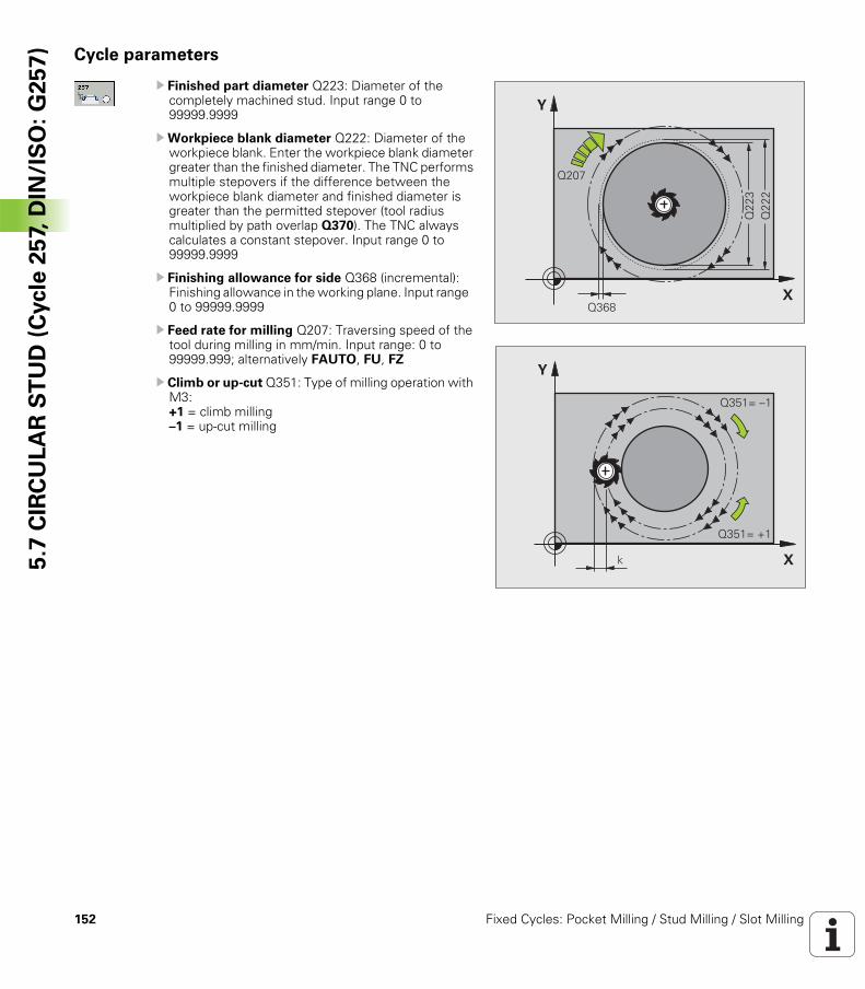
152 Fixed Cycles: Pocket Milling / Stud Milling / Slot Milling
5.7
CIR
CU
LA
R S
TU
D (
Cycle
25
7, D
IN/I
SO
: G
25
7) Cycle parameters
U Finished part diameter Q223: Diameter of the completely machined stud. Input range 0 to 99999.9999
UWorkpiece blank diameter Q222: Diameter of the workpiece blank. Enter the workpiece blank diameter greater than the finished diameter. The TNC performs multiple stepovers if the difference between the workpiece blank diameter and finished diameter is greater than the permitted stepover (tool radius multiplied by path overlap Q370). The TNC always calculates a constant stepover. Input range 0 to 99999.9999
U Finishing allowance for side Q368 (incremental): Finishing allowance in the working plane. Input range 0 to 99999.9999
U Feed rate for milling Q207: Traversing speed of the tool during milling in mm/min. Input range: 0 to 99999.999; alternatively FAUTO, FU, FZ
U Climb or up-cut Q351: Type of milling operation with M3:+1 = climb milling–1 = up-cut milling
�
�
����
����
����
���
�
�
�
�������
�������
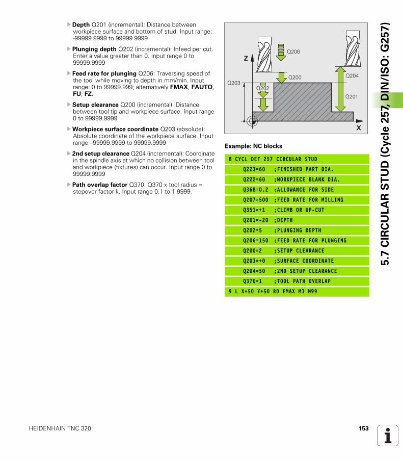
HEIDENHAIN TNC 320 153
5.7
CIR
CU
LA
R S
TU
D (
Cycle
25
7, D
IN/I
SO
: G
25
7)U Depth Q201 (incremental): Distance between
workpiece surface and bottom of stud. Input range: -99999.9999 to 99999.9999
U Plunging depth Q202 (incremental): Infeed per cut. Enter a value greater than 0. Input range 0 to 99999.9999
U Feed rate for plunging Q206: Traversing speed of the tool while moving to depth in mm/min. Input range: 0 to 99999.999; alternatively FMAX, FAUTO, FU, FZ.
U Setup clearance Q200 (incremental): Distance between tool tip and workpiece surface. Input range 0 to 99999.9999
UWorkpiece surface coordinate Q203 (absolute): Absolute coordinate of the workpiece surface. Input range –99999.9999 to 99999.9999
U 2nd setup clearance Q204 (incremental): Coordinate in the spindle axis at which no collision between tool and workpiece (fixtures) can occur. Input range 0 to 99999.9999
U Path overlap factor Q370: Q370 x tool radius = stepover factor k. Input range 0.1 to 1.9999.
Example: NC blocks
8 CYCL DEF 257 CIRCULAR STUD
Q223=60 ;FINISHED PART DIA.
Q222=60 ;WORKPIECE BLANK DIA.
Q368=0.2 ;ALLOWANCE FOR SIDE
Q207=500 ;FEED RATE FOR MILLING
Q351=+1 ;CLIMB OR UP-CUT
Q201=-20 ;DEPTH
Q202=5 ;PLUNGING DEPTH
Q206=150 ;FEED RATE FOR PLUNGING
Q200=2 ;SETUP CLEARANCE
Q203=+0 ;SURFACE COORDINATE
Q204=50 ;2ND SETUP CLEARANCE
Q370=1 ;TOOL PATH OVERLAP
9 L X+50 Y+50 R0 FMAX M3 M99
�
�
����
����
����
��������
����
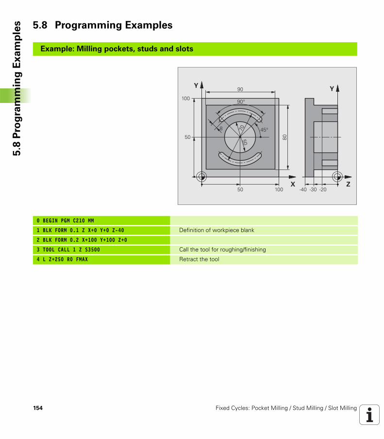
154 Fixed Cycles: Pocket Milling / Stud Milling / Slot Milling
5.8
Pro
gra
mm
ing
Ex
am
ple
s 5.8 Programming Examples
Example: Milling pockets, studs and slots
0 BEGIN PGM C210 MM
1 BLK FORM 0.1 Z X+0 Y+0 Z-40 Definition of workpiece blank
2 BLK FORM 0.2 X+100 Y+100 Z+0
3 TOOL CALL 1 Z S3500 Call the tool for roughing/finishing
4 L Z+250 R0 FMAX Retract the tool
�
�
�
�
���
���
�
��
���
��
�
��
�
�
��� ������
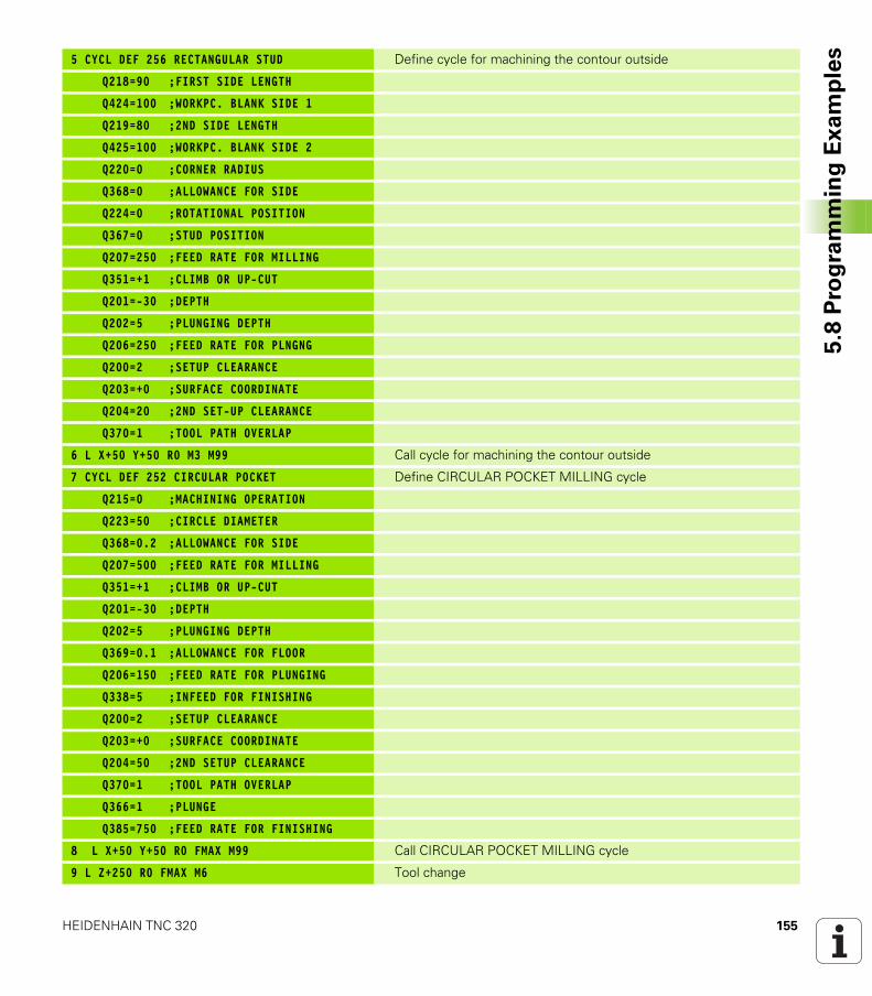
HEIDENHAIN TNC 320 155
5.8
Pro
gra
mm
ing
Ex
am
ple
s5 CYCL DEF 256 RECTANGULAR STUD Define cycle for machining the contour outside
Q218=90 ;FIRST SIDE LENGTH
Q424=100 ;WORKPC. BLANK SIDE 1
Q219=80 ;2ND SIDE LENGTH
Q425=100 ;WORKPC. BLANK SIDE 2
Q220=0 ;CORNER RADIUS
Q368=0 ;ALLOWANCE FOR SIDE
Q224=0 ;ROTATIONAL POSITION
Q367=0 ;STUD POSITION
Q207=250 ;FEED RATE FOR MILLING
Q351=+1 ;CLIMB OR UP-CUT
Q201=-30 ;DEPTH
Q202=5 ;PLUNGING DEPTH
Q206=250 ;FEED RATE FOR PLNGNG
Q200=2 ;SETUP CLEARANCE
Q203=+0 ;SURFACE COORDINATE
Q204=20 ;2ND SET-UP CLEARANCE
Q370=1 ;TOOL PATH OVERLAP
6 L X+50 Y+50 R0 M3 M99 Call cycle for machining the contour outside
7 CYCL DEF 252 CIRCULAR POCKET Define CIRCULAR POCKET MILLING cycle
Q215=0 ;MACHINING OPERATION
Q223=50 ;CIRCLE DIAMETER
Q368=0.2 ;ALLOWANCE FOR SIDE
Q207=500 ;FEED RATE FOR MILLING
Q351=+1 ;CLIMB OR UP-CUT
Q201=-30 ;DEPTH
Q202=5 ;PLUNGING DEPTH
Q369=0.1 ;ALLOWANCE FOR FLOOR
Q206=150 ;FEED RATE FOR PLUNGING
Q338=5 ;INFEED FOR FINISHING
Q200=2 ;SETUP CLEARANCE
Q203=+0 ;SURFACE COORDINATE
Q204=50 ;2ND SETUP CLEARANCE
Q370=1 ;TOOL PATH OVERLAP
Q366=1 ;PLUNGE
Q385=750 ;FEED RATE FOR FINISHING
8 L X+50 Y+50 R0 FMAX M99 Call CIRCULAR POCKET MILLING cycle
9 L Z+250 R0 FMAX M6 Tool change
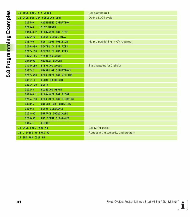
156 Fixed Cycles: Pocket Milling / Stud Milling / Slot Milling
5.8
Pro
gra
mm
ing
Ex
am
ple
s 10 TOLL CALL 2 Z S5000 Call slotting mill
11 CYCL DEF 254 CIRCULAR SLOT Define SLOT cycle
Q215=0 ;MACHINING OPERATION
Q219=8 ;SLOT WIDTH
Q368=0.2 ;ALLOWANCE FOR SIDE
Q375=70 ;PITCH CIRCLE DIA.
Q367=0 ;REF. SLOT POSITION No pre-positioning in X/Y required
Q216=+50 ;CENTER IN 1ST AXIS
Q217=+50 ;CENTER IN 2ND AXIS
Q376=+45 ;STARTING ANGLE
Q248=90 ;ANGULAR LENGTH
Q378=180 ;STEPPING ANGLE Starting point for 2nd slot
Q377=2 ;NUMBER OF OPERATIONS
Q207=500 ;FEED RATE FOR MILLING
Q351=+1 ;CLIMB OR UP-CUT
Q201=-20 ;DEPTH
Q202=5 ;PLUNGING DEPTH
Q369=0.1 ;ALLOWANCE FOR FLOOR
Q206=150 ;FEED RATE FOR PLUNGING
Q338=5 ;INFEED FOR FINISHING
Q200=2 ;SETUP CLEARANCE
Q203=+0 ;SURFACE COORDINATE
Q204=50 ;2ND SETUP CLEARANCE
Q366=1 ;PLUNGE
12 CYCL CALL FMAX M3 Call SLOT cycle
13 L Z+250 R0 FMAX M2 Retract in the tool axis, end program
14 END PGM C210 MM
Fixed Cycles: Pattern
Definitions
158 Fixed Cycles: Pattern Definitions
6.1
Fu
nd
am
en
tals 6.1 Fundamentals
Overview
The TNC provides two cycles for machining point patterns directly:
You can combine Cycle 220 and Cycle 221 with the following fixed cycles:
Cycle Soft key Page
220 CIRCULAR PATTERN Page 159
221 LINEAR PATTERN Page 162
If you have to machine irregular point patterns, use CYCL CALL PAT (see “Point Tables” on page 52) to develop point tables.
More regular point patterns are available with the PATTERN DEF function (see “Pattern Definition PATTERN DEF” on page 44).
Cycle 200 DRILLINGCycle 201 REAMINGCycle 202 BORINGCycle 203 UNIVERSAL DRILLINGCycle 204 BACK BORINGCycle 205 UNIVERSAL PECKINGCycle 206 TAPPING NEW with a floating tap holderCycle 207 RIGID TAPPING without a floating tap holder NEWCycle 208 BORE MILLINGCycle 209 TAPPING WITH CHIP BREAKINGCycle 240 CENTERINGCycle 251 RECTANGULAR POCKETCycle 252 CIRCULAR POCKET MILLINGCycle 253 SLOT MILLINGCycle 254 CIRCULAR SLOT (can only be combined with
Cycle 221)Cycle 256 RECTANGULAR STUDCycle 257 CIRCULAR STUDCycle 262 THREAD MILLINGCycle 263 THREAD MILLING/COUNTERSINKINGCycle 264 THREAD DRILLING/MILLINGCycle 265 HELICAL THREAD DRILLING/MILLINGCycle 267 OUTSIDE THREAD MILLING
HEIDENHAIN TNC 320 159
6.2
CIR
CU
LA
R P
AT
TE
RN
(C
ycle
22
0,
DIN
/IS
O:
G2
20
)6.2 CIRCULAR PATTERN (Cycle 220, DIN/ISO: G220)
Cycle run
1 The TNC moves the tool at rapid traverse from its current position to the starting point for the first machining operation.
Sequence:
Move to the 2nd set-up clearance (spindle axis)Approach the starting point in the spindle axis.Move to the setup clearance above the workpiece surface (spindle axis).
2 From this position the TNC executes the last defined fixed cycle.3 The tool then approaches on a straight line or circular arc the
starting point for the next machining operation. The tool stops at the set-up clearance (or the 2nd setup clearance).
4 This process (1 to 3) is repeated until all machining operations have been executed.
Please note while programming:
Cycle 220 is DEF active, which means that Cycle 220 automatically calls the last defined fixed cycle.
If you combine Cycle 220 with one of the fixed cycles 200 to 209 and 251 to 267, the setup clearance, workpiece surface and 2nd setup clearance that you defined in Cycle 220 will be effective for the selected fixed cycle.
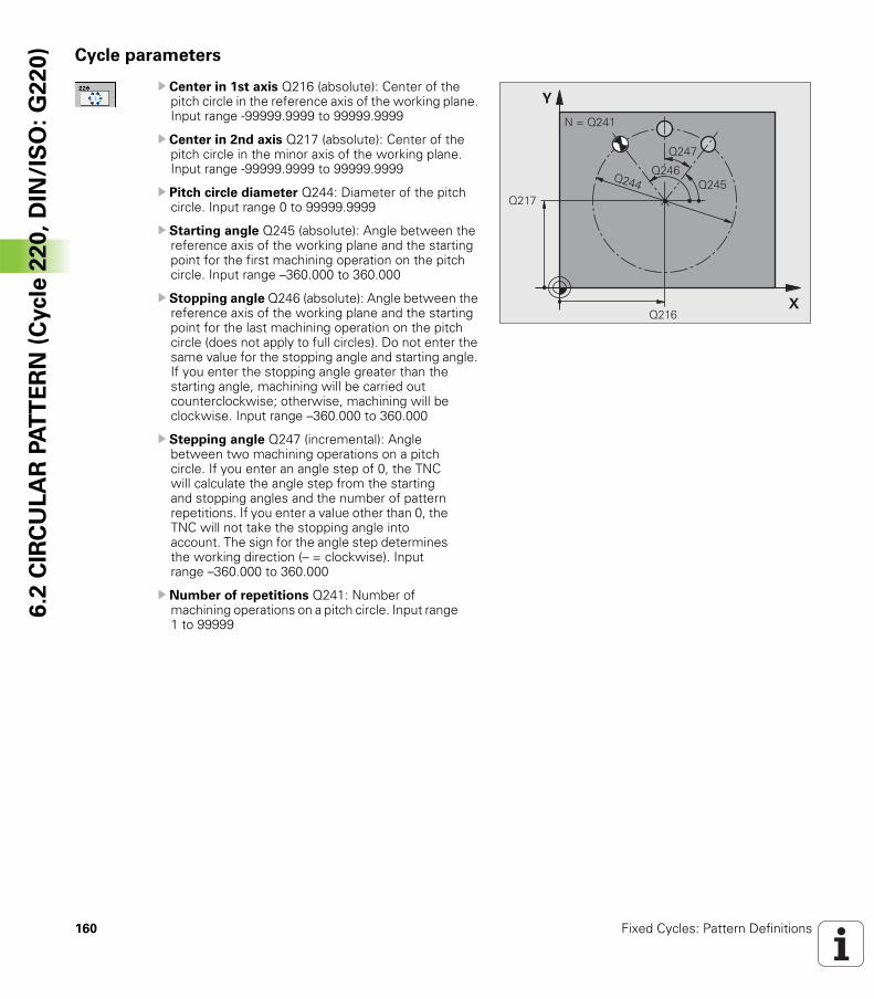
160 Fixed Cycles: Pattern Definitions
6.2
CIR
CU
LA
R P
AT
TE
RN
(C
ycle
22
0,
DIN
/IS
O:
G2
20
) Cycle parameters
U Center in 1st axis Q216 (absolute): Center of the pitch circle in the reference axis of the working plane. Input range -99999.9999 to 99999.9999
U Center in 2nd axis Q217 (absolute): Center of the pitch circle in the minor axis of the working plane. Input range -99999.9999 to 99999.9999
U Pitch circle diameter Q244: Diameter of the pitch circle. Input range 0 to 99999.9999
U Starting angle Q245 (absolute): Angle between the reference axis of the working plane and the starting point for the first machining operation on the pitch circle. Input range –360.000 to 360.000
U Stopping angle Q246 (absolute): Angle between the reference axis of the working plane and the starting point for the last machining operation on the pitch circle (does not apply to full circles). Do not enter the same value for the stopping angle and starting angle. If you enter the stopping angle greater than the starting angle, machining will be carried out counterclockwise; otherwise, machining will be clockwise. Input range –360.000 to 360.000
U Stepping angle Q247 (incremental): Angle between two machining operations on a pitch circle. If you enter an angle step of 0, the TNC will calculate the angle step from the starting and stopping angles and the number of pattern repetitions. If you enter a value other than 0, the TNC will not take the stopping angle into account. The sign for the angle step determines the working direction (– = clockwise). Input range –360.000 to 360.000
U Number of repetitions Q241: Number of machining operations on a pitch circle. Input range 1 to 99999
�
�
����
����
����
�������
����
��������
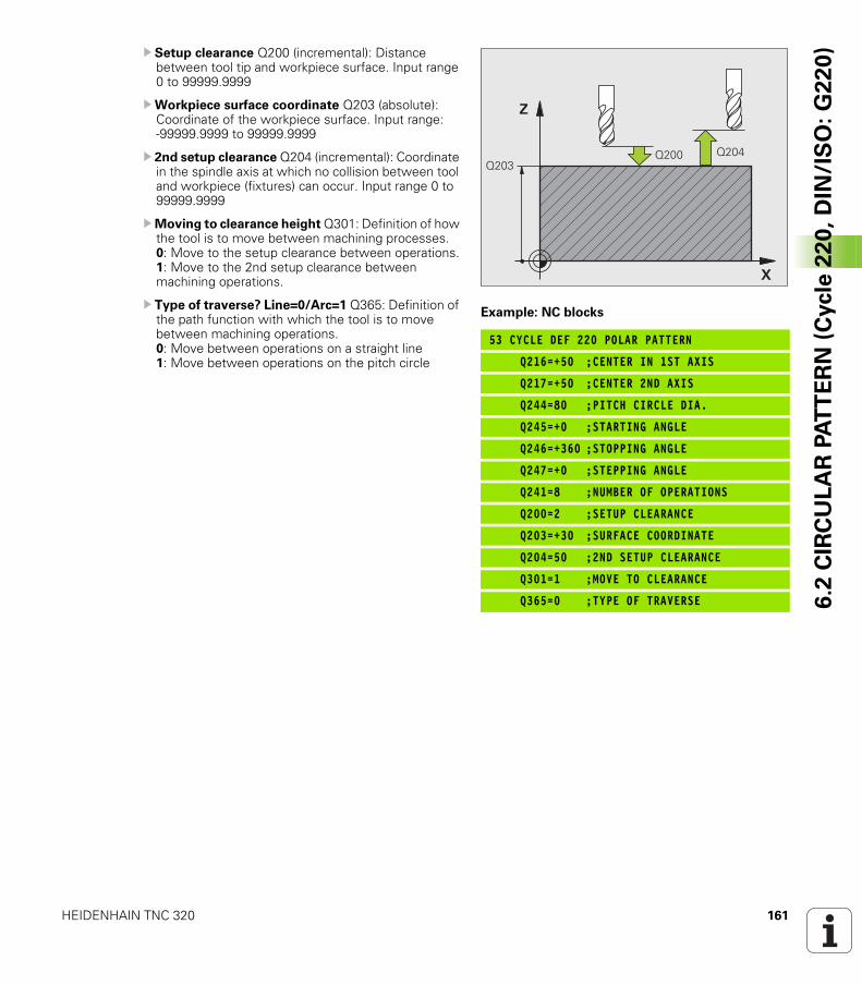
HEIDENHAIN TNC 320 161
6.2
CIR
CU
LA
R P
AT
TE
RN
(C
ycle
22
0,
DIN
/IS
O:
G2
20
)U Setup clearance Q200 (incremental): Distance between tool tip and workpiece surface. Input range 0 to 99999.9999
UWorkpiece surface coordinate Q203 (absolute): Coordinate of the workpiece surface. Input range: -99999.9999 to 99999.9999
U 2nd setup clearance Q204 (incremental): Coordinate in the spindle axis at which no collision between tool and workpiece (fixtures) can occur. Input range 0 to 99999.9999
UMoving to clearance height Q301: Definition of how the tool is to move between machining processes.0: Move to the setup clearance between operations.1: Move to the 2nd setup clearance between machining operations.
U Type of traverse? Line=0/Arc=1 Q365: Definition of the path function with which the tool is to move between machining operations.0: Move between operations on a straight line1: Move between operations on the pitch circle
Example: NC blocks
53 CYCLE DEF 220 POLAR PATTERN
Q216=+50 ;CENTER IN 1ST AXIS
Q217=+50 ;CENTER 2ND AXIS
Q244=80 ;PITCH CIRCLE DIA.
Q245=+0 ;STARTING ANGLE
Q246=+360 ;STOPPING ANGLE
Q247=+0 ;STEPPING ANGLE
Q241=8 ;NUMBER OF OPERATIONS
Q200=2 ;SETUP CLEARANCE
Q203=+30 ;SURFACE COORDINATE
Q204=50 ;2ND SETUP CLEARANCE
Q301=1 ;MOVE TO CLEARANCE
Q365=0 ;TYPE OF TRAVERSE
�
�
��������
����
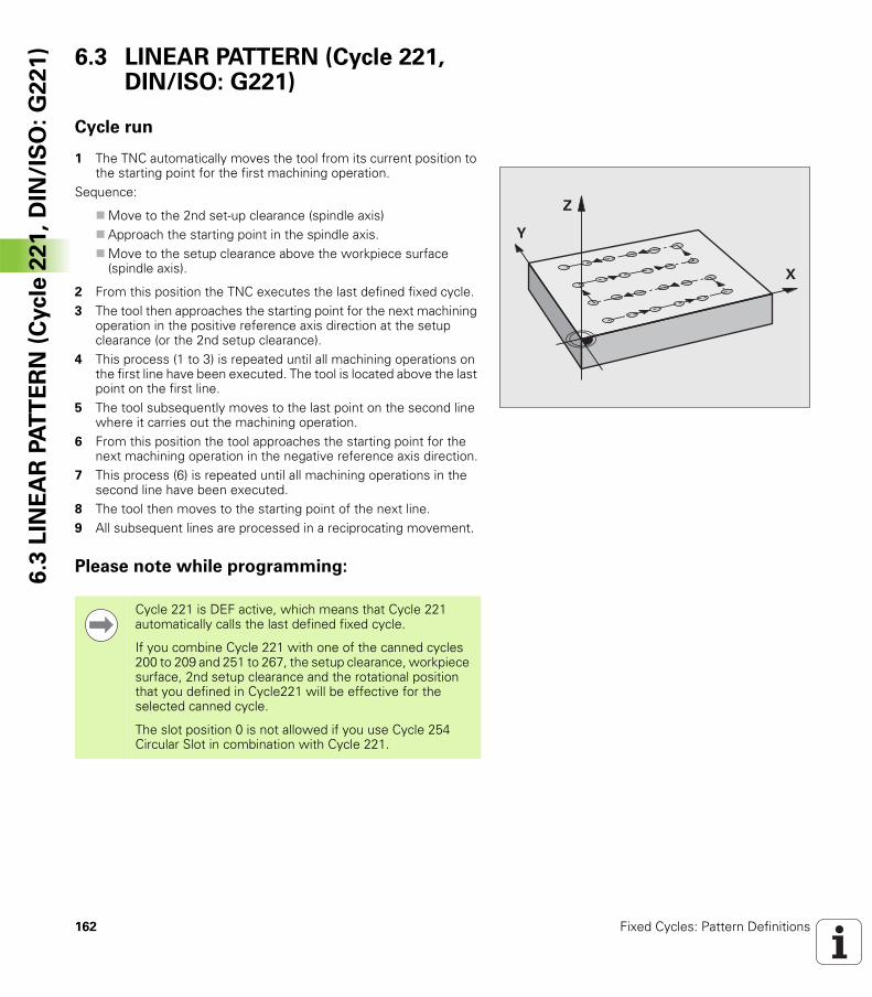
162 Fixed Cycles: Pattern Definitions
6.3
LIN
EA
R P
AT
TE
RN
(C
ycle
22
1,
DIN
/IS
O:
G2
21
) 6.3 LINEAR PATTERN (Cycle 221, DIN/ISO: G221)
Cycle run
1 The TNC automatically moves the tool from its current position to the starting point for the first machining operation.
Sequence:
Move to the 2nd set-up clearance (spindle axis)Approach the starting point in the spindle axis.Move to the setup clearance above the workpiece surface (spindle axis).
2 From this position the TNC executes the last defined fixed cycle.3 The tool then approaches the starting point for the next machining
operation in the positive reference axis direction at the setup clearance (or the 2nd setup clearance).
4 This process (1 to 3) is repeated until all machining operations on the first line have been executed. The tool is located above the last point on the first line.
5 The tool subsequently moves to the last point on the second line where it carries out the machining operation.
6 From this position the tool approaches the starting point for the next machining operation in the negative reference axis direction.
7 This process (6) is repeated until all machining operations in the second line have been executed.
8 The tool then moves to the starting point of the next line.9 All subsequent lines are processed in a reciprocating movement.
Please note while programming:
�
�
�
Cycle 221 is DEF active, which means that Cycle 221 automatically calls the last defined fixed cycle.
If you combine Cycle 221 with one of the canned cycles 200 to 209 and 251 to 267, the setup clearance, workpiece surface, 2nd setup clearance and the rotational position that you defined in Cycle221 will be effective for the selected canned cycle.
The slot position 0 is not allowed if you use Cycle 254 Circular Slot in combination with Cycle 221.
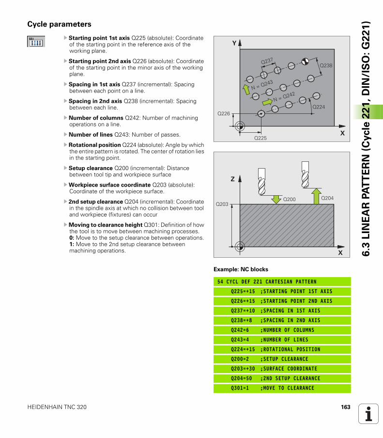
HEIDENHAIN TNC 320 163
6.3
LIN
EA
R P
AT
TE
RN
(C
ycle
22
1,
DIN
/IS
O:
G2
21
)Cycle parameters
U Starting point 1st axis Q225 (absolute): Coordinate of the starting point in the reference axis of the working plane.
U Starting point 2nd axis Q226 (absolute): Coordinate of the starting point in the minor axis of the working plane.
U Spacing in 1st axis Q237 (incremental): Spacing between each point on a line.
U Spacing in 2nd axis Q238 (incremental): Spacing between each line.
U Number of columns Q242: Number of machining operations on a line.
U Number of lines Q243: Number of passes.
U Rotational position Q224 (absolute): Angle by which the entire pattern is rotated. The center of rotation lies in the starting point.
U Setup clearance Q200 (incremental): Distance between tool tip and workpiece surface
UWorkpiece surface coordinate Q203 (absolute): Coordinate of the workpiece surface.
U 2nd setup clearance Q204 (incremental): Coordinate in the spindle axis at which no collision between tool and workpiece (fixtures) can occur
UMoving to clearance height Q301: Definition of how the tool is to move between machining processes.0: Move to the setup clearance between operations.1: Move to the 2nd setup clearance between machining operations.
Example: NC blocks
54 CYCL DEF 221 CARTESIAN PATTERN
Q225=+15 ;STARTING POINT 1ST AXIS
Q226=+15 ;STARTING POINT 2ND AXIS
Q237=+10 ;SPACING IN 1ST AXIS
Q238=+8 ;SPACING IN 2ND AXIS
Q242=6 ;NUMBER OF COLUMNS
Q243=4 ;NUMBER OF LINES
Q224=+15 ;ROTATIONAL POSITION
Q200=2 ;SETUP CLEARANCE
Q203=+30 ;SURFACE COORDINATE
Q204=50 ;2ND SETUP CLEARANCE
Q301=1 ;MOVE TO CLEARANCE
�
�
����
���
����
�������
��������
��������
�
�
��������
����

164 Fixed Cycles: Pattern Definitions
6.4
Pro
gra
mm
ing
Ex
am
ple
s 6.4 Programming Examples
Example: Circular hole patterns
0 BEGIN PGM PATTERN MM
1 BLK FORM 0.1 Z X+0 Y+0 Z-40 Definition of workpiece blank
2 BLK FORM 0.2 Y+100 Y+100 Z+0
3 TOOL CALL 1 Z S3500 Tool call
4 L Z+250 R0 FMAX M3 Retract the tool
5 CYCL DEF 200 DRILLING Cycle definition: drilling
Q200=2 ;SETUP CLEARANCE
Q201=-15 ;DEPTH
Q206=250 ;FEED RATE FOR PLNGN
Q202=4 ;PLUNGING DEPTH
Q210=0 ;DWELL TIME
Q203=+0 ;SURFACE COORDINATE
Q204=0 ;2ND SET-UP CLEARANCE
Q211=0.25 ;DWELL TIME AT DEPTH
�
�
��
��
���
���
��
��
���
��
�
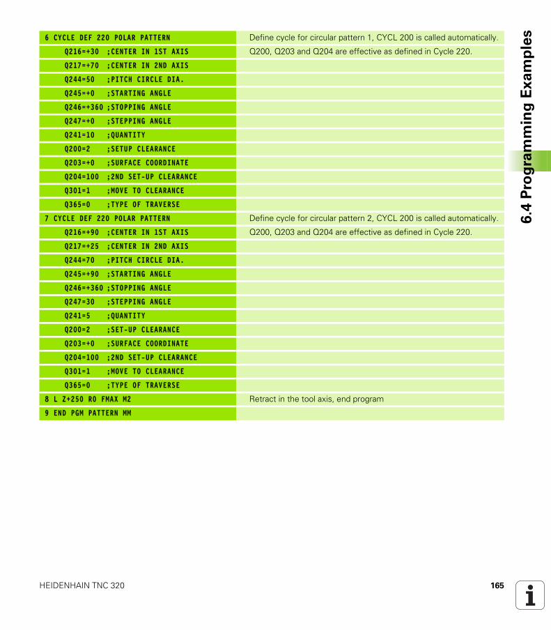
HEIDENHAIN TNC 320 165
6.4
Pro
gra
mm
ing
Ex
am
ple
s6 CYCLE DEF 220 POLAR PATTERN Define cycle for circular pattern 1, CYCL 200 is called automatically.
Q216=+30 ;CENTER IN 1ST AXIS Q200, Q203 and Q204 are effective as defined in Cycle 220.
Q217=+70 ;CENTER IN 2ND AXIS
Q244=50 ;PITCH CIRCLE DIA.
Q245=+0 ;STARTING ANGLE
Q246=+360 ;STOPPING ANGLE
Q247=+0 ;STEPPING ANGLE
Q241=10 ;QUANTITY
Q200=2 ;SETUP CLEARANCE
Q203=+0 ;SURFACE COORDINATE
Q204=100 ;2ND SET-UP CLEARANCE
Q301=1 ;MOVE TO CLEARANCE
Q365=0 ;TYPE OF TRAVERSE
7 CYCLE DEF 220 POLAR PATTERN Define cycle for circular pattern 2, CYCL 200 is called automatically.
Q216=+90 ;CENTER IN 1ST AXIS Q200, Q203 and Q204 are effective as defined in Cycle 220.
Q217=+25 ;CENTER IN 2ND AXIS
Q244=70 ;PITCH CIRCLE DIA.
Q245=+90 ;STARTING ANGLE
Q246=+360 ;STOPPING ANGLE
Q247=30 ;STEPPING ANGLE
Q241=5 ;QUANTITY
Q200=2 ;SET-UP CLEARANCE
Q203=+0 ;SURFACE COORDINATE
Q204=100 ;2ND SET-UP CLEARANCE
Q301=1 ;MOVE TO CLEARANCE
Q365=0 ;TYPE OF TRAVERSE
8 L Z+250 R0 FMAX M2 Retract in the tool axis, end program
9 END PGM PATTERN MM

166 Fixed Cycles: Pattern Definitions
6.4
Pro
gra
mm
ing
Ex
am
ple
s
Fixed Cycles: Contour
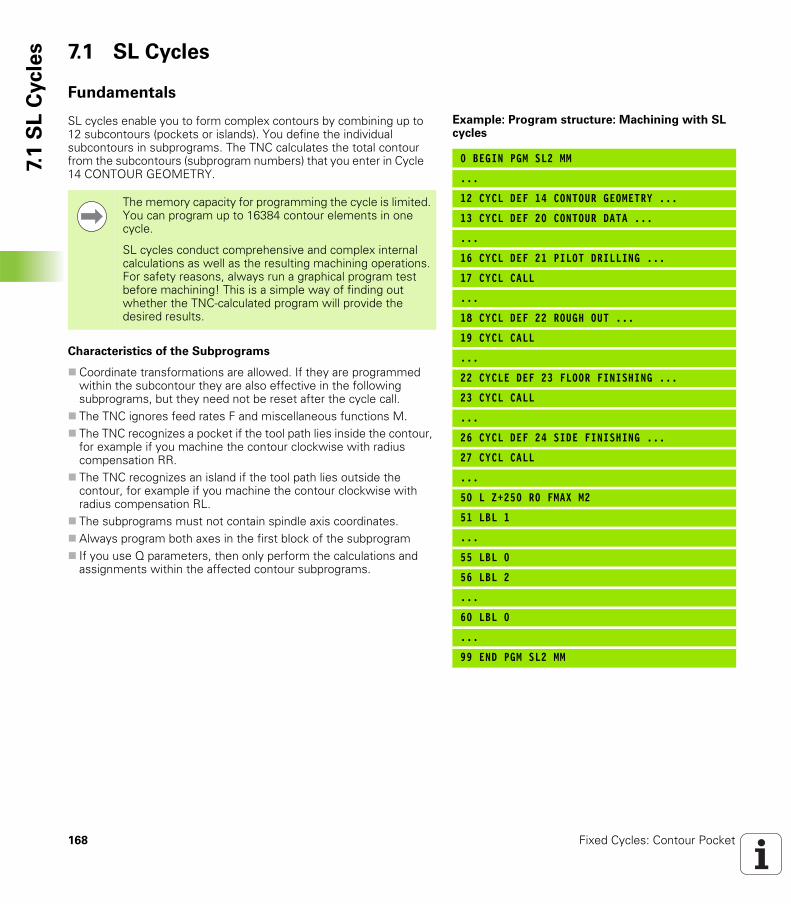
168 Fixed Cycles: Contour Pocket
7.1
SL
Cycle
s 7.1 SL Cycles
Fundamentals
SL cycles enable you to form complex contours by combining up to 12 subcontours (pockets or islands). You define the individual subcontours in subprograms. The TNC calculates the total contour from the subcontours (subprogram numbers) that you enter in Cycle 14 CONTOUR GEOMETRY.
Characteristics of the Subprograms
Coordinate transformations are allowed. If they are programmed within the subcontour they are also effective in the following subprograms, but they need not be reset after the cycle call.The TNC ignores feed rates F and miscellaneous functions M.The TNC recognizes a pocket if the tool path lies inside the contour, for example if you machine the contour clockwise with radius compensation RR.The TNC recognizes an island if the tool path lies outside the contour, for example if you machine the contour clockwise with radius compensation RL.The subprograms must not contain spindle axis coordinates.Always program both axes in the first block of the subprogramIf you use Q parameters, then only perform the calculations and assignments within the affected contour subprograms.
Example: Program structure: Machining with SL cycles
0 BEGIN PGM SL2 MM
...
12 CYCL DEF 14 CONTOUR GEOMETRY ...
13 CYCL DEF 20 CONTOUR DATA ...
...
16 CYCL DEF 21 PILOT DRILLING ...
17 CYCL CALL
...
18 CYCL DEF 22 ROUGH OUT ...
19 CYCL CALL
...
22 CYCLE DEF 23 FLOOR FINISHING ...
23 CYCL CALL
...
26 CYCL DEF 24 SIDE FINISHING ...
27 CYCL CALL
...
50 L Z+250 R0 FMAX M2
51 LBL 1
...
55 LBL 0
56 LBL 2
...
60 LBL 0
...
99 END PGM SL2 MM
The memory capacity for programming the cycle is limited. You can program up to 16384 contour elements in one cycle.
SL cycles conduct comprehensive and complex internal calculations as well as the resulting machining operations. For safety reasons, always run a graphical program test before machining! This is a simple way of finding out whether the TNC-calculated program will provide the desired results.
HEIDENHAIN TNC 320 169
7.1
SL
Cycle
sCharacteristics of the fixed cycles
The TNC automatically positions the tool to the setup clearance before a cycle.Each level of infeed depth is milled without interruptions since the cutter traverses around islands instead of over them.The radius of “inside corners” can be programmed—the tool keeps moving to prevent surface blemishes at inside corners (this applies for the outermost pass in the Rough-out and Side Finishing cycles).The contour is approached on a tangential arc for side finishing.For floor finishing, the tool again approaches the workpiece on a tangential arc (for tool axis Z, for example, the arc may be in the Z/X plane).The contour is machined throughout in either climb or up-cut milling.
The machining data (such as milling depth, finishing allowance and setup clearance) are entered as CONTOUR DATA in Cycle 20.
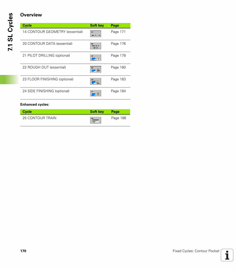
170 Fixed Cycles: Contour Pocket
7.1
SL
Cycle
s Overview
Enhanced cycles:
Cycle Soft key Page
14 CONTOUR GEOMETRY (essential) Page 171
20 CONTOUR DATA (essential) Page 176
21 PILOT DRILLING (optional) Page 178
22 ROUGH OUT (essential) Page 180
23 FLOOR FINISHING (optional) Page 183
24 SIDE FINISHING (optional) Page 184
Cycle Soft key Page
25 CONTOUR TRAIN Page 186
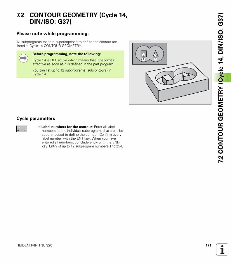
HEIDENHAIN TNC 320 171
7.2
CO
NT
OU
R G
EO
ME
TR
Y (
Cycle
14
, D
IN/I
SO
: G
37
)7.2 CONTOUR GEOMETRY (Cycle 14, DIN/ISO: G37)
Please note while programming:
All subprograms that are superimposed to define the contour are listed in Cycle 14 CONTOUR GEOMETRY.
Cycle parameters
U Label numbers for the contour: Enter all label numbers for the individual subprograms that are to be superimposed to define the contour. Confirm every label number with the ENT key. When you have entered all numbers, conclude entry with the END key. Entry of up to 12 subprogram numbers 1 to 254.
�
�
Before programming, note the following:
Cycle 14 is DEF active which means that it becomes effective as soon as it is defined in the part program.
You can list up to 12 subprograms (subcontours) in Cycle 14.
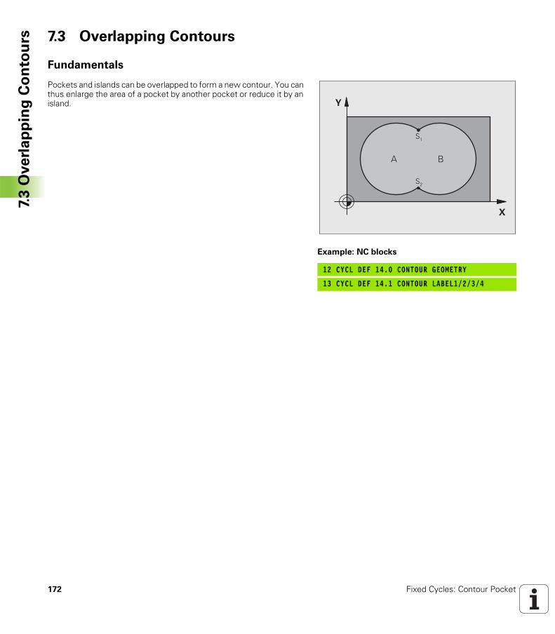
172 Fixed Cycles: Contour Pocket
7.3
Ove
rla
pp
ing
Co
nto
urs 7.3 Overlapping Contours
Fundamentals
Pockets and islands can be overlapped to form a new contour. You can thus enlarge the area of a pocket by another pocket or reduce it by an island.
Example: NC blocks
12 CYCL DEF 14.0 CONTOUR GEOMETRY
13 CYCL DEF 14.1 CONTOUR LABEL1/2/3/4
�
�
� �
��
��
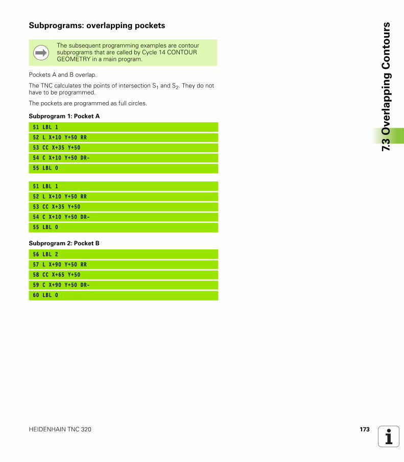
HEIDENHAIN TNC 320 173
7.3
Ove
rla
pp
ing
Co
nto
ursSubprograms: overlapping pockets
Pockets A and B overlap.
The TNC calculates the points of intersection S1 and S2. They do not have to be programmed.
The pockets are programmed as full circles.
Subprogram 1: Pocket A
Subprogram 2: Pocket B
The subsequent programming examples are contour subprograms that are called by Cycle 14 CONTOUR GEOMETRY in a main program.
51 LBL 1
52 L X+10 Y+50 RR
53 CC X+35 Y+50
54 C X+10 Y+50 DR-
55 LBL 0
51 LBL 1
52 L X+10 Y+50 RR
53 CC X+35 Y+50
54 C X+10 Y+50 DR-
55 LBL 0
56 LBL 2
57 L X+90 Y+50 RR
58 CC X+65 Y+50
59 C X+90 Y+50 DR-
60 LBL 0
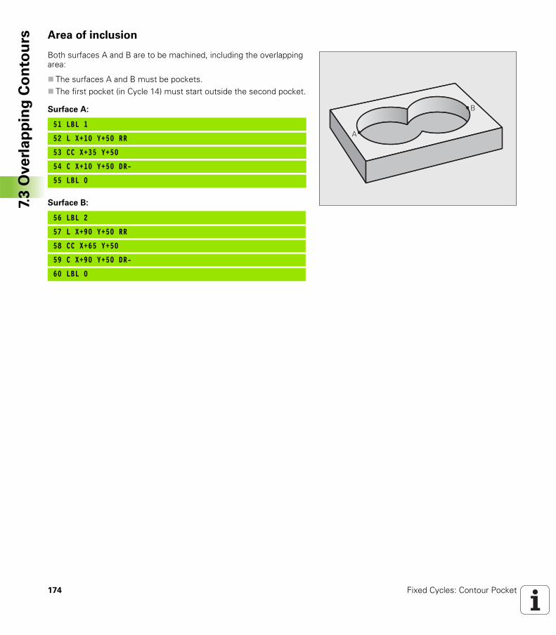
174 Fixed Cycles: Contour Pocket
7.3
Ove
rla
pp
ing
Co
nto
urs Area of inclusion
Both surfaces A and B are to be machined, including the overlapping area:
The surfaces A and B must be pockets.The first pocket (in Cycle 14) must start outside the second pocket.
Surface A:
Surface B:
�
�
51 LBL 1
52 L X+10 Y+50 RR
53 CC X+35 Y+50
54 C X+10 Y+50 DR-
55 LBL 0
56 LBL 2
57 L X+90 Y+50 RR
58 CC X+65 Y+50
59 C X+90 Y+50 DR-
60 LBL 0
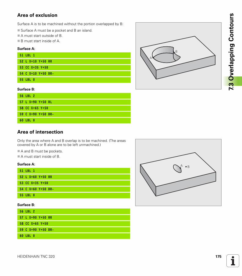
HEIDENHAIN TNC 320 175
7.3
Ove
rla
pp
ing
Co
nto
ursArea of exclusion
Surface A is to be machined without the portion overlapped by B:
Surface A must be a pocket and B an island.A must start outside of B.B must start inside of A.
Surface A:
Surface B:
Area of intersection
Only the area where A and B overlap is to be machined. (The areas covered by A or B alone are to be left unmachined.)
A and B must be pockets.A must start inside of B.
Surface A:
Surface B:
�
�51 LBL 1
52 L X+10 Y+50 RR
53 CC X+35 Y+50
54 C X+10 Y+50 DR-
55 LBL 0
56 LBL 2
57 L X+90 Y+50 RL
58 CC X+65 Y+50
59 C X+90 Y+50 DR-
60 LBL 0
� �51 LBL 1
52 L X+60 Y+50 RR
53 CC X+35 Y+50
54 C X+60 Y+50 DR-
55 LBL 0
56 LBL 2
57 L X+90 Y+50 RR
58 CC X+65 Y+50
59 C X+90 Y+50 DR-
60 LBL 0
176 Fixed Cycles: Contour Pocket
7.4
CO
NT
OU
R D
ATA
(C
ycle
20
, D
IN/I
SO
: G
12
0) 7.4 CONTOUR DATA (Cycle 20,
DIN/ISO: G120)
Please note while programming:
Machining data for the subprograms describing the subcontours are entered in Cycle 20.
Cycle 20 is DEF active, which means that it becomes effective as soon as it is defined in the part program.
The algebraic sign for the cycle parameter DEPTH determines the working direction. If you program DEPTH = 0, the TNC performs the cycle at the depth 0.
The machining data entered in Cycle 20 are valid for Cycles 21 to 24.
If you are using the SL cycles in Q parameter programs, the cycle parameters Q1 to Q20 cannot be used as program parameters.
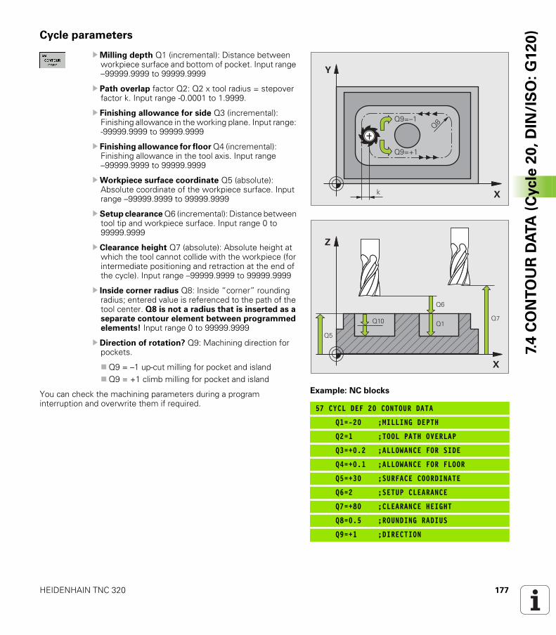
HEIDENHAIN TNC 320 177
7.4
CO
NT
OU
R D
ATA
(C
ycle
20
, D
IN/I
SO
: G
12
0)Cycle parameters
UMilling depth Q1 (incremental): Distance between workpiece surface and bottom of pocket. Input range –99999.9999 to 99999.9999
U Path overlap factor Q2: Q2 x tool radius = stepover factor k. Input range -0.0001 to 1.9999.
U Finishing allowance for side Q3 (incremental): Finishing allowance in the working plane. Input range: -99999.9999 to 99999.9999
U Finishing allowance for floor Q4 (incremental): Finishing allowance in the tool axis. Input range –99999.9999 to 99999.9999
UWorkpiece surface coordinate Q5 (absolute): Absolute coordinate of the workpiece surface. Input range –99999.9999 to 99999.9999
U Setup clearance Q6 (incremental): Distance between tool tip and workpiece surface. Input range 0 to 99999.9999
U Clearance height Q7 (absolute): Absolute height at which the tool cannot collide with the workpiece (for intermediate positioning and retraction at the end of the cycle). Input range –99999.9999 to 99999.9999
U Inside corner radius Q8: Inside “corner” rounding radius; entered value is referenced to the path of the tool center. Q8 is not a radius that is inserted as a separate contour element between programmed elements! Input range 0 to 99999.9999
U Direction of rotation? Q9: Machining direction for pockets.
Q9 = –1 up-cut milling for pocket and islandQ9 = +1 climb milling for pocket and island
You can check the machining parameters during a program interruption and overwrite them if required.
Example: NC blocks
57 CYCL DEF 20 CONTOUR DATA
Q1=-20 ;MILLING DEPTH
Q2=1 ;TOOL PATH OVERLAP
Q3=+0.2 ;ALLOWANCE FOR SIDE
Q4=+0.1 ;ALLOWANCE FOR FLOOR
Q5=+30 ;SURFACE COORDINATE
Q6=2 ;SETUP CLEARANCE
Q7=+80 ;CLEARANCE HEIGHT
Q8=0.5 ;ROUNDING RADIUS
Q9=+1 ;DIRECTION
�
�
�
�����
������
�
�
��
�������
�
178 Fixed Cycles: Contour Pocket
7.5
PIL
OT
DR
ILL
ING
(C
ycle
21
, D
IN/I
SO
: G
12
1) 7.5 PILOT DRILLING (Cycle 21,
DIN/ISO: G121)
Cycle run
1 The tool drills from the current position to the first plunging depth at the programmed feed rate F.
2 Then the tool retracts at rapid traverse FMAX to the starting position and advances again to the first plunging depth minus the advanced stop distance t.
3 The advanced stop distance is automatically calculated by the control:
At a total hole depth up to 30 mm: t = 0.6 mmAt a total hole depth exceeding 30 mm: t = hole depth / 50Maximum advanced stop distance: 7 mm
4 The tool then advances with another infeed at the programmed feed rate F.
5 The TNC repeats this process (1 to 4) until the programmed depth is reached.
6 After a dwell time at the hole bottom, the tool is returned to the starting position at rapid traverse FMAX for chip breaking.
Application
Cycle 21 is for PILOT DRILLING of the cutter infeed points. It accounts for the allowance for side and the allowance for floor as well as the radius of the rough-out tool. The cutter infeed points also serve as starting points for roughing.
Please note while programming:
Before programming, note the following:
When calculating the infeed points, the TNC does not account for the delta value DR programmed in a TOOL CALL block.
In narrow areas, the TNC may not be able to carry out pilot drilling with a tool that is larger than the rough-out tool.
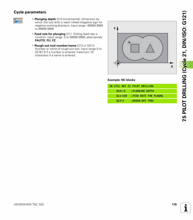
HEIDENHAIN TNC 320 179
7.5
PIL
OT
DR
ILL
ING
(C
ycle
21
, D
IN/I
SO
: G
12
1)Cycle parameters
U Plunging depth Q10 (incremental): Dimension by which the tool drills in each infeed (negative sign for negative working direction). Input range: -99999.9999 to 99999.9999
U Feed rate for plunging Q11: Drilling feed rate in mm/min. Input range: 0 to 99999.9999; alternatively FAUTO, FU, FZ.
U Rough-out tool number/name Q13 or QS13: Number or name of rough-out tool. Input range 0 to 32767.9 if a number is entered; maximum 16 characters if a name is entered.
Example: NC blocks
58 CYCL DEF 21 PILOT DRILLING
Q10=+5 ;PLUNGING DEPTH
Q11=100 ;FEED RATE FOR PLNGNG
Q13=1 ;ROUGH-OUT TOOL
�
�
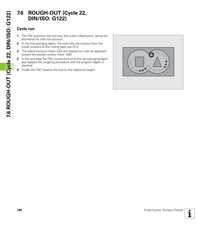
180 Fixed Cycles: Contour Pocket
7.6
RO
UG
H-O
UT
(C
ycle
22
, D
IN/I
SO
: G
12
2) 7.6 ROUGH-OUT (Cycle 22,
DIN/ISO: G122)
Cycle run
1 The TNC positions the tool over the cutter infeed point, taking the allowance for side into account.
2 In the first plunging depth, the tool mills the contour from the inside outward at the milling feed rate Q12.
3 The island contours (here: C/D) are cleared out with an approach toward the pocket contour (here: A/B).
4 In the next step the TNC moves the tool to the next plunging depth and repeats the roughing procedure until the program depth is reached.
5 Finally the TNC retracts the tool to the clearance height.
HEIDENHAIN TNC 320 181
7.6
RO
UG
H-O
UT
(C
ycle
22
, D
IN/I
SO
: G
12
2)Please note while programming:
This cycle requires a center-cut end mill (ISO 1641) or pilot drilling with Cycle 21.
You define the plunging behavior of Cycle 22 with parameter Q19 and with the tool table in the ANGLE and LCUTS columns:
If Q19=0 is defined, the TNC always plunges perpendicularly, even if a plunge angle (ANGLE) is defined for the active tool.If you define the ANGLE=90°, the TNC plunges perpendicularly. The reciprocation feed rate Q19 is used as plunging feed rate.If the reciprocation feed rate Q19 is defined in Cycle 22 and ANGLE is defined between 0.1 and 89.999 in the tool table, the TNC plunges helically at the defined ANGLE.If the reciprocation feed is defined in Cycle 22 and no ANGLE is in the tool table, the TNC displays an error message.If geometrical conditions do not allow helical plunging (slot geometry), the TNC tries a reciprocating plunge. The reciprocation length is calculated from LCUTS and ANGLE (reciprocation length = LCUTS / tan ANGLE).
If you clear out an acute inside corner and use an overlap factor greater than 1, some material might be left over. Check especially the innermost path in the test run graphic and, if necessary, change the overlap factor slightly. This allows another distribution of cuts, which often provides the desired results.
During fine roughing the TNC does not take a defined wear value DR of the coarse roughing tool into account.
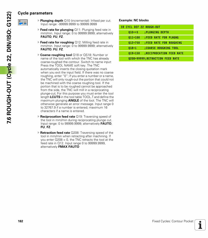
182 Fixed Cycles: Contour Pocket
7.6
RO
UG
H-O
UT
(C
ycle
22
, D
IN/I
SO
: G
12
2) Cycle parameters
U Plunging depth Q10 (incremental): Infeed per cut. Input range: -99999.9999 to 99999.9999
U Feed rate for plunging Q11: Plunging feed rate in mm/min. Input range: 0 to 99999.9999; alternatively FAUTO, FU, FZ.
U Feed rate for roughing Q12: Milling feed rate in mm/min. Input range: 0 to 99999.9999; alternatively FAUTO, FU, FZ.
U Coarse roughing tool Q18 or QS18: Number or name of the tool with which the TNC has already coarse-roughed the contour. Switch to name input: Press the TOOL NAME soft key. The TNC automatically inserts the closing quotation mark when you exit the input field. If there was no coarse roughing, enter “0”; if you enter a number or a name, the TNC will only rough-out the portion that could not be machined with the coarse roughing tool. If the portion that is to be roughed cannot be approached from the side, the TNC will mill in a reciprocating plunge-cut; For this purpose you must enter the tool length LCUTS in the tool table TOOL.T and define the maximum plunging ANGLE of the tool. The TNC will otherwise generate an error message. Input range 0 to 32767.9 if a number is entered; maximum 16 characters if a name is entered.
U Reciprocation feed rate Q19: Traversing speed of the tool in mm/min during reciprocating plunge cut. Input range: 0 to 99999.9999; alternatively FAUTO, FU, FZ.
U Retraction feed rate Q208: Traversing speed of the tool in mm/min when retracting after machining. If you enter Q208 = 0, the TNC retracts the tool at the feed rate in Q12. Input range 0 to 99999.9999, alternatively FMAX FAUTO
Example: NC blocks
59 CYCL DEF 22 ROUGH-OUT
Q10=+5 ;PLUNGING DEPTH
Q11=100 ;FEED RATE FOR PLNGNG
Q12=750 ;FEED RATE FOR ROUGHING
Q18=1 ;COARSE ROUGHING TOOL
Q19=150 ;RECIPROCATION FEED RATE
Q208=99999;RETRACTION FEED RATE
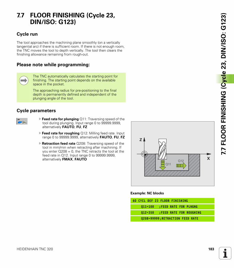
HEIDENHAIN TNC 320 183
7.7
FLO
OR
FIN
ISH
ING
(C
ycle
23
, D
IN/I
SO
: G
12
3)7.7 FLOOR FINISHING (Cycle 23,
DIN/ISO: G123)
Cycle run
The tool approaches the machining plane smoothly (on a vertically tangential arc) if there is sufficient room. If there is not enough room, the TNC moves the tool to depth vertically. The tool then clears the finishing allowance remaining from rough-out.
Please note while programming:
Cycle parameters
U Feed rate for plunging Q11: Traversing speed of the tool during plunging. Input range 0 to 99999.9999, alternatively FAUTO, FU, FZ
U Feed rate for roughing Q12: Milling feed rate. Input range 0 to 99999.9999, alternatively FAUTO, FU, FZ
U Retraction feed rate Q208: Traversing speed of the tool in mm/min when retracting after machining. If you enter Q208 = 0, the TNC retracts the tool at the feed rate in Q12. Input range 0 to 99999.9999, alternatively FMAX, FAUTO
The TNC automatically calculates the starting point for finishing. The starting point depends on the available space in the pocket.
The approaching radius for pre-positioning to the final depth is permanently defined and independent of the plunging angle of the tool.
Example: NC blocks
60 CYCL DEF 23 FLOOR FINISHING
Q11=100 ;FEED RATE FOR PLNGNG
Q12=350 ;FEED RATE FOR ROUGHING
Q208=99999;RETRACTION FEED RATE
�
�
������
184 Fixed Cycles: Contour Pocket
7.8
SID
E F
INIS
HIN
G (
Cycle
24
, D
IN/I
SO
: G
12
4) 7.8 SIDE FINISHING (Cycle 24,
DIN/ISO: G124)
Cycle run
The subcontours are approached and departed on a tangential arc. Each subcontour is finished separately.
Please note while programming:
The sum of allowance for side (Q14) and the radius of the finish mill must be smaller than the sum of allowance for side (Q3, Cycle 20) and the radius of the rough mill.
This calculation also holds if you run Cycle 24 without having roughed out with Cycle 22; in this case, enter “0” for the radius of the rough mill.
You can use Cycle 24 also for contour milling. Then you must:
define the contour to be milled as a single island (without pocket limit), and
enter the finishing allowance (Q3) in Cycle 20 to be greater than the sum of the finishing allowance Q14 + radius of the tool being used.
The TNC automatically calculates the starting point for finishing. The starting point depends on the available space in the pocket and the allowance programmed in Cycle 20.
The starting point calculated by the TNC also depends on the machining sequence. If you select the finishing cycle with the GOTO key and then start the program, the starting point can be at a different location from where it would be if you execute the program in the defined sequence.
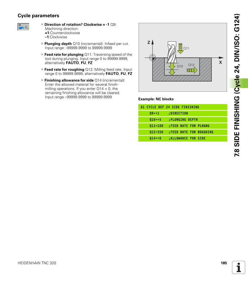
HEIDENHAIN TNC 320 185
7.8
SID
E F
INIS
HIN
G (
Cycle
24
, D
IN/I
SO
: G
12
4)Cycle parameters
U Direction of rotation? Clockwise = -1 Q9: Machining direction:+1:Counterclockwise–1:Clockwise
U Plunging depth Q10 (incremental): Infeed per cut. Input range: -99999.9999 to 99999.9999
U Feed rate for plunging Q11: Traversing speed of the tool during plunging. Input range 0 to 99999.9999, alternatively FAUTO, FU, FZ
U Feed rate for roughing Q12: Milling feed rate. Input range 0 to 99999.9999, alternatively FAUTO, FU, FZ
U Finishing allowance for side Q14 (incremental): Enter the allowed material for several finish-milling operations. If you enter Q14 = 0, the remaining finishing allowance will be cleared. Input range –99999.9999 to 99999.9999
Example: NC blocks
61 CYCLE DEF 24 SIDE FINISHING
Q9=+1 ;DIRECTION
Q10=+5 ;PLUNGING DEPTH
Q11=100 ;FEED RATE FOR PLNGNG
Q12=350 ;FEED RATE FOR ROUGHING
Q14=+0 ;ALLOWANCE FOR SIDE
�
����
������
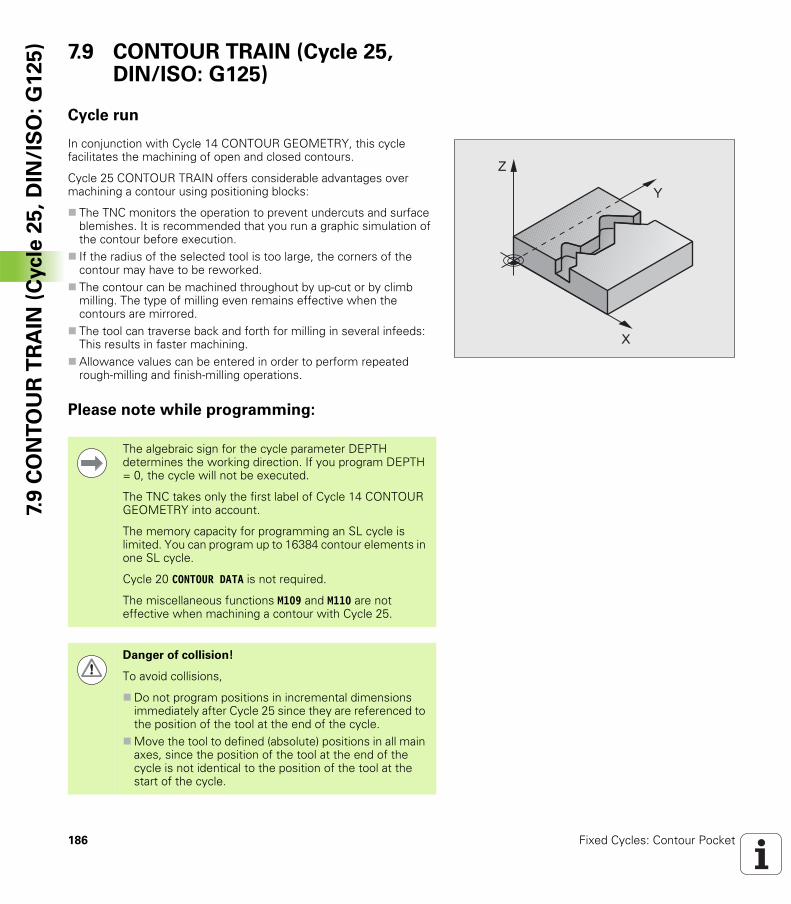
186 Fixed Cycles: Contour Pocket
7.9
CO
NT
OU
R T
RA
IN (
Cycle
25
, D
IN/I
SO
: G
12
5) 7.9 CONTOUR TRAIN (Cycle 25,
DIN/ISO: G125)
Cycle run
In conjunction with Cycle 14 CONTOUR GEOMETRY, this cycle facilitates the machining of open and closed contours.
Cycle 25 CONTOUR TRAIN offers considerable advantages over machining a contour using positioning blocks:
The TNC monitors the operation to prevent undercuts and surface blemishes. It is recommended that you run a graphic simulation of the contour before execution.If the radius of the selected tool is too large, the corners of the contour may have to be reworked.The contour can be machined throughout by up-cut or by climb milling. The type of milling even remains effective when the contours are mirrored.The tool can traverse back and forth for milling in several infeeds: This results in faster machining.Allowance values can be entered in order to perform repeated rough-milling and finish-milling operations.
Please note while programming:
�
�
The algebraic sign for the cycle parameter DEPTH determines the working direction. If you program DEPTH = 0, the cycle will not be executed.
The TNC takes only the first label of Cycle 14 CONTOUR GEOMETRY into account.
The memory capacity for programming an SL cycle is limited. You can program up to 16384 contour elements in one SL cycle.
Cycle 20 CONTOUR DATA is not required.
The miscellaneous functions M109 and M110 are not effective when machining a contour with Cycle 25.
Danger of collision!
To avoid collisions,
Do not program positions in incremental dimensions immediately after Cycle 25 since they are referenced to the position of the tool at the end of the cycle.Move the tool to defined (absolute) positions in all main axes, since the position of the tool at the end of the cycle is not identical to the position of the tool at the start of the cycle.
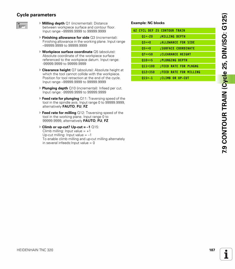
HEIDENHAIN TNC 320 187
7.9
CO
NT
OU
R T
RA
IN (
Cycle
25
, D
IN/I
SO
: G
12
5)Cycle parameters
UMilling depth Q1 (incremental): Distance between workpiece surface and contour floor. Input range –99999.9999 to 99999.9999
U Finishing allowance for side Q3 (incremental): Finishing allowance in the working plane. Input range –99999.9999 to 99999.9999
UWorkpiece surface coordinate Q5 (absolute): Absolute coordinate of the workpiece surface referenced to the workpiece datum. Input range: -99999.9999 to 99999.9999
U Clearance height Q7 (absolute): Absolute height at which the tool cannot collide with the workpiece. Position for tool retraction at the end of the cycle. Input range –99999.9999 to 99999.9999
U Plunging depth Q10 (incremental): Infeed per cut. Input range: -99999.9999 to 99999.9999
U Feed rate for plunging Q11: Traversing speed of the tool in the spindle axis. Input range 0 to 99999.9999, alternatively FAUTO, FU, FZ
U Feed rate for milling Q12: Traversing speed of the tool in the working plane. Input range 0 to 99999.9999, alternatively FAUTO, FU, FZ
U Climb or up-cut? Up-cut = –1 Q15:Climb milling: Input value = +1Up-cut milling: Input value = –1To enable climb milling and up-cut milling alternately in several infeeds:Input value = 0
Example: NC blocks
62 CYCL DEF 25 CONTOUR TRAIN
Q1=-20 ;MILLING DEPTH
Q3=+0 ;ALLOWANCE FOR SIDE
Q5=+0 ;SURFACE COORDINATE
Q7=+50 ;CLEARANCE HEIGHT
Q10=+5 ;PLUNGING DEPTH
Q11=100 ;FEED RATE FOR PLNGNG
Q12=350 ;FEED RATE FOR MILLING
Q15=-1 ;CLIMB OR UP-CUT
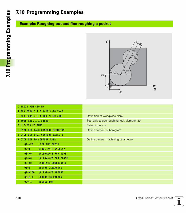
188 Fixed Cycles: Contour Pocket
7.10
Pro
gra
mm
ing
Ex
am
ple
s 7.10 Programming Examples
Example: Roughing-out and fine-roughing a pocket
0 BEGIN PGM C20 MM
1 BLK FORM 0.1 Z X-10 Y-10 Z-40
2 BLK FORM 0.2 X+100 Y+100 Z+0 Definition of workpiece blank
3 TOOL CALL 1 Z S2500 Tool call: coarse roughing tool, diameter 30
4 L Z+250 R0 FMAX Retract the tool
5 CYCL DEF 14.0 CONTOUR GEOMETRY Define contour subprogram
6 CYCL DEF 14.1 CONTOUR LABEL 1
7 CYCL DEF 20 CONTOUR DATA Define general machining parameters
Q1=-20 ;MILLING DEPTH
Q2=1 ;TOOL PATH OVERLAP
Q3=+0 ;ALLOWANCE FOR SIDE
Q4=+0 ;ALLOWANCE FOR FLOOR
Q5=+0 ;SURFACE COORDINATE
Q6=2 ;SETUP CLEARANCE
Q7=+100 ;CLEARANCE HEIGHT
Q8=0.1 ;ROUNDING RADIUS
Q9=-1 ;DIRECTION
�
�
��
��
���
���
���
����
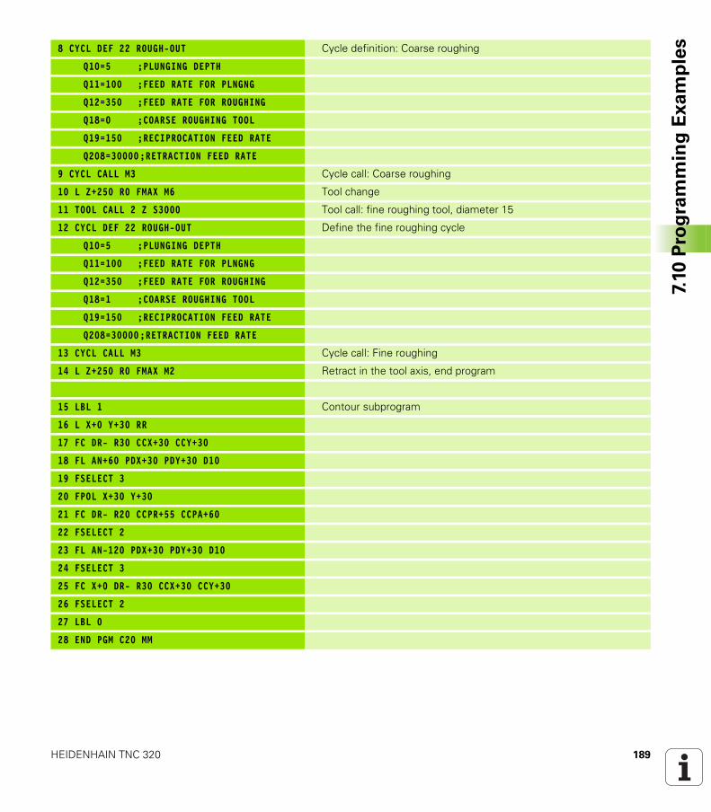
HEIDENHAIN TNC 320 189
7.10
Pro
gra
mm
ing
Ex
am
ple
s8 CYCL DEF 22 ROUGH-OUT Cycle definition: Coarse roughing
Q10=5 ;PLUNGING DEPTH
Q11=100 ;FEED RATE FOR PLNGNG
Q12=350 ;FEED RATE FOR ROUGHING
Q18=0 ;COARSE ROUGHING TOOL
Q19=150 ;RECIPROCATION FEED RATE
Q208=30000;RETRACTION FEED RATE
9 CYCL CALL M3 Cycle call: Coarse roughing
10 L Z+250 R0 FMAX M6 Tool change
11 TOOL CALL 2 Z S3000 Tool call: fine roughing tool, diameter 15
12 CYCL DEF 22 ROUGH-OUT Define the fine roughing cycle
Q10=5 ;PLUNGING DEPTH
Q11=100 ;FEED RATE FOR PLNGNG
Q12=350 ;FEED RATE FOR ROUGHING
Q18=1 ;COARSE ROUGHING TOOL
Q19=150 ;RECIPROCATION FEED RATE
Q208=30000;RETRACTION FEED RATE
13 CYCL CALL M3 Cycle call: Fine roughing
14 L Z+250 R0 FMAX M2 Retract in the tool axis, end program
15 LBL 1 Contour subprogram
16 L X+0 Y+30 RR
17 FC DR- R30 CCX+30 CCY+30
18 FL AN+60 PDX+30 PDY+30 D10
19 FSELECT 3
20 FPOL X+30 Y+30
21 FC DR- R20 CCPR+55 CCPA+60
22 FSELECT 2
23 FL AN-120 PDX+30 PDY+30 D10
24 FSELECT 3
25 FC X+0 DR- R30 CCX+30 CCY+30
26 FSELECT 2
27 LBL 0
28 END PGM C20 MM
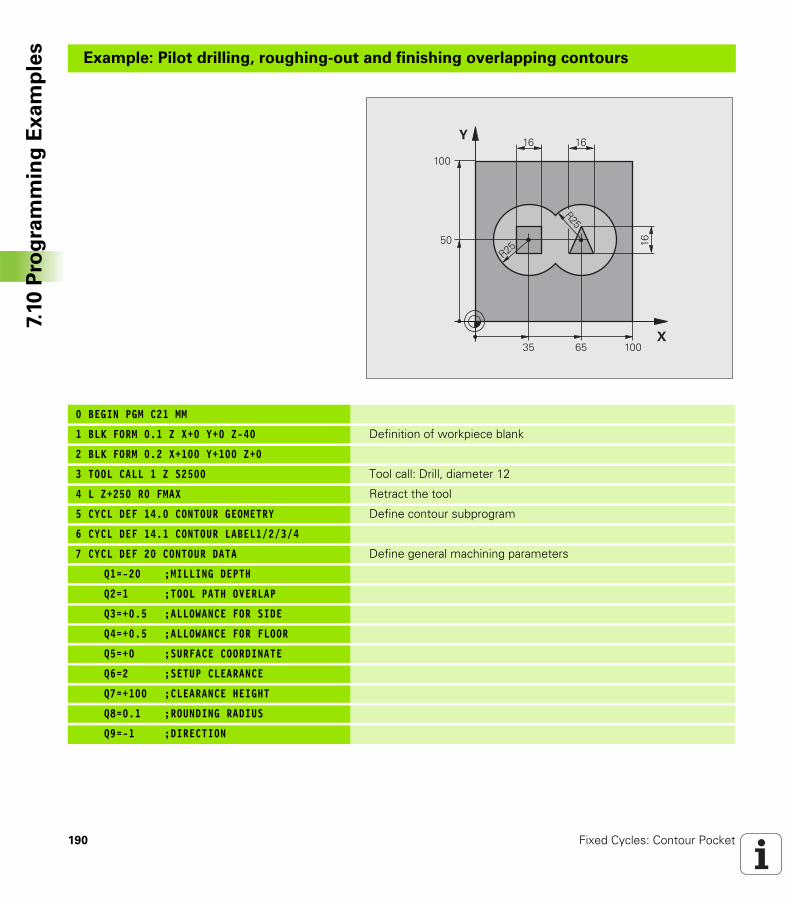
190 Fixed Cycles: Contour Pocket
7.10
Pro
gra
mm
ing
Ex
am
ple
sExample: Pilot drilling, roughing-out and finishing overlapping contours
0 BEGIN PGM C21 MM
1 BLK FORM 0.1 Z X+0 Y+0 Z-40 Definition of workpiece blank
2 BLK FORM 0.2 X+100 Y+100 Z+0
3 TOOL CALL 1 Z S2500 Tool call: Drill, diameter 12
4 L Z+250 R0 FMAX Retract the tool
5 CYCL DEF 14.0 CONTOUR GEOMETRY Define contour subprogram
6 CYCL DEF 14.1 CONTOUR LABEL1/2/3/4
7 CYCL DEF 20 CONTOUR DATA Define general machining parameters
Q1=-20 ;MILLING DEPTH
Q2=1 ;TOOL PATH OVERLAP
Q3=+0.5 ;ALLOWANCE FOR SIDE
Q4=+0.5 ;ALLOWANCE FOR FLOOR
Q5=+0 ;SURFACE COORDINATE
Q6=2 ;SETUP CLEARANCE
Q7=+100 ;CLEARANCE HEIGHT
Q8=0.1 ;ROUNDING RADIUS
Q9=-1 ;DIRECTION
�
�
�
�
���
���
��
��
��
�
��
��
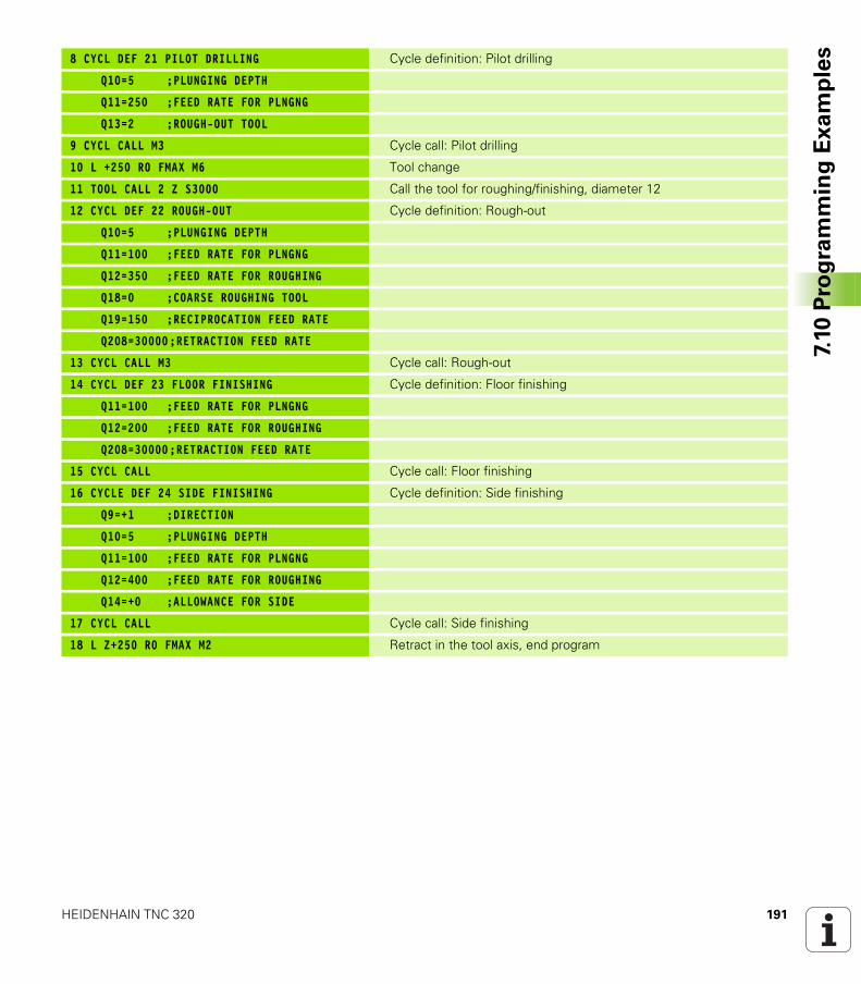
HEIDENHAIN TNC 320 191
7.10
Pro
gra
mm
ing
Ex
am
ple
s8 CYCL DEF 21 PILOT DRILLING Cycle definition: Pilot drilling
Q10=5 ;PLUNGING DEPTH
Q11=250 ;FEED RATE FOR PLNGNG
Q13=2 ;ROUGH-OUT TOOL
9 CYCL CALL M3 Cycle call: Pilot drilling
10 L +250 R0 FMAX M6 Tool change
11 TOOL CALL 2 Z S3000 Call the tool for roughing/finishing, diameter 12
12 CYCL DEF 22 ROUGH-OUT Cycle definition: Rough-out
Q10=5 ;PLUNGING DEPTH
Q11=100 ;FEED RATE FOR PLNGNG
Q12=350 ;FEED RATE FOR ROUGHING
Q18=0 ;COARSE ROUGHING TOOL
Q19=150 ;RECIPROCATION FEED RATE
Q208=30000;RETRACTION FEED RATE
13 CYCL CALL M3 Cycle call: Rough-out
14 CYCL DEF 23 FLOOR FINISHING Cycle definition: Floor finishing
Q11=100 ;FEED RATE FOR PLNGNG
Q12=200 ;FEED RATE FOR ROUGHING
Q208=30000;RETRACTION FEED RATE
15 CYCL CALL Cycle call: Floor finishing
16 CYCLE DEF 24 SIDE FINISHING Cycle definition: Side finishing
Q9=+1 ;DIRECTION
Q10=5 ;PLUNGING DEPTH
Q11=100 ;FEED RATE FOR PLNGNG
Q12=400 ;FEED RATE FOR ROUGHING
Q14=+0 ;ALLOWANCE FOR SIDE
17 CYCL CALL Cycle call: Side finishing
18 L Z+250 R0 FMAX M2 Retract in the tool axis, end program
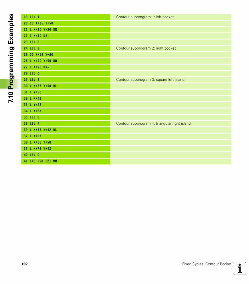
192 Fixed Cycles: Contour Pocket
7.10
Pro
gra
mm
ing
Ex
am
ple
s 19 LBL 1 Contour subprogram 1: left pocket
20 CC X+35 Y+50
21 L X+10 Y+50 RR
22 C X+10 DR-
23 LBL 0
24 LBL 2 Contour subprogram 2: right pocket
25 CC X+65 Y+50
26 L X+90 Y+50 RR
27 C X+90 DR-
28 LBL 0
29 LBL 3 Contour subprogram 3: square left island
30 L X+27 Y+50 RL
31 L Y+58
32 L X+43
33 L Y+42
34 L X+27
35 LBL 0
36 LBL 4 Contour subprogram 4: triangular right island
39 L X+65 Y+42 RL
37 L X+57
38 L X+65 Y+58
39 L X+73 Y+42
40 LBL 0
41 END PGM C21 MM
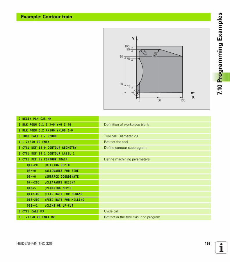
HEIDENHAIN TNC 320 193
7.10
Pro
gra
mm
ing
Ex
am
ple
s
Example: Contour train
0 BEGIN PGM C25 MM
1 BLK FORM 0.1 Z X+0 Y+0 Z-40 Definition of workpiece blank
2 BLK FORM 0.2 X+100 Y+100 Z+0
3 TOOL CALL 1 Z S2000 Tool call: Diameter 20
4 L Z+250 R0 FMAX Retract the tool
5 CYCL DEF 14.0 CONTOUR GEOMETRY Define contour subprogram
6 CYCL DEF 14.1 CONTOUR LABEL 1
7 CYCL DEF 25 CONTOUR TRAIN Define machining parameters
Q1=-20 ;MILLING DEPTH
Q3=+0 ;ALLOWANCE FOR SIDE
Q5=+0 ;SURFACE COORDINATE
Q7=+250 ;CLEARANCE HEIGHT
Q10=5 ;PLUNGING DEPTH
Q11=100 ;FEED RATE FOR PLNGNG
Q12=200 ;FEED RATE FOR MILLING
Q15=+1 ;CLIMB OR UP-CUT
8 CYCL CALL M3 Cycle call
9 L Z+250 R0 FMAX M2 Retract in the tool axis, end program
�
�
��
���
���
�
�
�
�
����
���
194 Fixed Cycles: Contour Pocket
7.10
Pro
gra
mm
ing
Ex
am
ple
s 10 LBL 1 Contour subprogram
11 L X+0 Y+15 RL
12 L X+5 Y+20
13 CT X+5 Y+75
14 L Y+95
15 RND R7.5
16 L X+50
17 RND R7.5
18 L X+100 Y+80
19 LBL 0
20 END PGM C25 MM
Fixed Cycles: Cylindrical
Surface
196 Fixed Cycles: Cylindrical Surface
8.1
Fu
nd
am
en
tals 8.1 Fundamentals
Overview of cylindrical surface cycles
Cycle Soft key Page
27 CYLINDER SURFACE Page 197
28 CYLINDER SURFACE slot milling Page 200
29 CYLINDER SURFACE ridge milling Page 203
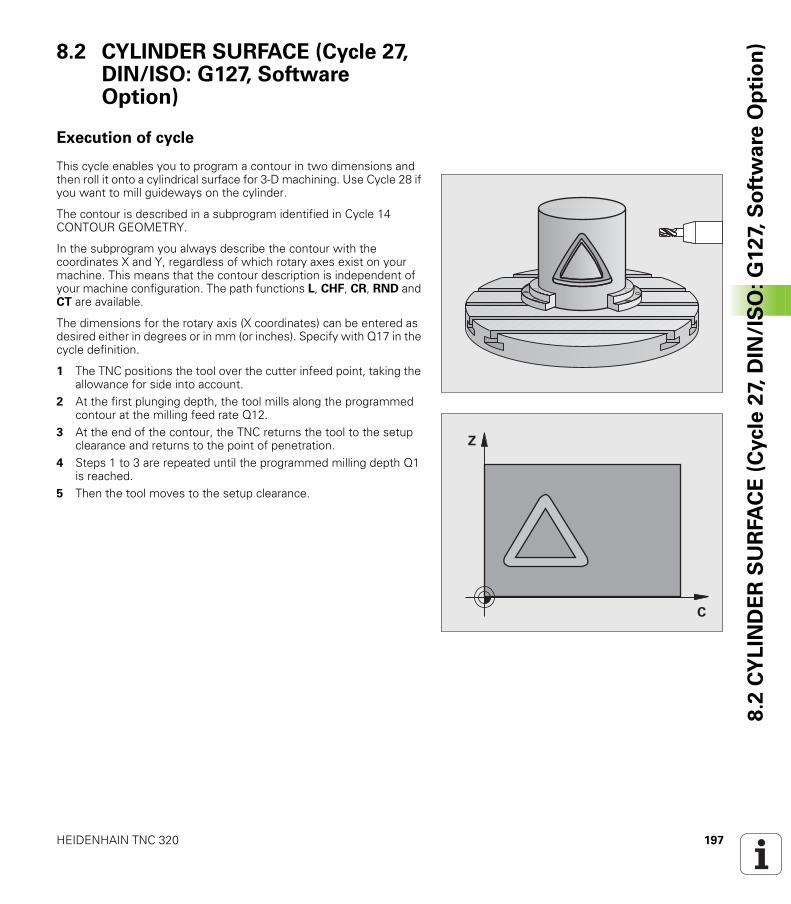
HEIDENHAIN TNC 320 197
8.2
CY
LIN
DE
R S
UR
FA
CE
(C
ycle
27,
DIN
/IS
O:
G1
27,
So
ftw
are
Op
tio
n)8.2 CYLINDER SURFACE (Cycle 27,
DIN/ISO: G127, Software Option)
Execution of cycle
This cycle enables you to program a contour in two dimensions and then roll it onto a cylindrical surface for 3-D machining. Use Cycle 28 if you want to mill guideways on the cylinder.
The contour is described in a subprogram identified in Cycle 14 CONTOUR GEOMETRY.
In the subprogram you always describe the contour with the coordinates X and Y, regardless of which rotary axes exist on your machine. This means that the contour description is independent of your machine configuration. The path functions L, CHF, CR, RND and CT are available.
The dimensions for the rotary axis (X coordinates) can be entered as desired either in degrees or in mm (or inches). Specify with Q17 in the cycle definition.
1 The TNC positions the tool over the cutter infeed point, taking the allowance for side into account.
2 At the first plunging depth, the tool mills along the programmed contour at the milling feed rate Q12.
3 At the end of the contour, the TNC returns the tool to the setup clearance and returns to the point of penetration.
4 Steps 1 to 3 are repeated until the programmed milling depth Q1 is reached.
5 Then the tool moves to the setup clearance.
�
�
198 Fixed Cycles: Cylindrical Surface
8.2
CY
LIN
DE
R S
UR
FA
CE
(C
ycle
27,
DIN
/IS
O:
G1
27,
So
ftw
are
Op
tio
n) Please note while programming:
The machine and TNC must be prepared for cylinder surface interpolation by the machine manufacturer. Refer to your machine tool manual.
In the first NC block of the contour program, always program both cylinder surface coordinates.
The memory capacity for programming an SL cycle is limited. You can program up to 16384 contour elements in one SL cycle.
The algebraic sign for the cycle parameter DEPTH determines the working direction. If you program DEPTH = 0, the cycle will not be executed.
This cycle requires a center-cut end mill (DIN 844).
The cylinder must be set up centered on the rotary table. Set the reference point to the center of the rotary table.
The spindle axis must be perpendicular to the rotary table axis when the cycle is called; switching of the kinematics may be required. If this is not the case, the TNC will generate an error message.
This cycle can also be used in a tilted working plane.
The set-up clearance must be greater than the tool radius.
The machining time can increase if the contour consists of many non-tangential contour elements.
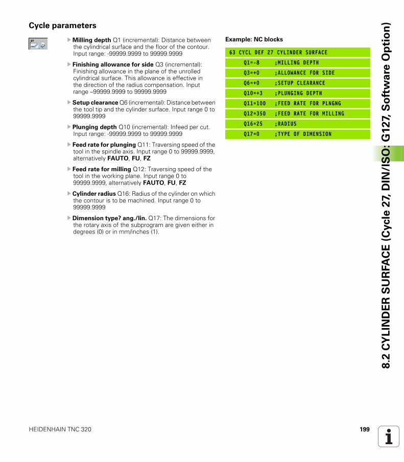
HEIDENHAIN TNC 320 199
8.2
CY
LIN
DE
R S
UR
FA
CE
(C
ycle
27,
DIN
/IS
O:
G1
27,
So
ftw
are
Op
tio
n)Cycle parameters
UMilling depth Q1 (incremental): Distance between the cylindrical surface and the floor of the contour. Input range: -99999.9999 to 99999.9999
U Finishing allowance for side Q3 (incremental): Finishing allowance in the plane of the unrolled cylindrical surface. This allowance is effective in the direction of the radius compensation. Input range –99999.9999 to 99999.9999
U Setup clearance Q6 (incremental): Distance between the tool tip and the cylinder surface. Input range 0 to 99999.9999
U Plunging depth Q10 (incremental): Infeed per cut. Input range: -99999.9999 to 99999.9999
U Feed rate for plunging Q11: Traversing speed of the tool in the spindle axis. Input range 0 to 99999.9999, alternatively FAUTO, FU, FZ
U Feed rate for milling Q12: Traversing speed of the tool in the working plane. Input range 0 to 99999.9999, alternatively FAUTO, FU, FZ
U Cylinder radius Q16: Radius of the cylinder on which the contour is to be machined. Input range 0 to 99999.9999
U Dimension type? ang./lin. Q17: The dimensions for the rotary axis of the subprogram are given either in degrees (0) or in mm/inches (1).
Example: NC blocks
63 CYCL DEF 27 CYLINDER SURFACE
Q1=-8 ;MILLING DEPTH
Q3=+0 ;ALLOWANCE FOR SIDE
Q6=+0 ;SETUP CLEARANCE
Q10=+3 ;PLUNGING DEPTH
Q11=100 ;FEED RATE FOR PLNGNG
Q12=350 ;FEED RATE FOR MILLING
Q16=25 ;RADIUS
Q17=0 ;TYPE OF DIMENSION
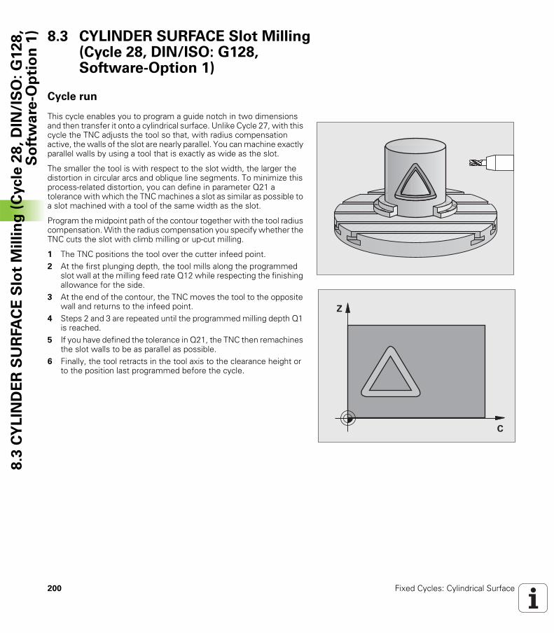
200 Fixed Cycles: Cylindrical Surface
8.3
CY
LIN
DE
R S
UR
FA
CE
Slo
t M
illi
ng
(C
ycle
28
, D
IN/I
SO
: G
12
8,
So
ftw
are
-Op
tio
n 1
) 8.3 CYLINDER SURFACE Slot Milling (Cycle 28, DIN/ISO: G128, Software-Option 1)
Cycle run
This cycle enables you to program a guide notch in two dimensions and then transfer it onto a cylindrical surface. Unlike Cycle 27, with this cycle the TNC adjusts the tool so that, with radius compensation active, the walls of the slot are nearly parallel. You can machine exactly parallel walls by using a tool that is exactly as wide as the slot.
The smaller the tool is with respect to the slot width, the larger the distortion in circular arcs and oblique line segments. To minimize this process-related distortion, you can define in parameter Q21 a tolerance with which the TNC machines a slot as similar as possible to a slot machined with a tool of the same width as the slot.
Program the midpoint path of the contour together with the tool radius compensation. With the radius compensation you specify whether the TNC cuts the slot with climb milling or up-cut milling.
1 The TNC positions the tool over the cutter infeed point.2 At the first plunging depth, the tool mills along the programmed
slot wall at the milling feed rate Q12 while respecting the finishing allowance for the side.
3 At the end of the contour, the TNC moves the tool to the opposite wall and returns to the infeed point.
4 Steps 2 and 3 are repeated until the programmed milling depth Q1 is reached.
5 If you have defined the tolerance in Q21, the TNC then remachines the slot walls to be as parallel as possible.
6 Finally, the tool retracts in the tool axis to the clearance height or to the position last programmed before the cycle.
�
�
HEIDENHAIN TNC 320 201
8.3
CY
LIN
DE
R S
UR
FA
CE
Slo
t M
illi
ng
(C
ycle
28
, D
IN/I
SO
: G
12
8,
So
ftw
are
-Op
tio
n 1
)Please note while programming:
The machine and TNC must be prepared for cylinder surface interpolation by the machine manufacturer. Refer to your machine tool manual.
In the first NC block of the contour program, always program both cylinder surface coordinates.
The memory capacity for programming an SL cycle is limited. You can program up to 16384 contour elements in one SL cycle.
The algebraic sign for the cycle parameter DEPTH determines the working direction. If you program DEPTH = 0, the cycle will not be executed.
This cycle requires a center-cut end mill (DIN 844).
The cylinder must be set up centered on the rotary table. Set the reference point to the center of the rotary table.
The spindle axis must be perpendicular to the rotary table axis when the cycle is called; switching of the kinematics may be required. If this is not the case, the TNC will generate an error message.
This cycle can also be used in a tilted working plane.
The set-up clearance must be greater than the tool radius.
The machining time can increase if the contour consists of many non-tangential contour elements.
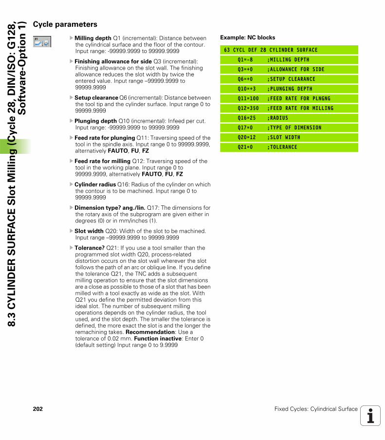
202 Fixed Cycles: Cylindrical Surface
8.3
CY
LIN
DE
R S
UR
FA
CE
Slo
t M
illi
ng
(C
ycle
28
, D
IN/I
SO
: G
12
8,
So
ftw
are
-Op
tio
n 1
) Cycle parameters
UMilling depth Q1 (incremental): Distance between the cylindrical surface and the floor of the contour. Input range: -99999.9999 to 99999.9999
U Finishing allowance for side Q3 (incremental): Finishing allowance on the slot wall. The finishing allowance reduces the slot width by twice the entered value. Input range –99999.9999 to 99999.9999
U Setup clearance Q6 (incremental): Distance between the tool tip and the cylinder surface. Input range 0 to 99999.9999
U Plunging depth Q10 (incremental): Infeed per cut. Input range: -99999.9999 to 99999.9999
U Feed rate for plunging Q11: Traversing speed of the tool in the spindle axis. Input range 0 to 99999.9999, alternatively FAUTO, FU, FZ
U Feed rate for milling Q12: Traversing speed of the tool in the working plane. Input range 0 to 99999.9999, alternatively FAUTO, FU, FZ
U Cylinder radius Q16: Radius of the cylinder on which the contour is to be machined. Input range 0 to 99999.9999
U Dimension type? ang./lin. Q17: The dimensions for the rotary axis of the subprogram are given either in degrees (0) or in mm/inches (1).
U Slot width Q20: Width of the slot to be machined. Input range –99999.9999 to 99999.9999
U Tolerance? Q21: If you use a tool smaller than the programmed slot width Q20, process-related distortion occurs on the slot wall wherever the slot follows the path of an arc or oblique line. If you define the tolerance Q21, the TNC adds a subsequent milling operation to ensure that the slot dimensions are a close as possible to those of a slot that has been milled with a tool exactly as wide as the slot. With Q21 you define the permitted deviation from this ideal slot. The number of subsequent milling operations depends on the cylinder radius, the tool used, and the slot depth. The smaller the tolerance is defined, the more exact the slot is and the longer the remachining takes. Recommendation: Use a tolerance of 0.02 mm. Function inactive: Enter 0 (default setting) Input range 0 to 9.9999
Example: NC blocks
63 CYCL DEF 28 CYLINDER SURFACE
Q1=-8 ;MILLING DEPTH
Q3=+0 ;ALLOWANCE FOR SIDE
Q6=+0 ;SETUP CLEARANCE
Q10=+3 ;PLUNGING DEPTH
Q11=100 ;FEED RATE FOR PLNGNG
Q12=350 ;FEED RATE FOR MILLING
Q16=25 ;RADIUS
Q17=0 ;TYPE OF DIMENSION
Q20=12 ;SLOT WIDTH
Q21=0 ;TOLERANCE
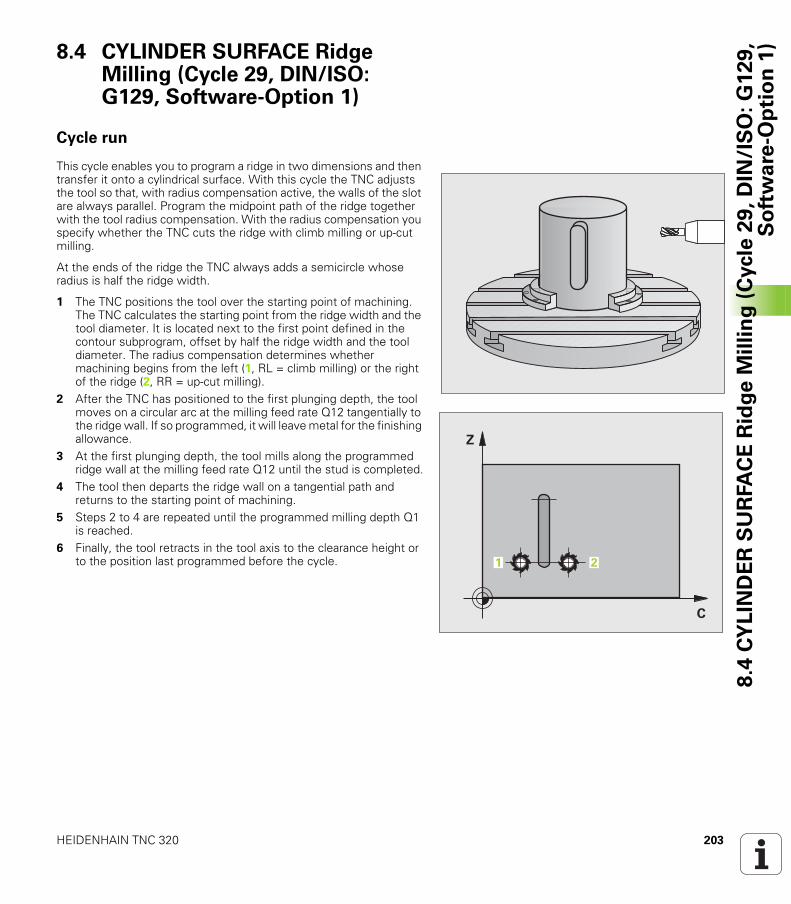
HEIDENHAIN TNC 320 203
8.4
CY
LIN
DE
R S
UR
FA
CE
Rid
ge
Mil
lin
g (
Cycle
29
, D
IN/I
SO
: G
12
9,
So
ftw
are
-Op
tio
n 1
)8.4 CYLINDER SURFACE Ridge Milling (Cycle 29, DIN/ISO: G129, Software-Option 1)
Cycle run
This cycle enables you to program a ridge in two dimensions and then transfer it onto a cylindrical surface. With this cycle the TNC adjusts the tool so that, with radius compensation active, the walls of the slot are always parallel. Program the midpoint path of the ridge together with the tool radius compensation. With the radius compensation you specify whether the TNC cuts the ridge with climb milling or up-cut milling.
At the ends of the ridge the TNC always adds a semicircle whose radius is half the ridge width.
1 The TNC positions the tool over the starting point of machining. The TNC calculates the starting point from the ridge width and the tool diameter. It is located next to the first point defined in the contour subprogram, offset by half the ridge width and the tool diameter. The radius compensation determines whether machining begins from the left (1, RL = climb milling) or the right of the ridge (2, RR = up-cut milling).
2 After the TNC has positioned to the first plunging depth, the tool moves on a circular arc at the milling feed rate Q12 tangentially to the ridge wall. If so programmed, it will leave metal for the finishing allowance.
3 At the first plunging depth, the tool mills along the programmed ridge wall at the milling feed rate Q12 until the stud is completed.
4 The tool then departs the ridge wall on a tangential path and returns to the starting point of machining.
5 Steps 2 to 4 are repeated until the programmed milling depth Q1 is reached.
6 Finally, the tool retracts in the tool axis to the clearance height or to the position last programmed before the cycle.
�
�
� �
204 Fixed Cycles: Cylindrical Surface
8.4
CY
LIN
DE
R S
UR
FA
CE
Rid
ge
Mil
lin
g (
Cycle
29
, D
IN/I
SO
: G
12
9,
So
ftw
are
-Op
tio
n 1
) Please note while programming:
The machine and TNC must be prepared for cylinder surface interpolation by the machine manufacturer. Refer to your machine tool manual.
In the first NC block of the contour program, always program both cylinder surface coordinates.
The memory capacity for programming an SL cycle is limited. You can program up to 16384 contour elements in one SL cycle.
The algebraic sign for the cycle parameter DEPTH determines the working direction. If you program DEPTH = 0, the cycle will not be executed.
This cycle requires a center-cut end mill (DIN 844).
The cylinder must be set up centered on the rotary table. Set the reference point to the center of the rotary table.
The spindle axis must be perpendicular to the rotary table axis when the cycle is called; switching of the kinematics may be required. If this is not the case, the TNC will generate an error message.
This cycle can also be used in a tilted working plane.
The set-up clearance must be greater than the tool radius.
The machining time can increase if the contour consists of many non-tangential contour elements.

HEIDENHAIN TNC 320 205
8.4
CY
LIN
DE
R S
UR
FA
CE
Rid
ge
Mil
lin
g (
Cycle
29
, D
IN/I
SO
: G
12
9,
So
ftw
are
-Op
tio
n 1
)Cycle parameters
UMilling depth Q1 (incremental): Distance between the cylindrical surface and the floor of the contour. Input range: -99999.9999 to 99999.9999
U Finishing allowance for side Q3 (incremental): Finishing allowance on the ridge wall. The finishing allowance increases the ridge width by twice the entered value. Input range: -99999.9999 to 99999.9999
U Setup clearance Q6 (incremental): Distance between the tool tip and the cylinder surface. Input range 0 to 99999.9999
U Plunging depth Q10 (incremental): Infeed per cut. Input range: -99999.9999 to 99999.9999
U Feed rate for plunging Q11: Traversing speed of the tool in the spindle axis. Input range 0 to 99999.9999, alternatively FAUTO, FU, FZ
U Feed rate for milling Q12: Traversing speed of the tool in the working plane. Input range 0 to 99999.9999, alternatively FAUTO, FU, FZ
U Cylinder radius Q16: Radius of the cylinder on which the contour is to be machined. Input range 0 to 99999.9999
U Dimension type? ang./lin. Q17: The dimensions for the rotary axis of the subprogram are given either in degrees (0) or in mm/inches (1).
U Ridge width Q20: Width of the ridge to be machined. Input range –99999.9999 to 99999.9999
Example: NC blocks
63 CYCL DEF 29 CYLINDER SURFACE RIDGE
Q1=-8 ;MILLING DEPTH
Q3=+0 ;ALLOWANCE FOR SIDE
Q6=+0 ;SETUP CLEARANCE
Q10=+3 ;PLUNGING DEPTH
Q11=100 ;FEED RATE FOR PLNGNG
Q12=350 ;FEED RATE FOR MILLING
Q16=25 ;RADIUS
Q17=0 ;TYPE OF DIMENSION
Q20=12 ;RIDGE WIDTH
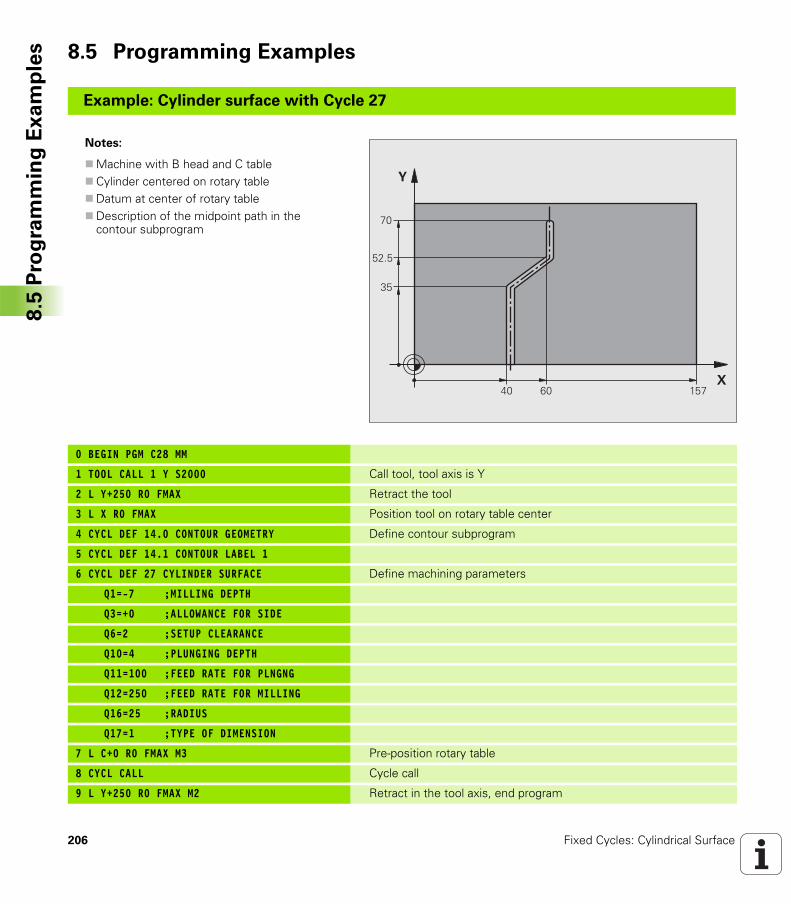
206 Fixed Cycles: Cylindrical Surface
8.5
Pro
gra
mm
ing
Ex
am
ple
s 8.5 Programming Examples
Example: Cylinder surface with Cycle 27
Notes:
Machine with B head and C tableCylinder centered on rotary tableDatum at center of rotary tableDescription of the midpoint path in the contour subprogram
0 BEGIN PGM C28 MM
1 TOOL CALL 1 Y S2000 Call tool, tool axis is Y
2 L Y+250 R0 FMAX Retract the tool
3 L X R0 FMAX Position tool on rotary table center
4 CYCL DEF 14.0 CONTOUR GEOMETRY Define contour subprogram
5 CYCL DEF 14.1 CONTOUR LABEL 1
6 CYCL DEF 27 CYLINDER SURFACE Define machining parameters
Q1=-7 ;MILLING DEPTH
Q3=+0 ;ALLOWANCE FOR SIDE
Q6=2 ;SETUP CLEARANCE
Q10=4 ;PLUNGING DEPTH
Q11=100 ;FEED RATE FOR PLNGNG
Q12=250 ;FEED RATE FOR MILLING
Q16=25 ;RADIUS
Q17=1 ;TYPE OF DIMENSION
7 L C+0 R0 FMAX M3 Pre-position rotary table
8 CYCL CALL Cycle call
9 L Y+250 R0 FMAX M2 Retract in the tool axis, end program
�
�
��
��
��
�
��
��
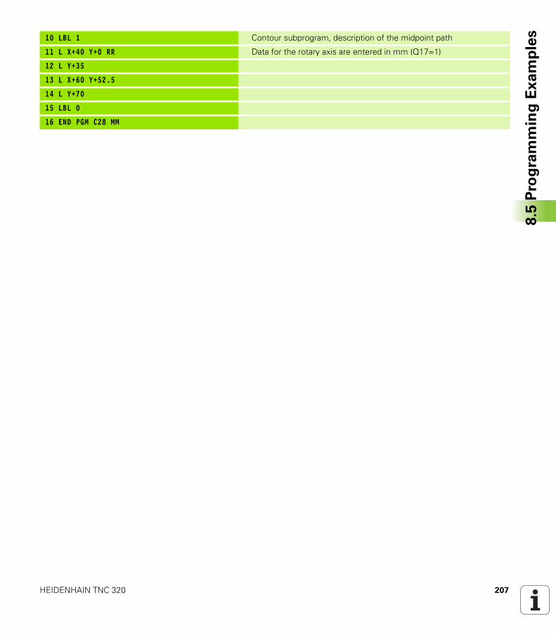
HEIDENHAIN TNC 320 207
8.5
Pro
gra
mm
ing
Ex
am
ple
s10 LBL 1 Contour subprogram, description of the midpoint path
11 L X+40 Y+0 RR Data for the rotary axis are entered in mm (Q17=1)
12 L Y+35
13 L X+60 Y+52.5
14 L Y+70
15 LBL 0
16 END PGM C28 MM
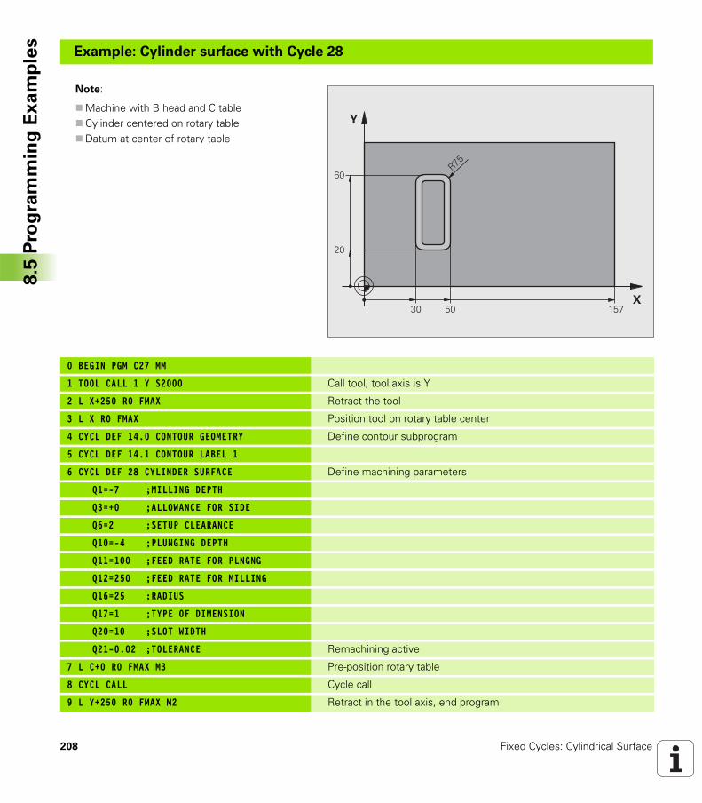
208 Fixed Cycles: Cylindrical Surface
8.5
Pro
gra
mm
ing
Ex
am
ple
sExample: Cylinder surface with Cycle 28
Note:
Machine with B head and C tableCylinder centered on rotary tableDatum at center of rotary table
0 BEGIN PGM C27 MM
1 TOOL CALL 1 Y S2000 Call tool, tool axis is Y
2 L X+250 R0 FMAX Retract the tool
3 L X R0 FMAX Position tool on rotary table center
4 CYCL DEF 14.0 CONTOUR GEOMETRY Define contour subprogram
5 CYCL DEF 14.1 CONTOUR LABEL 1
6 CYCL DEF 28 CYLINDER SURFACE Define machining parameters
Q1=-7 ;MILLING DEPTH
Q3=+0 ;ALLOWANCE FOR SIDE
Q6=2 ;SETUP CLEARANCE
Q10=-4 ;PLUNGING DEPTH
Q11=100 ;FEED RATE FOR PLNGNG
Q12=250 ;FEED RATE FOR MILLING
Q16=25 ;RADIUS
Q17=1 ;TYPE OF DIMENSION
Q20=10 ;SLOT WIDTH
Q21=0.02 ;TOLERANCE Remachining active
7 L C+0 R0 FMAX M3 Pre-position rotary table
8 CYCL CALL Cycle call
9 L Y+250 R0 FMAX M2 Retract in the tool axis, end program
�
�
��
��
��
��
���
�
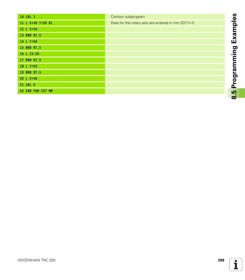
HEIDENHAIN TNC 320 209
8.5
Pro
gra
mm
ing
Ex
am
ple
s10 LBL 1 Contour subprogram
11 L X+40 Y+20 RL Data for the rotary axis are entered in mm (Q17=1)
12 L X+50
13 RND R7.5
14 L Y+60
15 RND R7.5
16 L IX-20
17 RND R7.5
18 L Y+20
19 RND R7.5
20 L X+40
21 LBL 0
22 END PGM C27 MM

210 Fixed Cycles: Cylindrical Surface
8.5
Pro
gra
mm
ing
Ex
am
ple
s
Fixed Cycles: Contour
Pocket with Contour
Formula
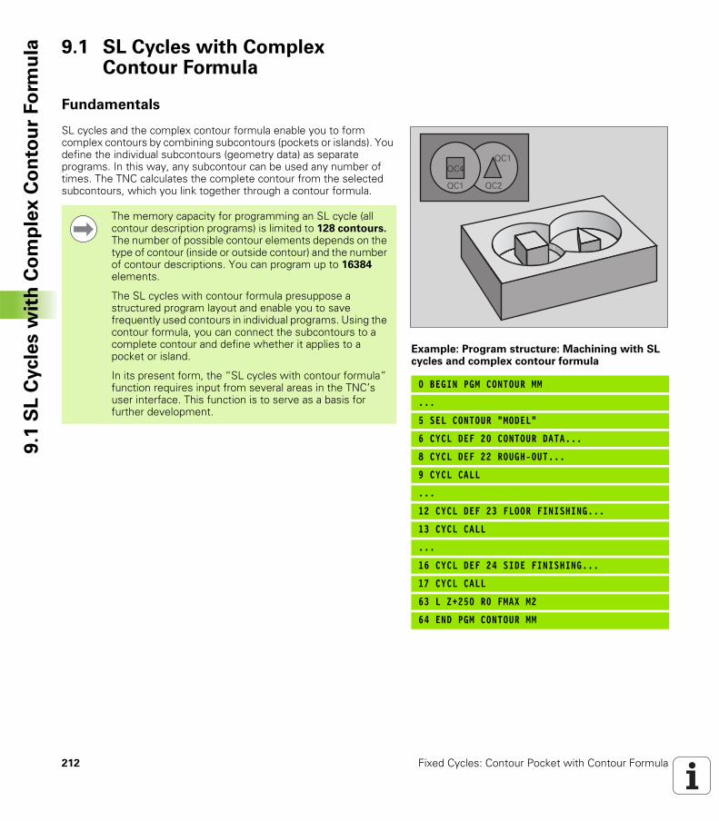
212 Fixed Cycles: Contour Pocket with Contour Formula
9.1
SL
Cycle
s w
ith
Co
mp
lex
Co
nto
ur
Fo
rmu
la 9.1 SL Cycles with Complex Contour Formula
Fundamentals
SL cycles and the complex contour formula enable you to form complex contours by combining subcontours (pockets or islands). You define the individual subcontours (geometry data) as separate programs. In this way, any subcontour can be used any number of times. The TNC calculates the complete contour from the selected subcontours, which you link together through a contour formula.
Example: Program structure: Machining with SL cycles and complex contour formula
0 BEGIN PGM CONTOUR MM
...
5 SEL CONTOUR “MODEL“
6 CYCL DEF 20 CONTOUR DATA...
8 CYCL DEF 22 ROUGH-OUT...
9 CYCL CALL
...
12 CYCL DEF 23 FLOOR FINISHING...
13 CYCL CALL
...
16 CYCL DEF 24 SIDE FINISHING...
17 CYCL CALL
63 L Z+250 R0 FMAX M2
64 END PGM CONTOUR MM
��� ���
������
The memory capacity for programming an SL cycle (all contour description programs) is limited to 128 contours. The number of possible contour elements depends on the type of contour (inside or outside contour) and the number of contour descriptions. You can program up to 16384 elements.
The SL cycles with contour formula presuppose a structured program layout and enable you to save frequently used contours in individual programs. Using the contour formula, you can connect the subcontours to a complete contour and define whether it applies to a pocket or island.
In its present form, the “SL cycles with contour formula” function requires input from several areas in the TNC’s user interface. This function is to serve as a basis for further development.
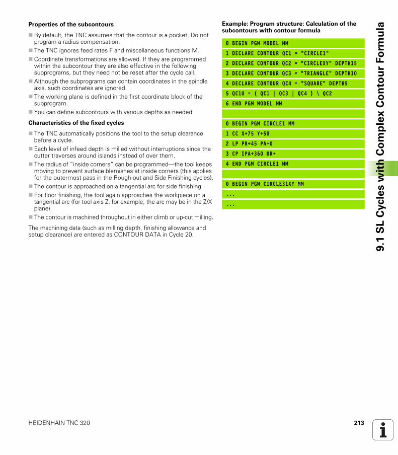
HEIDENHAIN TNC 320 213
9.1
SL
Cycle
s w
ith
Co
mp
lex
Co
nto
ur
Fo
rmu
laProperties of the subcontours
By default, the TNC assumes that the contour is a pocket. Do not program a radius compensation.The TNC ignores feed rates F and miscellaneous functions M.Coordinate transformations are allowed. If they are programmed within the subcontour they are also effective in the following subprograms, but they need not be reset after the cycle call.Although the subprograms can contain coordinates in the spindle axis, such coordinates are ignored.The working plane is defined in the first coordinate block of the subprogram.You can define subcontours with various depths as needed
Characteristics of the fixed cycles
The TNC automatically positions the tool to the setup clearance before a cycle.Each level of infeed depth is milled without interruptions since the cutter traverses around islands instead of over them.The radius of “inside corners” can be programmed—the tool keeps moving to prevent surface blemishes at inside corners (this applies for the outermost pass in the Rough-out and Side Finishing cycles).The contour is approached on a tangential arc for side finishing.For floor finishing, the tool again approaches the workpiece on a tangential arc (for tool axis Z, for example, the arc may be in the Z/X plane).The contour is machined throughout in either climb or up-cut milling.
The machining data (such as milling depth, finishing allowance and setup clearance) are entered as CONTOUR DATA in Cycle 20.
Example: Program structure: Calculation of the subcontours with contour formula
0 BEGIN PGM MODEL MM
1 DECLARE CONTOUR QC1 = “CIRCLE1“
2 DECLARE CONTOUR QC2 = “CIRCLEXY“ DEPTH15
3 DECLARE CONTOUR QC3 = “TRIANGLE“ DEPTH10
4 DECLARE CONTOUR QC4 = “SQUARE“ DEPTH5
5 QC10 = ( QC1 | QC3 | QC4 ) \ QC2
6 END PGM MODEL MM
0 BEGIN PGM CIRCLE1 MM
1 CC X+75 Y+50
2 LP PR+45 PA+0
3 CP IPA+360 DR+
4 END PGM CIRCLE1 MM
0 BEGIN PGM CIRCLE31XY MM
...
...
214 Fixed Cycles: Contour Pocket with Contour Formula
9.1
SL
Cycle
s w
ith
Co
mp
lex
Co
nto
ur
Fo
rmu
la Selecting a program with contour definitions
With the SEL CONTOUR function you select a program with contour definitions, from which the TNC takes the contour descriptions:
U Show the soft-key row with special functions
U Select the menu for functions for contour and point machining.
U Press the SEL CONTOUR soft key.
U Enter the full name of the program with the contour definition and confirm with the END key.
Defining contour descriptions
With the DECLARE CONTOUR function you enter in a program the path for programs from which the TNC draws the contour descriptions. In addition, you can select a separate depth for this contour description (FCL 2 function):
U Show the soft-key row with special functions
U Select the menu for functions for contour and point machining.
U Press the DECLARE CONTOUR soft key.
U Enter the number for the contour designator QC, and confirm with the ENT key.
U Enter the full name of the program with the contour description and confirm with the END key, or if desired,
U define a separate depth for the selected contour.
Program a SEL CONTOUR block before the SL cycles. Cycle 14 CONTOUR GEOMETRY is no longer necessary if you use SEL CONTOUR.
With the given contour designators QC you can include the various contours in the contour formula.
If you program separate depths for contours, then you must assign a depth to all subcontours (assign the depth 0 if necessary).
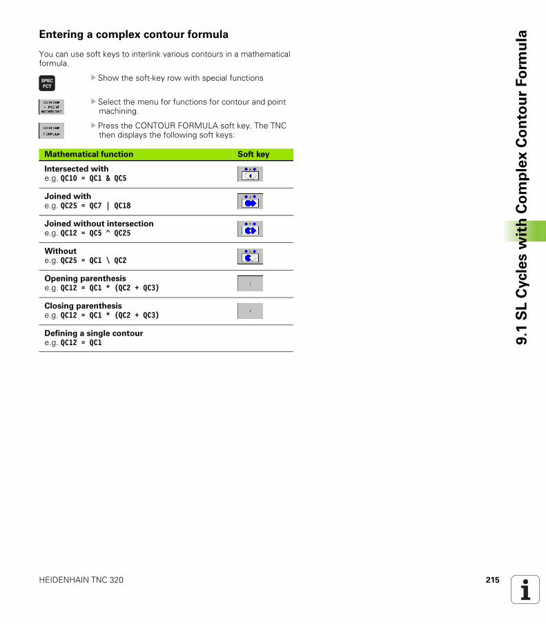
HEIDENHAIN TNC 320 215
9.1
SL
Cycle
s w
ith
Co
mp
lex
Co
nto
ur
Fo
rmu
laEntering a complex contour formula
You can use soft keys to interlink various contours in a mathematical formula.
U Show the soft-key row with special functions
U Select the menu for functions for contour and point machining.
U Press the CONTOUR FORMULA soft key. The TNC then displays the following soft keys:
Mathematical function Soft key
Intersected withe.g. QC10 = QC1 & QC5
Joined withe.g. QC25 = QC7 | QC18
Joined without intersectione.g. QC12 = QC5 ^ QC25
Withoute.g. QC25 = QC1 \ QC2
Opening parenthesise.g. QC12 = QC1 * (QC2 + QC3)
Closing parenthesise.g. QC12 = QC1 * (QC2 + QC3)
Defining a single contoure.g. QC12 = QC1
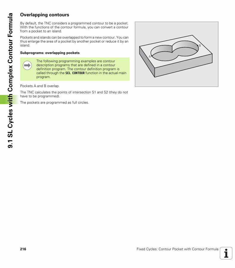
216 Fixed Cycles: Contour Pocket with Contour Formula
9.1
SL
Cycle
s w
ith
Co
mp
lex
Co
nto
ur
Fo
rmu
la Overlapping contours
By default, the TNC considers a programmed contour to be a pocket. With the functions of the contour formula, you can convert a contour from a pocket to an island.
Pockets and islands can be overlapped to form a new contour. You can thus enlarge the area of a pocket by another pocket or reduce it by an island.
Subprograms: overlapping pockets
Pockets A and B overlap.
The TNC calculates the points of intersection S1 and S2 (they do not have to be programmed).
The pockets are programmed as full circles.
�
�
The following programming examples are contour description programs that are defined in a contour definition program. The contour definition program is called through the SEL CONTOUR function in the actual main program.
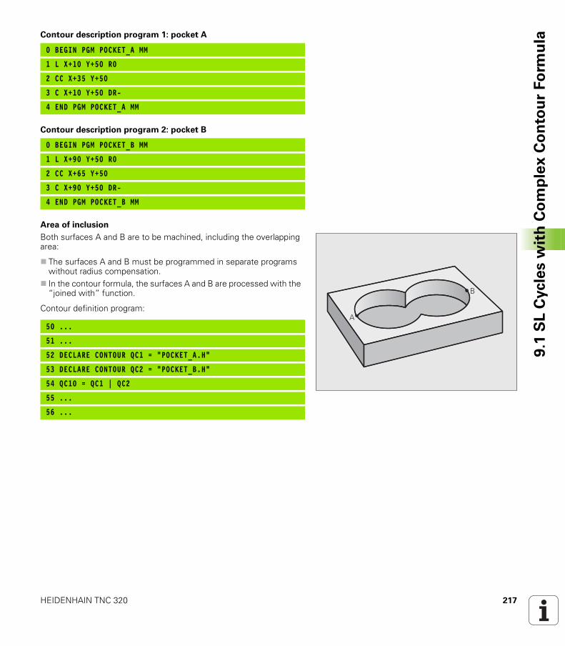
HEIDENHAIN TNC 320 217
9.1
SL
Cycle
s w
ith
Co
mp
lex
Co
nto
ur
Fo
rmu
laContour description program 1: pocket A
Contour description program 2: pocket B
Area of inclusion
Both surfaces A and B are to be machined, including the overlapping area:
The surfaces A and B must be programmed in separate programs without radius compensation.In the contour formula, the surfaces A and B are processed with the “joined with” function.
Contour definition program:
0 BEGIN PGM POCKET_A MM
1 L X+10 Y+50 R0
2 CC X+35 Y+50
3 C X+10 Y+50 DR-
4 END PGM POCKET_A MM
0 BEGIN PGM POCKET_B MM
1 L X+90 Y+50 R0
2 CC X+65 Y+50
3 C X+90 Y+50 DR-
4 END PGM POCKET_B MM
�
�
50 ...
51 ...
52 DECLARE CONTOUR QC1 = “POCKET_A.H“
53 DECLARE CONTOUR QC2 = “POCKET_B.H“
54 QC10 = QC1 | QC2
55 ...
56 ...
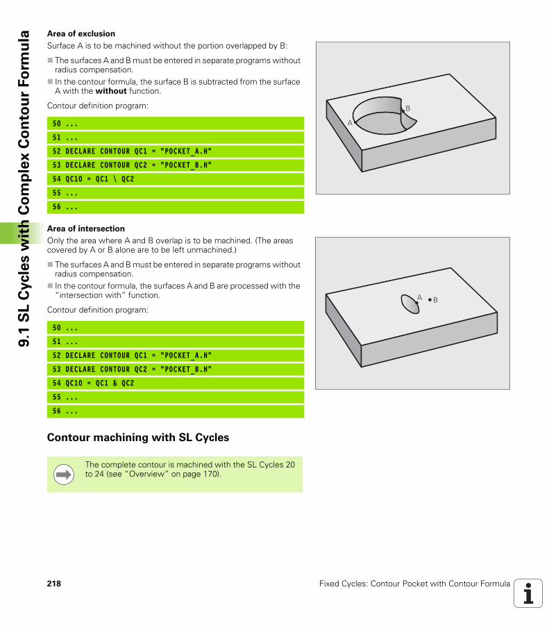
218 Fixed Cycles: Contour Pocket with Contour Formula
9.1
SL
Cycle
s w
ith
Co
mp
lex
Co
nto
ur
Fo
rmu
la Area of exclusion
Surface A is to be machined without the portion overlapped by B:
The surfaces A and B must be entered in separate programs without radius compensation.In the contour formula, the surface B is subtracted from the surface A with the without function.
Contour definition program:
Area of intersection
Only the area where A and B overlap is to be machined. (The areas covered by A or B alone are to be left unmachined.)
The surfaces A and B must be entered in separate programs without radius compensation.In the contour formula, the surfaces A and B are processed with the “intersection with” function.
Contour definition program:
Contour machining with SL Cycles
�
�
50 ...
51 ...
52 DECLARE CONTOUR QC1 = “POCKET_A.H“
53 DECLARE CONTOUR QC2 = “POCKET_B.H“
54 QC10 = QC1 \ QC2
55 ...
56 ...
� �
50 ...
51 ...
52 DECLARE CONTOUR QC1 = “POCKET_A.H“
53 DECLARE CONTOUR QC2 = “POCKET_B.H“
54 QC10 = QC1 & QC2
55 ...
56 ...
The complete contour is machined with the SL Cycles 20 to 24 (see “Overview” on page 170).
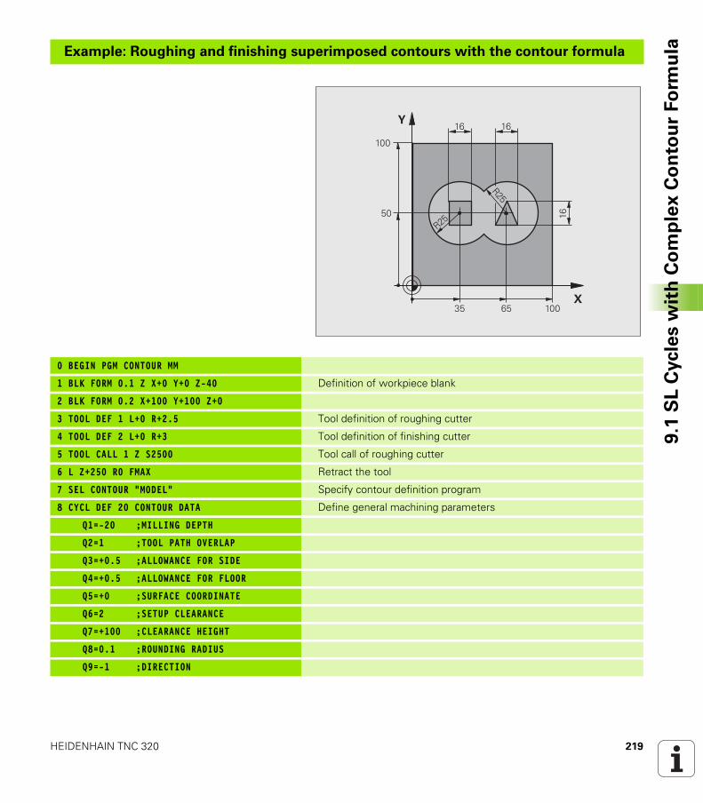
HEIDENHAIN TNC 320 219
9.1
SL
Cycle
s w
ith
Co
mp
lex
Co
nto
ur
Fo
rmu
laExample: Roughing and finishing superimposed contours with the contour formula
0 BEGIN PGM CONTOUR MM
1 BLK FORM 0.1 Z X+0 Y+0 Z-40 Definition of workpiece blank
2 BLK FORM 0.2 X+100 Y+100 Z+0
3 TOOL DEF 1 L+0 R+2.5 Tool definition of roughing cutter
4 TOOL DEF 2 L+0 R+3 Tool definition of finishing cutter
5 TOOL CALL 1 Z S2500 Tool call of roughing cutter
6 L Z+250 R0 FMAX Retract the tool
7 SEL CONTOUR “MODEL“ Specify contour definition program
8 CYCL DEF 20 CONTOUR DATA Define general machining parameters
Q1=-20 ;MILLING DEPTH
Q2=1 ;TOOL PATH OVERLAP
Q3=+0.5 ;ALLOWANCE FOR SIDE
Q4=+0.5 ;ALLOWANCE FOR FLOOR
Q5=+0 ;SURFACE COORDINATE
Q6=2 ;SETUP CLEARANCE
Q7=+100 ;CLEARANCE HEIGHT
Q8=0.1 ;ROUNDING RADIUS
Q9=-1 ;DIRECTION
�
�
�
�
���
���
��
��
��
�
��
��
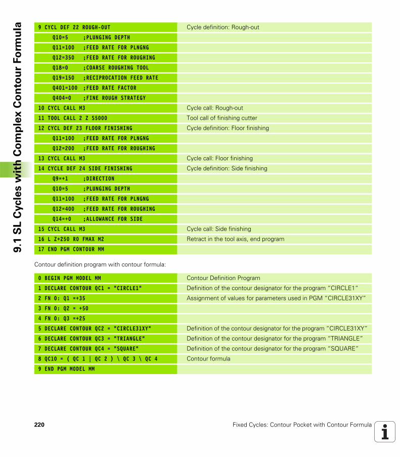
220 Fixed Cycles: Contour Pocket with Contour Formula
9.1
SL
Cycle
s w
ith
Co
mp
lex
Co
nto
ur
Fo
rmu
la
Contour definition program with contour formula:
9 CYCL DEF 22 ROUGH-OUT Cycle definition: Rough-out
Q10=5 ;PLUNGING DEPTH
Q11=100 ;FEED RATE FOR PLNGNG
Q12=350 ;FEED RATE FOR ROUGHING
Q18=0 ;COARSE ROUGHING TOOL
Q19=150 ;RECIPROCATION FEED RATE
Q401=100 ;FEED RATE FACTOR
Q404=0 ;FINE ROUGH STRATEGY
10 CYCL CALL M3 Cycle call: Rough-out
11 TOOL CALL 2 Z S5000 Tool call of finishing cutter
12 CYCL DEF 23 FLOOR FINISHING Cycle definition: Floor finishing
Q11=100 ;FEED RATE FOR PLNGNG
Q12=200 ;FEED RATE FOR ROUGHING
13 CYCL CALL M3 Cycle call: Floor finishing
14 CYCLE DEF 24 SIDE FINISHING Cycle definition: Side finishing
Q9=+1 ;DIRECTION
Q10=5 ;PLUNGING DEPTH
Q11=100 ;FEED RATE FOR PLNGNG
Q12=400 ;FEED RATE FOR ROUGHING
Q14=+0 ;ALLOWANCE FOR SIDE
15 CYCL CALL M3 Cycle call: Side finishing
16 L Z+250 R0 FMAX M2 Retract in the tool axis, end program
17 END PGM CONTOUR MM
0 BEGIN PGM MODEL MM Contour Definition Program
1 DECLARE CONTOUR QC1 = “CIRCLE1“ Definition of the contour designator for the program “CIRCLE1“
2 FN 0: Q1 =+35 Assignment of values for parameters used in PGM “CIRCLE31XY”
3 FN 0: Q2 = +50
4 FN 0: Q3 =+25
5 DECLARE CONTOUR QC2 = “CIRCLE31XY“ Definition of the contour designator for the program “CIRCLE31XY”
6 DECLARE CONTOUR QC3 = “TRIANGLE“ Definition of the contour designator for the program “TRIANGLE”
7 DECLARE CONTOUR QC4 = “SQUARE“ Definition of the contour designator for the program “SQUARE”
8 QC10 = ( QC 1 | QC 2 ) \ QC 3 \ QC 4 Contour formula
9 END PGM MODEL MM
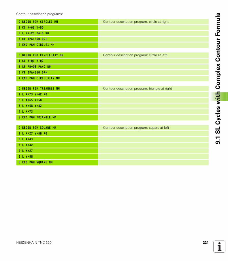
HEIDENHAIN TNC 320 221
9.1
SL
Cycle
s w
ith
Co
mp
lex
Co
nto
ur
Fo
rmu
laContour description programs:
0 BEGIN PGM CIRCLE1 MM Contour description program: circle at right
1 CC X+65 Y+50
2 L PR+25 PA+0 R0
3 CP IPA+360 DR+
4 END PGM CIRCLE1 MM
0 BEGIN PGM CIRCLE31XY MM Contour description program: circle at left
1 CC X+Q1 Y+Q2
2 LP PR+Q3 PA+0 R0
3 CP IPA+360 DR+
4 END PGM CIRCLE31XY MM
0 BEGIN PGM TRIANGLE MM Contour description program: triangle at right
1 L X+73 Y+42 R0
2 L X+65 Y+58
3 L X+58 Y+42
4 L X+73
5 END PGM TRIANGLE MM
0 BEGIN PGM SQUARE MM Contour description program: square at left
1 L X+27 Y+58 R0
2 L X+43
3 L Y+42
4 L X+27
5 L Y+58
6 END PGM SQUARE MM

222 Fixed Cycles: Contour Pocket with Contour Formula
9.2
SL
Cycle
s w
ith
Sim
ple
Co
nto
ur
Fo
rmu
la 9.2 SL Cycles with Simple Contour Formula
Fundamentals
SL cycles and the simple contour formula enable you to form contours by combining up to 9 subcontours (pockets or islands) in a simple manner. You define the individual subcontours (geometry data) as separate programs. In this way, any subcontour can be used any number of times. The TNC calculates the contour from the selected subcontours.
Properties of the subcontours
Do not program a radius compensation. The TNC ignores feed rates F and miscellaneous functions M.Coordinate transformations are allowed. If they are programmed within the subcontour they are also effective in the following subprograms, but they need not be reset after the cycle call.Although the subprograms can contain coordinates in the spindle axis, such coordinates are ignored.The working plane is defined in the first coordinate block of the subprogram.
Characteristics of the fixed cycles
The TNC automatically positions the tool to the setup clearance before a cycle.Each level of infeed depth is milled without interruptions since the cutter traverses around islands instead of over them.The radius of “inside corners” can be programmed—the tool keeps moving to prevent surface blemishes at inside corners (this applies for the outermost pass in the Rough-out and Side Finishing cycles).The contour is approached on a tangential arc for side finishing.For floor finishing, the tool again approaches the workpiece on a tangential arc (for tool axis Z, for example, the arc may be in the Z/X plane).The contour is machined throughout in either climb or up-cut milling.
The machining data (such as milling depth, finishing allowance and setup clearance) are entered as CONTOUR DATA in Cycle 20.
Example: Program structure: Machining with SL cycles and complex contour formula
0 BEGIN PGM CONTDEF MM
...
5 CONTOUR DEFP1= “POCK1.H”I2 = “ISLE2.H“ DEPTH5I3 “ISLE3.H“ DEPTH7.5
6 CYCL DEF 20 CONTOUR DATA...
8 CYCL DEF 22 ROUGH-OUT...
9 CYCL CALL
...
12 CYCL DEF 23 FLOOR FINISHING...
13 CYCL CALL
...
16 CYCL DEF 24 SIDE FINISHING...
17 CYCL CALL
63 L Z+250 R0 FMAX M2
64 END PGM CONTDEF MM
The memory capacity for programming an SL cycle (all contour description programs) is limited to 128 contours. The number of possible contour elements depends on the type of contour (inside or outside contour) and the number of contour descriptions. You can program up to 16384 elements.
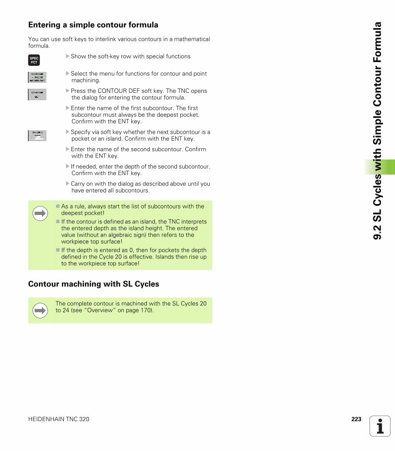
HEIDENHAIN TNC 320 223
9.2
SL
Cycle
s w
ith
Sim
ple
Co
nto
ur
Fo
rmu
laEntering a simple contour formula
You can use soft keys to interlink various contours in a mathematical formula.
U Show the soft-key row with special functions
U Select the menu for functions for contour and point machining.
U Press the CONTOUR DEF soft key. The TNC opens the dialog for entering the contour formula.
U Enter the name of the first subcontour. The first subcontour must always be the deepest pocket. Confirm with the ENT key.
U Specify via soft key whether the next subcontour is a pocket or an island. Confirm with the ENT key.
U Enter the name of the second subcontour. Confirm with the ENT key.
U If needed, enter the depth of the second subcontour. Confirm with the ENT key.
U Carry on with the dialog as described above until you have entered all subcontours.
Contour machining with SL Cycles
As a rule, always start the list of subcontours with the deepest pocket!If the contour is defined as an island, the TNC interprets the entered depth as the island height. The entered value (without an algebraic sign) then refers to the workpiece top surface!If the depth is entered as 0, then for pockets the depth defined in the Cycle 20 is effective. Islands then rise up to the workpiece top surface!
The complete contour is machined with the SL Cycles 20 to 24 (see “Overview” on page 170).
224 Fixed Cycles: Contour Pocket with Contour Formula
9.2
SL
Cycle
s w
ith
Sim
ple
Co
nto
ur
Fo
rmu
la
Fixed Cycles: Multipass
Milling
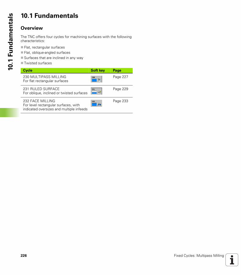
226 Fixed Cycles: Multipass Milling
10
.1 F
un
da
me
nta
ls 10.1 Fundamentals
Overview
The TNC offers four cycles for machining surfaces with the following characteristics:
Flat, rectangular surfacesFlat, oblique-angled surfacesSurfaces that are inclined in any wayTwisted surfaces
Cycle Soft key Page
230 MULTIPASS MILLING For flat rectangular surfaces
Page 227
231 RULED SURFACE For oblique, inclined or twisted surfaces
Page 229
232 FACE MILLING For level rectangular surfaces, with indicated oversizes and multiple infeeds
Page 233
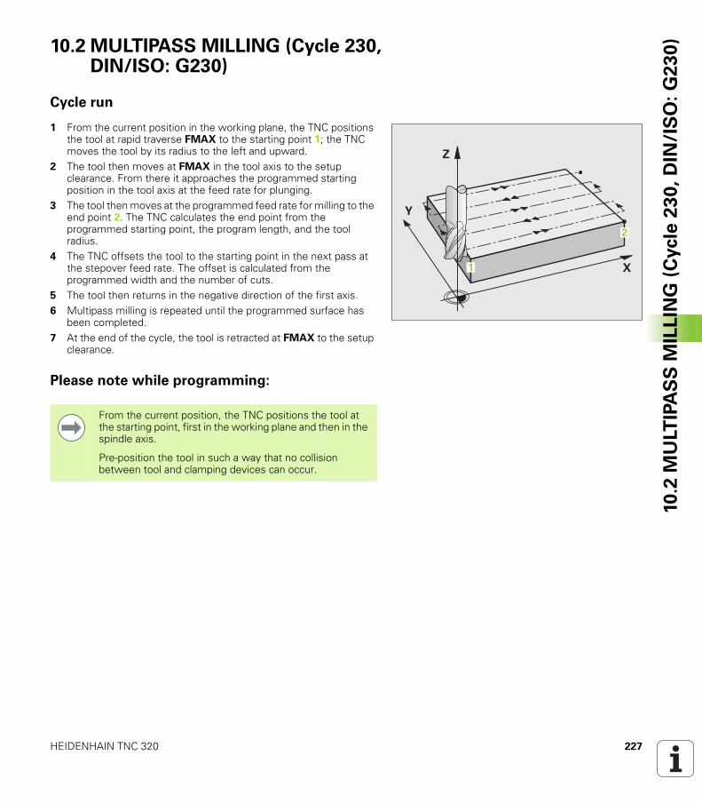
HEIDENHAIN TNC 320 227
10
.2 M
ULT
IPA
SS
MIL
LIN
G (
Cycle
23
0,
DIN
/IS
O:
G2
30
)10.2 MULTIPASS MILLING (Cycle 230, DIN/ISO: G230)
Cycle run
1 From the current position in the working plane, the TNC positions the tool at rapid traverse FMAX to the starting point 1; the TNC moves the tool by its radius to the left and upward.
2 The tool then moves at FMAX in the tool axis to the setup clearance. From there it approaches the programmed starting position in the tool axis at the feed rate for plunging.
3 The tool then moves at the programmed feed rate for milling to the end point 2. The TNC calculates the end point from the programmed starting point, the program length, and the tool radius.
4 The TNC offsets the tool to the starting point in the next pass at the stepover feed rate. The offset is calculated from the programmed width and the number of cuts.
5 The tool then returns in the negative direction of the first axis.6 Multipass milling is repeated until the programmed surface has
been completed.7 At the end of the cycle, the tool is retracted at FMAX to the setup
clearance.
Please note while programming:
�
�
�
�
�
From the current position, the TNC positions the tool at the starting point, first in the working plane and then in the spindle axis.
Pre-position the tool in such a way that no collision between tool and clamping devices can occur.
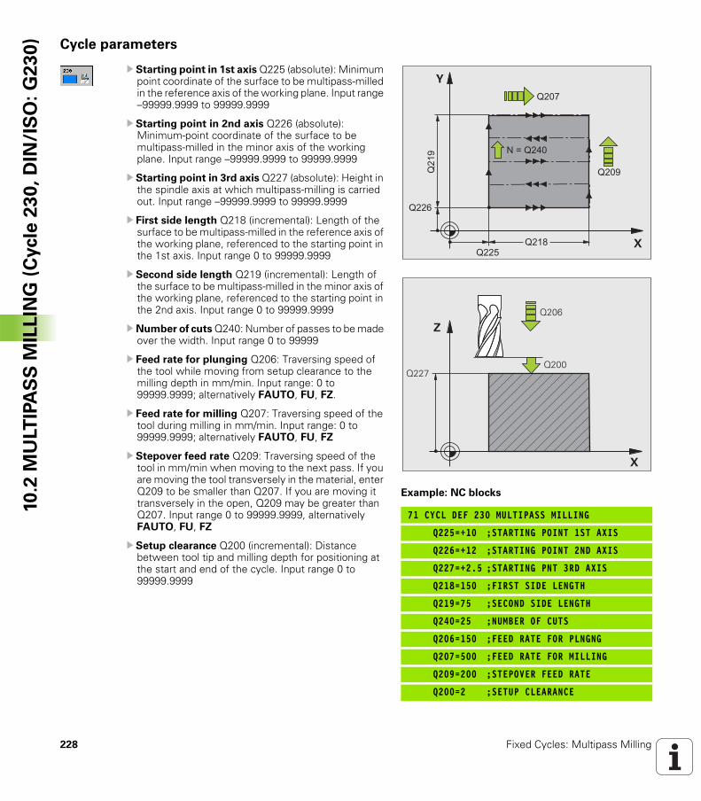
228 Fixed Cycles: Multipass Milling
10
.2 M
ULT
IPA
SS
MIL
LIN
G (
Cycle
23
0,
DIN
/IS
O:
G2
30
) Cycle parameters
U Starting point in 1st axis Q225 (absolute): Minimum point coordinate of the surface to be multipass-milled in the reference axis of the working plane. Input range –99999.9999 to 99999.9999
U Starting point in 2nd axis Q226 (absolute): Minimum-point coordinate of the surface to be multipass-milled in the minor axis of the working plane. Input range –99999.9999 to 99999.9999
U Starting point in 3rd axis Q227 (absolute): Height in the spindle axis at which multipass-milling is carried out. Input range –99999.9999 to 99999.9999
U First side length Q218 (incremental): Length of the surface to be multipass-milled in the reference axis of the working plane, referenced to the starting point in the 1st axis. Input range 0 to 99999.9999
U Second side length Q219 (incremental): Length of the surface to be multipass-milled in the minor axis of the working plane, referenced to the starting point in the 2nd axis. Input range 0 to 99999.9999
U Number of cuts Q240: Number of passes to be made over the width. Input range 0 to 99999
U Feed rate for plunging Q206: Traversing speed of the tool while moving from setup clearance to the milling depth in mm/min. Input range: 0 to 99999.9999; alternatively FAUTO, FU, FZ.
U Feed rate for milling Q207: Traversing speed of the tool during milling in mm/min. Input range: 0 to 99999.9999; alternatively FAUTO, FU, FZ
U Stepover feed rate Q209: Traversing speed of the tool in mm/min when moving to the next pass. If you are moving the tool transversely in the material, enter Q209 to be smaller than Q207. If you are moving it transversely in the open, Q209 may be greater than Q207. Input range 0 to 99999.9999, alternatively FAUTO, FU, FZ
U Setup clearance Q200 (incremental): Distance between tool tip and milling depth for positioning at the start and end of the cycle. Input range 0 to 99999.9999
Example: NC blocks
71 CYCL DEF 230 MULTIPASS MILLING
Q225=+10 ;STARTING POINT 1ST AXIS
Q226=+12 ;STARTING POINT 2ND AXIS
Q227=+2.5 ;STARTING PNT 3RD AXIS
Q218=150 ;FIRST SIDE LENGTH
Q219=75 ;SECOND SIDE LENGTH
Q240=25 ;NUMBER OF CUTS
Q206=150 ;FEED RATE FOR PLNGNG
Q207=500 ;FEED RATE FOR MILLING
Q209=200 ;STEPOVER FEED RATE
Q200=2 ;SETUP CLEARANCE
�
�
����
����
���
�
����
����
����
��������
�
�
��������
����
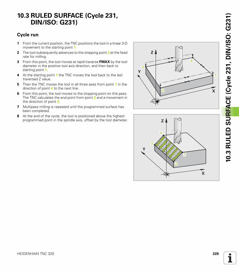
HEIDENHAIN TNC 320 229
10
.3 R
UL
ED
SU
RFA
CE
(C
ycle
23
1,
DIN
/IS
O:
G2
31
)10.3 RULED SURFACE (Cycle 231, DIN/ISO: G231)
Cycle run
1 From the current position, the TNC positions the tool in a linear 3-D movement to the starting point 1
2 The tool subsequently advances to the stopping point 2 at the feed rate for milling.
3 From this point, the tool moves at rapid traverse FMAX by the tool diameter in the positive tool axis direction, and then back to starting point 1.
4 At the starting point 1 the TNC moves the tool back to the last traversed Z value.
5 Then the TNC moves the tool in all three axes from point 1 in the direction of point 4 to the next line.
6 From this point, the tool moves to the stopping point on this pass. The TNC calculates the end point from point 2 and a movement in the direction of point 3.
7 Multipass milling is repeated until the programmed surface has been completed.
8 At the end of the cycle, the tool is positioned above the highest programmed point in the spindle axis, offset by the tool diameter.
�
�
�
�
�
�
�
�
�
�
�
�
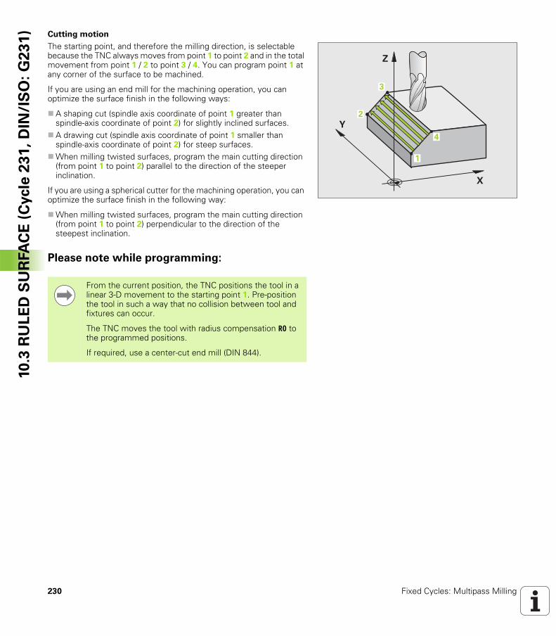
230 Fixed Cycles: Multipass Milling
10
.3 R
UL
ED
SU
RFA
CE
(C
ycle
23
1,
DIN
/IS
O:
G2
31
) Cutting motion
The starting point, and therefore the milling direction, is selectable because the TNC always moves from point 1 to point 2 and in the total movement from point 1 / 2 to point 3 / 4. You can program point 1 at any corner of the surface to be machined.
If you are using an end mill for the machining operation, you can optimize the surface finish in the following ways:
A shaping cut (spindle axis coordinate of point 1 greater than spindle-axis coordinate of point 2) for slightly inclined surfaces.A drawing cut (spindle axis coordinate of point 1 smaller than spindle-axis coordinate of point 2) for steep surfaces.When milling twisted surfaces, program the main cutting direction (from point 1 to point 2) parallel to the direction of the steeper inclination.
If you are using a spherical cutter for the machining operation, you can optimize the surface finish in the following way:
When milling twisted surfaces, program the main cutting direction (from point 1 to point 2) perpendicular to the direction of the steepest inclination.
Please note while programming:
�
�
�
�
�
�
From the current position, the TNC positions the tool in a linear 3-D movement to the starting point 1. Pre-position the tool in such a way that no collision between tool and fixtures can occur.
The TNC moves the tool with radius compensation R0 to the programmed positions.
If required, use a center-cut end mill (DIN 844).
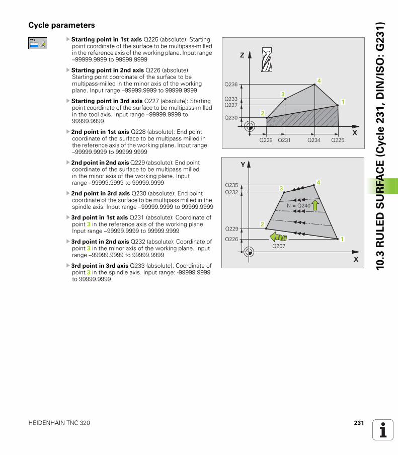
HEIDENHAIN TNC 320 231
10
.3 R
UL
ED
SU
RFA
CE
(C
ycle
23
1,
DIN
/IS
O:
G2
31
)Cycle parameters
U Starting point in 1st axis Q225 (absolute): Starting point coordinate of the surface to be multipass-milled in the reference axis of the working plane. Input range –99999.9999 to 99999.9999
U Starting point in 2nd axis Q226 (absolute): Starting point coordinate of the surface to be multipass-milled in the minor axis of the working plane. Input range –99999.9999 to 99999.9999
U Starting point in 3rd axis Q227 (absolute): Starting point coordinate of the surface to be multipass-milled in the tool axis. Input range –99999.9999 to 99999.9999
U 2nd point in 1st axis Q228 (absolute): End point coordinate of the surface to be multipass milled in the reference axis of the working plane. Input range –99999.9999 to 99999.9999
U 2nd point in 2nd axis Q229 (absolute): End point coordinate of the surface to be multipass milled in the minor axis of the working plane. Input range –99999.9999 to 99999.9999
U 2nd point in 3rd axis Q230 (absolute): End point coordinate of the surface to be multipass milled in the spindle axis. Input range –99999.9999 to 99999.9999
U 3rd point in 1st axis Q231 (absolute): Coordinate of point 3 in the reference axis of the working plane. Input range –99999.9999 to 99999.9999
U 3rd point in 2nd axis Q232 (absolute): Coordinate of point 3 in the minor axis of the working plane. Input range –99999.9999 to 99999.9999
U 3rd point in 3rd axis Q233 (absolute): Coordinate of point 3 in the spindle axis. Input range: -99999.9999 to 99999.9999
�
�
����
��������
����
��� �����������
�
�
�
�
�
����
����
��������
����
�������
�
�
�
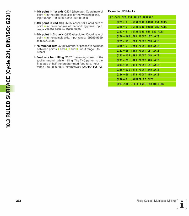
232 Fixed Cycles: Multipass Milling
10
.3 R
UL
ED
SU
RFA
CE
(C
ycle
23
1,
DIN
/IS
O:
G2
31
) U 4th point in 1st axis Q234 (absolute): Coordinate of point 4 in the reference axis of the working plane. Input range –99999.9999 to 99999.9999
U 4th point in 2nd axis Q235 (absolute): Coordinate of point 4 in the minor axis of the working plane. Input range –99999.9999 to 99999.9999
U 4th point in 3rd axis Q236 (absolute): Coordinate of point 4 in the spindle axis. Input range: -99999.9999 to 99999.9999
U Number of cuts Q240: Number of passes to be made between points 1 and 4, 2 and 3. Input range 0 to 99999
U Feed rate for milling Q207: Traversing speed of the tool in mm/min while milling. The TNC performs the first step at half the programmed feed rate. Input range 0 to 99999.999, alternatively FAUTO, FU, FZ
Example: NC blocks
72 CYCL DEF 231 RULED SURFACE
Q225=+0 ;STARTING POINT 1ST AXIS
Q226=+5 ;STARTING POINT 2ND AXIS
Q227=-2 ;STARTING PNT 3RD AXIS
Q228=+100 ;2ND POINT 1ST AXIS
Q229=+15 ;2ND POINT 2ND AXIS
Q230=+5 ;2ND POINT 3RD AXIS
Q231=+15 ;3RD POINT 1ST AXIS
Q232=+125 ;3RD POINT 2ND AXIS
Q233=+25 ;3RD POINT 3RD AXIS
Q234=+15 ;4TH POINT 1ST AXIS
Q235=+125 ;4TH POINT 2ND AXIS
Q236=+25 ;4TH POINT 3RD AXIS
Q240=40 ;NUMBER OF CUTS
Q207=500 ;FEED RATE FOR MILLING
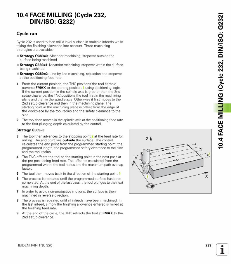
HEIDENHAIN TNC 320 233
10
.4 F
AC
E M
ILL
ING
(C
ycle
23
2,
DIN
/IS
O:
G2
32
)10.4 FACE MILLING (Cycle 232, DIN/ISO: G232)
Cycle run
Cycle 232 is used to face mill a level surface in multiple infeeds while taking the finishing allowance into account. Three machining strategies are available:
Strategy Q389=0: Meander machining, stepover outside the surface being machinedStrategy Q389=1: Meander machining, stepover within the surface being machinedStrategy Q389=2: Line-by-line machining, retraction and stepover at the positioning feed rate
1 From the current position, the TNC positions the tool at rapid traverse FMAX to the starting position 1 using positioning logic: If the current position in the spindle axis is greater than the 2nd setup clearance, the TNC positions the tool first in the machining plane and then in the spindle axis. Otherwise it first moves to the 2nd setup clearance and then in the machining plane. The starting point in the machining plane is offset from the edge of the workpiece by the tool radius and the safety clearance to the side.
2 The tool then moves in the spindle axis at the positioning feed rate to the first plunging depth calculated by the control.
Strategy Q389=0
3 The tool then advances to the stopping point 2 at the feed rate for milling. The end point lies outside the surface. The control calculates the end point from the programmed starting point, the programmed length, the programmed safety clearance to the side and the tool radius.
4 The TNC offsets the tool to the starting point in the next pass at the pre-positioning feed rate. The offset is calculated from the programmed width, the tool radius and the maximum path overlap factor.
5 The tool then moves back in the direction of the starting point 1.6 The process is repeated until the programmed surface has been
completed. At the end of the last pass, the tool plunges to the next machining depth.
7 In order to avoid non-productive motions, the surface is then machined in reverse direction.
8 The process is repeated until all infeeds have been machined. In the last infeed, simply the finishing allowance entered is milled at the finishing feed rate.
9 At the end of the cycle, the TNC retracts the tool at FMAX to the 2nd setup clearance.
�
�
�
�
�
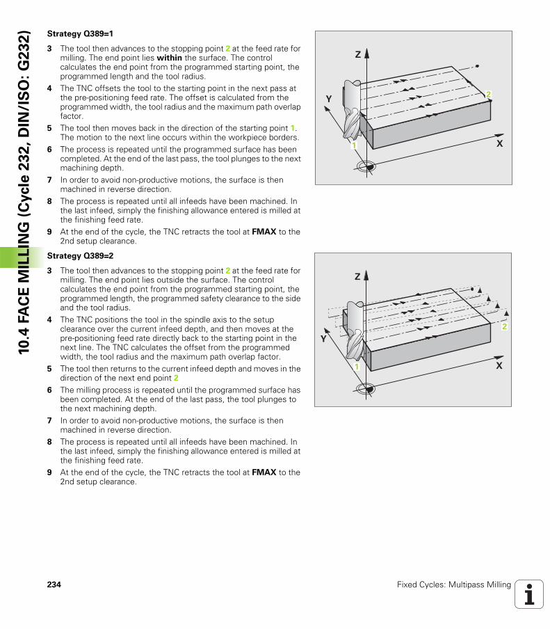
234 Fixed Cycles: Multipass Milling
10
.4 F
AC
E M
ILL
ING
(C
ycle
23
2,
DIN
/IS
O:
G2
32
) Strategy Q389=1
3 The tool then advances to the stopping point 2 at the feed rate for milling. The end point lies within the surface. The control calculates the end point from the programmed starting point, the programmed length and the tool radius.
4 The TNC offsets the tool to the starting point in the next pass at the pre-positioning feed rate. The offset is calculated from the programmed width, the tool radius and the maximum path overlap factor.
5 The tool then moves back in the direction of the starting point 1. The motion to the next line occurs within the workpiece borders.
6 The process is repeated until the programmed surface has been completed. At the end of the last pass, the tool plunges to the next machining depth.
7 In order to avoid non-productive motions, the surface is then machined in reverse direction.
8 The process is repeated until all infeeds have been machined. In the last infeed, simply the finishing allowance entered is milled at the finishing feed rate.
9 At the end of the cycle, the TNC retracts the tool at FMAX to the 2nd setup clearance.
Strategy Q389=2
3 The tool then advances to the stopping point 2 at the feed rate for milling. The end point lies outside the surface. The control calculates the end point from the programmed starting point, the programmed length, the programmed safety clearance to the side and the tool radius.
4 The TNC positions the tool in the spindle axis to the setup clearance over the current infeed depth, and then moves at the pre-positioning feed rate directly back to the starting point in the next line. The TNC calculates the offset from the programmed width, the tool radius and the maximum path overlap factor.
5 The tool then returns to the current infeed depth and moves in the direction of the next end point 2
6 The milling process is repeated until the programmed surface has been completed. At the end of the last pass, the tool plunges to the next machining depth.
7 In order to avoid non-productive motions, the surface is then machined in reverse direction.
8 The process is repeated until all infeeds have been machined. In the last infeed, simply the finishing allowance entered is milled at the finishing feed rate.
9 At the end of the cycle, the TNC retracts the tool at FMAX to the 2nd setup clearance.
�
�
�
�
�
�
�
�
�
�
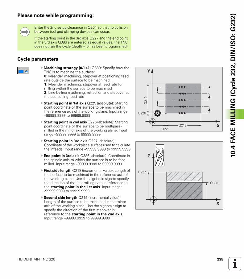
HEIDENHAIN TNC 320 235
10
.4 F
AC
E M
ILL
ING
(C
ycle
23
2,
DIN
/IS
O:
G2
32
)Please note while programming:
Cycle parameters
UMachining strategy (0/1/2) Q389: Specify how the TNC is to machine the surface:0: Meander machining, stepover at positioning feed rate outside the surface to be machined1: Meander machining, stepover at feed rate for milling within the surface to be machined2: Line-by-line machining, retraction and stepover at the positioning feed rate
U Starting point in 1st axis Q225 (absolute): Starting point coordinate of the surface to be machined in the reference axis of the working plane. Input range –99999.9999 to 99999.9999
U Starting point in 2nd axis Q226 (absolute): Starting point coordinate of the surface to be multipass-milled in the minor axis of the working plane. Input range –99999.9999 to 99999.9999
U Starting point in 3rd axis Q227 (absolute): Coordinate of the workpiece surface used to calculate the infeeds. Input range –99999.9999 to 99999.9999
U End point in 3rd axis Q386 (absolute): Coordinate in the spindle axis to which the surface is to be face milled. Input range –99999.9999 to 99999.9999
U First side length Q218 (incremental value): Length of the surface to be machined in the reference axis of the working plane. Use the algebraic sign to specify the direction of the first milling path in reference to the starting point in the 1st axis. Input range: -99999.9999 to 99999.9999
U Second side length Q219 (incremental value): Length of the surface to be machined in the minor axis of the working plane. Use the algebraic sign to specify the direction of the first stepover in reference to the starting point in the 2nd axis. Input range –99999.9999 to 99999.9999
Enter the 2nd setup clearance in Q204 so that no collision between tool and clamping devices can occur.
If the starting point in the 3rd axis Q227 and the end point in the 3rd axis Q386 are entered as equal values, the TNC does not run the cycle (depth = 0 has been programmed).
�
�
����
���
����
���
�
�
����
���
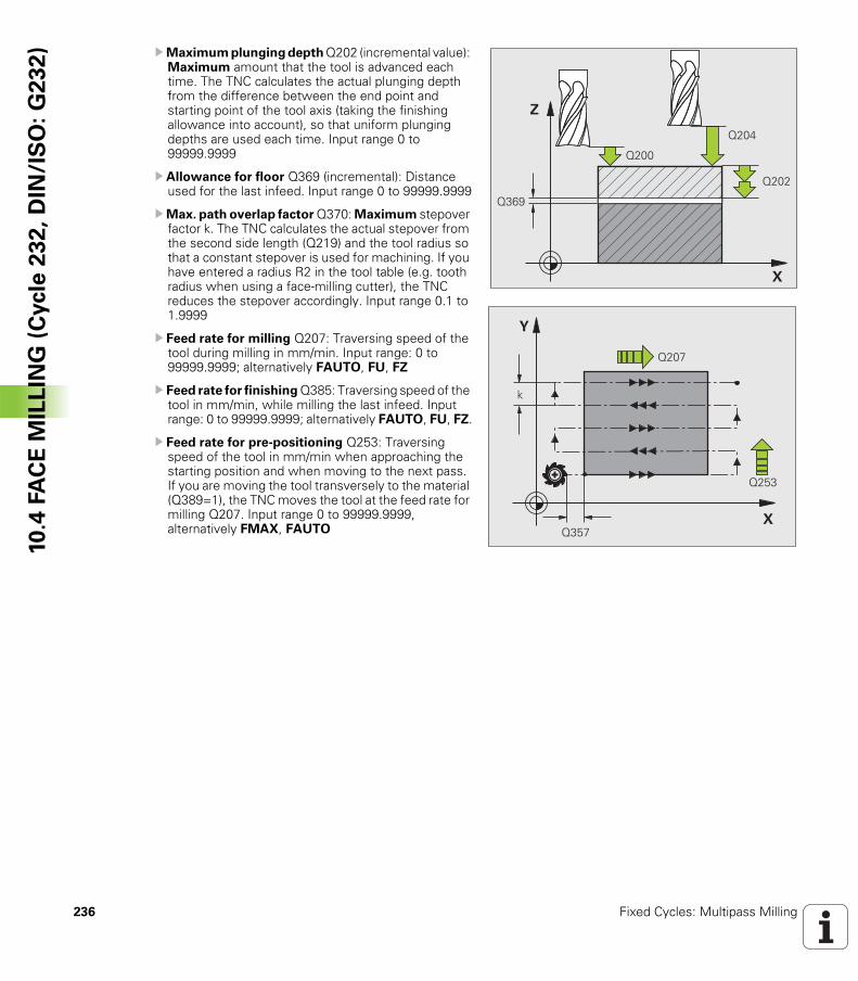
236 Fixed Cycles: Multipass Milling
10
.4 F
AC
E M
ILL
ING
(C
ycle
23
2,
DIN
/IS
O:
G2
32
) UMaximum plunging depth Q202 (incremental value): Maximum amount that the tool is advanced each time. The TNC calculates the actual plunging depth from the difference between the end point and starting point of the tool axis (taking the finishing allowance into account), so that uniform plunging depths are used each time. Input range 0 to 99999.9999
U Allowance for floor Q369 (incremental): Distance used for the last infeed. Input range 0 to 99999.9999
UMax. path overlap factor Q370: Maximum stepover factor k. The TNC calculates the actual stepover from the second side length (Q219) and the tool radius so that a constant stepover is used for machining. If you have entered a radius R2 in the tool table (e.g. tooth radius when using a face-milling cutter), the TNC reduces the stepover accordingly. Input range 0.1 to 1.9999
U Feed rate for milling Q207: Traversing speed of the tool during milling in mm/min. Input range: 0 to 99999.9999; alternatively FAUTO, FU, FZ
U Feed rate for finishing Q385: Traversing speed of the tool in mm/min, while milling the last infeed. Input range: 0 to 99999.9999; alternatively FAUTO, FU, FZ.
U Feed rate for pre-positioning Q253: Traversing speed of the tool in mm/min when approaching the starting position and when moving to the next pass. If you are moving the tool transversely to the material (Q389=1), the TNC moves the tool at the feed rate for milling Q207. Input range 0 to 99999.9999, alternatively FMAX, FAUTO
�
�
����
����
����
����
�
�
���
���
����
�
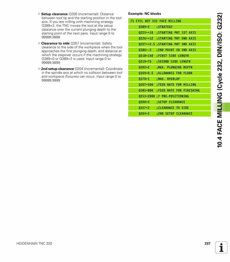
HEIDENHAIN TNC 320 237
10
.4 F
AC
E M
ILL
ING
(C
ycle
23
2,
DIN
/IS
O:
G2
32
)U Setup clearance Q200 (incremental): Distance between tool tip and the starting position in the tool axis. If you are milling with machining strategy Q389=2, the TNC moves the tool at the setup clearance over the current plunging depth to the starting point of the next pass. Input range 0 to 99999.9999
U Clearance to side Q357 (incremental): Safety clearance to the side of the workpiece when the tool approaches the first plunging depth, and distance at which the stepover occurs if the machining strategy Q389=0 or Q389=2 is used. Input range 0 to 99999.9999
U 2nd setup clearance Q204 (incremental): Coordinate in the spindle axis at which no collision between tool and workpiece (fixtures) can occur. Input range 0 to 99999.9999
Example: NC blocks
71 CYCL DEF 232 FACE MILLING
Q389=2 ;STRATEGY
Q225=+10 ;STARTING PNT 1ST AXIS
Q226=+12 ;STARTING PNT 2ND AXIS
Q227=+2.5 ;STARTING PNT 3RD AXIS
Q386=-3 ;END POINT IN 3RD AXIS
Q218=150 ;FIRST SIDE LENGTH
Q219=75 ;SECOND SIDE LENGTH
Q202=2 ;MAX. PLUNGING DEPTH
Q369=0.5 ;ALLOWANCE FOR FLOOR
Q370=1 ;MAX. OVERLAP
Q207=500 ;FEED RATE FOR MILLING
Q385=800 ;FEED RATE FOR FINISHING
Q253=2000 ;F PRE-POSITIONING
Q200=2 ;SETUP CLEARANCE
Q357=2 ;CLEARANCE TO SIDE
Q204=2 ;2ND SETUP CLEARANCE
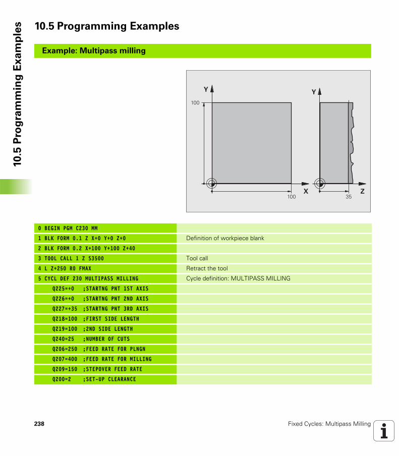
238 Fixed Cycles: Multipass Milling
10
.5 P
rog
ram
min
g E
xa
mp
les 10.5 Programming Examples
Example: Multipass milling
0 BEGIN PGM C230 MM
1 BLK FORM 0.1 Z X+0 Y+0 Z+0 Definition of workpiece blank
2 BLK FORM 0.2 X+100 Y+100 Z+40
3 TOOL CALL 1 Z S3500 Tool call
4 L Z+250 R0 FMAX Retract the tool
5 CYCL DEF 230 MULTIPASS MILLING Cycle definition: MULTIPASS MILLING
Q225=+0 ;STARTNG PNT 1ST AXIS
Q226=+0 ;STARTNG PNT 2ND AXIS
Q227=+35 ;STARTNG PNT 3RD AXIS
Q218=100 ;FIRST SIDE LENGTH
Q219=100 ;2ND SIDE LENGTH
Q240=25 ;NUMBER OF CUTS
Q206=250 ;FEED RATE FOR PLNGN
Q207=400 ;FEED RATE FOR MILLING
Q209=150 ;STEPOVER FEED RATE
Q200=2 ;SET-UP CLEARANCE
�
�
���
���
�
�
�
HEIDENHAIN TNC 320 239
10
.5 P
rog
ram
min
g E
xa
mp
les6 L X+-25 Y+0 R0 FMAX M3 Pre-position near the starting point
7 CYCL CALL Cycle call
8 L Z+250 R0 FMAX M2 Retract in the tool axis, end program
9 END PGM C230 MM
240 Fixed Cycles: Multipass Milling
10
.5 P
rog
ram
min
g E
xa
mp
les
Cycles: Coordinate
Transformations
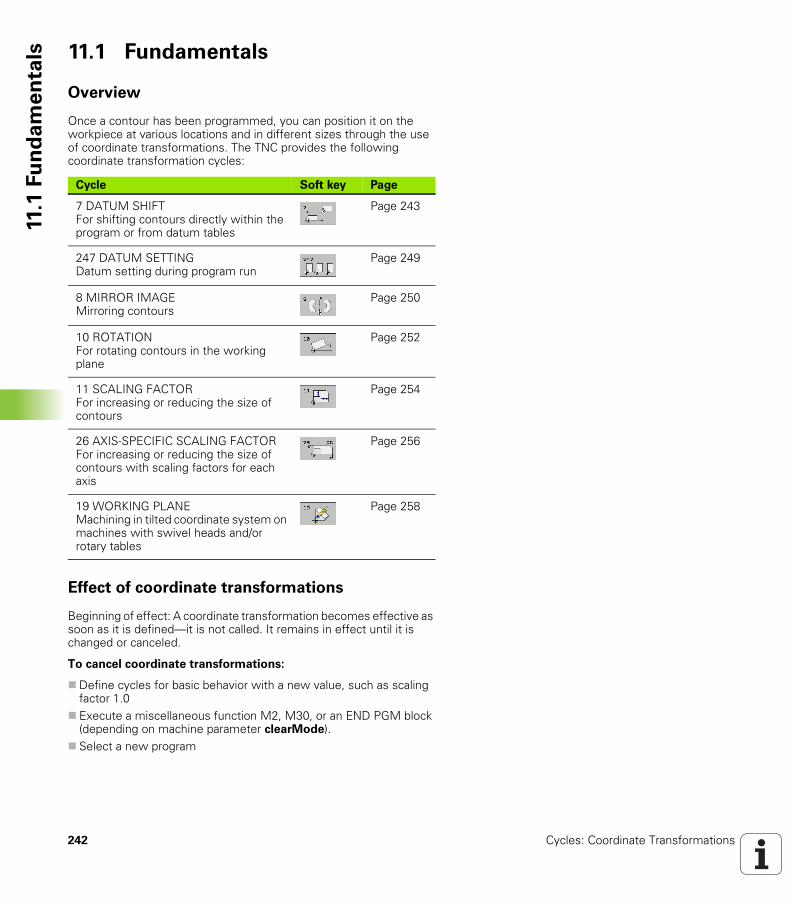
242 Cycles: Coordinate Transformations
11.1
Fu
nd
am
en
tals 11.1 Fundamentals
Overview
Once a contour has been programmed, you can position it on the workpiece at various locations and in different sizes through the use of coordinate transformations. The TNC provides the following coordinate transformation cycles:
Effect of coordinate transformations
Beginning of effect: A coordinate transformation becomes effective as soon as it is defined—it is not called. It remains in effect until it is changed or canceled.
To cancel coordinate transformations:
Define cycles for basic behavior with a new value, such as scaling factor 1.0Execute a miscellaneous function M2, M30, or an END PGM block (depending on machine parameter clearMode).Select a new program
Cycle Soft key Page
7 DATUM SHIFTFor shifting contours directly within the program or from datum tables
Page 243
247 DATUM SETTINGDatum setting during program run
Page 249
8 MIRROR IMAGEMirroring contours
Page 250
10 ROTATIONFor rotating contours in the working plane
Page 252
11 SCALING FACTORFor increasing or reducing the size of contours
Page 254
26 AXIS-SPECIFIC SCALING FACTORFor increasing or reducing the size of contours with scaling factors for each axis
Page 256
19 WORKING PLANEMachining in tilted coordinate system on machines with swivel heads and/or rotary tables
Page 258
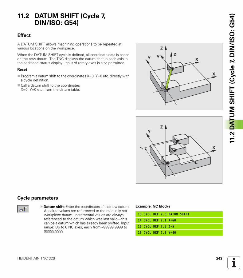
HEIDENHAIN TNC 320 243
11.2
DA
TU
M S
HIF
T (
Cycle
7,
DIN
/IS
O:
G5
4)11.2 DATUM SHIFT (Cycle 7,
DIN/ISO: G54)
Effect
A DATUM SHIFT allows machining operations to be repeated at various locations on the workpiece.
When the DATUM SHIFT cycle is defined, all coordinate data is based on the new datum. The TNC displays the datum shift in each axis in the additional status display. Input of rotary axes is also permitted.
Reset
Program a datum shift to the coordinates X=0, Y=0 etc. directly with a cycle definition.Call a datum shift to the coordinatesX=0; Y=0 etc. from the datum table.
Cycle parameters
U Datum shift: Enter the coordinates of the new datum. Absolute values are referenced to the manually set workpiece datum. Incremental values are always referenced to the datum which was last valid—this can be a datum which has already been shifted. Input range: Up to 6 NC axes, each from –99999.9999 to 99999.9999
�
�
�
�� �
�
�
�
�
�
Example: NC blocks
13 CYCL DEF 7.0 DATUM SHIFT
14 CYCL DEF 7.1 X+60
16 CYCL DEF 7.3 Z-5
15 CYCL DEF 7.2 Y+40
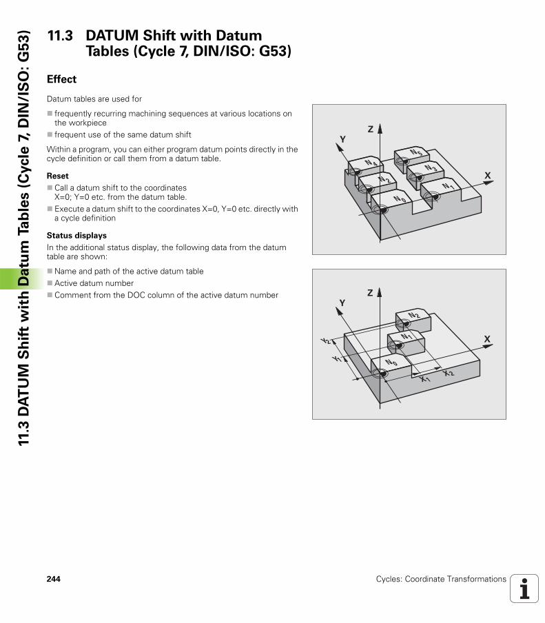
244 Cycles: Coordinate Transformations
11.3
DA
TU
M S
hif
t w
ith
Da
tum
Ta
ble
s (
Cycle
7, D
IN/I
SO
:G
53
) 11.3 DATUM Shift with Datum Tables (Cycle 7, DIN/ISO: G53)
Effect
Datum tables are used for
frequently recurring machining sequences at various locations on the workpiecefrequent use of the same datum shift
Within a program, you can either program datum points directly in the cycle definition or call them from a datum table.
Reset
Call a datum shift to the coordinatesX=0; Y=0 etc. from the datum table.Execute a datum shift to the coordinates X=0, Y=0 etc. directly with a cycle definition
Status displays
In the additional status display, the following data from the datum table are shown:
Name and path of the active datum tableActive datum numberComment from the DOC column of the active datum number
�
�
�
�
�
�
�
�
�
�
�
�
�
�
� �
�
�
��
�
�
HEIDENHAIN TNC 320 245
11.3
DA
TU
M S
hif
t w
ith
Da
tum
Ta
ble
s (
Cycle
7, D
IN/I
SO
:G
53
)Please note while programming:
Danger of collision!
Datums from a datum table are always and exclusively referenced to the current datum (preset).
If you are using datum shifts with datum tables, then use the SEL TABLE function to activate the desired datum table from the NC program.
If you work without SEL TABLE, then you must activate the desired datum table before the test run or the program run. (This applies also to the programming graphics).
Use the file management to select the desired table for a test run in the Test Run operating mode: The table receives the status S.Use the file management in a program run mode to select the desired table for a program run: The table receives the status M.
The coordinate values from datum tables are only effective with absolute coordinate values.
New lines can only be inserted at the end of the table.
If you create datum tables, the file name has to start with a letter.
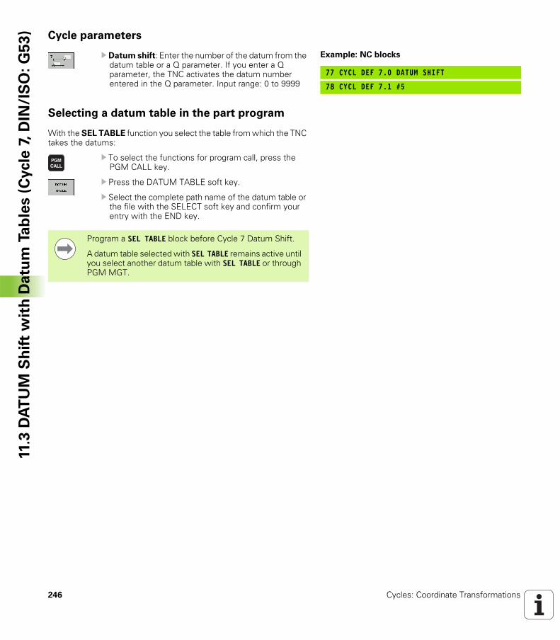
246 Cycles: Coordinate Transformations
11.3
DA
TU
M S
hif
t w
ith
Da
tum
Ta
ble
s (
Cycle
7, D
IN/I
SO
:G
53
) Cycle parameters
U Datum shift: Enter the number of the datum from the datum table or a Q parameter. If you enter a Q parameter, the TNC activates the datum number entered in the Q parameter. Input range: 0 to 9999
Selecting a datum table in the part program
With the SEL TABLE function you select the table from which the TNC takes the datums:
U To select the functions for program call, press the PGM CALL key.
U Press the DATUM TABLE soft key.
U Select the complete path name of the datum table or the file with the SELECT soft key and confirm your entry with the END key.
Example: NC blocks
77 CYCL DEF 7.0 DATUM SHIFT
78 CYCL DEF 7.1 #5
Program a SEL TABLE block before Cycle 7 Datum Shift.
A datum table selected with SEL TABLE remains active until you select another datum table with SEL TABLE or through PGM MGT.
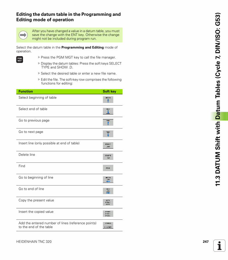
HEIDENHAIN TNC 320 247
11.3
DA
TU
M S
hif
t w
ith
Da
tum
Ta
ble
s (
Cycle
7, D
IN/I
SO
:G
53
)Editing the datum table in the Programming and
Editing mode of operation
Select the datum table in the Programming and Editing mode of operation.
U Press the PGM MGT key to call the file manager.
U Display the datum tables: Press the soft keys SELECT TYPE and SHOW .D.
U Select the desired table or enter a new file name.
U Edit the file. The soft-key row comprises the following functions for editing:
After you have changed a value in a datum table, you must save the change with the ENT key. Otherwise the change might not be included during program run.
Function Soft key
Select beginning of table
Select end of table
Go to previous page
Go to next page
Insert line (only possible at end of table)
Delete line
Find
Go to beginning of line
Go to end of line
Copy the present value
Insert the copied value
Add the entered number of lines (reference points) to the end of the table

248 Cycles: Coordinate Transformations
11.3
DA
TU
M S
hif
t w
ith
Da
tum
Ta
ble
s (
Cycle
7, D
IN/I
SO
:G
53
) Configuring the datum table
If you do not wish to define a datum for an active axis, press the DEL key. Then the TNC clears the numerical value from the corresponding input field.
To leave a datum table
Select a different type of file in file management and choose the desired file.
Status displays
In the additional status display, the TNC shows the values of the active datum shift.
After you have changed a value in a datum table, you must save the change with the ENT key. Otherwise the change may not be included during program run.
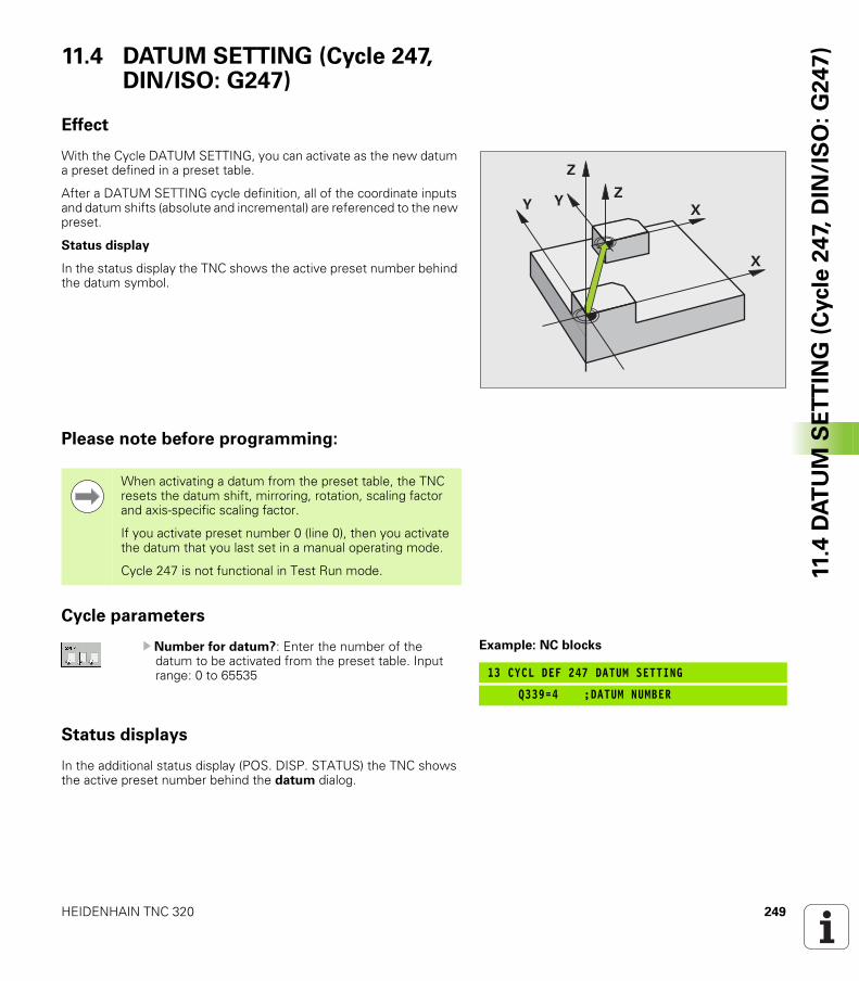
HEIDENHAIN TNC 320 249
11.4
DA
TU
M S
ET
TIN
G (
Cycle
24
7, D
IN/I
SO
: G
24
7)11.4 DATUM SETTING (Cycle 247,
DIN/ISO: G247)
Effect
With the Cycle DATUM SETTING, you can activate as the new datum a preset defined in a preset table.
After a DATUM SETTING cycle definition, all of the coordinate inputs and datum shifts (absolute and incremental) are referenced to the new preset.
Status display
In the status display the TNC shows the active preset number behind the datum symbol.
Please note before programming:
Cycle parameters
U Number for datum?: Enter the number of the datum to be activated from the preset table. Input range: 0 to 65535
Status displays
In the additional status display (POS. DISP. STATUS) the TNC shows the active preset number behind the datum dialog.
�
�
�
�� �
When activating a datum from the preset table, the TNC resets the datum shift, mirroring, rotation, scaling factor and axis-specific scaling factor.
If you activate preset number 0 (line 0), then you activate the datum that you last set in a manual operating mode.
Cycle 247 is not functional in Test Run mode.
Example: NC blocks
13 CYCL DEF 247 DATUM SETTING
Q339=4 ;DATUM NUMBER
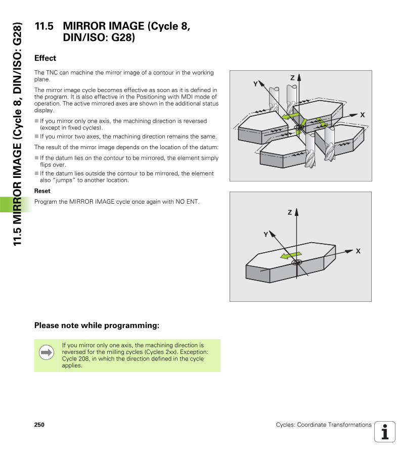
250 Cycles: Coordinate Transformations
11.5
MIR
RO
R I
MA
GE
(C
ycle
8,
DIN
/IS
O:
G2
8) 11.5 MIRROR IMAGE (Cycle 8,
DIN/ISO: G28)
Effect
The TNC can machine the mirror image of a contour in the working plane.
The mirror image cycle becomes effective as soon as it is defined in the program. It is also effective in the Positioning with MDI mode of operation. The active mirrored axes are shown in the additional status display.
If you mirror only one axis, the machining direction is reversed (except in fixed cycles).If you mirror two axes, the machining direction remains the same.
The result of the mirror image depends on the location of the datum:
If the datum lies on the contour to be mirrored, the element simply flips over. If the datum lies outside the contour to be mirrored, the element also “jumps” to another location.
Reset
Program the MIRROR IMAGE cycle once again with NO ENT.
Please note while programming:
�
�
�
�
�
�
If you mirror only one axis, the machining direction is reversed for the milling cycles (Cycles 2xx). Exception: Cycle 208, in which the direction defined in the cycle applies.
HEIDENHAIN TNC 320 251
11.5
MIR
RO
R I
MA
GE
(C
ycle
8,
DIN
/IS
O:
G2
8)Cycle parameters
UMirrored axis?: Enter the axis to be mirrored. You can mirror all axes, including rotary axes, except for the spindle axis and its auxiliary axes. You can enter up to three axes. Input range: Up to three NC axes X, Y, Z, U, V, W, A, B, C
Example: NC blocks
79 CYCL DEF 8.0 MIRROR IMAGE
80 CYCL DEF 8.1 X Y Z
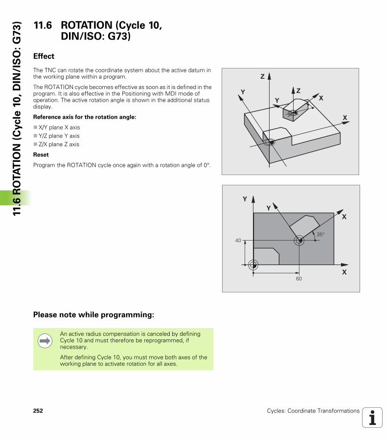
252 Cycles: Coordinate Transformations
11.6
RO
TA
TIO
N (
Cycle
10
, D
IN/I
SO
: G
73
) 11.6 ROTATION (Cycle 10, DIN/ISO: G73)
Effect
The TNC can rotate the coordinate system about the active datum in the working plane within a program.
The ROTATION cycle becomes effective as soon as it is defined in the program. It is also effective in the Positioning with MDI mode of operation. The active rotation angle is shown in the additional status display.
Reference axis for the rotation angle:
X/Y plane X axisY/Z plane Y axisZ/X plane Z axis
Reset
Program the ROTATION cycle once again with a rotation angle of 0°.
Please note while programming:
�
�
�
��
�
�
�
��
����
��
An active radius compensation is canceled by defining Cycle 10 and must therefore be reprogrammed, if necessary.
After defining Cycle 10, you must move both axes of the working plane to activate rotation for all axes.
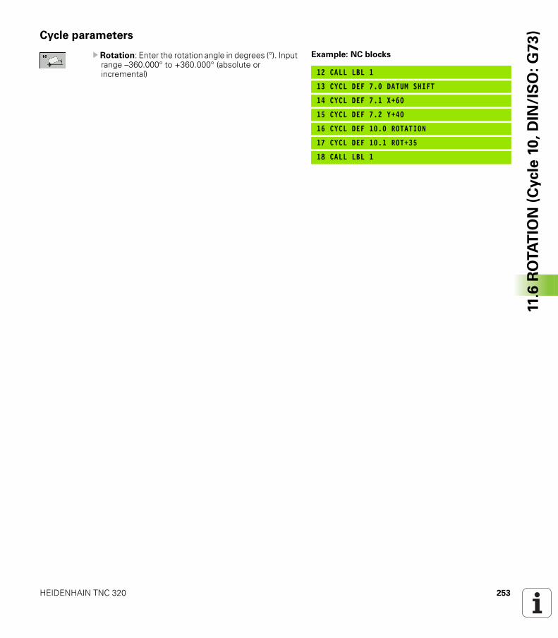
HEIDENHAIN TNC 320 253
11.6
RO
TA
TIO
N (
Cycle
10
, D
IN/I
SO
: G
73
)Cycle parameters
U Rotation: Enter the rotation angle in degrees (°). Input range –360.000° to +360.000° (absolute or incremental)
Example: NC blocks
12 CALL LBL 1
13 CYCL DEF 7.0 DATUM SHIFT
14 CYCL DEF 7.1 X+60
15 CYCL DEF 7.2 Y+40
16 CYCL DEF 10.0 ROTATION
17 CYCL DEF 10.1 ROT+35
18 CALL LBL 1
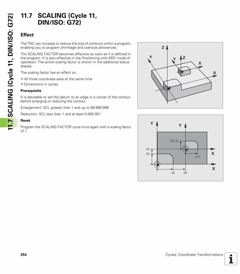
254 Cycles: Coordinate Transformations
11.7
SC
AL
ING
(C
ycle
11
, D
IN/I
SO
: G
72
) 11.7 SCALING (Cycle 11, DIN/ISO: G72)
Effect
The TNC can increase or reduce the size of contours within a program, enabling you to program shrinkage and oversize allowances.
The SCALING FACTOR becomes effective as soon as it is defined in the program. It is also effective in the Positioning with MDI mode of operation. The active scaling factor is shown in the additional status display.
The scaling factor has an effect on
All three coordinate axes at the same timeDimensions in cycles
Prerequisite
It is advisable to set the datum to an edge or a corner of the contour before enlarging or reducing the contour.
Enlargement: SCL greater than 1 and up to 99.999 999
Reduction: SCL less than 1 and at least 0.000 001
Reset
Program the SCALING FACTOR cycle once again with a scaling factor of 1.
�
�
�
�
� �
�
�
��
���
�
��
������
�����
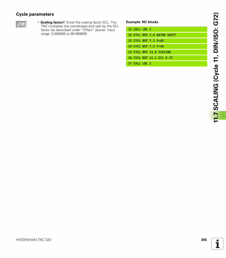
HEIDENHAIN TNC 320 255
11.7
SC
AL
ING
(C
ycle
11
, D
IN/I
SO
: G
72
)Cycle parameters
U Scaling factor?: Enter the scaling factor SCL. The TNC multiplies the coordinates and radii by the SCL factor (as described under “Effect” above). Input range: 0.000000 to 99.999999
Example: NC blocks
11 CALL LBL 1
12 CYCL DEF 7.0 DATUM SHIFT
13 CYCL DEF 7.1 X+60
14 CYCL DEF 7.2 Y+40
15 CYCL DEF 11.0 SCALING
16 CYCL DEF 11.1 SCL 0.75
17 CALL LBL 1
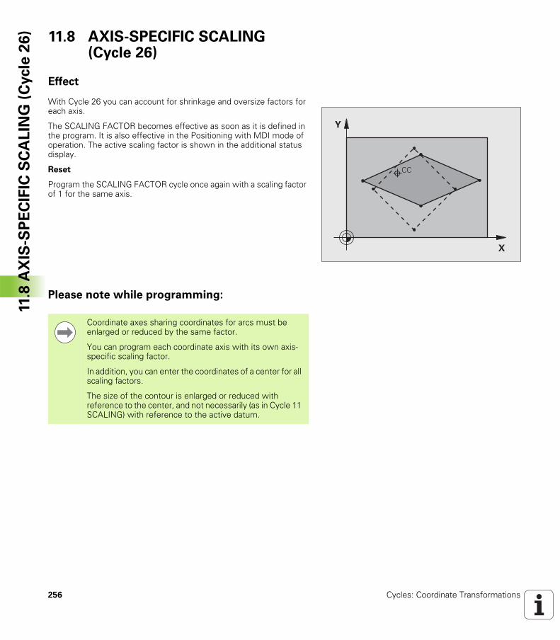
256 Cycles: Coordinate Transformations
11.8
AX
IS-S
PE
CIF
IC S
CA
LIN
G (
Cycle
26
) 11.8 AXIS-SPECIFIC SCALING (Cycle 26)
Effect
With Cycle 26 you can account for shrinkage and oversize factors for each axis.
The SCALING FACTOR becomes effective as soon as it is defined in the program. It is also effective in the Positioning with MDI mode of operation. The active scaling factor is shown in the additional status display.
Reset
Program the SCALING FACTOR cycle once again with a scaling factor of 1 for the same axis.
Please note while programming:
�
�
��
Coordinate axes sharing coordinates for arcs must be enlarged or reduced by the same factor.
You can program each coordinate axis with its own axis-specific scaling factor.
In addition, you can enter the coordinates of a center for all scaling factors.
The size of the contour is enlarged or reduced with reference to the center, and not necessarily (as in Cycle 11 SCALING) with reference to the active datum.
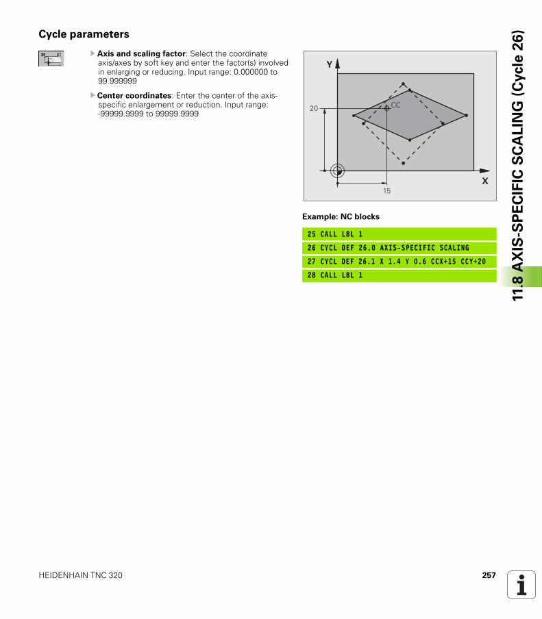
HEIDENHAIN TNC 320 257
11.8
AX
IS-S
PE
CIF
IC S
CA
LIN
G (
Cycle
26
)Cycle parameters
U Axis and scaling factor: Select the coordinate axis/axes by soft key and enter the factor(s) involved in enlarging or reducing. Input range: 0.000000 to 99.999999
U Center coordinates: Enter the center of the axis-specific enlargement or reduction. Input range: -99999.9999 to 99999.9999
Example: NC blocks
25 CALL LBL 1
26 CYCL DEF 26.0 AXIS-SPECIFIC SCALING
27 CYCL DEF 26.1 X 1.4 Y 0.6 CCX+15 CCY+20
28 CALL LBL 1
��
�
�� ��

258 Cycles: Coordinate Transformations
11.9
WO
RK
ING
PL
AN
E (
Cycle
19
, D
IN/I
SO
: G
80
, S
oft
wa
re O
pti
on
1) 11.9 WORKING PLANE (Cycle 19,
DIN/ISO: G80, Software Option 1)
Effect
In Cycle 19 you define the position of the working plane—i.e. the position of the tool axis referenced to the machine coordinate system—by entering tilt angles. There are two ways to determine the position of the working plane:
Enter the position of the rotary axes directly. Describe the position of the working plane using up to 3 rotations (spatial angle) of the fixed machine coordinate system. The required spatial angle can be calculated by cutting a perpendicular line through the tilted working plane and considering it from the axis around which you wish to tilt. With two spatial angles, every tool position in space can be defined exactly.
If you program the position of the working plane via spatial angles, the TNC will calculate the required angle positions of the tilted axes automatically and will store these in the parameters Q120 (A axis) to Q122 (C axis). If two solutions are possible, the TNC will choose the shorter path from the zero position of the rotary axes.
The axes are always rotated in the same sequence for calculating the tilt of the plane: The TNC first rotates the A axis, then the B axis, and finally the C axis.
Cycle 19 becomes effective as soon as it is defined in the program. As soon as you move an axis in the tilted system, the compensation for this specific axis is activated. You must move all axes to activate compensation for all axes.
If you set the function Tilting program run to Active in the Manual Operation mode, the angular value entered in this menu is overwritten by Cycle 19 WORKING PLANE.
�
�
�
�
�
�
�
�
Note that the position of the tilted coordinate system, and therefore also all movements in the tilted system, are dependent on your description of the tilted plane.
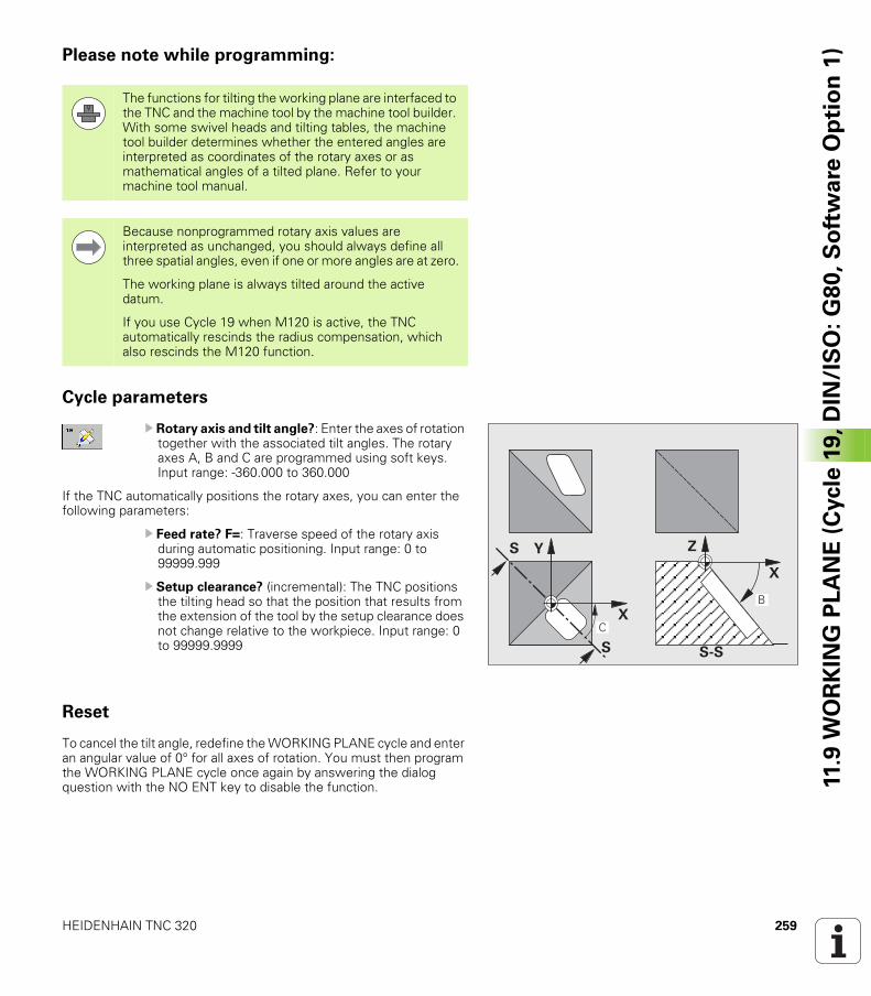
HEIDENHAIN TNC 320 259
11.9
WO
RK
ING
PL
AN
E (
Cycle
19
, D
IN/I
SO
: G
80
, S
oft
wa
re O
pti
on
1)Please note while programming:
Cycle parameters
U Rotary axis and tilt angle?: Enter the axes of rotation together with the associated tilt angles. The rotary axes A, B and C are programmed using soft keys. Input range: -360.000 to 360.000
If the TNC automatically positions the rotary axes, you can enter the following parameters:
U Feed rate? F=: Traverse speed of the rotary axis during automatic positioning. Input range: 0 to 99999.999
U Setup clearance? (incremental): The TNC positions the tilting head so that the position that results from the extension of the tool by the setup clearance does not change relative to the workpiece. Input range: 0 to 99999.9999
Reset
To cancel the tilt angle, redefine the WORKING PLANE cycle and enter an angular value of 0° for all axes of rotation. You must then program the WORKING PLANE cycle once again by answering the dialog question with the NO ENT key to disable the function.
The functions for tilting the working plane are interfaced to the TNC and the machine tool by the machine tool builder. With some swivel heads and tilting tables, the machine tool builder determines whether the entered angles are interpreted as coordinates of the rotary axes or as mathematical angles of a tilted plane. Refer to your machine tool manual.
Because nonprogrammed rotary axis values are interpreted as unchanged, you should always define all three spatial angles, even if one or more angles are at zero.
The working plane is always tilted around the active datum.
If you use Cycle 19 when M120 is active, the TNC automatically rescinds the radius compensation, which also rescinds the M120 function.
��
� ���
�
�
�
��
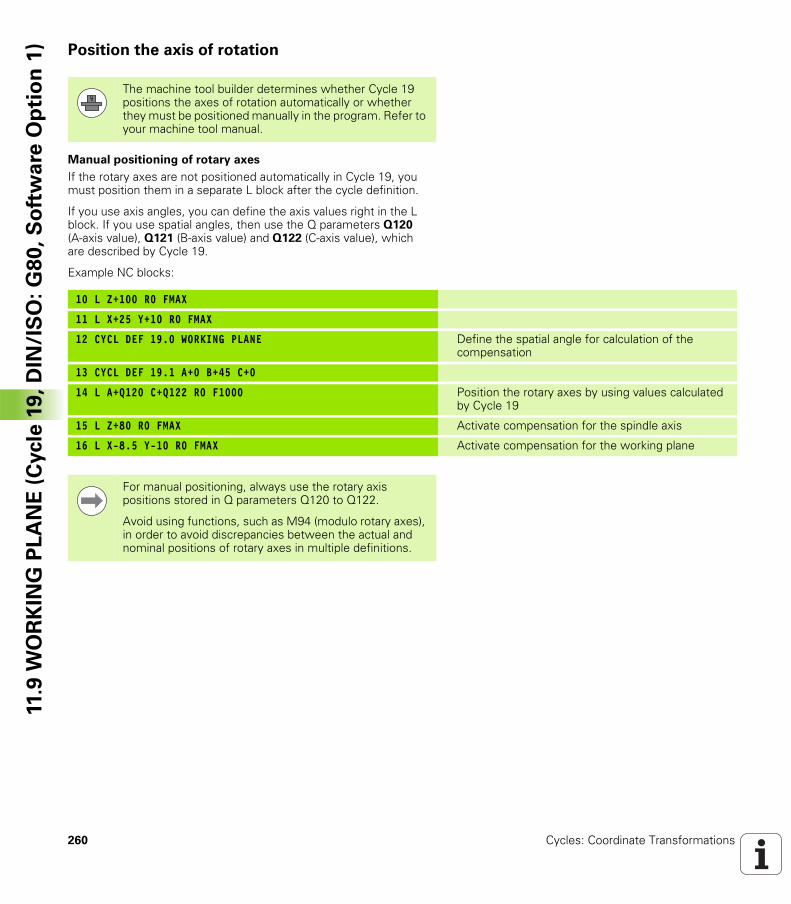
260 Cycles: Coordinate Transformations
11.9
WO
RK
ING
PL
AN
E (
Cycle
19
, D
IN/I
SO
: G
80
, S
oft
wa
re O
pti
on
1) Position the axis of rotation
Manual positioning of rotary axes
If the rotary axes are not positioned automatically in Cycle 19, you must position them in a separate L block after the cycle definition.
If you use axis angles, you can define the axis values right in the L block. If you use spatial angles, then use the Q parameters Q120 (A-axis value), Q121 (B-axis value) and Q122 (C-axis value), which are described by Cycle 19.
Example NC blocks:
The machine tool builder determines whether Cycle 19 positions the axes of rotation automatically or whether they must be positioned manually in the program. Refer to your machine tool manual.
10 L Z+100 R0 FMAX
11 L X+25 Y+10 R0 FMAX
12 CYCL DEF 19.0 WORKING PLANE Define the spatial angle for calculation of the compensation
13 CYCL DEF 19.1 A+0 B+45 C+0
14 L A+Q120 C+Q122 R0 F1000 Position the rotary axes by using values calculated by Cycle 19
15 L Z+80 R0 FMAX Activate compensation for the spindle axis
16 L X-8.5 Y-10 R0 FMAX Activate compensation for the working plane
For manual positioning, always use the rotary axis positions stored in Q parameters Q120 to Q122.
Avoid using functions, such as M94 (modulo rotary axes), in order to avoid discrepancies between the actual and nominal positions of rotary axes in multiple definitions.
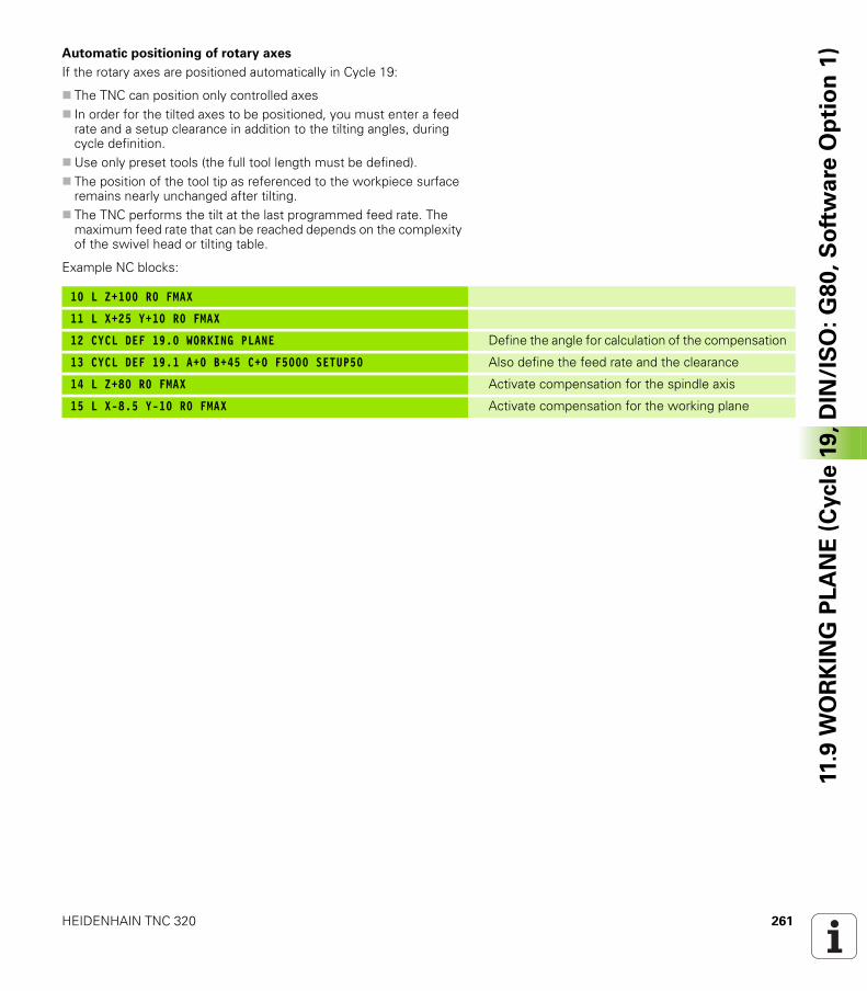
HEIDENHAIN TNC 320 261
11.9
WO
RK
ING
PL
AN
E (
Cycle
19
, D
IN/I
SO
: G
80
, S
oft
wa
re O
pti
on
1)Automatic positioning of rotary axes
If the rotary axes are positioned automatically in Cycle 19:
The TNC can position only controlled axesIn order for the tilted axes to be positioned, you must enter a feed rate and a setup clearance in addition to the tilting angles, during cycle definition.Use only preset tools (the full tool length must be defined).The position of the tool tip as referenced to the workpiece surface remains nearly unchanged after tilting.The TNC performs the tilt at the last programmed feed rate. The maximum feed rate that can be reached depends on the complexity of the swivel head or tilting table.
Example NC blocks:
10 L Z+100 R0 FMAX
11 L X+25 Y+10 R0 FMAX
12 CYCL DEF 19.0 WORKING PLANE Define the angle for calculation of the compensation
13 CYCL DEF 19.1 A+0 B+45 C+0 F5000 SETUP50 Also define the feed rate and the clearance
14 L Z+80 R0 FMAX Activate compensation for the spindle axis
15 L X-8.5 Y-10 R0 FMAX Activate compensation for the working plane
262 Cycles: Coordinate Transformations
11.9
WO
RK
ING
PL
AN
E (
Cycle
19
, D
IN/I
SO
: G
80
, S
oft
wa
re O
pti
on
1) Position display in the tilted system
On activation of Cycle 19, the displayed positions (ACTL and NOML) and the datum indicated in the additional status display are referenced to the tilted coordinate system. The positions displayed immediately after cycle definition might not be the same as the coordinates of the last programmed position before Cycle 19.
Workspace monitoring
The TNC monitors only those axes in the tilted coordinate system that are moved. If necessary, the TNC outputs an error message.
Positioning in a tilted coordinate system
With the miscellaneous function M130 you can move the tool, while the coordinate system is tilted, to positions that are referenced to the non-tilted coordinate system.
Positioning movements with straight lines that are referenced to the machine coordinate system (blocks with M91 or M92) can also be executed in a tilted working plane. Constraints:
Positioning is without length compensation.Positioning is without machine geometry compensation.Tool radius compensation is not permitted.
HEIDENHAIN TNC 320 263
11.9
WO
RK
ING
PL
AN
E (
Cycle
19
, D
IN/I
SO
: G
80
, S
oft
wa
re O
pti
on
1)Combining coordinate transformation cycles
When combining coordinate transformation cycles, always make sure the working plane is swiveled around the active datum. You can program a datum shift before activating Cycle 19. In this case, you are shifting the machine-based coordinate system.
If you program a datum shift after having activated Cycle 19, you are shifting the tilted coordinate system.
Important: When resetting the cycles, use the reverse sequence used for defining them:
1st: Activate the datum shift2nd: Activate tilting function3rd: Activate rotation...Machining...1st: Reset the rotation2nd: Reset the tilting function3rd: Reset the datum shift
264 Cycles: Coordinate Transformations
11.9
WO
RK
ING
PL
AN
E (
Cycle
19
, D
IN/I
SO
: G
80
, S
oft
wa
re O
pti
on
1) Procedure for working with Cycle 19 WORKING
PLANE
1 Write the program
U Define the tool (not required if TOOL.T is active), and enter the full tool length.
U Call the toolU Retract the tool in the tool axis to a position where there is no
danger of collision with the workpiece (clamping devices) during tilting.
U If required, position the rotary axis or axes with an L block to the appropriate angular value(s) (depending on a machine parameter).
U Activate datum shift if required.U Define Cycle 19 WORKING PLANE; enter the angular values for the
tilt axes.U Traverse all principal axes (X, Y, Z) to activate compensation.U Write the program as if the machining process were to be executed
in a non-tilted plane.U If required, define Cycle 19 WORKING PLANE with other angular
values to execute machining in a different axis position. In this case, it is not necessary to reset Cycle 19. You can define the new angular values directly.
U Reset Cycle 19 WORKING PLANE; program 0° for all rotary axes.U Disable the WORKING PLANE function; redefine Cycle 19 and
answer the dialog question with NO ENT.U Reset datum shift if required.U Position the rotary axes to the 0° position, if required.
2 Clamp the workpiece
3 Datum setting
Manually by touch-offControlled with a HEIDENHAIN 3-D touch probe (see the Touch Probe Cycles User's Manual, chapter 2).Automatically with a HEIDENHAIN 3-D touch probe (see the Touch Probe Cycles User's Manual, chapter 3).
4 Start the part program in the operating mode Program Run, Full Sequence
5 Manual Operation mode
Use the 3-D ROT soft key to set the TILT WORKING PLANE function to INACTIVE. Enter an angular value of 0° for each rotary axis in the menu.
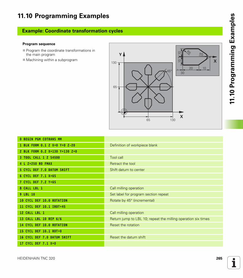
HEIDENHAIN TNC 320 265
11.1
0 P
rog
ram
min
g E
xa
mp
les11.10 Programming Examples
Example: Coordinate transformation cycles
Program sequence
Program the coordinate transformations in the main programMachining within a subprogram
0 BEGIN PGM COTRANS MM
1 BLK FORM 0.1 Z X+0 Y+0 Z-20 Definition of workpiece blank
2 BLK FORM 0.2 X+130 Y+130 Z+0
3 TOOL CALL 1 Z S4500 Tool call
4 L Z+250 R0 FMAX Retract the tool
5 CYCL DEF 7.0 DATUM SHIFT Shift datum to center
6 CYCL DEF 7.1 X+65
7 CYCL DEF 7.2 Y+65
8 CALL LBL 1 Call milling operation
9 LBL 10 Set label for program section repeat
10 CYCL DEF 10.0 ROTATION Rotate by 45° (incremental)
11 CYCL DEF 10.1 IROT+45
12 CALL LBL 1 Call milling operation
13 CALL LBL 10 REP 6/6 Return jump to LBL 10; repeat the milling operation six times
14 CYCL DEF 10.0 ROTATION Reset the rotation
15 CYCL DEF 10.1 ROT+0
16 CYCL DEF 7.0 DATUM SHIFT Reset the datum shift
17 CYCL DEF 7.1 X+0
�
�
�
�
���
���
��
�
����
��
� �����
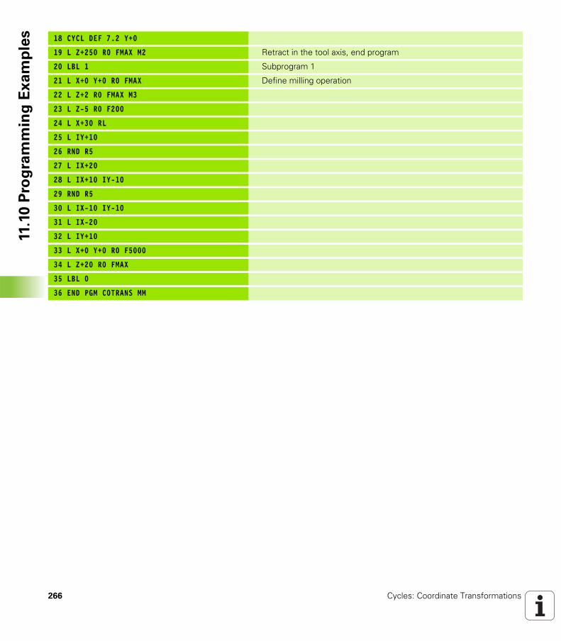
266 Cycles: Coordinate Transformations
11.1
0 P
rog
ram
min
g E
xa
mp
les 18 CYCL DEF 7.2 Y+0
19 L Z+250 R0 FMAX M2 Retract in the tool axis, end program
20 LBL 1 Subprogram 1
21 L X+0 Y+0 R0 FMAX Define milling operation
22 L Z+2 R0 FMAX M3
23 L Z-5 R0 F200
24 L X+30 RL
25 L IY+10
26 RND R5
27 L IX+20
28 L IX+10 IY-10
29 RND R5
30 L IX-10 IY-10
31 L IX-20
32 L IY+10
33 L X+0 Y+0 R0 F5000
34 L Z+20 R0 FMAX
35 LBL 0
36 END PGM COTRANS MM
Cycles: Special
Functions
268 Cycles: Special Functions
12
.1 F
un
da
me
nta
ls 12.1 Fundamentals
Overview
The TNC provides four cycles for the following special purposes:
Cycle Soft key Page
9 DWELL TIME Page 269
12 PROGRAM CALL Page 270
13 ORIENTED SPINDLE STOP Page 272
32 TOLERANCE Page 273
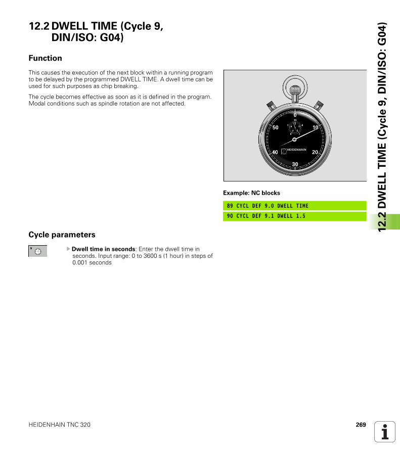
HEIDENHAIN TNC 320 269
12
.2 D
WE
LL
TIM
E (
Cycle
9,
DIN
/IS
O:
G0
4)12.2 DWELL TIME (Cycle 9,
DIN/ISO: G04)
Function
This causes the execution of the next block within a running program to be delayed by the programmed DWELL TIME. A dwell time can be used for such purposes as chip breaking.
The cycle becomes effective as soon as it is defined in the program. Modal conditions such as spindle rotation are not affected.
Cycle parameters
U Dwell time in seconds: Enter the dwell time in seconds. Input range: 0 to 3600 s (1 hour) in steps of 0.001 seconds
Example: NC blocks
89 CYCL DEF 9.0 DWELL TIME
90 CYCL DEF 9.1 DWELL 1.5
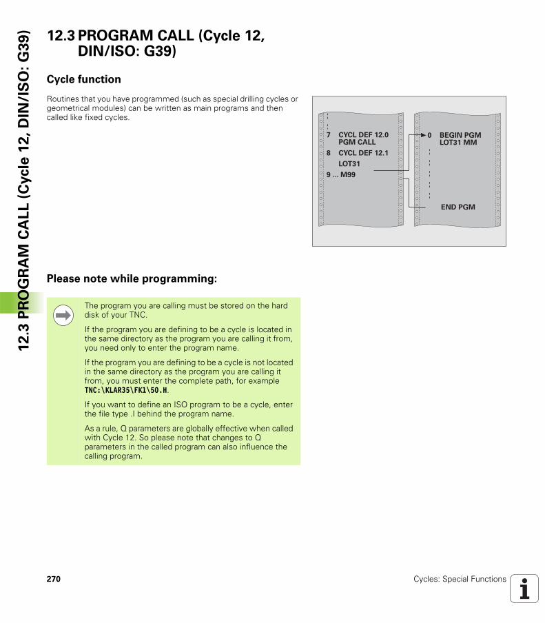
270 Cycles: Special Functions
12
.3 P
RO
GR
AM
CA
LL
(C
ycle
12
, D
IN/I
SO
: G
39
) 12.3 PROGRAM CALL (Cycle 12, DIN/ISO: G39)
Cycle function
Routines that you have programmed (such as special drilling cycles or geometrical modules) can be written as main programs and then called like fixed cycles.
Please note while programming:
���������������������������
��������������������������������
������������������
�����������
������
�������������
The program you are calling must be stored on the hard disk of your TNC.
If the program you are defining to be a cycle is located in the same directory as the program you are calling it from, you need only to enter the program name.
If the program you are defining to be a cycle is not located in the same directory as the program you are calling it from, you must enter the complete path, for example TNC:\KLAR35\FK1\50.H.
If you want to define an ISO program to be a cycle, enter the file type .I behind the program name.
As a rule, Q parameters are globally effective when called with Cycle 12. So please note that changes to Q parameters in the called program can also influence the calling program.
HEIDENHAIN TNC 320 271
12
.3 P
RO
GR
AM
CA
LL
(C
ycle
12
, D
IN/I
SO
: G
39
)Cycle parameters
U Program name: Enter the name of the program you want to call and, if necessary, the directory it is located in or
U activate the file select dialog with the SELECT soft key and select the program to be called
Call the program with
CYCL CALL (separate block) orM99 (blockwise) orM89 (executed after every positioning block)
Example: Designate program 50 as a cycle and call it with M99
55 CYCL DEF 12.0 PGM CALL
56 CYCL DEF 12.1 PGM TNC:\KLAR35\FK1\50.H
57 L X+20 Y+50 FMAX M99
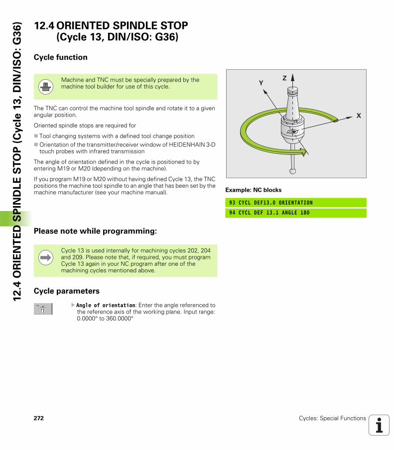
272 Cycles: Special Functions
12
.4 O
RIE
NT
ED
SP
IND
LE
ST
OP
(C
ycle
13
, D
IN/I
SO
: G
36
) 12.4 ORIENTED SPINDLE STOP (Cycle 13, DIN/ISO: G36)
Cycle function
The TNC can control the machine tool spindle and rotate it to a given angular position.
Oriented spindle stops are required for
Tool changing systems with a defined tool change positionOrientation of the transmitter/receiver window of HEIDENHAIN 3-D touch probes with infrared transmission
The angle of orientation defined in the cycle is positioned to by entering M19 or M20 (depending on the machine).
If you program M19 or M20 without having defined Cycle 13, the TNC positions the machine tool spindle to an angle that has been set by the machine manufacturer (see your machine manual).
Please note while programming:
Cycle parameters
U Angle of orientation: Enter the angle referenced to the reference axis of the working plane. Input range: 0.0000° to 360.0000°
Example: NC blocks
93 CYCL DEF13.0 ORIENTATION
94 CYCL DEF 13.1 ANGLE 180
�
��Machine and TNC must be specially prepared by the
machine tool builder for use of this cycle.
Cycle 13 is used internally for machining cycles 202, 204 and 209. Please note that, if required, you must program Cycle 13 again in your NC program after one of the machining cycles mentioned above.
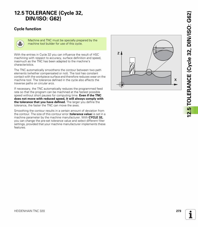
HEIDENHAIN TNC 320 273
12
.5 T
OL
ER
AN
CE
(C
ycle
32
, D
IN/I
SO
: G
62
)12.5 TOLERANCE (Cycle 32, DIN/ISO: G62)
Cycle function
With the entries in Cycle 32 you can influence the result of HSC machining with respect to accuracy, surface definition and speed, inasmuch as the TNC has been adapted to the machine’s characteristics.
The TNC automatically smoothens the contour between two path elements (whether compensated or not). The tool has constant contact with the workpiece surface and therefore reduces wear on the machine tool. The tolerance defined in the cycle also affects the traverse paths on circular arcs.
If necessary, the TNC automatically reduces the programmed feed rate so that the program can be machined at the fastest possible speed without short pauses for computing time. Even if the TNC does not move with reduced speed, it will always comply with the tolerance that you have defined. The larger you define the tolerance, the faster the TNC can move the axes.
Smoothing the contour results in a certain amount of deviation from the contour. The size of this contour error (tolerance value) is set in a machine parameter by the machine manufacturer. With CYCLE 32, you can change the pre-set tolerance value and select different filter settings, provided that your machine manufacturer implements these features.
�
�
Machine and TNC must be specially prepared by the machine tool builder for use of this cycle.
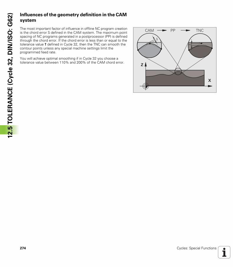
274 Cycles: Special Functions
12
.5 T
OL
ER
AN
CE
(C
ycle
32
, D
IN/I
SO
: G
62
) Influences of the geometry definition in the CAM
system
The most important factor of influence in offline NC program creation is the chord error S defined in the CAM system. The maximum point spacing of NC programs generated in a postprocessor (PP) is defined through the chord error. If the chord error is less than or equal to the tolerance value T defined in Cycle 32, then the TNC can smooth the contour points unless any special machine settings limit the programmed feed rate.
You will achieve optimal smoothing if in Cycle 32 you choose a tolerance value between 110% and 200% of the CAM chord error.
�
�
�
�� ��!!
HEIDENHAIN TNC 320 275
12
.5 T
OL
ER
AN
CE
(C
ycle
32
, D
IN/I
SO
: G
62
)Please note while programming:
With very small tolerance values the machine cannot cut the contour without jerking. These jerking movements are not caused by poor processing power in the TNC, but by the fact that, in order to machine the contour element transitions very exactly, the TNC might have to drastically reduce the speed.
Cycle 32 is DEF active which means that it becomes effective as soon as it is defined in the part program.
The TNC resets Cycle 32 if you
Redefine it and confirm the dialog question for the tolerance value with NO ENTSelect a new program with the PGM MGT key.
After you have reset Cycle 32, the TNC reactivates the tolerance that was predefined by machine parameter.
In a program with millimeters set as unit of measure, the TNC interprets the entered tolerance value in millimeters. In an inch program it interprets it as inches.
If you transfer a program with Cycle 32 that contains only the cycle parameter Tolerance value T, the TNC inserts the two remaining parameters with the value 0 if required.
As the tolerance value increases, the diameter of circular movements usually decreases. If the HSC filter is active on your machine (ask your machine manufacturer, if necessary), the circle can also become larger.
If Cycle 32 is active, the TNC shows the parameters defined for Cycle 32 on the CYC tab of the additional status display.
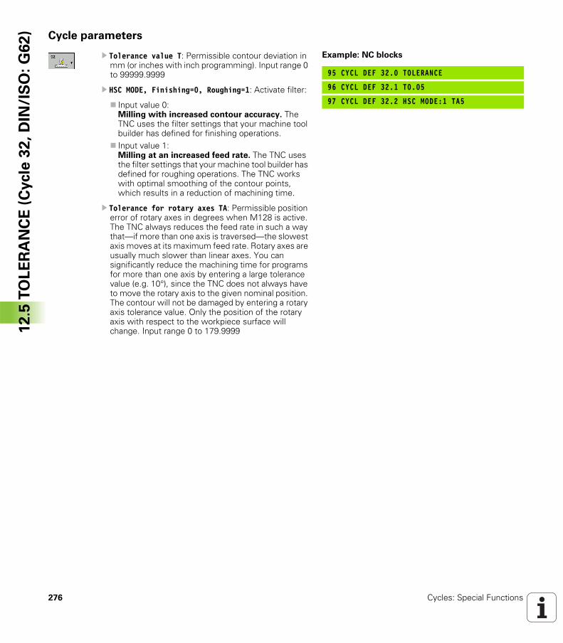
276 Cycles: Special Functions
12
.5 T
OL
ER
AN
CE
(C
ycle
32
, D
IN/I
SO
: G
62
) Cycle parameters
U Tolerance value T: Permissible contour deviation in mm (or inches with inch programming). Input range 0 to 99999.9999
U HSC MODE, Finishing=0, Roughing=1: Activate filter:
Input value 0:Milling with increased contour accuracy. The TNC uses the filter settings that your machine tool builder has defined for finishing operations. Input value 1:Milling at an increased feed rate. The TNC uses the filter settings that your machine tool builder has defined for roughing operations. The TNC works with optimal smoothing of the contour points, which results in a reduction of machining time.
U Tolerance for rotary axes TA: Permissible position error of rotary axes in degrees when M128 is active. The TNC always reduces the feed rate in such a way that—if more than one axis is traversed—the slowest axis moves at its maximum feed rate. Rotary axes are usually much slower than linear axes. You can significantly reduce the machining time for programs for more than one axis by entering a large tolerance value (e.g. 10°), since the TNC does not always have to move the rotary axis to the given nominal position. The contour will not be damaged by entering a rotary axis tolerance value. Only the position of the rotary axis with respect to the workpiece surface will change. Input range 0 to 179.9999
Example: NC blocks
95 CYCL DEF 32.0 TOLERANCE
96 CYCL DEF 32.1 T0.05
97 CYCL DEF 32.2 HSC MODE:1 TA5
Using Touch Probe
Cycles
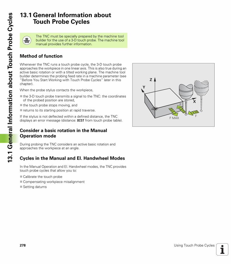
278 Using Touch Probe Cycles
13
.1 G
en
era
l In
form
ati
on
ab
ou
t To
uch
Pro
be
Cycle
s 13.1 General Information about Touch Probe Cycles
Method of function
Whenever the TNC runs a touch probe cycle, the 3-D touch probe approaches the workpiece in one linear axis. This is also true during an active basic rotation or with a tilted working plane. The machine tool builder determines the probing feed rate in a machine parameter (see “Before You Start Working with Touch Probe Cycles” later in this chapter).
When the probe stylus contacts the workpiece,
the 3-D touch probe transmits a signal to the TNC: the coordinates of the probed position are stored,the touch probe stops moving, andreturns to its starting position at rapid traverse.
If the stylus is not deflected within a defined distance, the TNC displays an error message (distance: DIST from touch probe table).
Consider a basic rotation in the Manual
Operation mode
During probing the TNC considers an active basic rotation and approaches the workpiece at an angle.
Cycles in the Manual and El. Handwheel Modes
In the Manual Operation and El. Handwheel modes, the TNC provides touch probe cycles that allow you to:
Calibrate the touch probeCompensating workpiece misalignmentSetting datums
The TNC must be specially prepared by the machine tool builder for the use of a 3-D touch probe. The machine tool manual provides further information.
�
�
�
"
"� �#"
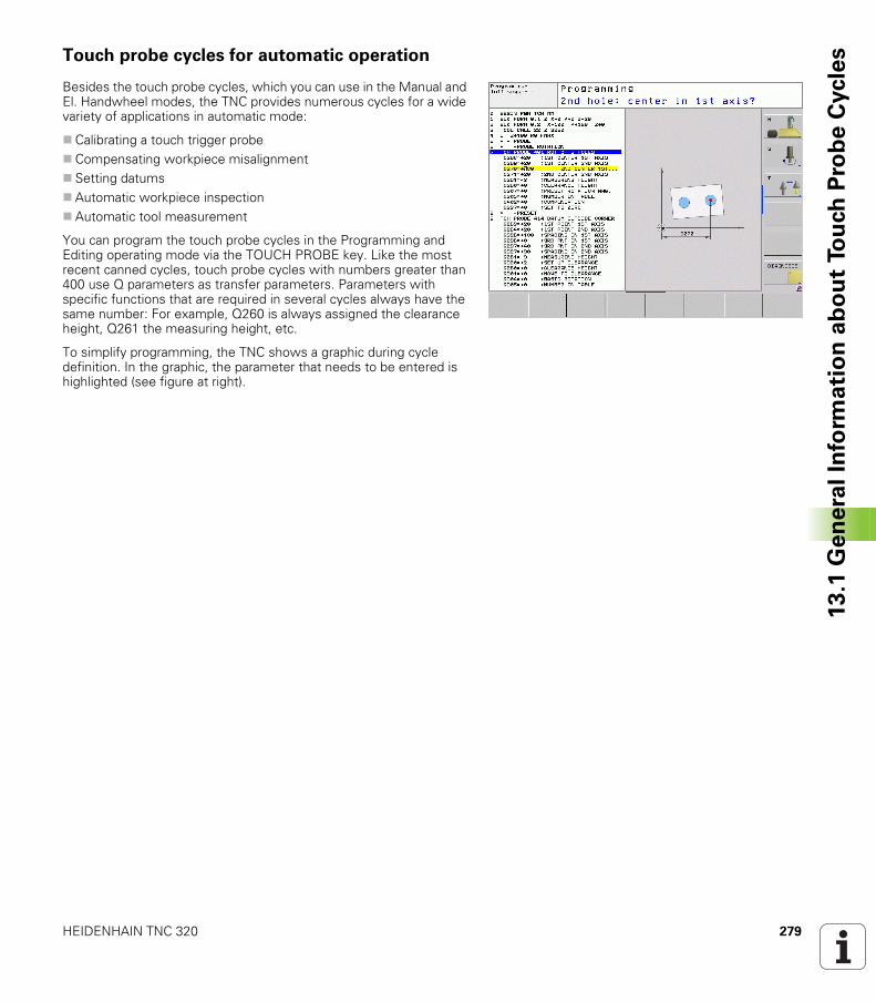
HEIDENHAIN TNC 320 279
13
.1 G
en
era
l In
form
ati
on
ab
ou
t To
uch
Pro
be
Cycle
sTouch probe cycles for automatic operation
Besides the touch probe cycles, which you can use in the Manual and El. Handwheel modes, the TNC provides numerous cycles for a wide variety of applications in automatic mode:
Calibrating a touch trigger probeCompensating workpiece misalignmentSetting datumsAutomatic workpiece inspectionAutomatic tool measurement
You can program the touch probe cycles in the Programming and Editing operating mode via the TOUCH PROBE key. Like the most recent canned cycles, touch probe cycles with numbers greater than 400 use Q parameters as transfer parameters. Parameters with specific functions that are required in several cycles always have the same number: For example, Q260 is always assigned the clearance height, Q261 the measuring height, etc.
To simplify programming, the TNC shows a graphic during cycle definition. In the graphic, the parameter that needs to be entered is highlighted (see figure at right).
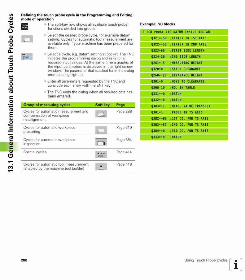
280 Using Touch Probe Cycles
13
.1 G
en
era
l In
form
ati
on
ab
ou
t To
uch
Pro
be
Cycle
s Defining the touch probe cycle in the Programming and Editing mode of operation
U The soft-key row shows all available touch probe functions divided into groups.
U Select the desired probe cycle, for example datum setting. Cycles for automatic tool measurement are available only if your machine has been prepared for them.
U Select a cycle, e.g. datum setting at pocket. The TNC initiates the programming dialog and asks for all required input values. At the same time a graphic of the input parameters is displayed in the right screen window. The parameter that is asked for in the dialog prompt is highlighted.
U Enter all parameters requested by the TNC and conclude each entry with the ENT key.
U The TNC ends the dialog when all required data has been entered.
Example: NC blocks
5 TCH PROBE 410 DATUM INSIDE RECTAN.
Q321=+50 ;CENTER IN 1ST AXIS
Q322=+50 ;CENTER IN 2ND AXIS
Q323=60 ;FIRST SIDE LENGTH
Q324=20 ;2ND SIDE LENGTH
Q261=-5 ;MEASURING HEIGHT
Q320=0 ;SETUP CLEARANCE
Q260=+20 ;CLEARANCE HEIGHT
Q301=0 ;MOVE TO CLEARANCE
Q305=10 ;NO. IN TABLE
Q331=+0 ;DATUM
Q332=+0 ;DATUM
Q303=+1 ;MEAS. VALUE TRANSFER
Q381=1 ;PROBE IN TS AXIS
Q382=+85 ;1ST CO. FOR TS AXIS
Q383=+50 ;2ND CO. FOR TS AXIS
Q384=+0 ;3RD CO. FOR TS AXIS
Q333=+0 ;DATUM
Group of measuring cycles Soft key Page
Cycles for automatic measurement and compensation of workpiece misalignment
Page 288
Cycles for automatic workpiece presetting
Page 310
Cycles for automatic workpiece inspection
Page 364
Special cycles Page 414
Cycles for automatic tool measurement (enabled by the machine tool builder)
Page 418
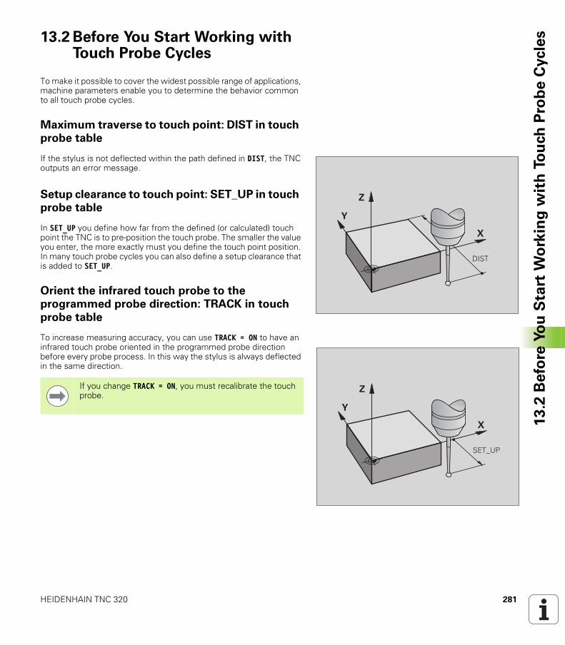
HEIDENHAIN TNC 320 281
13
.2 B
efo
re Y
ou
Sta
rt W
ork
ing
wit
h T
ou
ch
Pro
be
Cycle
s13.2 Before You Start Working with Touch Probe Cycles
To make it possible to cover the widest possible range of applications, machine parameters enable you to determine the behavior common to all touch probe cycles.
Maximum traverse to touch point: DIST in touch
probe table
If the stylus is not deflected within the path defined in DIST, the TNC outputs an error message.
Setup clearance to touch point: SET_UP in touch
probe table
In SET_UP you define how far from the defined (or calculated) touch point the TNC is to pre-position the touch probe. The smaller the value you enter, the more exactly must you define the touch point position. In many touch probe cycles you can also define a setup clearance that is added to SET_UP.
Orient the infrared touch probe to the
programmed probe direction: TRACK in touch
probe table
To increase measuring accuracy, you can use TRACK = ON to have an infrared touch probe oriented in the programmed probe direction before every probe process. In this way the stylus is always deflected in the same direction.
�
�
�
$%�
�
�
�
�& '(!
If you change TRACK = ON, you must recalibrate the touch probe.
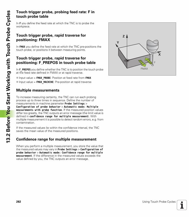
282 Using Touch Probe Cycles
13
.2 B
efo
re Y
ou
Sta
rt W
ork
ing
wit
h T
ou
ch
Pro
be
Cycle
s Touch trigger probe, probing feed rate: F in
touch probe table
In F you define the feed rate at which the TNC is to probe the workpiece.
Touch trigger probe, rapid traverse for
positioning: FMAX
In FMAX you define the feed rate at which the TNC pre-positions the touch probe, or positions it between measuring points.
Touch trigger probe, rapid traverse for
positioning: F_PREPOS in touch probe table
In F_PREPOS you define whether the TNC is to position the touch probe at the feed rate defined in FMAX or at rapid traverse.
Input value = FMAX_PROBE: Position at feed rate from FMAXInput value = FMAX_MACHINE: Pre-position at rapid traverse
Multiple measurements
To increase measuring certainty, the TNC can run each probing process up to three times in sequence. Define the number of measurements in machine parameter Probe Settings > Configuration of probe behavior > Automatic mode: Multiple measurements with probe function. If the measured position values differ too greatly, the TNC outputs an error message (the limit value is defined in confidence range for multiple measurement). With multiple measurement it is possible to detect random errors, e.g. from contamination.
If the measured values lie within the confidence interval, the TNC saves the mean value of the measured positions.
Confidence range for multiple measurement
When you perform a multiple measurement, you store the value that the measured values may vary in Probe Settings > Configuration of probe behavior > Automatic mode: Confidence range for multiple measurement. If the difference in the measured values exceeds the value defined by you, the TNC outputs an error message.
�
�
�
��"
" �#
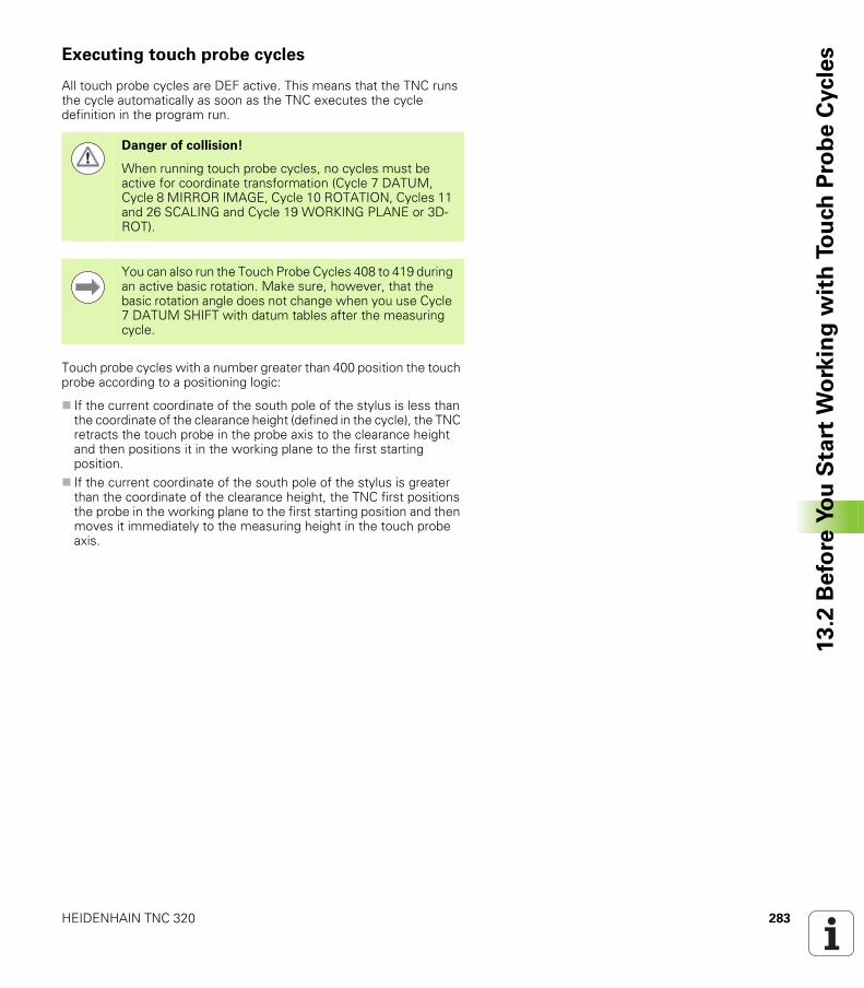
HEIDENHAIN TNC 320 283
13
.2 B
efo
re Y
ou
Sta
rt W
ork
ing
wit
h T
ou
ch
Pro
be
Cycle
sExecuting touch probe cycles
All touch probe cycles are DEF active. This means that the TNC runs the cycle automatically as soon as the TNC executes the cycle definition in the program run.
Touch probe cycles with a number greater than 400 position the touch probe according to a positioning logic:
If the current coordinate of the south pole of the stylus is less than the coordinate of the clearance height (defined in the cycle), the TNC retracts the touch probe in the probe axis to the clearance height and then positions it in the working plane to the first starting position.If the current coordinate of the south pole of the stylus is greater than the coordinate of the clearance height, the TNC first positions the probe in the working plane to the first starting position and then moves it immediately to the measuring height in the touch probe axis.
Danger of collision!
When running touch probe cycles, no cycles must be active for coordinate transformation (Cycle 7 DATUM, Cycle 8 MIRROR IMAGE, Cycle 10 ROTATION, Cycles 11 and 26 SCALING and Cycle 19 WORKING PLANE or 3D-ROT).
You can also run the Touch Probe Cycles 408 to 419 during an active basic rotation. Make sure, however, that the basic rotation angle does not change when you use Cycle 7 DATUM SHIFT with datum tables after the measuring cycle.
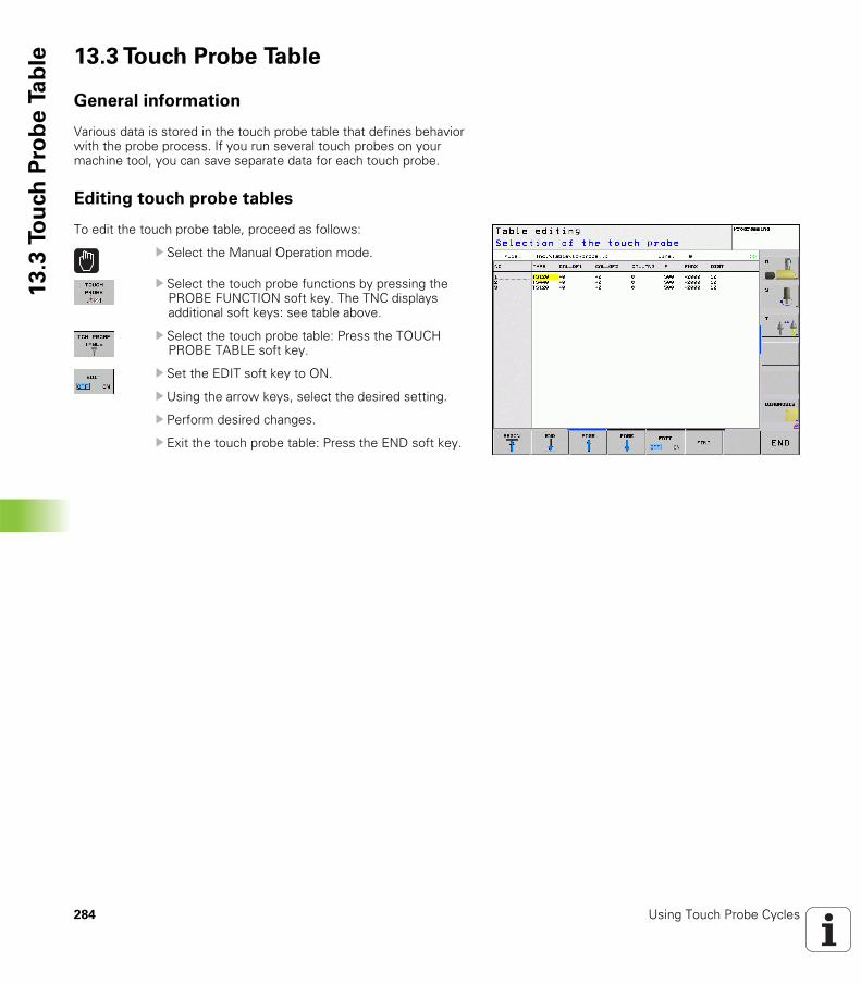
284 Using Touch Probe Cycles
13
.3 T
ou
ch
Pro
be
Ta
ble 13.3 Touch Probe Table
General information
Various data is stored in the touch probe table that defines behavior with the probe process. If you run several touch probes on your machine tool, you can save separate data for each touch probe.
Editing touch probe tables
To edit the touch probe table, proceed as follows:
U Select the Manual Operation mode.
U Select the touch probe functions by pressing the PROBE FUNCTION soft key. The TNC displays additional soft keys: see table above.
U Select the touch probe table: Press the TOUCH PROBE TABLE soft key.
U Set the EDIT soft key to ON.
U Using the arrow keys, select the desired setting.
U Perform desired changes.
U Exit the touch probe table: Press the END soft key.
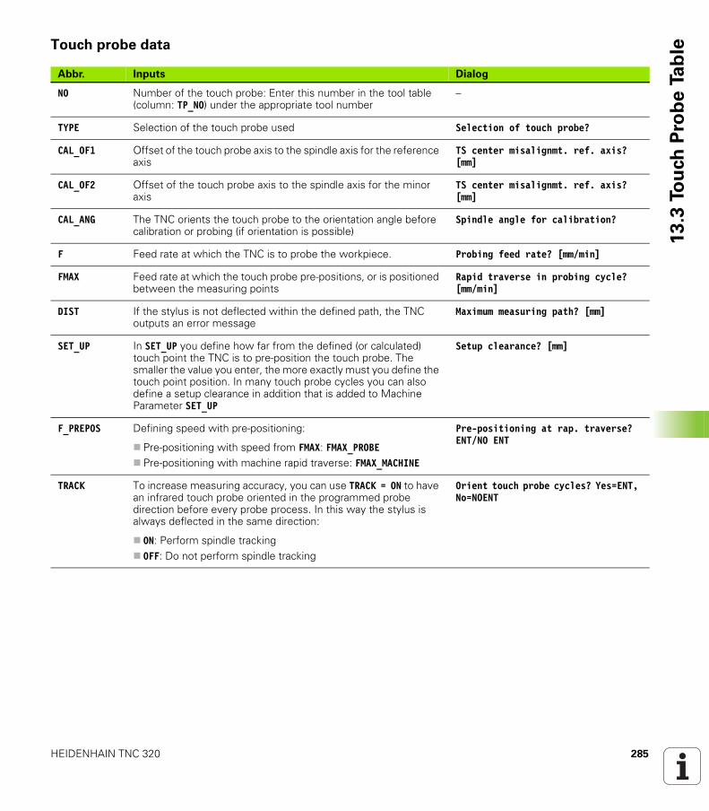
HEIDENHAIN TNC 320 285
13
.3 T
ou
ch
Pro
be
Ta
bleTouch probe data
Abbr. Inputs Dialog
NO Number of the touch probe: Enter this number in the tool table (column: TP_NO) under the appropriate tool number
–
TYPE Selection of the touch probe used Selection of touch probe?
CAL_OF1 Offset of the touch probe axis to the spindle axis for the reference axis
TS center misalignmt. ref. axis? [mm]
CAL_OF2 Offset of the touch probe axis to the spindle axis for the minor axis
TS center misalignmt. ref. axis? [mm]
CAL_ANG The TNC orients the touch probe to the orientation angle before calibration or probing (if orientation is possible)
Spindle angle for calibration?
F Feed rate at which the TNC is to probe the workpiece. Probing feed rate? [mm/min]
FMAX Feed rate at which the touch probe pre-positions, or is positioned between the measuring points
Rapid traverse in probing cycle? [mm/min]
DIST If the stylus is not deflected within the defined path, the TNC outputs an error message
Maximum measuring path? [mm]
SET_UP In SET_UP you define how far from the defined (or calculated) touch point the TNC is to pre-position the touch probe. The smaller the value you enter, the more exactly must you define the touch point position. In many touch probe cycles you can also define a setup clearance in addition that is added to Machine Parameter SET_UP
Setup clearance? [mm]
F_PREPOS Defining speed with pre-positioning:
Pre-positioning with speed from FMAX: FMAX_PROBE Pre-positioning with machine rapid traverse: FMAX_MACHINE
Pre-positioning at rap. traverse? ENT/NO ENT
TRACK To increase measuring accuracy, you can use TRACK = ON to have an infrared touch probe oriented in the programmed probe direction before every probe process. In this way the stylus is always deflected in the same direction:
ON: Perform spindle trackingOFF: Do not perform spindle tracking
Orient touch probe cycles? Yes=ENT, No=NOENT

286 Using Touch Probe Cycles
13
.3 T
ou
ch
Pro
be
Ta
ble
Touch Probe Cycles:
Automatic Measurement
of Workpiece
Misalignment
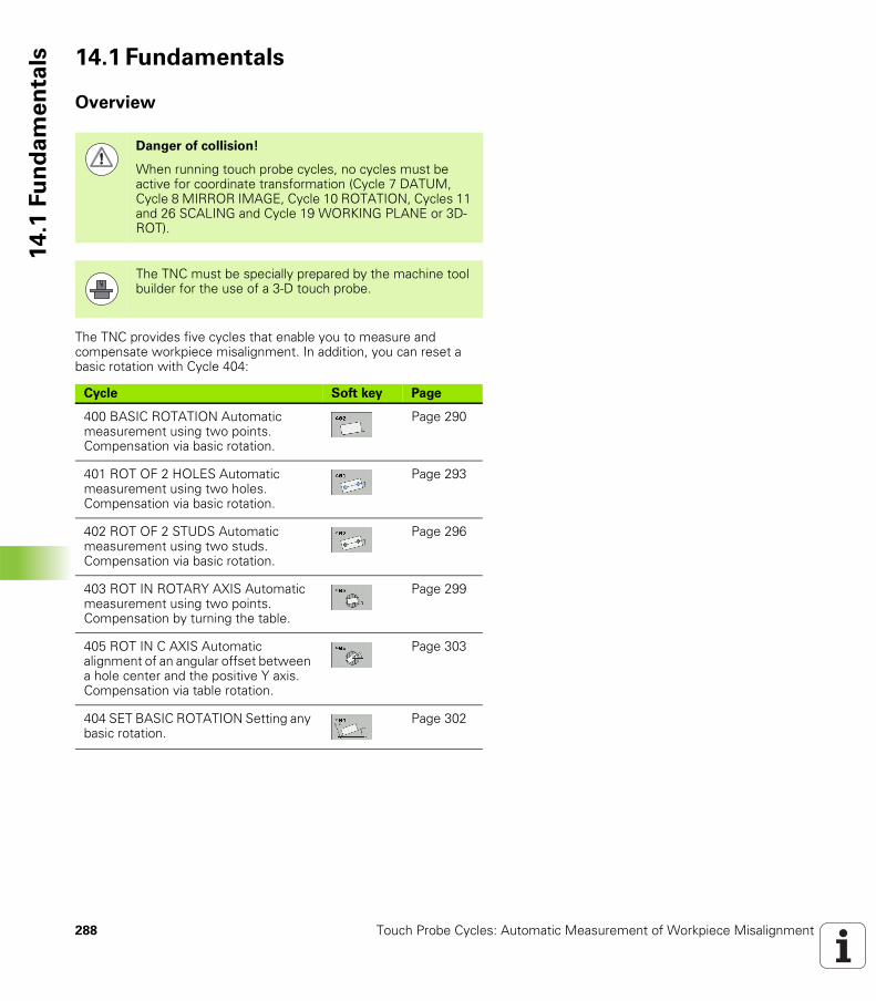
288 Touch Probe Cycles: Automatic Measurement of Workpiece Misalignment
14
.1 F
un
da
me
nta
ls 14.1 Fundamentals
Overview
The TNC provides five cycles that enable you to measure and compensate workpiece misalignment. In addition, you can reset a basic rotation with Cycle 404:
Danger of collision!
When running touch probe cycles, no cycles must be active for coordinate transformation (Cycle 7 DATUM, Cycle 8 MIRROR IMAGE, Cycle 10 ROTATION, Cycles 11 and 26 SCALING and Cycle 19 WORKING PLANE or 3D-ROT).
The TNC must be specially prepared by the machine tool builder for the use of a 3-D touch probe.
Cycle Soft key Page
400 BASIC ROTATION Automatic measurement using two points. Compensation via basic rotation.
Page 290
401 ROT OF 2 HOLES Automatic measurement using two holes. Compensation via basic rotation.
Page 293
402 ROT OF 2 STUDS Automatic measurement using two studs. Compensation via basic rotation.
Page 296
403 ROT IN ROTARY AXIS Automatic measurement using two points. Compensation by turning the table.
Page 299
405 ROT IN C AXIS Automatic alignment of an angular offset between a hole center and the positive Y axis. Compensation via table rotation.
Page 303
404 SET BASIC ROTATION Setting any basic rotation.
Page 302
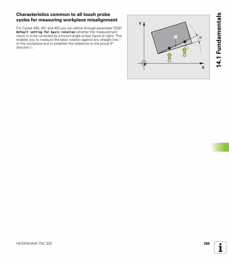
HEIDENHAIN TNC 320 289
14
.1 F
un
da
me
nta
lsCharacteristics common to all touch probe
cycles for measuring workpiece misalignment
For Cycles 400, 401 and 402 you can define through parameter Q307 Default setting for basic rotation whether the measurement result is to be corrected by a known angle α (see figure at right). This enables you to measure the basic rotation against any straight line 1 of the workpiece and to establish the reference to the actual 0° direction 2.
�
�
��
�
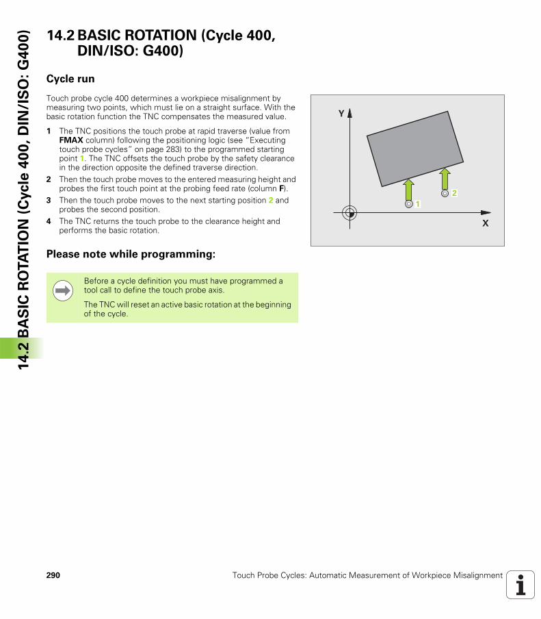
290 Touch Probe Cycles: Automatic Measurement of Workpiece Misalignment
14
.2 B
AS
IC R
OTA
TIO
N (
Cycle
40
0,
DIN
/IS
O:
G4
00
) 14.2 BASIC ROTATION (Cycle 400, DIN/ISO: G400)
Cycle run
Touch probe cycle 400 determines a workpiece misalignment by measuring two points, which must lie on a straight surface. With the basic rotation function the TNC compensates the measured value.
1 The TNC positions the touch probe at rapid traverse (value from FMAX column) following the positioning logic (see “Executing touch probe cycles” on page 283) to the programmed starting point 1. The TNC offsets the touch probe by the safety clearance in the direction opposite the defined traverse direction.
2 Then the touch probe moves to the entered measuring height and probes the first touch point at the probing feed rate (column F).
3 Then the touch probe moves to the next starting position 2 and probes the second position.
4 The TNC returns the touch probe to the clearance height and performs the basic rotation.
Please note while programming:
�
�
��
Before a cycle definition you must have programmed a tool call to define the touch probe axis.
The TNC will reset an active basic rotation at the beginning of the cycle.
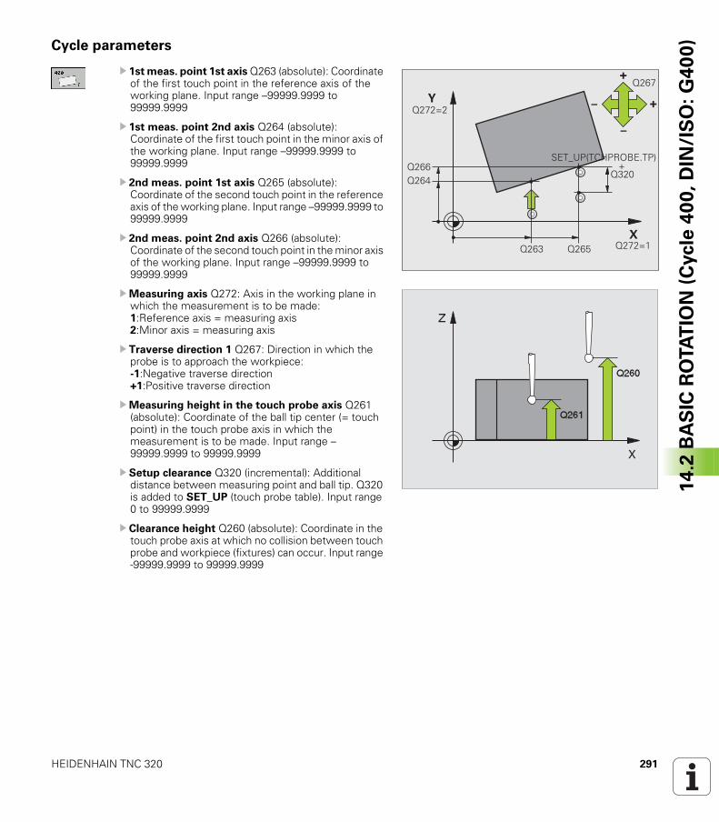
HEIDENHAIN TNC 320 291
14
.2 B
AS
IC R
OTA
TIO
N (
Cycle
40
0,
DIN
/IS
O:
G4
00
)Cycle parameters
U 1st meas. point 1st axis Q263 (absolute): Coordinate of the first touch point in the reference axis of the working plane. Input range –99999.9999 to 99999.9999
U 1st meas. point 2nd axis Q264 (absolute): Coordinate of the first touch point in the minor axis of the working plane. Input range –99999.9999 to 99999.9999
U 2nd meas. point 1st axis Q265 (absolute): Coordinate of the second touch point in the reference axis of the working plane. Input range –99999.9999 to 99999.9999
U 2nd meas. point 2nd axis Q266 (absolute): Coordinate of the second touch point in the minor axis of the working plane. Input range –99999.9999 to 99999.9999
UMeasuring axis Q272: Axis in the working plane in which the measurement is to be made: 1:Reference axis = measuring axis 2:Minor axis = measuring axis
U Traverse direction 1 Q267: Direction in which the probe is to approach the workpiece: -1:Negative traverse direction +1:Positive traverse direction
UMeasuring height in the touch probe axis Q261 (absolute): Coordinate of the ball tip center (= touch point) in the touch probe axis in which the measurement is to be made. Input range –99999.9999 to 99999.9999
U Setup clearance Q320 (incremental): Additional distance between measuring point and ball tip. Q320 is added to SET_UP (touch probe table). Input range 0 to 99999.9999
U Clearance height Q260 (absolute): Coordinate in the touch probe axis at which no collision between touch probe and workpiece (fixtures) can occur. Input range -99999.9999 to 99999.9999
�
�
��������
���� ���������
������
!
"
" !
����
�& '(!� �)!�*�&� !�����������������������������������������������������
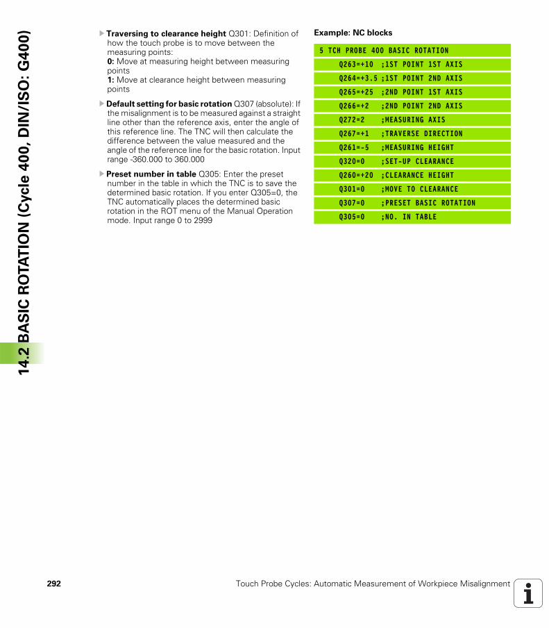
292 Touch Probe Cycles: Automatic Measurement of Workpiece Misalignment
14
.2 B
AS
IC R
OTA
TIO
N (
Cycle
40
0,
DIN
/IS
O:
G4
00
) U Traversing to clearance height Q301: Definition of how the touch probe is to move between the measuring points: 0: Move at measuring height between measuring points1: Move at clearance height between measuring points
U Default setting for basic rotation Q307 (absolute): If the misalignment is to be measured against a straight line other than the reference axis, enter the angle of this reference line. The TNC will then calculate the difference between the value measured and the angle of the reference line for the basic rotation. Input range -360.000 to 360.000
U Preset number in table Q305: Enter the preset number in the table in which the TNC is to save the determined basic rotation. If you enter Q305=0, the TNC automatically places the determined basic rotation in the ROT menu of the Manual Operation mode. Input range 0 to 2999
Example: NC blocks
5 TCH PROBE 400 BASIC ROTATION
Q263=+10 ;1ST POINT 1ST AXIS
Q264=+3.5 ;1ST POINT 2ND AXIS
Q265=+25 ;2ND POINT 1ST AXIS
Q266=+2 ;2ND POINT 2ND AXIS
Q272=2 ;MEASURING AXIS
Q267=+1 ;TRAVERSE DIRECTION
Q261=-5 ;MEASURING HEIGHT
Q320=0 ;SET-UP CLEARANCE
Q260=+20 ;CLEARANCE HEIGHT
Q301=0 ;MOVE TO CLEARANCE
Q307=0 ;PRESET BASIC ROTATION
Q305=0 ;NO. IN TABLE
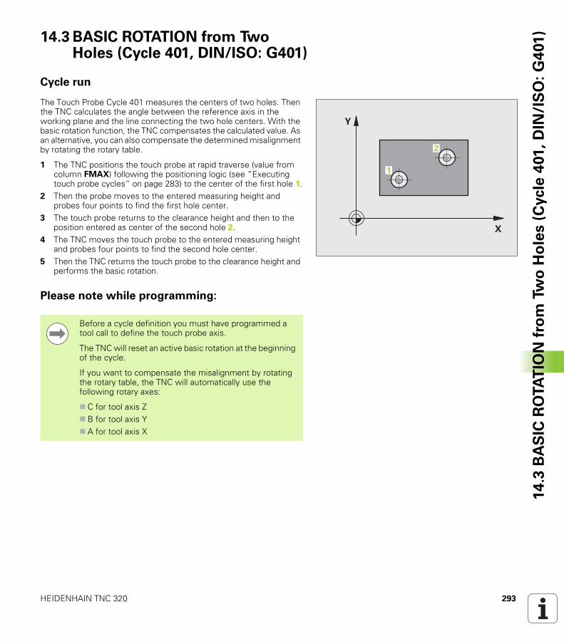
HEIDENHAIN TNC 320 293
14
.3 B
AS
IC R
OTA
TIO
N f
rom
Tw
o H
ole
s (
Cycle
401
, D
IN/I
SO
: G
401
)14.3 BASIC ROTATION from Two Holes (Cycle 401, DIN/ISO: G401)
Cycle run
The Touch Probe Cycle 401 measures the centers of two holes. Then the TNC calculates the angle between the reference axis in the working plane and the line connecting the two hole centers. With the basic rotation function, the TNC compensates the calculated value. As an alternative, you can also compensate the determined misalignment by rotating the rotary table.
1 The TNC positions the touch probe at rapid traverse (value from column FMAX) following the positioning logic (see “Executing touch probe cycles” on page 283) to the center of the first hole 1.
2 Then the probe moves to the entered measuring height and probes four points to find the first hole center.
3 The touch probe returns to the clearance height and then to the position entered as center of the second hole 2.
4 The TNC moves the touch probe to the entered measuring height and probes four points to find the second hole center.
5 Then the TNC returns the touch probe to the clearance height and performs the basic rotation.
Please note while programming:
�
�
�
�
Before a cycle definition you must have programmed a tool call to define the touch probe axis.
The TNC will reset an active basic rotation at the beginning of the cycle.
If you want to compensate the misalignment by rotating the rotary table, the TNC will automatically use the following rotary axes:
C for tool axis ZB for tool axis YA for tool axis X
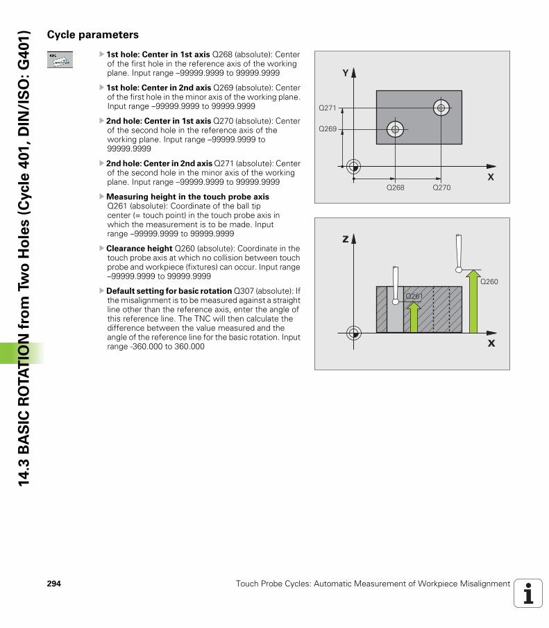
294 Touch Probe Cycles: Automatic Measurement of Workpiece Misalignment
14
.3 B
AS
IC R
OTA
TIO
N f
rom
Tw
o H
ole
s (
Cycle
401
, D
IN/I
SO
: G
401
) Cycle parameters
U 1st hole: Center in 1st axis Q268 (absolute): Center of the first hole in the reference axis of the working plane. Input range –99999.9999 to 99999.9999
U 1st hole: Center in 2nd axis Q269 (absolute): Center of the first hole in the minor axis of the working plane. Input range –99999.9999 to 99999.9999
U 2nd hole: Center in 1st axis Q270 (absolute): Center of the second hole in the reference axis of the working plane. Input range –99999.9999 to 99999.9999
U 2nd hole: Center in 2nd axis Q271 (absolute): Center of the second hole in the minor axis of the working plane. Input range –99999.9999 to 99999.9999
UMeasuring height in the touch probe axis Q261 (absolute): Coordinate of the ball tip center (= touch point) in the touch probe axis in which the measurement is to be made. Input range –99999.9999 to 99999.9999
U Clearance height Q260 (absolute): Coordinate in the touch probe axis at which no collision between touch probe and workpiece (fixtures) can occur. Input range –99999.9999 to 99999.9999
U Default setting for basic rotation Q307 (absolute): If the misalignment is to be measured against a straight line other than the reference axis, enter the angle of this reference line. The TNC will then calculate the difference between the value measured and the angle of the reference line for the basic rotation. Input range -360.000 to 360.000
�
�
����
����
��� ����
�
�
����
����
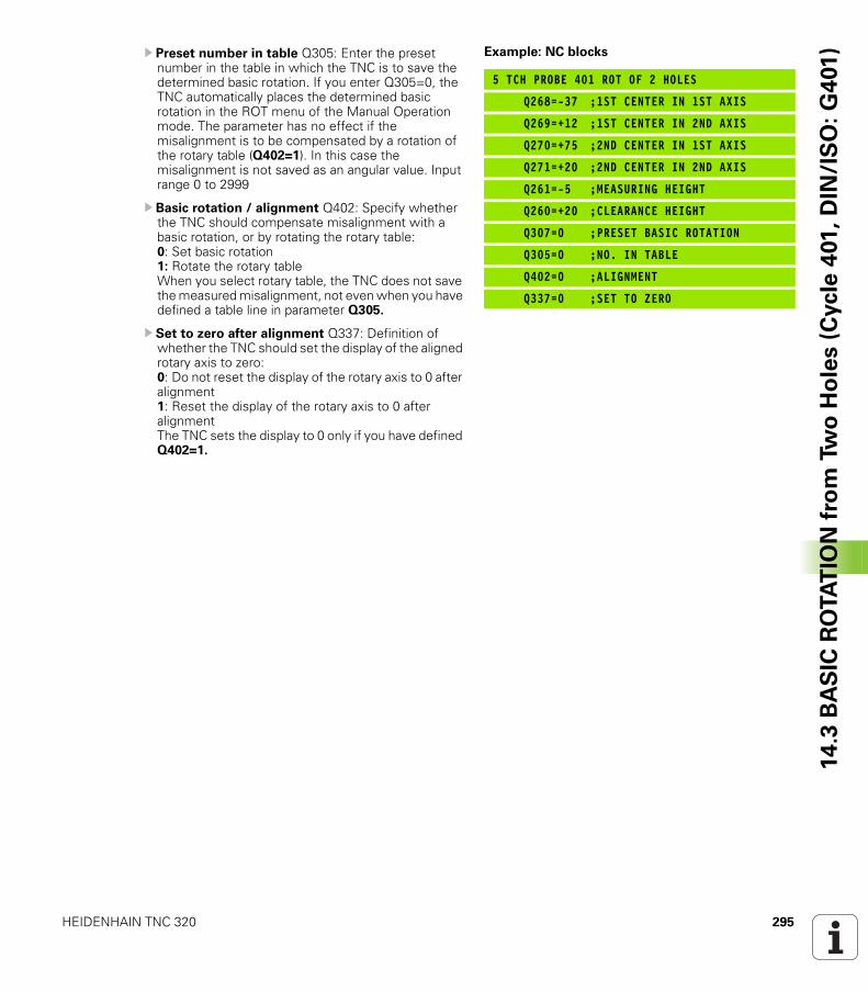
HEIDENHAIN TNC 320 295
14
.3 B
AS
IC R
OTA
TIO
N f
rom
Tw
o H
ole
s (
Cycle
401
, D
IN/I
SO
: G
401
)U Preset number in table Q305: Enter the preset number in the table in which the TNC is to save the determined basic rotation. If you enter Q305=0, the TNC automatically places the determined basic rotation in the ROT menu of the Manual Operation mode. The parameter has no effect if the misalignment is to be compensated by a rotation of the rotary table (Q402=1). In this case the misalignment is not saved as an angular value. Input range 0 to 2999
U Basic rotation / alignment Q402: Specify whether the TNC should compensate misalignment with a basic rotation, or by rotating the rotary table: 0: Set basic rotation 1: Rotate the rotary tableWhen you select rotary table, the TNC does not save the measured misalignment, not even when you have defined a table line in parameter Q305.
U Set to zero after alignment Q337: Definition of whether the TNC should set the display of the aligned rotary axis to zero: 0: Do not reset the display of the rotary axis to 0 after alignment 1: Reset the display of the rotary axis to 0 after alignmentThe TNC sets the display to 0 only if you have defined Q402=1.
Example: NC blocks
5 TCH PROBE 401 ROT OF 2 HOLES
Q268=-37 ;1ST CENTER IN 1ST AXIS
Q269=+12 ;1ST CENTER IN 2ND AXIS
Q270=+75 ;2ND CENTER IN 1ST AXIS
Q271=+20 ;2ND CENTER IN 2ND AXIS
Q261=-5 ;MEASURING HEIGHT
Q260=+20 ;CLEARANCE HEIGHT
Q307=0 ;PRESET BASIC ROTATION
Q305=0 ;NO. IN TABLE
Q402=0 ;ALIGNMENT
Q337=0 ;SET TO ZERO
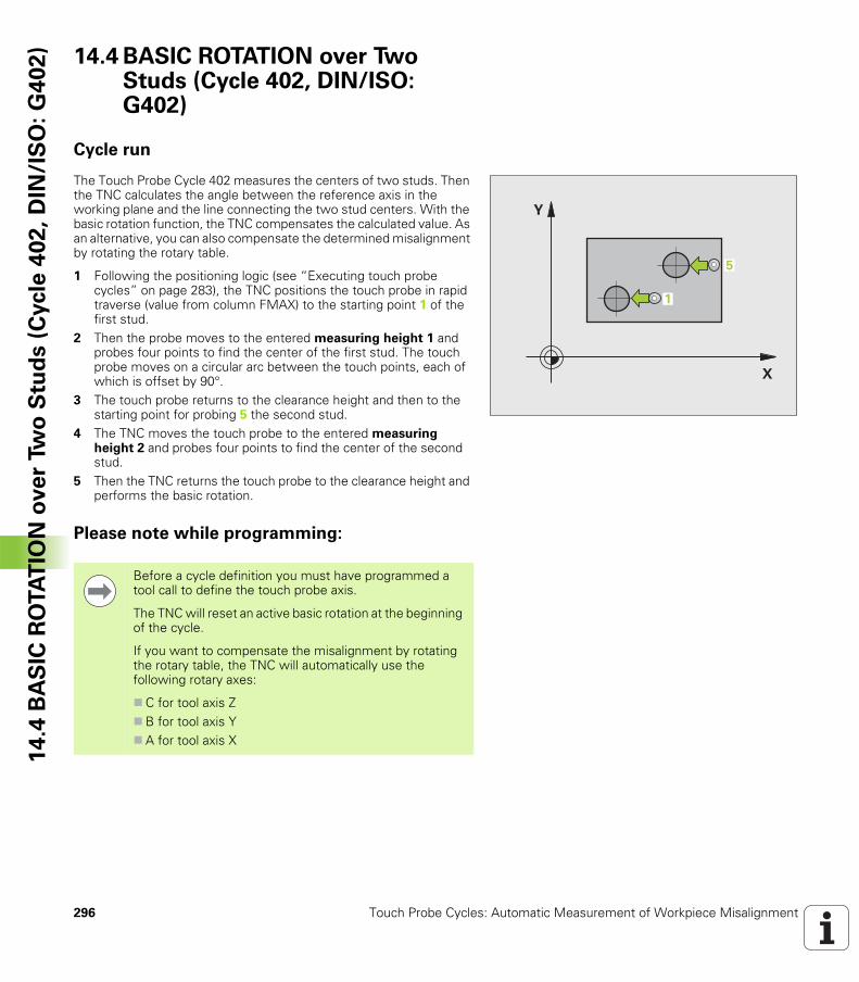
296 Touch Probe Cycles: Automatic Measurement of Workpiece Misalignment
14
.4 B
AS
IC R
OTA
TIO
N o
ve
r Tw
o S
tud
s (
Cycle
40
2,
DIN
/IS
O:
G4
02
) 14.4 BASIC ROTATION over Two Studs (Cycle 402, DIN/ISO: G402)
Cycle run
The Touch Probe Cycle 402 measures the centers of two studs. Then the TNC calculates the angle between the reference axis in the working plane and the line connecting the two stud centers. With the basic rotation function, the TNC compensates the calculated value. As an alternative, you can also compensate the determined misalignment by rotating the rotary table.
1 Following the positioning logic (see “Executing touch probe cycles” on page 283), the TNC positions the touch probe in rapid traverse (value from column FMAX) to the starting point 1 of the first stud.
2 Then the probe moves to the entered measuring height 1 and probes four points to find the center of the first stud. The touch probe moves on a circular arc between the touch points, each of which is offset by 90°.
3 The touch probe returns to the clearance height and then to the starting point for probing 5 the second stud.
4 The TNC moves the touch probe to the entered measuring height 2 and probes four points to find the center of the second stud.
5 Then the TNC returns the touch probe to the clearance height and performs the basic rotation.
Please note while programming:
�
�
�
�
Before a cycle definition you must have programmed a tool call to define the touch probe axis.
The TNC will reset an active basic rotation at the beginning of the cycle.
If you want to compensate the misalignment by rotating the rotary table, the TNC will automatically use the following rotary axes:
C for tool axis ZB for tool axis YA for tool axis X
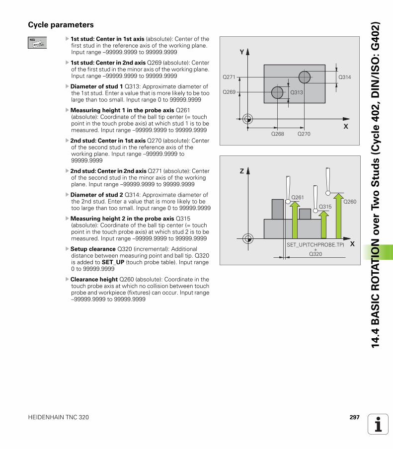
HEIDENHAIN TNC 320 297
14
.4 B
AS
IC R
OTA
TIO
N o
ve
r Tw
o S
tud
s (
Cycle
40
2,
DIN
/IS
O:
G4
02
)Cycle parameters
U 1st stud: Center in 1st axis (absolute): Center of the first stud in the reference axis of the working plane. Input range –99999.9999 to 99999.9999
U 1st stud: Center in 2nd axis Q269 (absolute): Center of the first stud in the minor axis of the working plane. Input range –99999.9999 to 99999.9999
U Diameter of stud 1 Q313: Approximate diameter of the 1st stud. Enter a value that is more likely to be too large than too small. Input range 0 to 99999.9999
UMeasuring height 1 in the probe axis Q261 (absolute): Coordinate of the ball tip center (= touch point in the touch probe axis) at which stud 1 is to be measured. Input range –99999.9999 to 99999.9999
U 2nd stud: Center in 1st axis Q270 (absolute): Center of the second stud in the reference axis of the working plane. Input range –99999.9999 to 99999.9999
U 2nd stud: Center in 2nd axis Q271 (absolute): Center of the second stud in the minor axis of the working plane. Input range –99999.9999 to 99999.9999
U Diameter of stud 2 Q314: Approximate diameter of the 2nd stud. Enter a value that is more likely to be too large than too small. Input range 0 to 99999.9999
UMeasuring height 2 in the probe axis Q315 (absolute): Coordinate of the ball tip center (= touch point in the touch probe axis) at which stud 2 is to be measured. Input range –99999.9999 to 99999.9999
U Setup clearance Q320 (incremental): Additional distance between measuring point and ball tip. Q320 is added to SET_UP (touch probe table). Input range 0 to 99999.9999
U Clearance height Q260 (absolute): Coordinate in the touch probe axis at which no collision between touch probe and workpiece (fixtures) can occur. Input range –99999.9999 to 99999.9999
�
�
����
����
��� ����
����
����
�
�
��������
���
�& '(!� �)!�*�&� !��
����

298 Touch Probe Cycles: Automatic Measurement of Workpiece Misalignment
14
.4 B
AS
IC R
OTA
TIO
N o
ve
r Tw
o S
tud
s (
Cycle
40
2,
DIN
/IS
O:
G4
02
) U Traversing to clearance height Q301: Definition of how the touch probe is to move between the measuring points: 0: Move at measuring height between measuring points1: Move at clearance height between measuring points
U Default setting for basic rotation Q307 (absolute): If the misalignment is to be measured against a straight line other than the reference axis, enter the angle of this reference line. The TNC will then calculate the difference between the value measured and the angle of the reference line for the basic rotation. Input range –360.000 to 360.000
U Preset number in table Q305: Enter the preset number in the table in which the TNC is to save the determined basic rotation. If you enter Q305=0, the TNC automatically places the determined basic rotation in the ROT menu of the Manual Operation mode. The parameter has no effect if the misalignment is to be compensated by a rotation of the rotary table (Q402=1). In this case the misalignment is not saved as an angular value. Input range 0 to 2999
U Basic rotation / alignment Q402: Specify whether the TNC should compensate misalignment with a basic rotation, or by rotating the rotary table: 0: Set basic rotation 1: Rotate the rotary tableWhen you select rotary table, the TNC does not save the measured misalignment, not even when you have defined a table line in parameter Q305.
U Set to zero after alignment Q337: Definition of whether the TNC should set the display of the aligned rotary axis to zero: 0: Do not reset the display of the rotary axis to 0 after alignment 1: Reset the display of the rotary axis to 0 after alignmentThe TNC sets the display to 0 only if you have defined Q402=1.
Example: NC blocks
5 TCH PROBE 402 ROT OF 2 STUDS
Q268=-37 ;1ST CENTER IN 1ST AXIS
Q269=+12 ;1ST CENTER IN 2ND AXIS
Q313=60 ;DIAMETER OF STUD 1
Q261=-5 ;MEASURING HEIGHT 1
Q270=+75 ;2ND CENTER IN 1ST AXIS
Q271=+20 ;2ND CENTER IN 2ND AXIS
Q314=60 ;DIAMETER OF STUD 2
Q315=-5 ;MEASURING HEIGHT 2
Q320=0 ;SET-UP CLEARANCE
Q260=+20 ;CLEARANCE HEIGHT
Q301=0 ;MOVE TO CLEARANCE
Q307=0 ;PRESET BASIC ROTATION
Q305=0 ;NO. IN TABLE
Q402=0 ;ALIGNMENT
Q337=0 ;SET TO ZERO
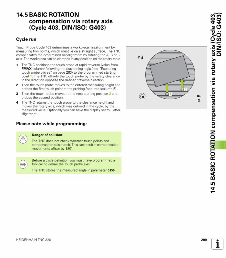
HEIDENHAIN TNC 320 299
14
.5 B
AS
IC R
OTA
TIO
N c
om
pe
nsa
tio
n v
ia r
ota
ry a
xis
(C
ycle
40
3,
DIN
/IS
O:
G4
03
)14.5 BASIC ROTATION compensation via rotary axis (Cycle 403, DIN/ISO: G403)
Cycle run
Touch Probe Cycle 403 determines a workpiece misalignment by measuring two points, which must lie on a straight surface. The TNC compensates the determined misalignment by rotating the A, B or C axis. The workpiece can be clamped in any position on the rotary table.
1 The TNC positions the touch probe at rapid traverse (value from FMAX column) following the positioning logic (see “Executing touch probe cycles” on page 283) to the programmed starting point 1. The TNC offsets the touch probe by the safety clearance in the direction opposite the defined traverse direction.
2 Then the touch probe moves to the entered measuring height and probes the first touch point at the probing feed rate (column F).
3 Then the touch probe moves to the next starting position 2 and probes the second position.
4 The TNC returns the touch probe to the clearance height and moves the rotary axis, which was defined in the cycle, by the measured value. Optionally you can have the display set to 0 after alignment.
Please note while programming:
�
�
��
Danger of collision!
The TNC does not check whether touch points and compensation axis match. This can result in compensation movements offset by 180°.
Before a cycle definition you must have programmed a tool call to define the touch probe axis.
The TNC stores the measured angle in parameter Q150.
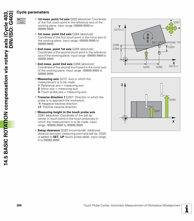
300 Touch Probe Cycles: Automatic Measurement of Workpiece Misalignment
14
.5 B
AS
IC R
OTA
TIO
N c
om
pe
nsa
tio
n v
ia r
ota
ry a
xis
(C
ycle
40
3,
DIN
/IS
O:
G4
03
) Cycle parameters
U 1st meas. point 1st axis Q263 (absolute): Coordinate of the first touch point in the reference axis of the working plane. Input range -99999.9999 to 99999.9999
U 1st meas. point 2nd axis Q264 (absolute): Coordinate of the first touch point in the minor axis of the working plane. Input range –99999.9999 to 99999.9999
U 2nd meas. point 1st axis Q265 (absolute): Coordinate of the second touch point in the reference axis of the working plane. Input range –99999.9999 to 99999.9999
U 2nd meas. point 2nd axis Q266 (absolute): Coordinate of the second touch point in the minor axis of the working plane. Input range –99999.9999 to 99999.9999
UMeasuring axis Q272: Axis in which the measurement is to be made:1: Reference axis = measuring axis2: Minor axis = measuring axis3: Touch probe axis = measuring axis
U Traverse direction 1 Q267: Direction in which the probe is to approach the workpiece: -1: Negative traverse direction +1: Positive traverse direction
UMeasuring height in the touch probe axis Q261 (absolute): Coordinate of the ball tip center (= touch point) in the touch probe axis in which the measurement is to be made. Input range –99999.9999 to 99999.9999
U Setup clearance Q320 (incremental): Additional distance between measuring point and ball tip. Q320 is added to SET_UP (touch probe table). Input range 0 to 99999.9999
�
�
��������
���� ���������
������
!
"
" !
����
��� �& '(!� �)!�*�&� !�
����������������������������������������������������
�
�
����
����
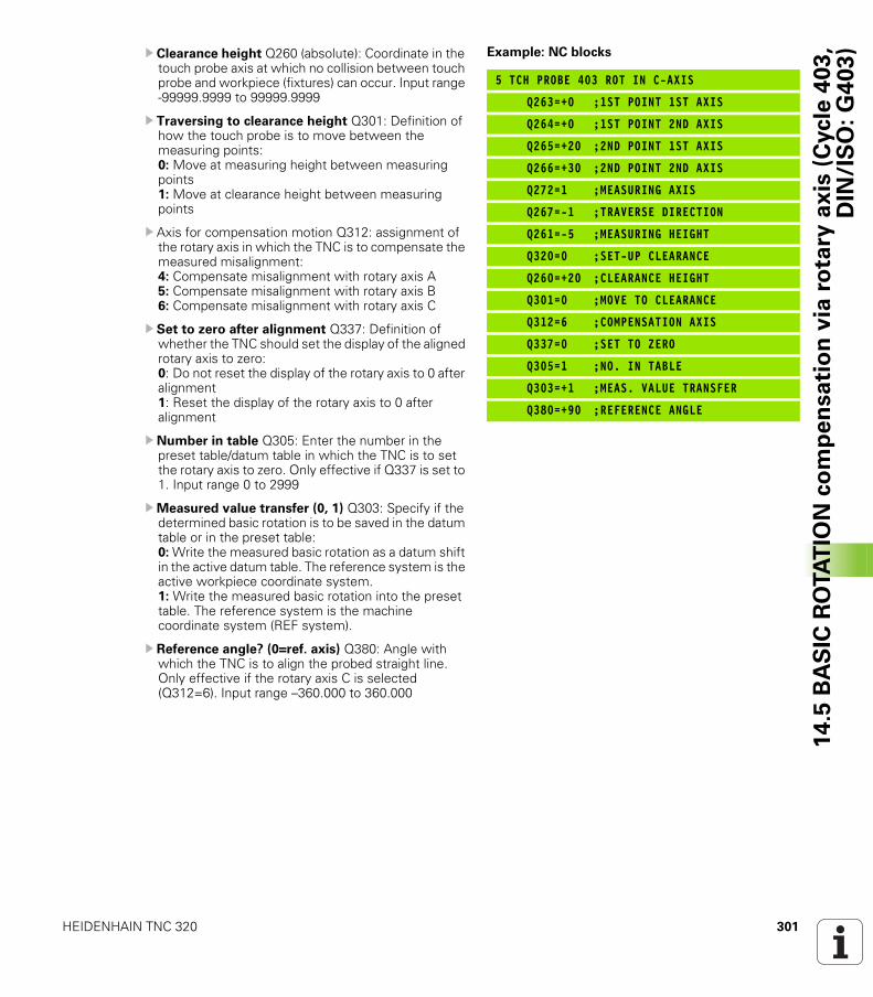
HEIDENHAIN TNC 320 301
14
.5 B
AS
IC R
OTA
TIO
N c
om
pe
nsa
tio
n v
ia r
ota
ry a
xis
(C
ycle
40
3,
DIN
/IS
O:
G4
03
)U Clearance height Q260 (absolute): Coordinate in the touch probe axis at which no collision between touch probe and workpiece (fixtures) can occur. Input range -99999.9999 to 99999.9999
U Traversing to clearance height Q301: Definition of how the touch probe is to move between the measuring points: 0: Move at measuring height between measuring points1: Move at clearance height between measuring points
U Axis for compensation motion Q312: assignment of the rotary axis in which the TNC is to compensate the measured misalignment: 4: Compensate misalignment with rotary axis A5: Compensate misalignment with rotary axis B6: Compensate misalignment with rotary axis C
U Set to zero after alignment Q337: Definition of whether the TNC should set the display of the aligned rotary axis to zero: 0: Do not reset the display of the rotary axis to 0 after alignment 1: Reset the display of the rotary axis to 0 after alignment
U Number in table Q305: Enter the number in the preset table/datum table in which the TNC is to set the rotary axis to zero. Only effective if Q337 is set to 1. Input range 0 to 2999
UMeasured value transfer (0, 1) Q303: Specify if the determined basic rotation is to be saved in the datum table or in the preset table:0: Write the measured basic rotation as a datum shift in the active datum table. The reference system is the active workpiece coordinate system.1: Write the measured basic rotation into the preset table. The reference system is the machine coordinate system (REF system).
U Reference angle? (0=ref. axis) Q380: Angle with which the TNC is to align the probed straight line. Only effective if the rotary axis C is selected (Q312=6). Input range –360.000 to 360.000
Example: NC blocks
5 TCH PROBE 403 ROT IN C-AXIS
Q263=+0 ;1ST POINT 1ST AXIS
Q264=+0 ;1ST POINT 2ND AXIS
Q265=+20 ;2ND POINT 1ST AXIS
Q266=+30 ;2ND POINT 2ND AXIS
Q272=1 ;MEASURING AXIS
Q267=-1 ;TRAVERSE DIRECTION
Q261=-5 ;MEASURING HEIGHT
Q320=0 ;SET-UP CLEARANCE
Q260=+20 ;CLEARANCE HEIGHT
Q301=0 ;MOVE TO CLEARANCE
Q312=6 ;COMPENSATION AXIS
Q337=0 ;SET TO ZERO
Q305=1 ;NO. IN TABLE
Q303=+1 ;MEAS. VALUE TRANSFER
Q380=+90 ;REFERENCE ANGLE
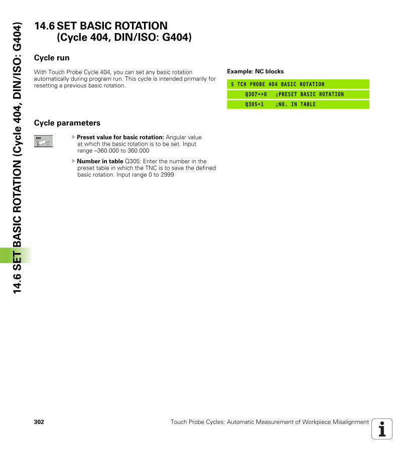
302 Touch Probe Cycles: Automatic Measurement of Workpiece Misalignment
14
.6 S
ET
BA
SIC
RO
TA
TIO
N (
Cycle
40
4,
DIN
/IS
O:
G4
04
) 14.6 SET BASIC ROTATION (Cycle 404, DIN/ISO: G404)
Cycle run
With Touch Probe Cycle 404, you can set any basic rotation automatically during program run. This cycle is intended primarily for resetting a previous basic rotation.
Cycle parameters
U Preset value for basic rotation: Angular value at which the basic rotation is to be set. Input range –360.000 to 360.000
U Number in table Q305: Enter the number in the preset table in which the TNC is to save the defined basic rotation. Input range 0 to 2999
Example: NC blocks
5 TCH PROBE 404 BASIC ROTATION
Q307=+0 ;PRESET BASIC ROTATION
Q305=1 ;NO. IN TABLE
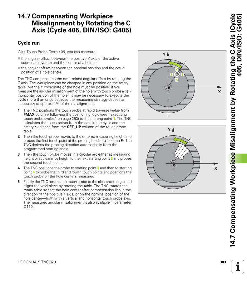
HEIDENHAIN TNC 320 303
14
.7 C
om
pe
nsa
tin
g W
ork
pie
ce
Mis
ali
gn
me
nt
by
Ro
tati
ng
th
e C
Ax
is (
Cycle
40
5,
DIN
/IS
O:
G4
05
)14.7 Compensating Workpiece Misalignment by Rotating the C Axis (Cycle 405, DIN/ISO: G405)
Cycle run
With Touch Probe Cycle 405, you can measure
the angular offset between the positive Y axis of the active coordinate system and the center of a hole, orthe angular offset between the nominal position and the actual position of a hole center.
The TNC compensates the determined angular offset by rotating the C axis. The workpiece can be clamped in any position on the rotary table, but the Y coordinate of the hole must be positive. If you measure the angular misalignment of the hole with touch probe axis Y (horizontal position of the hole), it may be necessary to execute the cycle more than once because the measuring strategy causes an inaccuracy of approx. 1% of the misalignment.
1 The TNC positions the touch probe at rapid traverse (value from FMAX column) following the positioning logic (see “Executing touch probe cycles” on page 283) to the starting point 1. The TNC calculates the touch points from the data in the cycle and the safety clearance from the SET_UP column of the touch probe table.
2 Then the touch probe moves to the entered measuring height and probes the first touch point at the probing feed rate (column F). The TNC derives the probing direction automatically from the programmed starting angle.
3 Then the touch probe moves in a circular arc either at measuring height or at clearance height to the next starting point 2 and probes the second touch point.
4 The TNC positions the probe to starting point 3 and then to starting point 4 to probe the third and fourth touch points and positions the touch probe on the hole centers measured.
5 Finally the TNC returns the touch probe to the clearance height and aligns the workpiece by rotating the table. The TNC rotates the rotary table so that the hole center after compensation lies in the direction of the positive Y axis, or on the nominal position of the hole center—both with a vertical and horizontal touch probe axis. The measured angular misalignment is also available in parameter Q150.
�
�
�
�
�
�
�
304 Touch Probe Cycles: Automatic Measurement of Workpiece Misalignment
14
.7 C
om
pe
nsa
tin
g W
ork
pie
ce
Mis
ali
gn
me
nt
by
Ro
tati
ng
th
e C
Ax
is (
Cycle
40
5,
DIN
/IS
O:
G4
05
) Please note while programming:
Danger of collision!
To prevent a collision between the touch probe and the workpiece, enter a low estimate for the nominal diameter of the pocket (or hole).
If the dimensions of the pocket and the safety clearance do not permit pre-positioning in the proximity of the touch points, the TNC always starts probing from the center of the pocket. In this case the touch probe does not return to the clearance height between the four measuring points.
Before a cycle definition you must have programmed a tool call to define the touch probe axis.
The smaller the angle, the less accurately the TNC can calculate the circle center. Minimum input value: 5°.
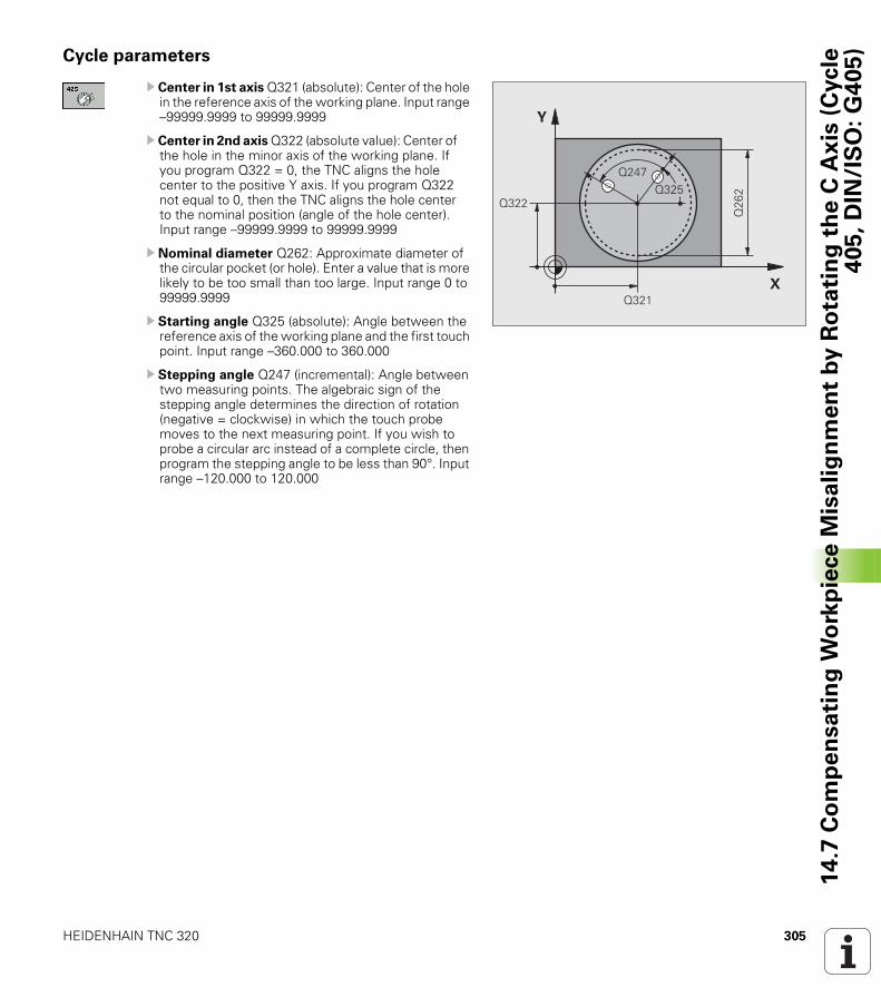
HEIDENHAIN TNC 320 305
14
.7 C
om
pe
nsa
tin
g W
ork
pie
ce
Mis
ali
gn
me
nt
by
Ro
tati
ng
th
e C
Ax
is (
Cycle
40
5,
DIN
/IS
O:
G4
05
)Cycle parameters
U Center in 1st axis Q321 (absolute): Center of the hole in the reference axis of the working plane. Input range –99999.9999 to 99999.9999
U Center in 2nd axis Q322 (absolute value): Center of the hole in the minor axis of the working plane. If you program Q322 = 0, the TNC aligns the hole center to the positive Y axis. If you program Q322 not equal to 0, then the TNC aligns the hole center to the nominal position (angle of the hole center). Input range –99999.9999 to 99999.9999
U Nominal diameter Q262: Approximate diameter of the circular pocket (or hole). Enter a value that is more likely to be too small than too large. Input range 0 to 99999.9999
U Starting angle Q325 (absolute): Angle between the reference axis of the working plane and the first touch point. Input range –360.000 to 360.000
U Stepping angle Q247 (incremental): Angle between two measuring points. The algebraic sign of the stepping angle determines the direction of rotation (negative = clockwise) in which the touch probe moves to the next measuring point. If you wish to probe a circular arc instead of a complete circle, then program the stepping angle to be less than 90°. Input range –120.000 to 120.000
�
�
����
����
���
��������
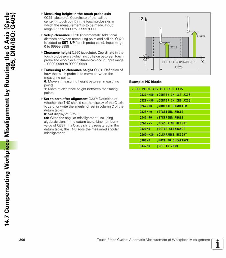
306 Touch Probe Cycles: Automatic Measurement of Workpiece Misalignment
14
.7 C
om
pe
nsa
tin
g W
ork
pie
ce
Mis
ali
gn
me
nt
by
Ro
tati
ng
th
e C
Ax
is (
Cycle
40
5,
DIN
/IS
O:
G4
05
) UMeasuring height in the touch probe axis Q261 (absolute): Coordinate of the ball tip center (= touch point) in the touch probe axis in which the measurement is to be made. Input range -99999.9999 to 99999.9999
U Setup clearance Q320 (incremental): Additional distance between measuring point and ball tip. Q320 is added to SET_UP (touch probe table). Input range 0 to 99999.9999
U Clearance height Q260 (absolute): Coordinate in the touch probe axis at which no collision between touch probe and workpiece (fixtures) can occur. Input range –99999.9999 to 99999.9999
U Traversing to clearance height Q301: Definition of how the touch probe is to move between the measuring points: 0: Move at measuring height between measuring points1: Move at clearance height between measuring points
U Set to zero after alignment Q337: Definition of whether the TNC should set the display of the C axis to zero, or write the angular offset in column C of the datum table: 0: Set display of C to 0 >0: Write the angular misalignment, including algebraic sign, in the datum table. Line number = value of Q337. If a C-axis shift is registered in the datum table, the TNC adds the measured angular misalignment.
Example: NC blocks
5 TCH PROBE 405 ROT IN C AXIS
Q321=+50 ;CENTER IN 1ST AXIS
Q322=+50 ;CENTER IN 2ND AXIS
Q262=10 ;NOMINAL DIAMETER
Q325=+0 ;STARTING ANGLE
Q247=90 ;STEPPING ANGLE
Q261=-5 ;MEASURING HEIGHT
Q320=0 ;SETUP CLEARANCE
Q260=+20 ;CLEARANCE HEIGHT
Q301=0 ;MOVE TO CLEARANCE
Q337=0 ;SET TO ZERO
�
�
����
����
�& '(!� �)!�*�&� !��
����
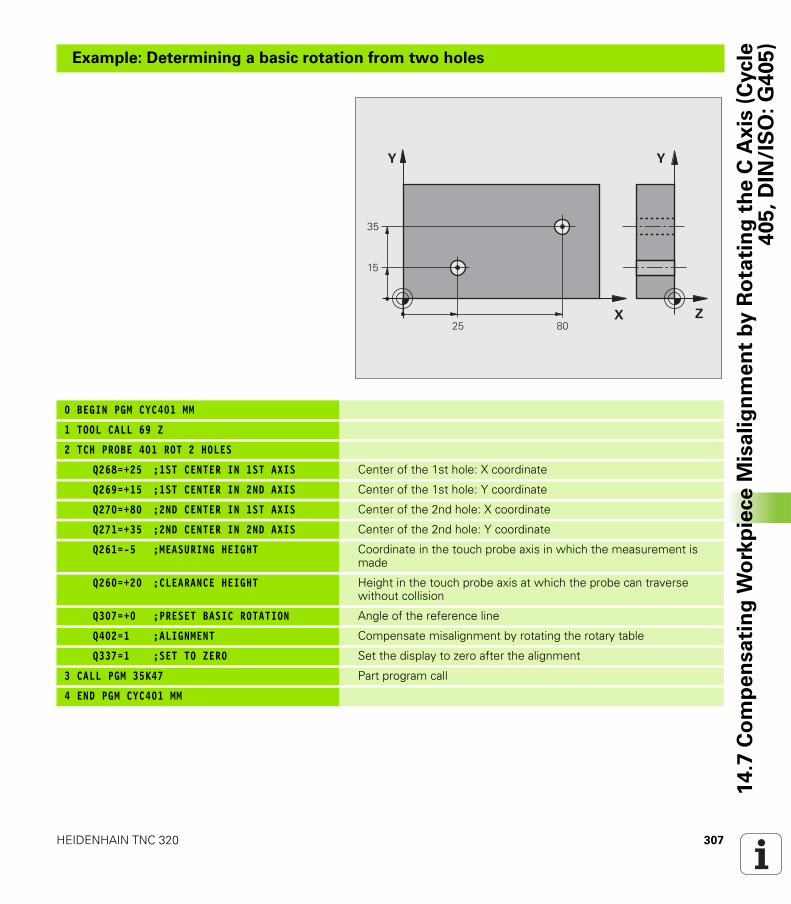
HEIDENHAIN TNC 320 307
14
.7 C
om
pe
nsa
tin
g W
ork
pie
ce
Mis
ali
gn
me
nt
by
Ro
tati
ng
th
e C
Ax
is (
Cycle
40
5,
DIN
/IS
O:
G4
05
)
Example: Determining a basic rotation from two holes
0 BEGIN PGM CYC401 MM
1 TOOL CALL 69 Z
2 TCH PROBE 401 ROT 2 HOLES
Q268=+25 ;1ST CENTER IN 1ST AXIS Center of the 1st hole: X coordinate
Q269=+15 ;1ST CENTER IN 2ND AXIS Center of the 1st hole: Y coordinate
Q270=+80 ;2ND CENTER IN 1ST AXIS Center of the 2nd hole: X coordinate
Q271=+35 ;2ND CENTER IN 2ND AXIS Center of the 2nd hole: Y coordinate
Q261=-5 ;MEASURING HEIGHT Coordinate in the touch probe axis in which the measurement is made
Q260=+20 ;CLEARANCE HEIGHT Height in the touch probe axis at which the probe can traverse without collision
Q307=+0 ;PRESET BASIC ROTATION Angle of the reference line
Q402=1 ;ALIGNMENT Compensate misalignment by rotating the rotary table
Q337=1 ;SET TO ZERO Set the display to zero after the alignment
3 CALL PGM 35K47 Part program call
4 END PGM CYC401 MM
�
�
�
�
�
�
�
�
308 Touch Probe Cycles: Automatic Measurement of Workpiece Misalignment
14
.7 C
om
pe
nsa
tin
g W
ork
pie
ce
Mis
ali
gn
me
nt
by
Ro
tati
ng
th
e C
Ax
is (
Cycle
40
5,
DIN
/IS
O:
G4
05
)
Touch Probe Cycles:
Automatic Datum
Setting
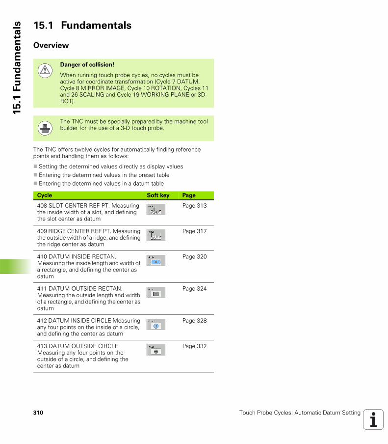
310 Touch Probe Cycles: Automatic Datum Setting
15
.1 F
un
da
me
nta
ls 15.1 Fundamentals
Overview
The TNC offers twelve cycles for automatically finding reference points and handling them as follows:
Setting the determined values directly as display valuesEntering the determined values in the preset tableEntering the determined values in a datum table
Danger of collision!
When running touch probe cycles, no cycles must be active for coordinate transformation (Cycle 7 DATUM, Cycle 8 MIRROR IMAGE, Cycle 10 ROTATION, Cycles 11 and 26 SCALING and Cycle 19 WORKING PLANE or 3D-ROT).
The TNC must be specially prepared by the machine tool builder for the use of a 3-D touch probe.
Cycle Soft key Page
408 SLOT CENTER REF PT. Measuring the inside width of a slot, and defining the slot center as datum
Page 313
409 RIDGE CENTER REF PT. Measuring the outside width of a ridge, and defining the ridge center as datum
Page 317
410 DATUM INSIDE RECTAN. Measuring the inside length and width of a rectangle, and defining the center as datum
Page 320
411 DATUM OUTSIDE RECTAN. Measuring the outside length and width of a rectangle, and defining the center as datum
Page 324
412 DATUM INSIDE CIRCLE Measuring any four points on the inside of a circle, and defining the center as datum
Page 328
413 DATUM OUTSIDE CIRCLE Measuring any four points on the outside of a circle, and defining the center as datum
Page 332
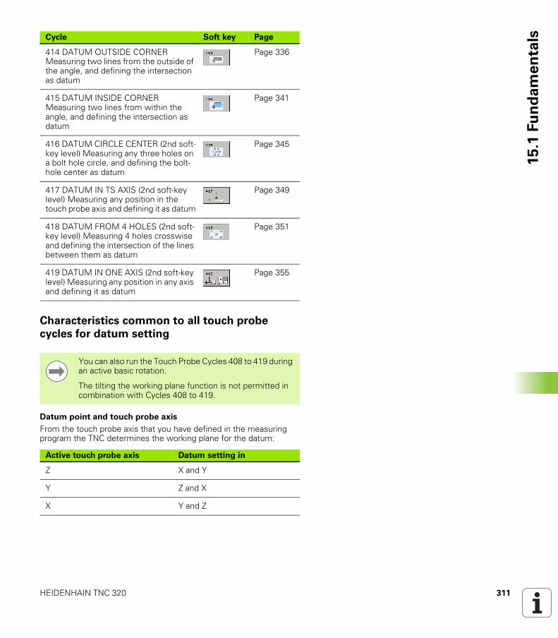
HEIDENHAIN TNC 320 311
15
.1 F
un
da
me
nta
ls
Characteristics common to all touch probe
cycles for datum setting
Datum point and touch probe axis
From the touch probe axis that you have defined in the measuring program the TNC determines the working plane for the datum:
414 DATUM OUTSIDE CORNER Measuring two lines from the outside of the angle, and defining the intersection as datum
Page 336
415 DATUM INSIDE CORNER Measuring two lines from within the angle, and defining the intersection as datum
Page 341
416 DATUM CIRCLE CENTER (2nd soft-key level) Measuring any three holes on a bolt hole circle, and defining the bolt-hole center as datum
Page 345
417 DATUM IN TS AXIS (2nd soft-key level) Measuring any position in the touch probe axis and defining it as datum
Page 349
418 DATUM FROM 4 HOLES (2nd soft-key level) Measuring 4 holes crosswise and defining the intersection of the lines between them as datum
Page 351
419 DATUM IN ONE AXIS (2nd soft-key level) Measuring any position in any axis and defining it as datum
Page 355
Cycle Soft key Page
You can also run the Touch Probe Cycles 408 to 419 during an active basic rotation.
The tilting the working plane function is not permitted in combination with Cycles 408 to 419.
Active touch probe axis Datum setting in
Z X and Y
Y Z and X
X Y and Z
312 Touch Probe Cycles: Automatic Datum Setting
15
.1 F
un
da
me
nta
ls Saving the calculated datum
In all cycles for datum setting you can use the input parameters Q303 and Q305 to define how the TNC is to save the calculated datum:
Q305 = 0, Q303 = any valueThe TNC sets the calculated datum in the display. The new datum is active immediately. At the same time, the TNC saves the datum set in the display by the cycle in line 0 of the preset table.Q305 not equal to 0, Q303 = -1
Q305 not equal to 0, Q303 = 0The TNC writes the calculated reference point in the active datum table. The reference system is the active workpiece coordinate system. The value of parameter Q305 determines the datum number. Activate datum with Cycle 7 in the part program.
Q305 not equal to 0, Q303 = 1The TNC writes the calculated reference point in the preset table. The reference system is the machine coordinate system (REF coordinates). The value of parameter Q305 determines the preset number. Activate preset with Cycle 247 in the part program.
Measurement results in Q parameters
The TNC saves the measurement results of the respective touch probe cycle in the globally effective Q parameters Q150 to Q160. You can use these parameters in your program. Note the table of result parameters that are listed with every cycle description.
This combination can only occur if you
read in programs containing Cycles 410 to 418 created on a TNC 4xxread in programs containing Cycles 410 to 418 created with an older software version on an iTNC 530did not specifically define the measured-value transfer with parameter Q303 when defining the cycle.
In these cases the TNC outputs an error message, since the complete handling of REF-referenced datum tables has changed. You must define a measured-value transfer yourself with parameter Q303.
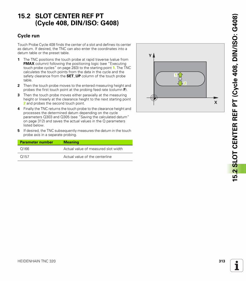
HEIDENHAIN TNC 320 313
15
.2 S
LO
T C
EN
TE
R R
EF
PT
(C
ycle
40
8,
DIN
/IS
O:
G4
08
)15.2 SLOT CENTER REF PT (Cycle 408, DIN/ISO: G408)
Cycle run
Touch Probe Cycle 408 finds the center of a slot and defines its center as datum. If desired, the TNC can also enter the coordinates into a datum table or the preset table.
1 The TNC positions the touch probe at rapid traverse (value from FMAX column) following the positioning logic (see “Executing touch probe cycles” on page 283) to the starting point 1. The TNC calculates the touch points from the data in the cycle and the safety clearance from the SET_UP column of the touch probe table.
2 Then the touch probe moves to the entered measuring height and probes the first touch point at the probing feed rate (column F).
3 Then the touch probe moves either paraxially at the measuring height or linearly at the clearance height to the next starting point 2 and probes the second touch point.
4 Finally the TNC returns the touch probe to the clearance height and processes the determined datum depending on the cycle parameters Q303 and Q305 (see “Saving the calculated datum” on page 312) and saves the actual values in the Q parameters listed below.
5 If desired, the TNC subsequently measures the datum in the touch probe axis in a separate probing.
�
�
�
�
Parameter number Meaning
Q166 Actual value of measured slot width
Q157 Actual value of the centerline
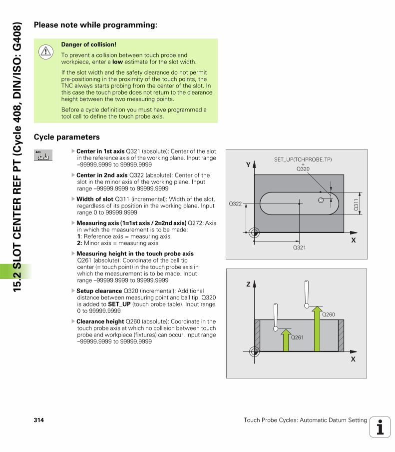
314 Touch Probe Cycles: Automatic Datum Setting
15
.2 S
LO
T C
EN
TE
R R
EF
PT
(C
ycle
40
8,
DIN
/IS
O:
G4
08
) Please note while programming:
Cycle parameters
U Center in 1st axis Q321 (absolute): Center of the slot in the reference axis of the working plane. Input range –99999.9999 to 99999.9999
U Center in 2nd axis Q322 (absolute): Center of the slot in the minor axis of the working plane. Input range –99999.9999 to 99999.9999
UWidth of slot Q311 (incremental): Width of the slot, regardless of its position in the working plane. Input range 0 to 99999.9999
UMeasuring axis (1=1st axis / 2=2nd axis) Q272: Axis in which the measurement is to be made:1: Reference axis = measuring axis2: Minor axis = measuring axis
UMeasuring height in the touch probe axis Q261 (absolute): Coordinate of the ball tip center (= touch point) in the touch probe axis in which the measurement is to be made. Input range –99999.9999 to 99999.9999
U Setup clearance Q320 (incremental): Additional distance between measuring point and ball tip. Q320 is added to SET_UP (touch probe table). Input range 0 to 99999.9999
U Clearance height Q260 (absolute): Coordinate in the touch probe axis at which no collision between touch probe and workpiece (fixtures) can occur. Input range –99999.9999 to 99999.9999
Danger of collision!
To prevent a collision between touch probe and workpiece, enter a low estimate for the slot width.
If the slot width and the safety clearance do not permit pre-positioning in the proximity of the touch points, the TNC always starts probing from the center of the slot. In this case the touch probe does not return to the clearance height between the two measuring points.
Before a cycle definition you must have programmed a tool call to define the touch probe axis.
�
�
����
����
����
�& '(!� �)!�*�&� !��
����
�
�
����
����
HEIDENHAIN TNC 320 315
15
.2 S
LO
T C
EN
TE
R R
EF
PT
(C
ycle
40
8,
DIN
/IS
O:
G4
08
)U Traversing to clearance height Q301: Definition of how the touch probe is to move between the measuring points: 0: Move at measuring height between measuring points 1: Move at clearance height between measuring points
U Number in table Q305: Enter the number in the datum/preset table in which the TNC is to save the coordinates of the slot center. If you enter Q305=0, the TNC automatically sets the display so that the new datum is on the slot center. Input range 0 to 2999
U New datum Q405 (absolute): Coordinate in the measuring axis at which the TNC should set the calculated slot center. Default setting = 0. Input range: -99999.9999 to 99999.9999
UMeasured-value transfer (0, 1) Q303: Specify whether the determined datum is to be saved in the datum table or in the preset table:0: Write determined datum in the active datum table. The reference system is the active workpiece coordinate system.1: Write determined datum in the preset table. The reference system is the machine coordinate system (REF system).
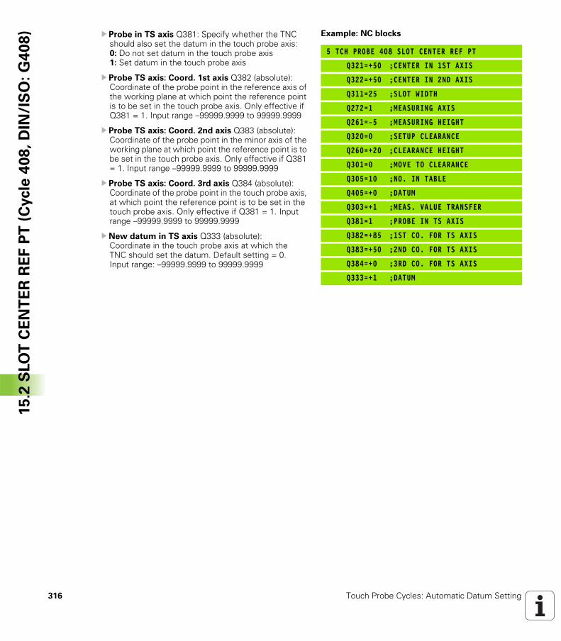
316 Touch Probe Cycles: Automatic Datum Setting
15
.2 S
LO
T C
EN
TE
R R
EF
PT
(C
ycle
40
8,
DIN
/IS
O:
G4
08
) U Probe in TS axis Q381: Specify whether the TNC should also set the datum in the touch probe axis: 0: Do not set datum in the touch probe axis 1: Set datum in the touch probe axis
U Probe TS axis: Coord. 1st axis Q382 (absolute): Coordinate of the probe point in the reference axis of the working plane at which point the reference point is to be set in the touch probe axis. Only effective if Q381 = 1. Input range –99999.9999 to 99999.9999
U Probe TS axis: Coord. 2nd axis Q383 (absolute): Coordinate of the probe point in the minor axis of the working plane at which point the reference point is to be set in the touch probe axis. Only effective if Q381 = 1. Input range –99999.9999 to 99999.9999
U Probe TS axis: Coord. 3rd axis Q384 (absolute): Coordinate of the probe point in the touch probe axis, at which point the reference point is to be set in the touch probe axis. Only effective if Q381 = 1. Input range –99999.9999 to 99999.9999
U New datum in TS axis Q333 (absolute): Coordinate in the touch probe axis at which the TNC should set the datum. Default setting = 0. Input range: –99999.9999 to 99999.9999
Example: NC blocks
5 TCH PROBE 408 SLOT CENTER REF PT
Q321=+50 ;CENTER IN 1ST AXIS
Q322=+50 ;CENTER IN 2ND AXIS
Q311=25 ;SLOT WIDTH
Q272=1 ;MEASURING AXIS
Q261=-5 ;MEASURING HEIGHT
Q320=0 ;SETUP CLEARANCE
Q260=+20 ;CLEARANCE HEIGHT
Q301=0 ;MOVE TO CLEARANCE
Q305=10 ;NO. IN TABLE
Q405=+0 ;DATUM
Q303=+1 ;MEAS. VALUE TRANSFER
Q381=1 ;PROBE IN TS AXIS
Q382=+85 ;1ST CO. FOR TS AXIS
Q383=+50 ;2ND CO. FOR TS AXIS
Q384=+0 ;3RD CO. FOR TS AXIS
Q333=+1 ;DATUM
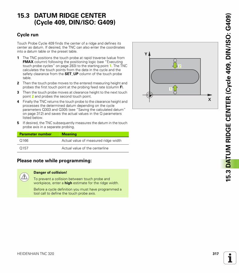
HEIDENHAIN TNC 320 317
15
.3 D
AT
UM
RID
GE
CE
NT
ER
(C
ycle
40
9,
DIN
/IS
O:
G4
09
)15.3 DATUM RIDGE CENTER (Cycle 409, DIN/ISO: G409)
Cycle run
Touch Probe Cycle 409 finds the center of a ridge and defines its center as datum. If desired, the TNC can also enter the coordinates into a datum table or the preset table.
1 The TNC positions the touch probe at rapid traverse (value from FMAX column) following the positioning logic (see “Executing touch probe cycles” on page 283) to the starting point 1. The TNC calculates the touch points from the data in the cycle and the safety clearance from the SET_UP column of the touch probe table.
2 Then the touch probe moves to the entered measuring height and probes the first touch point at the probing feed rate (column F).
3 Then the touch probe moves at clearance height to the next touch point 2 and probes the second touch point.
4 Finally the TNC returns the touch probe to the clearance height and processes the determined datum depending on the cycle parameters Q303 and Q305 (see “Saving the calculated datum” on page 312) and saves the actual values in the Q parameters listed below.
5 If desired, the TNC subsequently measures the datum in the touch probe axis in a separate probing.
Please note while programming:
�
�
�
�
Parameter number Meaning
Q166 Actual value of measured ridge width
Q157 Actual value of the centerline
Danger of collision!
To prevent a collision between touch probe and workpiece, enter a high estimate for the ridge width.
Before a cycle definition you must have programmed a tool call to define the touch probe axis.
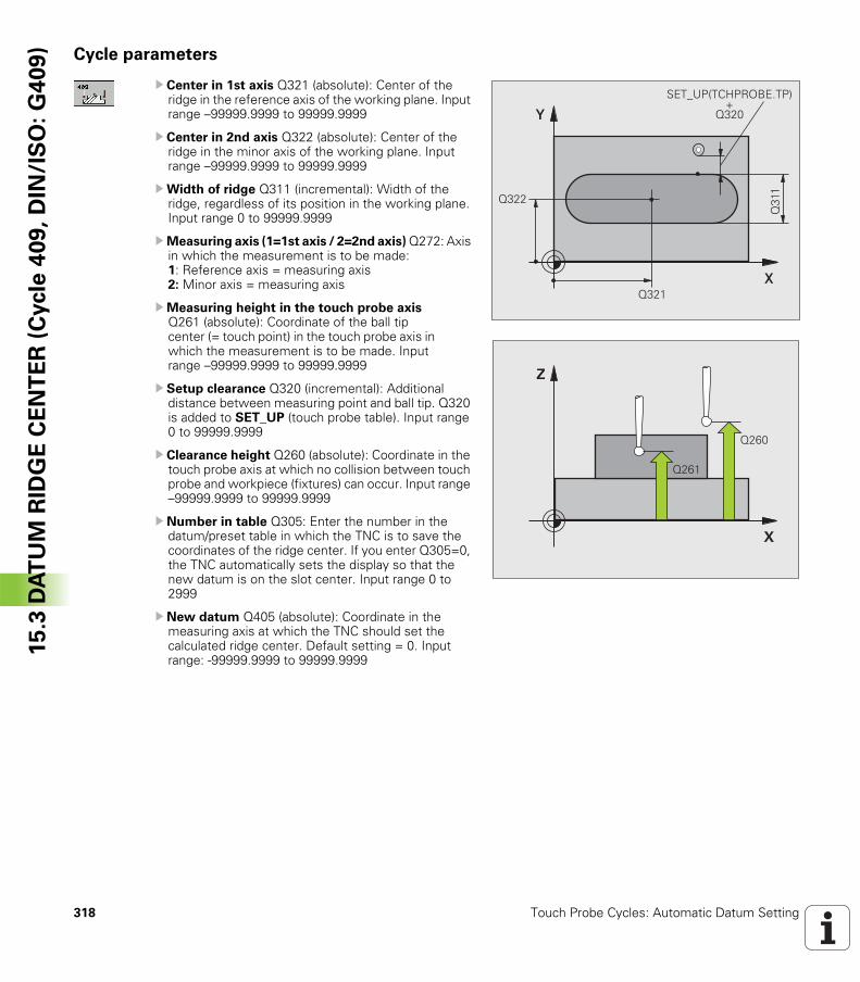
318 Touch Probe Cycles: Automatic Datum Setting
15
.3 D
AT
UM
RID
GE
CE
NT
ER
(C
ycle
40
9,
DIN
/IS
O:
G4
09
) Cycle parameters
U Center in 1st axis Q321 (absolute): Center of the ridge in the reference axis of the working plane. Input range –99999.9999 to 99999.9999
U Center in 2nd axis Q322 (absolute): Center of the ridge in the minor axis of the working plane. Input range –99999.9999 to 99999.9999
UWidth of ridge Q311 (incremental): Width of the ridge, regardless of its position in the working plane. Input range 0 to 99999.9999
UMeasuring axis (1=1st axis / 2=2nd axis) Q272: Axis in which the measurement is to be made:1: Reference axis = measuring axis2: Minor axis = measuring axis
UMeasuring height in the touch probe axis Q261 (absolute): Coordinate of the ball tip center (= touch point) in the touch probe axis in which the measurement is to be made. Input range –99999.9999 to 99999.9999
U Setup clearance Q320 (incremental): Additional distance between measuring point and ball tip. Q320 is added to SET_UP (touch probe table). Input range 0 to 99999.9999
U Clearance height Q260 (absolute): Coordinate in the touch probe axis at which no collision between touch probe and workpiece (fixtures) can occur. Input range –99999.9999 to 99999.9999
U Number in table Q305: Enter the number in the datum/preset table in which the TNC is to save the coordinates of the ridge center. If you enter Q305=0, the TNC automatically sets the display so that the new datum is on the slot center. Input range 0 to 2999
U New datum Q405 (absolute): Coordinate in the measuring axis at which the TNC should set the calculated ridge center. Default setting = 0. Input range: -99999.9999 to 99999.9999
�
�
����
����
����
�& '(!� �)!�*�&� !��
����
�
�
����
����
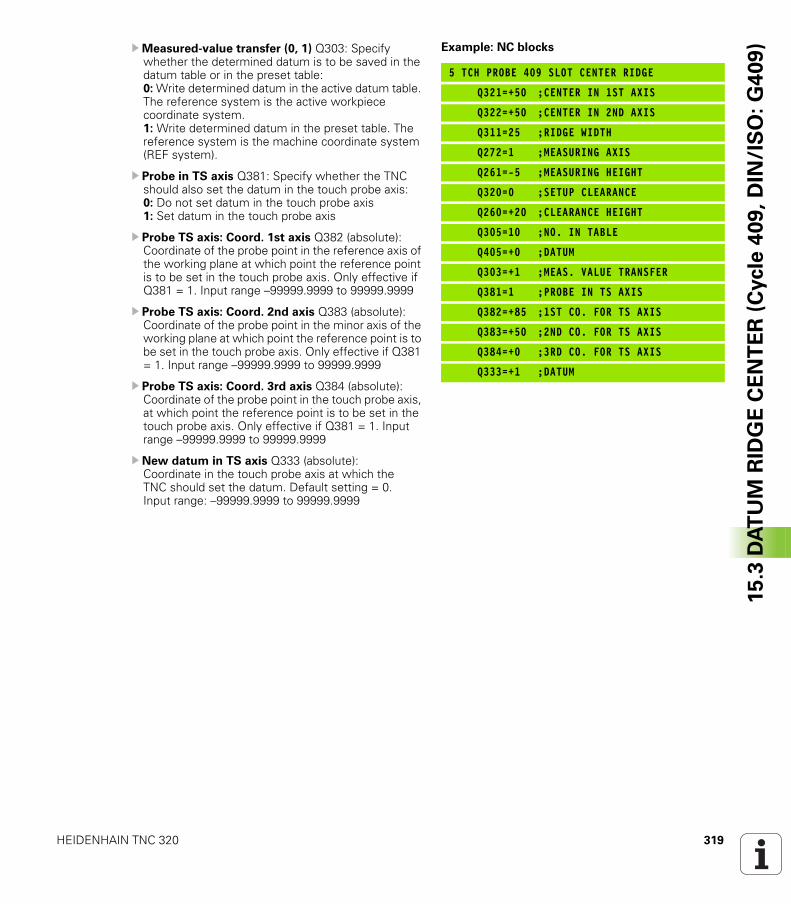
HEIDENHAIN TNC 320 319
15
.3 D
AT
UM
RID
GE
CE
NT
ER
(C
ycle
40
9,
DIN
/IS
O:
G4
09
)UMeasured-value transfer (0, 1) Q303: Specify whether the determined datum is to be saved in the datum table or in the preset table:0: Write determined datum in the active datum table. The reference system is the active workpiece coordinate system.1: Write determined datum in the preset table. The reference system is the machine coordinate system (REF system).
U Probe in TS axis Q381: Specify whether the TNC should also set the datum in the touch probe axis: 0: Do not set datum in the touch probe axis 1: Set datum in the touch probe axis
U Probe TS axis: Coord. 1st axis Q382 (absolute): Coordinate of the probe point in the reference axis of the working plane at which point the reference point is to be set in the touch probe axis. Only effective if Q381 = 1. Input range –99999.9999 to 99999.9999
U Probe TS axis: Coord. 2nd axis Q383 (absolute): Coordinate of the probe point in the minor axis of the working plane at which point the reference point is to be set in the touch probe axis. Only effective if Q381 = 1. Input range –99999.9999 to 99999.9999
U Probe TS axis: Coord. 3rd axis Q384 (absolute): Coordinate of the probe point in the touch probe axis, at which point the reference point is to be set in the touch probe axis. Only effective if Q381 = 1. Input range –99999.9999 to 99999.9999
U New datum in TS axis Q333 (absolute): Coordinate in the touch probe axis at which the TNC should set the datum. Default setting = 0. Input range: –99999.9999 to 99999.9999
Example: NC blocks
5 TCH PROBE 409 SLOT CENTER RIDGE
Q321=+50 ;CENTER IN 1ST AXIS
Q322=+50 ;CENTER IN 2ND AXIS
Q311=25 ;RIDGE WIDTH
Q272=1 ;MEASURING AXIS
Q261=-5 ;MEASURING HEIGHT
Q320=0 ;SETUP CLEARANCE
Q260=+20 ;CLEARANCE HEIGHT
Q305=10 ;NO. IN TABLE
Q405=+0 ;DATUM
Q303=+1 ;MEAS. VALUE TRANSFER
Q381=1 ;PROBE IN TS AXIS
Q382=+85 ;1ST CO. FOR TS AXIS
Q383=+50 ;2ND CO. FOR TS AXIS
Q384=+0 ;3RD CO. FOR TS AXIS
Q333=+1 ;DATUM
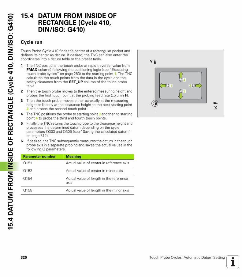
320 Touch Probe Cycles: Automatic Datum Setting
15
.4 D
AT
UM
FR
OM
IN
SID
E O
F R
EC
TA
NG
LE
(C
ycle
410
, D
IN/I
SO
: G
410
) 15.4 DATUM FROM INSIDE OF RECTANGLE (Cycle 410, DIN/ISO: G410)
Cycle run
Touch Probe Cycle 410 finds the center of a rectangular pocket and defines its center as datum. If desired, the TNC can also enter the coordinates into a datum table or the preset table.
1 The TNC positions the touch probe at rapid traverse (value from FMAX column) following the positioning logic (see “Executing touch probe cycles” on page 283) to the starting point 1. The TNC calculates the touch points from the data in the cycle and the safety clearance from the SET_UP column of the touch probe table.
2 Then the touch probe moves to the entered measuring height and probes the first touch point at the probing feed rate (column F).
3 Then the touch probe moves either paraxially at the measuring height or linearly at the clearance height to the next starting point 2 and probes the second touch point.
4 The TNC positions the probe to starting point 3 and then to starting point 4 to probe the third and fourth touch points.
5 Finally the TNC returns the touch probe to the clearance height and processes the determined datum depending on the cycle parameters Q303 and Q305 (see “Saving the calculated datum” on page 312).
6 If desired, the TNC subsequently measures the datum in the touch probe axis in a separate probing and saves the actual values in the following Q parameters.
�
�
�
�
�
Parameter number Meaning
Q151 Actual value of center in reference axis
Q152 Actual value of center in minor axis
Q154 Actual value of length in the reference axis
Q155 Actual value of length in the minor axis
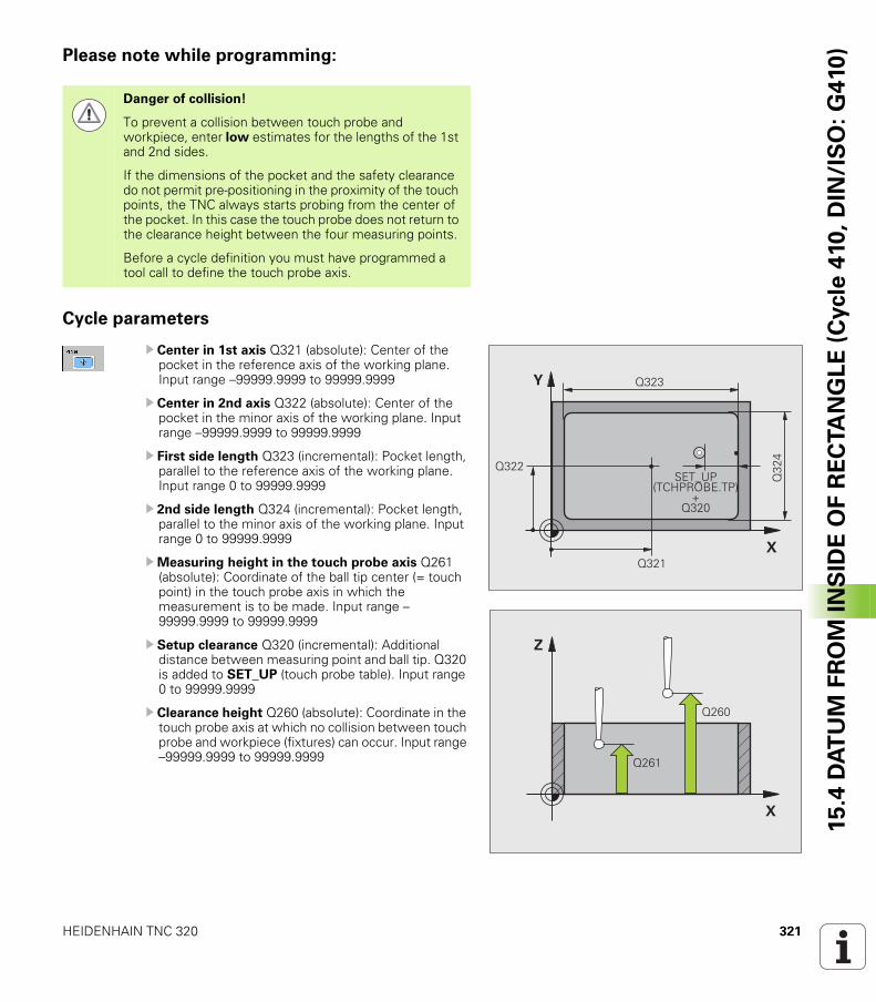
HEIDENHAIN TNC 320 321
15
.4 D
AT
UM
FR
OM
IN
SID
E O
F R
EC
TA
NG
LE
(C
ycle
410
, D
IN/I
SO
: G
410
)Please note while programming:
Cycle parameters
U Center in 1st axis Q321 (absolute): Center of the pocket in the reference axis of the working plane. Input range –99999.9999 to 99999.9999
U Center in 2nd axis Q322 (absolute): Center of the pocket in the minor axis of the working plane. Input range –99999.9999 to 99999.9999
U First side length Q323 (incremental): Pocket length, parallel to the reference axis of the working plane. Input range 0 to 99999.9999
U 2nd side length Q324 (incremental): Pocket length, parallel to the minor axis of the working plane. Input range 0 to 99999.9999
UMeasuring height in the touch probe axis Q261 (absolute): Coordinate of the ball tip center (= touch point) in the touch probe axis in which the measurement is to be made. Input range –99999.9999 to 99999.9999
U Setup clearance Q320 (incremental): Additional distance between measuring point and ball tip. Q320 is added to SET_UP (touch probe table). Input range 0 to 99999.9999
U Clearance height Q260 (absolute): Coordinate in the touch probe axis at which no collision between touch probe and workpiece (fixtures) can occur. Input range –99999.9999 to 99999.9999
Danger of collision!
To prevent a collision between touch probe and workpiece, enter low estimates for the lengths of the 1st and 2nd sides.
If the dimensions of the pocket and the safety clearance do not permit pre-positioning in the proximity of the touch points, the TNC always starts probing from the center of the pocket. In this case the touch probe does not return to the clearance height between the four measuring points.
Before a cycle definition you must have programmed a tool call to define the touch probe axis.
�
�
����
����
���
�
����
�& '(!� �)!�*�&� !�
�����
�
�
����
����
322 Touch Probe Cycles: Automatic Datum Setting
15
.4 D
AT
UM
FR
OM
IN
SID
E O
F R
EC
TA
NG
LE
(C
ycle
410
, D
IN/I
SO
: G
410
) U Traversing to clearance height Q301: Definition of how the touch probe is to move between the measuring points: 0: Move at measuring height between measuring points 1: Move at clearance height between measuring points
U Datum number in table Q305: Enter the number in the datum/preset table in which the TNC is to save the coordinates of the pocket center. If you enter Q305=0, the TNC automatically sets the display so that the new datum is at the center of the pocket. Input range 0 to 2999
U New datum for reference axis Q331 (absolute): Coordinate in the reference axis at which the TNC should set the pocket center. Default setting = 0. Input range: –99999.9999 to 99999.9999
U New datum for minor axis Q332 (absolute): Coordinate in the minor axis at which the TNC should set the pocket center. Default setting = 0. Input range: –99999.9999 to 99999.9999
UMeasured-value transfer (0, 1) Q303: Specify whether the determined datum is to be saved in the datum table or in the preset table:-1: Do not use. Is entered by the TNC when old programs are read in (see “Saving the calculated datum” on page 312).0: Write determined datum in the active datum table. The reference system is the active workpiece coordinate system.1: Write determined datum in the preset table. The reference system is the machine coordinate system (REF system).
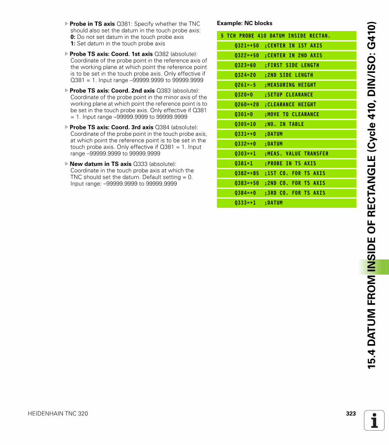
HEIDENHAIN TNC 320 323
15
.4 D
AT
UM
FR
OM
IN
SID
E O
F R
EC
TA
NG
LE
(C
ycle
410
, D
IN/I
SO
: G
410
)U Probe in TS axis Q381: Specify whether the TNC should also set the datum in the touch probe axis: 0: Do not set datum in the touch probe axis 1: Set datum in the touch probe axis
U Probe TS axis: Coord. 1st axis Q382 (absolute): Coordinate of the probe point in the reference axis of the working plane at which point the reference point is to be set in the touch probe axis. Only effective if Q381 = 1. Input range –99999.9999 to 99999.9999
U Probe TS axis: Coord. 2nd axis Q383 (absolute): Coordinate of the probe point in the minor axis of the working plane at which point the reference point is to be set in the touch probe axis. Only effective if Q381 = 1. Input range –99999.9999 to 99999.9999
U Probe TS axis: Coord. 3rd axis Q384 (absolute): Coordinate of the probe point in the touch probe axis, at which point the reference point is to be set in the touch probe axis. Only effective if Q381 = 1. Input range –99999.9999 to 99999.9999
U New datum in TS axis Q333 (absolute): Coordinate in the touch probe axis at which the TNC should set the datum. Default setting = 0. Input range: –99999.9999 to 99999.9999
Example: NC blocks
5 TCH PROBE 410 DATUM INSIDE RECTAN.
Q321=+50 ;CENTER IN 1ST AXIS
Q322=+50 ;CENTER IN 2ND AXIS
Q323=60 ;FIRST SIDE LENGTH
Q324=20 ;2ND SIDE LENGTH
Q261=-5 ;MEASURING HEIGHT
Q320=0 ;SETUP CLEARANCE
Q260=+20 ;CLEARANCE HEIGHT
Q301=0 ;MOVE TO CLEARANCE
Q305=10 ;NO. IN TABLE
Q331=+0 ;DATUM
Q332=+0 ;DATUM
Q303=+1 ;MEAS. VALUE TRANSFER
Q381=1 ;PROBE IN TS AXIS
Q382=+85 ;1ST CO. FOR TS AXIS
Q383=+50 ;2ND CO. FOR TS AXIS
Q384=+0 ;3RD CO. FOR TS AXIS
Q333=+1 ;DATUM
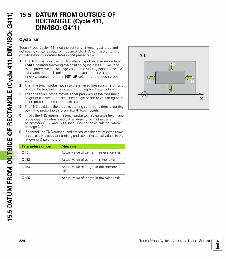
324 Touch Probe Cycles: Automatic Datum Setting
15
.5 D
AT
UM
FR
OM
OU
TS
IDE
OF
RE
CTA
NG
LE
(C
ycle
411
, D
IN/I
SO
: G
411
) 15.5 DATUM FROM OUTSIDE OF RECTANGLE (Cycle 411, DIN/ISO: G411)
Cycle run
Touch Probe Cycle 411 finds the center of a rectangular stud and defines its center as datum. If desired, the TNC can also enter the coordinates into a datum table or the preset table.
1 The TNC positions the touch probe at rapid traverse (value from FMAX column) following the positioning logic (see “Executing touch probe cycles” on page 283) to the starting point 1. The TNC calculates the touch points from the data in the cycle and the safety clearance from the SET_UP column of the touch probe table.
2 Then the touch probe moves to the entered measuring height and probes the first touch point at the probing feed rate (column F).
3 Then the touch probe moves either paraxially at the measuring height or linearly at the clearance height to the next starting point 2 and probes the second touch point.
4 The TNC positions the probe to starting point 3 and then to starting point 4 to probe the third and fourth touch points.
5 Finally the TNC returns the touch probe to the clearance height and processes the determined datum depending on the cycle parameters Q303 and Q305 (see “Saving the calculated datum” on page 312).
6 If desired, the TNC subsequently measures the datum in the touch probe axis in a separate probing and saves the actual values in the following Q parameters.
�
�
�
�
�
Parameter number Meaning
Q151 Actual value of center in reference axis
Q152 Actual value of center in minor axis
Q154 Actual value of length in the reference axis
Q155 Actual value of length in the minor axis
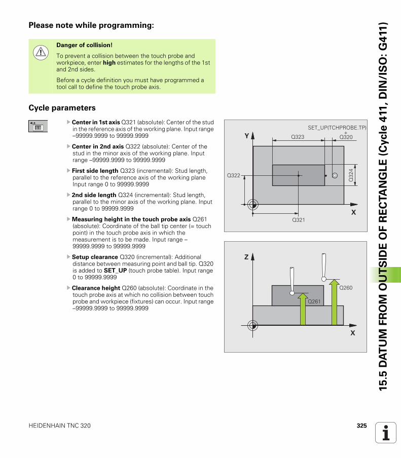
HEIDENHAIN TNC 320 325
15
.5 D
AT
UM
FR
OM
OU
TS
IDE
OF
RE
CTA
NG
LE
(C
ycle
411
, D
IN/I
SO
: G
411
)Please note while programming:
Cycle parameters
U Center in 1st axis Q321 (absolute): Center of the stud in the reference axis of the working plane. Input range –99999.9999 to 99999.9999
U Center in 2nd axis Q322 (absolute): Center of the stud in the minor axis of the working plane. Input range –99999.9999 to 99999.9999
U First side length Q323 (incremental): Stud length, parallel to the reference axis of the working plane Input range 0 to 99999.9999
U 2nd side length Q324 (incremental): Stud length, parallel to the minor axis of the working plane. Input range 0 to 99999.9999
UMeasuring height in the touch probe axis Q261 (absolute): Coordinate of the ball tip center (= touch point) in the touch probe axis in which the measurement is to be made. Input range –99999.9999 to 99999.9999
U Setup clearance Q320 (incremental): Additional distance between measuring point and ball tip. Q320 is added to SET_UP (touch probe table). Input range 0 to 99999.9999
U Clearance height Q260 (absolute): Coordinate in the touch probe axis at which no collision between touch probe and workpiece (fixtures) can occur. Input range –99999.9999 to 99999.9999
Danger of collision!
To prevent a collision between the touch probe and workpiece, enter high estimates for the lengths of the 1st and 2nd sides.
Before a cycle definition you must have programmed a tool call to define the touch probe axis.
�
�
����
����
���
�
����
�& '(!� �)!�*�&� !���������������������������������������������������
�
�
����
����
326 Touch Probe Cycles: Automatic Datum Setting
15
.5 D
AT
UM
FR
OM
OU
TS
IDE
OF
RE
CTA
NG
LE
(C
ycle
411
, D
IN/I
SO
: G
411
) U Traversing to clearance height Q301: Definition of how the touch probe is to move between the measuring points: 0: Move at measuring height between measuring points 1: Move at clearance height between measuring points
U Datum number in table Q305: Enter the datum number in the table in which the TNC is to save the coordinates of the pocket center. If you enter Q305=0, the TNC automatically sets the display so that the new datum is on the stud center. Input range 0 to 2999
U New datum for reference axis Q331 (absolute): Coordinate in the reference axis at which the TNC should set the stud center. Default setting = 0. Input range: –99999.9999 to 99999.9999
U New datum for minor axis Q332 (absolute): Coordinate in the minor axis at which the TNC should set the stud center. Default setting = 0. Input range: –99999.9999 to 99999.9999
UMeasured-value transfer (0, 1) Q303: Specify whether the determined datum is to be saved in the datum table or in the preset table:-1: Do not use. Is entered by the TNC when old programs are read in (see “Saving the calculated datum” on page 312).0: Write determined datum in the active datum table. The reference system is the active workpiece coordinate system.1: Write determined datum in the preset table. The reference system is the machine coordinate system (REF system).
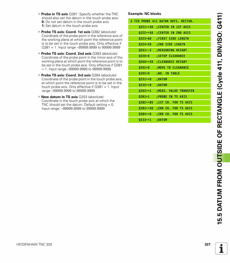
HEIDENHAIN TNC 320 327
15
.5 D
AT
UM
FR
OM
OU
TS
IDE
OF
RE
CTA
NG
LE
(C
ycle
411
, D
IN/I
SO
: G
411
)U Probe in TS axis Q381: Specify whether the TNC should also set the datum in the touch probe axis: 0: Do not set datum in the touch probe axis 1: Set datum in the touch probe axis
U Probe TS axis: Coord. 1st axis Q382 (absolute): Coordinate of the probe point in the reference axis of the working plane at which point the reference point is to be set in the touch probe axis. Only effective if Q381 = 1. Input range –99999.9999 to 99999.9999
U Probe TS axis: Coord. 2nd axis Q383 (absolute): Coordinate of the probe point in the minor axis of the working plane at which point the reference point is to be set in the touch probe axis. Only effective if Q381 = 1. Input range –99999.9999 to 99999.9999
U Probe TS axis: Coord. 3rd axis Q384 (absolute): Coordinate of the probe point in the touch probe axis, at which point the reference point is to be set in the touch probe axis. Only effective if Q381 = 1. Input range –99999.9999 to 99999.9999
U New datum in TS axis Q333 (absolute): Coordinate in the touch probe axis at which the TNC should set the datum. Default setting = 0. Input range: –99999.9999 to 99999.9999
Example: NC blocks
5 TCH PROBE 411 DATUM OUTS. RECTAN.
Q321=+50 ;CENTER IN 1ST AXIS
Q322=+50 ;CENTER IN 2ND AXIS
Q323=60 ;FIRST SIDE LENGTH
Q324=20 ;2ND SIDE LENGTH
Q261=-5 ;MEASURING HEIGHT
Q320=0 ;SETUP CLEARANCE
Q260=+20 ;CLEARANCE HEIGHT
Q301=0 ;MOVE TO CLEARANCE
Q305=0 ;NO. IN TABLE
Q331=+0 ;DATUM
Q332=+0 ;DATUM
Q303=+1 ;MEAS. VALUE TRANSFER
Q381=1 ;PROBE IN TS AXIS
Q382=+85 ;1ST CO. FOR TS AXIS
Q383=+50 ;2ND CO. FOR TS AXIS
Q384=+0 ;3RD CO. FOR TS AXIS
Q333=+1 ;DATUM
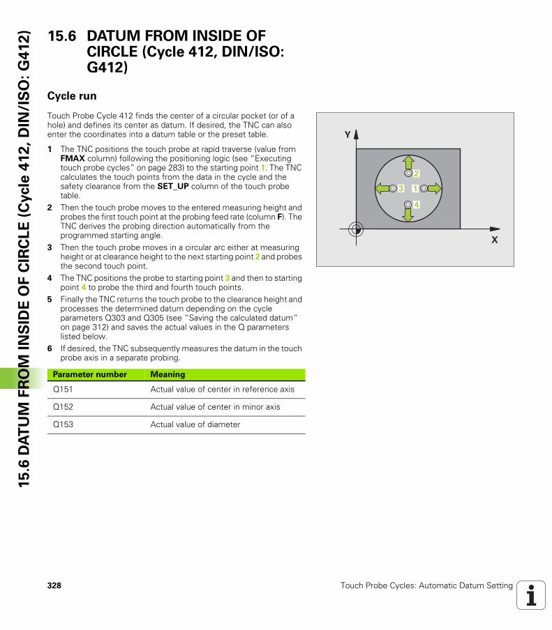
328 Touch Probe Cycles: Automatic Datum Setting
15
.6 D
AT
UM
FR
OM
IN
SID
E O
F C
IRC
LE
(C
ycle
41
2,
DIN
/IS
O:
G4
12
) 15.6 DATUM FROM INSIDE OF CIRCLE (Cycle 412, DIN/ISO: G412)
Cycle run
Touch Probe Cycle 412 finds the center of a circular pocket (or of a hole) and defines its center as datum. If desired, the TNC can also enter the coordinates into a datum table or the preset table.
1 The TNC positions the touch probe at rapid traverse (value from FMAX column) following the positioning logic (see “Executing touch probe cycles” on page 283) to the starting point 1. The TNC calculates the touch points from the data in the cycle and the safety clearance from the SET_UP column of the touch probe table.
2 Then the touch probe moves to the entered measuring height and probes the first touch point at the probing feed rate (column F). The TNC derives the probing direction automatically from the programmed starting angle.
3 Then the touch probe moves in a circular arc either at measuring height or at clearance height to the next starting point 2 and probes the second touch point.
4 The TNC positions the probe to starting point 3 and then to starting point 4 to probe the third and fourth touch points.
5 Finally the TNC returns the touch probe to the clearance height and processes the determined datum depending on the cycle parameters Q303 and Q305 (see “Saving the calculated datum” on page 312) and saves the actual values in the Q parameters listed below.
6 If desired, the TNC subsequently measures the datum in the touch probe axis in a separate probing.
�
�
�
�
�
Parameter number Meaning
Q151 Actual value of center in reference axis
Q152 Actual value of center in minor axis
Q153 Actual value of diameter
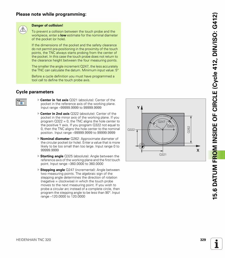
HEIDENHAIN TNC 320 329
15
.6 D
AT
UM
FR
OM
IN
SID
E O
F C
IRC
LE
(C
ycle
41
2,
DIN
/IS
O:
G4
12
)Please note while programming:
Cycle parameters
U Center in 1st axis Q321 (absolute): Center of the pocket in the reference axis of the working plane. Input range –99999.9999 to 99999.9999
U Center in 2nd axis Q322 (absolute): Center of the pocket in the minor axis of the working plane. If you program Q322 = 0, the TNC aligns the hole center to the positive Y axis. If you program Q322 not equal to 0, then the TNC aligns the hole center to the nominal position. Input range –99999.9999 to 99999.9999
U Nominal diameter Q262: Approximate diameter of the circular pocket (or hole). Enter a value that is more likely to be too small than too large. Input range 0 to 99999.9999
U Starting angle Q325 (absolute): Angle between the reference axis of the working plane and the first touch point. Input range –360.0000 to 360.0000
U Stepping angle Q247 (incremental): Angle between two measuring points. The algebraic sign of the stepping angle determines the direction of rotation (negative = clockwise) in which the touch probe moves to the next measuring point. If you wish to probe a circular arc instead of a complete circle, then program the stepping angle to be less than 90°. Input range –120.0000 to 120.0000
Danger of collision!
To prevent a collision between the touch probe and the workpiece, enter a low estimate for the nominal diameter of the pocket (or hole).
If the dimensions of the pocket and the safety clearance do not permit pre-positioning in the proximity of the touch points, the TNC always starts probing from the center of the pocket. In this case the touch probe does not return to the clearance height between the four measuring points.
The smaller the angle increment Q247, the less accurately the TNC can calculate the datum. Minimum input value: 5°
Before a cycle definition you must have programmed a tool call to define the touch probe axis.
�
�
����
����
���
��������
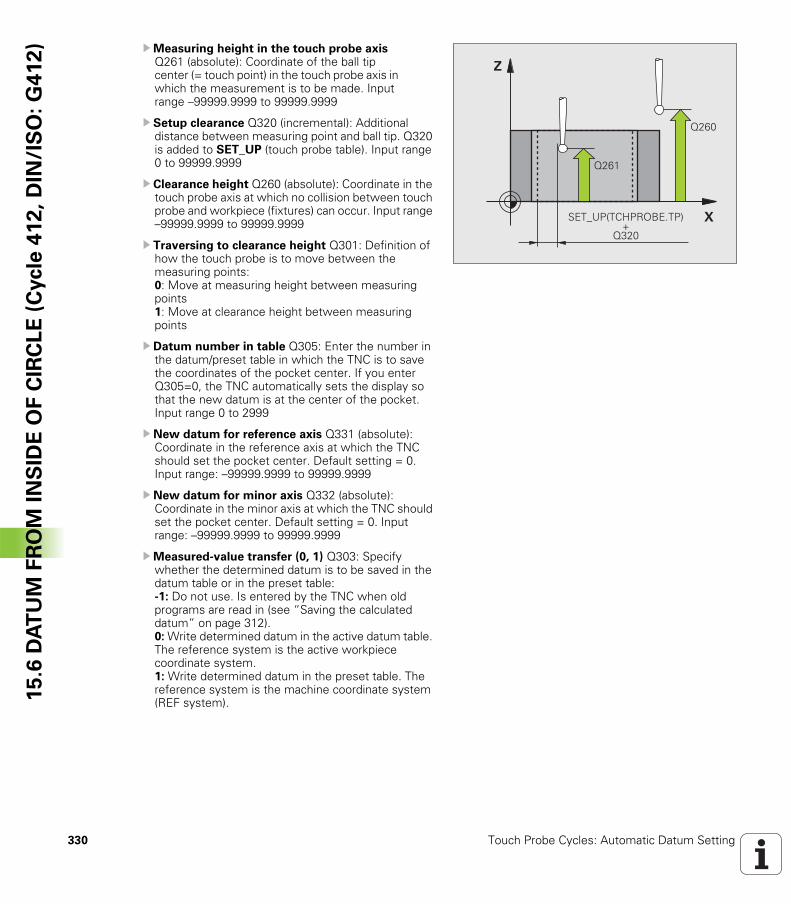
330 Touch Probe Cycles: Automatic Datum Setting
15
.6 D
AT
UM
FR
OM
IN
SID
E O
F C
IRC
LE
(C
ycle
41
2,
DIN
/IS
O:
G4
12
) UMeasuring height in the touch probe axis Q261 (absolute): Coordinate of the ball tip center (= touch point) in the touch probe axis in which the measurement is to be made. Input range –99999.9999 to 99999.9999
U Setup clearance Q320 (incremental): Additional distance between measuring point and ball tip. Q320 is added to SET_UP (touch probe table). Input range 0 to 99999.9999
U Clearance height Q260 (absolute): Coordinate in the touch probe axis at which no collision between touch probe and workpiece (fixtures) can occur. Input range –99999.9999 to 99999.9999
U Traversing to clearance height Q301: Definition of how the touch probe is to move between the measuring points: 0: Move at measuring height between measuring points1: Move at clearance height between measuring points
U Datum number in table Q305: Enter the number in the datum/preset table in which the TNC is to save the coordinates of the pocket center. If you enter Q305=0, the TNC automatically sets the display so that the new datum is at the center of the pocket. Input range 0 to 2999
U New datum for reference axis Q331 (absolute): Coordinate in the reference axis at which the TNC should set the pocket center. Default setting = 0. Input range: –99999.9999 to 99999.9999
U New datum for minor axis Q332 (absolute): Coordinate in the minor axis at which the TNC should set the pocket center. Default setting = 0. Input range: –99999.9999 to 99999.9999
UMeasured-value transfer (0, 1) Q303: Specify whether the determined datum is to be saved in the datum table or in the preset table:-1: Do not use. Is entered by the TNC when old programs are read in (see “Saving the calculated datum” on page 312).0: Write determined datum in the active datum table. The reference system is the active workpiece coordinate system.1: Write determined datum in the preset table. The reference system is the machine coordinate system (REF system).
�
�
����
����
�& '(!� �)!�*�&� !��
����
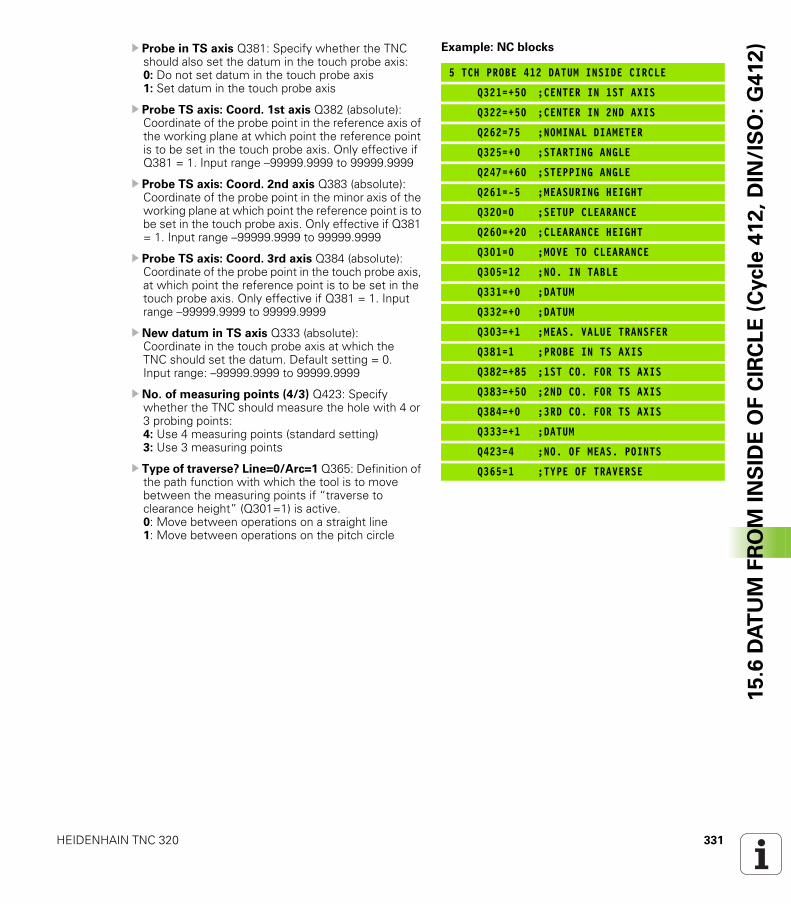
HEIDENHAIN TNC 320 331
15
.6 D
AT
UM
FR
OM
IN
SID
E O
F C
IRC
LE
(C
ycle
41
2,
DIN
/IS
O:
G4
12
)U Probe in TS axis Q381: Specify whether the TNC should also set the datum in the touch probe axis: 0: Do not set datum in the touch probe axis 1: Set datum in the touch probe axis
U Probe TS axis: Coord. 1st axis Q382 (absolute): Coordinate of the probe point in the reference axis of the working plane at which point the reference point is to be set in the touch probe axis. Only effective if Q381 = 1. Input range –99999.9999 to 99999.9999
U Probe TS axis: Coord. 2nd axis Q383 (absolute): Coordinate of the probe point in the minor axis of the working plane at which point the reference point is to be set in the touch probe axis. Only effective if Q381 = 1. Input range –99999.9999 to 99999.9999
U Probe TS axis: Coord. 3rd axis Q384 (absolute): Coordinate of the probe point in the touch probe axis, at which point the reference point is to be set in the touch probe axis. Only effective if Q381 = 1. Input range –99999.9999 to 99999.9999
U New datum in TS axis Q333 (absolute): Coordinate in the touch probe axis at which the TNC should set the datum. Default setting = 0. Input range: –99999.9999 to 99999.9999
U No. of measuring points (4/3) Q423: Specify whether the TNC should measure the hole with 4 or 3 probing points: 4: Use 4 measuring points (standard setting) 3: Use 3 measuring points
U Type of traverse? Line=0/Arc=1 Q365: Definition of the path function with which the tool is to move between the measuring points if “traverse to clearance height” (Q301=1) is active.0: Move between operations on a straight line1: Move between operations on the pitch circle
Example: NC blocks
5 TCH PROBE 412 DATUM INSIDE CIRCLE
Q321=+50 ;CENTER IN 1ST AXIS
Q322=+50 ;CENTER IN 2ND AXIS
Q262=75 ;NOMINAL DIAMETER
Q325=+0 ;STARTING ANGLE
Q247=+60 ;STEPPING ANGLE
Q261=-5 ;MEASURING HEIGHT
Q320=0 ;SETUP CLEARANCE
Q260=+20 ;CLEARANCE HEIGHT
Q301=0 ;MOVE TO CLEARANCE
Q305=12 ;NO. IN TABLE
Q331=+0 ;DATUM
Q332=+0 ;DATUM
Q303=+1 ;MEAS. VALUE TRANSFER
Q381=1 ;PROBE IN TS AXIS
Q382=+85 ;1ST CO. FOR TS AXIS
Q383=+50 ;2ND CO. FOR TS AXIS
Q384=+0 ;3RD CO. FOR TS AXIS
Q333=+1 ;DATUM
Q423=4 ;NO. OF MEAS. POINTS
Q365=1 ;TYPE OF TRAVERSE
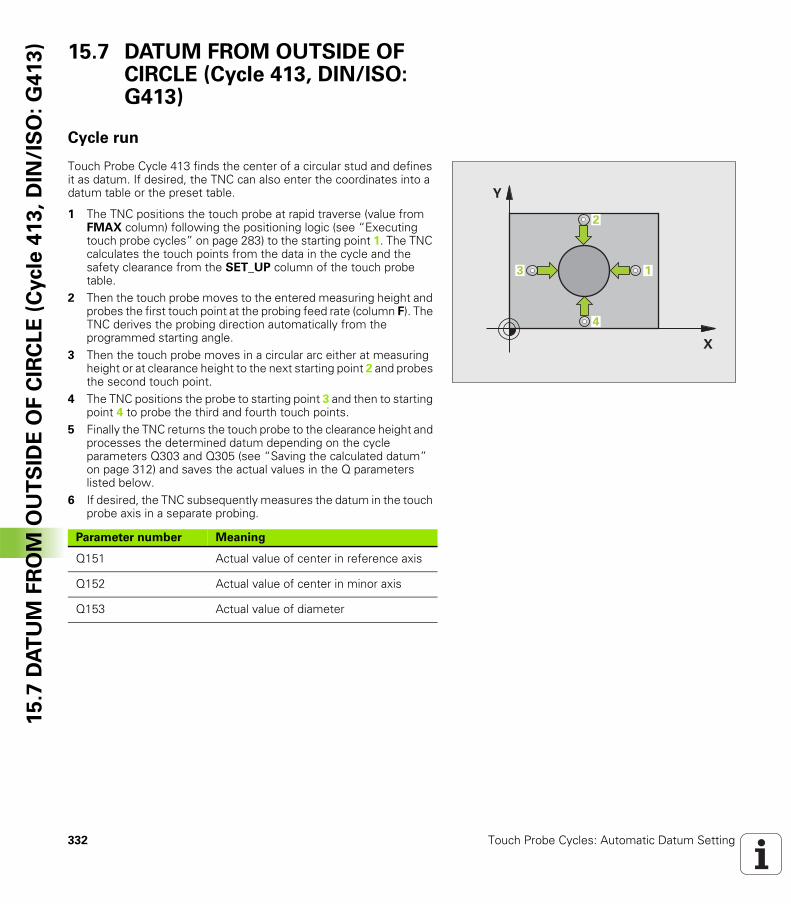
332 Touch Probe Cycles: Automatic Datum Setting
15
.7 D
AT
UM
FR
OM
OU
TS
IDE
OF
CIR
CL
E (
Cycle
41
3,
DIN
/IS
O:
G4
13
) 15.7 DATUM FROM OUTSIDE OF CIRCLE (Cycle 413, DIN/ISO: G413)
Cycle run
Touch Probe Cycle 413 finds the center of a circular stud and defines it as datum. If desired, the TNC can also enter the coordinates into a datum table or the preset table.
1 The TNC positions the touch probe at rapid traverse (value from FMAX column) following the positioning logic (see “Executing touch probe cycles” on page 283) to the starting point 1. The TNC calculates the touch points from the data in the cycle and the safety clearance from the SET_UP column of the touch probe table.
2 Then the touch probe moves to the entered measuring height and probes the first touch point at the probing feed rate (column F). The TNC derives the probing direction automatically from the programmed starting angle.
3 Then the touch probe moves in a circular arc either at measuring height or at clearance height to the next starting point 2 and probes the second touch point.
4 The TNC positions the probe to starting point 3 and then to starting point 4 to probe the third and fourth touch points.
5 Finally the TNC returns the touch probe to the clearance height and processes the determined datum depending on the cycle parameters Q303 and Q305 (see “Saving the calculated datum” on page 312) and saves the actual values in the Q parameters listed below.
6 If desired, the TNC subsequently measures the datum in the touch probe axis in a separate probing.
�
�
�
�
�
Parameter number Meaning
Q151 Actual value of center in reference axis
Q152 Actual value of center in minor axis
Q153 Actual value of diameter
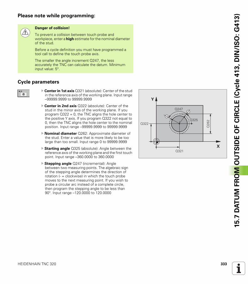
HEIDENHAIN TNC 320 333
15
.7 D
AT
UM
FR
OM
OU
TS
IDE
OF
CIR
CL
E (
Cycle
41
3,
DIN
/IS
O:
G4
13
)Please note while programming:
Cycle parameters
U Center in 1st axis Q321 (absolute): Center of the stud in the reference axis of the working plane. Input range –99999.9999 to 99999.9999
U Center in 2nd axis Q322 (absolute): Center of the stud in the minor axis of the working plane. If you program Q322 = 0, the TNC aligns the hole center to the positive Y axis. If you program Q322 not equal to 0, then the TNC aligns the hole center to the nominal position. Input range –99999.9999 to 99999.9999
U Nominal diameter Q262: Approximate diameter of the stud. Enter a value that is more likely to be too large than too small. Input range 0 to 99999.9999
U Starting angle Q325 (absolute): Angle between the reference axis of the working plane and the first touch point. Input range –360.0000 to 360.0000
U Stepping angle Q247 (incremental): Angle between two measuring points. The algebraic sign of the stepping angle determines the direction of rotation (- = clockwise) in which the touch probe moves to the next measuring point. If you wish to probe a circular arc instead of a complete circle, then program the stepping angle to be less than 90°. Input range –120.0000 to 120.0000
Danger of collision!
To prevent a collision between touch probe and workpiece, enter a high estimate for the nominal diameter of the stud.
Before a cycle definition you must have programmed a tool call to define the touch probe axis.
The smaller the angle increment Q247, the less accurately the TNC can calculate the datum. Minimum input value: 5°.
�
�
����
����
���
����
����
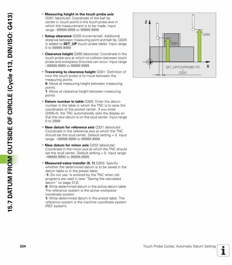
334 Touch Probe Cycles: Automatic Datum Setting
15
.7 D
AT
UM
FR
OM
OU
TS
IDE
OF
CIR
CL
E (
Cycle
41
3,
DIN
/IS
O:
G4
13
) UMeasuring height in the touch probe axis Q261 (absolute): Coordinate of the ball tip center (= touch point) in the touch probe axis in which the measurement is to be made. Input range –99999.9999 to 99999.9999
U Setup clearance Q320 (incremental): Additional distance between measuring point and ball tip. Q320 is added to SET_UP (touch probe table). Input range 0 to 99999.9999
U Clearance height Q260 (absolute): Coordinate in the touch probe axis at which no collision between touch probe and workpiece (fixtures) can occur. Input range –99999.9999 to 99999.9999
U Traversing to clearance height Q301: Definition of how the touch probe is to move between the measuring points: 0: Move at measuring height between measuring points1: Move at clearance height between measuring points
U Datum number in table Q305: Enter the datum number in the table in which the TNC is to save the coordinates of the pocket center. If you enter Q305=0, the TNC automatically sets the display so that the new datum is on the stud center. Input range 0 to 2999
U New datum for reference axis Q331 (absolute): Coordinate in the reference axis at which the TNC should set the stud center. Default setting = 0. Input range: –99999.9999 to 99999.9999
U New datum for minor axis Q332 (absolute): Coordinate in the minor axis at which the TNC should set the stud center. Default setting = 0. Input range: –99999.9999 to 99999.9999
UMeasured-value transfer (0, 1) Q303: Specify whether the determined datum is to be saved in the datum table or in the preset table:-1: Do not use. Is entered by the TNC when old programs are read in (see “Saving the calculated datum” on page 312).0: Write determined datum in the active datum table. The reference system is the active workpiece coordinate system.1: Write determined datum in the preset table. The reference system is the machine coordinate system (REF system).
�
�
����
����
�& '(!� �)!�*�&� !��
����
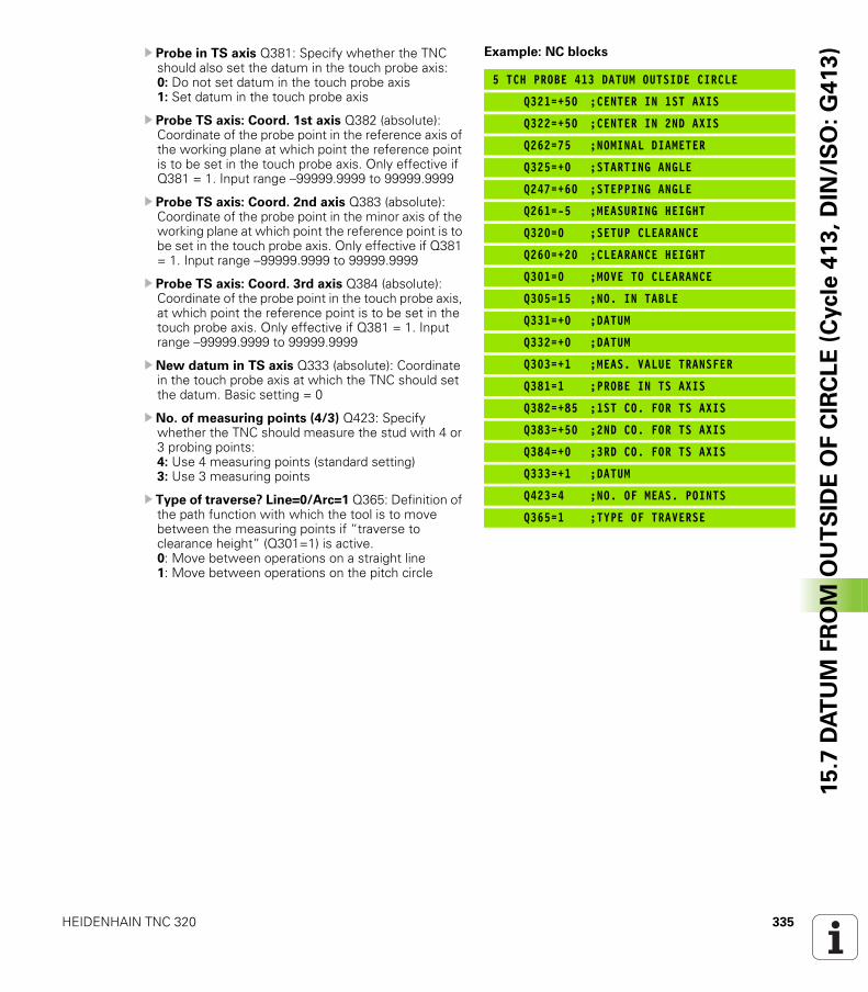
HEIDENHAIN TNC 320 335
15
.7 D
AT
UM
FR
OM
OU
TS
IDE
OF
CIR
CL
E (
Cycle
41
3,
DIN
/IS
O:
G4
13
)U Probe in TS axis Q381: Specify whether the TNC should also set the datum in the touch probe axis: 0: Do not set datum in the touch probe axis 1: Set datum in the touch probe axis
U Probe TS axis: Coord. 1st axis Q382 (absolute): Coordinate of the probe point in the reference axis of the working plane at which point the reference point is to be set in the touch probe axis. Only effective if Q381 = 1. Input range –99999.9999 to 99999.9999
U Probe TS axis: Coord. 2nd axis Q383 (absolute): Coordinate of the probe point in the minor axis of the working plane at which point the reference point is to be set in the touch probe axis. Only effective if Q381 = 1. Input range –99999.9999 to 99999.9999
U Probe TS axis: Coord. 3rd axis Q384 (absolute): Coordinate of the probe point in the touch probe axis, at which point the reference point is to be set in the touch probe axis. Only effective if Q381 = 1. Input range –99999.9999 to 99999.9999
U New datum in TS axis Q333 (absolute): Coordinate in the touch probe axis at which the TNC should set the datum. Basic setting = 0
U No. of measuring points (4/3) Q423: Specify whether the TNC should measure the stud with 4 or 3 probing points: 4: Use 4 measuring points (standard setting) 3: Use 3 measuring points
U Type of traverse? Line=0/Arc=1 Q365: Definition of the path function with which the tool is to move between the measuring points if “traverse to clearance height” (Q301=1) is active.0: Move between operations on a straight line1: Move between operations on the pitch circle
Example: NC blocks
5 TCH PROBE 413 DATUM OUTSIDE CIRCLE
Q321=+50 ;CENTER IN 1ST AXIS
Q322=+50 ;CENTER IN 2ND AXIS
Q262=75 ;NOMINAL DIAMETER
Q325=+0 ;STARTING ANGLE
Q247=+60 ;STEPPING ANGLE
Q261=-5 ;MEASURING HEIGHT
Q320=0 ;SETUP CLEARANCE
Q260=+20 ;CLEARANCE HEIGHT
Q301=0 ;MOVE TO CLEARANCE
Q305=15 ;NO. IN TABLE
Q331=+0 ;DATUM
Q332=+0 ;DATUM
Q303=+1 ;MEAS. VALUE TRANSFER
Q381=1 ;PROBE IN TS AXIS
Q382=+85 ;1ST CO. FOR TS AXIS
Q383=+50 ;2ND CO. FOR TS AXIS
Q384=+0 ;3RD CO. FOR TS AXIS
Q333=+1 ;DATUM
Q423=4 ;NO. OF MEAS. POINTS
Q365=1 ;TYPE OF TRAVERSE
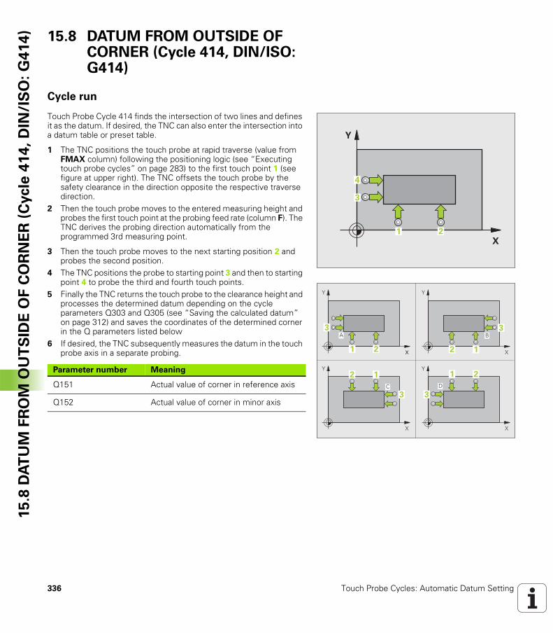
336 Touch Probe Cycles: Automatic Datum Setting
15
.8 D
AT
UM
FR
OM
OU
TS
IDE
OF
CO
RN
ER
(C
ycle
41
4,
DIN
/IS
O:
G4
14
) 15.8 DATUM FROM OUTSIDE OF CORNER (Cycle 414, DIN/ISO: G414)
Cycle run
Touch Probe Cycle 414 finds the intersection of two lines and defines it as the datum. If desired, the TNC can also enter the intersection into a datum table or preset table.
1 The TNC positions the touch probe at rapid traverse (value from FMAX column) following the positioning logic (see “Executing touch probe cycles” on page 283) to the first touch point 1 (see figure at upper right). The TNC offsets the touch probe by the safety clearance in the direction opposite the respective traverse direction.
2 Then the touch probe moves to the entered measuring height and probes the first touch point at the probing feed rate (column F). The TNC derives the probing direction automatically from the programmed 3rd measuring point.
3 Then the touch probe moves to the next starting position 2 and probes the second position.
4 The TNC positions the probe to starting point 3 and then to starting point 4 to probe the third and fourth touch points.
5 Finally the TNC returns the touch probe to the clearance height and processes the determined datum depending on the cycle parameters Q303 and Q305 (see “Saving the calculated datum” on page 312) and saves the coordinates of the determined corner in the Q parameters listed below
6 If desired, the TNC subsequently measures the datum in the touch probe axis in a separate probing.
�
�
� �
�
�
+
#
+
#
+
#
+
� �
� $
� �
�
� �
�
� �
�
� �
�
Parameter number Meaning
Q151 Actual value of corner in reference axis
Q152 Actual value of corner in minor axis
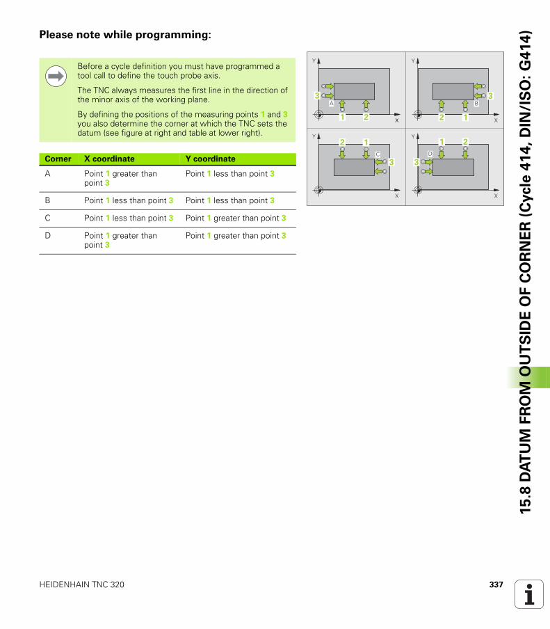
HEIDENHAIN TNC 320 337
15
.8 D
AT
UM
FR
OM
OU
TS
IDE
OF
CO
RN
ER
(C
ycle
41
4,
DIN
/IS
O:
G4
14
)Please note while programming:
�
+
#
+
#
+
#
+
� �
� $
� �
�
� �
�
� �
�
� �
�
Before a cycle definition you must have programmed a tool call to define the touch probe axis.
The TNC always measures the first line in the direction of the minor axis of the working plane.
By defining the positions of the measuring points 1 and 3 you also determine the corner at which the TNC sets the datum (see figure at right and table at lower right).
Corner X coordinate Y coordinate
A Point 1 greater than point 3
Point 1 less than point 3
B Point 1 less than point 3 Point 1 less than point 3
C Point 1 less than point 3 Point 1 greater than point 3
D Point 1 greater than point 3
Point 1 greater than point 3
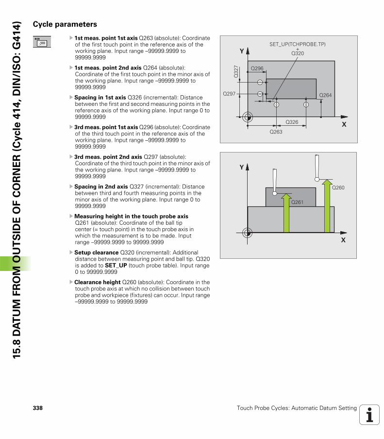
338 Touch Probe Cycles: Automatic Datum Setting
15
.8 D
AT
UM
FR
OM
OU
TS
IDE
OF
CO
RN
ER
(C
ycle
41
4,
DIN
/IS
O:
G4
14
) Cycle parameters
U 1st meas. point 1st axis Q263 (absolute): Coordinate of the first touch point in the reference axis of the working plane. Input range –99999.9999 to 99999.9999
U 1st meas. point 2nd axis Q264 (absolute): Coordinate of the first touch point in the minor axis of the working plane. Input range –99999.9999 to 99999.9999
U Spacing in 1st axis Q326 (incremental): Distance between the first and second measuring points in the reference axis of the working plane. Input range 0 to 99999.9999
U 3rd meas. point 1st axis Q296 (absolute): Coordinate of the third touch point in the reference axis of the working plane. Input range –99999.9999 to 99999.9999
U 3rd meas. point 2nd axis Q297 (absolute): Coordinate of the third touch point in the minor axis of the working plane. Input range –99999.9999 to 99999.9999
U Spacing in 2nd axis Q327 (incremental): Distance between third and fourth measuring points in the minor axis of the working plane. Input range 0 to 99999.9999
UMeasuring height in the touch probe axis Q261 (absolute): Coordinate of the ball tip center (= touch point) in the touch probe axis in which the measurement is to be made. Input range –99999.9999 to 99999.9999
U Setup clearance Q320 (incremental): Additional distance between measuring point and ball tip. Q320 is added to SET_UP (touch probe table). Input range 0 to 99999.9999
U Clearance height Q260 (absolute): Coordinate in the touch probe axis at which no collision between touch probe and workpiece (fixtures) can occur. Input range –99999.9999 to 99999.9999
�
�
����
����
����
����
����
���
�
�& '(!� �)!�*�&� !��
����
�
�
����
����
HEIDENHAIN TNC 320 339
15
.8 D
AT
UM
FR
OM
OU
TS
IDE
OF
CO
RN
ER
(C
ycle
41
4,
DIN
/IS
O:
G4
14
)U Traversing to clearance height Q301: Definition of how the touch probe is to move between the measuring points: 0: Move at measuring height between measuring points 1: Move at clearance height between measuring points
U Execute basic rotation Q304: Definition of whether the TNC should compensate workpiece misalignment with a basic rotation: 0: No basic rotation1: Basic rotation
U Datum number in table Q305: Enter the datum number in the datum or preset table in which the TNC is to save the coordinates of the corner. If you enter Q305=0, the TNC automatically sets the display so that the new datum is on the corner. Input range 0 to 2999
U New datum for reference axis Q331 (absolute): Coordinate in the reference axis at which the TNC should set the corner. Default setting = 0. Input range: –99999.9999 to 99999.9999
U New datum for minor axis Q332 (absolute): Coordinate in the minor axis at which the TNC should set the calculated corner. Default setting = 0. Input range: –99999.9999 to 99999.9999
UMeasured-value transfer (0, 1) Q303: Specify whether the determined datum is to be saved in the datum table or in the preset table:-1: Do not use. Is entered by the TNC when old programs are read in (see “Saving the calculated datum” on page 312).0: Write determined datum in the active datum table. The reference system is the active workpiece coordinate system.1: Write determined datum in the preset table. The reference system is the machine coordinate system (REF system).
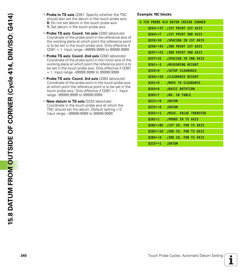
340 Touch Probe Cycles: Automatic Datum Setting
15
.8 D
AT
UM
FR
OM
OU
TS
IDE
OF
CO
RN
ER
(C
ycle
41
4,
DIN
/IS
O:
G4
14
) U Probe in TS axis Q381: Specify whether the TNC should also set the datum in the touch probe axis: 0: Do not set datum in the touch probe axis 1: Set datum in the touch probe axis
U Probe TS axis: Coord. 1st axis Q382 (absolute): Coordinate of the probe point in the reference axis of the working plane at which point the reference point is to be set in the touch probe axis. Only effective if Q381 = 1. Input range –99999.9999 to 99999.9999
U Probe TS axis: Coord. 2nd axis Q383 (absolute): Coordinate of the probe point in the minor axis of the working plane at which point the reference point is to be set in the touch probe axis. Only effective if Q381 = 1. Input range –99999.9999 to 99999.9999
U Probe TS axis: Coord. 3rd axis Q384 (absolute): Coordinate of the probe point in the touch probe axis, at which point the reference point is to be set in the touch probe axis. Only effective if Q381 = 1. Input range –99999.9999 to 99999.9999
U New datum in TS axis Q333 (absolute): Coordinate in the touch probe axis at which the TNC should set the datum. Default setting = 0. Input range: –99999.9999 to 99999.9999
Example: NC blocks
5 TCH PROBE 414 DATUM INSIDE CORNER
Q263=+37 ;1ST POINT 1ST AXIS
Q264=+7 ;1ST POINT 2ND AXIS
Q326=50 ;SPACING IN 1ST AXIS
Q296=+95 ;3RD POINT 1ST AXIS
Q297=+25 ;3RD POINT 2ND AXIS
Q327=45 ;SPACING IN 2ND AXIS
Q261=-5 ;MEASURING HEIGHT
Q320=0 ;SETUP CLEARANCE
Q260=+20 ;CLEARANCE HEIGHT
Q301=0 ;MOVE TO CLEARANCE
Q304=0 ;BASIC ROTATION
Q305=7 ;NO. IN TABLE
Q331=+0 ;DATUM
Q332=+0 ;DATUM
Q303=+1 ;MEAS. VALUE TRANSFER
Q381=1 ;PROBE IN TS AXIS
Q382=+85 ;1ST CO. FOR TS AXIS
Q383=+50 ;2ND CO. FOR TS AXIS
Q384=+0 ;3RD CO. FOR TS AXIS
Q333=+1 ;DATUM
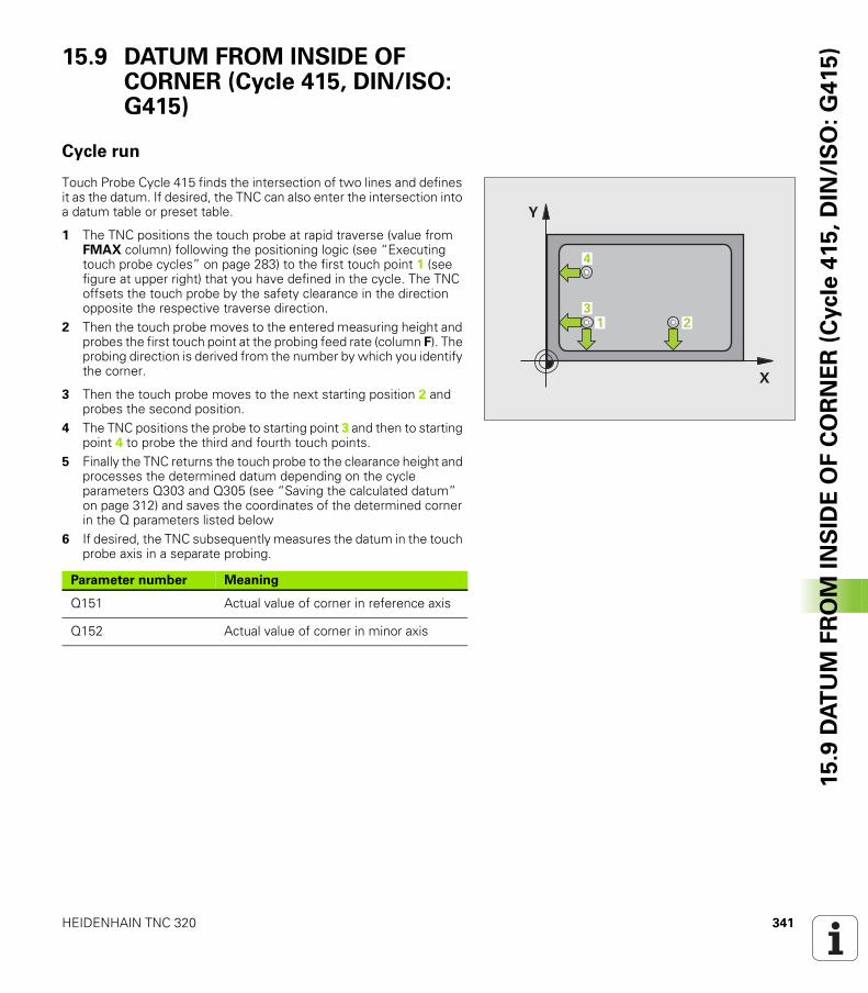
HEIDENHAIN TNC 320 341
15
.9 D
AT
UM
FR
OM
IN
SID
E O
F C
OR
NE
R (
Cycle
41
5,
DIN
/IS
O:
G4
15
)15.9 DATUM FROM INSIDE OF CORNER (Cycle 415, DIN/ISO: G415)
Cycle run
Touch Probe Cycle 415 finds the intersection of two lines and defines it as the datum. If desired, the TNC can also enter the intersection into a datum table or preset table.
1 The TNC positions the touch probe at rapid traverse (value from FMAX column) following the positioning logic (see “Executing touch probe cycles” on page 283) to the first touch point 1 (see figure at upper right) that you have defined in the cycle. The TNC offsets the touch probe by the safety clearance in the direction opposite the respective traverse direction.
2 Then the touch probe moves to the entered measuring height and probes the first touch point at the probing feed rate (column F). The probing direction is derived from the number by which you identify the corner.
3 Then the touch probe moves to the next starting position 2 and probes the second position.
4 The TNC positions the probe to starting point 3 and then to starting point 4 to probe the third and fourth touch points.
5 Finally the TNC returns the touch probe to the clearance height and processes the determined datum depending on the cycle parameters Q303 and Q305 (see “Saving the calculated datum” on page 312) and saves the coordinates of the determined corner in the Q parameters listed below
6 If desired, the TNC subsequently measures the datum in the touch probe axis in a separate probing.
�
�
� ��
Parameter number Meaning
Q151 Actual value of corner in reference axis
Q152 Actual value of corner in minor axis
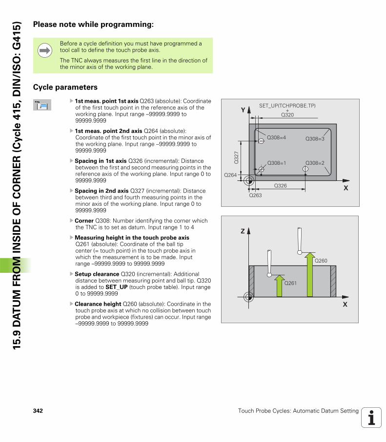
342 Touch Probe Cycles: Automatic Datum Setting
15
.9 D
AT
UM
FR
OM
IN
SID
E O
F C
OR
NE
R (
Cycle
41
5,
DIN
/IS
O:
G4
15
) Please note while programming:
Cycle parameters
U 1st meas. point 1st axis Q263 (absolute): Coordinate of the first touch point in the reference axis of the working plane. Input range –99999.9999 to 99999.9999
U 1st meas. point 2nd axis Q264 (absolute): Coordinate of the first touch point in the minor axis of the working plane. Input range –99999.9999 to 99999.9999
U Spacing in 1st axis Q326 (incremental): Distance between the first and second measuring points in the reference axis of the working plane. Input range 0 to 99999.9999
U Spacing in 2nd axis Q327 (incremental): Distance between third and fourth measuring points in the minor axis of the working plane. Input range 0 to 99999.9999
U Corner Q308: Number identifying the corner which the TNC is to set as datum. Input range 1 to 4
UMeasuring height in the touch probe axis Q261 (absolute): Coordinate of the ball tip center (= touch point) in the touch probe axis in which the measurement is to be made. Input range –99999.9999 to 99999.9999
U Setup clearance Q320 (incremental): Additional distance between measuring point and ball tip. Q320 is added to SET_UP (touch probe table). Input range 0 to 99999.9999
U Clearance height Q260 (absolute): Coordinate in the touch probe axis at which no collision between touch probe and workpiece (fixtures) can occur. Input range –99999.9999 to 99999.9999
Before a cycle definition you must have programmed a tool call to define the touch probe axis.
The TNC always measures the first line in the direction of the minor axis of the working plane.
�
�
����
����
����
���
�
����� �����
����������
�& '(!� �)!�*�&� !��
����
�
�
����
����
HEIDENHAIN TNC 320 343
15
.9 D
AT
UM
FR
OM
IN
SID
E O
F C
OR
NE
R (
Cycle
41
5,
DIN
/IS
O:
G4
15
)U Traversing to clearance height Q301: Definition of how the touch probe is to move between the measuring points: 0: Move at measuring height between measuring points1: Move at clearance height between measuring points
U Execute basic rotation Q304: Definition of whether the TNC should compensate workpiece misalignment with a basic rotation: 0: No basic rotation1: Basic rotation
U Datum number in table Q305: Enter the datum number in the datum or preset table in which the TNC is to save the coordinates of the corner. If you enter Q305=0, the TNC automatically sets the display so that the new datum is on the corner. Input range 0 to 2999
U New datum for reference axis Q331 (absolute): Coordinate in the reference axis at which the TNC should set the corner. Default setting = 0. Input range: –99999.9999 to 99999.9999
U New datum for minor axis Q332 (absolute): Coordinate in the minor axis at which the TNC should set the calculated corner. Default setting = 0. Input range: –99999.9999 to 99999.9999
UMeasured-value transfer (0, 1) Q303: Specify whether the determined datum is to be saved in the datum table or in the preset table:-1: Do not use. Is entered by the TNC when old programs are read in (see “Saving the calculated datum” on page 312).0: Write determined datum in the active datum table. The reference system is the active workpiece coordinate system.1: Write determined datum in the preset table. The reference system is the machine coordinate system (REF system).
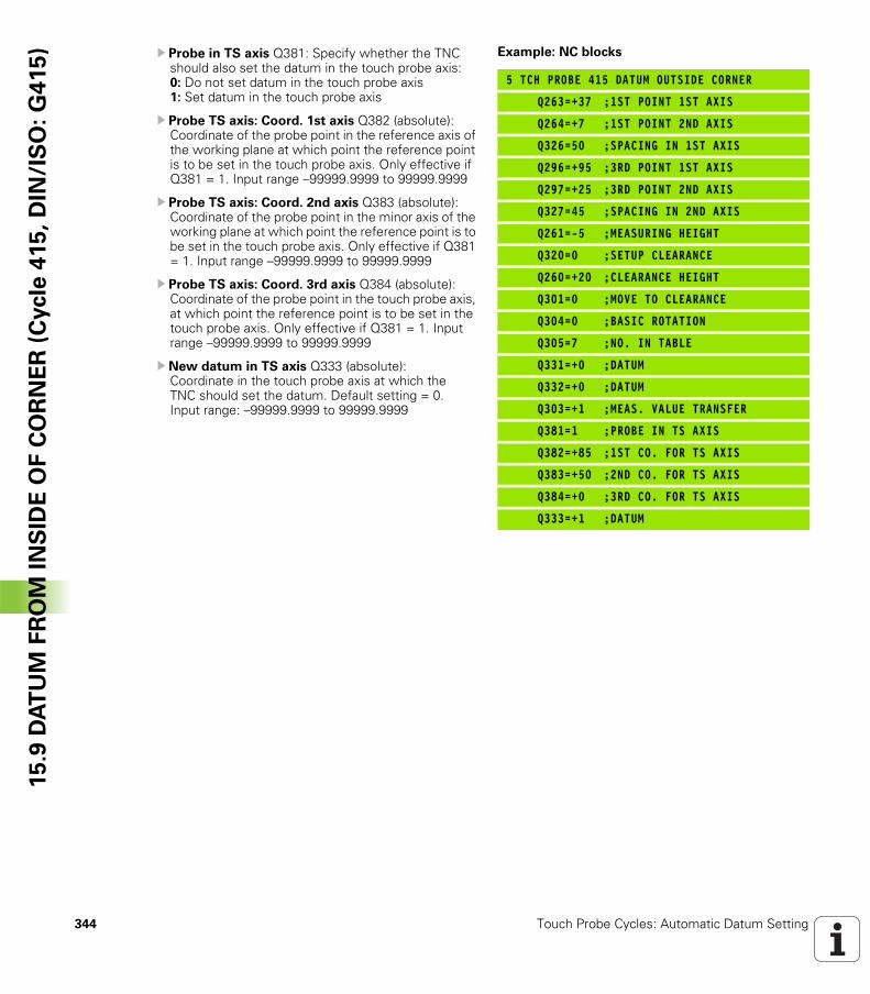
344 Touch Probe Cycles: Automatic Datum Setting
15
.9 D
AT
UM
FR
OM
IN
SID
E O
F C
OR
NE
R (
Cycle
41
5,
DIN
/IS
O:
G4
15
) U Probe in TS axis Q381: Specify whether the TNC should also set the datum in the touch probe axis: 0: Do not set datum in the touch probe axis 1: Set datum in the touch probe axis
U Probe TS axis: Coord. 1st axis Q382 (absolute): Coordinate of the probe point in the reference axis of the working plane at which point the reference point is to be set in the touch probe axis. Only effective if Q381 = 1. Input range –99999.9999 to 99999.9999
U Probe TS axis: Coord. 2nd axis Q383 (absolute): Coordinate of the probe point in the minor axis of the working plane at which point the reference point is to be set in the touch probe axis. Only effective if Q381 = 1. Input range –99999.9999 to 99999.9999
U Probe TS axis: Coord. 3rd axis Q384 (absolute): Coordinate of the probe point in the touch probe axis, at which point the reference point is to be set in the touch probe axis. Only effective if Q381 = 1. Input range –99999.9999 to 99999.9999
U New datum in TS axis Q333 (absolute): Coordinate in the touch probe axis at which the TNC should set the datum. Default setting = 0. Input range: –99999.9999 to 99999.9999
Example: NC blocks
5 TCH PROBE 415 DATUM OUTSIDE CORNER
Q263=+37 ;1ST POINT 1ST AXIS
Q264=+7 ;1ST POINT 2ND AXIS
Q326=50 ;SPACING IN 1ST AXIS
Q296=+95 ;3RD POINT 1ST AXIS
Q297=+25 ;3RD POINT 2ND AXIS
Q327=45 ;SPACING IN 2ND AXIS
Q261=-5 ;MEASURING HEIGHT
Q320=0 ;SETUP CLEARANCE
Q260=+20 ;CLEARANCE HEIGHT
Q301=0 ;MOVE TO CLEARANCE
Q304=0 ;BASIC ROTATION
Q305=7 ;NO. IN TABLE
Q331=+0 ;DATUM
Q332=+0 ;DATUM
Q303=+1 ;MEAS. VALUE TRANSFER
Q381=1 ;PROBE IN TS AXIS
Q382=+85 ;1ST CO. FOR TS AXIS
Q383=+50 ;2ND CO. FOR TS AXIS
Q384=+0 ;3RD CO. FOR TS AXIS
Q333=+1 ;DATUM
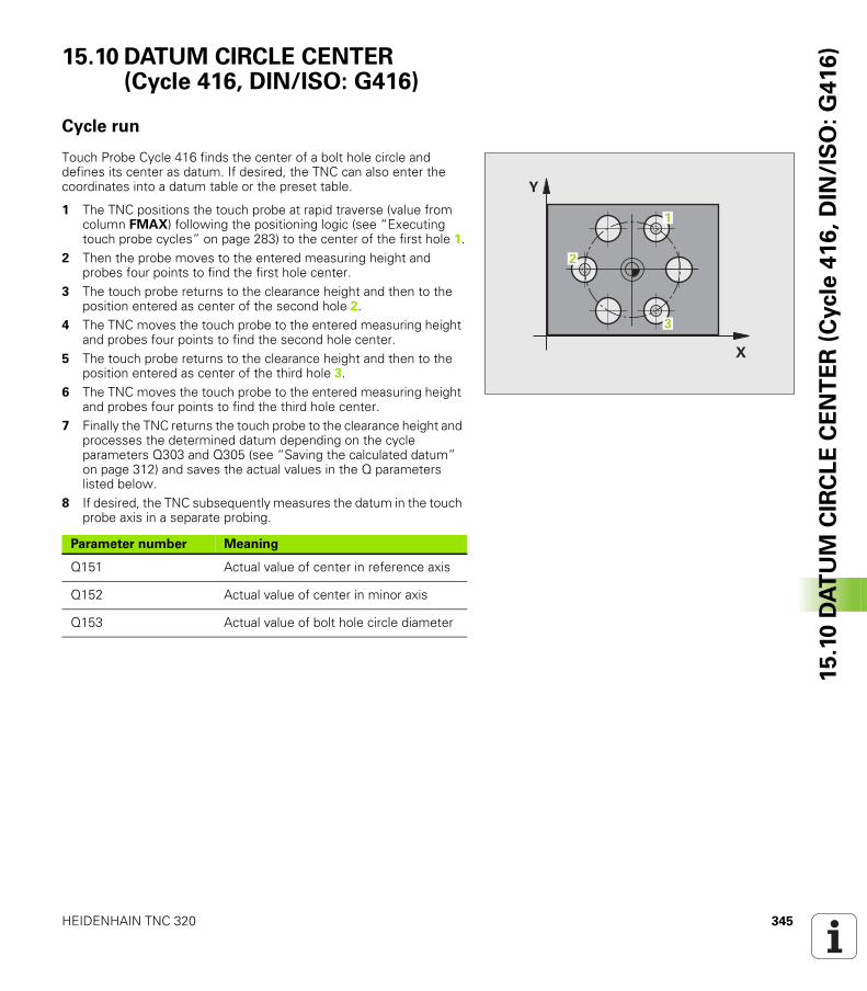
HEIDENHAIN TNC 320 345
15
.10
DA
TU
M C
IRC
LE
CE
NT
ER
(C
ycle
41
6,
DIN
/IS
O:
G4
16
)15.10 DATUM CIRCLE CENTER (Cycle 416, DIN/ISO: G416)
Cycle run
Touch Probe Cycle 416 finds the center of a bolt hole circle and defines its center as datum. If desired, the TNC can also enter the coordinates into a datum table or the preset table.
1 The TNC positions the touch probe at rapid traverse (value from column FMAX) following the positioning logic (see “Executing touch probe cycles” on page 283) to the center of the first hole 1.
2 Then the probe moves to the entered measuring height and probes four points to find the first hole center.
3 The touch probe returns to the clearance height and then to the position entered as center of the second hole 2.
4 The TNC moves the touch probe to the entered measuring height and probes four points to find the second hole center.
5 The touch probe returns to the clearance height and then to the position entered as center of the third hole 3.
6 The TNC moves the touch probe to the entered measuring height and probes four points to find the third hole center.
7 Finally the TNC returns the touch probe to the clearance height and processes the determined datum depending on the cycle parameters Q303 and Q305 (see “Saving the calculated datum” on page 312) and saves the actual values in the Q parameters listed below.
8 If desired, the TNC subsequently measures the datum in the touch probe axis in a separate probing.
�
�
�
�
�
Parameter number Meaning
Q151 Actual value of center in reference axis
Q152 Actual value of center in minor axis
Q153 Actual value of bolt hole circle diameter
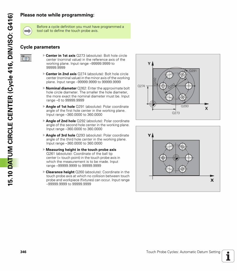
346 Touch Probe Cycles: Automatic Datum Setting
15
.10
DA
TU
M C
IRC
LE
CE
NT
ER
(C
ycle
41
6,
DIN
/IS
O:
G4
16
) Please note while programming:
Cycle parameters
U Center in 1st axis Q273 (absolute): Bolt hole circle center (nominal value) in the reference axis of the working plane. Input range –99999.9999 to 99999.9999
U Center in 2nd axis Q274 (absolute): Bolt hole circle center (nominal value) in the minor axis of the working plane. Input range –99999.9999 to 99999.9999
U Nominal diameter Q262: Enter the approximate bolt hole circle diameter. The smaller the hole diameter, the more exact the nominal diameter must be. Input range –0 to 99999.9999
U Angle of 1st hole Q291 (absolute): Polar coordinate angle of the first hole center in the working plane. Input range –360.0000 to 360.0000
U Angle of 2nd hole Q292 (absolute): Polar coordinate angle of the second hole center in the working plane. Input range –360.0000 to 360.0000
U Angle of 3rd hole Q293 (absolute): Polar coordinate angle of the third hole center in the working plane. Input range –360.0000 to 360.0000
UMeasuring height in the touch probe axis Q261 (absolute): Coordinate of the ball tip center (= touch point) in the touch probe axis in which the measurement is to be made. Input range –99999.9999 to 99999.9999
U Clearance height Q260 (absolute): Coordinate in the touch probe axis at which no collision between touch probe and workpiece (fixtures) can occur. Input range –99999.9999 to 99999.9999
Before a cycle definition you must have programmed a tool call to define the touch probe axis.
�
�
����
����
����
����
����
���
�
�
�
HEIDENHAIN TNC 320 347
15
.10
DA
TU
M C
IRC
LE
CE
NT
ER
(C
ycle
41
6,
DIN
/IS
O:
G4
16
)U Datum number in table Q305: Enter the number in the datum or preset table in which the TNC is to save the coordinates of the bolt-hole circle center. If you enter Q305=0, the TNC automatically sets the display so that the new datum is on the bolt hole center. Input range 0 to 2999
U New datum for reference axis Q331 (absolute): Coordinate in the reference axis at which the TNC should set the bolt-hole center. Default setting = 0. Input range: –99999.9999 to 99999.9999
U New datum for minor axis Q332 (absolute): Coordinate in the minor axis at which the TNC should set the bolt-hole center. Default setting = 0. Input range: –99999.9999 to 99999.9999
UMeasured-value transfer (0, 1) Q303: Specify whether the determined datum is to be saved in the datum table or in the preset table:-1: Do not use. Is entered by the TNC when old programs are read in (see “Saving the calculated datum” on page 312).0: Write determined datum in the active datum table. The reference system is the active workpiece coordinate system.1: Write determined datum in the preset table. The reference system is the machine coordinate system (REF system).
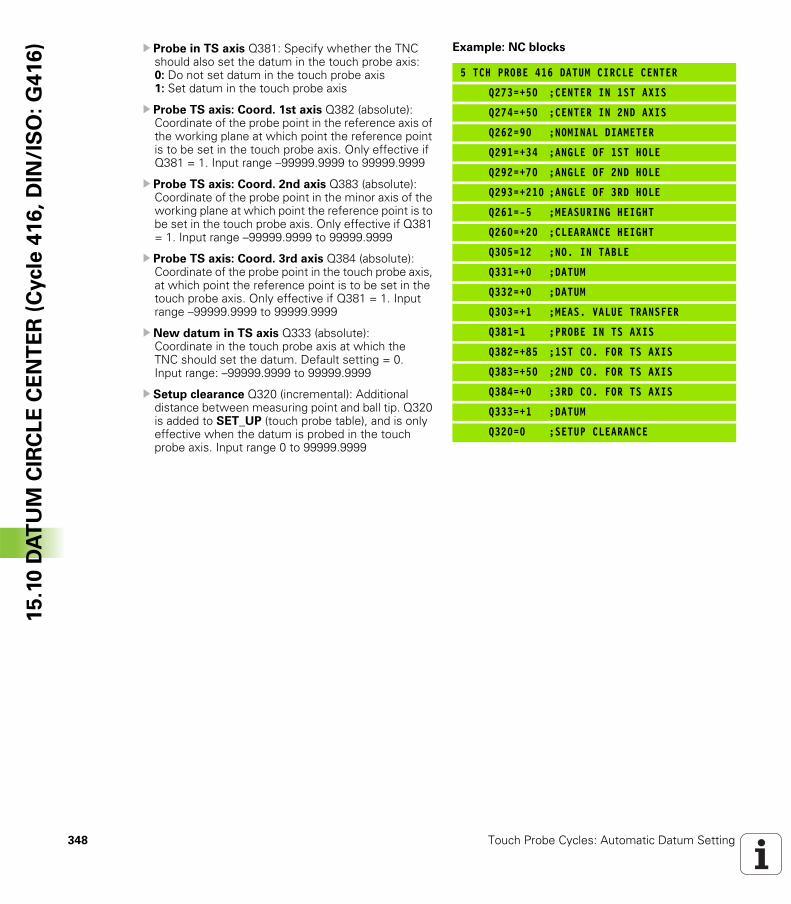
348 Touch Probe Cycles: Automatic Datum Setting
15
.10
DA
TU
M C
IRC
LE
CE
NT
ER
(C
ycle
41
6,
DIN
/IS
O:
G4
16
) U Probe in TS axis Q381: Specify whether the TNC should also set the datum in the touch probe axis: 0: Do not set datum in the touch probe axis 1: Set datum in the touch probe axis
U Probe TS axis: Coord. 1st axis Q382 (absolute): Coordinate of the probe point in the reference axis of the working plane at which point the reference point is to be set in the touch probe axis. Only effective if Q381 = 1. Input range –99999.9999 to 99999.9999
U Probe TS axis: Coord. 2nd axis Q383 (absolute): Coordinate of the probe point in the minor axis of the working plane at which point the reference point is to be set in the touch probe axis. Only effective if Q381 = 1. Input range –99999.9999 to 99999.9999
U Probe TS axis: Coord. 3rd axis Q384 (absolute): Coordinate of the probe point in the touch probe axis, at which point the reference point is to be set in the touch probe axis. Only effective if Q381 = 1. Input range –99999.9999 to 99999.9999
U New datum in TS axis Q333 (absolute): Coordinate in the touch probe axis at which the TNC should set the datum. Default setting = 0. Input range: –99999.9999 to 99999.9999
U Setup clearance Q320 (incremental): Additional distance between measuring point and ball tip. Q320 is added to SET_UP (touch probe table), and is only effective when the datum is probed in the touch probe axis. Input range 0 to 99999.9999
Example: NC blocks
5 TCH PROBE 416 DATUM CIRCLE CENTER
Q273=+50 ;CENTER IN 1ST AXIS
Q274=+50 ;CENTER IN 2ND AXIS
Q262=90 ;NOMINAL DIAMETER
Q291=+34 ;ANGLE OF 1ST HOLE
Q292=+70 ;ANGLE OF 2ND HOLE
Q293=+210 ;ANGLE OF 3RD HOLE
Q261=-5 ;MEASURING HEIGHT
Q260=+20 ;CLEARANCE HEIGHT
Q305=12 ;NO. IN TABLE
Q331=+0 ;DATUM
Q332=+0 ;DATUM
Q303=+1 ;MEAS. VALUE TRANSFER
Q381=1 ;PROBE IN TS AXIS
Q382=+85 ;1ST CO. FOR TS AXIS
Q383=+50 ;2ND CO. FOR TS AXIS
Q384=+0 ;3RD CO. FOR TS AXIS
Q333=+1 ;DATUM
Q320=0 ;SETUP CLEARANCE
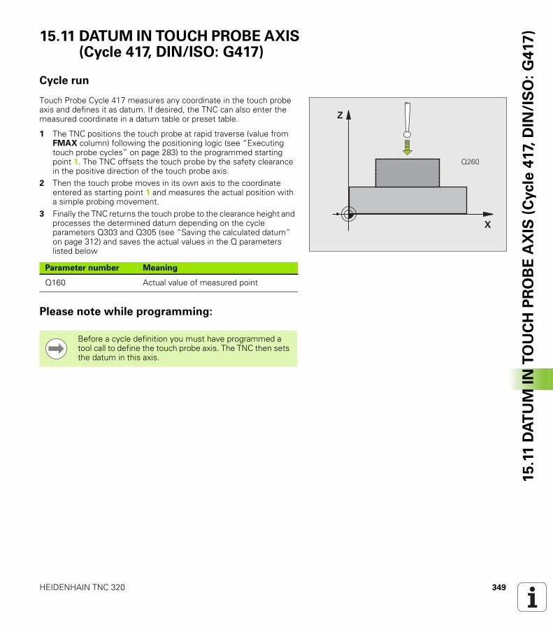
HEIDENHAIN TNC 320 349
15
.11
DA
TU
M I
N T
OU
CH
PR
OB
E A
XIS
(C
ycle
417,
DIN
/IS
O:
G4
17
)15.11 DATUM IN TOUCH PROBE AXIS (Cycle 417, DIN/ISO: G417)
Cycle run
Touch Probe Cycle 417 measures any coordinate in the touch probe axis and defines it as datum. If desired, the TNC can also enter the measured coordinate in a datum table or preset table.
1 The TNC positions the touch probe at rapid traverse (value from FMAX column) following the positioning logic (see “Executing touch probe cycles” on page 283) to the programmed starting point 1. The TNC offsets the touch probe by the safety clearance in the positive direction of the touch probe axis.
2 Then the touch probe moves in its own axis to the coordinate entered as starting point 1 and measures the actual position with a simple probing movement.
3 Finally the TNC returns the touch probe to the clearance height and processes the determined datum depending on the cycle parameters Q303 and Q305 (see “Saving the calculated datum” on page 312) and saves the actual values in the Q parameters listed below
Please note while programming:
�
�
����
Parameter number Meaning
Q160 Actual value of measured point
Before a cycle definition you must have programmed a tool call to define the touch probe axis. The TNC then sets the datum in this axis.
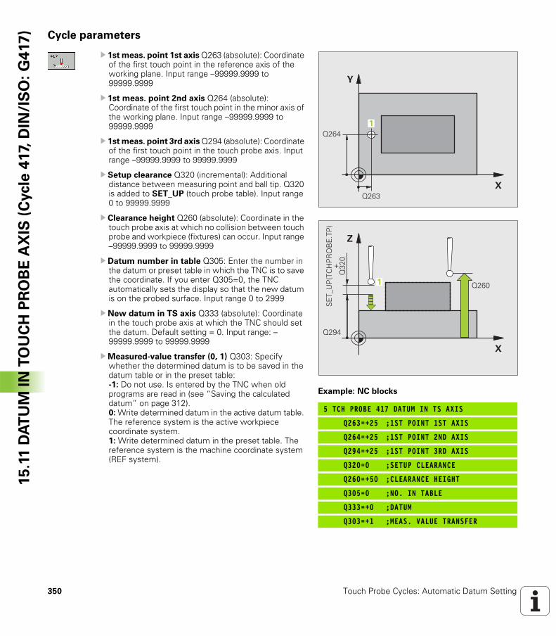
350 Touch Probe Cycles: Automatic Datum Setting
15
.11
DA
TU
M I
N T
OU
CH
PR
OB
E A
XIS
(C
ycle
417,
DIN
/IS
O:
G4
17
) Cycle parameters
U 1st meas. point 1st axis Q263 (absolute): Coordinate of the first touch point in the reference axis of the working plane. Input range –99999.9999 to 99999.9999
U 1st meas. point 2nd axis Q264 (absolute): Coordinate of the first touch point in the minor axis of the working plane. Input range –99999.9999 to 99999.9999
U 1st meas. point 3rd axis Q294 (absolute): Coordinate of the first touch point in the touch probe axis. Input range –99999.9999 to 99999.9999
U Setup clearance Q320 (incremental): Additional distance between measuring point and ball tip. Q320 is added to SET_UP (touch probe table). Input range 0 to 99999.9999
U Clearance height Q260 (absolute): Coordinate in the touch probe axis at which no collision between touch probe and workpiece (fixtures) can occur. Input range –99999.9999 to 99999.9999
U Datum number in table Q305: Enter the number in the datum or preset table in which the TNC is to save the coordinate. If you enter Q305=0, the TNC automatically sets the display so that the new datum is on the probed surface. Input range 0 to 2999
U New datum in TS axis Q333 (absolute): Coordinate in the touch probe axis at which the TNC should set the datum. Default setting = 0. Input range: –99999.9999 to 99999.9999
UMeasured-value transfer (0, 1) Q303: Specify whether the determined datum is to be saved in the datum table or in the preset table:-1: Do not use. Is entered by the TNC when old programs are read in (see “Saving the calculated datum” on page 312).0: Write determined datum in the active datum table. The reference system is the active workpiece coordinate system.1: Write determined datum in the preset table. The reference system is the machine coordinate system (REF system).
Example: NC blocks
5 TCH PROBE 417 DATUM IN TS AXIS
Q263=+25 ;1ST POINT 1ST AXIS
Q264=+25 ;1ST POINT 2ND AXIS
Q294=+25 ;1ST POINT 3RD AXIS
Q320=0 ;SETUP CLEARANCE
Q260=+50 ;CLEARANCE HEIGHT
Q305=0 ;NO. IN TABLE
Q333=+0 ;DATUM
Q303=+1 ;MEAS. VALUE TRANSFER
�
�
����
����
�
�
�
����
����
�
�&
'(!� �)!�*�&� !�
����
�
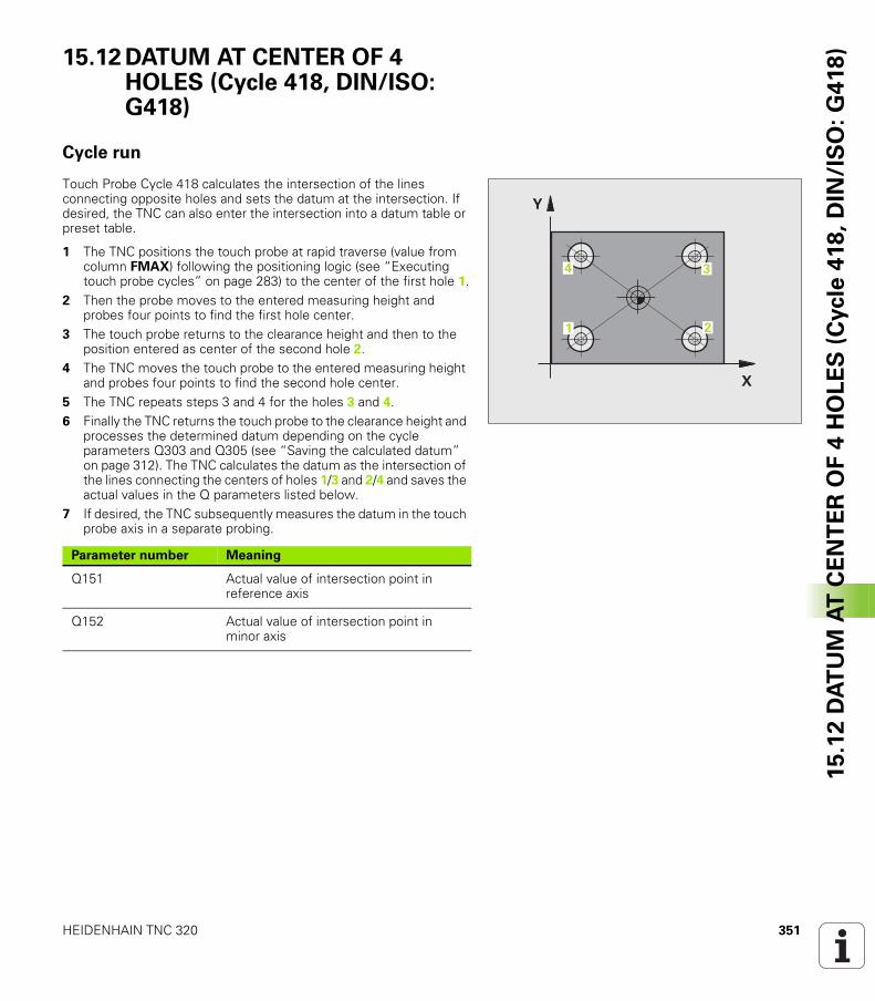
HEIDENHAIN TNC 320 351
15
.12
DA
TU
M A
T C
EN
TE
R O
F 4
HO
LE
S (
Cycle
418
, D
IN/I
SO
: G
418
)15.12 DATUM AT CENTER OF 4 HOLES (Cycle 418, DIN/ISO: G418)
Cycle run
Touch Probe Cycle 418 calculates the intersection of the lines connecting opposite holes and sets the datum at the intersection. If desired, the TNC can also enter the intersection into a datum table or preset table.
1 The TNC positions the touch probe at rapid traverse (value from column FMAX) following the positioning logic (see “Executing touch probe cycles” on page 283) to the center of the first hole 1.
2 Then the probe moves to the entered measuring height and probes four points to find the first hole center.
3 The touch probe returns to the clearance height and then to the position entered as center of the second hole 2.
4 The TNC moves the touch probe to the entered measuring height and probes four points to find the second hole center.
5 The TNC repeats steps 3 and 4 for the holes 3 and 4.6 Finally the TNC returns the touch probe to the clearance height and
processes the determined datum depending on the cycle parameters Q303 and Q305 (see “Saving the calculated datum” on page 312). The TNC calculates the datum as the intersection of the lines connecting the centers of holes 1/3 and 2/4 and saves the actual values in the Q parameters listed below.
7 If desired, the TNC subsequently measures the datum in the touch probe axis in a separate probing.
�
�
� �
�
Parameter number Meaning
Q151 Actual value of intersection point in reference axis
Q152 Actual value of intersection point in minor axis
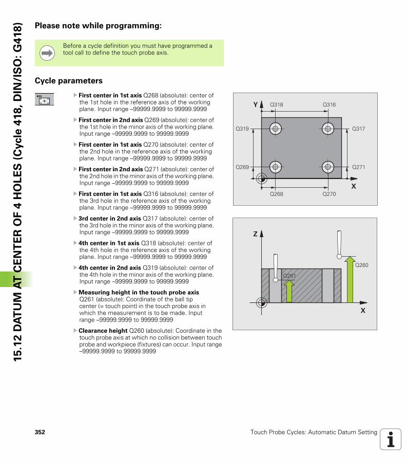
352 Touch Probe Cycles: Automatic Datum Setting
15
.12
DA
TU
M A
T C
EN
TE
R O
F 4
HO
LE
S (
Cycle
418
, D
IN/I
SO
: G
418
) Please note while programming:
Cycle parameters
U First center in 1st axis Q268 (absolute): center of the 1st hole in the reference axis of the working plane. Input range –99999.9999 to 99999.9999
U First center in 2nd axis Q269 (absolute): center of the 1st hole in the minor axis of the working plane. Input range –99999.9999 to 99999.9999
U First center in 1st axis Q270 (absolute): center of the 2nd hole in the reference axis of the working plane. Input range –99999.9999 to 99999.9999
U First center in 2nd axis Q271 (absolute): center of the 2nd hole in the minor axis of the working plane. Input range –99999.9999 to 99999.9999
U First center in 1st axis Q316 (absolute): center of the 3rd hole in the reference axis of the working plane. Input range –99999.9999 to 99999.9999
U 3rd center in 2nd axis Q317 (absolute): center of the 3rd hole in the minor axis of the working plane. Input range –99999.9999 to 99999.9999
U 4th center in 1st axis Q318 (absolute): center of the 4th hole in the reference axis of the working plane. Input range –99999.9999 to 99999.9999
U 4th center in 2nd axis Q319 (absolute): center of the 4th hole in the minor axis of the working plane. Input range –99999.9999 to 99999.9999
UMeasuring height in the touch probe axis Q261 (absolute): Coordinate of the ball tip center (= touch point) in the touch probe axis in which the measurement is to be made. Input range –99999.9999 to 99999.9999
U Clearance height Q260 (absolute): Coordinate in the touch probe axis at which no collision between touch probe and workpiece (fixtures) can occur. Input range –99999.9999 to 99999.9999
Before a cycle definition you must have programmed a tool call to define the touch probe axis.
�
�
����
��� ����
����
����
��� ����
����
�
�
����
����
HEIDENHAIN TNC 320 353
15
.12
DA
TU
M A
T C
EN
TE
R O
F 4
HO
LE
S (
Cycle
418
, D
IN/I
SO
: G
418
)U Datum number in table Q305: Enter the number in the datum or preset table in which the TNC is to save the coordinates of the line intersection. If you enter Q305=0, the TNC automatically sets the display so that the new datum is at the intersection of the connecting lines. Input range 0 to 2999
U New datum for reference axis Q331 (absolute): Coordinate in the reference axis at which the TNC should set the calculated intersection of the connecting lines. Default setting = 0. Input range: -99999.9999 to 99999.9999
U New datum for minor axis Q332 (absolute): Coordinate in the minor axis at which the TNC should set the calculated intersection of the connecting lines. Default setting = 0. Input range: -99999.9999 to 99999.9999
UMeasured-value transfer (0, 1) Q303: Specify whether the determined datum is to be saved in the datum table or in the preset table:-1: Do not use. Is entered by the TNC when old programs are read in (see “Saving the calculated datum” on page 312).0: Write determined datum in the active datum table. The reference system is the active workpiece coordinate system.1: Write determined datum in the preset table. The reference system is the machine coordinate system (REF system).
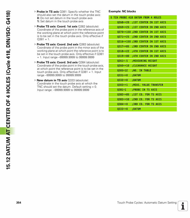
354 Touch Probe Cycles: Automatic Datum Setting
15
.12
DA
TU
M A
T C
EN
TE
R O
F 4
HO
LE
S (
Cycle
418
, D
IN/I
SO
: G
418
) U Probe in TS axis Q381: Specify whether the TNC should also set the datum in the touch probe axis: 0: Do not set datum in the touch probe axis 1: Set datum in the touch probe axis
U Probe TS axis: Coord. 1st axis Q382 (absolute): Coordinate of the probe point in the reference axis of the working plane at which point the reference point is to be set in the touch probe axis. Only effective if Q381 = 1.
U Probe TS axis: Coord. 2nd axis Q383 (absolute): Coordinate of the probe point in the minor axis of the working plane at which point the reference point is to be set in the touch probe axis. Only effective if Q381 = 1. Input range –99999.9999 to 99999.9999
U Probe TS axis: Coord. 3rd axis Q384 (absolute): Coordinate of the probe point in the touch probe axis, at which point the reference point is to be set in the touch probe axis. Only effective if Q381 = 1. Input range –99999.9999 to 99999.9999
U New datum in TS axis Q333 (absolute): Coordinate in the touch probe axis at which the TNC should set the datum. Default setting = 0. Input range: –99999.9999 to 99999.9999
Example: NC blocks
5 TCH PROBE 418 DATUM FROM 4 HOLES
Q268=+20 ;1ST CENTER IN 1ST AXIS
Q269=+25 ;1ST CENTER IN 2ND AXIS
Q270=+150 ;2ND CENTER IN 1ST AXIS
Q271=+25 ;2ND CENTER IN 2ND AXIS
Q316=+150 ;3RD CENTER IN 1ST AXIS
Q317=+85 ;3RD CENTER IN 2ND AXIS
Q318=+22 ;4TH CENTER IN 1ST AXIS
Q319=+80 ;4TH CENTER IN 2ND AXIS
Q261=-5 ;MEASURING HEIGHT
Q260=+10 ;CLEARANCE HEIGHT
Q305=12 ;NO. IN TABLE
Q331=+0 ;DATUM
Q332=+0 ;DATUM
Q303=+1 ;MEAS. VALUE TRANSFER
Q381=1 ;PROBE IN TS AXIS
Q382=+85 ;1ST CO. FOR TS AXIS
Q383=+50 ;2ND CO. FOR TS AXIS
Q384=+0 ;3RD CO. FOR TS AXIS
Q333=+0 ;DATUM
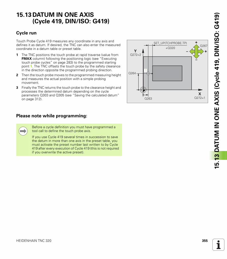
HEIDENHAIN TNC 320 355
15
.13
DA
TU
M I
N O
NE
AX
IS (
Cycle
419
, D
IN/I
SO
: G
419
)15.13 DATUM IN ONE AXIS (Cycle 419, DIN/ISO: G419)
Cycle run
Touch Probe Cycle 419 measures any coordinate in any axis and defines it as datum. If desired, the TNC can also enter the measured coordinate in a datum table or preset table.
1 The TNC positions the touch probe at rapid traverse (value from FMAX column) following the positioning logic (see “Executing touch probe cycles” on page 283) to the programmed starting point 1. The TNC offsets the touch probe by the safety clearance in the direction opposite the programmed probing direction.
2 Then the touch probe moves to the programmed measuring height and measures the actual position with a simple probing movement.
3 Finally the TNC returns the touch probe to the clearance height and processes the determined datum depending on the cycle parameters Q303 and Q305 (see “Saving the calculated datum” on page 312).
Please note while programming:
�
�
����
����
!
"
" !����
������
������
�
�& '(!� �)!�*�&� !�
�����
Before a cycle definition you must have programmed a tool call to define the touch probe axis.
If you use Cycle 419 several times in succession to save the datum in more than one axis in the preset table, you must activate the preset number last written to by Cycle 419 after every execution of Cycle 419 (this is not required if you overwrite the active preset).
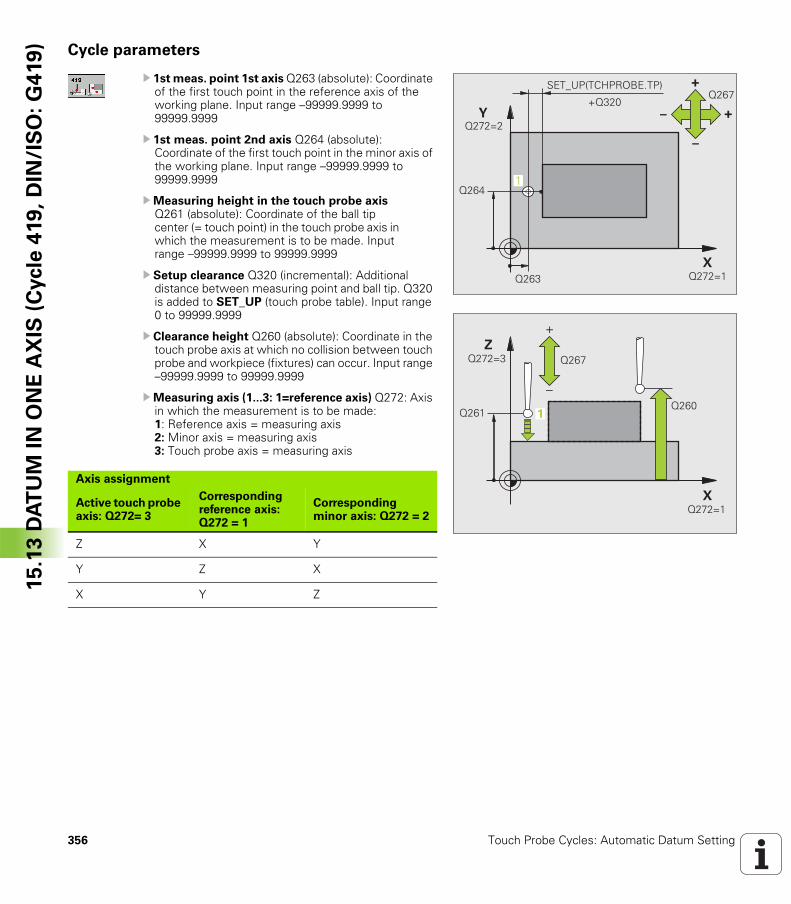
356 Touch Probe Cycles: Automatic Datum Setting
15
.13
DA
TU
M I
N O
NE
AX
IS (
Cycle
419
, D
IN/I
SO
: G
419
) Cycle parameters
U 1st meas. point 1st axis Q263 (absolute): Coordinate of the first touch point in the reference axis of the working plane. Input range –99999.9999 to 99999.9999
U 1st meas. point 2nd axis Q264 (absolute): Coordinate of the first touch point in the minor axis of the working plane. Input range –99999.9999 to 99999.9999
UMeasuring height in the touch probe axis Q261 (absolute): Coordinate of the ball tip center (= touch point) in the touch probe axis in which the measurement is to be made. Input range –99999.9999 to 99999.9999
U Setup clearance Q320 (incremental): Additional distance between measuring point and ball tip. Q320 is added to SET_UP (touch probe table). Input range 0 to 99999.9999
U Clearance height Q260 (absolute): Coordinate in the touch probe axis at which no collision between touch probe and workpiece (fixtures) can occur. Input range –99999.9999 to 99999.9999
UMeasuring axis (1...3: 1=reference axis) Q272: Axis in which the measurement is to be made: 1: Reference axis = measuring axis2: Minor axis = measuring axis3: Touch probe axis = measuring axis
�
�
����
����
!
"
" !����
������
������
�
�& '(!� �)!�*�&� !�
�����
�
�
��������
�
�
������
������ ����
�
Axis assignment
Active touch probe axis: Q272= 3
Corresponding reference axis: Q272 = 1
Corresponding minor axis: Q272 = 2
Z X Y
Y Z X
X Y Z
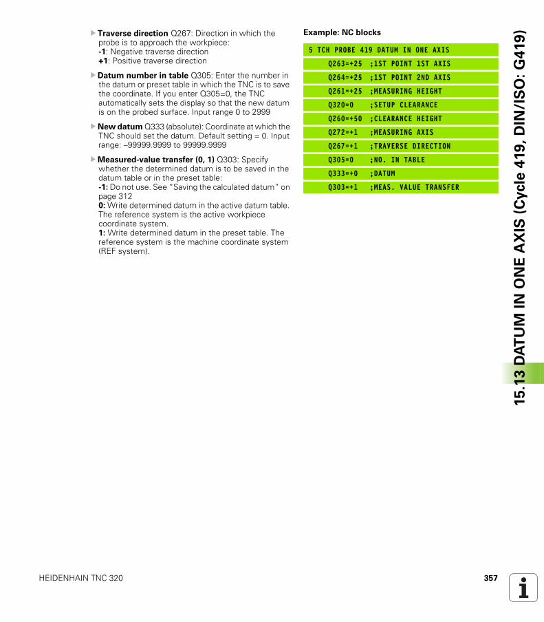
HEIDENHAIN TNC 320 357
15
.13
DA
TU
M I
N O
NE
AX
IS (
Cycle
419
, D
IN/I
SO
: G
419
)U Traverse direction Q267: Direction in which the probe is to approach the workpiece: -1: Negative traverse direction +1: Positive traverse direction
U Datum number in table Q305: Enter the number in the datum or preset table in which the TNC is to save the coordinate. If you enter Q305=0, the TNC automatically sets the display so that the new datum is on the probed surface. Input range 0 to 2999
U New datum Q333 (absolute): Coordinate at which the TNC should set the datum. Default setting = 0. Input range: –99999.9999 to 99999.9999
UMeasured-value transfer (0, 1) Q303: Specify whether the determined datum is to be saved in the datum table or in the preset table:-1: Do not use. See “Saving the calculated datum” on page 3120: Write determined datum in the active datum table. The reference system is the active workpiece coordinate system.1: Write determined datum in the preset table. The reference system is the machine coordinate system (REF system).
Example: NC blocks
5 TCH PROBE 419 DATUM IN ONE AXIS
Q263=+25 ;1ST POINT 1ST AXIS
Q264=+25 ;1ST POINT 2ND AXIS
Q261=+25 ;MEASURING HEIGHT
Q320=0 ;SETUP CLEARANCE
Q260=+50 ;CLEARANCE HEIGHT
Q272=+1 ;MEASURING AXIS
Q267=+1 ;TRAVERSE DIRECTION
Q305=0 ;NO. IN TABLE
Q333=+0 ;DATUM
Q303=+1 ;MEAS. VALUE TRANSFER
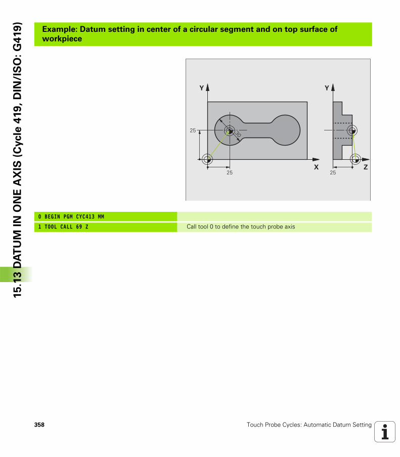
358 Touch Probe Cycles: Automatic Datum Setting
15
.13
DA
TU
M I
N O
NE
AX
IS (
Cycle
419
, D
IN/I
SO
: G
419
)Example: Datum setting in center of a circular segment and on top surface of
workpiece
0 BEGIN PGM CYC413 MM
1 TOOL CALL 69 Z Call tool 0 to define the touch probe axis
�
�
�
�
�
�
�
��
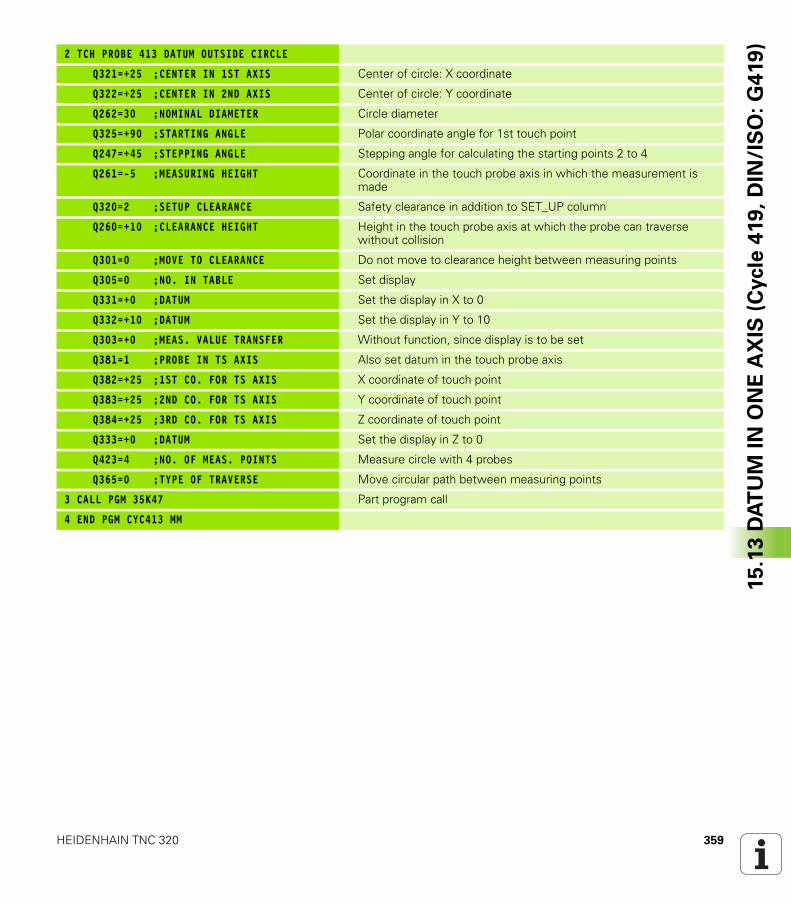
HEIDENHAIN TNC 320 359
15
.13
DA
TU
M I
N O
NE
AX
IS (
Cycle
419
, D
IN/I
SO
: G
419
)
2 TCH PROBE 413 DATUM OUTSIDE CIRCLE
Q321=+25 ;CENTER IN 1ST AXIS Center of circle: X coordinate
Q322=+25 ;CENTER IN 2ND AXIS Center of circle: Y coordinate
Q262=30 ;NOMINAL DIAMETER Circle diameter
Q325=+90 ;STARTING ANGLE Polar coordinate angle for 1st touch point
Q247=+45 ;STEPPING ANGLE Stepping angle for calculating the starting points 2 to 4
Q261=-5 ;MEASURING HEIGHT Coordinate in the touch probe axis in which the measurement is made
Q320=2 ;SETUP CLEARANCE Safety clearance in addition to SET_UP column
Q260=+10 ;CLEARANCE HEIGHT Height in the touch probe axis at which the probe can traverse without collision
Q301=0 ;MOVE TO CLEARANCE Do not move to clearance height between measuring points
Q305=0 ;NO. IN TABLE Set display
Q331=+0 ;DATUM Set the display in X to 0
Q332=+10 ;DATUM Set the display in Y to 10
Q303=+0 ;MEAS. VALUE TRANSFER Without function, since display is to be set
Q381=1 ;PROBE IN TS AXIS Also set datum in the touch probe axis
Q382=+25 ;1ST CO. FOR TS AXIS X coordinate of touch point
Q383=+25 ;2ND CO. FOR TS AXIS Y coordinate of touch point
Q384=+25 ;3RD CO. FOR TS AXIS Z coordinate of touch point
Q333=+0 ;DATUM Set the display in Z to 0
Q423=4 ;NO. OF MEAS. POINTS Measure circle with 4 probes
Q365=0 ;TYPE OF TRAVERSE Move circular path between measuring points
3 CALL PGM 35K47 Part program call
4 END PGM CYC413 MM
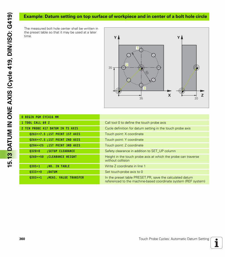
360 Touch Probe Cycles: Automatic Datum Setting
15
.13
DA
TU
M I
N O
NE
AX
IS (
Cycle
419
, D
IN/I
SO
: G
419
)Example: Datum setting on top surface of workpiece and in center of a bolt hole circle
The measured bolt hole center shall be written in the preset table so that it may be used at a later time.
0 BEGIN PGM CYC416 MM
1 TOOL CALL 69 Z Call tool 0 to define the touch probe axis
2 TCH PROBE 417 DATUM IN TS AXIS Cycle definition for datum setting in the touch probe axis
Q263=+7.5 ;1ST POINT 1ST AXIS Touch point: X coordinate
Q264=+7.5 ;1ST POINT 2ND AXIS Touch point: Y coordinate
Q294=+25 ;1ST POINT 3RD AXIS Touch point: Z coordinate
Q320=0 ;SETUP CLEARANCE Safety clearance in addition to SET_UP column
Q260=+50 ;CLEARANCE HEIGHT Height in the touch probe axis at which the probe can traverse without collision
Q305=1 ;NO. IN TABLE Write Z coordinate in line 1
Q333=+0 ;DATUM Set touch-probe axis to 0
Q303=+1 ;MEAS. VALUE TRANSFER In the preset table PRESET.PR, save the calculated datum referenced to the machine-based coordinate system (REF system)
�
�
�
�
�
�
�
��
�
�
�
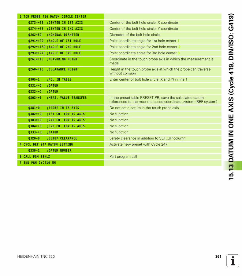
HEIDENHAIN TNC 320 361
15
.13
DA
TU
M I
N O
NE
AX
IS (
Cycle
419
, D
IN/I
SO
: G
419
)
3 TCH PROBE 416 DATUM CIRCLE CENTER
Q273=+35 ;CENTER IN 1ST AXIS Center of the bolt hole circle: X coordinate
Q274=+35 ;CENTER IN 2ND AXIS Center of the bolt hole circle: Y coordinate
Q262=50 ;NOMINAL DIAMETER Diameter of the bolt hole circle
Q291=+90 ;ANGLE OF 1ST HOLE Polar coordinate angle for 1st hole center 1
Q292=+180 ;ANGLE OF 2ND HOLE Polar coordinate angle for 2nd hole center 2
Q293=+270 ;ANGLE OF 3RD HOLE Polar coordinate angle for 3rd hole center 3
Q261=+15 ;MEASURING HEIGHT Coordinate in the touch probe axis in which the measurement is made
Q260=+10 ;CLEARANCE HEIGHT Height in the touch probe axis at which the probe can traverse without collision
Q305=1 ;NO. IN TABLE Enter center of bolt hole circle (X and Y) in line 1
Q331=+0 ;DATUM
Q332=+0 ;DATUM
Q303=+1 ;MEAS. VALUE TRANSFER In the preset table PRESET.PR, save the calculated datum referenced to the machine-based coordinate system (REF system)
Q381=0 ;PROBE IN TS AXIS Do not set a datum in the touch probe axis
Q382=+0 ;1ST CO. FOR TS AXIS No function
Q383=+0 ;2ND CO. FOR TS AXIS No function
Q384=+0 ;3RD CO. FOR TS AXIS No function
Q333=+0 ;DATUM No function
Q320=0 ;SETUP CLEARANCE Safety clearance in addition to SET_UP column
4 CYCL DEF 247 DATUM SETTING Activate new preset with Cycle 247
Q339=1 ;DATUM NUMBER
6 CALL PGM 35KLZ Part program call
7 END PGM CYC416 MM
362 Touch Probe Cycles: Automatic Datum Setting
15
.13
DA
TU
M I
N O
NE
AX
IS (
Cycle
419
, D
IN/I
SO
: G
419
)
Touch Probe Cycles:
Automatic Workpiece
Inspection
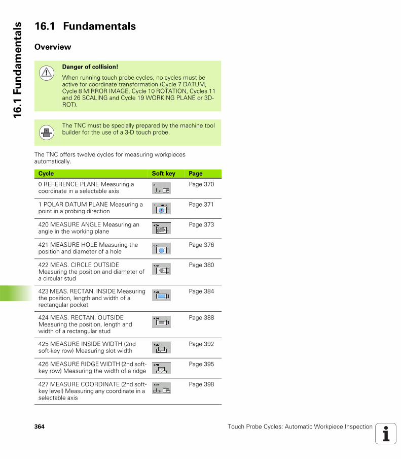
364 Touch Probe Cycles: Automatic Workpiece Inspection
16
.1 F
un
da
me
nta
ls 16.1 Fundamentals
Overview
The TNC offers twelve cycles for measuring workpieces automatically.
Danger of collision!
When running touch probe cycles, no cycles must be active for coordinate transformation (Cycle 7 DATUM, Cycle 8 MIRROR IMAGE, Cycle 10 ROTATION, Cycles 11 and 26 SCALING and Cycle 19 WORKING PLANE or 3D-ROT).
The TNC must be specially prepared by the machine tool builder for the use of a 3-D touch probe.
Cycle Soft key Page
0 REFERENCE PLANE Measuring a coordinate in a selectable axis
Page 370
1 POLAR DATUM PLANE Measuring a point in a probing direction
Page 371
420 MEASURE ANGLE Measuring an angle in the working plane
Page 373
421 MEASURE HOLE Measuring the position and diameter of a hole
Page 376
422 MEAS. CIRCLE OUTSIDE Measuring the position and diameter of a circular stud
Page 380
423 MEAS. RECTAN. INSIDE Measuring the position, length and width of a rectangular pocket
Page 384
424 MEAS. RECTAN. OUTSIDE Measuring the position, length and width of a rectangular stud
Page 388
425 MEASURE INSIDE WIDTH (2nd soft-key row) Measuring slot width
Page 392
426 MEASURE RIDGE WIDTH (2nd soft-key row) Measuring the width of a ridge
Page 395
427 MEASURE COORDINATE (2nd soft-key level) Measuring any coordinate in a selectable axis
Page 398
HEIDENHAIN TNC 320 365
16
.1 F
un
da
me
nta
ls
Recording the results of measurement
For all cycles in which you automatically measure workpieces (with the exception of Cycles 0 and 1), you can have the TNC record the measurement results. In the respective probing cycle you can define if the TNC is to
Save the measuring log to a file.Interrupt the program run and display the measuring log on the screen.Create no measuring log.
If you want to save the measuring log to a file, the TNC, by default, saves the data as an ASCII file in the directory TNC:\..
430 MEAS. BOLT HOLE CIRC. (2nd soft-key level) Measuring position and diameter of a bolt hole circle
Page 401
431 MEASURE PLANE (2nd soft-key level) Measuring the A and B axis angles of a plane
Page 405
Cycle Soft key Page
Use the HEIDENHAIN data transfer software TNCremo if you wish to output the measuring log via the data interface.
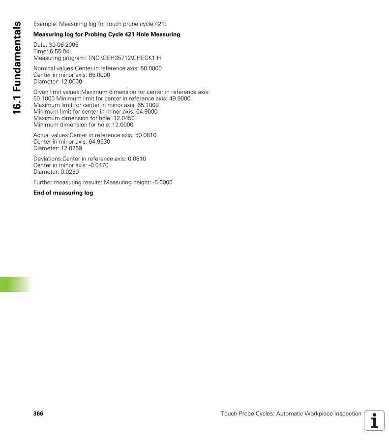
366 Touch Probe Cycles: Automatic Workpiece Inspection
16
.1 F
un
da
me
nta
ls Example: Measuring log for touch probe cycle 421:
Measuring log for Probing Cycle 421 Hole Measuring
Date: 30-06-2005 Time: 6:55:04 Measuring program: TNC:\GEH35712\CHECK1.H
Nominal values:Center in reference axis: 50.0000 Center in minor axis: 65.0000 Diameter: 12.0000
Given limit values:Maximum dimension for center in reference axis: 50.1000 Minimum limit for center in reference axis: 49.9000 Maximum limit for center in minor axis: 65.1000 Minimum limit for center in minor axis: 64.9000 Maximum dimension for hole: 12.0450 Minimum dimension for hole: 12.0000
Actual values:Center in reference axis: 50.0810 Center in minor axis: 64.9530 Diameter: 12.0259
Deviations:Center in reference axis: 0.0810 Center in minor axis: -0.0470 Diameter: 0.0259
Further measuring results: Measuring height: -5.0000
End of measuring log
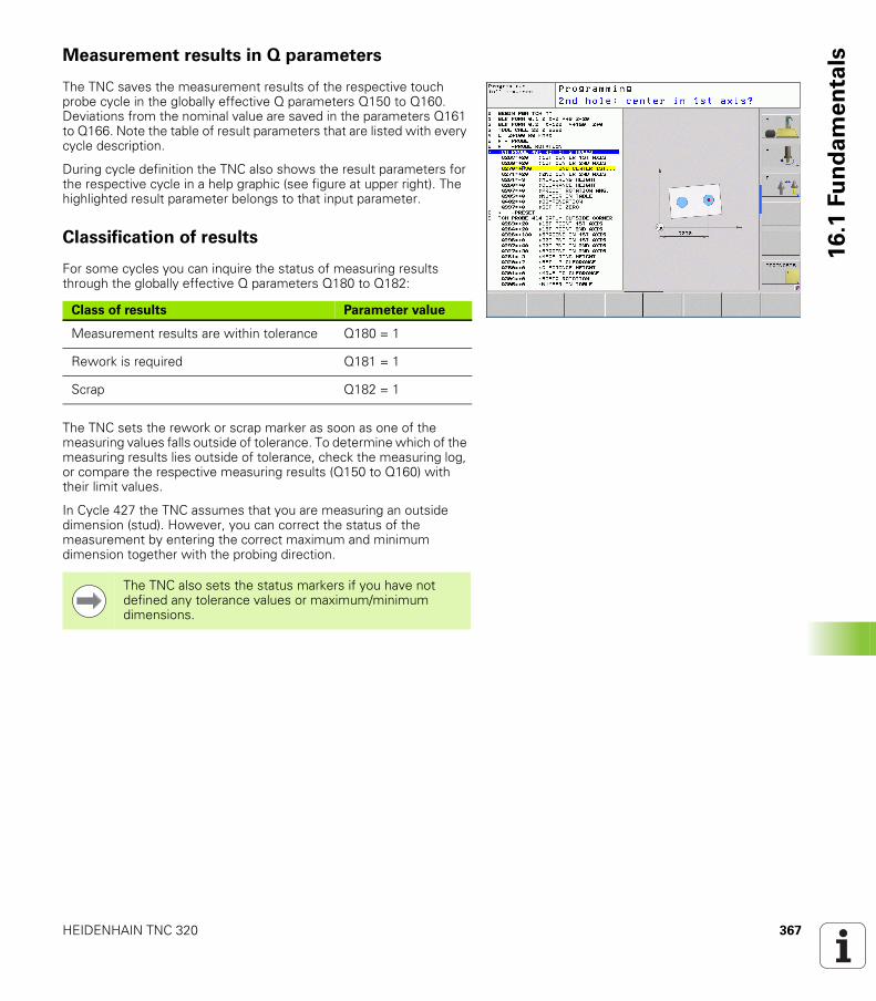
HEIDENHAIN TNC 320 367
16
.1 F
un
da
me
nta
lsMeasurement results in Q parameters
The TNC saves the measurement results of the respective touch probe cycle in the globally effective Q parameters Q150 to Q160. Deviations from the nominal value are saved in the parameters Q161 to Q166. Note the table of result parameters that are listed with every cycle description.
During cycle definition the TNC also shows the result parameters for the respective cycle in a help graphic (see figure at upper right). The highlighted result parameter belongs to that input parameter.
Classification of results
For some cycles you can inquire the status of measuring results through the globally effective Q parameters Q180 to Q182:
The TNC sets the rework or scrap marker as soon as one of the measuring values falls outside of tolerance. To determine which of the measuring results lies outside of tolerance, check the measuring log, or compare the respective measuring results (Q150 to Q160) with their limit values.
In Cycle 427 the TNC assumes that you are measuring an outside dimension (stud). However, you can correct the status of the measurement by entering the correct maximum and minimum dimension together with the probing direction.
Class of results Parameter value
Measurement results are within tolerance Q180 = 1
Rework is required Q181 = 1
Scrap Q182 = 1
The TNC also sets the status markers if you have not defined any tolerance values or maximum/minimum dimensions.
368 Touch Probe Cycles: Automatic Workpiece Inspection
16
.1 F
un
da
me
nta
ls Tolerance monitoring
For most of the cycles for workpiece inspection you can have the TNC perform tolerance monitoring. This requires that you define the necessary limit values during cycle definition. If you do not wish to monitor for tolerances, simply leave the 0 (the default value) in the monitoring parameters.
Tool monitoring
For some cycles for workpiece inspection you can have the TNC perform tool monitoring. The TNC then monitors whether
The tool radius should be compensated because of the deviations from the nominal value (values in Q16x).The deviations from the nominal value (values in Q16x) are greater than the tool breakage tolerance.
Tool compensation
The TNC always compensates the tool radius in the DR column of the tool table, even if the measured deviation lies within the given tolerance. You can inquire whether re-working is necessary via Parameter Q181 in the NC program (Q181=1: must be reworked).
For Cycle 427:
If an axis of the active working plane is defined as measuring axis (Q272 = 1 or 2), the TNC compensates the tool radius as described above. From the defined traversing direction (Q267) the TNC determines the direction of compensation.If the touch probe axis is defined as measuring axis (Q272 = 3), the TNC compensates the tool length.
This function works only:
If the tool table is active.If tool monitoring is switched on in the cycle (enter a tool name or Q330 unequal to 0). Select the tool name input by soft key. The TNC no longer displays the right single quotation mark.
If you perform several compensation measurements, the TNC adds the respective measured deviation to the value stored in the tool table.
HEIDENHAIN TNC 320 369
16
.1 F
un
da
me
nta
lsTool breakage monitoring
The TNC will output an error message and stop program run if the measured deviation is greater than the breakage tolerance of the tool. At the same time the tool will be deactivated in the tool table (column TL = L).
Reference system for measurement results
The TNC transfers all the measurement results to the result parameters and the protocol file in the active coordinate system, or as the case may be, the shifted or/and rotated/tilted coordinate system.
This function works only:
If the tool table is active.If tool monitoring is switched on in the cycle (enter Q330 not equal to 0).If the breakage tolerance RBREAK for the tool number entered in the table is greater than 0 (see also the User's Manual, section 5.2 “Tool Data”).
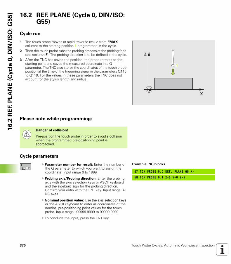
370 Touch Probe Cycles: Automatic Workpiece Inspection
16
.2 R
EF.
PL
AN
E (
Cycle
0,
DIN
/IS
O:
G5
5) 16.2 REF. PLANE (Cycle 0, DIN/ISO:
G55)
Cycle run
1 The touch probe moves at rapid traverse (value from FMAX column) to the starting position 1 programmed in the cycle.
2 Then the touch probe runs the probing process at the probing feed rate (column F). The probing direction is to be defined in the cycle.
3 After the TNC has saved the position, the probe retracts to the starting point and saves the measured coordinate in a Q parameter. The TNC also stores the coordinates of the touch probe position at the time of the triggering signal in the parameters Q115 to Q119. For the values in these parameters the TNC does not account for the stylus length and radius.
Please note while programming:
Cycle parameters
U Parameter number for result: Enter the number of the Q parameter to which you want to assign the coordinate. Input range 0 to 1999
U Probing axis/Probing direction: Enter the probing axis with the axis selection keys or ASCII keyboard and the algebraic sign for the probing direction. Confirm your entry with the ENT key. Input range: All NC axes
U Nominal position value: Use the axis selection keys or the ASCII keyboard to enter all coordinates of the nominal pre-positioning point values for the touch probe. Input range –99999.9999 to 99999.9999
U To conclude the input, press the ENT key.
�
�
�
Danger of collision!
Pre-position the touch probe in order to avoid a collision when the programmed pre-positioning point is approached.
Example: NC blocks
67 TCH PROBE 0.0 REF. PLANE Q5 X-
68 TCH PROBE 0.1 X+5 Y+0 Z-5

HEIDENHAIN TNC 320 371
16
.3 P
OL
AR
RE
FE
RE
NC
E P
LA
NE
(C
ycle
1)16.3 POLAR REFERENCE PLANE
(Cycle 1)
Cycle run
Touch Probe Cycle 1 measures any position on the workpiece in any direction.
1 The touch probe moves at rapid traverse (value from FMAX column) to the starting position 1 programmed in the cycle.
2 Then the touch probe runs the probing process at the probing feed rate (column F). During probing the TNC moves simultaneously in 2 axes (depending on the probing angle). The scanning direction is defined by the polar angle entered in the cycle.
3 After the TNC has saved the position, the probe returns to the starting point. The TNC also stores the coordinates of the touch probe position at the time of the triggering signal in parameters Q115 to Q119.
Please note while programming:
�
�
�
Danger of collision!
Pre-position the touch probe in order to avoid a collision when the programmed pre-positioning point is approached.
The probing axis defined in the cycle specifies the probing plane:
Probing axis X: X/Y plane
Probing axis Y: Y/Z plane
Probing axis Z: Z/X plane
372 Touch Probe Cycles: Automatic Workpiece Inspection
16
.3 P
OL
AR
RE
FE
RE
NC
E P
LA
NE
(C
ycle
1) Cycle parameters
U Probing axis: Enter the probing axis with the axis selection keys or ASCII keyboard. Confirm your entry with the ENT key. Input range: X, Y or Z
U Probing angle: Angle, measured from the probing axis, at which the touch probe is to move. Input range –180.0000 to 180.0000
U Nominal position value: Use the axis selection keys or the ASCII keyboard to enter all coordinates of the nominal pre-positioning point values for the touch probe. Input range –99999.9999 to 99999.9999
U To conclude the input, press the ENT key.
Example: NC blocks
67 TCH PROBE 1.0 POLAR REFERENCE PLANE
68 TCH PROBE 1.1 X ANGLE: +30
69 TCH PROBE 1.2 X+5 Y+0 Z-5
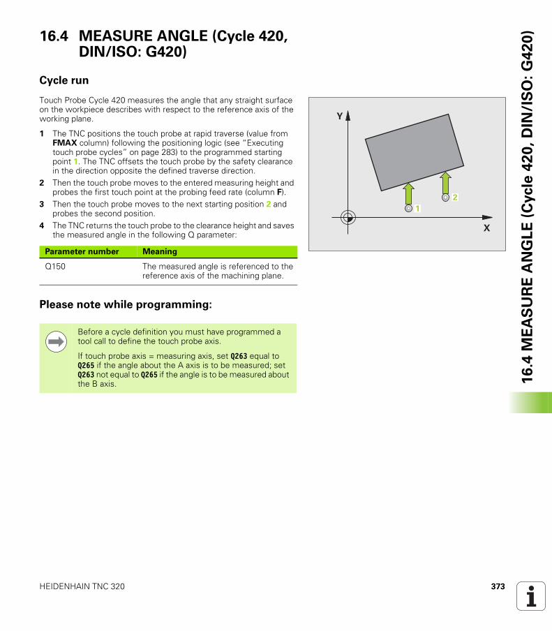
HEIDENHAIN TNC 320 373
16
.4 M
EA
SU
RE
AN
GL
E (
Cycle
42
0,
DIN
/IS
O:
G4
20
)16.4 MEASURE ANGLE (Cycle 420, DIN/ISO: G420)
Cycle run
Touch Probe Cycle 420 measures the angle that any straight surface on the workpiece describes with respect to the reference axis of the working plane.
1 The TNC positions the touch probe at rapid traverse (value from FMAX column) following the positioning logic (see “Executing touch probe cycles” on page 283) to the programmed starting point 1. The TNC offsets the touch probe by the safety clearance in the direction opposite the defined traverse direction.
2 Then the touch probe moves to the entered measuring height and probes the first touch point at the probing feed rate (column F).
3 Then the touch probe moves to the next starting position 2 and probes the second position.
4 The TNC returns the touch probe to the clearance height and saves the measured angle in the following Q parameter:
Please note while programming:
�
�
��
Parameter number Meaning
Q150 The measured angle is referenced to the reference axis of the machining plane.
Before a cycle definition you must have programmed a tool call to define the touch probe axis.
If touch probe axis = measuring axis, set Q263 equal to Q265 if the angle about the A axis is to be measured; set Q263 not equal to Q265 if the angle is to be measured about the B axis.
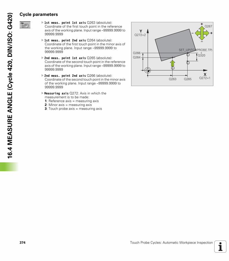
374 Touch Probe Cycles: Automatic Workpiece Inspection
16
.4 M
EA
SU
RE
AN
GL
E (
Cycle
42
0,
DIN
/IS
O:
G4
20
) Cycle parameters
U 1st meas. point 1st axis Q263 (absolute): Coordinate of the first touch point in the reference axis of the working plane. Input range –99999.9999 to 99999.9999
U 1st meas. point 2nd axis Q264 (absolute): Coordinate of the first touch point in the minor axis of the working plane. Input range –99999.9999 to 99999.9999
U 2nd meas. point 1st axis Q265 (absolute): Coordinate of the second touch point in the reference axis of the working plane. Input range –99999.9999 to 99999.9999
U 2nd meas. point 2nd axis Q266 (absolute): Coordinate of the second touch point in the minor axis of the working plane. Input range –99999.9999 to 99999.9999
U Measuring axis Q272: Axis in which the measurement is to be made: 1: Reference axis = measuring axis 2: Minor axis = measuring axis 3: Touch probe axis = measuring axis
�
�
��������
���� ���������
������
!
"
" !
����
�& '(!� �)!�*�&� !�����������������������������������������������������
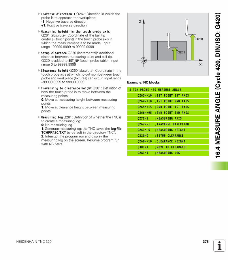
HEIDENHAIN TNC 320 375
16
.4 M
EA
SU
RE
AN
GL
E (
Cycle
42
0,
DIN
/IS
O:
G4
20
)U Traverse direction 1 Q267: Direction in which the probe is to approach the workpiece: -1: Negative traverse direction +1: Positive traverse direction
U Measuring height in the touch probe axis Q261 (absolute): Coordinate of the ball tip center (= touch point) in the touch probe axis in which the measurement is to be made. Input range –99999.9999 to 99999.9999
U Setup clearance Q320 (incremental): Additional distance between measuring point and ball tip. Q320 is added to SET_UP (touch probe table). Input range 0 to 99999.9999
U Clearance height Q260 (absolute): Coordinate in the touch probe axis at which no collision between touch probe and workpiece (fixtures) can occur. Input range –99999.9999 to 99999.9999
U Traversing to clearance height Q301: Definition of how the touch probe is to move between the measuring points: 0: Move at measuring height between measuring points1: Move at clearance height between measuring points
U Measuring log Q281: Definition of whether the TNC is to create a measuring log: 0: No measuring log1: Generate measuring log: the TNC saves the log file TCHPR420.TXT by default in the directory TNC:\2: Interrupt the program run and display the measuring log on the screen. Resume program run with NC Start.
Example: NC blocks
5 TCH PROBE 420 MEASURE ANGLE
Q263=+10 ;1ST POINT 1ST AXIS
Q264=+10 ;1ST POINT 2ND AXIS
Q265=+15 ;2ND POINT 1ST AXIS
Q266=+95 ;2ND POINT 2ND AXIS
Q272=1 ;MEASURING AXIS
Q267=-1 ;TRAVERSE DIRECTION
Q261=-5 ;MEASURING HEIGHT
Q320=0 ;SETUP CLEARANCE
Q260=+10 ;CLEARANCE HEIGHT
Q301=1 ;MOVE TO CLEARANCE
Q281=1 ;MEASURING LOG
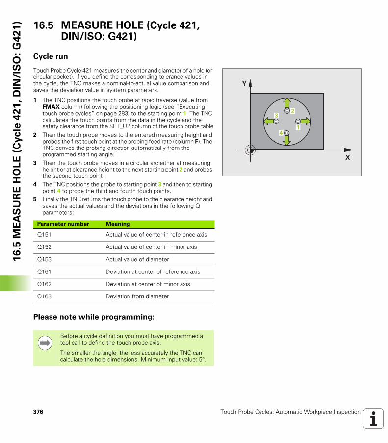
376 Touch Probe Cycles: Automatic Workpiece Inspection
16
.5 M
EA
SU
RE
HO
LE
(C
ycle
42
1,
DIN
/IS
O:
G4
21
) 16.5 MEASURE HOLE (Cycle 421, DIN/ISO: G421)
Cycle run
Touch Probe Cycle 421 measures the center and diameter of a hole (or circular pocket). If you define the corresponding tolerance values in the cycle, the TNC makes a nominal-to-actual value comparison and saves the deviation value in system parameters.
1 The TNC positions the touch probe at rapid traverse (value from FMAX column) following the positioning logic (see “Executing touch probe cycles” on page 283) to the starting point 1. The TNC calculates the touch points from the data in the cycle and the safety clearance from the SET_UP column of the touch probe table
2 Then the touch probe moves to the entered measuring height and probes the first touch point at the probing feed rate (column F). The TNC derives the probing direction automatically from the programmed starting angle.
3 Then the touch probe moves in a circular arc either at measuring height or at clearance height to the next starting point 2 and probes the second touch point.
4 The TNC positions the probe to starting point 3 and then to starting point 4 to probe the third and fourth touch points.
5 Finally the TNC returns the touch probe to the clearance height and saves the actual values and the deviations in the following Q parameters:
Please note while programming:
�
�
�
��
Parameter number Meaning
Q151 Actual value of center in reference axis
Q152 Actual value of center in minor axis
Q153 Actual value of diameter
Q161 Deviation at center of reference axis
Q162 Deviation at center of minor axis
Q163 Deviation from diameter
Before a cycle definition you must have programmed a tool call to define the touch probe axis.
The smaller the angle, the less accurately the TNC can calculate the hole dimensions. Minimum input value: 5°.
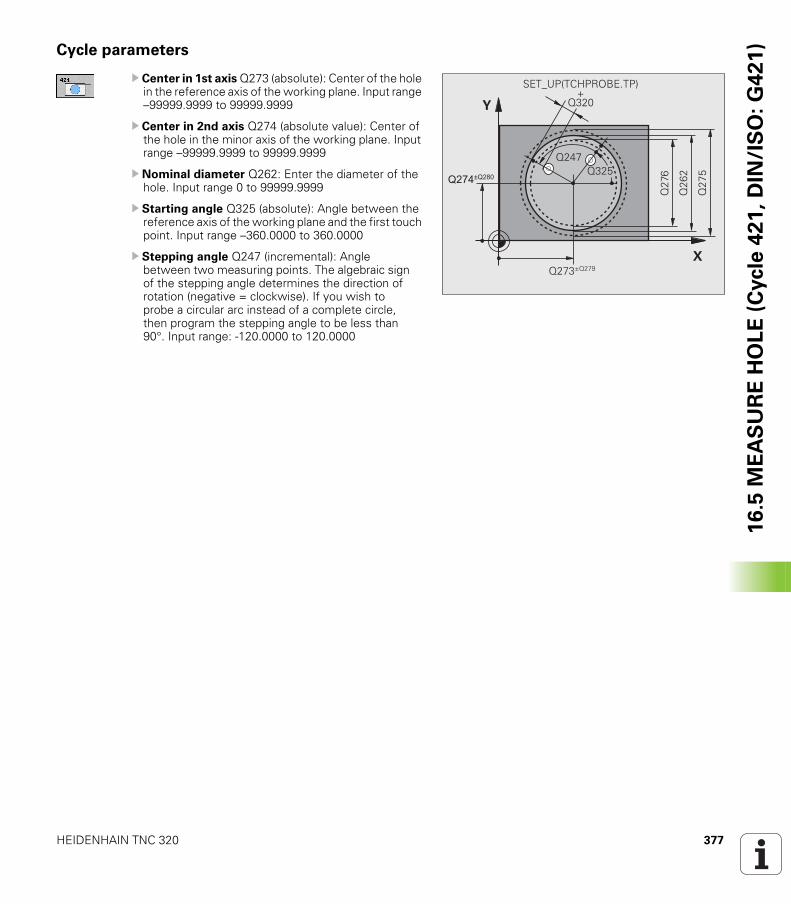
HEIDENHAIN TNC 320 377
16
.5 M
EA
SU
RE
HO
LE
(C
ycle
42
1,
DIN
/IS
O:
G4
21
)Cycle parameters
U Center in 1st axis Q273 (absolute): Center of the hole in the reference axis of the working plane. Input range –99999.9999 to 99999.9999
U Center in 2nd axis Q274 (absolute value): Center of the hole in the minor axis of the working plane. Input range –99999.9999 to 99999.9999
U Nominal diameter Q262: Enter the diameter of the hole. Input range 0 to 99999.9999
U Starting angle Q325 (absolute): Angle between the reference axis of the working plane and the first touch point. Input range –360.0000 to 360.0000
U Stepping angle Q247 (incremental): Angle between two measuring points. The algebraic sign of the stepping angle determines the direction of rotation (negative = clockwise). If you wish to probe a circular arc instead of a complete circle, then program the stepping angle to be less than 90°. Input range: -120.0000 to 120.0000
�
�
���������
����,����
�������
����
���
�
���
�& '(!� �)!�*�&� !��
����
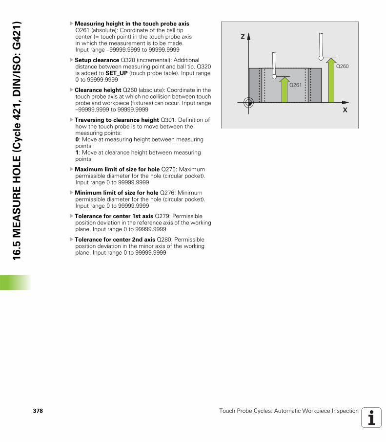
378 Touch Probe Cycles: Automatic Workpiece Inspection
16
.5 M
EA
SU
RE
HO
LE
(C
ycle
42
1,
DIN
/IS
O:
G4
21
) UMeasuring height in the touch probe axis Q261 (absolute): Coordinate of the ball tip center (= touch point) in the touch probe axis in which the measurement is to be made. Input range –99999.9999 to 99999.9999
U Setup clearance Q320 (incremental): Additional distance between measuring point and ball tip. Q320 is added to SET_UP (touch probe table). Input range 0 to 99999.9999
U Clearance height Q260 (absolute): Coordinate in the touch probe axis at which no collision between touch probe and workpiece (fixtures) can occur. Input range –99999.9999 to 99999.9999
U Traversing to clearance height Q301: Definition of how the touch probe is to move between the measuring points: 0: Move at measuring height between measuring points1: Move at clearance height between measuring points
UMaximum limit of size for hole Q275: Maximum permissible diameter for the hole (circular pocket). Input range 0 to 99999.9999
UMinimum limit of size for hole Q276: Minimum permissible diameter for the hole (circular pocket). Input range 0 to 99999.9999
U Tolerance for center 1st axis Q279: Permissible position deviation in the reference axis of the working plane. Input range 0 to 99999.9999
U Tolerance for center 2nd axis Q280: Permissible position deviation in the minor axis of the working plane. Input range 0 to 99999.9999
�
�
����
����
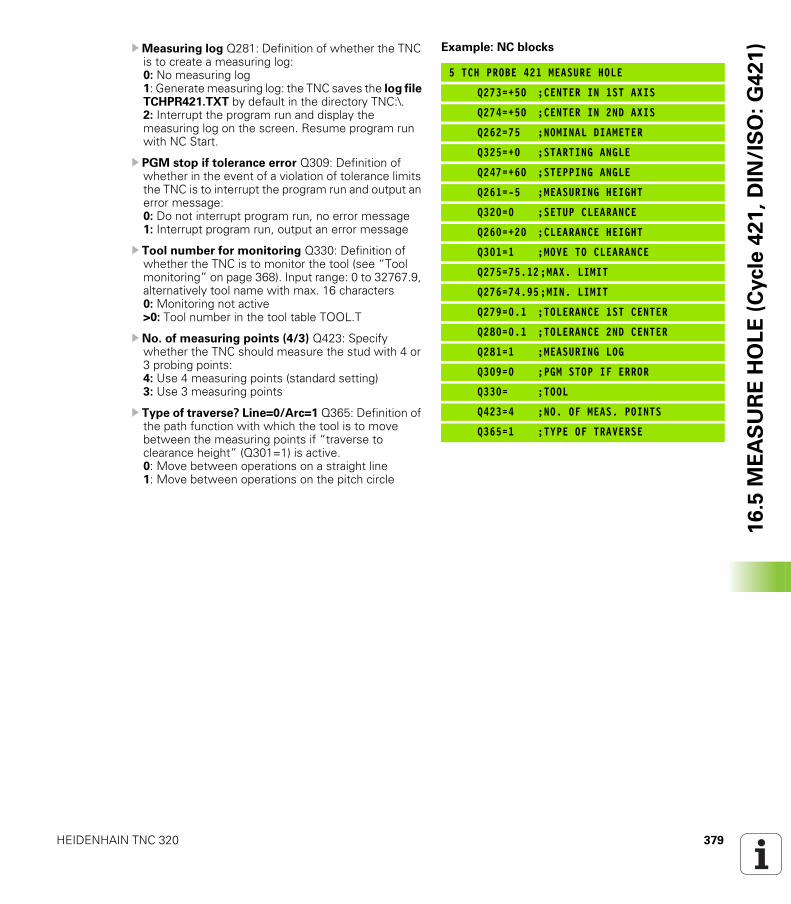
HEIDENHAIN TNC 320 379
16
.5 M
EA
SU
RE
HO
LE
(C
ycle
42
1,
DIN
/IS
O:
G4
21
)UMeasuring log Q281: Definition of whether the TNC is to create a measuring log: 0: No measuring log1: Generate measuring log: the TNC saves the log file TCHPR421.TXT by default in the directory TNC:\.2: Interrupt the program run and display the measuring log on the screen. Resume program run with NC Start.
U PGM stop if tolerance error Q309: Definition of whether in the event of a violation of tolerance limits the TNC is to interrupt the program run and output an error message: 0: Do not interrupt program run, no error message1: Interrupt program run, output an error message
U Tool number for monitoring Q330: Definition of whether the TNC is to monitor the tool (see “Tool monitoring” on page 368). Input range: 0 to 32767.9, alternatively tool name with max. 16 characters0: Monitoring not active >0: Tool number in the tool table TOOL.T
U No. of measuring points (4/3) Q423: Specify whether the TNC should measure the stud with 4 or 3 probing points: 4: Use 4 measuring points (standard setting) 3: Use 3 measuring points
U Type of traverse? Line=0/Arc=1 Q365: Definition of the path function with which the tool is to move between the measuring points if “traverse to clearance height” (Q301=1) is active.0: Move between operations on a straight line1: Move between operations on the pitch circle
Example: NC blocks
5 TCH PROBE 421 MEASURE HOLE
Q273=+50 ;CENTER IN 1ST AXIS
Q274=+50 ;CENTER IN 2ND AXIS
Q262=75 ;NOMINAL DIAMETER
Q325=+0 ;STARTING ANGLE
Q247=+60 ;STEPPING ANGLE
Q261=-5 ;MEASURING HEIGHT
Q320=0 ;SETUP CLEARANCE
Q260=+20 ;CLEARANCE HEIGHT
Q301=1 ;MOVE TO CLEARANCE
Q275=75.12;MAX. LIMIT
Q276=74.95;MIN. LIMIT
Q279=0.1 ;TOLERANCE 1ST CENTER
Q280=0.1 ;TOLERANCE 2ND CENTER
Q281=1 ;MEASURING LOG
Q309=0 ;PGM STOP IF ERROR
Q330= ;TOOL
Q423=4 ;NO. OF MEAS. POINTS
Q365=1 ;TYPE OF TRAVERSE
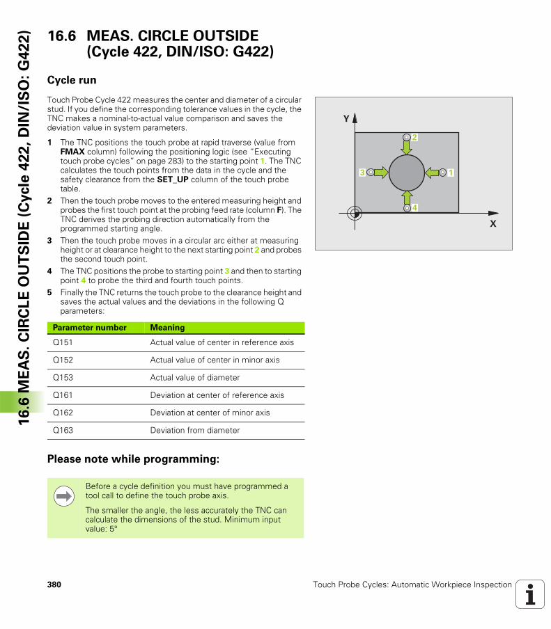
380 Touch Probe Cycles: Automatic Workpiece Inspection
16
.6 M
EA
S.
CIR
CL
E O
UT
SID
E (
Cycle
42
2,
DIN
/IS
O:
G4
22
) 16.6 MEAS. CIRCLE OUTSIDE (Cycle 422, DIN/ISO: G422)
Cycle run
Touch Probe Cycle 422 measures the center and diameter of a circular stud. If you define the corresponding tolerance values in the cycle, the TNC makes a nominal-to-actual value comparison and saves the deviation value in system parameters.
1 The TNC positions the touch probe at rapid traverse (value from FMAX column) following the positioning logic (see “Executing touch probe cycles” on page 283) to the starting point 1. The TNC calculates the touch points from the data in the cycle and the safety clearance from the SET_UP column of the touch probe table.
2 Then the touch probe moves to the entered measuring height and probes the first touch point at the probing feed rate (column F). The TNC derives the probing direction automatically from the programmed starting angle.
3 Then the touch probe moves in a circular arc either at measuring height or at clearance height to the next starting point 2 and probes the second touch point.
4 The TNC positions the probe to starting point 3 and then to starting point 4 to probe the third and fourth touch points.
5 Finally the TNC returns the touch probe to the clearance height and saves the actual values and the deviations in the following Q parameters:
Please note while programming:
�
�
�
�
�
Parameter number Meaning
Q151 Actual value of center in reference axis
Q152 Actual value of center in minor axis
Q153 Actual value of diameter
Q161 Deviation at center of reference axis
Q162 Deviation at center of minor axis
Q163 Deviation from diameter
Before a cycle definition you must have programmed a tool call to define the touch probe axis.
The smaller the angle, the less accurately the TNC can calculate the dimensions of the stud. Minimum input value: 5°
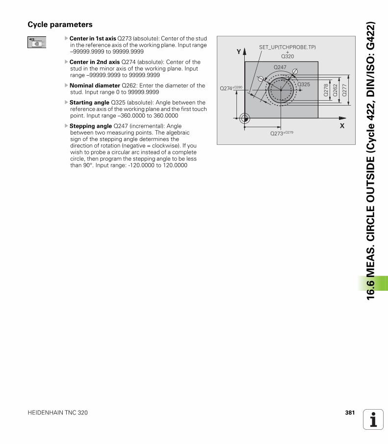
HEIDENHAIN TNC 320 381
16
.6 M
EA
S.
CIR
CL
E O
UT
SID
E (
Cycle
42
2,
DIN
/IS
O:
G4
22
)Cycle parameters
U Center in 1st axis Q273 (absolute): Center of the stud in the reference axis of the working plane. Input range –99999.9999 to 99999.9999
U Center in 2nd axis Q274 (absolute): Center of the stud in the minor axis of the working plane. Input range –99999.9999 to 99999.9999
U Nominal diameter Q262: Enter the diameter of the stud. Input range 0 to 99999.9999
U Starting angle Q325 (absolute): Angle between the reference axis of the working plane and the first touch point. Input range –360.0000 to 360.0000
U Stepping angle Q247 (incremental): Angle between two measuring points. The algebraic sign of the stepping angle determines the direction of rotation (negative = clockwise). If you wish to probe a circular arc instead of a complete circle, then program the stepping angle to be less than 90°. Input range: -120.0000 to 120.0000
�
�
���
����
���
���
�
���
�
����,���
����,����
�& '(!� �)!�*�&� !��
����
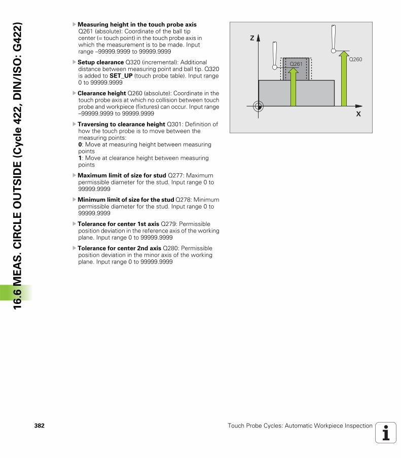
382 Touch Probe Cycles: Automatic Workpiece Inspection
16
.6 M
EA
S.
CIR
CL
E O
UT
SID
E (
Cycle
42
2,
DIN
/IS
O:
G4
22
) UMeasuring height in the touch probe axis Q261 (absolute): Coordinate of the ball tip center (= touch point) in the touch probe axis in which the measurement is to be made. Input range –99999.9999 to 99999.9999
U Setup clearance Q320 (incremental): Additional distance between measuring point and ball tip. Q320 is added to SET_UP (touch probe table). Input range 0 to 99999.9999
U Clearance height Q260 (absolute): Coordinate in the touch probe axis at which no collision between touch probe and workpiece (fixtures) can occur. Input range –99999.9999 to 99999.9999
U Traversing to clearance height Q301: Definition of how the touch probe is to move between the measuring points: 0: Move at measuring height between measuring points1: Move at clearance height between measuring points
UMaximum limit of size for stud Q277: Maximum permissible diameter for the stud. Input range 0 to 99999.9999
UMinimum limit of size for the stud Q278: Minimum permissible diameter for the stud. Input range 0 to 99999.9999
U Tolerance for center 1st axis Q279: Permissible position deviation in the reference axis of the working plane. Input range 0 to 99999.9999
U Tolerance for center 2nd axis Q280: Permissible position deviation in the minor axis of the working plane. Input range 0 to 99999.9999
�
�
��������
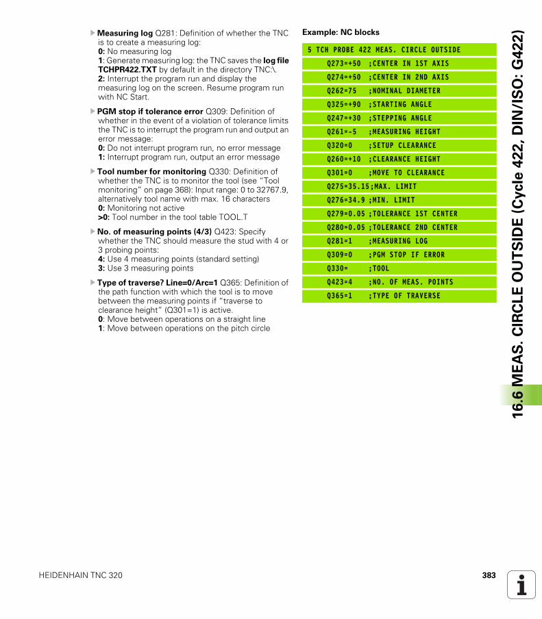
HEIDENHAIN TNC 320 383
16
.6 M
EA
S.
CIR
CL
E O
UT
SID
E (
Cycle
42
2,
DIN
/IS
O:
G4
22
)UMeasuring log Q281: Definition of whether the TNC is to create a measuring log: 0: No measuring log1: Generate measuring log: the TNC saves the log file TCHPR422.TXT by default in the directory TNC:\.2: Interrupt the program run and display the measuring log on the screen. Resume program run with NC Start.
U PGM stop if tolerance error Q309: Definition of whether in the event of a violation of tolerance limits the TNC is to interrupt the program run and output an error message: 0: Do not interrupt program run, no error message1: Interrupt program run, output an error message
U Tool number for monitoring Q330: Definition of whether the TNC is to monitor the tool (see “Tool monitoring” on page 368): Input range: 0 to 32767.9, alternatively tool name with max. 16 characters0: Monitoring not active>0: Tool number in the tool table TOOL.T
U No. of measuring points (4/3) Q423: Specify whether the TNC should measure the stud with 4 or 3 probing points: 4: Use 4 measuring points (standard setting) 3: Use 3 measuring points
U Type of traverse? Line=0/Arc=1 Q365: Definition of the path function with which the tool is to move between the measuring points if “traverse to clearance height” (Q301=1) is active.0: Move between operations on a straight line1: Move between operations on the pitch circle
Example: NC blocks
5 TCH PROBE 422 MEAS. CIRCLE OUTSIDE
Q273=+50 ;CENTER IN 1ST AXIS
Q274=+50 ;CENTER IN 2ND AXIS
Q262=75 ;NOMINAL DIAMETER
Q325=+90 ;STARTING ANGLE
Q247=+30 ;STEPPING ANGLE
Q261=-5 ;MEASURING HEIGHT
Q320=0 ;SETUP CLEARANCE
Q260=+10 ;CLEARANCE HEIGHT
Q301=0 ;MOVE TO CLEARANCE
Q275=35.15;MAX. LIMIT
Q276=34.9 ;MIN. LIMIT
Q279=0.05 ;TOLERANCE 1ST CENTER
Q280=0.05 ;TOLERANCE 2ND CENTER
Q281=1 ;MEASURING LOG
Q309=0 ;PGM STOP IF ERROR
Q330= ;TOOL
Q423=4 ;NO. OF MEAS. POINTS
Q365=1 ;TYPE OF TRAVERSE
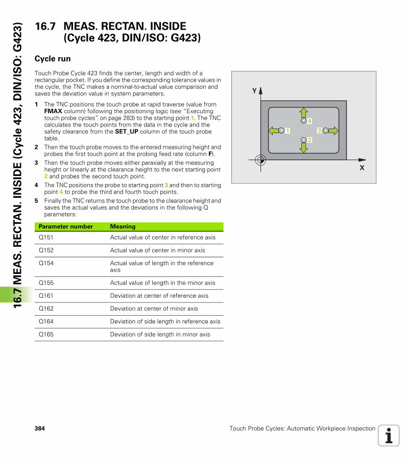
384 Touch Probe Cycles: Automatic Workpiece Inspection
16
.7 M
EA
S.
RE
CTA
N.
INS
IDE
(C
ycle
42
3,
DIN
/IS
O:
G4
23
) 16.7 MEAS. RECTAN. INSIDE (Cycle 423, DIN/ISO: G423)
Cycle run
Touch Probe Cycle 423 finds the center, length and width of a rectangular pocket. If you define the corresponding tolerance values in the cycle, the TNC makes a nominal-to-actual value comparison and saves the deviation value in system parameters.
1 The TNC positions the touch probe at rapid traverse (value from FMAX column) following the positioning logic (see “Executing touch probe cycles” on page 283) to the starting point 1. The TNC calculates the touch points from the data in the cycle and the safety clearance from the SET_UP column of the touch probe table.
2 Then the touch probe moves to the entered measuring height and probes the first touch point at the probing feed rate (column F).
3 Then the touch probe moves either paraxially at the measuring height or linearly at the clearance height to the next starting point 2 and probes the second touch point.
4 The TNC positions the probe to starting point 3 and then to starting point 4 to probe the third and fourth touch points.
5 Finally the TNC returns the touch probe to the clearance height and saves the actual values and the deviations in the following Q parameters:
�
�
�
�
�
Parameter number Meaning
Q151 Actual value of center in reference axis
Q152 Actual value of center in minor axis
Q154 Actual value of length in the reference axis
Q155 Actual value of length in the minor axis
Q161 Deviation at center of reference axis
Q162 Deviation at center of minor axis
Q164 Deviation of side length in reference axis
Q165 Deviation of side length in minor axis
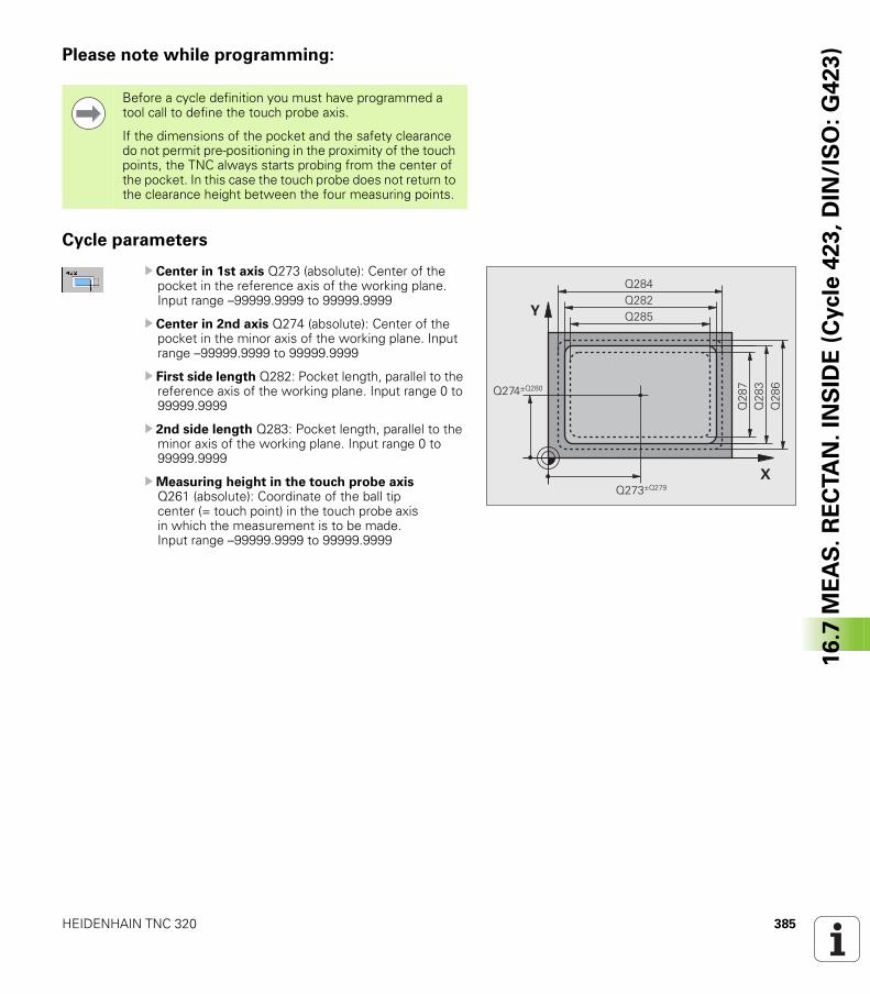
HEIDENHAIN TNC 320 385
16
.7 M
EA
S.
RE
CTA
N.
INS
IDE
(C
ycle
42
3,
DIN
/IS
O:
G4
23
)Please note while programming:
Cycle parameters
U Center in 1st axis Q273 (absolute): Center of the pocket in the reference axis of the working plane. Input range –99999.9999 to 99999.9999
U Center in 2nd axis Q274 (absolute): Center of the pocket in the minor axis of the working plane. Input range –99999.9999 to 99999.9999
U First side length Q282: Pocket length, parallel to the reference axis of the working plane. Input range 0 to 99999.9999
U 2nd side length Q283: Pocket length, parallel to the minor axis of the working plane. Input range 0 to 99999.9999
UMeasuring height in the touch probe axis Q261 (absolute): Coordinate of the ball tip center (= touch point) in the touch probe axis in which the measurement is to be made. Input range –99999.9999 to 99999.9999
Before a cycle definition you must have programmed a tool call to define the touch probe axis.
If the dimensions of the pocket and the safety clearance do not permit pre-positioning in the proximity of the touch points, the TNC always starts probing from the center of the pocket. In this case the touch probe does not return to the clearance height between the four measuring points.
�
�
���
��
����,���
����,����
���
���
������
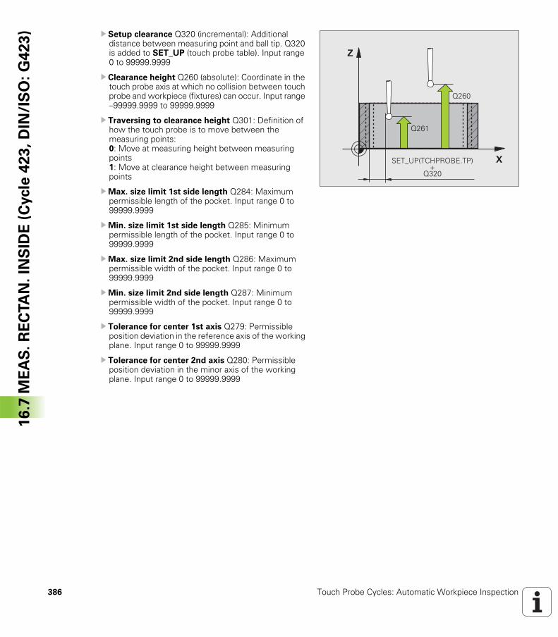
386 Touch Probe Cycles: Automatic Workpiece Inspection
16
.7 M
EA
S.
RE
CTA
N.
INS
IDE
(C
ycle
42
3,
DIN
/IS
O:
G4
23
) U Setup clearance Q320 (incremental): Additional distance between measuring point and ball tip. Q320 is added to SET_UP (touch probe table). Input range 0 to 99999.9999
U Clearance height Q260 (absolute): Coordinate in the touch probe axis at which no collision between touch probe and workpiece (fixtures) can occur. Input range –99999.9999 to 99999.9999
U Traversing to clearance height Q301: Definition of how the touch probe is to move between the measuring points: 0: Move at measuring height between measuring points1: Move at clearance height between measuring points
UMax. size limit 1st side length Q284: Maximum permissible length of the pocket. Input range 0 to 99999.9999
UMin. size limit 1st side length Q285: Minimum permissible length of the pocket. Input range 0 to 99999.9999
UMax. size limit 2nd side length Q286: Maximum permissible width of the pocket. Input range 0 to 99999.9999
UMin. size limit 2nd side length Q287: Minimum permissible width of the pocket. Input range 0 to 99999.9999
U Tolerance for center 1st axis Q279: Permissible position deviation in the reference axis of the working plane. Input range 0 to 99999.9999
U Tolerance for center 2nd axis Q280: Permissible position deviation in the minor axis of the working plane. Input range 0 to 99999.9999
�
�
����
����
�& '(!� �)!�*�&� !��
����
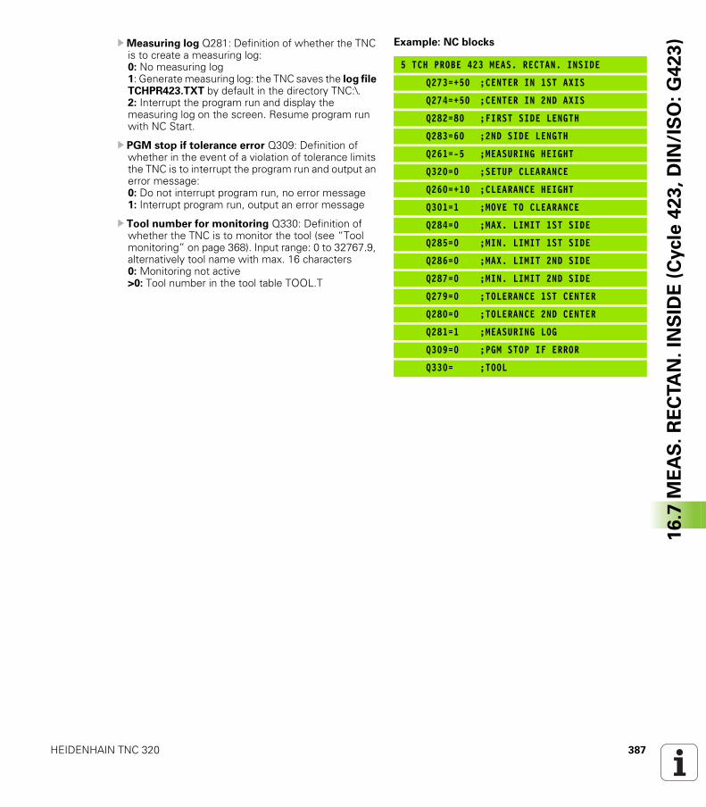
HEIDENHAIN TNC 320 387
16
.7 M
EA
S.
RE
CTA
N.
INS
IDE
(C
ycle
42
3,
DIN
/IS
O:
G4
23
)UMeasuring log Q281: Definition of whether the TNC is to create a measuring log: 0: No measuring log1: Generate measuring log: the TNC saves the log file TCHPR423.TXT by default in the directory TNC:\.2: Interrupt the program run and display the measuring log on the screen. Resume program run with NC Start.
U PGM stop if tolerance error Q309: Definition of whether in the event of a violation of tolerance limits the TNC is to interrupt the program run and output an error message: 0: Do not interrupt program run, no error message1: Interrupt program run, output an error message
U Tool number for monitoring Q330: Definition of whether the TNC is to monitor the tool (see “Tool monitoring” on page 368). Input range: 0 to 32767.9, alternatively tool name with max. 16 characters0: Monitoring not active>0: Tool number in the tool table TOOL.T
Example: NC blocks
5 TCH PROBE 423 MEAS. RECTAN. INSIDE
Q273=+50 ;CENTER IN 1ST AXIS
Q274=+50 ;CENTER IN 2ND AXIS
Q282=80 ;FIRST SIDE LENGTH
Q283=60 ;2ND SIDE LENGTH
Q261=-5 ;MEASURING HEIGHT
Q320=0 ;SETUP CLEARANCE
Q260=+10 ;CLEARANCE HEIGHT
Q301=1 ;MOVE TO CLEARANCE
Q284=0 ;MAX. LIMIT 1ST SIDE
Q285=0 ;MIN. LIMIT 1ST SIDE
Q286=0 ;MAX. LIMIT 2ND SIDE
Q287=0 ;MIN. LIMIT 2ND SIDE
Q279=0 ;TOLERANCE 1ST CENTER
Q280=0 ;TOLERANCE 2ND CENTER
Q281=1 ;MEASURING LOG
Q309=0 ;PGM STOP IF ERROR
Q330= ;TOOL
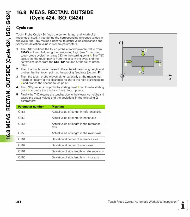
388 Touch Probe Cycles: Automatic Workpiece Inspection
16
.8 M
EA
S.
RE
CTA
N.
OU
TS
IDE
(C
ycle
42
4,
ISO
: G
42
4) 16.8 MEAS. RECTAN. OUTSIDE
(Cycle 424, ISO: G424)
Cycle run
Touch Probe Cycle 424 finds the center, length and width of a rectangular stud. If you define the corresponding tolerance values in the cycle, the TNC makes a nominal-to-actual value comparison and saves the deviation value in system parameters.
1 The TNC positions the touch probe at rapid traverse (value from FMAX column) following the positioning logic (see “Executing touch probe cycles” on page 283) to the starting point 1. The TNC calculates the touch points from the data in the cycle and the safety clearance from the SET_UP column of the touch probe table.
2 Then the touch probe moves to the entered measuring height and probes the first touch point at the probing feed rate (column F).
3 Then the touch probe moves either paraxially at the measuring height or linearly at the clearance height to the next starting point 2 and probes the second touch point.
4 The TNC positions the probe to starting point 3 and then to starting point 4 to probe the third and fourth touch points.
5 Finally the TNC returns the touch probe to the clearance height and saves the actual values and the deviations in the following Q parameters:
�
�
�
�
�
Parameter number Meaning
Q151 Actual value of center in reference axis
Q152 Actual value of center in minor axis
Q154 Actual value of length in the reference axis
Q155 Actual value of length in the minor axis
Q161 Deviation at center of reference axis
Q162 Deviation at center of minor axis
Q164 Deviation of side length in reference axis
Q165 Deviation of side length in minor axis
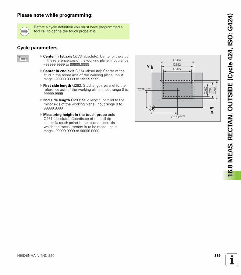
HEIDENHAIN TNC 320 389
16
.8 M
EA
S.
RE
CTA
N.
OU
TS
IDE
(C
ycle
42
4,
ISO
: G
42
4)Please note while programming:
Cycle parameters
U Center in 1st axis Q273 (absolute): Center of the stud in the reference axis of the working plane. Input range –99999.9999 to 99999.9999
U Center in 2nd axis Q274 (absolute): Center of the stud in the minor axis of the working plane. Input range –99999.9999 to 99999.9999
U First side length Q282: Stud length, parallel to the reference axis of the working plane. Input range 0 to 99999.9999
U 2nd side length Q283: Stud length, parallel to the minor axis of the working plane. Input range 0 to 99999.9999
UMeasuring height in the touch probe axis Q261 (absolute): Coordinate of the ball tip center (= touch point) in the touch probe axis in which the measurement is to be made. Input range –99999.9999 to 99999.9999
Before a cycle definition you must have programmed a tool call to define the touch probe axis.
�
�
��
�
��
����,���
����,����
��
���
�
������
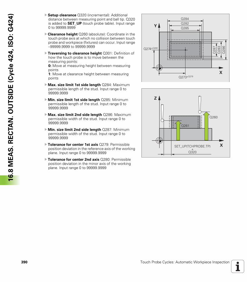
390 Touch Probe Cycles: Automatic Workpiece Inspection
16
.8 M
EA
S.
RE
CTA
N.
OU
TS
IDE
(C
ycle
42
4,
ISO
: G
42
4) U Setup clearance Q320 (incremental): Additional
distance between measuring point and ball tip. Q320 is added to SET_UP (touch probe table). Input range 0 to 99999.9999
U Clearance height Q260 (absolute): Coordinate in the touch probe axis at which no collision between touch probe and workpiece (fixtures) can occur. Input range –99999.9999 to 99999.9999
U Traversing to clearance height Q301: Definition of how the touch probe is to move between the measuring points: 0: Move at measuring height between measuring points 1: Move at clearance height between measuring points
UMax. size limit 1st side length Q284: Maximum permissible length of the stud. Input range 0 to 99999.9999
UMin. size limit 1st side length Q285: Minimum permissible length of the stud. Input range 0 to 99999.9999
UMax. size limit 2nd side length Q286: Maximum permissible width of the stud. Input range 0 to 99999.9999
UMin. size limit 2nd side length Q287: Minimum permissible width of the stud. Input range 0 to 99999.9999
U Tolerance for center 1st axis Q279: Permissible position deviation in the reference axis of the working plane. Input range 0 to 99999.9999
U Tolerance for center 2nd axis Q280: Permissible position deviation in the minor axis of the working plane. Input range 0 to 99999.9999
�
�
��
�
��
����,���
����,����
��
���
�
������
�
�
����
����
�& '(!� �)!�*�&� !��
����
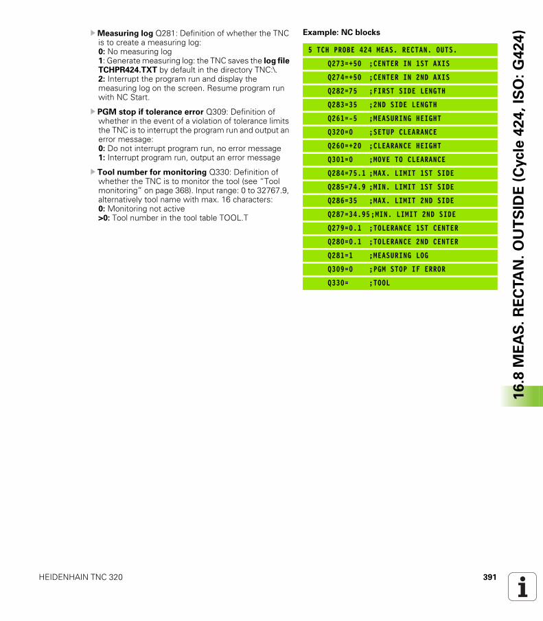
HEIDENHAIN TNC 320 391
16
.8 M
EA
S.
RE
CTA
N.
OU
TS
IDE
(C
ycle
42
4,
ISO
: G
42
4)UMeasuring log Q281: Definition of whether the TNC
is to create a measuring log: 0: No measuring log1: Generate measuring log: the TNC saves the log file TCHPR424.TXT by default in the directory TNC:\.2: Interrupt the program run and display the measuring log on the screen. Resume program run with NC Start.
U PGM stop if tolerance error Q309: Definition of whether in the event of a violation of tolerance limits the TNC is to interrupt the program run and output an error message: 0: Do not interrupt program run, no error message1: Interrupt program run, output an error message
U Tool number for monitoring Q330: Definition of whether the TNC is to monitor the tool (see “Tool monitoring” on page 368). Input range: 0 to 32767.9, alternatively tool name with max. 16 characters:0: Monitoring not active>0: Tool number in the tool table TOOL.T
Example: NC blocks
5 TCH PROBE 424 MEAS. RECTAN. OUTS.
Q273=+50 ;CENTER IN 1ST AXIS
Q274=+50 ;CENTER IN 2ND AXIS
Q282=75 ;FIRST SIDE LENGTH
Q283=35 ;2ND SIDE LENGTH
Q261=-5 ;MEASURING HEIGHT
Q320=0 ;SETUP CLEARANCE
Q260=+20 ;CLEARANCE HEIGHT
Q301=0 ;MOVE TO CLEARANCE
Q284=75.1 ;MAX. LIMIT 1ST SIDE
Q285=74.9 ;MIN. LIMIT 1ST SIDE
Q286=35 ;MAX. LIMIT 2ND SIDE
Q287=34.95;MIN. LIMIT 2ND SIDE
Q279=0.1 ;TOLERANCE 1ST CENTER
Q280=0.1 ;TOLERANCE 2ND CENTER
Q281=1 ;MEASURING LOG
Q309=0 ;PGM STOP IF ERROR
Q330= ;TOOL
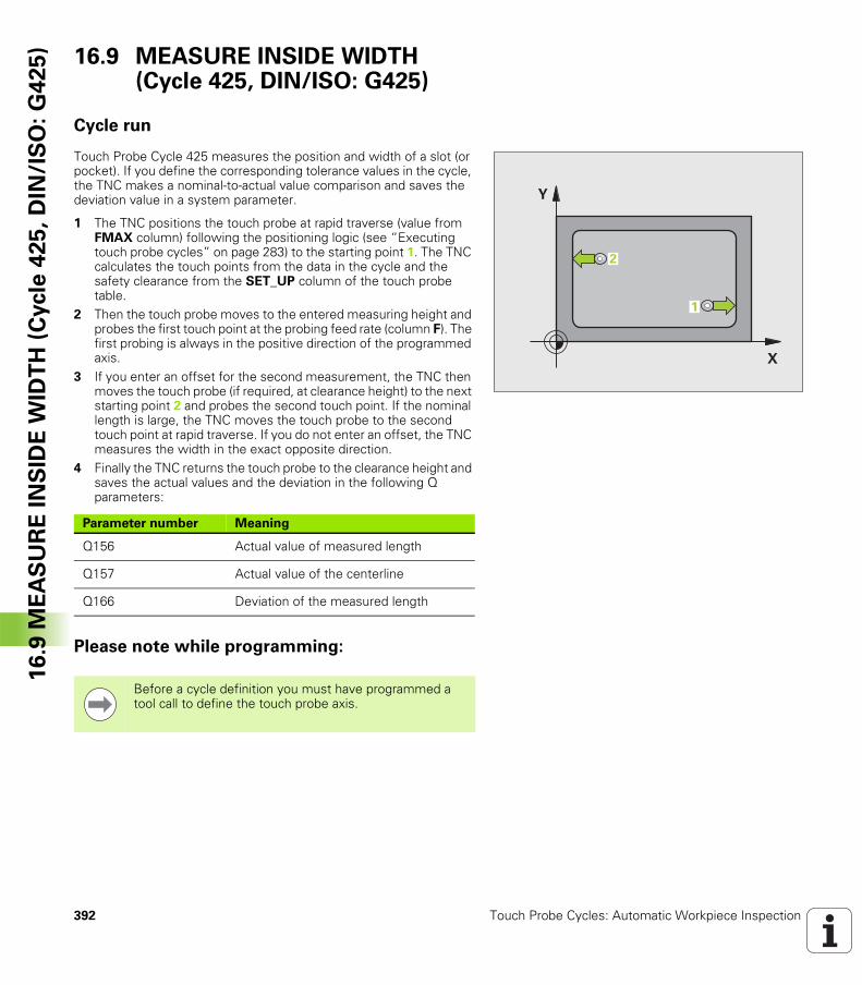
392 Touch Probe Cycles: Automatic Workpiece Inspection
16
.9 M
EA
SU
RE
IN
SID
E W
IDT
H (
Cycle
42
5,
DIN
/IS
O:
G4
25
) 16.9 MEASURE INSIDE WIDTH (Cycle 425, DIN/ISO: G425)
Cycle run
Touch Probe Cycle 425 measures the position and width of a slot (or pocket). If you define the corresponding tolerance values in the cycle, the TNC makes a nominal-to-actual value comparison and saves the deviation value in a system parameter.
1 The TNC positions the touch probe at rapid traverse (value from FMAX column) following the positioning logic (see “Executing touch probe cycles” on page 283) to the starting point 1. The TNC calculates the touch points from the data in the cycle and the safety clearance from the SET_UP column of the touch probe table.
2 Then the touch probe moves to the entered measuring height and probes the first touch point at the probing feed rate (column F). The first probing is always in the positive direction of the programmed axis.
3 If you enter an offset for the second measurement, the TNC then moves the touch probe (if required, at clearance height) to the next starting point 2 and probes the second touch point. If the nominal length is large, the TNC moves the touch probe to the second touch point at rapid traverse. If you do not enter an offset, the TNC measures the width in the exact opposite direction.
4 Finally the TNC returns the touch probe to the clearance height and saves the actual values and the deviation in the following Q parameters:
Please note while programming:
�
�
�
�
Parameter number Meaning
Q156 Actual value of measured length
Q157 Actual value of the centerline
Q166 Deviation of the measured length
Before a cycle definition you must have programmed a tool call to define the touch probe axis.
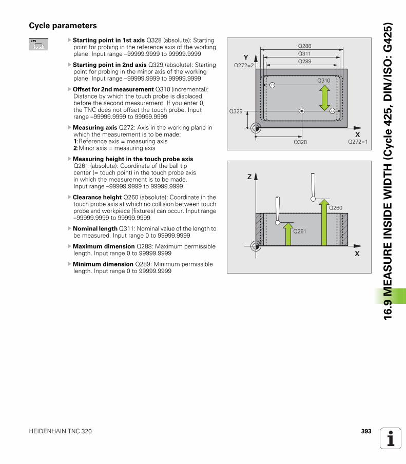
HEIDENHAIN TNC 320 393
16
.9 M
EA
SU
RE
IN
SID
E W
IDT
H (
Cycle
42
5,
DIN
/IS
O:
G4
25
)Cycle parameters
U Starting point in 1st axis Q328 (absolute): Starting point for probing in the reference axis of the working plane. Input range –99999.9999 to 99999.9999
U Starting point in 2nd axis Q329 (absolute): Starting point for probing in the minor axis of the working plane. Input range –99999.9999 to 99999.9999
U Offset for 2nd measurement Q310 (incremental): Distance by which the touch probe is displaced before the second measurement. If you enter 0, the TNC does not offset the touch probe. Input range –99999.9999 to 99999.9999
UMeasuring axis Q272: Axis in the working plane in which the measurement is to be made: 1:Reference axis = measuring axis 2:Minor axis = measuring axis
UMeasuring height in the touch probe axis Q261 (absolute): Coordinate of the ball tip center (= touch point) in the touch probe axis in which the measurement is to be made. Input range –99999.9999 to 99999.9999
U Clearance height Q260 (absolute): Coordinate in the touch probe axis at which no collision between touch probe and workpiece (fixtures) can occur. Input range –99999.9999 to 99999.9999
U Nominal length Q311: Nominal value of the length to be measured. Input range 0 to 99999.9999
UMaximum dimension Q288: Maximum permissible length. Input range 0 to 99999.9999
UMinimum dimension Q289: Minimum permissible length. Input range 0 to 99999.9999
����
����
����������
������
������
����
�
�
����
����
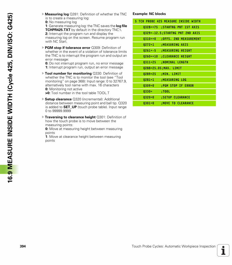
394 Touch Probe Cycles: Automatic Workpiece Inspection
16
.9 M
EA
SU
RE
IN
SID
E W
IDT
H (
Cycle
42
5,
DIN
/IS
O:
G4
25
) UMeasuring log Q281: Definition of whether the TNC is to create a measuring log: 0: No measuring log1: Generate measuring log: the TNC saves the log file TCHPR425.TXT by default in the directory TNC:\.2: Interrupt the program run and display the measuring log on the screen. Resume program run with NC Start.
U PGM stop if tolerance error Q309: Definition of whether in the event of a violation of tolerance limits the TNC is to interrupt the program run and output an error message: 0: Do not interrupt program run, no error message1: Interrupt program run, output an error message
U Tool number for monitoring Q330: Definition of whether the TNC is to monitor the tool (see “Tool monitoring” on page 368): Input range: 0 to 32767.9, alternatively tool name with max. 16 characters 0: Monitoring not active >0: Tool number in the tool table TOOL.T
U Setup clearance Q320 (incremental): Additional distance between measuring point and ball tip. Q320 is added to SET_UP (touch probe table). Input range 0 to 99999.9999
U Traversing to clearance height Q301: Definition of how the touch probe is to move between the measuring points: 0: Move at measuring height between measuring points 1: Move at clearance height between measuring points
Example: NC blocks
5 TCH PROBE 425 MEASURE INSIDE WIDTH
Q328=+75 ;STARTNG PNT 1ST AXIS
Q329=-12.5;STARTNG PNT 2ND AXIS
Q310=+0 ;OFFS. 2ND MEASUREMENT
Q272=1 ;MEASURING AXIS
Q261=-5 ;MEASURING HEIGHT
Q260=+10 ;CLEARANCE HEIGHT
Q311=25 ;NOMINAL LENGTH
Q288=25.05;MAX. LIMIT
Q289=25 ;MIN. LIMIT
Q281=1 ;MEASURING LOG
Q309=0 ;PGM STOP IF ERROR
Q330= ;TOOL
Q320=0 ;SETUP CLEARANCE
Q301=0 ;MOVE TO CLEARANCE
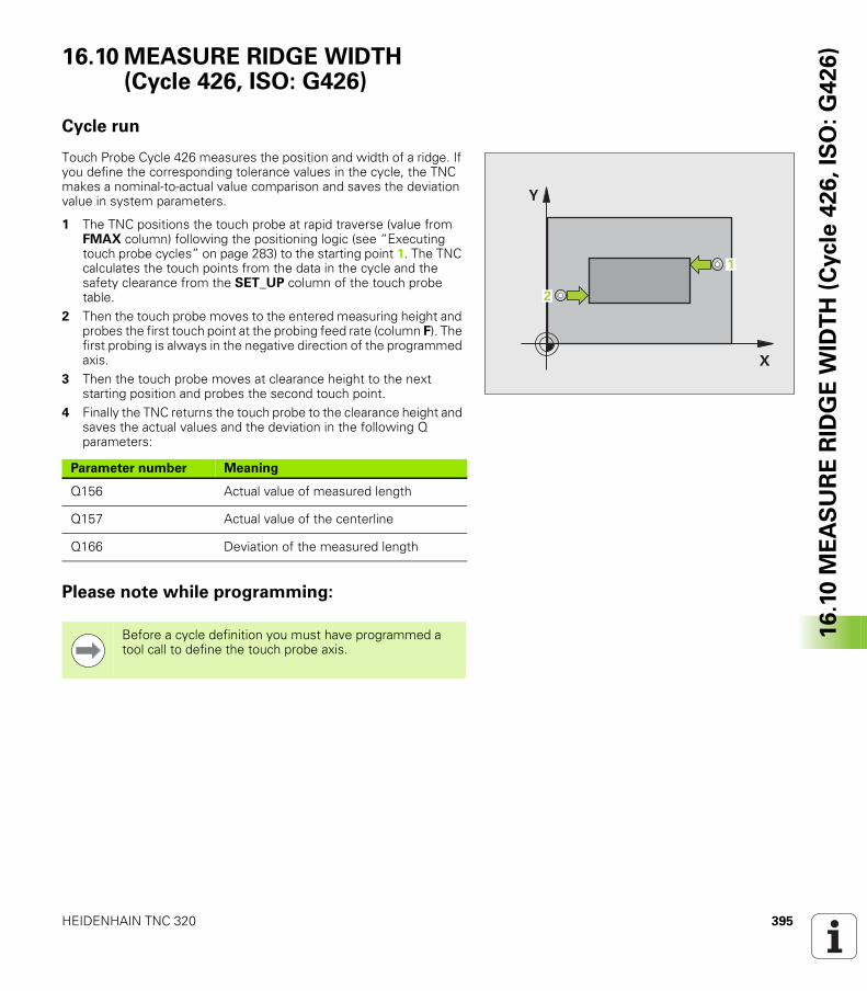
HEIDENHAIN TNC 320 395
16
.10
ME
AS
UR
E R
IDG
E W
IDT
H (
Cycle
42
6,
ISO
: G
42
6)16.10 MEASURE RIDGE WIDTH
(Cycle 426, ISO: G426)
Cycle run
Touch Probe Cycle 426 measures the position and width of a ridge. If you define the corresponding tolerance values in the cycle, the TNC makes a nominal-to-actual value comparison and saves the deviation value in system parameters.
1 The TNC positions the touch probe at rapid traverse (value from FMAX column) following the positioning logic (see “Executing touch probe cycles” on page 283) to the starting point 1. The TNC calculates the touch points from the data in the cycle and the safety clearance from the SET_UP column of the touch probe table.
2 Then the touch probe moves to the entered measuring height and probes the first touch point at the probing feed rate (column F). The first probing is always in the negative direction of the programmed axis.
3 Then the touch probe moves at clearance height to the next starting position and probes the second touch point.
4 Finally the TNC returns the touch probe to the clearance height and saves the actual values and the deviation in the following Q parameters:
Please note while programming:
�
�
�
�
Parameter number Meaning
Q156 Actual value of measured length
Q157 Actual value of the centerline
Q166 Deviation of the measured length
Before a cycle definition you must have programmed a tool call to define the touch probe axis.
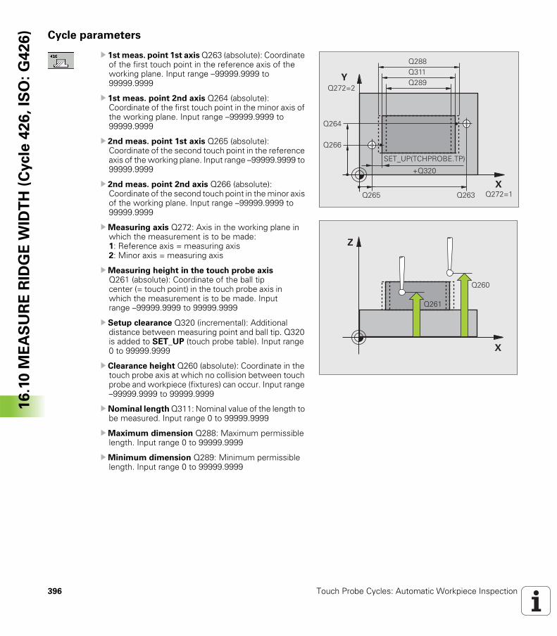
396 Touch Probe Cycles: Automatic Workpiece Inspection
16
.10
ME
AS
UR
E R
IDG
E W
IDT
H (
Cycle
42
6,
ISO
: G
42
6) Cycle parameters
U 1st meas. point 1st axis Q263 (absolute): Coordinate of the first touch point in the reference axis of the working plane. Input range –99999.9999 to 99999.9999
U 1st meas. point 2nd axis Q264 (absolute): Coordinate of the first touch point in the minor axis of the working plane. Input range –99999.9999 to 99999.9999
U 2nd meas. point 1st axis Q265 (absolute): Coordinate of the second touch point in the reference axis of the working plane. Input range –99999.9999 to 99999.9999
U 2nd meas. point 2nd axis Q266 (absolute): Coordinate of the second touch point in the minor axis of the working plane. Input range –99999.9999 to 99999.9999
UMeasuring axis Q272: Axis in the working plane in which the measurement is to be made: 1: Reference axis = measuring axis 2: Minor axis = measuring axis
UMeasuring height in the touch probe axis Q261 (absolute): Coordinate of the ball tip center (= touch point) in the touch probe axis in which the measurement is to be made. Input range –99999.9999 to 99999.9999
U Setup clearance Q320 (incremental): Additional distance between measuring point and ball tip. Q320 is added to SET_UP (touch probe table). Input range 0 to 99999.9999
U Clearance height Q260 (absolute): Coordinate in the touch probe axis at which no collision between touch probe and workpiece (fixtures) can occur. Input range –99999.9999 to 99999.9999
U Nominal length Q311: Nominal value of the length to be measured. Input range 0 to 99999.9999
UMaximum dimension Q288: Maximum permissible length. Input range 0 to 99999.9999
UMinimum dimension Q289: Minimum permissible length. Input range 0 to 99999.9999
����
����
����������
������
������
����
����
�& '(!� �)!�*�&� !�
�����
�
�
����
����
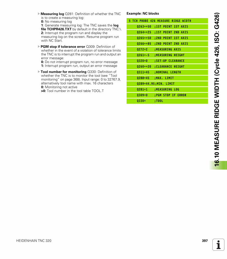
HEIDENHAIN TNC 320 397
16
.10
ME
AS
UR
E R
IDG
E W
IDT
H (
Cycle
42
6,
ISO
: G
42
6)UMeasuring log Q281: Definition of whether the TNC
is to create a measuring log: 0: No measuring log 1: Generate measuring log: The TNC saves the log file TCHPR426.TXT by default in the directory TNC:\.2: Interrupt the program run and display the measuring log on the screen. Resume program run with NC Start.
U PGM stop if tolerance error Q309: Definition of whether in the event of a violation of tolerance limits the TNC is to interrupt the program run and output an error message: 0: Do not interrupt program run, no error message1: Interrupt program run, output an error message
U Tool number for monitoring Q330: Definition of whether the TNC is to monitor the tool (see “Tool monitoring” on page 368). Input range: 0 to 32767.9, alternatively tool name with max. 16 characters0: Monitoring not active >0: Tool number in the tool table TOOL.T
Example: NC blocks
5 TCH PROBE 426 MEASURE RIDGE WIDTH
Q263=+50 ;1ST POINT 1ST AXIS
Q264=+25 ;1ST POINT 2ND AXIS
Q265=+50 ;2ND POINT 1ST AXIS
Q266=+85 ;2ND POINT 2ND AXIS
Q272=2 ;MEASURING AXIS
Q261=-5 ;MEASURING HEIGHT
Q320=0 ;SET-UP CLEARANCE
Q260=+20 ;CLEARANCE HEIGHT
Q311=45 ;NOMINAL LENGTH
Q288=45 ;MAX. LIMIT
Q289=44.95;MIN. LIMIT
Q281=1 ;MEASURING LOG
Q309=0 ;PGM STOP IF ERROR
Q330= ;TOOL
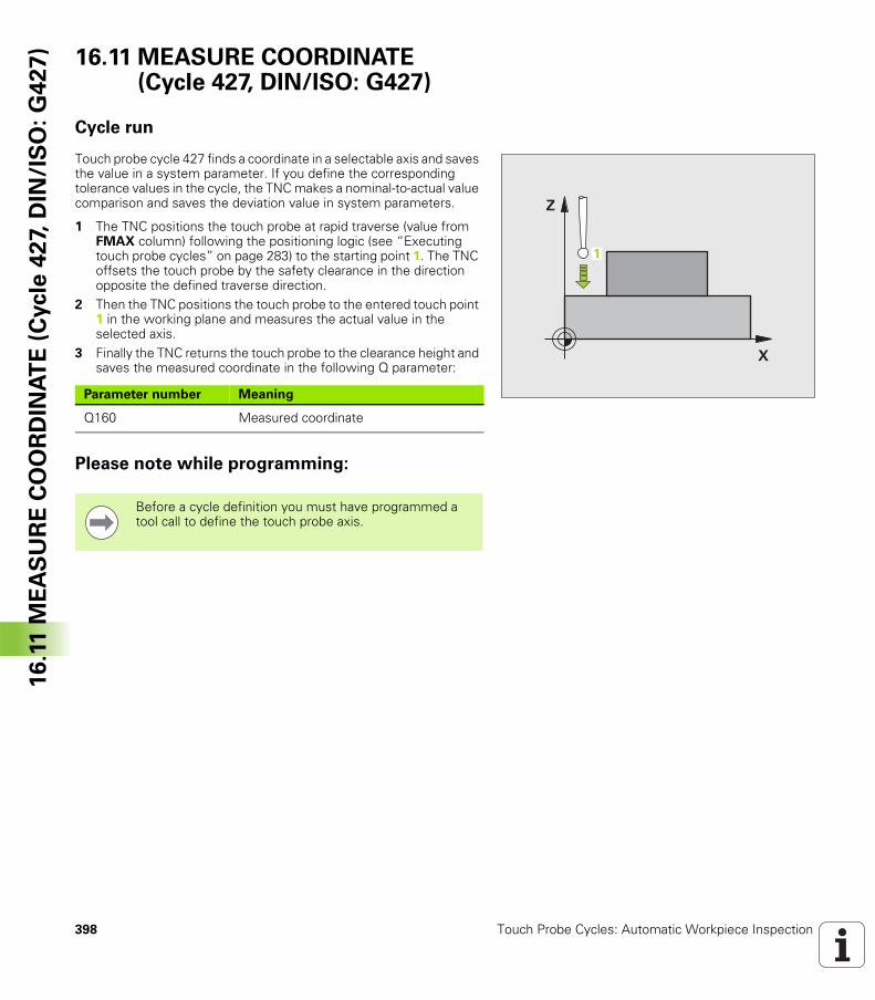
398 Touch Probe Cycles: Automatic Workpiece Inspection
16
.11
ME
AS
UR
E C
OO
RD
INA
TE
(C
ycle
42
7, D
IN/I
SO
: G
42
7) 16.11 MEASURE COORDINATE
(Cycle 427, DIN/ISO: G427)
Cycle run
Touch probe cycle 427 finds a coordinate in a selectable axis and saves the value in a system parameter. If you define the corresponding tolerance values in the cycle, the TNC makes a nominal-to-actual value comparison and saves the deviation value in system parameters.
1 The TNC positions the touch probe at rapid traverse (value from FMAX column) following the positioning logic (see “Executing touch probe cycles” on page 283) to the starting point 1. The TNC offsets the touch probe by the safety clearance in the direction opposite the defined traverse direction.
2 Then the TNC positions the touch probe to the entered touch point 1 in the working plane and measures the actual value in the selected axis.
3 Finally the TNC returns the touch probe to the clearance height and saves the measured coordinate in the following Q parameter:
Please note while programming:
�
�
�
Parameter number Meaning
Q160 Measured coordinate
Before a cycle definition you must have programmed a tool call to define the touch probe axis.
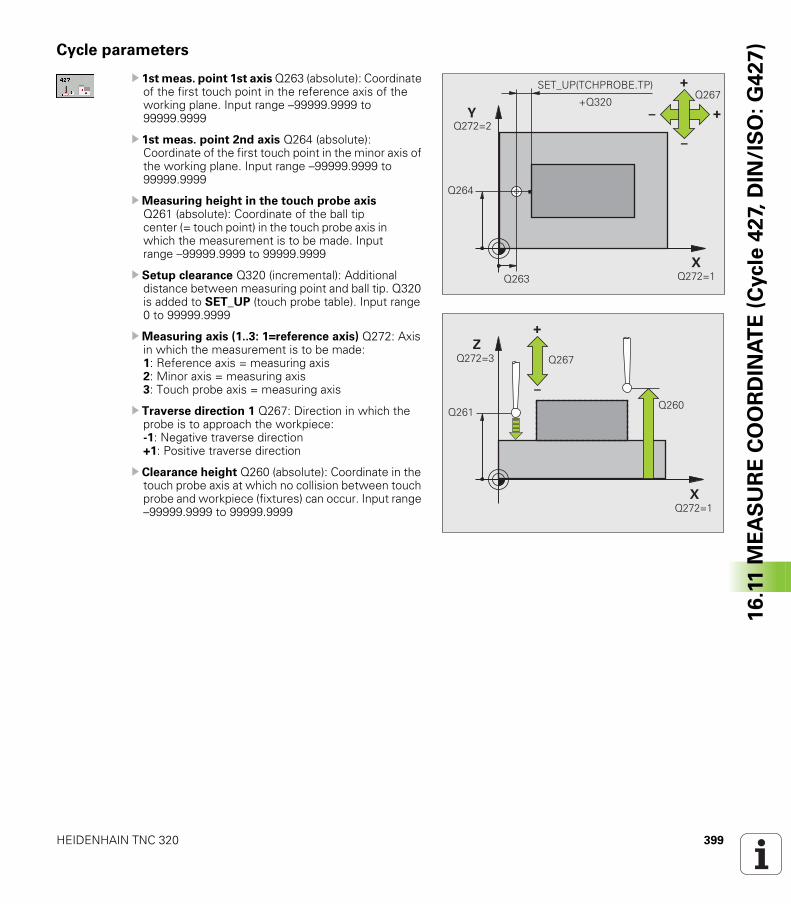
HEIDENHAIN TNC 320 399
16
.11
ME
AS
UR
E C
OO
RD
INA
TE
(C
ycle
42
7, D
IN/I
SO
: G
42
7)Cycle parameters
U 1st meas. point 1st axis Q263 (absolute): Coordinate of the first touch point in the reference axis of the working plane. Input range –99999.9999 to 99999.9999
U 1st meas. point 2nd axis Q264 (absolute): Coordinate of the first touch point in the minor axis of the working plane. Input range –99999.9999 to 99999.9999
UMeasuring height in the touch probe axis Q261 (absolute): Coordinate of the ball tip center (= touch point) in the touch probe axis in which the measurement is to be made. Input range –99999.9999 to 99999.9999
U Setup clearance Q320 (incremental): Additional distance between measuring point and ball tip. Q320 is added to SET_UP (touch probe table). Input range 0 to 99999.9999
UMeasuring axis (1..3: 1=reference axis) Q272: Axis in which the measurement is to be made: 1: Reference axis = measuring axis 2: Minor axis = measuring axis 3: Touch probe axis = measuring axis
U Traverse direction 1 Q267: Direction in which the probe is to approach the workpiece: -1: Negative traverse direction +1: Positive traverse direction
U Clearance height Q260 (absolute): Coordinate in the touch probe axis at which no collision between touch probe and workpiece (fixtures) can occur. Input range –99999.9999 to 99999.9999
�
�
����
����
!
"
" !����
������
������
�& '(!� �)!�*�&� !�
�����
�
�
��������
!
"
������
������ ����
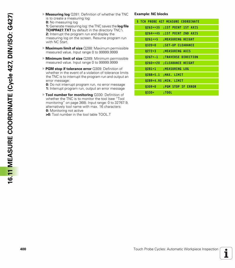
400 Touch Probe Cycles: Automatic Workpiece Inspection
16
.11
ME
AS
UR
E C
OO
RD
INA
TE
(C
ycle
42
7, D
IN/I
SO
: G
42
7) UMeasuring log Q281: Definition of whether the TNC
is to create a measuring log: 0: No measuring log1: Generate measuring log: the TNC saves the log file TCHPR427.TXT by default in the directory TNC:\.2: Interrupt the program run and display the measuring log on the screen. Resume program run with NC Start.
UMaximum limit of size Q288: Maximum permissible measured value. Input range 0 to 99999.9999
UMinimum limit of size Q289: Minimum permissible measured value. Input range 0 to 99999.9999
U PGM stop if tolerance error Q309: Definition of whether in the event of a violation of tolerance limits the TNC is to interrupt the program run and output an error message: 0: Do not interrupt program run, no error message1: Interrupt program run, output an error message
U Tool number for monitoring Q330: Definition of whether the TNC is to monitor the tool (see “Tool monitoring” on page 368). Input range: 0 to 32767.9, alternatively tool name with max. 16 characters:0: Monitoring not active>0: Tool number in the tool table TOOL.T
Example: NC blocks
5 TCH PROBE 427 MEASURE COORDINATE
Q263=+35 ;1ST POINT 1ST AXIS
Q264=+45 ;1ST POINT 2ND AXIS
Q261=+5 ;MEASURING HEIGHT
Q320=0 ;SET-UP CLEARANCE
Q272=3 ;MEASURING AXIS
Q267=-1 ;TRAVERSE DIRECTION
Q260=+20 ;CLEARANCE HEIGHT
Q281=1 ;MEASURING LOG
Q288=5.1 ;MAX. LIMIT
Q289=4.95 ;MIN. LIMIT
Q309=0 ;PGM STOP IF ERROR
Q330= ;TOOL
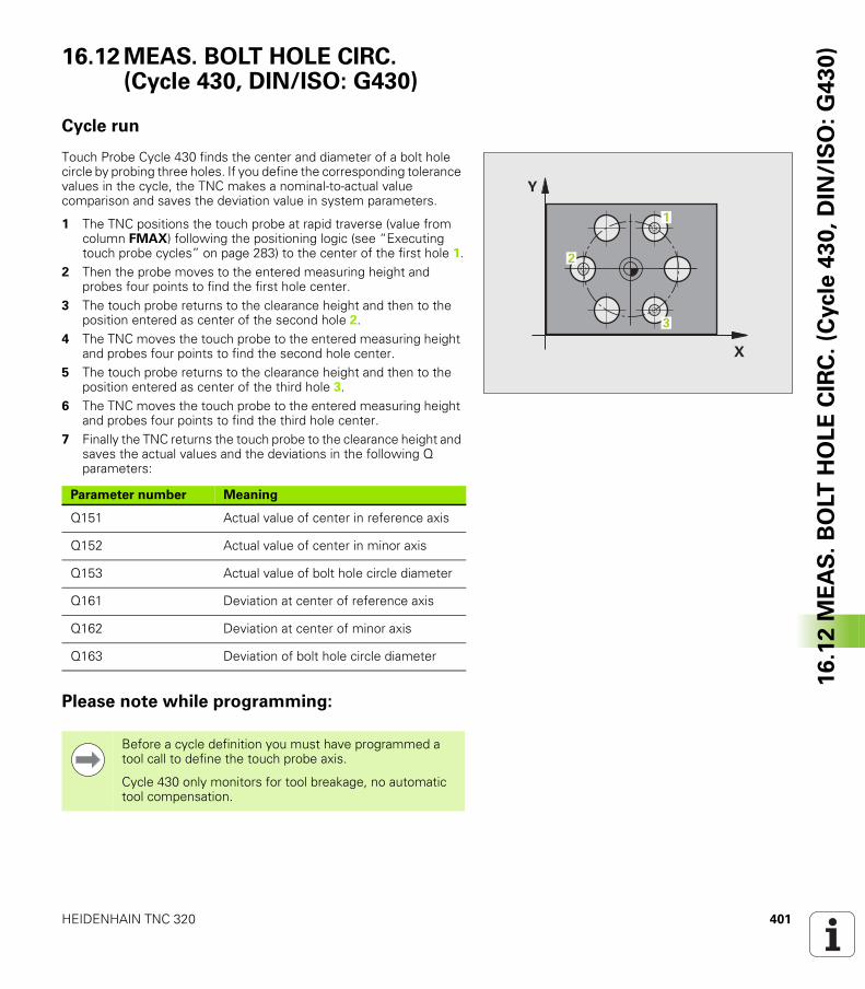
HEIDENHAIN TNC 320 401
16
.12
ME
AS
. B
OLT
HO
LE
CIR
C.
(Cycle
43
0,
DIN
/IS
O:
G4
30
)16.12 MEAS. BOLT HOLE CIRC. (Cycle 430, DIN/ISO: G430)
Cycle run
Touch Probe Cycle 430 finds the center and diameter of a bolt hole circle by probing three holes. If you define the corresponding tolerance values in the cycle, the TNC makes a nominal-to-actual value comparison and saves the deviation value in system parameters.
1 The TNC positions the touch probe at rapid traverse (value from column FMAX) following the positioning logic (see “Executing touch probe cycles” on page 283) to the center of the first hole 1.
2 Then the probe moves to the entered measuring height and probes four points to find the first hole center.
3 The touch probe returns to the clearance height and then to the position entered as center of the second hole 2.
4 The TNC moves the touch probe to the entered measuring height and probes four points to find the second hole center.
5 The touch probe returns to the clearance height and then to the position entered as center of the third hole 3.
6 The TNC moves the touch probe to the entered measuring height and probes four points to find the third hole center.
7 Finally the TNC returns the touch probe to the clearance height and saves the actual values and the deviations in the following Q parameters:
Please note while programming:
�
�
�
�
�
Parameter number Meaning
Q151 Actual value of center in reference axis
Q152 Actual value of center in minor axis
Q153 Actual value of bolt hole circle diameter
Q161 Deviation at center of reference axis
Q162 Deviation at center of minor axis
Q163 Deviation of bolt hole circle diameter
Before a cycle definition you must have programmed a tool call to define the touch probe axis.
Cycle 430 only monitors for tool breakage, no automatic tool compensation.
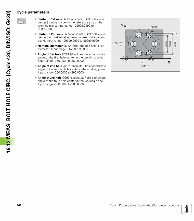
402 Touch Probe Cycles: Automatic Workpiece Inspection
16
.12
ME
AS
. B
OLT
HO
LE
CIR
C.
(Cycle
43
0,
DIN
/IS
O:
G4
30
) Cycle parameters
U Center in 1st axis Q273 (absolute): Bolt hole circle center (nominal value) in the reference axis of the working plane. Input range –99999.9999 to 99999.9999
U Center in 2nd axis Q274 (absolute): Bolt hole circle center (nominal value) in the minor axis of the working plane. Input range –99999.9999 to 99999.9999
U Nominal diameter Q262: Enter the bolt hole circle diameter. Input range 0 to 99999.9999
U Angle of 1st hole Q291 (absolute): Polar coordinate angle of the first hole center in the working plane. Input range –360.0000 to 360.0000
U Angle of 2nd hole Q292 (absolute): Polar coordinate angle of the second hole center in the working plane. Input range –360.0000 to 360.0000
U Angle of 3rd hole Q293 (absolute): Polar coordinate angle of the third hole center in the working plane. Input range –360.0000 to 360.0000
�
� ����
����
���
�
����,���
����,����
��
�
���
�
��
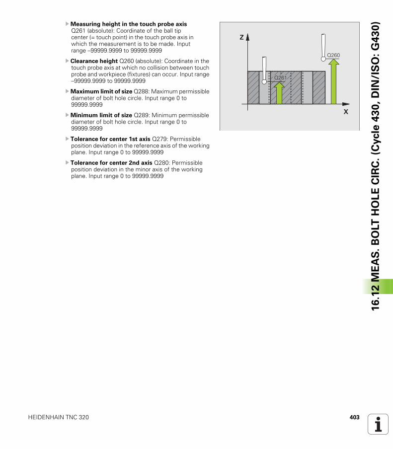
HEIDENHAIN TNC 320 403
16
.12
ME
AS
. B
OLT
HO
LE
CIR
C.
(Cycle
43
0,
DIN
/IS
O:
G4
30
)UMeasuring height in the touch probe axis Q261 (absolute): Coordinate of the ball tip center (= touch point) in the touch probe axis in which the measurement is to be made. Input range –99999.9999 to 99999.9999
U Clearance height Q260 (absolute): Coordinate in the touch probe axis at which no collision between touch probe and workpiece (fixtures) can occur. Input range –99999.9999 to 99999.9999
UMaximum limit of size Q288: Maximum permissible diameter of bolt hole circle. Input range 0 to 99999.9999
UMinimum limit of size Q289: Minimum permissible diameter of bolt hole circle. Input range 0 to 99999.9999
U Tolerance for center 1st axis Q279: Permissible position deviation in the reference axis of the working plane. Input range 0 to 99999.9999
U Tolerance for center 2nd axis Q280: Permissible position deviation in the minor axis of the working plane. Input range 0 to 99999.9999
�
�
����
����
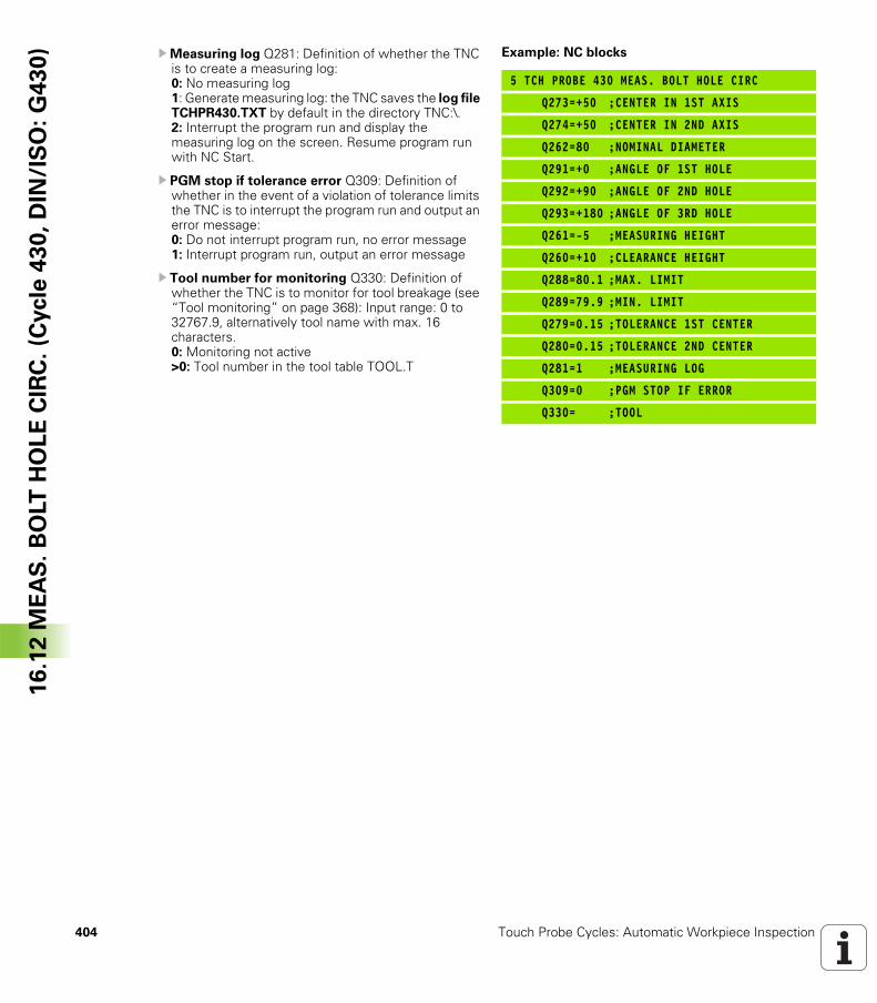
404 Touch Probe Cycles: Automatic Workpiece Inspection
16
.12
ME
AS
. B
OLT
HO
LE
CIR
C.
(Cycle
43
0,
DIN
/IS
O:
G4
30
) UMeasuring log Q281: Definition of whether the TNC is to create a measuring log: 0: No measuring log1: Generate measuring log: the TNC saves the log file TCHPR430.TXT by default in the directory TNC:\.2: Interrupt the program run and display the measuring log on the screen. Resume program run with NC Start.
U PGM stop if tolerance error Q309: Definition of whether in the event of a violation of tolerance limits the TNC is to interrupt the program run and output an error message: 0: Do not interrupt program run, no error message 1: Interrupt program run, output an error message
U Tool number for monitoring Q330: Definition of whether the TNC is to monitor for tool breakage (see “Tool monitoring” on page 368): Input range: 0 to 32767.9, alternatively tool name with max. 16 characters.0: Monitoring not active>0: Tool number in the tool table TOOL.T
Example: NC blocks
5 TCH PROBE 430 MEAS. BOLT HOLE CIRC
Q273=+50 ;CENTER IN 1ST AXIS
Q274=+50 ;CENTER IN 2ND AXIS
Q262=80 ;NOMINAL DIAMETER
Q291=+0 ;ANGLE OF 1ST HOLE
Q292=+90 ;ANGLE OF 2ND HOLE
Q293=+180 ;ANGLE OF 3RD HOLE
Q261=-5 ;MEASURING HEIGHT
Q260=+10 ;CLEARANCE HEIGHT
Q288=80.1 ;MAX. LIMIT
Q289=79.9 ;MIN. LIMIT
Q279=0.15 ;TOLERANCE 1ST CENTER
Q280=0.15 ;TOLERANCE 2ND CENTER
Q281=1 ;MEASURING LOG
Q309=0 ;PGM STOP IF ERROR
Q330= ;TOOL
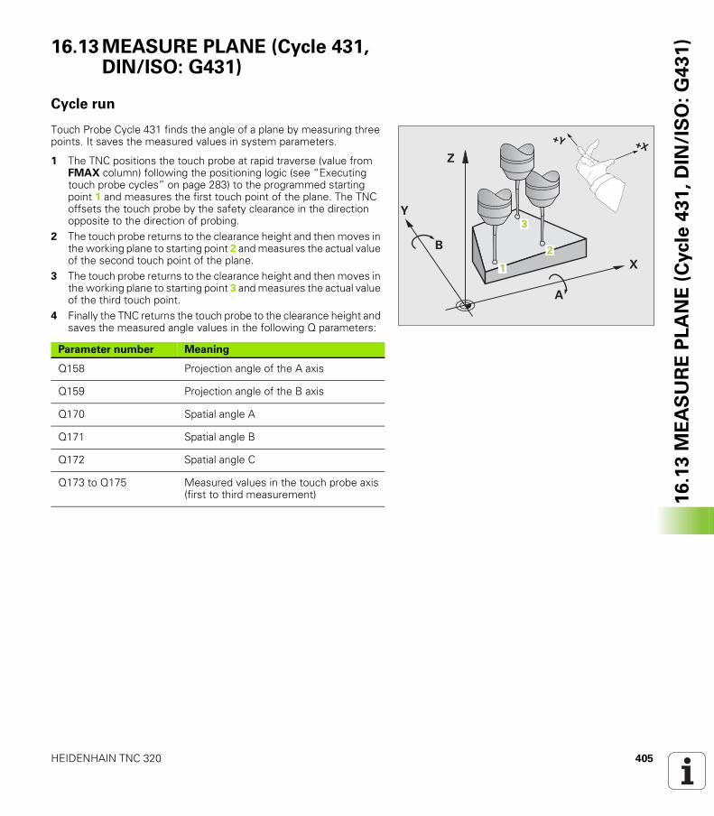
HEIDENHAIN TNC 320 405
16
.13
ME
AS
UR
E P
LA
NE
(C
ycle
43
1,
DIN
/IS
O:
G4
31
)16.13 MEASURE PLANE (Cycle 431, DIN/ISO: G431)
Cycle run
Touch Probe Cycle 431 finds the angle of a plane by measuring three points. It saves the measured values in system parameters.
1 The TNC positions the touch probe at rapid traverse (value from FMAX column) following the positioning logic (see “Executing touch probe cycles” on page 283) to the programmed starting point 1 and measures the first touch point of the plane. The TNC offsets the touch probe by the safety clearance in the direction opposite to the direction of probing.
2 The touch probe returns to the clearance height and then moves in the working plane to starting point 2 and measures the actual value of the second touch point of the plane.
3 The touch probe returns to the clearance height and then moves in the working plane to starting point 3 and measures the actual value of the third touch point.
4 Finally the TNC returns the touch probe to the clearance height and saves the measured angle values in the following Q parameters:
�
�
�
�
�
�
!�!�
�
�
Parameter number Meaning
Q158 Projection angle of the A axis
Q159 Projection angle of the B axis
Q170 Spatial angle A
Q171 Spatial angle B
Q172 Spatial angle C
Q173 to Q175 Measured values in the touch probe axis (first to third measurement)
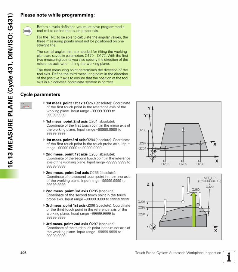
406 Touch Probe Cycles: Automatic Workpiece Inspection
16
.13
ME
AS
UR
E P
LA
NE
(C
ycle
43
1,
DIN
/IS
O:
G4
31
) Please note while programming:
Cycle parameters
U 1st meas. point 1st axis Q263 (absolute): Coordinate of the first touch point in the reference axis of the working plane. Input range –99999.9999 to 99999.9999
U 1st meas. point 2nd axis Q264 (absolute): Coordinate of the first touch point in the minor axis of the working plane. Input range –99999.9999 to 99999.9999
U 1st meas. point 3rd axis Q294 (absolute): Coordinate of the first touch point in the touch probe axis. Input range –99999.9999 to 99999.9999
U 2nd meas. point 1st axis Q265 (absolute): Coordinate of the second touch point in the reference axis of the working plane. Input range –99999.9999 to 99999.9999
U 2nd meas. point 2nd axis Q266 (absolute): Coordinate of the second touch point in the minor axis of the working plane. Input range –99999.9999 to 99999.9999
U 2nd meas. point 3rd axis Q295 (absolute): Coordinate of the second touch point in the touch probe axis. Input range –99999.9999 to 99999.9999
U 3rd meas. point 1st axis Q296 (absolute): Coordinate of the third touch point in the reference axis of the working plane. Input range –99999.9999 to 99999.9999
U 3rd meas. point 2nd axis Q297 (absolute): Coordinate of the third touch point in the minor axis of the working plane. Input range –99999.9999 to 99999.9999
Before a cycle definition you must have programmed a tool call to define the touch probe axis.
For the TNC to be able to calculate the angular values, the three measuring points must not be positioned on one straight line.
The spatial angles that are needed for tilting the working plane are saved in parameters Q170 – Q172. With the first two measuring points you also specify the direction of the reference axis when tilting the working plane.
The third measuring point determines the direction of the tool axis. Define the third measuring point in the direction of the positive Y axis to ensure that the position of the tool axis in a clockwise coordinate system is correct.
�
�
����
����
����
����
�������
�
�
�
�
���
���
����
����
�& '(!� �)!�*�&� !�
�����
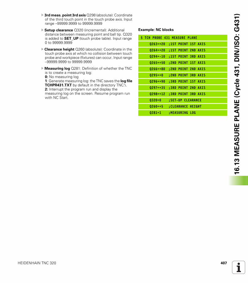
HEIDENHAIN TNC 320 407
16
.13
ME
AS
UR
E P
LA
NE
(C
ycle
43
1,
DIN
/IS
O:
G4
31
)U 3rd meas. point 3rd axis Q298 (absolute): Coordinate of the third touch point in the touch probe axis. Input range –99999.9999 to 99999.9999
U Setup clearance Q320 (incremental): Additional distance between measuring point and ball tip. Q320 is added to SET_UP (touch probe table). Input range 0 to 99999.9999
U Clearance height Q260 (absolute): Coordinate in the touch probe axis at which no collision between touch probe and workpiece (fixtures) can occur. Input range –99999.9999 to 99999.9999
UMeasuring log Q281: Definition of whether the TNC is to create a measuring log: 0: No measuring log1: Generate measuring log: the TNC saves the log file TCHPR431.TXT by default in the directory TNC:\.2: Interrupt the program run and display the measuring log on the screen. Resume program run with NC Start.
Example: NC blocks
5 TCH PROBE 431 MEASURE PLANE
Q263=+20 ;1ST POINT 1ST AXIS
Q264=+20 ;1ST POINT 2ND AXIS
Q294=-10 ;1ST POINT 3RD AXIS
Q265=+50 ;2ND POINT 1ST AXIS
Q266=+80 ;2ND POINT 2ND AXIS
Q295=+0 ;2ND POINT 3RD AXIS
Q296=+90 ;3RD POINT 1ST AXIS
Q297=+35 ;3RD POINT 2ND AXIS
Q298=+12 ;3RD POINT 3RD AXIS
Q320=0 ;SET-UP CLEARANCE
Q260=+5 ;CLEARANCE HEIGHT
Q281=1 ;MEASURING LOG
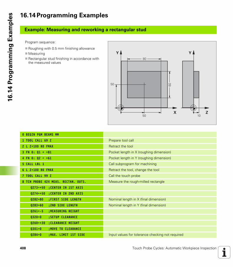
408 Touch Probe Cycles: Automatic Workpiece Inspection
16
.14
Pro
gra
mm
ing
Ex
am
ple
s 16.14 Programming Examples
Example: Measuring and reworking a rectangular stud
Program sequence:
Roughing with 0.5 mm finishing allowance Measuring Rectangular stud finishing in accordance with the measured values
0 BEGIN PGM BEAMS MM
1 TOOL CALL 69 Z Prepare tool call
2 L Z+100 R0 FMAX Retract the tool
3 FN 0: Q1 = +81 Pocket length in X (roughing dimension)
4 FN 0: Q2 = +61 Pocket length in Y (roughing dimension)
5 CALL LBL 1 Call subprogram for machining
6 L Z+100 R0 FMAX Retract the tool, change the tool
7 TOOL CALL 99 Z Call the touch probe
8 TCH PROBE 424 MEAS. RECTAN. OUTS. Measure the rough-milled rectangle
Q273=+50 ;CENTER IN 1ST AXIS
Q274=+50 ;CENTER IN 2ND AXIS
Q282=80 ;FIRST SIDE LENGTH Nominal length in X (final dimension)
Q283=60 ;2ND SIDE LENGTH Nominal length in Y (final dimension)
Q261=-5 ;MEASURING HEIGHT
Q320=0 ;SETUP CLEARANCE
Q260=+30 ;CLEARANCE HEIGHT
Q301=0 ;MOVE TO CLEARANCE
Q284=0 ;MAX. LIMIT 1ST SIDE Input values for tolerance checking not required
�
�
�
�
�
�
�
��
��
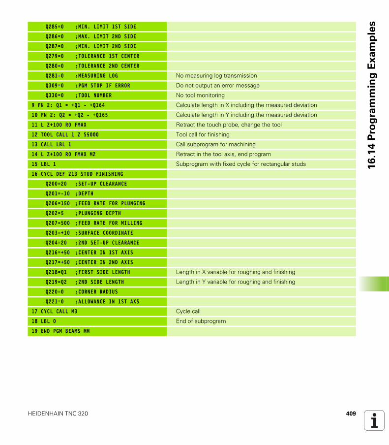
HEIDENHAIN TNC 320 409
16
.14
Pro
gra
mm
ing
Ex
am
ple
sQ285=0 ;MIN. LIMIT 1ST SIDE
Q286=0 ;MAX. LIMIT 2ND SIDE
Q287=0 ;MIN. LIMIT 2ND SIDE
Q279=0 ;TOLERANCE 1ST CENTER
Q280=0 ;TOLERANCE 2ND CENTER
Q281=0 ;MEASURING LOG No measuring log transmission
Q309=0 ;PGM STOP IF ERROR Do not output an error message
Q330=0 ;TOOL NUMBER No tool monitoring
9 FN 2: Q1 = +Q1 - +Q164 Calculate length in X including the measured deviation
10 FN 2: Q2 = +Q2 - +Q165 Calculate length in Y including the measured deviation
11 L Z+100 R0 FMAX Retract the touch probe, change the tool
12 TOOL CALL 1 Z S5000 Tool call for finishing
13 CALL LBL 1 Call subprogram for machining
14 L Z+100 R0 FMAX M2 Retract in the tool axis, end program
15 LBL 1 Subprogram with fixed cycle for rectangular studs
16 CYCL DEF 213 STUD FINISHING
Q200=20 ;SET-UP CLEARANCE
Q201=-10 ;DEPTH
Q206=150 ;FEED RATE FOR PLUNGING
Q202=5 ;PLUNGING DEPTH
Q207=500 ;FEED RATE FOR MILLING
Q203=+10 ;SURFACE COORDINATE
Q204=20 ;2ND SET-UP CLEARANCE
Q216=+50 ;CENTER IN 1ST AXIS
Q217=+50 ;CENTER IN 2ND AXIS
Q218=Q1 ;FIRST SIDE LENGTH Length in X variable for roughing and finishing
Q219=Q2 ;2ND SIDE LENGTH Length in Y variable for roughing and finishing
Q220=0 ;CORNER RADIUS
Q221=0 ;ALLOWANCE IN 1ST AXS
17 CYCL CALL M3 Cycle call
18 LBL 0 End of subprogram
19 END PGM BEAMS MM
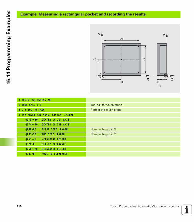
410 Touch Probe Cycles: Automatic Workpiece Inspection
16
.14
Pro
gra
mm
ing
Ex
am
ple
sExample: Measuring a rectangular pocket and recording the results
0 BEGIN PGM BSMEAS MM
1 TOOL CALL 1 Z Tool call for touch probe
2 L Z+100 R0 FMAX Retract the touch probe
3 TCH PROBE 423 MEAS. RECTAN. INSIDE
Q273=+50 ;CENTER IN 1ST AXIS
Q274=+40 ;CENTER IN 2ND AXIS
Q282=90 ;FIRST SIDE LENGTH Nominal length in X
Q283=70 ;2ND SIDE LENGTH Nominal length in Y
Q261=-5 ;MEASURING HEIGHT
Q320=0 ;SET-UP CLEARANCE
Q260=+20 ;CLEARANCE HEIGHT
Q301=0 ;MOVE TO CLEARANCE
�
�
�
�� ��
��
�
�
�����
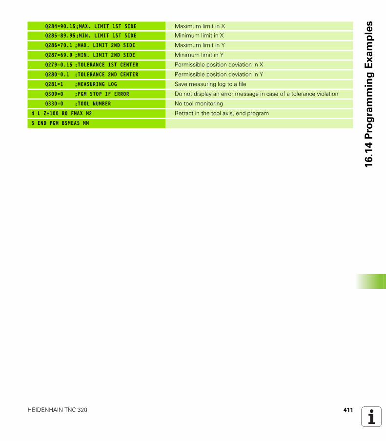
HEIDENHAIN TNC 320 411
16
.14
Pro
gra
mm
ing
Ex
am
ple
sQ284=90.15;MAX. LIMIT 1ST SIDE Maximum limit in X
Q285=89.95;MIN. LIMIT 1ST SIDE Minimum limit in X
Q286=70.1 ;MAX. LIMIT 2ND SIDE Maximum limit in Y
Q287=69.9 ;MIN. LIMIT 2ND SIDE Minimum limit in Y
Q279=0.15 ;TOLERANCE 1ST CENTER Permissible position deviation in X
Q280=0.1 ;TOLERANCE 2ND CENTER Permissible position deviation in Y
Q281=1 ;MEASURING LOG Save measuring log to a file
Q309=0 ;PGM STOP IF ERROR Do not display an error message in case of a tolerance violation
Q330=0 ;TOOL NUMBER No tool monitoring
4 L Z+100 R0 FMAX M2 Retract in the tool axis, end program
5 END PGM BSMEAS MM

412 Touch Probe Cycles: Automatic Workpiece Inspection
16
.14
Pro
gra
mm
ing
Ex
am
ple
s
Touch Probe Cycles:
Special Functions
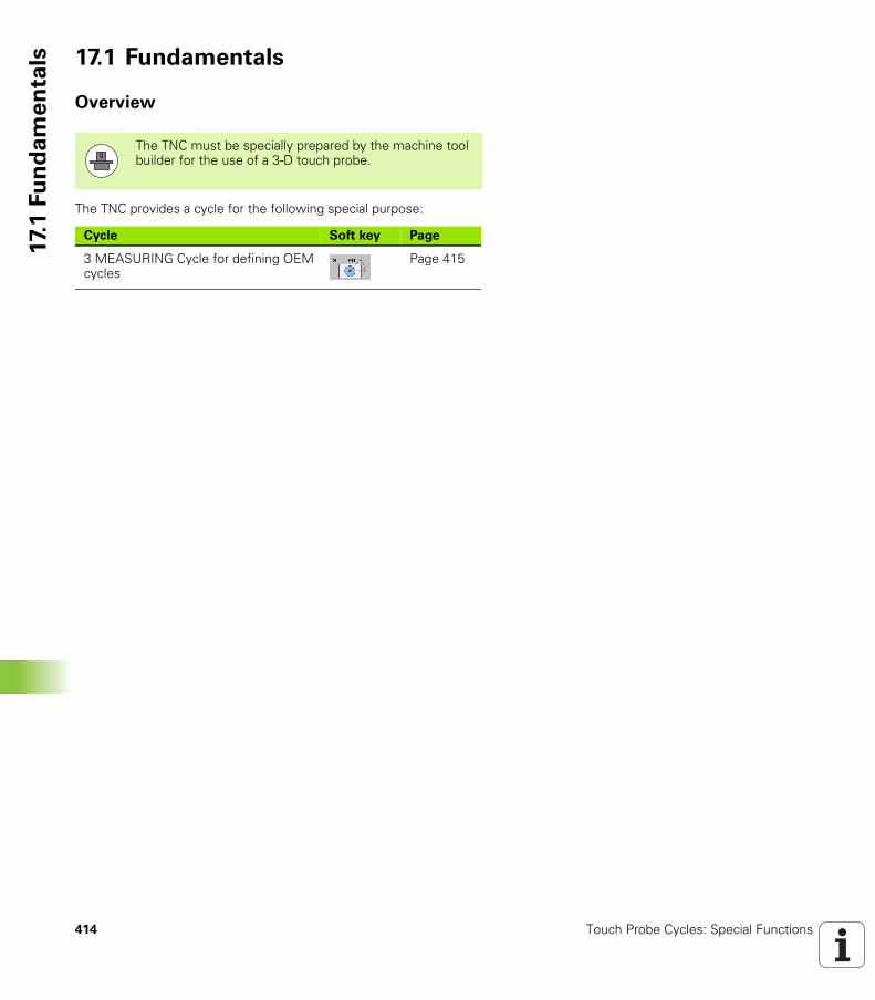
414 Touch Probe Cycles: Special Functions
17.
1 F
un
da
me
nta
ls 17.1 Fundamentals
Overview
The TNC provides a cycle for the following special purpose:
The TNC must be specially prepared by the machine tool builder for the use of a 3-D touch probe.
Cycle Soft key Page
3 MEASURING Cycle for defining OEM cycles
Page 415
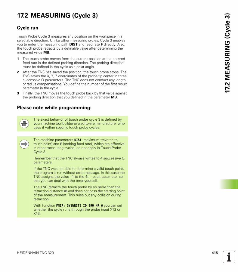
HEIDENHAIN TNC 320 415
17.
2 M
EA
SU
RIN
G (
Cycle
3)17.2 MEASURING (Cycle 3)
Cycle run
Touch Probe Cycle 3 measures any position on the workpiece in a selectable direction. Unlike other measuring cycles, Cycle 3 enables you to enter the measuring path DIST and feed rate F directly. Also, the touch probe retracts by a definable value after determining the measured value MB.
1 The touch probe moves from the current position at the entered feed rate in the defined probing direction. The probing direction must be defined in the cycle as a polar angle.
2 After the TNC has saved the position, the touch probe stops. The TNC saves the X, Y, Z coordinates of the probe-tip center in three successive Q parameters. The TNC does not conduct any length or radius compensations. You define the number of the first result parameter in the cycle.
3 Finally, the TNC moves the touch probe back by that value against the probing direction that you defined in the parameter MB.
Please note while programming:
The exact behavior of touch probe cycle 3 is defined by your machine tool builder or a software manufacturer who uses it within specific touch probe cycles.
The machine parameters DIST (maximum traverse to touch point) and F (probing feed rate), which are effective in other measuring cycles, do not apply in Touch Probe Cycle 3.
Remember that the TNC always writes to 4 successive Q parameters.
If the TNC was not able to determine a valid touch point, the program is run without error message. In this case the TNC assigns the value –1 to the 4th result parameter so that you can deal with the error yourself.
The TNC retracts the touch probe by no more than the retraction distance MB and does not pass the starting point of the measurement. This rules out any collision during retraction.
With function FN17: SYSWRITE ID 990 NR 6 you can set whether the cycle runs through the probe input X12 or X13.
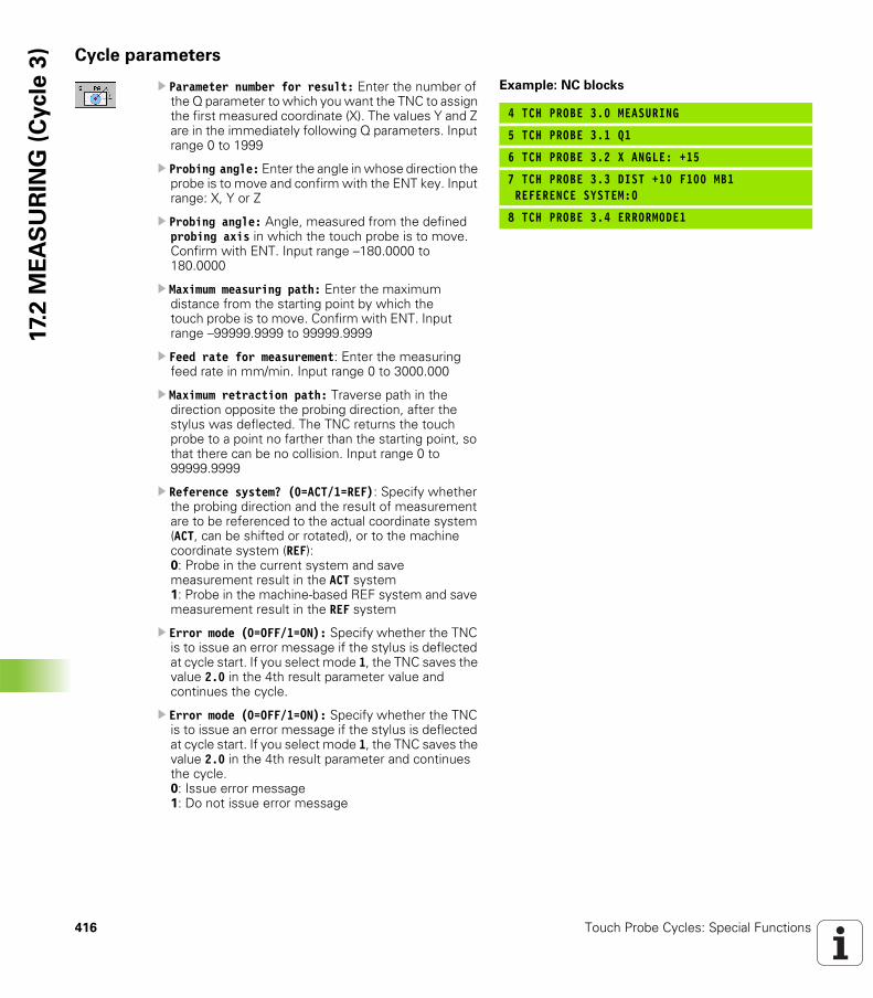
416 Touch Probe Cycles: Special Functions
17.
2 M
EA
SU
RIN
G (
Cycle
3) Cycle parameters
U Parameter number for result: Enter the number of the Q parameter to which you want the TNC to assign the first measured coordinate (X). The values Y and Z are in the immediately following Q parameters. Input range 0 to 1999
U Probing angle: Enter the angle in whose direction the probe is to move and confirm with the ENT key. Input range: X, Y or Z
U Probing angle: Angle, measured from the defined probing axis in which the touch probe is to move. Confirm with ENT. Input range –180.0000 to 180.0000
U Maximum measuring path: Enter the maximum distance from the starting point by which the touch probe is to move. Confirm with ENT. Input range –99999.9999 to 99999.9999
U Feed rate for measurement: Enter the measuring feed rate in mm/min. Input range 0 to 3000.000
U Maximum retraction path: Traverse path in the direction opposite the probing direction, after the stylus was deflected. The TNC returns the touch probe to a point no farther than the starting point, so that there can be no collision. Input range 0 to 99999.9999
U Reference system? (0=ACT/1=REF): Specify whether the probing direction and the result of measurement are to be referenced to the actual coordinate system (ACT, can be shifted or rotated), or to the machine coordinate system (REF):0: Probe in the current system and save measurement result in the ACT system1: Probe in the machine-based REF system and save measurement result in the REF system
U Error mode (0=OFF/1=ON): Specify whether the TNC is to issue an error message if the stylus is deflected at cycle start. If you select mode 1, the TNC saves the value 2.0 in the 4th result parameter value and continues the cycle.
U Error mode (0=OFF/1=ON): Specify whether the TNC is to issue an error message if the stylus is deflected at cycle start. If you select mode 1, the TNC saves the value 2.0 in the 4th result parameter and continues the cycle.0: Issue error message1: Do not issue error message
Example: NC blocks
4 TCH PROBE 3.0 MEASURING
5 TCH PROBE 3.1 Q1
6 TCH PROBE 3.2 X ANGLE: +15
7 TCH PROBE 3.3 DIST +10 F100 MB1REFERENCE SYSTEM:0
8 TCH PROBE 3.4 ERRORMODE1
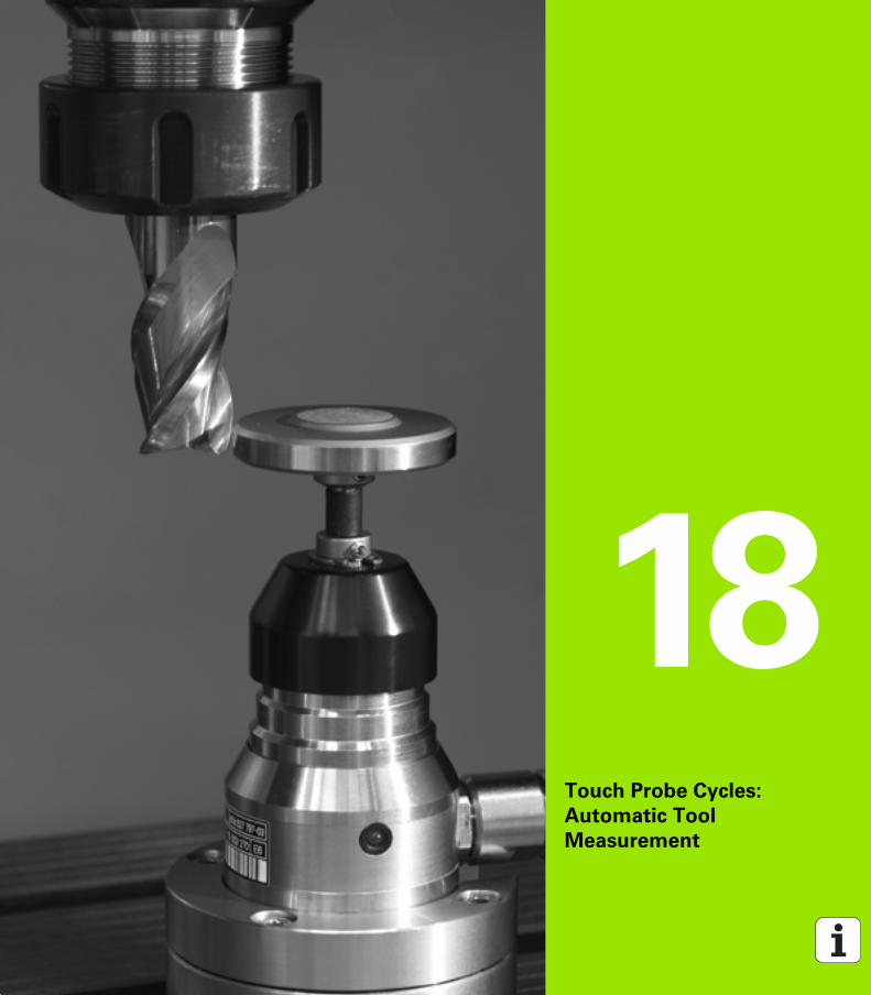
Touch Probe Cycles:
Automatic Tool
Measurement
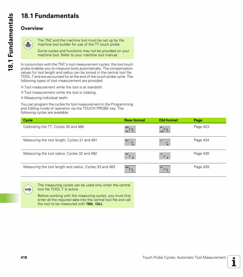
418 Touch Probe Cycles: Automatic Tool Measurement
18
.1 F
un
da
me
nta
ls 18.1 Fundamentals
Overview
In conjunction with the TNC’s tool measurement cycles, the tool touch probe enables you to measure tools automatically. The compensation values for tool length and radius can be stored in the central tool file TOOL.T and are accounted for at the end of the touch probe cycle. The following types of tool measurement are provided:
Tool measurement while the tool is at standstill.Tool measurement while the tool is rotating.Measuring individual teeth.
You can program the cycles for tool measurement in the Programming and Editing mode of operation via the TOUCH PROBE key. The following cycles are available:
The TNC and the machine tool must be set up by the machine tool builder for use of the TT touch probe.
Some cycles and functions may not be provided on your machine tool. Refer to your machine tool manual.
Cycle New format Old format Page
Calibrating the TT, Cycles 30 and 480 Page 423
Measuring the tool length, Cycles 31 and 481 Page 424
Measuring the tool radius, Cycles 32 and 482 Page 426
Measuring the tool length and radius, Cycles 33 and 483 Page 428
The measuring cycles can be used only when the central tool file TOOL.T is active.
Before working with the measuring cycles, you must first enter all the required data into the central tool file and call the tool to be measured with TOOL CALL.
HEIDENHAIN TNC 320 419
18
.1 F
un
da
me
nta
lsDifferences between Cycles 31 to 33 and
Cycles 481 to 483
The features and the operating sequences are absolutely identical. There are only two differences between Cycles 31 to 33 and Cycles 481 to 483:
Cycles 481 to 483 are also available in controls for ISO programming under G481 to G483.Instead of a selectable parameter for the status of the measurement, the new cycles use the fixed parameter Q199.
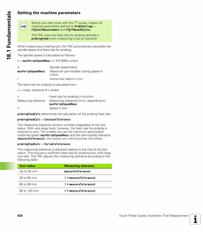
420 Touch Probe Cycles: Automatic Tool Measurement
18
.1 F
un
da
me
nta
ls Setting the machine parameters
When measuring a rotating tool, the TNC automatically calculates the spindle speed and feed rate for probing.
The spindle speed is calculated as follows:
n = maxPeriphSpeedMeas / (r • 0.0063) where
The feed rate for probing is calculated from:
v = meas. tolerance • n where
probingFeedCalc determines the calculation of the probing feed rate:
probingFeedCalc = ConstantTolerance:
The measuring tolerance remains constant regardless of the tool radius. With very large tools, however, the feed rate for probing is reduced to zero. The smaller you set the maximum permissible rotational speed (maxPeriphSpeedMeas) and the permissible tolerance (measureTolerance1), the sooner you will encounter this effect.
probingFeedCalc = VariableTolerance:
The measuring tolerance is adjusted relative to the size of the tool radius. This ensures a sufficient feed rate for probing even with large tool radii. The TNC adjusts the measuring tolerance according to the following table:
Before you start work with the TT cycles, inspect all machine parameters defined in ProbSettings > CfgToolMeasurement and CfgTTRoundStylus.
The TNC uses the feed rate for probing defined in probingFeed when measuring a tool at standstill.
n Spindle speed [rpm]maxPeriphSpeedMeas Maximum permissible cutting speed in
m/minr Active tool radius in mm
v Feed rate for probing in mm/minMeasuring tolerance Measuring tolerance [mm], depending on
maxPeriphSpeedMeasn Speed in rpm
Tool radius Measuring tolerance
Up to 30 mm measureTolerance1
30 to 60 mm 2 • measureTolerance1
60 to 90 mm 3 • measureTolerance1
90 to 120 mm 4 • measureTolerance1
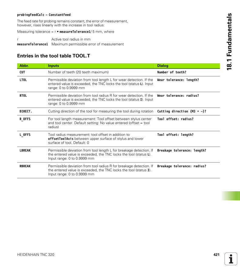
HEIDENHAIN TNC 320 421
18
.1 F
un
da
me
nta
lsprobingFeedCalc = ConstantFeed:
The feed rate for probing remains constant, the error of measurement, however, rises linearly with the increase in tool radius:
Measuring tolerance = r • measureTolerance1/ 5 mm, where
Entries in the tool table TOOL.T
r Active tool radius in mmmeasureTolerance1 Maximum permissible error of measurement
Abbr. Inputs Dialog
CUT Number of teeth (20 teeth maximum) Number of teeth?
LTOL Permissible deviation from tool length L for wear detection. If the entered value is exceeded, the TNC locks the tool (status L). Input range: 0 to 0.9999 mm
Wear tolerance: length?
RTOL Permissible deviation from tool radius R for wear detection. If the entered value is exceeded, the TNC locks the tool (status I). Input range: 0 to 0.9999 mm
Wear tolerance: radius?
DIRECT. Cutting direction of the tool for measuring the tool during rotation Cutting direction (M3 = –)?
R_OFFS For tool length measurement: Tool offset between stylus center and tool center. Default setting: No value entered (offset = tool radius)
Tool offset: radius?
L_OFFS Tool radius measurement: tool offset in addition to offsetToolAxis between upper surface of stylus and lower surface of tool. Default: 0
Tool offset: length?
LBREAK Permissible deviation from tool length L for breakage detection. If the entered value is exceeded, the TNC locks the tool (status L). Input range: 0 to 0.9999 mm
Breakage tolerance: length?
RBREAK Permissible deviation from tool radius R for breakage detection. If the entered value is exceeded, the TNC locks the tool (status I). Input range: 0 to 0.9999 mm
Breakage tolerance: radius?
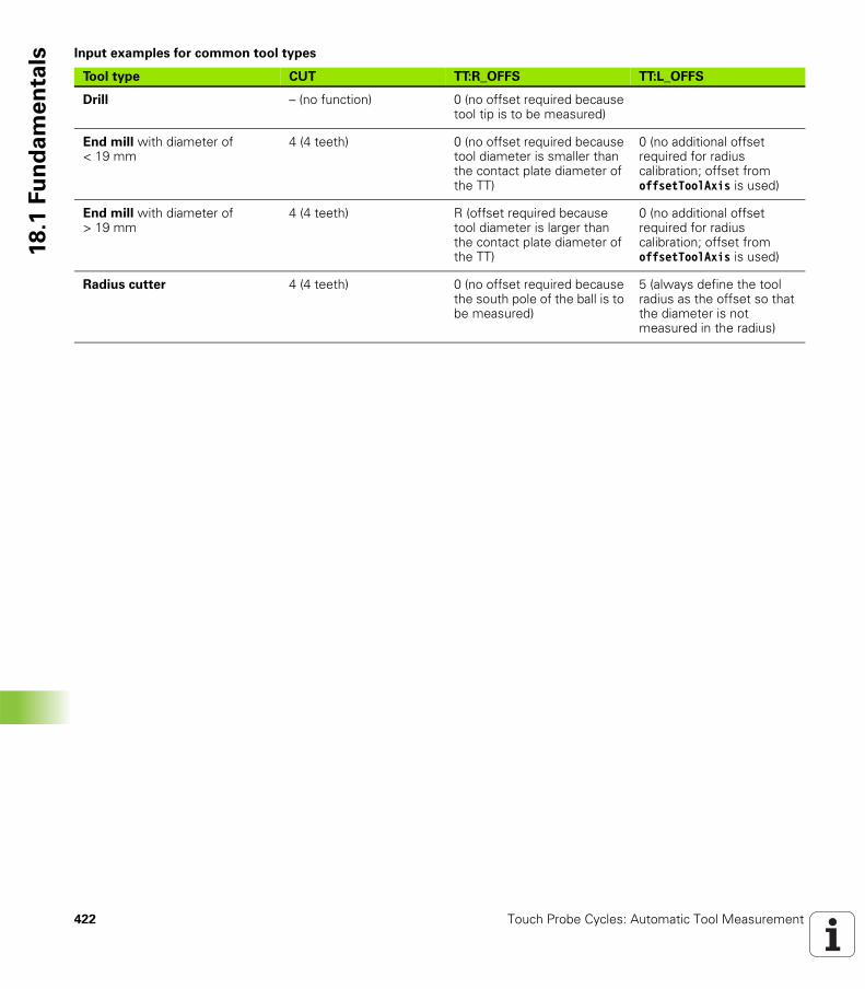
422 Touch Probe Cycles: Automatic Tool Measurement
18
.1 F
un
da
me
nta
ls Input examples for common tool types
Tool type CUT TT:R_OFFS TT:L_OFFS
Drill – (no function) 0 (no offset required because tool tip is to be measured)
End mill with diameter of < 19 mm
4 (4 teeth) 0 (no offset required because tool diameter is smaller than the contact plate diameter of the TT)
0 (no additional offset required for radius calibration; offset from offsetToolAxis is used)
End mill with diameter of > 19 mm
4 (4 teeth) R (offset required because tool diameter is larger than the contact plate diameter of the TT)
0 (no additional offset required for radius calibration; offset from offsetToolAxis is used)
Radius cutter 4 (4 teeth) 0 (no offset required because the south pole of the ball is to be measured)
5 (always define the tool radius as the offset so that the diameter is not measured in the radius)
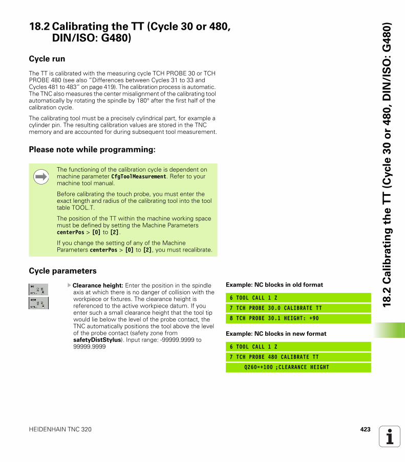
HEIDENHAIN TNC 320 423
18
.2 C
ali
bra
tin
g t
he
TT
(C
ycle
30
or
48
0,
DIN
/IS
O:
G4
80
)18.2 Calibrating the TT (Cycle 30 or 480, DIN/ISO: G480)
Cycle run
The TT is calibrated with the measuring cycle TCH PROBE 30 or TCH PROBE 480 (see also ”Differences between Cycles 31 to 33 and Cycles 481 to 483” on page 419). The calibration process is automatic. The TNC also measures the center misalignment of the calibrating tool automatically by rotating the spindle by 180° after the first half of the calibration cycle.
The calibrating tool must be a precisely cylindrical part, for example a cylinder pin. The resulting calibration values are stored in the TNC memory and are accounted for during subsequent tool measurement.
Please note while programming:
Cycle parameters
U Clearance height: Enter the position in the spindle axis at which there is no danger of collision with the workpiece or fixtures. The clearance height is referenced to the active workpiece datum. If you enter such a small clearance height that the tool tip would lie below the level of the probe contact, the TNC automatically positions the tool above the level of the probe contact (safety zone from safetyDistStylus). Input range: -99999.9999 to 99999.9999
The functioning of the calibration cycle is dependent on machine parameter CfgToolMeasurement. Refer to your machine tool manual.
Before calibrating the touch probe, you must enter the exact length and radius of the calibrating tool into the tool table TOOL.T.
The position of the TT within the machine working space must be defined by setting the Machine Parameters centerPos > [0] to [2].
If you change the setting of any of the Machine Parameters centerPos > [0] to [2], you must recalibrate.
Example: NC blocks in old format
6 TOOL CALL 1 Z
7 TCH PROBE 30.0 CALIBRATE TT
8 TCH PROBE 30.1 HEIGHT: +90
Example: NC blocks in new format
6 TOOL CALL 1 Z
7 TCH PROBE 480 CALIBRATE TT
Q260=+100 ;CLEARANCE HEIGHT
424 Touch Probe Cycles: Automatic Tool Measurement
18
.3 M
ea
su
rin
g t
he
To
ol
Le
ng
th (
Cycle
31
or
48
1,
DIN
/IS
O:
G4
81
) 18.3 Measuring the Tool Length (Cycle 31 or 481, DIN/ISO: G481)
Cycle run
To measure the tool length, program the measuring cycle TCH PROBE 31 or TCH PROBE 480 (see also ”Differences between Cycles 31 to 33 and Cycles 481 to 483” on page 419). Via input parameters you can measure the length of a tool by three methods:
If the tool diameter is larger than the diameter of the measuring surface of the TT, you can measure the tool while it is rotating.If the tool diameter is smaller than the diameter of the measuring surface of the TT, or if you are measuring the length of a drill or spherical cutter, you can measure the tool while it is at standstill.If the tool diameter is larger than the diameter of the measuring surface of the TT, you can measure the individual teeth of the tool while it is at standstill.
Cycle for measuring a tool during rotation
The control determines the longest tooth of a rotating tool by positioning the tool to be measured at an offset to the center of the touch probe system and then moving it toward the measuring surface until it contacts the surface. The offset is programmed in the tool table under Tool offset: Radius (TT: R_OFFS).
Cycle for measuring a tool during standstill (e.g. for drills)
The control positions the tool to be measured over the center of the measuring surface. It then moves the non-rotating tool toward the measuring surface of the TT until it touches the surface. To activate this function, enter zero for the tool offset: Radius (TT: R_OFFS) in the tool table.
Cycle for measuring individual teeth
The TNC pre-positions the tool to be measured to a position at the side of the touch probe head. The distance from the tip of the tool to the upper edge of the touch probe head is defined in offsetToolAxis. You can enter an additional offset with tool offset: Length (TT: L_OFFS) in the tool table. The TNC probes the tool radially during rotation to determine the starting angle for measuring the individual teeth. It then measures the length of each tooth by changing the corresponding angle of spindle orientation. To activate this function, program TCH PROBE 31 = 1 for CUTTER MEASUREMENT.
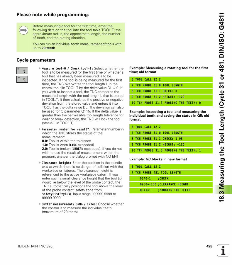
HEIDENHAIN TNC 320 425
18
.3 M
ea
su
rin
g t
he
To
ol
Le
ng
th (
Cycle
31
or
48
1,
DIN
/IS
O:
G4
81
)Please note while programming:
Cycle parameters
U Measure tool=0 / Check tool=1: Select whether the tool is to be measured for the first time or whether a tool that has already been measured is to be inspected. If the tool is being measured for the first time, the TNC overwrites the tool length L in the central tool file TOOL.T by the delta value DL = 0. If you wish to inspect a tool, the TNC compares the measured length with the tool length L that is stored in TOOL.T. It then calculates the positive or negative deviation from the stored value and enters it into TOOL.T as the delta value DL. The deviation can also be used for Q parameter Q115. If the delta value is greater than the permissible tool length tolerance for wear or break detection, the TNC will lock the tool (status L in TOOL.T).
U Parameter number for result?: Parameter number in which the TNC stores the status of the measurement:0.0: Tool is within the tolerance1.0: Tool is worn (LTOL exceeded)2.0: Tool is broken (LBREAK exceeded). If you do not wish to use the result of measurement within the program, answer the dialog prompt with NO ENT.
U Clearance height: Enter the position in the spindle axis at which there is no danger of collision with the workpiece or fixtures. The clearance height is referenced to the active workpiece datum. If you enter such a small clearance height that the tool tip would lie below the level of the probe contact, the TNC automatically positions the tool above the level of the probe contact (safety zone from safetyDistStylus). Input range –99999.9999 to 99999.9999
U Cutter measurement? 0=No / 1=Yes: Choose whether the control is to measure the individual teeth (maximum of 20 teeth)
Before measuring a tool for the first time, enter the following data on the tool into the tool table TOOL.T: the approximate radius, the approximate length, the number of teeth, and the cutting direction.
You can run an individual tooth measurement of tools with up to 20 teeth.
Example: Measuring a rotating tool for the first time; old format
6 TOOL CALL 12 Z
7 TCH PROBE 31.0 TOOL LENGTH
8 TCH PROBE 31.1 CHECK: 0
9 TCH PROBE 31.2 HEIGHT: +120
10 TCH PROBE 31.3 PROBING THE TEETH: 0
Example: Inspecting a tool and measuring the individual teeth and saving the status in Q5; old format
6 TOOL CALL 12 Z
7 TCH PROBE 31.0 TOOL LENGTH
8 TCH PROBE 31.1 CHECK: 1 Q5
9 TCH PROBE 31.2 HEIGHT: +120
10 TCH PROBE 31.3 PROBING THE TEETH: 1
Example: NC blocks in new format
6 TOOL CALL 12 Z
7 TCH PROBE 481 TOOL LENGTH
Q340=1 ;CHECK
Q260=+100 ;CLEARANCE HEIGHT
Q341=1 ;PROBING THE TEETH
426 Touch Probe Cycles: Automatic Tool Measurement
18
.4 M
ea
su
rin
g t
he
To
ol
Ra
diu
s (
Cycle
32
or
48
2,
ISO
: G
48
2) 18.4 Measuring the Tool Radius
(Cycle 32 or 482, ISO: G482)
Cycle run
To measure the tool radius, program the cycle TCH PROBE 32 or TCH PROBE 482 (see also ”Differences between Cycles 31 to 33 and Cycles 481 to 483” on page 419). Via input parameters you can measure the radius of a tool by two methods:
Measuring the tool while it is rotating.Measuring the tool while it is rotating and subsequently measuring the individual teeth.
The TNC pre-positions the tool to be measured to a position at the side of the touch probe head. The distance from the tip of the milling tool to the upper edge of the touch probe head is defined in offsetToolAxis. The TNC probes the tool radially while it is rotating. If you have programmed a subsequent measurement of individual teeth, the control measures the radius of each tooth with the aid of oriented spindle stops.
Please note while programming:
Before measuring a tool for the first time, enter the following data on the tool into the tool table TOOL.T: the approximate radius, the approximate length, the number of teeth, and the cutting direction.
Cylindrical tools with diamond surfaces can be measured with stationary spindle. To do so, define the number of teeth (CUT) with 0 in the tool table and adjust the machine parameter CfgToolMeasurement. Refer to your machine tool manual.
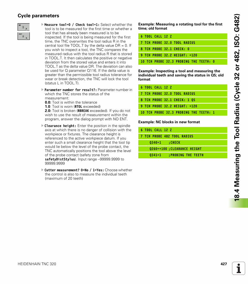
HEIDENHAIN TNC 320 427
18
.4 M
ea
su
rin
g t
he
To
ol
Ra
diu
s (
Cycle
32
or
48
2,
ISO
: G
48
2)Cycle parameters
U Measure tool=0 / Check tool=1: Select whether the tool is to be measured for the first time or whether a tool that has already been measured is to be inspected. If the tool is being measured for the first time, the TNC overwrites the tool radius R in the central tool file TOOL.T by the delta value DR = 0. If you wish to inspect a tool, the TNC compares the measured radius with the tool radius R that is stored in TOOL.T. It then calculates the positive or negative deviation from the stored value and enters it into TOOL.T as the delta value DR. The deviation can also be used for Q parameter Q116. If the delta value is greater than the permissible tool radius tolerance for wear or break detection, the TNC will lock the tool (status L in TOOL.T).
U Parameter number for result?: Parameter number in which the TNC stores the status of the measurement:0.0: Tool is within the tolerance1.0: Tool is worn (RTOL exceeded)2.0: Tool is broken (RBREAK exceeded). If you do not wish to use the result of measurement within the program, answer the dialog prompt with NO ENT.
U Clearance height: Enter the position in the spindle axis at which there is no danger of collision with the workpiece or fixtures. The clearance height is referenced to the active workpiece datum. If you enter such a small clearance height that the tool tip would lie below the level of the probe contact, the TNC automatically positions the tool above the level of the probe contact (safety zone from safetyDistStylus). Input range –99999.9999 to 99999.9999
U Cutter measurement? 0=No / 1=Yes: Choose whether the control is also to measure the individual teeth (maximum of 20 teeth)
Example: Measuring a rotating tool for the first time; old format
6 TOOL CALL 12 Z
7 TCH PROBE 32.0 TOOL RADIUS
8 TCH PROBE 32.1 CHECK: 0
9 TCH PROBE 32.2 HEIGHT: +120
10 TCH PROBE 32.3 PROBING THE TEETH: 0
Example: Inspecting a tool and measuring the individual teeth and saving the status in Q5; old format
6 TOOL CALL 12 Z
7 TCH PROBE 32.0 TOOL RADIUS
8 TCH PROBE 32.1 CHECK: 1 Q5
9 TCH PROBE 32.2 HEIGHT: +120
10 TCH PROBE 32.3 PROBING THE TEETH: 1
Example: NC blocks in new format
6 TOOL CALL 12 Z
7 TCH PROBE 482 TOOL RADIUS
Q340=1 ;CHECK
Q260=+100 ;CLEARANCE HEIGHT
Q341=1 ;PROBING THE TEETH
428 Touch Probe Cycles: Automatic Tool Measurement
18
.5 M
ea
su
rin
g T
oo
l L
en
gth
an
d R
ad
ius (
Cycle
33
or
48
3,
ISO
: G
48
3) 18.5 Measuring Tool Length and
Radius (Cycle 33 or 483, ISO: G483)
Cycle run
To measure both the length and radius of a tool, program the measuring cycle TCH PROBE 33 or TCH PROBE 482 (see also ”Differences between Cycles 31 to 33 and Cycles 481 to 483” on page 419). This cycle is particularly suitable for the first measurement of tools, as it saves time when compared with individual measurement of length and radius. In input parameters you can select the desired type of measurement:
Measuring the tool while it is rotating.Measuring the tool while it is rotating and subsequently measuring the individual teeth.
The TNC measures the tool in a fixed programmed sequence. First it measures the tool radius, then the tool length. The sequence of measurement is the same as for measuring cycles 31 and 32.
Please note while programming:
Before measuring a tool for the first time, enter the following data on the tool into the tool table TOOL.T: the approximate radius, the approximate length, the number of teeth, and the cutting direction.
Cylindrical tools with diamond surfaces can be measured with stationary spindle. To do so, define the number of teeth (CUT) with 0 in the tool table and adjust the machine parameter CfgToolMeasurement. Refer to your machine tool manual.

HEIDENHAIN TNC 320 429
18
.5 M
ea
su
rin
g T
oo
l L
en
gth
an
d R
ad
ius (
Cycle
33
or
48
3,
ISO
: G
48
3)Cycle parameters
U Measure tool=0 / Check tool=1: Select whether the tool is to be measured for the first time or whether a tool that has already been measured is to be inspected. If the tool is being measured for the first time, the TNC overwrites the tool radius R and the tool length L in the central tool file TOOL.T by the delta values DR = 0 and DL = 0. If you wish to inspect a tool, the TNC compares the measured data with the tool data stored in TOOL.T. The TNC calculates the deviations and enters them as positive or negative delta values DR and DL in TOOL.T. The deviations are also available in the Q parameters Q115 and Q116. If the delta values are greater than the permissible tool tolerances for wear or break detection, the TNC will lock the tool (status L in TOOL.T).
U Parameter number for result?: Parameter number in which the TNC stores the status of the measurement:0.0: Tool is within the tolerance1.0: Tool is worn (LTOL or/and RTOL exceeded)2.0: Tool is broken (LBREAK or/and RBREAK exceeded). If you do not wish to use the result of measurement within the program, answer the dialog prompt with NO ENT.
U Clearance height: Enter the position in the spindle axis at which there is no danger of collision with the workpiece or fixtures. The clearance height is referenced to the active workpiece datum. If you enter such a small clearance height that the tool tip would lie below the level of the probe contact, the TNC automatically positions the tool above the level of the probe contact (safety zone from safetyDistStylus). Input range –99999.9999 to 99999.9999
U Cutter measurement? 0=No / 1=Yes: Choose whether the control is also to measure the individual teeth (maximum of 20 teeth)
Example: Measuring a rotating tool for the first time; old format
6 TOOL CALL 12 Z
7 TCH PROBE 33.0 MEASURE TOOL
8 TCH PROBE 33.1 CHECK: 0
9 TCH PROBE 33.2 HEIGHT: +120
10 TCH PROBE 33.3 PROBING THE TEETH: 0
Example: Inspecting a tool and measuring the individual teeth and saving the status in Q5; old format
6 TOOL CALL 12 Z
7 TCH PROBE 33.0 MEASURE TOOL
8 TCH PROBE 33.1 CHECK: 1 Q5
9 TCH PROBE 33.2 HEIGHT: +120
10 TCH PROBE 33.3 PROBING THE TEETH: 1
Example: NC blocks in new format
6 TOOL CALL 12 Z
7 TCH PROBE 483 MEASURE TOOL
Q340=1 ;CHECK
Q260=+100 ;CLEARANCE HEIGHT
Q341=1 ;PROBING THE TEETH
430 Touch Probe Cycles: Automatic Tool Measurement
18
.5 M
ea
su
rin
g T
oo
l L
en
gth
an
d R
ad
ius (
Cycle
33
or
48
3,
ISO
: G
48
3)
HEIDENHAIN TNC 320 431
Ind
exSymbole
3-D touch probes ... 36, 278
AAngle of a plane, measuring ... 405Angle, measuring in a plane ... 405Automatic tool measurement ... 421Axis-specific scaling ... 256
BBack boring ... 73Basic rotation
Measuring during program run ... 288
Setting directly ... 302Bolt hole circle ... 159Bolt hole circle, measuring ... 401Bore milling ... 81Boring ... 65
CCentering ... 59Circle, measuring from inside ... 376Circle, measuring from outside ... 380Circular pocket
Roughing+finishing ... 132Circular slot
Roughing+finishing ... 141Circular stud ... 150Classification of results ... 367Compensating workpiece misalignment
By measuring two points of a line ... 290
Over two holes ... 293Over two studs ... 296Via rotary axis ... 299, 303
Confidence range ... 282Consider basic rotation ... 278Contour cycles ... 168Contour train ... 186Coordinate transformation ... 242Coordinate, measuring a single ... 398Cycle
Calling ... 42Defining ... 41
Cycles and point tables ... 55Cylinder surface
Contour machining ... 197Ridge machining ... 203Slot machining ... 200
DDatum shift
With datum tables ... 244Within the program ... 243
Deepened starting point for drilling ... 80, 85
Drilling ... 61, 69, 77Deepened starting point ... 80, 85
Drilling cycles ... 58Dwell time ... 269
EExternal thread milling ... 118
FFace milling ... 233FCL function ... 6Feature content level ... 6Floor finishing ... 183
HHelical thread drilling/milling ... 114Hole, measuring ... 376
KKey-way milling
Roughing+finishing ... 136
MMachine parameters for 3-D touch
probes ... 281Machining patterns ... 44Measurement results in Q
parameters ... 312, 367Measuring angles ... 373Mirror image ... 250Multiple measurements ... 282
OOriented spindle stop ... 272
PPattern definition ... 44Pecking ... 77, 84
Deepened starting point ... 80, 85Point pattern
Circular ... 159Linear ... 162Overview ... 158
Point patternsPoint tables ... 52Positioning logic ... 283Preset table ... 312Presetting automatically ... 310
Center of 4 holes ... 351Center of bolt hole circle ... 345Center of circular pocket (or
hole) ... 328Center of circular stud ... 332Center of rectangular pocket ... 320Center of rectangular stud ... 324In any axis ... 355In inside corner ... 341In the touch probe axis ... 349Outside corner ... 336Ridge center ... 317Slot center ... 313
Probing feed rate ... 282Program call
Via cycle ... 270
RReaming ... 63Recording the results of
measurement ... 365Rectangular pocket
Roughing+finishing ... 127Rectangular pocket
measurement ... 388Rectangular stud ... 146Rectangular stud, measuring ... 384Reference point
Save in a datum table ... 312Save in the preset table ... 312
Result parameters ... 312, 367Ridge, measuring from outside ... 395Rotation ... 252Rough out: See SL Cycles: Rough-outRuled surface ... 229
432
Ind
ex S
Scaling factor ... 254Side finishing ... 184Single-fluted deep-hole drilling ... 84SL CyclesSL cycles
Contour data ... 176Contour geometry cycle ... 171Contour train ... 186Floor finishing ... 183Fundamentals ... 168, 222Overlapping contours ... 172, 216Pilot drilling ... 178Rough-out ... 180Side finishing ... 184
SL Cycles with Complex Contour Formula
SL cycles with simple contour formula ... 222
Slot width, measuring ... 392
TTapping
With a floating tap holder ... 93With chip breaking ... 98Without floating tap holder ... 95, 98
Thread drilling/milling ... 110Thread milling, fundamentals ... 101Thread milling, internal ... 103Thread milling/countersinking ... 106Tilting the working plane ... 258Tolerance monitoring ... 368Tool compensation ... 368Tool measurement ... 421
Calibrating the TT ... 423Machine parameters ... 420Measuring tool length and
radius ... 428Tool length ... 424Tool radius ... 426
Tool monitoring ... 368Touch probe cycles
Touch probe cycles for automatic operation ... 280
Touch probe data ... 285Touch probe table ... 284
UUniversal drilling ... 69, 77
WWidth, measuring from inside ... 392Width, measuring from outside ... 395Working plane, tilting the ... ... 258
Cycle ... 258Guide ... 264
Workpiece measurement ... 364
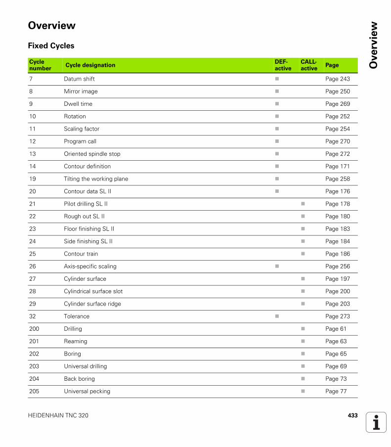
HEIDENHAIN TNC 320 433
Ove
rvie
wOverview
Fixed Cycles
Cycle number
Cycle designationDEF-active
CALL-active
Page
7 Datum shift Page 243
8 Mirror image Page 250
9 Dwell time Page 269
10 Rotation Page 252
11 Scaling factor Page 254
12 Program call Page 270
13 Oriented spindle stop Page 272
14 Contour definition Page 171
19 Tilting the working plane Page 258
20 Contour data SL II Page 176
21 Pilot drilling SL II Page 178
22 Rough out SL II Page 180
23 Floor finishing SL II Page 183
24 Side finishing SL II Page 184
25 Contour train Page 186
26 Axis-specific scaling Page 256
27 Cylinder surface Page 197
28 Cylindrical surface slot Page 200
29 Cylinder surface ridge Page 203
32 Tolerance Page 273
200 Drilling Page 61
201 Reaming Page 63
202 Boring Page 65
203 Universal drilling Page 69
204 Back boring Page 73
205 Universal pecking Page 77
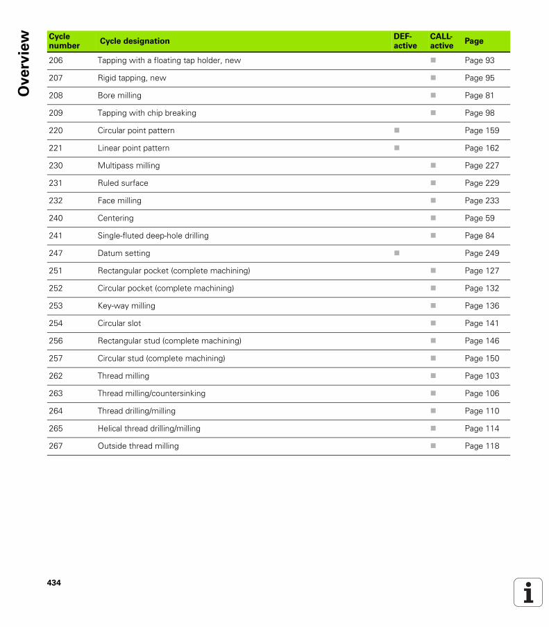
434
Ove
rvie
w
206 Tapping with a floating tap holder, new Page 93
207 Rigid tapping, new Page 95
208 Bore milling Page 81
209 Tapping with chip breaking Page 98
220 Circular point pattern Page 159
221 Linear point pattern Page 162
230 Multipass milling Page 227
231 Ruled surface Page 229
232 Face milling Page 233
240 Centering Page 59
241 Single-fluted deep-hole drilling Page 84
247 Datum setting Page 249
251 Rectangular pocket (complete machining) Page 127
252 Circular pocket (complete machining) Page 132
253 Key-way milling Page 136
254 Circular slot Page 141
256 Rectangular stud (complete machining) Page 146
257 Circular stud (complete machining) Page 150
262 Thread milling Page 103
263 Thread milling/countersinking Page 106
264 Thread drilling/milling Page 110
265 Helical thread drilling/milling Page 114
267 Outside thread milling Page 118
Cycle number
Cycle designationDEF-active
CALL-active
Page
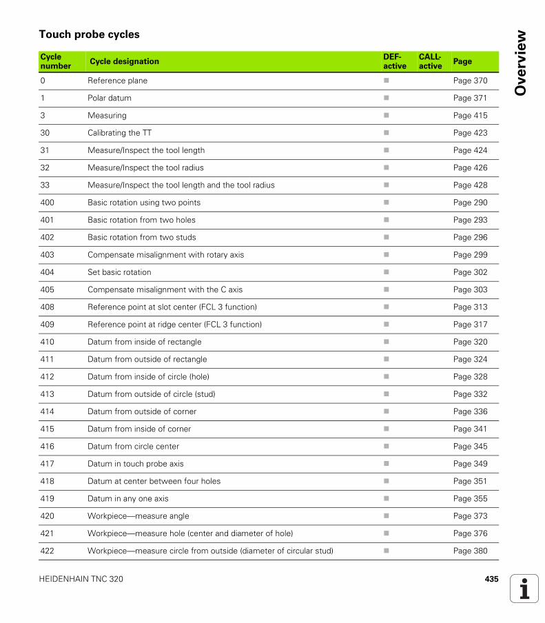
HEIDENHAIN TNC 320 435
Ove
rvie
wTouch probe cycles
Cycle number
Cycle designationDEF-active
CALL-active
Page
0 Reference plane Page 370
1 Polar datum Page 371
3 Measuring Page 415
30 Calibrating the TT Page 423
31 Measure/Inspect the tool length Page 424
32 Measure/Inspect the tool radius Page 426
33 Measure/Inspect the tool length and the tool radius Page 428
400 Basic rotation using two points Page 290
401 Basic rotation from two holes Page 293
402 Basic rotation from two studs Page 296
403 Compensate misalignment with rotary axis Page 299
404 Set basic rotation Page 302
405 Compensate misalignment with the C axis Page 303
408 Reference point at slot center (FCL 3 function) Page 313
409 Reference point at ridge center (FCL 3 function) Page 317
410 Datum from inside of rectangle Page 320
411 Datum from outside of rectangle Page 324
412 Datum from inside of circle (hole) Page 328
413 Datum from outside of circle (stud) Page 332
414 Datum from outside of corner Page 336
415 Datum from inside of corner Page 341
416 Datum from circle center Page 345
417 Datum in touch probe axis Page 349
418 Datum at center between four holes Page 351
419 Datum in any one axis Page 355
420 Workpiece—measure angle Page 373
421 Workpiece—measure hole (center and diameter of hole) Page 376
422 Workpiece—measure circle from outside (diameter of circular stud) Page 380
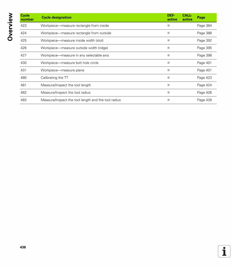
436
Ove
rvie
w
423 Workpiece—measure rectangle from inside Page 384
424 Workpiece—measure rectangle from outside Page 388
425 Workpiece—measure inside width (slot) Page 392
426 Workpiece—measure outside width (ridge) Page 395
427 Workpiece—measure in any selectable axis Page 398
430 Workpiece—measure bolt hole circle Page 401
431 Workpiece—measure plane Page 401
480 Calibrating the TT Page 423
481 Measure/Inspect the tool length Page 424
482 Measure/Inspect the tool radius Page 426
483 Measure/Inspect the tool length and the tool radius Page 428
Cycle number
Cycle designationDEF-active
CALL-active
Page
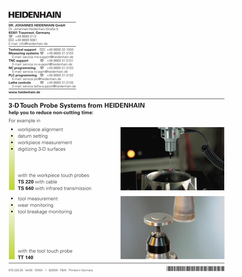
������������ ��� ��������������� ��������������������������������������� �������������� ������������������ ��!�"����������
����� ��!�"�##$�� � ����������#�����%��"�� �&�"�"���" � ����������������
����� ����$�%������&''���"�����������'�"�##$�� � ����������������
����� ����$�%��%��&''���"����������'�#�$&���� �& � ����������������
����� ����$�%��%�'(�"����������()'�#�$&���� �& � ���������������#
����� ����$�%��'�%"����������)������$���$!" � ����������������
����� ����$�%��������&''���"����������
***��� +���� ��+�
3-D Touch Probe Systems from HEIDENHAINhelp you to reduce non-cutting time:
For example in
workpiece alignment• datum setting• workpiece measurement• digitizing 3-D surfaces•
with the workpiece touch probesTS 220 with cableTS 640 with infrared transmission
tool measurement• wear monitoring• tool breakage monitoring•
with the tool touch probeTT 140
679 220-20 · Ver00 · SW04 · 1 · 9/2009 · F&W · Printed in Germany