to 00-25-172cl-3 technical manual checklist hot refueling...
TRANSCRIPT
TO 00-25-172CL-3
TECHNICAL MANUALCHECKLIST
HOT REFUELING OF U.S. NAVY AIRCRAFT(ATOS)
This Publication Augments TO 00-25-172.
DISTRIBUTION STATEMENT A - Approved for publicrelease; distribution is unlimited (WR-ALC/PA Cert. No. 04-10-74). Other request for this document shall be referred to584 CBSS/GBMUDE, Robins AFB GA 31098. Questionsconcerning technical content shall be referred to 579CBSS/GBZAB, Robins AFB GA 31098.
Published under authority of the Secretary of the Air Force
22 OCTOBER 1990CHANGE 2 - 15 MAY 2006
BASIC AND ALL CHANGES HAVE BEEN MERGEDTO MAKE THIS A COMPLETE PUBLICATION
Downloaded from http://www.everyspec.com

TO 00-25-172CL-3
LIST OF EFFECTIVE PAGESInsert latest changed pages; dispose of superseded pages in accordance with applica-ble regulations.
NOTE: On a changed page, the portion of the text affected by the latest change isindicated by a vertical line, or other change symbol, in the outer margin of the page.Changes to illustrations are indicated by miniature pointing hands. Changes to wiringdiagrams by shaded areas.
Dates of issue for original and changed pages are:Original................... 0 ...................... 22 October 1990Change.................... 1 ....................... 26 August 2002Change.................... 2 ............................ 15 May 2006
Total number of pages in this manual is 64, consisting of thefollowing:
Page *Change Page *Change Page *ChangeNo. No. No. No. No. No.
Title ..................... 2A .......................... 2i ............................1ii........................... 21-1 ....................... 21-2 ........................01-3 ....................... 21-4 - 1-7................01-8 Blank .............02-1 - 2-6................03-1 - 3-6................04-1 - 4-5................04-6 Blank .............05-1 ........................05-2 - 5-4 ............... 25-4.1 Added ........ 25-4.2 Blank......... 25-5 ....................... 25-6 - 5-8................06-1 - 6-7................06-8 Blank .............07-1 - 7-15 Added..17-16 Blank ...........1
*Zero in this column indicates an original page
A Change 2
Downloaded from http://www.everyspec.com

TO 00-25-172CL-3
TABLE OF CONTENTS
Section/Para Page
INTRODUCTION........................................ ii
I SUPPORT EQUIPMENT FORHOT REFUELINGOPERATIONS.......................................... 1-1
II EA/A-6 HOT REFUELINGPROCEDURES......................................... 2-1
III E-2 HOT REFUELING............................ 3-1
IV F-14 HOT REFUELINGPROCEDURES......................................... 4-1
V F-18 HOT REFUELINGPROCEDURES......................................... 5-1
VI S-3 HOT REFUELINGPROCEDURE........................................... 6-1
VII AV-8 HOT REFUELINGPROCEDURES......................................... 7-1
Change 1 i
Downloaded from http://www.everyspec.com
TO 00-25-172CL-3
INTRODUCTIONINTRODUCTION AND GENERALINSTRUCTIONS
In a wartime situation, U.S. Navy aircraft mayland at USAF bases to refuel on its way to homebase or carrier. The Navy aircraft may need to behot refueled (i.e., refueled with an engine running)in order to minimize ground turnaround time andavoid the need for support equipment.
This checklist provides the procedures for hotrefueling Navy aircraft. Applicable aircraft are theEA/A-6, A-7E, E-2, F-14, F-18, S-3 and AV-8. TheE/A-6, E-2, F-14, and S-3 aircraft will shut downthe right engine for hot refueling. This checklist isa step-by-step guide to accomplish the selectedtasks. Although many details are present, thischecklist is intended for use by fully qualified andtrained hot refueling personnel only.
ii Change 2
Downloaded from http://www.everyspec.com

TO 00-25-172CL-3
SECTION ISUPPORT EQUIPMENT FOR HOT
REFUELING OPERATIONS
The following support equipment is required tofollow the procedures set forth in this checklist:
Refueling Pantograph (GRU-17E or SolidState Stainless Steel) with DeadmanControlFuel Source (R5/R9/R11/R12 Fuel Truck,Hydrant Fuel Pit, or Fuel Bladders)Grounding and Bonding WiresFire Extinguisher, 150-lb Halon, orEquivalentCrash/Fire/Rescue VehicleM32A-60 Power Cart, or Equivalent (ForE-2 Aircraft Only)Eye Protection (For E-2 Aircraft Only)Hand Signalling Wands (For NightOperations)ChocksIntercom Cord with Adaptors (Ifavailable)
PERSONNEL AND PERSONNEL LOCATIONS
HRS Hot refueling supervisor. Sta-(A MAN) tioned forward and to the
right of the aircraft (approxi-mately lined up with the noseand wingtip). Holds panto-graph or hydrant deadmancontrol. Maintains intercom(if available) with the aircrew.
Change 2 1-1
Downloaded from http://www.everyspec.com

TO 00-25-172CL-3
REO Refueling equipment operator. Sta-(B MAN) tioned at the truck or hydrant.
Holds the fuel truck deadman con-trol.
SPRM Single point receptacle monitor.(C MAN) Stationed at the aircraft SPR and
operates the aircraft refueling con-trols.
RA Refueling assistant. Various loca-(D MAN) tions. Attaches grounding/bonding
wires, checks for hot brakes, checksaircraft vents for air f low, andmonitors the pantograph for leaks.
GENERAL PRECAUTIONS
1. Hot refueling will only be done by properlytrained and qualified personnel.
2. Only USAF-approved hot refueling equipmentwill be used.
3. Do not hot refuel aircraft with a hot brakecondition.
4. Prior to hot refueling, all external tanks, stores,and weapons must be safed.
5. A major crash/fire/rescue vehicle must be on-scene during hot refueling (unless the site is equippedwith a fixed fire extinguishing system).
6. The maximum refueling pressure is 55 psi.
7. Verify with the aircrew that fuel has not beendumped (jettisoned) on the previous f light. If fuel hadbeen dumped and the position of the dump valve is notpositively known to be closed, then aircraft will not behot refueled.
8. Intercom will be used if available. Otherwise,the hand signals in Figure 1-1 will be used.
9. Aircraft high level shutoff valves must be pre-checked at the beginning of the hot refueling operation.If an aircraft fails any pre-check, the aircraft can only becold refueled.
1-2
Downloaded from http://www.everyspec.com

TO 00-25-172CL-3
10. During hot refueling, check that air is flow-ing from the aircraft fuel vent outlet(s) (except F-18). Navy external tank vents are on the bottoms ofthe external tanks.
11. If sufficient grounding receptacles are notavailable, attach a grounding clamp to anyunpainted metal surface.
12. Avoid the tail hook area (bottom of fuselagenear the aft end).
13. Do not touch any pitot tubes or probeswhich may be hot.
14. Avoid the areas underneath external tanksor stores until they are safed.
15. Many US Navy hot refueling operationsemploy the use of emergency dry-break disconnectdevices for rapid taxi away in emergencies. USAFbases do not use this device, so NAVY pilots mustbe advised beforehand on current USAF hot refuel-ing emergency procedures.
Change 2 1-3
Downloaded from http://www.everyspec.com

TO 00-25-172CL-3
Figure 1-1. Navy Hand Signals (Sheet 1 of 3)
1-4
Downloaded from http://www.everyspec.com

TO 00-25-172CL-3
Figure 1-1. Navy Hand Signals (Sheet 2 of 3)
1-5
Downloaded from http://www.everyspec.com

TO 00-25-172CL-3
Figure 1-1. Navy Hand Signals (Sheet 3 of 3)
1-6
Downloaded from http://www.everyspec.com

TO 00-25-172CL-3
EMERGENCY PROCEDURES
If a f ire or fuel leak occurs at the aircraft:
1. Stop fuel f low at the source.
2. Notify the aircrew of the emergency and to stopaircraft engine(s) and auxiliary power units (APUs).
3. Notify the fire department.
4. Evacuate all personnel (including the aircrewother than fire guards).
5. If leak: Fire guards will stand by with portableextinguisher nozzles in hand until the fire departmentarrives.
6. If f ire: Fire guards will attempt to extinguishthe fire until f ire department arrives or until munitionsare engulfed in f lame (in this case, immediately with-draw at least 4000 feet).
If a f ire occurs at another location in the area:
1. Stop fuel f low at source and at the nozzle.
2. Disconnect nozzle, intercom, and ground wires.Remove chocks.
3. Signal the aircrew to taxi the aircraft clear ofthe area.
4. Fire guards will assist in fire f ighting until thefire department arrives.
1-7/(1-8 blank)
Downloaded from http://www.everyspec.com

Downloaded from http://www.everyspec.com

TO 00-25-172CL-3
SECTION II
EA/A-6 HOT REFUELING PROCEDURES
The single point receptacle (SPR) is located on the lowerpart of the right engine nacelle about 2.5 feet aft of theengine inlet. The fueling control panel (station) is imme-diately aft of the right nacelle boarding ladder atapproximately eye level. Figure 2-1 shows the refuelingstation switches that control fuel f low into the threefuselage tanks, f ive wing tanks, and up to four externaltanks. Total internal fuel capacity is 2344 gallons; eachexternal fuel tank holds an additional 300 gallons. Air-craft fuel dump outlets are located on the wing trailingedges near the wingtips and at the aft end of thefuselage. Fuel vent outlets are located in the aft fuse-lage and on the undersides of the wings near the wing-tips. (The wingtip vents are used only when the wingsare folded). Three fuel tank overpressurization lightsare located on the fueling station door to warn ofimpending fuel tank overpressurization. The aircrafthas no on board auxiliary power unit (APU) or self-startcapability, but one engine can start the other. The A-6aircraft SPR panel receives electrical power from theright engine only, so A-6 aircraft cannot be hot refueledat USAF bases until the entire f leet is modified toprovide electrical power to the SPR panel from the leftengine. EA-6 aircraft can be hot refueled with the rightengine shut down because the left engine can provideelectrical power to the SPR panel.
2-1
Downloaded from http://www.everyspec.com

TO 00-25-172CL-3
WARNING
. Do not hot refuel following aerial refuelingoperations until a positive check has beenmade to ascertain the aerial refueling probehas not been damaged.
. During refueling, tank overpressure indica-tor lights on the fueling station door mustbe monitored to prevent rupture of the fueltanks. If one or more of these lights illumi-nate during fueling, refueling must bestopped immediately and the cause of theoverpressure must be corrected beforerefueling may be resumed.
. Only EA-6 aircraft can be hot refueled atUSAF bases.
CURSORY INSPECTION
1. Stop the aircraft at least 50 feet short of the hotrefueling area.
2. Signal the aircrew to shut down the right engine.
3. Check for hot brakes.
4. Verify all weapons, external tanks and storeshave been safed. If they have not been safed, open theleft crew access ladder door and remove the pins fromthe storage compartment. Install the pins.
5. Verify the fuel dump (jettison) valve is closed.
6. If aerial refueling operations have occurred sincethe last ground refueling, visually inspect the bulletshaped plug at the end of the refueling probe to ascertainthat the bullet plug is properly aligned with the probe.An angle alignment indicates the plug is not properlyseated and that a fuel spill is likely to occur during therefueling cycle. Do not proceed with hot refueling, if thebullet plug is not properly aligned.
2-2
Downloaded from http://www.everyspec.com

TO 00-25-172CL-3
7. Signal the aircrew to spread wings.
8. Signal the aircrew to taxi to the hot refuelingarea.
REFUELING
1. Position the aircraft on the hot refueling pit.
2. Chock and ground (clamp) the aircraft.
3. If available, connect the intercom (usually at theSPR panel).
4. Ensure DUMP circuit breaker (on nose wheelwell circuit breaker panel) is engaged (A-6 only).
5. Prior to refueling, check that no air is f lowingfrom the external fuel tank vents (on the bottom of theexternal tanks). This verifies that engine bleed air is notpressurizing the tanks.
6. On the FUELING STATION panel, set thePOWER switch to FUEL, and set the WING TANKS,FUS TANKS, and DROP TANKS switches to FUEL.
CAUTION
If the indicators checked in steps 7 and 8malfunction, do not refuel the aircraft.
7. On the fueling station access door, press theOUTER HIGH PRESS indicator FUSELAGE HIGHPRESS, INNER HIGH PRESS, and OUTER HIGHPRESS lights should illuminate; if not, stop refueling.
8. On the FUELING STATION panel, momentarilypress each WING TANKS, FUS TANKS, and DROPTANKS indicator that is not lighted; each indicatorshould illuminate when pressed; if not, stop refueling.
9. Ground the refueling equipment and bond to theaircraft.
2-3
Downloaded from http://www.everyspec.com

TO 00-25-172CL-3
WARNING
Prior to pressurizing the fuel source, verifythe nozzle is locked onto the aircraft byattempting to remove the nozzle with thef low handle open. If you can remove thenozzle, do not start the refueling until thenozzle is replaced.
10. Remove the dust cap from the fueling adapterand connect the fueling nozzle to the adapter and openthe f low handle. Attempt to remove the nozzle with thef low handle in the open position.
11. Start fueling the aircraft; immediately set andhold the SOL CHECK switch to PRI. All WING TANKSPRI, FUS TANKS PRI, and DROP TANKS PRI indica-tors should go out and fueling automatically stop prior tothe aircraft receiving 45 gallons of fuel (10 to 15seconds). If this does not occur, discontinue the fuelingoperation.
12. When the fuel f low stops, check f low rate. If thef low rate exceeds 3 gallons or 20 pounds per minute,shut off the fueling unit and disconnect the fuel nozzle.
13. On the FUELING STATION panel, set theDROP TANKS switches to HOLD and release the SOLCHECK switch.
14. When the fuel f low starts, immediately set andhold the SOL CHECK switch to SEC. All WING TANKSEC and FUS TANKS SEC indicators should go out andfueling will automatically stop prior to aircraft receiving30 gallons or 200 pounds of fuel. If this does not occur,discontinue the fueling operation.
15. When the fuel f low stops, check f low rate. If thef low rate exceeds 3 gallons or 20 pounds per minute,shut off the fueling unit and disconnect the fuel nozzle.
2-4
Downloaded from http://www.everyspec.com

TO 00-25-172CL-3
16. On the FUELING STATION panel, set theWING TANKS switches to HOLD and release the SOLCHECK switch.
17. Check the aerial refueling probe for leaking.
18. Check for airf low from the fuel vents. (Airf lowshould be present as the tanks fill.)
CAUTION
If any of the three high pressure indicatorsilluminate during the fueling, fueling mustbe stopped immediately and the cause ofthe vent system overpressure correctedbefore the fueling is resumed.
19. Fuel the fuselage tanks until the FUS TANKindicators on the FUELING STATION panel go out.
20. On the FUELING STATION panel, set theWING TANKS switches to FUEL. On aircraft withexternal fuel tanks, set the DROP TANKS switches toFUEL. When the WING TANKS, FUS TANKS, andDROP TANKS indicators are all out, the aircraft isrefueled.
21. On the FUELING STATION panel, set thePOWER switch to OFF.
22. Shut off the fueling unit and disconnect thenozzle. Replace the dust cap on the fueling nozzleadapter.
23. Close and secure the FUELING STATION door.
24. Disconnect the intercom and the grounding/bonding cables.
25. Remove the safety pins and replace in the board-ing ladder stowage compartment.
26. Remove the chocks and direct the aircrew to taxiaway from the area.
2-5
Downloaded from http://www.everyspec.com

TO 00-25-172CL-3
Figure 2-1. A-6 Fueling Station Panel
2-6
Downloaded from http://www.everyspec.com

TO 00-25-172CL-3
SECTION III
E-2 HOT REFUELING
The single point receptacle and refueling control panel(Figure 3-1) are located on the inboard side of the rightengine nacelle. The NOT FULL lights illuminate toindicate fuel is f lowing into the tank. The pre-check willtest both the primary and secondary f loats in each highlevel shutoff valve. Fuel is carried in two wing tankswith a total capacity of 824 gallons. There are noexternal fuel tanks or weapons. The fuel vent and dumpoutlets are at the extreme aft end of the fuselage. If atank overfills, the vent system cannot handle the excessf low, so the fuel will spray from one of the fuel tankrelief valves on top of the wing at the outboard end of thefuel tank. This sprayed fuel might reach an engineexhaust, so to further prevent overfilling, refuel f lowmust be stopped when the pilot signals a tank hasreached 200 pounds less than full.
The aircraft has no on board auxiliary power unit (APU)and except for newer models, one engine cannot start theother. Therefore, a ground power cart is needed.
CURSORY INSPECTION
WARNING
The E-2 is a turboprop aircraft. Be con-stantly aware of the rotating propellers. Donot walk forward of the wings unless youare outboard of the wingtips. Due topropwash, the SPR monitor must wear eyeprotection.
1. Stop the aircraft at least 50 feet short of the hotrefueling area.
3-1
Downloaded from http://www.everyspec.com

TO 00-25-172CL-3
WARNING
. Due to the crash fire rescue limitationswith E-2 aircraft with wings folded, thisaircraft will not be hot refueled unless thewings are in the fully extended position.
. Ensure the area is clear prior to spreading(unfolding) the wings.
2. Signal the aircrew to spread the wings.
3. Check for hot brakes. When moving from onewheel to the other, walk to the wingtips prior to goingforward. Walk well in front of the aircraft.
4. Verify the fuel dump (jettison) valve is closed.
5. Signal the aircrew to shut down the right engine.
6. Signal the pilot to taxi to the hot refueling area.
REFUELING
1. Position the aircraft on the hot refueling pit.
2. Chock and ground the aircraft. (Groundingreceptacles are located near the SPR and on the rightcenter fuselage at eye level.)
CAUTION
Avoid the cooling fan on the fuselage, justinboard of the SPR.
3. Open the PRESS FUE STA access door (inboardside of right engine nacelle) and check the left and rightstrainer bypass lights. If either is illuminated, signalthe aircrew to shut down the left engine, and notifyaircrew of the situation.
3-2
Downloaded from http://www.everyspec.com

TO 00-25-172CL-3
4. Ground the refueling equipment and bond to theaircraft. Route the refueling equipment behind the rightmain landing gear.
WARNING
Prior to pressurizing the fuel source, verifythe nozzle is locked onto the aircraft byattempting to remove the nozzle with thef low handle open. If you can remove thenozzle, do not start refueling until the noz-zle is replaced.
5. Remove the dust cap from the pressure fuelingadaptor, and connect the fueling nozzle. Rotate thenozzle f low handle to the open position and attempt toremove the nozzle.
6. Begin the fueling. Both NOT FULL lightsshould illuminate indicating that fuel is entering thetanks.
7. Hold the left TANK PRE-CHECK switch toPRIM. After the left NOT FULL LIGHT goes out(approximately 3 seconds later) hold the right TANKPRE-CHECK switch to SEC. After the right NOT FULLLIGHT goes out, the fueling should terminate, if thisdoes not occur, discontinue the refueling operation. Iffuel f low stops, release the switches and continuefueling.
8. Hold the left TANK PRE-CHECK switch to SECand the right TANK PRE-CHECK to PRIM. If fuel f lowdoes not stop when NOT FULL lights go out, turn offfueling source immediately and disconnect pressure fuel-ing nozzle.
3-3
Downloaded from http://www.everyspec.com

TO 00-25-172CL-3
WARNING
Because failure of a fuel shutoff valve couldresult in fuel being sprayed from the fueltank pressure relief valve (on top of thewing above each nacelle) onto the hotexhaust area of the tailpipe, the possibilityof causing a fire exists. Hot refueling mustbe stopped when either tank reaches 200pounds less than full.
9. Continue refueling. SPRM will monitor theNOT FULL lights and the HRS will watch attentivelythe aircrew for the cutoff signal, and release thedeadman control immediately when the cutoff signal isreceived.
10. When the fuel f low is stopped, shut off therefueling unit and disconnect the nozzle. Install the dustcap. Remove the fueling equipment.
11. Close and secure the PRESS FUE STA accessdoor.
12. If needed, connect the M32A-60 or equivalentair/power source air hose to the ground air start station(inside the right main landing gear wheel well).
WARNING
Avoid the rotating propeller.
13. Signal the aircrew to start the right engine.
14. Disconnect the power cart and remove from theaircraft.
15. Remove the grounding/bonding wires.
16. Remove the chocks and signal the pilot to taxiaway from the area.
3-4
Downloaded from http://www.everyspec.com

TO 00-25-172CL-3
Figure 3-1. E-2 Refueling Provisions (Sheet 1 of 2)
3-5
Downloaded from http://www.everyspec.com

TO 00-25-172CL-3
Figure 3-1. E-2 Refueling Provisions (Sheet 2 of 2)
3-6
Downloaded from http://www.everyspec.com
TO 00-25-172CL-3
SECTION IV
F-14 HOT REFUELING PROCEDURES
The single point receptacle (SPR) is on the right side ofthe fuselage at eye level and 16 feet forward of the rightengine inlet. The SPR panel (Figure 4-1) includes aREFUEL/TRANSFER switch, two pre-check switches(FUS TANKS and WING/EXT TANKS) and a fuel ventpressure gauge. The fuel vent pressure gauge consists ofa pointer on a scale having a green (safe) band and a red(danger) band. The aircraft has eight fuselage fueltanks two wing box tanks, two integral wing tanks, andtwo external fuel tanks. Total internal capacity is 2385gallons, while each external tank holds 267 gallons.
The aircraft fuel dump (jettison) outlet is located on theboat tail between and forward of the engine exhausts.The internal fuel tanks are vented through an outlet onthe bottom of the fuselage just forward of the tail hookpivot. The external fuel tanks are vented through out-lets on the tank bottoms.
The aircraft has no on board auxiliary power unit or self-start capability, but either engine can start the other.Refueling can be done with the wings swept forward oraft.
CURSORY INSPECTION
1. Stop the aircraft at least 50 feet short of the hotrefueling area.
2. Signal the aircrew to shut down the right engine.
3. Check for hot brakes.
4. Verify all weapons and external tanks have beensafed. The external tanks use integral safing levers(Figure 4-2) instead of pins.
5. Verify the fuel dump (jettison) valve is closed.
4-1
Downloaded from http://www.everyspec.com

TO 00-25-172CL-3
6. Signal the aircrew to taxi to the hot refuelingarea.
REFUELING
1. Position the aircraft on the hot refueling pit.
2. Chock and ground (clamp) the aircraft.
3. Prior to refueling, check that no air is f lowingfrom the external fuel tank vents (on bottom of theexternal tanks). This verifies that engine bleed air is notpressurizing the tanks.
4. Open the SPR panel door (on the right fuselage).
5. Ground the refueling equipment and bond to theaircraft. (Use the grounding receptacle at the SPRpanel.)
6. If available, connect the intercom (in nose wheelwell).
WARNING
Prior to pressurizing the fuel source, verifythe nozzle is locked onto the aircraft byattempting to remove the nozzle with thef low handle open. If you can remove thenozzle, do not start refueling until the noz-zle is replaced.
7. Remove the dust cap from the SPR adaptor,connect the fueling nozzle, and open the f low handle.Attempt to remove the nozzle with the f low handle inthe open position.
4-2
Downloaded from http://www.everyspec.com

TO 00-25-172CL-3
CAUTION
If the pre-checks do not automatically stopfuel f low, do not hot refuel the aircraft.
8. Verify DEFUEL/TRANSFER switch is in theNORM position.
9. Begin the fuel f low.
10. Pre-check the refuel system. Place both selectorvalves to the STOP FUEL position at the same time.Fuel f low should stop within 30 seconds. If this does notoccur, discontinue the refueling operation.
11. Place both selector valves to the FUEL position,and continue the refueling.
12. Check for air f low from the fuel vents, airf lowshould be present as the tanks fill. Avoid the tail hookarea.
WARNING
Monitor the fuel vent pressure indicatorand stop the refueling if the pressure indi-cates in the red band (above 4 psi).
13. Monitor the vent pressure indicator during therefueling operation.
14. When the fuel f low stops (tanks filled), shut offthe fuel source and disconnect the nozzle.
15. Remove the grounding/bonding wires and theintercom.
16. Unsafe the external tanks.
17. Close and secure the SPR panel.
4-3
Downloaded from http://www.everyspec.com

TO 00-25-172CL-3
18. Remove the chocks and signal the aircrew to taxiaway from the area.
4-4
Downloaded from http://www.everyspec.com

TO 00-25-172CL-3
Figure 4-1. F-14 Single Point Receptacle
4-5/(4-6 blank)
Downloaded from http://www.everyspec.com

Downloaded from http://www.everyspec.com

TO 00-25-172CL-3
SECTION V
F-18 HOT REFUELING PROCEDURES
The single point receptacle (SPR) is on the right side ofthe forward fuselage about 17 feet forward of the rightengine inlet. Figure 5-1 shows the SPR panel whichincludes pre-check switches, a rotating fuel f low indica-tor, and a tank pressure gauge (with a green safe zoneand a red danger zone). F-18C/D aircraft also include aREFUEL TEST switch (which will not be used duringhot refueling) and a VENT TANK WET light with a testswitch.
The fuel dump outlets are on the trailing edges of thevertical stabilizers, while the external tanks have theirown vents at the tank bottoms. Total internal fuelcapacity (in four fuselage tanks and two wet wing tanks)is 1589 gallons. Each of three external tanks carries 315or 330 gallons.
The aircraft has a self-start capability provided by an onboard jet fuel starter (JFS) which is not operated duringrefueling.
5-1
Downloaded from http://www.everyspec.com
TO 00-25-172CL-3
CURSORY INSPECTION
1. Stop the aircraft at least 50 feet short of thehot refueling area.
2. Check for hot brakes.
3. Verify all weapons and external tanks havebeen safed. Ensure the external fuel tank safetyselect (Figure 5-2) is in the LOCKED position.
4. Verify the fuel dump (jettison) valve isclosed.
5. Signal the aircrew to taxi to the hot refuel-ing area.
REFUELING
1. Position the aircraft on the hot refuelingpit.
2. Deleted.
3. Chock and ground the aircraft. Use anapproved grounding clamp on an unpaintedsurface.
5-2 Change 2
Downloaded from http://www.everyspec.com
TO 00-25-172CL-3
WARNING
When the right engine is operating,keep all personnel and refuelingequipment at least 15 feet from theengine intake. Do not allow the rightengine to be operated above the idlepower setting.
4. Open the SPR door No. 8 on the right sideof the forward fuselage and remove the SPR dustcap.
5. If available, connect the intercom (nearSPR).
6. Check that no air is flowing from the exter-nal fuel tank vent outlets (on the bottom of thetanks). This verifies that the engine bleed air is notpressurizing the tanks.
7. Ground the refueling equipment and bondto the aircraft using the grounding receptacle in theSPR panel.
Change 2 5-3
Downloaded from http://www.everyspec.com

TO 00-25-172CL-3
WARNING
Prior to pressurizing the fuel source,verify the nozzle is locked onto theaircraft by attempting to remove thenozzle with the flow handle open. Ifyou can remove the nozzle, do notstart the refueling until the nozzle isreplaced.
8. Connect the nozzle to the SPR adaptor andopen the nozzle flow handle. Attempt to remove thenozzle with the flow handle in the open position.
9. (F-18C/D only.) Press the VENT TANKSNSR TEST switch and observe the VENT TANKWET light illuminate. If the light fails to illumi-nate, do not hot refuel the aircraft.
10. Begin fuel flow and place the red masterpre-check handle to the UP PRE-CHECK position.
11. Approximately 30 seconds later, place theexternal fuel tank pre-check switches to the pre-check positions:
a. On F-18A/B S/N 161353 thru 161761,press and hold the L, R, and C F TK CHECKswitches.
b. On F-18A/B S/N 161924 and up, press andhold the EXT TX PRCHKSW.
5-4 Change 2
Downloaded from http://www.everyspec.com

TO 00-25-172CL-3
c. On F-18C/D, press and hold the EXTTANK PRE CHK switch to pre-check.
12. Fuel flow should stop 10 to 30 seconds later(check the fuel flow indicator). If the fuel flow doesnot stop, discontinue the hot refueling.
13. Release the external fuel tank pre-checkswitches and place the master pre-check handle tothe DOWN OFF position. Fuel flow should begin.
WARNING
Monitor the fuel vents on the verticalstabilizers for fuel spills.
14. Monitor the fuel vent outlets and stop fuelflow if fuel spills from either vent outlet.
WARNING
Monitor the fuel tank pressure indica-tor and stop all refueling flow if theindicator shows red.
15. Monitor the fuel tank pressure indicatorduring refueling.
Change 2 5-4.1/(5-4.2 blank)
Downloaded from http://www.everyspec.com

Downloaded from http://www.everyspec.com

TO 00-25-172CL-3
WARNING
(F-18C/D only.) If the VENT TANKWET light illuminates, fuel may spillfrom the vent outlet(s).
16. (F-18C/D only) Monitor the VENT TANKWET light. If it illuminates, immediately discon-tinue the hot refueling.
17. Check the external fuel tank vents for air-flow as the tanks fill.
18. When the fuel flow stops, shut off the fuelat the source and disconnect the nozzle. Replacethe dust cap on the SPR adaptor.
19. Remove the grounding/bonding wires.
20. Disconnect the intercom and close door No.8. Do not catch the SPR dust cap chain in the door.
21. Deleted.
22. Remove the chocks and signal the aircrewto taxi away from the area.
Change 2 5-5
Downloaded from http://www.everyspec.com

TO 00-25-172CL-3
Figure 5-1. F-18 Refueling Provisions (Sheet 1 of 2)
5-6
Downloaded from http://www.everyspec.com

TO 00-25-172CL-3
Figure 5-1. F-18 Refueling Provisions (Sheet 2 of 2)
5-7
Downloaded from http://www.everyspec.com

TO 00-25-172CL-3
Figure 5-2. F-18 External Tank Safing Mechanism
5-8
Downloaded from http://www.everyspec.com
TO 00-25-172CL-3
SECTION VI
S-3 HOT REFUELING PROCEDURE
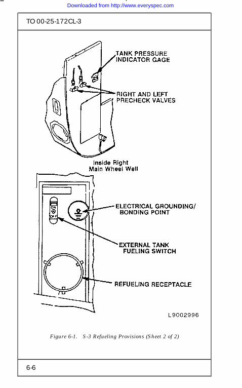
The single point receptacle (SPR) is located on the rightside of the fuselage immediately aft of the main landinggear well (Figure 6-1). Manual pre-check controls andthe tank pressure gauge are located in the right mainwheel well ‘‘around the corner’’ from the SPR. Theaircraft can carry 1933 gallons in four internal fueltanks in the center wing section (inboard of the wingfolds) and 265 gallons in each of two external fuel tanks.The external tanks have no pre-check capability, but canbe hot refueled. Internal tanks are vented through asingle outlet at the aft end of the fuselage, while theexternal tanks are vented at the tank bottoms. A singlefuel dump (jettison) chute is located at the fuselage aftend.
The aircraft has an on board auxiliary power unit (APU)with an exhaust port on the fuselage left side (near therunning engine). The APU can be running during hotrefueling. The right engine is shut down during hotrefueling.
The aircraft carries up to 46 sonobuoys that arelaunched from tubes on the bottom aft fuselage. Prior torefueling, these sonobuoys are safed by opening a smalldoor just forward of the left hand sonobuoy chutes. Thedoor has a link that operates a safing switch.
CURSORY INSPECTION
1. Stop the aircraft at least 50 feet short of the hotrefueling area.
6-1
Downloaded from http://www.everyspec.com

TO 00-25-172CL-3
WARNING
Do not hot refuel with the wings folded.
2. Signal the aircrew to spread the wings.
3. Signal the aircrew to shut down the right engine.
4. Check for hot brakes.
5. Verify all external weapons and external tankshave been safed. Ensure the external fuel tank lockingindicator (Figure 6-2) is in the LOCK position.
6. Verify the fuel dump (jettison) valve is closed.
WARNING
Avoid the tail hook area when workingbeneath the aircraft.
7. Open the sonobuoy safing door (on the fuselagebottom) just forward of the left hand sonobuoy chutes.Check the safing link for integrity. (There are two links-one for holding the door and the other for operating thesafing switch).
8. Signal the aircrew to taxi to the hot refuelingarea.
REFUELING
1. Position the aircraft on the hot refueling pit.
2. Chock and ground the aircraft. (A groundingpoint is located on the bottom of the fuselage about threefeet aft of the nose gear door.)
3. If available, connect the intercom (on the nosewheel door).
6-2
Downloaded from http://www.everyspec.com

TO 00-25-172CL-3
4. Check that no air is f lowing from the externalfuel tank vents. This verifies that engine bleed air is notpressurizing the external tanks.
WARNING
Prior to pressurizing the fuel source, verifythe nozzle is locked onto the aircraft byattempting to remove the nozzle with thef low handle open. If you can remove thenozzle, do not start the refueling until thenozzle is replaced.
5. Bring the fueling equipment behind the rightengine and attach the nozzle to the SPR. Open thenozzle f low handle and attempt to remove the nozzlewith the f low handle in the open position.
6. Verify that the external tank fueling switch (atthe SPR) is OFF.
7. Begin the refueling. Rotate and hold both pre-check valves to the vertical (open) position at the sametime. (The switches are spring-loaded to the horizontal(closed) position). Fuel f low should stop within 20seconds. If fuel f low does not stop, discontinue the hotrefueling.
8. After the internal fuel tanks have completedtheir pre-check, release the pre-check valves and posi-tion the external tank fueling switch to ON.
WARNING
Stop the hot refueling operation if the tankpressure gauge reaches the red zone.
9. Observe the tank pressure gauge as the tanksfill.
6-3
Downloaded from http://www.everyspec.com

TO 00-25-172CL-3
10. As the fuel tanks fill, check for air f lowing fromthe vent outlets.
11. When the tanks are full, turn off the fuel at thesource and disconnect the nozzle.
12. Position the external tank fueling switch to OFF.
13. Disconnect the grounding/bonding wires and theintercom. Secure the SPR panel.
WARNING
Avoid the tail hook area when workingbeneath the aircraft.
14. Close the sonobuoy safing door.
15. Remove the chocks and signal the aircrew to taxiaway from area.
6-4
Downloaded from http://www.everyspec.com

TO 00-25-172CL-3
Figure 6-1. S-3 Refueling Provisions (Sheet 1 of 2)
6-5
Downloaded from http://www.everyspec.com
TO 00-25-172CL-3
Figure 6-1. S-3 Refueling Provisions (Sheet 2 of 2)
6-6
Downloaded from http://www.everyspec.com

TO 00-25-172CL-3
Figure 6-2. S-3 External Tank Safing Indicator
6-7/(6-8 blank)
Downloaded from http://www.everyspec.com

Downloaded from http://www.everyspec.com

TO 00-25-172CL-3
SECTION VII
AV-8 HOT REFUELING PROCEDURES
REFUELING/DEFUELING
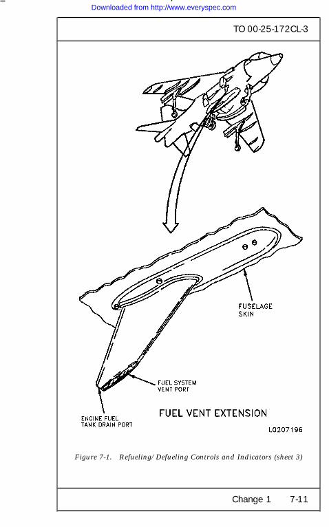
The aircraft is refueled/defueled through a standardrefuel/defuel receptacle located below Door 22 on theleft forward fuselage. Ground refueling controls andindicators and the intercom connection are inside Door22. The maximum refueling pressure is 55 psi. Alltanks are vented through the vent mast on lower rightside of fuselage, below the right front nozzle. Use ofthe intercom is preferred, but not mandatory. The dia-grams at the end of this chapter show the groundrefueling provisions and the armament safingprovisions.
Change 1 7-1
Downloaded from http://www.everyspec.com

TO 00-25-172CL-3
REFUELING PRECAUTIONS
WARNING
. Failure to comply with the precautionsbelow could result in injury or death topersonnel.
. Aviation turbine fuel is f lammable andtoxic to eyes, skin, and respiratory tract.Skin/eye protection is required. Avoidrepeated/prolonged contact. Use only inwell ventilated areas. Keep away fromopen f lames or other sources of ignition.
1. Do not refuel aircraft with suspected hotbrakes.
2. Make sure aircraft fuel servicingequipment and external electrical powersource are grounded.
3. Make sure enough fire f ighting equipmentis available (TO 00-25-172).
4. Inspect refueling nozzle locking device tomake sure aircraft ground refuelingreceptacle is serviceable.
5. Make sure vent mast is not obstructed.
6. Make sure refueling is not done within 300feet of ground radar equipment.
7. Make sure refueling is not done within 50feet of other aircraft with engine(s)operating.
7-2 Change 1
Downloaded from http://www.everyspec.com
TO 00-25-172CL-3
8. Operation of the auxiliary power unit(APU) is prohibited during normalrefueling.
9. Do not carry or wear loose metal objects,such as knives, keys, or other objects whichmight cause sparks.
10. Never fuel or defuel during electricalstorms.
11. Do not carry matches or cigarette lighters.
12. Do not wear shoes with exposed nails,metal plates or hobnails.
13. Make sure aircraft is chocked.
NOTE
Safetied means installation of any arminglever, safety pin, electrical interrupt, plugpin, securing of armament switches and/orany applicable action which makes thespecific ordnance carried safe.
14. All ordnance will be safetied.
15. Fuel pressure from servicing equipmentshould not exceed 55 psi, during normalrefueling.
16. Make sure aircraft is receiving correct fuel(JP-4, JP-5 or JP-8).
REFUELING PROCEDURE
1. Attach intercom cord and determinequantity of fuel required.
2. Observe all refueling precautions. Avoidthe engine inlet.
Change 1 7-3
Downloaded from http://www.everyspec.com

TO 00-25-172CL-3
WARNING
To prevent injury to personnel or damageto aircraft from possible static electricitydischarge, all personnel involved in refuel-ing shall dissipate static potential by grip-ping grounding wire before starting refuel-ing operation and repeating frequentlyduring refueling operation.
3. Static bond aircraft and refuelingequipment. (Bonding receptacle is on leftside of the aircraft near the SPR.)
4. On FUEL control panel assembly, makesure WING dump switches are in NORMposition.
5. Remove ground refuel/defuel receptaclecap. On cap equipped with locking lever,press lever to unlock cap during removal.
6. Insert refueling/defueling nozzle in groundrefuel/defuel receptacle by pushing andturning clockwise.
7-4 Change 1
Downloaded from http://www.everyspec.com
TO 00-25-172CL-3
WARNING
To prevent spillage, resulting in possiblefire and/or explosion, make sure nozzle isin locked position.
7. Make sure refueling nozzle is fully engagedby turning clockwise until nozzle resiststurning. Lock nozzle in position bypositioning nozzle manual fuel shutofflever in full open position.
8. Inspect refueling nozzle engagement by acounterclockwise tug on nozzle handles.Determine refueling hose quick disconnectfitting engagement by pulling on hose andvisual inspection.
9. Make sure aircraft is receiving the correctfuel (JP-4, JP-5 or JP-8).
10. Open Door 22.
11. If required, set EXTERNAL TANKLOCKOUT switch to LOCKOUT position.
WARNING
To prevent injury to personnel and dam-age to equipment, do not refuel aircraft, ifTANK OVER PRESS warning lamp isinoperative.
12. Press-to-test TANK OVER PRESS (red)warning light for lamp operation.
Change 1 7-5
Downloaded from http://www.everyspec.com

TO 00-25-172CL-3
13. On external fuel control panel assembly,set LEFT and RIGHT REFUEL switches tothe SHUT OFF position (toggles up).
WARNING
To prevent injury to personnel and dam-age to fuel system, fuel pressure from ser-vicing equipment shall not exceed 55 psi.
14. Apply 55 psi refueling pressure.
WARNING
To prevent injury to personnel and dam-age to equipment, do not attempt to refuelaircraft if fuel enters tanks.
15. Make sure REFUEL VALVES are closedpreventing fuel from entering fuel tanks,with refueling pressure applied.
16. Remove 55 psi refueling pressure.
17. Set LEFT and RIGHT REFUEL switchesto REFUEL position (toggles down).
WARNING
To prevent injury to personnel and dam-age to equipment, do not exceed 55 psirefueling pressure.
18. Apply 55 psi refueling pressure.
7-6 Change 1
Downloaded from http://www.everyspec.com

TO 00-25-172CL-3
19. Make sure LEFT and RIGHT FUELCONTENTS (green) lights are on whenrefueling pressure is applied.
WARNING
To prevent injury to personnel and dam-age to equipment, stop refueling immedi-ately if TANK OVER PRESS (red) warn-ing light comes on.
20. Fuel can be stopped from entering theexternal tanks by setting EXT TANKLOCKOUT switch to LOCKOUT position.
21. Monitor external fuel control panelassembly. If the tanks becomeoverpressurized during refueling, theTANK OVER PRESS warning light willcome on. If this occurs, stop refuelingimmediately and investigate cause.
22. After 60 to 120 gallons of fuel have enteredtanks, make sure air is venting from ventmast on lower right side of fuselage, belowthe right front nozzle.
23. When tanks are full, LEFT and RIGHTFUEL CONTENTS lights will go off. Iffuel f low does not stop automatically, fuelspillage from vent mast will result. Dosubsteps below immediately:
a. Stop fuel service operation and turn offfuel servicing equipment.
b. Disconnect refueling nozzle from refuel/defuel receptacle.
Change 1 7-7
Downloaded from http://www.everyspec.com

TO 00-25-172CL-3
c. Alert f ire department and take action tomake area safe before moving aircraft orground support equipment.
24. Stop refueling equipment.
25. Verify that the correct quantity of fuel isdisplayed on fuel digital display indicator.
26. Set LEFT and RIGHT REFUEL switchesto f light position (toggles up).
27. Turn refueling nozzle counterclockwise andremove refueling nozzle. To prevent loss ordamage to receptacle cap, make sure caphas engaged all three lugs on the refuel/defuel receptacle. On caps equipped withlocking lever, make sure lever is f lush withcap.
28. Inspect refueling receptacle for leakage andinstall receptacle cap.
29. Remove intercom cord and refueling unitbond wire.
30. Close Door 22.
7-8 Change 1
Downloaded from http://www.everyspec.com

TO 00-25-172CL-3
Figure 7-1. Refueling/Defueling Controls and Indicators(sheet 1 of 3)
Change 1 7-9
Downloaded from http://www.everyspec.com

TO 00-25-172CL-3
Figure 7-1. Refueling/Defueling Controls and Indicators (sheet 2)
7-10 Change 1
Downloaded from http://www.everyspec.com
TO 00-25-172CL-3
Figure 7-1. Refueling/Defueling Controls and Indicators (sheet 3)
Change 1 7-11
Downloaded from http://www.everyspec.com

TO 00-25-172CL-3
Figure 7-2. LAU-7/A-5 Launcher Detent Wrench Safety Pin
7-12 Change 1
Downloaded from http://www.everyspec.com

TO 00-25-172CL-3
Figure 7-3. ITER Ejector Unit Assembly Safety Stop Lever
Change 1 7-13
Downloaded from http://www.everyspec.com

TO 00-25-172CL-3
Figure 7-4. Aircraft 25MM Gun Safety Pin
7-14 Change 1
Downloaded from http://www.everyspec.com

TO 00-25-172CL-3
Figure 7-5. ALE-39 Ejector Rack Safety Pin
Change 1 7-15/(7-16 blank)
Downloaded from http://www.everyspec.com

Downloaded from http://www.everyspec.com