to appear in acm transactions on graphics exposing photo ... · xxx:2 a forensic setting, a...
TRANSCRIPT

To appear in ACM Transactions on Graphics
Exposing Photo Manipulation with Inconsistent ShadowsEric Kee, Dartmouth CollegeJames O’Brien, University of California, Berkeleyand
Hany Farid, Dartmouth College
We describe a geometric technique to detect physically inconsistent ar-rangements of shadows in an image. This technique combines multiple con-straints from cast and attached shadows to constrain the projected locationof a point light source. The consistency of the shadows is posed as a linearprogramming problem. A feasible solution indicates that the collection ofshadows is physically plausible, while a failure to find a solution providesevidence of photo tampering.
Categories and Subject Descriptors: I.2.10 [Artificial Intelligence]: Visionand Scene Understanding—Scene Analysis; I.3.6 [Computer Graphics]:Methodology and Techniques—Image Forensics; K.4.m [Computing Mi-lieux]: Computers and Society—Miscellaneous
Additional Key Words and Phrases: Shadows, image forensics, photo ma-nipulation, image manipulation, forgery detection
ACM Reference Format:Kee, E., O’Brien, J. F., and Farid, H., 2013. Exposing Photo Manipulationwith Inconsistent Shadows. ACM Trans. Graph. ??, ?, Article ??? (August2013), 12 pages.To appear.
1. INTRODUCTION
Recent advances in computational photography, computer vision,and computer graphics allow for the creation of visually com-pelling photographic fakes. The resulting undermining of trust inphotographs impacts law enforcement, national security, the me-dia, advertising, e-commerce, and more. The nascent field of photoforensics has emerged to help restore some trust in digital pho-tographs [Farid 2009].
In the absence of any digital watermarks or signatures, tech-niques in image forensics operate on the assumption that mostforms of tampering will disturb some statistical or geometric prop-erty of an image. In a well-executed forgery these disturbances
Authors’ email addresses: [email protected], [email protected],[email protected] to make digital or hard copies of part or all of this work forpersonal or classroom use is granted without fee provided that copies arenot made or distributed for profit or commercial advantage and that copiesshow this notice on the first page or initial screen of a display along withthe full citation. Copyrights for components of this work owned by othersthan ACM must be honored. Abstracting with credit is permitted. To copyotherwise, to republish, to post on servers, to redistribute to lists, or to useany component of this work in other works requires prior specific permis-sion and/or a fee. Permissions may be requested from Publications Dept.,ACM, Inc., 2 Penn Plaza, Suite 701, New York, NY 10121-0701 USA, fax+1 (212) 869-0481, or [email protected]© 2013 ACM 0730-0301/2013/13-ARTXXX $10.00
DOI: http://dx.doi.org/10.1145/XXXXXXX.YYYYYYY
Original image copyright 1969, NASA
Fig. 1. Our algorithm finds that the shadows in this 1969 moon landingphoto are physically consistent with a single light source. The solid linescorrespond to constraints from cast shadows and dashed lines correspondto constraints from attached shadows. The region outlined in black, whichextends beyond the figure boundary, contains the projected light locationsthat satisfy all of these constraints.
will either be perceptibly insignificant or they may be noticeablebut subjectively plausible. Methods for forensic analysis provide ameans to detect and quantify specific types of tampering. To theextent that these perturbations can be quantified and detected, theycan be used to objectively invalidate a photo.
We describe a technique for determining if cast and attachedshadows in a photo are consistent with the model of a single distantor local point light source. Forensic techniques based on analyz-ing lighting and shadows are attractive because 3-D lighting effectscan be difficult to modify using commercial photo editing software,and low quality images can be analyzed since lighting effects andshadows survive common operations such as image compressionand down-sizing.
There is some evidence that the visual system is capable of de-tecting small changes in lighting direction in simple controlled set-tings [Koenderink et al. 2004; Mamassian 2004; Khang et al. 2006;Pont and Koenderink 2007; Koenderink et al. 2007; O’Shea et al.2010]. In more complex settings, however, the visual system is farless capable at detecting gross inconsistencies in lighting [Jacobsonand Werner 2004; Ostrovsky et al. 2005; Farid and Bravo 2010]. In
ACM Transactions on Graphics, Vol. 32, No. 4, Article XXX, Publication date: September 2013.

XXX:2 •
a forensic setting, a multitude and variety of cast and attached shad-ows from complex shapes are cast onto equally complex and variedsurfaces. Such limitations of the visual system imply that a forgermay overlook inconsistencies in lighting and shadowing, and a vi-sual inspection of shadows will, at best, be highly subjective.
The iconic photo of the 1969 moon landing, Fig. 1, provides anexample of the variety and complexity of shadows that are com-mon in photos. In fact, it has been argued by conspiracy theoriststhat the shadows in this photo are physically implausible and henceevidence of photo tampering and broader nefarious conspiracies.Beyond a subjective visual analysis, the physical consistency ofshadows can be objectively determined by considering their basicgeometry.
Consider a ray that connects a point in a shadowed region toits corresponding point on the shadow-casting object. In the 3-Dscene, this ray intersects the light source. In a 2-D image of thescene created under linear perspective, the projection of this rayremains a straight line that must connect the images of the shadowpoint and object point, and intersect the projected image of the lightsource. These constraints hold regardless of the geometry of the ob-ject and the surface onto which the shadows are cast, and for eitheran infinitely distant or local light. Multiple constraints can there-fore be used to determine the projected location of a light source inthe image plane. Note that this projected location corresponds to aninfinite number of 3-D light positions. We concern ourselves withthe 2-D projection because a single image typically does not allowone to compute the 3-D location of the light in the scene.
If a scene purportedly contains a single light source but the shad-ows in the scene specify mutually inconsistent constraints that can-not be satisfied by any single light position, then this inconsistencyevidences photo tampering. It can sometimes be difficult or impos-sible to precisely match a point on a shadow to its correspondingpoint on an object — particularly on attached shadows that form asa surface smoothly curves to face away from the light. We thereforeconsider a relaxed, conservative constraint in which the location ofpoints on the object are restricted to a range of possible locations.These relaxed constraints specify either angular wedges or half-planes in the image that restrict the projected location of the lightsource. (See Fig. 2.) The consistency of multiple such constraintsis framed as a linear programming problem. A viable solution isinterpreted to mean that the shadows are physically plausible whilea failure to find a solution is used as evidence of photo tampering.
1.1 Related Work
Previous lighting-based forensics methods estimate the 2-D light-ing direction or lighting environment from the shading on an ob-ject’s contour [Johnson and Farid 2005; 2007]. If the 3-D geometryof an object is known, then the 3-D lighting direction or lightingenvironment can be estimated [Kee and Farid 2010]. Related com-puter vision techniques that estimate lighting from a single imageuse object shading [Nillius and Eklundh 2001], or shadows castonto planar surfaces [Sato et al. 2003; Okabe et al. 2004; Lalondeet al. 2011]. In [Karsch et al. 2011], manually approximated scenegeometry is used to fit a local lighting model that is perceptuallyplausible, but insufficient for forensic application because the phys-ical accuracy is heavily influenced by user input.
Photometric inconsistencies of a cast shadow’s umbra were usedto detect inconsistent shadows in [Liu et al. 2011]. Inconsisten-cies in the location of a cast shadow were used in [Zhang et al.2009], but they placed several assumptions on the scene geome-try: shadows were cast onto a planar ground plane and the objectscasting shadows were vertical relative to the ground plane. In the
Original image copyright 2011, Geico Insurance
Fig. 2. Shown are: (top) a frame from the Geico commercial “Dunk –Easier Way to Save” depicting a somewhat incredible athletic performance;(middle) examples of cast (1-2) and attached (3) shadow constraints. Theprojected location of the light source must lie in the intersection of theseconstraints. Shown in the bottom is a multitude of constraints (solid linescorrespond to cast shadows and dashed lines correspond to attached shad-ows). The shadows from the people and house are consistent with a lightsource located somewhere in the black-outlined region. The boy’s shadow,however, is inconsistent with the rest of the scene.
most closely related work [Stork and Johnson 2006], the consis-tency of cast shadows in artworks was determined by identifying
ACM Transactions on Graphics, Vol. 32, No. 4, Article XXX, Publication date: September 2013.
• XXX:3
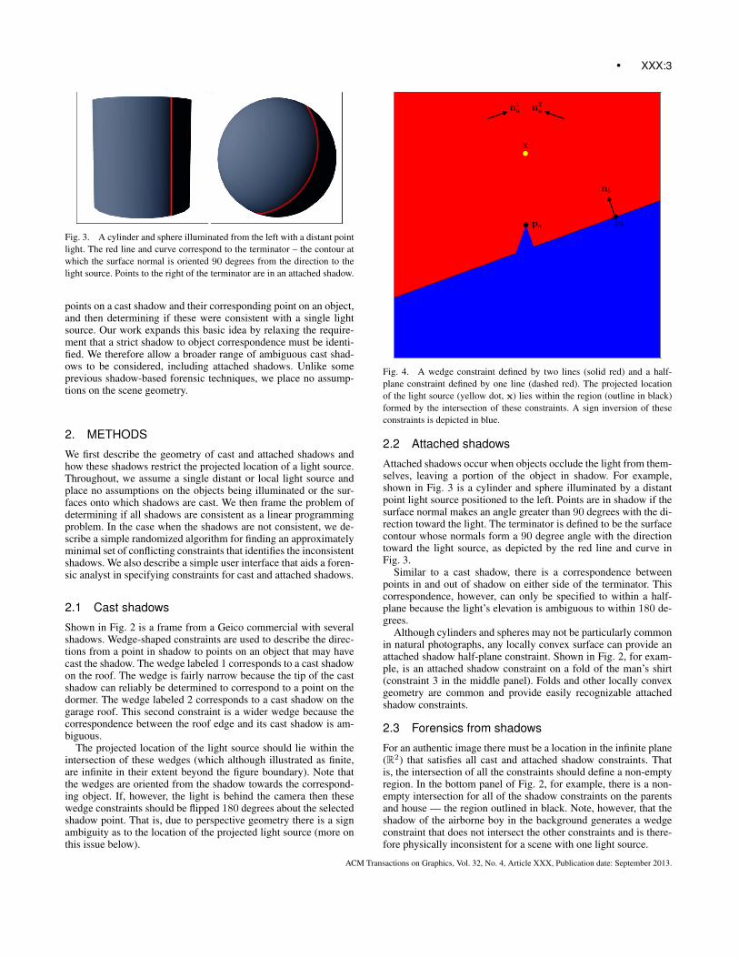
Fig. 3. A cylinder and sphere illuminated from the left with a distant pointlight. The red line and curve correspond to the terminator – the contour atwhich the surface normal is oriented 90 degrees from the direction to thelight source. Points to the right of the terminator are in an attached shadow.
points on a cast shadow and their corresponding point on an object,and then determining if these were consistent with a single lightsource. Our work expands this basic idea by relaxing the require-ment that a strict shadow to object correspondence must be identi-fied. We therefore allow a broader range of ambiguous cast shad-ows to be considered, including attached shadows. Unlike someprevious shadow-based forensic techniques, we place no assump-tions on the scene geometry.
2. METHODS
We first describe the geometry of cast and attached shadows andhow these shadows restrict the projected location of a light source.Throughout, we assume a single distant or local light source andplace no assumptions on the objects being illuminated or the sur-faces onto which shadows are cast. We then frame the problem ofdetermining if all shadows are consistent as a linear programmingproblem. In the case when the shadows are not consistent, we de-scribe a simple randomized algorithm for finding an approximatelyminimal set of conflicting constraints that identifies the inconsistentshadows. We also describe a simple user interface that aids a foren-sic analyst in specifying constraints for cast and attached shadows.
2.1 Cast shadows
Shown in Fig. 2 is a frame from a Geico commercial with severalshadows. Wedge-shaped constraints are used to describe the direc-tions from a point in shadow to points on an object that may havecast the shadow. The wedge labeled 1 corresponds to a cast shadowon the roof. The wedge is fairly narrow because the tip of the castshadow can reliably be determined to correspond to a point on thedormer. The wedge labeled 2 corresponds to a cast shadow on thegarage roof. This second constraint is a wider wedge because thecorrespondence between the roof edge and its cast shadow is am-biguous.
The projected location of the light source should lie within theintersection of these wedges (which although illustrated as finite,are infinite in their extent beyond the figure boundary). Note thatthe wedges are oriented from the shadow towards the correspond-ing object. If, however, the light is behind the camera then thesewedge constraints should be flipped 180 degrees about the selectedshadow point. That is, due to perspective geometry there is a signambiguity as to the location of the projected light source (more onthis issue below).
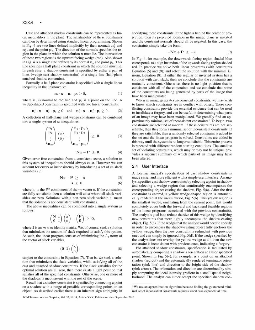
Fig. 4. A wedge constraint defined by two lines (solid red) and a half-plane constraint defined by one line (dashed red). The projected locationof the light source (yellow dot, x) lies within the region (outline in black)formed by the intersection of these constraints. A sign inversion of theseconstraints is depicted in blue.
2.2 Attached shadows
Attached shadows occur when objects occlude the light from them-selves, leaving a portion of the object in shadow. For example,shown in Fig. 3 is a cylinder and sphere illuminated by a distantpoint light source positioned to the left. Points are in shadow if thesurface normal makes an angle greater than 90 degrees with the di-rection toward the light. The terminator is defined to be the surfacecontour whose normals form a 90 degree angle with the directiontoward the light source, as depicted by the red line and curve inFig. 3.
Similar to a cast shadow, there is a correspondence betweenpoints in and out of shadow on either side of the terminator. Thiscorrespondence, however, can only be specified to within a half-plane because the light’s elevation is ambiguous to within 180 de-grees.
Although cylinders and spheres may not be particularly commonin natural photographs, any locally convex surface can provide anattached shadow half-plane constraint. Shown in Fig. 2, for exam-ple, is an attached shadow constraint on a fold of the man’s shirt(constraint 3 in the middle panel). Folds and other locally convexgeometry are common and provide easily recognizable attachedshadow constraints.
2.3 Forensics from shadows
For an authentic image there must be a location in the infinite plane(R2) that satisfies all cast and attached shadow constraints. Thatis, the intersection of all the constraints should define a non-emptyregion. In the bottom panel of Fig. 2, for example, there is a non-empty intersection for all of the shadow constraints on the parentsand house — the region outlined in black. Note, however, that theshadow of the airborne boy in the background generates a wedgeconstraint that does not intersect the other constraints and is there-fore physically inconsistent for a scene with one light source.
ACM Transactions on Graphics, Vol. 32, No. 4, Article XXX, Publication date: September 2013.
XXX:4 •
Cast and attached shadow constraints can be represented as lin-ear inequalities in the plane. The satisfiability of these constraintscan then be determined using standard linear programming. Shownin Fig. 4 are two lines defined implicitly by their normals n1
a andn2a, and the point pa. The direction of the normals specifies the re-
gion in the plane in which the solution x must lie. The intersectionof these two regions is the upward facing wedge (red). Also shownin Fig. 4 is a single line defined by its normal nb and point pb. Thisline specifies a half plane constraint in which the solution must lie.In each case, a shadow constraint is specified by either a pair oflines (wedge cast shadow constraint) or a single line (half-planeattached shadow constraint).
Formally, a half-plane constraint is specified with a single linearinequality in the unknown x:
ni · x− ni · pi ≥ 0, (1)
where ni is normal to the line and pi is a point on the line. Awedge-shaped constraint is specified with two linear constraints:
n1i · x− n1
i · pi ≥ 0 and n2i · x− n2
i · pi ≥ 0. (2)
A collection of half-plane and wedge constrains can be combinedinto a single system of m inequalities:
n1
n2
...nm
(xy)−
n1 · p1
n2 · p2
...nm · pm
≥ 0 (3)
Nx−P ≥ 0. (4)
Given error-free constraints from a consistent scene, a solution tothis system of inequalities should always exist. However we canaccount for errors or inconsistency by introducing a set of m slackvariables si:
Nx−P ≥ −s (5)s ≥ 0, (6)
where si is the ith component of the m-vector s. If the constraintsare fully satisfiable then a solution will exist where all slack vari-ables are zero. Solutions with a non-zero slack variable si meanthat the solution is not consistent with constraint i.
The above inequalities can be combined into a single system asfollows: (
N I0 I
)(xs
)−(P0
)≥ 0, (7)
where I is an m×m identity matrix. We, of course, seek a solutionthat minimizes the amount of slack required to satisfy this system.As such, the linear program consists of minimizing the L1 norm ofthe vector of slack variables,(
0 1)(x
s
), (8)
subject to the constraints in Equation (7). That is, we seek a solu-tion that minimizes the slack variables, while satisfying all of thecast and attached shadow constraints. If the slack variables for theoptimal solution are all zero, then there exists a light position thatsatisfies all of the specified constraints. Otherwise, one or more ofthe shadows is inconsistent with the rest of the scene.
Recall that a shadow constraint is specified by connecting a pointon a shadow with a range of possible corresponding points on anobject. As described earlier there is an inherent sign ambiguity in
specifying these constraints: if the light is behind the center of pro-jection, then its projected location in the image plane is invertedand the constraint normals should all be negated. In this case, theconstraints simply take the form:
−Nx+P ≥ −s. (9)
In Fig. 4, for example, the downwards facing region shaded bluecorresponds to a sign inversion of the upwards facing region shadedred. In practice we solve both linear programs (with constraintsEquation (5) and (9)) and select the solution with the minimal L1
norm, Equation (8). If either the regular or inverted system has asolution with zero slack, then we conclude that the constraints aremutually consistent. Otherwise, there is no light position that isconsistent with all of the constraints and we conclude that someof the constraints are being generated by parts of the image thathave been manipulated.
When an image generates inconsistent constraints, we may wishto know which constraints are in conflict with others. These con-flicting constraints provide the essential evidence that can be usedto invalidate a forgery, and can be useful in determining what partsof an image may have been manipulated. We greedily find an ap-proximately minimal set of inconsistent constraints.1 To begin, twoconstraints are selected at random. If these constraints are not sat-isfiable, then they form a minimal set of inconsistent constraints. Ifthey are satisfiable, then a randomly selected constraint is added tothe set and the linear program is solved. Constraints are added inthis way until the system is no longer satisfiable. This entire processis repeated with different random starting conditions. The smallestset of violating constraints, which may or may not be unique, pro-vides a succinct summary of which parts of an image may havebeen altered.
2.4 User Interface
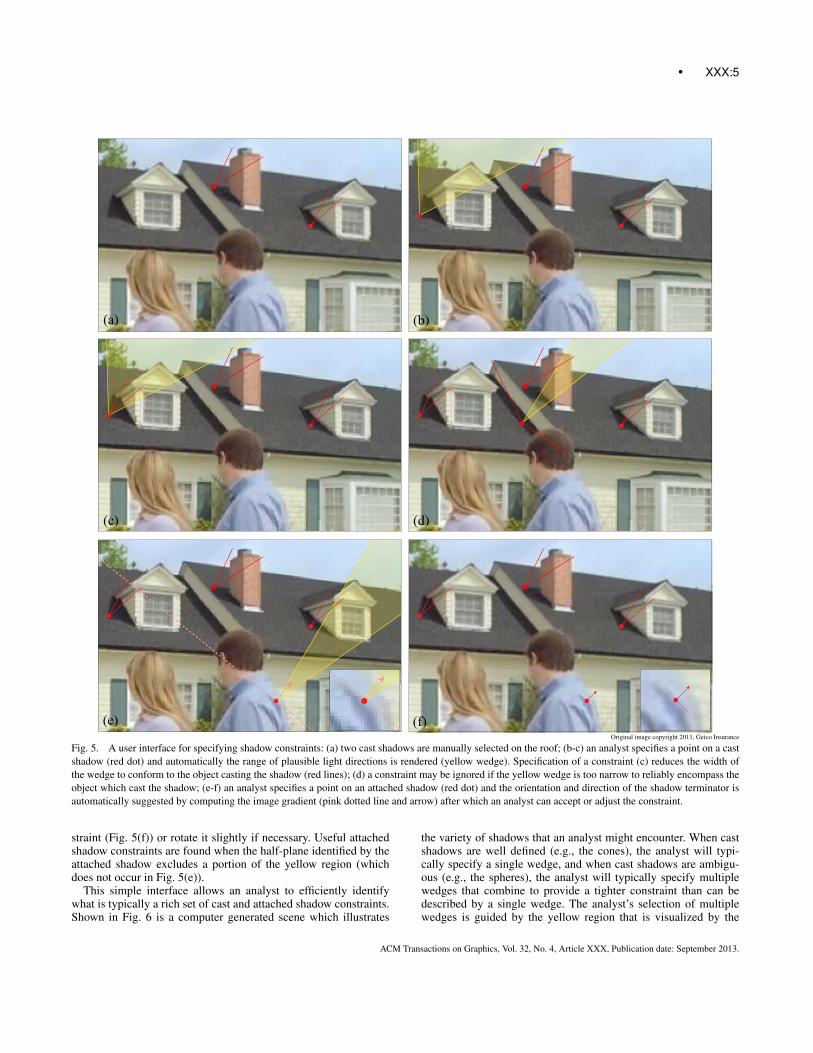
A forensic analyst’s specification of cast shadow constraints ismade easier and more efficient with a simple user interface. An ana-lyst specifies cast shadow constraints by selecting a point in shadowand selecting a wedge region that comfortably encompasses thecorresponding object casting the shadow, Fig. 5(a). After the firstconstraint is entered, a yellow wedge-shaped region is automati-cally rendered at the user’s cursor, Fig. 5(b). This yellow region isthe smallest wedge, emanating from the current point, that wouldcompletely cover both the forward and backward feasible regionsof the linear programs associated with the previous constraint(s).The analyst’s goal is to reduce the size of this wedge by identifyingnew constraints that more tightly encompass the shadow-castingobject, Fig. 5(c). If the wedge that the analyst would need to specifyin order to encompass the shadow-casting object fully encloses theyellow wedge, then the new constraint is redundant with previousones and can simply be ignored, Fig. 5(d). If the wedge specified bythe analyst does not overlap the yellow wedge at all, then the newconstraint is inconsistent with previous ones, indicating a forgery.
For attached shadow constraints, specification is facilitated byautomatically computing a shadow’s orientation at a user specifiedpoint. Shown in Fig. 5(e), for example, is a point on an attachedshadow (red dot) and the automatically rendered terminator orien-tation (pink line) and direction to the bright side of the shadow(pink arrow). The orientation and direction are determined by sim-ply computing the local intensity gradient in a small spatial neigh-borhood. The analyst can either accept the specified shadow con-
1We use an approximation algorithm because finding the guaranteed mini-mal set of inconsistent constraints requires worst case exponential time.
ACM Transactions on Graphics, Vol. 32, No. 4, Article XXX, Publication date: September 2013.
• XXX:5
(a) (b)
(c) (d)
(e) (f)Original image copyright 2011, Geico Insurance
Fig. 5. A user interface for specifying shadow constraints: (a) two cast shadows are manually selected on the roof; (b-c) an analyst specifies a point on a castshadow (red dot) and automatically the range of plausible light directions is rendered (yellow wedge). Specification of a constraint (c) reduces the width ofthe wedge to conform to the object casting the shadow (red lines); (d) a constraint may be ignored if the yellow wedge is too narrow to reliably encompass theobject which cast the shadow; (e-f) an analyst specifies a point on an attached shadow (red dot) and the orientation and direction of the shadow terminator isautomatically suggested by computing the image gradient (pink dotted line and arrow) after which an analyst can accept or adjust the constraint.
straint (Fig. 5(f)) or rotate it slightly if necessary. Useful attachedshadow constraints are found when the half-plane identified by theattached shadow excludes a portion of the yellow region (whichdoes not occur in Fig. 5(e)).
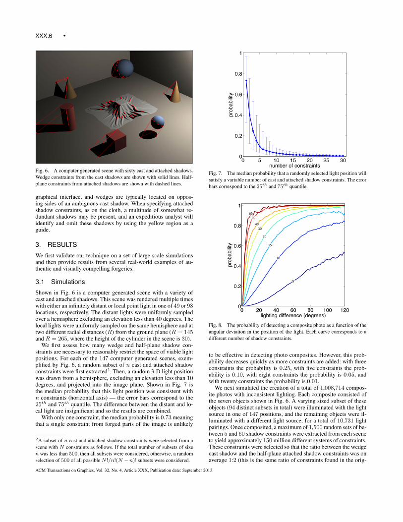
This simple interface allows an analyst to efficiently identifywhat is typically a rich set of cast and attached shadow constraints.Shown in Fig. 6 is a computer generated scene which illustrates
the variety of shadows that an analyst might encounter. When castshadows are well defined (e.g., the cones), the analyst will typi-cally specify a single wedge, and when cast shadows are ambigu-ous (e.g., the spheres), the analyst will typically specify multiplewedges that combine to provide a tighter constraint than can bedescribed by a single wedge. The analyst’s selection of multiplewedges is guided by the yellow region that is visualized by the
ACM Transactions on Graphics, Vol. 32, No. 4, Article XXX, Publication date: September 2013.
XXX:6 •
Fig. 6. A computer generated scene with sixty cast and attached shadows.Wedge constraints from the cast shadows are shown with solid lines. Half-plane constraints from attached shadows are shown with dashed lines.
graphical interface, and wedges are typically located on oppos-ing sides of an ambiguous cast shadow. When specifying attachedshadow constraints, as on the cloth, a multitude of somewhat re-dundant shadows may be present, and an expeditious analyst willidentify and omit these shadows by using the yellow region as aguide.
3. RESULTS
We first validate our technique on a set of large-scale simulationsand then provide results from several real-world examples of au-thentic and visually compelling forgeries.
3.1 Simulations
Shown in Fig. 6 is a computer generated scene with a variety ofcast and attached shadows. This scene was rendered multiple timeswith either an infinitely distant or local point light in one of 49 or 98locations, respectively. The distant lights were uniformly sampledover a hemisphere excluding an elevation less than 40 degrees. Thelocal lights were uniformly sampled on the same hemisphere and attwo different radial distances (R) from the ground plane (R = 145and R = 265, where the height of the cylinder in the scene is 30).
We first assess how many wedge and half-plane shadow con-straints are necessary to reasonably restrict the space of viable lightpositions. For each of the 147 computer generated scenes, exem-plified by Fig. 6, a random subset of n cast and attached shadowconstraints were first extracted2. Then, a random 3-D light positionwas drawn from a hemisphere, excluding an elevation less than 10degrees, and projected into the image plane. Shown in Fig. 7 isthe median probability that this light position was consistent withn constraints (horizontal axis) — the error bars correspond to the25th and 75th quantile. The difference between the distant and lo-cal light are insignificant and so the results are combined.
With only one constraint, the median probability is 0.73 meaningthat a single constraint from forged parts of the image is unlikely
2A subset of n cast and attached shadow constraints were selected from ascene with N constraints as follows. If the total number of subsets of sizen was less than 500, then all subsets were considered, otherwise, a randomselection of 500 of all possible N !/n!(N − n)! subsets were considered.
0 5 10 15 20 25 300
0.2
0.4
0.6
0.8
1
number of constraints
prob
abilit
y
Fig. 7. The median probability that a randomly selected light position willsatisfy a variable number of cast and attached shadow constraints. The errorbars correspond to the 25th and 75th quantile.
0 20 40 60 80 100 1200
0.2
0.4
0.6
0.8
1
lighting difference (degrees)
prob
abilit
y
5
10
15
20
3040
5060
Fig. 8. The probability of detecting a composite photo as a function of theangular deviation in the position of the light. Each curve corresponds to adifferent number of shadow constraints.
to be effective in detecting photo composites. However, this prob-ability decreases quickly as more constraints are added: with threeconstraints the probability is 0.25, with five constraints the prob-ability is 0.10, with eight constraints the probability is 0.05, andwith twenty constraints the probability is 0.01.
We next simulated the creation of a total of 1,008,714 compos-ite photos with inconsistent lighting. Each composite consisted ofthe seven objects shown in Fig. 6. A varying sized subset of theseobjects (94 distinct subsets in total) were illuminated with the lightsource in one of 147 positions, and the remaining objects were il-luminated with a different light source, for a total of 10,731 lightpairings. Once composited, a maximum of 1,500 random sets of be-tween 5 and 60 shadow constraints were extracted from each sceneto yield approximately 150 million different systems of constraints.These constraints were selected so that the ratio between the wedgecast shadow and the half-plane attached shadow constraints was onaverage 1:2 (this is the same ratio of constraints found in the orig-
ACM Transactions on Graphics, Vol. 32, No. 4, Article XXX, Publication date: September 2013.

• XXX:7
Fig. 9. Shown is an authentic photo and the successful result of a consis-tency check. The region of plausible locations for the light source is outlinedin black.
inal scenes). If no solution is found that satisfies the selected con-straints, then the photo is correctly classified as a fake.
Shown in Fig. 8 is the accuracy with which a forgery was de-tected in these scenes. The individual curves correspond to the to-tal number of constraints. The horizontal axis corresponds to theangle between the two projected light directions in the compositephoto, which is computed as the median angle between the pro-jected directions of the two light sources at each constraint. Thedetection accuracy improves with the total number of constraintsbecause more constraints carve out an increasingly smaller validsolution space.
With only 10 constraints, the difference in the lighting mustreach 100◦ before the probability of detecting the fake reaches80%. With 20 constraints, this same accuracy is achieved for alighting difference of 35◦, and with 50 constraints even a small10◦ discrepancy can be detected with a probability of 80%. At thesame time, the accuracy of correctly classifying an authentic photoin these scenes is 100%. Because any portion of a cast or attachedshadow can be used, it is fairly easy to find 50 or more constraintsin a typical image.
Fig. 10. Shown is a fake scene in which the floating sphere’s shadow is in-consistent with the rest of the scene. Shown in the upper panel are the com-plete set of user specified constraints. Shown in the lower panel is a minimalset of violating constraints automatically determined from the above set ofconstraints. The red shaded regions corresponds to the positive constraintsand the blue shaded regions correspond to the negative constraints.
Shown in panel of Fig. 9 is an authentic scene with eight con-straints. The projected light position is in the intersection of theconstraints which is outlined in black. Shown in Fig. 10 is a fakeversion of the scene shown in Fig. 9 in which the floating spherefrom a differently lit scene was inserted. Shown in the upper panelare eight constraints selected in this scene and shown in the lowerpanel is the result from the automatic detection of a minimal set ofunsatisfiable constraints. The red shading corresponds to the pos-itive constraints and the blue shading corresponds to the negativeconstraints — neither are satisfiable. The median angular lightingdifference at each constraint is 3.6◦ which in this case is enough ofa difference to create an inconsistency in the shadows.
In the supplemental document that accompanies this paper weapplied our method to several synthetic images from a previouslypublished study [Farid and Bravo 2010]. In that study subjects werepresented with fairly simple images where shadows were cast bytwo sets of objects onto two separate surfaces, and the subjectswere asked to indicate if the shadows were mutually consistent(correct) or inconsistent. The results of that study showed that peo-ple performed poorly at this task even for these relatively simplescenes containing well-defined shapes with strong salient features.As shown in Sup. Fig. 1, our method works well on these imagesthat confound human viewers.
3.2 Real World
Shown in Fig. 11 is an authentic photo illuminated with a distantlight source (the sun). Also shown is the result of a successful con-sistency check for eleven cast shadows (dozens of other consistent
ACM Transactions on Graphics, Vol. 32, No. 4, Article XXX, Publication date: September 2013.
XXX:8 •
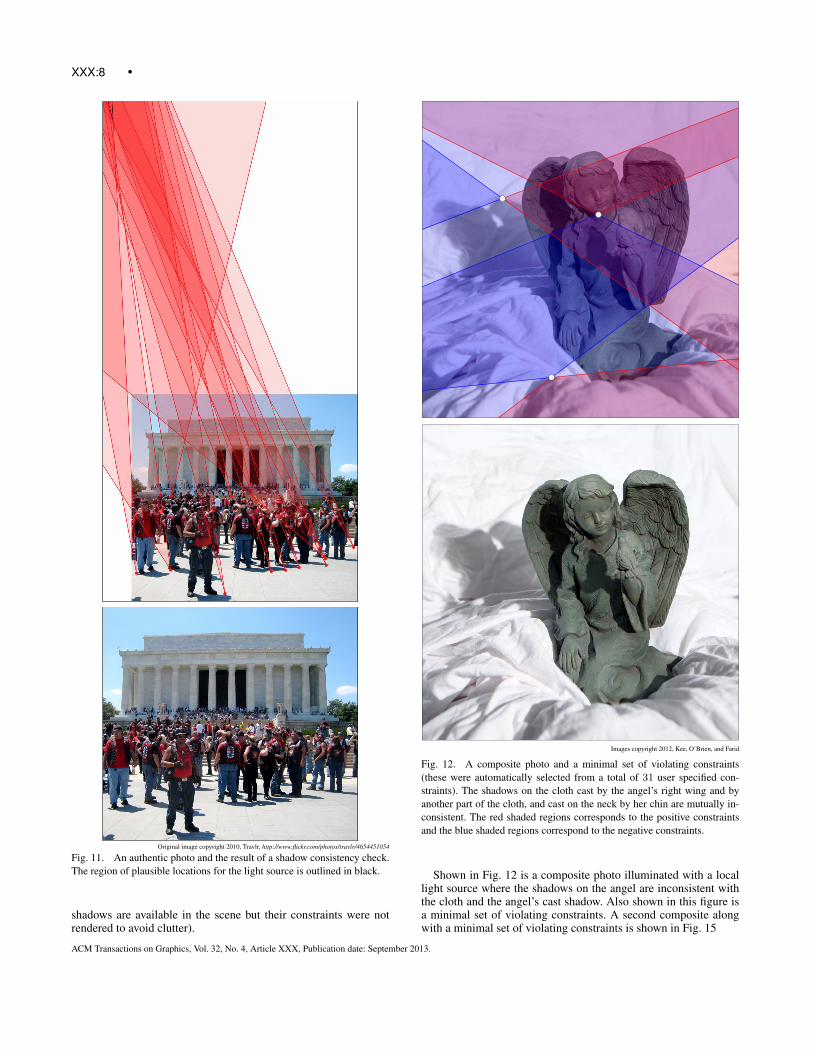
Original image copyright 2010, Travlr, http://www.flickr.com/photos/travlr/4654451054
Fig. 11. An authentic photo and the result of a shadow consistency check.The region of plausible locations for the light source is outlined in black.
shadows are available in the scene but their constraints were notrendered to avoid clutter).
Images copyright 2012, Kee, O’Brien, and Farid
Fig. 12. A composite photo and a minimal set of violating constraints(these were automatically selected from a total of 31 user specified con-straints). The shadows on the cloth cast by the angel’s right wing and byanother part of the cloth, and cast on the neck by her chin are mutually in-consistent. The red shaded regions corresponds to the positive constraintsand the blue shaded regions correspond to the negative constraints.
Shown in Fig. 12 is a composite photo illuminated with a locallight source where the shadows on the angel are inconsistent withthe cloth and the angel’s cast shadow. Also shown in this figure isa minimal set of violating constraints. A second composite alongwith a minimal set of violating constraints is shown in Fig. 15
ACM Transactions on Graphics, Vol. 32, No. 4, Article XXX, Publication date: September 2013.
• XXX:9
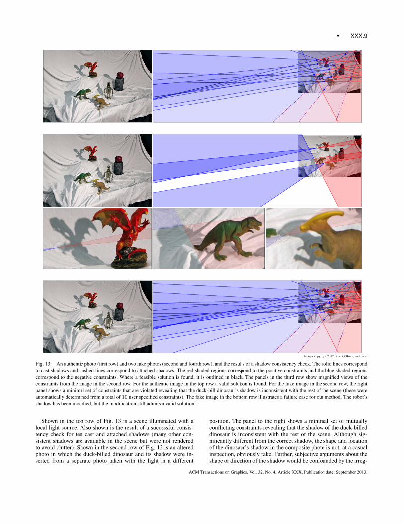
Images copyright 2012, Kee, O’Brien, and Farid
Fig. 13. An authentic photo (first row) and two fake photos (second and fourth row), and the results of a shadow consistency check. The solid lines correspondto cast shadows and dashed lines correspond to attached shadows. The red shaded regions correspond to the positive constraints and the blue shaded regionscorrespond to the negative constraints. Where a feasible solution is found, it is outlined in black. The panels in the third row show magnified views of theconstraints from the image in the second row. For the authentic image in the top row a valid solution is found. For the fake image in the second row, the rightpanel shows a minimal set of constraints that are violated revealing that the duck-bill dinosaur’s shadow is inconsistent with the rest of the scene (these wereautomatically determined from a total of 10 user specified constraints). The fake image in the bottom row illustrates a failure case for our method. The robot’sshadow has been modified, but the modification still admits a valid solution.
Shown in the top row of Fig. 13 is a scene illuminated with alocal light source. Also shown is the result of a successful consis-tency check for ten cast and attached shadows (many other con-sistent shadows are available in the scene but were not renderedto avoid clutter). Shown in the second row of Fig. 13 is an alteredphoto in which the duck-billed dinosaur and its shadow were in-serted from a separate photo taken with the light in a different
position. The panel to the right shows a minimal set of mutuallyconflicting constraints revealing that the shadow of the duck-billeddinosaur is inconsistent with the rest of the scene. Although sig-nificantly different from the correct shadow, the shape and locationof the dinosaur’s shadow in the composite photo is not, at a casualinspection, obviously fake. Further, subjective arguments about theshape or direction of the shadow would be confounded by the irreg-
ACM Transactions on Graphics, Vol. 32, No. 4, Article XXX, Publication date: September 2013.
XXX:10 •
ular geometry upon which the shadow is cast. In addition to insert-ing the dinosaur, the image was also modified by rotating the appleand black container counter-clockwise while leaving their shadowsunchanged. The apple’s shadow, however, remains consistent byour test because the wedge specifying the cast shadow constraint iswide enough to encompass the intersection of the other constraints.
Shown in the bottom row of Fig. 13 is an altered photo thatdemonstrates a failure case for our method. The shadow of the robotwas manipulated using Photoshop. However the manipulation pur-posefully shifted the shadow along rays from the light to the orig-inal shadow point. The result of this contrived manipulation is adistorted shadow that still generates constraints consistent with thetrue light location.
Shown in Fig. 1 is a shadow analysis of a photo from the Apollo11 moon landing. The constraints correspond to four cast shadowsfrom the astronaut’s legs onto the moon’s surface, three cast shad-ows from objects on the moon’s surface, and three attached shad-ows on the astronaut’s helmet, and footprint on the moon’s surface.The region outlined in black identifies locations that satisfy all 11of these constraints (dozens of other consistent shadows are avail-able in the scene but were not rendered to avoid clutter). Thus weconclude that by our measure the lighting in this image is consis-tent.
3.3 Usability
We performed an informal survey of five users with some photoediting experience but no experience with our shadow analysis. Af-ter one hour of instruction and training, all five of the users success-fully completed the analysis of the image shown in Fig. 13. The av-erage amount of time taken was 30 minutes. Although the fifth usersuccessfully completed the analysis, he employed one constraintthat was invalid. In a post interview, he agreed that it was invalid,and was able to subsequently complete the analysis.
In certain cases, the specified shadow constraints will restrictthe position of the projected light source to be in a closed polygo-nal region. Although not rendered as such, this is also the case inFigs. 1, 9, and 11. In these cases, it is more difficult for a forger toadd a consistent shadow. In addition, this restriction to a finite areais a stronger constraint than previous work that identified incon-sistencies in the projected 2-D light direction [Johnson and Farid2005].
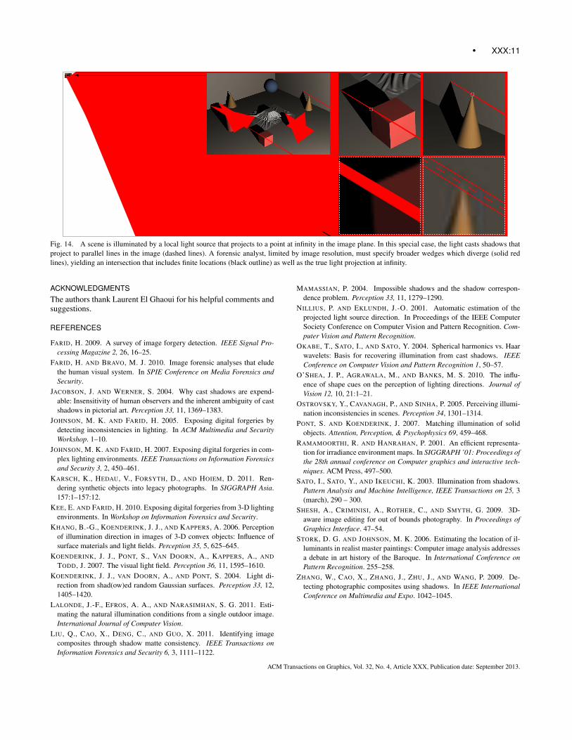
Lastly, we note that a local or infinite light source may some-times project to a point at infinity in the image plane. A local light,for example, will project to infinity if the direction from the cam-era center to the light is parallel to the image plane. In this case,lines connecting points on a cast shadow to their correspondingpoints on an object will be parallel and hence intersect at infinity.Shown in Fig. 14 is such an example where the dashed lines con-necting shadow and object on the cone and cube are parallel. Ananalyst limited by finite image resolution, however, cannot unam-biguously identify exact points to specify these parallel lines andinstead must specify a broader wedge shape (solid lines). Thesewedges diverge and therefore their intersection includes finite loca-tions (black region) as well as the true light projection at infinity.Although lights projecting to infinity would create problems for al-gorithms attempting to find the light position by intersecting nearlyparallel rays [Stork and Johnson 2006], this situation does not poseany particular difficulty in specifying a valid region using wedgeand half-plane constraints.
4. DISCUSSION
We have described a geometric technique for detecting photomanipulation based on inconsistent shadows. Previous lighting-and shadow-based forensic techniques exploited cast shadows forwhich a unique object-to-shadow pairing was available (e.g., thetip of a cone). In contrast, we exploit a broad range of ambiguouscast and attached shadows. Although each constraint is typicallynot highly informative, a combination of many such constraintscan be highly effective in detecting inconsistent shadows that arenot perceptually obvious. The subsequent determination of shadowconsistency is framed as a standard linear programming problemaffording a computationally efficient solution. A consistent solu-tion to all specified shadow constraints is interpreted to mean thatthe shadows are physically plausible while a failure to find a solu-tion is used as evidence of photo tampering. In the latter case, it canbe difficult to visually identify which constraints are inconsistent.We, therefore, developed a method to identify the inconsistent con-straints thus providing insight into which parts of an image weremanipulated.
This method is intended for use where there is only a single dom-inant light source. While this limitation does preclude analysis ofscenes lit by multiple point lights or diffuse area lighting, it in-cludes the common situation of outdoor scenes lit by the sun or in-door scenes photographed with a flash. Scenes with multiple lightsources or strong interreflections are usually evident by a corre-sponding multitude of shadows for a single object. It is likely thatthis basic approach will extend to area lights [Ramamoorthi andHanrahan 2001] that yield reasonably well defined shadows.
Beyond an assumption of linear perspective projection and a sin-gle dominant point light source, no other assumptions about thescene geometry or photometry are required. Should lens distortionbe an issue, standard techniques can be employed to estimate andremove lens distortion. Alternatively the constraint wedges couldbe expanded to accommodate the bounded movement of featuresin the image plane due to lens or other type of distortion.
A key step in applying our method is for the analyst to select aset of shadows from the image and to specify appropriate wedgesor half-planes. A poor selection of constraints could, of course, leadto a failure in detecting a manipulated image. To minimize the like-lihood of this, we described a simple user interface which makesthe annotation of shadows relatively fast and easy to perform.
Even with this interface, our method relies on a user correctlyselecting constraints. The strength of our approach is that theseconstraints can be objectively validated because the correspon-dence between objects and their shadows is generally clear. Incases where the relation is not clear, large encompassing wedgesmay be specified or other less ambiguous shadows may be used.Our method therefore shifts the dialogue from “does the light-ing/shadow look correct?” (which is well known to be highly un-reliable), to a discussion of whether an analyst has correctly se-lected the range of points on an object that correspond to a pointon a shadow (a far more objective task). In this regard, our methodlets humans do what computers are poor at — understanding scenecontent — and lets the computer do what humans are poor at —assessing the validity of geometric constraints.
A sufficiently informed forger (e.g., [Shesh et al. 2009]) could,of course, use this forensic technique to ensure that all shadowsare consistent. One way to counter this is to combine this shadowanalysis with other techniques for estimating lighting from a singleimage [Nillius and Eklundh 2001; Okabe et al. 2004; Lalonde et al.2011]. This addition will make it more difficult, but never impossi-ble, to create a consistent and visually compelling fake.
ACM Transactions on Graphics, Vol. 32, No. 4, Article XXX, Publication date: September 2013.
• XXX:11
Fig. 14. A scene is illuminated by a local light source that projects to a point at infinity in the image plane. In this special case, the light casts shadows thatproject to parallel lines in the image (dashed lines). A forensic analyst, limited by image resolution, must specify broader wedges which diverge (solid redlines), yielding an intersection that includes finite locations (black outline) as well as the true light projection at infinity.
ACKNOWLEDGMENTSThe authors thank Laurent El Ghaoui for his helpful comments andsuggestions.
REFERENCES
FARID, H. 2009. A survey of image forgery detection. IEEE Signal Pro-cessing Magazine 2, 26, 16–25.
FARID, H. AND BRAVO, M. J. 2010. Image forensic analyses that eludethe human visual system. In SPIE Conference on Media Forensics andSecurity.
JACOBSON, J. AND WERNER, S. 2004. Why cast shadows are expend-able: Insensitivity of human observers and the inherent ambiguity of castshadows in pictorial art. Perception 33, 11, 1369–1383.
JOHNSON, M. K. AND FARID, H. 2005. Exposing digital forgeries bydetecting inconsistencies in lighting. In ACM Multimedia and SecurityWorkshop. 1–10.
JOHNSON, M. K. AND FARID, H. 2007. Exposing digital forgeries in com-plex lighting environments. IEEE Transactions on Information Forensicsand Security 3, 2, 450–461.
KARSCH, K., HEDAU, V., FORSYTH, D., AND HOIEM, D. 2011. Ren-dering synthetic objects into legacy photographs. In SIGGRAPH Asia.157:1–157:12.
KEE, E. AND FARID, H. 2010. Exposing digital forgeries from 3-D lightingenvironments. In Workshop on Information Forensics and Security.
KHANG, B.-G., KOENDERINK, J. J., AND KAPPERS, A. 2006. Perceptionof illumination direction in images of 3-D convex objects: Influence ofsurface materials and light fields. Perception 35, 5, 625–645.
KOENDERINK, J. J., PONT, S., VAN DOORN, A., KAPPERS, A., AND
TODD, J. 2007. The visual light field. Perception 36, 11, 1595–1610.KOENDERINK, J. J., VAN DOORN, A., AND PONT, S. 2004. Light di-
rection from shad(ow)ed random Gaussian surfaces. Perception 33, 12,1405–1420.
LALONDE, J.-F., EFROS, A. A., AND NARASIMHAN, S. G. 2011. Esti-mating the natural illumination conditions from a single outdoor image.International Journal of Computer Vision.
LIU, Q., CAO, X., DENG, C., AND GUO, X. 2011. Identifying imagecomposites through shadow matte consistency. IEEE Transactions onInformation Forensics and Security 6, 3, 1111–1122.
MAMASSIAN, P. 2004. Impossible shadows and the shadow correspon-dence problem. Perception 33, 11, 1279–1290.
NILLIUS, P. AND EKLUNDH, J.-O. 2001. Automatic estimation of theprojected light source direction. In Proceedings of the IEEE ComputerSociety Conference on Computer Vision and Pattern Recognition. Com-puter Vision and Pattern Recognition.
OKABE, T., SATO, I., AND SATO, Y. 2004. Spherical harmonics vs. Haarwavelets: Basis for recovering illumination from cast shadows. IEEEConference on Computer Vision and Pattern Recognition 1, 50–57.
O’SHEA, J. P., AGRAWALA, M., AND BANKS, M. S. 2010. The influ-ence of shape cues on the perception of lighting directions. Journal ofVision 12, 10, 21:1–21.
OSTROVSKY, Y., CAVANAGH, P., AND SINHA, P. 2005. Perceiving illumi-nation inconsistencies in scenes. Perception 34, 1301–1314.
PONT, S. AND KOENDERINK, J. 2007. Matching illumination of solidobjects. Attention, Perception, & Psychophysics 69, 459–468.
RAMAMOORTHI, R. AND HANRAHAN, P. 2001. An efficient representa-tion for irradiance environment maps. In SIGGRAPH ’01: Proceedings ofthe 28th annual conference on Computer graphics and interactive tech-niques. ACM Press, 497–500.
SATO, I., SATO, Y., AND IKEUCHI, K. 2003. Illumination from shadows.Pattern Analysis and Machine Intelligence, IEEE Transactions on 25, 3(march), 290 – 300.
SHESH, A., CRIMINISI, A., ROTHER, C., AND SMYTH, G. 2009. 3D-aware image editing for out of bounds photography. In Proceedings ofGraphics Interface. 47–54.
STORK, D. G. AND JOHNSON, M. K. 2006. Estimating the location of il-luminants in realist master paintings: Computer image analysis addressesa debate in art history of the Baroque. In International Conference onPattern Recognition. 255–258.
ZHANG, W., CAO, X., ZHANG, J., ZHU, J., AND WANG, P. 2009. De-tecting photographic composites using shadows. In IEEE InternationalConference on Multimedia and Expo. 1042–1045.
ACM Transactions on Graphics, Vol. 32, No. 4, Article XXX, Publication date: September 2013.

XXX:12 •
Images copyright 2012, Kee, O’Brien, and Farid
Fig. 15. A composite photo and a minimal set of violating constraints (these were automatically determined from a total of 25 user specified constraints).The red shaded regions corresponds to the positive constraints and the blue shaded regions correspond to the negative constraints. The three middle panels area magnified view of the selected shadows.
ACM Transactions on Graphics, Vol. 32, No. 4, Article XXX, Publication date: September 2013.