to appear in ieee communications surveys and tutorials, the first...
TRANSCRIPT

TO APPEAR IN IEEE COMMUNICATIONS SURVEYS AND TUTORIALS, THE FIRST QUARTER, 2007. 1
Fast Handoff Support in IEEE 802.11 Wireless
Networks
Sangheon PackMember, IEEE, Jaeyoung ChoiStudent Member, IEEE, Taekyoung Kwon,
and Yanghee Choi,Senior Member, IEEE
Abstract
With the advance of wireless local area network (WLAN) technology, handoff support has become one of the
most important issues in IEEE 802.11 WLANs. However, the current IEEE 802.11 specification does not provide
fast handoff required for real-time multimedia applications. To support fast handoff in IEEE 802.11 networks, a
number of fast handoff schemes have been proposed in the literature. In this article, we review these fast handoff
schemes and analyze their advantages and disadvantages qualitatively. After that, important design considerations
for mobility support in future IEEE 802.11 networks are suggested. Also, we introduce a fast handoff framework
which adaptively meets different application requirements via a cross-layer approach.
Index Terms
IEEE 802.11, fast handoff, survey, adaptive fast handoff framework, cross-layer approach.
Contact author: Sangheon Pack, Address: 301-518, Multimedia & Mobile Communications Lab., Seoul National University, Seoul, Korea,
151-742, Tel:+82-2-880-1849, Fax:+82-2-872-2045, Email: [email protected])
S. Pack, J. Choi, T. Kwon, and Y. Choi are with the School of Computer Science & Engineering, Seoul National University, Seoul, Korea.
Email:{shpack,jychoi}@mmlab.snu.ac.kr,{tkkwon,yhchoi}@snu.ac.kr

TO APPEAR IN IEEE COMMUNICATIONS SURVEYS AND TUTORIALS, THE FIRST QUARTER, 2007. 2
I. I NTRODUCTION
Public wireless local area network (WLAN) systems based on IEEE 802.11 are exponentially becoming
popular in hot spot areas such as airports, campuses, convention centers, and so on. Unlike existing
wireless Internet services based on cellular networks, public WLAN systems can provide high-speed
Internet connectivity up to 11Mbps (IEEE 802.11b [1]) or 54Mbps (IEEE 802.11a/g [2], [3]). Originally,
WLAN was designed as a network solution for eliminating the problem of tangled cables among network
devices in an indoor environment, so that handoff support was not perceived as a critical issue. However,
the advances of public Wi-Fi services and multimedia applications have raised an unforeseen problem,
handoff supportbetween access points (APs) [4], [5]. Due to insufficient handoff support in IEEE 802.11
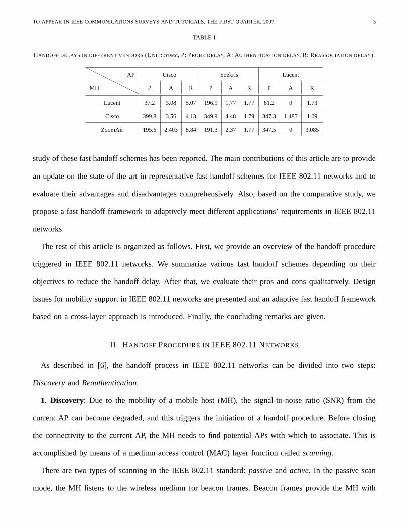
networks, a significant disruption can be experienced while a handoff is performed. Table I summarizes
the measured handoff delay reported in [6] and it indicates that the handoff delay is unsatisfactory to
support multimedia applications in IEEE 802.11 networks. Consequently, supporting fast handoff in IEEE
802.11 networks has become a vital issue to achieve seamless mobile services.
Currently, several IEEE working groups (WGs) have endeavored to enhance and augment IEEE 802.11,
i.e., 11g for 2.4 GHz OFDM [3], 11e for quality of service (QoS) [7], 11i for security [8], 11f for inter-
AP protocol [9], and so on [10]. Regarding handoff support, the 11i and 11f WGs have proposed several
schemes to address security concerns and to support communications between the APs involved in a
handoff event, respectively. More recently, two new IEEE 802.11 groups, 11k and 11r, have been launched
for the purpose of radio resource management and fast handoff support, respectively. The draft 802.11k
specification provides a radio resource measurement mechanism [11]. This measurement information can
be used to obtain information on the currently available APs, before a handoff decision takes place. On the
other hand, the 11r task group will define roaming algorithms to satisfy the stringent QoS requirements
but, as yet, no tangible results have been forthcoming.
In addition to these standardization activities, many studies have been conducted in order to improve the
handoff performance in IEEE 802.11 networks. The existing fast handoff schemes have been evaluated by
simulations or measurements on specific testbeds. However, to the best of our knowledge, no comparative
TO APPEAR IN IEEE COMMUNICATIONS SURVEYS AND TUTORIALS, THE FIRST QUARTER, 2007. 3
TABLE I
HANDOFF DELAYS IN DIFFERENT VENDORS(UNIT: msec, P: PROBE DELAY, A: AUTHENTICATION DELAY, R: REASSOCIATION DELAY).
HHHHHHHHMH
AP Cisco Soekris Lucent
P A R P A R P A R
Lucent 37.2 3.08 5.07 196.9 1.77 1.77 81.2 0 1.73
Cisco 399.8 3.56 4.13 349.9 4.48 1.79 347.3 1.485 1.09
ZoomAir 195.6 2.403 8.84 191.3 2.37 1.77 347.5 0 3.085
study of these fast handoff schemes has been reported. The main contributions of this article are to provide
an update on the state of the art in representative fast handoff schemes for IEEE 802.11 networks and to
evaluate their advantages and disadvantages comprehensively. Also, based on the comparative study, we
propose a fast handoff framework to adaptively meet different applications’ requirements in IEEE 802.11
networks.
The rest of this article is organized as follows. First, we provide an overview of the handoff procedure
triggered in IEEE 802.11 networks. We summarize various fast handoff schemes depending on their
objectives to reduce the handoff delay. After that, we evaluate their pros and cons qualitatively. Design
issues for mobility support in IEEE 802.11 networks are presented and an adaptive fast handoff framework
based on a cross-layer approach is introduced. Finally, the concluding remarks are given.
II. H ANDOFF PROCEDURE INIEEE 802.11 NETWORKS
As described in [6], the handoff process in IEEE 802.11 networks can be divided into two steps:
DiscoveryandReauthentication.
1. Discovery: Due to the mobility of a mobile host (MH), the signal-to-noise ratio (SNR) from the
current AP can become degraded, and this triggers the initiation of a handoff procedure. Before closing
the connectivity to the current AP, the MH needs to find potential APs with which to associate. This is
accomplished by means of a medium access control (MAC) layer function calledscanning.
There are two types of scanning in the IEEE 802.11 standard:passiveandactive. In the passive scan
mode, the MH listens to the wireless medium for beacon frames. Beacon frames provide the MH with

TO APPEAR IN IEEE COMMUNICATIONS SURVEYS AND TUTORIALS, THE FIRST QUARTER, 2007. 4
timing and advertising information. Using the information obtained from these beacon frames, the MH
can choose an AP to associate with next. The current IEEE 802.11 standard supports multiple channels.
Specifically, both the IEEE 802.11b and 11g standards operate in the 2.4 GHz ISM band and use 11
channels of the 14 possible channels, whereas the IEEE 802.11a standard operates in the 5 GHz ISM
band in which a total of 32 channels are defined. During the passive scanning mode, the MH listens to
each channel of the physical medium one by one, in an attempt to locate the next AP. Therefore, the
passive scan mode incurs significant delay.
On the other hand, the active scanning mode involves the transmissions of probe request frames by
the MH and the processing of the received probe response frames from the APs. After all channels have
been scanned, the MH collects the information from all available APs and therefore the MH can select
the next AP to associate. The detailed active scanning procedure is as follows [12]:
1) The normal channel access procedure, carrier sense multiple access with collision avoidance (CSMA/CA)
is performed to gain control of the wireless medium.
2) The MH transmits a probe request frame containing the broadcast address as its destination.
3) A probe timer is started.
4) The MH waits for probe responses.
5) If no response has been received byMinChannelTime, the next channel is scanned
6) If one or more responses are received byMinChannelTime, the MH stops accepting probe responses
at MaxChannelTimeand processes all of the responses received by this time.
7) The above steps are repeated for the next channel.
2. Reauthentication: The reauthentication procedure1 involves authentication and reassociation to the
new AP and the transfer of the MH’s credentials from the old AP to the new AP. Authentication is a
process that the AP either accepts or rejects the identity of the MH. An MH begins the authentication
process by sending an authentication request frame that informs the AP of its identity. Then, the AP
1The association refers to a procedure to make a logical connection by an MH, which is invoked once when the MH enters a WLAN
system for the first time. On the other hand, the reassociation is a procedure that an MH provides information to the WLAN system with
which the MH was previously associated.

TO APPEAR IN IEEE COMMUNICATIONS SURVEYS AND TUTORIALS, THE FIRST QUARTER, 2007. 5
MH
Availab
le AP
s
Probe request on CH1
Probe request on CH11
Probe response
Probe response
…
New AP
Authentication request
Reassociation request
Reassociation response
Authentication response
Probe delayProbe delayProbe delayProbe delay
Authentication delayAuthentication delayAuthentication delayAuthentication delay
ReassociationReassociationReassociationReassociation delaydelaydelaydelay
Total handoff delayTotal handoff delayTotal handoff delayTotal handoff delay
Fig. 1. Handoff message flow in IEEE 802.11 networks.
responds with an authentication response frame indicating its acceptance or rejection. Once a successful
authentication has been accomplished, the MH can send a reassociation request frame to the new AP,
which then replies with a reassociation response frame containing an acceptance or rejection notice.
Figure 1 illustrates the message flow during a handoff. The handoff process starts with a probe request
message and ends with a reassociation response message originating from the AP. The entire handoff
delay can be divided into three delays:probe delay, authentication delay, andreassociation delay.
A. Probe Delay
The probe delay is dependent on which scan mode is used (i.e., passive or active mode). The average
probe delay in the passive scan can be represented as a function of the beacon interval and the number
of channels available. Specifically, if the beacon interval is 100msec, the average probe delays of IEEE
802.11b with 11 channels and 802.11a with 32 channels are 1100msec and 3200msec, respectively.
Note that the channel switching delay is negligible, i.e., about 40-150usec [13].
On the other hand, the probe delay bound of the active scan mode can be determined by theMinChan-
nelTimeandMaxChannelTimevalues, which are device-dependent. The current active scanning procedure
requires for an MH to scan all available channels (i.e., 11 channels for IEEE 802.11b and 32 channels

TO APPEAR IN IEEE COMMUNICATIONS SURVEYS AND TUTORIALS, THE FIRST QUARTER, 2007. 6
for IEEE 802.11a). Therefore, the probe delay bound,TA, of the active scan can be expressed as
N ×MinChannelT ime ≤ TA ≤ N ×MaxChannelT ime,
whereN is the number of channels available.
The most intuitive method for reducing the probe delay is to reduce the number of channels to be probed.
Namely, the probe delay can be reduced by probing only selected channels rather than all channels. Another
method is to refine theMinChannelTimeand MaxChannelTimevalues for the purpose of reducing the
channel waiting time. Research work based on these methods will be introduced later.
B. Authentication Delay
The authentication delay is incurred by the exchange of the authentication frames. In general, two
authentication approaches are widely accepted. One is the open-system authentication, in which the AP
always accepts an MH without any authentication procedure. Optionally, MAC address filtering can be
employed with the open-system authentication, but this is not a part of the IEEE 802.11 standard. The
other is the shared-key authentication method based on wired equivalent privacy (WEP) [14], which
requires that both the AP and MH implement WEP. The shared-key authentication requires four message
exchanges as follows:
1) The MH requests authentication to the AP by sending aChallenge-Request message
2) The AP sends a random number to the MH through aChallenge-Response message.
3) The MH signs this random number using WEP, which is a pre-shared secret key, and sends a
Response message back to the AP.
4) The AP verifies that the random number has been signed by the correct key, by calculating the
signature itself and comparing the computed and the received values. Once the key has been verified
by the AP, it authenticates the MH by sending anApproval message.
The authentication delay is proportional to the number of messages exchanged between the AP and
MH. Therefore, the shared-key authentication results in longer authentication delay than the open-system
authentication. Furthermore, if an IEEE 802.11 network utilizes enhanced authentication schemes described

TO APPEAR IN IEEE COMMUNICATIONS SURVEYS AND TUTORIALS, THE FIRST QUARTER, 2007. 7
in the IEEE 802.11i standard (e.g., IEEE 802.1x and EAP-TLS [15]), more message exchanges are
required. For instance, recently deployed public WLAN systems (e.g., NeSpot in Korea [16]) employ the
802.1x-based authentication scheme. Consequently, the problem of reducing the authentication delay is
likely to become an even more challenging issue in future WLAN systems.
C. Reassociation Delay
Reassociation is the process of moving an association from an old AP to a new AP within an extended
service set (ESS). An ESS is a set of one or more interconnected basic service sets (BSSs), where a
BSS is a service coverage of an AP. The reassociation delay is incurred due to the exchange of the
reassociation frames. Upon the successful completion of the authentication process, an MH sends a
reassociation request frame to the AP and receives a reassociation response frame, and completes the
handoff. Over the air, the reassociation procedure is almost the same as the association procedure. On the
backbone network, however, APs may interact with each other to deliver frames related to the reassociation.
Namely, future implementations may also include additional inter-AP protocol (IAPP) [9] messages during
the reassociation phase, which may further increase the reassociation delay.
III. FAST HANDOFF SCHEMES: STATE OF THE ART
A number of schemes have been proposed to reduce the handoff delay in IEEE 802.11 networks. Among
them, we select representative ones and describe them in two categories:reducing the probe delayand
reducing the authentication/reassociation delay. Note that the authentication and reassociation procedures
have similar operations and therefore we consider these two procedures into one.
A. Reducing Probe Delay
As indicated in [6], the probe delay is the main contributor to the handoff delay, and hence it is crucial
to reduce the probe delay.
In [17], Velayoset al. proposed a fast handoff detection scheme (referred to as thetuning scheme). In
this work, they used the frame loss distribution caused by collisions, in order to determine the optimal

TO APPEAR IN IEEE COMMUNICATIONS SURVEYS AND TUTORIALS, THE FIRST QUARTER, 2007. 8
handoff trigger timing to a new AP. To reduce the handoff detection time, the MH starts the channel
probe procedure as soon as it deems that collision can be excluded as a reason for the frame transmission
failure. In other words, based on the probability distribution, if a frame and its next two consecutive
retransmissions fail, the MH concludes that the frame failure is caused by the MH’s movement (not
by collision) and therefore a further handoff process is required. In addition, they leveraged the active
scan mode and derived new values forMinChannelTimeand MaxChannelTimefrom their measurement
results and analytical models. Specifically, they used smaller values of 1msec and 10.24msec for
MinChannelTimeand MaxChannelTime, respectively. By using these reduced timer values, the tuning
scheme can reduce the channel probe delay.
[18] presented a novel discovery method using a neighbor graph (NG) and non-overlap graph (NOG).
This scheme (referred to as theNG-pruning scheme) focuses on reducing both the total number of channels
to be probed and the waiting time on each channel. They suggested two algorithms: the NG and NG-
pruning algorithms. The rationale behind these algorithms is to ascertain whether a channel needs to be
probed or not (by the NG algorithm) and whether the MH has to wait more probe response messages
on a specific channel before the expiration ofMaxChannelTime(by the NG-pruning algorithm). The NG
abstracts the hand-off relationship between adjacent APs. Using the NG, the set of channels on which
neighboring APs are currently operating and the set of neighbor APs on each channel can be learned.
Based on this information, an MH can determine whether a channel needs to be probed or not. On the
other hand, the NOG abstracts the non-overlapping relation among the APs. Two APs are considered to
be non-overlapping if and only if the MH cannot communicate with both of them simultaneously with
acceptable link quality. For instance, if the distance betweenAPi and APj is far, an MH can associate
with only one of them. In this case,APi andAPj are non-overlapping each other. Therefore, if the MH
has received a probe response frame fromAPi, it implies that the MH cannot receive a response frame
from APj by the principle of non-overlapping. By means of the NOG, the MH can prune some of the
APs which are non-overlapping with the current AP group that has already responded.
Figure 2 illustrates the operation of the NG-pruning scheme. The unbracketed and bracketed numbers

TO APPEAR IN IEEE COMMUNICATIONS SURVEYS AND TUTORIALS, THE FIRST QUARTER, 2007. 9
3[11]
1[1]
2[6]
5[11]
4[6]
6[6]
3
1
2
5
4
6
NOG on Channel 6
3
1
2
5
4
6
NOG on Channel 11
Fig. 2. NG-pruning scheme.
represent the AP identifier and channel number used by the AP, respectively. In this example, only three
channels (i.e., 1, 6, and 11) are used and the current AP (AP1) has five neighboring APs (AP2-AP6). The
neighbor information can be learned by the construction of the NG. By using this neighbor information,
the MH knows that the number of channels it has to probe is just two (i.e., channels 6 and 11). On
the other hand, individual NOGs are constructed on each channel, i.e., one NOG on channel 6 and the
other NOG on channel 11. First, suppose that the MH is probing on channel 6. When it receives a probe
response message fromAP6, the MH decides that it is unnecessary to wait for additional probe response
messages on channel 6. This is becauseAP6 is non-overlapping withAP2 and AP4 even though they
use channel 6. After probing channel 6, the MH sends a probe request message on channel 11. Then, the
MH receives a probe response message fromAP5 and stops probing on this channel becauseAP3 using
channel 11 is non-overlapping withAP5.
In [12], a selective scanning algorithm with a caching mechanism was proposed (referred to as the
channel mask scheme). In the channel mask scheme, only a well-selected subset of all available channels
is probed. Channel selection is performed by means of a channel mask that is built when the driver is first
loaded at the MH. Specifically, full-scan is triggered at first and the channel mask is then constructed by
the information obtained in the first full-scan. In IEEE 802.11b, only three channels do not overlap among
all 11 channels. Hence, in a well configured wireless network, all or most of the APs operate on channels
TO APPEAR IN IEEE COMMUNICATIONS SURVEYS AND TUTORIALS, THE FIRST QUARTER, 2007. 10
1, 6, and 11. Consequently, the channel mask is formed by combining three frequent channels (i.e., 1, 6,
and 11) and the channels scanned at the first full-scan. By using this channel mask, an MH can reduce
the amount of unnecessary time that it spends probing non-existent channels among neighboring APs. To
further reduce the handoff delay, a cache mechanism was also introduced. The basic idea of the caching
mechanism is for each MH to store its handoff history. When an MH associates with an AP, the AP is
inserted into the cache maintained at the MH. When a handoff is needed, the MH first checks whether
there is an entry corresponding to the current AP’s MAC address in the cache. If there is a matched cache
entry, the MH can associate with the AP without any further probing procedures.
Figure 3 illustrates the operation of the channel mask scheme. Each MH has its own channel mask,
which is built during the network setup phase. At the same time, each MH has its own cache table that
is constructed and updated dynamically by handoff events. Namely, when an MH associates with an AP,
the AP’s identifier (i.e., MAC address) is stored in the cache as a key. In addition, two APs with the best
received signal strengths (RSS) are stored in the cache. When a handoff is needed, the MH first checks
the entries in its own cache table using the current AP’s MAC address as the search key. If there is a
cache entry for the current AP (i.e., cache hit), the MH tries to associate with the first AP that has the
highest RSS. If the association is successful, the handoff is finished and therefore the handoff latency can
be significantly reduced. Otherwise, the association to the second AP is tried. Only when the first and
second associations fail, the MH performs selective channel probing using the channel mask. In Figure 3,
only three channels are used, so that it is sufficient for the MH to probe the three channels even if a cache
miss occurs.
In [19], a new handoff scheme, calledSyncScan, was proposed to reduce the probe delay. Unlike the
existing probe procedures defined in IEEE 802.11, SyncScan allows an MH to monitor the proximity of
nearby APs continuously. In other words, the MH regularly switches to each channel and records the
signal strengths of the channels. By doing so, the MH can keep track of information on all neighbor APs.
Moreover, through continuous monitoring the signaling quality of multiple APs, a better handoff decision
can be made and the authentication/reassociation delay can be also reduced. To minimize the packet

TO APPEAR IN IEEE COMMUNICATIONS SURVEYS AND TUTORIALS, THE FIRST QUARTER, 2007. 11
3[11] 1[1]
2[6]
5[11]
4[6]
6[6]5[11]3[11]6[6]
………
2[6]5[11]1[1]
SecondBestKey
Cache TableHit
3[11] 1[1]
2[6]
4[6]
6[6]5[11]3[11]6[6]
………
3[11]4[6]2[6]
SecondBestKey
5[11]
Channel Mask
Cache TableMiss
(a) Cache hit (b) Cache miss
Fig. 3. Channel mask scheme.
loss during the periodical monitoring, the power saving mode (PSM) in the IEEE 802.11 specification
is utilized. Since SyncScan is based on the regular monitoring of APs, time synchronization is a critical
issue. For synchronization with APs, the network time protocol (NTP) can be leveraged. On the other
hand, if multiple APs use the same channel and they generate beacons at the same time, a randomization
technique can be employed.
Figure 4 shows the timing diagram in SyncScan.d is a stagger parameter that determines the beacon
broadcasting timing. For instance, APs operating on channel 1 broadcast beacon frames at timeT , while
APs on channel 2 will do the same at timeT + d, APs on channel 3 will send beacon frames at time
T + 2d, and so on. By this schedule, the MH switches from the current channelc to the channelc + 1
and receives beacon frames from APs on the channelc+1. This operations are continuously repeated and
hence the MH learns information on neighbor APs. Consequently, SyncScan enables an MH to determine
the time when a handoff should be triggered, which reduces the handoff delay.
Brik et al. introduced a handoff scheme utilizing multiple radios calledMultiScan[20]. Similar to Sync-
Scan, MultiScan obtains information on neighbor APs by scanning opportunistically. However, MultiScan
requires an additional radio interface for the channel scanning. In MultiScan, the primary interface is
associated with the current AP and used for data transmission. At the same time, the secondary interface

TO APPEAR IN IEEE COMMUNICATIONS SURVEYS AND TUTORIALS, THE FIRST QUARTER, 2007. 12
3[11]
2[6]
5[11]
4[6]
6[6]
T T+11dT+10d
Channel 1 Channel 11Channel 10
…
…
T+d
Channel 2
…
…
1[1]
T
T+5d
T+5d
T+5dT+10d
T+10d
Fig. 4. SyncScan operation.
is performing the channel scanning. If a handoff to a new AP is required, the second interface is associated
with the new AP while the primary interface is still employed for data transmission. After the completion of
a new association by the secondary interface, interface switch from the secondary interface to the primary
one is triggered. As a result, the formerly secondary interface becomes primary for data transmission
and the formerly primary interface is used for channel scanning. Consequently, MultiScan achieves a
make-before-breakhandoff by using multiple radio interfaces.
B. Reducing Authentication/Reassociation Delay
Even though the probe delay takes a large portion of the total handoff delay, the authentication/reassociation
delay should be also reduced to achieve seamless mobile services. Actually, in public WLAN services,
the authentication scheme based on the centralized authentication server is widely adopted for the sake
of secure service and efficient accounting. In such an environment, the authentication/reassociation delay
may be higher than those observed in the case where the open authentication procedure is employed [21].
Different fast authentication methods in IEEE 802.11 networks are overviewed and analyzed in [22] in
terms of network architectures and trust models. In this article, we describe several schemes focusing on
the communication model.
In [23], Packet al. proposed a predictive handoff scheme for reducing the authentication/reassociation

TO APPEAR IN IEEE COMMUNICATIONS SURVEYS AND TUTORIALS, THE FIRST QUARTER, 2007. 13
0
2
5
7
4
8
1
3
6
9
FHR
0
2
5
7
4
8
1
3
6
9
FHR
(a) Login atAP4 (b) Handoff fromAP4 to AP2
Fig. 5. FHR scheme.
delay (referred to as theFHR scheme). In this scheme, an MH’s authentication information is proactively
distributed to multiple APs depending on the MH’s mobility pattern and service class. To predict the
MH’s mobility pattern, a concept of frequent handoff region (FHR) was introduced. The FHR is a set of
APs which have high possibilities of being visited by an MH in the near future. The FHR is constructed
based on the handoff frequency and the MH’s priority at the centralized system. The FHR can be easily
implemented based on the IEEE 802.1x model [24]. From several measurement studies [5], the number
of APs associated with an MH during its service time is typically bounded to 2 or 3. Therefore, in the
FHR scheme, the MH’s authentication information is delivered to a subset of the adjacent APs which are
located at a maximum two-hop distance from the current AP.
Figure 5 shows the operation of the FHR scheme. In this example, an MH associates withAP4 at the
login phase, and it forms a FHR consisting ofAP0, AP4, AP7, andAP8. Therefore, the authentication
information is distributed to four APs (i.e.,AP0, AP4, AP7, andAP8) in advance. If the MH moves to one
of the selected APs, no authentication procedure to the authentication server is needed. However, if the MH
moves to another AP (e.g.,AP2 in Figure 5(b)), which was not involved in the predictive authentication
operation, new authentication and reassociation procedures have to be performed. In addition, after
performing handoff toAP2, a new FHR consisting ofAP1, AP2, AP3, andAP5 has to be constructed.

TO APPEAR IN IEEE COMMUNICATIONS SURVEYS AND TUTORIALS, THE FIRST QUARTER, 2007. 14
0
2
5
7
4
8
1
3
6
9
MH1
MH1
MH1
MH1MH1
MH1
0
2
5
7
4
8
1
3
6
9
MH1
MH1
MH1
MH1
MH1
MH1
MH1
MH1
(a) Login atAP4 (b) Handoff fromAP4 to AP2
Fig. 6. PNC scheme.
Instead of using the centralized system, a proactive scheme based on a distributed cache structure
was introduced in [25]. This scheme is called theproactive neighbor caching (PNC)scheme. The PNC
scheme uses a neighbor graph, which dynamically captures the mobility topology of a wireless network
for the purpose of pre-positioning an MH’s context. The PNC scheme ensures that the MH’s context is
always dispatched one-hop ahead, and therefore the handoff delay can be substantially reduced. Here,
the context includes information regarding the MH’s session, quality of service (QoS), and security [26].
The neighbor graph is constructed using the information exchanged during the MH’s handoff, and it is
maintained at each AP in a distributed manner. The propagated MH’s context is stored in the cache. The
cached MH’s context may be replaced by a cache replacement policy (e.g., least recently used (LRU)
scheme) if there is no remaining capacity in the cache. Recently, the PNC scheme has been included in
the IAPP specification [9], which is a standard protocol for communications between APs.
The operation of the PNC scheme is illustrated in Figure 6. When an MH logs in toAP4, this AP
propagates the MH’s context to all neighboring APs (i.e.,AP0, AP2, AP5, AP7, and AP8). When the
MH moves toAP2, no further authentication procedure is performed becauseAP2 has already received
the MH’s context. At the same time, the MH’s contexts are removed from the other non-neighboring APs
(i.e., AP0, AP7, andAP8).

TO APPEAR IN IEEE COMMUNICATIONS SURVEYS AND TUTORIALS, THE FIRST QUARTER, 2007. 15
In the PNC scheme, an MH’s context is propagated to all neighboring APs whenever a new (re)association
is created. Therefore, the PNC scheme may result in high signaling overhead, especially when there are a
large number of MHs in IEEE 802.11 wireless networks. Furthermore, previous measurement studies [4],
[5] indicate that even in the case where a number of APs are deployed, a maximum of 2 or 3 APs are the
main target points of the handoffs. Therefore, propagating the MH’s context to a subset of neighboring
APs may be sufficient to provide seamless mobility. To reduce the signaling overhead caused by context
transfer, an enhanced neighbor caching scheme called theselective neighbor caching (SNC)scheme was
proposed in [27]. The SNC scheme enhances the PNC scheme by adding a new concept ofneighbor weight.
The neighbor weight represents the handoff probability for each neighboring AP. Based on the neighbor
weight, the MH’s context is propagated only to the selected neighboring APs (i.e., those neighboring APs
whose neighbor weights are equal to or higher than a pre-defined threshold). The neighbor graph and its
neighbor weights can be easily constructed by monitoring the handoff patterns among the APs.
When we compare Figure 7 with Figure 6, the SNC scheme involves less context transfer operations.
For example, when the MH is associated withAP4, only three neighbor APs (i.e.,AP2, AP5, and
AP8) receive the MH’s context. If the MH hands off to one of the selected neighboring APs, the SNC
scheme shows the same reduced delay as the PNC scheme, whereas the SNC scheme requires longer
authentication/reassociation delay if the MH moves to a non-selected neighboring APs. The SNC can
provide similar handoff performance if the threshold value is carefully selected. In addition, if the cache
at the AP is limited, the SNC scheme is more preferable than the PNC scheme.
IV. PUTTING IT ALL TOGETHER: QUALITATIVE ANALYSIS
As mentioned above, reducing the probe delay is the most important requirement to achieve fast handoff
in IEEE 802.11 networks. Figure 8 shows the classification for schemes to reduce the probe delay. Two
different approaches are available for reducing the probe delay: limiting the number of channels to be
probed and reducing the waiting time for each channel to be probed.
The tuning scheme is based on the latter approach. Specifically, the tuning scheme attempts to find more
appropriateMaxChannelTimeandMinChannelTimevalues to reduce the channel probing delay. The NOG

TO APPEAR IN IEEE COMMUNICATIONS SURVEYS AND TUTORIALS, THE FIRST QUARTER, 2007. 16
02
5
7
4
8
1
3
6
9
MH1
MH1
MH1
Selected Neighbors
MH1
02
5
7
4
8
1
3
6
9
MH1
MH1
MH1
MH1
MH1
MH1
Selected Neighbors
(a) Login atAP4 (b) Handoff fromAP4 to AP2
Fig. 7. SNC scheme.
Reducing probe delay
NG-Pruning
Channel mask
Tuning
NG-Pruning
SyncScan
MultiScan
Empirical
Number of channels Channel waiting time
Non-empirical
Fig. 8. Classification: Reducing probe delay.
in the NG-pruning scheme allows the channel waiting time to be reduced because the MH does not need
to wait for further probe responses once it receives some probe responses from available APs. The channel
mask scheme and the NG-pruning scheme limit the number of channels to be probed by introducing the
channel mask/cache and the NG, respectively. These two schemes utilize empirical handoff information
to construct the cache and the NG. SyncScan and MultiScan also reduce the number of channels to be
probed; however, they are not dependent on the empirical handoff information. Instead, SyncScan and
MultiScan collect information on nearby APs through continuous monitoring.

TO APPEAR IN IEEE COMMUNICATIONS SURVEYS AND TUTORIALS, THE FIRST QUARTER, 2007. 17
Reducing authentication/reassociation delay
Distributed Centralized
PNC
SNCFHR
Fig. 9. Classification: Reducing authentication/reassociation delay.
When IEEE 802.11 WLANs are deployed in public areas, secure and robust authentications become
critical issues. However, more secure authentication schemes will incur longer authentication/reassociation
delay. Hence reducing the authentication/reassociation delay is as important as reducing the probe delay in
such an environment. For the schemes reducing the authentication/reassociation delay, how to propagate
the MH context is a criterion for classification.
The FHR and PNC schemes are based on a similar concept, i.e., proactive propagation of the MH’s
context to the selected APs. However, these two schemes realize this concept in different manners. In
the FHR scheme, the central system constructs the frequent handoff region by considering the mobility
history and profile of the MHs. On the contrary, in the PNC scheme, each AP learns the mobility patterns
of the MHs and configures the neighbor graph in a distributed manner. The SNC scheme is an extended
version of the PNC scheme where only a subset of the neighbor APs keeps the MH’s context.
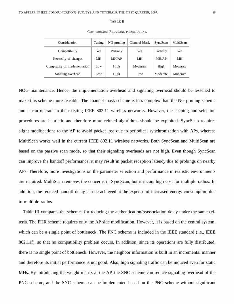
Table II shows the comparison of schemes for reducing the probe delay in terms of compatibility,
necessity of changes (AP side or MH side), implementation complexity, and signaling overhead. The
tuning scheme requires only MH side modification and it does not lead to an incompatibility issue.
Even though the tuning scheme can be easily implemented with low signaling overhead, how to select
appropriate tuning values should be addressed more comprehensively. To support the NG pruning scheme,
both AP and MH should be modified even though a part of the NG pruning scheme is the IEEE standard.
The main drawback of the NG pruning scheme is its high complexity and signaling overhead for NG and
TO APPEAR IN IEEE COMMUNICATIONS SURVEYS AND TUTORIALS, THE FIRST QUARTER, 2007. 18
TABLE II
COMPARISON: REDUCING PROBE DELAY.
Consideration Tuning NG pruning Channel Mask SyncScan MultiScan
Compatibility Yes Partially Yes Partially Yes
Necessity of changes MH MH/AP MH MH/AP MH
Complexity of implementation Low High Moderate High Moderate
Singling overhead Low High Low Moderate Moderate
NOG maintenance. Hence, the implementation overhead and signaling overhead should be lessened to
make this scheme more feasible. The channel mask scheme is less complex than the NG pruning scheme
and it can operate in the existing IEEE 802.11 wireless networks. However, the caching and selection
procedures are heuristic and therefore more refined algorithms should be exploited. SyncScan requires
slight modifications to the AP to avoid packet loss due to periodical synchronization with APs, whereas
MultiScan works well in the current IEEE 802.11 wireless networks. Both SyncScan and MultiScan are
based on the passive scan mode, so that their signaling overheads are not high. Even though SyncScan
can improve the handoff performance, it may result in packet reception latency due to probings on nearby
APs. Therefore, more investigations on the parameter selection and performance in realistic environments
are required. MultiScan removes the concerns in SyncScan, but it incurs high cost for multiple radios. In
addition, the reduced handoff delay can be achieved at the expense of increased energy consumption due
to multiple radios.
Table III compares the schemes for reducing the authentication/reassociation delay under the same cri-
teria. The FHR scheme requires only the AP side modification. However, it is based on the central system,
which can be a single point of bottleneck. The PNC scheme is included in the IEEE standard (i.e., IEEE
802.11f), so that no compatibility problem occurs. In addition, since its operations are fully distributed,
there is no single point of bottleneck. However, the neighbor information is built in an incremental manner
and therefore its initial performance is not good. Also, high signaling traffic can be induced even for static
MHs. By introducing the weight matrix at the AP, the SNC scheme can reduce signaling overhead of the
PNC scheme, and the SNC scheme can be implemented based on the PNC scheme without significant

TO APPEAR IN IEEE COMMUNICATIONS SURVEYS AND TUTORIALS, THE FIRST QUARTER, 2007. 19
TABLE III
COMPARISON: REDUCING AUTHENTICATION/REASSOCIATION DELAY.
Consideration FHR PNC SNC
Compatibility No Yes Partially
Necessity of changes AP AP AP
Complexity of implementation Low Moderate Moderate
Singling overhead Low High Moderate
changes in the standard. However, an additional data structure should be constructed and maintained, and
the SNC scheme only probabilistically lowers the authentication/reassociation delay.
V. PERSPECTIVE ONHANDOFF SUPPORT INFUTURE WLAN SYSTEMS
Even though a number of handoff schemes have been proposed for IEEE 802.11 wireless networks,
seamless mobility support is still one of the most challenging issues. The handoff issue in IEEE 802.11
networks has been dealt with by the IEEE 802.11f working group. IEEE 802.11f defines an optional
extension to IEEE 802.11 for AP communications among multi-vendor systems to support users’ roaming
and load balancing. Handoffs considered in the existing IEEE standards focus on only data traffic. Hence,
the handoff delay is too long to support multimedia applications such as voice over IP. Recently, the IEEE
802.11r task group has been formed to develop a handoff solution at the IEEE 802.11 level. IEEE 802.11r
specifies fast transition between BSSs, which allows seamless connectivity. However, IEEE 802.11r has
not been standardized until now. On the other hand, the IEEE 802.21 working group is trying to develop
standards to enable handoff and inter-operability between heterogeneous network types, including both
802 and non 802 networks. In this section, we first present important guidelines for handoff support in
future WLAN systems. After that, we propose an adaptive fast handoff framework.
A. Design Considerations
To support heterogeneous applications and users’ demands, future mobility solutions in IEEE 802.11
WLANs need to meet the following requirements.

TO APPEAR IN IEEE COMMUNICATIONS SURVEYS AND TUTORIALS, THE FIRST QUARTER, 2007. 20
• Interoperability/Backward compatibility : With the popularity of the WLAN technology, a lot of
APs have been already installed and many users are using WLAN services based on the IEEE 802.11b
standard. Furthermore, many improvements are being made to the current IEEE standard. Therefore,
future handoff schemes should be compatible with the legacy WLAN systems and standard activities.
• Adaptability : In future WLAN systems, a variety of applications will be supported and the handoff
delay bounds of these applications are likely to differ depending on their characteristics. For example,
elastic applications (e.g., web browsing) do not require a strict handoff delay bound compared with
real-time (RT) applications [28]. Hence, to meet the various applications’ requirements, the handoff
scheme should be designed in an adaptive manner.
• Extensibility : In next-generation wireless networks, integrating WLANs with other heterogeneous
networks is a hot issue. For example, cellular-WLAN integration networks provide wider coverage
and seamless mobile services [29]. In addition, WLAN-based wireless mesh networks are promising
network architectures [30]. Therefore, a mobility solution needs to be extensible to these new types
of integrated networks.
B. Adaptive Fast Handoff Framework: A Cross-Layer Approach
As mentioned before, a variety of applications will be supported in future WLAN systems and they
have different handoff delay bounds. For instance, RT applications require a strict handoff delay, whereas
elastic applications are more sensitive to throughput rather than handoff delay. If these applications’
requirements can be utilized for handoff support in IEEE 802.11 wireless networks, more desirable handoff
performance will be achieved. In the proposed adaptive fast handoff framework, the handoff related
parameters (e.g., the number of channels to be probed,MinChannelTime/MaxChannelTime, the number of
APs to be authenticated in advance, and so on) are dynamically determined depending on the applications’
requirements.
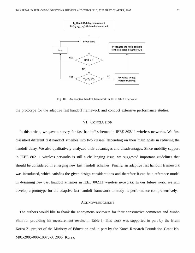
Figure 10 illustrates the adaptive fast handoff framework in IEEE 802.11 wireless networks. LetN be
the the number of channels available.C represents the ordered channel set, wherec1 is the channel with
the highest priority andcN is the channel with the lowest priority. The priority refers to the degree of

TO APPEAR IN IEEE COMMUNICATIONS SURVEYS AND TUTORIALS, THE FIRST QUARTER, 2007. 21
the possibility that an MH uses the channel at the next time.C can be constructed by considering the
typical channel assignment policy and/or by utilizing other schemes such as NG-pruning scheme [18] and
SyncScan [19]. Sincec1 has the highest priority, probingc1 is firstly performed. If the signal-to-noise
ratio (SNR) of channelc1 is less than a pre-defined thresholdδ, the next channelc2 is probed. If the
SNR of c1 is higher thanδ, the test on the handoff delay requirement is triggered. LetTR be the handoff
delay requirement determined by the application. In addition, letTP andTE be the average probe delay
for a channel and the total elapsed time from the handoff trigger epoch, respectively. IfTR − TE (i.e.,
the remaining time by the excess of the handoff delay requirement) is less thanTP , the additional probe
may result in the violation of the handoff delay requirement. Therefore, the overall probe procedure is
terminated. Otherwise, the probing process continues.
As a result of the probe procedure, the MH obtains a set of neighbor APs. Then, the MH authenticates
and reassociates to the AP with the highest SNR. In this step, proactive authentication based on mobility
estimation is performed. In other words, if the estimated mobility is high, the context regarding authen-
tication/reassociation is propagated to more neighbor APs; otherwise, only less neighbor APs receive the
context. This procedure can be accomplished by employing the SNC scheme.
The adaptive fast handoff scheme reduces both the number of channels to be probed and the channel
waiting time depending on the application requirement. In terms of reducing the authentication/reassociation
delay, the context propagation procedure is performed in a distributed manner. However, with the help of
the central system, cost-effective context transfer considering the mobility and network topology can be
accomplished. Therefore, the adaptive fast handoff scheme can be considered as a hybrid approach.
The adaptive fast handoff framework has the following advantages: 1) it allows an MH to select the most
appropriate AP with respect to its application. For RT applications, a tight delay requirementTR can be
adopted to minimize the handoff disruption time. On the other hand, elastic applications have loose delay
requirements and therefore an AP with the highest SNR can be chosen through more channel probings;
2) in terms of authentication/reassociation delay, different numbers of APs are selected by considering
mobility. Therefore, unnecessary context transfer can be minimized. In our future work, we will implement
TO APPEAR IN IEEE COMMUNICATIONS SURVEYS AND TUTORIALS, THE FIRST QUARTER, 2007. 22
Probe on ci
TR - TE < TP
TR: Handoff delay requirementC={c1, c2, … ,cN}: Ordered channel set
Associate to ap(j)j=argmax{SNR(j)}
i++
SNR < dYES
YES
NO
NO
Propagate the MH’s contextto the selected neighbor APs
Fig. 10. An adaptive handoff framework in IEEE 802.11 networks.
the prototype for the adaptive fast handoff framework and conduct extensive performance studies.
VI. CONCLUSION
In this article, we gave a survey for fast handoff schemes in IEEE 802.11 wireless networks. We first
classified different fast handoff schemes into two classes, depending on their main goals in reducing the
handoff delay. We also qualitatively analyzed their advantages and disadvantages. Since mobility support
in IEEE 802.11 wireless networks is still a challenging issue, we suggested important guidelines that
should be considered in emerging new fast handoff schemes. Finally, an adaptive fast handoff framework
was introduced, which satisfies the given design considerations and therefore it can be a reference model
in designing new fast handoff schemes in IEEE 802.11 wireless networks. In our future work, we will
develop a prototype for the adaptive fast handoff framework to study its performance comprehensively.
ACKNOWLEDGMENT
The authors would like to thank the anonymous reviewers for their constructive comments and Minho
Shin for providing his measurement results in Table I. This work was supported in part by the Brain
Korea 21 project of the Ministry of Education and in part by the Korea Research Foundation Grant No.
M01-2005-000-10073-0, 2006, Korea.

TO APPEAR IN IEEE COMMUNICATIONS SURVEYS AND TUTORIALS, THE FIRST QUARTER, 2007. 23
REFERENCES
[1] IEEE 802.11b, “Wireless LAN Medium Access Control (MAC) and Physical Layer (PHY) specifications: Higher-speed Physical Layer
Extension in the 2.4 GHz Band,”IEEE Standard, September 1999.
[2] IEEE 802.11a, “Wireless LAN Medium Access Control (MAC) and Physical Layer (PHY) specifications: High-speed Physical Layer in
the 5 GHz Band,”IEEE Standard, September 1999.
[3] IEEE 802.11g, “Wireless LAN Medium Access Control (MAC) and Physical Layer (PHY) specifications: Further Higher-Speed Physical
Layer Extension in the 2.4 GHz Band,”IEEE Standard, June 2003.
[4] A. Balachandran, G. Woelker, P. Bahl, and P. Rangan, “Characterizing User Behaviour and Network Performance in a Public Wireless
LAN,” in Proc. ACM SIGMETRIC 2002, June 2002.
[5] D. Schwab and R. Bunt, “Characterising the Use of a Campus Wireless Network,” inProc. IEEE INFOCOM 2004, March 2004.
[6] A. Mishra, M. Shin, W. Arbaugh, “An Empirical Analysis of the IEEE 802.11 MAC Layer Handoff Process,”ACM SIGCOMM Computer
Communications Review, vol. 33, no. 2, April 2003, pp. 93-102.
[7] IEEE 802.11e, “Wireless LAN Medium Access Control (MAC) and Physical Layer (PHY) specifications: Medium Access Control
(MAC) Quality of Service Enhancements,”IEEE Standard, November 2005.
[8] IEEE 802.11i, “Wireless LAN Medium Access Control (MAC) and Physical Layer (PHY) specifications: Medium Access Control (MAC)
Security Enhancements,”IEEE Standard, July 2004.
[9] IEEE 802.11f, “Recommended Practice for Multi-Vendor Access Point Interoperability via an Inter-Access Point Protocol Across
Distribution Systems Supporting IEEE 802.11 Operation,”IEEE Standard, July 2003.
[10] S. Choi, “Overview of Emerging IEEE 802.11 Protocols for MAC and Above,”SK Telecom Telecommunications Review, vol. 13,
November 2003, pp. 104-127.
[11] IEEE 802.11k, “Wireless Medium Access Control (MAC) and Physical Layer (PHY) Specifications: Specification for Radio Resource
Measurement,” IEEE 802.11k/D0.7, 2003.
[12] S. Shin, A. Forte, A. Rawat, and H. Schulzrinne, “Reducing MAC Layer Handoff Latency in IEEE 802.11 Wireless LANs,” inProc.
ACM MobiWac 2004, October 2004.
[13] P. Bahl, R. Chandra, and J. Dunagan, “SSCH: Slotted Seeded Channel Hopping for Capacity Improvement in IEEE 802.11 Ad-Hoc
Wireless Networks,” inProc. ACM Mobicom 2004, October 2004.
[14] H. Yang, F. Ricciato, S. Lu, and L. Zhang, “Securing a wireless world,”Proceedings of the IEEE, vol. 94, no. 2, February 2006, pp.
442- 454.
[15] A. Mishra, M. Shin, N. Petroni, T. Clancy, and W. Arbaugh, “Proactive Key Distribution Using Neighbor Graphs,”IEEE Wireless
Communications Magazine, vol. 11, no. 1, February 2004, pp. 26-36.
[16] Y. Choi, S. Park, S. Choi, G. Lee, J. Lee, and H. Jung, “Enhancement of a WLAN-Based Internet Service,”ACM Mobile Networks
and Applications, vol. 10, no. 3, June 2005, pp. 303-314.
[17] H. Velayos and G. Karlsson, “Techniques to Reduce IEEE 802.11b MAC Layer Handover Time,” inProc. IEEE ICC 2004, June 2004.

TO APPEAR IN IEEE COMMUNICATIONS SURVEYS AND TUTORIALS, THE FIRST QUARTER, 2007. 24
[18] M. Shin, A. Mishra, and W. Arbaugh, “Improving the Latency of 802.11 Hand-offs using Neighbor Graphs,” inProc. ACM MobiSys
2004, June 2004.
[19] I. Ramani and S. Savage, “SyncScan: Practical Fast Handoff for 802.11 Infrastructure Networks,” inProc. IEEE Infocom 2005, March
2005.
[20] V. Brik, V. Mishra, and S. Banerjee, “Eliminating Handoff Latencies in 802.11 WLANs using Multiple Radios: Applications, Experience,
and Evaluation,” inProc. ACM Internet Measurement Conference 2005, October 2005.
[21] K. Chi, J. Jiang, and L. Yen, “Cost-Effective Caching for Mobility Support in IEEE 802.1X Frameworks,”IEEE Transaction on Mobile
Computing, to appear.
[22] M. Bargh, R. Hulseboch, E. Eertink, A. Prasa, H. Wang, and P. Schoo, “Fast Authentication Mothods for Handovers between IEEE
802.11 Wireless LANs,” inProc. ACM WMASH 2004, October 2004.
[23] S. Pack and Y. Choi, “Fast Handoff Scheme based on Mobility Prediction in Public Wireless LAN Systems,”IEE Proceedings
Communications, vol. 151, no. 5, October 2004, pp. 489-495.
[24] IEEE 802.1x, “IEEE Standards for Local and Metropolitan Area Networks: Port based Network Access Control,”IEEE Standard, June
2001.
[25] A. Mishra, M. Shin, and W. Arbaugh, “Context Caching using Neighbor Graphs for Fast Handoffs in a Wireless Network,” inProc.
IEEE INFOCOM 2004, March 2004.
[26] J. Loughney, M. Nakhjiri, C. Perkins, and R. Koodli, “Context Transfer Protocol (CXTP),”IETF RFC 4067, July 2005.
[27] S. Pack, H. Jung, T. Kwon, and Y. Choi, “SNC: A Selective Neighbor Caching Scheme for Fast Handoff in IEEE 802.11 Wireless
Networks,” in ACM Mobile Computing and Communications Review, vol. 9, no. 4, October 2005, pp. 39-49.
[28] International Telecommunication Union, “General Characteristics of International Telephone Connections and International Telephone
Circuits,” ITU-TG.114, 1998.
[29] D. Cavalcanti, D. Agrawal, C. Cordeiro, B. Xie, and A. Kumar, “Issues in Integrating Cellular Networks, WLANs, and MANETs: A
Futuristic Heterogeneous Wireless Network,”IEEE Wireless Communications Magazine, vol. 12, no. 3, June 2005, pp. 30-41.
[30] I. Akylidiz and X. Wang, “A Survey on Wireless Mesh Networks,”IEEE Communications Magazine, vol. 43, no. 9, September 2005,
pp. S23-S30.
Sangheon PackHe received B.S. (2000) and Ph.D. (2005) degrees from Seoul National University, both in computer engineering. He is a
post doctorial fellow in Multimedia and Mobile Communications Laboratory, Seoul National University. From July 2005 to June 2006, he
was a post doctorial fellow in the Centre for Wireless Communications, Department of Electrical and Computer Engineering, University of
Waterloo. During 2002-2005, he was a recipient of the Korea Foundation for Advanced Studies (KFAS) Computer Science and Information
Technology Scholarship. He has been also a member of Samsung Frontier Membership (SFM) from 1999. He received a student travel
grant award for the IFIP Personal Wireless Conference (PWC) 2003. He was a visiting researcher to Fraunhofer FOKUS, Germany in 2003.

TO APPEAR IN IEEE COMMUNICATIONS SURVEYS AND TUTORIALS, THE FIRST QUARTER, 2007. 25
His research interests include mobility management and multimedia transmission in the next-generation wireless/mobile networks. He is a
member of the IEEE and ACM.
Jaeyoung Choi He received his B. S. degree in computer engineering from Seoul National University in 2004. Currently, he is working
towards a Ph. D. degree at the School of Computer Science and Engineering, Seoul National University. His research interests include
wireless sensor networks, mobility management for MAC and next-generation internet architecture. He is a student member of the IEEE.
Taekyoung Kwon He is an assistant professor in Multimedia and Mobile Communications Laboratory, School of Computer Science and
Engineering, Seoul National University. He received his Ph.D., M.S., and B.S. degrees in computer engineering from Seoul National University
in 2000, 1995, and 1993, respectively. He was a visiting student at IBM T. J. Watson Research Center in 1998 and a visiting scholar at the
University of North Texas in 1999. His recent research areas include radio resource management, wireless technology convergence, mobility
management, and wireless sensor networks.
Yanghee Choi He received B.S. in electronics engineering from Seoul National University, M.S. in electrical engineering from Korea
advanced Institute of Science, and Doctor of Engineering in Computer Science from Ecole Nationale Superieure des Telecommunications
(ENST) in Paris, in 1975, 1977 and 1984, respectively. Before joining the School of Computer Engineering, Seoul National University in
1991, he has been with Electronics and Telecommunications Research Institute (ETRI) during 1977-1991, where he served as director of
Data Communication Section, and Protocol Engineering Center. He was president of Open Systems and Internet Association of Korea. He
is now leading the Multimedia and Mobile Communications Laboratory in Seoul National University. His research interest lies in the field
of multimedia systems and high-speed networking.