to - defense technical information center · control only of notice: when ... and aircraft...
TRANSCRIPT

UNCLASSIFIED
AD NUMBER
CLASSIFICATION CHANGESTO:FROM:
LIMITATION CHANGESTO:
FROM:
AUTHORITY
THIS PAGE IS UNCLASSIFIED
AD139876
UNCLASSIFIED
CONFIDENTIAL
Approved for public release; distribution isunlimited.
Distribution authorized to U.S. Gov't. agenciesand their contractors;Administrative/Operational Use; JUL 1956. Otherrequests shall be referred to Office of NavalResearch, 875 North Randolph Street, Arlington,VA 22203-1995.
31 Jul 1968, DoDD 5200.10; ONR ltr, 20 Jul 1977
■■■■-.
THrs «PORT HAS BEEN OEUHITED
*NO CLEARED FOR PUBUC REUW«
WffiEii two DIRECTIVE 5200.20 AND
NO RESTRICTIONS ARE IMPOSED UPON
ITS USE AND DISCLOSURE.
DISTRIBUTION STATHOT A
WPNOVED FOR PUiUc RELMSE;
BISTRIBUTION UNLIMITED.
mmtm
UNCLASSIFIED
luf Ute
ARMED SERVICES TECHNICAI, I.NEORMATIOX AGENCY ARLINGTON HALL STATION ARLINGTON 12, VIRGINIA
DECLASniFIKD DOD DIR 5200.9
UNCLASSIFIED

'^^^B
flrmeil Services Technical Information Agency Reproduced by
DOCUMENT SERVICE CENTER KNOTT BUILDING. DAYTON. 2. OHIO
FOR
MICRO-CARD
CONTROL ONLY OF NOTICE: WHEN GOVERNMENT OR OTHER DRAWINGS, SPECIFICATIONS OR OTHER DATA ARE USED FOR ANY PURPOSE OTHER THAN IN CONNECTION WITH A DEFINITELY RELATED GOVERNMENT PROCUREMENT OPERATION, THE U. S. GOVERNMENT THEREBY INCURS NO RESPONSIBILITY, NOR ANY OBLIGATION WHATSOEVER; AND THE FACT THAT THE GOVERNMENT MAY HAVE FORMULATED, FURNISHED, OR IN ANY WAY SUPPLIED THE SAID DRAWINGS, SPECIFICATIONS, OR OTHER DATA IS NOT TO BE REGARDED BY IMPLICATION OR OTHERWISE AS IN ANY MANNER LICENSING THE HOLDER OR ANY OTHER PERSON OR CORPORATION, OR CONVEYING ANY RIGHTS OR PERMISSION TO MANUFACTURE, USE OR SELL ANY PATENTED INVENTION THAT MAY IN ANY WAY BE RELATED THERETO.
nri B&.jie.^
• ■.■
I
I
I I I
I I I I I I
CONrloKKTIAL
Comporottve Study of Types of
VTOL Transport Aircraft DUCTED FAN DESIGN STUDY
OF THE VERTODYNE REPORT R-80 VStrtol Aircraft Corporation Morton , Pennsylvania
ONR ARMY
Research and Development Program
Contract NONR 1681(00)
Thi» document conlatnt informnilon »Hec ting the nMional defenae of the Unittd Stalat within the meaning of the Capion^gn Law«, Title IB, U.S.C., Sectiona 79) and 794, The tranamlaatun or the revelation of ita contenta in any manner to an unauthoriaed peraun ta prohibited by law.
tieproduction in whole or in part ia permitted for any purpoae of the United Statea Government,
MA WAHL AND 0 T JULIAN
I
1
Supor*n«d by W. * • ^SfH»**^ Approved by
W.l. ITErNlfWSKr Clibl 1*0 LIOOUGIAS Vic« IW- Engin^einQ
Cof^f No COWrtDtNTlAL July 13, 1956
■ ■ .■
■■■.■ .•■

GOIfFIDBHTIAL Pag« 1 Report R-ao
TABLE OF CONTENTS
Figures
I • Siunmary
II. Symbols
III. Introduction
IV. Ducted Fan Concept
V. Duct Design and Limitations
VI. Fan Design A. Design Basis B. Fluid Flow Requirements G. Fan Configuration and Inlet Geometry D. Fan Blading E. Inlet Guide Vane Control
VII. Results and Conclusions -
VIII. Recommendations
IX. References
Table I
Figures
ii
1
2
If
7
9
12 12 12 Ik lh
15
17
18
19
20-37
COHFIDENTIAL
-
I I
1 1 (
[
I
CCKFimMflU, IM U
1. Static Thrust Characteristics of Ducted Fans Ideal Thrust
I per Horsepower vs Disk Loading Sea Level - Standard Day
2. Flow Pressure Traces
3. Variation in Thrust per Horsepower with Diffusion Ratio for
Several Inlet Loss Configurations
5. Variation in Thrust per Horsepower with Diffusion R&tlo for
Several Inlet Loss Configurations
h. Variation in Thrust per Horsepower with Diffusion Ratio for
Several Inlet Loss Configurations
I I 6. Thrust per Horsepower vs Inlet Pressure Loss Coefficient
7. Exit Velocity <S: Mass Flow vs Exit Area
8. Exit Velocity Pressure & Volume Flow vs Exit Area
9. Variation of Fan Design Parameters with Annulus Ratio
10. Variation of Fan Design Parameters with Annulus Ratio
11. Variation of Fan Design Parameters with Annulus Ratio
12. Variation of Fan Design Parameters with Annulus Ratio
■ 13. Variation of Fan Design Parameters with Annulus Ratio
I 1*+. Variation in Fan Design Parameters with Annulus Ratio
CONFIDENTIAL
- —....
cfmimmiu Hf lit »«»port fl-ao
15' Variation In Fan Design Parameters with Area Ratio at Minimum
Root Radius
16. Variation in Fan Design Parameters with Diffusion Ratio at
Minimum Hoot Radius
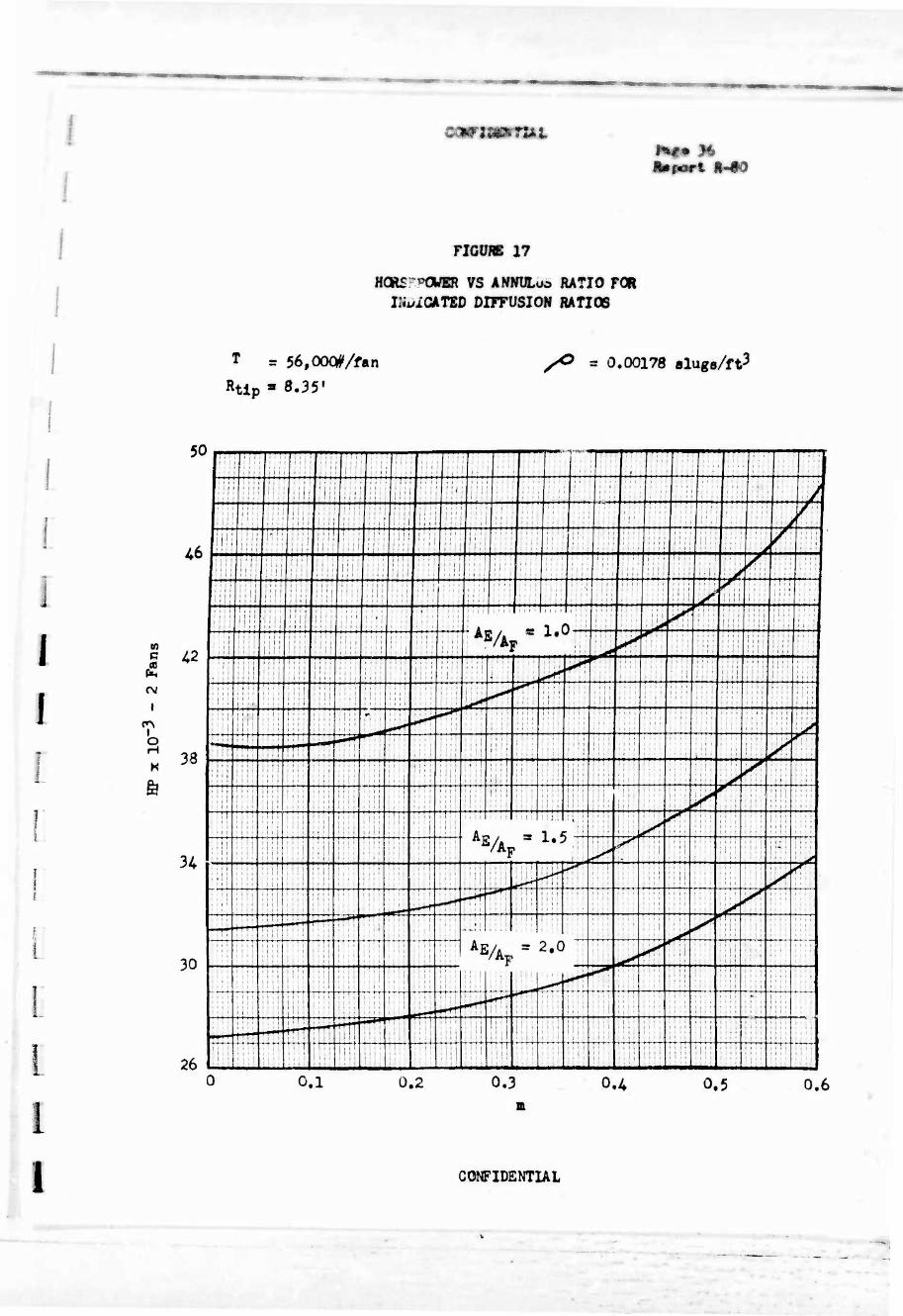
17. Horsepower vs Amiulus Ratio for Indicated Diffusion Ratios
18. Inlet Guide Vane Turning Angle vs Thrust for Non-Diffused
Duct at Minimum Root Radius
CONFIDENTIAL
;-*--S ■■■■■.
£,^.~ZZ
I I I
cowrmcNTUtL
I. SUMMARY
The fluid flow principles of ducted fan propulsion are reviewed and developed for several duct configurations. Momentum theory has been modified by duct pressure loss concepts to provide an understanding between duct and fan requirements. The thrust per horsepower capabili- ties are shown to be a function of duct shape and the fan design is inci- dental to such propulsion efficiency; however, for a giver duct a specific fan is defined and required.
For the vertodyne transport configuration of Ref. (1) the thrust per horsepower requirements, fan sizes and required blade design parameters were determined. A perfect bellmouth entry with no downstream diffusion has been assumed as the basis of the fan design.
Thrust control by variable guide vanes has been evaluated and satis- factory thrust reductions have been obtained at inlet vane turning angles between 0 and 20°. Further basic cascade test data is required to evalu- ate the ability to obtain such inlet vane turning angles.
CONFIDENTIAL
—«.
■>. - -
; m ■■ . i *: i ^'■■'--i(^.-:':W ri-. ' ;■■-?■?!■■■ LSJ.A-

i 1 II. SYMBOLS
I
I
Wm%w «
ftp pert i-^O
A Area, ft2
D Diameter, ft
M Mass, slugs
m Annulus ratio, RR/RT
N Number of blades
In Rotational speed, RPM
P Pressure, lb/ft^
Q Volume flow, ft3/sec
R Radius, ft
T Thrust, lbs
- V Velocity, fps
W Resultant velocity, cascade inlet, fps
w Disc Loading, lb/ft2
I CO Rotational velocity, radians/sec
(O Mass density, slugs/ft3
I ^j- Density ratio, P/fo', or cascade solidity
I (3 Inlet angle, cascade
ß. Exit angle, cascade
I Q Turning angle, cascade.
a Cascade angle of attack
0 Cascade angle of incidence
Z Inlet vane turning angle
I I I CONFIDENTIAL
,
0
Subscripts;
A Axial
B Exit
F Fan (or propeller)
I Inlet
R Root
T Tip
U Tangential component, cascade flow
«o Infinity
.»
.
CONFIDENTIAL
— — . - --

mnmmtii
a*port R"
]
J
1
III. üfTHODUCTIOIt
The objective of this report was to present the operating principles
of free and ducted propellers and then to specifically evaluate the ducted
propeller requirements for the Vertodyne. The words "fan" and "propeller"
are considered synonymous in this report. This entire study has been
limited to static thrust conditions, but could, of course, be extended to
encompass various inflow ratios.
This design study was preceded by a review of all the available liter-
ature on the subject of ducted fans and propellers. Various agencies and
personnel were contacted including the Langley Aeronautical Lab, the Univer-
sity of Wichita and Professor H. B. Helmbold, now of Fairchild Aircraft
Corporation, Hagerstown, Maryland. In addition, the principles developed
and used by VERTOL in the design of aircraft cooling fans were employed
where suitable.
Momentum principles have been used to analyze the flow through ducted
propellers and it has been shown that for a given diameter the thrust per
horsepower of a propulsion unit consisting of a duct through which a fluid
is pumped can be greater than a free propeller.
It has also been shown that the duct defines the thrust per horsepower
capabilities and the fan or propeller is an accessory to the propulsion
unit; the propeller is a necessary evil but need not be considered when
comparing thrust per horsepower capabilities of various duct configurations
(or "free" propellers).
CONFIDENTIAL
■1 .,,:■: v
. ..: :, .
iniiPilliffil
Btport S-80
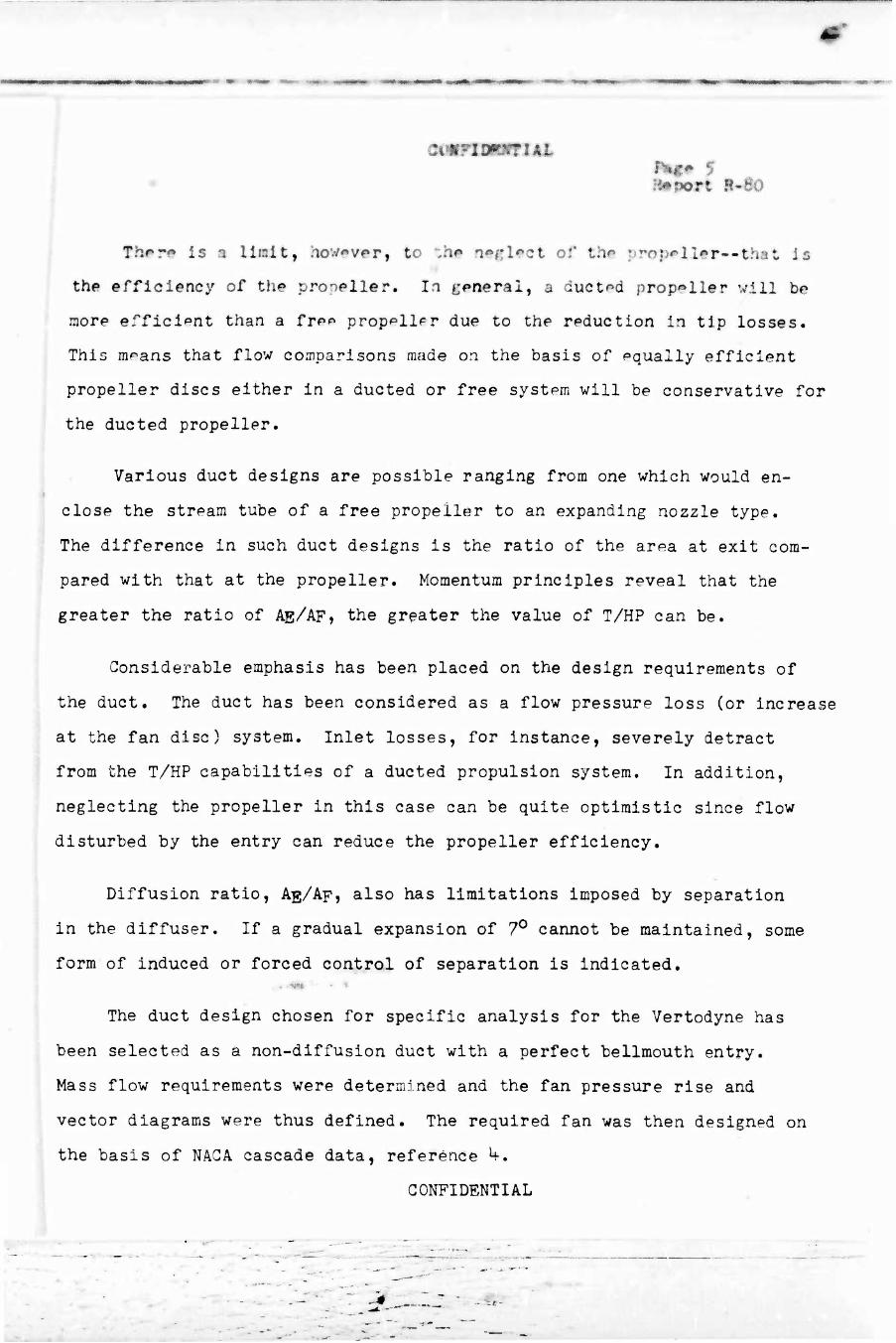
fher* is a Halt, howpvi»r, to "JM* a*»ßl«»ct or the : rop«»lI#r—that is
thp efficiency of the propeller. In general, a ducted propeller will be
more efficient than a frpp prop^llpr due to the rpduction in tip losses.
This m^ans that flow comparisons made on the basis of pqually efficient
propeller discs either in a ducted or free system will be conservative for
the ducted propeller.
Various duct designs are possible ranging from one which would en-
close the stream tube of a free propeller to an expanding nozzle type.
The difference in such duct designs is the ratio of the ar^a at exit com-
pared with that at the propeller. Momentum principles reveal that the
greater the ratio of AE/AF, the greater the value of T/HP can be.
Considerable emphasis has been placed on the design requirements of
the duct. The duct has been considered as a flow pressure loss (or increase
at the fan disc) system. Inlet losses, for instance, severely detract
from the T/HP capabilities of a ducted propulsion system. In addition,
neglecting the propeller in this case can be quite optimistic since flow
disturbed by the entry can reduce the propeller efficiency.
Diffusion ratio, Ag/Ap, also has limitations imposed by separation
in the diffuser. If a gradual expansion of 7° cannot be maintained, some
form of induced or forced control of separation is indicated. . -«« • •
The duct design chosen for specific analysis for the Vertodyne has
been selected as a non-diffusion duct with a perfect bellmouth entry.
Mass flow requirements were determined and the fan pressure rise and
vector diagrams were thus defined. The required fan was then designed on
the basis of NAGA cascade data, reference L(-.
CONFIDENTIAL
!
1 t
I
I I I I I I I I I •
GCNFimMTlkl
Report H-dO
Thrust control was proposed by inlet guide vanes. Th^ analysis shows
that the thrust can be effectively reduced at inlet vane turning angles
between 0 and 20 degrees. However, no cascade test data is available for
the existing inlet vane cascade situation of & = 0°. Such basic test
data is one of the recommended programs necessary for ducted fan propul-
sion units.
CONFIDENTIAL
^Ä "'
zcmimmfiAh ?m* 7 mport B-BO
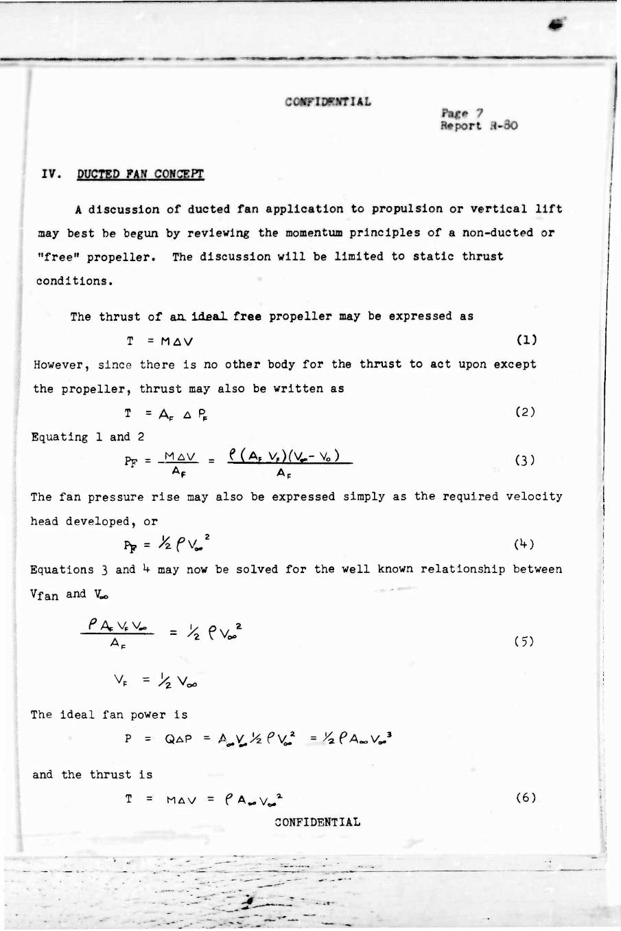
if. pypTgD nn coN?ppr
A discussion of ducted fan application to propulsion or vertical lift
may best be begun by reviewing the momentum principles of a non-ducted or
"free" propeller. The discussion will be limited to static thrust
conditions.
The thrust of an. Ideal free propeller may be expressed as
T = M^V (1)
However, since there is no other body for the thrust to act upon except
the propeller, thrust may also be written as
T = AP A PP (2)
Ap ' v ro0 (5)
The ideal fan power is
P = QAP ~ A^&evJ =^PAo0V0.3
i
and the thrust is
T = MAV = fA^v^ C6)
CONFIDENTIAL
Equating 1 and 2
Pr - M^\/ - fCA. V^rV-.-Vo) (3)
The fan pressure rise may also be expressed simply as the required velocity
head developed, or
Equations 3 and h may now be solved for the well known relationship between
Vfan and V^

I I I
mimmiAt
Bmpsrt R«^0
The principle that Thrust Is A function of \ß and Power of %ß is
apparent} by increasing aiass flow and decreasing V^ the basic "improvement"
in T/HP referred to in ducted fan propulsion is obtained.
The following specific equations may be developed:
For constant disc loading yHPD DUCTED
yup PRE£- \ (7)
!
I I I
For constant power and disc area
1/ HPDUCTED
VHP FREE \
2 JZl. (8)
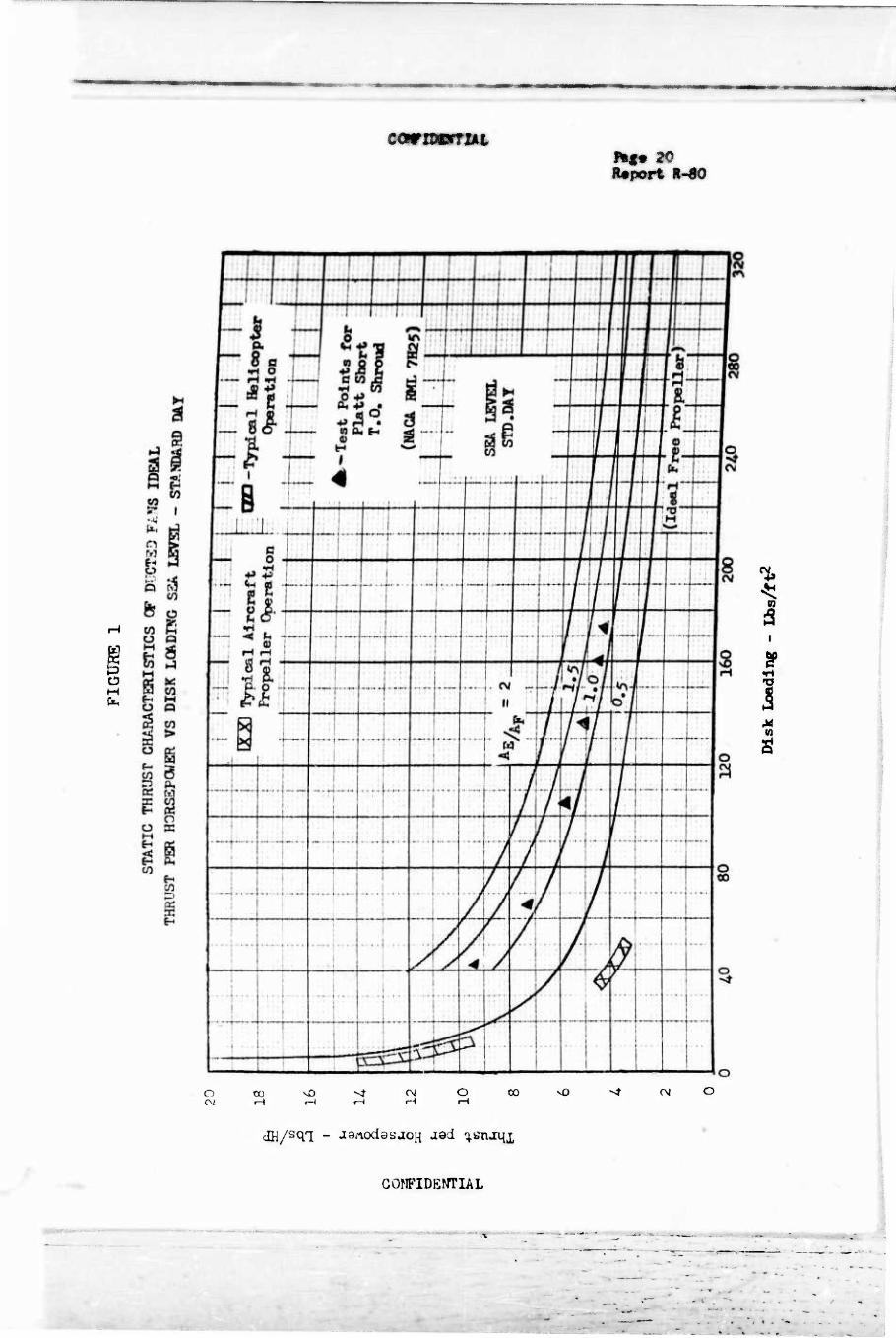
Thrust per horsepower capabilities of propellers based on the above
momentum considerations are presented on Figure 1. The area of helicopter
and aircraft propeller operation are noted and one set of available ducted
propeller (reference 6) test data* is shown. To incorporate such data
conveniently, Figure 1 is at standard sea level conditions.
I I I
♦The included ducted propeller tests are based on reference 6 by Robert J. Platt, Jr. Discussions with Mr. Platt have indicated that the propeller-duct combination was not necessarily operated on design.
I CONFIDENTIAL
- »MNB - ■-»
smrimmiAL
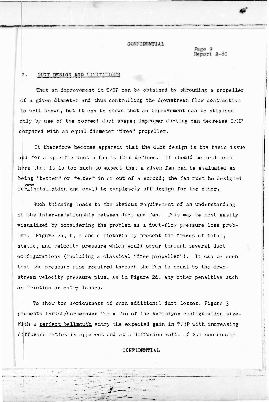
/. 'jvcr PFSIG*? WD ivn^xru:'*
That an L-nprov^ment in T/HP can bo obtained by shrouding a propeller
of a giv^n diameter and thus controlling the downstream flow contraction
Is well known, but it can be shown that an improvement can be obtained
only by use of the correct duct shape; improper ducting can decrease T/HP
compared with an equal diameter "free" propeller.
It therefore becomes apparent that the duct design is the basic issue
and for a specific duct a fan is then defined. It should be mentioned
here that it is too much to expect that a given fan can be evaluated as
being "better" or "worse" in or out of a shroud; the fan must be designed one
forAinstallation and could be completely off design for the other.
Such thinking leads to the obvious requirement of an understanding
of the inter-relationship between duct and fan. This may be most easily
visualized by considering the problem as a duct-flow pressure loss prob-
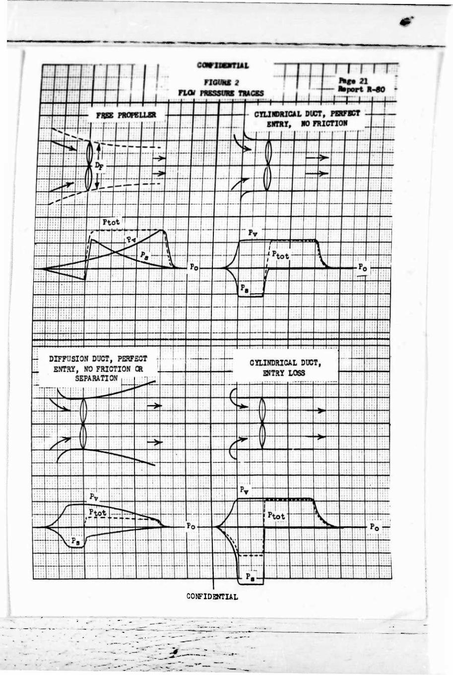
lem. Figure 2a, b, c and d pictorially present the traces of total,
static, and velocity pressure which would occur through several duct
configurations (including a classical "free propeller"). It can be seen
that the pressure rise required through the fan is equal to the down-
stream velocity pressure plus, as in Figure 2d, any other penalties such
as friction or entry losses.
To show the seriousness of such additional duct losses. Figure 3
presents thrust/horsepower for a fan of the Vertodyne configuration size.
With a perfect bellmouth entry the expected gain in T/HP with increasing
ffusion ratios is apparent and at a diffusion ratio of 2:1 can double di
- -
CONFIDENTIAL
- * w ■
i <
:
I
I
I
I
I
izmtKL
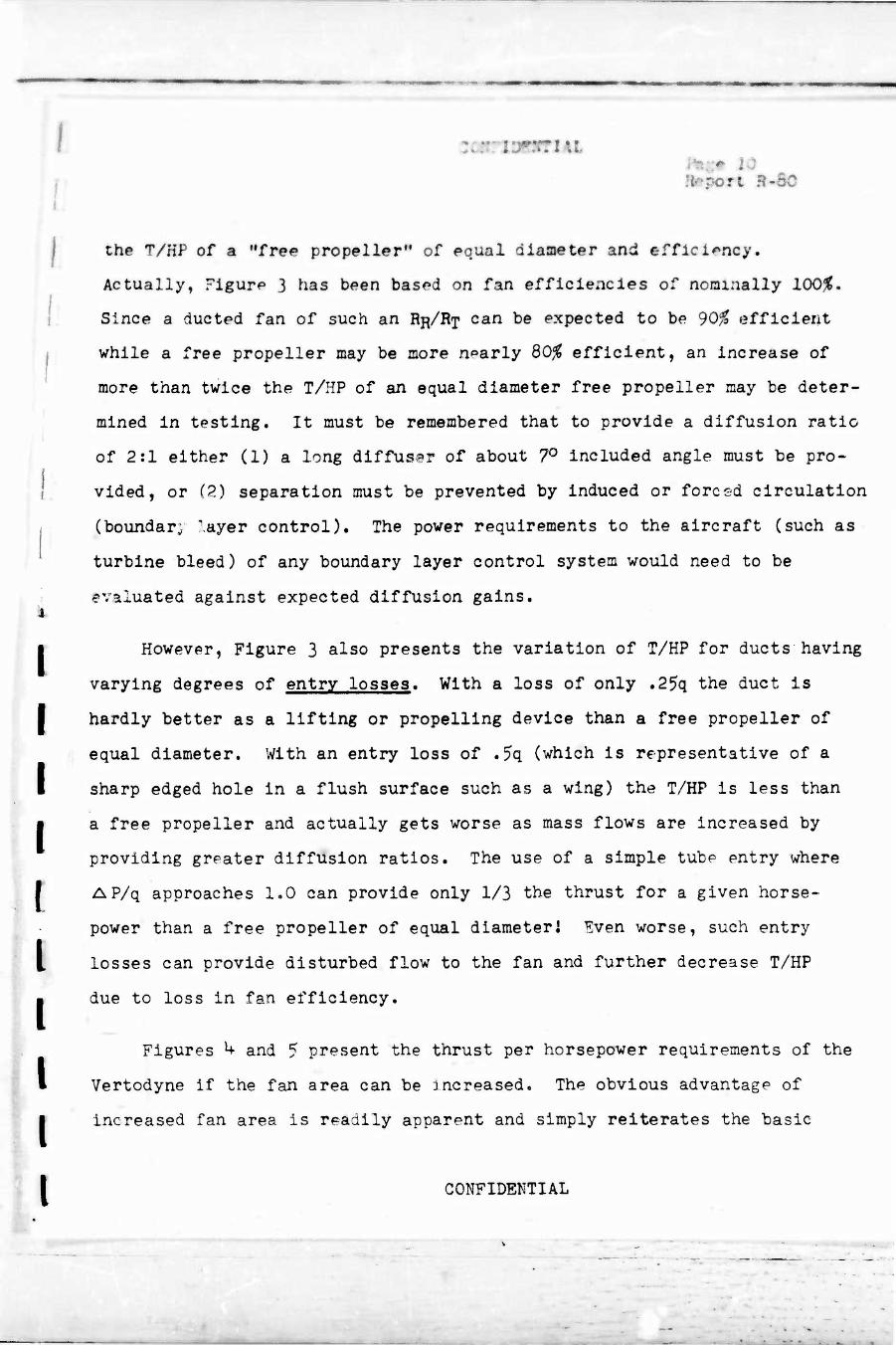
the T/HP of a "free propeller" of equal diameter and efficiency.
Actually, Figure 3 has been based on fan efficiencies of nominally 100%,
Since a ducted fan of such an RR/RT can be expected to be 90% efficient
while a free propeller may be more nearly 80% efficient, an increase of
more than twice the T/HP of an equal diameter free propeller may be deter-
mined In testing. It must be remembered that to provide a diffusion ratio
of 2:1 either (1) a long diffuser of about 7° included angle must be pro-
vided, or (2) separation must be prevented by induced or forced circulation
(boundary layer control). The power requirements to the aircraft (such as
turbine bleed) of any boundary layer control system would need to be
evaluated against expected diffusion gains.
However, Figure 3 also presents the variation of T/HP for ducts having
varying degrees of entry losses. With a loss of only .25q the duct is
I hardly better as a lifting or propelling device than a free propeller of
equal diameter. With an entry loss of .5q (which is representative of a
i sharp edged hole in a flush surface such as a wing) the T/HP is less than
a free propeller and actually gets worse as mass flows are increased by
providing greater diffusion ratios. The use of a simple tube entry where
f AP/q approaches 1.0 can provide only 1/3 the thrust for a given horse-
power than a free propeller of equal diameter 1 Even worse, such entry
losses can provide disturbed flow to the fan and further decrease T/HP
due to loss in fan efficiency.
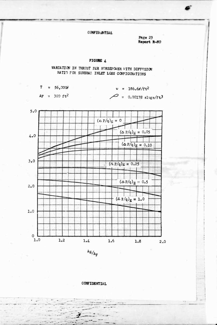
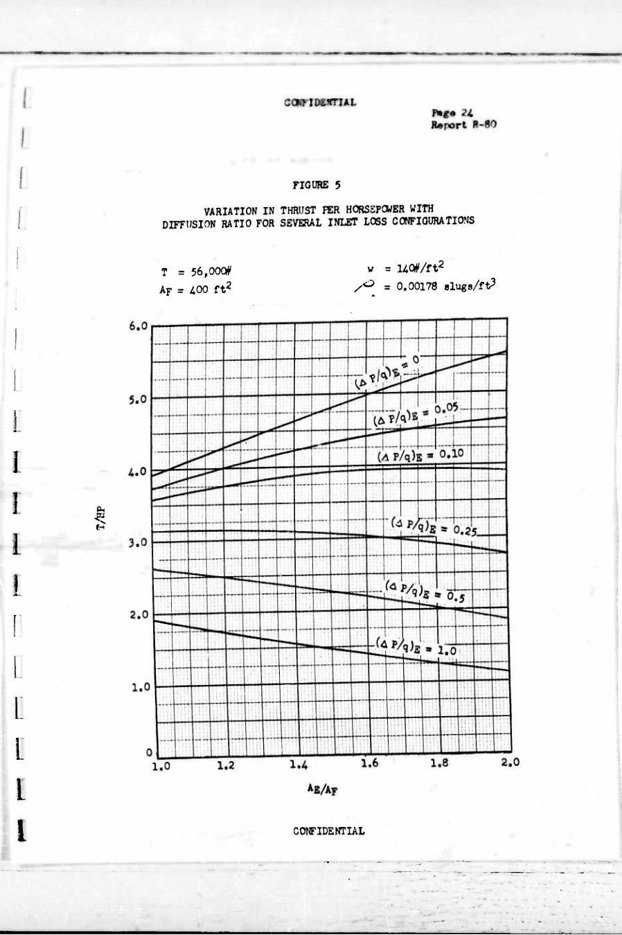
Figures *+ and 5 present the thrust per horsepower requirements of the
Vertodyne if the fan area can be increased. The obvious advantage of
increased fan area is readily apparent and simply reiterates the basic
CONFIDENTIAL
#*
9% »Ist
SP U {11 .-
principle of the aivanta^s of lauer disc loading. Figur« 6 nas teen
cross plotted froci the abovp iata specifically for a 1:1 diffusion ratio
duct. It zero ontry loss conditions thrust per horsepower can bp Increased
U-0% if the fan annular area can be doubled.
■
CONFIDENTIAL
:- ■. ;.-■■■..■..,
I
j
I I
I
on !.-
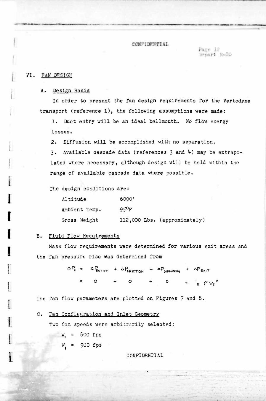
VI. FAN 3^10::
A. Design Basis
In order to present the fan design requirements for the Vertodyne
transport (reference 1), the following assumptions were made:
1. Duct entry will be an ideal bellmouth. No flow energy
losses.
2. Diffusion will be accomplished with no separation.
3. Available cascade data (references 3 and k-) may be extrapo-
lated where necessary, although design will be held within the
range of available cascade data where possible.
The design conditions are:
Altitude 6000'
Ambient Temp. 950F
Gross Weight 112,000 Lbs. (approximately)
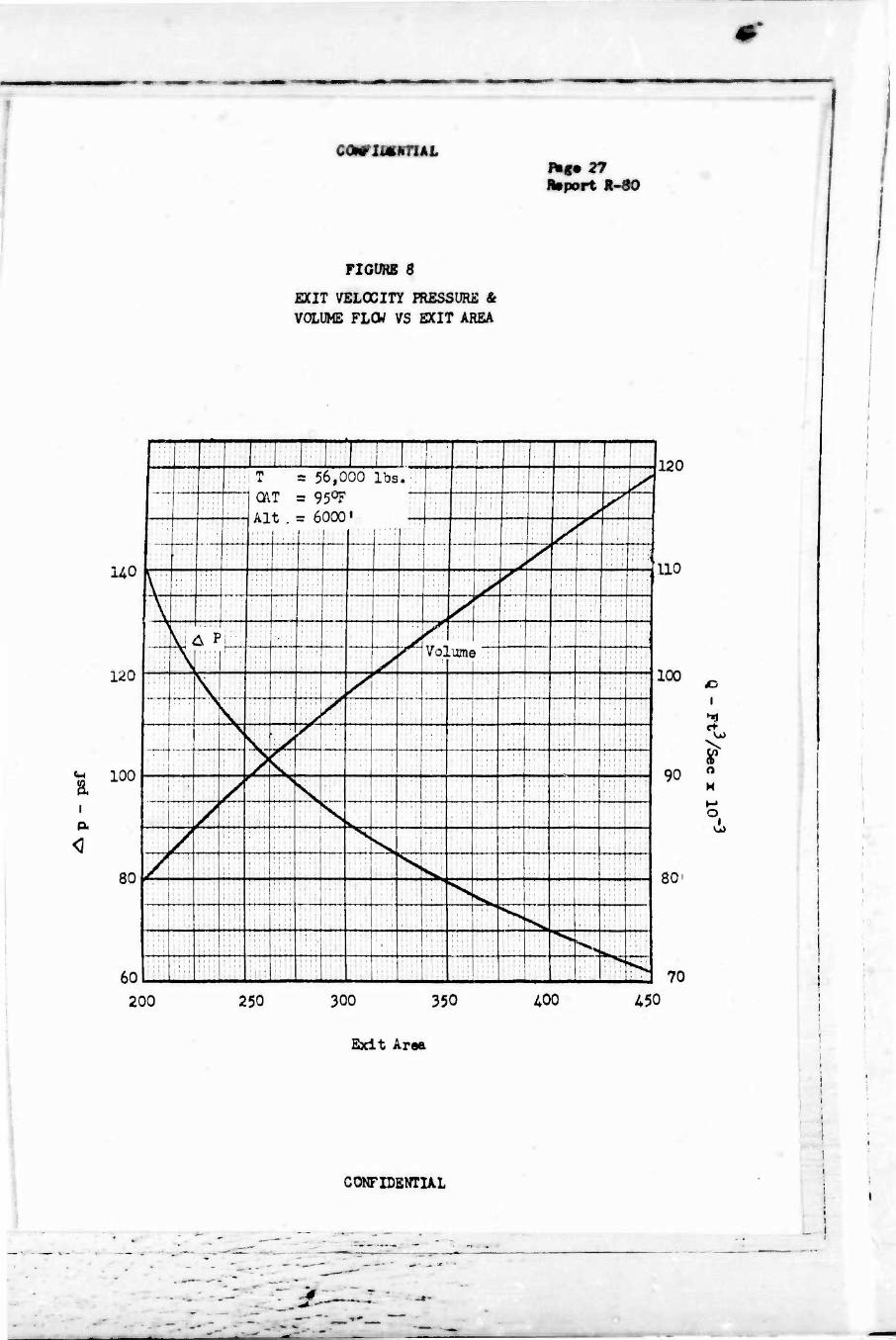
1 B• Fluid Flow Requirements
• Mass flow requirements were determined for various exit areas and
the fan pressure rise was determined from
The fan flow parameters are plotted on Figures 7 and 8.
G. Fan Configuration and Inlet Geometry
Two fan speeds were arbitrarily selected:
W, = 800 fps
W| = 900 fps
CONFIDENTIAL
mmmmm report H-80
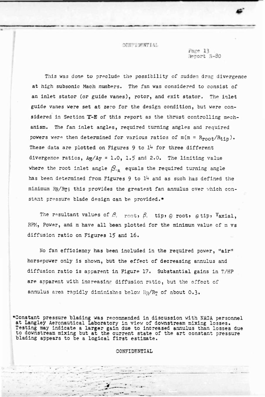
This was don«» to prßclud" the possibility of sudden drag divergence
at high subsonic Mach nurabprs. The fan was considered to consist of
an inlet stator (or guide vanes), rotor, and exit stator. The inlet
guide vanes were set at zero for the design condition, but were con-
sidered in Section TT-E of this report as the thrust controlling mech-
anism. The fan inlet angles, required turning angles and required
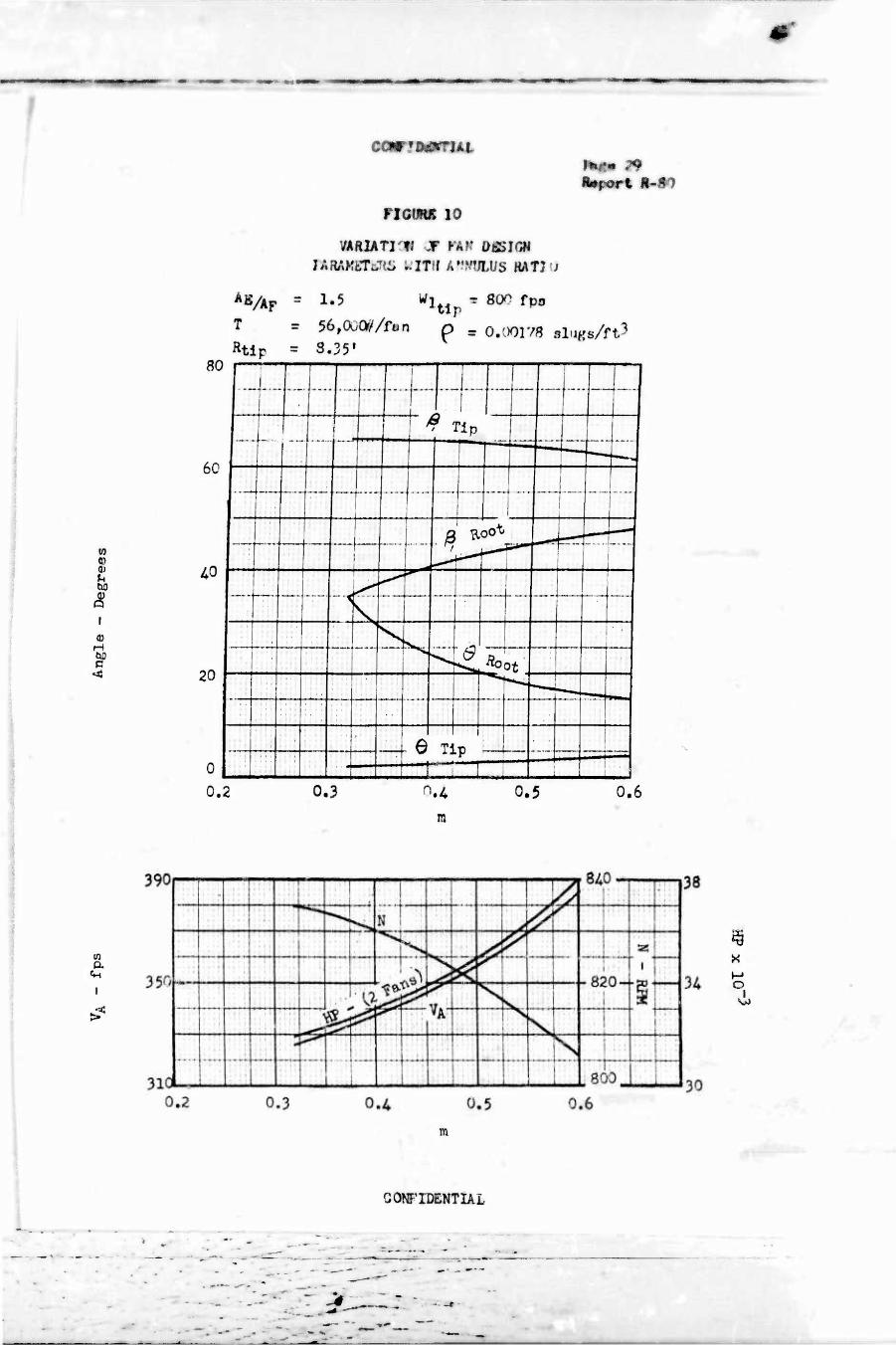
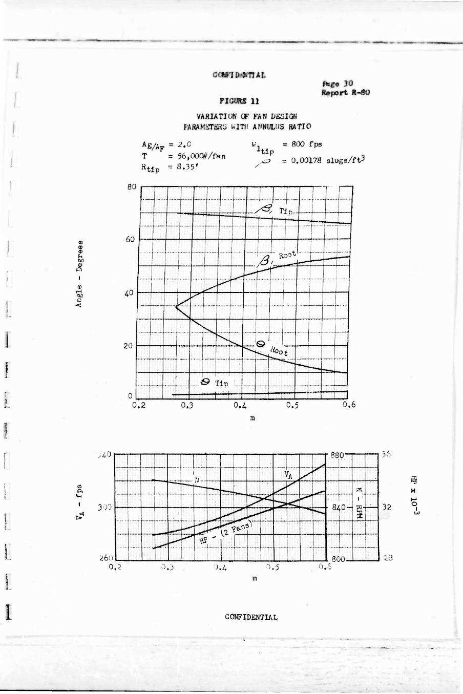
powers wer^3 then determined for various ratios of m(m = Rroot/Rtip^*
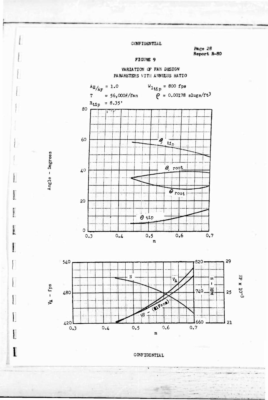
These data are plotted on Figures 9 to 1^ for three different
divergence ratios, Ag/Ap = 1.0, 1.5 and 2.0. The limiting value
where the root inlet angle ßIR equals the required turning angle
has been determined from Figures 9 to 1^ and as such has defined the
minimum RR/RT; this provides the greatest fan annulus over which con-
stant pressure blade design can be provided.*
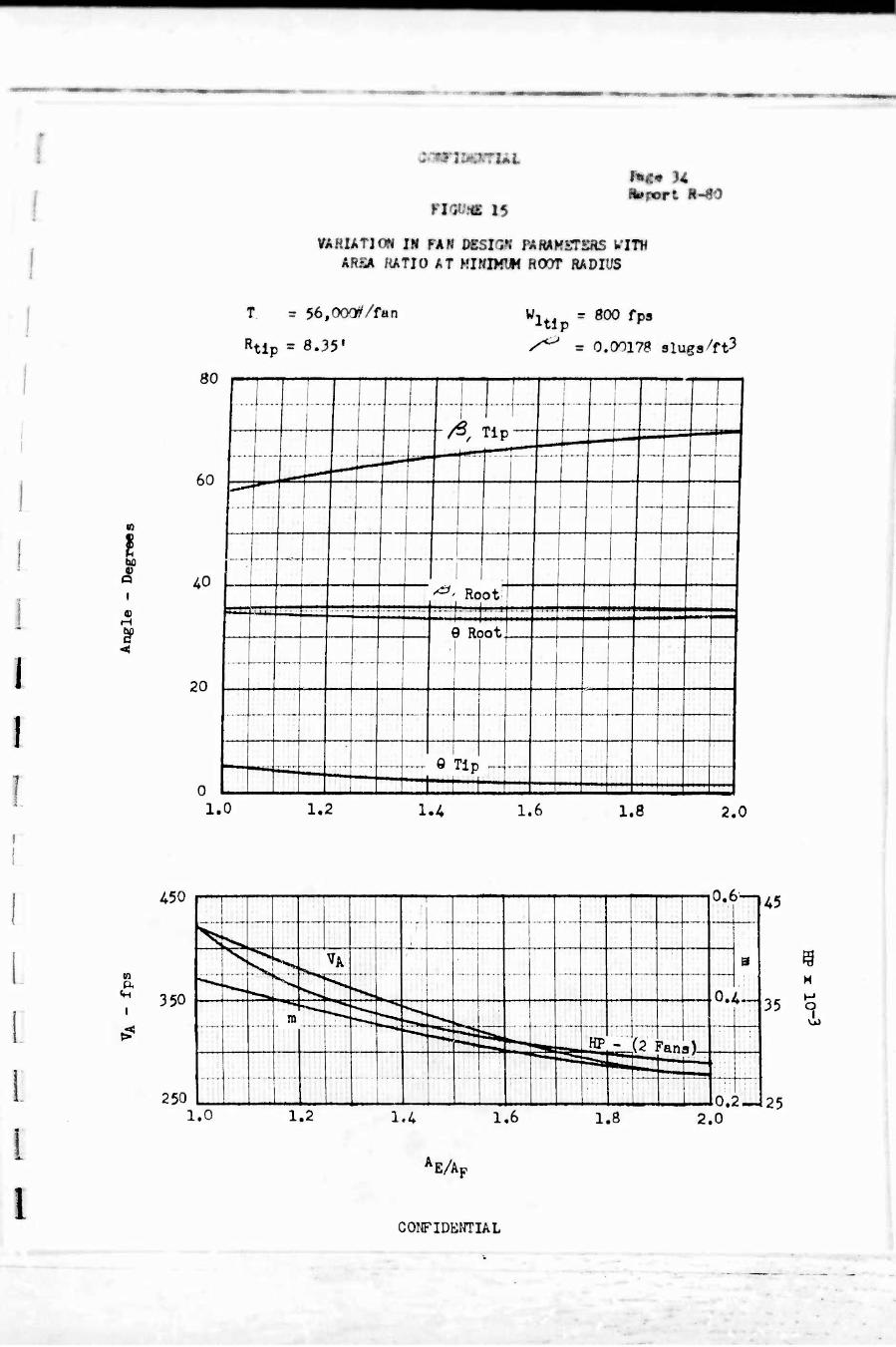
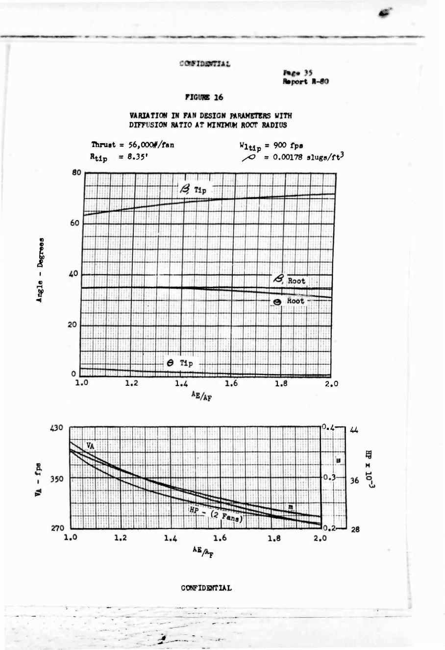
The resultant values of ^ root} ßt tip» 0 root» ©tip» Vaxlal,
RPM, Power, and m have all been plotted for the minimum value of m vs
diffusion ratio on Figures 15 and 16.
No fan efficiency has been Included in the required power, "air"
horsepower only is shown, but the effect of decreasing annulus and
diffusion ratio is apparent in Figure 17. Substantial gains in T/HP
are apparent with increaslnp diffusion ratio, but the effect of
annulus area rapidly diminishes below RR/R^ of about 0,3,
♦Constant pressure blading was recommended in discussion with NACA personnel at Langley Aeronautical Laboratory in view of downstream mixing losses. Testing may Indicate a larger gain due to increased annulus than losses due to downstream mixing but at the current state of the art constant pressure blading appears to be a logical first estimate.
CONFIDENTIAL
■^ iiiiMmLiiiiiwiwwMMi) ■■-- in mm^^mmmmmmmmmmm^mmmmmmmt^mmmmmmmmKmm^m
.r ort S-
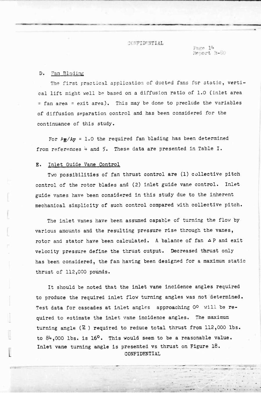
D. Fan BladmK
The first practical application of ducted fans for static, verti-
cal lift might well hp based on a diffusion ratio of 1.0 (inlet area
= fan area = exit area). This may be done to preclude the variables
of diffusion separation control and has been considered for the
continuance of this study.
For ^ß/Ap = 1*0 the required fan blading has been determined
from references k and 5- These data are presented in Table I.
E. Inlet Guide Vane Control
Two possibilities of fan thrust control are (1) collective pitch
control of the rotor blades and (2) inlet guide vane control. Inlet
guide vanes have been considered in this study due to the inherent
mechanical simplicity of such control compared with collective pitch.
The inlet vanes have been assumed capable of turning the flow by
various amounts and the resulting pressure rise through the vanes,
rotor and stator have been calculated. A balance of fan AP and exit
velocity pressure define the thrust output. Decreased thrust only
has been considered, the fan having been designed for a maximum static
thrust of 112,000 pounds.
It should be noted that the inlet vane incidence angles required
to produce the required inlet flow turning angles was not determined.
Test data for cascades at inlet angles approaching 0° will be re-
quired to estimate the inlet vane incidence angles. The maximum
turning angle (Z ) required to reduce total thrust from 112,000 lbs.
to 8^,000 lbs. is 16°. This would seem to be a reasonable value.
L Inlet vane turning angle is presented vs thrust on Figure 18.
CONFIDENTIAL
:
. mm .- - — - . , _ , .
... I ■ . ,.■..
^OMFI^fTlÄf*
%port 'l-SO
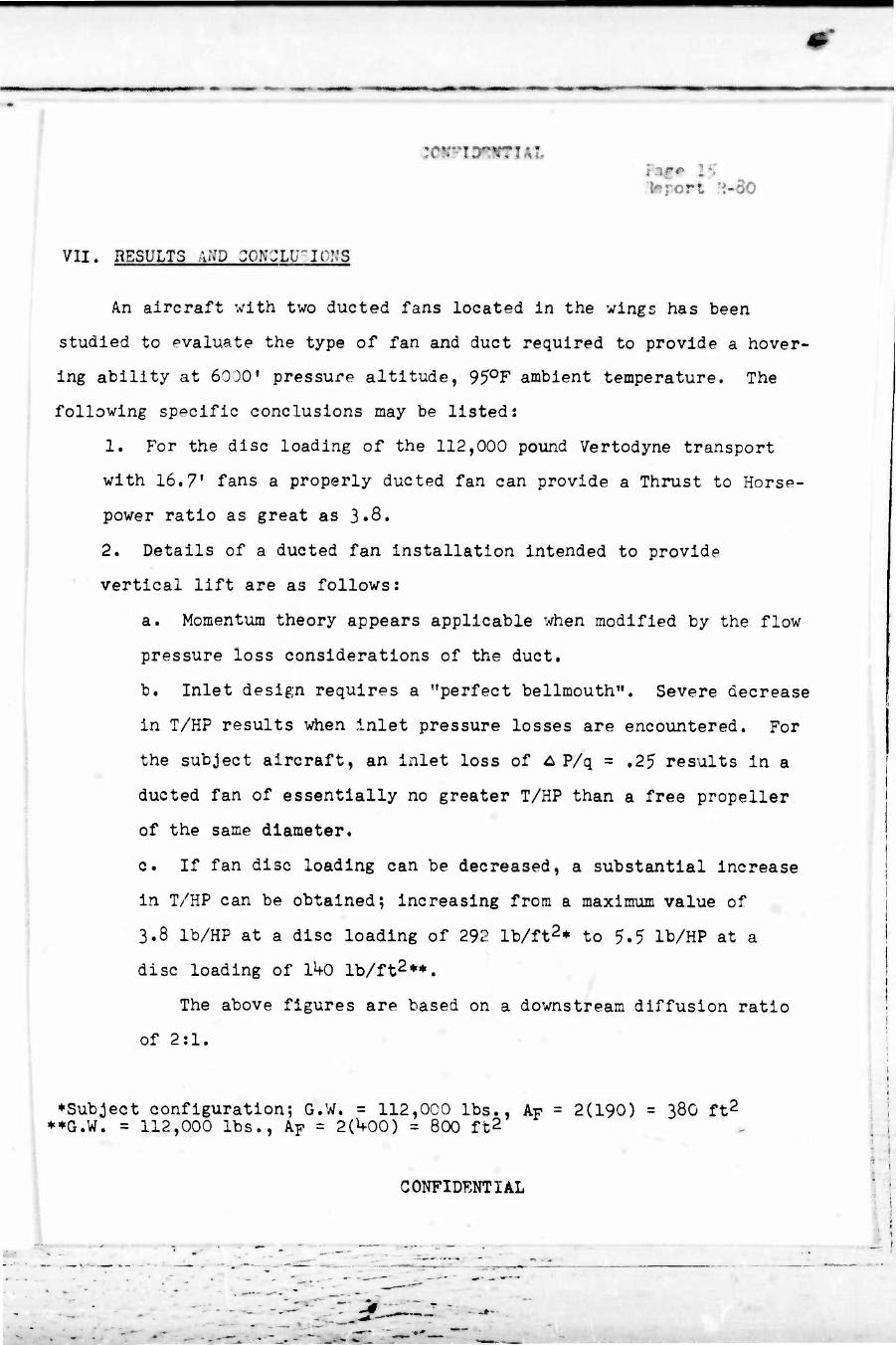
VII. RESULTS AiVD C0N'JLU"ICr:3
An aircraft with two ducted fans located in the wings has been
studied to evaluate the type of fan and duct required to provide a hover-
ing ability at 6000' pressure altitude, 950F ambient temperature. The
following specific conclusions may be listed:
1. For the disc loading of the 112,000 pound Vertodyne transport
with 16.7' fans a properly ducted fan can provide a Thrust to Horse-
power ratio as great as 3*8.
2. Details of a ducted fan installation intended to provide
vertical lift are as follows:
a. Momentum theory appears applicable when modified by the flow
pressure loss considerations of the duct.
b. Inlet design requires a "perfect bellmouth". Severe decrease
in T/KP results when inlet pressure losses are encountered. For
the subject aircraft, an inlet loss of ^ P/q = ,25 results in a
ducted fan of essentially no greater T/HP than a free propeller
of the same diameter.
c. If fan disc loading can be decreased, a substantial increase
in T/HP can be obtained; increasing from a maximum value of
3.8 lb/HP at a disc loading of 292 lb/ft2* to 5.5 lb/HP at a
disc loading of 1^0 lb/ft2**.
The above figures are based on a downstream diffusion ratio
of 2:1.
♦Subject configuration; G.W. = 112,000 lbs., Ap = 2(190) = 380 ft2
**G.W. = 112,000 lbs., AF = 2(^00) = 800 ft2
CONFIDENTIAL
I I II III-
I I 1
-cmniFffiAi»
Upport i
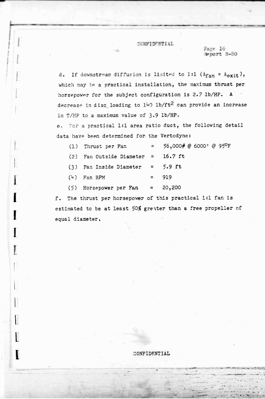
d. If downstr^ae dlffufion is llslt^ci to 1:1 (kfg^ ■ ^exit^f
which may b* a practical installation, the maximum thrust per
horsepower for the subject configuration is 2.7 lb/HP. A
decrease in disc loading to ikO lb/ft2 can provide an increase
in T/HP to a maximum value of 3-9 lb/HP«
e. For a practical 1:1 area ratio duct, the following detail
data have been determined for the Vertodyne:
(1) Thrust per Fan = 56,000# @ 6000» @ 950F
(2) Fan Outside Diameter = 16.7 ft
(3) Fan Inside Diameter =
C^) Fan RPM
(?) Horsepower per Fan =
f. The thrust per horsepower of this practical 1:1 fan is
estimated to be at least 50% greater than a free propeller of
equal diameter.
5-9 ft
919
20,200
I GONFIDF.NTIAL
■ .
mmmmmmmm wmmm
MPW« •
I 1
"■ ■
I
:«m^!tTi4L 17
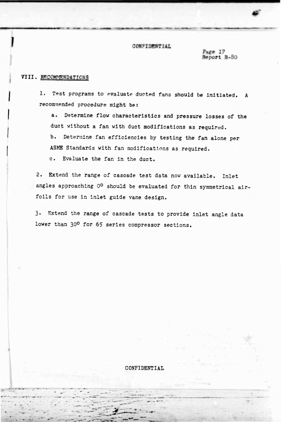
vui. mcoM^npnTicns
l, Ti»st programs to evaluate ducted fans should be initiated. A
recomnpndpd procedure might be:
a. Determine flow characteristics and pressure losses of the
duct without a fan with duct modifications as required.
b. Determine fan efficiencies by testing the fan alone per
ASME Standards with fan modlflcatinns as required.
c. Evaluate the fan In the duct.
2. Extend the range of cascade test data now available. Inlet
angles approaching 0° should be evaluated for thin symmetrical air-
foils for use In Inlet guide vane design.
3» Extend the range of cascade tests to provide Inlet angle data
lower than 30° for 65 series compressor sections.
CONFIDENTIAL
I I.
ix. BB3MBM
I
1 I I 1
I I
1
zcmFimntiki Pag«» 18 Report R-SO
1. VERTOL Report R-76; "Comparativp Study of Various Types of
VTOL Transport Aircraft - Configurations Studies" -
May 1, 1956
2. Helmbold, H. B.; "Range of Application of Shrouded Propellers"
Fairchild Aircraft Division, R221-011 - August 1955
3. Stone, Arthur; "A Study of Shrouded vs Unshrouded Propellers"
BuAer Report No. DR-1750 - July 1955
h. Herrig, Joseph L., Emery, James C. and Erwin, John R.;
"Systematic Two-Dimensional Cascade Tests of NACA 65- Series
Compressor Blades at Low Speeds" - NACA HM L51G31 - September
1951
5. Felix, Richard A.; "Summary of 65- Series Compressor-Blade
Low-Speed Cascade Data by Use of the Carpet-Plotting
Technique" - NACA RM L5l+Hl8a - November 195^
6. Platt, Robert J. Jr.; "Static Tests of a Shrouded and an
Unshrouded Propeller" - NACA RM L7H25 - February 19hS
CONFIDENTIAL
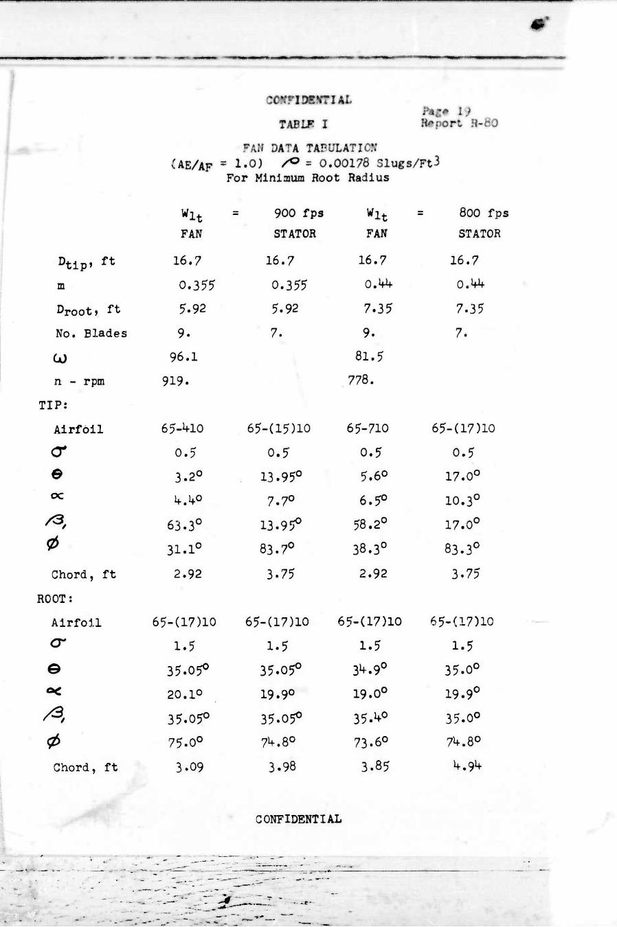
TABU? I Hgm 1$ R#port H-
FAII DATA TAPULATIi CAE/AF = 1'0^ ^ = O.ÖÖ178 31ugs/Ft3
For Miniaium Root Radius
wlt = 900 fps wlt 800 fps
FAN STATOR FAN STATOR
Dtlp» ft 16.7 16.7 16.7 16.7
m 0.355 0.355 0.M+ O.Mf
Droot, " 5.92 5.92 7.35 7.35
No. Blades 9. 7. 9. 7*
U) 96.1 81.5
n - rpm 919. 778.
TIP:
Airfoil 65-^10 65-(15)10 65-710 65-(17)l0
<r 0.5 0.5 0.5 0.5
B 3.2° 13.95° 5.60 17.0° oc ifA0 7.7° 6.5° 10.3°
/3. 63.3° 13.95° 58.2° 17.0°
0 31.1° 83.7° 38.3° 83.3°
Chord, ft 2.92 3.75 2.92 3.75
ROOT:
Airfoil 65-(17)10 65-(17)10 65-(17)10 65-(17)10
cr 1.5 1.5 1.5 1.5
e 35.05° 35.05° 3^.9° 35.0°
ö< 20.10 19.9° 19.0° 19.9°
/$. 35.05° 35.05° 35.^° 35.00
<t> 75.0° 7^.8° 73.6° 7^.80
Chord, ft 3.09 3.98 3.85 ^.9^
,*, — . —-a— ■—
CONFIDENTIAL
■
•V "I^W.^P #"«^:miK9 * A^* ft*
JUport H-SO
M
CO
5
•H
'S
m
o tX) vO CO vO CM
JH/scn - aartodasaoH aad ^.sruqx
GO^IDENTIAL
CONFIDENTIAL

( iMim
Wm# mm Bmport R-HO
FIGURE 3
VARIATICN IN THRUST PER HORSEFCWER VITH DlFFUSICff
RATIO FOR SEVSRAI, INLET LOSS CONFIGURATIONS
"liimpi
56,O0(#
192 ft2
w = 291.7#/ft2
/^ = 0.00178 alugs/ft^
§
5.0 I—1—I— 1 1 .1 1 1 !• 1 1 1 1 1 1 1 1 1 1 1 1 1
1 1 1
. i 1 i ii:
4.0 — [■—-
[—.,. .~.. U—. — ,<
h^ ^^
■: —. i ^r —
r
^ ^ -' r ■|""f M
■ _^i*i zz —"■ II ..1 3.0
iwT j~Lir ̂ a*]
= T* .P/q)Es 0-l0l
i' 1
—^ „ .... .«— /A T, / V
! 1 ' ■ ::
.-,^,J ... ^r/QJ* m D-?«rn
' »— j Wt 2.0 Äfl ■»»«
; i {
J -J -»«
1 ill im *l
1 -H u P/q si' j
~n il n ̂
«1 -. ^
rjfl UH ■ < ̂ P/n\^t'^i ji 1.0 l 1 T*Tr| "1
' T a - x,u Ti
' ! ' : :: ! ' ' | , 1
i i
: ; ' ! 1 ' ' i' • ' 1 j i]
0 :; ' ni ! j ■ ill ■ 1! ' j j ■ yj
; ! ' j ■ j ! jj |
1.0 1.2 1.4- 1.6
AE/J
1.8 2.0
'AF
CONFIDENTIAL
, • -
ut
»•pert %-SO
FIGURE 4
VARIATIOW IN TWJST i'j£R HORSSI'CVSH V'lTH DIFFUSION um rm menm nnjsr LOSS ccKFiouR/iTioNs
T
AF
561000/
300 ft2
v = 186.6y/ft2
/^^ s 0.00173 slugs/ft3
2.0
CONFIDENTIAL
i
r.1 : i
_. I
1 I I I
SQPlMHIlt f*g* Ü «•pert 1-iB
■* 'V-'
FIGURE 5
VARIATION IN THRUST FER HORSEPOWER WITH DIFFUSION RATIO FOR SEVHUL INLET LOSS CONFIGURATIONS
T = 56,OOC^
AF = ^00 ft2
w = UOlf/f t2
/O = 0,00178 slugs/ft3
I [ I 1
£
I CONFIDENTIAL

c«rfs«frut
■•port ft-#0
riGÖRE 6
THRUST PER HORSEPCWER VS
INLET PRESSURE LOSS COEFFICIENT
T = 56,OOQj<
/O a 0.00178 slugs/ft3 lE/AF = 1.0
1.0
(A P/q)E
CONFIDBNTIAL

^ ---:-"r: -'m .-; :■:■«>■■..■.:.[;■:■■ ■^rm^:r,^^v. .,-.„-..-■■ -V„n-W : ■
I
I
(
i I
[
l l
a I
•r)
8
AOO
330
360
320
280
260 200
COiriOUfTlAL
FIGWI 7
KIT VELOCITY 4 MASS FL» VS EXIT AREA
HB port I-ÄO
250 300 350
Exit Area - Ft2
CONFIDENTIAL
400
■\ L
T-
1 1 illfnl 1 1 1! ■ 1
! , i 111! 1 ■ 1 ■ * ] T
1 1 • 1 y K
Alt = 6000« QAT = 95*^
1 y / 1 £xSJ
1 \J K \\ i I; i —
i \ \ i: v K * 200
V:: '; j; y
V y \
L_ ■ /
1 ;; \ Velocity / /
190 \ i
—■
A / Mass |
\
■
/
.-...■ 1
? \ v. / ;;;!
CO 01
\
......
J / isoi
\ ' IJ / •
N A ^
%
f \ CO
i A V 170 If •
/ \i"\ ; ,
J f N i N ;,[
1 N 160 l
A /
\ A N /
f!|T
....- ..,..,_ —J \ h, i ll \ Ik 150 7 *
4444- \
S. ' / f 1 i'
^ v / ill
• HT _.... i; 11 ;;' ; 1! i I.' ill m« N.
_ ■
" ■■■'■"
"UO A50
■....■.„:■■..■■
niwiMmn »•port Ä-«0
riOÜRÄ 8
EXIT VELOCITY PRESSURE & VOLUME FLCW VS EXIT AREA
UO
120
I 100
i
a <3
80
60
1 i'' :: ■■—
1 Y 1 ..>_.
IT =56,000 lbs * /
CAT = 95^ s iffi . — u
x '
V I 1 '; i
y >r ili
! , ' ■ /
^_ h 1 1
■"-
WP i ■ I > vo:
' | ■ ; ■ i.
1 ' ! . y /^ .umf » . 1 i 11
1 \ / - ■ 1 \ v V
/ \\\\ . !
\
V y S
: i 1 i
>
'■''■'<
/
^"* T'TH \
l:lj
/ s ̂
/ V X i 11 i ::::
■ 111 {
/ X .. :
■':'.',. f. Sw
iil! ii jl ^> 4L liii 'ill
^ isl *^
lijl \\\\ ""•s; ItH
120
100
90
80'
70
o H
O VJJ
200 250 300 350 A00 A50
Exit Area
CONFIDENTIAL
_ t
zimiömn*i
ricü« 9
VARIATION <P FAN DBSION
RUHuanna nni A>INUI;JS HATIO
I m
l
1. i
OS
i l
80
AVAI
T Rtlp
s 1.0 Wltip = 800 fP3
56,000#/fan f> = 0.00178 slugs/ft3
8.35'
60
AO
20
1 ■- i i i.. 1 1 1 r i J ! 1
1 1 1 i 1 k« • 1—" — L,_ —
r ! D 1 L 1
i r~~«.
_...., — ---• i i . ri
0, root
^ >^- — )~\ i~~i —< ^
— yfi
— _ ■ ■ ^
1 ^ ) ' . * t . i
i i ■ i !
■i ■' ' ~l 'H" i • "4
i , ©tip ^ -A H"
0.3 0.4, 0.5 0.6 0.7 m
!
1 cn
I
0
540. """l *T^1 ̂ ^ ^w —^ M»M
VA
>
r82( J «^ i
- N /1 as"
1 _
-H --- —- M, /
^80 •r-fi
TS- >v ^/ ̂ s
■W )__
...... ^ ^<
JP
^ ^ ^ »
^ ^ s
-•■ rrH » - i-4
1 ^
>. ; ■ \
/90 ^
v> -
l66i D -
0.3 O.A 0.5 0.6 m
GOIIFIDENTIAL
0.7
29
25
21
o
. • ■■■ - ..- ■ .«« ■■■ • •
———
eomtommi
nomE io
VARIATIff JF Km DSSIOH JAHAMSraiX Um Ä»'MULUS KAT3 ;
(0 «) 0) U b0
I
<u H
80
äVAF
■ 1.5
T - 56,0)0//fan Rtip ■ 3.35'
wltlr . 800 tm
p = 0.00178 sl'Wft?
60
^0
20
—- T~" I
L... ..„ j
_ ■ 1 'i ■•
-., ! [ ! ^ «P
' ""- ■K — -— —
i
— I 1 1
1 ' 1 - 1
1 1
) i .i,
-•5
— i
1
\
•
\ ^ e? ^oot
' ■' 1 .
' I ' .
■ 1 1 1
. e TIP :
—: wWill '
! r i . in -,.1
0.2 0.3 0.4 m
0.5 0.6
I
m
CONFIDENTIAL
i ^
o
■HM
I : miu*r:Ai
FIÜURS 11 Report Ä-HU
I VAJUATIUN ÜF FAN USSIOH
FAHAMhrrivRLi WITH ANNULUS RATIO
AE/AF a 2.0 T = 56,000///fan Rtlp --- 8.3f'
Hip ■ BOO fps
s 0.00178 slugs/ft^
(0 0) 0)
M
0)
c
(X
l
ÖU
~ 1 S&, 71*'.
7 ' 1
■ ■ i i f 1
60 1 i 1
.... L i . t f-R 'S Koo^
„„. -^ r \
1 : ■
1 i '' ^0 1 >>
\
/ x'
,
1 i i
■ "i
^ M
N-J -„- —i
20
TS
7 ̂ 1 o -_-
^^0 t ! - M -J
^ ? Tip u ■~l —1 —J , 1 ,,,,.. J
0 [ rrr i i ' i i ,::!., ! —i -j 0.2 0.3 0.A 0.5 0.6
0,2
m
.>//J]
H . H
■88 P""
M V K x
-*— *tfr ^
s r-
i 300
*-* ̂ i > <d ■ 8^ •ou
^
-^ ""■^
y !6.^ i)!l
|.u.j4 : •" • v f ->• vs '
26t) i 8C )0~ 0.3 0.4 0.5 0.6
32
28
o
m
S.- CONFIDENTIAL
. :•• - • _

cmitmrruL
riGim 12
VARUTION (F FAN DESIGN M/UÄTms WITH ANHÜLUS IttnO
AB/AF
Thruat Rtlp
1.0
56,0000/tun 8.35'
Wltip . 900 tm
/* m 0.00178 al^ga/tt^
.«?***» .*»«wt ■

. ;^.. :,, , .
I fwm i?
Thruat = 56,(>JO//fan Z^7 « 0.0Ü178 slugs/ft^
Htlr » 8.35'
10 0)
I
0) H
-4
in
i
m
%
o
CONFIDENTUL
■ . — — . - -

*
V)
8 u to
I
0)
<
iOWSMMSit
riGtii« i4 ■ipirt M9
VAIU*TIC¥ I» FÄ» DBSICÜ rARÄ^!E?»»S Ulli imnui RATIO
ÄE/Ar =2.0 «Itip'Wfps Thrust ■ 56,0CN>//f8n /O = 0.00178 olugs/ft3
Rtlp = 8.35'
CO a. u i
3^0
300
260 0.2
■ ■"*'" -—
/
•10( D0- —«i
^ s
rrrfis -. . . VT VA ^ X ^"
, § ■ ^ ̂ ^ srfv»1
■98( 3r-
•-:- —- ^ >^
>- > <
^^ ^
V5 > * ^ S " .
i|
■fH*
rfT" ̂ ^ ■ ■ 1
I ' * -■ ■-;-_ ■***■
4rt ifff ; ■'
■^^
!.„„ r^ K i&i. '■1
LL._ _ ^96 0— [1 , Ll,
0.3
36
0,4 0.5 0.6
32
E9 H
28
CONFIDENTIAL
— »- ■
i . - ■—■ _ • ■■■--
- .
■
:
öaifiiÄriÄi
n^m is VARUTICH IN FAH DESIGN PAHÄMSTERS WITH
AR£A RATIO AT MINIMUM ROOT RADIUS
I
in
i to I i
0) H
T ■ 56,000^^11
Rtlp = 8.35«
80
60
^0
20
Wltlp " 800 fP8
•** = 0.OO17B slugs^t3
r _. _., i ! 1 ! i i
L 1 |
...
t '
^ UP :"l-: L rr-
■--
.— | 1
-r.. j, ,..
....
! 1
—.-, _.- —
1
! i
... ! —1 ^ Root I
; i „UJ -—
....
! 1
i "''' ——
8 Root p ^^ —. ■MM. ■""^
i
i
r
1
-jU. ■ —
^t*
1 1 Q rip
St —< T ^.
rt =3 -] —. =
1.0 1.2 1.4 1.6 1.8 2.0
i
1
10
I
450 —- — — "P —
1 '■ "'
.,..-
0.« | ^^PW
S^ 4= % ^
^
in
k VA
^v.
_.,. .-.
350 Htfi, "^ 0..
_ I^t **-*,
% T-Li —pf
'HP ^b
^ (2: ^an ,)
.... .... ••- ,.., .... 3E t=
250 _ o.: 2_ 1.0 1.2 1.4
45
3
35 VjJ
1.6
AE/Ax
■ .■
C0NFIDKNTIAL
g
1.8 2.0 —J25
mm
cariösm*!
riGum 16
VAWATIOM I» FAN DESICIt «RAKSTERS WITH DIFFISION fttTIO AT MIMIWJM ROCT RADIOS
Thruat ■ 56,000#/fan
Rtlp ■ 8.35»
wltlp " 900 fpa /O = 0.00178 sluga/ft3
2.0
o«4rni u
Afi /Ay
CONFIDBWTIAL
-■
— —. ... - -I-**" M
I I
larai
FIOOTB 17
HCR5 «OWBR VS AfWULuo RATIO FOR INi/iCATED DIFFUSION RATIOS
T s 56,OOCtf/fan
Rtlp a 8.35'
^ = 0.00178 aluga/ft3
I j
I I !
!
I. L I
CO c
I
? o
?w fljT I [ 1 f 1 ' ' ' i n i 1*1' j r "ypiw
1 *■ 1: 'ii !::
I''' N 1'; 1 1 I 1 1 I ' 1 ' ' ■ j 1 111 y 4 lii 1 < 11 {
hin 1 • ' 1
-rrr ill 11(1
! ii | 4 1 | {
"Trh 1 i:|l
11 ' j i ■ 1 ' ' ' i ItH
> 1 46 UJJi Mi In.
1 t M ' iiiii 1 Ittft | J j! j
!ill 1
11 f 1 i |!| Hill
1 | i | i
Ii P ! j j! 11 *' IJJjj IIII d 1 jiiii flfn ijttf i ■ • • i
1 :i nil .J UJ
111 i !!i! 1
1 ■ i 11! il ! ' 1 j j ] ] 11
1 1 1 1 111 I ! <; 1 1 M | i . . i
ttflt III if m
i l
: ' i i II 1 ) • 1
KM lii! 1 1 M
rHfi I'M
II 1 II
Hrr* i j 1 i j ! j 111 1 m Mil
| ■ i . ■ II iii' i
1 1111 11 II iii I i j [nmi.iiiimnnM
) :ii hi iiif %
frTT!
iiii iiii
42 t
i Ü ' 1 ' i i ii t i 1 * VAj r ij] jr. iii 1111
|| i il r-rr T
i . i
■ ;; < ! i ! . i i
. i
iff k> \ ', ! 1 ■ '
i i'i • i t '
■i j l
| [ \ I i t 1 t i
' ' 1 ■ ! 1 I < i ii >r ̂ i\ ■r^
1' i - i
; i: | |; 1 1 1 ! 1 ' ■
i ' i » f-f-h r fr
' 'i
- 1 i • • r • i <
' i1
iii 1 1
iff
«• i
i*jfl IHT • i'
1 !' i i
> ■ . 1 i ;| | I ! ii Ls\ >««**i ! ii
■
i II ■ 1 il ' \ \\
in i ii 1 1 • ' j iii
||
JT \
'■ ' 1 "^8 t 1 Tn 1 ! ' 1 ■ '
1 TT] JJO | ttfl
! ii 1 H! ' UJ
Ttt , li!
1 ; ii ■■■jr
ii : i
t M
i 1 ' i i j i i i i it i ttl
1 ii : i 1
Um ffjt • Hi t } i i; ' '' TTn
: ii : n
11 i ■'
iiii J 1 L J
i :i 1 i: : :. 1 i HI \ • { ' 1 \ ]A ii ffT
i ii ■ H
i LU \ ■ j t (
1 i i i i J M
* i : m iiiiHiniimiiijjj
AE/AF '1-5 Ü
1 ni 1 ii i !;
1 1 '
i Ü
! I : ftn i 1 ' 1 34
1 1 1 ;M ■
' 1 !
i ' 1 '11 ! '' 1 ! ' ' ' 1 >^ 1: ■! M
tA
! ■ ' ' ' 1 I!
; 1 ■ 1 Tni
tftll 1 1 ! ! ii ||
fil ' ' • [ I j ' ' ' M 1 l| ttn
i^-pn TTll ■MTI irn
iJil \i > '' i * ''
+T-H "^ f tn **Jm
: ■: 1 in It! 1 !i : n iiW m T^! 1 11 ■
i ii rrrj i 1 M
I | 1 1 : . |i 1
10 ' i i' 1 1 !
* J F 1 \ '1 1
1' i | AE/AF = 2-0 i
1 ' 14j| ̂H t i [
1 ■ i
i i ! il ' pi
1 Ijl 1 n i iii
: ' M ! \ \\ I 1
**H s J W\ i ^i ii 1 ill i y \ i iii i ii ' 11 > 1
i i i I : ! 11 ! ii fill •rrrt. iiftl TTll ' i
: 1 fl 11 i ::
TTii
■ !
ttx i" :i! I "TT
i Ii! TnT i IP r Tn
i i , t M 1 1 i ; i i'i ! i
26 1 1 !l I ii ill i i i
. I 1
T ]fi Tit 1 \ 1! || i !: j Ijl ' '
i [ j i i iij ; i M
0.1 0.2 0.3 0.4 0.5 0.6
1 CONFIDENTIAL
1 ,■■.'■■■.:.:■..-:, -.-,...,.,,:,,,..,-,::.. , .-..-,. _ _ .,,,
.. ■ ..
:*ir.- ^^

CIIFIDr/TJAL Hg9 37 Report R-SO
FIGURE 18
INXST GIIIDi- VANE rüRNING ÄNGLS 7S THRrJST FOR nOR-DIFFUSED D'JCT AT MINIMUM ROOT RADIUS
Rtlp- 8.35' /<=? = 0.00178 slugs/ft3
20°
16C
12' w
M (D a i
eo 8<
1 ■
1 |
|;
I
f-H— i
1 ■■:"■■;
i i : i ,: i i: 1 ' ■•!
i T
1 ■ 1 1 . ; :j ■
i i
i
—,-.^^J-^. ■
i
1 1 ^x
1
1
,„_:.„. i 1 ; \ v
l
hi .i . ■ i ■ .1
... i.
■ ■ '
| ■
1 I
\ i 1
^ '-
— ,' ■ : ' 1 [ ■ 1 ' ' 1
j
i \ ; ■
1 i-™-..
1 ::: ■'ii
i V --. WT = 900-
WlT a 800-
•j
1
i i ■ 1 j \
i L
::: ; : ;; ;i
t
■i \ 1
i. i .. i
i
! ... ■ ■ .1 ': '
1
. 1 !
_ .^
I ■
.,,... ._
\ | i ■ i
1 1 1
i 1 N i' ■ i
i
.1 ■; . 1 ■ I 1
., ,,..„
\ |
... ,
■ i
! , '. i.. 1 : \ i '
1 ' j ■
■ : | li ;:' ■
1 ' [ 1
1
i\ i
i ,, , ' ! ■:;
\ • i;
1 . . i
[ ; - !\ i
■ 1 1 ■ ; I
i
....i.,„.l i ] i
i w ,:
60 70 80 90 100
Thrust - 2 Fans x 10-3 - Lbs.
110 120
■ .
i
CONFIDENTIAL !- ,

firmed Services Technical Information Agency Reproduced by
DOCUMENT SERVICE CENTER KMOTT BUILDING. UUULL OHIO
NOTICE: WHEN GOVERNMENT OR OTHER DRAWINGS, SPECIFICATIONS OR OTHER DATA ARE USED FOR ANY PURPOSE OTHER THAN IN CONNECTION WITH A DEFINITELY RELATED GOVERNMENT PROCUREMENT OPERATION, THE U. S. GOVERNMENT THEREBY INCURS NO RESPONSIBILITY, NOR ANY OBLIGATION WHATSOEVER; AND THE FACT THAT THE GOVERNMENT MAY HAVE FORMULATED, FURNISHED, OR IN ANY WAY SUPPLIED THE SAID DRAWINGS, SPECIFICATIONS, OR OTHER DATA IS NOT TO BE REGARDED BY IMPLICATION OR OTHERWISE AS IN ANY MANNER LICENSING THE HOLDER OR ANY OTHER PERSON OR CORPORATION, OE CONVEYING ANY RIGHTS OR PERMISSION TO MANUFACTURE, USE OR SELL ANY PATENTED INVENTION THAT MAY IN ANY WAY BE RELATED THERETO.
, ■
^
■«•r

UNCLASSIFIED
UNCLASSIFIED