to - dtic. · pdf filerockets 16 illustrations - appendix 1, ... at 60 deg.c the sensitivities...
TRANSCRIPT
UNCLASSIFIED
AD NUMBER
CLASSIFICATION CHANGESTO:FROM:
LIMITATION CHANGESTO:
FROM:
AUTHORITY
THIS PAGE IS UNCLASSIFIED
AD323631
unclassified
restricted
Approved for public release; distribution isunlimited.
Controlling Organization: British Embassy, 3100Massachusetts Avenue, NW, Washington, DC 20008.
DSTL, AVIA 6/19533, 11 Dec 2008; DSTL, AVIA6/19533, 11 Dec 2008
TECH. NOTE ARM. 684
RESTRICTED TECH. NOTE ARM. 684
AD"3^3
Deci ;OADR
* B^AO, ^uui^iii^^tr iBOT&ia&asiafiiasTO, DE (FARNBOROUGH)
J
J TECHNICAL NOTE No: ARM. 684 V
<L A SURVEY OF POSSIBLE METHODS FOR INVESTIGATING THE KINETIC HEATING
OF ARMAMENT STORES CARRIED EXTERNALLY ON HIGH-SPEED AIRCRAFT
D
by
W. F. FIELDING, B.S.c, A.lnst.P. and J. H. CHALONER L
EXCLUDED FROM AUTOMATIC REGRADING DOD DIR 5200.10 DOES NOT APPLY
I MIS INFORMATION IS OlSCLOifci. uNtT H>A Ca/<Cl.V USE BY THE RECIPIENT GOVERNMENT AND SUCH <Jr •?» CONTRACTORS. UNDER SEAL OF SECRECY. Ai MATJWMUARY 1961 ENGAGED ON A DEFENCE PROJEOr. D.<ClO<OHE vJC **** DTHF.R GOVERNMENT ")R REl.?'*i TO TME P«£SV*«5*-*. ANY OTHER WAY WOULD BE A BREACH 0» THF<f CONDITIONS
1 THE INFORMATION SHOULD BE SAFEGu* »C*r> ^Nr.*» RULES DESIGNED TO GIVE THE SAME ST*-' r.f 01
'AS THAT MAINTAINED BY Hfc» MAIESTT* GOvlANMfaNT IN THE UNITED KINGDOM « THE RECIPIENT IS WARNED THAT if..O* *»':r*. CONTAINED IN THIS DOCUMENT M** BE SliR.c » «r • sTVveTFiv ^WNff-, ilGHTt
PVCi tECHHlCW. \a?u> HkkVSM SECTION
MINI STRY OF AVI ATI O N
THIS DOCUMENT IS THE PROPERTY OF H.M. GOVERNMENT AND
ATTENTION IS CALLED TO THE PENALTIES ATTACHING TO
ANY INFRINGEMENT OF THE OFFICIAL SECRETS ACTS. 1911-1939
It ts intended for the me of the recipient only, and for communication to such officers under him » may require to be acquainted with iti contents in the course of their duties The officer! exercising thii power of communication are responsible that tuch information it imparted with due caution and reserve Any person other than the authorised holder, upon obtaining possession of this document, by finding or otherwise, should forward it. together with hit name and address, in a closed envelope to :-
THE SECRETARY, ' MINISTRY OF AVIATION, LONDON, W.C.2
Letter pottage need not be prepaid, other postage will be refunded All pwio.u. art hereby warned that the unauthorised retention or destruction of this document is an offence against the Official
Secrets Acts
RESTRICTED
steJ^tjra/

RESTRICTED
U.D.C, No. 623.451.7 : 531.65 : 623.42S.622 : 533.6.011.5
Technical Note No. Arm. 684
January, 1961
ROYAL AIRCRAFT ESTABLISHMENT
(FARNBOROUGH)
A SURVEY OF POSSIBLE METHODS FOR INVESTIGATING THE KINETIC HEATING OF ARMAMENT STORES CARRIED EXTERNALLY ON
HIGH-SPEED AIRCRAFT
by
W. F. Fielding, B.Sc., A.Inst.P. and
J. H. Chaloner
RAE Ref: Arm.2200/'l
SUMMARY
The various methods which can be used to study the kinetic heating of
externalay carried aircraft armament stores are examined and their merits
and limitations discussed.
It is concluded that whatever method is ultimately used to study this
problem, it is desirable to carry out flight trials at an early date to
obtain results iMhich could be used to check data obtained by any other means.
RESTRICTED

RESTRICTED
1
2
3
4
5
6
7
LIST OF CONTENTS
INTRODUCTION
PERMISSIBLE TEMPERATURES
METHODS OF INVESTIGATING THE PROBLEM
THEORETICAL EXAMINATION
LABORATORY HEATING TRIALS
5.1 General 5.2 Uses of the apparatus 5.3 First method 5.4 Second method
WIND TUNNEL TESTS
FLIGHT TRIALS
7.1 General 7.2 Flight programme
Technical Note No. Arm.864
Pagg
3
3
4
5
7
7 7 8 8
10
11
11 11
8 TEMPERATURE MONITORING DEVICE 12
9 RECOMMENDATIONS 13
LIST OF REFERENCES 13
ADVANCE DISTRIBUTION LIST 14
TABLE 1 - Flight limitations for conventional armament stores 15
APPENDIX 1 - Comparison between the results of ground heating tests and kinetic heating during flight for 3 inch aircraft rockets 16
ILLUSTRATIONS - Appendix 1, Figs.l and 2
Fig.l - Kinetic heating of 1,000 lb Mk.83 bomb. Results for a position 24 inches aft of the nose. Standard I.C.A.O. atmosphere
DETACHABLE ABSTRACT CARDS
- 2 -
RESTRICTED

RESTRICTED
Technical Note No. Arm. 684
1 INTRODUCTION
The purpose of this Note is to study the information available on the kinetic heating oi externally-carried armament stores and to assess the problem of estimating or measuring the temperatures which will be reached during carriage on the newer aircraft.
The examination of this problem is much more difficult than is the case of internally-carried stores. For this latter case, the stores are, in effect, contained in a heated oven whose walls are those of the aircraft bomb bay which are themselves subjected to kinetic heating by reason of the airflow over the aircraft skin. There is no forced airflow around the stores and they acquit e heat from the bomb bay walls by the processes of radiation and free convection. This internal carriage problem has been investigated by a simulation of these effects (fully described in Ref.l); a system which has given satisfactory results.
The externally-carried store does not lend itself readily to such a simple investigation. The rate at which it absorbs heat will be very much greater since it is subjected to the full kinetic heating from the airflow around it. This rate of heat absorption must be calculated from:
(a) The heat transfer coefficient, which is a measure of the rate at which heat generated in the layers of air surrounding the store is transferred through the boundary layer* to the store.
(b) The thermal conductivity and thermal capacity of the store.
This calculation is necessary before any heating tests can be undertaken and immediately suggests that the whole problem could be examined mathematic- ally. This and other methods for examining the problem form the basis of this Note. It is written from the point of view of conventional armament stores, but applies equally well to other stores whose temperature limitations might be even more stringent.
2 PERMISSIBLE TEMPERATURES
A temperature of 60 to 70 deg.C is the maximum which can be tolerated for the filling of most conventional armament stores and this does not permit much temperature rise above the tropical maximum of 50 deg.C. This critical temperature band arises for the following reasons:
(a) At 70 deg.C melting and segregation of H.E. filliixgs begins to take place. This is not dangerous when it occurs during a flight but if returned to base and subsequently handled, bombs which had suffered a large degree of segregation would be potentially dangerous and might have to be destroyed.
(b) At 60 deg.C the sensitivities of Nos.906 and 916 V.T. fuzes begin to decrease and at 70 deg.C will be reduced by roughly one half for the 906 fuze. A fuze overheated to this degree will subsequently function correctly if brought back to base and allowed to cool to normal air temperature, since the heating affects the electrical components rather than the explosive ones. A fuze which is very much overheated will not return to a normal state.
-«- The boundary layer is the thin layer of air which closely surrounds a moving body. For a fuller description see Ref.2, para,3.
- 3 - RESTRICTED
RESTRICTED
Technical Note No. Arm. 684
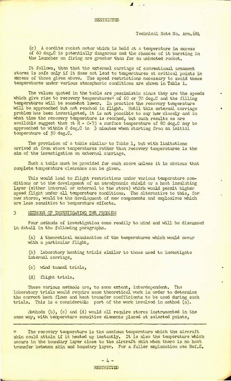
(c) A cordite rocket motor which is held at a temperature in excess of 60 deg.C is potentially dangerous and the chances of it bursting in the launcher on firing are greater than for an unheated rocket.
It follows, then that the external carriage of conventional armament stores is safe only if it does not lead to temperatures at critical points in excess of those given above. The speed restrictions necessary to avoid these temperatures under various atmospheric conditions are shown in Table 1.
The values quoted in the table are pessimistic since they are the speeds which give rise to recovery temperatures* of 60 or 70 deg.C and the filling temperatures will be somewhat lower. In practice the recovery temperature will be approached but not reached in flight. Until this external carriage problem has been investigated, it is not possible to say how closely and in what time the recovery temperature is reached, but such results as are available suggest that at M = 0»75 a surface temperature of 80 deg.C may be approached to xvithin 2 deg.C in 3 minutes when starting from an initial temperature of 50 deg.C.
The provision of a table similar to Table 1, but with limitations arrived at from store temperatures rather than recovery temperatures is the aim of the investigation on external carriage.
Such a table must be provided for each store unless it is obvious that complete temperature clearance can be given.
This would lead to flight restrictions under various temperature con- ditions or to the development of an aerodynamic shield or a heat insulating layer (either internal or external to the store) which would permit higher speed flight under all temperature conditions. The alternative to this, for new stores, would be the development of new components and explosives which are less sensitive to temperature effects.
3 METHODS OF INVESTIGATING THE PROBLEM
Four methods of investigation come readily to mind and will be discussed in detail in the following paragraphs.
(a) A theoretical examination of the temperatures which would occur with a particular flight,
(b) laboratory heating trials similar to those used to investigate internal carriage,
(c) wind tunnel trials,
(d) flight trials.
These various methods are, to some extent, interdependent. The laboratory trials would require some theoretical work in order to determine the correct heat flows and heat transfer coefficients to be used during such trials. This is a considerable part of the work involved in method (a).
Methods (b), (c) and (d) would all require stores instrumented in the same way, with temperature sensitive elements placed at selected points,
-x- The recovery temperature is the maximum temperature which the aircraft skin could attain if it heated up instantly. It is also the temperature which occurs in the boundary layer close to the aircraft skin when there is no heat transfer between skin and boundary layer. For a fuller explanation see Ref,2.
- 4- RESTRICTED

RESTRICTED
Technical Note No. Arm. 684
feeding into a suitable recording system. Such instrumentation is itself no small task, particularly if several stores are involved, and more especially where an empty, instrumented store has to be filled with high-explosive, or explosive substitute, without damage to the instrumentation.
4 THEORETICAL EXAMINATION
For a regularly shaped store, such as a bomb, it is possible to obtain an estimate of the temperature rises at selected places in it during a specified flight path. This method has been used in the U.S.A. and a series of reports 3-5 is available giving details of it and the results obtained for the 1,000 lb IIk.83 bomb (dimensionally equivalent to the British 1,000 lb N.l bomb) and several other stores. Adaptation to cover other regularly- shaped stores and other flight paths would be laborious rather than difficult but it would be very difficult to adapt this method to study temperatures in a complex and composite body such as a fuze.
The method, briefly, is to derive an equation (or more usually several overlapping equations) which describes the bomb shape and from this to estimate the air flov; over it. With this air flow and values for the air constants (density, viscosity, etc.) it is possible to calculate recovery temperatures and heat transfer coefficients at various points along the store.
The recovery temperature is given by:
TR = T (1+0.17 M2) for smooth (laminar) air flow (1)
= T (1 + 0-18 H2) for turbulent air flow (2)
where To is recovery temperature in deg.K
T is air ambient temperature in deg.K
M is Mach number.
Those and the following equations apply, strictly, to a flat plate moving through the air but give a close approximation for large stores provided local conditions are used in the equations i.e. T and II are local temperature and Mach number at the edge of the boundary layer.
For smaller diameter stores the approximation is not so good.
The heat transfer coefficient for a particular store and flight path is obtained from the dimensionlcss parameters associated with movement through the air:
Nusselt number Nu = Mi (3)
Reynolds number Re = £LX (4)
Prandtl number Pr = tfilE (5) k
where h is the local coefficient of heat transfer
L is the distance from the nose measured along the surface of the store
- P -
RESTRICTED

RESTRICTED
Technical Note No. Arm.684
k is the thermal conductivity for air
p is the local air density just outside the boundary layer
V is the local velocity just outside the boundary layer
u is the air -viscosity
C_ is the specific heat at constant pressure for air. (All quantities in consistent units.)
Now for a body moving through the air we have:-
Nu • 0.034 Re0,8 Pr0,33 (for turbulent flow over the pointed nose) (6a)
Nu = 0.029 Re0'8 Pr0'33 (for turbulent flow over the parallel body and tail) (6b)
Nu = 0«51 Re0"5 (for laminar flow over the pointed nose) (6c)
Nu • 0*29 Re '? (for laminar flow over the parallel body and tail) (6d)
Combining the appropriate equation for Nu with equation (3) we have:-
h = Nu . k/L (7)
from which the heat transfer coefficient h can be obtained for a particular point distant L from the nose of the store. The other quantities on the right-hand side of equations (3), (4) and (5) are constants (or at least constants over the range of air speeds considered here). The heat transfer coefficients should take into account the heat received from the sun and from the ground, and radiated from the store, but this is only a small correction (about 1$) and can probably be neglected without causing appreciable error in the final results.
Working on the assumption that the rate of temperature rise in any chosen sector of the store is equal to the heat flow into that sector divided by its heat capacity, equations can be obtained for selected points on or in the store, such as the outer surface, the surface of the filling, etc. These equations, when put into finite difference form, can be solved for small increments of time to give plots of temperature against time for the selected points.
This is a very laborious process, particularly if a very close coverage is required over the whole surface and at a number of points within the filling, but an estimate at a few selected points can be obtained much more readily.
It is felt that this method could give results as accurate as any obtained from wind tunnel tests of isolated stores and better than those from ground heating tests provided that the thermal characteristics of the filling are known accurately and that the following assumptions which have to be made are valid.
- 6 -
RESTRICTED

RESTRICTED
Technical Note No. Arm.684
(i) that the air flow in flight approximates to the free air flow used in the calculations,
(ii) that the equations used for calculating the bomb shape are accurate.
(a) The air flow over the store, which in these calculations can only be the air flow over a free store. No account can be taken of the disturbing effect of the pylon which carries the store in flight or of the effect of the proximity of the aircraft structure. The true air flow can only be obtained from flight trials, and since such flight trials could be used to make direct temperature measurements there would be little point in carrying them out for air flow measurements only.
(b) Equations of bomb shape. In general one equation alone will not describe the bomb shape. Several are required for, say, nose, middle section and tail and there may be discontinuities at the transition points from one equation to another.
Subject to these limitations, the method gives results which agree closely with the temperatures which one would expect to be associated with a particular flight path and recovery temperature, namely a rapid rise followed by an exponential approach to a steady recovery temperature.
Curve C of Fig.l is a plot of the results obtained for one position on a 1,000 lb Mk,83 bomb and curve D is the corresponding recovery temperature for the particular flight path. They are drawn from the values given in the U.S. reports mentioned earlier in this paragraph. The differences between curves C and D agree well with the differences shown between measured temperatures and recovery temperatures on Figs.l and 2 of Appendix 1.
Unfortunately the results given in the U.S. reports are for flight paths and temperatures different from those required here. The calculations would have to be repeated for our conditions and would take 6 to 9 months to complete with the small effort at present available for this work.
5 LABORATORY HEATING TRIALS
5.1 General
The apparatus envisaged for these is in the form of a shell, probably of light alloy, larger than and completely enclosing the store and with a large number of infra-red heaters attached to it so that they follow the contours of the store and are about 4 inches from its surface. Power would be fed to these heaters and recordings would bo made at intervals of the temperatures at selected points on the skin of the store and within it.
Such an apparatus is relatively easy to construct and operate but, for reasons given in para, 1 its results (unlike those for internal carriage) must be viewed with suspicion until flight trials have been carried out. These would show whether the results were correct or whether or not it was possible to apply a correction factor to them.
5.2 Uses of the apparatus
This type of apparatus could be used in two ways. In the first (and simpler) method heat would be applied to maintain as closely as possible a constant desired temperature (recovery temperature) adjacent to the skin of the store, thus simulating boundary layer temperature conditions. In the second, these would be ignored and the heat supplied at such a rate that the correct heat flux was obtained over the surface of the store.
- 7 -
RESTRICTED

RESTRICTED
Technical Note No. Arm.684
To be effective in assessing component temperatures in flight both methods require a knowledge of the heat transfer coefficient, the first to enable a correction to be applied to the heating rates which it gives and the second to enable the rate of heat supply to be determined.
5.3 First method
Considering the first method, where an approximately correct recovery temperature is maintained close to the store, this recovery temperature will, in theory, vary along the store, being greatest at the nose. However, in practice such variations are very small except over the first few inches of a pointed-nose store and so the recovery temperature may be taken as sensibly constant over the store and given by equations (1) and (2) above.
Heating such as this, with a constant recovery temperature would cause a rapid temperature rise on the skin of the store and a 3lower one at points inside, but this temperature rise might not be the same as would be obtained in flight, since it would be caused solely by radiant heating and not by kinetic heating. The net results of this could be different heat transfer coefficients between the air and store in the two cases.
During the heating tests the heat transfer function would have to be measured and compared with that calculated for the particular store and flight path used; one would then hope to work out some correction factor for the apparatus.
Equation (7) shows that the heat transfer coefficient is inversely proportional to distance from the nose of the store and so a series of correction factors would be necessary to cover the whole store.
To test the validity of this method, an apparatus was constructed and heating tests with a constant recovery temperature were carried out on a 3 inch rocket. This store was chosen since there are available a few A & A.E.E. results of temperature measurements made during tropical flight tests.
Details of some results obtained during the heating tests and their comparison with the results obtained during flight are given in Appendix 1. It can be seen that the temperatures recorded on the ground are considerably less than those obtained during flight, and approach recovery temperature much more slowly, but it must be borne in mind that the small size of the apparatus made the measurement of heat transfer rates impossible and con- sequently no correction factor has been applied to the results.
It appears that ground heating tests of this nature, in which the rate of heat supply is considered to give the recovery temperature near the surface of the store with no correction for the true heat flux, will give values of temperatures less than those reached in flight and this will impair the usefulness of the results since they will always be subject to the uncertainty as to how much hotter the store will become in flight.
5.4 Second method
The second method, where the boundary layer temperature is not simulated and heat is supplied at such a rate that the calculated heat flux is obtained at the surface of the store, should give correct simulation of aerodynamic heating. It suffers, however, from several difficulties:
(a) In order to obtain the correct heat flux at the surface of the store, the values of this heat flux must be known throughout the period of simulated flight. They can be obtained from flight or wind tunnel tests
- 8 -
RESTRICTED

RESTRICTED
Technical Note No. Arm.684
(in which case such tests could supply the full data on kinetic heating) or by calculation of the air flow over the store and hence the heat transfer between air flow and store.
As shown in equation (7) the heat transfer coefficient is inversely proportional to the distance from the nose of the store and so must be evaluated for a number of points over the length of the store. An effective heat transfer coefficient should really be used, which takes into account small allowances (about 1 per cent) for solar radiation, heat reflected from the ground, and heat radiated from the bomb, but this correction is small enough to be neglected.
For the Mk.83 bomb flown at M = 0*95 under standard atmosphere condi- tions calculation3j4 shows that the heat transfer coefficient will vary from about 135 BTU/hr ft2 deg.F (0,018 cal/sec cm2 deg.C) at 10 inches from the nose to 84 BTU/hi ft2 deg.F (0»0114 cal/sec cm2 deg.C) at the middle and 70 BTU/hr ft2 deg.F (0*0095 cal/sec cm2 deg.C) at the tail.
This variation is due partly to the fact that the air flow is laminar over the nose of the bomb and turbulent over the parallel portion and tail and partly to the variation with distance from nose of the Reynolds and Nusselt numbers used in the calculations of heat transfer coefficients.
Under tropical conditions the heat transfer coefficients will be 0*019 cal/sec cm2 deg.C at the nose and 0»0101 cal/sec cm2 deg.C at the tail.
The corresponding heat fluxes can be calculated from the equation:
q = h (TR - %) (8)
where
q is the heat flux
h is the heat transfer coefficient
Tp is the recovery temperature
Tut is the store skin temperature
(All quantities measured in consistent units.)
For flight at M - 0*95 under tropical conditions the initial heat fluxes (assuming the store initially at 122 deg.F (50 deg.C),will be approximately 12,600 BTU/hr ft2 at 10 inches from the nose and 6,500 BTU/hr ft2 at the tail. These values will reduce to zero as the store skin temperature approaches recovery temperature.
(b) Since the heat fluxes will be different at different points on the store and will decrease by different amounts at these points as their temperatures change, one should really use a complex system of heat control to monitor and correct the flux at each desired point.
With the equipment at present available for these tests only one con- trol is used for the whole of the power supply, and stores are heated to a constant temperature all over the skin. It is felt that results so obtained will be reasonably accurate.
In any case, control would be possible at only three or four points along a large store and the remainder would have to be subjected to incorrect heating,
- 9 -
RESTRICTED
RESTRICTED
Technical Note No. Arm.684
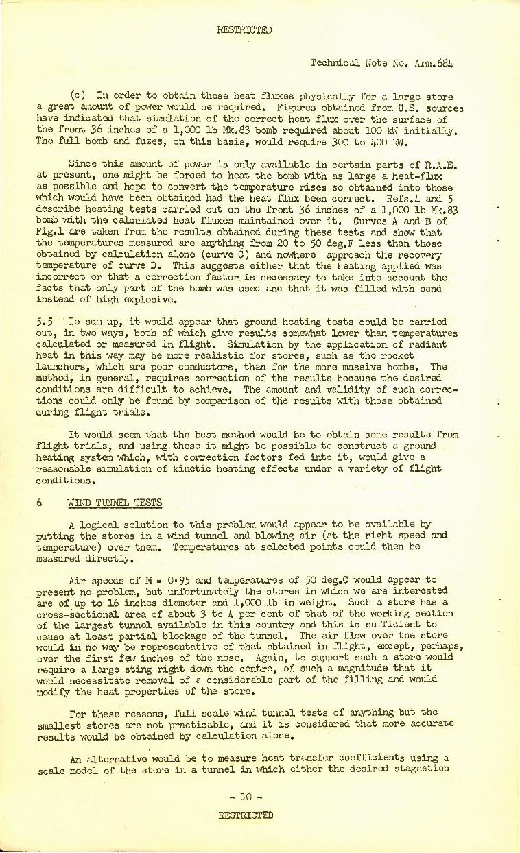
(c) In order to obtain these heat fluxes physically for a large store a great amount of power would be required. Figures obtained from U.S. sources have indicated that simulation of the correct heat flux over the surface of the front 36 inches of a 1,000 lb Mk,83 bomb required about 100 kW initially. The full bomb and fuzes, on this basis, would require 300 to 400 Idtf.
Since this amount of power is only available in certain parts of R.A,E. at present, one might be forced to heat the bomb with as large a heat-flux as possible and hope to convert the temperature rises so obtained into those which would have been obtained had the heat flux been correct. Refs.4 and 5 describe heating tests carried out on the front 36 inches of a 1,000 lb Mk.83 bomb with the calculated heat fluxes maintained over it. Curves A and B of Fig.l are taken from the results obtained during these tests and show that the temperatures measured are anything from 20 to 50 deg.F less than those obtained by calculation alone (curve C) and nowhere approach the recovery temperature of curve D. This suggests either that the heating applied was incorrect or that a correction factor is necessary to take into account the facts that only part of the bomb was used and that it was filled with sand instead of high explosive.
5.5 To sum up, it would appear that ground heating tests could be carried out, in two ways, both of which give results somewhat lower than temperatures calculated or measured in flight. Simulation by the application of radiant heat in this way may be more realistic for stores, such as the rocket launchers, which are poor conductors, than for the more massive bombs. The method, in general, requires correction of the results because the desired conditions are difficult to achieve. The amount and validity of such correc- tions could only be found by comparison of the results with those obtained during flight trials.
It would seem that the best method would be to obtain some results from flight trials, and using these it might be possible to construct a ground heating system which, with correction factors fed into it, would give a reasonable simulation of kinetic heating effects under a variety of flight conditions.
6 WIND TUNNEL TESTS
A logical solution to this problem would appear to be available by putting the stores in a wind tunnel and blowing air (at the right speed and temperature) over them. Temperatures at selected points could then be measured directly.
Air speeds of 14 = 0*95 and temperatures of 50 deg.C would appear to present no problem, but unfortunately the stores in which we are interested are of up to 16 inches diameter and 1,000 lb in weight. Such a store has a cross-sectional area of about 3 to 4 per cent of that of the working section of the largest tunnel available in this country and this is sufficient to cause at least partial blockage of the tunnel. The air flow over the store would in no way be representative of that obtained in flight, except, perhaps, over the first few inches of the nose. Again, to support such a store would require a large sting right down the centre, of such a magnitude that it would necessitate removal of e considerable part of the filling and would modify the heat properties of the store.
For these reasons, full scale wind tunnel tests of anything but the smallest stores are not practicable, and it is considered that more accurate results would be obtained by calculation alone.
An alternative would be to measure heat transfer coefficients using a scale model of the store in a tunnel in which either the desired stagnation
- 10 -
RESTRICTED

RESTRICTED
Technical Note No. Arm.684
temperature could be attained almost instantaneously, or where the store could be kept out of the air-stream until the stagnation temperature was reached, and could then be moved rapidly into the air-stream.
These two requirements are not easy to obtain in practice and tempera- ture rises at desired points on and in the full-scale store would have to be calculated as in para.4. For a regularly shaped store, calculation of the neat transfer coefficients is simple and wind tunnel experiments *o find this alone are hardly necessary.
7 FLIGHT TRIALS
7.1 General
This appears to be the best method of investigation antf one which must be carried out eventually, no matter what other means is adopted to obtain an interim solution. It must also be carried out (at least as a check) on all aircraft types with which a particular store is associated, due to the different air flows. Two types of flight trials are theoretically possible involving different techniques, but both require stores fitted with tempera- ture measuring elements feeding into a recording system on the aircraft.
Tne first, and obvious, method is to carry these stores on aircraft designed for their carriage, and to fly as fast as possible xn an air temperature as high as can be obtained. The immediate requirement is a speed of M = 0»95 at ground level with a temperature of 50 deg.C. Subsequent requirements will undoubtedly increase the speed at this temperature.
Any speed in excess of M = 0«6 at 50 deg.C would give useful results and if a series of speeds could be obtained, it should be possible to obtain an approximate extrapolation to M = 0»95. An aircraft is required which will exceed M = 0*6 in a tropical atmosphere and fly at low level for at least half-an-hour. An advantage of this method is that live-filled bombs (with inert fuzes) might be used, thus reducing the uncertainty arising from the different heat properties of the inert and live fillings.
The second method has been used for small stores and makes use of the fact that the air flow over a large-chord wing can be modified by the shape of the structure and may well be supersonic when the aircraft as a whole is flying at subsonic speeds. If a store is mounted at a suitable place just above the upper surface of the aircraft wing high rates of air flow can be investigated with a slower-speed aircraft. Such an aircraft is the Avro Vulcan but this cannot operate for any long period at ground level without serious weakening of the aircraft structure.
Without a considerable amount of preliminary investigation it is not possible to say whether a suitable air flow could be obtained or whether a store as large as a 1,000 lb bomb cculd be mounted in such a way as to make use of this efiect, so although given here for completeness, it is not suggested as a serious method of approach, other, perhaps, than for a smaller store.
7.2 Flight programme
The following programme of flights is envisaged, using the first method of direct flight trials:
(a) Stores
(i) 1,000 lb M.C. bomb Mk.10, inert filled, inert fuzed.
- 11 -
RESTRICTED

RESTRICTED
Technical Note No. Ana.684
(ii) 1,000 lb M.C. bomb Mk.10, live filled, inert fuzed (if safe results were obtained at (i)).
(iii) 1,000 lb N.l bomb, inert filled, inert fuzed.
(iv) 1,000 lb N.l bomb, live filled, inert fuzed (if safe results were obtained at (iii)).
(v) 28 lb Practice bomb, inert filled, inert fuzed.
(vi) 28 lb Practice bomb, live filled, inert fuzed (if safe results were obtained at (v)).
(vii) 37-tube 2 inch Rocket Launcher, nose cap fitted, and filled with inert rockets.
(b) Air speeds
These should be chosen so as to cover as far as possible the temperature range (recovery temperature) 60 deg.C to 130 deg.C under the highest attain- able temperature atmosphere conditions for all stores, with at least two flights per store at each chosen temperature. Under maximum temperature condition the range 60 to 130 deg.C corresponds to a speed range of M = 0«4 to M = 1«2.
With aircraft at present available the higher temperatures will not be possible, but with an aircraft such as a Hunter, temperatures approaching 90 deg.C (corresponding to M = 0*8 under maximum temperature atmosphere conditions) should be possible. It is thought that at these temperatures the amount of heating obtained (at least with some stores) in 30 minutes flight will be so serious that higher temperatures need not bo investigated.until some modification to the heat properties of the stores have been carried out.
8 TEMPERATURE MONITORING DEVICE
The effects of kinetic heating on the stores can be so serious that it would be desirable to have a device fitted either to the aircraft or to the store to indicate its temperature, or temperature history.
Three occasions when this would be desirable are:
(a) to avoid danger from burst rocket motors,
(b) to know when V.T. fuzes are likely to be ineffective,
(c) to be able to set aside for destruction bombs in which the filling may have segregated, or rockets which have been overheated.
The first two would require a temperature sensing element close to the store, (or at some point on the aircraft which undergoes temperature changes similar to tnose of the store) connected to give temperature indication (or indication that a dangerous temperature has been exceeded) in the cockpit. The indication could be a lamp which, when alight, would indicate to the pilot that it was dangerous to fire his rockets or useless to drop his bombs.
The third could be met by the use of substances giving permanent colour changes with temperature and time or by a stick of some substance with melting point in the range 60 to 70 deg.C. It could be situated in some position readily accessible to ground staff.
- 12 -
RESTRICTED

RESTRICTED
Technical Note No. Arm. 684
More sophisticated methods could be devised to record the temperature- time history of each store in flight, but their complexity is probably- greater than is required.
It is considered that a device or devices of this sort are essential •when explosive stores are carried on high speed aircraft, as there can be no guarantee that circumstances will not arise in which arbitrary speed limitations will be exceeded for times long enough to be dangerous.
9 RECOMMENDATIONS
The details given in this paper lead to the following recomnendations.
(a) Tropical flight trials should be arranged with a programme sufficient to cover all the factors mentioned in para.7.2.
These instrumented stores would also be useful for ground heating tests if desired,
(b) In parallel with this preparation a theoretical investigation of the problem should be undertaken to cover the required flight conditions.
(c) Thought should be given to the development of an airborne device to give an indication of the temperature-time history of stores during flight.
(d) Since it is apparent that some stores, at least, will overheat in flight, thought should be given to ways of making stores less susceptible to heat effects. For fuzes, this would probably mean a redesign using electrical components and explosives which are less temperature sensitive than the present ones. Similarly for new bombs and rockets, explosives less temperature sensitive than cordite or Torpex are required. For existing stores the oriy solution appears to be some form of heat-insulating jacket attached round them when they are fitted to an aircraft. Such a jacket would delay, but not completely prevent the passage of heat to the bomb filling.
LIST OF REFERENCES
Ref.No. Author Title, etc.
1 Chaloner, J. H., Tests to simulate the effects of kinetic Fielding, W. F. heating on bombs and fuzes carried
internally in the TSR.2. R.A.E. Technical Note No. ARM.677, October 196C.
2 Fieldirg, W. F. Some notes on kinetic heating with particular reference to the heating of bombs carried internally in the TSR.2 aircraft. R.A.E. Technical Note No. ARM.66O, April I960.
3 Budenholzer, R. A., Investigation of problems of temperature Goldsmith, A., and pressure influencing the design of Nielsen, H. J. bomb weapons.
Report No.l, November 1957. P68312,
- 23 -
RESTRICTED

RESTRICTED
Technical Note No. Arm.684
LIST OF REFERENCES (CONT'D)
Ref.No.
4
Author
Budenholzer, R. A., Goldsmith, A,, Nielsen, H. J.
Budenholzer, R. A., Goldsmith, A., Nielsen, H. J.
Budenholzer, R. A., Goldsmith, A., Nielsen, H. J.
Title, etc.
Investigation of problems of temperature and pressure influencing the design of bomb weapons. Report No.2. November 1957. P72279.
Investigation of problems of temperature and pressure influencing the design of bomb weapons. Report No.3. November 1957. P72280.
Investigation of problems of temperature and pressure influencing the design of bomb weapons. Report No.5. November 1957. P69989.
ATTACHED:
Table 1 Appendix 1 (Figs.l and 2, Drg. No. ARM.R1659-1660) Fig.l Drg, No. ARM.R1658 Detachable abstract cards
ADVANCE DISTRIBUTION LIST;
M.O.A.
DCQ DA Arm ADA Arm 1 ERDE fatten Mr. G.W.C. Taylor) A & AEE Sec, O.B. TIL 60
R.A.E.
Director DD(E) Pats 1 Library- Head of Aerodynamics Dept Head of GW Dept Head of MS Dept Head of Structures Dept
R.A.E. (cont'd)
Head of Armament Dept Head of *A* Div Armament Dept
'.B', Div Armament Dept IC! Div Armament Dept !D? Div Armament Dept IE! Div Armament Dept !P! Div Armament Dept
T. S. Pearson «B' Mr. W. F. Fielding «.F< Mr. J. H. Chaloner «F! Dr. Lt F. Crabtree Aero .Dept Mr. J. Rudman ME Dept Mr. G. Speak Arm Dept
Head of Head of Head of Siaad of Head of Mr. W. Div Arm Dept
Div Arm Dept Div Arm Dept
External to M.O.A. (through T.I.L.)
Vickers Armstrongs Ltd., Weybridge, Surrey (Mr. P. Ashby) 3
ARDE Fort Hal3tead (atten Dr. Runnicles)
-14- RESTRICTSD
RESTRICTED
Technical Note No. Arm.68k
2 i a o
4) X)
5 c
R
^
C\J
E a CO
co 3 a
NNi^oMoor—3-«-cr>vx;c\in>'oc\i coKr~r--'0'o o lr\iISiA-&-5-5 N-HANJ
I _____,-,-, __„ • . •
1 ^^^.Nt^.ScSS^SS n »-»-T-.-»-T-T-,-«-,-«-»-»-000 i ni
o cr> tno >« c\i i»-r^qa-^Q! cr>>o c\i ao H?tl • ^r^^c\lN~^OOo5\a\ojcocoac> cu »-«-»-r-.-»-«-T-T-»-000©00
8 a)
3 CTS">5)-*CO r^ico CM r—jNcotfK\'-f. M s>K\w««*»-oooMriC!M»ococoS 0) • •••••••••*•••••
»_,-<-,-«- — »-T-00000000 o
a o c
3 <J\C\I trCJ W3'- l'~i,3>K">r>-'- -3-f-Q«- «- o iftK\NN'-'-ocS a\cb co r^- >o »C in-j 2 »-^~ ^~*^»-"ooodo oooo
| s too ino u1 inpioo^ojn^cQ^Ln^^^
IAK^CO f>cot<">cr>-3,or~uiio*-cr.>oc\i «- »- D Q a> cx% co co o S-1»- r» r- >o >5 vo • • . • ••••••«••••• C\l<MC\l<M'-«-«-«-«-»-'-»-'-'-*-«-
COCOCOKl^l^O^oSRlHlJS-cl-Sf-cf • « • • • » ••••••> • * »
5533533355553533
I 9553555SS3555SSS n u •
» T- T- »- «- T- r- I- »-»-»- T- »- »- O O O
o r- •o a>
| ^3^^.f;-#cS3S$^8^ 3 *i g —_
3 ^^£^8SkoHc88f2!8cK U «-»-«-i- T- rr?rr-0 O O O OO O
C s <0
I ^^S'po^OiDSKJ^^SSR
1-2
Hi • • «
ana E J E u U Cb
III a m §
oou • • • u u tt • • 01 •O T3 TJ
JOR * 4-> *J 4->
i
- 15 -
RESTRICTED
RESTRICTED
Technical Note No, Arm. 684
APPENDIX 1
COMPARISON EETWEEN THE RESULTS OF GROUND HEATING TESTS AND KINETIC HEATING DURING FLIGHT FOR 3 INCH AIRCRAFT ROCKETS
As mentioned in para.5.3 of this Note some ground heating tests were carried out on a 3 inch rocket and temperatures on the rocket mooor were measured over periods of 60 minutes at various "recovery temperatures" between 64 and 90 deg.C.
At the same time a few flight results became available from A & A.E.E. tropical trials and this Appendix compares the results obtained in the two cases. Unfortunately there are only two comparable sets of results and of these the A & A.E.E. results given in Fig.2 (Run 2) are in fact extrapolated by A & A.E.E, from the results of Run 1.
However, it is thought that this is the first time that flight results have become available to compare with those obtained from ground heating tests.
Table 1 shows the results for comparison, and they are plotted in Figsd and 2 for the two cases.
Figs.l and 2 show that the temperatures obtained from the ground heating tests are lower than those obtained in the air and the recovery temperature is not approached as quickly.
As mentioned in para.5.3 no attempt was made to correct the ground heating results for any possible error in the quantity of heat supplied. Reference to Fig.l of this Note, however, shows that even with the calculated heating rates, the recovery temperature is not approached very closely.
These tests suggest that ground heating tests tend to give results somewhat lower than those obtained during flight. It would appear better to carry out flight trials first, and then endeavour to simulate them on the ground if necessary, by introducing a correction factor for the apparatus.
/Table
-DE-
RESTRICTED

RESTRICTED
Technical Note No. Arm.684 Appendix 1
TABLE 1
Ground and flight kinetic heating results
Run Time
Flight Trials Ground Heating
Rocket Rocket number (minutes) Mach Recovery motor Recovery- motor
number temp. °G temp. °C temp. °C temp. °C
1 0 0 mm 35.0 — 35*0 1 0.18 36-7 36.0 - -
2 C42 45-0 38*0 — -
3 0.69 61.1 40.0 63-8 -
5 0.73 64*0 46.0 - -
15 0.73 64*0 6C0 63-8 450 25 0.73 64*0 62.0 - -
30 C34 41.2 57.0 63-8 52.2 45 - - - 63.8 53.6 60 — • - — 63.8 55.6
2 0 0 45'0 _ 45«0 1 0.17 46.7 46«0 - -
2 0.42 55.0 48.0 - -
3 0.67 71.1 50.0 77-0 -
5 0.72 74«9 56.0 - -
15 C72 74.9 70.0 77'0 56.1 25 C72 74*9 72.0 - -
30 0.33 5L2 67*0 77«0 6O.5 45 - - - 77«0 63.4 60 — —
" 77-0 650
<
ATTACHED;
Drg. No. Affil R1659-1660
- 17 - RESTRICTED

ARM.R.I659 TECH. NOTE N? ARM. 6&4.
APPENDIX I. FIG. I
70
65
60
U o
id QL 3
<
UJ a.
55
50
45
40
35
<
*•
(
© RECOVERY TEMPERATURE
X ROCKET MOTOR TEMP. (FLIGHT TRIALS)
1 O ROCKET MOTOR TEMP. (GftOUNO HEATING ^
10 20 30 MINUTES
40 50 GO
APPENDIX I. FIG.I KINETIC HEATING OF 3 INCH ROCKETS
RUN No I.

TECH. NOTE WARM. 684-.
APPENDIX I. FIG.2
60
75
70
U • 65 id
3
< at
2 *° 2 id t-
55
50
45
— — _ _ .
(
© RECOVERY TEMPERATURE X ROCKET MOTOR TEMP.
(FUCiHT TRIALS) Q ROCKET MOTOR TEMP.
(GROUND TRIALS)
10 20 30 MINUTES
40 SO 00
APPENDIX I. FIG.2 KINETIC HEATING OF 3 INCH ROCKETS
RUN No 2.
ARM.RI658 TECH. NOTE WARM.6&4.
FIG. I
CURVE A - TEMPERATURES REACHED ON OUTSIDE SKIN OF BOMB DURINQ HEATING TESTS.
CURVE B - TEMPERATURES REACHED AT SURFACE OF BOMB FILLING DURING HEATINQ TESTS.
CURVE C
CURVE D - CALCULATED RECOVERY TEMPERATURES.
CALCULATED TEMPERATURES ON OUTSIDE SKIN OF BOMB AND AT SURFACE OF BOMB FILLING.
400
u. o
UJ a. D
< QC LU Q.
UJ
350
300
250
200
150
100
M • 2-5 D
c.
/ A
B
&]£. MELTI slQ POINT OF T.N.T.
10 20 MINUTES
30 40
FIG.I KINETIC HEATING OF IOOOLB.MK.83 BOMB. RESULTS FOR A POSITION 24 INS. AFT OF THE
NOSE. STANDARD I.C.A.O. ATMOSPHERE

DETACHABLE ABSTRACT CARDS
These abstract cards are Inserted In Reports and Technical Notes for the convenience of Librarians and others who need to maintain an Information Index.
Detached cards are subject to the same security Regulations as the parent document, and a record of their location should be made on the Inside of the back cover of the parent document.
a1? mmcM • • • • %
cvJacvtn VD rnvo in
P c
3!
£3 QJ p P «-• o cd
•as
11 <D o 6- a:
CM in CM •
r>» co »-
inincM •
VD mio in
p
• 10
gs < -9 <0 • P o ia
z u
s£ ss
o a! o <
si 0) O E-. a:
.<-: t,
e- a e
a) 03
O >»P (-.
TJ co 3 co £ PUP oi «3 o
3»s •o U co «j n « A
>> O a; r-l C CO *J "2 p (fl K) tfl P g UX1 ** i-j o p ro
p a) oi TJ
«-4 p
•OS'S o »* <u
3 *J bs« co ^ TJ > >> co a) L, to
•g°.2 o
CJ rj SO) 3
rH O •S ° •a as
0) J-. -G •a »-• o 3 to •— r(«S cJ -a s c 0 01 w O— P
01 P 3 —. --> m
* .£ 3c. r-l -; to
§2§
w m CM •
r^- co«- • • T-
v- ••co o inincM • -JiO-JVO • • • • CMK~>CM r<~\ vo in'o m
cri £-
a *—< OS
i P c
Si
^3
o «i
15 u
8 Q E- O
oi
co rj
a1? CO «-
«~ ••CO o u. « mmcM • o ao -=t io -3- >o c
\D irivo in E-i o>
o 0]
M P
p 0) 5) S CO
o co SS ST. S§ CO TJ J3 CO P C
TJ a 3 X
O C, P (0
TJ CO 0) CO
s& P
CO 0}
4»
i 01 03 TJ
Si3 co a) o g 10
TJ »•• W 0) TJ
O Li 01 -Ec «- (0 o O O «H > *i
e^ B 4J TJ
a> 3
o •2 2 3 CO £3 4-> H 4-> 01 BJ o
TJ O ^ >, 4J >» C
^«!>, CO XI g
>» 3 CO r-l C CO 4-J »< Pan a} 4J B no
p a)
TJ'S'S O w-4 q>
0) T3 > >> CO CO U 01
s§3
|04? o 4J p TJ
UHO
TJ 03 0) fc, X3
TJ »< O 3B1-
I5« O 03 01 0 —• P
r-l 01 P p — ~ 01
CO
JQ a) d
'.8 1 ?J
I •-H a:
