to - dtic fuselage responds rather readily to frequencies in this ranga. the transmission suspension...
TRANSCRIPT

UNCLASSIFIED
AD NUMBER
AD477910
NEW LIMITATION CHANGE
TOApproved for public release, distributionunlimited
FROMDistribution authorized to U.S. Gov't.agencies and their contractors;Administrative/Operational Use; NOV 1964.Other requests shall be referred to ArmyTransportation Research Command, FortEustis, VA.
AUTHORITY
USAAMRDL ltr 23 Jun 1971
THIS PAGE IS UNCLASSIFIED
IN
U. S. A R M YTRANSPORTATION RESEARCH COMMANDFORT EUSTIS, VIRGINIA 1.1.1
PRELIMINARY FLIGHT TEST DATAO
H-51A RIGID ROTOR HIGH SPEED FLIGHT PROGRAM*
LLINTERIM REP NO.
0 f -)2)-$ cm i
S ;2
¢jAi'
OD€ ...
The infoksihation contained herein has been reproduced to disseminate toGovernmeht and industry, as rapidly as possible, current data vital toArmy rotkry-wing progress and objectives. In this respect, it is empha-sized that the data, although measured flight data, are preliminary;therefore, the contents of this document are subject to revision.
wantSIi~
'W':
........
............ **I .......
. .......
four-bladed rotor testing on the XH-51A rigid rotorlf helicopter. Theobject of Phase III was to evaluate the four-blade rotor in comparisonwith the three-blade rotor. Ground tests commenced on 13 July 1964 withthe first flight on 21 July 1964. The phase was terminated on 3 October1964 after 49 flights and 14.9 flight hours
Results and Discussion
General
Two problems were apparent as a result of early flights, bladestresses and vibration level - both were high. At this stagei thetransmission was in soft suspension in pitch only with a spring rate of14,400 pounds/inch; vertically and laterally the mount was solid. Thefuselage vibretion problem was dominantly 4P; it was considered that thisresulted from the second add third harmonics of blade natural flappingfrequency which were close to 3P and 5P. The 3P and 5P rotating inputsresulted in a 4P shaft oscillation which was transmitted to the fuselage. .,:The fuselage responds rather readily to frequencies in this ranga. Thetransmission suspension was varied incrementally to tune it to a point of "minimum tranmissability; this approach had not been completed at the closeof Phase III. Additionally, experimental moves were made towards cuttingdown the input by reducing the blade natural flapping frequencies. Theconfiguration at the termination of the phase, resulting from these twoapproaches, incorporated a 13-pound we~tht at station 6.0 on each of thefour blades and the transmission soft mounted in pitch, roll, and vertically.Blade stresses were reduced to within the infinite life level and vibration,although unacceptable from a production viewpoint, was also considerablyreduced
Apart from the vibration level, no flying qualities problems wereencountered. A marked increase in the Phase III flight envelope wasachieved, 2.5 g being demonstrated from 0 to 120 knots CAS #nd a speed of180 knots IAS flown in a shallow dive. 1
Phase III employed four blades of the same design used on the three-blade rotor, the hub blade attachment geometry was modified compared withthat employed in the Phase II flying. The only significant problemapparent at the close of Phase III was fuselage vibration, none of thestability problems encountered with the three-blade rotor existed andstreis levels, subject to fatigue test confirmation, indicate infinite lifefor the hub. With the reduction of the vibration level to within normallimits, a substantial speed envelope expansion should be possible. Thephase is considered a considerable success in that a marked increase in
4
L
flight envelope was demonstrated, no stability problems existed, and noproblems considered insurmountable were encountered. The stabilitycharacteristics confirmed the advisability of the choice of the four-bladerotor for' the compound configuration.
Confizuration
Four-blade rotor - The blade design was that employed duringPhase II, the three-blade rotor; however, the blade hub attachment wasmodified. The cone angle built into the hub was increased from 2.8degrees to 3.2 degrees.
Main rotor gearbox suspension varied as described.Tailplane angle of incidence -5k° through test 271 and
-3r thereafter.Blade weights 13 pounds each, fitted to each main rotorblade at station 6.0 foj test 352 and remAined on thereafter.
Four-arm gyro 7.3 slug ftArm incidence 30 degrees.
Structures
Structural loads recorded during the program included main rotorhub-and blades, gyro control arms, main rotor pitch link, tail rotor andtailplane loads. An incremental approach was employed during the tests,flight records being examined prior to further envelope expansion.
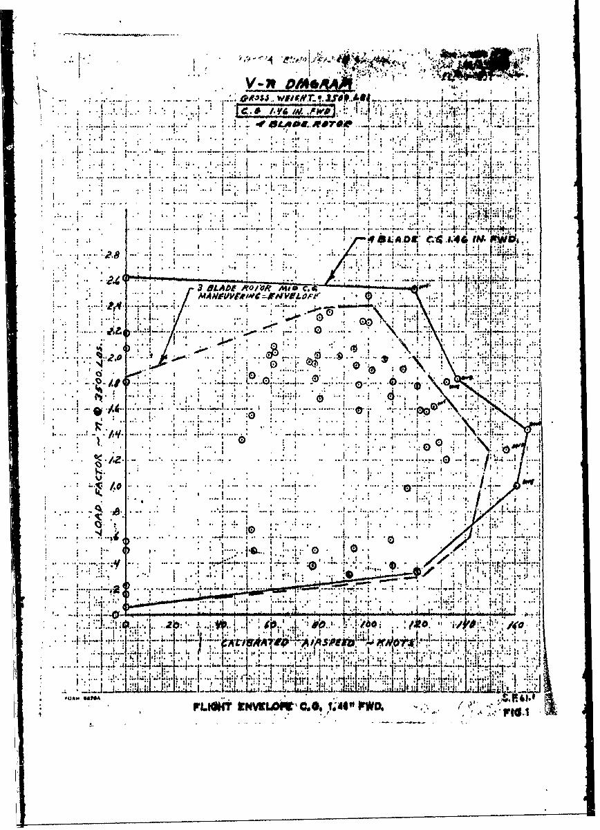
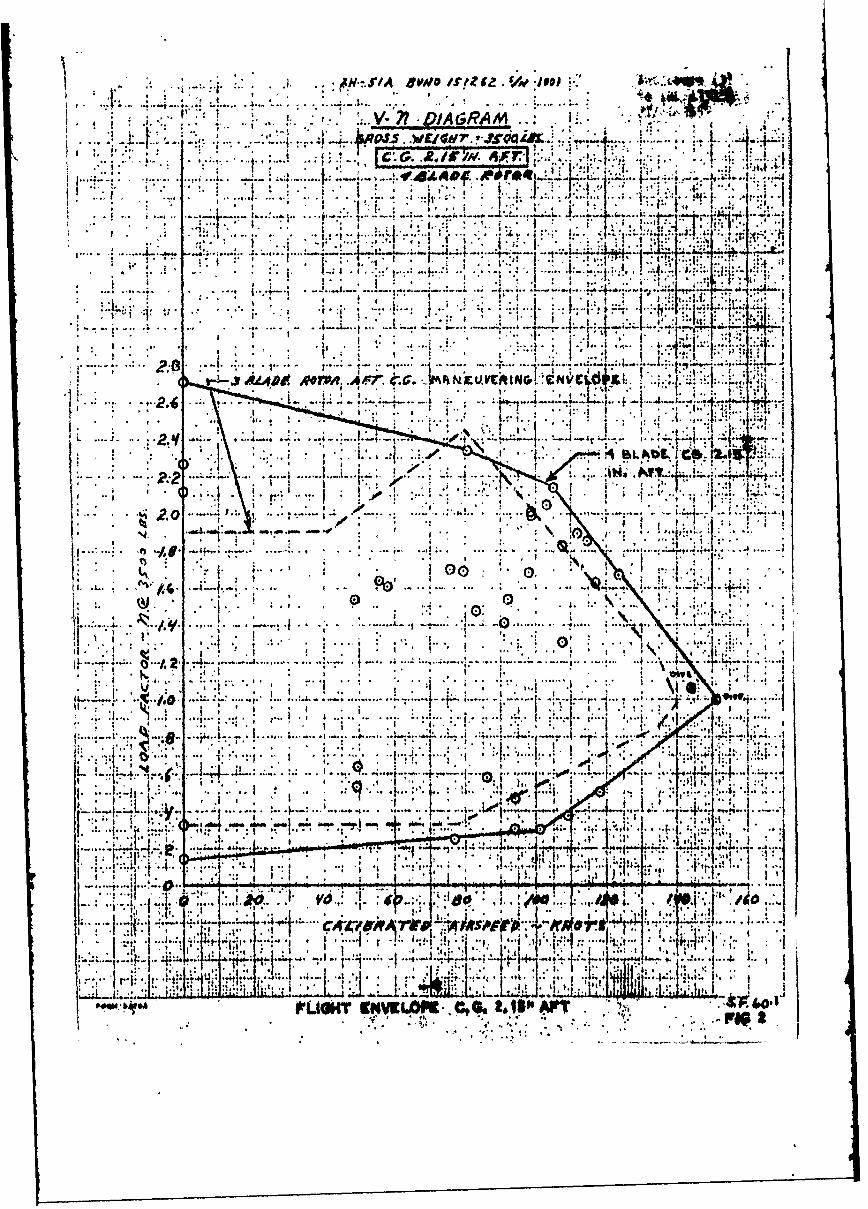
Figures 1 and 2 compare Phase II and III flight envelopes. At aC.G. of. 1.5 forward, the envelope is substantially 2.5 to 0.2 g up to120 knots CAS with reducing normal acceleration cut to 165 knots CAS.The aft -envelope was opened up in only three or four flights and nospecific attemptwas made to exceed the Phase II envelope. While it isfelt that there would be little point in extending the hover beyond the0.15 to 2.7 g demonstrated, no structural, performance, or stabilitylimits ,were encountered in forward flight.
RotorBStresses
A review of all structural data indicates that hub station 7.0. isthe. critical fatigue section of the rotor. It consists of three steellaminations'!bonded and bolted together. Assum ing a stress concentrationof 3, the i durange likaft stress is 26,000 psi. The strain calibrations
were effected in terms of bending moment rather than stress because thebendingmoment curve along the span of hub and blade is predictable. Theconversion of bending moment to stress at station 7.0 is as follows:
2
Flapwise bending Station 6.0 moment x 1.42 =station 7.0 stress
Chordwise bending Station 6.0 moment x 1.152 -
station 7.0 stress
Figure 3 shows that during the initial flights, the chordwise bend-ing stress was 40 percent lower than that in the three-blade, but theflapping stress was up by 80 to 90 percent. At this state, the vibrationwas very high and & series of changes in transmission suspension springswas initiated to reduce both vibration and stress. The pitch spring ratewas varied.first; the range covered was 6,400 pounds/inch to solid whileboth vertical and lateral remained solid. From the structural loads andvibration results 11,000 pounds/inch was selected as the pitch springrate to be held constant during vertical spring variations. The verticalrange covered was from solid down to 4,000 pounds/inch and 6,000 pounds/inch was selected from the results.
An analysis of the flapwise bending at station 6.0 during forwardflight and flare showed considerable 3P and 5P content superimposedon the 1P. Note, 1P iSLmain rotor rotational frequency, normally 5.9pcps (100T), 3P is 3 times rotor frequency, etc. The second and thirdharmonic blade natural flap bending frequencies were slightly below the3P and 5P forcing frequencies. Tests conducted at 95 percent, 100 percent,and 105 percent illustrated the diminishing response of the blade as theforcing frequency was increased and separated from the natural. The 3Pand 5P bending moments were reduced by approximately 45 and 55 percentrespectively. The reduction of the blade natural frequencies had asimilar effect; at 100 knots, the 3P bending moment was reduced from4,090 inch pounds to 2,400 inch pounds and the 5P from 1,960 inch poundsto 740 Inch-pounds. In reducing these moments, the weights reduced the3 and 5P driving forces which produced the 4P pitching &nd rollingmoment into the fuselage. The vibration benefited to a minimm degree.
To reduce the 4P moment further, a transmission lateral spring wasintroduced~with a rate of 19,000 pounds/inch; it did reduce the cabinvibration to a small degree, but did not affect the structural loads.
3
Records showed a 1? flapping component increasing with speed at high speedand producing a nose down moment and indicating that a reduction of tail-plane negative incidence would be of value in reducing the total bendingmoment. The tailplane incidence waei changed from .5kO to -30 for test228. The bhange in slope of the flapwise bending moment curve betweenfigures 4 and 5 at high speed is attributable to this change.
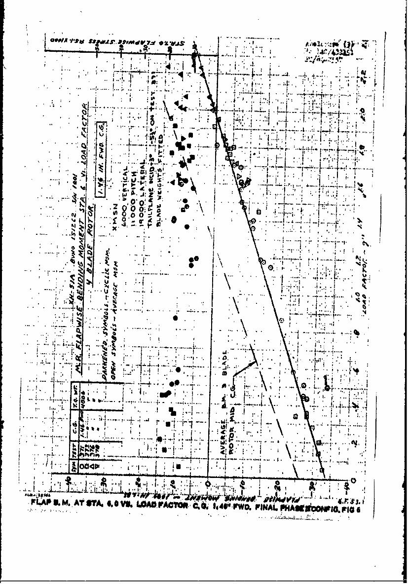
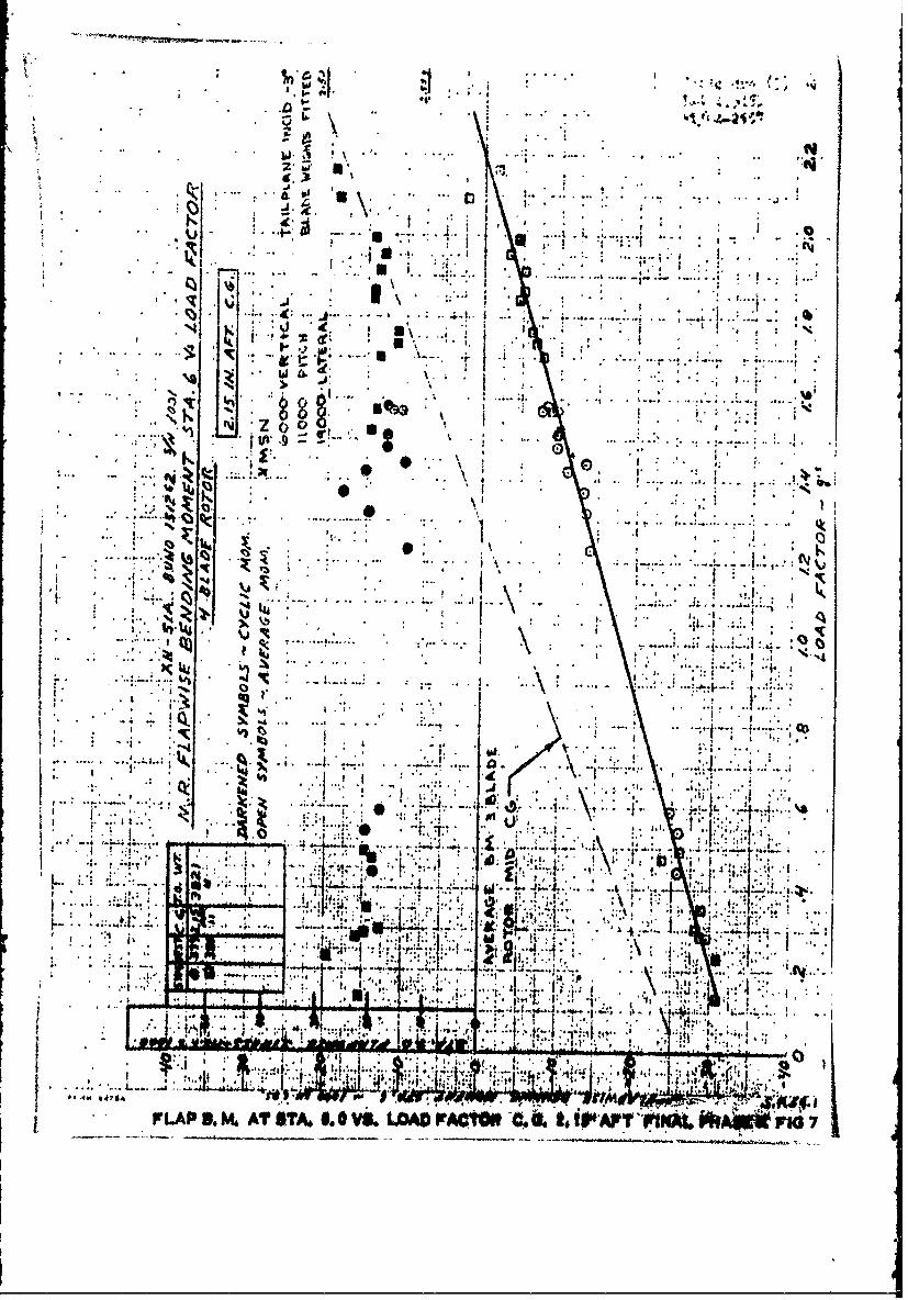
Figures 6 and 7 illustrate the affect of normal accelvation on theflapwise bending moment at station 6.0 at two centers of gravity. Theaverage-moment increased tcoards up flapping with increasing load factordue to lift on the rotor blade. Down flapping was recorded at 1.0 gdue to the fact that the blade line was below the cone angle built into thehub. Zero moment was recorded whhn the blade at this station lined upwith the hub cone angle. The smaller built-in cone angle on the three-blade rotor and the 30 percent greater lift per blade resulted in thedifferent intercept shown in the graphs. The Phase III flapping cyclicstresses, figure 7, at the aft C.G. were of the order of 10 percent lowerthan those at a mid-C.G. on Phase II. At the forward C.G., figure 6,they were about 30 percent lower than the Phase I mid-C.G. Chordwiseaverage and cyclic moments in maneuver 'were 50 percent lower than withthe three-blade rotor except at high load factors where the reduction inaverage moment was about 10 percent. The cyclic flapiise and chordwisestresses at station 6.0 are the maximum that occurred during the maneuversand do not necessarily coincide with the maximum load factor.
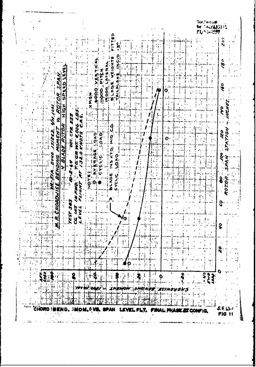
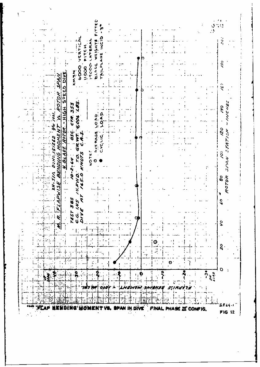
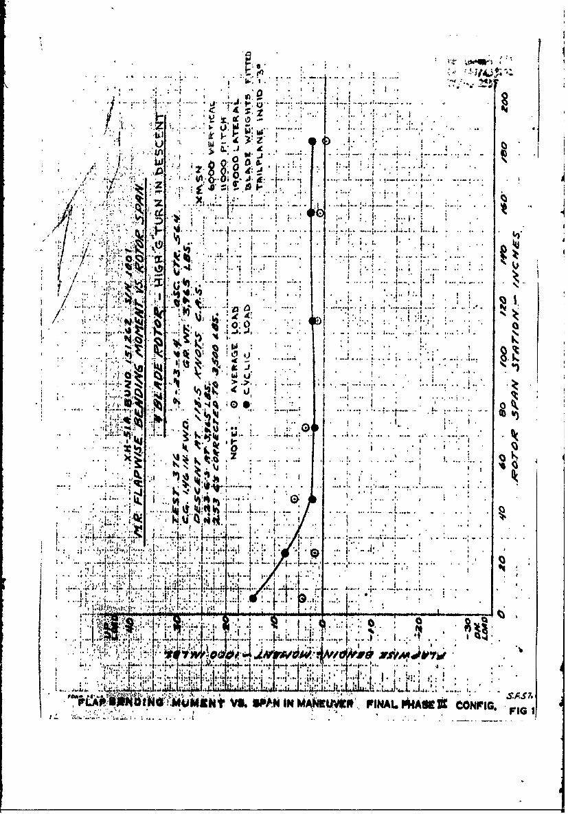
The spanwise bending moment distribution in high speed level flight,
descent, and in maneuver are shown in figures 10 through 15.
Vibration
Vibration level in the cabin was measured for speeds up to 132 knotsCAS in level flight and to 165 knots CAS in a descent. Tri-axis (vertical,fore and aft, lateral) measurements were made on the cabin floor at thepilot's seat. Vibration data in the 3 axes is plotted versus airspeed(CAS), figure 16.
The analysis of vibration for the various configuration was carriedout in conjunction with the structural loads, because they were in mostcases a function of each other. The comparison with the three-blade datais obvious, but it must be pointed out that the three-blade data representsonly the soft 4abin configuration. The high vibration level remaining atthe terminatiod of Phase III was the only problem of any significance andwas the factor Ohich limited the speeds attainable under this contract.
Stabiliq
No adverse stability characteristics were recorded at any timethrotighout the Phase III flying. There was a tendency for the static
4

longitudinal stability to become neutral at high speed and some cycliccross-coupling existed. The correction of the cross-coupling would haveimproved the stability which could have been made further positive byaerodynamic shaping of the gyro arms. For the purposes of the program,neither the stability nor the coupling warranged corrective action.
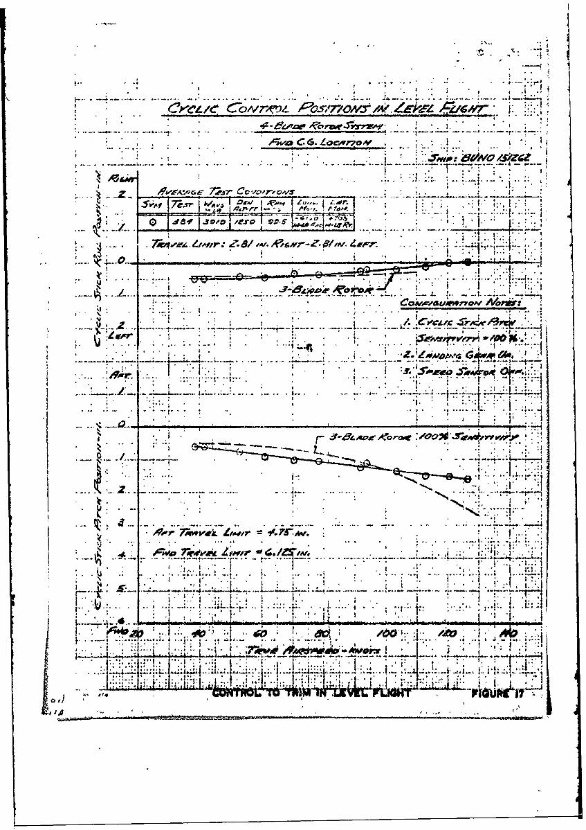
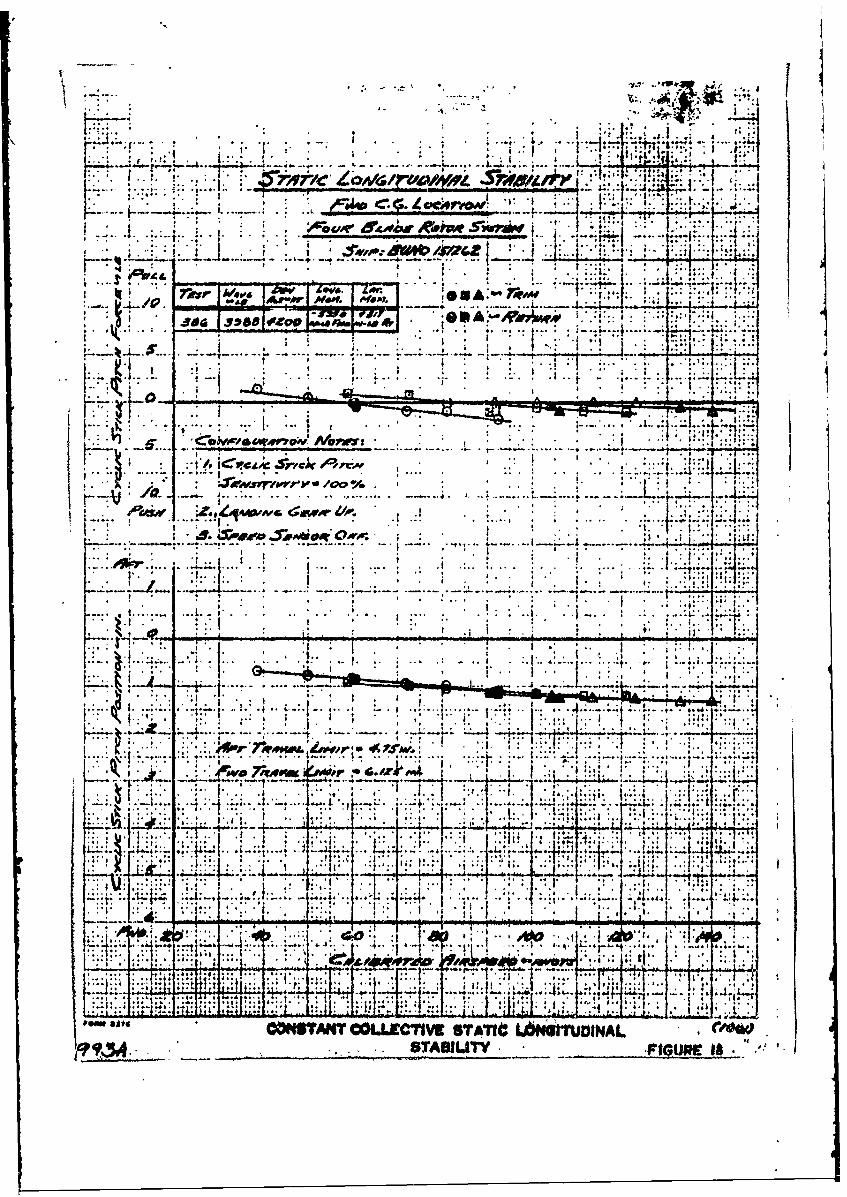
The cyclic control to trim is shown in figures 17 and 19 in termsof control position and maximum blade incidence. Figure 18 shows theresults of constant collective static stick fixed and free longitudinalstability measurements.
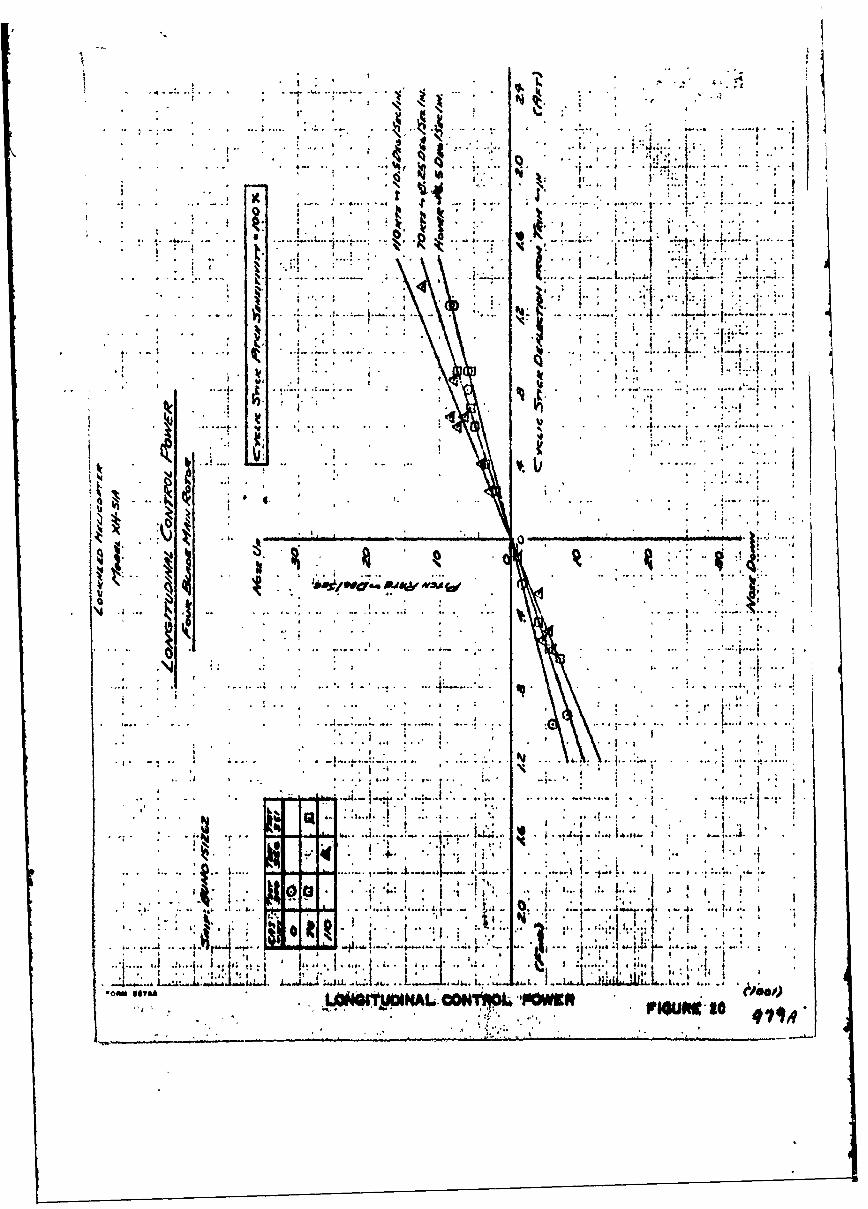
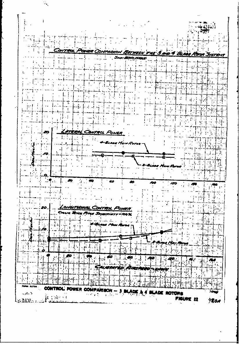
Figures 20 and 21 illustrate the longitudinal and lateral controlpower and 22 compares Phase II and Phase III results. The lateral controlpower was increased by 14 percent to 12.0 degrees/second-inch and in bothphases and was independent of speed. Ia.nitudinally, the 20 to 25 percentincrease apparent at the lover airspeeds decreased with speed to becomezero at about 110 knots LAS. The data was obtained from longitudinalstep inputs in the hover and at 70 and 110 knots IAS. The time historiesshowed compliance with MIL-H-8501A in that tle angular velocity was inthe proper direction within 0.2 seconds of the control displacement andthe point of inflection of normal accelerationoccurred within 1.0 secondof the control displacement.
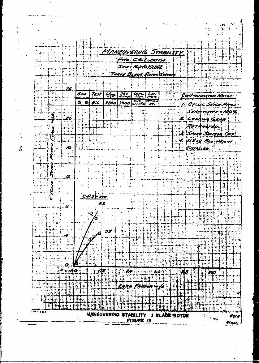
The stick force per g plots in figures 23, 24, and 25 illustratethe greatest single improvemnt of the four-blade rotor relative to thethree-blade rotor. No pitch up, nor any tendency for the stick force/gto be other than positive was experienced during Phase III. The stickforce/g has improved 150 to 200 percent, providing a high degree of confi-dence with regard to the anticipated outcome of maneuver tests at highairspeeds. An envelope of the bank angles flown during these maneuversis presented in figure 26.
A number of entries and autorotations were affbcted in the range80 to 120 knots CAS the characteristics were normal and perfectlyacceptable. The load factor to- hold rotor speed presented in figure27 stems from tests conducted to assist in the definition of the techniqueto be used following failure of the rotor engine on the compound helicopter.
Performance
Performance data presented in figure 29 is not representative ofthe four-bladed clean helicopter configuration in that at the time thetests were conducted, the blade weights were installed, and they representa significant and unknown drag increment. The hover data presented infigure 28 is clean four-blade data.
f5
/iN
Lt

1 Flight Enielope C.G.l1.46v Forvard . *
2 Flight Enveope -C. . 2.1 Aft.. .. . .
3 M~omnt at Biab Station 6.0 - Irnitial Thaoij IIIData e s ., . o e * . .. o
I. Jmcnt at Hub station 6.0 - Trahozission $us-apension Modified Blade Weights Incorporated
S Mment at Ibb Station 6.0 - inil Phaae IIIConfiguration - Tailpiane .30 1 o *
6 Flap Bending Moment at Station 4,oQ Va. Load Fao..tor.C.G., i.46" Forward -Final Pbaaie III Con.-figuration ... 0e* 6., ..
7. Flap Bending Moment at station 6.0 vs. Za&Factor - C.G. 2.15" Aft -Final IFhase III Con-
8 Chord Bondit )Iwsnt at )kb Station 60 OLoad, ?akt6r - CoO. 1.46" Forvar-d - Final Phase
III~nfi~atiO 0 ... 0.0.*J
9 Cbc-d Bending Moment at Hub Station 6.0 vs.Load Jactor - C.G. 2.15' Aft - Final Phase IIIConfiguration 0 * 0 0 0, .* ... a.1v0i0'
210, lApBondingMoment at bub Station 6.0 vs. SpanZewi ,Flight -Final PMase- III Configdritlin i
11 Chord Bending Moment at Station 6.0 vs. SpanIsvel Flight - Final Phase III Configuation
12 Flap Bending Moment at Ibb Station 6.0 vs*Span in Dive -Final Phase III Configuration
13 -Chord Bending Moment at station 6.0 vs# Spanin Dive - Final Phase III Configuration ,
U4 Flap Bending Moment at Hutb Station 6.0 vs.Span in Maneuver -Final Phase III Configuf-
15 Chord Bending Moment at Station 6.0 vs. Spanin Maneuver - Final Phase III Configuration.
16 Cabin Vibration Level - Final Phase III4 ~Configuration .... ... .o# a soo.
17 Control to Trim in lAvel light
29 Constant Collective Statico Longitudinal Sta,.bIiy 60000*
19 Blade Incidence to Trim in level Flight ..
20 longitudinal Control Power. i
21 lateral Control Paver . . . . . . . .
22 Control Power Comprison - 3-blade and 4-blade Rotors . .....
23 Maneuvering Stability -B"lade System.
24 Maneuvering Stab~.itY- 3-Diade Rotor.
* 25 Maneuvering Stability -3,-Blade Rotor
26 Angle of Bank Veooity hvelope.....
27 lad Factor - Rotor Speed in Mutorotation
-lip
28 Bm Pefi= 0 0 0 000
29 Frward t rorjoe 0***~
N ''. " - Ze
0 0
....... .....h.
J! N~l I I g.
Eli-* - 1-*J-.s-* .... -.1 E. ....... J2rumN 04"A II
OfttN PISA
J.~f
t.a~~~~~_ 'V S ~ . ..... 4... ,
S4_1 ~ t .....
I..* . I- ic
AHI
.... ~' ... .. t*.4 .... 4....0.9.
H47(
.171
&j, 4.-.-Plot4

i PIAP.4 r Z' z. ftr
-sit VRT/?BAIL.AA ~cs4 lP __ .~
.L #ATP A? SPi:*SZC)
!:L.;i-. .. . -. Lb~~
M RWAM G 0 IITIA PWAX IfDAT

PM/ OrO.4- B4./&6 'L 9AI,'S A. CAL/8RA Trit A4jQj
0 3Sf -vGo;#ORiZOt/7AZ .$r-8jj/7f' 5- L Pe0 J10 YO/C RICA
*/W A. 0 ~OP~~~~~t ~ *1,0J s~vAnen rs
144
. ... . .. . .. ..
-C . I
'30
.1 -0 -- -
U4a
.......... . cA L1##Mr4. AlRPt .sra I"m rsot
Pont, CN a SF. SI AA. HB SA. .0.FIG 4

tIIR9 OAW 8t / Ot I-.CFOS V.S.-AJ
,~~r~. -r - v .
SJ
ROMP'' *V 373 O&tM
41&,o or1vmPV £4,.~
* /4~Ob,#'/PC
44..O~K~Dsyass,~Cc.JX J~~j
'II.OPW ~AfOAS ... qvR$4 a.*a~e~~f4S"Sn
. ~ .Q 8LO~R~o t.'76AB.(too~,' .
-" ~ s S '' .@: ~it
3 stj: e, kao im-*.0-4 . ..
-/0 I now* . . . .. . . t
* . .
I I-
S SJ
.ON TNBOt6 W3NL JAN6,9 kAIroRW -irissS. 5
i . l oti ' .
411
IL J. *..,.
0.~- J
0 0*0
4q46
Al .41
FM~~~ ~ ~ No M.ATfIkC0
1
.4C
''S to
X *~ ..
Al on 1'
* 44
'bIV
FLAP4 10. ~ M6 AT STA 0.0VLLDIAII.C t1 l-AP A i

-a-.~. --1
U.~
41
It. K
.4ra'
4 4b: .
. a4
.,14A PA. X . -W.

1?A.
-.b.f~
0''0**
4.-C . &
.1 .- .- ~ a 004Pep
KA
L.
I.J~
r~R ,M THNSA . s

.. ~. ....
* I I j
.1 *~i ~ , a7a,
141 0 1 P4 .14 01 I . .
ft A
road
.- tic I I.
* . 0 . .
K I 1-.. 1.La..................... . . . . .. . . . . . - . . . . . .:4! l. . . 1
It ..
* 0 0 .1 0%
* 0 * 0., ....j0* * 0**
-- ~~~~~ ~4 0 ~ *J. .. ........
7..
jh. . ) go
. 2 It
* 2Tr
2: *~ 'l
* ,. .jIJL
lot a or Ott...
tile at :411601 VA LX~t Plo?, X.
IkkD
0. 4.
c4 N
A!*, 'AW . * K
* *. FIG 12

0 Z:
* ;+ .+ .
... . ".o: . a. ' 4 '.,
*.. .... . , . . . . . .
. , o . . I+.. ..
-" " ' . 4,. .! "., d .... .. .. q , *.I . . .., 4.
0. ," "" .. . I ' . .., ,... ...' , :" " "" : -. " .... .
44."
k 14
_ ~....,.
_ , .J[.. ... . ., , I . : : . ' . ' : 4 '
.,~"' r, oF " :"
"" 17 ... .. ' ., ..... ....... .:, , , ,. , ... ..-
i, 4 o,
-O VAN IN
? . V ......... ... . .
.', ' I+ . .
• "4 '. . ... . 4 . .
4 ! .*
. 4 . .. . . .. 4 4 .. .. .
'4 . 4**4, . , 4 4 I'" "
S, I 4
. . . ... . . . .+ ' I • . . ... " . . . . ! "+ , ,1
I 'I/ I:. . I.
I,,, w,,"
• " I " " "I " ' "7" . .. . . "7 "" . ... N,'" 4h • • "
.1 j . 4
....... I ... . . .M+. ,... t-.N". +.V', .... , I I.,., .,- , .. .. .. 40 4 'Ig
I I.
141
4t*, J
V '1.4~' ~ - h ' 1,o,.;. ~ .~ . -
f r' "~ t . I
Jw ~Id9K ~ .
a..O 9 04 INMW IALkW*.NjI
IFir 11*

-. -- uq
.. .. .. .
41 .4.'~
t, . '
.A ... ... ... -
... . "1 1. ... - .
t 4,It 0 ~~'.~j i.' it.
~ 3 . 1.
tolo~os SPA IN'4U*O 0P1A O HFGi

Am V
... .... : VZr'C L VE R I I.
- ~ ~ r r . .
1,..
12....1 I
C~eelv Co..rr.).
.,.. o o*
a..W . , . .
ao, lea
a . . .
fu.e.s
.
*e vo.a a 6
..- o.. -. a4Tl
______________________________ ) . a
JA
VA 4,6 -.* .. 6 A :*
J L,
-~f!# .Aer NOW I~,.*
11.
jor 5.m1 .ro A* #. tIi;At
. 4~W~fr~w~r" /00%'
"0, z , z~wc .w /
I. - T
I I
.4AIU * M
1*
* . 4 If
,.. , , ~
* 43 4 *1 44
- 4-.. ~~~~~-4 I
0 *i4~~~:~ 4 4
4 '.4.. --. 4* - 4* * ~ 4
4 4 .. 4 I* . 44 is.. I.
14 . 4 -4.-'.
- . ~ I ~ *-: . I * 4'4 4 4 ~4
4.4 .. I j .~4~.4*4.44~*~
73 , ~ .4 ~.. ..- 4. -. 4 --. 4. II 4. 9 .4
4 -* - I; ~ ~ j~ '~' .4I .- ~-...... .14
- ~. - . - i::; I'a
.h .4 4 .I~.4I
.? 44...~f.. .4.,. .4 * L
.4....~ 4 * 4. I4.~) ,
.44 I'
4 -4
~,4 - - hD~/.~D.w~'-IA~,v - -
I i 4,
-... 4.444 .4..- .4 .4 -,
4 .4 4 44 * 4 . I . 4 4 4
-. 4 4. . 4 4 4 44
4 .4
4 . La ..-........ 4.......-u.................I..
- 4 4 4 . 4 '.4 -- 4 4
4 4-I.- ,I..J. I- 4.4.......
-1' - 4
S- I4' 1' , 4 4 ..
I.% ~ * h-. 4 ~ ~.4 4 -.4 I 4 -44-; --.- 4~
44 *~' 4 4.4~ .4-4 ~ 4 .
.. 1:4;- :,444*4~44. ~-
7 1r~-
4-~*4* -~,'~4~'~t '~'
* 4 ~..!....1. I. i- .i.-i'..' I4,! .Z~... - f....4..4.3444444.4 *~4 I
OAU *UPA Li4~II'U~KAL ~ft~~y~Aj 'ihiaMWb - -
WI~1W7W EWWUinWU . t3AIib~-tA~
4 44 ' .4
44 4

a i .
. 'a .. ~ . .4* I . .
"4.:,
. 4 0 ~1** ~1 I h Ii
* ..f 1 1
*1~~* . a -. r*'*'
- ,*.......' ~ $ *~'' ~
0 . ... 4* . . .~ 4
a K....LL.....4 0~*.~ ~ ..
. . .
1 *
ji ~j
1 1
*0~ a 4a.....
.2 ....D 2~ 4. a .
.4.* a
'a). .
* .4 . a.. . . '4
1 -
0 I.-
N II
0 4~.. a
4 .
~.1 ... a. . 1a a a.
* * j 4 a . . 4
.~ - .
*~aI4,00;.0..10aa4.
~ ~ 1 I ~ *~ **
44, . . a
LW4eI1~u~It4AL CONT~Ot. '~WEft6.
.4 .4

? *f..* :.: L.
. . . - - . . I t
-: .4; H
-,r4."~
1: "1 :1",. .
* Llij
* . ~ ; *-. . *cc
1.'~,i. I
* -.
I : *.~
* I . , .. 2.~ ..,w713
* .44 4 I 4 4
I I c~'w~w ~YWJ*' ~W~J ~ V &,0,A!~ ~a t II. .
1*2 ~ 2 1* I * 4
f I jI 3 .~I I
22
.1 I I .
* *1.... ''I
4 4~- ****.*.....4...* -
S-.2 i* *~'1I If I
**. * * . 4 I , .1I. *.
- 2 1 *. I: ;: ~ >1~.*, 2 .v4
d~ ~ _____________________ *1
* * ~
*. 2 *2*
.11*~-~ **I
.,. ED 2
go*4J. '.4 . ~.-.,
. .~ 2 * *., *~I.
4.. .4 Ii:.
.4 .~.2.1 ~ ~ . .7t7:7771.L~&j ~
.... 1....L..tM... L..~f j..4j.t 4..U~ *. *~ ~ . 2
1'~~ ...
'L 4~ '~ ~ -..
-I .~..I. .t.i,,I .4
OOW7'9~L ~WKR J.~ .544*1-LZL LULL LtAuLL.~1OO~PAMg~t~ - S aiA~g g~ ~ ~ ftO1~ftSI
________ Pgetjwg

t
t. .'1 I 1i. HL.
.... :i : j: 'I ........ 4 1 - A ZAP __ __ __ ___ __ ___ __ _
7}- t.f
I I..
-r: 4le-
I- . -WIN.--.r'7f'MANEUEO STI T .4 010 .4
*l 93 *j...*

-~~C u - -. -. - .
.......... 1.
IA,
t 4 -
Z~~~~~~- %44MAEVEIGjTML ? AX M
.... ....
zm ,Fo S.
S f. :104f..44 I I
1./6 5~ rcow
f5 ~ 4 .:"-?l *
In-f. - * a+ :..
-IT
MM VE-N .rBIT I .LD 10M.
-.- ,hcu.t .

rj
0I
S . . ..
14. 4 .
* 44
044 *tw ANGL '- INANX 'V~di kNEL L 4

I..CeovefRllnor
:-vr pwiw jZ * ,C .4.
* . C~c~i7 O f',av ro*
I. I 1
.. .. ... ... :
4- -7 Z *. - £
:1 I 4.
lfy 16 ! 3 -t IL* M ev. f 1

- ldi*~
.. .. .. ... ~~0 L ZR
..._ . .. . .. ... ..
Oil .41~
--V. Aida- t-*
rni

- -- 4 -- -.---t- -- ' - - ,--- . - - - - - .
* J:: I . IT
4 4 *[.7j i '4
N a..
a A
.4 ~ _: .4%V
. -
1 :4;171. ~ ~ ** . .. F i . . .
-. -------