to: mr. dave bryant usa kinectrics north america … · “drake” aluminum conductor, ......
TRANSCRIPT

Page 1 of 30 K-419138-RC-0001-R00
To: Mr. Dave Bryant CTC Cable Corporation
2026 McGaw Avenue Irvine, CA 92614
USA KINECTRICS NORTH AMERICA INC. TEST REPORT
FOR CTC CABLE CORPORATION
SEQUENTIAL MECHANICAL TESTING OF 1020 KCMIL “DRAKE” ACCC/TW CONDUCTOR
Kinectrics North America Inc. Report No.: K-419138-RC-0001-R00
December 15, 2009
Zsolt Peter, Dmitry Ladin, Michael Kastelein, Greg Brown Transmission and Distribution Technologies Business
Sequential mechanical tests were performed on a sample of 1.108 inch (28.14 mm), 1020 kcmil “Drake” Aluminum Conductor, Composite Core/Trapezoidal Wire (ACCC/TW) for CTC Cable Corporation (CTC). The conductor consists of a single composite glass and carbon fiber core covered by two (2) layers of twenty-two (22) annealed, trapezoidally-shaped aluminum alloy wires. The composite core is manufactured by CTC and the conductor is stranded by General Cable Company. The complete specification for the conductor is shown in Appendix A. TEST INTENT The intent of the sequential mechanical tests is to subject a single test conductor to a simulated field conductor installation (Sheave Test), galloping motions caused by the wind as it passed over iced conductor (Galloping Test), aeolian vibrations caused by laminar wind passing over bare conductor (Aeolian Vibration Test), and cyclic tensile loading experienced during typical thermal excursions (Tension Cycling Test). TEST OBJECTIVE When required, conductor manufacturers usually subject conductors to various individual, stand alone tests including sheave, aeolian vibration and galloping. As there is currently no industry standard specifically for bare overhead conductors, these tests are often based on IEEE Std. 1138-1994, which describes laboratory tests on optical overhead ground wires. American Electric Power (AEP) developed a testing protocol to evaluate new conductor designs by simulating accelerated aging process occurring during the life cycle of an overhead conductor. The objective of the sequential mechanical tests on 1020 kcmil ACCC/TW is to verify whether the conductor satisfies pass/fail criteria set in the AEP test protocol.
PRIVATE INFORMATION Contents of this report shall not be disclosed without authority of the client.
Kinectrics North America Inc., 800 Kipling Avenue, Unit 2, Toronto, Ontario M8Z 6C4.

Page 2 of 30 K-419138-RC-0001-R00
TEST SEQUENCE The test protocol is comprised of a series of four (4) tests performed in sequence. The corresponding test reports are assembled in the following order.
TEST TEST DATE
1. Sheave Test September 2, 2009 2. Galloping Test September 8 - 11, 2009 3. Aeolian Vibration Test September 16 - November 3, 2009 4. Tension Cycling Test November 5 - 6, 2009
PASS/FAIL CRITERIA Upon completion of the test sequence, the remaining conductor specimen is pulled to failure, which should meet or exceed 95% of the conductor’s original Rated Tensile Strength (RTS). CONCLUSION Following the completion of the sequential mechanical tests, the sample of 1020 kcmil “Drake” ACCC/TW was subsequently pulled to failure. The maximum load recorded at the conductor’s breaking point was 17,409 kgf (38,380 lbf). This load corresponds to 93.6% of the conductor’s Rated Tensile Strength (RTS) of 18,643 kgf (41,100 lbf). However, during the second 80% RTS load period of the Tension Cycling Test, when loading the conductor was under a sustained load of 14,914 kgf (32,880 lbf) an epoxy test grip failure occurred. While the failed fixture was replaced and the test series successfully completed, conclusions regarding the conductor’s ultimate breaking strength cannot be made with precision, as some damage to the core and/or the aluminum strands may have occurred as a result of the grip failure. No fatigue failure of the aluminum strands was observed during the test series. All tests were performed by Kinectrics North America Inc. personnel at 800 Kipling Avenue, Toronto, Ontario, M8Z 6C4, Canada. A copy of Kinectrics ISO 9001 Accreditation Certificate is included in Appendix C.

Page 3 of 30 K-419138-RC-0001-R00
Prepared by:
________________ ______ Zs. Peter Principal Engineer
Transmission and Distribution Technologies Business _________________________________________ D. Ladin Engineer/Scientist
Transmission and Distribution Technologies Business
______________ ___ M. Kastelein
Lead Technologist Transmission and Distribution Technologies Business
________________ ______ G. Brown
Technologist Transmission and Distribution Technologies Business
Reviewed ________________ ________________ C.J. Pon Department Manager Transmission and Distribution Technologies Business
Approved by: _______________ ______________ R. Lings General Manager
Transmission and Distribution Technologies Business ZP:DL:MK:GB:CP:RL:JC
DISCLAIMER
Kinectrics North America, Inc (KNAI) has taken reasonable steps to ensure that all work performed meets industry standards as set out in Kinectrics Quality Manual, and that, for the intended purpose of this report, is reasonably free of errors, inaccuracies or omissions. KNAI DOES NOT MAKE ANY WARRANTY OR REPRESENTATION WHATSOEVER, EXPRESS OR IMPLIED, WITH RESPECT TO THE MERCHANTABILITY OR FITNESS FOR ANY PARTICULAR PURPOSE OF ANY INFORMATION CONTAINED IN THIS REPORT OR THE RESPECTIVE WORKS OR SERVICES SUPPLIED OR PERFORMED BY KNAI. KNAI does not accept any liability for any damages, either directly, consequentially or otherwise resulting from the use of this report.
Kinectrics North America Inc., 2009.

Page 4 of 30 K-419138-RC-0001-R00
KINECTRICS NORTH AMERICA INC. TEST REPORT
FOR CTC CABLE CORPORATION
Test Name: SHEAVE TEST Test Date: September 2, 2009 Test Laboratory: Kinectrics North America Inc. 800 Kipling Avenue
Toronto, Ontario, M8Z 6C4 CANADA
Conductor Manufacturer: CTC Cable Corporation Conductor Designation: 1020 kcmil “Drake” ACCC/TW Accessories: Kellem Grips, 1.1 – 1.5 inch conductor diameter range Kinectrics Staff: Mr. Mike Kastelein
Mr. Greg Brown Witnesses: None TEST INTENT The intent of the Sheave Test is to subject “Drake” ACCC/TW to a simulated pull over a number of sheaves during field conductor installation. This test is the first test in a series of sequential tests pre-conditioning the test conductor for final pull test. TEST STANDARD
The test was performed in general accordance with IEEE 1138-1994 “Construction of Composite Fiber Optic Overhead Ground Wire (OPGW) for Use on Electric Utility Power Lines” Standard, Paragraph 4.1.1.6/5.1.1.6, and AEP test protocol developed for qualifying High Temperature Low Sag (HTLS) conductors.

Page 5 of 30 K-419138-RC-0001-R00
TEST SET-UP A schematic of the set-up for the Sheave Test is shown in Figure 1, and the actual test setup is illustrated in Figure 2. Test Apparatus The total conductor length between the attachment points was approximately 12.7 m (41.7 ft). The target tension of the conductor was 1,860 kgf (4,101 lbf) or 10% of the conductor Rated Tensile Strength or RTS (18,643 kgf or 41,100 lbf). Before the test, the conductor was pre-loaded to 372 kgf (820 lbf). The inside diameter of the urethane lined sheave wheel was
711 mm (28 inch). The total deflection angle of the conductor over the sheave was 20° for the
first 27 passes, and 30° for the last 3 passes. The set-up allowed 2.5 m (8.2 ft) of conductor to travel through the sheave at a speed of 0.157 m/sec (0.515 ft/sec). A load cell was installed at one end to measure the tension in the conductor. The test was carried out in a temperature-controlled laboratory at 20ºC ± 2ºC. Instrumentation and Data Acquisition The load cell output was monitored continuously and recorded every second during the test by a digital data logging system. The measuring instruments used in this test are listed in Appendix B. TEST PROCEDURE A 2.5 m (8.2 ft) length of conductor was pulled 30 times forward and backward over the sheave (i.e., 15 times each way). Before the first pull, the midpoint and both ends of the 2.5 m (8.2 ft) length were located and marked. The actual deflection angle of the conductor over the sheave on both North and South sides was measured with a digital protractor. A digital caliper was used to measure conductor diameters at the three (3) locations after applying load and after the 1st, 10th, 20th, 27th, and 30th cycle. TEST RESULTS The number of forward/backward cycles over the sheave can be seen as cyclic variations in the conductor tension. All the collected test data are summarized in Table 1.

Page 6 of 30 K-419138-RC-0001-R00
Table 1 Sheave Test Results
Measured at
Tension, kgf
Conductor Diameter, mm Deflection Angle
over Sheave, degrees
North End Center South End North South
Min Max Min Max Min Max
Pre-loading
372 - - - - - -
9.69 9.54
Before 1st
cycle
1,860 28.36 28.50 28.40 28.42 28.34 28.44
After 1st
cycle
1,402 28.22 28.34 28.28 28.33 28.30 28.39
After 10th
cycle
1,300 28.01 28.22 28.00 28.16 28.23 28.32
After 20th
cycle
1,842 27.65 27.77 27.63 27.67 28.21 28.24
After 27th
cycle
1,860 27.23 27.40 27.32 27.69 28.12 28.16
After 30th
cycle
1,860 27.33 27.44 27.38 27.47 27.97 28.60 15.7 15.6
Ovality After completion of the 30 cycles, the ovality of the conductor was calculated using measured maximum and minimum diameters taken at the three locations under the sheave area. The nominal diameter of 1020 kcmil “Drake” ACCC/TW conductor is 28.14 mm (1.108 inch). The ovality of the conductor is calculated as follows: (dmax – dmin) / (dmax + dmin) % The calculated maximum ovality of the conductor was 1.11 %. The corresponding diameter was 28.60 mm (max) and 27.97 mm (min), and was measured at the North location under the sheave area.
There were no signs of physical damage to the conductor strands. No breaks, cracks, failure, bird-caging or discoloration of any conductor components was detected.

Page 7 of 30 K-419138-RC-0001-R00
Figure 1 Schematic of Set-up for Sheave Test
Figure 2 Sheave Test Set-up

Page 8 of 30 K-419138-RC-0001-R00
KINECTRICS NORTH AMERICA INC. TEST REPORT FOR CTC CABLE CORPORATION
Test Name: GALLOPING TEST Test Date: September 8 - 11, 2009 Test Laboratory: Kinectrics North America Inc. 800 Kipling Avenue
Toronto, Ontario, M8Z 6C4 CANADA
Conductor Manufacturer: CTC Cable Corporation Conductor Designation: 1020 kcmil “Drake” ACCC/TW Accessories: Epoxy Resin Dead-end Assembly Suspension Assembly Kinectrics Staff: Mr. Mike Kastelein
Witnesses: None
TEST INTENT The intent of the Galloping Test is to subject “Drake” ACCC/TW to simulated galloping motions caused by the wind as it passed over iced conductor, which may occur in areas that experience icing or wet snow. This test is the second test in a series of sequential tests pre-conditioning the test conductor for final pull test. TEST STANDARD The test was performed in general accordance with IEEE 1138-1994 “Standard Construction of Composite Fiber Optic Overhead Ground Wire (OPGW) for Use on Electric Utility Power Lines”

Page 9 of 30 K-419138-RC-0001-R00
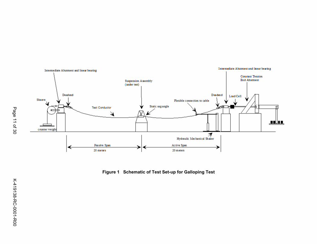
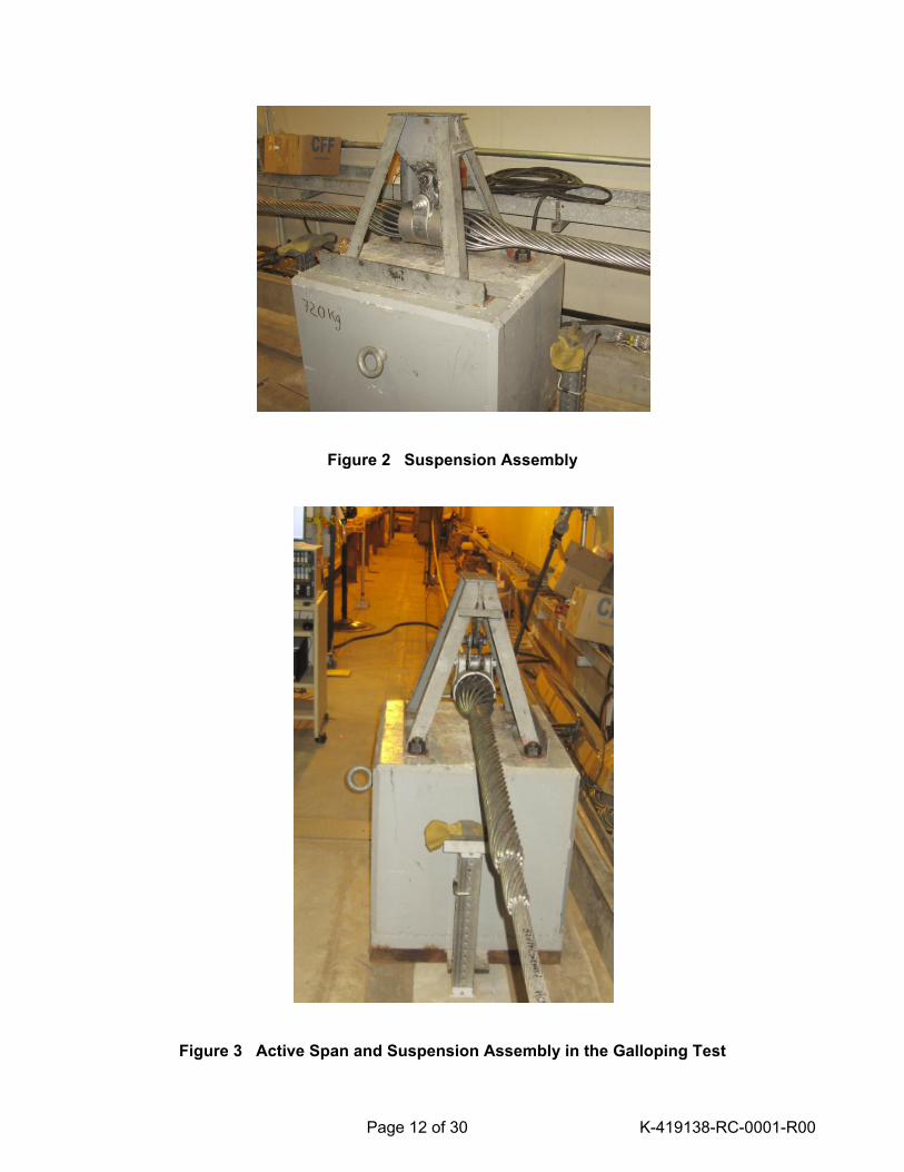
Standard, Paragraph 4.1.1.5/5.1.1.5, and AEP test protocol developed for qualifying High Temperature Low Sag (HTLS) conductors. TEST SET-UP A schematic of the set-up for the Galloping Test is shown in Figure 1. Test Apparatus Upon completion of the Sheave Test, the test conductor ends were terminated using epoxy-resin dead-ends. The dead-end assemblies were located between the intermediate abutments. An ARMOR-GRIP (made by PLP) suspension assembly and armor rods (see Figure 2) were installed in the middle of the conductor span (i.e. where the test conductor was originally pulled over the sheave). The suspension assembly was supported at a height such that the static sag
angle of the conductor to horizontal was less than 1º in the active span. The test section was contained between two intermediate abutments. The active conductor span (see Figure 3) length was 20 m (66 ft) and the passive conductor span length was also 20 m (66 ft) for a total conductor length of 40 m (132 ft) between the dead-end clamps. Fixed end abutments were used to load and maintain tension in the test conductor. The initial target tension was 372 kgf (820 lbf) or 2% of the conductor Rated Tensile Strength or RTS (18,643 kgf or 41,100 lbf). This was applied using a cantilever weight on one of the end abutments and a sheave and counter weight at the other end abutment. The end abutments allowed horizontal motion of the test sample by way of linear bearings. The free loop antinode amplitude was measured at a point midway between the suspension assembly and the dead-end. This was achieved by manually observing a graduated scale supported next to the conductor. The test was carried out in a temperature-controlled laboratory at 20ºC ± 2ºC. Instrumentation and Data Acquisition A load cell was used to measure the conductor tension. A hand-held digital protractor was used to measure the exit angle of the conductor from the suspension clamp. A thermocouple was used to measure the air temperature. The tension, number of cycles and temperature were monitored and recorded every 5 minutes by a digital data logging system. The free loop peak-to-peak antinode amplitude and frequency were recorded manually. The measuring instruments used in this test are listed in Appendix B. TEST PROCEDURE The conductor was subjected to 104,240 galloping cycles in the single loop mode. The free loop peak-to-peak antinode amplitude was maintained at a minimum of about 0.80 m (2.64 ft) or 1/25th of the distance from the dead-end to the suspension clamp length (i.e., 20 m or 66 ft).

Page 10 of 30 K-419138-RC-0001-R00
TEST RESULTS The galloping frequency at the start of the test was 0.92 Hz and varied between 0.89 to 0.92 Hz during the test. The free loop antinode amplitude in the active (driven) span was maintained at 0.75 - 0.8 m. The free loop antinode amplitude in the passive span varied between 0.3 m to 0.4 m during the test. The tension in the conductor fluctuated between 204 - 270 kgf (450 – 595 lbf) as the conductor galloped. Visual Examination After completion of 104,240 cycles, the conductor was visually examined. There were no signs of physical damage to the conductor strands. No breaks, cracks, failure, bird-caging or discoloration of any conductor components was detected. Active Span - There were no visible signs of breaks, cracks, failure or discoloration of
any conductor components. Passive Span - There were no visible signs of breaks, cracks, failure or discoloration of
any conductor components. Suspension - There were no visible signs of breaks, cracks, failure or discoloration of
any conductor components. The ARMOR-GRIP suspension clamp and armor rods also were inspected for signs of breaks or component failure, and no visible mechanical damage was detected on those parts.
Page 11 of 30 K-419138-RC-0001-R00
Figure 1 Schematic of Test Set-up for Galloping Test
Page 11 of 3
0
K-419138-RC-0001-R00
Page 12 of 30 K-419138-RC-0001-R00
Figure 2 Suspension Assembly
Figure 3 Active Span and Suspension Assembly in the Galloping Test

Page 13 of 30 K-419138-RC-0001-R00
ff
KINECTRICS NORTH AMERICA INC. TEST REPORT FOR CTC CABLE CORPORATION
Test Name: AEOLIAN VIBRATION TEST Test Date: September 16 - November 3, 2009 Test Laboratory: Kinectrics North America Inc. 800 Kipling Avenue
Toronto, Ontario, M8Z 6C4 CANADA
Conductor Manufacturer: CTC Cable Corporation Conductor Designation: 1020 kcmil “Drake” ACCC/TW Accessories: Epoxy Resin Dead-end Assembly Suspension Assembly Kinectrics Staff: Mr. Mike Kastelein Witnesses: None TEST INTENT The intent of the Aeolian Vibration Test is to subject “Drake” ACCC/TW to simulate aeolian vibrations caused by laminar wind as it passes over bare conductor. This type of conductor vibration is a common occurrence in the field, and may lead to fatigue damage of the conductor. The Aeolian Vibration Test is the third test in a series of sequential tests pre-conditioning the test conductor for final pull test. TEST STANDARD The test was performed in general accordance with IEEE 1138-1994 “Standard Construction of Composite Fiber Optic Overhead Ground Wire (OPGW) for Use on Electric Utility Power Lines” Standard, Paragraph 4.1.1.5/5.1.1.5, and AEP test protocol developed for qualifying High Temperature Low Sag (HTLS) conductors.

Page 14 of 30 K-419138-RC-0001-R00
TEST SETUP A schematic of the set-up for the Aeolian Vibration Test is shown in Figure 1. The test was performed on the span designated KB019-East. Test Apparatus Upon completion of the Galloping Test, the test conductor was subjected to the Aeolian Vibration Test. The same suspension assembly (which was installed for the Galloping Test, see Figure 2), at the same conductor location, was used in the Aeolian Vibration Test. The suspension assembly was supported at a height such that the static sag angle of the conductor to horizontal was 2.30 degrees in the active span and 2.66 degrees in the passive span. The test conductor ends were terminated using epoxy-resin dead-ends. The dead-end assemblies were located between the intermediate abutments. The active span conductor length was 20.0 m (65.6 ft) and the passive span conductor length was 16.3 m (53.5 ft) for a total conductor length of 36.3 m (119.1 ft) between the dead-end clamps. Fixed end abutments were used to load and maintain tension in the test conductor. The initial target tension of 3,720 kgf (8,200 lbf) was 20% of the conductor's Rated Tensile Strength or RTS (18,643 kgf or 41,100 lbf). This was applied using a cantilever weight on one of the end abutments. The free loop antinode amplitude of the conductor was measured at the first free loop from the suspension assembly towards the shaker. An electronically controlled shaker was used to excite the conductor in the vertical plane. The shaker armature was securely fastened to the conductor so that it was perpendicular to the conductor in the vertical plane. The shaker was located in the span to allow a minimum of six vibration loops between the suspension assembly and the shaker. The test was carried out in a temperature-controlled laboratory at 20ºC ± 2ºC. Instrumentation and Data Acquisition A laser micrometer was used to measure the free loop antinode amplitude. A load cell was used to measure the conductor tension. A hand-held digital protractor was used to measure the exit angle of the conductor from the suspension clamp. A thermocouple was used to measure the air temperature. The peak-to-peak free loop amplitude, vibration frequency, number of cycles, conductor tension and air temperature were recorded every minute by a digital data logging system. The measuring instruments used in this test are listed in Appendix B. TEST PROCEDURE The test conductor was tensioned to approximately 3,720 kgf (8,200 lbf) or 20% of the conductor’s RTS and the exit angles of the conductor from the suspension clamp were measured.

Page 15 of 30 K-419138-RC-0001-R00
The initial target vibration frequency was 29.50 Hz, which is the frequency produced by a 4.5 m/s or 14.8 ft/s wind (i.e., frequency = 830 ÷ diameter of the conductor in mm). The actual vibration frequency was the system resonance nearest to the target frequency that also provided good system stability. The target free loop peak-to-peak antinode amplitude was 14.07 mm (0.554 inch) or one half of the conductor diameter. The amplitude was maintained at this level in the first free loop from the suspension assembly towards the shaker. The amplitudes in the passive span and the section between the shaker and the dead-end in the active span were maintained at levels no greater than one half of the conductor diameter (14.07 mm or 0.554 inch). The test conductor was subjected to 100 million vibration cycles. After the test completion, the test conductor and suspension assembly were visually examined for signs of breaks, cracks, failure or discoloration. TEST RESULTS The average values of all the data recorded are listed in Table 1. The average vibration loop length is the average of the free vibration loops only, excluding the vibration loops next to the dead-ends, shaker, or suspension.
Table 1 Average Values of Key Parameters
Parameter Average Value
Test Conductor Tension 3,746 kgf
Vibration Frequency 31.13 Hz
Peak-to-peak
Amplitude
Active Span 14.03 mm
Passive Span 3.89 mm
Visual Examination After completion of 100 million cycles, the conductor was visually examined (see Figure 3). There were no signs of physical damage to the conductor strands. No breaks, cracks, failure, bird-caging or discoloration of any conductor components was detected. Active Span - There were no visible signs of breaks, cracks, failure or discoloration of
any components of the test conductor. Passive Span - There were no visible signs of breaks, cracks, failure or discoloration of
any components of the test conductor. Suspension - There were no visible signs of breaks, cracks, failure or discoloration of
any components of the test conductor. The ARMOR-GRIP suspension clamp and armor rods also were inspected for signs of breaks or component failure, and no visible mechanical damage was detected on those parts.

Page 16 of 30 K-419138-RC-0001-R00
Figure 1 Schematic of Set-Up for Aeolian Vibration Test
Page 16 of 3
0
K-419138-RC-0001-R00

Page 17 of 30 K-419138-RC-0001-R00
Figure 2 Suspension Assembly
Figure 3 Test Conductor Condition under the Suspension Assembly after Test Completion

Page 18 of 30 K-419138-RC-0001-R00
KINECTRICS NORTH AMERICA INC. TEST REPORT FOR CTC CABLE CORPORATION
Test Name: TENSION CYCLING TEST Test Date: November 5 - 6, 2009 Test Laboratory: Kinectrics North America Inc. 800 Kipling Avenue
Toronto, Ontario, M8Z 6C4 CANADA
Conductor Manufacturer: CTC Cable Corporation Conductor Designation: 1020 kcmil “Drake” ACCC/TW Accessories: Epoxy Resin Dead-end Assembly Kinectrics Staff: Mr. Michael Kastelein Mr. Greg Brown Witnesses: None
TEST INTENT The intent of the Tension Cycling Test is to subject “Drake” ACCC/TW to simulated cyclic tensile loading as the conductor may be exposed to during extreme ice and wind load events. The Tension Cycling Test was the fourth, and last, test performed in a series of pre-conditioning sequential tests prior to the final conductor pull test.
TEST STANDARD The test is performed in accordance with a custom load cycling test procedure developed by AEP.

Page 19 of 30 K-419138-RC-0001-R00
TEST SET-UP
A schematic of the test set-up is shown in Figure 1. Upon completion of the Aeolian Vibration Test, the epoxy resin dead-ends were cut off, suspension assembly removed, and new epoxy-resin dead-ends (Figure 2) were installed on the shortened test conductor. Both epoxy dead-ends were marked with paint to detect conductor slippage during the test. The test conductor was installed in a hydraulically-activated horizontal test machine (see Figure 3). Area of the conductor span where the suspension clamp was placed in the vibration tests, was now located approximately in the middle of the conductor span on the tensile machine bed.
Conductor Description The selected conductor size was 1020 kcmil, “Drake” ACCC/TW, which consists of a single composite glass and carbon fiber core covered by two (2) layers of twenty-two (22) annealed, trapezoidally-shaped aluminum alloy wires. The overall conductor diameter is 28.14 mm (1.108 inch). The total length of the conductor was 13.4 m (43.9 ft). The conductor is designed with a high strength carbon fiber hybrid composite core. The conductor’s Rated Tensile Strength, or RTS, is 18,643 kgf (41,100 lbf). Instrumentation and Data Acquisition The conductor tension was measured by a load cell located at the hydraulic end of the sample (see Figure 4). The signals from the load cell were amplified to provide a 0 to 5 V signal for the data acquisition system. The controller for the hydraulically activated horizontal test machine recorded the peak tension. The test was carried out in a temperature-controlled laboratory at 20ºC ± 2ºC. The conductor tension as measured by the load cell was monitored continuously using a digital data logging system. The measuring instruments used in this test are listed in Appendix B. TEST PROCEDURE Load Cycling (Part A) The test conductor was placed in a hydraulically-activated horizontal test machine and the load cycled between 10% of RTS and 80% of RTS, with 5 minutes holds at 20%, 30%, 40%, 50%, 60%, and 70% of RTS and a minimum of 30 minutes hold at 80% of RTS. At each load increment, the tensile load was gradually increased at the rate of 907 kgf/min (2,000 lbf/min). After each hold period during this initial load cycle only, the tension was reduced to 10% of RTS and the conductor was visually examined for evidence of breaks of any aluminum strands. After examining the conductor, the tension was increased to the previous level and the cycle resumed to the next load increment.

Page 20 of 30 K-419138-RC-0001-R00
This above loading sequence (without the tension reductions and visual examinations) was repeated for four (4) additional cycles with a 3 hour hold at the end of fifth (last) cycle. Detailed Visual Examination (Part B) The conductor sample was visually examined (including the grip fixtures) after completion of the load cycling when the tension was reduced to 10% of RTS. All layers and components of the conductor were inspected for breaks, cracks, or failure. Tension to Failure (Part C) The load was gradually increased at the rate of 454 kgf/min (1,000 lbf/min), and the test sample was tensioned to the breaking point. The maximum force and conductor slippage during the test were recorded. TEST RESULTS Figure 5 shows actual conductor tension plotted against time. Load Cycling and Detailed Visual Examination There were no visible breaks or conductor strands failure detected at the test end. When loading the test conductor to 80% of RTS during the second tension cycle, an epoxy resin dead-end slippage occurred. The load was reduced to zero, and test conductor removed from the tensile machine. Upon careful examination of the conductor condition (see Figure 6 depicting localized conductor bird-caging), it was decided to cut off the failed dead-end, and install a new one. Once epoxy resin was cured in the newly installed dead-end, the test conductor was placed again in the tensile machine to proceed with the load cycling. From this point, there was no conductor slippage from the epoxy resin dead-ends at either end of the conductor during the test. Tension to Failure The conductor aluminum strands failed due to tension overload. The failure occurred approximately 1 m (3.3 ft) away from the area where the sheave and suspension clamp were located in pre-conditioning tests (see Sheave Test, Galloping Test and Aeolian Vibration Test reports). Pictorial view of the failed conductor is shown in Figures 7. Figure 7 shows the conductor’s aluminum strands with the typical ductile “necking” of the strands, which occurs when the material tensile limit is exceeded. The maximum load recorded at the conductor breaking point was 17,409 kgf (38,380 lbf). This load corresponds to 93.6% of the conductor’s RTS. No further slippage was observed at the epoxy dead-ends and no fatigue failures were noted in any of the aluminum strands.

Page 21 of 30 K-419138-RC-0001-R00
Figure 1 Schematic of Set-Up for Tension Cycling Test
Figure 2 Epoxy Resin Dead-End

Page 22 of 30 K-419138-RC-0001-R00
Figure 3 Hydraulically-Activated Horizontal Test Machine
Figure 4 Load Cell Installed at the Hydraulic End of the Conductor

Page 23 of 30 K-419138-RC-0001-R00
Figure 5 Test Conductor Tensile Load Cycling and Tension to Failure Test
Figure 6 Bird-Caging Occurred after Epoxy Dead-end Failure
Figure 7 Magnified View of Conductor Aluminum Strands at Breaking Point
Dead-end
Failure
Conductor Breaking Point

Page 24 of 30 K-419138-RC-0001-R00
APPENDIX A
CONDUCTOR DESCRIPTION
(1020 kcmil “Drake” ACCC/TW Trapezoidal Concentric-Lay-Stranded Conductor)

Page 25 of 30 K-419138-RC-0001-R00

Page 25 of 30 K-419138-RC-0001-R00
ISO-9001 Form: QF11-1 Rev 0, 97-10
APPENDIX B INSTRUMENT SHEET
CTC Cable Corporation
Test Description: SEQUENTIAL MECHANICAL TESTING OF 1020 KCMIL “DRAKE” ACCC/TW CONDUCTOR Test Start Date: September 2, 2009
Project Number: K-419138 Test Finish Date: November 6, 2009
TEST DESCRIPTION
EQUIPMENT DESCRIPTION
MAKE
MODEL ASSET # or
SERIAL # ACCURACY
CLAIMED CALIBRATION
DATE CALIBRATION
DUE DATE TEST USE
Sheave
Load Cell (MTS)
Load Cell Conditioner
Eaton
Daytronic
3124
3170
17952-0
11148-0 #8
±1% of reading
January 4, 2009 January 4, 2010 Conductor Tension
Digital Protractor Mitutoyo Pro 3600 19693-0 0 to -0.1 degree February 21, 2009 February 21, 2010 Conductor Angle
Digital Caliper
Mitutoyo 500-130 0-6 inches
10067-0 ±0.025 mm March 18, 2009 March 18, 2010 Conductor Diameter
Measuring Tape Stanley FatMax (34-813) KIN-00723 < 0.05% of Reading
October 2, 2008 October 2, 2010 Conductor Length
Tension Cycling
A/D Board National
Instruments PCI-6034E CCC745 ±0.1% of reading June 25, 2009 June 25, 2010
Data Acquisition
Load Cell (MTS)
Conditioner
Lebow
MTS
3156 (100,000 lbs)
493.01DC
17356-0
10000686-0
±1% of Reading
May 29, 2009 May 29, 2010 Conductor Tension
Measuring Tape Mastercraft 57-7190-0 KIN-00314 < 0.1% of Reading
February 5, 2009 February 5, 2010 Conductor Length
Page 26 of 3
0
K-419138-RC-0001-R00

Page 25 of 30 K-419138-RC-0001-R00
Aeolian Vibration
Load Cell
Conditioner
Interface
Daytronics
1020AF-50KN-B
(5000 kg)
3170
12505-0
#16
10717-0
±1% of Full Scale
May 29, 2009 May 29, 2010 Conductor Tension
A/D Datalogger
National Instruments
PCI-6034E KIN-00232 F ±0.1% of Reading
May 5, 2009 May 5, 2010 Data
Acquisition
Digital Protractor Mitutoyo Pro 3600 19693-0 0 to -0.1 degree February 21, 2009 February 21, 2010 Conductor Angle
V-Scope PLP not available KIN-00970 #2 see cal sheet July 6, 2009 July 6, 2010 Conductor Amplitude
Measuring Tape Mastercraft 57-7190-0 KIN-00314 < 0.1% of Reading
February 5, 2009 February 5, 2010 Conductor Length
Galloping
Data Logger National
Instruments PCI6034E CCC745 ±0.1% of reading June 25, 2009 June 25, 2010
Data Acquisition
Measuring Tape Mastercraft 57-7190-0 KIN-00314 < 0.1% of Reading
February 5, 2009 February 5, 2010 Conductor Length
Load Cell
Load Cell Conditioner
Straincert
Daytronics
TSN-10
3170
19679-0
19678-0
±1.0% of reading February 4, 2009 February 4, 2010 Conductor Tension
Digital Protractor Mitutoyo Pro 3600 19693-0 0 to -0.1 degree February 21, 2009 February 21, 2010 Conductor Angle
Page 27 of 3
0
K-419138-RC-0001-R00

Page 28 of 30 K-419138-RC-0001-R00
APPENDIX C
KINECTRICS ISO 9001 QUALITY MANAGEMENT SYSTEM REGISTRATION CERTICATE

Page 29 of 30 K-419138-RC-0001-R00

Page 30 of 30 K-419138-RC-0001-R00
DISTRIBUTION Mr. Dave Bryant (3) CTC Cable Corporation
2026 McGaw Avenue Irvine, CA 92614 USA
Mr. Zsolt Peter (1) Kinectrics North America Inc., Unit 2
800 Kipling Ave, KB 223 Toronto, Ontario
M8Z 6C4 Canada