to the expe - managemylife.com · the 48ez-a unit (see fig. 1) is a fully self-contained,...
TRANSCRIPT
Installation Instructions
to the expe_
NOTE: Read the entire instruction manual before starting the
installation.
NOTE: Installer: Make sure the Owner's Manual and Service
Instructions are left with the unit after installation.
TABLE OF CONTENTSPAGE
SAFETY CONSIDERATIONS ....................... 1-2
INTRODUCTION ................................... 2
RECEIVING AND INSTALLATION ................. 2-13
Check Equipment .................................. 2
Identify Unit .................................... 2
Inspect Shipment ................................. 2
Provide Unit Support ............................... 2Roof Curb ...................................... 2
Slab Mount ..................................... 2
Field Fabricate Ductwork ............................ 6
Provide Clearances ................................. 6
Rig and Place Unit ................................. 6Connect Condensate Drain ........................... 7
Install Flue Hood ................................... 7
Install Gas Piping .................................. 7Install Duct Connections ............................. 9
Configuring Units for Downflow (Vertical)
Discharge ...................................... 9Install Electrical Connections ........................ 12
High-Voltage Connections ........................ 12
Special Procedures for 208-V Operation .............. 12
Control Voltage Connections ....................... 13
Balance Point Setting Thermidistat or Hybrid HeatThermostat .................................... 13
Transformer Protection ........................... 13
PRE-START-UP ................................ 13-14
START-UP ..................................... 14-17
Check for Refrigerant Leaks ......................... 14
Unit Sequence of Operation ......................... 14
Start-Up Heating and Make Adjustments ............... 14
Checking Heating Control ......................... 14
Check Gas Input ................................ 15
Adjust Gas Input ................................ 15Check Burner Flame ............................. 16
Start-Up Cooling and Make Adjustments ............... 16
Checking Cooling Control Operation ................ 16
Checking and Adjusting Refrigerant ................. 17
Indoor Airflow and Airflow Adjustments ............. 17MAINTENANCE ................................ 32-38
Air Filter ........................................ 32
Indoor Blower and Motor ........................... 32
Flue Gas Passageways .............................. 33Limit Switch ..................................... 33
Burner Ignition ................................... 33Main Burners .................................... 33
Outdoor Coil, Indoor Coil, & Condensate Drain Pan ...... 33Outdoor Fan ..................................... 34
Electrical Controls and Wiring ....................... 34
Refrigerant Circuit ................................. 34
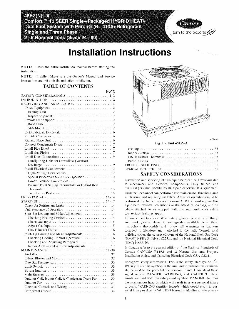
A09034
Fig. 1 - Unit 48EZ-A
Gas Input ........................................ 35Indoor Airflow ................................... 35
Check Defrost Thermostat ........................... 35
Puron® Items .................................... 35
TROUBLESHOOTING .............................. 38
START-UP CHECKLIST ............................ 38
SAFETY CONSIDERATIONS
Installation and servicing of this equipment can be hazardous due
to mechanical and electrical components. Only trained and
qualified personnel should install, repair, or service this equipment.
Untrained personnel can perform basic maintenance functions such
as cleaning and replacing air filters. All other operations must be
performed by trained service personnel. When working on this
equipment, observe precautions in the literature, on tags, and on
labels attached to or shipped with the unit and other safety
precautions that may apply.
Follow all safety codes. Wear safety glasses, protective clothing,
and work gloves. Have fire extinguisher available. Read these
instructions thoroughly and follow all warnings or cautionsincluded in literature and attached to the unit. Consult local
building codes, the current editions of the National Fuel Gas Code
(NFGC) NFPA 54/ANSI Z223.1, and the National Electrical Code
(NEC) NFPA 70.
In Canada refer to the current editions of the National Standards of
Canada CAN/CSA-BI49.1 and .2 Natural Gas and Propane
Installation codes, and Canadian Electrical Code CSA C22.1.
Recognize safety information. This is the safety-alert symbol Z_.
When you see this symbol on the unit and in instructions or manu-
als, be alert to the potential for personal iniury. Understand these
signal words: DANGER, WARNING, and CAUTION. These
words are used with the safety-alert symbol. DANGER identifies
the most serious hazards which will result in severe personal iniury
or death. WARNING signifies hazards which could result in per-
sonal iniury or death. CAUTION is used to identify unsafe practic-
eswhichmayresultinminorpersonalinjuryorproductandprop-ertydamage.NOTEisusedtohighlightsuggestionswhichwillresult in enhanced installation, reliability, or operation.
ELECTRICALSHOCK HAZARD
Failure to follow this warning could result in personal
injury or death.
Before installing or servicing system, always turn off main
power to system and install lockout tag. There may be
more than one disconnect switch. Turn off accessory heater
power switch if applicable.
FIRE, EXPLOSION, ELECTRICAL SHOCK ANDCARBON MONOXIDE POISONING HAZARD
Failure to follow this warning could result in personal
injury, death or property damage.
A qualified installer or agency must use only
factory-authorized kits or accessories when modifying this
product.
CUT HAZARD
Failure to follow this caution may result in personal iniury.
When removing access panels (see Fig. 18) or performingmaintenance functions inside your unit, be aware of sharp
sheet metal parts and screws. Although special care is taken
to reduce sharp edges to a minimum, be extremely careful
when handling parts or reaching into the unit.
INTRODUCTION
The 48EZ-A unit (see Fig. 1) is a fully self-contained,
combination Category I gas heating/electric heating and cooling
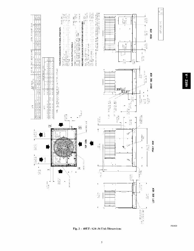
unit designed for outdoor installation (See Fig. 2 and 3 for unit
dimensions). All unit sizes have return and discharge openings for
both horizontal and downflow configurations, and are factory
shipped with all downflow duct openings covered. Units may be
installed either on a rooftop, or on a cement slab (See Fig. 4 for
roof curb dimensions).
In gas heating mode, this unit is designed for a minimum
continuous return-air temperature of 55°F (13°C) db and a
maximum continuous return-air temperature of 80°F (27 °C) db.
Failure to follow these return-air temperature limits may affect
reliability of heat exchangers, motors, and other components.
Models with an N in the fifth position of the model number are
dedicated Low NOx units designed for California installations.
These models meet the California maximum oxides of nitrogen
(NOx) emissions requirements of 40 nanograms/joule or less as
shipped from the factory and must be installed in California Air
Quality Management Districts or any other regions in NorthAmerica where a Low NOx rule exists.
RECEIVING AND INSTALLATION
Step 1 -- Check EquipmentIDENTIFY UNIT
The unit model number and serial number are stamped on the unit
information plate. Check this information against shipping papers.
INSPECT SHIPMENT
Inspect for shipping damage before removing packaging materials.
If unit appears to be damaged or is torn loose from its anchorage,
have it examined by transportation inspectors before removal.
Forward claim papers directly to transportation company.
Manufacturer is not responsible for any damage incurred in transit.
Check all items against shipping list. Immediately notify the
nearest equipment distribution office if any item is missing. To
prevent loss or damage, leave all parts in original packages untilinstallation.
If the unit is to be mounted on a curb in a downflow application,
review Step 9 to deternfine which method is to be used to remove
the downflow panels before rigging and lifting into place. The
panel removal process may require the unit to be on the ground.
Step 2 -- Provide Unit Support
For hurricane tie downs, contact distributor for details and PE(Professional Engineering) Certificate if required.ROOF CURB
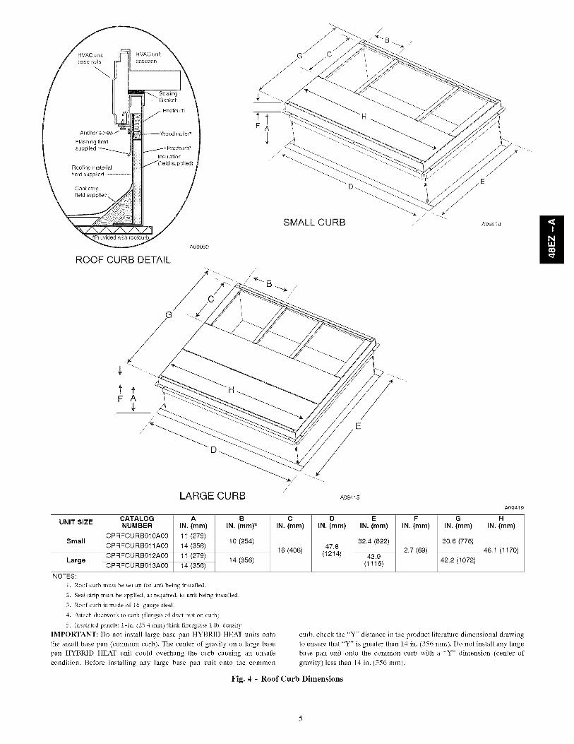
Install accessory roof curb in accordance with instructions shippedwith curb (See Fig. 4). Install insulation, cant strips, roofing, andflashing. Ductwork must be attached to curb.
IMPORTANT: The gasketing of the unit to the roof curb iscritical for a water tight seal. Install gasketing material suppliedwith the roof curb. Improperly applied gasketing also can result inair leaks and poor unit performance.
Curb should be level to within 1/4 in. (6 mm). This is necessary forunit drain to function properly. Refer to accessory roof curbinstallation instructions for additional information as required.Installation on older "G" series roof curbs.
Two accessory kits are available to aid in installing a new "G"series unit on an old "G" roof curb.
1. Accessory kit number CPADCURB001A00, (small chassis)and accessory kit number CPADCURB002A00, (largechassis) includes roof curb adapter and gaskets for theperimeter seal and duct openings. No additionalmodifications to the curb are required when using this kit.
2. An alternative to the adapter curb is to modify the existingcurb by removing the outer horizontal flange and useaccessory kit number CPGSKTKIT001A00 which includesspacer blocks (for easy alignment to existing curb) andgaskets for the perimeter seal and duct openings. This kit isused when existing curb is modified by removing outerhorizontal flange.
UNIT/STRUCTURAL DAMAGE HAZARD
Failure to follow this caution may result in propertydamage.
Ensure there is sufficient clearance for saw blade whencutting the outer horizontal flange of the roof curb so thereis no damage to the roof or flashing.
SLAB MOUNT
Place the unit on a solid, level concrete pad that is a minimum of 4
in. (102 mm) thick with 2 in. (51 mm) above grade. The slab
should be flush on the compressor end of the unit (to allow
condensate drain installation) and should extend 2 in. (51 mm) on
the three remaining sides of the unit. Do not secure the unit to the
slab except when required by local codes.
Ducts passing through an unconditioned space must be insulated
and covered with a vapor barrier.
m
0
-- I
-+- 1
_E
i°
Fig. 2 - 48EZ-A24-36 Unit Dimensions
>
0c)
A09450
I!
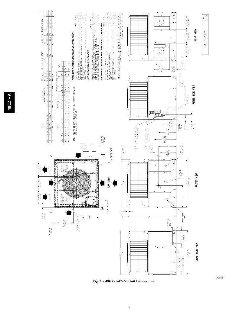
Fig. 3 - 48EZ-A42-60 Unit Dimensions
<B>
oo
A09451
HVACunit I
base rails
Anchor screw -/
Flashing fieldsupplied _
Gasket
j Roofcurb
Wood nailer*
/ Roofcurb*Insulation
/(field supplied)Roofingmaterial
field supplied
Cant strip _/ J
/A09090
ROOF CURB DETAIL
SMALL CURB A09418 I!
F A
E
LARGE CURB A09415
UNIT SIZE
Small
Large
NOTES:
CATALOGNUMBER
CPRFCURB010A00
CPRFCURB011A00
CPRFCURB012A00
CPRFCURB013A00
A
IN. (mm)
11 (279)
14 (356)
11 (279)
14 (356)
B C D F
IN. (mm)* IN. (mm) IN. (mm) IN. (mm)
10 (254)
14 (356)
1. Roof curb must be set up for unit being installed.
2. Seal strip must be applied, as required, to unit being installed.
3. Roof curb is made of 1d-gauge steel.
4. Attach ductwork to curb (flanges of duct rest on curb).
5. Insulated panels: 1-in. (25.4 mm) thick fiberglass 1 lb. density.
IMPORTANT: Do not install large base pan HYBRID HEAT units onto
the small base pan (common curb). The center of gravity on a large base
pan HYBRID HEAT unit could overhang the curb causing an unsafe
condition. Before installing any large base pan unit onto the common
16 (406)47.8
(1214)
E
IN. (mm)
32.4 (822)
43.9
(1116)
2.7 (69)
A09419
G H
IN. (mm) IN. (mm)
30.6 (778)
46.1 (1170)
42.2 (1072)
curb. check the "Y" distance in the product literature dimensional drawing
to ensure that "Y" is greater than 14 in. (356 mm). Do not install any large
base pan unit onto the common curb with a "Y" dimension (center of
gravity) less than 14 in. (356 mm).
Fig. 4 - Roof Curb Dimensions
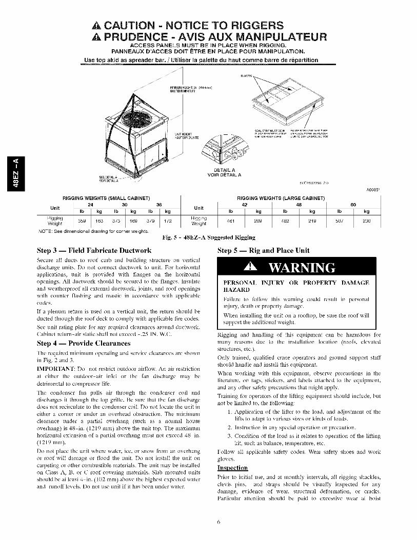
CAUTION - NOTICE TO RIGGERSPRUDENCE - AVIS AUX MANIPULATEUR
ACCESS PANELS MUST BE iN PLACE WHEN RiGGiNG.PANNEAUX D'ACCES DOff F:TRE EN PLACE POUR MANiPULATiON.
Use top skid as spreader bar. / Utiliser la palette du haut comme barre de repartition
J MINIMUM HEIGHT: 36" (914.4 mm)_/ HAUTEUR MINIMUM
I!UNIT HEIGHTHAUTEURD UNITE
///
SEAL STRIP MUST SE IN 8ANOE S CELLANT DOlT ETRE
pLACE SEFORE pLAClN6 EN PL._CE AVANT OE PLACERUNIT ON ROOF CURS L UNITE SUR LA _ASE DE TOIT
DETAIL AVOIR DETAIL A
V01R DETAILA /50CY502286 2.0
A09051
RIGGING WEIGHTS (SMALL CABINET) RIGGING WEIGHTS (LARGE CABINET)
24 30 36 42 48 60
Unit Ib kg Ib kg Ib kg Unit 2_1 :: 2_2 ::9 ]_7 k::oRiggingweight 359 163 373 169 379 172 Riggingweight
NOTE: See dimensional drawing for corner weights.
Fig. 5 - 48EZ-A Suggested Rigging
Step 3 -- Field Fabricate Ductwork
Secure all ducts to roof curb and building structure on verticaldischarge units. Do not connect ductwork to unit. For horizontalapplications, unit is provided with flanges on the horizontalopenings. All ductwork should be secured to the flanges. Insulateand weatherproof all external ductworL joints, and roof openingswith counter flashing and mastic in accordance with applicablecodes.
If a plenum return is used on a vertical unit, the return should beducted through the roof deck to comply with applicable fire codes.
See unit rating plate for any required clearances around ductwork.Cabinet return-air static shall not exceed -.25 IN. W.C.
Step 4 -- Provide Clearances
The required minimum operating and service clearances are shownin Fig. 2 and 3.IMPORTANT: Do not restrict outdoor airflow. An air restriction
at either the outdoor-air inlet or the fan discharge may bedetrimental to compressor life.
The condenser fan pulls air through the condenser coil anddischarges it through the top grille. Be sure that the fan dischargedoes not recirculate to the condenser coil. Do not locate the unit ineither a corner or under an overhead obstruction. The minimum
clearance under a partial overhang (such as a normal houseoverhang) is 48-in. (1219 mm) above the unit top. The maximumhorizontal extension of a partial overhang must not exceed 48-in.(1219 mm).
Do not place the unit where water, ice, or snow from an overhangor roof will damage or flood the unit. Do not install the unit oncarpeting or other combustible materials. The unit may be installedon Class A, B, or C roof covering materials. Slab mounted unitsshould be at least 4-in. (102 mm) above the highest expected waterand runoff levels. Do not use unit if it has been under water.
Step 5 -- Rig and Place Unit
PERSONAL INJURY OR PROPERTY DAMAGEHAZARD
Failure to follow this warning could result in personaliniury, death or property damage.
When installing the unit on a rooftop, be sure the roof willsupport the additional weight.
Rigging and handling of this equipment can be hazardous formany reasons due to the installation location (roofs, elevatedstructures, etc.).
Only trained, qualified crane operators and ground support staffshould handle and install this equipment.
When working with this equipment, observe precautions in theliterature, on tags, stickers, and labels attached to the equipment,and any other safety precautions that might apply.
Training for operators of the lifting equipment should include, butnot be limited to, the following:
1. Application of the lifter to the load, and adjustment of thelifts to adapt to various sizes or kinds of loads.
2. Instruction in any special operation or precaution.
3. Condition of the load as it relates to operation of the liftingkit, such as balance, temperature, etc.
Follow all applicable safety codes. Wear safety shoes and workgloves.
Inspection
Prior to initial use, and at monthly intervals, all rigging shackles,clevis pins, and straps should be visually inspected for anydamage, evidence of wear, structural deformation, or cracks.Particular attention should be paid to excessive wear at hoist
hooking points and load support areas. Materials showing any kind
of wear in these areas must not be used and should be discarded.
UNIT FALLING HAZARD
Failure to follow this warning could result in personal
iniury or death.
Never stand beneath rigged units or lift over people.
PROPERTY DAMAGE HAZARD
Failure to follow this warning could result in personal
iniury/death or property damage.
When straps are taut, the clevis should be a minimum of 36
in. (914 mm) above the unit top cover.
Riu_inu/Liftinu of Unit (See Fire 51
Lifting holes are provided in base rails as shown in Fig. 2 and 3.
1. Leave top shipping skid on the unit for use as a spreader bar
to prevent the rigging straps from damaging the unit. If the
skid is not available, use a spreader bar of sufficient length
to protect the unit from damage.
2. Attach shackles, clevis pins, and straps to the base rails of
the unit. Be sure materials are rated to hold the weight of the
unit (See Fig. 5).
3. Attach a clevis of sufficient strength in the middle of the
straps. Adjust the clevis location to ensure unit is lifted level
with the ground.
After the unit is placed on the roof curb or mounting pad, remove
the top skid.
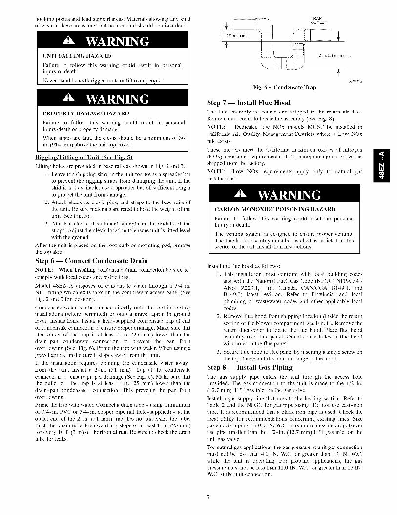
Step 6 -- Connect Condensate Drain
NOTE: When installing condensate drain connection be sure to
comply with local codes and restrictions.
Model 48EZ-A disposes of condensate water through a 3/4 in.
NPT fitting which exits through the compressor access panel (See
Fig. 2 and 3 for location).
Condensate water can be drained directly onto the roof in rooftop
installations (where permitted) or onto a gravel apron in ground
level installations. Install a field-supplied condensate trap at end
of condensate connection to ensure proper drainage. Make sure that
the outlet of the trap is at least 1 in. (25 mm) lower than the
drain-pan condensate connection to prevent the pan from
overflowing (See Fig. 6). Prime the trap with water. When using a
gravel apron, make sure it slopes away from the unit.
If the installation requires draining the condensate water away
from the unit, install a 2-in. (51 mm) trap at the condensate
connection to ensure proper drainage (See Fig. 6). Make sure that
the outlet of the trap is at least 1 in. (25 mm) lower than the
drain-pan condensate connection. This prevents the pan from
overflowing.
Prime the trap with water. Connect a drain tube - using a minimum
of 3/4-in. PVC or 3/4-in. copper pipe (all field-supplied) - at the
outlet end of the 2-in. (51 mm) trap. Do not undersize the tube.
Pitch the drain tube downward at a slope of at least l-in. (25 mm)
for every 10 ft (3 m) of horizontal run. Be sure to check the draintube for leaks.
l-in. (25 mm) min.
TRAP
t OUTLET
--! _L
A09052
Fig. 6 - Condensate Trap
Step 7 -- Install Flue Hood
The flue assembly is secured and shipped in the return air duct.
Remove duct cover to locate the assembly (See Fig. 8).
NOTE: Dedicated low NOx models MUST be installed in
California Air Quality Management Districts where a Low NOxrule exists.
These models meet the California maximum oxides of nitrogen
(NOx) emissions requirements of 40 nanograms/joule or less asshipped from the factory.
NOTE: Low NOx requirements apply only to natural gasinstallations.
CARBON MONOXIDE POISONING HAZARD
Failure to follow this warning could result in personal
iniury or death.
The venting system is designed to ensure proper venting.
The flue hood assembly must be installed as indicted in thissection of the unit installation instructions.
Install the flue hood as follows:
1. This installation must conform with local building codes
and with the National Fuel Gas Code (NFGC) NFPA 54 /
ANSI Z223.1, (in Canada, CAN/CGA B149.1, and
B149.2) latest revision. Refer to Provincial and local
plumbing or wastewater codes and other applicable localcodes.
2. Remove flue hood from shipping location (inside the return
section of the blower compartment-see Fig. 8). Remove thereturn duct cover to locate the flue hood. Place flue hood
assembly over flue panel. Orient screw holes in flue hood
with holes in the flue panel.
3. Secure flue hood to flue panel by inserting a single screw on
the top flange and the bottom flange of the hood.
Step 8 -- Install Gas Piping
The gas supply pipe enters the unit through the access hole
provided. The gas connection to the unit is made to the l/2-in.
(12.7 mm) FPT gas inlet on the gas valve.
Install a gas supply line that runs to the heating section. Refer toTable 2 and the NFGC for gas pipe sizing. Do not use cast-iron
pipe. It is recommended that a black iron pipe is used. Check the
local utility for recommendations concerning existing lines. Size
gas supply piping for 0.5 IN. W.C. maximum pressure drop. Never
use pipe smaller than the l/2-in. (12.7 mm) FPT gas inlet on the
unit gas valve.
For natural gas applications, the gas pressure at unit gas connection
must not be less than 4.0 IN. W.C. or greater than 13 IN. W.C.
while the unit is operating. For propane applications, the gas
pressure must not be less than 11.0 IN. W.C. or greater than 13 IN.W.C. at the unit connection.

A1/8-in.(3.2ram)NPTpluggedtapping, accessible for test gauge
connection, nmst be installed immediately upstream of the gas
supply connection to the gas valve.
When installing the gas supply line, observe local codes pertaining
to gas pipe installations. Refer to the NFGC NFPA 54/ANSI
Z223.1 latest edition (in Canada, CAN/CGA B149.1).
NOTE: In the state of Massachusetts:
1. Gas supply connections MUST be performed by a licensed
plumber or gas fitter.
2. When flexible connectors are used, the maximum length
shall not exceed 36 in. (915 ram).
3. When lever handle type manual equipment shutoff valves
are used, they shall be T-handle valves.
4. The use of copper tubing for gas piping is NOT approved
by the state of Massachusetts.
In the absence of local building codes, adhere to the following
pertinent recommendations:
1. Avoid low spots in long runs of pipe. Grade all pipe 1/4 in.
(6.35 ram) for every 15 ft (4.6 m) of length to prevent traps.Grade all horizontal runs downward to risers. Use risers to
connect to heating section and to meter.
2. Protect all segments of piping system against physical and
thermal damage. Support all piping with appropriate straps,
hangers, etc. Use a minimum of one hanger every 6 ft (1.8
m). For pipe sizes larger than 1/2 in., (12.7 ram) followrecommendations of national codes.
3. Apply joint compound (pipe dope) sparingly and only to
male threads of joint when making pipe connections. Use
only pipe dope that is resistant to action of liquedfied
petroleum gases as specified by local and/or national codes.
Never use Teflon tape.
4. Install sediment trap in riser leading to heating section (See
Fig. 7). This drip leg functions as a trap for dirt andcondensate.
5. Install an accessible, external, manual main shutoff valve in
gas supply pipe within 6 ft (1.8 m) of heating section.
6. Install ground-joint union close to heating section betweenunit manual shutoff and external manual main shut-off
valve.
7. Pressure test all gas piping in accordance with local and
national plumbing and gas codes before connecting pipingto unit.
NOTE: Pressure test the gas supply system after the gas supply
piping is connected to the gas valve. The supply piping nmst be
disconnected from the gas valve during the testing of the piping
systems when test pressure is in excess of 0.5 psig. Pressure test the
gas supply piping system at pressures equal to or less than 0.5 psig.
The unit heating section nmst be isolated from the gas piping
system by closing the external main manual shutoff valve and
slightly opening the ground-joint union.
FIRE OR EXPLOSION HAZARD
Failure to follow this warning could result in personal iniury,
death and/or property damage.
-Connect gas pipe to unit using a backup wrench to avoid
damaging gas controls.
-Never purge a gas line into a combustion chamber. Never
test for gas leaks with an open flame. Use a commercially
available soap solution made specifically for the detection ofleaks to check all connections.
-Use proper length of pipe to avoid stress on gas controlmanifold.
-If a flexible connector is required or allowed by authority
having jurisdiction, black iron pipe shall be installed at
furnace gas valve and extend a nfininmm of 2 in. (51 ram)
outside furnace casing.
-If codes allow a flexible connector, always use a new
connector. Do not use a connector which has previouslyserviced another gas appliance.
8. Check for gas leaks at the field-installed and
factory-installed gas lines after all piping connections have
been completed. Use a commercially available soap solution
made specifically for the detection of leaks (or method
specified by local codes and/or regulations).
IN
TEE
NIPPLE
CAP
Fig. 7 - Sediment Trap
C99020
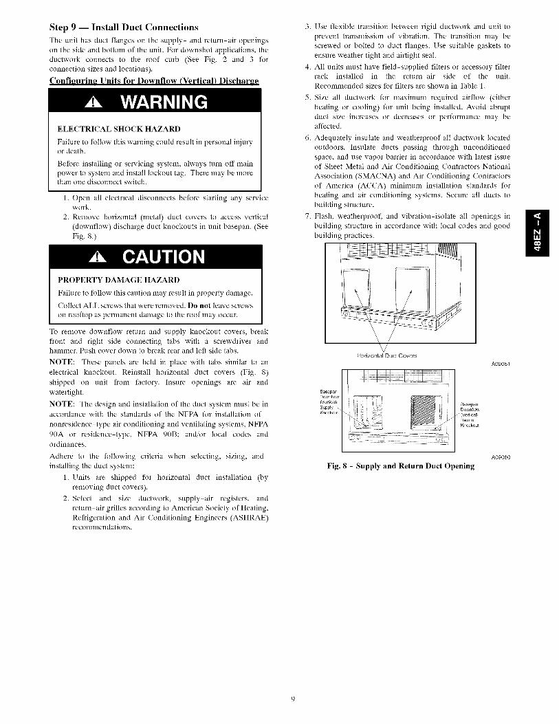
Step 9 -- Install Duct Connections
The unit has duct flanges on the supply- and return-air openings
on the side and bottom of the unit. For downshot applications, the
ductwork connects to the roof curb (See Fig. 2 and 3 for
connection sizes and locations).
Configuring Units for Downflow (Vertical) Discharge
ELECTRICALSHOCK HAZARD
Failure to follow this warning could result in personal injuryor death.
Before installing or servicing system, always turn off main
power to system and install lockout tag. There may be morethan one disconnect switch.
1. Open all electrical disconnects before starting any servicework.
2. Remove horizontal (metal) duct covers to access vertical
(downflow) discharge duct knockouts in unit basepan. (See
Fig. 8 0
PROPERTY DAMAGE HAZARD
Failure to follow this caution may result in property damage.
Collect ALL screws that were removed, Do not leave screws
on rooftop as permanent damage to the roof may occur.
To remove downflow return and supply knockout covers, break
front and right side connecting tabs with a screwdriver andhammer. Push cover down to break rear and left side tabs.
NOTE: These panels are held in place with tabs similar to an
electrical knockout. Reinstall horizontal duct covers (Fig. 8)
shipped on unit from factory. Insure openings are air and
watertight.
NOTE: The design and installation of the duct system must be in
accordance with the standards of the NFPA for installation of
nonresidence-type air conditioning and ventilating systems, NFPA
90A or residence-type, NFPA 90B; and/or local codes and
ordinances.
Adhere to the following criteria when selecting, sizing, and
installing the duct system:
1. Units are shipped for horizontal duct installation (by
removing duct covers).
2. Select and size ductwork, supply-air registers, and
return-air grilles according to American Society of Heating,
Refrigeration and Air Conditioning Engineers (ASHRAE)recommendations.
3.
4.
5.
7.
Use flexible transition between rigid ductwork and unit to
prevent transmission of vibration. The transition may be
screwed or bolted to duct flanges. Use suitable gaskets to
ensure weather tight and airtight seal.
All units must have field-supplied filters or accessory filterrack installed in the return-air side of the unit.
Recommended sizes for filters are shown in Table 1.
Size all ductwork for maximum required airflow (either
heating or cooling) for unit being installed. Avoid abrupt
duct size increases or decreases or performance may beaffected.
Adequately insulate and weatherproof all ductwork located
outdoors. Insulate ducts passing through unconditioned
space, and use vapor barrier in accordance with latest issue
of Sheet Metal and Air Conditioning Contractors National
Association (SMACNA) and Air Conditioning Contractors
of America (ACCA) minimum installation standards for
heating and air conditioning systems. Secure all ducts to
building structure.
Flash, weatherproof, and vibration-isolate all openings in
building structure in accordance with local codes and good
building )ractices.
Horizontal Duct Covers
A09061
BasepanDownflow
_e_ical)
SupplyBasepan
Downflow
Return
Knockout
Fig. 8 - Supply and Return Duct Opening
A09060
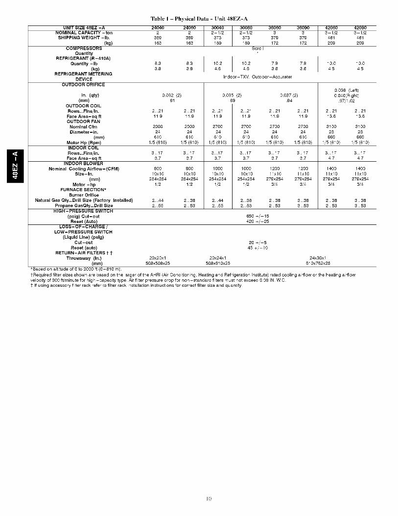
Table 1 - Physical Data - Unit 48EZ-A
UNIT SIZE 48EZ -A 24040 24060 30040 30060 36060 36090 42060 42090
NOMINAL CAPACITY -ton 2 2 2-1/2 2-1/2 3 3 3-1/2 3-1/2SHIPPING WEIGHT -lb. 359 359 373 373 379 379 461 461
(kg) 163 163 169 169 172 172 209 209COMPRESSORS Scroll
Quantity 1REFRIGERANT (R-410A)
Quantity -Ib 8.3 8.3 10.2 10.2 7.9 7.9 10.0 10.0(kg) 3.8 3.8 4.6 4.6 3.6 3.6 4.5 4.5
REFRIGERANT METERINGDEVICE Indoor-TXV, Outdoor-Accurater
OUTDOOR ORIFICE
0.038 (Left)in. (qty) 0.032 (2) 0.035 (2) 0.037 (2) 0.040(Right)
(mm) .81 .89 .94 .97/1.02OUTDOOR COIL
Rows...Fins/in. 2...21 2...21 2...21 2...21 2...21 2...21 2...21 2...21
Face Area-sq ft 11.9 11.9 11.9 11.9 11.9 11.9 13.6 13.6OUTDOOR FAN
Nominal Cfm 2000 2000 2700 2700 2700 2700 3100 3100Diameter- in. 24 24 24 24 24 24 26 26
(mm) 610 610 610 610 610 610 660 660Motor Hp (Rpm) 1/5 (810) 1/5 (810) 1/5 (810) 1/5 (810) 1/5 (810) 1/5 (810) 1/5 (810) 1/5 (810)INDOOR COILRows...Fins/in. 3...17 3...17 3...17 3...17 3...17 3...17 3...17 3...17
Face Area-sq ft 3.7 3.7 3.7 3.7 3.7 3.7 4.7 4.7INDOOR BLOWER
Nominal Cooling Airflow-(CFM) 800 800 1000 1000 1200 1200 1400 1400Size-in. 10x10 10x10 10x10 10x10 1lx10 1lx10 1lx10 1lx10
(mm) 254x254 254x254 254x254 254x254 279x254 279x254 279x254 279x254Motor - hp 1/2 1/2 1/2 1/2 3/4 3/4 3/4 3/4
FURNACE SECTION*Burner Orifice
Natural Gas Qty...Drill Size (Factory Installed) 2...44 2...38 2...44 2...38 2...38 3...38 2...38 3...38Propane GasQty...Drill Size 2...55 2...53 2...55 2...53 2...53 3...53 2...53 3...53
HIGH-PRESSURE SWITCH
(psig) Cut-out 650 +/-15Reset (Auto) 420 +/-25
LOSS-OF-CHARGE /LOW- PRESSURE SWITCH
(Liquid Line) (psig)Cut-out 20 +/-5
Reset (auto) 45 +/-10RETURN-AIR FILTERS t $
Throwaway (in.) 20x20x1 20x24x1 24x30x1(mm) 508x508x25 508x610x25 610x762x25
*Based on altitude of 0 to 2000 ft (0-610 m).
1-Required filter sizes shown are based on the larger of the AHRI (Air Conditioning, Heating and Refrigeration Institute) rated cooling airflow or the heating airflowvelocity of 300 if/minute for high-capacity type. Air filter pressure drop for non-standard filters must not exceed 0.08 IN. W.C.:l: If using accessory filter rack refer to filter rack installation instructions for correct filter size and quantity.
10
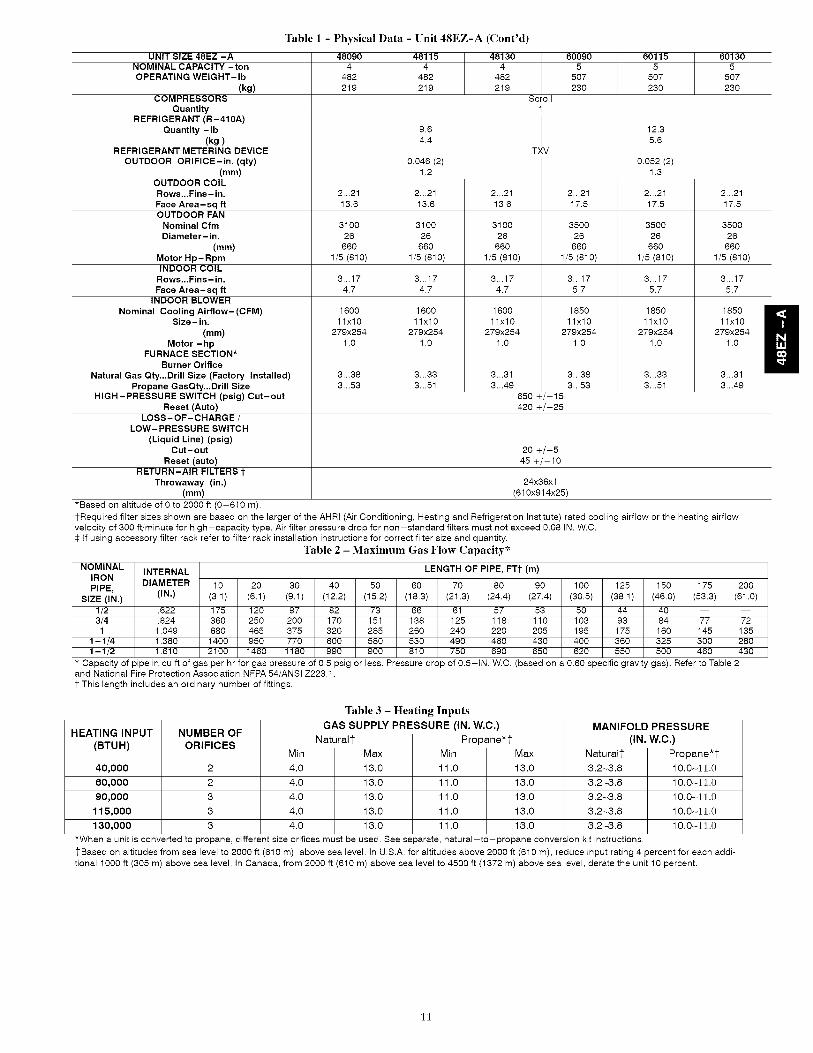
Table 1 - Physical Data - Unit 48EZ-A (Cont'd)
48090 48115 481304 4 4
482 482 482219 219 219
Scroll
UNIT SIZE 48EZ -ANOMINAL CAPACITY -tonOPERATING WEIGHT-Ib
(kg)COMPRESSORS
QuantityREFRIGERANT (R-410A)
Quantity -Ib(kg)
REFRIGERANT METERING DEVICE
OUTDOOR ORIFICE-in. (qty)(mm)
OUTDOOR COIL
Rows...Fins- in.
Face Area-sq ftOUTDOOR FAN
Nominal CfmDiameter- in.
(me)Motor Hp- RpmINDOOR COIL
Rows...Fins- in.
Face Area-sq ftINDOOR BLOWER
Nominal Cooling Airflow-(CFM)Size-in.
(me)Motor - hp
FURNACE SECTION*Burner Orifice
Natural Gas Qty...Drill Size (Factory Installed)
Propane GasQty...Drill SizeHIGH-PRESSURE SWITCH (psig) Cut-out
Reset (Auto)LOSS-OF-CHARGE /
LOW- PRESSURE SWITCH
(Liquid Line) (psig)Cut-out
Reset (auto)RETURN-AIR FILTERS t
Throwaway (in.)(mm)
60090 60115 601305 5 5
507 507 507230 230 230
9.6 12.34.4 5.6
TXV
0.046 (2) 0.052 (2)1.2 1.3
2...21 2...21 2...21 2...2113.6 13.6 17.5 17.5
3100 3100 3500 350026 26 26 26660 660 660 660
1/5 (810) 1/5 (810) 1/5 (810) 1/5 (810)
3...17 3...17 3...17 3...17
4.7 4.7 5.7 5.7
1600 1600 1850
11x10 11x10 11x10279x254 279x254 279x254
1.0 1.0 1.0
2...21 2...2113.6 17.5
3100 350026 26
660 660
1/5 (810) 1/5 (810)
3...17 3...17
4.7 5.7
1600 1850
11x10 11x10279x254 279x254
1.0 1.0
3...31 3...38
3...49 3...53650 +/-15420 +/-25
3...38 3...33 3...33
3...53 3...51 3...51
20 +/-545 +/-10
24x36x1
(610x914x25)
1850 I
11x10279x254
1.0
3...31
3...49
*Based on altitude of 0 to 2000 ff (0-610 m).1-Required filter sizes shown are based on the larger of the AHRI (Air Conditioning, Heating and Refrigeration Institute) rated cooling airflow or the heating airflow
velocity of 300 ff/minute for high-capacity type. Air filter pressure drop for non-standard filters must not exceed 0.08 IN. W.C.:l: If using accessory filter rack refer to filter rack installation instructions for correct filter size and quantity.
Table 2 - Maximum Gas Flow Capacity*
NOMINAL INTERNAL LENGTH OF PIPE, FTt (m)IRON
DIAMETER 10 20 30 40 50 60 70 80 90 100 125 150 175 200PIPE, (IN.) (3.1) (6.1) (9.1) (12.2) (15.2) (18.3) (21.3) (24.4) (27.4) (30.5) (38.1) (46.0) (53.3) (61.0)
SIZE (IN.)1/2 .622 175 120 97 82 73 66 61 57 53 50 44 40 -- --3/4 .824 360 250 200 170 151 138 125 118 110 103 93 84 77 721 1.049 680 465 375 320 285 260 240 220 205 195 175 160 145 135
1- 1/4 1.380 1400 950 770 600 580 530 490 460 430 400 360 325 300 2801- 1/2 1.610 2100 1460 1180 990 900 810 750 690 650 620 550 500 460 430
Capacity of pipe in cu ft of gas per hr for gas pressure of 0.5 psig or less. Pressure drop of 0.5-IN. W.C. (based on a 0.60 specific gravity gas). Refer to Table 2and National Fire Protection Association NFPA 54/ANSI Z223.1.1-This length includes an ordinary number of fittings.
Table 3 - Heating Inputs
GAS SUPPLY PRESSURE (IN. W.C.)HEATING INPUT
(BTUH)
NUMBER OFORIFICES
40,000 2
60,000 2
90,000 3
115,000 3
130,000 3
Min
4.0
4.0
4.0
4.0
4.0
Naturalt
Max
13.0
13.0
13.0
13.0
13.0
Propane*l-
Min Max
11.0 13.0
11.0 13.0
11.0 13.0
11.0 13.0
11.0 13.0
MANIFOLD PRESSURE
(IN. W.C.)Naturall-
3.2_3.8
3.2_3.8
3.2_3.8
3.2_3.8
3.2_3.8
Propane*[10.0_11.0
10.0_11.0
10.0_11.0
10.0_11.0
10.0_11.0
*When a unit is converted to propane, different size orifices must be used. See separate, natural-to-propane conversion kit instructions.
1-Based on altitudes from sea level to 2000 ff (610 m) above sea level. In U.S.A. for altitudes above 2000 ft (610 m), reduce input rating 4 percent for each addi-
tional 1000 ft (305 m) above sea level. In Canada, from 2000 ft (610 m) above sea level to 4500 ft (1372 m) above sea level, derate the unit 10 percent.
11

Step 10 -- Install Electrical Connections
ELECTRICALSHOCK HAZARD
Failure to follow this warning could result in personal injuryor death.
The unit cabinet must have an uninterrupted, unbroken
electrical ground. This ground may consist of an electrical
wire connected to the unit ground screw in the control
compartment, or conduit approved for electrical ground when
installed in accordance with NEC, NFPA 70 National Fire
Protection Association (latest edition) (in Canada, Canadian
Electrical Code CSA C22.1) and local electrical codes.
UNIT COMPONENT DAMAGE HAZARD
Failure to follow this caution may result in damage to the unit
being installed.
1. Make all electrical connections in accordance with NEC
NFPA 70 (latest edition) and local electrical codes
governing such wiring. In Canada, all electricalconnections must be in accordance with CSA standard
C22.1 Canadian Electrical Code Part 1 and applicable
local codes. Refer to unit wiring diagram.
2. Use only copper conductor for connections between
field-supplied electrical disconnect switch and unit. DONOT USE ALUMINUM WIRE.
3. Be sure that high-voltage power to unit is within
operating voltage range indicated on unit rating plate. On
3-phase units, ensure phases are balanced within 2
percent. Consult local power company for correction of
improper voltage and/or phase imbalance.
4. Insulate low-voltage wires for highest voltage contained
within conduit when low-voltage control wires are in
same conduit as high-voltage wires.
5. Do not damage internal components when drilling
through any panel to mount electrical hardware, conduit,
etc.
Hi,h-Voltage Connections
When routing power leads into unit, use only copper wire between
disconnect and unit. The high voltage leads should be in a conduit
until they enter the duct panel; conduit termination at the duct
panel must be watertight.
The unit must have a separate electrical service with a
field-supplied, waterproof disconnect switch mounted at, or within
sight from, the unit. Refer to the unit rating plate, NEC and localcodes for maximum fuse/circuit breaker size and minimum circuit
amps (ampacity) for wire sizing.
The field-supplied disconnect switch box may be mounted on the
unit over the high-voltage inlet hole when the standard power and
low-voltage entry points are used (See Fig. 2 and 3 for acceptable
location).
NOTE: Field supplied disconnect switch box should be
positioned so that it does not cover up any of the unit gas
combustion supply air louvers.
See unit wiring label (Fig. 14 and 15) and Fig. 9 for referencewhen making high voltage connections. Proceed as follows to
complete the high-voltage connections to the unit.
Single phase units:
1. Run the high-voltage (L1, L2) and ground lead into thecontrol box.
2. Connect ground lead to chassis ground connection.
HIGH VOLTAGE |POWER LEADS _:o,.-(SEE UNIT WIRING|LABEL) _:_
1_--
EQUIP GR
CONTROL BOX
LOW VOLTAGEPOWER LEADS(SEE UNITWIRING LABEL)
m
'o.-
o,,,.
o _,
o.-
o,=
13-
13-
O,,.
FIELD-SUPPLIED
FUSED DISCONNECT
_'LVH_..TLW_I).D_
Y EL_),_ ,_
G-aye2D--RE D_RZ
ORN_(O_)D-
BLU (DH)_.
m
@®@
THERMOSTAT(TYPICAL)
©®493_Phas_
Only
SPLICE BOX
A09067
Fig. 9 - High and Control-Voltage Connections
3. Locate the black and yellow wires connected to the line sideof the contactor.
4. Connect field LI to black wire on connection 11 of the
compressor contactor.
5. Connect field wire L2 to yellow wire on connection 23 of
the compressor contactor.
Three-phase units:
1. Run the high-voltage (L1, L2, L3) and ground lead into thecontrol box.
2. Connect ground lead to chassis ground connection.
3. Locate the black and yellow wires connected to the line sideof the contactor.
4. Connect field LI to black wire on connection 11 of the
compressor contactor.
5. Connect field wire L3 to yellow wire on connection 13 of
the compressor contactor.
6. Connect field wire L2 to blue wire from compressor.
Special Procedures for 208-V Operation
ELECTRICALSHOCK HAZARD
Failure to follow this warning could result in personal iniuryor death.
Make sure the power supply to the unit is switched OFF before
making any wiring changes. Tag the disconnect switch with a
suitable warning label. With disconnect switch open, move
black wire from transformer (3/16 in.) terminal marked 230 to
terminal marked 200. This retaps transformer to primary
voltage of 208 vac.
ELECTRICAL SHOCK AND EXPLOSION HAZARD
Failure to follow this warning could result in personal iniuryor death.
Before making any wiring changes, make sure the gas supply
is switched off first. Then switch off the power supply to the
unit and install lockout tag.
12
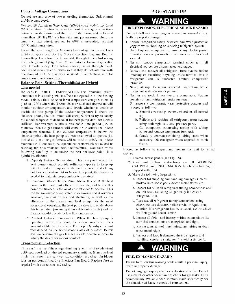
Control Voltage Connections
Do not use any type of power-stealing thermostat. Unit control
problems may result.
Use no. 18 American Wire Gage (AWG) color-coded, insulated
(35°C minimum) wires to make the control voltage connectionsbetween the thermostat and the unit. If the thermostat is located
more than 100 fl (30.5 m) from the unit (as measured along the
control voltage wires), use no. 16 AWG color-coded, insulated
(35 ° C minimum) wires.
Locate the seven (eight on 3-phase) low voltage thermostat leads
in 24 volt splice box. See Fig. 9 for connection diagram. Run the
low-voltage leads from the thermostat, through the control wiring
inlet hole grommet (Fig. 2 and 3), and into the low-voltage splice
box. Provide a drip loop before running wires through panel.
Secure and strain relief all wires so that they do not interfere with
operation of unit. A gray wire is standard on 3-phase unit forconnection to an economizer.
Balance Point Setting-Thermidistat or HybridThermostat
BALANCE POINT TEMPERATURE-The "balance point"
temperature is a setting which affects the operation of the heating
mode. This is a field-selected input temperature (range 5 to 55°F)
(-15 to 12°C) where the Thermidistat or dual fuel thermostat will
monitor outdoor air temperature and decide whether to enable or
disable the heat pump. If the outdoor temperature is above the
"balance point", the heat pump will energize first to try to satisfy
the indoor temperature demand. If the heat pump does not make a
sufficient improvement within a reasonable time period (i.e. 15
minutes), then the gas furnace will come on to satisfy the indoor
temperature demand. If the outdoor temperature is below the
"balance point", the heat pump will not be allowed to operate (i.e.
locked out), and the gas furnace will be used to satisfy the indoor
temperature. There are three separate concepts which are related to
selecting the final "balance point" temperature. Read each of the
following carefully to determine the best "balance point" in a
hybrid installation:
1. Capacity Balance Temperature: This is a point where the
heat pump cannot provide sufficient capacity to keep up
with the indoor temperature demand because of declining
outdoor temperature. At or below this point, the furnace is
needed to maintain proper indoor temperature.
2. Economic Balance Temperature: Above this point, the heat
pump is the most cost efficient to operate, and below this
point the furnace is the most cost efficient to operate. This
can be somewhat complicated to determine and it involves
knowing the cost of gas and electricity, as well as the
efficiency of the furnace and heat pump. For the most
economical operation, the heat pump should operate above
this temperature (assuming it has sufficient capacity) and the
furnace should operate below this temperature.
3. Comfort Balance Temperature: When the heat pump is
operating below this point, the indoor supply air feels
uncomfortable (i.e. too cool). This is purely subjective and
will depend on the homeowner's idea of comfort. Below
this temperature the gas furnace should operate in order to
satisfy the desire for indoor comfort.
Transformer Protection
The transformer is of the energy-limiting type. It is set to withstand
a 30-sec. overload or shorted secondary condition. If an overload
or short is present, correct overload condition and check for blown
fuse on gas control board or Interface Fan Board. Replace fuse as
required with correct size and rating.
PRE-START-UP
FIRE, EXPLOSION, ELECTRICAL SHOCK HAZARD
Failure to follow this warning could result in personal iniury,
death or property damage.
1. Follow recognized safety practices and wear protective
goggles when checking or servicing refrigerant system.
2. Do not operate compressor or provide any electric power
to unit unless compressor terminal cover is in place and
secured.
3. Do not remove compressor terminal cover until all
electrical sources are disconnected and tagged.
4. Relieve and recover all refrigerant from system before
touching or disturbing anything inside terminal box if
refrigerant leak is suspected around compressorterminals.
5. Never attempt to repair soldered connection while
refrigerant system is under pressure.
6. Do not use torch to remove any component. System
contains oil and refrigerant under pressure.
To remove a component, wear protective goggles and
proceed as follows:
a. Shut off electrical power to unit and install lockout
tag.
b. Relieve and reclaim all refrigerant from system
using both high- and low-pressure ports.
c. Cut component connecting tubing with tubing
cutter and remove component from unit.
d. Carefully unsweat remaining tubing stubs when
necessary. Oil can ignite when exposed to torch
flame.
Proceed as follows to inspect and prepare the unit for initial
start-up:
1. Remove access panels (see Fig. 18).
2. Read and follow instructions on all WARNING,
CAUTION, and INFORMATION labels attached to, or
shipped with, unit.
3. Make the following inspections:
a. Inspect for shipping and handling damages such as
broken lines, loose parts, disconnected wires, etc.
b. Inspect for oil at all refrigerant tubing connections and
on unit base. Detecting oil generally indicates a
refrigerant leak.
c. Leak test all refrigerant tubing connections using
electronic leak detector, halide torch, or liquid-soap
solution. If a refrigerant leak is detected, see the Check
for Refrigerant Leaks section.
d. Inspect all field- and factory-wiring connections. Be
sure that connections are completed and tight.
e. Ensure wires do not touch refrigerant tubing or sharp
sheet metal edges.
f. Inspect coil fins. If damaged during shipping and
handling, carefully straighten fins with a fin comb.
FIRE, EXPLOSION HAZARD
Failure to follow this warning could result in personal iniury,
death or property damage.
Do not purge gas supply into the combustion chamber. Do not
use a match or other open flame to check for gas leaks. Use a
commercially available soap solution made specifically forthe detection of leaks to check all connections.
13
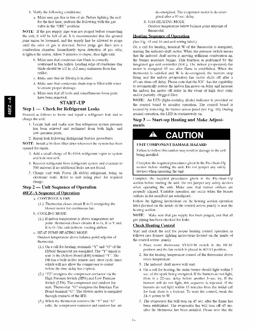
4.Verifythefollowingconditions:a.Makesuregaslineisfreeofair.Beforelightingtheunit
forthefirsttime,performthefollowingwiththegasvalveinthe"OFF"position:
NOTE:If thegassupplypipewasnotpurgedbeforeconnectingtheunit,it willbefullofair.It isrecommendedthatthegroundjointunionbeloosened,andthesupplylinebeallowedtopurgeuntiltheodorof gasisdetected.Neverpurgegaslinesintoacombustionchamber.Immediatelyupondetectionof gasodor,retightentheunion.Allow5minutestoelapse,thenlightunit.
b.Makesurethatcondenser-fanbladeiscorrectlypositionedinfanorifice.Leadingedgeofcondenser-fanbladeshouldbe1/2in.(12mm)maximumfromfanorifice.
c.Makesurethatairfilter(s)isinplace.d.Makesurethatcondensatedraintrapisfilledwithwater
toensureproperdrainage.e.Makesurethatalltoolsandmiscellaneouslooseparts
havebeenremoved.START-UP
Step 1 -- Check for Refrigerant Leaks
Proceed as follows to locate and repair a refrigerant leak and to
charge the unit:
1. Locate leak and make sure that refrigerant system pressure
has been relieved and reclaimed from both high- and
low-pressure ports.
2. Repair leak following Refrigerant Service procedures.
NOTE: Install a bi-flow filter drier whenever the system has been
opened for repair.
3. Add a small charge of R-410A refrigerant vapor to systemand leak-test unit.
4. Recover refrigerant from refrigerant system and evacuate to500 microns if no additional leaks are not found.
5. Charge unit with Puron (R-410A) refrigerant, using anelectronic scale. Refer to unit rating plate for required
charge.
Step 2 -- Unit Sequence of Operation
48EZ-A Sequence of Operationa. CONTINUOUS FAN
(1.) Thermostat closes circuit R to G energizing theblower motor for continuous fan.
b. COOLING MODE
(1.) If indoor temperature is above temperature set
point thermostat closes circuits R to G, R to Y and
R to O-The unit delivers cooling airflow.
c. HEAT PUMP HEATING MODE
Outdoor temperature above balance point setpoint ofthermostat.
(1.) On a call for heating, terminals "Y" and "G" of the
Hybrid thermostat are energized. The "Y" signal is
sent to the Defrost Board (DB) terminal "Y". The
DB has a built in five minute anti-short cycle timer
which will not allow the compressor to restart
before the time delay has expired.
(2.) "T2" energizes the compressor contactor via the
High Pressure Switch (HPS) and Low Pressure
Switch (LPS). The compressor and outdoor fan
start. Thermostat "G" energizes the Interface Fan
Board terminal "G". The blower motor is energized
through contacts of the IFB.
(3.) When the thermostat removes the "Y" and "G"
calls, the compressor contactor and outdoor fan are
de-energized. The evaporator motor is de-ener-
gized after a 90 sec. delay.
d. GAS HEATING MODE
Outdoor temperature below balance point setpoint ofthermostat,
Heating Sequence of Operation
(See Fig. 15 and 16 and unit wiring label.)
On a call for heating, terminal W of the thermostat is energized,
starting the induced-draft motor. When the pressure switch senses
that the induced-draft motor is moving sufficient combustion air,
the burner sequence begins. This function is performed by the
integrated gas unit controller (IGC). The indoor (evaporator)-fan
motor is energized 45 sec after flame is established. When the
thermostat is satisfied and W is de-energized, the burners stop
firing and the indoor (evaporator) fan motor shuts off after a
45-sec time-off delay. Please note that the IGC has the capability
to automatically reduce the indoor fan motor on delay and increase
the indoor fan motor off delay in the event of high duct static
and/or partially-clogged filter.
NOTE: An LED (light-emitting diode) indicator is provided on
the control board to monitor operation. The control board is
located by removing the burner access panel (see Fig. 18). During
normal operation, the LED is continuously on.
Step 3 -- Start-up Heating and Make Adjust-ments
UNIT COMPONENT DAMAGE HAZARD
Failure to follow this caution may result in damage to the unitbeing installed,
Complete the required procedures given in the Pre-Start-Up
section before starting the unit. Do not jumper any safety
devices when operating the unit.
Complete the required procedures given in the Pre-Start-Up
section before starting the unit. Do not jumper any safety devices
when operating the unit. Make sure that burner orifices are
properly aligned. Unstable operation my occur when the burner
orifices in the manifold are misaligned.
Follow the lighting instructions on the heating section operation
label (located on the inside of the control access panel) to start theheating section.
NOTE: Make sure that gas supply has been purged, and that all
gas piping has been checked for leaks.
Check Heating Control
Start and check the unit for proper heating control operation as
follows (see furnace lighting instructions located on the inside of
the control access panel):
1. Place room thermostat SYSTEM switch in the HEAT
position and the fan switch is placed in AUTO position.
2. Set the heating temperature control of the thermostat above
room temperature.
3. The induced-draft motor will start.
4. On a call for heating, the main burner should light within 5
sec. of the spark being energized. If the burners do not light,
there is a 22-sec. delay before another 5-sec. try. If the
burners still do not light, this sequence is repeated. If the
burners do not light within 15 minutes from the initial call
for heat, there is a lockout. To reset the control, break the
24-v power to W.
5. The evaporator fan will turn on 45 sec. after the flame has
been established. The evaporator fan will turn off 45 sec.after the thermostat has been satisfied. Please note that the
14
integratedgasunitcontroller (IGC) has the capability to
automatically reduce the evaporator "ON" delay and in-
crease the evaporator "OFF" delay in the event of high duct
static and/or partially-clogged filter.
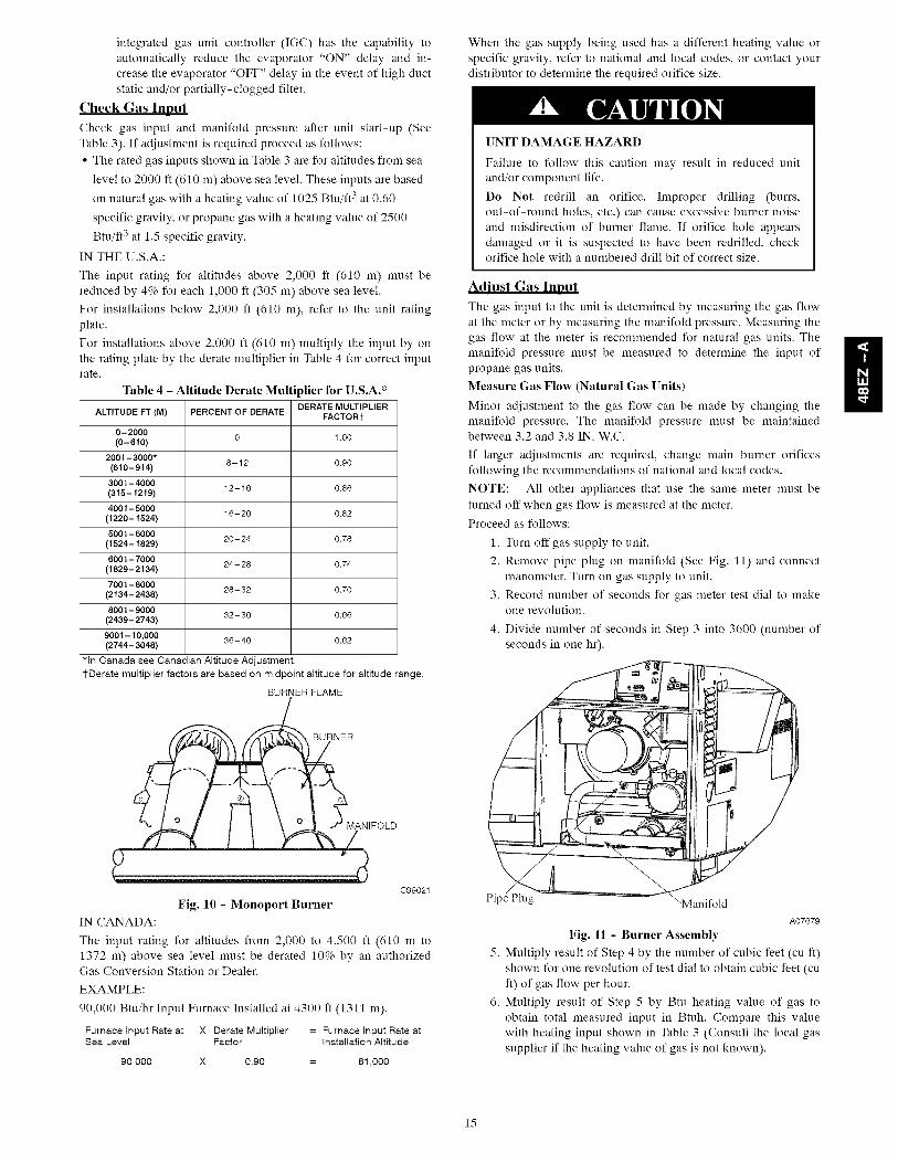
Cheek Gas Input
Check gas input and manifold pressure after unit start-up (See
Table 3). If adjustment is required proceed as follows:
• The rated gas inputs shown in Table 3 are for altitudes from sea
level to 2000 fl (610 m) above sea level. These inputs are based
on natural gas with a heating value of 1025 Btu/fl 3 at 0.60
specific gravity, or propane gas with a heating value of 2500
Btu/fl 3 at 1.5 specific gravity.
IN THE U.S.A.:
The input rating for altitudes above 2,000 fl (610 m) must be
reduced by 4% for each 1,000 ft (305 m) above sea level.
For installations below 2,000 ft (610 m), refer to the unit rating
plate.
For installations above 2,000 ft (610 m) multiply the input by on
the rating plate by the derate multiplier in Table 4 for correct input
rate.
Table 4 - Altitude Derate Multiplier for U.S.A.*
DERATE MULTIPLIERALTITUDE FT (M) PERCENT OF DERATE
FACTORt
0-20000 1,00
(0-610)
2001-3000*8-12 0.90
(610-914)
3001-400012-16 0.86
(315-1219)
4001-500016-20 0,82
(1220 - 1524)
5001-600020-24 0.78
(1524-1829)
6001-700024-28 0.74
(1829 - 2134)
7001-800028-32 0.70
(2134-2438)
8001-900032-36 0,66
(2439-2743)
9001-10,000 36-40 0.62(2744-3048)
*In Canada see Canadian Altitude Adjustment.
1-Derate multiplier factors are based on midpoint altitude for altitude range.
BURNER FLAME
WOLD
C99021
Fig. 10 - Monoport Burner
IN CANADA:
The input rating for altitudes from 2,000 to 4,500 fl (610 m to
1372 m) above sea level must be derated 10% by an authorizedGas Conversion Station or Dealer.
EXAMPLE:
90,000 Btu/hr Input Furnace Installed at 4300 fl (1311 m).
Furnace Input Rate at X Derate Multiplier = Furnace Input Rate atSea Level Factor Installation Altitude
90,000 X 0.90 = 81,000
When the gas supply being used has a different heating value or
specific gravity, refer to national and local codes, or contact your
distributor to determine the required orifice size.
UNIT DAMAGE HAZARD
Failure to follow this caution may result in reduced unit
and/or component life.
Do Not redrill an orifice. Improper drilling (burrs,
out-of-round holes, etc.) can cause excessive burner noise
and misdirection of burner flame. If orifice hole appears
damaged or it is suspected to have been redrilled, checkorifice hole with a numbered drill bit of correct size.
Adjust Gas Input
The gas input to the unit is determined by measuring the gas flow
at the meter or by measuring the manifold pressure. Measuring the
gas flow at the meter is recommended for natural gas units. The
manifold pressure must be measured to determine the input of
propane gas units.
Measure Gas Flow (Natural Gas Units)
Minor adjustment to the gas flow can be made by changing themanifold pressure. The manifold pressure must be maintainedbetween 3.2 and 3.8 IN. W.C.
If larger adjustments are required, change main burner orifices
following the recommendations of national and local codes.
NOTE: All other appliances that use the same meter must be
turned off when gas flow is measured at the meter.
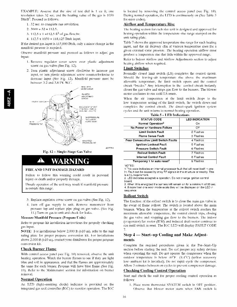
Proceed as follows:
1. Turn off gas supply to unit.
2. Remove pipe plug on manifold (See Fig. 11) and connect
manometer. Turn on gas supply to unit.
3. Record number of seconds for gas meter test dial to makeone revolution.
4. Divide number of seconds in Step 3 into 3600 (number of
seconds in one hr).
Pi ug "Manifold
A07679
Fig. 11 - Burner Assembly
5. Multiply result of Step 4 by the number of cubic feet (cu ft)
shown for one revolution of test dial to obtain cubic feet (cu
ft) of gas flow per hour.
6. Multiply result of Step 5 by Btu heating value of gas to
obtain total measured input in Btuh. Compare this value
with heating input shown in Table 3 (Consult the local gas
supplier if the heating value of gas is not known).
l!
15
l!
EXAMPLE: Assume that the size of test dial is 1 cu fl, onerevolution takes 32 sec, and the heating value of the gas is 1050Btu/ft 3, Proceed as follows:
1, 32 sec, to complete one revolution,2. 3600 + 32 = 112,5.
3, 112,5 x 1 =112,5 ft3 of gas flow/hr.
4. 112,5 x 1050 = 118,125 Btuh input,
If the desired gas input is 115,000 Btuh, only a minor change in themanifold pressure is required,
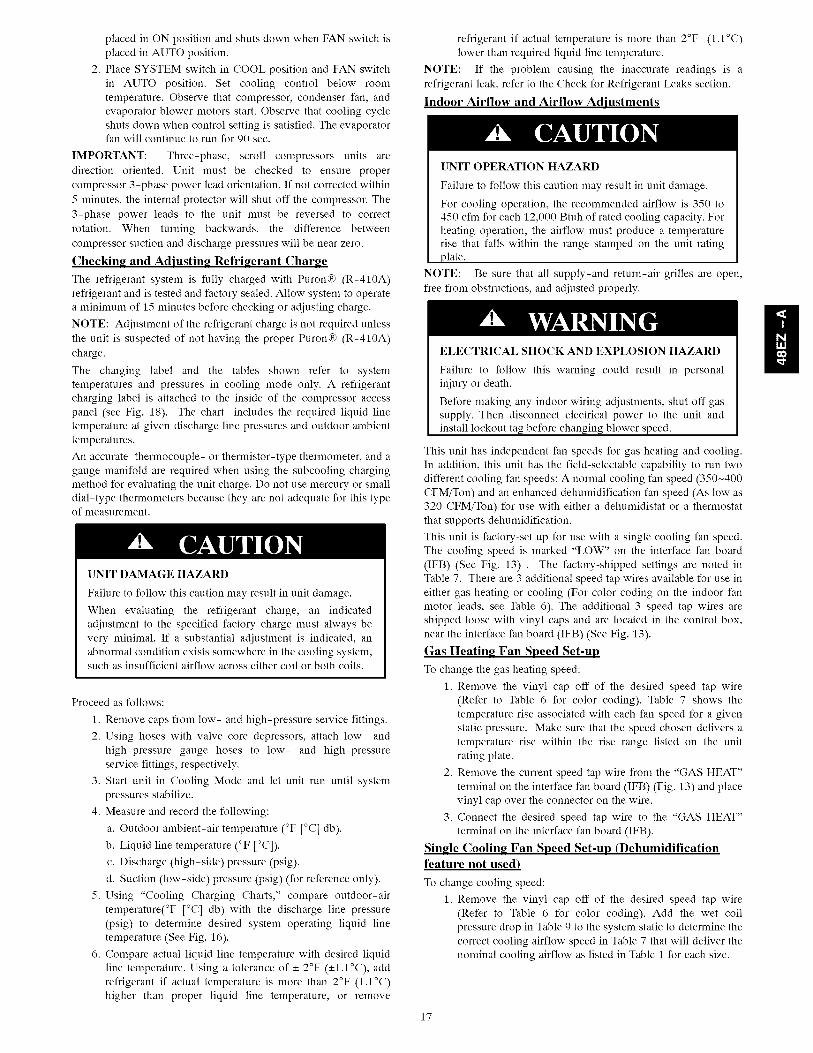
Observe manifold pressure and proceed as follows to adjust gasinput:
1, Remove regulator cover screw over plastic adjustmentscrew on gas valve (See Fig. 12).
2, Turn plastic adjustment screw clockwise to increase gasinput, or turn plastic adjustment screw counterclockwise todecrease input (See Fig. 12). Manifold pressure must bebetween 3,2 and 3,8 IN, W,C,
PLASTICADJUSTMENT
(NATURAL - SILVER)
):
MANIFOLDPRESSURE TAP
Fig. 12 - Single-Stage Gas ValveA07751
FIRE AND UNIT DAMAGE HAZARD
Failure to follow this warning could result in personalinjury or death and/or property damage.
Unsafe operation of the unit may result if manifold pressureis outside this range,
3, Replace regulator cover screw on gas valve (See Fig. 12).
4, Turn off gas supply to unit. Remove manometer frompressure tap and replace pipe plug on gas valve, (See Fig.11,) Turn on gas to unit and check for leaks,
Measure Manifold Pressure (Propane Units)
Refer to propane kit installation instructions for properly checkinggas input,
NOTE: For installations below 2,000 fl (610 m), refer to the unitrating plate for proper propane conversion kit, For installationsabove 2,000 ft (610 m), contact your distributor for proper propaneconversion kit,
Check Burner Flame
With control access panel (see Fig. 18) removed, observe the unitheating operation. Watch the burner flames to see if they are lightblue and soft in appearance, and that the flames are approximatelythe same for each burner. Propane will have blue flame (See Fig.10). Refer to the Maintenance section for information on burnerremoval.
Normal Operation
An LED (light-emitting diode) indicator is provided on theintegrated gas unit controller (IGC) to monitor operation. The IGC
is located by removing the control access panel (see Fig. 18).During normal operation, the LED is continuously on (See Table 5for error codes).
Airflow and Temperature Rise
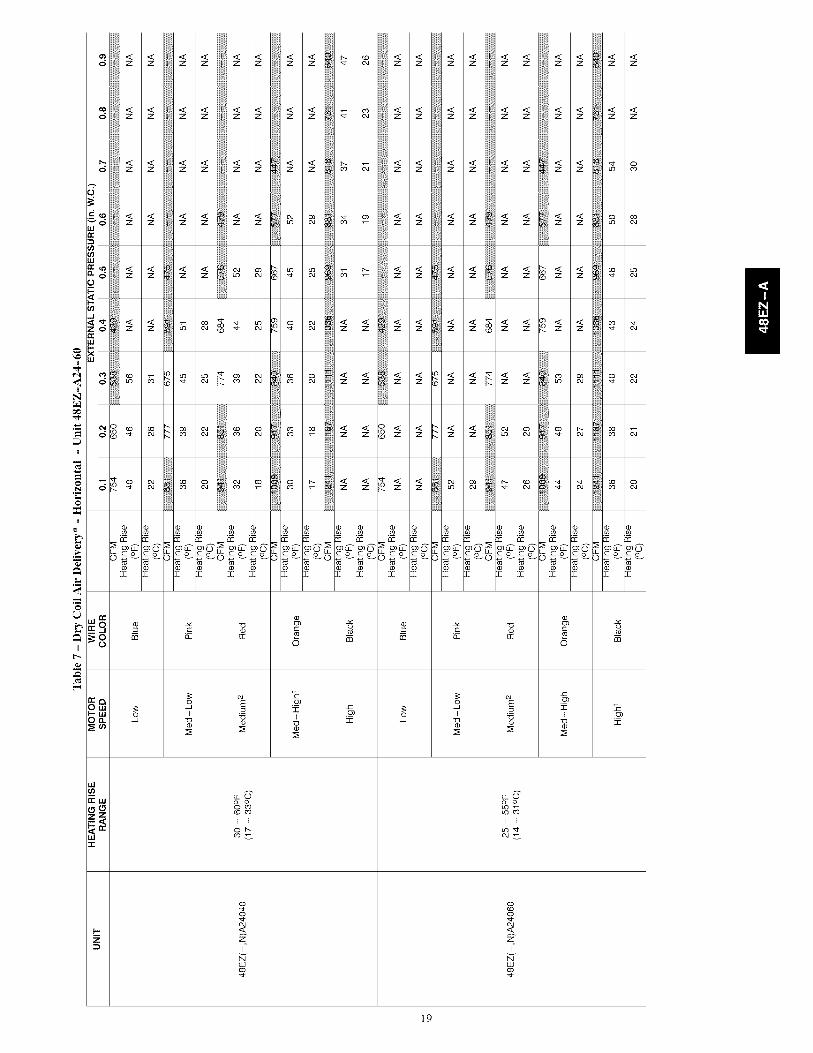
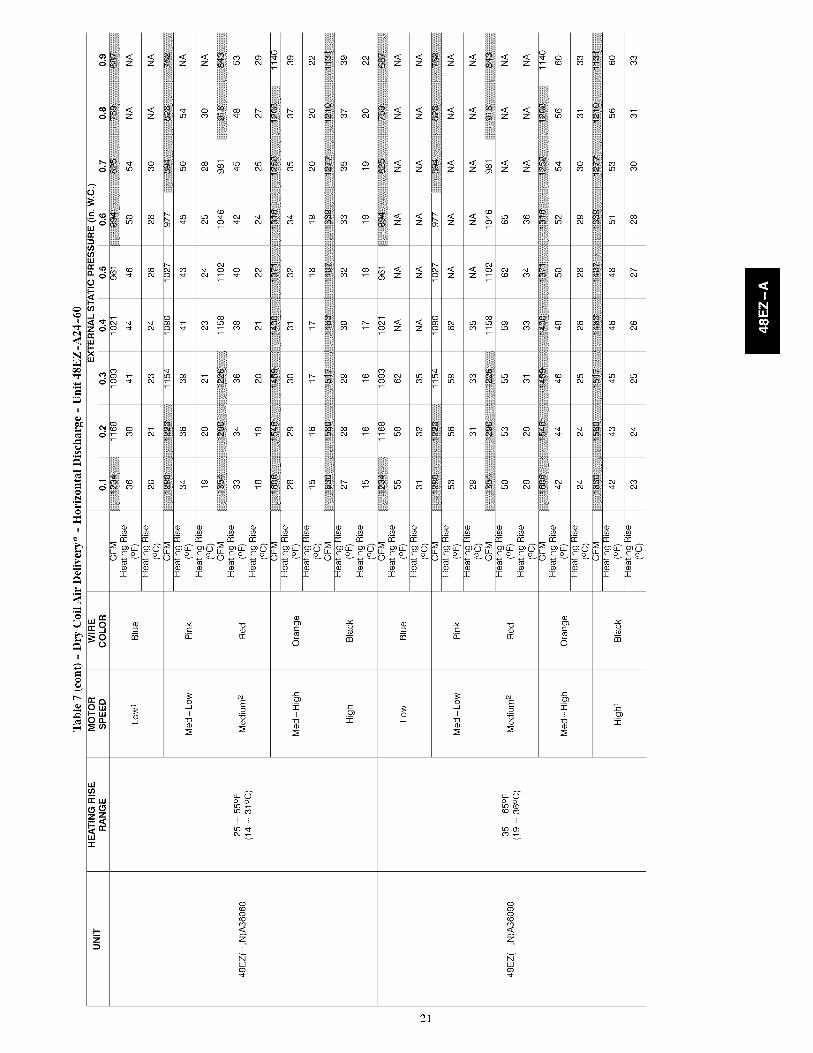
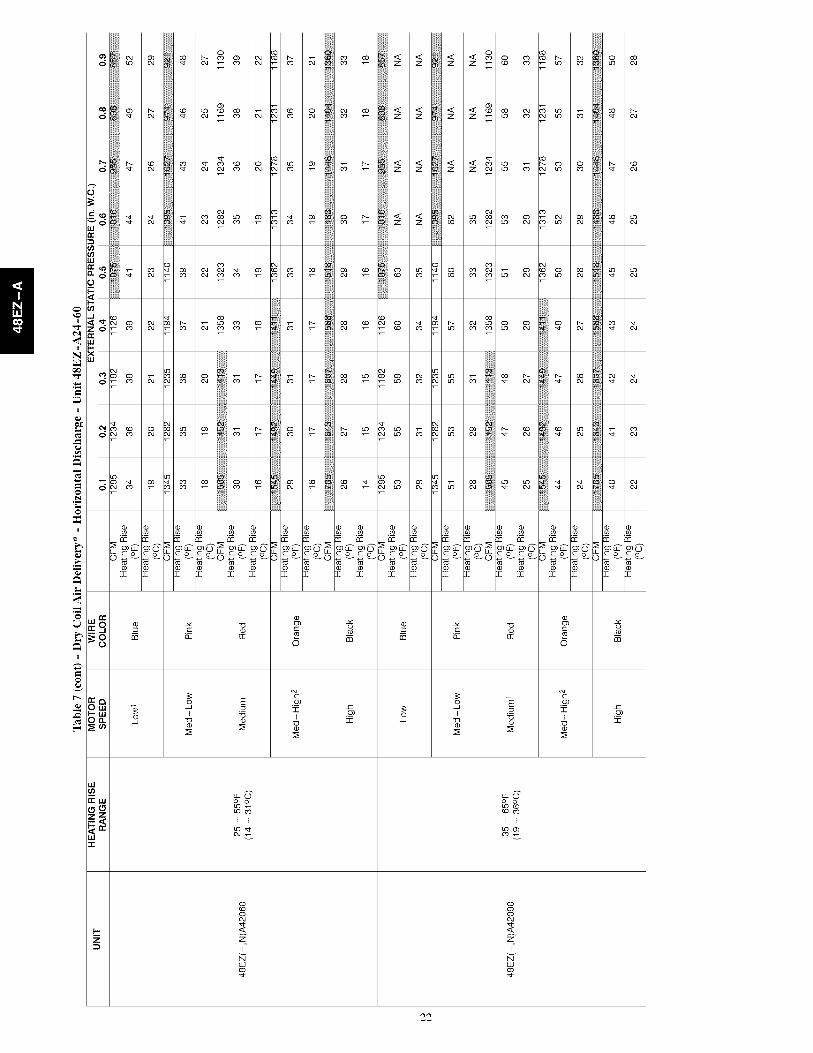
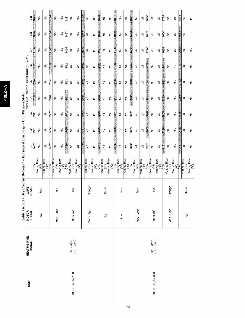
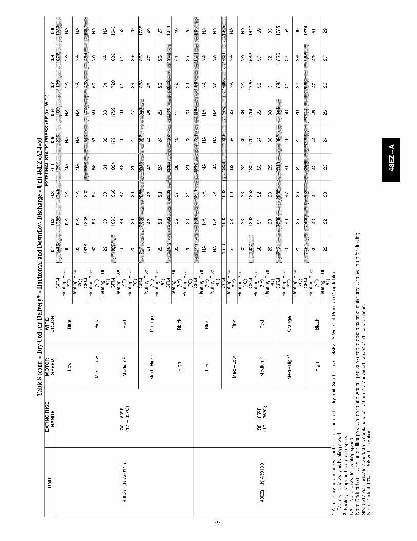
The heating section for each size unit is designed and approved forheating operation within the temperature-rise range stamped on theunit rating plate,
Table 7 shows the approved temperature rise range for each heatinginput, and the air delivery cfm at various temperature rises for agiven external static pressure. The heating operation airflow mustproduce a temperature rise that falls within the approved range.
Refer to Indoor Airflow and Airflow Adjustments section to adjustheating airflow when required,Limit Switches
Normally closed limit switch (LS) completes the control circuit.Should the leaving-air temperature rise above the maximumallowable temperature, the limit switch opens and the controlcircuit "breaks," Any interruption in the control circuit instantlycloses the gas valve and stops gas flow to the burners, The blowermotor continues to run until LS resets,
When the air temperature at the limit switch drops to thelow-temperature setting of the limit switch, the switch closes andcompletes the control circuit, The direct-spark ignition systemcycles and the unit returns to normal heating operation,
Table 5 - LED IndicationsSTATUS CODE LED INDICATION
Normal Operation 2 On
No Power or Hardware Failure Off
Limit Switch Fault 2 Flashes
Flame Sense Fault 3 Flashes
Four Consecutive Limit Switch Faults 4 Flashes
Ignition Lockout Fault 5 Flashes
Pressure Switch Fault 6 Flashes
Rollout Switch Fault 7 Flashes
Internal Control Fault 8 Flashes
Temporary 1 hr auto reset I 9 Flashes
NOTES:
1.This code indicates an internal processor fault that will reset itself in onehr. Fault can be caused by stray RF signals in the structure or nearby. Thisis a UL requirement.2, LED indicates acceptable operation. Do not change ignition controlboard,
3. When W is energized the burners will remain on for a minimum of 60 sec.4. If more than one error mode exists they will be displayed on the LED insequence.
Rollout Switch
The function of the rollout switch is to close the main gas valve inthe event of flame rollout, The switch is located above the main
burners. When the temperature at the rollout switch reaches themaximum allowable temperature, the control circuit trips, closingthe gas valve and stopping gas flow to the burners, The indoor(evaporator) fan motor (IFM) and induced draft motor continue torun until switch is reset, The IGC LED will display FAULT CODE7.
Step 4 -- Start-up Cooling and Make Adjust-ments
Complete the required procedures given in the Pre-Start-Up
section before starting the unit. Do not jumper any safety devices
when operating the unit, Do not operate the compressor when the
outdoor temperature is below 40°F (4.4°C) (unless accessory
low-ambient kit is installed). Do not rapid-cycle the compressor.
Allow 5 minutes between on cycles to prevent compressor damage,
Checking Cooling Control Operation
Start and check the unit for proper cooling control operation asfollows:
1. Place room thermostat SYSTEM switch in OFF position.Observe that blower motor starts when FAN switch is
16
placedinONpositionandshutsdownwhenFANswitchisplacedinAUTOposition.
2.PlaceSYSTEMswitchinCOOLpositionandFANswitchin AUTOposition.Setcoolingcontrolbelowroomtemperature.Observethatcompressor,condenserfan,andevaporatorblowermotorsstart.Observethatcoolingcycleshutsdownwhencontrolsettingissatisfied.Theevaporatorfanwillcontinuetorunfor90sec.
IMPORTANT:Three-phase,scrollcompressorsunitsaredirectionoriented.Unitmustbecheckedto ensurepropercompressor3-phasepowerleadorientation.If notcorrectedwithin5minutes,theinternalprotectorwillshutoffthecompressor.The3-phasepowerleadsto theunitmustbereversedto correctrotation.Whenturningbackwards,the differencebetweencompressorsuctionanddischargepressureswillbenearzero.ChecMn_ and Adiustin_ Refrigerant Charge
The refrigerant system is fully charged with Puron® (R-410A)
refrigerant and is tested and factory sealed. Allow system to operate
a minimum of 15 minutes before checking or adjusting charge.
NOTE: Adjustment of the refrigerant charge is not required unless
the unit is suspected of not having the proper Puron® (R-410A)
charge.
The charging label and the tables shown refer to system
temperatures and pressures in cooling mode only. A refrigerant
charging label is attached to the inside of the compressor access
panel (see Fig. 18). The chart includes the required liquid line
temperature at given discharge line pressures and outdoor ambient
temperatures.
An accurate thermocouple- or thermistor-type thermometer, and a
gauge manifold are required when using the subcooling charging
method for evaluating the unit charge. Do not use mercury or small
dial-type thermometers because they are not adequate for this typeof measurement.
[]NIT DAMAGE HAZARD
Failure to follow this caution may result in unit damage.
When evaluating the refrigerant charge, an indicated
adjustment to the specified factory charge must always be
very minimal. If a substantial adjustment is indicated, an
abnormal condition exists somewhere in the cooling system,
such as insufficient airflow across either coil or both coils.
Proceed as follows:
1, Remove caps from low- and high-pressure service fittings.
2, Using hoses with valve core depressors, attach low- andhigh-pressure gauge hoses to low- and high-pressureservice fittings, respectively,
3, Start unit in Cooling Mode and let unit run until systempressures stabilize.
4. Measure and record the following:
a. Outdoor ambient-air temperature (°F [°C] db).
b. Liquid line temperature (°F [°C]).
c. Discharge (high-side) pressure (psig).
d. Suction (low-side) pressure (psig) (for reference only).
5. Using "Cooling Charging Charts," compare outdoor-airtemperature(°F [°C] db) with the discharge line pressure(psig) to determine desired system operating liquid linetemperature (See Fig. 16).
6. Compare actual liquid line temperature with desired liquidline temperature. Using a tolerance of - 2°F (-1.1°C), addrefrigerant if actual temperature is more than 2°F (1.1°C)higher than proper liquid line temperature, or remove
refrigerant if actual temperature is more than 2°F (1.1°C)
lower than required liquid line temperature.
NOTE: If the problem causing the inaccurate readings is a
refrigerant leak, refer to the Check for Refrigerant Leaks section.
Indoor Airflow and Airflow Adjustments
[]NIT OPERATION HAZARD
Failure to follow this caution may result in unit damage.
For cooling operation, the recommended airflow is 350 to450 cfm for each 12,000 Btuh of rated cooling capacity. Forheating operation, the airflow must produce a temperaturerise that falls within the range stamped on the unit ratingplate.
NOTE: Be sure that all supply-and return-air grilles are open,free from obstructions, and adjusted properly.
ELECTRICAL SHOCK AND EXPLOSION HAZARD
Failure to follow this warning could result in personal
iniury or death.
Before making any indoor wiring adjustments, shut off gas
supply. Then disconnect electrical power to the unit and
install lockout tag before changing blower speed.
This unit has independent fan speeds for gas heating and cooling.
In addition, this unit has the field-selectable capability to run two
different cooling fan speeds: A normal cooling fan speed (350~400
CFM/Ton) and an enhanced dehumidification fan speed (As low as
320 CFM/Ton) for use with either a dehumidistat or a thermostat
that supports dehumidification.
This unit is factory-set up for use with a single cooling fan speed.
The cooling speed is marked "LOW" on the interface fan board
(IFB) (See Fig. 13) . The factory-shipped settings are noted in
Table 7. There are 3 additional speed tap wires available for use in
either gas heating or cooling (For color coding on the indoor fan
motor leads, see Table 6). The additional 3 speed tap wires areshipped loose with vinyl caps and are located in the control box,
near the interface fan board (IFB) (See Fig. 13).
Gas Heating Fan Speed Set-up
To change the gas heating speed:
1. Remove the vinyl cap off of the desired speed tap wire
(Refer to Table 6 for color coding). Table 7 shows the
temperature rise associated with each fan speed for a given
static pressure. Make sure that the speed chosen delivers a
temperature rise within the rise range listed on the unit
rating plate.
2, Remove the current speed tap wire from the "GAS HEAT"
terminal on the interface fan board (IFB) (Fig. 13) and place
vinyl cap over the connector on the wire,
3, Connect the desired speed tap wire to the "GAS HEAT"
terminal on the interface fan board (IFB).
Single Cooling Fan Speed Set-up (Dehumidificationfeature not used)
To change cooling speed:
1. Remove the vinyl cap off of the desired speed tap wire
(Refer to Table 6 for color coding). Add the wet coil
pressure drop in Table 9 to the system static to determine the
correct cooling airflow speed in Table 7 that will deliver the
nominal cooling airflow as listed in Table 1 for each size.
17
H

I!
2. Remove the current speed tap wire from the "LOW"terminal on the interface fan board (IFB) (See Fig. 13) andplace vinyl cap over the connector on the wire.
3. Connect the desired speed tap wire to the "LOW" terminalon the interface fan board (IFB).
Two Cooling Fan Speeds Set-up (Dehumidificationfeature used)
IMPORTANT: Dehumidification control must open controlcircuit on humidity rise above set point.
Use of the dehumidification cooling fan speed requires use ofeither a 24 VAC dehumidistat or a thermostat which includes
control of a 24 VAC dehumidistat connection. In either case, thedehumidification control must open the control circuit on humidityrise above the dehumidification set point.
1. Remove fan speed tap wire from the "LOW" terminal onthe interface fan board (IFB) (See Fig. 13).
2. Determine correct normal cooling fan speed for unit andapplication. Add the wet coil pressure drop in Table 9 tothe system static to determine the correct cooling airflowspeed in Table 7 that will deliver the nominal coolingairflow as listed in Table 1 for each size.
3. Remove the vinyl cap off of the desired speed tap wire(Refer to Table 6 for color coding) for the normal coolingfan speed and place desired speed tap wire on "HIGH" onthe interface board.
4. Refer to airflow tables (Table 7) to determine allowablespeeds for the dehumidification cooling fan speed. In Table7, speeds that are not allowed for dehumidification coolingare shaded.
5. Remove the vinyl cap off of the desired speed tap wire(Refer to Table 6 for color coding) for the dehumidificationcooling fan speed and place desired speed tap wire on the"LOW" connection on the interface board (IFB). Verifythat static pressure is in the acceptable range for the speedtap to be used for dehumidification cooling.
6. Use any spare vinyl plugs to cap any unused speed tapwires.
Continuous Fan Operation
When the DEHUM feature is not used, the continuous fan speedwill be the same as cooling fan speed. When the DEHUM featureis used, the continuous fan will operate on IFB "LOW" speedwhen the DH control lead is not energized, or IFB "HIGH" speedwhen the DH lead is energized (see Fig. 13).
NOTE: For heat pump operation, the recommended airflow is 350to 450 CFM for each 12,000 Btuh of rated cooling capacity.
Table 6 - Color Coding for Indoor Fan Motor LeadsBlack = High Speed
Orange = Med-High Speed
Red = Med Speed
Pink = Med-Low Speed
Blue = Low Speed
GASHEAT HIGH LOW COM
QC6 QC7 QC4 QC3
cRL3 C8 R1L Q1 D2
.o000c!!!! .....OILL C2 D6 D4
5 F1
0mOO004
...... "l JY2/ _1/ CW2 DH G R
q]
P
Fig. 13 - Interface Fan Board (IFB)
A09058
18
4
4
!
N_
!
I
LL©0 0
I I
8o
I
19

LL©0 0
_*) CO
I I
C'q _v
8ooco
I
2O
LL©0 0LO C,O_0 CO
I I
o8co
I
21
LL©0 0LO C,O_0 CO
I I
oo
I
22

LL©0 O0 C_
I I
I
23
LL©0 0
I I
oo_o
I
24
bbLbbLbbLbbLbbc G c G c G c G c 8
_ c_oc_o c_oc_o c_oc_o c_oc_o c_oc_o°W W_ W W_ W W_ W W_ W W_
N N
o ots_ _D_D CO
<
25
c_
>,
.o_
wW
c
o
_J
o
¥
_J
x2
_22
aao_s3=
O OZ_
u- u- < S_ _ ZZ
wo
q_
°_
m_8°_g
x:ECO;:"

I!
!
I
(D LO OO
(D O OLO
, , O (D 0"_ CO
O LO (DOqD O _l- C0
O (D OLOO,1 _:_ 0,1LO
LO O LOO(D (D i_. C0 _ LOLO LO 00 LO 0,1 0,1C0 C0 _ _ O,10,1
LO O LO LO(D (D 00 00 Ob O,1
O O O-_ h...._ CDNN_mm
O O LO LO LOOLO LO _ i_,- (D 00O O qD i_,, LO LO
8 2_ 2_ 2_ 2_ 2_ 2_O O O O O O
wZNNNNNN
g
o
O
WWWWWW
D
Z
o
oo
o
8
o
o
o
g
o
_C
0
8
8
8
Z__zO0
oo_
_z
d
d
o
d _ S
o
_ o _-d _ S
o
S _ S
ot-_ o c,l
d _ d
oo
d S _ S'S
o
d d __ d d
C'd
0
•_ c_
c6
E'€ E'€_cJ _c_x o xO_ 000
_T_T
_x6x
_,_
26
o
o_d
o
g o_d
cJ co _co

CONNECTTONWIRING DTAGRAM
DANGER ELECTRICAL SHOCK HAZARD DISCONNECT POWERBEFORE SERVICINGNOTES, SCHEMATIC, IF ANY OF THE ORIGINAL WIRES FURNISHED ARE REPLACED, IF USED_._ rrg
THEY MUST BE REPLACED WITH THE SAME WIRE OR ITS EQUIVALENT. _BK 2 0 _ / 2 3 0 - I - 6 0R.SEEPRICEP.ESFORTHERMOSTATG. Is, USE 75 DES. COPPER CONDUCTORS FOR FIELD INSTALLATION. [ _ B_ /_BK--_BK_BK "-/_ OFM
4, SEE INSTALLATION INSTRUCTIONS FOR PROPER HEATING AND FIELD Z__BI I "_ _.--BK _ r""""'_ Y "_- Y @---_ /
COOLINO CONNECTIONS FOR YOUR UNIT. INDOOR FAN MOTOR _ /'--k _::_"_' " _ U_I _V_IcAPI ', _ ,'
PLUGS - 'DO NOT DISCONNECT UNDER LOAD' SUPPLY----I_I_--- Y I"I _23)_(B3_/_Tx_/SV_-- _'I HPI-)_.... _BR_\ i /oRSMALLBASEMODELSLSIANDLSRAREWKRED . _.F--= .H.'_--RBIRSER"SLAROEBASEMOOELSBAVELSIONLYEOUIPGRDI III -
INDUCER CAPACITOR AND WIRING ON CERTAIN MODELS ONLY.6. IF CAPB IS PRESENT, YELLOW WIRES FROM IGC AND IDM CONNECT _ I llJ I _Y-_ )ONDAHESIBEOFCAPD _ I 111 --BL--_--_--__
Y.THiSFDSEISMANDFACTUNEDBYLITTELFDSE.P,U_B,DU_. ,/ l|l COMPRESSORFLD_"8, THIS FUSE I$ MANUFACTURED BY LITTELFUSE, P/N Z57OO5, l Ill BK_ _
LEGEND I II J_ Y I IN_' FIELD SPLICE RD n_Dn_T B_ARD RELAY J _ °_ /Y
TERMINAL (MARLED) _'", _"_" _ I _ Dn , FG/Y_ t _
o TERMINAL (UNMARKED) LQU_P LQULPMLN. BK _ I /-7-7 I I \ I L _• SPLICE (IF USED) FS FLAME SENSOR • _ PRIMARY "_ r_l C _ L_ I© SPLICE (MARKED) GND GROUND _ Y_COM) _[9' _?RD_ I L--I "_ / _ _I I I
-- FACTORY WIRING lIPS HIGH PRESSURE SWITCH _ 208/230V _ I _-q III-- FIELD CONTROL WIRING I IGNITOR I / I I I I I I--- FIELD POWER WIRING IGC INTERGRATED GAS UNIT CONTROLLER / / I--- ACCESSORY OR OPTIONAL IFB INDOOR FAN BOARD { _ J l 11 2 3 4 sl
WIRING IDM INDUCED DRAFT MOTOR _ _ I-- TO INDICATE COMMON IFM INDOOR FAN MOTOR I o_ I I I I I
PR_E_TI_,O_L_T WFDFM_ LGPS LOW GAS PRESSURE SWITCH (WHEN USED) SECONDARY - _" et I I I HK
C "_" 'CON"T_'C"TOR......... LsILPS PRIMARyLOWPRESSURELIMITSWITCHswITCH R4V _l'CAP 1 CAPACITOR, COUP LSB SECOHDARY LIMIT SWITCHCAP 2 CAPACITOR, INDUCER MDV MAIN GAS VALVECCH CRANK CASE HEATER OFM OUTDOOR FAN MOTORCOMP COMPRESSORMOTOR PRG PRESSURE SWITCHCR COMBUSTION RELAY RS ROLLOUT SWITCHDB DEFROST BOARD NVS REVERSING VALVEDFT DEFROST TEMPERATURE THAN TRANSFORMER
SWITCH T-STAT THERMOSTAT
J2
5AMP
FUSE
_D
NOTE 8--R
R--
USED)
COLOR CODE
BK BLACKBL BLUEBR BROWN
GY GRAY
G GREENO ORANGE
PINKREDV VIOLETW WHITEV YELLOW
NOTE 7
J JJ_ FUSE3A
DEFROST BOARD (DR)CTD
BLOWER24V CONNECTIONSGEE NOTE 4
RL--J
SEE NOTE 4
DIP SWITCH SETTINGSDEFAULT
30 MINUTES SOMINUTEU9QMENU.S 1_o MINUTES
OR OR OR
I oo I÷.
FIELD SELECTABLE OPTIONS FOR TIME PERIODBETWEEN DEFROST CYCLES (MINUTES)THE COMPRESSORWILL SHUT OFF FOR 30 SEC. ON DEFROSTINITIATION AND TERMINATION IN THE 'QUIET SHIFT" ON DEFROST WILL TERMINATE IN 30 SEC. IF DFT OPEN.POSITION DEFROST WILL TERMINATE NORMALLY IF DFT IS CLOSED.
s_DF_ JUMPERED TEST PINS (USE METAL OBJECT)FIELD SPEED-UP CYCLE
I) MOMENTARILY SHORT PINS AND RELEASE TO BYPASSCOMPRESSOR OFF DELAY.
2) SHORT FOR 5+ SEC. AND RELEASE FOR FORCED DEFROST,3) PERMANENTSHORT WILL BE IGNORED,
A10207C
Fig. 14 - 208/230-1-60 Connection Wiring Diagram, Unit 48EZ-A
27
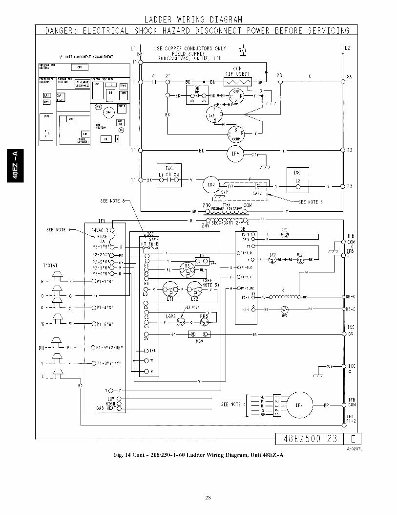
II
LADDER WIRING DIAGRAM
DANGER ELECTRICAL SHOCK HAZARD DISCONNECT POWER BEFORE SERVICING
1¢ UNIT COMPONENT ARRANGEMENT
}UTD(X}R FAN_ECTION
PRESSOITION
COMP
¢ sR
INDOOR FAN
SECTION L$1 (LAROE)
;AP I
E(RRALLCkBINET)
CONTROLBOX ARER
ORS []
SECTION ®
FqB
BK
11
/
USE COPPER CONDUCTORS ONLY G/'YFIELD SUPPLY _L
208/230 VAC, 60 HZ, IPH =
CCH ]C 21 (IF USED) 'r 23 c
i_( _ BK _e_BK_BK-J_ T(_BK BK-o-BK. < / Y--_r y
R--e-B_ _
BK _BL__y
1 BK_ Y
G/ Y-3_ 7
[ J _SEE NOTE 6SEE NOTE8---_ 250 TRAN COM
\ BK PRIMARY 2081230V Y
SEE NOTE 7_
T'STAT
R __Z_ R--
W --Z_L- W--
DH- -'_-- BL-
y_ Z_ Y--
C _ _Z]_L_
BR
IFB j24VACR (._
FUSEi)3,A,,,(
P2-1,,R,,O_ R
P2-2,,C,C)'_B RP2-5 X (_GY-
P2-3"W"O- w-P2-4"R"O- R
•--OP1-1 "RI'
0
-_OP1-4"G"
_PI -6"W"
--OP1-5"Y21DH"
-_0 P1-3"YI IY"
YO--Y
LOW0HIGH 0
GAS HEATO
R 24_ BR DFT
I_ I P3-I0--- P-_ l
IJ _1 I .-_o-- P-_= ,
1_reO_ Y _ L0 -OP1 :_ "BL-_L+BK---_K'_] I "
II_ I - _ ,_'EE- Y--OP,-,.Y III "a I/I _ /I _NOTE 51 _ I
L_V L_1 R LS.._2 v I w- -(_Pl -B,W2 C
P_-,8--°,_.-- --
II I /,0,,0 Y P2-1&--BI(_BR-- --
C_ oLeo__ _ __ RVS
__--_ F__ GIY_
W
SEE NOTE4--Rq_ IFM /_BR--
-- BIi_
IFB
ioo,
_F_
iOoOi [ IGGvC
IcGc
| IFB
I COM
t 48EZ500123 EA10207L
Fig. 14 Cont - 208/230-1-60 Ladder Wiring Diagram, Unit 48EZ-A
28
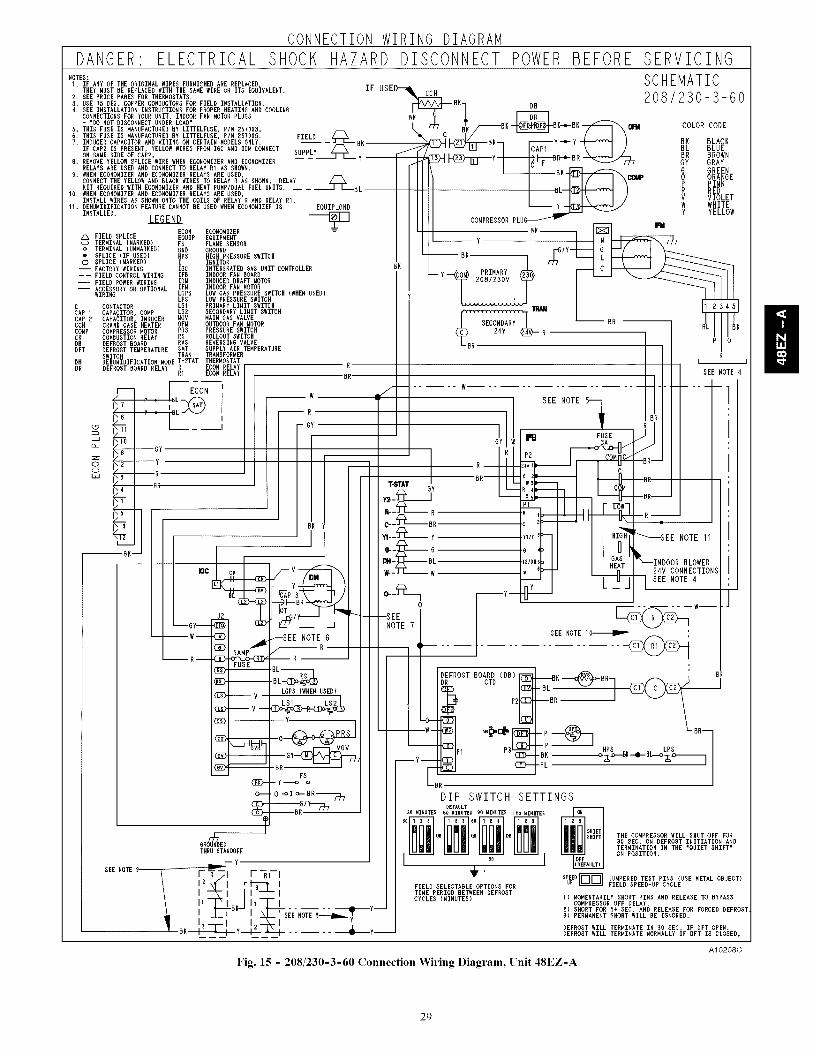
CONNECTION WIRING DIAGRAM
DANGER ELECTRICAL SHOCK HAZARD DISCONNECT POWERBEFORENOTES:I. IF ANY OF THE ORIGINAL WIRES FURNISHED ARE REPLACED,
THEY MUST BE REPLACED WITH THE SAME WERE OR ITS EQUIVALENT. IF USED'--_k_.2. SEE PRICE PABES FOR THERMOSTATS.3. USE ?5 BEG. COPPER CONDUCTORS FOR FIELD INSTALLATION. _BK_ DB4. SEE INSTALLATION INSTRUCTIONS FOR PROPER HEATING AND COOLING IL--_ l
- "DO NOT DISCONNECT UNDER LOAD" BK B[--I_-BK5. THIS FUSE IS MANUFACTURED BY LITTELFUSE, P/N 257003.6. THIS FUSE IS MANUFACTUREDHY LITTELFUSE, PIN 2S7005.
, INDUCERCAPACITORANDHIRINDONCERTAENMODELSDNLY --J'--. _ _,_--Bh _F_V-'-YT--_ ;IF CAPZ IS PRESENT, YELLOW WIRES FROM IGC AND IDM CONNECT SUpmy/--\_ONSAMESIDEOPCAPU y f_____H______I____Y _HH-_R. REMOVE YELLOW SPLICE WERE WHEN ECONOMIZER AND ECONOMIZER
g. WHEN ECONOMIZER AND ECONOMIZER RELAYS ARE USED, B
KIT REQUIRED WITH ECONOMIZER AND HEAT PUMP/DUAL FUEL UNITS. BL10. WHEN ECONOMIZER AND ECONOMIZER RELAYS ARE USED,
INSTALL WINES AS SHOWN ONTO THE COILS OF RELAY R AND RELAY RI.11. DEHUMIDIFICATION FEATURE CANNOT BE USED WHEN ECONOMIZER IS _Y'-KI_>I---_J_ "
INSTALLED. LEGEND eK _COMPREGSOR PLUG F_
ECON ECONOMIZER = BK_
Z_ FIELD SPLICE EQUIP EQUIPMENT y ___ _ _____.._TERMINAL (MARLED) F$ FLAME SENSOR -- /Y
2081230V y
IFM INDOOR FAN MOTOR
LBR P
o TERMINAL (UNMARKED) GND GROUND• SPLICE (IF USED) HPS HIGH PRESSURE SWITCH© SPLICE (MARKED) I IGNITOR-- FACTORY WIRING IGC INTERGRATED GAS UNIT CONTROLLER-- FIELD CONTROL WIRING IFB INDOOR FAN BOARD--- FIELD POWER WIRING IDM INDUCED DRAFT MOTOR--- ACCESSORY OR OPTIONAL
WIRING LBPS LOW GAS PRESSURE SWITCH (WHEN USED)LPG LOW PRESSURE SWITCH
C CONTACTOR LSI PRIMARY LIMIT SWITCHCAP I CAPACITOR, COMP SECONDARY LIMIT SWITCH
SERVICINGSCHEMATIC208/230-3-6
COLOR CODE
BK BLACKBL BLUEBR BROWNGY GRAYG GREEN0 ORANGE
PINKRDV V_OLETW WHITEY YELLOW
0
CAP B CAPACITOR, INDUCER MGV MAIN GAS VALVECCH CRANK CASE HEATER OUTDOORFAN MOTORCOMP COMPRESSOR MOTOR PRESSURE SWITCHCR COMBUSTION RELAY ROLLOUT SWITCHDH DEFROST HOARD REVERSING VALVEDFT DEFROST TEMPERATURE SAT SUPPLY AIR TEMPERATURE
SWITCHDH DEHUMIDIFICATION MODET-STAT THERMOSTATDR DEFROST HOARDRELAY
..--I
I'--,/
G
I.--
--BK--
OFM
_sRVGSATTRAN TRANSFORMERT-ST THERMOSTATR ECON RELAY [ R
R1 ECON RELAY BR
II N' W
----i_ I
IGC cJ _//-- V
OT/
IGyI_ _ ,,,, i - Ii
iwi-_D . _SEE NOTE 6 I
5AMP_ _-- R I
FUSE .BL
--. BL_J)
V LOPS )WHEN USED)
®--v -Ni) Y
o----
TGROUNDEDTHRU STANDOFF
-BR
FG-y-_ o
_IB R----_ 7
--HR
DIP SWITCH SETTINGSDEFAULT
DUMINUTES 60 MINUTES DOMINUTED 1_0 MINUTES JouJ
De DR De THE COMPRESSOR WILL SHUT OFF FORBO DEC, ON DEFROST INITIATION ANDTERMINATION IN THE "QUIET SHIFT"
I 9U I ON POSITION.
+.S_F_D_ JUMPERED TEST PINS (USE METAL OBJECT)
FIELD SPEED-UP CYOLEFIELD SELEOTABLE OPTIONS FORTIME PERIOD BE_EEN DEFROSTCYCLES (MINUTES) I) MOMENTARILY SHORT PINS AND RELEASE TO BYPASS
COMPRESSOR OFF DELAY,R) S_RT FOR 5_ DEC. AND RELEASE FOR FORCED DEFROST3) PERMANENT SHORT WILL BE IGNORED.
DEFROST WILL TERMINATE IN 30 DEC, IF DFT OPEN.DEFROST WILL TERMINATE NORMALLY IF DFT IS CLOSED.
--G1
--y
--R
--BP,
SEE NOTE R__- I Y i-- --R1-- It I z \f" I r _-_--_ Jt I _l l l_-'-_
L I -L_ I '" I ..._/ seeNOTE8.--_lmh..y'_-Y-
.....A10208C
Fig. 15 - 208/230-3-60 Connection Wiring Diagram, Unit 48EZ-A
29
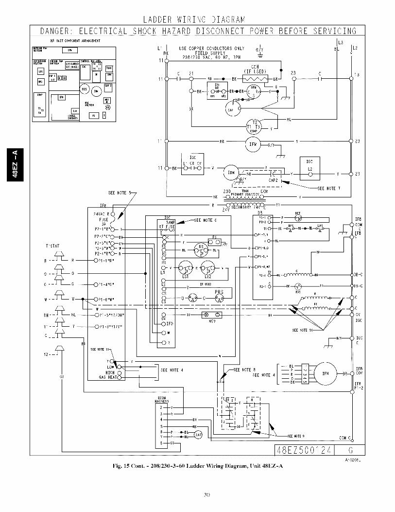
LADDER WIRING DIAGRAM
DANGER ELECTRICALUNIT COMPONENT ARRANGEMENT
_UIt_OORF_NBECTIOW
CeaPRESSOR_EGTRON
COMP
TR
CONTROL B_
S_TION
E ®
T'STAT
R --_'- R--
___L._ 0
w - -_L-_ w
Y1--Q Y ----
C - -_L--_B
Y2- -_'_
GY
SEE NOTE
IFB ,
24VAC R4 _
FUSE i) --3A
P2-I "R"_)-.- R
P2-2'c"OIBR
P2-5'X'(_GyP2- 3"w'C)- v_
P2-4"R'C'- R
"_OP1 11 IIRI
OP1-4IIG I
"_0 P1-6IIWI
w
----OP1-5Iy2/DH '
0 P1-311yI/Y II
SEE NOTE 11--_
LOW_0-.,
HIGH 0GASHEATO
---- y
SHOCK HAZARD DISCONNECT POWERBEFORE SERVICING
EllBK
!11
11
11
/
USE COPPER CONDUCTORSONLY G/YFIELD SUPPLY _L
208/230 VAC, 60 HZ, 3PH
CCH 1
C 21 (IF USED) T 23 C
I_ :S)_ BI(_BK---_ _'- BKJ (::)_-----_I I
( BK --d F_iy_ Y
IGC "_" /J-7
L1 CR CM IGC
k -BKI_ I-0--- V ---_IDM ___ Y L2
.//-f-zI_ J
-- - _'_s EE230 THAN COM
PRIMARY2081230VBK ..................
H _,RDB DFT
IGC..8_--SEE NOTE 65AMP
RT FUSE
_'_'_ - R
O--- YFSO BLRS
P$-I
P3-2
T1 O"
OPI-7,R
YO-
-- 0 I --OP1-8,0
L3BL
I
I
[
o
R,@@_V I R VLS _LSI LS2
LOs IF USED
--y
o-¢s
cO---o-@o
GV MGV
-- Y - --OP115' Y
-- -- W- --OPt -6,_v2
p214 _"
0P2-I 0
BR
Y
NOTE 7
"BL--BK-o_BK_BL_ _
BR
---OIFO
----Ow
I---OR
c
--BL--_BR.
-_BK---_BR
RVS R
SEE NOTElO_
IL2
SEE NOTE 4_SEE NOTE 8
j SEE NOTE 4, -y_
ECONHARNESS
2---Y
3--1R--
4 BR--
6-- -P---_B7-- -P_BL.._k,._Y I
8-- -GYq
I I
y -_-,i, _'J-:,,_LI , _I
2 I
,T4,,J _
13()
(>23
<>23
IFB
COWC
IFB,C
DB-C
DB-C
_ IGCC
--R--_ _ IFM _--BR-_COM
--&--=_ _p__
48EZ500124
Fig. 15 Cont. - 208/230-3-60 Ladder Wiring Diagram, Unit 48EZ-A
COMC
AlO208L
30
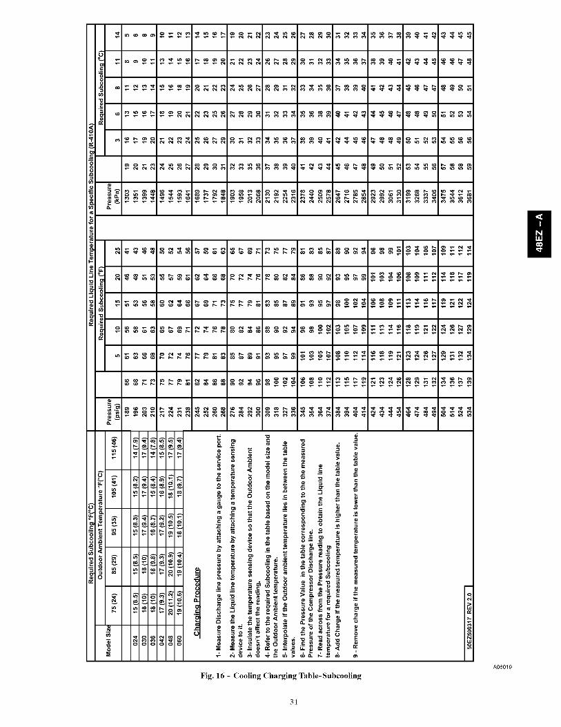
G
o
8
_*_ _: ooO _
=
oo
_°
.r- _
<
Fig. 16 - Cooling Charging Table-Subcooling
o
>u_r¢
A0801g
31
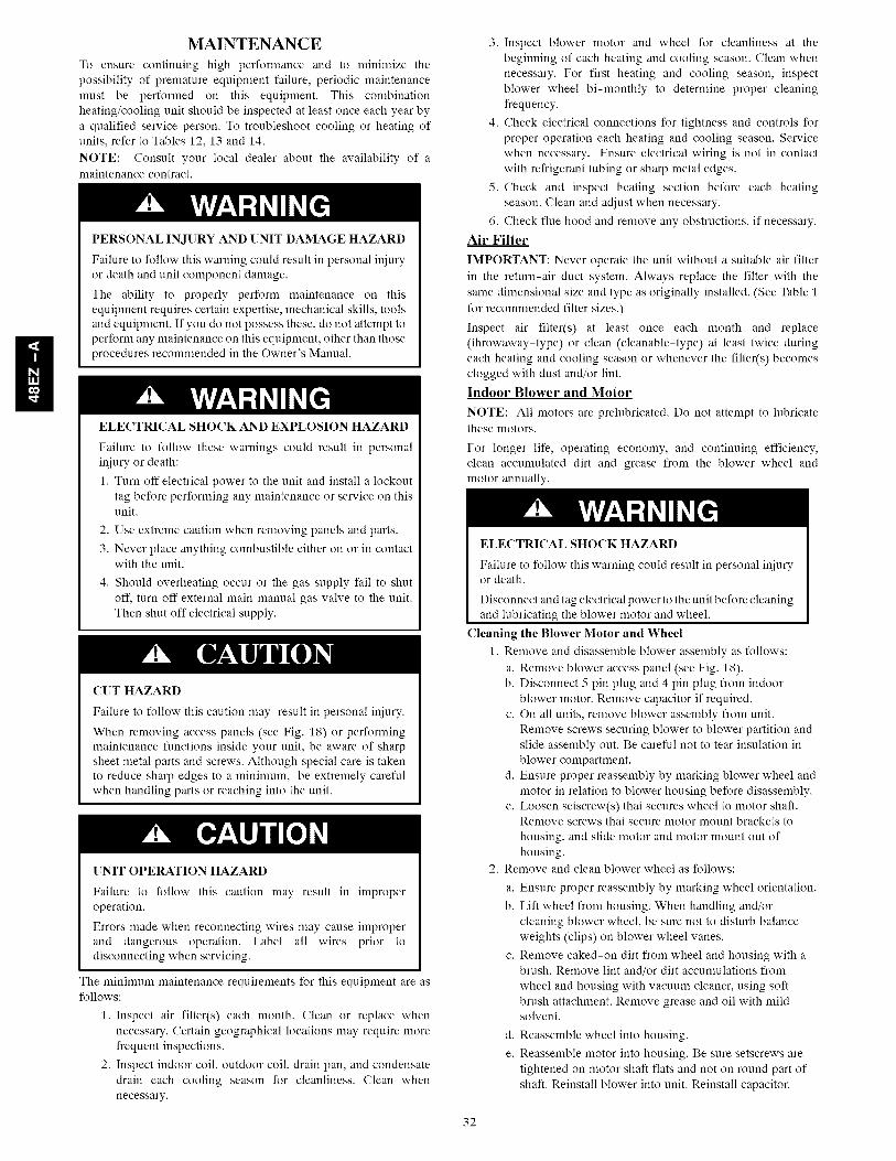
H
MAINTENANCE
To ensure continuing high performance and to minimize thepossibility of premature equipment failure, periodic maintenancemust be performed on this equipment. This combinationheating/cooling unit should be inspected at least once each year bya qualified service person. To troubleshoot cooling or heating ofunits, refer to Tables 12, 13 and 14.
NOTE: Consult your local dealer about the availability of amaintenance contract.
PERSONAL INJURY AND UNIT DAMAGE HAZARD
Failure to follow this warning could result in personal injury
or death and unit component damage.
The ability to properly perform maintenance on this
equipment requires certain expertise, mechanical skills, tools
and equipment. If you do not possess these, do not attempt to
perform any maintenance on this equipment, other than those
procedures recommended in the Owner's Manual.
ELECTRICAL SHOCK AND EXPLOSION HAZARD
Failure to follow these warnings could result in personaliniury or death:
1. Turn off electrical power to the unit and install a lockouttag before performing any maintenance or service on thisunit.
2. Use extreme caution when removing panels and parts.
3. Never place anything combustible either on or in contactwith the unit.
4. Should overheating occur or the gas supply fail to shutoff, turn off external main manual gas valve to the unit.Then shut off electrical supply.
CUT HAZARD
Failure to follow this caution may result in personal iniury.
When removing access panels (see Fig. 18) or performingmaintenance functions inside your unit, be aware of sharpsheet metal parts and screws. Although special care is takento reduce sharp edges to a minimum, be extremely carefulwhen handling parts or reaching into the unit.
[]NIT OPERATION HAZARD
Failure to follow this caution may result in improperoperation.
Errors made when reconnecting wires may cause improperand dangerous operation. Label all wires prior todisconnecting when servicing.
The minimum maintenance requirements for this equipment are asfollows:
1. Inspect air filter(s) each month. Clean or replace whennecessary. Certain geographical locations may require morefrequent inspections.
2. Inspect indoor coil, outdoor coil, drain pan, and condensatedrain each cooling season for cleanliness. Clean whennecessary.
3. Inspect blower motor and wheel for cleanliness at thebeginning of each heating and cooling season. Clean whennecessary. For first heating and cooling season, inspectblower wheel bi-monthly to determine proper cleaningfrequency.
4. Check electrical connections for tightness and controls forproper operation each heating and cooling season. Servicewhen necessary. Ensure electrical wiring is not in contactwith refrigerant tubing or sharp metal edges.
5. Check and inspect heating section before each heatingseason. Clean and adjust when necessary.
6. Check flue hood and remove any obstructions, if necessary.
Air Filter
IMPORTANT: Never operate the unit without a suitable air filterin the return-air duct system. Always replace the filter with thesame dimensional size and type as originally installed. (See Table 1for recommended filter sizes.)
Inspect air filter(s) at least once each month and replace(throwaway-type) or clean (cleanable-type) at least twice duringeach heating and cooling season or whenever the filter(s) becomesclogged with dust and/or lint.
Indoor Blower and Motor
NOTE: All motors are prelubricated. Do not attempt to lubricatethese motors.
For longer life, operating economy, and continuing efficiency,clean accumulated dirt and grease from the blower wheel andmotor annually.
ELECTRICALSHOCK HAZARD
Failure to follow this warning could result in personal injuryor death.
Disconnect and tag electrical power to the unit before cleaningand lubricating the blower motor and wheel.
Cleaning the Blower Motor and Wheel
1. Remove and disassemble blower assembly as follows:
a. Remove blower access panel (see Fig. 18).b. Disconnect 5 pin plug and 4 pin plug from indoor
blower motor. Remove capacitor if required.c. On all units, remove blower assembly from unit.
Remove screws securing blower to blower partition andslide assembly out. Be careful not to tear insulation inblower compartment.
d. Ensure proper reassembly by marking blower wheel andmotor in relation to blower housing before disassembly.
e. Loosen setscrew(s) that secures wheel to motor shaft.Remove screws that secure motor mount brackets to
housing, and slide motor and motor mount out ofhousing.
2. Remove and clean blower wheel as follows:
a. Ensure proper reassembly by marking wheel orientation.
b. Lift wheel from housing. When handling and/orcleaning blower wheel, be sure not to disturb balanceweights (clips) on blower wheel vanes.
c. Remove caked-on dirt from wheel and housing with abrush. Remove lint and/or dirt accumulations from
wheel and housing with vacuum cleaner, using softbrush attachment. Remove grease and oil with mildsolvent.
d. Reassemble wheel into housing.
e. Reassemble motor into housing. Be sure setscrews aretightened on motor shaft fiats and not on round part ofshaft. Reinstall blower into unit. Reinstall capacitor.
32

f. Connect5pinplugand4pinplugtoindoorblowermotor.
g.Reinstallbloweraccesspanel(seeFig.18).3.Restoreelectricalpowertounit.Startunitandcheckfor
properblowerrotationandmotorspeedsduringheatingandcoolingcycles.
i
Fan Par
Mounting Collector Induce_
Bracket Box Blower
Housing
Burner Mounting
Rack Screw
Integrated
Gas Unit
Rollout
Switch
(IGC)
Auto Transformer
fuses used on 460
(Hidden)
Board (IFB)
Induced Draft
Motor
Fig. 17 - Blower Housing and Flue Collector Box
A09193
COMPRESSORACCESS PANEL
BLOWER
ACCESSPANEL
CONTROLACCESS
PANEL
A09207
Fig. 18 - Unit Access Panels
Induced Draft (combustion air) Blower Assembly
The induced-draft blower assembly consists of the inducer motor,the blower housing, and the induced-draft blower wheel.
Clean periodically to assure proper airflow and heating efficiency.Inspect blower wheel every fall and periodically during the heatingseason. For the first heating season, inspect blower wheelbimonthly to determine proper cleaning frequency.
To inspect blower wheel, remove draft hood assembly. Shine aflashlight into opening to inspect wheel. If cleaning is required,remove induced-draft blower assembly as follows:
1. Remove control access panel (See Fig. 18).2. Remove the 5 screws that attach induced-draft blower as-
sembly to the flue collector box cover.
3. Slide the assembly out of the unit. (See 20). Clean theblower wheel. If additional cleaning is required, continuewith Steps 4 and 5.
4. To remove blower wheel, remove 2 setscrews.
5. To remove inducer motor, remove screws that hold theinducer motor to the blower housing.
6. To reinstall, reverse the procedure outlined above.
Flue Gas Passageways
To inspect the flue collector box and upper areas of the heatexchanger:
1. Remove the induced draft blower assembly according todirections in the Induced Draft Blower Assembly section.
2. Remove the 11 screws holding the flue collector box cover(See Fig. 17) to the heat exchanger assembly. Inspect theheat exchangers.
3. Clean all surfaces, as required, using a wire brush.Limit Switch
Remove blower access panel (see Fig. 18). Limit switch is locatedon the fan partition.
Burner Ignition
Unit is equipped with a direct spark ignition 100 percent lockoutsystem. Ignition module (IGC) is located in the control box (SeeFig. 17). Module contains a self-diagnostic LED. Duringservicing, refer to label diagram or Table 5 in these instructions forLED interpretation.
If lockout occurs, unit may be reset by either momentarilyinterrupting power supply to unit or by turning selector switch toOFF position at the thermostat.Main Burners
At the beginning of each heating season, inspect for deteriorationor blockage due to corrosion or other causes. Observe the mainburner flames and adjust, if necessary.Removal of Gas Train
To remove the gas train for servicing:
1. Shut off main gas valve.
2. Shut off power to unit and install lockout tag.
3. Remove control access panel (See Fig. 18).
4. Disconnect gas piping at unit gas valve.
5. Remove fan partition mounting bracket (2 screws locatedon the left side of the control compartment on the fan parti-tion panel). Slide bracket forward, bottom first, to remove(See Fig. 17).
6. Remove wires connected to gas valve. Mark each wire.
7. Remove the mounting screw that attaches the burner rack tothe unit base (See Fig. 17).
8. Partially slide the burner rack out of the unit (see Fig. 17and 20). Remove ignitor and sensor wires at the burner as-sembly. Remove rollout switch wires.
9. Slide the burner rack out of the unit (See Fig. 17 and 20).
10. To reinstall, reverse the procedure outlined above.
Outdoor Coil, Indoor Coil, and Condensate Drain Pan
Inspect the outdoor coil, indoor coil, and condensate drain pan atleast once each year. The coils are easily cleaned when dry;therefore, inspect and clean the coils either before or after eachcooling season. Remove all obstructions, including weeds andshrubs, that interfere with the airflow through the condenser coil.
Straighten bent fins with a fin comb. If coated with dirt or lint,clean the coils with a vacuum cleaner, using the soft brushattachment. Be careful not to bend the fins. If coated with oil orgrease, clean the coils with a mild detergent-and-water solution.Rinse coils with clear water, using a garden hose. Be careful not tosplash water on motors, insulation, wiring, or air filter(s). For bestresults, spray outdoor coil fins from inside to outside the unit. Onunits with an outer and inner condenser coil, be sure to cleanbetween the coils. Be sure to flush all dirt and debris from the unitbase.
Inspect the drain pan and condensate drain line when inspectingthe coils. Clean the drain pan and condensate drain by removing allforeign matter from the pan. Flush the pan and drain tube withclear water. Do not splash water on the insulation, motor, wiring, orair filter(s). If the drain tube is restricted, clear it with a "plumberssnake" or similar probe device. Ensure that the auxiliary drain portabove the drain tube is also clear.
33
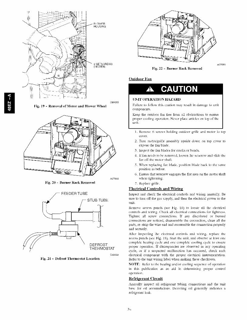
BLOWERHOUSING
2 SETSCREWS
(HIDDEN)Fig. 22 - Burner Rack Removed
Outdoor Fan
A07680
I! Fig. 19 - Removal of Motor and Blower Wheel
Fig. 20 - Burner Rack Removed
FEEDER TUBE
STUB TUBE
DEFROSTTHERMOSTAT
Fig. 21 - Defrost Thermostat Location
C99085
A07680
C99029
UNIT OPERATION HAZARD
Failure to follow this caution may result in damage to unit
components.
Keep the outdoor fan free from all obstructions to ensure
proper cooling operation. Never place articles on top of theunit.
1. Remove 6 screws holding outdoor grille and motor to topcover.
2. Turn motor/grille assembly upside down on top cover to
expose the fan blade.
3. Inspect the fan blades for cracks or bends.
4. If fan needs to be removed, loosen the setscrew and slide thefan off the motor shaft.
5. When replacing fan blade, position blade back to the same
position as before.
6. Ensure that setscrew engages the flat area on the motor shaft
when tightening.
7. Replace grille.
Electrical Controls and Wiring
Inspect and check the electrical controls and wiring annually. Be
sure to turn off the gas supply, and then the electrical power to theunit.
Remove access panels (see Fig. 18) to locate all the electrical
controls and wiring. Check all electrical connections for tightness.
Tighten all screw connections. If any discolored or burned
connections are noticed, disassemble the connection, clean all the
parts, re-strip the wire end and reassemble the connection properly
and securely.
After inspecting the electrical controls and wiring, replace the
access panels (see Fig. 18). Start the unit, and observe at least one
complete heating cycle and one complete cooling cycle to ensure
proper operation. If discrepancies are observed in any operating
cycle, or if a suspected malfunction has occurred, check each
electrical component with the proper electrical instrumentation.
Refer to the unit wiring label when making these checkouts.
NOTE: Refer to the heating and/or cooling sequence of operation
in this publication as an aid in determining proper control
operation.
Refrigerant Circuit
Annually inspect all refrigerant tubing connections and the unit
base for oil accumulations. Detecting oil generally indicates a
refrigerant leak.
34

O -rl--t
-0
O-13Ix.)
©
-<::D--
SpeedupPins
QuietShift
Defrost intervalDI P switches
Fig. 23 - Defrost Control
A08020
EXPLOSION, PERSONALENVIRONMENTAL HAZARD
INJURY AND
Failure to follow this warning could result in personal injury,
death or property damage.
System under pressure. Relieve pressure and recover allrefrigerant before system repair or final unit disposal. Use allservice ports and open all flow-control devices, includingsolenoid valves.
If oil is detected or if low cooling performance is suspected,
leak-test all refrigerant tubing using an electronic leak-detector,
halide torch, or liquid-soap solution. If a refrigerant leak is
detected, refer to the Check for Refrigerant Leaks section.
If no refrigerant leaks are found and low cooling performance is
suspected, refer to the Checking and Adjusting Refrigerant Chargesection.
Gas Input
The gas input does not require checking unless improper heating
performance is suspected. If a problem exists, refer to the Start-Upsection.
Indoor Airflow
The heating and/or cooling airflow does not require checking
unless improper performance is suspected. If a problem exists, be
sure that all supply- and return-air grilles are open and free from
obstructions, and that the air filter is clean. When necessary, refer to
the Indoor Airflow and Airflow Adjustments section to check thesystem airflow,
Check Defrost Thermostat
The defrost thermostat is usually located on the lowest liquid
leaving circuit of the left condenser coil (see Fig. 21). The
thermostat closes at 32°F (0°C) and opens at 65°F (18°C).
Puron Items
Metering Device (Thermostatic Expansion Valve &Piston)
This unit uses both a hard shutoff, balance port TXV in the indoor
coil and a piston in each side of the outdoor coil. The TXV
maintains a constant superheat at the evaporator coil exit (cooling
mode) resulting in higher overall system efficiency.
Pressure Switches
Pressure switches are protective devices wired into control circuit
(low voltage). They shut off compressor if abnomaally high or lowpressures are present in the refrigeration circuit. These pressure
switches are specifically designed to operate with Puron (R-410A)
systems. R-22 pressure switches must not be used as replacements
for the Puron (R-410A) system.
Loss of Charge Switch
This switch is located on the liquid line and protects against low
suction pressures caused by such events as loss of charge, low
airflow across indoor coil, dirty filters, etc. It opens on a pressure
drop at about 20 psig. If system pressure is above this, switchshould be closed. To check switch:
1. Turn off all power to unit.
35
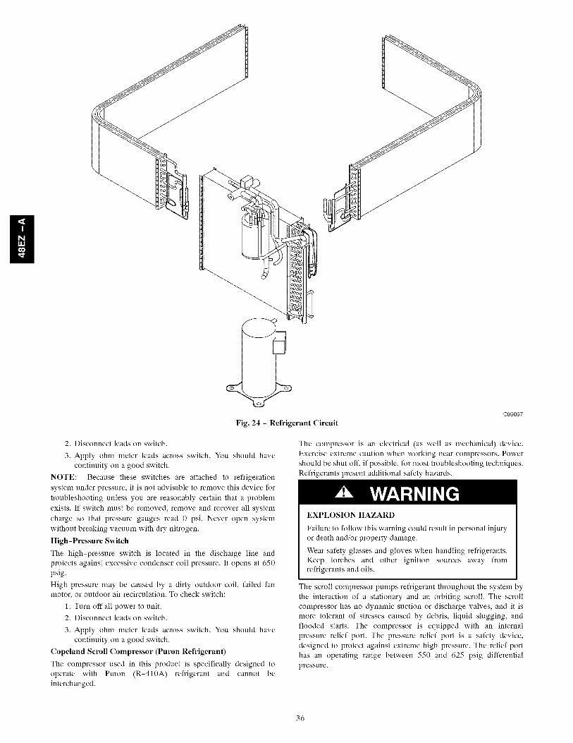
Fig. 24 - Refrigerant Circuit
oggog7
2. Disconnect leads on switch.
3. Apply ohm meter leads across switch. You should have
continuity on a good switch.
NOTE: Because these switches are attached to refrigeration
system under pressure, it is not advisable to remove this device for
troubleshooting unless you are reasonably certain that a problem
exists. If switch must be removed, remove and recover all system
charge so that pressure gauges read 0 psi. Never open system
without breaking vacuum with dry nitrogen.
High-Pressure Switch
The high-pressure switch is located in the discharge line andprotects against excessive condenser coil pressure. It opens at 650
psig.
High pressure may be caused by a dirty outdoor coil, failed fan
motor, or outdoor air recirculation. To check switch:
1. Turn off all power to unit.
2. Disconnect leads on switch.
3. Apply ohm meter leads across switch. You should have
continuity on a good switch.
Copeland Scroll Compressor (Puron Refrigerant)
The compressor used in this product is specifically designed to
operate with Puron (R-410A) refrigerant and cannot be
interchanged.
The compressor is an electrical (as well as mechanical) device.
Exercise extreme caution when working near compressors. Power
should be shut off, if possible, for most troubleshooting techniques.
Refrigerants present additional safety hazards.
EXPLOSION HAZARD
Failure to follow this warning could result in personal injury
or death and/or property damage.
Wear safety glasses and gloves when handling refrigerants.
Keep torches and other ignition sources away from
refrigerants and oils.
The scroll compressor pumps refrigerant throughout the system by
the interaction of a stationary and an orbiting scroll. The scroll
compressor has no dynamic suction or discharge valves, and it is
more tolerant of stresses caused by debris, liquid slugging, and
flooded starts. The compressor is equipped with an internal
pressure relief port. The pressure relief port is a safety device,
designed to protect against extreme high pressure. The relief port
has an operating range between 550 and 625 psig differential
pressure.
36

OUTDOORCOIL
F
I
LEGEND
HPS - High Pressure Switch
LCS - Loss of Charge Switch
_']]_ Accurater_Metering Device
[}7 Arrow indicates direction of flow
BypassPosition
TXV in Meterin(Position
r-q
LCS
Fig. 25 - Typical Heat Pump Operation, Cooling Mode
N DOOR COIL
D
D
I!C03011
OUTDOOR COIL
l
LEGEND
HPS - High Pressure Switch
LCS - Loss of Charge Switch
_ _iii_ Accuratef_Metefing Device
[] Arrow indicates direction of flow
Mete_ngPosition
TXV in BypassPosition
:[=3
LCS
Fig. 26 - Typical Heat Pump Operation, Heating Mode
i
J
INDOOR COIL
*-[
C03012
UNIT OPERATION AND SAFETY HAZARD
Failure to follow this warning could result in personal iniury
or equipment damage.
This system uses Puron (R-410A) refrigerant which hashigher operating pressures than R-22 and other refrigerants.
No other refrigerant may be used in this system. Gauge set,
hoses, and recovery system nmst be designed to handle Puron.
If you are unsure, consult the equipment manufacturer.
Refrigerant System
This information covers the refrigerant system of the 48EZ-A,
including the compressor oil needed, servicing systems on roofs
containing synthetic materials, the filter drier and refrigerant
charging.
Compressor Oil
If additional oil is needed use Uniqema RL32-3MAF. If this oil is
not available, use Copeland Ultra 32CC or Mobil Artic EAL22CC.
This oil is extremely hygroscopic, meaning it absorbs water
readily. POE oils can absorb 15 times as nmch water as other oils
designed for HCFC and CFC refrigerants. Take all necessary
precautions to avoid exposure of the oil to the atmosphere.
37

ServicingSystemsonRoofsand with Synthetic materials
POE (polyolester) compressor lubricants are known to cause longterm damage to some synthetic roofing materials.
Exposure, even if immediately cleaned up, may causeembrittlement (leading to cracking) to occur in one year or more.
When performing any service that may risk exposure ofcompressor oil to the roof, take appropriate precautions to protect
roofing. Procedures which risk oil leakage include, but are not
limited to, compressor replacement, repairing refrigerant leaks,
replacing refrigerant components such as filter drier, pressure
switch, metering device, coil, accumulator, or reversing valve.
Synthetic Roof Precautionary Procedure
1. Cover extended roof working area with an in, permeable
polyethylene (plastic) drip cloth or tarp. Cover an
approximate 10xl0 ft (3x3 m) area.
2. Cover area in front of the unit service panel with a terry
cloth shop towel to absorb lubricant spills and prevent
run-offs, and protect drop cloth from tears caused by tools
or components.
3. Place terry cloth shop towel inside unit immediately under
component(s) to be serviced and prevent lubricant run-offs
through the louvered openings in the unit base.
4. Perform required service.
5. Remove and dispose of any oil contaminated material perlocal codes.
Liquid Line Filter Drier
This filter drier is specifically designed to operate with Puron. Use
only factory-authorized components. Filter drier must be replaced
whenever the refrigerant system is opened. When removing a filter
drier, use a tubing cutter to cut the drier from the system. Do not
unsweat a filter drier from the system. Heat from unsweating will
release moisture and contaminants from drier into system.
Puron (R-410A) Refrigerant Charging
Refer to unit information plate and charging chart. Some R-410A
refrigerant cylinders contain a dip tube to allow liquid refrigerant to
flow from cylinder in upright position. For cylinders equipped
with a dip tube, charge Puron units with cylinder in upright
position and a commercial metering device in manifold hose.
Charge refrigerant into suction-line.
TROUBLESHOOTING
Use the Troubleshooting Guides (See Tables 12-14) if problemsoccur with these units.
START-UP CHECKLIST
Use Start-Up checklist to ensure proper start-up procedures arefollowed.
PURON® (R-410A) QUICK REFERENCE GUIDE
• Puron refrigerant operates at 50-70 percent higher pressures than R-22. Be sure that servicing equipment and replacement
components are designed to operate with Puron
• Puron refrigerant cylinders are rose colored.
• Recovery cylinder service pressure rating nmst be 400 psig, DOT 4BA400 or DOT BW400.
• Puron systems should be charged with liquid refrigerant. Use a commercial type metering device in the manifold hose when
charging into suction line with compressor operating
• Manifold sets should be minimum 700 psig high side and 180 psig low side with 550 psig low-side retard.
• Use hoses with minimum 700 psig service pressure rating.
• Leak detectors should be designed to detect HFC refrigerant.
• Puron, as with other HFCs, is only compatible with POE oils.
• Vacuum pumps will not remove moisture from oil.
• Do not use liquid-line filter driers with rated working pressures less than 600 psig.
• Do not leave Puron suction line filter driers in line longer than 72 hrs.
• Do not install a suction-line filter drier in liquid line.
• POE oils absorb moisture rapidly. Do not expose oil to atmosphere.
• POE oils may cause damage to certain plastics and roofing materials.
• Wrap all filter driers and service valves with wet cloth when brazing.
• A factory approved liquid-line filter drier is required on every unit.
• Do NOT use an R-22 TXV.
• Never open system to atmosphere while it is under a vacuum.
• When system must be opened for service, recover refrigerant, evacuate then break vacuum with dry nitrogen and replace filter
driers. Evacuate to 500 microns prior to recharging.
• Do not vent Puron into the atmosphere.
• Observe all warnings, cautions, and bold text.
• All indoor coils must be installed with a hard shutoff Puron TXV metering device.
38
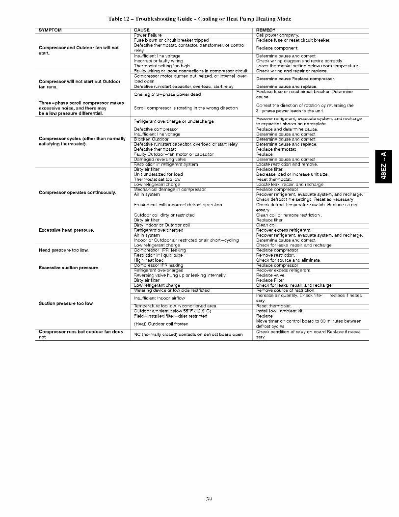
Table12- Troubleshooting Guide - Cooling or Heat Pump Heating Mode
SYMPTOM
Compressor and Outdoor fan will notstart.
Compressor will not start but Outdoorfan runs.
CAUSEPower Failure
Fuse blown or circuit breaker trippedDefective thermostat, contactor, transformer, or controlrelay
Insufficient line voltageIncorrect or faulty wiringThermostat setting too highFaulty wiring or loose connections in compressor circuitCompressor motor burned out, seized, or internal over-load open
Defective run/start capacitor, overload, start relay
One leg of 3-phase power dead
Three-phase scroll compressor makesexcessive noise, and there may Scroll compressor is rotating in the wrong direction
be a low pressure differential.
Refrigerant overcharge or undercharge
Compressor cycles (other than normallysatisfying thermostat).
Compressor operates continuously.
Excessive head pressure.
Head pressure too low.
Excessive suction pressure.
Suction pressure too low.
Compressor runs but outdoor fan doesnot
Defective compressorInsufficient line voltageBlocked Outdoor
Defective run/start capacitor, overload or start relayDefective thermostat
Faulty Outdoor-fan motor or capacitorDamaged reversing valveRestriction in refrigerant systemDirty air filterUnit undersized for loadThermostat set too low
Low refrigerant chargeMechanical damage in compressor.Air in system
Frosted coil with incorrect defrost operation
Outdoor coil dirty or restrictedDirty air filterDirty Indoor or Outdoor coilRefrigerant overchargedAir in systemIndoor or Outdoor air restricted or air short-cyclingLow refrigerant chargeCompressor IPR leakingRestriction in liquid tubeHigh heat loadCompressor IPR leakingRefrigerant overchargedReversing valve hung up or leaking internallyDirty air filterLow refrigerant chargeMetering device or low side restricted
Insufficient Indoor airflow
Temperature too low in conditioned areaOutdoor ambient below 55°F (12.8°C)Field-installed filter-drier restricted
(Heat) Outdoor coil frosted
NC (normally closed) contacts on defrost board open
REMEDY
Call power company.Replace fuse or reset circuit breaker.
Replace component.
Determine cause and correct.
Check wiring diagram and rewire correctly.Lower thermostat setting below room temperature.Check wiring and repair or replace.
Determine cause Replace compressor.
Determine cause and replace.Replace fuse or reset circuit breaker. Determinecause.
Correct the direction of rotation by reversing the
3-phase power leads to the unit.
Recover refrigerant, evacuate system, and recharge
to capacities shown on nameplate.
Replace and determine cause.Determine cause and correct.
Determine cause and correct.
Determine cause and replace.
Replace thermostat.Replace.Determine cause and correctLocate restriction and remove.
Replace filter.Decrease load or increase unit size.Reset thermostat.
Locate leak, repair, and recharge.
Replace compressor.
Recover refrigerant, evacuate system, and recharge.Check defrost time settings, Reset as necessary
Check defrost temperature switch, Replace as nec-
essaryClean coil or remove restriction.
Replace filter.Clean coil.
Recover excess refrigerant.
Recover refrigerant, evacuate system, and recharge.Determine cause and correct.
Check for leaks, repair, and recharge.
Replace compressor.Remove restriction.Check for source and eliminate.
Replace compressor.
Recover excess refrigerant.
Replace valveReplace Filter.
Check for leaks, repair, and recharge.Remove source of restriction.
Increase air quantity. Check filter -- replace if neces-
sary.Reset thermostat.
Install low-ambient kit.
Replace.Move timer on control board to 30 minutes between
defrost cycles
Check condition of relay on board Replace if neces-
sary
39

Table 13 - Troubleshooting Guide-HeatingSYMPTOM CAUSE
Water in gas line
No power to furnace
No 24-v power supply to control circuit
Burners will not ignite Mis-wired or loose connections
Misaligned spark electrodes
No gas at main burners
Dirty air filter
Gas input to furnace too low
Unit undersized for applicationInadequate heating Restricted airflow
Limit switch cycles main burners
Incomplete combustion results in: Aldehyde odors,carbon monoxide, sooting flame, floating flame
Poor flame characteristics
REMEDY
Drain. Install drip leg.
Check power supply fuses, wiring or circuit breaker.
Check transformer.
NOTE: Some transformers have internal over-current protectionthat requires a cool-down period to reset.
Check all wiring and wire nut connections
Check flame ignition and sense electrode positioning.Adjust as necessary.
1. Check gas line for air. Purge as necessary. NOTE: After purginggas line of air, wait at least 5 minutes for any gas to dissipate be-fore attempting to light unit.2. Check gas valve.
Clean or replace filter as necessary
Check gas pressure at manifold match with that on unit nameplate
Replace with proper unit or add additional unit
Clean or replace filter. Remove any restriction.
Check rotation of blower, temperature rise of unit. Adjust as neces-sary.
1. Tighten all screws around burner compartment2. Cracked heat exchanger. Replace.3. Unit over-fired. Reduce input (change orifices or adjust gas lineor manifold pressure).4. Check burner alignment.
5. Inspect heat exchanger for blockage. Clean as necessary.
Table 14 - Troubleshooting Guide-LED Error Codes
SYMPTOM CAUSE REMEDY
Check 5-amp fuse son IGC*, power to unit, 24-v circuit breaker,No Power or Hardware fail- and transformer. Units without a 24-v circuit breaker have an
ure Loss of power to control module (IGC)*. internal overload in the 24-v transformer. If the overload trips,(LED OFF) allow 10 minutes for automatic reset.
Limit switch faults Check the operation of the indoor (evaporator) fan motor, Ensure
(LED 2 flashes) High temperature limit switch is open. that the supply-air temperature rise is in accordance with therange on the unit nameplate. Clean or replace filters.
Flame sense faultThe IGC* sensed flame that should not be present. Reset unit. If problem persists, replace control board.(LED 3 flashes)
4 consecutive limit switch Check the operation of the indoor (evaporator) fan motor and thatfaults Inadequate airflow to unit. supply-air temperature rise agrees with range on unit nameplate(LED 4 flashes) information.
Ignition lockout Check ignitor and flame sensor electrode spacing, gaps, etc.(LED 5 flashes) Unit unsuccessfully attempted ignition for 15 minutes. Ensure that fame sense and ignition wires are properly terminated.
Verify that unit is obtaining proper amount of gas.
Verify wiring connections to pressure switch and inducer motor.
Pressure Switch Fault Verify pressure switch hose is tightly connected to both inducer
(LED 6 flashes) Open pressure switch, housing and pressure switch, Verify inducer wheel is properlyattached to inducer motor shaft. Verify inducer motor shaft is turn-
ing.
Rollout switch will automatically reset, but IGC will continue toRollout switch fault lockout unit. Check gas valve operation. Ensure that induced-draft(LED 7 flashes) Rollout switch has opened, blower wheel is properly secured to motor shaft. Inspect heat
exchanger. Reset unit at unit disconnect.
Internal control fault Microprocessor has sensed an error in the software If error code is not cleared by resetting unit power, replace the
(LED 8 flashes) or hardware. IGC*.
Temporary I hr auto reset Reset 24-v. to control board or turn thermostat off, then on again.(LED 9 flashes) Electrical interference impeding IGC software Fault will automatically reset itself in one (1) hour.
*WARNING .!_ : If the IGC must be replaced, be sure to ground yourself to dissipate any electrical charge that my be present before handling new control
board. The IGC is sensitive to static electricity and my be damaged if the necessary precautions are not taken.IMPORTANT: Refer to Table 12-Troubleshooting Guide-Heating for additional troubleshooting analysis.LEGEND
IGC--Integrated Gas Unit ControllerLED--Light-Emitting Diode
40
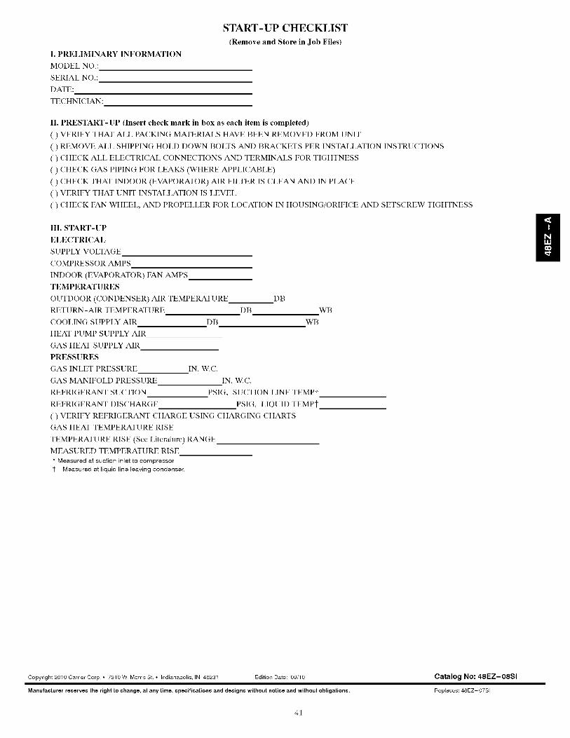
I. PRELIMINARY INFORMATION
MODEL NO.:
SERIAL NO.:
DATE:
TECHNICIAN:
START-UP CHECKLIST
(Remove and Store in Job Files)
II. PRESTART-UP (Insert check mark in box as each item is completed)
( ) VERIFY THAT ALL PACKING MATERIALS HAVE BEEN REMOVED FROM UNIT
( ) REMOVE ALL SHIPPING HOLD DOWN BOLTS AND BRACKETS PER INSTALLATION INSTRUCTIONS
( ) CHECK ALL ELECTRICAL CONNECTIONS AND TERMINALS FOR TIGHTNESS
( ) CHECK GAS PIPING FOR LEAKS (WHERE APPLICABLE)
( ) CHECK THAT INDOOR (EVAPORATOR) AIR FILTER IS CLEAN AND IN PLACE
( ) VERIFY THAT UNIT INSTALLATION IS LEVEL
( ) CHECK FAN WHEEL, AND PROPELLER FOR LOCATION IN HOUSING/ORIFICE AND SETSCREW TIGHTNESS
III. START-UP
ELECTRICAL
SUPPLY VOLTAGE
COMPRESSOR AMPS
INDOOR (EVAPORATOR) FAN AMPS
TEMPERATURES
OUTDOOR (CONDENSER) AIR TEMPERATURE
RETURN-AIR TEMPERATURE DB
COOLING SUPPLY AIR DB
HEAT PUMP SUPPLY AIR
GAS HEAT SUPPLY AIR
PRESSURES
GAS INLET PRESSURE
GAS MANIFOLD PRESSURE
REFRIGERANT SUCTION
REFRIGERANT DISCHARGE
( ) VERIFY REFRIGERANT CHARGE USING CHARGING CHARTS
GAS HEAT TEMPERATURE RISE
TEMPERATURE RISE (See Literature) RANGE
MEASURED TEMPERATURE RISE
* Measured at suction inlet to compressor
1- Measured at liquid line leaving condenser.
DB
WB
WB
IN. W.C.
IN. W.C.
PSIG, SUCTION LINE TEMP*
PSIG, LIQUID TEMPi-
Copyright 2010 Carrier Corp. • 7310 W. Morris St. • Indianapolis, IN 46231 Edition Date: 09/10
Manufacturer reserve8 the right to change, at any time, specification8 and design8 without notice and without obligations.
Catalog No: 48EZ-O8Sl
Replaces: 48EZ-07SI
41