toc - process catalog - airflow meters, airflow measurement · velocity pressure (in w.c.) = total...
TRANSCRIPT
INDUSTRIAL CATALOG
Tab Document Name Part Number
1 TABLE OF CONTENTS ..................................................................................................... N/A
2 SUMMARY OF PRODUCTS Summary of Products.......................................................................................................121-650
3 EDUCATIONAL MATERIALS Standards .........................................................................................................................125-013 Conversion Chart .............................................................................................................125-080
4 FLOW MEASURING & CONTROL STATIONS FAN-E Airflow Measuring Station ....................................................................................125-030 LO-flo/SS Pitot Traverse Station......................................................................................125-038 FAN-E & LO-flo Minimum Installation Requirements....................................................SUB-H012 ACCU-flo Nozzle Pitot Flow Station.................................................................................125-070 Combustion Airflow (CA) Measurement Station .............................................................125-495
5 FLOW MEASURING PROBES VOLU-probe/SS Stainless Steel Pitot Airflow Traverse Probe .......................................125-068 VOLU-probe/SM Airflow Traverse Probe ........................................................................125-069 VOLU-probe/FI-SS Fan Inlet Airflow Traverse Probes.......................SUB-N011,15,13,17,10,14,12,16 CEM Continuous Emissions Monitoring ..........................................................................125-491 STACK-probe/SP ...........................................................................................................SUB-R009
6 PRESSURE SENSORS S.A.P./B,P,S,R Shield Static Air Probe............................................................................125-271 S.O.A.P. Static Outside Air Probe....................................................................................125-275
7 ELECTRONIC TRANSMITTERS & TRANSMITTER-CONTROLLERS VELTRON DPT Ultra Low Range Pressure & Flow Transmitter ....................................125-024 VELTRON DPT-plus Microprocessor Based Transmitter ...............................................125-025 VELTRON II, MASS-tron II & VEL-trol II Microprocessor Based Transmitter.................125-550
8 ACCESSORY PRODUCTS AUTO-purge III .................................................................................................................125-061 CAMS Combustion Airflow Management System...........................................................125-009 Airflow Meters...................................................................................................................125-105 Continuous Protective Purge – Flow Transmitter..........................................................SUB-Q003
Accurate Airflow Measurement for Demanding Applications
1050 Hopper Avenue www.airmonitor.com [email protected] 707.544.2706 - P Santa Rosa, CA 95403 707.526.9970 - F
STANDARDSVelocity Traverse of Air Ducts
These Standards, and others, provide formats for the quantity and positioning of individual velocity measurements. Simply stated, these longestablished Standards recognize that the accuracy of any duct velocity traverse is highly dependent upon the quantity and location of the flowmeasuring points in a duct (or st ack) cross-section. Listed below is a summary t able of the duct traverse format s set forth in the aboveStandards. In addition, for your referral, we have reproduced portions of the text of the referenced Standards.
ASHRAE HANDBOOK
FUNDAMENTALS
I-P Edition
American Society of Heating, Refrigerating and Air-Conditioning Engineers Inc.1791 Tullie Circle, NE
Atlanta, GA 30329
AMCA
FIELD PERFORMANCEMEASUREMENT OF FAN SYSTEMS
Publication 203
Air Movement and Control Association, Inc.30 West University Drive
Arlington Heights, IL 60004-1893
CODE OFFEDERAL REGULATIONS
40 CFR 60, APPENDIX A
Method 1Velocity Traverses for Stationary Sources
Method 2Determination of Gas Velocity and Volumetric Flow Rate
ASHRAE HANDBOOK – FUNDAMENTALSpublished by the American Society of Heating, Refrigerating and Air-Conditioning Engineers, Inc.
To determine the velocity in the traverse plane, a straightaverage of individual point velocities will give satisfactoryresults when point velocities are determined by the log-Tchebycheff rule (ISO 3966). Figure 6 shows suggestedsensor locations for traversing round and rect angularducts. For circular ducts, the log-Tchebycheff and log-linear traverse methods are similar. Log-Tchebycheff isnow recommended for rect angular duct s as well. Itminimizes the positive error (measured greater thanactual) caused by the failure to account for losses atthe duct wall. This error can occur when using the oldermethod of equal subareas to traverse rectangular ducts.
For a rectangular duct traverse, a minimum of 25 pointsshould be measured. For a duct side less than 18 inches,locate the points at the center of equal areas not morethan 6 inches apart, and use a minimum of 2 points perside. For a duct side greater than 56 inches, themaximum distance between points is 8 inches. For acircular duct traverse, the log-linear rule and threesymmetrically disposed diameters may be used. Pointson two perpendicular diameters may be used whereaccess is limited.
Figure 6 – Measuring Points for Round and Rectangular Duct Traverse
Duct / StationConfiguration
Rectangular
Circular
ASHRAEHANDBOOK
25 or more points, maximum 6 or 8inches apart, depending on duct size
12 to 30 points, along 2 or 3 diameters
AMCAPUBLICATION 203
24 or more points, no less than 1point per 3 square feet
24 to 48 points, along 3 diameters
CODE OFFEDERAL REGULATIONS
9 to 16 minimum, depending on distance toflow disturbances
8 to 16 minimum, along 2 diameters,depending on distance to flow disturbances
Accurate airflow measurement for demanding applications

FIELD PERFORMANCE MEASUREMENTS – PUBLICATION 203published by the Air Movement and Control Association, Inc.
Appendix H – Distribution of Traverse PointsThe recommended minimum number of traverse points for rectangularducts is indicated below in Figure H-3. For rectangular duct s withcross-sectional areas of 24 square feet and less, the recommendedminimum number is 24. For cross-sectional areas greater than 24square feet, the minimum number of points increases as indicated inFigure H-3. The points are to be located in the centers of equal areaswith the areas as nearly square as practical (see Figure H-2). If theflow conditions at the traverse plane are less than satisfactory , theaccuracy of the determination of flow rate may be improved by usingmore than the recommended minimum number of points. Fewer pointsmay be used if the flow is very uniform; however, the maximum areacovered per point should not exceed 3 square feet.
Figure H-2. Distribution of Traverse Points for Rectangular Duct
Figure H-3. Recommended Minimum Number of Traverse Pointsfor Rectangular Ducts
In order to obt ain a represent ative average velocity in a duct, it isnecessary to locate each traverse point accurately. It is recommendedthat the number of traverse points increase with increasing duct size.The distribution of traverse points for circular ducts, as indicated below,are based on log-linear Pitot traverse method.
Figure H-1. Distribution of Traverse Points for Circular Ducts
Figure 1-4. Example showing rectangular stack cross section dividedinto 12 equal areas, with a traverse point at centroid of each area.
125-013-00 (1/08)
Figure 1-3. Example showing circular stack cross section divided into12 equal areas, with location of traverse point s indicated.
Figure 1-2. Minimum number of traverse point s for velocity(non-particulate) traverses.
CODE OF FEDERAL REGULATIONS – 40CFR60 Appendix A, Methods 1 and 2Method 1 – Velocity Traverses for Stationary Sources
Method 2 – Determination of Gas Velocity and Volumetric Flow Rate
Xa = D x Ka
where D is the inside diameter of the duct and Ka is the factorcorresponding to the duct size and the traverse point location asindicated in the table below.
K1 K2 K3 K4 K5 K6 K7 K8 K9 K10 K11 K12 K13 K14 K15 K16
< 8 ft 8 .021 .117 .184 .345 .655 .816 .883 .978 – – – – – – – –
8-12 ft 12 .014 .075 .114 .183 .241 .374 .626 .750 .817 .886 .925 .986 – – – –
>12 ft 16 .010 .055 .082 .128 .166 .225 .276 .391 .609 .724 .775 .834 .872 .918 .945 .990
InsideDia
of Duct
# ofTraverse
Pts inEach of3 Dia
P.O. Box 6358 • Santa Rosa, CA 95406 • P: 800-AIRFLOW • F: 707-526-9970www.airmonitor.com • amcsales@airmonitor .com

Calculating Air Volume. The station air volume, expressed cubic feet per minute (CFM), is the product of the air velocity through the airflowstation and the station area in square feet (Ft2).
Station Air Volume (CFM) = Air Velocity (FPM) x Station Area (Ft2)
CONVERSION CHARTVELOCITY PRESSURE in inches of water to VELOCITY in feet per minute
Calculating Air Velocity. Fechheimer Pitot airflow stations and traverse probes measure in the same manner and magnitude as the Pitot tube,via separate signals of airstream total pressure and static pressure, in inches water column (IN w.c.). To obtain velocity pressure (the forcegenerated by the velocity of the air moving in a duct), the static pressure must be subtracted from the total pressure:
Velocity Pressure (IN w.c.) = Total Pressure (IN w.c.) – Static Pressure (IN w.c.)
Air velocity, expressed in feet per minute, is a function of velocity pressure, converted by means of the following formula:
Air Velocity (FPM) = 1096.5 x Velocity Pressure (IN w.c.)Density of (Gas)
In commercial applications where air is the gas, its density is at 70º Fahrenheit and 29.92 inches of mercury (barometric pressure), and theairflow is not compressed (under 10 IN w.c.), the formula reduces to:
Air Velocity (FPM) = 4005 x Velocity Pressure (IN w.c.)
VP V.001" 127.002" 179.003" 219.004" 253.005" 283.006" 310.007" 335.008" 358.009" 380.010" 400.011" 420.012" 439.013" 457.014" 474.015" 491.016" 507.017" 522.018" 537.019" 552.020" 566.021" 580.022" 594.023" 607.024" 620.025" 633.026" 645.027" 658.028" 670.029" 682.030" 694.031" 705.032" 716.033" 727.034" 738.035" 749.036" 759.037" 770.038" 780.039" 791.040" 801.041" 811.042" 821.043" 831.044" 840.045" 849.046" 859.047" 868.048" 877.049" 887.050" 896.051" 904
VP V1.51" 49211.52" 49381.53" 49541.54" 49701.55" 49861.56" 50021.57" 50181.58" 50341.59" 50501.60" 50661.61" 50821.62" 50981.63" 51141.64" 51291.65" 51441.66" 51601.67" 51751.68" 51911.69" 52061.70" 52221.71" 52371.72" 52531.73" 52681.74" 52831.75" 52981.76" 53131.77" 53281.78" 53431.79" 53591.80" 53741.81" 53881.82" 54031.83" 54181.84" 54331.85" 54471.86" 54621.87" 54771.88" 54911.89" 55061.90" 55211.91" 55351.92" 55501.93" 55641.94" 55791.95" 55931.96" 56081.97" 56231.98" 56371.99" 56512.00" 5664
VP V.102" 1279.103" 1285.104" 1292.105" 1298.106" 1304.107" 1310.108" 1316.109" 1322.110" 1328.111" 1334.112" 1340.113" 1346.114" 1352.115" 1358.116" 1364.117" 1370.118" 1376.119" 1382.120" 1387.121" 1393.122" 1399.123" 1404.124" 1410.125" 1416.126" 1422.127" 1427.128" 1433.129" 1439.130" 1444.131" 1449.132" 1455.133" 1461.134" 1466.135" 1471.136" 1477.137" 1482.138" 1488.139" 1493.140" 1498.141" 1504.142" 1509.143" 1515.144" 1520.145" 1525.146" 1530.147" 1536.148" 1541.149" 1546.150" 1551.151" 1556
VP V.152" 1561.153" 1567.154" 1572.155" 1577.156" 1582.157" 1587.158" 1592.159" 1597.160" 1602.161" 1607.162" 1612.163" 1617.164" 1622.165" 1627.166" 1632.167" 1637.168" 1642.169" 1646.170" 1651.171" 1656.172" 1661.173" 1666.174" 1670.175" 1675.176" 1680.177" 1685.178" 1690.179" 1695.180" 1699.181" 1704.182" 1709.183" 1713.184" 1718.185" 1723.186" 1727.187" 1732.188" 1737.189" 1741.190" 1746.191" 1750.192" 1755.193" 1759.194" 1764.195" 1768.196" 1773.197" 1777.198" 1782.199" 1787.200" 1791.201" 1795
VP V.202" 1800.203" 1804.204" 1809.205" 1813.206" 1818.207" 1822.208" 1827.209" 1831.210" 1835.211" 1839.212" 1844.213" 1848.214" 1853.215" 1857.216" 1862.217" 1866.218" 1870.219" 1875.220" 1879.221" 1883.222" 1887.223" 1892.224" 1896.225" 1900.226" 1905.227" 1909.228" 1913.229" 1917.230" 1921.231" 1925.232" 1929.233" 1933.234" 1937.235" 1941.236" 1945.237" 1950.238" 1954.239" 1958.240" 1962.241" 1966.242" 1970.243" 1974.244" 1978.245" 1982.246" 1987.247" 1991.248" 1995.249" 1999.250" 2003.251" 2007
VP V.252" 2011.253" 2015.254" 2019.255" 2023.256" 2027.257" 2031.258" 2035.259" 2039.260" 2042.261" 2046.262" 2050.263" 2054.264" 2058.265" 2062.266" 2066.267" 2070.268" 2074.269" 2078.270" 2081.271" 2085.272" 2089.273" 2093.274" 2097.275" 2101.276" 2105.277" 2109.278" 2113.279" 2116.280" 2119.281" 2123.282" 2127.283" 2131.284" 2135.285" 2139.286" 2143.287" 2147.288" 2151.289" 2154.290" 2157.291" 2161.292" 2164.293" 2168.294" 2171.295" 2175.296" 2179.297" 2182.298" 2186.299" 2189.300" 2193.301" 2197
VP V.302" 2200.303" 2204.304" 2208.305" 2212.306" 2215.307" 2219.308" 2223.309" 2226.310" 2230.311" 2233.312" 2236.313" 2239.314" 2242.315" 2245.316" 2248.317" 2251.318" 2254.319" 2257.320" 2260.321" 2264.322" 2268.323" 2272.324" 2276.325" 2280.326" 2284.327" 2289.328" 2293.329" 2297.330" 2301.331" 2304.332" 2308.333" 2311.334" 2315.335" 2318.336" 2322.337" 2325.338" 2329.339" 2332.340" 2335.341" 2338.342" 2342.343" 2345.344" 2349.345" 2352.346" 2356.347" 2360.348" 2363.349" 2366.350" 2369.351" 2372
VP V.352" 2376.353" 2379.354" 2383.355" 2386.356" 2389.357" 2393.358" 2396.359" 2400.360" 2403.361" 2406.362" 2410.363" 2413.364" 2416.365" 2420.366" 2423.367" 2426.368" 2429.369" 2433.370" 2436.371" 2439.372" 2443.373" 2445.374" 2449.375" 2453.376" 2456.377" 2459.378" 2462.379" 2466.380" 2469.381" 2472.382" 2475.383" 2479.384" 2481.385" 2485.386" 2488.387" 2491.388" 2495.389" 2499.390" 2501.400" 2533.410" 2563.420" 2595.430" 2626.440" 2656.450" 2687.460" 2716.470" 2746.480" 2775.490" 2804.500" 2832
VP V.51" 2860.52" 2888.53" 2916.54" 2943.55" 2970.56" 2997.57" 3024.58" 3050.59" 3076.60" 3102.61" 3127.62" 3153.63" 3179.64" 3204.65" 3229.66" 3254.67" 3279.68" 3303.69" 3327.70" 3351.71" 3375.72" 3398.73" 3422.74" 3445.75" 3468.76" 3491.77" 3514.78" 3537.79" 3560.80" 3582.81" 3604.82" 3625.83" 3657.84" 3669.85" 3690.86" 3709.87" 3729.88" 3758.89" 3779.90" 3800.91" 3821.92" 3842.93" 3863.94" 3884.95" 3904.96" 3924.97" 3945.98" 3965.99" 3985
1.00" 4005
VP V1.01" 40251.02" 40451.03" 40641.04" 40841.05" 41031.06" 41231.07" 41421.08" 41621.09" 41811.10" 42001.11" 42191.12" 42381.13" 42571.14" 42761.15" 42951.16" 43141.17" 43321.18" 43501.19" 43681.20" 43861.21" 44051.22" 44231.23" 44421.24" 44601.25" 44781.26" 44951.27" 45131.28" 45311.29" 45491.30" 45661.31" 45831.32" 46011.33" 46191.34" 46361.35" 46531.36" 46711.37" 46881.38" 47051.39" 47221.40" 47391.41" 47561.42" 47731.43" 47901.44" 48061.45" 48231.46" 48401.47" 48561.48" 48731.49" 48891.50" 4905
VP V.052" 913.053" 922.054" 931.055" 939.056" 948.057" 956.058" 964.059" 973.060" 981.061" 989.062" 996.063" 1004.064" 1012.065" 1020.066" 1029.067" 1037.068" 1045.069" 1052.070" 1060.071" 1067.072" 1075.073" 1082.074" 1089.075" 1097.076" 1104.077" 1111.078" 1119.079" 1125.080" 1133.081" 1140.082" 1147.083" 1154.084" 1161.085" 1167.086" 1175.087" 1181.088" 1188.089" 1193.090" 1201.091" 1208.092" 1215.093" 1222.094" 1228.095" 1234.096" 1241.097" 1247.098" 1254.099" 1260.100" 1266.101" 1273

125-080 (5/00)
P.O. Box 6358 • Santa Rosa, CA 95406 • TEL 800-AIRFLOW • Fax 707-526-9970 • www.airmonitor.com
FAN-E AIRFLOW MEASURING STATION.Multi-point, self-averaging, Pitot traverse station with integral air straightener-equalizer honeycomb cell. Capable of continuously measuring fan dischargesor ducted airflow with an accuracy of two percent or better.
AMCA CERTIFIED in accordance with Standard 610.
VOLU-PROBE/1,2,3,4 AIRFLOW TRAVERSE PROBES.Multi-point, self-averaging, Pitot Fechheimer airflow traverse probes withintegral airflow direction correcting design. Four mounting configurationsto fit every application.
AMCA CERTIFIED in accordance with Standard 610.
VOLU-PROBE/FI FAN INLET AIRFLOW PROBES.Multi-point, self-averaging, Pitot Fechheimer airflow probes with integral airflowdirection correcting design. For mounting directly in the inlet cones or bellmouthof centrifugal or vane-axial fans to measure fan capacities within three percent ofactual flow.
VOLU-PROBE/VS AIRFLOW PROBE TRAVERSE STATIONS.Multi-point, self-averaging, Pitot Fechheimer airflow probes factory mountedin a flanged sheet metal casing, with interconnecting tubing. Capable ofmeasuring ducted airflow within two percent accuracy without using an airstraightener or incurring significant resistance to airflow.
AMCA CERTIFIED in accordance with Standard 610.
S.A.P./1,2,3 and S.O.A.P. STATIC PRESSURE SENSORS.Available in three separate mounting configurations, the S.A.P. family of staticpressure sensors generate a steady, non-pulsating output of room, space orplenum pressure.
The S.O.A.P. was designed to accurately sense outside atmospheric air pressure.
STAT-PROBE STATIC PRESSURE TRAVERSE PROBE.Multi-point, self-averaging, Fechheimer static pressure traverse probe foraccurate sensing of duct or system static pressure in the presence of turbulentor rotational airflows.
Air Monitor's Product Families of Flow Measurement and Pressure Sensors


FAN-EvaluatorAirflow Measuring Station
AIRMOVEMENTAND CONTROLASSOCIATIONINTERNATIONAL, INC. ®
AIRFLOWMEASUREMENT
STATIONAIR
PERFORMANCE
amcaCERTIFIEDRATInGS

The FAN-E is a multi-point, self-averaging Pitot traverse stationwith integral air straightener-equalizer honeycomb cell, capable ofcontinuously measuring fan discharges or ducted airflow with anaccuracy of 2% or better. The FAN-E derives its high degree ofmeasurement accuracy from a combination of precision sensorlocations, honeycomb airflow processing, pneumatic averaging of
a large number of sensed airflow pressures, and patented"symmetrical averaging" (Patent No. 3,685,355), which requiresthat all stages in the averaging process occur at a point where thereis a balanced array of sensors present, thereby assuring that eachsensed pressure is given the same "equal weight" in the averagingprocess as other sensed pressures.
Product Description
FAN-Evaluator
How It Works
Log-Tchebycheff Sensor Location. A high concentration of totaland static pressure sensors positioned according to the log-Tchebycheff rule sense the multiple and varying flow componentsthat constitute the airstream's velocity profile. The log-Tchebycheff'sperimeter weighted sensor pattern is utilized to minimize the positiveerror (measurements greater than actual) caused by the failure toaccount for slower velocities at the duct wall when using traditionalequal area sensor locations. Spacing of total pressure sensors is perASHRAE 1993 Fundamentals Handbook which is summarizedbelow. Since the static pressure across the station is relativelyuniform, a lesser number of static pressure sensors are utilized tominimize unrecovered pressure drop.
Duct / StationConfiguration ASHRAE 1993 Fundamentals Handbook
Rectangular 25 or more points, maximum 6" or 8" apart, depending on duct size.
Circular 12 to 30 points, along 2 or 3 diameters.
Fechheimer Pitot Flow Measurement. The FAN-E operates on theFechheimer Pitot derivative of the multi-point, self-averaging Pitotprinciple to measure the total and static pressure components ofairflow. Total pressure sensing ports with patented (U.S. PatentNo. 4,559,835) chamfered entrances, and Fechheimer pairs of offsetstatic pressure sensing ports combine to minimize the effect ofdirectional airflow. When located downstream of honeycomb airflowprocessing cell, the Fechheimer Pitot method is extremely effectiveat accurately measuring airflow in limited straight duct runs.
Airflow Processing. To assure extremely high levels of measuringaccuracy (2% of actual flow or better) under extreme conditionscaused by turbulent, rotating, and multi-directional airflows normallypresent near fan inlets or discharge ducts and directly downstreamfrom duct elbows, transitions, etc., the FAN-E uses open, parallelcell, honeycomb panels to "process" the air into straightened flowjust prior to the total pressure measurement plane. These honeycombpanels sharply reduce the need for long, straight runs of duct beforeand after the station to obtain accurate flow measurement.
Negligible Airflow Resistance. The FAN-E airflow measuringstation is designed to function while producing a minimum ofresistance to airflow, due to the unique honeycomb air straightener-equalizer section having a free area of 96.6%. The unique, non-restrictive characteristic of the FAN-E is seen in the Resistance vs.Airflow Velocity graph belo w. The values indicated are totalresistance and do not include any allowances for static regain (apotential 20% reduction to the values).
2% Certified Measurement Accuracy
Air Monitor Corporation certifies that theFAN-Evaluator Airflow Measuring Stationshown herein is licensed to bear the AMCACertified Ratings Seal – Airflow MeasurementStation Performance. The ratings shown arebased on tests and procedures performed inaccordance with AMCA Publication 611 andcomply with the requirements of the AMCACertified Ratings Program.
Performance ratings include the effect of anintegral air equalizer-straightener cell in theAMS.
Test Data
Model. FAN-E and FAN-E/SSType. Differential Pressure
Conversion Formula. Velocity = 1096 AMS Velocity Pressure
Air DensitySizes & Shapes Tested. 36" x 36" Rectangular; 36" dia. CircularApplicable Sizes Rated. Rectangular stations with cross-sectional
areas between 4.5 and 18.0 square feet.Circular stations with cross-sectional areasbetween 3.5 and 14.1 square feet.
Test Setup. AMCA Standard 610, Figure 1
Test Results – Rectangular Stations
AirflowReference Reference % Resistance
V olume, ACFM Velocity, AFPM Accuracy IN w.c.
35,838 3,982 1.72 .29729,689 3,299 1.59 .22524,616 2,735 1.51 .15820,400 2,267 1.14 .08914,434 1,604 0.84 .046
8,629 959 2.08 .021
Test Results – Circular Stations
AirflowReference Reference % Resistance
V olume, ACFM Velocity, AFPM Accuracy IN w.c.
29,141 4,123 0.64 .27224,275 3,434 – 0.17 .20020,176 2,854 – 0.51 .11214,550 2,058 – 0.77 .06710,215 1,445 0.33 .038
8,672 1,227 1.24 .021
AIRMOVEMENTAND CONTROLASSOCIATION
INTERNATIONAL, INC. ®
AIRFLOWMEASUREMENT
STATIONAIR
PERFORMANCE
amcaCERTIFIEDRATInGS

Construction Features
Airf low Measuring Station
90º Connection Flanges
Total and Static Pressure Signal Connection Fittings
Welded 14 Ga.Galvanized Casing
8" Depth (10" for Beaded)
Offset FechheimerStatic Pressure Sensors
Copper Total PressureSensing Manifold
Specifications
Air Equalizer – Straightener Cell.Corrosion resistant 3003 aluminum. 3" deep x 1/2" cell.
Total Pressure Manifold.Copper tubing assembled with 50/50 tin/lead solder.Galvanized mounting and support brackets.
Static Pressure Header and Sensors.Copper tubing. Galvanized mounting bracket.
Connection Fittings.1/4" brass compression type located on the long dimension ofrectangular and flat oval stations.
Special Construction.Casing and Flanges: Aluminum, Carbon Steel, Stainless Steel,
PVC and Fiberglass, Hastelloy, Inconel.Air Equalizer–Straightener Cell: Type 304 and 316 Stainless
Steel, Carbon Steel, PVC, Hastelloy.Total and Static Pressure Manifolds: Type 316 Stainless Steel,
Hastelloy, Inconel, PVC, Kynar.Connection Fittings: Stainless Steel, Hastelloy, Nylon.
Contact the Factory for special construction stations using theabove listed and other materials.
Configurations.Rectangular, Circular, and Flat Oval.
Accuracy.2% of actual flow.
Operating Temperature.Continuous operation to 200ºF.
Casing.Rectangular. 14 gauge galvanized sheet metal, intermittent
welded casing sealed with metal caulking.Circular and Flat Oval. 18 gauge galvanized sheet metal, spot
welded casing seams.
Casing Depth.8" deep for stations with 90º flanges.10" deep, 8" from bead-to-bead for stations with beaded edges.
Flanges.Rectangular. 1-1/2" wide, 90º formed. Sizes up to 144" x 144".Circular and Flat Oval.
Sizes 10" to 24". 1" wide flanges, or beaded edge.Sizes > 24" and < 45". 1-1/2" wide flange.Sizes > 45". 3/16" x 2" bar stock flanges.
Aluminum Honeycomb Air Straightener
Copper Total PressureCentral Averaging Manifold

Note: FAN-E locations shown are not ideal. The locations indicate the minimum clearance required from air turbulence producing sources.Wherever possible, the FAN-E should be installed where greater runs of straight duct (or clearances) than shown below exist.
Minimum Installation Requirements
125-030 (May 2011)Web (6/16)
FAN-Evaluator
Rectangular Duct: x = Circular Duct: x = Duct Diameter2 H x W
H + W
The airflow measuring station(s) shall be fabricated of a minimumof 14 ga. galvanized steel, welded casing in 8" depth with 90ºconnecting flanges in a configuration and size equal to that ofthe duct it is mounted into. Each station shall be complete withan open parallel cell air straightener-equalizer honeycombmechanically fastened to the casing, and external signalconnection fittings. An identification label shall be placed oneach station casing listing the model number, size, area, andspecified airflow capacity.
Stations shall be AMCA certified and be capable of measuringthe airflow rates within an accuracy of ±2%. The maximumallowable unrecovered pressure drop caused by the stationshall not exceed .085" w.c. at 2000 FPM, or .30" w.c. at 4000FPM.
The airflow measuring station(s) shall be the FAN-Evaluator asmanufactured by Air Monitor Corporation, Santa Rosa, California.
Suggested Specification
Provide where indicated, airflow measuring station(s) capableof continuously monitoring the fan or duct capacities (air volumes)they serve.
Each airflow measuring station shall contain multiple total andstatic pressure sensors positioned in a log-Tchebycheff pattern.Rectangular stations having a cross-section greater than 4square feet will have a minimum of 25 points of measurement.For stations having a dimension less than 18", locate the pointsof measurement at the center of equal areas not more than 6"apart, and use a minimum of two measurement points per side.For a station having a dimension greater than 56", the maximumdistance between measurement points will be 8". For circularducts having a diameter of 18" or greater, locate measurementpoints on three systematically disposed diameters. For roundstations smaller than 18", locate the measurement points on twoperpendicular diameters.
P.O. Box 6358 • Santa Rosa, CA 95406 • TEL 800-AIRFLOW • Fax 707-526-9970www.airmonitor.com • amcsales@airmonitor .com

LO-flo/SSPitot Traverse Station

LO-flo/SS
The LO-flo Pitot Traverse Station is a combination air equalizer-straightener with self-averaging Pitot tube traverse station. TheLO-flo is fabricated entirely of Type 316 stainless steel with allwelded construction. It is capable of operation up to 1000ºF and issuitable for application to corrosive gases within the limitation ofthe 316 stainless steel construction.
The LO-flo provides highly accurate measurement of low airvolumes of 2 to 2000 CFM for monitoring, indicating, andcontrolling applications when coupled with ultra-low span electronicdifferential pressure or flow transmitters (such as the Air MonitorVELTRON II, MASS-tron II, and VELTRON DPT-plus trans-mitters). See respective product brochures for operating ranges andperformance data.
Product Description
Specifications
Air Equalizer – Straightener Cell.Type 316 welded stainless steel cell.2" deep x ¹/₈" cell for sizes ³/₄" up to 3".3" deep x ¹/₄" cell for sizes 4" up to 8".
Total Pressure Manifold.Type 316 stainless steel tubing.
Static Pressure Chamber.Type 316 stainless steel.
Signal Connections.¹/₄" FPT.
Special Construction.14 ga, 10 ga, and ¹/₄" plate flanges. Integral RTD temperaturesensor and transmitter. PVC, Inconel, Hastelloy, etc., materialsof construction.
Accuracy.2% of actual flow.
Operating Temperature.Continuous operation to 900ºF.
Maximum Static Pressure.20 psig.
Casing.Schedule 5, Type 316 stainless steel pipe.
Casing Depth.12" deep for Models P and F.12" deep plus the depth of two transitions for Models R and FR.See rear cover for detailed dimensions.
Flanges.150 lb. raised face, Type 316 stainless steel for Models F and FR.
How It Works
Equal Area Traverse. Total and static pressure sensors arepositioned so that each sensor represents an equal portion of thestation's cross-sectional area. The total pressure sensors are the onlymeans for sensing the multiple velocity pressures in the airstreamprofile, therefore, a maximum number of total pressure sensors areutilized. Since the static pressure across the station is relativelyuniform, a lesser number of static pressure sensors are utilized.
Equal Weighted Average. The "averaging" process in the airflowmeasuring station manifolds is critical to maintaining highmeasurement accuracy. Unlike a manual Pitot tube traverse whereindividually taken velocity readings are totalled and mathematicallyaveraged, the airflow measuring station must pneumatically averageall of the sensed total pressure values in a manner that gives equalweight to each value. The adjacent figure illustrates how totalpressure sensors are positioned to represent each cross-section equalarea in a balanced pattern to achieve equal weighted averaging.
Airflow Processing. To assure extremely high levels of measuringaccuracy (2% of actual flow or better) under adverse conditionscaused by turbulent, rotating, and multi-directional airflows normallypresent directly downstream from duct elbows, transitions, etc., theLO-flo uses open, parallel cell, honeycomb panels to "process" theair into straightened flow just prior to the total pressure measurementplane. These honeycomb panels sharply reduce the need for long,straight runs of duct before and after the station to obtain accurateflow measurement.

Construction Features
Pitot Traverse Station
Suggested Specification
Provide at each indicated location a self-averaging Pitot traversestation with integral flow straightener-equalizer for continuousmonitoring of the air volume flow rate in that line.
Each flow traverse station shall contain multiple Pitot total andstatic pressure sensors placed at concentric area centers. A flowstraightener-equalizer consisting of an open cell honeycomb structurehaving a minimum cell size-to-length ratio of 12 to 1 shall be mountedupstream of the sensors to eliminate all turbulent and rotationalflows. The Pitot sensors shall be mounted on averaging manifolds,
terminating in external 1/4" FPT fittings for signal connections. Theentire flow station assembly shall be fabricated of Type 316 stainlesssteel, all welded construction, and be furnished with the required[pipe flanges, reducers, weld-in, compression fittings] for mountingin the indicated lines.
The flow traverse station shall be capable of measuring the air volumewithin an accuracy of 2% of actual flow. The station shall be theLO-flo Pitot traverse station as manufactured by Air MonitorCorporation, Santa Rosa, California.
Note: LO-flo locations shown are not ideal. The locations indicate the minimum clearance required from turbulence producing sources.Wherever possible, the LO-flo should be installed where straight runs exist.
Minimum Installation Requirements
Static Pressure Averaging Chamber
1/4" Total Pressure Signal Connection
1/4" FPT Static Pressure Signal Connection
Schedule 5 Pipe Casing
150 lb. Raised Face Flange(Models F and FR)
Air Equalizer-Straightener Cell
Model P – Plain Ends Model R – Reducer
Model F – Flanged Ends Model FR – Flanged Reducer
Dimensional Specifications
125-038 (9/97)
LO-flo/SS Pitot Traverse Station
StationNominal
Size
Basic Station Flange Options Reducer Options
GNominal
No. of SensorsAir
VolumeRange,CFM
AreaFactorSq Ft
Straightener/Equalizer
AFlangeSize
ASA 150#Raised Face Pipe
SizeE
FO.D.
TotalPressure
StaticPressure
O.D. I.D. C* D
³/₄"
1"
1¹/₄"
1¹/₂"
2"
3"
4"
5"
6"
8"
1.05
1.32
1.66
1.90
2.38
3.50
4.50
5.56
6.63
8.63
³/₄"1"
1¹/₄"1¹/₂"
1"1¹/₂"2"
1¹/₄"2"
2¹/₂"
1¹/₂"2"
2¹/₂"3"
2"3"
3¹/₂"4"
3"4"5"6"
4"6"8"
5"6"8"
6"8"
8"
.50
.56
.62
.69
.56
.69
.75
.62
.75
.88
.69
.75
.88
.94
.75
.94
.94
.94
.94
.94
.941.00
.941.001.12
.941.001.12
1.001.12
1.12
.920
1.185
1.53
1.77
2.245
3.334
4.334
5.345
6.407
8.407
3.884.254.625.00
4.255.006.00
4.626.007.00
5.006.007.007.50
6.007.508.509.00
7.509.00
10.0011.00
9.0011.0013.50
10.0011.0013.50
11.0013.50
13.50
—1"
1¹/₄"1¹/₂"
—1¹/₂"2"
—2"
2¹/₂"
—2"
2¹/₂"3"
—3"
3¹/₂"4"
—4"5"6"
—6"8"
—6"8"
—8"
8"
—2.02.02.5
—2.53.0
—3.03.5
—3.03.53.5
—3.54.04.0
—4.05.05.5
—5.56.0
—5.56.0
—6.0
6.0
—1.3151.661.90
—1.902.375
—2.3752.975
—2.3752.8753.50
—3.504.004.50
—4.505.5626.625
—6.6258.625
—6.6258.625
—8.625
8.625
1.10
1.10
1.10
1.25
1.25
1.25
1.25
1.25
1.25
1.25
4
4
6
6
8
14
14
14
14
14
4
4
6
6
6
8
8
8
8
8
2 to25
3 to33
5 to70
7 to95
12 to170
24 to340
40 to570
60 to880
90 to1250
150 to2160
¹/₈" x 2"
¹/₈" x 2"
¹/₈" x 2"
¹/₈" x 2"
¹/₈" x 2"
¹/₈" x 2"
¹/₄" x 3"
¹/₄" x 3"
¹/₄" x 3"
¹/₄" x 3"
.0046
.0077
.0128
.0171
.0275
.0606
.1025
.1558
.2239
.3855
P.O. Box 6358 • Santa Rosa, CA 95406 • TEL 800-AIRFLOW • Fax 707-526-9970 • www.airmonitor.com

SUBMITTAL SHEET
P.O. Box 6358 • Santa Rosa, CA 95406 • (707) 544-2706 • (707) 526-2825 Fax
SUB-H012, Rev. 5 (10/02)
FAN-E and LO-floMINIMUM INSTALLATION REQUIREMENTS
INSTALLATION CONSIDERATIONS. Installation factors to be considered when applying the FAN-E are as follows:
Turbulent Airflow. The unique use of honeycomb airflow straightener in the FAN-E will permit accurate flow measurement in the pres-ence of moderate air turbulence. The distances from air turbulence producing fittings, transitions, etc., shown below in the MinimumRequirements for Installation, are required to assure accurate FAN-E operation.
Airborne Contaminants. The levels of air filtration and cleanliness associated with commercial HVAC Systems, whether supply/return/exhaust/outside air, are satisfactory for operation of the FAN-E. Industrial applications containing airborne contaminants may requireperiodic manual or automatic cleaning using compressed air applied via the signal fittings, and/or physical cleaning.
Direction of Airflow. The FAN-E will function only with the airflow passing through the air straightener section prior to entering the totaland static pressure sensing section. To prevent improper installation, each FAN-E is marked with an arrow indicating the requireddirection of airflow.
MINIMUM REQUIREMENTS FOR INSTALLATION. Note: FAN-E locations shown are NOT ideal. They indicate the minimum clear-ance required from air turbulence producing sources. Wherever possible, the FAN-E should be installed where greater runs of straightduct (or clearances) than shown exist.
2X 1X 3X 1X 2X
CENTRIFUGAL FAN CENTRIFUGAL FAN VANE-AXIAL FAN DISCHARGE VANE-AXIAL FAN INLET DISCHARGE INLET
FANS DAMPERS
ELBOWS TAKEOFFS
DUCT TRANSITIONS
X2
X2
90º VANED ELBOW ROUNDSWEEP
ELBOW
90º UNVANED ELBOW SWEEP ELBOW
1XX2
2X
X2
2X
X2 1X
X2 3X
X2
X2
α
α
α
α
α
α
X2
X2
α
α
α
α
α
TRANSITION ANGLE: < -15º TRANSITION ANGLE: < -15º TRANSITION ANGLE: < -15º TRANSITION ANGLE: < -15º
( )Rectangular Duct: x = Circular Duct: x = Duct Diameter2 H x W
H + W
3.10.2

ACCU-f lo / NPNozzle Pitot Flow Station
Accurate airflow measurement for demanding applications

The ACCU-flo/NP is a combination precision nozzle and multi-point self-averaging Fechheimer Pitot airflow measuring station.When combined with an ultra high accuracy transmitter such asAir Monitor’s VELTRON II, MASS-tron II or VELTRON DPT-plus,the ACCU-flo/NP provides high accuracy (±0.5%) flowmeasurement for process monitoring and control applications.Due to the combined effect of the integral flow straightener cell
and the nozzle, the ACCU-flo/NP requires little or no upstreamstraight run to achieve its published measurement accuracy.Constructed of either Type 316 stainless steel or carbon steelwith a combination of welded and bolted flanges, the ACCU-flo/NP is capable of operation up to 900ºF and is suitable forapplication to corrosive gases within the limitations of Type 316stainless steel.
Product Description
Specifications
Air Straightener Cell. 1/4” or 3/8” hexagonal welded cell,Type 316 stainless steel.
Total & Static Pressure Sensors. Type 316 stainless steel.
Signal Fittings. 1/4” FPT, stainless or carbon steel to matchcasing material.
Non-Recovered Pressure Loss. 42-45% of the velocityhead (pressure) for the design flow rate.
Special Construction. Integral temperature sensor andtransmitter. Static pressure port. Temperature port. 316stainless zeroing valve with 1/4" NPTF connection.
Accuracy. 0.5% of actual flow.
Operating Temperature. Continuous operation to 900ºF.
Maximum Static Pressure. Dependent on materials ofconstruction, operating temperature, and installation. ContactFactory.
Casing. Model S. Rolled sheet metal, Type 316 stainless steel.Model HP. Pipe, Type 316 stainless or carbon steel.
Flanges. Model S. 10 ga. plate, Type 316 stainless steel.Model HP. 150 lb. raised face flange, stainless orcarbon steel.
Nozzle. Type 316 stainless steel.
How It Works
Precision Nozzle. The precision nozzle incorporated in theACCU-flo/NP reduces the measurement area by 50%, whichhas the effect of conditioning the velocity profile of the measuredflow stream, producing highly uniform and stable processpressure signals that are measured at each total and staticpressure sensing port. The nozzle also boosts the measureddifferential pressure by a factor of 4, ensuring high accuracyflow measurement of ±0.5% of actual flow down to 175 FPM.
Airflow Processing . In order to achieve i ts precisemeasurement accuracy under adverse conditions caused byturbulent, rotating, and multi-directional airflows, the ACCU-flo/NP uses a parallel cell honeycomb panel to process the flowinto velocity vectors parallel with its longitudinal axis.Downstream of the cell the precision nozzle compresses thestraightened airflow, which has the ef fect of flattening thevelocity profile where it comes in contact with the total andstatic pressure sensing manifolds. The combination of thehoneycomb panel and precision nozzle eliminates the traditional
ACCU-f lo / NP
need for long upstream straight runs of duct required to obtainaccurate flow measurement. See Figure 1.
Equal Weighted Average. Within the separate total and staticpressure manifolds the individually sensed pressures arepneumatically averaged in a manner that gives equal weight toeach value. The equal weighted averaging compensates forany remaining minor variances in total pressure at the plane ofmeasurement.
Fechheimer Static Pressure Measurement. Even smallamounts of flow angularity can contribute to measurement error.The ACCU-flo/NP utilizes paired Fechheimer static pressure portspositioned at designated angles offset from the flow normalvector. As flow angularity veers from normal, one port isexposed to a higher pressure (P s + part of P t), whereas theother port experiences a lower pressure (Ps - part of Pt) of thesame magnitude, thereby canceling out the undesired effect ofthe partial total pressure (Pt). See Figure 2.
Figure 1 Figure 2

Nozzle Pitot Flow Station
Construction Features
Suggested Specification
Provide at each indicated location a precision nozzle, multi-point self-averaging Pitot airflow measuring station integral flowstraightener, for continuous flow rate measurement.
Each flow measurement station shall contain Fechheimer Pitottraverse probes with multiple total and static pressure sensorsplaced in the minimum throat diameter of a precision flow nozzle.Flow straightener in the form of an open cell honeycomb structurehaving a minimum cell length-to-size ratio of 8:1 shall be mountedupstream of the nozzle and traverse probes to eliminateturbulent, rotational and angular flow.
The flow nozzle shall reduce the area at the point of measurementby 50% and shall produce a uniform velocity profile.
The entire flow station shall be constructed of Type 316 stainlesssteel [or carbon steel] casing and flange materials that theconstruction of the pipe or duct into which the station will bemounted.
The flow traverse station shall be capable of measuring thevolumetric flow within an accuracy of 0.5% of reading over arange of 175 to 10,000 FPM and shall require no length of straightduct upstream of the measurement point.
The station shall be the ACCU-flo/NP Nozzle-Pitot Flow Stationas manufactured by Air Monitor Corporation, Santa Rosa,California.
Rolled metal or pipe casing
These installation locations indicate the minimum clearance from a source of airflow disturbance. If more than the minimum is available,proportionally adjust the upstream and downstream clearances. Avoid locating the ACCU-flo/NP where it will be subjected to condensationfrom a coil or humidifier. Contact Air Monitor's Applications Engineering Department to discuss sub-minimum installation.
Minimum Installation Requirements
Parallel cellhoneycomb air
straightener
Precision nozzle
1/2” FPT temperature probe insertion port
1/4” FPT processsignal connections
Total and staticpressure manifolds
Plate steel or150 lb RF flanges

ACCU-f lo / NP – Nozzle Pitot Flow Station
Dimensional Specifications – Model S
125-070 (7/07)
Dimensional Specifications – Model HP
P.O. Box 6358 • Santa Rosa, CA 95406 • P: 800-AIRFLOW • F: 707-526-9970www.airmonitor.com • amcsales@airmonito r.com
Nominal Duct Duct Flange Bolt Bolt CellDuct Size ID Wall O.D. Circle Qty Hex Size
4" 4.03 0.237 9.0 7.50 8 1/4 x 3 6" 6.07 0.280 11.0 9.50 8 1/4 x 3 8" 7.98 0.322 13.5 11.75 8 3/8 x 310" 10.02 0.365 16.0 14.25 12 3/8 x 312" 12.00 0.375 19.0 17.00 12 3/8 x 3
Nominal Duct Duct Flange Bolt Bolt CellDuct Size ID Wall O.D. Circle Qty Hex Size
14" 13.25 0.375 21.0 19.75 12 3/8 x 316" 15.25 0.375 23.5 21.25 16 3/8 x 318" 17.25 0.375 25.0 22.75 16 3/8 x 320" 19.25 0.375 27.5 25.00 20 3/8 x 324" 23.25 0.375 32.0 29.50 20 3/8 x 3
Nominal Duct Duct Flange Bolt Bolt CellDuct Size ID Wall O.D. Circle Qty Hex Size
4" 3.87 0.048 6.06 5.31 6 1/4 x 3 6" 5.87 0.075 8.09 7.31 6 1/4 x 3 8" 7.85 0.075 10.38 9.56 6 3/8 x 310" 9.85 0.075 12.88 11.81 6 3/8 x 312" 11.85 0.075 15.13 14.00 6 3/8 x 314" 13.85 0.075 17.13 16.00 8 3/8 x 3
Nominal Duct Duct Flange Bolt Bolt CellDuct Size ID Wall O.D. Circle Qty Hex Size
16" 15.85 0.075 19.13 18.00 8 3/8 x 318" 17.85 0.075 21.13 20.00 8 3/8 x 320" 19.85 0.075 23.13 21.75 12 3/8 x 324" 23.85 0.075 27.13 25.88 12 3/8 x 330" 29.85 0.075 34.13 32.38 16 3/8 x 3

CA StationCombustion Airflow Measurement Station
Proven solutions for a tough industry

CA Station
How It Works
The CA Station is also ideally suited to measure SA enteringeach burner level of a partitioned windbox, SA being taken outof a windbox to supply multiple OFA ports, at the ducted inlet ofFD fans, and bulk SA entering each windbox of a corner firedunit.
The Need for Combustion Airflow MeasurementThe objectives in the power industry today are twofold; to loweremissions, and increase plant performance. Precisemeasurement of combustion airflow and fuel rates positivelycontributes to achieving those objectives, by providing theinformation needed to optimize stoichiometric ratios and facilitatemore complete, stable combustion. Usable measurements cannotbe obtained from existing devices such as venturis, foils, jambtubes, etc., or instrumentation such as thermal anemometersdue to limited available straight duct runs, low flow rates,proximity to modulating control dampers, broad turndown range,and high concentrations of airborne particulate (flyash).
AMC Power’s ruggedly constructed Combustion Air (CA) Station,with both integral airflow processing cell and Fechheimer-Pitotmeasurement technology, is engineered to meet the challengingoperating conditions of the typical power plant while providingmass flow measurement of PA, SA, and OFA within an accuracyof ±2-3% of actual airflow.
While the main functions of primary air are to first dry and thenpneumatically convey the pulverized coal from the mill to theindividual burners, it also determines coal particle velocity at theburner exit, influencing the flame position relative to the burnertip and impacting flame stability, both key factors in achievingoptimized burner performance. Accurate PA measurementobtained with a CA Station can contribute to reducing NOx andCO, improving flame stability, avoidance of coal pipe layout,minimizing LOI/UBC, reducing waterwall corrosion, andincreasing combustion efficiency.
Log-Tchebycheff Sensor Location. A high concentration oftotal and static pressure sensors positioned according to thelog-Tchebycheff rule sense the multiple and varying flowcomponents that constitute the airstream's velocity profile. Thelog-Tchebycheff's perimeter weighted sensor pattern is utilizedto minimize the positive error (measurements greater than actual)caused by the failure to account for slower velocities at theduct wall when using traditional equal area sensor locations.Spacing of total pressure sensors is per the table below. Sincethe static pressure across the station is relatively uniform, alesser number of static pressure sensors are utilized to minimizeunrecovered pressure drop.
Fechheimer Pitot Flow Measurement. The CA Stationoperates on the Fechheimer-Pitot derivative of the multi-point,self-averaging Pitot principle to measure the total and staticpressure components of airflow. Total pressure sensing portswith patented (U.S. Patent No. 4,559,835) chamfered entrances,and Fechheimer pairs of offset static pressure sensing portscombine to minimize the effect of directional airflow . Whenlocated downstream of honeycomb airflow processing cell, theFechheimer Pitot method is extremely effective at accuratelymeasuring airflow in limited straight duct runs.
Airflow Processing. To assure extremely high levels ofmeasuring accuracy (3% of actual flow) under extremeconditions caused by turbulent, rotating, and multi-directionalairflows normally present near fan inlets, discharge ducts, anddirectly downstream from duct elbows, transitions, etc., the CAStation uses open, parallel cell, honeycomb panels to "process"the air into straightened flow just prior to the total pressuremeasurement plane. These honeycomb panels sharply reducethe need for long, straight runs of duct before and after thestation to obtain accurate flow measurement.
Negligible Airflow Resistance. The CA Station airflowmeasuring station is designed to function while producing aminimum of resistance to airflow, due to the unique honeycombair straightener-equalizer section having a free area of 96.6%.The unique, non-restrictive characteristic of the CA Station isseen in the Resistance vs. Airflow Velocity graph below. Thevalues indicated are total resistance and do not include anyallowances for static regain (a potential 20% reduction to thevalues).
Duct / StationConfiguration
Rectangular
Circular
Quantity of Sensing Points
25 or more points, maximum 6" or 8" apart,depending on duct size.
12 to 30 points, along 2 or 3 diameters.
Denotes CA Station location
Construction Features
Combustion Airflow Measurement Station
Specifications
Minimum Installation Requirements
Welded 3/16"Carbon Steel Casing
90º Connection Flanges
12" Depth
24 ga. Carbon SteelAirflow Straightener
Offset Fechheimer StaticPressure Sensing Probe
Total Pressure Sensing Manifold
Configurations.Rectangular, Circular, and Custom
Accuracy.2-3% of actual flow
Operating Temperatures.Continuous operation to 800ºF
Connection Fittings.1/2" FPT, Type 316 stainless steel
Static and Total Pressure Sensing Manifolds.Type 316 stainless steel, welded construction
Airflow Straightener.1" hexagonal, parallel cell straightener, 3" deep,24 ga. (.024") thick carbon steel
Casing and Flanges.3/16" carbon steel, continuous welded seamsCasing depth is 12"
Special Construction Options.Sensing Manifold CleanoutsInlet Bell MouthMulti-point Temperature MeasurementAlternate Materials of ConstructionIntegral Control Damper
Optional Manifold Cleanouts

125-495 (04-09)
P.O. Box 6358 • Santa Rosa, CA 95406 • P: 800- AIRFLOW • F: 707-526-9970www.airmonitor.com • amcsales@airmonitor .com
Air Monitor Power's Product Families of Air & Coal Flow Measurement Systems
IBAMTM – Individual Burner Airflow MeasurementThe IBAMTM – Individual Burner Airflow Measurement probe is ideally suited for new orretrofit applications where a reduction in plant emissions and improvement in ef ficiencycan be obtained through accurate measurement of burner secondary airflow. The IBAMTM
probe has been designed to accurately measure in the p articulate laden, high operatingtemperature conditions found in burner air p assages.
CEMSTM – Continuous Emissions Monitoring SystemAir Monitor Power's CEMS TM – Continuous Emissions Monitoring Systems assist incomplying with the Clean Air Act’s stringent emission measurement standards and therequirements of 40 CFR 75. Air Monitor has assembled a cost effective integrated systemconsisting of in-st ack flow measurement equipment and companion instrumentation toprovide continuous, accurate, and reliable volumetric airflow monitoring of stacks and ductsof any size and configuration .
CAMSTM – Combustion Airflow Management Systems.
The CAMSTM – Combustion Airflow Management System has been designed to reliablyand accurately measure airflow in combustion airflow applications. The CAMSTM containsthe microprocessor based instrumentation to measure the airflow and manage the AUTO-purge. The AUTO-purge is a high pressure air blowback system that protect s the ductmounted flow measurement device from any degradation in performance due to thepresence of airborne particulate (flyash).
Engineering & Testing Services. Air Monitor Power offers complete engineering and testing to analyze air and coaldelivery systems. Air Monitor Power ’s field testing services use 3D airflow traversing and Pf- FLO coal flow measurementsystems for the highest possible accuracy . To ensure cost effective and accurate solutions, Air Monitor Power has full scalephysical flow modeling cap ability and in house Computational Fluid Dynamics (CFD). CFD analysis is used to analyze flowprofiles and design/redesign ductwork to improve overall performance. Full scale model fabrication and certified wind tunneltesting is used to develop application specific products that will measure accurately where no standard flow measurement can.
Pf-FLOTM – Pulverized Fuel Flow ManagementThe Pf-FLO TM system performs continuous and accurate fuel flow measurement inpulverized coal fired combustion applications, providing boiler operators with the real-timedata needed to balance coal mass distribution between burners. Balanced fuel improvescombustion efficiency and lowers emissions while reducing in-furnace slagging, coal layout,fuel slagging, and coal pipe fires.
VOLU-probe/SSTM Stainless Steel Airflow Traverse Probes.Multi-point, self-averaging, Pitot-Fechheimer airflow traverse probes with integral airflowdirection correcting design. Constructed of Type 316 st ainless steel and available inexternally and internally mounted versions for harsh, corrosive or high temperatureapplications such as fume hood, laboratory exhaust, pharmaceutical, and clean roomproduction and dirty industrial process applications.

VOLU-probe/SSStainless Steel Pitot Airf low Traverse Probes

The VOLU-probe/SS Stainless Steel Pitot Airflow Traverse Probeis ideally suited for new installations or retrofit applicationsrequiring accurate airflow measurement in locations having limitedstraight duct runs. Multiple sets of total and static pressure sensingports along the entire length of the VOLU-probe/SS traverse theairstream in a single line across the duct, and average the sensedpressures in separate manifolds. An array of VOLU-probe/SS
probes are used to properly sense the typically stratified flow toprovide an equal area traverse of an entire duct cross-section. TheVOLU-probe/SS is suited for clean or harsh and particulate ladenapplications, operating at temperatures ranging from –20 to 900ºF.As a primary flow sensing means, the VOLU-probe/SS can be usedin industrial process applications ranging from power generation(combustion airflow), fiber quenching, process drying, emissionmonitoring, etc.
Product Description
VOLU-probe/SS
When installed per Air Monitor's Minimum InstallationRequirements (see back page), the minimum quantity and placementof VOLU-probe/SS airflow traverse probes shown below willproduce assured measuring accuracies of ±2-3% of actual airflow.
Accuracy
All recognized flow measurement standards (ASHRAEFundamentals, AMCA Publication 203, Industrial VentilationManual, 40CFR60, etc.) agree that accurate airflow measurementis highly dependent upon the quantity and pattern of sensing pointsin the airstream, and the relative position of the sensing points toupstream/downstream flow disturbances.
static sensor experiences a lower pressure (P s – part of Pt) of thesame magnitude, thereby canceling out the undesired effect ofpartial total pressure (P t). It is this unique design of offset staticpressure and chamfered total pressure sensors (see Figure 1) thatmake the VOLU-probe/SS insensitive to approaching multi-directional, rotating airflow with yaw and pitch up to 30º fromstraight flow, thereby assuring the accurate measurement of thesensed airflow rate without the presence of an airflow straightenerupstream. This unique design of the VOLU-probe/SS is coveredby U.S. Patent No. 4,559,835.
How It Works
The VOLU-probe/SS operates on the Fechheimer Pitot derivativeof the multi-point, self-averaging Pitot principle to measure thetotal and static pressure components of airflow. Total pressuresensing ports, with chamfered entrances to eliminate air directioneffects, are located on the leading surface of the VOLU-probe/SSto sense the impact pressure (Pt) of the approaching airstream (seeFigure 2). Fechheimer pair of static pressure sensing ports,positioned at designated angles offset from the flow normal vector,minimize the error inducing effect of directionalized airflow. Asthe flow direction veers from the normal, one static sensor isexposed to a higher pressure (P s + part of P t), whereas the other
Figure 1 Figure 2

The VOLU-probe/1SS is designed for mounting in ducts or stacksby drilling two holes in opposing walls, without the need to enterthose structures.
The VOLU-probe/1SS is furnished with a threaded end support,gasketed washer and nut, and a mounting plate with signal take-offFPT connections, all fabricated of type 316 stainless steel.
VOLU-probe/1SS – Externally Mounted
VOLU-probe/1SS & 2SS
The VOLU-probe/2SS is designed for larger ducts or stacks wherethe size permits entry for installation, or where duct externalaccessibility or clearance is insufficient to permit probe mountingfrom outside the duct.
The VOLU-probe/2SS is furnished with interior mounting and endsupport plates, and midpoint signal take-off FPT connections, allfabricated of type 316 stainless steel.
VOLU-probe/2SS – Internally Mounted

VOLU-probe/SS – Construction Options
VOLU-probe/SS Options
150 lb. Mounting Flange Probe End Supports
Temperature Probe Companion Mounting Plates

Construction Features
Stainless Steel Airf low Traverse Probes
Features
Provides for Equal Area Traverse. Each VOLU-probe/SScontains multiple total and static pressure sensors specifically andprecisely located along the length of the probe to provide an equalarea traverse of ducted airflow. For rectangular duct configurations,the sensors are spaced at equal distances along the probe. Forcircular duct configurations, the sensors are located at the centersof the equivalent concentric area along the probe.
True Velocity Pressure Measurement. The total and staticpressure components of airflow measured by the VOLU-probe/SScan be directly converted in velocity pressure (and velocity) withoutthe use of correction factors, thereby facilitating flow verificationwith a Pitot tube or other hand held instrumentation.
No Sensor Protrusions. The VOLU-probe/SS total and staticpressure sensors are all contained within the confines of the externalsurface of the probe. There are no protruding sensors to be bent,broken, or otherwise damaged during installation or possiblesubsequent removal for inspection or cleaning.
Rugged Construction Assures Long Service Life. The standardVOLU-probe/SS is fabricated from Type 316 stainless steel usingall welded construction. See Page 4 for construction options, andcontact Factory for alternate materials of construction such asHastelloy, Inconel, Kynar, PVC, etc.
No Air Straighteners Required. The VOLU-probe/SS uniquedual offset static pressure sensor and patented chamfered totalpressure sensor design permit the accurate measurement of theairflow rate in highly turbulent flow locations (with directionalyaw and pitch varying up to 30º from the duct's longitudinal axis)without the need for upstream air straightening means.
Offered in Two Models. The VOLU-probe/SS is offered in twobasic configurations to facilitate installation in new or existingducts or stacks; the Model 1 for external mounting, and the Model2 for internal mounting.
Negligible Resistance to Airflow. The VOLU-probe/SScylindrical configuration and smooth surface free of external sensorprotrusions permit the airstream to flow unrestricted around andbetween the installed traverse probes, creating a very minimal, ifnot negligible resistance to airflow (Ex: 0.046 IN w.c. at 2000 fpmair velocity).
Performs Equal-Weighted Averaging of Flow Signals. Throughthe use of separate averaging manifolds, the VOLU-probe/SSinstantaneously averages, on an equal-weighted basis, the multiplepressures sensed along the length of the probe, producing separate"averaged" total pressure and static pressures at the probe's externalsignal connections.
FPT Signal Connections
Offset Fechheimer Static Pressure Sensors
Integral 10 Gauge Mounting Plate
Chamfered Total Pressure Sensors

Note: VOLU-probe/SS locations shown are not ideal. The locations indicate the minimum clearance required from air turbulence producingsources. Wherever possible, the VOLU-probe/SS should be installed where greater runs of straight duct (or clearances) than shown below exist.
Minimum Installation Requirements
125-068 (1/99)Website (10/13)
VOLU-probe/SS
Suggested Specification
Provide where indicated an array of airflow traverse probes capableof continuously monitoring the stack or duct capacities (air volumes)it serves.
Each airflow traverse probe shall contain multiple total and staticpressure sensors and internally connected to their respective averagingmanifolds. The flow sensors shall not protrude beyond the surfaceof each probe, and shall be the offset (Fechheimer) type for staticpressure and the chamfered impact type for total pressuremeasurement. The airflow sensing probe's measurement accuracyshall not be affected by directional flow having pitch and/or yawangles up to 30º.
Each airflow traverse probe shall be fabricated of type 316 stainlesssteel, all welded construction, and shall be furnished with the flat orcurved plate mounting means. In addition, access ports and accessory
hardware shall be provided to facilitate external installation of theprobe and end support (if required), yet permitting easy proberemoval for inspection, etc.
The airflow traverse probe shall not induce a pressure drop in excessof 0.046 IN w.c. at 2000 FPM, nor measurably contribute to soundlevels within the duct. Total and static pressure sensors shall belocated at the centers of equal areas (for rectangular duct) or at equalconcentric area centers (for circular ducts) along the probe length.The airflow traverse probe shall be capable of producing steady,non-pulsating signals of total and static pressure without need forflow corrections or factors, with an accuracy of 2-3% of actual flow,over a velocity range of 400 to 4000 FPM.
The airflow traverse probe(s) shall be the VOLU-probe [1SS, 2SS]as manufactured by Air Monitor Corporation, Santa Rosa, California.
Rectangular Duct: x = Circular Duct: x = Duct Diameter2 H x W
H + W
P.O. Box 6358 • Santa Rosa, CA 95406 • TEL 800-AIRFLOW • Fax 707-526-9970 • www.airmonitor.com

VOLU-probe/SMAirflow Traverse Probe
Product Specifications
• Accuracy. ±2%; dependent upon quantity and placement of probesto achieve traverse of ducted airflow.
• Outputs. Averaged signals of static and total pressure.
• Operating Velocity. 100 to 10,000 FPM.
• Directional Sensitivity. Not measurably affected by directionalairflows with pitch and yaw angles up to 30º.
• Traverse Pattern. On an equal area basis for rectangular probes.On an equal concentric area basis for circular probes.
• Resistance. Less than 0.1 times the velocity pressure head atprobe operating velocity.
• Construction. All welded construction, utilizing Type 316 stainlesssteel. 10 ga. plate, 1" MPT, or 150 lb. RF flange mounting options.
The VOLU-probe/SM Airflow Traverse Probe is ideally suited fornew installations or retrofit applications requiring accurate flowmeasurement in pipes or small duct locations having limited straightduct runs. The "tube-in-tube" design has multiple total and staticpressure sensing ports along the length of the probe to traversethe airstream in a single line across the duct or pipe, providing
separately averaged pressures at the signal connections. TheVOLU-probe/SM is suited for clean applications, operating attemperatures ranging from –20 to 900ºF. As a primary flow sensingmeans, the VOLU-probe/SM can be used in industrial processapplications such as fiber quenching, process drying, emissionmonitoring, wastewater treatment, etc.
Product Description
The VOLU-probe/SM locations shown are not ideal. The locations indicate the minimum clearance required from air turbulence producingsources. Wherever possible, the VOLU-probe/SM should be installed where greater runs of straight duct (or clearances) than shown belowexist.
Minimum Installation Requirements
Rectangular Duct: x = Circular Duct: x = Duct Diameter2 H x W
H + W
1X
Downstream of 15º Transition Upstream of 15º Transition
TRANSITIONSX2
X2
1.5X
90º Vaned Elbow
X22X
Round Sweep Elbow
5X
90º Unvaned Elbow
1X 2XX2
Sweep Elbow
1.5X
Centrifugal Fan Inlet
2X
Vane-Axial Fan Inlet
3X
1X 4X
2X
1X3X
FANS DAMPERS
ELBOWS TAKEOFFS

125-069 (9/12)
VOLU-probe/SM
P.O. Box 6358 • Santa Rosa, CA 95406 • TEL 800-AIRFLOW • Fax 707-526-9970www.airmonitor.com
pressure (P s + part of P t), whereas the other static sensorexperiences a lower pressure (Ps – part of Pt) of the same magnitude,thereby canceling out the undesired effect of partial total pressure(Pt). It is this unique design of offset static pressure and chamferedtotal pressure sensors (see Figure 1) that make the VOLU-probe/SM insensitive to approaching multi-directional, rotating airflow withyaw and pitch up to 30º from straight flow, thereby assuring theaccurate measurement of the sensed airflow rate without thepresence of an airflow straightener upstream. This unique designof the VOLU-probe/SM is covered by U.S. Patent No. 4,559,835.
How It WorksThe VOLU-probe/SM operates on the Fechheimer Pitot derivative ofthe multi-point, self-averaging Pitot principle to measure the total andstatic pressure components of airflow. Total pressure sensing ports,with chamfered entrances to eliminate air direction effects, arelocated on the leading surface of the VOLU-probe/SM to sense theimpact pressure (Pt) of the approaching airstream (see Figure 2).Fechheimer pair of static pressure sensing ports, positioned atdesignated angles offset from the flow normal vector, minimize theerror inducing effect of directionalized airflow. As the flow directionveers from the normal, one static sensor is exposed to a higher
Figure 1
Dimensional and Construction Information
Suggested Specification
Provide where indicated airflow traverse probe(s) capable ofcontinuous measurement of ducted airflow.
Each airflow traverse probe shall contain multiple forward facingtotal and static pressure sensors, internally connected to theirrespective tube-in-tube averaging manifolds. The flow sensorsshall not protrude beyond the surface of each probe, and shall bethe offset (Fechheimer) type for static pressure and the chamferedimpact type for total pressure measurement. The airflow sensingprobe's measurement accuracy shall not be affected by directionalflow having pitch and/or yaw angles up to 30º.
Each airflow traverse probe shall be fabricated of Type 316 stainlesssteel (or Inconel, Hastelloy, etc.), all welded construction, and shall
be furnished with a 10 ga. plate [or 1" MPT, 2"-150 lb. RF flange]mounting means.
Total and static pressure sensors shall be located at the centers ofequal areas (for rectangular duct) or at equal concentric area centers(for circular ducts) along the probe length. The airflow traverseprobe shall be capable of producing steady, non-pulsating signalsof total and static pressure without need for flow corrections orfactors, with an accuracy of 2-3% of actual flow , over a velocityrange of 400 to 4000 FPM.
The airflow traverse probe(s) shall be the VOLU-probe/SM asmanufactured by Air Monitor Corporation, Santa Rosa, California.
Figure 2

SUBMITTAL SHEET
P.O. Box 6358 • Santa Rosa, CA 95406 • (707) 544-2706 • (707) 526-2825 Fax
SUB-N011, Rev. 7 (6/00)
VOLU-probe / FI-SSFAN INLET AIRFLOW TRAVERSE PROBE• DOUBLE WIDE, DOUBLE INLET• FAN INLETS LESS THAN 20" IN DIAMETER
STANDARD CONSTRUCTION
Probe. 3/8" tube. Type 316 stainless steel.Mounting Brackets. Type 316 stainless steel.Connection Fittings. 1/4" stainless steel compression type.Operating Temperature. Continuous operation to 900ºF.
DIMENSIONAL SPECIFICATIONS
4.64.2

SUBMITTAL SHEET
P.O. Box 6358 • Santa Rosa, CA 95406 • (707) 544-2706 • (707) 526-2825 Fax
SUB-N013, Rev. 8 (10/02)
VOLU-probe / FI-SSFAN INLET AIRFLOW TRAVERSE PROBE• PLUG FAN• FAN INLETS LESS THAN 20" IN DIAMETER
STANDARD CONSTRUCTION
Probe. 3/8" tube. Type 316 stainless steel.Mounting Brackets. Type 316 stainless steel.Connection Fittings. 1/4" stainless steel compression type.Operating Temperature. Continuous operation to 900ºF.
DIMENSIONAL SPECIFICATIONS
4.66.2

SUBMITTAL SHEET
P.O. Box 6358 • Santa Rosa, CA 95406 • (707) 544-2706 • (707) 526-2825 Fax
SUB-N010, Rev. 7 (6/00)
VOLU-probe / FI-SSFAN INLET AIRFLOW TRAVERSE PROBE• SINGLE WIDE, SINGLE INLET• FAN INLETS LESS THAN 20" IN DIAMETER
STANDARD CONSTRUCTION
Probe. 3/8" tube. Type 316 stainless steel.Mounting Brackets. Type 316 stainless steel.Connection Fittings. 1/4" stainless steel compression type.Operating Temperature. Continuous operation to 900ºF.
DIMENSIONAL SPECIFICATIONS
4.68.2

SUBMITTAL SHEET
P.O. Box 6358 • Santa Rosa, CA 95406 • (707) 544-2706 • (707) 526-2825 Fax
SUB-N012, Rev. 7 (6/00)
VOLU-probe / FI-SSFAN INLET AIRFLOW TRAVERSE PROBE• VANE AXIAL• FAN INLETS LESS THAN 20" IN DIAMETER
STANDARD CONSTRUCTION
Probe. 3/8" tube. Type 316 stainless steel.Mounting Brackets. Type 316 stainless steel.Connection Fittings. 1/4" stainless steel compression type.Operating Temperature. Continuous operation to 900ºF.
DIMENSIONAL SPECIFICATIONS
4.70.2

CEM SYSTEMSContinuous Emissions Monitoring
Proven solutions for a tough industry
40 CFR 75 Summary
On October 26, 1992, the Environmental Protection Agency (EPA)signed into law Part 75 of the Code of Federal Regulationsgoverning Continuous Emission Monitoring. First proposed inDecember 1991 and subjected to extensive public review, thefinalized version of 40 CFR 75 follows. The full version of 40CFR 75 outlines the purpose, standards, certification process,and recordkeeping requirements for monitoring seven emissionparameters:
SO2 concentration OpacityCO2 concentration Volumetric flowNOx concentration Diluent concentration (O2 or CO2)Moisture concentration
Volumetric Flow Monitoring Systems
Prior to receiving certification by the EPA, a flow monitoringsystem must satisfy continuous emission monitoring requirementsvia a detailed test procedure to verify that the performance andsystem configuration is within the EPA mandated requirementsrelative to:
Measurement LocationInterference CheckCalibration ErrorRelative AccuracyBias
U.S. EPA Requirements for Continuous Emissions Monitoring (CEM)
Bias is a systematic error resulting in measurements that will beconsistently low or high relative to the true flow measurement.Flow monitors that exhibit the need for low bias will not pass
certification. Flow monitors that exhibit the need for high biascan have the monitor output values adjusted by a singlecorrection factor.
Bias
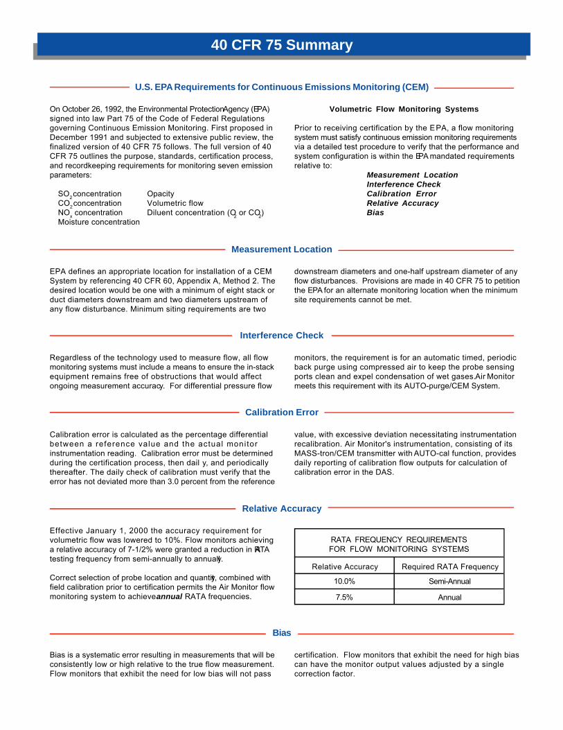
Effective January 1, 2000 the accuracy requirement forvolumetric flow was lowered to 10%. Flow monitors achievinga relative accuracy of 7-1/2% were granted a reduction in RATAtesting frequency from semi-annually to annually.
Correct selection of probe location and quantity, combined withfield calibration prior to certification permits the Air Monitor flowmonitoring system to achieve annual RATA frequencies.
Relative Accuracy
EPA defines an appropriate location for installation of a CEMSystem by referencing 40 CFR 60, Appendix A, Method 2. Thedesired location would be one with a minimum of eight stack orduct diameters downstream and two diameters upstream ofany flow disturbance. Minimum siting requirements are two
downstream diameters and one-half upstream diameter of anyflow disturbances. Provisions are made in 40 CFR 75 to petitionthe EPA for an alternate monitoring location when the minimumsite requirements cannot be met.
Measurement Location
Regardless of the technology used to measure flow, all flowmonitoring systems must include a means to ensure the in-stackequipment remains free of obstructions that would affectongoing measurement accuracy. For differential pressure flow
monitors, the requirement is for an automatic timed, periodicback purge using compressed air to keep the probe sensingports clean and expel condensation of wet gases. Air Monitormeets this requirement with its AUTO-purge/CEM System.
Interference Check
Calibration error is calculated as the percentage differentialbetween a reference value and the actual monitorinstrumentation reading. Calibration error must be determinedduring the certification process, then dail y, and periodicallythereafter. The daily check of calibration must verify that theerror has not deviated more than 3.0 percent from the reference
value, with excessive deviation necessitating instrumentationrecalibration. Air Monitor's instrumentation, consisting of itsMASS-tron/CEM transmitter with AUTO-cal function, providesdaily reporting of calibration flow outputs for calculation ofcalibration error in the DAS.
Calibration Error
RATA FREQUENCY REQUIREMENTSFOR FLOW MONITORING SYSTEMS
Relative Accuracy
10.0%
7.5%
Semi-Annual
Annual
Required RATA Frequency

To assist in complying with the Clean Air Act's stringent emissionmeasurement standards, Air Monitor has assembled a costeffective integrated system consisting of in-stack flow
measurement equipment and companion instrumentation toprovide continuous, accurate, and reliable volumetric flowmonitoring for stacks and ducts of any size and configuration.
System Components
In-Stack Flow Traverse Probe(s)
Required is the means to accurately monitor the average flowrate and temperature of the stack emissions. Flow rate monitoringis performed by sensing individual flow components at multiplepoints (traversing) across one or more diameters for circularstacks or along multiple parallel traverses for rectangular stacks,and averaging the obtained values. Average temperaturemeasurement is achieved using one or more temperature probesto obtain a single full traverse of a stack.
The Air Monitor STACK-probe is an airflow traverse probe basedon differential pressure (Pitot-Fechheimer) technology formeasuring airflow; the same technology that will be used duringthe certification process to verify relative accuracy of the flowmonitoring system. Each STACK-probe consists of two separateround tube self-averaging manifolds; one to measure the stacktotal pressure, and the other to measure stack static pressure.Multiple Pitot-Fechheimer ports are positioned on each manifoldon an equal area basis (for rectangular stacks) or on an equalconcentric area (for circular stacks). Similarly, average stacktemperature is measured using a temperature probe withmultiple sensing elements spaced along the probe length.
The engineered truss type design of the STACK-probe utilizestubular structural materials welded to a 6", 150# raised face
pipe flange, permitting cantilever probe mounting in evenextremely large stacks. Standard Type 316 stainless steelconstruction ensures long-term durability and continuingaccuracy in most installations, with materials such as HastelloyC22 and Inconel available for extreme temperature and/orseverely corrosive applications.
As a basic instrument, the STACK-probe does not require anyinitial or periodic calibration to measure flow accurately. As apassive device with no moving parts or active electrical circuits,removal of the STACK-probe from the stack after installation forrepair or calibration is not required.
Probe Back Purge
Required for differential pressure flow monitoring systems is aback purging means to ensure that the in-stack flow monitorprobe has its pressure sensing ports and averaging manifoldmaintained free of particulate build-up and vapor condensation.
When activated by Air Monitor's MASS-tron/CEM or the DataAcquisition System (DAS), the AUTO-purge/CEM Systemsequentially operates a combination of failsafe valves toautomatically back purge the sensing lines and the S TACK-
probes with high volume/high pressure compressed air for ashort duration, while simultaneously isolating the transmitterfrom over-pressurization.
Standard AUTO-purge/CEM construction mounts all componentsin a steel NEMA 4 rated enclosure, with all wetted parts made ofcopper or brass. The AUTO-purge/CEM is optionally available ina stainless steel NEMA 4X enclosure, with stainless steel wettedparts for corrosive applications.
AUTO-purge/CEM MASS-tron/CEM
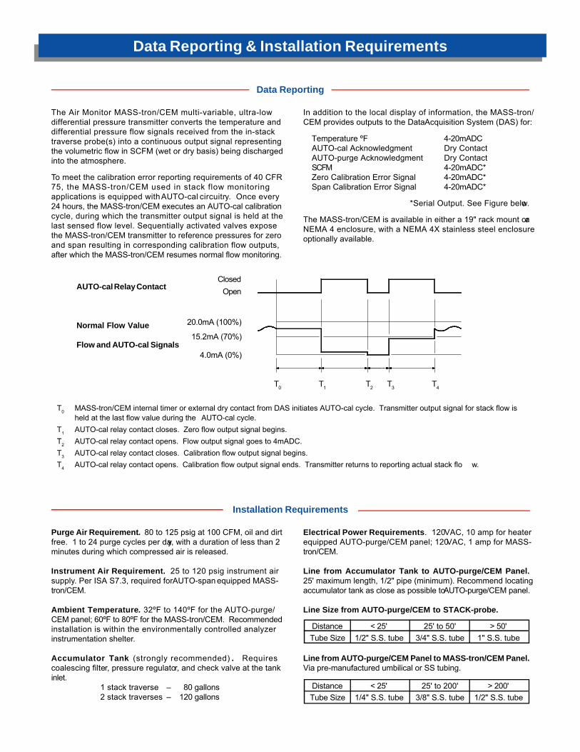
The Air Monitor MASS-tron/CEM multi-variable, ultra-lowdifferential pressure transmitter converts the temperature anddifferential pressure flow signals received from the in-stacktraverse probe(s) into a continuous output signal representingthe volumetric flow in SCFM (wet or dry basis) being dischargedinto the atmosphere.
To meet the calibration error reporting requirements of 40 CFR75, the MASS-tron/CEM used in stack flow monitoringapplications is equipped with AUTO-cal circuitry. Once every24 hours, the MASS-tron/CEM executes an AUTO-cal calibrationcycle, during which the transmitter output signal is held at thelast sensed flow level. Sequentially activated valves exposethe MASS-tron/CEM transmitter to reference pressures for zeroand span resulting in corresponding calibration flow outputs,after which the MASS-tron/CEM resumes normal flow monitoring.
In addition to the local display of information, the MASS-tron/CEM provides outputs to the Data Acquisition System (DAS) for:
Temperature ºF 4-20mADCAUTO-cal Acknowledgment Dry ContactAUTO-purge Acknowledgment Dry ContactSCFM 4-20mADC*Zero Calibration Error Signal 4-20mADC*Span Calibration Error Signal 4-20mADC*
*Serial Output. See Figure below.
The MASS-tron/CEM is available in either a 19" rack mount or aNEMA 4 enclosure, with a NEMA 4X stainless steel enclosureoptionally available.
Data Reporting
Data Reporting & Installation Requirements
T0 T1 T2 T3 T4
T0 MASS-tron/CEM internal timer or external dry contact from DAS initiates AUTO-cal cycle. Transmitter output signal for stack flow isheld at the last flow value during the AUTO-cal cycle.
T1 AUTO-cal relay contact closes. Zero flow output signal begins. T2 AUTO-cal relay contact opens. Flow output signal goes to 4mADC. T3 AUTO-cal relay contact closes. Calibration flow output signal begins. T4 AUTO-cal relay contact opens. Calibration flow output signal ends. Transmitter returns to reporting actual stack flo w.
Purge Air Requirement. 80 to 125 psig at 100 CFM, oil and dirtfree. 1 to 24 purge cycles per day, with a duration of less than 2minutes during which compressed air is released.
Instrument Air Requirement. 25 to 120 psig instrument airsupply. Per ISA S7.3, required for AUTO-span equipped MASS-tron/CEM.
Ambient Temperature. 32ºF to 140ºF for the AUTO-purge/CEM panel; 60ºF to 80ºF for the MASS-tron/CEM. Recommendedinstallation is within the environmentally controlled analyzerinstrumentation shelter.
Accumulator Tank (strongly recommended) . Requirescoalescing filter, pressure regulator, and check valve at the tankinlet.
1 stack traverse – 80 gallons2 stack traverses – 120 gallons
Electrical Power Requirements. 120VAC, 10 amp for heaterequipped AUTO-purge/CEM panel; 120VAC, 1 amp for MASS-tron/CEM.
Line from Accumulator Tank to AUTO-purge/CEM Panel.25' maximum length, 1/2" pipe (minimum). Recommend locatingaccumulator tank as close as possible to AUTO-purge/CEM panel.
Line Size from AUTO-purge/CEM to STACK-probe.
Line from AUTO-purge/CEM Panel to MASS-tron/CEM Panel.Via pre-manufactured umbilical or SS tubing.
Installation Requirements
AUTO-cal Relay Contact
Normal Flow Value
Flow and AUTO-cal Signals
DistanceTube Size
< 25'1/2" S.S. tube
25' to 50'3/4" S.S. tube
> 50'1" S.S. tube
DistanceTube Size
< 25'1/4" S.S. tube
25' to 200'3/8" S.S. tube
> 200'1/2" S.S. tube
ClosedOpen
20.0mA (100%)
15.2mA (70%)
4.0mA (0%)

STACK-probe w/Temperature and Insert Port
Typical Installation
In-Stack Probe Configurations – Single-Wall Stacks

Dual Traverse Schematic
Typical Installation
AUTO-purge/CEM Located on the Stack PlatformMASS-tron/CEM Located in the Instrumentation Enclosure

Flow Monitor Probe and Test Port Locations
STACK-probe Locations
NOTES:
1. Test ports should be located on a different axisthan flow monitor probe(s) to minimize disturbingthe flow being sensed by the probe(s) during40CFR60, Appendix A, Method 2 testing.
2. The distance from the flow monitor probe(s) ortest ports to an upstream flow disturbance is 2Dminimum, 8D desirable. The distance from theflow monitor probe(s) or test ports todownstream flow disturbance is D/2 minimum, 2Ddesirable.
3. The distance between the flow monitor probe(s)and the test port planes is usually only 6" to 12"due to practical limitations relative to stackplatform access. Flow disturbances created bythe test probe may affect flow monitor readingsduring 40CFR60, Appendix A, Method 2 testing.
4. Considered as flow disturbances are:– Any stack mounted equipment or structure that
protrudes or extends out into the air stream.– Any dimensional changes in the stack.– Any directional changes in the stack.
NOTES:
1. Test ports should be located on the same plane or elevation asthe flow monitor probe(s) to minimize disturbing the flow beingsensed by the flow monitor probe(s) during 40CFR60,Appendix A, Method 2 testing.
2. If test ports cannot be located on the same plane or elevationas the flow monitor probe(s) due to insufficient space orclearance, locate the test ports 2D upstream of the flowmonitor probe(s).
The distance from the flow monitor probe(s) or test ports to anupstream flow disturbance is 2D minimum, 8D desirable. Thedistance from the flow monitor probe(s) or test ports todownstream flow disturbance is D/2 minimum, 2D desirable.
4. Considered as flow disturbances are:– Any stack mounted equipment or structure that protrudes
or extends out into the air stream.– Any dimensional changes in the stack.– Any directional changes in the stack.
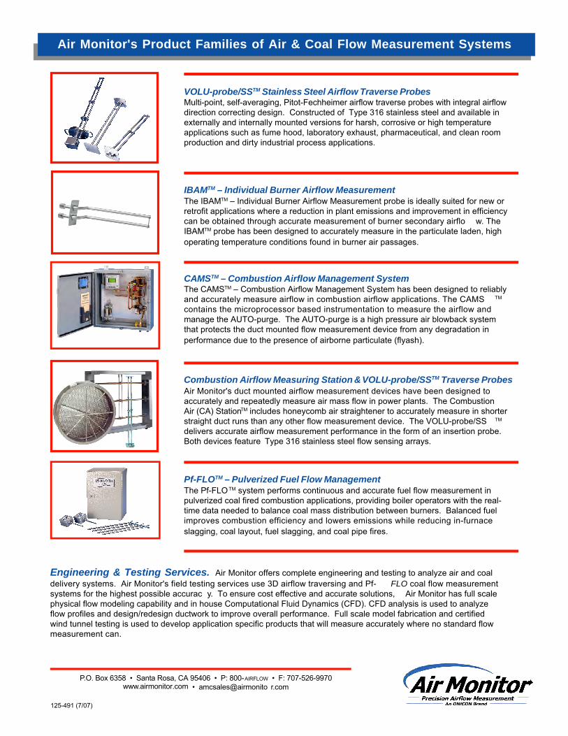
125-491 (7/07)
Air Monitor's Product Families of Air & Coal Flow Measurement Systems
P.O. Box 6358 • Santa Rosa, CA 95406 • P: 800-AIRFLOW • F: 707-526-9970www.airmonitor.com • amcsales@airmonito r.com
IBAMTM – Individual Burner Airflow MeasurementThe IBAMTM – Individual Burner Airflow Measurement probe is ideally suited for new orretrofit applications where a reduction in plant emissions and improvement in efficiencycan be obtained through accurate measurement of burner secondary airflo w. TheIBAMTM probe has been designed to accurately measure in the particulate laden, highoperating temperature conditions found in burner air passages.
CAMSTM – Combustion Airflow Management SystemThe CAMSTM – Combustion Airflow Management System has been designed to reliablyand accurately measure airflow in combustion airflow applications. The CAMS TM
contains the microprocessor based instrumentation to measure the airflow andmanage the AUTO-purge. The AUTO-purge is a high pressure air blowback systemthat protects the duct mounted flow measurement device from any degradation inperformance due to the presence of airborne particulate (flyash).
Air Monitor's duct mounted airflow measurement devices have been designed toaccurately and repeatedly measure air mass flow in power plants. The CombustionAir (CA) StationTM includes honeycomb air straightener to accurately measure in shorterstraight duct runs than any other flow measurement device. The VOLU-probe/SS TM
delivers accurate airflow measurement performance in the form of an insertion probe.Both devices feature Type 316 stainless steel flow sensing arrays.
Combustion Airflow Measuring Station & VOLU-probe/SSTM Traverse Probes
Pf-FLOTM – Pulverized Fuel Flow ManagementThe Pf-FLO TM system performs continuous and accurate fuel flow measurement inpulverized coal fired combustion applications, providing boiler operators with the real-time data needed to balance coal mass distribution between burners. Balanced fuelimproves combustion efficiency and lowers emissions while reducing in-furnaceslagging, coal layout, fuel slagging, and coal pipe fires.
VOLU-probe/SSTM Stainless Steel Airflow Traverse ProbesMulti-point, self-averaging, Pitot-Fechheimer airflow traverse probes with integral airflowdirection correcting design. Constructed of Type 316 stainless steel and available inexternally and internally mounted versions for harsh, corrosive or high temperatureapplications such as fume hood, laboratory exhaust, pharmaceutical, and clean roomproduction and dirty industrial process applications.
Engineering & Testing Services. Air Monitor offers complete engineering and testing to analyze air and coaldelivery systems. Air Monitor's field testing services use 3D airflow traversing and Pf- FLO coal flow measurementsystems for the highest possible accurac y. To ensure cost effective and accurate solutions, Air Monitor has full scalephysical flow modeling capability and in house Computational Fluid Dynamics (CFD). CFD analysis is used to analyzeflow profiles and design/redesign ductwork to improve overall performance. Full scale model fabrication and certifiedwind tunnel testing is used to develop application specific products that will measure accurately where no standard flowmeasurement can.
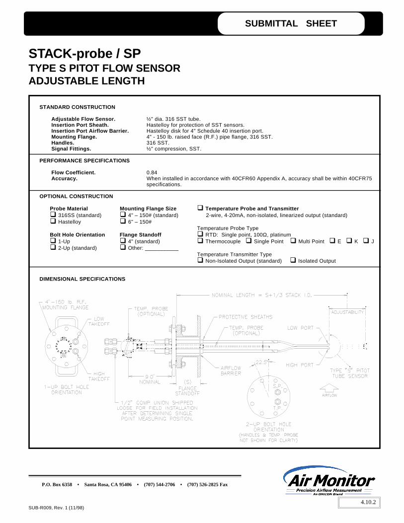
SUBMITTAL SHEET
P.O. Box 6358 • Santa Rosa, CA 95406 • (707) 544-2706 • (707) 526-2825 Fax
SUB-R009, Rev. 1 (11/98)
STANDARD CONSTRUCTION
Adjustable Flow Sensor. ½" dia. 316 SST tube.Insertion Port Sheath. Hastelloy for protection of SST sensors.Insertion Port Airflow Barrier. Hastelloy disk for 4" Schedule 40 insertion port.Mounting Flange. 4" - 150 lb. raised face (R.F.) pipe flange, 316 SST.Handles. 316 SST.Signal Fittings. ½" compression, SST.
PERFORMANCE SPECIFICATIONS
Flow Coefficient. 0.84Accuracy. When installed in accordance with 40CFR60 Appendix A, accuracy shall be within 40CFR75
specifications.
OPTIONAL CONSTRUCTION
Probe Material Mounting Flange Size Temperature Probe and Transmitter 316SS (standard) 4" – 150# (standard) 2-wire, 4-20mA, non-isolated, linearized output (standard) Hastelloy 6" – 150#
Temperature Probe TypeBolt Hole Orientation Flange Standoff RTD: Single point, 100Ω, platinum 1-Up 4" (standard) Thermocouple Single Point Multi Point E K J 2-Up (standard) Other: ___________
Temperature Transmitter Type Non-Isolated Output (standard) Isolated Output
DIMENSIONAL SPECIFICATIONS
STACK-probe / SPTYPE S PITOT FLOW SENSORADJUSTABLE LENGTH
4.10.2

S.A.P.Shielded Static Air Probes
The Air Monitor S.A.P. family of static air probes is designed for room or space pressurization applications where it is essential thatthe static pressure level within a room or space, and that of a reference pressure (corridor, adjacent space, outdoor location, etc.),be accurately sensed, free of pulsations or effects of air movement in the vicinity of the sensing probe(s). The S.A.P./R can also beutilized to sense the static pressure within fan inlet and discharge plenums or large ducts, where the presence of multi-directional andturbulent airflows prohibit the use of flow sensitive static pressure tips or probes.
Performance Specifications
Suggested Specification
Shielded Room and Space Static Pressure Sensor
Provide for each room or space, a shielded static pressuresensor suitable for surface [recessed flush; suspended; junctionbox; external flush] mounting, complete with multiple sensingports, pressure impulse suppression chamber, airflow shielding,and 1/8" FPT [ 1/2" FPT (for S.A.P./P)] takeoff fitting, all containedin an aluminum [316 stainless steel] casing, with brushed finishon exposed surfaces. These probes shall be capable of sensingthe static pressure in the proximity of the sensor to within 1%of the actual pressure value while being subjected to a maximumairflow of 1,000 FPM from a 360º radial source.
The shielded room or space static pressure sensors shall bethe S.A.P. [/B /P /S /R] shielded static air probe as manufacturedby Air Monitor Corporation, Santa Rosa, California.
Shielded Plenum or Duct Static Pressure Sensor
Provide where indicated for each plenum [duct], two shieldedstatic pressure sensors suitable for mounting externally on theplenum [duct] wall in opposing positions. The plenum [duct]pressure sensors shall be complete with multiple sensing ports,pressure impulse suppression chamber, airflow shielding, and1/8" FPT takeoff fitting, all contained in an aluminum [316stainless steel] casing, with brushed finish on exposed surfaces.These probes shall be capable of sensing the static pressureof the plenum or duct in the proximity of the sensor to within 1%of the actual pressure value.
The shielded plenum or duct static pressure sensors shall bethe S.A.P./R shielded static air probe as manufactured by AirMonitor Corporation, Santa Rosa, California.
• Engineered sensing ports and integral volume chambersuppress minor room, space or plenum pressurepulsations, providing a steady (non-noisy) staticpressure signal.
• Capable of sensing room, space or plenum pressureswithin 1% of actual static pressure.
• Measurement accuracy is unaffected by airflows up to1,000 FPM from a 360º radial source.
• Available in aluminum or Type 316 stainless steelconstruction.
• Self draining sensing ports for applications where roomor space washdown is required.
• Available in four mounting configurations:
S.A.P./B – Electrical Junction Box MountS.A.P./P – Suspended Mount via ½" PipeS.A.P./S – Surface MountS.A.P./R – Recessed Flush Mount
Accurate airflow measurement for demanding applications

125-271-00 (11/08)
S.A.P. – Shielded Static Air Probes
Application Examples
S.A.P./S Surface mount; 1/8" FPT signal connection
Construction / Dimensional Data
S.A.P./P Suspended mount via 1/2" pipe; 1/2" FPT signal connection
S.A.P./R Recessed flush mount; 1/8" FPT signal connectionS.A.P./B Recessed flush mount via electrical junction box
P.O. Box 6358 • Santa Rosa, CA 95406 • P: 800-AIRFLOW • F: 707-526-9970www.airmonitor.com • amcsales@airmonito r.com
(provided by others)

S.O.A.P.Static Outside Air Probe
entering air edges of the parallel plates act as a means of dif fusing the entering airflow to minimize the ef fect of non-horizontalflow on the sensor performance, thereby permitting entry flows with approach angles up to 60º from the horizont al withoutaffecting the accuracy of the pressure measurement. The perforations located near the center of the bottom plate opposite thesignal connection serve to relieve the venturi ef fect that will develop with higher airflow rates (winds) through parallel plat es,thereby permitting non-pulsating sensing in the presence of high wind gust s. It is the combined action of the above uniquedesign features of the S.O.A.P. static outside air probe that permits it to sense the outside atmospheric air pressure to within 1%of the actual value when being subjected to varying horizontal radial wind flows with velocities up to 40 miles per hour and sensewithin 2% and 3% when subjected to similar wind flows having approach angles up to 30º and 60º to the horizontal respectively.
Product Features
• Capable of sensing the outside atmospheric air pressureto within 1% of the actual value.
• Unique circular parallel plate design maintains sensingaccuracy regardless of flow (wind) direction or pattern.
• Operation not affected nor impaired by rain or snow.
• Construction has no moving parts nor requiredmaintenance.
• Sensing accuracy not affected by wind velocities up to 40miles per hour.
• Perforations on plate edges diffuse the ef fect of windapproach angles on sensor performance.
• Made entirely of Type 316 stainless steel.
• Mounting via 2" FPT stainless steel connection fitting.
Product Description
Air Monitor's S.O.A.P. static outside air probe is designed for accurate and instantaneous sensing of outside static air pressure levels.
To optimize the performance of the S.O.A.P., it must be located away from all structures and obstacles of sufficient size to create a wind induced pressure envelope. Typical locations are on an elevated position in an out door parking lot, in a below ground recess (landscaped or lawn area), away from buildings, in a below ground location like a parking garage with non-forced ventilation, or on a rooftop mounted pole sufficiently elevated to be out side any anticip ated wind induced pressure envelope.
The circular shape of the S.O.A.P. presents a 360º radial entrance for the flow of air (wind) through the sensor . The perforations located on the
Accurate airflow measurement for demanding applications

S.O.A.P. Static Outside Air Probe
125-275 (11/08)
The Need for a Stable, Common Pressure Reference
For the accurate measurement and/or control of room,laboratory, space, or building pressurization, it is essentialthat these sensed pressure levels be referenced to a commonpressure. Ideally , that reference is the out doors. But theusual out door sensor , because of it s design, has to be
shielded from the wind, and of ten ends up located where itwill be subjected to the pressure envelope developed by thewind's effect upon the building, refer to Figure 1 below. Themagnitude of the pressure envelope that can be created byvarious wind velocities is also shown below.
Dimensional Specification
Suggested Specification
Provide for the room or sp ace static pressure indicating orcontrolling systems an out door static pressure sensorconstructed of 10 ga. Type 316 st ainless steel with a 2"diameter FPT connection.
The outdoor air probe shall be capable of sensing the outsideatmospheric air pressure to within 2% of the actual value when
subjected to radial wind velocities up to 40 miles per hourwith approach angles up to 30º to the horizontal.
The st atic out side air probe shall be the S.O.A.P . asmanufactured by Air Monitor Corporation, Sant a Rosa,California.
P.O. Box 6358 • Santa Rosa, CA 95406 • P: 800-AIRFLOW • F: 707-526-9970www.airmonitor.com • amcsales@airmonitor .com
WIND VELOCITYMILES PER HOUR
101520253035404550556065
UPWIND SIDEINCHES W.C.
0.0350.0880.140.220.300.420.540.700.851.061.281.70
DOWNWIND SIDEINCHES W.C.
- 0.015- 0.025- 0.050- 0.065- 0.090- 0.125- 0.180- 0.260- 0.340- 0.425- 0.540- 0.700
Figure 1

VELTRON DPTUltra-Low Range
Pressure & Flow Transmitter
Accurate airflow measurement for demanding applications
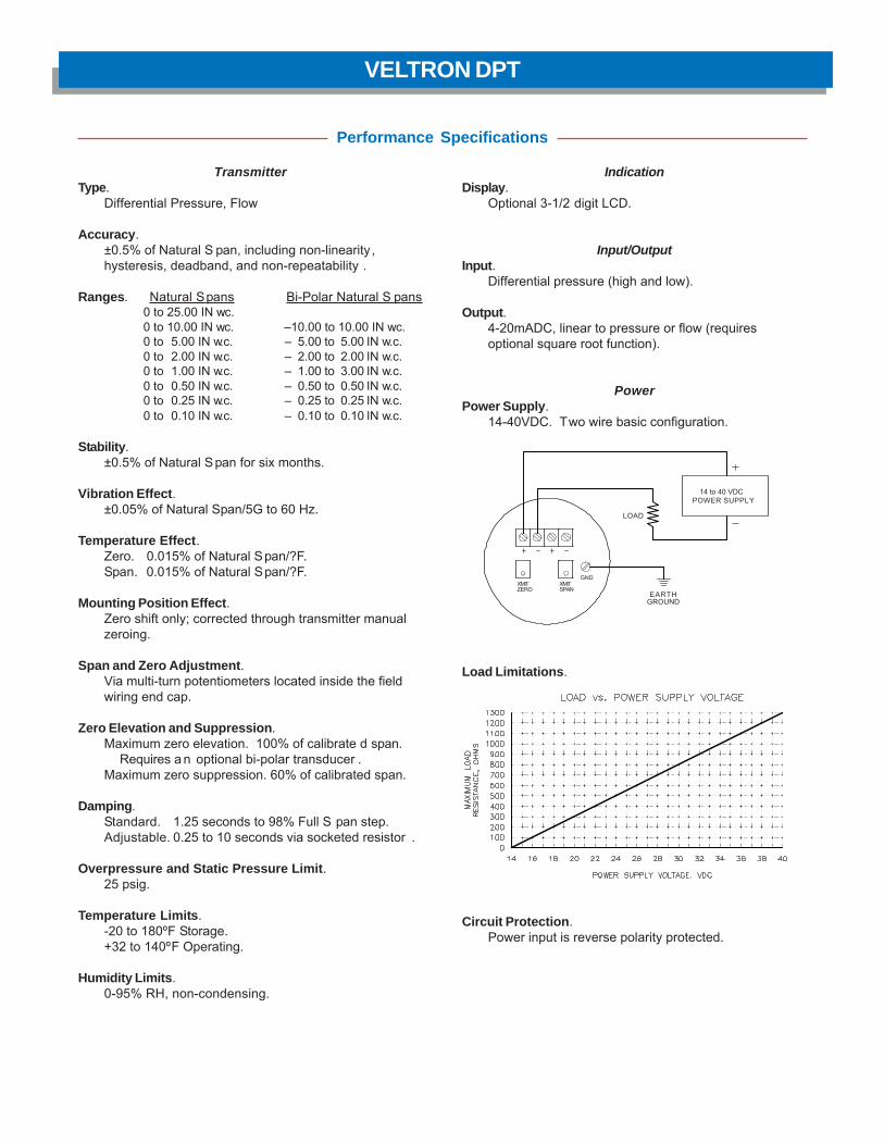
IndicationDisplay.
Optional 3-1/2 digit LCD.
Input/OutputInput.
Differential pressure (high and low).
Output.4-20mADC, linear to pressure or flow (requiresoptional square root function).
PowerPower Supply.
14-40VDC. Two wire basic configuration.
Load Limitations.
Circuit Protection.Power input is reverse polarity protected.
TransmitterType.
Differential Pressure, Flow
Accuracy.±0.5% of Natural S pan, including non-linearity ,hysteresis, deadband, and non-repeatability .
Ranges. Natural Spans Bi-Polar Natural S pans0 to 25.00 IN w.c.0 to 10.00 IN w.c. –10.00 to 10.00 IN w.c.0 to 5.00 IN w.c. – 5.00 to 5.00 IN w.c.0 to 2.00 IN w.c. – 2.00 to 2.00 IN w.c.0 to 1.00 IN w.c. – 1.00 to 3.00 IN w.c.0 to 0.50 IN w.c. – 0.50 to 0.50 IN w.c.0 to 0.25 IN w.c. – 0.25 to 0.25 IN w.c.0 to 0.10 IN w.c. – 0.10 to 0.10 IN w.c.
Stability.±0.5% of Natural Span for six months.
Vibration Effect.±0.05% of Natural Span/5G to 60 Hz.
Temperature Effect.Zero. 0.015% of Natural Span/?F.Span. 0.015% of Natural Span/?F.
Mounting Position Effect.Zero shift only; corrected through transmitter manualzeroing.
Span and Zero Adjustment.Via multi-turn potentiometers located inside the fieldwiring end cap.
Zero Elevation and Suppression.Maximum zero elevation. 100% of calibrate d span.
Requires a n optional bi-polar transducer .Maximum zero suppression. 60% of calibrated span.
Damping.Standard. 1.25 seconds to 98% Full S pan step.Adjustable. 0.25 to 10 seconds via socketed resistor .
Overpressure and Static Pressure Limit.25 psig.
Temperature Limits.-20 to 180ºF Storage.+32 to 140ºF Operating.
Humidity Limits.0-95% RH, non-condensing.
Performance Specifications
VELTRON DPT
GND
14 to 40 VDCPOWER SUPPLY
EARTHGROUND
XMITZERO
XMITSPAN
LOAD

Construction Features
Ultra-Low Differential Pressure & Flow Transmitter
Accuracy. The VELTRON DPT is designed to maint ain anaccuracy of ±0.5% of Natural Span. For a span of 0 to 0.10 INw.c., this is equivalent to an output accuracy of ±0.0005 INw.c. differential pressure or ±6.33 FPM velocity.
Primary Signal Noise Filter. To eliminate background noiseand pulsations from the flow signal, the VEL TRON DPT isequipped with a user selectable low pass filter .
Square Root Function (optional). When equipped with thesquare root option, the VELTRON DPT can provide an outputsignal linear to velocity or volume.
High Turndown Ratio Operation. The VELTRON DPT, withits high level of accuracy, can maintain linear output signalson applications requiring velocity or pressure turndown of 5to 1.
Continuous Display of Process (optional). The VELTRONDPT can be equipped with a 3-1/2 digit LCD display to providea continuous readout of the measured process inengineering units (Inches w.c., SCFM, lbs/hr, etc.).
Hazardous Locations. The VELTRON DPT is Factory Mutualapproved for the following:
• Explosion Proof: Class 1, Division 1, Groups B, C, D.• Dust Ignition Proof: Class II, III, Division 1, Groups E, F, G.• Suitable for indoor and outdoor NEMA Type 4X hazardous
locations.
Enclosure. The VELTRON DPT is packaged in a NEMA Type4X enclosure with standard industrial process connections.
Performance Specifications
Optional3-1/2 digitLCD Display
6.75(Max)
4.50(Max)
Locknut
Calibration Port
5.40(Max)
3/4 -14 NPTconduitconnections(2 places)
NEMA 4XField wiringend.
High port1/4-18 NPT
for pressureconnection
Low port1/4-18 NPTfor pressureconnection

Process Connections. Industry standard 1/4"-NPT portson 2-1/8" centers on bottom of base.
Electrical Connections. Dual 3/4" conduit connections.Terminal strip for field wiring and test point s.
Electrical Enclosure. NEMA Type 4X aluminum body withNeoprene gaskets.
Physical Specifications
O-Rings. BUNA N.
Paint. Polyurethane with epoxy primer.
Mounting. Flat and angle mounting brackets for 2" pipe.
Weight. 9.4 lbs.
125-024-00 (1/00)
VELTRON DPT
Mounting Configurations with Standard Brackets
Suggested Specification
The transmitter shall be capable of receiving flow signals(total and static pressure) from an airflow station or probearray, and produce an output linear and proportional to staticor velocity pressure.
(Optional) The transmitter will include a means of performingan internal square root of the process signal to provide anoutput signal linear to velocity or volume.
(Optional) The transmitter shall contain an integral LCDcapable of indication of the process during normal operatingmode.
The transmitter will be available in multiple Natural S panscovering the range of 0.10 IN w .c. to 10.0 IN w .c. with anaccuracy of ±0.5% of Natural Span. The transmitter shall becapable of maintaining linear output signals on applicationsrequiring 5 to 1 velocity or pressure turndown.
The transmitter shall be the VELTRON DPT as manufacturedby Air Monitor Corporation, Santa Rosa, California.
Mount to Horizontal Channel
Mount to Flat Surface
Angle Mount to Horizontal Pipe Vertical Mount to Horizontal Pipe
Vertical Mount to Vertical Pipe
Note: Mounting bracket kit includes3/8-16 U-bolt, nuts, and washers for2" Schedule 40 pipe, plus 4 bolts andwashers to attach the transmitter tothe mounting bracket.
P.O. Box 6358 • Santa Rosa, CA 95406 • P: 800-AIRFLOW • F: 707-526-9970www.airmonitor.com • amcsales@airmonitor .com

VELTRON DPT-plusMicroprocessor Based Ultra-Low Range
Pressure & Flow "Smart" Transmitter
Proven solutions for a tough industry

The VELTRON DPT -plus transmitter is furnished with anautomatic zeroing circuit cap able of electronically adjustingthe transmitter zero at predetermined time intervals whilesimul-taneously holding the transmitter output signal.
The automatic zeroing circuit eliminates all output signal driftdue to thermal, electronic or mechanical effect s, as well asthe need for initial or periodic transmitter zeroing. Fortransmitters operating in a moderately steady temperaturelocation (thus no thermally induced span drift), this automatic
with Automatic Zeroing Circuit
VELTRON DPT-plus
Indication
Display. A backlit, graphical LCD providing three lines ofdata display. Also used for programming.
Inputs/Outputs
Analog Inputs. Differential pressure (high and low), and 4-20mA, 2-wire, internally or externally loop poweredtemperature signal.
Analog Outputs. Dual 4-20mA output s, individuallyconfigurable as internally powered/non-isolated, or externallypowered/isolated.
Digital Inputs. Digital contacts for AUTO-purge external start.
Digital Outputs. Dual Form A dry contacts rated for 3 ampsat 24VAC/VDC for optional HI/LO alarm; or dual Form A drycontacts for AUTO-purge activation and acknowledgment.
Temperature Compensation Selection. Pushbuttonselection of linearized or non-linear temperature transmitterinput for the following temperature sensing types:
Type E –50 to 1750ºF –50 to 950ºC
Type T –50 to 750ºF –50 to 400ºC
Type J –50 to 2000ºF –50 to 1090ºC
Type K –50 to 2000ºF –50 to 1090ºC
RTD –50 to 1500ºF –50 to 815ºC
PowerPower Supply.Standard 24VAC (20-28VAC) or 24VDC (20-40VDC).Optional 120VAC (100-132VAC), via external transformer.
Power Consumption.Standard: 18VA at 24VAC; 13VA at 24VDC; 36VA at120VAC. With AUTO-purge Management: 54VA at 24VAC;48VA at 24VDC; 108VA at 120VAC.
Circuit Protection. Power input is fused and reversepolarity protected.
Transmitter
Accuracy. 0.1% of Natural Span, including hysteresis,deadband, non-linearity, and non-repeatability.
Type. Differential pressure, flow, and mass flow.
Ranges. Natural Spans Bi-Polar Natural Spans0 to 25.00 IN w.c.0 to 10.00 IN w.c. –10.00 to 10.00 IN w.c.0 to 5.00 IN w.c. – 5.00 to 5.00 IN w.c.0 to 2.00 IN w.c. – 2.00 to 2.00 IN w.c.0 to 1.00 IN w.c. – 1.00 to 1.00 IN w.c.0 to 0.50 IN w.c. – 0.50 to 0.50 IN w.c.0 to 0.25 IN w.c. – 0.25 to 0.25 IN w.c.0 to 0.10 IN w.c. – 0.10 to 0.10 IN w.c.0 to 0.05 IN w.c. – 0.05 to 0.05 IN w.c.
Span Rangeability. The calibrated span can be downranged to 40% of the Natural Span.
Stability. ±0.5% of Natural Span for six months.
Temperature Effect. Zero. None; corrected by AUTO-zero. Span. 0.015% of Natural Span/ºF.
Mounting Position Effect. None; corrected throughtransmitter automatic zeroing.
Span and Zero Adjustment. Digital, via internally locatedpushbuttons.
Low Pass Filtration. Response time to reach 98% of astep change is adjustable from 2.0 to 250.0 seconds.
Overpressure and Static Pressure Limit. 25 psig.
Automatic Zeroing.Accuracy. Within 0.1% of calibrated span.Frequency.Every 1 to 24 hours on 1 hour intervals.
Temperature Limits.–20 to 180ºF Storage; +32 to 140ºF Operating.
Humidity Limits. 0-95% RH, non-condensing.
Performance Specifications
zeroing function essentially produces a "self-calibrating"transmitter. The automatic zeroing circuit will re-zero thetransmitter to within 0.1% of it s operating sp an; for atransmitter with a 0.02 IN w.c. operating span, this representsa zeroing capability within 0.00002 IN w.c.
To permit manual calibration of the VELTRON DPT-plus, anelectronic switch is provided to permit manual positioning ofthe zeroing valve.

Construction Features
Ultra-Low Differential Pressure & Flow "Smart" Transmitter
Accuracy. The VELTRON DPT-plus is designed to maintainan accuracy of 0.1% of Natural Span. For a span of 0 to 0.05IN w.c., this accuracy is equivalent to an output accuracy of±0.00005 IN w.c. differential pressure or ±0.90 FPM velocity.
Microprocessor Based Functionality. The VELTRON DPT-plus on-board microprocessor performs the functions ofoperating parameter selection, transmitter configuration, input/output and display signal scaling, and transducer calibration.Imbedded software performs span, flow, and 3-point "K" factorcalculations. Input to the microprocessor is via pushbuttons.
Electronic Respanning. The VELTRON DPT-plus operatingspan can be electronically selected anywhere between theNatural Span and 40% of Natural S pan, without having toperform recalibration involving an external pressure source.
Air Density Correction. The VELTRON DPT-plus is capableof accepting a process temperature input to perform densitycorrection to volumetric or mass flow. Temperature input is a4-20mA signal from a remote temperature transmitter; non-linear temperature input s can be linearized by themicroprocessor. Temperature sensor type is sof twareselectable from the following choices: Thermocouple typesE, T, J, and K; or Platinum RTD.
High Turndown Ratio Operation. The VELTRON DPT-plus,with its high level of accuracy and automatic zeroing circuitry,can maintain linear output signals on applications requiringvelocity turndown of 10 to 1 (equal to a velocity pressureturndown of 100 to 1).
Features
Continuous Display of Process. The VELTRON DPT-pluscomes equipped with a multi-line, backlit, graphical LCD foruse during transmitter configuration and calibration, and todisplay multiple measured processes in engineering units .The LCD provides one line having 8 digits with double wideand double high characters, two 20 digit lines having standardsize characters, and various descriptors for transmitteroperating status.
Primary Signal Noise Filter. To eliminate background noiseand pulsations from the flow signal, the VELTRON DPT-plushas a user selectable low pass digital filter.
AUTO-purge Management (optional). For "dirty air"applications requiring the use of an Air Monitor AUTO-purgesystem, the VELTRON DPT-plus provides the capabilities ofestablishing purge frequency and duration while giving theuser a choice of either internally timed cycle frequency orexternally triggered purge initiation. During the purge cycleall transmitter outputs are maintained at their last value priorto the start of the purge cycle.
Hazardous Locations. The VELTRON DPT-plus is FactoryMutual approved for the following:• Explosion Proof: Class 1, Division 1, Groups B, C, D.• Dust Ignition Proof: Class II, III, Division 1, Groups E, F, G.• Suitable for indoor and outdoor NEMA Type 4X hazardous
locations.
Enclosure. The VELTRON DPT-plus is packaged in a NEMA4X enclosure with standard industrial process connections.
High port1/4–18 NPT for
pressure connection
3/4–14 NPT conduitconnections (2places)
NEMA 4XField wiringend
Low port 1/4–18 NPTfor pressureconnection
7.88(Max)
2Z\,
6.75(Max)
4.50(Max)
Standard LCDGraphical Display
Locknut
Calibration Port

Process Connections. Industry standard 1/4"-NPT portson 2-1/8" centers on flanges. 1/2"-NPT ports on bottom ofbase.
Electrical Connections. Dual 3/4" conduit connections.Terminal strip for field wiring and test points. External terminalstrip with plug-in connectors.
O-Rings. BUNA N.
Physical SpecificationsElectrical Enclosure. NEMA 4X aluminum body withNeoprene gaskets.
Paint. Polyurethane with epoxy primer.
Mounting. Flat and angle mounting brackets for 2" pipe.
Weight. 10.5 lbs.
125-025-00 (1/00)
VELTRON DPT-plus
Suggested Specification
The mass flow transmitter shall be capable of receiving flowsignals (total and static pressure) from an airflow st ation orprobe array equipped with a temperature sensing means,internally perform density correction for the processtemperature, and produce individual outputs linear and scaledfor standard air volume or mass flow, and temperature.
The mass flow transmitter shall contain an integral graphicLCD for use during the configuration and calibration process,and be capable of indicating multiple process parameters(temperature, flow, dp, etc.) during normal operating mode.All transmitter parameter setting, zero and span calibration,and display scaling will be performed digitally in the on-boardmicroprocessor via input pushbuttons.
The mass flow transmitter will be available in multiple naturalspans covering the range of 0.05 IN w.c. to 10.0 IN w.c. with
an accuracy of 0.1% of natural span. The transmitter shall befurnished with a transducer automatic zeroing circuit and becapable of maintaining linear output signals on applicationsrequiring 10 to 1 velocity (100 to 1 pressure) turndown. Thetransmitter shall be cap able of having it s operating sp anelectronically selected without having to perform recalibrationinvolving an external pressure source.
(Optional) The transmitter will provide the means of managinga system for automatic high pressure purge of the airflowstation or probe array, with user selectable purge frequencyand duration, while maint aining the last transmitter outputduring the purge cycle.
The mass flow transmitter shall be the VEL TRON DPT-plusas manufactured by Air Monitor Corporation, Santa Rosa,California.
Mounting Configurations with Optional Brackets
Angle Mount to Horizontal Pipe Vertical Mount to Horizontal Pipe Mount to Horizontal Channel
Mount to Flat SurfaceVertical Mount to Vertical Pipe
Note: Mounting bracket kit includes3/8-16 U-bolt, nuts, and washers for2" Schedule 40 pipe, plus 4 bolts andwashers to attach the transmitter tothe mounting bracket.
P.O. Box 6358 • Santa Rosa, CA 95406 • P: 800-AIRFLOW • F: 707-526-9970www.airmonitor.com • amcsales@airmonitor .com

VELTRON IIMicroprocessor Based
Pressure & Flow "Smart" Transmitter
Accurate airflow measurement for demanding applications

The VELTRON II transmitter is furnished with an automatic zeroingcircuit capable of electronically adjusting the transmitter zero atpredetermined time intervals while simultaneously holding thetransmitter output signal.
The automatic zeroing circuit eliminates all output signal drift due tothermal, electronic or mechanical effects, as well as the need forinitial or periodic transmitter zeroing. For transmitters operated intemperature controlled spaces (with no thermal effect upon span),
this automatic zeroing function essentially produces a "self-calibrating" transmitter. The automatic zeroing circuit will re-zerothe transmitter to within 0.1% of its operating span; for a transmitterwith a 0.02 IN w .c. operating sp an, this represent s a zeroingcapability within 0.00002 IN w.c.
To permit manual calibration of the VELTRON II, an electronic switchis provided to permit manual positioning of the zeroing valve.
with Automatic Zeroing Circuit
VELTRON II
Span Rangeability. The calibrated span can be down ranged to 40% of the Natural Span.
Stability. ±0.5% of Natural Span for six months.
Transducer Response Time. 0.5 second to reach 98% of a step change.
Temperature Effect. Zero. None; corrected by AUTO-zero. Span. 0.015% of Full Span/ºF.
Mounting Position Effect. None; corrected by AUTO-zero.
Ranges. Natural Spans Bi-Polar Natural Spans0 to 25.00 IN w.c.0 to 10.00 IN w.c. –10.00 to 10.00 IN w.c.0 to 5.00 IN w.c. – 5.00 to 5.00 IN w.c.0 to 2.00 IN w.c. – 2.00 to 2.00 IN w.c.0 to 1.00 IN w.c. – 1.00 to 3.00 IN w.c.0 to 0.50 IN w.c. – 0.50 to 0.50 IN w.c.0 to 0.25 IN w.c. – 0.25 to 0.25 IN w.c.0 to 0.10 IN w.c. – 0.10 to 0.10 IN w.c.0 to 0.05 IN w.c. – 0.05 to 0.05 IN w.c.
Accuracy. 0.1% of Natural Span, including non-linearity, hysteresis, deadband, and non-repeatability.
Performance Specification
Overpressure and Static Pressure Limit. 25 psig.
Low Pass Filtration. Response time to reach 98% of a stepchange is adjustable from 2.0 to 250.0 seconds.
Automatic Zeroing. Accuracy. Within 0.1% of calibratedspan. Frequency. Every 1 to 24 hours on 1 hour intervals.
Circuit Protection. Power input is isolated, fused, and reversepolarity protected.
Span and Zero Adjustment. Electronic adjustment viakeypad.
Display. Standard 2 line x 20 characters LCD provides oneline of data display. Optional (standard on MASS-tron II) backlit,graphical LCD provides indication of up to four processvariables. Triple-size digits for main process variable, standardsize characters for the other process variables.
Humidity Limits. 0-95% RH, non-condensing.
Temperature Limits. –20 to 180ºF Storage.+40 to 140ºF Operating.
Digital Outputs. Form C dry contacts rated for 3 amps at24VAC/VDC for optional HI/LO alarm. Dual Form A dry contactsrated for 3 amps at 24VAC/VDC for AUTO-purge activation andacknowledgment.
Digital Inputs. Dry contact for AUTO-purge external start.
Analog Outputs. Dual transmitter outputs are individuallyconfigurable via jumper for 0-5VDC, 0-10VDC, or 4-20mADC.Two additional outputs are optionally available.
Analog Inputs. A single input is field configurable via jumperfor 0-5VDC, 0-10VDC, or 4-20mADC. For use with optionalspecial function.
Network Communication. Optional ModBus TCP/IP overEthernet or LonWorks.
Power Supply. Standard 24VAC (20-28VAC) or 24VDC (20-40VDC). Optional 120VAC (100-132VAC), via externaltransformer.
Power Consumption. Standard: 18VA at 24VAC; 13VA at24VDC; 36VA at 120VAC. With AUTO-purge Management: 54VAat 24VAC; 48VA at 24VDC; 108VA at 120VAC.
Functional Specification

Construction Features
Ultra-Low Differential Pressure & Flow "Smart" Transmitter
Accuracy. The VELTRON II is designed to maintain an accuracy of 0.1% of Natural Span. For a span of 0 to 0.05 IN w.c., this accuracy is equivalent to an output accuracy of ±0.00005 IN w.c. differential pressure or 0.45 FPM velocity at span.
Continuous Display of Process. All VELTRON II’s are equipped with a 2x20 liquid crystal display (LCD) for use during the configuration and calibration process, and to display one transmitter output during normal operating mode. Standard on the MASS-tron and optional for both the VELTRON II and VEL-trol II is a multi-line backlit, graphical LCD providing up to four lines of data display, with each line individually scalable in user selectable format and units of measure. For high visibility, the main process variable (flow) is displayed with easy-to-read, triple-size digits. Other process variables are displayed with standard size digits.
Analog Communication. Each analog input and output signal can be individually configured for 0-5VDC, 0-10VDC, or 4-20mADC by means of a single jumper.
Electronic Respanning. The VELTRON II operating span can be electronically selected anywhere between the Natural Span and 40% of Natural Span, without having to perform recalibration involving an external pressure source.
Primary Signal Noise Filter. To eliminate background noise and pulsations from the flow signal, the VELTRON II is equipped with a user selectable digital low pass filter.
High Turndown Ratio Operation. The VELTRON II, with its high level of accuracy and automatic zeroing circuitry, can maintain linear output signals on applications requiring velocity turndown of 10 to 1 (equal to a velocity pressure turndown of 100 to 1).
Features
Microprocessor Based Functionality. The VELTRON II's on-board microprocessor performs the functions of operating parameter selection, transmitter configuration, input/output and display signa scaling, and transducer calibration. Imbedded software performs span, flow, and 3-point "K" factor calculations. Input to the micro processor is via pushbutton.
AUTO-purge Management (optional). For "dirty air" applications requiring the use of an Air Monitor AUTO-purge system, the VELTRON II provides the capabilities of establishing purge frequency and duration while giving the user a choice of either internally timed cycle frequency or externally triggered purge initiation. During the purge cycle all transmitter outputs are maintained at their last value prior to the start of the purge cycle.
Special Functions and Alarm Capability. The VELTRON II is capable of performing one of five special application functions using a second transmitter as an input: Summed flow, flow differential, low signal select, high signal select, or percent deviation. The special function output can be both displayed and provided as an analog output signal. Alarms related to the measured process can be configured for one of three modes: Low/Low, High/Low, and High/High.
Multiple Operating Power Selections. Standard input power supplied to the VELTRON II can be either 24VAC or 24VDC via automatic selection. An optional 120VAC external power transformer (UL listed) can be provided.
Enclosure. The VELTRON II is furnished in a NEMA 1 aluminum enclosure with external, unitary plug in terminal strips for ease of installation and removal. An optional junction box is available for applications requiring enclosed field wiring.
Hinged removabletop cover
External, unitaryplug-in terminalstrips for field
wiring connections
ON-OFF power switch
Graphical backlit LCD
Aluminum NEMA 1enclosure
Cover mountedmembrane keypad

Via the addition of both process temperature and pressurecompensation, the ultra high accuracy VELTRON II becomes theMASS-tron II multi-variable mass flow transmitter. The processtemperature input is an analog signal from a remote 4-wire or looppowered temperature transmitter; with the MASS-tron II having thecapability of performing the linearization. The process pressure ismeasured by means of an internal absolute pressure transducerconnected to the transmitter’s static pressure signal input.
Performance Specifications
In addition to those available with the VELTRON II, the MASS-tron IIincludes these performance specifications:
Analog Output. 0-5VDC, 0-10VDC or 4-20mA for processdifferential pressure, temperature, and absolute pressure.
Analog Input. 0-5VDC, 0-10VDC or 4-20mA for processtemperature.
Temperature Compensation Selection. Pushbutton selectionof linearized or non-linearized input, thermocouple or 100 ohmplatinum RTD temperature sensor type:
Type E -50 to 1750ºF -50 to 950ºCType T -50 to 750ºF -50 to 400ºCType J -50 to 2000ºF -50 to 1090ºCType K -50 to 2000ºF -50 to 1090ºCRTD -50 to 1500ºF -50 to 815ºC
MASS-tron II
VEL-trol II
*Shown with standard 4-line graphic LCD
The VEL-trol II incorporates a controller into the ultra high accuracyVELTRON II transmitter, providing the three modes of proportional,integral reset, and inverse derivative to permit the controller to betuned to the extreme dynamics of critical airflow and pressurizationcontrol processes. The selection of the P,I,1/D tuning parametersis accomplished using the password protected membrane switchpushbuttons on the front of the enclosure. By means of a drycontact input, the controller operating set point can be switchedfrom the internal fixed setpoint to an externally provided fixed orvariable input.
Performance Specifications
In addition to those available with the VELTRON II, the VEL-trol IIincludes these performance specifications:
Analog Output. 0-5VDC, 0-10VDC or 4-20mA for controller output.
Analog Input. 0-5VDC, 0-10VDC or 4-20mA for controller externalsetpoint.
Digital Input. Dry contact for soft start command.*Shown with optional 4-line graphic LCD
Pressure Compensation. Absolute pressure (atmospheric or duct static), up to 60 IN Hg.
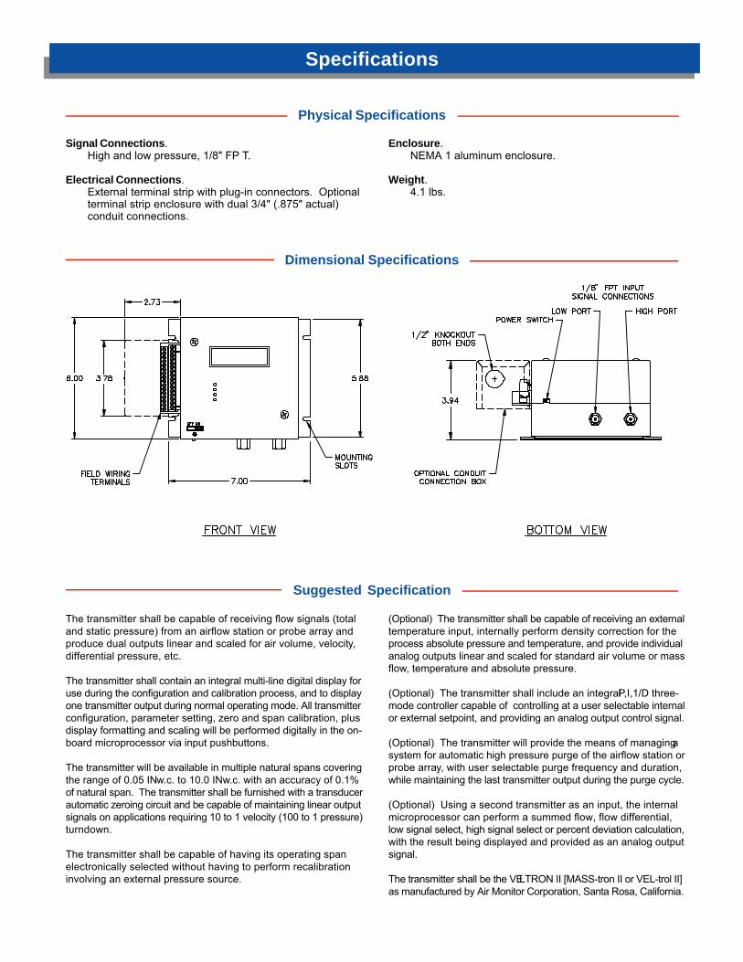
Signal Connections.High and low pressure, 1/8" FP T.
Electrical Connections.External terminal strip with plug-in connectors. Optionalterminal strip enclosure with dual 3/4" (.875" actual)conduit connections.
Physical Specifications
Enclosure.NEMA 1 aluminum enclosure.
Weight.4.1 lbs.
Specifications
Dimensional Specifications
Suggested Specification
The transmitter shall be capable of receiving flow signals (totaland static pressure) from an airflow station or probe array andproduce dual outputs linear and scaled for air volume, velocity,differential pressure, etc.
The transmitter shall contain an integral multi-line digital display foruse during the configuration and calibration process, and to displayone transmitter output during normal operating mode. All transmitterconfiguration, parameter setting, zero and span calibration, plusdisplay formatting and scaling will be performed digitally in the on-board microprocessor via input pushbuttons.
The transmitter will be available in multiple natural spans coveringthe range of 0.05 IN w.c. to 10.0 IN w.c. with an accuracy of 0.1%of natural span. The transmitter shall be furnished with a transducerautomatic zeroing circuit and be capable of maintaining linear outputsignals on applications requiring 10 to 1 velocity (100 to 1 pressure)turndown.
The transmitter shall be capable of having its operating spanelectronically selected without having to perform recalibrationinvolving an external pressure source.
(Optional) The transmitter shall be capable of receiving an externaltemperature input, internally perform density correction for theprocess absolute pressure and temperature, and provide individualanalog outputs linear and scaled for standard air volume or massflow, temperature and absolute pressure.
(Optional) The transmitter shall include an integral P,I,1/D three-mode controller capable of controlling at a user selectable internalor external setpoint, and providing an analog output control signal.
(Optional) The transmitter will provide the means of managing asystem for automatic high pressure purge of the airflow station orprobe array, with user selectable purge frequency and duration,while maintaining the last transmitter output during the purge cycle.
(Optional) Using a second transmitter as an input, the internalmicroprocessor can perform a summed flow, flow differential,low signal select, high signal select or percent deviation calculation,with the result being displayed and provided as an analog outputsignal.
The transmitter shall be the VELTRON II [MASS-tron II or VEL-trol II]as manufactured by Air Monitor Corporation, Santa Rosa, California.

Air Monitor's Product Families of Flow Measurement and Pressure Products
FAN-E AIRFLOW MEASURING STATION.Multi-point, self-averaging, Pitot traverse station with integral air straightener-equalizer honeycomb cell. Capable of continuously measuring fan dischargesor ducted airflow with an accuracy of 2% or better.
AMCA CERTIFIED in accordance with Standard 610 for airflow measurementstation performance.
VOLU-PROBE /1, 2, 3, 4 AIRFLOW TRAVERSE PROBES & STATIONS.Multi-point, self-averaging, Pitot Fechheimer airflow traverse probes andstations with integral airflow direction correcting design ensures accuratemeasurement. Various mounting configurations to fit every application.
AMCA CERTIFIED in accordance with Standard 610 for airflow measurementstation performance.
VOLU-PROBE/FI FAN INLET AIRFLOW PROBES.Multi-point, self-averaging, Pitot Fechheimer airflow probes with integralairflow direction correcting design.
For mounting directly in the inlet cones or bellmouth of centrifugal or vane-axial fans to measure fan capacities within 3% of actual flow.
S.A.P. /B, P, S, R STATIC PRESSURE SENSORS.Available in four separate mounting configurations, the S.A.P. family of staticpressure sensors generate a steady, non-pulsating output of room, space orplenum pressure.
S.A.P. sensors are available in aluminum or stainless steel construction.
VOLU-flo/OAM OUTSIDE AIR MONITOR.Monitor/Controller designed to accurately measure outside air to assist inmeeting air ventilation requirements of ASHRAE 62-99. Capable of accuratemeasurement throughout flow turndown range of 16:1 and unaffected by rain,wind, and airborne debris. Optional measurement station provides simpleinstallation and commissioning.
P.O. Box 6358 • Santa Rosa, CA 95406 • P: 800-AIRFLOW • F: 707-526-9970www.airmonitor.com • amcsales@airmonitor .com
125-550 (7/07)
VOLU-probe/SS STAINLESS STEEL AIRFLOW TRAVERSE PROBES.Multi-point, self-averaging, Pitot-Fechheimer airflow traverse probes withintegral airflow direction correcting design. Constructed of type 316 stainlesssteel and available in externally and internally mounted versions for harsh,corrosive or high temperature applications such as fume hood, laboratoryexhaust, pharmaceutical, and clean room production and dirty industrialprocess applications.

AUTO-purge III
Proven solutions for a tough industry

Air Monitor’s AUTO-purge III is designed for applications where the continuous exposure to airborne particulate might impair the measurement accuracy of Air Monitor’s Combustion Air (CA) Station or VOLU-probe/SS array. When activated by an Air Monitor “smart” flow transmitter (such as the VELTRON II, MASS-tron II or VELTRON DPT-plus) or a distributed control system, a combination of valves are
operated to introduce high pressure/high volume air to the flow measurement device’s sensing ports for a short duration while simultaneously isolating the transmitter from over-pressurization. This periodic purging assists in maintaining the sensing ports of the total and static pressure manifolds in a clear, unobstructed condition.
Product Description
AUTO-purge III
NEMA 4X Stainless Steel Enclosure Vortex Cooler. Requires 80-100 psi air supply Enclosure Heater. Requires 120VAC power supply Viewing Window
Power Capacity 24VAC Standard 24VDC Low – Model SP 120VAC High – Model HP
Optional Construction
Dimensional Specifications
Brass and Copper Construction• All wetted tubing, fittings, and valves constructed of copper
and/or brass.• Enclosure is NEMA 4 painted steel.• External connection fittings are stainless steel FPT.
Stainless Steel Construction• All wetted tubing, fittings, and valves constructed of 316
stainless steel.• Enclosure is NEMA 4 painted steel.• External connection fittings are stainless steel FPT.
Standard Construction

AUTO-purge III
Sequence of Operation
Automatic purging at regular field selectable intervals utilizes short duration, high pressure (up to 125 psig) air to maintain signal lines and the sensing ports of the total and static pressure manifolds in a clean, unobstructed condition. If accompanied with a VELTRON II, MASS-tron II or VELTRON DPT-plus transmitter, the last transmitted process outputs are maintained for the purge cycle. At the start of the purge cycle solenoid piloted spool valves are activated to isolate the transmitter from the process signal lines, followed by the energizing of a separate purge air solenoid valve that
allows high pressure purge air to flow to the measurement station or probe array, forcefully flushing out all particulate contaminants.
At the end of the timed purge cycle the purge air valve is de-energized to shut off the supply of compressed air. After a short period to allow the pressures in the signal lines to bleed down to process levels, the spool valves are shuttled to reconnect process signal lines to the attached transmitter and active process measurement resumes.
Installation Guide
Air Requirement
• 80 to 125 psig at 100 CFM, oil and dirt free.
Line Size
• If the distance from the AUTO-purge Panel to the airflowmeasuring station or probe array is less than 25', tubesize to be 1/2" O.D. with a wall thickness no greater than0.065".
• If the distance from the AUTO-purge Panel to the airflowmeasuring station or probe array is 25' to 50', tube size tobe 3/4" O.D. with a wall thickness no greater than 0.065".
• If the distance from the AUTO-purge Panel to the airflowmeasuring station or probe array is greater than 50', tubesize to be 1.0" O.D. with a wall thickness no greater than0.065".
Ambient Temperature
• 40ºF to 140ºF. For ranges above or below this ambienttemperature, the use of an enclosure heater and/or cooleris required.
Accumulator Tank (strongly recommended)
• Requires coalescing filter, pressure regulator, and checkvalve at the tank inlet.
120 gallons – All CA stations.
120 gallons – Multiple VOLU-probes having a combinedlength greater than 10'.
80 gallons – One or more VOLU-probes having a combined length less than 10'.
Line from Accumulator Tank to AUTO-purge Panel
• 25' maximum length, 1/2" pipe (minimum).
• Recommend locating accumulator tank as close aspossible to AUTO-purge Panel.
Electrical Power Requirement
• 74VA at 24VAC; 28W at 24VDC; 77VA at 120VAC.
• 120VAC, 5 amp when an optional enclosure heater isinstalled.
The VELTRON II ultra-low differential pressure and flow “smart” transmitter, with its 0.1% of Natural Span accuracy, is intended for the most critical and demanding industrial applications that require the utmost accuracy and long-term stability. The VELTRON II’s long list of features include: AUTO-purge management; microprocessor based configuration and calibration; four lines of process data display via the graphical LCD; four analog outputs individually configurable for 0-10VDC or 4-20mA; AUTO-zero capability; electronic re-spanning; adjustable digital low pass filter; membrane keypad interface; 10:1 turndown capability; and nine different standard and bi-polar natural spans covering a range of 25.0 to 0.05 Inches w.c.
Via the addition of process temperature and pressure compensation, the ultra high accuracy VELTRON II becomes the MASS-tron II multi-variable flow transmitter. For process temperature the input is an analog signal from a remote 4-wire or loop powered temperature transmitter with the MASS-tron II having the capability of performing the linearization. The process pressure is measured by means of an internal absolute pressure transducer connected to the transmitter’s static pressure signal input.
The VELTRON DPT-plus transmitter combines most of the features and capability of the VELTRON II in a rugged, corrosion resistant NEMA 4X enclosure with standard industrial process connections that is Factory Mutual approved for hazardous locations – Explosion Proof for Class 1, Division 1, Groups B, C & D, and Dust Ignition Proof for Class II & III, Division I, Groups E, F & G. Other features include process temperature compensation, 3-line graphical LCD for display of process data, and dual 4-20mA isolated or non-isolatedprocess outputs.

P.O. Box 6358 • Santa Rosa, CA 95406 • P: 800-airflow • F: 707-526-9970www.airmonitor.com • [email protected]
Air Monitor's Product Families of Air & Coal Flow Measurement Systems
IBAMTM – Individual Burner Airflow MeasurementThe IBAMTM – Individual Burner Airflow Measurement probe is ideally suited for new or retrofit applications where a reduction in plant emissions and improvement in efficiency can be obtained through accurate measurement of burner secondary airflow. The IBAMTM probe has been designed to accurately measure in the particulate laden, high operating temperature conditions found in burner air passages.
CEMSTM – Continuous Emissions Monitoring SystemAir Monitor's CEMSTM – Continuous Emissions Monitoring Systems assist in complying with the Clean Air Act’s stringent emission measurement standards and the requirements of 40 CFR 75. Air Monitor has assembled a cost effective integrated system consisting of in-stack flow measurement equipment and companion instrumentation to provide continuous, accurate, and reliable volumetric airflow monitoring of stacks and ducts of any size and configuration.
CATM – Combustion Airflow Measuring Station & VOLU-probe/SSTM Traverse Probes. Air Monitor's duct mounted airflow measurement devices have been designed to accurately and repeatedly measure air mass flow in power plants. The Combustion Air (CA) StationTM includes honeycomb air straightener to accurately measure in shorter straight duct runs than any other flow measurement device. The VOLU-probe/SSTM delivers accurate airflow measurement performance in the form of an insertion probe. Both devices feature Type 316 stainless steel flow sensing arrays.
Engineering & Testing Services. Air Monitor offers complete engineering and testing to analyze air and coal delivery systems. Air Monitor's field testing services use 3D airflow traversing and Pf-FLO coal flow measurement systems for the highest possible accuracy. To ensure cost effective and accurate solutions, Air Monitor has full scale physical flow modeling capability and in house Computational Fluid Dynamics (CFD). CFD analysis is used to analyze flow profiles and design/redesign ductwork to improve overall performance. Full scale model fabrication and certified wind tunnel testing is used to develop application specific products that will measure accurately where no standard flow measurement can.
Pf-FLOTM – Pulverized Fuel Flow ManagementThe Pf-FLOTM system performs continuous and accurate fuel flow measurement in pulverized coal fired combustion applications, providing boiler operators with the real-time data needed to balance coal mass distribution between burners. Balanced fuel improves combustion efficiency and lowers emissions while reducing in-furnace slagging, coal layout, fuel slagging, and coal pipe fires.
VOLU-probe/SSTM Stainless Steel Airflow Traverse ProbesMulti-point, self-averaging, Pitot-Fechheimer airflow traverse probes with integral airflow direction correcting design. Constructed of Type 316 stainless steel and available in externally and internally mounted versions for harsh, corrosive or high temperature applications such as fume hood, laboratory exhaust, pharmaceutical, and clean room production and dirty industrial process applications.
125-501-00 (9/11)

CAMSCombustion Airflow Management System
Proven solutions for a tough industry

The Air Monitor Power CAMS TM – Combustion AirflowManagement System is designed to fulfill the need for areliable and accurate means of f low measurement incombustion airflow applications. Combined into a singleengineered package are the CAMM TM – Combustion Airflow
Management Module containing the microprocessor basedinstrumentation to measure the airflow and manage the purgecycle, and AUTO-purge to protect against any degradation inperformance of the duct mounted measurement device(s) dueto the presence of airborne particulate.
Product Description
CAMS – Combustion Airflow Management SystemTM
CAMMTM Performance Specification
Accuracy. ±0.1% of Natural Span, including non-linearity,hysteresis, and non-repeatability.
Stability. ±0.5% of Natural Span for six months.
Temperature Effect. Zero. None; corrected by AUTO-zero.Span. 0.015% of Full Span/ºF.
Mounting Position Effect. None; corrected by AUTO-zero.
Transducer Response Time. 0.5 second to reach 98% of astep change.
Power Consumption. 35VA at 24VAC, 20VA at 24VDC,and 42VA at 120VAC.
CAMMTM Functional Specification
Digital Output. Form "A" dry contacts (maintained) forAUTO-purge activation and acknowledgment.
Digital Inputs. External dry contact closure for AUTO-purgeexternal start and purge interrupt commands.
Analog Outputs. Four outputs for flow, temperature,absolute pressure, and special function individuallyconfigurable via jumper for 0-5VDC, 0-10VDC or 4-20mADC.
Analog Inputs. Dual inputs are field configurable via jumperfor 0-5VDC, 0-10VDC, or 4-20mADC. One is reserved fortemperature input; the other for use with optional specialfunction.
Network Communication. Optional ModBus TCP/IP overEthernet.
AUTO-purge Management. The AUTO-purge cycle isinitiated via an external dry contact input, or via the CAMMtimer, with field selectable frequencies of 1 to 24 hours in 1hour increments. A pair of CAMM dry contacts control theAUTO-purge System, and third dry contact provides remotepurge activation acknowledgment.
Power Supply. Standard 24VAC (20-28VAC) or 24VDC(20-40VDC), with automatic selection. Optional 120VAC(100-132VAC) via external UL listed transformer.
Overpressure and Static Pressure Limit. 25 psig.
Low Pass Filtration. Response time to reach 98% of a stepchange is adjustable from 2.0 to 250.0 seconds.
Automatic Zeroing. Accuracy. Within 0.1% of calibratedspan. Frequency. Every 1 to 24 hours selectable on 1 hourintervals.
Circuit Protection. Power input is fused and reversepolarity protected.
Span and Zero Adjustment. Electronic adjustment viakeypad.
Display. Backlit, graphical LCD provides indication of up tofour process variables. Triple-size digits for main processvariable, standard size characters for the other processvariables.
Temperature Compensation Selection. Push-buttonselection of linearized or nonlinear input. Choice ofthermocouple (Type E, K, J, and T) or 100 ohm platinumRTD temperature sensor type.
Pressure Compensation. Absolute pressure (atmosphereor duct static), up to 60"Hg.
Humidity Limits. 0-95% RH, non-condensing.
Temperature Limits. –20ºF to 180ºF Storage.+40ºF to 140ºF Operating.
Special Functions Power Certification Rapid Stop Summed Flow 24VAC Standard Yes Differential Flow 24VDC NIST Traceable No
120VAC
CAMMTM Construction Options

Air Monitor Power's AUTO-purge is designed for applicationswhere the presence of airborne particulate might impair themeasurement accuracy of Air Monitor Power's CombustionAir (CA) Station or VOLU-probe array. When activated by aCAMMTM or distributed control system, a combination of fail-safe valves are operated to introduce high pressure/high
volume air to the flow measuring device's sensing ports for ashort duration while simultaneously isolating the CAMMTM fromoverpressurization. This periodic purging assists inmaintaining the sensing ports of the total and static pressuremanifolds in a clear, unobstructed condition.
Product Description
AUTO-purge
STANDARD CAPACITY
NEMA 4X Stainless Steel Enclosure Vortex Cooler. Requires 80-100 psi air supply. Rapid StopTM
Enclosure Heater. Requires 120VAC power supply. Viewing Window
Power Capacity 24VAC Standard 24VDC Low – Model SP 120VAC High – Model HP
Optional Construction
Dimensional Specifications
Brass and Copper Construction• All wetted tubing, fittings, and valves constructed of copper
and/or brass.• Enclosure is NEMA 4 painted steel.• External connection fittings are stainless steel FPT.
Stainless Steel Construction• All wetted tubing, fittings, and valves constructed of 316
stainless steel.• Enclosure is NEMA 4 painted steel.• External connection fittings are stainless steel FPT.
Standard Construction
BOTTOM VIEW
INTERIOR VIEW

AUTO-purge
Sequence of Operation
Automatic purging at regular field select able intervals utilizesshort duration, high pressure (up to 125 p sig) air to maint ainsignal lines and the sensing orifices of the tot al and st aticpressure manifolds in a clean, unobstructed condition. For theduration of the purge cycle the CAMM maint ains the lasttransmitted process outputs. At the start of the purge cycle theCAMM first activates solenoid purge valves to isolate thetransmitter from the signal lines, then energizes a separate mainair purge valve, allowing the high pressure purge air to flowthrough the shuttle valves, flushing out all p articulatecontaminants in the signal ports of the airflow station or probearray.
At the end of the timed purge cycle or upon receipt of a purgeinterrupt signal the CAMM first de-energizes the main air valveto shut of f the supply of compressed air , followed by a shortperiod to allow the pressures in the signal lines to bleed downto process levels, then the purge valves are shuttled to reconnectthe CAMM to the process signal lines. The final step in thesequence releases the output signal hold, allowing theresumption of transmitting active process information.
Purge Frequency & Cycle Management
Installation Guide
Accumulator Tank (strongly recommended)
• Requires coalescing filter , pressure regulator , and checkvalve at the tank inlet.
120 gallons – All CA stations.
120 gallons – Multiple VOLU-probes having a combinedlength greater than 10'.
80 gallons– One or more VOLU-probes having acombined length less than 10'.
Line from Accumulator Tank to AUTO-purge Panel
• 25' maximum length, 1/2" pipe (minimum).
• Recommend locating accumulator tank as close aspossible to CAMSTM Panel.
Electrical Power Requirement
• 35VA at 24VAC; 20VA at 24VDC; 42VA at 120VAC.
• 120VAC, 10 amp when an optional enclosure heater isinstalled.
Air Requirement
• 80 to 125 psig at 100 CFM, oil and dirt free.
Line Size
• If the distance from the CAMSTM Panel to Flow MeasuringStation or Probes is less than 25', tube size to be 1/2" O.D.Wall thickness no greater than 0.065".
• If the distance from the CAMSTM Panel to Flow MeasuringStation or Probes is 25' to 50', tube size to be 3/4" O.D.Wall thickness no greater than 0.065".
• If the distance from the CAMSTM Panel to Flow MeasuringStation or Probes is greater than 50', tube size to be 1.0"O.D. Wall thickness no greater than 0.065".
Ambient Temperature
• 40ºF to 140ºF.
• For ranges above or below this ambient temperature, theuse of an enclosure heater and/or cooler is required.
The CAMM can be configured to fully manage both the frequencyand duration of the purge cycle, or allow the DCS to controleither. When operating independently, and depending upon theconcentration of airborne particulate, the frequency of purge isuser selectable via set-up menu to activate as infrequently asonce every 24 hours, or as often as hourly. In a similar mannerthe active purge duration is adjustable from 30 to 150 seconds,while the combined purge plus recovery cycle is adjustable from60 seconds to 10 minutes.
The CAMM can also be configured to allow the DCS to determinethe frequency or scheduling of the purge cycle, by means ofproviding a dry contact purge st art input to the CAMM. Aseparate purge interrupt dry cont act input from the DCS willtrigger the CAMM to terminate the purge cycle and return tonormal operation. When equipped with optional Rapid StopTM
valving, the resumption of active process measurement can bereduced from a typical 30 seconds to as short as 5 seconds.

CAMM – Combustion Airflow Management ModuleTM
Construction Features
Features
ModBus Network Communication. Each analog input andoutput signal can be individually configured for 0-5VDC, 0-10VDCor 4-20mADC by means of a single jumper.
High Turndown Ratio Operation. The CAMMTM, with its highlevel of accuracy and automatic zeroing circuitry, can maintainlinear output signals on applications requiring flow measurementturndown of 10:1.
Primary Signal Noise Filter. To eliminate background noise andpulsations from the flow signal, the CAMMTM is equipped with auser selectable digital low pass filter.
Air Density Correction. The CAMMTM is capable of performingdensity compensation for both air temperature and air pressurevariations. Temperature input is an analog signal from a remotetemperature transmitter; non-linear temperature inputs can belinearized by the microprocessor. Process pressure is measuredby means of an internal absolute pressure transducer connectedto the transmitter static pressure signal input.
Optional Rapid StopTM. The Rapid StopTM valving combined withpurge sequence timing in the CAMMTM permits a reduction of therecovery portion of an AUTO-purge cycle from a typical 30 secondsto as short as 5 seconds.
Built-In Characterization Function. For installations requiring afield characterization factor (K-factor) the CAMM has an integral"K-factor" calculator with gain and/or bias, or multi-order polynomialfunction to accurately match field testing results throughout flowturndown.
Accuracy. The CAMMTM is designed to maintain a measurementaccuracy of ±0.1% of Natural Span. For a span of 0 to 0.05 INw.c., this accuracy is equivalent to an output accuracy of ±0.00005IN w.c. differential pressure or ±0.45 FPM velocity at Natural Span.
Continuous Display of Process. All CAMMsTM are equippedwith a large multi-line, backlit, graphical LCD for use duringtransmitter configuration and calibration, and to display multiplemeasured process variables (Flow, Temperature, AbsolutePressure, Differential Pressure, or Special Function). For highvisibility, the main process variable (flow) is displayed with easy-to-read, triple-size digits. Other process variables are displayedwith standard size digits. Each measured process variable isindividually scalable in user selectable engineering units.
Special Functions Capability. Built into the CAMMTM micro-processor is the capability to perform special application functionsinvolving two transmitters. Using a second transmitter as an input,the CAMMTM can compute the sum of, or differential between thetwo measured flows. The special function output can be bothdisplayed and provided as an analog output signal.
Microprocessor Based Functionality. The CAMM'sTM on-boardmicroprocessor performs the functions of operating parameterselection, transmitter configuration, input/output and display signalscaling, density correction, and transducer calibration.
Keypad. A cover mounted keypad provides instant access to allCAMM configuration menus and calibration functions. The durablemembrane keypad is user configurable for password protection
Hinged removabletop cover
External, unitaryplug-in terminalstrips for field
wiring connections
ON-OFF power switch
Graphical backlit LCD
Aluminum NEMA 1enclosure
Cover mountedmembrane keypad

125-009-00 (2/13)
P.O. Box 6358 • Santa Rosa, CA 95406 • P: 800-AIRFLOW • F: 707-526-9970www.airmonitor.com • amcsales@airmonitor .com
Air Monitor Power's Product Families of Air & Coal Flow Measurement Systems
IBAMTM – Individual Burner Airflow MeasurementThe IBAMTM – Individual Burner Airflow Measurement probe is ideally suited for new orretrofit applications where a reduction in plant emissions and improvement in ef ficiencycan be obtained through accurate measurement of burner secondary airflow. The IBAMTM
probe has been designed to accurately measure in the p articulate laden, high operatingtemperature conditions found in burner air p assages.
CEMSTM – Continuous Emissions Monitoring SystemAir Monitor Power's CEMS TM – Continuous Emissions Monitoring Systems assist incomplying with the Clean Air Act’s stringent emission measurement standards and therequirements of 40 CFR 75. Air Monitor has assembled a cost effective integrated systemconsisting of in-st ack flow measurement equipment and companion instrumentation toprovide continuous, accurate, and reliable volumetric airflow monitoring of stacks and ductsof any size and configuration .
CATM – Combustion Airflow Measuring Station & VOLU-probe/SSTM
Traverse Probes. Air Monitor Power's duct mounted airflow measurement deviceshave been designed to accurately and repeatedly measure air mass flow in power plants.The Combustion Air (CA) S tationTM includes honeycomb air straightener to accuratelymeasure in shorter straight duct runs than any other flow measurement device. The VOLU-probe/SSTM delivers accurate airflow measurement performance in the form of an insertionprobe. Both devices feature Type 316 stainless steel flow sensing arrays.
Engineering & Testing Services. Air Monitor Power offers complete engineering and testing to analyze air and coaldelivery systems. Air Monitor Power ’s field testing services use 3D airflow traversing and Pf- FLO coal flow measurementsystems for the highest possible accuracy . To ensure cost effective and accurate solutions, Air Monitor Power has full scalephysical flow modeling cap ability and in house Computational Fluid Dynamics (CFD). CFD analysis is used to analyze flowprofiles and design/redesign ductwork to improve overall performance. Full scale model fabrication and certified wind tunneltesting is used to develop application specific products that will measure accurately where no standard flow measurement can.
Pf-FLOTM – Pulverized Fuel Flow ManagementThe Pf-FLO TM system performs continuous and accurate fuel flow measurement inpulverized coal fired combustion applications, providing boiler operators with the real-timedata needed to balance coal mass distribution between burners. Balanced fuel improvescombustion efficiency and lowers emissions while reducing in-furnace slagging, coal layout,fuel slagging, and coal pipe fires.
VOLU-probe/SSTM Stainless Steel Airflow Traverse Probes.Multi-point, self-averaging, Pitot-Fechheimer airflow traverse probes with integral airflowdirection correcting design. Constructed of Type 316 st ainless steel and available inexternally and internally mounted versions for harsh, corrosive or high temperatureapplications such as fume hood, laboratory exhaust, pharmaceutical, and clean roomproduction and dirty industrial process applications.

Airflow MetersStationary and Panel Mounted
Ease of Installation. Factory mounted, pre-tubed, andcalibrated for ease of field installation. Customer specifiedsignal connection fittings included.
Indication. Each meter serves as a visual monitor of theHVAC system and fan operation and can indicate slipping orbroken fan belts, fan off due to overload, closed fire dampers,failing fan bearing, open access door , erratic controlsperformance, etc.
Custom Scaling . Meter faces custom scaled in userselectable volume, velocity, and/or pressure engineering unitsof measure.
Identification Label. Each meter is provided with anapplication specific, engraved, plastic data plate stating thesystem, the airflow station number, and the maximum meterrange.
Features
Accuracy. Rated at 70ºF, ±2.0% for 1.0" to 6.0" w.c. range;±3.0% for 0.50" w.c. range; ±4.0% for 0.25" w.c. range.
Temperature Limits. 20ºF to 140ºF Operating.
Overpressurization Limit. –20" Hg to 15 psig on either sideof diaphragm.
Performance Specifications
Accurate airflow measurement for demanding applications

125-105 (5/00)
Airflow Meters
Construction Features
Suggested Specification
Stationary Meter. Provide where indicated a stationary meterconsisting of a dual-scale, diaphragm-actuated, dif ferentialpressure gauge mounted in an anodized aluminum enclosure.Gauges to be custom scaled to read in user selected volume,velocity, and/or pressure units of measure. Meter to becomplete with internal tubing, [specify type] signal connectionfittings, wall mounting brackets, and furnished with a plasticdata plate listing the system, the airflow station number, andthe maximum scheduled air volume.
The meter shall be the Stationary Meter as manufactured byAir Monitor Corporation, Santa Rosa, California.
Meter Panel. Provide where indicated a meter p anelconsisting of multiple dual-scale, diaphragm-actuated,differential pressure gauges mounted in a NEMA 1 steelenclosure. Gauges to be custom scaled to read in userselected volume, velocity, and/or pressure units of measure.Meter to be complete with internal tubing, [specify type] signalconnection fittings, wall mounting brackets, and furnished witha plastic data plate listing for each gauge, the system, theairflow st ation number , and the maximum scheduled airvolume.
The central panel shall be the Meter Panel as manufacturedby Air Monitor Corporation, Santa Rosa, California.
Stationary Meter
Type. Stationary.
Gauge. Diaphragm activated, differential pressure.
Enclosure. Anodized aluminum, NEMA 1.
Signal Fittings. Standard barbed fittings for 1/4" O.D. tubing.Other fittings available.
Display. Custom, dual scaled display of process.
Meter Panel
Type. Door mounted (minimum of two meters per panel).
Gauge. Diaphragm activated, differential pressure.
Enclosure. NEMA 1 steel with polyurethane paint finish.
Signal Fittings. Standard barbed fittings for 1/4" O.D. tubing.Other fittings available.
Display. Custom, dual scaled display of process.
Stationary Meter Meter Panel
Dimensional Specifications
P.O. Box 6358 • Santa Rosa, CA 95406 • P: 800-AIRFLOW • F: 707-526-9970www.airmonitor.com • amcsales@airmonitor .com
Meters23456789
10111213141516
H W16 x 1616 x 1616 x 1620 x 2020 x 2020 x 2020 x 2020 x 2030 x 2430 x 2430 x 2430 x 2430 x 2430 x 2430 x 24
A17.2517.2517.2521.2521.2521.2521.2521.2531.2531.2531.2531.2531.2531.2531.25
B111111151515151519191919191919

SUBMITTAL SHEET
P.O. Box 6358 • Santa Rosa, CA 95406 • (707) 544-2706 • (707) 526-2825 Fax
SUB-Q003, Rev. 3 (10/05)
CONTINUOUS PROTECTIVE PURGEFLOW TRANSMITTER
THEORY OF OPERATION
A regulated constant volume of purge air is introduced insensing lines. When any resistance to flow occurs, constantvolume purge circuit wil l create an equal amount of backpressure to overcome this resistance. Velocity pressuresensed at airflow station is reproduced as a back pressure atflow transmitter by purge air. Sensing lines are filled withpurge air, thereby keeping lines free of duct effluent.
Since each sensing line can have an unequal resistance, systemrequires initial zeroing to achieve zero differential pressure at thetransmitter. This is accomplished by adjusting the amount of purgeair in one of the two legs of the sensing lines. Adjustment is madeuntil true differential is achieved at transmitter. No flow or pressurecondition in duct must exist for initial zeroing.
FLOW CALIBRATION PROCEDURE
1. Verify high and low signal input lines are connected to flowelement and have zero input pressures. (Zero flowcondition.)
2. Connect a calibration gauge PI-CAL as shown.
3. Open HV-1 to provide pressure to purge generator PY-1.Set PRV-1 to obtain a reading of 5 PSI at PI-1.
4. Check calibration gauge for zero differential after 15 or moreseconds to see if balancing of purge differential pressure isrequired.
5. Adjust the V.R. screw CW or CCW until you have a reading asclose to zero as possible.
Caution: Hard tubing is recommended, as any blockage (pinching) of sensing lines can cause over-pressurization damage to thetransmitter.
6.30.2